JP2022537633A - Formulations containing sinterable materials for additive manufacturing of three-dimensional objects - Google Patents
Formulations containing sinterable materials for additive manufacturing of three-dimensional objects Download PDFInfo
- Publication number
- JP2022537633A JP2022537633A JP2021566051A JP2021566051A JP2022537633A JP 2022537633 A JP2022537633 A JP 2022537633A JP 2021566051 A JP2021566051 A JP 2021566051A JP 2021566051 A JP2021566051 A JP 2021566051A JP 2022537633 A JP2022537633 A JP 2022537633A
- Authority
- JP
- Japan
- Prior art keywords
- mold
- formulation
- layer
- binder
- cast
- Prior art date
- Legal status (The legal status is an assumption and is not a legal conclusion. Google has not performed a legal analysis and makes no representation as to the accuracy of the status listed.)
- Granted
Links
Images


Classifications
-
- B—PERFORMING OPERATIONS; TRANSPORTING
- B28—WORKING CEMENT, CLAY, OR STONE
- B28B—SHAPING CLAY OR OTHER CERAMIC COMPOSITIONS; SHAPING SLAG; SHAPING MIXTURES CONTAINING CEMENTITIOUS MATERIAL, e.g. PLASTER
- B28B7/00—Moulds; Cores; Mandrels
- B28B7/34—Moulds, cores, or mandrels of special material, e.g. destructible materials
- B28B7/342—Moulds, cores, or mandrels of special material, e.g. destructible materials which are at least partially destroyed, e.g. broken, molten, before demoulding; Moulding surfaces or spaces shaped by, or in, the ground, or sand or soil, whether bound or not; Cores consisting at least mainly of sand or soil, whether bound or not
-
- B—PERFORMING OPERATIONS; TRANSPORTING
- B22—CASTING; POWDER METALLURGY
- B22C—FOUNDRY MOULDING
- B22C9/00—Moulds or cores; Moulding processes
-
- B—PERFORMING OPERATIONS; TRANSPORTING
- B22—CASTING; POWDER METALLURGY
- B22F—WORKING METALLIC POWDER; MANUFACTURE OF ARTICLES FROM METALLIC POWDER; MAKING METALLIC POWDER; APPARATUS OR DEVICES SPECIALLY ADAPTED FOR METALLIC POWDER
- B22F1/00—Metallic powder; Treatment of metallic powder, e.g. to facilitate working or to improve properties
- B22F1/10—Metallic powder containing lubricating or binding agents; Metallic powder containing organic material
- B22F1/107—Metallic powder containing lubricating or binding agents; Metallic powder containing organic material containing organic material comprising solvents, e.g. for slip casting
-
- B—PERFORMING OPERATIONS; TRANSPORTING
- B22—CASTING; POWDER METALLURGY
- B22F—WORKING METALLIC POWDER; MANUFACTURE OF ARTICLES FROM METALLIC POWDER; MAKING METALLIC POWDER; APPARATUS OR DEVICES SPECIALLY ADAPTED FOR METALLIC POWDER
- B22F10/00—Additive manufacturing of workpieces or articles from metallic powder
- B22F10/10—Formation of a green body
- B22F10/18—Formation of a green body by mixing binder with metal in filament form, e.g. fused filament fabrication [FFF]
-
- B—PERFORMING OPERATIONS; TRANSPORTING
- B22—CASTING; POWDER METALLURGY
- B22F—WORKING METALLIC POWDER; MANUFACTURE OF ARTICLES FROM METALLIC POWDER; MAKING METALLIC POWDER; APPARATUS OR DEVICES SPECIALLY ADAPTED FOR METALLIC POWDER
- B22F10/00—Additive manufacturing of workpieces or articles from metallic powder
- B22F10/50—Treatment of workpieces or articles during build-up, e.g. treatments applied to fused layers during build-up
-
- B—PERFORMING OPERATIONS; TRANSPORTING
- B22—CASTING; POWDER METALLURGY
- B22F—WORKING METALLIC POWDER; MANUFACTURE OF ARTICLES FROM METALLIC POWDER; MAKING METALLIC POWDER; APPARATUS OR DEVICES SPECIALLY ADAPTED FOR METALLIC POWDER
- B22F10/00—Additive manufacturing of workpieces or articles from metallic powder
- B22F10/60—Treatment of workpieces or articles after build-up
- B22F10/64—Treatment of workpieces or articles after build-up by thermal means
-
- B—PERFORMING OPERATIONS; TRANSPORTING
- B22—CASTING; POWDER METALLURGY
- B22F—WORKING METALLIC POWDER; MANUFACTURE OF ARTICLES FROM METALLIC POWDER; MAKING METALLIC POWDER; APPARATUS OR DEVICES SPECIALLY ADAPTED FOR METALLIC POWDER
- B22F3/00—Manufacture of workpieces or articles from metallic powder characterised by the manner of compacting or sintering; Apparatus specially adapted therefor ; Presses and furnaces
- B22F3/22—Manufacture of workpieces or articles from metallic powder characterised by the manner of compacting or sintering; Apparatus specially adapted therefor ; Presses and furnaces for producing castings from a slip
- B22F3/225—Manufacture of workpieces or articles from metallic powder characterised by the manner of compacting or sintering; Apparatus specially adapted therefor ; Presses and furnaces for producing castings from a slip by injection molding
-
- B—PERFORMING OPERATIONS; TRANSPORTING
- B28—WORKING CEMENT, CLAY, OR STONE
- B28B—SHAPING CLAY OR OTHER CERAMIC COMPOSITIONS; SHAPING SLAG; SHAPING MIXTURES CONTAINING CEMENTITIOUS MATERIAL, e.g. PLASTER
- B28B1/00—Producing shaped prefabricated articles from the material
- B28B1/001—Rapid manufacturing of 3D objects by additive depositing, agglomerating or laminating of material
-
- B—PERFORMING OPERATIONS; TRANSPORTING
- B28—WORKING CEMENT, CLAY, OR STONE
- B28B—SHAPING CLAY OR OTHER CERAMIC COMPOSITIONS; SHAPING SLAG; SHAPING MIXTURES CONTAINING CEMENTITIOUS MATERIAL, e.g. PLASTER
- B28B1/00—Producing shaped prefabricated articles from the material
- B28B1/008—Producing shaped prefabricated articles from the material made from two or more materials having different characteristics or properties
-
- B—PERFORMING OPERATIONS; TRANSPORTING
- B28—WORKING CEMENT, CLAY, OR STONE
- B28B—SHAPING CLAY OR OTHER CERAMIC COMPOSITIONS; SHAPING SLAG; SHAPING MIXTURES CONTAINING CEMENTITIOUS MATERIAL, e.g. PLASTER
- B28B1/00—Producing shaped prefabricated articles from the material
- B28B1/24—Producing shaped prefabricated articles from the material by injection moulding
-
- B—PERFORMING OPERATIONS; TRANSPORTING
- B28—WORKING CEMENT, CLAY, OR STONE
- B28B—SHAPING CLAY OR OTHER CERAMIC COMPOSITIONS; SHAPING SLAG; SHAPING MIXTURES CONTAINING CEMENTITIOUS MATERIAL, e.g. PLASTER
- B28B11/00—Apparatus or processes for treating or working the shaped or preshaped articles
- B28B11/24—Apparatus or processes for treating or working the shaped or preshaped articles for curing, setting or hardening
- B28B11/243—Setting, e.g. drying, dehydrating or firing ceramic articles
-
- B—PERFORMING OPERATIONS; TRANSPORTING
- B28—WORKING CEMENT, CLAY, OR STONE
- B28B—SHAPING CLAY OR OTHER CERAMIC COMPOSITIONS; SHAPING SLAG; SHAPING MIXTURES CONTAINING CEMENTITIOUS MATERIAL, e.g. PLASTER
- B28B7/00—Moulds; Cores; Mandrels
- B28B7/34—Moulds, cores, or mandrels of special material, e.g. destructible materials
- B28B7/346—Manufacture of moulds
-
- B—PERFORMING OPERATIONS; TRANSPORTING
- B33—ADDITIVE MANUFACTURING TECHNOLOGY
- B33Y—ADDITIVE MANUFACTURING, i.e. MANUFACTURING OF THREE-DIMENSIONAL [3-D] OBJECTS BY ADDITIVE DEPOSITION, ADDITIVE AGGLOMERATION OR ADDITIVE LAYERING, e.g. BY 3-D PRINTING, STEREOLITHOGRAPHY OR SELECTIVE LASER SINTERING
- B33Y10/00—Processes of additive manufacturing
-
- B—PERFORMING OPERATIONS; TRANSPORTING
- B33—ADDITIVE MANUFACTURING TECHNOLOGY
- B33Y—ADDITIVE MANUFACTURING, i.e. MANUFACTURING OF THREE-DIMENSIONAL [3-D] OBJECTS BY ADDITIVE DEPOSITION, ADDITIVE AGGLOMERATION OR ADDITIVE LAYERING, e.g. BY 3-D PRINTING, STEREOLITHOGRAPHY OR SELECTIVE LASER SINTERING
- B33Y70/00—Materials specially adapted for additive manufacturing
-
- C—CHEMISTRY; METALLURGY
- C03—GLASS; MINERAL OR SLAG WOOL
- C03B—MANUFACTURE, SHAPING, OR SUPPLEMENTARY PROCESSES
- C03B19/00—Other methods of shaping glass
- C03B19/06—Other methods of shaping glass by sintering, e.g. by cold isostatic pressing of powders and subsequent sintering, by hot pressing of powders, by sintering slurries or dispersions not undergoing a liquid phase reaction
-
- C—CHEMISTRY; METALLURGY
- C03—GLASS; MINERAL OR SLAG WOOL
- C03C—CHEMICAL COMPOSITION OF GLASSES, GLAZES OR VITREOUS ENAMELS; SURFACE TREATMENT OF GLASS; SURFACE TREATMENT OF FIBRES OR FILAMENTS MADE FROM GLASS, MINERALS OR SLAGS; JOINING GLASS TO GLASS OR OTHER MATERIALS
- C03C8/00—Enamels; Glazes; Fusion seal compositions being frit compositions having non-frit additions
- C03C8/14—Glass frit mixtures having non-frit additions, e.g. opacifiers, colorants, mill-additions
- C03C8/16—Glass frit mixtures having non-frit additions, e.g. opacifiers, colorants, mill-additions with vehicle or suspending agents, e.g. slip
-
- C—CHEMISTRY; METALLURGY
- C04—CEMENTS; CONCRETE; ARTIFICIAL STONE; CERAMICS; REFRACTORIES
- C04B—LIME, MAGNESIA; SLAG; CEMENTS; COMPOSITIONS THEREOF, e.g. MORTARS, CONCRETE OR LIKE BUILDING MATERIALS; ARTIFICIAL STONE; CERAMICS; REFRACTORIES; TREATMENT OF NATURAL STONE
- C04B35/00—Shaped ceramic products characterised by their composition; Ceramics compositions; Processing powders of inorganic compounds preparatory to the manufacturing of ceramic products
- C04B35/01—Shaped ceramic products characterised by their composition; Ceramics compositions; Processing powders of inorganic compounds preparatory to the manufacturing of ceramic products based on oxide ceramics
- C04B35/10—Shaped ceramic products characterised by their composition; Ceramics compositions; Processing powders of inorganic compounds preparatory to the manufacturing of ceramic products based on oxide ceramics based on aluminium oxide
- C04B35/111—Fine ceramics
-
- C—CHEMISTRY; METALLURGY
- C04—CEMENTS; CONCRETE; ARTIFICIAL STONE; CERAMICS; REFRACTORIES
- C04B—LIME, MAGNESIA; SLAG; CEMENTS; COMPOSITIONS THEREOF, e.g. MORTARS, CONCRETE OR LIKE BUILDING MATERIALS; ARTIFICIAL STONE; CERAMICS; REFRACTORIES; TREATMENT OF NATURAL STONE
- C04B35/00—Shaped ceramic products characterised by their composition; Ceramics compositions; Processing powders of inorganic compounds preparatory to the manufacturing of ceramic products
- C04B35/01—Shaped ceramic products characterised by their composition; Ceramics compositions; Processing powders of inorganic compounds preparatory to the manufacturing of ceramic products based on oxide ceramics
- C04B35/14—Shaped ceramic products characterised by their composition; Ceramics compositions; Processing powders of inorganic compounds preparatory to the manufacturing of ceramic products based on oxide ceramics based on silica
-
- C—CHEMISTRY; METALLURGY
- C04—CEMENTS; CONCRETE; ARTIFICIAL STONE; CERAMICS; REFRACTORIES
- C04B—LIME, MAGNESIA; SLAG; CEMENTS; COMPOSITIONS THEREOF, e.g. MORTARS, CONCRETE OR LIKE BUILDING MATERIALS; ARTIFICIAL STONE; CERAMICS; REFRACTORIES; TREATMENT OF NATURAL STONE
- C04B35/00—Shaped ceramic products characterised by their composition; Ceramics compositions; Processing powders of inorganic compounds preparatory to the manufacturing of ceramic products
- C04B35/01—Shaped ceramic products characterised by their composition; Ceramics compositions; Processing powders of inorganic compounds preparatory to the manufacturing of ceramic products based on oxide ceramics
- C04B35/46—Shaped ceramic products characterised by their composition; Ceramics compositions; Processing powders of inorganic compounds preparatory to the manufacturing of ceramic products based on oxide ceramics based on titanium oxides or titanates
-
- C—CHEMISTRY; METALLURGY
- C04—CEMENTS; CONCRETE; ARTIFICIAL STONE; CERAMICS; REFRACTORIES
- C04B—LIME, MAGNESIA; SLAG; CEMENTS; COMPOSITIONS THEREOF, e.g. MORTARS, CONCRETE OR LIKE BUILDING MATERIALS; ARTIFICIAL STONE; CERAMICS; REFRACTORIES; TREATMENT OF NATURAL STONE
- C04B35/00—Shaped ceramic products characterised by their composition; Ceramics compositions; Processing powders of inorganic compounds preparatory to the manufacturing of ceramic products
- C04B35/01—Shaped ceramic products characterised by their composition; Ceramics compositions; Processing powders of inorganic compounds preparatory to the manufacturing of ceramic products based on oxide ceramics
- C04B35/48—Shaped ceramic products characterised by their composition; Ceramics compositions; Processing powders of inorganic compounds preparatory to the manufacturing of ceramic products based on oxide ceramics based on zirconium or hafnium oxides, zirconates, zircon or hafnates
- C04B35/486—Fine ceramics
-
- C—CHEMISTRY; METALLURGY
- C04—CEMENTS; CONCRETE; ARTIFICIAL STONE; CERAMICS; REFRACTORIES
- C04B—LIME, MAGNESIA; SLAG; CEMENTS; COMPOSITIONS THEREOF, e.g. MORTARS, CONCRETE OR LIKE BUILDING MATERIALS; ARTIFICIAL STONE; CERAMICS; REFRACTORIES; TREATMENT OF NATURAL STONE
- C04B35/00—Shaped ceramic products characterised by their composition; Ceramics compositions; Processing powders of inorganic compounds preparatory to the manufacturing of ceramic products
- C04B35/622—Forming processes; Processing powders of inorganic compounds preparatory to the manufacturing of ceramic products
- C04B35/626—Preparing or treating the powders individually or as batches ; preparing or treating macroscopic reinforcing agents for ceramic products, e.g. fibres; mechanical aspects section B
- C04B35/62605—Treating the starting powders individually or as mixtures
- C04B35/62625—Wet mixtures
- C04B35/6264—Mixing media, e.g. organic solvents
-
- B—PERFORMING OPERATIONS; TRANSPORTING
- B22—CASTING; POWDER METALLURGY
- B22F—WORKING METALLIC POWDER; MANUFACTURE OF ARTICLES FROM METALLIC POWDER; MAKING METALLIC POWDER; APPARATUS OR DEVICES SPECIALLY ADAPTED FOR METALLIC POWDER
- B22F2201/00—Treatment under specific atmosphere
- B22F2201/20—Use of vacuum
-
- B—PERFORMING OPERATIONS; TRANSPORTING
- B22—CASTING; POWDER METALLURGY
- B22F—WORKING METALLIC POWDER; MANUFACTURE OF ARTICLES FROM METALLIC POWDER; MAKING METALLIC POWDER; APPARATUS OR DEVICES SPECIALLY ADAPTED FOR METALLIC POWDER
- B22F2999/00—Aspects linked to processes or compositions used in powder metallurgy
-
- C—CHEMISTRY; METALLURGY
- C04—CEMENTS; CONCRETE; ARTIFICIAL STONE; CERAMICS; REFRACTORIES
- C04B—LIME, MAGNESIA; SLAG; CEMENTS; COMPOSITIONS THEREOF, e.g. MORTARS, CONCRETE OR LIKE BUILDING MATERIALS; ARTIFICIAL STONE; CERAMICS; REFRACTORIES; TREATMENT OF NATURAL STONE
- C04B2235/00—Aspects relating to ceramic starting mixtures or sintered ceramic products
- C04B2235/02—Composition of constituents of the starting material or of secondary phases of the final product
- C04B2235/50—Constituents or additives of the starting mixture chosen for their shape or used because of their shape or their physical appearance
- C04B2235/54—Particle size related information
- C04B2235/5418—Particle size related information expressed by the size of the particles or aggregates thereof
- C04B2235/5436—Particle size related information expressed by the size of the particles or aggregates thereof micrometer sized, i.e. from 1 to 100 micron
-
- C—CHEMISTRY; METALLURGY
- C04—CEMENTS; CONCRETE; ARTIFICIAL STONE; CERAMICS; REFRACTORIES
- C04B—LIME, MAGNESIA; SLAG; CEMENTS; COMPOSITIONS THEREOF, e.g. MORTARS, CONCRETE OR LIKE BUILDING MATERIALS; ARTIFICIAL STONE; CERAMICS; REFRACTORIES; TREATMENT OF NATURAL STONE
- C04B2235/00—Aspects relating to ceramic starting mixtures or sintered ceramic products
- C04B2235/60—Aspects relating to the preparation, properties or mechanical treatment of green bodies or pre-forms
- C04B2235/602—Making the green bodies or pre-forms by moulding
- C04B2235/6022—Injection moulding
-
- C—CHEMISTRY; METALLURGY
- C04—CEMENTS; CONCRETE; ARTIFICIAL STONE; CERAMICS; REFRACTORIES
- C04B—LIME, MAGNESIA; SLAG; CEMENTS; COMPOSITIONS THEREOF, e.g. MORTARS, CONCRETE OR LIKE BUILDING MATERIALS; ARTIFICIAL STONE; CERAMICS; REFRACTORIES; TREATMENT OF NATURAL STONE
- C04B2235/00—Aspects relating to ceramic starting mixtures or sintered ceramic products
- C04B2235/60—Aspects relating to the preparation, properties or mechanical treatment of green bodies or pre-forms
- C04B2235/602—Making the green bodies or pre-forms by moulding
- C04B2235/6026—Computer aided shaping, e.g. rapid prototyping
-
- C—CHEMISTRY; METALLURGY
- C04—CEMENTS; CONCRETE; ARTIFICIAL STONE; CERAMICS; REFRACTORIES
- C04B—LIME, MAGNESIA; SLAG; CEMENTS; COMPOSITIONS THEREOF, e.g. MORTARS, CONCRETE OR LIKE BUILDING MATERIALS; ARTIFICIAL STONE; CERAMICS; REFRACTORIES; TREATMENT OF NATURAL STONE
- C04B2235/00—Aspects relating to ceramic starting mixtures or sintered ceramic products
- C04B2235/60—Aspects relating to the preparation, properties or mechanical treatment of green bodies or pre-forms
- C04B2235/602—Making the green bodies or pre-forms by moulding
- C04B2235/6027—Slip casting
-
- Y—GENERAL TAGGING OF NEW TECHNOLOGICAL DEVELOPMENTS; GENERAL TAGGING OF CROSS-SECTIONAL TECHNOLOGIES SPANNING OVER SEVERAL SECTIONS OF THE IPC; TECHNICAL SUBJECTS COVERED BY FORMER USPC CROSS-REFERENCE ART COLLECTIONS [XRACs] AND DIGESTS
- Y02—TECHNOLOGIES OR APPLICATIONS FOR MITIGATION OR ADAPTATION AGAINST CLIMATE CHANGE
- Y02P—CLIMATE CHANGE MITIGATION TECHNOLOGIES IN THE PRODUCTION OR PROCESSING OF GOODS
- Y02P10/00—Technologies related to metal processing
- Y02P10/25—Process efficiency
Landscapes
- Engineering & Computer Science (AREA)
- Chemical & Material Sciences (AREA)
- Ceramic Engineering (AREA)
- Manufacturing & Machinery (AREA)
- Materials Engineering (AREA)
- Mechanical Engineering (AREA)
- Organic Chemistry (AREA)
- Structural Engineering (AREA)
- Inorganic Chemistry (AREA)
- Chemical Kinetics & Catalysis (AREA)
- Composite Materials (AREA)
- Dispersion Chemistry (AREA)
- Thermal Sciences (AREA)
- Geochemistry & Mineralogy (AREA)
- General Chemical & Material Sciences (AREA)
- Physics & Mathematics (AREA)
- Life Sciences & Earth Sciences (AREA)
- Powder Metallurgy (AREA)
- Producing Shaped Articles From Materials (AREA)
- Manufacture Of Metal Powder And Suspensions Thereof (AREA)
- Health & Medical Sciences (AREA)
- Medicinal Chemistry (AREA)
- Polymers & Plastics (AREA)
Abstract

キャストモールド製法においてモールド材配合物と共にキャスト材として使用可能な易焼結性ペースト配合物を提供する。当該易焼結性ペースト配合物は、少なくとも前記配合物の総重量に対して85重量%の易焼結性材料の粉末と、本明細書に記載のバインダーと、酢酸n-ブチル基準で0.3~0.8の範囲内の蒸発率を有する水和性有機溶媒および水を含む水溶液とを含む。本配合物を用いる方法ならびにそれから得られる物体や製品も提供する。
Provided is an easily sinterable paste formulation that can be used as a casting material together with a molding material formulation in a cast mold manufacturing method. The sinterable paste formulation comprises at least 85% by weight of powder of a sinterable material, based on the total weight of the formulation, a binder as described herein, and 0.5% on the basis of n-butyl acetate. Including a water-containing aqueous solution and a water-miscible organic solvent with an evaporation rate in the range of 3 to 0.8. Also provided are methods of using the formulations and articles and articles obtained therefrom.
Description
本発明は、そのいくつかの実施形態において、付加製造法に関し、より具体的には、付加製造法や、易焼結性材料を含む物体を提供する他の製法、ならびにその後の焼結材料を含む製品の提供に使用可能な、金属やセラミックスの粉末といった易焼結性材料を含む配合物に関するが、これに限定されるものではない。 The present invention, in some embodiments thereof, relates to additive manufacturing methods, and more particularly, to additive manufacturing methods and other methods of providing bodies comprising sinterable materials, as well as subsequent sintering materials. The present invention relates to formulations containing sinterable materials such as, but not limited to, metal and ceramic powders, which can be used to provide products containing them.
付加製造法(AM)または固体自由成形(SFF)は、物体のコンピューターモデルを利用して三次元(3D)物体を製造する一般的な製法である。いかなるAMシステムの基本操作も三次元コンピューターモデルの断面への分割、結果の二次元位置データへの翻訳、および三次元構造を層を交互に製造する制御装置へのデータの送り込みからなる。 Additive Manufacturing (AM) or Solid Free Forming (SFF) is a common manufacturing method for producing three-dimensional (3D) objects using a computer model of the object. The basic operation of any AM system consists of dividing a three-dimensional computer model into cross-sections, translating the results into two-dimensional positional data, and feeding the data to a controller that alternately fabricates the three-dimensional structure layer by layer.
種々のAM技術が存在し、その中にはステレオリソグラフィ、デジタル光処理(DLP)および三次元(3D)プリンティングが含まれる。このような技術は、通常、1種以上の形成材料の交互層積層および硬化によって実施される。 Various AM techniques exist, including stereolithography, digital light processing (DLP) and three-dimensional (3D) printing. Such techniques are commonly practiced by alternate layer lamination and curing of one or more forming materials.
三次元プリンティング製法においては、例えば、支持構造の上に層を積層させるための一式のノズルを有するプリンターヘッドから形成材料を分注する。形成材料によっては、その後、任意で適切な装置を用いて、層を固体化、固化または硬化させる。 In a three-dimensional printing process, for example, the build material is dispensed from a printer head having a set of nozzles for depositing layers onto a support structure. Depending on the forming material, the layer is then solidified, hardened or hardened, optionally using suitable equipment.
通常、AMにおいては、三次元物体は、コンピューターオブジェクトデータに基づき、物体の形状に対応するパターンに構成された複数の層を形成することで、層ごとに作製される。コンピューターオブジェクトデータは公知のいかなるフォーマットでも良く、標準平面充填言語(STL)またはステレオリソグラフィ輪郭(SLC)形式、仮想現実モデリング言語(VRML)、付加製造ファイル(AMF)形式、描画交換形式(DXF)、ポリゴンファイル形式(PLY)あるいはコンピューター支援設計(CAD)に適した他の形式が挙げられるが、これらに限定されるものではない。 Typically, in AM, a three-dimensional object is created layer by layer by forming multiple layers arranged in a pattern corresponding to the shape of the object based on computer object data. The computer object data can be in any known format, such as Standard Surface Fill Language (STL) or Stereolithography Contour (SLC) format, Virtual Reality Modeling Language (VRML), Additive Manufacturing File (AMF) format, Drawing Exchange Format (DXF), Examples include, but are not limited to, polygon file format (PLY) or other format suitable for computer aided design (CAD).
各層は、二次元表面をスキャンし、それをパターン化する付加製造装置によって形成される。スキャンの際に装置は二次元層または表面の複数の標的位置を訪れ、各標的位置または一群の標的位置について、当該標的位置または一群の標的位置が形成材料によって満たされるべきか否か、そしてどの種類の形成材料をそこに送達すべきかを決定する。決定は、表面のコンピューター画像に基づき行われる。 Each layer is formed by additive manufacturing equipment that scans a two-dimensional surface and patterns it. During scanning, the device visits a plurality of target locations on the two-dimensional layer or surface, and for each target location or group of target locations, whether or not that target location or group of target locations is to be filled with build material, and which Determine what kind of forming material should be delivered there. A determination is made based on a computer image of the surface.
付加製造法または3Dプリンティングは、現在、プロトタイプ部品の作製および小規模製造のために広く使用されている。広く使用されている技術は、プラスチック製のフィラメントをコイルから解き、熱溶解させてノズルを通し、平坦化された紐として下に置き、そこから最終的には3D物体が現れる、熱溶解積層法(FDM)である。 Additive manufacturing, or 3D printing, is now widely used for the fabrication of prototype parts and for small-scale manufacturing. A widely used technique is Fused Lamination, in which a plastic filament is unwound from a coil, hot melted, passed through a nozzle, and laid down as a flattened string from which the 3D object ultimately emerges. (FDM).
使用されている他の技術はステレオリソグラフィである。ステレオリソグラフィは、容器内の光重合性樹脂に紫外線(UV)レーザーを当てることで機能する付加製造法である。コンピューター支援製造またはコンピューター支援設計ソフトウエア(CAM/CAD)の助けにより、UVレーザーで予めプログラミングされたデザインまたは形状を光重合性樹脂の入った容器の表面に描く。光重合性樹脂は紫外線に対して光感受性であることから、樹脂は固化し、所望の3D物体の一層を形成する。3D物体が完成するまで、デザインの各層についてこの方法を繰り返す。 Another technique that has been used is stereolithography. Stereolithography is an additive manufacturing process that works by applying an ultraviolet (UV) laser to a photopolymerizable resin in a container. With the aid of computer-aided manufacturing or computer-aided design software (CAM/CAD), a UV laser engraves a pre-programmed design or shape onto the surface of the container containing the photopolymerizable resin. Since the photopolymerizable resin is photosensitive to UV light, the resin hardens to form a layer of the desired 3D object. This method is repeated for each layer of the design until the 3D object is complete.
選択的レーザー焼結(SLS)は別の付加製造層技術であり、高出力レーザー、例えば二酸化炭素レーザー、を使用して、所望の三次元形状を有する塊にプラスチックの小粒子を融着させる。レーザーは、粉体ベッド表面の、部品の(例えば、CADファイルやスキャンデータによる)3Dデジタル描写によって作製された断面をスキャンすることで粉末材料を選択的に融着させる。各断面をスキャンした後に、粉体ベッドを一層分だけ下げて、新しい材料の層をその上に付与し、部品が完成するまでこの方法を繰り返す。 Selective laser sintering (SLS) is another additive manufacturing layer technology that uses a high power laser, such as a carbon dioxide laser, to fuse small particles of plastic into a mass having a desired three-dimensional shape. The laser selectively fuses the powder material by scanning a cross-section of the powder bed surface created by a 3D digital representation of the part (eg, via CAD files or scan data). After scanning each cross-section, the powder bed is lowered by one layer, a new layer of material is applied over it, and the process is repeated until the part is complete.
その比較的高い溶融温度故に、金属およびセラミックス材料を付加製造法に使用することはより困難である。 Metallic and ceramic materials are more difficult to use in additive manufacturing because of their relatively high melting temperatures.
付加製造技術は、一般的に、層ごとに部品を形成するという組み立て方法故に、機械加工などの従来の製造方法と比べて遅い。 Additive manufacturing techniques are generally slow compared to traditional manufacturing methods such as machining due to the assembly method of forming parts layer by layer.
さらに、単純な付加製造法では達成することのできないいくつかの形状がある。このような形状のいくつかは、後に除去する支持領域をプリントアウトすることで達成することができる。 Additionally, there are some geometries that cannot be achieved with simple additive manufacturing methods. Some such shapes can be achieved by printing out support areas that are later removed.
広く使用されている金属プリント技術はDMLS、即ち、直接金属焼結レーザーである。金属粉末の非常に薄い層を、プリントされる表面全体に広げる。粉末を焼結するために、レーザーをゆっくり且つ安定的に移動する。その後、さらなる粉末の層を付加して焼結させることで、1回に物体の1つの断面を「プリント」する。こうすることで、DMLSは、一連の非常に薄い層によって、徐々に3D物体を組み立てる。 A widely used metal printing technique is DMLS, direct metal sintering laser. A very thin layer of metal powder is spread over the surface to be printed. The laser is moved slowly and steadily to sinter the powder. Additional layers of powder are then added and sintered to "print" one cross-section of the object at a time. In doing so, DMLS builds up 3D objects incrementally by a series of very thin layers.
3D金属プリントの別の方法は選択的レーザー溶融(SLM)法であり、この方法では、高出力レーザーは金属粉末を単に焼結させるのではなく、完全に溶融させる。選択的レーザー溶融は、非常に高密度で丈夫なプリント物体を製造する。選択的レーザー溶融は、特定の金属にしか使用することができない。この技術は、ステンレス鋼、工具鋼、チタン、コバルト、クロムおよびアルミ部品の付加製造に使用することができる。選択的レーザー溶融は、金属粉末の各層が金属の融点超に加熱されなければならないため、非常に高エネルギーな方法である。SLM製造の際に生じる高温勾配は、最終製品内部の圧迫や断層に繋がり得るものであり、その結果、物性が損なわれる可能性もある。 Another method of 3D metal printing is the selective laser melting (SLM) method, in which a high power laser completely melts the metal powder instead of just sintering it. Selective laser melting produces very dense and robust printed objects. Selective laser melting can only be used for certain metals. This technology can be used for additive manufacturing of stainless steel, tool steel, titanium, cobalt, chromium and aluminum parts. Selective laser melting is a very high-energy method because each layer of metal powder must be heated above the melting point of the metal. High temperature gradients that occur during SLM manufacturing can lead to stresses and faults within the final product, which can also result in compromised physical properties.
電子線溶融(EBM)は、選択的レーザー溶融と非常に近い付加製造法である。SLMと同様に、非常に高密度のモデルを製造する。2つの技術の違いは、金属粉末を溶融するためにEBMはレーザーではなく電子線を使用する点にある。近年、電子線溶融は限られた数の金属にしか使用することができない。チタン合金がこの方法の主たる出発材料であるが、コバルトクロムも使用することができる。 Electron beam melting (EBM) is an additive manufacturing method that closely resembles selective laser melting. Similar to SLM, it produces very high density models. The difference between the two technologies is that EBM uses an electron beam rather than a laser to melt the metal powder. Currently, electron beam melting can only be used for a limited number of metals. Titanium alloys are the main starting material for this method, but cobalt-chromium can also be used.
上記金属プリント技術は高価であり、非常に遅く、且つ作製できる大きさおよび使用可能な材料に限界がある。 The metal printing techniques described above are expensive, very slow, and limited in the sizes that can be made and the materials that can be used.
バインダージェット3Dプリンティングは、鋳造用の砂型のプリントや、複雑なセラミックス部品の作製に広く使用されている。これは金属付加製造技術としても知られている。選択的レーザー溶融(SLM)や電子線溶融(EBM)で行われているように材料を溶融する代わりに、接着性のインクによって金属粉末を選択的に結合させる。「グリーン」部品は後に熱工程、即ち、脱バインダーおよび焼結、場合によっては付加材料の浸入、を経験する。 Binder jet 3D printing is widely used for printing sand molds for casting and for making complex ceramic parts. This is also known as metal additive manufacturing technology. Instead of melting the material as is done in selective laser melting (SLM) or electron beam melting (EBM), an adhesive ink selectively binds the metal powder together. The "green" part later undergoes a thermal process, namely debinding and sintering, and possibly infiltration of additional material.
セラミックスのプリンティングに関する技術は、Ceramics 3D Printing by Selective Inhibition Sintering - Khoshnevis et al.に開示されており、ここでは、金属と同様に、後に焼結されるセラミックス粉末層の周りを画定する境界線を阻害材料が形成する。続いて阻害層を除去する。 Techniques for printing ceramics are disclosed in Ceramics 3D Printing by Selective Inhibition Sintering - Khoshnevis et al., where, similar to metals, the inhibition of boundaries defining around a later sintered ceramic powder layer is performed. Material forms. The blocking layer is then removed.
Stuart Uramの米国特許公開第2014/0339745号明細書は、モールドキャスト製法を使用して物体を製造する方法であって、付加製造法を用いて作製されたモールドにスリップ混合物を適応し、混合物が中に入ったモールドを焼成することを含む方法を開示する。当該開示は、10~60重量%のアルミン酸カルシウムと充填材との組成物について検討している。 US Patent Publication No. 2014/0339745 to Stuart Uram is a method of manufacturing an object using a mold casting process, wherein a slip mixture is applied to a mold made using an additive manufacturing process, and the mixture is A method is disclosed that includes firing a mold therein. The disclosure discusses compositions of 10-60% by weight calcium aluminate and fillers.
粉末射出成形(PIM)は、微粉砕化した金属(MIM、即ち、金属射出成形の場合)またはセラミックス(CIM、即ち、セラミックス射出成形の場合)を計量したバインダー材料と混合することで、射出成形によって扱うことが可能なフィードストックを得る。この成型方法は、フィードストック中のバインダー剤によって嵩増しされ、膨らんだ複雑な部品を、一工程且つ高容積で成形することができる。 Powder Injection Molding (PIM) is the mixing of finely divided metals (for MIM, i.e. metal injection molding) or ceramics (for CIM, i.e. ceramics injection molding) with a weighed amount of binder material to form an injection molding Obtain a feedstock that can be handled by This molding method is capable of molding in one step and high volume complex parts that are bulked up by binders in the feedstock.
成形後には、粉末-バインダー混合物を、モールドとバインダーとを除去するための脱バインダー工程、および粉末を高密度化するための焼結に付す。最終製品は、種々の産業や用途に使用される小さな部品である。PIMフィードストックの流動的性質は、レオロジーを用いて定義される。現在の機器能力では、モールド当たりの射出量の典型的な容量が100グラム以下の製品に製造を限定する必要がある。PIMフィードストックとして使用可能な材料の種類は幅広い。続く調整操作は成形形状に対して行われ、ここでバインダー材料が除去され、金属またはセラミックス粒子が拡散接合されて、各寸法が典型的には15%縮小された所望の状態に高密度化される。PIM部品は、プラスチックに用いられるのと同様の精密射出成型で製造されるため、器具は高価になり得る。その結果、PIMはより高容積(higher-volume)の部品にのみ使用されている。 After compaction, the powder-binder mixture undergoes a debinding step to remove the mold and binder, and sintering to densify the powder. End products are small parts used in various industries and applications. The flow properties of PIM feedstocks are defined using rheology. Current equipment capabilities require manufacturing to be limited to products with typical capacities of 100 grams or less shot weight per mold. There is a wide variety of materials that can be used as PIM feedstocks. Subsequent conditioning operations are performed on the molded shape in which the binder material is removed and the metal or ceramic particles are diffusion bonded and densified to the desired state with each dimension typically reduced by 15%. be. Since PIM parts are manufactured with precision injection molding similar to that used for plastics, the equipment can be expensive. As a result, PIM is only used for higher-volume parts.
金属粒子およびバインダーで形成されたペーストを含むプリント可能な固体(mass)の3Dスクリーンプリンティングにおける使用が、フラウンホーファー生産技術研究所で実施されている。例えば、www(dot)ifam-dd(dot)fraunhofer(dot)deを参照。 The use in 3D screen printing of a printable mass comprising a paste formed of metal particles and a binder is being carried out at the Fraunhofer Institute for Production Technology. See, eg, www (dot) ifam-dd (dot) fraunhofer (dot) de.
溶媒無しの水系金属、セラミックスまたは支持ペーストを用いた3D金属プリンティングがwww(dot)rapidia(dot)comに記載されている。プリントされた物体は焼結のために直接炉に移動され、ポリマー製の支持材料は焼結の際に蒸発される。 3D metal printing using solvent-free water-based metals, ceramics or supporting pastes is described at www(dot)rapidia(dot)com. The printed object is transferred directly to a furnace for sintering, and the polymeric support material is evaporated during sintering.
追加の従来技術としては、国際公開公報第2018/203331号、2018年8月29日出願の米国特許仮出願第62/724,120号(代理人整理番号74484)、および2018年12月16日出願の米国特許仮出願第62/780,273号(代理人整理番号75727)が挙げられ、これらはすべて本願の譲受人によるものであり、それらの内容の全てが本参照によって本明細書に組み込まれたものとする。 Additional prior art includes WO 2018/203331, U.S. Provisional Patent Application No. 62/724,120 filed Aug. 29, 2018 (Attorney Docket No. 74484), and Dec. 16, 2018. and US Provisional Patent Application No. 62/780,273 (Attorney Docket No. 75727), all of which are owned by the assignee of the present application and whose entire contents are incorporated herein by reference. shall be
本発明のいくつかの実施形態の一態様によると、キャストモールド製法においてモールド材配合物と共にキャスト材として使用可能な易焼結性ペースト配合物であって、易焼結性ペースト配合物は易焼結性材料の粉末、バインダーおよび水溶液を含み、粉末の含有量は配合物の総重量に対して少なくとも85重量%であり、水溶液は水と水和性有機溶媒とを含み、有機溶媒の蒸発率は酢酸n-ブチル基準で0.3~0.8の範囲内である、配合物が提供される。 According to an aspect of some embodiments of the present invention, a sinterable paste formulation that can be used as a cast material with a molding compound in a cast molding process, wherein the sinterable paste formulation is sinterable. It contains a powder of binding material, a binder and an aqueous solution, the content of powder is at least 85% by weight based on the total weight of the formulation, the aqueous solution contains water and a hydratable organic solvent, and the evaporation rate of the organic solvent is is in the range of 0.3 to 0.8 based on n-butyl acetate.
本明細書に記載の任意の実施形態のいくつかによると、水溶液の総量は、配合物の総重量に対して6~10重量%である。 According to some of the optional embodiments described herein, the total amount of aqueous solution is 6-10% by weight relative to the total weight of the formulation.
本明細書に記載の任意の実施形態のいくつかによると、水溶液中の水和性有機溶媒の含有量は、水溶液の総重量に対して20~80重量%、または20~60重量%、または20~40重量%である。 According to some of the optional embodiments described herein, the content of the water-miscible organic solvent in the aqueous solution is 20-80% by weight, or 20-60% by weight, based on the total weight of the aqueous solution, or 20 to 40% by weight.
本明細書に記載の任意の実施形態のいくつかによると、水和性有機溶媒およびバインダーは、有機溶媒とそこに溶解および/または分散可能なバインダーとの組み合わせから選択されたものである。 According to some of the optional embodiments described herein, the water-miscible organic solvent and binder are selected from combinations of organic solvents and binders that are soluble and/or dispersible therein.
本明細書に記載の任意の実施形態のいくつかによると、水和性有機溶媒およびバインダーは、互いに化学的に不活性な組み合わせから選択されたものである。 According to some of the optional embodiments described herein, the water-miscible organic solvent and binder are selected from chemically inert combinations with each other.
本明細書に記載の任意の実施形態のいくつかによると、有機溶媒はアルキレングリコールである、またはアルキレングリコールを含む。 According to some of the optional embodiments described herein, the organic solvent is or comprises alkylene glycol.
本明細書に記載の任意の実施形態のいくつかによると、バインダーの含有量は、配合物の総重量に対して10重量%以下、または5重量%以下である。 According to some of the optional embodiments described herein, the binder content is 10 wt% or less, or 5 wt% or less, relative to the total weight of the formulation.
本明細書に記載の任意の実施形態のいくつかによると、バインダーの含有量は、配合物の総重量に対して0.8~2重量%の範囲内である。 According to some of the optional embodiments described herein, the binder content is in the range of 0.8-2% by weight relative to the total weight of the formulation.
本明細書に記載の任意の実施形態のいくつかによると、バインダーは、易焼結性材料の焼結温度よりも少なくとも100℃低い温度で熱化可能である。 According to some of the optional embodiments described herein, the binder is thermalizable at a temperature at least 100° C. below the sintering temperature of the sinterable material.
本明細書に記載の任意の実施形態のいくつかによると、モールド材が除去される条件下において、バインダーは完全な形態を保持する。 According to some of the optional embodiments described herein, the binder retains its integrity under conditions in which the molding compound is removed.
本明細書に記載の任意の実施形態のいくつかによると、バインダーのTgは少なくとも30℃である。 According to some of the optional embodiments described herein, the Tg of the binder is at least 30°C.
本明細書に記載の任意の実施形態のいくつかによると、バインダーは、少なくとも0℃、または少なくとも5℃、または少なくとも10℃のフィルム形成温度(TMF)によって特徴づけられる。 According to some of the optional embodiments described herein, the binder is characterized by a film forming temperature (TMF) of at least 0°C, or at least 5°C, or at least 10°C.
本明細書に記載の任意の実施形態のいくつかによると、配合物のpHは少なくとも8、または8~10である。 According to some of the optional embodiments described herein, the pH of the formulation is at least 8, or 8-10.
本明細書に記載の任意の実施形態のいくつかによると、配合物の粘度は10000~50000センチポアズの範囲内である。 According to some of the optional embodiments described herein, the viscosity of the formulation is in the range of 10000-50000 centipoise.
本明細書に記載の任意の実施形態のいくつかによると、配合物は、5ミリバールまたは10ミリバールの減圧下においてずり減粘挙動を示さない。 According to some of the optional embodiments described herein, the formulation does not exhibit shear thinning behavior under reduced pressure of 5 mbar or 10 mbar.
本明細書に記載の任意の実施形態のいくつかによると、モールド材配合物は、少なくとも20個の炭素原子からなる炭化水素を含む。 According to some of the optional embodiments described herein, the molding compound formulation comprises a hydrocarbon consisting of at least 20 carbon atoms.
本明細書に記載の任意の実施形態のいくつかによると、モールド材配合物は、鉱蝋、例えば、本明細書に記載の鉱蝋を含む。 According to some of the optional embodiments described herein, the molding compound formulation comprises a mineral wax, such as a mineral wax as described herein.
本明細書に記載の任意の実施形態のいくつかによると、配合物は、85~95重量%の易焼結性材料の粉末と、6~10重量%の水溶液であって、水と少なくとも20%の有機溶媒を含む水溶液と、1~2重量%のバインダーとを含む。 According to some of the optional embodiments described herein, the formulation comprises 85-95% by weight powder of the sinterable material and 6-10% by weight aqueous solution of water and at least 20 % organic solvent and 1-2% by weight binder.
本明細書に記載の任意の実施形態のいくつかによると、配合物は、pH調整剤、分散剤、消泡剤およびこれらの任意の組み合わせをさらに含む。 According to some of the optional embodiments described herein, the formulation further comprises pH adjusters, dispersants, antifoam agents and any combination thereof.
本明細書に記載の任意の実施形態のいくつかによると、易焼結性材料は金属である、または金属を含む。 According to some of the optional embodiments described herein, the sinterable material is or comprises a metal.
本明細書に記載の任意の実施形態のいくつかによると、配合物は、表1、2または3に記載の材料を含むまたは表1、2または3に記載の材料からなる。 According to some of the optional embodiments described herein, the formulation comprises or consists of the materials listed in Tables 1, 2 or 3.
本発明のいくつかの実施形態の一態様によると、バインダー、水溶液および粉末を室温で混合することを含む、任意の対応する実施形態について本明細書に記載の配合物の製造方法を提供する。 According to an aspect of some embodiments of the present invention there is provided a method of making a formulation as described herein for any corresponding embodiment comprising mixing a binder, an aqueous solution and a powder at room temperature.
本発明のいくつかの実施形態の一態様によると、焼結材料を含む三次元物体の形成方法であって、モールド材配合物を用いて物体の形状に沿ったモールドを形成し、任意の対応する実施形態について本明細書に記載の易焼結性配合物でモールドを充填して鋳造製品を得、鋳造製品からモールドを除去してグリーン体を得、グリーン体からバインダーを除去してブラウン体を得、ブラウン体を焼結条件に付して物体を形成する、ことを含む方法を提供する。 According to an aspect of some embodiments of the invention, there is provided a method of forming a three-dimensional object comprising a sintered material, comprising forming a mold that conforms to the shape of the object using a mold material formulation, and any corresponding Filling a mold with the sinterable formulation described herein to obtain a cast product, removing the mold from the cast product to obtain a green body, removing the binder from the green body to obtain a brown body and subjecting the brown body to sintering conditions to form the body.
本明細書に記載の任意の実施形態のいくつかによると、充填は、易焼結性ペースト配合物の(キャスト材配合物としての)モールドへの注入を含む。 According to some of the optional embodiments described herein, filling comprises injecting a sinterable paste formulation (as a cast material formulation) into a mold.
本明細書に記載の任意の実施形態のいくつかによると、充填は、易焼結性ペースト配合物の(キャスト材配合物としての)モールドへの射出成形を含む。 According to some of the optional embodiments described herein, filling comprises injection molding the sinterable paste formulation (as a cast material formulation) into a mold.
本明細書に記載の任意の実施形態のいくつかによると、充填は、易焼結性配合物をモールドに広げるためにモールドに押し付けるスキージの使用を含む、あるいは充填は、易焼結性配合物をモールドに広げるためにモールド表面から離れた位置のブレードの使用を含む。 According to some of the optional embodiments described herein, the filling comprises using a squeegee pressed against the mold to spread the sinterable formulation into the mold, or the filling comprises the sinterable formulation. includes the use of a blade positioned away from the mold surface to spread the mold over the mold.
本明細書に記載の任意の実施形態のいくつかによると、モールドの除去は、加熱およびモールドと有機溶媒との接触の少なくとも1種を含む。 According to some of the optional embodiments described herein, removing the mold comprises at least one of heating and contacting the mold with an organic solvent.
本明細書に記載の任意の実施形態のいくつかによると、本方法は、モールドの除去の前に、鋳造製品の硬化をさらに含む。 According to some of the optional embodiments described herein, the method further comprises curing the cast product prior to removal of the mold.
本明細書に記載の任意の実施形態のいくつかによると、モールドの形成は、モールド材配合物の複数の層を物体の形状に対応するように構成されたパターンに分配して多層モールドを形成することを含む。 According to some of the optional embodiments described herein, forming the mold comprises distributing multiple layers of the molding material formulation in a pattern configured to correspond to the shape of the object to form a multi-layer mold. including doing
本明細書に記載の任意の実施形態のいくつかによると、本方法は、多層モールドの一層を画定するためにモールド材の第1の層をプリントし、第1のモールドを易焼結性配合物で充填して第1のモールドキャスト層を形成し、第1のモールドキャスト層の上にモールドの第2の層をプリントして、多層モールドの第2の層を画定し、易焼結性配合物で第1の層の上に第2の層を充填することを含む。 According to some of the optional embodiments described herein, the method includes printing a first layer of mold material to define a layer of a multi-layer mold, and forming the first mold from a sinterable formulation. filling with an article to form a first mold cast layer; printing a second layer of the mold over the first mold cast layer to define a second layer of the multi-layer mold; filling the second layer over the first layer with the formulation.
本明細書に記載の任意の実施形態のいくつかによると、本方法は、第1の層の形成後で第2のモールドのプリントの前に、第1の層の表面仕上げを行い、第1の層の仕上げ後の表面の上に第2の層を形成することをさらに含む。 According to some of the optional embodiments described herein, the method includes surface finishing the first layer after formation of the first layer and prior to printing the second mold; forming a second layer over the finished surface of the layer of.
本明細書に記載の任意の実施形態のいくつかによると、本方法は、充填に続き実施する、モールドキャスト層の硬化をさらに含む。 According to some of the optional embodiments described herein, the method further comprises curing the mold cast layer following filling.
本明細書に記載の任意の実施形態のいくつかによると、硬化は、モールドキャスト層または物体を減圧下に一定期間付すことを含む。 According to some of the optional embodiments described herein, curing comprises subjecting the mold cast layer or object to a reduced pressure for a period of time.
本明細書に記載の任意の実施形態のいくつかによると、本方法は、減圧下に付す前に、モールドキャスト層または物体に熱風を当てることをさらに含む。 According to some of the optional embodiments described herein, the method further comprises subjecting the mold cast layer or object to hot air prior to subjecting it to reduced pressure.
本明細書に記載の任意の実施形態のいくつかによると、減圧は、0.01ミリバール~100ミリバールの範囲内、または0.1ミリバール~25ミリバール、または1~10ミリバールの範囲内である。 According to some of the optional embodiments described herein, the reduced pressure is in the range of 0.01 mbar to 100 mbar, or in the range of 0.1 mbar to 25 mbar, or in the range of 1 to 10 mbar.
本明細書に記載の任意の実施形態のいくつかによると、一定期間は、10~150秒の範囲内または約30秒である。 According to some of the optional embodiments described herein, the period of time is in the range of 10-150 seconds or about 30 seconds.
本発明のいくつかの実施形態の一態様においては、任意の対応する実施形態について本明細書に記載の方法で得られた、焼結材料を含む物品を提供する。 In one aspect of some embodiments of the invention, there is provided an article comprising a sintered material obtained by the method described herein for any corresponding embodiment.
本発明のいくつかの実施形態の一態様においては、本明細書に記載の製品を含む成形品を提供する。 In an aspect of some embodiments of the invention, there is provided a molded article comprising the product described herein.
特に定義しない限り、本明細書で使用する全ての技術および/または科学用語は、本発明が属する技術分野の当業者により通常理解されるものと同じ意味を有する。本明細書に記載のものと同様のまたは等価な方法および材料を、本発明の実施形態の実践または試験に使用することができるが、例示的な方法および/または材料を下記に記載する。矛盾する場合、定義を含み、特許明細書が優先する。加えて、材料、方法、および実施例は単なる例示であり、必ずしも限定を意図するものではない。 Unless defined otherwise, all technical and/or scientific terms used herein have the same meaning as commonly understood by one of ordinary skill in the art to which this invention belongs. Although methods and materials similar or equivalent to those described herein can be used in the practice or testing of the embodiments of the invention, exemplary methods and/or materials are described below. In case of conflict, the patent specification, including definitions, will control. In addition, the materials, methods, and examples are illustrative only and not necessarily intended to be limiting.
本発明の実施形態の3Dプリンティング装置の操作は、選択されたタスクを、手動で、または自動的に、またはこれらを組み合わせて、実行または完了することを含み得る。さらに、本発明の方法および/またはシステムのいくつかの実施形態の実際の機器および装置によれば、いくつかの選択されたタスクを、ハードウェアによって、またはソフトウェアによって、またはファームウェアによって、および/またはこれらの組合せによって、オペレーティングシステムを使用して実施することができる。 Operation of the 3D printing device of embodiments of the present invention may involve performing or completing selected tasks manually, automatically, or a combination thereof. Further, the actual equipment and apparatus of some embodiments of the method and/or system of the present invention perform some selected tasks by hardware, or by software, or by firmware, and/or These combinations allow implementation using an operating system.
例えば、本発明のいくつかの実施形態に係る選択されたタスクを実行するハードウェアを、チップまたは回路として実施することができる。ソフトウェアとしては、本発明のいくつかの実施形態に係る選択されたタスクを、任意の適切なオペレーティングシステムを使用してコンピュータによって実行される複数のソフトウェア命令として実施することができる。本発明の例示的な実施形態においては、本明細書に記載されている方法および/またはシステムのいくつかの例示的な実施形態に係る1つまたは複数のタスクは、データプロセッサ(複数の命令を実行するコンピューティングプラットフォームなど)によって実行される。データプロセッサは、オプションとして、命令もしくはデータまたはその両方を記憶する揮発性メモリ、および/または、命令もしくはデータまたはその両方を記憶する不揮発性記憶装置(例えば磁気ハードディスクおよび/またはリムーバブル媒体)、を含む。オプションとして、ネットワーク接続も提供される。オプションとして、ディスプレイおよび/またはユーザ入力デバイス(キーボードやマウスなど)も提供される。 For example, hardware that performs selected tasks according to some embodiments of the invention could be implemented as a chip or a circuit. As software, selected tasks according to some embodiments of the invention could be implemented as a plurality of software instructions being executed by a computer using any suitable operating system. In an exemplary embodiment of the invention, one or more tasks according to some exemplary embodiments of the methods and/or systems described herein are performed by a data processor (executing instructions). the computing platform on which it runs). The data processor optionally includes volatile memory for storing instructions and/or data, and/or non-volatile storage (e.g., magnetic hard disks and/or removable media) for storing instructions and/or data. . An optional network connection is also provided. Optionally, a display and/or user input device (such as keyboard and mouse) are also provided.
本発明のいくつかの実施形態について、その例示のみを目的として付属の図面を参照して本明細書に記載する。以下、特に図面を詳細に参照して示す細部は、例示を目的とし、また本発明の実施形態の詳細な説明を目的とすることを強調する。同様に、図面と共に説明を見ることで、本発明の実施形態をどのように実践し得るかが当業者には明らかとなる。 Several embodiments of the present invention are described herein, by way of illustration only, with reference to the accompanying drawings. It is emphasized that the details, hereinafter with particular reference to the drawings, are for the purpose of illustration and detailed description of the embodiments of the invention. Likewise, it will become apparent to those skilled in the art how the embodiments of the invention can be practiced, when viewed in conjunction with the drawings.
本発明は、そのいくつかの実施形態において、付加製造法に関し、より具体的には、付加製造法や、易焼結性材料を含む物体を提供する他の製法、ならびにその後の焼結材料を含む製品の提供に使用可能な、金属やセラミックスの粉末といった易焼結性材料を含む配合物に関するが、これに限定されるものではない。当該配合物は、モールドキャスト法および/または減圧下の適用を含む付加製造方法におけるキャスト材として特に有用である。 The present invention, in some embodiments thereof, relates to additive manufacturing methods, and more particularly, to additive manufacturing methods and other methods of providing bodies comprising sinterable materials, as well as subsequent sintering materials. The present invention relates to formulations containing sinterable materials such as, but not limited to, metal and ceramic powders, which can be used to provide products containing them. The formulations are particularly useful as cast materials in additive manufacturing processes involving mold casting and/or application under reduced pressure.
上記背景技術に記載したように、少なくともその一部分に金属および/またはセラミックス材料を含有する三次元物体の付加製造は、機械加工やラピッドプロトタイプ製造などの方法と比べて非常に有利ではあるが、AM法を効率化するにはいくつかの課題が存在する。近年、金属および/またはセラミックスで製造された物体のために実施されるAM方法の一部は、金属/セラミックス粉末、可能であればバインダーをさらに含む金属/セラミックスペーストを使用する。 As described in the Background Art above, additive manufacturing of three-dimensional objects containing metal and/or ceramic materials in at least a portion thereof has significant advantages over methods such as machining and rapid prototyping, but AM There are several challenges in making the law efficient. Some of the AM methods currently practiced for objects made of metals and/or ceramics use metal/ceramic powders, possibly metal/ceramic pastes that also contain a binder.
本願の譲受人の国際公開公報第2018/203331号は、比較的速く、複雑な幾何学的構造を製造可能であり、種々の材料に適応可能な、セラミックスおよび/または金属によって製造された物体の付加製造のための方法を開示する。この開示は、従来の成形または機械成形技術ではこれまで不可能であった形状の作製、あるいは公知の付加製造技術による使用が困難または不可能であった材料を使用するため、または公知の付加製造技術で可能な速度よりも高速に形状を作製するために、付加製造を成形法と組み合わせることを教示する。実施例においては、モールド材を使用して付加製造法によりモールドを製造し、その後、モールドを最終製品の材料(キャスト材)で充填する。キャスト材は、易焼結性材料、例えば、金属またはセラミックス粉末等や、本明細書で定義したものを含み得る。変法においては、最終製品の層を個別のモールドを用いて別々に構築し、次の層をその前に成形した層の上に形成する。前に成形した層は、実際は新しい層のモールドを支持するだけでなく、新しい層のための床を提供する。 WO 2018/203331 of the assignee of the present application describes the development of objects made of ceramics and/or metals that are relatively fast, capable of producing complex geometric structures, and adaptable to a variety of materials. A method for additive manufacturing is disclosed. This disclosure is useful for making shapes heretofore not possible with conventional molding or machining techniques, or for using materials that are difficult or impossible to use with known additive manufacturing techniques, or for known additive manufacturing techniques. It teaches combining additive manufacturing with molding methods to create shapes faster than the technology allows. In an embodiment, the mold material is used to manufacture the mold by additive manufacturing, after which the mold is filled with the material of the final product (cast material). Cast materials may include easily sinterable materials, such as metal or ceramic powders, as defined herein. In a variant, the layers of the final product are built up separately using separate molds and the next layer is formed over the previous molded layer. The previously molded layer actually provides a floor for the new layer as well as supporting the mold for the new layer.
一変法においては、プリンティングユニットは、モールドを形成するための3Dプリンティング材料用の第1のノズルと、充填材(キャスト材)を提供するための第2の別のノズルとを備える。第2のノズルは、異なる大きさのモールドを効率的に充填するために異なる大きさの開口部を提供するように調節されてもよい。他の変法においては、2つの個別のアプリケーター、即ち、モールドのプリンティング用であって、3Dプリンティングに必要な3つの自由度を有するものと、キャスト材によって形成された後にモールドを充填するためのものとが提供される。 In one variant, the printing unit comprises a first nozzle for the 3D printing material for forming the mold and a second separate nozzle for providing the filler (cast material). The second nozzle may be adjusted to provide different sized openings to efficiently fill different sized molds. In another variation, two separate applicators, one for printing the mold and having the three degrees of freedom required for 3D printing, and one for filling the mold after it has been formed by the cast material. Things are provided.
一変法は、ワックスまたは他のホットメルト(例:相転移インク)または熱硬化性材料を用いてモールドをプリントするためのインクジェットプリントヘッドの使用と、セルフレベリング・キャスト材の使用によって、それがペースト状のときに、キャスト材の積層した層を平坦化する可能性とを含む。キャスト材の平坦化の代わりは、成形直後のキャスト材を振動させることであり、さらなる代わりは、モールド材および/またはキャスト材を充填し、平坦化するためのスキージやブレードといった機械的ツールの使用を含む。 One variation is the use of an inkjet printhead to print the mold with wax or other hot-melt (e.g. phase change inks) or thermoset materials and the use of a self-leveling cast material that allows it to form a paste. and the possibility of flattening the laminated layers of cast material when in shape. An alternative to flattening the cast is vibrating the cast immediately after forming, and a further alternative is the use of mechanical tools such as squeegees and blades to fill and flatten the mold and/or cast. including.
この変法においては、キャスト材、例えば、金属またはセラミックスのペーストは液状であり、ドクターブレードまたはスキージによってモールド内部に適応されて薄層を形成する。平削り工程では、硬化したペーストをカッターまたはプレーナで機械加工して平滑な表面を形成する。 In this variant, the cast material, for example a metal or ceramic paste, is in liquid form and is applied by a doctor blade or squeegee inside the mold to form a thin layer. In the planing process, the hardened paste is machined with a cutter or planer to form a smooth surface.
平削りに先立ち、ペーストは乾燥工程に付されてもよい。乾燥工程においては、ペースト中の液体の一部を除去してもよく、部品の製造速度を低下させないように、乾燥が比較的迅速であることが望ましい。 Prior to planing, the paste may be subjected to a drying step. The drying step may remove some of the liquid in the paste, and it is desirable that the drying be relatively rapid so as not to slow down the production of the part.
乾燥は、例えば、温風で温度を上昇させることで実施され得る。しかし、国際公開第2018/203331号のような、モールドキャスト層の連続的な体積を含む方法を使用する場合、乾燥をプロセスの要件を満たす温度、時間および他の条件で実施するよう気を付けなければならない。例えば、乾燥温度は、モールド材の典型的には既に低い溶解温度よりも低くすべきでありながらも、AM法が高効率となるように十分に早くなければならない。さらに、高温は熱膨張を起こす可能性もあり、その結果、変形、破壊および/または他の望ましくない影響を物体の物性に与える得る。 Drying can be carried out, for example, by raising the temperature with hot air. However, when using methods involving a continuous volume of mold cast layers, such as WO2018/203331, care should be taken to perform drying at temperatures, times and other conditions that meet the requirements of the process. There must be. For example, the drying temperature should be lower than the typically already low melting temperature of the mold material, yet fast enough so that the AM process is highly efficient. Additionally, high temperatures can also cause thermal expansion, which can result in deformation, fracture and/or other undesirable effects on the physical properties of the object.
本願譲受人の2018年8月29日出願の米国仮特許出願第62/724,120号(代理人整理番号74484)は、乾燥、より具体的には、モールド内で層を形成するために使用されるペーストまたは他の充填材の硬化の実施を真空で補助する方法を教示することで、形成層を昇温下で乾燥させることによって生じる問題を解決する方法を教示する。より具体的には、各層においてモールドを形成してからペーストまたは他の物質で充填し、その後、新たに充填した層の表面を真空下に静置することで、層内の液体の沸点が変化するように圧力を低下させる。そうして、液体を蒸発させて層を固化する。固化後に真空を開放し、内部を換気する。 U.S. Provisional Patent Application No. 62/724,120 (Attorney Docket No. 74484), filed Aug. 29, 2018, of the assignee of the present application, describes a method for drying, more specifically forming layers in a mold. It teaches how to overcome the problems caused by drying the forming layer at elevated temperatures by teaching how to vacuum assist the hardening of the paste or other filler to be applied. More specifically, forming a mold in each layer and then filling it with a paste or other substance and then placing the surface of the newly filled layer under vacuum changes the boiling point of the liquid in the layer. Reduce the pressure so that The liquid is then evaporated to solidify the layer. After solidification, the vacuum is released and the inside is ventilated.
本発明者らは、金属、ガラスおよびセラミックスなどの材料を含む製品またはその部分の製造用であるキャスト材、特に国際公開第2018/203331号等に記載の付加製造方法および/またはキャストモールド法を用いる他の製造方法に使用可能なキャスト材として使用可能な、易焼結性材料を含む新規な配合物を設計した。 The inventors have found cast materials for the production of articles or parts thereof comprising materials such as metals, glasses and ceramics, in particular the additive manufacturing method and/or the cast mold method as described in WO 2018/203331. A novel formulation was designed containing a sinterable material that could be used as a cast material that could be used in other manufacturing methods used.
新規配合物は、選択したノズルまたは任意の他のディスペンサーからの分注、効率的な製造を可能せしめる各層の急速な固化と同時に、モールド材の除去、脱バインダーおよび焼結等の他の製造工程との化学的許容性といった(例:付加)製造方法の要件を満たすように設計した。いくつかの実施形態においては、新規配合物は、モールド材と、直前のキャスト層の両方に正しく接着するように設計される。いくつかの実施形態においては、新規配合物は、均質性および/またはキャスト材の寸法に影響を与えることなく(例:熱収縮を経ずに)、減圧下で乾燥されるように設計される。新規配合物は、金属射出成形および易焼結性材料を用いる他の方法に、さらに使用可能である。 The new formulations can be dispensed from the nozzle or any other dispenser of your choice, allowing rapid solidification of each layer to enable efficient manufacturing, as well as other manufacturing steps such as mold removal, debinding and sintering. was designed to meet (eg, additive) manufacturing process requirements such as chemical tolerance of In some embodiments, the new formulations are designed to adhere properly to both the mold compound and the immediately preceding cast layer. In some embodiments, the new formulations are designed to be dried under reduced pressure without affecting the homogeneity and/or dimensions of the cast material (e.g., without undergoing heat shrinkage). . The new formulations can further be used in metal injection molding and other processes using sinterable materials.
本発明の実施形態は、易焼結性材料を含む新規配合物、当該配合物をキャスト材として使用する、例えば、金属、セラミックスおよび/またはガラス材料を含む三次元物体のモールドキャスト製造(モールドキャスト付加製造法等)、および当該配合物を用いて作製された物体に関する。 Embodiments of the present invention relate to novel formulations comprising sinterable materials, mold cast production of three-dimensional objects comprising metals, ceramics and/or glass materials, e.g. additive manufacturing methods, etc.), and objects made using such formulations.
本発明の少なくとも1つの実施形態を詳細に説明する前に、本発明は、必ずしもその用途が、以下の記載に示す、および/または図面および/または実施例で例示する、構成の詳細および要素の配置および/または方法に限定されるものではないことを理解するべきである。本発明は、他の実施形態が可能であり、また、さまざまな手段で実施または実行することが可能である。 Before describing at least one embodiment of the present invention in detail, the present invention should not necessarily be understood by describing the details of construction and elements the application of which is set forth in the following description and/or illustrated in the drawings and/or examples. It should be understood that the arrangement and/or methods are not limited. The invention is capable of other embodiments and of being practiced or carried out by various means.
本明細書および当業界において、「モールドキャスト製法」、「モールドキャスティング製法」、「モールドキャスト方法」、「モールドキャスティング方法」、「モールドキャスト法」、「モールドキャスティング法」およびモールドとキャストの組み合わせに関する他の句は、モールド、典型的には犠牲モールドが少なくとも一の自由空間の周りを覆うように形成され、少なくとも一の自由空間が分注可能な(例:流動可能な、流動性の)キャスト材で充填される製法を表す。一度キャスト材が少なくとも部分的に固化し、自立するおよび/または形状を維持するのに十分なほど固くなったら、モールドを除去する。典型的には、モールドキャスト法は、キャスト材を固化するための追加の工程をさらに含む。 In this specification and in the art, "mold casting process", "mold casting process", "mold casting method", "mold casting process", "mold casting process", "mold casting process" and combinations of mold and cast Another phrase is a mold, typically a sacrificial mold, formed over at least one free space, the at least one free space being a dispensable (e.g., flowable, flowable) cast Represents a manufacturing method that is filled with lumber. Once the cast material has at least partially set and is sufficiently hard to stand on its own and/or maintain its shape, the mold is removed. Typically, the mold casting method further includes an additional step to solidify the cast material.
本明細書において、「モールド材」という句は、モールドの形成に使用される材料を表す。製法の途中でモールド材が固化した場合、この句は固化したモールド材に関連し、モールド材を提供するために分注される固化前の材料は、モールド材配合物と称される。いくつかの実施形態においては、モールド材配合物の固化は、材料の化学組成を変化させず、このような場合、「モールド材配合物」と「モールド材」は代替可能に使用される。 As used herein, the phrase "mold material" refers to the material used to form the mold. If the molding compound solidifies during the manufacturing process, the phrase refers to the solidified molding compound and the pre-solidified material dispensed to provide the molding compound is referred to as the molding compound. In some embodiments, solidification of the mold compound formulation does not change the chemical composition of the material, and in such cases, "mold compound" and "mold compound" are used interchangeably.
本明細書において使用する「キャスト材配合物」または「キャスト配合物」という句は、モールドを充填する、固化前の材料を表す。「キャスト材」という句は、(例:本明細書で定義するグリーン体中の)固化した状態のキャスト材配合物を表す。 As used herein, the phrase "cast material formulation" or "cast formulation" refers to the material that fills the mold prior to solidification. The phrase "cast material" refers to the cast material composition in the solidified state (eg, in a green body as defined herein).
本明細書で使用する「グリーン体」という句は、付加製造(AM)法で形成された物体であって、少なくともその一部が部分的にしか固化または固体化されておらず、完全に固体化した物体を得るためにさらなる固化が必要な物体を表す。グリーン体は、必須ではないが、典型的には、その幾何学的形状を維持可能な自立性の本体である。本実施形態の文脈においてグリーン体は、モールドキャスト法を用いたAMによって作製され、モールド材が除去された後の物体に関連する。 As used herein, the phrase "green body" refers to an additive manufacturing (AM) formed body, at least a portion of which is only partially consolidated or solidified, and which is a completely solid body. Represents an object that requires further solidification to obtain a solidified object. A green body is typically, but not necessarily, a self-supporting body capable of maintaining its geometric shape. A green body in the context of this embodiment relates to an object produced by AM using the mold casting method and after the molding material has been removed.
本明細書で使用する「ブラウン体」という句は、モールドキャスト製法で作製され、モールド材およびバインダーを除去した後(脱バインダー後)の物体を表す。 As used herein, the phrase "brown body" refers to an object made in a mold casting process after the mold material and binder have been removed (post-debinding).
以下、本明細書において、「物体」という用語は、付加製造法またはモールドキャスト法の製品を表す。「製品」という用語は、易焼結性材料が焼結または粉末材料を融着させるための他の工程を経た最終製品を表す。製品は最終成形品でもその部分でもよい。 Hereinafter, the term "object" refers to an additive manufacturing or mold casting product. The term "product" refers to the final product after which the sinterable material has undergone sintering or other process to fuse the powder material. The product can be the final molded product or a part thereof.
本願に記載の任意の実施形態のいくつかにおいては、モールドキャスト法においてモールドは付加製造法によって形成され、いくつかの実施形態においては、付加製造法は三次元(3D)プリンティング、例えば、三次元(3D)インクジェットプリンティングである。 In some of the optional embodiments described herein, the mold is formed by an additive manufacturing process in the mold casting process, and in some embodiments the additive manufacturing process is three-dimensional (3D) printing, e.g. (3D) inkjet printing.
本願に記載の任意の実施形態のいくつかにおいて、モールドキャスト法はモールド材の交互積層を含み、ここでは、例えば、国際公開第2018/203331号に記載され、さらに詳細に後述するように、モールド材の各層がキャスト材配合物で充填される。 In some of the optional embodiments described herein, the mold casting method comprises layer-by-layer molding material, wherein the mold material, for example, as described in WO2018/203331 and described in more detail below. Each layer of timber is filled with a cast timber mix.
本明細書に記載のキャスト材配合物は、任意の他のモールドキャスト法に使用することもできる。 The casting material formulations described herein can also be used in any other mold casting process.
いくつかの実施形態においては、キャスト材配合物は、さらに詳細に後述するように、キャスト材配合物の固化が減圧下で実施されるモールドキャスト法において使用可能である。 In some embodiments, the casting compound can be used in a mold casting process in which consolidation of the casting compound is performed under reduced pressure, as described in more detail below.
本発明のいくつかの実施形態の一態様によると、キャスト材配合物が提供される。いくつかの実施形態において、キャスト材配合物はモールドキャスト法、例えば、本明細書の例示的な実施形態に記載したモールドキャスト法に使用可能である。 According to an aspect of some embodiments of the present invention, a casting compound is provided. In some embodiments, the casting material formulation can be used in a mold casting process, such as the mold casting processes described in the exemplary embodiments herein.
本実施形態に係る配合物は、焼結性材料の粉末および水溶液(本明細書において水性担体とも称する)を含む。いくつかの実施形態において配合物は、水溶液中に分散した易焼結性材料の粉末を含む。 Formulations according to this embodiment include powders and aqueous solutions of sinterable materials (also referred to herein as aqueous carriers). In some embodiments, the formulation comprises a powder of sinterable material dispersed in an aqueous solution.
本願に記載の任意の実施形態のいくつかにおいて、水溶液は水および水和性有機溶媒を含む。いくつかの実施形態においては、水和性有機溶媒は、0.3~0.8、または約0.3~約0.65の範囲の蒸発率によって特徴づけられる。 In some of the optional embodiments described herein, the aqueous solution comprises water and a water-miscible organic solvent. In some embodiments, the water-miscible organic solvent is characterized by an evaporation rate ranging from 0.3 to 0.8, or from about 0.3 to about 0.65.
本明細書において使用する蒸発率は、参照材料として酢酸n-ブチルに参照する。 The evaporation rates used herein refer to n-butyl acetate as the reference material.
本発明のいくつかの実施形態の一態様によると、キャストモールド製法において、モールド材配合物と共にキャスト材として使用可能な易焼結性ペースト配合物が提供される。本発明のいくつかの実施形態によると、易焼結性ペースト配合物は、任意の対応する実施形態について本明細書に記載する易焼結性材料の粉末(例えば、後述する実施例1参照)、任意の対応する実施形態について本明細書に記載するバインダー(例えば、後述する実施例1参照)、および任意の対応する実施形態について本明細書に記載する水溶液(例えば、後述する実施例1参照)を含む。 According to an aspect of some embodiments of the present invention, there is provided a sinterable paste formulation that can be used as a cast material with a mold formulation in a cast mold process. According to some embodiments of the present invention, the sinterable paste formulation is a powder of a sinterable material described herein for any corresponding embodiment (see, e.g., Example 1 below). , a binder described herein for any corresponding embodiment (see, e.g., Example 1 below), and an aqueous solution described herein for any corresponding embodiment (see, e.g., Example 1 below) )including.
本明細書に記載の任意の実施形態のいくつかによると、粉末の量は、前記配合物の総重量に対して少なくとも85重量%である。本明細書に記載の任意の実施形態のいくつかによると、粉末の量は、前記配合物の総重量に対して、少なくとも87重量%、または88重量%、または89重量%、または少なくとも90重量%、少なくとも91重量%または少なくとも92重量%である。本明細書に記載の任意の実施形態のいくつかによると、粉末の量は、前記配合物の総重量に対して、約85~約95、または約88~約92重量%の範囲であり、その中の任意の中間値および副範囲も含む。 According to some of the optional embodiments described herein, the amount of powder is at least 85% by weight relative to the total weight of said formulation. According to some of the optional embodiments described herein, the amount of powder is at least 87 wt%, or 88 wt%, or 89 wt%, or at least 90 wt%, relative to the total weight of said formulation. %, at least 91% by weight or at least 92% by weight. According to some of the optional embodiments described herein, the amount of powder ranges from about 85 to about 95, or from about 88 to about 92 weight percent, based on the total weight of said formulation; It also includes any intermediate values and subranges therein.
本明細書に記載の任意の実施形態のいくつかによると、水溶液は水と、水和性有機溶媒とを含む。 According to some of the optional embodiments described herein, the aqueous solution comprises water and a water-miscible organic solvent.
本明細書に記載の任意の実施形態のいくつかによると、有機溶媒の蒸発率は、酢酸n-ブチル基準で、0.3~0.8、または0.3~0.7、または0.4~0.8、または0.4~0.7、または0.5~0.7の範囲内である。 According to some of the optional embodiments described herein, the evaporation rate of the organic solvent is from 0.3 to 0.8, or from 0.3 to 0.7, or from 0.3 to 0.7, based on n-butyl acetate. 4 to 0.8, or 0.4 to 0.7, or 0.5 to 0.7.
本明細書に記載の任意の実施形態のいくつかによると、(例:水と有機溶媒との)水溶液の総量は、前記配合物の総重量に対して、6~10、または7~10、または6~9、または7~9重量%の範囲であり、その中の任意の中間値および副範囲も含む。 According to some of the optional embodiments described herein, the total amount of aqueous solution (e.g., water and organic solvent) is 6 to 10, or 7 to 10, relative to the total weight of the formulation, or ranges from 6 to 9, or 7 to 9 weight percent, including any intermediate values and subranges therein.
本明細書に記載の任意の実施形態のいくつかによると、水溶液中の水和性有機溶媒の量は、水溶液の総重量に対して、20~80、または20~60、または20~40重量%(重量パーセント)の範囲である。 According to some of the optional embodiments described herein, the amount of water-miscible organic solvent in the aqueous solution is from 20 to 80, or from 20 to 60, or from 20 to 40 by weight relative to the total weight of the aqueous solution. % (percent by weight).
本明細書に記載の任意の実施形態のいくつかによると、水和性有機溶媒およびバインダーは、バインダーが有機溶媒またはそれを含む水溶液中に溶解可能および/または分散可能なように選択する。「溶解可能または分散可能」とは、水溶液または有機溶媒と混合されたときに沈殿するバインダーの量が、その重量の30%以下、または20%以下、または10%以下であることを意味する。 According to some of the optional embodiments described herein, the hydratable organic solvent and binder are selected such that the binder is soluble and/or dispersible in the organic solvent or aqueous solution containing same. By "soluble or dispersible" is meant that the amount of binder that precipitates when mixed with an aqueous solution or organic solvent is 30% or less, or 20% or less, or 10% or less by weight.
本明細書に記載の任意の実施形態のいくつかによると、水和性有機溶媒およびバインダーは、互いに化学的に不活性なものを選択する、即ち、有機溶媒とバインダーとが接触したとき、例えば、室温および/または本明細書に記載するモールドキャスト法(脱バインダーの前)に使用する条件において接触させたときに、互いに化学的に反応しない。 According to some of the optional embodiments described herein, the water-miscible organic solvent and binder are selected to be chemically inert with each other, i.e., when the organic solvent and binder are brought into contact, e.g. , do not chemically react with each other when brought into contact at room temperature and/or at the conditions used in the mold casting process described herein (prior to debinding).
本明細書に記載の任意の実施形態のいくつかによると、有機溶媒はアルキレングリコール、例えば、下記式で表されるアルキレングリコールである。
RaO-[(CR’R”)z-O]y-Rb
式中、Ra、Rb、R’およびR”はそれぞれ独立に水素、アルキル、シクロアルキルまたはアリールであり、zは1~10、好ましくは2~6、より好ましくは2または3の整数であり、yは1以上の整数である。好ましくはR’およびR”は共に水素である。好ましくは、RaおよびRbの一方または両方がアルキルである。zが2でyが1のとき、この基はエチレングリコールである。zが3でyが1のとき、この基はプロピレングリコールである。
According to some of the optional embodiments described herein, the organic solvent is an alkylene glycol, eg, an alkylene glycol of the formula:
RaO—[(CR′R″) z —O] y —Rb
wherein Ra, Rb, R′ and R″ are each independently hydrogen, alkyl, cycloalkyl or aryl, z is an integer from 1 to 10, preferably 2 to 6, more preferably 2 or 3; y is an integer greater than or equal to 1. Preferably both R' and R'' are hydrogen. Preferably one or both of Ra and Rb are alkyl. When z is 2 and y is 1, the group is ethylene glycol. When z is 3 and y is 1, the group is propylene glycol.
例示的な実施形態によると、有機溶媒はプロピレングリコールであり、いくつかの実施形態においてそれはプロピレングリコールメチルエーテルである。 According to an exemplary embodiment, the organic solvent is propylene glycol, and in some embodiments it is propylene glycol methyl ether.
本明細書で定義した蒸発率を有する他の水和性有機溶媒も想定される。 Other water-miscible organic solvents with evaporation rates as defined herein are also envisioned.
本明細書に記載の任意の実施形態のいくつかによると、バインダーの量は、前記配合物の総重量に対して、10重量%以下、または5重量%以下、または3重量%以下、または2重量%以下である。 According to some of the optional embodiments described herein, the amount of binder is 10 wt% or less, or 5 wt% or less, or 3 wt% or less, or 2 wt% or less, based on the total weight of said formulation. % by weight or less.
いくつかの実施形態においては、バインダーの量は、前記配合物の総重量に対して、0.8~2重量%の範囲であり、その中の任意の中間値および副範囲も含む。 In some embodiments, the amount of binder ranges from 0.8 to 2% by weight, based on the total weight of the formulation, including any intermediate values and subranges therein.
本明細書に記載の任意の実施形態のいくつかによると、バインダーは、脱バインダー工程におけるバインダーの完全な熱化(thermolization)を確保する、および/またはブラウン体を焼結に付したときにバインダーが残らないことを確保するために、易焼結性材料の焼結温度よりも少なくとも100℃低い温度で熱化可能である。 According to some of the optional embodiments described herein, the binder ensures complete thermalization of the binder in the debinding step and/or the binder when the brown body is subjected to sintering. It can be thermalized at a temperature at least 100° C. lower than the sintering temperature of the sinterable material to ensure that no sintering remains.
本明細書に記載の任意の実施形態のいくつかによると、バインダーは、モールド材を除去する条件下に付されたときに完全な形態を保持する。例えば、バインダーは、モールド材を溶解する有機溶媒と接触したとき、および/またはモールド材の溶融温度において、非溶解性である。 According to some of the optional embodiments described herein, the binder retains its integrity when subjected to conditions that remove the molding material. For example, the binder is insoluble when in contact with an organic solvent that dissolves the molding compound and/or at the melting temperature of the molding compound.
本明細書に記載の任意の実施形態のいくつかによると、約5ミリバールの減圧下におけるバインダーの体積収縮率は1%未満である。 According to some of the optional embodiments described herein, the binder has a volumetric shrinkage of less than 1% under reduced pressure of about 5 mbar.
本明細書に記載の任意の実施形態のいくつかによると、バインダーのTgは少なくとも30℃、または少なくとも40℃である。 According to some of the optional embodiments described herein, the Tg of the binder is at least 30°C, or at least 40°C.
本明細書に記載の任意の実施形態のいくつかによると、バインダーは、少なくとも0℃、または少なくとも5℃または少なくとも10℃のフィルム形成温度(TMF)によって特徴づけられる。いくつかの実施形態において、TMFは0~10℃の範囲である。いくつかの実施形態においては、TMFは、減圧下で水溶液(水性担体)が蒸発する温度を超えない。 According to some of the optional embodiments described herein, the binder is characterized by a film forming temperature (TMF) of at least 0°C, or at least 5°C, or at least 10°C. In some embodiments, the TMF ranges from 0-10°C. In some embodiments, the TMF does not exceed the temperature at which the aqueous solution (aqueous carrier) evaporates under reduced pressure.
バインダーのさらなる特徴および例示的な適切なバインダーは後述する実施例に記載されている。 Further characteristics of binders and exemplary suitable binders are described in the Examples below.
本願に記載の任意の実施形態のいくつかにおいて、バインダーは、(メタ)アクリル重合体、即ち、アクリルおよび/またはメタクリル重合体または共重合体からなるまたは含む。アクリル共重合体は、例えば、アクリル/メタクリル骨格単位と、スチレン骨格単位等の芳香族骨格単位とを含む共重合体であり得る。 In some of the optional embodiments described herein, the binder consists of or comprises a (meth)acrylic polymer, ie an acrylic and/or methacrylic polymer or copolymer. Acrylic copolymers can be, for example, copolymers comprising acrylic/methacrylic backbone units and aromatic backbone units such as styrene backbone units.
本明細書に記載の任意の実施形態のいくつかによると、配合物は、1以上の付加材料(ここで添加物とも称される)を含む。このような材料としては、例えば、分散剤(分散剤)、pH調整剤、消泡剤、レオロジー改質剤、増粘剤、界面活性剤、等が挙げられる。 According to some of the optional embodiments described herein, the formulation includes one or more additional materials (also referred to herein as additives). Examples of such materials include dispersants (dispersants), pH adjusters, antifoaming agents, rheology modifiers, thickeners, surfactants, and the like.
例示的なこのような材料は後述する実施例に記載されている。 Exemplary such materials are described in the Examples below.
本明細書に記載の任意の実施形態のいくつかによると、配合物のpHはアルカリ性である、例えば、pHは少なくとも8、または8~10の範囲である。いくつかの実施形態においては、pHはバインダーがそのままでは硬化しないように選択される。 According to some of the optional embodiments described herein, the pH of the formulation is alkaline, eg, the pH is at least 8, or in the range of 8-10. In some embodiments, the pH is selected such that the binder does not cure on its own.
本明細書に記載の任意の実施形態のいくつかによると、配合物の粘度は10000~50000、または10000~30000センチポアズの範囲であり、その中の任意の中間値および副範囲も含む。 According to some of the optional embodiments described herein, the viscosity of the formulation ranges from 10,000 to 50,000, or from 10,000 to 30,000 centipoise, including any intermediate values and subranges therein.
本明細書に記載の任意の実施形態のいくつかによると、配合物は、5ミリバールまたは10ミリバールの減圧下においてずり減粘挙動を示さないように設計される。 According to some of the optional embodiments described herein, the formulation is designed to exhibit no shear thinning behavior under reduced pressure of 5 mbar or 10 mbar.
本明細書に記載の任意の実施形態のいくつかによると、モールド材配合物またはモールド材は、炭素数が少なくとも20の飽和および/または不飽和の炭化水素を含む。いくつかの実施形態においては、炭化水素は炭素原子及び水素原子からなる。いくつかの実施形態においては、炭化水素の炭素原子数は30、32、34、36、38、40、またはそれ以上である。例示的なモールド材はワックス、例えば、ポリオレフィンまたはポリオレフィン混合物、任意で酸化ワックスおよび/またはミクロ化ワックスとの組み合わせを含む鉱物蝋である。本明細書に記載する融点、および本明細書に記載する他の所望の/必須の特徴を有する任意の他のワックス材料も想定される。 According to some of the optional embodiments described herein, the molding material formulation or molding material comprises saturated and/or unsaturated hydrocarbons having at least 20 carbon atoms. In some embodiments, hydrocarbons consist of carbon and hydrogen atoms. In some embodiments, the hydrocarbon has 30, 32, 34, 36, 38, 40, or more carbon atoms. Exemplary mold materials are waxes, such as mineral waxes, including polyolefins or polyolefin mixtures, optionally in combination with oxidized waxes and/or micronized waxes. Any other wax material having the melting point described herein and other desired/essential characteristics described herein is also envisioned.
本明細書に記載の任意の実施形態のいくつかによると、配合物は、
85~95重量%の、任意の対応する実施形態に関して本明細書に記載した易焼結性材料の粉末と、
6~10重量%の、任意の対応する実施形態に関して本明細書に記載した、水および有機溶媒を含む水溶液と、
1~2重量%の、任意の対応する実施形態に関して本明細書に記載したバインダーとを含む。
According to some of the optional embodiments described herein, the formulation comprises
85-95% by weight of a powder of a sinterable material as described herein with respect to any corresponding embodiment;
6-10% by weight of an aqueous solution comprising water and an organic solvent as described herein with respect to any corresponding embodiment;
1-2% by weight of a binder described herein with respect to any corresponding embodiment.
本発明のいくつかの実施形態によると、任意の対応する実施形態に関して本明細書に記載したキャスト材配合物およびその任意の組み合わせ、ならびに任意の対応する実施形態に関して本明細書に記載したモールド材配合物を含むキットが提供される。キャスト配合物およびモールド材配合物はキット内で個別に梱包されている。 According to some embodiments of the present invention, cast material formulations and any combinations thereof as described herein with respect to any corresponding embodiment and mold materials as described herein with respect to any corresponding embodiment. Kits containing the formulations are provided. The casting compound and molding compound are packaged separately within the kit.
本発明のいくつかの実施形態によると、任意の対応する実施形態に関して本明細書に記載したキャスト材配合物と、任意の対応する実施形態に関して本明細書に記載した製法において配合物を使用するための説明書とを含むキットが提供される。いくつかの実施形態においてキットは、任意の対応する実施形態に関して本明細書に記載したモールド材配合物と共に配合物を使用するための説明書を含む。 According to some embodiments of the present invention, casting stock formulations as described herein with respect to any corresponding embodiment and using the formulations in processes described herein with respect to any corresponding embodiment Kits are provided that include instructions for. In some embodiments, the kits include instructions for using the formulations with the molding compound formulations described herein with respect to any corresponding embodiment.
本発明のいくつかの実施形態の一態様によると、本明細書に記載したキャスト材配合物によって形成されたキャスト材が提供される。いくつかの実施形態においてキャスト材は、水および/または有機溶媒の少なくとも一部が蒸発したときに形成される。 According to an aspect of some embodiments of the present invention there is provided a cast material formed by the casting material formulation described herein. In some embodiments, the cast material is formed when at least a portion of the water and/or organic solvent evaporates.
「少なくとも一部」とは、水および/または有機溶媒の少なくとも20%、または少なくとも30%、好ましくは少なくとも40%、または少なくとも50%、または少なくとも60%、または少なくとも70%、または少なくとも80%、または少なくとも90%、または100%も意味する。 "At least a portion" means at least 20%, or at least 30%, preferably at least 40%, or at least 50%, or at least 60%, or at least 70%, or at least 80% of water and/or organic solvent; Or at least 90%, or even 100%.
本願に記載の任意の実施形態のいくつかにおいて、キャスト材は易焼結性材料粉末およびバインダーを含み、配合物中に存在する場合には、分散剤、消泡剤、レオロジー改質剤および/またはpH調整剤をさらに含む。 In some of the optional embodiments described herein, the cast material comprises a sinterable material powder and a binder, and dispersants, defoamers, rheology modifiers and/or Or it further contains a pH adjuster.
本願に記載の任意の実施形態のいくつかにおいて、キャスト材は、少なくとも95%、または少なくとも97重量%、例えば、95%~約99重量%、または約97重量%~約99重量%の易焼結性材料を含み、キャスト材の残りの成分はバインダーと、配合物中に存在する場合は1種以上の付加成分である。 In some of the optional embodiments described herein, the cast material is at least 95%, or at least 97% by weight, such as from 95% to about 99%, or from about 97% to about 99% by weight of refractory With the binder material included, the remaining components of the cast material are the binder and one or more additional ingredients, if present in the formulation.
本願に記載の任意の実施形態のいくつかにおいて、キャスト材は、本明細書で定義した減圧下(真空)で溶媒を除去して得られる。 In some of the optional embodiments described herein, the cast material is obtained by solvent removal under reduced pressure (vacuum) as defined herein.
本願に記載の任意の実施形態のいくつかにおいて、キャスト材は、水および/または有機溶媒の、本明細書において定義した少なくとも一部が配合物から除去される条件に配合物が付されることで得られる。 In some of the optional embodiments described herein, the cast material is subjected to conditions such that at least a portion of the water and/or organic solvent, as defined herein, is removed from the formulation. is obtained by
いくつかの実施形態によると、このような条件は温風の適応を含む。いくつかの実施形態によると、このような条件は、配合物を減圧下に付すことを含む。いくつかの実施形態によると、これら条件は、(例:本明細書に記載の)温風の適応および減圧下に付すことを含み、必須ではないが好ましくは温風の適応後に減圧下に付すことを含む。 According to some embodiments, such conditions include application of warm air. According to some embodiments, such conditions include subjecting the formulation to reduced pressure. According to some embodiments, these conditions include application of warm air (e.g., as described herein) and application of reduced pressure, preferably but not necessarily application of warm air followed by application of reduced pressure. Including.
温風の適応および減圧下に付すことを実施するための条件は、後に詳細に説明する。 The conditions for applying hot air and applying under reduced pressure are described in detail later.
本発明のいくつかの実施形態によると、後述する実施例1に記載したキャスト材配合物が提供される。キャスト材配合物は、本明細書において、易焼結性ペースト配合物とも称する。 According to some embodiments of the present invention, there is provided a casting compound as described in Example 1 below. Cast material formulations are also referred to herein as sinterable paste formulations.
本発明のいくつかの実施形態によると、表1、2または3およびその説明によって提示された材料/成分を含む、またはこれらからなるキャスト材配合物が提供される。 According to some embodiments of the present invention, casting compound formulations are provided comprising or consisting of the materials/components set forth by Tables 1, 2 or 3 and their descriptions.
本発明のいくつかの実施形態によると、表4およびその説明によって提示された成分を含む、またはこれらからなるキャスト材配合物が提供される。 Casting formulations comprising or consisting of the components set forth in Table 4 and its description are provided according to some embodiments of the present invention.
本発明のいくつかの実施形態によると、任意の対応する実施形態に関して本明細書に記載したキャスト材配合物を作製するための、バインダー、水溶液および粉末を室温で混合することを含む方法が提供される。例示的な方法は後述する実施例で説明する。 According to some embodiments of the present invention there is provided a method comprising mixing a binder, an aqueous solution and a powder at room temperature to make a casting compound formulation as described herein with respect to any corresponding embodiment. be done. Exemplary methods are described in the Examples below.
本発明のいくつかの実施形態の一態様によると、本明細書に記載するキャスト材配合物を使用する、焼結材料を含むまたは焼結材料からなる物体(例:三次元物体)のための付加製造の方法が提供される。 According to an aspect of some embodiments of the present invention, for an object (e.g., a three-dimensional object) comprising or consisting of a sintered material using the casting formulations described herein A method of additive manufacturing is provided.
本発明のいくつかの実施形態によると、付加製造法は、本明細書に記載するモールドキャスト法からなる、または当該モールドキャスト法を含む。 According to some embodiments of the invention, the additive manufacturing method consists of or includes the mold casting method described herein.
使用する一般的な方法は下記工程を含む。
a)物体の一層を画定するために第1のモールドをプリントし、
b)第1のモールドを任意の対応する実施形態に関して本明細書に記載したキャスト材配合物で充填し、物体の第1の層を形成し、
c)第1の層の上に第2のモールドをプリントし、第2の層を画定し、
d)第1の層の上の第2のモールドを、任意の対応する実施形態に関して本明細書に記載したキャスト材配合物で充填し、第2の層を形成する。
The general method used includes the following steps.
a) printing a first mold to define a layer of the object;
b) filling a first mold with a casting compound formulation as described herein with respect to any corresponding embodiment to form a first layer of an object;
c) printing a second mold over the first layer to define a second layer;
d) Filling a second mold over the first layer with a casting compound formulation as described herein with respect to any corresponding embodiment to form a second layer.
方法は、モールド化多層物体が形成されるまで、モールドのプリンティングとキャスティングを交互に繰り返す。 The method alternates between printing and casting a mold until a molded multilayer object is formed.
以後、「ペースト」または「キャスト材」に言及した場合、本実施形態および任意の対応する実施形態に関して本明細書に記載したキャスト材配合物が含まれるものとする。 Hereinafter, any reference to "paste" or "cast material" is intended to include the cast material formulations described herein with respect to this embodiment and any corresponding embodiments.
いくつかの実施形態においては、プリントする場所に封止フードが設けられ、モールド内にペーストを適応可能なように初めに第1の位置に開かれ、その後閉められて、モールドと、モールド内に適応されたペーストとの周りに気密な封止を提供する。その後、真空源が閉じた封止フード内の空気を排気し、ペーストを真空状態にさらす。真空はペーストから液体を除去し、ペーストを固化させる。 In some embodiments, a sealing hood is provided at the printing location and is first opened to a first position and then closed to accommodate the paste in the mold and the Provides a hermetic seal around the applied paste. The vacuum source then evacuates the air in the closed sealing hood, exposing the paste to vacuum conditions. The vacuum removes liquid from the paste and causes the paste to solidify.
グリーン体を得るためのモールド材の除去と、続くブラウン体を得るためのバインダーの除去が実施される。焼結材料を含むまたは焼結材料からなる最終物体を得るために、その後、焼結に付すことができる。 Removal of the mold material to obtain a green body and subsequent removal of the binder to obtain a brown body are carried out. It can then be subjected to sintering in order to obtain a final object comprising or consisting of sintered material.
最終物体は製品そのものであっても、製品の部分であってもよい。 The final object may be the product itself or a part of the product.
焼結が必要な場合に、不定形を取り扱うための追加の方法が提供される。 本明細書で定義した付加製造法をさらに用いた関連する製法において、製品または部分に相補的な形状を有する支持部材をプリントする。支持部材は、焼結のために炉に入れる前に物体を相補的な形状にはめ込むことで、焼結の際に物体を支持する。 Additional methods are provided for handling irregular shapes when sintering is required. In a related process, which further uses the additive manufacturing process defined herein, the product or part is printed with a support member having a complementary shape. The support member supports the object during sintering by fitting the object into a complementary shape before entering the furnace for sintering.
図1Aは、本実施形態のいくつかによる形成多層物体の製造方法を示す単純化したフローチャートである。第1のボックス10は、例えば、物体の最終形状に応じて構成されたパターンに基づき、本明細書に記載するモールド材配合物を分注する、物体の一層を画定するための第1のモールドのプリントを表す。モールドは、本明細書で説明したような公知の付加製造技術を用いてプリントしてもよい。ボックス12は、ボックス10でプリントしたモールドを充填するようにキャスト材配合物(例:任意の対応する実施形態において記載したもの)を注入することを表す。その後、キャスト材は、最終的に形成される多層物体の第1の層を形成し得る。
FIG. 1A is a simplified flow chart illustrating a method of manufacturing a formed multi-layer article according to some of the present embodiments. A
ボックス14では、第2の層モールドが、第1の層および/または第1のモールド層の上にプリントされる。場合によっては、第2の層は、少なくとも一の寸法において第1の層よりも小さいため、第2の層のモールドは第1の層のキャスト部の上に積層される。後に詳細に説明するように、キャスト層はプリントを支持するように硬化されてもよいし、第2の層のモールドを支持するのに十分な程度まで第1の層が乾燥するか固化するまで、第2の層のモールドのプリントを保留してもよい。
In
ボックス16では、物体の第2の層を形成するために、(例:任意の対応する実施形態について本明細書に記載した)キャスト材配合物を第2の層のモールドに注入する。ボックス18に示したように、必要な数の層を有する成形多層物体を形成するのに必要な回数だけ工程を繰り返す。異なる層は異なる厚みでもよいことを理解されたい。異なる層は、同じまたは異なるキャスト材配合物を用いて形成され得る。異なるキャスト材配合物は、互いに、例えば、易焼結性材料の種類および/または粒径と粒径分布、1以上のバインダー材料の種類、および/または本明細書に記載する有機溶媒の種類および/または量が異なり得る。
At
注入後、キャスト層の新しい表面は、20および22に示したように、任意で、表面仕上げ用のツールを用いて表面仕上げまたは研磨してもよい。 After pouring, the new surface of the cast layer may optionally be surfaced or polished using a surface finishing tool, as shown at 20 and 22 .
モールドは、キャスト温度および他のキャスト条件においてキャスト材を保持するのに十分な強度を有する標準的モールドプリンティング材料を使用してプリントすることができる。任意の標準3Dプリント技術、例えば、熱溶解積層法(FDM)またはインクジェットプリンティング(例:3Dインクジェットプリンティング)をモールドのプリントに用いてもよい。 Molds can be printed using standard mold printing materials that are strong enough to hold the cast material at casting temperatures and other casting conditions. Any standard 3D printing technique, such as fused deposition modeling (FDM) or inkjet printing (eg, 3D inkjet printing) may be used to print the mold.
いくつかの実施形態においては、モールド材の融点温度はキャスト材の融点よりも低く、そうすることで、プリントされた物体の準備が整ったら、加熱によりモールドを取り去ることができる。 In some embodiments, the melting point temperature of the mold material is lower than the melting point of the cast material so that the mold can be removed by heating when the printed object is ready.
いくつかの実施形態において、所望の温度以上に工程が加熱される傾向がある。よって、気流などの冷却工程を使用してもよい。 In some embodiments, the process tends to be heated above the desired temperature. Thus, a cooling process such as airflow may be used.
キャスト材配合物の固化は、蒸発またはエネルギー硬化を含む活性化反応、例えば熱硬化や、UV硬化等を含んでもよい。温風/熱風の送風に加えて、IR照射、電磁波照射、またはUV照射も使用することができる。 Hardening of the cast material formulation may involve activation reactions, including evaporation or energy curing, such as thermal curing, UV curing, and the like. In addition to warm/hot air blowing, IR radiation, electromagnetic radiation, or UV radiation can also be used.
AM法で得られた多層物体は、次に、モールド材を融解させるために加熱するか、モールド材を溶解させるために溶媒に浸漬させることでき、その後、添加材の一部を浸出させるために溶媒に浸漬したり、バインダーを除去するためにより高温で加熱したりしてもよく、さらに粉末を融着させるために焼結させ、さらにはHIP(熱間等方圧加圧)といった他の一般的な熱工程に付すことさえもできる。 The multilayer body obtained by the AM method can then be heated to melt the molding material or immersed in a solvent to dissolve the molding material and then to leach out some of the additive. It may be immersed in a solvent, heated to a higher temperature to remove binders, sintered to fuse the powder, and other general techniques such as HIP (Hot Isostatic Pressing). It can even be subjected to an extensive thermal process.
従って、本実施形態は、易焼結性材料を含む成形物体を作製するための手段を提供し得る。 Accordingly, the present embodiments may provide a means for making shaped bodies comprising sinterable materials.
いくつかの実施形態においては、モールド材およびキャスト材は、キャスト材がモールド材に対して非混和性であり、逆もまた同様となるように選択される。例示的な実施形態において、キャスト材配合物は本明細書に記載する水系の配合物であり、モールド材は疎水性の材料、ワックスまたは本明細書に記載する他の長鎖炭化水素である。 In some embodiments, the mold material and cast material are selected such that the cast material is immiscible with the mold material and vice versa. In an exemplary embodiment, the casting material formulation is a water-based formulation as described herein and the molding material is a hydrophobic material, wax or other long chain hydrocarbons as described herein.
本願に記載の任意の実施形態のいくつかにおいて、本実施形態のキャスト材配合物(ペースト)は、モールドの一方向から流れてモールドを充填し、モールド界面の表面のモールド材の上に層をきちんと積層することを可能にするレオロジー特性を有する。 In some of the optional embodiments described herein, the cast material formulation (paste) of the present embodiments flows from one direction of the mold to fill the mold and lay a layer on top of the mold material on the surface of the mold interface. It has rheological properties that allow for neat lamination.
モールド設計の手法は、スリップキャスト材に対するモールド材の荷重を削減させることを可能にする。設計工程の工法は、構造を支持するために、積層されるモールド材の重量が可能な限り広い面積に対して分割されることを確実にすることができる。 Mold design techniques allow for reduced loading of the mold material relative to the slip cast material. The design process methodology can ensure that the weight of the laminated molding material is divided over as large an area as possible to support the structure.
実施形態においては、キャスト材を注入したときにモールドが完全な形態を保持するように、モールド材の粘度はキャスト材の粘度よりも高くてもよい。キャスト材がモールドを完全に充填できるように、良好な浸潤性を有してもよい。 In embodiments, the viscosity of the mold material may be higher than the viscosity of the cast material so that the mold retains its integrity when the cast material is injected. It may have good wettability so that the cast material can completely fill the mold.
実施形態においては、キャスト材配合物は室温では低粘度であり、モールド材に対して良好な浸潤性を有してもよい。キャスト材配合物は積層後に、本明細書に記載する硬化条件への暴露によって硬化可能でもよい。 In embodiments, the casting compound formulation may have a low viscosity at room temperature and good wettability to the molding compound. After lamination, the cast material formulation may be curable by exposure to the curing conditions described herein.
AM製法において、本明細書に記載する多層物体の形成を使用し、機械的または化学的な欠陥のない強い層間結合をもって製品を組み立てることができる。 In AM manufacturing processes, the formation of multi-layer objects described herein can be used to assemble products with strong interlayer bonds without mechanical or chemical defects.
キャスティングまたは注入は、必要な機械的性質を提供するために材料の厳密な制御と共に昇温下で実施しても良い。注入は、分注制御ユニットからなる液体分注システムを使用してもよい。充填材料の量は、体積、オーバーフロー計数等のサブ・モールド(Sub Mold)・パラメーターに基づいて設定することができる。そして、キャスト材は、スキージまたはブレードといった機械的手段、あるいは任意の振動手法を用いる、自己平坦化特性によって平坦化されてもよい。 Casting or injection may be performed at elevated temperatures with close control of the materials to provide the required mechanical properties. The injection may use a liquid dispensing system consisting of a dispensing control unit. The amount of fill material can be set based on Sub Mold parameters such as volume, overflow count, and the like. The cast may then be flattened by its self-flattening properties, using mechanical means such as squeegees or blades, or any vibrating technique.
その後、アセンブリを高温に暴露する、あるいは酸等またはモールド材を溶解するための溶媒への浸漬による化学溶解法、あるいは他の方法によって、サブ・モールド、即ち、個別の層のモールドを、除去してもよい。ワックスをベースとするモールドの場合、適切な温度は50~250℃の範囲内である。 The sub-mold, i.e., the individual layer mold, is then removed by chemical dissolution, such as by exposing the assembly to elevated temperatures, or by immersion in a solvent such as acid or a solvent to dissolve the mold material, or by other methods. may For wax-based molds, suitable temperatures are in the range of 50-250°C.
脱バインダーおよび焼結工程は、キャスト材の活性部分の脱バインダーおよび焼結を可能せしめるための温度上昇を含んでもよく、脱バインダーおよび焼結のための典型的な温度は、実際の材料および最終製品の必要とする機械特性に応じて、200℃~1800℃である。 The debinding and sintering steps may include increasing the temperature to allow debinding and sintering of the active portion of the cast material, typical temperatures for debinding and sintering will vary depending on the actual material and final 200° C. to 1800° C., depending on the required mechanical properties of the product.
本実施形態において提案する製法によると、ペーストキャスト材は、高ずり応力下および温度制御下においてキャストされる。本実施形態におけるペーストキャスト材は、高粘度と高硬度でキャストされたキャスト材からなる前の層の上に積層され、低温下に置かれてもよい。 According to the manufacturing method proposed in this embodiment, the paste cast material is cast under high shear stress and temperature control. The paste cast material in this embodiment may be laminated onto a previous layer of high viscosity, high hardness cast material and placed under low temperature.
乾燥、脱バインダーおよび焼結は、1つの装置に組み込まれているか、または別途提供される加熱炉内で実施することができる。 Drying, debinding and sintering can be carried out in a heating furnace that is integrated in one piece of equipment or is provided separately.
ここで、図1Aに基づく製法についてより詳細に説明する。 The manufacturing method based on FIG. 1A will now be described in more detail.
製法はキャスト材配合物とモールド材配合物とを使用し得る。モールド材配合物は、例えば、300℃未満で凍結し、シャープな融点を有する材料(鉱物蝋など)でもよい。モールド材は、上述したFDMまたはインクジェット技術などの、制御された付加製造ツールによって適応させることができるため、このような手法に適した材料から選択される。 The manufacturing process may use cast material formulations and mold material formulations. The molding compound formulation may be, for example, a material that freezes below 300° C. and has a sharp melting point (mineral wax, etc.). Mold materials are selected from materials suitable for such techniques, as they can be accommodated by controlled additive manufacturing tools, such as the FDM or inkjet techniques described above.
次に図1Bに参照するが、この製法は、ボックス10に示したように、モールドの作製を含み、融点が少なくとも60℃である鉱物蝋、UV/EB硬化性アクリル、メタクリル、熱硬化性エポキシ、ポリウレタン等のいずれかを使用して、モールド部分を形成することができる。好ましくは、モールド材は本明細書に記載するワックスである。
Referring now to FIG. 1B, the process involves making a mold, as shown in
トレイを設置し、第1の層のモールドのサブパートをトレイの上に作製する。 A tray is installed and a first layer mold subpart is fabricated on the tray.
キャスト材配合物(例:本明細書に記載のペースト)でモールドを次に充填する12。キャスト材は注ぎ入れてもよいし、実施形態によっては、モールド壁と詳細な接触を確実にするために高ずり応力下でモールド内に射出して、モールドの正しく、完全な充填を確実にする。モールドそのものは射出力に耐えうる機械強度を有してもよい。 The mold is then filled 12 with a cast material formulation (eg, a paste as described herein). The cast material may be poured or, in some embodiments, injected into the mold under high shear stress to ensure intimate contact with the mold walls to ensure correct and complete filling of the mold. . The mold itself may have mechanical strength to withstand the injection force.
こうして形成された(n-1)層は、次のn番目の層の基礎を提供する。 The (n-1) layers thus formed provide the basis for the next nth layer.
キャスト材のスラリーまたはペーストの固体化または固化23は、モールド材からなる次の層の荷重を層が受け止められるように行われることが必要となる場合もある。その他の場合は、既に形成された層の粘度で十分となり得る。キャスト材配合物の固体化または固化は、配合物の成分に応じて、種々の手段で達成することができる。次に例示的な手段を列挙する。
バインダーの重合化および/または架橋が生じる硬化条件にキャスト材配合物を付す、
その少なくとも1つの成分が固体化する温度にキャスト材配合物を付す、および/または
液状担体(例:本明細書に記載する水溶液)の少なくとも一部を蒸発させて、ペースト配合物を固化する。
The solidification or hardening 23 of the cast material slurry or paste may need to be done so that the layer can take the load of the next layer of molding material. In other cases, the viscosity of the already formed layer may be sufficient. Solidification or hardening of the cast stock formulation can be accomplished by a variety of means, depending on the components of the formulation. Exemplary means are listed below.
subjecting the cast material formulation to curing conditions in which polymerization and/or cross-linking of the binder occurs;
subjecting the cast material formulation to a temperature at which at least one component thereof solidifies; and/or evaporating at least a portion of the liquid carrier (e.g., the aqueous solution described herein) to solidify the paste formulation.
当該製法は、次のモールド層14のプリントによって続く。
The process continues with the printing of the
第2のモールド層は、先にキャストしたペースト材料の表面にプリントしてもよいし、前の層からのモールド材の上にも作製されてもよい。 The second mold layer may be printed on top of the previously cast paste material, or it may be built over the mold material from the previous layer.
次の工程で、第1の層に対して実施したのと同様の手順で、第2のモールド層を充填する-16。固体化24も必要に応じて行われる。
In the next step, the second mold layer is filled-16 in a similar procedure as was done for the first layer.
製品に必要な追加の層ごとに、固化、プリント、および充填の工程を繰り返す-18。 Repeat the curing, printing, and filling steps for each additional layer required for the product-18.
最終製品の形状に固化したキャスト材ペーストは、ここでサブ・モールドに埋め込まれる。 The cast material paste, solidified in the shape of the final product, is now embedded in the sub-mold.
ここで最終物体を安定化し得る25。ずり応力を止めながら、スラリーまたはペーストは固化を始めてもよく、そうすることでキャスト材にグリーン強度を付与する。グリーン強度とは、その繊細な部分および鋭利な角を壊すことなく、焼結に付される前の機械的操作に粉末が耐えられるように、押し固めた粉末に付与され得る機械強度である。 The final object can now be stabilized 25 . While releasing shear stress, the slurry or paste may begin to solidify, thereby imparting green strength to the cast material. Green strength is the mechanical strength that can be imparted to a compacted powder so that it can withstand mechanical manipulations before being subjected to sintering without breaking its delicate parts and sharp corners.
その後、モールド材を除去してもよい-26。除去には、製品およびモールドをモールドの融点まで加熱し、モールド材を液状化して再利用のために回収することが含まれ得る。代わりに、本明細書に記載するような、モールド材を溶解する適切な有機溶媒中の化学溶解によって、モールドを除去してもよい。 The molding material may then be removed-26. Removal may include heating the product and mold to the melting point of the mold to liquefy the mold material and recover it for reuse. Alternatively, the mold may be removed by chemical dissolution in a suitable organic solvent that dissolves the mold material, as described herein.
全てのモールドおよびサブ・モールド部品の製造において、溶融したモールド材(鉱物蝋等)を再利用のために回収するシンクを設けてもよい。 In the manufacture of all molds and sub-mold parts, a sink may be provided in which molten molding compound (mineral wax, etc.) is recovered for reuse.
モールドを除去し、本明細書に記載のグリーン体が得られたら、ペーストの犠牲材料(例:バインダー材料)を、例えば、制御下での最適温度への過熱による犠牲材料の分解によって除去する-27。 Once the mold is removed and the green body described herein is obtained, the sacrificial material (e.g., binder material) of the paste is removed, for example, by decomposition of the sacrificial material by controlled heating to an optimum temperature— 27.
犠牲材料の除去後、活性材料の粉末を固体状に融着(例:焼結)させてもよい。熱処理-ボックス27-例えば、焼結は、製品の所望の最終物性を得るために実施することができる。上述したように、400℃~1800℃の例示的な温度、特に500℃超の温度、を使用してもよい。 After removal of the sacrificial material, the active material powder may be fused (eg, sintered) into a solid state. Heat Treatment - Box 27 - For example, sintering can be performed to obtain the desired final physical properties of the product. As noted above, exemplary temperatures of 400° C. to 1800° C., especially temperatures above 500° C. may be used.
上記方法の変法は、製造工程の途中で部分の硬化を促進するための真空の適応に基づくものである。 A variation of the above method is based on applying a vacuum to accelerate hardening of the part during the manufacturing process.
物質の沸点は圧力の関数である。例えば、1バール(1気圧)の圧力では、水の沸点は約100℃である。高さ4500mの山の頂上では、しかし、低い大気圧故に、水は85℃ちょうどで沸騰する。例えば、図5を参照。 The boiling point of a substance is a function of pressure. For example, at a pressure of 1 bar (1 atmosphere), the boiling point of water is approximately 100°C. At the top of a mountain 4500m high, however, water boils at just 85°C because of the low atmospheric pressure. For example, see FIG.
さらに低い、20ミリバールの近真空圧力では、水の沸点は約25℃であり、10ミリバールの沸点は約7℃であり、さらに低い1ミリバールの真空は、さらに低い沸点を提供するだけでなく、ペーストおよびモールドに残留する液体を引き出すことができる。よって、ペーストの固化に対する真空の効果は実際は乾燥のみならず、捕捉された液体の除去である。 At a lower, near-vacuum pressure of 20 mbar, the boiling point of water is about 25° C., at 10 mbar the boiling point is about 7° C., and a lower vacuum of 1 mbar not only provides an even lower boiling point, Liquid remaining in the paste and mold can be drawn off. Thus, the effect of the vacuum on the solidification of the paste is actually not only drying, but also the removal of entrapped liquid.
上記に基づき、本発明の実施形態は、初めに、例えばモールドのプリントによって、層を形成し、次にペーストでモールドを充填する。形成層は次に、例えば、45℃の熱風で30秒間加熱してもよい。 Based on the above, embodiments of the present invention first form the layers, for example by printing the mold, and then fill the mold with paste. The forming layer may then be heated, for example, with hot air at 45° C. for 30 seconds.
加熱に続き、層の周りに真空封止を形成する真空フードを層にかぶせる。封止は、通常、製造済みの残りの部分に及んでもよい。次に、適切なレベルの真空、例えば、約1ミリバールの圧力レベルになるようにフード内の空気(volume)を吸引し、30秒程度の一定時間保持する。 Following heating, the layers are covered with a vacuum hood that forms a vacuum seal around the layers. Sealing may generally extend to the rest of the manufactured part. Then the volume in the hood is drawn to a suitable level of vacuum, for example a pressure level of about 1 millibar, and held for a period of time of the order of 30 seconds.
最後に、大気圧になるように内部に通気する。 Finally, the inside is ventilated so as to reach atmospheric pressure.
第1の加熱工程は、液体分子(通常は水または多様な溶媒)のエネルギーを増加させるために、部分の表面を励起し得る。 A first heating step can excite the surface of the part to increase the energy of liquid molecules (usually water or various solvents).
実施形態においては、加熱と、続く真空とのサイクルを使用することができる。さらなる実施形態においては、真空を開放するための通気は暖められた空気を用いて実施してもよい。 In embodiments, a cycle of heating followed by vacuum can be used. In a further embodiment, venting to release the vacuum may be performed using warmed air.
モールド壁内のペーストを固化するための上記方法を実施可能な装置は、モールド内にペーストを適応可能なように初めに第1の位置に開かれ、その後、閉じられて、モールドと、モールド内に適応されたペーストとの周りに気密な封止を提供する封止フードを含んでもよい。その後、真空源が閉鎖位置の封止フード内の空気を排気し、ペーストを真空状態にさらす。真空はペーストから水および他の液体を除去し、ペーストを固化させる。 An apparatus capable of implementing the above method for solidifying a paste in a mold wall is first opened to a first position to accommodate the paste in the mold and then closed to remove the mold and the mold. A sealing hood may be included that provides a hermetic seal around the applied paste. A vacuum source then evacuates the air within the sealing hood in the closed position, exposing the paste to vacuum conditions. The vacuum removes water and other liquids from the paste and causes the paste to solidify.
図2は、成形多層物体を製造するための方法を示す、単純化したフローチャートである。第1の層をペーストを用いて形成する-ボックス200。後述するように、実施形態においては、ペーストで充填される面積を内包するようにモールドをプリントし、ペーストをプリントしたモールド内に広げて層を形成してもよい。ペーストから層を形成する他の方法を使用してもよい。
FIG. 2 is a simplified flow chart showing a method for manufacturing a molded multi-layer object. Form the first layer with a paste--
ボックス202に示したように、層を加熱する任意の工程が存在する。例えば、温風を新しく形成された層に吹き付けてもよい。真空を用いた固化はペーストの予備加熱無しでも機能するため、加熱は任意である。しかし、加熱の使用は蒸発率を向上させ得る。モールドは、典型的には、プリンティングに続く除去が容易であるように、低融点材料、または代わりに、易溶解性材料で形成されている。よって加熱は、モールド融解温度未満に限定される、例えば、融解温度の20℃以下に保持される。つまり、例えばモールドの融解温度が80℃の場合、加熱は60℃に限定され得る。温風を加熱に使用する場合、温風はモールド材の融点よりも少なくとも少し低い温度に維持される。
There is an optional step of heating the layer as shown in
続いて、新しく形成された層は、例えば、形成されている部分または製品の出現してきた構造の周りの真空フードを閉じることで、気密性のチャンバー内に封止してもよい-ボックス204。
The newly formed layer may then be sealed within an airtight chamber, eg, by closing a vacuum hood around the emerging structure of the part or product being formed—
次にペーストを固化するために、あらかじめ定めた時間にわたり、層を真空下においてもよい。真空は現在の温度でペースト内の液体が沸騰するのに十分な真空である必要がある。 The layer may then be placed under vacuum for a predetermined period of time to set the paste. The vacuum should be sufficient to boil the liquid in the paste at the current temperature.
図5は、対数目盛に基づく水の相図を示し、10ミリバール等の低圧力では、水の沸点は6.8℃である。さらに低い圧力である1ミリバールでは、沸点は単に関与する機構となり、低圧力が残存蒸気をペーストから実際に抜き出し得る。真空は、効果が得られるように選択した、あらかじめ決めておいた期間、例えば、30秒間、維持する-ボックス208の通り。ペーストは、独自の相図を示す、水以外の溶媒を含み得ることを指摘しておく。
Figure 5 shows the phase diagram of water based on a logarithmic scale, and at low pressures such as 10 mbar, the boiling point of water is 6.8°C. At an even lower pressure of 1 mbar, the boiling point becomes the only mechanism involved and the low pressure can actually extract residual vapor from the paste. The vacuum is maintained for a predetermined period of time, eg, 30 seconds, selected to be effective—per
ボックス210のように、真空を開放し、真空フードを取り除く。
As in
製法は連続した付加層をそれぞれ前の層の上にプリントすることで、継続してもよい。各層について、モールドをプリントし、本実施形態におけるキャスト材ペースト配合物で充填する。層は封止する。真空とし、必要な時間保持し、その後開放し、最終的に形成された多層製品または部分が得られ得る。 The process may continue by printing each successive additional layer over the previous layer. For each layer, a mold is printed and filled with the cast material paste formulation in this embodiment. The layers are sealed. A vacuum may be applied, held for the required time, and then released, resulting in a final formed multi-layer product or part.
図4のボックス20に示したように、現在形成している層の平滑化を実施してもよい。平滑化は、固化の前に、スパチュラ、ブレードなどで表面をなぞることで実施してもよい。代わりに、または加えて、平滑化は固化後に、平削り工程を用いて不用な突起を切り出すことで実施してもよい。さらなる代替としては、平滑化を先に実施し、平削りを固化後に実施してもよい。いずれの場合も、次の層をプリントするための基礎として平滑な表面を提供する。これは次の層が前の層の仕上げ済みの層に上に製造されることを確実にするためである。
Smoothing of the currently forming layer may be performed as shown in
ここで、図2に示した実施形態の変法を示す図3に参照する。図2と同じ部分は同じ参照番号で示し、本変法の理解のために必要でない限り、再度説明はしない。図3に示したように、封止204と、減圧下での真空処理206と、一定期間の保持208と、真空の開放とを、個別の層ごとに繰り返し、よって、個別の層は2回、3回またはそれ以上の回数真空下に付されてもよい。
Reference is now made to FIG. 3 which shows a modification of the embodiment shown in FIG. The same parts as in FIG. 2 are given the same reference numerals and will not be described again unless necessary for the understanding of this variant. As shown in FIG. 3, the steps of sealing 204, vacuuming under reduced
加熱202も2回、3回またはそれ以上の回数実施してもよい。一実施形態においては、サイクルを通じて真空フードが層にかぶせられている。層は初めに加熱され、その後、真空フードが適応される。真空にし、必要な時間維持され、その後、温めた空気を真空フード内に流入させることで真空を開放する。暖かい空気をフードから排出することで、再度真空にする。
平削りは、固化後に各層に対して実施してもよい。 Planing may be performed on each layer after solidification.
実施形態においては、各サイクルごとに層の硬度を試験する。高度が一定レベル以下のときに、更なるサイクルを実施する。 In embodiments, the hardness of the layer is tested after each cycle. Further cycles are performed when the altitude is below a certain level.
より詳細には、モールドをプリントし、ペースト配合物を適応してスキージでモールドを充填した後、ペーストは濡れている。次の工程である空気乾燥工程において、ペースト中の液体の一部が除去されるが、しかし、層は十分には固くなく、平削り工程を耐えることはできない。 More specifically, after printing the mold and applying the paste formulation and filling the mold with a squeegee, the paste is wet. In the next step, the air-drying step, some of the liquid in the paste is removed, but the layer is not hard enough to withstand the planing step.
真空工程は、作製時に物体中に捕捉された液体の大部分を乾燥させて除去する。 The vacuum process dries out and removes most of the liquid trapped in the object during fabrication.
真空工程の実施後に層は、切断(平削り)工程を耐えるのに十分な硬度となり得るが、ここで硬度と強度には相関があり、固い層はグリーン強度の高い部分を意味する。グリーン強度については詳細に上述した。 After the vacuum process is performed the layer can be hard enough to withstand the cutting (planing) process, where hardness and strength are correlated, with a hard layer meaning a high green strength part. Green strength is described in detail above.
硬度を測定するためのいくつかの方法および基準が存在し、工業および冶金の分野で一般的に使用されている方法は圧入硬度の測定である。一般的な圧入硬度の基準は、数ある中でも、ロックウエル、ビッカーズ、ショアおよびブリンネルであり、一実施形態においては、デュロメーターを用いたショアA硬度試験を実施する。ショア硬度が90以上の層は効果的に平坦化させることができる。ショア硬度が90未満の層は、平削り工程で破壊され得る。よって本実施形態においては、真空および加熱のサイクルが層をショア硬度90以上まで硬化させない場合、サイクルを繰り返す。必要な硬度が達成されれば、さらなるサイクルは使用しない。 Several methods and standards exist for measuring hardness, and a method commonly used in industry and metallurgy is the measurement of indentation hardness. Common indentation hardness standards are Rockwell, Vickers, Shore and Brinnel, among others, and in one embodiment Shore A hardness testing using a durometer is performed. A layer with a Shore hardness of 90 or higher can be effectively planarized. Layers with a Shore hardness of less than 90 can be destroyed in the planing process. Thus, in this embodiment, if the vacuum and heat cycle does not cure the layer to a Shore hardness of 90 or greater, the cycle is repeated. No further cycles are used when the required hardness is achieved.
更なる実施形態においては、層が形成されたら初めに真空フードをかぶせ、フード内に温風を導入することで初期加熱を実施することもできる。続く真空は、いくつかの実施形態においては、適切な低圧の温風を使用する。他の加熱方法には、赤外線加熱が含まれる。真空下で放射加熱を行ってもよい。 In a further embodiment, the initial heating may be performed by covering the layer with a vacuum hood and introducing warm air into the hood the first time the layer is formed. The vacuum that follows uses hot air at a suitable low pressure in some embodiments. Other heating methods include infrared heating. Radiant heating may be performed under vacuum.
物体の連続層は、層の融着を容易にするために、同じ材料で形成されていてもよいことに着目されたい。代わりに、最終製品が異なる場所に異なる機械物資を必要とする場合、異なるキャスト材配合物を異なる層に使用することもできる。 Note that successive layers of the object may be made of the same material to facilitate fusing of the layers. Alternatively, different cast material formulations can be used for different layers if the final product requires different machine materials in different locations.
ここで、本実施形態による成形多層物体の製造方法を単純化したフローチャートである図4に参照する。第1のボックス310は、物体の一層を画定するための第1のモールドのプリントを示す。モールドは公知の付加製造技術(例:3Dインクジェットプリンティング)を用いてプリントしてもよい。ボックス312は、ボックス310でプリントしたモールドを(本実施形態における)キャスト材配合物で充填するために広げることを示す。スキージによってキャスト材配合物をモールド全体に広げてもよい。
Reference is now made to FIG. 4, which is a simplified flow chart of a method for manufacturing a molded multi-layer object according to the present embodiment. A
ペースト状のキャスト材配合物は、次に、最終成形多層物体の第1の層を形成するが、現時点では柔らかく、一定量の液体(本明細書に記載の水溶液)を含み、図2または3に概要を示した方法を用いて、層を硬化させることができる-ボックス313。
The pasty cast material formulation, which then forms the first layer of the final molded multi-layer object, is now soft and contains a certain amount of liquid (aqueous solution as described herein), FIG. The layer can be cured using the method outlined in
ボックス314においては、第2の層のモールドを次に第1の層および/または第1のモールド層の上にプリントする。場合によっては、第2の層は、少なくとも一の寸法において第1の層よりも小さいため、第2の層のモールドは第1の層のキャスト材部分の上に積層される。後に詳細に説明するように、キャスト材の層は第2の層のモールドのプリントを支持するように、ここで硬化された。
In
ボックス316では、物体の第2の層を形成するために、キャスト材配合物を第2の層のモールドに注入する。ボックス317に示したように、図2または3の硬化工程を実施する。ボックス318に示したように、必要な数の層を有する成形多層物体または部分を形成するために、更に層を付加する。
At
注入後、そして任意で固化の前または後、あるいは両方で、キャスト材層の新しい表面を、320、321、322および323に示したように、任意で、表面仕上げ用のツールを用いて平滑化、表面仕上げ、平坦化または研磨してもよい。 After pouring and optionally before or after setting, or both, the new surface of the cast material layer is optionally smoothed using a surfacing tool, as shown at 320, 321, 322 and 323. , may be surface finished, planarized or polished.
モールドは、本明細書に記載のキャスト材を保持するのに十分な強度を有する標準的モールド材を使用してプリントしてもよい。実施形態においては、層をキャストしてもよく、この場合、モールドは、キャスト温度および他のキャスト条件においてキャスト材を保持することが求められ得る。 Molds may be printed using standard mold materials that are strong enough to hold the cast materials described herein. In embodiments, the layer may be cast, in which case a mold may be required to hold the cast material at the casting temperature and other casting conditions.
任意の標準3Dプリント技術、例えば、熱溶解積層法(FDM)または3Dインクジェットプリンティングをモールドのプリントに用いてもよい。 Any standard 3D printing technique, such as Fused Deposition Modeling (FDM) or 3D inkjet printing, may be used to print the mold.
実施形態においては、モールドプリント材料の融点温度はキャスト材または他の充填材料の融点よりも低く、そうすることで、製品の準備が整ったら、加熱によりモールドを取り去ることができる。代わりに、モールドを適切な溶媒で溶解することもできる。 In embodiments, the melting point temperature of the mold print material is lower than the melting point of the cast material or other filler material so that the mold can be removed by heating when the product is ready. Alternatively, the mold can be dissolved with a suitable solvent.
いくつかの実施形態においては、次に最終物体は、モールド材を融解させるために加熱するか、モールド材を溶解させるために溶媒に浸漬してもよく、その後、添加材の一部を浸出させるために溶媒に浸漬したり、バインダーを除去するためにより高温で加熱したりしてもよく、さらに粉末を融着させるために焼結させ、さらにはHIP(熱間等方圧加圧)といった他の一般的な熱工程に付すことさえもできる。従って、本実施形態は、成形セラミックスまたは金属製品あるいは複合製品を作製する手段を提供し得る。 In some embodiments, the final object may then be heated to melt the molding compound or immersed in a solvent to dissolve the molding compound, after which some of the additive is leached out. It may be immersed in a solvent, heated to a higher temperature to remove the binder, sintered to fuse the powder, or HIP (hot isostatic pressing). can even be subjected to a general thermal process of Accordingly, the present embodiments may provide a means of making molded ceramic or metal products or composite products.
いくつかの実施形態においては、キャスト材配合物を広げたときにモールドが完全な形態を保持するように、モールド材の粘度はキャスト材配合物の粘度よりも高くてもよい。キャスト材配合物がモールドを完全に充填できるように、良好な浸潤性を有してもよい。 In some embodiments, the viscosity of the mold compound may be higher than the viscosity of the cast compound so that the mold retains its integrity when the cast compound is spread. It may have good wetting properties so that the casting compound can completely fill the mold.
モールド層へのキャスト材配合物の(例:塗広げおよび/または注入による)分注は、必要な機械的性質を提供するための材料の厳密な制御と共に、昇温下で実施しても良い。注入は、分注制御ユニットからなる液体分注システムを使用してもよい。キャスト材配合物の量は、体積、オーバーフロー計数等のサブ・モールド・パラメーターに基づいて設定することができる。そして、キャスト材配合物は、上述したスキージまたはブレードといった機械的手段、あるいは任意の振動手法を用いて、自己平坦化特性によって、平坦化されてもよい。 Dispensing (e.g., by spreading and/or pouring) of the cast compound formulation onto the mold layer may be performed at elevated temperatures with close control of the material to provide the required mechanical properties. . The injection may use a liquid dispensing system consisting of a dispensing control unit. The amount of cast material formulation can be set based on sub-mold parameters such as volume, overflow count, and the like. The casting compound may then be flattened due to its self-flattening properties using mechanical means such as squeegees or blades as described above, or any vibrating technique.
その後、アセンブリの高温暴露または酸等を使用する化学溶解法、あるいはモールド材を溶解するための溶媒への浸漬、あるいは他の方法によって、サブ・モールド、即ち、個別の層のモールドを、除去してもよい。ワックスをベースとするモールドの場合、適切な温度は100~200℃の範囲内である。 The sub-mold, ie, the individual layer mold, is then removed by exposure of the assembly to high temperatures or chemical dissolution methods such as acids, or immersion in solvents to dissolve the mold material, or other methods. may For wax-based molds, suitable temperatures are in the range of 100-200°C.
脱バインダーおよび焼結工程は、キャスト材の活性部分の脱バインダーおよび焼結を可能せしめるための温度上昇を含んでもよく、脱バインダーおよび焼結のための典型的な温度は、実際の材料および最終製品の必要とする機械特性に応じて、200℃~1800℃の範囲内である。 The debinding and sintering steps may include increasing the temperature to allow debinding and sintering of the active portion of the cast material, typical temperatures for debinding and sintering will vary depending on the actual material and final It is in the range of 200° C. to 1800° C., depending on the required mechanical properties of the product.
本実施形態において提案する製法によると、キャスト材ペースト配合物は高ずり応力下、温度制御下において分注される。本実施形態におけるペーストキャスト材は、硬化されたキャスト材の前の層の上に分注されてもよい。 According to the method proposed in this embodiment, the cast material paste formulation is dispensed under high shear stress and under temperature control. The paste cast material in this embodiment may be dispensed onto a previous layer of hardened cast material.
2つの連続する層が同じ材料で構成されている場合、これらは同じ物性を示すと予測される。乾燥および焼結は、1つの装置に組み込まれているか、または別途提供される加熱炉内で実施することができる。 If two successive layers are composed of the same material, they are expected to exhibit the same physical properties. Drying and sintering can be carried out in a heating furnace that is integrated in one piece of equipment or is provided separately.
ここで図4に示した製法を詳細に説明する。 Here, the manufacturing method shown in FIG. 4 will be described in detail.
ペーストキャスト材配合物は、モールド材の氷点よりも高く、且つ融点よりも低い温度で乾燥および硬化させてもよい。キャスト材の第1の層の安定性を確保するために、キャスト材配合物は、静止した非流動性(still non-flowing)材料が硬化し、必要な時には、適切なずり減粘およびチキソトロピーを示し、粘度が変化するまたは変化しないようなレオロジー特性を有するように設計する。 Paste cast material formulations may be dried and cured at temperatures above the freezing point and below the melting point of the mold material. To ensure the stability of the first layer of cast stock, the cast stock formulation is such that the still non-flowing material hardens and, when necessary, has adequate shear thinning and thixotropy. It is designed to have rheological properties such that the viscosity changes or does not change.
図4に再び参照すると、製法は、ボックス310に示したように、モールドの作製においては、3Dプリンティングで、融点が少なくとも120℃の鉱物蝋を使用してモールド部分を形成してもよい。
Referring again to FIG. 4, the method of manufacture, as shown in
本実施形態のキャスト材配合物で次にモールドを充填する312。キャスト材配合物は注入してもよいし、実施形態によっては、モールド壁と詳細な接触を確実にするために高ずり応力下でモールド内に射出して、モールドの正しく、完全な充填を確実にしてもよい。モールドそのものは射出力に耐えうる機械強度を有してもよい。 The mold is then filled 312 with the cast material formulation of the present embodiments. The cast material formulation may be poured or, in some embodiments, injected into the mold under high shear stress to ensure intimate contact with the mold walls to ensure correct and complete filling of the mold. can be The mold itself may have mechanical strength to withstand the injection force.
こうして形成された(n-1)層は、次のn番目の層の基礎を提供する。 The (n-1) layers thus formed provide the basis for the next nth layer.
図2および3に示したようにペーストを固化することは、層がモールド材からなる次の層の荷重を受け止められるようにし得る。 Solidifying the paste as shown in FIGS. 2 and 3 may allow the layer to take the load of the next layer of molding compound.
当該製法は、次のモールド層314のプリントによって続く。
The process continues with the printing of the
第2のモールド層は、前の層の表面にプリントしてもよく、前の層からのモールド材の上に作製されてもよい。 The second mold layer may be printed on top of the previous layer or may be built over the mold material from the previous layer.
次の工程で、第1の層に対して実施したのと同様の手順で、第2のモールド層を充填する-316。固化317も第2の層のために別途設けてもよい。
The next step is to fill the second mold layer - 316 in a similar procedure as was done for the first layer.
物体に必要な追加の層ごとに、プリント、充填、任意の加熱、及び固化の工程を繰り返す-318。 The steps of printing, filling, optional heating, and curing are repeated-318 for each additional layer required for the object.
最終物体の形状に固化したキャスト材には、サブ・モールド、即ち、各層のために製造したモールドが今では埋め込まれている。 The cast material, which has solidified into the shape of the final object, now embeds the sub-molds, ie the molds produced for each layer.
全ての層が形成されたら、最終物体は任意で安定化してもよい。ずり応力を止めながら、キャスト材配合物は固化を始めてもよく、そうすることでキャスト材にグリーン強度を付与する。 Once all layers have been formed, the final object may optionally be stabilized. While releasing the shear stress, the cast material formulation may begin to set, thereby imparting green strength to the cast material.
次にモールド材を除去してもよい。除去には、製品およびモールドを、モールドの融点まで加熱し、モールド材を液状化して再利用のために回収することが含まれ得る。代わりに、そして好ましくは、本明細書に記載する化学融解によって、モールドを除去してもよい。 The molding material may then be removed. Removal may include heating the product and mold to the melting point of the mold to liquefy the mold material and recover it for reuse. Alternatively, and preferably, the mold may be removed by chemical melting as described herein.
通常、図2および3の固化工程は、液状担体(水溶液)をキャスト材から取り除いている。バインダー材料等の他の材料は、最適温度まで制御下で加熱することにより、ここで除去してもよい。モールドは既に除去されているため、加熱はもうモールドの融点による制限を受けない。 Generally, the solidification step of Figures 2 and 3 removes the liquid carrier (aqueous solution) from the cast material. Other materials, such as binder materials, may now be removed by controlled heating to the optimum temperature. Since the mold has already been removed, heating is no longer limited by the melting point of the mold.
犠牲材料を除去したのち、粉末を固体状に融着させてもよい。製品の所望の最終性質を得るために、焼結等の熱処理を実施し得る。本明細書に記載する例示的な温度を使用してもよい。 After removing the sacrificial material, the powder may be fused into a solid state. Heat treatments such as sintering may be performed to obtain the desired final properties of the product. Exemplary temperatures described herein may be used.
本実施形態の配合物を有利に使用可能な例示的なモールドキャスト法は、国際公開第2018/203331号に記載されており、その内容は本参照をもって本願に組み込まれたものとする。 Exemplary mold casting methods in which the formulations of the present embodiments can be used to advantage are described in WO2018/203331, the contents of which are incorporated herein by reference.
本実施形態の配合物を有利に使用可能な例示的なモールドキャスト法は、米国特許仮出願第62/724,120号に記載されており、その内容は本参照をもって本願に組み込まれたものとする。 An exemplary mold casting method in which the formulations of the present embodiments can be used to advantage is described in US Provisional Patent Application No. 62/724,120, the contents of which are incorporated herein by reference. do.
本発明のいくつかの実施形態の一態様によると、任意の対応する実施形態に関して本明細書に記載した方法およびその任意の組み合わせによって得られた製品が提供される。 According to an aspect of some embodiments of the present invention there is provided a product obtained by the methods and any combination thereof described herein with respect to any corresponding embodiment.
本発明のいくつかの実施形態の一態様によると、任意の対応する実施形態に関して本明細書に記載したモールドキャスト製法およびその任意の組み合わせによって得られ得る3Dモールドキャスト物体が提供される。 According to an aspect of some embodiments of the present invention there is provided a 3D mold cast object obtainable by the mold casting process described herein with respect to any corresponding embodiment and any combination thereof.
本発明のいくつかの実施形態の一態様によると、任意の対応する実施形態に関して本明細書に記載したモールドキャスト製法およびその任意の組み合わせにおいて、モールド材の除去後に得られ得るグリーン体が提供される。 According to an aspect of some embodiments of the present invention there is provided a green body obtainable after removal of the molding material in the mold casting process described herein with respect to any corresponding embodiment and any combination thereof. be.
本発明のいくつかの実施形態の一態様によると、任意の対応する実施形態に関して本明細書に記載したモールドキャスト製法およびその任意の組み合わせにおいて、モールド材およびバインダー材料、および他の添加剤の除去後に得られ得るブラウン体が提供される。 According to an aspect of some embodiments of the present invention, removal of mold and binder materials and other additives in the mold casting process described herein with respect to any corresponding embodiment and any combination thereof Brown bodies are provided which can be obtained later.
本発明のいくつかの実施形態の一態様によると、任意の対応する実施形態に関して本明細書に記載したモールドキャスト製法およびその任意の組み合わせによって得られ得る3Dモールドキャスト物体が提供される。 According to an aspect of some embodiments of the present invention there is provided a 3D mold cast object obtainable by the mold casting process described herein with respect to any corresponding embodiment and any combination thereof.
本発明のいくつかの実施形態の一態様によると、本明細書に記載する製品(例:本明細書に記載する易焼結性ペースト配合物を用い、任意で本明細書に記載する方法を使用して得られた製品)を含む、成形品またはその部分が提供される。 According to an aspect of some embodiments of the present invention, the products described herein (e.g., using the sinterable paste formulations described herein, optionally using the methods described herein) Articles or parts thereof are provided, including products obtained using them.
例示的な成形品またはその部分としては、大きな物品、例えば、自動車、トラック、電車の車両、飛行機の車体、飛行機のエンジン、船舶、ヨットのマスト、信号機の柱、線路、油井ケーシング、水力発電タービン、核反応機の制御棒、窓、扉、鏡、天体観測用品や、小さな物品、例えば、車両エンジン、ギア、ファスナー、腕時計、調理道具、食品容器、自転車部品、包装品、家電製品の外装、電気器具の吸熱器、高輝度発光ダイオード(LED)照明の基材、金物器具や他の金属製の物品が挙げられるが、これらに限定されるものではない。 Exemplary articles or parts thereof include large articles such as automobiles, trucks, train cars, airplane bodies, airplane engines, ships, yacht masts, traffic light poles, railroad tracks, oil well casings, hydroelectric turbines. , control rods for nuclear reactors, windows, doors, mirrors, astronomical objects, and small articles such as vehicle engines, gears, fasteners, watches, cooking utensils, food containers, bicycle parts, packaging, home appliance exteriors, Examples include, but are not limited to, heat sinks in appliances, substrates for high intensity light emitting diode (LED) lighting, hardware and other metal articles.
本願から発生する特許の存続期間中に多くの関連する成形技術、3Dプリント技術およびキャスト技術が開発されることが期待され、対応する用語の範囲にはこのような新規技術も演繹的に包含されることを意図する。 It is expected that many related molding, 3D printing and casting technologies will be developed during the life of the patents issuing from this application, and such new technologies are a priori included within the scope of the corresponding terms. intended to
本願から発生する特許の存続期間中に多くの関連するモールド材、易焼結性材料、バインダー、およびその他の本実施形態に使用可能な材料が開発されることが期待され、対応する用語の範囲にはこのような新規技術も演繹的に包含されることを意図する。 It is expected that many related mold materials, sinterable materials, binders, and other materials that can be used in the present embodiments will be developed during the life of patents arising from this application, and the scope of the corresponding terms is intended to include such novel techniques a priori.
本明細書で使用する「約」は、±10%または±5%を指す。 As used herein, "about" refers to ±10% or ±5%.
用語「含む(comprises)」、「含む(comprising)」、「含む(includes)」、「含む(including)」、「有する(having)」およびその活用形は、「限定されるものではないが、含む(including but not limited to)」を意味する。 The terms "comprises," "comprising," "includes," "including," "having," and conjugations thereof include, but are not limited to, means including but not limited to.
「からなる」という用語は、「含み、限定される」ことを意味する。 The term "consisting of" means "including and limited to."
「から実質的になる」という用語は、組成物、方法または構造が追加の成分、工程および/または部分を含み得ることを意味する。但しこれは、追加の成分、工程および/または部分が、請求項に記載の組成物、方法または構造の基本的かつ新規な特性を実質的に変更しない場合に限られる。 The term "consisting essentially of" means that the composition, method or structure may contain additional components, steps and/or moieties. This is so long as the additional ingredients, steps and/or parts do not materially alter the basic and novel characteristics of the claimed compositions, methods or structures.
本明細書において、単数形を表す「a」、「an」および「the」は、文脈が明らかに他を示さない限り、複数をも対象とする。例えば、「化合物(a compound)」または「少なくとも1種の化合物」には、複数の化合物が含まれ、それらの混合物をも含み得る。 As used herein, the singular forms "a," "an," and "the" refer to the plural unless the context clearly dictates otherwise. For example, reference to "a compound" or "at least one compound" includes multiple compounds and can include mixtures thereof.
本願全体を通して、本発明のさまざまな実施形態は、範囲形式にて示され得る。範囲形式での記載は、単に利便性および簡潔さのためであり、本発明の範囲の柔軟性を欠く制限ではないことを理解されたい。したがって、範囲の記載は、可能な下位の範囲の全部、およびその範囲内の個々の数値を特異的に開示していると考えるべきである。例えば、1~6といった範囲の記載は、1~3、1~4、1~5、2~4、2~6、3~6等の部分範囲のみならず、その範囲内の個々の数値、例えば1、2、3、4、5および6も具体的に開示するものとする。これは、範囲の大きさに関わらず適用される。 Throughout this application, various embodiments of this invention can be presented in a range format. It should be understood that the description in range format is merely for convenience and brevity and is not an inflexible limitation on the scope of the invention. Accordingly, the description of a range should be considered to have specifically disclosed all of the possible subranges as well as individual numerical values within that range. For example, the description of a range such as 1 to 6 includes not only partial ranges such as 1 to 3, 1 to 4, 1 to 5, 2 to 4, 2 to 6, 3 to 6, but also individual numerical values within that range, For example, 1, 2, 3, 4, 5 and 6 are also specifically disclosed. This applies regardless of the size of the range.
本明細書において数値範囲を示す場合、それは常に示す範囲内の任意の引用数(分数または整数)を含むことを意図する。第1の指示数と第2の指示数「との間の範囲」という表現と、第1の指示数「から」第2の指示数「までの範囲」という表現は、本明細書で代替可能に使用され、第1の指示数および第2の指示数と、それらの間の分数および整数の全部を含むことを意図する。 Whenever a numerical range is indicated herein, it is intended to include any cited number (fractional or integral) within the indicated range. The phrases "range between" a first indicated number and a second indicated number and "range to" a first indicated number "to" a second indicated number are interchangeable herein. is intended to include the first index number and the second index number and all fractions and integers therebetween.
本明細書で使用する「方法」という用語は、所定の課題を達成するための様式、手段、技術および手順を意味し、化学、薬理学、生物学、生化学および医療の各分野の従事者に既知のもの、または既知の様式、手段、技術および手順から従事者が容易に開発できるものが含まれるが、これらに限定されない。 As used herein, the term "method" refers to modalities, means, techniques and procedures for accomplishing a given task and can be used by practitioners of the chemical, pharmacological, biological, biochemical and medical fields. or readily developed by the practitioner from known modalities, means, techniques and procedures.
明確さのために別個の実施形態に関連して記載した本発明の所定の特徴はまた、1つの実施形態において、これら特徴を組み合わせて提供され得ることを理解されたい。逆に、簡潔さのために1つの実施形態に関連して記載した本発明の複数の特徴はまた、別々に、または任意の好適な部分的な組み合わせ、または適当な他の記載された実施形態に対しても提供され得る。さまざまな実施形態に関連して記載される所定の特徴は、その要素なしでは特定の実施形態が動作不能でない限り、その実施形態の必須要件であると捉えてはならない。 It should be understood that certain features of the invention that are, for clarity, described in the context of separate embodiments, can also be provided in combination in a single embodiment. Conversely, several features of the invention, which are, for brevity, described in the context of a single embodiment, may also be combined separately or in any suitable subcombination or other suitable described embodiment. can also be provided for Certain features described in association with various embodiments should not be construed as essential requirements of that embodiment, unless that particular embodiment is inoperable without that element.
上述したように、本明細書に記載され、特許請求の範囲に請求される本発明のさまざまな実施形態および態様は、以下の実施例によって実験的に支持されるものである。 As noted above, the various embodiments and aspects of the invention described and claimed herein find experimental support in the following examples.
ここで、上記の記載と共に本発明を限定することなく説明する以下の実施例に参照する。 Reference is now made to the following examples which, in conjunction with the above description, illustrate but do not limit the invention.
実施例1
例示的な配合物
ステンレス鋼粉末を易焼結性材料として含む、本実施形態における例示的な配合物を作成するために使用する材料を下記表1に提示した。
Example 1
Exemplary Formulations Materials used to make exemplary formulations in this embodiment, including stainless steel powder as the sinterable material, are provided in Table 1 below.
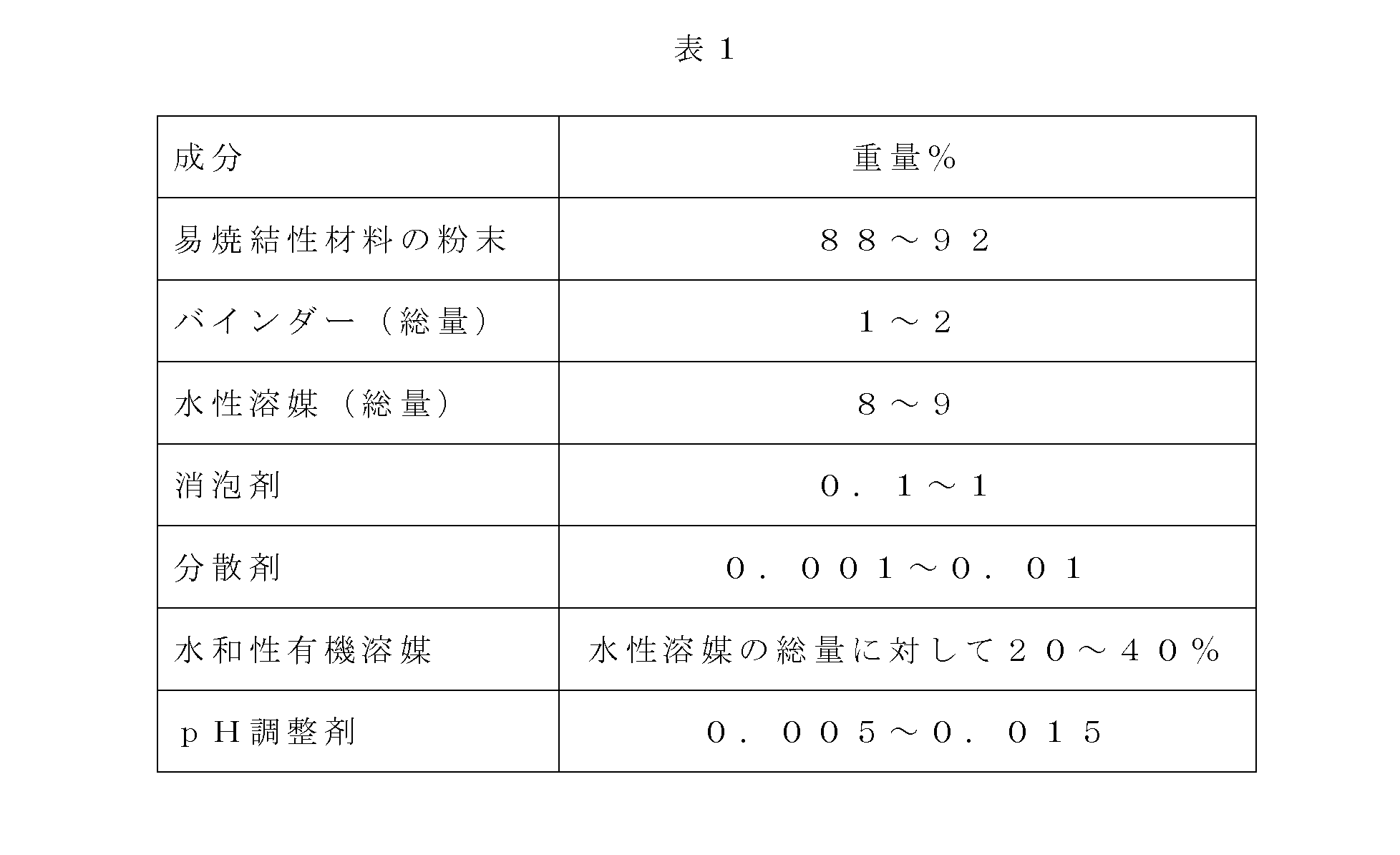
易焼結性材料の粉末は、金属、セラミックスおよび/またはガラスの少なくとも1種の粉末を含み得る。いくつかの実施形態においては、易焼結性材料は、少なくとも500℃、または少なくとも800℃、または少なくとも1000℃の温度で易焼結性であり、そうすることによって焼結の前にバインダーの完全な熱化が確実となる。 The easily sinterable material powder may comprise powder of at least one of metals, ceramics and/or glasses. In some embodiments, the sinterable material is sinterable at a temperature of at least 500° C., or at least 800° C., or at least 1000° C., so that the binder is completely dissolved prior to sintering. thermalization is ensured.
「焼結する」とは、粉末を溶融させることなく粘着した塊を形成することを意味する。 By "sintering" is meant forming a cohesive mass without melting the powder.
例示的な易焼結性ガラス材料としては、ソーダ石灰シリカガラス、ホウケイ酸ナトリウムガラス、石英ガラス、アルミノケイ酸ガラスが挙げられるが、これらに限定されるものではない。 Exemplary sinterable glass materials include, but are not limited to, soda lime silica glass, sodium borosilicate glass, quartz glass, and aluminosilicate glass.
例示的な易焼結性セラミックス材料としては、チタニア、シリカ、ジルコニアおよびアルミナ等の金属酸化物が挙げられるが、これらに限定されるものではない。 Exemplary sinterable ceramic materials include, but are not limited to, metal oxides such as titania, silica, zirconia, and alumina.
例示的な易焼結性金属材料としては、金、白金、銅、銀、亜鉛、アルミニウム、アンチモン、バリウム、ベリリウム、ビスマス、ホウ素、カドミウム、カルシウム、セリン、セシウム、クロム、コバルト、エルビウム、ユーロピウム、ガドリニウム、ガリウム、ゲルマニウム、ハフニウム、ホロミウム、インジウム、鉄、ランタン、鉛、ルテチウム、リチウム、マグネシウム、マンガン、モリブデン、ネオジミウム、ニッケル、ニオブ、オスミウム、パラジウム、カリウム、プラセオジミウム、レニウム、ロジウム、ルビジウム、ルテニウム、サマリウム、スカンジウム、ケイ素、ナトリウム、ストロンチウム、タンタル、テルリウム、テルビウム、タリウム、錫、チタン、タングステン、バナジウム、イットリウム、イッテルビウム、ジルコニウム、これら金属の2種以上を含む合金、例えば、真鍮、鋼(例:ステンレス鋼)およびブロンズが挙げられるが、これらに限定されるものではない。 Exemplary sinterable metallic materials include gold, platinum, copper, silver, zinc, aluminum, antimony, barium, beryllium, bismuth, boron, cadmium, calcium, serine, cesium, chromium, cobalt, erbium, europium, gadolinium, gallium, germanium, hafnium, holmium, indium, iron, lanthanum, lead, lutetium, lithium, magnesium, manganese, molybdenum, neodymium, nickel, niobium, osmium, palladium, potassium, praseodymium, rhenium, rhodium, rubidium, ruthenium, Samarium, scandium, silicon, sodium, strontium, tantalum, tellurium, terbium, thallium, tin, titanium, tungsten, vanadium, yttrium, ytterbium, zirconium, alloys containing two or more of these metals, e.g. brass, steel (e.g.: stainless steel) and bronze.
例示的な実施形態において、易焼結性材料はステンレス鋼粉末である、またはステンレス鋼粉末を含む。 In an exemplary embodiment, the sinterable material is or comprises stainless steel powder.
本願に記載の任意の実施形態のいくつかにおいて、粉末の平均粒径は、本明細書に記載するAM法によって形成される層の厚みの50%以下である。例示的な実施形態において、平均粒径は1~約100ミクロン、または1~約50ミクロン、または1~約20ミクロン(例:5~15、または5~10ミクロン)の範囲であり、その中の任意の中間値および副範囲も含む。 In some of the optional embodiments described herein, the average particle size of the powder is 50% or less of the thickness of the layer formed by the AM method described herein. In exemplary embodiments, the average particle size ranges from 1 to about 100 microns, or 1 to about 50 microns, or 1 to about 20 microns (eg, 5-15, or 5-10 microns), wherein Also includes any intermediate values and subranges of .
本願に記載の任意の実施形態のいくつかにおいて、粉末は、例えば、バインダージェット付加製造法またはレーザー光付加製造法または電子線付加製造法に通常使用されるよりも高い粒径分布(PSD)によって特徴づけられる。例えば、d(50)が10ミクロン、カットオフが45ミクロンである。論理に縛られるものではないが、高PSDは、より高いタップ密度およびプリントされた物体における粒子のより高密度のパッケージングを提供すると考えられる。 In some of the optional embodiments described herein, the powder has a higher particle size distribution (PSD) than typically used in, for example, binder jet additive manufacturing or laser beam additive manufacturing or electron beam additive manufacturing. Characterized. For example, d(50) is 10 microns with a cutoff of 45 microns. Without being bound by theory, it is believed that high PSDs provide higher tap densities and denser packaging of particles in the printed object.
「バインダー」は、熱または他の硬化性エネルギーまたは硬化条件(例えば、pH変化)に暴露されたときに、硬化性材料を硬化(固化)可能なものを意味する。バインダーは、典型的には、硬化条件(例:熱などの硬化エネルギー)に暴露されたときにさらなる重合(例:鎖伸長)および/または架橋を経て、硬化した材料を提供する重合性材料または重合体材料を含む。 "Binder" means something capable of curing (hardening) the curable material when exposed to heat or other curing energy or curing conditions (eg, pH change). Binders are typically polymerizable materials or Contains polymeric material.
本発明のいくつかの実施形態において、バインダーは、硬化条件下において架橋するポリマー材料である。 In some embodiments of the invention, the binder is a polymeric material that crosslinks under curing conditions.
これら実施形態のいくつかにおいて、バインダーは自己架橋する。 In some of these embodiments, the binder is self-crosslinking.
本実施形態によると、バインダーは、以下の特性の1以上、好ましくは2以上、好ましくは全てを満たすものから選択される。
減圧下における収縮率が低い(例:1%未満)、
フィルム形成の傾向が低い、例えば、フィルム形成温度(TMF)が5℃超または10℃超、あるいは、キャスト材の固化を実施する(例:真空下の)温度よりも高い、
Tgが少なくとも30℃または少なくとも40℃、
熱化温度が易焼結性材料の焼結温度よりも低い、例えば、1000℃未満、好ましくは600℃未満、または500℃未満であって、モールド材の融点よりも高い、そして
低粘度(例:少なくとも高ずり速度下で溶液様の挙動を示す)、例えば、高ずり速度下で粘度が10000センチポアズ未満であり、任意で、より低いずり速度下ではより高い粘度(例:常温ではずり減粘挙動を示す)である。いくつかの実施形態においては、バインダーは、それぞれが配合物に対して上記性質の1以上のを付与する2種以上の異なる材料を含む。例えば、1種のバインダー材料は高いTgを有し、1種のバインダー材料は低粘度であり、1種のバインダー材料は高TMFである、というように、選択したバインダー材料の組み合わせとそれらの相対量が、本明細書においてバインダーについて定義した所望の性質を提供する。
According to this embodiment, the binder is selected from those that satisfy one or more, preferably two or more, preferably all of the following properties.
low shrinkage under reduced pressure (e.g. less than 1%);
low propensity for film formation, e.g. film forming temperature (TMF) above 5°C or above 10°C or above the temperature at which solidification of the cast material is performed (e.g. under vacuum);
a Tg of at least 30°C or at least 40°C;
The thermalization temperature is lower than the sintering temperature of the sinterable material, e.g., less than 1000°C, preferably less than 600°C, or less than 500°C, and higher than the melting point of the molding compound, and has a low viscosity (e.g. exhibiting solution-like behavior at least under high shear rates), e.g., having a viscosity of less than 10,000 centipoise under high shear rates, and optionally higher viscosities under lower shear rates (e.g., shear thinning at ambient temperature). behavior). In some embodiments, the binder comprises two or more different materials that each impart one or more of the above properties to the formulation. For example, one binder material has a high Tg, one binder material has a low viscosity, and one binder material has a high TMF. The amount provides the desired properties defined for the binder herein.
例示的な実施形態において、バインダーは2種のバインダー材料、ここでは「バインダーA」および「バインダーB」とも称する、を含む。これら実施形態のいくつかにおいて、バインダーAはニュートン性流体と特徴づけられ、30℃超または40℃超のTgを有する。 In an exemplary embodiment, the binder comprises two binder materials, also referred to herein as "binder A" and "binder B." In some of these embodiments, Binder A is characterized as a Newtonian fluid and has a Tg greater than 30°C or greater than 40°C.
これら実施形態のいくつかにおいて、バインダーBはずり減粘挙動によって特徴づけられ、レオロジー改質剤としても機能する。 In some of these embodiments, Binder B is characterized by shear thinning behavior and also functions as a rheology modifier.
本願に記載の任意の実施形態のいくつかにおいて、剛性、均質性、硬化工程および任意で行われる次の工程における割れの発生に対する耐性、モールド材を除去するための溶媒に対する耐性等のキャスト材の性質を付与するように、バインダーAおよび/またはBは選択される。 In some of the optional embodiments described herein, the properties of the cast material such as stiffness, homogeneity, resistance to cracking during the curing step and optional subsequent steps, resistance to solvents for removing the mold material, etc. Binders A and/or B are selected to impart properties.
例示的な実施形態において、バインダー材料の重量比の範囲は、バインダーA:バインダーBが1:3~3:1の範囲であり、その中の任意の中間値および副範囲も含む。 In an exemplary embodiment, the range of binder material weight ratios ranges from 1:3 to 3:1 binder A:binder B, including any intermediate values and subranges therein.
本願に記載の任意の実施形態のいくつかにおいて、1以上のバインダー材料は、それぞれ独立に、(メタ)アクリル重合体、例えば、自己架橋性ポリ(メタ)アクリル重合体またはスチレン-アクリル共重合体である。 In some of the optional embodiments described herein, the one or more binder materials are each independently a (meth)acrylic polymer, such as a self-crosslinking poly(meth)acrylic polymer or a styrene-acrylic copolymer is.
本願に記載の任意の実施形態のいくつかにおいて、1以上のバインダー材料は、エマルションとして、あらかじめ水溶液に分散させる。これら実施形態のいくつかにおいて、エマルションは40~60重量%のポリマー性バインダー材料を含む。 In some of the optional embodiments described herein, one or more binder materials are pre-dispersed in an aqueous solution as an emulsion. In some of these embodiments, the emulsion comprises 40-60% by weight polymeric binder material.
バインダーAとして適切な例示的な材料としては、下記名称で市販されているエマルションが挙げられるが、これらに限定されるものではない。Joncryl(登録商標)8224、Joncryl(登録商標)-2178-E、Joncryl(登録商標)537-E、Joncryl(登録商標)8211、Joncryl(登録商標)617、Joncryl(登録商標)652、Joncryl(登録商標)646、Joncryl(登録商標)142E、Joncryl(登録商標)1685、Alberdingk(登録商標)AC 2523。 Exemplary materials suitable as Binder A include, but are not limited to, emulsions marketed under the following names. Joncryl® 8224, Joncryl®-2178-E, Joncryl® 537-E, Joncryl® 8211, Joncryl® 617, Joncryl® 652, Joncryl® 646, Joncryl® 142E, Joncryl® 1685, Alberdingk® AC 2523.
バインダーAとして使用可能な例示的な材料は、Joncryl(登録商標)8224として市販されているエマルションに含まれるポリマー材料である。バインダーBとしての使用に適した例示的な材料としては、下記名称で市販されているエマルションに含まれるものが挙げられるが、これらに限定されるものではない。Joncryl(登録商標)661、Rheovis AS 1125、Rheovis AS 1130、Rheovis HS 1303 EB、Rheovis PU 1291、Carbomer 940およびカルボキシメチルセルロース(CMC)。 An exemplary material that can be used as Binder A is the polymeric material contained in the emulsion sold as Joncryl®8224. Exemplary materials suitable for use as Binder B include, but are not limited to, those contained in the emulsions marketed under the following names. Joncryl® 661, Rheovis AS 1125, Rheovis AS 1130, Rheovis HS 1303 EB, Rheovis PU 1291, Carbomer 940 and carboxymethylcellulose (CMC).
バインダーBとして使用可能な例示的な材料は、Joncryl(登録商標)661である。 An exemplary material that can be used as Binder B is Joncryl®661.
分散剤(分散剤)としての使用に適した例示的な材料としては乳化剤が挙げられ、ドデシルベンゼンスルホン酸ナトリウム、ラウリル硫酸ナトリウム、クエン酸ナトリウム、ステアリン酸、およびクエン酸、ならびにDispex Ultra PX 4483、Dispex Ultra PX 4484、Dispex Ultra PX 4275、Dsipex Ultra PX 4575、DISPERBYK 180、DISPERBYK 192およびDISPERBYK 2060の商標で市販されているものが含まれるが、これらに限定されない。 Exemplary materials suitable for use as dispersants (dispersants) include emulsifiers such as sodium dodecylbenzene sulfonate, sodium lauryl sulfate, sodium citrate, stearic acid, and citric acid, and Dispex Ultra PX 4483, Dispex Ultra PX 4484, Dispex Ultra PX 4275, Dsipex Ultra PX 4575, DISPERBYK 180, DISPERBYK 192 and DISPERBYK 2060 trademarks.
例示的な分散剤はドデシルベンゼンスルホン酸ナトリウムである。 An exemplary dispersant is sodium dodecylbenzenesulfonate.
例示的な実施形態において、水性担体(例:水)中の分散剤の溶液または分散液を使用する。例示的な実施形態において、5重量%のドデシルベンゼンスルホン酸ナトリウムおよび95重量%の水を含む溶液を分散剤として使用する。 In an exemplary embodiment, a solution or dispersion of the dispersant in an aqueous carrier (eg, water) is used. In an exemplary embodiment, a solution containing 5% by weight sodium dodecylbenzene sulfonate and 95% by weight water is used as the dispersant.
消泡剤として適切な例示的な材料には、可塑剤としても機能し得るものであって、所望の表面張力を配合物に付与するものが含まれる。例えば、BYKファミリーの化合物である、BYK 024、FoamStar SI 2210、FoamStar ST 2438、FoamStar SI 2240、Byk 093、Byk 025、Byk 1640、Byk 3455、BYK 1680、Foamex 810の商標で市販されているものが含まれるが、これらに限定されない。 Exemplary materials suitable as defoamers include those that can also function as plasticizers and impart the desired surface tension to the formulation. For example, the BYK family of compounds BYK 024, FoamStar SI 2210, FoamStar ST 2438, FoamStar SI 2240, Byk 093, Byk 025, Byk 1640, Byk 3455, BYK 1680, Foamex 810 are commercially available under the trademarks. including but not limited to:
pH調整剤として適切な例示的な材料には、易焼結性材料が化学的に安定である(例:酸化を生じない)および/またはバインダーが化学的に安定である(例:架橋および/または更なる重合を行わない)pH値を配合物に付与する材料が挙げられる。 Exemplary materials suitable as pH modifiers include sinterable materials that are chemically stable (e.g., do not undergo oxidation) and/or binders that are chemically stable (e.g., cross-linked and/or or materials that impart a pH value to the formulation (without further polymerization).
本願に記載の任意の実施形態のいくつかにおいて、水和性有機溶媒は、本明細書において定義した蒸発率である0.3~0.9、または0.3~0.8、または0.3~0.7によって特徴づけられる。 In some of the optional embodiments described herein, the water-miscible organic solvent has an evaporation rate as defined herein of 0.3 to 0.9, or 0.3 to 0.8, or 0.3 to 0.8. characterized by 3 to 0.7.
特定の論理によって拘束されるものではないが、このように相対的に低い蒸発率は、本明細書に記載するモールドキャストAM製法における配合物の使用を可能にすると考えられ、これは、配合物が分注されたときには溶媒は蒸発しないものの、配合物を分配し、例えば、本明細書に記載する加熱および/または減圧下における硬化に付したときには速やかに蒸発するためである。 While not wishing to be bound by any particular theory, it is believed that such relatively low evaporation rates enable the formulation to be used in the mold cast AM process described herein, which This is because the solvent does not evaporate when the is dispensed, but evaporates quickly when the formulation is dispensed and subjected to curing, e.g., under heat and/or vacuum as described herein.
本願に記載の任意の実施形態のいくつかにおいて、水和性有機溶媒とは、バインダーおよび/またはモールド材と化学的に相互作用しないものである。いくつかの実施形態においては、有機溶媒はモールド材を溶解しない。 In some of the optional embodiments described herein, a water-miscible organic solvent is one that does not chemically interact with the binder and/or mold material. In some embodiments, the organic solvent does not dissolve the molding compound.
例示的な溶媒はプロピレングリコールモノメチルエーテル(PM)、CAS No.107-98-2(蒸発率:0.62)である。他の例示的な適切な溶媒としては、プロピレングリコールプロピルエーテル(PnP)、ジプロピレングリコールモノメチルエーテル(DPM)、酢酸プロピレングリコールメチルエーテル(PMA)およびジアセトンアルコール、及びこれらの混合物が挙げられるが、これらに限定されるものではない。 An exemplary solvent is propylene glycol monomethyl ether (PM), CAS No. 107-98-2 (evaporation rate: 0.62). Other exemplary suitable solvents include propylene glycol propyl ether (PnP), dipropylene glycol monomethyl ether (DPM), propylene glycol methyl ether acetate (PMA) and diacetone alcohol, and mixtures thereof, It is not limited to these.
水溶液の蒸発率が0.8、0.9、または1を超えない限り、本明細書に記載する蒸発率を有する有機溶媒に加えて、より高い蒸発率を有する水混和性溶媒を水性溶媒に含めることもできる。 In addition to the organic solvents having the evaporation rates described herein, water-miscible solvents with higher evaporation rates are added to the aqueous solvent, as long as the evaporation rate of the aqueous solution does not exceed 0.8, 0.9, or 1. can also be included.
本明細書を通じて、「水溶液」および「水性担体」という句は代替可能に使用される。 Throughout this specification, the phrases "aqueous solution" and "aqueous carrier" are used interchangeably.
本発明のいくつかの実施形態によると、例示的な配合物は以下を含む。
易焼結性材料粉末として、ステンレス鋼316L粉末、即ち、Huarui Chinaより得られた、平均粒子径が8~10ミクロン(例:d50:9ミクロン。
バインダーAとして、Joncryl(登録商標)8224、即ち、水中の45重量%のアクリル重合体。
バインダーBとして、Joncryl(登録商標)661、即ち、約22~23重量%のアクリル重合体、約53~54重量%の水、約20~21重量%のPM溶媒を含むエマルション。
分散剤として、水中の5重量%のドデシルベンゼンスルホン酸ナトリウム。
消泡剤として、BYK024。
水和性有機溶媒として、プロピレングリコールモノメチルエーテル(PM)、CAS No. 107-98-2。
pH調整剤として、モノエタノールアミン。
水として、逆浸透水DI水。
Exemplary formulations, according to some embodiments of the invention, include:
As the sinterable material powder, stainless steel 316L powder, ie obtained from Huarui China, with an average particle size of 8-10 microns (eg d50: 9 microns).
As Binder A, Joncryl® 8224, a 45% by weight acrylic polymer in water.
As Binder B, Joncryl® 661, an emulsion comprising about 22-23% by weight acrylic polymer, about 53-54% by weight water, and about 20-21% by weight PM solvent.
5% by weight sodium dodecylbenzenesulfonate in water as a dispersant.
BYK024 as an antifoaming agent.
As a hydratable organic solvent, propylene glycol monomethyl ether (PM), CAS No. 107-98-2.
Monoethanolamine as a pH adjuster.
As water, reverse osmosis water DI water.
本明細書に記載する成分を、必須ではないが、好ましくは室温で混合することで、本実施形態の配合物を作製した。 The formulations of the present embodiments were made by mixing the ingredients described herein, preferably, but not necessarily, at room temperature.
例示的な手順では、バインダーB、水およびpH調整剤を密閉容器、任意で振動ミル内で15分間混合する。その後、消泡剤を添加し、得られた混合物をさらに5分間振動させる。次に有機溶媒を添加し、得られた混合物をさらに5分間振動させ、次に分散剤を添加し、さらなる混合を実施する。次いでバインダーAを添加し、さらに混合物を混合する。この段階で易焼結性材料粉末を添加し、得られた混合物を数時間(例:4時間)混合する。全工程を室温で実施する。
In an exemplary procedure, Binder B, water and pH adjuster are mixed in a closed vessel, optionally in a vibrating mill, for 15 minutes. An antifoam agent is then added and the resulting mixture is shaken for an additional 5 minutes. The organic solvent is then added and the resulting mixture is shaken for an additional 5 minutes, then the dispersant is added and further mixing is performed. Binder A is then added and the mixture is further mixed. At this stage the sinterable material powder is added and the resulting mixture is mixed for several hours (
下記表2は、本実施形態のいくつかによるキャスト材を形成するために有用な配合物の化学組成を示す。配合物は後述する手順で調製することができる。 Table 2 below shows chemical compositions of formulations useful for forming cast materials according to some of the present embodiments. The formulation can be prepared by the procedure described below.

下記表3は、本実施形態のいくつかによる例示的な配合物を100グラム調製するために使用する化学成分を示す。 Table 3 below shows the chemical ingredients used to prepare 100 grams of an exemplary formulation according to some of the present embodiments.

ここに示した配合物は、温度21℃において、ブルックフィールドR/Sレオメーター、スピンドルP25で測定したとき、ペースト状である粘度範囲が約10000~50000センチポアズ(例:約30,000センチポアズ)である。 The formulations shown herein have a pasty viscosity range of about 10,000 to 50,000 centipoise (e.g., about 30,000 centipoise) as measured by a Brookfield R/S rheometer, spindle P25 at a temperature of 21°C. be.
実施例2
本明細書に記載するモールドキャスト3Dプリンティング法に、上記表2および表3に示した、本実施形態における例示的な配合物を使用し、本明細書に記載するように、配合物を減圧下で乾燥させた。モールド材配合物としては鉱物蝋、例えば、Fisher-Tropschポリオレフィンワックスと、ミクロ化ワックスと、ある種の酸化ワックスとの混合物を用いた。
Example 2
Exemplary formulations in this embodiment, shown in Tables 2 and 3 above, were used in the mold cast 3D printing method described herein, and the formulations were placed under vacuum as described herein. dried with The molding material formulation used a mixture of mineral waxes such as Fisher-Tropsch polyolefin waxes, micronized waxes and certain oxidized waxes.
モールドキャスト法を完了したら、得られたプリント物体を脂肪族有機溶媒(例:ヘプタン類)と昇温下(例:50~70℃)で接触させてモールド材(例:本明細書に記載する炭化水素ワックス)を除去し、キャスト材で形成されたグリーン体を提供する。 Once the mold casting process is complete, the resulting printed object is contacted with an aliphatic organic solvent (e.g. heptanes) at elevated temperature (e.g. 50-70°C) to form a mold material (e.g. as described herein). (hydrocarbon wax) is removed to provide a green body formed of the cast material.
下記表4は、得られたグリーン体のキャスト材の化学組成を示す。 Table 4 below shows the chemical composition of the cast material of the resulting green body.

得られたグリーン体を次に以下の後処理に付した。 The resulting green bodies were then subjected to the following post-treatments.
「ブラウン体」を提供するために、得られたグリーン体を脱バインダー化(バインダー材料(s0)の除去)に付した。脱バインダー化は加熱、例えば250~650℃、2~10Torrに付すことで実施した。 The resulting green body was subjected to debinding (removal of binder material (s0)) to provide a "brown body". Debinding was performed by heating, eg, 250-650° C., 2-10 Torr.
ブラウン体は次に、1000~1400℃の温度範囲、2~10Torrで焼結に付した。 The brown body was then subjected to sintering at a temperature range of 1000-1400° C. at 2-10 Torr.
図6A~Hは、SEM顕微鏡、製造者:FEIモデルにインストールされたOxford EDSアナライザーとINCAプログラムによる観察によって撮影されたSEM画像であって、2種の倍率の例示的なペースト配合物(図6Aおよび6B)、それをキャストモールド材中で使用して得られたグリーン体(図6C)、脱バインダー化で得られた対応するブラウン体(図6D)、およびそこから製造した、部分焼結された物体(図6E~H)を示す。 Figures 6A-H are SEM images taken by observation with an SEM microscope, Oxford EDS Analyzer and INCA program installed on a Manufacturer: FEI model, showing an exemplary paste formulation at two magnifications (Figure 6A and 6B), the green body obtained by using it in a cast mold material (Fig. 6C), the corresponding brown body obtained by debinding (Fig. 6D), and the partially sintered body produced therefrom. 6E-H).
図7は、本明細書に記載の例示的な配合物を用いて作製したダンベル型試験片である。上の写真は、引っ張り強度試験に付したグリーン体であり、下の写真は最終焼結製品である。 FIG. 7 is a dumbbell specimen made using an exemplary formulation described herein. The top photo is the green body subjected to tensile strength testing and the bottom photo is the final sintered product.
最終焼結製品をISO 6892-1:2016に従ってInstrone 3369装置で分析したところ、引っ張り強度は512MPa、伸長率は66%であった。 The final sintered product was analyzed with an Instrone 3369 instrument according to ISO 6892-1:2016 and found to have a tensile strength of 512 MPa and an elongation of 66%.
本発明をその特定の実施形態との関連で説明したが、多数の代替、修正および変種が当業者には明らかであろう。したがって、そのような代替、修正および変種の全ては、添付の特許請求の範囲の趣旨および広い範囲内に含まれることを意図するものである。 Although the invention has been described in relation to specific embodiments thereof, many alternatives, modifications and variations will be apparent to those skilled in the art. Accordingly, all such alternatives, modifications and variations are intended to be included within the spirit and broad scope of the appended claims.
本明細書で言及した全ての刊行物、特許および特許出願は、個々の刊行物、特許および特許出願のそれぞれについて具体的且つ個別の参照により本明細書に組み込む場合と同程度に、それらの全体が参照により本明細書に組み込まれる。加えて、本願におけるいかなる参考文献の引用または特定は、このような参考文献が本発明の先行技術として使用できることの容認として解釈されるべきではない。また、各節の表題が使用される範囲において、必ずしも限定として解釈されるべきではない。 All publications, patents and patent applications mentioned in this specification are incorporated by reference in their entirety to the same extent as if each individual publication, patent and patent application were specifically and individually incorporated herein by reference. is incorporated herein by reference. In addition, citation or identification of any reference in this application shall not be construed as an admission that such reference is available as prior art to the present invention. Also, to the extent section headings are used, they should not necessarily be construed as limiting.
さらに本願の基礎出願に係る書類も、本参照をもって本明細書に完全に組み込まれたものとする。 Further, the documents relating to the basic application of this application are also fully incorporated herein by this reference.
Claims (37)
6~10重量%の水溶液であって、水と少なくとも20%の前記有機溶媒を含む水溶液と、
1~2重量%の前記バインダーと
を含む、請求項1~16のいずれか一項に記載の配合物。 85-95% by weight of a powder of an easily sinterable material;
a 6-10% by weight aqueous solution comprising water and at least 20% of said organic solvent;
17. The formulation according to any one of the preceding claims, comprising 1-2% by weight of said binder.
モールド材配合物を用いて、物体の形状に沿ったモールドを形成し、
請求項1~20のいずれか一項に記載の易焼結性配合物で前記モールドを充填し、鋳造製品を得、
前記鋳造製品からモールドを除去し、グリーン体を得、
前記グリーン体からバインダーを除去し、ブラウン体を得、
前記ブラウン体を焼結条件に付して、前記物体を形成する、
ことを含む、方法。 A method of forming a three-dimensional object comprising a sintered material, comprising:
forming a mold conforming to the shape of the object using the mold material formulation;
filling the mold with the sinterable formulation according to any one of claims 1 to 20 to obtain a cast product,
removing the mold from the cast product to obtain a green body;
removing the binder from the green body to obtain a brown body;
subjecting the brown body to sintering conditions to form the body;
method, including
前記第1のモールドを前記易焼結性配合物で充填し、第1のモールドキャスト層を形成し、
前記第1のモールドキャスト層の上に前記モールドの第2の層をプリントして、前記多層モールドの第2の層を画定し、
前記易焼結性配合物で、前記第1の層の上に前記第2の層を充填する
ことを含む、請求項28に記載の方法。 printing a first layer of molding material to define a layer of said multilayer mold;
filling the first mold with the sinterable composition to form a first mold cast layer;
printing a second layer of the mold over the first mold cast layer to define a second layer of the multilayer mold;
29. The method of claim 28, comprising filling the second layer over the first layer with the sinterable composition.
A molded article comprising the product of claim 36.
Applications Claiming Priority (1)
| Application Number | Priority Date | Filing Date | Title |
|---|---|---|---|
| PCT/IB2019/053749 WO2020225591A1 (en) | 2019-05-07 | 2019-05-07 | Formulations for additive manufacturing of three-dimensional objects containing sinterable materials |
Publications (3)
| Publication Number | Publication Date |
|---|---|
| JP2022537633A true JP2022537633A (en) | 2022-08-29 |
| JPWO2020225591A5 JPWO2020225591A5 (en) | 2023-12-01 |
| JP7443397B2 JP7443397B2 (en) | 2024-03-05 |
Family
ID=73051029
Family Applications (1)
| Application Number | Title | Priority Date | Filing Date |
|---|---|---|---|
| JP2021566051A Active JP7443397B2 (en) | 2019-05-07 | 2019-05-07 | Formulations containing easily sinterable materials for additive manufacturing of three-dimensional objects |
Country Status (8)
| Country | Link |
|---|---|
| US (1) | US20220235194A1 (en) |
| EP (1) | EP3966008A4 (en) |
| JP (1) | JP7443397B2 (en) |
| CN (1) | CN114025930B (en) |
| AU (1) | AU2019444497B9 (en) |
| CA (1) | CA3139121A1 (en) |
| IL (1) | IL287869A (en) |
| WO (1) | WO2020225591A1 (en) |
Families Citing this family (7)
| Publication number | Priority date | Publication date | Assignee | Title |
|---|---|---|---|---|
| US20220266337A1 (en) * | 2019-07-19 | 2022-08-25 | Vito Nv | Paste composition for additive manufacturing |
| CN113461315A (en) * | 2020-03-31 | 2021-10-01 | 康宁股份有限公司 | Multi-component glass structure via 3D printing |
| EP4244001A4 (en) * | 2020-11-11 | 2025-08-13 | Tritone Tech Ltd | ORGANIC FORMULATIONS FOR THE ADDED MANUFACTURING OF THREE-DIMENSIONAL OBJECTS WITH SINTERABLE MATERIALS |
| WO2023021202A1 (en) * | 2021-08-19 | 2023-02-23 | Headmade Materials Gmbh | Processes for producing a sintered part |
| JP7078300B1 (en) * | 2021-10-05 | 2022-05-31 | 株式会社写真化学 | Stereolithography equipment |
| EP4279240A1 (en) * | 2022-05-17 | 2023-11-22 | Aptiv Technologies Limited | A method of manufacturing a mold body |
| US20240092481A1 (en) * | 2022-09-16 | 2024-03-21 | Hydronalix, Inc. | Ceramic propeller |
Citations (7)
| Publication number | Priority date | Publication date | Assignee | Title |
|---|---|---|---|---|
| US6596224B1 (en) * | 1996-05-24 | 2003-07-22 | Massachusetts Institute Of Technology | Jetting layers of powder and the formation of fine powder beds thereby |
| JP2004296177A (en) * | 2003-03-26 | 2004-10-21 | Toray Ind Inc | Inorganic powder containing paste, and method for manufacturing display panel member using the same |
| JP2018080359A (en) * | 2016-11-15 | 2018-05-24 | 株式会社リコー | 3D modeling powder material, 3D modeling material set, 3D model manufacturing apparatus, and 3D model manufacturing method |
| WO2018149748A1 (en) * | 2017-02-16 | 2018-08-23 | Höganäs Ab | Particles having a sinterable core and a polymeric coating, use thereof, and additive manufacturing method using the same |
| WO2018156933A1 (en) * | 2017-02-24 | 2018-08-30 | Hewlett-Packard Development Company, L.P. | Three-dimensional printing |
| JP2018141225A (en) * | 2017-02-28 | 2018-09-13 | セイコーエプソン株式会社 | Composition for producing three-dimensional molded article, and method for producing three-dimensional molded article |
| WO2018203331A1 (en) * | 2017-05-01 | 2018-11-08 | Tritone Technologies Ltd. | Molding method and apparatus, particularly applicable to metal and/or ceramics |
Family Cites Families (12)
| Publication number | Priority date | Publication date | Assignee | Title |
|---|---|---|---|---|
| NL9400879A (en) * | 1994-05-27 | 1996-01-02 | Univ Delft Tech | A method of manufacturing molded articles from metallic or ceramic powder particles as well as a binder system suitable for use therewith. |
| DE69619179T2 (en) * | 1995-04-03 | 2002-08-22 | Mitsubishi Materials Corp., Tokio/Tokyo | POROUS METALLIC BODY WITH A HIGH SPECIFIC SURFACE, METHOD FOR THE PRODUCTION THEREOF, POROUS METAL MATERIAL AND ELECTRODE FOR ALKALINE SECONDARY BATTERY |
| JP4536943B2 (en) * | 2000-03-22 | 2010-09-01 | 日本碍子株式会社 | Method for producing powder compact |
| US6660224B2 (en) * | 2001-08-16 | 2003-12-09 | National Research Council Of Canada | Method of making open cell material |
| KR100730044B1 (en) * | 2005-12-06 | 2007-06-20 | 엘지전자 주식회사 | Method for manufacturing partition wall of slurry, green sheet and plasma display panel for partition wall |
| CN101306950B (en) * | 2008-06-23 | 2011-01-05 | 西安交通大学 | A direct manufacturing method of light-cured ceramic mold for hollow blades |
| GB201006625D0 (en) * | 2010-04-21 | 2010-06-02 | Rolls Royce Plc | A method of manufacturing a ceramic matrix composite article |
| US20140339745A1 (en) * | 2013-05-17 | 2014-11-20 | Stuart URAM | Molds for ceramic casting |
| US9475945B2 (en) * | 2013-10-03 | 2016-10-25 | Kennametal Inc. | Aqueous slurry for making a powder of hard material |
| JP2019522105A (en) * | 2016-04-14 | 2019-08-08 | デスクトップ メタル インコーポレイテッドDesktop Metal, Inc. | Additive manufacturing with support structure |
| JP6855846B2 (en) * | 2017-03-06 | 2021-04-07 | セイコーエプソン株式会社 | Manufacturing method of paste and 3D model |
| CN111936448B (en) * | 2019-03-13 | 2023-04-04 | 互应化学工业株式会社 | Firing slurry composition, green sheet, method for producing green sheet, sintered product, and monolithic ceramic capacitor |
-
2019
- 2019-05-07 AU AU2019444497A patent/AU2019444497B9/en active Active
- 2019-05-07 JP JP2021566051A patent/JP7443397B2/en active Active
- 2019-05-07 IL IL287869A patent/IL287869A/en unknown
- 2019-05-07 WO PCT/IB2019/053749 patent/WO2020225591A1/en not_active Ceased
- 2019-05-07 US US17/609,391 patent/US20220235194A1/en active Pending
- 2019-05-07 CA CA3139121A patent/CA3139121A1/en active Pending
- 2019-05-07 CN CN201980097281.8A patent/CN114025930B/en active Active
- 2019-05-07 EP EP19927676.7A patent/EP3966008A4/en active Pending
Patent Citations (7)
| Publication number | Priority date | Publication date | Assignee | Title |
|---|---|---|---|---|
| US6596224B1 (en) * | 1996-05-24 | 2003-07-22 | Massachusetts Institute Of Technology | Jetting layers of powder and the formation of fine powder beds thereby |
| JP2004296177A (en) * | 2003-03-26 | 2004-10-21 | Toray Ind Inc | Inorganic powder containing paste, and method for manufacturing display panel member using the same |
| JP2018080359A (en) * | 2016-11-15 | 2018-05-24 | 株式会社リコー | 3D modeling powder material, 3D modeling material set, 3D model manufacturing apparatus, and 3D model manufacturing method |
| WO2018149748A1 (en) * | 2017-02-16 | 2018-08-23 | Höganäs Ab | Particles having a sinterable core and a polymeric coating, use thereof, and additive manufacturing method using the same |
| WO2018156933A1 (en) * | 2017-02-24 | 2018-08-30 | Hewlett-Packard Development Company, L.P. | Three-dimensional printing |
| JP2018141225A (en) * | 2017-02-28 | 2018-09-13 | セイコーエプソン株式会社 | Composition for producing three-dimensional molded article, and method for producing three-dimensional molded article |
| WO2018203331A1 (en) * | 2017-05-01 | 2018-11-08 | Tritone Technologies Ltd. | Molding method and apparatus, particularly applicable to metal and/or ceramics |
Also Published As
| Publication number | Publication date |
|---|---|
| AU2019444497B9 (en) | 2025-07-31 |
| EP3966008A1 (en) | 2022-03-16 |
| AU2019444497A1 (en) | 2022-01-06 |
| EP3966008A4 (en) | 2023-05-03 |
| CA3139121A1 (en) | 2020-11-12 |
| IL287869A (en) | 2024-03-01 |
| AU2019444497B2 (en) | 2025-06-26 |
| WO2020225591A1 (en) | 2020-11-12 |
| CN114025930B (en) | 2024-03-29 |
| JP7443397B2 (en) | 2024-03-05 |
| US20220235194A1 (en) | 2022-07-28 |
| CN114025930A (en) | 2022-02-08 |
Similar Documents
| Publication | Publication Date | Title |
|---|---|---|
| JP7443397B2 (en) | Formulations containing easily sinterable materials for additive manufacturing of three-dimensional objects | |
| AU2018262560B2 (en) | Molding method and apparatus, particularly applicable to metal and/or ceramics | |
| EP3261841B1 (en) | Additive manufacturing processes for making transparent 3d parts from inorganic materials | |
| TWI659940B (en) | Sintering and shaping method and sintered shaped article | |
| US20150041098A1 (en) | 3-D Printed Casting Shell And Method Of Manufacture | |
| JP7557264B2 (en) | Method for manufacturing ceramic article, and ceramic article | |
| WO2018093763A1 (en) | Three dimensional printing compositions and processes | |
| CN107847306A (en) | Method of making a dental article | |
| CN109396433A (en) | The method and machine of at least one blank made of at least one ceramics and/or metal material are manufactured increases material manufacturing technology | |
| US10610922B2 (en) | Ceramic slurry compositions and methods of use thereof | |
| AU2019330385B2 (en) | Hardening method and apparatus, particularly applicable to metal and/or ceramics | |
| WO2020116568A1 (en) | Ceramic article production method and ceramic article | |
| US20250262663A1 (en) | Organic formulations for additive manufacturing of three-dimensional objects containing sinterable materials | |
| US20240052167A1 (en) | Mold formulations for metal additive manufacturing | |
| Fei | Hydrothermal-Assisted Jet Fusion: A Binder-Free Additive Manufacturing Approach for Ceramics | |
| HK40024447A (en) | Molding method and apparatus, particularly applicable to metal and/or ceramics |
Legal Events
| Date | Code | Title | Description |
|---|---|---|---|
| A521 | Request for written amendment filed |
Free format text: JAPANESE INTERMEDIATE CODE: A821 Effective date: 20211227 |
|
| RD01 | Notification of change of attorney |
Free format text: JAPANESE INTERMEDIATE CODE: A7426 Effective date: 20211224 |
|
| A521 | Request for written amendment filed |
Free format text: JAPANESE INTERMEDIATE CODE: A523 Effective date: 20220428 |
|
| A621 | Written request for application examination |
Free format text: JAPANESE INTERMEDIATE CODE: A621 Effective date: 20220428 |
|
| A977 | Report on retrieval |
Free format text: JAPANESE INTERMEDIATE CODE: A971007 Effective date: 20230306 |
|
| A131 | Notification of reasons for refusal |
Free format text: JAPANESE INTERMEDIATE CODE: A131 Effective date: 20230404 |
|
| A524 | Written submission of copy of amendment under article 19 pct |
Free format text: JAPANESE INTERMEDIATE CODE: A524 Effective date: 20230629 |
|
| A131 | Notification of reasons for refusal |
Free format text: JAPANESE INTERMEDIATE CODE: A131 Effective date: 20230815 |
|
| A524 | Written submission of copy of amendment under article 19 pct |
Free format text: JAPANESE INTERMEDIATE CODE: A524 Effective date: 20231114 |
|
| TRDD | Decision of grant or rejection written | ||
| A01 | Written decision to grant a patent or to grant a registration (utility model) |
Free format text: JAPANESE INTERMEDIATE CODE: A01 Effective date: 20240130 |
|
| A61 | First payment of annual fees (during grant procedure) |
Free format text: JAPANESE INTERMEDIATE CODE: A61 Effective date: 20240221 |
|
| R150 | Certificate of patent or registration of utility model |
Ref document number: 7443397 Country of ref document: JP Free format text: JAPANESE INTERMEDIATE CODE: R150 |