JP2022531655A - Mapping and cautery catheter with multiple loop segments - Google Patents
Mapping and cautery catheter with multiple loop segments Download PDFInfo
- Publication number
- JP2022531655A JP2022531655A JP2021560726A JP2021560726A JP2022531655A JP 2022531655 A JP2022531655 A JP 2022531655A JP 2021560726 A JP2021560726 A JP 2021560726A JP 2021560726 A JP2021560726 A JP 2021560726A JP 2022531655 A JP2022531655 A JP 2022531655A
- Authority
- JP
- Japan
- Prior art keywords
- catheter
- loop
- loop segment
- ablation
- electrode
- Prior art date
- Legal status (The legal status is an assumption and is not a legal conclusion. Google has not performed a legal analysis and makes no representation as to the accuracy of the status listed.)
- Pending
Links
Images


Classifications
-
- A—HUMAN NECESSITIES
- A61—MEDICAL OR VETERINARY SCIENCE; HYGIENE
- A61B—DIAGNOSIS; SURGERY; IDENTIFICATION
- A61B18/00—Surgical instruments, devices or methods for transferring non-mechanical forms of energy to or from the body
- A61B18/04—Surgical instruments, devices or methods for transferring non-mechanical forms of energy to or from the body by heating
- A61B18/12—Surgical instruments, devices or methods for transferring non-mechanical forms of energy to or from the body by heating by passing a current through the tissue to be heated, e.g. high-frequency current
- A61B18/14—Probes or electrodes therefor
- A61B18/1492—Probes or electrodes therefor having a flexible, catheter-like structure, e.g. for heart ablation
-
- A—HUMAN NECESSITIES
- A61—MEDICAL OR VETERINARY SCIENCE; HYGIENE
- A61B—DIAGNOSIS; SURGERY; IDENTIFICATION
- A61B17/00—Surgical instruments, devices or methods
- A61B17/00234—Surgical instruments, devices or methods for minimally invasive surgery
- A61B2017/00292—Surgical instruments, devices or methods for minimally invasive surgery mounted on or guided by flexible, e.g. catheter-like, means
- A61B2017/003—Steerable
-
- A—HUMAN NECESSITIES
- A61—MEDICAL OR VETERINARY SCIENCE; HYGIENE
- A61B—DIAGNOSIS; SURGERY; IDENTIFICATION
- A61B17/00—Surgical instruments, devices or methods
- A61B2017/00831—Material properties
- A61B2017/00867—Material properties shape memory effect
-
- A—HUMAN NECESSITIES
- A61—MEDICAL OR VETERINARY SCIENCE; HYGIENE
- A61B—DIAGNOSIS; SURGERY; IDENTIFICATION
- A61B18/00—Surgical instruments, devices or methods for transferring non-mechanical forms of energy to or from the body
- A61B2018/00053—Mechanical features of the instrument of device
- A61B2018/0016—Energy applicators arranged in a two- or three dimensional array
-
- A—HUMAN NECESSITIES
- A61—MEDICAL OR VETERINARY SCIENCE; HYGIENE
- A61B—DIAGNOSIS; SURGERY; IDENTIFICATION
- A61B18/00—Surgical instruments, devices or methods for transferring non-mechanical forms of energy to or from the body
- A61B2018/00053—Mechanical features of the instrument of device
- A61B2018/00214—Expandable means emitting energy, e.g. by elements carried thereon
-
- A—HUMAN NECESSITIES
- A61—MEDICAL OR VETERINARY SCIENCE; HYGIENE
- A61B—DIAGNOSIS; SURGERY; IDENTIFICATION
- A61B18/00—Surgical instruments, devices or methods for transferring non-mechanical forms of energy to or from the body
- A61B2018/00315—Surgical instruments, devices or methods for transferring non-mechanical forms of energy to or from the body for treatment of particular body parts
- A61B2018/00345—Vascular system
- A61B2018/00351—Heart
- A61B2018/00357—Endocardium
-
- A—HUMAN NECESSITIES
- A61—MEDICAL OR VETERINARY SCIENCE; HYGIENE
- A61B—DIAGNOSIS; SURGERY; IDENTIFICATION
- A61B18/00—Surgical instruments, devices or methods for transferring non-mechanical forms of energy to or from the body
- A61B2018/00315—Surgical instruments, devices or methods for transferring non-mechanical forms of energy to or from the body for treatment of particular body parts
- A61B2018/00345—Vascular system
- A61B2018/00351—Heart
- A61B2018/00375—Ostium, e.g. ostium of pulmonary vein or artery
-
- A—HUMAN NECESSITIES
- A61—MEDICAL OR VETERINARY SCIENCE; HYGIENE
- A61B—DIAGNOSIS; SURGERY; IDENTIFICATION
- A61B18/00—Surgical instruments, devices or methods for transferring non-mechanical forms of energy to or from the body
- A61B2018/00571—Surgical instruments, devices or methods for transferring non-mechanical forms of energy to or from the body for achieving a particular surgical effect
- A61B2018/00577—Ablation
-
- A—HUMAN NECESSITIES
- A61—MEDICAL OR VETERINARY SCIENCE; HYGIENE
- A61B—DIAGNOSIS; SURGERY; IDENTIFICATION
- A61B18/00—Surgical instruments, devices or methods for transferring non-mechanical forms of energy to or from the body
- A61B2018/00636—Sensing and controlling the application of energy
- A61B2018/00773—Sensed parameters
- A61B2018/00839—Bioelectrical parameters, e.g. ECG, EEG
-
- A—HUMAN NECESSITIES
- A61—MEDICAL OR VETERINARY SCIENCE; HYGIENE
- A61B—DIAGNOSIS; SURGERY; IDENTIFICATION
- A61B18/00—Surgical instruments, devices or methods for transferring non-mechanical forms of energy to or from the body
- A61B18/04—Surgical instruments, devices or methods for transferring non-mechanical forms of energy to or from the body by heating
- A61B18/12—Surgical instruments, devices or methods for transferring non-mechanical forms of energy to or from the body by heating by passing a current through the tissue to be heated, e.g. high-frequency current
- A61B18/14—Probes or electrodes therefor
- A61B2018/1405—Electrodes having a specific shape
- A61B2018/1435—Spiral
- A61B2018/1437—Spiral whereby the windings of the spiral touch each other such as to create a continuous surface
-
- A—HUMAN NECESSITIES
- A61—MEDICAL OR VETERINARY SCIENCE; HYGIENE
- A61B—DIAGNOSIS; SURGERY; IDENTIFICATION
- A61B18/00—Surgical instruments, devices or methods for transferring non-mechanical forms of energy to or from the body
- A61B18/04—Surgical instruments, devices or methods for transferring non-mechanical forms of energy to or from the body by heating
- A61B18/12—Surgical instruments, devices or methods for transferring non-mechanical forms of energy to or from the body by heating by passing a current through the tissue to be heated, e.g. high-frequency current
- A61B18/14—Probes or electrodes therefor
- A61B2018/1467—Probes or electrodes therefor using more than two electrodes on a single probe
-
- A—HUMAN NECESSITIES
- A61—MEDICAL OR VETERINARY SCIENCE; HYGIENE
- A61B—DIAGNOSIS; SURGERY; IDENTIFICATION
- A61B18/00—Surgical instruments, devices or methods for transferring non-mechanical forms of energy to or from the body
- A61B18/04—Surgical instruments, devices or methods for transferring non-mechanical forms of energy to or from the body by heating
- A61B18/12—Surgical instruments, devices or methods for transferring non-mechanical forms of energy to or from the body by heating by passing a current through the tissue to be heated, e.g. high-frequency current
- A61B18/14—Probes or electrodes therefor
- A61B2018/1497—Electrodes covering only part of the probe circumference
-
- A—HUMAN NECESSITIES
- A61—MEDICAL OR VETERINARY SCIENCE; HYGIENE
- A61B—DIAGNOSIS; SURGERY; IDENTIFICATION
- A61B2218/00—Details of surgical instruments, devices or methods for transferring non-mechanical forms of energy to or from the body
- A61B2218/001—Details of surgical instruments, devices or methods for transferring non-mechanical forms of energy to or from the body having means for irrigation and/or aspiration of substances to and/or from the surgical site
- A61B2218/002—Irrigation
Landscapes
- Health & Medical Sciences (AREA)
- Life Sciences & Earth Sciences (AREA)
- Surgery (AREA)
- Engineering & Computer Science (AREA)
- Plasma & Fusion (AREA)
- Medical Informatics (AREA)
- Otolaryngology (AREA)
- Physics & Mathematics (AREA)
- Cardiology (AREA)
- Biomedical Technology (AREA)
- Heart & Thoracic Surgery (AREA)
- Nuclear Medicine, Radiotherapy & Molecular Imaging (AREA)
- Molecular Biology (AREA)
- Animal Behavior & Ethology (AREA)
- General Health & Medical Sciences (AREA)
- Public Health (AREA)
- Veterinary Medicine (AREA)
- Surgical Instruments (AREA)
Abstract
マッピング及び焼灼カテーテル1が提示される。マッピング及び焼灼カテーテル1は、細長いカテーテルシャフト10と、カテーテルシャフト10の遠位端10-1に配置された焼灼部分11とを備え、焼灼部分11は、複数のループセグメント111~114を含み、そのうちの少なくとも1つの第1のループセグメント111は、血管組織にエネルギーを送達するように構成された1つ又は複数の焼灼電極110を示し、ループセグメント111~114は共に3次元スパイラルを形成し、ループセグメント111~114の各々の直径は、3次元スパイラルが圧縮されたときに、各ループセグメント111~114が隣接するループセグメント111~114上にあるようなものである。複数のループセグメント111~114は、複数のループセグメント111~114の最も近位のループセグメントである電極を示さないスタビライザ・ループ・セグメント114を含む。
Mapping and ablation catheter 1 is presented. The mapping and ablation catheter 1 comprises an elongated catheter shaft 10 and an ablation portion 11 located at the distal end 10-1 of the catheter shaft 10, wherein the ablation portion 11 comprises a plurality of loop segments 111-114. At least one first loop segment 111 of the ablation electrode 110 configured to deliver energy to the vascular tissue, the loop segments 111-114 together form a three-dimensional spiral, looping. The diameter of each of the segments 111-114 is such that each loop segment 111-114 is on the adjacent loop segments 111-114 when the three-dimensional spiral is compressed. The plurality of loop segments 111-114 include a stabilizer loop segment 114 that does not indicate an electrode, which is the most proximal loop segment of the plurality of loop segments 111-114.
Description
本発明は、マッピング及び焼灼カテーテルの実施例に関する。特に、本発明は、多電極灌注高周波(radiofrequency:RF)焼灼カテーテル等の、肺静脈隔離(pulmonary vein isolation:PVI)に使用することができるマッピング及び焼灼カテーテルの実施例に関する。 The present invention relates to examples of mapping and ablation catheters. In particular, the present invention relates to examples of mapping and ablation catheters that can be used for pulmonary vein isolation (PVI), such as multi-electrode irrigation radio frequency (RF) ablation catheters.
心房細動(atrial fibrillation:AF)患者の治療におけるPVI手順に焼灼カテーテルを使用することが知られている。このような手順では、肺静脈口(pulmonary vein ostium:PVO)の周囲に隣接する円周方向の焼灼病変を作成することにより、左心房から肺静脈(pulmonary vein:PV)が電気的に分離される。従って、PV内で生成された望ましくない摂動電気信号が左心房に伝播することを妨げることにより、不規則な心房収縮を回避することができる。 It is known to use a cautery catheter for the PVI procedure in the treatment of patients with atrial fibrillation (AF). In such a procedure, the pulmonary vein (PV) is electrically separated from the left atrium by creating a circumferential ablation lesion adjacent to the circumference of the pulmonary vein ostium (PVO). Ru. Therefore, irregular atrial contraction can be avoided by preventing unwanted perturbation electrical signals generated within the PV from propagating to the left atrium.
単一点先端電極カテーテル、円形多電極ループカテーテル、及び異なるエネルギー源を使用するバルーンベースの焼灼カテーテルを含む、いくつかの型式のAF焼灼カテーテルを利用することができる。実例としては、米国特許第6,666,853号明細書及び米国特許第7,101,368号明細書に記載されているクライオ・バルーン・カテーテル、米国特許第8,540,704号明細書及び米国特許第9,861,437号明細書に記載されているレーザ・バルーン・カテーテル、米国特許第9,352,134号明細書に記載されているRFバルーンカテーテル、米国特許第8,641,704号明細書に記載されている電極アレイカテーテル、及び米国特許第9,717,559号明細書に記載されている灌注式多電極カテーテルが含まれる。 Several types of AF ablation catheters are available, including single point tip electrode catheters, circular multi-electrode loop catheters, and balloon-based ablation catheters that use different energy sources. Examples include the cryoballoon catheter described in US Pat. No. 6,666,853 and US Pat. No. 7,101,368, US Pat. No. 8,540,704 and Laser balloon catheter described in US Pat. No. 9,861,437, RF balloon catheter described in US Pat. No. 9,352,134, US Pat. No. 8,641,704 Included are the electrode array catheters described in No. 9 and the irrigation multi-electrode catheters described in US Pat. No. 9,717,559.
欧州特許出願公開第3023069号明細書は、管状領域をマッピング及び焼灼するための柔らかい遠位先端を備えた、多電極の灌注された管腔カテーテルに関する。特に開示されるのは、柔らかい遠位ループ及びより堅い近位ループを備えたカテーテル先端、焼灼リング電極を有する近位ループ、及び電位を感知するためのリング電極を有する遠位ループである。 European Patent Application Publication No. 3023069 relates to a multi-electrode irrigated luminal catheter with a soft distal tip for mapping and cauterizing tubular areas. Particularly disclosed are catheter tips with soft and stiffer proximal loops, proximal loops with cautery ring electrodes, and distal loops with ring electrodes for sensing potential.
米国特許出願公開第2001007070号明細書及び国際公開第02/089687号はそれぞれ、螺旋状の遠位部分及び螺旋に沿って形成された焼灼部分を備えたカテーテルを記載している。 US Patent Application Publication No. 2001007070 and International Publication No. 02/089687 describe catheters with a helical distal portion and a cauterized portion formed along the spiral, respectively.
既知の焼灼カテーテルにはいくつかの欠点がある。 Known ablation catheters have some drawbacks.
例えば、単一の灌注チップを使用してポイント毎の焼灼を行う場合、この方法は時間がかかり、面倒であり、熟練した電気生理学(electrophysiology:EP)医師が必要である。また、単一の灌注チップでは、焼灼病変の間隙は非常に問題があり、やり直し手順が必要になる場合がある。 For example, when performing point-by-point cauterization using a single irrigation tip, this method is time consuming, cumbersome, and requires a skilled electrophysiology (EP) physician. Also, with a single irrigation tip, the gaps in the cautery lesions are very problematic and may require redo procedures.
ワンショット・バルーン・カテーテルは、むしろ不適合であり、PVOから外れることがある。更に、そのようなカテーテルは、比較的大きなフレンチサイズの送達シースを必要とする。 One-shot balloon catheters are rather incompatible and can disengage from PVO. Moreover, such catheters require a relatively large French-sized delivery sheath.
単一の円形ループ構造上の複数の電極は、個人間の人体構造に固有のばらつきがあるため、単一のループが様々なPVOの形状及びサイズに対応できないため、組織接触の問題が発生する可能性がある。 Multiple electrodes on a single circular loop structure cause tissue contact problems as a single loop cannot accommodate different PVO shapes and sizes due to the inherent variability of the human body structure between individuals. there is a possibility.
本発明の目的は、PVI用の改良された焼灼カテーテルを提供することである。 An object of the present invention is to provide an improved ablation catheter for PVI.
このことは、細長いカテーテルシャフトと、カテーテルシャフトの遠位端に配置された焼灼部分とを備えたカテーテル、特に焼灼カテーテルであって、焼灼部分は、複数のループセグメント(即ち、少なくとも2つのループセグメント)を含み、複数のループセグメントのうちの少なくとも1つの第1のループセグメントは、1つ又は複数の焼灼電極を示し、1つ又は複数の焼灼電極は、血管組織にエネルギーを送達するように構成されており、ループセグメントは共に3次元スパイラルを形成し、ループセグメントの各々の直径は、3次元スパイラルが圧縮されたときに、各ループセグメントが隣接するループセグメント上にあるようなものである、カテーテルによって達成される。特に、3次元スパイラルが圧縮されるとき、各ループセグメントは、その全周に沿って隣接するループセグメント上に置かれ得ることが提供され得る。 This is a catheter with an elongated catheter shaft and a cautery portion located at the distal end of the catheter shaft, particularly a cautery catheter, where the cautery portion is a plurality of loop segments (ie, at least two loop segments). ), The first loop segment of at least one of the plurality of loop segments indicates one or more ablation electrodes, and the one or more ablation electrodes are configured to deliver energy to the vascular tissue. The loop segments together form a three-dimensional spiral, and the diameter of each of the loop segments is such that each loop segment is on an adjacent loop segment when the three-dimensional spiral is compressed. Achieved by catheter. In particular, when a three-dimensional spiral is compressed, it can be provided that each loop segment can be placed on adjacent loop segments along its entire circumference.
焼灼カテーテルは、主に、PVO及び人間の心臓の他の心房領域での焼灼用に構成することができる。 The ablation catheter can be configured primarily for ablation in PVO and other atrial regions of the human heart.
複数のループセグメントによって形成される3次元スパイラルは、可変半径を有する螺旋の目盛りであり得、焼灼電極は、第1のループセグメント上に円周方向に配置することができ、従って、例えば、焼灼部分は、以下では、螺旋ループセグメントとも称されるループセグメントで形成された本質的にサイクロン形状の先端を示し得る。 The three-dimensional spiral formed by the plurality of loop segments can be a spiral scale with a variable radius, and the ablation electrode can be placed circumferentially on the first loop segment, thus, for example, ablation. The moiety may indicate an essentially cyclone-shaped tip formed by a loop segment, also referred to below as a spiral loop segment.
サイクロン形状又は螺旋構造及びループセグメントの柔軟性により、焼灼部分は、単一の円形ループ型式の焼灼カテーテルの形状と比較して、PVOの異なる形状によりよく適合し得る。従って、より標的化されたエネルギー送達、及び潜在的に、隣接する病変を作成するためのより短い焼灼時間をもたらし得る良好な組織接触が達成され得る。言い換えれば、提案された焼灼カテーテルは、近年一般的にEP医師にとって非常に魅力的になっている高出力/短時間焼灼アプローチに特に適している可能性がある。 Due to the cyclone shape or spiral structure and the flexibility of the loop segment, the ablation moiety may better fit different shapes of PVO compared to the shape of a single circular loop type ablation catheter. Thus, better targeted energy delivery, and potentially good tissue contact that can result in shorter cauterization time to create adjacent lesions, can be achieved. In other words, the proposed ablation catheter may be particularly suitable for the high power / short time ablation approach, which has become very attractive to EP physicians in recent years.
更に、複数のループセグメントは、複数のループセグメントの最も近位のループセグメントである、電極を示さないスタビライザ・ループ・セグメントを含み得る。スタビライザ・ループ・セグメントは、後部ループセグメントとも呼ばれ得る。 Further, the plurality of loop segments may include stabilizer loop segments showing no electrodes, which are the most proximal loop segments of the plurality of loop segments. The stabilizer loop segment can also be referred to as the rear loop segment.
後部ループセグメントは、それが肺静脈に係合しているときに、焼灼電極が、焼灼手順の過程で、PVO又は心臓の他の心房領域に作用し得るように、遠位ループアセンブリに横方向の安定性及び構造的支持を追加するように構成され得る。スタビライザ・ループ・セグメントは焼灼電極を持たないので、その形状及び配置は、特に焼灼部分がPVOの近くでPVと係合するPVI処置中に、安定化機能のために最適化され得る。 The posterior loop segment laterally to the distal loop assembly so that the cautery electrode can act on the PVO or other atrial regions of the heart during the cauterization procedure when it engages the pulmonary veins. Can be configured to add stability and structural support. Since the stabilizer loop segment does not have a cautery electrode, its shape and arrangement can be optimized for stabilizing function, especially during PVI treatment where the cautery moiety engages the PV near the PVO.
例えば、一実施例では、スタビライザ・ループ・セグメントの直径は、隣接するループセグメントの直径、即ち、スタビライザ・ループ・セグメントから遠位に配置されている隣接するループ部分の直径よりも小さい。結果として、全体としての焼灼部分(スタビライザ・ループ・セグメントを含む)は、樽形状の輪郭又は少なくとも準樽形状の輪郭を示し得る。 For example, in one embodiment, the diameter of the stabilizer loop segment is smaller than the diameter of the adjacent loop segment, i.e., the diameter of the adjacent loop portion located distal to the stabilizer loop segment. As a result, the cauterized portion as a whole (including the stabilizer loop segment) may exhibit a barrel-shaped contour or at least a quasi-barrel-shaped contour.
一実施例では、複数のループセグメントの第2のループセグメントもまた、複数の焼灼電極を含む。例えば、それぞれがいくつかの焼灼電極を含む第2のループセグメント及び第1のループセグメントは、隣接するループセグメントであり得る。特に、第2のループセグメントの焼灼電極は、第1のループセグメントの焼灼電極に対して互い違いに配置され得る。 In one embodiment, the second loop segment of the plurality of loop segments also comprises the plurality of ablation electrodes. For example, a second loop segment and a first loop segment, each containing several cautery electrodes, can be adjacent loop segments. In particular, the ablation electrodes of the second loop segment can be staggered with respect to the ablation electrodes of the first loop segment.
現在のPVI手順は、PV洞、及び心房内のいくつかの非PVAFトリガサイトを対象としているため、それぞれが焼灼電極を有する2つの螺旋状焼灼ループセグメントにより、バルーン焼灼カテーテルの効果にいくらか匹敵する、より広い又はより広い焼灼領域が可能になる。 Since the current PVI procedure targets PV sinuses and several non-PVAF trigger sites in the atrium, two spiral ablation loop segments, each with a cautery electrode, are somewhat comparable to the effect of a balloon ablation catheter. Allows for a wider or wider cautery area.
焼灼電極を追加し過ぎる(隣接する病変を作成するのがより困難になり得る)ことなくこれを達成するには、比較的長い焼灼電極を使用することが有利な場合がある。例えば、焼灼電極の長さは、4.0mm以上であってもよい。 To achieve this without adding too many ablation electrodes (which can make it more difficult to create adjacent lesions), it may be advantageous to use relatively long ablation electrodes. For example, the length of the cautery electrode may be 4.0 mm or more.
好ましい変形例では、焼灼電極は、スリーブ形状又は管状であってもよい。例えば、そのようなスリーブ形状又は管状の焼灼電極の直径は、2.0mm以上であってもよい。さらに、上記のように、スリーブ形状又は管状の焼灼電極の長さは、4.0mm以上であり得る。 In a preferred variant, the cautery electrode may be sleeve-shaped or tubular. For example, the diameter of such a sleeve-shaped or tubular cautery electrode may be 2.0 mm or more. Further, as described above, the length of the sleeve-shaped or tubular cautery electrode can be 4.0 mm or more.
適切な材料として、焼灼電極は、例えば、金及び白金/イリジウム合金のうちの少なくとも1つを含み得る。 As a suitable material, the cautery electrode may include, for example, at least one of gold and platinum / iridium alloys.
一実施例によれば、焼灼カテーテルは、焼灼電極を介して血管組織に電気RF信号を送達するように構成される。言い換えれば、焼灼カテーテルは、RF焼灼を実行するように構成され得る。現在、RFは、PVIでの使用の長い歴史があるため、他のエネルギーよりも依然として好ましいエネルギーである。 According to one embodiment, the ablation catheter is configured to deliver an electrical RF signal to the vascular tissue via the ablation electrode. In other words, the ablation catheter may be configured to perform RF ablation. Currently, RF is still the preferred energy over other energies due to its long history of use in PVI.
例えば、焼灼カテーテルは、RFエネルギーを送達するために、及びAF患者におけるPVI処置のために電位図信号を送信するために構成されるマルチチャネルRF発生器に接続されるように構成され得る。 For example, a cautery catheter may be configured to be connected to a multi-channel RF generator configured to deliver RF energy and to transmit potential map signals for PVI treatment in AF patients.
他の実施例では、焼灼部分の提案されたスパイラル形状のアーキテクチャは、電気穿孔法、パルス磁場焼灼、又は冷凍焼灼等、RF以外のエネルギー源を利用する焼灼カテーテルに適用され得る。 In another embodiment, the proposed spiral shaped architecture of the cautery moiety can be applied to ablation catheters that utilize energy sources other than RF, such as electroporation, pulsed magnetic field ablation, or frozen ablation.
好ましくは、焼灼電極は、生理食塩水灌注焼灼電極等の灌注焼灼電極である。この目的のために、そして灌注液の送達を容易にするために、焼灼電極は、通気孔及び/又は複数の微細な穴若しくは細孔を有していてもよい。 Preferably, the ablation electrode is an irrigation ablation electrode such as a physiological saline irrigation ablation electrode. For this purpose and to facilitate delivery of the irrigation solution, the cautery electrode may have vents and / or multiple micropores or pores.
従って、焼灼電極は、動作中に灌注液によって冷却され得る。更に、導電性灌注液は、血管組織への電気エネルギー(RF信号等)の送達を支援することができ、それにより、隣接する病変の標的化された作成が可能になる。 Therefore, the cautery electrode can be cooled by the irrigation solution during operation. In addition, conductive irrigation fluid can assist in the delivery of electrical energy (such as RF signals) to vascular tissue, thereby allowing targeted creation of adjacent lesions.
例えば、焼灼電極がスリーブ形状又は管状である場合、各焼灼電極の管状壁は、螺旋状の灌注ベント又はカットを含み得る。従って、灌注のスループットは、特に冷却を改善するために、焼灼電極の長さに沿って均一に広がり得る。特により長い長さ(4.0mm以上)の電極の場合の螺旋状のベント又はカットの追加の利点は、電極がより柔軟になり、従って、固体リング電極とは対照的に、PVOでの組織接触により適合することである。 For example, if the cautery electrodes are sleeve-shaped or tubular, the tubular wall of each cautery electrode may include a spiral irrigation vent or cut. Therefore, the irrigation throughput can spread uniformly along the length of the ablation electrode, especially to improve cooling. An additional advantage of spiral vents or cuts, especially for longer length (4.0 mm and above) electrodes, is that the electrodes become more flexible and therefore the texture at PVO as opposed to solid ring electrodes. It is more compatible with contact.
例えば、ループセグメントに提供される生理食塩水灌注送達用の管腔は、生理食塩水灌注を全ての焼灼電極に均一に送達するために、様々な剛性及び断面形状を有し得る。 For example, the saline irrigation delivery lumen provided in the loop segment may have various stiffness and cross-sectional shapes to uniformly deliver the saline irrigation to all cautery electrodes.
さらに、焼灼電極のいくつか又は全ては、電極温度を監視し、例えば、電力及び灌注流等の焼灼パラメータを制御するためのマルチチャネルRF発生器にフィードバックを提供するための1つ又は複数の温度センサを含み得る。 In addition, some or all of the cautery electrodes are one or more temperatures to monitor the electrode temperature and provide feedback to the multi-channel RF generator for controlling cautery parameters such as power and perfusion flow. May include sensors.
焼灼部分が複数のマッピング電極を含み得、マッピング電極が血管組織から電気信号を受信するように構成されることもまた、本発明の範囲内である。これにより、PVI用の単一の焼灼カテーテルによるマッピング及び焼灼、並びにAF患者用の一部の非PVトリガの焼灼が可能になり得る。 It is also within the scope of the invention that the cauterized moiety may include a plurality of mapping electrodes, the mapping electrodes being configured to receive electrical signals from vascular tissue. This may allow mapping and cauterization with a single ablation catheter for PVI, as well as cauterization of some non-PV triggers for AF patients.
例えば、一実施例では、複数のループセグメントのうちの第3のループセグメントは、複数のマッピング電極を示し得る。追加的又は代替的に、マッピング電極はまた、焼灼電極に加えて、上記のように、第1のループセグメント上及び/又は該当する場合、第2のループセグメント上に配置され得る。複数のマッピング電極はまた、複数の焼灼電極の遠位に、又は2つの焼灼電極の内側に組み込むことができる。さらに、第3のループセグメントは、マッピング電極に加えて、又はその代わりに、焼灼電極を含み得る。 For example, in one embodiment, the third loop segment of the plurality of loop segments may indicate a plurality of mapping electrodes. Additional or alternative, the mapping electrode may also be placed on the first loop segment and / or, where applicable, on the second loop segment, as described above, in addition to the ablation electrode. The plurality of mapping electrodes can also be incorporated distal to the plurality of cautery electrodes or inside the two cautery electrodes. Further, the third loop segment may include a cautery electrode in addition to or instead of the mapping electrode.
有利な実施例では、焼灼部分、特にループセグメントは、形状記憶材料を含む。好ましくは、形状記憶材料は、超弾性材料(超弾性合金等)であり、即ち、材料は弾性であり、形状記憶特性を有する。例えば、ニチノールは、本目的に適した生体適合性の超弾性合金である。 In an advantageous embodiment, the cauterized portion, in particular the loop segment, comprises a shape memory material. Preferably, the shape memory material is a superelastic material (superelastic alloy or the like), that is, the material is elastic and has shape memory properties. For example, nitinol is a biocompatible superelastic alloy suitable for this purpose.
一変形例では、焼灼部分、特にループセグメントは、そのような形状記憶又は超弾性特性を有する、内部支持ワイヤ等の内部支持要素を含み得る。内側支持ワイヤは、例えば、ニチノールワイヤであり得る。形状記憶支持ワイヤは、様々な剛性及び断面形状を有し得る。 In one variant, the cauterized portion, in particular the loop segment, may include an internal support element such as an internal support wire having such shape memory or hyperelastic properties. The inner support wire can be, for example, a nitinol wire. The shape memory support wire can have various stiffness and cross-sectional shapes.
一実施例では、焼灼カテーテルは、操縦可能な送達シースを更に含む。従って、動作中、焼灼部分の位置は、各焼灼電極の接触が満たされるまで、標的内臓組織で容易に調整され得る。 In one embodiment, the cautery catheter further comprises a maneuverable delivery sheath. Thus, during operation, the position of the cautery portion can be easily adjusted in the target visceral tissue until the contact of each cautery electrode is satisfied.
有利なことに、いくつかの実施例では、焼灼部分の提案されたスパイラル形状の構成は、既存のバルーン焼灼カテーテルで使用されるものよりも小さいサイズの経中隔シースを必要とし得る。 Advantageously, in some embodiments, the proposed spiral-shaped configuration of the ablation moiety may require a transseptal sheath of a smaller size than that used with existing balloon ablation catheters.
別の実施例では、カテーテル、特に焼灼カテーテルは、カテーテル近位端のハンドルからの少なくとも1つ又は2つの引っ張りワイヤを更に含み、遠位ループセグメントの一方向又は双方向の撓みを可能にするために主シャフトの遠位セクションに取り付けられる。ループセグメントの直径を圧縮又は調整するために、追加のプルワイヤを含めることができる。これらのカテーテル機能により、PVO内のループセグメントの配置を改善するための更なる調整機能が可能になる。 In another embodiment, the catheter, in particular the ablation catheter, further comprises at least one or two pull wires from the handle at the proximal end of the catheter to allow unidirectional or bidirectional deflection of the distal loop segment. Attached to the distal section of the main shaft. Additional pull wires can be included to compress or adjust the diameter of the loop segment. These catheter functions allow for further adjustment functions to improve the placement of loop segments within the PVO.
本明細書に開示されるマルチ焼灼電極構成を有するカテーテル、特に焼灼カテーテルは、上記の利用可能なアプローチの欠点に対処する。更に、焼灼部分のスパイラルアーキテクチャは、好ましくは灌注された可撓性焼灼電極と組み合わせて、組織接触の課題に対処する。 Catheter with a multi-cautery electrode configuration disclosed herein, in particular a cautery catheter, addresses the shortcomings of the available approaches described above. In addition, the spiral architecture of the cautery moiety, preferably in combination with an irrigated flexible cautery electrode, addresses the challenge of tissue contact.
上記及び以下に記載される実施例の全ての態様及び特徴は、特に明記しない限り、互いに組み合わせることができる。 All aspects and features of the embodiments described above and below may be combined with each other unless otherwise specified.
本発明の様々な特徴及び利点は、以下の詳細な説明及び図面に示される実施例を参照することにより、より容易に理解され得る。 The various features and advantages of the present invention can be more easily understood by reference to the examples shown in the following detailed description and drawings.
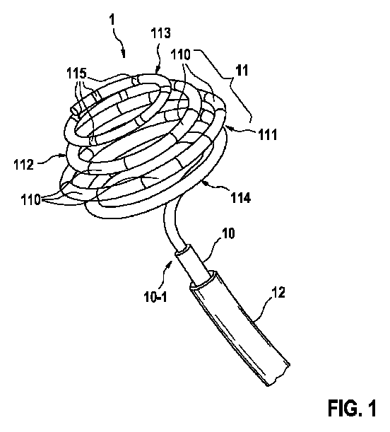
図1は、1つ又は複数の実施例による、焼灼カテーテル1の遠位部分を概略的且つ例示的に示している。カテーテル1は、細長い円形のカテーテルシャフト10を有し、カテーテルシャフト10は、カテーテルシャフトの図示された遠位端10-1の偏向を操作するために、近位端(図示せず)にハンドルを含み得る。
FIG. 1 schematically and exemplary shows the distal portion of the
カテーテルシャフト10の図示された遠位端10-1には、複数の圧縮可能なループセグメント111、112、113、114を含む焼灼部分11が配置されている。
The illustrated distal end 10-1 of the
第1のループセグメント111及び隣接する第2のループセグメント112のそれぞれは、血管組織にエネルギーを送達するように構成されたいくつかの焼灼電極110を示す。特に、焼灼カテーテル1は、焼灼電極110を介して血管組織に電気RF信号を送達するように構成され得る。例えば、焼灼電極110は、金及び/又は白金/イリジウム合金からなるか、又はそれらを含み得る。
Each of the
図1に示される例示的な実施例において、第2のループセグメント112の焼灼電極110は、第1のループセグメント111の焼灼電極110に対して互い違いに配置されている。
In the exemplary embodiment shown in FIG. 1, the
更に、第3のループセグメント113が提供され、第3のループセグメント113は、複数のループセグメント111、112、113、114のうちの最も遠位のループセグメント113である。従って、本例示的な実施例によれば、第3のループセグメント113は、前部ループセグメント113とも呼ばれ得る。第3のループセグメントは、血管組織から電気信号を受信するように構成された複数のマッピング電極115を示す。
Further, a
更に、複数のループセグメント111、112、113、114は、電極を示さないスタビライザ・ループ・セグメント114を含む。スタビライザ・ループ・セグメント114は、複数のループセグメント111、112、113、114の最も近位のループセグメントであり、従って、後部ループセグメント114とも呼ばれ得る。
Further, the plurality of
ループセグメント111、112、113、114は、サイクロン形状の先端部分を特徴とする(圧縮可能な)3次元スパイラルを共に形成する。ループセグメント111、112、113、114のそれぞれの直径は、3次元スパイラルが圧縮されたときに、各ループセグメント111、112、113、114がその全周に沿って隣接するループセグメント111、112、113、114上にあるようなものであることに留意されたい。このことは、図3により明確に示され、以下の図3の説明で更に説明される。
The
図1及び図3の両方に見られるように、スタビライザ・ループ・セグメント114の直径は、隣接する第1のループセグメント111の直径よりも小さい。第1、第2及び第3のループ111、112、113(近位から遠位の方向に直径が減少する)のサイクロン形状の配置と組み合わせて、これは、焼灼部分の本質的に樽形状の輪郭をもたらす。
As can be seen in both FIGS. 1 and 3, the diameter of the
ループセグメント111、112、113、114は、例えば、形状記憶特性を有する内部構造支持ワイヤ(図示せず)の形態の形状記憶材料を含み得る。例えば、ニチノールワイヤは、内部構造支持ワイヤとして提供され得る。特に、ループセグメント111、112、113、114は、超弾性特性を有し得る。
従って、焼灼部分11は、付勢された構成(例えば、図1に示されているような)から、異なる拘束された構成でもたらされ得、逆もまた同様である。例えば、焼灼部分11は、導入シース12とも呼ばれ得る(固定又は操縦可能な)送達シース12による人体の標的領域への送達の目的のために、本質的に細長い形状に拘束され得る。次に、標的位置で、導入シース12の遠位端を出ると、焼灼部分11は、元の(付勢された)形状に反動することができる。
Thus, the cauterized
図2は、人間の心臓の肺静脈口PVOに繋がる焼灼カテーテル1の送達経路を概略的且つ例示的に示している。方向付けのために、下大静脈IVC、右心房RA、右心室RV、左心房LA、左心室LV、及び肺静脈PVが示され、それぞれに肺静脈口PVOがある。大きな白い矢印は、下大静脈IVC、右心房RA、中隔壁SW、及び左心房LAを通過し、最終的に肺静脈口PVOの領域に至る送達経路を示している。
FIG. 2 schematically and schematically shows the delivery route of the
図3は、肺静脈口PVO上に位置する焼灼カテーテル1の遠位部分を概略的且つ例示的に示している。図示のように、スパイラル状の焼灼部分11を肺静脈PVの洞に配置して、肺静脈隔離PVI焼灼を達成することができる。カテーテルシャフト10及び/又は操縦可能なシース12の遠位端10-1は、焼灼部分11が肺静脈口PVOの開口角度と適切に位置合わせされることを確実にするために偏向させることができる。例えば、焼灼部分11の位置決めは、各焼灼電極110及び/又はマッピング電極115の接触が満たされるまで調整され得る。必要に応じて、操縦可能なシース12を使用して、安定性を維持するために焼灼部分11を穏やかに押すことができる。
FIG. 3 schematically and schematically shows the distal portion of the
図3は、焼灼部分11の圧縮状態を示しており、各ループセグメント111、112、113、114は、その全周に沿って隣接するループセグメント111、112、113、114上にある。特に、後部ループセグメント114は、遠位ループアセンブリ111、112、113、114に横方向の安定性及び構造的支持を提供する。
FIG. 3 shows the compressed state of the cauterized
焼灼部分が適切な位置になると、焼灼電極110を介して、ユニポーラ方式で同時に、順次に、又は個別に、又は同じループ111、112内若しくはループ111、112を横切って隣接する焼灼電極110間で双極モードで焼灼が実行され得る。焼灼中、医師は、マッピング電極115及び/又は焼灼電極110を用いてPV電位の低下を観察することができる。
Once the ablation portion is in the proper position, via the
図4は、1つ又は複数の実施形態による、灌注された焼灼電極110を含む焼灼カテーテル1の遠位部分を概略的且つ例示的に示す。特に、図4は、灌注ベント及び/又は焼灼電極110に設けられた複数の微細孔又は細孔を通して灌注されている、生理食塩水灌注液等の灌注液を示している。
FIG. 4 schematically and schematically shows the distal portion of the
図5は、図3に示されるような遠位部分の断面図を示しており、特に、1つのループから隣接するループへの管又はフレンチ直径の10~70%の重なりが示されている。図3に示すように、各ループセグメント111、112、113、114は、その全周に沿って隣接するループ上にあり、ループセグメント114(後部ループセグメントと称される)の管又はフレンチ直径は、ループ111の隣接する管直径と10~70%重なる。ループセグメント114のループ直径は、ループセグメント111のループ直径よりも小さい。隣接するループセグメント111のループ直径が小さいループセグメント112についても同じことが言える。同様に、ループセグメント113は、ループセグメント112よりもサイズが小さい。
FIG. 5 shows a cross-sectional view of the distal portion as shown in FIG. 3, in particular showing an overlap of 10-70% of the tube or French diameter from one loop to the adjacent loop. As shown in FIG. 3, each
図6は、1つ又は複数の実施形態による、焼灼カテーテル1の焼灼電極110を概略的且つ例示的に示している。焼灼電極110は、本質的にスリーブ形状又は管状である。
FIG. 6 schematically and schematically shows the
そのようなスリーブ形状又は管状の焼灼電極110の直径Dは、2.0mm以上であり得る。スリーブ形状又は管状の焼灼電極110の長さLは、4.0mm以上であり得る。
The diameter D of such a sleeve-shaped or
焼灼電極110の管状壁は、螺旋状の灌注ベント又はカット1101を備えている。従って、灌注のスループットは、ベントスペーサとして複数の微小突起カット1102を用いて、焼灼電極110の長さLに沿って均一に広がる。
The tubular wall of the
1 焼灼カテーテル
10 カテーテルシャフト
10-1 カテーテルシャフトの遠位端
11 焼灼部分
110 焼灼電極
1101 灌注ベント
111 第1のループセグメント
112 第2のループセグメント
113 第3のループセグメント
114 スタビライザ・ループ・セグメント
115 マッピング電極
12 送達シース
D 焼灼電極の直径
IVC 下大静脈
L 焼灼電極の長さ
LA 左心房
LV 左心室
PV 肺静脈
PVO 肺静脈口
RA 右心房
RV 右心室
SW 隔壁
1
Claims (13)
前記焼灼部分(11)は、複数のループセグメント(111、112、113、114)を含み、
前記複数のループセグメント(111、112、113、114)のうちの少なくとも1つの第1のループセグメント(111)は、1つ又は複数の焼灼電極(110)を示し、前記1つ又は複数の焼灼電極(110)は、血管組織にエネルギーを送達するように構成されており、
前記ループセグメント(111、112、113、114)は共に3次元スパイラルを形成し、
前記ループセグメント(111、112、113、114)の各々の直径は、前記3次元スパイラルが圧縮されたときに、各ループセグメント(111、112、113、114)が隣接するループセグメント(111、112、113、114)上にあるようなものであり、
前記複数のループセグメント(111、112、113、114)は、電極を示さないスタビライザ・ループ・セグメント(114)を含み、前記スタビライザ・ループ・セグメント(114)は、前記複数のループセグメント(111、112、113、114)のうち最も近位のループセグメントであることを特徴とする、カテーテル(1)。 A catheter (1) comprising an elongated catheter shaft (10) and a cauterizing portion (11) located at the distal end (10-1) of the catheter shaft (10), particularly a cauterizing catheter.
The cauterized portion (11) comprises a plurality of loop segments (111, 112, 113, 114).
At least one first loop segment (111) of the plurality of loop segments (111, 112, 113, 114) indicates one or more ablation electrodes (110), said one or more ablation. The electrode (110) is configured to deliver energy to the vascular tissue.
The loop segments (111, 112, 113, 114) together form a three-dimensional spiral.
Each diameter of the loop segment (111, 112, 113, 114) is such that when the three-dimensional spiral is compressed, the loop segment (111, 112, 113, 114) is adjacent to the loop segment (111, 112). , 113, 114), like on
The plurality of loop segments (111, 112, 113, 114) include a stabilizer loop segment (114) showing no electrode, and the stabilizer loop segment (114) includes the plurality of loop segments (111, A catheter (1) characterized by being the most proximal loop segment of 112, 113, 114).
Applications Claiming Priority (5)
| Application Number | Priority Date | Filing Date | Title |
|---|---|---|---|
| US201962844143P | 2019-05-07 | 2019-05-07 | |
| US62/844,143 | 2019-05-07 | ||
| EP19209312 | 2019-11-15 | ||
| EP19209312.8 | 2019-11-15 | ||
| PCT/EP2020/061275 WO2020224972A1 (en) | 2019-05-07 | 2020-04-23 | Mapping and ablation catheter with multiple loop segments |
Publications (1)
| Publication Number | Publication Date |
|---|---|
| JP2022531655A true JP2022531655A (en) | 2022-07-08 |
Family
ID=70289818
Family Applications (1)
| Application Number | Title | Priority Date | Filing Date |
|---|---|---|---|
| JP2021560726A Pending JP2022531655A (en) | 2019-05-07 | 2020-04-23 | Mapping and cautery catheter with multiple loop segments |
Country Status (5)
| Country | Link |
|---|---|
| US (1) | US20220218412A1 (en) |
| EP (1) | EP3965677B1 (en) |
| JP (1) | JP2022531655A (en) |
| CN (1) | CN113939241B (en) |
| WO (1) | WO2020224972A1 (en) |
Families Citing this family (5)
| Publication number | Priority date | Publication date | Assignee | Title |
|---|---|---|---|---|
| US20220233235A1 (en) * | 2021-01-22 | 2022-07-28 | CRC EP, Inc. | Ablation Catheter for Pulsed-Field Ablation and Method for Electrode Position Assessment for Such Catheter |
| US12082877B2 (en) * | 2021-01-22 | 2024-09-10 | CRC EP, Inc. | Ablation catheter and operation method of same |
| CN114404035B (en) * | 2022-01-21 | 2024-08-16 | 杭州德诺电生理医疗科技有限公司 | Ablation Device |
| CN117481790B (en) * | 2024-01-03 | 2024-04-05 | 梅奥心磁(杭州)医疗科技有限公司 | Double-ring high-density mapping ablation catheter |
| WO2025240606A1 (en) * | 2024-05-14 | 2025-11-20 | Cardiofocus, Inc. | Ablation catheters with deployable electrode structures for use in ablation and electrophysiological mapping |
Citations (8)
| Publication number | Priority date | Publication date | Assignee | Title |
|---|---|---|---|---|
| US20060009785A1 (en) * | 2003-11-13 | 2006-01-12 | The Regents Of The University Of California | Shape memory polymer medical device |
| US20060030933A1 (en) * | 2004-08-04 | 2006-02-09 | Delegge Rebecca | Thermal transition methods and devices |
| JP2012196463A (en) * | 2012-05-10 | 2012-10-18 | Saint Louis Univ | Intramedullary nail device and method for mending long bone |
| JP2014198262A (en) * | 2008-05-14 | 2014-10-23 | オンセット メディカル コーポレイションOnset Medical Corporation | Expandable iliac sheath and method of use |
| JP2016097307A (en) * | 2014-11-20 | 2016-05-30 | バイオセンス・ウエブスター・(イスラエル)・リミテッドBiosense Webster (Israel), Ltd. | Catheter having a flexible distal tip for mapping and cauterizing a tubular region |
| US20170172554A1 (en) * | 2012-03-06 | 2017-06-22 | Highlife Sas | Treatment catheter member with encircling function |
| EP3254635A1 (en) * | 2015-02-03 | 2017-12-13 | Shanghai Golden Leaf Med Tec Co., Ltd | Radio-frequency ablation catheter having spiral structure, and equipment thereof |
| US20190076179A1 (en) * | 2017-09-05 | 2019-03-14 | Adagio Medical, Inc. | Ablation catheter having a shape memory stylet |
Family Cites Families (25)
| Publication number | Priority date | Publication date | Assignee | Title |
|---|---|---|---|---|
| US8728065B2 (en) * | 2009-07-02 | 2014-05-20 | St. Jude Medical, Atrial Fibrillation Division, Inc. | Apparatus and methods for contactless electrophysiology studies |
| CA2185781C (en) * | 1994-03-18 | 2006-07-11 | Kurt J. Tekulve | Helical embolization coil |
| US5680860A (en) * | 1994-07-07 | 1997-10-28 | Cardiac Pathways Corporation | Mapping and/or ablation catheter with coilable distal extremity and method for using same |
| US6537248B2 (en) * | 1998-07-07 | 2003-03-25 | Medtronic, Inc. | Helical needle apparatus for creating a virtual electrode used for the ablation of tissue |
| US20010007070A1 (en) | 1999-04-05 | 2001-07-05 | Medtronic, Inc. | Ablation catheter assembly and method for isolating a pulmonary vein |
| US6702811B2 (en) | 1999-04-05 | 2004-03-09 | Medtronic, Inc. | Ablation catheter assembly with radially decreasing helix and method of use |
| US8540704B2 (en) | 1999-07-14 | 2013-09-24 | Cardiofocus, Inc. | Guided cardiac ablation catheters |
| US6666858B2 (en) | 2001-04-12 | 2003-12-23 | Scimed Life Systems, Inc. | Cryo balloon for atrial ablation |
| US6666853B2 (en) | 2002-03-27 | 2003-12-23 | Scimed Life Systems, Inc. | Low profile adaptor for use with a medical catheter |
| EP1715792A2 (en) * | 2004-01-30 | 2006-11-02 | NMT Medical, Inc. | Welding systems for closure of cardiac openings |
| WO2007070544A2 (en) * | 2005-12-13 | 2007-06-21 | Cook Incorporated | Implantable medical device using palladium |
| US8641704B2 (en) | 2007-05-11 | 2014-02-04 | Medtronic Ablation Frontiers Llc | Ablation therapy system and method for treating continuous atrial fibrillation |
| US8747351B2 (en) * | 2009-08-28 | 2014-06-10 | Biosense Webster, Inc. | Catheter with multi-functional control handle having linear mechanism |
| US20130204311A1 (en) * | 2010-05-12 | 2013-08-08 | Helical Solutions, Inc. | Implants and methods for treating cardiac arrhythmias |
| CN102198015B (en) * | 2011-05-03 | 2013-11-06 | 上海微创电生理医疗科技有限公司 | Retractable spiral laminar ring type electrode catheter |
| US9220433B2 (en) * | 2011-06-30 | 2015-12-29 | Biosense Webster (Israel), Ltd. | Catheter with variable arcuate distal section |
| US9050010B2 (en) * | 2012-12-31 | 2015-06-09 | Biosense Webster (Israel) Ltd. | Double loop lasso with single puller wire for bi-directional actuation |
| US20150073515A1 (en) * | 2013-09-09 | 2015-03-12 | Medtronic Ardian Luxembourg S.a.r.I. | Neuromodulation Catheter Devices and Systems Having Energy Delivering Thermocouple Assemblies and Associated Methods |
| US9352134B2 (en) | 2013-11-01 | 2016-05-31 | Biosense Webster (Israel) Ltd. | Segmented balloon catheter |
| EP3232970A4 (en) * | 2014-12-17 | 2018-11-14 | CathRx Ltd | An improved catheter and method of manufacture thereof |
| US20180161092A1 (en) * | 2015-06-10 | 2018-06-14 | Cathrx Ltd | Double shape catheter |
| US10660700B2 (en) * | 2016-04-28 | 2020-05-26 | Biosense Webster (Israel) Ltd. | Irrigated balloon catheter with flexible circuit electrode assembly |
| EP3463554B1 (en) * | 2016-05-24 | 2021-02-17 | Ecole Polytechnique Federale de Lausanne (EPFL) | Endoluminal nerve modulation device |
| JP6811318B2 (en) * | 2016-11-01 | 2021-01-13 | セント・ジュード・メディカル,カーディオロジー・ディヴィジョン,インコーポレイテッド | Manufacturing methods for catheters and medical devices |
| US10617867B2 (en) * | 2017-04-28 | 2020-04-14 | Farapulse, Inc. | Systems, devices, and methods for delivery of pulsed electric field ablative energy to esophageal tissue |
-
2020
- 2020-04-23 JP JP2021560726A patent/JP2022531655A/en active Pending
- 2020-04-23 EP EP20719467.1A patent/EP3965677B1/en active Active
- 2020-04-23 US US17/608,067 patent/US20220218412A1/en active Pending
- 2020-04-23 CN CN202080032777.XA patent/CN113939241B/en active Active
- 2020-04-23 WO PCT/EP2020/061275 patent/WO2020224972A1/en not_active Ceased
Patent Citations (8)
| Publication number | Priority date | Publication date | Assignee | Title |
|---|---|---|---|---|
| US20060009785A1 (en) * | 2003-11-13 | 2006-01-12 | The Regents Of The University Of California | Shape memory polymer medical device |
| US20060030933A1 (en) * | 2004-08-04 | 2006-02-09 | Delegge Rebecca | Thermal transition methods and devices |
| JP2014198262A (en) * | 2008-05-14 | 2014-10-23 | オンセット メディカル コーポレイションOnset Medical Corporation | Expandable iliac sheath and method of use |
| US20170172554A1 (en) * | 2012-03-06 | 2017-06-22 | Highlife Sas | Treatment catheter member with encircling function |
| JP2012196463A (en) * | 2012-05-10 | 2012-10-18 | Saint Louis Univ | Intramedullary nail device and method for mending long bone |
| JP2016097307A (en) * | 2014-11-20 | 2016-05-30 | バイオセンス・ウエブスター・(イスラエル)・リミテッドBiosense Webster (Israel), Ltd. | Catheter having a flexible distal tip for mapping and cauterizing a tubular region |
| EP3254635A1 (en) * | 2015-02-03 | 2017-12-13 | Shanghai Golden Leaf Med Tec Co., Ltd | Radio-frequency ablation catheter having spiral structure, and equipment thereof |
| US20190076179A1 (en) * | 2017-09-05 | 2019-03-14 | Adagio Medical, Inc. | Ablation catheter having a shape memory stylet |
Also Published As
| Publication number | Publication date |
|---|---|
| EP3965677A1 (en) | 2022-03-16 |
| EP3965677B1 (en) | 2024-10-02 |
| CN113939241A (en) | 2022-01-14 |
| WO2020224972A1 (en) | 2020-11-12 |
| US20220218412A1 (en) | 2022-07-14 |
| CN113939241B (en) | 2025-02-18 |
Similar Documents
| Publication | Publication Date | Title |
|---|---|---|
| US12102382B2 (en) | Biased electrodes for improved tissue contact and current delivery | |
| US6923808B2 (en) | Probes having helical and loop shaped inflatable therapeutic elements | |
| JP2022531655A (en) | Mapping and cautery catheter with multiple loop segments | |
| EP4115834A1 (en) | Biased electrodes for improved tissue contact and current delivery | |
| US20230301712A1 (en) | Elongated trapezoidal electrodes of a basket catheter and methods of making the same | |
| US20230225787A1 (en) | Systems and methods for linear spines forming a spherical basket for improved tissue contact and current delivery | |
| US20230225789A1 (en) | Systems and methods for linear spines and spine retention hub for improved tissue contact and current delivery | |
| CN116250914A (en) | Basket catheter with electrically connected ridges forming distributed electrodes | |
| US12440263B2 (en) | Systems and methods for tripodic spines forming a spherical basket for improved tissue contact and current delivery | |
| US12446946B2 (en) | Systems and methods for a single spiral electrode assembly forming a spherical basket for improved tissue contact and current delivery | |
| US20230225788A1 (en) | Systems and methods for c-shaped spines forming a spherical basket for improved tissue contact and current delivery | |
| US20240197391A1 (en) | Basket assembly with atraumatic tip electrode and methods of making thereof | |
| US20240216056A1 (en) | Systems and methods for coupling segmented spine struts | |
| JP2023175056A (en) | Medical device and shunt formation method | |
| US20260033886A1 (en) | Systems and methods for tripodic spines forming a spherical basket for improved tissue contact and current delivery | |
| EP4268749A1 (en) | Systems and devices for improved irrigation flow during cardiac procedure | |
| US20230029648A1 (en) | Planar end effector with irrigation | |
| US20250082383A1 (en) | Medical device with tactile feedback for spine deployment | |
| JP2025051752A (en) | Medical device with irrigation manifold | |
| CN116458989A (en) | Systems and methods for forming a single helical electrode assembly of a spherical basket for improved tissue contact and current delivery | |
| CN116458991A (en) | System and method for forming tripodal ridges of spherical basket for improved tissue contact and current delivery |
Legal Events
| Date | Code | Title | Description |
|---|---|---|---|
| A621 | Written request for application examination |
Free format text: JAPANESE INTERMEDIATE CODE: A621 Effective date: 20230224 |
|
| A977 | Report on retrieval |
Free format text: JAPANESE INTERMEDIATE CODE: A971007 Effective date: 20231129 |
|
| A131 | Notification of reasons for refusal |
Free format text: JAPANESE INTERMEDIATE CODE: A131 Effective date: 20231205 |
|
| A02 | Decision of refusal |
Free format text: JAPANESE INTERMEDIATE CODE: A02 Effective date: 20240625 |