JP2022526671A - Methods for improving cerebrospinal fluid and devices and systems for that purpose - Google Patents
Methods for improving cerebrospinal fluid and devices and systems for that purpose Download PDFInfo
- Publication number
- JP2022526671A JP2022526671A JP2021560113A JP2021560113A JP2022526671A JP 2022526671 A JP2022526671 A JP 2022526671A JP 2021560113 A JP2021560113 A JP 2021560113A JP 2021560113 A JP2021560113 A JP 2021560113A JP 2022526671 A JP2022526671 A JP 2022526671A
- Authority
- JP
- Japan
- Prior art keywords
- csf
- improver
- flow
- fluid
- catheter
- Prior art date
- Legal status (The legal status is an assumption and is not a legal conclusion. Google has not performed a legal analysis and makes no representation as to the accuracy of the status listed.)
- Pending
Links
Images


Classifications
-
- A—HUMAN NECESSITIES
- A61—MEDICAL OR VETERINARY SCIENCE; HYGIENE
- A61M—DEVICES FOR INTRODUCING MEDIA INTO, OR ONTO, THE BODY; DEVICES FOR TRANSDUCING BODY MEDIA OR FOR TAKING MEDIA FROM THE BODY; DEVICES FOR PRODUCING OR ENDING SLEEP OR STUPOR
- A61M1/00—Suction or pumping devices for medical purposes; Devices for carrying-off, for treatment of, or for carrying-over, body-liquids; Drainage systems
- A61M1/71—Suction drainage systems
- A61M1/73—Suction drainage systems comprising sensors or indicators for physical values
-
- A—HUMAN NECESSITIES
- A61—MEDICAL OR VETERINARY SCIENCE; HYGIENE
- A61M—DEVICES FOR INTRODUCING MEDIA INTO, OR ONTO, THE BODY; DEVICES FOR TRANSDUCING BODY MEDIA OR FOR TAKING MEDIA FROM THE BODY; DEVICES FOR PRODUCING OR ENDING SLEEP OR STUPOR
- A61M1/00—Suction or pumping devices for medical purposes; Devices for carrying-off, for treatment of, or for carrying-over, body-liquids; Drainage systems
- A61M1/14—Dialysis systems; Artificial kidneys; Blood oxygenators ; Reciprocating systems for treatment of body fluids, e.g. single needle systems for hemofiltration or pheresis
- A61M1/15—Dialysis systems; Artificial kidneys; Blood oxygenators ; Reciprocating systems for treatment of body fluids, e.g. single needle systems for hemofiltration or pheresis with a cassette forming partially or totally the flow circuit for the treating fluid, e.g. the dialysate fluid circuit or the treating gas circuit
- A61M1/156—Constructional details of the cassette, e.g. specific details on material or shape
-
- A—HUMAN NECESSITIES
- A61—MEDICAL OR VETERINARY SCIENCE; HYGIENE
- A61M—DEVICES FOR INTRODUCING MEDIA INTO, OR ONTO, THE BODY; DEVICES FOR TRANSDUCING BODY MEDIA OR FOR TAKING MEDIA FROM THE BODY; DEVICES FOR PRODUCING OR ENDING SLEEP OR STUPOR
- A61M1/00—Suction or pumping devices for medical purposes; Devices for carrying-off, for treatment of, or for carrying-over, body-liquids; Drainage systems
- A61M1/14—Dialysis systems; Artificial kidneys; Blood oxygenators ; Reciprocating systems for treatment of body fluids, e.g. single needle systems for hemofiltration or pheresis
- A61M1/16—Dialysis systems; Artificial kidneys; Blood oxygenators ; Reciprocating systems for treatment of body fluids, e.g. single needle systems for hemofiltration or pheresis with membranes
- A61M1/1601—Control or regulation
-
- A—HUMAN NECESSITIES
- A61—MEDICAL OR VETERINARY SCIENCE; HYGIENE
- A61M—DEVICES FOR INTRODUCING MEDIA INTO, OR ONTO, THE BODY; DEVICES FOR TRANSDUCING BODY MEDIA OR FOR TAKING MEDIA FROM THE BODY; DEVICES FOR PRODUCING OR ENDING SLEEP OR STUPOR
- A61M1/00—Suction or pumping devices for medical purposes; Devices for carrying-off, for treatment of, or for carrying-over, body-liquids; Drainage systems
- A61M1/36—Other treatment of blood in a by-pass of the natural circulatory system, e.g. temperature adaptation, irradiation ; Extra-corporeal blood circuits
- A61M1/3621—Extra-corporeal blood circuits
- A61M1/3622—Extra-corporeal blood circuits with a cassette forming partially or totally the blood circuit
- A61M1/36226—Constructional details of cassettes, e.g. specific details on material or shape
-
- A—HUMAN NECESSITIES
- A61—MEDICAL OR VETERINARY SCIENCE; HYGIENE
- A61M—DEVICES FOR INTRODUCING MEDIA INTO, OR ONTO, THE BODY; DEVICES FOR TRANSDUCING BODY MEDIA OR FOR TAKING MEDIA FROM THE BODY; DEVICES FOR PRODUCING OR ENDING SLEEP OR STUPOR
- A61M1/00—Suction or pumping devices for medical purposes; Devices for carrying-off, for treatment of, or for carrying-over, body-liquids; Drainage systems
- A61M1/36—Other treatment of blood in a by-pass of the natural circulatory system, e.g. temperature adaptation, irradiation ; Extra-corporeal blood circuits
- A61M1/3621—Extra-corporeal blood circuits
- A61M1/3653—Interfaces between patient blood circulation and extra-corporal blood circuit
- A61M1/3655—Arterio-venous shunts or fistulae
-
- A—HUMAN NECESSITIES
- A61—MEDICAL OR VETERINARY SCIENCE; HYGIENE
- A61M—DEVICES FOR INTRODUCING MEDIA INTO, OR ONTO, THE BODY; DEVICES FOR TRANSDUCING BODY MEDIA OR FOR TAKING MEDIA FROM THE BODY; DEVICES FOR PRODUCING OR ENDING SLEEP OR STUPOR
- A61M1/00—Suction or pumping devices for medical purposes; Devices for carrying-off, for treatment of, or for carrying-over, body-liquids; Drainage systems
- A61M1/36—Other treatment of blood in a by-pass of the natural circulatory system, e.g. temperature adaptation, irradiation ; Extra-corporeal blood circuits
- A61M1/3621—Extra-corporeal blood circuits
- A61M1/3653—Interfaces between patient blood circulation and extra-corporal blood circuit
- A61M1/3659—Cannulae pertaining to extracorporeal circulation
-
- A—HUMAN NECESSITIES
- A61—MEDICAL OR VETERINARY SCIENCE; HYGIENE
- A61M—DEVICES FOR INTRODUCING MEDIA INTO, OR ONTO, THE BODY; DEVICES FOR TRANSDUCING BODY MEDIA OR FOR TAKING MEDIA FROM THE BODY; DEVICES FOR PRODUCING OR ENDING SLEEP OR STUPOR
- A61M1/00—Suction or pumping devices for medical purposes; Devices for carrying-off, for treatment of, or for carrying-over, body-liquids; Drainage systems
- A61M1/36—Other treatment of blood in a by-pass of the natural circulatory system, e.g. temperature adaptation, irradiation ; Extra-corporeal blood circuits
- A61M1/3687—Chemical treatment
-
- A—HUMAN NECESSITIES
- A61—MEDICAL OR VETERINARY SCIENCE; HYGIENE
- A61M—DEVICES FOR INTRODUCING MEDIA INTO, OR ONTO, THE BODY; DEVICES FOR TRANSDUCING BODY MEDIA OR FOR TAKING MEDIA FROM THE BODY; DEVICES FOR PRODUCING OR ENDING SLEEP OR STUPOR
- A61M27/00—Drainage appliance for wounds or the like, i.e. wound drains, implanted drains
- A61M27/002—Implant devices for drainage of body fluids from one part of the body to another
- A61M27/006—Cerebrospinal drainage; Accessories therefor, e.g. valves
-
- A—HUMAN NECESSITIES
- A61—MEDICAL OR VETERINARY SCIENCE; HYGIENE
- A61M—DEVICES FOR INTRODUCING MEDIA INTO, OR ONTO, THE BODY; DEVICES FOR TRANSDUCING BODY MEDIA OR FOR TAKING MEDIA FROM THE BODY; DEVICES FOR PRODUCING OR ENDING SLEEP OR STUPOR
- A61M27/00—Drainage appliance for wounds or the like, i.e. wound drains, implanted drains
- A61M27/002—Implant devices for drainage of body fluids from one part of the body to another
- A61M2027/004—Implant devices for drainage of body fluids from one part of the body to another with at least a part of the circuit outside the body
-
- A—HUMAN NECESSITIES
- A61—MEDICAL OR VETERINARY SCIENCE; HYGIENE
- A61M—DEVICES FOR INTRODUCING MEDIA INTO, OR ONTO, THE BODY; DEVICES FOR TRANSDUCING BODY MEDIA OR FOR TAKING MEDIA FROM THE BODY; DEVICES FOR PRODUCING OR ENDING SLEEP OR STUPOR
- A61M2202/00—Special media to be introduced, removed or treated
- A61M2202/04—Liquids
- A61M2202/0464—Cerebrospinal fluid
-
- A—HUMAN NECESSITIES
- A61—MEDICAL OR VETERINARY SCIENCE; HYGIENE
- A61M—DEVICES FOR INTRODUCING MEDIA INTO, OR ONTO, THE BODY; DEVICES FOR TRANSDUCING BODY MEDIA OR FOR TAKING MEDIA FROM THE BODY; DEVICES FOR PRODUCING OR ENDING SLEEP OR STUPOR
- A61M2205/00—General characteristics of the apparatus
- A61M2205/10—General characteristics of the apparatus with powered movement mechanisms
- A61M2205/103—General characteristics of the apparatus with powered movement mechanisms rotating
-
- A—HUMAN NECESSITIES
- A61—MEDICAL OR VETERINARY SCIENCE; HYGIENE
- A61M—DEVICES FOR INTRODUCING MEDIA INTO, OR ONTO, THE BODY; DEVICES FOR TRANSDUCING BODY MEDIA OR FOR TAKING MEDIA FROM THE BODY; DEVICES FOR PRODUCING OR ENDING SLEEP OR STUPOR
- A61M2205/00—General characteristics of the apparatus
- A61M2205/12—General characteristics of the apparatus with interchangeable cassettes forming partially or totally the fluid circuit
-
- A—HUMAN NECESSITIES
- A61—MEDICAL OR VETERINARY SCIENCE; HYGIENE
- A61M—DEVICES FOR INTRODUCING MEDIA INTO, OR ONTO, THE BODY; DEVICES FOR TRANSDUCING BODY MEDIA OR FOR TAKING MEDIA FROM THE BODY; DEVICES FOR PRODUCING OR ENDING SLEEP OR STUPOR
- A61M2205/00—General characteristics of the apparatus
- A61M2205/33—Controlling, regulating or measuring
- A61M2205/3331—Pressure; Flow
- A61M2205/3334—Measuring or controlling the flow rate
-
- A—HUMAN NECESSITIES
- A61—MEDICAL OR VETERINARY SCIENCE; HYGIENE
- A61M—DEVICES FOR INTRODUCING MEDIA INTO, OR ONTO, THE BODY; DEVICES FOR TRANSDUCING BODY MEDIA OR FOR TAKING MEDIA FROM THE BODY; DEVICES FOR PRODUCING OR ENDING SLEEP OR STUPOR
- A61M2205/00—General characteristics of the apparatus
- A61M2205/33—Controlling, regulating or measuring
- A61M2205/3331—Pressure; Flow
- A61M2205/3344—Measuring or controlling pressure at the body treatment site
-
- A—HUMAN NECESSITIES
- A61—MEDICAL OR VETERINARY SCIENCE; HYGIENE
- A61M—DEVICES FOR INTRODUCING MEDIA INTO, OR ONTO, THE BODY; DEVICES FOR TRANSDUCING BODY MEDIA OR FOR TAKING MEDIA FROM THE BODY; DEVICES FOR PRODUCING OR ENDING SLEEP OR STUPOR
- A61M2205/00—General characteristics of the apparatus
- A61M2205/33—Controlling, regulating or measuring
- A61M2205/3379—Masses, volumes, levels of fluids in reservoirs, flow rates
-
- A—HUMAN NECESSITIES
- A61—MEDICAL OR VETERINARY SCIENCE; HYGIENE
- A61M—DEVICES FOR INTRODUCING MEDIA INTO, OR ONTO, THE BODY; DEVICES FOR TRANSDUCING BODY MEDIA OR FOR TAKING MEDIA FROM THE BODY; DEVICES FOR PRODUCING OR ENDING SLEEP OR STUPOR
- A61M2210/00—Anatomical parts of the body
- A61M2210/06—Head
- A61M2210/0693—Brain, cerebrum
-
- A—HUMAN NECESSITIES
- A61—MEDICAL OR VETERINARY SCIENCE; HYGIENE
- A61M—DEVICES FOR INTRODUCING MEDIA INTO, OR ONTO, THE BODY; DEVICES FOR TRANSDUCING BODY MEDIA OR FOR TAKING MEDIA FROM THE BODY; DEVICES FOR PRODUCING OR ENDING SLEEP OR STUPOR
- A61M2210/00—Anatomical parts of the body
- A61M2210/10—Trunk
- A61M2210/1003—Spinal column
-
- A—HUMAN NECESSITIES
- A61—MEDICAL OR VETERINARY SCIENCE; HYGIENE
- A61M—DEVICES FOR INTRODUCING MEDIA INTO, OR ONTO, THE BODY; DEVICES FOR TRANSDUCING BODY MEDIA OR FOR TAKING MEDIA FROM THE BODY; DEVICES FOR PRODUCING OR ENDING SLEEP OR STUPOR
- A61M2210/00—Anatomical parts of the body
- A61M2210/10—Trunk
- A61M2210/1025—Respiratory system
- A61M2210/1039—Lungs
Landscapes
- Health & Medical Sciences (AREA)
- Heart & Thoracic Surgery (AREA)
- Vascular Medicine (AREA)
- Engineering & Computer Science (AREA)
- Biomedical Technology (AREA)
- Life Sciences & Earth Sciences (AREA)
- Anesthesiology (AREA)
- Hematology (AREA)
- Animal Behavior & Ethology (AREA)
- General Health & Medical Sciences (AREA)
- Public Health (AREA)
- Veterinary Medicine (AREA)
- Urology & Nephrology (AREA)
- Cardiology (AREA)
- Emergency Medicine (AREA)
- Otolaryngology (AREA)
- Chemical Kinetics & Catalysis (AREA)
- General Chemical & Material Sciences (AREA)
- Chemical & Material Sciences (AREA)
- Ophthalmology & Optometry (AREA)
- Neurology (AREA)
- External Artificial Organs (AREA)
- Medicines Containing Material From Animals Or Micro-Organisms (AREA)
Abstract
哺乳動物対象内に完全にまたは部分的に埋め込み可能な、脳脊髄液(CSF)および他の流体改善システム、ならびに関連する方法は、基質、およびCSFまたは流体中に存在する毒性生体分子の改善のための薬剤を含み、薬剤は、基質上または基質内に配設されている。
Cerebrospinal fluid (CSF) and other fluid improvement systems that can be fully or partially implanted in a mammalian subject, and related methods, are used to improve the substrate and toxic biomolecules present in the CSF or fluid. The agent is disposed on or within the substrate.
Description
関連出願の相互参照
本出願は、2019年4月11日に出願された米国仮特許出願第62/832,486号に対する優先権および利益を主張し、その開示全体は、参照によりその全体が本明細書に組み込まれる。本出願はまた、2020年1月14日に出願された米国仮特許出願第62/960,861に対する優先権および利益を主張する。
Cross-reference to related applications This application claims priority and benefit to US Provisional Patent Application No. 62 / 832,486 filed April 11, 2019, the entire disclosure of which is in its entirety by reference. Incorporated in the specification. This application also claims priority and benefit to US Provisional Patent Application No. 62 / 960,861 filed January 14, 2020.
本発明の様々な実施形態は、くも膜下腔内の流体の改善のためのシステムおよび方法、より具体的には、哺乳動物対象のくも膜下腔と流体連通している、構造上に配設されたか、配置されたか、または位置する改善剤が、くも膜下腔内に含まれる生体分子を改善する、方法およびシステムを提供する。 Various embodiments of the present invention are arranged structurally in a system and method for improving the fluid in the subarachnoid space, more specifically in fluid communication with the subarachnoid space of a mammalian subject. An improver that is, placed, or located provides a method and system for improving biomolecules contained within the subarachnoid space.
多くの神経変性疾患は、哺乳動物対象のくも膜下腔(SAS)内の脳脊髄液(CSF)または他の液体(例えば、間質液)に含まれる生体分子(例えば、毒性タンパク質)の蓄積に関係している。問題なのは、これらの(例えば、毒性のある)生体分子が分泌され、CSFによって体内の他の細胞に輸送される可能性があることであり、このプロセスは、何年にもわたって発生する可能性がある。例えば、ジペプチドリピートタンパク質(DPR)および/またはTDP-43は、ほんの数例を挙げると、筋萎縮性側索硬化症(ALS、またはルーゲーリック病)、アルツハイマー病(AD)、前頭側頭型変性症(FTD)、パーキンソン病(PD)、ハンチントン病(HD)、および進行性核上性麻痺(PSP)の病態における神経細胞死に関与している。したがって、研究は、主に有害なDPRの除去に焦点を合わせてきた。DPRおよび/またはTDP-43を取り出すための技術には、CSF空間からCSFをシャントすること、CSFを希釈すること(例えば、人工液で)、CSFへ薬物を投与すること、CSFを調整すること、および/またはCSF流を操作することが含まれる。しかし、これらの従来の技術は、しばしば合併症を引き起こす。 Many neurodegenerative diseases are associated with the accumulation of biomolecules (eg, toxic proteins) in cerebrospinal fluid (CSF) or other fluids (eg, interstitial fluid) in the subarachnoid space (SAS) of mammalian subjects. Involved. The problem is that these (eg, toxic) biomolecules can be secreted and transported by CSF to other cells in the body, a process that can occur over the years. There is sex. For example, dipeptide repeat protein (DPR) and / or TDP-43, to name just a few, amyotrophic lateral sclerosis (ALS, or Lugeric's disease), Alzheimer's disease (AD), frontotemporal degeneration. (FTD), Parkinson's disease (PD), Huntington's disease (HD), and progressive supranuclear palsy (PSP) are involved in nerve cell death in the pathology. Therefore, research has focused primarily on the removal of harmful DPR. Techniques for removing DPR and / or TDP-43 include shunting CSF from the CSF space, diluting CSF (eg, with artificial fluid), administering drugs to CSF, and adjusting CSF. , And / or manipulating the CSF flow. However, these conventional techniques often cause complications.
発明の概要
結果として、インビボでシステムまたはその構成要素を部分的または完全に(例えば、SAS内で完全にまたは主に)埋め込むことによって、SAS内のCSFおよび他の流体(例えば、間質液)の改善のためのインサイチュおよび他のシステムおよび方法を提供することが望ましい。
INDUSTRIAL APPLICABILITY As a result, CSF and other fluids (eg, interstitial fluid) within the SAS are partially or completely (eg, completely or predominantly) implanted in vivo with the system or its components. It is desirable to provide in vivo and other systems and methods for improvement.
第1の態様において、本発明のいくつかの実施形態は、CSF中の毒性生体分子の存在を特徴とする、病態、外傷、神経疾患、非神経疾患、または欠損症のうちの少なくとも1つに罹患している哺乳動物対象を処理するための方法に関する。いくつかの実施形態では、方法は、改善剤、改善技術、またはそれらの組み合わせを使用した、(例えば、毒性生体分子を酵素的に消化することを介する、および/またはpin1、エキソソーム、および/または生細胞をカートリッジに配設し、CSFをカートリッジを通して循環させることによる)CSF中の毒性生体分子の改善を含む。いくつかの変形例では、毒性生体分子を酵素的に消化することは、プロテアーゼを使用して、毒性生体分子を酵素的に消化することを含み得る。毒性生体分子の改善は、少なくとも部分的に、対象の脳室空間、対象の脳くも膜下腔、および/または対象の腰部領域で起こり得る。 In a first aspect, some embodiments of the invention relate to at least one of pathology, trauma, neurological disease, non-neurological disease, or deficiency characterized by the presence of toxic biomolecules in the CSF. Concerning methods for treating affected mammalian subjects. In some embodiments, the method uses improvers, techniques, or combinations thereof (eg, via enzymatic digestion of toxic biomolecules and / or pin1, exosomes, and / or Includes improvement of toxic biomolecules in CSF (by placing live cells in a cartridge and circulating the CSF through the cartridge). In some variants, enzymatically digesting toxic biomolecules may include enzymatically digesting toxic biomolecules using proteases. Improvements in toxic biomolecules can occur, at least in part, in the subject's ventricular space, the subject's subarachnoid space, and / or the subject's lumbar region.
いくつかの実施態様では、方法は、病態、外傷、神経疾患(例えば、筋萎縮性側索硬化症(ALS)、アルツハイマー病(AD)、前頭側頭変性症(FTD)、進行性核上麻痺(PSP)、ハンチントン病(HD)、およびパーキンソン病(PD)、がん、頭蓋内転移性疾患(IMD)、糖尿病、3型糖尿病、ループス、中毒、慢性外傷性脳症(CTE)、細菌性髄膜炎、動脈瘤、脳卒中、脳血管痙攣、および外傷性脳損傷)、非神経疾患、または欠損症のうちの少なくとも1つの症状を有する患者を選択するステップと、ある量(例えば、約0.1mL/分~約100mL/分の流量で約1mL~約200mLの間)のCSFを第1の場所(例えば、腰部CSF空間内の場所)から取り出すステップと、その量のCSFをカートリッジで処理して、例えば、酵素活性による、物質(例、タウ、シスp-タウ、アミロイドベータ、TDP-43、SOD1、DPR、ニューロフィラメント、およびα-シヌクレイン)などの病状を処理(例えば、除去、低減、改変、隔離、消化、中和、または不活性化)するステップと、CSFの処理された量を第2の場所(例えば、頸部CSF空間または心室CSF空間内の場所)で患者に戻すステップと、を含み得る。いくつかの用途では、方法の実施形態はまた、患者から流体の量を取り出した後、第1の時間の長さ、待機すること、および/または流体の処理された量を患者に戻した後、第2の時間の長さ、待機することを含む。
In some embodiments, the method is pathology, trauma, neurological disease (eg, muscle atrophic lateral sclerosis (ALS), Alzheimer's disease (AD), frontal temporal degeneration (FTD), progressive supranuclear palsy). (PSP), Huntington's disease (HD), and Parkinson's disease (PD), cancer, intracranial metastatic disease (IMD), diabetes,
いくつかの実施態様では、方法はまた、センサを使用して、CSFの処理された量の特性を測定すること、およびCSFの処理された量を、患者の頸部CSF空間および/または心室CSF空間内の第2の場所で患者に戻すことを含み得る。いくつかの変形例では、方法の双方向および/または二重の流れ特性のため、代替案では、CSFのある量は、患者場所の頸部CSF空間および/または心室CSF空間の第1の場所から取り出され得、患者へのCSFの処理された量は、患者の腰部CSF空間の第2の位置に戻され得る。さらに、CSFは、1回または複数回、可逆的に酵素カートリッジを通って流れ、カートリッジ内の滞留時間を増加させ、処理の効果および有効性を高め得る。好ましくは、処理されたCSFは、その量のCSFが取り出される速度と実質的に同じ速度で患者に戻される。いくつかの実施態様では、これらのステップは、少なくとも部分的に同時に発生し得る。任意選択で、方法は、処理されたCSFを患者に戻す前に、未結合の酵素を捕捉するために、処理されたCSFをゲッターで濾過することを含み得る。 In some embodiments, the method also uses a sensor to measure the characteristics of the processed amount of CSF, and the processed amount of CSF in the patient's cervical CSF space and / or ventricular CSF. It may include returning to the patient at a second location in space. In some variants, due to the bidirectional and / or dual flow characteristics of the method, in the alternative, a certain amount of CSF is the first location in the cervical CSF space and / or the ventricular CSF space at the patient location. Can be removed from and the processed amount of CSF to the patient can be returned to a second position in the patient's lumbar CSF space. In addition, the CSF can reversibly flow through the enzyme cartridge one or more times, increasing the residence time in the cartridge and enhancing the effectiveness and effectiveness of the treatment. Preferably, the treated CSF is returned to the patient at substantially the same rate at which the amount of CSF is removed. In some embodiments, these steps can occur at least partially simultaneously. Optionally, the method may include filtering the treated CSF with a getter to capture the unbound enzyme before returning the treated CSF to the patient.
いくつかの変形例では、なされる方法はまた、所定の閾値を満たすか、または超える測定されたCSF特性に基づいて、処理操作パラメータのセットの1つ以上のパラメータを更新することを含む。操作パラメータは、特定の圧力および/または特定の量を維持するように設定し得る。 In some variations, the method made also involves updating one or more parameters of a set of processing operation parameters based on measured CSF characteristics that meet or exceed a predetermined threshold. Operating parameters can be set to maintain a particular pressure and / or a particular amount.
いくつかの実施態様では、方法は、1つ以上の基準が満たされるまで、所定の閾値を満たすか、または超える測定された流体特性に基いて、処理操作パラメータのセットのパラメータ(例えば、患者のCSF空間内の、特定の圧力、特定の量変化、および特定の流量のうちの少なくとも1つを維持するパラメータ)を取り出すステップ、処理するステップ、戻すステップ、および/または更新するステップを繰り返すことを含み得る。 In some embodiments, the method is based on measured fluid properties that meet or exceed a predetermined threshold until one or more criteria are met, with a set of parameters (eg, of the patient). Repeating the steps of retrieving, processing, returning, and / or updating a specific pressure, a specific amount change, and a parameter that maintains at least one of a specific flow rate in the CSF space. Can include.
いくつかの変形例では、取り出されるCSFの量は、戻される処理されたCSFの量以上である。好ましくは、その量のCSFは、その量のCSFが患者から取り出されるのと実質的に同じ速度で患者に戻される。 In some variants, the amount of CSF taken out is greater than or equal to the amount of processed CSF returned. Preferably, that amount of CSF is returned to the patient at substantially the same rate as that amount of CSF is removed from the patient.
第2の態様では、本発明のいくつかの実施形態は、哺乳動物対象と流体連通して使用するための(例えば、哺乳動物対象内に(完全にまたは部分的に)埋め込み可能な)CSF改善システムに関する。一実施形態では、システムは、基質(例えば、カートリッジ)および改善剤を含む。改善剤は、カートリッジの内面に配設された酵素および/またはカートリッジの内面に施された酵素であり得る。代替的に、改善剤は、カートリッジ内に配設された、pin1、エキソソーム、および/または生細胞を含み得る。 In a second aspect, some embodiments of the invention improve CSF for use in fluid communication with a mammalian subject (eg, implantable (eg, fully or partially) within the mammalian subject). Regarding the system. In one embodiment, the system comprises a substrate (eg, a cartridge) and an improver. The improver can be an enzyme disposed on the inner surface of the cartridge and / or an enzyme applied on the inner surface of the cartridge. Alternatively, the improver may include pin1, exosomes, and / or living cells disposed within the cartridge.
一実施態様では、改善剤は、酵素消化によってCSFに存在する生体分子を修飾または分解し、いくつかの変形例では、酵素消化に使用される酵素は、プロテアーゼ(例えば、トリプシン;エラスターゼ;カテプシン;クロストリパイン;カルパイン-2を含むカルパイン;カスパーゼ-1、カスパーゼ-3、カスパーゼ-6、カスパーゼ-7、およびカスパーゼ-8を含むカスパーゼ;M24ホモログ;ヒト気道トリプシン様ペプチダーゼ;プロテイナーゼK;サーモリシン;Asp-Nエンドペプチダーゼ;キモトリプシン;LysC;LysN;グルタミルエンドペプチダーゼ;ブドウ球菌ペプチダーゼ;arg-Cプロテイナーゼ;プロリン-エンドペプチダーゼ;トロンビン;カテプシンE、S、B、K、L1;組織タイプA;ヘパリナーゼ;グランザイムAを含むグランザイム;メプリンα;ペプシン;エンドチアペプカリクレイン-6;カリクレイン-5、およびそれらの組み合わせであり得る。 In one embodiment, the improver modifies or degrades biomolecules present in the CSF by enzymatic digestion, and in some variants, the enzyme used for enzymatic digestion is a protease (eg, trypsin; elastase; catepsin; Crostripine; Carpine containing carpine-2; Caspase-1, Caspase-3, Caspase-6, Caspase-7, and Caspase-8; M24 homolog; Human airway trypsin-like peptidase; Proteinase K; Thermolysine; Asp -N endopeptidase; chymotrypsin; LysC; LysN; glutamilendopeptidase; staphylococcal peptidase; arg-C proteinase; proline-endopeptidase; thrombin; catepsin E, S, B, K, L1; tissue type A; heparinase; granzyme A Granzymes comprising; mepurin α; pepsin; endothia pepcalicrane-6; calicrane-5, and combinations thereof.
基質の例示的な実施形態は、対象内へのカテーテルベースの埋め込みを容易にするために折り畳み可能および/または可撓性である基質、複数の繊毛を含む基質(例えば、外殻部分から延びる繊毛突起、基質内から格納可能および/または伸長可能な繊維および/またはブラシ繊維)、基質(例えば、容器)内または基質上に配置されたビーズ(例えば、超常磁性ビーズ)、透析膜カテーテル、生体分子改善剤を含む管状デバイス、および/または複数の付属物を含み得る。 An exemplary embodiment of the substrate is a substrate that is foldable and / or flexible to facilitate implantation of the catheter base into the subject, a substrate that comprises multiple cilia (eg, cilia extending from an outer shell portion). Protrusions, cilia storable and / or extensible from within the substrate and / or brush fibers), beads (eg, hypernormal magnetic beads) placed in or on the substrate (eg, container), dialysate catheters, biomolecules. It may include a tubular device containing an improver and / or multiple appendages.
いくつかの用途では、システムはまた、CSFをサンプリングすること、改善剤を導入、除去、または補充すること、基質を導入または除去すること、薬物を導入すること、および/または薬物を慢性的に維持することための皮下ポートを含む。別の用途では、システムはまた、基質を横切るCSF流を増強するためのアクセスポート(例えば、第1のアクセスポートおよび第2のアクセスポート)を有する1つ以上のCSF流体ループ、ならびに、CSFループ内に位置するセンサ(例えば、温度センサ、圧力センサ、pHセンサ、UVセンサ、IRセンサ、乱流センサ、ラマン散乱センサ、動的光散乱センサ、成分濃度センサ、流れセンサ、およびそれらの組み合わせ)、ポンプ(例えば、蠕動ポンプ、ロータリーベーンポンプ、アルキメデススクリュー、エアブラダ、空気圧ブラダ、油圧ブラダ、置換ポンプ、電動ポンプ、受動ポンプ、自動ポンプ、バルブレスポンプ、双方向ポンプ、およびそれらの組み合わせ)、弁(例えば、一方向弁、二尖弁、三尖弁、ルビー弁、およびそれらの組み合わせ)、および/またはCSFループ内に位置するアクチュエータのうちの1つ以上を含み得る。好ましくは、システムコントローラ(例えば、開ループコントローラ、閉ループコントローラ、PIDコントローラ、PID閾値コントローラ、システム同定アルゴリズム、およびそれらの組み合わせ)は、センサ、ポンプ、および/またはアクチュエータのうちの1つ以上に動作可能に結合され得る。 In some applications, the system also samples CSF, introduces, removes, or supplements improvers, introduces or removes substrates, introduces drugs, and / or chronically introduces drugs. Includes a subcutaneous port for maintenance. In another application, the system also has one or more CSF fluid loops with access ports (eg, first and second access ports) for enhancing CSF flow across the substrate, as well as CSF loops. Sensors located within (eg, temperature sensor, pressure sensor, pH sensor, UV sensor, IR sensor, turbulent flow sensor, Raman scattering sensor, dynamic light scattering sensor, component concentration sensor, flow sensor, and combinations thereof). Pumps (eg, peristaltic pumps, rotary vanes pumps, archimedes screws, air bladder, pneumatic bladder, hydraulic bladder, replacement pumps, electric pumps, passive pumps, automatic pumps, valveless pumps, bidirectional pumps, and combinations thereof), valves (eg, eg It may include one or more of a one-way valve, a two-point valve, a three-point valve, a ruby valve, and combinations thereof), and / or an actuator located within a CSF loop. Preferably, the system controller (eg, open-loop controller, closed-loop controller, PID controller, PID threshold controller, system identification algorithm, and combinations thereof) can operate on one or more of sensors, pumps, and / or actuators. Can be combined with.
いくつかの変形例では、システムはまた、ステントおよび/またはポンプ(例えば、多孔質壁を有する)および/またはアクチュエータを含み得、したがって、生体分子改善剤は、ポンプの内面に施され、より具体的には、生体分子改善剤は、多孔質壁によって保持される。 In some variants, the system may also include a stent and / or a pump (eg, having a porous wall) and / or an actuator, so that the biomolecule improver is applied to the inner surface of the pump and is more specific. The biomolecule improver is retained by the porous wall.
いくかの用途では、システムはまた、CSF方向システム、頸部カテーテル、材木カテーテル、または心室カテーテルのうちの1つ以上、およびCSF成分および/またはCSF特性を測定または感知するためのセンサのうちの1つ以上を含む。制御システムは、哺乳動物対象内のCSFの圧力および/または流れを維持し得る。いくつかの変形例では、制御システムは、プログラム可能なメモリ、データ処理システム、および通信サブシステムを有し、一方、CSF方向システムは、ポンプ、チュービング、Tバルブ、逆流防止弁、および/またはシャットオフバルブ、ならびにアクセスポートおよび/または皮下アクセスポートを有する。 In some applications, the system is also one or more of a CSF directional system, a cervical catheter, a lumber catheter, or a ventricular catheter, and of sensors for measuring or sensing CSF components and / or CSF characteristics. Includes one or more. The control system may maintain the pressure and / or flow of CSF within the mammalian subject. In some variants, the control system has a programmable memory, data processing system, and communication subsystem, while the CSF directional system has a pump, tubing, T-valve, check valve, and / or shut. It has an off-valve and an access port and / or a subcutaneous access port.
いくつかの実施形態では、その量のCSFを処理することは、サイズ濾過、イオン濾過、接線流濾過、向流接線流濾過、限外濾過、ノッチ濾過、直列濾過、またはカスケード濾過のうちの少なくとも1つを使用して、その量のCSFを濾過することを含み得る。他の実施形態では、その量のCSFを処理することは、廃棄物を除去することと、その量のCSFを酵素消化にさらすことと、抗体を使用してもしくは使用せずにその量のCSFを生物親和性相互作用にさらすことと、その量のCSFを紫外線放射にさらすことと、その量のCSFを熱または冷気または温度変化にさらすことと、その量のCSFを電磁場に導入することと、その量のCSFを圧力変化にさらすことと、その量のCSFをpH変化にさらすことと、またはその量のCSFを、単独で、もしくは生物親和性剤と組み合わせて、操作剤(例えば、磁気ビーズ、ナノ粒子、光ピンセット、およびそれらの組み合わせ)にさらすことと、を含み得る。 In some embodiments, treating that amount of CSF is at least one of size filtration, ion filtration, tangential flow filtration, countercurrent tangential flow filtration, ultrafiltration, notch filtration, series filtration, or cascade filtration. One may be used to filter that amount of CSF. In other embodiments, treating that amount of CSF removes waste, exposes that amount of CSF to enzymatic digestion, and uses that amount of CSF with or without an antibody. To expose the amount of CSF to bioaffinity interactions, to expose that amount of CSF to ultraviolet radiation, to expose that amount of CSF to heat or cold air or temperature changes, and to introduce that amount of CSF into an electromagnetic field. , The amount of CSF exposed to pressure changes, the amount of CSF exposed to pH changes, or the amount of CSF alone or in combination with a biocompatible agent (eg, magnetic). It may include exposure to beads, nanoparticles, optical tweezers, and combinations thereof).
いくつかの用途では、方法はまた、CSF中の最初の毒性生体分子含有量が減少した後、CSF中の減少した毒性生体分子含有量を維持することと、CSFを電荷またはサイズ濾過して、毒性生体分子を濾過除去することと、毒性生体分子を濾過除去するための、CSFの抗体またはナノボディ処理と、毒性生体分子を濾過除去するための酵素法および電荷またはサイズ濾過方法の組み合わせ、および/またはCSFの自然に発生する(例えば、集束された)流れを増強することと、を含み得る。 In some applications, the method also maintains the reduced toxic biomolecule content in the CSF after the initial toxic biomolecule content in the CSF is reduced, and charges or size filters the CSF. A combination of CSF antibody or nanobody treatment for filtering off toxic biomolecules and enzymatic and charge or size filtering methods for filtering out toxic biomolecules, and / Alternatively, it may include enhancing the naturally occurring (eg, focused) flow of the CSF.
いくつかの実施態様では、改善剤は、対象のくも膜下腔内のCSFに導入され得る。他の実施態様では、改善剤は、(例えば、カテーテルベースの埋め込みによって)対象に埋め込まれ得る、固体構造、折り畳み可能構造、または可撓性構造上に配設され得る。いくつかの変形例では、構造は、基質、繊毛、基質から延びる繊毛、繊維、基質から延びる繊維、付属物、基質から延びる付属物、開窓、ビーズ、複数のビーズ、双安定モノリシック構造、露出する付属物、ステント、カテーテル、カートリッジ、スラリー、およびそれらの組み合わせのうちの1つ以上を含む。 In some embodiments, the improver can be introduced into the CSF within the subarachnoid space of the subject. In other embodiments, the improver can be disposed on a solid, foldable, or flexible structure that can be implanted in the subject (eg, by catheter-based implantation). In some variants, the structure is substrate, fiber, fiber extending from substrate, fiber, fiber extending from substrate, appendage, appendage extending from substrate, fenestration, bead, multiple beads, bistable monolithic structure, exposed. Includes accessories, stents, catheters, cartridges, slurries, and one or more of combinations thereof.
いくつかの実施形態では、構造は、いくつかの変形例では、内核を取り囲む外殻を含み得る表面(例えば、水圧活性化可能表面、空気圧活性化可能表面、および/または形状記憶表面)上の繊毛を含む。そのような組成物を用いて、方法は、繊毛が形成される外殻を膨張させることと、内核と外殻の間に位置するCSFが、繊毛を通過するように、内核を膨張させることと、内核と外殻をしぼませることと、さらに含み得る。 In some embodiments, the structure is on a surface that, in some modifications, may include an outer shell surrounding the inner core (eg, a hydraulically activating surface, a pneumatically activating surface, and / or a shape memory surface). Includes cilia. With such a composition, the method is to inflate the outer shell on which the cilia are formed and to inflate the inner core so that the CSF located between the inner core and the outer shell passes through the cilia. , Can include deflating the inner core and outer shell, and more.
他の実施形態では、構造は、繊維を含み得る。そのような組成物を用いて、方法は、送達デバイス内からCSF内に繊維を伸長させることと、繊維を送達デバイス内に格納することを含み得る。 In other embodiments, the structure may include fibers. With such compositions, the method may include extending the fibers from within the delivery device into the CSF and storing the fibers in the delivery device.
さらに別の実施形態では、構造は、モノリシック双安定構造を含み、モノリシック双安定構造は、その上に形成された付属物を備え得る。そのような組成物を用いて、方法は、モノリシック双安定構造を拡張して、付属物をCSFに展開し、モノリシック双安定構造から露出することと、モノリシック双安定構造をしぼませて、付属物を格納して、CSF内に混合運動を提供することと、を含み得る。 In yet another embodiment, the structure comprises a monolithic bistable structure, the monolithic bistable structure may comprise an appendage formed on it. With such a composition, the method is to extend the monolithic bistable structure, deploy the appendages to the CSF, expose from the monolithic bistable structure, and deflate the monolithic bistable structure, the appendages. Can include storing and providing mixed motion within the CSF.
方法のいくつかの実施形態では、改善技術は、対象のくも膜下腔の外側に改善剤を導入することと、改善剤を通過するCSFの循環を可能にする(例えば、能動ポンプまたは受動ポンプを使用して)ことを含む。いくつかの実施態様では、実施形態は、処理されたCSFをくも膜下腔に戻すことを含む。いくつかの用途では、CSFを循環させること、および処理されたCSFを戻すことは、くも膜下腔にアクセスする複数のカテーテル挿入場所を介して、(例えば、カテーテルを使用して)CSFを輸送すること、くも膜下腔にアクセスする単一のカテーテル挿入位置を介して、(例えば、マルチルーメンカテーテル配置を使用して)CSFを輸送すること、および/または制御された流体の流れを維持するための能動的循環(例えば、能動的または受動的ポンピングによる)を含み得る。いくつかの実施態様では、CSFを循環させることは、改善剤をカテーテルまたはカートリッジに配設すること、およびCSFをカテーテルまたはカートリッジを通して流すことを含む。 In some embodiments of the method, the improvement technique allows the introduction of the improver outside the subarachnoid space of the subject and the circulation of CSF through the improver (eg, active or passive pumps). Including). In some embodiments, embodiments include returning the treated CSF to the subarachnoid space. In some applications, circulating the CSF, and returning the treated CSF, transports the CSF (eg, using a catheter) through multiple catheter insertion sites that access the subarachnoid space. That, to transport the CSF (eg, using a multi-lumen catheter arrangement) through a single catheter insertion position to access the subarachnoid space, and / or to maintain controlled fluid flow. It can include active circulation (eg, by active or passive pumping). In some embodiments, circulating the CSF comprises placing an improver on the catheter or cartridge, and flushing the CSF through the catheter or cartridge.
第3の態様では、本発明のいくつかの実施形態は、哺乳動物対象と流体連通するように、その中に(例えば、完全にまたは部分的に)埋め込み可能なCSF改善システムに関する。いくつかの実施形態では、システムは、CSFの集束した流れを提供するように動作可能であり、流体の流れを改変するための、流れコントローラ、カテーテル、ポンプ、および/または構造を含むように構成されている。任意選択で、システムはまた、くも膜下腔への別個の流体アクセスポイントに位置するカテーテルを含み得る(例えば、側脳室および腰椎嚢内、大槽および腰椎嚢内、大槽および前頭葉内、側脳くも膜下腔内、ならびに/または頸部くも膜下腔および腰椎嚢内)。いくつかの実施態様では、1つ以上の受動ポンプ、内部能動ポンプ、および/または受動流動調整剤は、実質的にくも膜下腔内に埋め込まれ得る。 In a third aspect, some embodiments of the invention relate to a CSF improvement system that can be (eg, completely or partially) implanted in a mammalian subject for fluid communication. In some embodiments, the system is capable of operating to provide a focused flow of CSF and is configured to include a flow controller, catheter, pump, and / or structure for modifying the flow of fluid. Has been done. Optionally, the system may also include a catheter located at a separate fluid access point to the subarachnoid space (eg, lateral ventricle and intralumbar sac, cisterna magna and lumbar sac, cisterna magna and frontal lobe, lateral arachnoid membrane). In the subarachnoid space and / or in the cervical subarachnoid space and lumbar cisterna magna). In some embodiments, the one or more passive pumps, internal active pumps, and / or passive flow regulators can be substantially implanted in the subarachnoid space.
第4の態様では、本発明のいくつかの実施形態は、哺乳動物対象と流体連通するように、その中に(例えば、完全にまたは部分的に)埋め込み可能なCSF改善システムに関する。いくつかの実施形態では、システムは、CSFの集束した流れを提供するように構成されており、基質、基質上および/または基質内に配置された改善剤、および流体の流れを改変するための、流れコントローラ、カテーテル、ポンプ、および/または構造のうちの1つ以上を含む。 In a fourth aspect, some embodiments of the invention relate to a CSF improvement system that can be (eg, completely or partially) implanted in a mammalian subject for fluid communication. In some embodiments, the system is configured to provide a focused flow of CSF to modify the flow of the substrate, the improver placed on and / or within the substrate, and the fluid. , Flow controller, catheter, pump, and / or one or more of structures.
第5の態様では、本発明のいくつかの実施形態は、本発明のいくつかの実施形態は、CSF中の毒性生体分子の存在を特徴とする、病態、外傷、神経疾患、非神経疾患、または欠損症のうちの少なくとも1つに罹患している哺乳動物対象を処理するための方法に関する。いくつかの実施形態では、方法は、改善剤、改善技術、またはそれらの組み合わせを使用した、(例えば、毒性生体分子を酵素的に消化することを介する、および/またはpin1、エキソソーム、および/または生細胞をカートリッジに配設し、CSFをカートリッジを通して循環させることによる)CSF中の毒性生体分子の改善を含む。いくつかの変形例では、毒性生体分子を酵素的に消化することは、プロテアーゼを使用して、毒性生体分子を酵素的に消化することを含み得る。毒性生体分子の改善は、少なくとも部分的に、対象の脳室空間、対象の脳くも膜下腔、および/または対象の腰部領域で起こり得る。いくつかの用途では、方法は、酵素カートリッジを通してCSFを可逆的に流すことを含み得る。 In a fifth aspect, some embodiments of the invention are characterized by the presence of toxic biomolecules in the CSF, pathology, trauma, neurological disorders, non-neurological disorders, Or related to a method for treating a mammalian subject suffering from at least one of the deficiencies. In some embodiments, the method uses improvers, techniques, or combinations thereof (eg, via enzymatic digestion of toxic biomolecules and / or pin1, exosomes, and / or Includes improvement of toxic biomolecules in CSF (by placing live cells in a cartridge and circulating the CSF through the cartridge). In some variants, enzymatically digesting toxic biomolecules may include enzymatically digesting toxic biomolecules using proteases. Improvements in toxic biomolecules can occur, at least in part, in the subject's ventricular space, the subject's subarachnoid space, and / or the subject's lumbar region. In some applications, the method may include flushing the CSF reversibly through an enzyme cartridge.
方法のさらに別の実施形態では、改善技術は、くも膜下腔の第1の場所から、くも膜下腔の第2の場所への流れの中でCSFを循環させる(例えば、自動ブラダポンプを使用してCSFを能動的に輸送する)ことを含む。いくつかの変形例では、流れは、実質的にくも膜下腔内に留まる。いくつかの用途では、方法はまた、CSFがくも膜下腔の外側を循環することを可能にすること、またはCSFを自然流量で循環させることを含む。循環は、低濃度の生体分子を有する第1の場所から高濃度の生体分子を有する場所へ、または高濃度の生体分子を有する第1の場所から低濃度の生体分子を有する場所へであり得る。 In yet another embodiment of the method, the improvement technique circulates the CSF in the flow from the first location of the subarachnoid space to the second location of the subarachnoid space (eg, using an automatic bladder pump). (Actively transporting CSF). In some variants, the flow remains substantially within the subarachnoid space. In some applications, the method also comprises allowing the CSF to circulate outside the subarachnoid space, or circulating the CSF at a natural flow rate. Circulation can be from a first location with a low concentration of biomolecules to a location with a high concentration of biomolecules, or from a first location with a high concentration of biomolecules to a location with a low concentration of biomolecules. ..
別の実施形態では、方法は、CSFの自然に発生する(例えば、集束された)流れ(例えば、CSF流れの位相、方向、および/または振幅)を増大させることを含む。いくつかの用途では、方法はまた、対象のCSFを通して改善剤を循環させることを含み得る。 In another embodiment, the method comprises increasing the naturally occurring (eg, focused) flow of the CSF (eg, the phase, direction, and / or amplitude of the CSF flow). In some applications, the method may also include circulating the improver through the CSF of interest.
さらに別の実施形態では、方法は、対象のCSFを通して循環された改善剤を含み得る。様々な用途において、改善剤は、自然の流れレベルで流れるCSFを通って循環され得、改善剤は、対象のくも膜下腔の外側のCSFを通って循環され得、および/または改善剤は、実質的に対象のくも膜下腔内でCSFを通って循環され得る。いくつかの変形例では、くも膜下腔内のCSFを通して改善剤を循環させることは、改善剤を複数のビーズに適用すること、くも膜下腔内のCSFにビーズを導入すること(例えば、透析膜カテーテルまたは多孔質バッグ内にビーズを収容することにより、ビーズをスラリーに導入することにより、ビーズを管状デバイスに収容することにより、および/またはビーズをマルチルーメンカテーテルに収容することにより)、およびビーズに動きを与えることを含み得る。任意選択で、注射器を使用して、ビーズを追加または除去し得る。 In yet another embodiment, the method may comprise an improver circulated through the subject's CSF. In various applications, the improver can be circulated through the CSF flowing at the natural flow level, the improver can be circulated through the CSF outside the subarachnoid space of the subject, and / or the improver. It can be circulated substantially through the CSF within the subject's subarachnoid space. In some variants, circulating the improver through the CSF in the subspinal cavity is to apply the improver to multiple beads, to introduce the beads into the CSF in the subspinal cavity (eg, dialysis membrane). By accommodating the beads in a catheter or porous bag, by introducing the beads into the slurry, by accommodating the beads in a tubular device, and / or by accommodating the beads in a multi-lumen catheter), and beads. May include giving movement to. Optionally, a syringe may be used to add or remove beads.
いくつかの用途では、マルチルーメンカテーテルを使用する場合、方法は、ビーズを、供給リザーバからマルチルーメンカテーテルの第1の管腔に導入することと、ビーズを、マルチルーメンカテーテルの第1の管腔および第2の管腔を通して循環させることと、第2の管腔から受容リザーバにビーズを導入することと、を含み得る。さらに、改善剤を、くも膜下腔の外側のCSFを通して循環させることは、改善剤を複数のビーズに適用すること、くも膜下腔の外側のCSFにビーズを導入すること、およびビーズを循環させることを含み得る。いくつかの変形例では、マルチルーメンカテーテルの第1の管腔および第2の管腔は、ビーズが細孔を通過するのを防ぎながら、CSF生体分子が細孔を通過し得るようにサイズ決めされた細孔を含む。他の変形例では、マルチルーメンカテーテルは、向流を可能にするように動作可能である。 In some applications, when using a multi-lumen catheter, the method is to introduce the beads from the feed reservoir into the first lumen of the multi-lumen catheter and the beads into the first lumen of the multi-lumen catheter. And can include circulating through a second lumen and introducing beads from the second lumen into the receiving reservoir. In addition, circulating the improver through the CSF outside the subarachnoid space means applying the improver to multiple beads, introducing the beads into the CSF outside the subarachnoid space, and circulating the beads. May include. In some variants, the first and second lumens of the multi-lumen catheter are sized to allow CSF biomolecules to pass through the pores while preventing the beads from passing through the pores. Includes the pores that have been formed. In another variant, the multi-lumen catheter is operable to allow countercurrent.
第6の態様では、本発明のいくつかの実施形態は、神経または非神経病態、神経または非神経外傷、または神経または非神経欠損症に罹患している哺乳動物対象を処理する方法に関する。いくつかの実施形態において、方法は、対象における集束した流れの中でCSFを循環させることを含む。いくつかの用途では、改善剤、改善技術、またはそれらの組み合わせを使用した、CSF中の毒性生体分子の改善。他の実施態様では、改善剤は、利用されない。いくつかの実施態様では、集束した流れの中でCSFを循環させることは、自然な流れレベルでCSFを循環させること、くも膜下腔の外側のCSF流れを可能にすること、くも膜下腔内のみのCSF流れを制限すること、および/または受動ポンプを使用することを含む。 In a sixth aspect, some embodiments of the invention relate to methods of treating a mammalian subject suffering from a neurological or non-neurological condition, a neural or non-neurological trauma, or a neural or non-neurological defect. In some embodiments, the method comprises circulating the CSF in a focused stream in the subject. In some applications, improvement of toxic biomolecules in CSF using improvers, techniques, or combinations thereof. In other embodiments, no improver is utilized. In some embodiments, circulating CSF in a focused flow allows circulation of CSF at a natural flow level, allows CSF flow outside the subarachnoid space, only in the subarachnoid space. Includes limiting CSF flow and / or using passive pumps.
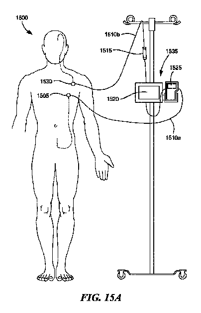
第7の態様では、本発明のいくつかの実施形態は、哺乳動物対象から採取された流体の改善に使用するためのキットに関する。いくつかの実施形態では、キットは、対象の第1の位置に取り外し可能に取り付け可能な心室線部分と、対象の第2の位置に取り外し可能に取り付け可能な腰部線部分と、心室線部分と腰部線部分との間の流体連通している循環システムと、循環システムと動作可能に通信しているカートリッジを含む監視ハードウェアであって、カートリッジは、流体の改善のための改善剤を収容する、監視ハードウェアと、流体を採取し、流体を循環させ、流体を対象に戻すためのポンピングデバイスと、を含む。いくつかの実施態様では、心室線部分は、心室カテーテル、心室カテーテルに取り外し可能に取り付け可能なカテーテルアダプタ、皮下アクセスポート、および皮下アクセス針を含み得る。いくつかの実施態様では、腰部線部分は、腰部カテーテル、腰部カテーテルに取り外し可能に取り付け可能なカテーテルアダプタ、皮下アクセスポート、および皮下アクセス針を含み得る。任意選択で、心室線部分および/または腰部線部分は、腹膜カテーテルを含み得る。 In a seventh aspect, some embodiments of the invention relate to kits for use in improving fluids taken from mammalian subjects. In some embodiments, the kit comprises a removably attachable ventricular line portion in the first position of the subject, a removable lumbar line portion in the second position of the subject, and a ventricular line portion. Monitoring hardware that includes a fluid communication system between the lumbar line portion and a cartridge that is operably communicating with the circulation system, the cartridge containing an improving agent for fluid improvement. Includes monitoring hardware and a pumping device for collecting fluid, circulating the fluid, and returning the fluid to the subject. In some embodiments, the ventricular line portion may include a ventricular catheter, a catheter adapter detachably attached to the ventricular catheter, a subcutaneous access port, and a subcutaneous access needle. In some embodiments, the lumbar line portion may include a lumbar catheter, a catheter adapter detachably attached to the lumbar catheter, a subcutaneous access port, and a subcutaneous access needle. Optionally, the ventricular and / or lumbar line portion may include a peritoneal catheter.
本発明の態様の様々な実施形態および実施態様の様々な特徴および利点、ならびに本発明自体は、添付の概略図と一緒に読まれた場合、様々な提示された実施形態の以下の説明からより完全に理解することができる。
本発明の実施形態は、主に流体中の神経疾患を処理することに関して、より具体的には、哺乳動物対象からの脳脊髄液(CSF)の改善に関して説明されるが、本明細書に記載のシステム、方法、および技術は、非神経疾患および障害、ならびに適用および状態(例えば、がん、頭蓋内転移性疾患(IMD)、糖尿病、3型糖尿病、ループス、中毒、慢性外傷性脳症(CTE)、細菌性髄膜炎、動脈瘤、脳卒中、脳血管痙攣、外傷性脳損傷、関節リウマチ、薬物の過剰摂取、特定の外傷など)に等しく適用可能である。さらに、本発明の実施形態は、生細胞における状態および用途にも適用される。例えば、本発明の特定の実施形態および適用または実施態様は、生細胞またはエキソソームを流体(例えば、CSF)および神経系に送達するためのアクセスポイントを提供することができる。より具体的には、生細胞または他の生物(例えば、酵母、細菌、ウイルスなど)を、例えば中枢神経系の健康に利益をもたらし得る分泌産物を提供する外部(体外)カートリッジに配置し得る。CSFは、生細胞を含むカートリッジを通過し得る。
Embodiments of the invention are described primarily with respect to treating neurological disorders in fluids, and more specifically with respect to improvement of cerebrospinal fluid (CSF) from mammalian subjects, although described herein. Systems, methods, and techniques for non-neurological disorders and disorders, as well as applications and conditions (eg, cancer, intracranial metastatic disease (IMD), diabetes,
定義
本明細書および付随する特許請求の範囲で使用されるように、以下の用語は、文脈が異なる意味を要求または明確にしない限り、示された意味を有するものとする。
Definitions As used herein and in the accompanying claims, the following terms shall have the indicated meanings unless the context requires or makes clear a different meaning.
生体分子とは、生体系(すなわち、生物)によって生成され得る、またはそのようなものに類似している任意の分子を指す。限定ではなく例示の目的で、生体分子は、RNA、DNA、タンパク質、ペプチド、脂質、炭水化物、多糖類、核酸、オリゴヌクレオチド、アンチセンスオリゴヌクレオチド、ポリヌクレオチド、アミノ酸、酵素、抗体、ナノボディ、分子インプリントポリマー、一次代謝物、二次代謝物、および天然産物を含み得る。 A biomolecule refers to any molecule that can or is similar to a biological system (ie, an organism). For purposes of illustration, but not limitation, biomolecules include RNA, DNA, proteins, peptides, lipids, carbohydrates, polysaccharides, nucleic acids, oligonucleotides, antisense oligonucleotides, polynucleotides, amino acids, enzymes, antibodies, nanobodies, molecular inns. It may include printed polymers, primary metabolites, secondary metabolites, and natural products.
液体とは、対象のくも膜下腔または他の場所に存在し、脳脊髄液(CSF)、間質液(ISF)、血液、汗、涙、精液、リンパ、尿、母乳などを含む流動性媒体などの任意の流動性生物学的媒体を指す。 A fluid is a fluid medium that is present in the subject's submucosal cavity or elsewhere and contains cerebrospinal fluid (CSF), interstitial fluid (ISF), blood, sweat, tears, semen, lymph, urine, breast milk, and the like. Refers to any fluid biological medium such as.
脳脊髄液空間とは、くも膜下腔を含む、血液脳関門の内部の容積を指す。 Cerebrospinal fluid space refers to the internal volume of the blood-brain barrier, including the subarachnoid space.
対象または患者とは、医学的処理、診断、監視、研究、またはケアを受けている哺乳動物(例えば、ヒトまたは動物)を指す。 A subject or patient refers to a mammal (eg, human or animal) undergoing medical treatment, diagnosis, monitoring, research, or care.
体外とは、哺乳動物の体の外側で発生することを指し、本明細書では、体外(extracorporeal)およびエクスビボという用語と交換可能に使用され得る。 In vitro refers to occurring outside the body of a mammal and can be used interchangeably herein with the terms extracorporeal and exvivo.
インサイチュとは、哺乳動物の体の中で発生することを指し、インビボという用語と交換可能に使用され得る。 In situ refers to what occurs in the body of a mammal and can be used interchangeably with the term in vivo.
改善
本発明の実施形態は、一般に、特に区別されない限り、本明細書ではCSFと呼ばれる(例えば、単にCSFと呼ばれる)、哺乳動物対象のくも膜下腔(SAS)内の液体(例えば、脳脊髄液(CSF)、間質液(ISF)、血液など)の改善のためのシステムおよび方法を提供する。代表的なシステムは、哺乳動物対象の体内に完全にまたは部分的に埋め込まれ得る。体内では、システムおよび/またはその構成要素はまた、SAS内に完全にまたは部分的に埋め込まれ得る。方法は、完全にインビボで起こり得るステップを含み得るか、または体外で起こるいくつかのステップを含み得る。
Improved Embodiments of the invention are generally referred to herein as CSF (eg, simply referred to as CSF), unless otherwise specified, a fluid within the subarachnoid space (SAS) of a mammalian subject (eg, cerebrospinal fluid). (CSF), interstitial fluid (ISF), blood, etc.) to provide systems and methods for improvement. Typical systems can be fully or partially implanted in the body of a mammalian subject. Within the body, the system and / or its components can also be fully or partially implanted within the SAS. The method may include steps that may occur entirely in vivo, or may include several steps that occur in vitro.
改善は、限定ではなく例示目的で、流体の物理的パラメータを変更すること、ならびにより受け入れられるようになるための消化、除去、固定、低減、および/もしくは変更、ならびに/または標的分子、タンパク質、凝集体、ウイルス、細菌、細胞、カップル、酵素、抗体、物質、および/もしくはそれらの任意の組み合わせを含む特定の実体の不活性化を含み得る。例えば、本発明のいくつかの実施形態および用途において、改善は、毒性タンパク質を、そこに含まれる血液、間質液、もしくはリンパ液、または他の流体のうちの1つ以上から除去することか、またはそれらのうちの1つ以上を調整すること、ならびにこの除去が、様々な身体機能に影響を与える疾患または状態を処理すること(すなわち、患者の臨床状態を改善すること)に及ぼす影響を指す場合がある。さらに、改善は、消化、酵素消化、濾過、サイズ濾過、接線流濾過、向流カスケード限外濾過、遠心分離、分離、磁気分離(ナノ粒子などを含む)、電気物理的分離(酵素、抗体、ナノボディ、分子インプリントポリマー、リガンド-受容体複合体、および他の電荷および/または生体親和性相互作用のうちの1つ以上の手段によって実行される)、フォトニック法(蛍光活性化セルソーティング(FACS)、紫外線(UV)滅菌、および/または光ピンセットを含む)、光音響相互作用、化学処理、熱的方法、およびそれらの組み合わせのうちのいずれか1つによって実行され得る。有利には、本発明の様々な実施形態または実施態様は、毒性のレベルを低減し得、一旦低減されると、経時的に、低減されたレベルを維持することを容易にし得る。 Improvements are, but not limited to, altering the physical parameters of the fluid, as well as digestion, removal, fixation, reduction, and / or modification to become more acceptable, and / or target molecules, proteins, etc. It may include inactivation of certain entities including aggregates, viruses, bacteria, cells, couples, enzymes, antibodies, substances, and / or any combination thereof. For example, in some embodiments and uses of the invention, the improvement is to remove the toxic protein from one or more of the blood, interstitial fluid, or lymph, or other fluid contained therein. Or to regulate one or more of them, as well as the effect of this removal on treating diseases or conditions that affect various physical functions (ie, improving the patient's clinical condition). In some cases. Further improvements include digestion, enzyme digestion, filtration, size filtration, tangential flow filtration, countercurrent cascade extrafiltration, centrifugation, separation, magnetic separation (including nanoparticles, etc.), electrophysical separation (enzymes, antibodies, etc.) Performed by one or more means of nanobody, molecular imprint polymer, ligand-acceptor complex, and other charge and / or bioaffinity interactions), photonic method (fluorescence activated cell sorting (fluorescence activated cell sorting). It can be performed by any one of FACS), UV (UV) sterilization, and / or optical tweezers), photoacoustic interactions, chemical treatments, thermal methods, and combinations thereof. Advantageously, various embodiments or embodiments of the present invention may reduce the level of toxicity and, once reduced, may facilitate maintaining the reduced level over time.
改善の程度は、標的生体分子の濃度によって反映されるように、様々な手段によって検出され得る。これらには、光学技術(例えば、ラマン、コヒーレントストークス、およびアンチストークスラマン分光法、表面増強ラマン分光法、ダイヤモンド窒素空孔磁気測定法、蛍光相関分光法、動的光散乱法など)およびカーボンナノチューブ、酵素結合免疫吸着アッセイ、表面プラズモン共鳴、液体クロマトグラフィ質量分析、円形近接ライゲーションアッセイなどのナノ構造の使用が含まれる。 The degree of improvement can be detected by various means, as reflected by the concentration of the target biomolecule. These include optical techniques (eg, Raman, Coherent Stokes, and Anti-Stokes Slaman spectroscopy, surface-enhanced Raman spectroscopy, diamond nitrogen pore magnetic measurement, fluorescence correlation spectroscopy, dynamic light scattering, etc.) and carbon nanotubes. Includes the use of nanostructures such as enzyme-bound immunoadsorption assay, surface plasmon resonance, liquid chromatography mass analysis, circular proximity ligation assay.
改善には、処理システム(例えば、UV放射、IR放射)、ならびに物質の特性が改善に好適なものにする物質の使用が含まれ得る。 Improvements may include treatment systems (eg, UV radiation, IR radiation), as well as the use of materials that make the properties of the material suitable for improvement.
CSFの改善または改善されたCSFは、本明細書では互換的に使用され得る用語であり、1つ以上の標的化合物が部分的、大部分、または完全に除去されたCSFの処理された量を指す。本明細書で使用される場合、取り出されるという用語は、取り除く場合のように空間的に分離するだけでなく、分子を隔離、固定、または変換することによって(例えば、形状変化、変性、消化、異性化、または翻訳後修飾によって)効果的に除去して、それを低毒性、非毒性、または無関係にすることを指す場合がある。 CSF improved or improved CSF is a term interchangeably used herein that refers to the treated amount of CSF from which one or more target compounds have been partially, largely, or completely removed. Point to. As used herein, the term taken out is not only spatially separated as in removal, but also by sequestering, immobilizing, or transforming molecules (eg, shape change, denaturation, digestion, etc.). It may refer to effective removal (by isomerization, or post-translational modification) to make it less toxic, non-toxic, or irrelevant.
改善剤とは、酵素、抗体、または抗体フラグメント、核酸、受容体、抗菌剤、抗ウイルス剤、抗DNA/RNA、タンパク質/アミノ酸、炭水化物、酵素、イソメラーゼ、高低生体特異的結合親和性を有する化合物、アプタマー、エキソソーム、紫外線、温度変化、電場、分子インプリントポリマー、生細胞などを含む、流体の改善の能力がある任意の材料またはプロセスを指す。 An improver is an enzyme, antibody, or antibody fragment, nucleic acid, receptor, antibacterial agent, antiviral agent, anti-DNA / RNA, protein / amino acid, carbohydrate, enzyme, isomerase, compound having high-low biospecific binding affinity. Refers to any material or process capable of improving fluid, including, aptamers, exosomes, ultraviolet rays, temperature changes, electric fields, molecular imprint polymers, living cells, etc.
酵素消化による改善
CSF内の生体分子の改善はまた、酵素消化によるものであり得、したがって、いくつかの実施形態および用途において、改善剤は、CSF内の生体分子を修飾または分解する。そのために、酵素-基質対は、パネルおよびカウンターパネル検索によって選択され得る。例えば、生体分子を消化するための候補酵素のパネルは、安定性、商業的入手可能性、および関連する相互作用のメカニズムについて等級分けされ得、一方、カウンターパネルは、候補酵素が、酵素が変化してはならないCSF中の物質に影響を及ぼさないことを保証し得る。代替的に、酵素は、突然変異体ハントまたは窒素生存率アッセイなどの微生物スクリーニングを通して発見され得る。さらに別の実施形態では、酵素は、生体分子工学計算モデルを使って選択することができる。
Improvement by Enzymatic Digestion Improvement of biomolecules in CSF can also be by enzymatic digestion, and therefore, in some embodiments and uses, the improving agent modifies or degrades biomolecules in CSF. To that end, enzyme-substrate pairs can be selected by panel and counter panel searches. For example, a panel of candidate enzymes for digesting biomolecules can be graded for stability, commercially available, and related interaction mechanisms, while counterpanels are candidate enzymes, enzyme-altered. It can be assured that it will not affect the substances in the CSF that should not be done. Alternatively, the enzyme can be found through microbial screening such as mutant hunt or nitrogen viability assay. In yet another embodiment, the enzyme can be selected using a biomolecular engineering computational model.
改善の方法および改善化学は、国際特許出願第PCT/US2019/042880号および同第PCT/US2019/042879号に記載されており、どちらも「Methods of Treating Neurological Disorders」と題され、2019年7月22日に出願され、その開示は、それらの全体が、参照により本明細書に組み込まれる。 Methods of improvement and improved chemistry are described in International Patent Application Nos. PCT / US2019 / 042880 and PCT / US2019 / 042879, both entitled "Methods of Treating Neurological Disorders", July 2019. Filed on 22nd, the disclosures thereof are incorporated herein by reference in their entirety.
いくつかの実施形態では、改善システムでの使用のための薬剤には、トリプシン;エラスターゼ;クロストリパイン;カルパイン-2を含むカルパイン;カスパーゼ-1、カスパーゼ-3、カスパーゼ-6、カスパーゼ-7、およびカスパーゼ-8を含むカスパーゼ;M24ホモログ;ヒト気道トリプシン様ペプチダーゼ;プロテイナーゼK;サーモリシン;Asp-Nエンドペプチダーゼ;キモトリプシン;LysC;LysN;グルタミルエンドペプチダーゼ;ブドウ球菌ペプチダーゼ;arg-Cプロテイナーゼ;プロリン-エンドペプチダーゼ;トロンビン;カテプシンE、S、B、K、またはL1を含むカテプシン;組織タイプA;ヘパリナーゼ;グランザイムAを含むグランザイム;メプリンα;ペプシン;エンドチアペプシン;カリクレイン-6;カリクレイン-5、およびそれらの組み合わせが含まれ得る。他の実施形態では、pin1、エキソソーム、および/または生細胞を改善剤として使用し得る。 In some embodiments, agents for use in the improvement system include trypsin; elastase; crosstripine; carpine containing carpine-2; caspase-1, caspase-3, caspase-6, caspase-7, And caspase containing caspase-8; M24 homolog; human airway trypsin-like peptidase; proteinase K; thermolysin; Asp-N endopeptidase; chymotypsin; LysC; LysN; glutamilend peptidase; staphylococcal peptidase; arg-C proteinase; Peptidases; Trombin; Catepsin E, S, B, K, or L1 containing catepsin; Tissue type A; Heparinase; Granzyme containing Granzyme A; Meprine α; Pepsin; Endopeptidase; Caliclein-6; Caliclein-5, and them. Combinations of may be included. In other embodiments, pin1, exosomes, and / or living cells can be used as improving agents.
毒性タンパク質の修飾
本発明の様々な用途は、CSF中の毒性タンパク質の存在を特徴とする神経障害または関連状態を処理する方法を提供し、方法は、それを必要とする対象のCSFを、インサイチュまたは他の方法で、毒性タンパク質を修飾することができる有効量の翻訳後修飾タンパク質と接触させることを含み、したがって、毒性タンパク質の濃度が低下する。
Modification of Toxic Proteins Various uses of the invention provide methods for treating neuropathy or related conditions characterized by the presence of toxic proteins in CSF, the method instituting the CSF of interest in need thereof. Alternatively, it involves contacting with an effective amount of post-translational modified protein capable of modifying the toxic protein, thus reducing the concentration of the toxic protein.
いくつかの実施形態において、基質、標的分子、または物質は、反応性酸化種の、ベータアミロイド(任意の種または形態)またはタウ(または任意の数の過リン酸化タウアイソフォーム(例えば、タウタンパク質凝集体、タウタンパク質もつれ、タウオリゴマー、過リン酸化タウタンパク質、可溶性タウタンパク質、タウ二量体、シスpタウ)タンパク質の、炎症性メディエータ(例えば、TNF-a、IL-1、IL-2、IL-6、IL-12、インターフェロン-yなどを含むサイトカイン)、α-シヌクレインタンパク質(ペプチドまたはオリゴマーを含む)、不溶性スーパーオキシドジスムターゼ-1(SODI)(例えば、変異タンパク質または誤って折り畳まれた野生型SOD1タンパク質)、グルタミン酸、ニューロフィラメントタンパク質、および抗GMIガングリオシド抗体、抗AGM1-ガングリオシド抗体、およびスルファチド、血液細胞(例えば、赤血球)、オキシヘモグロビン、エンドセリン、炎症性メディエータ、細菌またはウイルス実体、腫瘍壊死因子-α(TNFa)およびIgG、C5a、TNF a、IL 2、IL-6、インターフェロン-γ、IgGを含むがこれらに限定されない細胞および炎症性メディエータ、およびエンドトキシン、T細胞、B細胞、抗ミエリン抗体、およびTNF a、IL 2、IL-6、インターフェロン-γ、エンドセリンを含むがこれらに限定されない炎症性メディエータ、およびエノラーゼ、DPR、循環腫瘍細胞を含み得る。特定の実施形態において、毒性タンパク質は、変異型FUS/TLSタンパク質である。特定の実施形態において、毒性タンパク質は、毒性形態である。
In some embodiments, the substrate, target molecule, or substance is a reactive oxidant, beta amyloid (any species or form) or tau (or any number of hyperphosphorylated tau isoforms (eg, tau protein). Aggregates, tau protein entanglements, tau oligomers, perphosphorylated tau proteins, soluble tau proteins, tau dimers, cisp tau) inflammatory mediators of proteins (eg, TNF-a, IL-1, IL-2, Cythins including IL-6, IL-12, interferon-y, etc.), α-sinucrane protein (including peptides or oligomers), insoluble superoxide dismutase-1 (SODI) (eg, mutant protein or misfolded wild). Type SOD1 protein), glutamic acid, neurofilament protein, and anti-GMI ganglioside antibody, anti-AGM1-ganglioside antibody, and sulfatide, blood cells (eg, erythrocytes), oxyhemoglobin, endoserin, inflammatory mediators, bacterial or viral entities, tumor necrosis Cells and inflammatory mediators including, but not limited to, factors-α (TNFa) and IgG, C5a, TNF a,
微小管結合タンパク質タウは、タウの過剰リン酸化および凝集を特徴とする、ADおよびタウオパチーと関連する神経原線維変化(NFT)の主要な構成要素である。タウは、プロジェクション領域、基本的なプロリンリッチ領域、およびアセンブリ領域を含む、疎水性含有量が非常に低いため、本質的に構造化されていないタンパク質である。タウは、アセチル化、脱アミド化、糖化、グリコシル化、異性化、メチル化、ニトロ化、リン酸化、タンパク質分解、SUMO化、ユビキチン化など、様々な翻訳後修飾を行うことが知られている。特にアセンブリ領域のタウの過剰リン酸化は、微小管へのタウの親和性を低下させ、微小管動態および軸索輸送を調節する能力を損なう。加えて、基本的なプロリンリッチ領域および疑似リピートの一部も、その負に帯電した表面と相互作用することによって微小管を安定化する。2つのN末端インサート領域およびタウのエクソン2、エクソン3、およびエクソン10の選択的スプライシングにより、CNSで長さが異なる6つのタウアイソフォームが生成される。タンパク質のカルボキシル末端部分のアセンブリ領域には、エクソン10の選択的スプライシングに応じて、保存されたチューブリン結合モチーフの3リピートまたは4リピート(3Rまたは4R)が含まれている。タウ4Rアイソフォームは、3Rアイソフォームよりも高い微小管結合および安定化能力を有する。人間の成人の脳は、同様のレベルの3Rおよび4Rアイソフォームを有するが、胎児の段階では、3Rタウのみが発現している。タウオパチーでは、タウ転写産物のスプライシングおよび3Rと4Rのタウアイソフォームの比率を変化させる変異は、神経変性疾患を引き起こすのに十分である。全長タウタンパク質のアイソフォームに加えて、特定のタウフラグメント(例えば、内因性プロテアーゼ切断から生じるフラグメント)はまた、重合または凝集する傾向、別のタウアイソフォームまたはフラグメントの重合または凝集を促進する能力、および/またはタウの重合または凝集を他の細胞に伝播し、それによって神経毒性をもたらす能力を示す。このようなタウフラグメントには、フラグメント14-441、26-230、1-314、26-44、1-44、1-156、45-230、243-441、256-441、256-368、1-368、1-421、151-421、1-391、およびX-441を含むが、これらに限定されず、Xは、182~194の任意の整数(2N4Rアイソフォームの配列に従って番号が付けられたアミノ酸位置)。これらのタウフラグメントに加えて、フラグメント124-441および1-402(2N4Rアイソフォームの配列に従って番号が付けられたアミノ酸位置)などの特定の他のフラグメントは、神経障害を診断するための、または患者の進行もしくは処理への反応を監視するための、バイオマーカーとして有用であり得る。リン酸化および異性化(シスまたはトランス異性体)などのタウの翻訳後修飾も、タウが凝集する能力に大きく影響する。例えば、プロリンに先行するセリンおよびスレオニン残基(pSer/Thr-Pro)でのタウの過剰リン酸化は、不溶性をもたらし、神経原線維変化(NFT)を引き起こす。特にThr231-Proでのタウのリン酸化は、シス型とトランス型との間の変換を触媒するプロリルイソメラーゼPin1の結合を可能にする。PP2Aなどのホスファターゼは、トランス型でのみタウの脱リン酸化を触媒する。上記を考慮すると、ヒトの脳組織におけるタウは、様々な異なる長さおよび形態で、複数の翻訳後修飾を伴って存在し得る。本明細書で使用される場合、「タウ」という用語は、1つ以上の翻訳後修飾を有する、任意の折り畳み状態のタウタンパク質の様々なアイソフォームおよびフラグメントを含む。タウは、正常からNFTに進行するにつれて、タンパク質が、過剰リン酸化、誤局在化、立体配座変化、および/またはオリゴマー化し得るがまだ繊維状ではない「可溶性」状態を通過する。
Microtubule-associated protein tau is a major component of neurofibrillary tangles (NFTs) associated with AD and tauopathy, characterized by hyperphosphorylation and aggregation of tau. Tau is an essentially unstructured protein with a very low hydrophobic content, including projection regions, basic proline-rich regions, and assembly regions. Tau is known to perform various post-translational modifications such as acetylation, deamidation, glycation, glycosylation, isomerization, methylation, nitration, phosphorylation, proteolysis, SUMOylation, and ubiquitination. .. In particular, hyperphosphorylation of tau in the assembly region reduces the affinity of tau for microtubules and impairs the ability to regulate microtubule dynamics and axonal transport. In addition, some of the basic proline-rich regions and pseudo-repeats also stabilize microtubules by interacting with their negatively charged surfaces. Alternative splicing of the two N-terminal insert regions and
翻訳後修飾タンパク質
いくつかの実施態様において、本発明の実施形態は、CSF中の毒性タンパク質の存在を特徴とする神経学害または関連状態を処理する方法を提供し、方法は、それを必要とする対象のCSFを、毒性タンパク質を修飾することができる有効量の翻訳後修飾タンパク質と接触させることを含み、したがって、毒性タンパク質の濃度が低下する。
Post-Translational Modification Protein In some embodiments, embodiments of the invention provide a method of treating a neurological hazard or associated condition characterized by the presence of a toxic protein in a CSF, which requires it. It involves contacting the CSF of interest with an effective amount of post-translational modification protein capable of modifying the toxic protein, thus reducing the concentration of the toxic protein.
いくつかの変形例では、実施形態はまた、CSF中の毒性または前毒性形態の毒性タンパク質の存在を特徴とする神経障害または関連状態を有する対象のCSF、および毒性タンパク質を修飾することができる翻訳後修飾タンパク質を含む組成物を提供し、したがって、毒性タンパク質の濃度が低下する。 In some variants, embodiments can also modify CSFs of subjects with neuropathy or related conditions characterized by the presence of toxic or pretoxic forms of toxic proteins in the CSF, and translations that can modify the toxic proteins. A composition comprising a post-modifying protein is provided, thus reducing the concentration of toxic protein.
本発明の実施形態の翻訳後修飾タンパク質による毒性または前毒性形態の毒性タンパク質の選択的変化は、基質選択性(タンパク質の毒性または前毒性形態の毒性タンパク質を優先的に認識する翻訳後修飾タンパク質)、活性部位特異性(毒性または前毒性形態の毒性タンパク質で遭遇する残基モチーフのペプチド結合を切断するための特異性を有する翻訳後修飾タンパク質)、基質親和性(結合キネティクスに基づく)、および酵素効率(酵素反応の速度)の組み合わせによって達成される。本発明の特定の実施形態では、翻訳後修飾タンパク質は、哺乳動物、微生物(例えば、真菌、細菌、またはウイルス)、または植物タンパク質である。 The selective change of the toxic or pretoxic form of the toxic protein by the post-translational modified protein of the embodiment of the invention is substrate selectivity (post-translation modified protein that preferentially recognizes the toxic or pre-toxic form of the toxic protein). , Active site specificity (post-translational modified protein with specificity for cleaving peptide binding of residue motifs encountered in toxic or pretoxic forms of toxic proteins), substrate affinity (based on binding kinetics), and enzymes. Achieved by a combination of efficiencies (rates of enzymatic reaction). In certain embodiments of the invention, the post-translational modification protein is a mammalian, microorganism (eg, fungus, bacterium, or virus), or plant protein.
本発明の他の態様および実施形態では、翻訳後修飾タンパク質は、ホスファターゼ、イソメラーゼ、ユビキチン活性化酵素(E1)、ユビキチン結合酵素(E2)、ユビキチンリガーゼ(E3)、キナーゼ、アセチラーゼ、デアセチラーゼ、グリコシラーゼ、またはデグリコシラーゼであり得る。 In other embodiments and embodiments of the invention, the post-translational modification protein is a phosphatase, isomerase, ubiquitin activating enzyme (E1), ubiquitin ligase (E2), ubiquitin ligase (E3), kinase, acetylase, deacetylase, glycosylase, etc. Or it can be a deglycosylase.
ホスファターゼ
ホスファターゼは、基質タンパク質のリン酸化アミノ酸残基からリン酸基を除去する酵素である。本発明の実施形態の特定の変形例では、翻訳後修飾タンパク質は、PP1、PP2A、PP2B、PP4、PP5、PP6、PP7、PP2C、VHR、DUSP1、DUSP2、DUSP3、DUSP4、DUSP5、DUSP6、DUSP7、DUSP8、DUSP9、DUSP10、DUSP11、DUSP12、DUSP13、DUSP14、DUSP15、DUSP16、DUSP17、DUSP18、DUSP19、DUSP20、DUSP21、DUSP22、DUSP23、DUSP24、DUSP25、DUSP26、DUSP27、DUSP28、PHP、PPP1CA、PPP1CB、PPP1CC、PPP2CA、PPP2CB、PPP3CA、PPP3CB、PPP3CC、PPP4C、PPP5C、PPP6C、CDC14A、CDC14B、CDC14C、CDKN3、PTEN、SSH1、SSH2、SSH3、CTDP1、CTDSP1、CTDSP2、CTDSPL、DULLARD、EPM2A、ILKAP、MDSP、PGAM5、PHLPP1、PHLPP2、PPEF1、PPEF2、PPM1A、PPM1B、PPM1D、PPM1E、PPM1F、PPM1G、PPM1H、PPM1J、PPM1K、PPM1L、PPM1M、PPM1N、PPTC7、PTPMT1、SSU72、およびUBLCP1を含むリストから選択されるホスファターゼである。
Phosphatase Phosphatase is an enzyme that removes phosphate groups from phosphorylated amino acid residues of substrate proteins. In a particular variant of the embodiment of the invention, the post-translational modification proteins are PP1, PP2A, PP2B, PP4, PP5, PP6, PP7, PP2C, VHR, DUSP1, DUSP2, DUSP3, DUSP4, DUSP5, DUSP6, DUSP7, DUSP8, DUSP9, DUSP10, DUSP11, DUSP12, DUSP13, DUSP14, DUSP15, DUSP16, DUSP17, DUSP18, DUSP19, DUSP20, DUSP21, DUSP22, DUSP23, DUSP24, DUSP25, DUSP1 PPP2CA, PPP2CB, PPP3CA, PPP3CB, PPP3CC, PPP4C, PPP5C, PPP6C, CDC14A, CDC14B, CDC14C, CDKN3, PTEN, SSH1, SSH2, SSH3, CTDP1, CTDSP1, CTDSP2, CTDASPLD PHLPP1, PHLPP2, PPEF1, PPEF2, PPM1A, PPM1B, PPM1D, PPM1E, PPM1F, PPM1G, PPM1H, PPM1J, PPM1K, PPM1L, PPM1M, PPM1N, PPM1L, PPM1M, PPM1N, PPM1L, PPM1M, PPM1N, PPTC7, PTPMT1, SSU72, ..
イソメラーゼ
イソメラーゼは、ある異性体構造から別の異性体構造への分子の変換を触媒する酵素である。分子内結合は、異性化中に切断されて形成され、分子式は同じであるが、結合の接続性または空間配置が異なる分子をもたらす。様々な実施形態の特定の実施態様では、翻訳後修飾タンパク質は、FK506結合タンパク質4(FKBP52)、FK506結合タンパク質51(FKBP51、FKBP5としても知られる)、FK506結合タンパク質(FKBP12)、ペプチジルプロリルシス/トランスイソメラーゼNIMA相互作用1(Pin1)、アラニンラセマーゼ、メチオニンラセマーゼ、乳酸塩ラセマーゼ、酒石酸エピメラーゼ、リブロースリン酸3-エピメラーゼ、UDP-グルコース4-エピメラーゼ、メチルマロニルCoAエピメラーゼ、ハイダンマレイン酸イソメラーゼ、マレイルアセトアセテートイソメラーゼ、マレイルピルビン酸イソメラーゼ、リノール酸イソメラーゼ、フリルフラミドイソメラーゼ、ペプチジルプロリルイソメラーゼ、ファルネソール2-イソメラーゼ、2-クロロ-4-カルボキシメチレンブト-2-エン-1,4-オリドイソメラーゼ、ゼータ-カロテンイソメラーゼ、プロリコペンイソメラーゼ、ベータカロチンイソメラーゼ、トリオースリン酸イソメラーゼ、リボース-5リン酸イソメラーゼ、フェニルピルビン酸トートメラーゼ、オキサロ酢酸トートメラーゼ、ステロイドデルタイソメラーゼ、L-ドパクロムイソメラーゼ、タンパク質ジスルフィドイソメラーゼ、プロスタグランジン-Dシンターゼ、アレンオキシドシクラーゼ、リゾレシチンアシルムターゼ、プレコリン-8Xメチルムターゼ、ホスホグルコムターゼ、ホスホペントムターゼ、ベータ-リジン5,6-アミノムターゼ、チロシン2,3-アミノムターゼ、(ヒドロキシアミノ)ベンゼンムターゼ、イソコリスメートシンターゼ、メチルアスパラギン酸ムターゼ、コリスメートムターゼ、ムコネートシクロイソメラーゼ、3-カルボキシ-シス、シス-ムコネートシクロイソメラーゼ、テトラヒドロキシプテリジンシクロイソメラーゼ、イノシトール-3-リン酸シンターゼ、カルボキシ-シス、シス-ムコネートシクラーゼ、カルコンイソメラーゼ、クロロムコン酸シクロイソメラーゼ、(+)-ボルニル二リン酸シンターゼ、シクロユーカレノールシクロイソメラーゼ、α-ピネンオキシドデシクラーゼ、ジクロロムコン酸シクロイソメラーゼ、コパリル二リン酸シンターゼ、Ent-コパリル二リン酸シンターゼ、Syn-コパリル-二リン酸シンターゼ、テルペンチエニル-二リン酸シンターゼ、ハリマジエニル-二リン酸シンターゼ、(S)-ベータ-マクロカルペンイプシロン-シクラーゼ、リコペンベータ-シクラーゼ、プロソラナピロン-IIIシクロイソメラーゼ、およびD-リボースピラナーゼを含むリストから選択されるイソメラーゼである。特定の実施形態では、イソメラーゼは、Pin1である。
Isomerase Isomerase is an enzyme that catalyzes the conversion of a molecule from one isomer structure to another. Intramolecular bonds are cleaved and formed during isomerization, resulting in molecules with the same molecular formula but different bond connectivity or spatial arrangement. In certain embodiments of the various embodiments, the post-translational modified proteins are FK506 binding protein 4 (FKBP52), FK506 binding protein 51 (also known as FKBP51, FKBP5), FK506 binding protein (FKBP12), peptidylprolylsis. / Transisomerase NIMA interaction 1 (Pin1), alanin racemase, methionine racemase, lactate racemase, tartrate epimerase, ribulose phosphate 3-epimerase, UDP-glucose 4-epimerase, methylmalonyl CoA epimerase, hydanmaleic acid isomerase, ma Railacetacetate isomerase, maleylpyrvate isomerase, linoleic acid isomerase, frillfuramide isomerase, peptidylprolyl isomerase, farnesol 2-isomerase, 2-chloro-4-carboxymethylenebut-2-en-1,4-olidoisomerase , Zeta-carotene isomerase, prolicopen isomerase, beta carotene isomerase, triose phosphate isomerase, ribose-5 phosphate isomerase, phenylpyrvate totomerase, oxaloacetate totomerase, steroid delta isomerase, L-dopachrome isomerase, protein disulfide isomerase. , Prostaglandin-D synthase, allenoxide cyclase, lysolecithin acylmase, precholine-8X methylmutase, phosphoglucomase, phosphopentomase, beta-lysine 5,6-aminomase,
ユビキチン化酵素
ユビキチン化は、翻訳後修飾であり、小さな調節タンパク質であるユビキチンがタンパク質基質の標的リジン残基に結合している。ユビキチン化には、活性化(ユビキチン活性化酵素E1によって実行される)、結合(ユビキチン結合酵素E2によって実行される)、およびライゲーション(ユビキチンリガーゼE3によって実行される)の複数のステップが含まれる。
Ubiquitin-activating enzyme Ubiquitination is a post-translational modification in which a small regulatory protein, ubiquitin, binds to the target lysine residue of the protein substrate. Ubiquitinization involves multiple steps of activation (performed by ubiquitin activating enzyme E1), binding (performed by ubiquitin conjugating enzyme E2), and ligation (performed by ubiquitin ligase E3).
様々な実施形態の特定の用途では、翻訳後修飾タンパク質は、E1ユビキチン活性化酵素、例えば、UBA1、UBA2、UBA3、UBA5、UBA6、UBA7、ATG7、NAE1、SAE1;E2ユビキチン結合酵素、例えば、UBE2A、UBE2B、UBE2C、UBE2D1、UBE2D2、UBE2D3、UBE2D4、UBE2E1、UBE2E2、UBE2E3、UBE2F、UBE2G1、UBE2G2、UBE2H、UBE2I、UBE2J1、UBE2J2、UBE2K、UBE2L3、UBE2L6、UBE2M、UBE2N、UBE2O、UBE2Q1、UBE2Q2、UBE2R1(CDC34)、UBE2R2、UBE2S、UBE2T、UBE2U、UBE2V1、UBE2V2、UBE2W、UBE2Z、ATG3、BIRC6、UFC1、およびE3ユビキチンリガーゼ、例えば、AFF4、AMFR、ANAPC11、ANKIB1、AREL1、ARIH1、ARIH2、BARD1、BFAR、BIRC2、BIRC3、BIRC7、BIRC8、BMI1、BRAP、BRCA1、CBL、CBLB、CBLC、CBLL1、CCDC36、CCNB1IP1、CGRRF1、CHFR、CNOT4、CUL9、CYHR1、DCST1、DTX1、DTX2、DTX3、DTX3L、DTX4、DZIP3、E4F1、FANCL、G2E3、HACE1、HECTD1、HECTD2、HECTD3、HECTD4、HECW1、HECW2、HERC1、HERC2、HERC3、HERC4、HERC5、HERC6、HLTF、HUWE1、IRF2BP1、IRF2BP2、IRF2BPL、ITCH、KCMF1、KMT2C、KMT2D、LNX1、LNX2、LONRF1、LONRF2、LONRF3、LRSAM1、LTN1、MAEA、MAP3K1、MARCH1、MARCH10、MARCH11、MARCH2、MARCH3、MARCH4、MARCH5、MARCH6、MARCH7、MARCH8、MARCH9、MDM2、MDM4、MECOM、MEX3A、MEX3B、MEX3C、MEX3D、MGRN1、MIB1、MIB2、MIDI、MID2、MKRN1、MKRN2、MKRN3、MKRN4P、MNAT1、MSL2、MUL1、MYCBP2、MYLIP、NEDD4、NEDD4L、NEURL1、NEURL1B、NEURL3、NFX1、NFXL1、NHLRC1、NOSIP、NSMCE1、PARK2、PCGF1、PCGF2、PCGF3、PCGF5、PCGF6、PDZRN3、PDZRN4、PELI1、PELI2、PELI3、PEX10、PEX12、PEX2、PHF7、PHRF1、PJA1、PJA2、PLAG1、PLAGL1、PML、PPIL2、PRPF19、RAD18、RAG1、RAPSN、RBBP6、RBCK1、RBX1、RC3H1、RC3H2、RCHY1、RFFL、RFPL1、RFPL2、RFPL3、RFPL4A、RFPL4AL1、RFPL4B、RFWD2、RFWD3、RING1、RLF、RLIM、RMND5A、RMND5B、RNF10、RNF103、RNF11、RNF111、RNF112、RNF113A、RNF113B、RNF114、RNF115、RNF121、RNF122、NF123、RNF125、RNF126、RNF128、RNF13、RNF130、RNF133、RNF135、RNF138、RNF139、RNF14、RNF141、RNF144A、RNF144B、RNF145、RNF146、RNF148、RNF149、RNF150、RNF151、RNF152、RNF157、RNF165、RNF166、RNF167、RNF168、RNF169、RNF17、RNF170、RNF175、RNF180、RNF181、RNF182、RNF183、RNF185、RNF186、RNF187、RNF19A、RNF19B、RNF2、RNF20、RNF207、RNF208、RNF212、RNF212B、RNF213、RNF214、RNF215、RNF216、RNF217、RNF219、RNF220、RNF222、RNF223、RNF224、RNF225、RNF24、RNF25、RNF26、RNF31、RNF32、RNF34、RNF38、RNF39、RNF4、RNF40、RNF41、RNF43、RNF44、RNF5、RNF6、RNF7、RNF8、RNFT1、RNFT2、RSPRY1、SCAF11、SH3RF1、SH3RF2、SH3RF3、SHPRH、SIAH1、SIAH2、SIAH3、SMURF1、SMURF2、STUB1、SYVN1、TMEM129、TOPORS、TRAF2、TRAF3、TRAF4、TRAF5、TRAF6、TRAF7、TRAIP、TRIM10、TRIM11、TRIM13、TRIM15、TRIM17、TRIM2、TRIM21、TRIM22、TRIM23、TRIM24、TRIM25、TRIM26、TRIM27、TRIM28、TRIM3、TRIM31、TRIM32、TRIM33、TRIM34、TRIM35、TRIM36、TRIM37、TRIM38、TRIM39、TRIM4、TRIM40、TRIM41、TRIM42、TRIM43、TRIM43B、TRIM45、TRIM46、TRIM47、TRIM48、TRIM49、TRIM49B、TRIM49C、TRIM49D1、TRIM5、TRIM50、TRIM51、TRIM52、TRIM54、TRIM55、TRIM56、TRIM58、TRIM59、TRIM6、TRIM60、TRIM61、TRIM62、TRIM63、TRIM64、TRIM64B、TRIM64C、TRIM65、TRIM67、TRIM68、TRIM69、TRIM7、TRIM71、TRIM72、TRIM73、TRIM74、TRIM75P、TRIM77、TRIM8、TRIM9、TRIML1、TRIML2、TRIP12、TTC3、UBE3A、UBE3B、UBE3C、UBE3D、UBE4A、UBE4B、UBOX5、UBR1、UBR2、UBR3、UBR4、UBR5、UBR7、UHRF1、UHRF2、UNK、UNKL、VPS11、VPS18、VPS41、VPS8、WDR59、WDSUB1、WWP1、WWP2、CIAR、ZBTB12、ZFP91、ZFPL1、ZNF280A、ZNF341、ZNF511、ZNF521、ZNF598、ZNF645、ZNRF1、ZNRF2、ZNRF3、ZNRF4、ZSWIM2、ZXDCからなるリストから選択されるユビキチン化酵素である。 In certain applications of various embodiments, the post-translational modified protein is an E1 ubiquitin activating enzyme such as UBA1, UBA2, UBA3, UBA5, UBA6, UBA7, ATG7, NAE1, SAE1; E2 ubiquitin ligating enzyme, eg UBE2A. 、UBE2B、UBE2C、UBE2D1、UBE2D2、UBE2D3、UBE2D4、UBE2E1、UBE2E2、UBE2E3、UBE2F、UBE2G1、UBE2G2、UBE2H、UBE2I、UBE2J1、UBE2J2、UBE2K、UBE2L3、UBE2L6、UBE2M、UBE2N、UBE2O、UBE2Q1、UBE2Q2、UBE2R1 (CDC34), UBE2R2, UBE2S, UBE2T, UBE2U, UBE2V1, UBE2V2, UBE2W, UBE2Z, ATG3, BIRC6, UFC1, and E3 ubiquitin ligases such as AFF4, AMFR, ANAPC11, AFF4, AMFR, ANAPC11, AN , BIRC2, BIRC3, BIRC7, BIRC8, BMI1, BRAP, BRCA1, CBL, CBLB, CBLC, CBLL1, CCDC36, CCNB1IP1, CGRRF1, CHFR, CNOT4, CUL9, CYHR1, DCST1, DTX3DX1 , E4F1, FANCL, G2E3, HACE1, HECTD1, HECTD2, HECTD3, HECTD4, HECW1, HECW2, HERC1, HERC2, HERC3, HERC4, HERC5, HERC6, HLTF, HUBP2 , LNX1, LNX2, LONRF1, LONRF2, LONRF3, LRSAM1, LTN1, MAEA, MAP3K1, MARCH1, MARCH10, MARCH11, MARCH2, MARCH3, MARCH4, MARCH5, MARCH6, MARCH7, MARCH3 , MEX3C, MEX3D, MGRN1, MIB1, MIB2, MIDI, MID2, MKRN1, MKRN2, MKRN3, MKRN4P, MNAT1, MSL2, MUL1, MYCBP2, MYLIP, NEDD4, NEDD4L, NEURL URL1B, NEURL3, NFX1, NFXL1, NHLRC1, NOSIP, NSMCE1, PARK2, PCGF1, PCGF2, PCGF3, PCGF5, PCGF6, PDZRN3, PDZRN4, PELI1, PELI2, PELI3, PEX10, PEX12 PLAG1, PLAGL1, PML, PPIL2, PRPF19, RAD18, RAG1, RAPSN, RBBP6, RBCK1, RBX1, RC3H1, RC3H2, RCYY1, RFFL, RFPL1, RFPL2, RFPL3, RFPL4A, RFPL4AL1, RFPL4A, RFPL4AL1, RFPL4 RLIM, RMND5A, RMND5B, RNF10, RNF103, RNF11, RNF111, RNF112, RNF113A, RNF113B, RNF114, RNF115, RNF121, RNF122, NF123, RNF125, RNF126, RNF128, RNF1 RNF141, RNF144A, RNF144B, RNF145, RNF146, RNF148, RNF149, RNF150, RNF151, RNF152, RNF157, RNF165, RNF166, RNF168, RNF168, RNF187 RNF187, RNF19A, RNF19B, RNF2, RNF20, RNF207, RNF208, RNF212, RNF212B, RNF213, RNF214, RNF215, RNF216, RNF217, RNF219, RNF220, RNF22R RNF34, RNF38, RNF39, RNF4, RNF40, RNF41, RNF43, RNF44, RNF5, RNF6, RNF7, RNF8, RNFT1, RNFT2, RSPRY1, SCAF11, SH3RF1, SH3RF2, SH3RF1, SH3RF2, STUB1, SYVN1, TMEM129, TOPORS, TRAF2, T RAF3, TRAF4, TRAF5, TRAF6, TRAF7, TRAIP, TRIM10, TRIM11, TRIM13, TRIM15, TRIM17, TRIM2, TRIM21, TRIM22, TRIM23, TRIM24, TRIM25, TRIM26, TRIM27, TRIM28, TRIM3, TRIM31, TRIM32, TRIM33 TRIM35, TRIM36, TRIM37, TRIM38, TRIM39, TRIM4, TRIM40, TRIM41, TRIM42, TRIM43, TRIM43B, TRIM45, TRIM46, TRIM47, TRIM48, TRIM49, TRIM49B, TRIM49C, TRIM49D1, TRIM5, TRIM50, TRIM51, TRIM52 TRIM56, TRIM58, TRIM59, TRIM6, TRIM60, TRIM61, TRIM62, TRIM63, TRIM64, TRIM64B, TRIM64C, TRIM65, TRIM67, TRIM68, TRIM69, TRIM7, TRIM71, TRIM72, TRIM73, TRIM74, TRIM75P, TRIM77, TRIM8 TRIML2, TRIP12, TTC3, UBE3A, UBE3B, UBE3C, UBE3D, UBE4A, UBE4B, UBOX5, UBR1, UBR2, UBR3, UBR4, UBR5, UBR7, UHR4, UBR5, UBR7, UHRF1, WDSUB1, WWP1, WWP2, CIAR, ZBTB12, ZFP91, ZFPL1, ZNF280A, ZNF341, ZNF511, ZNF521, ZNF598, ZNF645, ZNRF1, ZNRF2, ZNRF3, ZNRF4, ZSNRF4
薬剤の循環を伴わずに導入された改善剤
CSFは、本発明のシステムおよび方法の様々な実施形態に従って、いくつかの方式で(例えば、慢性的に、断続的に、または同様に)処理され得る。例えば、CSFは、哺乳動物対象内であるがSASの外側に完全に埋め込まれている静止または実質的に静止した改善剤を通過する高流量で提示され得る。例えば、未処理のCSFは、SASを離れ、SASの外部の薬剤によって改善され、次いで、SASに戻され得る。通常、CSFを、SASおよび/または体の外に輸送してSASに戻す目的で、このようなアプローチでは、複数のカテーテル(および複数の挿入場所)の使用および/またはマルチルーメンカテーテル(および任意選択で、単一の挿入場所のみ)の使用が必要になる場合がある。CSFの流れは、能動的ポンピングまたは受動的ポンピングによって自然に発生し得る。このようなアプローチの利点には、SASへの侵襲性が低く、固定改善剤と関連する構造へのアクセスが容易であり、固定改善剤および任意のポンプ要素により大きなスペースが提供されることが含まれる。このアプローチには、注意深い制御を必要とする、CSFおよびCSFの流体の流れの活発な循環が含まれる。
The improver CSF introduced without drug circulation is treated in several ways (eg, chronically, intermittently, or similarly) according to various embodiments of the systems and methods of the invention. obtain. For example, the CSF can be presented at high flow rates through a stationary or substantially stationary improver that is within the mammalian subject but is completely embedded outside the SAS. For example, untreated CSF can leave the SAS, be ameliorated by agents external to the SAS, and then be returned to the SAS. Usually for the purpose of transporting the CSF out of the SAS and / or body back to the SAS, such an approach uses multiple catheters (and multiple insertion points) and / or multi-lumen catheters (and optional). It may be necessary to use only a single insertion point). The CSF flow can occur spontaneously by active or passive pumping. Advantages of such an approach include less invasiveness to SAS, easy access to fixation improver and associated structures, and greater space provided by fixation improver and any pump element. Is done. This approach involves active circulation of CSF and CSF fluid flows that require careful control.
別のアプローチでは、改善剤は、崩壊可能または柔軟であり得る構造(例えば、局所的に固定化される固体基質などの基質)上のSAS内に位置し得、未処理のCSFは、改善剤を通過して循環され得る。いくつかの用途では、改善剤が静止したままであるか、または実質的に静止したままであることが望ましい場合がある。他の用途では、改善剤を意図的に作動させ得る。実質的に静止しているという用語は、改善剤が活発に移動しないが、構造の移動または構造内の移動の変動は、生理学的なCSFの動きによって引き起こされ得ることを意味する。 In another approach, the improver can be located within the SAS on a structure that can be disintegrating or flexible (eg, a substrate such as a locally immobilized solid substrate), and the untreated CSF is the improver. Can be circulated through. In some applications, it may be desirable for the improver to remain stationary or substantially stationary. In other applications, the improver may be intentionally activated. The term substantially resting means that the improver does not move actively, but structural movements or fluctuations in movement within the structure can be caused by physiological CSF movements.
通常、CSFの流れは、自然に発生し得るが、いくつかの用途では、改善活動および効率を高めるために、CSFを能動的にポンピングまたは受動的にポンピングすることが望ましい場合がある。実装された循環方法および/または使用されたシステムまたはデバイスに応じて、CSFの流れは、完全にSAS内に留まる場合がある。しかしながら、いくつかの実施態様では、CSFは、SASの一部分から、SASの外部に輸送され、SASの別の部分に戻され得、これは、1つまたは2つ以上のカテーテル挿入場所を必要とし得る。 Normally, the CSF flow can occur spontaneously, but in some applications it may be desirable to actively or passively pump the CSF in order to increase improvement activities and efficiency. Depending on the circulation method implemented and / or the system or device used, the CSF flow may remain entirely within the SAS. However, in some embodiments, the CSF can be transported from one part of the SAS to the outside of the SAS and returned to another part of the SAS, which requires one or more catheter insertion sites. obtain.
様々な実施態様では、感染の可能性を低減するために、改善剤と関連する構造および/またはシステム構成要素(例えば、皮下ポートおよびリザーバ、能動的または受動的ポンプなど)は、表皮の下、SAS内またはSASの外側に埋め込まれ得る。皮下ポートおよびリザーバは、(例えば、固体)基質を導入することか、または除去すること、改善剤を導入、除去、または補充/更新すること、および/またはCSFに薬物を投与すること(例えば、導入することおよび慢性的に維持すること)(例えば、ボーラス投与によってまたは継続的に)を容易にするためにシステムに提供され得る。 In various embodiments, structural and / or system components associated with the improver (eg, subcutaneous ports and reservoirs, active or passive pumps, etc.) are placed under the epidermis to reduce the likelihood of infection. It can be embedded within the SAS or outside the SAS. Subcutaneous ports and reservoirs introduce or remove (eg, solid) substrates, introduce, remove, or replenish / renew improvers, and / or administer drugs to the CSF (eg,). It may be provided to the system to facilitate introduction and chronic maintenance (eg, by bolus administration or continuously).
薬剤の活発な循環がない場合、インサイチュ改善要素はまた、CSF空間における標的生体分子(例えば、DPR)濃度を低下させ得る。バルクフローが遅い(例えば、約0.5mL/分)と仮定すると、改善効果は、呼吸または心周期が原因であり得る拍動流によって支配される。酵素デバイスが、流れの断面積の10%である前後の(すなわち、脈動する)流れの中で有効断面を有すると仮定し、および生体分子と酵素デバイスとの間の1つの衝突または相互作用が生体分子を改善すると仮定すると、分子がn回のパスで改善(つまり変換)される確率は、次のとおりである。 In the absence of active circulation of the drug, the in situ improving factor can also reduce the concentration of the target biomolecule (eg, DPR) in the CSF space. Assuming a slow bulk flow (eg, about 0.5 mL / min), the ameliorating effect is dominated by pulsatile flow, which may be due to respiration or cardiac cycle. It is assumed that the enzyme device has an effective cross section in the flow before and after (ie, pulsating) which is 10% of the cross-sectional area of the flow, and one collision or interaction between the biomolecule and the enzyme device. Assuming that the biomolecule is improved, the probability that the molecule will be improved (ie, converted) in n passes is as follows.
P(n)=1-(1-0.1)n。 P (n) = 1- (1-0.1) n .
したがって、P(n)>95%の場合、n>ln(0.05)/ln(0.9)=28、または露光時間(t)>n×3秒=85秒である。 Therefore, when P (n)> 95%, n> ln (0.05) / ln (0.9) = 28, or exposure time (t)> n × 3 seconds = 85 seconds.
改善剤が施されている要素(例えば、繊毛)を横切る局所的な流体の流れの方法が、図1A~1Cに概略的に示されている。いくつかの実施形態では、改善剤が施された(例えば、可撓性または折り畳み可能な、固体)構造または基質100は、改善剤を循環させることを必要とせずに、SASに導入され得る。いくつかの用途では、構造または基質100は、カテーテルを介してSASに埋め込まれ得る。CSFは、静止または実質的に静止した改善剤を通過して選択的に循環され得る(例えば、自然に、CSFを能動的にポンピングすることによって、および/またはCSFを受動的にポンピングすることによって)。したがって、CSFの流れは、自然のCSFの流量以上であり得る。能動的および受動的なポンピング、ならびに自然循環は、完全にSAS内で行われ得るか、またはCSFは、SASの内外にルーティングされ得る。油圧または空気圧作動のための供給源および電源は、SASの外部に位置し得る。表面および構造は、ポリマー、エラストマー、熱可塑性エラストマー(TPE)などを含む、任意の好適なコンプライアントかつ弾力性のある生体適合性材料で作ることができる。油圧または空気圧で作動する表面に関連して様々な実施形態が説明されているが、構造は、代替的または追加的に、形状記憶表面を含み得る。
Methods of local fluid flow across the element (eg, cilia) to which the improver is applied are schematically shown in FIGS. 1A-1C. In some embodiments, the improver-applied (eg, flexible or foldable, solid) structure or
いくつかの実施態様では、構造または基質100は、それぞれ、内核10a(図1Aおよび1C)、10b(図1B)および外殻20a(図1C)、20b(図1Aおよび1B)を含み得、その各々は、しぼんだ状態または収縮状態(a)および膨張状態または拡張状態(b)を有する。複数の(例えば、毛様または繊維状の)繊毛25は、外殻20a、20b、または外殻20a、20b(例えば、その外側の周辺面)と一体であるか、またはそれに固定的に取り付けられ得る。有利なことに、動作中、様々な量の改善剤30は、繊毛25の各々ならびに/または核および殻に施され得るかまたは付着され得る。外殻20a、20bはまた、入口/出口ポート35、ならびに複数の開口部40を含み得る。入口/出口ポート35は、それぞれ、流体を外殻20a、20bの内側に導入することによって、および流体を外殻20a、20bの内側から除去することによって、外殻20a、20bを選択的に膨張および収縮させることができる供給源(例えば、油圧、空気圧など)と流体連通している。複数の開口部40は、外殻20a、20bの内周面と外周面との間の流体連通を提供するように構造化および配置されている。
In some embodiments, the structure or
内核10a、10bはまた、入口/出口ポート45を含み得、入口/出口ポート45はまた、それぞれ、流体を内核10a、10bの内側に流体を導入することによって、および流体を内核10a、10bの内側から除去することによって、内核10a、10bを選択的に膨張および収縮させることができる供給源(例えば、油圧、空気圧など)と流体連通している。
動作の第1のステップでは、内核10aと外殻20aの両方がしぼんでいるか、または収縮している静止状態(図1C)から、膨張する流体は、(例えば、入口/出口ポート35を介して)しぼんだまたは収縮した外殻20a内に導入され得、それを膨張または拡張させ、しぼんだまたは収縮した内核10aと拡張した外殻20bとの間に空隙15を作成する(図1A)。空隙15は、最初にまたは部分的に処理されたCSFを含む。より具体的には、収縮またはしぼんだ外殻20aが拡張または膨張すると、CSFは、膨張する外殻20bの開口部40を通って、改善剤30が施された繊毛25を横切って空隙15に流れ込み、改善剤30がCSF内の生体分子を酵素的に消化する可能性を高める。
In the first step of operation, the expanding fluid from the stationary state (FIG. 1C) where both the
次のステップ(図1B)では、膨張する流体は、(例えば、入口/出口ポート45を介して)しぼんだまたは収縮した内核10aに導入され得、それを膨張または拡張させる。有利には、収縮またはしぼんだ内核10aが拡張すると、空隙15内の最初にまたは部分的に処理されたCSFが、拡張された外殻20bの開口部40を通って押し出される。CSFが開口部40を出ると、未処理のCSFは、改善剤30が施された繊毛25を横切って流れ、改善剤30がCSF内の生体分子を酵素的に消化する可能性を高める。
In the next step (FIG. 1B), the expanding fluid can be introduced into the deflated or contracted
次のステップ(図1C)において、拡張された内核10bに、および拡張された外殻20bに、以前に導入された膨張する流体は、拡張された内核10bおよび拡張された外殻20bから排出され得、各々を、しぼんだまたは収縮した内核10a、およびしぼんだまたは収縮した外殻20aによって例示される静止状態にしぼませるか、または収縮させる。有利なことに、拡張された外殻20bがしぼむか、または収縮すると、CSFは、改善剤30が施された繊毛25を横切って流れ、改善剤30がCSF内の生体分子を酵素的に消化する可能性を高める。
In the next step (FIG. 1C), the previously introduced expanding fluid into the expanded
改善剤が施されている要素(例えば、繊毛)を横切る局所的な流体の流れのための方法およびシステムの別の実施形態が、図2A~図2Cに示されている。いくつかの実施形態では、(例えば、可撓性のあるまたは折り畳み可能な、固体の)構造または基質200は、改善剤を循環させることを必要とせずに、SASに導入され得る。いくつかの用途では、構造または基質200は、カテーテルを介してSASに埋め込まれ得る。CSFは、静止または実質的に静止した改善剤を通過して選択的に循環され得る(例えば、自然に、CSFを能動的にポンピングすることによって、および/またはCSFを受動的にポンピングすることによって)。能動的および受動的なポンピング、ならびに自然循環は、完全にSAS内で行われ得るか、またはCSFは、SASの内外にルーティングされ得る。油圧または空気圧作動のための供給源および電源は、SASの外部に位置し得る。本発明の様々な実施形態は、水圧または空気圧で作動する表面に関連して説明されているが、構造は、代替的または追加的に、形状記憶表面を含み得る。受動的ポンピングは、蠕動または他の前方変位ポンプを含み得るか、または体内の圧力変化を使用して、具体化されたシステムにおけるCSFの循環に動力を与え得る。いくつかの実施態様では、構造または基質200は、構造本体215の間に複数の陥入210aおよび外転210b構造を形成する複数の付属物210を有するモノリシック双安定基質205a、205bを含み得る。図2Bに示されるように、複数の繊毛220は、外転した付属物210bの外周面から突出するように、付属物210の外周面と一体であるか、または固定的に付着され得、ならびに各陥入付属物210aの表面および構造本体215と一体であるか、または固定的に付着され得、したがって、それによって形成されたポケットを覆う。有利なことに、動作中、様々な量の改善剤は、繊毛220を含む付属物210の各々および本体215に施され得るかまたは付着され得る。
Another embodiment of the method and system for local fluid flow across the element (eg, cilia) to which the improver is applied is shown in FIGS. 2A-2C. In some embodiments, the structure (eg, flexible or foldable, solid) structure or
構造または基質200はまた、双安定基質205a、205bと、(例えば、油圧、空気圧などの)供給源との間の流体連通を提供するための入口/出口ポート225と、を含み得、供給源は、それぞれ、基質205a、205bの内部に流体を導入することによって、および基質205a、205bの内部から流体を除去することによって、双安定基質205a、205bを選択的に膨張および収縮することができる。
The structure or
双安定基質205aがしぼむか、または実質的にしぼむ静止状態(図2A)から、第1のステップ(図2C)において、膨張する流体は、(例えば、入口/出口ポート225を介して)双安定基質205aに導入され得、それを、膨張または拡張230させる。有利には、双安定基質205bおよび付属物210bが膨張230すると、拡張する基質205bおよび拡張する付属物210bは、CSFを混合し、改善剤が施された繊毛220(図2B)により大量のCSFを曝露し、改善剤がCSF内の生体分子を酵素的に消化する可能性を高める。
From the quiescent state (FIG. 2A) where the
次のステップでは、基質205bおよび付属物210bを拡張するために以前に導入された流体は、排出され得、基質205bを、静止状態に、しぼませるかまたは収縮させる235(図2A)。この場合も、双安定基質205aおよび付属物210aが収縮235すると、収縮する基質205aおよび収縮する付属物210aは、CSFを混合し、改善剤が施された繊毛220に大量のCSFを曝露し、改善剤がCSF内の生体分子を酵素的に消化する可能性を高める。したがって、構造または基質200の多数の膨張および収縮サイクルは、CSFの混合運動を生成し、CSFと、改善剤でコーティングされた繊毛220との間の相互作用、ならびに改善剤がCSF内の生体分子を酵素的に消化する可能性をさらに高める。
In the next step, the fluid previously introduced to expand the
改善剤が施されている要素(例えば、開窓)を横切る局所的な流体の流れの方法のさらなる実施形態が図3に示されている。いくつかの実施形態では、(例えば、可撓性または折り畳み可能な、固体の)構造または基質300は、改善剤の循環を必要とせずに、SASに導入され得る。いくつかの用途では、構造300は、カテーテルを介してSASに埋め込まれ得る。CSFは、静止または実質的に静止した改善剤を通過して選択的に循環され得る(例えば、自然に、CSFを能動的にポンピングすることによって、および/またはCSFを受動的にポンピングすることによって)。したがって、CSFの流れは、自然のCSFの流量以上であり得る。能動的および受動的なポンピング、ならびに自然循環は、完全にSAS内で行われ得るか、またはCSFは、SASの内外にルーティングされ得る。油圧または空気圧作動のための供給源および電源は、SASの外部に位置し得る。表面および構造は、ポリマー、エラストマー、熱可塑性エラストマー(TPE)などを含む、任意の好適なコンプライアントで弾力性のある生体適合性材料で作ることができる。本発明の様々な実施形態および実施態様は、油圧または空気圧で作動する表面に関連して説明されているが、構造は、代替的または追加的に、形状記憶表面を含み得る。
A further embodiment of a method of local fluid flow across an element (eg, a window) to which an improver is applied is shown in FIG. In some embodiments, the structure (eg, flexible or foldable, solid) structure or
いくつかの実施態様では、基質300の構造は、複数の付属物(すなわち、開窓310)およびギャップ315を有する基質305を含み得る。有利には、様々な量の改善剤350を、開窓310の各々に施すか、またはそれらに付着させ得る。
In some embodiments, the structure of
動作中、基質305がSASに導入された後、基質305は、前述のように交互に膨張および収縮し得る。構造300の多数の膨張および収縮サイクルは、CSFの混合運動を生成し、CSFと、開窓310に施された改善剤350との間の相互作用、ならびに改善剤がCSF内の生体分子を酵素的に消化する可能性をさらに増加させる。代替的に、または加えて、基質305は、前後に振動またはゆっくりと回転/ねじられ、微動を生成し得る。前後の回転または振動の微動はまた、CSFと、開窓310に施された改善剤350との間の相互作用、ならびに改善剤がCSF内の生体分子を酵素的に消化する可能性を増加させ得る。有利には、構造300は、単一の材料および/または単一の材料片から製造し得、機械的故障のリスクを低減する。
During operation, after
改善剤が施されている要素(例えば、伸長可能な繊維)を横切る局所的な流体の流れのためのさらに別のシステムまたはデバイスおよび方法が、図4Aおよび4Bに示されている。いくつかの用途では、構造または基質400は、カテーテルを介してSASに埋め込まれ得る。CSFは、静止または実質的に静止した改善剤を通過して選択的に循環され得る(例えば、自然に、CSFを能動的にポンピングすることによって、および/またはCSFを受動的にポンピングすることによって)。したがって、CSF流れは、自然のCSF流れのレベル(例えば、流量)以上であり得る。能動的および受動的なポンピング、ならびに自然循環は、完全にSAS内で行われ得るか、またはCSFは、SASの内外にルーティングされ得る。油圧または空気圧作動のための供給源および電源は、SASの外部に位置し得る。表面および構造は、ポリマー、エラストマー、熱可塑性エラストマー(TPE)などを含む、任意の好適なコンプライアントで弾力性のある生体適合性材料で作ることができる。本発明のいくつかの実施形態および用途は、油圧または空気圧で作動する表面に関連して説明されているが、構造は、代替的または追加的に、形状記憶表面を含み得る。
Yet another system or device and method for local fluid flow across the element to which the improver is applied (eg, stretchable fibers) is shown in FIGS. 4A and 4B. In some applications, the structure or
いくつかの実施形態では、構造400は、複数の毛様繊維410a、410b(例えば、ブラシ繊維)を含む(例えば、管状の)構造またはケーシング(例えば、カテーテル405)を含み得る。有利には、繊維410a、410bは、格納可能および伸長可能であり、したがって、カテーテル405がSASに導入またはSASから引き抜かれるとき、繊維410aは、格納された状態のままであり得る(図4A)が、CSF流れにさらされると(図4B)、格納された繊維410aは、カテーテル405からSAS内に伸長するように展開することができる。任意選択で、または代替的に、構造またはケーシング400を、振動または回転/ねじって、伸長した繊維410bを横切る局所的なCSF運動を容易にするための微動を作り出すこともできる。
In some embodiments, the
有利には、様々な量の改善剤415を、繊維410a、410bの各々に施すかまたは付着させ得、したがって、繊維410bがCSF空間に伸長されると、伸長された繊維410bは、CSFと相互作用するための大量を提供し、CSFと改善剤415との間の相互作用、ならびに改善剤415がCSF内の生体分子を酵素的に消化する可能性を増加させる。
Advantageously, various amounts of the
上記の実施形態は、対応する構造がSAS内に完全に埋め込まれるように説明されてきたが、当業者は、構造のいくつかの部分がSAS内に埋め込まれ得、他の部分が哺乳動物対象の体内であるが、SASの外部に埋め込まれ得ることを理解することができる。このような配置では、CSFを、SASから循環させ、SASの外部に埋め込まれた構造を通過させて、次いでSASに戻す必要がある。油圧または空気圧作動のための供給源および電源は、SASの外部に位置し得る。 Although the above embodiments have been described such that the corresponding structure is completely embedded within the SAS, one of ordinary skill in the art can implant some parts of the structure within the SAS and others within the mammalian subject. It can be understood that it can be embedded outside the SAS, although it is inside the body of the animal. In such an arrangement, the CSF needs to be circulated from the SAS, passed through a structure embedded outside the SAS, and then returned to the SAS. Sources and power sources for hydraulic or pneumatic operation may be located outside the SAS.
改善剤が施された構造を使用する局所的な流体の流れのさらなる方法が図5に示されている。いくつかの実施形態では、具体化された構造505は、改善剤を循環させることを必要とせずに、SAS(例えば、中脳水道、第4脳室近くなど)に導入され(すなわち、完全に埋め込まれ)得る。代わりに、CSFは、改善剤の存在下で、CSFを能動的にポンピングすることによって、および/またはCSFを受動的にポンピングすることによって、選択的に循環し得る。CSFの能動的および受動的ポンピング、ならびにCSFの自然循環は、完全にSAS内で行われ得るか、またはCSFがSASの内外にルーティングされ得る。
Further methods of local fluid flow using the improver-applied structure are shown in FIG. In some embodiments, the embodied
図5に示されるように、いくつかの実施態様では、構造500は、改善剤がコーティングされるか、施されるか、またはさもなければ適用され得る内周面を有するステント505を含み得る。比較的高いCSFの流れを経験する場所(例えば、中脳水道、第4脳室の近くなど)のSAS内にステント505を配置すると、CSFと改善剤との間の相互作用、ならびに改善剤がCSF内の生体分子を酵素的に消化する可能性が増加する。
As shown in FIG. 5, in some embodiments, the
別の実施態様では、構造500は、改善剤がコーティングされるか、またはさもなければ適用され得る薄いシート(例えば、平面、起伏のある、らせんなど)を含み得る。比較的高いCSFの流れを経験する場所(例えば、運動皮質上、SAS槽内など)のSAS内にコーティングされたシートを配置すると、CSFと改善剤の間の相互作用、ならびに改善剤がCSF内の生体分子を酵素的に消化する可能性が増加する。
In another embodiment, the
酵素消化およびサイズ濾過
図6を参照すると、酵素消化(すなわち、酵素消化槽を使用する)とサイズ濾過を組み合わせたシステム600の例示的な実施形態が示されている。いくつかの用途では、システム600は、改善剤610を含む構造(例えば、酵素消化槽)と組み合わせて、複数のサイズ-電荷フィルタ605a、605bを含み得る。
Enzymatic Digestion and Size Filtration With reference to FIG. 6, an exemplary embodiment of
図6に示されるループ-流れの実施形態は、対向流交換を利用する。動作中、最高濃度の小さな成分615、大きな非毒性生体分子620、および大きな生体分子625aを有する未処理のCSFは、最高濃度から離れて第1の方向(例えば、右に)に流れるシステム600に入り得る。
The loop-flow embodiment shown in FIG. 6 utilizes countercurrent exchange. During operation, untreated CSF with the highest concentration of
高濃度の未処理のCSFがシステム600に入った後、それは、第1のサイズ-電荷フィルタ(例えば、多孔質壁)605aに遭遇し、第1の方向に移動する高濃度の未処理のCSFを、第2の、かつ反対の方向に移動する低濃度の濾過および処理されたCSFから分離する。第1の多孔質壁605aの開口部のサイズは、小さな成分615がフィルタを通過することが可能になるように選択され得、これは、小さな成分615が通常、高濃度から低濃度に流れるときに発生する。小さな成分615が第1の多孔質壁605aを横切って濾過されるとき、より小さな成分615のいくつかは、大きな非毒性生体分子620および大きな生体分子625aから分離される(すなわち、離れて濾過される)。濾過された小さな成分615は、処理されたCSFとともにシステム600から流出し得る。
After a high concentration of untreated CSF enters
次のステップでは、濾過されたCSFは、改善剤610(例えば、酵素消化槽内)に遭遇するか、または接触し得る。改善剤610は、設計により、残りの小さな成分615または大きな非毒性生体分子620にほとんどまたはまったく影響を及ぼさないように選択され得るが、薬剤610は、大きな毒性生体分子625aを改善し(例えば、酵素的に消化する)、これらの改善された生体分子625bのサイズの低減を引き起こす。
In the next step, the filtered CSF may encounter or contact the improver 610 (eg, in the enzyme digestion tank). The
処理されたCSFが酵素消化槽および改善剤610から右に流れ続けると、処理されたCSFは、第2のサイズ-電荷フィルタ(例えば、多孔質壁)605bに遭遇して、改善された生体分子625bを、酵素消化の影響を受けない大きな非毒性生体分子620から分離する。第2の多孔質壁605bの開口部のサイズは、改善された生体分子625bが、フィルタ605bを横切って通過することを可能にするように選択され得、これは、改善された生体分子625bが、より高い濃度からより低い濃度に流れる傾向があるときに起こる。いくつかの小さな成分615はまた、第2の多孔質壁605bを横切って濾過され得る。第2の多孔質壁605bによって濾過除去されたこれらの小さな成分615および改善された生体分子625bは、ブラダまたは他の場所に(例えば、廃棄物として)排出され得る。次いで、小さな成分615および大きな非毒性生体分子620のいくつかを含む処理されたCSFは、システム600を左に(例えば、向流パターンで)出ることができる。
As the treated CSF continues to flow to the right from the enzyme digestion tank and
図17に描写される別の濾過システムを参照すると、酵素カートリッジ1707と組み合わせた接線流濾過段階の実施形態の概略図が示されている。システム1700は、カテーテルによって患者のくも膜下腔(SAS)から引き出され、濾過サブシステム1700に循環される流体(例えば、CSF)を示す。この時点での液体は、細胞、組織フラグメント、免疫グロブリン、目的の標的毒性タンパク質(TDP-43、ジペプチドリピートタンパク質(DRP)、リン酸化タウなど)、アルブミン、グルコース、イオン、および他の種を含む、複数の潜在的成分を含む。CSFは、接線流濾過(TFF)1701の第1段階に入り、CSFは、分画分子量(MWCO)を備えた膜によって、保持液1702および透過液1703の流れに分離される。例えば、第1の段階では、約55kDaのMWCOは、細胞およびアルブミンを通過させるが、より小さなタンパク質、グルコース、およびイオンを濾過する。次いで、透過液1703は、より低いMWCO(例えば、約3kDa)を有する第2の段階TFF1704に渡され得る。第2段階1704は、イオンおよびグルコースなどのより小さな種を透過液1705として濾過するが、より大きなタンパク質は、保持液1706として保持される。次いで、保持液1706は、酵素カートリッジ1707に渡され得る。このカートリッジ1707において、酵素(例えば、トリプシン)は、標的タンパク質を消化し、出力1708内のフラグメントを通過させる。有利には、滞留時間を増加させ、したがって、保持液1706をカートリッジ1707内に配設および/またはカートリッジ1707上に施された酵素(例えば、トリプシン)に曝露するために、CSF流れは、カートリッジ1707を通る二重流れパターンに従うことができ、すなわち、移動相は、固定相を横切って双方向の流れで、1回または繰り返し通過することができる。このパターンでは、CSFは、吸引され、出力に渡される前に1つ以上のサイクルで排出される。この変形例では、カートリッジ1707の出力ポートは、カートリッジ1707の入力ポートと同じであり得る。
Referring to another filtration system depicted in FIG. 17, a schematic of an embodiment of a tangential flow filtration step in combination with an
次いで、酵素カートリッジ1707の出力1708は、消化されたフラグメントをタンパク質全体から分離するのに十分なMWCOを用いて、第3のTFF段階1709に渡され得る。
The
次いで、潜在的に自己消化されたトリプシンを含む消化されたフラグメントは、廃棄物1710に渡され得る。保持液の流れ1712には、消化されなかった標的タンパク質全体、および1707において基質から分離された酵素が含まれている可能性がある。次いで、この流れは、「ゲッター」、例えば、第1のカートリッジ1707から放出された任意の浮遊トリプシンを捕捉するのに役立つ、固定化されたα-1アンチトリプシンを含む第2のカートリッジ1711に渡され得る。より具体的には、第1のカートリッジ1707に以前に配設および/または施された緩い酵素が、処理されたCSFを介してSASに到達するのを防止または最小化するために、ゲッターは、第1のカートリッジ1707の下流に位置し得、したがって、ゲッターは、出力の流れ1712に含まれる緩い酵素または遊離酵素を取り込むかまたは捕捉する。いくつかの実施態様において、酵素がトリプシンである場合、好適なゲッター材料は、α-1アンチトリプシンAATであり、一方、ベンジジアミド、ベンザミジン(例えば、Benzamidine Sepharose 4 Fast Flow(High Sub)、G.E.Healthcare Lifescience,Cytiva)などは、プロテアーゼに対してより一般的に使用され得る。いくつかの変形例では、ゲッター材料は、管腔、ビーズ、微細格子、繊毛、繊維構造などのような表面に固定化され得る。最後に、出力の流れ1712は、他の流れ1702および1705と組み合わされてストリーム1713になり、これは、患者に再導入され、再循環される。MWCOの段階は、所望の標的種に最適になるように調整され得る。
Digested fragments containing potentially autolyzed trypsin can then be passed to
有利なことに、この濾過システムは、接線流濾過段階の性質により、組織および細胞残屑による目詰まりの影響を受けにくい。さらに、この構成は、毒性タンパク質の消化フラグメントを酵素カートリッジ1707から除去する。さらに、第2のカートリッジは、第1のカートリッジから分離する任意の酵素を捕捉する。最後に、カートリッジは、TFF段階が早いため、よりクリーンな供給流れを有する。
Advantageously, this filtration system is less susceptible to clogging by tissue and cell debris due to the nature of the tangential flow filtration step. In addition, this configuration removes digestive fragments of toxic proteins from the
流体の流れおよび流体の流れの増大
本明細書に記載のシステム、方法、およびデバイスのいくつかの実施態様では、自然なCSF流れの許容が受け入れられるが、他の実施態様では、CSF流れを制御するために能動的および/または受動的ポンピング技術の使用が望ましい場合がある。ポンピング技術は、ポンプ、弁、アクチュエータ、およびそれらの組み合わせを含み得る。例えば、ポンプは、蠕動ポンプ、ロータリーベーンポンプ、アルキメディアンスクリュー、エアブラダ、空気圧ブラダ、油圧ブラダ、置換ポンプ、電動ポンプ、受動ポンプ、自動ポンプ、バルブレスポンプ、双方向ポンプ、およびそれらの組み合わせを含み得る。弁は、一方向弁、二尖弁、三尖弁、ルビー弁、およびそれらの組み合わせを含み得る。
Fluid Flow and Increased Fluid Flow In some embodiments of the systems, methods, and devices described herein, the tolerance of natural CSF flow is acceptable, while in other embodiments the CSF flow is controlled. It may be desirable to use active and / or passive pumping techniques to do this. Pumping techniques can include pumps, valves, actuators, and combinations thereof. For example, the pump may include a peristaltic pump, a rotary vane pump, an archimedian screw, an air bladder, a pneumatic bladder, a hydraulic bladder, a replacement pump, an electric pump, a passive pump, an automatic pump, a valveless pump, a bidirectional pump, and combinations thereof. The valve may include a one-way valve, a two-point valve, a tricuspid valve, a ruby valve, and a combination thereof.
(処理システムを使用するものとは対照的に)改善剤の使用を含む改善技術は、ある場所(例えば、SAS内またはSASの外部からの)から、SASの内部または外部のいずれかである別の場所への流れの能動的(または積極的)実施を伴う可能性がある。実際、CSFの循環が高い改善剤を提示することにより、CSFと改善剤との間の相互作用が増加し得、これにより、改善剤がCSF内の生体分子を酵素的に消化する可能性が増加する。流体の流れを実施する際に、CSFは、改善剤が施されたもしくはコーティングされた静止または実質的に静止した構造を通過して循環し得、改善剤が施されたもしくはコーティングされた構造は、CSFを通過して循環し得、またはCSF、および改善剤が施されたまたはコーティングされた構造の両方は、互いに通過して循環し得る。 Improvement techniques, including the use of improvers (as opposed to those that use a treatment system), are from one location (eg, from within the SAS or from outside the SAS), either inside or outside the SAS. May involve active (or active) implementation of the flow to the location of. In fact, by presenting an improver with a high circulation of CSF, the interaction between the CSF and the improver can be increased, which may allow the improver to enzymatically digest the biomolecules in the CSF. To increase. In performing fluid flow, the CSF may circulate through an improver-coated or coated stationary or substantially stationary structure, and the improver-coated or coated structure , Can circulate through the CSF, or both the CSF and the improver-coated or coated structure can pass through and circulate with each other.
CSF循環の場合、そのような移動は、流体の自然な流れの一部として発生し得るか、または、代替案では、自然な流れが能動的または受動的に増大し得る。そのような能動的または受動的増強(すなわち、ポンピング)は、同時に、定期的に、連続的になど発生し得る。さらに、上記のように、CSFは、SAS内を完全に循環するようになされ得るか、または、代替案では、CSFが改善剤を通過して循環した後、CSFは、SASから輸送されるが、後にSASに再導入され得る。 In the case of CSF circulation, such movement can occur as part of the natural flow of fluid, or, in the alternative, the natural flow can be actively or passively increased. Such active or passive enhancement (ie, pumping) can occur simultaneously, periodically, continuously, and so on. Further, as described above, the CSF can be configured to circulate completely within the SAS, or, in the alternative, after the CSF has circulated through the improver, the CSF is transported from the SAS. , Can later be reintroduced into SAS.
前に述べたように、SAS内の自然に流れる流体および/または流体の流れが人為的に増強される流体と関連する圧力変化および/または体積変化は、対象の脊髄頭痛または死さえももたらし得る影響を回避または最小化するように調節されるべきである。したがって、流体がSASから取り出され、および/またはSASに再導入されるとき、圧力過渡は、少なくとも部分的に、関係する手順のデューティサイクルおよび流量に依存し得る。 As mentioned earlier, pressure and / or volume changes associated with naturally flowing fluids and / or fluids in which the fluid flow is artificially enhanced in the SAS can result in spinal headache or even death in the subject. It should be adjusted to avoid or minimize the impact. Therefore, when the fluid is removed from the SAS and / or reintroduced into the SAS, the pressure transient may depend, at least in part, on the duty cycle and flow rate of the procedure involved.
いくつかの用途では、CSFの乱流混合が望ましい場合があるが、従来、CSF空間内の高レベルの流体運動はまた、対象に不快感を引き起こし得る。したがって、流体の流れを、SAS内で能動的にポンプされるか、SAS内で受動的にポンプされるかにかかわらず、またはSASからポンプで排出されて、SASに再導入される場合に、制御して、流体の過度または望ましくない混合を回避すべきである。実際に、いくらかの混合は、望ましく、有益である一方で、過度のまたは望ましくない混合は、一般に好ましくない。 In some applications, turbulent mixing of CSF may be desirable, but traditionally, high levels of fluid motion within the CSF space can also cause discomfort to the subject. Thus, whether the fluid flow is actively pumped within the SAS, passively pumped within the SAS, or pumped out of the SAS and reintroduced into the SAS. It should be controlled to avoid excessive or undesired mixing of fluids. In fact, some mixing is desirable and beneficial, while excessive or undesired mixing is generally undesirable.
システムコンポーネントと関連する作動のための供給源および電源は、SASの外部に位置し得る。ポンプに必要な電力は、 Sources and power sources for operation associated with system components may be located outside the SAS. The power required for the pump is
Ph(kW)=qρgz/(3.6×106)、 Ph (kW) = qρgz / (3.6 × 10⁶ ),
式中、 During the ceremony
Ph(kW)=水力(kW)、 Ph (kW) = Hydropower (kW),
q=流量容量(m3/時)、によって見積もることができる。 It can be estimated by q = flow capacity (m 3 / hour).
ρ=流体の密度(kg/m3)、 ρ = fluid density (kg / m 3 ),
g=重力(9.81m/秒2)、および g = gravity (9.81 m / sec 2 ), and
z=差動ヘッド(m)。 z = differential head (m).
必要な流量容量(q)は、約20mL/時、つまり約20×10-6m3/時である。CSFの密度(ρ)は、約1.00059×103kg/m3である。平均脊椎長(z)は、約0.5mである。ポンプの効率が0.6の場合、これにより、P=27μWが得られる。 The required flow capacity (q) is about 20 mL / hour, or about 20 × 10-6 m 3 / hour. The density (ρ) of CSF is about 1.00059 × 10 3 kg / m 3 . The average spine length (z) is about 0.5 m. If the efficiency of the pump is 0.6, this will give P = 27 μW.
塩化チオニルリチウム電池(例えば、St.Louis,MOのEaglePicherによって製造されたLTC-EP-200014電池)は、8Ahの容量を有する。したがって、この電池は、原理的には、約8Ah/(30μW/3V)=8×105時の間、動作することができる。システム損失は、この時間値を減らすが、CSFの自然な流れは、ポンプ要件を完全に軽減しない場合でも、ポンプ要件を減らす。 A lithium thionyl chloride battery (eg, an LTC-EP-200014 battery manufactured by St. Louis, MO's Eagle Picker) has a capacity of 8 Ah. Therefore, in principle, this battery can operate for about 8Ah / ( 30μW / 3V) = 8 × 10⁵ o'clock. System loss reduces this time value, but the natural flow of CSF reduces pump requirements, even if they do not completely reduce pump requirements.
図7Aおよび7Bを参照すると、SAS内または対象の体内の他の場所に埋め込むことができる例示的なモノリシックかつ水圧的に作動する蠕動ポンプ700が示されている。いくつかの実施形態では、ポンプ700は、一対の対向する選択的に膨張可能なブラダ715a、715bが位置するいくつかのチャンバ705、710を含み得る。図7Aに示される2チャンバポンプ700は、アンティチャンバ705およびポストチャンバ710を含むが、より多くのチャンバも可能である。各チャンバ705、710の上流および下流は、ブラダ715a、715bに近接して構造化および配置され得る二尖弁720a、720b、720cであり得る。有利には、二尖弁720a、720b、720cの一方向の性質は、ポンプ700または前のチャンバ705、710に戻る逆流を防ぐ。
Referring to FIGS. 7A and 7B, an exemplary monolithic and hydraulically operated
例えば、ブラダ715a、715bを、交互に連続して膨張および収縮させることによってブラダ715a、715bを作動させると、流体(例えば、CSFまたはISF)が、第1の二尖弁720aを通ってアンティチャンバ705に入る。例えば、アンティチャンバ705内のブラダ715aが、以前に膨張または膨らんだ状態からしぼむまたは縮むとき、ブラダ715aの縮みは、アンティチャンバ705内の圧力の低下を引き起こし、アンティチャンバ705の外側から、第1の二尖弁720aを介して、アンティチャンバ705に流体を引き込む。ポストチャンバ710内のブラダ715bが、以前に膨張または膨らんだ状態から同時にしぼむまたは縮むため、ブラダ715bの縮みは、ポストチャンバ710内の圧力の低下を引き起こし、アンティチャンバ705から、第2の二尖弁720bを介して、ポストチャンバ710に流体を引き込む。次のサイクルでは、ポストチャンバ710内のブラダ715bが、以前にしぼんだまたは縮んだ状態から膨張すると、ブラダ715bの膨らみにより、流体がポストチャンバ710から、第3の二尖弁720cを介して、ポストチャンバ710から押し出される。
For example, when the
いくつかの実施形態では、(例えば、頭蓋または脊椎の)SASに完全に埋め込むことができる受動ポンプを有する構造が望ましい場合がある。図8A~図8Cを参照すると、CSF自体の通常の圧力変動を使用して、流体を構造800を通して循環させる、受動ポンプ805を有する構造800が示されている。いくつかの変形例では、構造800はまた、埋め込まれた皮下アダプタに接続され得、これは、構造800の導入、維持、および除去を容易にする。
In some embodiments, a structure with a passive pump that can be completely implanted in the SAS (eg, skull or spine) may be desirable. Referring to FIGS. 8A-8C,
いくつかの用途では、構造800は、第1の一方向弁815aおよび第2の一方向弁815bが動作可能に配設される、第1の開口部および第2の開口部を有するカートリッジ810(例えば、カテーテル本体)を含み得る。開口部の各々および一方向弁815a、815bは、CSF空間820と流体連通している。
In some applications, the
カートリッジ810は、剛性または可撓性であり得る。いくつかの変形例では、剛性カートリッジ810は、放射状に開存する管腔を支持するように構成され得る複数の金属スパイラルまたはヘリカル構造を含み得る。カートリッジ810への流体の流れを促進するために剛性が望ましいが、カートリッジ810は、SAS820内の解剖学的輪郭に適合するのに十分な柔軟性を維持しなければならない。他の変形例では、カートリッジは、カートリッジ810の(例えば、圧縮された)形状が回復するにつれて、形状の回復が、SASからカートリッジ810への流体の流入を駆動し得るように、可撓性(例えば、弾性)であり得る。
The
いくつかの実施形態では、受動ポンプ805(例えば、エアブラダまたは自動ブラダ)は、カートリッジ810内に位置し得る。改善剤825は、カートリッジ810の内面に施されされ得る。
In some embodiments, the passive pump 805 (eg, air bladder or automatic bladder) may be located within the
構造800は、脊椎SASに完全に埋め込まれたものとして説明されるが、当業者は、それが頭蓋SASにも埋め込まれ得ることを理解することができる。例えば、一実施態様では、構造800は、脊髄SASに埋め込まれ、吻側尾側方向に著しく伸長し、したがって、CSFは、循環し、脳幹領域と腰部領域との間で改善され得る。有利なことに、そのような場所は、脳のSAS流体、ならびに脊髄のSAS流体との混合を誘発する。別の実施態様では、構造800を頭蓋SASに埋め込んで、その中の場所の間(例えば、大槽と前頭葉の間、2つの外側半球の間など)に動作可能に流れを誘導し得る。
受動ポンプ805の動作は、いくつかの段階で説明されるが、実際には、一連のステップは、より連続的なプロセスと見なされるべきである。第1段階(図8A)では、カートリッジ810内の受動ポンプ805は、膨張状態にあり得、したがって、受動ポンプ805内830の圧力(P’)は、脊椎空間820内の(例えば、比較的低い)圧力(P)に等しい。図8Bに示されるように、脊髄空間内の圧力(P)が増加するにつれて、増加する外部圧力(P)は、受動ポンプ805を圧縮し、それをしぼませる。受動ポンプ805がカートリッジ810内で収縮すると、カートリッジ内の圧力(P’)が減少し(すなわち、外部圧力(P)未満)、流体が第1の一方向弁815aを通ってカートリッジ810に流入する。第2の一方向弁815bは閉じたままである。有利には、未処理のCSFが、第1の一方向弁815aを介してカートリッジ810に入るとき、未処理のCSFは、改善剤825が施された表面積にさらされ得、改善剤825がCSF内の生体分子を酵素的に消化する可能性を増加させる。
The operation of the
SAS内の圧力(P)が再び低下すると、受動ポンプ805は再び膨張し、処理されたCSFをカートリッジ810内から第2の一方向弁815bを介してカートリッジから押し出す。膨張する受動ポンプ805がカートリッジ810内に過圧を生成するので、第1の一方向弁815aは、閉じたままである。
When the pressure (P) in the SAS drops again, the
別の実施形態では、ポンプ805は、外部圧力変動源、すなわち、活性ガスリザーバもしくはポンプのいずれか、または圧力が定期的に変化する解剖学的構造内の別の場所(例えば、腹腔または胸膜腔)に接続され得る。この外部圧力変動源は、次いで、ポンプ内のバルーンアクチュエータを駆動する。
In another embodiment, the
図8Dに描写されるさらに別の実施形態では、デバイス800’は、改善剤825を、デバイスの管腔830を通って循環するCSFから分離する多孔質仕切り850を備えている。有利なことに、この構成は、カートリッジ810の内面に施され得るものよりも著しく大きい改善剤の表面をCSFに提示する。
In yet another embodiment depicted in FIG. 8D, the device 800'is provided with a porous partition 850 that separates the
図8Dを参照すると、実施形態は、多孔質壁(または仕切り)850を含むカートリッジ810’を含む。多孔質壁850は、主管腔830を別個の管腔835から分離している。いくつかの変形例では、多孔質壁850は、カートリッジ810と同心かつ同軸であり得る。しかしながら、いくつかの用途では、多孔質壁850は、カートリッジ810に対して偏心している場合がある。
Referring to FIG. 8D, embodiments include a cartridge 810'including a porous wall (or partition) 850. The porous wall 850 separates the
いくつかの実施態様では、改善剤825は、別個の管腔835内に提供され、閉じ込められ、一方、CSFは、主管腔830を通って循環される。CSFが主管腔830を通って流れるとき、未処理または部分的に処理されたCSFは、例えば、複数のビーズ上に施され得る改善剤825と相互作用する機会を有する。有利には、多孔質壁850の細孔のサイズは、生体分子が多孔質仕切り850を通過することを許可しながら、改善剤825でコーティングされたビーズを別個の管腔835内に保持および閉じ込めるように寸法決定されている。一対の一方向弁815a、815bは、CSF空間と流体連通するように、カートリッジ810の両端に形成されている。受動ポンプ(例えば、自動ポンプ)805は、主管腔830内に位置し得る。
In some embodiments, the
800’の動作は、800の動作と同様であるが、改善剤825が多孔質壁850の後ろに隔離されているという相違がある。
The operation of 800'is similar to that of 800, with the difference that the
図8Eを参照すると、連続的な体外使用のための開口端のバルーンカテーテル自動ポンプ800’’の実験室規模の実施形態が、自動ポンプ800’’の原理を例解するために示されている。いくつかの実施態様では、自動ポンプ800’’は、剛性または実質的に剛性のカテーテル855の管腔内に配設された膨張可能なバルーン860を含む。いくつかの変形例では、カートリッジ865はまた、カテーテル855の管腔内に配設され得る。改善剤は、カートリッジ865内に配設され得る。代替的に、改善剤は、カートリッジ865の内面に付着され得る。
Referring to FIG. 8E, a laboratory-scale embodiment of an open-ended balloon catheter automatic pump 800'' for continuous extracorporeal use is shown to illustrate the principle of automatic pump 800''. .. In some embodiments, the
第1の逆止弁870aは、バルーンカテーテル855の上流に配設され得、第2の逆止弁870bは、バルーンカテーテル855の下流に配設され得る。T接続875は、バルーンカテーテル855の上流であるが、第1の逆止弁870aの下流に配設され得る。圧力源885とバルーン860との間の流体連通を提供する導管880は、T接続875内に配設されている。圧力源885は、活性ガスリザーバまたはポンプのいずれかの圧力変動の外部源であり、バルーン860を選択的または周期的に膨張およびしぼませて、CSFを自動ポンプ800’’を通して移動させるように構造化および配置されている。
The
動作中、自動ポンプ800’’の上流端890aは、哺乳動物対象の第1の場所に挿入されて、CSF空間との流体連通を提供し得、一方、自動ポンプ800’’の下流端890bは、哺乳動物対象の第2の位置に挿入され得、CSF空間820との流体連通を提供し得る。いくつかの用途では、バルーン860の各膨張およびしぼみサイクルは、ある量のCSFを引き込み、排出し、次いで、それは、カテーテル855内に、またはカテーテル855と流体連通して配設されたカートリッジ865に含まれるかまたは付着する改善剤にさらされる。より具体的には、バルーン860が(例えば、圧力源885によって)しぼむと、カテーテル855の管腔と外部との間に圧力差が生じる。この圧力差により、第1の(例えば、上流の)逆止弁870aが開放し、第2の(例えば、下流の)逆止弁870bが閉鎖したままになり、したがって、流体は、上流端890aからカテーテル855に引き込まれる。圧力が平衡化すると、両方の逆止弁890a、890bは、閉鎖する。次に、バルーン860が(例えば、圧力源885によって)膨張すると、カテーテル855の管腔と外部との間に圧力差が生じる。この圧力差により、第2の(例えば、下流の)逆止弁870bが開放し、第1の(例えば、上流の)逆止弁870aが閉鎖したままになり、したがって、流体は、カテーテル855およびカテーテル855内に配設されたカートリッジ865から、およびそれらから出て、下流端890bに向かって、排出される。
During operation, the
図8Fを参照すると、バッチ体外使用のための閉鎖端のバルーンカテーテル自動ポンプ800’’’の実験室規模の実施形態が、自動ポンプ800’’’の原理を例解するために例解されている。いくつかの実施態様では、自動ポンプ800’’’は、剛性または実質的に剛性のカテーテル855の管腔内に配設された膨張可能なバルーン860を含む。いくつかの変形例では、カートリッジ865はまた、カテーテル855の管腔内に配設され得る。改善剤は、カートリッジ865内に、またはカートリッジ865と流体連通して配設され得る。代替的に、改善剤は、カートリッジ865の内面に付着され得る。動作中、ある量の流体、すなわちバッチが患者から取り出された後、その量の流体は、閉ループに含まれ得、二重の流れ能力により、取り出された量の流体は、カートリッジ865を介して、前後にまたは連続して、繰り返し導入および再導入されて、滞留時間、およびカートリッジ865内の改善剤への取り出された流体の曝露を増加させることができる。次いで、処理された量の流体、すなわちバッチは、そのバッチの処理が完了すると、閉ループから患者に戻され得る。次いで、液体の追加のバッチを患者から取り出し、バッチ処理プロセスを繰り返すことができる。
Referring to FIG. 8F, a laboratory-scale embodiment of a closed-end balloon catheter automatic pump 800'''' for batch extracorporeal use is illustrated to illustrate the principle of automatic pump 800''''. There is. In some embodiments, the
より具体的には、第1の逆止弁870aは、バルーンカテーテル855の上流に配設され得、第2の逆止弁870bは、バルーンカテーテル855の下流に配設され得る。T接続875は、バルーンカテーテル855の上流であるが、第1の逆止弁870aの下流に配設され得る。圧力源885とバルーン860との間の流体連通を提供する導管880は、T接続875内に配設されている。圧力源885は、活性ガスリザーバまたはポンプのいずれかの圧力変動の外部源であり、バルーン860を選択的または周期的に膨張およびしぼませて、CSFを自動ポンプ800’’を通して移動させるように構造化および配置されている。
More specifically, the
動作中、自動ポンプ800’’の上流端890aおよび下流端890bは、接合部890cに物理的に取り付けられている。いくつかの用途では、バルーン860の各膨張およびしぼみサイクルは、ある量のCSFを引き込み、排出し、次いで、それは、カテーテル855の管腔内に配設されたカートリッジ865に含まれるかまたは付着する改善剤にさらされる。より具体的には、バルーン860が(例えば、圧力源885によって)しぼむと、カテーテル855の管腔と外部との間に圧力差が生じる。この圧力差により、第1の(例えば、上流の)逆止弁870aが開放し、第2の(例えば、下流の)逆止弁870bが閉鎖したままになり、したがって、流体は、上流端890aからカテーテル855の管腔に引き込まれる。圧力が平衡化すると、両方の逆止弁870a、870bは、閉鎖する。次に、バルーン860が(例えば、圧力源885によって)膨張すると、カテーテル855の管腔と外部との間に圧力差が生じる。この圧力差により、第2の(例えば、下流の)逆止弁870bが開放し、第1の(例えば、上流の)逆止弁870aは閉鎖したままであり、したがって、流体は、カテーテル855の管腔から、およびそこから出て、下流端890bに向かって排出される。
During operation, the
開放端自動ポンプ800’’は、好適な弁調節を用いて閉鎖端自動ポンプ800’’’の閉ループで変更して、患者から液体のバッチにアクセスし、患者を隔離し、液体を処理してから、処理された液体のバッチを患者に戻すことができる。 The open end automatic pump 800'' is modified with a closed loop of the closed end automatic pump 800'' using suitable valve adjustment to access the batch of liquid from the patient, isolate the patient and process the liquid. The processed liquid batch can be returned to the patient.
図13を参照すると、加圧チャンバ1305内の自動ポンプ1300の実験室規模の実施形態の概略図が示されている。いくつかの実施態様では、CSFは、改善剤を含む(例えば、可撓管)カートリッジ1310を含む配置に導入され得る。第1の導管1315は、チャンバ1305の外側の場所からのカートリッジ1310の第1の端部との流体連通を提供し、第2の導管は、チャンバ1305の外側の場所へのカートリッジ1310の第2の端部との流体連通を提供する。第1の逆止弁1320aは、第1の端部でカートリッジ1310の上流に配設され得、第2の逆止弁1320bは、第2の端部でカートリッジ1310の下流に配設され得る。カートリッジ1310は、加圧チャンバ1305内に含まれる液体に浸漬され得る。
Referring to FIG. 13, a schematic of a laboratory scale embodiment of the
圧力変動を生成することができる圧力生成源(例えば、空気圧縮機、圧力差デバイスなど)1325は、加圧チャンバ1305の内部プレナム空間と流体連通するように配置され得る。圧力を逃がすための逃し弁1330はまた、加圧チャンバ1305のプレナム空間と流体連通するように配置され得る。
A pressure generating source capable of generating pressure fluctuations (eg, an air compressor, a pressure difference device, etc.) 1325 may be arranged to communicate fluidly with the internal plenum space of the pressurizing
動作中、ある量のCSFは、好適な流体接続を介して第1の導管1315を介してカートリッジ1310に導入され得る。圧力発生源1325は、加圧チャンバ1305内に含まれるガス(例えば、空気)圧力を増加させ、逃し弁1330は、開放されると、加圧チャンバ1305内のガス圧力を減少させる。ガス圧の増加は、液体(例えば、水)圧力の増加をもたらし、それは、可撓性カートリッジ1310を崩壊させる。崩壊するカートリッジ1310は、第2の逆止弁1320bおよび第2の導管を介して、ある量のCSFをカートリッジ1310から追い出す。加圧されたガス逃し弁1330を介して排出されると、液体(例えば、水)の圧力が低下し、可撓性カートリッジ1310を拡張させる。拡張するカートリッジ1310は、第1の逆止弁1320aおよび第1の導管1315を介して、新たな量のCSFをカートリッジ1310に引き込む。次いで、サイクルを繰り返すことができる。
During operation, an amount of CSF may be introduced into the
図14A~14Cを参照すると、カートリッジ本体1410の管腔内に封入されたバルーン1405を備えた自動ポンプ1400の実施形態が示されている。第1の逆止弁1420aは、カートリッジ本体1410およびバルーン1405の上流に配設され得、第2の逆止弁1420bは、カートリッジ本体1410およびバルーン1405の下流に配設され得る。タンク内の流体圧力の変化により、バルーン1405を、膨張させるおよび膨らませる1405b(図14Aおよび14C)か、または崩壊させるかもしくはしぼませる1405a(図14B)。臨床手術では、自動ポンプ1400のいずれかの端部を、SAS内の2つの異なる場所に配設し得る。
Referring to FIGS. 14A-14C, an embodiment of an
臨床手術では、CSFは、自動ポンプ1400を満たし、さらにデバイスを囲む。より低い周囲のCSF圧力では、バルーン1405bは、膨らむか、または膨張する(図14C)。より高い周囲のCSF圧力では、バルーン1405aは、崩壊するか、またはしぼむ(図14B)。バルーンが膨張する1405bと、第1の逆止弁1420aは、閉鎖し、第2の逆止弁は、開放し、流体をカートリッジ本体1410から排出させる。バルーンがしぼむ1405aと、第1の逆止弁1420aは、開放し、第2の逆止弁は、閉鎖し、流体をカートリッジ本体1410に引き込ませる。
In clinical surgery, the CSF fills the
結果として、SAS空間内の流体圧力が交互に増加および減少するにつれて、バルーン1405は、膨張する1405bか、またはしぼむ1405a。バルーン1405のこの繰り返される膨張およびしぼみは、逆止弁1420a、1420bを一方向に通過する流体の流れを引き起こし、それにより、内圧変動によって駆動されるCSFポンプ1400を実施する。いくつかの用途では、改善剤は、カートリッジ本体1410の管腔に配設され得る。代替的に、他の用途では、改善剤は、自動ポンプ1400内に、または自動ポンプ1400と流体的に直列に配設され得る。
As a result, the
図9A~9Cを参照すると、CSFを能動的に(例えば、油圧、空気圧などで)ポンピングするための完全に埋め込み可能な構造900が示されている。構造は、前述の構造100、200、300、400、500、600、700、800と組み合わせて使用するために説明されるが、当業者は、構造900の内面もまた、改善剤が施されることができ、したがって、未処理または部分的に処理されたCSFは、一方向または別の方向に能動的にポンピングされ、未処理または部分的に処理されたCSFは、改善剤が施された表面積にさらされ得、改善剤がCSF内の生体分子を酵素的に消化する可能性を増加させることを理解することができる。
Referring to FIGS. 9A-9C, a fully
構造900の動作の原理は、油圧、空気圧(例えば、ヘリウムを使用)などで作動する拍動流を使用する。いくつかの実施形態では、構造900は、カートリッジ905の両端に配設された一対のブラダ910、915を含むカートリッジ905を含み得る。この実施形態はカートリッジ905を使用するが、当業者は、固相カートリッジは必要ではなく、いくつかの変形例では、ブラダ910、915の対は、代わりに、SAS自体とともに2つの場所に配設され得ることを理解することができる。
The principle of operation of the
中立状態または静止状態(図9B)から、ブラダのうちの一方は、膨張し、他方のブラダは、同時にしぼみ得る。SAS内で正味の体積変化がない状態を維持するために、膨張したブラダは、しぼみ、しぼんだブラダは、膨張し得る。好ましくは、膨張/しぼみの速度および程度は、生理学的変動を超えるか、もしくは実質的に超える圧力もしくは体積の変化をもたらすべきではなく、または、望ましくないかもしくは過度の乱流をもたらすべきではない。前に述べたように、場合によっては、例えば、処理されたCSFと未処理/部分的に処理されたCSFを混合するために、ある程度の乱流は、望ましい。 From a neutral or stationary state (FIG. 9B), one of the bladder can expand and the other bladder can deflate at the same time. Inflated bladder may deflate and deflated bladder may swell in order to maintain no net volume change in the SAS. Preferably, the rate and degree of expansion / deflation should not result in pressure or volume changes that exceed or substantially exceed physiological variability, or should result in undesired or excessive turbulence. .. As mentioned earlier, some turbulence is desirable in some cases, for example, to mix treated CSF with untreated / partially treated CSF.
中立状態または中間状態から右への圧力勾配を作成するために(図9A)、第1のブラダ910bは、(例えば、油圧、空気圧などで)膨張910aし、第2のブラダ915bは、しぼみ915a得る。これは、膨張したブラダ910aからしぼんだブラダ915aへの圧力勾配を生成し、膨張したブラダ910aからしぼんだブラダ915aに向かって流体の流れを引き起こす。次いで、膨張したブラダ910aおよびしぼんだブラダ915aの各々を静止状態または中間状態(図9B)に戻し得、膨張したブラダ910aを中間圧力までしぼませ910b、収縮したブラダ915aを中間圧力まで膨張させる915b必要がある。
To create a pressure gradient from the neutral or intermediate state to the right (FIG. 9A), the
中立状態または中間状態から左への圧力勾配を作成するために(図9C)、第2のブラダ915bは、(例えば、油圧、空気圧などで)膨張し915c、第1のブラダ910aは、しぼみ910c得る。これは、膨張したブラダ915cからしぼんだブラダ910cへの圧力勾配を生成し、膨張したブラダ915cからしぼんだ910cに向かって流体の流れを引き起こす。次いで、膨張したブラダ915cおよびしぼんだブラダ910cの各々を静止状態または中間状態(図9B)に戻し得、膨張したブラダ915cを中間圧力まで収縮させ915b、収縮したブラダ910cを中間圧力まで膨張させる910b必要がある。
To create a pressure gradient to the left from the neutral or intermediate state (FIG. 9C), the
構造900を循環させることにより、CSF流れは、空間に流体を導入または抽出することなく、脈動方式でSAS内で作動および循環させることができる。作動したCSF流れの位相および/または振幅は、例えば、対象の心臓または呼吸周期の既存の拍動流を増強もしくは減少させ得るか、または、代替案では、両方とは無関係であり得る。
By circulating the
別の態様では、可動弁の代わりに、ノズルを備えた圧電マイクロ流体ポンプに見られるような固定構造の弁を使用し得る。バルブレスポンプの利点は、弁付きポンプの場合のように、誤動作する別個の可動部品がないことである。さらに、非線形の流体挙動は、流れに方向性を提供する。 In another embodiment, instead of a movable valve, a fixed structure valve as found in a piezoelectric microfluidic pump with a nozzle may be used. The advantage of valveless pumps is that there are no separate moving parts that malfunction, as is the case with valved pumps. In addition, the non-linear fluid behavior provides directionality for the flow.
流れの制御
いくつかの実施形態では、CSF空間を横切る時間的に変化する流れが(例えば、センサによって)検出され得、流れは、システムの性能を最適化するように調整され得る。例示的な一般的な流れセンサは、熱線、膜、カルマン渦、ベンチュリ管、ピトー管、コリオリ流量計、ドップラーセンサなどを含み得る。
Flow Control In some embodiments, a time-varying flow across CSF space can be detected (eg, by a sensor) and the flow can be adjusted to optimize the performance of the system. Exemplary general flow sensors may include heat rays, membranes, Karman vortices, Venturi tubes, Pitot tubes, Koriori flow meters, Doppler sensors and the like.
例えば、循環しているものの流れ(CSFが循環されているのか、または改善剤がコーティングまたは施されている構造が循環されているのかを問わず)は、例えば、パルス認識および/または呼吸認識になるように制御され得る。制御パラメータは、限定ではなく例解の目的で、pH、温度、圧力、局所流量、機械的応力、機械的ひずみ、電気伝導率などを含み得る。 For example, the flow of what is circulating (whether the CSF is circulating or the structure coated or coated with the improver is circulating) is, for example, to pulse recognition and / or respiratory recognition. Can be controlled to be. Control parameters may include pH, temperature, pressure, local flow rate, mechanical stress, mechanical strain, electrical conductivity, etc. for illustration purposes without limitation.
制御ループは、開ループ、フィードバックループ、フィードフォワードループなどのアルゴリズムを含み得る。フィードバック制御は、バンバン、PIDなどであり得る。有利には、システムは、カーネルが開発され得るように、システム識別レベルで分析され得る。さらに、いくつかの実施形態では、摂動作動(例えば、疑似ランダムバイナリシーケンス圧力トレイン)は、より大きな制御のためにシステムに与えられ得る。 The control loop may include algorithms such as an open loop, a feedback loop, and a feedforward loop. The feedback control can be bang bang, PID, or the like. Advantageously, the system can be analyzed at the system identification level, just as the kernel can be developed. Moreover, in some embodiments, perturbation movements (eg, pseudo-random binary sequence pressure trains) can be given to the system for greater control.
本発明のいくつかの実施態様では、パラメータ値に対して警報および安全レールを確立し得る。例示的な警報および安全レールは、pH(例えば、7.1~7.7)、圧力(例えば、5~15mmHgの頭蓋内圧(ICP))、生理学的に許容される温度範囲(例えば、摂氏34~39度)などを含み得る。他の実施態様では、詰まりまたはポンプの故障が発生した場合に、流れの安全バイパスを構造に組み込み得る。 In some embodiments of the invention, alarm and safety rails can be established for parameter values. Exemplary alarm and safety rails include pH (eg 7.1-7.7), pressure (eg 5-15 mmHg intracranial pressure (ICP)), and physiologically acceptable temperature range (eg 34 degrees Celsius). ~ 39 degrees) and the like can be included. In other embodiments, a safety bypass of flow may be incorporated into the structure in the event of a blockage or pump failure.
いくつかの実施形態では、診断パラメータは、システム内およびシステムによって収集され得る。例えば、これらのパラメータは、物理的パラメータ(例えば、動的、動態、および化学的パラメータ)、ならびに疾患診断または疾患研究(例えば、人工知能、ビッグデータ分析などを使用する)を目的とするパラメータを含み得る。 In some embodiments, diagnostic parameters can be collected within and by the system. For example, these parameters are physical parameters (eg, dynamic, dynamic, and chemical parameters), as well as parameters intended for disease diagnosis or disease research (eg, using artificial intelligence, big data analysis, etc.). Can include.
バルクフローシステムを備えた改善システム
図10Aおよび10Bを参照すると、CSF流れを作動させるためのバルクフローシステムを含む、CSFの改善のためのシステム1000、1000’の実施形態が示されている。作動は、CSFの自然に発生する流れを増強することを含み得る。増強は、CSF流れの位相、方向、および/または振幅を増強することを含み得る。有利なことに、バルクフローシステムは、哺乳動物対象の体内、SAS内またはSASの外部に埋め込まれ得る。代替案では、バルクフローシステムの実質的にすべてまたはいくつかの部分を、体外または体の外側に実装し得る。
Improved Systems with Bulk Flow Systems With reference to FIGS. 10A and 10B, embodiments of
作動した(例えば、能動的または受動的にポンピングされた)流れは、完全にSAS内に留まり得、SASから輸送されてSASに再導入され得、および/または体外に輸送されてSASに再導入され得る。いくつかの実施態様では、改善剤と関連し、それ自体の支持カテーテル1010を有する構造1005は、SAS内に完全に埋め込まれ得る。限定ではなく例解の目的で、構造1005およびカテーテル1010は、脊椎SAS1020(例えば、腰部領域の場所)ではなく、脳SAS1015(例えば、心室の場所)内に埋め込まれたものとして示されている。さらに、限定ではなく例解の目的で、出力ポート1025は、脳SAS1015に作成され、入力ポート1030は、脊髄SAS1020に作成される。他の実施形態では、入力ポート1030は、脳SAS1015に作成され得、出力ポート1025は、脊椎SAS1020に作成され得るか、または入力ポート1030および出力ポート1025の両方は、脳SAS1015もしくは代替的に脊椎SAS1020に位置し得る。各ポート1025、1030は、カテーテルを使用して実装され得る。いくつかの変形例では、出力ポートと入力ポートの両方として機能する単一のポートを使用し得る(例えば、マルチルーメンカテーテルを使用して)。
Activated (eg, actively or passively pumped) flows can remain entirely within the SAS, be transported from the SAS and reintroduced into the SAS, and / or transported out of the body and reintroduced into the SAS. Can be. In some embodiments, the
バルクフローシステム1050は、ポート1025、1030間の流体連通を提供し得る。バルクフローシステム1050はまた、対象内に完全にまたは部分的に埋め込まれ得る。いくつかの用途では、バルクフローシステム1050は、CSFが流れる導管1035を含み得る。CSFの流れは、インビボに留まり得るか、または生体外的に、つまり体の外側に輸送され得る。1つ以上のセンサ1040は、導管1035、バルクフローシステム1050、ならびにシステムコントローラ1045にデータ信号を提供するためのSAS内の個別の場所に提供され得る。典型的なセンサ1040は、pH、温度、圧力、流量、流速、成分濃度、UV放射、IR放射、乱流、ラマン散乱、動的光散乱などのデータ信号を提供することができる。
The
バルクフローシステム1050を通るCSF流れは、CSFの自然流量で発生することが許容されるが、能動的または受動的圧力技術が使用される場合、SASの外部のCSFの循環は、ポンプ1055、アクチュエータ、弁、およびそれらの組み合わせを使用して実装または増強され得る。いくつかの変形例では、ポンプ1055は、蠕動ポンプ、ロータリーベーンポンプ、アルキメディアンスクリュー、エアブラダ、空気圧ブラダ、油圧ブラダ、置換ポンプ、電動ポンプ、受動ポンプ、自動ポンプ、バルブレスポンプ、双方向ポンプ、およびそれらの組み合わせを含み得る。他の変形例では、ポンプ1055は、原理的に、バルブレスのシンセティックジェットベースのマイクロポンプ、ブラダポンプなどに類似し得る。いくつかの用途では、システムコントローラ1045によって実行されるアルゴリズム、ドライバプログラムなどは、CSFの流量および流速を制御し得る。制御アルゴリズムは、開ループ、フィードフォワード、フィードバックなどであり得る。システムコントローラ1045は、開ループコントローラ、閉ループコントローラ、PIDコントローラ、PID閾値コントローラ、システム同定アルゴリズムなどを含み得る。
The CSF flow through the
図10Bを参照すると、実質的にSAS1015’内に配設され得るバルクフローシステム1000’が示されている。限定ではなく例解の目的で、管またはカートリッジ1060内に配置され得る改善剤1005’は、脳SAS1015’(例えば、心室内の場所)内に完全に埋め込まれている。当業者は、代替案では、埋め込みが、完全に脊髄SAS内(例えば、腰部領域内の場所)でも起こり得ることを理解することができる。いくつかの実施態様では、流れアクチュエータ1040a、1040bは、CSF流れをカートリッジ1060に強制的に通す目的で、カートリッジ1060の両端に配設され得る。2つの流れアクチュエータ1040a、1040bが示されているが、流れアクチュエータ1040a、1040bはまた、単独で実装され得る。
Referring to FIG. 10B, a bulk flow system 1000'that can be substantially disposed within
支持カテーテル1010’および通信バス1065もまた提供され得る。支持カテーテル1010’およびバス1065は、それらが別々の場所に提供されることを示唆するように示されているが、当業者は、マルチルーメンカテーテルが支持カテーテル1010’および通信バス1065の両方に使用されて、両方が単一のカテーテル場所に閉じ込められ得る。いくつかの変形例では、通信バス1065は、リモートシステムコントローラ1045’と流れアクチュエータ1040a、1040bとの間の電気的および電子的通信を提供するように構成され得る。
A support catheter 1010'and a
薬剤の循環を伴って導入された改善剤
いくつかの用途では、酵素改善剤をCSFに導入することに加えて(例えば、SASにおいて)、改善剤はまた、静止したまままたは実質的に静止したままではなく、CSFを通して循環され得る。いくつかの実施態様では、改善剤は、例えば、SASに完全に(例えば、カテーテルを介して)埋め込まれ、SAS内で循環され得、一方、他の実施態様では、改善剤は、哺乳動物対象の体内であるが、SASの外側に埋め込まれ得、そこから、改善剤は、SASに出入りして循環され得る。前述のように、改善剤が循環を伴わずに導入されると、CSFは、SASを出て、改善剤を通過して循環し、SASに戻り得る。
Improvement agents introduced with drug circulation In some applications, in addition to introducing enzyme improving agents into the CSF (eg, in SAS), the improving agents also remain stationary or substantially stationary. It can be circulated through CSF, not as it is. In some embodiments, the improver can be, for example, completely implanted in the SAS (eg, via a catheter) and circulated within the SAS, while in other embodiments, the improver is a mammalian subject. Although inside the body, it can be implanted outside the SAS, from which the improver can enter and exit the SAS and be circulated. As mentioned above, when the improver is introduced without circulation, the CSF can exit the SAS, pass through the improver, circulate and return to the SAS.
図11を参照すると、いくつかの実施形態では、システムまたはデバイスは、表皮1160の下に埋め込まれ、SAS1150内に完全に埋め込まれ得る(例えば、マルチルーメン)カテーテル1105を含み得、好ましくは、改善剤が施されている構造または支持体(例えば、複数の超常磁性ビーズ)1125の循環を可能にするために、SAS1150に、またはSAS1150内の場所にある。供給リザーバ1130は、SASの外側に位置し得、ビーズ1125は、静止または実質的に静止したままであり、一方、CSFは、供給リザーバ1130を通して循環されて、(例えば、自然にまたは能動的または受動的ポンピング技術を使用して)、曝露およびCSFと改善剤でコーティングされたビーズ1125との間の相互作用、ならびに改善剤がCSF内の生体分子を酵素的に消化する可能性を増加させ得る。
Referring to FIG. 11, in some embodiments, the system or device may include a
さらに別の実施態様では、改善剤およびそれが注入されるかまたはそれが適用される構造または支持体(例えば、ビーズ)は、SAS内または実質的にSAS内に導入され、SASを通って循環され得、自然な変動および流れを除く場合、CSFは、意図的または人工的に動作するように(例えば、能動的または受動的ポンピングによって)作動しない。有利なことに、そのようなアプローチでは、改善中、CSFは、実質的に完全にSAS内に留まる可能性があり、これは望ましいことである。 In yet another embodiment, the improver and the structure or support to which it is injected or applied (eg, beads) is introduced into the SAS or substantially into the SAS and circulates through the SAS. Except for natural fluctuations and flows, the CSF does not operate to operate intentionally or artificially (eg, by active or passive pumping). Advantageously, with such an approach, the CSF may remain substantially completely within the SAS during improvement, which is desirable.
具現化された構造1100は、スラリー内にビーズ1125を含み、マルチルーメンカテーテル1105を通してスラリーを循環させる(例えば、機械的、浸透圧的に、能動的または受動的ポンピングによる、ガス作動ベローズによるなど)実施形態のために説明されるが、当業者は、例えば、超常磁性ビーズ1125の磁気特性が、いくつかの用途において、ビーズ1125の循環を作動させるのを助け得ることを理解することができる。実際、受容リザーバ内に磁場を配置することにより、結果として生じる磁力がビーズ1125を引き付けるため、超常磁性ビーズ1125は、SAS1150を通して磁気的に循環し得る。いくつかの変形例では、マルチルーメンカテーテル1105は、外側管腔1115内に構造化および配置された内側管腔1110を含み得る。例えば、先端が閉じたマルチルーメンカテーテル1105(例えば、脊椎カテーテルまたは透析膜カテーテル)を使用し得る。有利なことに、マルチルーメンカテーテル1105は、単一のカテーテル挿入場所を必要とする。
The embodied
好ましくは、外側管腔1115は、CSF内の生体分子(例えば、約10~100nmの直径)が多孔質膜を通過することを許可するのに十分大きいが、ビーズ1125を含むには十分小さい細孔径(例えば、1μmを超える直径)を有する多孔質であり得る。いくつの超常磁性ビーズの直径は、約1~3μmの範囲であり得る(例えば、Santa Clara、CAのAGILENT(登録商標)Technologiesによって製造されたLODESTARビーズは、約2.7μmの直径である)が、他のビーズは、はるかに大きい直径を有し得る(例えば、St.Louis、MOのSIGMA-ALDRICH(登録商標)Corporationによって製造されたSEPHAROSE(登録商標)4Bビーズの場合は、45~165μm)。
Preferably, the
いくつかの実施態様では、改善剤が施されているビーズ1125は、(例えば、カテーテルのアクセスポートを介して、注射器および針を使用して)供給リザーバ1130に導入され得、これは、SAS1150の内部または好ましくは外部の対象に完全に埋め込まれ得る。次いで、供給リザーバ1130から、ビーズ1125を(例えば、機械的、浸透圧的に、磁気引力によって、能動的または受動的ポンピングによって、ガス作動ベローズによって、など)内側管腔1110に導入し得る。ビーズ1125は、カテーテル1105の長さを下って内側管腔1110を通って循環し、次いで、受容リザーバ1135に戻る前に、内側管腔1110と外側管腔1115との間の空間1120に入る。内側管腔1110と外側管腔1115との間の空間1120を流れる間、循環するビーズ1125は、未処理または部分的に処理されたCSFに遭遇する。実際、生体分子を含む未処理または部分的に処理されたCSFは、多孔質外側管腔1115を自由に通過して、ビーズ1125に遭遇する空間1120に入り、CSFと改善剤でコーティングされたビーズ1125との間の相互作用、ならびに改善剤がCSF内の生体分子を酵素的に消化する可能性を増加させる。有利なことに、ビーズ1125の循環中、CSFは、SAS1150内に留まり得る。CSFは、カテーテル1105に自然に出入りして流れ得るか、またはいくつかの用途では、CSFは、SAS1150内にある間、能動的または受動的にポンピングされ得る。
In some embodiments, the
ビーズ1125は、連続的な向流接線クロマトグラフィ構成と同様に、並んでまたは同軸に循環することができる。カテーテル1105を通過し、未処理または部分的に処理されたCSFに曝露されたビーズ1125は、受容リザーバ1135から(例えば、出口ポートを介して、注射器および針を使用して)除去され得る。供給リザーバ1130に関連して前述したように、受容リザーバ1135はまた、SAS1150の内側または好ましくは外側の対象に完全に埋め込まれ得る。
改善剤でコーティングされたビーズの必要量の上限値は、DPR濃度が、約69,000g/molの濃度を有する最も一般的なCSF神経タンパク質(アルブミン)の濃度よりも低いと仮定することによって推定され得、それは、4×10-6mol/Lで、約300mg/Lの濃度に相当する。対照的に、最も一般的でないCSF神経タンパク質(タンパク質14-3-3)の濃度は、アルブミンの濃度よりも8~10桁低い場合がある。CSF中のすべての神経タンパク質の濃度は、10-12~10-1g/Lの範囲に入り得る。 The upper limit of the required amount of improver-coated beads is estimated by assuming that the DPR concentration is lower than the concentration of the most common CSF neural protein (albumin) having a concentration of about 69,000 g / mol. It can be 4 × 10⁻⁶ mol / L, which corresponds to a concentration of about 300 mg / L. In contrast, the concentration of the least common CSF neural protein (protein 14-3-3) can be 8-10 orders of magnitude lower than the concentration of albumin. Concentrations of all neural proteins in CSF can range from 10-12 to 10-1 g / L.
100μmの平均ビーズ径、2×10⁻⁷mol/L(トランスフェリンの濃度)の濃度、0.15LのCSF量、0.02L/時のCSF生成速度を仮定すると、必要なビーズ量は、約250mL/週である。したがって、約1.5×106ビーズ/mLがあり得る。 Assuming an average bead diameter of 100 μm, a concentration of 2 × 10 -7 mol / L (transferrin concentration), a CSF amount of 0.15 L, and a CSF generation rate of 0.02 L / hour, the required bead amount is about 250 mL. / Week. Therefore, there can be about 1.5 × 10⁶ beads / mL.
例示的な実施形態では、ビーズあたり約1兆個の機能的反応性基があり得、ビーズあたり約10億個の親和性結合タンパク質の容量があり得、したがって、想定される濃度、CSF量、およびCSF生成率の場合、1年に約2×10¹⁹の分子が捕捉される。分子のその数は、250mL/週(約12L/年)で2×1010ビーズを必要とする。 In an exemplary embodiment, there can be about 1 trillion functional reactive groups per bead and a volume of about 1 billion affinity binding proteins per bead, thus the expected concentration, CSF amount, and so on. And in the case of CSF production, about 2 × 10 19 molecules are captured annually. Its number of molecules requires 2 x 10 10 beads at 250 mL / week (about 12 L / year).
対照的に、超常磁性ビーズは、約1~3μmの平均ビーズ直径を有し、つまり、上記の計算で使用された直径よりも約2桁小さい。rがビーズの半径に対応する場合、表面積(A)と体積(V)の比率は、式、 In contrast, superparamagnetic beads have an average bead diameter of about 1-3 μm, i.e., about two orders of magnitude smaller than the diameter used in the above calculations. If r corresponds to the radius of the bead, the ratio of surface area (A) to volume (V) is the formula,
A/V=4πr2/4/3πr3=3/rで与えられる。 A / V = 4πr 2/4 / 3πr 3 = 3 / r.
したがって、ビーズの半径(r)が100分の1に減少すると、比率は、約100増加する。したがって、アルブミンのような濃度の毒素でさえも一掃するために、週に数十mLのビーズが必要である。対照的に、抗体の代わりに酵素を使用した場合、酵素は、相互作用後も活性を維持するため、必要なビーズ量ははるかに少なくなる。実際、酵素に必要な量は、酵素の活性(例えば、k_mおよびk_cat)、流量、および所望のCSF成分変換速度に依存する。 Therefore, when the radius (r) of the beads is reduced by a factor of 100, the ratio increases by about 100. Therefore, tens of mL of beads per week are needed to wipe out even toxins of concentrations such as albumin. In contrast, when an enzyme is used instead of an antibody, the enzyme remains active after the interaction and therefore requires much less beads. In fact, the amount required for an enzyme depends on the activity of the enzyme (eg, k_m and k_cat), the flow rate, and the desired CSF component conversion rate.
SAS内の未処理のCSFを通してビーズを使用および循環させる代わりに、改善剤が施された糸状構造を供給リザーバ1130(例えば、スプール状構造上)に導入し、内側管腔1110および外側管腔1115を受容リザーバ1135に通し、糸状構造の端部を(例えば、別のスプール状構造に)巻いて、改善剤が施された糸状構造を未処理のCSFを通して引き込むことができる。カテーテル1105を通して糸状構造を引くことは、露出、およびCSFと改善剤でコーティングされた糸状構造との間の相互作用、ならびに改善剤がCSF内の生体分子を酵素的に消化する可能性を増加させる。複数の糸(例えば、糸構造)を利用することができ、基材または薬剤は、支持することができる。
Instead of using and circulating the beads through the untreated CSF in the SAS, a filamentous structure with an improving agent is introduced into the supply reservoir 1130 (eg, on a spooled structure) and the inner and
改善剤を伴わないCSFの集束した流れ
いくつかの実施形態では、例えば、比較的低濃度の毒性生体分子を有するSASの第1の場所から、比較的高濃度の毒性生体分子を有するSASの第2の場所への集束および増加した流れが望ましい場合がある。代替的に、高濃度の毒性生体分子を有する第1の場所から、より低濃度の毒性生体分子を有する第2の場所への輸送が望ましい場合がある。例えば、SAS内の、SASの外側の、中枢神経系を横切る、および/または脳の中央または脊髄の中央の運動ニューロンからの、集束したCSFの流れは、望ましく、効果的であり得る。好ましくは、第1の場所から第2の場所への流れは、改善剤を必要とせずに効果的な処理を提供するために増加され得る。代わりに、流れ自体は、生体分子を停滞した場所から、生体分子の自然の生理学的分解がより効果的に起こっている別の場所に輸送するように調整し得る。より高密度の改善剤を有するSAS内の領域へもしくはそこからから、より低い密度の改善剤を有するSAS内の領域からもしくはそこへの、集束または増加した流れはまた、望ましい場合がある。自動ブラダポンプなどを使用して、自然のCSF流れの増大が可能であり得る。CSF流は、心臓および呼吸の振動によって引き起こされる強い拍動流によってだけでなく、大量の循環によっても特徴付けられる。脊髄CSFの振動運動は、ほぼ心臓の高さに分水界を有する。心室経路の閉塞は、水頭症につながるため、CSFは、バルクフローを有する必要がある。CSFの尾側および頭側の移動が観察されるが、この流れのメカニズムについては議論の余地があるが、脊髄量のCSFの双方向バルク運動(約1cm/分)は、対流加速度の非線形累積効果によって説明され得る。腰部からのCSFは、約15~20分で頭蓋円蓋に進み、脊柱管容積のCSF容積全体を更新する時間は数時間である。さらに、頭蓋容積内のCSFの移動は、脳SASの様々な部分にわたって、4mm/秒~5cm/秒の範囲の異なる流量を有する。CSF流は、対象の毒性生体分子クリアランスの自然なプロセスの重要な構成要素であるため、CSF流の異常は、神経変性病因の原因であり得る。特に、SASの特定の領域の紅潮の変化は、毒性化合物のクリアランスを低下させ得、したがって、多くの神経毒性タンパク質媒介性疾患の病因に関係し得る。したがって、本発明のいくつかの実施形態では、神経毒性タンパク質の不均一な分布に有利に対処するためにフローパターンが考案される。さらに、空間識別を備えた調整された流れのシステムを利用して、薬剤を送達するだけでなく、CSFから毒性成分を取り除き得る。
Focused flow of CSF without improver In some embodiments, for example, from the first location of the SAS with a relatively low concentration of toxic biomolecules to the first location of the SAS with a relatively high concentration of toxic biomolecules. Focusing and increased flow to two locations may be desirable. Alternatively, transport from a first location with a high concentration of toxic biomolecules to a second location with a lower concentration of toxic biomolecules may be desirable. For example, a focused CSF flow within the SAS, outside the SAS, across the central nervous system, and / or from motor neurons in the center of the brain or the center of the spinal cord can be desirable and effective. Preferably, the flow from the first location to the second location can be increased to provide effective treatment without the need for improvers. Instead, the flow itself can be adjusted to transport the biomolecule from the stagnant location to another location where the natural physiological degradation of the biomolecule is occurring more effectively. Focused or increased flow from or from the region within the SAS with the higher density improver and from or from the region within the SAS with the lower density improver may also be desirable. It may be possible to increase the natural CSF flow using an automatic bladder pump or the like. The CSF flow is characterized not only by the strong pulsatile flow caused by the vibrations of the heart and breath, but also by the massive circulation. The oscillating motion of the spinal cord CSF has a watershed approximately at the height of the heart. The CSF needs to have bulk flow because obstruction of the ventricular pathway leads to hydrocephalus. Although caudal and cranial movements of the CSF are observed, the mechanism of this flow is controversial, but the bidirectional bulk motion of the spinal cord mass CSF (approximately 1 cm / min) is a non-linear accumulation of convective acceleration. Can be explained by the effect. The CSF from the lumbar region progresses to the cranial fornix in about 15-20 minutes, and the time to renew the entire CSF volume of the spinal canal volume is several hours. Moreover, the movement of CSF within the cranial volume has different flow rates in the range of 4 mm / sec to 5 cm / sec across various parts of the brain SAS. Abnormalities in CSF flow can be responsible for the etiology of neurodegenerative disease, as CSF flow is an important component of the natural process of toxic biomolecular clearance of interest. In particular, changes in flushing in specific areas of SAS can reduce clearance of toxic compounds and thus can be associated with the etiology of many neurotoxic protein-mediated diseases. Therefore, in some embodiments of the invention, flow patterns are devised to favorably address the non-uniform distribution of neurotoxic proteins. In addition, a regulated flow system with spatial identification can be utilized not only to deliver the drug, but also to remove toxic components from the CSF.
CSFの集束した流れは、能動的および/または受動的なポンピングメカニズムによって与えられ得る。既知の疾患の状況および場所に対処するために特定のフローパターンが望まれる場合、様々な流量のカテーテルおよびポンプのシステムを埋め込んで、所望の集束したフローパターンを達成し得る。例えば、病的状態で、前頭葉のCSF循環が損なわれている場合、能動ポンプがその領域への流れを増加させる可能性がある。これは、それ自体が有益であり得るが、改善剤と組み合わせることもできる。毒性タンパク質の推定されるソースおよびシンクに対応するための特定のフローパターンの理由は、フローシステムの設計を推進する。三次元流れ場は、計算流体力学の方法を使用して計算することができる。新規の循環経路の例には、貯水槽から貯水槽、心室から貯水槽、および貯水槽から腰部が含まれる。加えて、複数の同時循環パスを実装することができる。流れは、本明細書の他の場所で説明されているように、受動ポンプ、能動ポンプ、またはそれらの組み合わせによって作動し得る。集束した流れの態様は、図12A~12Dに示されている。 The focused flow of CSF can be provided by active and / or passive pumping mechanisms. If a particular flow pattern is desired to address a known disease situation and location, various flow rate catheter and pump systems can be implanted to achieve the desired focused flow pattern. For example, in a pathological condition, if the CSF circulation in the frontal lobe is impaired, active pumps may increase flow to that area. This can be beneficial in itself, but can also be combined with improvers. Reasons for specific flow patterns to accommodate presumed sources and sinks of toxic proteins drive the design of flow systems. The three-dimensional flow field can be calculated using computational fluid dynamics methods. Examples of new circulation pathways include water tanks to water tanks, ventricles to water tanks, and water tanks to the waist. In addition, multiple simultaneous circular paths can be implemented. The flow can be operated by passive pumps, active pumps, or a combination thereof, as described elsewhere herein. The mode of the focused flow is shown in FIGS. 12A-12D.
例えば、図12Aは、運動皮質を横切って集束した流れを与えるシステムを描写している。このシステム1200は、大槽に埋め込まれた第1のカテーテル1205、例えば運動皮質の上などの大脳SASに埋め込まれた第2のカテーテル1210、およびポンプ1215を通過するかまたはポンプ1215を通して輸送されるCSFを改善剤に暴露する受動(例えば、フロースルー)ポンプ1215を含み得る。いくつかの実施態様では、改善剤は、必要とされない。ポンプ1215は、SAS内またはSASの外側に埋め込まれ得る。
For example, FIG. 12A depicts a system that provides a focused flow across the motor cortex. The
図12Bは、脊柱管に集束した流れを与えるシステム1200’を描写している。システムは、ポンプ1225を通過するか、またはポンプ1225を通して輸送されるCSFを改善剤に暴露させる、埋め込まれた(例えば、能動または受動)ポンプ1225と組み合わせて、脊椎SASの腰椎から頸椎までの領域に埋め込まれた第1のカテーテル1220aを含み得る。繰り返すが、いくつかの実施態様では、改善剤は、必要とされない。ポンプ1225は、SASの外側に埋め込まれ得、いくつかの変形例では、皮下アクセスポートを含み得る。有利には、流れは、吻側尾側またはその逆であり得る。反対側のカテーテル1220bは、SAS内のCSF流れ回路を継続し得る。
FIG. 12B depicts a system 1200'that provides a focused flow to the spinal canal. The system, in combination with an implanted (eg, active or passive)
図12Cは、心室から腰椎嚢に集束した流れを与えるシステム1200’’を描写している。システムは、ポンプ1240を通過するかまたはポンプ1240を通して輸送される、すなわち第2のカテーテル1235aから第3のカテーテル1245(またはその逆)へのCSFを、改善剤に暴露させる、埋め込まれた(例えば、能動または受動)ポンプ1240と組み合わせて、第1のカテーテル(例えば、心室カテーテル)1230、(例えば、皮下)カテーテル1235aおよび1235b、ならびに第3の(例えば、腰部/髄腔内)カテーテル1245を含み得る。ポンプ1240は、SASの外側に埋め込まれ得、いくつかの変形例では、皮下アクセスポートを含み得る。有利には、流れは、吻側尾側またはその逆であり得る。
FIG. 12C depicts a
図12Dは、第1のカテーテル1250から腰椎穿刺アクセス1260(またはその逆)にポンプ1265を通過するかまたは輸送されるCSFを改善剤に曝露する、埋め込まれた(例えば、能動または受動)ポンプ1265と組み合わせて、第1のカテーテル(例えば、脳室ドレーン)1250、腰椎穿刺アクセス(例えば、脊椎容積へ)1260、および廃棄物シャント1270(例えば、ブラダへ)を含み得るシステム1200’’’を描写している。ポンプ1265は、SAS内に埋め込まれ得る。有利には、流れは、吻側尾側またはその逆であり得る。このシステムは、一実施形態では、図6に記載されている濾過ユニットとともに使用し得る。これらのシステム(図12)は、2つの一般的な手順(水頭症のための腹膜への脳室シャントおよび腰椎薬剤注入脊髄穿刺)のアーキテクチャを利用する。
FIG. 12D shows an implanted (eg, active or passive)
濾過方法
いくつかの実施態様では、改善は、デッドエンド(一般的なシリンジフィルタ)、デプスフィルタ、親和性フィルタ、接線流フィルタ、向流カスケード限外フィルタ、および連続向流接線クロマトグラフィを含むがこれらに限定されない、様々な濾過技術またはそれらの組み合わせによって達成され得る。
Filtration Methods In some embodiments, improvements include dead ends (common syringe filters), depth filters, affinity filters, tangential flow filters, countercurrent cascade extrafilters, and continuous countercurrent tangential chromatography. It can be achieved by various filtration techniques or combinations thereof, not limited to.
本発明の一態様では、CSFは、形質転換剤を含むフィルタまたはカートリッジによって改善される。この処理は、一時的または継続的であり得る。これは、間質腔からの毒性タンパク質が、血液量に移動してからCSFに移動するか、または血管周囲空間のCSFに直接移動することを促進する。毒性タンパク質がCSFにあると、循環系は、タンパク質を除去、分解、または無毒にする。システム全体は、したがって、脳実質からの毒性タンパク質の高いクリアランス率を生み出す効果を有する。本発明の特定の実施形態の別の態様では、CSFは、形質転換剤を含むフィルタまたはカートリッジによって改善され、それにより、間質腔からの毒性タンパク質がCSFに直接移動することを促進し得る。毒性タンパク質がCSFにあると、循環系は、これらのタンパク質を除去、分解、または無毒にする。システム全体は、したがって、脳実質からの毒性タンパク質の高いクリアランスの効果を有する。本発明の一実施形態では、フィルタは、次のタイプ、すなわち、デッドエンドフィルタ、接線フィルタ、周期的向流クロマトグラフィ(PCC)、マルチカラム向流溶媒勾配精製(MCSGP)、および連続向流接線クロマトグラフィ(CCTC)などの連続クロマトグラフィプロセス、または単一パス接線流濾過(SPTFF)、またはそれらの組み合わせである。 In one aspect of the invention, CSF is improved by a filter or cartridge containing a transformant. This process can be temporary or continuous. This facilitates the transfer of toxic proteins from the interstitial space to the blood volume and then to the CSF, or directly to the CSF in the perivascular space. When a toxic protein is in CSF, the circulatory system removes, degrades, or detoxifies the protein. The entire system therefore has the effect of producing a high clearance rate of toxic proteins from the brain parenchyma. In another aspect of a particular embodiment of the invention, the CSF can be improved by a filter or cartridge containing a transformant, thereby facilitating the direct transfer of toxic proteins from the interstitial cavity to the CSF. When toxic proteins are in CSF, the circulatory system removes, degrades, or detoxifies these proteins. The entire system therefore has the effect of high clearance of toxic proteins from the brain parenchyma. In one embodiment of the invention, the filters are of the following types: dead-end filters, tangential filters, periodic countercurrent chromatography (PCC), multi-column countercurrent solvent gradient purification (MCSGP), and continuous tangential chromatography. A continuous chromatographic process such as (CCTC), or single-pass tangential flow filtration (SPTFF), or a combination thereof.
本発明の一実施形態では、フィルタによって使用される濾過方法は、(1)高周波、電磁、超音波放射、音波、圧電、静電、ナノ-、分子/生物学的力、原子力、ならびに超音波濾過および限外濾過に基づく方法を含むがこれらに限定されない電気機械的方法、(2)サイズ排除、細孔流、溶液拡散、タンパク質サイズまたは二次、三次もしくは四次構造、拡散、疎水性/親水性、陰イオン/陽イオン、高/低結合親和性、キレート剤、磁気またはナノ粒子に基づくシステム、および様々な神経化学的濾過システムを含むがこれらに限定されない、生化学的/物理化学的特性および/または温度法、および(3)固定化抗体または抗体フラグメント、核酸、受容体、抗菌、抗ウイルス、抗-DNA/RNA、タンパク質/アミノ酸、炭水化物、酵素、イソメラーゼ、高低の生物特異的結合親和性に基づくシステムを持つ化合物を使用する、特定の抗体、免疫療法に基づく、免疫調節、生体外免疫療法を含むがこれらに限定されない生体特異的親和性方法のうちの1つ以上に基づいている。 In one embodiment of the invention, the filtering methods used by the filter are: (1) high frequency, electromagnetic, ultrasonic radiation, sound, piezoelectric, electrostatic, nano-, molecular / biological force, nuclear, and ultrasonic. Electromechanical methods, including but not limited to methods based on and limited to filtration, (2) size exclusion, pore flow, solution diffusion, protein size or secondary, tertiary or quaternary structure, diffusion, hydrophobic / Biochemical / physicochemical, including but not limited to hydrophilic, anionic / cation, high / low binding affinity, chelating agents, magnetic or nanoparticles based systems, and various neurochemical filtration systems. Properties and / or temperature method, and (3) immobilized antibody or antibody fragment, nucleic acid, receptor, antibacterial, antiviral, anti-DNA / RNA, protein / amino acid, carbohydrate, enzyme, isomerase, high and low biospecific binding Based on one or more of the biospecific affinity methods, including but not limited to specific antibodies, immunotherapy-based, immunomodulatory, in vitro immunotherapy using compounds with an affinity-based system. There is.
いくつかの実施形態では、濾過は、トリプシン;エラスターゼ;クロストリパイン;カルパイン-2を含むカルパイン;カスパーゼ-1、カスパーゼ-3、カスパーゼ-6、カスパーゼ-7、およびカスパーゼ-8を含むカスパーゼ;M24ホモログ;ヒト気道トリプシン様ペプチダーゼ;プロテイナーゼK;サーモリシン;Asp-Nエンドペプチダーゼ;キモトリプシン;LysC;LysN;グルタミルエンドペプチダーゼ;ブドウ球菌ペプチダーゼ;arg-Cプロテイナーゼ;プロリン-エンドペプチダーゼ;トロンビン;カテプシンE、S、B、K、またはL1を含むカテプシン;組織タイプA;ヘパリナーゼ;グランザイムAを含むグランザイム;メプリンα;ペプシン;エンドチアペプシン;カリクレイン-6;カリクレイン-5、およびそれらの組み合わせが含まれ得る1つ以上の酵素の使用による酵素消化に基づいている。
他の実施形態において、濾過は、グループ、すなわちEpCAM、Notch1、HER2+、EGFR、ヘパラナーゼ、およびNotch1の細胞表面マーカーに依存する親和性方法に基づいている。
In some embodiments, filtration comprises trypsin; elastase; crostripine; carpine containing carpine-2; caspase-1, caspase-3, caspase-6, caspase-7, and caspase-8; M24. Homolog; Human airway trypsin-like peptidase; Proteinase K; Thermolysine; Asp-N endopeptidase; Kimotrypsin; LysC; LysN; Glutamilendopeptidase; Dextrose bacillus peptidase; arg-C proteinase; Proline-endopeptidase; Catepsin containing B, K, or L1; tissue type A; heparinase; granzyme containing granzyme A; mepurin α; pepsin; endothia pepsin; calicrane-6; calicrane-5, and one or more thereof. Based on enzymatic digestion by the use of enzymes in.
In other embodiments, filtration is based on an affinity method that depends on the cell surface markers of the groups, namely EpCAM, Notch1, HER2 +, EGFR, heparanase, and Notch1.
接線方向の流体の流れ
いくつかの実施形態では、タンパク質または他の生物学的部分などの目的の種は、混合物を接線流濾過(TFF)にかけることによって、それらを含む混合物から分離される。いくつかの実施形態において、濾過プロセスは、約1kDa~約1000kDaの分子量を有する溶質を保持するために利用される。本明細書で使用される場合、接線流濾過またはTFFという用語は、濾過によって分離される成分を含む流体混合物が、膜の平面の接線方向に高速で再循環されて、逆拡散の物質移動係数を増加させるプロセスを指す。このような濾過では、膜の長さに沿って圧力差が適用され、流体および濾過可能な溶質がフィルタを通って流れる。この濾過は、バッチプロセスおよび連続フロープロセスとして好適に実行される。例えば、溶液は、フィルタを通過するその(例えば、CSF)流体が継続的に別のユニットに引き出される間、膜を繰り返し通過し得るか、または溶液は、膜を1回通過し、フィルタを通過する(例えば、CSF)流体は、継続的に下流で処理される。
Tangent Fluid Flow In some embodiments, the species of interest, such as a protein or other biological moiety, is separated from the mixture containing them by subjecting the mixture to tangential flow filtration (TFF). In some embodiments, the filtration process is utilized to retain a solute having a molecular weight of about 1 kDa to about 1000 kDa. As used herein, the term tangential filtration or TFF refers to the mass transfer coefficient of backdiffusion as a fluid mixture containing components separated by filtration is rapidly recirculated tangentially in the plane of the membrane. Refers to the process of increasing. In such filtration, a pressure difference is applied along the length of the membrane, allowing fluid and filterable solute to flow through the filter. This filtration is preferably performed as a batch process and a continuous flow process. For example, the solution may repeatedly pass through the membrane while its (eg, CSF) fluid passing through the filter is continuously drawn to another unit, or the solution may pass through the membrane once and through the filter. (Eg, CSF) fluid is continuously processed downstream.
有利なことに、TFFは、粒子サイズによって分別することができ、それによって、フィルタケーキが形成されるのを防止または阻害され、したがって長い操作時間を許可する。さらに、いくつかの実施形態では、交互の接線流を使用して、ブロックを取り除くことができる。特に有利な点として、TFFは、溶質の分極層が元の限外濾過装置と直列の追加フィルタとして機能し、溶媒の濾過に対して大きな耐性を提供する従来の濾過に見られる分極濃度効果を克服する。TFFでは、供給流れは、膜の平面の接線方向に高速で再循環され、逆拡散の物質移動係数を増加させる。この流体の流れのパターンは、保持された溶質の膜表面から離れて供給の大部分に戻る輸送を強化する。フィルタ膜に平行な方向に流れる流体は、フィルタ表面を継続的に洗浄し、濾過できない溶質による目詰まりを防ぐ。別の同様の実施形態では、外筒および内筒を含む回転濾過デバイスにおいて、内筒を回転させて、渦を発生させ、圧力の変化を伴わずに高速を得る。TFFでは、膜貫通圧力(TMP)と呼ばれる圧力差勾配が膜の長さに沿って適用され、流体および濾過可能な溶質がフィルタを通って流れる。 Advantageously, the TFF can be sorted by particle size, thereby preventing or inhibiting the formation of a filter cake, thus allowing a long operating time. Moreover, in some embodiments, alternating tangential flows can be used to remove the block. A particular advantage is that the TFF has the polarization concentration effect found in conventional filtration, where the solute's polarization layer acts as an additional filter in series with the original extrafiltration device, providing greater resistance to solvent filtration. Overcome. In TFF, the supply flow is rapidly recirculated tangentially in the plane of the membrane, increasing the mass transfer coefficient of backdiffusion. This fluid flow pattern enhances transport of retained solute away from the membrane surface and back to most of the supply. The fluid flowing in the direction parallel to the filter membrane continuously cleans the filter surface and prevents clogging due to unfilterable solutes. In another similar embodiment, in a rotary filtration device that includes an outer cylinder and an inner cylinder, the inner cylinder is rotated to generate a vortex to obtain high speed without a change in pressure. In TFF, a pressure differential gradient called transmembrane pressure (TMP) is applied along the length of the membrane, allowing fluid and filterable solute to flow through the filter.
一実施態様では、本明細書に記載の高性能接線流過プロセスは、TMPおよび流束の特定の条件下での接線流濾過の一タイプ用に設計された装置またはモジュール内の1つ以上の濾過膜を通して分離される種の混合物を通過させることを含む。特に、TMPは、流束対TMP曲線の圧力依存領域の範囲、つまり、遷移点でのTMP値以下の範囲に保持される。したがって、濾過は、遷移点流束の約5%~約100%の範囲の流束で動作する。さらに、濾過は、TMPが時間とともにほぼ一定であるか、または濾過全体を通して、減少するように実行される。 In one embodiment, the high performance tangential flow overprocess described herein is one or more in an apparatus or module designed for a type of tangential flow filtration under specific conditions of TMP and flux. It involves passing a mixture of species separated through a filtration membrane. In particular, the TMP is maintained in the range of the pressure-dependent region of the flux vs. TMP curve, that is, in the range below the TMP value at the transition point. Therefore, filtration operates with a flux in the range of about 5% to about 100% of the transition point flux. In addition, filtration is performed so that the TMP is nearly constant over time or decreases throughout the filtration.
この圧力依存領域内でTMPを維持すると、分子量が膜定格よりも低い分子の保持が減少し、精製が必要な種に対するシステムの全体的な選択性が向上し、それによって濃度分極層の障壁が克服される。その結果、目的の種は、保持液として膜によって選択的に保持され、より小さい種は、濾液として膜を通過するか、または目的の種は、濾液として膜を通過し、混合物中の汚染物質は、膜によって保持される。TMPは、濾過時間とともに増加せず、濾過全体を通して必ずしも一定に保たれないことに留意されたい。TMPは、時間とともにほぼ一定に保たれ得るか、または濾過が進むにつれて減少し得る。保持された種が濃縮されている場合は、濃縮ステップの過程でTMPを低下させることが好ましい場合がある。 Maintaining TMP within this pressure-dependent region reduces retention of molecules with molecular weights below the membrane rating, improving the overall selectivity of the system for species requiring purification, thereby creating a barrier to the concentration polarization layer. Overcome. As a result, the species of interest is selectively retained by the membrane as a retainer, the smaller seeds pass through the membrane as a filtrate, or the seeds of interest pass through the membrane as a filtrate and contaminants in the mixture. Is held by the membrane. It should be noted that TMP does not increase with filtration time and does not necessarily remain constant throughout the filtration. TMP can be kept nearly constant over time or can decrease as filtration progresses. If the retained seeds are enriched, it may be preferable to reduce the TMP during the enrichment step.
本明細書における好ましい態様は、同じ細孔径を有する2つ以上の膜を利用することであり、膜は、互いに平行に、好ましくは順に重ねて層状になるように配置される。好ましくは、この目的のための膜の数は2つであるが、追加の膜を追加することができる。 A preferred embodiment herein is to utilize two or more membranes having the same pore size, the membranes being arranged parallel to each other, preferably sequentially stacked and layered. Preferably, the number of membranes for this purpose is two, but additional membranes can be added.
TMPは、膜表面に沿って実質的に一定に維持される必要はないが、TMPを実質的に一定に維持することが好ましい場合がある。このような条件は、一般に、膜の濾液側に圧力勾配を作成することによって達成される。したがって、濾液は、濾過デバイスの濾液区画を通って同じ方向に、かつデバイスの保持液区画内の混合物の流れと平行に再循環する。リサイクル材料の入口および出口の圧力は、濾液区画全体の圧力降下が、保持液区画全体の圧力降下と等しくなるように調節される。 The TMP does not need to be kept substantially constant along the membrane surface, but it may be preferable to keep the TMP substantially constant. Such conditions are generally achieved by creating a pressure gradient on the filtrate side of the membrane. Therefore, the filtrate recirculates through the filtrate compartment of the filtration device in the same direction and parallel to the flow of the mixture in the holding fluid compartment of the device. The pressure at the inlet and outlet of the recycled material is adjusted so that the pressure drop across the filtrate compartment is equal to the pressure drop across the holding fluid compartment.
本発明の特定の実施形態はまた、上記プロセスからの濾液が、第2の接線流濾過装置における第1の装置の膜よりも小さい細孔径を有する濾過膜を通過する、多段階カスケードプロセスを企図する。この第2の濾過からの濾液は、第1の装置に再循環され得、プロセスは、繰り返され得る。このカスケードプロセスでは、第2の濾過は通常、従来の濾過であり、流束は、遷移点流束の約100%を超えるレベルに保持され、また、一般的に、TMPは、膜に沿って実質的に一定に保たれない。 A particular embodiment of the invention also contemplates a multi-step cascade process in which the filtrate from the above process passes through a filtration membrane with a smaller pore size than the membrane of the first apparatus in the second tangential flow filtration apparatus. do. The filtrate from this second filtration can be recirculated to the first device and the process can be repeated. In this cascade process, the second filtration is usually conventional filtration, the flux is held at a level above about 100% of the transition point flux, and generally the TMP is along the membrane. It cannot be kept substantially constant.
カスケードプロセスのより好ましい実施形態では、両方の段階は、接線流限外濾過を含み、細孔径は、1~1000kDaである。3段階カスケードプロセスにおいて、第2の濾過からの濾液は、第3の接線流濾過装置において第2の膜の細孔径よりも小さい細孔径を有する濾過膜を通過し、この第3の濾過からの濾液は、第1の濾過装置に戻って再循環され、プロセスは、繰り返される。カスケードプロセスで、2つの高性能濾過のみが必要な場合、第3段階は、従来型であり得、すなわち、流束は、この第3段階で遷移点流束の約100%を超えるレベルに保持される。この3段階カスケードプロセスのより好ましい実施形態では、3段階すべては、接線流限外濾過を伴う。 In a more preferred embodiment of the cascade process, both stages include tangential out-of-limit filtration with a pore size of 1-1000 kDa. In the three-step cascade process, the filtrate from the second filtration passes through a filtration membrane having a pore size smaller than the pore diameter of the second membrane in the third tangential flow filtration device and from this third filtration. The filtrate is recirculated back to the first filtration device and the process is repeated. If only two high performance filtrations are required in the cascade process, the third stage can be conventional, i.e., the flux is maintained at a level above about 100% of the transition point flux in this third stage. Will be done. In a more preferred embodiment of this three-step cascade process, all three steps involve tangential outflow filtration.
例示的な方法は、ヒトまたは動物の対象のCSFから材料を濾過するためのものであり得る。例示的な方法は、濾過システムを使用して、対象のCSF含有空間からCSFを含むある量の流体を引き出すことを含み得る。例示的な方法は、濾過システムの第1のフィルタを使用して、その量の流体を透過液および保持液に濾過することを含み得、第1のフィルタは、接線流フィルタを含む。例示的な方法は、透過液を対象のCSF含有空間に戻すことを含み得る。例示的な方法は、濾過システムの第2のフィルタを使用して保持液を濾過することを含み得る。例示的な方法は、濾過された保持液を対象のCSF含有空間に戻すことを含み得る。 An exemplary method may be for filtering material from a human or animal subject CSF. An exemplary method may include using a filtration system to draw a certain amount of fluid containing CSF from the CSF-containing space of interest. An exemplary method may include filtering that amount of fluid into a permeate and a holding fluid using a first filter in the filtration system, the first filter comprising a tangential flow filter. An exemplary method may include returning the permeate to the CSF-containing space of interest. An exemplary method may include filtering the retention fluid using a second filter in the filtration system. An exemplary method may include returning the filtered retention fluid to the CSF-containing space of interest.
いくつかの実施態様では、濾過システムの第2のフィルタは、デッドエンドフィルタまたはデプスフィルタを含む。例えば、方法は、平行して動作する濾過システムの複数の第2のフィルタを使用して保持液を濾過することを含み得る。いくつかの例では、方法は、透過液を戻す前、および濾過された保持液を戻す前に、結合器で透過液と濾過された保持液を結合し、結合された透過液および濾過された保持液を、対象のCSF含有空間に戻し、それによって透過液を戻し、濾過された保持液を戻すことをさらに含む。例示的なシステムは、透過液出口および第2のフィルタの出口に結合された吸気口を有する結合器を含み得る。結合器は、第2のフィルタによって濾過された流体と保持液とを組み合わせるように構成することができ、結合器は、流体を対象のCSF含有空間に戻すための出口を有する。いくつかの変形例では、システムは、第2の保持液出口に結合された吸気口を有する第3のフィルタをさらに含み得、結合器は、透過液出口、第2の透過液出口、および第3のフィルタの出口に結合されており、保持液、第2のフィルタの第2の保持液、および第3のフィルタによって濾過された流体を組み合わせるように構成されている。いくつかの例では、第2のフィルタは、平行に配置された複数のデッドエンドフィルタまたはデプスフィルタを含む。いくつかの例では、平行な複数のデッドエンドフィルタまたはデプスフィルタは、自己調節型であり、したがって、デッドエンドフィルタまたはデプスフィルタのうちの1つが、満杯になるか詰まると、圧力が上昇し、より多くの廃液が、1つ以上の他のデッドエンドフィルタまたはデプスフィルタに向けられる。 In some embodiments, the second filter of the filtration system includes a dead end filter or a depth filter. For example, the method may include filtering the holding fluid using a plurality of second filters of a filtration system operating in parallel. In some examples, the method combined the permeate with the filtered retainer with a combiner before returning the permeate and before returning the filtered retainer, and the combined permeate and filtered. It further comprises returning the retentate to the CSF-containing space of interest, thereby returning the permeate and the filtered retentive fluid. An exemplary system may include a coupler having an intake port coupled to a permeate outlet and an outlet of a second filter. The combiner can be configured to combine the fluid filtered by the second filter with the retentate, and the combiner has an outlet for returning the fluid to the CSF-containing space of interest. In some variants, the system may further include a third filter having an intake port coupled to a second holding fluid outlet, the coupler being a permeate outlet, a second permeate outlet, and a second. It is coupled to the outlet of the third filter and is configured to combine the holding liquid, the second holding liquid of the second filter, and the fluid filtered by the third filter. In some examples, the second filter includes a plurality of dead-end filters or depth filters arranged in parallel. In some examples, multiple parallel dead-end filters or depth filters are self-regulating, so when one of the dead-end filters or depth filters is full or clogged, the pressure rises and More effluent is directed to one or more other dead-end filters or depth filters.
いくつかの用途では、結合器は、第2のフィルタへの逆流に抵抗するように構成された逆止弁を含み得る。いくつかの変形例では、方法は、濾過システムの廃棄率を計算することと、システムの1つ以上のパラメータを修正して、閾値未満の廃棄率を維持することと、をさらに含み得る。いくつかの例では、閾値は、対象における自然のCSF産生の予測された速度に基づいている。いくつかの例では、閾値は、毎分0.25ミリリットルのCSFである。いくつかの例では、閾値は、毎分0.20ミリリットルのCSFである。いくつかの例では、濾過システムの第2のフィルタは、保持液を第2の透過液および第2の保持液に濾過するように構成された接線流フィルタを含み、濾過された保持液を対象のCSF含有空間に戻すことは、第2の透過液を対象のCSF含有空間に戻すことを含む。いくつかの例では、方法は、濾過システムの第3のフィルタを使用して第2の保持液を濾過することと、濾過された第2の保持液を対象のCSF含有空間に戻すことと、をさらに含む。 In some applications, the coupler may include a check valve configured to resist backflow to the second filter. In some variants, the method may further include calculating the disposal rate of the filtration system and modifying one or more parameters of the system to maintain the disposal rate below the threshold. In some examples, the threshold is based on the predicted rate of natural CSF production in the subject. In some examples, the threshold is 0.25 ml / min CSF. In some examples, the threshold is 0.20 milliliters per minute CSF. In some examples, the second filter of the filtration system comprises a tangential flow filter configured to filter the retention fluid into a second permeate and a second retention fluid, subject to the filtered retention fluid. Returning the second permeate to the CSF-containing space of the subject comprises returning the second permeate to the CSF-containing space of interest. In some examples, the method is to filter the second retainer using a third filter in the filtration system and to return the filtered second retainer to the CSF-containing space of interest. Including further.
基質向流カスケード限外濾過
本発明の別の実施形態は、向流カスケード分離システムを対象とする。いくつかの実施態様では、向流カスケード分離システムは、各段階がフローストリームを受け入れるダイアフィルタを含む、一連の相互接続された段階を含み得る。各段階のダイアフィルタは、標的溶質に対して優先的に透過性であり、ダイアフィルタは、保持液の流れに残りの溶質を優先的に保持しながら、溶質を優先的に透過液の流れに通過させる。各段階はまた、ダイアフィルタから透過液の流れを受け入れる限外濾過器を含み、限外濾過器は、溶媒に対して選択的に透過性であるが、透過液の流れに含まれる残りの溶質に対しては透過性ではない。システムの段階は、相互接続されているため、第1の段階を超える各段階は、異なる段階からの保持液の流れと透過液の流れを組み合わせて形成された混合フローストリームを受け入れる。標的溶質は、相互接続された一連の段階を通る向流カスケードによって分離される。
Substrate countercurrent cascade extrafiltration Another embodiment of the invention is directed to a countercurrent cascade separation system. In some embodiments, the countercurrent cascading separation system may include a series of interconnected steps, each step comprising a diafilter that accepts a flow stream. The diafilter at each stage is preferentially permeable to the target solute, and the diafilter preferentially retains the remaining solute in the flow of the retaining solution while preferentially retaining the solute in the flow of the permeate. Let it pass. Each step also includes an extrafilter that accepts the permeate flow from the diafilter, which is selectively permeable to the solvent but the remaining solute contained in the permeate stream. Is not transparent to. Since the stages of the system are interconnected, each stage beyond the first stage accepts a mixed flow stream formed by combining the retention fluid flow and the permeate flow from different stages. Target solutes are separated by a countercurrent cascade through a series of interconnected steps.
いくつかの好ましい実施形態では、システムは、3つの相互接続された段階を含み得る。様々な好ましいシステムは、限外濾過器によって収集された溶媒をリサイクルし、その溶媒をフローストリームに戻す。特定の実施形態では、これらのシステムは、ダイアフィルタ上に溶媒を均一に分配することができるマクロポーラス膜をさらに含む少なくとも1つの段階を含む。 In some preferred embodiments, the system may include three interconnected stages. Various preferred systems recycle the solvent collected by the ultrafilter and return the solvent to the flow stream. In certain embodiments, these systems include at least one step further comprising a macroporous membrane capable of uniformly distributing the solvent onto the diafilter.
連続向流接線クロマトグラフィ(CCTC)
本発明の別の実施形態は、複数の単一パスモジュールを有する連続的な単一パス向流接線クロマトグラフィのためのシステムを対象とする。単一パス結合ステップモジュールは、未精製の生成物溶液からの生成物を樹脂スラリーで(例えば、永続的、半永続的、または一時的に)結合するために使用される。単一パス洗浄ステップモジュールは、樹脂スラリーから不純物を洗浄するために使用される。洗浄ステップモジュールの出力を溶出するための単一パス溶出ステップモジュールは、精製された生成物溶液として使用される。単一パス再生ステップモジュールは、樹脂スラリーを再生するために使用される。好ましくは、樹脂スラリーは、単一パスモジュールの各々を通って、連続した単一パスで流れる。単一パスモジュールのうちの1つ以上には、その単一パスモジュール内の樹脂スラリーの流れに向流する透過流を備えた2つ以上の段階が含まれる。
Continuous countercurrent tangential chromatography (CCTC)
Another embodiment of the invention is directed to a system for continuous single-pass countercurrent tangential chromatography with multiple single-pass modules. The single-pass binding step module is used to bind products from unpurified product solutions in resin slurries (eg, permanent, semi-permanent, or temporary). The single-pass cleaning step module is used to clean impurities from the resin slurry. The single-pass elution step module for eluting the output of the wash step module is used as a purified product solution. The single pass regeneration step module is used to regenerate the resin slurry. Preferably, the resin slurry flows through each of the single pass modules in a continuous single pass. One or more of the single pass modules includes two or more steps with a permeation flow directed against the flow of the resin slurry in the single pass module.
いくつかの用途では、システムには、1つ以上の段階を備えた複数の単一パスモジュールが含まれ、各段階には、相互接続された接線流フィルタおよび静的ミキサが含まれる。好ましい実施形態では、単一パスモジュールは、少なくとも2つの段階を含み、各段階は、相互接続された接線流フィルタおよび静的ミキサを含む。クロマトグラフィ樹脂は、各モジュールを通って単一パスで流れるが、通常のクロマトグラフィプロセスと同様の動作(結合、洗浄、溶出、再生、平衡化など)が樹脂に対して実行される。これらの動作用の緩衝液は、樹脂の流れに対して向流方向にモジュールにポンピングされ、後の段階からの透過液溶液は、前の段階に戻ってリサイクルされる。これにより、接線流フィルタの透過液溶液に、樹脂の流れに対して向流方向の濃度勾配が生じる。 In some applications, the system includes multiple single-pass modules with one or more stages, each stage including interconnected tangential flow filters and static mixers. In a preferred embodiment, the single path module comprises at least two steps, each step comprising an interconnected tangential flow filter and a static mixer. The chromatographic resin flows through each module in a single pass, but the same operations as a normal chromatography process (binding, washing, elution, regeneration, equilibration, etc.) are performed on the resin. The buffers for these operations are pumped into the module in a countercurrent direction with respect to the resin flow, and the permeate solution from the later stage is recycled back to the previous stage. As a result, the permeate solution of the tangential flow filter has a concentration gradient in the countercurrent direction with respect to the resin flow.
体外システムおよび改善のための方法
哺乳動物対象から取り出されたCSFの改善のための体外システムが、図15A~15Cに示されている。より具体的には、図15A~15Cは、疾患に悪影響を及ぼし、疾患の症状を示す(例えば、毒性の)タンパク質、細胞などなどの物質を除去するために使用され得る、体外に配設されたカートリッジ1515および流体連通システム1535を含む部分的に埋め込み可能なシステム1500を示す。用途には、限定ではなく例解の目的で、神経変性疾患、脳卒中、および狼瘡などの免疫性疾患が含まれる。
In-vitro system and methods for improvement In-vitro systems for improving CSF taken from mammalian subjects are shown in FIGS. 15A-15C. More specifically, FIGS. 15A-15C are arranged extracorporeally, which can be used to remove substances such as proteins, cells, etc. that adversely affect the disease and exhibit symptoms of the disease (eg, toxic). Shown is a partially
図16を参照すると、図15A~15Cと併せて、(例えば、神経または非神経)疾患の症状の改善の方法が示されている。第1のステップでは、医療専門家が、特定の疾患の症状のうちの1つ以上を示す処理対象の患者を選択する(ステップ1)。限定ではなく、例解の目的で、これらの疾患には、筋栄養性側頭硬化症(ALS)、前頭側頭型変性症(FTD)、進行性核上麻痺(PSP)、アルツハイマー病(AD)、パーキンソン病(PD)、ハンチントン病(HD)、ギランバール症候群(GBS)、髄膜炎、脳血管痙攣、薬物の過剰摂取などが含まれ得る。 With reference to FIGS. 16A-15C, together with FIGS. 15A-15C, a method of ameliorating the symptoms of a disease (eg, neural or non-neurological) is shown. In the first step, a healthcare professional selects a patient to be treated that exhibits one or more of the symptoms of a particular disease (step 1). For illustration purposes, these disorders include myotrophic temporal sclerosis (ALS), frontotemporal degeneration (FTD), progressive supranuclear palsy (PSP), and Alzheimer's disease (AD). ), Parkinson's disease (PD), Huntington's disease (HD), Gilanbar's syndrome (GBS), meningitis, cerebrovascular spasm, drug overdose and the like.
哺乳動物対象の第1の場所1505において、出口ポートアクセス針(例えば、腰部カテーテル)が、対象のSAS空間(例えば、腰部CSF空間)に(例えば、腰部アクセスポートを介して)導入され得、そこから、ある量のCSFを取り出し得る(ステップ2)。いくつかの実施態様では、取り出されるCSFの量は、約1mL~約200mLの範囲であり得、取り出しの流量は、約0.1mL/分~約100mL/分の範囲であり得る。取り出し流量は、本明細書に記載されている能動ポンプまたは受動ポンプのうちのいずれかなどのポンピングデバイス1525によって制御され得る。取り出された量のCSFは、例えば、導管1510aを介して、改善剤、改善技術、および/または改善プロセスの存在下での処理のために、カートリッジ1515に輸送され、カートリッジ1515に導入され得る(ステップ3)。いくつかの変形例では、処理(ステップ5)は、直ちに開始され得、一方、他の変形例では、処理は、所定の期間の満了後に開始され得る(ステップ4)。所定の期間または時間、または第1の待機期間は、ポンプリサイクル時間、カートリッジ圧力上昇、および/または生理学的再平衡時間に対応するために、短いもの(ミリ秒から分で測定される)から長いもの(1時間以上で測定される)までの範囲であり得る。いくつかの変形例では、プロセスは、連続的または実質的に連続的であり得る。
At
取り出された量のCSFがカートリッジ1515に導入されると、取り出された量のCSFを処理して(ステップ5)(例えば、除去、中和、消化変換、隔離など)、取り出された量のCSFに含まれている、または含まれていると考えられている、生体分子または毒性タンパク質(例えば、タウ、シスpタウアミロイドベータ、TDP-43、SOD1、DPR、ニューロフィラメント、αシヌクレインなど)を改善し得る。好ましくは、カートリッジ1515は、生体分子または毒性タンパク質を処理するための改善剤を含む。改善剤は、カートリッジ1515の内面に施される、堆積される、付着させる、接着されるなどであり得、カートリッジ1515内に配設されたビーズ(例えば、多孔質、クロマトグラフィ樹脂ビーズなど)に施される、堆積される、付着させる、接着されるなどであり得る、などである。前述のように、いくつかの用途では、改善剤は、例えば、タウ、シスpタウアミロイドベータ、TDP-43、SOD1、DPR、ニューロフィラメント、αシヌクレインなどの生体分子または毒性タンパク質を(例えば、酵素消化によって)処理するための、pin1、生細胞、エキソソーム、酵素(例えば、トリプシン;エラスターゼ;カテプシン;クロストリパイン;カルパイン-2を含むカルパイン;カスパーゼ-1、カスパーゼ-3、カスパーゼ-6、カスパーゼ-7、およびカスパーゼ-8を含むカスパーゼ;M24ホモログ;ヒト気道トリプシン様ペプチダーゼ;プロテイナーゼK;サーモリシン;Asp-Nエンドペプチダーゼ;キモトリプシン;LysC;LysN;グルタミルエンドペプチダーゼ;ブドウ球菌ペプチダーゼ;arg-Cプロテイナーゼ;プロリン-エンドペプチダーゼ;トロンビン;カスパーゼE、S、B、K、L1;組織タイプA;ヘパリナーゼ;グランザイムAを含むグランザイム;メプリンα;ペプシン;エンドチアペプシン;カリクレイン-6;カリクレイン-5;およびそれらの組み合わせ)を含み得る。
When the removed amount of CSF is introduced into the
取り出された量のCSFがカートリッジ1515内で処理されると(ステップ5)、処理された量のCSFは、戻り導管1510bを介して哺乳動物対象に戻され得る(ステップ8)。より具体的には、処理された量のCSFは、処理された量のCSFを(例えば、皮下アクセスポートを介して)対象のSAS空間(例えば、頸部CSF空間、対象の脳室CSF空間など)に導入する、例えば、入口ポートアクセス針(例えば、頸部カテーテル、心室カテーテルなど)を使用して、第2の場所1530で哺乳動物対象(ステップ8)に戻され得る。好ましくは、ポンピングデバイス1525は、取り出された量のCSFの流量と同じまたは実質的に同じ流量で、処理された量のCSFを哺乳動物対象に戻すようにさらに構造化および配置される(ステップ8)。取り出された量のCSFを処理することは、ある量のCSFを患者から取り出した後(ステップ2)および処理されたCSFを患者に戻す前に(ステップ8)、その量のCSFを、カートリッジ1515に双方向にまたは繰り返し連続して導入および再導入して、滞留時間およびカートリッジ1515内の改善剤への取り出されたCSFの曝露を増加させ得るような二重流れ能力を含み得る。方法の様々なステップが順次説明されるが、当業者は、方法が実施されているときに、様々な量のCSFが具現化された方法の様々な段階を通過するため、これらのステップは、同時に、または部分的に同時に発生し得、発生する可能性があることを理解することができる。
Once the removed amount of CSF has been processed in the cartridge 1515 (step 5), the processed amount of CSF can be returned to the mammalian subject via the
本明細書に記載のシステムおよび方法は、任意選択で双方向であり、したがって、第1の場所1505において、出口ポートアクセス針(例えば、頸部カテーテル、心室カテーテルなど)を、(例えば、皮下アクセスポートを介して)対象のSAS空間(例えば、頸部CSF空間、対象の脳室CSF空間など)に導入し得、そこから、ある量のCSFを取り出し得る(ステップ2)。取り出された量のCSFがカートリッジ1515内で処理されると(ステップ5)、処理された量のCSFを(例えば、皮下アクセスポートを介して)対象のSAS空間(例えば、腰部CSF空間)に導入する入口ポートアクセス針(例えば、腰部カテーテル)を使用して、処理された量のCSFは、戻り導管1510bを介して、例えば、第2の場所1530で哺乳動物対象に戻され得る(ステップ8)。
The systems and methods described herein are optional and bidirectional, thus providing exit port access needles (eg, cervical catheters, ventricular catheters, etc.) at location 1505 (eg, subcutaneous access). It can be introduced into the subject's SAS space (eg, cervical CSF space, subject's ventricular CSF space, etc.) (via a port), from which an amount of CSF can be removed (step 2). When the removed amount of CSF is processed in the cartridge 1515 (step 5), the processed amount of CSF is introduced into the target SAS space (eg, via the subcutaneous access port) (eg, lumbar CSF space). Using an inlet port access needle (eg, a lumbar catheter), the processed amount of CSF can be returned to the mammalian subject via the
いくつかの変形例では、少なくとも1つの感知デバイスが、カートリッジ1515の後に、戻り導管1510bに配設されて、処理された量のCSFが哺乳動物対象に戻されるときに(ステップ8)、処理された量のCSFの測定可能な特性を捕捉し得る(ステップ6)。任意選択で、感知デバイスは、上流導管1510aに配設され得る。処理された量の例示的な特性は、体積、圧力、温度、pH、流量などのうちの1つ以上を測定するように構成されている感知デバイスを使用して捕捉され得る。有利には、感知デバイスからのデータは、とりわけ、データを受信および処理し、さらに、感知デバイスによって提供される感知されたデータを、制御システム1520に含まれるメモリに記憶される所定の閾値と比較する(ステップ7)制御システム1520(例えば、マイクロプロセッサ)に伝送され得る。処理された量のCSFが、例えば、生理学的に許容できない流量、圧力、温度、体積などで(すなわち、哺乳動物の対象に害または不快感を引き起こす可能性がある、速度、圧力、温度、体積などで)SAS空間に戻されることの悪影響についての懸念のため、制御システム1520の既存の状態と所定の閾値との比較は、制御システム1520によって、通信サブシステムを使用して、処理された量のCSFの流れを制御するために使用され得、戻されたCSFの操作パラメータが生理学的に許容できることを保証する。これらの比較および感知されたデータは、一連の操作パラメータのパラメータを更新するために使用され得る。例えば、センサが圧力の上昇を検出した場合、ポンプ量が低下するか、場合によっては逆になる。
In some variants, at least one sensing device is placed in the
処理された量のCSFが哺乳動物対象のSAS空間に戻されると(ステップ8)、改善目標が得られるまで、方法を繰り返し得る(ステップ10)。いくつかの実施態様では、方法を繰り返す(ステップ10)前に、第2の期間が経過する必要がある(ステップ9)。第2の期間、または第2の待機期間は、短いもの(ミリ秒から分で測定される)、長いもの(1時間以上で測定される)、または可変長の組み合わせであり得る。例えば、医師は、9時間の実質的に連続的なCSF濾過、5日以上連続または間隔を空けた日数の間1日1回の処理レジメンを繰り返すこと、疾患の他の臨床測定を観察すること、および約3ヶ月の処理、多かれ少なかれ、1日1回の処理を繰り返すこと含む、処理レジメンを必要とし得る。 Once the processed amount of CSF has been returned to the mammalian subject's SAS space (step 8), the method can be repeated until improvement goals are obtained (step 10). In some embodiments, a second period needs to elapse (step 9) before the method is repeated (step 10). The second period, or second waiting period, can be short (measured from milliseconds to minutes), long (measured over an hour), or a combination of variable lengths. For example, the physician should repeat the treatment regimen once daily for 9 hours of substantially continuous CSF filtration, 5 days or more consecutive or spaced days, and observe other clinical measurements of the disease. And may require a treatment regimen, including about 3 months of treatment, more or less repeating the treatment once a day.
任意選択で、導管1510aおよび戻り導管1510bのための管類に加えて、CSF方向または循環システム1535は、薬物を注入するか、もしくは管類にボーラスを導入するための、および/または未処理もしくは処理された量のCSFから廃棄物を除去するためのアクセスポートを含み得る。CSF方向または循環システム1535はまた、導管を通るCSFの流れを制御するためのT弁、遮断弁、逆流防止弁などのうちの1つ以上を含み得る。様々な弁を使用して、例えば、意図しない逆方向の流体の流れを防止するか、または最小化し、およびプライミング、フラッシング、ガス抜き、閉塞の除去、メンテナンス操作(例えば、構成要素交換)などのうちの1つ以上を許可することができる。CSF方向または循環システム1535はまた、一次または追加の処理方法として、カートリッジ1515の前または後に位置決めされた1つ以上の濾過システムを含み得る。例示的な濾過システムは、限定ではなく例解の目的で、サイズ濾過、イオン濾過、接線流濾過、向流接線流濾過、限外濾過、ノッチ濾過、直列濾過、カスケード濾過、およびそれらの組み合わせを含み得る。未処理の量の取り出されたCSFまたは処理された量のCSFがCSF方向または循環システム1535を通過するとき、流れるCSFは、CSFが電磁場、紫外線(UV)放射、熱、生体親和性相互作用(抗体を使用してまたは使用せずに)などにさらされ得る位置を通過して流れ得る。任意選択で、生体親和性相互作用は、操作剤(例えば、ビーズ、ナノ粒子、光ピンセットなど)とともに現れ得るか、またはそれらと組み合わせて使用され得る。
Optionally, in addition to the tubing for the
カートリッジ
図18を参照すると、哺乳動物対象から取り出されたCSFを処理する際に使用するためのカートリッジ1800の一実施形態が示されている。いくつかの実施形態では、カートリッジ1800は、Waltham,MassachusettsのRepligen Corporationによって製造されたOPUS(登録商標)MiniChrom(11.3mm×5mL、REP-001)などの市販のクロマトグラフィカラム1805であり得る。カートリッジ1800は、第1のキャップ1810が(例えば、摩擦嵌合、ねじ込み、スナップオンなどによって)取り外し可能に取り付け可能な第1の端部、ならびに(例えば、摩擦嵌合、ねじ込み、スナップオンなどによって)第2のキャップ1815が取り外し可能に取り付け可能な第2の端部を有し得る。キャップ1810、1815の各々は、第1の(例えば、上流)導管1820または第2の(例えば、下流)導管1825を貫通して、カートリッジ1800へのおよびカートリッジ1800を通る流体連通を提供し得る開口部を含み得る。いくつかの実施形態では、カートリッジ1800の内側プレナム空間1830は、圧縮充填された複数の(例えば、多孔質のクロマトグラフィ樹脂)ビーズ1835で満たされ得る。成分がカートリッジ1800に入るか、またはカートリッジ1800から逃げるのを防ぐために、第1のフィルタ膜1838を、カートリッジ1800の第1の端部に配設し、第2のフィルタ膜1840を、カートリッジ1800の第2の端部に配設し得る。いくつかの用途では、改善剤は、ビーズ1835に施されている。
Cartridge With reference to FIG. 18, one embodiment of the
いくつかの用途では、カートリッジ1800は、三次元樹脂マトリックスに共有結合された(すなわち、固定化された)プロテアーゼを有するクロマトグラフィ樹脂(例えば、アガロース、エポキシメタクリレート、アミノ樹脂など)で圧縮充填され得る。樹脂は、一般に75~300マイクロメートルの範囲の粒子サイズ、および特定のグレードに応じて、一般に300~1800Åの範囲の細孔サイズを有する多孔質構造である。
In some applications, the
カートリッジ1800の適切な機能および無菌性を維持するために、カートリッジ製造プロセスの様子を注意深く管理する必要がある。例えば、カートリッジ1800の活性、または標的タンパク質を消化するためのプロテアーゼの活性部位の利用可能性、および樹脂マトリックス内の微生物増殖の阻害が重要である。いくつかの実施態様では、粒子サイズは、約1~50マイクロメートルであり得、細孔サイズは、約8~12ナノメートルであり得る。いくつかの用途では、細孔径の狭い分布が望ましい場合があり、他の用途では、細孔径の広い分布が望ましい場合がある。さらに他の用途では、細孔径の多様な分布が望ましい場合がある。
Careful control of the cartridge manufacturing process is required to maintain proper functioning and sterility of the
カートリッジ活性の場合、保存のためにカラム1805を緩衝液で満たすのが一般的である。緩衝液は、自己触媒作用を阻害し、樹脂マトリックスの利用可能な表面積の活性部位の減少を防ぐことを目的としている。正常に実装された緩衝液の一例は、pH2で20mMのCaCl2を有する10mMのHClであり、4℃で保管される。いくつかの変形例では、緩衝液は、PBS 1Xを固定化緩衝液として使用し得、エタノールアミン1M、pH 7.5をブロッキング緩衝液として使用し得、PBS 1X/0.05%ProClin 300を貯蔵緩衝液として使用し得、HBSSを消化緩衝液として使用し得ることを含む。
For cartridge activity, it is common to fill
微生物増殖を阻害する場合、微生物の導入を避けるために、クリーンな(例えば、ISO 14644-1クリーンルーム規格に準拠)または滅菌されている環境で同様の構成要素を組み立て、その後、ガンマ線照射、X線、UV、電子ビーム、エチレンオキシド、蒸気、またはそれらの組み合わせなどの実証済みのアプローチを利用する滅菌処理をするのが一般的である。 When inhibiting microbial growth, similar components are assembled in a clean (eg, ISO 14644-1 cleanroom standard compliant) or sterile environment to avoid microbial introduction, followed by gamma irradiation, X-rays. , UV, electron beam, ethylene oxide, steam, or a combination thereof, etc., are commonly used for sterilization using proven approaches.
微生物の増殖を阻害するために、および/または酵素の自己分解の阻害に影響を与えるために制御され得る別の変数は、溶液のpHレベルである。pHが2の溶液は、正常に実装することができるが、約3~約7.5のpHの範囲のpHを有する溶液が可能である。 Another variable that can be controlled to inhibit microbial growth and / or to affect inhibition of enzyme autolysis is the pH level of the solution. A solution having a pH of 2 can be successfully implemented, but a solution having a pH in the range of about 3 to about 7.5 is possible.
微生物の増殖を阻害するために制御され得るさらに別の変数は、温度である。クロマトグラフィカラムは通常、2~8℃の範囲の温度で保管され、この範囲は、効果的かつ広く受け入れられていることが証明されている。カートリッジを使用する準備ができるまで、保管は、この温度範囲内に保たれ得る。 Yet another variable that can be controlled to inhibit the growth of microorganisms is temperature. Chromatographic columns are usually stored at temperatures in the range of 2-8 ° C, which has proven to be effective and widely accepted. Storage can be kept within this temperature range until the cartridge is ready for use.
カートリッジ1800の製造は、周囲温度に近いクリーンルーム(例えば、ISOクラス8)環境で生じ得る。この製造プロセスは、樹脂(固定化酵素を備える)をクロマトグラフィカラム1805に詰めること、および二層フィルムポリプロピレンパッケージに包装することを含む。次いで、包装されたカートリッジ1800は、ガンマ線滅菌であり得る滅菌プロセスのために準備され得る。ガンマ線滅菌は、主に液体緩衝液の存在によって駆動される例示的な滅菌技術として識別されている。エチレンオキシドおよび蒸気などの技術は、必要なレベルの無菌性を達成するために液体に適切に浸透および透過する可能性が低い場合がある。理想的には、カートリッジ1800は、製造されたらすぐに冷蔵し、滅菌への輸送および滅菌からの輸送の間、冷蔵しておく必要がある。カートリッジは、滅菌プロセスを通過すると、2~8℃で保管することができる委託製造業者または在庫保有領域などの最終目的地に(例えば冷蔵後に)出荷することができる。
Manufacture of
使用中、カートリッジ1800は、その温度制御された環境から取り出され、ポイントオブケア(POC)で段階分けされ得る。POCにおいて、カートリッジ1800は、その滅菌パッケージから取り出され、フラッシングプロトコルにさらされて、緩衝液溶液、ならびに非結合酵素などの潜在的に望ましくない残留成分を洗い流し得る。フラッシングまたは洗浄は、処理されたCSFが対象に戻されたときに、残留/分離したトリプシンまたは他の改善剤が体内に入るリスクを軽減する。
During use, the
フラッシングプロトコルは、様々な量のフラッシング溶液を使用する複数のフラッシング手順を必要とし得る。有利なことに、フラッシングプロトコルは、カートリッジ1800から溶出し得る任意の潜在的な残留改善剤または酵素(例えば、トリプシン)が洗い流されることを保証し得る。例えば、いくつかの実施態様では、カートリッジ1800は、約1カラム容量(すなわち、1.0CV)の溶液(例えば、リン酸緩衝生理食塩水(PBS))でフラッシュされ得る。PBSは、微量の残留酵素を除去することが示されている。保証を追加するために、より大量の溶液を使用することができる。例えば、カートリッジ1800は、5mLのカラム1805に5~6のCV(または25~30Ml)でフラッシュされることができる。いくつかの変形例では、多孔質クロマトグラフィ樹脂を通るより一貫した流れのために、カートリッジ1800の温度を周囲温度より高くし得る。例示的なフラッシングプロトコルは、6CV(または30mL)のPBSでのフラッシングと、それに続く第2のフラッシング6CVまたは30mLのハンクス平衡塩類溶液(HBSS)を含み得る。
Flushing protocols may require multiple flushing procedures using different amounts of flushing solutions. Advantageously, the flushing protocol can ensure that any potential residual improver or enzyme (eg, trypsin) that can elute from the
一実施形態では、システムは、カートリッジ1515内に堆積または施された細胞またはエキソソームによって物質を送達するために使用され得る。改善に使用される細胞または生体分子は、分泌されるか、または遺伝子操作されている有益な分子(例えば、栄養因子、抗炎症分子など)に基づいて選択されて、(例えば、栄養因子、抗炎症性因子などを有する)有益な生体分子を生成および放出し得る。したがって、治療用材料は、これらの有益な分子を使用して、哺乳動物対象(例えば、脳、脊髄など)に(例えば、CSFの循環によって)送達され得る。カートリッジ1515上の炎症性メディエータおよび免疫系細胞に対する障壁がある限り、アプリケーションカートリッジ1515のエクスビボの性質はまた、細胞が他の方法で直接体に埋め込まれた場合、対象の免疫系が外来細胞を攻撃するのを防止または妨害し得る。
In one embodiment, the system can be used to deliver material by cells or exosomes deposited or applied within a
より具体的には、具体化されたシステム1500は、いくつかの用途において、哺乳動物対象から取り出されたCSFの改善においてエキソソームおよびまたは生細胞を使用する。エキソソームは、例えば、DNA、RNA、タンパク質、脂質、およびmiRNAを含む小胞である。エキソソームは通常、細胞外空間に見られ、体内で様々な機能を有する。例えば、エキソソームは、細胞間を移動することが知られており、細胞間伝達の方法を提供する。エキソソームはまた、神経保護作用のあるエキソソームからのタンパク質の放出を介すると考えられる保護活性を示している。保護特性を有することが知られている関連細胞から単離されたエキソソームは、カートリッジ1515に充填され、分泌された分子は、脳および脊髄に循環する。
More specifically, the embodied
いくつかの実施態様では、システム内のカートリッジ1515にエキソソームまたは細胞を装填し得、したがって、CSFが対象から取り出されると、CSFは、エキソソームまたは細胞が充填されたカートリッジ1515を通って循環し、その後、処理されたCSFが哺乳動物対象に戻されるときに、カートリッジ1515に詰められたエキソソームまたは細胞によって放出された分泌因子は、CSFに分配され、脳および脊髄を通って循環され得る。
In some embodiments, the
エキソソームは、特定の場合では、病状に悪影響を与える可能性もある。例えば、エキソソームは、誤って折り畳まれたタンパク質の移動を促進し得る。エキソソームは、血液脳関門を通過することができることも知られている。このような場合、血液脳関門を通過するこれらのエキソソームは、CSFから除去または分解され、疾患経過への影響を軽減する必要がある。研究はまた、CSFに見られるエキソソームの含有量が疾患の存在下で変化する可能性があることを発見した。いくつかの実施態様では、システム1500を使用して、CSFから望ましくないエキソソームまたは細胞を除去し得る。
Exosomes can also adversely affect the condition in certain cases. For example, exosomes can promote the migration of misfolded proteins. Exosomes are also known to be able to cross the blood-brain barrier. In such cases, these exosomes that cross the blood-brain barrier need to be removed or degraded from the CSF to reduce their impact on the course of the disease. Studies have also found that the exosome content found in CSF can change in the presence of the disease. In some embodiments, the
キット
上記の様々なシステムおよびデバイスの実施形態のいくつかの実施態様では、望ましいまたは必要なシステムコンポーネントおよびサブシステムを含むパッケージ化されたキットが有用である。図19を参照すると、例示的なキット1900のブロック図が示されている。いくつかの実施態様では、キット1900は、心室CSFライン、腰部CSFライン、CSF循環システムまたはセット1925、監視ハードウェア1930、およびポンピングデバイス1940のためのデバイスを含み得る。いくつかの変形例では、心室CSFラインは、腹膜カテーテル1905、心室カテーテル1910、1つ以上のカテーテルアダプタ、皮下アクセスポート1920、および皮下アクセス針1935を含み得る。いくつかの変形例では、腰部CSFラインは、腹膜カテーテル1905、腰部カテーテル1915、1つ以上のカテーテルアダプタ、皮下アクセスポート1920、および皮下アクセス針1935を含み得る。いくつかの変形例では、腰部カテーテル1915が対象の下腹部に到達することができ、腰部カテーテル1915を皮下アクセスポート1920に直接接続することを可能にする場合、第2の腹膜カテーテル1905および/または腹膜カテーテル1905は任意選択である。
Kit In some embodiments of the various system and device embodiments described above, a packaged kit containing the desired or required system components and subsystems is useful. Referring to FIG. 19, a block diagram of an
いくつかの実施形態では、CSF循環セット1925は、カートリッジ1800(図18)、1つ以上の圧力センサ(および/または他のセンサ)、1つ以上のサンプルポート、およびポンプ固有の管類を含み得る。有利なことに、カートリッジ1800は、別々に包装および保管され得る。キット1900が必要な場合、カートリッジ1800をPOCで追加し得る。キット1900のCSF循環セット1925内のポンプ固有の管類は、ポンピングデバイス(例えば、蠕動ポンプ)1940と互換性があるように選択され得る。監視ハードウェア1930は、タッチスクリーングラフィカルユーザインターフェース、ランダムアクセスメモリ、読み取り専用メモリ、および処理ユニットを有するプログラム可能なプログラム可能なマイクロプロセッサを含み得る。任意選択で、監視ハードウェア1930は、ポンピングデバイス1940を監視ハードウェア1930に解放可能に取り付けるように(図15Bに示されるように)、監視ハードウェア1930を標準のIVポールまたは同様の固定具に解放可能に取り付けるために(図15Aに示されるように)構造化および配置され得るクレードルを含み得る。
In some embodiments, the CSF circulation set 1925 includes a cartridge 1800 (FIG. 18), one or more pressure sensors (and / or other sensors), one or more sample ports, and pump-specific tubes. obtain. Advantageously, the
本発明のいくつかの実施形態の様々な利点
本発明の変形例および実施形態の重要な利点は、CSFからの毒性タンパク質の除去である。その他の利点および利益は、数多くある。例えば、完全に埋め込まれたデバイスは、CSFが体内に残っているときに圧力または温度を明示的に調節する必要はない。さらに、体内には実質的に正味の流れがない状態があるため、正確な流れ制御は必要ではなく、したがって、対象の体内でCSF量の変化はない。
Various Benefits of Some Embodiments of the Invention An important advantage of variants and embodiments of the invention is the removal of toxic proteins from CSF. There are many other benefits and benefits. For example, a fully implanted device does not need to explicitly regulate pressure or temperature when CSF remains in the body. Furthermore, since there is a state in which there is virtually no net flow in the body, accurate flow control is not necessary and therefore there is no change in the amount of CSF in the body of the subject.
構造を完全に埋め込むことにより、構造は、より無菌で、より許容性があり、より持ち運びやすく、その状態で維持することがより容易である。埋め込まれた構造では、流体のデッドスペースがなく、詰まる可能性のある広範な管類もない。 By fully embedding the structure, the structure is more sterile, more tolerant, more portable and easier to maintain in that condition. In the embedded structure, there is no dead space for fluid and no extensive tubing that can become clogged.
SASに柔軟な構造を導入する場合、その柔軟な性質により、より小さな直径の開口部を介して体内に入ることが許可され得る。 When introducing a flexible structure into a SAS, its flexible nature may allow entry into the body through smaller diameter openings.
能動的ポンピングがない場合、システムは、その構成において、より堅牢かつより単純であり得る。モノリシック埋め込みポンプを使用すると、可動部品を1つの部品に組み合わせ得、これは、外部ポンプシステムよりも単純かつ潜在的により堅牢である。 In the absence of active pumping, the system can be more robust and simpler in its configuration. With a monolithic embedded pump, moving parts can be combined into one part, which is simpler and potentially more robust than an external pump system.
代替的に、外部システムの利点には、迅速かつ大きな障害を伴わずに、構成要素を交換、修理、または調整する能力、特定の電池電源などの非生体適合性材料を利用する能力、および濾過のより大きな容量、温度または圧力制御のための流れまたは電力に容易に構成する能力が含まれる。 Alternatively, the benefits of external systems include the ability to replace, repair, or adjust components quickly and without major disruption, the ability to utilize non-biocompatible materials such as certain battery power sources, and filtration. Includes the ability to easily configure the flow or power for larger capacity, temperature or pressure control of.
治療および処理の過程は、広範囲に及ぶ可能性があるため、例えば、CSF中の低レベルのDPRが達成されると、本発明は、その侵襲性が低く、埋め込み可能で、外来の、低電力で、低メンテナンスで、および制約のない属性が好適な、慢性使用を提供する。 Since the course of treatment and treatment can be extensive, for example, once low levels of DPR in CSF are achieved, the invention is less invasive, implantable, extraneous, low power. It provides chronic use, with low maintenance and unrestricted attributes suitable.
代替的に、低レベルの標的タンパク質が達成されると、体外システムを取り外して、患者の可動性を可能にし、その後、追加の処理のために再び取り付け得る。 Alternatively, once low levels of target protein have been achieved, the extracorporeal system can be removed to allow patient mobility and then reattached for additional processing.
本発明の実施形態はまた、例えば、DPRが対象の体内の他の場所に影響を与えることができる前に、治療または処理を必要とする特定の領域への集束されたまたは標的化された流れを可能にする。例えば、細胞毒性が腰部で識別された場合、本発明の実施形態は、罹患領域を処理する(すなわち、焦点を合わせる)ために、DPRの供給源の上流または近接する腰部に局所的に埋め込まれ得る。特定の領域に近接する構造を位置付ける際のそのような選択性は、問題の領域に焦点を合わせることを提供すると同時に、CSFを介した輸送を通して毒素誘発性損傷の広がりを低減する。 Embodiments of the invention also include focused or targeted flows to specific areas requiring treatment or treatment, for example, before DPR can affect other parts of the body of the subject. Enables. For example, if cytotoxicity is identified in the lumbar region, embodiments of the invention are locally implanted in the lumbar region upstream or adjacent to the source of DPR to treat (ie, focus on) the affected area. obtain. Such selectivity in positioning structures in close proximity to a particular region provides focus on the region in question while reducing the spread of toxin-induced damage through transport through the CSF.
有利なことに、構造が完全に埋め込まれると、構造を使用して、任意に、または代替的に、疑似連続的または周期的にCSFをサンプリングすることもできる。この特徴は、対象の慢性的な監視および処理を容易にする。対象に完全に埋め込まれた構造を有することも、スタンドアロン型診断ツールを構成し得る。 Advantageously, once the structure is fully embedded, the structure can also be used to sample CSF, optionally or alternatively, quasi-continuously or periodically. This feature facilitates chronic monitoring and processing of subjects. Having a structure completely embedded in the subject can also constitute a stand-alone diagnostic tool.
システム、サブシステム、構成要素、および関連する処理方法の様々な組み合わせおよび順列が企図され、本発明の範囲内であると見なされる。例えば、本発明の実施形態は、神経および非神経病態、神経および非神経外傷、および/または神経および非神経欠損症を処理する体外法を含み得る。例えば、一実施形態では、本発明を使用して、例えば、酵素消化によって、毒性DPRまたは他の生体分子をCSFから除去し、それにより、限定ではなく説明の目的で、筋栄養性側方硬化症(ALS)、前頭側頭変性症(FTD)、進行性核上麻痺(PSP)、アルツハイマー病(AD)、パーキンソン病(PD)、ハンチントン病(HD)、ギランバール症候群(GBS)、髄膜炎、脳血管痙攣、薬物の過剰摂取など、神経または非神経病態、神経または非神経外傷、および/または神経または非神経欠損症を改善し得る。 Various combinations and sequences of systems, subsystems, components, and related processing methods are contemplated and are considered to be within the scope of the invention. For example, embodiments of the invention may include extracorporeal methods for treating neural and non-neurological conditions, neural and non-neurological trauma, and / or neural and non-neurological deficiencies. For example, in one embodiment, the invention is used to remove toxic DPR or other biomolecules from CSF, eg, by enzymatic digestion, thereby causing amyotrophic lateral sclerosis for purposes of illustration, but not limitation. Symptoms (ALS), frontal temporal degeneration (FTD), progressive supranuclear palsy (PSP), Alzheimer's disease (AD), Parkinson's disease (PD), Huntington's disease (HD), Gilanbar's syndrome (GBS), meningitis , Cerebral vascular spasm, drug overdose, neurological or non-neurological pathology, neurological or non-neuronal trauma, and / or neurological or non-neurological deficiency may be ameliorated.
いくつかの実施態様では、方法は、生化学的環境(例えば、真菌、胞子、プリオン、ペプチド、細菌、ウイルス、抗原、血液細胞、毒性タンパク質、溶存ガス、炎症性メディエータなど)の動的配置、動態配置、および/または空間的配置のうちの1つ以上、および/または哺乳動物の対象(例えば、人間)のCSFの物理的特性(例えば、pH、体積、塩分、圧力、濃度、温度、膠質浸透圧、総タンパク質含有量など)の1つ以上を改変することを含み得る。いくつかの用途において、動的改変は、シャントを介してCSFを取り出すこと、CSF内の(例えば、毒性の)生体分子の濃度の低減すること、CSF内の(例えば、毒性)生体分子を再分配すること、および/またはCSF内の流れパターンを集束することのうちの1つ以上による、CSF内の(例えば、毒性の)生体分子の改善を含み得る。動的改変のいくつかの実施形態は、濾過、電荷分離、紫外線への曝露、赤外線への曝露、核放射線への曝露、ラマン散乱、動的光散乱、などのうちの1つ以上を含む生理学的プロセスを実装することに基づく処理方法を含み得る。動態改変は、流量、局所流速、位置エネルギー、および/または光子または化学的励起のうちの1つ以上に影響を与えることを含み得る。空間的改変には、生物学的、化学的、および/または分子成分を処理することが含まれ得る。例えば、空間的改変目的のためのそのような処理は、分離、分解、滅菌、照射、固定化、隔離、無菌分離、化学反応、分子再構成、脱凝集、局所的改変、実体の組み合わせなどを含み得る。 In some embodiments, the method comprises dynamic placement of a biochemical environment (eg, fungi, spores, prions, peptides, bacteria, viruses, antigens, blood cells, toxic proteins, dissolved gases, inflammatory mediators, etc.). One or more of the dynamic and / or spatial arrangements, and / or the physical properties of the CSF of a mammalian subject (eg, human) (eg, pH, volume, salt, pressure, concentration, temperature, oncotic pressure). It may include modifying one or more of the osmotic pressure, total protein content, etc.). In some applications, dynamic modification removes the CSF via a shunt, reduces the concentration of (eg, toxic) biomolecules in the CSF, and regenerates the (eg, toxic) biomolecules in the CSF. It may include improvement of (eg, toxic) biomolecules within the CSF by one or more of partitioning and / or focusing the flow pattern within the CSF. Some embodiments of dynamic modification include one or more of filtration, charge separation, exposure to ultraviolet light, exposure to infrared light, exposure to nuclear radiation, Raman scattering, dynamic light scattering, and the like. It may include processing methods based on implementing a specific process. The dynamic modification may include affecting one or more of the flow rate, local flow velocity, potential energy, and / or photon or chemical excitation. Spatial modifications may include processing biological, chemical, and / or molecular components. For example, such treatments for spatial modification purposes include separation, decomposition, sterilization, irradiation, immobilization, isolation, aseptic separation, chemical reaction, molecular rearrangement, deagglomeration, local modification, combination of entities, etc. Can include.
動的改変には、集束したCSF流を実装することに基づく処理方法が含まれ得る。いくつかの実施形態では、集束した流れは、流れが、別個の標的場所における1つ以上の標的種(例えば、生体分子)の濃度を低下させるように動作可能であるように実装され得る。他の実施態様では、集束した流れは、流れが、処理場所での標的種の濃度を増加させるように動作可能であり得るように実装され得る。さらに他の実施態様では、集束した流れは、流れが、ある場所から別の場所への標的種の輸送を増加させるように動作可能であり得るように実装され得る。 The dynamic modification may include a processing method based on implementing a focused CSF flow. In some embodiments, the focused stream can be implemented such that the stream can behave to reduce the concentration of one or more target species (eg, biomolecules) at separate target sites. In another embodiment, the focused flow can be implemented such that the flow can behave to increase the concentration of target species at the treatment site. In yet another embodiment, the focused flow can be implemented such that the flow can behave to increase the transport of the target species from one location to another.
集束した流れを伴ういくつかの実施態様では、改善剤を含むコンディショニングカートリッジまたは他の構造は、くも膜下腔(SAS)の外部に配置され得、一方、CSFは、外部コンディショニングカートリッジに、およびそれを通して(例えば、複数のカテーテルを介して)能動的にポンピングされ、したがって、運動ニューロン場所は、CSFの高い循環を提示する。 In some embodiments with focused flow, the conditioning cartridge or other structure containing the improving agent may be placed outside the subarachnoid space (SAS), while the CSF is to and through the external conditioning cartridge. Actively pumped (eg, via multiple catheters), the motor neuron location thus presents a high circulation of CSF.
空間的改変(例えば、化学成分の改変)は、CSF内の生体分子を酵素的に(例えば、タンパク質分解的に)消化するように動作可能な改善剤(例えば、酵素)を導入することを含み得る。いくつかの実施態様では、改善剤は、改善剤の循環を伴わずに、SAS内またはSAS外のCSF生体分子に導入され得る。CSFは、静止または実質的に静止した改善剤の周りを自然に選択的に循環し得るか、能動的に循環され得るか、または受動的に循環され得る。改善剤が実質的に静止している例では、改善剤は、例えば、(例えば、固体の)基質上に配設され得、したがって、改善剤は、複数の多孔質ビーズの外面、カートリッジ内に含まれる多孔質モノリシック構造などに施される。カートリッジは、カートリッジを出る前に改善剤と接触する内因性CSFの流入を可能にする。いくつかの変形例では、空間的改変は、改善プロセスの組み合わせおよび/または改善剤の組み合わせを含み得る。例えば、改善剤が基質に結合している場合、CSFは、濾過され、改善剤にさらされ、次いで再び濾過され得る。いくつかの用途では、空間的改変は、改善プロセスと集束した流れの組み合わせ、および/または改善剤と集束した流れの組み合わせを含み得る。 Spatial modification (eg, modification of chemical composition) involves introducing an improver (eg, an enzyme) that can act to digest biomolecules in the CSF enzymatically (eg, proteolytically). obtain. In some embodiments, the improver can be introduced into a CSF biomolecule inside or outside the SAS without circulation of the improver. The CSF can be spontaneously selectively circulated, actively circulated, or passively circulated around a resting or substantially resting improver. In an example where the improver is substantially stationary, the improver can be disposed, for example, on a substrate (eg, solid), so that the improver can be placed on the outer surface of multiple porous beads, in a cartridge. It is applied to the included porous monolithic structure. The cartridge allows an influx of endogenous CSF that comes into contact with the improver before leaving the cartridge. In some variants, the spatial modification may include a combination of improving processes and / or a combination of improving agents. For example, if the improver is attached to the substrate, the CSF can be filtered, exposed to the improver, and then filtered again. In some applications, the spatial modification may include a combination of improving process and focused flow, and / or a combination of improving agent and focused flow.
空間的改変(例えば、化学成分の改変)は、CSF内の生体分子を酵素的に(例えば、タンパク質分解的に)消化するように動作可能な改善剤を導入することおよび循環させることを含み得る。いくつかの実施態様では、改善剤は、完全にSAS内に導入および循環されるか、SASの内外に導入および循環されるか、または完全にSASの外部に導入および循環され得る。例えば、いくつかの変形例では、改善剤は、多孔質バッグ、管状デバイス、および/または透析様(例えば、透析膜)カテーテル内のスラリーとしてインビボ(例えば、腰椎嚢内)で配設される複数の(例えば、超常磁性)ビーズの外面上に形成または施され得る。改善剤が施されたビーズは、SAS内を循環させ得る(例えば、磁気引力を使用する、能動的にポンピングすることなどによって)。CSFは、循環する改善剤の周りを自然に循環し得るか、または能動的または受動的に循環し得る。 Spatial modifications (eg, modifications of chemical composition) can include the introduction and circulation of improving agents that are capable of enzymatically (eg, proteolytically) digesting biomolecules within a CSF. .. In some embodiments, the improver can be introduced and circulated entirely within the SAS, introduced and circulated inside and outside the SAS, or completely introduced and circulated outside the SAS. For example, in some variants, the improver is disposed in vivo (eg, in the lumbar sac) as a slurry in a porous bag, tubular device, and / or dialysis-like (eg, dialysis membrane) catheter. It can be formed or applied on the outer surface of the (eg, superparamagnetic) beads. The beads with the improver can be circulated in the SAS (eg, by using magnetic attraction, by active pumping, etc.). The CSF can circulate spontaneously around the circulating improver, or can circulate actively or passively.
さらなる実施形態は、改善剤を循環させることなく、改善剤をSAS内(例えば、固体、折り畳み可能または可撓性基質上、または管状構造、カートリッジ、またはカテーテル内)に導入または配置することを含むインビボ処理方法を含み得る。様々な用途において、CSFは、改善剤の存在下で自然に(例えば、受動循環によって)循環し得、したがって、CSFは、完全にSAS内に留まるか、CSFは、CSFを完全にSAS内に能動的にポンピングすることにより、改善剤の存在下で循環させ得るか、CSFは、CSFを完全にSAS内に受動的にポンピングすることにより、改善剤の存在下で循環させ得るか、または、CSFは、CSFを能動的または受動的にポンピングすることによって、改善剤の存在下で循環させ得、これは、CSFをSASからおよびSASに戻すようにポンピングすることを含み得る。 Further embodiments include introducing or placing the improver in a SAS (eg, on a solid, foldable or flexible substrate, or in a tubular structure, cartridge, or catheter) without circulating the improver. In vivo processing methods may be included. In various applications, the CSF can circulate spontaneously (eg, by passive circulation) in the presence of an improver, so that the CSF remains entirely within the SAS or the CSF is entirely within the SAS. Can it be circulated in the presence of an improver by actively pumping, or the CSF can be circulated in the presence of an improver by passively pumping the CSF completely into the SAS. The CSF can be circulated in the presence of an improver by actively or passively pumping the CSF, which may include pumping the CSF back from and back from the SAS.
CSFは、基質から、または基質に組み込まれた複数の付属物から突出する複数の繊毛を有する(例えば、水圧的または空気圧的に)膨張可能な基質の存在下で循環し得る。繊毛の各々は、改善剤が施され得、したがって、基質は、周期的に膨張および収縮するときに、CSFは、混合され得、CSF内の任意の生体分子は、改善剤と相互作用し(例えば、改善剤によって酵素的に消化され)得る。 The CSF can circulate in the presence of an inflatable substrate (eg, hydraulically or pneumatically) with multiple cilia protruding from the substrate or from multiple appendages incorporated into the substrate. Each of the cilia can be applied with an improving agent, so that the CSF can be mixed and any biomolecule within the CSF interacts with the improving agent when the substrate expands and contracts periodically (the CSF can be mixed (). For example, it can be enzymatically digested by an improver).
CSFは、基質に組み込まれた複数の露出する付属物を有する(例えば、水圧的または空気圧的に)膨張可能な基質の存在下で循環され得る。露出する付属物の各々は、改善剤が施され得、したがって、基質が周期的に膨張および収縮するときに、CSFは、混合され得、CSF内の任意の生体分子は、露出する付属物上の改善剤と相互作用し(例えば、改善剤によって酵素的に消化され)得る。 The CSF can be circulated in the presence of an expandable substrate (eg, hydraulically or pneumatically) with multiple exposed appendages incorporated into the substrate. Each of the exposed appendages can be applied with an improving agent, thus the CSF can be mixed when the substrate periodically expands and contracts, and any biomolecule within the CSF can be on the exposed appendages. Can interact with the improver (eg, enzymatically digested by the improver).
CSFは、基質の内側に複数の繊維が付着している管形状の構造の存在下で循環され得る。繊維の各々は、改善剤が施され得、構造の内側から伸長し、構造内に戻って格納し得る。CSF内の生体分子は、伸長状態で繊維上の改善剤と相互作用し(例えば、改善剤によって酵素的に消化され)得る。 The CSF can be circulated in the presence of a tubular structure with multiple fibers attached to the inside of the substrate. Each of the fibers can be applied with an improving agent, can extend from the inside of the structure and can be stored back in the structure. Biomolecules within the CSF can interact with the improver on the fiber in the elongated state (eg, enzymatically digested by the improver).
変形例では、改善剤は、SAS内に位置し、ステントを通して、またはプレートを横切ってCSFを循環させるステントまたはプレートの露出された面に適用される。いくつかの変形例では、CSFは、ステントを通して、またはプレートを横切って自然に(例えば、受動循環によって)循環することができる。他の変形例では、CSFは、SASの外側を循環され、ステントを通して、またはプレートを横切って循環する前に、SASに戻され得る。本発明のいくつかの実施形態は、複数のセンサと、システムコントローラによって制御可能ないくつかのポンプ、弁、および/またはアクチュエータと、を有するバルクフローシステムを含む処理方法を含み得る。 In a variant, the improver is located within the SAS and is applied to the exposed surface of the stent or plate that circulates the CSF through or across the plate. In some variants, the CSF can circulate spontaneously (eg, by passive circulation) through a stent or across a plate. In another variant, the CSF can be circulated outside the SAS and returned to the SAS before circulating through the stent or across the plate. Some embodiments of the invention may include processing methods comprising a bulk flow system having a plurality of sensors and several pumps, valves, and / or actuators that can be controlled by a system controller.
他の実施形態は、神経または非神経病態、神経または非神経外傷、または神経または非神経欠損症に罹患している哺乳動物対象を処理する方法を含み得る。いくつかの実施形態において、方法は、対象における集束した流れの中でCSFを循環させることを含む。いくつかの用途では、改善剤、改善技術、またはそれらの組み合わせを使用する、CSF中の毒性生体分子の改善。他の実施態様では、改善剤は、利用されない。いくつかの実施態様では、集束した流れの中でCSFを循環させることは、自然な流れレベルでCSFを循環させること、くも膜下腔の外側のCSF流れを可能にすること、くも膜下腔内のみのCSF流れを制限すること、および/または受動ポンプを使用することを含む。 Other embodiments may include methods of treating a mammalian subject suffering from a neural or non-neurological condition, neural or non-neurological trauma, or neural or non-neurological deficiency. In some embodiments, the method comprises circulating the CSF in a focused stream in the subject. Improvement of toxic biomolecules in CSF using improvers, techniques, or combinations thereof in some applications. In other embodiments, no improver is utilized. In some embodiments, circulating CSF in a focused flow allows circulation of CSF at a natural flow level, allows CSF flow outside the subarachnoid space, only in the subarachnoid space. Includes limiting CSF flow and / or using passive pumps.
本発明の例示的な実施形態を本明細書に記載したが、当業者は、上記に具体的に記載されたものとは別に、本発明の様々な他の特徴および利点を理解するであろう。したがって、前述のことは本発明の原理の例示にすぎず、構造要素および方法ステップのすべての組み合わせおよび順列を含む、様々な修正および追加を、本発明の趣旨および範囲を逸脱することなく、当業者がなすことができることを理解されたい。したがって、添付の特許請求の範囲は、示され、説明されている定の特徴によって限定されないが、修正およびその同等物をカバーするようにも解釈されなければならない。 Although exemplary embodiments of the invention have been described herein, one of ordinary skill in the art will appreciate various other features and advantages of the invention, apart from those specifically described above. .. Therefore, the above is merely an example of the principles of the invention, and various modifications and additions, including all combinations and sequences of structural elements and method steps, are made without departing from the spirit and scope of the invention. Please understand that a person skilled in the art can do. Accordingly, the claims of attachment are not limited by the defined features shown and described, but must also be construed to cover amendments and their equivalents.
Claims (126)
病態、外傷、神経疾患、非神経疾患、または欠損症からなる群から選択される状態のリスク、診断、予後、または少なくとも1つの症状のうちの少なくとも1つを有する患者を選択するステップと、
前記患者の第1の場所から、ある量のCSFを取り出すステップと、
カートリッジを用いて、酵素活性により、取り出された前記量のCSFを処理するステップと、
処理された前記量のCSFを第2の場所で前記患者に戻すステップと、を含む、方法。 Pathophysiology, trauma, neurological disorders characterized by the presence of said toxic biomolecules in said CSF by improving toxic biomolecules in cerebrospinal fluid (CSF) using improvers, improving techniques, or combinations thereof. A method for treating a mammalian subject suffering from at least one of a non-neurological disorder, or a deficiency.
The step of selecting a patient with at least one of the risk, diagnosis, prognosis, or at least one symptom of a condition selected from the group consisting of pathology, trauma, neurological disease, non-neurological disease, or deficiency.
A step of removing a certain amount of CSF from the patient's first location,
Using a cartridge, the step of processing the amount of CSF taken out by enzymatic activity, and
A method comprising returning the treated amount of CSF to the patient at a second location.
前記第1の場所は、前記患者の腰部CSF空間を含み、
前記第2の場所は、前記患者の頸部CSF空間または心室CSF空間のうちの少なくとも1つを含み、
処理された前記量のCSFは、前記量のCSFが取り出される速度と実質的に同じ速度で、前記患者に戻される、請求項1に記載の方法。 It further comprises the step of measuring the characteristics of the processed CSF using a sensor.
The first location comprises the patient's lumbar CSF space.
The second location comprises at least one of the patient's cervical CSF space or ventricular CSF space.
The method of claim 1, wherein the processed amount of CSF is returned to the patient at substantially the same rate at which the amount of CSF is removed.
前記処理された量のCSFを前記患者に戻した後、第2の時間の長さ待機するステップと、をさらに含む、請求項1に記載の方法。 A step of waiting for a first length of time after removing the amount of CSF from the patient,
The method of claim 1, further comprising a step of waiting for a second length of time after returning the treated amount of CSF to the patient.
基質と、
CSF改善剤であって、前記基質上または前記基質内のうちの少なくとも1つに配設されたCSF改善剤と、を含む、システム。 A cerebrospinal fluid (CSF) improvement system for fluid communication with mammalian subjects.
Substrate and
A system comprising a CSF improver, a CSF improver disposed on or in at least one of the substrates.
前記改善剤を導入、除去、または補充すること、
前記基質を導入または除去すること、
薬物を導入すること、または
慢性的に薬物を維持すること、のうちの少なくとも1つのための少なくとも1つの皮下ポートをさらに含む、請求項17に記載のシステム。 Sampling CSF ,;
Introducing, removing, or replenishing the improver,
Introducing or removing the substrate,
17. The system of claim 17, further comprising at least one subcutaneous port for at least one of introducing the drug or maintaining the drug chronically.
プログラム可能なメモリと、
データ処理システムと、
通信サブシステムと、をさらに含む、請求項17に記載のシステム。 Further comprising a control system for maintaining at least one of the pressures or flows of CSF in the mammalian subject, said control system.
Programmable memory and
Data processing system and
17. The system of claim 17, further comprising a communication subsystem.
ポンプと、
管類と、
T弁、逆流防止弁、または遮断弁のうちの1つ以上と
アクセスポートまたは皮下アクセスポートのうちの1つ以上と、を含む、請求項17に記載のシステム。 Including the CSF circulation system, the CSF direction system is
With a pump,
Tubes and
17. The system of claim 17, comprising one or more of a T-valve, a check valve, or a isolation valve and one or more of an access port or a subcutaneous access port.
流れコントローラ、
カテーテル、
ポンプ、または
流体の流れを改変するための構造のうちの少なくとも1つ以上を含む、システム。 A cerebrospinal fluid (CSF) improvement system for fluid communication with a mammalian subject, said system capable of operating to provide a focused flow of said CSF.
Flow controller,
catheter,
A system comprising at least one of a pump, or a structure for modifying a fluid flow.
基質と、
CSF改善剤であって、前記基質上または前記基質内のうちの少なくとも1つに配設されたCSF改善剤と、
流れコントローラ、
カテーテル、
ポンプ、または
流体の流れを改変するための構造のうちの少なくとも1つ以上と、を含む、システム。 A cerebrospinal fluid (CSF) improvement system for use in fluid communication with a mammalian subject, said system to provide a focused flow of said CSF.
Substrate and
A CSF improving agent, which is a CSF improving agent disposed on or in at least one of the substrates.
Flow controller,
catheter,
A system comprising a pump, or at least one or more of structures for modifying the flow of fluid.
ピン1、エキソソーム、または生細胞のうちの少なくとも1つを、カートリッジに廃棄することと、
前記カートリッジを通して、前記CSF中の前記毒性生体分子を循環させることと、を含む、請求項60に記載の方法。 The improvement of the toxic biomolecule is
Discarding at least one of pin 1, exosomes, or living cells in a cartridge,
60. The method of claim 60, comprising circulating the toxic biomolecule in the CSF through the cartridge.
前記繊毛が位置する前記外殻を膨張させることと、
前記内核と前記外殻との間に位置する前記CSFが、前記繊毛を通過するように、前記内核を膨張させることと、
前記内核および前記外殻をしぼませることと、をさらに含む、請求項76に記載の方法。 The surface includes an outer shell that surrounds the inner core, according to the method.
Inflating the outer shell where the cilia are located and
Inflating the inner core so that the CSF located between the inner core and the outer shell passes through the cilia.
76. The method of claim 76, further comprising deflating the inner core and the outer shell.
前記モノリシック双安定構造をしぼませて、前記付属物を格納し、前記CSF内に混合運動を提供することと、をさらに含む、請求項80に記載の方法。 Extending the monolithic bistable structure to deploy the appendages into the fluid and exposing it from the monolithic bistable structure.
80. The method of claim 80, further comprising deflating the monolithic bistable structure, accommodating the appendages, and providing mixed motion within the CSF.
前記対象のくも膜下腔の外側に改善剤を導入することと、
前記改善剤を通過するCSFの循環を許可または指示することと、を含む、請求項60に記載の方法。 The improvement technique is
Introducing an improving agent to the outside of the subarachnoid space of the subject and
60. The method of claim 60, comprising permitting or instructing circulation of CSF through the improver.
前記改善剤を、カテーテルまたはカートリッジに廃棄することと、
CSFを、前記カテーテルまたは前記カートリッジを通して流すことと、を含む、請求項82に記載の方法。 The circulation of CSF
Disposing of the improver in a catheter or cartridge
82. The method of claim 82, comprising flushing the CSF through the catheter or the cartridge.
前記改善剤を含む複数のビーズを提供することと、
前記ビーズを、前記くも膜下腔内の前記CSFに導入することと、
前記ビーズに移動を与えることと、を含む、請求項103に記載の方法。 Circulating the improver through the CSF in the subarachnoid space
To provide a plurality of beads containing the above-mentioned improver,
Introducing the beads into the CSF in the subarachnoid space and
10. The method of claim 103, comprising imparting movement to the beads.
前記ビーズを、前記マルチルーメンカテーテルの第1の管腔および第2の管腔を通して循環させることと、
前記ビーズを、前記第2の管腔から受容リザーバに導入することと、をさらに含む、請求項108に記載の方法。 Introducing the beads from the feed reservoir into the first lumen of the multi-lumen catheter and
Circulating the beads through the first and second lumens of the multi-lumen catheter.
The method of claim 108, further comprising introducing the beads from the second lumen into the receiving reservoir.
前記改善剤を含む複数のビーズを提供することと、
前記くも膜下腔の外側の前記CSFに前記ビーズを導入することと、
前記ビーズを循環させることと、を含む、請求項102に記載の方法。 Circulating the improver through the CSF outside the subarachnoid space
To provide a plurality of beads containing the above-mentioned improver,
Introducing the beads into the CSF outside the subarachnoid space and
102. The method of claim 102, comprising circulating the beads.
前記対象の第1の場所に取り外し可能に取り付け可能な心室線部分と、
前記対象の第2の位置に取り外し可能に取り付け可能な腰部線部分と、
前記心室線部分と前記腰部線部分との間で流体連通している循環システムであって、任意選択で、前記CSFの改善のための改善剤を含むカートリッジを含む、循環システムと、を含む、キット。 A kit for use in improving cerebrospinal fluid (CSF) collected from mammalian subjects.
A removable ventricular line portion in the first location of the subject,
A removable lumbar line portion at the second position of the subject,
A circulation system in which fluid is communicated between the ventricular line portion and the lumbar line portion and optionally comprises a cartridge comprising an improving agent for improving the CSF. kit.
心室カテーテルと、
前記心室カテーテルに取り外し可能に取り付け可能な1つ以上のカテーテルアダプタと、
皮下アクセスポートと、
皮下アクセス針と、を含む、請求項121に記載のキット。 The ventricular line portion is
With a ventricular catheter,
With one or more catheter adapters that are removable and attachable to the ventricular catheter,
Subcutaneous access port and
The kit of claim 121, comprising a subcutaneous access needle.
腰部カテーテルと、
前記腰部カテーテルに取り外し可能に取り付け可能な1つ以上のカテーテルアダプタと、
皮下アクセスポートと、
皮下アクセス針と、を含む、請求項121に記載のキット。 The waist line portion is
Lumbar catheter and
With one or more catheter adapters that are removable and attachable to the lumbar catheter,
Subcutaneous access port and
The kit of claim 121, comprising a subcutaneous access needle.
前記CSFを採取するための、前記CSFを循環させるための、および前記CSFを前記対象に戻すためのポンピングデバイスのうちの少なくとも1つをさらに含む、請求項121に記載のキット。 12. The kit of claim 121, further comprising monitoring hardware, or at least one pumping device for collecting the CSF, circulating the CSF, and returning the CSF to the subject. ..
Priority Applications (1)
| Application Number | Priority Date | Filing Date | Title |
|---|---|---|---|
| JP2024187635A JP2025013964A (en) | 2019-04-11 | 2024-10-24 | Methods for improving cerebrospinal fluid and devices and systems therefor |
Applications Claiming Priority (5)
| Application Number | Priority Date | Filing Date | Title |
|---|---|---|---|
| US201962832486P | 2019-04-11 | 2019-04-11 | |
| US62/832,486 | 2019-04-11 | ||
| US202062960861P | 2020-01-14 | 2020-01-14 | |
| US62/960,861 | 2020-01-14 | ||
| PCT/US2020/027683 WO2020210634A1 (en) | 2019-04-11 | 2020-04-10 | Methods of amelioration of cerebrospinal fluid and devices and systems therefor |
Related Child Applications (1)
| Application Number | Title | Priority Date | Filing Date |
|---|---|---|---|
| JP2024187635A Division JP2025013964A (en) | 2019-04-11 | 2024-10-24 | Methods for improving cerebrospinal fluid and devices and systems therefor |
Publications (1)
| Publication Number | Publication Date |
|---|---|
| JP2022526671A true JP2022526671A (en) | 2022-05-25 |
Family
ID=72750853
Family Applications (2)
| Application Number | Title | Priority Date | Filing Date |
|---|---|---|---|
| JP2021560113A Pending JP2022526671A (en) | 2019-04-11 | 2020-04-10 | Methods for improving cerebrospinal fluid and devices and systems for that purpose |
| JP2024187635A Pending JP2025013964A (en) | 2019-04-11 | 2024-10-24 | Methods for improving cerebrospinal fluid and devices and systems therefor |
Family Applications After (1)
| Application Number | Title | Priority Date | Filing Date |
|---|---|---|---|
| JP2024187635A Pending JP2025013964A (en) | 2019-04-11 | 2024-10-24 | Methods for improving cerebrospinal fluid and devices and systems therefor |
Country Status (8)
| Country | Link |
|---|---|
| US (3) | US11278657B2 (en) |
| EP (1) | EP3952947A4 (en) |
| JP (2) | JP2022526671A (en) |
| KR (1) | KR20220011123A (en) |
| CN (1) | CN114007665B (en) |
| AU (1) | AU2020271894A1 (en) |
| CA (1) | CA3136648A1 (en) |
| WO (1) | WO2020210634A1 (en) |
Families Citing this family (15)
| Publication number | Priority date | Publication date | Assignee | Title |
|---|---|---|---|---|
| ES3048938T3 (en) * | 2017-03-17 | 2025-12-12 | Irras Usa Inc | Fluid exchange system |
| AU2019310040A1 (en) | 2018-07-23 | 2021-02-11 | Enclear Therapies, Inc. | Methods of treating neurological disorders |
| AU2019310039A1 (en) | 2018-07-23 | 2021-02-18 | Enclear Therapies, Inc. | Methods of treating neurological disorders |
| CN114007665B (en) | 2019-04-11 | 2024-11-12 | 因柯利尔疗法公司 | Method for improving cerebrospinal fluid and its device and system |
| US12329930B2 (en) | 2020-09-29 | 2025-06-17 | Enclear Therapies, Inc. | Subarachnoid fluid management method and system |
| KR20230107565A (en) | 2020-10-06 | 2023-07-17 | 엔클리어 테라피스, 인크. | Systems and methods for controlling CSF flow and managing intracranial pressure |
| WO2022271938A1 (en) * | 2021-06-23 | 2022-12-29 | Enclear Therapies, Inc. | Method of regulating gene expression |
| AU2022315184A1 (en) * | 2021-07-19 | 2024-03-07 | Enclear Therapies, Inc. | Csf diagnostics platform |
| US11944736B2 (en) * | 2022-01-11 | 2024-04-02 | John O. Tate | Methods for treating Alzheimer's disease |
| US20230218812A1 (en) * | 2022-01-11 | 2023-07-13 | John O. Tate | Methods for treating alzheimer's disease |
| AU2023228911A1 (en) * | 2022-03-02 | 2024-09-12 | BrainSpace, Inc. | Assemblies and associated methods for re-circulation of body fluids including therapeutic filtration or conditioning |
| EP4496603A1 (en) * | 2022-03-22 | 2025-01-29 | Enclear Therapies, Inc. | System and method for managing cancer cells in csf |
| US20240099573A1 (en) * | 2022-09-22 | 2024-03-28 | Aquillonv | Minimally invasive cerebral ventricular access processes, products & systems for diagnosis, therapies & imaging at once |
| WO2024064561A2 (en) * | 2022-09-23 | 2024-03-28 | Haughton Victor M | Implantable medical device for modulation of cerebrospinal fluid and glymphatic flow |
| US12521482B2 (en) | 2023-11-22 | 2026-01-13 | Richard McNeer | Multi-fluid delivery method and system |
Citations (7)
| Publication number | Priority date | Publication date | Assignee | Title |
|---|---|---|---|---|
| JP2002136295A (en) * | 1990-12-03 | 2002-05-14 | Genentech Inc | Human growth hormone mutant |
| JP2010505556A (en) * | 2006-10-09 | 2010-02-25 | ニューロフルーディクス, インコーポレイテッド | Cerebrospinal fluid purification system |
| US20140377319A1 (en) * | 2011-04-21 | 2014-12-25 | Washington University | Altering protein concentrations in cerebrospinal fluid and/or brain interstitial fluid |
| US20160002627A1 (en) * | 2013-01-09 | 2016-01-07 | Isis Pharmaceuticals. Inc. | Compositions and methods for modulation of smn2 splicing in a subject |
| WO2016143227A1 (en) * | 2015-03-10 | 2016-09-15 | 株式会社島津製作所 | Kit for preparing sample for detecting monoclonal antibody |
| WO2018160993A1 (en) * | 2017-03-03 | 2018-09-07 | Obsidian Therapeutics, Inc. | Compositions and methods for immunotherapy |
| US20190009014A1 (en) * | 2015-12-28 | 2019-01-10 | Cognos Therapeutics Inc. | An Apparatus and Method for Cerebral Microdialysis to Treat Neurological Disease, Including Alzheimer's, Parkinson's or Multiple Sclerosis |
Family Cites Families (174)
| Publication number | Priority date | Publication date | Assignee | Title |
|---|---|---|---|---|
| ZA737247B (en) | 1972-09-29 | 1975-04-30 | Ayerst Mckenna & Harrison | Rapamycin and process of preparation |
| US4830849A (en) * | 1980-04-14 | 1989-05-16 | Thomas Jefferson University | Extravascular circulation of oxygenated synthetic nutrients to treat tissue hypoxic and ischemic disorders |
| US4376110A (en) | 1980-08-04 | 1983-03-08 | Hybritech, Incorporated | Immunometric assays using monoclonal antibodies |
| US4366241A (en) | 1980-08-07 | 1982-12-28 | Syva Company | Concentrating zone method in heterogeneous immunoassays |
| US4316885A (en) | 1980-08-25 | 1982-02-23 | Ayerst, Mckenna And Harrison, Inc. | Acyl derivatives of rapamycin |
| US4382445A (en) | 1980-12-04 | 1983-05-10 | Cosmos Research Associates | Physiological fluid shunt system and improvements therefor |
| US4517288A (en) | 1981-01-23 | 1985-05-14 | American Hospital Supply Corp. | Solid phase system for ligand assay |
| US4655745A (en) | 1985-07-29 | 1987-04-07 | Corbett Joseph E | Ventricular catheter |
| US4650803A (en) | 1985-12-06 | 1987-03-17 | University Of Kansas | Prodrugs of rapamycin |
| CA1291031C (en) | 1985-12-23 | 1991-10-22 | Nikolaas C.J. De Jaeger | Method for the detection of specific binding agents and their correspondingbindable substances |
| US4950232A (en) | 1987-08-11 | 1990-08-21 | Surelab Superior Research Laboratories | Cerebrospinal fluid shunt system |
| WO1991005575A1 (en) | 1989-10-11 | 1991-05-02 | Baxter International Inc. | Integral intracranial pressure monitor and drainage catheter assembly |
| US5023264A (en) | 1990-07-16 | 1991-06-11 | American Home Products Corporation | Rapamycin oximes |
| US5023263A (en) | 1990-08-09 | 1991-06-11 | American Home Products Corporation | 42-oxorapamycin |
| US5130307A (en) | 1990-09-28 | 1992-07-14 | American Home Products Corporation | Aminoesters of rapamycin |
| US5221670A (en) | 1990-09-19 | 1993-06-22 | American Home Products Corporation | Rapamycin esters |
| US5233036A (en) | 1990-10-16 | 1993-08-03 | American Home Products Corporation | Rapamycin alkoxyesters |
| GB9103430D0 (en) | 1991-02-19 | 1991-04-03 | Smithkline Beecham Plc | Novel compound |
| US5120842A (en) | 1991-04-01 | 1992-06-09 | American Home Products Corporation | Silyl ethers of rapamycin |
| US5100883A (en) | 1991-04-08 | 1992-03-31 | American Home Products Corporation | Fluorinated esters of rapamycin |
| US5118678A (en) | 1991-04-17 | 1992-06-02 | American Home Products Corporation | Carbamates of rapamycin |
| US5118677A (en) | 1991-05-20 | 1992-06-02 | American Home Products Corporation | Amide esters of rapamycin |
| US5162333A (en) | 1991-09-11 | 1992-11-10 | American Home Products Corporation | Aminodiesters of rapamycin |
| US5177203A (en) | 1992-03-05 | 1993-01-05 | American Home Products Corporation | Rapamycin 42-sulfonates and 42-(N-carboalkoxy) sulfamates useful as immunosuppressive agents |
| US5256790A (en) | 1992-08-13 | 1993-10-26 | American Home Products Corporation | 27-hydroxyrapamycin and derivatives thereof |
| GB9221220D0 (en) | 1992-10-09 | 1992-11-25 | Sandoz Ag | Organic componds |
| US5480989A (en) | 1992-10-13 | 1996-01-02 | American Home Products Corporation | Carbamates of rapamycin |
| US5489680A (en) | 1992-10-13 | 1996-02-06 | American Home Products Corporation | Carbamates of rapamycin |
| US5480988A (en) | 1992-10-13 | 1996-01-02 | American Home Products Corporation | Carbamates of rapamycin |
| US5434260A (en) | 1992-10-13 | 1995-07-18 | American Home Products Corporation | Carbamates of rapamycin |
| US5302584A (en) | 1992-10-13 | 1994-04-12 | American Home Products Corporation | Carbamates of rapamycin |
| US5411967A (en) | 1992-10-13 | 1995-05-02 | American Home Products Corporation | Carbamates of rapamycin |
| US5262423A (en) | 1992-10-29 | 1993-11-16 | American Home Products Corporation | Rapamycin arylcarbonyl and alkoxycarbonyl carbamates as immunosuppressive and antifungal agents |
| US5258389A (en) | 1992-11-09 | 1993-11-02 | Merck & Co., Inc. | O-aryl, O-alkyl, O-alkenyl and O-alkynylrapamycin derivatives |
| US5260300A (en) | 1992-11-19 | 1993-11-09 | American Home Products Corporation | Rapamycin carbonate esters as immuno-suppressant agents |
| AU669026B2 (en) | 1993-01-29 | 1996-05-23 | Becton Dickinson & Company | Catheter/needle assembly kit and method for administering therapeutic agents to the subarachnoid space |
| US5504091A (en) | 1993-04-23 | 1996-04-02 | American Home Products Corporation | Biotin esters of rapamycin |
| US5378836A (en) | 1993-10-08 | 1995-01-03 | American Home Products Corporation | Rapamycin oximes and hydrazones |
| US5391730A (en) | 1993-10-08 | 1995-02-21 | American Home Products Corporation | Phosphorylcarbamates of rapamycin and oxime derivatives thereof |
| US5373014A (en) | 1993-10-08 | 1994-12-13 | American Home Products Corporation | Rapamycin oximes |
| US5405316A (en) | 1993-11-17 | 1995-04-11 | Magram; Gary | Cerebrospinal fluid shunt |
| US5385909A (en) | 1993-11-22 | 1995-01-31 | American Home Products Corporation | Heterocyclic esters of rapamycin |
| US5385910A (en) | 1993-11-22 | 1995-01-31 | American Home Products Corporation | Gem-distributed esters of rapamycin |
| US5385908A (en) | 1993-11-22 | 1995-01-31 | American Home Products Corporation | Hindered esters of rapamycin |
| US5389639A (en) | 1993-12-29 | 1995-02-14 | American Home Products Company | Amino alkanoic esters of rapamycin |
| US5362718A (en) | 1994-04-18 | 1994-11-08 | American Home Products Corporation | Rapamycin hydroxyesters |
| US5463048A (en) | 1994-06-14 | 1995-10-31 | American Home Products Corporation | Rapamycin amidino carbamates |
| US20030044396A1 (en) | 1998-04-21 | 2003-03-06 | Elia James P. | Methods for treating diseases and increasing longevity |
| US6136548A (en) | 1994-11-22 | 2000-10-24 | Rutgers, The State University Of New Jersey | Methods for identifying useful T-PA mutant derivatives for treatment of vascular hemorrhaging |
| US5491231A (en) | 1994-11-28 | 1996-02-13 | American Home Products Corporation | Hindered N-oxide esters of rapamycin |
| US5563145A (en) | 1994-12-07 | 1996-10-08 | American Home Products Corporation | Rapamycin 42-oximes and hydroxylamines |
| US5531673A (en) | 1995-05-26 | 1996-07-02 | Helenowski; Tomasz K. | Ventricular catheter |
| US5780462A (en) | 1995-12-27 | 1998-07-14 | American Home Products Corporation | Water soluble rapamycin esters |
| US20040068241A1 (en) | 1996-06-04 | 2004-04-08 | Fischer Frank J. | Implantable medical device |
| US6599275B1 (en) | 1996-06-04 | 2003-07-29 | Cook Incorporated | Implantable medical device |
| US20060025726A1 (en) | 1996-06-04 | 2006-02-02 | Vance Products Incorporated, D/B/A Cook Urological Incorporated | Implantable medical device with pharmacologically active layer |
| US6689085B1 (en) | 1996-07-11 | 2004-02-10 | Eunoe, Inc. | Method and apparatus for treating adult-onset dementia of the Alzheimer's type |
| EP0937082A2 (en) | 1996-07-12 | 1999-08-25 | Ariad Pharmaceuticals, Inc. | Materials and method for treating or preventing pathogenic fungal infection |
| US6273913B1 (en) | 1997-04-18 | 2001-08-14 | Cordis Corporation | Modified stent useful for delivery of drugs along stent strut |
| US6030358A (en) | 1997-08-08 | 2000-02-29 | Odland; Rick Matthew | Microcatheter and method for site specific therapy |
| US6197300B1 (en) | 1997-08-12 | 2001-03-06 | Smithkline Beecham Corporation | ftsZ |
| EP1019065A4 (en) | 1997-09-17 | 2002-02-20 | Univ East Carolina | VARIETY OF TARGETED, HYBRIDIZING NUCLEIC ACIDS, THEIR SYNTHESIS, COMPOSITION, FORMULATION, KITS AND APPLICATION |
| TW557297B (en) | 1997-09-26 | 2003-10-11 | Abbott Lab | Rapamycin analogs having immunomodulatory activity, and pharmaceutical compositions containing same |
| US5957912A (en) | 1998-04-16 | 1999-09-28 | Camino Neurocare, Inc. | Catheter having distal stylet opening and connector |
| US20030060436A1 (en) | 1998-11-05 | 2003-03-27 | Clifford Kent Weber Esq. | Treatment of parkinson's disease with oligonucleotides |
| EP1178800A4 (en) | 1999-03-24 | 2002-07-31 | Univ California | TREATMENT OF NEURODEGENERATIVE DISEASES WITH ASPARTYL PROTEASE INHIBITORS |
| US6193691B1 (en) | 1999-03-30 | 2001-02-27 | Depuy Orthopaedics, Inc. | Catheter system |
| CA2383451A1 (en) | 1999-08-24 | 2001-03-01 | Ariad Gene Therapeutics, Inc. | 28-epirapalogs |
| US6277983B1 (en) | 2000-09-27 | 2001-08-21 | American Home Products Corporation | Regioselective synthesis of rapamycin derivatives |
| WO2001034816A1 (en) | 1999-10-29 | 2001-05-17 | Kosan Biosciences, Inc. | Rapamycin analogs |
| US20020025521A1 (en) | 1999-11-29 | 2002-02-28 | Lu Kun Ping | Pin1 as a marker for abnormal cell growth |
| WO2001039819A2 (en) | 1999-12-03 | 2001-06-07 | Neuron Therapeutics, Inc. | Method and apparatus for closed recirculation of synthetic cerebrospinal fluid |
| US7769420B2 (en) | 2000-05-15 | 2010-08-03 | Silver James H | Sensors for detecting substances indicative of stroke, ischemia, or myocardial infarction |
| AU2001281250A1 (en) | 2000-08-11 | 2002-02-25 | The Brigham And Women's Hospital, Inc. | (hydroxyethyl)ureas as inhibitors of alzheimer's beta-amyloid production |
| GB0101049D0 (en) | 2001-01-15 | 2001-02-28 | Univ Aberdeen | Materials and methods relating to protein aggregation in neurodegenerative disease |
| JP4371657B2 (en) | 2001-03-01 | 2009-11-25 | ディヴィッド エイ ワトソン | Indwelling catheter assembly prevents ingrowth |
| US7025739B2 (en) | 2001-08-09 | 2006-04-11 | Integra Lifesciences Corporation | System and method for treating elevated intracranial pressure |
| AU2002313778A1 (en) * | 2001-08-21 | 2003-03-03 | Eunoe, Inc. | Combined drug and csf removal therapies and systems |
| EP1465624A1 (en) | 2002-01-10 | 2004-10-13 | Novartis AG | Drug delivery systems for the prevention and treatment of vascular diseases comprising rapamycin and derivatives thereof |
| US7037288B2 (en) | 2002-01-14 | 2006-05-02 | Codman & Shurtleff, Inc. | Anti-block catheter |
| US6913589B2 (en) | 2002-01-14 | 2005-07-05 | Codman & Shurtleff, Inc. | Multi-catheter insertion device and method |
| US7902185B2 (en) | 2002-06-03 | 2011-03-08 | Als Therapy Development Foundation, Inc. | Treatment of neurodegenerative diseases using proteasome modulators |
| AU2003299891A1 (en) | 2002-12-23 | 2004-07-22 | Medtronic, Inc. | Drug solution density adjustment systems and methods |
| ATE422164T1 (en) | 2003-02-18 | 2009-02-15 | Medtronic Inc | OCCLUSION-RESISTANT HYDROCEPHALIC SHUNT |
| US20040185042A1 (en) | 2003-03-20 | 2004-09-23 | Friedrich Scheiflinger | Immunoadsorption of anti-von Willebrand Factor cleaving protease antibodies |
| US20040236309A1 (en) | 2003-05-19 | 2004-11-25 | Benson Yang | Mesh ventricular catheter with antithrombogenic coating |
| US6916310B2 (en) | 2003-05-30 | 2005-07-12 | Codman & Shurtleff, Inc. | Percutaneous access device |
| US7686780B2 (en) | 2003-09-26 | 2010-03-30 | New York University | System and method for correction of intracerebral chemical imbalances |
| US9138537B2 (en) | 2003-10-02 | 2015-09-22 | Medtronic, Inc. | Determining catheter status |
| EP1689480A2 (en) * | 2003-11-26 | 2006-08-16 | Sinu Shunt A/S | Method for shunting toxic substances from a brain ventricle to the sinus system |
| US8057401B2 (en) | 2005-02-24 | 2011-11-15 | Erich Wolf | System for transcutaneous monitoring of intracranial pressure |
| WO2006014764A2 (en) | 2004-07-20 | 2006-02-09 | Medtronic, Inc. | Implantable cerebral spinal fluid drainage device and method of draining cerebral spinal fluid |
| US7976517B2 (en) | 2004-09-30 | 2011-07-12 | Codman & Shurtleff, Inc. | Fluid management flow implants of improved occlusion resistance |
| US7585280B2 (en) | 2004-12-29 | 2009-09-08 | Codman & Shurtleff, Inc. | System and method for measuring the pressure of a fluid system within a patient |
| US20060264897A1 (en) | 2005-01-24 | 2006-11-23 | Neurosystec Corporation | Apparatus and method for delivering therapeutic and/or other agents to the inner ear and to other tissues |
| US9097723B2 (en) | 2005-04-01 | 2015-08-04 | Caliper Life Sciences, Inc. | Method and apparatus for performing peptide digestion on a microfluidic device |
| US20070173787A1 (en) | 2005-11-01 | 2007-07-26 | Huang Mark C T | Thin-film nitinol based drug eluting stent |
| US8206334B2 (en) | 2006-01-31 | 2012-06-26 | Kralick Francis A | Implantable micro-system for treatment of hydrocephalus |
| US20080082036A1 (en) | 2006-04-25 | 2008-04-03 | Medtronic, Inc. | Cerebrospinal fluid shunt having long term anti-occlusion agent delivery |
| US9770180B2 (en) | 2006-08-17 | 2017-09-26 | Milan Radojicic | System and method for monitoring and delivering therapeutics to the spinal cord |
| US10695484B1 (en) | 2006-08-17 | 2020-06-30 | Agathos Holdings Llc | Systems and methods for lumbar cerebrospinal fluid access and treatment |
| US20080051691A1 (en) | 2006-08-28 | 2008-02-28 | Wyeth | Implantable shunt or catheter enabling gradual delivery of therapeutic agents |
| US10569064B2 (en) | 2013-03-13 | 2020-02-25 | Minnetronix, Inc. | Devices and methods for providing focal cooling to the brain and spinal cord |
| US10695545B2 (en) * | 2006-10-09 | 2020-06-30 | Minnetronix, Inc. | Systems and methods for the conditioning of cerebrospinal fluid |
| TW200907056A (en) | 2007-03-28 | 2009-02-16 | Astrazeneca Ab | New method |
| US8366652B2 (en) | 2007-08-17 | 2013-02-05 | The Invention Science Fund I, Llc | Systems, devices, and methods including infection-fighting and monitoring shunts |
| US20090131857A1 (en) | 2007-11-20 | 2009-05-21 | Mark Geiger | Method and apparatus for introducing a medicinal dose directly into a mammalian patient's cerebrospinal fluid |
| US7887503B2 (en) | 2007-11-20 | 2011-02-15 | Mark Geiger | Method and apparatus for removing harmful proteins from a mammalian's ventricular cerebrospinal fluid |
| EP2320987A1 (en) | 2008-07-29 | 2011-05-18 | Medtronic, Inc. | Apheresis of a target molecule from cerebrospinal fluid |
| US20170157038A1 (en) | 2008-11-13 | 2017-06-08 | Gholam A. Peyman | Ophthalmic drug delivery method |
| US8088091B2 (en) | 2009-03-09 | 2012-01-03 | New Jersey Institute Of Technology | No clog shunt using a compact fluid drag path |
| WO2010123558A1 (en) | 2009-04-22 | 2010-10-28 | Neurofluidics, Inc. | Programmable system for conditioning of cerebrospinal fluid |
| US20110033463A1 (en) | 2009-08-06 | 2011-02-10 | Medtronic, Inc. | Apheresis, administration of agent, or combination thereof |
| WO2011085406A1 (en) | 2010-01-11 | 2011-07-14 | Mithridion, Inc. | Compounds and compositions for cognition-enhancement, methods of making, and methods of treating |
| CA2793672C (en) | 2010-03-19 | 2020-08-04 | University Of Washington | Drainage systems for excess body fluids |
| WO2011114260A1 (en) | 2010-03-19 | 2011-09-22 | Pfizer Inc. | Cerebrospinal fluid purification system |
| DK2622071T3 (en) | 2010-10-01 | 2016-03-07 | Novozymes As | Polypeptides having endopeptidase activity and polynucleotides encoding them |
| US10653713B2 (en) | 2010-10-06 | 2020-05-19 | Medtronic, Inc. | Methods for distributing agents to areas of brain |
| EP2647720B1 (en) | 2010-12-03 | 2019-06-19 | The University of Tokyo | Peptide library production method, peptide library, and screening method |
| US20160074581A1 (en) | 2014-09-17 | 2016-03-17 | Lawrence J. Gerrans | Modulated Drug Delivery |
| US20120238837A1 (en) | 2011-03-16 | 2012-09-20 | Searete Llc, A Limited Liability Corporation Of The State Of Delaware | System, devices, and methods for real-time monitoring of cerebrospinal fluid for markers of progressive conditions |
| ITMI20120097A1 (en) | 2012-01-27 | 2013-07-28 | Siad Healthcare Spa | IMPLANTABLE IMPROVED DEVICE FOR THE TREATMENT OF HYDROCEPHALIC PATHOLOGY AND CORRESPONDING METHOD |
| US20150201882A1 (en) | 2012-08-02 | 2015-07-23 | Shuntcheck, Inc. | Continuous real-time csf flow monitor and method |
| US10942184B2 (en) * | 2012-10-23 | 2021-03-09 | Caris Science, Inc. | Aptamers and uses thereof |
| US20140207043A1 (en) | 2013-01-22 | 2014-07-24 | Alcyone Lifesciences, Inc. | Systems and methods for shunting fluid |
| WO2014116865A1 (en) | 2013-01-24 | 2014-07-31 | Mayo Foundation For Medical Education And Research | Methods and materials for detecting c9orf72 hexanucleotide repeat expansion positive frontotemporal lobar degeneration or c9orf72 hexanucleotide repeat expansion positive amyotrophic lateral sclerosis |
| WO2014124365A2 (en) | 2013-02-08 | 2014-08-14 | Cornell University | Biomolecular processing platform and uses thereof |
| KR102300302B1 (en) * | 2013-02-12 | 2021-09-09 | 도레이 카부시키가이샤 | Blood purification column |
| EP2970884A4 (en) | 2013-03-14 | 2016-11-02 | Univ Florida | PROTEINS CONTAINING DIAMINATE CARBOXYLIC ACID REPETITIONS ASSOCIATED WITH ALS |
| US20140303455A1 (en) | 2013-04-03 | 2014-10-09 | Pharmaco-Kinesis Corporation | Multipurpose cerebrospinal fluid sensor assembly and method of operation of the same |
| AU2014302183A1 (en) | 2013-06-27 | 2016-02-11 | Theranova, Llc | Sensing foley catheter |
| EP3027259B1 (en) | 2013-07-31 | 2019-03-13 | Alcyone Lifesciences, Inc. | Systems and methods for drug delivery, treatment, and monitoring |
| WO2015049588A2 (en) | 2013-10-01 | 2015-04-09 | Md Start Sa | Systems and methods for moving and circulating fluid to treat alzheimer's disease |
| CN203604173U (en) * | 2013-10-21 | 2014-05-21 | 东风商用车有限公司 | Built-in air bag type fluid extrusion device |
| EP3102253A1 (en) | 2014-01-31 | 2016-12-14 | University Hospitals | Systems and methods for intrathecal delivery of a pharmaceutical agent |
| EP3131617B1 (en) | 2014-04-18 | 2019-12-11 | Anuncia, Inc. | Systems for shunting fluid |
| US10272188B1 (en) | 2014-07-23 | 2019-04-30 | Mensanan Therapeutics LLC | Cerebrospinal fluid treatment |
| CN107735140B (en) | 2015-05-11 | 2021-04-20 | 亚克安娜生命科学有限公司 | Drug delivery systems and methods |
| RU2017143158A (en) | 2015-05-15 | 2019-06-17 | Ливин Селл Текнолоджис Нью Зиланд Лимитед | TREATMENT OF CNS DISEASES WITH THE HELP OF INCAPSULATED INDUCED VASCULAR WEAVING CELLS |
| WO2016210136A2 (en) | 2015-06-23 | 2016-12-29 | Advanced Csf Therapies, Llc | Methods and system for ultrasonic targeted drug delivery in cystic fluids, such as the cerebrospinal fluid, using buoyancy specific drug carriers |
| AU2016354478B2 (en) | 2015-11-13 | 2021-07-22 | Oasis Pharmaceuticals, LLC | Protease-activated receptor-2 modulators |
| CA3006975C (en) | 2015-12-04 | 2022-02-22 | Minnetronix, Inc. | Systems and methods for the conditioning of cerebrospinal fluid |
| EP3387003A4 (en) | 2015-12-09 | 2019-11-13 | The UAB Research Foundation | BACTERIAL COLICIN IMMUNITY PROTEIN, PROTEIN PURIFICATION SYSTEM |
| EP3411479A4 (en) | 2016-02-04 | 2019-09-18 | Zhenglun Zhu | TREATMENT AND DIAGNOSIS OF INFLAMMATORY DISORDERS |
| WO2018005621A1 (en) | 2016-06-29 | 2018-01-04 | The Penn State Research Foundation | Devices and methods for accessing subarachnoid space |
| EP3490653B1 (en) | 2016-07-28 | 2025-08-27 | Biogen MA Inc. | Implantable intraventricular sampling and infusion access device |
| US10927391B2 (en) | 2016-12-19 | 2021-02-23 | Enzymocore Ltd. | Enzymatic enrichment of n-3 fatty acids in the form of glycerides |
| KR20190098131A (en) | 2016-12-21 | 2019-08-21 | 알시온 라이프사이언스 인크. | Drug delivery system and method |
| WO2019028006A1 (en) * | 2017-08-04 | 2019-02-07 | Aethlon Medical, Inc. | Multiplex cerebrospinal fluid processing system |
| EP3457567B1 (en) | 2017-09-15 | 2020-11-25 | Socionext Inc. | Phase alignment |
| US11534336B2 (en) | 2017-09-15 | 2022-12-27 | Rohit Khanna | Selective central nervous system treatment catheter and a method of using the same |
| WO2019079686A1 (en) * | 2017-10-19 | 2019-04-25 | Elysium Health, Inc. | Prevention and treatment of tdp-43 associated diseases |
| US12109378B2 (en) | 2017-11-20 | 2024-10-08 | The Regents Of The University Of Michigan | Digital external ventricular drain with integrated intracranial pressure monitor and cerebral spinal fluid monitor/pressure regulator |
| US10639389B2 (en) | 2018-04-30 | 2020-05-05 | CathBuddy, Inc | Methods and devices for portable sterilization and containment of medical devices |
| EP4582113A3 (en) | 2018-07-02 | 2025-10-08 | Minnetronix Neuro, Inc. | Systems, catheters, and methods for treating along the central nervous system |
| AU2019310040A1 (en) | 2018-07-23 | 2021-02-11 | Enclear Therapies, Inc. | Methods of treating neurological disorders |
| AU2019310039A1 (en) | 2018-07-23 | 2021-02-18 | Enclear Therapies, Inc. | Methods of treating neurological disorders |
| US12383714B2 (en) | 2018-08-08 | 2025-08-12 | Minnetronix Neuro, Inc. | Systems, catheters, and methods for treating along the central nervous system |
| US10940290B2 (en) | 2018-08-27 | 2021-03-09 | Alcyone Lifesciences, Inc. | Fluid delivery systems and methods |
| CA3112374A1 (en) | 2018-09-25 | 2020-04-02 | Aarhus Universitet | System and method for estimation and control of compliance and pressure/volume variations within a body cavity |
| WO2020149993A1 (en) | 2019-01-18 | 2020-07-23 | Cerebral Therapeutics LLC | Infusing drug solution directly into brain fluid |
| US20220313890A1 (en) | 2019-04-11 | 2022-10-06 | Enclear Therapies, Inc. | Method of regulating gene expression |
| CN114007665B (en) * | 2019-04-11 | 2024-11-12 | 因柯利尔疗法公司 | Method for improving cerebrospinal fluid and its device and system |
| US20220355015A1 (en) | 2019-04-11 | 2022-11-10 | Enclear Therapies, Inc. | Csf diagnostics platform |
| US20210033620A1 (en) | 2019-07-29 | 2021-02-04 | University Of Utah | Immobilized Enzymatic Digestion of Blood Products for Diagnostic Testing |
| US11672476B2 (en) | 2019-09-17 | 2023-06-13 | Medtronic, Inc. | Intrathecal catheter with means to measure quality of drug dispersion |
| US20230001165A1 (en) | 2019-11-20 | 2023-01-05 | Massachusetts Institute Of Technology | Cerebrospinal fluid space draining catheters |
| WO2022051653A1 (en) | 2020-09-03 | 2022-03-10 | BrainSpace, Inc. | Body fluid management systems for patient care |
| US12329930B2 (en) | 2020-09-29 | 2025-06-17 | Enclear Therapies, Inc. | Subarachnoid fluid management method and system |
| KR20230107565A (en) | 2020-10-06 | 2023-07-17 | 엔클리어 테라피스, 인크. | Systems and methods for controlling CSF flow and managing intracranial pressure |
| US11992642B2 (en) | 2020-10-30 | 2024-05-28 | Medtronic, Inc. | Implantable medical device for delivery of pharmacological agents to the deep brain structures |
| EP4291263A1 (en) | 2021-02-12 | 2023-12-20 | Medtronic, Inc. | Implantable microsphere reservoir |
| US20220257854A1 (en) | 2021-02-12 | 2022-08-18 | Medtronic, Inc. | Implantable microsphere reservoir |
| WO2022246042A1 (en) | 2021-05-19 | 2022-11-24 | Alcyone Therapeutics, Inc. | Fluid delivery systems and methods of treatment |
-
2020
- 2020-04-10 CN CN202080041867.5A patent/CN114007665B/en active Active
- 2020-04-10 EP EP20788080.8A patent/EP3952947A4/en active Pending
- 2020-04-10 AU AU2020271894A patent/AU2020271894A1/en not_active Abandoned
- 2020-04-10 JP JP2021560113A patent/JP2022526671A/en active Pending
- 2020-04-10 CA CA3136648A patent/CA3136648A1/en active Pending
- 2020-04-10 KR KR1020217036733A patent/KR20220011123A/en not_active Ceased
- 2020-04-10 WO PCT/US2020/027683 patent/WO2020210634A1/en not_active Ceased
- 2020-10-02 US US17/062,440 patent/US11278657B2/en active Active
-
2022
- 2022-02-11 US US17/669,883 patent/US12350416B2/en active Active
-
2024
- 2024-10-24 JP JP2024187635A patent/JP2025013964A/en active Pending
-
2025
- 2025-06-20 US US19/244,447 patent/US20250312524A1/en active Pending
Patent Citations (7)
| Publication number | Priority date | Publication date | Assignee | Title |
|---|---|---|---|---|
| JP2002136295A (en) * | 1990-12-03 | 2002-05-14 | Genentech Inc | Human growth hormone mutant |
| JP2010505556A (en) * | 2006-10-09 | 2010-02-25 | ニューロフルーディクス, インコーポレイテッド | Cerebrospinal fluid purification system |
| US20140377319A1 (en) * | 2011-04-21 | 2014-12-25 | Washington University | Altering protein concentrations in cerebrospinal fluid and/or brain interstitial fluid |
| US20160002627A1 (en) * | 2013-01-09 | 2016-01-07 | Isis Pharmaceuticals. Inc. | Compositions and methods for modulation of smn2 splicing in a subject |
| WO2016143227A1 (en) * | 2015-03-10 | 2016-09-15 | 株式会社島津製作所 | Kit for preparing sample for detecting monoclonal antibody |
| US20190009014A1 (en) * | 2015-12-28 | 2019-01-10 | Cognos Therapeutics Inc. | An Apparatus and Method for Cerebral Microdialysis to Treat Neurological Disease, Including Alzheimer's, Parkinson's or Multiple Sclerosis |
| WO2018160993A1 (en) * | 2017-03-03 | 2018-09-07 | Obsidian Therapeutics, Inc. | Compositions and methods for immunotherapy |
Also Published As
| Publication number | Publication date |
|---|---|
| US11278657B2 (en) | 2022-03-22 |
| US20220160947A1 (en) | 2022-05-26 |
| KR20220011123A (en) | 2022-01-27 |
| US20210023293A1 (en) | 2021-01-28 |
| US12350416B2 (en) | 2025-07-08 |
| US20250312524A1 (en) | 2025-10-09 |
| EP3952947A1 (en) | 2022-02-16 |
| CN114007665A (en) | 2022-02-01 |
| CA3136648A1 (en) | 2020-10-15 |
| AU2020271894A1 (en) | 2021-12-02 |
| EP3952947A4 (en) | 2024-07-03 |
| WO2020210634A1 (en) | 2020-10-15 |
| CN114007665B (en) | 2024-11-12 |
| JP2025013964A (en) | 2025-01-28 |
Similar Documents
| Publication | Publication Date | Title |
|---|---|---|
| JP2022526671A (en) | Methods for improving cerebrospinal fluid and devices and systems for that purpose | |
| US12280229B2 (en) | Cerebrospinal fluid purification system | |
| EP4496603A1 (en) | System and method for managing cancer cells in csf | |
| EP3655137A1 (en) | Removal of unbound drug after antibody drug conjugate coupling |
Legal Events
| Date | Code | Title | Description |
|---|---|---|---|
| A521 | Request for written amendment filed |
Free format text: JAPANESE INTERMEDIATE CODE: A523 Effective date: 20211214 |
|
| A621 | Written request for application examination |
Free format text: JAPANESE INTERMEDIATE CODE: A621 Effective date: 20230410 |
|
| A131 | Notification of reasons for refusal |
Free format text: JAPANESE INTERMEDIATE CODE: A131 Effective date: 20240104 |
|
| A521 | Request for written amendment filed |
Free format text: JAPANESE INTERMEDIATE CODE: A523 Effective date: 20240327 |
|
| A02 | Decision of refusal |
Free format text: JAPANESE INTERMEDIATE CODE: A02 Effective date: 20240625 |
|
| A521 | Request for written amendment filed |
Free format text: JAPANESE INTERMEDIATE CODE: A523 Effective date: 20241024 |
|
| A911 | Transfer to examiner for re-examination before appeal (zenchi) |
Free format text: JAPANESE INTERMEDIATE CODE: A911 Effective date: 20241031 |