JP2022522118A - Combined electrosurgery and mechanical excision device - Google Patents
Combined electrosurgery and mechanical excision device Download PDFInfo
- Publication number
- JP2022522118A JP2022522118A JP2021547756A JP2021547756A JP2022522118A JP 2022522118 A JP2022522118 A JP 2022522118A JP 2021547756 A JP2021547756 A JP 2021547756A JP 2021547756 A JP2021547756 A JP 2021547756A JP 2022522118 A JP2022522118 A JP 2022522118A
- Authority
- JP
- Japan
- Prior art keywords
- tissue
- blade
- outer sleeve
- electrode
- medical device
- Prior art date
- Legal status (The legal status is an assumption and is not a legal conclusion. Google has not performed a legal analysis and makes no representation as to the accuracy of the status listed.)
- Granted
Links
Images


Classifications
-
- A—HUMAN NECESSITIES
- A61—MEDICAL OR VETERINARY SCIENCE; HYGIENE
- A61B—DIAGNOSIS; SURGERY; IDENTIFICATION
- A61B18/00—Surgical instruments, devices or methods for transferring non-mechanical forms of energy to or from the body
- A61B18/04—Surgical instruments, devices or methods for transferring non-mechanical forms of energy to or from the body by heating
- A61B18/12—Surgical instruments, devices or methods for transferring non-mechanical forms of energy to or from the body by heating by passing a current through the tissue to be heated, e.g. high-frequency current
- A61B18/14—Probes or electrodes therefor
- A61B18/16—Indifferent or passive electrodes for grounding
-
- A—HUMAN NECESSITIES
- A61—MEDICAL OR VETERINARY SCIENCE; HYGIENE
- A61B—DIAGNOSIS; SURGERY; IDENTIFICATION
- A61B18/00—Surgical instruments, devices or methods for transferring non-mechanical forms of energy to or from the body
- A61B18/04—Surgical instruments, devices or methods for transferring non-mechanical forms of energy to or from the body by heating
- A61B18/12—Surgical instruments, devices or methods for transferring non-mechanical forms of energy to or from the body by heating by passing a current through the tissue to be heated, e.g. high-frequency current
- A61B18/14—Probes or electrodes therefor
- A61B18/148—Probes or electrodes therefor having a short, rigid shaft for accessing the inner body transcutaneously, e.g. for neurosurgery or arthroscopy
-
- A—HUMAN NECESSITIES
- A61—MEDICAL OR VETERINARY SCIENCE; HYGIENE
- A61B—DIAGNOSIS; SURGERY; IDENTIFICATION
- A61B17/00—Surgical instruments, devices or methods
- A61B17/32—Surgical cutting instruments
- A61B17/320016—Endoscopic cutting instruments, e.g. arthroscopes, resectoscopes
- A61B17/32002—Endoscopic cutting instruments, e.g. arthroscopes, resectoscopes with continuously rotating, oscillating or reciprocating cutting instruments
-
- A—HUMAN NECESSITIES
- A61—MEDICAL OR VETERINARY SCIENCE; HYGIENE
- A61B—DIAGNOSIS; SURGERY; IDENTIFICATION
- A61B18/00—Surgical instruments, devices or methods for transferring non-mechanical forms of energy to or from the body
- A61B18/04—Surgical instruments, devices or methods for transferring non-mechanical forms of energy to or from the body by heating
- A61B18/12—Surgical instruments, devices or methods for transferring non-mechanical forms of energy to or from the body by heating by passing a current through the tissue to be heated, e.g. high-frequency current
- A61B18/1206—Generators therefor
-
- A—HUMAN NECESSITIES
- A61—MEDICAL OR VETERINARY SCIENCE; HYGIENE
- A61B—DIAGNOSIS; SURGERY; IDENTIFICATION
- A61B17/00—Surgical instruments, devices or methods
- A61B2017/00477—Coupling
-
- A—HUMAN NECESSITIES
- A61—MEDICAL OR VETERINARY SCIENCE; HYGIENE
- A61B—DIAGNOSIS; SURGERY; IDENTIFICATION
- A61B18/00—Surgical instruments, devices or methods for transferring non-mechanical forms of energy to or from the body
- A61B2018/00053—Mechanical features of the instrument of device
- A61B2018/00059—Material properties
- A61B2018/00071—Electrical conductivity
- A61B2018/00077—Electrical conductivity high, i.e. electrically conducting
-
- A—HUMAN NECESSITIES
- A61—MEDICAL OR VETERINARY SCIENCE; HYGIENE
- A61B—DIAGNOSIS; SURGERY; IDENTIFICATION
- A61B18/00—Surgical instruments, devices or methods for transferring non-mechanical forms of energy to or from the body
- A61B2018/00053—Mechanical features of the instrument of device
- A61B2018/00059—Material properties
- A61B2018/00071—Electrical conductivity
- A61B2018/00083—Electrical conductivity low, i.e. electrically insulating
-
- A—HUMAN NECESSITIES
- A61—MEDICAL OR VETERINARY SCIENCE; HYGIENE
- A61B—DIAGNOSIS; SURGERY; IDENTIFICATION
- A61B18/00—Surgical instruments, devices or methods for transferring non-mechanical forms of energy to or from the body
- A61B2018/00053—Mechanical features of the instrument of device
- A61B2018/00184—Moving parts
- A61B2018/00202—Moving parts rotating
- A61B2018/00208—Moving parts rotating actively driven, e.g. by a motor
-
- A—HUMAN NECESSITIES
- A61—MEDICAL OR VETERINARY SCIENCE; HYGIENE
- A61B—DIAGNOSIS; SURGERY; IDENTIFICATION
- A61B18/00—Surgical instruments, devices or methods for transferring non-mechanical forms of energy to or from the body
- A61B2018/00571—Surgical instruments, devices or methods for transferring non-mechanical forms of energy to or from the body for achieving a particular surgical effect
- A61B2018/00577—Ablation
-
- A—HUMAN NECESSITIES
- A61—MEDICAL OR VETERINARY SCIENCE; HYGIENE
- A61B—DIAGNOSIS; SURGERY; IDENTIFICATION
- A61B18/00—Surgical instruments, devices or methods for transferring non-mechanical forms of energy to or from the body
- A61B2018/00571—Surgical instruments, devices or methods for transferring non-mechanical forms of energy to or from the body for achieving a particular surgical effect
- A61B2018/00589—Coagulation
-
- A—HUMAN NECESSITIES
- A61—MEDICAL OR VETERINARY SCIENCE; HYGIENE
- A61B—DIAGNOSIS; SURGERY; IDENTIFICATION
- A61B18/00—Surgical instruments, devices or methods for transferring non-mechanical forms of energy to or from the body
- A61B2018/00571—Surgical instruments, devices or methods for transferring non-mechanical forms of energy to or from the body for achieving a particular surgical effect
- A61B2018/00601—Cutting
-
- A—HUMAN NECESSITIES
- A61—MEDICAL OR VETERINARY SCIENCE; HYGIENE
- A61B—DIAGNOSIS; SURGERY; IDENTIFICATION
- A61B18/00—Surgical instruments, devices or methods for transferring non-mechanical forms of energy to or from the body
- A61B2018/00636—Sensing and controlling the application of energy
- A61B2018/00696—Controlled or regulated parameters
- A61B2018/00744—Fluid flow
-
- A—HUMAN NECESSITIES
- A61—MEDICAL OR VETERINARY SCIENCE; HYGIENE
- A61B—DIAGNOSIS; SURGERY; IDENTIFICATION
- A61B18/00—Surgical instruments, devices or methods for transferring non-mechanical forms of energy to or from the body
- A61B2018/00636—Sensing and controlling the application of energy
- A61B2018/00773—Sensed parameters
- A61B2018/00791—Temperature
-
- A—HUMAN NECESSITIES
- A61—MEDICAL OR VETERINARY SCIENCE; HYGIENE
- A61B—DIAGNOSIS; SURGERY; IDENTIFICATION
- A61B18/00—Surgical instruments, devices or methods for transferring non-mechanical forms of energy to or from the body
- A61B2018/0091—Handpieces of the surgical instrument or device
- A61B2018/00916—Handpieces of the surgical instrument or device with means for switching or controlling the main function of the instrument or device
-
- A—HUMAN NECESSITIES
- A61—MEDICAL OR VETERINARY SCIENCE; HYGIENE
- A61B—DIAGNOSIS; SURGERY; IDENTIFICATION
- A61B18/00—Surgical instruments, devices or methods for transferring non-mechanical forms of energy to or from the body
- A61B18/04—Surgical instruments, devices or methods for transferring non-mechanical forms of energy to or from the body by heating
- A61B18/12—Surgical instruments, devices or methods for transferring non-mechanical forms of energy to or from the body by heating by passing a current through the tissue to be heated, e.g. high-frequency current
- A61B18/1206—Generators therefor
- A61B2018/1246—Generators therefor characterised by the output polarity
- A61B2018/126—Generators therefor characterised by the output polarity bipolar
-
- A—HUMAN NECESSITIES
- A61—MEDICAL OR VETERINARY SCIENCE; HYGIENE
- A61B—DIAGNOSIS; SURGERY; IDENTIFICATION
- A61B18/00—Surgical instruments, devices or methods for transferring non-mechanical forms of energy to or from the body
- A61B18/04—Surgical instruments, devices or methods for transferring non-mechanical forms of energy to or from the body by heating
- A61B18/12—Surgical instruments, devices or methods for transferring non-mechanical forms of energy to or from the body by heating by passing a current through the tissue to be heated, e.g. high-frequency current
- A61B18/14—Probes or electrodes therefor
- A61B2018/1405—Electrodes having a specific shape
- A61B2018/1412—Blade
-
- A—HUMAN NECESSITIES
- A61—MEDICAL OR VETERINARY SCIENCE; HYGIENE
- A61B—DIAGNOSIS; SURGERY; IDENTIFICATION
- A61B18/00—Surgical instruments, devices or methods for transferring non-mechanical forms of energy to or from the body
- A61B18/04—Surgical instruments, devices or methods for transferring non-mechanical forms of energy to or from the body by heating
- A61B18/12—Surgical instruments, devices or methods for transferring non-mechanical forms of energy to or from the body by heating by passing a current through the tissue to be heated, e.g. high-frequency current
- A61B18/14—Probes or electrodes therefor
- A61B18/16—Indifferent or passive electrodes for grounding
- A61B2018/162—Indifferent or passive electrodes for grounding located on the probe body
-
- A—HUMAN NECESSITIES
- A61—MEDICAL OR VETERINARY SCIENCE; HYGIENE
- A61B—DIAGNOSIS; SURGERY; IDENTIFICATION
- A61B2218/00—Details of surgical instruments, devices or methods for transferring non-mechanical forms of energy to or from the body
- A61B2218/001—Details of surgical instruments, devices or methods for transferring non-mechanical forms of energy to or from the body having means for irrigation and/or aspiration of substances to and/or from the surgical site
- A61B2218/007—Aspiration
Landscapes
- Health & Medical Sciences (AREA)
- Surgery (AREA)
- Life Sciences & Earth Sciences (AREA)
- Engineering & Computer Science (AREA)
- Veterinary Medicine (AREA)
- Molecular Biology (AREA)
- Nuclear Medicine, Radiotherapy & Molecular Imaging (AREA)
- Public Health (AREA)
- Biomedical Technology (AREA)
- Heart & Thoracic Surgery (AREA)
- Medical Informatics (AREA)
- General Health & Medical Sciences (AREA)
- Animal Behavior & Ethology (AREA)
- Otolaryngology (AREA)
- Plasma & Fusion (AREA)
- Physics & Mathematics (AREA)
- Neurology (AREA)
- Neurosurgery (AREA)
- Orthopedic Medicine & Surgery (AREA)
- Surgical Instruments (AREA)
Abstract
【解決手段】 患者の組織を除去および治療するための複合医療デバイスが開示される。デバイスは、再使用可能なハンドルと、ハンドルに選択的に接続可能なブレードと、を含む。ブレードは、内部に配設された内側シャフトを含む内腔を有する外側スリーブを含む。内側シャフトは、ハンドル内に配設されたモータ駆動ユニットに結合され得、内側シャフトが回転する際に組織を機械的に切断するように回転し得る。外側スリーブは、組織を電気外科治療するための少なくとも1つの電極を含む。再使用可能なハンドルは、内側シャフトの回転と関連付けられたパラメータを制御するための少なくとも1つの制御スイッチを含む。ブレードはまた、少なくとも1つの電極と電気通信するスイッチアセンブリを含み得、スイッチアセンブリは、再使用可能なハンドルへのスイッチアセンブリの選択的取り付けのための取り付け手段を含む。
【選択図】図1
A complex medical device for removing and treating a patient's tissue is disclosed. The device includes a reusable handle and a blade that can be selectively connected to the handle. The blade comprises an outer sleeve having a lumen including an inner shaft disposed internally. The inner shaft may be coupled to a motor drive unit disposed within the handle and may rotate to mechanically cut tissue as the inner shaft rotates. The outer sleeve contains at least one electrode for electrosurgical treatment of the tissue. The reusable handle includes at least one control switch for controlling the parameters associated with the rotation of the inner shaft. The blade may also include a switch assembly that telecommunications with at least one electrode, which includes mounting means for selective mounting of the switch assembly on a reusable handle.
[Selection diagram] Fig. 1
Description
本開示は、組織を切除および電気外科治療するための外科用装置および関連方法全般に関する。本開示は、より具体的には、組織を焼灼、切断、または凝固するための複数の電極と一体的な機械的切除ブレードに結合された電動ハンドヘルド器具を含む、関節鏡視下手術で使用するためのシステムに関する。 The present disclosure relates to surgical instruments and related methods for excision and electrosurgical treatment of tissue in general. The present disclosure is more specifically used in arthroscopic surgery, including an electric handheld instrument coupled to a mechanical excision blade integrated with multiple electrodes for ablation, cutting, or coagulation of tissue. Regarding the system for.
組織の機械的切断用に設計された外科用ツールが長年使用されてきた。これらのタイプのツールは、典型的には、電動ハンドピースと、ハンドピースの遠位端に固設されている回転切断ブレードと、を含む。ブレードは、ハンドピースのモータと関連付けられた出力シャフトと駆動可能に係合されたハブを含む内側駆動部材と、切断器具、またはその遠位端にヘッドを画定する、ハブに固定された駆動シャフトと、を有し得る。外側カニューレ状ハウジング要素が、内側駆動部材の駆動シャフトの周りに配設され、その上に切断窓を画定し、切断窓は、窓に隣接して位置付けられた標的患者組織を操作するために移動切断ヘッドと協働する。 Surgical tools designed for mechanical cutting of tissue have been used for many years. These types of tools typically include an electric handpiece and a rotary cutting blade anchored to the distal end of the handpiece. The blades are an inner drive member, including a hub that is driveably engaged with the output shaft associated with the motor of the handpiece, and a hub-fixed drive shaft that defines the head at the cutting instrument or its distal end. And may have. An outer cannula-like housing element is disposed around the drive shaft of the inner drive member, defining a cutting window on it, which moves to manipulate the target patient tissue located adjacent to the window. Work with the cutting head.
電気外科ツールもまた、長年にわたって利用可能であり、電気エネルギーを用いて、標的患者組織を様々なやり方で治療してきた。例えば、電気焼灼は、失血を防止するために、手術中に血管を密封し、閉鎖するために利用される。加えて、焼灼は、電気エネルギーを使用して組織を気化または除去するために利用され得る。電気外科プローブは、典型的には、そこに供給される電力のレベルに依存して、これらの機能の両方を実施するように設計される。さらに、単極および双極電気外科ツールは、従来的であり、単極ツールは、ツール上に画定される活性電極から患者の身体を通って戻り電極に電流を向け、戻り電極は、典型的には、患者に取り付けられた接地パッドによって画定される。一方で、双極ツールは、活性電極および戻り電極の両方を含み、電流は、接触した組織を通して活性電極と戻り電極との間に向けられる。電気外科手術におけるより最近の開発は、本発明の譲受人によって開発された、Coblation(登録商標)技術を使用する治療デバイスを用いる。Coblation(登録商標)技術は、標的組織の近傍における高い電界強度を発現するために、1つ以上の活性電極と1つ以上の戻り電極との間の高周波電圧差の適用を伴う。高電界強度は、活性電極の先端と標的組織との間の領域内の活性電極の少なくとも一部分にわたって導電性流体を気化させるために十分である高周波電圧を印加することによって生成され得る。十分なエネルギーが、気化された導電性流体に供給される際、組織は、分子解離によって体積的に除去され得る。この現象のより詳細な説明は、同一譲受人による米国特許第5,697,882号、同第6,355,032号、同第6,149,120号および同第6,296,136号に見出すことができ、それらの開示全体は、参照により本明細書に組み込まれる。より最近では、本発明の譲受人は、所望の組織効果に従うと共に、感知されたパラメータに応答して、活性電極に隣接する吸引の体積流量を調節することによってプラズマ場を制御する、さらなる方法を開発した。これは、プラズマ内のエネルギーの制御を改善し、例えば、特定の組織タイプまたは手順に対して、より標的化された組織効果を可能にし得る。この現象のより詳細な説明は、少なくとも同一譲受人による米国特許第8,192,424号、同第9,333,024号、同第9,713,489号に見出すことができ、それらの開示全体は、参照により本明細書に組み込まれる。 Electrosurgical tools have also been available for many years and have used electrical energy to treat target patient tissue in a variety of ways. For example, electrocautery is used to seal and close blood vessels during surgery to prevent blood loss. In addition, cauterization can be utilized to vaporize or remove tissue using electrical energy. Electrosurgical probes are typically designed to perform both of these functions, depending on the level of power delivered to them. In addition, unipolar and bipolar electrosurgery tools are conventional, unipolar tools direct current from the active electrode defined on the tool through the patient's body to the return electrode, and the return electrode is typically Is defined by a ground pad attached to the patient. Bipolar tools, on the other hand, include both active and return electrodes, and current is directed between the active and return electrodes through the contacted tissue. More recent developments in electrosurgery use therapeutic devices that use Coblation® technology developed by the assignee of the invention. Coblation® technology involves the application of high frequency voltage differences between one or more active electrodes and one or more return electrodes in order to develop high field strength in the vicinity of the target tissue. High field strength can be generated by applying a high frequency voltage sufficient to vaporize the conductive fluid over at least a portion of the active electrode in the region between the tip of the active electrode and the target tissue. When sufficient energy is supplied to the vaporized conductive fluid, the tissue can be volumetrically removed by molecular dissociation. A more detailed explanation of this phenomenon can be found in US Pat. Nos. 5,697,882, 6,355,032, 6,149,120 and 6,296,136 by the same assignee. It can be found and the entire disclosure thereof is incorporated herein by reference. More recently, the assignees of the invention have further methods of controlling the plasma field by adjusting the volumetric flow rate of suction adjacent to the active electrode in response to the desired tissue effect and in response to the sensed parameters. developed. This may improve the control of energy in the plasma and allow for more targeted tissue effects, for example for a particular tissue type or procedure. A more detailed explanation of this phenomenon can be found at least in U.S. Pat. Nos. 8,192,424, 9,333,024, and 9,713,489 by the same assignee, and their disclosures. The whole is incorporated herein by reference.
関節鏡視下手術または内視鏡手術では、機械的切除ツールおよび電気外科ツールの両方が、単一のカニューレ内で頻繁に交換され、両方の選択肢を単一のデバイスに組み合わせる必要性について話す。これは、手術時間および失血と関連付けられた合併症を低減し得る。複合デバイスは、一般的には、妥協を伴う傾向がある。第1に、追加される機能は、内視鏡および関節鏡検査の世界でより大きく望ましくないカニューレサイズを必要とする、先端直径または先端幾何学的形状の増加を必要とし得る。より大きいカニューレサイズはまた、要求される組織へのアクセスを防止し得る。あるいは、機械的切断表面は、追加された機能のための空間を可能にするが、潜在的に低減された切除率を代償に、陥凹されるか、サイズを低減され得る。追加的に、上記のように組織を分子解離させる選択肢は、使用される特定のプラズマ抵抗性材料を必要とし、機械的切除デバイスに統合されるときの追加の複雑さを伴う。 In arthroscopic or endoscopic surgery, both mechanical and electrosurgical tools are frequently replaced within a single cannula, discussing the need to combine both options into a single device. This may reduce surgery time and complications associated with bleeding. Composite devices generally tend to come with compromises. First, the added functionality may require an increase in tip diameter or tip geometry, requiring larger and undesired cannulation in the world of endoscopy and arthroscopy. Larger cannula sizes can also prevent access to the required tissue. Alternatively, the mechanically cut surface allows space for additional functionality, but can be recessed or reduced in size at the cost of potentially reduced excision rates. In addition, the option of molecular dissociation of tissue as described above requires the specific plasma resistant material used and involves additional complexity when integrated into a mechanical excision device.
表記および用語
特定の用語が、特定のシステム構成要素を指すために、以下の説明および特許請求の範囲全体を通して使用される。当業者であれば理解するように、電気外科システムを設計および製造する企業は、異なる名称によって構成要素を指し得る。本書は、名称が異なるが機能が異ならない構成要素間を区別することを意図していない。
Notations and Terms Specific terms are used throughout the description and claims below to refer to specific system components. As one of ordinary skill in the art will understand, a company that designs and manufactures electrosurgical systems can refer to components by different names. This document is not intended to distinguish between components that differ in name but not in function.
以下の考察および特許請求の範囲において、「含む」および「備える」という用語は、オープンエンド形式で使用され、したがって、「含むがこれに限定されない」と解釈されるべきである。また、「結合」という用語は、間接的または直接的な接続のいずれかを意味することが意図されている。したがって、第1のデバイスが第2のデバイスに結合される場合、その接続は、直接接続を介して、または他のデバイスおよび接続を介した間接的な接続を介してもよい。 In the following discussion and claims, the terms "include" and "provide" are used in an open-ended format and should therefore be construed as "include, but not limited to". Also, the term "join" is intended to mean either an indirect or direct connection. Thus, when the first device is coupled to the second device, the connection may be via a direct connection or through an indirect connection through another device and connection.
単数形の項目への参照は、複数の同じ項目が存在する可能性を含む。より具体的には、本明細書に使用される場合、および添付の特許請求の範囲において、単数形「a」、「an」、「said」および「the」は、文脈が別途明確に指示しない限り、複数形を含む。さらに、任意の任意選択の要素を除外するために、特許請求の範囲が起草され得ることに留意されたい。したがって、本明細書は、特許請求の範囲の要素の列挙、または「負」の限定の使用に関連して、そのような排他的な用語を「単独」、「のみ」などとして使用するための先行的基礎としての役割を果たす。最後に、別段の定義がない限り、本明細書で使用される全ての技術用語および科学用語は、本発明が属する技術分野の当業者によって一般的に理解されるものと同じ意味を有することが理解されるべきである。 References to singular items include the possibility that multiple identical items may exist. More specifically, as used herein and in the appended claims, the singular forms "a", "an", "said" and "the" are not explicitly indicated by the context. As long as it includes the plural. Further note that the claims may be drafted to exclude any optional element. Accordingly, the present specification is intended to use such exclusive terms as "alone", "only", etc. in connection with the enumeration of elements in the claims, or the limited use of "negative". Serves as a leading foundation. Finally, unless otherwise defined, all technical and scientific terms used herein may have the same meanings as commonly understood by one of ordinary skill in the art to which the invention belongs. Should be understood.
「焼灼」は、プラズマとの組織相互作用に基づく組織の除去を意味するものとする。 "Cauterization" shall mean removal of tissue based on tissue interaction with plasma.
「焼灼のモード」は、焼灼の1つ以上の特性を指すものとする。焼灼の欠如(すなわち、プラズマの欠如)は、「焼灼モード」とはみなされないものとする。凝固のみを実施するモードは、焼灼モードとはみなされないものとする。 "Cauterization mode" shall refer to one or more characteristics of cauterization. The lack of cauterization (ie, the lack of plasma) shall not be considered a "cautery mode". A mode in which only coagulation is performed shall not be considered a cautery mode.
「活性電極」は、治療標的組織と接触したとき、または治療標的組織に近接したときに電気的に誘導された組織変化効果を生じる、開示された実施形態の電極を意味するものとする。 By "active electrode" is meant the electrode of the disclosed embodiment that produces an electrically induced tissue-altering effect when in contact with or in close proximity to the therapeutic target tissue.
「戻り電極」は、活性電極に対する電荷の電流経路を提供する役割を果たす、開示された実施形態の電極、および/またはそれ自体が、治療標的組織に対して電気的に誘導された組織変化効果を生じさせない、開示された実施形態の電極を意味するものとする。 The "return electrode" serves to provide a current path of charge to the active electrode, the electrode of the disclosed embodiment, and / or itself, an electrically induced tissue change effect on the therapeutic target tissue. It shall mean the electrode of the disclosed embodiment which does not cause the above.
「流体の流れを制御すること」は、体積流量の制御を意味するものとする。適用される圧力によって引き起こされる液体の体積流量とは無関係に設定点圧力(例えば、吸引圧力)を維持するために適用される圧力を制御することは、「流体の流れを制御すること」とはみなされないものとする。しかしながら、液体の設定点体積流量を維持するために適用される圧力を変化させることは、「流体の流れを制御すること」とみなされるものとする。 "Controlling the flow of fluid" shall mean controlling the volumetric flow rate. Controlling the pressure applied to maintain a set point pressure (eg, suction pressure) independent of the volumetric flow rate of the liquid caused by the applied pressure is "controlling the flow of fluid". It shall not be considered. However, changing the pressure applied to maintain the set point volume flow rate of the liquid shall be considered to be "controlling the flow of the fluid".
値の範囲が提供される場合、その範囲の上限と下限との間の全ての介在する値、およびその記載される範囲内の任意の他の記載または介在する値は、本発明内に包含されることが理解される。また、説明される発明の変形の任意の任意選択の特徴は、独立して、または本明細書に説明される特徴のうちの任意の1つ以上と組み合わせて記載され、特許請求され得ることが企図される。 Where a range of values is provided, all intervening values between the upper and lower bounds of the range, and any other description or intervening values within that range, are included within the invention. Is understood. Also, any optional feature of the modifications of the described invention may be described independently or in combination with any one or more of the features described herein and claimed. It is intended.
本明細書に記述された全ての既存の主題(例えば、刊行物、特許、特許出願、およびハードウェア)は、主題が本発明の主題と矛盾する可能性がある場合を除き(その場合、本明細書に存在するものが優先される)、その全体が参照により本明細書に組み込まれる。参照される項目は、本出願の出願日の前にそれらの開示のみのために提供される。本明細書のいかなる規定も、本発明が先行発明により、そのような材料に先行する権利を有しないことを認めるものとして解釈されるべきではない。 All existing subject matter described herein (eg, publications, patents, patent applications, and hardware) shall be used unless the subject matter may be inconsistent with the subject matter of the invention (in which case, the book. Anything present in the specification takes precedence), which is incorporated herein by reference in its entirety. The referenced items are provided solely for their disclosure prior to the filing date of this application. Nothing in this specification should be construed as recognizing that the present invention has no prior right to such material by prior invention.
例示的な実施形態の詳細な説明について、次に、添付図面を参照する。 A detailed description of the exemplary embodiment will then be referred to in the accompanying drawings.
概して、本開示は、組織を機械的に切除する、および組織を電気外科治療する両方の複合デバイスを含むシステムを説明する。したがって、様々な実施形態は、機械的切断、電気外科焼灼および吸引を使用して、組織を除去するための様々なシステムおよび方法を対象とする。本明細書は、次に、例示的なシステムに移る。 In general, the present disclosure describes a system that includes both composite devices that mechanically excise tissue and electrosurgery tissue. Therefore, various embodiments cover different systems and methods for removing tissue using mechanical cutting, electrosurgical ablation and suction. The present specification then moves on to an exemplary system.
様々な実施形態は、ハンドル部分およびブレード部分を含む、患者の組織を除去および治療するための複合医療デバイスを対象とする。ハンドル部分は、モータを制御するための制御ボックスに選択的に結合することができるモータを含む。ブレード部分は、それを通って延在する内腔を有する外側スリーブと、内腔に沿った内側シャフトと、を含む。外側スリーブは、静止スリーブとなるようにハンドル部分に固定される。外側スリーブは、遠位端に窓を有し、窓は、切刃を有する。内側シャフトはまた、その遠位端に切刃を有し得、内側シャフトを移動させ、外側スリーブ窓切刃と協働して組織を機械的に切断させるように動作可能なモータに結合される。内側シャフトは、例えば、回転し得る。外側スリーブは、外側スリーブの遠位端に露出された導電性部分を画定する少なくとも部分的に露出されている導電性材料を含む。外側スリーブはまた、外側スリーブ壁の厚さを通る横方向開口部を含み、横方向開口部は、窓から周方向に離間されている。誘電体スペーサは、横方向開口部に結合され、横方向開口部を通って延在する。誘電体スペーサは、外側スリーブ内側内腔の一部分を画定し得る。スペーサは、外側スリーブ内腔の一部分を画定する内面を有し得る。誘電体スペーサは、外側スリーブの一部分を置き換え、後の操作のない外側スリーブと比較したときに外側スリーブに増加した剛性を提供するように構成され得る。誘電体スペーサは、活性電極を入れ子にし、活性電極を外側スリーブから電気的に分離するように構成される。これは、露出された導電性部分が、RF発生器に電気的に結合され、戻り電極として動作することを可能にする。 Various embodiments are intended for complex medical devices for removing and treating a patient's tissue, including a handle portion and a blade portion. The handle portion includes a motor that can be selectively coupled to a control box for controlling the motor. The blade portion includes an outer sleeve with a lumen extending through it and an inner shaft along the lumen. The outer sleeve is fixed to the handle portion so as to be a stationary sleeve. The outer sleeve has a window at the distal end and the window has a cutting edge. The inner shaft may also have a cutting edge at its distal end and is coupled to a motor capable of moving the inner shaft and working with the outer sleeve window cutting edge to mechanically cut the tissue. .. The inner shaft can rotate, for example. The outer sleeve comprises at least a partially exposed conductive material defining an exposed conductive portion at the distal end of the outer sleeve. The outer sleeve also includes a lateral opening through the thickness of the outer sleeve wall, which is circumferentially spaced from the window. The dielectric spacer is coupled to the lateral opening and extends through the lateral opening. The dielectric spacer may define a portion of the inner lumen of the outer sleeve. The spacer may have an inner surface that defines a portion of the outer sleeve lumen. The dielectric spacer may be configured to replace a portion of the outer sleeve and provide increased rigidity to the outer sleeve when compared to a later unoperated outer sleeve. The dielectric spacer is configured to nest the active electrode and electrically separate the active electrode from the outer sleeve. This allows the exposed conductive portion to be electrically coupled to the RF generator and act as a return electrode.
いくつかの実施形態では、誘電体スペーサは、セラミック、または隣接するプラズマによって最小限に分解されるプラズマ硬化性誘電体材料であってもよい。横方向開口部は、誘電体スペーサ上の対応する軸方向に離間された保持要素とメッシュ化する軸方向に離間された歯要素などの、複数の保持要素を有する周縁を有し得る。スペーサはまた、外側スリーブの外表面の周囲/上に部分的に巻き付く周方向張出部分を有し得る。内側シャフトが、流体吸引要素の一部を形成する内腔を有し得、それにより、組織を機械的に切除している間に窓を通して引き出される組織を除去すると共に、デバイスが組織を電気外科治療している間に活性電極を通して引き出される流体およびプラズマ副生成物を除去する。活性電極は、流体および壊死組織片を内側シャフト内腔内に送達するための活性電極を通る吸引開口部を有し得る。 In some embodiments, the dielectric spacer may be ceramic, or a plasma curable dielectric material that is minimally degraded by adjacent plasma. The lateral opening may have a peripheral edge having a plurality of retaining elements, such as a corresponding axially spaced retaining element on a dielectric spacer and an axially spaced tooth element to be meshed. The spacer may also have a circumferential overhang that partially wraps around / on the outer surface of the outer sleeve. The inner shaft may have a cavity that forms part of the fluid suction element, thereby removing the tissue that is pulled out through the window while mechanically excising the tissue, while the device electrosurgery the tissue. The fluid and plasma by-products drawn out through the active electrode during treatment are removed. The active electrode may have a suction opening through the active electrode for delivering fluid and necrotic tissue pieces into the inner shaft lumen.
患者の組織を除去および治療するための別の実施形態のデバイスは、外側スリーブおよびその中に配設された回転可能な内側シャフトを含み得る。外側スリーブおよび内側シャフトは、各々、内側シャフトが外側スリーブに対して回転するときに、組織を機械的に切断する縁面を有する。外側スリーブは、活性電極部分および戻り電極部分の両方を含み、セラミックスペーサによって互いから電気的に分離される。セラミックスペーサは、外側スリーブ縁面から離間されており、したがって、機械的切断縁の一部分を形成しない。スペーサは、外側スリーブの外周面から外側スリーブの内腔表面に向かって外側スリーブの開口部を通って延在する。 Another embodiment of the device for removing and treating a patient's tissue may include an outer sleeve and a rotatable inner shaft disposed therein. The outer sleeve and inner shaft each have an edge that mechanically cuts the tissue as the inner shaft rotates with respect to the outer sleeve. The outer sleeve contains both an active electrode portion and a return electrode portion and is electrically separated from each other by a ceramic spacer. The ceramic spacer is separated from the outer sleeve edge and therefore does not form part of the mechanically cut edge. The spacer extends from the outer peripheral surface of the outer sleeve toward the luminal surface of the outer sleeve through the opening of the outer sleeve.
この外側スリーブ開口部は、金属外側スリーブへのセラミックの固定を改善するために、セラミックスペーサ上の相補的な保持要素とメッシュ化する、複数の保持要素を含む周縁を有し得る。複数の保持要素は、一連の軸方向に離間された歯を含み得る。セラミックスペーサはまた、外側スリーブの外面の周囲に部分的に巻き付く周方向張出部分を含み得る。これは、スリーブへのセラミックの固定を改善すると共に、改善された電気外科組織効果のための活性電極と戻り電極との間の距離を増大させ得る。外側スリーブ縁面は、戻り電極の一部分を形成し得る。内側シャフトはまた、流体吸引要素の一部を形成する内腔を有し得、それゆえに、デバイスが組織を機械的に切除している間に外側スリーブの窓を通して引き出される組織を除去し得ると共に、デバイスが組織を電気外科治療している間に活性電極を通して引き出される流体およびプラズマ副生成物を除去し得る。 This outer sleeve opening may have a perimeter containing a plurality of retaining elements that mesh with complementary retaining elements on the ceramic spacer to improve the fixation of the ceramic to the metal outer sleeve. The retaining element may include a series of axially spaced teeth. The ceramic spacer may also include a circumferential overhang that partially wraps around the outer surface of the outer sleeve. This can improve the fixation of the ceramic to the sleeve and increase the distance between the active and return electrodes for an improved electrosurgical tissue effect. The outer sleeve edge may form part of the return electrode. The inner shaft can also have a cavity that forms part of the fluid suction element, and thus can remove tissue that is pulled out through the window of the outer sleeve while the device is mechanically excising the tissue. , The fluid and plasma by-products drawn out through the active electrode can be removed while the device is electrosurgically treating the tissue.
本明細書に開示されるさらなる実施形態は、組織を機械的に切除し、組織を電気外科治療するためのシステムを含む。システムは、モータ駆動ユニットと、モータ駆動ユニットに対して取り外し可能であり得るブレードと、を含む。モータ駆動ユニットおよびブレードは、各々、互いに流体連通している流体吸引導管の一部分を形成し得る。システムはまた、モータ駆動ユニットと通信するモータ駆動ユニットコントローラと、モータ駆動ユニットおよびブレード流体吸引導管を通る流量を制御する流体吸引コントローラと、ブレードの活性電極および戻り電極と電気通信するRF発生器と、を含む。ブレードは、内部に同心に配設された内側スリーブを含む外側スリーブを有し、内側スリーブが、モータ駆動ユニットに結合されて、それにより、内側スリーブを駆動して、組織を機械的に切断するために静止外側スリーブに対して内側スリーブを移動させる。外側スリーブは、戻り電極として作用するようにサイズ決めされた、RF発生器に結合された露出された導電性部分を有する。外側スリーブはまた、外側スリーブの横方向開口部を通って延在し、かつ外側スリーブの一部分を置き換える、セラミックスペーサを含み、セラミックスペーサは、外側スリーブに結合され、かつ活性電極を外側スリーブから電気的に分離する。 Further embodiments disclosed herein include a system for mechanically excising tissue and performing electrosurgical treatment of the tissue. The system includes a motor drive unit and a blade that may be removable for the motor drive unit. The motor drive unit and blades can each form part of a fluid suction conduit that communicates with each other. The system also includes a motor drive unit controller that communicates with the motor drive unit, a fluid suction controller that controls the flow rate through the motor drive unit and the blade fluid suction conduit, and an RF generator that telecommunicationss with the blade's active and return electrodes. ,including. The blade has an outer sleeve that includes an inner sleeve that is concentrically disposed internally, the inner sleeve being coupled to a motor drive unit, thereby driving the inner sleeve and mechanically cutting the tissue. To move the inner sleeve relative to the stationary outer sleeve. The outer sleeve has an exposed conductive portion coupled to an RF generator, sized to act as a return electrode. The outer sleeve also includes a ceramic spacer that extends through the lateral opening of the outer sleeve and replaces a portion of the outer sleeve, the ceramic spacer being coupled to the outer sleeve and electricalizing the active electrode from the outer sleeve. Separated.
流体吸引コントローラは、モータ駆動ユニットコントローラおよびRF発生器にも通信可能に結合され得、それにより、モータ駆動ユニットコントローラが動作中であるときに第1の流量で流量を制御し、RF発生器が動作中であるときに第1の流量とは異なる第2の流量で流量を制御する。この第2の流量は、ブレードの電極回路インピーダンスと関連付けられた感知されたパラメータに応答して調整される、可変流量であり得る。 The fluid suction controller can also be communicably coupled to the motor drive unit controller and RF generator, thereby controlling the flow rate at the first flow rate when the motor drive unit controller is in operation, and the RF generator The flow rate is controlled by a second flow rate different from the first flow rate during operation. This second flow rate can be a variable flow rate adjusted in response to the sensed parameters associated with the electrode circuit impedance of the blade.
本明細書に開示されるさらなる実施形態は、再使用可能なハンドル部分と、ハンドル部分に選択的に接続可能なブレード部分とを含む、患者の組織を除去および治療するための複合医療デバイスを含み得る。ブレード部分は、内部に内側シャフトを含む内腔を有する外側スリーブを含み、内側スリーブは、ハンドル部分内に配設されたモータ駆動ユニットに結合される。内側スリーブは、回転し、組織を機械的に切断するために結合される。外側スリーブは、組織を電気外科治療するための少なくとも1つの電極を含み得る。再使用可能なハンドル部分は、内側シャフトの回転と関連付けられたパラメータを制御するためのモータ駆動ユニットと電気通信する少なくとも1つの制御スイッチを含む。ブレード部分はまた、少なくとも1つの電極と電気通信するスイッチアセンブリを含み得、スイッチアセンブリは、ブレード部分の近位端から延在する。スイッチアセンブリは、取り付け手段を使用して再使用可能なハンドルに選択的に結合され得る。スイッチアセンブリは、第1および第2の対向する側を有する可撓性基材を含むか、またはそれから形成され得、第1の側上の取り付け手段および可撓性基材の第2の側上の少なくとも1つのボタンを伴い、導電性要素が、少なくとも1つの電極を電気外科発電機の出力と選択的に結合するためのボタンに動作可能に接続されている。スイッチアセンブリ取り付け手段は、接着剤、またはクリップ、またはスリーブ、またはラップを含み得る。ボタンは、一連のボタンまたは制御であり得、ボタンを閉じた際に電気外科発電機が少なくとも1つの電極にエネルギーを送達するように、2つの電気接点を電気的に結合するように動作可能であり得る。ボタンは、一連のボタンまたは制御であり得、ボタンを閉じた際に流体制御装置が、ブレード部分内腔に沿った流体の流れを調整すると共に、少なくとも1つの電極へのエネルギーの送達も制御するように、2つの電気接点を電気的に結合するように動作可能であり得る。スイッチアセンブリは、2つの組織治療モード間を選択するための2つのボタンを含み得、各組織治療モードは、エネルギー送達と、ブレード部分の内腔に沿った流体の流体流量との組み合わせを含む。 Further embodiments disclosed herein include a composite medical device for removing and treating a patient's tissue, including a reusable handle portion and a blade portion selectively connectable to the handle portion. obtain. The blade portion includes an outer sleeve having a lumen including an inner shaft inside, and the inner sleeve is coupled to a motor drive unit disposed within the handle portion. The inner sleeve rotates and is joined to mechanically cut the tissue. The outer sleeve may include at least one electrode for electrosurgical treatment of the tissue. The reusable handle portion includes at least one control switch that telecommunications with the motor drive unit to control the parameters associated with the rotation of the inner shaft. The blade portion may also include a switch assembly that telecommunications with at least one electrode, the switch assembly extending from the proximal end of the blade portion. The switch assembly may be selectively coupled to a reusable handle using mounting means. The switch assembly may include or be formed from a flexible substrate having first and second opposite sides, a mounting means on the first side and a second side of the flexible substrate. Along with at least one button, a conductive element is operably connected to a button for selectively coupling the at least one electrode to the output of the electrosurgical generator. The switch assembly mounting means may include an adhesive, or a clip, or a sleeve, or a wrap. The button can be a series of buttons or controls and can operate to electrically connect two electrical contacts so that the electrosurgical generator delivers energy to at least one electrode when the button is closed. possible. The button can be a series of buttons or controls, when the button is closed, the fluid control device regulates the flow of fluid along the blade portion lumen and also controls the delivery of energy to at least one electrode. As such, it may be possible to operate to electrically couple the two electrical contacts. The switch assembly may include two buttons for selecting between two tissue treatment modes, each tissue treatment mode comprising a combination of energy delivery and fluid flow rate of fluid along the lumen of the blade portion.
本明細書に開示されるさらなる実施形態は、組織を機械的に切除し、組織を電気外科治療するためのシステムを含み得る。システムは、モータ駆動ユニットおよびそこに選択的に結合されたブレードを含み得、モータ駆動ユニットおよびブレードが、各々、互いに流体連通している流体吸引導管を有する。システムはまた、モータ駆動ユニットと通信するモータ駆動ユニットコントローラと、モータ駆動ユニットおよびブレード流体吸引導管を通る流量を制御するように構成された流体吸引コントローラと、を含み得る。システムはまた、ブレードの活性電極および戻り電極と電気通信するRF発生器を含み得る。ブレードは、内部に同心に配設された内側スリーブを有する外側スリーブを含み得、内側スリーブが、モータ駆動ユニットに結合され、組織を機械的に切断するために外側スリーブに対して移動するように構成されている。内側スリーブは、外側スリーブに対して回転し得る。外側スリーブは、戻り電極および活性電極をブレードの遠位端の外側スリーブの外面上に有し得る。ブレードはまた、戻り電極および活性電極と電気通信するスイッチアセンブリを含み得、スイッチアセンブリが、ブレードの近位端から延在し、モータ駆動ユニットの外面へのスイッチアセンブリの選択的取り付けのための取り付け手段を含む。スイッチアセンブリは、第1および第2の対向する側を有する可撓性基材、可撓性基材の第2の側上のボタン、およびボタンに動作可能に接続され、かつ基材内に少なくとも部分的に配設された導電性要素から形成され得る。導電性要素は、活性電極および戻り電極を電気外科発電機の出力と選択的に結合するための一連のワイヤであり得る。ブレードは、ブレードをRF発生器と電気的に結合するためのケーブルを含み得、ボタンは、ケーブルに動作可能に結合され得る。スイッチアセンブリ取り付け手段は、スイッチアセンブリの一部分上の接着剤、クリップ、スリーブ、またはラップのいずれかであり得る。ボタンは、2つの電気接点を電気的に結合するように動作可能であり、それにより、閉じた際に、RF発生器が、活性電極および戻り電極にエネルギーを送達する。スイッチアセンブリは、2つの組織治療モード間を選択するための2つのボタンを含み得る。ボタンは、2つの電気接点を電気的に結合するように動作可能であり、それにより、閉じた際に、RF発生器が、活性電極および戻り電極にエネルギーを送達すると共に、モータ駆動ユニットおよびブレード流体吸引導管を通る流量を調整する。 Further embodiments disclosed herein may include a system for mechanically excising tissue and performing electrosurgical treatment of the tissue. The system may include a motor drive unit and blades selectively coupled therein, each of which has a fluid suction conduit in which the motor drive unit and blades communicate with each other. The system may also include a motor drive unit controller that communicates with the motor drive unit and a fluid suction controller that is configured to control the flow rate through the motor drive unit and the blade fluid suction conduit. The system may also include an RF generator that telecommunications with the active and return electrodes of the blade. The blade may include an outer sleeve with an inner sleeve concentrically disposed inside, such that the inner sleeve is coupled to the motor drive unit and moves relative to the outer sleeve to mechanically cut the tissue. It is configured. The inner sleeve can rotate relative to the outer sleeve. The outer sleeve may have a return electrode and an active electrode on the outer surface of the outer sleeve at the distal end of the blade. The blade may also include a switch assembly that telecommunicationss with the return and active electrodes, the switch assembly extending from the proximal end of the blade and mounting for selective mounting of the switch assembly on the outer surface of the motor drive unit. Including means. The switch assembly is operably connected to a flexible substrate having first and second opposed sides, a button on the second side of the flexible substrate, and a button, and at least within the substrate. It can be formed from partially disposed conductive elements. The conductive element can be a series of wires for selectively coupling the active and return electrodes to the output of the electrosurgical generator. The blade may include a cable for electrically coupling the blade to the RF generator, and the button may be operably coupled to the cable. The switch assembly mounting means can be either an adhesive, a clip, a sleeve, or a wrap on a portion of the switch assembly. The button can operate to electrically couple the two electrical contacts so that when closed, the RF generator delivers energy to the active and return electrodes. The switch assembly may include two buttons for selecting between two tissue treatment modes. The button can operate to electrically couple the two electrical contacts so that when closed, the RF generator delivers energy to the active and return electrodes, as well as the motor drive unit and blades. Adjust the flow rate through the fluid suction conduit.
詳細な説明
以下の考察は、様々な実施形態を対象とする。これらの実施形態のうちの1つ以上が好ましい場合があるが、開示された実施形態は、特許請求の範囲を含む、本開示の範囲を限定するものとして、解釈されるべきではなく、または別様に使用されるべきではない。加えて、当業者であれば、以下の説明が広範な用途を有することを理解することになり、任意の実施形態の考察は、その実施形態の例示であることを意味するのみであり、特許請求の範囲を含む本開示の範囲がその実施形態に限定されることを意図するものではない。
Detailed Description The following discussion is intended for various embodiments. One or more of these embodiments may be preferred, but the disclosed embodiments should not be construed as limiting the scope of the present disclosure, including the claims, or otherwise. Should not be used as such. In addition, one of ordinary skill in the art will appreciate that the following description has a wide range of uses, and the discussion of any embodiment only means that it is an example of that embodiment, and the patent. It is not intended that the scope of the present disclosure, including the claims, will be limited to that embodiment.
本開示は、概して、機械的切除を、単一のデバイスの電気外科組織治療、組織焼灼、切断および凝固を含むがこれらに限定されない電気外科組織治療と組み合わせるシステムを含み得る。これらの2つのモダリティを組み合わせることは、内視鏡または関節鏡視下手術などの手術中の複数の器具の必要性を低減し得る。静止部材および回転部材の両方の機械的ブレード縁面は、好ましくは、金属を含む。活性電極および戻り電極は、好ましくは、両方、電極とエネルギー源との間の信頼性がある、かつより単純な電気通信のために、ブレードの静止外側スリーブ部分上に配設される。電極はまた、ブレードの外径を最小限変更するように、外側スリーブ部分の一部分と一体化されるか、またはその一部分を形成する。 The present disclosure may generally include systems that combine mechanical resection with electrosurgical tissue treatment, including but not limited to electrosurgical tissue treatment, tissue ablation, cutting and coagulation of a single device. Combining these two modalities can reduce the need for multiple instruments during surgery, such as endoscopic or arthroscopic surgery. The mechanical blade edges of both the stationary and rotating members preferably contain metal. The active and return electrodes are preferably both disposed on the stationary outer sleeve portion of the blade for reliable and simpler telecommunications between the electrode and the energy source. The electrodes are also integrated with or form a portion of the outer sleeve portion so as to minimize the outer diameter of the blade.
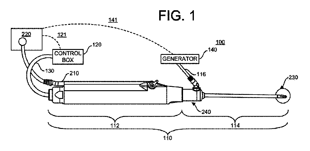
外科手術システム100の概要は、図1に最良に見られ、ブレード114に機械的に結合されたモータ駆動ユニット(「MDU」)112を有する複合デバイス110を含む。複合デバイス110は、静止外側スリーブ内に配設された高速回転内側シャフトを有する市販の金属シェーバまたはバリと同様に構成され、動作し得る。複合デバイス110はまた、RF電力をブレード114に供給するための、ブレード114に電気的および機械的に結合されたRF双極電源コード116を含む。外科システム100は、電源コード130を通じてMDU112に電力を供給するための制御ボックス120と、RF電源コード116を通じてブレード114にRF電力を供給するためのRF発生器140と、をさらに含む。
An overview of the
さらに、デバイス110は、吸引制御機構220に結合し得るMDU112に沿って延在する吸引管210を含む。吸引制御機構220は、管210を通る流体流を制御し得、吸引ポンプまたは複数の吸引ポンプ(図示せず)であってもよく、組織および流体の吸引を提供および制御するためにロータまたは他のデバイスを有する蠕動ポンプであってもよい。さらなる例として、吸引制御機構は、吸引管を挟むか、または解放する複数の位置を有するピンチバルブを含み得るか、または制御機構は、吸引管と関連付けられた流体導管サイズ(オリフィス)を変更する手段を含み得る。吸引制御220は、RF電源140のコントローラと通信(141)してもよく、後でより詳細に論じられる制御ボックス120と通信121してもよい。制御ボックス120、発生器140、および吸引制御220は、別個の筐体として表されているが、これらは、いくつかの実施形態では、単一の筐体に組み込まれてもよい。代替的な実施形態では、制御ボックス120および発生器140は、各々、それら自体の専用の吸引制御システム、ならびに関連する管および流体流制御手段を有し得る。代替的な実施形態では、吸引は、MDU112上に配設された制御バルブによって少なくとも部分的に制御され得、制御バルブは、より強力な吸引を選択的に可能にし、かつ使用中にそれを低減し得る。この実施形態では、吸引制御220は、一定の吸引流量を供給し、例えば、バルブを押して吸引速度を変更することによって、ユーザによって手動で変更され得る。
Further, the
ブレード114は、ブレード114を通って延在し、遠位部分230で吸引用の吸引管210と連通する内腔を含み、それにより、流体および破片が遠位部分230の窓を通じて吸引され得、内腔に沿って、かつ管210を通って流れる。ブレード114は、組織を機械的に切断し、組織を電気外科治療するために、患者の身体に挿入される遠位部分230を含む。ブレード114は、ブレード114をMDU112に選択的に接続および取り外すように構成され、ブレード114の一部分をMDU112内のモータに機械的に係合するように構成された近位部分240を含む。
The
制御ボックス120は、例えば、Andover、MassのSmith&Nephew,Inc.によって供給されるDyonics(登録商標)Power Shaver systemまたはDyonics(登録商標)EP-18 Shaver Systemとすることができる。発生器140は、例えば、Andover、MassのSmith and Nephew,Incによって供給されるCOBLATION WEREWOLF systemなどの市販の発生器とすることができる。ブレード114は、所望の用途に適合するようにサイズ決めされる。例えば、肩で使用するために、ブレードは、前立腺で使用するためのブレードとは異なってサイズ決めされる。用途としては、例えば、肩、膝、および他の関節における使用、ならびに、例えば、子宮、尿道、鼻腔、および口などの自然孔における使用が挙げられる。
The
図2を参照すると、RF電源コード116は、コネクタ320を有する自由端で終端し得る。コネクタ320は、発生器140またはフットスイッチのいずれかに接続するように設計された少なくとも2つの突起322および324を有し得る。各突起は、RF電源コード116内の2つの別個のコンダクタのうちの1つに接続して、ブレード114用の供給経路および戻り経路の両方を提供する。追加の突起(図示せず)が、デバイスのタイプおよび/または流体流設定もしくは電力設定などの所望のもしくは候補設定などの、さらなる情報をRF発生器/コントローラ140に提供してもよい。代替的なコネクタは、その開示全体が参照により本明細書に組み込まれる、同一譲受人による米国特許第9,333,024号に説明されるシステムなどの、RFコントローラ140のコネクタに接続するように構成された一連のピンを含み得る。
Referring to FIG. 2, the
MDU112は、ブレード114の近位端と選択的に結合するように構成される駆動シャフト(図示せず)を含み、その開示全体が参照により本明細書に組み込まれる、同一譲受人による米国特許第7,150,747号に開示されているものと同様の結合手段を含み得る。
吸引コントローラ220は、MDUが動作中である時間の間、吸引速度が、制御ボックス120によって調節される流体流量で制御され得るように、図1に表されるMDU制御ボックス120およびRF発生器140の両方と通信し得る。これは、MDUと関連付けられた感知されたパラメータ、または患者の関節内の感知された温度に応答してさらに動的に変更され得る。さらに、RF発生器140が動作中である時間の間、吸引は、RF発生器140によって指令される流体流量で制御され得る。流体流量は、その開示全体が参照により本明細書に組み込まれる同一譲受人による米国特許第8,192,424号および同第9,333,024号に説明される電極回路インピーダンスなどの感知されたパラメータに応答してさらに動的に変更され得る。
The
概して、ブレード114は、他の市販の機械的切除装置と同様の様式で機械的に切除し、その場合、ブレード114は、MDU112に固定的に取り付けられ、かつ使用中に静止スリーブである外側スリーブ310と、MDU112に結合された、外側スリーブと同心の内側スリーブ410と、を含み、それによって、内側スリーブ410は、静止外側スリーブ310に対して高速で回転し得る。ブレード114は、例えば、ねじ山付き接続および圧入接続などの様々な構造を使用して、MDU112に取り付けられ得る。MDU112の様々な実施形態は、Andover、MassのSmith&Nephew,Inc.によって製造されたモータ駆動ユニット、例えば、部品番号7205354、7205355、および7205971などを含む。
In general, the
様々な切断表面が機械的切断を提供し得る。そのような表面は、例えば、湾曲した、バリ付き、直線状、波状、または小型のブレードを含む。機械的切断は、典型的には、毎分数千サイクル(例えば、回転または往復)の速度で達成される。 Various cutting surfaces can provide mechanical cutting. Such surfaces include, for example, curved, burred, linear, wavy, or small blades. Mechanical cutting is typically achieved at speeds of thousands of cycles per minute (eg, rotation or reciprocation).
ここで、ブレード遠位先端340の実施形態を示す図3A~3Dを参照すると、外側スリーブ310は、長手方向開口部320を含み、開口部320の外周の少なくとも一部分の周囲で縁面325を画定する。縁面325は、好ましくは、内側スリーブ410と組み合わせて使用される場合、組織を切断するために十分鋭利である。内側スリーブ410は、内側スリーブが回転する際に、組織を機械的に切除するために、縁面325と協働するように構成されている同様の開口部420および縁面425を有し得る。内側スリーブ410および開口部420は、内側スリーブ410がその内腔(図示せず)に沿って細長い流体導管を画定するように、吸引管210と連通し得、その結果、機械的切除中に形成された壊死組織片が、導管および開口部420を通して除去され得る。内側および外側スリーブ(410および310)の両方は、それらの切刃面425および325を含み、ステンレス鋼などの金属から形成され得、これは、この材料が一般的に良好な強度および耐久性の切刃を提案することを発明者らが見出したためである。スリーブのうちの1つの代替的な選択肢は、容易にろう付けされるニッケルー鉄合金である、Invarとすることができる。金属切断縁は、より脆い材料で発生し得る、切断中の粒子形成を低減するために好ましい。
Here, referring to FIGS. 3A-3D showing embodiments of the blade
外側スリーブ310は、好ましくは、電気コード116からブレード遠位先端への電気経路を提供するように構成された、金属または導電性の管である。外側スリーブ310は、外側スリーブ310の一部分を電気絶縁し、かつ外側スリーブの露出された部分を制御されたエリアに制限するために、層または鞘305によって少なくとも部分的にコーティングまたは被覆され得る。例えば、MDU112に隣接する、外側スリーブ310の近位部分は、コード116と電気的に結合し、それによってRF発生器140(図示せず)と電気的に結合するために十分露出され得る。外側スリーブ310の遠位部分もまた、露出されたままであり得、そのため、金属切刃面325が機械的切除のために露出されると共に、それにより、RFエネルギーの適用中に使用するための、システム100の戻り電極350を画定する表面積が露出される。
The
外側スリーブ310は、活性電極360をさらに備え、ケーブルまたはワイヤ(図示せず)を介してRF発生器140に電気的に結合され、外側スリーブ310から電気絶縁され、それによって、電気絶縁スペーサ370を介して戻り電極350から電気絶縁される。活性電極360が、組織を選択的に焼灼し、したがって、プラズマを形成することを意図するため、スペーサ370は、好ましくは、プラズマからの分解またはプラズマ硬化にも耐性がある電気絶縁材料である。材料は、アルミナ、ジルコニアなどのセラミックまたはガラス材料を含み得る。好ましい実施形態は、ジルコニアなどの固有の高強度および耐破壊性セラミックを使用し得る。このセラミックは、アルミナと同様に詳細な形状に成形されることができるが、従来のジルコニアのようにプラズマ下で分解しない。窒化ケイ素は、さらなる選択肢である。
The
加えて、活性電極360は、好ましくは、タングステン、チタン、白金、モリブデン、アルミニウム、金、および銅などの、プラズマに対する劣化に耐性がある材料であるべきである。より具体的には、活性電極は、好ましくは、内側および外側のスリーブ材料とは異なる材料であり得る。ステンレス鋼は、機械的切刃に好ましいが、ステンレス鋼は、プラズマによる劣化に対する耐性が低い傾向があるため、焼灼電極に好ましい材料ではない。加えて、例えば、タングステンは、ステンレス鋼よりも脆い金属であり、したがって、機械的切除中に粒子が形成し得るため、切刃としては、好ましくない。追加的に、発明者らは、プラズマを形成する遠位端の部分が、機械的切刃から離間されるべきであり、機械的切刃用の選択材料が何であれ、縁が、プラズマによって分解されてもよく、機械的切断が損なわれてもよいことを見出した。鋭利な縁などの凹凸は、その上にプラズマを形成する傾向がより強いため、活性電極360の周縁と切刃325との間の最小距離は、少なくとも2mmとするべきである。プラズマを形成する遠位端の一部分は、機械的切刃から離間されるべきであり、それにより、機械的切刃に沿ったプラズマ形成は、優先的ではない。
In addition, the
遠位先端340のより小さい外径を維持するために、スペーサ370は、外面から内側内腔に向かって外側スリーブ310の壁厚を通って延在するように、外側スリーブ310の一部分を置き換え得る。別の表現では、外側スリーブ310は、第2の開口部330を備え、それを通してスペーサ370を受容する。開口部330は、外側スリーブ310の切刃325および最遠位先端から離間された、包囲された開口部であり得、少なくとも部分的に直径方向に対向する開口部320であり得る。開口部330は、好ましくは、内側スリーブの開口部420と軸方向に重なる。スペーサ370は、好ましくは、外側スリーブ310に構造的完全性を提供する高強度セラミックから形成され、全ての金属外側スリーブと比較して強度改善を提供するように外側スリーブに剛性を追加し得る。絶縁スペーサ370は、切断表面として使用されないが、代わりに、金属内側スリーブ410を封止し、プラズマからの分離を提供する役割を果たす。スペーサ370は、第2の開口部330を通って延在するが、内側スリーブ410が回転する際にスペーサ370が内側スリーブ410と干渉し得るため、好ましくは、外側スリーブ内腔内に延在しないか、または侵入しない。図3Cに最良に見られ、スペーサ370は、外側スリーブ310の内側内腔壁312まで第2の開口部330を通って延在し得る。スペーサ370の内側曲面371は、内側内腔壁312の湾曲と実質的に連続的であるように湾曲し得る。外側スリーブ310の外面上のみに位置し得るスペーサと比較して、外側スリーブ310の一部分をスペーサ370と置き換えることは、全体的に顕著に小さい断面が維持されることを可能するが、(図3C参照)、一方、活性電極と戻り電極との間の間隔要件を依然として維持して、2つの電極間の電気経路を制御する。したがって、開示されたスペーサ構成によると、デバイスの外側断面への最小限の増加が達成される。例えば、発明者らは、外側スリーブの外径(OD)が、Platinum Bonecutterなどの既存のデバイスと同様に、およそ4.5mmである場合、スペーサ370および電極360を含む最大断面(CS)が、5mmのカニューレを通って依然として収まることを見出した。
To maintain the smaller outer diameter of the
スペーサ370および活性電極360のさらなる詳細は、遠位部分340の上側および下側の分解図を示す図4Aおよび4Bに最良に見られる。第2の開口部330は、外側スリーブ310の内側内腔まで通って延在し、内側スリーブ410は、図4Aおよび4Bでは、第2の開口部330を通して見られ得る。内側スリーブ410は、好ましくは、内側スリーブ開口部420が、RF発生器140の動作中に第2の開口部330と流体連通するように、配向され得る。別の表現では、内側スリーブ開口部420は、好ましくは、焼灼モードの動作中に第2の開口部330に面し得る。(図は、開口部330から遠ざかる方向を向く内側スリーブ開口部420を示す)。いくつかのモードでは、この内側スリーブ開口部420は、活性電極360、スペーサ370および第2の開口部330を通る流体流量を制御する手段として、第2の開口部330と部分的にのみ重なるか、または第2の開口部330と調整可能に重なるように回転され得る。これは、先に説明されたように、活性電極360で形成される任意のプラズマ内の組織効果およびエネルギーをさらに制御し得る。あるいは、内側スリーブ開口部420は、第2の開口部330と位置合わせされ得、体積流量は、コントローラ220と通信するポンプなどの流れ制御デバイスを使用して制御され得る。
Further details of the
第2の開口部330は、スペーサ370を外側スリーブ310とより良好に結合するために、複数の軸方向に離間された歯などの、機械的係止特徴335を含み得る。相補的保持特徴375が、図4Bでは、スペーサ370上で見られ得、歯の形成は、2つの部品間の応力分布を改善するように構成されている。接合強度はまた、増加した接触面積に起因して改善され得る。スペーサ保持特徴375は、張出部380によって取り囲むスペーサ370内に入り込み得、図4Bおよび3Cの両方に見られる。この張出部380は、いくつかの利点を提供する。第1に、デバイスの使用中に任意の側方負荷に起因して、スペーサ370と外側スリーブ310との間に応力をより良好に分散する。また、接着結合のための面積を追加するスペーサ370と外側スリーブ310との間の表面積接触を増加させる。加えて、この張出部380は、戻り電極350と活性電極360との間に好ましい電気絶縁ギャップを提供し、したがって、活性電極360の周囲のプラズマ形成を改善する。ギャップは、間隔XおよびYとして図3Bおよび3Cに示されている。2つの電極間の距離が小さ過ぎると、プラズマを形成する高電圧の蓄積が破壊され得、電気的短絡が発生し得る。追加的に、張出部の輪郭または周縁381は、切断窓325の周縁表面輪郭に追従して、窓325の可視性を維持し、セラミックスペーサ370によって遮られる可視性を制限する。
The
スペーサ370は、外側スリーブ310の内側内腔と流体連通するように、スペーサ370の厚さを通して吸引開口部372を含む。上述されたように、内側スリーブ開口部420が、吸引開口部372と少なくとも部分的に面するか、または流体連通するように配向されるとき、流体、プラズマ、および凝固副生成物の吸引は、組織治療部位から除去され得、機械的切除およびRF組織治療の両方に対して、同じ吸引経路が使用されることを可能にする。典型的には、これは、活性電極360が戻り350からより離れてオフセットされて、プラズマがデバイス内部で形成することを防止することを必要とする。(デバイスの内側の活性と戻りとの間の距離は、好ましくは、デバイスの外面における活性と戻りとの間の距離より大きくなければならない)。ここで、外側スリーブ310の内側の一部分が絶縁スペーサ370(曲面部分371)と置き換えられるため、活性電極360から戻り350(表面312)までの距離が、ここで、増加し、それによって、デバイスの内側の意図しないプラズマを最小化する。活性電極360はまた、使用中に活性電極表面を通して破片およびプラズマ副生成物を除去するために、スペーサ370の吸引開口部372と流体連通する少なくとも1つの吸引開口部362を含む。活性電極360は、スペーサ空洞376内に丸みを帯びた外面および入れ子を有し、デバイスが5mmカニューレ内に収まり得るように、任意の追加のサイズの増加を最小化する。活性電極360は、空洞376の横方向側上のスロット373および両側張出部374によって、セラミックスペーサ370によって拘束され支持される。電極フランジまたはテール363は、スペーサ370内のスロット373内に摺動し、電極360の横方向部分は、張出部374によって部分的に被覆される。張出部374は、活性電極360と戻り電極350との間の距離をさらに増加させる。このタイプの機械的インターフェースは、理想的には主にタングステンからなる、金属射出成形電極360を使用することによって可能である。フランジ363は、導電性であり、活性電極360からRF発生器への電気経路の一部分を形成する。フランジ363は、フランジ363および電極360が単一の成形部品であるように、電極360の成形部分とすることができる。あるいは、フランジ363は、電極360に電気的に結合された導電性ワイヤまたはケーブルであってもよい。導電性ケーブルまたは可撓性回路(図示せず)は、フランジ363または電極360に電気的に結合され、ブレード114および電気コード116の近位部分に外側スリーブ310に沿って延在し得る。この導電性ケーブルは、外側スリーブ310が、好ましくは、戻り電極350の導電性経路をコード116に提供するため、外側スリーブ310から電気的に分離される。
The
活性電極360は、凹状の下側364を有し得る。これは、活性電極360と内側スリーブ410との間の距離を増加させ、内側スリーブ410がいくつかの配向で電気経路シャントとして意図せず作用し、それによって、プラズマ形成に影響を与えることを抑制する。これは、活性電極が凹状ではない場合、または金属内側スリーブ410に近過ぎる場合に発生し得る。上述されたように、活性電極360の外面上に一貫したプラズマが形成されるために、活性電極および戻り電極の内面間の間隔は、好ましくは、外面部分上の距離XおよびYよりも離れるべきである。外側スリーブ310が戻り電極として結合されている間、内側および外側スリーブ(それぞれ410および310)間に電気絶縁手段が存在しない場合がある。内側スリーブがいくつかの場所で外側スリーブと接触し得ることを考慮すると、内側スリーブ410は、外側スリーブに電気的に結合され、それによって、戻り経路の一部を形成し得ることがある。したがって、内側スリーブ410が外側スリーブ310の内側内腔に接触するため、内側スリーブ410が導電性経路の一部分を形成するように動作可能であり得ると仮定されることになる。したがって、内側スリーブ410は、内側スリーブが図4Aに示される配向などの特定の配向にあるとき、活性電極内面364と戻り電極350との間の電気経路をブリッジまたは短絡し得ることになる。内側スリーブ410が図4Aおよび4Bに示されるように回転される場合、内面364と内側スリーブ310の外面との間の間隔は、好ましくは、図3Bおよび3Cに説明される距離Xおよび/またはYよりも離れるべきである。凹状内面364は、この最小間隔を達成する1つの手段である。代替的な手段は、後述の図に説明されるボスを含む。
The
活性電極は、デバイス断面を最小化すると共に、デバイスの遠位先端でRF組織効果も提供するために、外側スリーブの丸みを帯びた遠位先端の周囲に延在し得る遠位先端368を有する。遠位先端368はまた、狭い面積への改善されたアクセスのために、先端における全体直径を最小化するように先細であり得る。外側曲面はまた、スペーサ370内の活性電極360の陥凹位置と共に、デバイスを操作することによる組織裂開を最小化する。裂開を低減することに加えて、ブレード遠位端は、互いに平滑に移行し、かつ、好ましくは、湾曲および平滑外形を有する、構成要素を含むべきである。これは、純粋な機械的切除デバイスのみなどの、外科医が慣れているデバイスと同様のデバイスの感触または触覚フィードバックを維持する。触覚フィードバックは、組織を機械的に切除するか、または一般的に組織を操作する間のデバイスの感触にとって重要である。
The active electrode has a
活性電極360およびスペーサ370を通した吸引は、シェーバの「窓係止」特徴によって制御され得る。外科医は、内側スリーブ410の開口部420を「閉鎖」に設定し、それによって、排他的に活性電極360を通って開口部362を通る流れを可能にする能力を有する。これは、RFプラズマ焼灼中に生成された気泡の領域をきれいにするために必要であり得る。レーザマークが、開口部420が閉じているときに位置合わせを示すために、内側および/または外側スリーブに追加され得る。吸引チャネルを機械的切除ハンドルと共有することによって、外科医はまた、ハンドル上の吸引を制御することによって焼灼性能をカスタマイズすることができる。図3Dに最良に見られる吸引開口部362および372は、角度付けられ、互いにわずかに軸方向にオフセットされ得る。これは、流れまたは破片および副生成物を近位に方向付けることを助け得る。
Suction through the
図5Aは、ブレード遠位部分についての代替的な実施形態の等角図を示す。上記の実施形態と同様に、ブレード遠位部分は、内側スリーブ510、外側スリーブ520、活性電極560、およびスペーサ570を含む。外側スリーブ520および内側スリーブ510は、両方、組織を機械的に切断するために、鋭利な縁を有する開口部を有し得る。活性電極560は、ケーブルまたはワイヤを介してRF発生器140に電気的に結合され、外側スリーブ520から電気絶縁され、それによって、電気絶縁スペーサ570を介して戻り電極550から電気絶縁され得る。上記の実施形態に説明されるように、プラズマ硬化性および耐久性のある切断表面などの同様の材料因子が、スペーサ、外側スリーブ、および活性電極560について考慮される。
FIG. 5A shows an alternative embodiment isometric view for the distal portion of the blade. Similar to the above embodiments, the distal portion of the blade comprises an
遠位部分のより小さい外径を維持するために、スペーサ570は、外面から内側内腔に向かって、または内側内腔まで、外側スリーブ560の壁厚を通って延在するように、外側スリーブ560の一部分を置き換え得る。開口部530は、外側スリーブ520の切刃525および最遠位先端から離間された、包囲された開口部であり得る。スペーサ570は、好ましくは、外側スリーブ520に構造的完全性を提供する高強度セラミックから形成され、強度改善を提供するように外側スリーブ520に剛性を追加し得る。絶縁スペーサ570は、好ましくは、切断表面として使用されないが、代わりに金属内側スリーブ510を封止し、RF焼灼プラズマに対する分離を提供する役割を果たす。スペーサ570は、開口部530を通って延在するが、内側スリーブ510が回転する際にスペーサ570が内側スリーブ510と干渉し得るため、好ましくは、外側スリーブ内腔内に延在しないか、または侵入しない。図5Aの断面を示す図5Bおよび5Cに最良に見られ、スペーサ570は、外側スリーブ520の内側内腔壁に向かうが、それを越えずに、開口部530を通って延在し得る。スペーサ570の内側曲面は、内側内腔壁512の湾曲と実質的に連続するように湾曲し得る。このハイブリッド先端を作成することによって、外側スリーブ520の一部分を置き換えるスペーサ570を用いて、全体的に顕著に小さい断面が維持される(図5Bおよび5C参照)。したがって、開示されるスペーサ構成によると、デバイスの外断面に最小限の増加が必要である。例えば、発明者らは、外側スリーブの外径(OD)が、Platinum Bonecutterなどの既存のデバイスと同様に、およそ4.5mmである場合、スペーサ570および電極560を含む最大断面(CS)が、5mmのカニューレを通って依然として収まることを見出した。
To maintain a smaller outer diameter of the distal portion, the
図5A~5Cには示されないが、開口部530およびスペーサ570は、図4Aおよび4Bに説明されるものと同様の機械的係止特徴を含み得る。スペーサ570はまた、デバイスの使用中の任意の側方負荷に起因するスペーサ570と外側スリーブ520との間の応力分布を改善するために、図5Bおよび5Cの両方に見られる、張出部580を含み得る。張出部580はまた、接着結合のための面積を追加するスペーサ570と外側スリーブ520との間の表面積接触を増加させ得る。加えて、この張出部580は、活性電極560で一貫したプラズマを形成するために、戻り電極550と活性電極560との間に好ましいギャップを提供し、ギャップは、間隔XおよびYとして図3Bおよび3Cに示されるものと同様である。
Although not shown in FIGS. 5A-5C,
スペーサ570は、外側スリーブ520の内側内腔と流体連通しているスペーサ570の厚さを通る吸引開口部572を含む。この実施形態では、吸引開口部572は、活性電極560と有効な戻り電極との間の誘電体間隔を増加させるために、ボス573を含む。上記に説明されたように、デバイスの内側の活性と戻りとの間の距離が、デバイスの外面における活性と戻りとの間の距離より大きいことが好ましい。ここで、外側スリーブ520の内側の一部分が絶縁スペーサ570およびボス付き開口部572、573と置き換えられるため、活性電極560から戻り電極550までの距離が、ここで、増加し、それによって、デバイスの内側の意図しないプラズマ形成を最小化する。ボス573は、活性電極560内の相補的開口部565を通って延在し、その中で入れ子になり、活性電極560の上面からわずかに陥凹するように終端する。これは、活性電極開口部565の周囲に露出された縁面を維持して、電界を集束させ、開口部565の縁にプラズマを形成する。吸引開口部565およびボス573は、使用中に活性電極表面から壊死組織片およびプラズマ副生成物を除去するようにサイズ決めされる。活性電極560は、遠位先端断面を最小に保ち、5mmのカニューレ内に収まるように、丸みを帯びた外面を有し、スペーサ空洞576内に少なくとも部分的に入れ子になる。活性電極の凹状の下側を開示した、上記の図の実施形態とは異なり、活性電極560のこの実施形態は、ボス572が補助的な電気経路間隔を提供し、デバイスの外面上の一次電気経路を優先するように、スペーサ空洞576内で面一であり得る。これは、遠位先端断面をさらに低減し得る。これはまた、上記のように、より良好な戦術的感触を提供し得る。
The
手動制御に加えて、デバイス110は、本出願の同一譲受人によって所有され、参照により本明細書に組み込まれる、WEREWOLF◇ COBLATION◇ Systemに直接接続されてもよい。これは、COBLATIONがアクティブであるときに吸引の自動制御を可能にし、COBLATIONがアクティブではないときにシェーバデバイスに対して一定の吸引または制御された吸引を提供し得る。シェーバ流れ制御は、管内の圧力、モータを後進させる電力、モータに接続されたトルク変換器、および/またはモータ温度などの様々なフィードバックに基づいて制御され得る。また、流れ制御モジュールは、詰まりを除去するために逆方向に作動させることができる。
In addition to manual control, the
この複合デバイス110はまた、一般的に焼灼モードと比較してより低い電圧モードとして特徴付けられる凝固モードを有し得る。このデバイス110の凝固場は、活性電極360の周囲のエリアに包含される。この制御されたエリアは、意図しない熱組織損傷を低減する。
The
このデバイスの電気経路は、活性電極への電力送達のために外側スリーブ310の外側の可撓性回路を使用し得る。この同じ可撓性回路は、本出願の同一譲受人によって所有され、参照により本明細書に組み込まれる、Ambient◇技術を可能にするように回路を組み込み得る。Ambient技術は、RFコントローラおよび/または制御ボックス120に温度情報を提供し、それによって、機械的切除およびRF組織治療の両方の間に、関節内の流体の温度を示す値を感知する。温度を示す値を感知するためのセンサは、デバイス遠位先端340の任意の部分に結合され得、例えば、活性電極から軸方向に近位に離間された、スペーサの一部分に結合され得る。
The electrical path of this device may use the outer flexible circuit of the
ブレード遠位部分600の代替的な実施形態が、図6Aおよび6Bに示され、ブレード遠位部分600にRFエネルギーを送達している間の動作のための専用吸引チャネル650を含む。切断窓または開口部および戻り電極などの特徴は、上記に開示された実施形態と同様であり得る。吸引チャネル650は、デバイスシャフトに沿って近位に延在し得る、スペーサ670の一部分であり得る。この実施形態では、吸引経路は、機械的切除吸引経路から分離し、デバイスの外側部分に沿って延在し、RF制御デバイスのみと関連付けられた流れ制御デバイスに直接結合された別個の吸引管(図示せず)と接続する。これは、よりカスタマイズされた吸引プロファイル、および、それによって、よりカスタマイズされた焼灼性能(例えば、Werewolf Flow Controlモジュールまたは同様の方法を用いたものなど)を可能にし得る。また注目すべきことに、活性電極660は、各々が異なる形状を有する、複数の吸引開口部672を含み得る。
An alternative embodiment of the blade
ブレード遠位部分700のさらなる代替的な実施形態が、図7A、7B、および7Cの様々な角度から示されている。切断窓または開口部および戻り電極などの特徴は、上記に開示された実施形態と同様であり得る。この実施形態は、内側管720および外側管750に加えて、シールドまたは中央管730を含む。上記の実施形態と同様に、活性電極760は、外側管750に結合されたスペーサ740によって支持され、RF出力の戻り経路を提供し得る。このデバイスは、「Orbit」スタイルのシェーバに類似している。中央管730のシールドは、吸引を制御するために使用され得、それによって、吸引を制御するために「窓係止」を設定する必要性を防止する。図7Aにおいて示される、シールド730は、開放構成であり、内側管720は、シールド730に対して回転して、組織を機械的に切除し、内側管の内腔を通して壊死組織片を吸引し得る。この開放構成では、エネルギーが供給されても、活性電極760に利用可能な吸引が存在しない場合があるが、このことは、いくつかの組織治療に好ましい場合がある。中央管730および内側管720のそれぞれの開口部に沿った縁が、組織切除を提供することに留意されたい。図7Bは、活性電極760を通すと共に、内側管腔を通して、いくつかの吸引を提供し得る、部分的開放構成のシールドを示す。この部分的開放構成では、機械的切除および電気外科組織治療は、組み合わせて、または順次使用され得る。この構成はまた、吸引速度を制御するように構成され得る。第3のおよび閉鎖構成では、シールド730は、内側管720を完全に被覆するように回転され、活性電極760の下側に面する開口部を有し得る。吸引は、主に活性電極760を通して開口に提供され得る。
Further alternative embodiments of the blade
ブレード遠位部分800のさらなる代替的な実施形態は、図8に見ることができる。この実施形態は、軸方向に摺動可能な電極860を含み得、この電極860は、機械的切除中に遠位先端の周囲の非常に近いエリアから除去され、その後、電気外科組織治療が所望されるときに吸引開口850上に摺動し得る。複数の吸引孔865が、この実施形態、および詰まりを軽減するための代替的な吸引経路を提供し得る上記の他の実施形態に示されている。
A further alternative embodiment of the blade distal portion 800 can be seen in FIG. This embodiment may include an axially
複合デバイスは、様々なモードで動作し得る。例えば、第1の機械的切除モードでは、MDU112は、他のシェーバデバイスと同様に、組織を機械的に切断するように、内側スリーブ410を回転または移動させ得る。このモードの間、切除された組織は、開口部420を介して、および吸引源に結合された内側スリーブ内の内腔に沿って患者から除去され得る。吸引は、例えば、蠕動ポンプの速度または回転を制御し得る、吸引コントローラ220によって制御され得る。あるいは、真空源は、吸引チューブに結合され得、吸引コントローラは、ピンチ要素を動かすか、またはバルブを選択的に閉じ得る。あるいは、吸引コントローラは、1つ以上の開口を有する第1の本体と、1つ以上の開口を有する第2の本体と、を有する、移動可能な構築物を含み得、それによって、第1および第2の本体のうちの1つ以上は、第1および第2の本体開口間の位置合わせが流量を変化させるために変更され得るように、他方に対して移動可能である。吸引は、切除中に第1の流量で制御され得、この第1の流量は、非限定的な例として、モータ速度設定、MDUと関連付けらえた感知された電気パラメータ、およびデバイスと関連付けられた温度などの、様々なパラメータに依存して、ユーザによってまたは自動的に調整可能であり得る。
The composite device can operate in various modes. For example, in the first mechanical excision mode, the
第2のモード、電気外科モードでは、内側スリーブ410は、静止し得、窓420は、焼灼もしくは凝固、または両方の組み合わせなどの電気外科治療の間に吸引導管を提供するために、横方向開口部330に面し得る。この第2のモードの間、活性電極360は、組織を電気外科治療するために、標的組織およびRF発生器に隣接して配置され得る。流体、組織、および/またはプラズマ副生成物は、活性電極362の開口部362を通ること、スペーサ開口部472を通ること、内側スリーブ開口部420を通ること、および内側スリーブ410に沿うことを含む、経路に沿って、同時に除去され得る。吸引は、内側スリーブ吸引内腔と連通している流体導管または開口のサイズを制御することを伴う蠕動ポンプまたはデバイスなどの吸引制御システムによって制御され得る。吸引制御システムは、RF発生器と通信し得る。通信は、無線であってもよい。吸引は、ユーザによって調整されてもよく、またはRF発生器上の電力設定などの動作パラメータに基づいて、もしくは電極回路インピーダンスなどの感知されたパラメータに基づいて、自動的に設定され、調整されてもよい。このことのさらなる説明は、同一譲受人による米国特許第8,192,424号、同第9,333,024号、および同第9,713,489号に見出すことができ、それらの開示全体は、参照により本明細書に組み込まれる。吸引は、吸引コントローラと関連付けられたポンプ速度の制御、バルブ位置の制御、または上記のオリフィスサイズの制御を介して調整され得る。加えて、吸引は、開口部330に対して開口部420の位置を調整することによって制御され得、開口部330は、吸引導管を通ることに対する活性電極開口を通る有効な吸引を調整し得る。あるいは、この第2のモードは、組織を分子解離させるのではなく、組織を凝固させるように構成されたより低い電圧出力を含む凝固モードであり得る。
In a second mode, electrosurgical mode, the
あるいは、この第2のモードは、組織の焼灼とのある程度同時の凝固を含み得る。これは、RF発生器の出力を調節することによって達成され得る。このさらなる説明は、同一譲受人による特許出願第PCT/US18/032989号に見出すことができ、その開示全体は、参照により本明細書に組み込まれる。あるいは、この調節は、蠕動ポンプなどの吸引制御システムの制御を通じた、またはRFを送達する間の内側スリーブの継続的な回転による、パルス吸引によって達成され得る。内側スリーブの制御された回転は、活性電極開口362を通して吸引を調節し得、これは、次に、活性電極表面上にプラズマを形成し、崩壊させ得る。RF発生器によって供給される電圧は、一定の高周波数電圧レベルであり、内側スリーブ410を回転させながら電極表面でプラズマを形成するために十分であり得る。例えば、内側スリーブ410が活性電極を通して吸引を遮断するように配向されるとき、プラズマが、活性電極表面上に形成され、組織の焼灼を提供する。内側スリーブ410が、活性電極開口362を通して流体を引き込むように配向されているとき、RF発生器によって供給されるエネルギーは、プラズマを形成するために十分ではなく、したがって、組織に凝固効果を提供し得る。吸引速度の調節が発生する速度は、組織効果が一貫しているとユーザによって知覚されるが、プラズマが断続的に形成することを可能にするために十分遅いように、十分に速いことが好ましい。ブレードの回転は、連続的であってもよく、またはブレードは、活性電極を通る流れに影響を与えることになる、いくつかの位置の間で断続的に交互に起こってもよい。組織の同時の機械的切除を制御または制限するために、内側スリーブは、好ましくは、内側スリーブの切刃が外側スリーブ切断窓を通して露出されず、組織を意図せず機械的に切断しないように、往復し得る。同期された電圧変調もまた、プラズマを形成するために十分な第1の電圧と、必要とされる内側スリーブ配向間のいくつかの通信によってプラズマが崩壊することを支援し得る第2の電圧との間に追加され得る。
Alternatively, this second mode may include some degree of simultaneous coagulation with tissue cauterization. This can be achieved by adjusting the output of the RF generator. This further description can be found in patent application No. PCT / US18 / 032989 by the same assignee, the entire disclosure of which is incorporated herein by reference. Alternatively, this regulation may be achieved through pulsed suction through the control of a suction control system such as a peristaltic pump or by continuous rotation of the inner sleeve while delivering RF. The controlled rotation of the inner sleeve may regulate the suction through the
この同時モードの間、プラズマ形成および崩壊の頻度を制御するために、機械的切除中よりも遅い回転速度が望ましい場合がある。吸引速度は、活性電極を通る吸引が最大であるとき(内側スリーブ開口部425が活性電極に直接面しているとき)に、プラズマが崩壊し、プラズマが再形成することを低減された吸引(開口部425が活性電極の下側に面して離れて回転する際)が可能にし得るように、活性電極、それを通る吸引開口、および供給される電圧の第1の構成のための第1の流量に設定され得る。あるいは、吸引流量は、活性電極を通る吸引開口を有する活性電極の第2の構成に対してより中程度であり得、電圧は、最大の適度の吸引(内側スリーブ開口部425が活性電極に直接面するとき)がプラズマを形成することを支援し、プラズマが崩壊することをより低い吸引速度(開口部425が活性電極の下側に面して離れて回転する際)が可能にするように、供給され得る。
During this simultaneous mode, a slower rotation speed than during mechanical excision may be desirable in order to control the frequency of plasma formation and decay. The suction rate is such that when the suction through the active electrode is maximum (when the
第3の複合モードでは、RF電力は、組織を機械的に切断しながら同時に供給され得る。RF電力は、可視性(領域内の血液の低減)を改善するために、組織を凝固させるために十分な電圧で供給され得る。これはまた、外科医が血液を見るとき、または組織を焼灼する必要があるときに、外科医がRF発生器を停止し、別々に活性化する必要性を低減し得る。あるいは、より積極的な切断が所望される場合、RF電力は、組織を機械的に切除しながら組織を同時に焼灼するために十分に供給され得る。この第3のモードでは、より一貫したプラズマ形成が所望される場合、内側スリーブ内腔とは異なる、電極用の別個の吸引導管は、より一貫した流体吸引速度、および、それによって、より一貫したプラズマ形成を維持するために好ましい場合がある。吸引は、2つの吸引コントローラ、または単一のコントローラと関連付けられた少なくとも2つのポンプによって制御され得、第1のポンプは、MDU制御からの入力に基づいて制御され、第2のポンプは、RF発生器からの入力に応答して制御される。吸引は、ユーザによって調整されてもよく、またはMDUコントローラおよび/またはRF発生器上の電力設定などの動作パラメータに基づいて、もしくは電極回路インピーダンスなどの感知されたパラメータに基づいて、自動的に設定され、調整されてもよい。このことのさらなる説明は、同一出願人による米国特許第8,192,424号、同第9,333,024号、および同第9,713,489号に見出すことができ、それらの開示全体は、参照により本明細書に組み込まれる。 In the third combined mode, RF power can be supplied simultaneously while mechanically cutting the tissue. RF power may be supplied at a voltage sufficient to coagulate the tissue in order to improve visibility (reduction of blood in the region). This can also reduce the need for the surgeon to stop and activate the RF generator separately when looking at the blood or when the tissue needs to be cauterized. Alternatively, if more aggressive cleavage is desired, RF power may be adequately supplied to simultaneously cauterize the tissue while mechanically excising the tissue. In this third mode, if more consistent plasma formation is desired, a separate suction conduit for the electrodes, which is different from the inner sleeve lumen, has a more consistent fluid suction rate, and thereby more consistent. It may be preferable to maintain plasma formation. Suction can be controlled by two suction controllers, or at least two pumps associated with a single controller, the first pump is controlled based on the input from the MDU control and the second pump is RF. It is controlled in response to the input from the generator. Suction may be adjusted by the user or automatically set based on operating parameters such as power settings on the MDU controller and / or RF generator, or based on sensed parameters such as electrode circuit impedance. And may be adjusted. Further explanations for this can be found in U.S. Pat. Nos. 8,192,424, 9,333,024, and 9,713,489 by the same applicant, the entire disclosure of which is: , Incorporated herein by reference.
ここで、複合外科用デバイスと使用するためのボタンおよびコントロール905を有する、使い捨てハンドスイッチ900を含むブレード部分114を含む実施形態を示す、図9Aおよび9Bを参照する。同様の構成要素は、上記の図と同様の番号が与えられている。再使用可能なハンドル112が、電動切除のみを提供する非複合デバイスと代替的に使用され得るため、第2のモダリティを含む複合デバイスは、再使用可能なハンドル112を介して利用可能ではない制御手段を必要とし得る。ここまで説明された1つの選択肢は、フットスイッチの使用である。ユーザに好ましい場合がある、代替的な選択肢は、(RF)高周波治療の制御用の複合外科用デバイスなどの、再使用可能なデバイス(図9Bに示される)のハンドルに取り付けられ得る、ハンドスイッチ選択肢900の提供である。これは、RF発生器ケーブル116を介してRF発生器(140)に電気的に結合されたRF発生器制御ボタン905の形態であってもよい。ハンドスイッチ900でブレード部分114を含む使い捨てパッケージを開くとき、ユーザは、ブレード部分112をハンドル112に結合し、次いで、使い捨てハンドスイッチ900を再使用可能なハンドル112の所望の部分上に配置し得る。使い捨てハンドスイッチ900は、例えば、接着剤などの結合手段、またはMDU112を少なくとも部分的に取り囲むクリップを使用して、MDU112に取り外し可能に固定され得る。結合手段は、ハンドスイッチ900と再使用可能なハンドル112との間の意図しない相対運動を防止するように動作可能であり得る。処置が完了すると、使い捨てハンドスイッチ900は、廃棄のためにブレード部分114と共に取り外され得る。
See here, FIGS. 9A and 9B, showing an embodiment comprising a
1つの例示的な実施形態では、発明者は、ゴムまたはエラストマーマット内にオーバーモールドされるか、または配置される、単一ストリップのボタン905を想定する。ボタン905は、ボタン905の起動時に電気回路または一対の接点を閉じて、ブレード部分114の電極間に電気エネルギーが送達されることを可能にするように動作可能である。オーバーモールドされたゴムマットのコード910またはより好ましくは延長部が、使い捨てブレード114をボタン905と物理的に結合し得る。コード910は、ブレード114と発生器ケーブル116との間の選択的電気通信のための配線を収容し得ると共に、ワイヤを電気絶縁し得る。ハンドスイッチ900は、ブレード部分114の任意の部分に結合され得、コード910は、十分に長いか、または伸長可能であり得、ハンドスイッチ900が再使用可能なハンドル112に取り付くことを可能にする。ハンドスイッチ900は、接着剤または粘着性ストリップを使用して再使用可能なハンドル112に取り付けられ得、これは、包装されている間に被覆され、剥離し易い接着剤カバー915によって被覆され得る。この容易な剥離カバーの取り外しは、次いで、接着剤を露出させて、次いで、ハンドスイッチマット900をハンドル112に取り付け得る。
In one exemplary embodiment, the inventor envisions a
ブレード部分114は、図9Bで再使用可能なハンドルに結合されて示され、接着剤カバーは、取り外され、ハンドスイッチストリップは、再使用可能なハンドル112の所望の場所に取り付けられる。ハンドスイッチ900を、再使用可能なパーマネントボタン950および951の側部に垂直な側部に取り付けることが最良であり得ることが好ましい場合がある。発明者はまた、パーマネントボタン951の2つの対向する側上にボタンが配置されることを可能にし、外科医により多くの選択肢を与える、「Y」字形ストリップを想定する。使い捨てハンドスイッチ900ストリップは、再使用可能なハンドル112の既存の表面上に簡単に収まるように形状決めされるべきであるが、示されているように長方形である必要はない。使い捨てハンドスイッチ900ストリップは、ユーザによって容易にアクセス可能であるデバイスの分配に取り付くように構成されている。ボタン910は、焼灼を起動するための第1のボタン、凝固を起動するための第2のボタン、および電力設定、または参照により全体が本明細書に組み込まれる、同一譲受人による米国特許第8,192,424号、第9,333,024号、および第9,713,489号により詳述されている真空モードなどの異なるモードを循環するための第3のボタンを含み得る。接着剤は、再使用可能なMDUハンドル112への強力な取り付けを可能にすると共に、処置の終了時に容易な解放を提供するべきである。したがって、接着剤は、動作処置中に剥離を防止する程度の耐水性を有するように構成される。
The
代替的な実施形態では、ハンドスイッチ900は、ハンドスイッチ900を再使用可能なハンドル112に選択的または一時的に固定するためのクリップを含み得る。クリップは、再使用可能なハンドル112を部分的に取り囲み得る。クリップは、再使用可能なハンドル112の外面に係合するように構成された内周面を有し得、ハンドスイッチ900をより良好に固設するように、再使用可能なハンドル112の外径よりもわずかに小さい内径を有し得る。代替的にまたは追加的に、クリップの内面は、ハンドスイッチ900とハンドル112との間の係合を再び改善するために、歯または高摩擦表面などの、把持特徴を有し得る。ハンドスイッチ900は、2つのクリップを含み得、1つが、ハンドスイッチ900を再使用可能なハンドル112とより良好に安定させるために、ハンドスイッチ900のいずれかの端にある。
In an alternative embodiment, the
さらなる代替的な実施形態では、ハンドスイッチ900は、再使用可能なハンドル上に摺動し得る薄いスリーブを含み得、スリーブは、再使用可能な制御950および951へのアクセスのための開口部を有する。あるいは、ハンドスイッチ900は、再使用可能なハンドルの一部分の周囲に巻き付くように構成されている薄いラッピング要素を含み得、再使用可能な制御950および950を露出させるための開口部を含み得る。例示的なラップは、ハンドル112の周囲に完全に巻き付き得、例えば、摩擦、Velcroまたは接着剤を使用してそれ自体に結合し得る。薄いラッピング要素は、再使用可能なハンドルとの固設を改善するために部分的に伸縮性であり得る。
In a further alternative embodiment, the
上記の考察は、本発明の原理および様々な実施形態の例示であることを意味する。上述の開示が完全に理解されると、数多くの変形および改変が当業者に明らかになるであろう。以下の特許請求の範囲は、そのような変形および改変の全てを受け入れるように解釈されることが意図される。 The above considerations are meant to be exemplary of the principles and various embodiments of the invention. Once the above disclosure is fully understood, a number of modifications and modifications will be apparent to those of skill in the art. The following claims are intended to be construed to accept all such modifications and modifications.
Claims (20)
ハンドル部分およびブレード部分を備え、前記ブレード部分が、内部に配設された内側シャフトを有する内腔を有する外側スリーブを含み、前記外側スリーブが、前記内側シャフトが回転するときに組織を機械的に切断するように構成された、切刃を含む窓を有し、
前記外側スリーブが、横方向開口部が通っている露出された導電性部分を画定し、前記横方向開口部が、前記窓から周方向に離間されており、
誘電体スペーサが、前記横方向開口部を通って延在するように、前記横方向開口部に結合されており、
前記誘電体スペーサが、活性電極を入れ子にし、前記活性電極を前記外側スリーブから電気的に分離し、前記露出された導電性部分が、戻り電極を画定している、複合医療デバイス。 A complex medical device for removing and treating patient tissue,
The blade portion comprises a handle portion and a blade portion, wherein the blade portion includes an outer sleeve having a lumen having an inner shaft disposed inside, and the outer sleeve mechanically structures the tissue as the inner shaft rotates. Has a window containing a cutting edge, configured to cut,
The outer sleeve defines an exposed conductive portion through which the lateral opening passes, the lateral opening being circumferentially separated from the window.
The dielectric spacer is coupled to the lateral opening so as to extend through the lateral opening.
A composite medical device in which the dielectric spacer nests the active electrode, electrically separates the active electrode from the outer sleeve, and the exposed conductive portion defines the return electrode.
ハンドルおよび前記ハンドルに選択的に接続可能なブレードを備え、前記ブレードが、内部に配設された内側シャフトを含む内腔を有する外側スリーブを含み、前記内側スリーブが、前記ハンドル内に配設されたモータ駆動ユニットに結合され、前記内側シャフトが回転するときに組織を機械的に切断するように、回転するように構成されており、
前記ブレードが、組織を電気外科治療するように構成された少なくとも1つの電極を含み、
前記ハンドルが、前記内側シャフトの回転と関連付けられたパラメータを制御するための前記モータ駆動ユニットと電気通信する少なくとも1つの制御スイッチを含み、
前記ブレードが、前記少なくとも1つの電極と電気通信するスイッチアセンブリをさらに含み、前記スイッチアセンブリが、前記ブレードの近位端から延在し、前記ハンドルへの前記スイッチアセンブリの選択的取り付けのための取り付け手段を含む、複合医療デバイス。 A complex medical device for removing and treating patient tissue,
It comprises a handle and a blade selectively connectable to the handle, wherein the blade comprises an outer sleeve having a lumen including an inner shaft disposed therein, and the inner sleeve is disposed within the handle. It is coupled to a motor drive unit and is configured to rotate so that it mechanically cuts the tissue as the inner shaft rotates.
The blade comprises at least one electrode configured for electrosurgical treatment of tissue.
The handle comprises at least one control switch that telecommunicationss with the motor drive unit for controlling parameters associated with rotation of the inner shaft.
The blade further comprises a switch assembly that telecommunicationss with the at least one electrode, the switch assembly extending from the proximal end of the blade and mounting for selective attachment of the switch assembly to the handle. Complex medical device, including means.
モータ駆動ユニットおよびそこに選択的に結合されたブレードであって、前記モータ駆動ユニットおよびブレードが、各々、互いに流体連通している流体吸引導管を有する、モータ駆動ユニットおよびブレードと、
前記モータ駆動ユニットと通信するモータ駆動ユニットコントローラと、
前記モータ駆動ユニットおよびブレード流体吸引導管を通る流体流量を制御するように構成された流体吸引コントローラと、
前記ブレードの活性電極および戻り電極と電気通信するRF発生器と、を備え、
前記ブレードが、内部に同心に配設された内側スリーブを有する外側スリーブを含み、前記内側スリーブが、前記モータ駆動ユニットに結合され、組織を機械的に切断するために前記外側スリーブに対して移動するように構成されており、
前記外側スリーブが、前記戻り電極を画定する露出された導電性部分と、前記外側スリーブの横方向開口部を通して配設されたセラミックスペーサと、を有し、前記セラミックスペーサが、前記活性電極を前記外側スリーブから電気的に分離するように構成されている、システム。 A system for mechanically excising tissue and performing electrosurgical treatment of the tissue.
A motor drive unit and a blade that are selectively coupled to the motor drive unit, wherein the motor drive unit and the blade each have a fluid suction conduit in which the motor drive unit and the blade communicate with each other.
A motor drive unit controller that communicates with the motor drive unit,
A fluid suction controller configured to control the fluid flow rate through the motor drive unit and blade fluid suction conduit.
An RF generator that telecommunicationss with the active and return electrodes of the blade.
The blade comprises an outer sleeve having an inner sleeve disposed concentrically inside, the inner sleeve being coupled to the motor drive unit and moving relative to the outer sleeve to mechanically cut the tissue. Is configured to
The outer sleeve comprises an exposed conductive portion defining the return electrode and a ceramic spacer disposed through the lateral opening of the outer sleeve, wherein the ceramic spacer provides the active electrode. A system that is configured to be electrically separated from the outer sleeve.
Applications Claiming Priority (5)
| Application Number | Priority Date | Filing Date | Title |
|---|---|---|---|
| US201962809286P | 2019-02-22 | 2019-02-22 | |
| US62/809,286 | 2019-02-22 | ||
| US201962853972P | 2019-05-29 | 2019-05-29 | |
| US62/853,972 | 2019-05-29 | ||
| PCT/US2020/019479 WO2020172659A1 (en) | 2019-02-22 | 2020-02-24 | Combination electrosurgical and mechanical resection device |
Publications (3)
| Publication Number | Publication Date |
|---|---|
| JP2022522118A true JP2022522118A (en) | 2022-04-14 |
| JPWO2020172659A5 JPWO2020172659A5 (en) | 2023-02-03 |
| JP7389126B2 JP7389126B2 (en) | 2023-11-29 |
Family
ID=69845617
Family Applications (1)
| Application Number | Title | Priority Date | Filing Date |
|---|---|---|---|
| JP2021547756A Active JP7389126B2 (en) | 2019-02-22 | 2020-02-24 | Combined electrosurgical and mechanical ablation device |
Country Status (6)
| Country | Link |
|---|---|
| US (2) | US12274493B2 (en) |
| EP (1) | EP3927265A1 (en) |
| JP (1) | JP7389126B2 (en) |
| CN (1) | CN113329709B (en) |
| AU (1) | AU2020225647B2 (en) |
| WO (1) | WO2020172659A1 (en) |
Cited By (2)
| Publication number | Priority date | Publication date | Assignee | Title |
|---|---|---|---|---|
| JP2022039992A (en) * | 2020-08-26 | 2022-03-10 | ジャイラス メディカル リミテッド | Electrosurgical device |
| JP2024039015A (en) * | 2022-09-08 | 2024-03-21 | ジャイラス メディカル リミテッド | Rotary shaver configuration for surgical instruments |
Families Citing this family (15)
| Publication number | Priority date | Publication date | Assignee | Title |
|---|---|---|---|---|
| US12359184B2 (en) | 2017-05-24 | 2025-07-15 | Thoeris Gmbh | Use of glutamine synthetase for treating hyperammonemia |
| EP4076228A4 (en) * | 2019-12-19 | 2024-04-10 | Relign Corporation | Arthroscopic devices and methods |
| US12161389B2 (en) * | 2020-07-15 | 2024-12-10 | RELIGN Corporation | Arthroscopic devices and methods |
| US20220031390A1 (en) * | 2020-07-31 | 2022-02-03 | Medtronic, Inc. | Bipolar tool for separating tissue adhesions or tunneling |
| EP4231950A1 (en) | 2020-10-26 | 2023-08-30 | Smith&Nephew, Inc. | Methods and systems of variable aspiration control in surgical procedures |
| EP4236846A1 (en) * | 2020-10-30 | 2023-09-06 | Smith & Nephew, Inc. | Arthroscopic resection probe |
| US12520997B2 (en) | 2021-02-18 | 2026-01-13 | Acclarent, Inc. | Flexible sensor assembly for ENT instrument |
| GB2612944B (en) * | 2021-09-20 | 2024-04-03 | Gyrus Medical Ltd | Electrode assembly |
| GB2612370B (en) * | 2021-11-01 | 2023-10-25 | Gyrus Medical Ltd | Electrosurgical instrument |
| GB2614052B (en) * | 2021-12-15 | 2024-07-24 | Gyrus Medical Ltd | Electrosurgical instrument |
| GB2618580B (en) * | 2022-05-10 | 2024-05-08 | Gyrus Medical Ltd | Electrode assembly |
| CN115005966B (en) * | 2022-05-31 | 2023-07-14 | 上海意昕医疗科技有限公司 | Surgical electrode and surgical system |
| CN115040786B (en) * | 2022-06-21 | 2025-09-05 | 中国科学技术大学先进技术研究院 | Plasma therapy device for damaged skin and mucous membranes |
| GB2623118B (en) * | 2022-10-06 | 2024-11-20 | Gyrus Medical Ltd | RF shaver auxiliary suction |
| TWI836701B (en) * | 2022-11-04 | 2024-03-21 | 財團法人金屬工業研究發展中心 | A driving device of a surgical cutting tool |
Citations (7)
| Publication number | Priority date | Publication date | Assignee | Title |
|---|---|---|---|---|
| JP2001511043A (en) * | 1997-02-10 | 2001-08-07 | ウェスト,ヒュー,エス.,ジュニア. | Mechanical and electrical endoscopic surgical instruments |
| JP2008532712A (en) * | 2005-03-17 | 2008-08-21 | ストライカー コーポレーション | Surgical instrument device |
| JP2015519147A (en) * | 2012-06-20 | 2015-07-09 | ジャイラス エーシーエムアイ インク | Bipolar surgical instrument with two half tube electrodes |
| US20150265337A1 (en) * | 2014-02-26 | 2015-09-24 | Medtronic Advanced Energy Llc | Electrosurgical cutting instrument |
| US20160235468A1 (en) * | 2015-02-18 | 2016-08-18 | Medtronic Xomed, Inc. | Rotating electrical connector for rf energy enabled tissue debridement device |
| JP2018110859A (en) * | 2017-01-10 | 2018-07-19 | バイオセンス・ウエブスター・(イスラエル)・リミテッドBiosense Webster (Israel), Ltd. | Combined debrider and coagulator |
| WO2018213461A1 (en) * | 2017-05-16 | 2018-11-22 | Smith & Nephew, Inc. | Electrosurgical systems and methods |
Family Cites Families (24)
| Publication number | Priority date | Publication date | Assignee | Title |
|---|---|---|---|---|
| US5697882A (en) | 1992-01-07 | 1997-12-16 | Arthrocare Corporation | System and method for electrosurgical cutting and ablation |
| US6355032B1 (en) | 1995-06-07 | 2002-03-12 | Arthrocare Corporation | Systems and methods for selective electrosurgical treatment of body structures |
| US6238391B1 (en) * | 1995-06-07 | 2001-05-29 | Arthrocare Corporation | Systems for tissue resection, ablation and aspiration |
| US6149120A (en) | 1997-03-27 | 2000-11-21 | Hall; Donald M. | Low profile slidable shelf |
| FR2780953B1 (en) | 1998-07-09 | 2000-09-29 | Itw De France | SHUTTER FOR AN OPENING MADE IN A SHEET |
| US6827725B2 (en) | 2001-05-10 | 2004-12-07 | Gyrus Medical Limited | Surgical instrument |
| US7205355B2 (en) | 2001-06-04 | 2007-04-17 | Sipix Imaging, Inc. | Composition and process for the manufacture of an improved electrophoretic display |
| KR100389715B1 (en) | 2001-06-11 | 2003-07-02 | 엘지.필립스 엘시디 주식회사 | driving circuits for liquid crystal display device |
| US7150747B1 (en) | 2003-01-22 | 2006-12-19 | Smith & Nephew, Inc. | Electrosurgical cutter |
| US7205354B2 (en) | 2003-09-04 | 2007-04-17 | Asahi Kasei Kabushiki Kaisha | Resin-made mechanical element with excellent heat resistance and dimensional precision for optical disk drive |
| US8192424B2 (en) | 2007-01-05 | 2012-06-05 | Arthrocare Corporation | Electrosurgical system with suction control apparatus, system and method |
| US9259234B2 (en) * | 2010-02-11 | 2016-02-16 | Ethicon Endo-Surgery, Llc | Ultrasonic surgical instruments with rotatable blade and hollow sheath arrangements |
| US9597149B2 (en) * | 2011-11-04 | 2017-03-21 | Iogyn, Inc. | Tissue extraction devices and methods |
| US9713489B2 (en) | 2013-03-07 | 2017-07-25 | Arthrocare Corporation | Electrosurgical methods and systems |
| RU2657960C2 (en) | 2013-03-07 | 2018-06-18 | Артрокер Корпорейшн | Electrosurgical systems and methods |
| CN107920851B (en) * | 2015-08-24 | 2021-04-06 | 史密夫和内修有限公司 | Electrosurgical wand with spacer and active electrode, associated system and ablation method including generating plasma |
| US9603656B1 (en) * | 2015-10-23 | 2017-03-28 | RELIGN Corporation | Arthroscopic devices and methods |
| GB201600546D0 (en) * | 2016-01-12 | 2016-02-24 | Gyrus Medical Ltd | Electrosurgical device |
| WO2017156335A1 (en) | 2016-03-10 | 2017-09-14 | RELIGN Corporation | Arthroscopic devices and methods |
| US10701615B2 (en) | 2017-01-23 | 2020-06-30 | Cisco Technology, Inc. | System and method to facilitate unequal cost multipath routing in a network environment |
| US11065023B2 (en) | 2017-03-17 | 2021-07-20 | RELIGN Corporation | Arthroscopic devices and methods |
| US11207092B2 (en) | 2017-03-27 | 2021-12-28 | RELIGN Corporation | Arthroscopic devices and methods |
| WO2019046131A1 (en) * | 2017-08-28 | 2019-03-07 | RELIGN Corporation | Arthroscopic devices and methods |
| US11246650B2 (en) | 2019-01-10 | 2022-02-15 | RELIGN Corporation | Arthroscopic devices and methods |
-
2020
- 2020-02-24 US US17/433,026 patent/US12274493B2/en active Active
- 2020-02-24 WO PCT/US2020/019479 patent/WO2020172659A1/en not_active Ceased
- 2020-02-24 AU AU2020225647A patent/AU2020225647B2/en active Active
- 2020-02-24 CN CN202080010392.3A patent/CN113329709B/en active Active
- 2020-02-24 EP EP20712181.5A patent/EP3927265A1/en active Pending
- 2020-02-24 JP JP2021547756A patent/JP7389126B2/en active Active
-
2025
- 2025-03-12 US US19/077,575 patent/US20250204983A1/en active Pending
Patent Citations (7)
| Publication number | Priority date | Publication date | Assignee | Title |
|---|---|---|---|---|
| JP2001511043A (en) * | 1997-02-10 | 2001-08-07 | ウェスト,ヒュー,エス.,ジュニア. | Mechanical and electrical endoscopic surgical instruments |
| JP2008532712A (en) * | 2005-03-17 | 2008-08-21 | ストライカー コーポレーション | Surgical instrument device |
| JP2015519147A (en) * | 2012-06-20 | 2015-07-09 | ジャイラス エーシーエムアイ インク | Bipolar surgical instrument with two half tube electrodes |
| US20150265337A1 (en) * | 2014-02-26 | 2015-09-24 | Medtronic Advanced Energy Llc | Electrosurgical cutting instrument |
| US20160235468A1 (en) * | 2015-02-18 | 2016-08-18 | Medtronic Xomed, Inc. | Rotating electrical connector for rf energy enabled tissue debridement device |
| JP2018110859A (en) * | 2017-01-10 | 2018-07-19 | バイオセンス・ウエブスター・(イスラエル)・リミテッドBiosense Webster (Israel), Ltd. | Combined debrider and coagulator |
| WO2018213461A1 (en) * | 2017-05-16 | 2018-11-22 | Smith & Nephew, Inc. | Electrosurgical systems and methods |
Cited By (4)
| Publication number | Priority date | Publication date | Assignee | Title |
|---|---|---|---|---|
| JP2022039992A (en) * | 2020-08-26 | 2022-03-10 | ジャイラス メディカル リミテッド | Electrosurgical device |
| JP7335926B2 (en) | 2020-08-26 | 2023-08-30 | ジャイラス メディカル リミテッド | electrosurgical instruments |
| US12064164B2 (en) | 2020-08-26 | 2024-08-20 | Gyrus Medical Limited | Electrosurgical instrument |
| JP2024039015A (en) * | 2022-09-08 | 2024-03-21 | ジャイラス メディカル リミテッド | Rotary shaver configuration for surgical instruments |
Also Published As
| Publication number | Publication date |
|---|---|
| US12274493B2 (en) | 2025-04-15 |
| EP3927265A1 (en) | 2021-12-29 |
| AU2020225647A1 (en) | 2021-08-12 |
| CN113329709B (en) | 2024-10-29 |
| JP7389126B2 (en) | 2023-11-29 |
| AU2020225647B2 (en) | 2025-06-05 |
| WO2020172659A1 (en) | 2020-08-27 |
| US20250204983A1 (en) | 2025-06-26 |
| US20220160425A1 (en) | 2022-05-26 |
| CN113329709A (en) | 2021-08-31 |
Similar Documents
| Publication | Publication Date | Title |
|---|---|---|
| US20250204983A1 (en) | Combination electrosurgical and mechanical resection device | |
| JP4785332B2 (en) | Surgical microablation instrument with electrocautery function | |
| CN104321030B (en) | There is the bipolar surgical instrument of two half pipe electrodes | |
| US7854736B2 (en) | Surgical instrument and method | |
| JP5567602B2 (en) | Surgical instrument device having a handpiece that can be used with a surgical instrument | |
| US7150747B1 (en) | Electrosurgical cutter | |
| US20050043728A1 (en) | Converting cutting and coagulating electrosurgical device and method | |
| WO2000056238A1 (en) | Device for converting a mechanical cutting device to an electrosurgical cutting device | |
| US12484956B2 (en) | Systems and methods for turbinate reduction | |
| US20250204971A1 (en) | Electrosurgical laryngeal wand |
Legal Events
| Date | Code | Title | Description |
|---|---|---|---|
| RD03 | Notification of appointment of power of attorney |
Free format text: JAPANESE INTERMEDIATE CODE: A7423 Effective date: 20210914 |
|
| RD04 | Notification of resignation of power of attorney |
Free format text: JAPANESE INTERMEDIATE CODE: A7424 Effective date: 20210916 |
|
| A521 | Request for written amendment filed |
Free format text: JAPANESE INTERMEDIATE CODE: A523 Effective date: 20230125 |
|
| A621 | Written request for application examination |
Free format text: JAPANESE INTERMEDIATE CODE: A621 Effective date: 20230125 |
|
| TRDD | Decision of grant or rejection written | ||
| A977 | Report on retrieval |
Free format text: JAPANESE INTERMEDIATE CODE: A971007 Effective date: 20231018 |
|
| A01 | Written decision to grant a patent or to grant a registration (utility model) |
Free format text: JAPANESE INTERMEDIATE CODE: A01 Effective date: 20231023 |
|
| A61 | First payment of annual fees (during grant procedure) |
Free format text: JAPANESE INTERMEDIATE CODE: A61 Effective date: 20231116 |
|
| R150 | Certificate of patent or registration of utility model |
Ref document number: 7389126 Country of ref document: JP Free format text: JAPANESE INTERMEDIATE CODE: R150 |