JP2022511658A - Precoding vector instruction method, precoding vector determination method, and communication device - Google Patents
Precoding vector instruction method, precoding vector determination method, and communication device Download PDFInfo
- Publication number
- JP2022511658A JP2022511658A JP2021523305A JP2021523305A JP2022511658A JP 2022511658 A JP2022511658 A JP 2022511658A JP 2021523305 A JP2021523305 A JP 2021523305A JP 2021523305 A JP2021523305 A JP 2021523305A JP 2022511658 A JP2022511658 A JP 2022511658A
- Authority
- JP
- Japan
- Prior art keywords
- spatial frequency
- weighting
- normalized
- coefficient
- units
- Prior art date
- Legal status (The legal status is an assumption and is not a legal conclusion. Google has not performed a legal analysis and makes no representation as to the accuracy of the status listed.)
- Granted
Links
Images


Classifications
-
- H—ELECTRICITY
- H04—ELECTRIC COMMUNICATION TECHNIQUE
- H04B—TRANSMISSION
- H04B7/00—Radio transmission systems, i.e. using radiation field
- H04B7/02—Diversity systems; Multi-antenna system, i.e. transmission or reception using multiple antennas
- H04B7/04—Diversity systems; Multi-antenna system, i.e. transmission or reception using multiple antennas using two or more spaced independent antennas
- H04B7/06—Diversity systems; Multi-antenna system, i.e. transmission or reception using multiple antennas using two or more spaced independent antennas at the transmitting station
- H04B7/0613—Diversity systems; Multi-antenna system, i.e. transmission or reception using multiple antennas using two or more spaced independent antennas at the transmitting station using simultaneous transmission
- H04B7/0615—Diversity systems; Multi-antenna system, i.e. transmission or reception using multiple antennas using two or more spaced independent antennas at the transmitting station using simultaneous transmission of weighted versions of same signal
- H04B7/0619—Diversity systems; Multi-antenna system, i.e. transmission or reception using multiple antennas using two or more spaced independent antennas at the transmitting station using simultaneous transmission of weighted versions of same signal using feedback from receiving side
- H04B7/0658—Feedback reduction
- H04B7/0663—Feedback reduction using vector or matrix manipulations
-
- H—ELECTRICITY
- H04—ELECTRIC COMMUNICATION TECHNIQUE
- H04B—TRANSMISSION
- H04B7/00—Radio transmission systems, i.e. using radiation field
- H04B7/02—Diversity systems; Multi-antenna system, i.e. transmission or reception using multiple antennas
- H04B7/04—Diversity systems; Multi-antenna system, i.e. transmission or reception using multiple antennas using two or more spaced independent antennas
- H04B7/0413—MIMO systems
- H04B7/0456—Selection of precoding matrices or codebooks, e.g. using matrices antenna weighting
- H04B7/0486—Selection of precoding matrices or codebooks, e.g. using matrices antenna weighting taking channel rank into account
-
- H—ELECTRICITY
- H04—ELECTRIC COMMUNICATION TECHNIQUE
- H04B—TRANSMISSION
- H04B7/00—Radio transmission systems, i.e. using radiation field
- H04B7/02—Diversity systems; Multi-antenna system, i.e. transmission or reception using multiple antennas
- H04B7/04—Diversity systems; Multi-antenna system, i.e. transmission or reception using multiple antennas using two or more spaced independent antennas
- H04B7/06—Diversity systems; Multi-antenna system, i.e. transmission or reception using multiple antennas using two or more spaced independent antennas at the transmitting station
- H04B7/0613—Diversity systems; Multi-antenna system, i.e. transmission or reception using multiple antennas using two or more spaced independent antennas at the transmitting station using simultaneous transmission
- H04B7/0615—Diversity systems; Multi-antenna system, i.e. transmission or reception using multiple antennas using two or more spaced independent antennas at the transmitting station using simultaneous transmission of weighted versions of same signal
- H04B7/0619—Diversity systems; Multi-antenna system, i.e. transmission or reception using multiple antennas using two or more spaced independent antennas at the transmitting station using simultaneous transmission of weighted versions of same signal using feedback from receiving side
- H04B7/0621—Feedback content
- H04B7/0626—Channel coefficients, e.g. channel state information [CSI]
-
- H—ELECTRICITY
- H04—ELECTRIC COMMUNICATION TECHNIQUE
- H04B—TRANSMISSION
- H04B7/00—Radio transmission systems, i.e. using radiation field
- H04B7/02—Diversity systems; Multi-antenna system, i.e. transmission or reception using multiple antennas
- H04B7/04—Diversity systems; Multi-antenna system, i.e. transmission or reception using multiple antennas using two or more spaced independent antennas
- H04B7/06—Diversity systems; Multi-antenna system, i.e. transmission or reception using multiple antennas using two or more spaced independent antennas at the transmitting station
- H04B7/0613—Diversity systems; Multi-antenna system, i.e. transmission or reception using multiple antennas using two or more spaced independent antennas at the transmitting station using simultaneous transmission
- H04B7/0615—Diversity systems; Multi-antenna system, i.e. transmission or reception using multiple antennas using two or more spaced independent antennas at the transmitting station using simultaneous transmission of weighted versions of same signal
- H04B7/0619—Diversity systems; Multi-antenna system, i.e. transmission or reception using multiple antennas using two or more spaced independent antennas at the transmitting station using simultaneous transmission of weighted versions of same signal using feedback from receiving side
- H04B7/0621—Feedback content
- H04B7/0632—Channel quality parameters, e.g. channel quality indicator [CQI]
-
- H—ELECTRICITY
- H04—ELECTRIC COMMUNICATION TECHNIQUE
- H04B—TRANSMISSION
- H04B7/00—Radio transmission systems, i.e. using radiation field
- H04B7/02—Diversity systems; Multi-antenna system, i.e. transmission or reception using multiple antennas
- H04B7/04—Diversity systems; Multi-antenna system, i.e. transmission or reception using multiple antennas using two or more spaced independent antennas
- H04B7/06—Diversity systems; Multi-antenna system, i.e. transmission or reception using multiple antennas using two or more spaced independent antennas at the transmitting station
- H04B7/0613—Diversity systems; Multi-antenna system, i.e. transmission or reception using multiple antennas using two or more spaced independent antennas at the transmitting station using simultaneous transmission
- H04B7/0615—Diversity systems; Multi-antenna system, i.e. transmission or reception using multiple antennas using two or more spaced independent antennas at the transmitting station using simultaneous transmission of weighted versions of same signal
- H04B7/0619—Diversity systems; Multi-antenna system, i.e. transmission or reception using multiple antennas using two or more spaced independent antennas at the transmitting station using simultaneous transmission of weighted versions of same signal using feedback from receiving side
- H04B7/0621—Feedback content
- H04B7/0634—Antenna weights or vector/matrix coefficients
-
- H—ELECTRICITY
- H04—ELECTRIC COMMUNICATION TECHNIQUE
- H04L—TRANSMISSION OF DIGITAL INFORMATION, e.g. TELEGRAPHIC COMMUNICATION
- H04L1/00—Arrangements for detecting or preventing errors in the information received
- H04L1/0001—Systems modifying transmission characteristics according to link quality, e.g. power backoff
- H04L1/0023—Systems modifying transmission characteristics according to link quality, e.g. power backoff characterised by the signalling
- H04L1/0026—Transmission of channel quality indication
-
- H—ELECTRICITY
- H04—ELECTRIC COMMUNICATION TECHNIQUE
- H04L—TRANSMISSION OF DIGITAL INFORMATION, e.g. TELEGRAPHIC COMMUNICATION
- H04L1/00—Arrangements for detecting or preventing errors in the information received
- H04L1/12—Arrangements for detecting or preventing errors in the information received by using return channel
- H04L1/16—Arrangements for detecting or preventing errors in the information received by using return channel in which the return channel carries supervisory signals, e.g. repetition request signals
- H04L1/1607—Details of the supervisory signal
- H04L1/1614—Details of the supervisory signal using bitmaps
Landscapes
- Engineering & Computer Science (AREA)
- Computer Networks & Wireless Communication (AREA)
- Signal Processing (AREA)
- Physics & Mathematics (AREA)
- Mathematical Physics (AREA)
- Quality & Reliability (AREA)
- Mobile Radio Communication Systems (AREA)
- Compression, Expansion, Code Conversion, And Decoders (AREA)
- Compression Or Coding Systems Of Tv Signals (AREA)
- Radio Transmission System (AREA)
Abstract
本出願は、フィードバックオーバヘッドを低減するために、プリコーディングベクトル指示方法、プリコーディングベクトル決定方法、および通信装置を提供する。方法は、端末装置がチャネル状態情報(CSI)報告を生成および送信し、ネットワーク装置がCSI報告に基づいて1つまたは複数の周波数領域ユニットのプリコーディングベクトルを決定することを含む。CSI報告は、M個の空間周波数ユニットと、M個の空間周波数ユニットの一部またはすべての重み係数とを示すために使用され、M個の空間周波数ユニットの各々は1つのビームベクトルおよび1つの周波数領域ベクトルに対応し、M個の空間周波数ユニットの一部またはすべての加重総和は、1つまたは複数の周波数領域ユニットのプリコーディングベクトルを決定するために使用される。The present application provides a precoding vector indicating method, a precoding vector determining method, and a communication device in order to reduce feedback overhead. The method comprises generating and transmitting a channel state information (CSI) report by the terminal device and the network device determining the precoding vector of one or more frequency domain units based on the CSI report. The CSI report is used to indicate M spatial frequency units and some or all weighting coefficients of M spatial frequency units, each of which has one beam vector and one beam vector. Corresponding to the frequency region vector, the weighted sum of some or all of the M spatial frequency units is used to determine the precoding vector for one or more frequency region units.
Description
本出願は、2018年10月27日に出願された、「PRECODING VECTOR INDICATION METHOD,PRECODING VECTOR DETERMINING METHOD,AND COMMUNICATIONS APPARATUS」と題する中国特許出願第201811263110.1号に対する優先権を主張するものであり、参照によりその内容全体が本明細書に組み入れられる。 This application claims priority to Chinese Patent Application No. 201811126311.1, entitled "PRECODING VECTOR INDICATION METHOD, PRECODING VECTOR DETERMINING METHOD, AND COMMUNICATIONS APPARATUS" filed on October 27, 2018. The entire content is incorporated herein by reference.
本出願は、無線通信分野に関し、より具体的には、プリコーディングベクトル指示方法、プリコーディングベクトル決定方法、および通信装置に関する。 The present application relates to the field of wireless communication, and more specifically to a precoding vector indicating method, a precoding vector determining method, and a communication device.
大規模多入力多出力(massive multiple-input multiple-output,Massive MIMO)技術では、ネットワーク装置は、プリコーディングによって、複数のユーザ間の干渉と、同じユーザの複数の信号ストリーム間の干渉とを低減することができる。これは、信号品質を改善し、空間多重化を実装し、スペクトル利用率を改善するのに役立つ。 In massive multiple-input multiple-output (Massive MIMO) technology, network appliances use precoding to reduce interference between multiple users and interference between multiple signal streams of the same user. can do. This helps improve signal quality, implement spatial multiplexing, and improve spectral utilization.
例えば、端末装置は、チャネル測定を介して、または他の方法で、プリコーディングベクトルを決定することができ、ネットワーク装置が、フィードバックを介して、端末装置によって決定されたプリコーディングベクトルと同じまたは類似のプリコーディングベクトルを取得することを可能にすることを意図する。一実装形態では、端末装置は、広帯域フィードバックおよびサブバンドフィードバックを含む2つのレベルのフィードバック方式でネットワーク装置にプリコーディングベクトルを示すことができる。具体的には、各トランスポート層について、端末装置は、広帯域フィードバックを介して1つまたは複数の選択されたビームベクトルおよび各ビームベクトルの広帯域振幅係数の量子化値を示すことができ、サブバンドフィードバックを介して、各サブバンドに使用され得る合成係数の量子化値を示すことができ、合成係数は、例えば、サブバンド振幅係数およびサブバンド位相係数を含むことができる。ネットワーク装置は、広帯域フィードバックに関する情報とサブバンドフィードバックに関する情報とを組み合わせて、各サブバンドに対応するプリコーディングベクトルを復元することができる。端末装置によって、広帯域フィードバックおよびサブバンドフィードバックを含む2つのレベルのフィードバック方式でネットワーク装置にプリコーディングベクトルを示すための特定の方法については、新無線(new radio,NR)プロトコルTS 38.214で定義されたタイプII(type II)コードブックフィードバック方式を参照されたい。 For example, the terminal device may determine the precoding vector via channel measurement or otherwise, and the network device may be the same as or similar to the precoding vector determined by the terminal device via feedback. It is intended to be able to get the precoding vector of. In one implementation, the terminal device can present the precoding vector to the network device in two levels of feedback schemes, including wideband feedback and subband feedback. Specifically, for each transport layer, the terminal device can indicate one or more selected beam vectors and the quantization value of the wideband amplitude factor of each beam vector via wideband feedback, subband. Through the feedback, the quantization value of the synthesis coefficient that can be used for each subband can be shown, and the synthesis coefficient can include, for example, the subband amplitude coefficient and the subband phase coefficient. The network device can combine the information about the wideband feedback and the information about the subband feedback to restore the precoding vector corresponding to each subband. Specific methods for presenting precoding vectors to network devices in two levels of feedback schemes, including wideband feedback and subband feedback, depending on the terminal device, are defined in the new radio (NR) protocol TS 38.214. Please refer to the type II codebook feedback method.
しかしながら、トランスポート層の量が増加するにつれて、前述のフィードバック方式によって引き起こされるフィードバックオーバヘッドが増加する。さらに、サブバンドの量が多いほど、フィードバックオーバヘッドの増加も大きくなる。 However, as the amount of transport layer increases, the feedback overhead caused by the feedback scheme described above increases. In addition, the greater the amount of subbands, the greater the increase in feedback overhead.
本出願は、フィードバックオーバヘッドを低減するために、プリコーディングベクトル指示方法、プリコーディングベクトル決定方法、および通信装置を提供する。 The present application provides a precoding vector indicating method, a precoding vector determining method, and a communication device in order to reduce feedback overhead.
第1の態様によれば、プリコーディングベクトル指示方法が提供される。方法は、端末装置によって実行されてもよく、または端末装置に配置されたチップによって実行されてもよい。 According to the first aspect, a precoding vector instruction method is provided. The method may be performed by a terminal device or by a chip located in the terminal device.
具体的には、方法は、チャネル状態情報CSI報告を生成するステップであって、CSI報告は、M個の空間周波数ユニットと、M個の空間周波数ユニットの一部またはすべての重み係数とを示すために使用され、M個の空間周波数ユニットの各々は1つのビームベクトルおよび1つの周波数領域ベクトルに対応し、M個の空間周波数ユニットの一部またはすべての加重総和は、1つまたは複数の周波数領域ユニットのプリコーディングベクトルを決定するために使用される、ステップと、CSI報告を送信するステップとを含む。 Specifically, the method is a step of generating a channel state information CSI report, which shows M spatial frequency units and some or all weighting coefficients of the M spatial frequency units. Used for, each of the M spatial frequency units corresponds to one beam vector and one frequency region vector, and the weighted sum of some or all of the M spatial frequency units is one or more frequencies. Includes a step used to determine the precoding vector for the region unit and a step to send a CSI report.
第2の態様によれば、プリコーディングベクトル決定方法が提供される。方法は、ネットワーク装置によって実行されてもよく、またはネットワーク装置に配置されたチップによって実行されてもよい。 According to the second aspect, a precoding vector determination method is provided. The method may be performed by a network device or by a chip located in the network device.
具体的には、方法は、チャネル状態情報CSI報告を受信するステップであって、CSI報告は、M個の空間周波数ユニットと、M個の空間周波数ユニットの一部またはすべての重み係数とを示すために使用され、M個の空間周波数ユニットの各々は1つのビームベクトルおよび1つの周波数領域ベクトルに対応し、M個の空間周波数ユニットの一部またはすべての加重総和は、1つまたは複数の周波数領域ユニットのプリコーディングベクトルを決定するために使用される、ステップと、CSI報告に基づいて1つまたは複数の周波数領域ユニットのプリコーディングベクトルを決定するステップとを含む。 Specifically, the method is the step of receiving a channel state information CSI report, which shows M spatial frequency units and some or all weighting coefficients of the M spatial frequency units. Used for, each of the M spatial frequency units corresponds to one beam vector and one frequency region vector, and the weighted sum of some or all of the M spatial frequency units is one or more frequencies. It includes a step used to determine the precoding vector for a region unit and a step to determine the precoding vector for one or more frequency region units based on the CSI report.
したがって、本出願の実施形態では、周波数領域ベクトルを使用して周波数領域におけるチャネルの変更規則が説明され、周波数領域におけるチャネルの変更は、1つまたは複数の周波数領域ベクトルの線形重畳によってシミュレートされる。これは、周波数領域ユニット間の関係を十分に探索する。複数の周波数領域ユニットの変更規則は、比較的少量の周波数領域ベクトルを使用して周波数領域連続性に基づいて記述される。端末装置は、ネットワーク装置が比較的高い近似でプリコーディングベクトルを復元するように、ネットワーク装置に、1つもしくは複数のビームベクトル、1つもしくは複数の周波数領域ベクトル、および1つもしくは複数の対応する重み係数を指示し、またはネットワーク装置に、1つもしくは複数の空間周波数ユニットおよび1つもしくは複数の対応する重み係数を示す。現在の技術とは異なり、重み係数は、各周波数領域ユニットに基づいて独立して報告される必要はない。周波数領域ユニットの量が増加するとき、フィードバックオーバヘッドは増加しない。したがって、高い近似を保証しながら、フィードバックオーバヘッドを大幅に低減することができる。 Therefore, in embodiments of the present application, frequency domain vectors are used to illustrate channel change rules in the frequency domain, where channel changes in the frequency domain are simulated by linear superposition of one or more frequency domain vectors. To. It fully explores the relationships between frequency domain units. The modification rules for multiple frequency domain units are described based on frequency domain continuity using a relatively small amount of frequency domain vectors. The terminal device corresponds to the network device with one or more beam vectors, one or more frequency domain vectors, and one or more so that the network device restores the precoding vector with a relatively high approximation. Specify a weighting factor or indicate to the network device one or more spatial frequency units and one or more corresponding weighting factors. Unlike current technology, the weighting factor does not need to be reported independently based on each frequency domain unit. The feedback overhead does not increase as the amount of frequency domain units increases. Therefore, feedback overhead can be significantly reduced while ensuring a high approximation.
第1の態様または第2の態様を参照して、いくつかの可能な実装形態では、CSI報告は、第1の部分および第2の部分を含み、第2の部分は、正規化空間周波数ユニットの指示と、M個の空間周波数ユニットに対応するM個の重み係数内にあり正規化係数とは異なる各重み係数の量子化情報とを含み、正規化空間周波数ユニットは正規化係数に対応する。 In some possible implementations with reference to the first or second aspect, the CSI report comprises a first part and a second part, the second part being a normalized spatial frequency unit. And the quantization information of each weighting coefficient in the M weighting coefficients corresponding to the M spatial frequency units and different from the normalization coefficient, the normalized spatial frequency unit corresponds to the normalization coefficient. ..
CSI報告の第1の部分は、PMI関連情報を含まなくてもよい。正規化空間周波数ユニットは正規化係数に対応するため、正規化係数は正規化空間周波数ユニットを示すことによって示されることがある。 The first part of the CSI report may not include PMI-related information. Since the normalized spatial frequency unit corresponds to the normalization coefficient, the normalization coefficient may be indicated by indicating the normalized spatial frequency unit.
第1の態様または第2の態様を参照して、いくつかの可能な実装形態では、CSI報告は、第1の部分および第2の部分を含み、第2の部分は、M個の空間周波数ユニットに対応するM個の重み係数の各々の量子化情報を含む。 With reference to the first or second embodiment, in some possible implementations, the CSI report comprises a first part and a second part, the second part being M spatial frequencies. Contains the quantization information for each of the M weighting coefficients corresponding to the unit.
CSI報告の第1の部分は、PMI関連情報を含まなくてもよい。 The first part of the CSI report may not include PMI-related information.
第1の態様または第2の態様を参照して、いくつかの可能な実装形態では、CSI報告は、第1の部分および第2の部分を含み、第1の部分は、M個の空間周波数ユニットに対応するM個の重み係数内にあり正規化係数とは異なる非ゼロ振幅重み係数の量の指示、またはM個の重み係数内にあり正規化係数とは異なるゼロ振幅重み係数の量の指示を含み、第2の部分は、正規化空間周波数ユニットの指示と、M個の重み係数内にあり、正規化係数とは異なる各重み係数の振幅の量子化情報と、M個の重み係数内にあり、正規化係数とは異なる各非ゼロ振幅重み係数の位相の量子化情報とを含み、正規化空間周波数ユニットは、正規化係数に対応する。 With reference to the first or second aspect, in some possible implementations, the CSI report comprises a first part and a second part, the first part having M spatial frequencies. Indicates the amount of non-zero amplitude weighting coefficient within the M weighting coefficients corresponding to the unit and different from the normalization coefficient, or the amount of zero amplitude weighting coefficient within the M weighting coefficient and different from the normalizing coefficient. The second part, which contains the indication, is the instruction of the normalized spatial frequency unit and the quantization information of the amplitude of each weighting coefficient, which is within the M weighting coefficients and is different from the normalizing coefficient, and the M weighting coefficients. The normalized spatial frequency unit corresponds to the normalized coefficient, which contains the quantized information of the phase of each non-zero amplitude weighting coefficient that is inside and is different from the normalized coefficient.
ゼロ振幅重み係数の位相を示す必要はない。正規化係数とは異なる非ゼロ振幅重み係数の量が第1の部分に示され、正規化係数とは異なる各重み係数の振幅が第2の部分に示されて、非ゼロ振幅重み係数の位置を暗黙的に示す。したがって、フィードバックオーバヘッドを低減するために、正規化係数とは異なる非ゼロ振幅重み係数の位相のみを第2の部分で示すことができる。 It is not necessary to indicate the phase of the zero amplitude weighting factor. The amount of non-zero amplitude weighting factors that differ from the normalization factor is shown in the first part, the amplitude of each weighting factor that differs from the normalizing factor is shown in the second part, and the position of the non-zero amplitude weighting factor. Is implicitly shown. Therefore, in order to reduce the feedback overhead, only the phase of the non-zero amplitude weighting coefficient, which is different from the normalizing coefficient, can be shown in the second part.
第1の態様または第2の態様を参照して、いくつかの可能な実装形態では、CSI報告は、第1の部分および第2の部分を含み、第1の部分は、M個の空間周波数ユニットに対応するM個の重み係数内の非ゼロ振幅重み係数の量の指示、またはM個の重み係数内のゼロ振幅重み係数の量の指示を含み、第2の部分は、M個の重み係数の各々の振幅の量子化情報と、M個の重み係数内の各非ゼロ振幅重み係数の位相の量子化情報とを含む。 With reference to the first or second embodiment, in some possible implementations, the CSI report comprises a first part and a second part, the first part having M spatial frequencies. It contains an indication of the amount of non-zero amplitude weighting factors in the M weighting factors corresponding to the unit, or the amount of the zero amplitude weighting factors in the M weighting factors, the second part of which is the M weights. It contains the quantization information for each amplitude of the coefficients and the phase quantization information for each non-zero amplitude weighting factor within the M weighting coefficients.
ゼロ振幅重み係数の位相を示す必要はない。非ゼロ振幅重み係数の量は、第1の部分に示され、各重み係数の振幅は、非ゼロ振幅重み係数の位置を暗黙的に示すために第2の部分に示される。したがって、フィードバックオーバヘッドを低減するために、非ゼロ振幅重み係数の位相のみを第2の部分で示すことができる。 It is not necessary to indicate the phase of the zero amplitude weighting factor. The amount of the non-zero amplitude weighting factor is shown in the first part, and the amplitude of each weighting factor is shown in the second part to implicitly indicate the position of the nonzero amplitude weighting factor. Therefore, in order to reduce the feedback overhead, only the phase of the nonzero amplitude weighting factor can be shown in the second part.
第1の態様または第2の態様を参照して、いくつかの可能な実装形態では、CSI報告は第1の部分および第2の部分を含み、第1の部分は、M個の空間周波数ユニットに対応するM個の重み係数内にあり正規化係数とは異なる各重み係数の振幅の量子化情報を含み、第2の部分は、正規化空間周波数ユニットの指示と、M個の重み係数内にあり正規化係数とは異なる各非ゼロ振幅重み係数の位相の量子化情報とを含み、正規化空間周波数ユニットは正規化係数に対応する。 With reference to the first or second aspect, in some possible implementations, the CSI report comprises a first part and a second part, the first part being M spatial frequency units. It contains the quantization information of the amplitude of each weighting coefficient that is in the M weighting coefficients corresponding to and is different from the normalizing coefficient, and the second part is the instruction of the normalized spatial frequency unit and within the M weighting coefficients. The normalized spatial frequency unit corresponds to the normalized coefficient, which contains the quantized information of the phase of each non-zero amplitude weighting coefficient that is different from the normalized coefficient.
ゼロ振幅重み係数の位相を示す必要はない。正規化係数とは異なる各重み係数の振幅が第1の部分に示され、その結果、正規化係数とは異なる非ゼロ振幅重み係数の量および位置が暗黙的に示され得る。したがって、フィードバックオーバヘッドを低減するために、非ゼロ振幅重み係数の位相のみを第2の部分で示すことができる。 It is not necessary to indicate the phase of the zero amplitude weighting factor. The amplitude of each weighting factor that differs from the normalization factor is shown in the first part, so that the quantity and position of the non-zero amplitude weighting factor that differs from the normalizing factor can be implicitly shown. Therefore, in order to reduce the feedback overhead, only the phase of the nonzero amplitude weighting factor can be shown in the second part.
第1の態様または第2の態様を参照して、いくつかの可能な実装形態では、CSI報告は、第1の部分および第2の部分を含み、第1の部分は、M個の空間周波数ユニットに対応するM個の重み係数の各々の振幅の量子化情報を含み、第2の部分は、M個の重み係数内の各非ゼロ振幅重み係数の位相の量子化情報を含む。 With reference to the first or second embodiment, in some possible implementations, the CSI report comprises a first part and a second part, the first part having M spatial frequencies. It contains the quantization information of the amplitude of each of the M weighting factors corresponding to the unit, and the second part contains the phase quantization information of each non-zero amplitude weighting factor within the M weighting factors.
ゼロ振幅重み係数の位相を示す必要はない。各重み係数の振幅は第1の部分で示され、その結果、非ゼロ振幅重み係数の量および位置が暗黙的に示され得る。したがって、フィードバックオーバヘッドを低減するために、非ゼロ振幅重み係数の位相のみを第2の部分で示すことができる。 It is not necessary to indicate the phase of the zero amplitude weighting factor. The amplitude of each weighting factor is shown in the first part, so that the quantity and position of the nonzero amplitude weighting factor can be implicitly shown. Therefore, in order to reduce the feedback overhead, only the phase of the nonzero amplitude weighting factor can be shown in the second part.
第1の態様または第2の態様を参照して、いくつかの可能な実装形態では、CSI報告は第1の部分および第2の部分を含み、第1の部分はビットマップを含み、ビットマップは、M個の空間周波数ユニットに対応するM個の重み係数内にあり正規化係数とは異なる非ゼロ振幅重み係数の量および位置を示すために使用され、第2の部分は、正規化空間周波数ユニットの指示と、M個の重み係数内にあり正規化係数とは異なる各非ゼロ振幅重み係数の量子化情報とを含み、正規化空間周波数ユニットは正規化係数に対応する。 With reference to the first or second aspect, in some possible implementations, the CSI report includes a first part and a second part, the first part contains a bitmap, and the bitmap. Is used to indicate the amount and position of the non-zero amplitude weighting factors that are within the M weighting factors corresponding to the M spatial frequency units and are different from the normalized coefficients, the second part is the normalized space. The normalized spatial frequency unit corresponds to the normalized coefficient, including the frequency unit indication and the quantization information for each non-zero amplitude weighted coefficient within the M weighting coefficients that is different from the normalized coefficient.
ゼロ振幅重み係数の位相を示す必要はない。正規化係数とは異なる各重み係数の振幅が0であるかどうかは、ビットマップを介して第1の部分に示され、その結果、正規化係数とは異なる非ゼロ振幅重み係数の量および位置が暗黙的に示され得る。したがって、フィードバックオーバヘッドを低減するために、正規化係数とは異なる非ゼロ振幅重み係数の振幅および位相のみ第2の部分で示すことができる。 It is not necessary to indicate the phase of the zero amplitude weighting factor. Whether or not the amplitude of each weighting factor that differs from the normalization factor is 0 is indicated in the first part via the bitmap, and as a result, the amount and position of the non-zero amplitude weighting factor that differs from the normalizing factor. Can be implicitly shown. Therefore, in order to reduce the feedback overhead, only the amplitude and phase of the non-zero amplitude weighting factor, which is different from the normalizing coefficient, can be shown in the second part.
第1の態様または第2の態様を参照して、いくつかの可能な実装形態では、CSI報告は第1の部分および第2の部分を含み、第1の部分はビットマップを含み、ビットマップは、M個の空間周波数ユニットに対応するM個の重み係数内の非ゼロ振幅重み係数の量および位置を示すために使用され、第2の部分は、M個の重み係数内の各非ゼロ振幅重み係数の量子化情報を含む。 With reference to the first or second aspect, in some possible implementations, the CSI report includes a first part and a second part, the first part contains a bitmap, and the bitmap. Is used to indicate the amount and position of the non-zero amplitude weighting factors in the M weighting coefficients corresponding to the M spatial frequency units, and the second part is each non-zero in the M weighting factors. Includes amplitude information for amplitude weighting factors.
ゼロ振幅重み係数の位相を示す必要はない。各重み係数の振幅が0であるかどうかは、ビットマップを介して第1の部分に示され、その結果、非ゼロ振幅重み係数の量および位置は暗黙的に示され得る。したがって、フィードバックオーバヘッドを低減するために、非ゼロ振幅重み係数の振幅および位相のみを第2の部分で示すことができる。 It is not necessary to indicate the phase of the zero amplitude weighting factor. Whether the amplitude of each weighting factor is 0 is indicated in the first part via a bitmap, so that the quantity and position of the nonzero amplitude weighting factor can be implicitly indicated. Therefore, in order to reduce the feedback overhead, only the amplitude and phase of the nonzero amplitude weighting factor can be shown in the second part.
第1の態様または第2の態様を参照して、いくつかの可能な実装形態では、CSI報告は第1の部分および第2の部分を含み、第1の部分はビットマップを含み、ビットマップは、M個の空間周波数ユニットに対応するM個の重み係数内にあり正規化係数とは異なる非ゼロ振幅重み係数の量および位置と、正規化係数とは異なる各重み係数の量子化ビットの量とを示すために使用され、第2の部分は、正規化空間周波数ユニットの指示と、M個の重み係数内にあり正規化係数とは異なる各非ゼロ振幅重み係数の量子化情報とを含み、正規化空間周波数ユニットは正規化係数に対応する。 With reference to the first or second aspect, in some possible implementations, the CSI report includes a first part and a second part, the first part contains a bitmap, and the bitmap. Is the amount and position of the non-zero amplitude weighting factors that are within the M weighting factors corresponding to the M spatial frequency units and are different from the normalization coefficients, and the quantization bit of each weighting factor that is different from the normalizing factor. Used to indicate the quantity, the second part is the indication of the normalized spatial frequency unit and the quantization information of each non-zero amplitude weighting factor within the M weighting factors and different from the normalizing factor. Including, the normalized spatial frequency unit corresponds to the normalized coefficient.
ゼロ振幅重み係数の位相を示す必要はない。正規化係数とは異なる各重み係数の振幅が0であるかどうかは、ビットマップを介して第1の部分に示され、その結果、正規化係数とは異なる非ゼロ振幅重み係数の量および位置が暗黙的に示され得る。したがって、フィードバックオーバヘッドを低減するために、正規化係数とは異なる非ゼロ振幅重み係数の振幅および位相のみ第2の部分で示すことができる。 It is not necessary to indicate the phase of the zero amplitude weighting factor. Whether or not the amplitude of each weighting factor that differs from the normalization factor is 0 is indicated in the first part via the bitmap, and as a result, the amount and position of the non-zero amplitude weighting factor that differs from the normalizing factor. Can be implicitly shown. Therefore, in order to reduce the feedback overhead, only the amplitude and phase of the non-zero amplitude weighting factor, which is different from the normalizing coefficient, can be shown in the second part.
さらに、異なる重み係数の量子化ビットの量を示すために複数のビットが使用されるので、より強い空間周波数構成要素の重み係数にはより多くの量子化ビットが割り当てられ得、より弱い空間周波数構成要素の重み係数にはより少ない量子化ビットが割り当てられ得る。このようにして、より強い空間周波数構成要素に対してより多くのオーバヘッドを使用することができ、これは近似精度を向上させるのに役立つ。 In addition, since multiple bits are used to indicate the amount of quantization bits for different weighting coefficients, more quantization bits can be assigned to the weighting coefficients of the stronger spatial frequency components, resulting in weaker spatial frequencies. Less quantization bits may be assigned to the component weighting coefficients. In this way, more overhead can be used for stronger spatial frequency components, which helps improve approximation accuracy.
第1の態様または第2の態様を参照して、いくつかの可能な実装形態では、CSI報告は第1の部分および第2の部分を含み、第1の部分はビットマップを含み、ビットマップは、M個の空間周波数ユニットに対応するM個の重み係数内の非ゼロ振幅重み係数の量および位置と、各重み係数の量子化ビットの量とを示すために使用され、第2の部分は、M個の重み係数内の各非ゼロ振幅重み係数の量子化情報を含む。 With reference to the first or second aspect, in some possible implementations, the CSI report includes a first part and a second part, the first part contains a bitmap, and the bitmap. Is used to indicate the amount and position of the non-zero amplitude weighting factors within the M weighting factors corresponding to the M spatial frequency units and the amount of quantization bits for each weighting factor, the second part. Contains the quantization information for each non-zero amplitude weighting factor in the M weighting factors.
ゼロ振幅重み係数の位相を示す必要はない。各重み係数の振幅が0であるかどうかは、ビットマップを介して第1の部分に示され、その結果、非ゼロ振幅重み係数の量および位置は暗黙的に示され得る。したがって、フィードバックオーバヘッドを低減するために、非ゼロ振幅重み係数の振幅および位相のみを第2の部分で示すことができる。 It is not necessary to indicate the phase of the zero amplitude weighting factor. Whether the amplitude of each weighting factor is 0 is indicated in the first part via a bitmap, so that the quantity and position of the nonzero amplitude weighting factor can be implicitly indicated. Therefore, in order to reduce the feedback overhead, only the amplitude and phase of the nonzero amplitude weighting factor can be shown in the second part.
さらに、異なる重み係数の量子化ビットの量を示すために複数のビットが使用されるので、より強い空間周波数構成要素の重み係数にはより多くの量子化ビットが割り当てられ得、より弱い空間周波数構成要素の重み係数にはより少ない量子化ビットが割り当てられ得る。このようにして、より強い空間周波数構成要素に対してより多くのオーバヘッドを使用することができ、これは近似精度を向上させるのに役立つ。 In addition, since multiple bits are used to indicate the amount of quantization bits for different weighting coefficients, more quantization bits can be assigned to the weighting coefficients of the stronger spatial frequency components, resulting in weaker spatial frequencies. Less quantization bits may be assigned to the component weighting coefficients. In this way, more overhead can be used for stronger spatial frequency components, which helps improve approximation accuracy.
第1の態様または第2の態様を参照して、いくつかの可能な実装形態では、第2の部分は、M個の空間周波数ユニットの指示をさらに含む。 With reference to the first aspect or the second aspect, in some possible implementations, the second part further comprises the indication of M spatial frequency units.
CSI報告の上記のいくつかの列挙された可能な設計では、第2の部分は、M個の空間周波数ユニットの指示をさらに含むことができる。M個の空間周波数ユニットの指示は、例えば、いくつかの(例えば、L個)ビームベクトルおよびいくつかの(例えば、K個)周波数領域ベクトルの指示であってもよく、M個の空間周波数構成要素行列の指示であってもよく、M個の空間周波数構成要素ベクトルの指示であってもよく、L個のビームベクトル、K個の周波数領域ベクトル、およびL×K個の空間周波数ユニットのMの指示であってもよい。 In some of the above listed possible designs in the CSI report, the second part can further include instructions for M spatial frequency units. The indications for the M spatial frequency units may be, for example, some (eg, L) beam vectors and some (eg, K) frequency region vectors, with M spatial frequency configurations. It may be an instruction of an element matrix or an instruction of M spatial frequency component vectors, and may be an indication of L beam vectors, K frequency region vectors, and M of L × K spatial frequency units. It may be an instruction of.
第1の態様または第2の態様を参照して、いくつかの可能な実装形態では、CSI報告は第1の部分および第2の部分を含み、第1の部分はビットマップを含み、ビットマップは、L×K個の重み係数内にあり正規化係数とは異なる非ゼロ振幅重み係数の量および位置を示すために使用され、第2の部分は、正規化空間周波数ユニットの指示と、正規化係数とは異なる各非ゼロ振幅重み係数の量子化情報とを含み、正規化空間周波数ユニットは正規化係数に対応し、L×K個の重み係数はL×K個の空間周波数ユニットに対応し、L×K個の空間周波数ユニットの一部の加重総和が1つまたは複数の周波数領域ユニットのプリコーディングベクトルを決定するために使用され、L×K≧Mである。 With reference to the first or second aspect, in some possible implementations, the CSI report contains a first part and a second part, the first part contains a bitmap, and the bitmap. Is used to indicate the amount and position of the non-zero amplitude weighting coefficient, which is within L × K weighting coefficients and is different from the normalized coefficient, the second part is the indication of the normalized spatial frequency unit and the normalization. The normalized spatial frequency unit corresponds to the normalized coefficient, and the L × K weighting coefficient corresponds to the L × K spatial frequency unit, including the quantization information of each non-zero amplitude weighting coefficient different from the normalized coefficient. Then, the weighted sum of some of the L × K spatial frequency units is used to determine the precoding vector of one or more frequency domain units, where L × K ≧ M.
L×K個の重み係数内にあり、M個の空間周波数ユニットとは異なる空間周波数ユニットに対応する重み係数の振幅は0であり、L×K個の重み係数内にあり正規化係数とは異なる各重み係数の振幅が0であるかどうかは、ビットマップを介して第1の部分に示され、その結果、正規化係数とは異なる非ゼロ振幅重み係数の量および位置が暗黙的に示され得る。したがって、正規化係数とは異なる非ゼロ振幅重み係数の量および位置を決定することができ、正規化係数とは異なる非ゼロ振幅重み係数の振幅および位相のみを第2の部分に示すことができ、L×K個の空間周波数ユニットから選択されたいくつかの空間周波数ユニットを示すのに追加のオーバヘッドは必要とされない。このようにして、フィードバックオーバヘッドをさらに低減することができる。 The amplitude of the weighting coefficients corresponding to the spatial frequency units different from the M spatial frequency units, which are within L × K weighting coefficients, is 0, and are within the L × K weighting coefficients. What is the normalization coefficient? Whether the amplitude of each different weighting factor is 0 is shown in the first part via the bitmap, resulting in an implicit indication of the amount and position of the non-zero amplitude weighting factor that is different from the normalized factor. Can be done. Therefore, the amount and position of the non-zero amplitude weighting coefficient that is different from the normalization coefficient can be determined, and only the amplitude and phase of the non-zero amplitude weighting coefficient that is different from the normalization coefficient can be shown in the second part. No additional overhead is required to indicate some spatial frequency units selected from the L × K spatial frequency units. In this way, the feedback overhead can be further reduced.
L×K個の空間周波数ユニットから選択される空間周波数ユニットの量は、Mであってもよく、Mより小さくてもよいことに留意されたい。これは、本出願では限定されない。具体的には、L×K個の重み係数内のゼロ振幅重み係数の量はL×K-Mであり得るか、またはL×K-Mより大きくてもよい。ゼロ振幅重み係数の量がL×K-Mより大きい場合、選択された空間周波数ユニットの量はMより小さくてもよい。この場合、端末装置によって示されるM個の空間周波数ユニット内のゼロ振幅空間周波数ユニットは不要であり得る、すなわち、ゼロ振幅空間周波数ユニットの重み係数は0である。したがって、端末装置は、第1の部分のビットマップを介して、プリコーディングベクトルを決定するために加重加算に使用されるいくつかの空間周波数ユニットを示すことができる。簡潔にするために、以下では同じまたは同様の場合の説明を省略する。 Note that the amount of spatial frequency units selected from L × K spatial frequency units may be M or less than M. This is not limited in this application. Specifically, the amount of zero amplitude weighting coefficients in the L × K weighting coefficients may be L × K—M or may be greater than L × K—M. If the amount of zero amplitude weighting factor is greater than L × K—M, then the amount of selected spatial frequency units may be less than M. In this case, the zero-amplitude spatial frequency unit in the M spatial frequency units indicated by the terminal device may not be needed, i.e., the weighting factor of the zero-amplitude spatial frequency unit is zero. Thus, the terminal device can indicate, via the bitmap of the first part, some spatial frequency units used for weighted addition to determine the precoding vector. For the sake of brevity, the same or similar cases will be omitted below.
第1の態様または第2の態様を参照して、いくつかの可能な実装形態では、CSI報告は第1の部分および第2の部分を含み、第1の部分はビットマップを含み、ビットマップは、L×K個の重み係数内の非ゼロ振幅重み係数の量および位置を示すために使用され、第2の部分は、各非ゼロ振幅重み係数の量子化情報を含み、L×K個の重み係数はL×K個の空間周波数ユニットに対応し、L×K個の空間周波数ユニットの一部の加重総和は、1つまたは複数の周波数領域ユニットのプリコーディングベクトルを決定するために使用され、L×K≧Mである。 With reference to the first or second aspect, in some possible implementations, the CSI report includes a first part and a second part, the first part contains a bitmap, and the bitmap. Is used to indicate the amount and position of non-zero amplitude weighting coefficients within L × K weighting factors, the second part contains the quantization information for each non-zero amplitude weighting factor, L × K pieces. The weighting factor of corresponds to L × K spatial frequency units, and the weighted sum of some of the L × K spatial frequency units is used to determine the precoding vector for one or more frequency domain units. And L × K ≧ M.
L×K個の重み係数内にあり、M個の空間周波数ユニットとは異なる空間周波数ユニットに対応する重み係数の振幅は0であり、L×K個の重み係数の各々の振幅が0であるかどうかは、ビットマップを介して第1の部分に示され、その結果、非ゼロ振幅重み係数の量および位置が暗黙的に示され得る。したがって、非ゼロ振幅重み係数の量および位置を決定することができ、非ゼロ振幅重み係数の振幅および位相のみを第2の部分に示すことができ、L×K個の空間周波数ユニットから選択されたいくつかの空間周波数ユニットを示すのに追加のオーバヘッドは必要とされない。このようにして、フィードバックオーバヘッドをさらに低減することができる。 The amplitude of the weighting coefficients corresponding to the spatial frequency units within L × K and different from the M spatial frequency units is 0, and the amplitude of each of the L × K weighting coefficients is 0. Whether or not is indicated in the first part via the bitmap, so that the amount and position of the non-zero amplitude weighting factor can be implicitly indicated. Therefore, the amount and position of the non-zero amplitude weighting coefficient can be determined, only the amplitude and phase of the non-zero amplitude weighting coefficient can be shown in the second part, selected from L × K spatial frequency units. No additional overhead is required to indicate some spatial frequency units. In this way, the feedback overhead can be further reduced.
第1の態様または第2の態様を参照して、いくつかの可能な実装形態では、CSI報告は第1の部分および第2の部分を含み、第1の部分はビットマップを含み、ビットマップは、L×K個の重み係数内にあり正規化係数とは異なる非ゼロ振幅重み係数の量および位置と、正規化係数とは異なる各重み係数の量子化ビットの量とを示すために使用され、第2の部分は、正規化空間周波数ユニットの指示と、正規化係数とは異なる各非ゼロ振幅重み係数の量子化情報とを含み、正規化空間周波数ユニットは正規化係数に対応し、L×K個の重み係数はL×K個の空間周波数ユニットに対応し、L×K個の空間周波数ユニットの一部の加重総和が1つまたは複数の周波数領域ユニットのプリコーディングベクトルを決定するために使用され、L×K≧Mである。 With reference to the first or second aspect, in some possible implementations, the CSI report includes a first part and a second part, the first part contains a bitmap, and the bitmap. Is used to indicate the amount and position of non-zero amplitude weighting coefficients within L × K weighting coefficients that are different from the normalization coefficients and the amount of quantization bits for each weighting factor that is different from the normalization coefficients. The second part contains the indication of the normalized spatial frequency unit and the quantization information of each non-zero amplitude weighting coefficient that is different from the normalized coefficient, and the normalized spatial frequency unit corresponds to the normalized coefficient. The L × K weighting factors correspond to the L × K spatial frequency units, and the weighted sum of some of the L × K spatial frequency units determines the precoding vector for one or more frequency region units. Used for L × K ≧ M.
L×K個の重み係数内にあり、M個の空間周波数ユニットとは異なる空間周波数ユニットに対応する重み係数の振幅は0であり、L×K個の重み係数内にあり正規化係数とは異なる各重み係数の振幅が0であるかどうかは、ビットマップを介して第1の部分に示され、その結果、正規化係数とは異なる非ゼロ振幅重み係数の量および位置が暗黙的に示され得る。したがって、正規化係数とは異なる非ゼロ振幅重み係数の量および位置を決定することができ、正規化係数とは異なる非ゼロ振幅重み係数の振幅および位相のみを第2の部分に示すことができ、L×K個の空間周波数ユニットから選択されたいくつかの空間周波数ユニットを示すのに追加のオーバヘッドは必要とされない。このようにして、フィードバックオーバヘッドをさらに低減することができる。 The amplitude of the weighting coefficients corresponding to the spatial frequency units different from the M spatial frequency units, which are within L × K weighting coefficients, is 0, and are within the L × K weighting coefficients. What is the normalization coefficient? Whether the amplitude of each different weighting factor is 0 is shown in the first part via the bitmap, resulting in an implicit indication of the amount and position of the non-zero amplitude weighting factor that is different from the normalized factor. Can be done. Therefore, the amount and position of the non-zero amplitude weighting coefficient that is different from the normalization coefficient can be determined, and only the amplitude and phase of the non-zero amplitude weighting coefficient that is different from the normalization coefficient can be shown in the second part. No additional overhead is required to indicate some spatial frequency units selected from the L × K spatial frequency units. In this way, the feedback overhead can be further reduced.
さらに、異なる重み係数の量子化ビットの量を示すために複数のビットが使用されるので、より強い空間周波数構成要素の重み係数にはより多くの量子化ビットが割り当てられ得、より弱い空間周波数構成要素の重み係数にはより少ない量子化ビットが割り当てられ得る。このようにして、より強い空間周波数構成要素に対してより多くのオーバヘッドを使用することができ、これは近似精度を向上させるのに役立つ。 In addition, since multiple bits are used to indicate the amount of quantization bits for different weighting coefficients, more quantization bits can be assigned to the weighting coefficients of the stronger spatial frequency components, resulting in weaker spatial frequencies. Less quantization bits may be assigned to the component weighting coefficients. In this way, more overhead can be used for stronger spatial frequency components, which helps improve approximation accuracy.
第1の態様または第2の態様を参照して、いくつかの可能な実装形態では、CSI報告は第1の部分および第2の部分を含み、第1の部分はビットマップを含み、ビットマップは、L×K個の重み係数内の非ゼロ振幅重み係数の量および位置と、各重み係数が属する量子化レベルとを示すために使用され、第2の部分は、各非ゼロ振幅重み係数の量子化情報を含み、L×K個の重み係数はL×K個の空間周波数ユニットに対応し、L×K個の空間周波数ユニットの一部の加重総和は、1つまたは複数の周波数領域ユニットのプリコーディングベクトルを決定するために使用され、L×K≧Mである。 With reference to the first or second aspect, in some possible implementations, the CSI report includes a first part and a second part, the first part contains a bitmap, and the bitmap. Is used to indicate the amount and position of the non-zero amplitude weighting factors within L × K weighting factors and the quantization level to which each weighting factor belongs, the second part is each non-zero amplitude weighting factor. Containing the quantization information of, L × K weighting factors correspond to L × K spatial frequency units, and the weighted sum of some of the L × K spatial frequency units is one or more frequency regions. Used to determine the precoding vector of the unit, L × K ≧ M.
L×K個の重み係数内にあり、M個の空間周波数ユニットとは異なる空間周波数ユニットに対応する重み係数の振幅は0であり、L×K個の重み係数の各々の振幅が0であるかどうかは、ビットマップを介して第1の部分に示され、その結果、非ゼロ振幅重み係数の量および位置が暗黙的に示され得る。したがって、非ゼロ振幅重み係数の量および位置を決定することができ、非ゼロ振幅重み係数の振幅および位相のみを第2の部分に示すことができ、L×K個の空間周波数ユニットから選択されたいくつかの空間周波数ユニットを示すのに追加のオーバヘッドは必要とされない。このようにして、フィードバックオーバヘッドをさらに低減することができる。 The amplitude of the weighting coefficients corresponding to the spatial frequency units within L × K and different from the M spatial frequency units is 0, and the amplitude of each of the L × K weighting coefficients is 0. Whether or not is indicated in the first part via the bitmap, so that the amount and position of the non-zero amplitude weighting factor can be implicitly indicated. Therefore, the amount and position of the non-zero amplitude weighting coefficient can be determined, only the amplitude and phase of the non-zero amplitude weighting coefficient can be shown in the second part, selected from L × K spatial frequency units. No additional overhead is required to indicate some spatial frequency units. In this way, the feedback overhead can be further reduced.
さらに、異なる重み係数の量子化ビットの量を示すために複数のビットが使用されるので、より強い空間周波数構成要素の重み係数にはより多くの量子化ビットが割り当てられ得、より弱い空間周波数構成要素の重み係数にはより少ない量子化ビットが割り当てられ得る。このようにして、より強い空間周波数構成要素に対してより多くのオーバヘッドを使用することができ、これは近似精度を向上させるのに役立つ。 In addition, since multiple bits are used to indicate the amount of quantization bits for different weighting coefficients, more quantization bits can be assigned to the weighting coefficients of the stronger spatial frequency components, resulting in weaker spatial frequencies. Less quantization bits may be assigned to the component weighting coefficients. In this way, more overhead can be used for stronger spatial frequency components, which helps improve approximation accuracy.
第1の態様または第2の態様を参照して、いくつかの可能な実装形態では、第2の部分は、L×K個の空間周波数ユニットの指示をさらに含む。 With reference to the first aspect or the second aspect, in some possible implementations, the second part further comprises the indication of L × K spatial frequency units.
CSI報告の上記のいくつかの列挙された可能な設計では、第2の部分は、L×K個の空間周波数ユニットの指示をさらに含むことができる。例えば、L×K個の空間周波数ユニットの指示は、L個のビームベクトルおよびK個の周波数領域ベクトルの指示であってもよく、L×K個の空間周波数構成要素行列の指示であってもよく、L×K個の空間周波数構成要素ベクトルの指示であってもよい。これは本出願では限定されない。 In some of the above listed possible designs in the CSI report, the second part can further include instructions for L × K spatial frequency units. For example, the indication of the L × K spatial frequency unit may be the indication of the L beam vector and the K frequency region vector, or may be the indication of the L × K spatial frequency component matrix. Often, it may be an instruction of L × K spatial frequency component vectors. This is not limited in this application.
第3の態様によれば、通信装置が提供される。通信装置は、第1の態様の可能な実装形態のいずれか1つによる方法を実行するように構成されたモジュールまたはユニットを備える。 According to the third aspect, a communication device is provided. The communication device comprises a module or unit configured to perform the method according to any one of the possible implementations of the first aspect.
第4の態様によれば、通信装置が提供される。通信装置は、プロセッサを備える。プロセッサは、メモリに結合され、第1の態様の可能な実装形態のいずれか1つによる方法を実施するために、メモリ内の命令を実行するように構成され得る。任意選択で、通信装置は、メモリをさらに備える。任意選択で、通信装置は通信インタフェースをさらに備え、プロセッサは通信インタフェースに結合される。 According to the fourth aspect, a communication device is provided. The communication device includes a processor. The processor is coupled to memory and may be configured to execute in-memory instructions in order to implement the method according to any one of the possible implementations of the first aspect. Optionally, the communication device further comprises memory. Optionally, the communication device further comprises a communication interface and the processor is coupled to the communication interface.
一実装形態では、通信装置は端末装置である。通信装置が端末装置である場合、通信インタフェースは送受信機または入力/出力インタフェースであり得る。 In one implementation, the communication device is a terminal device. If the communication device is a terminal device, the communication interface can be a transceiver or an input / output interface.
別の実装形態では、通信装置は、端末装置に配置されたチップである。通信装置が端末装置に配置されたチップである場合、通信インタフェースは入力/出力インタフェースであり得る。 In another embodiment, the communication device is a chip located in the terminal device. If the communication device is a chip located in the terminal device, the communication interface can be an input / output interface.
任意選択で、送受信機は送受信機回路であってよい。任意選択で、入力/出力インタフェースは、入力/出力回路であってよい。 Optionally, the transceiver may be a transceiver circuit. Optionally, the input / output interface may be an input / output circuit.
第5の態様によれば、通信装置が提供される。通信装置は、第2の態様の可能な実装形態のいずれか1つによる方法を実行するように構成されたモジュールまたはユニットを含む。 According to the fifth aspect, a communication device is provided. The communication device includes a module or unit configured to perform the method according to any one of the possible implementations of the second aspect.
第6の態様によれば、通信装置が提供される。通信装置は、プロセッサを備える。プロセッサは、メモリに結合され、第2の態様の可能な実装形態のいずれか1つによる方法を実施するために、メモリ内の命令を実行するように構成され得る。任意選択で、通信装置は、メモリをさらに備える。任意選択で、通信装置は通信インタフェースをさらに備え、プロセッサは通信インタフェースに結合される。 According to the sixth aspect, a communication device is provided. The communication device includes a processor. The processor is coupled to memory and may be configured to execute in-memory instructions in order to implement the method according to any one of the possible implementations of the second aspect. Optionally, the communication device further comprises memory. Optionally, the communication device further comprises a communication interface and the processor is coupled to the communication interface.
一実装形態では、通信装置はネットワーク装置である。通信装置がネットワーク装置である場合、通信インタフェースは送受信機または入力/出力インタフェースであり得る。 In one implementation, the communication device is a network device. If the communication device is a network device, the communication interface can be a transceiver or an input / output interface.
別の実装形態では、通信装置は、ネットワーク装置に配置されたチップである。通信装置がネットワーク装置に配置されたチップである場合、通信インタフェースは入力/出力インタフェースであり得る。 In another embodiment, the communication device is a chip placed in a network device. If the communication device is a chip located in a network device, the communication interface can be an input / output interface.
任意選択で、送受信機は送受信機回路であってよい。任意選択で、入力/出力インタフェースは、入力/出力回路であってよい。 Optionally, the transceiver may be a transceiver circuit. Optionally, the input / output interface may be an input / output circuit.
第7の態様によれば、プロセッサが提供される。プロセッサは、入力回路と、出力回路と、処理回路とを含む。処理回路は、プロセッサが第1の態様、第1の態様の可能な実装形態、第2の態様、または第2の態様の可能な実装形態のいずれか1つによる方法を実行することを可能にするために、入力回路を介して入力信号を受信し、出力回路を介して信号を出力するように構成される。 According to the seventh aspect, a processor is provided. The processor includes an input circuit, an output circuit, and a processing circuit. The processing circuit allows the processor to perform the method according to any one of the first aspect, the possible implementation of the first aspect, the second aspect, or the possible implementation of the second aspect. In order to do so, it is configured to receive an input signal via an input circuit and output a signal via an output circuit.
特定の実装形態プロセスでは、プロセッサはチップであってもよく、入力回路は入力ピンであってもよく、出力回路は出力ピンであってもよく、処理回路はトランジスタ、ゲート回路、トリガ、様々な論理回路などであってもよい。入力回路によって受信された入力信号は、例えば、限定されるものではないが、受信機によって受信および入力されてもよく、出力回路によって出力された信号は、例えば、限定されるものではないが、送信機によって出力および送信されてもよく、入力回路および出力回路は同じ回路であってもよく、回路は異なる時点で入力回路および出力回路として使用される。プロセッサおよび様々な回路の特定の実装形態は、本出願の実施形態では限定されない。 In a particular implementation process, the processor may be a chip, the input circuit may be an input pin, the output circuit may be an output pin, the processing circuit may be a transistor, a gate circuit, a trigger, etc. It may be a logic circuit or the like. The input signal received by the input circuit may be, for example, not limited, but may be received and input by the receiver, and the signal output by the output circuit may be, for example, not limited. It may be output and transmitted by the transmitter, the input circuit and the output circuit may be the same circuit, and the circuit is used as an input circuit and an output circuit at different time points. Specific implementations of the processor and various circuits are not limited to the embodiments of the present application.
第8の態様によれば、処理装置が提供される。処理装置は、プロセッサとメモリとを備える。プロセッサは、第1の態様、第1の態様の可能な実装形態、第2の態様、または第2の態様の可能な実装形態のいずれか1つによる方法を実行するために、メモリに記憶された命令を読み出し、受信機を介して信号を受信し、送信機を介して信号を送信するように構成される。 According to the eighth aspect, a processing device is provided. The processing device includes a processor and a memory. The processor is stored in memory to perform the method according to any one of the first aspect, the possible implementation of the first aspect, the second aspect, or the possible implementation of the second aspect. It is configured to read the command, receive the signal via the receiver, and transmit the signal via the transmitter.
任意選択で、1つまたは複数のプロセッサおよび1つまたは複数のメモリが存在する。 Optionally, there is one or more processors and one or more memories.
任意選択で、メモリは、プロセッサに統合されてもよく、またはメモリとプロセッサとは別々に配置されてもよい。 Optionally, the memory may be integrated into the processor, or the memory and processor may be located separately.
特定の実装形態プロセスでは、メモリは、非一時的(non-transitory)メモリ、例えば読み出し専用メモリ(read only memory、ROM)であってもよい。メモリおよびプロセッサは、同じチップ上に統合されてもよく、または異なるチップ上に別々に配置されてもよい。メモリの種類ならびにメモリおよびプロセッサの配置方法は、本出願の実施形態では限定されない。 In a particular implementation process, the memory may be non-transitory memory, eg read only memory (ROM). The memory and processor may be integrated on the same chip or may be located separately on different chips. The type of memory and the method of arranging the memory and the processor are not limited in the embodiments of the present application.
関連するデータ交換プロセス、例えば、指示情報を送信することは、プロセッサによって指示情報を出力するプロセスであってもよく、または関連するデータ交換プロセス、例えば、能力情報を受信することは、プロセッサによって入力された能力情報を受信するプロセスであってもよいことを理解されたい。具体的には、プロセッサによって出力されたデータは送信機に出力されてもよく、プロセッサによって受信された入力データは受信機からのものであってもよい。送信機および受信機はまとめて送受信機と呼ばれることがある。 The related data exchange process, eg, transmitting the instruction information, may be the process of outputting the instruction information by the processor, or the related data exchange process, eg, receiving the capability information, is input by the processor. It should be understood that it may be the process of receiving the given capability information. Specifically, the data output by the processor may be output to the transmitter, and the input data received by the processor may be from the receiver. Transmitters and receivers are sometimes collectively referred to as transceivers.
第8の態様による処理装置は、1つまたは複数のチップであってもよい。プロセッサは、ハードウェアを使用して実装されてもよいし、ソフトウェアを使用して実装されてもよい。プロセッサがハードウェアを使用して実装される場合、プロセッサは、論理回路、集積回路などであってもよい。プロセッサがソフトウェアを使用して実施される場合、プロセッサは、汎用プロセッサであってもよく、メモリに記憶されたソフトウェアコードを読み出すことによって実施される。メモリは、プロセッサに統合されていてもよく、またはプロセッサの外部に位置し、独立して存在していてもよい。 The processing device according to the eighth aspect may be one or more chips. The processor may be implemented using hardware or software. If the processor is implemented using hardware, the processor may be a logic circuit, an integrated circuit, or the like. When the processor is implemented using software, the processor may be a general purpose processor and is implemented by reading the software code stored in memory. The memory may be integrated into the processor or may be located outside the processor and exist independently.
第9の態様によれば、コンピュータプログラム製品が提供される。コンピュータプログラム製品は、コンピュータプログラム(コードまたは命令とも呼ばれ得る)を含む。コンピュータプログラムが実行されると、コンピュータは、第1の態様、第1の態様の可能な実装形態、第2の態様、または第2の態様の可能な実装形態のいずれか1つによる方法を実行することが可能になる。 According to the ninth aspect, a computer program product is provided. Computer program products include computer programs (which may also be called codes or instructions). When the computer program is executed, the computer executes the method according to any one of the first aspect, the possible implementation form of the first aspect, the second aspect, or the possible implementation form of the second aspect. It will be possible to do.
第10の態様によれば、コンピュータ可読媒体が提供される。コンピュータ可読媒体は、コンピュータプログラム(コードまたは命令とも呼ばれ得る)を記憶する。コンピュータプログラムがコンピュータ上で実行されると、コンピュータは、第1の態様、第1の態様の可能な実装形態、第2の態様、または第2の態様の可能な実装形態のいずれか1つによる方法を実行することが可能になる。 According to a tenth aspect, a computer readable medium is provided. Computer-readable media stores computer programs (which may also be called codes or instructions). When the computer program is run on the computer, the computer is in one of a first aspect, a possible implementation of the first aspect, a second aspect, or a possible implementation of the second aspect. It will be possible to carry out the method.
第11の態様によれば、通信システムが提供される。通信システムは、前述のネットワーク装置および端末装置を含む。 According to the eleventh aspect, a communication system is provided. The communication system includes the above-mentioned network device and terminal device.
以下では、添付の図面を参照して、本願の技術的解決策について説明する。 In the following, the technical solution of the present application will be described with reference to the accompanying drawings.
本出願の実施形態の技術的解決策は、グローバル・システム・フォー・モバイル・コミュニケーションズ(global system for mobile communications、GSM)システム、符号分割多元接続(code division multiple access、CDMA)システム、広帯域符号分割多元接続(wideband code division multiple access、WCDMA(登録商標))システム、汎用パケット無線サービス(general packet radio service、GPRS)システム、ロングタームエボリューション(long term evolution、LTE)システム、LTE周波数分割複信(frequency division duplex、FDD)システム、LTE時分割複信(time division duplex、TDD)システム、ユニバーサルモバイルテレコミュニケーションズシステム(universal mobile telecommunication system、UMTS)、ワールドワイド・インターオペラビリティ・フォー・マイクロウェーブ・アクセス(worldwide interoperability for microwave access、WiMAX)通信システム、または将来の第5世代(5th generation、5G)システムもしくは新無線(new radio、NR)システムなどの様々な通信システムで使用され得る。 The technical solutions of the embodiments of the present application are global system for mobile communications (GSM) systems, code division multiple access (CDMA) systems, wideband code division multiple access (CDMA) systems. Wide band code division multiple access (WCDMA®) system, general packet radio service (GPRS) system, long term evolution (LTE) system, LTE frequency division duplex, FDD) system, LTE time division duplex (TDD) system, universal mobile telecommunication system (UMTS), worldwide interoperability for microwave access (UMTS) It can be used in various communication systems such as for microwave access, WiMAX) communication systems, or future 5th generation (5G) systems or new radio (NR) systems.
本出願の実施形態の理解を容易にするために、図1に示される通信システムを最初に例として使用して、本出願の実施形態に適用可能な通信システムを詳細に説明する。図1は、本出願の一実施形態による、プリコーディングベクトル指示方法が適用可能な通信システム100の概略図である。図1に示されるように、通信システム100は、少なくとも1つのネットワーク装置、例えば、図1に示されるネットワーク装置110を含むことができる。通信システム100は、少なくとも1つの端末装置、例えば図1に示す端末装置120をさらに含むことができる。ネットワーク装置110および端末装置120は、無線リンクを介して互いに通信することができる。ネットワーク装置110または端末装置120などの各通信装置は、複数のアンテナで構成されてもよい。通信システム100内の各通信装置について、複数の構成されたアンテナは、信号を送信するように構成された少なくとも1つの送信アンテナと、信号を受信するように構成された少なくとも1つの受信アンテナとを含み得る。したがって、通信システム100内の通信装置、例えば、ネットワーク装置110および端末装置120は、多アンテナ技術を使用して互いに通信することができる。
In order to facilitate the understanding of the embodiments of the present application, the communication system shown in FIG. 1 is first used as an example to describe in detail the communication systems applicable to the embodiments of the present application. FIG. 1 is a schematic diagram of a
通信システム内のネットワーク装置は、無線送受信機機能を有する任意の装置であってもよいことを理解されたい。ネットワーク装置には、進化型ノードB(evolved Node B,eNB)、無線ネットワークコントローラ(radio network controller,RNC)、ノードB(NodeB,NB)、基地局コントローラ(base station controller,BSC)、基地送受信機局(base transceiver station,BTS)、ホーム基地局(例えば、home evolved NodeB、またはhome Node B,HNB)、ベースバンドユニット(baseband unit,BBU)、ワイヤレスフィデリティ(wireless fidelity,WiFi)システムのアクセスポイント(access point,AP)、ワイヤレスリレーノード、ワイヤレスバックホールノード、送信ポイント(transmission point,TP)、送信および受信ポイント(transmission and reception point,TRP)などが含まれるが、これらに限定されない。あるいは、ネットワーク装置は、NRシステムなどの5GシステムのgNBもしくは送信ポイント(TRPまたはTP)は、5Gシステムの基地局の1つのアンテナパネルまたはアンテナパネルのグループ(複数のアンテナパネルを含む)であってもよく、またはgNBもしくは送信ポイントを構成するベースバンドユニット(BBU)、または分散型ユニット(distributed unit,DU)などのネットワークノードあってもよい。 It should be understood that the network device in the communication system may be any device having a radio transceiver function. Network devices include evolved node B (eNB), wireless network controller (RNC), node B (NodeB, NB), base station controller (BSC), and base transmitter / receiver. Stations (base transceiver stations, BTS), home base stations (eg, home evolved Node B, or home Node B, HNB), baseband units (BBUs), wireless fidelity (WiFi) system access points (eg) Access point, AP), wireless relay node, wireless backhaul node, transmission point (TP), transmission and reception point (TRP), etc., but not limited to these. Alternatively, the network device is a gNB or transmit point (TRP or TP) of a 5G system such as an NR system, which is one antenna panel or group of antenna panels (including multiple antenna panels) of the base station of the 5G system. It may also be a network node such as a baseband unit (BBU) or a distributed unit (DU) that constitutes a gNB or transmission point.
いくつかの展開では、gNBは、集中型ユニット(centralized unit,CU)およびDUを含み得る。gNBは、無線ユニット(radio unit,RU)をさらに含み得る。CUはgNBの一部の機能を実装し、DUはgNBの一部の機能を実装する。例えば、CUは、無線リソース制御(radio resource control,RRC)層とパケットデータ収束プロトコル(packet data convergence protocol,PDCP)層の機能を実装し、DUは、無線リンク制御(radio link control,RLC)層、メディアアクセス制御(media access control,MAC)層、および物理(physical,PHY)層の機能を実装する。RRC層の情報は、最終的にPHY層の情報に変換されるか、またはPHY層の情報から変換される。したがって、このアーキテクチャでは、RRC層シグナリングなどの上位層信号も、DUによって送信された、またはDUおよびCUによって送信されたとみなすことができる。ネットワーク装置は、CUノード、DUノード、またはCUノードおよびDUノードを含む装置であり得ることが理解され得る。さらに、CUは、無線アクセスネットワーク(radio access network,RAN)内のネットワーク装置であってもよく、またはコアネットワーク(core network,CN)内のネットワーク装置であってもよい。これは本出願では限定されない。 In some deployments, gNB may include centralized unit (CU) and DU. The gNB may further include a radio unit (RU). CU implements some functions of gNB, and DU implements some functions of gNB. For example, the CU implements the functions of the radio resource control (RRC) layer and the packet data convergence protocol (PDCP) layer, and the DU is the radio link control (RLC) layer. , Media access control (MAC) layer, and physical (PHY) layer functions are implemented. The information in the RRC layer is finally converted into the information in the PHY layer or converted from the information in the PHY layer. Therefore, in this architecture, higher layer signals such as RRC layer signaling can also be considered as transmitted by DU or transmitted by DU and CU. It can be understood that the network device can be a CU node, a DU node, or a device that includes a CU node and a DU node. Further, the CU may be a network device in a radio access network (RAN) or a network device in a core network (CN). This is not limited in this application.
無線通信システムにおける端末装置は、ユーザ機器(user equipment、UE)、アクセス端末、加入者ユニット、加入者局、移動局、モバイルコンソール、リモート局、リモート端末、モバイル装置、ユーザ端末、端末、ワイヤレス通信装置、ユーザエージェント、またはユーザ装置と呼ばれる場合もあることをさらに理解されたい。本出願の実施形態における端末装置は、携帯電話(mobile phone)、タブレットコンピュータ(pad)、無線送受信機機能を備えたコンピュータ、仮想現実(virtual reality,VR)端末装置、拡張現実(augmented reality,AR)端末装置、産業用制御(industrial control)の無線端末、自動運転(self driving)の無線端末、遠隔医療(remote medical)の無線端末、スマートグリッド(smart grid)の無線端末、輸送安全性(transportation safety)の無線端末、スマートシティ(smart city)の無線端末、スマートホーム(smart home)の無線端末などであってもよい。本出願の実施形態では、適用シナリオは限定されない。 Terminal devices in wireless communication systems include user equipment (UE), access terminals, subscriber units, subscriber stations, mobile stations, mobile consoles, remote stations, remote terminals, mobile devices, user terminals, terminals, and wireless communication. It should be further understood that it may also be referred to as a device, user agent, or user device. The terminal device in the embodiment of the present application is a mobile phone, a tablet computer (pad), a computer having a wireless transmitter / receiver function, a virtual reality (VR) terminal device, and an augmented reality (AR). ) Terminal devices, industrial control wireless terminals, self-driving wireless terminals, remote medical wireless terminals, smart grid wireless terminals, transportation It may be a safety wireless terminal, a smart city wireless terminal, a smart home wireless terminal, or the like. In the embodiments of the present application, the application scenario is not limited.
図1は、理解を容易にするための例示的な概略図として使用するにすぎないことを理解されたい。通信システム100は、図1に示されていない別のネットワーク装置または別の端末装置をさらに含み得る。
It should be understood that Figure 1 is only used as an exemplary schematic for ease of understanding.
本出願の実施形態の理解を容易にするために、以下で、ダウンリンク信号が送信される前の物理層におけるダウンリンク信号の処理プロセスを簡単に説明する。後述するダウンリンク信号の処理プロセスは、ネットワーク装置によって実行されてもよく、またはネットワーク装置に配置されたチップによって実行されてもよいことを理解されたい。説明を容易にするために、以下では、ネットワーク装置およびチップをまとめてネットワーク装置と呼ぶ。 In order to facilitate the understanding of the embodiments of the present application, the process of processing the downlink signal in the physical layer before the downlink signal is transmitted will be briefly described below. It should be understood that the downlink signal processing process described below may be performed by a network device or by a chip located in the network device. In the following, for the sake of simplicity, the network device and the chip are collectively referred to as a network device.
ネットワーク装置は、物理チャネル上のコードワード(code word)を処理することができる。コードワードは、符号化(例えば、チャネル符号化を含む)によって得られた符号化ビットであってもよい。コードワードは、スクランブルビットを生成するためにスクランブル(scrambling)される。変調シンボルを取得するために、スクランブルビットに対して変調マッピング(modulation mapping)が実行される。変調シンボルは、層マッピング(layer mapping)により、複数の層(layer)にマッピングされる。この層はまた、トランスポート層と呼ばれる。プリコードされた信号を取得するために、層マッピングにより得られた変調シンボルをプリコーディング(precoding)する。プリコーディングされた信号は、REマッピングにより複数のリソース要素(resource element,RE)にマッピングされる。これらのREは、その後、REに対して直交周波数分割多重(orthogonal frequency division multiplexing,OFDM)変調が実行された後、アンテナポート(antenna port)を介して送信される。 The network device can process code words on the physical channel. The codeword may be a coded bit obtained by coding (eg, including channel coding). Codewords are scrambling to generate scrambled bits. Modulation mapping is performed on the scrambled bits to obtain the modulation symbols. Modulation symbols are mapped to multiple layers by layer mapping. This layer is also called the transport layer. Precoding the modulation symbols obtained by layer mapping to obtain the precoded signal. The precoded signal is mapped to multiple resource elements (RE) by RE mapping. These REs are then transmitted over the antenna port after performing orthogonal frequency division multiplexing (OFDM) modulation on the REs.
上記のダウンリンク信号の処理プロセスは、説明のための例にすぎず、本出願に対するいかなる限定も構成するものではないことを理解されたい。ダウンリンク信号の処理の具体的なプロセスについては、現在の技術を参照されたい。簡潔にするために、本明細書では具体的なプロセスの詳細な説明を省く。 It should be understood that the downlink signal processing process described above is merely an example for illustration purposes and does not constitute any limitation to the present application. For the specific process of processing downlink signals, refer to the current technology. For brevity, this specification omits a detailed description of the specific process.
本出願の実施形態の理解を容易にするために、以下では、本出願の実施形態で使用される用語をまず簡単に説明する。 To facilitate understanding of the embodiments of the present application, the terms used in the embodiments of the present application will first be briefly described below.
1.プリコーディング技術:チャネル状態が分かっている場合、ネットワーク装置は、受信装置によるチャネル間の干渉を排除する複雑さを低減するために、プリコーディングされた送信される信号がチャネルに適応するように、チャネルリソースと一致するプリコーディング行列を使用して送信される信号を処理することができる。したがって、送信される信号がプリコーディングされた後、受信された信号の品質(例えば、信号対干渉電力と雑音比(signal to interference plus noise ratio,SINR))が改善される。したがって、送信装置と複数の受信装置との間の送信は、プリコーディング技術を使用することによって同じ時間周波数リソース上で実施することができる。すなわち、マルチユーザ多入力多出力(multiple user multiple input multiple output,MU-MIMO)が実施される。プリコーディング技術の関連する説明は、理解を容易にするための単なる例であり、本出願の実施形態の保護範囲を限定することを意図するものではないことに留意されたい。特定の実装形態プロセスでは、送信装置は別の方法でプリコーディングを代替的に実行することができる。例えば、チャネル情報(例えば、これに限定されないが、チャネル行列)を学習することができない場合、事前設定プリコーディング行列を使用して、または重み付け処理によってプリコーディングが実行される。簡潔にするために、プリコーディングの具体的な内容は本明細書ではこれ以上詳細に説明されない。 1. 1. Precoding technology: If the channel state is known, the network appliance allows the precoded transmitted signal to adapt to the channel in order to reduce the complexity of eliminating interference between channels by the receiver. The signal transmitted can be processed using a precoding matrix that matches the channel resource. Therefore, after the transmitted signal is precoded, the quality of the received signal (eg, signal to interference plus noise ratio (SINR)) is improved. Therefore, transmission between a transmitter and a plurality of receivers can be performed on the same time frequency resource by using precoding techniques. That is, multiple user multiple input multiple output (MU-MIMO) is implemented. It should be noted that the relevant description of the precoding technique is merely an example for ease of understanding and is not intended to limit the scope of protection of the embodiments of the present application. In certain implementation processes, the transmitter may perform alternative precoding in another way. For example, if channel information (eg, but not limited to, a channel matrix) cannot be learned, precoding is performed using a preset precoding matrix or by weighting. For the sake of brevity, the specific content of precoding is not described in further detail herein.
2.チャネル状態情報(channel state information,CSI)報告(report):CSI報告は、通信リンクのチャネル属性を記述するために使用され、無線通信システムにおいて受信端(例えば、端末装置)によって送信端(例えば、ネットワーク装置)に報告される情報である。CSI報告は、例えば、プリコーディング行列インジケータ(precoding matrix indicator,PMI)、ランク指示(rank indication,RI)、チャネル品質インジケータ(channel quality indicator,CQI)、チャネル状態情報参照信号(channel state information reference signal,CSI-RS)リソースインジケータ(CSI-RS resource indicator,CRI)、およびレイヤインジケータ(layer indicator,LI)を含み得るが、これらに限定されない。CSI報告の前述の列挙された特定の内容は、説明のための単なる例であり、本出願に対するいかなる限定も構成するものではないことを理解されたい。CSIは、前述の列挙された内容のうちの1つまたは複数を含んでもよく、または前述の列挙された内容とは異なり、CSIを表すために使用される他の情報を含んでもよい。これは、本出願では限定されない。 2. Channel state information (CSI) report (CSI): A CSI report is used to describe the channel attributes of a communication link and is used in a wireless communication system by a receiving end (eg, a terminal device) to send a transmitting end (eg, eg). Information reported to the network device). CSI reports include, for example, precoding matrix indicator (PMI), rank indication (RI), channel quality indicator (CQI), channel state information reference signal, It may include, but is not limited to, a CSI-RS resource indicator (CRI) and a layer indicator (LI). It should be understood that the above-mentioned specific content of the CSI report is merely an example for illustration and does not constitute any limitation to this application. The CSI may include one or more of the above-mentioned enumerated contents, or may contain other information used to represent the CSI, unlike the above-mentioned enumerated contents. This is not limited in this application.
端末装置がCSIをネットワーク装置に報告する例が使用される。 An example is used in which the terminal device reports the CSI to the network device.
端末装置は1つの時間ユニット(例えば、スロット(slot))で1つまたは複数のCSI報告を報告することができ、各CSI報告は1つのCSI報告設定条件に対応することができる。例えば、CSI報告設定条件は、CSI報告設定(CSI reporting setting)に基づいて決定され得る。CSI報告設定は、CSI報告の時間領域挙動、帯域幅、報告量(report quantity)に対応するフォーマットなどを示すために使用され得る。時間領域挙動は、例えば、周期的(periodic)報告、半永続的(semi-persistent)報告、および非周期的(aperiodic)報告を含む。端末装置は、1つのCSI報告設定に基づいて1つのCSI報告を生成することができる。 The terminal device can report one or more CSI reports in one time unit (eg, slot), and each CSI report can correspond to one CSI report setting condition. For example, the CSI reporting setting conditions may be determined based on the CSI reporting setting. CSI reporting settings can be used to indicate the time domain behavior, bandwidth, report quantity-corresponding format, etc. of CSI reporting. Time domain behavior includes, for example, periodic reports, semi-persistent reports, and aperiodic reports. The terminal device can generate one CSI report based on one CSI report setting.
端末装置が1つの時間ユニットで1つまたは複数のCSI報告を報告することは、1つのCSI報告と呼ばれ得る。 The fact that the terminal device reports one or more CSI reports in one time unit can be called one CSI report.
本出願の実施形態では、CSI報告を生成するとき、端末装置は、プリコーディングベクトルを示すための第1の指示情報を2つの部分に分割することができる。例えば、CSI報告は、第1の部分および第2の部分を含み得る。第1の部分および第2の部分は、独立して符号化されてもよい。第1の部分のペイロード(payload)サイズ(size)は事前定義されてもよく、第2の部分のペイロードサイズは、第1の部分で搬送される情報に基づいて決定されてもよい。 In embodiments of the present application, when generating a CSI report, the terminal device can divide the first instructional information for indicating the precoding vector into two parts. For example, a CSI report may include a first part and a second part. The first and second parts may be coded independently. The payload size of the first part may be predefined and the payload size of the second part may be determined based on the information carried in the first part.
ネットワーク装置は、第1の部分で搬送された情報を取得するために、第1の部分の事前定義されたペイロードサイズに基づいて第1の部分を復号することができる。ネットワーク装置は、第1の部分から取得された情報に基づいて第2の部分のペイロードサイズを決定し、次いで、第2の部分で搬送された情報を取得するために第2の部分を復号することができる。 The network appliance can decode the first part based on the predefined payload size of the first part in order to obtain the information carried in the first part. The network appliance determines the payload size of the second part based on the information obtained from the first part, and then decodes the second part to obtain the information carried in the second part. be able to.
第1の部分および第2の部分は、NRプロトコルTS 38.214リリース15(release 15,R15)で定義されているCSI報告のパート1(part 1)およびパート2(part 2)として理解され得ることを理解されたい。 The first and second parts can be understood as part 1 and part 2 of the CSI report as defined in the NR Protocol TS 38.214 Release 15 (release 15, R15). Please understand that.
本出願の実施形態は主にPMI報告に関連するので、以下の実施形態に列挙されるCSI報告の第1の部分および第2の部分の内容は、PMI関連情報にのみ関連し、他の情報には関連しないことをさらに理解されたい。しかしながら、これは本出願に対するいかなる限定も構成するものではないことを理解されたい。以下の実施形態で列挙されるCSI報告の第1の部分および第2の部分に含まれるかまたは示される情報に加えて、CSI報告の第1の部分は、RI、CQI、およびLIのうちの1つまたは複数をさらに含んでもよく、またはフィードバックオーバヘッドを事前定義するために使用される他の情報をさらに含んでもよく、CSI報告の第2の部分はまた、他の情報を含んでもよい。これは本出願では限定されない。 Since the embodiments of this application are primarily related to PMI reporting, the content of the first and second parts of the CSI report listed in the following embodiments is only relevant to PMI-related information and other information. It should be further understood that it is not related to. However, it should be understood that this does not constitute any limitation on this application. In addition to the information contained or shown in the first and second parts of the CSI report listed in the following embodiments, the first part of the CSI report is of RI, CQI, and LI. One or more may be further included, or other information used to predefine the feedback overhead may be further included, and the second part of the CSI report may also include other information. This is not limited in this application.
3.プリコーディング行列インジケータ(PMI):PMIはプリコーディング行列を示すために使用され得る。プリコーディング行列は、例えば、各周波数領域ユニット(例えば、サブバンド)のチャネル行列に基づいて端末装置によって決定されたプリコーディング行列であってもよい。チャネル行列は、チャネル推定を介して、または別の方法で、またはチャネル相反性に基づいて端末装置によって決定され得る。しかしながら、端末装置によってプリコーディング行列を決定するための具体的な方法は、前述の説明に限定されないことを理解されたい。特定の実装形態については、現在の技術を参照されたい。簡潔にするために、特定の実装形態は、本明細書において1つずつ列挙されない。 3. 3. Precoding Matrix Indicator (PMI): PMI can be used to indicate a precoding matrix. The precoding matrix may be, for example, a precoding matrix determined by the terminal device based on the channel matrix of each frequency domain unit (eg, subband). The channel matrix can be determined by the terminal device via channel estimation, otherwise, or based on channel reciprocity. However, it should be understood that the specific method for determining the precoding matrix by the terminal device is not limited to the above description. See current technology for specific implementations. For brevity, the specific implementations are not listed one by one herein.
例えば、プリコーディング行列は、チャネル行列またはチャネル行列の共分散行列に対して特異値分解(singular value decomposition,SVD)を実行することによって取得されてもよいし、チャネル行列の共分散行列に対して固有値分解(eigenvalue decomposition,EVD)を実行することによって取得されてもよい。これは本出願では限定されない。プリコーディング行列を決定する上記の列挙された方法は単なる例であり、本出願に対するいかなる限定も構成するものではないことを理解されたい。プリコーディング行列を決定する方法については、現在の技術を参照されたい。簡潔にするために、本明細書では具体的なプロセスの詳細な説明を省く。 For example, the precoding matrix may be obtained by performing a singular value decomposition (SVD) on the channel matrix or the covariance matrix of the channel matrix, or on the covariance matrix of the channel matrix. It may be obtained by performing an eigenvalue decomposition (EVD). This is not limited in this application. It should be understood that the above listed methods for determining the precoding matrix are merely examples and do not constitute any limitation to the present application. See current technology for how to determine the precoding matrix. For brevity, this specification omits a detailed description of the specific process.
端末装置は、PMIを介して各周波数領域ユニットのプリコーディング行列をネットワーク装置に示すことができ、その結果、ネットワーク装置は、PMIに基づいて、端末装置によって決定されたプリコーディング行列と同じまたは同様のプリコーディング行列を決定する。例えば、ネットワーク装置は、PMIに基づいて各周波数領域ユニットのプリコーディング行列を直接決定してもよく、またはPMIに基づいて各周波数領域ユニットのプリコーディング行列を決定し、次いでさらなる処理を実行してもよく、例えば、最終的に使用されるプリコーディング行列を決定するために、異なるユーザのプリコーディング行列に対して直交化処理を実行する。このようにして、ネットワーク装置は、送信される信号に対してプリコーディング処理を実行するために、各周波数領域ユニットのチャネルに適応するプリコーディング行列を決定することができる。ネットワーク装置により、PMIに基づいて最終的に使用されるプリコーディング行列を決定するための特定の方法については、現在の技術を参照することを理解されたい。本明細書の例は、単に理解を容易にするために使用されており、本出願に対するいかなる限定も構成するものではない。 The terminal device can show the precoding matrix of each frequency domain unit to the network device via the PMI, so that the network device is the same as or similar to the precoding matrix determined by the terminal device based on the PMI. Determine the precoding matrix of. For example, the network device may directly determine the precoding matrix for each frequency region unit based on the PMI, or determine the precoding matrix for each frequency region unit based on the PMI and then perform further processing. Often, for example, an orthogonalization process is performed on the precoding matrices of different users to determine the precoding matrix that will eventually be used. In this way, the network appliance can determine the precoding matrix that applies to the channel of each frequency domain unit in order to perform the precoding process on the transmitted signal. It should be understood that the network appliance refers to current technology for specific methods for determining the precoding matrix that will ultimately be used based on the PMI. The examples herein are used solely for ease of understanding and do not constitute any limitation to this application.
結論として、端末装置によって決定されたプリコーディング行列は、フィードバックされるプリコーディング行列として理解され得る。端末装置は、ネットワーク装置がPMIに基づいてプリコーディング行列を復元するように、PMIを介してフィードバックされるプリコーディング行列を示すことができる。PMIに基づいてネットワーク装置によって復元されたプリコーディング行列は、フィードバックされるプリコーディング行列と同じまたは同様であり得ることが理解され得る。 In conclusion, the precoding matrix determined by the terminal device can be understood as a feedback precoding matrix. The terminal appliance can show the precoding matrix that is fed back through the PMI, just as the network appliance restores the precoding matrix based on the PMI. It can be understood that the precoding matrix restored by the network appliance based on the PMI can be the same as or similar to the feedback precoding matrix.
ランク(rank)が1である場合に2つのレベルのフィードバック方式でフィードバックされるプリコーディング行列の簡単な例を以下に示す。
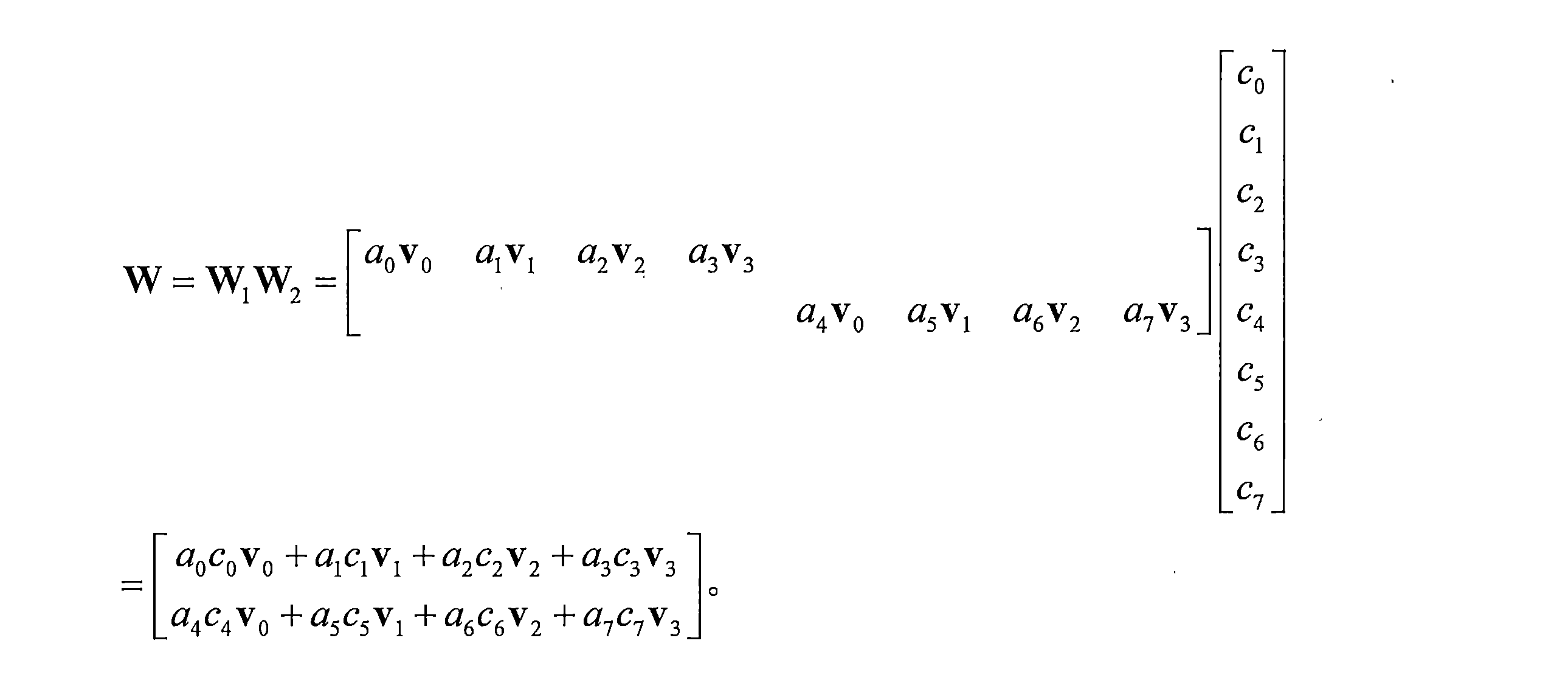
Wは、1つのトランスポート層、1つのサブバンド(すなわち、周波数領域ユニットの一例である)、および2つの偏波方向に対応するフィードバックされるプリコーディング行列を表す。W1は各広帯域のためにフィードバックされてもよく、W2は各サブバンドのためにフィードバックされてもよい。v0~v3は、W1に含まれるビームベクトルであり、複数のビームベクトルは、例えば、複数のビームベクトルの組み合わせのインデックスを用いて示されてもよい。上記のプリコーディング行列では、2つの偏波方向のビームベクトルは同じであり、ビームベクトルv0~v3は2つの偏波方向の両方で使用される。a0~a7は、W1に含まれる広帯域振幅係数であり、広帯域振幅係数の量子化値を用いて示すことができる。c0~c7は、W2に含まれるサブバンド係数であり、各サブバンド係数は、サブバンド振幅係数およびサブバンド位相係数を含むことができる。例えば、c0~c7は、それぞれサブバンド振幅係数p0~p7およびサブバンド位相係数φ0~φ7を含み、それぞれサブバンド振幅係数p0~p7の量子化値およびサブバンド位相係数φ0~φ7の量子化値を用いて示されてもよい。フィードバックされるプリコーディング行列は、複数のビームベクトルの加重総和と考えることができることが分かる。 W represents one transport layer, one subband (ie, an example of a frequency domain unit), and a feedback precoding matrix corresponding to two polarization directions. W 1 may be fed back for each wideband and W 2 may be fed back for each subband. v 0 to v 3 are beam vectors included in W 1 , and a plurality of beam vectors may be indicated by using, for example, an index of a combination of a plurality of beam vectors. In the precoding matrix above, the beam vectors in the two polarization directions are the same, and the beam vectors v 0 to v 3 are used in both of the two polarization directions. A 0 to a 7 are wideband amplitude coefficients included in W 1 , and can be shown by using the quantized value of the wide band amplitude coefficient. c 0 to c 7 are subband coefficients included in W 2 , and each subband coefficient can include a subband amplitude coefficient and a subband phase coefficient. For example, c 0 to c 7 include subband amplitude coefficients p 0 to p 7 and subband phase coefficients φ 0 to φ 7 , respectively, and the quantization values and subband phases of the subband amplitude coefficients p 0 to p 7 , respectively. It may be shown using a quantization value having a coefficient of φ 0 to φ 7 . It can be seen that the feedback precoding matrix can be thought of as the weighted sum of multiple beam vectors.
上記のプリコーディング行列は、1つのトランスポート層のフィードバックに基づいて取得され、したがって、プリコーディングベクトルとも呼ばれる場合があることを理解されたい。トランスポート層の量が増加すると、端末装置は、各トランスポート層に基づいてプリコーディングベクトルを別々にフィードバックすることができる。すべてのトランスポート層に基づいてフィードバックされたプリコーディングベクトルを使用して、1つのサブバンドのプリコーディング行列を構築することができる。例えば、トランスポート層の量が4である場合、プリコーディング行列は、4つのトランスポート層にそれぞれ対応する4つのプリコーディングベクトルを含み得る。 It should be understood that the above precoding matrix is obtained based on the feedback of one transport layer and is therefore sometimes referred to as the precoding vector. As the amount of transport layer increases, the terminal device can feed back the precoding vector separately based on each transport layer. Precoding vectors fed back based on all transport layers can be used to construct a precoding matrix for one subband. For example, if the amount of transport layer is 4, the precoding matrix may contain 4 precoding vectors corresponding to each of the 4 transport layers.
トランスポート層の量が増加するにつれて、端末装置のフィードバックオーバヘッドも増加する。例えば、トランスポート層の量が4である場合、a0~a7およびc0~c7のフィードバックオーバヘッドは、トランスポート層の量が1である場合に生じるフィードバックオーバヘッドの最大4倍に達する。言い換えれば、端末装置が各トランスポート層に基づいて前述の広帯域フィードバックおよびサブバンドフィードバックを実行する場合、トランスポート層の量が増加するにつれてフィードバックオーバヘッドが増加する。さらに、サブバンドの量が多いほど、フィードバックオーバヘッドの増加も大きくなる。したがって、PMIフィードバックオーバヘッドを低減する方法を提供することが期待される。 As the amount of transport layer increases, so does the feedback overhead of the terminal device. For example, if the amount of transport layer is 4, the feedback overhead of a 0 to a 7 and c 0 to c 7 reaches up to 4 times the feedback overhead that occurs when the amount of transport layer is 1. In other words, if the terminal device performs the aforementioned wideband feedback and subband feedback based on each transport layer, the feedback overhead increases as the amount of transport layer increases. In addition, the greater the amount of subbands, the greater the increase in feedback overhead. Therefore, it is expected to provide a method for reducing PMI feedback overhead.
PMIを介してプリコーディング行列をフィードバックする前述の列挙された方法は単なる例であり、本出願に対するいかなる限定も構成するべきではないことを理解されたい。例えば、端末装置は、代替としてPMIを介してチャネル行列をネットワーク装置にフィードバックしてもよく、ネットワーク装置は、プリコーディング行列を決定するために、PMIに基づいてチャネル行列を決定してもよい。これは本出願では限定されない。 It should be understood that the above-mentioned listed methods of feeding back the precoding matrix via PMI are merely examples and should not constitute any limitation to the present application. For example, the terminal device may feed back the channel matrix to the network device via the PMI as an alternative, and the network device may determine the channel matrix based on the PMI to determine the precoding matrix. This is not limited in this application.
4.プリコーディングベクトル:本出願の実施形態では、プリコーディングベクトルは、プリコーディング行列内の1つのベクトル、例えば1つの列ベクトルを使用することによって決定され得る。言い換えれば、プリコーディング行列は、1つまたは複数の列ベクトルを含むことができ、各列ベクトルは、1つのプリコーディングベクトルを決定するために使用されることができる。プリコーディング行列が1つの列ベクトルのみを含む場合、プリコーディング行列はプリコーディングベクトルと呼ばれることもある。 Four. Precoding Vectors: In embodiments of the present application, precoding vectors can be determined by using one vector within the precoding matrix, eg, one column vector. In other words, the precoding matrix can contain one or more column vectors, and each column vector can be used to determine one precoding vector. If the precoding matrix contains only one column vector, the precoding matrix is sometimes called the precoding vector.
プリコーディング行列は、1つまたは複数のトランスポート層のプリコーディングベクトルを使用することによって決定され得、プリコーディング行列内の各ベクトルは、1つのトランスポート層に対応し得る。プリコーディングベクトルがN1×1次元であり得ると仮定すると、トランスポート層の量がR(Rは正の整数)である場合、プリコーディング行列はN1×R次元であり得る。トランスポート層の量は、ランクインジケータ(rank indicator,RI)によって示すことができ、N1はアンテナポートの量を表すことができ、N1は正の整数である。 The precoding matrix can be determined by using the precoding vectors of one or more transport layers, and each vector in the precoding matrix can correspond to one transport layer. Assuming that the precoding vector can be N 1 × 1 dimension, the precoding matrix can be N 1 × R dimension if the amount of transport layer is R (R is a positive integer). The amount of transport layer can be indicated by a rank indicator (RI), where N 1 can represent the amount of antenna ports and N 1 is a positive integer.
送信アンテナに対して複数の偏波方向が構成される場合、プリコーディングベクトルは、代替的に、1つの偏波方向および1つのトランスポート層に対応するプリコーディング行列内の構成要素を指すことができる。偏波方向の量をP(Pは正の整数)とし、1つの偏波方向のアンテナポートの量をN2とすると、1つのトランスポート層に対応するプリコーディングベクトルは(P×N2)×1次元であり、1つの偏波方向のプリコーディングベクトルはN2×1次元であり得る。N2は、正の整数である。 If multiple polarization directions are configured for the transmit antenna, the precoding vector may instead point to a component in the precoding matrix that corresponds to one polarization direction and one transport layer. can. Assuming that the amount in the polarization direction is P (P is a positive integer) and the amount of antenna ports in one polarization direction is N 2 , the precoding vector corresponding to one transport layer is (P × N 2 ). It is × 1 dimension, and the precoding vector in one polarization direction can be N 2 × 1 dimension. N 2 is a positive integer.
したがって、プリコーディングベクトルは、1つのトランスポート層に対応してもよく、1つのトランスポート層における1つの偏波方向に対応してもよく、または別のパラメータに対応してもよい。これは本出願では限定されない。 Therefore, the precoding vector may correspond to one transport layer, one polarization direction in one transport layer, or another parameter. This is not limited in this application.
5.アンテナポート:アンテナポートは、略してポートと呼ばれる場合がある。アンテナポートは、受信装置によって識別される送信アンテナ、または空間的に区別され得る送信アンテナとして理解され得る。1つのアンテナポートが仮想アンテナごとに構成されてもよく、各仮想アンテナは複数の物理アンテナの重み付き組み合わせであってよく、各アンテナポートは1つの基準信号に対応し得る。したがって、各アンテナポートは、基準信号ポート、例えば、CSI-RSポートまたはサウンディング基準信号(sounding reference signal,SRS)ポートと呼ばれる場合がある。 Five. Antenna port: The antenna port is sometimes referred to as a port for short. The antenna port can be understood as a transmitting antenna identified by the receiving device, or a transmitting antenna that can be spatially distinguished. One antenna port may be configured for each virtual antenna, each virtual antenna may be a weighted combination of multiple physical antennas, and each antenna port may correspond to one reference signal. Therefore, each antenna port may be referred to as a reference signal port, eg, a CSI-RS port or a sounding reference signal (SRS) port.
6.ビームおよびビームベクトル:ビームは、空間内の方向にされた信号強度の分布として理解することができる。ビームフォーミングの技術は、ビームフォーミング技術または別の技術であってもよい。ビームフォーミング技術は、具体的には、デジタルビームフォーミング技術、アナログビームフォーミング技術、またはハイブリッドデジタル/アナログビームフォーミング技術であり得る。本出願の実施形態では、デジタルビームフォーミング技術を使用してビームを形成することができる。 6. Beams and Beam Vectors: Beams can be understood as a distribution of signal intensities oriented in space. The beamforming technique may be a beamforming technique or another technique. The beamforming technique can be specifically a digital beamforming technique, an analog beamforming technique, or a hybrid digital / analog beamforming technique. In embodiments of the present application, digital beamforming techniques can be used to form the beam.
ビームベクトルは、ビームに対応してもよく、プリコーディング行列におけるプリコーディングベクトルであってもよく、またはビームフォーミングベクトルであってもよい。ビームベクトル内の各要素は、各アンテナポートの重みを表すことができる。異なるアンテナポートにおける重み付き信号は、比較的強い信号強度を有する領域を形成するために重畳される。 The beam vector may correspond to a beam, may be a precoding vector in a precoding matrix, or may be a beamforming vector. Each element in the beam vector can represent the weight of each antenna port. Weighted signals at different antenna ports are superimposed to form regions with relatively strong signal strength.
本出願の実施形態では、ビームベクトルは空間領域ベクトルと呼ばれることもある。任意選択で、ビームベクトルの長さ(または次元)は、1つの偏波方向におけるアンテナポートの量である。 In embodiments of the present application, the beam vector may also be referred to as a spatial region vector. Optionally, the length (or dimension) of the beam vector is the amount of antenna ports in one polarization direction.
ビームベクトルの長さをNsと仮定する。ビームベクトルは、Ns×1次元の列ベクトルであってもよいし、1×Ns次元の行ベクトルであってもよい。これは本出願では限定されない。 Assume the length of the beam vector is N s . The beam vector may be an N s × 1-dimensional column vector or a 1 × N s -dimensional row vector. This is not limited in this application.
7.周波数領域ユニット:周波数領域ユニットは周波数領域リソースのユニットであり、異なる周波数領域リソース粒度を表すことができる。例えば、周波数領域ユニットは、サブバンド、リソースブロック(resource block,RB)、サブキャリア、リソースブロックグループ(resource block group,RBG)、プリコーディングリソースブロックグループ(precoding resource block group,PRG)を含み得るが、これらに限定されない。 7. 7. Frequency domain unit: A frequency domain unit is a unit of frequency domain resources and can represent different frequency domain resource granularity. For example, a frequency domain unit may include subbands, resource blocks (RBs), subcarriers, resource block groups (RBGs), and precoding resource block groups (PRGs). , Not limited to these.
8.周波数領域ベクトル:周波数領域ベクトルは、本出願の実施形態で提案され、周波数領域におけるチャネルの変更規則を示すために使用されるベクトルである。周波数領域ベクトルは、具体的には、周波数領域ユニット上の各ビームベクトルの重み係数の変更規則を表すために使用され得る。この変更規則は、多経路遅延に関連し得る。信号が無線チャネルを介して送信される場合、異なる伝搬経路上に異なる送信遅延が存在し得る。したがって、異なる伝搬経路上の遅延に起因してチャネルが周波数領域で変化するという規則を表すために、異なる周波数領域ベクトルが使用され得る。 8. Frequency domain vector: A frequency domain vector is a vector proposed in embodiments of the present application and used to indicate channel change rules in the frequency domain. The frequency domain vector can be specifically used to represent a rule of change of the weighting factor of each beam vector on the frequency domain unit. This change rule may be related to multipath delay. If the signal is transmitted over a radio channel, there may be different transmission delays on different propagation paths. Therefore, different frequency domain vectors can be used to represent the rule that channels change in the frequency domain due to delays on different propagation paths.
周波数領域ベクトルの次元は、CSI測定が実行される必要がある周波数領域ユニットの量であり得る。CSI測定を実行する必要がある周波数領域ユニットの数は異なる瞬間に異なる可能性があるため、周波数領域ベクトルの次元も変化し得る。言い換えれば、周波数領域ベクトルの次元は可変である。 The dimension of the frequency domain vector can be the quantity of frequency domain units for which a CSI measurement needs to be performed. Since the number of frequency domain units that need to perform CSI measurements can vary at different moments, the dimensions of the frequency domain vector can also change. In other words, the dimensions of the frequency domain vector are variable.
任意選択で、周波数領域ベクトルの長さ(または次元)は、CSI測定リソースの周波数領域占有帯域幅に含まれる周波数領域ユニットの量である。 Optionally, the length (or dimension) of the frequency domain vector is the amount of frequency domain units included in the frequency domain occupied bandwidth of the CSI measurement resource.
CSI測定リソースの周波数領域占有帯域幅は、基準信号を送信するために使用される帯域幅であってもよい。ここでの基準信号は、チャネル測定に使用される基準信号、例えばCSI-RSであってもよい。CSI測定リソースの周波数領域占有帯域幅は、例えば、パイロット送信帯域幅(または測定帯域幅と呼ばれる)以下であり得る。NRでは、例えば、CSI占有帯域幅範囲(CSI-Frequency Occupation)を使用して、CSI測定リソースの周波数領域占有帯域幅を示すことができる。 The frequency domain occupied bandwidth of the CSI measurement resource may be the bandwidth used to transmit the reference signal. The reference signal here may be a reference signal used for channel measurement, for example, CSI-RS. The frequency domain occupied bandwidth of the CSI measurement resource can be, for example, less than or equal to the pilot transmit bandwidth (or referred to as the measurement bandwidth). In NR, for example, the CSI-Frequency Occupation can be used to indicate the frequency domain occupied bandwidth of the CSI measurement resource.
CSI測定リソースの周波数領域占有帯域幅は、説明を簡単にするためだけに命名されており、本出願に対するいかなる限定も構成するべきではないことを理解されたい。本出願は、別の名称を使用することによって同じ意味を表す可能性を排除しない。 It should be understood that the frequency domain occupied bandwidth of the CSI measurement resource is named for simplicity of explanation only and should not constitute any limitation to this application. This application does not rule out the possibility of expressing the same meaning by using different names.
任意選択で、周波数領域ベクトルの長さは、報告される周波数領域ユニットの位置および量を示すために使用されるシグナリングの長さである。 Optionally, the frequency domain vector length is the length of the signaling used to indicate the position and quantity of the reported frequency domain unit.
NRでは、報告される周波数領域ユニットの位置および量を示すために使用されるシグナリングは、報告帯域(reporting band)であり得る。例えば、シグナリングは、ビットマップを介して、報告される周波数領域ユニットの位置および量を示すことができる。したがって、周波数領域ベクトルの次元は、ビットマップ内のビットの量であり得る。reporting bandは、シグナリングの可能な名称にすぎず、本出願に対するいかなる限定も構成するべきではないことを理解されたい。本出願は、同じまたは同様の機能を実装するために別の名前を使用してシグナリングを命名する可能性を排除しない。 In NR, the signaling used to indicate the location and quantity of reported frequency domain units can be the reporting band. For example, signaling can indicate the location and quantity of frequency domain units reported via a bitmap. Therefore, the dimension of the frequency domain vector can be the amount of bits in the bitmap. It should be understood that the reporting band is only a possible name for signaling and should not constitute any limitation on this application. This application does not rule out the possibility of naming signaling using different names to implement the same or similar functionality.
任意選択で、周波数領域ベクトルの長さは、報告される周波数領域ユニットの量である。 Optionally, the length of the frequency domain vector is the amount of frequency domain units reported.
例えば、報告される周波数領域ユニットの量は、前述のシグナリング、すなわち報告帯域を使用して示すことができる。報告される周波数領域ユニットは、CSI測定リソースの周波数領域占有帯域幅内のすべての周波数領域ユニットであってもよいし、CSI測定リソースの周波数領域占有帯域幅内のいくつかの周波数領域ユニットであってもよい。あるいは、報告される周波数領域ユニットの量は、報告帯域のシグナリング長と同じであってもよく、報告帯域のシグナリング長より短くてもよい。これは本出願では限定されない。 For example, the amount of frequency domain units reported can be indicated using the signaling, or reporting band, described above. The reported frequency domain units may be all frequency domain units within the frequency domain occupied bandwidth of the CSI measurement resource, or some frequency domain units within the frequency domain occupied bandwidth of the CSI measurement resource. May be. Alternatively, the amount of reported frequency domain units may be the same as the signaling length of the reporting band or shorter than the signaling length of the reporting band. This is not limited in this application.
プロトコルが周波数領域ベクトルの長さとして前述の列挙されたシグナリングのうちの1つを定義するとき、周波数領域ベクトルの長さは、CSI測定リソースの周波数領域占有帯域幅を示すために使用されるシグナリング、または報告される周波数領域ユニットの位置および量を示すために使用されるシグナリングによって暗黙的に示されると考えることができる。区別および説明を容易にするために、周波数領域ベクトルの長さを示すために使用される情報は、第5の指示情報として示される。第5の指示情報は、CSI測定リソースの周波数領域占有帯域幅を示すために使用されるシグナリングであってもよく、報告される周波数領域ユニットの位置および量を示すために使用されるシグナリングであってもよく、将来のプロトコルで新たに追加されるシグナリングであってもよい。これは本出願では限定されない。 When the protocol defines one of the above listed signaling as the length of the frequency domain vector, the length of the frequency domain vector is the signaling used to indicate the frequency domain occupied bandwidth of the CSI measurement resource. , Or can be considered implicitly indicated by the signaling used to indicate the location and quantity of the reported frequency domain units. For ease of distinction and description, the information used to indicate the length of the frequency domain vector is shown as the fifth instructional information. The fifth instructional information may be the signaling used to indicate the frequency domain occupied bandwidth of the CSI measurement resource, or the signaling used to indicate the location and quantity of the reported frequency domain units. It may be a signaling newly added in a future protocol. This is not limited in this application.
周波数領域ベクトルの長さをNfとすると、周波数領域ベクトルは、Nf×1次元の列ベクトルであってもよいし、1×Nf次元の行ベクトルであってもよい。これは本出願では限定されない。 Assuming that the length of the frequency domain vector is N f , the frequency domain vector may be an N f × 1-dimensional column vector or a 1 × N f -dimensional row vector. This is not limited in this application.
9.空間周波数行列および空間周波数ベクトル:同じトランスポート層における異なる周波数領域ユニットのプリコーディングベクトルを使用して、トランスポート層に対応する空間周波数行列または空間周波数ベクトルを構築することができる。説明を容易にするために、以下では空間周波数行列および空間周波数ベクトルをまとめて空間周波数情報と呼ぶ場合がある。 9. Spatial Frequency Matrix and Spatial Frequency Vectors: Precoding vectors of different frequency region units in the same transport layer can be used to construct the spatial frequency matrix or spatial frequency vector corresponding to the transport layer. In the following, for ease of explanation, the spatial frequency matrix and the spatial frequency vector may be collectively referred to as spatial frequency information.
理解および説明を容易にするために、空間周波数情報は、送信アンテナの偏波方向の量が1である例を使用して最初に説明される。送信アンテナの偏波方向の量が1である場合、1つのトランスポート層における異なる周波数領域ユニットのプリコーディングベクトルを使用して、偏波方向に対応する空間周波数情報を構築することができる。 For ease of understanding and explanation, spatial frequency information is first described using an example in which the amount in the direction of polarization of the transmitting antenna is 1. When the amount of polarization direction of the transmitting antenna is 1, the precoding vectors of different frequency domain units in one transport layer can be used to construct spatial frequency information corresponding to the polarization direction.
一例として、空間周波数行列が使用される。本出願の実施形態では、例えば、端末装置は、1つのトランスポート層に対応する空間周波数行列を取得するために、チャネル測定を通じて、または別の方法で、周波数領域ユニット上のフィードバックされるプリコーディング行列を決定し、周波数領域ユニット上のフィードバックされるプリコーディング行列を処理することができる。例えば、空間周波数行列を取得するために、同じトランスポート層にある周波数領域ユニットのフィードバックされるプリコーディングベクトルを組み合わせることができる。空間周波数行列は、フィードバックされる空間周波数行列と呼ばれる場合がある。 As an example, a spatial frequency matrix is used. In embodiments of the present application, for example, the terminal device is precoding that is fed back on the frequency domain unit through channel measurement or otherwise to obtain the spatial frequency matrix corresponding to one transport layer. The matrix can be determined and the precoding matrix fed back on the frequency domain unit can be processed. For example, feedback precoding vectors of frequency domain units in the same transport layer can be combined to obtain a spatial frequency matrix. The spatial frequency matrix may be referred to as a feedback spatial frequency matrix.
端末装置が空間周波数ベクトルを決定する方式は、端末装置が空間周波数行列を決定する方式と同じである。同じトランスポート層の周波数領域ユニットのプリコーディングベクトル内の要素(空間周波数行列の各列ベクトル内の要素に対応する)を順次接続することによって得られるベクトルは、空間周波数ベクトルである。空間周波数ベクトルは、フィードバックされる空間周波数ベクトルと呼ばれる場合がある。 The method by which the terminal device determines the spatial frequency vector is the same as the method by which the terminal device determines the spatial frequency matrix. The vector obtained by sequentially connecting the elements in the precoding vector of the frequency region unit of the same transport layer (corresponding to the elements in each column vector of the spatial frequency matrix) is the spatial frequency vector. The spatial frequency vector may be referred to as the fed back spatial frequency vector.
具体的には、空間周波数行列は、Ns×Nf次元の行列であってもよい。言い換えれば、空間周波数行列は、各々がNsの長さを有するNf個の列ベクトルを含むことができる。Nf個の列ベクトルはNf個の周波数領域ユニットに対応してもよく、各列ベクトルは対応する周波数領域ユニットのプリコーディングベクトルを決定するために使用されてもよい。 Specifically, the spatial frequency matrix may be an N s × N f -dimensional matrix. In other words, the spatial frequency matrix can contain N f column vectors, each of which has a length of N s . N f column vectors may correspond to N f frequency domain units, and each column vector may be used to determine the precoding vector of the corresponding frequency domain unit.
例えば、空間周波数行列は、Hとして表されてもよく、ここで


空間周波数ベクトルは、(Ns×Nf)×1次元のベクトルであってもよい。言い換えれば、空間周波数ベクトルは、長さがNs×Nfである1つの列ベクトルまたは行ベクトルを含んでもよい。この場合、ベクトルは行列の表現形式ともみなされ得るので、空間周波数ベクトルは空間周波数行列とも呼ばれるか、またはそれに置き換えられ得る。本出願の実施形態では、空間周波数ベクトルは単に区別を容易にするために使用される。 The spatial frequency vector may be a (N s × N f ) × one-dimensional vector. In other words, the spatial frequency vector may include one column vector or row vector of length N s × N f . In this case, the spatial frequency vector can also be referred to or replaced by the spatial frequency matrix, since the vector can also be considered as a representation of the matrix. In embodiments of this application, spatial frequency vectors are used solely to facilitate distinction.
空間周波数ベクトルは、事前定義された規則に従ってプリコーディングベクトル内の要素を連結または編成することによって得られるベクトルであってもよい。 The spatial frequency vector may be a vector obtained by concatenating or organizing the elements in the precoding vector according to a predefined rule.
可能な設計では、空間周波数ベクトルをhと表すことができ、ここで

前述の例における空間周波数ベクトルは単なる例であることを理解されたい。空間周波数ベクトルは、必ずしもプリコーディングベクトルをヘッド-テール方式で接続することに限定されず、プリコーディングベクトルは、代替的に、固定規則に従って配置されてもよい。例えば、配置規則は、要素に基づいてもよい。例えば、ベクトル内の第1の要素は、新しいベクトルを構成する。 It should be understood that the spatial frequency vector in the above example is just an example. The spatial frequency vector is not necessarily limited to connecting the precoding vectors in a head-tail manner, and the precoding vectors may be arranged according to a fixed rule instead. For example, placement rules may be element-based. For example, the first element in a vector constitutes a new vector.
上記は、理解を容易にするために、偏波方向の量が1である場合の空間周波数情報のいくつかの可能な形態、例えば、Ns×Nf次元の空間周波数行列または長さがNs×Nfである空間周波数ベクトルを説明しているにすぎないことをさらに理解されたい。ただし、これは本出願の限定を構成するものではない。偏波方向の量が1より大きい場合、空間周波数情報は、前述のいくつかの列挙された形態を使用して依然として表すことができる。しかしながら、空間周波数行列または空間周波数ベクトルの次元は、偏波方向の量によって変化し得る。例えば、偏波方向の量が2である場合、空間周波数情報は、2Ns×Nf次元の空間周波数行列として表されてもよいし、長さが2Ns×Nfの空間周波数ベクトルとして表されてもよい。2は2つの偏波方向があることを表す。 The above, for ease of understanding, are some possible forms of spatial frequency information when the quantity in the direction of polarization is 1, eg, a spatial frequency matrix of N s × N f dimensions or a length of N. It should be further understood that it merely explains the spatial frequency vector of s × N f . However, this does not constitute a limitation of this application. If the amount in the direction of polarization is greater than 1, spatial frequency information can still be represented using some of the listed forms described above. However, the dimensions of the spatial frequency matrix or spatial frequency vector can vary with quantities in the direction of polarization. For example, if the quantity in the polarization direction is 2, the spatial frequency information may be represented as a 2N s × N f -dimensional spatial frequency matrix or as a spatial frequency vector with a length of 2N s × N f . May be done. 2 indicates that there are two polarization directions.
10.空間周波数ユニット:1つの空間周波数基本ユニットは、1つのビームベクトルおよび1つの周波数領域ベクトルを使用して一意に決定され得る。本出願の実施形態では、空間周波数基本ユニットは、空間周波数ユニットと呼ばれる場合がある。ビームベクトルは、事前定義されたビームベクトルセットから取得されてもよく、周波数領域ベクトルは、事前定義された周波数領域ベクトルセットから取得されてもよい。空間周波数ユニットはまた、事前定義された空間周波数ユニットセットから取得されてもよい。空間周波数ユニットセット内の各空間周波数ユニットは、1つのビームベクトルおよび1つの周波数領域ベクトルを使用して一意に決定され得る。したがって、ビームベクトルセット、周波数領域ベクトルセット、および空間周波数ユニットセットは、相互に変換され得る。 Ten. Spatial frequency unit: One spatial frequency fundamental unit can be uniquely determined using one beam vector and one frequency domain vector. In embodiments of the present application, the spatial frequency basic unit may be referred to as the spatial frequency unit. The beam vector may be obtained from a predefined beam vector set and the frequency domain vector may be obtained from a predefined frequency domain vector set. Spatial frequency units may also be obtained from a predefined set of spatial frequency units. Each spatial frequency unit within the spatial frequency unit set can be uniquely determined using one beam vector and one frequency domain vector. Therefore, the beam vector set, frequency domain vector set, and spatial frequency unit set can be converted to each other.
本出願の実施形態では、空間周波数ユニットは、例えば、空間周波数構成要素行列、空間周波数構成要素ベクトル、または空間周波数ベクトル対であってもよい。 In embodiments of the present application, the spatial frequency unit may be, for example, a spatial frequency component matrix, a spatial frequency component vector, or a spatial frequency vector pair.
空間周波数構成要素行列は、Ns×Nf次元の行列であってもよい。例えば、ビームベクトルと周波数領域ベクトルの両方が列ベクトルである場合、1つの空間周波数構成要素行列は、1つのビームベクトルと1つの周波数領域ベクトルの共役転置との積であり得る。ビームベクトルが列ベクトルであり、周波数領域ベクトルが行ベクトルである場合、1つの空間周波数構成要素行列は、代替的に、1つのビームベクトルと1つの周波数領域ベクトルとの積であってもよい。空間周波数行列は、1つまたは複数の空間周波数構成要素行列のほぼ加重総和であり得る。端末装置は、1つまたは複数の空間周波数構成要素行列の加重総和を使用して、フィードバックされる空間周波数行列を示すことができる。 The spatial frequency component matrix may be an N s × N f dimension matrix. For example, if both the beam vector and the frequency domain vector are column vectors, then one spatial frequency component matrix can be the product of one beam vector and a conjugate translocation of one frequency domain vector. If the beam vector is a column vector and the frequency region vector is a row vector, then one spatial frequency component matrix may be an alternative product of one beam vector and one frequency region vector. The spatial frequency matrix can be an approximately weighted sum of one or more spatial frequency component matrices. The terminal device can use the weighted sum of one or more spatial frequency component matrices to indicate the spatial frequency matrix to be fed back.
空間周波数構成要素ベクトルは、長さがNs×Nfのベクトルであってもよい。例えば、ビームベクトルと周波数領域ベクトルの両方が列ベクトルである場合、1つの空間周波数構成要素ベクトルは、1つのビームベクトルと1つの周波数領域ベクトルとのクロネッカー積であってもよいし、1つの周波数領域ベクトルと1つのビームベクトルとのクロネッカー積であってもよい。空間周波数ベクトルは、1つまたは複数の空間周波数構成要素ベクトルのほぼ加重総和であってもよい。端末装置は、1つまたは複数の空間周波数構成要素ベクトルの加重総和を用いてフィードバックされる空間周波数ベクトルを示すことができる。加えて、ベクトルは行列の表現形式ともみなされ得るので、空間周波数構成要素ベクトルは空間周波数構成要素行列とも呼ばれるか、またはそれに置き換えられ得る。本出願の実施形態では、空間周波数構成要素ベクトルは単に区別を容易にするために使用される。 The spatial frequency component vector may be a vector of length N s × N f . For example, if both the beam vector and the frequency region vector are column vectors, then one spatial frequency component vector may be the Kronecker product of one beam vector and one frequency region vector, or one frequency. It may be a Kronecker product of a region vector and one beam vector. The spatial frequency vector may be an approximately weighted sum of one or more spatial frequency component vectors. The terminal device can indicate a spatial frequency vector that is fed back using a weighted sum of one or more spatial frequency component vectors. In addition, since the vector can also be regarded as a representation of the matrix, the spatial frequency component vector can also be referred to or replaced by the spatial frequency component matrix. In embodiments of this application, spatial frequency component vectors are used solely to facilitate distinction.
空間周波数構成要素ベクトルが周波数領域ベクトルとビームベクトルとのクロネッカー積に基づいて決定される場合、複数の空間周波数構成要素ベクトルの加重総和に基づいて決定される空間周波数ベクトルは、各々がNsの長さを有するNf個の列ベクトルを順次接続することによって取得され得る。Nf個の列ベクトルはNf個の周波数領域ユニットに対応してもよく、各列ベクトルは対応する周波数領域ユニットのプリコーディングベクトルを決定するために使用されてもよい。 If the spatial frequency component vector is determined based on the Kronecker product of the frequency region vector and the beam vector, then the spatial frequency vector determined based on the weighted sum of the multiple spatial frequency component vectors is each N s . It can be obtained by sequentially connecting N f column vectors with length. N f column vectors may correspond to N f frequency domain units, and each column vector may be used to determine the precoding vector of the corresponding frequency domain unit.
空間周波数構成要素ベクトルがビームベクトルと周波数領域ベクトルとのクロネッカー積に基づいて決定される場合、複数の空間周波数構成要素ベクトルの加重総和に基づいて決定される空間周波数ベクトルは、各々がNfの長さを有するNs個の列ベクトルを順次接続することによって取得され得る。各列ベクトル内のNf個の要素は、Nf個の周波数領域ユニットに対応し得る。Ns個の列ベクトル内の要素nfは、長さがNsであるベクトルを取得するために順次接続され、ベクトルは、周波数領域ユニットnfのプリコーディングベクトルを決定するために使用され得る。0≦nf≦Nf-1であり、nfは整数である。 When the spatial frequency component vector is determined based on the Kronecker product of the beam vector and the frequency region vector, the spatial frequency vector determined based on the weighted sum of the plurality of spatial frequency component vectors is N f , respectively. It can be obtained by sequentially connecting N s column vectors with length. N f elements in each column vector can correspond to N f frequency domain units. The elements n f in the N s column vector are sequentially connected to obtain a vector of length N s , and the vector can be used to determine the precoding vector for the frequency domain unit n f . .. 0 ≤ n f ≤ N f -1, and n f is an integer.
空間周波数構成要素行列および空間周波数構成要素ベクトルはそれぞれ、1つのビームベクトルおよび1つの周波数領域ベクトルの演算によって取得され得る。ビームベクトルおよび周波数領域ベクトルに対して操作が行われない場合、ビームベクトルおよび周波数領域ベクトルは、1つの空間周波数ベクトル対を決定するために使用され得る。空間周波数ベクトル対は、1つのビームベクトルおよび1つの周波数領域ベクトルを含むことができる。空間周波数構成要素行列、空間周波数構成要素ベクトル、および空間周波数ベクトル対は、相互に変換されてもよく、同じビームベクトルおよび同じ周波数領域ベクトルを使用して決定されてもよいことが理解されよう。3つの用語は等価であると考えてもよい。 The spatial frequency component matrix and the spatial frequency component vector can be obtained by the operation of one beam vector and one frequency domain vector, respectively. If no manipulation is performed on the beam vector and frequency domain vector, the beam vector and frequency domain vector can be used to determine one spatial frequency vector pair. Spatial frequency vector pairs can include one beam vector and one frequency domain vector. It will be appreciated that the spatial frequency component matrix, spatial frequency component vector, and spatial frequency vector pair may be converted to each other or determined using the same beam vector and the same frequency region vector. The three terms may be considered equivalent.
本出願の実施形態では、空間周波数ユニットは1つの偏波方向に対応し得る。さらに、基本ユニットの加重総和を使用して、複数の偏波方向の空間周波数行列または空間周波数ベクトルを構築することができる。したがって、各偏波方向に対応する空間周波数情報は、複数の空間周波数ユニットの加重総和によって表されてもよい。言い換えれば、各偏波方向に対応する空間周波数情報は、複数の空間周波数ユニットの加重総和として近似的に表されてもよい。異なる偏波方向で使用される複数の空間周波数ユニットは同じであってもよい。言い換えれば、複数の同じ空間周波数ユニットが複数の偏波方向で共有されてもよい。言い換えれば、同じトランスポート層における複数の偏波方向の空間周波数行列または空間周波数ベクトルは、同じグループのビームベクトルおよび同じグループの周波数領域ベクトルを使用して構築され得る。しかしながら、異なる偏波方向における空間周波数構成要素行列または空間周波数構成要素ベクトルの重み係数は異なっていてもよい。 In embodiments of the present application, the spatial frequency unit may correspond to one polarization direction. In addition, the weighted sums of the basic units can be used to construct spatial frequency matrices or spatial frequency vectors in multiple polarization directions. Therefore, the spatial frequency information corresponding to each polarization direction may be represented by the weighted sum of a plurality of spatial frequency units. In other words, the spatial frequency information corresponding to each polarization direction may be approximately expressed as a weighted sum of a plurality of spatial frequency units. Multiple spatial frequency units used in different polarization directions may be the same. In other words, a plurality of the same spatial frequency units may be shared in a plurality of polarization directions. In other words, a spatial frequency matrix or spatial frequency vector in multiple polarization directions in the same transport layer can be constructed using the same group of beam vectors and the same group of frequency domain vectors. However, the weighting coefficients of the spatial frequency component matrix or the spatial frequency component vector in different polarization directions may be different.
空間周波数行列および空間周波数ベクトルの特定の形態は、前述の例に限定されないことを理解されたい。簡潔にするために、例は、本明細書において1つずつ列挙されない。以下に示す実施形態では、端末装置がプリコーディングベクトルを示し、ネットワーク装置がプリコーディングベクトルを決定する具体的なプロセスは、空間周波数構成要素行列がビームベクトルと周波数領域ベクトルの共役転置との積であり、空間周波数構成要素ベクトルが周波数領域ベクトルとビームベクトルとのクロネッカー積である2つの形式を参照して詳細に説明される。ただし、これは本出願の限定を構成するものではない。同じ概念に基づいて、当業者は、空間周波数構成要素行列または空間周波数構成要素ベクトルに対して等価な変換または置換を実行することができ、等価な変換および置換は、本出願の保護範囲内に入るものとする。 It should be understood that the particular forms of spatial frequency matrices and spatial frequency vectors are not limited to the above examples. For brevity, the examples are not listed one by one herein. In the embodiment shown below, the terminal device indicates the precoding vector, and the network device determines the precoding vector. The specific process is that the spatial frequency component matrix is the product of the beam vector and the conjugate transpose of the frequency region vector. Yes, the spatial frequency component vector is described in detail with reference to the two forms of the Kronecker product of the frequency region vector and the beam vector. However, this does not constitute a limitation of this application. Based on the same concept, one of ordinary skill in the art can perform equivalent conversions or substitutions on spatial frequency component matrices or spatial frequency component vectors, which are within the scope of the protection of the present application. Shall enter.
11.ビームベクトルセット、周波数領域ベクトルセット、および空間周波数ユニットセット:ビームベクトルセットは、複数のビームベクトルを含むことができる。各ビームベクトルの長さはNsであってもよく、Nsは各偏波方向のアンテナポートの量を表してもよい。 11. 11. A beam vector set can include multiple beam vectors: a beam vector set, a frequency domain vector set, and a spatial frequency unit set. The length of each beam vector may be N s , where N s may represent the amount of antenna ports in each polarization direction.
可能な設計では、ビームベクトルセットはNs個のビームベクトルを含むことができ、Ns個のビームベクトルは互いに直交することができる。ビームベクトルセット内の各ビームベクトルは、2次元(2 dimension,2D)-DFT行列から取得することができる。2Dは、2つの異なる方向、例えば、水平方向および垂直方向を表すことができる。 In a possible design, the beam vector set can contain N s beam vectors, and the N s beam vectors can be orthogonal to each other. Each beam vector in the beam vector set can be obtained from a two-dimensional (2D) -DFT matrix. 2D can represent two different directions, eg horizontal and vertical.
例えば、Ns個のビームベクトルは、


別の可能な設計では、ビームベクトルセットは、オーバサンプリングファクタOsを使用してOs×Ns個のビームベクトルに拡張されてもよい。この場合、ビームベクトルセットはOs個のサブセットを含み得、各サブセットはNs個のビームベクトルを含み得る。各サブセット内のNs個のビームベクトルは、互いに直交していてもよい。ビームベクトルセット内の各ビームベクトルは、オーバサンプリングされた2D-DFT行列から取得され得る。オーバサンプリングファクタOsは正の整数である。具体的には、Os=O1×O2であり、O1は水平方向のオーバサンプリングファクタであり、O2は垂直方向のオーバサンプリングファクタであってもよい。O1≧1、O2≧1であり、O1とO2は同時に1になることはできず、O1とO2は両方とも整数である。 In another possible design, the beam vector set may be extended to Os × N s beam vectors using the oversampling factor Os. In this case, the beam vector set may contain Os subsets, and each subset may contain N s beam vectors. The N s beam vectors in each subset may be orthogonal to each other. Each beam vector in the beam vector set can be obtained from the oversampled 2D-DFT matrix. The oversampling factor Os is a positive integer. Specifically, Os = O 1 × O 2 , O 1 may be a horizontal oversampling factor, and O 2 may be a vertical oversampling factor. O 1 ≧ 1, O 2 ≧ 1, O 1 and O 2 cannot be 1 at the same time, and both O 1 and O 2 are integers.
例えば、ビームベクトルセット内のサブセットos((式中、0≦os≦Os-1であり、osは整数である))内のNs個のビームベクトルは、それぞれ


周波数領域ベクトルセットは、複数の周波数領域ベクトルを含むことができる。各周波数領域ベクトルの長さは、Nfとして表すことができる。以上、Nfの意味について詳細に説明した。簡潔にするために、ここで再度詳細は説明しない。 A frequency domain vector set can include multiple frequency domain vectors. The length of each frequency domain vector can be expressed as N f . The meaning of N f has been explained in detail above. For the sake of brevity, I won't go into details here again.
可能な設計では、周波数領域ベクトルセットはNf個の周波数領域ベクトルを含むことができる。Nf個の周波数領域ベクトルは互いに直交してもよい。周波数領域ベクトルセット内の各周波数領域ベクトルは、DFT行列から取得され得る。 In a possible design, the frequency domain vector set can contain N f frequency domain vectors. N f frequency domain vectors may be orthogonal to each other. Each frequency domain vector in the frequency domain vector set can be obtained from the DFT matrix.
例えば、Nf個の周波数領域ベクトルは、


別の可能な設計では、周波数領域ベクトルセットは、オーバサンプリングファクタOfを使用して、Of×Nf周波数領域ベクトルに拡張され得る。この場合、周波数領域ベクトルセットはOf個のサブセットを含むことができ、各サブセットはNf個の周波数領域ベクトルを含むことができる。各サブセット内のNf個の周波数領域ベクトルは、互いに直交し得る。周波数領域ベクトルセット内の各周波数領域ベクトルは、オーバサンプリングされたDFT行列から取得され得る。オーバサンプリングファクタOfは正の整数である。 In another possible design, the frequency domain vector set can be extended to the Of x N f frequency domain vector using the oversampling factor Of. In this case, the frequency domain vector set can contain Of subsets, and each subset can contain N f frequency domain vectors. The N f frequency domain vectors in each subset can be orthogonal to each other. Each frequency domain vector in the frequency domain vector set can be obtained from the oversampled DFT matrix. The oversampling factor Of is a positive integer.
例えば、周波数領域ベクトルセット内の(ここで、0≦of≦Of-1であり、ofは整数である)のサブセットof内のNf個の周波数領域ベクトルは、それぞれ


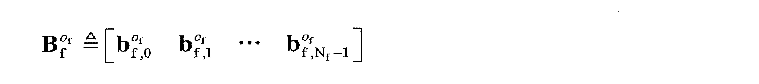
空間周波数ユニットセットは、例えば、空間周波数構成要素行列セットまたは空間周波数構成要素ベクトルセットを含んでもよい。 The spatial frequency unit set may include, for example, a spatial frequency component matrix set or a spatial frequency component vector set.
空間周波数構成要素行列セットは、複数の空間周波数構成要素行列を含むことができる。各空間周波数構成要素行列は、Ns×Nf次元の行列であってもよい。 A spatial frequency component matrix set can include a plurality of spatial frequency component matrices. Each spatial frequency component matrix may be an N s × N f dimension matrix.
可能な設計では、空間周波数構成要素行列セットはNs×Nf個の空間周波数構成要素行列を含み得る。空間周波数構成要素行列セット内の各空間周波数構成要素行列は、ビームベクトルセット内の1つのビームベクトルおよび周波数領域ベクトルセット内の1つの周波数領域ベクトルを使用することによって一意に決定され得る。したがって、ビームベクトルセット、周波数領域ベクトルセット、および空間周波数構成要素行列セットを相互に変換することができる。 In a possible design, the spatial frequency component matrix set may contain N s × N f spatial frequency component matrices. Each spatial frequency component matrix in the spatial frequency component matrix set can be uniquely determined by using one beam vector in the beam vector set and one frequency domain vector in the frequency domain vector set. Therefore, the beam vector set, the frequency domain vector set, and the spatial frequency component matrix set can be converted to each other.
具体的には、ビームベクトルセット内のNs個のビームベクトルをそれぞれ


Ns×Nf個の空間周波数構成要素行列の配置シーケンスは事前定義されてもよい。 The arrangement sequence of N s × N f spatial frequency component matrices may be predefined.
例えば、Ns×Nf個の空間周波数構成要素行列を取得するために、周波数領域ベクトル0~Nf-1が最初にトラバースされ、次いでビームベクトル0~Ns-1がトラバースされる。 For example, the frequency domain vectors 0 to N f -1 are traversed first, and then the beam vectors 0 to N s -1 are traversed to obtain N s x N f spatial frequency component matrices.
各空間周波数構成要素行列が1つのビームベクトルと1つの周波数領域ベクトルの共役転置行列の積である場合、空間周波数構成要素行列セット内の空間周波数構成要素行列の配置シーケンスは、

各空間周波数構成要素行列が1つの周波数領域ベクトルと1つのビームベクトルとのクロネッカー積である場合、空間周波数構成要素行列セット内の空間周波数構成要素行列の配置シーケンスは、

ビームベクトル0~Ns-1を最初にトラバースすることができ、次いで周波数領域ベクトル0~Nf-1をトラバースして、Ns×Nf個の空間周波数構成要素行列を取得する。 The beam vectors 0 to N s -1 can be traversed first, and then the frequency domain vectors 0 to N f -1 are traversed to obtain N s x N f spatial frequency component matrices.
各空間周波数構成要素行列が1つのビームベクトルと1つの周波数領域ベクトルの共役転置行列の積である場合、空間周波数構成要素行列セット内の空間周波数構成要素行列の配置シーケンスは、
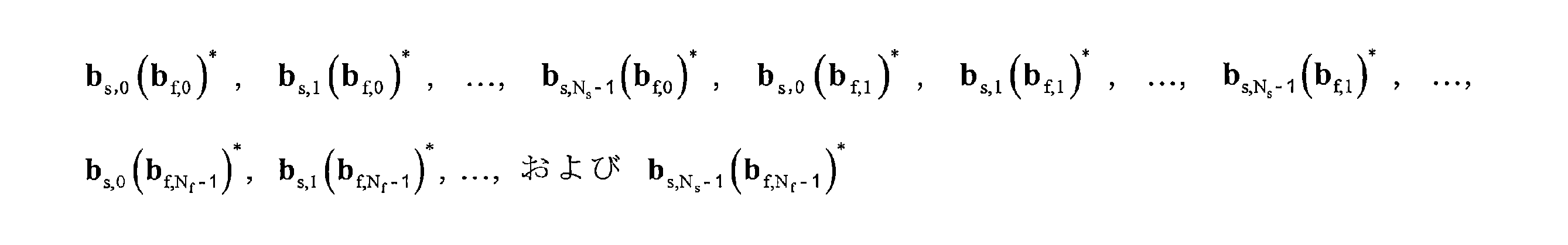
空間周波数構成要素行列セットおよびビームベクトルセットが決定されると、周波数領域ベクトルセットも推定され得ることが分かる。または、空間周波数構成要素行列セットおよび周波数領域ベクトルセットが決定されると、ビームベクトルセットも推定され得る。 Once the spatial frequency component matrix set and beam vector set have been determined, it can be seen that the frequency domain vector set can also be estimated. Alternatively, once the spatial frequency component matrix set and frequency domain vector set have been determined, the beam vector set can also be estimated.
別の可能な設計では、空間周波数構成要素行列セットは、Oc×Ns×Nf個の空間周波数構成要素行列を含み得る。具体的には、空間周波数構成要素行列セットは、オーバサンプリングファクタOcを使用してOcサブセットに拡張され得る。Ocは、Os、Of、またはOs×Ofであり得る。Ocの値は、空間周波数構成要素行列を構築するために使用されるビームベクトルセットおよび周波数領域ベクトルセットがオーバサンプリングされるかどうかに関連し得る。例えば、ビームベクトルセットがオーバサンプリングされず、周波数領域ベクトルセットがオーバサンプリングされる場合、空間周波数構成要素行列セットのオーバサンプリングファクタはOfであり得る。周波数領域ベクトルセットがオーバサンプリングされ、ビームベクトルセットがオーバサンプリングされない場合、空間周波数構成要素行列セットのオーバサンプリングファクタはOsであり得る。ビームベクトルセットと周波数領域ベクトルセットの両方がオーバサンプリングされる場合、空間周波数構成要素行列セットのオーバサンプリングファクタはOs×Ofであり得る。 In another possible design, the spatial frequency component matrix set may contain O c x N s x N f spatial frequency component matrices. Specifically, the spatial frequency component matrix set can be extended to an O c subset using the oversampling factor O c . O c can be Os , Of , or Os × Of. The value of O c may be related to whether the beam vector set and frequency domain vector set used to construct the spatial frequency component matrix are oversampled. For example, if the beam vector set is not oversampled and the frequency domain vector set is oversampled , the oversampling factor of the spatial frequency component matrix set can be Of. If the frequency domain vector set is oversampled and the beam vector set is not oversampled, the oversampling factor for the spatial frequency component matrix set can be Os . If both the beam vector set and the frequency domain vector set are oversampled, the oversampling factor of the spatial frequency component matrix set can be Os × Of.
空間周波数構成要素行列セット内の各空間周波数構成要素行列は、ビームベクトルセット内の1つのビームベクトルおよび周波数領域ベクトルセット内の1つの周波数領域ベクトルを使用することによって一意に決定され得る。したがって、ビームベクトルセット、周波数領域ベクトルセット、および空間周波数構成要素行列セットを相互に変換することができる。 Each spatial frequency component matrix in the spatial frequency component matrix set can be uniquely determined by using one beam vector in the beam vector set and one frequency domain vector in the frequency domain vector set. Therefore, the beam vector set, the frequency domain vector set, and the spatial frequency component matrix set can be converted to each other.
上記では、オーバサンプリングレートが考慮されない場合を参照して、ビームベクトルセット、周波数領域ベクトルセット、および空間周波数構成要素行列セットの間の変換関係について詳細に説明した。オーバサンプリングレートを考慮すると、ビームベクトルセット、周波数領域ベクトルセット、および空間周波数構成要素行列セットの間の変換関係は、上述した関係と同様である。簡潔にするために、ここで再度詳細は説明しない。 In the above, the transformation relationship between the beam vector set, the frequency domain vector set, and the spatial frequency component matrix set has been described in detail with reference to the case where the oversampling rate is not considered. Considering the oversampling rate, the transformation relationship between the beam vector set, the frequency domain vector set, and the spatial frequency component matrix set is similar to the relationship described above. For the sake of brevity, I won't go into details here again.
空間周波数構成要素行列セットと同様に、空間周波数構成要素ベクトルセットは、複数の空間周波数構成要素ベクトルを含むことができる。各空間周波数構成要素ベクトルは、長さがNs×Nfのベクトルであってもよい。 Similar to the spatial frequency component matrix set, the spatial frequency component vector set can include multiple spatial frequency component vectors. Each spatial frequency component vector may be a vector of length N s × N f .
可能な設計では、空間周波数構成要素ベクトルセットはNs×Nf個の空間周波数構成要素ベクトルを含むことができる。別の可能な設計では、空間周波数構成要素ベクトルセットは、オーバサンプリングファクタOcを使用してOc×Ns×Nf空間周波数構成要素ベクトルに拡張される。 In a possible design, the spatial frequency component vector set can contain N s × N f spatial frequency component vectors. In another possible design, the spatial frequency component vector set is extended to the O c × N s × N f spatial frequency component vector using the oversampling factor O c .
各空間周波数構成要素ベクトルが1つの周波数領域ベクトルと1つのビームベクトルとのクロネッカー積である場合、空間周波数構成要素ベクトルセット内の空間周波数構成要素ベクトルの配置シーケンスは、
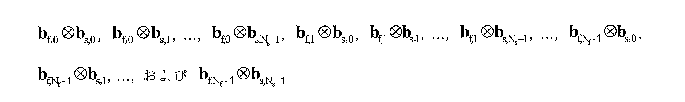
空間周波数構成要素ベクトルセット内の各空間周波数構成要素ベクトルは、ビームベクトルセット内の1つのビームベクトルおよび周波数領域ベクトルセット内の1つの周波数領域ベクトルを使用することによって一意に決定され得る。したがって、ビームベクトルセット、周波数領域ベクトルセット、および空間周波数構成要素ベクトルセットを相互に変換することができる。 Each spatial frequency component vector in the spatial frequency component vector set can be uniquely determined by using one beam vector in the beam vector set and one frequency domain vector in the frequency domain vector set. Therefore, the beam vector set, the frequency domain vector set, and the spatial frequency component vector set can be converted to each other.
以上、空間周波数構成要素行列セット、ビームベクトルセット、および周波数領域ベクトルセットの間の関係について詳細に説明した。簡潔にするために、空間周波数構成要素ベクトルセットの詳細な説明はここでは省略する。 The relationship between the spatial frequency component matrix set, the beam vector set, and the frequency domain vector set has been described in detail above. For the sake of brevity, a detailed description of the spatial frequency component vector set is omitted here.
12.重み係数、振幅、および位相:重み係数は、加重加算に使用される各空間周波数ユニットの重みを表すために使用される。例えば、上述の空間周波数行列は、複数の空間周波数構成要素行列のほぼ加重総和であってもよく、重み係数は、複数の空間周波数構成要素行列の各々の重みを表してもよい。 12. Weighting factor, amplitude, and phase: The weighting factor is used to represent the weight of each spatial frequency unit used for weighted addition. For example, the above-mentioned spatial frequency matrix may be a substantially weighted sum of a plurality of spatial frequency component matrices, and the weighting coefficient may represent the weight of each of the plurality of spatial frequency component matrices.
各重み係数は、振幅および位相を含むことができる。例えば、重み係数aejθにおいて、aは振幅であり、θは位相である。 Each weighting factor can include amplitude and phase. For example, in the weighting factor ae j θ, a is the amplitude and θ is the phase.
複数の空間周波数ユニットに対応する複数の重み係数では、いくつかの重み係数の振幅(またはモジュラス)は0または0に近い場合がある。振幅が0または0に近い重み係数の振幅を量子化する場合、振幅の量子化値は0であってもよい。量子化値が0であることを利用して振幅が量子化された重み係数を、ゼロ振幅重み係数と呼ぶことがある。これに対応して、いくつかの重み係数はより大きな振幅を有する。これらの振幅が大きい重み係数の振幅を量子化すると、振幅の量子化値は0にならない。ゼロでない量子化値を用いて振幅が量子化された重み係数を非ゼロ振幅重み係数と呼ぶことがある。言い換えれば、複数の重み係数は、1つまたは複数の非ゼロ振幅重み係数および1つまたは複数のゼロ振幅重み係数を含む。 With multiple weighting factors corresponding to multiple spatial frequency units, the amplitude (or modulus) of some weighting factors may be 0 or close to 0. When the amplitude of the weighting factor whose amplitude is 0 or close to 0 is quantized, the quantized value of the amplitude may be 0. A weighting coefficient whose amplitude is quantized by utilizing the fact that the quantization value is 0 is sometimes called a zero amplitude weighting coefficient. Correspondingly, some weighting factors have larger amplitudes. When the amplitude of these large amplitude coefficients is quantized, the quantized value of the amplitude does not become 0. A weighting factor whose amplitude is quantized using a non-zero quantized value is sometimes called a non-zero amplitude weighting factor. In other words, the plurality of weighting factors includes one or more non-zero amplitude weighting factors and one or more zero amplitude weighting factors.
重み係数は、量子化値を使用して示されてもよいし、量子化値のインデックスを使用して示されてもよいし、非量子化値を使用して示されてもよいことを理解されたい。ピアエンドが重み係数を知ることができる限り、重み係数の指示方法は本出願では限定されない。以下では、説明を簡単にするために、重み係数を示すために用いられる情報を、重み係数の量子化情報と呼ぶ。量子化情報は、例えば、量子化値、インデックス、または重み係数を示すために使用することができる任意の他の情報であってもよい。 Understand that the weighting factor may be shown using a quantized value, an index of the quantized value, or a non-quantized value. I want to be. As long as the peer end knows the weighting factor, the method of indicating the weighting factor is not limited in this application. In the following, for the sake of simplicity, the information used to indicate the weighting factor will be referred to as the quantized information of the weighting factor. The quantization information may be, for example, any other information that can be used to indicate the quantization value, index, or weighting factor.
13.正規化、正規化係数、および正規化空間周波数ユニット:重み係数が量子化される前に、重み係数に対して正規化処理が実行され得る。正規化基準として用いられる重み係数は、複数の重み係数のうち振幅(またはモジュラス長)が最も大きい重み係数であってもよい。正規化基準として用いられる重み係数は、正規化係数と呼ばれてもよい。 13. Normalization, normalization coefficients, and normalized spatial frequency units: Normalization processing can be performed on the weighting coefficients before they are quantized. The weighting factor used as the normalization criterion may be the weighting factor having the largest amplitude (or modulus length) among the plurality of weighting factors. The weighting factor used as a normalization criterion may be referred to as a normalization factor.
重み係数が量子化される前に、正規化係数は1に正規化されてもよい。例えば、正規化係数の振幅を1に正規化し、正規化係数の位相を0または2πに正規化し、正規化処理を行っていない正規化係数と比較した他の重み係数の相対値として他の重み係数を表してもよい。そして、正規化係数とは異なる他の重み係数が量子化されてもよい。すなわち、重み係数の振幅の量子化値は、正規化処理が行われていない正規化係数の振幅と比較した重み係数の振幅の相対値と同じであってもよいし、近い値であってもよい。重み係数の位相の量子化値は、正規化処理が行われていない正規化係数の位相と比較した重み係数の位相の相対値と同じであってもよいし、近い値であってもよい。 The normalization factor may be normalized to 1 before the weighting factor is quantized. For example, normalize the amplitude of the normalization factor to 1, normalize the phase of the normalization factor to 0 or 2π, and use other weights as relative values of the other weighting factors compared to the unnormalized normalization factor. It may represent a coefficient. Then, another weighting coefficient different from the normalizing coefficient may be quantized. That is, the quantized value of the amplitude of the weighting coefficient may be the same as or close to the relative value of the amplitude of the weighting coefficient compared with the amplitude of the normalized coefficient without normalization processing. good. The quantized value of the phase of the weighting coefficient may be the same as or close to the relative value of the phase of the weighting coefficient compared with the phase of the normalized coefficient not subjected to the normalization process.
他の重み係数の振幅の値の範囲は、0~1であってもよく、他の重み係数の位相の値の範囲は、0~2πまたは-π~πであってもよい。正規化係数に対応するベクトルは、正規化ベクトルと呼ばれてもよい。言い換えれば、正規化ベクトルの重み係数は1である。本明細書における値または値の範囲は、10進数表記の値または値の範囲であってもよいことが理解されよう。 The range of amplitude values of the other weighting factors may be 0 to 1, and the range of phase values of the other weighting factors may be 0 to 2π or −π to π. The vector corresponding to the normalization coefficient may be referred to as a normalization vector. In other words, the weighting factor of the normalized vector is 1. It will be appreciated that the value or range of values herein may be a value or range of values in decimal notation.
1つの正規化係数は1つの空間周波数ユニットに対応することができ、正規化係数に対応する空間周波数ユニットは正規化空間周波数ユニットと呼ばれる。正規化空間周波数ユニットは、例えば、正規化空間周波数構成要素行列、正規化空間周波数構成要素ベクトル、または正規化空間周波数ベクトル対であってもよい。これは本出願では限定されない。正規化係数は、対応する正規化空間周波数ユニットの重み係数であってもよい。 One normalization coefficient can correspond to one spatial frequency unit, and the spatial frequency unit corresponding to the normalization coefficient is called a normalized spatial frequency unit. The normalized spatial frequency unit may be, for example, a normalized spatial frequency component matrix, a normalized spatial frequency component vector, or a normalized spatial frequency vector pair. This is not limited in this application. The normalization factor may be the weighting factor of the corresponding normalized spatial frequency unit.
本出願の実施形態では、正規化空間周波数ユニットの複数の指示方法があり得る。例えば、正規化空間周波数ユニットは、正規化ベクトルを示すために使用され、NRプロトコルTS 38.214 R15のタイプIIコードブックで定義される方法を参照して示されてもよい。簡潔にするために、本出願では詳細を説明しない。 In embodiments of the present application, there may be multiple ways of indicating a normalized spatial frequency unit. For example, the normalized spatial frequency unit is used to indicate the normalized vector and may be indicated with reference to the method defined in the Type II Codebook of NR Protocol TS 38.214 R15. For the sake of brevity, this application does not provide details.
以下に示される実施形態では、正規化中に、1つの偏波方向のユニットで最大重み係数が決定されてもよく、1つのトランスポート層(例えば、1つのトランスポート層における1つまたは複数の偏波方向)のユニットで最大重み係数が決定されてもよく、またはすべてのトランスポート層のユニットで最大重み係数が決定されてもよい。したがって、各偏波方向、各トランスポート層、またはすべてのトランスポート層などの異なるユニットで正規化を実行することができる。正規化ユニットは、上記の列挙されたユニットに限定されないことを理解されたい。これは本出願では限定されない。 In the embodiments shown below, the maximum weighting factor may be determined for a unit in one polarization direction during normalization, and one or more transport layers (eg, one or more in one transport layer). The maximum weighting factor may be determined by the unit in the polarization direction), or the maximum weighting factor may be determined by the unit of all transport layers. Therefore, normalization can be performed on different units, such as each polarization direction, each transport layer, or all transport layers. It should be understood that the normalized units are not limited to the listed units above. This is not limited in this application.
14.共通(common)情報および特定の(specific)情報:以下に示す方法200では、端末装置が第1の指示情報を生成する具体的なプロセスが、一例として、1つまたは複数のトランスポート層内の1つのトランスポート層および1つまたは複数の偏波方向内の1つの偏波方向を使用することによって詳細に説明される。実際には、端末装置は、複数のトランスポート層および複数の偏波方向に基づいて周波数領域ユニットのプリコーディングベクトルを示すことができる。
14. Common and specific information: In
本出願の実施形態では、1つのトランスポート層で1つの偏波方向の周波数領域ユニットのプリコーディングベクトルを示すために使用される指示情報は、第1の指示情報と呼ばれる。1つのトランスポート層で、端末装置は、1つまたは複数の偏波方向に基づいて1つまたは複数の第1の指示情報を生成することができる。複数の第1の指示情報は、共通情報および特定情報を有することができる。複数の第1の指示情報の共通情報は、生成され、1回だけ送信されてもよい。例えば、共通情報は、複数の第1の指示情報のうちの1つのみで搬送されてもよい。特定情報は、偏波方向に対応する第1の指示情報で別々に搬送されてもよい。 In embodiments of the present application, the instructional information used to indicate the precoding vector of a frequency domain unit in one polarization direction in one transport layer is referred to as the first instructional information. At one transport layer, the terminal device can generate one or more first instructional information based on one or more polarization directions. The plurality of first instruction information can have common information and specific information. The common information of the plurality of first instruction information may be generated and transmitted only once. For example, the common information may be carried by only one of the plurality of first instruction information. The specific information may be carried separately by the first instruction information corresponding to the polarization direction.
1つのトランスポート層に対応する1つまたは複数の第1の指示情報は、トランスポート層に対応する指示情報と呼ぶことができる。例えば、第1のトランスポート層に対応するとき、指示情報は、第1のトランスポート層に対応する指示情報と呼ばれてもよく、第2のトランスポート層に対応するときに、指示情報は、第2のトランスポート層に対応する指示情報と呼ばれてもよく、残りは類推によって推定することができる。本明細書では例は1つずつ列挙されない。 The one or more first instructional information corresponding to one transport layer can be referred to as the instructional information corresponding to the transport layer. For example, when corresponding to the first transport layer, the instruction information may be referred to as instruction information corresponding to the first transport layer, and when corresponding to the second transport layer, the instruction information may be referred to as instruction information. , May be referred to as instructional information corresponding to the second transport layer, the rest can be estimated by analogy. Examples are not listed one by one herein.
複数のトランスポート層に対応する複数の指示情報も、共通情報および特定情報を有し得る。複数のトランスポート層に対応する複数の指示情報の共通情報は、生成され、1回だけ送信されてもよい。例えば、共通情報は、1つのトランスポート層に対応する指示情報でのみ搬送されてもよい。特定情報は、トランスポート層に対応する指示情報で別々に搬送されてもよい。 A plurality of instructional information corresponding to a plurality of transport layers may also have common information and specific information. Common information of a plurality of instructional information corresponding to a plurality of transport layers may be generated and transmitted only once. For example, common information may be carried only with instructional information corresponding to one transport layer. The specific information may be carried separately by the instruction information corresponding to the transport layer.
上述したように、ダウンリンクチャネル測定では、PMIに基づいてネットワーク装置によって決定されたプリコーディング行列と端末装置によって決定されたプリコーディング行列との間のより高い近似は、データ送信のためにネットワーク装置によって決定されたプリコーディング行列がチャネル状態によりよく適合することができ、したがって、信号受信品質を改善することができることを示す。 As mentioned above, in downlink channel measurements, a higher approximation between the precoding matrix determined by the network appliance based on the PMI and the precoding matrix determined by the terminal appliance is the network appliance for data transmission. It is shown that the precoding matrix determined by can be better adapted to the channel state and thus can improve the signal reception quality.
スペクトルリソース利用を改善し、通信システムのデータ伝送能力を改善するために、ネットワーク装置は、複数のトランスポート層を介して端末装置にデータを送信することができる。しかしながら、トランスポート層の量が増加するにつれて、各トランスポート層に基づいて端末装置によって実行されるフィードバックによって引き起こされるオーバヘッドが増加する。さらに、周波数領域ユニット(例えば、サブバンド)の量が多いと、フィードバックオーバヘッドの増加も大きくなる。したがって、フィードバックオーバヘッドを低減する方法を提供することが期待される。 In order to improve the utilization of spectral resources and the data transmission capability of the communication system, the network device can transmit data to the terminal device via a plurality of transport layers. However, as the amount of transport layers increases, the overhead caused by the feedback performed by the terminal device based on each transport layer increases. In addition, the larger the amount of frequency domain units (eg, subbands), the greater the increase in feedback overhead. Therefore, it is expected to provide a method for reducing feedback overhead.
これを考慮して、本出願は、PMIフィードバックオーバヘッドを低減するために、プリコーディングベクトル指示方法およびプリコーディングベクトル決定方法を提供する。 In view of this, the present application provides a precoding vector indicating method and a precoding vector determining method in order to reduce the PMI feedback overhead.
本出願の実施形態の理解を容易にするために、以下の概念が最初に説明される。 To facilitate understanding of the embodiments of the present application, the following concepts will be described first.
まず、理解および説明を容易にするために、本出願で使用される主なパラメータを以下に説明する。 First, for ease of understanding and explanation, the main parameters used in this application are described below.
Mは、重み係数の量、または加重加算に使用される空間周波数構成要素行列(または空間周波数構成要素ベクトル)の量である。 M is the amount of weighting factors, or the amount of spatial frequency component matrix (or spatial frequency component vector) used for weighted addition.
Sは非ゼロ振幅重み係数の量であり、Sは正の整数である。 S is the quantity of the nonzero amplitude weighting factor and S is a positive integer.
Tは正規化係数の量であり、Tは正の整数であり、T<Sである。 T is the quantity of the normalization coefficient, T is a positive integer, and T <S.
Rはゼロ振幅重み係数の量であり、M=S+Rである。 R is the quantity of the zero amplitude weighting factor, and M = S + R.
Lは、ビームベクトルセットから選択されたビームベクトルの量である。 L is the amount of beam vector selected from the beam vector set.
Kは、周波数領域ベクトルセットから選択される周波数領域ベクトルの量である。 K is the quantity of frequency domain vectors selected from the frequency domain vector set.
xは、重み係数の振幅の量子化ビットの量である。 x is the amount of quantization bits for the amplitude of the weighting factor.
yは、重み係数の位相の量子化ビットの量である。 y is the quantity of the quantization bit of the phase of the weighting factor.
第2に、実施形態では、説明を容易にするために、付番が含まれる場合、番号は連続していてもよく、0から開始してもよい。例えば、R個のトランスポート層は、トランスポート層0からトランスポート層R-1を含むことができ、L個のビームベクトルは、ビームベクトル0からビームベクトルL-1を含むことができる。残りは類似によって推定されてよい。本明細書では例は1つずつ列挙されない。当然のことながら、具体的な実装形態はこれに限定されない。例えば、番号は、代替的に連続していてもよく、1から開始してもよい。前述の説明はすべて、本出願の実施形態で提供される技術的解決策を説明しやすくするために提供されているが、本出願の範囲を限定することを意図するものではないことを理解されたい。 Second, in embodiments, for ease of explanation, the numbers may be contiguous or may start at 0 if a numbering is included. For example, the R transport layers can include the transport layers R-1 from the transport layer 0, and the L beam vectors can include the beam vectors L-1 from the beam vector 0. The rest may be estimated by similarity. Examples are not listed one by one herein. As a matter of course, the specific implementation form is not limited to this. For example, the numbers may be contiguous or start with 1. It is understood that all of the above description is provided to facilitate the explanation of the technical solutions provided in the embodiments of this application, but is not intended to limit the scope of this application. sea bream.
第3に、本出願の実施形態では、行列およびベクトルの変換は多くの場所に関係する。理解を容易にするために、本明細書では統一された説明が提供される。上付き文字Tは、転置を表す。例えば、ATは、行列(またはベクトル)Aの転置を表す。上付き文字*は、共役転置を表す。例えば、A*は、行列(またはベクトル)Aの共役転置を表す。簡潔にするために、同じまたは同様の場合の説明は以下では省略する。 Third, in embodiments of the present application, matrix and vector transformations involve many places. For ease of understanding, a unified description is provided herein. The superscript T represents transpose. For example, A T represents the transpose of the matrix (or vector) A. The superscript * represents the conjugate transpose. For example, A * represents the conjugate transpose of the matrix (or vector) A. For the sake of brevity, the same or similar cases will be omitted below.
第4に、以下に示す実施形態では、ビームベクトルおよび周波数領域ベクトルの両方が列ベクトルである例が、本出願で提供される実施形態を説明するために使用される。ただし、これは本出願の限定を構成するものではない。同じ概念に基づいて、当業者は、より可能な表現をさらに見出すことができる。 Fourth, in the embodiments shown below, an example in which both the beam vector and the frequency domain vector are column vectors is used to illustrate the embodiments provided in the present application. However, this does not constitute a limitation of this application. Based on the same concept, those skilled in the art can find more possible expressions.
第5に、行列のクロネッカー(Kronecker)積演算が本出願の実施形態に含まれる。本出願の実施形態では、クロネッカー積演算は、
![]()
![]()
![]()
![]()
クロネッカー積は、行列内のすべての要素に別の行列内のすべての要素を乗算することによって得られるブロック行列である。例えば、k×l次元の行列Aとp×q次元の行列Bとのクロネッカー積は、kp×ql次元の行列である。行列は、具体的には以下の通りであり、

クロネッカー積の具体的な定義については、現在の技術を参照されたい。簡潔にするために、本明細書では詳細を説明しない。 See current technology for a specific definition of the Kronecker product. For the sake of brevity, no details are given herein.
第6に、本出願の実施形態では、ベクトル間の投影は多くの場所に関与する。例えば、ベクトルaをベクトルbに投影することは、ベクトルaとベクトルbとの内積を計算することとして理解され得る。 Sixth, in embodiments of the present application, projections between vectors involve many places. For example, projecting vector a onto vector b can be understood as calculating the inner product of vector a and vector b.
第7に、本出願の実施形態では、「示すために使用される」は、「直接示すために使用される。」および「間接的に示すために使用される」を含むことができる。例えば、情報Iを示すために1つの指示情報が使用される場合、指示情報は、Iを直接的または間接的に示すために使用され得るが、指示情報がIを確実に搬送することを示すものではない。 Seventh, in embodiments of the present application, "used to indicate" can include "used to indicate directly" and "used to indicate indirectly". For example, if one instructional information is used to indicate information I, the instructional information can be used to indicate I directly or indirectly, but indicates that the instructional information reliably carries I. It's not a thing.
指示情報によって示される情報は、指示される情報と呼ばれる。特定の実装形態プロセスでは、指示される情報を示す複数の方法は、例えば、これに限定されないが、以下の方法がある:指示される情報は直接指示され、例えば、指示される情報または指示される情報のインデックスが指示される。あるいは、指示される情報は、他の情報を指示することによって間接的に指示されてもよく、他の情報と指示される情報との間には関連関係がある。あるいは、指示される情報の一部のみが指示されてもよく、指示される情報の他の部分は事前に知られているかまたは合意されている。例えば、特定情報は、代替として、指示オーバヘッドをある程度低減するために、事前に合意された複数の情報の配置シーケンス(例えば、プロトコルで規定されている)を使用して示されてもよい。さらに、同じ情報を別々に示すことによって生じる指示オーバヘッドを低減するために、複数の情報の共通部分をさらに識別して1回指示することができる。例えば、当業者は、プリコーディング行列がプリコーディングベクトルを含み、プリコーディング行列内のプリコーディングベクトルが合成または別の属性に関して同じ部分を有し得ることを理解すべきである。 The information indicated by the instruction information is called the instruction information. In a particular implementation process, the methods of indicating the indicated information are, for example, but not limited to, the following methods: the indicated information is directly indicated, eg, the indicated information or directed. The index of information is specified. Alternatively, the instructed information may be indirectly instructed by instructing other information, and there is a relational relationship between the other information and the instructed information. Alternatively, only part of the indicated information may be indicated, and the other parts of the indicated information are known or agreed in advance. For example, the particular information may be presented as an alternative using a plurality of pre-agreed information placement sequences (eg, as specified in the protocol) to reduce instructional overhead to some extent. Further, in order to reduce the instruction overhead caused by presenting the same information separately, the intersection of a plurality of pieces of information can be further identified and instructed once. For example, one of ordinary skill in the art should understand that a precoding matrix contains a precoding vector and that the precoding vector in the precoding matrix can have the same part with respect to synthesis or another attribute.
加えて、特定の指示方法は、代替的に、様々な既存の指示方法、例えば、これらに限定されないが、前述の指示方法およびそれらの様々な組み合わせであってもよい。様々な指示方法の具体的な詳細については、現在の技術を参照されたい。本明細書では詳細を説明しない。上記の説明から、例えば、同じタイプの複数の情報を示す必要がある場合、異なる情報の指示方法が異なり得ることが分かる。特定の実装形態プロセスでは、特定の要件に基づいて必要な指示方法を選択することができる。選択された指示方法は、本出願の実施形態では限定されない。このようにして、本出願の実施形態における指示方法は、指示される当事者が指示される情報を知ることを可能にすることができる様々な方法を網羅するものとして理解されるべきである。 In addition, the particular instruction method may optionally be various existing instruction methods, such as, but not limited to, the aforementioned instruction methods and various combinations thereof. For specific details of various instruction methods, refer to the current technology. No details are given herein. From the above description, it can be seen that, for example, when it is necessary to indicate a plurality of information of the same type, different information instruction methods may be different. In a particular implementation process, the required instruction method can be selected based on specific requirements. The instruction method selected is not limited to the embodiments of the present application. In this way, the instructional methods in the embodiments of the present application should be understood to cover the various methods that can allow the instructed party to know the instructed information.
さらに、指示される情報は、別の同等の形態を有してもよい。例えば、行ベクトルは列ベクトルとして表されてもよく、行列は行列の転置行列を使用して表されてもよく、または行列はベクトルまたは配列の形で表されてもよく、ベクトルまたは配列は行列の行ベクトルまたは列ベクトルを接続することによって形成されてもよく、2つのベクトルのクロネッカー積は、ベクトルと他方のベクトルの転置ベクトルとの積などの形で表されてもよい。本出願の実施形態で提供される技術的解決策は、様々な形態を網羅するものとして理解されるべきである。例えば、本出願の実施形態におけるいくつかまたはすべての特徴は、特徴の様々な表現形態を網羅するものとして理解されるべきである。 In addition, the indicated information may have another equivalent form. For example, a row vector may be represented as a column vector, a matrix may be represented using a matrix inversion matrix, or a matrix may be represented in the form of a vector or array, and a vector or array may be represented as a matrix. It may be formed by connecting the row or column vectors of, and the Kronecker product of two vectors may be expressed in the form of the product of the vector and the transposed vector of the other vector. The technical solutions provided in the embodiments of this application should be understood as covering various embodiments. For example, some or all features in embodiments of this application should be understood as covering various forms of expression of features.
指示される情報は、全体として送信されてもよいし、複数のサブ情報に分割された後に別々に送信されてもよい。さらに、これらのサブ情報の送信周期および/または送信機会は、同じであっても異なっていてもよい。具体的な送信方法は、本出願では限定されない。これらのサブ情報の送信周期および/または送信機会は、事前定義されてもよく、例えば、プロトコルに従って事前定義されてもよく、または受信側装置に構成情報を送信することによって送信側装置によって構成されてもよい。構成情報は、例えば、RRCシグナリングなどの無線リソース制御シグナリング、MAC-CEシグナリングなどのMAC層シグナリング、およびダウンリンク制御情報(downlink control information,DCI)などの物理層シグナリングのうちの1つ、または少なくとも2つの組み合わせを含み得るが、これらに限定されない。 The indicated information may be transmitted as a whole, or may be divided into a plurality of sub-information and then transmitted separately. Further, the transmission cycle and / or transmission opportunity of these sub-information may be the same or different. The specific transmission method is not limited in this application. The transmission cycle and / or transmission opportunity for these sub-information may be predefined, for example, according to a protocol, or configured by the transmitting device by transmitting the configuration information to the receiving device. You may. The configuration information is, for example, one or at least one of radio resource control signaling such as RRC signaling, MAC layer signaling such as MAC-CE signaling, and physical layer signaling such as downlink control information (DCI). It may include, but is not limited to, a combination of the two.
第8に、本出願では、多くの特徴(例えば、クロネッカー積、PMI、周波数領域ユニット、ビーム、ビームベクトル、およびビームベクトルの重み係数)の定義は、例を使用して特徴の機能を説明するために列挙されているにすぎない。特徴の詳細な内容については、現在の技術を参照されたい。 Eighth, in this application, the definition of many features (eg, Kronecker product, PMI, frequency domain unit, beam, beam vector, and weighting factor of beam vector) describes the function of the feature using examples. It is only listed for the sake of. Please refer to the current technology for the detailed contents of the features.
第9に、以下の実施形態における「第1」、「第2」、「第3」、および「第4」という用語、ならびに様々な数字は、単に説明を容易にするために区別するために使用されており、本出願の実施形態の範囲を限定することを意図するものではない。例えば、これらの用語は、異なる指示情報と異なるトランスポート層とを区別するために使用される。 Ninth, the terms "first," "second," "third," and "fourth" in the following embodiments, as well as the various numbers, are used to distinguish them for ease of explanation. It has been used and is not intended to limit the scope of embodiments of this application. For example, these terms are used to distinguish between different directives and different transport layers.
第10に、以下の実施形態では、「事前に取得」は、ネットワーク装置のシグナリングによって示されること、または事前定義、例えばプロトコルで定義されることを含むことができる。「事前定義された」は、対応するコードまたは対応する表を装置(例えば、端末装置およびネットワーク装置を含む)に予め記憶することによって、または関連情報を示すために使用され得る別の方法で実装され得る。本出願では、特定の実装形態に限定されない。 Tenth, in the following embodiments, "pre-acquisition" can include being indicated by signaling of a network appliance or being predefined, eg, defined by a protocol. "Predefined" is implemented by pre-storing the corresponding code or corresponding table in a device (including, for example, terminal devices and network devices), or in another way that can be used to indicate relevant information. Can be done. The present application is not limited to a particular implementation.
第11に、本出願の実施形態における「記憶する」は、1つまたは複数のメモリに記憶することを指すことができる。1つまたは複数のメモリは、別々に配置されてもよく、エンコーダもしくはデコーダ、プロセッサ、チップ、通信装置、または端末に統合されてもよい。あるいは、1つまたは複数のメモリのいくつかは別々に配置されてもよく、その他は、デコーダ、プロセッサ、チップ、通信装置、または端末に統合されてもよい。メモリは、どのような形態の記憶媒体であってもよい。これは本出願では限定されない。 Eleventh, "remembering" in embodiments of the present application can refer to storing in one or more memories. One or more memories may be arranged separately or integrated into an encoder or decoder, processor, chip, communication device, or terminal. Alternatively, some of the one or more memories may be located separately and the others may be integrated into a decoder, processor, chip, communication device, or terminal. The memory may be any form of storage medium. This is not limited in this application.
第12に、本出願の実施形態における「プロトコル」は、通信分野における標準プロトコルであってもよく、例えば、LTEプロトコル、NRプロトコル、および将来の通信システムに使用される関連プロトコルを含んでもよい。これは本出願では限定されない。 Twelve, the "protocol" in the embodiments of the present application may be a standard protocol in the field of communication and may include, for example, the LTE protocol, the NR protocol, and related protocols used in future communication systems. This is not limited in this application.
第13に、「少なくとも1つ」は1つまたは複数を示し、「複数の」は2つ以上を示す。「および/または」という用語は、関連付けられる対象を記述するための関連付け関係を記述し、3つの関係が存在し得ることを表す。例えば、Aおよび/またはBは、以下の場合を、すなわち、Aのみが存在する場合、AおよびBの両方が存在する場合、およびBのみが存在する場合を表してもよく、その場合、AおよびBは、単数または複数であり得る。記号「/」は通常、関連付けられた対象間の「または」関係を示す。「以下の少なくとも1つ」またはそれと同様の表現は、以下の任意の組み合わせを示し、以下の1つまたは複数の任意の組み合わせを含む。例えば、a、b、またはcのうちの少なくとも1つとは、a、b、c、aおよびb、aおよびc、bおよびc、またはa、b、およびcを表し、a、b、およびcは各々、単数または複数であり得る。 Thirteenth, "at least one" indicates one or more, and "plurality" indicates two or more. The term "and / or" describes an association relationship to describe the object to be associated and indicates that there can be three relationships. For example, A and / or B may represent the following cases, that is, if only A is present, if both A and B are present, and if only B is present, in which case A. And B can be singular or plural. The symbol "/" usually indicates a "or" relationship between the associated objects. The expression "at least one of the following" or the like thereof indicates any combination of the following and includes any combination of the following or a plurality of the following. For example, at least one of a, b, or c represents a, b, c, a and b, a and c, b and c, or a, b, and c, a, b, and c. Can be singular or plural, respectively.
以下、添付の図面を参照して、本出願の実施形態で提供されるプリコーディングベクトル指示および決定方法を詳細に説明する。 Hereinafter, the precoding vector instruction and determination method provided in the embodiments of the present application will be described in detail with reference to the accompanying drawings.
本出願の実施形態で提供される方法は、多アンテナ技術を使用して通信が実行されるシステム、例えば、図1に示される通信システム100で使用され得ることを理解されたい。通信システムは、少なくとも1つのネットワーク装置および少なくとも1つの端末装置を含み得る。ネットワーク装置と端末装置とは、多アンテナ技術を用いて互いに通信し得る。
It should be understood that the method provided in the embodiments of this application can be used in a system in which communication is performed using multi-antenna technology, eg,
本出願の実施形態で提供される方法のコードを記録するプログラムを実行して、本出願の実施形態で提供される方法に従って通信を実行することができるという条件で、本出願の実施形態で提供される方法の実行体の具体的な構造は、以下の実施形態では特に限定されないことをさらに理解されたい。例えば、本出願の実施形態で提供される方法の実行体は、プログラムを呼び出して実行することができ、端末装置またはネットワーク装置内にある端末装置、ネットワーク装置、または機能モジュールであってもよい。 Provided in an embodiment of the present application, provided in the embodiments of the present application, provided that a program can be run to record the code of the method provided in the embodiments of the present application and communication can be performed in accordance with the methods provided in the embodiments of the present application. It should be further understood that the specific structure of the implementation of the method to be performed is not particularly limited in the following embodiments. For example, the executable of the method provided in the embodiments of the present application may be a terminal device, a network device, or a functional module within a terminal device or network device, which can call and execute a program.
一般性を失うことなく、本出願の実施形態で提供されるプリコーディングベクトル指示および決定方法は、ネットワーク装置と端末装置との間の対話の例を使用することによって以下で詳細に説明される。 Without loss of generality, the precoding vector instruction and determination methods provided in the embodiments of the present application are described in detail below by using an example of a dialogue between a network device and a terminal device.
図2は、本出願の一実施形態による、装置対話の観点から示されたプリコーディングベクトル指示および決定方法200の概略フローチャートである。図に示すように、方法200は、ステップ210からステップ230を含むことができる。方法200のステップは、以下で詳細に説明される。
FIG. 2 is a schematic flowchart of the precoding vector instruction and
理解を容易にするために、端末装置が1つまたは複数のトランスポート層内の1つのトランスポート層およびトランスポート層内の1つまたは複数の偏波方向の1つの偏波方向に基づいてプリコーディングベクトルを示し、ネットワーク装置がプリコーディングベクトルを決定する具体的なプロセスを最初に詳細に説明する。トランスポート層の量および送信アンテナの偏波方向の量は、本出願では限定されないことを理解されたい。以下の例では、1つのトランスポート層は1つまたは複数のトランスポート層のいずれか1つであってもよく、1つの偏波方向は1つまたは複数の偏波方向のいずれか1つであってもよい。 For ease of understanding, the terminal device is pre-based on one transport layer in one or more transport layers and one polarization direction in one or more polarization directions in the transport layer. The coding vector is shown, and the specific process by which the network device determines the precoding vector is first described in detail. It should be understood that the amount of transport layer and the amount of transmit antenna in the direction of polarization are not limited in this application. In the example below, one transport layer may be either one or more transport layers, with one polarization direction being either one or more polarization directions. There may be.
ステップ210において、端末装置はCSI報告を生成し、CSI報告はM個の空間周波数ユニットおよびM個の空間周波数ユニットの一部またはすべての重み係数を示すのに使用される。 In step 210, the terminal device generates a CSI report, which is used to indicate the M spatial frequency units and some or all of the weighting factors of the M spatial frequency units.
M個の空間周波数ユニットおよびM個の空間周波数ユニットの一部またはすべての重み係数は、各周波数領域ユニットのプリコーディングベクトルを決定するために使用され得る。M個の空間周波数ユニットおよびM個の空間周波数ユニットの一部またはすべての重み係数は、1つのトランスポート層で1つの偏波方向のプリコーディングベクトルを決定するために使用され得ることを理解されたい。区別および説明を容易にするために、この実施形態では、M個の空間周波数ユニットおよびM個の空間周波数ユニットの一部またはすべての重み係数を示すために使用される情報は、第1の指示情報と呼ばれる。複数の偏波方向がある場合、CSI報告は、複数の偏波方向に対応する複数の第1の指示情報を含み得る。複数のトランスポート層がある場合、CSI報告は、複数のトランスポート層に対応する指示情報を含み得る。各トランスポート層に対応する指示情報は、1つまたは複数の偏波方向に対応する1つまたは複数の第1の指示情報を含むことができる。 The M spatial frequency units and some or all weighting factors of the M spatial frequency units can be used to determine the precoding vector for each frequency domain unit. It is understood that M spatial frequency units and some or all weighting factors of M spatial frequency units can be used to determine one polarization direction precoding vector in one transport layer. sea bream. For ease of distinction and description, in this embodiment, the information used to indicate the M spatial frequency units and some or all of the weighting factors of the M spatial frequency units is the first indication. Called information. If there are multiple polarization directions, the CSI report may include multiple first directives corresponding to the multiple polarization directions. If there are multiple transport layers, the CSI report may contain instructional information corresponding to the multiple transport layers. The instruction information corresponding to each transport layer can include one or more first instruction information corresponding to one or more polarization directions.
第1の指示情報は、PMIであってもよいし、PMI内のいくつかの情報要素であってもよいことを理解されたい。これは、本出願では限定されない。PMIは、プリコーディング行列を示すために使用される情報の名称にすぎず、本出願に対するいかなる限定も構成するものではないことを理解されたい。本出願は、PMIを置き換えるためにPMIの同じまたは同様の機能を実装するために使用できる別の名前が将来のプロトコルで定義される可能性を排除しない。以下の説明を容易にするために、本出願のプリコーディングベクトルを示すために使用され得るすべての情報は、集合的にPMIと呼ばれる。 It should be understood that the first instructional information may be a PMI or some information element within the PMI. This is not limited in this application. It should be understood that PMI is merely the name of the information used to indicate the precoding matrix and does not constitute any limitation to this application. This application does not rule out the possibility that future protocols will define another name that can be used to implement the same or similar functionality of PMI to replace PMI. To facilitate the following description, all information that can be used to indicate the precoding vector of the present application is collectively referred to as PMI.
理解を容易にするために、端末装置が第1の指示情報を決定する具体的なプロセスを最初に詳細に説明する。 For ease of understanding, the specific process by which the terminal device determines the first instructional information will be described first in detail.
具体的には、端末装置は、同じトランスポート層で各周波数領域ユニットのプリコーディングベクトルをさらに決定するために、周波数領域ユニットのプリコーディング行列を予め決定してもよい。この実施形態では、端末装置は、各周波数領域ユニットの事前定義されたフィードバックされるプリコーディングベクトルに基づいて、第1の指示情報を介してネットワーク装置に空間周波数ユニットおよび重み係数を示すために、各周波数領域ユニットのプリコーディングベクトルを示すために使用され得る空間周波数ユニットおよび重み係数を決定し得る。端末装置によって、同じトランスポート層で周波数領域ユニットのプリコーディング行列および各周波数領域ユニットのプリコーディングベクトルを決定するための具体的な方法については、現在の技術を参照されたい。さらに、いくつかの可能な特定の方法が上記に列挙されている。簡潔にするために、ここで再度詳細は説明しない。この実装形態では、端末装置は、複数の可能な実装形態に基づいて各周波数領域ユニットのプリコーディングベクトルを示すことができる。異なる実装形態では、プリコーディングベクトルの指示情報は異なり得る。端末装置は、異なる実装形態に基づいてプリコーディングベクトルの指示情報を決定し、次いで、CSI報告を介してネットワーク装置にプリコーディングベクトルの指示情報を送信することができる。 Specifically, the terminal device may predetermine the precoding matrix of the frequency domain unit in order to further determine the precoding vector of each frequency domain unit in the same transport layer. In this embodiment, the terminal device indicates the spatial frequency unit and the weighting coefficient to the network device via the first instruction information based on the predefined feedback precoding vector of each frequency region unit. Spatial frequency units and weighting coefficients that can be used to indicate the precoding vector for each frequency region unit can be determined. See current technology for specific methods for determining the frequency domain unit precoding matrix and each frequency domain unit precoding vector in the same transport layer by the terminal device. In addition, some possible specific methods are listed above. For the sake of brevity, I won't go into details here again. In this embodiment, the terminal device can indicate the precoding vector of each frequency domain unit based on a plurality of possible implementations. In different implementations, the precoding vector directive information can be different. The terminal device can determine the precoding vector instruction information based on different implementations and then send the precoding vector instruction information to the network device via CSI reporting.
具体的には、端末装置は、以下に列挙された実装形態のいずれか1つに基づいて各周波数領域ユニットのプリコーディングベクトルを示すことができる。 Specifically, the terminal device can indicate the precoding vector of each frequency domain unit based on any one of the implementations listed below.
実装形態1:端末装置は、L個の選択されたビームベクトル、K個の選択された周波数領域ベクトル、ならびにL個のビームベクトルおよびK個の周波数領域ベクトルを使用して決定されたL×K個の空間周波数ベクトル対の一部またはすべての重み係数を示す。 Implementation Form 1: The terminal device uses L selected beam vectors, K selected frequency domain vectors, and L × K determined using L beam vectors and K frequency domain vectors. Shows some or all weighting factors for a pair of spatial frequency vectors.
実装形態2:端末装置は、M個の選択された空間周波数構成要素行列およびM個の空間周波数構成要素行列の一部またはすべての重み係数を示すか、または端末装置は、M個の選択された空間周波数構成要素ベクトルおよびM個の空間周波数構成要素ベクトルの一部またはすべての重み係数を示す。 Implementation 2: The terminal device exhibits M selected spatial frequency component matrices and some or all of the weighting coefficients of the M spatial frequency component matrix, or the terminal device is M selected. The weight coefficients of some or all of the spatial frequency component vector and the M spatial frequency component vectors are shown.
実装形態3:端末装置は、L個の選択されたビームベクトル、K個の選択された周波数領域ベクトル、L個のビームベクトルおよびK個の周波数領域ベクトルを使用して決定されたL×K個の空間周波数ベクトル対のM個の空間周波数ベクトル対、ならびにM個の空間周波数ベクトル対の一部またはすべての重み係数を示す。 Implementation Form 3: The terminal device has L × K determined using L selected beam vectors, K selected frequency region vectors, L beam vectors, and K frequency region vectors. Shows M spatial frequency vector pairs of spatial frequency vector pairs, as well as some or all weighting coefficients of M spatial frequency vector pairs.
端末装置は、トランスポート層における各周波数領域ユニットの事前定義されたプリコーディングベクトルに基づいて、トランスポート層に対応する空間周波数情報(例えば、空間周波数行列または空間周波数ベクトル)を決定することができる。空間周波数情報は、フィードバックされる空間周波数情報と考えることができる。端末装置は、予め記憶されたベクトルセットまたは行列セットから、上記の列挙された3つの実装形態に基づいて、フィードバックされるベクトルまたは行列および対応する重み係数を決定することができる。 The terminal device can determine the spatial frequency information (eg, spatial frequency matrix or spatial frequency vector) corresponding to the transport layer based on the predefined precoding vectors of each frequency region unit in the transport layer. .. The spatial frequency information can be considered as the spatial frequency information to be fed back. The terminal device can determine the vector or matrix to be fed back and the corresponding weighting factor from the pre-stored vector or matrix set based on the three implementations listed above.
単に理解を容易にするために、端末装置がM個の空間周波数ユニットおよび空間周波数ユニットの一部またはすべての重み係数を決定する具体的なプロセスを説明するために、空間周波数情報が本明細書に導入されることを理解されたい。空間周波数情報は、端末装置が前述の情報を決定するプロセスにおける中間量であり得る。ただし、これは本出願の限定を構成するものではない。前述の情報を決定するプロセスでは、端末装置は、空間周波数情報を生成または決定するのではなく、各周波数領域ユニットのプリコーディングベクトルに基づいて、M個の空間周波数ユニットおよび空間周波数ユニットの一部またはすべての重み係数を直接決定してもよい。これは本出願では限定されない。 Spatial frequency information is provided herein to illustrate the specific process by which the terminal device determines the weighting factors of M spatial frequency units and some or all of the spatial frequency units solely for ease of understanding. Please understand that it will be introduced in. Spatial frequency information can be an intermediate amount in the process by which the terminal device determines the above information. However, this does not constitute a limitation of this application. In the process of determining the above information, the terminal device does not generate or determine spatial frequency information, but is part of M spatial frequency units and spatial frequency units based on the precoding vector of each frequency region unit. Alternatively, all weight coefficients may be determined directly. This is not limited in this application.
端末装置によって予め記憶されるベクトルセットまたは行列セットは、例えば、ビームベクトルセットおよび周波数領域ベクトルセット、空間周波数構成要素行列セット、空間周波数構成要素行列セットおよびビームベクトルセット、または空間周波数構成要素行列セットおよび周波数領域ベクトルセットであってもよい。 The vector set or matrix set pre-stored by the terminal device is, for example, a beam vector set and a frequency region vector set, a spatial frequency component matrix set, a spatial frequency component matrix set and a beam vector set, or a spatial frequency component matrix set. And may be a frequency region vector set.
上述したように、ビームベクトルセット、周波数領域ベクトルセット、および空間周波数ユニットセットは、相互に変換されてもよい。空間周波数ユニットセットおよびビームベクトルセットが決定されると、周波数領域ベクトルセットも推定することができるか、または、空間周波数ユニットセットおよび周波数領域ベクトルセットが決定されたときに、ビームベクトルセットも推定することができる。したがって、端末装置によって予め記憶されるセットの具体的な形態は、本出願では限定されない。 As mentioned above, the beam vector set, frequency domain vector set, and spatial frequency unit set may be converted to each other. Once the spatial frequency unit set and beam vector set are determined, the frequency domain vector set can also be estimated, or when the spatial frequency unit set and frequency domain vector set are determined, the beam vector set is also estimated. be able to. Therefore, the specific form of the set pre-stored by the terminal device is not limited in this application.
これに対応して、ネットワーク装置は、ビームベクトルセットおよび周波数領域ベクトルセット、空間周波数ユニットセット、空間周波数ユニットセットおよびビームベクトルセット、空間周波数ユニットセットおよび周波数領域ベクトルセットなども予め記憶することができる。 Correspondingly, the network device can also store in advance a beam vector set and a frequency domain vector set, a spatial frequency unit set, a spatial frequency unit set and a beam vector set, a spatial frequency unit set and a frequency domain vector set, and the like. ..
加えて、ネットワーク装置および端末装置は、同じ形式でセットを予め記憶してもよいし、異なる形式でセットを予め記憶してもよい。これは本出願では限定されない。 In addition, the network device and the terminal device may pre-store the set in the same format or may pre-store the set in different formats. This is not limited in this application.
前述のいくつかの可能な実装形態を参照して、以下で、端末装置がプリコーディングベクトルの指示情報を決定する具体的なプロセスを詳細に説明する。 With reference to some of the possible implementations described above, the specific process by which the terminal device determines the instructional information of the precoding vector will be described in detail below.
実装形態1
端末装置は、ビームベクトルセット、周波数領域ベクトルセット、およびフィードバックされる空間周波数行列に基づいて、L個のより強いビームベクトル、K個のより強い周波数領域ベクトル、および対応する重み係数を決定することができる。
Implementation form 1
The terminal device shall determine L stronger beam vectors, K stronger frequency domain vectors, and corresponding weighting coefficients based on the beam vector set, frequency domain vector set, and feedback spatial frequency matrix. Can be done.
端末装置によって決定されたNf個の周波数領域ユニットのプリコーディングベクトルはそれぞれ


LおよびKの値は、両方ともネットワーク装置によって構成されてもよく、事前定義されてもよく、または端末装置によって決定され、次いでネットワーク装置に報告されてもよい。これは本出願では限定されない。 The values of L and K may both be configured by the network device, may be predefined, or may be determined by the terminal device and then reported to the network device. This is not limited in this application.
Lの値がネットワーク装置によって構成される場合、任意選択で、方法は、端末装置が第2の指示情報を受信することをさらに含み、第2の指示情報がLの値を示すために使用される。これに対応して、ネットワーク装置は第2の指示情報を送信する。 If the value of L is configured by a network device, optionally, the method further includes the terminal device receiving a second instruction, the second instruction being used to indicate the value of L. To. Correspondingly, the network device transmits the second instruction information.
任意選択で、第2の指示情報は、上位層シグナリング、例えば無線リソース制御(radio resource control,RRC)メッセージで搬送されてもよい。 Optionally, the second instructional information may be carried by higher layer signaling, such as radio resource control (RRC) messages.
Lの値が端末装置によって決定される場合、任意選択で、方法は、端末装置が第2の指示情報を送信することをさらに含み、第2の指示情報がLの値を示すために使用される。これに対応して、ネットワーク装置は第2の指示情報を受信する。 If the value of L is determined by the terminal device, optionally, the method further comprises the terminal device transmitting a second instruction information, the second instruction information being used to indicate the value of L. To. Correspondingly, the network device receives the second instruction information.
任意選択で、第2の指示情報は、アップリンク制御情報(uplink control information,UCI)、例えばCSIで搬送されてもよい。 Optionally, the second instruction information may be carried by uplink control information (UCI), eg, CSI.
Kの値がネットワーク装置によって構成される場合、任意選択で、方法は、端末装置が第3の指示情報を受信することをさらに含み、第3の指示情報がKの値を示すために使用される。これに対応して、ネットワーク装置は第3の指示情報を送信する。 If the value of K is configured by a network device, optionally, the method further comprises receiving a third instruction information, the third instruction information is used to indicate the value of K. To. In response to this, the network device sends a third instruction information.
任意選択で、第3の指示情報は、上位層シグナリング、例えばRRCメッセージで搬送されてもよい。 Optionally, the third instructional information may be carried by higher layer signaling, such as an RRC message.
Kの値が端末装置によって決定される場合、任意選択で、方法は、端末装置が第3の指示情報を送信することをさらに含み、第3の指示情報がKの値を示すために使用される。これに対応して、ネットワーク装置は第3の指示情報を受信する。 If the value of K is determined by the terminal device, optionally, the method further comprises the terminal device transmitting a third instruction information, the third instruction information being used to indicate the value of K. To. Correspondingly, the network device receives the third instruction information.
任意選択で、第3の指示情報は、UCI、例えばCSIで搬送される。 Optionally, the third instructional information is carried by UCI, eg CSI.
第2の指示情報および第3の指示情報を搬送するために使用される前述の列挙されたシグナリングは単なる例であり、本出願に対するいかなる限定も構成するものではないことを理解されたい。第2の指示情報および第3の指示情報を搬送する特定のシグナリングは、本出願では限定されない。 It should be understood that the above-mentioned listed signalings used to carry the second and third instructional information are merely examples and do not constitute any limitation to the present application. The specific signaling that carries the second and third instructional information is not limited in this application.
第2の指示情報および第3の指示情報は、同じシグナリングで搬送されてもよいし、異なるシグナリングで搬送されてもよいことをさらに理解されたい。これは本出願では限定されない。 It should be further understood that the second instruction information and the third instruction information may be carried by the same signaling or may be carried by different signalings. This is not limited in this application.
実装形態1では、L個のビームベクトルの各々およびK個の周波数領域ベクトルの各々は、L×K個の空間周波数ユニットを取得するために対で結合される。例えば、L個のビームベクトル0~L-1が最初にトラバースされ、次いでK個の周波数領域ベクトル0~K-1がトラバースされて、L×K個の空間周波数ユニットが得られる。別の例では、K個の周波数領域ベクトル0~K-1が最初にトラバースされ、次いでL個のビームベクトル0~L-1がトラバースされる。これは本出願では限定されない。 In implementation 1, each of the L beam vectors and each of the K frequency domain vectors are paired together to obtain L × K spatial frequency units. For example, L beam vectors 0 to L-1 are traversed first, then K frequency domain vectors 0 to K-1 are traversed to obtain L × K spatial frequency units. In another example, the K frequency domain vectors 0 to K-1 are traversed first, and then the L beam vectors 0 to L-1 are traversed. This is not limited in this application.
L×K個の空間周波数ユニットは、L×K個の空間周波数ベクトル対であってもよく、L×K個の空間周波数構成要素行列であってもよく、L×K個の空間周波数構成要素ベクトルであってもよい。すなわち、実装形態1では、M=L×Kである。 The L × K spatial frequency units may be L × K spatial frequency vector pairs, L × K spatial frequency component matrices, or L × K spatial frequency components. It may be a vector. That is, in the implementation form 1, M = L × K.
以下、L個のビームベクトル、K個の周波数領域ベクトル、および重み係数を決定する具体的なプロセスについて詳細に説明する。 Hereinafter, the specific process for determining the L beam vectors, the K frequency domain vectors, and the weighting coefficients will be described in detail.
ビームベクトルセットと周波数領域ベクトルセットの両方についてオーバサンプリングレートが考慮されない場合、ビームベクトルセットは上述のNs個のビームベクトルを含むことができ、構築された行列はBsであり、周波数領域ベクトルセットは上述のNf個の周波数領域ベクトルを含むことができ、構築された行列はBfである。端末装置は、W=Bs *HBfに基づいて行列Wを決定することができる。行列Wは、Ns×Nf次元であってもよい。行列WのNs個の行は、ビームベクトルセット(またはビームベクトルセットに基づいて構築された行列Bs)のNs個のビームベクトルに対応することができ、行列W内のNf個の列は、周波数領域ベクトルセット(または周波数領域ベクトルセットに基づいて構築された行列Bf)内のNf個の周波数領域ベクトルに対応することができる。行列W内の各要素は、Ns個のビームベクトルのうちの1つおよびNf個の周波数領域ベクトルのうちの1つに対応することができる。言い換えれば、行列W内の各要素は、Ns個のビームベクトルのうちの1つおよびNf個の周波数領域ベクトルのうちの1つを使用することによって決定された1つの空間周波数ユニットに対応することができる。 If the oversampling rate is not taken into account for both the beam vector set and the frequency domain vector set, the beam vector set can contain the N s beam vectors described above, the constructed matrix is B s , and the frequency domain vector. The set can contain the N f frequency domain vectors described above, and the constructed matrix is B f . The terminal device can determine the matrix W based on W = B s * HB f . The matrix W may be N s × N f dimensions. The N s rows of the matrix W can correspond to the N s beam vectors of the beam vector set (or the matrix B s built on the beam vector set), and the N f n rows in the matrix W. The column can correspond to N f frequency region vectors in the frequency region vector set (or the matrix B f constructed based on the frequency region vector set). Each element in the matrix W can correspond to one of N s beam vectors and one of N f frequency domain vectors. In other words, each element in the matrix W corresponds to one spatial frequency unit determined by using one of N s beam vectors and one of N f frequency domain vectors. can do.
端末装置は、行列W内のNs個の行の各々に対してモジュロ演算を実行し、各行のモジュラス長に基づいてより大きいモジュラスを有するL個の行を決定することができる。行列W内のL個の行の行シーケンス番号は、ビームベクトルセット内のL個のより強いビームベクトルのシーケンス番号(または番号)またはBs内のL個のより強いビームベクトルの列シーケンス番号であり得る。端末装置は、行列W内のNf個の列の各々に対してモジュロ演算をさらに実行し、各列のモジュラス長に基づいてより大きいモジュラスを有するK個の列を決定することができる。行列W内のK個の列の列シーケンス番号は、周波数領域ベクトルセット内のK個のより強い周波数領域ベクトルのシーケンス番号またはBf内のK個のより強い周波数領域ベクトルの列シーケンス番号であり得る。 The terminal can perform a modulo operation on each of the N s rows in the matrix W to determine L rows with a larger modulus based on the modulus length of each row. The row sequence number of the L rows in the matrix W is the sequence number (or number) of the L stronger beam vectors in the beam vector set or the column sequence number of the L stronger beam vectors in B s . possible. The terminal device can further perform a modulo operation on each of the N f columns in the matrix W to determine K columns with a larger modulus based on the modulus length of each column. The column sequence number of the K columns in the matrix W is the sequence number of the K stronger frequency domain vectors in the frequency domain vector set or the column sequence number of the K stronger frequency domain vectors in B f . obtain.
また、行列WのL個の行のモジュラスが大きい要素とK個の列のモジュラスが大きい要素を用いて、L×K次元の行列を構成してもよい。行列は、重み係数行列Wcと呼ばれてもよい。例えば、重み係数行列Wcは以下の通りであってもよい。

重み係数行列はL×K個の要素を含むことができ、各要素はL個のビームベクトルのうちの1つおよびK個の周波数領域ベクトルのうちの1つに対応することができることが分かる。言い換えれば、各要素は、L個のビームベクトルのうちの1つおよびK個の周波数領域ベクトルのうちの1つを使用することによって決定された1つの空間周波数ユニットに対応することができる。具体的には、重み係数cl,kは、L個のビームベクトル内のビームベクトルlおよびK個の周波数領域ベクトル内の周波数領域ベクトルkに対応することができる。また、各重み係数は、振幅および位相を含んでもよい。例えば、重み係数cl,kは、振幅al,kおよび位相φl,kを含む。0≦l≦L-1、0≦k≦K-1であり、lおよびkはいずれも整数である。 It can be seen that the weighting factor matrix can contain L × K elements, and each element can correspond to one of the L beam vectors and one of the K frequency domain vectors. In other words, each element can correspond to one spatial frequency unit determined by using one of the L beam vectors and one of the K frequency domain vectors. Specifically, the weighting coefficients c l and k can correspond to the beam vectors l in the L beam vectors and the frequency domain vector k in the K frequency domain vectors. Also, each weighting factor may include amplitude and phase. For example, the weighting factors c l, k include the amplitudes a l, k and the phases φ l, k . 0 ≦ l ≦ L-1, 0 ≦ k ≦ K-1, and both l and k are integers.
端末装置は、L×K個の空間周波数ユニットに対応するL×K個の重み係数を最初に決定することができることに留意されたい。上述したように、いくつかの重み係数は、量子化された後に0の振幅を有することができる。この場合、ゼロ振幅重み係数は報告されなくてもよく、またはゼロ振幅重み係数の位相は報告されなくてもよい。したがって、端末装置は、第1の指示情報で、L×K個の空間周波数ユニットの一部またはすべての重み係数を示すことができる。簡潔にするために、以下では同じまたは同様の場合の説明を省略する。 It should be noted that the terminal device can first determine the L × K weighting factors corresponding to the L × K spatial frequency units. As mentioned above, some weighting factors can have an amplitude of 0 after being quantized. In this case, the zero amplitude weighting factor may not be reported, or the phase of the zero amplitude weighting factor may not be reported. Therefore, the terminal device can indicate the weighting factors of some or all of the L × K spatial frequency units in the first instruction information. For the sake of brevity, the same or similar cases will be omitted below.
行列演算によってL個のビームベクトルおよびK個の周波数領域ベクトルを決定するための前述の方法は、理解を容易にするために示された可能な実装形態にすぎず、端末装置がL個のビームベクトルおよびK個の周波数領域ベクトルを決定するプロセスにおいて行列Wを確実に生成することを示すものではないことを理解されたい。例えば、行列Wは、行(または列)内の要素を順次接続することによって得られるシーケンス付き配列であってもよいし、行列W内の要素を事前定義されたシーケンスで配置することによって得られるシーケンス付き配列であってもよい。 The above-mentioned method for determining L beam vectors and K frequency domain vectors by matrix operation is only a possible implementation shown for ease of understanding, and the terminal device has L beams. It should be understood that it does not indicate that the matrix W is reliably generated in the process of determining the vector and the K frequency domain vectors. For example, the matrix W may be a sequenced array obtained by sequentially connecting the elements in a row (or column), or by arranging the elements in the matrix W in a predefined sequence. It may be an array with a sequence.
端末装置によって、ビームベクトルセット内のL個のより強いビームベクトルおよび周波数領域ベクトルセット内のK個のより強い周波数領域ベクトルを決定するための前述の特定の方法は、理解を容易にするための一例にすぎず、本出願に対するいかなる限定も構成するものではないことをさらに理解されたい。例えば、端末装置は、代替として、周波数領域ユニットのプリコーディングベクトルをビームベクトルセット内のビームベクトルに別々に投影することによってL個のより強いビームベクトルを決定してもよく、L個のビームベクトルの重み係数を周波数領域ベクトルセット内の周波数領域ベクトルに投影することによってK個のより強い周波数領域ベクトルを決定してもよい。別の例では、端末装置によってL個のビームベクトルを決定するための方法については、NRプロトコルTS 38.214 R15で定義されたタイプIIコードブックフィードバック方式を参照されたい。K個の周波数領域ベクトルは、同じ層の1つの偏波方向における各周波数領域ユニット(例えば、これに限られるわけではないが、プリコーディングベクトルを構成するビームベクトルの重み係数)のプリコーディングベクトルの少なくとも1つの構成要素を比較することによって決定され得る。端末装置によって、ビームベクトルセット内のL個のより強いビームベクトルを決定し、周波数領域ベクトルセット内のK個のより強い周波数領域ベクトルを決定するための具体的な方法については、現在の技術を参照されたい。簡潔にするために、ここでは詳細を説明しない。 The specific method described above for determining the L stronger beam vectors in the beam vector set and the K stronger frequency domain vectors in the frequency domain vector set by the terminal device is for ease of understanding. It should be further understood that this is only an example and does not constitute any limitation on this application. For example, the terminal device may, as an alternative, determine L stronger beam vectors by separately projecting the precoding vectors of the frequency domain unit onto the beam vectors in the beam vector set, L beam vectors. You may determine K stronger frequency domain vectors by projecting the weighting factors of to the frequency domain vectors in the frequency domain vector set. In another example, see the Type II Codebook Feedback Method defined in the NR protocol TS 38.214 R15 for a method for determining L beam vectors by the terminal device. The K frequency domain vectors are the precoding vectors of each frequency domain unit (eg, but not limited to, the weighting coefficients of the beam vectors that make up the precoding vector) in one polarization direction of the same layer. It can be determined by comparing at least one component. The current technology is used for specific methods for determining the L stronger beam vectors in the beam vector set and the K stronger frequency domain vectors in the frequency domain vector set by the terminal device. Please refer. For the sake of brevity, no details are given here.
行列演算によって得られた行列Wに基づいて重み係数を決定するための前述の方法は、理解を容易にするために示された可能な実装形態にすぎず、端末装置が重み係数を決定するプロセスにおいて重み係数行列Wcおよび行列Wを確実に生成することを示すものではないことをさらに理解されたい。上述したように、行列Wは、複数の要素を含む配列集合として表されてもよく、重み係数行列Wcは、複数の要素を含む配列集合として表されてもよい。例えば、重み係数行列の行(または列)の要素を順次接続したり、事前定義されたシーケンスで配置したりして、配列集合の要素を構成してもよい。 The above-mentioned method for determining the weighting factor based on the matrix W obtained by the matrix operation is only a possible implementation form shown for ease of understanding, and the process by which the terminal device determines the weighting factor. Further understand that it does not indicate that the weighting factor matrix W c and the matrix W are reliably generated in. As described above, the matrix W may be represented as an array set containing a plurality of elements, and the weighting coefficient matrix W c may be represented as an array set containing a plurality of elements. For example, the elements of a row (or column) of a weighting factor matrix may be sequentially connected or arranged in a predefined sequence to form the elements of an array set.
オーバサンプリングレートを考慮すると、ビームベクトルセットおよび周波数領域ベクトルセットに含まれるベクトルについて、以下の3つの可能なケースがあり得る。 Considering the oversampling rate, there are three possible cases for the vectors contained in the beam vector set and the frequency domain vector set:
ケース1:ビームベクトルセットは、オーバサンプリングファクタOsを使用してOs×Ns個のビームベクトルに拡張され、周波数領域ベクトルセットは、オーバサンプリングファクタOfを使用してOf×Nf個の周波数領域ベクトルに拡張される。 Case 1: The beam vector set is extended to Os × N s beam vectors using the oversampling factor O s , and the frequency domain vector set is O f × N f using the oversampling factor O f . Expanded to multiple frequency domain vectors.
ケース2:ビームベクトルセットは、オーバサンプリングファクタOsを使用してOs×Ns個のビームベクトルに拡張され、周波数領域ベクトルセットはNf個の周波数領域ベクトルを含む。 Case 2: The beam vector set is extended to Os × N s beam vectors using the oversampling factor Os, and the frequency domain vector set contains N f frequency domain vectors.
ケース3:ビームベクトルセットはNs個のビームベクトルを含み、周波数領域ベクトルセットはオーバサンプリングファクタOfを使用してOf×Nf個の周波数領域ベクトルに拡張される。 Case 3: The beam vector set contains N s beam vectors, and the frequency domain vector set is extended to Of x N f frequency domain vectors using the oversampling factor Of.
前述の3つの可能なケースでは、端末装置の処理方法は同じであり得る。以下では、端末装置がL個のビームベクトル、K個の周波数領域ベクトル、およびL×K個の空間周波数ユニットに対応するL×K個の重み係数を決定する具体的なプロセスを詳細に説明するための例としてケース1を使用する。 In the three possible cases mentioned above, the processing method of the terminal device can be the same. In the following, the specific process by which the terminal device determines the L × K weighting coefficients corresponding to the L beam vectors, the K frequency domain vectors, and the L × K spatial frequency units will be described in detail. Case 1 is used as an example for this.
ビームベクトルセットがオーバサンプリングファクタOsを使用してOs×Ns個のビームベクトルに拡張され、周波数領域ベクトルセットがオーバサンプリングファクタOfを使用してOf×Nf個の周波数領域ベクトルに拡張される場合、ビームベクトルセットは上述のOs個のサブセットを含むことができ、サブセットosに基づいて構築された行列は


端末装置は、Os×Of個の行列内の行列において、L個のより強いビームベクトル、K個のより強い周波数領域ベクトル、および対応する重み係数を決定することができる。言い換えると、端末装置は、Os個のサブセットのうちの1つとOf個のサブセットのうちの1つとに基づいて、L個のより強いビームベクトル、K個のより強い周波数領域ベクトル、および対応する重み係数を決定することができる。L個のより強いビームベクトル、K個のより強い周波数領域ベクトル、および対応する重み係数を決定するために選択される特定のサブセットを事前定義することができる。これは本出願では限定されない。 The terminal device can determine L stronger beam vectors, K stronger frequency domain vectors, and corresponding weighting coefficients in a matrix in an Os × Of matrix. In other words, the terminal device has L stronger beam vectors, K stronger frequency domain vectors, and corresponding, based on one of the Os subsets and one of the Of subsets. The weighting factor to be used can be determined. It is possible to predefine L stronger beam vectors, K stronger frequency domain vectors, and a specific subset selected to determine the corresponding weighting factors. This is not limited in this application.
あるいは、端末装置は、Os×Of個の行列に基づいて、L個のより強いビームベクトル、K個のより強い周波数領域ベクトル、および対応する重み係数を決定することができる。例えば、L個のビームベクトル、K個の周波数領域ベクトル、および対応する重み係数は、モジュラス長の和に基づいて、Os×Of個の行列からモジュラス長の和が最大の行列を選択することによって決定され得る。具体的には、Os×Of個の行列の各々のL個のより強い行のモジュラス長の合計を計算することができ、L個のビームベクトル、K個の周波数領域ベクトル、および対応する重み係数は、モジュラス長の合計が最も大きい行列に基づいて決定される。あるいは、Os×Of個の行列のそれぞれにおけるK個のより強い列のモジュラス長の合計が計算されてもよく、L個のビームベクトル、K個の周波数領域ベクトル、および対応する重み係数は、モジュラス長の合計が最も大きい行列に基づいて決定される。 Alternatively, the terminal can determine L stronger beam vectors, K stronger frequency domain vectors, and corresponding weighting coefficients based on the Os × Of matrix. For example, the L beam vector, the K frequency domain vector, and the corresponding weighting factor select the matrix with the largest modulus length sum from the Os × Of matrix based on the sum of the modulus lengths. Can be determined by Specifically, it is possible to calculate the sum of the modulus lengths of the L stronger rows of each of the Os × Of matrices, L beam vectors, K frequency domain vectors, and the corresponding. The weighting factor is determined based on the matrix with the largest total modulus length. Alternatively, the sum of the modulus lengths of the K stronger columns in each of the Os × Of matrices may be calculated, with the L beam vectors, the K frequency domain vectors, and the corresponding weighting coefficients. , The sum of the modulus lengths is determined based on the largest matrix.
選択された行列に基づいて端末装置によって重み係数を決定するための具体的な方法は、オーバサンプリングレートが考慮されないときに使用される具体的な方法と同じであり得る。簡潔にするために、ここで再度詳細は説明しない。 The specific method for determining the weighting factor by the terminal device based on the selected matrix can be the same as the specific method used when the oversampling rate is not taken into account. For the sake of brevity, I won't go into details here again.
行列演算によってL個のビームベクトルおよびK個の周波数領域ベクトルを決定するための前述の方法は、理解を容易にするために示された可能な実装形態にすぎず、端末装置がL個のビームベクトルおよびK個の周波数領域ベクトルを決定するプロセスにおいて行列


オーバサンプリングレートが考慮される場合に、ビームベクトルセット内のL個のより強いビームベクトルおよび周波数領域ベクトルセット内のK個のより強い周波数領域ベクトルを決定するための具体的な方法は、前述の例に限定されないことをさらに理解されたい。具体的な実装形態については、現在の技術、例えば、NRプロトコルTS 38.214 R15で定義されているタイプIIコードブックフィードバック方式を参照されたい。簡潔にするために、例は、本明細書において1つずつ列挙されない。 Specific methods for determining the L stronger beam vectors in the beam vector set and the K stronger frequency domain vectors in the frequency domain vector set when the oversampling rate is taken into account are described above. Further understand that it is not limited to examples. See current technology, eg, Type II Codebook Feedback Method defined in NR Protocol TS 38.214 R15, for specific implementations. For brevity, the examples are not listed one by one herein.
上記の説明に基づいて、端末装置は、L個のビームベクトル、K個の周波数領域ベクトル、およびL×K個の重み係数を決定することができる。この実装形態では、プリコーディングベクトルの指示情報は、L個のビームベクトル、K個の周波数領域ベクトル、およびL×K個の空間周波数ユニットに対応するL×K個の重み係数を含むことができる。 Based on the above description, the terminal device can determine L beam vectors, K frequency domain vectors, and L × K weighting coefficients. In this implementation, the precoding vector directive information can include L beam vectors, K frequency domain vectors, and L × K weighting coefficients corresponding to L × K spatial frequency units. ..
L個のビームベクトルおよびK個の周波数領域ベクトルを決定するための方法は単なる例であり、本出願に対するいかなる限定も構成するものではないことを理解されたい。 It should be understood that the method for determining the L beam vectors and the K frequency domain vectors is merely an example and does not constitute any limitation to the present application.
例えば、可能な設計では、端末装置は、最初にL個のビームベクトルを選択し、次に各ビームベクトルに対してK個の周波数領域ベクトルを選択し、各ビームベクトルに対応する重み係数およびビームベクトルに対応する各周波数領域ベクトル、すなわち合計L×K個の重み係数をさらに決定することができる。 For example, in a possible design, the terminal device first selects L beam vectors, then K frequency domain vectors for each beam vector, and the weighting factors and beams corresponding to each beam vector. Each frequency domain vector corresponding to the vector, i.e. a total of L × K weighting coefficients, can be further determined.
この場合、第1の指示情報は、L個のビームベクトルおよびビームベクトルに対応する周波数領域ベクトルの各々を示すために特に使用される。可能な設計は、L個の選択されたビームベクトルのうちの少なくとも2つが異なる周波数領域ベクトルに対応するシナリオで使用されてもよく、特に、L個の選択されたビームベクトルのうちの少なくとも2つが異なる周波数領域ベクトルに対応し、比較的少量のビームベクトルが選択される、すなわち、Lの値が比較的小さい(言い換えれば、空間領域疎性は比較的良好である)シナリオで使用されてもよい。任意選択で、第1の指示情報は、各ビームベクトルに対応する周波数領域ベクトルの量を示すためにさらに使用される。 In this case, the first instructional information is specifically used to indicate each of the L beam vectors and the frequency domain vectors corresponding to the beam vectors. Possible designs may be used in scenarios where at least two of the L selected beam vectors correspond to different frequency domain vectors, in particular at least two of the L selected beam vectors. It may be used in scenarios where a relatively small amount of beam vectors are selected, corresponding to different frequency domain vectors, i.e., where the value of L is relatively small (in other words, the spatial domain sparseness is relatively good). .. Optionally, the first instructional information is further used to indicate the amount of frequency domain vector corresponding to each beam vector.
別の可能な設計では、端末装置は、代替として、最初にK個の周波数領域ベクトルを選択し、次に各周波数領域ベクトルに対してL個のビームベクトルを選択し、各周波数領域ベクトルに対応する重み係数および周波数領域ベクトルに対応する各ビームベクトル、すなわち合計L×K個の重み係数をさらに決定することができる。 In another possible design, the terminal device, as an alternative, first selects K frequency domain vectors, then selects L beam vectors for each frequency domain vector, and corresponds to each frequency domain vector. It is possible to further determine each beam vector corresponding to the weighting coefficient and the frequency domain vector, that is, a total of L × K weighting coefficients.
この場合、第1の指示情報は、K個の周波数領域ベクトルおよび周波数領域ベクトルに対応するビームベクトルの各々を示すために特に使用される。可能な設計は、K個の選択された周波数領域ベクトルのうちの少なくとも2つが異なるビームベクトルに対応するシナリオで使用されてもよく、特に、K個の選択された周波数領域ベクトルのうちの少なくとも2つが異なるビームベクトルに対応し、比較的少量の周波数領域ベクトルが選択される、すなわち、Kの値が比較的小さい(言い換えれば、周波数領域疎性は比較的良好である)シナリオで使用されてもよい。任意選択で、第1の指示情報は、各周波数領域ベクトルに対応するビームベクトルの量を示すためにさらに使用される。 In this case, the first instructional information is specifically used to indicate each of the K frequency domain vectors and the beam vectors corresponding to the frequency domain vectors. Possible designs may be used in scenarios where at least two of the K selected frequency domain vectors correspond to different beam vectors, in particular at least two of the K selected frequency domain vectors. Even if one corresponds to a different beam vector and a relatively small amount of frequency domain vector is selected, i.e., even if used in a scenario where the value of K is relatively small (in other words, the frequency domain sparseness is relatively good). good. Optionally, the first instructional information is further used to indicate the amount of beam vector corresponding to each frequency domain vector.
L個のビームベクトルおよびK個の周波数領域ベクトルは、L×K(すなわち、M)個の空間周波数構成要素行列または空間周波数構成要素ベクトルを決定するために使用されてもよく、したがって、代替的に、M個の空間周波数構成要素行列またはM個の空間周波数構成要素ベクトルを使用することによって示されてもよいことをさらに理解されたい。実装形態1では、空間周波数構成要素行列セット(または空間周波数構成要素ベクトルセット)内のM個の空間周波数構成要素行列(または空間周波数構成要素ベクトル)の位置は、M個の空間周波数構成要素行列(または空間周波数構成要素ベクトル)を決定するために使用されるビームベクトルセット内のL個のビームベクトルの位置、およびM個の空間周波数構成要素行列(または空間周波数構成要素ベクトル)を決定するために使用される周波数領域ベクトルセット内のK個の周波数領域ベクトルの位置に対応し得る。言い換えれば、実装形態1では、L個のビームベクトルおよびK個の周波数領域ベクトルを示すために使用される情報と、M個の空間周波数構成要素行列またはM個の空間周波数構成要素ベクトルを示すために使用される情報とは、等価であるとみなされ得る。これに対応して、L個のビームベクトルおよびK個の周波数領域ベクトルに対応するL×K個の重み係数は、M個の空間周波数構成要素行列またはM個の空間周波数構成要素ベクトルに対応する重み係数である。 The L beam vector and the K frequency region vector may be used to determine the L × K (ie, M) spatial frequency component matrix or spatial frequency component vector, and are therefore alternative. Further understand that it may be indicated by using an M spatial frequency component matrix or an M spatial frequency component vector. In the first embodiment, the position of the M spatial frequency component matrix (or spatial frequency component vector) in the spatial frequency component matrix set (or spatial frequency component vector set) is the position of the M spatial frequency component matrix. To determine the position of the L beam vectors in the beam vector set used to determine (or the spatial frequency component vector), and the M spatial frequency component matrix (or the spatial frequency component vector). Can correspond to the positions of K frequency region vectors in the frequency region vector set used for. In other words, to show the information used to show the L beam vectors and the K frequency domain vectors and to show the M spatial frequency component matrix or the M spatial frequency component vectors in the first embodiment. The information used in can be considered equivalent. Correspondingly, the L × K weighting coefficients corresponding to the L beam vectors and the K frequency region vectors correspond to the M spatial frequency component matrix or the M spatial frequency component vector. It is a weighting factor.
具体的には、空間周波数構成要素行列が例として使用される。M個の空間周波数構成要素行列は、事前定義された空間周波数構成要素行列セットから選択することができる。空間周波数構成要素行列セット内の各空間周波数構成要素行列は、1つの1次元インデックスに対応し得る。これに対応して、ビームベクトルセット内のL個のビームベクトルおよびM個の空間周波数構成要素行列に対応するK個の周波数領域ベクトルは、M個の空間周波数構成要素行列の2次元インデックスと考えることができる。 Specifically, the spatial frequency component matrix is used as an example. M spatial frequency component matrices can be selected from a predefined set of spatial frequency component matrices. Each spatial frequency component matrix in the spatial frequency component matrix set may correspond to one one-dimensional index. Correspondingly, the K frequency region vectors corresponding to the L beam vectors and the M spatial frequency component matrix in the beam vector set are considered to be the two-dimensional indexes of the M spatial frequency component matrix. be able to.
空間周波数構成要素行列に対してオーバサンプリングレートが考慮されない場合、空間周波数構成要素行列セットはNs×Nf個の空間周波数構成要素行列を含み得る。Ns×Nf個の空間周波数構成要素行列は、ビームベクトルセット内のNs個のビームベクトルおよび周波数領域ベクトルセット内のNf個の周波数領域ベクトルを使用して決定され得る。 If the oversampling rate is not considered for the spatial frequency component matrix, the spatial frequency component matrix set may contain N s × N f spatial frequency component matrices. The N s × N f spatial frequency component matrix can be determined using N s beam vectors in the beam vector set and N f frequency domain vectors in the frequency domain vector set.
mは空間周波数構成要素行列セット内の空間周波数構成要素行列のインデックスであり、0≦m≦Ns×Nf-1であり、mは整数であり、nsはビームベクトルセット内のビームベクトルのインデックスであり、0≦ns≦Ns-1であり、nsは整数であり、nfは周波数領域ベクトルセット内の周波数領域ベクトルのインデックスであり、0≦nf≦Nf-1であり、nfは整数であると仮定する。この場合、m、ns、およびnfの間の対応関係は、空間周波数構成要素行列セット内の空間周波数構成要素行列の配置シーケンスに関連し得る。 m is the index of the spatial frequency component matrix in the spatial frequency component matrix set, 0 ≤ m ≤ N s x N f -1, m is an integer, and n s is the beam vector in the beam vector set. 0 ≤ n s ≤ N s -1, n s is an integer, n f is the index of the frequency region vector in the frequency region vector set, 0 ≤ n f ≤ N f -1. And assume that n f is an integer. In this case, the correspondence between m, n s , and n f may relate to the placement sequence of the spatial frequency component matrix within the spatial frequency component matrix set.
例えば、Nf個の周波数領域ベクトル内の周波数領域ベクトル0から周波数領域ベクトルNf-1およびNs個のビームベクトル内のビームベクトル0を使用して決定されたNf個の空間周波数構成要素行列は、1次元インデックス0からNf-1に対応することができ、Nf個の周波数領域ベクトル内の周波数領域ベクトル0から周波数領域ベクトルNf-1およびNs個のビームベクトル内のビームベクトル1を使用して決定されたNf個の空間周波数構成要素行列は、1次元インデックスNfから2Nf-1に対応することができ、同様に、Nf個の周波数領域ベクトル内の周波数領域ベクトル0から周波数領域ベクトルNf-1およびNs個のビームベクトル内のビームベクトルnsを使用して決定されたNf個の空間周波数構成要素行列は、1次元インデックスns×Nfから(ns+1)×Nf-1に対応することができる。区別および説明を容易にするために、この付番規則は規則1として示され得る。 For example, N f spatial frequency components determined using frequency region vector N f-1 in frequency region vector 0 in N f frequency region vectors and beam vector 0 in N s beam vectors. The matrix can correspond to a one-dimensional index 0 to N f -1, from frequency region vector 0 in N f frequency region vectors to frequency region vector N f -1 and beams in N s beam vectors. The N f spatial frequency component matrix determined using vector 1 can correspond to the one-dimensional index N f to 2 N f -1, as well as the frequencies in the N f frequency region vector. The 1-dimensional index n s × N f is a 1-dimensional index n s × N f for the N f spatial frequency component matrix determined using the beam vectors n s in the region vector 0 to the frequency region vector N f -1 and N s . It can correspond to (n s + 1) × N f -1. For ease of distinction and explanation, this numbering rule may be presented as Rule 1.
したがって、空間周波数構成要素行列セット内のNs×Nf個の空間周波数構成要素行列において、空間周波数構成要素行列mは、ビームベクトルセット内のビームベクトルnsおよび周波数領域ベクトルセット内の周波数領域ベクトルnfを使用して示すことができると仮定する。


ビームベクトルセット内のNs個のビームベクトルおよび周波数領域ベクトルセット内のNf個の周波数領域ベクトルにおいて、ビームベクトルセット内のビームベクトルnsおよび周波数領域ベクトルセット内の周波数領域ベクトルnfに基づいて構築された空間周波数構成要素行列は、空間周波数構成要素行列mを使用して示すことができる。m=nf+ns×Nfである。 Based on N s beam vectors in the beam vector set and N f frequency region vectors in the frequency region vector set, based on the beam vector n s in the beam vector set and the frequency region vector n f in the frequency region vector set. The spatial frequency component matrix constructed in the above can be shown using the spatial frequency component matrix m. m = n f + n s × N f .
別の例では、Nf個の周波数領域ベクトル内の周波数領域ベクトル0とNs個のビームベクトル内のビームベクトル0からビームベクトルNs-1とのクロネッカー積に基づいて決定されたNs個の空間周波数構成要素行列は、1次元インデックス0からNs-1に対応することができ、Nf個の周波数領域ベクトル内の周波数領域ベクトル1とNs個のビームベクトル内のビームベクトル0からビームベクトルNs-1とのクロネッカー積に基づいて決定されたNs個の空間周波数構成要素行列は、1次元インデックスNsから2Ns-1に対応することができ、同様に、Nf個の周波数領域ベクトル内の周波数領域ベクトルnfとNs個のビームベクトル内のビームベクトル0からビームベクトルNs-1とのクロネッカー積に基づいて決定されたNs個の空間周波数構成要素行列は、1次元インデックスnf×Nsから(nf+1)×Ns-1に対応することができる。区別および説明を容易にするために、この付番規則は規則2として示され得る。 In another example, N s determined based on the Kronecker product of the frequency region vector 0 in N f frequency region vectors and the beam vector 0 in N s beam vectors to the beam vector N s -1. The spatial frequency component matrix of can correspond from one-dimensional index 0 to N s -1, from frequency region vector 1 in N f frequency region vectors and beam vector 0 in N s beam vectors. The N s spatial frequency component matrix determined based on the Kronecker product with the beam vector N s -1 can correspond to 2 N s -1 from the one-dimensional index N s , as well as N f . The N s spatial frequency component matrix determined based on the Kronecker product of the Kronecker product from the beam vector 0 in the N s beam vectors to the frequency region vector n f in the frequency region vector of , One-dimensional index n f × N s can correspond to (n f + 1) × N s -1. For ease of distinction and explanation, this numbering rule may be presented as Rule 2.
したがって、空間周波数構成要素行列セット内のNs×Nf個の空間周波数構成要素行列において、空間周波数構成要素行列m(0≦m≦Ns×Nf-1)は、ビームベクトルセット内のビームベクトルnsおよび周波数領域ベクトルセット内の周波数領域ベクトルnfを使用して示すことができる。

ビームベクトルセット内のNs個のビームベクトルおよび周波数領域ベクトルセット内のNf個の周波数領域ベクトルにおいて、ビームベクトルセット内のビームベクトルnsおよび周波数領域ベクトルセット内の周波数領域ベクトルnfに基づいて構築された空間周波数構成要素行列は、空間周波数構成要素行列mを使用して示すことができる。m=ns+nf×Nsである。 Based on N s beam vectors in the beam vector set and N f frequency region vectors in the frequency region vector set, based on the beam vector n s in the beam vector set and the frequency region vector n f in the frequency region vector set. The spatial frequency component matrix constructed in the above can be shown using the spatial frequency component matrix m. m = n s + n f × N s .
空間周波数構成要素行列セット内の空間周波数構成要素行列の前述の2つの付番方式は単なる例であり、本出願に対するいかなる限定も構成するものではないことを理解されたい。端末装置およびネットワーク装置は、事前に合意された規則に従って、空間周波数構成要素行列セット内の空間周波数構成要素行列に番号を付けることができる。ネットワーク装置および端末装置は、各空間周波数構成要素行列とインデックスとの間に同じ対応関係を定義する。 It should be understood that the above two numbering schemes for the spatial frequency component matrix in the spatial frequency component matrix set are merely examples and do not constitute any limitation to the present application. Terminal devices and network devices can number the spatial frequency component matrices in the spatial frequency component matrix set according to pre-agreed rules. The network device and the terminal device define the same correspondence between each spatial frequency component matrix and the index.
実装形態2
端末装置は、空間周波数構成要素行列セットおよび事前定義されたフィードバックされる空間周波数行列に基づいて、M個のより強い空間周波数構成要素行列および対応する重み係数を決定することができる。あるいは、端末装置は、空間周波数構成要素ベクトルセットおよび事前定義されたフィードバックされる空間周波数ベクトルに基づいて、M個のより強い空間周波数構成要素ベクトルおよび対応する重み係数を決定してもよい。
Implementation form 2
The terminal device can determine M stronger spatial frequency component matrices and corresponding weighting coefficients based on the spatial frequency component matrix set and the predefined feedback spatial frequency matrix. Alternatively, the terminal device may determine M stronger spatial frequency component vectors and corresponding weighting factors based on the spatial frequency component vector set and the predefined feedback spatial frequency vectors.
Mの値は、ネットワーク装置によって構成されてもよく、例えばプロトコルで事前定義されてもよく、または端末装置によって決定され、次いでネットワーク装置に報告されてもよい。 The value of M may be configured by the network device, eg, predefined by a protocol, or may be determined by the terminal device and then reported to the network device.
Mの値がネットワーク装置によって構成される場合、任意選択で、方法は、端末装置が第4の指示情報を受信することをさらに含み、第4の指示情報がMの値を示すために使用される。これに対応して、ネットワーク装置は第4の指示情報を送信する。 If the value of M is configured by a network appliance, optionally, the method further comprises receiving the fourth instruction information, the fourth instruction information being used to indicate the value of M. To. In response to this, the network device transmits the fourth instruction information.
任意選択で、第4の指示情報は、上位層シグナリング、例えばRRCメッセージで搬送されてもよい。 Optionally, the fourth instructional information may be carried by higher layer signaling, such as an RRC message.
Mの値が端末装置によって決定される場合、任意選択で、方法は、端末装置が第4の指示情報を送信することをさらに含み、第4の指示情報がMの値を示すために使用される。これに対応して、ネットワーク装置は第4の指示情報を受信する。 If the value of M is determined by the terminal device, optionally, the method further comprises the terminal device transmitting a fourth instruction information, the fourth instruction information being used to indicate the value of M. To. Correspondingly, the network device receives the fourth instruction information.
任意選択で、第4の指示情報は、UCI、例えばCSIで搬送される。 Optionally, the fourth instructional information is carried by UCI, eg CSI.
第4の指示情報を搬送するために使用される前述の列挙されたシグナリングは単なる例であり、本出願に対するいかなる限定も構成するものではないことを理解されたい。第4の指示情報を搬送する特定のシグナリングは、本出願では限定されない。 It should be understood that the above-mentioned listed signaling used to carry the fourth instructional information is merely an example and does not constitute any limitation to the present application. The specific signaling that carries the fourth instructional information is not limited in this application.
実装形態2では、端末装置は、Nf個の周波数領域ユニットのプリコーディングベクトルに基づいて、空間周波数ベクトルh、ここで、


上述したように、空間周波数構成要素ベクトルセットにおける空間周波数構成要素ベクトルは、長さがNs×Nfのベクトルであってもよく(ケースa)、空間周波数構成要素行列セットにおける空間周波数構成要素行列は、Ns×Nf次元の行列であってもよい(ケースb)。2つの異なるケースを参照して、以下で、端末装置がM個の空間周波数構成要素ベクトルおよびM個の空間周波数構成要素ベクトルの重み係数、またはM個の空間周波数構成要素行列およびM個の空間周波数構成要素行列の重み係数を決定する具体的なプロセスを詳細に説明する。 As described above, the spatial frequency component vector in the spatial frequency component vector set may be a vector of length N s × N f (case a), and the spatial frequency component in the spatial frequency component matrix set. The matrix may be an N s × N f dimension matrix (case b). With reference to two different cases, in the following, the terminal device has M spatial frequency component vectors and M spatial frequency component vectors weighting coefficients, or M spatial frequency component matrices and M spatial. The specific process of determining the weighting factor of the frequency component matrix will be described in detail.
ケースa:
端末装置は、事前定義されたフィードバックされる空間周波数ベクトルおよび空間周波数構成要素ベクトルセットに基づいて、M個の空間周波数構成要素ベクトルおよび対応する重み係数を決定することができる。
Case a:
The terminal device can determine the M spatial frequency component vectors and the corresponding weighting factors based on the predefined feedback spatial frequency vector and spatial frequency component vector set.
空間周波数構成要素ベクトルセットに対してオーバサンプリングレートが考慮されない場合、空間周波数構成要素ベクトルセットは、上述したNs×Nf個の空間周波数構成要素ベクトルを含むことができる。空間周波数構成要素ベクトルセット内のNs×Nf個の空間周波数構成要素ベクトルの配置シーケンスは事前定義されてもよい。例えば、Ns×Nf個の空間周波数構成要素ベクトルは、最初にビームベクトル0~Ns-1をトラバースし、次いで周波数領域ベクトル0~Nf-1をトラバースすることによって取得されてもよく、または最初に周波数領域ベクトル0~Nf-1をトラバースし、次いでビームベクトル0~Ns-1をトラバースすることによって取得されてもよい。2つの可能な配置方法を参照して、詳細な説明は上記で提供されている。簡潔にするために、ここで再度詳細は説明しない。 If the oversampling rate is not considered for the spatial frequency component vector set, the spatial frequency component vector set can include the N s × N f spatial frequency component vectors described above. The arrangement sequence of N s × N f spatial frequency component vectors in the spatial frequency component vector set may be predefined. For example, N s × N f spatial frequency component vectors may be obtained by first traversing the beam vectors 0 to N s -1 and then traversing the frequency domain vectors 0 to N f -1. , Or may be obtained by first traversing the frequency domain vectors 0 to N f -1 and then traversing the beam vectors 0 to N s -1. A detailed description is provided above with reference to the two possible placement methods. For the sake of brevity, I won't go into details here again.
端末装置は、Ns×Nf個の投影値を取得するために、フィードバックされる空間周波数ベクトルを空間周波数構成要素ベクトルセット内の各空間周波数構成要素ベクトルに投影することができる。端末装置は、Ns×Nf個の投影値のモジュラス長に基づいてM個のより大きい投影値を決定することができる。M個のより大きい投影値のうちの任意の1つのモジュラス長は、残りのNs×Nf-M個の投影値のうちの任意の1つのモジュラス長以上である。M個のより大きい投影値を生成するために使用される空間周波数構成要素ベクトルは、M個のより強い空間周波数構成要素ベクトルとして決定され得る。したがって、端末装置は、空間周波数構成要素ベクトルセット内のM個の選択された空間周波数構成要素ベクトルの位置を決定することができる。さらに、M個のより大きい投影値は、M個の選択された空間周波数構成要素ベクトルの重み係数として使用されてもよい。各空間周波数構成要素ベクトルは、1つの重み係数に対応し得る。各空間周波数構成要素ベクトルに対応する重み係数は、空間周波数ベクトルを空間周波数構成要素ベクトルに投影した投影値であってもよい。 The terminal device can project the fed-back spatial frequency vector onto each spatial frequency component vector in the spatial frequency component vector set in order to obtain N s × N f projection values. The terminal can determine M larger projections based on the modulus length of N s × N f projections. The modulus length of any one of the M larger projections is greater than or equal to the modulus length of any one of the remaining N s x N f -M projections. The spatial frequency component vector used to generate M larger projection values can be determined as M stronger spatial frequency component vectors. Therefore, the terminal device can determine the position of M selected spatial frequency component vectors within the spatial frequency component vector set. In addition, M larger projections may be used as weighting factors for M selected spatial frequency component vectors. Each spatial frequency component vector may correspond to one weighting factor. The weighting coefficient corresponding to each spatial frequency component vector may be a projection value obtained by projecting the spatial frequency vector onto the spatial frequency component vector.
オーバサンプリングレートを考慮すると、空間周波数構成要素ベクトルセットは、オーバサンプリングファクタOcを用いてOc×Ns×Nf個の空間周波数構成要素ベクトルに拡張することができる。空間周波数構成要素ベクトルセットは、Oc個のサブセットを含み得る。端末装置は、投影値のOc個のグループを取得するために、フィードバックされる空間周波数ベクトルを空間周波数構成要素ベクトルセット内の各サブセットに投影することができる。端末装置は、各投影値グループにおいて、より大きいモジュラス長を有するM個の投影値を別々に決定することができ、各グループ内のM個の投影値のモジュラス長の合計に基づいて、投影値のOc個のグループにおいて、モジュラス長の合計が最も大きい1つの投影値グループを決定することができる。モジュラス長の合計が最大の投影値のグループを生成するために使用されるM個の空間周波数構成要素ベクトルは、M個のより強い空間周波数構成要素ベクトルとして決定され得る。M個の空間周波数構成要素ベクトルは同じサブセットに属することが理解されよう。したがって、端末装置は、空間周波数構成要素ベクトルセット内のM個の選択された空間周波数構成要素ベクトルの位置を決定することができる。また、M個の空間周波数構成要素ベクトルの重み係数として、モジュラス長の総和が最も大きい投影値のグループ内のM個の投影値を用いてもよい。各空間周波数構成要素ベクトルは、1つの重み係数に対応し得る。各空間周波数構成要素ベクトルに対応する重み係数は、空間周波数ベクトルを空間周波数構成要素ベクトルに投影した投影値であってもよい。 Considering the oversampling rate, the spatial frequency component vector set can be extended to O c × N s × N f spatial frequency component vectors using the oversampling factor O c . The spatial frequency component vector set can contain a subset of O c . The terminal device can project the fed-back spatial frequency vector onto each subset within the spatial frequency component vector set in order to obtain an Occ group of projected values. The terminal device can separately determine M projections with a larger modulus length in each projection group, and the projections are based on the sum of the modulus lengths of the M projections in each group. Of the O c groups of, one projection group with the largest total modulus length can be determined. The M spatial frequency component vectors used to generate the group of projected values with the highest sum of modulus lengths can be determined as M stronger spatial frequency component vectors. It will be understood that the M spatial frequency component vectors belong to the same subset. Therefore, the terminal device can determine the position of M selected spatial frequency component vectors within the spatial frequency component vector set. Further, as the weighting coefficient of the M spatial frequency component vector, M projection values in the group of projection values having the largest sum of modulus lengths may be used. Each spatial frequency component vector may correspond to one weighting factor. The weighting coefficient corresponding to each spatial frequency component vector may be a projection value obtained by projecting the spatial frequency vector onto the spatial frequency component vector.
前述の説明に基づいて、端末装置は、M個の空間周波数構成要素ベクトルおよびM個の重み係数を決定することができる。 Based on the above description, the terminal device can determine M spatial frequency component vectors and M weighting coefficients.
端末装置は、M個の空間周波数構成要素ベクトルに対応するM個の重み係数をまず決定し得ることに留意されたい。上述したように、いくつかの重み係数は、量子化された後に0の振幅を有することができる。この場合、ゼロ振幅重み係数は報告されなくてもよく、またはゼロ振幅重み係数の位相は報告されなくてもよい。したがって、端末装置は、第1の指示情報で、M個の空間周波数構成要素ベクトルの一部またはすべての重み係数を示すことができる。簡潔にするために、以下では同じまたは同様の場合の説明を省略する。 It should be noted that the terminal device can first determine the M weighting coefficients corresponding to the M spatial frequency component vectors. As mentioned above, some weighting factors can have an amplitude of 0 after being quantized. In this case, the zero amplitude weighting factor may not be reported, or the phase of the zero amplitude weighting factor may not be reported. Therefore, the terminal device can indicate the weighting factors of some or all of the M spatial frequency component vectors in the first instruction information. For the sake of brevity, the same or similar cases will be omitted below.
投影によってM個の空間周波数構成要素ベクトルを決定するための前述の方法は、理解を容易にするために示された可能な実装形態にすぎず、本出願に対するいかなる限定も構成するものではないことを理解されたい。例えば、端末装置は、代替として、行列演算によってM個の空間周波数構成要素ベクトルを決定してもよい。 The aforementioned method for determining the M spatial frequency component vectors by projection is merely a possible implementation shown for ease of understanding and does not constitute any limitation to the present application. Please understand. For example, the terminal device may, as an alternative, determine M spatial frequency component vectors by matrix operation.
ケースb:
端末装置は、事前定義されたフィードバックされる空間周波数行列および空間周波数構成要素行列セットに基づいて、M個の空間周波数構成要素行列および対応する重み係数を決定することができる。
Case b:
The terminal device can determine the M spatial frequency component matrix and the corresponding weighting coefficient based on the predefined feedback spatial frequency matrix and spatial frequency component matrix set.
オーバサンプリングレートが考慮されない場合、空間周波数構成要素行列セットはNs×Nf個の空間周波数構成要素行列を含み得る。空間周波数構成要素行列セット内のNs×Nf個の空間周波数構成要素行列の配置シーケンスは事前定義されてもよい。例えば、Ns×Nf個の空間周波数構成要素行列は、最初にビームベクトル0~Ns-1をトラバースし、次いで周波数領域ベクトル0~Nf-1をトラバースすることによって取得されてもよく、または最初に周波数領域ベクトル0~Nf-1をトラバースし、次いでビームベクトル0~Ns-1をトラバースすることによって取得されてもよい。2つの可能な配置方法を参照して、詳細な説明は上記で提供されている。簡潔にするために、ここで再度詳細は説明しない。 If the oversampling rate is not taken into account, the spatial frequency component matrix set may contain N s × N f spatial frequency component matrices. The arrangement sequence of N s × N f spatial frequency component matrices in the spatial frequency component matrix set may be predefined. For example, the N s × N f spatial frequency component matrix may be obtained by first traversing the beam vectors 0 to N s -1 and then traversing the frequency domain vectors 0 to N f -1. , Or may be obtained by first traversing the frequency domain vectors 0 to N f -1 and then traversing the beam vectors 0 to N s -1. A detailed description is provided above with reference to the two possible placement methods. For the sake of brevity, I won't go into details here again.
端末装置は、Ns×Nf個の空間周波数構成要素行列に対応するNs×Nf個の値を取得するために、各空間周波数構成要素行列の要素と事前定義されたフィードバックされる空間周波数行列の対応する要素との共役の積を合計し得る。具体的には、空間周波数構成要素行列セット内の1つの空間周波数構成要素行列内の要素は、例えば、


前述のステップは、行列演算によって実装されてもよい。例えば、Ns×Nf個の値は、各空間周波数構成要素行列の共役転置行列と空間周波数行列との積のトレースを計算することによって得ることができる。 The above steps may be implemented by matrix operations. For example, N s × N f values can be obtained by computing a trace of the product of the conjugate transpose matrix of each spatial frequency component matrix and the spatial frequency matrix.
次いで、端末装置は、Ns×Nf個の値において、より大きいモジュラス長を有するM個の値を決定することができる。M個の値のいずれか1つのモジュラス長は、残りのNs×Nf-M個の値のいずれか1つのモジュラス長以上である。より大きいモジュラス長を有するM個の値を生成するために使用されるM個の空間周波数構成要素行列は、M個のより強い空間周波数構成要素行列として決定され得る。したがって、端末装置は、空間周波数構成要素行列セット内のM個の選択された空間周波数構成要素行列の位置を決定することができる。さらに、より大きいモジュラス長を有するM個の値は、M個の選択された空間周波数構成要素行列の重み係数として使用されてもよい。各空間周波数構成要素行列は、1つの重み係数に対応し得る。各空間周波数構成要素行列に対応する重み係数は、フィードバックされる空間周波数行列および空間周波数構成要素行列の前述の演算によって得られた値であり得る。 The terminal device can then determine M values with a larger modulus length at N s × N f values. The modulus length of any one of the M values is greater than or equal to the modulus length of any one of the remaining N s x N f -M values. The M spatial frequency component matrix used to generate M values with a larger modulus length can be determined as the M stronger spatial frequency component matrix. Therefore, the terminal device can determine the position of the M selected spatial frequency component matrix within the spatial frequency component matrix set. In addition, M values with larger modulus lengths may be used as weighting coefficients for M selected spatial frequency component matrices. Each spatial frequency component matrix may correspond to one weighting factor. The weighting factor corresponding to each spatial frequency component matrix can be a value obtained by the above-mentioned calculation of the fed-back spatial frequency matrix and the spatial frequency component matrix.
オーバサンプリングレートを考慮する場合、空間周波数構成要素行列セットは、オーバサンプリングファクタOcを使用してOc×Ns×Nf個の空間周波数構成要素行列に拡張することができる。空間周波数構成要素ベクトルセットは、Oc個のサブセットを含み得る。 When considering the oversampling rate, the spatial frequency component matrix set can be extended to O c × N s × N f spatial frequency component matrices using the oversampling factor O c . The spatial frequency component vector set can contain a subset of O c .
端末装置は、上述の方法に従って、Ocサブセットに対応するOc個の値のグループを決定することができ、各値グループはNs×Nf個の値を含む。端末装置は、各値のグループ内のモジュラス長に基づいて、各値のグループからより大きいモジュラス長を有するM個の値を別々に選択することができる。端末装置は、各値のグループ内のM個の値のより大きいモジュラス長の合計に基づいて、Oc個の値のグループ内で、モジュラス長の合計が最も大きい1つの値のグループをさらに決定することができる。モジュラス長の合計が最大の値のグループを生成するために使用されるM個の空間周波数構成要素行列は、M個のより強い空間周波数構成要素行列として決定され得る。M個の空間周波数構成要素行列は同じサブセットに属することが理解されよう。したがって、端末装置は、空間周波数構成要素行列セット内のM個の選択された空間周波数構成要素行列の位置を決定することができる。加えて、モジュラス長の合計が最も大きい値のグループを、M個の選択された空間周波数構成要素行列の重み係数として使用することができる。各空間周波数構成要素行列は、1つの重み係数に対応し得る。各空間周波数構成要素行列に対応する重み係数は、フィードバックされる空間周波数行列および空間周波数構成要素行列に対する前述の演算によって得られた値であり得る。 The terminal device can determine a group of O c values corresponding to an O c subset according to the method described above, and each value group contains N s × N f values. The terminal device can separately select M values with a larger modulus length from each group of values based on the modulus length within each group of values. The terminal device further determines the group of one value with the largest total modulus length within the group of Oc values, based on the sum of the larger modulus lengths of the M values in each group of values. can do. The M spatial frequency component matrix used to generate the group with the highest sum of modulus lengths can be determined as the M stronger spatial frequency component matrix. It will be understood that the M spatial frequency component matrices belong to the same subset. Therefore, the terminal device can determine the position of the M selected spatial frequency component matrix within the spatial frequency component matrix set. In addition, the group with the highest total modulus length can be used as the weighting factor for the M selected spatial frequency component matrix. Each spatial frequency component matrix may correspond to one weighting factor. The weighting factor corresponding to each spatial frequency component matrix can be a value obtained by the above-mentioned calculation for the spatial frequency matrix and the spatial frequency component matrix to be fed back.
空間周波数行列に基づいてM個の空間周波数構成要素行列を決定するための前述の列挙された方法は、理解を容易にするための単なる例であり、本出願に対するいかなる限定も構成するものではないことを理解されたい。 The above-mentioned enumerated methods for determining the M spatial frequency component matrix based on the spatial frequency matrix are merely examples for ease of understanding and do not constitute any limitation to the present application. Please understand that.
前述の説明に基づいて、端末装置は、M個の空間周波数構成要素行列およびM個の重み係数を決定することができる。 Based on the above description, the terminal device can determine M spatial frequency component matrices and M weighting coefficients.
M個の空間周波数構成要素行列または空間周波数構成要素ベクトルは、いくつかのビームベクトルおよびいくつかの周波数領域ベクトルを使用して示すこともできることを理解されたい。空間周波数構成要素行列および空間周波数構成要素ベクトルは相互に変換されてもよく、または等価であってもよいため、本明細書では空間周波数構成要素行列を説明のための例として使用する。上述したように、各空間周波数構成要素行列は、ビームベクトルセット内の1つのビームベクトルおよび周波数領域ベクトルセット内の1つの周波数領域ベクトルを使用して決定され得る。例えば、各空間周波数構成要素行列は、1つのビームベクトルと1つの周波数領域ベクトルの共役転置行列との積であってもよく、または1つの周波数領域ベクトルと1つのビームベクトルとのクロネッカー積であってもよい。簡潔にするために、例は、本明細書において1つずつ列挙されない。したがって、M個の空間周波数構成要素行列は、いくつかのビームベクトルおよびいくつかの周波数領域ベクトルを使用して決定され得る。空間周波数構成要素行列セット内のM個の空間周波数構成要素行列の位置は、ビームベクトルセット内のいくつかのビームベクトルの位置および周波数領域ベクトルセット内のいくつかの周波数領域ベクトルの位置に対応し得る。したがって、M個の空間周波数構成要素行列を示すために使用される情報、ならびにいくつかのビームベクトルおよびいくつかの周波数領域ベクトルを示すために使用される情報は、等価であるとみなされ得る。 It should be appreciated that an M spatial frequency component matrix or spatial frequency component vector can also be shown using some beam vectors and some frequency domain vectors. Since the spatial frequency component matrix and the spatial frequency component vector may be interchangeably or equivalent, the spatial frequency component matrix is used herein as an example for illustration. As mentioned above, each spatial frequency component matrix can be determined using one beam vector in the beam vector set and one frequency domain vector in the frequency domain vector set. For example, each spatial frequency component matrix may be the product of one beam vector and a conjugated transposed matrix of one frequency region vector, or the Kronecker product of one frequency region vector and one beam vector. You may. For brevity, the examples are not listed one by one herein. Therefore, the M spatial frequency component matrix can be determined using some beam vectors and some frequency domain vectors. The positions of the M spatial frequency component matrices in the spatial frequency component matrix set correspond to the positions of some beam vectors in the beam vector set and the positions of some frequency region vectors in the frequency region vector set. obtain. Therefore, the information used to indicate the M spatial frequency component matrix, as well as some beam vectors and some frequency domain vectors, can be considered equivalent.
実装形態2では、M個の空間周波数構成要素行列は、空間周波数構成要素行列セットから選択されたM個のより強い空間周波数構成要素行列であるが、必ずしも、いくつかのビームベクトルおよびいくつかの周波数領域ベクトルをトラバースし、いくつかのビームベクトルおよびいくつかの周波数領域ベクトルを対にして組み合わせることによって得られるわけではないことに留意されたい。すなわち、実装形態2では、M、ビームベクトルの量、および周波数領域ベクトルの量の間の関係は限定されない。 In embodiment 2, the M spatial frequency component matrix is an M stronger spatial frequency component matrix selected from the spatial frequency component matrix set, but not necessarily some beam vectors and some. Note that it is not obtained by traversing the frequency region vectors and combining some beam vectors and some frequency region vectors in pairs. That is, in Implementation 2, the relationship between M, the amount of beam vector, and the amount of frequency domain vector is not limited.
実装形態3
端末装置は、事前定義されたフィードバックされる空間周波数行列または空間周波数ベクトルに基づいて、ビームベクトルセット内のL個のより強いビームベクトルおよび周波数領域ベクトルセット内のK個のより強い周波数領域ベクトルを決定することができ、L個のビームベクトルおよびK個の周波数領域ベクトルを対で組み合わせて、L×K個の空間周波数ベクトル対を取得することができる(方式a)。あるいは、端末装置は、空間周波数構成要素行列セット内のL×K個のより強い空間周波数構成要素行列を決定し得るか、または空間周波数構成要素ベクトルセット内のL×K個のより強い空間周波数構成要素ベクトルを決定し得る(方式b)。L×K個の空間周波数ベクトル対、L×K個の空間周波数構成要素行列、およびL×K個の空間周波数構成要素ベクトルはすべて、L×K個の空間周波数ユニットの特定の形態である。
Implementation form 3
The terminal device has L stronger beam vectors in the beam vector set and K stronger frequency region vectors in the frequency region vector set based on the predefined feedback spatial frequency matrix or spatial frequency vector. It can be determined, and L × K spatial frequency vector pairs can be obtained by combining L beam vectors and K frequency region vectors in pairs (method a). Alternatively, the terminal device may determine L × K stronger spatial frequency component matrices in the spatial frequency component matrix set, or L × K stronger spatial frequencies in the spatial frequency component vector set. The component vector can be determined (method b). The L × K spatial frequency vector pair, the L × K spatial frequency component matrix, and the L × K spatial frequency component vector are all specific forms of the L × K spatial frequency unit.
L、K、およびMの値はすべて、ネットワーク装置によって構成されてもよく、事前定義されてもよく、または端末装置によって決定され、次いでネットワーク装置に報告されてもよい。これは本出願では限定されない。L、K、およびMの値がシグナリングによって別々に示される場合、LおよびKの値は、例えば、実装形態1に記載された第2の指示情報および第3の指示情報によってそれぞれ示されてもよく、Mの値は、例えば、実装形態2に記載された第4の指示情報によって示されてもよい。L、K、およびMの値の指示方法は上記で説明されている。簡潔にするために、ここで再度詳細は説明しない。 The values of L, K, and M may all be configured by the network device, predefined, or determined by the terminal device and then reported to the network device. This is not limited in this application. When the values of L, K, and M are indicated separately by signaling, the values of L and K may be indicated, for example, by the second and third directives described in Implementation 1, respectively. Often, the value of M may be indicated, for example, by the fourth instructional information described in Implementation 2. How to indicate the values of L, K, and M is described above. For the sake of brevity, I won't go into details here again.
実装形態3では、L、K、およびMの値を示すためにそれぞれ使用される第2の指示情報、第3の指示情報、および第4の指示情報は、同じシグナリングで搬送されてもよいし、異なるシグナリングで搬送されてもよいことを理解されたい。これは本出願では限定されない。 In implementation 3, the second instruction information, the third instruction information, and the fourth instruction information used to indicate the values of L, K, and M, respectively, may be carried by the same signaling. Please understand that they may be carried by different signaling. This is not limited in this application.
実装形態1とは異なり、実装形態3では、L×K≧Mであることに留意されたい。 Note that, unlike the implementation form 1, in the implementation form 3, L × K ≧ M.
L個のビームベクトルは、ビームベクトルセット内のいくつかのビームベクトルであってもよいし、ビームベクトルセット内のすべてのビームベクトルであってもよい。K個の周波数領域ベクトルは、周波数領域ベクトルセット内のいくつかの周波数領域ベクトルであってもよいし、周波数領域ベクトルセット内のすべての周波数領域ベクトルであってもよい。しかしながら、L個のビームベクトルおよびK個の周波数領域ベクトルは、ビームベクトルセットのユニバーサルセットおよび周波数領域ベクトルセットのユニバーサルセットを同時に使用しない。言い換えれば、L個のビームベクトルは、ビームベクトルセット内のいくつかのビームベクトルであり、および/またはK個の周波数領域ベクトルは、周波数領域ベクトルセット内のいくつかの周波数領域ベクトルである。 The L beam vectors may be some beam vectors in the beam vector set or all beam vectors in the beam vector set. The K frequency domain vectors may be some frequency domain vectors in the frequency domain vector set or all frequency domain vectors in the frequency domain vector set. However, the L beam vectors and the K frequency domain vectors do not use the universal set of beam vector sets and the universal set of frequency domain vectors at the same time. In other words, the L beam vectors are some beam vectors in the beam vector set, and / or the K frequency domain vectors are some frequency domain vectors in the frequency domain vector set.
L個のビームベクトルがビームベクトルセットのユニバーサルセットを使用する場合、L個のビームベクトルは示されなくてもよい。K個の周波数領域ベクトルが周波数領域ベクトルセットのユニバーサルセットを使用するとき、K個の周波数領域ベクトルは示されなくてもよい。言い換えれば、第1の指示情報がL個のビームベクトルおよびK個の周波数領域ベクトルを示すために使用される場合、L個のビームベクトルのみが示されてもよいし、K個の周波数領域ベクトルのみが示されてもよいし、L個のビームベクトルおよびK個の周波数領域ベクトルが示されてもよい。 If L beam vectors use a universal set of beam vector sets, then L beam vectors need not be shown. When K frequency domain vectors use a universal set of frequency domain vector sets, the K frequency domain vectors need not be shown. In other words, if the first instruction information is used to indicate L beam vectors and K frequency domain vectors, then only L beam vectors may be shown or K frequency domain vectors. Only may be shown, or L beam vectors and K frequency domain vectors may be shown.
方式aおよび方式bを参照して、以下で、端末装置がL個のビームベクトル、K個の周波数領域ベクトル、L×K個の空間周波数ユニットのM個の空間周波数ユニット、およびM個の空間周波数ユニットに対応する重み係数を決定する具体的なプロセスを詳細に説明する。 With reference to method a and method b, in the following, the terminal device has L beam vectors, K frequency region vectors, L × K spatial frequency units, M spatial frequency units, and M spatials. The specific process of determining the weighting factor corresponding to the frequency unit will be described in detail.
方式aでは、まず、端末装置は、Nf個の周波数領域ユニットのプリコーディングベクトルに基づいて空間周波数行列Hを決定することができ、

ビームベクトルセットと周波数領域ベクトルセットの両方についてオーバサンプリングレートが考慮されない場合、ビームベクトルセットは上述のNs個のビームベクトルを含むことができ、構築された行列はBsであり、周波数領域ベクトルセットは上述のNf個の周波数領域ベクトルを含むことができ、構築された行列はBfである。端末装置は、W=Bs *HBfに基づいて行列Wを決定することができる。行列Wは、Ns×Nf次元であってもよい。行列WのNs個の行は、ビームベクトルセット(またはビームベクトルセットに基づいて構築された行列Bs)のNs個のビームベクトルに対応することができ、行列W内のNf個の列は、周波数領域ベクトルセット(または周波数領域ベクトルセットに基づいて構築された行列Bf)内のNf個の周波数領域ベクトルに対応することができる。行列W内の各要素は、Ns個のビームベクトルのうちの1つおよびNf個の周波数領域ベクトルのうちの1つに対応することができる。言い換えれば、行列W内の各要素は、Ns個のビームベクトルのうちの1つおよびNf個の周波数領域ベクトルのうちの1つを使用することによって決定された1つの空間周波数ユニットに対応することができる。 If the oversampling rate is not taken into account for both the beam vector set and the frequency domain vector set, the beam vector set can contain the N s beam vectors described above, the constructed matrix is B s , and the frequency domain vector. The set can contain the N f frequency domain vectors described above, and the constructed matrix is B f . The terminal device can determine the matrix W based on W = B s * HB f . The matrix W may be N s × N f dimensions. The N s rows of the matrix W can correspond to the N s beam vectors of the beam vector set (or the matrix B s built on the beam vector set), and the N f n rows in the matrix W. The column can correspond to N f frequency region vectors in the frequency region vector set (or the matrix B f constructed based on the frequency region vector set). Each element in the matrix W can correspond to one of N s beam vectors and one of N f frequency domain vectors. In other words, each element in the matrix W corresponds to one spatial frequency unit determined by using one of N s beam vectors and one of N f frequency domain vectors. can do.
端末装置は、行列Wの各行のモジュラス長に基づいてモジュラスがより大きいL個の行を選択することができ、行列Wの各列のモジュラス長に基づいてモジュラスがより大きいK個の列を選択することができる。L個の行の位置に基づいてビームベクトルセット内でL個のより強いビームベクトルが決定され、K個の列の位置に基づいて周波数領域ベクトルセット内でK個のより強い周波数領域ベクトルが決定される。また、行列Wのモジュラスが大きいL個の行と、モジュラスが大きいK個の列とを用いて、L×K次元の行列Wcを構成してもよい。行列Wcは、L個のビームベクトルおよびK個の周波数領域ベクトルを用いて決定されたL×K個の空間周波数ユニットにそれぞれ対応するL×K個の要素を含む。 The terminal can select L rows with greater modulus based on the modulus length of each row in matrix W, and select K columns with greater modulus based on the modulus length of each column in matrix W. can do. L stronger beam vectors are determined in the beam vector set based on the position of the L rows, and K stronger frequency domain vectors are determined in the frequency domain vector set based on the position of the K columns. Will be done. Further, an L × K-dimensional matrix W c may be constructed by using L rows having a large modulus of the matrix W and K columns having a large modulus. The matrix W c contains L × K elements corresponding to L × K spatial frequency units, respectively, determined using L beam vectors and K frequency domain vectors.
ビームベクトルセットおよび周波数領域ベクトルセットの少なくとも一方に対してオーバサンプリングレートが考慮される場合、端末装置は、実装形態1に記載された方法に従って、L個のより強いビームベクトル、K個のより強い周波数領域ベクトル、およびL個のビームベクトルおよびK個の周波数領域ベクトルを使用して決定されたL×K個の空間周波数ユニットに対応する重み係数をさらに決定することができる。 If the oversampling rate is considered for at least one of the beam vector set and the frequency domain vector set, the terminal device will have L stronger beam vectors and K stronger according to the method described in Embodiment 1. The weighting factors corresponding to the L × K spatial frequency units determined using the frequency domain vector and the L beam vector and the K frequency domain vector can be further determined.
端末装置により、空間周波数行列、ビームベクトルセット、および周波数領域ベクトルセットに基づいてL個のより強いビームベクトルおよびK個のより強い周波数領域ベクトルを決定するための具体的な方法は、前述の実装形態1に記載された方法と同じであり得る。簡潔にするために、ここで再度詳細は説明しない。 The specific method for determining L stronger beam vectors and K stronger frequency domain vectors based on the spatial frequency matrix, beam vector set, and frequency domain vector set by the terminal device is the implementation described above. It can be the same as the method described in Form 1. For the sake of brevity, I won't go into details here again.
次いで、端末装置は、L個のビームベクトルおよびK個の周波数領域ベクトルに対応するL×K個の空間周波数ユニットのM個のより強い空間周波数ユニットを決定し得る。 The terminal device may then determine M stronger spatial frequency units of L × K spatial frequency units corresponding to the L beam vectors and the K frequency domain vectors.
端末装置は、L×K個の空間周波数ユニットを取得するために、事前定義されたシーケンスでL個のビームベクトルおよびK個の周波数領域ベクトルを別々にトラバースすることができる。 The terminal device can traverse L beam vectors and K frequency domain vectors separately in a predefined sequence to obtain L × K spatial frequency units.
説明を容易にするために、本明細書では、ビームベクトルセットから選択されたL個のビームベクトルを


例えば、端末装置は、最初にL個のビームベクトルをトラバースし、次にK個の周波数領域ベクトルをトラバースして、L×K個の空間周波数ユニットを取得することができる。具体的には、周波数領域ベクトルごとに、L個のビームベクトルがビームベクトル0からビームベクトルL-1まで順にトラバースされ、K個の周波数領域ベクトルが周波数領域ベクトル0から周波数領域ベクトルK-1まで順にトラバースされて、L×K個の空間周波数ユニットが得られる。 For example, the terminal device can first traverse L beam vectors and then K frequency domain vectors to obtain L × K spatial frequency units. Specifically, for each frequency domain vector, L beam vectors are traversed in order from beam vector 0 to beam vector L-1, and K frequency domain vectors are from frequency domain vector 0 to frequency domain vector K-1. Traversed in sequence, L × K spatial frequency units are obtained.
空間周波数構成要素行列は一例として使用される。L個のビームベクトルおよびK個の周波数領域ベクトルが上記の方法でトラバースされる場合、以下のL×K個の空間周波数構成要素行列が得られ得る。

別の例では、端末装置は、L×K個の空間周波数ユニットを取得するために、最初にK個の周波数領域ベクトルをトラバースし、次にL個のビームベクトルをトラバースすることができる。具体的には、ビームベクトルごとに、K個の周波数領域ベクトルが周波数領域ベクトル0から周波数領域ベクトルK-1まで順にトラバースされ、L個のビームベクトルがビームベクトル0からビームベクトルL-1まで順にトラバースされて、L×K個の空間周波数ユニットが得られる。 In another example, the terminal device can first traverse K frequency domain vectors and then L beam vectors to obtain L × K spatial frequency units. Specifically, for each beam vector, K frequency domain vectors are traversed in order from frequency domain vector 0 to frequency domain vector K-1, and L beam vectors are traversed in order from beam vector 0 to beam vector L-1. Traversed to give L × K spatial frequency units.
空間周波数構成要素行列は、依然として一例として使用される。K個の周波数領域ベクトルおよびL個のビームベクトルが上記の方法でトラバースされる場合、以下のL×K個の空間周波数構成要素行列が得られ得る。

前述の列挙された空間周波数構成要素行列は単なる例であり、本出願に対するいかなる限定も構成するものではないことを理解されたい。L個のビームベクトルおよびK個の周波数領域ベクトルをトラバースする前述の方法に基づいて、L×K個の空間周波数構成要素ベクトルもまた、周波数領域ベクトルとビームベクトルとのクロネッカー積に基づいて取得されてもよく、またはL×K個の空間周波数ベクトル対もまた、結合演算などの任意のベクトル演算を使用して取得されてもよい。 It should be understood that the spatial frequency component matrix listed above is merely an example and does not constitute any limitation to the present application. Based on the above method of traversing L beam vectors and K frequency region vectors, the L × K spatial frequency component vectors are also obtained based on the Kronecker product of the frequency region vector and the beam vector. Alternatively, L × K spatial frequency vector pairs may also be obtained using any vector operation, such as a coupling operation.
端末装置は、L×K個の空間周波数ユニットのM個のより強い空間周波数ユニットを決定し得る。M個のより強い空間周波数ユニットは、より大きなモジュラスを有し、L×K個の空間周波数ユニットの重み係数(すなわち、前述のWcに含まれるL×K個の要素)内にある要素に対応する空間周波数ユニットであり得る。行列Wc内のより大きいモジュラス長を有するM個の要素は、M個の空間周波数ユニットの重み係数であり得る。具体的には、M個の選択された空間周波数ユニットのいずれか1つの重み係数のモジュラス長は、残りのL×K-M個の空間周波数ユニットのいずれか1つの重み係数のモジュラス長以上である。 The terminal device may determine M stronger spatial frequency units of L × K spatial frequency units. The M stronger spatial frequency units have a larger modulus and are in the elements within the L × K spatial frequency unit weighting coefficients (ie, the L × K elements contained in W c above). It can be the corresponding spatial frequency unit. The M elements with a larger modulus length in the matrix W c can be the weighting factors of the M spatial frequency units. Specifically, the modulus length of the weighting factor of any one of the M selected spatial frequency units is greater than or equal to the modulus length of the weighting factor of any one of the remaining L × K—M spatial frequency units. be.
上記の説明に基づいて、端末装置は、L個のビームベクトル、K個の周波数領域ベクトル、L個のビームベクトルおよびK個の周波数領域ベクトルを使用して決定されたL×K個の空間周波数ユニットのM個の空間周波数ユニット、およびM個の空間周波数ユニットに対応する重み係数を決定することができる。 Based on the above description, the terminal device has L × K spatial frequencies determined using L beam vectors, K frequency region vectors, L beam vectors and K frequency region vectors. It is possible to determine the M spatial frequency units of the unit and the weighting factors corresponding to the M spatial frequency units.
実装形態1で説明したように、L個のビームベクトルおよびK個の周波数領域ベクトルは、L×K個の空間周波数構成要素行列または空間周波数構成要素ベクトルを決定するために使用されてもよく、したがって、代替的に、L×K個の空間周波数構成要素行列またはL×K個の空間周波数構成要素ベクトルを使用することによって示されてもよいことを理解されたい。 As described in Implementation 1, the L beam vector and the K frequency region vector may be used to determine the L × K spatial frequency component matrix or spatial frequency component vector. Therefore, it should be understood that alternatives may be indicated by using the L × K spatial frequency component matrix or the L × K spatial frequency component vector.
上述したように、ビームベクトルセット内のL個のビームベクトルの位置および周波数領域ベクトルセット内のK個の周波数領域ベクトルの位置は、空間周波数構成要素行列セット内のL×K個の空間周波数構成要素行列の位置、または空間周波数構成要素ベクトルセット内のL×K個の空間周波数構成要素ベクトルの位置に変換することができる。特定の変換方法は、前述の実装形態1で詳細に説明されている。簡潔にするために、ここで再度詳細は説明しない。 As described above, the positions of the L beam vectors in the beam vector set and the positions of the K frequency region vectors in the frequency region vector set are the L × K spatial frequency configurations in the spatial frequency component matrix set. It can be converted to the position of the element matrix or the position of L × K spatial frequency component vectors in the spatial frequency component vector set. The specific conversion method is described in detail in the above-mentioned implementation form 1. For the sake of brevity, I won't go into details here again.
方式bでは、まず、端末装置は、Nf個の周波数領域ユニットのプリコーディングベクトルに基づいて、空間周波数行列H、ここで、


端末装置が空間周波数ベクトルhを事前に決定する場合、端末装置は、空間周波数ベクトルhに基づいて空間周波数構成要素ベクトルセット内のL×K個のより強い空間周波数構成要素ベクトルを決定し得、L×K個の空間周波数構成要素ベクトル内のM個のより強い空間周波数構成要素ベクトルをさらに決定し得る。 If the terminal device predetermines the spatial frequency vector h, the terminal device may determine L × K stronger spatial frequency component vectors in the spatial frequency component vector set based on the spatial frequency vector h. It is possible to further determine the M stronger spatial frequency component vectors within the L × K spatial frequency component vectors.
オーバサンプリングレートが考慮されない場合、端末装置は、Ns×Nf個の投影値を取得するために、空間周波数構成要素ベクトルセット内の空間周波数ベクトルhをNs×Nf個の空間周波数構成要素ベクトルに投影することができる。Ns×Nf個の投影値の配置シーケンスは、空間周波数構成要素ベクトルセットにおけるNs×Nf個の空間周波数構成要素ベクトルの配置シーケンスに対応する。 If the oversampling rate is not taken into account, the terminal device sets the spatial frequency vector h in the spatial frequency component vector set to N s × N f spatial frequency configurations in order to obtain N s × N f projection values. It can be projected onto an element vector. The arrangement sequence of N s × N f projection values corresponds to the arrangement sequence of N s × N f spatial frequency component vectors in the spatial frequency component vector set.
端末装置は、空間周波数構成要素ベクトルセット内のNs×Nf個の空間周波数構成要素ベクトルの配置シーケンスに基づいて、Ns×Nf個の投影値を予め指定されたシーケンスで配置して、Ns×Nf次元の行列を形成することができる。 The terminal device arranges N s × N f projection values in a predetermined sequence based on the arrangement sequence of N s × N f spatial frequency component vectors in the spatial frequency component vector set. , N s × N f dimensional matrix can be formed.
例えば、端末装置は、Ns個の行を取得するために、Ns×Nf個の投影値の第1の投影値から、Nf個の連続する投影値ごとに1つの行に配置することができ、各行はNf個の投影値を含む。Ns個の行を上から下に並べることで、Ns×Nf次元の行列Wを得ることができる。別の例では、端末装置は、Nf個の列を取得するために、Ns×Nf個の投影値内の第1の投影値から、Ns個の連続する投影値ごとに1つの列に配置することができ、各列はNs個の投影値を含む。Nf個の列を左から右に並べることで、Ns×Nf次元の行列Wを求めることができる。Ns×Nf次元である行列W内のNs×Nf要素は、空間周波数構成要素ベクトルセット内のNs×Nf個の空間周波数構成要素ベクトルに対応する。 For example, the terminal device is placed in one row for every N f consecutive projections from the first projection of N s × N f projections to get N s rows. Each row can contain N f projections. By arranging N s rows from top to bottom, we can obtain an N s × N f -dimensional matrix W. In another example, the terminal device has one for every N s consecutive projections from the first projection in N s × N f projections to get N f columns. It can be placed in columns, and each column contains N s projected values. By arranging N f columns from left to right, the matrix W of N s × N f dimension can be obtained. The N s × N f elements in the matrix W that are N s × N f dimensions correspond to the N s × N f spatial frequency component vectors in the spatial frequency component vector set.
端末装置は、行列W内のNs個の行の各々に対してモジュロ演算を実行し、各行のモジュラス長に基づいてより大きいモジュラスを有するL個の行を決定することができる。モジュラスが大きいL個の行は、L個のより強い行である。端末装置は、行列W内のNf個の列の各々に対してモジュロ演算をさらに実行し、各列のモジュラス長に基づいてより大きいモジュラスを有するK個の列を決定することができる。より大きいモジュラスを有するK個の列は、K個のより強い列である。端末装置は、行列W内のL個のより強い行およびK個のより強い列の位置、ならびにビームベクトルセットおよび周波数領域ベクトルセットを空間周波数構成要素ベクトルセットに変換する前述の方法に基づいて、空間周波数構成要素ベクトルセット内のL×K個のより強い空間周波数構成要素ベクトルを決定することができる。 The terminal can perform a modulo operation on each of the N s rows in the matrix W to determine L rows with a larger modulus based on the modulus length of each row. L rows with a large modulus are L stronger rows. The terminal device can further perform a modulo operation on each of the N f columns in the matrix W to determine K columns with a larger modulus based on the modulus length of each column. A row of K with a larger modulus is a row of K stronger. The terminal device is based on the positions of L stronger rows and K stronger columns in the matrix W, as well as the method described above for converting a beam vector set and a frequency region vector set into a spatial frequency component vector set. It is possible to determine L × K stronger spatial frequency component vectors in the spatial frequency component vector set.
オーバサンプリングレートが考慮される場合、端末装置はまた、上記と同様の方法に従って空間周波数構成要素ベクトルセット内のL×K個のより強い空間周波数構成要素ベクトルを決定することができる。 If the oversampling rate is taken into account, the terminal device can also determine L × K stronger spatial frequency component vectors in the spatial frequency component vector set according to the same method as described above.
L個のより強いビームベクトルおよびK個のより強い周波数領域ベクトルを決定する具体的なプロセスは、オーバサンプリングレートが考慮され、オーバサンプリングレートが考慮されない2つの場合を参照して上記で詳細に説明されている。方式bでは、端末装置が空間周波数構成要素ベクトルセット内のL×K個のより強い空間周波数構成要素ベクトルを決定する具体的なプロセスは、上述した具体的なプロセスと同様である。簡潔にするために、ここで再度詳細は説明しない。 The specific process of determining the L stronger beam vectors and the K stronger frequency domain vectors is described in detail above with reference to the two cases where the oversampling rate is taken into account and the oversampling rate is not taken into account. Has been done. In method b, the specific process by which the terminal device determines the L × K stronger spatial frequency component vectors in the spatial frequency component vector set is similar to the specific process described above. For the sake of brevity, I won't go into details here again.
実際には、空間周波数構成要素ベクトルセット内の各空間周波数構成要素ベクトルは、ビームベクトルセット内の各ビームベクトルおよび周波数領域ベクトルセット内の各周波数領域ベクトルを使用して決定され得る。L×K個の空間周波数構成要素ベクトルは、ビームベクトルセット内のL個のより強いビームベクトルおよび周波数領域ベクトルセット内のK個のより強い周波数領域ベクトルを使用することによって決定され得る。行列W内のL個の決定されたより強い行の行シーケンス番号は、ビームベクトルセット内のL個のより強いビームベクトルのシーケンス番号であってもよく、行列W内のK個の決定されたより強い列の列シーケンス番号は、周波数領域ベクトルセット内のK個のより強い周波数領域ベクトルのシーケンス番号であってもよい。 In practice, each spatial frequency component vector in the spatial frequency component vector set can be determined using each beam vector in the beam vector set and each frequency domain vector in the frequency domain vector set. The L × K spatial frequency component vectors can be determined by using the L stronger beam vectors in the beam vector set and the K stronger frequency domain vectors in the frequency domain vector set. The row sequence number of the L determined stronger rows in the matrix W may be the sequence number of the L stronger beam vectors in the beam vector set, and the K determined stronger sequence numbers in the matrix W. The column sequence number of the column may be the sequence number of K stronger frequency domain vectors in the frequency domain vector set.
端末装置が、行列Wに基づいてL個のより強い行およびK個のより強い列を決定することによってL×K個のより強い空間周波数構成要素ベクトルを決定するための具体的な方法は、理解を容易にするための一例にすぎず、本出願に対するいかなる限定も構成するものではないことを理解されたい。本出願は、端末装置が他の方法でL×K個のより強い空間周波数構成要素ベクトルを決定する可能性を排除しない。端末装置によって決定されたL×K個のより強い空間周波数構成要素ベクトルが、L個のビームベクトルおよびK個の周波数領域ベクトルを使用して構築され得るという条件で、他のすべての方法が本出願の保護範囲内に入るべきである。 A concrete method for the terminal device to determine L × K stronger spatial frequency component vectors by determining L stronger rows and K stronger columns based on the matrix W It should be understood that this is just an example for ease of understanding and does not constitute any limitation on this application. This application does not rule out the possibility that the terminal device may otherwise determine L × K stronger spatial frequency component vectors. All other methods are booked, provided that L × K stronger spatial frequency component vectors determined by the terminal can be constructed using L beam vectors and K frequency domain vectors. It should be within the scope of protection of the application.
次いで、端末装置は、方式aの方法に従って、L×K個の空間周波数構成要素ベクトル内のM個のより強い空間周波数構成要素ベクトルおよび対応する重み係数を決定することができる。 The terminal device can then determine the M stronger spatial frequency component vectors and the corresponding weighting coefficients in the L × K spatial frequency component vectors according to the method of method a.
端末装置が空間周波数行列Hを事前決定する場合、端末装置は、空間周波数行列Hおよび空間周波数構成要素行列セットに基づいてL×K個のより強い空間周波数構成要素行列を決定し得、L×K個の空間周波数構成要素行列内のM個のより強い空間周波数構成要素行列をさらに決定し得る。 If the terminal device predetermines the spatial frequency matrix H, the terminal device may determine L × K stronger spatial frequency component matrices based on the spatial frequency matrix H and the spatial frequency component matrix set, L × It is possible to further determine the M stronger spatial frequency component matrices in the K spatial frequency component matrix.
オーバサンプリングレートが考慮されない場合、端末装置は、Ns×Nf個の空間周波数構成要素行列に対応するNs×Nf個の空間周波数構成要素行列を取得するために、空間周波数構成要素行列セット内のNs×Nf個の空間周波数構成要素行列の各々の要素と空間周波数行列H内の対応する要素との共役の積を合計し得る。例えば、空間周波数構成要素行列セット内の1つの空間周波数構成要素行列内の要素は、ap,q(ここで、p=0、1、...、またはNs-1および、q=0、1、...、またはNf-1)と表され、空間周波数行列内の要素は、bp,qと表される。この場合、各空間周波数構成要素行列の要素と空間周波数行列の対応する要素との共役の積の和は、


オーバサンプリングレートが考慮される場合、端末装置はまた、上記と同様の方法に従って、空間周波数構成要素行列セット内のL×K個のより強い空間周波数構成要素行列を決定し得る。 If oversampling rates are taken into account, the terminal device may also determine L × K stronger spatial frequency component matrices in the spatial frequency component matrix set in a manner similar to the above.
L個のより強いビームベクトルおよびK個のより強い周波数領域ベクトルを決定する具体的なプロセスは、オーバサンプリングレートが考慮され、オーバサンプリングレートが考慮されない2つの場合を参照して上記で詳細に説明されている。方式bでは、端末装置が空間周波数構成要素行列セット内のL×K個のより強い空間周波数構成要素行列を決定する具体的なプロセスは、上述した具体的なプロセスと同様である。簡潔にするために、ここで再度詳細は説明しない。 The specific process of determining the L stronger beam vectors and the K stronger frequency domain vectors is described in detail above with reference to the two cases where the oversampling rate is taken into account and the oversampling rate is not taken into account. Has been done. In method b, the specific process by which the terminal device determines the L × K stronger spatial frequency component matrices in the spatial frequency component matrix set is similar to the specific process described above. For the sake of brevity, I won't go into details here again.
次いで、端末装置は、空間周波数構成要素行列セット内のNs×Nf個の空間周波数構成要素行列の配置シーケンスに基づいて、Ns×Nf個の値を予め指定されたシーケンスで配置して、Ns×Nf次元の行列Wを形成することができる。端末装置は、Ns×Nf次元の行列Wを形成するためにNs×Nf個の値を予め指定されたシーケンスに配置し、行列Wに基づいてL×K個のより強い空間周波数構成要素行列を決定することができる。端末装置は、L×K個の空間周波数構成要素行列において、M個のより強い空間周波数構成要素行列およびM個のより強い空間周波数構成要素行列に対応する重み係数をさらに決定することができる。 The terminal device then arranges N s × N f values in a pre-specified sequence based on the arrangement sequence of the N s × N f spatial frequency component matrix in the spatial frequency component matrix set. Therefore, a matrix W of N s × N f dimensions can be formed. The terminal device arranges N s × N f values in a pre-specified sequence to form an N s × N f dimensional matrix W, and L × K stronger spatial frequencies based on the matrix W. The component matrix can be determined. In the L × K spatial frequency component matrix, the terminal device can further determine the weighting coefficients corresponding to the M stronger spatial frequency component matrix and the M stronger spatial frequency component matrix.
端末装置がL×K個のより強い空間周波数構成要素行列を決定し、L×K個の空間周波数構成要素行列内のM個のより強い空間周波数構成要素行列およびM個の空間周波数構成要素行列の重み係数を決定する具体的なプロセスは、端末装置がL×K個の空間周波数構成要素ベクトルを決定し、L×K個の空間周波数構成要素ベクトル内のM個のより強い空間周波数構成要素ベクトルおよびM個のより強い空間周波数構成要素ベクトルの重み係数を決定する前述の具体的なプロセスと同様である。以上、端末装置がL×K個の空間周波数構成要素ベクトルを決定し、L×K個の空間周波数構成要素ベクトルの内のM個のより強い空間周波数構成要素ベクトルおよびM個のより強い空間周波数構成要素ベクトルの重み係数を決定するプロセスについて詳細に説明した。簡潔にするために、ここで再度詳細は説明しない。 The terminal device determines the L × K stronger spatial frequency component matrix, and the M stronger spatial frequency component matrix and the M spatial frequency component matrix in the L × K spatial frequency component matrix. In the specific process of determining the weighting factor of, the terminal device determines the L × K spatial frequency component vectors, and the M stronger spatial frequency components in the L × K spatial frequency component vector. Similar to the specific process described above for determining the weighting coefficients of the vector and the M stronger spatial frequency component vectors. As described above, the terminal device determines the L × K spatial frequency component vectors, and M of the L × K spatial frequency component vectors have M stronger spatial frequency component vectors and M stronger spatial frequencies. The process of determining the weighting factor of the component vector has been described in detail. For the sake of brevity, I won't go into details here again.
実際には、L×K個の空間周波数ユニットから選択される空間周波数ユニットの量は、Mであってもよく、M未満であってもよい。これは、本出願では限定されない。具体的には、L×K個の重み係数内のゼロ振幅重み係数の量はL×K-Mであり得るか、またはL×K-Mより大きくてもよい。ゼロ振幅重み係数の量がL×K-Mより大きい場合、選択された空間周波数ユニットの量はMより小さくてもよい。この場合、M個の空間周波数ユニットを示すとき、端末装置はいくつかの非ゼロ振幅空間周波数ユニットのみを示してもよいし、端末装置はM個の空間周波数ユニットを示してもよいが、端末装置は、重み係数の指示に基づいて、M個の空間周波数ユニットのうちのいくつかの重み係数が0であるとさらに判定してもよい。以下の説明を容易にするために、L×K個の空間周波数ユニットから選択される空間周波数ユニットの量はMであると仮定する。しかしながら、これは本出願に対するいかなる限定も構成するものではないことを理解されたい。 In practice, the amount of spatial frequency units selected from L × K spatial frequency units may be M or less than M. This is not limited in this application. Specifically, the amount of zero amplitude weighting coefficients in the L × K weighting coefficients may be L × K—M or may be greater than L × K—M. If the amount of zero amplitude weighting factor is greater than L × K—M, then the amount of selected spatial frequency units may be less than M. In this case, when indicating M spatial frequency units, the terminal device may indicate only some non-zero amplitude spatial frequency units, or the terminal device may indicate M spatial frequency units, but the terminal. The device may further determine that some of the M spatial frequency units have a weighting factor of 0, based on the weighting factor indication. To facilitate the following explanation, it is assumed that the amount of spatial frequency units selected from L × K spatial frequency units is M. However, it should be understood that this does not constitute any limitation on this application.
上記の説明に基づいて、端末装置は、L個のビームベクトル、K個の周波数領域ベクトル、L個のビームベクトルおよびK個の周波数領域ベクトルを使用して決定されたL×K個の空間周波数ユニットのM個の空間周波数ユニット、およびM個の空間周波数ユニットに対応する重み係数を決定することができる。 Based on the above description, the terminal device has L × K spatial frequencies determined using L beam vectors, K frequency region vectors, L beam vectors and K frequency region vectors. It is possible to determine the M spatial frequency units of the unit and the weighting factors corresponding to the M spatial frequency units.
端末装置がプリコーディングベクトルを指示する具体的な方法は、実装形態1から実装形態3を参照して上記で詳細に説明されている。端末装置は、プリコーディングベクトルを示すために使用される決定された情報に基づいてCSI報告を生成することができる。 The specific method in which the terminal device indicates the precoding vector is described in detail above with reference to the implementation forms 1 to 3. The terminal device can generate a CSI report based on the determined information used to indicate the precoding vector.
上述したように、端末装置は、1つの時間ユニット(例えば、スロット(slot))で1つまたは複数のCSI報告を報告することができる。各CSI報告は、1つのCSI報告設定に基づいて生成され得る。 As mentioned above, the terminal device can report one or more CSI reports in one time unit (eg, slot). Each CSI report can be generated based on one CSI reporting setting.
この実施形態では、CSI報告は、第1の指示情報を含むことができる。具体的には、CSI報告の第1の部分および第2の部分の設計に基づいて、端末装置は、CSI報告の第1の部分に第1の指示情報の一部を含み、CSI報告の第2の部分に第1の指示情報の他の部分を含み得る。 In this embodiment, the CSI report can include a first instructional information. Specifically, based on the design of the first and second parts of the CSI report, the terminal device contains a part of the first instructional information in the first part of the CSI report, and the first part of the CSI report. The second part may contain other parts of the first instructional information.
具体的には、第1の指示情報内にあり、ベクトル(例えば、空間周波数構成要素ベクトル、ビームベクトル、または周波数領域ベクトルを含む)および行列(例えば、空間周波数構成要素行列を含む)を示すために使用される情報は、CSI報告の第2の部分で搬送され得る。例えば、第2の部分は、実装形態1で決定されたL個のビームベクトルおよびK個の周波数領域ベクトルを示すために使用される情報、またはL×K個の空間周波数構成要素行列もしくは空間周波数構成要素ベクトルを示すために使用される同等の情報を搬送することができる。別の例では、第2の部分は、実装形態2で決定されたM個の空間周波数構成要素行列もしくは空間周波数構成要素ベクトルを示すために使用される情報、またはいくつかのビームベクトルおよびいくつかの周波数領域ベクトルを示すために使用される同等の情報を搬送することができる。別の例として、第2の部分は、実装形態3で決定されたL個のビームベクトル、K個の周波数領域ベクトル、およびL×K個の空間周波数ユニット内のM個の空間周波数ユニットを示すために使用される情報、またはL×K個の空間周波数ユニットおよびM個の空間周波数ユニットを示すために使用される同等の情報を搬送することができる。説明を容易にするために、ベクトル(例えば、空間周波数構成要素ベクトル、ビームベクトル、または周波数領域ベクトルを含む)および行列(例えば、空間周波数構成要素行列を含む)を示すために使用される前述の列挙された情報は、以下ではまとめて構成要素情報と呼ばれる。これに対応して、前述のベクトルまたは行列に対応する重み係数を示すために使用される情報は、係数情報と呼ばれる。 Specifically, to indicate a vector (including, for example, a spatial frequency component vector, a beam vector, or a frequency domain vector) and a matrix (including, for example, a spatial frequency component matrix) within the first instruction information. The information used for can be carried in the second part of the CSI report. For example, the second part is the information used to indicate the L beam vectors and K frequency domain vectors determined in Implementation 1, or the L × K spatial frequency component matrix or spatial frequency. Equivalent information used to indicate a component vector can be carried. In another example, the second part is the information used to indicate the M spatial frequency component matrix or spatial frequency component vector determined in Implementation 2, or some beam vectors and some. Can carry equivalent information used to indicate the frequency domain vector of. As another example, the second part shows the L beam vectors, the K frequency region vectors, and the M spatial frequency units within the L × K spatial frequency units determined in embodiment 3. It can carry information used for, or equivalent information used to indicate L × K spatial frequency units and M spatial frequency units. As described above, used to indicate vectors (eg, including spatial frequency component vectors, beam vectors, or frequency domain vectors) and matrices (eg, including spatial frequency component matrices) for ease of explanation. The listed information is collectively referred to as component information below. Correspondingly, the information used to indicate the weighting coefficients corresponding to the vectors or matrices described above is called coefficient information.
具体的には、構成要素情報は、以下のうちの1つを含むことができる:
情報(a):いくつかのビームベクトルおよびいくつかの周波数領域ベクトル(LビームベクトルおよびKビームベクトルを含む)、
情報(b):M個の空間周波数構成要素行列またはM個の空間周波数構成要素ベクトル、
情報(c):L個のビームベクトル、K個の周波数領域ベクトル、およびL個のビームベクトルおよびK個の周波数領域ベクトルに対応するL×K個の空間周波数ユニット内のM個の空間周波数ユニット、または
情報(d):L×K個の空間周波数ユニットおよびL×K個の空間周波数ユニットのM個の空間周波数ユニット。
Specifically, the component information can include one of the following:
Information (a): Some beam vectors and some frequency domain vectors (including L beam vector and K beam vector),
Information (b): M spatial frequency component matrices or M spatial frequency component vectors,
Information (c): M spatial frequency units in L × K spatial frequency units corresponding to L beam vectors, K frequency region vectors, and L beam vectors and K frequency region vectors. , Or information (d): M spatial frequency units of L × K spatial frequency units and L × K spatial frequency units.
プリコーディングベクトルの指示方法はプロトコルで定義され得ることを理解されたい。プリコーディングベクトルの特定の指示方法が決定されると、使用されるビットオーバヘッドが決定され得る。 It should be understood that the method of indicating the precoding vector can be defined by the protocol. Once the particular method of indicating the precoding vector is determined, the bit overhead used can be determined.
具体的には、構成要素情報が情報(a)である場合、L個のビームベクトルおよびK個の周波数領域ベクトルがあると仮定する。この場合、構成要素情報は、ビームベクトルセット内のL個のビームベクトルおよび周波数領域ベクトルセット内のK個の周波数領域ベクトルを示すために使用される情報であり得る。 Specifically, when the component information is information (a), it is assumed that there are L beam vectors and K frequency domain vectors. In this case, the component information can be the information used to indicate the L beam vectors in the beam vector set and the K frequency domain vectors in the frequency domain vector set.
ビームベクトルセットと周波数領域ベクトルセットの両方についてオーバサンプリングが考慮されない場合、ビームベクトルセットはNs個のビームベクトルを含むことができ、周波数領域ベクトルセットはNf個の周波数領域ベクトルを含むことができる。この場合、第1の指示情報がL個のビームベクトルを示すために使用されるとき、第1の指示情報は、ビームベクトルセット内のL個のビームベクトルの組み合わせのインデックスを示すために使用されてもよく、第1の指示情報のオーバヘッドは


ビームベクトルセットと周波数領域ベクトルセットの両方に対してオーバサンプリングが考慮される場合、ビームベクトルセットはOs個のサブセットを含むことができ、各サブセットはNs個のビームベクトルを含むことができる。周波数領域ベクトルセットはOf個のサブセットを含むことができ、各サブセットはNf個のサブセットを含むことができる。第1の指示情報がL個のビームベクトルを示すために使用されるとき、第1の指示情報は、L個のビームベクトルが属するサブセットおよびサブセット内のL個のビームベクトルの位置を示すために使用されてもよく、第1の指示情報のオーバヘッドは、


ビームベクトルセットおよび周波数領域ベクトルセットの一方に対してオーバサンプリングが考慮される場合、L個のビームベクトルおよびK個の周波数領域ベクトルは、上記に列挙された方法で別々に示されてもよく、オーバヘッドはまた、上記に列挙された計算式に基づいて決定されてもよい。簡潔にするために、例は、本明細書において1つずつ列挙されない。 If oversampling is considered for one of the beam vector set and the frequency domain vector set, the L beam vectors and the K frequency domain vectors may be shown separately by the methods listed above. The overhead may also be determined based on the formulas listed above. For brevity, the examples are not listed one by one herein.
構成要素情報が情報(b)である場合、構成要素情報は、空間周波数構成要素行列セット内のM個の空間周波数構成要素行列を示すために使用される情報、または空間周波数構成要素ベクトルセット内のM個の空間周波数構成要素ベクトルを示すために使用される情報であり得る。 If the component information is information (b), the component information is the information used to indicate the M spatial frequency component matrix in the spatial frequency component matrix set, or in the spatial frequency component vector set. It can be the information used to indicate the M spatial frequency component vectors of.
オーバサンプリングが考慮されない場合、空間周波数構成要素行列セットは、Ns×Nf個の空間周波数構成要素行列を含み得る。第1の指示情報がM個の空間周波数構成要素行列を示すのに使用される場合、第1の指示情報は、空間周波数構成要素行列セット内のM個の空間周波数構成要素行列の組み合わせのインデックスを示すのに使用されてもよく、第1の指示情報のオーバヘッドは


オーバサンプリングレートが考慮される場合、空間周波数構成要素行列セットはOcサブセットを含むことができ、各サブセットはNs×Nf個の空間周波数構成要素行列を含むことができる。第1の指示情報がM個の空間周波数構成要素行列を示すために使用されるとき、第1の指示情報は、M個の空間周波数構成要素行列が属するサブセットおよびサブセット内のM個の空間周波数構成要素行列の位置を示すために使用され得、第1の指示情報のオーバヘッドは、


M個の空間周波数構成要素行列を示すための具体的な方法およびオーバヘッドは、空間周波数構成要素行列セット内のM個の空間周波数構成要素行列の位置の例を使用して上述されている。空間周波数構成要素ベクトルセット内のM個の空間周波数構成要素ベクトルの位置を示すための方法およびオーバヘッドは、前述の方法およびオーバヘッドと同様である。簡潔にするために、ここで再度詳細は説明しない。 Specific methods and overheads for indicating the M spatial frequency component matrix are described above using an example of the location of the M spatial frequency component matrix within the spatial frequency component matrix set. The method and overhead for indicating the position of the M spatial frequency component vectors within the spatial frequency component vector set is similar to the method and overhead described above. For the sake of brevity, I won't go into details here again.
構成要素情報が(c)である場合、構成要素情報は、L個のビームベクトル、K個の周波数領域ベクトル、およびL×K個の空間周波数ユニット内のM個の空間周波数ユニットの相対位置を示すために使用される情報であり得る。 When the component information is (c), the component information contains the relative positions of the L beam vectors, the K frequency domain vectors, and the M spatial frequency units within the L × K spatial frequency units. It can be information used to indicate.
L個のビームベクトルおよびK個の周波数領域ベクトルを示すための方法およびオーバヘッドは、情報(a)の説明において上述した。簡潔にするために、ここで再度詳細は説明しない。 The methods and overheads for showing the L beam vectors and the K frequency domain vectors are described above in the description of information (a). For the sake of brevity, I won't go into details here again.
L×K個の空間周波数ユニット内のM個の空間周波数ユニットの相対位置は、以下の方式のいずれか1つで示され得る。 The relative positions of the M spatial frequency units within the L × K spatial frequency units can be indicated by any one of the following methods.
方式1:L×K個の空間周波数ユニット内のM個の空間周波数ユニットは、ビットマップ(bitmap)を使用して示される。 Method 1: M spatial frequency units in L × K spatial frequency units are shown using a bitmap.
方式2:L×K個の空間周波数ユニット内のM個の空間周波数ユニットの組み合わせのインデックスが示される。 Method 2: The index of the combination of M spatial frequency units in L × K spatial frequency units is shown.
方式3:L×K個の空間周波数ユニット内のM個の空間周波数ユニットのインデックスがそれぞれ示される。 Method 3: The indexes of M spatial frequency units in L × K spatial frequency units are shown respectively.
方式4:M個の空間周波数ユニットの各々に対応するビームベクトルのものである、L個のビームベクトル内の位置、およびM個の空間周波数ユニットの各々に対応する周波数領域ベクトルのものである、K個の周波数領域ベクトル内の位置が示される。 Method 4: A beam vector corresponding to each of the M spatial frequency units, a position within the L beam vector, and a frequency region vector corresponding to each of the M spatial frequency units. Positions within the K frequency region vector are shown.
方式1では、M個の空間周波数ユニットは、長さがL×Kビットであるビットマップを使用することによって示され得る。ビットマップ内の各ビットは、L×K個の空間周波数ユニットのうちの1つに対応し得る。各ビットは、対応する空間周波数ユニットがM個の空間周波数ユニットに属するかどうか、言い換えれば、対応する空間周波数ユニットがフィードバックされるように選択されるかどうかを示すために使用され得る。例えば、ビットが「0」に設定されている場合、それは、対応する空間周波数ユニットがM個の空間周波数ユニットに属さないことを示す。ビットが「1」に設定されるとき、それは、対応する空間周波数ユニットがM個の空間周波数ユニットに属することを示す。 In method 1, M spatial frequency units can be shown by using a bitmap of length L × K bits. Each bit in the bitmap may correspond to one of L × K spatial frequency units. Each bit can be used to indicate whether the corresponding spatial frequency unit belongs to M spatial frequency units, in other words, whether the corresponding spatial frequency unit is selected for feedback. For example, if the bit is set to "0", it indicates that the corresponding spatial frequency unit does not belong to M spatial frequency units. When the bit is set to "1", it indicates that the corresponding spatial frequency unit belongs to M spatial frequency units.
ビットマップ内のL×KビットとL×K個の空間周波数ユニットとの間の対応関係は、L×K個の空間周波数ユニットのビームベクトルおよび周波数領域ベクトルの組み合わせ方式に対応する。例えば、L×Kビットに対応するL×K個の空間周波数ユニットは、最初にK個の周波数領域ベクトルをトラバースし、次いでL個のビームベクトルをトラバースするシーケンスで配置されてもよく、例えば、

別の例として、L×Kビットに対応するL×K個の空間周波数ユニットは、最初にL個のビームベクトルをトラバースし、次いでK個の周波数領域ベクトル、例えば、

ビットマップ内のL×KビットとL×K個の空間周波数ユニットとの間の対応関係は、一例として空間周波数構成要素行列を使用して上述されているが、これは本出願に対するいかなる限定も構成するものではないことを理解されたい。ビットマップ内のL×KビットとL×K個の空間周波数構成要素ベクトルまたは空間周波数ベクトル対との対応関係は、ビットマップ内のL×KビットとL×K個の空間周波数ユニットとの対応関係と同様である。簡潔にするために、例は、本明細書において1つずつ列挙されない。 The correspondence between L × K bits and L × K spatial frequency units in the bitmap is described above using the spatial frequency component matrix as an example, but this is not limited to this application. Please understand that it does not constitute. The correspondence between the L × K bits in the bitmap and the L × K spatial frequency component vectors or spatial frequency vector pairs is the correspondence between the L × K bits in the bitmap and the L × K spatial frequency units. Similar to a relationship. For brevity, the examples are not listed one by one herein.
L×KビットとL×K個の空間周波数ユニットとの間の前述の列挙された1対1の対応関係は単なる例であり、本出願に対するいかなる限定も構成するものではないことをさらに理解されたい。L×KビットとL×K個の空間周波数ユニットとの間の対応関係は、本出願では限定されない。さらに、L×K個の空間周波数ユニットの配置方法は、本出願では限定されない。L×Kビットと1対1の対応関係にあるL×K個の空間周波数ユニットの2つの可能な配置方法は、単にL×KビットとL×K個の空間周波数ユニットとの1対1の対応関係を説明しやすくするために上記に示されている。 It is further understood that the above listed one-to-one correspondence between L × K bits and L × K spatial frequency units is merely an example and does not constitute any limitation to this application. sea bream. The correspondence between L × K bits and L × K spatial frequency units is not limited in this application. Furthermore, the method of arranging L × K spatial frequency units is not limited in this application. Two possible placements of L × K spatial frequency units in a one-to-one correspondence with L × K bits are simply one-to-one with L × K bits and L × K spatial frequency units. It is shown above for ease of explaining the correspondence.
方式2では、端末装置は、L×K個の空間周波数ユニットのM個の空間周波数ユニットの組み合わせのインデックスを使用してM個の空間周波数ユニットを示すことができる。言い換えると、端末装置は、L個のビームベクトルとK個の周波数領域ベクトルとを結合することによって得られたL×K個の空間周波数ユニットに基づいて複数の空間周波数ユニットの複数の組み合わせを事前に決定することができ、各組み合わせは1つのインデックスに対応することができる。M個の空間周波数ユニットは、複数の組み合わせのうちの1つであってもよいし、複数の組み合わせのうちの1つに近接していてもよい。第1の指示情報がM個の空間周波数ユニットを示すために使用されるとき、M個の空間周波数ユニットは、M個の空間周波数ユニットの組み合わせのインデックスを示すことによって示され得る。したがって、端末装置は、L×K個の空間周波数ユニットのM個の空間周波数ユニットを

方式3では、端末装置は、L×K個の空間周波数ユニット内のM個の空間周波数ユニットのインデックスを使用して、M個の空間周波数ユニットをそれぞれ示すことができる。例えば、端末装置は、L×K個の空間周波数ユニットの番号を振り直し、L×K個の空間周波数ユニット内のM個の空間周波数ユニットの各々のインデックスを示すことができる。したがって、端末装置は、L×K個の空間周波数ユニットのM個の空間周波数ユニットを

方式4では、端末装置は、M個の空間周波数ユニットを取得するために結合されたM個のビームベクトルおよびM個の周波数領域ベクトルの、L個のビームベクトルおよびK個の周波数領域ベクトル内の位置を示すことができる。このようにして、M個の空間周波数ユニットはM個の空間周波数ベクトル対であり、M個のビームベクトルおよびM個の周波数領域ベクトルはM個の空間周波数ベクトル対に結合され得る。各空間周波数ベクトル対について、端末装置は、


M個の空間周波数ユニットを示すための上記の列挙された方法では、端末装置は、L×K個の空間周波数ユニット内のM個の空間周波数ユニットの相対位置(例えば、相対インデックスまたは相対番号)を使用してM個の空間周波数ユニットを示すか、または、L個のビームベクトルおよびK個の周波数領域ベクトル内のM個の空間周波数ユニットの相対位置(例えば、相対インデックスまたは相対番号)を使用してM個の空間周波数ベクトル対を示すことが分かる。言い換えれば、M個の空間周波数ユニットを示すとき、端末装置は、L×K個の空間周波数ユニット内のM個の空間周波数ユニットのローカル(local)位置を示すことができる。選択範囲が狭くなるため、M個の空間周波数ユニットを示すためのオーバヘッドも低減される。 In the above enumerated method for indicating M spatial frequency units, the terminal device is a relative position (eg, relative index or relative number) of M spatial frequency units within L × K spatial frequency units. Use to indicate M spatial frequency units, or use the relative positions of M spatial frequency units within the L beam vector and K frequency region vector (eg, relative index or relative number). It can be seen that M spatial frequency vector pairs are shown. In other words, when showing M spatial frequency units, the terminal device can indicate the local position of M spatial frequency units within L × K spatial frequency units. Since the selection range is narrowed, the overhead for indicating M spatial frequency units is also reduced.
M個の空間周波数ユニットを示すための前述の列挙された方法は単なる例であり、本出願に対するいかなる限定も構成するものではないことを理解されたい。L×K個の空間周波数ユニット内のM個の空間周波数ユニットの位置を示すための具体的な方法は、本出願では限定されない。 It should be understood that the methods listed above for indicating M spatial frequency units are merely examples and do not constitute any limitation to this application. Specific methods for indicating the position of M spatial frequency units within L × K spatial frequency units are not limited in this application.
構成要素情報が情報(d)である場合、構成要素情報は、L×K個の空間周波数ユニット(例えば、空間周波数構成要素行列セット内のL×K個の空間周波数構成要素行列、または空間周波数構成要素ベクトルセット内のL×K個の空間周波数構成要素ベクトル)およびL×K個の空間周波数ユニットにおけるM個の空間周波数ユニットの相対位置を示すために使用される情報であり得る。 When the component information is information (d), the component information is an L × K spatial frequency unit (for example, an L × K spatial frequency component matrix in a spatial frequency component matrix set, or a spatial frequency. It can be information used to indicate the relative positions of the L × K spatial frequency components) and the L × K spatial frequency units in the component vector set.
端末装置によってM個の空間周波数構成要素行列またはM個の空間周波数構成要素ベクトルを示すための方法およびオーバヘッドは、情報(b)の説明で説明されている。端末装置によってL×K個の空間周波数構成要素行列またはL×K個の空間周波数構成要素ベクトルを示すためのオーバヘッドの方法および計算方法も、前述の方法およびオーバヘッドと同様である。簡潔にするために、ここで再度詳細は説明しない。 Methods and overheads for indicating an M spatial frequency component matrix or M spatial frequency component vectors by a terminal device are described in the description of information (b). The overhead method and calculation method for indicating the L × K spatial frequency component matrix or the L × K spatial frequency component vector depending on the terminal device are the same as those described above and the overhead. For the sake of brevity, I won't go into details here again.
L×K個の空間周波数ユニットにおけるM個の空間周波数ユニットの位置は、上記の列挙された方法のうちの少なくともいずれか1つで示され得る。簡潔にするために、ここで再度詳細は説明しない。 The position of the M spatial frequency units in the L × K spatial frequency units may be indicated by at least one of the methods listed above. For the sake of brevity, I won't go into details here again.
前述の説明に基づいて、前述の列挙された情報(a)から情報(d)のいずれが構成要素情報であるかにかかわらず、構成要素情報のオーバヘッドが決定され得ることが分かる。 Based on the above description, it can be seen that the overhead of the component information can be determined regardless of which of the above listed information (a) to information (d) is the component information.
以下、係数情報について詳細に説明する。この実施形態では、係数情報はすべてCSI報告の第2の部分で搬送されてもよく、または係数情報の一部はCSI報告の第1の部分で搬送されてもよく、他の部分はCSI報告の第2の部分で搬送される。この実装形態では、プリコーディングベクトルを示す複数の実装形態が提供され、異なる実装形態では異なる情報が示される。以下で、上記の3つの列挙された実装形態を参照して係数情報を示すための方法を詳細に説明する。 Hereinafter, the coefficient information will be described in detail. In this embodiment, all coefficient information may be carried in the second part of the CSI report, or part of the coefficient information may be carried in the first part of the CSI report, the other part in the CSI report. It is transported in the second part of. This implementation provides a plurality of implementations that indicate precoding vectors, and different implementations show different information. In the following, the method for showing the coefficient information with reference to the above three listed implementations will be described in detail.
実装形態1および実装形態2に基づいて、端末装置は、前述の方法に従って、M個の空間周波数ユニットに対応するM個の重み係数を決定することができる。M個の重み係数は、表1の任意の設計を使用して示すことができる。 Based on the first and second implementations, the terminal device can determine the M weighting coefficients corresponding to the M spatial frequency units according to the method described above. The M weighting factors can be shown using any of the designs in Table 1.

設計1および設計2では、第1の部分に示された情報は列挙されておらず、これは、第1の部分がいかなる情報も搬送していないことを示すものではないことに留意されたい。実際には、表1に列挙された設計1から設計10のそれぞれにおいて、第1の部分は、PMI以外の情報を搬送してもよい。例えば、第1の部分は、RI、CQI、およびLIのうちの1つまたは複数を搬送してもよい。 Note that Design 1 and Design 2 do not enumerate the information presented in the first part, which does not indicate that the first part does not carry any information. In practice, in each of Designs 1 to 10 listed in Table 1, the first part may carry information other than PMI. For example, the first part may carry one or more of RI, CQI, and LI.
加えて、表1に列挙された設計1から設計10において、第2の部分は、前述の列挙された構成要素情報(a)または(b)のうちの1つをさらに含むことができる。簡潔にするために、例は表1に1つずつ列挙されていない。 In addition, in Designs 1 to 10 listed in Table 1, the second part may further include one of the above-listed component information (a) or (b). For brevity, the examples are not listed one by one in Table 1.
表内に1つまたは複数の正規化係数が存在し得ることにさらに留意されたい。これは本出願では限定されない。以上、正規化および正規化処理について詳細に説明した。簡潔にするために、ここで再度詳細は説明しない。以下の説明を容易にするために、正規化係数の量はTであり、Tは正の整数であると仮定する。正規化係数の量は、正規化処理のユニットに関連し得る。正規化処理のユニットは事前定義され得るので、端末装置およびネットワーク装置は、正規化係数の量を事前に決定することができる。正規化係数の位置は、M個の重み係数内のT個の正規化係数の位置であってもよい。 Further note that there can be one or more normalization coefficients in the table. This is not limited in this application. The normalization and normalization processing have been described in detail above. For the sake of brevity, I won't go into details here again. To facilitate the following explanation, we assume that the amount of normalization coefficient is T, where T is a positive integer. The amount of normalization factor can be related to the unit of normalization processing. Since the unit of normalization processing can be predefined, the terminal device and the network device can predetermine the amount of the normalization coefficient. The position of the normalization coefficient may be the position of T normalization coefficients within M weight coefficients.
また、以下の説明を簡単にするために、振幅量子化に用いられる量子化ビットの量をx、位相量子化に用いられる量子化ビットの量をy、非ゼロ振幅重み係数の量をS、正規化係数とは異なる非ゼロ振幅重み係数の量をS-Tと仮定する。 To simplify the following explanation, the amount of quantization bits used for amplitude quantization is x, the amount of quantization bits used for phase quantization is y, and the amount of non-zero amplitude weighting coefficient is S. It is assumed that the amount of non-zero amplitude weighting coefficient different from the normalized coefficient is ST.
以下で、上記のいくつかの列挙された可能な設計について詳細に説明する。 The following describes in detail some of the listed possible designs above.
設計1:第2の部分は、構成要素情報を含み、正規化空間周波数ユニットの指示と、M個の重み係数内にあり、正規化係数とは異なる各重み係数の量子化情報とをさらに含むことができる。 Design 1: The second part contains the component information, further including the indication of the normalized spatial frequency unit and the quantization information of each weighting factor, which is within M weighting factors and is different from the normalizing factor. be able to.
正規化空間周波数ユニットは、M個の重み係数内の正規化係数に対応する空間周波数ユニットであってもよい。例えば、各正規化空間周波数ユニットは、正規化ベクトルを示すために使用され、NRプロトコルTS 38.214 R15のタイプIIコードブックで定義される方法を参照して示されてもよい。例えば、M個の空間周波数ユニットにおける正規化空間周波数ユニットの位置が指示され得る。例えば、各正規化空間周波数ユニットは、

正規化空間周波数ベクトルが決定されると、端末装置は、M個の重み係数内にあり、正規化係数とは異なる各重み係数の振幅および位相を示すことができる。各重み係数の量子化情報は、振幅の量子化情報と位相の量子化情報とを含んでもよい。各重み係数の振幅の量子化情報は、重み係数の振幅の量子化値のインデックスであってもよい。各重み係数の位相の量子化情報は、重み係数の位相の量子化値のインデックスであってもよい。 Once the normalized spatial frequency vector is determined, the terminal device is within M weighting factors and can indicate the amplitude and phase of each weighting factor that is different from the normalizing factor. The quantization information of each weighting factor may include amplitude quantization information and phase quantization information. The quantized information of the amplitude of each weighting factor may be an index of the quantized value of the amplitude of the weighting factor. The quantized information of the phase of each weighting coefficient may be an index of the quantized value of the phase of the weighting coefficient.
振幅を量子化するために使用される量子化ビットの量および重み係数の位相を量子化するために使用される量子化ビットの量は、プロトコルで事前定義されてもよい。したがって、M個の重み係数内にあり、正規化係数とは異なるM-T個の重み係数の振幅の量子化ビットの量および位相の量子化ビットの量を決定することができる。M個の重み係数内にあり、正規化係数とは異なるM-T個の重み係数の振幅の量子化ビットの量は、(M-T)×xビットであり得、M個の重み係数内にあり、正規化係数とは異なるM-T個の重み係数の位相の量子化ビットの量は、(M-T)×yビットであり得る。 The amount of quantization bits used to quantize the amplitude and the amount of quantization bits used to quantize the phase of the weighting coefficients may be predefined in the protocol. Therefore, it is possible to determine the amount of quantization bits and the amount of phase quantization bits of the amplitudes of M—T weight coefficients that are within M weight coefficients and are different from the normalization coefficients. The amount of quantization bits for the amplitudes of the MT weighting coefficients that are within the M weighting coefficients and are different from the normalization coefficients can be (MT) x x bits and are within the M weighting coefficients. The amount of quantization bits in the phase of MT weighting coefficients, which is different from the normalization coefficients, can be (MT) × y bits.
設計2:第2の部分は、構成要素情報を含み、M個の重み係数の各々の振幅の量子化情報およびM個の重み係数の各々の位相の量子化情報をさらに含むことができる。 Design 2: The second part contains the component information and can further include the quantization information of the amplitude of each of the M weighting factors and the quantization information of the phase of each of the M weighting factors.
具体的には、設計2では、正規化係数が除外されず、各重み係数の振幅および位相の量子化情報が示される。したがって、M個の重み係数の振幅の量子化ビットの量およびM個の重み係数の位相の量子化ビットの量を決定することができる。M個の重み係数の振幅の量子化ビットの量をM×xビットとし、M個の重み係数の位相の量子化ビットの量をM×yビットとしてもよい。 Specifically, in Design 2, the normalization coefficients are not excluded and the amplitude and phase quantization information for each weighting factor is shown. Therefore, it is possible to determine the amount of the quantization bit of the amplitude of the M weight coefficients and the amount of the quantization bit of the phase of the M weight coefficients. The amount of quantization bits of the amplitude of M weight coefficients may be M × x bits, and the amount of phase quantization bits of M weight coefficients may be M × y bits.
設計3:CSI報告の第1の部分は、M個の重み係数内にあり、正規化係数とは異なる非ゼロ振幅重み係数の量の指示、またはM個の重み係数内にあり、正規化係数とは異なるゼロ振幅重み係数の量の指示を含むことができ、第2の部分は構成要素情報を含み、正規化空間周波数ユニットの指示と、M個の重み係数内にあり、正規化係数とは異なる各重み係数の振幅の量子化情報と、M個の重み係数内にあり、正規化係数とは異なる各非ゼロ振幅重み係数の位相の量子化情報とをさらに含むことができる。 Design 3: The first part of the CSI report is in the M weighting factors, indicating the amount of non-zero amplitude weighting factors that are different from the normalizing factors, or in the M weighting factors, the normalization factor. Can contain indications of the amount of zero amplitude weighting factors different from, the second part contains the component information, with the indications of the normalized spatial frequency unit and within the M weighting factors, with the normalization coefficients. Can further contain different amplitude information for each weighting factor and phase quantization information for each non-zero amplitude weighting factor that is within M weighting factors and is different from the normalization factor.
重み係数の総量Mは固定されているので、重み係数内の非ゼロ振幅重み係数の量と重み係数内のゼロ振幅重み係数の量との和Mは変化しないままである。M個の重み係数内にあり、正規化係数とは異なる非ゼロ振幅重み係数の量と、M個の重み係数内にあり、正規化係数とは異なるゼロ振幅重み係数の量とは、相互に変換され得る。実際には、第1の部分は、M個の重み係数内にあり、正規化係数とは異なる非ゼロ振幅重み係数の量を示すために使用されてもよい。情報は、M個の重み係数内にあり、正規化係数とは異なる非ゼロ振幅重み係数の量の前述の列挙された指示、またはM個の重み係数内にあり、正規化係数とは異なるゼロ振幅重み係数の量の前述の列挙された指示であってもよく、または他の情報であってもよい。これは本出願では限定されない。 Since the total amount M of the weighting factors is fixed, the sum M of the amount of non-zero amplitude weighting factors in the weighting factors and the amount of zero amplitude weighting factors in the weighting factors remains unchanged. The amount of non-zero amplitude weighting coefficients within M weighting coefficients and different from the normalizing coefficient and the amount of zero amplitude weighting coefficients within M weighting coefficients and different from the normalizing coefficient are mutually exclusive. Can be converted. In practice, the first part is within M weighting factors and may be used to indicate the amount of nonzero amplitude weighting factors that differ from the normalizing factor. The information is in the M weighting coefficients and is in the above-mentioned listed indications of the amount of non-zero amplitude weighting coefficients that are different from the normalizing coefficient, or in the M weighting coefficients and is different from the normalizing coefficient. It may be the above-mentioned listed indication of the amount of amplitude weighting factor, or it may be other information. This is not limited in this application.
第1の部分が、M個の重み係数内にあり、正規化係数とは異なる非ゼロ振幅重み係数の量を示すために特に使用されるか、またはM個の重み係数内にあり、正規化係数とは異なるゼロ振幅重み係数の量を示すために使用されるかは、プロトコルで事前定義され得る。しかしながら、プロトコルが、第1の部分が前者の量または後者の量を示すために特に使用されることを定義するかどうかにかかわらず、M個の重み係数内にあり、正規化係数とは異なる非ゼロ振幅重み係数の量を決定することができる。加えて、情報のビットの量がプロトコルでさらに定義されてもよい。 The first part is in the M weighting factors and is specifically used to indicate the amount of non-zero amplitude weighting factors that is different from the normalizing factor, or is in the M weighting factors and is normalized. Whether used to indicate the amount of zero amplitude weighting factor that is different from the factor may be predefined in the protocol. However, regardless of whether the protocol defines that the first part is specifically used to indicate the former quantity or the latter quantity, it is within M weighting factors and is different from the normalizing factor. The amount of non-zero amplitude weighting factor can be determined. In addition, the amount of bits of information may be further defined in the protocol.
M個の重み係数内にあり、正規化係数とは異なる非ゼロ振幅重み係数の量が決定された後、第2の部分は、正規化空間周波数ユニットおよび各重み係数の振幅を示すためにさらに使用されてもよい。 After the amount of non-zero amplitude weighting factors that are within M weighting factors and are different from the normalized coefficients is determined, the second part is further to show the normalized spatial frequency unit and the amplitude of each weighting factor. May be used.
正規化空間周波数ユニットの指示は、設計1で詳細に説明されている。簡潔にするために、ここでは詳細を説明しない。 The instructions for the normalized spatial frequency unit are described in detail in Design 1. For the sake of brevity, no details are given here.
第2の部分は、M個の重み係数のうちの正規化係数とは異なる各重み係数の振幅の量子化情報を含むことができる。上述したように、重み係数の配置シーケンスは事前定義されていてもよい。同じ配置シーケンスに基づいて各重み係数の量子化値を、ネットワーク装置は示してもよく、端末装置は解析してもよい。したがって、非ゼロ振幅重み係数の位置は、各重み係数の振幅を示すことによって暗黙的に示され得る。M個の重み係数内にあり、正規化係数とは異なる各重み係数の位相の量子化情報が第2の部分に示されてもよく、その結果、ネットワーク装置は、各重み係数の量子化情報に基づいて各非ゼロ振幅重み係数の位相を決定する。 The second part can contain quantized information on the amplitude of each weighting factor that is different from the normalization factor of the M weighting factors. As mentioned above, the weighting factor placement sequence may be predefined. The network device may indicate the quantized value of each weighting factor based on the same arrangement sequence, and the terminal device may analyze it. Therefore, the position of the nonzero amplitude weighting factors can be implicitly indicated by showing the amplitude of each weighting factor. Quantization information of the phase of each weighting factor, which is within M weighting factors and is different from the normalization factor, may be shown in the second part, so that the network device has the quantization information of each weighting factor. Determines the phase of each non-zero amplitude weighting factor based on.
ゼロ振幅重み係数の位相を報告する必要はない。したがって、端末装置は、第2の部分を介して、非ゼロ振幅重み係数の位相のみを示すことができる。加えて、第2の部分では、非ゼロ振幅重み係数の位置は、各重み係数の振幅を示すことによって暗黙的に示される。したがって、ネットワーク装置は、各重み係数の振幅に基づいて、第2の部分に示された各位相に対応する重み係数を決定することができる。 It is not necessary to report the phase of the zero amplitude weighting factor. Therefore, the terminal device can only show the phase of the non-zero amplitude weighting factor through the second part. In addition, in the second part, the position of the nonzero amplitude weighting factors is implicitly indicated by showing the amplitude of each weighting factor. Therefore, the network device can determine the weighting factor corresponding to each phase shown in the second part based on the amplitude of each weighting factor.
第1の部分は、M個の重み係数内にあり、正規化係数とは異なる非ゼロ振幅重み係数の量を示すので、正規化係数とは異なるM-T個の重み係数の振幅の量子化ビットの量、および正規化係数とは異なるS-T個の非ゼロ振幅重み係数の位相の量子化ビットの量も、第2の部分で別々に決定することができる。M個の重み係数内にあり、正規化係数とは異なるM-T個の重み係数の振幅の量子化ビットの量は、(M-T)×xビットであり得、M個の重み係数内にあり、正規化係数とは異なるS-T個の非ゼロ振幅重み係数の位相の量子化ビットの量は、(S-T)×yビットであり得る。 The first part is within the M weighting coefficients and shows the amount of non-zero amplitude weighting coefficients that are different from the normalization coefficients, so the amplitudes of the MT weighting coefficients that are different from the normalizing coefficients are quantized. The amount of bits, and the amount of quantization bits for the phase of the ST non-zero amplitude weighting coefficients that differ from the normalization coefficients, can also be determined separately in the second part. The amount of quantization bits for the amplitudes of the MT weighting coefficients that are within the M weighting coefficients and are different from the normalization coefficients can be (MT) x x bits and are within the M weighting coefficients. The amount of quantization bits in the phase of the ST non-zero amplitude weighting coefficients, which is different from the normalization coefficients, can be (ST) × y bits.
設計4:CSI報告の第1の部分は、M個の重み係数内の非ゼロ振幅重み係数の量の指示、またはM個の重み係数内のゼロ振幅重み係数の量の指示を含むことができ、第2の部分は、構成要素情報を含み、M個の重み係数の各々の振幅の量子化情報と、M個の重み係数の各々の非ゼロ振幅重み係数の位相の量子化情報とをさらに含んでもよい。 Design 4: The first part of the CSI report can include an indication of the amount of non-zero amplitude weighting factors in M weighting factors, or an indication of the amount of zero amplitude weighting factors in M weighting coefficients. , The second part contains component information, further with the amplitude information of each of the M weighting coefficients and the phase quantization information of each non-zero amplitude weighting factor of the M weighting factors. It may be included.
重み係数の総量Mは固定されているので、重み係数内の非ゼロ振幅重み係数の量と重み係数内のゼロ振幅重み係数の量との和Mは変化しないままである。M個の重み係数内の非ゼロ振幅重み係数の量およびM個の重み係数内のゼロ振幅重み係数の量は、相互に変換することができる。実際には、第1の部分は、M個の重み係数内の非ゼロ振幅重み係数の量を示すために使用され得る。情報は、M個の重み係数内の非ゼロ振幅重み係数の前述の列挙された量、またはM個の重み係数内のゼロ振幅重み係数の前述の列挙された量であってもよく、または他の情報であってもよい。これは本出願では限定されない。 Since the total amount M of the weighting factors is fixed, the sum M of the amount of non-zero amplitude weighting factors in the weighting factors and the amount of zero amplitude weighting factors in the weighting factors remains unchanged. The amount of non-zero amplitude weighting factors in M weighting coefficients and the amount of zero amplitude weighting factors in M weighting factors can be converted to each other. In practice, the first part can be used to indicate the amount of non-zero amplitude weighting factors within M weighting factors. The information may be the above-mentioned listed quantities of non-zero amplitude weighting coefficients in M weight coefficients, or the above-mentioned listed quantities of zero-amplitude weighting coefficients in M weight coefficients, or others. It may be the information of. This is not limited in this application.
第1の部分が、M個の重み係数内の非ゼロ振幅重み係数の量を示すために特に使用されるか、またはM個の重み係数内のゼロ振幅重み係数の量を示すために特に使用されるかは、プロトコルで事前定義され得る。しかしながら、プロトコルが、第1の部分が前者の量または後者の量を示すために特に使用されることを定義するかどうかにかかわらず、M個の重み係数内の非ゼロ振幅重み係数の量が決定されてもよい。加えて、情報のビットの量がプロトコルでさらに定義されてもよい。 The first part is specifically used to indicate the amount of non-zero amplitude weighting factors in M weighting coefficients, or specifically to indicate the amount of zero amplitude weighting factors in M weighting factors. Whether it is done can be predefined in the protocol. However, regardless of whether the protocol defines that the first part is used specifically to indicate the former quantity or the latter quantity, the amount of non-zero amplitude weighting factors in the M weighting factors is It may be decided. In addition, the amount of bits of information may be further defined in the protocol.
M個の重み係数内の非ゼロ振幅重み係数の量が決定された後、第2の部分は、各重み係数の振幅を示すためにさらに使用され得る。上述したように、M個の重み係数の振幅を使用して、非ゼロ振幅重み係数の位置を暗黙的に示すことができる。したがって、第2の部分は、各非ゼロ振幅重み係数の位相を示すためにさらに使用されてもよい。 After the amount of non-zero amplitude weighting factors in the M weighting factors has been determined, the second part can be further used to indicate the amplitude of each weighting factor. As mentioned above, the amplitudes of the M weighting coefficients can be used to implicitly indicate the position of the nonzero amplitude weighting factors. Therefore, the second part may be further used to indicate the phase of each nonzero amplitude weighting factor.
第1の部分はM個の重み係数内の非ゼロ振幅重み係数の量を示すので、M個の重み係数の振幅の量子化ビットの量およびS個の非ゼロ振幅重み係数の位相の量子化ビットの量も、第2の部分で別々に決定されてもよい。M個の重み係数の振幅の量子化ビットの量はM×xビットであってもよく、S個の非ゼロ振幅重み係数の位相の量子化ビットの量はS×yビットであってもよい。 The first part shows the amount of non-zero amplitude weighting coefficients in M weighting coefficients, so the amount of quantization bits for the amplitude of M weighting coefficients and the phase quantization of S non-zero amplitude weighting coefficients. The amount of bits may also be determined separately in the second part. The amount of quantization bits for the amplitudes of M weight coefficients may be M × x bits, and the amount of phase quantization bits for S non-zero amplitude weight coefficients may be S × y bits. ..
設計3の第2の部分に示された情報と設計4の第2の部分に示された情報とは交換されてもよいことを理解されたい。 It should be understood that the information presented in the second part of Design 3 and the information presented in the second part of Design 4 may be exchanged.
設計5:CSI報告の第1の部分は、M個の重み係数内にあり、正規化係数とは異なる各重み係数の振幅の量子化情報を含むことができ、第2の部分は構成要素情報を含み、正規化空間周波数ユニットの指示と、M個の重み係数内にあり、正規化係数とは異なる各非ゼロ振幅重み係数の位相の量子化情報とをさらに含むことができる。 Design 5: The first part of the CSI report is within M weighting factors and can contain the amplitude information of each weighting factor different from the normalization factor, the second part is the component information. Can further include the indication of the normalized spatial frequency unit and the phase quantization information for each non-zero amplitude weighting factor within the M weighting factors and different from the normalizing factor.
M個の重み係数内にあり、正規化係数とは異なる各重み係数の振幅が第1の部分に示され、その結果、M個の重み係数内にあり、正規化係数とは異なる非ゼロ振幅重み係数の量および位置が暗黙的に示されてもよく、すなわち、正規化係数とは異なるM-T個の重み係数の各々の振幅が0であるか否かを判定してもよい。振幅の量子化ビットの量はプロトコルで事前定義され得るので、M個の重み係数内にあり、正規化係数とは異なるM-T個の重み係数の振幅の量子化ビットの量が決定され得る。M個の重み係数内にあり、正規化係数とは異なるM-T個の重み係数の振幅の量子化ビットの量は、(M-T)×xビットであり得る。 The amplitude of each weighting factor within M weighting coefficients and different from the normalization factor is shown in the first part, and as a result, the non-zero amplitude within M weighting factors and different from the normalizing factor. The amount and position of the weighting factors may be implied, i.e., it may be determined whether or not the amplitude of each of the MT weighting coefficients, which is different from the normalizing factor, is zero. Since the amount of amplitude quantization bits can be predefined in the protocol, the amount of amplitude quantization bits of MT weighting factors that are within M weighting factors and are different from the normalization factor can be determined. .. The amount of quantized bits of the amplitude of the MT weighting coefficients within the M weighting coefficients and different from the normalizing coefficient can be (MT) × x bits.
M個の重み係数内にあり、正規化係数とは異なる非ゼロ振幅重み係数の量および位置は、第1の部分で暗黙的に示され、正規化空間周波数ユニットは、第2の部分で示される。したがって、正規化係数とは異なる各非ゼロ振幅重み係数の位相のみが第2の部分に示されてもよく、第2の部分に示された各位相に対応する重み係数が決定されてもよい。 The quantity and position of the non-zero amplitude weighting coefficients within the M weighting coefficients and different from the normalizing coefficients are implicitly shown in the first part and the normalized spatial frequency unit is shown in the second part. Is done. Therefore, only the phase of each non-zero amplitude weighting coefficient that is different from the normalization coefficient may be shown in the second part, and the weighting factor corresponding to each phase shown in the second part may be determined. ..
位相の量子化ビットの量はプロトコルで事前定義され得るので、M個の重み係数内にあり、正規化係数とは異なるS-T個の非ゼロ振幅重み係数の位相の量子化ビットの量も決定され得る。M個の重み係数内にあり、正規化係数とは異なるS-T個の非ゼロ振幅重み係数の位相の量子化ビットの量は、(S-T)×yビットであり得る。 Since the amount of phase quantization bits can be predefined in the protocol, the amount of phase quantization bits of ST non-zero amplitude weighting coefficients that are within M weighting coefficients and different from the normalization coefficients Can be determined. The amount of quantization bits in the phase of ST non-zero amplitude weighting coefficients within M weighting coefficients and different from the normalizing coefficient can be (ST) × y bits.
設計6:CSI報告の第1の部分は、M個の重み係数の各々の振幅の量子化情報を含むことができ、第2の部分は、構成要素情報を含み、M個の重み係数のうちの非ゼロ振幅重み係数の位相の量子化情報をさらに含んでもよい。 Design 6: The first part of the CSI report can contain the quantization information of the amplitude of each of the M weighting factors, the second part contains the component information and of the M weighting factors. Further may include quantization information of the phase of the non-zero amplitude weighting factor of.
M個の重み係数の各々の振幅は、第1の部分で示され、その結果、M個の重み係数内の非ゼロ振幅重み係数の量および位置は、暗黙的に示されてもよく、すなわち、M個の重み係数の各々の振幅が0であるか否かを判定してもよい。振幅の量子化ビットの量はプロトコルで事前定義され得るので、M個の重み係数の振幅の量子化ビットの量が決定され得る。M個の重み係数の振幅の量子化ビットの量は、M×xビットであってもよい。 The amplitude of each of the M weighting factors is shown in the first part, so that the quantity and position of the non-zero amplitude weighting factors within the M weighting factors may be shown implicitly, ie. , It may be determined whether or not the amplitude of each of the M weight coefficients is 0. Since the amount of amplitude quantization bits can be predefined in the protocol, the amount of amplitude quantization bits for M weighting coefficients can be determined. The amount of quantization bits for the amplitude of the M weighting coefficients may be M × x bits.
M個の重み係数内の非ゼロ振幅重み係数の量および位置は、第1の部分に示されている。したがって、各非ゼロ振幅重み係数の位相のみが第2の部分に示されてもよく、第2の部分に示された各非ゼロ振幅重み係数の位相に対応する重み係数が決定されてもよい。 The quantity and position of the non-zero amplitude weighting factors within the M weighting factors are shown in the first part. Therefore, only the phase of each non-zero amplitude weighting factor may be shown in the second part, and the weighting factor corresponding to the phase of each non-zero amplitude weighting factor shown in the second part may be determined. ..
位相の量子化ビットの量はプロトコルで事前定義され得るので、M個の重み係数内のS個の非ゼロ振幅重み係数の位相の量子化ビットの量も決定され得る。M個の重み係数内のS個の非ゼロ振幅重み係数の位相の量子化ビットの量は、S×yビットであってもよい。 Since the amount of phase quantization bits can be predefined in the protocol, the amount of phase quantization bits for S non-zero amplitude weighting coefficients within M weighting coefficients can also be determined. The amount of the phase quantization bits of the S non-zero amplitude weighting coefficients in the M weighting coefficients may be S × y bits.
設計7:CSI報告の第1の部分は、M個の重み係数内にあり、正規化係数とは異なる非ゼロ振幅重み係数の量および位置を示すために使用されるビットマップであってもよく、第2の部分は構成要素情報を含み、正規化空間周波数ユニットの指示と、M個の重み係数内にあり、正規化係数とは異なる各非ゼロ振幅重み係数の量子化情報とをさらに含むことができる。 Design 7: The first part of the CSI report may be a bitmap that is within M weighting factors and is used to indicate the amount and position of non-zero amplitude weighting factors that differ from the normalization factors. , The second part contains the component information, further including the indication of the normalized spatial frequency unit and the quantization information of each non-zero amplitude weighting factor within the M weighting factors, which is different from the normalizing factor. be able to.
具体的には、ビットマップの長さはM-Tビットとすることができる。M-Tビットは、正規化係数とは異なるM-T非ゼロ振幅重み係数と1対1の対応関係にあってもよく、各ビットは、対応する重み係数の振幅が0であるかどうかを示すために使用することができる。例えば、ビットが「1」に設定されている場合、対応する重み係数の振幅が0ではないことを示すことができる。ビットが「0」に設定されている場合、対応する重み係数の振幅が0であることを示すことができる。したがって、正規化係数とは異なるM-T個の重み係数における非ゼロ振幅重み係数の量および位置を示すことができ、言い換えれば、ゼロ振幅重み係数の量および位置を示すことができる。言い換えれば、ビットマップは、M個の重み係数内にあり、正規化係数とは異なる非ゼロ振幅重み係数の量および位置を示すために使用されるか、またはビットマップ内の各ビットは、対応する重み係数の振幅が0であるかどうかを示すために使用される。2つの指示は、同等であっても交換可能であってもよい。 Specifically, the length of the bitmap can be MT bits. The MT bits may have a one-to-one correspondence with the MT non-zero amplitude weighting factor, which is different from the normalization factor, and each bit determines whether the amplitude of the corresponding weighting factor is 0. Can be used to indicate. For example, if the bit is set to "1", it can indicate that the amplitude of the corresponding weighting factor is non-zero. If the bit is set to "0", it can indicate that the amplitude of the corresponding weighting factor is 0. Therefore, it is possible to indicate the amount and position of the non-zero amplitude weighting coefficients in MT weighting coefficients different from the normalization coefficient, in other words, the amount and position of the zero amplitude weighting coefficients. In other words, the bitmap is within M weighting factors and is used to indicate the amount and position of non-zero amplitude weighting factors that differ from the normalizing factor, or each bit in the bitmap corresponds. Used to indicate if the amplitude of the weighting factor to be zero is zero. The two instructions may be equivalent or interchangeable.
ビットマップ内のビットと示された情報との間の対応関係は、単に理解を容易にするために上記に示されていることを理解されたい。ただし、これは本出願の限定を構成するものではない。ビットマップ内のビットと指示された情報との間の対応関係は、本出願では限定されない。 It should be understood that the correspondence between the bits in the bitmap and the information shown is shown above solely for ease of understanding. However, this does not constitute a limitation of this application. The correspondence between the bits in the bitmap and the indicated information is not limited in this application.
M個の重み係数内にあり、正規化係数とは異なる非ゼロ振幅重み係数の量および位置が第1の部分に示され、正規化空間周波数ユニットが第2の部分に示される。したがって、正規化係数とは異なる各非ゼロ振幅重み係数の振幅および位相のみが第2の部分に示されてもよく、第2の部分に示された各振幅および位相に対応する重み係数が決定されてもよい。 The quantity and position of the non-zero amplitude weighting coefficients within the M weighting factors, which are different from the normalizing coefficients, are shown in the first part and the normalized spatial frequency unit is shown in the second part. Therefore, only the amplitude and phase of each non-zero amplitude weighting factor that is different from the normalization factor may be shown in the second part, and the weighting factor corresponding to each amplitude and phase shown in the second part is determined. May be done.
各重み係数の量子化情報は、振幅の量子化情報と位相の量子化情報とを含んでもよい。振幅の量子化ビットの量および位相の量子化ビットの量はプロトコルで事前定義され得るので、M個の重み係数内にあり、正規化係数とは異なるS-T個の非ゼロ振幅重み係数の振幅の量子化ビットの量および位相の量子化ビットの量の両方が決定され得る。M個の重み係数内にあり、正規化係数とは異なるS-T個の非ゼロ振幅重み係数の振幅の量子化ビットの量は、(S-T)×xビットであり得、S-T個の非ゼロ振幅重み係数の位相の量子化ビットの量は、(S-T)×yビットであり得る。 The quantization information of each weighting factor may include amplitude quantization information and phase quantization information. The amount of amplitude quantized bits and the amount of phase quantized bits can be predefined in the protocol, so they are within M weighting coefficients and have ST non-zero amplitude weighting coefficients that are different from the normalized coefficients. Both the amount of amplitude quantized bits and the amount of phase quantized bits can be determined. The amount of quantization bits for the amplitudes of the ST non-zero amplitude weighting coefficients, which are within the M weighting coefficients and are different from the normalization coefficients, can be (ST) × x bits, ST. The amount of quantization bits in the phase of the non-zero amplitude weighting factors can be (ST) × y bits.
設計8:CSI報告の第1の部分は、M個の重み係数内の非ゼロ振幅重み係数の量および位置を示すために使用されるビットマップであってもよく、第2の部分は、構成要素情報を含み、M個の重み係数のうちの非ゼロ振幅重み係数の量子化情報をさらに含んでもよい。 Design 8: The first part of the CSI report may be a bitmap used to show the quantity and position of the non-zero amplitude weighting factors within the M weighting factors, and the second part is the configuration. It may include element information and may further include quantization information for non-zero amplitude weighting coefficients out of M weighting coefficients.
具体的には、ビットマップの長さはMビットであってもよい。Mビットは、M個の重み係数と1対1の対応関係にあってもよく、各ビットは、対応する重み係数の振幅が0であるかどうかを示すために使用されてもよい。したがって、M個の重み係数内の非ゼロ振幅重み係数の量および位置を示すことができ、言い換えれば、ゼロ振幅重み係数の量および位置を示すことができる。言い換えれば、ビットマップは、M個の重み係数内の非ゼロ振幅重み係数の量および位置を示すために使用されるか、またはビットマップ内の各ビットは、対応する重み係数の振幅が0であるかどうかを示すために使用される。2つの指示は、同等であっても交換可能であってもよい。 Specifically, the length of the bitmap may be M bits. The M bits may have a one-to-one correspondence with the M weighting coefficients, and each bit may be used to indicate whether the amplitude of the corresponding weighting coefficients is zero. Therefore, it is possible to indicate the amount and position of the non-zero amplitude weighting factors within the M weighting factors, in other words, the amount and position of the zero amplitude weighting factors. In other words, the bitmap is used to indicate the amount and position of the non-zero amplitude weighting factors in the M weighting factors, or each bit in the bitmap has a corresponding weighting factor amplitude of 0. Used to indicate if there is. The two instructions may be equivalent or interchangeable.
M個の重み係数内の非ゼロ振幅重み係数の量および位置は、第1の部分に示されている。したがって、各非ゼロ振幅重み係数の振幅および位相のみが第2の部分に示されてもよく、第2の部分に示された各振幅および位相に対応する重み係数が決定されてもよい。 The quantity and position of the non-zero amplitude weighting factors within the M weighting factors are shown in the first part. Therefore, only the amplitude and phase of each non-zero amplitude weighting factor may be shown in the second part, or the weighting factor corresponding to each amplitude and phase shown in the second part may be determined.
各重み係数の量子化情報は、振幅の量子化情報と位相の量子化情報とを含んでもよい。振幅の量子化ビットの量および位相の量子化ビットの量はプロトコルで事前定義され得るので、M個の重み係数内のS個の非ゼロ振幅重み係数の振幅の量子化ビットの量および位相の量子化ビットの量の両方が決定され得る。M個の重み係数内にあり、正規化係数とは異なるS個の非ゼロ振幅重み係数の振幅の量子化ビットの量は、S×xビットであってもよく、S個の非ゼロ振幅重み係数の位相の量子化ビットの量は、S×yビットであってもよい。 The quantization information of each weighting factor may include amplitude quantization information and phase quantization information. Since the amount of amplitude quantization bits and the amount of phase quantization bits can be predefined in the protocol, the amount of amplitude quantization bits and phase of S non-zero amplitude weighting coefficients within M weighting coefficients. Both the amount of quantization bits can be determined. The amount of quantization bits for the amplitudes of the S non-zero amplitude weighting coefficients within the M weighting coefficients and different from the normalization coefficients may be S × x bits, and the S non-zero amplitude weights. The amount of quantization bits for the phase of the coefficients may be S × y bits.
設計9:CSI報告の第1の部分は、M個の重み係数内にあり、正規化係数とは異なる非ゼロ振幅重み係数の量および位置、ならびに各非ゼロ振幅重み係数が属する量子化レベルを示すために使用されるビットマップであってもよく、第2の部分は構成要素情報を含み、正規化空間周波数ユニットの指示と、M個の重み係数内にあり、正規化係数とは異なる各非ゼロ振幅重み係数の量子化情報とをさらに含むことができる。 Design 9: The first part of the CSI report is in the M weighting coefficients, the amount and position of the non-zero amplitude weighting factors that are different from the normalized coefficients, and the quantization level to which each non-zero amplitude weighting factor belongs. It may be a bitmap used to indicate, the second part containing the component information, the indication of the normalized spatial frequency unit, and each within M weighting coefficients, which is different from the normalized coefficients. It can further include quantization information for non-zero amplitude weighting factors.
具体的には、ビットマップの長さは、(M-T)×kビットとすることができる。(M-T)×kビットは、正規化係数とは異なるM-T個の重み係数に対応することができ、kビットごとに、対応する重み係数の振幅が0であるかどうかを示すために使用することができる。言い換えれば、ビットマップは、M個の重み係数内にあり、正規化係数とは異なる非ゼロ振幅重み係数の量および位置を示すために使用されるか、またはビットマップ内のkビットごとに、対応する重み係数の振幅が0であるかどうかを示すために使用される。2つの指示は、同等であっても交換可能であってもよい。 Specifically, the length of the bitmap can be (MT) × k bits. (MT) × k bits can correspond to MT weight coefficients different from the normalization coefficient, and for each k bit, to indicate whether the amplitude of the corresponding weighting coefficients is 0. Can be used for. In other words, the bitmap is within M weighting factors and is used to indicate the amount and position of the non-zero amplitude weighting factor that is different from the normalization factor, or every k bits in the bitmap. Used to indicate if the amplitude of the corresponding weighting factor is 0. The two instructions may be equivalent or interchangeable.
kの値は1より大きくてもよく、例えば2であってもよい。この場合、kビットごとに、対応する重み係数の量子化ビットの量を示すためにさらに使用することができる。 The value of k may be greater than 1, for example 2, 2. In this case, for each k-bit, it can be further used to indicate the amount of quantization bit of the corresponding weighting factor.
各重み係数の量子化ビットの量は量子化レベルに対応し得る。ビットマップ内のkビットごとに、対応する重み係数が属する量子化レベルを示すために使用することができ、その結果、重み係数の量子化ビットの量を間接的に示すことができる。 The amount of quantization bits for each weighting factor may correspond to the quantization level. For each k-bit in the bitmap, it can be used to indicate the quantization level to which the corresponding weighting factor belongs, thus indirectly indicating the amount of quantization bits for the weighting factor.
この実施形態では、重み係数の量子化ビットの量は、複数の量子化レベルに分類することができる。例えば、振幅やその他の情報に基づいて分類を行ってもよい。これは本出願では限定されない。すべてのkビットは、2k量子化レベルを示すために使用され得る。各量子化レベルは、量子化ビットの量の1つの構成に対応することができる。量子化ビットの量の各構成において、振幅の量子化ビットの量と位相の量子化ビットの量とが別々に構成されてもよい。少なくとも2つの量子化レベルは、量子化ビットの量の異なる構成に対応する。 In this embodiment, the amount of quantization bits in the weighting factor can be classified into multiple quantization levels. For example, classification may be performed based on amplitude or other information. This is not limited in this application. All k bits can be used to indicate the 2 k quantization level. Each quantization level can correspond to one configuration of the amount of quantization bits. In each configuration of the amount of quantization bits, the amount of amplitude quantization bits and the amount of phase quantization bits may be configured separately. At least two quantization levels correspond to configurations with different amounts of quantization bits.
具体的には、複数の量子化レベルは、少なくとも第1のレベル、第2のレベル、および第3のレベルを含んでもよい。例えば、ビットが「00」に設定されている場合、対応する重み係数が第1のレベルに属することを示すことができ、ビットが「11」に設定されている場合、対応する重み係数が第3のレベルに属することを示すことができ、ビットが「10」または「01」に設定されている場合、対応する重み係数が第2のレベルに属することを示すことができる。第1のレベルは、振幅が0である重み係数に対応してもよく、第3のレベルは、振幅が1である重み係数に対応してもよく、第2のレベルは、振幅が0でも1でもない重み係数に対応してもよい。第2のレベルは、第1のレベルおよび第3のレベルとの区別を容易にするためにのみ定義され、本出願に対するいかなる限定も構成するものではないことを理解されたい。重み係数は、単に理解を容易にするために上記の3つのレベルに分類され、本出願に対するいかなる限定も構成するものではない。kの値が2である場合、kは代替的に、4つの量子化レベルを示すために使用されてもよい。例えば、振幅が0でも1でもない重み係数は、振幅に基づいてより多くの量子化レベルに分類されてもよい。これは本出願では限定されない。ビットマップ内のビットと量子化レベルとの間の対応関係は、単に理解を容易にするために上記に示されていることをさらに理解されたい。ただし、これは本出願の限定を構成するものではない。ビットマップ内のビットと量子化レベルとの対応関係は、本出願では限定されない。 Specifically, the plurality of quantization levels may include at least a first level, a second level, and a third level. For example, if the bit is set to "00", it can indicate that the corresponding weighting factor belongs to the first level, and if the bit is set to "11", the corresponding weighting factor is the first. It can indicate that it belongs to the 3rd level, and if the bit is set to "10" or "01", it can indicate that the corresponding weighting factor belongs to the 2nd level. The first level may correspond to a weighting factor with an amplitude of 0, the third level may correspond to a weighting factor with an amplitude of 1, and the second level may have an amplitude of 0. It may correspond to a weighting factor that is not 1. It should be understood that the second level is defined only to facilitate the distinction between the first level and the third level and does not constitute any limitation on this application. The weighting factors are categorized into the above three levels solely for ease of understanding and do not constitute any limitation to the present application. If the value of k is 2, then k may instead be used to indicate the four quantization levels. For example, weighting coefficients whose amplitude is neither 0 nor 1 may be classified into more quantization levels based on the amplitude. This is not limited in this application. It should be further understood that the correspondence between the bits in the bitmap and the quantization level is shown above solely for ease of understanding. However, this does not constitute a limitation of this application. The correspondence between the bits in the bitmap and the quantization level is not limited in this application.
表2は、異なる量子化レベルの例を示す。 Table 2 shows examples of different quantization levels.

第1のレベルはゼロ振幅重み係数に対応するので、第1のレベルに対応する重み係数(振幅および位相を含む)は示されなくてもよく、すなわち、y1は0であってもよい。 Since the first level corresponds to the zero amplitude weighting factor, the weighting factor corresponding to the first level (including amplitude and phase) need not be shown, i.e. y 1 may be 0.
例えば、表内の量子化ビットの量は、x3>x2>x1およびy3>y2>y1、またはx3+y3>x2+y2>x1+y1、またはx3=x2、x2>x1、y3=y2およびy2>y1、またはx3+y3=x2+y2およびx2+y2>x1+y1である。異なるレベルに対応する量子化ビットの量間の値の関係は、本出願では限定されない。少なくとも2つの量子化レベルに対応する振幅の量子化ビットの量が異なること、および/または少なくとも2つの量子化レベルに対応する位相の量子化ビットの量が異なることを条件として、任意の値の関係が本出願の保護範囲内に入るものとする。 For example, the amount of quantization bits in the table is x 3 > x 2 > x 1 and y 3 > y 2 > y 1 or x 3 + y 3 > x 2 + y 2 > x 1 + y 1 or x 3 = x 2 , x 2 > x 1 , y 3 = y 2 and y 2 > y 1 , or x 3 + y 3 = x 2 + y 2 and x 2 + y 2 > x 1 + y 1 . The relationship of values between the quantities of quantization bits corresponding to different levels is not limited in this application. Any value, provided that the amount of amplitude bits corresponding to at least two quantization levels is different and / or the amount of phase quantization bits corresponding to at least two quantization levels is different. The relationship shall fall within the scope of protection of this application.
さらに、第2の部分は、正規化係数の位置の指示をさらに含むことができる。正規化係数とは異なる非ゼロ振幅重み係数の量および位置が第1の部分に示されているので、正規化係数とは異なるS-T個の非ゼロ振幅重み係数の位置は、第2の部分に示されている正規化空間周波数ユニットに基づいて決定され得る。 In addition, the second part can further include indications of the position of the normalization factor. Since the amount and position of the non-zero amplitude weighting coefficients that are different from the normalization coefficient are shown in the first part, the positions of the ST non-zero amplitude weighting coefficients that are different from the normalizing coefficient are in the second part. It can be determined based on the normalized spatial frequency unit shown in the section.
量子化レベルはプロトコルで事前定義されてもよく、各量子化レベルに対応する量子化ビットの量も定義されてもよい。量子化ビットの量は、具体的には、振幅の量子化ビットの量および位相の量子化ビットの量を含むことができる。したがって、第2の部分に示され、正規化係数とは異なるS-T個の非ゼロ振幅重み係数の振幅の量子化ビットの量および位相の量子化ビットの量の両方が決定されてもよい。 The quantization level may be predefined in the protocol, and the amount of quantization bits corresponding to each quantization level may also be defined. The amount of quantization bits can specifically include the amount of amplitude quantization bits and the amount of phase quantization bits. Therefore, both the amount of quantized bits of amplitude and the amount of quantized bits of phase of ST non-zero amplitude weighting coefficients shown in the second part, which are different from the normalization coefficient, may be determined. ..
設計10:CSI報告の第1の部分は、M個の重み係数内の非ゼロ振幅重み係数の量および位置、ならびに非ゼロ振幅重み係数の量子化ビットの量を示すために使用されるビットマップであり得、第2の部分は構成要素情報を含み、M個の重み係数内にあり、正規化係数とは異なる各非ゼロ振幅重み係数の量子化情報をさらに含むことができる。 Design 10: The first part of the CSI report is a bitmap used to show the amount and position of non-zero amplitude weighting factors within M weighting factors, as well as the amount of quantization bits for non-zero amplitude weighting factors. The second part contains component information, which is within M weighting factors and can further contain quantization information for each non-zero amplitude weighting factor that is different from the normalization factor.
具体的には、ビットマップの長さはM×kビットであってもよい。M×kビットは、M個の重み係数に対応することができ、kビットごとに、対応する重み係数の振幅が0であるかどうかを示すために使用することができる。言い換えれば、ビットマップは、M個の重み係数内の非ゼロ振幅重み係数の量および位置を示すために使用されるか、またはビットマップ内のkビットごとに、対応する重み係数の振幅が0であるかどうかを示すために使用される。2つの指示は、同等であっても交換可能であってもよい。 Specifically, the length of the bitmap may be M × k bits. The M × k bits can correspond to M weight coefficients, and can be used for each k bit to indicate whether or not the amplitude of the corresponding weight coefficient is 0. In other words, the bitmap is used to indicate the amount and position of the non-zero amplitude weighting factors in the M weighting factors, or for every k bits in the bitmap, the amplitude of the corresponding weighting factor is 0. Used to indicate if. The two instructions may be equivalent or interchangeable.
kの値は1より大きくてもよく、例えば2であってもよい。この場合、kビットごとに、対応する重み係数の量子化ビットの量を示すためにさらに使用することができる。各重み係数の量子化ビットの量は量子化レベルに対応し得る。ビットマップ内のkビットごとに、対応する重み係数が属する量子化レベルを示すために使用することができ、その結果、重み係数の量子化ビットの量を間接的に示すことができる。 The value of k may be greater than 1, for example 2, 2. In this case, for each k-bit, it can be further used to indicate the amount of quantization bit of the corresponding weighting factor. The amount of quantization bits for each weighting factor may correspond to the quantization level. For each k-bit in the bitmap, it can be used to indicate the quantization level to which the corresponding weighting factor belongs, thus indirectly indicating the amount of quantization bits for the weighting factor.
以上、量子化レベル、ならびに量子化レベルと量子化ビットの量との対応関係について説明した。簡潔にするために、ここで再度詳細は説明しない。 The quantization level and the correspondence between the quantization level and the amount of the quantization bit have been described above. For the sake of brevity, I won't go into details here again.
正規化空間周波数ユニットは、第1の部分においてビットマップから除外されないため、S個の非ゼロ振幅重み係数の振幅および位相は、第2の部分において示され得る。振幅の量子化ビットの量および第2の部分に示されたS個の非ゼロ振幅重み係数の位相の量子化ビットの量は、量子化レベルと量子化ビットの量との間の事前定義された対応関係に基づいて決定され得る。 Since the normalized spatial frequency unit is not excluded from the bitmap in the first part, the amplitude and phase of the S nonzero amplitude weighting factors can be shown in the second part. The amount of quantization bits of amplitude and the amount of quantization bits of the phase of the S non-zero amplitude weighting coefficients shown in the second part are predefined between the quantization level and the amount of quantization bits. It can be determined based on the correspondence.
実装形態3に基づいて、端末装置は、前述の方法に従って、M個の空間周波数ユニットに対応するM個の重み係数を決定することができる。M個の重み係数は、表3の任意の設計を使用して示すことができる。 Based on the third embodiment, the terminal device can determine the M weighting coefficients corresponding to the M spatial frequency units according to the method described above. The M weighting factors can be shown using any of the designs in Table 3.


設計1および設計2では、第1の部分に示された情報は列挙されておらず、これは、第1の部分がいかなる情報も搬送していないことを示すものではないことに留意されたい。実際には、表2に列挙された設計1から設計10のそれぞれにおいて、第1の部分は、PMI以外の情報を搬送してもよい。例えば、第1の部分は、RI、CQI、およびLIのうちの1つまたは複数を搬送してもよい。 Note that Design 1 and Design 2 do not enumerate the information presented in the first part, which does not indicate that the first part does not carry any information. In practice, in each of Designs 1 to 10 listed in Table 2, the first part may carry information other than PMI. For example, the first part may carry one or more of RI, CQI, and LI.
加えて、表2に列挙された設計1から設計10において、第2の部分は、前述の列挙された構成要素情報(c)または(d)のうちの1つをさらに含むことができる。設計11から設計14において、第2の部分は、前述の列挙された構成要素情報(a)または(b)のうちの一方をさらに含んでもよい。簡潔にするために、例は表2に1つずつ列挙されていない。 In addition, in Designs 1 to 10 listed in Table 2, the second part may further include one of the above-listed component information (c) or (d). In Design 11 to Design 14, the second part may further include one of the above-listed component information (a) or (b). For brevity, the examples are not listed one by one in Table 2.
設計1から設計10は、表1を参照して上記で詳細に説明されている。簡潔にするために、ここで再度詳細は説明しない。以下、設計11から設計14について詳細に説明する。 Designs 1 through 10 are described in detail above with reference to Table 1. For the sake of brevity, I won't go into details here again. Hereinafter, design 11 to design 14 will be described in detail.
設計11:CSI報告の第1の部分は、K×L個の重み係数内にあり、正規化係数とは異なる非ゼロ振幅重み係数の量および位置を示すために使用されるビットマップであってもよく、第2の部分は構成要素情報を含み、正規化空間周波数ユニットの指示と、正規化係数とは異なる各非ゼロ振幅重み係数の量子化情報とをさらに含むことができる。 Design 11: The first part of the CSI report is a bitmap that is within K × L weighting factors and is used to indicate the amount and position of non-zero amplitude weighting factors that differ from the normalization factors. Often, the second part contains component information, which can further include instructions for the normalized spatial frequency unit and quantization information for each non-zero amplitude weighting factor that is different from the normalized coefficient.
具体的には、ビットマップの長さは、L×K-Tビットとすることができる。L×K-Tビットは、正規化係数とは異なるL×K-T個の重み係数に対応してもよく、各ビットは、対応する重み係数の振幅が0であるかどうかを示すために使用されてもよい。言い換えれば、ビットマップは、M個の重み係数内にあり、正規化係数とは異なる非ゼロ振幅重み係数の量および位置を示すために使用されるか、またはビットマップ内の各ビットは、対応する重み係数の振幅が0であるかどうかを示すために使用される。2つの指示は、同等であっても交換可能であってもよい。 Specifically, the length of the bitmap can be L × K−T bits. The L × K—T bits may correspond to L × K—T weighting coefficients that are different from the normalization coefficient, and each bit indicates whether the amplitude of the corresponding weighting coefficient is 0. May be used. In other words, the bitmap is within M weighting factors and is used to indicate the amount and position of non-zero amplitude weighting factors that are different from the normalizing factor, or each bit in the bitmap corresponds. Used to indicate if the amplitude of the weighting factor to be zero is zero. The two instructions may be equivalent or interchangeable.
L×K個の重み係数は、実装形態3で説明したL×K個の空間周波数ユニットに対応する重み係数である。端末装置は、L×K個の空間周波数ユニットからM個の空間周波数ユニットをさらに選択することができるので、L×K個の空間周波数ユニット内にあり、M個の選択された空間周波数ユニットとは異なるL×K-M個の空間周波数ユニットの重み係数の振幅はすべて0に設定され得る。したがって、各重み係数の振幅が0であるかどうかを示すことができ、L×K個の空間周波数ユニット内のM個の選択された空間周波数ユニットの位置をさらに示すことができる。設計14に対する以下に列挙される設計12において、L×K個の空間周波数ユニット内のM個の選択された空間周波数ユニットの位置も、同じ方法に基づいて示すことができる。 The L × K weighting coefficients are the weighting coefficients corresponding to the L × K spatial frequency units described in the implementation form 3. Since the terminal device can further select M spatial frequency units from L × K spatial frequency units, it is in L × K spatial frequency units and has M selected spatial frequency units. The amplitudes of the weighting coefficients of different L × K—M spatial frequency units can all be set to 0. Therefore, it is possible to indicate whether the amplitude of each weighting factor is 0, and further indicate the positions of M selected spatial frequency units within L × K spatial frequency units. In Design 12, listed below for Design 14, the positions of M selected spatial frequency units within L × K spatial frequency units can also be indicated based on the same method.
実際には、L×K個の空間周波数ユニットから選択される空間周波数ユニットの量は、Mであってもよく、M未満であってもよい。これは、本出願では限定されない。具体的には、L×K個の重み係数内のゼロ振幅重み係数の量はL×K-Mであり得るか、またはL×K-Mより大きくてもよい。ゼロ振幅重み係数の量がL×K-Mより大きい場合、選択された空間周波数ユニットの量はMより小さくてもよい。この場合、端末装置によって示されるM個の空間周波数ユニット内のゼロ振幅空間周波数ユニットは不要であり得る、すなわち、ゼロ振幅空間周波数ユニットの重み係数は0である。したがって、端末装置は、第1の部分のビットマップを介して、プリコーディングベクトルを決定するために加重加算に使用されるいくつかの空間周波数ユニットを示すことができる。簡潔にするために、以下では同じまたは同様の場合の説明を省略する。 In practice, the amount of spatial frequency units selected from L × K spatial frequency units may be M or less than M. This is not limited in this application. Specifically, the amount of zero amplitude weighting coefficients in the L × K weighting coefficients may be L × K—M or may be greater than L × K—M. If the amount of zero amplitude weighting factor is greater than L × K—M, then the amount of selected spatial frequency units may be less than M. In this case, the zero-amplitude spatial frequency unit in the M spatial frequency units indicated by the terminal device may not be needed, i.e., the weighting factor of the zero-amplitude spatial frequency unit is zero. Thus, the terminal device can indicate, via the bitmap of the first part, some spatial frequency units used for weighted addition to determine the precoding vector. For the sake of brevity, the same or similar cases will be omitted below.
L×K個の空間周波数ユニット内のいくつかの選択された空間周波数ユニットの位置は、第1の部分において暗黙的に示されるので、L×K個の空間周波数ユニット内のいくつかの選択された空間周波数ユニットの位置は、CSI報告の第2の部分において示される必要がない場合がある。加えて、端末装置は、ネットワーク装置が正規化係数とは異なる非ゼロ振幅重み係数の位置を決定するように、第2の部分における正規化係数の位置を示すことができる。端末装置は、第2の部分において、正規化係数とは異なる各非ゼロ振幅重み係数の振幅および位相をさらに示すことができる。 The location of some selected spatial frequency units within L × K spatial frequency units is implicitly shown in the first part, so some selected spatial frequency units within L × K spatial frequency units. The location of the spatial frequency unit may not need to be indicated in the second part of the CSI report. In addition, the terminal device can indicate the position of the normalization coefficient in the second part so that the network device determines the position of the non-zero amplitude weighting factor that is different from the normalization coefficient. In the second part, the terminal device can further show the amplitude and phase of each nonzero amplitude weighting factor that is different from the normalization factor.
各重み係数の量子化情報は、振幅の量子化情報と位相の量子化情報とを含んでもよい。量子化レベルは設計11において区別されないため、正規化係数とは異なるS-T個の非ゼロ振幅重み係数の振幅の量子化ビットの量は、(S-T)×xビットであってもよく、正規化係数とは異なるS-T個の非ゼロ振幅重み係数の位相の量子化ビットの量は、(S-T)×yビットであってもよい。 The quantization information of each weighting factor may include amplitude quantization information and phase quantization information. Since the quantization level is indistinguishable in Design 11, the amount of quantization bits for the amplitudes of the ST non-zero amplitude weighting coefficients, which are different from the normalization coefficients, may be (ST) × x bits. , The amount of quantization bits in the phase of ST non-zero amplitude weighting coefficients different from the normalization coefficients may be (ST) × y bits.
設計12:CSI報告の第1の部分は、L×K個の重み係数における非ゼロ振幅重み係数の量および位置を示すために使用されるビットマップであってもよく、第2の部分は、構成要素情報を含み、各非ゼロ振幅重み係数の量子化情報をさらに含むことができる。 Design 12: The first part of the CSI report may be a bitmap used to show the quantity and position of the nonzero amplitude weighting factors in L × K weighting factors, and the second part may be. It includes component information and can further include quantization information for each nonzero amplitude weighting factor.
具体的には、ビットマップの長さはL×Kビットであってもよい。L×Kビットは、L×K個の重み係数に対応してもよく、各ビットは、対応する重み係数の振幅が0であるかどうかを示すために使用されてもよい。言い換えれば、ビットマップは、M個の重み係数内の非ゼロ振幅重み係数の量および位置を示すために使用されるか、またはビットマップ内の各ビットは、対応する重み係数の振幅が0であるかどうかを示すために使用される。2つの指示は、同等であっても交換可能であってもよい。 Specifically, the length of the bitmap may be L × K bits. The L × K bits may correspond to L × K weighting coefficients, and each bit may be used to indicate whether the amplitude of the corresponding weighting coefficients is zero. In other words, the bitmap is used to indicate the amount and position of the non-zero amplitude weighting factors in the M weighting factors, or each bit in the bitmap has a corresponding weighting factor amplitude of 0. Used to indicate if there is. The two instructions may be equivalent or interchangeable.
L×K個の空間周波数ユニット内のいくつかの選択された空間周波数ユニットの位置は、L×K個の重み係数に対応するL×Kビットを介して第1の部分で暗黙的に示されるので、L×K個の空間周波数ユニット内のいくつかの選択された空間周波数ユニットの位置は、CSI報告の第2の部分で示される必要がない場合がある。 The location of some selected spatial frequency units within the L × K spatial frequency units is implicitly indicated in the first part via the L × K bits corresponding to the L × K weighting coefficients. So the location of some selected spatial frequency units within the L × K spatial frequency units may not need to be indicated in the second part of the CSI report.
第2の部分には、各非ゼロ振幅重み係数の振幅および位相のみが示されてもよい。量子化レベルは設計12において区別されないため、S個の非ゼロ振幅重み係数の振幅の量子化ビットの量はS×xビットであってもよく、S個の非ゼロ振幅重み係数の位相の量子化ビットの量はS×yビットであってもよい。 The second part may show only the amplitude and phase of each nonzero amplitude weighting factor. Since the quantization level is indistinguishable in Design 12, the amount of quantization bits for the amplitude of the S non-zero amplitude weighting coefficients may be S × x bits, and the phase quantum of the S non-zero amplitude weighting coefficients. The amount of quantized bits may be S × y bits.
設計13:CSI報告の第1の部分は、K×L個の重み係数内にあり、正規化係数とは異なる非ゼロ振幅重み係数の量および位置、ならびに各非ゼロ振幅重み係数が属する量子化レベルを示すために使用されるビットマップであり得、第2の部分は構成要素情報を含み、正規化空間周波数ユニットの指示と、正規化係数とは異なる各非ゼロ振幅重み係数の量子化情報とをさらに含むことができる。 Design 13: The first part of the CSI report is in the K × L weighting coefficients, the amount and position of the non-zero amplitude weighting factors that are different from the normalized coefficients, and the quantization to which each non-zero amplitude weighting factor belongs. It can be a bitmap used to indicate the level, the second part contains the component information, the indication of the normalized spatial frequency unit, and the quantization information of each non-zero amplitude weighting factor that is different from the normalized factor. And can be further included.
具体的には、ビットマップの長さは、(L×K-T)×kビットとすることができる。(L×K-T)×kビットは、正規化係数とは異なるL×K-T個の重み係数に対応することができ、kビットごとに、対応する重み係数の振幅が0であるかどうかを示すために使用することができる。言い換えれば、ビットマップは、K×L個の重み係数内にあり、正規化係数とは異なる非ゼロ振幅重み係数の量および位置を示すために使用されるか、またはビットマップ内のkビットごとに、対応する重み係数の振幅が0であるかどうかを示すために使用される。2つの指示は、同等であっても交換可能であってもよい。 Specifically, the length of the bitmap can be (L × KT) × k bits. (L × K-T) × k bits can correspond to L × K-T weight coefficients different from the normalization coefficient, and for each k bit, is the amplitude of the corresponding weighting coefficients 0? Can be used to indicate whether or not. In other words, the bitmap is in K × L weighting factors and is used to indicate the amount and position of the non-zero amplitude weighting factor that is different from the normalization factor, or every k bits in the bitmap. Is used to indicate if the amplitude of the corresponding weighting factor is 0. The two instructions may be equivalent or interchangeable.
kビットごとは、対応する重み係数の量子化ビットの量を示すためにさらに使用される。各重み係数の量子化ビットの量は量子化レベルに対応し得る。ビットマップ内のkビットごとに、対応する重み係数が属する量子化レベルを示すために使用することができ、その結果、重み係数の量子化ビットの量を間接的に示すことができる。 Each k-bit is further used to indicate the amount of quantization bits for the corresponding weighting factor. The amount of quantization bits for each weighting factor may correspond to the quantization level. For each k-bit in the bitmap, it can be used to indicate the quantization level to which the corresponding weighting factor belongs, thus indirectly indicating the amount of quantization bits for the weighting factor.
以上、量子化レベル、ならびに量子化レベルと量子化ビットの量との対応関係について説明した。簡潔にするために、ここで再度詳細は説明しない。 The quantization level and the correspondence between the quantization level and the amount of the quantization bit have been described above. For the sake of brevity, I won't go into details here again.
L×K-T個の空間周波数ユニット内のM個の空間周波数ユニットの位置は、L×K-T個の重み係数に対応する(L×K-T)×kビットによって第1の部分で暗黙的に示されるので、L×K個の空間周波数ユニット内のM個の空間周波数ユニットの位置は、CSI報告の第2の部分で示される必要がない場合がある。 The position of the M spatial frequency units within the L × KT spatial frequency units is in the first part by the (L × KT) × k bits corresponding to the L × KT weight coefficients. As implied, the location of M spatial frequency units within L × K spatial frequency units may not need to be indicated in the second part of the CSI report.
加えて、端末装置は、正規化された空間周波数ユニットを第2の部分で示すことができ、その結果、ネットワーク装置は、正規化係数とは異なる非ゼロ振幅重み係数の位置を決定する。端末装置は、第2の部分において、正規化係数とは異なる各非ゼロ振幅重み係数の振幅および位相をさらに示すことができる。 In addition, the terminal device can indicate the normalized spatial frequency unit in the second part, so that the network device determines the position of the non-zero amplitude weighting factor that is different from the normalized coefficient. In the second part, the terminal device can further show the amplitude and phase of each nonzero amplitude weighting factor that is different from the normalization factor.
各重み係数の量子化情報は、振幅の量子化情報および位相の量子化情報を含むことができ、具体的には、振幅の量子化ビットの量および位相の量子化ビットの量を含むことができる。設計13では、量子化レベルはkビットを介して示され得るので、正規化係数とは異なるS-T個の非ゼロ振幅重み係数の振幅の量子化ビットの量および位相の量子化ビットの量は、量子化レベルと量子化ビットの量との間の事前定義された対応関係に基づいて決定され得る。 The quantization information for each weighting coefficient can include amplitude quantization information and phase quantization information, specifically, the amount of amplitude quantization bits and the amount of phase quantization bits. can. In Design 13, the quantization level can be indicated via k-bits, so the amount of quantization bits and the amount of phase quantization bits for the amplitudes of the ST non-zero amplitude weighting coefficients that differ from the normalization coefficients. Can be determined based on a predefined correspondence between the quantization level and the amount of quantization bits.
設計14:CSI報告の第1の部分は、L×K個の重み係数内の非ゼロ振幅重み係数の量および位置、ならびに各非ゼロ振幅重み係数が属する量子化レベルを示すために使用されるビットマップであり得、第2の部分は、構成要素情報を含み、各非ゼロ振幅重み係数の量子化情報をさらに含み得る。 Design 14: The first part of the CSI report is used to show the quantity and position of non-zero amplitude weighting factors within L × K weighting factors, as well as the quantization level to which each non-zero amplitude weighting factor belongs. The second part may be a bitmap, including component information and further including quantization information for each non-zero amplitude weighting factor.
具体的には、ビットマップの長さは、L×K×kビットであってもよい。L×K×kビットは、L×K個の重み係数に対応することができ、kビットごとに、対応する重み係数の振幅が0であるかどうかを示すために使用することができる。言い換えれば、ビットマップは、K×L個の重み係数内の非ゼロ振幅重み係数の量および位置を示すために使用されるか、またはビットマップ内のkビットごとに、対応する重み係数の振幅が0であるかどうかを示すために使用される。2つの指示は、同等であっても交換可能であってもよい。 Specifically, the length of the bitmap may be L × K × k bits. The L × K × k bits can correspond to L × K weight coefficients, and can be used for each k bit to indicate whether or not the amplitude of the corresponding weight coefficient is 0. In other words, the bitmap is used to indicate the amount and position of the non-zero amplitude weighting factors in K × L weighting factors, or for every k bits in the bitmap, the amplitude of the corresponding weighting factor. Is used to indicate if is 0. The two instructions may be equivalent or interchangeable.
ビットマップ内のkビットごとに、対応する重み係数の量子化ビットの量を示すためにさらに使用され、量子化ビットの量は、具体的には、振幅の量子化ビットの量および位相の量子化ビットの量を含み得る。各重み係数の量子化ビットの量は量子化レベルに対応し得る。ビットマップ内のkビットごとに、対応する重み係数が属する量子化レベルを示すために使用することができ、その結果、重み係数の量子化ビットの量を間接的に示すことができる。 Further used to indicate the amount of quantization bits for the corresponding weighting coefficients, for each k-bit in the bitmap, the amount of quantization bits is specifically the amount of quantization bits of amplitude and the quantum of phase. May include the amount of quantized bits. The amount of quantization bits for each weighting factor may correspond to the quantization level. For each k-bit in the bitmap, it can be used to indicate the quantization level to which the corresponding weighting factor belongs, thus indirectly indicating the amount of quantization bits for the weighting factor.
以上、量子化レベル、ならびに量子化レベルと量子化ビットの量との対応関係について説明した。簡潔にするために、ここで再度詳細は説明しない。 The quantization level and the correspondence between the quantization level and the amount of the quantization bit have been described above. For the sake of brevity, I won't go into details here again.
正規化空間周波数ユニットは、第1の部分においてビットマップから除外されないため、S個の非ゼロ振幅重み係数の振幅および位相は、第2の部分において示され得る。設計14では、量子化レベルはkビットを介して示され得るので、第2の部分で示されるS個の非ゼロ振幅重み係数の振幅の量子化ビットの量および位相の量子化ビットの量は、量子化レベルと量子化ビットの量との間の事前定義された対応関係に基づいて決定され得る。 Since the normalized spatial frequency unit is not excluded from the bitmap in the first part, the amplitude and phase of the S nonzero amplitude weighting factors can be shown in the second part. In Design 14, the quantization level can be indicated via k bits, so the amount of quantization bits and the amount of phase quantization bits for the S non-zero amplitude weighting coefficients shown in the second part. , Can be determined based on a predefined correspondence between the quantization level and the amount of quantization bits.
理解を容易にするために、CSI報告のいくつかの可能な設計を上記に列挙している。ただし、これは本出願の限定を構成するものではない。CSI報告の設計は前述の例に限定されない。例えば、設計4の第2の部分は、設計3の第2の部分の情報を使用することができ、設計6の第2の部分は、設計5の第2の部分の情報を使用することができ、設計8の第2の部分は、設計7の第2の部分の情報を使用することができ、設計10の第2の部分はまた、設計9の第2の部分の情報を使用することができ、設計12の第2の部分はまた、設計11の第2の部分の情報を使用することができ、設計14の第2の部分はまた、設計13の第2の部分の情報を使用することができる。簡潔にするために、例は、本明細書において1つずつ列挙されない。CSI報告の設計はプロトコルで定義することができる。端末装置は、設計に基づいてCSI報告を生成することができ、ネットワーク装置はまた、設計に基づいてCSI報告を解析することができる。
For ease of understanding, some possible designs of the CSI report are listed above. However, this does not constitute a limitation of this application. The design of the CSI report is not limited to the above example. For example, the second part of design 4 can use the information of the second part of design 3, and the second part of design 6 can use the information of the second part of design 5. Yes, the second part of Design 8 can use the information of the second part of Design 7, and the second part of Design 10 can also use the information of the second part of
CSI報告は上記の列挙された情報に限定されず、CSI報告に含まれる他の情報は本出願では限定されないことを理解されたい。 It should be understood that the CSI report is not limited to the information listed above and that the other information contained in the CSI report is not limited to this application.
ステップ220で、端末装置はCSI報告を送信する。これに対応して、ステップ220において、ネットワーク装置はCSI報告を受信する。 At step 220, the terminal device sends a CSI report. Correspondingly, at step 220, the network appliance receives the CSI report.
例えば、端末装置は、物理アップリンク共有チャネル(physical uplink share channel,PUSCH)または物理アップリンク制御チャネル(physical uplink control channel,PUCCH)などの物理アップリンクリソースを介してネットワーク装置に第1の指示情報を送信することができ、その結果、ネットワーク装置は、第1の指示情報に基づいてプリコーディングベクトルを復元する。 For example, the terminal device provides first instruction to the network device via a physical uplink resource such as a physical uplink share channel (PUSCH) or a physical uplink control channel (PUCCH). As a result, the network device restores the precoding vector based on the first instruction information.
端末装置によって、物理アップリンクリソースを介してネットワーク装置に第1の指示情報を送信するための具体的な方法は、現在の技術の方法と同じであり得る。簡潔にするために、本明細書では具体的なプロセスの詳細な説明を省く。 The specific method for transmitting the first instruction information by the terminal device to the network device via the physical uplink resource may be the same as the method of the current technology. For brevity, this specification omits a detailed description of the specific process.
具体的には、端末装置は、ネットワーク装置によって事前構成された時間周波数リソースで1つまたは複数のCSI報告をネットワーク装置に送信することができる。端末装置がネットワーク装置にCSI報告を送信する具体的なプロセスについては、現在の技術を参照されたい。簡潔にするために、本出願では具体的なプロセスの詳細な説明は省略される。 Specifically, the terminal device can send one or more CSI reports to the network device with time frequency resources preconfigured by the network device. See Current Technology for the specific process by which a terminal device sends a CSI report to a network device. For brevity, detailed description of the specific process is omitted in this application.
ステップ230において、ネットワーク装置は、PMI報告に基づいて、1つまたは複数の周波数領域ユニットのプリコーディングベクトルを決定する。 In step 230, the network appliance determines the precoding vector for one or more frequency domain units based on the PMI report.
ネットワーク装置は、第1の指示情報に基づいて空間周波数行列(または空間周波数ベクトル)を決定することができる。空間周波数行列(または空間周波数ベクトル)は、上記のステップ210で端末装置によって決定された空間周波数行列(または空間周波数ベクトル)と同じまたは同様である。 The network device can determine the spatial frequency matrix (or spatial frequency vector) based on the first instructional information. The spatial frequency matrix (or spatial frequency vector) is the same as or similar to the spatial frequency matrix (or spatial frequency vector) determined by the terminal device in step 210 above.
あるいは、ネットワーク装置は、第1の指示情報および事前定義された式に基づいて各周波数領域ユニットのプリコーディングベクトルを決定してもよい。 Alternatively, the network appliance may determine the precoding vector for each frequency domain unit based on the first instructional information and the predefined equations.
ネットワーク装置がプリコーディングベクトルを決定する具体的なプロセスは、上記の3つの列挙された実装形態でフィードバックされた情報を参照して以下に説明される。 The specific process by which the network device determines the precoding vector is described below with reference to the information fed back in the three listed implementations above.
実装形態1に基づいて、ネットワーク装置は、L個のビームベクトル、K個の周波数領域ベクトル、および対応する重み係数に基づいて、L個のビームベクトルに対応するL×K個の空間周波数ユニットとK個の周波数領域ベクトルとの加重総和を計算して、空間周波数行列を決定することができる。空間周波数行列の各列ベクトルは、対応する周波数領域ユニットのプリコーディングベクトルを決定するために使用され得る。例えば、各周波数領域ユニットに対応するプリコーディングベクトルを取得するために、空間周波数行列内の各列ベクトルに対して正規化処理が実行される。 Based on the first embodiment, the network device has L × K spatial frequency units corresponding to L beam vectors based on L beam vectors, K frequency region vectors, and corresponding weighting coefficients. The spatial frequency matrix can be determined by calculating the weighted sum with the K frequency region vectors. Each column vector of the spatial frequency matrix can be used to determine the precoding vector of the corresponding frequency domain unit. For example, a normalization process is performed on each column vector in the spatial frequency matrix to obtain the precoding vector corresponding to each frequency domain unit.
正規化処理は、各列内のNs個の要素に正規化係数を別々に乗算することによって実行され、列内の要素の累乗の合計が1に等しくなることを可能にすることができる。正規化係数は、例えば、この列のNs個の要素のモジュラス長の和の平方根の逆数であってもよい。正規化処理の具体的な方法は、本出願では限定されない。 The normalization process is performed by multiplying the N s elements in each column separately by the normalization factor, which can allow the sum of the powers of the elements in the column to be equal to 1. The normalization coefficient may be, for example, the reciprocal of the square root of the sum of the modulus lengths of the N s elements in this column. The specific method of normalization processing is not limited in this application.
本明細書に記載の正規化係数は、上述の正規化係数とは異なり得ることを理解されたい。 It should be understood that the normalization coefficients described herein can differ from the normalization coefficients described above.
あるいは、ネットワーク装置は、空間周波数行列を決定せずに、以下の式に基づいて、周波数領域ユニットnfに対応するプリコーディングベクトル

β1は正規化係数であり、β1>0であり、


あるいは、ネットワーク装置は、M個の空間周波数構成要素ベクトルおよび対応する重み係数に基づいて、各空間周波数構成要素ベクトルの加重総和を計算して、空間周波数ベクトルを決定することができる。空間周波数ベクトル内にあり、同じ周波数領域ユニットに対応する要素を順次接続することによって構築された列ベクトルは、周波数領域ユニットのプリコーディングベクトルとして使用され得る。 Alternatively, the network device can calculate the weighted sum of each spatial frequency component vector based on the M spatial frequency component vectors and the corresponding weighting factors to determine the spatial frequency vector. A column vector within a spatial frequency vector and constructed by sequentially connecting elements corresponding to the same frequency domain unit can be used as a precoding vector for the frequency domain unit.
例えば、空間周波数構成要素ベクトルが周波数領域ベクトルとビームベクトルとのクロネッカー積に基づいて決定される場合、空間周波数ベクトル内の要素nf×nsから(nf+1)×ns-1は、周波数領域ユニットnfのプリコーディングベクトルに対応し得る。 For example, if the spatial frequency component vector is determined based on the Kronecker product of the frequency domain vector and the beam vector, then (n f + 1) x n s -1 from the elements n f x n s in the spatial frequency vector It can correspond to the precoding vector of the frequency domain unit n f .
あるいは、ネットワーク装置は、空間周波数行列または空間周波数ベクトルを決定せずに、以下の式に基づいて、周波数領域ユニットnfに対応するプリコーディングベクトル


β2は正規化係数であり、β2>0であり、

あるいは、ネットワーク装置は、空間周波数行列または空間周波数ベクトルを決定せずに、以下の式に基づいて、周波数領域ユニットnfに対応するプリコーディングベクトル


β3は正規化係数を表し、β3>0であり、


前述の列挙された方法によれば、ネットワーク装置は、トランスポート層で1つまたは複数の周波数領域ユニットのプリコーディングベクトルを決定することができる。 According to the methods enumerated above, the network device can determine the precoding vector of one or more frequency domain units at the transport layer.
上述したように、周波数領域ベクトルの長さNfは、端末装置のために構成されたCSI測定リソースの周波数領域占有帯域幅に含まれる周波数領域ユニットの量、reporting bandのシグナリング長、または報告される周波数領域ユニットの量であり得ることに留意されたい。周波数領域ベクトルの長さが、端末装置のために構成されたCSI測定リソースの周波数領域占有帯域幅に含まれる周波数領域ユニットの量またはreporting bandのシグナリング長である場合、報告される周波数領域ユニットの量はNf以下であり得る。したがって、ネットワーク装置は、報告される周波数領域ユニットのものであり、reporting bandまたは他のシグナリングによって示される位置に基づいて、各周波数領域ユニットのプリコーディングベクトルを決定することができる。 As mentioned above, the frequency domain vector length N f is the amount of frequency domain units included in the frequency domain occupied bandwidth of the CSI measurement resource configured for the terminal device, the signaling length of the reporting band, or reported. Note that it can be the amount of frequency domain units. If the length of the frequency domain vector is the amount of frequency domain units included in the frequency domain occupied bandwidth of the CSI measurement resource configured for the terminal device or the signaling length of the reporting band, then the reported frequency domain units. The quantity can be N f or less. Thus, the network device is for the reported frequency domain units and can determine the precoding vector for each frequency domain unit based on the position indicated by the reporting band or other signaling.
周波数領域ベクトルの長さが、CSI測定リソースの周波数領域占有帯域幅に含まれる周波数領域ユニットの量またはreporting bandのシグナリング長に基づいて決定される場合、複数の連続する周波数領域ユニットにおけるチャネルの変更規則は、周波数領域ベクトルを使用することによって反映され得る。報告される周波数領域ユニットの量に基づいて周波数領域ベクトルの長さを決定するための方法と比較して、CSI測定リソースの周波数領域占有帯域幅内の周波数領域ユニットの量またはreporting bandのシグナリング長に基づいて決定された周波数領域ベクトルは、周波数領域におけるチャネルの変更規則をより正確に反映することができ、フィードバックに基づいて復元されたプリコーディングベクトルは、チャネルによりよく適合することができる。 Channel changes in multiple contiguous frequency domain units if the length of the frequency domain vector is determined based on the amount of frequency domain units included in the frequency domain occupied bandwidth of the CSI measurement resource or the signaling length of the reporting band. The rules can be reflected by using frequency domain vectors. The amount of frequency domain units within the frequency domain occupied bandwidth of the CSI measurement resource or the signaling length of the reporting band compared to the method for determining the length of the frequency domain vector based on the amount of frequency domain units reported. The frequency domain vector determined on the basis of can more accurately reflect the channel change rules in the frequency domain, and the precoding vector restored on the basis of feedback can better fit the channel.
ネットワーク装置が第1の指示情報に基づいて周波数領域ユニットnfに対応するプリコーディングベクトルを決定するための具体的な方法は一例にすぎず、本出願に対するいかなる限定も構成するものではないことを理解されたい。本出願は、ネットワーク装置が、第1の指示情報に基づいて別の方法で、サブバンドnfに対応するプリコーディングベクトルを決定する可能性を排除しない。端末装置が1つのトランスポート層で1つの偏波方向のプリコーディングベクトルを示し、ネットワーク装置がプリコーディングベクトルを決定する具体的なプロセスは、図2を参照して上記で詳細に説明されていることをさらに理解されたい。しかしながら、この方法は、1つのトランスポート層または1つの偏波方向がある場合に適用可能であるだけでなく、複数のトランスポート層または複数の偏波方向がある場合にも適用可能であることを理解されたい。 The specific method by which the network device determines the precoding vector corresponding to the frequency domain unit n f based on the first instructional information is merely an example and does not constitute any limitation to the present application. I want to be understood. This application does not rule out the possibility that the network device will otherwise determine the precoding vector corresponding to the subband n f based on the first instructional information. The specific process by which the terminal device presents the precoding vector in one polarization direction at one transport layer and the network device determines the precoding vector is described in detail above with reference to FIG. Please understand that further. However, this method is applicable not only when there is one transport layer or one polarization direction, but also when there are multiple transport layers or multiple polarization directions. Please understand.
上述したように、同じトランスポート層について、端末装置は、複数の第1の指示情報を使用して、複数の偏波方向の周波数領域ユニットのプリコーディングベクトルをそれぞれ示すことができる。区別および説明を容易にするために、1つのトランスポート層における周波数領域ユニットの1つまたは複数のプリコーディングベクトルを示すために使用される(それぞれ1つまたは複数の偏波方向に対応する)1つまたは複数の第1の指示情報は、以下ではトランスポート層に対応する指示情報と呼ばれる。 As mentioned above, for the same transport layer, the terminal device can use the plurality of first instruction information to indicate the precoding vectors of the frequency domain units in the plurality of polarization directions. Used to indicate one or more precoding vectors of frequency domain units in one transport layer (corresponding to one or more polarization directions, respectively) for ease of distinction and description 1 The one or more first instructional information is hereinafter referred to as the instructional information corresponding to the transport layer.
複数の偏波方向に対応する複数の第1の指示情報は、複数の偏波方向に対応する構成要素情報が同一であってもよいし、異なっていてもよく、複数の偏波方向に対応する係数情報が異なっていてもよい。 The plurality of first instruction information corresponding to the plurality of polarization directions may have the same component information corresponding to the plurality of polarization directions or may be different, and correspond to the plurality of polarization directions. The coefficient information to be used may be different.
複数の偏波方向に対応する構成要素情報が同じである場合、複数の偏波方向で同じ構成要素情報が共有されてもよく、複数の第1の指示情報は1回だけ構成要素情報を示してもよい。この場合、構成要素情報は共通情報とみなすことができる。区別および説明を容易にするために、共通情報は偏波方向間共通情報と呼ばれる。偏波方向間共通情報は、複数の第1の指示情報の共通部分とみなすことができる。 When the component information corresponding to a plurality of polarization directions is the same, the same component information may be shared in a plurality of polarization directions, and the plurality of first instruction information indicates the component information only once. You may. In this case, the component information can be regarded as common information. For ease of distinction and explanation, common information is called common information between polarization directions. The common information between the polarization directions can be regarded as the common part of the plurality of first instruction information.
複数の偏波方向に対応する構成要素情報が異なる場合、複数の第1の指示情報は、複数の偏波方向にそれぞれ対応する構成要素情報を示すために使用され得る。この場合、構成要素情報は、特定情報とみなすことができる。 When the component information corresponding to the plurality of polarization directions is different, the plurality of first instruction information can be used to indicate the component information corresponding to each of the plurality of polarization directions. In this case, the component information can be regarded as specific information.
複数の偏波方向に対応する係数情報が異なる場合、複数の第1の指示情報は、複数の偏波方向にそれぞれ対応する係数情報を示すために使用され得る。この場合、係数情報は特定情報とみなすことができる。 When the coefficient information corresponding to the plurality of polarization directions is different, the plurality of first instruction information can be used to indicate the coefficient information corresponding to each of the plurality of polarization directions. In this case, the coefficient information can be regarded as specific information.
上記の列挙された構成要素情報(a)~(d)を参照して、以下に詳細な説明を提供する。 A detailed description is provided below with reference to the above-listed component information (a)-(d).
構成要素情報(a)に関して、いくつかのビームベクトルおよびいくつかの周波数領域ベクトルは、複数の偏波方向で共有されてもよい。この場合、いくつかのビームベクトルを示すために使用される情報およびいくつかの周波数領域ベクトルを示すために使用される情報は、両方とも偏波方向間共通情報であり得る。あるいは、複数の偏波方向において、いくつかのビームベクトルのみ、またはいくつかの周波数領域ベクトルのみが共有されてもよい。この場合、いくつかのビームベクトルを示すために使用される情報またはいくつかの周波数領域ベクトルを示すために使用される情報は偏波方向間共通情報であってもよく、共有されないいくつかの周波数領域ベクトルまたはいくつかのビームベクトルを示すために使用される情報は特定情報であってもよい。 With respect to component information (a), some beam vectors and some frequency domain vectors may be shared in multiple polarization directions. In this case, the information used to indicate some beam vectors and the information used to indicate some frequency domain vectors can both be common information between polarization directions. Alternatively, only some beam vectors or only some frequency domain vectors may be shared in a plurality of polarization directions. In this case, the information used to indicate some beam vectors or the information used to indicate some frequency domain vectors may be common information between polarization directions and some frequencies that are not shared. The information used to indicate a region vector or some beam vector may be specific information.
構成要素情報(b)に関して、M個の空間周波数構成要素行列または空間周波数構成要素ベクトルは複数の偏波方向で共有されてもよく、M個の空間周波数構成要素行列または空間周波数構成要素ベクトルを示すために使用される情報は偏波方向間共通情報であってもよい。 Regarding the component information (b), the M spatial frequency component matrix or the spatial frequency component vector may be shared in a plurality of polarization directions, and the M spatial frequency component matrix or the spatial frequency component vector may be shared. The information used to indicate may be common information between polarization directions.
構成要素情報(c)に関して、L個のビームベクトル、K個の周波数領域ベクトル、およびM個の空間周波数ユニットは、複数の偏波方向で共有されてもよい。この場合、L個のビームベクトルを示すために使用される情報、K個の周波数領域ベクトルに使用される情報、およびM個の空間周波数ユニットに使用される情報はすべて偏波方向間共通情報であり得る。 With respect to component information (c), L beam vectors, K frequency domain vectors, and M spatial frequency units may be shared in multiple polarization directions. In this case, the information used to indicate the L beam vectors, the information used for the K frequency domain vectors, and the information used for the M spatial frequency units are all common information between polarization directions. possible.
あるいは、L個のビームベクトルおよびK個の周波数領域ベクトルのみが複数の偏波方向で共有されてもよい。この場合、L個のビームベクトルを示すために使用される情報およびK個の周波数領域ベクトルを示すために使用される情報は偏波方向間共通情報であってもよく、M個の空間周波数ユニットを示すために使用される情報は特定情報であってもよい。 Alternatively, only the L beam vector and the K frequency domain vector may be shared in a plurality of polarization directions. In this case, the information used to indicate the L beam vectors and the information used to indicate the K frequency domain vectors may be common information between the polarization directions, and M spatial frequency units. The information used to indicate may be specific information.
あるいは、L個のビームベクトルのみを複数の偏波方向で共有してもよい。この場合、L個のビームベクトルを示すために使用される情報は偏波方向間共通情報であってもよく、K個の周波数領域ベクトルを示すために使用される情報およびM個の空間周波数ユニットを示すために使用される情報は特定情報であってもよい。 Alternatively, only L beam vectors may be shared in a plurality of polarization directions. In this case, the information used to indicate the L beam vectors may be common information between the polarization directions, the information used to indicate the K frequency domain vectors and the M spatial frequency units. The information used to indicate may be specific information.
あるいは、K個の周波数領域ベクトルのみが複数の偏波方向で共有されてもよい。この場合、K個の周波数領域ベクトルを示すために使用される情報は偏波方向間共通情報であってもよく、L個のビームベクトルを示すために使用される情報およびM個の空間周波数ユニットを示すために使用される情報は特定情報であってもよい。 Alternatively, only K frequency domain vectors may be shared in a plurality of polarization directions. In this case, the information used to indicate the K frequency domain vectors may be common information between the polarization directions, the information used to indicate the L beam vectors and the M spatial frequency units. The information used to indicate may be specific information.
構成要素情報(d)は、L×K個の空間周波数ユニットとM個の空間周波数ユニットとを複数の偏波方向で共有してもよい。この場合、L×K個の空間周波数ユニットを示すために使用される情報およびM個の空間周波数ユニットを示すために使用される情報は、両方とも偏波方向間共通情報であり得る。 The component information (d) may share L × K spatial frequency units and M spatial frequency units in a plurality of polarization directions. In this case, the information used to indicate the L × K spatial frequency units and the information used to indicate the M spatial frequency units can both be common information between the polarization directions.
あるいは、L×K個の空間周波数ユニットのみが複数の偏波方向で共有されてもよい。この場合、L×K個の空間周波数ユニットを示すために使用される情報は偏波方向間共通情報であってもよく、M個の空間周波数ユニットを示すために使用される情報は特定情報であってもよい。 Alternatively, only L × K spatial frequency units may be shared in a plurality of polarization directions. In this case, the information used to indicate L × K spatial frequency units may be common information between polarization directions, and the information used to indicate M spatial frequency units is specific information. There may be.
以下、説明の便宜上、共通情報として用いられる構成要素情報を共通構成要素情報と呼び、特定情報として用いられる構成要素情報を特定構成要素情報と呼ぶ。 Hereinafter, for convenience of explanation, the component information used as common information is referred to as common component information, and the component information used as specific information is referred to as specific component information.
なお、構成要素情報において、共通情報として用いられる情報および特定情報として用いられる情報は、事前定義されていてもよく、例えば、プロトコルで規定されていてもよい。同じ規則に基づいてCSI報告内の情報を、端末装置は生成することができ、ネットワーク装置は解析することができる。 In the component information, the information used as common information and the information used as specific information may be predefined or may be specified by a protocol, for example. The information in the CSI report can be generated by the terminal device and analyzed by the network device based on the same rules.
1つのトランスポート層が存在し、複数の第1の指示情報が偏波方向間共通情報を含む場合、偏波方向間共通情報は、CSI報告内の対応する位置の最前部に位置し得る。例えば、偏波方向間共通情報は、前述の列挙された共通構成要素情報であってもよい。この場合、共通構成要素情報は、CSI報告の第2の部分の最前部に位置してもよく、または第2の部分内にあり、PMIを搬送するために使用される位置の最前部に位置してもよい。各偏波方向に対応する特定情報は、偏波方向間共通情報の後に順次配置されてもよい。すなわち、偏波方向間共通情報の優先度は、特定情報の優先度よりも高くてもよい。 If there is one transport layer and the plurality of first directives contain common information between polarization directions, the common information between polarization directions can be located at the forefront of the corresponding position in the CSI report. For example, the common information between the polarization directions may be the above-mentioned listed common component information. In this case, the common component information may be located at the forefront of the second part of the CSI report, or within the second part and at the forefront of the position used to carry the PMI. You may. The specific information corresponding to each polarization direction may be sequentially arranged after the common information between the polarization directions. That is, the priority of the information common to the polarization directions may be higher than the priority of the specific information.
一般に、構成要素情報は複数の偏波方向で共有されてもよいが、偏波方向に対応する重み係数は互いに異なる。 In general, the component information may be shared in a plurality of polarization directions, but the weighting coefficients corresponding to the polarization directions are different from each other.
一例として2つの偏波方向が使用され、CSI報告における係数情報の設計は、以下の表4および表5に示すようになり得る。 Two polarization directions are used as an example, and the design of the coefficient information in the CSI report can be as shown in Tables 4 and 5 below.
実装形態1および実装形態2に基づいて、端末装置は、前述の方法に従って、2つの偏波方向に対応する2M個の重み係数を決定することができる。2M個の重み係数は、表4の任意の設計を使用して示すことができる。 Based on the first and second implementations, the terminal device can determine 2M weighting coefficients corresponding to the two polarization directions according to the method described above. The 2M weighting factors can be shown using any of the designs in Table 4.

設計1および設計2では、第1の部分に示された情報は列挙されておらず、これは、第1の部分がいかなる情報も搬送していないことを示すものではないことに留意されたい。実際には、表4に列挙された設計1から設計10のそれぞれにおいて、第1の部分は、PMI以外の情報を搬送してもよい。例えば、第1の部分は、RI、CQI、およびLIのうちの1つまたは複数を搬送してもよい。 Note that Design 1 and Design 2 do not enumerate the information presented in the first part, which does not indicate that the first part does not carry any information. In practice, in each of Designs 1 to 10 listed in Table 4, the first part may carry information other than PMI. For example, the first part may carry one or more of RI, CQI, and LI.
加えて、表4に列挙された設計1から設計10において、第2の部分は、前述の列挙された構成要素情報(a)または(b)のうちの1つをさらに含むことができる。簡潔にするために、例は表4に1つずつ列挙されていない。 In addition, in Designs 1 to 10 listed in Table 4, the second part may further include one of the above-listed component information (a) or (b). For brevity, the examples are not listed one by one in Table 4.
表内の正規化係数は、各偏波方向に基づいて決定されてもよいし、2つの偏波方向に基づいて決定されてもよいことにさらに留意されたい。これは本出願では限定されない。 Further note that the normalization coefficients in the table may be determined based on each polarization direction or based on two polarization directions. This is not limited in this application.
実装形態3に基づいて、端末装置は、前述の方法に従って、2つの偏波方向に対応する2M個の重み係数を決定することができる。2M個の重み係数は、表5の任意の設計を使用して示すことができる。 Based on the third embodiment, the terminal device can determine 2M weighting coefficients corresponding to the two polarization directions according to the method described above. The 2M weighting factors can be shown using any of the designs in Table 5.


設計1および設計2では、第1の部分に示された情報は列挙されておらず、これは、第1の部分がいかなる情報も搬送していないことを示すものではないことに留意されたい。実際には、表5に列挙された設計1から設計10のそれぞれにおいて、第1の部分は、PMI以外の情報を搬送してもよい。例えば、第1の部分は、RI、CQI、およびLIのうちの1つまたは複数を搬送してもよい。 Note that Design 1 and Design 2 do not enumerate the information presented in the first part, which does not indicate that the first part does not carry any information. In practice, in each of Designs 1 to 10 listed in Table 5, the first part may carry information other than PMI. For example, the first part may carry one or more of RI, CQI, and LI.
加えて、表5に列挙された設計1から設計10において、第2の部分は、前述の列挙された構成要素情報(c)または(d)のうちの1つをさらに含むことができる。設計11から設計14において、第2の部分は、前述の列挙された構成要素情報(a)または(b)のうちの一方をさらに含んでもよい。簡潔にするために、例は表5に1つずつ列挙されていない。 In addition, in Designs 1 to 10 listed in Table 5, the second part may further include one of the above-listed component information (c) or (d). In Design 11 to Design 14, the second part may further include one of the above-listed component information (a) or (b). For brevity, the examples are not listed one by one in Table 5.
表4および表5に列挙された各部分のビットオーバヘッドは、表1および表2の単一偏波方向の場合に提供される計算方法に従って計算され得ることを理解されたい。違いは、2つの偏波方向内の重み係数の総量が、単一偏波方向内の重み係数の総量の2倍であり得ることである。例えば、2つの偏波方向の重み係数の総量は、2Mまたは2L×Kである。正規化係数の量は、2倍にされても、不変のままであってもよく、これは正規化処理のユニットに依存する。 It should be understood that the bit overhead of each part listed in Tables 4 and 5 can be calculated according to the calculation method provided for the single polarization directions in Tables 1 and 2. The difference is that the total amount of weighting factors in the two polarization directions can be twice the total amount of weighting factors in the single polarization direction. For example, the total amount of weighting factors in the two polarization directions is 2M or 2L × K. The amount of normalization factor may be doubled or remain invariant, which depends on the unit of normalization processing.
表4および表5に列挙されたCSI報告の第1の部分および第2の部分に含まれるすべての情報は、特定情報とみなすことができることをさらに理解されたい。 It should be further understood that all information contained in the first and second parts of the CSI report listed in Tables 4 and 5 can be considered specific information.
1つの偏波方向の場合の前述の設計は、上記で詳細に別々に説明されている。2つの偏波方向の場合の具体的な設計およびオーバヘッドは、上述したものと同様である。簡潔にするために、ここで再度詳細は説明しない。 The aforementioned design for one polarization direction is described in detail and separately above. The specific design and overhead for the two polarization directions are similar to those described above. For the sake of brevity, I won't go into details here again.
複数のトランスポート層について、端末装置は、各トランスポート層に対応する1つの指示情報を生成することができる。例えば、第1のトランスポート層に対応するとき、指示情報は、第1のトランスポート層に対応する指示情報と呼ばれてもよく、第2のトランスポート層に対応するときに、指示情報は、第2のトランスポート層に対応する指示情報と呼ばれてもよく、残りは類推によって推定することができる。本明細書では例は1つずつ列挙されない。 For a plurality of transport layers, the terminal device can generate one instruction information corresponding to each transport layer. For example, when corresponding to the first transport layer, the instruction information may be referred to as instruction information corresponding to the first transport layer, and when corresponding to the second transport layer, the instruction information may be referred to as instruction information. , May be referred to as instructional information corresponding to the second transport layer, the rest can be estimated by analogy. Examples are not listed one by one herein.
複数のトランスポート層に対応する指示情報において、複数のトランスポート層に対応する構成要素情報は同じであっても異なっていてもよく、複数のトランスポート層に対応する係数情報は異なっていてもよい。 In the instruction information corresponding to a plurality of transport layers, the component information corresponding to the plurality of transport layers may be the same or different, and the coefficient information corresponding to the plurality of transport layers may be different. good.
複数のトランスポート層に対応する構成要素情報が同じである場合、複数のトランスポート層は同じ構成要素情報を共有してもよく、構成要素情報は、複数のトランスポート層に対応する複数の指示情報において1回だけ示されてもよい。この場合、構成要素情報は共通情報とみなすことができる。以下、この共通情報を偏波方向間共通情報と区別するために、トランスポート層間共通情報と呼ぶ。トランスポート層間共通情報は、複数のトランスポート層に対応する複数の指示情報の共通部分と考えることができる。 If the component information corresponding to a plurality of transport layers is the same, the plurality of transport layers may share the same component information, and the component information may be a plurality of instructions corresponding to a plurality of transport layers. It may be shown only once in the information. In this case, the component information can be regarded as common information. Hereinafter, in order to distinguish this common information from the common information between the polarization directions, it is referred to as transport layer common information. The transport layer common information can be considered as a common part of a plurality of instruction information corresponding to a plurality of transport layers.
複数のトランスポート層に対応する構成要素情報が異なる場合、複数のトランスポート層に対応する指示情報は、複数のトランスポート層にそれぞれ基づいて構成要素情報を示すために使用され得る。この場合、構成要素情報は、特定情報とみなすことができる。 When the component information corresponding to a plurality of transport layers is different, the instruction information corresponding to the plurality of transport layers can be used to indicate the component information based on each of the plurality of transport layers. In this case, the component information can be regarded as specific information.
複数のトランスポート層に対応する係数情報が異なる場合、第1の指示情報は、複数のトランスポート層に基づいて係数情報をそれぞれ示すために使用され得る。この場合、係数情報は特定情報とみなすことができる。 If the coefficient information corresponding to the plurality of transport layers is different, the first instruction information can be used to indicate the coefficient information based on the plurality of transport layers. In this case, the coefficient information can be regarded as specific information.
構成要素情報内にあり、共通情報として使用され得る情報の関連する説明は、複数の偏波方向に関する前述の部分で詳細に説明されている。複数のトランスポート層がある場合、端末装置は、代替的に、上記の説明に基づいて構成要素情報の一部またはすべてを共通情報として使用してもよい。簡潔にするために、ここで再度詳細は説明しない。 A relevant description of the information within the component information that can be used as common information is described in detail in the aforementioned section with respect to the plurality of polarization directions. When there are multiple transport layers, the terminal device may optionally use some or all of the component information as common information based on the above description. For the sake of brevity, I won't go into details here again.
任意選択で、1つのCSI報告において、複数のトランスポート層に対応する複数の指示情報がトランスポート層間共通情報を共有しない場合、複数のトランスポート層に対応する複数の指示情報内の特定情報は、トランスポート層のシーケンスで順次配置される。 Optionally, in one CSI report, if multiple directives corresponding to multiple transport layers do not share common transport layer information, then the specific information in the multiple directives corresponding to multiple transport layers is , Are arranged sequentially in the transport layer sequence.
任意選択で、トランスポート層間共通情報の優先度は、特定情報の優先度よりも高くてもよい。 Optionally, the priority of the transport-layer common information may be higher than the priority of the specific information.
具体的には、1つのCSI報告において、複数のトランスポート層に対応する複数の指示情報がトランスポート層間共通情報を共有する場合、トランスポート層間共通情報は、CSI報告における対応する部分の最前面に位置し得る。言い換えると、1つのCSI報告において、トランスポート層間共通情報は、特定情報の前に位置してもよい。 Specifically, in one CSI report, when multiple instructional information corresponding to multiple transport layers share transport-layer common information, the transport-layer common information is in the foreground of the corresponding part in the CSI report. Can be located in. In other words, in one CSI report, the transport-interlayer common information may precede the specific information.
一般に、複数のトランスポート層は、構成要素情報の一部またはすべてを共有してもよいが、トランスポート層の重み係数は互いに異なる。この実施形態では、各CSI報告の第1の部分は、複数のトランスポート層の各々に対応する特定情報の一部を含むことができ、各CSI報告の第2の部分は、トランスポート層間共通情報および複数のトランスポート層の各々に対応する特定情報の他の部分を含むことができる。 In general, multiple transport layers may share some or all of the component information, but the transport layers have different weighting factors. In this embodiment, the first part of each CSI report can contain a portion of specific information corresponding to each of the plurality of transport layers, and the second part of each CSI report is common between transport layers. It can include other parts of the information and specific information corresponding to each of the multiple transport layers.
CSI報告の第1の部分として使用され得る特定情報およびCSI報告の第2の部分として使用され得る特定情報は、例えば、表4または表5の複数の設計のうちの1つに基づいて決定され得る。CSI報告の第2の部分として使用され得る共通情報は、例えば、構成要素情報(a)、(b)、(c)、または(d)における、第1の部分に対応する前述の共通構成要素情報であり得る。加えて、CSI報告の第2の部分は、特定構成要素情報をさらに含むことができる。 The specific information that can be used as the first part of the CSI report and the specific information that can be used as the second part of the CSI report is determined based on, for example, one of multiple designs in Table 4 or Table 5. obtain. The common information that can be used as the second part of the CSI report is, for example, the above-mentioned common component corresponding to the first part in the component information (a), (b), (c), or (d). It can be information. In addition, the second part of the CSI report can further include specific component information.
図3は、本出願の一実施形態によるCSI報告の第1の部分の概略図である。図3に示すように、端末装置は、トランスポート層のシーケンスにおいて、各トランスポート層に対応し、CSI報告の第1の部分として使用され得る特定情報を順次配置することができる。 FIG. 3 is a schematic diagram of the first part of the CSI report according to one embodiment of the present application. As shown in FIG. 3, the terminal device can sequentially arrange specific information corresponding to each transport layer and which can be used as the first part of the CSI report in the transport layer sequence.
図4~図7はそれぞれ、本出願の一実施形態によるCSI報告の第2の部分の概略図である。 4 to 7 are schematic views of the second part of the CSI report according to one embodiment of the present application, respectively.
図に示すように、共通情報は、CSI報告の第2の部分の最前部、または第2の部分でPMIを搬送するために使用される位置の最前部に配置されてもよい。各トランスポート層に対応する特定情報は、共通情報の後に順次配置されてもよい。例えば、特定情報は、特定構成要素情報および係数情報を含んでもよい。端末装置は、トランスポート層のシーケンスにおいて、各トランスポート層に対応し、CSI報告の第2の部分として使用され得る特定情報を順次配置することができる。 As shown in the figure, the common information may be located at the front of the second part of the CSI report, or at the front of the position used to carry the PMI in the second part. The specific information corresponding to each transport layer may be sequentially arranged after the common information. For example, the specific information may include specific component information and coefficient information. The terminal device can sequentially place specific information corresponding to each transport layer in the transport layer sequence, which can be used as a second part of the CSI report.
さらに任意選択で、特定構成要素情報の優先度は、係数情報の優先度よりも高い。 Further, by arbitrary selection, the priority of the specific component information is higher than the priority of the coefficient information.
具体的には、1つのCSI報告では、複数のトランスポート層に対応する複数の指示情報内の特定情報において、構成要素情報は係数情報の前に配置されてもよい。 Specifically, in one CSI report, the component information may be placed before the coefficient information in the specific information in the plurality of instructional information corresponding to the plurality of transport layers.
例えば、各トランスポート層に対応する指示情報では、図4に示すように、特定構成要素情報は係数情報の前に配置されてもよい。別の例では、図5に示すように、同じCSI報告に含まれ、複数のトランスポート層に対応する指示情報において、複数のトランスポート層に対応する特定構成要素情報は、複数のトランスポート層に対応する係数情報の前に配置されてもよい。 For example, in the instruction information corresponding to each transport layer, the specific component information may be arranged before the coefficient information, as shown in FIG. In another example, as shown in FIG. 5, in the instructional information that is included in the same CSI report and corresponds to multiple transport layers, the specific component information corresponding to multiple transport layers is the multiple transport layers. It may be placed before the coefficient information corresponding to.
また、量子化ビットの量が多い係数情報の優先度は、量子化ビットの量が少ない係数情報の優先度よりも高い。 Further, the priority of the coefficient information having a large amount of quantization bits is higher than the priority of the coefficient information having a small amount of quantization bits.
この実施形態では、第1のレベルの係数情報は、第2のレベルの係数情報の前に配置されてもよく、第2のレベルの係数情報は、第3のレベルの係数情報の前に配置されてもよい。 In this embodiment, the first level coefficient information may be placed before the second level coefficient information, and the second level coefficient information may be placed before the third level coefficient information. May be done.
例えば、図4または図5に示すCSI報告の第2の部分はさらに拡張される。各トランスポート層に対応する指示情報では、特定構成要素情報は係数情報の前に配置されてもよく、第1のレベルの係数情報は第2のレベルの係数情報の前に配置され、第2のレベルの係数情報は第3のレベルの係数情報の前に配置される。このようにして、図6または図7に示すCSI報告の第2の部分を取得することができる。 For example, the second part of the CSI report shown in Figure 4 or Figure 5 is further extended. In the instruction information corresponding to each transport layer, the specific component information may be placed before the coefficient information, the first level coefficient information may be placed before the second level coefficient information, and the second level coefficient information may be placed before the second level coefficient information. The level coefficient information of is placed before the third level coefficient information. In this way, the second part of the CSI report shown in Figure 6 or Figure 7 can be obtained.
図6に示すCSI報告の第2の部分では、トランスポート層0、トランスポート層1、およびトランスポート層R-1の特定情報が、トランスポート層のシーケンスで順次配置されている。各トランスポート層の特定情報は、特定構成要素情報、第1のレベルの係数情報、第2のレベルの係数情報、および第3のレベルの係数情報の順に配置される。 In the second part of the CSI report shown in FIG. 6, the specific information of transport layer 0, transport layer 1, and transport layer R-1 is sequentially arranged in the transport layer sequence. The specific information of each transport layer is arranged in the order of specific component information, first level coefficient information, second level coefficient information, and third level coefficient information.
図7に示すCSI報告の第2の部分では、トランスポート層0の特定情報は、最初に、特定構成要素情報、第1のレベルの係数情報、第2のレベルの係数情報、および第3のレベルの係数情報のシーケンスで配置される。そして、特定構成要素情報、第1のレベルの係数情報、第2のレベルの係数情報、第3のレベルの係数情報の順にトランスポート層1の特定情報が配置される。類推すると、最終的に、トランスポート層R-1の特定情報は、特定構成要素情報、第1のレベルの係数情報、第2のレベルの係数情報、および第3のレベルの係数情報の順に配置される。 In the second part of the CSI report shown in Figure 7, the transport layer 0 specific information is first described as specific component information, first level coefficient information, second level coefficient information, and third. Arranged in a sequence of level coefficient information. Then, the specific information of the transport layer 1 is arranged in the order of the specific component information, the coefficient information of the first level, the coefficient information of the second level, and the coefficient information of the third level. By analogy, finally, the specific information of the transport layer R-1 is arranged in the order of the specific component information, the first level coefficient information, the second level coefficient information, and the third level coefficient information. Will be done.
理解を容易にするために、図はCSI報告の第1の部分および第2の部分のPMI関連情報の一部のみを示しており、PMI関連情報のすべてを示しているわけではないことを理解されたい。したがって、図に示される情報は、本出願に対するいかなる限定も構成するものではない。CSI報告の第1の部分は、RI、CQI、およびLIのうちの1つまたは複数をさらに含むことができ、これらは、例えば、PMIの前または後に位置することができる。これは、本出願では限定されない。あるいは、CSI報告の第2の部分は、各トランスポート層の特定構成要素情報を含まなくてもよい。この場合、各トランスポート層の係数情報は、トランスポート層間共通情報の後に位置してもよい。あるいは、CSI報告の第2の部分は、トランスポート層間共通情報を含まなくてもよい。この場合、トランスポート層の特定構成要素情報および係数情報は、図4~図7に示す優先順位に配置されてもよい。CSI報告の第2の部分は、例えば、PMIの前または後に位置することができる他の情報をさらに含むことができる。これは、本出願では限定されない。 For ease of understanding, understand that the figure shows only some of the PMI-related information in the first and second parts of the CSI report, not all of the PMI-related information. I want to be. Therefore, the information shown in the figures does not constitute any limitation to this application. The first part of the CSI report can further include one or more of RI, CQI, and LI, which can be located, for example, before or after the PMI. This is not limited in this application. Alternatively, the second part of the CSI report may not include specific component information for each transport layer. In this case, the coefficient information of each transport layer may be located after the transport layer common information. Alternatively, the second part of the CSI report may not include common information between transport layers. In this case, the specific component information and the coefficient information of the transport layer may be arranged in the order of priority shown in FIGS. 4 to 7. The second part of the CSI report can further include, for example, other information that can be located before or after the PMI. This is not limited in this application.
複数のトランスポート層の場合のCSI報告の第1の部分および第2の部分の具体的な設計は、添付の図面を参照して上記で詳細に説明されていることをさらに理解されたい。図に示す情報の配置シーケンスは、CSI報告に基づいて生成されたビットシーケンス内の情報に対応するビットシーケンスのランクとして理解することができる。端末装置は、上記の列挙された情報の配置シーケンスに基づいて対応するビットシーケンスを符号化することができる。これに対応して、ネットワーク装置はまた、情報の上記の列挙された配置シーケンスに基づいて対応するビットシーケンスを復号することができる。 It should be further understood that the specific design of the first and second parts of the CSI report for multiple transport layers is described in detail above with reference to the accompanying drawings. The information placement sequence shown in the figure can be understood as the rank of the bit sequence corresponding to the information in the bit sequence generated based on the CSI report. The terminal device can encode the corresponding bit sequence based on the arrangement sequence of the listed information above. Correspondingly, the network appliance can also decode the corresponding bit sequence based on the above listed arrangement sequence of information.
複数の偏波方向および複数のトランスポート層に対応する情報の配置シーケンスの前述の列挙された設計は、本出願の実施形態で提供されるいくつかの可能な例にすぎず、本出願に対するいかなる限定も構成するものではないことをさらに理解されたい。例えば、1つのトランスポート層に対応する複数の第1の指示情報が偏波方向間共通情報を共有する場合、偏波方向間共通情報は、CSI報告における対応する部分の最前面に位置してもよい。例えば、各トランスポート層に対応する指示情報は、トランスポート層間共通情報の後に各トランスポート層の特定情報に順次配置されてもよい。1つのトランスポート層に対応する指示情報では、偏波方向間共通情報が最前に配置され、次いで各偏波方向に対応する特定情報が配置される。すなわち、トランスポート層間共通情報の優先度を偏波方向間共通情報の優先度よりも高くし、偏波方向間共通情報の優先度を特定情報の優先度よりも高くしてもよい。 The above-mentioned enumerated design of the arrangement sequence of information corresponding to a plurality of polarization directions and a plurality of transport layers is only a few possible examples provided in the embodiments of the present application, and any of the present applications. It should be further understood that the limitation does not constitute either. For example, if multiple first directives corresponding to one transport layer share common information between polarization directions, the common information between polarization directions is located in the foreground of the corresponding part in the CSI report. May be good. For example, the instruction information corresponding to each transport layer may be sequentially arranged in the specific information of each transport layer after the common information between the transport layers. In the instruction information corresponding to one transport layer, the common information between the polarization directions is arranged at the front, and then the specific information corresponding to each polarization direction is arranged. That is, the priority of the information common to the transport layers may be higher than the priority of the information common to the polarization directions, and the priority of the information common to the polarization directions may be higher than the priority of the specific information.
上述したように、端末装置は、1回のCSI報告で1つまたは複数のCSI報告を送信することができる。複数のCSI報告を報告するとき、端末装置は、CSI報告の事前定義された優先順位シーケンスに基づいて、各CSI報告の第1の部分のビットシーケンスと各CSI報告の第2の部分のビットシーケンスとを別々に生成することができる。複数のCSI報告の第1の部分に基づいて生成されたビットシーケンスは、第1のシーケンスとして表されてもよく、第1のシーケンスにおける複数のCSI報告の第1の部分の配置シーケンスは、上述したCSI報告の優先シーケンスであってもよい。複数のCSI報告の第2の部分に基づいて生成されたビットシーケンスは、第2のシーケンスとして表されてもよく、第2のシーケンスにおける複数のCSI報告の第2の部分の配置シーケンスは、CSI報告の優先順位シーケンスであってもよい。端末装置は、第1のシーケンス内のビットシーケンスの配置シーケンスおよび第2のシーケンス内のビットシーケンスの配置シーケンスに基づいて符号化を実行することができる。これに対応して、ネットワーク装置はまた、第1のシーケンス内のビットシーケンスの配置シーケンスおよび第2のシーケンス内のビットシーケンスの配置シーケンスに基づいて復号を実行することもできる。 As mentioned above, the terminal device can transmit one or more CSI reports in one CSI report. When reporting multiple CSI reports, the terminal unit has a bit sequence of the first part of each CSI report and a bit sequence of the second part of each CSI report based on the predefined priority sequence of the CSI report. And can be generated separately. The bit sequence generated based on the first part of the plurality of CSI reports may be represented as the first sequence, and the placement sequence of the first part of the plurality of CSI reports in the first sequence is described above. It may be the priority sequence of the CSI report. The bit sequence generated based on the second part of the multiple CSI reports may be represented as the second sequence, and the placement sequence of the second part of the multiple CSI reports in the second sequence is the CSI. It may be a reporting priority sequence. The terminal device can perform coding based on the arrangement sequence of the bit sequence in the first sequence and the arrangement sequence of the bit sequence in the second sequence. Correspondingly, the network appliance can also perform decoding based on the arrangement sequence of the bit sequence in the first sequence and the arrangement sequence of the bit sequence in the second sequence.
例えば、CSI報告の優先順位は、ネットワーク装置によって構成されたCSI報告識別子(CSI reporting ID)に基づいて決定され得る。具体的には、複数のCSI報告は、CSI報告のCSI reporting IDのシーケンスに基づいてソートされてもよい。端末装置は符号化を行うことができ、ネットワーク装置は同じシーケンスに基づいて復号を行うことができる。 For example, the priority of CSI reporting can be determined based on the CSI reporting ID configured by the network device. Specifically, multiple CSI reports may be sorted based on the sequence of CSI reporting IDs in the CSI report. The terminal device can perform coding and the network device can perform decoding based on the same sequence.
複数のCSI報告識別子に基づいて複数のCSI報告の優先順位を決定することは、可能な実装形態にすぎず、本出願に対するいかなる限定も構成するものではないことを理解されたい。 It should be understood that prioritizing multiple CSI reports based on multiple CSI reporting identifiers is only a possible implementation and does not constitute any limitation on this application.
図8~図12はそれぞれ、本出願の一実施形態による複数のCSI報告の概略図である。具体的には、図8~図12はそれぞれ、J個の(J>1であり、Jは正の整数である)CSI報告の第1の部分および第2の部分を示す。J個のCSI報告は、CSI報告#0、CSI報告#1、...、およびCSI報告#J-1であり得る。図8は、J個のCSI報告の第1の部分を示す。図9~図12はそれぞれ、J個のCSI報告の第2の部分を示す。 8 to 12 are schematic views of a plurality of CSI reports according to one embodiment of the present application, respectively. Specifically, FIGS. 8-12 show the first and second parts of the J (J> 1 and J is a positive integer) CSI report, respectively. J CSI reports are CSI report # 0, CSI report # 1, ... .. .. , And CSI report # J-1. Figure 8 shows the first part of the J CSI report. Figures 9-12 each show the second part of the J CSI report.
J個のCSI報告におけるトランスポート層の報告された量は、必ずしも同じではないことに留意されたい。例えば、CSI報告#0では、トランスポート層の量はR0であってもよく、CSI報告#1では、トランスポート層の量はR1であってもよく、同様に、CSI報告#J-1では、トランスポート層の量はRJ-1であり得る。R0、R1、...、およびRJ-1はすべて正の整数であり、R0、R1、...、およびRJ-1のうちの任意の2つは同じであっても異なっていてもよい。これは本出願では限定されない。 Note that the reported amounts of transport layer in J CSI reports are not necessarily the same. For example, in CSI report # 0, the amount of transport layer may be R 0 , in CSI report # 1, the amount of transport layer may be R 1 , and similarly, CSI report # J-. At 1, the amount of transport layer can be R J -1. R 0 , R 1 , ... .. .. , And R J -1 are all positive integers, R 0 , R 1 , ... .. .. , And any two of R J -1 may be the same or different. This is not limited in this application.
図3~図7に示す配置シーケンスで生成された複数のCSI報告の例は、単に例示を容易にするために図に示されていることを理解されたい。ただし、これは本出願の限定を構成するものではない。任意の2つのCSI報告内にあり、同じ名前を有する情報の長さは、同じであっても異なっていてもよい。これは本出願では限定されない。例えば、図9から図12では、CSI報告#0内のトランスポート層間共通情報のビット長は、CSI報告#1内のトランスポート層間共通情報のビット長と同じであっても異なっていてもよい。別の例として、図8では、CSI報告#1内のトランスポート層0の特定情報のビット長は、CSI報告#J-1内のトランスポート層0の特定情報のビット長と同じであっても異なっていてもよい。簡潔にするために、例は、本明細書において1つずつ列挙されない。 It should be understood that the examples of multiple CSI reports generated by the placement sequence shown in Figures 3-7 are shown in the figure simply for ease of illustration. However, this does not constitute a limitation of this application. Information that is in any two CSI reports and has the same name may have the same or different lengths. This is not limited in this application. For example, in FIGS. 9-12, the bit length of the transport-interlayer common information in CSI report # 0 may be the same as or different from the bit length of the transport-interlayer common information in CSI report # 1. .. As another example, in FIG. 8, the bit length of the specific information of transport layer 0 in CSI report # 1 is the same as the bit length of the specific information of transport layer 0 in CSI report # J-1. May be different. For brevity, the examples are not listed one by one herein.
さらに、図8は、CSI報告の第1の部分がRI、CQI、LI、およびPMIを含む例を示している。しかしながら、これは本出願に対するいかなる限定も構成するものではない。CSI報告は、RI、CQI、LI、およびPMIのうちの1つまたは複数のみを含むことができる。これは、本出願では限定されない。例えば、CSI報告の第1の部分は、RI、CQI、LI、およびPMIのうちの1つまたは複数のみを含み得る。 In addition, Figure 8 shows an example where the first part of the CSI report includes RI, CQI, LI, and PMI. However, this does not constitute any limitation on this application. CSI reports can include only one or more of RI, CQI, LI, and PMI. This is not limited in this application. For example, the first part of a CSI report may contain only one or more of RI, CQI, LI, and PMI.
図4~図7および図9~図12に示すCSI報告の第2の部分の各々において、図中の複数の情報は優先順位の降順に左から右に配置されていることをさらに理解されたい。プロトコルは、情報の優先順位シーケンスを事前定義することができる。例えば、優先度シーケンスは、図4から図7および図9から図12のシーケンスのうちの1つであってもよい。このようにして、端末装置は、優先順位シーケンスに基づいて、優先順位シーケンスに対応するCSI報告の第2の部分を生成する。 It should be further understood that in each of the second parts of the CSI report shown in Figures 4-7 and 9-12, the information in the figure is arranged from left to right in descending order of priority. .. The protocol can predefine a priority sequence of information. For example, the priority sequence may be one of the sequences of FIGS. 4-7 and 9-12. In this way, the terminal device generates a second part of the CSI report corresponding to the priority sequence based on the priority sequence.
ネットワーク装置によってスケジュールされたPUCCHおよびPUSCHなどのアップリンクリソースが不十分であり、その結果、PMI内のすべての情報を送信することができない場合、端末装置は、優先度の昇順で、CSI報告の第2の部分のPMI内の一部またはすべての情報を順次破棄することができることに留意されたい。 If the uplink resources such as PUCCH and PUSCH scheduled by the network device are inadequate and as a result cannot send all the information in the PMI, the terminal device will report the CSI in ascending order of priority. Note that some or all of the information in the second part of the PMI can be sequentially discarded.
特定の符号化および復号プロセスについては、現在の技術を参照することができることを理解されたい。簡潔にするために、本明細書では具体的なプロセスの詳細な説明を省く。 It should be understood that current technology can be referenced for specific coding and decoding processes. For brevity, this specification omits a detailed description of the specific process.
端末装置からCSI報告を受信した後、ネットワーク装置は、CSI報告内のPMIに基づいて、各周波数領域ユニットに対応するプリコーディング行列を決定することができる。 After receiving the CSI report from the terminal device, the network device can determine the precoding matrix corresponding to each frequency domain unit based on the PMI in the CSI report.
具体的には、周波数領域ユニットnfに対応するプリコーディング行列を決定する例が使用される。まず、ネットワーク装置は、同じトランスポート層の各偏波方向に対応する第1の指示情報に基づいて、トランスポート層の周波数領域ユニットnfに対応するプリコーディングベクトルを決定することができる。ネットワーク装置は、周波数領域ユニットnfに対応するプリコーディング行列をさらに決定するために、複数のトランスポート層に対応する指示情報に基づいて、各トランスポート層における周波数領域ユニットnfに対応するプリコーディングベクトルをさらに決定することができる。 Specifically, an example of determining the precoding matrix corresponding to the frequency domain unit n f is used. First, the network device can determine the precoding vector corresponding to the frequency domain unit n f of the transport layer based on the first instruction information corresponding to each polarization direction of the same transport layer. The network device further determines the precoding matrix corresponding to the frequency domain unit n f , based on the instruction information corresponding to the plurality of transport layers, and the precoding corresponding to the frequency domain unit n f in each transport layer. The coding vector can be further determined.
本実施形態では、偏波方向の量は2であると仮定する。2つの偏波方向で同じ構成要素情報を共有してもよい。 In this embodiment, it is assumed that the amount in the polarization direction is 2. The same component information may be shared in two polarization directions.
実装形態1に基づいて、ネットワーク装置は、以下の式に基づいて周波数領域ユニットnfのプリコーディングベクトル


γ1は正規化係数であり、γ1>0であり、


さらに、ネットワーク装置は、以下の式に基づいてトランスポート層rにおける周波数領域ユニットnfのプリコーディングベクトル


η1は正規化係数であり、η1>0であり、


複数のトランスポート層が同じL個のビームベクトルおよびK個の周波数領域ベクトルを共有する場合、ビームベクトル


実装形態2に基づいて、ネットワーク装置は、以下の式に基づいて周波数領域ユニットnfのプリコーディングベクトル


γ2は正規化係数であり、γ2>0であり、

さらに、ネットワーク装置は、以下の式に基づいてトランスポート層rにおける周波数領域ユニットnfのプリコーディングベクトル


η2は正規化係数であり、η2>0であり、

実装形態3に基づいて、ネットワーク装置は、以下の式に基づいて周波数領域ユニットnfのプリコーディングベクトル


γ3は正規化係数であり、γ3>0であり、


さらに、ネットワーク装置は、以下の式に基づいてトランスポート層rにおける周波数領域ユニットnfのプリコーディングベクトル


η3は正規化係数であり、η3>0であり、


複数のトランスポート層が同じM個の空間周波数ユニットを共有する場合、ビームベクトル


さらに、ネットワーク装置は、各トランスポート層における周波数領域ユニットnfのプリコーディングベクトルに基づいて、周波数領域ユニットnfに対応するプリコーディング行列をさらに決定することができる。

μは正規化係数であり、μ>0であり、

したがって、本出願の実施形態では、周波数領域ベクトルを使用して周波数領域におけるチャネルの変更規則が説明され、周波数領域におけるチャネルの変更は、1つまたは複数の周波数領域ベクトルの線形重畳によってシミュレートされる。これは、周波数領域ユニット間の関係を十分に探索する。複数の周波数領域ユニットの変更規則は、比較的少量の周波数領域ベクトルを使用して周波数領域連続性に基づいて記述される。端末装置は、ネットワーク装置が比較的高い近似でプリコーディングベクトルを復元するように、ネットワーク装置に、1つもしくは複数のビームベクトル、1つもしくは複数の周波数領域ベクトル、および1つもしくは複数の対応する重み係数を指示し、またはネットワーク装置に、1つもしくは複数の空間周波数ユニットおよび1つもしくは複数の対応する重み係数を示す。現在の技術とは異なり、重み係数は、各周波数領域ユニットに基づいて独立して報告される必要はない。周波数領域ユニットの量が増加するとき、フィードバックオーバヘッドは増加しない。したがって、近似精度を確保しながら、フィードバックオーバヘッドを大幅に削減することができる。 Therefore, in embodiments of the present application, frequency domain vectors are used to illustrate channel change rules in the frequency domain, where channel changes in the frequency domain are simulated by linear superposition of one or more frequency domain vectors. To. It fully explores the relationships between frequency domain units. The modification rules for multiple frequency domain units are described based on frequency domain continuity using a relatively small amount of frequency domain vectors. The terminal device corresponds to the network device with one or more beam vectors, one or more frequency domain vectors, and one or more so that the network device restores the precoding vector with a relatively high approximation. Specify a weighting factor or indicate to the network device one or more spatial frequency units and one or more corresponding weighting factors. Unlike current technology, the weighting factor does not need to be reported independently based on each frequency domain unit. The feedback overhead does not increase as the amount of frequency domain units increases. Therefore, the feedback overhead can be significantly reduced while ensuring the approximation accuracy.
前述のプロセスのシーケンス番号は、本出願における実行シーケンスを意味しないことを理解されたい。プロセスの実行シーケンスは、プロセスの機能および内部論理に基づいて決定されるべきであり、本出願の実装形態の実装形態プロセスに対する限定として解釈されるべきではない。 It should be understood that the sequence number of the process described above does not mean the execution sequence in this application. The process execution sequence should be determined based on the function and internal logic of the process and should not be construed as a limitation of the implementation form of the present application to the implementation form process.
本出願の実施形態で提供されるプリコーディングベクトル指示および決定方法は、図2~図12を参照して上記で詳細に説明されている。本願の実施形態による通信装置は、図13~図15を参照して以下に詳細に説明される。 The precoding vector instruction and determination methods provided in embodiments of the present application are described in detail above with reference to FIGS. 2-12. The communication device according to the embodiment of the present application will be described in detail below with reference to FIGS. 13 to 15.
図13は、本出願の一実施形態による通信装置1000の概略ブロック図である。図に示すように、通信装置1000は、通信ユニット1100および処理ユニット1200を含むことができる。 FIG. 13 is a schematic block diagram of the communication device 1000 according to an embodiment of the present application. As shown in the figure, the communication device 1000 can include a communication unit 1100 and a processing unit 1200.
可能な設計では、通信装置1000は、前述の方法実施形態における端末装置に対応し得る。例えば、通信装置1000は、端末装置であってもよいし、端末装置に配置されたチップであってもよい。 In a possible design, the communication device 1000 may correspond to the terminal device in the method embodiment described above. For example, the communication device 1000 may be a terminal device or a chip arranged in the terminal device.
具体的には、通信装置1000は、本出願の実施形態における方法200の端末装置に対応し得、通信装置1000は、図2の方法200の端末装置によって実行される方法を実行するように構成されたユニットを含み得る。加えて、通信装置1000内のユニットならびに前述の他の動作および/または機能は、図2の方法200の対応する手順を実装することを意図している。
Specifically, the communication device 1000 may correspond to the terminal device of
通信装置1000が図2の方法200を実行するように構成される場合、通信ユニット1100は、方法200のステップ220を実行するように構成されてもよく、処理ユニット1200は、方法200のステップ210を実行するように構成されてもよい。ユニットが前述の対応するステップを実行する具体的なプロセスは、前述の方法実施形態で詳細に説明されており、簡潔にするために、ここでは詳細を説明しないことを理解されたい。
If the communication device 1000 is configured to perform
通信装置1000が端末装置である場合、通信装置1000の通信ユニット1100は、図14に示される端末装置2000の送受信機2020に対応し得、通信装置1000の処理ユニット1200は、図14に示される端末装置2000のプロセッサ2010に対応し得ることをさらに理解されたい。
When the communication device 1000 is a terminal device, the communication unit 1100 of the communication device 1000 may correspond to the
通信装置1000が端末装置に配置されたチップである場合、通信装置1000の通信ユニット1100は入出力インタフェースであり得ることをさらに理解されたい。 It should be further understood that if the communication device 1000 is a chip arranged in a terminal device, the communication unit 1100 of the communication device 1000 can be an input / output interface.
別の可能な設計では、通信装置1000は、前述の方法実施形態におけるネットワーク装置に対応し得る。例えば、通信装置1000は、ネットワーク装置であってもよいし、ネットワーク装置に配置されたチップであってもよい。 In another possible design, the communication device 1000 may correspond to the network device in the method embodiment described above. For example, the communication device 1000 may be a network device or a chip arranged in the network device.
具体的には、通信装置1000は、本出願の実施形態における方法200のネットワーク装置に対応することができ、通信装置1000は、図2の方法200のネットワーク装置によって実行される方法を実行するように構成されたユニットを含むことができる。加えて、通信装置1000内のユニットならびに前述の他の動作および/または機能は、図2の方法200の対応する手順を実装することを意図している。
Specifically, the communication device 1000 can correspond to the network device of the
通信装置1000が図13の方法200を実行するように構成される場合、通信ユニット1100は、方法200のステップ220を実行するように構成されてもよく、処理ユニット1200は、方法200のステップ230を実行するように構成されてもよい。
If the communication device 1000 is configured to perform
通信装置1000がネットワーク装置である場合、通信装置1000の通信ユニット1100は、図15に示されるネットワーク装置3000の送受信機3200に対応し得、通信装置1000の処理ユニット1200は、図15に示されるネットワーク装置3000のプロセッサ3100に対応し得ることをさらに理解されたい。
If the communication device 1000 is a network device, the communication unit 1100 of the communication device 1000 may correspond to the
通信装置1000がネットワーク装置に配置されたチップである場合、通信装置1000内の通信ユニット1100は入力/出力インタフェースであり得ることをさらに理解されたい。 It should be further understood that if the communication device 1000 is a chip located in a network device, the communication unit 1100 in the communication device 1000 can be an input / output interface.
図14は、本出願の一実施形態による端末装置2000の概略構成図である。端末装置2000は、図1に示すシステムに使用可能であり得、前述の方法実施形態における端末装置の機能を実行し得る。図に示すように、端末装置2000は、プロセッサ2010および送受信機2020を含む。任意選択で、端末装置2000はメモリ2030をさらに含む。プロセッサ2010、送受信機2002およびメモリ2030は、内部接続経路を介して互いに通信し、制御信号および/またはデータ信号を送信することができる。メモリ2030は、コンピュータプログラムを記憶するように構成される。プロセッサ2010は、信号を送受信するように送受信機2020を制御するために、メモリ2030からコンピュータプログラムを呼び出し、コンピュータプログラムを実行するように構成される。任意選択で、端末装置2000は、無線信号を介して、送受信機2020によって出力されるアップリンクデータまたはアップリンク制御シグナリングを送信するように構成されたアンテナ2040をさらに含むことができる。
FIG. 14 is a schematic configuration diagram of the
プロセッサ2010およびメモリ2030は、単一の処理装置に統合されてもよい。プロセッサ2010は、前述の機能を実装するためにメモリ2030に記憶されたプログラムコードを実行するように構成される。特定の実装形態の間、メモリ2030は、代替的に、プロセッサ2010に統合されてもよく、またはプロセッサ2010から独立していてもよい。プロセッサ2010は、図13の処理ユニットに対応し得る。
送受信機2020は、図13の通信ユニットに対応し得、送受信機ユニットとも呼ばれ得る。送受信機2020は、受信機(または受信機械もしくは受信機回路と呼ばれる)および送信機(または送信機械または送信機回路と呼ばれる)を含むことができる。受信機は信号を受信するように構成され、送信機は信号を送信するように構成される。
The
図14に示される端末装置2000は、図2に示される方法実施形態における端末装置に関連する各プロセスを実施することができることを理解されたい。端末装置2000内のモジュールの動作および/または機能は、前述の方法実施形態中の対応する手順を実装することを意図している。詳細については、前述の方法実施形態における説明を参照されたい。繰り返しを避けるために、本明細書では詳細な説明は適宜省略される。
It should be understood that the
プロセッサ2010は、端末装置の内部で実装され、前述の方法実施形態で説明された動作を実行するように構成されてもよく、送受信機2020は、端末装置によって実行され、前述の方法実施形態で説明された、ネットワーク装置への送信またはネットワーク装置からの受信の動作を実行するように構成されてもよい。詳細については、前述の方法実施形態における説明を参照されたい。ここでは詳細は再度説明しない。
The
任意選択で、端末装置2000は、端末装置内の構成要素または回路に電力を供給するように構成された電源2050をさらに含んでもよい。
Optionally, the
また、端末装置の機能をより完全なものにするために、端末装置2000は、入力ユニット2060、表示ユニット2070、音声回路2080、カメラ2090、センサ2100などのうちの1つまたは複数をさらに含み、音声回路は、スピーカ2082、マイクロフォン2084などをさらに含んでもよい。
Also, to further complete the functionality of the terminal device, the
図15は、本出願の一実施形態によるネットワーク装置の概略構成図であり、例えば基地局3000の概略構造図であってもよい。基地局3000は、前述の方法実施形態におけるネットワーク装置の機能を実行するために、図1に示されたシステムで使用され得る。図示されるように、基地局3000は、1つまたは複数の無線周波数ユニット、例えば、1つまたは複数の遠隔無線ユニット(remote radio unit,RRU)3100、および1つまたは複数のベースバンドユニット(BBU)(分散ユニット(DU)とも呼ばれ得る)3200を含み得る。RRU 3100は送受信機ユニットと呼ばれることがあり、図13の通信ユニット1200に対応する。任意選択で、送受信機ユニット3100は、送受信機マシン、送受信機回路、送受信機などと呼ばれてもよく、少なくとも1つのアンテナ3101と無線周波数ユニット3102とを含んでもよい。任意選択で、送受信機ユニット3100は、受信ユニットおよび送信ユニットを含んでもよい。受信ユニットは受信機(または受信機械または受信機回路と呼ばれる)に対応してもよく、送信ユニットは送信機(または送信機械もしくは送信機回路と呼ばれる)に対応してもよい。RRU 3100は、主に、無線周波数信号を送受信し、無線周波数信号とベースバンド信号との間の変換を実行するように構成され、例えば、指示情報を端末装置に送信するように構成される。BBU3200は、例えば、ベースバンド処理を実行し、基地局を制御するように主に構成される。RRU3100およびBBU3200は、物理的に一緒に配置されてもよく、物理的に別々に配置されてもよく、具体的には、分散基地局であってもよい。
FIG. 15 is a schematic configuration diagram of a network device according to an embodiment of the present application, and may be, for example, a schematic structural diagram of a
BBU3200は、基地局の制御センタであるか、または処理ユニットと呼ばれることがある。BBU3200は、図13の処理ユニット1100に対応することができ、主に、ベースバンド処理機能、例えば、チャネル符号化、多重化、変調、または拡散を実装するように構成される。例えば、BBU(処理ユニット)は、前述の方法実施形態におけるネットワーク装置に関連する動作手順を実行し、例えば、前述の指示情報を生成するように基地局を制御するように構成され得る。 The BBU3200 may be the control center of a base station or may be referred to as a processing unit. The BBU3200 can accommodate the processing unit 1100 of FIG. 13 and is primarily configured to implement baseband processing functions such as channel coding, multiplexing, modulation, or spreading. For example, the BBU (processing unit) may be configured to perform operating procedures related to the network device in the method embodiment described above, for example, to control the base station to generate the instruction information described above.
一例では、BBU3200は1つまたは複数のボードを含んでもよく、複数のボードは、単一のアクセス規格の無線アクセスネットワーク(例えばLTEネットワーク)を共同でサポートしてもよく、または異なるアクセス規格の無線アクセスネットワーク(例えば、LTEネットワーク、5Gネットワークまたは別のネットワーク)を別々にサポートしてもよい。BBU3200は、メモリ3201とプロセッサ3202とをさらに含む。メモリ3201は、必要な命令および必要なデータを記憶するように構成される。プロセッサ3202は、必要な動作を実行するように基地局を制御するように構成され、例えば、前述の方法実施形態におけるネットワーク装置に関する動作手順を実行するように基地局を制御するように構成される。メモリ3201およびプロセッサ3202は、1つまたは複数のボードを担当してもよい。換言すると、メモリとプロセッサはそれぞれのボード上に別々に配置されてよい。あるいは、複数のボードは同じメモリおよび同じプロセッサを共有してもよい。さらに、必要な回路が各ボードにさらに配置されてもよい。
In one example, the BBU3200 may include one or more boards, which may jointly support a single access standard radio access network (eg LTE network), or different access standard radios. Access networks (eg LTE networks, 5G networks or other networks) may be supported separately. The BBU3200 further includes a
図15に示される基地局3000は、図2の方法実施形態のネットワーク装置に関連するプロセスを実装することができることが、理解されるべきである。基地局3000内のモジュールの動作および/または機能は、前述の方法実施形態中の対応する手順を実装することを意図している。詳細については、前述の方法実施形態における説明を参照されたい。繰り返しを避けるために、本明細書では詳細な説明は適宜省略される。
It should be understood that the
BBU 3200は、ネットワーク装置内で実装され、前述の方法実施形態で説明した動作を実行するように構成されてもよく、RRU 3100は、ネットワーク装置によって実行され、前述の方法実施形態で説明した、端末装置への送信または端末装置からの受信の動作を実行するように構成されてもよい。詳細については、前述の方法実施形態における説明を参照されたい。ここでは詳細は再度説明しない。
The
本出願の一実施形態は、プロセッサとインタフェースとを含む、処理装置をさらに提供する。プロセッサは、任意の前述の方法実施形態における方法を実行するように構成される。 One embodiment of the present application further provides a processing device, including a processor and an interface. The processor is configured to perform the method in any of the aforementioned method embodiments.
処理装置はチップであってもよいことを理解されたい。例えば、処理装置は、フィールドプログラマブルゲートアレイ(field programmable gate array,FPGA)、特定用途向け集積チップ(application specific integrated circuit,ASIC)、システムオンチップ(system on chip,SoC)、中央処理装置(central processor unit,CPU)、ネットワークプロセッサ(network processor,NP)、デジタル信号処理装置(digital signal processor,DSP)、マイクロコントローラユニット(micro controller unit,MCU)、プログラマブルコントローラ(programmable logic device,PLD)、または別の統合チップであってもよい。 It should be understood that the processing device may be a chip. For example, the processing equipment includes a field programmable gate array (FPGA), an application specific integrated circuit (ASIC), a system on chip (SoC), and a central processor (central processor). unit, CPU), network processor (NP), digital signal processor (DSP), microcontroller unit (MCU), programmable logic device (PLD), or another It may be an integrated chip.
実装形態プロセスにおいて、前述の方法のステップは、プロセッサ内のハードウェア集積論理回路、またはソフトウェアの形をとる命令を用いて実装されてよい。本出願の実施形態を参照して開示された方法のステップは、ハードウェアプロセッサによって直接実行および完了されてもよく、プロセッサ内のハードウェアとソフトウェアモジュールの組み合わせによって実行および完了されてもよい。ソフトウェアモジュールは、ランダムアクセスメモリ、フラッシュメモリ、読み出し専用メモリ、プログラマブル読み出し専用メモリ、電気的消去可能プログラマブルメモリ、またはレジスタなどの、当技術分野の成熟した記憶媒体に配置され得る。記憶媒体は、メモリ内に配置され、プロセッサは、メモリ内の情報を読み出し、プロセッサのハードウェアと共に前述の方法におけるステップを遂行する。繰り返しを避けるために、本明細書では詳細を説明しない。 In the implementation form process, the steps of the above method may be implemented using hardware integrated logic circuits in the processor, or instructions in the form of software. The steps of the method disclosed with reference to embodiments of the present application may be performed and completed directly by a hardware processor, or may be performed and completed by a combination of hardware and software modules within the processor. Software modules may be located on mature storage media in the art, such as random access memory, flash memory, read-only memory, programmable read-only memory, electrically erasable programmable memory, or registers. The storage medium is located in memory and the processor reads the information in memory and performs the steps in the above method with the hardware of the processor. To avoid repetition, no details are given herein.
本出願のこの実施形態におけるプロセッサは、集積回路チップであってもよく、信号処理能力を有することを理解されたい。実装形態プロセスにおいて、前述の方法実施形態のステップは、プロセッサ内のハードウェア集積論理回路を用いて実装されてよく、あるいはソフトウェアの形をとる命令を用いて実装されてよい。プロセッサは、汎用プロセッサ、デジタル信号プロセッサ(DSP)、特定用途向け集積回路(ASIC)、フィールドプログラマブルゲートアレイ(FPGA)もしくは別のプログラマブル論理装置、個別ゲートもしくはトランジスタ論理装置、または個別ハードウェア構成要素であってよい。プロセッサは、本願の実装形態で開示されている方法、ステップ、および論理ブロック図を実装または遂行できる。汎用プロセッサはマクロプロセッサであってよく、またはプロセッサは任意の従来のプロセッサなどであってよい。本出願の実施形態を参照して開示された方法のステップは、ハードウェア復号プロセッサによって直接実行および完了されてもよく、復号プロセッサ内のハードウェアとソフトウェアモジュールの組み合わせによって実行および完了されてもよい。ソフトウェアモジュールは、ランダムアクセスメモリ、フラッシュメモリ、読み出し専用メモリ、プログラマブル読み出し専用メモリ、電気的消去可能プログラマブルメモリ、またはレジスタなどの、当技術分野の成熟した記憶媒体に配置され得る。記憶媒体は、メモリ内に配置され、プロセッサは、メモリ内の情報を読み出し、プロセッサのハードウェアと共に前述の方法におけるステップを遂行する。 It should be understood that the processor in this embodiment of the present application may be an integrated circuit chip and has signal processing capability. In the implementation form process, the steps of the method embodiment described above may be implemented using hardware integrated logic circuits in the processor, or may be implemented using instructions in the form of software. Processors can be general purpose processors, digital signal processors (DSPs), application specific integrated circuits (ASICs), field programmable gate arrays (FPGAs) or other programmable logic devices, individual gate or transistor logic devices, or individual hardware components. It may be there. The processor can implement or carry out the methods, steps, and logic block diagrams disclosed in the embodiments of the present application. The general purpose processor may be a macro processor, or the processor may be any conventional processor or the like. The steps of the method disclosed with reference to embodiments of the present application may be performed and completed directly by a hardware decoding processor or by a combination of hardware and software modules within the decoding processor. .. Software modules may be located on mature storage media in the art, such as random access memory, flash memory, read-only memory, programmable read-only memory, electrically erasable programmable memory, or registers. The storage medium is located in memory and the processor reads the information in memory and performs the steps in the above method with the hardware of the processor.
本出願の実施形態のメモリは揮発性メモリであっても不揮発性メモリであってもよいし、揮発性メモリと不揮発性メモリとの両方を含んでもよいと考えることができる。不揮発性メモリは、読み出し専用メモリ(read-only memory、ROM)、プログラム可能な読み出し専用メモリ(programmable ROM、PROM)、消去可能でプログラム可能な読み出し専用メモリ(erasable PROM、EPROM)、電気的消去可能でプログラム可能な読み出し専用メモリ(electrically EPROM、EEPROM)、またはフラッシュメモリであってもよい。揮発性メモリはランダムアクセスメモリ(random access memory、RAM)であってもよく、外部キャッシュとして使用される。限定的な説明ではなく例として、多くの形態のRAM、例えば、スタティックランダムアクセスメモリ(static RAM、SRAM)、ダイナミックランダムアクセスメモリ(dynamic RAM、DRAM)、同期式ダイナミックランダムアクセスメモリ(synchronous DRAM、SDRAM)、ダブルデータレート同期式ダイナミックランダムアクセスメモリ(double data rate SDRAM、DDR SDRAM)、拡張同期式ダイナミックランダムアクセスメモリ(enhanced SDRAM、ESDRAM)、シンクリンクダイナミックランダムアクセスメモリ(synchlink DRAM、SLDRAM)、およびダイレクトラムバスランダムアクセスメモリ(direct rambus RAM、DR RAM)が使用されてよい。本明細書に記載されるシステムおよび方法のメモリは、これらのメモリおよび任意の別の適切な種類のメモリを含むが、これに限定されないことに留意されたい。 It can be considered that the memory of the embodiment of the present application may be a volatile memory or a non-volatile memory, or may include both a volatile memory and a non-volatile memory. Non-volatile memory includes read-only memory (ROM), programmable read-only memory (programmable ROM, PROM), erasable and programmable read-only memory (erasable PROM, EPROM), and electrically erasable. It may be a read-only memory (electrically EPROM, EEPROM) programmable with, or a flash memory. Volatile memory may be random access memory (RAM) and is used as an external cache. As an example, not a limited description, many forms of RAM, such as static random access memory (static RAM, SRAM), dynamic random access memory (dynamic RAM, DRAM), synchronous dynamic random access memory (synchronous DRAM, SDRAM). ), Double data rate synchronous dynamic random access memory (double data rate SDRAM, DDR SDRAM), extended synchronous dynamic random access memory (enhanced SDRAM, ESDRAM), synchlink dynamic random access memory (synchlink DRAM, SLDRAM), and direct. Rambus random access memory (direct rambus RAM, DR RAM) may be used. It should be noted that the memory of the systems and methods described herein includes, but is not limited to, these memories and any other suitable type of memory.
本出願の実施形態で提供される方法によれば、本出願はコンピュータプログラム製品をさらに提供する。コンピュータプログラム製品は、コンピュータプログラムコードを含む。コンピュータプログラムコードがコンピュータ上で実行されると、コンピュータは、図2に示す実施形態のいずれか1つの方法を実行することが可能になる。 According to the method provided in the embodiments of the present application, the present application further provides a computer program product. Computer program products include computer program code. When the computer program code is executed on the computer, the computer is capable of performing any one of the methods shown in FIG.
本出願の実施形態で提供される方法によれば、本出願はコンピュータ可読媒体をさらに提供する。コンピュータ可読媒体はプログラムコードを記憶する。プログラムコードがコンピュータ上で実行されると、コンピュータは、図2に示す実施形態のいずれか1つの方法を実行することが可能になる。 According to the methods provided in the embodiments of the present application, the present application further provides computer readable media. Computer-readable media store program code. When the program code is executed on the computer, the computer is capable of performing any one of the methods of the embodiment shown in FIG.
本出願の実施形態で提供される方法によれば、本出願はシステムをさらに提供する。本システムは、前述の1つまたは複数の端末装置と1つまたは複数のネットワーク装置とを含む。 According to the method provided in the embodiments of the present application, the present application further provides a system. The system includes the one or more terminal devices mentioned above and one or more network devices.
前述の実装形態のすべてまたは一部は、ソフトウェア、ハードウェア、ファームウェア、またはこれらの任意の組み合わせを使用して実装され得る。ソフトウェアが実装形態を実装するために使用される場合、実装形態のすべてまたは一部は、コンピュータプログラム製品の形態で実装され得る。コンピュータプログラム製品は、1つまたは複数のコンピュータ命令を含む。コンピュータ命令がコンピュータにロードされて実行されると、本出願の実施形態に係る手順または機能がすべてまたは部分的に生成される。コンピュータは、汎用コンピュータ、専用コンピュータ、コンピュータネットワークや別のプログラム可能な装置であってもよい。コンピュータ命令は、コンピュータ可読記憶媒体に記憶されてもよく、またはコンピュータ可読記憶媒体から別のコンピュータ可読記憶媒体に送信されてもよい。例えば、コンピュータ命令は、ウェブサイト、コンピュータ、サーバ、またはデータセンタから別のウェブサイト、コンピュータ、サーバ、またはデータセンタに有線(例えば、同軸ケーブル、光ファイバ、またはデジタル加入者線(digital subscriber line,DSL))または無線(赤外線、ラジオ、マイクロ波など)方式で伝送されてもよい。コンピュータ可読記憶媒体は、コンピュータがアクセスできる任意の使用可能な媒体、または、1つまたは複数の使用可能な媒体を統合した、サーバやデータセンタなどのデータ記憶装置であり得る。使用可能な媒体は、磁気媒体(例えば、フロッピー(登録商標)ディスク、ハードディスク、磁気テープ)、光媒体(例えば、高密度デジタルビデオディスク(digital video disc、DVD))、半導体媒体(例えば、ソリッドステートドライブ(solid state disc、SSD)などであり得る。 All or part of the aforementioned implementations may be implemented using software, hardware, firmware, or any combination thereof. When software is used to implement an implementation, all or part of the implementation may be implemented in the form of a computer program product. A computer program product contains one or more computer instructions. When a computer instruction is loaded and executed on a computer, all or part of the procedure or function according to an embodiment of the present application is generated. The computer may be a general purpose computer, a dedicated computer, a computer network or another programmable device. Computer instructions may be stored on a computer-readable storage medium or may be transmitted from the computer-readable storage medium to another computer-readable storage medium. For example, computer instructions are wired from a website, computer, server, or data center to another website, computer, server, or data center (eg, coaxial cable, fiber optics, or digital subscriber line, digital subscriber line, DSL)) or wireless (infrared, radio, microwave, etc.) may be transmitted. The computer-readable storage medium can be any usable medium accessible to the computer, or a data storage device such as a server or data center that integrates one or more usable media. Usable media are magnetic media (eg floppy® discs, hard disks, magnetic tapes), optical media (eg digital video discs (DVDs)), semiconductor media (eg solid state). It can be a drive (solid state disc, SSD), etc.
前述の装置実施形態におけるネットワーク装置および端末装置は、方法実施形態における端末装置またはネットワーク装置に完全に対応する。対応するモジュールまたはユニットは、対応するステップを実行する。例えば、通信ユニット(送受信機)は、方法実施形態における送信または受信ステップを実行し、処理ユニット(プロセッサ)は、送信または受信ステップ以外の別のステップを実行する。特定のユニットの機能については、対応する方法実施形態を参照されたい。1つまたは複数のプロセッサが存在してもよい。 The network device and the terminal device in the above-mentioned device embodiment fully correspond to the terminal device or the network device in the method embodiment. The corresponding module or unit performs the corresponding step. For example, the communication unit (transceiver) performs a transmit or receive step in the method embodiment, and the processing unit (processor) performs another step other than the transmit or receive step. For the function of a specific unit, refer to the corresponding method embodiment. There may be one or more processors.
本明細書で使用される「構成要素」、「モジュール」、「システム」などの用語は、コンピュータに関連したエンティティ、ハードウェア、ファームウェア、ハードウェアとソフトウェアの組み合わせ、ソフトウェア、または実行されているソフトウェアを示すのに使用される。例えば、構成要素は、プロセッサ上で動作するプロセス、プロセッサ、オブジェクト、実行可能ファイル、実行スレッド、プログラム、および/またはコンピュータであってもよいが、これらに限定されない。図示するように、コンピューティング装置と、コンピューティング装置で実行されるアプリケーションとの両方が構成要素であってもよい。1つまたは複数の構成要素は、プロセスおよび/または実行スレッド内に存在してもよく、構成要素は、1つのコンピュータ上に配置されてもよく、および/または2つ以上のコンピュータ間に分散されてもよい。さらに、これらの構成要素は、様々なデータ構造を記憶する様々なコンピュータ可読媒体から実行されてもよい。例えば、構成要素は、ローカルおよび/またはリモートプロセスを使用することによって、例えば、1つまたは複数のデータパケット(例えば、ローカルシステム、分散システムにおいて、および/または信号を使用することによって他のシステムと相互作用するインターネットなどのネットワークを介して別の構成要素と相互作用する2つの構成要素からのデータ)を有する信号に基づいて通信することができる。 As used herein, terms such as "component," "module," and "system" are computer-related entities, hardware, firmware, hardware-to-software combinations, software, or software running. Used to indicate. For example, the components may be, but are not limited to, processes, processors, objects, executables, threads of execution, programs, and / or computers running on the processor. As shown, both the computing device and the application running on the computing device may be components. One or more components may reside within a process and / or execution thread, and the components may be located on one computer and / or distributed among two or more computers. You may. In addition, these components may be performed from various computer-readable media that store different data structures. For example, a component may with other systems by using local and / or remote processes, eg, by using one or more data packets (eg, in a local system, a distributed system, and / or by using a signal). It is possible to communicate on the basis of a signal having data) from two components that interact with another component over a network such as the interacting Internet.
本明細書に開示された実装形態を参照して説明された例示的な論理ブロック(illustrative logical block)およびステップ(step)が、電子ハードウェア、またはコンピュータソフトウェアと電子ハードウェアの組み合わせによって実装されてよいことを当業者なら認識されよう。これらの機能がハードウェアによって遂行されるか、それともソフトウェアによって遂行されるかは、技術的なソリューションの具体的用途と設計上の制約条件しだいで決まる。当業者は、特定の用途ごとに、説明された機能を実装するために異なる方法を使用し得るが、その実装形態が本出願の範囲を超えると考えられるべきでない。 Illustrative logical blocks and steps described with reference to the embodiments disclosed herein are implemented by electronic hardware, or a combination of computer software and electronic hardware. Those skilled in the art will recognize the good things. Whether these functions are performed by hardware or software depends on the specific use of the technical solution and the design constraints. One of ordinary skill in the art may use different methods to implement the described functionality for a particular application, but it should not be considered that the implementation is beyond the scope of this application.
説明を簡便にするために、前述のシステム、装置、およびユニットの詳細な動作プロセスについては、方法実施形態における対応するプロセスを参照できることが当業者には明確に理解されよう。ここでは詳細は再度説明しない。 For the sake of brevity, those skilled in the art will clearly appreciate that the corresponding processes in method embodiments can be referred to for the detailed operating processes of the systems, devices, and units described above. The details will not be explained again here.
本出願において提供されるいくつかの実装形態においては、開示のシステム、装置、および方法を他のやり方で実装することもできることを理解されたい。例えば、記載された装置の実施形態は単なる例である。例えば、ユニットへの分割は、単に論理的な機能分割である。実際の実装形態では、別の分割方法があり得る。例えば、複数のユニットまたは構成要素は、別のシステムに組み合わされてもよい、もしくは統合されてもよいし、または一部の機能は、無視されてもよい、もしくは実行されなくてもよい。さらに、提示されたまたは述べられた相互結合または直接的な結合もしくは通信接続は、いくつかのインタフェースを使用して実装されてもよい。装置またはユニット間の間接結合または通信接続は、電子的、機械的、またはその他の形態で実装され得る。 It should be appreciated that in some implementations provided in this application, the disclosed systems, devices, and methods may be implemented in other ways. For example, the embodiments of the devices described are merely examples. For example, the division into units is simply a logical functional division. In the actual implementation, there may be another division method. For example, multiple units or components may be combined or integrated into different systems, or some functions may be ignored or not performed. In addition, the presented or mentioned interconnected or direct coupled or communication connections may be implemented using several interfaces. Indirect coupling or communication connections between devices or units may be implemented electronically, mechanically, or in other forms.
別個の部品として説明されるユニットは、物理的に別個であってもよくまたは物理的に別個でなくてもよく、また、ユニットとして示される部品は、物理的なユニットであってもなくてもよく、1つの場所に位置されてもよく、または、複数のネットワークユニットに分布されてもよい。ユニットの一部またはすべては、実施形態の解決策の目的を達成するために実際の要求に基づいて選択されてもよい。 Units described as separate parts may or may not be physically separate, and parts designated as units may or may not be physical units. It may be located in one place, or it may be distributed in multiple network units. Some or all of the units may be selected based on actual requirements to achieve the objectives of the solution of the embodiment.
加えて、本出願の実施形態における機能ユニットは、1つの処理ユニットに統合されてもよく、またはこれらのユニットの各々が物理的に単独で存在してもよく、または2つ以上のユニットが1つのユニットに統合されてもよい。 In addition, the functional units in the embodiments of the present application may be integrated into one processing unit, or each of these units may be physically present independently, or two or more units may be one. It may be integrated into one unit.
前述の実装形態では、機能ユニットの機能のすべてまたは一部がソフトウェア、ハードウェア、ファームウェアまたはそれらの任意の組み合わせを使用して実装され得る。ソフトウェアが実装形態を実装するために使用される場合、実装形態のすべてまたは一部は、コンピュータプログラム製品の形態で実装され得る。コンピュータプログラム製品は、1つまたは複数のコンピュータ命令(プログラム)を含む。コンピュータプログラム命令(プログラム)がコンピュータにロードされて実行されると、本出願の実施形態に係る手順または機能がすべてまたは部分的に生成される。コンピュータは、汎用コンピュータ、専用コンピュータ、コンピュータネットワークや別のプログラム可能な装置であってもよい。コンピュータ命令は、コンピュータ可読記憶媒体に記憶されてもよく、またはコンピュータ可読記憶媒体から別のコンピュータ可読記憶媒体に送信されてもよい。例えば、コンピュータ命令は、ウェブサイト、コンピュータ、サーバ、またはデータセンタから別のウェブサイト、コンピュータ、サーバ、またはデータセンタに、有線(例えば、同軸ケーブル、光ファイバ、もしくはデジタル加入者線(DSL))または無線(例えば、赤外線、電波、もしくはマイクロ波)方式で伝送され得る。コンピュータ可読記憶媒体は、コンピュータがアクセスできる任意の使用可能な媒体、または、1つまたは複数の使用可能な媒体を統合した、サーバやデータセンタなどのデータ記憶装置であり得る。使用可能媒体は、磁気媒体(例えば、フロッピー(登録商標)ディスク、ハードディスク、または磁気ディスク)、光学媒体(例えば、DVD)、半導体媒体(例えば、ソリッドステートドライブsolid state disk(SSD))などであってよい。 In the aforementioned implementation, all or part of the functionality of the functional unit may be implemented using software, hardware, firmware or any combination thereof. When software is used to implement an implementation, all or part of the implementation may be implemented in the form of a computer program product. A computer program product contains one or more computer instructions (programs). When a computer program instruction (program) is loaded and executed on a computer, all or part of the procedure or function according to the embodiment of the present application is generated. The computer may be a general purpose computer, a dedicated computer, a computer network or another programmable device. Computer instructions may be stored on a computer-readable storage medium or may be transmitted from the computer-readable storage medium to another computer-readable storage medium. For example, a computer command can be wired (eg, coaxial cable, fiber optic, or digital subscriber line (DSL)) from a website, computer, server, or data center to another website, computer, server, or data center. Alternatively, it may be transmitted wirelessly (eg, infrared, radio, or microwave). The computer-readable storage medium can be any usable medium accessible to the computer, or a data storage device such as a server or data center that integrates one or more usable media. Usable media include magnetic media (eg, floppy (registered trademark) disks, hard disks, or magnetic disks), optical media (eg, DVDs), semiconductor media (eg, solid state drives, solid state disks (SSDs)), and the like. It's okay.
機能が、ソフトウェア機能ユニットの形態で実装され、独立した製品として販売または使用される場合、機能は、コンピュータ可読記憶媒体に記憶されてもよい。このような理解に基づいて、本質的に本出願の技術的解決策、または現在の技術に寄与する部分、または技術的解決策の一部は、ソフトウェア製品の形態で実装され得る。コンピュータソフトウェア製品は記憶媒体に記憶され、コンピュータ装置(パーソナルコンピュータ、サーバやネットワーク装置であってもよい)に本出願の実施形態で説明されている方法のステップのすべてまたは一部を実行するように指示するいくつかの指示を含む。記憶媒体は、USBフラッシュドライブ、リムーバブルハードディスク、読み取り専用メモリ(read-only memory、ROM)、ランダムアクセスメモリ(random access memory、RAM)、磁気ディスク、光ディスクなど、プログラムコードを記憶できる何らかの媒体を含む。 If the function is implemented in the form of a software functional unit and sold or used as a stand-alone product, the function may be stored on a computer-readable storage medium. Based on this understanding, essentially the technical solution of the present application, or any part that contributes to the current technology, or part of the technical solution, may be implemented in the form of a software product. The computer software product is stored on a storage medium so that the computer device (which may be a personal computer, server or network device) performs all or part of the steps of the method described in embodiments of this application. Includes some instructions to direct. The storage medium includes any medium that can store the program code, such as a USB flash drive, a removable hard disk, a read-only memory (ROM), a random access memory (RAM), a magnetic disk, or an optical disk.
前述の説明は、本出願の特定の実装形態にすぎず、本出願の保護範囲を限定するためのものではない。本出願で開示される技術的範囲内で当業者によって容易く考え出されるバリエーションや代替は、本出願の保護範囲に入るものとする。したがって、本願の保護範囲は請求項の保護範囲に従うものとする。 The above description is merely a specific implementation of the present application and is not intended to limit the scope of protection of the present application. Variations and alternatives readily conceived by one of ordinary skill in the art within the technical scope disclosed in this application shall fall within the scope of protection of this application. Therefore, the scope of protection of the present application shall be in accordance with the scope of protection of the claims.
100 通信システム
110 ネットワーク装置
120 端末装置
200 方法
1000 通信装置
1100 通信ユニット
1200 処理ユニット
2000 端末装置
2010 プロセッサ
2020 送受信機
2030 メモリ
2040 アンテナ
2050 電源
2060 入力ユニット
2070 表示ユニット
2080 音声回路
2082 スピーカ
2084 マイクロフォン
2090 カメラ
2100 センサ
3000 基地局
3100 遠隔無線ユニット(RRU)/送受信機ユニット
3101 アンテナ
3102 無線周波数ユニット
3200 ベースバンドユニット(BBU)
3201 メモリ
3202 プロセッサ
100 communication system
110 Network equipment
120 Terminal device
200 ways
1000 communication device
1100 communication unit
1200 processing unit
2000 Terminal equipment
2010 processor
2020 transceiver
2030 memory
2040 antenna
2050 power supply
2060 input unit
2070 display unit
2080 voice circuit
2082 speaker
2084 microphone
2090 camera
2100 sensor
3000 base stations
3100 Remote wireless unit (RRU) / transceiver unit
3101 antenna
3102 Radio frequency unit
3200 Baseband Unit (BBU)
3201 memory
3202 processor
Claims (80)
前記CSI報告を送信するステップと
を含む、プリコーディングベクトル指示方法。 A step in generating a channel state information CSI report, said CSI report being used to indicate M spatial frequency units and some or all weighting coefficients of said M spatial frequency units. Each of the M spatial frequency units corresponds to one beam vector and one frequency region vector, and the weighted sum of all or all of the M spatial frequency units is that of one or more frequency region units. Steps and steps used to determine the precoding vector,
A precoding vector instruction method comprising the step of transmitting the CSI report.
前記CSI報告に基づいて前記1つまたは複数の周波数領域ユニットの前記プリコーディングベクトルを決定するステップと
を含む、プリコーディングベクトル決定方法。 A step of receiving a channel state information CSI report, said CSI report being used to indicate M spatial frequency units and some or all weighting coefficients of said M spatial frequency units. Each of the M spatial frequency units corresponds to one beam vector and one frequency region vector, and the weighted sum of all or all of the M spatial frequency units is that of one or more frequency region units. Steps and steps used to determine the precoding vector,
A precoding vector determination method comprising the step of determining the precoding vector of the one or more frequency domain units based on the CSI report.
前記CSI報告を送信するように構成された通信ユニットと
を備える、通信装置。 A processing unit configured to generate a channel state information CSI report, said CSI report showing M spatial frequency units and some or all weighting factors of said M spatial frequency units. Each of the M spatial frequency units corresponds to one beam vector and one frequency region vector, and the partial or all weighted sum of the M spatial frequency units is one or more. A processing unit and, which are used to determine the precoding vector of multiple frequency region units.
A communication device comprising a communication unit configured to transmit the CSI report.
前記CSI報告に基づいて前記1つまたは複数の周波数領域ユニットの前記プリコーディングベクトルを決定するように構成された処理ユニットと
を備える、通信装置。 A communication unit configured to receive a channel state information CSI report, said CSI report showing M spatial frequency units and some or all weighting coefficients of the M spatial frequency units. Each of the M spatial frequency units corresponds to one beam vector and one frequency region vector, and the partial or all weighted sum of the M spatial frequency units is one or more. With the communication unit, which is used to determine the precoding vector of multiple frequency region units,
A communication device comprising a processing unit configured to determine the precoding vector of the one or more frequency domain units based on the CSI report.
プロセッサであって、前記プロセッサは、前記装置が請求項1から17のいずれか一項に記載の方法を実施するのを可能にするように、メモリに記憶されたコンピュータプログラムを実行するように構成される、プロセッサを備える、処理装置。 It ’s a processing device.
A processor, wherein the processor is configured to execute a computer program stored in memory so that the apparatus can perform the method according to any one of claims 1 to 17. A processor, equipped with a processor.
プロセッサであって、前記プロセッサは、前記装置が請求項18から34のいずれか一項に記載の方法を実施するのを可能にするように、メモリに記憶されたコンピュータプログラムを実行するように構成される、プロセッサを備える、処理装置。 It ’s a processing device.
A processor, wherein the processor is configured to execute a computer program stored in memory so that the apparatus can perform the method according to any one of claims 18 to 34. A processor, equipped with a processor.
コンピュータプログラムを記憶するように構成されたメモリと、
前記メモリから前記コンピュータプログラムを呼び出し、前記コンピュータプログラムを実行して、前記装置が請求項1から17のいずれか一項に記載の方法を実施するのを可能にするように構成されたプロセッサとを備える、処理装置。 It ’s a processing device.
With memory configured to store computer programs,
With a processor configured to call the computer program from the memory and execute the computer program to allow the apparatus to perform the method according to any one of claims 1-17. A processing device to be equipped.
コンピュータプログラムを記憶するように構成されたメモリと、前記メモリから前記コンピュータプログラムを呼び出し、前記コンピュータプログラムを実行して、前記装置が請求項18から34のいずれか一項に記載の方法を実施するのを可能にするように構成されたプロセッサとを備える、処理装置。 It ’s a processing device.
A memory configured to store a computer program, the computer program is called from the memory, the computer program is executed, and the apparatus implements the method according to any one of claims 18 to 34. A processing device with a processor configured to enable it.
Applications Claiming Priority (3)
| Application Number | Priority Date | Filing Date | Title |
|---|---|---|---|
| CN201811263110.1 | 2018-10-27 | ||
| CN201811263110.1A CN111106857B (en) | 2018-10-27 | 2018-10-27 | Method for indicating and determining precoding vector and communication device |
| PCT/CN2019/110939 WO2020083057A1 (en) | 2018-10-27 | 2019-10-14 | Method for indicating and determining pre-coding vector, and communication apparatus |
Publications (2)
| Publication Number | Publication Date |
|---|---|
| JP2022511658A true JP2022511658A (en) | 2022-02-01 |
| JP7248793B2 JP7248793B2 (en) | 2023-03-29 |
Family
ID=70331859
Family Applications (1)
| Application Number | Title | Priority Date | Filing Date |
|---|---|---|---|
| JP2021523305A Active JP7248793B2 (en) | 2018-10-27 | 2019-10-14 | Precoding vector indication method, precoding vector determination method, and communication device |
Country Status (6)
| Country | Link |
|---|---|
| US (2) | US12284018B2 (en) |
| EP (1) | EP3866347A4 (en) |
| JP (1) | JP7248793B2 (en) |
| CN (2) | CN111106857B (en) |
| BR (1) | BR112021007889A2 (en) |
| WO (1) | WO2020083057A1 (en) |
Cited By (1)
| Publication number | Priority date | Publication date | Assignee | Title |
|---|---|---|---|---|
| JP2022504137A (en) * | 2018-11-02 | 2022-01-13 | 中▲興▼通▲訊▼股▲ふぇん▼有限公司 | CSI feedback and receiving methods, devices, devices, and storage media |
Families Citing this family (11)
| Publication number | Priority date | Publication date | Assignee | Title |
|---|---|---|---|---|
| CN118199834A (en) * | 2019-01-09 | 2024-06-14 | 华为技术有限公司 | Parameter configuration method and communication device |
| WO2020223839A1 (en) | 2019-05-03 | 2020-11-12 | Qualcomm Incorporated | Frequency domain bases report with a reference index across layers |
| EP4011110B1 (en) * | 2019-08-06 | 2024-09-18 | Qualcomm Incorporated | Channel state information reference signal (csi-rs) resources and ports occupation for finer precoding matrix indication (pmi) granularity |
| CN114788198B (en) * | 2019-12-31 | 2024-03-26 | 华为技术有限公司 | Channel information feedback method and communication device |
| CN115769624A (en) * | 2020-06-24 | 2023-03-07 | 中兴通讯股份有限公司 | Handles configuration for reporting channel state information |
| CN114070436A (en) * | 2020-07-31 | 2022-02-18 | 华为技术有限公司 | Channel measurement method and communication device |
| WO2022077324A1 (en) * | 2020-10-15 | 2022-04-21 | Zte Corporation | Configuration of channel state information reference signals for wireless communication systems |
| CN113839698B (en) * | 2021-09-24 | 2022-07-26 | Oppo广东移动通信有限公司 | A quantification method, communication device, and storage medium |
| US12438752B2 (en) * | 2021-12-17 | 2025-10-07 | Intel Corporation | Methods and devices for joint processing in massive MIMO systems |
| CN119404443A (en) * | 2022-08-05 | 2025-02-07 | 富士通株式会社 | Channel state information feedback method, data transmission method, device and system |
| WO2025194344A1 (en) * | 2024-03-19 | 2025-09-25 | Zte Corporation | Channel state information design and report |
Citations (4)
| Publication number | Priority date | Publication date | Assignee | Title |
|---|---|---|---|---|
| JP2017017735A (en) * | 2010-09-26 | 2017-01-19 | エルジー エレクトロニクス インコーポレイティド | Efficient feedback method and device in multiple antenna support radio communication system |
| JP2017528960A (en) * | 2014-07-31 | 2017-09-28 | 華為技術有限公司Huawei Technologies Co.,Ltd. | Data transmission method and apparatus |
| WO2017166281A1 (en) * | 2016-04-01 | 2017-10-05 | 华为技术有限公司 | Feedback method and apparatus for precoding matrix indication |
| US20180212661A1 (en) * | 2015-09-25 | 2018-07-26 | Huawei Technologies Co., Ltd. | Method and apparatus for reporting channel state information and electronic device |
Family Cites Families (13)
| Publication number | Priority date | Publication date | Assignee | Title |
|---|---|---|---|---|
| US9094834B2 (en) * | 2012-09-11 | 2015-07-28 | Microsoft Technology Licensing, Llc | White space utilization |
| CN103840907B (en) * | 2012-11-20 | 2018-06-05 | 电信科学技术研究院 | A kind of method, system and equipment for transmitting pilot signal and signal measurement |
| CN104639218B (en) * | 2013-11-11 | 2018-06-22 | 南京中兴软件有限责任公司 | A kind of method, apparatus of channel information acquisition |
| CN105322994B (en) * | 2014-08-05 | 2018-12-04 | 上海诺基亚贝尔股份有限公司 | A kind of methods, devices and systems carrying out 3D beam forming |
| CN105612707B (en) * | 2014-09-19 | 2019-03-01 | 华为技术有限公司 | A multi-user multiplexing method and base station |
| CN108352877B (en) * | 2015-10-23 | 2021-04-16 | 瑞典爱立信有限公司 | Receiver apparatus and transmitter apparatus for demodulating and decoding data symbols and methods thereof |
| CN107872253B (en) * | 2016-09-27 | 2021-06-08 | 华为技术有限公司 | Beam tracking method, device and system |
| CN108024375B (en) * | 2016-11-04 | 2020-12-15 | 华为技术有限公司 | A method and apparatus for data transmission |
| EP3358756A1 (en) * | 2017-02-02 | 2018-08-08 | Fraunhofer-Gesellschaft zur Förderung der angewandten Forschung e.V. | Beamforming codebook adaption to antenna array imperfections |
| US10256887B2 (en) * | 2017-03-23 | 2019-04-09 | Qualcomm Incorporated | Differential channel state information (CSI) reporting for higher resolution CSI |
| CN108418612B (en) * | 2017-04-26 | 2019-03-26 | 华为技术有限公司 | A method and device for indicating and determining a precoding vector |
| WO2019028860A1 (en) * | 2017-08-11 | 2019-02-14 | Qualcomm Incorporated | A scalable process for indicating beam selection |
| WO2019028878A1 (en) * | 2017-08-11 | 2019-02-14 | Qualcomm Incorporated | Techniques for non-zero-power beams in wireless systems |
-
2018
- 2018-10-27 CN CN201811263110.1A patent/CN111106857B/en active Active
- 2018-10-27 CN CN202210542025.9A patent/CN115225125A/en active Pending
-
2019
- 2019-10-14 BR BR112021007889-4A patent/BR112021007889A2/en not_active IP Right Cessation
- 2019-10-14 EP EP19876470.6A patent/EP3866347A4/en active Pending
- 2019-10-14 WO PCT/CN2019/110939 patent/WO2020083057A1/en not_active Ceased
- 2019-10-14 JP JP2021523305A patent/JP7248793B2/en active Active
-
2021
- 2021-04-27 US US17/241,165 patent/US12284018B2/en active Active
-
2025
- 2025-03-21 US US19/087,277 patent/US20250219701A1/en active Pending
Patent Citations (4)
| Publication number | Priority date | Publication date | Assignee | Title |
|---|---|---|---|---|
| JP2017017735A (en) * | 2010-09-26 | 2017-01-19 | エルジー エレクトロニクス インコーポレイティド | Efficient feedback method and device in multiple antenna support radio communication system |
| JP2017528960A (en) * | 2014-07-31 | 2017-09-28 | 華為技術有限公司Huawei Technologies Co.,Ltd. | Data transmission method and apparatus |
| US20180212661A1 (en) * | 2015-09-25 | 2018-07-26 | Huawei Technologies Co., Ltd. | Method and apparatus for reporting channel state information and electronic device |
| WO2017166281A1 (en) * | 2016-04-01 | 2017-10-05 | 华为技术有限公司 | Feedback method and apparatus for precoding matrix indication |
Non-Patent Citations (1)
| Title |
|---|
| HUAWEI, HISILICON: "Enhancements on CSI reporting and codebook design[online]", 3GPP TSG RAN WG1 #94 R1-1808949, JPN6022021764, 11 August 2018 (2018-08-11), ISSN: 0004791075 * |
Cited By (2)
| Publication number | Priority date | Publication date | Assignee | Title |
|---|---|---|---|---|
| JP2022504137A (en) * | 2018-11-02 | 2022-01-13 | 中▲興▼通▲訊▼股▲ふぇん▼有限公司 | CSI feedback and receiving methods, devices, devices, and storage media |
| JP7457698B2 (en) | 2018-11-02 | 2024-03-28 | 中興通訊股▲ふん▼有限公司 | CSI feedback and reception methods, apparatus, devices, and storage media |
Also Published As
| Publication number | Publication date |
|---|---|
| EP3866347A4 (en) | 2021-12-01 |
| WO2020083057A1 (en) | 2020-04-30 |
| US12284018B2 (en) | 2025-04-22 |
| JP7248793B2 (en) | 2023-03-29 |
| EP3866347A1 (en) | 2021-08-18 |
| US20210250076A1 (en) | 2021-08-12 |
| CN111106857A (en) | 2020-05-05 |
| BR112021007889A2 (en) | 2021-08-03 |
| CN111106857B (en) | 2022-05-24 |
| US20250219701A1 (en) | 2025-07-03 |
| CN115225125A (en) | 2022-10-21 |
Similar Documents
| Publication | Publication Date | Title |
|---|---|---|
| US20250219701A1 (en) | Precoding vector indication method, precoding vector determining method, and communications apparatus | |
| US11456786B2 (en) | Method for indicating precoding vector, method for determining precoding vector, and communications apparatus | |
| US12088384B2 (en) | Precoding matrix indicating and determining method and communications apparatus | |
| US11863262B2 (en) | Method for indicating vectors used to construct precoding vector and communications apparatus | |
| US11362707B2 (en) | Precoding vector indicating and determining method and communications apparatus | |
| US11943014B2 (en) | Channel measurement method and communications apparatus | |
| CN111757382B (en) | Method for indicating channel state information and communication device | |
| KR102547471B1 (en) | Method and communication device for displaying vectors used to construct precoding vectors | |
| CN110875767B (en) | Method and communication device for indicating and determining precoding vector |
Legal Events
| Date | Code | Title | Description |
|---|---|---|---|
| A521 | Request for written amendment filed |
Free format text: JAPANESE INTERMEDIATE CODE: A523 Effective date: 20210608 |
|
| A621 | Written request for application examination |
Free format text: JAPANESE INTERMEDIATE CODE: A621 Effective date: 20210608 |
|
| A977 | Report on retrieval |
Free format text: JAPANESE INTERMEDIATE CODE: A971007 Effective date: 20220526 |
|
| A131 | Notification of reasons for refusal |
Free format text: JAPANESE INTERMEDIATE CODE: A131 Effective date: 20220606 |
|
| A521 | Request for written amendment filed |
Free format text: JAPANESE INTERMEDIATE CODE: A523 Effective date: 20220906 |
|
| A02 | Decision of refusal |
Free format text: JAPANESE INTERMEDIATE CODE: A02 Effective date: 20221003 |
|
| A521 | Request for written amendment filed |
Free format text: JAPANESE INTERMEDIATE CODE: A523 Effective date: 20230120 |
|
| C60 | Trial request (containing other claim documents, opposition documents) |
Free format text: JAPANESE INTERMEDIATE CODE: C60 Effective date: 20230120 |
|
| A911 | Transfer to examiner for re-examination before appeal (zenchi) |
Free format text: JAPANESE INTERMEDIATE CODE: A911 Effective date: 20230130 |
|
| C21 | Notice of transfer of a case for reconsideration by examiners before appeal proceedings |
Free format text: JAPANESE INTERMEDIATE CODE: C21 Effective date: 20230206 |
|
| TRDD | Decision of grant or rejection written | ||
| A01 | Written decision to grant a patent or to grant a registration (utility model) |
Free format text: JAPANESE INTERMEDIATE CODE: A01 Effective date: 20230220 |
|
| A61 | First payment of annual fees (during grant procedure) |
Free format text: JAPANESE INTERMEDIATE CODE: A61 Effective date: 20230316 |
|
| R150 | Certificate of patent or registration of utility model |
Ref document number: 7248793 Country of ref document: JP Free format text: JAPANESE INTERMEDIATE CODE: R150 |