JP2022508122A - Aqueous two-phase nanofilter and separation method using this - Google Patents
Aqueous two-phase nanofilter and separation method using this Download PDFInfo
- Publication number
- JP2022508122A JP2022508122A JP2021526423A JP2021526423A JP2022508122A JP 2022508122 A JP2022508122 A JP 2022508122A JP 2021526423 A JP2021526423 A JP 2021526423A JP 2021526423 A JP2021526423 A JP 2021526423A JP 2022508122 A JP2022508122 A JP 2022508122A
- Authority
- JP
- Japan
- Prior art keywords
- phase
- aqueous
- nanoparticles
- liquid phase
- nanofilter
- Prior art date
- Legal status (The legal status is an assumption and is not a legal conclusion. Google has not performed a legal analysis and makes no representation as to the accuracy of the status listed.)
- Granted
Links
Images


Classifications
-
- B—PERFORMING OPERATIONS; TRANSPORTING
- B01—PHYSICAL OR CHEMICAL PROCESSES OR APPARATUS IN GENERAL
- B01D—SEPARATION
- B01D11/00—Solvent extraction
- B01D11/02—Solvent extraction of solids
- B01D11/0288—Applications, solvents
-
- B—PERFORMING OPERATIONS; TRANSPORTING
- B01—PHYSICAL OR CHEMICAL PROCESSES OR APPARATUS IN GENERAL
- B01D—SEPARATION
- B01D11/00—Solvent extraction
- B01D11/02—Solvent extraction of solids
- B01D11/0261—Solvent extraction of solids comprising vibrating mechanisms, e.g. mechanical, acoustical
- B01D11/0265—Applying ultrasound
-
- B—PERFORMING OPERATIONS; TRANSPORTING
- B01—PHYSICAL OR CHEMICAL PROCESSES OR APPARATUS IN GENERAL
- B01D—SEPARATION
- B01D17/00—Separation of liquids, not provided for elsewhere, e.g. by thermal diffusion
-
- B—PERFORMING OPERATIONS; TRANSPORTING
- B01—PHYSICAL OR CHEMICAL PROCESSES OR APPARATUS IN GENERAL
- B01D—SEPARATION
- B01D43/00—Separating particles from liquids, or liquids from solids, otherwise than by sedimentation or filtration
-
- B—PERFORMING OPERATIONS; TRANSPORTING
- B01—PHYSICAL OR CHEMICAL PROCESSES OR APPARATUS IN GENERAL
- B01D—SEPARATION
- B01D61/00—Processes of separation using semi-permeable membranes, e.g. dialysis, osmosis or ultrafiltration; Apparatus, accessories or auxiliary operations specially adapted therefor
- B01D61/02—Reverse osmosis; Hyperfiltration ; Nanofiltration
- B01D61/027—Nanofiltration
-
- B—PERFORMING OPERATIONS; TRANSPORTING
- B01—PHYSICAL OR CHEMICAL PROCESSES OR APPARATUS IN GENERAL
- B01D—SEPARATION
- B01D61/00—Processes of separation using semi-permeable membranes, e.g. dialysis, osmosis or ultrafiltration; Apparatus, accessories or auxiliary operations specially adapted therefor
- B01D61/02—Reverse osmosis; Hyperfiltration ; Nanofiltration
- B01D61/10—Accessories; Auxiliary operations
-
- B—PERFORMING OPERATIONS; TRANSPORTING
- B01—PHYSICAL OR CHEMICAL PROCESSES OR APPARATUS IN GENERAL
- B01D—SEPARATION
- B01D61/00—Processes of separation using semi-permeable membranes, e.g. dialysis, osmosis or ultrafiltration; Apparatus, accessories or auxiliary operations specially adapted therefor
- B01D61/02—Reverse osmosis; Hyperfiltration ; Nanofiltration
- B01D61/12—Controlling or regulating
-
- B—PERFORMING OPERATIONS; TRANSPORTING
- B01—PHYSICAL OR CHEMICAL PROCESSES OR APPARATUS IN GENERAL
- B01D—SEPARATION
- B01D69/00—Semi-permeable membranes for separation processes or apparatus characterised by their form, structure or properties; Manufacturing processes specially adapted therefor
- B01D69/02—Semi-permeable membranes for separation processes or apparatus characterised by their form, structure or properties; Manufacturing processes specially adapted therefor characterised by their properties
-
- B—PERFORMING OPERATIONS; TRANSPORTING
- B01—PHYSICAL OR CHEMICAL PROCESSES OR APPARATUS IN GENERAL
- B01D—SEPARATION
- B01D2311/00—Details relating to membrane separation process operations and control
- B01D2311/02—Specific process operations before starting the membrane separation process
-
- B—PERFORMING OPERATIONS; TRANSPORTING
- B01—PHYSICAL OR CHEMICAL PROCESSES OR APPARATUS IN GENERAL
- B01D—SEPARATION
- B01D2311/00—Details relating to membrane separation process operations and control
- B01D2311/10—Temperature control
-
- B—PERFORMING OPERATIONS; TRANSPORTING
- B01—PHYSICAL OR CHEMICAL PROCESSES OR APPARATUS IN GENERAL
- B01D—SEPARATION
- B01D2313/00—Details relating to membrane modules or apparatus
- B01D2313/90—Additional auxiliary systems integrated with the module or apparatus
- B01D2313/903—Integrated control or detection device
-
- B—PERFORMING OPERATIONS; TRANSPORTING
- B01—PHYSICAL OR CHEMICAL PROCESSES OR APPARATUS IN GENERAL
- B01D—SEPARATION
- B01D2325/00—Details relating to properties of membranes
- B01D2325/02—Details relating to pores or porosity of the membranes
- B01D2325/0283—Pore size
-
- C—CHEMISTRY; METALLURGY
- C02—TREATMENT OF WATER, WASTE WATER, SEWAGE, OR SLUDGE
- C02F—TREATMENT OF WATER, WASTE WATER, SEWAGE, OR SLUDGE
- C02F1/00—Treatment of water, waste water, or sewage
- C02F1/44—Treatment of water, waste water, or sewage by dialysis, osmosis or reverse osmosis
- C02F1/442—Treatment of water, waste water, or sewage by dialysis, osmosis or reverse osmosis by nanofiltration
Landscapes
- Chemical & Material Sciences (AREA)
- Engineering & Computer Science (AREA)
- Chemical Kinetics & Catalysis (AREA)
- Water Supply & Treatment (AREA)
- Nanotechnology (AREA)
- Physics & Mathematics (AREA)
- Thermal Sciences (AREA)
- Acoustics & Sound (AREA)
- Mechanical Engineering (AREA)
- Separation Using Semi-Permeable Membranes (AREA)
- Separation Of Solids By Using Liquids Or Pneumatic Power (AREA)
- Physical Or Chemical Processes And Apparatus (AREA)
Abstract
本発明は、互いに異なるサイズの粒子を短時間で効果的に分離することができる水溶液二相系ナノフィルター、及びこれを用いた分離方法に関する。前記水溶液二相系ナノフィルターは、各組成をなす組成の設計を介して10nm程度のサイズ差を有する混合ナノ粒子の分離が可能である。このように分離されたナノ粒子は、電子、光電子、磁気分野、バイオメディカル、医薬、化粧品分野、エネルギー、触媒、構造体などの産業全般にわたって応用可能である。【選択図】図1The present invention relates to an aqueous two-phase nanofilter capable of effectively separating particles of different sizes in a short time, and a separation method using the same. The aqueous two-phase nanofilter can separate mixed nanoparticles having a size difference of about 10 nm through the design of the composition forming each composition. The nanoparticles thus separated can be applied to all industries such as electrons, photoelectrons, magnetic fields, biomedicals, pharmaceuticals, cosmetics fields, energy, catalysts, and structures. [Selection diagram] Fig. 1
Description
[関連出願との相互引用]
本出願は、2018年11月19日付の韓国特許出願第10-2018-0142370号に基づく優先権の利益を主張し、その韓国特許出願の文献に開示されたすべての内容は、本明細書の一部として含まれる。
[Mutual citation with related applications]
This application claims the benefit of priority under Korean Patent Application No. 10-2018-0142370 dated November 19, 2018, and all the contents disclosed in the document of the Korean patent application are described in the present specification. Included as part.
[技術分野]
本発明は、水溶液二相系ナノフィルター及びこれを用いた分離方法に関する。
[Technical field]
The present invention relates to an aqueous two-phase nanofilter and a separation method using the same.
ナノ粒子とは、ナノ粒子を構成する一次粒子の直径(最大外径)のサイズが1~100nm程度の物質を意味する。前記ナノ粒子は、そのサイズが小さくなるにつれて表面積増加効果(surface-area effect)及び毛細管効果(capillarity effect)を有する。 The nanoparticles mean a substance having a diameter (maximum outer diameter) of the primary particles constituting the nanoparticles of about 1 to 100 nm. The nanoparticles have a surface-area effect and a capillary effect as their size decreases.
ナノ粒子の表面積増加効果は、表面現象との関連性が大きい化学反応及び触媒反応、異種成分の吸着・脱着挙動に大きな影響を及ぼす。これに対し、毛細管効果(表面張力の影響により粉末の内部に及ぶ圧力効果)は、粉末の根本的な物性を変化させることにより、以前には見られなかった新しい現象が現れるようにする。このため、ナノ粒子は、ミクロン(micron)もしくはサブミクロン(submicron)粉末が持たない特性を有するため、その活用分野が非常に広い。 The surface area increasing effect of nanoparticles has a great influence on chemical reactions and catalytic reactions, which are closely related to surface phenomena, and adsorption / desorption behavior of different kinds of components. On the other hand, the capillary effect (the pressure effect on the inside of the powder due to the influence of surface tension) changes the fundamental physical properties of the powder, allowing new phenomena not seen before to appear. For this reason, nanoparticles have characteristics that micron or submicron powder does not have, and therefore have a very wide range of applications.
通常知られているナノ粒子は、銀ナノ粒子などの金属ナノ粒子だけでなく、無機ナノ粒子、有機ナノ粒子、有機-無機ハイブリッドナノ粒子、バイオナノ粒子、及び生物由来のナノ粒子などの様々な種類がある。 Commonly known nanoparticles include not only metal nanoparticles such as silver nanoparticles, but also various types such as inorganic nanoparticles, organic nanoparticles, organic-inorganic hybrid nanoparticles, bio-nanoparticles, and biological nanoparticles. There is.
このため、多様な産業分野で前記ナノ粒子を適用した様々な製品が生産されている。一例として、半導体、医療、バイオ、電子通信、食品、個人用品などの各種分野でナノ粒子を用いた新しい技術の開発が盛んに行われており、代表的な製品としては、LCDモニター、携帯電話、洗濯機、各種抗菌製品、日焼け止めなどを含む様々な種類の化粧品といった非常に多くの製品にナノ粒子が活用されている。 Therefore, various products to which the nanoparticles are applied are produced in various industrial fields. As an example, new technologies using nanoparticles are being actively developed in various fields such as semiconductors, medical care, biotechnology, electronic communication, foods, and personal products, and typical products are LCD monitors and mobile phones. Nanoparticles are used in numerous products such as washing machines, various antibacterial products, and various types of cosmetics including sunscreens.
ナノ粒子は、合成によって得られるか、或いは自然又は生物から得られる。この時、ナノ粒子は、所定の範囲の粒子サイズの範囲で存在し、そのまま使用する場合もあるが、通常、ナノ粒子を分離して使用する。 Nanoparticles can be obtained synthetically or from nature or organisms. At this time, the nanoparticles exist in a predetermined range of particle size and may be used as they are, but usually, the nanoparticles are separated and used.
通常の粒子分離方法は、分離膜を用いたフィルター方式が採用されている。前記分離膜の種類及び方式によって、精密濾過(Micro Filtration、MF)、限外濾過(Ultra Filtration、UF)、ナノ濾過(Nano Filtration、NF)、及び逆浸透(Reverse Osmosis、RO)濾過方式がある。このような分離膜を用いた方式は、主に液体-固体システムにおける固体の分離方式であって、サイズによるナノ粒子の高純度分離に無理がある。また、ナノ粒子の分離のために、分離膜はナノサイズの気孔を持たなければならないが、分離膜に形成された気孔の大きさが均一ではなく、分離工程中に気孔にナノ粒子が凝集して分離膜の気孔が詰まってしまうという問題が発生する。また、分離に使用するナノ粒子の含有量が高いほど、気孔が詰まってしまう速度が増加して分離に困難が発生する。 As a normal particle separation method, a filter method using a separation membrane is adopted. Depending on the type and method of the separation membrane, there are precision filtration (Micro Filtration, MF), ultra-filtration (ULtra Filtration, UF), nano filtration (Nano Filtration, NF), and reverse osmosis (RO) filtration method. .. The method using such a separation membrane is mainly a solid separation method in a liquid-solid system, and it is difficult to separate nanoparticles with high purity by size. In addition, for separation of nanoparticles, the separation membrane must have nano-sized pores, but the size of the pores formed in the separation membrane is not uniform, and the nanoparticles aggregate in the pores during the separation process. This causes the problem that the pores of the separation membrane are clogged. Further, the higher the content of the nanoparticles used for separation, the higher the rate at which the pores are clogged, and the more difficult the separation becomes.
そこで、粒子の大きさではなく、異なる物性の差を用いて分離する方法が開発された。その例として、表面の電気的性質を用いる方法や、粒子の密度を用いる遠心分離などがある。 Therefore, a method has been developed that separates particles using different physical characteristics rather than particle size. Examples include methods that use the electrical properties of the surface and centrifugation that uses the density of particles.
ナノ粒子の表面の電気的性質を用いる場合、分離しようとする粒子の表面が電荷を帯びないか、或いはその差が大きくなければ適用することが難しいという限界がある。また、粒子の密度を用いる方法も実用化されたが、この場合にも、密度の差が少ない粒子を分離する場合に適用に限界があるので、制限的使用が避けられない。このような従来のナノ粒子分離方法は、多くのナノ粒子の損失を誘発するという共通の欠点がある。 When the electrical properties of the surface of nanoparticles are used, there is a limitation that it is difficult to apply unless the surface of the particles to be separated is charged or the difference is large. Further, a method using the density of particles has also been put into practical use, but even in this case, since there is a limit to the application when separating particles having a small difference in density, limited use is unavoidable. Such conventional nanoparticles separation methods have the common drawback of inducing the loss of many nanoparticles.
また、遠心分離器を用いてナノ粒子を分離するためには、非常に速い速度で回転させなければならず、超高速遠心分離器が必要である。この方法は、主にバイオ分野で使用する方法であって、ナノ粒子の分離に要する費用が上昇し、試料準備のための過程が複雑であり、処理時間が非常に長くかかるという問題が発生する。 In addition, in order to separate nanoparticles using a centrifuge, the nanoparticles must be rotated at a very high speed, and an ultrafast centrifuge is required. This method is mainly used in the biotechnology field, and has problems that the cost for separating nanoparticles increases, the process for preparing a sample is complicated, and the processing time is very long. ..
一方、最近、二種類の水溶液の相分離が起こった水溶液二相系を用いてナノ粒子を分離する方法が提案された。この方式は、ABS(Aqueous biphasic systems)、ATPS(Aqueous two-phase systems)またはATPE(Aqueous two-phase extraction)方式として知られている。 On the other hand, recently, a method of separating nanoparticles using an aqueous two-phase system in which phase separation of two kinds of aqueous solutions has occurred has been proposed. This method is known as ABS (Aqueous biphasic systems), ATPS (Aqueous two-phase systems) or ATPE (Aqueous two-phase extraction) method.
水溶液二相系を用いた分離は、ポリエチレングリコール(PEG)/デキストランの2つの高分子水溶液を用いてバイオ分子(biomolecules)を分離または精製している。この分離システムは、バイオ分子の表面特性を利用する方式でであって、未だに、高濃度でタンパク質を使用することに制限的に提示している。 Separation using an aqueous two-phase system separates or purifies biomolecules using two aqueous polymer solutions of polyethylene glycol (PEG) / dextran. This separation system utilizes the surface properties of biomolecules and still limits the use of proteins at high concentrations.
本発明では、バイオ物質の表面特性によって分離する方式ではなく、水溶液二相系の組成設計に焦点を合わせてタンパク質などのバイオ物質に限定するものではなく、すべてのナノ粒子の分離に適用可能である新しい概念を導入した分離システムを開発した。 The present invention is not limited to biomaterials such as proteins by focusing on the composition design of an aqueous two-phase system, rather than a method of separating by the surface characteristics of biomaterials, and can be applied to the separation of all nanoparticles. We have developed a separation system that introduces a new concept.
そこで、本発明は、水溶液二相系システムで2つの相が接触する界面での張力を調節することにより、ナノ粒子の分離が可能である水溶液二相系ナノフィルターを提供することを目的とする。 Therefore, an object of the present invention is to provide an aqueous solution two-phase nanofilter capable of separating nanoparticles by adjusting the tension at the interface where the two phases come into contact with each other in the aqueous solution two-phase system. ..
また、本発明は、前記水溶液二相系ナノフィルターを用いたナノ粒子の分離方法を提供することを他の目的とする。 Another object of the present invention is to provide a method for separating nanoparticles using the aqueous two-phase nanofilter.
上記の目的を達成するために、本発明は、互いに異なるサイズの混合ナノ粒子を分離するために、分散相をなす第1収容液相、及び前記分散相と相分離され、連続相をなす第2水溶液相を含む、水溶液二相系ナノフィルターを提供する。 In order to achieve the above object, the present invention has a first contained liquid phase which forms a dispersed phase in order to separate mixed nanoparticles of different sizes from each other, and a first phase which is phase-separated from the dispersed phase to form a continuous phase. Provided is an aqueous solution two-phase nanofilter containing a two aqueous phase.
この時、前記第1収容液相と前記第2水溶液相が相分離される界面での張力(γ)は、下記数式1を満足する。
At this time, the tension (γ) at the interface where the first accommodating liquid phase and the second aqueous solution phase are phase-separated satisfies the following
[数式1]
2×10⁻⁷μJ/m2≦γ≦50×10-5μJ/m2
[Formula 1]
2 × 10 -7 μJ / m 2 ≦ γ ≦ 50 × 10 -5 μJ / m 2
前記第1水溶液相は、バルク形態で重力又は浮力によって連続相内を流動し、拡散によって第1水溶液相から第2水溶液相へ移動して混合ナノ粒子を分離する。 The first aqueous phase flows in a continuous phase in bulk form by gravity or buoyancy, and moves from the first aqueous phase to the second aqueous phase by diffusion to separate mixed nanoparticles.
この時、前記界面での気孔は、粒子が通過するための臨界粒径であり、直径が1~500nmであることを特徴とする。 At this time, the pores at the interface have a critical particle size for the particles to pass through, and are characterized by having a diameter of 1 to 500 nm.
前記混合ナノ粒子は、金属ナノ粒子、無機ナノ粒子、有機ナノ粒子、有機-無機ハイブリッドナノ粒子、高分子粒子、バイオナノ粒子、生物由来のナノ粒子、またはこれらの混合粒子であることができる。 The mixed nanoparticles can be metal nanoparticles, inorganic nanoparticles, organic nanoparticles, organic-inorganic hybrid nanoparticles, polymer particles, bio-nanoparticles, biological nanoparticles, or a mixture of these.
また、本発明は、前記水溶液二相系ナノフィルターを用いるが、
(S1)第2収容液相を準備してチャンネル内に注入するステップと、
(S2)混合ナノ粒子を含む試料を第1水溶液相と混合するステップと、
(S3)前記試料を含む分散液を、第2水溶液相が担持されたチャンネル内に注入するステップと、
(S4)試料からナノ粒子分離工程を行う、ナノ粒子の分離方法を提供する。
Further, the present invention uses the aqueous two-phase nanofilter, but
(S1) The step of preparing the second accommodating liquid phase and injecting it into the channel,
(S2) The step of mixing the sample containing the mixed nanoparticles with the first aqueous phase,
(S3) A step of injecting the dispersion liquid containing the sample into the channel on which the second aqueous solution phase is supported, and
(S4) Provided is a method for separating nanoparticles, which performs a nanoparticle separation step from a sample.
本発明による水溶液二相系ナノフィルターは、10nm程度のサイズ差を有する混合ナノ粒子を分離することができる。 The aqueous two-phase nanofilter according to the present invention can separate mixed nanoparticles having a size difference of about 10 nm.
特に、前記分離は、低コストで短時間内に行われることが可能であり、ナノ粒子の損傷及び損失なしに高純度で分離が可能である。また、温度や超音波などの外力を印加する場合、その時間をさらに短縮させることができるという利点がある。 In particular, the separation can be performed at low cost within a short period of time, and can be separated with high purity without damage and loss of nanoparticles. Further, when an external force such as temperature or ultrasonic wave is applied, there is an advantage that the time can be further shortened.
このような水溶液二相系ナノフィルターは、バイオ分野に限定せず、ナノ粒子の分離が要求される多様な産業分野に適用可能である。 Such an aqueous two-phase nanofilter is not limited to the biotechnology field, but can be applied to various industrial fields where the separation of nanoparticles is required.
本発明は、互いに異なるサイズのナノ物質の分離に使用するナノフィルター、及びこれを用いた分離方法を提示する。 The present invention presents a nanofilter used for separating nanomaterials of different sizes from each other, and a separation method using the same.
本発明で言及するナノフィルターは、ナノレベルの粒子サイズを有する混合ナノ粒子から粒子サイズに応じてナノ粒子を分離する装置を意味する。 The nanofilter referred to in the present invention means a device for separating nanoparticles according to particle size from mixed nanoparticles having nano-level particle size.
本発明で言及する水溶液二相系とは、密度の異なる水溶液が液体-液体の状態に相分離されて存在することを意味する。 The aqueous two-phase system referred to in the present invention means that aqueous solutions having different densities exist in a liquid-liquid state in a phase-separated manner.
このため、本発明で提示する水溶液二相系ナノフィルターとは、二種類の水溶液が相分離された形で存在し、前記相分離された状態の界面(すなわち、境界面)からナノ粒子の脱出を介してナノ粒子の分離が可能なフィルターを意味する。 Therefore, in the aqueous two-phase nanofilter presented in the present invention, two types of aqueous solutions exist in a phase-separated form, and the nanoparticles escape from the interface (that is, the boundary surface) in the phase-separated state. It means a filter capable of separating nanoparticles via.
以下、水溶液二相系ナノフィルターを用いた粒子分離に関するメカニズムについて説明する。 Hereinafter, the mechanism related to particle separation using an aqueous two-phase nanofilter will be described.
図1は本発明で提示する水溶液二相系ナノフィルターの分離メカニズムを説明するための模式図である。 FIG. 1 is a schematic diagram for explaining the separation mechanism of the aqueous two-phase nanofilter presented in the present invention.
まず、分離しようとする3種類のナノ粒子を準備する。前記3種類のナノ粒子は、説明のためのもので、分離のために粒子サイズの異なる2種以上の混合されたナノ粒子であればいずれも使用可能である。 First, three types of nanoparticles to be separated are prepared. The three types of nanoparticles are for illustration purposes, and any of two or more types of nanoparticles having different particle sizes can be used for separation.
次に、水溶液二相系を形成するための二つの水溶液を準備する。この時、分離が必要な対象(混合ナノ粒子、試料)は、第1収容液相P1及び第2収容液相P2のうちのいずれか一つの相に含まれる。図1では、説明の便宜のために、第1収容液相P1に混合した。 Next, two aqueous solutions for forming an aqueous two-phase system are prepared. At this time, the target (mixed nanoparticles, sample) that needs to be separated is included in any one of the first contained liquid phase P1 and the second contained liquid phase P2. In FIG. 1, for convenience of explanation, it was mixed with the first contained liquid phase P1.
水溶液二相系の形成は、二つの水溶液が存在し、これらの水溶液は、接触によって、図1(a)に示すように第1収容液相P1と第2収容液相P2に相分離される。 In the formation of an aqueous solution two-phase system, there are two aqueous solutions, and these aqueous solutions are phase-separated into a first accommodating liquid phase P1 and a second accommodating liquid phase P2 as shown in FIG. 1 (a). ..
第1水溶液相P1は、重力(gravitational force)または浮力(buoyancy)によって、第2収容液相P2内で流動する状態で存在する。第1水溶液相P1が第2収容液相P2よりも高い密度を有する場合、重力方向に移動するが、浮力によって底部に沈まずに第2水溶液相P2に浮遊する状態で存在する。 The first aqueous phase P1 exists in a state of flowing in the second contained liquid phase P2 by gravity (gravitational force) or buoyancy. When the first aqueous solution phase P1 has a higher density than the second contained liquid phase P2, it moves in the direction of gravity, but exists in a state of floating in the second aqueous solution phase P2 without sinking to the bottom due to buoyancy.
特に、前記第1水溶液相P1は、微細な粒子や液滴の状態で存在するか、或いは、上層部/下層部のように上下層が分離された状態ではなく、バルク(bulk)形態で浮遊して存在する。従来の水溶液二相系を用いた粒子分離では、撹拌(vortexing)などの工程によって、第1水溶液相が微細な粒子状態に割れてナノ粒子の分離が起こるのに対し、本発明では、バルク形態内でナノ粒子の分離が行われる。また、従来の水溶液二相系は、撹拌(vortexing)過程に与えられる外力によって水溶液境界面のエネルギー障壁(energy barrier)が変わり、このような外力によって粒子が境界面を自由に通過することができるので、相境界面による粒子のフィルタリング効果よりも粒子の表面と各水溶液相との親和力(affinity)による分離効果がより顕著に現れる。 In particular, the first aqueous phase P1 exists in the form of fine particles or droplets, or floats in a bulk form rather than in a state where the upper and lower layers are separated as in the upper layer / lower layer. And exist. In the conventional particle separation using an aqueous two-phase system, the first aqueous phase is broken into fine particles by a step such as stirring, and nanoparticles are separated, whereas in the present invention, the bulk form is used. Separation of nanoparticles is performed within. Further, in the conventional two-phase aqueous solution system, the energy barrier of the boundary surface of the aqueous solution is changed by the external force applied to the stirring process, and the particles can freely pass through the boundary surface by such an external force. Therefore, the separation effect due to the affinity between the surface of the particles and each aqueous phase is more remarkable than the effect of filtering the particles by the phase boundary surface.
図1(b)を参照すると、バルク状態の第1収容液相P1に存在する混合ナノ粒子は、水溶液相内で不規則に運動するブラウン運動(Brownian motion)が活発に起こり、この運動によって第1水溶液相P1と第2収容液相P2とがなす境界面に接触する。 Referring to FIG. 1 (b), the mixed nanoparticles present in the first contained liquid phase P1 in the bulk state actively undergo Brownian motion, which moves irregularly in the aqueous solution phase, and this movement causes the first movement. The first aqueous solution phase P1 and the second contained liquid phase P2 come into contact with each other.
この時、第1収容液相P1と第2収容液相P2とが接触して境界面にトラップ(trap)されるが、このトラップされたナノ粒子の拡散係数(diffusion coefficient)によって第2収容液相P2又は第1水溶液相P1に移動するか或いは境界面に残留する。その結果、図1(c)に示すように、第1収容液相P1の混合ナノ粒子の一部が前記気孔を介して第2水溶液相P2に移動する。その結果、一定時間の経過後、混合ナノ粒子の一部は第2収容液相P2に残留し、その残りは第1収容液相P1又は境界面に残留し、前記第2収容液相P2が境界面を含んで分離することで、これに存在するナノ粒子の回収を介してナノ粒子の分離を行うことができる。 At this time, the first accommodating liquid phase P1 and the second accommodating liquid phase P2 come into contact with each other and are trapped at the interface, and the second accommodating liquid is trapped by the diffusion coefficient of the trapped nanoparticles. It moves to phase P2 or first aqueous phase P1 or remains on the interface. As a result, as shown in FIG. 1 (c), a part of the mixed nanoparticles of the first contained liquid phase P1 moves to the second aqueous solution phase P2 through the pores. As a result, after a lapse of a certain period of time, a part of the mixed nanoparticles remains in the second accommodating liquid phase P2, and the rest remains in the first accommodating liquid phase P1 or the boundary surface, and the second accommodating liquid phase P2 remains. By separating including the boundary surface, the nanoparticles can be separated through the recovery of the nanoparticles present therein.
特に、第1収容液相P1が第2収容液相P2に注入された後、重力によって下部側に移動する過程で、前記第1水溶液相P1が新しい第2水溶液相P2と継続的に会って界面を形成するので、前記二つの相P1、P2の境界面でナノ粒子の移動が連続的に起こりながら加速化できる。相分離形態の一つである上層部/下層部に相分離された形態では、持続的な新しい境界面の形成が不可能であって、ナノ粒子の連続的な移動が起こることができない。また、微細な液滴状態で相分離された形態では、撹拌などによって新しい境界面が形成できるが、前記撹拌過程に与えられる外力によって境界面におけるエネルギー障壁が変わり、この外力によって粒子が境界面を自由に通過することができるため、撹拌過程で境界面を介した多くの粒子の損失が発生して適さない。この方法は、境界面におけるフィルタリング効果よりは粒子の表面と各収容液相P1、P2との親和力(affinity)による分離効果が顕著に現れるので、本発明とは異なるメカニズムで分離が起こる。 In particular, after the first containing liquid phase P1 is injected into the second containing liquid phase P2, the first aqueous solution phase P1 continuously meets the new second aqueous phase P2 in the process of moving to the lower side by gravity. Since the interface is formed, the movement of nanoparticles can be accelerated while continuously occurring at the interface between the two phases P1 and P2. In the upper / lower layer phase-separated form, which is one of the phase-separated forms, it is impossible to form a continuous new boundary surface, and continuous movement of nanoparticles cannot occur. Further, in the phase-separated form in the state of fine droplets, a new boundary surface can be formed by stirring or the like, but the energy barrier at the boundary surface changes due to the external force applied to the stirring process, and the particles move on the boundary surface by this external force. Since it can pass freely, a lot of particles are lost through the interface during the stirring process, which is not suitable. In this method, the separation effect due to the affinity between the surface of the particles and the respective contained liquid phases P1 and P2 appears more prominently than the filtering effect at the boundary surface, so that the separation occurs by a mechanism different from that of the present invention.
本発明で提示する水溶液二相系ナノフィルターを用いたナノ粒子の分離は、第1収容液相P1及び第2収容液相P2を形成する水溶液の境界面における張力によって影響を受ける。 Separation of nanoparticles using the aqueous two-phase nanofilter presented in the present invention is affected by the tension at the interface of the aqueous solution forming the first containing liquid phase P1 and the second containing liquid phase P2.
界面張力(Interfacial tension)は、互いに異なる2種以上の物体が混合せずに層を成して接するとき、この境界面に発生する張力を意味する。第1水溶液相P1及び第2収容液相P2は、互いに異なる溶質を含むので密度差があり、互いに異なる溶質の大きさ差、物性差により界面を境界として張力が形成される。このような張力によって、粒子が越えなければならないエネルギー障壁が表面に形成され、このエネルギー障壁はまるで気孔のような役割を担うが、張力の大きさが大きければ、エネルギー障壁の高さが高くなって気孔が小さくなる傾向があるから、前記力によって界面での気孔のサイズ、すなわち臨界直径(threshold diameter、又は限界直径)を有する気孔が形成される。このように形成された気孔を介して混合ナノ粒子の一部が第1収容液相P1へ移動する。 Interfacial tension means the tension generated at this interface when two or more different objects are in contact with each other in layers without mixing. Since the first aqueous solution phase P1 and the second contained liquid phase P2 contain different solutes, there is a difference in density, and tension is formed with the interface as a boundary due to the difference in size and physical properties of the different solutes. Such tension creates an energy barrier on the surface that the particles must overcome, and this energy barrier acts like a pore, but the greater the tension, the higher the height of the energy barrier. Since the pores tend to be smaller, the force forms pores having the size of the pores at the interface, that is, the threshold energy, or the critical diameter. A part of the mixed nanoparticles moves to the first contained liquid phase P1 through the pores thus formed.
臨界直径は、通常、nmレベルであって、前記nmレベルを維持するためには、第1収容液相P1と第2収容液相P2との界面張力がある程度の範囲を持たなければならない。つまり、界面張力が小さいというのは、第1収容液相P1と第2収容液相P2とが互いに混和(miscible)できることを意味するため、粒子分離が起こることができず、逆に界面張力が大きい場合には、相分離が起こるものの、臨界直径が非常に小さいため、粒子分離を行うことができなくなる。この界面張力と臨界直径との関係は、水溶液二相系システムの研究分野でまだ提示したことのない新しい概念である。 The critical diameter is usually at the nm level, and in order to maintain the nm level, the interfacial tension between the first accommodating liquid phase P1 and the second accommodating liquid phase P2 must have a certain range. That is, the fact that the interfacial tension is small means that the first accommodating liquid phase P1 and the second accommodating liquid phase P2 can be miscible with each other, so that particle separation cannot occur, and conversely, the interfacial tension increases. If it is large, phase separation occurs, but the critical diameter is so small that particle separation cannot be performed. This relationship between interfacial tension and critical diameter is a new concept that has not yet been presented in the field of research on aqueous two-phase systems.
第1水溶液相P1と第2収容液相P2によって設定される界面張力の数値は、第1収容液相P1と第2収容液相P2の組成によって設計でき、このような組成の設計は、分離しようとするナノ粒子が第1収容液相P1と第2収容液相P2との接触によって形成される境界面におけるエネルギー障壁を越えて拡散が可能であるかによって変わる。 The numerical value of the interfacial tension set by the first aqueous phase P1 and the second accommodating liquid phase P2 can be designed by the composition of the first accommodating liquid phase P1 and the second accommodating liquid phase P2, and the design of such a composition is separated. It depends on whether the nanoparticles to be diffused can diffuse beyond the energy barrier at the interface formed by the contact between the first contained liquid phase P1 and the second contained liquid phase P2.
図2は第1収容液相P1及び第2収容液相P2のエネルギー障壁を示す模式図である。 FIG. 2 is a schematic diagram showing the energy barriers of the first contained liquid phase P1 and the second contained liquid phase P2.
図2を参照すると、第1収容液相P1と第2収容液相P2は、互いに異なる溶質を含む水溶液であって、それぞれ異なる高さを有するエネルギー障壁が存在する。前記第1収容液相P1に存在する混合ナノ粒子は、粒子分離のために境界面と第2収容液相P1との間のエネルギー障壁を越えて第2水溶液相P2に脱出する。この時、図1の装置を用いる場合、第2収容液相P2に脱出した一部のナノ粒子は、再び第1収容液相P1に移らない。前記界面でのエネルギー障壁の通過、すなわち第1収容液相P1からの脱出エネルギーは、第1収容液相P1と第2収容液相P2との界面での張力によって影響を受ける。 Referring to FIG. 2, the first contained liquid phase P1 and the second contained liquid phase P2 are aqueous solutions containing different solutes, and each has an energy barrier having a different height. The mixed nanoparticles present in the first contained liquid phase P1 escape to the second aqueous phase P2 over the energy barrier between the interface and the second contained liquid phase P1 for particle separation. At this time, when the apparatus of FIG. 1 is used, some nanoparticles that have escaped to the second contained liquid phase P2 do not move to the first contained liquid phase P1 again. The passage of the energy barrier at the interface, that is, the escape energy from the first contained liquid phase P1, is affected by the tension at the interface between the first contained liquid phase P1 and the second contained liquid phase P2.
境界面の表面張力は、高くなるほど、境界面の粒子が他の相に脱出するために越えなければならないエネルギー障壁の高さが高くなり、境界面を脱出することが可能な粒子の臨界サイズを減少させる。これは、使用する第1及び第2水溶液の相をどのように選択するかによって、境界面の界面張力を変数として活用することができることを意味する。 The higher the surface tension of the interface, the higher the height of the energy barrier that the particles of the interface must overcome in order to escape to other phases, and the critical size of the particles that can escape the interface. Reduce. This means that the interfacial tension of the interface can be utilized as a variable depending on how the phases of the first and second aqueous solutions to be used are selected.
また、境界面における第1収容液相P1から第2収容液相P2へのナノ粒子の移動及び脱出は、フィックの拡散法則(Fick’s laws of diffusion)を介して説明される。前記フィックの拡散法則は、熱力学における拡散過程を示す2つの法則であって、第1法則と第2法則があり、本発明では、連続的な拡散に関連するフィックの第二法則(Fick’s second law)で説明できる。 Also, the movement and escape of nanoparticles from the first contained liquid phase P1 to the second contained liquid phase P2 at the interface is described via Fick's laws of diffusion. Fick's diffusion law is two laws indicating the diffusion process in thermodynamics, and there are a first law and a second law. In the present invention, Fick's second law (Fick') related to continuous diffusion. It can be explained by s second law).
フィックの第二法則と境界面にトラップされた粒子の脱出割合(escaping rate)を用いて、粒子の移動を予測した。境界面にトラップされた粒子が脱出する割合は、下記式(1)を満足する。 Using Fick's second law and the escape rate of particles trapped at the interface, particle movement was predicted. The rate at which the particles trapped on the boundary surface escape satisfies the following equation (1).
![]()
![]()
(前記式(1)中、Γ:境界面から脱出する粒子の割合、J:粒子のflux、n:境界面にある粒子の濃度、α:比例定数、ΔΕ:境界面にある粒子と境界面から脱出した粒子とのエネルギー差、κ:ボルツマン定数、T:温度である。) (In the above equation (1), Γ: the ratio of particles escaping from the interface, J: the flux of the particles, n: the concentration of the particles at the interface, α: the proportionality constant, ΔΕ: the particles at the interface and the interface. Energy difference from the particles that escaped from, κ: Boltzmann constant, T: temperature.)
第1水溶液相P1と第2収容液相P2との境界面にある粒子のエネルギー障壁ΔΕは、下記式2で表現できる。
The energy barrier ΔΕ of the particles on the interface between the first aqueous solution phase P1 and the second contained liquid phase P2 can be expressed by the

(前記式(2)中、γPhase/Phase2:第1収容液相と第2水溶液相との境界面に作用する張力、R:粒子の半径、γparticle/Phase1:第1水溶液相中にある粒子の表面に作用する張力、γparticle/Phase2:第2水溶液中にある粒子の表面に作用する張力、κ:ボルツマン定数、T:絶対温度、K:分離係数である) (In the above formula (2), γ Phase / Phase 2 : tension acting on the interface between the first containing liquid phase and the second aqueous phase, R: particle radius, γ powder / Phase 1 : in the first aqueous phase. Tension acting on the surface of the particle, γ partial / Phase2 : Tension acting on the surface of the particle in the second aqueous solution, κ: Boltsmann constant, T: absolute temperature, K: separation coefficient)
前記式中、ΔΕは境界面にある粒子が境界面から抜け出すために越えなければならないエネルギー障壁(Energy barrier)を意味し、その値が大きいほど、粒子の脱出割合は低くなることを意味する。 In the above equation, ΔΕ means an energy barrier that the particles at the interface must overcome in order to escape from the interface, and the larger the value, the lower the escape rate of the particles.
また、第1収容液相P1と第2収容液相P2との境界面の近くにおける粒子の流動は、下記式を満足する。 Further, the flow of particles near the boundary surface between the first contained liquid phase P1 and the second contained liquid phase P2 satisfies the following equation.
![]()
![]()
![]()
![]()
(前記式(3)、(4)中、JPhase1-interface:第1水溶液相と境界面との間の粒子の流動、JInterface-Phase2:第2水溶液相と境界面との間の粒子の流動、CPhase1:境界面近くの第1水溶液相にある粒子の濃度、CPhase2:境界面近くの第2収容液相にある粒子の濃度、CInterface:境界面にある粒子の濃度、κ1、κ2:比例定数、ΓPhase1:境界面から第1収容液相に脱出する粒子の割合、ΓPhase2:境界面から第2水溶液相に脱出する粒子の割合である) (In the above formulas (3) and (4), J Phase1-interface : flow of particles between the first aqueous phase and the interface, J Interface-Phase 2 : particles between the second aqueous phase and the interface. Flow, C Phase 1 : Concentration of particles in the first aqueous phase near the interface, C Phase 2 : Concentration of particles in the second accommodating liquid phase near the interface, C Interface : Concentration of particles in the interface, κ1, κ2: Proportional constant, Γ Phase 1 : Percentage of particles escaping from the interface to the first accommodating liquid phase, Γ Phase 2 : Percentage of particles escaping from the interface to the second aqueous phase)
前記式を参照すると、第2収容液相P2と境界面との間の粒子の流動は、第2収容液相P2から境界面に移動する粒子の流動と、境界面から第2水溶液相P2に脱出する粒子の流動との合計である。同様に、第1収容液相P1と境界面との間の粒子の流動は、第1収容液相P1から境界面へ移動する粒子の流動と、境界面から第1収容液相P1へ脱出する粒子の流動との合計である。 Referring to the above equation, the flow of particles between the second contained liquid phase P2 and the boundary surface is the flow of particles moving from the second contained liquid phase P2 to the boundary surface and the flow of particles from the boundary surface to the second aqueous phase P2. It is the sum of the flow of particles that escape. Similarly, the flow of particles between the first contained liquid phase P1 and the interface is the flow of particles moving from the first contained liquid phase P1 to the interface and escapes from the interface to the first contained liquid phase P1. It is the total with the flow of particles.
前記式(1)乃至前記式(4)をフィックの第二法則(Fick’s second law)に適用してシミュレーションを行った。 The simulation was performed by applying the above equations (1) to (4) to Fick's second law (Fick's second law).
粒子として10nm、50nm及び100nmの3種類の混合ビーズ粒子を適用して、第2水溶液相P2に脱出したビーズ粒子の量を測定することにより、支配方程式と境界条件の係数を決定した。第1水溶液相P1としてはデキストラン水溶液(1%濃度)を使用し、第2収容液相P2としてはポリエチレングリコール(3%濃度)を使用した。また、前記式中、第1水溶液相P1は新しい第2水溶液相P2と連続して接するため、境界面近くの第2収容液相P2の粒子の濃度は0に近いと仮定した(
![]()
![]()
図3は粒子サイズの異なる3種類のビーズ粒子を用いて粒子サイズによる移動を示すシミュレーション結果である。 FIG. 3 is a simulation result showing movement according to the particle size using three types of bead particles having different particle sizes.
図3(a)及び図3(b)を参照すると、時間に応じて、境界面を通過するビーズ粒子の臨界サイズが益々増大しており、これに基づいて、サイズの小さいビーズ粒子から第2収容液相P2に脱出することが分かる。 With reference to FIGS. 3 (a) and 3 (b), the critical size of the bead particles passing through the interface is increasing more and more with time, and based on this, the second from the smaller bead particles. It can be seen that the particles escape to the contained liquid phase P2.
具体的には、図3(a)を参照すると、時間による、境界面を通過することができるビーズ粒子の臨界サイズの増加は、200秒内に急激に起こり、その後には一定の大きさに収束する。また、図3(b)を参照すると、10nmサイズのナノ粒子は60分経過後にすべて通過したことが分かり、50nm及び100nmサイズのナノ粒子は界面に残留することが分かる。これは、水溶液二相系ナノフィルターが特定のサイズ以下の粒子のみを通過させるフィルターの役割を果たすということを意味する。 Specifically, referring to FIG. 3A, the increase in the critical size of the bead particles that can pass through the interface with time occurs rapidly within 200 seconds, and then reaches a constant size. Converge. Further, referring to FIG. 3B, it can be seen that all the nanoparticles having a size of 10 nm have passed after 60 minutes, and that the nanoparticles having a size of 50 nm and 100 nm remain at the interface. This means that the aqueous two-phase nanofilter acts as a filter that allows only particles of a certain size or smaller to pass through.
特に、10nmの粒子は、60分後に完全に脱出することが分かるため、混合ナノ粒子からナノ粒子の損失なしに高純度、すなわち100%又はこれに近い収率でナノ粒子を分離することができることが分かる。このような結果から、実際ナノ粒子分離工程に適用する場合、従来の分離膜などの分離工程で発生するナノ粒子の損失などの問題を根本的に遮断して、本発明による水溶液二相系ナノフィルターを用いて高純度の分離工程を達成することができるという利点を確保することができることが分かる。 In particular, since the particles at 10 nm are found to completely escape after 60 minutes, the nanoparticles can be separated from the mixed nanoparticles with high purity, that is, in a yield of 100% or close to this, without loss of the nanoparticles. I understand. Based on these results, when actually applied to the nanoparticle separation process, problems such as loss of nanoparticles generated in the conventional separation process such as a separation membrane are fundamentally blocked, and the aqueous two-phase nanometer according to the present invention is used. It can be seen that the advantage of being able to achieve a high-purity separation step using a filter can be ensured.
これは、図4の模式図を介してより詳しく分かる。 This can be seen in more detail through the schematic diagram of FIG.
図4は粒子サイズの異なる3種類のビーズ粒子を用いて粒子サイズによる移動を示す模式図である。 FIG. 4 is a schematic diagram showing movement according to particle size using three types of bead particles having different particle sizes.
図4に示すように、粒子は、第1収容液相P1から、第2収容液相P2が接触して形成する界面へ移動する。境界面と接触した粒子の一部は境界面にトラップされ、この時、粒子サイズに応じて第1収容液相P1から第2収容液相P2に脱出する。 As shown in FIG. 4, the particles move from the first contained liquid phase P1 to the interface formed by the contact of the second contained liquid phase P2. A part of the particles in contact with the boundary surface is trapped in the boundary surface, and at this time, escapes from the first contained liquid phase P1 to the second contained liquid phase P2 according to the particle size.
図4は3つの形態の界面を図示し、界面A(Interface A)は最小サイズの粒子のみ通過し、界面B(Interface B)は中間サイズの粒子まで通過し、界面C(Interface C)はすべて通過可能である。これにより、粒子サイズに応じて選択的に混合ナノ粒子からナノ粒子を分離することができる。 FIG. 4 illustrates three forms of interface, interface A (Interface A) passing only the smallest size particles, interface B (Interface B) passing through to intermediate size particles, and interface C (Interface C) all passing through. It is possible to pass. This makes it possible to selectively separate the nanoparticles from the mixed nanoparticles according to the particle size.
付け加えると、3つの粒子のうち、最小サイズの粒子を分離しようとする場合には界面A(Interface A)のように設計して、第2収容液相P2に小さいサイズの粒子を通過させた後、これを回収して分離が可能である。また、最大サイズの粒子を分離しようとする場合には界面B(Interface B)のように設計して、第1収容液相P1に残留する大きいサイズの粒子を回収して分離が可能である。また、中間サイズの粒子の場合には、界面B(Interface B)のように設計した後、第2収容液相P2を回収し、これを再び界面A(Interface A)(図示せず)を持つように設計した後、第2収容液相P2内の小さいサイズの粒子と中間サイズの粒子をもう一度さらに分離する工程を経て、中間サイズの粒子のみを選択的に回収することができる。 In addition, if the smallest of the three particles is to be separated, it is designed as an interface A, and after the small size particles are passed through the second contained liquid phase P2. , It can be recovered and separated. Further, when the maximum size particles are to be separated, it is designed as an interface B, and the large size particles remaining in the first contained liquid phase P1 can be recovered and separated. Further, in the case of intermediate-sized particles, after designing the particles as interface B, the second contained liquid phase P2 is recovered and has interface A (not shown) again. After the design, only the intermediate size particles can be selectively recovered through the step of further separating the small size particles and the intermediate size particles in the second contained liquid phase P2.
この界面A(Interface A)、界面B(Interface B))、界面C(Interface C)でのナノ粒子の通過か否かは、上述したように、第1収容液相P1と第2収容液相P2をなす各組成によるエネルギー障壁と、これらが接触して形成する界面での張力(すなわち、界面張力)によって変わる。前記第1収容液相P1と第2収容液相P2が持つエネルギー障壁が低ければ、これらが接触して成す界面張力が低くなり、前記界面張力が低くなるほど、界面を通過する粒子のサイズ(すなわち、臨界粒径)が増加することができる。 As described above, whether or not the nanoparticles pass through the interface A (interface A), the interface B (interface B)), and the interface C (interface C) is determined by the first contained liquid phase P1 and the second contained liquid phase. It depends on the energy barrier due to each composition forming P2 and the tension at the interface formed by contacting them (that is, the interfacial tension). If the energy barrier of the first contained liquid phase P1 and the second contained liquid phase P2 is low, the interfacial tension formed by contacting them is low, and the lower the interfacial tension is, the size of the particles passing through the interface (that is, that is). , Critical particle size) can be increased.
図5は界面張力と粒子サイズによる第1水溶液相P1と第2収容液相P2との間のエネルギー障壁を示す模式図である。 FIG. 5 is a schematic diagram showing an energy barrier between the first aqueous phase P1 and the second contained liquid phase P2 depending on the interfacial tension and the particle size.
図5において、第1収容液相P1と第2収容液相P2とがなす界面張力が大きいほど、エネルギー障壁が高くなる。この時、10nm、50nm、及び100nmそれぞれのナノ粒子が越えなければならないエネルギー障壁に差があり、10nmで最も低いエネルギー障壁を有する。つまり、粒子サイズが小さいほど、境界面から他の相に脱出するときに越えなければならないエネルギー障壁がさらに低くなるが、粒子が特定のサイズ以上になると、エネルギー障壁があまり高いため粒子が越えなくなる。 In FIG. 5, the larger the interfacial tension formed by the first contained liquid phase P1 and the second contained liquid phase P2, the higher the energy barrier. At this time, there is a difference in the energy barrier that each of the nanoparticles of 10 nm, 50 nm, and 100 nm must overcome, and it has the lowest energy barrier at 10 nm. That is, the smaller the particle size, the lower the energy barrier that must be overcome when escaping from the interface to another phase, but when the particle is larger than a certain size, the energy barrier is so high that the particle cannot overcome it. ..
第1水溶液相P1と第2収容液相P2とが接して界面を形成する場合、エネルギー障壁が低い10nmサイズのナノ粒子から第2収容液相P2への脱出が先に起こる。このため、100nmサイズのナノ粒子の通過のために、第1収容液相P1と第2収容液相P2との界面張力を下げれば、これと比例的にエネルギー障壁が低くなって第2収容液相P2への脱出が起こり得ることが分かる。 When the first aqueous phase P1 and the second contained liquid phase P2 are in contact with each other to form an interface, the nanoparticles having a low energy barrier of 10 nm size escape to the second contained liquid phase P2 first. Therefore, if the interfacial tension between the first accommodating liquid phase P1 and the second accommodating liquid phase P2 is lowered for the passage of 100 nm-sized nanoparticles, the energy barrier is lowered proportionally to the second accommodating liquid. It can be seen that escape to phase P2 can occur.
このような結果は、界面張力に応じて、ナノ粒子が境界面を通過することが可能な臨界粒径が主導的に(dominant)決定できることを意味する。言い換えれば、界面張力が低いというのは、その分だけ通過するナノ粒子のサイズが大きくなり得ることを意味する。 Such a result means that the critical particle size at which nanoparticles can pass through the interface can be determined dominantly depending on the interfacial tension. In other words, low interfacial tension means that the size of nanoparticles that pass through can be increased accordingly.
図6は第1収容液相P1と第2収容液相P2との界面張力による臨界粒径DTの変化を示すグラフである。 FIG. 6 is a graph showing changes in the critical particle size DT due to the interfacial tension between the first contained liquid phase P1 and the second contained liquid phase P2.
図6を参照すると、界面張力に応じて、境界面を通過して脱出する臨界粒径が変わることが分かる。 With reference to FIG. 6, it can be seen that the critical particle size that escapes through the interface changes depending on the interfacial tension.
具体的には、界面張力が高いほど、界面を脱出することが可能な臨界粒径が最終的に小さくなる傾向を示すことが分かる。また、特定の時間に到達するまで時間に応じて臨界粒径が変わるが、最終的に到達する臨界粒径は同一であることが分かる。また、時間に応じて臨界粒径が増加することが分かるが、これを解析することにより、所望のサイズを取り除くのにかかる時間が分かる。一例として、界面張力が5×10⁻⁶μJ/m2に設計された水溶液二相系ナノフィルターの場合、臨界粒径40nmのナノ粒子を30分以内に分離することができることが分かる。 Specifically, it can be seen that the higher the interfacial tension, the smaller the critical particle size capable of escaping the interface. Further, it can be seen that the critical particle size changes depending on the time until a specific time is reached, but the critical particle size finally reached is the same. Further, it can be seen that the critical particle size increases with time, and by analyzing this, the time required to remove the desired size can be found. As an example, in the case of an aqueous two-phase nanofilter designed to have an interfacial tension of 5 × 10 -6 μJ / m 2 , it can be seen that nanoparticles having a critical particle size of 40 nm can be separated within 30 minutes.
このような結果からみて、本発明では、ナノレベルの粒径を有する混合ナノ粒子の分離のために、第1収容液相P1と第2収容液相P2は、下記数式1を満足する界面張力γの範囲を持たなければならない。
In view of these results, in the present invention, the first accommodating liquid phase P1 and the second accommodating liquid phase P2 satisfy the interfacial tension satisfying the
[数式1]
2×10⁻⁷μJ/m2≦γ≦50×10-5μJ/m2
[Formula 1]
2 × 10 -7 μJ / m 2 ≦ γ ≦ 50 × 10 -5 μJ / m 2
本発明による水溶液二相系ナノフィルターを用いて実現可能な気孔のサイズは、1~500nm、好ましくは3~450nm、もっと好ましくは5~400nm、さらに好ましくは5~350nm、よりさらに好ましくは10~250nm、最も好ましくは30~180nmの範囲を有する。この時、混合ナノ粒子は、少なくとも2種であり得る。 The pore size achievable using the aqueous two-phase nanofilter according to the present invention is 1 to 500 nm, preferably 3 to 450 nm, more preferably 5 to 400 nm, still more preferably 5 to 350 nm, still more preferably 10 to. It has a range of 250 nm, most preferably 30 to 180 nm. At this time, the mixed nanoparticles can be at least two kinds.
前述したサイズの混合ナノ粒子を分離するための界面張力は、2×10⁻⁷μJ/m2~50×10-5μJ/m2、好ましくは2×10-7μJ/m2~40×10-5μJ/m2、もっと好ましくは3×10-6μJ/m2~350×10-6μJ/m2、さらに好ましくは4×10-6μJ/m2~270×10-6μJ/m2、よりさらに好ましくは5×10-6μJ/m2~150×10-6μJ/m2、最も好ましくは10×10-6μJ/m2~60×10-6μJ/m2の範囲を有する。 The interfacial tension for separating mixed nanoparticles of the above-mentioned size is 2 × 10 -7 μJ / m 2 to 50 × 10 -5 μJ / m 2 , preferably 2 × 10 -7 μJ / m 2 to 40 ×. 10-5 μJ / m 2 , more preferably 3 × 10 -6 μJ / m 2 to 350 × 10 -6 μJ / m 2 , still more preferably 4 × 10 -6 μJ / m 2 to 270 × 10 -6 μJ. / M 2 , even more preferably 5 × 10 -6 μJ / m 2 to 150 × 10 -6 μJ / m 2 , most preferably 10 × 10 -6 μJ / m 2 to 60 × 10 -6 μJ / m 2 . Has a range of.
この時、界面張力が、前記数式1で提示した範囲ではなく、その数値が減少してある程度の限界、すなわち、2×10⁻⁷μJ/m2から外れると、相分離が発生せず、第1収容液相P1と第2収容液相P2との混合が起こって水溶液二相系ナノフィルターが構成されず、逆に前記界面張力がある数値以上、具体的には50×10-5μJ/m2を超える場合には、ナノ粒子の脱出が発生しなくなることが分かる。これは、本発明で提示する数式1の界面張力の数値範囲を持たなければ、安定な水溶液二相系ナノフィルターの構成が可能であって、ナノ粒子の脱出によるナノ粒子の分離が可能となることを立証することができるデータである。
At this time, if the interfacial tension is not in the range presented in the
また、分離時間を考察すると、ナノ粒子のサイズが小さいほど、界面を脱出する速度が速くなることが分かる。 Also, considering the separation time, it can be seen that the smaller the size of the nanoparticles, the faster the speed of escape from the interface.
このため、図6に示す界面張力による臨界粒径の変化に応じて、第1収容液相P1と第2収容液相P2の組成物を、特定の界面張力を持つように設計する場合、ナノ粒子を高純度で容易に分離することができることを予測することができる。 Therefore, when the composition of the first accommodating liquid phase P1 and the second accommodating liquid phase P2 is designed to have a specific interfacial tension according to the change in the critical particle size due to the interfacial tension shown in FIG. It can be predicted that the particles can be easily separated with high purity.
好ましくは、本発明による水溶液二相系ナノフィルターは、組成物の設計によって界面張力を調節し、前記界面張力の調節によって臨界粒径を制御することができることにより、臨界粒径が1~500nm、好ましくは3~450nm、もっと好ましくは5~400nm、さらに好ましくは5~350nm、よりさらに好ましくは10~250nm、最も好ましくは30~180nmの範囲を有するフィルターを実現することができる。この時、前記水溶液二相系ナノフィルターは、分離能が、粒子間の差が10nm程度となるまで分離可能である。この時、分離能が10nmであるというのは、ナノ粒子が10nm及び20nmのように10nmの差を有するものまでも分離可能であることを意味し、10nm及び100nmのように90nmの差を示す場合の分離は自明に行われ得ることを意味する。 Preferably, the aqueous two-phase nanofilter according to the present invention has a critical particle size of 1 to 500 nm because the interfacial tension can be adjusted by designing the composition and the critical particle size can be controlled by adjusting the interfacial tension. It is possible to realize a filter having a range of preferably 3 to 450 nm, more preferably 5 to 400 nm, still more preferably 5 to 350 nm, still more preferably 10 to 250 nm, and most preferably 30 to 180 nm. At this time, the aqueous two-phase nanofilter can be separated until the difference in separation ability between the particles is about 10 nm. At this time, the separation ability of 10 nm means that nanoparticles having a difference of 10 nm such as 10 nm and 20 nm can be separated, and a difference of 90 nm such as 10 nm and 100 nm is shown. The separation of cases means that it can be self-evident.
一方、図6は第1収容液相P1が固定相(stationary phase)である場合と移動相(moving phase)である場合に分けて示す。時間が無限大である場合、第1収容液相P1が固定相と移動相の両方では同一の結果を示したが、定められた時間内では第1収容液相P1が移動相を持つ場合、ナノ粒子の分離に有利であることが分かる。通常、ナノ粒子の分離が無限大の時間ではなく、定められた時間内で行われることを考慮すれば、第1収容液相P1が移動相である形態を持つ場合、実際分離工程に適用することが好ましいことが分かる。 On the other hand, FIG. 6 shows the case where the first contained liquid phase P1 is a stationary phase and the case where it is a moving phase. When the time is infinite, the first accommodating liquid phase P1 shows the same result in both the stationary phase and the mobile phase, but within the specified time, the first accommodating liquid phase P1 has a mobile phase. It can be seen that it is advantageous for the separation of nanoparticles. Considering that the separation of nanoparticles is usually performed within a specified time rather than an infinite time, when the first contained liquid phase P1 has a form of a mobile phase, it is actually applied to the separation step. It turns out that it is preferable.
前述した界面張力、エネルギー障壁及び臨界粒径に関する理論的考察と共に、シミュレーション結果によって、本発明でナノ粒子の分離が実際の工程で適用可能であるかを調べるために、図7及び図8で直接的な実験を行った。 In addition to the theoretical considerations of interfacial tension, energy barrier and critical particle size described above, simulation results are used directly in FIGS. 7 and 8 to determine if nanoparticle separation is applicable in practice in the present invention. Experiment was conducted.
まず、混合ナノ粒子として30nm、50nm及び100nmの3種類の蛍光ビーズを準備し、第1収容液相P1としてはデキストラン水溶液を使用し、第2収容液相P2としてはポリエチレングリコール(PEG)を使用した。分離係数(K、partition coefficient)=100、温度=20℃、時間=300s、境界張力=0.013mJ/m2の条件で行った。 First, three types of fluorescent beads of 30 nm, 50 nm and 100 nm are prepared as mixed nanoparticles, a dextran aqueous solution is used as the first containing liquid phase P1, and polyethylene glycol (PEG) is used as the second containing liquid phase P2. bottom. The test was performed under the conditions of separation coefficient (K, partition coefficient) = 100, temperature = 20 ° C., time = 300 s, and boundary tension = 0.013 mJ / m 2 .
この時、第1収容液相P1及び第2収容液相P2の濃度を調節して、次のように界面張力を有する水溶液二相系フィルターを設計した。 At this time, the concentrations of the first contained liquid phase P1 and the second contained liquid phase P2 were adjusted to design an aqueous two-phase filter having an interfacial tension as follows.

合計9つの管状試験管を準備し、構成A、B及びCのフィルターに30nm、50nm及び100nmの3種類の蛍光ビーズをそれぞれ注入して蛍光ビーズの移動を蛍光顕微鏡(fluorescence microscope)で確認した。この時、D及びEの構成を有するフィルターは、臨界粒径が30nm以下であって、ナノ粒子の脱出がないため、図8に示さなかった。 A total of nine tubular test tubes were prepared, and three types of fluorescent beads of 30 nm, 50 nm and 100 nm were injected into the filters of configurations A, B and C, respectively, and the movement of the fluorescent beads was confirmed with a fluorescence microscope. At this time, the filters having the configurations D and E were not shown in FIG. 8 because the critical particle size was 30 nm or less and the nanoparticles did not escape.
測定のために、まず、管状試験管(内径2mm)に、第2水溶液相(P2)をなすポリエチレングリコール水溶液75μLを注入した。第1水溶液相のデキストラン水溶液3μLに蛍光ビーズ5ngを添加して均一に混合した。得られた分散液3μLを前記第2水溶液相P2入りの管状試験管の上部にゆっくりと注入した。図7に示すように、第1収容液相P1が試験管の下部側に移送されることが分かる。
For the measurement, first, 75 μL of a polyethylene glycol aqueous solution forming the second aqueous solution phase (P2) was injected into a tubular test tube (
第1水溶液相P1と第2収容液相P2との混合即時(T=0分)、30分経過後及び60分経過後の蛍光ビーズの移動を蛍光分光器によって測定し、その結果を図8に示した。 The movement of the fluorescent beads immediately after mixing the first aqueous phase P1 and the second contained liquid phase P2 (T = 0 minutes), after 30 minutes and after 60 minutes was measured by a fluorescence spectroscope, and the results were measured in FIG. It was shown to.
図8は時間による蛍光ビーズの移動程度を示すイメージであり、その下端にはA、B及びCの第1収容液相(DEX)と第2収容液相(PEG)との界面張力を示す。 FIG. 8 is an image showing the degree of movement of the fluorescent beads with time, and at the lower end thereof, the interfacial tension between the first containing liquid phase (DEX) and the second containing liquid phase (PEG) of A, B and C is shown.
図8のA組成の場合を参照すると、界面張力が5.36×10⁻⁶μJ/m2である場合、30nm、50nm及び100nmそれぞれのナノ粒子のうち、30nmのナノ粒子のみが第2収容液相P2に移動したことが分かる。これと同様に、B組成の場合、界面張力が3.57×10-6μJ/m2であり、30nm及び50nmのナノ粒子が第2収容液相P2に移動し、100nmのナノ粒子は第1収容液相P1に残留することが分かる。また、C組成の場合、界面張力が1.65×10-6μJ/m2であり、30nm、50nm及び100nmのナノ粒子のいずれも第2収容液相P2に移動することが分かる。これにより、数式1に示すように、界面張力が少なくとも2×10-6μJ/m2以上にならなければならないことが分かる。
Referring to the case of the composition A in FIG. 8, when the interfacial tension is 5.36 × 10 -6 μJ / m 2 , only the nanoparticles of 30 nm among the nanoparticles of 30 nm, 50 nm and 100 nm are second contained. It can be seen that the particles have moved to the liquid phase P2. Similarly, in the case of the B composition, the interfacial tension is 3.57 × 10 -6 μJ / m 2 , nanoparticles of 30 nm and 50 nm move to the second accommodating liquid phase P2, and nanoparticles of 100 nm are the second. 1 It can be seen that it remains in the contained liquid phase P1. Further, in the case of the C composition, the interfacial tension is 1.65 × 10 -6 μJ / m 2 , and it can be seen that all the nanoparticles of 30 nm, 50 nm and 100 nm move to the second contained liquid phase P2. From this, it can be seen that the interfacial tension must be at least 2 × 10 -6 μJ / m 2 or more, as shown in
このような結果より、界面張力の制御によって、ナノ粒子の分離時に通過することが可能な臨界粒径を調節することができることが分かる。 From these results, it can be seen that by controlling the interfacial tension, the critical particle size that can pass through when the nanoparticles are separated can be adjusted.
第1水溶液相P1と第2収容液相P2との界面での張力は、第1収容液相と第2水溶液相の組成設計によって実現できる。 The tension at the interface between the first aqueous solution phase P1 and the second containing liquid phase P2 can be realized by designing the composition of the first containing liquid phase and the second containing liquid phase.
第1水溶液相P1と第2収容液相P2との間に界面張力を持つためには、これらの間の相分離が先行されなければならない。前記相分離は、様々な方法が可能であるが、本発明では、第1収容液相P1と第2収容液相P2との間のtwo phase diagramを介して行われ得る。また、ナノ粒子の分離は、ナノ粒子の表面が第1収容液相P1及び第2収容液相P2のうちのいずれか一つの相に親和力(affinity)があるかによって、分離速度及び分離能が向上することができる。このような内容を考慮して、第1収容液相P1及び第2収容液相P2をなす特定の組成をtwo phase diagramを介して選択して水溶液二相系ナノフィルターを構成することができる。 In order to have an interfacial tension between the first aqueous phase P1 and the second contained liquid phase P2, phase separation between them must precede. The phase separation can be performed by various methods, but in the present invention, it can be performed via a two phase diagram between the first containing liquid phase P1 and the second containing liquid phase P2. In addition, the separation of nanoparticles depends on whether the surface of the nanoparticles has an affinity for any one of the first containing liquid phase P1 and the second containing liquid phase P2. Can be improved. In consideration of such contents, the specific composition forming the first contained liquid phase P1 and the second contained liquid phase P2 can be selected via the two phase diagram to form an aqueous two-phase nanofilter.
第1水溶液相P1及び第2収容液相P2は、基本的に、溶質が水に溶けた水溶液である。 The first aqueous solution phase P1 and the second contained liquid phase P2 are basically aqueous solutions in which a solute is dissolved in water.
前記溶質の種類によって、第1収容液相P1及び第2収容液相P2は、高分子及び/又は塩が存在する高分子水溶液又は塩水溶液であり得る。 Depending on the type of the solute, the first accommodating liquid phase P1 and the second accommodating liquid phase P2 may be a polymer aqueous solution or a salt aqueous solution in which a polymer and / or a salt is present.
溶質としての高分子は、親水性高分子であり得る。 The polymer as a solute can be a hydrophilic polymer.
使用可能な親水性高分子としては、ポリアルギニン、ポリリジン、ポリエチレングリコール、ポリプロピレングリコール、ポリエチレンイミン、キトサン、プロタミン(protamin)、ポリビニルアセテート、ヒアルロン酸、コンドロイチン硫酸、ヘパリン、アルギン酸塩、ヒドロキシオキシプロピルメチルセルロース、ゼラチン、澱粉、ポリ(ビニルメチルエーテルエーテル)、ポリビニルピロリドン、及びこれらの組み合わせよりなる群から選択された1種の親水性高分子であることができる。 Hydrophilic polymers that can be used include polyarginine, polylysine, polyethylene glycol, polypropylene glycol, polyethyleneimine, chitosan, protamin, polyvinylacetate, hyaluronic acid, chondroitin sulfate, heparin, arginate, hydroxyoxypropylmethylcellulose, It can be one hydrophilic polymer selected from the group consisting of gelatin, starch, poly (vinyl methyl ether ether), polyvinylpyrrolidone, and combinations thereof.
また、溶質としての高分子は、高分子多糖類であることができる。前記高分子多糖類は、シクロデキストリン、グルコース、デキストラン、マンノース、スクロース、トレハロース、マルトース、フィコール(ficoll)、イノシトール、マンニトール、ソルビトール、スクロース-マンニトール、グルコース-マンニトール、トレハロース-ポリエチレングリコール、スクロース-ポリエチレングリコール、スクロース-デキストラン、及びこれらの組み合わせよりなる群から選択された1種の親水性高分子であることができる。 Further, the polymer as a solute can be a polymer polysaccharide. The high molecular weight polysaccharides include cyclodextrin, glucose, dextran, mannose, sucrose, trehalose, maltose, ficoll, inositol, mannitol, sorbitol, sucrose-mannitol, glucose-mannitol, sucrose-polyethylene glycol, sucrose-polyethylene glycol. , Sucrose-dextran, and one hydrophilic polymer selected from the group consisting of combinations thereof.
塩水溶液に使用する塩は、(NH4)2SO4、Na2SO4、MgSO4、K2HPO4、KH2PO4、NaCl、KCl、NaBr、NaI、LiCl、n-Bu4NBr、n-Pr4NBr、Et4NBr、Mg(OH)2、Ca(OH)2、Na2CO3、ZnCO3、Ca3(PO4)2、ZnCl2、(C2H3)2Zn、ZnCO3、CdCl2、HgCl2、CoCl2、(CaNO3)2、BaCl2、MgCl2、PbCl2、AlCl3、FeCl2、FeCl3、NiCl2、AgCl、AuCl3、CuCl2、ドデシル硫酸ナトリウム(sodium dodecyl sulfate)、テトラデシル硫酸ナトリウム(sodium tetradecyl sulfate)、臭化ドデシルトリメチルアンモニウム(dodecyl trimethylammonium bromide)、塩化ドデシルトリメチルアンモニウム(dodecyl trmethylammonium chloride)、臭化テトラデシルトリメチルアンモニウム(tetradecyl trimethylammonium bromide)、及びこれらの組み合わせよりなる群から選択された1種の親水性高分子であることができる。 The salts used in the salt aqueous solution are (NH 4 ) 2 SO 4 , Na 2 SO 4 , ו 4 , K 2 HPO 4 , KH 2 PO 4 , NaCl, KCl, NaBr, NaI, LiCl, n-Bu 4 NBr, n-Pr 4 NBr, Et 4 NBr, Mg (OH) 2 , Ca (OH) 2 , Na 2 CO 3 , ZnCO 3 , Ca 3 (PO 4 ) 2 , ZnCl 2 , (C 2 H 3 ) 2 Zn, ZnCO 3 , CdCl 2 , HgCl 2 , CoCl 2 , (CaNO 3 ) 2 , BaCl 2 , MgCl 2 , PbCl 2 , AlCl 3 , FeCl 2 , FeCl 3 , NiCl 2 , AgCl, AuCl 3 , CuCl 2 , sodium dodecyl sulfate. (Sodium dodecyl sulfate), sodium tetradecyl sulphate, dodecyl trimethylylthrimonium bromide, dodecyl trimethylyltetramium chloride (dodecyl trimethyl tremion) It can be one kind of hydrophilic polymer selected from the group consisting of the combination of.
また、前記溶質として高分子塩が使用でき、一例として、前述した高分子と塩の組み合わせになることができる。 Further, a polymer salt can be used as the solute, and as an example, the above-mentioned combination of the polymer and the salt can be used.
前述した高分子及び塩の中からの第1収容液相P1及び第2収容液相P2への選択は、分離しようとするナノ粒子の特性(例えば、表面特性)、及び相分離を可能にする特性及び濃度によって変わり得る。 The selection of the first containing liquid phase P1 and the second containing liquid phase P2 from the above-mentioned polymers and salts enables the characteristics (for example, surface characteristics) of the nanoparticles to be separated and the phase separation. It may vary depending on the characteristics and concentration.
その中で、第1収容液相P1及び第2収容液相P2として使用可能なそれぞれの組み合わせは、高分子である場合、親水性-疎水性の特性であり得る。前記高分子は、基本的に水溶液に溶解されるので親水性を示すが、二つの組成を組み合わせる場合、相対的に親水性を持つか或いは相対的に疎水性を持つことができる。一例として、デキストランとポリエチレングリコールの場合、デキストランは、相対的に親水性を有し、分子構造がより稠密であり(more denser)、ポリエチレングリコールは、相対的に疎水性を有し、分子構造がより少なく稠密である(less dense)特性がある。このため、デキストラン/ポリエチレングリコールは、それぞれ、第1収容液相/第2水溶液相(P1/P2)として使用することができる。 Among them, each combination that can be used as the first containing liquid phase P1 and the second containing liquid phase P2 may have hydrophilic-hydrophobic properties when it is a polymer. Since the polymer is basically dissolved in an aqueous solution, it exhibits hydrophilicity, but when the two compositions are combined, it can be relatively hydrophilic or relatively hydrophobic. As an example, in the case of dextran and polyethylene glycol, dextran is relatively hydrophilic and has a more dense molecular structure (more denser), and polyethylene glycol is relatively hydrophobic and has a molecular structure. It has the property of being less dense. Therefore, the dextran / polyethylene glycol can be used as the first accommodating liquid phase / second aqueous solution phase (P1 / P2), respectively.
また、第1収容液相P1及び第2収容液相P2として使用可能なそれぞれの組み合わせは、高分子の場合、分子量及び濃度は重要な選定理由になることができる。 Further, in the case of a polymer, the molecular weight and concentration of each combination that can be used as the first contained liquid phase P1 and the second contained liquid phase P2 can be an important selection reason.
高分子は、分子量が大きくなるほど、濃度が高くなるほど、第1水溶液相と第2水溶液相が安定的に形成され、高分子の分子量があまり小さい場合、第1水溶液と第2水溶液とが容易に混ぜられてしまう。 As the molecular weight of the polymer increases and the concentration increases, the first aqueous solution phase and the second aqueous solution phase are stably formed, and when the molecular weight of the polymer is too small, the first aqueous solution and the second aqueous solution can be easily formed. It will be mixed.
高分子の分子量は、少なくとも水溶液内に溶解(又は膨潤)した状態で存在しなければならず、これは、高分子の種類によって水に対する溶解度の差があるので、その範囲の限定が容易ではない。但し、前述した親水性高分子の場合、重量平均分子量が200~2,000,000、好ましくは500~1,000,000、さらに好ましくは1,000~500,000を有する。一例として、デキストランと組み合わせるポリエチレングリコールの場合、200~60,000、好ましくは500~40,000の範囲の重量平均分子量を有するものを使用する。また、デキストランは、15~1000,000、好ましくは1,000~500,000の範囲の重量平均分子量を有する。 The molecular weight of a polymer must be present at least in a dissolved (or swollen) state in an aqueous solution, which is not easy to limit because of the difference in solubility in water depending on the type of polymer. .. However, in the case of the above-mentioned hydrophilic polymer, the weight average molecular weight is 200 to 2,000,000, preferably 500 to 1,000,000, and more preferably 1,000 to 500,000. As an example, in the case of polyethylene glycol to be combined with dextran, one having a weight average molecular weight in the range of 200 to 60,000, preferably 500 to 40,000 is used. Dextran also has a weight average molecular weight in the range of 15 to 1,000,000, preferably 1,000 to 500,000.
この時、高分子又は高分子塩水溶液の濃度は、水に対する溶解度の差があるが、0.001~20重量%、好ましくは0.01~15重量%、さらに好ましくは0.1~10重量%であることができる。もし、その濃度があまり低い場合、第1収容液相P1及び第2収容液相P2の高分子水溶液が水と同様の流動性を示すため、この二つが互いに混和(miscible)されて水溶液二相系の形成が難しい。逆に、あまり高い場合、高分子の溶解に時間がかかり、水溶液二相系の界面での張力があまり大きいため、臨界粒径が小さくなってナノ粒子の分離が難しくなるという問題がある。 At this time, the concentration of the polymer or the aqueous polymer salt solution varies in solubility in water, but is 0.001 to 20% by weight, preferably 0.01 to 15% by weight, and more preferably 0.1 to 10% by weight. Can be%. If the concentration is too low, the polymer aqueous solutions of the first containing liquid phase P1 and the second containing liquid phase P2 show the same fluidity as water, so that the two are miscible with each other and the two aqueous solutions are phased. It is difficult to form a system. On the contrary, if it is too high, it takes time to dissolve the polymer, and the tension at the interface of the aqueous solution two-phase system is too large, so that there is a problem that the critical particle size becomes small and it becomes difficult to separate nanoparticles.
高分子の代わりに塩を使用する場合、水溶液二相系を成すために高濃度の塩が必要である。前述したように、高分子の分子量が大きくなるほど、第1水溶液相P1と第2収容液相P2が安定的に形成されるが、塩の場合、分子量が高分子よりも小さいため、高濃度でのみ水溶液二相系を形成させることができる。好ましくは、高濃度の塩は、1~70重量%、さらに好ましくは5~50%で使用することが好ましい。 When using a salt instead of a polymer, a high concentration of salt is required to form an aqueous two-phase system. As described above, as the molecular weight of the polymer increases, the first aqueous solution phase P1 and the second containing liquid phase P2 are stably formed, but in the case of a salt, the molecular weight is smaller than that of the polymer, so that the concentration is high. Only aqueous solution two-phase system can be formed. Preferably, the high concentration salt is used in an amount of 1 to 70% by weight, more preferably 5 to 50%.
既に第1収容液相と第2水溶液相を成すことができるシステムに低濃度の塩を追加する場合、塩が水溶液中でイオン状態に解離されるため、ナノ粒子の移動速度を変化させる役割を果たす。この時、塩は、平均分子量が10~1000重量部であることが好ましい。 When a low-concentration salt is added to a system that can already form a first containing liquid phase and a second aqueous solution phase, the salt is dissociated into an ionic state in the aqueous solution, which plays a role in changing the migration rate of nanoparticles. Fulfill. At this time, the salt preferably has an average molecular weight of 10 to 1000 parts by weight.
具体的には、本発明による水溶液二相系ナノフィルターで第1収容液相/第2水溶液相P1/P2の組み合わせは、下記表2に示すように、高分子-高分子、高分子-高分子塩、及び高分子-高濃度塩の組み合わせで使用できる。 Specifically, in the aqueous two-phase nanofilter according to the present invention, the combination of the first contained liquid phase / the second aqueous phase P1 / P2 is polymer-polymer, polymer-high, as shown in Table 2 below. It can be used in combination of molecular salt and high molecular weight-high concentration salt.
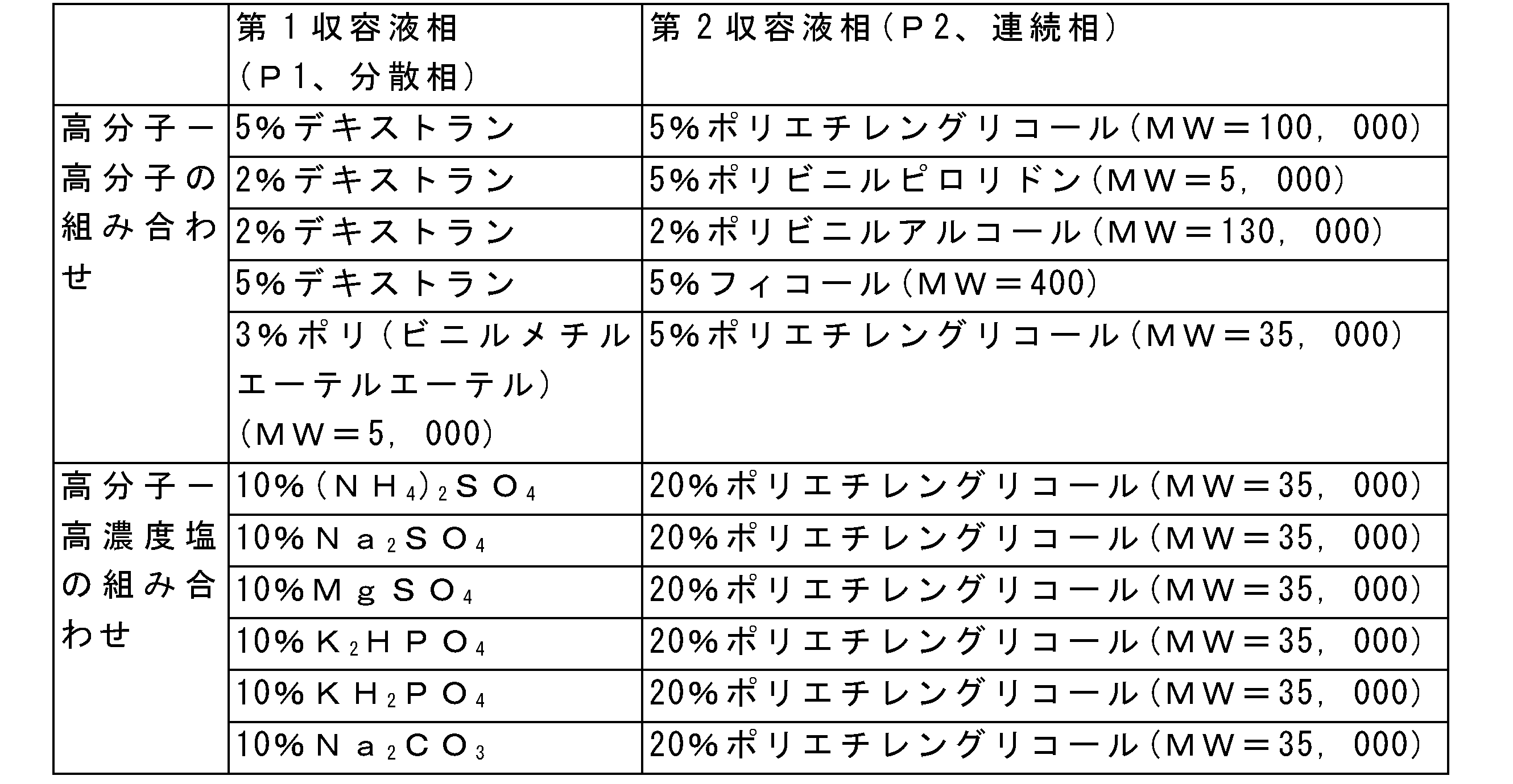
前記表2に例示した組み合わせは一例であり、この他に、前述した組成を用いた多様な組み合わせが、数式1で提示した界面張力を満足する範囲であれば、そのいずれの組み合わせでも使用できる。
The combinations illustrated in Table 2 are examples, and in addition to this, any combination can be used as long as various combinations using the above-mentioned compositions satisfy the interfacial tension presented in
さらに、本発明による水溶液二相系ナノフィルターの性能に関連して、追加パラメータにより分離速度に影響を受ける。前記追加パラメータは温度であり得る。 Furthermore, in relation to the performance of the aqueous two-phase nanofilter according to the present invention, the separation rate is affected by additional parameters. The additional parameter can be temperature.
水溶液二相系ナノフィルターにおいて、温度は、第1収容液相P1と第2収容液相P2との境界面でのナノ粒子の脱出速度を高めることにより、同じ時間内のナノ粒子の脱出割合を増加させることができる。 In the aqueous two-phase nanofilter, the temperature determines the escape rate of nanoparticles within the same time by increasing the escape rate of nanoparticles at the interface between the first contained liquid phase P1 and the second contained liquid phase P2. Can be increased.
図9はナノ粒子サイズによる界面での脱出速度の変化を示すグラフである。図9において、ΓP1:境界面から第1水溶液相に脱出する粒子の割合を意味し、ΓP2:境界面から第2水溶液相に脱出する粒子の割合を意味する。 FIG. 9 is a graph showing the change in the escape velocity at the interface depending on the nanoparticle size. In FIG. 9, Γ P1 : means the ratio of particles escaping from the interface to the first aqueous phase, and Γ P2 : means the ratio of particles escaping from the interface to the second aqueous phase.
図9を参照すると、温度が増加するほど、ナノ粒子のブラウン運動が加速化されて境界面にあるナノ粒子の脱出速度が増加する。このような結果より、非常に正確なサイズで短時間内に分離する必要がある場合に有用に使用することができる工程条件の変数として、温度を用いることもできることが分かる。 Referring to FIG. 9, as the temperature increases, the Brownian motion of the nanoparticles is accelerated and the escape velocity of the nanoparticles at the interface increases. From these results, it can be seen that temperature can also be used as a variable of process conditions that can be usefully used when it is necessary to separate in a very accurate size within a short period of time.
図10は温度の変化による臨界粒径の変化を示すグラフである。 FIG. 10 is a graph showing changes in the critical particle size due to changes in temperature.
図10を参照すると、温度の増加に伴って臨界粒径が線形的に増加する傾向を示すことが分かる。しかし、臨界粒径のサイズ差が10nm以内であるため、ナノ粒子分離の際に温度を増加させても、分離速度のみを増加させるだけであり、必要以上の臨界粒径を増加させないため、高純度でナノ粒子を分離させることができることが分かる。 With reference to FIG. 10, it can be seen that the critical particle size tends to increase linearly with increasing temperature. However, since the size difference of the critical particle size is within 10 nm, increasing the temperature during nanoparticle separation only increases the separation rate and does not increase the critical particle size more than necessary, so it is high. It can be seen that nanoparticles can be separated with purity.
また、第1収容液相P1が固定相(stationary droplet)及び移動相(moving droplet)である場合、分離速度のみ異なるだけであり、臨界粒径は最終的に同一になることが分かる。 Further, it can be seen that when the first contained liquid phase P1 is a stationary phase and a moving phase, only the separation rate is different, and the critical particle sizes are finally the same.
また、前記温度以外に、水溶液二相系ナノフィルターの分離能に関連するパラメータとして、振動印加か否かを含むことができる。 In addition to the temperature, whether or not vibration is applied can be included as a parameter related to the separation ability of the aqueous two-phase nanofilter.
振動印加は、超音波印加であってもよい。これは、外部からの物理力が境界面のエネルギー障壁を下げて臨界粒径を変化させるか、或いは粒子の拡散を助けてナノ粒子の脱出速度を増加させることができる。 The vibration application may be ultrasonic wave application. This can be done by external physical forces lowering the energy barrier at the interface to change the critical particle size, or by helping the particles diffuse to increase the escape velocity of the nanoparticles.
粒子サイズの異なる混合ナノ粒子は、そのサイズ差のような力学的物性の差が発生する。前記サイズの他に、その材質や組成が異なる場合には、材質、密度及び圧縮率などの力学的物性は大きく異なる。ここで、超音波が混合ナノ粒子に印加されると、粒子のサイズによって、互いに異なる音響放射力(acoustic radiationforce)を持つため、超音波の音圧節線(sound pressure node line)に沿ってナノ粒子が移動する。つまり、混合ナノ粒子が混在している場合、これらを分離することができ、これらの移動速度を高めることができる。特に、第1収容液相P1と第2収容液相P2との境界面にトラップされているナノ粒子の脱出を高めることができるため、前記トラップされたナノ粒子による分離速度の低下を防止することができる。 Mixed nanoparticles with different particle sizes have different mechanical characteristics such as the size difference. When the material and composition are different in addition to the above size, the mechanical properties such as material, density and compressibility are significantly different. Here, when ultrasonic waves are applied to the mixed nanoparticles, they have different acoustic radiation forces depending on the size of the particles, so that the nano waves are along the sound pressure node line of the ultrasonic waves. The particles move. That is, when mixed nanoparticles are mixed, they can be separated and their moving speed can be increased. In particular, since it is possible to enhance the escape of the nanoparticles trapped at the interface between the first contained liquid phase P1 and the second contained liquid phase P2, it is possible to prevent the separation rate from being lowered by the trapped nanoparticles. Can be done.
このような音響放射力は、周波数の制御によって調節可能である。好ましくは、本発明では、0.01~100kHzの200W~400Wの強度で1分~240分行うことが好ましい。この時、印加する超音波の強度があまり強い場合、バルク形態を成さなければならない第1収容液相P1に影響を与え、前記第1水溶液相P1が微細な液滴を形成することができるので、上記の範囲内で適切に行う。また、超音波印加は、超音波発生器によって行うことができる。 Such acoustic radiation force can be adjusted by controlling the frequency. Preferably, in the present invention, it is preferably carried out at an intensity of 200 W to 400 W at 0.01 to 100 kHz for 1 minute to 240 minutes. At this time, if the intensity of the applied ultrasonic wave is too strong, it affects the first contained liquid phase P1 that must form a bulk form, and the first aqueous solution phase P1 can form fine droplets. Therefore, do it appropriately within the above range. Further, the ultrasonic wave application can be performed by an ultrasonic wave generator.
一方、本発明による水溶液二相系ナノフィルターは、一方向に延長され、一側端部が開口した中空のチャンネルが形成され、前記チャンネルは、フィルターハウジング内に装着される。 On the other hand, the aqueous two-phase nanofilter according to the present invention is extended in one direction to form a hollow channel having one side end open, and the channel is mounted in the filter housing.
この時、チャンネルは、注入された流体が存在しうる通路又は導管である。前記チャンネルは、便宜上の表現であったが、微細な管だけでなく、内部直径の大きいカラムの意味も一緒に含む。詳細には、カラムは大量の試料分離のために使用でき、チャンネルは少量の試料分離のために使用できる。この時、チャンネルは、混合ナノ粒子の分離が容易であるように、マイクロチャンネル又はナノチャンネルであることができる。 At this time, the channel is a passage or conduit in which the injected fluid can exist. The channel is an expression for convenience, but also includes the meaning of a column having a large internal diameter as well as a fine tube. In particular, the column can be used for large sample separation and the channel can be used for small sample separation. At this time, the channel can be a microchannel or a nanochannel so that the mixed nanoparticles can be easily separated.
チャンネルの断面(流体の流れ方向に対する垂直方向)形状は、製造上の便利又は当業者の目的によって選択的に変更でき、これに限定されないが、例えば、円形、楕円形、長方形、正方形などを含む。好ましくは、本発明の前記チャンネルの断面形状は円形であることができる。 The cross-sectional (perpendicular to the flow direction of the fluid) shape of the channel can be selectively changed for convenience of manufacture or for the purposes of those skilled in the art, including, but not limited to, circular, elliptical, rectangular, square and the like. .. Preferably, the cross-sectional shape of the channel of the present invention can be circular.
チャンネルを介した抵抗は、その長さに比例し、断面積に反比例するので、長さ、幅、及び高さが適切に設計できる。特に、第1収容液相P1にバルク形態で流動するため、十分な長さ及び幅を確保することができるようにする。 The resistance through the channel is proportional to its length and inversely proportional to the cross-sectional area, so that the length, width, and height can be properly designed. In particular, since it flows in the first contained liquid phase P1 in a bulk form, it is possible to secure a sufficient length and width.
前記チャンネルは、長さが0.01~3cm、好ましくは1~5cmであることができ、高さ(導管の横断面基準)は0.001~5cm、好ましくは0.01~1cmであることができ、幅(幅)は0.001~5cm、好ましくは0.01~1cmであることができる。 The channel can be 0.01 to 3 cm in length, preferably 1 to 5 cm, and has a height (based on the cross section of the conduit) of 0.001 to 5 cm, preferably 0.01 to 1 cm. The width (width) can be 0.001 to 5 cm, preferably 0.01 to 1 cm.
フィルターハウジングは、金属又は合成樹脂で製作されたケース装置であって、水溶液二相系ナノフィルターを装着することができるように、上端又は下端に開閉可能なカバーが存在し、このようなフィルターハウジングのチャンネルの内部に流体が引き込まれる引込口と、内部の流体を排出することができる排出口を持っている。 The filter housing is a case device made of metal or synthetic resin, and there is a cover that can be opened and closed at the upper end or the lower end so that an aqueous two-phase nanofilter can be attached. Such a filter housing It has an inlet for drawing fluid inside the channel and an outlet for draining the fluid inside.
水溶液二相系ナノフィルターは、チャンネルの内部に第1水溶液相P1及び第2収容液相P2の注入を介して形成することができ、重力及び浮力によって第1収容液相P1が流動することができるように、チャンネルが地面に対して垂直に存在することができるようにする。 The aqueous two-phase nanofilter can be formed inside the channel through the injection of the first aqueous phase P1 and the second contained liquid phase P2, and the first contained liquid phase P1 can flow due to gravity and buoyancy. Allow the channel to be perpendicular to the ground so that it can.
前記フィルターハウジングは、必要に応じて温度調節装置が装着でき、超音波発生器に連結できる。 The filter housing can be fitted with a temperature control device as needed and can be connected to an ultrasonic generator.
一方、前述した水溶液二相系ナノフィルターは、ナノサイズの粒子分離工程に好適に適用することができる。 On the other hand, the above-mentioned aqueous solution two-phase nanofilter can be suitably applied to the nano-sized particle separation step.
具体的には、水溶液二相系ナノフィルターは、
(S1)混合ナノ粒子を含む試料を第1水溶液相P1と混合するステップと、
(S2)第2収容液相P2を準備してチャンネル内に注入するステップと、
(S3)前記試料を含む分散液を、第2水溶液相(P2)が担持されたチャンネル内に注入するステップと、
(S4)試料からナノ粒子分離工程を行う、ナノ粒子の分離方法を提供する。
Specifically, the aqueous two-phase nanofilter is
(S1) A step of mixing a sample containing mixed nanoparticles with the first aqueous phase P1.
(S2) The step of preparing the second accommodating liquid phase P2 and injecting it into the channel,
(S3) A step of injecting the dispersion liquid containing the sample into the channel on which the second aqueous solution phase (P2) is supported, and
(S4) Provided is a method for separating nanoparticles, which performs a nanoparticle separation step from a sample.
以下、各ステップで詳細に説明する。 Hereinafter, each step will be described in detail.
まず、水溶液二相系ナノフィルターの製作に先立って、第1収容液相P1と第2収容液相P2の組成を設計して準備する。前記第1収容液相P1及び第2収容液相P2は、前述したところによって適切な組み合わせとして選定できる。 First, prior to the production of the aqueous two-phase nanofilter, the compositions of the first contained liquid phase P1 and the second contained liquid phase P2 are designed and prepared. The first contained liquid phase P1 and the second contained liquid phase P2 can be selected as an appropriate combination as described above.
(S1)ステップでは、混合ナノ粒子を含む試料を第1水溶液相P1と混合して分散液を製造する。 In the step (S1), a sample containing mixed nanoparticles is mixed with the first aqueous phase P1 to produce a dispersion.
前記試料は、混合ナノ粒子であって、本水溶液二相系ナノフィルターの適用分野によって変わり得る。一例として、電子、光電子、磁気分野、バイオメディカル、医薬、化粧品分野、エネルギー、触媒、構造体などの産業全般にわたって使用するナノ粒子であることができる。また、前記試料は、その材質によって、金属ナノ粒子、無機ナノ粒子、有機ナノ粒子、有機-無機ハイブリッドナノ粒子、高分子粒子、バイオナノ粒子、生物由来のナノ粒子、又はこれらの混合粒子であることができる。 The sample is mixed nanoparticles and may vary depending on the field of application of the aqueous two-phase nanofilter. As an example, nanoparticles can be used throughout industries such as electrons, photoelectrons, magnetic fields, biomedicals, pharmaceuticals, cosmetics fields, energy, catalysts, structures and the like. The sample shall be metal nanoparticles, inorganic nanoparticles, organic nanoparticles, organic-inorganic hybrid nanoparticles, polymer particles, bio-nanoparticles, biological nanoparticles, or a mixture of these, depending on the material. Can be done.
次に、(S2)ステップでは、第2収容液相P2を準備してチャンネル内に注入する。 Next, in the (S2) step, the second accommodating liquid phase P2 is prepared and injected into the channel.
次に、(S3)ステップでは、前記試料を含む分散液を、第2水溶液相(P2)が担持されたチャンネル内に注入する。 Next, in the step (S3), the dispersion liquid containing the sample is injected into the channel on which the second aqueous solution phase (P2) is supported.
次に、(S4)ステップでは、一定時間放置して試料からナノ粒子分離工程を行う。 Next, in the step (S4), the nanoparticle separation step is performed from the sample after being left for a certain period of time.
この時、ナノ粒子の分離能及び分離速度を高めるために、温度調節装置及び超音波発生器の少なくとも一つの装置を作動させることができる。 At this time, at least one of the temperature control device and the ultrasonic generator can be operated in order to increase the separation ability and the separation rate of the nanoparticles.
前記ステップを経て行うナノ粒子の分離は、10nm程度のサイズ差を有する混合ナノ粒子を分離することができる。特に、前記分離は、短時間内に高純度で行われることができ、温度や超音波などの外力を印加する場合、その時間をさらに短縮させることができるという利点がある。 Separation of nanoparticles performed through the above steps can separate mixed nanoparticles having a size difference of about 10 nm. In particular, the separation can be performed with high purity within a short time, and there is an advantage that the time can be further shortened when an external force such as temperature or ultrasonic waves is applied.
以上で述べた本発明は、図面に示された実施形態を参考にして説明したが、これは、例示的なものに過ぎず、当該分野における通常の知識を有する者であれば、これから様々な変形及び実施形態の変形が可能であることを理解するだろう。ところが、このような変形は、本発明の技術的保護範囲内にあると見なすべきである。従って、本発明の真正な技術的保護範囲は、添付された特許請求の範囲の技術的思想によって定められるべきであろう。
The present invention described above has been described with reference to the embodiments shown in the drawings, but this is merely an example, and any person having ordinary knowledge in the art will be able to use the present invention in various ways. You will understand that variants and variants of the embodiment are possible. However, such modifications should be considered within the technical protection of the present invention. Therefore, the genuine technical protection scope of the present invention should be defined by the technical idea of the attached claims.
[数式1]
2×10⁻⁷
J/m2≦γ≦50×10-5
J/m2
[Formula 1]
2 × 10 -7 J / m 2 ≦ γ ≦ 50 × 10 -5 J / m 2
具体的には、界面張力が高いほど、界面を脱出することが可能な臨界粒径が最終的に小さくなる傾向を示すことが分かる。また、特定の時間に到達するまで時間に応じて臨界粒径が変わるが、最終的に到達する臨界粒径は同一であることが分かる。また、時間に応じて臨界粒径が増加することが分かるが、これを解析することにより、所望のサイズを取り除くのにかかる時間が分かる。一例として、界面張力が5×10⁻⁶ J/m2に設計された水溶液二相系ナノフィルターの場合、臨界粒径40nmのナノ粒子を30分以内に分離することができることが分かる。 Specifically, it can be seen that the higher the interfacial tension, the smaller the critical particle size capable of escaping the interface. Further, it can be seen that the critical particle size changes depending on the time until a specific time is reached, but the critical particle size finally reached is the same. Further, it can be seen that the critical particle size increases with time, and by analyzing this, the time required to remove the desired size can be found. As an example, in the case of an aqueous two-phase nanofilter designed to have an interfacial tension of 5 × 10 -6 J / m 2 , it can be seen that nanoparticles having a critical particle size of 40 nm can be separated within 30 minutes.
[数式1]
2×10⁻⁷
J/m2≦γ≦50×10-5
J/m2
[Formula 1]
2 × 10 -7 J / m 2 ≦ γ ≦ 50 × 10 -5 J / m 2
前述したサイズの混合ナノ粒子を分離するための界面張力は、2×10⁻⁷ J/m2~50×10-5 J/m2、好ましくは2×10-7 J/m2~40×10-5 J/m2、もっと好ましくは3×10-6 J/m2~350×10-6 J/m2、さらに好ましくは4×10-6 J/m2~270×10-6 J/m2、よりさらに好ましくは5×10-6 J/m2~150×10-6 J/m2、最も好ましくは10×10-6 J/m2~60×10-6 J/m2の範囲を有する。 The interfacial tension for separating mixed nanoparticles of the size described above is 2 × 10 -7 J / m 2 to 50 × 10 -5 J / m 2 , preferably 2 × 10 -7 J / m 2 to 40 ×. 10-5 J / m 2 , more preferably 3 x 10⁻⁶ J / m 2 to 350 x 10-6 J / m 2 , even more preferably 4 x 10⁻⁶ J / m 2 to 270 x 10-6 J. / M 2 , even more preferably 5 × 10 -6 J / m 2 to 150 × 10 -6 J / m 2 , most preferably 10 × 10 -6 J / m 2 to 60 × 10 -6 J / m 2 . Has a range of.
この時、界面張力が、前記数式1で提示した範囲ではなく、その数値が減少してある程度の限界、すなわち、2×10⁻⁷
J/m2から外れると、相分離が発生せず、第1収容液相P1と第2収容液相P2との混合が起こって水溶液二相系ナノフィルターが構成されず、逆に前記界面張力がある数値以上、具体的には50×10-5
J/m2を超える場合には、ナノ粒子の脱出が発生しなくなることが分かる。これは、本発明で提示する数式1の界面張力の数値範囲を持たなければ、安定な水溶液二相系ナノフィルターの構成が可能であって、ナノ粒子の脱出によるナノ粒子の分離が可能となることを立証することができるデータである。
At this time, if the interfacial tension is not in the range presented in the

図8のA組成の場合を参照すると、界面張力が5.36×10⁻⁶
J/m2である場合、30nm、50nm及び100nmそれぞれのナノ粒子のうち、30nmのナノ粒子のみが第2収容液相P2に移動したことが分かる。これと同様に、B組成の場合、界面張力が3.57×10-6
J/m2であり、30nm及び50nmのナノ粒子が第2収容液相P2に移動し、100nmのナノ粒子は第1収容液相P1に残留することが分かる。また、C組成の場合、界面張力が1.65×10-6
J/m2であり、30nm、50nm及び100nmのナノ粒子のいずれも第2収容液相P2に移動することが分かる。これにより、数式1に示すように、界面張力が少なくとも2×10-6
J/m2以上にならなければならないことが分かる。
Referring to the case of the composition A in FIG. 8, when the interfacial tension is 5.36 × 10 -6 J / m 2 , only the nanoparticles of 30 nm among the nanoparticles of 30 nm, 50 nm and 100 nm are second-contained. It can be seen that the particles have moved to the liquid phase P2. Similarly, in the case of the B composition, the interfacial tension is 3.57 × 10 -6 J / m 2 , nanoparticles of 30 nm and 50 nm move to the second accommodating liquid phase P2, and nanoparticles of 100 nm are the second. 1 It can be seen that it remains in the contained liquid phase P1. Further, in the case of the C composition, the interfacial tension is 1.65 × 10 -6 J / m 2 , and it can be seen that all the nanoparticles of 30 nm, 50 nm and 100 nm move to the second contained liquid phase P2. From this, it can be seen that the interfacial tension must be at least 2 × 10 -6 J / m 2 or more, as shown in
Claims (15)
分散相をなす第1収容液相、及び
前記分散相と相分離され、連続相をなす第2水溶液相を含み、
前記第1水溶液相と前記第2水溶液相とが相分離される界面での張力(γ)は下記数式1を満足する、水溶液二相系ナノフィルター。
[数式1]
2×10⁻⁷μJ/m2≦γ≦50×10-5μJ/m2 To separate mixed nanoparticles of different sizes from each other
It contains a first accommodating liquid phase forming a dispersed phase and a second aqueous solution phase that is phase-separated from the dispersed phase and forms a continuous phase.
An aqueous two-phase nanofilter in which the tension (γ) at the interface where the first aqueous phase and the second aqueous phase are phase-separated satisfies the following formula 1.
[Formula 1]
2 × 10 -7 μJ / m 2 ≦ γ ≦ 50 × 10 -5 μJ / m 2
シクロデキストリン、グルコース、デキストラン、マンノース、スクロース、トレハロース、マルトース、フィコール(ficoll)、イノシトール、マンニトール、ソルビトール、スクロース-マンニトール、グルコース-マンニトール、トレハロース-ポリエチレングリコール、スクロース-ポリエチレングリコール、スクロース-デキストラン、及びこれらの組み合わせよりなる群から選択された1種の高分子多糖類;
並びにこれらの組み合わせよりなる群から選択された1種以上である、請求項6又は7に記載の水溶液二相系ナノフィルター。 The macromolecules include polyarginine, polylysine, polyethylene glycol, polypropylene glycol, polyethyleneimine, chitosan, protamin, polyvinylacetate, hyaluronic acid, chondroitin sulfate, heparin, arginate, hydroxyoxypropylmethylcellulose, gelatin, starch, poly. One hydrophilic polymer selected from the group consisting of (vinyl methyl ether ether), polyvinylpyrrolidone, and combinations thereof;
Cyclodextrin, glucose, dextran, mannose, sucrose, trehalose, maltose, ficoll, inositol, mannitol, sorbitol, sucrose-mannitol, glucose-mannitol, trehalose-polyethylene glycol, sucrose-polyethylene glycol, sucrose-dextran, and these. One high molecular weight polysaccharide selected from the group consisting of combinations of
The aqueous two-phase nanofilter according to claim 6 or 7, which is one or more selected from the group consisting of these combinations.
(S2)第2水溶液相を準備してチャンネル内に注入するステップと、
(S3)前記試料を含む分散液を、第2水溶液相が担持されたチャンネル内に注入するステップと、を含む、ナノ粒子の分離方法であって、
前記第1水溶液相と前記第2水溶液相は相分離され、相分離される界面での張力(γ)は下記数式1を満足する、ナノ粒子の分離方法。
[数式1]
2×10⁻⁷μJ/m2≦γ≦50×10-5μJ/m2 (S1) The step of mixing the sample containing the mixed nanoparticles with the first aqueous phase,
(S2) The step of preparing the second aqueous phase and injecting it into the channel,
(S3) A method for separating nanoparticles, comprising a step of injecting a dispersion liquid containing the sample into a channel on which a second aqueous phase is supported.
A method for separating nanoparticles, wherein the first aqueous solution phase and the second aqueous solution phase are phase-separated, and the tension (γ) at the phase-separated interface satisfies the following formula 1.
[Formula 1]
2 × 10 -7 μJ / m 2 ≦ γ ≦ 50 × 10 -5 μJ / m 2
Applications Claiming Priority (3)
| Application Number | Priority Date | Filing Date | Title |
|---|---|---|---|
| KR10-2018-0142370 | 2018-11-19 | ||
| KR1020180142370A KR102174177B1 (en) | 2018-11-19 | 2018-11-19 | Aqueous two-phase system nano filter and separation method threrefor |
| PCT/KR2019/015304 WO2020105928A1 (en) | 2018-11-19 | 2019-11-12 | Aqueous two-phase system nanofilter and separation method using same |
Publications (2)
| Publication Number | Publication Date |
|---|---|
| JP2022508122A true JP2022508122A (en) | 2022-01-19 |
| JP7347851B2 JP7347851B2 (en) | 2023-09-20 |
Family
ID=70774383
Family Applications (1)
| Application Number | Title | Priority Date | Filing Date |
|---|---|---|---|
| JP2021526423A Active JP7347851B2 (en) | 2018-11-19 | 2019-11-12 | Aqueous two-phase nanofilter and separation method using it |
Country Status (6)
| Country | Link |
|---|---|
| US (1) | US12194415B2 (en) |
| EP (1) | EP3885019A4 (en) |
| JP (1) | JP7347851B2 (en) |
| KR (1) | KR102174177B1 (en) |
| CN (1) | CN113056319B (en) |
| WO (1) | WO2020105928A1 (en) |
Cited By (1)
| Publication number | Priority date | Publication date | Assignee | Title |
|---|---|---|---|---|
| JP2025016103A (en) * | 2023-07-21 | 2025-01-31 | ヤマト科学株式会社 | Concentration method of organism-derived substance |
Families Citing this family (4)
| Publication number | Priority date | Publication date | Assignee | Title |
|---|---|---|---|---|
| KR102294264B1 (en) * | 2019-08-07 | 2021-08-26 | 포항공과대학교 산학협력단 | Separation method of bio-nano particles by aqueous two-phase composition |
| CN112194740B (en) * | 2020-10-23 | 2022-06-10 | 宋江 | Method for extracting heparin sodium from small intestine of pig |
| KR102704051B1 (en) | 2021-08-30 | 2024-09-09 | 가톨릭대학교 산학협력단 | Exosomes as the composition for the treatment and prevention of dry eye syndrome |
| CN118833944A (en) * | 2023-04-24 | 2024-10-25 | 中国石化工程建设有限公司 | PTA sewage quality-classifying recovery treatment system and recovery treatment method |
Citations (6)
| Publication number | Priority date | Publication date | Assignee | Title |
|---|---|---|---|---|
| WO2004018066A2 (en) * | 2002-05-17 | 2004-03-04 | The Penn State Research Foundation | Aqueous two-phase systems for particle manipulation and encapsulation within microscopic volumes |
| JP2005224787A (en) * | 2004-02-15 | 2005-08-25 | Eiichi Tamiya | Method and device for separating insoluble substance |
| JP2011173119A (en) * | 2002-04-25 | 2011-09-08 | Tosoh Corp | Microchannel structure and solvent extraction method by micro channel structure |
| US20140174991A1 (en) * | 2013-02-25 | 2014-06-26 | National Institute Of Standards And Technology | Fractionating nanomaterials by a liquid multiphase composition |
| US20180105778A1 (en) * | 2015-03-24 | 2018-04-19 | Postech Academy-Industry Foundation | Multi-stage purification method and apparatus of extracellular vesicles using aqueous solution two-phase system |
| US20180164197A1 (en) * | 2015-03-31 | 2018-06-14 | Postech Academy-Industry Foundation | Method for isolating extracellular vesicles using aqueous two-phase system |
Family Cites Families (14)
| Publication number | Priority date | Publication date | Assignee | Title |
|---|---|---|---|---|
| US5078886A (en) * | 1989-10-18 | 1992-01-07 | Lehigh University | Separation of mixtures by two-phase systems |
| KR100194075B1 (en) * | 1996-04-08 | 1999-06-15 | 박종헌 | Purification Method of Cyclodextrin Glucanotransferase Using Aqueous Two-Phase System |
| CN100418897C (en) * | 2003-03-31 | 2008-09-17 | 科学与工业研究委员会 | Process for the separation and recovery of polyethylene glycol from spent aqueous two-phase systems |
| JP4670583B2 (en) * | 2005-10-20 | 2011-04-13 | チッソ株式会社 | Separation or detection method of lipid vesicles using water-soluble cationic magnetic fine particles |
| DE102007020220B3 (en) * | 2007-04-28 | 2008-11-13 | Forschungszentrum Karlsruhe Gmbh | Method for magnetically assisted extraction |
| KR100863466B1 (en) * | 2007-08-09 | 2008-10-16 | 고려대학교 산학협력단 | Method for separating membrane protein from animal cells |
| KR101196667B1 (en) * | 2010-04-15 | 2012-11-02 | 포항공과대학교 산학협력단 | A DELEVERY SYSTEM OF ANTI-CANCER AGENT USING pH SENSITIVE METAL NANOPARTICLE |
| WO2012024688A1 (en) * | 2010-08-20 | 2012-02-23 | President And Fellows Of Harvard College | Multiphase systems and uses thereof |
| FI127353B (en) * | 2013-07-05 | 2018-04-13 | Teknologian Tutkimuskeskus Vtt Oy | Concentration and purification of hydrophobins and antibodies by a phase separation method |
| US9823247B2 (en) * | 2014-03-07 | 2017-11-21 | The Regents Of The University Of California | Methods and devices for integrating analyte extraction, concentration and detection |
| KR101575488B1 (en) | 2014-06-12 | 2015-12-07 | 부산대학교 산학협력단 | Micro fluid centrifuge for separation of particle |
| US20180200645A1 (en) * | 2015-07-08 | 2018-07-19 | Amazon Filters Spólka Z O.O. | Separation system for simultaneous removal of both solid particles and liquid droplets suspended in another liquid |
| US11260358B2 (en) * | 2017-04-17 | 2022-03-01 | The Trustees Of The University Of Pennsylvania | Aqueous systems of at least two phases containing microcapsules and processes for manufacturing the same |
| CN108362535B (en) * | 2018-02-02 | 2021-01-15 | 北京恩泽康泰生物科技有限公司 | Method for extracting extracellular vesicles from body fluid based on aqueous two-phase system |
-
2018
- 2018-11-19 KR KR1020180142370A patent/KR102174177B1/en active Active
-
2019
- 2019-11-12 WO PCT/KR2019/015304 patent/WO2020105928A1/en not_active Ceased
- 2019-11-12 JP JP2021526423A patent/JP7347851B2/en active Active
- 2019-11-12 CN CN201980076173.2A patent/CN113056319B/en active Active
- 2019-11-12 EP EP19887450.5A patent/EP3885019A4/en active Pending
-
2021
- 2021-05-11 US US17/316,864 patent/US12194415B2/en active Active
Patent Citations (6)
| Publication number | Priority date | Publication date | Assignee | Title |
|---|---|---|---|---|
| JP2011173119A (en) * | 2002-04-25 | 2011-09-08 | Tosoh Corp | Microchannel structure and solvent extraction method by micro channel structure |
| WO2004018066A2 (en) * | 2002-05-17 | 2004-03-04 | The Penn State Research Foundation | Aqueous two-phase systems for particle manipulation and encapsulation within microscopic volumes |
| JP2005224787A (en) * | 2004-02-15 | 2005-08-25 | Eiichi Tamiya | Method and device for separating insoluble substance |
| US20140174991A1 (en) * | 2013-02-25 | 2014-06-26 | National Institute Of Standards And Technology | Fractionating nanomaterials by a liquid multiphase composition |
| US20180105778A1 (en) * | 2015-03-24 | 2018-04-19 | Postech Academy-Industry Foundation | Multi-stage purification method and apparatus of extracellular vesicles using aqueous solution two-phase system |
| US20180164197A1 (en) * | 2015-03-31 | 2018-06-14 | Postech Academy-Industry Foundation | Method for isolating extracellular vesicles using aqueous two-phase system |
Cited By (2)
| Publication number | Priority date | Publication date | Assignee | Title |
|---|---|---|---|---|
| JP2025016103A (en) * | 2023-07-21 | 2025-01-31 | ヤマト科学株式会社 | Concentration method of organism-derived substance |
| JP7638481B2 (en) | 2023-07-21 | 2025-03-04 | ヤマト科学株式会社 | Method for concentrating biological substances |
Also Published As
| Publication number | Publication date |
|---|---|
| KR20200058631A (en) | 2020-05-28 |
| EP3885019A4 (en) | 2023-04-05 |
| KR102174177B1 (en) | 2020-11-05 |
| JP7347851B2 (en) | 2023-09-20 |
| US20210260528A1 (en) | 2021-08-26 |
| CN113056319B (en) | 2022-11-22 |
| CN113056319A (en) | 2021-06-29 |
| WO2020105928A1 (en) | 2020-05-28 |
| EP3885019A1 (en) | 2021-09-29 |
| KR102174177B9 (en) | 2023-05-11 |
| US12194415B2 (en) | 2025-01-14 |
Similar Documents
| Publication | Publication Date | Title |
|---|---|---|
| JP2022508122A (en) | Aqueous two-phase nanofilter and separation method using this | |
| Sheth et al. | Multiple nanoemulsions | |
| Yoon et al. | Core flooding of complex nanoscale colloidal dispersions for enhanced oil recovery by in situ formation of stable oil-in-water pickering emulsions | |
| Kim et al. | Processable high internal phase Pickering emulsions using depletion attraction | |
| Vialetto et al. | Exploiting additives for directing the adsorption and organization of colloid particles at fluid interfaces | |
| Lebdioua et al. | Influence of different surfactants on Pickering emulsions stabilized by submicronic silica particles | |
| Pardhy et al. | Pickering emulsion as a template to synthesize Janus colloids with anisotropy in the surface potential | |
| Ji et al. | Interfacial viscoelasticity and jamming of colloidal particles at fluid–fluid interfaces: a review | |
| Zhang et al. | Natural halloysites-based janus platelet surfactants for the formation of pickering emulsion and enhanced oil recovery | |
| Tian et al. | Interface-directed self-assembly of gold nanoparticles and fabrication of hybrid hollow capsules by interfacial cross-linking polymerization | |
| Larson-Smith et al. | SANS and SAXS analysis of charged nanoparticle adsorption at oil–water interfaces | |
| Tran et al. | Templating interfacial nanoparticle assemblies via in situ techniques | |
| KR102294264B1 (en) | Separation method of bio-nano particles by aqueous two-phase composition | |
| Graham et al. | Formation mechanism of multipurpose silica nanocapsules | |
| Feld et al. | Nanocomposites of highly monodisperse encapsulated superparamagnetic iron oxide nanocrystals homogeneously dispersed in a poly (ethylene oxide) melt | |
| Zhang et al. | Direct pore-level visualization and verification of in situ oil-in-water pickering emulsification during polymeric nanogel flooding for EOR in a transparent three-dimensional micromodel | |
| Wei et al. | Surface wettability-switchable Janus fiber fragments stabilize pickering emulsions for effective oil/water separation | |
| Mahmoudvand et al. | Evaluation of interfacial structure of self-assembled nanoparticle layers: use of standard deviation between calculated and experimental drop profiles as a novel method | |
| Tham et al. | Magnetophoresis of magnetic pickering emulsions under low field gradient: macroscopic and microscopic motion | |
| Kumar et al. | Shape anisotropy induced jamming of nanoparticles at liquid interfaces: a tensiometric study | |
| Zhou et al. | Constructing multifunctional Janus carbon-mesoporous silica particles as Pickering emulsifier for biphasic reaction | |
| Fink et al. | Evidence for enhanced tracer diffusion in densely packed interfacial assemblies of hairy nanoparticles | |
| Bhatt et al. | Core-composite mediated separation of diverse nanoparticles to purity | |
| Yarlagadda | Dynamics of hard and soft colloids in confined geometries and on structured surfaces | |
| EP3034616B1 (en) | Device for producing and/or cleaning nanoparticle coupled biomaterials and method using the same |
Legal Events
| Date | Code | Title | Description |
|---|---|---|---|
| A521 | Request for written amendment filed |
Free format text: JAPANESE INTERMEDIATE CODE: A523 Effective date: 20210512 |
|
| A621 | Written request for application examination |
Free format text: JAPANESE INTERMEDIATE CODE: A621 Effective date: 20210512 |
|
| A977 | Report on retrieval |
Free format text: JAPANESE INTERMEDIATE CODE: A971007 Effective date: 20220422 |
|
| A131 | Notification of reasons for refusal |
Free format text: JAPANESE INTERMEDIATE CODE: A131 Effective date: 20220510 |
|
| A521 | Request for written amendment filed |
Free format text: JAPANESE INTERMEDIATE CODE: A523 Effective date: 20220805 |
|
| A131 | Notification of reasons for refusal |
Free format text: JAPANESE INTERMEDIATE CODE: A131 Effective date: 20221206 |
|
| A601 | Written request for extension of time |
Free format text: JAPANESE INTERMEDIATE CODE: A601 Effective date: 20230303 |
|
| A521 | Request for written amendment filed |
Free format text: JAPANESE INTERMEDIATE CODE: A523 Effective date: 20230428 |
|
| TRDD | Decision of grant or rejection written | ||
| A01 | Written decision to grant a patent or to grant a registration (utility model) |
Free format text: JAPANESE INTERMEDIATE CODE: A01 Effective date: 20230801 |
|
| A61 | First payment of annual fees (during grant procedure) |
Free format text: JAPANESE INTERMEDIATE CODE: A61 Effective date: 20230831 |
|
| R150 | Certificate of patent or registration of utility model |
Ref document number: 7347851 Country of ref document: JP Free format text: JAPANESE INTERMEDIATE CODE: R150 |