[go: up one dir, main page]

JP2022145482A - Pump with flow detection function, pump abnormality detection system - Google Patents

Pump with flow detection function, pump abnormality detection system Download PDF

Info

Publication number
JP2022145482A
JP2022145482A JP2021206051A JP2021206051A JP2022145482A JP 2022145482 A JP2022145482 A JP 2022145482A JP 2021206051 A JP2021206051 A JP 2021206051A JP 2021206051 A JP2021206051 A JP 2021206051A JP 2022145482 A JP2022145482 A JP 2022145482A
Authority
JP
Japan
Prior art keywords
pressure
flow
pump
flow path
detection function
Prior art date
Legal status (The legal status is an assumption and is not a legal conclusion. Google has not performed a legal analysis and makes no representation as to the accuracy of the status listed.)
Withdrawn
Application number
JP2021206051A
Other languages
Japanese (ja)
Inventor
陽子 篠原
Yoko Shinohara
学 大海
Manabu Omi
武 内山
Takeshi Uchiyama
彩子 野邉
Ayako Nobe
正之 須田
Masayuki Suda
Current Assignee (The listed assignees may be inaccurate. Google has not performed a legal analysis and makes no representation or warranty as to the accuracy of the list.)
Seiko Group Corp
Original Assignee
Seiko Holdings Corp
Priority date (The priority date is an assumption and is not a legal conclusion. Google has not performed a legal analysis and makes no representation as to the accuracy of the date listed.)
Filing date
Publication date
Application filed by Seiko Holdings Corp filed Critical Seiko Holdings Corp
Publication of JP2022145482A publication Critical patent/JP2022145482A/en
Withdrawn legal-status Critical Current

Links

Images

Landscapes

  • Reciprocating Pumps (AREA)

Abstract

To provide a pump with a flow detecting function capable of detecting a flow state in a flow passage while maintaining peristalsis type pump performance, and a pump abnormality detecting system.SOLUTION: A pump 1 with a flow detecting function includes a flow passage 10 having a flow passage wall 11 displaced in accordance with change in pressure of fluid flowing in an inside thereof, a pump 2 peristaltically moving the flow passage 10 by moving a plurality of pressure-contact pieces 22 coming in press-contact with the flow passage wall 11, and a pressure detector 3 having a pressure receiver 3b which is brought into contact with the flow passage wall 11 in a pressing region 100 in which the plurality of pressure-contact pieces 22 presses the flow passage wall 11 and at a position opposite across the plurality of the pressure-contact pieces 22 and the flow passage 10.SELECTED DRAWING: Figure 1

Description

本開示は、流動検知機能付きポンプ、ポンプ異常検知システムに関するものである。 The present disclosure relates to a pump with a flow detection function and a pump abnormality detection system.

下記特許文献1には、液体が収容された医療用容器と人体とを繋ぎ且つ可撓性を備える輸液チューブの中を流れる液体を、輸液チューブを蠕動運動させることによって強制的に流動させる蠕動式輸液ポンプが開示されている。この蠕動式輸液ポンプは、輸液チューブ内の液体の流れを阻止する複数個所の閉止点を有し、送液のための蠕動運動の経過に伴って1つの閉止点と他のもう1つの閉止点との間に挟まれた閉止領域の容積を変化させる容積変化手段と、閉止領域における輸液チューブ内の圧力を検出する圧力検出手段と、容積変化手段により容積変化を加えて圧力検出手段で検出される輸液チューブの圧力の変化量の変化に基づいて、輸液チューブ内に混入した空気の有無を判別する気泡検出手段とを備えている。 The following patent document 1 describes a peristaltic type in which a liquid flowing in a flexible infusion tube that connects a medical container containing the liquid and a human body and is forcibly flowed by peristaltic movement of the infusion tube. An infusion pump is disclosed. This peristaltic infusion pump has multiple closure points that block the flow of liquid in the infusion tube, one closure point and another closure point as the peristaltic movement for fluid delivery progresses. a volume change means for changing the volume of the closed region sandwiched between; a pressure detection means for detecting the pressure in the infusion tube in the closed region; air bubble detection means for determining whether or not there is air entrapped in the infusion tube based on a change in the amount of pressure change in the infusion tube.

特開2016-220958号公報JP 2016-220958 A

上記従来技術では、輸液チューブ内の気泡混入を検知できる一方、圧力検出手段の付近で、圧接子が輸液チューブから離れ、輸液チューブを押し潰さない区間が存在する。蠕動式のポンプは、圧接子が輸液チューブを押し潰す区間が長いほどポンプ上流側の圧力が低くなるため、吸い上げ能力を高くすることができる。このため、上記従来技術では、圧接子が輸液チューブを押し潰す区間が短く、かつ分割されるため、ポンプの吸い上げ能力が低くなってしまうという問題があった。 In the prior art described above, while it is possible to detect air bubbles in the infusion tube, there is a section in the vicinity of the pressure detecting means where the pressure contact is separated from the infusion tube and does not crush the infusion tube. In the peristaltic pump, the pressure on the upstream side of the pump becomes lower as the section where the press contact crushes the infusion tube becomes longer, so that the pumping capacity can be increased. For this reason, in the above-described prior art, there is a problem that the section in which the press contact crushes the infusion tube is short and divided, so that the sucking capacity of the pump becomes low.

本開示は、上記問題点に鑑みてなされたものであり、蠕動式のポンプ性能を維持したまま、流路内の流動状態を検知できる流動検知機能付きポンプ、ポンプ異常検知システムの提供を目的とする。 The present disclosure has been made in view of the above problems, and aims to provide a pump with a flow detection function and a pump abnormality detection system that can detect the flow state in the flow path while maintaining the performance of the peristaltic pump. do.

(1)本開示の一態様に係る流動検知機能付きポンプは、内部を流れる流体の圧力変化によって変位する流壁を有する流路と、前記流壁に圧接する複数の圧接子を動かすことによって、前記流路を蠕動運動させるポンプ部と、前記複数の圧接子が前記流壁を押圧する押圧範囲で、且つ、前記複数の圧接子と前記流路を挟んだ反対側の位置において、前記流壁に接触する受圧部を有する圧力検出部と、を備える。 (1) A pump with a flow detection function according to an aspect of the present disclosure includes a flow path having a flow wall that is displaced by a pressure change of a fluid flowing inside, and by moving a plurality of pressure contacts that are in pressure contact with the flow wall, a pump unit for peristaltic movement of the flow channel; and a pressure detecting portion having a pressure receiving portion that contacts with the pressure detecting portion.

本態様に係る流動検知機能付きポンプによれば、圧力検出部の受圧部が、流路を蠕動運動させる複数の圧接子と流路を挟んだ反対側の位置において、流路の流壁と接触する。受圧部が流壁と接触する位置は、複数の圧接子が流壁に接触しながら流壁を押圧する押圧範囲にあるため、圧接子が流路から離れることはなく、流路を押し潰す区間が長く確保され、ポンプの吸い上げ能力の低下を抑制できる。このため、蠕動式のポンプ性能を維持したまま、流路内の流動状態を検知することが可能となる。 According to the pump with a flow detection function according to this aspect, the pressure receiving portion of the pressure detecting portion contacts the flow wall of the flow channel at a position opposite to the plurality of press contacts that cause peristaltic motion of the flow channel. do. The position where the pressure-receiving part contacts the flow wall is in the pressure range where the plurality of pressure contacts presses the flow wall while contacting the flow wall. is ensured for a long time, and a decrease in the pump's suction ability can be suppressed. Therefore, it is possible to detect the state of flow in the channel while maintaining the performance of the peristaltic pump.

(2)(1)の態様の流動検知機能付きポンプにおいて、前記受圧部は、前記圧接子の前記流壁に対する押圧圧力が最も高くなる位置よりも前記流路の下流側の位置において前記流壁に接触していてもよい。 (2) In the pump with a flow detection function according to aspect (1), the pressure receiving portion is located at a position downstream of the flow path from a position where the pressing pressure of the pressure contact to the flow wall is highest. may be in contact with

この場合には、仮にポンプ部の下流側で流路に詰まりが生じた場合、ポンプ部における圧接子の流壁に対する押圧圧力が最も高くなる位置において、流体の逆流を阻止できるため、下流側での詰まりによって生じる当該流体の逆流による流路の内圧の上昇を受圧部が検知できるようになる。 In this case, if clogging occurs in the flow path on the downstream side of the pump section, the reverse flow of the fluid can be prevented at the position where the pressing pressure of the press contact against the flow wall in the pump section is the highest. The pressure receiving portion can detect an increase in the internal pressure of the flow path due to the reverse flow of the fluid caused by the clogging of the flow path.

(3)(1)または(2)の態様の流動検知機能付きポンプにおいて、前記押圧範囲には、前記複数の圧接子が前記流路を閉止しながら移動する閉止範囲が含まれ、前記閉止範囲には、前記圧接子が前記流路を閉止する位置とその隣の前記圧接子が前記流路を閉止する位置との間に挟まれた両端閉止部が形成され、前記受圧部は、前記閉止範囲の下流端から前記流路の上流側に向かって前記両端閉止部の1つ分の形成長さの範囲の位置において、前記流壁に接触していてもよい。 (3) In the pump with a flow detection function of aspect (1) or (2), the pressing range includes a closing range in which the plurality of pressure contacts move while closing the flow path, and the closing range is formed with both-end closing portions sandwiched between a position at which the pressure contact closes the flow path and a position at which the adjacent pressure contact closes the flow path. The flow wall may be contacted at a position within a range from the downstream end of the range to the upstream side of the flow path for the formation length of one of the both end closures.

蠕動式のポンプにおいては、複数の圧接子による流路の押圧範囲の中に、圧接子の押圧によって流路の内径がゼロになる閉止範囲が含まれ、その閉止範囲に、隣り合う2つの圧接子により挟まれた両端閉止部が形成される。両端閉止部は、閉止範囲の下流端において、圧接子による流壁の押圧が弱まることで、流路の内径がゼロからプラスになり、圧力が高い流路の下流側から流体の逆流が生じる。受圧部は、閉止範囲の下流端から流路の上流側に向かって両端閉止部の1つ分の形成長さの範囲内に位置しているため、このような逆流は、生じた瞬間に流路が閉止される箇所を通過することなく受圧部に到達することができる。その結果、受圧部が当該流体の逆流による流路の内圧の上昇を効率よく検知できるようになる。また、両端閉止部は、下流側の圧接子によって未だ閉止されているため、ポンプ部の上流側への流体の逆流を阻止できる。加えて、仮にポンプ部の下流側で流路に詰まりが生じた場合、上述した通常の流体の逆流と比べて、流体の逆流による流路の内圧の上昇が顕著になるため、通常の流体の逆流と比較することで流路の詰まりを検知することができる。 In a peristaltic pump, the pressure range of the flow path by a plurality of press contacts includes a closing range in which the inner diameter of the flow path becomes zero due to the pressing of the pressure contacts. A double-ended closure is formed which is pinched by the child. At the downstream end of the closing range of the both-end closing portion, the pressing force of the pressure contact on the flow wall is weakened, so that the inner diameter of the flow path changes from zero to positive, causing a reverse flow of fluid from the downstream side of the flow path where the pressure is high. Since the pressure-receiving part is located within the range of the formation length of one of the both-ends closing parts from the downstream end of the closing range toward the upstream side of the flow path, such a backflow immediately occurs. It is possible to reach the pressure receiving part without passing through the part where the path is closed. As a result, the pressure receiving portion can efficiently detect an increase in the internal pressure of the flow path due to the reverse flow of the fluid. Moreover, since the both-ends closing portion is still closed by the pressure contact on the downstream side, it is possible to prevent the fluid from flowing backward to the upstream side of the pump portion. In addition, if clogging occurs in the flow path downstream of the pump section, the increase in internal pressure of the flow path due to the backflow of the fluid becomes more pronounced than in the above-described normal backflow of the fluid. Clogging of the channel can be detected by comparing with the reverse flow.

(4)(1)の態様の流動検知機能付きポンプにおいて、前記押圧範囲には、前記複数の圧接子が前記流路を閉止しながら移動する閉止範囲が含まれ、前記ポンプ部は、前記閉止範囲の下流端に向かうに従って前記複数の圧接子の間隔を徐々に狭くする圧接子駆動部を備えてもよい。 (4) In the pump with a flow detection function of aspect (1), the pressing range includes a closing range in which the plurality of press contacts move while closing the flow path, and the pump section A press contact driving section may be provided that gradually narrows the intervals between the plurality of press contacts toward the downstream end of the range.

この場合には、圧接子の押圧によって流路の内径がゼロになる閉止範囲において、その下流側に向かうに従って圧接子の間隔が徐々に狭くなり、流路内の圧力が高まる。そうすると、当該流路内の圧力と、下流側の圧接子が閉止範囲から離脱したときの、その下流側の流路内の圧力との差が小さくなり、逆流や脈動の発生を抑制することができる。これにより、ノイズが小さくなり、圧力検出部の検出精度が高まる。 In this case, in the closed range where the inner diameter of the flow path becomes zero due to the pressing force of the pressure contact, the distance between the pressure contacts gradually narrows toward the downstream side, increasing the pressure in the flow path. As a result, the difference between the pressure in the flow path and the pressure in the flow path on the downstream side when the pressure contact on the downstream side is separated from the closed range becomes small, and the occurrence of backflow and pulsation can be suppressed. can. This reduces noise and increases the detection accuracy of the pressure detection unit.

(5)(4)の態様の流動検知機能付きポンプにおいて、前記受圧部は、前記閉止範囲の下流側の半分の位置において前記流壁に接触してもよい。 (5) In the pump with a flow detection function according to the mode (4), the pressure receiving portion may contact the flow wall at a half position on the downstream side of the closing range.

閉止範囲の下流端に向かうに従って複数の圧接子の間隔が徐々に狭くなる場合、通常時(正常時)では、下流側の圧接子が閉止範囲から離脱したときの流路内の圧力の変化はほぼないが、仮にポンプ部の下流側で流路に詰まりが生じていた場合、当該下流側の流路の詰まりによって通常時よりも下流側の流路内の圧力が上昇しているため、下流側の圧接子が閉止範囲から離脱したときに、流体の逆流が発生し、流路内の圧力が変化する。流体の逆流による圧力変化は閉止範囲の下流側で発生し易いため、閉止範囲の下流側の半分の位置に受圧部を設置することで、当該流体の逆流を検出し易くなる。 When the distance between multiple pressure contacts gradually narrows toward the downstream end of the closing range, the change in pressure in the flow path when the pressure contact on the downstream side leaves the closing range is Almost never, but if clogging occurs in the flow path downstream of the pump section, the clogging of the flow path on the downstream side will cause the pressure in the flow path on the downstream side to rise more than usual, so the downstream When the pressure contact on the side leaves the closed area, a reverse flow of fluid occurs and the pressure in the flow path changes. Since the pressure change due to the backflow of the fluid is likely to occur downstream of the closed range, the backflow of the fluid can be easily detected by installing the pressure receiving section at the downstream half position of the closed range.

(6)(4)または(5)の態様の流動検知機能付きポンプにおいて、前記閉止範囲には、前記圧接子が前記流路を閉止する位置とその隣の前記圧接子が前記流路を閉止する位置との間に挟まれた両端閉止部が形成され、前記受圧部は、前記閉止範囲の下流端から前記流路の上流側に向かって前記両端閉止部の最小の形成長さの範囲内の位置において、前記流壁に接触してもよい。 (6) In the pump with a flow detection function according to mode (4) or (5), the closing range includes a position where the pressure contact closes the flow path and a position where the pressure contact closes the flow path. and the pressure receiving portion extends from the downstream end of the closing range toward the upstream side of the flow path within the range of the minimum forming length of the both ends closing portion. may contact the flow wall at the position of

この場合には、受圧部が、閉止範囲の下流端から流路の上流側に向かって両端閉止部の最小の形成長さの範囲内に位置しているため、閉止範囲における流路内の圧力の最大値を検出することができる。仮に、流路が損傷し、流体の漏洩があった場合、閉止範囲における流路内の圧力の最大値が通常時よりも下降するため、流路の異常を検出し易くなる。 In this case, since the pressure-receiving portion is located within the minimum formation length of the both-end closing portions from the downstream end of the closed range toward the upstream side of the flow channel, the pressure in the flow channel in the closed range can be detected. If the flow path is damaged and fluid leaks, the maximum value of the pressure in the flow path in the closed range will be lower than normal, making it easier to detect an abnormality in the flow path.

(7)(1)から(6)のいずれかの態様の流動検知機能付きポンプにおいて、前記圧力検出部は、前記受圧部の内圧の変化によって撓み変形するカンチレバーを備えてもよい。 (7) In the pump with a flow detection function according to any one of aspects (1) to (6), the pressure detection section may include a cantilever that bends and deforms according to changes in the internal pressure of the pressure receiving section.

この場合には、カンチレバーが感度よく受圧部の内圧の変化を検知するため、圧接子の強い押圧から、流路の微弱な圧力変化まで、広い範囲で圧力を検知することができる。このため、受圧部を、圧接子によって押圧される流路の押圧範囲に設置でき、ポンプ部の送液能力を下げずに、流体の流動状況を流路の外部から検知できる。また、圧力検出部は、圧接子の押圧(タイミングや圧力)も測定することが可能であるため、ポンプ部の稼働状況も同時に検知することができる。 In this case, since the cantilever detects changes in the internal pressure of the pressure receiving portion with high sensitivity, it is possible to detect pressure in a wide range from strong pressure of the pressure contact to weak pressure changes in the flow path. Therefore, the pressure receiving part can be installed in the pressure range of the flow path pressed by the pressure contact, and the flow condition of the fluid can be detected from the outside of the flow path without lowering the liquid feeding performance of the pump part. In addition, since the pressure detection section can also measure the pressure (timing and pressure) of the pressure contact, it is possible to simultaneously detect the operation status of the pump section.

(8)(7)の態様の流動検知機能付きポンプにおいて、前記圧力検出部は、前記カンチレバーを挟んで前記受圧部の内部と連通する差圧室を形成するキャビティ筐体を備えてもよい。 (8) In the pump with a flow detection function of aspect (7), the pressure detection section may include a cavity housing that forms a differential pressure chamber that communicates with the inside of the pressure receiving section with the cantilever interposed therebetween.

この場合には、カンチレバーが外気からの影響を受け難くなるため、流体の圧力変化に伴う流路の変位を高精度に検知することができる。 In this case, since the cantilever is less likely to be affected by the outside air, it is possible to detect the displacement of the flow path due to the pressure change of the fluid with high accuracy.

(9)(1)から(8)のいずれかの態様の流動検知機能付きポンプにおいて、前記受圧部は、前記流壁に接触する弾性体と、前記弾性体を介して前記流壁に押し当てられた管路と、を備えてもよい。 (9) In the pump with a flow detection function according to any one of aspects (1) to (8), the pressure receiving portion includes an elastic body that contacts the flow wall and presses against the flow wall via the elastic body. and a duct.

この場合には、受圧部の管路が弾性体を介して流壁に密着するため、流壁の変位に伴うカンチレバーの撓み変形の応答性が良くなり、流路の形状変化を感度良く検知することができる。 In this case, since the conduit of the pressure receiving portion is in close contact with the flow wall via the elastic body, the responsiveness of the bending deformation of the cantilever accompanying the displacement of the flow wall is improved, and the shape change of the flow channel can be detected with high sensitivity. be able to.

(10)(9)の態様の流動検知機能付きポンプにおいて、前記弾性体は、前記流壁よりも軟質であってもよい。 (10) In the pump with a flow detection function of aspect (9), the elastic body may be softer than the flow wall.

この場合には、例えば、流壁が膨張する場合、流体の内圧によって流壁が厚み方向において変位しきる前に、流壁より軟質の弾性体が変位しはじめるため、流壁の変位に伴う受圧部の内圧の変化の応答性が良くなり、流路の形状変化を感度良く検知することができる。 In this case, for example, when the flow wall expands, before the flow wall is completely displaced in the thickness direction by the internal pressure of the fluid, the elastic body that is softer than the flow wall begins to displace. The responsiveness to changes in internal pressure is improved, and changes in the shape of the flow path can be detected with high sensitivity.

(11)(1)から(8)のいずれかの態様の流動検知機能付きポンプにおいて、前記受圧部は、前記流壁に接触するベローズ管を備えてもよい。 (11) In the pump with a flow detection function according to any one of aspects (1) to (8), the pressure receiving portion may include a bellows pipe that contacts the flow wall.

この場合には、受圧部のベローズ管が弾性的に流壁に密着するため、流壁の変位に伴う受圧部の内圧の変化の応答性が良くなり、流路の形状変化を感度良く検知することができる。 In this case, since the bellows pipe of the pressure receiving portion elastically adheres to the flow wall, responsiveness to changes in the internal pressure of the pressure receiving portion due to displacement of the flow wall is improved, and changes in the shape of the flow channel can be detected with high sensitivity. be able to.

(12)(1)から(8)のいずれかの態様の流動検知機能付きポンプにおいて、前記受圧部は、前記流壁に接触するバルーン体を備えてもよい。 (12) In the pump with a flow detection function according to any one of aspects (1) to (8), the pressure receiving section may include a balloon body that contacts the flow wall.

この場合には、受圧部のバルーン体が弾性的に流壁に密着するため、流壁の変位に伴う受圧部の内圧の変化の応答性が良くなり、流路の形状変化を感度良く検知することができる。 In this case, since the balloon body of the pressure-receiving portion elastically adheres to the flow wall, the responsiveness to changes in the internal pressure of the pressure-receiving portion accompanying displacement of the flow wall is improved, and changes in the shape of the flow channel can be detected with high sensitivity. be able to.

(13)(1)から(12)のいずれかの態様の流動検知機能付きポンプにおいて、前記圧力検出部は、さらに、前記受圧部を前記流壁に向かって付勢する付勢部を備えてもよい。 (13) In the pump with a flow detection function according to any one of aspects (1) to (12), the pressure detection section further includes a biasing section that biases the pressure receiving section toward the flow wall. good too.

この場合には、受圧部が付勢部からの付勢によって流壁に対する密着状態を維持しやすくなるため、流壁の変位に伴う受圧部の内圧の変化の応答性が良くなり、流路の形状変化を感度良く検知することができる。 In this case, since the pressure receiving portion is urged by the urging portion to maintain close contact with the flow wall, responsiveness to changes in the internal pressure of the pressure receiving portion due to displacement of the flow wall is improved. Shape change can be detected with high sensitivity.

(14)本開示の一態様に係るポンプ異常検知システムは、(1)から(13)のいずれかの態様の流動検知機能付きポンプと、前記流動検知機能付きポンプが備える圧力検出部から出力される信号に基づいて、前記流動検知機能付きポンプの異常の有無を判定する制御装置と、を備える。 (14) A pump abnormality detection system according to an aspect of the present disclosure includes a pump with a flow detection function according to any one of aspects (1) to (13), and a pressure detection unit included in the pump with a flow detection function. and a control device that determines whether or not there is an abnormality in the pump with a flow detection function based on the signal.

この場合には、蠕動式のポンプ性能を維持したまま、流路内の流動状態をモニタリングしつつ、ポンプ部や流路に異常が発生した場合は、その異常を速やかに検知して、ポンプ部の動作停止や低速化等、ポンプ制御に反映することができる。 In this case, while maintaining the performance of the peristaltic pump, the flow state in the flow path is monitored, and if an abnormality occurs in the pump section or flow path, the abnormality is promptly detected and the pump section can be reflected in pump control such as stopping operation or slowing down.

(15)本開示の一態様に係るポンプ異常検知システムは、(4)から(6)のいずれかの態様の流動検知機能付きポンプと、前記流動検知機能付きポンプが備える圧力検出部から出力される信号に基づいて、前記流動検知機能付きポンプの異常の有無を判定する制御装置と、を備え、前記制御装置は、前記閉止範囲の下流端から前記圧接子が離れた後の前記圧力検出部から出力される信号が、通常時よりも上昇した場合に、前記流路の下流側に詰まりが生じていると判定する。 (15) A pump abnormality detection system according to an aspect of the present disclosure includes a pump with a flow detection function according to any one of aspects (4) to (6), and a pressure detection unit included in the pump with a flow detection function. and a control device for determining whether or not there is an abnormality in the pump with a flow detection function based on the signal from the pressure detector, wherein the control device controls the pressure detection unit after the pressure contact is separated from the downstream end of the closing range. is higher than normal, it is determined that the downstream side of the channel is clogged.

閉止範囲の下流端に向かうに従って複数の圧接子の間隔が徐々に狭くなる場合、通常時(正常時)では、下流側の圧接子が閉止範囲から離脱したときの流路内の圧力の変化はほぼないが、ポンプ部の下流側で流路に詰まりが生じていた場合、当該下流側の流路の詰まりによって通常時よりも流路内の圧力が上昇する。このため、閉止範囲の下流端から圧接子が離れた後の圧力検出部から出力される信号が、通常時よりも上昇した場合に、流路の下流側に詰まりが生じていると判定することができる。 When the distance between multiple pressure contacts gradually narrows toward the downstream end of the closing range, the change in pressure in the flow path when the pressure contact on the downstream side leaves the closing range is Although almost never, when clogging occurs in the flow path on the downstream side of the pump section, the clogging of the flow path on the downstream side causes the pressure in the flow path to rise more than usual. Therefore, when the signal output from the pressure detection unit after the press contact has left the downstream end of the closing range is higher than normal, it is determined that the downstream side of the flow path is clogged. can be done.

(16)本開示の一態様に係るポンプ異常検知システムは、(4)から(6)のいずれかの態様の流動検知機能付きポンプと、前記流動検知機能付きポンプが備える圧力検出部から出力される信号に基づいて、前記流動検知機能付きポンプの異常の有無を判定する制御装置と、を備え、前記制御装置は、前記閉止範囲の下流端から前記圧接子が離れるタイミングでの前記圧力検出部から出力される信号が、通常時よりも下降していた場合に、前記流路の上流側が漏洩していると判定する。 (16) A pump abnormality detection system according to an aspect of the present disclosure includes a pump with a flow detection function according to any one of aspects (4) to (6), and a pressure detection unit included in the pump with a flow detection function. and a control device for determining whether or not there is an abnormality in the pump with a flow detection function based on the signal from the pressure detector, wherein the control device controls the pressure detection unit at the timing when the pressure contact moves away from the downstream end of the closing range. is lower than normal, it is determined that the upstream side of the flow path is leaking.

閉止範囲の下流端に向かうに従って複数の圧接子の間隔が徐々に狭くなる場合、通常時(正常時)では、両端閉止部が最小の形成長さになったときに、流路内の圧力が最大になる。このため、閉止範囲の下流端から圧接子が離れるタイミングでの圧力検出部から出力される信号が、通常時よりも下降していた場合には、流路の上流側が漏洩していると判定することができる。 When the distance between multiple pressure contacts gradually narrows toward the downstream end of the closing range, the pressure in the flow path increases when the both-ends closing parts reach the minimum formed length under normal conditions (normal conditions). become maximum. Therefore, if the signal output from the pressure detection unit at the timing when the press contact moves away from the downstream end of the closed range is lower than normal, it is determined that the upstream side of the flow path is leaking. be able to.

上記本開示の一態様によれば、蠕動式のポンプ性能を維持したまま、流路内の流動状態を検知できる流動検知機能付きポンプ、ポンプ異常検知システムを提供できる。 According to the above aspect of the present disclosure, it is possible to provide a pump with a flow detection function and a pump abnormality detection system that can detect the state of flow in a flow path while maintaining peristaltic pump performance.

第1実施形態に係る流動検知機能付きポンプ及びポンプ異常検知システムの構成図である。1 is a configuration diagram of a pump with a flow detection function and a pump abnormality detection system according to a first embodiment; FIG. 第1実施形態に係る圧力検出部の検出部本体の構成図である。4 is a configuration diagram of a detection unit main body of the pressure detection unit according to the first embodiment; FIG. 第1実施形態に係るカンチレバーの構成例を示す平面図である。2 is a plan view showing a configuration example of a cantilever according to the first embodiment; FIG. 第1実施形態に係るアナログ回路部の構成例を示す回路図である。3 is a circuit diagram showing a configuration example of an analog circuit section according to the first embodiment; FIG. 第1実施形態に係る圧接子の動きを説明するために流路を直線に延ばした展開図である。FIG. 4 is a developed view showing a flow path straightened for explaining the movement of the pressure contact according to the first embodiment; 第1実施形態に係る圧接子の動きに応じた流路の内圧と圧力検出部の出力値の変化を示すグラフである。7 is a graph showing changes in the internal pressure of the flow path and the output value of the pressure detection unit according to the movement of the pressure contact according to the first embodiment; 第1実施形態に係るポンプ部の下流側の流路に詰まりが発生した場合の流路の内圧と圧力検出部の出力値の変化を示すグラフである。7 is a graph showing changes in the internal pressure of the flow path and the output value of the pressure detection section when clogging occurs in the flow path on the downstream side of the pump section according to the first embodiment. 第1実施形態に係る圧力検出部(差圧センサ)の出力の変化を経時的に示すグラフである。5 is a graph showing changes over time in the output of the pressure detection unit (differential pressure sensor) according to the first embodiment. 比較例として圧力検出部を絶対圧センサにした場合の出力の変化を経時的に示すグラフである。7 is a graph showing changes in output over time when an absolute pressure sensor is used as a pressure detection unit as a comparative example. 第2実施形態に係る流動検知機能付きポンプの要部を示す構成図である。FIG. 10 is a configuration diagram showing a main part of a pump with a flow detection function according to a second embodiment; 第2実施形態に係る流動検知機能付きポンプの要部の一変形例を示す構成図である。FIG. 11 is a configuration diagram showing a modified example of the main part of the pump with a flow detection function according to the second embodiment; 第2実施形態に係る流動検知機能付きポンプの要部の一変形例を示す構成図である。FIG. 11 is a configuration diagram showing a modified example of the main part of the pump with a flow detection function according to the second embodiment; 第3実施形態に係る流動検知機能付きポンプ及びポンプ異常検知システムの構成図である。FIG. 11 is a configuration diagram of a pump with a flow detection function and a pump abnormality detection system according to a third embodiment; 第3実施形態に係る第1圧接子及び第2圧接子の動きを説明する説明図である。FIG. 11 is an explanatory diagram for explaining movements of the first pressure contact piece and the second pressure contact piece according to the third embodiment; 図14に示す第1圧接子及び第2圧接子の動きに応じた圧力検出部の出力値(絶対圧)の変化を示すグラフ図である。15 is a graph showing changes in the output value (absolute pressure) of the pressure detection unit according to the movement of the first pressure contact piece and the second pressure contact piece shown in FIG. 14; FIG. 図14に示す第1圧接子及び第2圧接子の動きに応じた圧力検出部の出力値(差圧)の変化を示すグラフ図である。FIG. 15 is a graph showing changes in the output value (differential pressure) of the pressure detection unit according to the movement of the first pressure contact piece and the second pressure contact piece shown in FIG. 14; 第3実施形態に係る流路に破損及び流体の漏洩があった場合の第1圧接子及び第2圧接子の動きを説明する説明図である。FIG. 11 is an explanatory diagram illustrating movements of the first pressure contact piece and the second pressure contact piece when the flow path is damaged and fluid leaks according to the third embodiment; 図17に示す第1圧接子及び第2圧接子の動きに応じた圧力検出部の出力値(絶対圧)の変化を示すグラフである。18 is a graph showing changes in the output value (absolute pressure) of the pressure detection unit according to movements of the first pressure contact piece and the second pressure contact piece shown in FIG. 17; 図17に示す第1圧接子及び第2圧接子の動きに応じた圧力検出部の出力値(差圧)の変化を示すグラフである。18 is a graph showing changes in the output value (differential pressure) of the pressure detection unit according to the movement of the first pressure contact piece and the second pressure contact piece shown in FIG. 17;

以下、本開示に係る実施形態について図面を参照して説明する。 Hereinafter, embodiments according to the present disclosure will be described with reference to the drawings.

(第1実施形態)
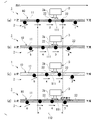
図1は、第1実施形態に係る流動検知機能付きポンプ1及びポンプ異常検知システム200の構成図である。
図1に示すように、流動検知機能付きポンプ1は、流路10を蠕動運動させるポンプ部2と、流路10内の圧力を検出する圧力検出部3と、を備えている。ポンプ異常検知システム200は、当該流動検知機能付きポンプ1と、流動検知機能付きポンプ1の圧力検出部3から出力される信号に基づいて、流動検知機能付きポンプ1の異常の有無を判定する制御装置201と、を備えている。
(First embodiment)
FIG. 1 is a configuration diagram of a pump 1 with a flow detection function and a pump abnormality detection system 200 according to the first embodiment.
As shown in FIG. 1 , a pump 1 with a flow detection function includes a pump section 2 that causes a flow path 10 to perform peristaltic motion, and a pressure detection section 3 that detects the pressure inside the flow path 10 . The pump abnormality detection system 200 determines whether or not there is an abnormality in the pump 1 with a flow detection function based on the signal output from the pump 1 with a flow detection function and the pressure detection unit 3 of the pump 1 with a flow detection function. a device 201;

流路10は、内部を流れる流体の圧力変化によって変位する流壁11を有する。本実施形態の流路10は、可撓性及び弾性を少なくとも有する、いわゆる送液用チューブであって、一定の内径(断面積)で長尺に形成されている。なお、流体の種類や用途等に応じて、必要に応じて流壁11に酸化処理等の各種処理を施しても構わないし、耐熱性、透明性等の各種の特性を付加しても構わない。流路10は、ポンプ部2の上流側において、流体を貯留している液体タンク4に接続されている。 The channel 10 has a flow wall 11 that is displaced by pressure changes of the fluid flowing inside. The channel 10 of the present embodiment is a so-called liquid-sending tube having at least flexibility and elasticity, and is elongated with a constant inner diameter (cross-sectional area). In addition, depending on the type of fluid, application, etc., the flow wall 11 may be subjected to various treatments such as oxidation treatment as necessary, or may be given various properties such as heat resistance and transparency. . The flow path 10 is connected to a liquid tank 4 that stores fluid on the upstream side of the pump section 2 .

ポンプ部2は、流路10を蠕動運動させ、液体タンク内に貯留されている流体を吸い込み、当該流体を脈動させながら吐出する、いわゆるローラポンプである。なお、ポンプ部2は、蠕動式のポンプであれば、ローラポンプ方式だけでなく、例えば、上記先行技術文献に開示されているようなペリスタルティックフィンガー方式のポンプであっても構わない。流路10は少なくとも可撓性及び弾性を有しているので、流壁11は、流体の脈動に応じて波打つように膨縮する。 The pump unit 2 is a so-called roller pump that causes the flow path 10 to perform peristaltic motion, sucks the fluid stored in the liquid tank, and discharges the fluid while pulsating it. As long as the pump unit 2 is a peristaltic pump, it may be not only a roller pump type but also a peristaltic finger type pump as disclosed in the prior art document. Since the channel 10 has at least flexibility and elasticity, the flow wall 11 undulates and contracts according to the pulsation of the fluid.

ポンプ部2は、平面視円形状のローラ収容部21aが形成されたポンプ本体21と、ローラ収容部21a内に配置された複数の圧接子22及び圧接子駆動部23と、を備えている。ポンプ本体21には、ローラ収容部21aの周壁に沿うように平面視U字状に流路10が配設されている。流路10は、複数の圧接子22を外側から囲んでいる。 The pump unit 2 includes a pump main body 21 in which a roller accommodating portion 21a having a circular shape in plan view is formed, and a plurality of press contacts 22 and a press contact driving portion 23 arranged in the roller accommodating portion 21a. In the pump main body 21, the channel 10 is arranged in a U shape in a plan view along the peripheral wall of the roller accommodating portion 21a. The flow path 10 surrounds the plurality of press contacts 22 from the outside.

圧接子駆動部23は、ローラ収容部21aの中央部において回転可能な中央ローラである。圧接子駆動部23は、複数の圧接子22の回転を案内する案内ローラとして機能する。複数の圧接子22は、圧接子駆動部23の周囲を囲むように周方向に均等配置された圧搾ローラである。図示の例では、6つの圧接子22を配置している場合を例にしているが、圧接子22の数は6つに限定されるものではない。 The pressure contact driving portion 23 is a central roller rotatable in the central portion of the roller accommodating portion 21a. The press contact driving portion 23 functions as a guide roller that guides the rotation of the plurality of press contacts 22 . The plurality of pressure contacts 22 are compression rollers that are evenly arranged in the circumferential direction so as to surround the pressure contact drive portion 23 . In the illustrated example, six press contacts 22 are arranged, but the number of press contacts 22 is not limited to six.

6つの圧接子22は、周方向に互いに摺接し合い、且つ圧接子駆動部23に対してそれぞれ摺接するように配置され、図示しない歯車輪列等の動力伝達機構を介して自転しながら、圧接子駆動部23の回りを公転可能とされている。
6つの圧接子22の公転方向は、例えば矢印M1の如く、流路10の上流側から下流側に向かう方向とされている。さらに6つの圧接子22の自転方向は、図1に示す矢印M2の如く、公転方向に対して逆方向とされている。
The six pressure contacts 22 are arranged so as to be in sliding contact with each other in the circumferential direction and in sliding contact with the pressure contact driving portion 23, and are pressed while rotating via a power transmission mechanism such as a gear train (not shown). It is capable of revolving around the child driving portion 23 .
The revolving direction of the six press contacts 22 is, for example, the direction from the upstream side to the downstream side of the flow path 10, as indicated by an arrow M1. Further, the directions of rotation of the six pressure contacts 22 are opposite to the directions of revolution, as indicated by arrows M2 in FIG.

さらに6つの圧接子22は、公転の過程において、ローラ収容部21aに収容されている流路10を押し潰すことが可能とされている。これにより、流路10を押し潰しながら圧接子22を回転させることができ、流体を下流側に向けて送ることができる。さらに、圧接子22が流路10に乗り上げ、流路10を押し潰しながら下流側に移動すると、圧接子22が移動した分だけ流路10内に負圧が発生するので、液体タンク4内から流路10内に流体を吸い込むことが可能となる。 Further, the six pressure contacts 22 are capable of crushing the flow path 10 housed in the roller housing portion 21a during the process of revolution. As a result, the press contact 22 can be rotated while the flow path 10 is crushed, and the fluid can be sent downstream. Furthermore, when the pressure contact 22 rides on the flow path 10 and moves downstream while crushing the flow path 10 , a negative pressure is generated in the flow path 10 by the movement of the pressure contact 22 . Fluid can be sucked into the channel 10 .

これらの動作が繰り返されることで、複数の圧接子22を利用して流路10を周期的にしごくことができ、流路10を蠕動運動させながら下流側に流体を供給(送液)することが可能となる。つまり、ポンプ部2は、流路10を周期的にしごいて、下流側に流体を送液できる。また、ポンプ部2(圧接子駆動部23)の回転数に応じて圧接子22の公転速度が変わるため、流体の送液速度を制御できる。なお、ポンプ部2の動作は、制御装置201によって制御されている。 By repeating these operations, the flow path 10 can be periodically squeezed using the plurality of pressure contacts 22, and the fluid can be supplied (fluid-fed) to the downstream side while causing the flow path 10 to perform peristaltic motion. becomes possible. That is, the pump part 2 can pump the fluid downstream by periodically squeezing the flow path 10 . In addition, since the revolution speed of the press contact 22 changes according to the number of rotations of the pump portion 2 (press contact driving portion 23), the fluid feeding speed can be controlled. Note that the operation of the pump unit 2 is controlled by the control device 201 .

圧力検出部3は、検出部本体3aと、受圧部3bと、を備えている。受圧部3bは、流路10の流壁11に接触する弾性体37と、弾性体37を介して流壁11に押し当てられた管路38と、を備えている。弾性体37は、流壁11の変位に応じて弾性変形する弾性を有する。この弾性体37は、流壁11よりも軟質な材料から形成することが好ましい。 The pressure detection section 3 includes a detection section body 3a and a pressure receiving section 3b. The pressure receiving portion 3 b includes an elastic body 37 that contacts the flow wall 11 of the flow path 10 and a conduit 38 that is pressed against the flow wall 11 via the elastic body 37 . The elastic body 37 has elasticity to elastically deform according to the displacement of the flow wall 11 . This elastic body 37 is preferably made of a material softer than the flow wall 11 .

本実施形態の弾性体37は、流壁11の変位に応じて弾性変形できる弾性を有すると共に、管路38の開口端を密閉できるシール性を有するゲル体から形成されている。管路38は、ポンプ本体21に対し挿抜可能に装着された筒体であり、弾性体37より硬い管材から形成されている。管路38の一端は、弾性体37によって閉塞され、管路38の他端は、検出部本体3aに接続されている。 The elastic body 37 of the present embodiment is formed of a gel body having elasticity capable of being elastically deformed according to the displacement of the flow wall 11 and sealing properties capable of sealing the opening end of the pipe line 38 . The pipe line 38 is a cylindrical body that is removably attached to the pump main body 21 and is made of a pipe material that is harder than the elastic body 37 . One end of the conduit 38 is closed by the elastic body 37, and the other end of the conduit 38 is connected to the detector main body 3a.

図2は、第1実施形態に係る圧力検出部3の検出部本体3aの構成図である。
図2に示すように、検出部本体3aは、センサ基板31と、カンチレバー32と、アナログ回路部33と、デジタル処理部34と、キャビティ筐体35と、を備えている。
センサ基板31は、例えば、プリント回路基板である。センサ基板31には、厚み方向に貫通する貫通孔31aが形成されている。貫通孔31aは、受圧部3bの管路38内と連通している。
FIG. 2 is a configuration diagram of the detection unit main body 3a of the pressure detection unit 3 according to the first embodiment.
As shown in FIG. 2, the detection section main body 3a includes a sensor substrate 31, a cantilever 32, an analog circuit section 33, a digital processing section 34, and a cavity housing 35. As shown in FIG.
The sensor board 31 is, for example, a printed circuit board. A through-hole 31a is formed through the sensor substrate 31 in the thickness direction. The through hole 31a communicates with the interior of the conduit 38 of the pressure receiving portion 3b.

キャビティ筐体35は、有底筒状に形成され、センサ基板31において管路38が接続される側の面と反対側の面に、貫通孔31aを囲うように接続されている。カンチレバー32は、キャビティ筐体35の内側に配置されている。カンチレバー32は、キャビティ筐体35の内側において、貫通孔31aを囲うように接続された筒状のレバー支持部36の開口端に取り付けられている。 The cavity housing 35 is formed in a cylindrical shape with a bottom, and is connected to the surface of the sensor substrate 31 opposite to the surface to which the conduit 38 is connected so as to surround the through hole 31a. The cantilever 32 is arranged inside the cavity housing 35 . Inside the cavity housing 35, the cantilever 32 is attached to the open end of a cylindrical lever support 36 connected to surround the through hole 31a.

キャビティ筐体35の内部空間は、カンチレバー32を挟んで、受圧室30Aと差圧室30Bとに区画されている。受圧室30Aと差圧室30Bとは、カンチレバー32に設けられた連通孔42を介して互いに連通している。受圧部3bの管路38及びセンサ基板31の貫通孔31aは、受圧室30Aに連通している。差圧室30Bは、カンチレバー32を挟んで受圧室30Aと連通する気密室となっている。 The internal space of the cavity housing 35 is divided into a pressure receiving chamber 30A and a differential pressure chamber 30B with the cantilever 32 interposed therebetween. The pressure receiving chamber 30A and the differential pressure chamber 30B communicate with each other through a communication hole 42 provided in the cantilever 32. As shown in FIG. The conduit 38 of the pressure receiving portion 3b and the through hole 31a of the sensor substrate 31 communicate with the pressure receiving chamber 30A. The differential pressure chamber 30B is an airtight chamber communicating with the pressure receiving chamber 30A with the cantilever 32 interposed therebetween.

この構成によれば、例えば、流路10の流壁11が変位して膨らんだ場合、弾性体37が弾性変形することで管路38内の気体が圧縮され、貫通孔31aに連通する受圧室30Aの圧力が高くなる。そうすると、カンチレバー32が受圧室30Aと差圧室30Bと差圧を撓み変形によって検出し、流路10の内圧の上昇に伴う流路10の形状変化を検知できる。 According to this configuration, for example, when the flow wall 11 of the flow path 10 is displaced and swells, the elastic body 37 is elastically deformed, thereby compressing the gas in the conduit 38, thereby compressing the pressure receiving chamber communicating with the through hole 31a. 30A pressure increases. Then, the cantilever 32 can detect the differential pressure between the pressure receiving chamber 30A and the differential pressure chamber 30B by flexural deformation, and the shape change of the flow path 10 due to the increase in the internal pressure of the flow path 10 can be detected.

図3は、第1実施形態に係るカンチレバー32の構成例を示す平面図である。
カンチレバー32は、例えば、SOI基板など半導体基板40に形成されている。半導体基板40には、ギャップG1およびギャップG2が設けられ、カンチレバー32のレバー本体41及びレバー支持部43が形成されている。なお、ギャップG1およびギャップG2は、受圧室30Aと差圧室30Bとを連通する連通孔42となる。
FIG. 3 is a plan view showing a configuration example of the cantilever 32 according to the first embodiment.
The cantilever 32 is formed on a semiconductor substrate 40 such as an SOI substrate, for example. A gap G1 and a gap G2 are provided in the semiconductor substrate 40, and a lever main body 41 and a lever support portion 43 of the cantilever 32 are formed. The gap G1 and the gap G2 serve as communication holes 42 that communicate the pressure receiving chamber 30A and the differential pressure chamber 30B.

レバー本体41は、その基端部41bがレバー支持部43に接続されて片持ち支持されており、その先端部41aが自由端とされている。レバー本体41は、基端部41bから先端部41aに向けて一方向に延びる板状であり、キャビティ筐体35の受圧室30Aと差圧室30Bとの圧力差に応じて撓み変形する。 The base end portion 41b of the lever main body 41 is connected to the lever support portion 43 so as to be cantilevered, and the distal end portion 41a thereof is a free end. The lever body 41 has a plate shape extending in one direction from the base end portion 41b toward the tip end portion 41a, and is flexurally deformed according to the pressure difference between the pressure receiving chamber 30A and the differential pressure chamber 30B of the cavity housing 35. As shown in FIG.

ギャップG1は、半導体基板40とレバー本体41の外周縁との間に形成された、半導体基板40を厚さ方向に貫通する平面視コ形状(C形状)の溝である。また、ギャップG2は、レバー本体41の基端部41bにおいて形成された、レバー本体41を厚さ方向に貫通する平面視コ形状(C形状)の溝である。ギャップG2は、レバー本体41の基端部41bにおいてレバー本体41の幅方向の中央部に配置されている。 The gap G1 is a U-shaped (C-shaped) groove formed between the semiconductor substrate 40 and the outer peripheral edge of the lever body 41 and penetrating the semiconductor substrate 40 in the thickness direction. The gap G2 is a U-shaped (C-shaped) groove formed in the base end portion 41b of the lever body 41 and penetrating the lever body 41 in the thickness direction. The gap G<b>2 is arranged at the center of the lever body 41 in the width direction at the base end 41 b of the lever body 41 .

レバー支持部43は、ギャップG2を挟んでレバー本体41の幅方向に並ぶように二個配置され、レバー本体41と半導体基板40とを接続すると共にレバー本体41を片持ち状態で支持している。2つのレバー支持部43のレバー本体41の幅方向における支持幅は、同等とされている。したがって、レバー本体41が撓み変形した際、一方のレバー支持部43に作用する単位面積当たりの応力と、他方のレバー支持部43に作用する単位面積当たりの応力とは同等となっている。 Two lever support portions 43 are arranged side by side in the width direction of the lever body 41 across a gap G2, connect the lever body 41 and the semiconductor substrate 40, and support the lever body 41 in a cantilever state. . The support widths of the two lever support portions 43 in the width direction of the lever main body 41 are made equal. Therefore, when the lever main body 41 is flexurally deformed, the stress per unit area acting on one lever support portion 43 is equal to the stress per unit area acting on the other lever support portion 43 .

半導体基板40には、レバー本体41を含むようにピエゾ抵抗(抵抗素子)であるドープ層44(不純物半導体層)が形成されている。このドープ層44は、例えばリン等のドープ材(不純物)がイオン注入法や拡散法等の各種の方法によりドーピングされることで形成されている。ドープ層44のうち、レバー本体41が形成された部分(レバー支持部43に形成されている部分を含む)は、抵抗R1(差圧検出抵抗Rsen1)として機能する。 A doped layer 44 (impurity semiconductor layer), which is a piezoresistor (resistive element), is formed on the semiconductor substrate 40 so as to include the lever body 41 . The doped layer 44 is formed by doping a dopant (impurity) such as phosphorus by various methods such as ion implantation and diffusion. A portion of the doped layer 44 where the lever main body 41 is formed (including the portion formed on the lever support portion 43) functions as a resistor R1 (differential pressure detection resistor Rsen1).

抵抗R1は、レバー支持部43の撓み量に応じて抵抗値が変化する。また、図示を省略するが、ドープ層44の上面の一部には、ドープ層44よりも電気抵抗率が小さい導電性材料(例えば、Au(金)等)からなる電極が形成されている。この電極は、抵抗R1(差圧検出抵抗Rsen1)の第1端および第2端として機能する。 The resistance value of the resistor R1 changes according to the deflection amount of the lever support portion 43 . Although not shown, an electrode made of a conductive material (for example, Au (gold) or the like) having an electrical resistivity lower than that of the doped layer 44 is formed on a part of the upper surface of the doped layer 44 . This electrode functions as a first end and a second end of the resistor R1 (differential pressure detection resistor Rsen1).

図2に戻り、アナログ回路部33は、レバー本体41の撓み変形に応じた変位を検出するアナログ処理を行う回路である。このアナログ回路部33は、AFE(アナログフロントエンド)である。アナログ回路部33は、キャビティ筐体35の内部、すなわち、差圧室30Bに配置されている。 Returning to FIG. 2, the analog circuit section 33 is a circuit that performs analog processing for detecting displacement according to bending deformation of the lever body 41 . This analog circuit section 33 is an AFE (analog front end). The analog circuit section 33 is arranged inside the cavity housing 35, that is, in the differential pressure chamber 30B.

図4は、第1実施形態に係るアナログ回路部33の構成例を示す回路図である。
図4に示すように、アナログ回路部33は、ホイートストンブリッジ回路45と、差動増幅回路46と、を備えている。ホイートストンブリッジ回路45は、カンチレバー32が有する抵抗R1(差圧検出抵抗Rsen1)と、抵抗R2と、抵抗R3と、抵抗R4とを備えている。
FIG. 4 is a circuit diagram showing a configuration example of the analog circuit section 33 according to the first embodiment.
As shown in FIG. 4 , the analog circuit section 33 includes a Wheatstone bridge circuit 45 and a differential amplifier circuit 46 . The Wheatstone bridge circuit 45 includes a resistor R1 (differential pressure detection resistor Rsen1) included in the cantilever 32, a resistor R2, a resistor R3, and a resistor R4.

抵抗R1(差圧検出抵抗Rsen1)は、第1端が基準電圧回路Vrefに、第2端がノードN1に接続されており、受圧室30Aと差圧室30Bとの差圧に応じて抵抗が変化する。抵抗R1は、例えば、ピエゾ抵抗(ドープ層44)である。また、抵抗R2は、第1端がノードN1に、第2端が電源GNDに接続されている。 The resistor R1 (differential pressure detection resistor Rsen1) has a first end connected to the reference voltage circuit Vref and a second end connected to the node N1. Change. Resistor R1 is, for example, a piezoresistor (doped layer 44). The resistor R2 has a first end connected to the node N1 and a second end connected to the power supply GND.

抵抗R3は、第1端が基準電圧回路Vrefに、第2端がノードN2に接続されている。抵抗R4は、第1端がノードN2に、第2端が電源GNDに接続されている。抵抗R1は、カンチレバー32内に構成されており、抵抗R3および抵抗R4は、カンチレバー32の外部に備えられた外付け抵抗である。 The resistor R3 has a first end connected to the reference voltage circuit Vref and a second end connected to the node N2. The resistor R4 has a first end connected to the node N2 and a second end connected to the power supply GND. The resistor R1 is configured within the cantilever 32, and the resistors R3 and R4 are external resistors provided outside the cantilever 32. FIG.

抵抗R2(参照抵抗Rref1)は、例えば、抵抗R1と温度特性が同一になるように形成された抵抗であり、カンチレバー32内に構成されてもよいし、カンチレバー32の近傍の外部に備えられてもよい。なお、抵抗R1と抵抗R2との温度特性を一致させることにより、アナログ回路部33は、温度変動による検出結果への影響を低減することができる。 The resistor R2 (reference resistor Rref1) is, for example, a resistor formed to have the same temperature characteristics as the resistor R1, and may be configured within the cantilever 32 or may be provided outside near the cantilever 32. good too. By matching the temperature characteristics of the resistor R1 and the resistor R2, the analog circuit section 33 can reduce the influence of temperature fluctuations on the detection result.

差動増幅回路46は、例えば、計測アンプ(インスツルメンテーションアンプ)であり、ノードN1とノードN2との電位差を増幅して出力信号として出力する。この電位差は、ピエゾ抵抗の抵抗値変化に応じた値、すなわちカンチレバー32の変位に基づいた値となる。差動増幅回路46は、反転入力端子(-端子)がノードN1に接続され、非反転入力端子(+端子)がノードN2に接続されている。 The differential amplifier circuit 46 is, for example, a measurement amplifier (instrumentation amplifier), amplifies the potential difference between the node N1 and the node N2, and outputs it as an output signal. This potential difference becomes a value corresponding to the change in the resistance value of the piezoresistor, that is, a value based on the displacement of the cantilever 32 . The differential amplifier circuit 46 has an inverting input terminal (-terminal) connected to the node N1 and a non-inverting input terminal (+terminal) connected to the node N2.

図2に示すデジタル処理部34は、例えば、マイクロコントローラなどのデジタル処理回路であり、アナログ回路部33が検出した差圧に対応した出力波形データを、圧力変動情報に変換する。デジタル処理部34は、例えば、センサ基板31に実装(配置)されており、キャビティ筐体35の外部に配置されている。 The digital processing unit 34 shown in FIG. 2 is, for example, a digital processing circuit such as a microcontroller, and converts the output waveform data corresponding to the differential pressure detected by the analog circuit unit 33 into pressure fluctuation information. The digital processing unit 34 is mounted (arranged) on, for example, the sensor substrate 31 and arranged outside the cavity housing 35 .

図1に戻り、圧力検出部3の受圧部3bは、複数の圧接子22が流壁11に接触しながら流壁11を押圧する押圧範囲100で、且つ、複数の圧接子22と流路10を挟んだ反対側の位置において、流壁11に接触している。流路10の押圧範囲100とは、複数の圧接子22が流路10の内径を潰しながら移動する範囲を言う。なお、当該押圧範囲100には、流路10の内径(流路面積)がゼロになる範囲(後述する閉止範囲110)と、流路10の内径がゼロではないが潰れている範囲とが含まれている。 Returning to FIG. 1 , the pressure receiving portion 3 b of the pressure detecting portion 3 has a pressure range 100 in which the plurality of pressure contacts 22 press the flow wall 11 while being in contact with the flow wall 11 . is in contact with the flow wall 11 at the position on the opposite side across the . The pressure range 100 of the flow path 10 refers to the range in which the plurality of press contacts 22 move while crushing the inner diameter of the flow path 10 . Note that the pressing range 100 includes a range in which the inner diameter (channel area) of the flow channel 10 is zero (closed range 110 described later) and a range in which the inner diameter of the flow channel 10 is not zero but is crushed. is

本実施形態の流路10の押圧範囲100は、図1に示す例では、圧接子駆動部23を中心とする時計回りに、圧接子22が流壁11の押圧を開始する9時の位置101から、圧接子22が流壁11から離れようとする3時の位置105までの範囲となっている。受圧部3bは、当該押圧範囲100において、圧接子22の流壁11に対する押圧圧力が最も高くなる12時の位置103よりも下流側の位置(図1に示す例では、12時の位置103と2時の位置104との間)において流壁11に接触している。 In the example shown in FIG. 1, the pressure range 100 of the flow path 10 of the present embodiment extends clockwise around the pressure contact driving portion 23 at the 9 o'clock position 101 where the pressure contact 22 starts pressing the flow wall 11. , to the 3 o'clock position 105 where the pressure contact 22 tends to leave the flow wall 11 . In the pressing range 100, the pressure receiving portion 3b is positioned downstream of the 12 o'clock position 103 where the pressing pressure of the pressure contact 22 against the flow wall 11 is highest (in the example shown in FIG. 1, the 12 o'clock position 103 and 2 o'clock position 104).

流路10の押圧範囲100には、複数の圧接子22が流路10を閉止しながら移動する閉止範囲110が含まれている。ここで、流路10の閉止とは、圧接子22の押圧によって流路10の内径がゼロになり、圧接子22の前後で流体の流れが阻止される状態を言う。本実施形態の流路10の閉止範囲110は、図1に示す例では、圧接子駆動部23を中心とする時計回りに、圧接子22の押圧によって流路10の内径がゼロになり始める10時の位置102(内径が殆どゼロの状態)から、圧接子22の流壁11に対する押圧圧力が最も高くなり、流路10の内径が完全にゼロになる12時の位置を経て、圧接子22の押圧が緩んで流路10の内径がゼロからプラスになり始める直前の2時の位置105(内径が殆どゼロの状態)までの範囲となっている。 A pressing range 100 of the flow path 10 includes a closing range 110 in which the plurality of press contacts 22 move while closing the flow path 10 . Here, closing of the flow path 10 means a state in which the inner diameter of the flow path 10 becomes zero by pressing the pressure contact 22 and the flow of fluid is blocked before and after the pressure contact 22 . In the example shown in FIG. 1, the closing range 110 of the flow path 10 of the present embodiment is 10 in which the inner diameter of the flow path 10 starts to become zero due to the pressing force of the pressure contactor 22 clockwise around the pressure contactor driving portion 23. From the hour position 102 (the state where the inner diameter is almost zero), the pressing pressure of the pressure contactor 22 against the flow wall 11 becomes the highest, and the pressure contactor 22 reaches the 12 o'clock position where the inner diameter of the flow path 10 becomes completely zero. 2 o'clock position 105 (the state where the inner diameter is almost zero) just before the inner diameter of the flow path 10 starts to increase from zero to plus.

流路10の閉止範囲110には、圧接子22が流路10を閉止する位置(例えば、12時の位置103)とその隣の圧接子22が流路10を閉止する位置(例えば2時の位置104)との間に挟まれた両端閉止部111が形成されている。受圧部3bは、閉止範囲110の下流端(図1に示す例では、2時の位置104)から流路10の上流側に向かって両端閉止部111の1つ分の形成長さPの範囲の位置において、流壁11に接触している。なお、両端閉止部111の1つ分の形成長さPは、複数の圧接子22が並ぶ1ピッチ分に相当している。 In the closing range 110 of the flow path 10, there are a position where the pressure contact 22 closes the flow path 10 (for example, 12 o'clock position 103) and an adjacent position where the pressure contact 22 closes the flow path 10 (for example, 2 o'clock position 103). Positions 104) are formed with both end closures 111 sandwiched between them. The pressure receiving portion 3b extends from the downstream end of the closing area 110 (the 2 o'clock position 104 in the example shown in FIG. 1) toward the upstream side of the flow path 10 in a range corresponding to the forming length P of one of the both end closing portions 111. is in contact with the flow wall 11 at the position of . It should be noted that the formation length P for one of the two-end closing portions 111 corresponds to one pitch of the plurality of press contacts 22 arranged side by side.

図5は、第1実施形態に係る圧接子22の動きを説明するために流路10を直線に延ばした展開図である。図5においては、(a)~(d)の順に動く圧接子22を識別するために便宜的に1~6の数字を付している(図6及び後述する図7でも同様)。図6は、第1実施形態に係る圧接子22の動きに応じた流路10の内圧と圧力検出部3の出力値3Aの変化を示すグラフである。なお、図6(a)~図6(d)に示すグラフは、図5(a)~図5(d)に示す圧接子22の動きに対応している。 FIG. 5 is a developed view in which the channel 10 is linearly extended to explain the movement of the pressure contact 22 according to the first embodiment. In FIG. 5, numerals 1 to 6 are assigned for convenience in order to identify the press contacts 22 that move in the order of (a) to (d) (the same applies to FIG. 6 and FIG. 7 described later). FIG. 6 is a graph showing changes in the internal pressure of the flow path 10 and the output value 3A of the pressure detector 3 according to the movement of the pressure contact 22 according to the first embodiment. Graphs shown in FIGS. 6(a) to 6(d) correspond to movements of the press contact 22 shown in FIGS. 5(a) to 5(d).

図5(a)に示すように、受圧部3bが流路10の両端閉止部111に対向するとき、受圧部3bは、両端閉止部111の内圧による流壁11の変位を検知する。つまり、圧力検出部3の出力値3Aは、図6(a)に示すように、流路10の内圧相当になる。なお、両端閉止部111の下流端を閉止する圧接子22(2の圧接子)より下流側においては、流体の押し出しにより圧力が高くなっている。 As shown in FIG. 5( a ), when the pressure receiving portion 3 b faces the both end closing portions 111 of the flow path 10 , the pressure receiving portion 3 b detects displacement of the flow wall 11 due to the internal pressure of the both end closing portions 111 . That is, the output value 3A of the pressure detection unit 3 corresponds to the internal pressure of the flow path 10 as shown in FIG. 6(a). Further, on the downstream side of the press contact 22 (2 press contact) that closes the downstream end of the both-ends closing portion 111, the pressure is increased due to the pushing out of the fluid.

図5(b)に示すように、受圧部3bが流路10を挟んで圧接子22(3の圧接子)と対向するとき、受圧部3bは、圧接子22(3の圧接子)の押圧による流壁11の変位を検知する。つまり、圧力検出部3の出力値3Aは、図6(b)に示すように、流路10の内圧よりも高くなる。 As shown in FIG. 5B, when the pressure receiving portion 3b faces the pressure contact 22 (the pressure contact 3) across the flow path 10, the pressure receiving portion 3b presses the pressure contact 22 (the pressure contact 3). The displacement of the flow wall 11 due to is detected. That is, the output value 3A of the pressure detection unit 3 becomes higher than the internal pressure of the flow path 10, as shown in FIG. 6(b).

図5(c)に示すように、受圧部3bと対向していた圧接子22(3の圧接子)が、受圧部3bの下流側に移動するが、未だ閉止範囲110に位置するとき、受圧部3bは、両端閉止部111の内圧による流壁11の変位を検知する。つまり、圧力検出部3の出力値3Aは、図6(c)に示すように、流路10の内圧相当になる。 As shown in FIG. 5(c), the pressure contact 22 (the pressure contact 3) facing the pressure receiving portion 3b moves downstream of the pressure receiving portion 3b, but is still positioned in the closed range 110. The portion 3b detects the displacement of the flow wall 11 due to the internal pressure of the both-end closing portion 111. FIG. That is, the output value 3A of the pressure detection unit 3 corresponds to the internal pressure of the flow path 10 as shown in FIG. 6(c).

図5(d)に示すように、圧接子22(3の圧接子)が、さらに受圧部3bの下流側に移動し、閉止範囲110の下流端を超えると、流路10の内径がゼロからプラスになり、圧力が高い流路10の下流側から、下流端が開放された両端閉止部111内に向かって流体の逆流が生じる。この流体の逆流は、蠕動式のポンプの動作原理的に必ず起こる逆流である。このときの圧力検出部3の出力値3Aは、図6(d)に示すように、流路10の逆流により一時的に高くなるが、逆流が落ち着くと、点線で示すように、ポンプ部2の下流側の流路10の内圧相当になる。 As shown in FIG. 5(d), when the pressure contact 22 (the pressure contact 3) moves further downstream of the pressure receiving portion 3b and exceeds the downstream end of the closing range 110, the inner diameter of the flow path 10 changes from zero to From the downstream side of the channel 10 where the pressure becomes positive and the pressure is high, the fluid reversely flows toward the inside of the double-end closing portion 111 whose downstream end is open. This reverse flow of fluid is a reverse flow that always occurs due to the principle of operation of peristaltic pumps. At this time, as shown in FIG. 6D, the output value 3A of the pressure detection unit 3 temporarily increases due to the backflow in the flow path 10, but when the backflow settles down, the pump unit 2 corresponds to the internal pressure of the flow path 10 on the downstream side of the .

図7は、第1実施形態に係るポンプ部2の下流側の流路10に詰まりが発生した場合の流路10の内圧と圧力検出部3の出力値3Aの変化を示すグラフである。なお、図7(a)~図7(d)に示すグラフは、図5(a)~図5(d)に示す圧接子22の動きに対応している。
図7に示すように、図7(a)~図7(c)までは、上述した図6(a)~図6(c)に示す流路10の内圧と圧力検出部3の出力値3Aの変化と同じであるが、ポンプ部2の下流側の流路10に詰まりが発生した場合は、当該下流側の流路10の内圧が非常に高くなるため、図7(d)の流路10の逆流において、圧力検出部3の出力値3Aのレベルが高くなる。つまり、図7(d)に示すタイミングで、圧力検出部3の出力値3Aを通常と比較すれば、ポンプ部2の下流側の流路10に詰まりが発生したことを検知することができる。
FIG. 7 is a graph showing changes in the internal pressure of the flow path 10 and the output value 3A of the pressure detection section 3 when clogging occurs in the flow path 10 on the downstream side of the pump section 2 according to the first embodiment. The graphs shown in FIGS. 7(a) to 7(d) correspond to the movement of the press contact 22 shown in FIGS. 5(a) to 5(d).
As shown in FIG. 7, from FIG. 7(a) to FIG. 7(c), the internal pressure of the flow path 10 shown in FIG. 6(a) to FIG. However, when clogging occurs in the flow path 10 on the downstream side of the pump section 2, the internal pressure of the flow path 10 on the downstream side becomes extremely high, so the flow path in FIG. At 10 reverse flows, the level of the output value 3A of the pressure detector 3 increases. In other words, by comparing the output value 3A of the pressure detection section 3 with the normal output value at the timing shown in FIG.

図8は、第1実施形態に係る圧力検出部3(差圧センサ)の出力の変化を経時的に示すグラフである。なお、図8において点線は、通常流動を示し、実線はポンプ部2の下流側の流路10に詰まりが発生した場合の流動を示している。また、図8においては、図5(a)~図5(d)における圧力検出部3の出力値を示すために便宜的にa~dの数字を付している(図9でも同様)。図9は、比較例として圧力検出部3を絶対圧センサにした場合の出力の変化を経時的に示すグラフである。なお、図9において点線は、通常流動を示し、実線はポンプ部2の下流側の流路10に詰まりが発生した場合の流動を示している。 FIG. 8 is a graph showing changes over time in the output of the pressure detection unit 3 (differential pressure sensor) according to the first embodiment. In FIG. 8, the dotted line indicates the normal flow, and the solid line indicates the flow when clogging occurs in the flow path 10 on the downstream side of the pump section 2. As shown in FIG. Further, in FIG. 8, numerals a to d are given for convenience to indicate the output values of the pressure detecting section 3 in FIGS. 5(a) to 5(d) (the same applies to FIG. 9). FIG. 9 is a graph showing changes in output over time when an absolute pressure sensor is used as the pressure detection unit 3 as a comparative example. In FIG. 9, the dotted line indicates the normal flow, and the solid line indicates the flow when clogging occurs in the flow path 10 on the downstream side of the pump section 2. As shown in FIG.

図8及び図9のどちら場合においても、dの閉止範囲110の下流端において流体の逆流が生じたときの出力を通常流動と比較すれば、ポンプ部2の下流側の流路10に詰まりが発生したことを検知することができる。また、図8に示す差圧センサの方が、図9に示す絶対圧センサよりも、通常流動との違いが顕著にでる。これは、圧力値の変化が大きくても時間をかけてゆっくり変化する場合には差圧センサの出力は小さく、圧力値の変化が小さくても瞬間的に変化する場合には差圧センサの出力が大きく得られるという差圧センサの出力特性に起因するものである。つまり、差圧センサは、圧力の変化の傾きを検知できるため、絶対圧センサよりもポンプ部2の下流側の流路10に詰まりが発生したことを検知し易くなる。 In both cases of FIGS. 8 and 9, if the output when the reverse flow of the fluid occurs at the downstream end of the closed range 110 of d is compared with the normal flow, clogging of the flow path 10 on the downstream side of the pump section 2 is observed. You can detect what happened. Further, the differential pressure sensor shown in FIG. 8 is more significantly different from the normal flow than the absolute pressure sensor shown in FIG. This is because the output of the differential pressure sensor is small if the change in pressure value is large but changes slowly over time, and the output of the differential pressure sensor is small if the change in pressure value is small but changes instantaneously. This is due to the output characteristic of the differential pressure sensor that a large is obtained. That is, since the differential pressure sensor can detect the slope of the pressure change, it becomes easier to detect clogging in the flow path 10 on the downstream side of the pump section 2 than the absolute pressure sensor.

図1に戻り、ポンプ異常検知システム200は、流動検知機能付きポンプ1が備える圧力検出部3から出力される信号に基づいて、流動検知機能付きポンプ1の異常の有無を判定する制御装置201を備えている。制御装置201は、例えば、図8に示すdの出力が所定の閾値を超えた場合に異常と判定する。また、制御装置201は、例えば、図8に示すdの出力が、bの出力に対し所定の割合(例えばbの50%)を超えた場合に異常と判定してもよい。あるいは、制御装置201は、例えば、図8に示すdの出力が、通常流動のdの出力に対し所定の割合(例えばdの110%)を超えた場合に異常と判定してもよい。制御装置201は、流動検知機能付きポンプ1の異常を判定したら、例えば、圧接子駆動部23を停止させる。 Returning to FIG. 1, the pump abnormality detection system 200 includes a control device 201 that determines whether or not there is an abnormality in the pump 1 with a flow detection function based on a signal output from the pressure detection unit 3 provided in the pump 1 with a flow detection function. I have. For example, the control device 201 determines that there is an abnormality when the output of d shown in FIG. 8 exceeds a predetermined threshold. Further, the control device 201 may determine that the output of d shown in FIG. 8 is abnormal when, for example, the output of b exceeds a predetermined ratio (for example, 50% of b). Alternatively, for example, the control device 201 may determine that there is an abnormality when the output of d shown in FIG. 8 exceeds a predetermined ratio (for example, 110% of d) with respect to the output of d for normal flow. When the control device 201 determines that the pump 1 with a flow detection function is abnormal, it stops the press contact driving section 23, for example.

以上説明したように、本実施形態の流動検知機能付きポンプ1では、図1に示すように、圧力検出部3の受圧部3bが、流路10を蠕動運動させる複数の圧接子22と流路10を挟んだ反対側の位置において、流路10の流壁11と接触する。受圧部3bが流壁11と接触する位置は、複数の圧接子22が流壁11に接触しながら流壁11を押圧する押圧範囲100にあるため、圧接子22が流路10から離れることはなく、流路10を押し潰す区間が長く確保され、ポンプの吸い上げ能力の低下を抑制できる。 As described above, in the pump 1 with a flow detection function of the present embodiment, as shown in FIG. It contacts the flow wall 11 of the channel 10 at the position on the opposite side across the 10 . The position where the pressure-receiving portion 3b contacts the flow wall 11 is within a pressing range 100 where the plurality of pressure contacts 22 press the flow wall 11 while contacting the flow wall 11. Instead, a long section for crushing the flow path 10 can be ensured, and a decrease in the suction ability of the pump can be suppressed.

このように、本実施形態に係る流動検知機能付きポンプ1は、内部を流れる流体の圧力変化によって変位する流壁11を有する流路10と、流壁11に圧接する複数の圧接子22を動かすことによって、流路10を蠕動運動させるポンプ部2と、複数の圧接子22が流壁11を押圧する押圧範囲100で、且つ、複数の圧接子22と流路10を挟んだ反対側の位置において、流壁11に接触する受圧部3bを有する圧力検出部3と、を備える。このため、蠕動式のポンプ性能を維持したまま、流路10内の流動状態を検知することが可能となる。 As described above, the pump 1 with a flow detection function according to the present embodiment moves the flow path 10 having the flow wall 11 that is displaced by the pressure change of the fluid flowing inside, and the plurality of press contacts 22 that press against the flow wall 11. As a result, the pressure range 100 in which the pump portion 2 that causes the flow path 10 to perform peristaltic motion and the plurality of pressure contacts 22 press against the flow wall 11 and the position on the opposite side of the pressure contact elements 22 and the flow path 10 are interposed. , a pressure detecting portion 3 having a pressure receiving portion 3 b that contacts the flow wall 11 . Therefore, it is possible to detect the state of flow in the flow path 10 while maintaining the performance of the peristaltic pump.

また、本実施形態の流動検知機能付きポンプ1において、受圧部3bは、圧接子22の流壁11に対する押圧圧力が最も高くなる位置103よりも流路10の下流側の位置において流壁11に接触している。この構成によれば、仮にポンプ部2の下流側で流路10に詰まりが生じた場合、ポンプ部2における圧接子22の流壁11に対する押圧圧力が最も高くなる位置103において、流体の逆流を阻止できるため、下流側での詰まりによって生じる当該流体の逆流による流路10の内圧の上昇を受圧部3bが感知できるようになる。 In addition, in the pump 1 with a flow detection function of the present embodiment, the pressure receiving portion 3b is attached to the flow wall 11 at a position downstream of the flow channel 10 from the position 103 where the pressing pressure of the pressure contact 22 against the flow wall 11 is the highest. in contact. According to this configuration, if clogging occurs in the flow path 10 on the downstream side of the pump section 2, the back flow of the fluid is prevented at the position 103 where the pressing pressure of the pressure contact 22 against the flow wall 11 in the pump section 2 is the highest. Since this can be prevented, the pressure receiving portion 3b can detect the rise in the internal pressure of the flow path 10 due to the reverse flow of the fluid caused by the clogging on the downstream side.

また、本実施形態の流動検知機能付きポンプ1において、押圧範囲100には、複数の圧接子22が流路10を閉止しながら移動する閉止範囲110が含まれ、閉止範囲110には、圧接子22が流路10を閉止する位置103とその隣の圧接子22が流路10を閉止する位置104との間に挟まれた両端閉止部111が形成され、受圧部3bは、閉止範囲110の下流端から流路10の上流側に向かって両端閉止部111の1つ分の形成長さPの範囲の位置において、流壁11に接触している。 Further, in the pump 1 with a flow detection function of the present embodiment, the pressing range 100 includes a closing range 110 in which the plurality of pressure contacts 22 move while closing the flow path 10. The closing range 110 includes the pressure contacts 22 closes the flow path 10 and a position 104 at which the pressure contact 22 adjacent thereto closes the flow path 10, and a both-end closing portion 111 is formed. The flow wall 11 is in contact with the flow wall 11 at a position within a formation length P corresponding to one end closing portion 111 from the downstream end toward the upstream side of the flow channel 10 .

蠕動式のポンプにおいては、複数の圧接子22による流路10の押圧範囲100の中に、圧接子22の押圧によって流路10の内径がゼロになる閉止範囲110が含まれ、その閉止範囲110に、隣り合う2つの圧接子22により挟まれた両端閉止部111が形成される。両端閉止部111は、閉止範囲110の下流端において、圧接子22による流壁11の押圧が弱まることで、流路10の内径がゼロからプラスになり、圧力が高い流路10の下流側から流体の逆流が生じる。 In the peristaltic pump, the pressure range 100 of the flow path 10 by the plurality of pressure contacts 22 includes a closing range 110 where the pressure of the pressure contacts 22 makes the inner diameter of the flow path 10 zero. , a both-end closing portion 111 sandwiched by two adjacent press contacts 22 is formed. At the downstream end of the closing range 110, the pressure on the flow wall 11 by the pressure contact 22 is weakened, so that the inner diameter of the flow channel 10 changes from zero to positive, and the pressure from the downstream side of the high pressure flow channel 10 is reduced. Backflow of fluid occurs.

受圧部3bは、閉止範囲110の下流端から流路10の上流側に向かって両端閉止部111の1つ分の形成長さPの範囲内に位置しているため、このような逆流は、生じた瞬間に流路10が閉止される箇所を通過することなく受圧部3bに到達することができる。その結果、受圧部3bが当該流体の逆流による流路10の内圧の上昇を効率よく検知できるようになる。また、両端閉止部111は、下流側の圧接子22によって未だ閉止されているため、ポンプ部2の上流側への流体の逆流を阻止できる。加えて、仮にポンプ部2の下流側で流路10に詰まりが生じた場合、上述した通常の流体の逆流と比べて、流体の逆流による流路10の内圧の上昇が顕著になるため、通常の流体の逆流と比較することで流路10の詰まりを検知することができる。 Since the pressure-receiving portion 3b is located within the range of the formation length P of one of the both-end closing portions 111 from the downstream end of the closing area 110 toward the upstream side of the flow path 10, such backflow is It is possible to reach the pressure receiving portion 3b without passing through the location where the flow path 10 is closed at the moment of occurrence. As a result, the pressure receiving portion 3b can efficiently detect an increase in the internal pressure of the flow path 10 due to the backflow of the fluid. Further, since the both-ends closing portion 111 is still closed by the pressure contact 22 on the downstream side, the reverse flow of the fluid to the upstream side of the pump portion 2 can be prevented. In addition, if clogging occurs in the flow path 10 on the downstream side of the pump section 2, compared to the normal backflow of the fluid described above, the increase in internal pressure of the flow path 10 due to the backflow of the fluid becomes more pronounced. Clogging of the flow path 10 can be detected by comparing with the reverse flow of the fluid.

また、本実施形態の流動検知機能付きポンプ1において、圧力検出部3は、図2に示すように、受圧部3bの内圧の変化によって撓み変形するカンチレバー32を備えている。この構成によれば、カンチレバー32が感度よく受圧部3bの内圧の変化を検知するため、圧接子22の強い押圧から、流路10の微弱な圧力変化まで、広い範囲で圧力を検知することができる。このため、受圧部3bを、圧接子22によって押圧される流路10の押圧範囲100に設置でき、ポンプ部2の送液能力を下げずに、流体の流動状況を流路10の外部から検知できる。また、圧力検出部3は、圧接子22の押圧(タイミングや圧力)も測定することが可能であるため、ポンプ部2の稼働状況も同時に検知することができる。 In addition, in the pump 1 with a flow detection function of the present embodiment, the pressure detection section 3 includes a cantilever 32 that bends and deforms according to changes in the internal pressure of the pressure receiving section 3b, as shown in FIG. According to this configuration, the cantilever 32 can detect changes in the internal pressure of the pressure receiving portion 3b with high sensitivity. can. Therefore, the pressure receiving part 3b can be installed in the pressure range 100 of the flow path 10 pressed by the pressure contact 22, and the flow condition of the fluid can be detected from the outside of the flow path 10 without lowering the liquid feeding capability of the pump part 2. can. In addition, since the pressure detection unit 3 can also measure the pressure (timing and pressure) of the press contact 22, it is possible to detect the operation status of the pump unit 2 at the same time.

また、本実施形態の流動検知機能付きポンプ1において、圧力検出部3は、カンチレバー32を挟んで受圧部3bの内部と連通する差圧室30Bを形成するキャビティ筐体35を備えている。この構成によれば、カンチレバー32が外気からの影響を受け難くなるため、流体の圧力変化に伴う流路10の変位を高精度に検知することができる。 Further, in the pump 1 with a flow detection function of the present embodiment, the pressure detection section 3 includes a cavity housing 35 that forms a differential pressure chamber 30B that communicates with the inside of the pressure receiving section 3b with the cantilever 32 interposed therebetween. According to this configuration, the cantilever 32 is less likely to be affected by the outside air, so displacement of the flow path 10 due to changes in fluid pressure can be detected with high accuracy.

また、本実施形態の流動検知機能付きポンプ1において、受圧部3bは、図1に示すように、流壁11に接触する弾性体37と、弾性体37を介して流壁11に押し当てられた管路38と、を備えている。この構成によれば、受圧部3bの管路38が弾性体37を介して流壁11に密着するため、流壁11の変位に伴う受圧部3bの内圧の変化の応答性が良くなり、流路10の形状変化を感度良く検知することができる。 Further, in the pump 1 with a flow detection function of the present embodiment, as shown in FIG. and a conduit 38 . According to this configuration, since the conduit 38 of the pressure receiving portion 3b is in close contact with the flow wall 11 via the elastic body 37, the responsiveness to changes in the internal pressure of the pressure receiving portion 3b due to the displacement of the flow wall 11 is improved. A shape change of the road 10 can be detected with high sensitivity.

また、本実施形態の流動検知機能付きポンプ1において、弾性体37は、流壁11よりも軟質である。この構成によれば、例えば、流壁11が膨張する場合、流体の内圧によって流壁11が厚み方向において変位しきる前に、流壁11より軟質の弾性体37が変位しはじめるため、流壁11の変位に伴う受圧部3bの内圧の変化の応答性が良くなり、流路10の形状変化を感度良く検知することができる。 Moreover, in the pump 1 with a flow detection function of the present embodiment, the elastic body 37 is softer than the flow wall 11 . According to this configuration, for example, when the flow wall 11 expands, the elastic body 37 softer than the flow wall 11 begins to displace before the flow wall 11 is completely displaced in the thickness direction by the internal pressure of the fluid. The responsiveness of the change in the internal pressure of the pressure receiving portion 3b due to the displacement of the pressure receiving portion 3b is improved, and the shape change of the flow path 10 can be detected with high sensitivity.

また、本実施形態に係るポンプ異常検知システム200は、流動検知機能付きポンプ1と、流動検知機能付きポンプ1が備える圧力検出部3から出力される信号に基づいて、流動検知機能付きポンプ1の異常の有無を判定する制御装置201と、を備える。この構成によれば、蠕動式のポンプ性能を維持したまま、流路10内の流動状態をモニタリングしつつ、ポンプ部2や流路10に異常が発生した場合は、その異常を速やかに検知して、ポンプ部2の動作停止や低速化等、ポンプ制御に反映することができる。 Further, the pump abnormality detection system 200 according to the present embodiment detects the flow detection function of the pump 1 based on the signal output from the flow detection function pump 1 and the pressure detection unit 3 provided in the flow detection function pump 1. and a control device 201 that determines the presence or absence of an abnormality. According to this configuration, when an abnormality occurs in the pump unit 2 or the flow path 10, the abnormality can be quickly detected while monitoring the flow state in the flow path 10 while maintaining the performance of the peristaltic pump. This can be reflected in pump control such as operation stop or speed reduction of the pump unit 2 .

(第2実施形態)
次に、本発明の第2実施形態について説明する。以下の説明において、上述の実施形態と同一又は同等の構成については同一の符号を付し、その説明を簡略若しくは省略する。
(Second embodiment)
Next, a second embodiment of the invention will be described. In the following description, the same reference numerals are given to the same or equivalent configurations as in the above-described embodiment, and the description thereof will be simplified or omitted.

図10は、第2実施形態に係る流動検知機能付きポンプ1の要部を示す構成図である。
図10に示すように、第2実施形態の流動検知機能付きポンプ1は、圧力検出部3が、受圧部3bを流壁11に向かって付勢する付勢部5を備えている。
FIG. 10 is a configuration diagram showing the essential parts of the pump 1 with a flow detection function according to the second embodiment.
As shown in FIG. 10 , in the pump 1 with a flow detection function of the second embodiment, the pressure detection section 3 includes an urging section 5 that urges the pressure receiving section 3 b toward the flow wall 11 .

付勢部5は、固定板51と、スプリング52と、を備えている。固定板51は、検出部本体3aの背面側(キャビティ筐体35側)に配置されている。スプリング52は、固定板51とキャビティ筐体35との間に配置され、検出部本体3aを介して受圧部3bを流壁11に向かって付勢している。つまり、付勢部5は、圧力検出部3全体を流壁11に向かって付勢している。 The biasing portion 5 includes a fixed plate 51 and a spring 52 . The fixing plate 51 is arranged on the back side (the cavity housing 35 side) of the detection unit main body 3a. The spring 52 is arranged between the fixed plate 51 and the cavity housing 35 and biases the pressure receiving portion 3b toward the flow wall 11 via the detection portion main body 3a. That is, the biasing portion 5 biases the entire pressure detecting portion 3 toward the flow wall 11 .

上述した第2実施形態によれば、付勢部5からの付勢によって受圧部3bが流壁11に対する密着状態を維持しやすくなるため、流壁11の変位に伴う受圧部3bの内圧の変化の応答性が良くなり、流路10の形状変化を感度良く検知することができる。 According to the second embodiment described above, the pressure from the biasing portion 5 makes it easier for the pressure-receiving portion 3b to maintain close contact with the flow wall 11. Therefore, the change in the internal pressure of the pressure-receiving portion 3b accompanying the displacement of the flow wall 11 , the change in shape of the flow path 10 can be detected with high sensitivity.

また、第2実施形態では、以下のような変形例を採用することができる。 Moreover, in the second embodiment, the following modifications can be employed.

図11は、第2実施形態に係る流動検知機能付きポンプ1の要部の一変形例を示す構成図である。
図11に示すように、第2実施形態の流動検知機能付きポンプ1は、受圧部3bが流壁11に接触するベローズ管53を備えている。すなわち、受圧部3b自体がバネ性を有し、流壁11に押し付けられている。この構成によれば、受圧部3bのベローズ管53が弾性的に流壁11に密着するため、流壁11の変位に伴う受圧部3bの内圧の変化の応答性が良くなり、流路10の形状変化を感度良く検知することができる。
FIG. 11 is a configuration diagram showing a modified example of the main part of the pump 1 with a flow detection function according to the second embodiment.
As shown in FIG. 11, the pump 1 with a flow detection function of the second embodiment includes a bellows pipe 53 in which the pressure receiving portion 3b contacts the flow wall 11. As shown in FIG. That is, the pressure-receiving portion 3 b itself has springiness and is pressed against the flow wall 11 . According to this configuration, the bellows pipe 53 of the pressure receiving portion 3b is elastically adhered to the flow wall 11, so that the responsiveness to changes in the internal pressure of the pressure receiving portion 3b due to the displacement of the flow wall 11 is improved. Shape change can be detected with high sensitivity.

図12は、第2実施形態に係る流動検知機能付きポンプ1の要部の一変形例を示す構成図である。
図12に示すように、第2実施形態の流動検知機能付きポンプ1は、受圧部3bが流壁11に接触するバルーン体54を備えている。すなわち、受圧部3b自体がバネ性を有し、流壁11に押し付けられている。この構成によれば、受圧部3bのバルーン体54が弾性的に流壁11に密着するため、流壁11の変位に伴う受圧部3bの内圧の変化の応答性が良くなり、流路10の形状変化を感度良く検知することができる。
FIG. 12 is a configuration diagram showing a modified example of the main part of the pump 1 with a flow detection function according to the second embodiment.
As shown in FIG. 12, the pump 1 with flow detection function of the second embodiment includes a balloon body 54 in which the pressure receiving portion 3b contacts the flow wall 11. As shown in FIG. That is, the pressure-receiving portion 3 b itself has springiness and is pressed against the flow wall 11 . According to this configuration, the balloon body 54 of the pressure receiving portion 3b elastically adheres to the flow wall 11, so that the responsiveness to changes in the internal pressure of the pressure receiving portion 3b accompanying displacement of the flow wall 11 is improved. Shape change can be detected with high sensitivity.

(第3実施形態)
次に、本発明の第3実施形態について説明する。以下の説明において、上述の実施形態と同一又は同等の構成については同一の符号を付し、その説明を簡略若しくは省略する。
(Third embodiment)
Next, a third embodiment of the invention will be described. In the following description, the same reference numerals are given to the same or equivalent configurations as in the above-described embodiment, and the description thereof will be simplified or omitted.

図13は、第3実施形態に係る流動検知機能付きポンプ1及びポンプ異常検知システム200の構成図である。
図13に示すように、第3実施形態の流動検知機能付きポンプ1は、第1圧接子22A及び第2圧接子22Bを備え、第1圧接子22A及び第2圧接子22Bの回転速度を独立して変化させる。つまり、第3実施形態では、第1圧接子22Aと第2圧接子22Bとの間隔が変化する。
FIG. 13 is a configuration diagram of the pump 1 with flow detection function and the pump abnormality detection system 200 according to the third embodiment.
As shown in FIG. 13, the pump 1 with a flow detection function of the third embodiment includes a first pressure contact piece 22A and a second pressure contact piece 22B, and the rotational speeds of the first pressure contact piece 22A and the second pressure contact piece 22B are controlled independently. to change. That is, in the third embodiment, the distance between the first pressure contact piece 22A and the second pressure contact piece 22B changes.

第3実施形態のポンプ部2は、平面視円形状のローラ収容部21aが形成されたポンプ本体21と、ローラ収容部21a内に配置された第1圧接子22A及び第2圧接子22Bと、第1圧接子22Aを駆動させる第1圧接子駆動部23Aと、第2圧接子22Bを駆動させる第2圧接子駆動部23Bと、を備えている。ポンプ本体21には、ローラ収容部21aの周壁に沿うように平面視略Ω字状に流路10が配設されている。流路10は、第1圧接子22A及び第2圧接子22Bを外側から囲んでいる。 The pump unit 2 of the third embodiment includes a pump body 21 formed with a roller housing portion 21a having a circular shape in plan view, a first pressure contact piece 22A and a second pressure contact piece 22B arranged in the roller housing portion 21a, It has a first pressure contact driving section 23A for driving the first pressure contact 22A and a second pressure contact driving section 23B for driving the second pressure contact 22B. In the pump main body 21, the channel 10 is arranged in a substantially Ω-shape in a plan view so as to follow the peripheral wall of the roller accommodating portion 21a. The flow path 10 surrounds the first pressure contact piece 22A and the second pressure contact piece 22B from the outside.

第1圧接子駆動部23Aは、ローラ収容部21aの中央部に配置され、第1アーム部材24Aを介して第1圧接子22Aを保持している。第1圧接子駆動部23Aは、図示しないモータ等の回転装置を備え、第1アーム部材24Aを介して第1圧接子22Aを矢印M1の如く公転させる。第1圧接子22Aは、矢印M2の如く、公転方向と逆方向に自転しながら、ローラ収容部21aに収容されている流路10を押し潰す。 The first press-contact driving portion 23A is arranged in the central portion of the roller accommodating portion 21a and holds the first press-contact 22A via the first arm member 24A. The first press contact driving section 23A includes a rotating device such as a motor (not shown), and revolves the first press contact 22A via the first arm member 24A as indicated by an arrow M1. The first pressure contact piece 22A crushes the flow path 10 housed in the roller housing portion 21a while rotating in a direction opposite to the direction of revolution as indicated by an arrow M2.

第2圧接子駆動部23Bは、第1圧接子駆動部23Aと同じくローラ収容部21aの中央部に配置され、第2アーム部材24Bを介して第2圧接子22Bを保持している。第2圧接子駆動部23Bは、図示しないモータ等の回転装置を備え、第2アーム部材24Bを介して第2圧接子22Bを矢印M1の如く公転させる。第2圧接子22Bは、矢印M2の如く、公転方向と逆方向に自転しながら、ローラ収容部21aに収容されている流路10を押し潰す。 The second press-contact driving portion 23B is arranged in the central portion of the roller accommodating portion 21a like the first press-contact driving portion 23A, and holds the second press-contact child 22B via the second arm member 24B. The second press contact driving portion 23B includes a rotating device such as a motor (not shown), and revolves the second press contact 22B via the second arm member 24B as indicated by an arrow M1. The second pressing member 22B crushes the flow path 10 accommodated in the roller accommodating portion 21a while rotating in a direction opposite to the direction of revolution as indicated by an arrow M2.

具体的に、第1圧接子駆動部23Aの回転軸は、ローラ収容部21aの中央部に配置されている。第2圧接子駆動部23Bの回転軸は、第1圧接子駆動部23Aの回転軸と同軸、且つ、第1圧接子駆動部23Aの回転軸を囲う円筒状に形成されている。第1圧接子駆動部23Aの回転軸の上端には、第1アーム部材24Aが連結されている。第1圧接子駆動部23Aの回転軸の下端は、第2圧接子駆動部23Bの円筒状の回転軸の下端から導出され、図示しない第1回転装置(モータ等)と接続されている。 Specifically, the rotation shaft of the first pressure contactor driving portion 23A is arranged in the central portion of the roller accommodating portion 21a. The rotation axis of the second pressure contact element driving section 23B is coaxial with the rotation axis of the first pressure contact element driving section 23A and is formed in a cylindrical shape surrounding the rotation axis of the first pressure contact element driving section 23A. A first arm member 24A is connected to the upper end of the rotating shaft of the first press contact driving portion 23A. The lower end of the rotating shaft of the first press contact driving portion 23A is led out from the lower end of the cylindrical rotating shaft of the second press contact driving portion 23B and is connected to a first rotating device (motor or the like) not shown.

第2圧接子駆動部23Bの円筒状の回転軸の上端には、第2アーム部材24Bが連結されている。第2アーム部材24Bは、第1アーム部材24Aよりも下方に配置されている。第2圧接子駆動部23Bの円筒状の回転軸の周面は、歯車輪列機構またはベルト機構等の動力伝達機構を介して第2回転装置(モータ等)と接続されている。第1回転装置と第2回転装置は、別の回転装置であり、それぞれが制御装置201の制御の下に駆動する。これにより、第1圧接子22A及び第2圧接子22Bの回転速度を独立して変化させることができる。なお、この種のポンプ部2の構成は、例えば、特開2020-133458号公報等に開示されている。 A second arm member 24B is connected to the upper end of the cylindrical rotating shaft of the second pressure contactor driving portion 23B. The second arm member 24B is arranged below the first arm member 24A. The peripheral surface of the cylindrical rotating shaft of the second pressure contactor driving portion 23B is connected to a second rotating device (motor or the like) via a power transmission mechanism such as a gear train mechanism or a belt mechanism. The first rotating device and the second rotating device are separate rotating devices, each driven under the control of the control device 201 . As a result, the rotational speeds of the first pressure contact piece 22A and the second pressure contact piece 22B can be changed independently. The configuration of this type of pump unit 2 is disclosed in, for example, Japanese Patent Application Laid-Open No. 2020-133458.

圧力検出部3の受圧部3bは、複数の圧接子22が流壁11に接触しながら流壁11を押圧する押圧範囲100で、且つ、複数の圧接子22と流路10を挟んだ反対側の位置において、流壁11に接触している。流路10の押圧範囲100とは、複数の圧接子22が流路10の内径を潰しながら移動する範囲を言う。なお、当該押圧範囲100には、流路10の内径(流路面積)がゼロになる範囲(閉止範囲110)と、流路10の内径がゼロではないが潰れている範囲とが含まれている。 The pressure receiving portion 3b of the pressure detecting portion 3 is located in a pressing range 100 in which the plurality of pressure contacts 22 press the flow wall 11 while being in contact with the flow wall 11, and on the opposite side of the plurality of pressure contacts 22 and the flow channel 10. is in contact with the flow wall 11 at the position of . The pressure range 100 of the flow path 10 refers to the range in which the plurality of press contacts 22 move while crushing the inner diameter of the flow path 10 . The pressing range 100 includes a range (closed range 110) in which the inner diameter (channel area) of the flow channel 10 is zero and a range in which the inner diameter of the flow channel 10 is not zero but is collapsed. there is

第3実施形態の流路10の押圧範囲100は、図13に示す例では、第1圧接子駆動部23A及び第2圧接子駆動部23Bを中心とする時計回りに、第1圧接子22Aまたは第2圧接子22Bが流壁11の押圧を開始する7時の位置121から、圧接子22が流壁11から離れようとする5時の位置122までの範囲となっている。 In the example shown in FIG. 13, the pressing range 100 of the flow path 10 of the third embodiment extends clockwise around the first pressure contact driving portion 23A and the second pressure contact driving portion 23B. The range is from the 7 o'clock position 121 where the second pressure contact member 22B starts pressing the flow wall 11 to the 5 o'clock position 122 where the pressure contact member 22 is about to leave the flow wall 11 .

流路10の押圧範囲100には、第1圧接子22Aまたは第2圧接子22Bが流路10を閉止しながら移動する閉止範囲110が含まれている。第3実施形態の流路10の閉止範囲110は、図13に示す例では、第1圧接子駆動部23A及び第2圧接子駆動部23Bを中心とする時計回りに、第1圧接子22Aまたは第2圧接子22Bの押圧によって流路10の内径がゼロになり始める8時の位置123(内径が殆どゼロの状態)から、第1圧接子22Aまたは第2圧接子22Bの押圧が緩んで流路10の内径がゼロからプラスになり始める直前の4時の位置124(内径が殆どゼロの状態)までの範囲となっている。なお、第3実施形態のポンプ部2においては、第1圧接子22Aと第2圧接子22Bとの間隔が変化し、第1圧接子22Aと第2圧接子22Bとがほぼ同じ圧で流路10を押圧するため、圧接子の場所で流路10への押圧が殆ど変化しない。 The pressing range 100 of the channel 10 includes a closing range 110 where the first press contact 22A or the second press contact 22B moves while closing the channel 10. As shown in FIG. In the example shown in FIG. 13, the closing range 110 of the flow path 10 of the third embodiment extends clockwise around the first pressure contact driving portion 23A and the second pressure contact driving portion 23B. From the 8 o'clock position 123 (when the inner diameter is almost zero), the pressure of the first pressure contact piece 22A or the second pressure contact piece 22B is loosened and flow begins. It ranges from zero to the 4 o'clock position 124, just before the inner diameter of the channel 10 begins to become positive (almost zero inner diameter). In the pump section 2 of the third embodiment, the gap between the first pressure contact piece 22A and the second pressure contact piece 22B changes, and the first pressure contact piece 22A and the second pressure contact piece 22B flow at substantially the same pressure. Since it presses against 10, the pressure on channel 10 hardly changes at the location of the pressure contact.

図14は、第3実施形態に係る第1圧接子22A及び第2圧接子22Bの動きを説明する説明図である。
図14に示すように、ポンプ部2においては、閉止範囲110の下流端に向かうに従って第1圧接子22A及び第2圧接子22Bの間隔が徐々に狭くなるように駆動する。つまり、第1圧接子22A及び第2圧接子22Bは、常に等速または定速で公転するわけではない。
14A and 14B are explanatory diagrams for explaining movements of the first pressure contact piece 22A and the second pressure contact piece 22B according to the third embodiment.
As shown in FIG. 14, the pump section 2 is driven such that the distance between the first press contact 22A and the second press contact 22B gradually narrows toward the downstream end of the closing range 110. As shown in FIG. In other words, the first pressure contact piece 22A and the second pressure contact piece 22B do not always revolve at a uniform or constant speed.

例えば、図14(a)に示すように、第1圧接子22Aが、閉止範囲110内において所定速度で回転し、閉止範囲110の下流端の近傍に位置している。そうすると、第1圧接子22Aよりも上流側の第2圧接子22Bは、第1圧接子22Aよりも回転速度が速く、第1圧接子22Aに対して近づいていく。 For example, as shown in FIG. 14(a), the first press contact 22A rotates at a predetermined speed within the closing range 110 and is positioned near the downstream end of the closing range 110. As shown in FIG. Then, the second press-contact piece 22B upstream of the first press-contact piece 22A rotates faster than the first press-contact piece 22A and approaches the first press-contact piece 22A.

図14(b)に示すように、第1圧接子22Aに第2圧接子22Bが近づくと、閉止範囲110において、第1圧接子22Aが流路10を閉止する位置と第2圧接子22Bが流路10を閉止する位置との間に挟まれた両端閉止部111の形成長さが短くなり、流路10内の圧力が上昇していく。 As shown in FIG. 14B, when the second pressure contact piece 22B approaches the first pressure contact piece 22A, the position where the first pressure contact piece 22A closes the flow path 10 and the second pressure contact piece 22B in the closing range 110 The formation length of the both-ends closing portion 111 sandwiched between the positions for closing the channel 10 is shortened, and the pressure in the channel 10 is increased.

このように、第1圧接子22Aに第2圧接子22Bが近づくことで、流路10内の圧力が上昇し、両端閉止部111における圧力と、第1圧接子22Aよりも下流側の流路10内の圧力がほぼ等しくなっていく。 As the second pressure contact piece 22B approaches the first pressure contact piece 22A in this way, the pressure in the flow path 10 rises, and the pressure in the both-end closing portion 111 and the flow path on the downstream side of the first pressure contact piece 22A increase. The pressure in 10 becomes almost equal.

そして、図14(c)に示すように、第1圧接子22Aが閉止範囲110の下流端から離脱すると、両端閉止部111が開放されるが、両端閉止部111内の圧力は、下流側の流路10内の圧力とほぼ等しくなるまで昇圧しているため、流体の逆流がほとんど発生しなくなる。 Then, as shown in FIG. 14(c), when the first press contact 22A leaves the downstream end of the closing range 110, the both-ends closing portion 111 is opened, but the pressure in the both-ends closing portion 111 increases to the downstream side. Since the pressure is increased to approximately the same as the pressure in the flow path 10, backflow of the fluid hardly occurs.

なお、第1圧接子22Aが閉止範囲110の下流端から離脱すると、第1圧接子22Aは加速に転じ、今度は、所定速度に変化中の第2圧接子22Bに対し第1圧接子22Aが近づいていく。つまり、図14に示す第1圧接子22Aと第2圧接子22Bとの位置が入れ替わり、上述した動作を繰り返すこととなる。 When the first press contact 22A leaves the downstream end of the closing range 110, the first press contact 22A begins to accelerate, and this time, the first press contact 22A moves against the second press contact 22B, which is changing to a predetermined speed. getting closer. That is, the positions of the first press contact 22A and the second press contact 22B shown in FIG. 14 are exchanged, and the above-described operations are repeated.

図13に戻り、圧力検出部3の受圧部3bは、閉止範囲110の下流側の半分の位置において流壁11に接触している。ここで、閉止範囲110の下流側の半分の位置とは、第1圧接子駆動部23A及び第2圧接子駆動部23Bを中心とする時計回りに、閉止範囲110を2等分する12時の位置126から、閉止範囲110の下流端である4時の位置124までの範囲内を言う。 Returning to FIG. 13 , the pressure receiving portion 3 b of the pressure detecting portion 3 is in contact with the flow wall 11 at the half position on the downstream side of the closing range 110 . Here, the half position on the downstream side of the closing range 110 is 12 o'clock which divides the closing range 110 into two in the clockwise direction around the first pressure contact driving portion 23A and the second pressure contact driving portion 23B. The range from position 126 to the 4 o'clock position 124 which is the downstream end of the closed range 110 .

また、圧力検出部3の受圧部3bは、閉止範囲110の下流端から流路10の上流側に向かって両端閉止部111の最小の形成長さ120の範囲内の位置において、流壁11に接触している。ここで、両端閉止部111の最小の形成長さ120の範囲内の位置とは、図14(c)に示すように、下流側の圧接子(この図14(c)の例では第1圧接子22A)が、閉止範囲110の下流端から離脱する直前の両端閉止部111の形成長さの範囲内の位置を言う。つまり、受圧部3bが両端閉止部111の最小の形成長さ120の範囲内の位置することで、圧力検出部3は、流路10内の圧力の最大値を検出できるようになる。 Further, the pressure receiving portion 3b of the pressure detecting portion 3 is positioned within the range of the minimum forming length 120 of the both end closing portions 111 toward the upstream side of the flow path 10 from the downstream end of the closing range 110. in contact. Here, the position within the range of the minimum formation length 120 of the both-ends closing portion 111 means, as shown in FIG. The position within the formed length of both end closures 111 just before the child 22A) leaves the downstream end of the closure region 110. As shown in FIG. In other words, the pressure detecting portion 3 can detect the maximum value of the pressure in the channel 10 by locating the pressure receiving portion 3 b within the range of the minimum forming length 120 of the both-end closing portion 111 .

図15及び図16は、図14に示す第1圧接子22A及び第2圧接子22Bの動きに応じた圧力検出部3の出力値の変化を示すグラフである。なお、図15に示すグラフは、圧力検出部3が絶対圧を検出するセンサを備える場合の出力値の変化を示している。また、図16に示すグラフは、圧力検出部3が差圧を検出するセンサ(図2参照)を備える場合の出力値の変化を示している。 15 and 16 are graphs showing changes in the output value of the pressure detector 3 according to the movements of the first pressure contactor 22A and the second pressure contactor 22B shown in FIG. Note that the graph shown in FIG. 15 shows changes in the output value when the pressure detection unit 3 includes a sensor for detecting absolute pressure. Also, the graph shown in FIG. 16 shows changes in the output value when the pressure detection unit 3 includes a sensor (see FIG. 2) for detecting differential pressure.

図15及び図16における時刻Taは、図14(a)に示す第1圧接子22A及び第2圧接子22Bの動きに対応している。また、図15及び図16における期間Tbは、図14(b)に示す第1圧接子22A及び第2圧接子22Bの動きに対応している。また、図15及び図16における時刻Tcは、図14(c)に示す第1圧接子22A及び第2圧接子22Bの動きに対応している。 Time Ta in FIGS. 15 and 16 corresponds to the movement of the first press contact 22A and the second press contact 22B shown in FIG. 14(a). A period Tb in FIGS. 15 and 16 corresponds to the movement of the first press contact 22A and the second press contact 22B shown in FIG. 14(b). Time Tc in FIGS. 15 and 16 corresponds to the movements of the first press contact 22A and the second press contact 22B shown in FIG. 14(c).

図14(a)に示すように、受圧部3bが流路10を挟んで第1圧接子22Aと対向するとき、受圧部3bは、第1圧接子22Aの押圧による流壁11の変位を検知する。つまり、圧力検出部3の出力値は、図15及び図16の時刻Taに示すように、一時的に高くなる。 As shown in FIG. 14A, when the pressure receiving portion 3b faces the first pressure contact member 22A across the flow path 10, the pressure receiving portion 3b detects the displacement of the flow wall 11 due to the pressure of the first pressure contact member 22A. do. That is, the output value of the pressure detector 3 temporarily increases as shown at time Ta in FIGS. 15 and 16 .

図14(b)に示すように、受圧部3bと対向していた第1圧接子22Aが、受圧部3bの下流側に移動した場合、図15及び図16に示すように、圧力検出部3の出力値は一時的に低下する。その後、上流側の第2圧接子22Bが第1圧接子22Aに近づいてくると、圧力検出部3の出力値は、図15及び図16の期間Tbに示すように、徐々に高くなる。 As shown in FIG. 14(b), when the first press contact 22A facing the pressure receiving portion 3b moves to the downstream side of the pressure receiving portion 3b, as shown in FIGS. output value temporarily decreases. After that, when the second press-contact piece 22B on the upstream side approaches the first press-contact piece 22A, the output value of the pressure detecting section 3 gradually increases as shown in period Tb in FIGS.

図14(c)に示すように、第1圧接子22Aが、さらに受圧部3bの下流側に移動し、閉止範囲110の下流端を超えると、両端閉止部111が開放される。このとき、圧力検出部3の出力値は、図15及び図16の時刻Tcに示すように、通常時(実線で示す)であれば、両端閉止部111がポンプ部2の下流側の流路10の内圧相当になっているため、その後の変化は殆ど無い。 As shown in FIG. 14(c), when the first press contact 22A moves further downstream of the pressure receiving portion 3b and exceeds the downstream end of the closing range 110, the both end closing portions 111 are opened. At this time, as shown at time Tc in FIGS. Since it is equivalent to the internal pressure of 10, there is almost no change after that.

一方で、ポンプ部2の下流側で流路10に詰まりが生じていた場合、当該下流側の流路10の詰まりによって通常時よりも下流側の流路10内の圧力が上昇しているため、下流側の圧接子(例えば第1圧接子22A)が閉止範囲110から離脱したときに、流体の逆流が発生し、流路10内の圧力が変化する。そうすると、圧力検出部3の出力値は、図15及び図16の時刻Tc以後の点線で示すように、通常時(実線)よりも上昇する。 On the other hand, when clogging occurs in the flow path 10 on the downstream side of the pump section 2, the pressure in the flow path 10 on the downstream side is higher than normal due to the clogging of the flow path 10 on the downstream side. , when the downstream side pressure contact (for example, the first pressure contact 22A) leaves the closing area 110, a reverse flow of fluid occurs and the pressure in the flow path 10 changes. Then, the output value of the pressure detection unit 3 rises from the normal time (solid line) as indicated by the dotted line after time Tc in FIGS. 15 and 16 .

制御装置201は、この異常を検出するため、閉止範囲110の下流端から下流側の圧接子(例えば第1圧接子22A)が離れた後の圧力検出部3から出力される信号が、通常時よりも上昇した場合に、流路10の下流側に詰まりが生じていると判定するようにプログラムされている。 In order to detect this abnormality, the control device 201 detects that the signal output from the pressure detection unit 3 after the downstream side pressure contact (for example, the first pressure contact 22A) leaves the downstream end of the closing range 110 is normal. is programmed to determine that clogging has occurred on the downstream side of the flow path 10 when it rises above .

図17は、第3実施形態に係る流路10に破損及び流体の漏洩があった場合の第1圧接子22A及び第2圧接子22Bの動きを説明する説明図である。図18及び図19は、図17に示す第1圧接子22A及び第2圧接子22Bの動きに応じた圧力検出部3の出力値の変化を示すグラフである。なお、図18に示すグラフは、圧力検出部3が絶対圧を検出するセンサを備える場合の出力値の変化を示している。また、図19に示すグラフは、圧力検出部3が差圧を検出するセンサ(図2参照)を備える場合の出力値の変化を示している。 17A and 17B are explanatory diagrams for explaining movements of the first pressure contact piece 22A and the second pressure contact piece 22B when the flow path 10 according to the third embodiment is damaged and fluid leaks. 18 and 19 are graphs showing changes in the output value of the pressure detector 3 according to the movements of the first pressure contactor 22A and the second pressure contactor 22B shown in FIG. Note that the graph shown in FIG. 18 shows changes in the output value when the pressure detection unit 3 includes a sensor for detecting absolute pressure. Also, the graph shown in FIG. 19 shows changes in the output value when the pressure detection unit 3 includes a sensor (see FIG. 2) for detecting differential pressure.

図18及び図19における時刻Taは、図17(a)に示す第1圧接子22A及び第2圧接子22Bの動きに対応している。また、図18及び図19における期間Tbは、図17(b)に示す第1圧接子22A及び第2圧接子22Bの動きに対応している。また、図18及び図19における時刻Tcは、図17(c)に示す第1圧接子22A及び第2圧接子22Bの動きに対応している。 Time Ta in FIGS. 18 and 19 corresponds to the movement of the first press contact 22A and the second press contact 22B shown in FIG. 17(a). A period Tb in FIGS. 18 and 19 corresponds to the movements of the first press contact 22A and the second press contact 22B shown in FIG. 17(b). Time Tc in FIGS. 18 and 19 corresponds to the movements of the first press contact 22A and the second press contact 22B shown in FIG. 17(c).

図17に示す例では、閉止範囲110における、両端閉止部111の最小の形成長さ120の範囲よりも上流側の位置で、流壁11の破損及び流体の漏洩があった場合を例示している。 The example shown in FIG. 17 illustrates the case where the flow wall 11 is damaged and the fluid leaks at a position upstream of the range of the minimum forming length 120 of the both-end closing portions 111 in the closing range 110. there is

この場合であっても、図17(a)に示すように、受圧部3bが流路10を挟んで第1圧接子22Aと対向するとき、受圧部3bは、第1圧接子22Aの押圧による流壁11の変位を検知する。つまり、圧力検出部3の出力値は、図18及び図19の時刻Taに示すように、一時的に高くなる。 Even in this case, as shown in FIG. 17(a), when the pressure receiving portion 3b faces the first pressure contact member 22A across the flow path 10, the pressure receiving portion 3b is pushed by the first pressure contact member 22A. A displacement of the flow wall 11 is detected. That is, the output value of the pressure detector 3 temporarily increases as shown at time Ta in FIGS. 18 and 19 .

しかし、図17(b)に示すように、受圧部3bと対向していた第1圧接子22Aが、受圧部3bの下流側に移動し、その後、上流側の第2圧接子22Bが第1圧接子22Aに近づいてくると、図18及び図19の期間Tbに示すように、第2圧接子22Bが流壁11の破損部分を超えるまでは流路10内の圧力がほとんど上がらず、第2圧接子22Bが流壁11の破損部分を超えた後で、流路10内の圧力が上昇し始める。 However, as shown in FIG. 17(b), the first press contact 22A facing the pressure receiving portion 3b moves to the downstream side of the pressure receiving portion 3b. 18 and 19, the pressure in the flow path 10 hardly rises until the second pressure contact 22B passes over the broken portion of the flow wall 11, After the second pressure contact 22B passes over the broken portion of the flow wall 11, the pressure inside the flow path 10 begins to rise.

そうすると、図17(c)に示すように、第1圧接子22Aが、閉止範囲110の下流端を超えて、両端閉止部111が開放されるとき、圧力検出部3の最大の出力値は、図18及び図19の時刻Tcに示すように、通常時(実線で示す)よりも下降している(点線で示す)。 Then, as shown in FIG. 17(c), when the first press contact 22A exceeds the downstream end of the closing range 110 and the both-end closing portion 111 is opened, the maximum output value of the pressure detecting portion 3 is As shown at time Tc in FIGS. 18 and 19, it is lower (indicated by dotted line) than at normal times (indicated by solid line).

制御装置201は、この異常を検出するため、閉止範囲110の下流端から下流側の圧接子(例えば第1圧接子22A)が離れるタイミング(時刻Tc)での圧力検出部3から出力される信号が、通常時よりも下降していた場合に、流路10の上流側が漏洩していると判定する。 In order to detect this abnormality, the control device 201 detects the signal output from the pressure detection unit 3 at the timing (time Tc) when the pressure contact on the downstream side (for example, the first pressure contact 22A) leaves the downstream end of the closing range 110. is lower than normal, it is determined that the upstream side of the flow path 10 is leaking.

このように、上述した第3実施形態の流動検知機能付きポンプ1によれば、図13に示すように、押圧範囲100には、第1圧接子22A及び第2圧接子22Bが流路10を閉止しながら移動する閉止範囲110が含まれ、ポンプ部2は、閉止範囲110の下流端に向かうに従って第1圧接子22A及び第2圧接子22Bの間隔を徐々に狭くする第1圧接子駆動部23A及び第2圧接子駆動部23Bを備えている。 As described above, according to the pump 1 with a flow detection function of the third embodiment described above, as shown in FIG. The pump section 2 includes a closing range 110 that moves while closing, and the pump section 2 is a first pressure contact driving section that gradually narrows the distance between the first pressure contact 22A and the second pressure contact 22B toward the downstream end of the closing range 110. 23A and a second press contact driving portion 23B.

この構成によれば、第1圧接子22A及び第2圧接子22Bの押圧によって流路10の内径がゼロになる閉止範囲110において、その下流側に向かうに従って第1圧接子22A及び第2圧接子22Bの間隔が徐々に狭くなり、流路10内の圧力が高まる。そうすると、当該流路10内の圧力と、下流側の圧接子(例えば第1圧接子22A)が閉止範囲110から離脱したときの、その下流側の流路10内の圧力との差が小さくなり、逆流や脈動の発生を抑制することができる。これにより、ノイズが小さくなり、圧力検出部3の検出精度が高まる。 According to this configuration, in the closing range 110 where the inner diameter of the flow path 10 becomes zero due to the pressing force of the first pressure contact piece 22A and the second pressure contact piece 22B, the first pressure contact piece 22A and the second pressure contact piece 22A and the second pressure contact piece 22A and the second pressure contact piece 22A and the second pressure contact piece move toward the downstream side. The interval 22B gradually narrows, and the pressure inside the flow path 10 increases. As a result, the difference between the pressure in the flow path 10 and the pressure in the flow path 10 on the downstream side when the downstream pressure contact (for example, the first pressure contact 22A) leaves the closed range 110 becomes small. , the occurrence of backflow and pulsation can be suppressed. This reduces noise and increases the detection accuracy of the pressure detection unit 3 .

また、第3実施形態の流動検知機能付きポンプ1において、受圧部3bは、閉止範囲110の下流側の半分の位置において流壁11に接触している。閉止範囲110の下流端に向かうに従って第1圧接子22A及び第2圧接子22Bの間隔が徐々に狭くなる場合、通常時(正常時)では、下流側の圧接子(例えば第1圧接子22A)が閉止範囲110から離脱したときの流路10内の圧力の変化はほぼないが、仮にポンプ部2の下流側で流路10に詰まりが生じていた場合、当該下流側の流路10の詰まりによって通常時よりも下流側の流路10内の圧力が上昇しているため、下流側の圧接子(例えば第1圧接子22A)が閉止範囲110から離脱したときに、流体の逆流が発生し、流路10内の圧力が変化する。流体の逆流による圧力変化は閉止範囲110の下流側で発生し易いため、閉止範囲110の下流側の半分の位置に受圧部3bを設置することで、当該流体の逆流を検出し易くなる。 In addition, in the pump 1 with a flow detection function of the third embodiment, the pressure receiving portion 3b is in contact with the flow wall 11 at the half position on the downstream side of the closing range 110 . When the distance between the first pressure contact 22A and the second pressure contact 22B gradually narrows toward the downstream end of the closing range 110, the pressure contact on the downstream side (for example, the first pressure contact 22A) normally (normally) Although there is almost no change in the pressure in the flow path 10 when the is withdrawn from the closed range 110, if clogging occurs in the flow path 10 on the downstream side of the pump unit 2, clogging of the flow path 10 on the downstream side As a result, the pressure in the flow path 10 on the downstream side is higher than normal, so when the pressure contact piece on the downstream side (for example, the first pressure contact piece 22A) leaves the closing range 110, a backflow of fluid occurs. , the pressure in the channel 10 changes. Pressure change due to backflow of fluid is likely to occur on the downstream side of the closed range 110, so by installing the pressure receiving portion 3b in the downstream half position of the closed range 110, it becomes easier to detect the backflow of the fluid.

また、第3実施形態の流動検知機能付きポンプ1において、閉止範囲110には、第1圧接子22Aが流路10を閉止する位置とその隣の第2圧接子22Bが流路10を閉止する位置との間に挟まれた両端閉止部111が形成され、受圧部3bは、閉止範囲110の下流端から流路10の上流側に向かって両端閉止部111の最小の形成長さ120の範囲内の位置において、流壁11に接触している。この構成によれば、受圧部3bが、閉止範囲110の下流端から流路10の上流側に向かって両端閉止部111の最小の形成長さ120の範囲内に位置しているため、閉止範囲110における流路10内の圧力の最大値を検出することができる。仮に、流路10が損傷し、流体の漏洩があった場合、閉止範囲110における流路10内の圧力の最大値が通常時よりも下降するため、流路10の異常を検出し易くなる。 In the pump 1 with a flow detection function of the third embodiment, the closing range 110 includes a position where the first pressure contact 22A closes the flow path 10 and a position where the second pressure contact 22B adjacent thereto closes the flow path 10. The pressure receiving portion 3b extends from the downstream end of the closing range 110 toward the upstream side of the flow path 10 in the range of the minimum formation length 120 of the both ends closing section 111. In the inner position, it is in contact with the flow wall 11 . According to this configuration, since the pressure receiving portion 3b is positioned within the range of the minimum forming length 120 of the both end closing portions 111 from the downstream end of the closing range 110 toward the upstream side of the flow path 10, the closing range A maximum value of pressure in channel 10 at 110 can be detected. If the flow path 10 is damaged and fluid leaks, the maximum value of the pressure in the flow path 10 in the closed range 110 will be lower than normal, making it easier to detect an abnormality in the flow path 10 .

また、第3実施形態のポンプ異常検知システム200は、上記流動検知機能付きポンプ1と、流動検知機能付きポンプ1が備える圧力検出部3から出力される信号に基づいて、流動検知機能付きポンプ1の異常の有無を判定する制御装置201と、を備え、制御装置201は、閉止範囲110の下流端から下流側の圧接子(例えば第1圧接子22A)が離れた後の圧力検出部3から出力される信号が、通常時よりも上昇した場合に、流路10の下流側に詰まりが生じていると判定する。この構成によれば、閉止範囲110の下流端に向かうに従って第1圧接子22A及び第2圧接子22Bの間隔が徐々に狭くなる場合、通常時(正常時)では、下流側の圧接子(例えば第1圧接子22A)が閉止範囲110から離脱したときの流路10内の圧力の変化はほぼないが、ポンプ部2の下流側で流路10に詰まりが生じていた場合、当該下流側の流路10の詰まりによって通常時よりも流路10内の圧力が上昇する。このため、閉止範囲110の下流端から圧接子(例えば第1圧接子22A)が離れた後の圧力検出部3から出力される信号が、通常時よりも上昇した場合に、流路10の下流側に詰まりが生じていると判定することができる。 Further, the pump abnormality detection system 200 of the third embodiment detects the pump 1 with a flow detection function based on the signals output from the pump 1 with a flow detection function and the pressure detection unit 3 provided in the pump 1 with a flow detection function. and a control device 201 that determines whether or not there is an abnormality in the closing range 110. The control device 201 detects pressure from the pressure detection unit 3 after the pressure contact member (for example, the first pressure contact member 22A) on the downstream side is separated from the downstream end of the closing range 110. If the output signal is higher than normal, it is determined that the flow path 10 is clogged downstream. According to this configuration, when the distance between the first press contact 22A and the second press contact 22B gradually narrows toward the downstream end of the closing range 110, the downstream press contact (for example, When the first pressure contact 22A) leaves the closing range 110, there is almost no change in the pressure in the flow path 10, but if clogging occurs in the flow path 10 on the downstream side of the pump section 2, Due to the clogging of the flow path 10, the pressure inside the flow path 10 rises more than usual. Therefore, when the signal output from the pressure detection unit 3 after the press contact (for example, the first press contact 22A) is separated from the downstream end of the closing range 110 is higher than normal, It can be determined that clogging has occurred on the side.

また、第3実施形態のポンプ異常検知システム200は、上記流動検知機能付きポンプ1と、流動検知機能付きポンプ1が備える圧力検出部3から出力される信号に基づいて、流動検知機能付きポンプ1の異常の有無を判定する制御装置201と、を備え、制御装置201は、閉止範囲110の下流端から下流側の圧接子(例えば第1圧接子22A)が離れるタイミングでの圧力検出部3から出力される信号が、通常時よりも下降していた場合に、流路10の上流側が漏洩していると判定する。この構成によれば、閉止範囲110の下流端に向かうに従って第1圧接子22A及び第2圧接子22Bの間隔が徐々に狭くなる場合、通常時(正常時)では、両端閉止部111が最小の形成長さ120になったときに、流路10内の圧力が最大になる。このため、閉止範囲110の下流端から圧接子(例えば第1圧接子22A)が離れるタイミングでの圧力検出部3から出力される信号が、通常時よりも下降していた場合には、流路10の上流側が漏洩していると判定することができる。 Further, the pump abnormality detection system 200 of the third embodiment detects the pump 1 with a flow detection function based on the signals output from the pump 1 with a flow detection function and the pressure detection unit 3 provided in the pump 1 with a flow detection function. and a control device 201 that determines whether or not there is an abnormality in the closing range 110. The control device 201 detects from the pressure detection unit 3 at the timing when the pressure contact on the downstream side (for example, the first pressure contact 22A) leaves the downstream end of the closing range 110. It is determined that the upstream side of the flow path 10 is leaking when the output signal is lower than normal. According to this configuration, when the distance between the first pressure contact element 22A and the second pressure contact element 22B gradually narrows toward the downstream end of the closing range 110, the two-end closing portion 111 is minimized under normal conditions. At forming length 120, the pressure in channel 10 is at its maximum. Therefore, if the signal output from the pressure detection unit 3 at the timing when the press contact (for example, the first press contact 22A) leaves the downstream end of the closing range 110 is lower than normal, the flow path 10 can be determined to be leaking.

以上、本開示の好ましい実施形態を記載し説明してきたが、これらは本開示の例示的なものであり、限定するものとして考慮されるべきではないことを理解すべきである。追加、省略、置換、およびその他の変更は、本開示の範囲から逸脱することなく行うことができる。従って、本開示は、前述の説明によって限定されていると見なされるべきではなく、特許請求の範囲によって制限されている。 While the preferred embodiments of the disclosure have been described and described, it is to be understood that they are exemplary of the disclosure and should not be considered limiting. Additions, omissions, substitutions, and other modifications may be made without departing from the scope of the disclosure. Accordingly, the present disclosure should not be considered limited by the foregoing description, but rather by the claims.

例えば、上記実施形態では、ホイートストンブリッジ回路45を利用して、カンチレバー32の抵抗値変化を検出したが、この場合に限定されるものではない。カンチレバー32の抵抗値変化を検出できれば、検出回路をどのように構成しても構わない。
また、上記実施形態では、検出部本体3aがキャビティ筐体35を備える構成を例示したが、例えば流動検知機能付きポンプ1が外気の影響が殆ど無い空間に配置される場合には、キャビティ筐体35が無くても構わない。
さらに、圧力検出部3の検出部本体3aは、カンチレバー32を備える差圧センサに限らず、絶対圧センサや流壁11に押し当てられる歪ゲージや圧電素子などのセンサであっても構わない。
For example, in the above embodiment, the Wheatstone bridge circuit 45 is used to detect the change in the resistance value of the cantilever 32, but the present invention is not limited to this case. Any configuration of the detection circuit may be used as long as it can detect the change in the resistance value of the cantilever 32 .
Further, in the above-described embodiment, the configuration in which the detection unit main body 3a includes the cavity housing 35 was exemplified. It does not matter if there is no 35.
Further, the detection unit main body 3a of the pressure detection unit 3 is not limited to the differential pressure sensor provided with the cantilever 32, and may be an absolute pressure sensor, a strain gauge pressed against the flow wall 11, a piezoelectric element, or the like.

また、例えば、上記第3実施形態では、独立して回転速度が制御される圧接子が2つの場合について例示したが、同じように閉止範囲110の下流端に向かうに従って隣り合う圧接子の間隔が狭くなるように動作するならば、当該圧接子が3つ以上の構成であっても構わない。
また、図17に示す流壁11の破損箇所は一例であって、流路10の破損箇所やそのタイミング、流体の漏洩具合に応じて、図18及び図19に示す圧力検出部3の出力値は適宜変化し得る。
Further, for example, in the above-described third embodiment, there are two press contacts whose rotational speeds are independently controlled, but similarly, the interval between adjacent press contacts increases toward the downstream end of the closing range 110. Three or more pressure contacts may be used as long as the pressure contacts are narrowed.
17 is only an example, and the output value of the pressure detection unit 3 shown in FIGS. can vary as appropriate.

1…流動検知機能付きポンプ
2…ポンプ部
3…圧力検出部
3a…検出部本体
3b…受圧部
4…液体タンク
5…付勢部
10…流路
11…流壁
21…ポンプ本体
22…圧接子
22A…第1圧接子
22B…第2圧接子
23…圧接子駆動部
23A…第1圧接子駆動部
23B…第2圧接子駆動部
30A…受圧室
30B…差圧室
32…カンチレバー
35…キャビティ筐体
37…弾性体
38…管路
52…スプリング
53…ベローズ管
54…バルーン体
100…押圧範囲
110…閉止範囲
111…両端閉止部
120…両端閉止部の最小の形成長さ
200…ポンプ異常検知システム
201…制御装置
DESCRIPTION OF SYMBOLS 1... Pump with a flow detection function 2... Pump part 3... Pressure detection part 3a... Detection part main body 3b... Pressure receiving part 4... Liquid tank 5... Biasing part 10... Flow path 11... Flow wall 21... Pump main body 22... Press contact 22A First pressure contact 22B Second pressure contact 23 Pressure contact drive part 23A First pressure contact drive part 23B Second pressure contact drive part 30A Pressure receiving chamber 30B Differential pressure chamber 32 Cantilever 35 Cavity housing Body 37 Elastic body 38 Tube line 52 Spring 53 Bellows tube 54 Balloon body 100 Pressing range 110 Closing range 111 Both ends closing portion 120 Minimum forming length of both ends closing portion 200 Pump abnormality detection system 201... control device

Claims (16)

内部を流れる流体の圧力変化によって変位する流壁を有する流路と、
前記流壁に圧接する複数の圧接子を動かすことによって、前記流路を蠕動運動させるポンプ部と、
前記複数の圧接子が前記流壁を押圧する押圧範囲で、且つ、前記複数の圧接子と前記流路を挟んだ反対側の位置において、前記流壁に接触する受圧部を有する圧力検出部と、を備える、ことを特徴とする流動検知機能付きポンプ。
a channel having a flow wall that is displaced by a change in pressure of a fluid flowing therein;
a pump unit that causes peristalsis in the flow path by moving a plurality of pressure contacts that are in pressure contact with the flow wall;
a pressure detecting portion having a pressure receiving portion that contacts the flow wall in a pressing range in which the plurality of pressure contact elements press the flow wall and at a position opposite to the plurality of pressure contact elements across the flow channel; A pump with a flow detection function, comprising:
前記受圧部は、前記圧接子の前記流壁に対する押圧圧力が最も高くなる位置よりも前記流路の下流側の位置において前記流壁に接触する、ことを特徴とする請求項1に記載の流動検知機能付きポンプ。 2. The flow according to claim 1, wherein the pressure-receiving portion contacts the flow wall at a position downstream of the flow channel from a position where the pressing pressure of the pressure contact against the flow wall is highest. Pump with detection function. 前記押圧範囲には、前記複数の圧接子が前記流路を閉止しながら移動する閉止範囲が含まれ、
前記閉止範囲には、前記圧接子が前記流路を閉止する位置とその隣の前記圧接子が前記流路を閉止する位置との間に挟まれた両端閉止部が形成され、
前記受圧部は、前記閉止範囲の下流端から前記流路の上流側に向かって前記両端閉止部の1つ分の形成長さの範囲内の位置において、前記流壁に接触する、ことを特徴とする請求項1または2に記載の流動検知機能付きポンプ。
The pressing range includes a closing range in which the plurality of press contacts move while closing the flow path,
Both end closing portions are formed in the closing range sandwiched between a position where the pressure contact closes the flow path and a position where the adjacent pressure contact closes the flow path,
The pressure receiving portion is in contact with the flow wall at a position within a formation length of one of the both end closing portions toward the upstream side of the flow path from the downstream end of the closing range. The pump with a flow detection function according to claim 1 or 2.
前記押圧範囲には、前記複数の圧接子が前記流路を閉止しながら移動する閉止範囲が含まれ、
前記ポンプ部は、前記閉止範囲の下流端に向かうに従って前記複数の圧接子の間隔を徐々に狭くする圧接子駆動部を備える、ことを特徴とする請求項1に記載の流動検知機能付きポンプ。
The pressing range includes a closing range in which the plurality of press contacts move while closing the flow path,
2. The pump with a flow detection function according to claim 1, wherein said pump section includes a press contact driving section that gradually narrows the intervals between said plurality of press contacts toward the downstream end of said closing range.
前記受圧部は、前記閉止範囲の下流側の半分の位置において前記流壁に接触する、ことを特徴とする請求項4に記載の流動検知機能付きポンプ。 5. The pump with a flow detection function according to claim 4, wherein the pressure receiving portion contacts the flow wall at a half position on the downstream side of the closing range. 前記閉止範囲には、前記圧接子が前記流路を閉止する位置とその隣の前記圧接子が前記流路を閉止する位置との間に挟まれた両端閉止部が形成され、
前記受圧部は、前記閉止範囲の下流端から前記流路の上流側に向かって前記両端閉止部の最小の形成長さの範囲内の位置において、前記流壁に接触する、ことを特徴とする請求項4または5に記載の流動検知機能付きポンプ。
Both end closing portions are formed in the closing range sandwiched between a position where the pressure contact closes the flow path and a position where the adjacent pressure contact closes the flow path,
The pressure-receiving portion is characterized in that it contacts the flow wall at a position within the range of the minimum formation length of the both-end closing portions toward the upstream side of the flow path from the downstream end of the closing range. The pump with a flow detection function according to claim 4 or 5.
前記圧力検出部は、前記受圧部の内圧の変化によって撓み変形するカンチレバーを備える、ことを特徴とする請求項1~6のいずれか一項に記載の流動検知機能付きポンプ。 The pump with a flow detection function according to any one of claims 1 to 6, characterized in that the pressure detection section includes a cantilever that bends and deforms according to changes in the internal pressure of the pressure receiving section. 前記圧力検出部は、前記カンチレバーを挟んで前記受圧部の内部と連通する差圧室を形成するキャビティ筐体を備える、ことを特徴とする請求項7に記載の流動検知機能付きポンプ。 8. The pump with a flow detection function according to claim 7, wherein the pressure detection section has a cavity housing that forms a differential pressure chamber that communicates with the inside of the pressure receiving section with the cantilever interposed therebetween. 前記受圧部は、
前記流壁に接触する弾性体と、
前記弾性体を介して前記流壁に押し当てられた管路と、を備える、ことを特徴とする請求項1~8のいずれか一項に記載の流動検知機能付きポンプ。
The pressure receiving portion is
an elastic body in contact with the flow wall;
The pump with a flow detection function according to any one of claims 1 to 8, further comprising: a pipeline pressed against the flow wall via the elastic body.
前記弾性体は、前記流壁よりも軟質である、ことを特徴とする請求項9に記載の流動検知機能付きポンプ。 10. The pump with flow detection function according to claim 9, wherein said elastic body is softer than said flow wall. 前記受圧部は、前記流壁に接触するベローズ管を備える、ことを特徴とする請求項1~8のいずれか一項に記載の流動検知機能付きポンプ。 The pump with a flow detection function according to any one of claims 1 to 8, characterized in that the pressure receiving portion has a bellows pipe that contacts the flow wall. 前記受圧部は、前記流壁に接触するバルーン体を備える、ことを特徴とする請求項1~8のいずれか一項に記載の流動検知機能付きポンプ。 The pump with a flow detection function according to any one of claims 1 to 8, characterized in that the pressure receiving part has a balloon body that contacts the flow wall. 前記圧力検出部は、さらに、前記受圧部を前記流壁に向かって付勢する付勢部を備える、ことを特徴とする請求項1~12のいずれか一項に記載の流動検知機能付きポンプ。 The pump with a flow detection function according to any one of claims 1 to 12, wherein the pressure detection section further includes an urging section that urges the pressure receiving section toward the flow wall. . 請求項1~13のいずれか一項に記載の流動検知機能付きポンプと、
前記流動検知機能付きポンプが備える圧力検出部から出力される信号に基づいて、前記流動検知機能付きポンプの異常の有無を判定する制御装置と、を備える、ことを特徴とするポンプ異常検知システム。
A pump with a flow detection function according to any one of claims 1 to 13;
A pump abnormality detection system, comprising: a control device that determines whether or not there is an abnormality in the pump with flow detection function based on a signal output from a pressure detection unit provided in the pump with flow detection function.
請求項4~6のいずれか一項に記載の流動検知機能付きポンプと、
前記流動検知機能付きポンプが備える圧力検出部から出力される信号に基づいて、前記流動検知機能付きポンプの異常の有無を判定する制御装置と、を備え、
前記制御装置は、前記閉止範囲の下流端から前記圧接子が離れた後の前記圧力検出部から出力される信号が、通常時よりも上昇した場合に、前記流路の下流側に詰まりが生じていると判定する、ことを特徴とするポンプ異常検知システム。
A pump with a flow detection function according to any one of claims 4 to 6;
a control device that determines whether or not there is an abnormality in the pump with flow detection function based on a signal output from a pressure detection unit provided in the pump with flow detection function,
In the control device, clogging occurs on the downstream side of the flow path when the signal output from the pressure detection unit after the pressure contact has left the downstream end of the closed range is higher than normal. A pump abnormality detection system characterized by:
請求項4~6のいずれか一項に記載の流動検知機能付きポンプと、
前記流動検知機能付きポンプが備える圧力検出部から出力される信号に基づいて、前記流動検知機能付きポンプの異常の有無を判定する制御装置と、を備え、
前記制御装置は、前記閉止範囲の下流端から前記圧接子が離れるタイミングでの前記圧力検出部から出力される信号が、通常時よりも下降していた場合に、前記流路の上流側が漏洩していると判定する、ことを特徴とするポンプ異常検知システム。
A pump with a flow detection function according to any one of claims 4 to 6;
a control device that determines whether or not there is an abnormality in the pump with flow detection function based on a signal output from a pressure detection unit provided in the pump with flow detection function,
The control device detects that the upstream side of the flow path leaks when the signal output from the pressure detecting section at the timing when the press contact moves away from the downstream end of the closed range is lower than normal. A pump abnormality detection system characterized by:
JP2021206051A 2021-03-18 2021-12-20 Pump with flow detection function, pump abnormality detection system Withdrawn JP2022145482A (en)

Applications Claiming Priority (2)

Application Number Priority Date Filing Date Title
JP2021044480 2021-03-18

Publications (1)

Publication Number Publication Date
JP2022145482A true JP2022145482A (en) 2022-10-04

Family

ID=83460366

Family Applications (1)

Application Number Title Priority Date Filing Date
JP2021206051A Withdrawn JP2022145482A (en) 2021-03-18 2021-12-20 Pump with flow detection function, pump abnormality detection system

Country Status (1)

Country Link
JP (1) JP2022145482A (en)

Cited By (1)

* Cited by examiner, † Cited by third party
Publication number Priority date Publication date Assignee Title
GB2627942A (en) * 2023-03-07 2024-09-11 Keymed Medical & Industrial Equipment Ltd Peristaltic pump pressure measurement system

Citations (3)

* Cited by examiner, † Cited by third party
Publication number Priority date Publication date Assignee Title
US20140081202A1 (en) * 2012-09-17 2014-03-20 MICREL Medical Devies S.A. Infusion Rotary Peristaltic Pump
JP2020049135A (en) * 2018-09-28 2020-04-02 セイコーインスツル株式会社 Pulse wave sensor and vibration sensor
JP2020133458A (en) * 2019-02-15 2020-08-31 サーパス工業株式会社 Tube pump system and control method therefor

Patent Citations (3)

* Cited by examiner, † Cited by third party
Publication number Priority date Publication date Assignee Title
US20140081202A1 (en) * 2012-09-17 2014-03-20 MICREL Medical Devies S.A. Infusion Rotary Peristaltic Pump
JP2020049135A (en) * 2018-09-28 2020-04-02 セイコーインスツル株式会社 Pulse wave sensor and vibration sensor
JP2020133458A (en) * 2019-02-15 2020-08-31 サーパス工業株式会社 Tube pump system and control method therefor

Cited By (2)

* Cited by examiner, † Cited by third party
Publication number Priority date Publication date Assignee Title
GB2627942A (en) * 2023-03-07 2024-09-11 Keymed Medical & Industrial Equipment Ltd Peristaltic pump pressure measurement system
GB2627942B (en) * 2023-03-07 2025-05-28 Keymed Medical & Industrial Equipment Ltd Peristaltic pump pressure measurement system

Similar Documents

Publication Publication Date Title
EP2026862B1 (en) System for detecting an occlusion in a tube
AU2008363189B2 (en) Mems fluid pump with integrated pressure sensor for dysfunction detection
CN103874855B (en) The peristaltic pump of pumping liquid and the method for operation peristaltic pump
EP2601483B1 (en) Method of varying the flow rate of fluid from a medical pump and hybrid sensor system performing the same
CN104769284A (en) Method for operating a peristaltic pump
CN111406243A (en) Flow rate control device
KR20030016174A (en) Method and device for service life monitoring of a filter
JP2022145482A (en) Pump with flow detection function, pump abnormality detection system
JP6478815B2 (en) Peristaltic infusion pump
US6871551B2 (en) Apparatus for generating and conducting a fluid flow, and method of monitoring said apparatus
WO2000055580A1 (en) Rocker style sensor system for use in a vortex shedding flowmeter
EP3344310B1 (en) Infusion device for acting onto a tube set
US10385844B2 (en) Abnormal discharge detection device and abnormal discharge detection method
CN114618051B (en) Liquid conveying device, blocking detection method and device for infusion pipeline and circuit
US12038102B2 (en) Fluid-dynamic device with integrated sensor element
CN110030180A (en) A kind of air pump and electronic sphygmomanometer
US20240299643A1 (en) Infusing pumping system including disposable cassette and pump
JP6478814B2 (en) Peristaltic infusion pump
CN113476738B (en) Blood pump with detection device
CA2350859C (en) Apparatus for generating and conducting a fluid flow, and method of monitoring said apparatus
JP2022117245A (en) Flow monitor and flow monitoring system
US1641673A (en) Means for measuring the viscosity of fluids
JP2021099290A (en) Flow detector and pump system
US10953153B2 (en) Infusion device and method allowing for detecting a drift in a sensor signal
JPS62229043A (en) Sliding state monitor for mechanical seal

Legal Events

Date Code Title Description
A621 Written request for application examination

Free format text: JAPANESE INTERMEDIATE CODE: A621

Effective date: 20241009

A977 Report on retrieval

Free format text: JAPANESE INTERMEDIATE CODE: A971007

Effective date: 20250430

A131 Notification of reasons for refusal

Free format text: JAPANESE INTERMEDIATE CODE: A131

Effective date: 20250507

A761 Written withdrawal of application

Free format text: JAPANESE INTERMEDIATE CODE: A761

Effective date: 20250701