JP2022141810A - Systems and devices for remotely operated unmanned aerial vehicle report-suppressing launcher with portable rf transparent launch tube - Google Patents
Systems and devices for remotely operated unmanned aerial vehicle report-suppressing launcher with portable rf transparent launch tube Download PDFInfo
- Publication number
- JP2022141810A JP2022141810A JP2022114240A JP2022114240A JP2022141810A JP 2022141810 A JP2022141810 A JP 2022141810A JP 2022114240 A JP2022114240 A JP 2022114240A JP 2022114240 A JP2022114240 A JP 2022114240A JP 2022141810 A JP2022141810 A JP 2022141810A
- Authority
- JP
- Japan
- Prior art keywords
- launcher
- launch
- uav
- sabot
- wall
- Prior art date
- Legal status (The legal status is an assumption and is not a legal conclusion. Google has not performed a legal analysis and makes no representation as to the accuracy of the status listed.)
- Pending
Links
Images


Classifications
-
- B—PERFORMING OPERATIONS; TRANSPORTING
- B64—AIRCRAFT; AVIATION; COSMONAUTICS
- B64U—UNMANNED AERIAL VEHICLES [UAV]; EQUIPMENT THEREFOR
- B64U30/00—Means for producing lift; Empennages; Arrangements thereof
- B64U30/10—Wings
- B64U30/12—Variable or detachable wings, e.g. wings with adjustable sweep
-
- B—PERFORMING OPERATIONS; TRANSPORTING
- B64—AIRCRAFT; AVIATION; COSMONAUTICS
- B64U—UNMANNED AERIAL VEHICLES [UAV]; EQUIPMENT THEREFOR
- B64U70/00—Launching, take-off or landing arrangements
- B64U70/50—Launching from storage containers, e.g. from submarine missile tubes
-
- B—PERFORMING OPERATIONS; TRANSPORTING
- B64—AIRCRAFT; AVIATION; COSMONAUTICS
- B64C—AEROPLANES; HELICOPTERS
- B64C13/00—Control systems or transmitting systems for actuating flying-control surfaces, lift-increasing flaps, air brakes, or spoilers
- B64C13/02—Initiating means
- B64C13/16—Initiating means actuated automatically, e.g. responsive to gust detectors
- B64C13/20—Initiating means actuated automatically, e.g. responsive to gust detectors using radiated signals
-
- B—PERFORMING OPERATIONS; TRANSPORTING
- B64—AIRCRAFT; AVIATION; COSMONAUTICS
- B64C—AEROPLANES; HELICOPTERS
- B64C39/00—Aircraft not otherwise provided for
- B64C39/02—Aircraft not otherwise provided for characterised by special use
- B64C39/024—Aircraft not otherwise provided for characterised by special use of the remote controlled vehicle type, i.e. RPV
-
- B—PERFORMING OPERATIONS; TRANSPORTING
- B64—AIRCRAFT; AVIATION; COSMONAUTICS
- B64F—GROUND OR AIRCRAFT-CARRIER-DECK INSTALLATIONS SPECIALLY ADAPTED FOR USE IN CONNECTION WITH AIRCRAFT; DESIGNING, MANUFACTURING, ASSEMBLING, CLEANING, MAINTAINING OR REPAIRING AIRCRAFT, NOT OTHERWISE PROVIDED FOR; HANDLING, TRANSPORTING, TESTING OR INSPECTING AIRCRAFT COMPONENTS, NOT OTHERWISE PROVIDED FOR
- B64F1/00—Ground or aircraft-carrier-deck installations
- B64F1/04—Ground or aircraft-carrier-deck installations for launching aircraft
- B64F1/06—Ground or aircraft-carrier-deck installations for launching aircraft using catapults
-
- B—PERFORMING OPERATIONS; TRANSPORTING
- B64—AIRCRAFT; AVIATION; COSMONAUTICS
- B64U—UNMANNED AERIAL VEHICLES [UAV]; EQUIPMENT THEREFOR
- B64U10/00—Type of UAV
- B64U10/25—Fixed-wing aircraft
-
- B—PERFORMING OPERATIONS; TRANSPORTING
- B64—AIRCRAFT; AVIATION; COSMONAUTICS
- B64U—UNMANNED AERIAL VEHICLES [UAV]; EQUIPMENT THEREFOR
- B64U70/00—Launching, take-off or landing arrangements
- B64U70/70—Launching or landing using catapults, tracks or rails
-
- F—MECHANICAL ENGINEERING; LIGHTING; HEATING; WEAPONS; BLASTING
- F41—WEAPONS
- F41A—FUNCTIONAL FEATURES OR DETAILS COMMON TO BOTH SMALLARMS AND ORDNANCE, e.g. CANNONS; MOUNTINGS FOR SMALLARMS OR ORDNANCE
- F41A21/00—Barrels; Gun tubes; Muzzle attachments; Barrel mounting means
- F41A21/02—Composite barrels, i.e. barrels having multiple layers, e.g. of different materials
-
- F—MECHANICAL ENGINEERING; LIGHTING; HEATING; WEAPONS; BLASTING
- F41—WEAPONS
- F41F—APPARATUS FOR LAUNCHING PROJECTILES OR MISSILES FROM BARRELS, e.g. CANNONS; LAUNCHERS FOR ROCKETS OR TORPEDOES; HARPOON GUNS
- F41F1/00—Launching apparatus for projecting projectiles or missiles from barrels, e.g. cannons; Harpoon guns
-
- F—MECHANICAL ENGINEERING; LIGHTING; HEATING; WEAPONS; BLASTING
- F41—WEAPONS
- F41F—APPARATUS FOR LAUNCHING PROJECTILES OR MISSILES FROM BARRELS, e.g. CANNONS; LAUNCHERS FOR ROCKETS OR TORPEDOES; HARPOON GUNS
- F41F3/00—Rocket or torpedo launchers
- F41F3/04—Rocket or torpedo launchers for rockets
- F41F3/042—Rocket or torpedo launchers for rockets the launching apparatus being used also as a transport container for the rocket
-
- F—MECHANICAL ENGINEERING; LIGHTING; HEATING; WEAPONS; BLASTING
- F42—AMMUNITION; BLASTING
- F42B—EXPLOSIVE CHARGES, e.g. FOR BLASTING, FIREWORKS, AMMUNITION
- F42B39/00—Packaging or storage of ammunition or explosive charges; Safety features thereof; Cartridge belts or bags
- F42B39/14—Explosion or fire protection arrangements on packages or ammunition
-
- B—PERFORMING OPERATIONS; TRANSPORTING
- B64—AIRCRAFT; AVIATION; COSMONAUTICS
- B64U—UNMANNED AERIAL VEHICLES [UAV]; EQUIPMENT THEREFOR
- B64U2201/00—UAVs characterised by their flight controls
- B64U2201/20—Remote controls
-
- B—PERFORMING OPERATIONS; TRANSPORTING
- B64—AIRCRAFT; AVIATION; COSMONAUTICS
- B64U—UNMANNED AERIAL VEHICLES [UAV]; EQUIPMENT THEREFOR
- B64U70/00—Launching, take-off or landing arrangements
-
- B—PERFORMING OPERATIONS; TRANSPORTING
- B64—AIRCRAFT; AVIATION; COSMONAUTICS
- B64U—UNMANNED AERIAL VEHICLES [UAV]; EQUIPMENT THEREFOR
- B64U80/00—Transport or storage specially adapted for UAVs
- B64U80/70—Transport or storage specially adapted for UAVs in containers
Landscapes
- Engineering & Computer Science (AREA)
- Aviation & Aerospace Engineering (AREA)
- General Engineering & Computer Science (AREA)
- Mechanical Engineering (AREA)
- Remote Sensing (AREA)
- Transportation (AREA)
- Automation & Control Theory (AREA)
- Toys (AREA)
- Aiming, Guidance, Guns With A Light Source, Armor, Camouflage, And Targets (AREA)
- Devices Affording Protection Of Roads Or Walls For Sound Insulation (AREA)
- Building Environments (AREA)
- User Interface Of Digital Computer (AREA)
- Filling Or Discharging Of Gas Storage Vessels (AREA)
- Radar Systems Or Details Thereof (AREA)
- Audible And Visible Signals (AREA)
- Control Of Position, Course, Altitude, Or Attitude Of Moving Bodies (AREA)
Abstract
【課題】命令ノードと発射前状態において命令ノードから命令信号を受信するように構成されたUAVを収容する発射機とを備えるシステムに関する。
【解決手段】無人航空機発射筒は、内壁により画定された発射機のボリューム内にUAVを係合させるように構成されたテザ付きサボを備え、サボは、内壁において圧力シールを提供するように寸法決めされるとともに内壁に繋がれており、サボは、中空であり、高圧ボリュームに向けて配向された開放端と、サボの中空部内に取り付けられるとともに高圧ボリュームを保持する内壁に取り付けられるかまたはベース内壁に取り付けられたテザとを有する。システムは、通信ノードと、発射前状態において、通信ノードから命令入力を受信するとともにそれらに応答するように構成された無人航空機を備える発射機とを備える。
【選択図】図10-1
A system comprising a command node and a launcher housing a UAV configured to receive a command signal from the command node in a pre-launch state.
An unmanned aerial vehicle launcher includes a tethered sabot configured to engage a UAV within a launcher volume defined by an inner wall, the sabot dimensioned to provide a pressure seal at the inner wall. The sabot is hollow and has an open end oriented toward the high pressure volume and an inner wall mounted in the hollow of the sabot and holding the high pressure volume or attached to the base. and a tether attached to the inner wall. The system comprises a communication node and a launch vehicle comprising an unmanned aerial vehicle configured to receive and respond to command inputs from the communication node in a pre-launch state.
[Selection drawing] Fig. 10-1
Description
関連出願の相互参照
本願は、2009年9月9日に出願された米国仮特許出願第61/240,996号明細書、2009年9月9日に出願された米国仮特許出願第61/240,987号明細書、および2009年9月9日に出願された米国仮特許出願第61/241,001号明細書の優先権を主張し、それらの特典を請求するものであり、かかる出願のすべては、あらゆる目的のためにそれらの全体が参照により本明細書に組み込まれる。
Cross-reference to Related Applications , 987, and U.S. Provisional Patent Application No. 61/241,001, filed September 9, 2009, and claims the benefit thereof, All are hereby incorporated by reference in their entirety for all purposes.
実施形態は、無人航空機(UAV)用の発射筒およびキャニスタ、レポート抑制発射筒、ならびにサボを含む。また、実施形態は、1つ以上のUAVを備えるシステムに関し、命令ノードと発射前状態において命令ノードから命令信号を受信するように構成されたUAVを収容する発射機とを備えるシステムに関する。 Embodiments include launchers and canisters for unmanned aerial vehicles (UAVs), report suppression launchers, and sabots. Embodiments also relate to systems comprising one or more UAVs, including a command node and a launcher containing the UAV configured to receive a command signal from the command node in a pre-launch state.
UAVは、典型的には、組み立てられていない状態で発射現場に輸送される。現場で組み立てられ、試験され、次いで発射される。発射は、典型的には、手作業、弾性テザ、動力ウェンチにより、移動している車両から、またはそれらの組み合わせにより実行される。かかる方法は、時間および/または手間がかかる可能性がある。一旦発射されると、UAVは、アップリンクを受信することができ、ヒューマンインザループ、例えば監視制御を介して間欠的に航路修正をアップリンクする人間により、または機上飛行経路誘導生成器ならびに慣性センサの出力および/または衛星航法システム(GPS)受信機からの出力と組み合わせた予め組み込まれた迎撃/攻撃点により、誘導することができる。 UAVs are typically shipped unassembled to the launch site. Assembled on site, tested and then launched. Firing is typically performed manually, by elastic tethers, powered wenches, from moving vehicles, or a combination thereof. Such methods can be time consuming and/or labor intensive. Once launched, the UAV can receive an uplink, human-in-the-loop, e.g., by a human uplinking course corrections intermittently via supervisory control, or by an on-board flight path guidance generator as well as inertial Guidance can be provided by preloaded intercept/attack points in combination with sensor output and/or output from a global navigation system (GPS) receiver.
実施形態は:(a)直方体状開口の周りに配設されたプリプレグ基板の少なくとも1つの内層と;(b)直方体状開口の周りに配設されたプリプレグ基板の少なくとも1つの外層と;(c)プリプレグ基板の少なくとも1つの内層とプリプレグ基板の少なくとも1つの外層との間に配設された1つ以上の構造パネルと;を備える、無人航空機(UAV)などの物体を含み得る。プリプレグ基板の少なくとも1つの内層は、エポキシプリプレグKevlar(商標)または他の軽量複合体を備えてもよい。プリプレグ基板の少なくとも1つの外層は、エポキシプリプレグKevlar(商標)または他の軽量複合体を備えてもよい。1つ以上の構造パネルは、バルサ材または軽量複合体を備えてもよい。いくつかの実施形態において、1つ以上の構造パネルは、4つの構造パネルを備えてもよく、各パネルは、円筒状セグメントを備え、各パネルは、コード長および円筒高さにより画定される平坦表面を有する。各近接した平坦表面は、互いに直角に配設されてもよく、各構造パネルは、コード長に対して垂直な第1の側方縁および第2の側方縁を有し、第1の構造パネルの第1の側方縁は、第2の構造パネルの第1の側方縁に対して近接しているが接触していない。第1の構造パネルの第2の側方縁は、第3の構造パネルの第1の側方縁に対して近接しているが接触していない。第4の構造パネルの第1の側方縁は、第2の構造パネルの第2の側方縁に対して近接しているが接触していない。第4の構造パネルの第2の側方縁は、第3の構造パネルの第2の側方縁に対して近接しているが接触しておらず、4つの構造パネルの各々の平坦表面は、発射筒の中心線に対して位置合わせされてもよい。加えて、4つの構造パネルの各々は、エポキシプリプレグ基板の内層とエポキシプリプレグ基板の外層との間に配設されてもよい。実施形態は、内壁により画定された発射機のボリューム内に無人航空機(UAV)を係合させるように構成された構造要素を備えるレポートを抑制するために構成されたUAV発射筒などの物体を含む。物体は、内壁において圧力シールを提供するように寸法決めされるとともに内壁に繋がれてもよい。構造要素は、中空部または空洞を有し、高圧ボリュームに向けて配向された開放端と、物体の中空部または空洞内に取り付けられるとともに高圧ボリュームを保持する内壁に取り付けられてもよいテザとを有してもよい。 Embodiments include: (a) at least one inner layer of prepreg substrate disposed around the rectangular parallelepiped opening; (b) at least one outer layer of prepreg substrate disposed around the rectangular parallelepiped opening; ) one or more structural panels disposed between at least one inner layer of prepreg substrate and at least one outer layer of prepreg substrate; At least one inner layer of the prepreg substrate may comprise epoxy prepreg Kevlar™ or other lightweight composite. At least one outer layer of the prepreg substrate may comprise epoxy prepreg Kevlar™ or other lightweight composite. One or more structural panels may comprise balsa wood or lightweight composites. In some embodiments, the one or more structural panels may comprise four structural panels, each panel comprising a cylindrical segment, each panel having a flat surface defined by the chord length and the cylindrical height. have a surface. Each adjacent planar surface may be disposed perpendicular to each other, each structural panel having a first lateral edge and a second lateral edge perpendicular to the cord length, the first structural The first lateral edge of the panel is adjacent to, but not touching, the first lateral edge of the second structural panel. The second lateral edge of the first structural panel is adjacent to, but not touching, the first lateral edge of the third structural panel. The first lateral edge of the fourth structural panel is adjacent to, but not touching, the second lateral edge of the second structural panel. The second lateral edge of the fourth structural panel is proximate to, but not in contact with, the second lateral edge of the third structural panel, and the planar surface of each of the four structural panels is , may be aligned with respect to the centerline of the launcher. Additionally, each of the four structural panels may be disposed between an inner layer of epoxy prepreg substrate and an outer layer of epoxy prepreg substrate. Embodiments include an object such as a UAV launcher configured for restraining a report comprising a structural element configured to engage an unmanned aerial vehicle (UAV) within a launcher volume defined by interior walls. . The object may be sized and tethered to the inner wall to provide a pressure seal at the inner wall. The structural element has a hollow or cavity and has an open end oriented towards the high pressure volume and a tether that may be attached within the hollow or cavity of the object and attached to the inner wall that holds the high pressure volume. may have.
追加の実施形態は、方法と、(a)通信ノードと;(b)発射前状態において、通信ノードから命令入力を受信するように構成された無人航空機(UAV)を備える発射機と;を備えるUAVシステムを含み得る。いくつかの実施形態において、発射前状態におけるUAVは、さらに、受信したクエリ信号に応答してUAVステータスデータを通信ノードに送信するように構成されている。いくつかの実施形態において、UAVのRFアンテナは、発射機のボリューム内に収容されている。いくつかの実施形態において、発射推進システムは、RF信号を受信するように構成されている。 Additional embodiments comprise a method, (a) a communication node; and (b) a launch vehicle comprising an unmanned aerial vehicle (UAV) configured to receive command input from the communication node in a pre-launch state. May include UAV systems. In some embodiments, the UAV in the pre-launch state is further configured to transmit UAV status data to communication nodes in response to received query signals. In some embodiments, the UAV's RF antenna is housed within the volume of the launcher. In some embodiments, the launch propulsion system is configured to receive RF signals.
実施形態は、例示のために示すものであり、以下の添付の図面の形態に限定するためではない。 Embodiments are shown by way of illustration and not by way of limitation in the form of the accompanying drawings, in which: FIG.
図1は、例示的な発射筒100の実施形態の上側斜視図である。例示的な発射筒の上端、または開放端110は、丸められた角部を有する四角形の開口を呈している。プリプレグ基板の外層120とプリプレグ基板の内層130との間には、4つの構造パネル141~144が配設されている。
FIG. 1 is a top perspective view of an
図2は、例示的な発射筒の実施形態200の一部分の下側斜視図である。例示的な発射筒の下端、または閉鎖端210は、第1の足部ピボット点突起230と共線的な軸心の周りに湾曲した端部220を呈しており、第1の足部ピボット点突起230の反対側に第2の足部ピボット点突起が設けられているが、図示していない。
FIG. 2 is a bottom perspective view of a portion of
図3は、図1の例示的な発射筒の実施形態の断面図300であり、発射筒の中心線の周りに配設された4つの構造パネル141~144を示している。非円筒状のUAVを配置し、かかるボリュームから発射することができる。図示の各パネルは、外表面350から発射筒の中心線360までの距離323よりも大きい曲率半径322を表す外表面曲率311を有している。図示の各パネル141~144は、コード長313を表す平坦な内表面312を有している。そのため、本断面図における各パネル141~144の端面314は、円形セグメントである。図示の各パネルは、プリプレグ基板の内層370とプリプレグ基板の外層380との間に配設されている。図示の各パネルは、互いに離れて配設されており、パネルの側方縁318、319の間に空間390が設けられている。そのため、プリプレグ基板の内層370とプリプレグ基板の外層380とは、直方体形状のボリューム305の角部301~304において互いに接触している。プリプレグ基板の外層380は、断面図において、実質的に卵形の外側周長を画定している。いくつかの実施形態において、内層370および外層380は、エポキシプリプレグKevlar(商標)もしくは複合材料、または両者の組み合わせを備えてもよく、構造パネルは、バルサ材もしくは軽量複合材料、または両者の組み合わせを備えてもよい。
FIG. 3 is a
図4は、UAV運搬ケース400の実施形態として構成された発射筒の例示的な描写である。図示の足部410は、足部ピボット点突起230を介して発射筒405に回転可能に取り付けられている。図示の第1のストラットまたは脚部420は、発射筒の上部110の近傍において発射筒405に回転可能に取り付けられている。第1のストラットの反対側に第2のストラットまたは脚部が配設されているが、本図では示していない。図示のキャップ430は、覆われてなければ開放されている発射筒の端部を覆っており、周方向ストラップ431により拘束された状態で示されている。
FIG. 4 is an exemplary depiction of a launcher configured as an embodiment of
図5は、部分的に展開された状態におけるUAV運搬ケースの実施形態として構成された発射筒の例示的な描写である。すなわち、図示のキャップ430は、取り外され、図示のようにオプションのメンブレンシール540を有してもよい発射筒の開放端を露出させている。シール540は、砂、土、湿気、および/またはグリットが発射前準備中に発射筒に進入しないように適用された破壊可能なフィルムであってもよい。図示の足部410は、発射筒から離れるように半ば回転しており、図示の第1のストラットまたは脚部420は、支持位置に向けて半ば回転している。
FIG. 5 is an exemplary depiction of a launcher configured as a UAV transport case embodiment in a partially deployed state; That is, the illustrated
図6は、支持ストラット420および足部410が展開された状態のUAV運搬ケースの実施形態として構成された発射筒600の例示的な描写である。「筒」との用語を用いた意図は、UAVを発射することができるボリュームを指示するためであって、ボリュームの形状を円筒状の筒に限定するためではない。一対のストラットまたは一対の脚部の角度610は、局所レベル602に対して所望される発射角度601に対応するように調節してもよい。同様に、発射筒と足部との間の角度620は、所望される発射角度601に対応するように調整してもよい。いくつかの実施形態において、一対のストラットまたは一対の脚部420は、近方側セグメント421に対して遠方側セグメント422が出入りして伸縮できるように、異なる直径のセグメントを備えてもよい。これらの実施形態において、脚部の全長は、平坦でない局所地形もしくは所望される発射角度601、またはそれらの両者に対応するように調節してもよい。足部410は、足部の下表面と局所地表面602との間の静摩擦をさらに高めるためにブートおよび/または質量からのダウンフォースを受けるようにサイズ決めしてもよい。発射筒630の上部は、発射機内部のボリュームをグリット、砂、湿気、および天気の影響から保護するために破壊可能なメンブレンを含んでもよい。一旦発射機が表面上で位置決めされると、UAVが発射前状態にある間にUAVにミッション情報をアップロードする目的で、およびUAVステータス情報を受信する目的で、発射機600を遠隔制御してもよい。
FIG. 6 is an exemplary depiction of a
実施形態は、無人航空機(UAV)発射筒を含み、かかる発射筒は、内壁により画定された発射機のボリューム内にUAVを係合させるように構成されたテザ付きサボを備えてもよく、テザ付きサボは、内壁において圧力シールを提供するように寸法決めされ、内壁に繋がれている。いくつかの実施形態において、テザ付きサボは、中空であり、高圧ボリュームに向けて配向された開放端と、サボの中空部内に取り付けられるとともに高圧ボリュームを保持する内壁に取り付けられたテザとを有してもよい。 Embodiments include an unmanned aerial vehicle (UAV) launcher, which may include a tethered sabot configured to engage the UAV within a volume of the launcher defined by an inner wall, the tether A threaded sabot is sized and joined to the inner wall to provide a pressure seal at the inner wall. In some embodiments, the tethered sabot is hollow and has an open end oriented toward the high pressure volume and a tether attached within the hollow of the sabot and attached to an inner wall that retains the high pressure volume. You may
直方体状開口を有する発射機には、図7に示す例示的なテザ付きサボ700の実施形態を用いてもよい。サボは、炭素繊維、例えば、一端が開放された中空物がもたらされるように型を用いて成形し硬化させたプリプレグ炭素繊維で作製されてもよい。サボは、UAVの推進プロペラアセンブリを受けるためのチャネル710を有してもよい。また、サボは、中空部により提供されるボリュームの外側にガスを受けるための凹み720を有してもよい。図示のサボは、テザのための構造取付体を提供するようにサボの幅に亘ってもよい構造要素の端部730を示している。図示のテザ740の一部分は、サボの中空部から延在している。
The exemplary
図8は、例示的なテザ付きサボ700の実施形態の上面図である。構造要素810は、棒であってもよく、サボ700の幅に亘ってもよい。テザのループ部820は、構造要素810に係合してもよい。テザ740は、シリコーンプリプレグ編組Kevlar(商標)であってもよく、テザ740の一端を構造要素810を一回りさせた後にテザ740の編組内に織り込み、さらに硬化させてもよい。
FIG. 8 is a top view of an exemplary
図9は、図8の上面図から取ったサボ700の断面図であり、サボ700の中空部910内で構造要素810に係合するテザ740を示している。
FIG. 9 is a cross-sectional view of
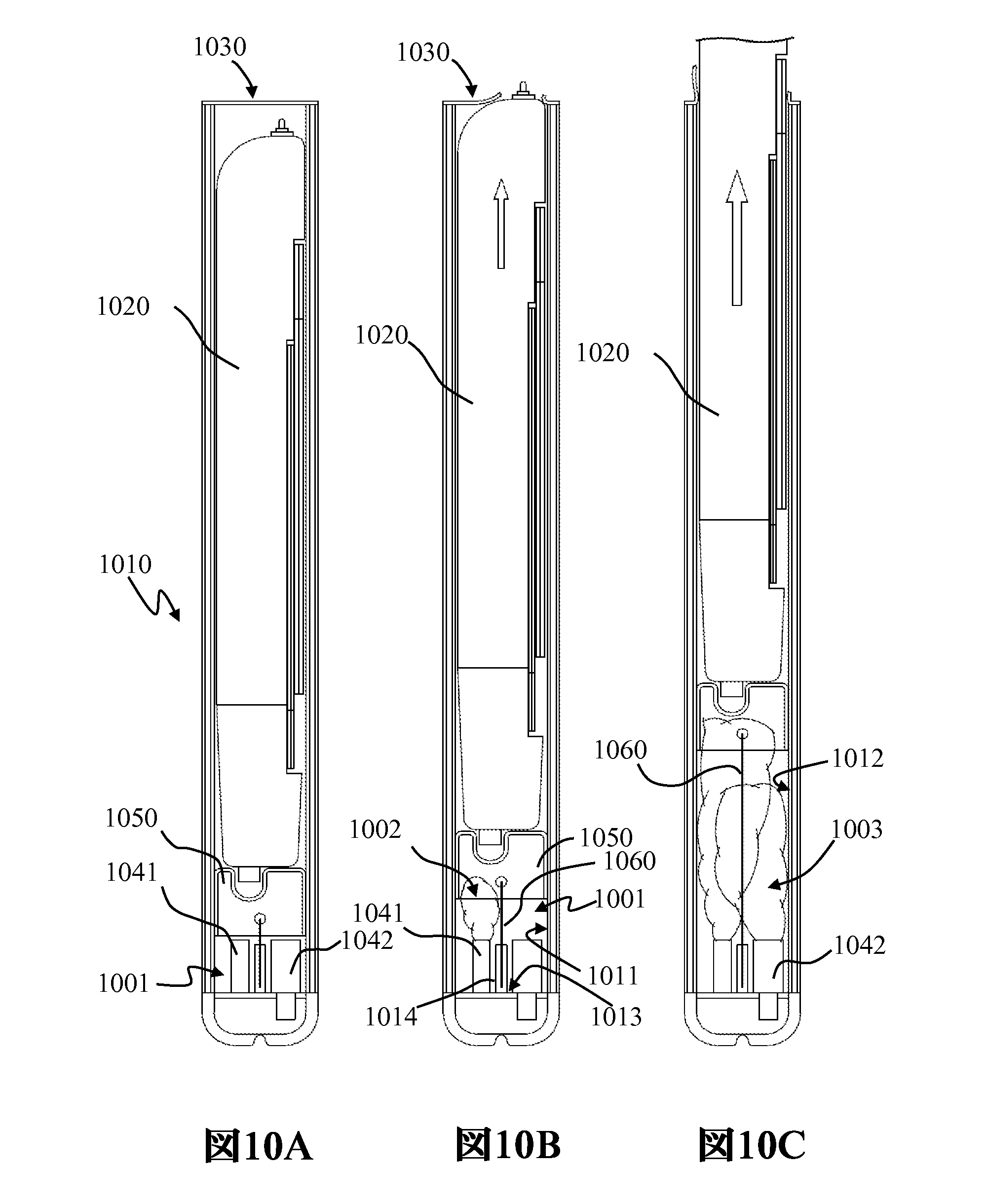
図10Aは、図1および図2に示す発射機などの装填済発射機1010の断面図であり、図3に示すUAVなどのUAV1020が装填されている。本例において、図示の発射機1010は、オプションの破壊可能なシール1030を有している。図示の2つのガス生成キャニスタ1041、1042は、発射機1010の機尾ボリューム1001内に配設されている。図示の例示のテザ付きサボ1050は、ガス生成キャニスタ1041、1042とUAV1020との間に配設されている。
FIG. 10A is a cross-sectional view of a loaded
図10Bは、図10Aの断面図において、第1のガス生成キャニスタ1041が発射機1010の機尾内壁1011とサボ1050との間のボリューム1001内の圧力を増加させている(煙雲1002により示す)様子を示す。テザ1060は、テザリールまたは巻き取り要素1014を介してベース内壁1013に取り付けられてもよい。図10Aに対して、図示のサボ1050は、発射筒(本例では、直方体状のボリューム)に沿って変位しており、それとともにUAV1020が移動している。図示のUAVは、破壊可能なシール1030を破壊し、発射機1010から外に出ようとしている。
10B shows the cross-sectional view of FIG. 10A with first
図10Cは、図10Aの断面図において、第2のガス生成キャニスタ1042が発射機1010の機尾内壁1012とサボ1050との間のボリューム内の圧力を増加または持続させている(第2の煙雲1003により示す)様子を示す。図示のサボ1050は、発射筒に沿ってさらに変位しており、図示のテザ1060は、繰り出された長さであり、図示のUAV1020は、サボ1050とともに移動して発射機の実質的に外側にある。
FIG. 10C shows the cross-sectional view of FIG. 10A with the second
図10Dは、図10Aの断面図において、発射筒内で完全に変位し、テザ1060によりさらなる移動が制約され、発射機のボリューム内にガスを保持している状態のサボ1050を示す。
FIG. 10D shows
図10Eは、図10Aの断面図において、発射筒内で完全に変位し、テザ1060によりさらなる移動が制約され、発射機のボリューム内にガスを保持しつつ発射機のボリュームから周囲の大気へのガスの漏出1090を許容している状態のサボ1050を示す。
FIG. 10E shows the cross-sectional view of FIG. 10A, fully displaced within the launcher, with further movement constrained by
図11Aは、サボ1050が図10Dに示す完全に繰り出された状態に近付く際の、ランチ筒1100のシールされていない遠端の断面図である。高温または中温ガス生成器を用いるいくつかの実施形態において、サボ1050は、概ね図11Aに示す場所よりも遠くへは移動せず、ガスの大気への漏出は、サボがガスにより熱せられた状態からの冷却サイクルにおいて収縮する際にサボの周りで行われる。中温または低温ガス生成器を用いるいくつかの実施形態において、サボ1050は、発射機のリム1120から部分的に延在するように移動し(図11B)、一旦サボのリップ701が発射機のリム1120をクリアしたら、ガスを側方の凹み720から漏出1110させてもよい。テザ1060を介してサボ1050を保持することにより、発射機は、短期間の間、高速ガス生成により発生する圧力波、すなわちレポート、および熱のかなりの部分を保持する。発射後、発射機は、サボ1050周りの漏出を介して発射機から圧力を拡散させる。
11A is a cross-sectional view of the unsealed distal end of
いくつかの実施形態において、サボ1050は、ガス生成器からのガスによりサボ1050の内側に与えられる圧力により発射機の1つの内壁または複数の内壁に接触するように伸張してもよい。この伸張により、サボ1050と1つの内壁または複数の内壁との間におけるシールの形成が可能になるか、または少なくとも容易になり、それにより、サボ1050が筒に沿って移動する間のサボ1050の周りにおけるガスの通過が防止または制限される。特定の実施形態において、サボは、サボと発射機の1つの内壁または複数の内壁との間に間隙を形成するように構成されてもよい。かかる空隙のサイズは、所望される量のガス漏れを提供するように設定してもよい。いくつかの実施形態において、サボ1050は、発射機が発射ガスを収容するために熱くなりすぎて発射機の構造的完全性が損なわれるかまたは失われることを防止するように、十分なガス漏れを許容するようにサイズ決めされてもよい。そのため、サボ1050の実施形態は、発射プロセス中に生成される音波の音響伝搬を制限するようにガス漏れを制限するようにサイズ決めされてもよい。
In some embodiments, the
図12Aは、発射前状態1200における、すなわち翼1210および尾翼面1220が航空機の胴体の下方に折り畳まれた状態の、例示的なUAVを示す下側斜視図である。プロペラが回転可能に搭載されたプロペラハブ1230も示している。航空機は、航空機に沿ったまたは航空機から延在する無線周波数(RF)アンテナ1231を含んでもよい。筒のボリュームが直円筒、直方体、または他の何らかの形状であれ、UAVの1つの断面または複数の断面は、航空機と発射機の内壁との間の気密な嵌合を維持するためには不十分であるかもしれない。そのため、ガス圧力に基づく発射については、ガス源とUAVとの間にサボを配設してもよい。図12Bは、翼1210、1220が展開され推進プロペラ1232が回転している状態の、発射後状態1201における例示的なUAVを示す。
FIG. 12A is a bottom perspective view showing an exemplary UAV in a
図13は、発射機1310の前方部分に装填された航空機1300の実施形態の側方立面図である。図示の発射機1320の機尾部は、ガス生成キャニスタ1331、1332を有し、RFアンテナ1333および受信機ユニット1334、ならびに発射機に動力を供給するためのバッテリなどの電源1336を含んでもよい。いくつかの実施形態において、電源1336は、発射機1310にあるときのUAV1300にも動力を供給し、発射機1310を出発した後のUAVのバッテリに最大のバッテリ寿命を与えてもよい。高いRF透過性を有する構造要素の例には、バルサ材およびエポキシプリプレグKevlar(商標)がある。そのため、UAVのRFアンテナおよび受信機要素ならびに/または発射推進ユニットのRFアンテナおよび受信機要素は、発射機の構造による信号の減衰が無視可能な状態で命令ノードからRF命令を受信することができる。
FIG. 13 is a side elevational view of an embodiment of aircraft 1300 loaded into the forward portion of
図14は、UAV処理および誘導および制御サブシステム1400の例示的な機能ブロック図であり、誘導センサ1414は、シーカ処理1420のシーク処理に関する外部環境についての情報を提供する。誘導センサ1414、より一般的には一揃いの誘導センサは、受動および/または能動レーダサブシステム、赤外線検出サブシステム、赤外線撮像サブシステム、ビデオカメラベースのサブシステムなどの可視光撮像サブシステム、紫外光検出サブシステム、ならびにそれらの組み合わせを含んでもよい。シーカ処理1420は、画像処理と目標追跡処理との両方、ならびにアップリンク受信機1435からおよび/または誘導プロセス1430の出力として受信され得る目標指定または再指定入力1421を含んでもよい。画像処理および/または目標追跡情報1422は、アップリンク/ダウンリンク送受信機の一部であってもよいダウンリンク送信機1423を介して送信してもよい。誘導プロセッサ1430は、誘導処理のための指令を実行する際に、シーカ処理1420から目標情報1424を取り込み、GPS受信機1431ならびにジャイロスコープおよび加速度計1432(存在する場合)から位置、速度、および姿勢などのUAV飛行ステータス情報を取り込んでもよい。一旦飛行に入ったら、誘導プロセッサ1430は、偵察中間地点および/または監視最適化軌跡を受信するため、メモリ格納1433を参照してもよい。システムの実施形態については、誘導プロセス1430は、例えば発射前局面においては外部データポート1434を経由して、または例えば発射後局面においてはアップリンク受信機1435を経由して、偵察中間地点および/または監視最適化軌跡を受信および/またはアップロードしてもよい。誘導プロセッサ1430は、飛行経路、軌跡、または航路操舵角度および方向を決定するための指令を実行する一部として、特にターミナル帰着モードでないときに、中間地点および/または監視最適化軌跡情報を参照してもよい。誘導プロセッサ1430は、アップリンク受信機1435を介して命令を受信し、当初の発射後モードまたは飛行計画を設定してもよい。アップリンク受信機1435は、UAVが発射前状態にある間に通信ノードから命令、目標データ、および/または飛行計画情報を受信してもよい。
FIG. 14 is an exemplary functional block diagram of UAV processing and guidance and
ターミナル帰着モードの一例は、ターミナル帰着モードの攻撃サブモードのための重力バイアス、およびターミナル帰着モードの空中迎撃サブモードのための加速度バイアスを用いる比例航法であってもよい。誘導処理1430および自動操縦処理1440は、航空機の方向をその速度ベクトルの配向を変更することにより変更するため、エレボンの実施形態において例えばバンクトゥターン誘導を生じさせる指令を実行してもよい。例えば、1つ以上の操縦面の配向を1つ以上の操縦面アクチュエータ1450を介して変更して、航空機とその直線加速度のうちのその速度ベクトルに対して直角な部分との配向を変更する力およびトルクを生じさせてもよい。航空機の直線加速度のうちの速度ベクトルに沿った部分は、空力抵抗により大きく影響され、直線加速度は、モータプロセッサ1460およびプロペラモータ1470を介して増加させることができる。完全な3軸制御を有する実施形態については、スキッドトゥターンおよび他の比例-積分-微分誘導ならびに制御処理アーキテクチャを含む追加の制御トポロジを実装してもよい。シーカ処理1420、誘導処理1430、モータ処理1460、および/または自動操縦処理1440は、アドレス指定可能なメモリを有する単一のマイクロプロセッサにより実行してもよく、ならびに/または、例えばデータバスを介して分散通信を行う2つ以上のマイクロプロセッサに処理を分散させてもよい。
An example of a terminal return mode may be proportional navigation with gravity bias for the attack submode of the terminal return mode and acceleration bias for the air interception submode of the terminal return mode.
図15は、システム1500の実施形態のトップレベルシステムアーキテクチャを示す。地上車両1501、航空機1502、宇宙船1503、空中監視もしくは空中通信ノード1504、または地上の人間により可搬の通信ノード1505は、例えば図13に示す実施形態であってもよい発射機1520の実施形態に、RFリンク1511~1515を介して命令信号を送信してもよい。いくつかの実施形態において、UAVは、発射前状態において、要求しているノード1501~1505に対してRFリンク1511~1515に沿って、例えばバッテリレベルなどのステータス情報および自己診断の結果を出力してもよい。発射機の実施形態は、発射機に収容されたUAVを介して独立したRFノードを提供する。例えば、UAVを待機モードとし、全電源投入を命令してもよい受信したRF信号に応答する状態にしておき、その後、発射機内のUAVを、例えば現場から離れた命令ノードのRF命令により、発射に備えて準備させてもよい。独立した発射機-UAVは、長期間の間、見込まれる発射現場において展開された状態のままにしておいてもよく、その後、現場から離れたまたはその他遠隔の命令ノードからの1つ以上の命令信号に応答して電源投入および発射されてもよい。
FIG. 15 shows the top-level system architecture of an embodiment of
上記実施形態の具体的な特徴および態様の様々な組み合わせおよび/または下位の組み合わせを作製することができ、それらはなお本発明の範囲に該当し得ることが考えられる。そのため、開示された発明の様々な様式を形成するために、開示された実施形態の様々な特徴および態様を互いに組み合わせるかまたは置換することができることを理解すべきである。さらに、例示により本明細書中で開示された本発明の範囲は、上で開示された特定の実施形態により限定されないことが意図されている。 It is contemplated that various combinations and/or subcombinations of the specific features and aspects of the above embodiments may be made and still fall within the scope of the invention. As such, it should be understood that various features and aspects of the disclosed embodiments can be combined or substituted with one another to form various aspects of the disclosed invention. Furthermore, the scope of the invention disclosed herein by way of illustration is not intended to be limited by the specific embodiments disclosed above.
Claims (10)
前記発射ボリュームは前記発射壁によって規定され、前記発射壁は連続的な無線周波数(RF)透過性材料を具えることを特徴とする方法。 1. A method comprising transmitting wireless communications via one or more RF signals wirelessly transmitted through a launch wall of a launcher by a transmitter located within a launch volume of the launcher, the method comprising:
A method, wherein the launch volume is defined by the launch wall, the launch wall comprising a continuous radio frequency (RF) transparent material.
前記発射ボリューム内に配置された無人航空機(UAV)の発射中に、1つまたは複数のガス生成キャニスタによってガスを生成するステップと、
前記UAVの発射後、生成されたガスを前記発射ボリューム内に保持するステップと、
を具えることを特徴とする方法。 The method of claim 1, further comprising:
generating gas by one or more gas generation canisters during launch of an unmanned aerial vehicle (UAV) positioned within the launch volume;
retaining generated gas within the launch volume after launch of the UAV;
A method comprising:
Applications Claiming Priority (7)
| Application Number | Priority Date | Filing Date | Title |
|---|---|---|---|
| US24099609P | 2009-09-09 | 2009-09-09 | |
| US24100109P | 2009-09-09 | 2009-09-09 | |
| US24098709P | 2009-09-09 | 2009-09-09 | |
| US61/241,001 | 2009-09-09 | ||
| US61/240,987 | 2009-09-09 | ||
| US61/240,996 | 2009-09-09 | ||
| JP2020137286A JP2020192980A (en) | 2009-09-09 | 2020-08-17 | Systems and devices for remotely operated unmanned aerial vehicle report-suppressing launcher with portable rf transparent launch tube |
Related Parent Applications (1)
| Application Number | Title | Priority Date | Filing Date |
|---|---|---|---|
| JP2020137286A Division JP2020192980A (en) | 2009-09-09 | 2020-08-17 | Systems and devices for remotely operated unmanned aerial vehicle report-suppressing launcher with portable rf transparent launch tube |
Publications (1)
| Publication Number | Publication Date |
|---|---|
| JP2022141810A true JP2022141810A (en) | 2022-09-29 |
Family
ID=44067166
Family Applications (5)
| Application Number | Title | Priority Date | Filing Date |
|---|---|---|---|
| JP2012528905A Active JP5865247B2 (en) | 2009-09-09 | 2010-09-09 | System and apparatus for a remotely operated unmanned aerial vehicle report suppression launcher having a portable RF transmissive launcher |
| JP2015252755A Active JP6250624B2 (en) | 2009-09-09 | 2015-12-25 | System and apparatus for a remotely operated unmanned aerial vehicle report suppression launcher having a portable RF transmissive launcher |
| JP2017224302A Pending JP2018047904A (en) | 2009-09-09 | 2017-11-22 | System and device for remotely-piloted unmanned aerial vehicle report-suppressing launcher with portable rf transparent launch tube |
| JP2020137286A Pending JP2020192980A (en) | 2009-09-09 | 2020-08-17 | Systems and devices for remotely operated unmanned aerial vehicle report-suppressing launcher with portable rf transparent launch tube |
| JP2022114240A Pending JP2022141810A (en) | 2009-09-09 | 2022-07-15 | Systems and devices for remotely operated unmanned aerial vehicle report-suppressing launcher with portable rf transparent launch tube |
Family Applications Before (4)
| Application Number | Title | Priority Date | Filing Date |
|---|---|---|---|
| JP2012528905A Active JP5865247B2 (en) | 2009-09-09 | 2010-09-09 | System and apparatus for a remotely operated unmanned aerial vehicle report suppression launcher having a portable RF transmissive launcher |
| JP2015252755A Active JP6250624B2 (en) | 2009-09-09 | 2015-12-25 | System and apparatus for a remotely operated unmanned aerial vehicle report suppression launcher having a portable RF transmissive launcher |
| JP2017224302A Pending JP2018047904A (en) | 2009-09-09 | 2017-11-22 | System and device for remotely-piloted unmanned aerial vehicle report-suppressing launcher with portable rf transparent launch tube |
| JP2020137286A Pending JP2020192980A (en) | 2009-09-09 | 2020-08-17 | Systems and devices for remotely operated unmanned aerial vehicle report-suppressing launcher with portable rf transparent launch tube |
Country Status (9)
| Country | Link |
|---|---|
| US (10) | US8505430B2 (en) |
| EP (3) | EP2475578B1 (en) |
| JP (5) | JP5865247B2 (en) |
| KR (6) | KR20120113210A (en) |
| CN (2) | CN102596722B (en) |
| AU (4) | AU2010325107B2 (en) |
| CA (3) | CA2789722C (en) |
| DK (2) | DK3133019T3 (en) |
| WO (1) | WO2011066030A2 (en) |
Families Citing this family (142)
| Publication number | Priority date | Publication date | Assignee | Title |
|---|---|---|---|---|
| US9298007B2 (en) | 2014-01-21 | 2016-03-29 | Osterhout Group, Inc. | Eye imaging in head worn computing |
| US9965681B2 (en) | 2008-12-16 | 2018-05-08 | Osterhout Group, Inc. | Eye imaging in head worn computing |
| US9952664B2 (en) | 2014-01-21 | 2018-04-24 | Osterhout Group, Inc. | Eye imaging in head worn computing |
| US9715112B2 (en) | 2014-01-21 | 2017-07-25 | Osterhout Group, Inc. | Suppression of stray light in head worn computing |
| US9229233B2 (en) | 2014-02-11 | 2016-01-05 | Osterhout Group, Inc. | Micro Doppler presentations in head worn computing |
| US9400390B2 (en) | 2014-01-24 | 2016-07-26 | Osterhout Group, Inc. | Peripheral lighting for head worn computing |
| SG173856A1 (en) | 2009-02-02 | 2011-09-29 | Aerovironment Inc | Multimode unmanned aerial vehicle |
| DK3133019T3 (en) * | 2009-09-09 | 2019-02-18 | Aerovironment Inc | NOISE DEVICE FOR A DRONE PROTECTION PIPE |
| CA2789726C (en) | 2009-09-09 | 2019-09-03 | Aerovironment, Inc. | Elevon control system |
| US8439301B1 (en) * | 2011-07-18 | 2013-05-14 | Systems Engineering Associates Corporation | Systems and methods for deployment and operation of unmanned aerial vehicles |
| WO2013126111A2 (en) | 2011-11-29 | 2013-08-29 | Aerovironment, Inc. | Launch tube restraint system for unmanned aerial vehicle (uav) |
| CN102591212B (en) * | 2012-03-01 | 2013-09-18 | 北京航空航天大学 | Method for observing longitudinal motion state of aircraft by using time varying measurement delay output signal |
| US9384668B2 (en) | 2012-05-09 | 2016-07-05 | Singularity University | Transportation using network of unmanned aerial vehicles |
| KR102094054B1 (en) * | 2012-06-07 | 2020-03-27 | 에어로바이론먼트, 인크. | System for detachably coupling an unmanned aerial vehicle within a launch tube |
| DE102012016668A1 (en) * | 2012-08-23 | 2014-02-27 | Iabg Industrieanlagen-Betriebsgesellschaft Mbh | Acceleration device for accelerating a projectile |
| DE102012016667B4 (en) * | 2012-08-23 | 2016-12-01 | Iabg Industrieanlagen-Betriebsgesellschaft Mbh | Acceleration device for accelerating a propellant |
| CN102837820B (en) * | 2012-10-09 | 2014-07-23 | 河北科技大学 | Small-size wing-foldable unmanned aerial vehicle with Z-shaped wing layout |
| AU2013204965B2 (en) | 2012-11-12 | 2016-07-28 | C2 Systems Limited | A system, method, computer program and data signal for the registration, monitoring and control of machines and devices |
| CN103963987A (en) * | 2013-02-02 | 2014-08-06 | 欧俊员 | Imitation pistol shrimp explosion hearth catapult |
| WO2014165230A1 (en) * | 2013-03-13 | 2014-10-09 | Lookout, Inc. | System and method for changing security behavior of a device based on proximity to another device |
| US9789950B1 (en) | 2013-04-24 | 2017-10-17 | Bird Aerospace Llc | Unmanned aerial vehicle (UAV) with multi-part foldable wings |
| KR20200105530A (en) | 2013-05-03 | 2020-09-07 | 에어로바이론먼트 인크 | Vertical takeoff and landing (vtol) air vehicle |
| CN103292637B (en) * | 2013-05-17 | 2016-01-20 | 湖州鹏翼航空器科技有限公司 | A kind of tubular type emitting module and control method thereof |
| GB2514770B (en) * | 2013-06-03 | 2015-08-05 | Lockheed Corp | Launched air vehicle system |
| EP3929525A1 (en) * | 2013-10-31 | 2021-12-29 | AeroVironment, Inc. | Interactive weapon targeting system displaying remote sensed image of target area |
| US9592744B2 (en) | 2013-12-06 | 2017-03-14 | SZ DJI Technology Co., Ltd | Battery and unmanned aerial vehicle with the battery |
| CN103723281B (en) * | 2013-12-31 | 2016-02-24 | 北京中宇新泰科技发展有限公司 | A kind of folding wings unmanned plane Pneumatic catapult |
| US9299194B2 (en) | 2014-02-14 | 2016-03-29 | Osterhout Group, Inc. | Secure sharing in head worn computing |
| US10254856B2 (en) | 2014-01-17 | 2019-04-09 | Osterhout Group, Inc. | External user interface for head worn computing |
| US9529195B2 (en) | 2014-01-21 | 2016-12-27 | Osterhout Group, Inc. | See-through computer display systems |
| US9841599B2 (en) | 2014-06-05 | 2017-12-12 | Osterhout Group, Inc. | Optical configurations for head-worn see-through displays |
| US11103122B2 (en) | 2014-07-15 | 2021-08-31 | Mentor Acquisition One, Llc | Content presentation in head worn computing |
| US9594246B2 (en) | 2014-01-21 | 2017-03-14 | Osterhout Group, Inc. | See-through computer display systems |
| US9671613B2 (en) | 2014-09-26 | 2017-06-06 | Osterhout Group, Inc. | See-through computer display systems |
| US11227294B2 (en) | 2014-04-03 | 2022-01-18 | Mentor Acquisition One, Llc | Sight information collection in head worn computing |
| US10191279B2 (en) | 2014-03-17 | 2019-01-29 | Osterhout Group, Inc. | Eye imaging in head worn computing |
| US9575321B2 (en) | 2014-06-09 | 2017-02-21 | Osterhout Group, Inc. | Content presentation in head worn computing |
| US10684687B2 (en) | 2014-12-03 | 2020-06-16 | Mentor Acquisition One, Llc | See-through computer display systems |
| US9939934B2 (en) | 2014-01-17 | 2018-04-10 | Osterhout Group, Inc. | External user interface for head worn computing |
| US10649220B2 (en) | 2014-06-09 | 2020-05-12 | Mentor Acquisition One, Llc | Content presentation in head worn computing |
| US20160019715A1 (en) | 2014-07-15 | 2016-01-21 | Osterhout Group, Inc. | Content presentation in head worn computing |
| US9810906B2 (en) | 2014-06-17 | 2017-11-07 | Osterhout Group, Inc. | External user interface for head worn computing |
| US9829707B2 (en) | 2014-08-12 | 2017-11-28 | Osterhout Group, Inc. | Measuring content brightness in head worn computing |
| US9746686B2 (en) | 2014-05-19 | 2017-08-29 | Osterhout Group, Inc. | Content position calibration in head worn computing |
| US9766463B2 (en) | 2014-01-21 | 2017-09-19 | Osterhout Group, Inc. | See-through computer display systems |
| US12093453B2 (en) | 2014-01-21 | 2024-09-17 | Mentor Acquisition One, Llc | Eye glint imaging in see-through computer display systems |
| US11737666B2 (en) | 2014-01-21 | 2023-08-29 | Mentor Acquisition One, Llc | Eye imaging in head worn computing |
| US20150205135A1 (en) | 2014-01-21 | 2015-07-23 | Osterhout Group, Inc. | See-through computer display systems |
| US11487110B2 (en) | 2014-01-21 | 2022-11-01 | Mentor Acquisition One, Llc | Eye imaging in head worn computing |
| US9651784B2 (en) | 2014-01-21 | 2017-05-16 | Osterhout Group, Inc. | See-through computer display systems |
| US9494800B2 (en) | 2014-01-21 | 2016-11-15 | Osterhout Group, Inc. | See-through computer display systems |
| US11892644B2 (en) | 2014-01-21 | 2024-02-06 | Mentor Acquisition One, Llc | See-through computer display systems |
| US9836122B2 (en) | 2014-01-21 | 2017-12-05 | Osterhout Group, Inc. | Eye glint imaging in see-through computer display systems |
| US9753288B2 (en) | 2014-01-21 | 2017-09-05 | Osterhout Group, Inc. | See-through computer display systems |
| US12105281B2 (en) | 2014-01-21 | 2024-10-01 | Mentor Acquisition One, Llc | See-through computer display systems |
| US9529199B2 (en) | 2014-01-21 | 2016-12-27 | Osterhout Group, Inc. | See-through computer display systems |
| US9532714B2 (en) | 2014-01-21 | 2017-01-03 | Osterhout Group, Inc. | Eye imaging in head worn computing |
| US11669163B2 (en) | 2014-01-21 | 2023-06-06 | Mentor Acquisition One, Llc | Eye glint imaging in see-through computer display systems |
| US9811159B2 (en) | 2014-01-21 | 2017-11-07 | Osterhout Group, Inc. | Eye imaging in head worn computing |
| US9846308B2 (en) | 2014-01-24 | 2017-12-19 | Osterhout Group, Inc. | Haptic systems for head-worn computers |
| US20150241964A1 (en) | 2014-02-11 | 2015-08-27 | Osterhout Group, Inc. | Eye imaging in head worn computing |
| US9401540B2 (en) | 2014-02-11 | 2016-07-26 | Osterhout Group, Inc. | Spatial location presentation in head worn computing |
| KR101483063B1 (en) * | 2014-02-13 | 2015-01-15 | 엘아이지넥스원 주식회사 | Operating method of portable launch apparatus for guided air vehicle launch system |
| KR101502090B1 (en) * | 2014-02-13 | 2015-03-12 | 엘아이지넥스원 주식회사 | Portable launch apparatus for guided air vehicle launch system |
| AU2015218853A1 (en) * | 2014-02-21 | 2016-09-15 | Lockheed Martin Corporation | Payload launcher and autonomous underwater vehicle |
| US20160187651A1 (en) | 2014-03-28 | 2016-06-30 | Osterhout Group, Inc. | Safety for a vehicle operator with an hmd |
| US10853589B2 (en) | 2014-04-25 | 2020-12-01 | Mentor Acquisition One, Llc | Language translation with head-worn computing |
| US9651787B2 (en) | 2014-04-25 | 2017-05-16 | Osterhout Group, Inc. | Speaker assembly for headworn computer |
| US9672210B2 (en) | 2014-04-25 | 2017-06-06 | Osterhout Group, Inc. | Language translation with head-worn computing |
| US20160137312A1 (en) * | 2014-05-06 | 2016-05-19 | Osterhout Group, Inc. | Unmanned aerial vehicle launch system |
| US10663740B2 (en) | 2014-06-09 | 2020-05-26 | Mentor Acquisition One, Llc | Content presentation in head worn computing |
| US9684172B2 (en) | 2014-12-03 | 2017-06-20 | Osterhout Group, Inc. | Head worn computer display systems |
| FR3029614A1 (en) * | 2014-12-05 | 2016-06-10 | Thales Sa | PROJECTILE AND CANON INTENDED TO RECEIVE SUCH PROJECTILE |
| USD751552S1 (en) | 2014-12-31 | 2016-03-15 | Osterhout Group, Inc. | Computer glasses |
| USD753114S1 (en) | 2015-01-05 | 2016-04-05 | Osterhout Group, Inc. | Air mouse |
| US11021266B2 (en) | 2015-02-11 | 2021-06-01 | Aerovironment, Inc. | Pod operating system for a vertical take-off and landing (VTOL) unmanned aerial vehicle (UAV) |
| US9880563B2 (en) | 2015-02-11 | 2018-01-30 | Aerovironment, Inc. | Geographic survey system for vertical take-off and landing (VTOL) unmanned aerial vehicles (UAVs) |
| WO2016130797A1 (en) * | 2015-02-11 | 2016-08-18 | Aerovironment, Inc. | Pod cover system for a vertical take-off and landing (vtol) unmanned aerial vehicle (uav) |
| US9977435B2 (en) | 2015-02-11 | 2018-05-22 | Aeroviroment, Inc. | Survey migration system for vertical take-off and landing (VTOL) unmanned aerial vehicles (UAVS) |
| WO2016130847A1 (en) | 2015-02-11 | 2016-08-18 | Aerovironment, Inc. | Pod launch and landing system for vertical take-off and landing (vtol) unmanned aerial vehicles (uavs) |
| US20160239985A1 (en) | 2015-02-17 | 2016-08-18 | Osterhout Group, Inc. | See-through computer display systems |
| US20170356726A1 (en) | 2015-02-26 | 2017-12-14 | Shawn M. Theiss | Aerial arresting system for unmanned aerial vehicle |
| US20160334785A1 (en) * | 2015-05-13 | 2016-11-17 | Robert Morrison | Control unit adapted to accommodate drone |
| US9444544B1 (en) * | 2015-07-13 | 2016-09-13 | Apollo Robotic Systems Incorporated | Unmanned vehicle communication through short message service |
| IL241024B (en) * | 2015-09-01 | 2019-06-30 | Uvision Air Ltd | Launcher for unmanned aerial vehicles |
| US9969491B2 (en) * | 2015-09-02 | 2018-05-15 | The Boeing Company | Drone launch systems and methods |
| US10464693B2 (en) | 2015-09-04 | 2019-11-05 | Lockheed Martin Corporation | Launch canister with air bag ram |
| WO2017083406A1 (en) * | 2015-11-10 | 2017-05-18 | Matternet, Inc. | Methods and systems for transportation using unmanned aerial vehicles |
| US11958588B2 (en) | 2015-11-11 | 2024-04-16 | Anduril Industries, Inc. | Foldable propeller blade with locking mechanism |
| US12491983B2 (en) | 2015-11-11 | 2025-12-09 | Anduril Industries, Inc. | Aerial vehicle with deployable components and configurable gearbox |
| US9555873B1 (en) | 2015-11-11 | 2017-01-31 | Area-I Inc. | Aerial vehicle with deployable components |
| US11117649B2 (en) | 2015-11-11 | 2021-09-14 | Area-I Inc. | Foldable propeller blade with locking mechanism |
| US10124880B1 (en) * | 2016-02-03 | 2018-11-13 | Lockheed Martin Corporation | Rotatable control surface assembly for an unmanned aerial vehicle |
| CN105698001B (en) * | 2016-04-29 | 2018-07-06 | 杨文清 | A kind of aerodynamic energy aircraft catapult-launching gear |
| CN106240836B (en) * | 2016-09-12 | 2018-10-02 | 北京特种机械研究所 | One case two machine cover opening mechanism suitable for unmanned plane |
| NO342636B1 (en) * | 2016-10-04 | 2018-06-25 | H Henriksen As | Pneumatic Launcher |
| KR101917785B1 (en) * | 2016-10-26 | 2019-01-29 | 한국항공우주연구원 | Non-motorized type flying unit for observation |
| KR102111243B1 (en) | 2016-12-09 | 2020-05-15 | 노스롭 그루먼 이노베이션 시스템스, 인코포레이티드 | Local defense communication delay compensation |
| USD864959S1 (en) | 2017-01-04 | 2019-10-29 | Mentor Acquisition One, Llc | Computer glasses |
| US10293957B2 (en) * | 2017-01-30 | 2019-05-21 | Hanhui Zhang | Rotary wing unmanned aerial vehicle and pneumatic launcher |
| IL250996B2 (en) * | 2017-03-07 | 2025-06-01 | Colugo Systems Ltd | Multi-bladed folding wing |
| US11117666B2 (en) * | 2017-03-28 | 2021-09-14 | Skyworks Aeronautics Corp. | Precision delivery vehicle |
| IL300908B2 (en) | 2017-03-28 | 2025-09-01 | Anduril Industries Inc | Foldable propeller blade with locking mechanism |
| US10151555B1 (en) * | 2017-06-08 | 2018-12-11 | Bell Helicopter Textron Inc. | Air cannon with sabot system |
| US11555679B1 (en) | 2017-07-07 | 2023-01-17 | Northrop Grumman Systems Corporation | Active spin control |
| US12031802B2 (en) | 2017-07-26 | 2024-07-09 | Northrop Grumman Systems Corporation | Despun wing control system for guided projectile maneuvers |
| US11027839B2 (en) | 2018-09-22 | 2021-06-08 | Eric Dupont Becnel | Tactical rapid access small unmanned aerial system |
| US11027845B2 (en) | 2017-09-29 | 2021-06-08 | Shawn M. Theiss | Device and method to intercept an aerial vehicle |
| US11067374B2 (en) * | 2017-10-05 | 2021-07-20 | Overwerx Ltd. | Remotely controllable aeronautical ordnance loitering |
| CN110654560B (en) * | 2017-10-13 | 2021-04-23 | 南京涵曦月自动化科技有限公司 | Vehicle-mounted unmanned aerial vehicle control system and control method thereof |
| US11578956B1 (en) | 2017-11-01 | 2023-02-14 | Northrop Grumman Systems Corporation | Detecting body spin on a projectile |
| CN111511643B (en) * | 2017-12-22 | 2024-09-27 | Wing航空有限责任公司 | Payload coupling device and payload delivery method for unmanned aerial vehicle |
| CN108177791A (en) * | 2017-12-28 | 2018-06-19 | 陕西中科博亿电子科技有限公司 | Launching tube |
| US10661878B1 (en) * | 2018-01-31 | 2020-05-26 | The Boeing Company | Unmanned aerial vehicle (UAV) launch systems and methods |
| US11148805B2 (en) * | 2018-04-10 | 2021-10-19 | Government Of The United States, As Represented By The Secretary Of The Army | Enclosure for an unmanned aerial system |
| CN108657460A (en) * | 2018-05-17 | 2018-10-16 | 北京中资燕京汽车有限公司 | It is vehicle-mounted to patrol the pneumatic emission system of winged device |
| US11685510B2 (en) * | 2018-11-01 | 2023-06-27 | Viettel Group | Wing deployment mechanism and design method using pneumatic technique |
| CN109436296B (en) * | 2018-12-26 | 2024-02-13 | 西北工业大学 | Canister-launched folding-wing UAV and launch method thereof |
| EP3908516B1 (en) * | 2019-01-10 | 2024-06-26 | Spear U.A.V Ltd | Unmanned aerial vehicle launching capsule |
| CN110017740A (en) * | 2019-04-25 | 2019-07-16 | 武汉雷神特种器材有限公司 | Portable packing box with transmitting device |
| DE102019003322B4 (en) | 2019-05-10 | 2024-11-07 | Mbda Deutschland Gmbh | System and device for launching a missile |
| CN110567326B (en) * | 2019-07-30 | 2020-10-02 | 中国人民解放军陆军工程大学 | Fixed wing-rotor wing composite unmanned aerial vehicle |
| EP4592189A3 (en) * | 2019-10-09 | 2025-09-03 | Kitty Hawk Corporation | Hybrid power systems for different modes of flight |
| CN111002646A (en) * | 2019-11-14 | 2020-04-14 | 南京航空航天大学 | Electromagnetic shielding interlayer composite material frangible cover and preparation method thereof |
| KR102275965B1 (en) * | 2019-12-30 | 2021-07-13 | 주식회사 한화 | Drone with parachute and method of drone release thereof |
| US11753164B2 (en) | 2020-05-04 | 2023-09-12 | Anduril Industries, Inc. | Rotating release launching system |
| US12351310B2 (en) | 2020-05-04 | 2025-07-08 | Anduril Industries, Inc. | Rotating release launching system |
| US11214370B2 (en) | 2020-05-04 | 2022-01-04 | Area-I Inc. | Rotating release launching system |
| US11041692B1 (en) * | 2020-05-12 | 2021-06-22 | Michael Chromych | System and method for launching and acceleration of objects |
| US11573069B1 (en) | 2020-07-02 | 2023-02-07 | Northrop Grumman Systems Corporation | Axial flux machine for use with projectiles |
| CN112896498B (en) * | 2021-03-12 | 2022-11-22 | 核工业二八0研究所 | Unmanned aerial vehicle gamma energy spectrum measurement system |
| CN112937905B (en) * | 2021-03-22 | 2022-08-19 | 泰山学院 | Seeding formula unmanned aerial vehicle auxiliary device that takes off based on thing networked control |
| IL282882B2 (en) * | 2021-05-03 | 2023-06-01 | Spear U A V Ltd | A launch mechanism for a drone |
| FR3133176B1 (en) * | 2022-03-01 | 2025-03-07 | Nexter Systems | Pneumatic launching device for a drone |
| US12313389B1 (en) | 2022-03-11 | 2025-05-27 | Northrop Grumman Systems Corporation | Tunable safe and arming devices and methods of manufacture |
| WO2024035714A1 (en) * | 2022-08-09 | 2024-02-15 | Pete Bitar | Compact and lightweight drone delivery device called an arcspear electric jet drone system having an electric ducted air propulsion system and being relatively difficult to track in flight |
| CN115649500A (en) * | 2022-11-15 | 2023-01-31 | 四块科技(深圳)有限公司 | folding multi-rotor drone |
| CN116119006A (en) * | 2023-02-09 | 2023-05-16 | 西安万飞控制科技有限公司 | Methane detection system and method based on unmanned aerial vehicle-mounted laser methane detector |
| US12345207B1 (en) * | 2023-12-29 | 2025-07-01 | Rtx Corporation | Centralized multi engine startup system for palletized applications |
| CN118343330A (en) * | 2024-06-18 | 2024-07-16 | 成都金支点科技有限公司 | A launching device for launching a drone |
| KR102801790B1 (en) * | 2024-10-23 | 2025-05-07 | 베셀에어로스페이스 주식회사 | Launch type unmanned aerial vehicle and canister apparatus for launch type unmanned aerial vehicle having airframe protecting function about the launch type unmanned aerial vehicle |
| KR102804002B1 (en) * | 2024-11-05 | 2025-05-09 | 베셀에어로스페이스 주식회사 | Wing variable type launch type unmanned aerial vehicle and canister apparatus of wing variable type launch type unmanned aerial vehicle for launching the wing variable type launch type unmanned aerial vehicle |
Family Cites Families (323)
| Publication number | Priority date | Publication date | Assignee | Title |
|---|---|---|---|---|
| US2512069A (en) | 1944-06-13 | 1950-06-20 | Spotswood Specialty Co Inc | Bomb-releasing folding-wing airplane |
| US2996011A (en) | 1944-06-30 | 1961-08-15 | Henry F Dunlap | Projectile |
| US2444332A (en) | 1944-12-07 | 1948-06-29 | Briggs Earl | Wing folding arrangement for submersible aircraft |
| US2426437A (en) * | 1945-01-22 | 1947-08-26 | Harold E Cole | Toy |
| CH410687A (en) * | 1964-05-12 | 1966-03-31 | Transurvey Holding Company Inc | Projectile intended to be fired by means of a fixed launching and guiding rod |
| US2750133A (en) | 1951-03-28 | 1956-06-12 | Lockheed Aircraft Corp | Alighting gear for vertically arising aircraft |
| US2752110A (en) | 1951-07-11 | 1956-06-26 | Adolphe C Peterson | Variable wing aircraft |
| US2708431A (en) * | 1952-01-19 | 1955-05-17 | American Junior Aircraft Compa | Catapult |
| US2792962A (en) * | 1955-10-21 | 1957-05-21 | Ernest H Granfelt | Multi-cellular rocket package |
| US3069115A (en) | 1958-10-08 | 1962-12-18 | Bristol Aircraft Ltd | Aircraft |
| US3083936A (en) | 1959-02-18 | 1963-04-02 | Scott C Rethorst | Aircraft |
| US3568191A (en) * | 1960-12-15 | 1971-03-02 | James C Hiester | Method for defending an aircraft against a frontal attack |
| US3107616A (en) * | 1961-03-14 | 1963-10-22 | Charles W Boaz | Sliding door opening mechanism |
| US3068612A (en) * | 1961-10-23 | 1962-12-18 | Roba R Simpson | Self-controlled toy airplane |
| US3107617A (en) * | 1962-04-11 | 1963-10-22 | William F Loeper | Ring decoy launching mechanism |
| US3147939A (en) | 1962-12-03 | 1964-09-08 | Karl Frudenfeld | Pitch and altitude control system |
| US3276722A (en) | 1964-02-04 | 1966-10-04 | Jr Alfred J Eggers | Flight craft |
| US3223361A (en) | 1964-10-05 | 1965-12-14 | Ryan Aeronautical Co | Flexible wing with integrated tail unit |
| US3262391A (en) | 1964-10-12 | 1966-07-26 | Budd Co | Subcaliber projectile and sabot |
| US3808940A (en) * | 1964-12-24 | 1974-05-07 | Gen Dynamics Corp | Portable decoy launcher system and rounds therefor |
| US3347466A (en) | 1966-11-15 | 1967-10-17 | Mark R Nichols | Nacelle afterbody for jet engines |
| US3415467A (en) | 1967-01-30 | 1968-12-10 | Joseph A. Barringer | Retrievable rocket with folded wings |
| US3724319A (en) | 1967-03-08 | 1973-04-03 | Us Navy | Fax minefield clearing device |
| US3496580A (en) * | 1968-04-29 | 1970-02-24 | Robert H Gulmon | Inflatable and recoverable lifesaving projectile apparatus |
| US4209147A (en) | 1972-08-10 | 1980-06-24 | Jones Allen Jr | Steering and stabilization apparatus for aerial missile |
| US3790103A (en) | 1972-08-21 | 1974-02-05 | Us Navy | Rotating fin |
| US3789353A (en) | 1973-01-03 | 1974-01-29 | Us Navy | Diver communication system |
| US3916560A (en) | 1974-02-01 | 1975-11-04 | Joseph T Becker | Miniature aircraft and launcher unit therefor |
| US3939967A (en) * | 1974-08-01 | 1976-02-24 | National Distillers And Chemical Corporation | Containers for projectiles |
| US5112006A (en) | 1975-03-12 | 1992-05-12 | The Boeing Company | Self defense missile |
| FR2321723A1 (en) | 1975-07-29 | 1977-03-18 | Thomson Brandt | ATTITUDE CONTROL SYSTEM AND MACHINE EQUIPPED WITH SUCH A SYSTEM |
| US4022403A (en) | 1976-01-28 | 1977-05-10 | Louis Francois Chiquet | Convertible aircraft |
| US4090684A (en) | 1976-03-24 | 1978-05-23 | The United States Of America As Represented By The Secretary Of The Air Force | Stowable airfoil structure |
| US4383663A (en) | 1976-06-01 | 1983-05-17 | The United States Of America As Represented By The Secretary Of The Navy | Active optical terminal homing |
| US4060930A (en) * | 1976-09-29 | 1977-12-06 | Mattel, Inc. | Toy airplane launcher |
| US4106727A (en) | 1977-05-09 | 1978-08-15 | Teledyne Brown Engineering, A Division Of Teledyne Industries, Inc. | Aircraft folding airfoil system |
| US4165849A (en) | 1977-12-14 | 1979-08-28 | Anthony Fox | Combination air brake and engine shield for aircraft |
| US4354646A (en) | 1978-09-20 | 1982-10-19 | Rockwell International Corporation | Variable dihedral angle tail unit for supersonic aircraft |
| FR2445509A1 (en) | 1978-12-28 | 1980-07-25 | Thomson Brandt | LAUNCHING MECHANISM OF A SUB-CALIBER PROJECTILE |
| US4336914A (en) | 1978-12-29 | 1982-06-29 | The Commonwealth Of Australia | Deployable wing mechanism |
| DE2904749C2 (en) | 1979-02-08 | 1984-01-05 | Messerschmitt-Bölkow-Blohm GmbH, 8000 München | Missile in the manner of a drone |
| US4277038A (en) | 1979-04-27 | 1981-07-07 | The United States Of America As Represented By The Secretary Of The Army | Trajectory shaping of anti-armor missiles via tri-mode guidance |
| US4294157A (en) * | 1979-05-01 | 1981-10-13 | Stahan Corporation | Projectile deployed cable weapons system |
| US4301708A (en) * | 1979-07-25 | 1981-11-24 | The United States Of America As Represented By The Secretary Of The Navy | Launch tube closure |
| DE2935044A1 (en) * | 1979-08-30 | 1981-03-19 | Vereinigte Flugtechnische Werke Gmbh, 2800 Bremen | UNMANNED MISSILE TO BE LAUNCHED FROM A CONTAINER |
| US4842218A (en) | 1980-08-29 | 1989-06-27 | The United States Of America As Represented By The Secretary Of The Navy | Pivotal mono wing cruise missile with wing deployment and fastener mechanism |
| US4364530A (en) | 1980-09-08 | 1982-12-21 | The United States Of America As Represented By The Secretary Of The Navy | Propulsion/control modular booster |
| US4364531A (en) | 1980-10-09 | 1982-12-21 | Knoski Jerry L | Attachable airfoil with movable control surface |
| DE3048598A1 (en) * | 1980-12-23 | 1982-07-29 | Dynamit Nobel Ag, 5210 Troisdorf | Recoil-less firearm with open barrel - has intermediate plungers halted by connecting rope before reaching barrel mouths |
| US4373688A (en) | 1981-01-19 | 1983-02-15 | The United States Of America As Represented By The Secretary Of The Army | Canard drive mechanism latch for guided projectile |
| US4530476A (en) | 1981-08-12 | 1985-07-23 | E-Systems, Inc. | Ordnance delivery system and method including remotely piloted or programmable aircraft with yaw-to-turn guidance system |
| US4730793A (en) | 1981-08-12 | 1988-03-15 | E-Systems, Inc. | Ordnance delivery system and method including remotely piloted or programmable aircraft with yaw-to-turn guidance system |
| FR2517818A1 (en) | 1981-12-09 | 1983-06-10 | Thomson Brandt | GUIDING METHOD TERMINAL AND MISSILE GUIDE OPERATING ACCORDING TO THIS METHOD |
| FR2523072A1 (en) | 1982-03-09 | 1983-09-16 | Cabrol Lucien | AIRCRAFT PROVIDED WITH A MULTIPLE OVERLAPPING SUSPENSION STRUCTURE |
| US4553718A (en) | 1982-09-30 | 1985-11-19 | The Boeing Company | Naval harrassment missile |
| US4590862A (en) | 1983-05-23 | 1986-05-27 | The United States Of America As Represented By The Secretary Of The Army | Projectile pusher-type discarding sabot |
| DE3403573A1 (en) | 1983-11-09 | 1985-08-08 | Diehl GmbH & Co, 8500 Nürnberg | BULLET WITH FOLD-OUT WINGS |
| JPS60188799A (en) | 1984-03-09 | 1985-09-26 | 株式会社東芝 | Guidance system for missile |
| GB2188713B (en) * | 1984-05-04 | 1988-05-25 | British Aerospace | Missile storage and launch arrangements |
| US4565340A (en) | 1984-08-15 | 1986-01-21 | Ford Aerospace & Communications Corporation | Guided projectile flight control fin system |
| CN85104530A (en) | 1985-06-15 | 1987-01-07 | 古飞 | Controllable wing-folded full-lift type road airplane |
| US4708304A (en) | 1985-12-27 | 1987-11-24 | General Dynamics, Pomona Division | Ring-wing |
| US4735148A (en) | 1986-03-18 | 1988-04-05 | United Technologies Corporation | Plastic composite sabot |
| DE3628129C1 (en) | 1986-08-19 | 1988-03-03 | Rheinmetall Gmbh | Missile |
| US4683797A (en) * | 1986-09-02 | 1987-08-04 | The United States Of America As Represented By The Secretary Of The Army | Line charge detonation interlock assembly |
| GB8622646D0 (en) | 1986-09-19 | 1987-02-04 | Smith J L C | Minefield penetration |
| FR2623898B1 (en) | 1987-11-26 | 1990-03-23 | France Etat Armement | DEVICE FOR DEPLOYING A PROJECTILE FIN |
| USH400H (en) | 1987-04-06 | 1988-01-05 | The United States Of America As Represented By The Secretary Of The Army | Aimpoint bias for terminal homing guidance |
| US4990921A (en) | 1987-05-01 | 1991-02-05 | Sundstrand Data Control, Inc. | Multi-mode microwave landing system |
| JPS6428096A (en) | 1987-07-23 | 1989-01-30 | Mitsubishi Heavy Ind Ltd | Vertical stabilizer for aircraft |
| US5118052A (en) | 1987-11-02 | 1992-06-02 | Albert Alvarez Calderon F | Variable geometry RPV |
| US5060413A (en) * | 1987-11-17 | 1991-10-29 | Garcia Manuel E | Fishing line launching device |
| US4841867A (en) | 1987-12-28 | 1989-06-27 | Ford Aerospace Corporation | Discarding sabot projectile |
| NL8801917A (en) | 1988-08-02 | 1990-03-01 | Hollandse Signaalapparaten Bv | COURSE CORRECTION SYSTEM FOR JOB-CORRECTABLE OBJECTS. |
| DE3827590A1 (en) | 1988-08-13 | 1990-02-22 | Messerschmitt Boelkow Blohm | MISSILE |
| JP2500317B2 (en) * | 1989-05-02 | 1996-05-29 | 防衛庁技術研究本部長 | Fiber reinforced plastic radome |
| US4958571A (en) | 1989-09-13 | 1990-09-25 | The United States Of America As Represented By The Secretary Of The Army | Continuous-fiber reinforcement sabot |
| USD317003S (en) | 1989-10-25 | 1991-05-21 | Northrop Corporation | Aircraft |
| GB9012829D0 (en) | 1990-06-08 | 1990-08-01 | Bernard D J C | Reduced diameter dummy piston |
| US5074493A (en) | 1990-12-21 | 1991-12-24 | The United States Of America As Represented By The Secretary Of The Navy | Wing-extendible gliding store |
| US5106033A (en) | 1991-03-22 | 1992-04-21 | Hughes Aircraft Company | Missile guidance electronics assembly for portable guided missile launcher |
| US5141175A (en) | 1991-03-22 | 1992-08-25 | Harris Gordon L | Air launched munition range extension system and method |
| US5115711A (en) * | 1991-03-25 | 1992-05-26 | Fmc Corporation | Missile canister and method of fabrication |
| US5154370A (en) | 1991-07-15 | 1992-10-13 | The United States Of America As Represented By The Secretary Of The Air Force | High lift/low drag wing and missile airframe |
| US5582364A (en) | 1991-11-07 | 1996-12-10 | Hughes Missile Systems Company | Flyable folding fin |
| JPH07101160B2 (en) * | 1991-11-28 | 1995-11-01 | 株式会社日本製鋼所 | Canister for missile |
| US5322243A (en) | 1992-06-25 | 1994-06-21 | Northrop Corporation | Separately banking maneuvering aerodynamic control surfaces, system and method |
| FR2697327B1 (en) | 1992-10-22 | 1994-12-30 | Luchaire Defense Sa | Box for propellant charge. |
| US5303695A (en) * | 1992-11-09 | 1994-04-19 | Noah Shopsowitz | Human free-flight launcher |
| NZ245238A (en) * | 1992-11-24 | 1995-02-24 | Lanfield Holdings Ltd Substitu | Slingshot toy launcher; handle with cord and progressively separable strip attached at free end of cord |
| JP2979888B2 (en) | 1993-03-16 | 1999-11-15 | 日産自動車株式会社 | Flying object |
| US5417393A (en) | 1993-04-27 | 1995-05-23 | Hughes Aircraft Company | Rotationally mounted flexible band wing |
| US5884872A (en) | 1993-05-26 | 1999-03-23 | The United States Of America As Represented By The Secretary Of The Navy | Oscillating flap lift enhancement device |
| FR2709875B1 (en) * | 1993-09-06 | 1995-11-24 | Aerospatiale | Container for packaging an object provided with a radio transmission device and removable element for such a container. |
| JPH0789492A (en) | 1993-09-27 | 1995-04-04 | Mitsubishi Heavy Ind Ltd | Missile |
| US5417139A (en) | 1993-10-01 | 1995-05-23 | Unisys Corporation | Delivery system and method for flexible array |
| US5566073A (en) | 1994-07-11 | 1996-10-15 | Margolin; Jed | Pilot aid using a synthetic environment |
| US5458041A (en) | 1994-08-02 | 1995-10-17 | Northrop Grumman Corporation | Air defense destruction missile weapon system |
| US5448937A (en) * | 1994-08-12 | 1995-09-12 | Buc; Steven M. | Muzzle launched grapnel hook projectile |
| US5722618A (en) | 1994-08-16 | 1998-03-03 | Northrop Grumman Corporation | Airborne tethered sensor system |
| US5615846A (en) | 1994-11-04 | 1997-04-01 | Gec Marconi Dynamics Inc. | Extendable wing for guided missles and munitions |
| DE19505791C1 (en) | 1995-02-20 | 1996-08-14 | Daimler Benz Aerospace Ag | Method and device for combating covertly operating helicopters |
| US5581250A (en) | 1995-02-24 | 1996-12-03 | Khvilivitzky; Alexander | Visual collision avoidance system for unmanned aerial vehicles |
| IL117792A (en) | 1995-05-08 | 2003-10-31 | Rafael Armament Dev Authority | Autonomous command and control unit for mobile platform |
| US5806791A (en) | 1995-05-26 | 1998-09-15 | Raytheon Company | Missile jet vane control system and method |
| US5654053A (en) * | 1995-06-15 | 1997-08-05 | The United States Of America As Represented By The Secretary Of The Navy | High-energy-absorbing enclosure for internal explosion containment |
| US5671138A (en) | 1995-07-06 | 1997-09-23 | The United States Of America As Represented By The Secretary Of The Navy | Fuzzy controller for acoustic vehicle target intercept guidance |
| JP3532661B2 (en) | 1995-07-10 | 2004-05-31 | 株式会社東芝 | Flying mechanism of flying object |
| US5890441A (en) | 1995-09-07 | 1999-04-06 | Swinson Johnny | Horizontal and vertical take off and landing unmanned aerial vehicle |
| US6991124B1 (en) * | 1995-09-25 | 2006-01-31 | Alliedsignal Inc. | Blast resistant and blast directing containers and methods of making |
| US5695153A (en) * | 1995-11-16 | 1997-12-09 | Northrop Grumman Corporation | Launcher system for an unmanned aerial vehicle |
| JPH09170898A (en) | 1995-12-20 | 1997-06-30 | Mitsubishi Electric Corp | Guiding device |
| US5904724A (en) | 1996-01-19 | 1999-05-18 | Margolin; Jed | Method and apparatus for remotely piloting an aircraft |
| US5671899A (en) | 1996-02-26 | 1997-09-30 | Lockheed Martin Corporation | Airborne vehicle with wing extension and roll control |
| DE19617221C2 (en) | 1996-04-30 | 1999-07-01 | Diehl Stiftung & Co | Steerable projectile that can be used as a mortar |
| US5965836A (en) * | 1996-08-29 | 1999-10-12 | Rakov; Mikhail A. | Method and devices for propulsion |
| US6460810B2 (en) | 1996-09-06 | 2002-10-08 | Terry Jack James | Semiautonomous flight director |
| US5927648A (en) * | 1996-10-17 | 1999-07-27 | Woodland; Richard Lawrence Ken | Aircraft based sensing, detection, targeting, communications and response apparatus |
| US5899410A (en) | 1996-12-13 | 1999-05-04 | Mcdonnell Douglas Corporation | Aerodynamic body having coplanar joined wings |
| US5933263A (en) * | 1997-02-14 | 1999-08-03 | The Boeing Company | Self-powered datalink activation system |
| US6168111B1 (en) | 1997-03-03 | 2001-01-02 | The United States Of America As Represented By The Secretary Of The Army | Fold-out fin |
| JP3051357B2 (en) | 1997-03-26 | 2000-06-12 | 株式会社コミュータヘリコプタ先進技術研究所 | Main rotor torque correction device |
| US6126109A (en) | 1997-04-11 | 2000-10-03 | Raytheon Company | Unlocking tail fin assembly for guided projectiles |
| IL120787A (en) | 1997-05-05 | 2003-02-12 | Rafael Armament Dev Authority | Tracking system that includes means for early target detection |
| US5819717A (en) | 1997-06-12 | 1998-10-13 | Johnson Research And Development Company, Inc. | Launcher for a toy projectile or similar launchable object |
| US6056237A (en) * | 1997-06-25 | 2000-05-02 | Woodland; Richard L. K. | Sonotube compatible unmanned aerial vehicle and system |
| US5855339A (en) | 1997-07-07 | 1999-01-05 | Raytheon Company | System and method for simultaneously guiding multiple missiles |
| US5978970A (en) | 1998-02-11 | 1999-11-09 | Bright; Patrick | Crotch cushion for a bicycle rider |
| USD417639S (en) | 1998-08-03 | 1999-12-14 | Lockheed Martin Corporation | JASSM missile |
| US6074265A (en) * | 1999-01-08 | 2000-06-13 | Mattel, Inc. | Glider toy having integral launcher |
| JP2000266499A (en) | 1999-03-16 | 2000-09-29 | Toshiba Corp | Anti-aircraft defense device |
| US6722252B1 (en) | 1999-04-07 | 2004-04-20 | Metal Storm Limited | Projectile firing apparatus |
| US6244535B1 (en) | 1999-06-07 | 2001-06-12 | The United States Of America As Represented By The Secretary Of The Navy | Man-packable missile weapon system |
| US6422507B1 (en) | 1999-07-02 | 2002-07-23 | Jay Lipeles | Smart bullet |
| SE517023C2 (en) | 1999-08-18 | 2002-04-02 | Saab Ab | Procedure for controlling a robot and a control system for controlling a robot |
| JP2001153599A (en) | 1999-11-25 | 2001-06-08 | Mitsubishi Electric Corp | Flying object |
| US6678394B1 (en) | 1999-11-30 | 2004-01-13 | Cognex Technology And Investment Corporation | Obstacle detection system |
| JP2001206298A (en) | 2000-01-28 | 2001-07-31 | Fuji Heavy Ind Ltd | Aerospacecraft |
| US6354182B1 (en) * | 2000-04-18 | 2002-03-12 | Philip J. Milanovich | Launch assist system |
| AUPQ749900A0 (en) | 2000-05-15 | 2000-08-10 | Metal Storm Limited | Projectiles |
| US6418870B1 (en) | 2000-05-31 | 2002-07-16 | Systems Engineering Associates Corporation | Torpedo launch mechanism and method |
| US20050127242A1 (en) | 2000-08-08 | 2005-06-16 | Rivers Eugene P.Jr. | Payload dispensing system particularly suited for unmanned aerial vehicles |
| SE519757C2 (en) | 2000-08-15 | 2003-04-08 | Bofors Defence Ab | Controllable artillery projectile with extremely long range |
| US6371002B1 (en) * | 2000-09-29 | 2002-04-16 | The United States Of America As Represented By The Secretary Of The Navy | Detachable shock-absorbing ram-plate |
| US6848649B2 (en) | 2000-10-03 | 2005-02-01 | Charles Gilpin Churchman | V/STOL biplane aircraft |
| US6392213B1 (en) | 2000-10-12 | 2002-05-21 | The Charles Stark Draper Laboratory, Inc. | Flyer assembly |
| US6626078B2 (en) | 2000-11-30 | 2003-09-30 | Lockheed Martin Corporation | Apparatus for detecting, identifying, and validating the existence of buried objects |
| US6359833B1 (en) | 2001-01-29 | 2002-03-19 | The United States Of America As Represented By The Secretary Of The Navy | Underwater small target weapon |
| US6626401B2 (en) | 2001-03-20 | 2003-09-30 | Norman Thomas Laurence Fraser | Aft fuselage control system for forward lifting elevator aircraft |
| GB0107552D0 (en) * | 2001-03-27 | 2005-01-05 | Matra Bae Dynamics Uk Ltd | Improvements in and relating to the launching of missiles |
| US7210654B1 (en) | 2003-07-23 | 2007-05-01 | Mission Technologies, Inc. | Unmanned airborne reconnaissance system |
| US7093791B2 (en) | 2001-06-22 | 2006-08-22 | Tom Kusic | Aircraft spiralling mechanism—c |
| DE10130383A1 (en) | 2001-06-23 | 2003-01-09 | Diehl Munitionssysteme Gmbh | Artillery projectile with interchangeable payload |
| GB0116219D0 (en) | 2001-07-03 | 2002-03-06 | Bae Systems Plc | An aircraft |
| US7014141B2 (en) | 2001-07-13 | 2006-03-21 | Mission Technologies, Inc. | Unmanned airborne reconnaissance system |
| USD461159S1 (en) | 2001-07-20 | 2002-08-06 | Aerovironment Inc. | Foldable wing aircraft |
| US6496151B1 (en) | 2001-08-20 | 2002-12-17 | Northrop Grumman Corporation | End-fire cavity slot antenna array structure and method of forming |
| US6567044B2 (en) | 2001-09-20 | 2003-05-20 | Ernest A. Carroll | Miniature, unmanned remotely guided vehicles for locating an object with a beacon |
| US6847865B2 (en) | 2001-09-27 | 2005-01-25 | Ernest A. Carroll | Miniature, unmanned aircraft with onboard stabilization and automated ground control of flight path |
| US6588700B2 (en) | 2001-10-16 | 2003-07-08 | Raytheon Company | Precision guided extended range artillery projectile tactical base |
| US20030094536A1 (en) | 2001-10-25 | 2003-05-22 | Labiche Mitchell G. | Flyable automobile |
| US6584879B2 (en) | 2001-11-14 | 2003-07-01 | Northrop Grumman Corporation | System and method for disabling time critical targets |
| US6467733B1 (en) | 2001-11-28 | 2002-10-22 | Northrop Grumman Corporation | Aerodynamic control surface system |
| US7243879B2 (en) | 2001-12-06 | 2007-07-17 | Kazak Composites, Incorporated | Lattice fin for missiles or other fluid-born bodies and method for producing same |
| JP3572288B2 (en) * | 2001-12-07 | 2004-09-29 | 株式会社カネコ | cracker |
| AU2002364006A1 (en) | 2001-12-21 | 2003-07-30 | David J. Arlton | Micro-rotocraft surveillance system |
| US6571715B1 (en) | 2002-03-11 | 2003-06-03 | Raytheon Company | Boot mechanism for complex projectile base survival |
| US6761331B2 (en) | 2002-03-19 | 2004-07-13 | Raytheon Company | Missile having deployment mechanism for stowable fins |
| US6892981B2 (en) | 2002-04-10 | 2005-05-17 | Jay Lipeles | Stealthy duffel bag airplane |
| US20040134336A1 (en) | 2002-04-22 | 2004-07-15 | Neal Solomon | System, methods and apparatus for aggregating groups of mobile robotic vehicles |
| US20040068351A1 (en) | 2002-04-22 | 2004-04-08 | Neal Solomon | System, methods and apparatus for integrating behavior-based approach into hybrid control model for use with mobile robotic vehicles |
| CN1628053A (en) | 2002-05-21 | 2005-06-15 | 尼尔·派丹 | Systems and methods for increasing payload capacity, transport efficiency, and accommodation mobility of external reserves mounted on aircraft |
| US6931775B2 (en) | 2002-06-05 | 2005-08-23 | Lockheed Martin Corporation | Remote control module for a vehicle |
| US6535816B1 (en) | 2002-06-10 | 2003-03-18 | The Aerospace Corporation | GPS airborne target geolocating method |
| US6601795B1 (en) | 2002-08-23 | 2003-08-05 | Zhuo Chen | Air vehicle having scissors wings |
| US7165484B2 (en) * | 2002-09-05 | 2007-01-23 | Industrial Technology Research Institute | Blast-resistant cargo container |
| US6698688B1 (en) | 2002-10-22 | 2004-03-02 | The Boeing Company | Apparatus and methods for actuating rotatable members |
| US6745979B1 (en) | 2002-10-22 | 2004-06-08 | Zhuo Chen | Spacecraft and aerospace plane having scissors wings |
| US6679155B1 (en) * | 2002-10-24 | 2004-01-20 | Johnson Research & Development Co., Inc. | Projectile launcher |
| US6986481B2 (en) | 2002-10-31 | 2006-01-17 | Kazak Composites, Incorporated | Extendable joined wing system for a fluid-born body |
| US6923404B1 (en) | 2003-01-10 | 2005-08-02 | Zona Technology, Inc. | Apparatus and methods for variable sweep body conformal wing with application to projectiles, missiles, and unmanned air vehicles |
| US7039367B1 (en) * | 2003-01-31 | 2006-05-02 | The United States Of America As Represented By The Secretary Of The Navy | Communications using unmanned surface vehicles and unmanned micro-aerial vehicles |
| US7077359B2 (en) * | 2003-02-12 | 2006-07-18 | Uncle Milton Industries | Pneumatically launched folding wing glider toy |
| US7149611B2 (en) | 2003-02-21 | 2006-12-12 | Lockheed Martin Corporation | Virtual sensor mast |
| DK1594736T3 (en) | 2003-02-21 | 2013-01-14 | Aai Corp | Pneumatic firing device for a lightweight aircraft |
| JP2004271216A (en) * | 2003-03-05 | 2004-09-30 | Mitsubishi Heavy Ind Ltd | High-speed crash testing system and its method |
| WO2005001372A2 (en) * | 2003-03-31 | 2005-01-06 | Aai Corporation | Multiple tube pneumatic launcher |
| US6851647B1 (en) * | 2003-04-03 | 2005-02-08 | The United States Of America As Represented By The Administrator Of The National Aeronautics And Space Administration | Portable catapult launcher for small aircraft |
| GB0310010D0 (en) | 2003-04-29 | 2003-11-26 | Mass Consultants Ltd | Control system for craft and a method of controlling craft |
| US6967614B1 (en) * | 2003-05-07 | 2005-11-22 | The United States Of America As Represented By The Secretary Of The Army | Projectile launch detection system utilizing a continuous wave radio frequency signal to confirm muzzle exit |
| FR2854687B1 (en) | 2003-05-09 | 2006-06-16 | Giat Ind Sa | SUB-CALIBER PROJECTILE, BAR AND SHAFT CONSTITUTING SUCH A PROJECTILE |
| US6896220B2 (en) | 2003-05-23 | 2005-05-24 | Raytheon Company | Munition with integrity gated go/no-go decision |
| US7555383B2 (en) | 2003-05-28 | 2009-06-30 | Northrop Grumman Corporation | Target acquisition and tracking system |
| US6910657B2 (en) | 2003-05-30 | 2005-06-28 | Raytheon Company | System and method for locating a target and guiding a vehicle toward the target |
| US6851347B1 (en) * | 2003-06-05 | 2005-02-08 | The United States Of America As Represented By The Secretary Of The Navy | Multi-lobed buoyant launch capsule |
| US7343232B2 (en) | 2003-06-20 | 2008-03-11 | Geneva Aerospace | Vehicle control system including related methods and components |
| US7800645B2 (en) | 2003-06-20 | 2010-09-21 | Mitsubishi Denki Kabushiki Kaisha | Image display method and image display apparatus |
| US20050139363A1 (en) | 2003-07-31 | 2005-06-30 | Thomas Michael S. | Fire suppression delivery system |
| US20090321094A1 (en) | 2003-07-31 | 2009-12-31 | Michael Steven Thomas | Fire suppression delivery system |
| US7549365B2 (en) * | 2003-08-01 | 2009-06-23 | Lockheed Martin Corporation | Electromagnetic missile launcher |
| JP3745754B2 (en) | 2003-08-25 | 2006-02-15 | 川田工業株式会社 | Small unmanned aerial vehicle |
| US7299130B2 (en) | 2003-12-12 | 2007-11-20 | Advanced Ceramic Research, Inc. | Unmanned vehicle |
| US7216429B2 (en) | 2003-12-24 | 2007-05-15 | Sikorsky Aircraft Corporation | Methods for replacement of a slotted tail rotor blade pitch horn |
| US20050178898A1 (en) | 2004-01-28 | 2005-08-18 | Yuen Shun M. | Method and apparatus for controlling an airplane |
| US7338010B2 (en) | 2004-02-07 | 2008-03-04 | Raytheon Company | Air-launchable aircraft and method of use |
| US7556219B2 (en) * | 2004-02-24 | 2009-07-07 | Swift Engineering, Inc. | Unmanned aerial vehicle and launch assembly |
| JP2005240841A (en) * | 2004-02-24 | 2005-09-08 | Kyoshin Engineering:Kk | Pressure vessel |
| US20050195096A1 (en) | 2004-03-05 | 2005-09-08 | Ward Derek K. | Rapid mobility analysis and vehicular route planning from overhead imagery |
| EP1761430B1 (en) | 2004-04-14 | 2014-07-23 | Paul E. Arlton | Rotary wing vehicle |
| US6978970B2 (en) | 2004-04-28 | 2005-12-27 | Purcell Jr Thomas H | Aircraft with foldable tail assembly |
| WO2006134425A2 (en) | 2004-05-06 | 2006-12-21 | Zf Friedrichshafen Ag | Helicopter rotor control system with individual blade control |
| GB2431493A (en) | 2004-05-17 | 2007-04-25 | Spatial Data Analytics Corp | Communication system and method for comprehensive collection, aggregation and dissemination of geopastial information |
| US7093789B2 (en) | 2004-05-24 | 2006-08-22 | The Boeing Company | Delta-winged hybrid airship |
| WO2006026753A2 (en) | 2004-09-02 | 2006-03-09 | General Dynamics C4 Systems, Inc. | Distributed networking agent (dna) and methods of making and using the same |
| US7083140B1 (en) | 2004-09-14 | 2006-08-01 | The United States Of America As Represented By The Secretary Of The Army | Full-bore artillery projectile fin development device and method |
| US7302316B2 (en) | 2004-09-14 | 2007-11-27 | Brigham Young University | Programmable autopilot system for autonomous flight of unmanned aerial vehicles |
| US20070246601A1 (en) | 2004-10-07 | 2007-10-25 | Layton Otis F | Manned/unmanned V.T.O.L. flight vehicle |
| US7520204B2 (en) * | 2004-10-28 | 2009-04-21 | Lockheed Martin Corporation | Article comprising a composite cover |
| US7237750B2 (en) | 2004-10-29 | 2007-07-03 | L3 Communications | Autonomous, back-packable computer-controlled breakaway unmanned aerial vehicle (UAV) |
| US7414706B2 (en) | 2004-12-22 | 2008-08-19 | Northrop Grumman Corporation | Method and apparatus for imaging a target using cloud obscuration prediction and detection |
| DE102004061977B4 (en) | 2004-12-23 | 2008-04-10 | Lfk-Lenkflugkörpersysteme Gmbh | Small Missile |
| CN2769834Y (en) | 2005-03-14 | 2006-04-05 | 蒋宁 | Popgun |
| FR2883403A1 (en) | 2005-03-17 | 2006-09-22 | Airbus France Sas | METHOD AND SYSTEM FOR FIELD ENJOYMENT FOR AN AIRCRAFT |
| US20070018033A1 (en) | 2005-03-22 | 2007-01-25 | Fanucci Jerome P | Precision aerial delivery of payloads |
| US7340986B1 (en) * | 2005-03-28 | 2008-03-11 | Lockheed Martin Corporation | Apparatus comprising a release system for canistered munitions |
| US7398721B1 (en) * | 2005-03-28 | 2008-07-15 | Lockheed Martin Corporation | Cold-gas munitions launch system |
| US7269513B2 (en) | 2005-05-03 | 2007-09-11 | Herwitz Stanley R | Ground-based sense-and-avoid display system (SAVDS) for unmanned aerial vehicles |
| CN2820264Y (en) * | 2005-05-26 | 2006-09-27 | 王娓娓 | Salute with ejecting mechanism |
| US7275973B2 (en) | 2005-06-03 | 2007-10-02 | Mattel, Inc. | Toy aircraft |
| DE102005027749B4 (en) | 2005-06-16 | 2011-07-28 | Airbus Operations GmbH, 21129 | Buoyancy-enhancing flap, in particular nose flap, for an aerodynamically effective wing |
| US7542828B2 (en) | 2005-07-01 | 2009-06-02 | Lockheed Martin Corporation | Unmanned air vehicle, integrated weapon platform, avionics system and control method |
| WO2007030687A2 (en) | 2005-09-09 | 2007-03-15 | General Dynamics Ordnance And Tactical Systems | Projectile trajectory control system |
| US7690304B2 (en) | 2005-09-30 | 2010-04-06 | Lone Star Ip Holdings, Lp | Small smart weapon and weapon system employing the same |
| US20070158911A1 (en) * | 2005-11-07 | 2007-07-12 | Torre Gabriel D L | Interactive role-play toy apparatus |
| CN101095090B (en) | 2005-11-15 | 2010-07-21 | 贝尔直升机泰克斯特龙公司 | Control system for automatic circle flight |
| US7559505B2 (en) | 2005-12-01 | 2009-07-14 | Lockheed Martin Corporation | Apparatus and method for restraining and deploying an airfoil |
| US7318565B2 (en) * | 2005-12-16 | 2008-01-15 | Itt Manufacturing Enterprises, Inc. | Electric motor assisted takeoff device for an air vehicle |
| US7322545B2 (en) | 2005-12-29 | 2008-01-29 | The Boeing Company | Structural mechanism for unlocking and engaging a controllable surface on a hinged platform (wing) |
| US8424233B2 (en) | 2006-01-17 | 2013-04-23 | Metal Storm Limited | Projectile for a stacked projectile weapon |
| GB2434783A (en) | 2006-02-01 | 2007-08-08 | Sam Proctor | Aircraft with folded wings |
| US7841559B1 (en) | 2006-02-16 | 2010-11-30 | Mbda Incorporated | Aerial vehicle with variable aspect ratio deployable wings |
| JP2007228065A (en) * | 2006-02-21 | 2007-09-06 | Mitsubishi Electric Corp | Radome forming method, radome structure by this method |
| US7484450B2 (en) * | 2006-02-23 | 2009-02-03 | Lockheed Martin Corporation | Apparatus and method for launching a vehicle |
| US7185846B1 (en) | 2006-03-06 | 2007-03-06 | The United States Of America As Represented By The Secretary Of The Army | Asymmetrical control surface system for tube-launched air vehicles |
| US7876258B2 (en) | 2006-03-13 | 2011-01-25 | The Boeing Company | Aircraft collision sense and avoidance system and method |
| US20070215751A1 (en) | 2006-03-20 | 2007-09-20 | Robbins Brent A | Asymmetrical VTOL UAV |
| US20100121575A1 (en) | 2006-04-04 | 2010-05-13 | Arinc Inc. | Systems and methods for aerial system collision avoidance |
| US7854410B2 (en) | 2006-05-15 | 2010-12-21 | Kazak Composites, Incorporated | Powered unmanned aerial vehicle |
| CN200960979Y (en) * | 2006-06-02 | 2007-10-17 | 珠海星宇模型实业有限公司 | Transmission system for unmanned machine |
| US7581702B2 (en) | 2006-06-09 | 2009-09-01 | Insitu, Inc. | Wirelessly controlling unmanned aircraft and accessing associated surveillance data |
| GB0612020D0 (en) | 2006-06-16 | 2006-07-26 | Brydges Price Richard I | Projectile for administering a medicament |
| DE102006032003B4 (en) | 2006-07-11 | 2015-10-22 | Airbus Operations Gmbh | Trimmable tailplane |
| US7813888B2 (en) | 2006-07-24 | 2010-10-12 | The Boeing Company | Autonomous vehicle rapid development testbed systems and methods |
| IL177527A (en) | 2006-08-16 | 2014-04-30 | Rafael Advanced Defense Sys | Target-seeking missile |
| WO2008085553A1 (en) | 2006-08-25 | 2008-07-17 | Eliezer Jacob | Improved digital camera with non-uniform image resolution |
| US7456779B2 (en) | 2006-08-31 | 2008-11-25 | Sierra Nevada Corporation | System and method for 3D radar image rendering |
| FR2905756B1 (en) | 2006-09-12 | 2009-11-27 | Thales Sa | METHOD AND APPARATUS FOR AIRCRAFT, FOR COLLISION EVACUATION WITH FIELD |
| US7693617B2 (en) | 2006-09-19 | 2010-04-06 | The Boeing Company | Aircraft precision approach control |
| US20080078865A1 (en) | 2006-09-21 | 2008-04-03 | Honeywell International Inc. | Unmanned Sensor Placement In A Cluttered Terrain |
| US7849628B2 (en) * | 2006-09-22 | 2010-12-14 | The United States Of America As Represented By The Secretary Of The Army | Rifle launcher for small unmanned aerial vehicles (UAVs) |
| FR2906921B1 (en) | 2006-10-10 | 2010-08-13 | Thales Sa | METHOD FOR FORMING A 3D EMERGENCY TRACK FOR AN AIRCRAFT AND DEVICE FOR IMPLEMENTING THE SAME |
| US7472866B2 (en) | 2006-11-15 | 2009-01-06 | The United States Of America As Represented By The Secretary Of The Navy | Deployment system and method for subsurface launched unmanned aerial vehicle |
| CN200967562Y (en) | 2006-11-20 | 2007-10-31 | 大连三科航空科技有限公司 | High Subsonic UAV |
| US7706932B2 (en) | 2006-11-30 | 2010-04-27 | Instituto Nacional de Tecnica Aeroespacial “Estaban Terradas” | Method for controlling control parameters in an air vehicle and system of controlling an air vehicle |
| US20080206718A1 (en) | 2006-12-01 | 2008-08-28 | Aai Corporation | Apparatus, method and computer program product for weapon flyout modeling and target damage assessment |
| US8657226B1 (en) | 2007-01-12 | 2014-02-25 | John William McGinnis | Efficient control and stall prevention in advanced configuration aircraft |
| US7793606B2 (en) | 2007-02-13 | 2010-09-14 | Ion Geophysical Corporation | Position controller for a towed array |
| US7699261B2 (en) | 2007-03-05 | 2010-04-20 | Lockheed Martin Corporation | Small unmanned airborne vehicle airframe |
| US7795566B2 (en) | 2007-03-29 | 2010-09-14 | Spacedev, Inc. | Exclusion zone guidance method for spacecraft |
| US8037798B2 (en) * | 2007-05-14 | 2011-10-18 | Raytheon Company | Methods and apparatus for communications between a fire control system and an effector |
| US8251307B2 (en) | 2007-06-11 | 2012-08-28 | Honeywell International Inc. | Airborne manipulator system |
| US8205536B2 (en) * | 2007-06-13 | 2012-06-26 | Efw Inc. | Integrated weapons pod |
| US8089033B2 (en) | 2007-06-18 | 2012-01-03 | Bae Systems Information And Electronic Systems Integration Inc. | POD launched unmanned air vehicle |
| US7631833B1 (en) | 2007-08-03 | 2009-12-15 | The United States Of America As Represented By The Secretary Of The Navy | Smart counter asymmetric threat micromunition with autonomous target selection and homing |
| DE102007037700A1 (en) | 2007-08-09 | 2009-02-12 | Rheinmetall Waffe Munition Gmbh | Driving or guiding cage and method for fixing such cages |
| US7798449B2 (en) | 2007-08-13 | 2010-09-21 | Raytheon Company | Method and system for inflight refueling of unmanned aerial vehicles |
| US7946527B2 (en) | 2007-09-10 | 2011-05-24 | Alan Glen Holmes | Aircraft with fixed, swinging and folding wings |
| WO2009036465A1 (en) | 2007-09-14 | 2009-03-19 | Aurora Flight Sciences Corporation | Non-planar adaptive wing solar aircraft |
| EP2190743B1 (en) * | 2007-09-18 | 2016-10-26 | Raytheon Company | Methods and apparatus for marine deployment |
| FR2922008B1 (en) | 2007-10-03 | 2015-12-11 | Nexter Munitions | DEVICE FOR REMOTE CONTROL OF A TARGET DESIGNER FROM AN ATTACK MODULE, ATTACK MODULE, AND DESIGNER EMPLOYING SUCH A DEVICE |
| US8178825B2 (en) | 2007-10-29 | 2012-05-15 | Honeywell International Inc. | Guided delivery of small munitions from an unmanned aerial vehicle |
| US8157203B2 (en) | 2007-11-02 | 2012-04-17 | Raytheon Company | Methods and apparatus for transforming unmanned aerial vehicle |
| US7816635B2 (en) | 2007-11-02 | 2010-10-19 | The Boeing Company | Air vehicle wing pivot |
| US9026272B2 (en) | 2007-12-14 | 2015-05-05 | The Boeing Company | Methods for autonomous tracking and surveillance |
| US8718838B2 (en) | 2007-12-14 | 2014-05-06 | The Boeing Company | System and methods for autonomous tracking and surveillance |
| CN101249891A (en) * | 2007-12-29 | 2008-08-27 | 北京航空航天大学 | grenade type ammunition drone |
| CN201155948Y (en) * | 2008-02-22 | 2008-11-26 | 黎升平 | Firework with direction-controlling device |
| US8686326B1 (en) | 2008-03-26 | 2014-04-01 | Arete Associates | Optical-flow techniques for improved terminal homing and control |
| US7883051B2 (en) | 2008-03-27 | 2011-02-08 | Johann Q. Sammy | Ducted propulsion vector system |
| EP2259966B1 (en) | 2008-03-31 | 2012-09-12 | Honda Patents & Technologies North America, LLC | Aerodynamic braking device for aircraft |
| US8924069B1 (en) | 2008-04-09 | 2014-12-30 | The United States of America as represented by the Administrator of the National Aeronautics & Space Administration (NASA) | Artificial immune system approach for airborne vehicle maneuvering |
| US8068983B2 (en) | 2008-06-11 | 2011-11-29 | The Boeing Company | Virtual environment systems and methods |
| US20110226174A1 (en) | 2008-06-16 | 2011-09-22 | Aurora Flight Sciences Corporation | Combined submersible vessel and unmanned aerial vehicle |
| IL192601A (en) | 2008-07-03 | 2014-07-31 | Elta Systems Ltd | Sensing/emitting apparatus, system and method |
| US7934456B1 (en) | 2008-11-20 | 2011-05-03 | Rheinmetall Waffe Munition Gmbh | Sabot projectile |
| SG173856A1 (en) | 2009-02-02 | 2011-09-29 | Aerovironment Inc | Multimode unmanned aerial vehicle |
| DE102009009772A1 (en) | 2009-02-20 | 2010-09-02 | Rheinmetall Waffe Munition Gmbh | Method for introducing predetermined breaking points in an annular retaining and sealing strip of a sabot projectile and Laborierwerkzeug for performing the method |
| US8089034B2 (en) | 2009-04-17 | 2012-01-03 | Itt Manufacturing Enterprises, Inc. | Mechanism for folding, sweeping, and locking vehicle wings about a single pivot |
| US20120068002A1 (en) | 2009-05-19 | 2012-03-22 | Unger Michael P | Guided missile |
| WO2010148023A1 (en) | 2009-06-15 | 2010-12-23 | Blue Origin, Llc | Predicting and correcting trajectories |
| US8515609B2 (en) | 2009-07-06 | 2013-08-20 | Honeywell International Inc. | Flight technical control management for an unmanned aerial vehicle |
| US8444082B1 (en) | 2009-08-19 | 2013-05-21 | The United States Of America, As Represented By The Secretary Of The Navy | High performance ‘X’-configuration airplane for storage and launch from a tubular container |
| DK3133019T3 (en) * | 2009-09-09 | 2019-02-18 | Aerovironment Inc | NOISE DEVICE FOR A DRONE PROTECTION PIPE |
| CA2789726C (en) | 2009-09-09 | 2019-09-03 | Aerovironment, Inc. | Elevon control system |
| US20110084162A1 (en) | 2009-10-09 | 2011-04-14 | Honeywell International Inc. | Autonomous Payload Parsing Management System and Structure for an Unmanned Aerial Vehicle |
| US8366054B2 (en) | 2009-12-17 | 2013-02-05 | The United States Of America As Represented By The Secretary Of The Navy | Hand launchable unmanned aerial vehicle |
| FR2954485B1 (en) | 2009-12-21 | 2012-05-11 | Nexter Munitions | LAUNCHING DEVICE FOR PROJECTILE OF ARTILLERY UNDER CALIBER. |
| US8662441B2 (en) | 2011-02-16 | 2014-03-04 | Sparton Corporation | Unmanned aerial vehicle launch system |
| WO2012119132A2 (en) | 2011-03-02 | 2012-09-07 | Aerovironment, Inc. | Unmanned aerial vehicle angular reorientation |
| US8439301B1 (en) | 2011-07-18 | 2013-05-14 | Systems Engineering Associates Corporation | Systems and methods for deployment and operation of unmanned aerial vehicles |
| US8887641B1 (en) | 2012-02-16 | 2014-11-18 | The United States Of America As Represented By The Secretary Of The Army | 40 mm low drag extended range projectile |
| US8939056B1 (en) | 2012-04-20 | 2015-01-27 | Barron Associates, Inc. | Systems, devices, and/or methods for managing targeted payload descent |
| US10279906B2 (en) | 2012-12-19 | 2019-05-07 | Elwha Llc | Automated hazard handling routine engagement |
| GB2514770B (en) | 2013-06-03 | 2015-08-05 | Lockheed Corp | Launched air vehicle system |
| IL226980B (en) | 2013-06-16 | 2019-02-28 | Rafael Advanced Defense Systems Ltd | Shutter mechanism for covering of a wing deployment opening |
| US9360270B2 (en) | 2013-08-21 | 2016-06-07 | Raytheon Company | Launcher with multi-part pusher, and method |
| EP2853974A1 (en) | 2013-09-26 | 2015-04-01 | Airbus Defence and Space GmbH | Method for autonomous controlling of a remote controlled aerial vehicle and corresponding system |
| US9731812B2 (en) | 2015-01-26 | 2017-08-15 | The Boeing Company | Flap mechanism and associated method |
| USD813761S1 (en) | 2015-07-29 | 2018-03-27 | Lr Acquisition, Llc | Controller of an unmanned aerial vehicle |
| US9947230B2 (en) | 2015-08-03 | 2018-04-17 | Amber Garage, Inc. | Planning a flight path by identifying key frames |
| US10042360B2 (en) | 2015-11-18 | 2018-08-07 | Aerovironment, Inc. | Unmanned aircraft turn and approach system |
| US10001776B2 (en) | 2016-03-21 | 2018-06-19 | The Boeing Company | Unmanned aerial vehicle flight control system |
| US10974809B2 (en) | 2016-06-23 | 2021-04-13 | Sierra Nevada Corporation | Air-launched unmanned aerial vehicle |
-
2010
- 2010-09-09 DK DK16179915.0T patent/DK3133019T3/en active
- 2010-09-09 KR KR1020127009071A patent/KR20120113210A/en not_active Ceased
- 2010-09-09 CA CA2789722A patent/CA2789722C/en active Active
- 2010-09-09 EP EP10833731.2A patent/EP2475578B1/en active Active
- 2010-09-09 CN CN201080047112.2A patent/CN102596722B/en active Active
- 2010-09-09 EP EP16179915.0A patent/EP3133019B1/en active Active
- 2010-09-09 AU AU2010325107A patent/AU2010325107B2/en active Active
- 2010-09-09 DK DK10833731.2T patent/DK2475578T3/en active
- 2010-09-09 CN CN201610566339.7A patent/CN106081109B/en active Active
- 2010-09-09 KR KR1020177017487A patent/KR101831119B1/en active Active
- 2010-09-09 WO PCT/US2010/048313 patent/WO2011066030A2/en not_active Ceased
- 2010-09-09 KR KR1020207013150A patent/KR102183553B1/en active Active
- 2010-09-09 KR KR1020197033927A patent/KR102111900B1/en active Active
- 2010-09-09 JP JP2012528905A patent/JP5865247B2/en active Active
- 2010-09-09 CA CA3011940A patent/CA3011940C/en active Active
- 2010-09-09 KR KR1020187004144A patent/KR101973914B1/en active Active
- 2010-09-09 KR KR1020197011352A patent/KR102049708B1/en active Active
- 2010-09-09 EP EP18201352.4A patent/EP3483071A3/en active Pending
- 2010-09-09 CA CA3041106A patent/CA3041106C/en active Active
-
2011
- 2011-09-09 US US13/229,377 patent/US8505430B2/en active Active
- 2011-09-15 US US13/234,044 patent/US9187184B2/en active Active
-
2015
- 2015-10-20 US US14/887,675 patent/US10124909B2/en active Active
- 2015-12-25 JP JP2015252755A patent/JP6250624B2/en active Active
-
2016
- 2016-10-31 AU AU2016253541A patent/AU2016253541B2/en active Active
-
2017
- 2017-11-22 JP JP2017224302A patent/JP2018047904A/en active Pending
-
2018
- 2018-09-20 US US16/137,196 patent/US10450089B2/en active Active
- 2018-11-01 AU AU2018256590A patent/AU2018256590A1/en not_active Abandoned
-
2019
- 2019-09-18 US US16/574,344 patent/US10703506B2/en active Active
-
2020
- 2020-07-03 US US16/920,578 patent/US11319087B2/en active Active
- 2020-08-17 JP JP2020137286A patent/JP2020192980A/en active Pending
- 2020-09-24 AU AU2020239722A patent/AU2020239722B2/en active Active
-
2022
- 2022-04-25 US US17/728,603 patent/US11731784B2/en active Active
- 2022-07-15 JP JP2022114240A patent/JP2022141810A/en active Pending
-
2023
- 2023-06-15 US US18/210,418 patent/US12139274B2/en active Active
-
2024
- 2024-10-03 US US18/905,452 patent/US20250026490A1/en active Pending
-
2025
- 2025-01-16 US US19/025,324 patent/US20250171161A1/en active Pending
Also Published As
Similar Documents
| Publication | Publication Date | Title |
|---|---|---|
| US12139274B2 (en) | Systems and devices for remotely operated unmanned aerial vehicle report-suppressing launcher with portable RF transparent launch tube |