JP2022113567A - Control device, position estimation method and program - Google Patents
Control device, position estimation method and program Download PDFInfo
- Publication number
- JP2022113567A JP2022113567A JP2021009887A JP2021009887A JP2022113567A JP 2022113567 A JP2022113567 A JP 2022113567A JP 2021009887 A JP2021009887 A JP 2021009887A JP 2021009887 A JP2021009887 A JP 2021009887A JP 2022113567 A JP2022113567 A JP 2022113567A
- Authority
- JP
- Japan
- Prior art keywords
- obstacle
- contact
- link
- arm
- representative point
- Prior art date
- Legal status (The legal status is an assumption and is not a legal conclusion. Google has not performed a legal analysis and makes no representation as to the accuracy of the status listed.)
- Pending
Links
Images


Landscapes
- Manipulator (AREA)
Abstract
【課題】マニピュレータの動作中に障害物と接触した際に、障害物位置を推定する方法を提供する。【解決手段】制御装置は、マニピュレータのアームが障害物へ接触したことを検知する接触検知部と、前記アームのうちの前記接触が検知されたリンク上に設定された代表点の移動方向と、前記代表点から前記障害物までの距離と、に基づいて前記障害物の位置を推定する位置推定部と、を備える。【選択図】図1[Problem] To provide a method for estimating the position of an obstacle when the manipulator comes into contact with the obstacle during operation. [Solution] A control device includes a contact detection unit that detects when the arm of the manipulator comes into contact with an obstacle, and a position estimation unit that estimates the position of the obstacle based on the movement direction of a representative point set on the link of the arm where the contact was detected, and the distance from the representative point to the obstacle. [Selected Figure] Figure 1
Description
本開示は、制御装置、位置推定方法及びプログラムに関する。 The present disclosure relates to a control device, position estimation method, and program.
マニピュレータの制御では、手先の位置と姿勢が所望の目標軌道に追従するように、各関節の角度及び角速度を制御している。マニピュレータが物と接触した場合、障害物によりマニピュレータの駆動が妨げられるため、作業を継続しようとすると、モータやマニピュレータ本体、または障害物が損傷する可能性がある。特許文献1には、マニピュレータのリンク(関節と関節の間の部位)の外乱トルクを推定し、推定した外乱トルクからマニピュレータと障害物との接触を検知して、元の位置へ戻したり、停止させたりすることによって、衝突緩和を行う制御が開示されている。マニピュレータが障害物に接触した場合、単に衝突緩和を行うだけではなく、それ以外の動作(例えば、障害物を回避して目的位置へ到達する等)を柔軟に選択できるような制御方法が求められている。なお、非特許文献1には、マニピュレータと障害物との接触を検知する方法、接触があったリンクを特定する方法が開示されている。
In manipulator control, the angle and angular velocity of each joint are controlled so that the position and posture of the hand follow a desired target trajectory. When the manipulator comes into contact with an object, the obstacle prevents the manipulator from driving, so if the manipulator tries to continue working, the motor, the manipulator body, or the obstacle may be damaged.
マニピュレータが障害物に接触した後に、その後の動作を様々に選択できるようにするためには、障害物の位置を把握する必要がある。 After the manipulator comes into contact with an obstacle, it is necessary to know the position of the obstacle in order to select various subsequent actions.
本開示は、上記課題を解決することができる制御装置、位置推定方法及びプログラムを提供する。 The present disclosure provides a control device, position estimation method, and program that can solve the above problems.
本開示の一実施形態によれば、制御装置は、マニピュレータのアームが障害物へ接触したことを検知する接触検知部と、前記アームのうちの前記接触が検知されたリンク上に設定された代表点の移動方向と、前記代表点から前記障害物までの距離と、に基づいて前記障害物の位置を推定する位置推定部と、を備える。 According to an embodiment of the present disclosure, a control device includes a contact detection unit that detects contact of an arm of a manipulator with an obstacle, and a representative of the arm that is set on a link where the contact is detected. a position estimating unit that estimates the position of the obstacle based on the moving direction of the point and the distance from the representative point to the obstacle.
本開示の一実施形態によれば、位置推定方法は、マニピュレータのアームが障害物へ接触したことを検知するステップと、前記アームのうちの前記接触が検知されたリンク上に設定された代表点の移動方向と、前記代表点から前記障害物までの距離と、に基づいて前記障害物の位置を推定するステップと、を有する。 According to an embodiment of the present disclosure, a position estimation method comprises the steps of detecting contact of an arm of a manipulator with an obstacle; and estimating the position of the obstacle based on the direction of movement of and the distance from the representative point to the obstacle.
本開示の一実施形態によれば、プログラムは、コンピュータにマニピュレータのアームが障害物へ接触したことを検知し、前記アームのうちの前記接触が検知されたリンク上に設定された代表点の移動方向と、前記代表点から前記障害物までの距離と、に基づいて前記障害物の位置を推定する処理を実行させる。 According to one embodiment of the present disclosure, the program causes the computer to detect that an arm of the manipulator has come into contact with an obstacle, and to move a representative point set on a link of the arm where the contact is detected. A process of estimating the position of the obstacle based on the direction and the distance from the representative point to the obstacle is executed.
上述の制御装置、位置推定方法及びプログラムによれば、障害物の位置を推定することができる。 According to the control device, position estimation method, and program described above, the position of the obstacle can be estimated.
<実施形態>
以下、本開示のマニピュレータについて、図1~図8を参照しながら説明する。
<Embodiment>
The manipulator of the present disclosure will be described below with reference to FIGS. 1-8.
(構成)
図1は、実施形態に係るマニピュレータの一例を示す図である。
図1に示すマニピュレータ100は、制御装置10とアーム20とを含む。アーム20は、リンク201A~201Dと関節202A~202Cを備える。リンク202Dの基端部は、移動体などの土台となる装置30に固定されている。リンク201Dの先端部は関節202Cを介してリンク201Cの基端部に接続される。リンク201Cの先端部は関節202Bを介してリンク201Bの基端部と接続される。リンク201Bの先端部は関節202Aを介してリンク201Aの基端部と接続される。リンク201Aの先端部には、図示しないエンドエフェクタ等の作業用ツールが取り付けられる。リンク201A~201Dを総称してリンク201、関節202A~202Cを総称して関節202と記載する場合がある。アーム20は、異なる数のリンク、異なる数の関節を備えていてもよい。関節202には、モータ203と角度センサ204が内蔵されている。モータ203の回転によって関節102に接続されるリンク201の姿勢が制御される。角度センサ204によって、関節202の角度や角速度が計測される。制御装置10は、角度センサ204が計測する関節202の角度や角速度を監視しながら、モータ203を制御し、アーム20の姿勢を制御する。制御装置10は、アーム20(例えばリンク201D)の内部に設けられていてもよいし、アーム20とは別に設けられていてもよい。なお、アーム20の外部には、障害物などとの接触を検知するセンサ類が設けられていない。
(Constitution)
FIG. 1 is a diagram showing an example of a manipulator according to an embodiment.
A
制御装置10は、センサ情報取得部11と、アーム制御部12と、接触検知部13と、障害物位置推定部14と、記憶部15と、障害物形状推定部16と、を備える。
センサ情報取得部11は、角度センサ204が検出した角度や角速度を所定の時間間隔で継続的に取得する。
アーム制御部12は、アーム20先端の目標位置やアーム20の目標姿勢などについての指示情報を受け付けて、アーム20の動作を制御する。例えば、アーム制御部12は、アーム20の目標軌道、各関節202の目標角度などを算出し、センサ情報取得部11が取得する角度や角速度が目標値となるようにモータ203を制御する。アーム制御部12が関節202の制御を行う方法は公知の任意の制御方法であってよい。
The
The sensor
The
接触検知部13は、リンク201の障害物への接触を検知する。接触検知部13は、リンク201に生じる外乱トルクを計算し、その値が所定の閾値(例えば0、あるいは0とみなせる値)以上であれば、リンク201が障害物へ接触したと判定する。この判定によって、障害物への接触が検知される。リンク201に生じる外乱トルクの計算方法や障害物との接触検知の方法については、特許文献1や非特許文献1に記載がある。例えば、接触検知部13は、これら文献に記載されたものと同様の方法によって、障害物への接触を検知する。非特許文献1に記載があるように、接触検知部13は、リンク201ごとに障害物への接触を検知する。
The
障害物位置推定部14は、障害物の位置を推定し、推定した位置の情報を記憶部15に記録する。障害物位置の推定方法については後述する。
記憶部15は、アーム20の制御に必要な情報を記憶する。また、記憶部15は、障害物位置推定部14が推定した障害物位置の情報を記憶する。
障害物形状推定部16は、記憶部15が記憶する障害物位置の情報に基づいて、障害物の形状や範囲を算出し、障害物の形状や障害物が存在する範囲を示す情報を出力する。
The obstacle
The
The obstacle
<第一実施形態>
第一実施形態は、障害物位置の推定処理に関する。図2~図6を用いて、マニピュレータ100の障害物の位置推定処理について説明する。
<First embodiment>
The first embodiment relates to obstacle position estimation processing. The obstacle position estimation processing of the
(動作)
図2は、第一実施形態に係る障害物接触時の制御の流れを示すフローチャートである。
アーム制御部12が指示情報に基づいてアーム20の動作制御を行う間、並行して、制御装置10は、センサ情報取得部11が取得する角度センサ204の値を監視して、以下の処理を継続的に繰り返し行う。
接触検知部13が、各リンク201A~201Dに発生する外乱トルクを推定する(ステップS11)。例えば、接触検知部13は、角度センサ204が計測した値に基づいて、特許文献1や非特許文献1に記載の方法で、各リンク201に生じる外乱トルクを推定する。次に接触検知部13は、外乱トルクの値が閾値以上か否かによって接触判定を行う(ステップS12)。閾値とは、例えば、0とみなせる値である。接触検知部13は、外乱トルクが閾値以上の場合は接触が生じたと判定し、外乱トルクが閾値未満の場合は接触が生じていないと判定する。接触検知部13は、リンク201A~201Dの各々について、この接触判定を行う。全てのリンク201にて接触が生じていないと判定した場合(ステップS12;No)、本処理フローを終了する。
(motion)
FIG. 2 is a flowchart showing the flow of control when contacting an obstacle according to the first embodiment.
While the
The
何れかのリンクで接触が生じたと判定した場合(ステップS12;Yes)、接触検知部13は、接触リンクを特定する(ステップS13)。接触リンクとは、障害物と接触したと特定するリンク201のことである。例えば、リンク201Bで障害物との接触が発生すると、多くの場合、リンク201B、201C、201Dで閾値以上の外乱トルクが検知される。接触検知部13は、閾値以上の外乱トルクが検出されたリンク201のうち、先端側のリンクを接触トルクとして特定する。この例の場合、接触検知部13は、リンク201Bを接触リンクとして特定する。つまり、複数のリンクで外乱トルクが閾値を超えた場合、接触検知部13は、最も先端側のリンクを接触リンクと特定する。
When it is determined that contact has occurred on any link (step S12; Yes), the
次に障害物位置推定部14が、障害物位置を推定する(ステップS14)。障害物位置推定部14は、接触が検知された時間にアーム20が移動していた方向に障害物があるとして、図3に示す手順で障害物を検知する。図3は、第一実施形態に係る障害物位置の推定処理のフローチャートである。まず、障害物位置推定部14は、代表点を設定する(ステップS21)。代表点とは、ステップS13で特定した接触リンク201に接続された関節202である。関節202が両端にある場合、障害物位置推定部14は、その何れかを代表点として特定する。両端の関節202のうちの何れを代表点とするかについては、後に図4、図5を用いて説明する。次に障害物位置推定部14は、代表点の移動方向を算出する(ステップS22)。障害物位置推定部14は、接触検知時のアーム20の関節角又は関節角速度から、障害物に接触しているリンク201(接触リンク)の代表点の移動方向を計算する。次に障害物位置推定部14は、ステップS22で算出した移動方向上に存在する1点を、障害物位置として推定する(ステップS23)。
Next, the obstacle
ここで、図3のフローチャートで示した処理について具体例を挙げて説明する。
図4は、第一実施形態に係る障害物位置の推定処理の一例を説明する第1の図である。
図4に、接触リンクの先端側(手先側)の関節202を代表点とし、その代表点の移動方向に障害物位置を推定する方法を示す。図4は、アーム20全体の関節202を動かしながら手先を矢印YA1が示す斜め左下向きに移動させているときに、リンク201Bに障害物400が接触した状況を示している。このとき、ステップS13により、リンク201Bが接触リンクとして特定される。全ての関節202を動かしてアーム20を移動している間に、あるいは、接触リンクから見てアーム20の先端側の関節202を動かしている間に、接触検知部13が、障害物との接触を検知した場合、障害物位置推定部14は、特定された接触リンクの先端側の関節202を代表点として設定する(ステップS21)。図4において、接触リンクはリンク201Bであるから、障害物位置推定部14は、関節202Aを代表点として設定する。
Here, the processing shown in the flowchart of FIG. 3 will be described with a specific example.
FIG. 4 is a first diagram illustrating an example of obstacle position estimation processing according to the first embodiment.
FIG. 4 shows a method of estimating the position of an obstacle in the moving direction of the representative point, using the joint 202 on the distal end side (hand side) of the contact link as a representative point. FIG. 4 shows a situation in which the
次に障害物位置推定部14は、代表点の移動方向を次のようにして算出する(ステップS22)。アーム20の関節角度q、関節角速度q・(微分を表すドット)とする。ここで、関節角度q、関節角速度q・は、アーム20の全ての関節202の角度、角速度の和のベクトルである。すると、代表点の位置は、以下の式(1)で表すことができる。
代表点の位置:xk=fk(q) ・・・(1)
ここで、fk(q)は代表点の位置の幾何式である。
代表点の速度は、以下の式(2)で表すことができる。
Next, the obstacle
Position of representative point: xk=fk ( q) (1)
where f k (q) is the geometric expression of the position of the representative point.
The speed of the representative point can be expressed by the following equation (2).
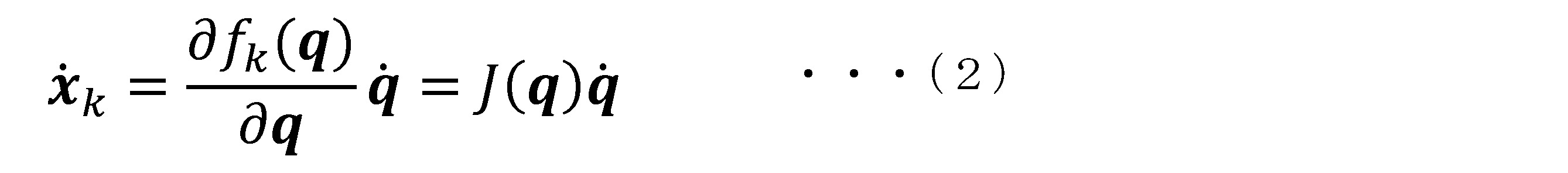
ここでJは、非特許文献1の「III.DETECTION AND REACTION WITH RIGID ROBOTS」に開示があるヤコビ行列である。
障害物位置推定部14は、以下の式(3)から代表点の移動方向を算出する。
Here, J is the Jacobian matrix disclosed in
The

次に障害物位置推定部14は、次のようにして障害物位置を推定する(ステップS23)。障害物位置推定部14は、ステップS22の式(3)で算出した移動方向に基づいて、以下の式(4)により、障害物位置μを推定する。なお、dは、接触リンクから障害物400までの距離(最短距離)を示す(図4のd)。距離dには、例えば、アーム20のリンク201Bの半径R(図4のR1÷2)を設定する。なお、リンク半径Rを距離dに設定することは一例であって、距離dには他の値を設定してもよい。
Next, the obstacle

全ての関節202の角度センサ204により計測された角度や角速度を式(2)に代入し、また、リンク半径Rを式(4)のdに代入することにより、障害物位置μを算出することができる。算出された障害物位置の位置を、図4の障害物位置μ0に示す。障害物位置推定部14は、所定のリンク半径R、接触検知時にセンサ情報取得部11が取得した各関節202の角度や角速度から代表点の位置xkや代表点の移動方向(式(3))を算出し、式(4)によって、障害物位置μ0を算出する。障害物位置μ0は、例えば、3次元の位置情報である。
By substituting the angles and angular velocities measured by the
次に図5を参照する。図5は、第一実施形態に係る障害物位置の推定処理の一例を説明する第2の図である。
図5に、接触リンクの基端側(ベース側)の関節202の移動方向に障害物位置を推定する方法を示す。図5は、アーム20の手首関節202Aを動かすことなく、肘関節202Bを矢印YA2の方向へ移動させているときに障害物401に接触した状況を示している。このとき、ステップS13により、リンク201Bが接触リンクとして特定される。手首関節202Aが固定されているにもかかわらず、肘関節202Bを動かす動作を行う場合、手首関節202Aの移動方向に障害物位置を推定するのが適切でない場合がある。そこで、アーム20の動きに応じて、代表点を変更することで、より正確な障害物位置推定を行う。例えば、接触リンクから見て先端側の関節202を動かさずに、基端側の関節202を動かしている間に、接触検知部13が、障害物401との接触を検知した場合、障害物位置推定部14は、特定された接触リンクの基端側の関節202を代表点として設定する(ステップS21)。図5において、接触リンクはリンク201Bであるから、障害物位置推定部14は、関節202Bを代表点として設定する。
Reference is now made to FIG. FIG. 5 is a second diagram illustrating an example of obstacle position estimation processing according to the first embodiment.
FIG. 5 shows a method of estimating an obstacle position in the moving direction of the joint 202 on the proximal side (base side) of the contact link. FIG. 5 shows a situation in which an obstacle 401 is contacted while moving the elbow joint 202B in the direction of the arrow YA2 without moving the wrist joint 202A of the
次に障害物位置推定部14は、上記の式(3)によって代表点の移動方向を算出する(ステップS22)。次に障害物位置推定部14は、上記の式(4)によって障害物位置μ1を推定する(ステップS23)。
Next, the obstacle
図4、図5の説明では、障害物400、401と接触が検知されたときに、接触リンクの先端側の関節202Aが動いている場合は接触リンクの先端側の関節202Aを代表点とし、接触リンクの先端側の関節202Aが動いておらず基端側の関節202Bが動いている場合は接触リンクの基端側の関節202Bを代表点とすると説明したが、代表点の決定方法はこの方法に限らない。状況によっては、接触リンクの先端側の関節202Aが動いている場合であっても、基端側を代表点として設定してもよいし、接触リンクの先端側の関節202Aが動いていない場合でも、先端側の関節202Aを代表点として設定してもよい。例えば、接触リンクの先端側の関節202Aを代表点として障害物位置μを推定する処理と、接触リンクの基端側の関節202Bを代表点として障害物位置μを推定する処理の両方を行い、複数回の障害物位置推定処理の結果、より確からしい方向に推定された障害物位置μを障害物位置であるとして選択し、その場合の代表点を以降の同じ接触リンクに対する接触検知の際の代表点として定めてもよい。
4 and 5, if the joint 202A on the tip side of the contact link is moving when contact with the
図2に戻る。図3の処理により、障害物位置μを推定すると、障害物位置推定部14は、推定した障害物位置μを記憶部15に記録する(ステップS15)。推定した障害物位置μを図示した例を図6に示す。図6の線300やその他の同様の線は、アーム20を様々に動作させている間のアーム20の姿勢の履歴を示している。また、障害物位置μ2~μ5は、アーム20の姿勢を様々に変化させている間に障害物402との接触が検知された際に、ステップS14の処理によって推定された障害物位置を示す。障害物位置推定部14は、アーム20の動作中に推定した複数の障害物位置μ2~μ5を記憶部15に記録する。
Return to FIG. After estimating the obstacle position μ by the process of FIG. 3, the obstacle
また、障害物位置推定部14は、障害物位置μを記憶部15に記録するとともに、障害物位置μをアーム制御部12へ出力する。アーム制御部12は、障害物位置μに基づいて、接触後の処理を実行する(ステップS16)。例えば、アーム制御部12は、アーム20を停止したり、アーム20を障害物との接触が生じない元の位置へ戻したりといった衝突緩和の制御を実行してもよい。さらに障害物位置μが把握できると、アーム20により積極的な動作を行わせることができる。例えば、アーム制御部12は、障害物位置μに基づいて、障害物を回避しつつ、アーム20の先端を目標位置へ近づけるような動作を行ってもよい。その際のアーム20の制御には、目標位置へ到達させる方法、障害物を回避させる方法にそれぞれ公知の技術を用いても良い。例えば、障害物位置μが判明している場合に障害物を回避させる方法の一例として、ポテンシャル法が知られている。アーム制御部12は、ポテンシャル法を適用して、障害物を回避するようアーム20を制御してもよい。また、目標位置へ到達させる方法についても、アーム制御部12は、マニピュレータを目標位置へ到達させる公知の技術を用いて、アーム20の制御を行ってもよい。障害物位置μの推定結果を取得することにより、アーム制御部12は、障害物接触後のアーム20の動作を選択することができる。
Further, the obstacle
以上、図2~図6を用いて説明したように、第一実施形態によれば、接触リンク上に設定した代表点の位置、速度を基に、障害物の位置を推定することができる。障害物位置を認識することで、障害物に対する公知の回避技術を適用でき、接触後に巻き戻しや停止以外の動作をアーム20に行わせることができる。これにより、従来技術であれば、障害物に接触した場合、停止などの衝突緩和の後にアーム20の軌道を調整する等の手間が必要となるところ、本実施形態によれば、障害物を回避しつつ目標動作を行わせることを自動化することができるので、マニピュレータ100を用いた作業効率が向上する。また、アーム20の動作状況(手首関節202Aを動かすか否か等)に応じて代表点の設定を切り換えることで、障害物位置をより正確に推定することができる。また、本実施形態によれば、マニピュレータ100に、接触検知や障害物位置推定用の外界センサ(接触センサ、カメラ等)を設置しなくても障害物との接触を検知し、障害物位置を推定することができる。外界センサが不要なので、狭隘部にてアーム20を動作させるような場合でもセンサ類によって動作空間を圧迫し、狭めることが無く、また、センサ類の故障や破損などを気にする必要が無い。例えば、本実施形態の制御方法は、カメラを設置できない環境でのマニピュレータの制御に適用することができる。また、外界センサを必要としないことで、コストや重量等を低減することができる。
As described above with reference to FIGS. 2 to 6, according to the first embodiment, the positions of obstacles can be estimated based on the positions and velocities of representative points set on contact links. Known obstacle avoidance techniques can be applied by recognizing the position of the obstacle, and the
<第二実施形態>
第二実施形態は、第一実施形態の方法で推定した障害物位置に基づいて、障害物の形状や範囲を推定する処理に関する。図7を参照して、第二実施形態の説明を行う。
<Second embodiment>
The second embodiment relates to processing for estimating the shape and range of an obstacle based on the obstacle position estimated by the method of the first embodiment. A second embodiment will be described with reference to FIG.
図7は、第二実施形態の係る障害物の形状を推定する処理について説明する図である。
図2のステップS15で説明したように、アーム20の運転を継続すると、記憶部15には、障害物位置μが複数(例えば、障害物位置μ2~μ5)記録される。障害物形状推定部16は、複数の障害物位置μから障害物402の形状や範囲を推定してその推定結果を出力する。図7の左図701は、記憶部15に記録された障害物位置μ2~μ5をその位置情報に基づいてプロットした図である。障害物形状推定部16は、障害物位置μ2~μ5に基づいて、障害物の形状を推定する。例えば、障害物形状推定部16は、障害物位置μ2~μ5をすべて内包し、その体積が最小となる直方体や円柱などを算出し、算出した直方体の形状を障害物の形状、算出した直方体が占める空間を障害物が存在する範囲であると推定する。また、障害物形状推定部16は、推定した直方体等とその位置関係を表示装置や電子ファイル等に出力する。障害物形状推定部16による障害物形状の推定結果およびその出力例を図7の右図702に示す。右図702の障害物u6は、障害物形状推定部16によって推定された障害物の形状や範囲を示している。推定結果を表示することで、障害物との実際の接触履歴に基づく障害物形状とマニピュレータ100との位置関係を容易に把握することができる。また、障害物形状推定部16が推定した障害物範囲の位置情報をアーム制御部12へ渡すことにより、アーム制御部12は、効率的に障害物を回避する制御が可能になる。
FIG. 7 is a diagram illustrating processing for estimating the shape of an obstacle according to the second embodiment.
As described in step S15 in FIG. 2, when the
第二実施形態では、障害物位置推定部14が推定した複数の障害物位置μのそれぞれが、障害物全体のある部分(点)であると考え、これらを統合して、障害物全体の形状を推定する。これにより、これまで障害物位置μとして推定されていない位置についても、その位置が障害物の一部であるかどうかを判断することができる。これにより、障害物の一部である可能性がある位置を予測して回避しつつ、アーム20を動作させることができるので、目標位置に向けて、スムーズにアーム20を動作させることができる。
In the second embodiment, each of the plurality of obstacle positions μ estimated by the obstacle
なお、アーム20の制御を効率化するために、作業開始時にアーム20を様々な方向(例えば、全方向に亘って網羅的に)に動作させて意図的に障害物と接触させ、障害物位置推定部14によって障害物位置推定およびその位置情報の記録を行い、さらに障害物形状推定部16によって障害物の形状を推定させる処理を行うようにしてもよい。作業の最初の段階で、障害物の形状や範囲を把握することにより、それ以降のマニピュレータ100の制御を効率化することができる。
In addition, in order to improve the efficiency of control of the
図8は、実施形態の制御装置のハードウェア構成の一例を示す図である。
コンピュータ900は、CPU901、主記憶装置902、補助記憶装置903、入出力インタフェース904、通信インタフェース905を備える。
上述の制御装置10は、コンピュータ900に実装される。そして、上述した各機能(センサ情報取得部11、アーム制御部12、接触検知部13、障害物位置推定部14、μ16)は、プログラムの形式で補助記憶装置903に記憶されている。CPU901は、プログラムを補助記憶装置903から読み出して主記憶装置902に展開し、当該プログラムに従って上記処理を実行する。また、CPU901は、プログラムに従って、記憶領域を主記憶装置902に確保する。また、CPU901は、プログラムに従って、処理中のデータを記憶する記憶領域を補助記憶装置903に確保する。
8 is a diagram illustrating an example of a hardware configuration of a control device according to the embodiment; FIG.
A
The
なお、制御装置10の全部または一部の機能を実現するためのプログラムをコンピュータ読み取り可能な記録媒体に記録して、この記録媒体に記録されたプログラムをコンピュータシステムに読み込ませ、実行することにより各機能部による処理を行ってもよい。ここでいう「コンピュータシステム」とは、OSや周辺機器等のハードウェアを含むものとする。また、「コンピュータシステム」は、WWWシステムを利用している場合であれば、ホームページ提供環境(あるいは表示環境)も含むものとする。また、「コンピュータ読み取り可能な記録媒体」とは、CD、DVD、USB等の可搬媒体、コンピュータシステムに内蔵されるハードディスク等の記憶装置のことをいう。また、このプログラムが通信回線によってコンピュータ900に配信される場合、配信を受けたコンピュータ900が当該プログラムを主記憶装置902に展開し、上記処理を実行しても良い。また、上記プログラムは、前述した機能の一部を実現するためのものであっても良く、さらに前述した機能をコンピュータシステムにすでに記録されているプログラムとの組み合わせで実現できるものであってもよい。
A program for realizing all or part of the functions of the
以上のとおり、本開示に係るいくつかの実施形態を説明したが、これら全ての実施形態は、例として提示したものであり、発明の範囲を限定することを意図していない。これらの実施形態は、その他の様々な形態で実施されることが可能であり、発明の要旨を逸脱しない範囲で種々の省略、置き換え、変更を行うことができる。これらの実施形態及びその変形は、発明の範囲や要旨に含まれると同様に、特許請求の範囲に記載された発明とその均等の範囲に含まれる。 Although several embodiments of the present disclosure have been described above, all these embodiments are provided by way of example and are not intended to limit the scope of the invention. These embodiments can be implemented in various other forms, and various omissions, replacements, and modifications can be made without departing from the scope of the invention. These embodiments and their modifications are included in the scope and spirit of the invention, as well as the scope of the invention described in the claims and equivalents thereof.
<付記>
各実施形態に記載の制御装置10、位置推定方法及びプログラムは、例えば以下のように把握される。
<Appendix>
The
(1)第1の態様に係る制御装置10は、マニピュレータ100のアーム20が障害物400、401等へ接触したことを検知する接触検知部13と、前記アームのうちの前記接触が検知されたリンク上に設定された代表点の移動方向(式(3))と、前記代表点から前記障害物までの距離dと、に基づいて前記障害物(μ0~μ5)の位置を推定する障害物位置推定部14と、を備える。
これにより、マニピュレータ100の外界を検出するセンサを設けなくても、障害物との接触を検知し、その位置を推定することができる。障害物の位置を推定することができるので、その位置情報を用いて、障害物との接触検知後のマニピュレータ100の動作を任意に制御することができる。
(1) The
Thereby, contact with an obstacle can be detected and its position can be estimated without providing a sensor for detecting the external environment of the
(2)第2の態様に係る制御装置10は、(1)の制御装置10であって、前記障害物位置推定部14は、前記アーム20が備える関節202の動作状況に応じて、前記代表点を設定する。
これにより、アーム20の動かし方に応じて、代表点を設定することにより、正確に障害物位置を推定することができる。
(2) The
Accordingly, by setting the representative point according to how the
(3)第3の態様に係る制御装置10は、(2)の制御装置10であって、前記接触が検知されたリンク(図4の201B)に接続された関節202のうち、先端側の関節202Aを動かしているときに前記障害物400との接触が検知された場合、前記障害物位置推定部14は、前記リンクの先端側の関節202Aを前記代表点として設定する。
本開示の第一実施形態では、接触リンクの移動方向に障害物があると推定するが、例えば、接触リンクの先端側の関節202を動かしているときに障害物と接触した場合(接触リンクの先端側の関節のさらに先のリンクでは外乱トルクが検知されていない)、接触リンクの先端側の関節の移動方向が基端側の移動方向よりも障害物位置に関係が深い(より適切に障害物位置を表す)と仮定し、接触リンクの先端側の関節を代表点として設定する。これにより、障害物位置を適切に推定する。
(3) The
In the first embodiment of the present disclosure, it is assumed that there is an obstacle in the movement direction of the contact link. No disturbance torque is detected in the link beyond the distal joint), and the movement direction of the distal joint of the contact link is more closely related to the obstacle position than the movement direction of the proximal side (more appropriately, the obstacle represents the object position), and the joint on the tip side of the contact link is set as the representative point. Thereby, the obstacle position is properly estimated.
(4)第4の態様に係る制御装置10は、(2)~(3)の制御装置10であって、前記接触が検知されたリンク(図5の201B)に接続された関節202のうち、基端側の関節202Bだけを動かしているときに前記障害物401との接触が検知された場合、前記障害物位置推定部14は、前記リンクの基端側の関節202Bを前記代表点として設定する。
本開示の第一実施形態では、接触リンクの移動方向に障害物があると推定するが、例えば、接触リンクの基端側の関節202のみを動かしているときに障害物と接触した場合、接触リンクの基端側の関節の移動によって接触が生じたとすると、接触リンクの基端側の移動方向が先端側の移動方向よりも障害物位置に関係が深いと考え、接触リンクの基端側の関節を代表点として設定する。これにより、障害物位置を適切に推定する。
(4) The
In the first embodiment of the present disclosure, it is assumed that there is an obstacle in the movement direction of the contact link. If contact occurs due to the movement of the joint on the proximal side of the link, the direction of movement of the proximal side of the contact link is more closely related to the position of the obstacle than the direction of movement of the distal side. Set joints as representative points. Thereby, the obstacle position is properly estimated.
(5)第5の態様に係る制御装置10は、(1)~(4)の制御装置10であって、前記接触検知部は、前記アームを構成するリンクの中の前記障害物への接触が検知された前記リンクのうち最も先端側の前記リンクを前記障害物へ接触したリンクであると特定する。
アームが障害物と接触すると、接触があったリンクと、それよりも基端側(ベース側)のリンクにて外乱トルクが観測される。従って、外乱トルクが観測されたリンクのうち、最も先端側のリンクを接触リンクと特定することで、実際に接触があったリンクを誤りなく特定できる確率が高まり、これにより、障害物位置の推定精度を確保することができる。
(5) A
When the arm comes into contact with an obstacle, disturbance torque is observed in the contact link and the link on the base end side (base side). Therefore, by identifying the link closest to the leading end of the links where the disturbance torque is observed as the contacting link, the probability of correctly identifying the link that was actually in contact increases, thereby estimating the position of the obstacle. Accuracy can be ensured.
(6)第6の態様に係る制御装置10は、(1)~(5)の制御装置10であって、前記代表点から前記障害物までの距離に前記アームを構成するリンクの半径の長さを設定する。
代表点から障害物までの距離は不明であるところ、大きく違わない値としてリンク半径を距離に設定することで障害物位置の推定が可能になる。
(6) A
Although the distance from the representative point to the obstacle is unknown, it is possible to estimate the position of the obstacle by setting the link radius as the distance as a value that does not differ greatly.
(7)第7の態様に係る制御装置10は、(1)~(6)の制御装置10であって、前記位置推定部は、推定した前記障害物の位置を記憶部に記録する。
障害物位置を記録することで、障害物全体の形状や範囲の推定を行うための基礎データを蓄積することができる。
(7) A
By recording the position of the obstacle, basic data for estimating the shape and range of the entire obstacle can be accumulated.
(8)第8の態様に係る制御装置10は、(7)の制御装置10であって、前記記憶部に記録された前記障害物の位置に基づいて、前記障害物の形状を推定する形状推定部、をさらに備える。
障害物の形状を推定することで、障害物の回避が可能になる。これにより、マニピュレータ100による作業効率を向上することができる。
(8) A
Obstacle avoidance becomes possible by estimating the shape of the obstacle. Thereby, the working efficiency of the
(9)第9の態様に係る位置推定方法は、マニピュレータのアームが障害物へ接触したことを検知するステップと、前記アームのうちの前記接触が検知されたリンク上に設定された代表点の移動方向と、前記代表点から前記障害物までの距離と、に基づいて前記障害物の位置を推定するステップと、を有する。 (9) A position estimation method according to a ninth aspect includes the step of detecting that an arm of a manipulator contacts an obstacle; and estimating the position of the obstacle based on the direction of movement and the distance from the representative point to the obstacle.
(10)第10の態様に係るプログラムは、コンピュータ900に、マニピュレータのアームが障害物へ接触したことを検知し、前記アームのうちの前記接触が検知されたリンク上に設定された代表点の移動方向と、前記代表点から前記障害物までの距離と、に基づいて前記障害物の位置を推定する処理を実行させる。
(10) The program according to the tenth aspect causes the
10・・・制御装置
11・・・センサ情報取得部
12・・・アーム制御部
13・・・接触検知部
14・・・障害物位置推定部
15・・・記憶部
16・・・障害物形状推定部
20・・・アーム
100・・・マニピュレータ
201、201A、201B、201C、201D・・・リンク
202、202A、202B、202C・・・関節
203・・・モータ
204・・・角度センサ
900・・・コンピュータ
901・・・CPU
902・・・主記憶装置
903・・・補助記憶装置
904・・・入出力インタフェース
905・・・通信インタフェース
DESCRIPTION OF
902
Claims (10)
前記アームのうちの前記接触が検知されたリンク上に設定された代表点の移動方向と、前記代表点から前記障害物までの距離と、に基づいて前記障害物の位置を推定する位置推定部と、
を備える制御装置。 a contact detection unit that detects that the arm of the manipulator has come into contact with an obstacle;
A position estimating unit for estimating the position of the obstacle based on the moving direction of the representative point set on the link of the arm where the contact is detected and the distance from the representative point to the obstacle. When,
A control device comprising:
請求項1に記載の制御装置。 The position estimating unit sets the representative point according to the motion state of the joints of the arm.
A control device according to claim 1 .
前記位置推定部は、前記リンクの先端側の前記関節を前記代表点として設定する、
請求項2に記載の制御装置。 When contact with the obstacle is detected while moving the joint on the distal end side among the joints connected to the link where the contact is detected,
The position estimation unit sets the joint on the tip side of the link as the representative point.
3. A control device according to claim 2.
前記位置推定部は、前記リンクの基端側の前記関節を前記代表点として設定する、
請求項2または請求項3に記載の制御装置。 When contact with the obstacle is detected while only the joint on the base end side is moving among the joints connected to the link where the contact is detected,
The position estimation unit sets the joint on the proximal side of the link as the representative point.
4. The control device according to claim 2 or 3.
請求項1から請求項4の何れか1項に記載の制御装置。 The contact detection unit identifies the link closest to the tip of the links that have detected contact with the obstacle among the links that constitute the arm as the link that has contacted the obstacle.
The control device according to any one of claims 1 to 4.
請求項1から請求項5の何れか1項に記載の制御装置。 setting the length of the radius of the link that constitutes the arm to the distance from the representative point to the obstacle;
The control device according to any one of claims 1 to 5.
請求項1から請求項6の何れか1項に記載の制御装置。 The position estimation unit records the estimated position of the obstacle in a storage unit.
The control device according to any one of claims 1 to 6.
をさらに備える請求項7に記載の制御装置。 a shape estimation unit that estimates the shape of the obstacle based on the position of the obstacle recorded in the storage unit;
8. The controller of claim 7, further comprising:
前記アームのうちの前記接触が検知されたリンク上に設定された代表点の移動方向と、前記代表点から前記障害物までの距離と、に基づいて前記障害物の位置を推定する、
位置推定方法。 Detecting that the manipulator arm has come into contact with an obstacle,
estimating the position of the obstacle based on the moving direction of the representative point set on the link of the arm where the contact is detected and the distance from the representative point to the obstacle;
Location estimation method.
マニピュレータのアームが障害物へ接触したことを検知し、
前記アームのうちの前記接触が検知されたリンク上に設定された代表点の移動方向と、前記代表点から前記障害物までの距離と、に基づいて前記障害物の位置を推定する処理、
を実行させるプログラム。 to the computer,
Detecting that the manipulator arm has come into contact with an obstacle,
A process of estimating the position of the obstacle based on the moving direction of the representative point set on the link of the arm where the contact is detected and the distance from the representative point to the obstacle;
program to run.
Priority Applications (1)
| Application Number | Priority Date | Filing Date | Title |
|---|---|---|---|
| JP2021009887A JP2022113567A (en) | 2021-01-25 | 2021-01-25 | Control device, position estimation method and program |
Applications Claiming Priority (1)
| Application Number | Priority Date | Filing Date | Title |
|---|---|---|---|
| JP2021009887A JP2022113567A (en) | 2021-01-25 | 2021-01-25 | Control device, position estimation method and program |
Publications (1)
| Publication Number | Publication Date |
|---|---|
| JP2022113567A true JP2022113567A (en) | 2022-08-04 |
Family
ID=82658112
Family Applications (1)
| Application Number | Title | Priority Date | Filing Date |
|---|---|---|---|
| JP2021009887A Pending JP2022113567A (en) | 2021-01-25 | 2021-01-25 | Control device, position estimation method and program |
Country Status (1)
| Country | Link |
|---|---|
| JP (1) | JP2022113567A (en) |
Citations (3)
| Publication number | Priority date | Publication date | Assignee | Title |
|---|---|---|---|---|
| JP2003136466A (en) * | 2001-10-25 | 2003-05-14 | Murata Mach Ltd | Control device of industrial robot |
| JP2008302496A (en) * | 2006-07-04 | 2008-12-18 | Panasonic Corp | Robot arm control apparatus and control method, robot, and robot arm control program |
| WO2020161910A1 (en) * | 2019-02-08 | 2020-08-13 | 日本電気株式会社 | Control device, control method, and recording medium |
-
2021
- 2021-01-25 JP JP2021009887A patent/JP2022113567A/en active Pending
Patent Citations (3)
| Publication number | Priority date | Publication date | Assignee | Title |
|---|---|---|---|---|
| JP2003136466A (en) * | 2001-10-25 | 2003-05-14 | Murata Mach Ltd | Control device of industrial robot |
| JP2008302496A (en) * | 2006-07-04 | 2008-12-18 | Panasonic Corp | Robot arm control apparatus and control method, robot, and robot arm control program |
| WO2020161910A1 (en) * | 2019-02-08 | 2020-08-13 | 日本電気株式会社 | Control device, control method, and recording medium |
Similar Documents
| Publication | Publication Date | Title |
|---|---|---|
| US20190283259A1 (en) | Robot control method | |
| JP5754454B2 (en) | Robot picking system and workpiece manufacturing method | |
| JP6157786B1 (en) | Medical manipulator system | |
| JP7206638B2 (en) | ROBOT, CONTROL DEVICE, AND ROBOT CONTROL METHOD | |
| CN109968377B (en) | Robot control system and method for controlling a robot | |
| US12114942B2 (en) | Information processing apparatus, information processing system, and information processing method | |
| JP2019532824A (en) | Continuous robot, method for correcting kinematic model of continuous robot, and control method for continuous robot | |
| CN113966265A (en) | Method and system for operating a robot | |
| US20230286159A1 (en) | Remote control system | |
| US20240100695A1 (en) | Information processing apparatus, information processing method, and program | |
| JP7160118B2 (en) | Control device, control method, program | |
| CN103732364B (en) | Robot device | |
| US12358132B2 (en) | Robot system and picking method | |
| JP2009045678A (en) | Robot work success / failure determination method and robot system | |
| JP5447150B2 (en) | Robot control device and method for controlling robot | |
| JP2026009312A (en) | Robot control device, robot control system, and robot control method | |
| JP2022113567A (en) | Control device, position estimation method and program | |
| JP2022156954A (en) | Control device, robot system, control method and program | |
| CN118700164B (en) | A control method and system for a gripping robot arm | |
| JP7479205B2 (en) | ROBOT SYSTEM, CONTROL DEVICE, AND CONTROL METHOD | |
| JP7697328B2 (en) | Workpiece holding device, workpiece holding method, program, and control device | |
| JP7441716B2 (en) | Work system and work control device | |
| JP2025006185A (en) | Robotic Work System | |
| JP7683505B2 (en) | Workpiece holding system, workpiece holding method, program, and control device | |
| US20220203531A1 (en) | Robot, transmission method, and transmission estimation method |
Legal Events
| Date | Code | Title | Description |
|---|---|---|---|
| A621 | Written request for application examination |
Free format text: JAPANESE INTERMEDIATE CODE: A621 Effective date: 20231227 |
|
| A977 | Report on retrieval |
Free format text: JAPANESE INTERMEDIATE CODE: A971007 Effective date: 20240521 |
|
| A131 | Notification of reasons for refusal |
Free format text: JAPANESE INTERMEDIATE CODE: A131 Effective date: 20240528 |
|
| A521 | Request for written amendment filed |
Free format text: JAPANESE INTERMEDIATE CODE: A523 Effective date: 20240729 |
|
| A131 | Notification of reasons for refusal |
Free format text: JAPANESE INTERMEDIATE CODE: A131 Effective date: 20241008 |
|
| A02 | Decision of refusal |
Free format text: JAPANESE INTERMEDIATE CODE: A02 Effective date: 20250325 |