[go: up one dir, main page]

JP2022109070A - Control device, magnetic flux estimation device and magnetic flux estimation method - Google Patents

Control device, magnetic flux estimation device and magnetic flux estimation method Download PDF

Info

Publication number
JP2022109070A
JP2022109070A JP2021004405A JP2021004405A JP2022109070A JP 2022109070 A JP2022109070 A JP 2022109070A JP 2021004405 A JP2021004405 A JP 2021004405A JP 2021004405 A JP2021004405 A JP 2021004405A JP 2022109070 A JP2022109070 A JP 2022109070A
Authority
JP
Japan
Prior art keywords
magnetic flux
estimation
electric motor
axis
primary
Prior art date
Legal status (The legal status is an assumption and is not a legal conclusion. Google has not performed a legal analysis and makes no representation as to the accuracy of the status listed.)
Granted
Application number
JP2021004405A
Other languages
Japanese (ja)
Other versions
JP7095760B1 (en
Inventor
考弘 佐伯
Takahiro Saeki
伸吾 福丸
Shingo Fukumaru
Current Assignee (The listed assignees may be inaccurate. Google has not performed a legal analysis and makes no representation or warranty as to the accuracy of the list.)
Yaskawa Electric Corp
Original Assignee
Yaskawa Electric Corp
Priority date (The priority date is an assumption and is not a legal conclusion. Google has not performed a legal analysis and makes no representation as to the accuracy of the date listed.)
Filing date
Publication date
Application filed by Yaskawa Electric Corp filed Critical Yaskawa Electric Corp
Priority to JP2021004405A priority Critical patent/JP7095760B1/en
Priority to EP22151663.6A priority patent/EP4030614B1/en
Priority to CN202210046301.2A priority patent/CN114844428B/en
Priority to US17/648,062 priority patent/US11929695B2/en
Application granted granted Critical
Publication of JP7095760B1 publication Critical patent/JP7095760B1/en
Publication of JP2022109070A publication Critical patent/JP2022109070A/en
Active legal-status Critical Current
Anticipated expiration legal-status Critical

Links

Images

Classifications

    • HELECTRICITY
    • H02GENERATION; CONVERSION OR DISTRIBUTION OF ELECTRIC POWER
    • H02PCONTROL OR REGULATION OF ELECTRIC MOTORS, ELECTRIC GENERATORS OR DYNAMO-ELECTRIC CONVERTERS; CONTROLLING TRANSFORMERS, REACTORS OR CHOKE COILS
    • H02P21/00Arrangements or methods for the control of electric machines by vector control, e.g. by control of field orientation
    • H02P21/14Estimation or adaptation of machine parameters, e.g. flux, current or voltage
    • H02P21/141Flux estimation
    • HELECTRICITY
    • H02GENERATION; CONVERSION OR DISTRIBUTION OF ELECTRIC POWER
    • H02PCONTROL OR REGULATION OF ELECTRIC MOTORS, ELECTRIC GENERATORS OR DYNAMO-ELECTRIC CONVERTERS; CONTROLLING TRANSFORMERS, REACTORS OR CHOKE COILS
    • H02P23/00Arrangements or methods for the control of AC motors characterised by a control method other than vector control
    • H02P23/0004Control strategies in general, e.g. linear type, e.g. P, PI, PID, using robust control
    • HELECTRICITY
    • H02GENERATION; CONVERSION OR DISTRIBUTION OF ELECTRIC POWER
    • H02PCONTROL OR REGULATION OF ELECTRIC MOTORS, ELECTRIC GENERATORS OR DYNAMO-ELECTRIC CONVERTERS; CONTROLLING TRANSFORMERS, REACTORS OR CHOKE COILS
    • H02P23/00Arrangements or methods for the control of AC motors characterised by a control method other than vector control
    • H02P23/14Estimation or adaptation of motor parameters, e.g. rotor time constant, flux, speed, current or voltage

Landscapes

  • Engineering & Computer Science (AREA)
  • Power Engineering (AREA)
  • Control Of Ac Motors In General (AREA)

Abstract

To provide an electric power conversion device effective to improve the reliability of motor control which is based on an estimation result of a primary magnetic flux.SOLUTION: A control device 1 comprises: an electric power conversion circuit 10 supplying drive electric power to a motor 3; a magnetic flux estimation unit 130 estimating a primary magnetic flux generated by the motor 3 due to being supplied with the drive electric power; and a voltage command generation unit 160 (a control unit) controlling the electric power conversion circuit 10 on the basis of a result of estimation of the primary magnetic flux performed by the magnetic flux estimation unit 130. The magnetic flux estimation unit 130 performs first estimation estimating a primary magnetic flux on the basis of output current from the electric power conversion circuit 10 to the motor 3 and the inductance of the motor 3 when the operation speed of the motor 3 is less than a prescribed level, and second estimation estimating a magnetic flux differential value on the basis of output voltage from the electric power conversion circuit 10 to the motor 3 and estimating a primary magnetic flux by integrating the magnetic flux differential value with the result of the estimation of the primary magnetic flux performed by the first estimation as an initial value when the operation speed exceeds the prescribed level.SELECTED DRAWING: Figure 1

Description

本開示は、制御装置、磁束推定装置及び磁束推定方法に関する。 The present disclosure relates to a control device, a magnetic flux estimation device, and a magnetic flux estimation method.

特許文献1には、回転子速度に基づいて、固定子磁束計算を電流モデルから電圧モデルに円滑に遷移させる制御装置が開示されている。 Patent Literature 1 discloses a control device that smoothly transitions the stator flux calculation from the current model to the voltage model based on the rotor speed.

特表2007-525137号公報Japanese Patent Publication No. 2007-525137

本開示は、一次磁束の推定結果に基づく電動機制御の信頼性向上に有効な電力変換装置を提供する。 The present disclosure provides a power conversion device that is effective in improving the reliability of motor control based on estimation results of primary magnetic flux.

本開示の一側面に係る制御装置は、電動機に駆動電力を供給する電力変換回路と、駆動電力の供給により電動機が発生する一次磁束を推定する磁束推定部と、磁束推定部による一次磁束の推定結果に基づいて電力変換回路を制御する制御部と、を備え、磁束推定部は、電動機の動作速度が所定レベル未満である場合に、電力変換回路から電動機への出力電流と、電動機のインダクタンスとに基づいて一次磁束を推定する第一推定と、動作速度が所定レベルを超える場合に、電力変換回路から電動機への出力電圧に基づいて磁束微分値を推定し、第一推定による一次磁束の推定結果を初期値として磁束微分値を積分して一次磁束を推定する第二推定と、を行う。 A control device according to one aspect of the present disclosure includes a power conversion circuit that supplies drive power to an electric motor, a magnetic flux estimation unit that estimates a primary magnetic flux generated by the electric motor by supplying the drive power, and an estimation of the primary magnetic flux by the magnetic flux estimation unit. a controller for controlling the power conversion circuit based on the result, wherein the magnetic flux estimator controls the output current from the power conversion circuit to the motor and the inductance of the motor when the operating speed of the motor is below a predetermined level. estimating the primary magnetic flux based on the first estimation, and estimating the magnetic flux differential value based on the output voltage from the power conversion circuit to the motor when the operating speed exceeds a predetermined level, and estimating the primary magnetic flux by the first estimation and a second estimation of estimating the primary magnetic flux by integrating the magnetic flux differential value using the result as an initial value.

本開示の他の側面に係る磁束推定装置は、電動機の動作速度が所定レベル未満である場合に、電力変換回路から電動機への出力電流と、電動機のインダクタンスとに基づいて、電動機が発生する一次磁束を推定する第一推定と、動作速度が所定レベルを超える場合に、電力変換回路から電動機への出力電圧に基づいて磁束微分値を推定し、第一推定による一次磁束の推定結果を初期値として磁束微分値を積分して一次磁束を推定する第二推定と、を行う。 A magnetic flux estimation device according to another aspect of the present disclosure provides a primary magnetic flux generated by the electric motor based on the output current from the power conversion circuit to the electric motor and the inductance of the electric motor when the operating speed of the electric motor is below a predetermined level. First estimation for estimating the magnetic flux, and when the operating speed exceeds a predetermined level, estimating the magnetic flux differential value based on the output voltage from the power conversion circuit to the motor, and using the result of the primary magnetic flux estimation by the first estimation as the initial value and a second estimation for estimating the primary magnetic flux by integrating the magnetic flux differential value.

本開示の更に他の側面に係る磁束推定方法は、電動機の動作速度が所定レベル未満である場合に、電力変換回路から電動機への出力電流と、電動機のインダクタンスとに基づいて、電動機が発生する一次磁束を推定する第一推定と、動作速度が所定レベルを超える場合に、電力変換回路から電動機への出力電圧に基づいて磁束微分値を推定し、第一推定による一次磁束の推定結果を初期値として磁束微分値を積分して一次磁束を推定する第二推定と、を含む。 A magnetic flux estimation method according to still another aspect of the present disclosure provides a method for estimating magnetic flux generated by the electric motor based on an output current from a power conversion circuit to the electric motor and the inductance of the electric motor when the operating speed of the electric motor is below a predetermined level. First estimation for estimating the primary magnetic flux, and when the operating speed exceeds a predetermined level, estimating the magnetic flux differential value based on the output voltage from the power conversion circuit to the motor, and initializing the estimation result of the primary magnetic flux by the first estimation a second estimation that estimates the primary flux by integrating the flux differential value as a value.

本開示によれば、一次磁束の推定結果に基づく電動機制御の信頼性向上に有効な電力変換装置を提供することができる。 Advantageous Effects of Invention According to the present disclosure, it is possible to provide a power converter that is effective in improving the reliability of motor control based on the estimation result of the primary magnetic flux.

制御装置の構成を例示する模式図である。It is a schematic diagram which illustrates the structure of a control apparatus. 磁束推定部の機能的な構成を例示するブロック図である。4 is a block diagram illustrating a functional configuration of a magnetic flux estimator; FIG. 補正ゲイン及びキャンセルゲインの設定例を示すグラフである。7 is a graph showing a setting example of a correction gain and a cancellation gain; 制御回路のハードウェア構成を例示するブロック図である。3 is a block diagram illustrating the hardware configuration of a control circuit; FIG. 制御手順を例示するフローチャートである。4 is a flow chart illustrating a control procedure; 磁束推定手順を例示するフローチャートである。4 is a flow chart illustrating a magnetic flux estimation procedure; 磁束推定部の変形例を示すブロック図である。It is a block diagram which shows the modification of a magnetic flux estimation part.

以下、実施形態について、図面を参照しつつ詳細に説明する。説明において、同一要素又は同一機能を有する要素には同一の符号を付し、重複する説明を省略する。 Hereinafter, embodiments will be described in detail with reference to the drawings. In the explanation, the same reference numerals are given to the same elements or elements having the same function, and duplicate explanations are omitted.

〔制御装置〕
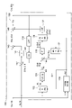
図1に示す制御装置1は、電動機3を制御する装置である。制御装置1は、電源2から供給された電力を駆動電力に変換して電動機3に供給する。電源2は直流電源であってもよく、交流電源であってもよい。一例として、図1は、電源2が三相交流電源である場合を図示している。三相交流電源の具体例としては、電力会社の電力系統、三相交流の発電機、又は無停電電源等が挙げられる。
〔Control device〕
A control device 1 shown in FIG. 1 is a device that controls an electric motor 3 . The control device 1 converts electric power supplied from the power supply 2 into drive power and supplies the drive power to the electric motor 3 . The power supply 2 may be a DC power supply or an AC power supply. As an example, FIG. 1 illustrates the case where the power supply 2 is a three-phase AC power supply. Specific examples of the three-phase AC power supply include a power system of a power company, a three-phase AC generator, an uninterruptible power supply, and the like.

電動機3は、交流の駆動電力(例えば三相交流電力)の供給により動作する交流電動機である。電動機3は、同期電動機であってもよい。例えば電動機3は、PMA(Permanent Magnet Assistance)モータである。電動機3は、IPM(Interior Permanent Magnet)モータであってもよく、SPM(Surface Permanent Magnet)モータであってもよい。電動機3は、永久磁石を有しないシンクロナスリラクタンスモータであってもよい。電動機3は、誘導電動機であってもよい。 The electric motor 3 is an AC electric motor that operates by being supplied with AC drive power (for example, three-phase AC power). The electric motor 3 may be a synchronous motor. For example, the electric motor 3 is a PMA (Permanent Magnet Assistance) motor. The electric motor 3 may be an IPM (Interior Permanent Magnet) motor or an SPM (Surface Permanent Magnet) motor. The electric motor 3 may be a synchronous reluctance motor without permanent magnets. The electric motor 3 may be an induction motor.

電動機3は、固定子にコイルが設けられた固定コイル型であってもよいし、可動子にコイルが設けられた可動コイル型であってもよい。また、電動機3は、回転型であってもよいし、リニア型であってもよい。 The electric motor 3 may be of a fixed coil type in which the stator is provided with coils, or may be of a moving coil type in which the mover is provided with coils. Also, the electric motor 3 may be of a rotary type or of a linear type.

制御装置1は、電力変換回路10と、制御回路100とを有する。電力変換回路10は、電源2から供給された電力(以下、「電源電力」という。)を駆動電力に変換して電動機3に供給する。一例として、電力変換回路10は、整流回路11と、平滑コンデンサ12と、インバータ回路13と、電流センサ14とを有する。整流回路11は、例えばダイオードブリッジ回路又はPWMコンバータ回路であり、上記電源電力を直流電力に変換する。平滑コンデンサ12は、上記直流電力を平滑化する。 The control device 1 has a power conversion circuit 10 and a control circuit 100 . The power conversion circuit 10 converts the power supplied from the power source 2 (hereinafter referred to as “power source power”) into drive power and supplies the drive power to the electric motor 3 . As an example, the power conversion circuit 10 has a rectifier circuit 11 , a smoothing capacitor 12 , an inverter circuit 13 and a current sensor 14 . The rectifier circuit 11 is, for example, a diode bridge circuit or a PWM converter circuit, and converts the power supply power into DC power. A smoothing capacitor 12 smoothes the DC power.

インバータ回路13は、上記直流電力と上記駆動電力との間の電力変換を行う。例えばインバータ回路13は、力行状態において、直流電力を駆動電力に変換して電動機3に供給し、回生状態において、電動機3が発電する電力を直流電力に変換する。なお、力行状態とは、インバータ回路13から供給された駆動電力により電動機3が動作する状態であり、回生状態とは、動作に応じた発電電力を電動機3がインバータ回路13に供給する状態である。 The inverter circuit 13 performs power conversion between the DC power and the driving power. For example, the inverter circuit 13 converts DC power into drive power and supplies it to the electric motor 3 in the power running state, and converts the power generated by the electric motor 3 into DC power in the regeneration state. Note that the power running state is a state in which the electric motor 3 is operated by the drive power supplied from the inverter circuit 13, and the regenerative state is a state in which the electric motor 3 supplies the inverter circuit 13 with generated electric power according to the operation. .

例えばインバータ回路13は、複数のスイッチング素子15を有し、複数のスイッチング素子15のオン・オフを切り替えることによって上記電力変換を行う。スイッチング素子15は、例えばパワーMOSFET(Metal Oxide Semiconductor Field Effect Transistor)又はIGBT(Insulated Gate Bipolar Transistor)等であり、ゲート駆動信号に応じてオン・オフを切り替える。 For example, the inverter circuit 13 has a plurality of switching elements 15, and performs the power conversion by switching ON/OFF of the plurality of switching elements 15. FIG. The switching element 15 is, for example, a power MOSFET (Metal Oxide Semiconductor Field Effect Transistor) or an IGBT (Insulated Gate Bipolar Transistor), and switches ON/OFF according to a gate drive signal.

電流センサ14は、インバータ回路13と電動機3との間に流れる電流(以下、「出力電流」という。)を検出する。例えば電流センサ14は、三相交流の全相(U相、V相及びW相)の電流を検出するように構成されていてもよいし、三相交流のいずれか2相の電流を検出するように構成されていてもよい。零相電流が生じない限り、U相、V相、及びW相の電流の合計はゼロなので、2相の電流を検出する場合にも全相の電流の情報が得られる。 The current sensor 14 detects current flowing between the inverter circuit 13 and the electric motor 3 (hereinafter referred to as "output current"). For example, the current sensor 14 may be configured to detect current in all phases (U-phase, V-phase and W-phase) of a three-phase alternating current, or may detect current in any two phases of a three-phase alternating current. It may be configured as As long as no zero-phase current occurs, the sum of the U-, V-, and W-phase currents is zero, so current information for all phases is obtained even when detecting two-phase currents.

以上に示した電力変換回路10の構成はあくまで一例である。電力変換回路10の構成は、電動機3の駆動電力を生成し得る限りにおいていかようにも変更可能である。例えば、整流回路11は交流電力を直流電力に変換するPWMコンバータ回路やマトリクスコンバータ回路であってもよい。電力変換回路10は、直流化を経ることなく電源電力と駆動電力との双方向の電力変換を行うマトリクスコンバータ回路であってもよい。電源電力が直流電力である場合に、電力変換回路10は整流回路11を有していなくてもよい。 The configuration of the power conversion circuit 10 described above is merely an example. The configuration of the power conversion circuit 10 can be changed in any way as long as the drive power for the electric motor 3 can be generated. For example, the rectifier circuit 11 may be a PWM converter circuit or a matrix converter circuit that converts AC power to DC power. The power conversion circuit 10 may be a matrix converter circuit that performs bidirectional power conversion between source power and drive power without conversion to direct current. When the source power is DC power, the power conversion circuit 10 may not have the rectifier circuit 11 .

制御回路100は、制御指令に対応する駆動電力を電動機3に供給するように電力変換回路10を制御する。制御回路100は、一次磁束の推定結果に基づいて電力変換回路10を制御する。より具体的に、制御回路100は、駆動電力の供給により電動機3が発生する一次磁束を推定することと、一次磁束の推定結果と出力電流(電流センサ14が検出する電流)とに基づいて電動機3の電磁力を推定することと、目標磁束と一次磁束の推定結果との偏差と、目標電磁力と電磁力の推定結果との偏差とに基づいて電力変換回路10を制御することと、を実行するように構成されている。このため制御回路100は、上記一次磁束を推定する磁束推定装置を含んでいる。 The control circuit 100 controls the power conversion circuit 10 to supply the electric motor 3 with drive power corresponding to the control command. The control circuit 100 controls the power conversion circuit 10 based on the estimation result of the primary magnetic flux. More specifically, the control circuit 100 estimates the primary magnetic flux generated by the electric motor 3 by supplying the drive power, and controls the electric motor based on the estimation result of the primary magnetic flux and the output current (the current detected by the current sensor 14). 3, controlling the power conversion circuit 10 based on the deviation between the target magnetic flux and the estimation result of the primary magnetic flux, and the deviation between the target electromagnetic force and the estimation result of the electromagnetic force. configured to run. Therefore, the control circuit 100 includes a magnetic flux estimator for estimating the primary magnetic flux.

例えば制御回路100は、機能上の要素として、電磁力指令生成部110と、磁束指令生成部120と、電流情報取得部101と、磁束推定部130と、電磁力推定部150と、電圧指令生成部160と、位相角算出部170と、PWM制御部180とを有する。 For example, the control circuit 100 includes, as functional elements, an electromagnetic force command generation unit 110, a magnetic flux command generation unit 120, a current information acquisition unit 101, a magnetic flux estimation unit 130, an electromagnetic force estimation unit 150, and a voltage command generation unit. It has a section 160 , a phase angle calculation section 170 and a PWM control section 180 .

電磁力指令生成部110は、電動機3に所望の動作をさせるように上述の目標電磁力を生成する。「電磁力」は、電動機3が駆動対象物に付与する力に相関する値であればよい。電動機3が回転型である場合、電磁力は、電動機3が回転軸まわりに発生するトルクであってもよい。電動機3がリニア型である場合、電磁力は、電動機3が可動子の移動方向に発生する推力であってもよい。 The electromagnetic force command generator 110 generates the target electromagnetic force described above so as to cause the electric motor 3 to operate as desired. The "electromagnetic force" may be any value that correlates with the force applied by the electric motor 3 to the object to be driven. If the electric motor 3 is of a rotary type, the electromagnetic force may be torque generated by the electric motor 3 around its rotation axis. If the electric motor 3 is of a linear type, the electromagnetic force may be a thrust generated by the electric motor 3 in the movement direction of the mover.

一例として、電磁力指令生成部110は、加え合わせ点111で表されるように、目標速度ωtと、速度推定値ωとの差である速度偏差を算出する。目標速度ωtは、例えば電気角の角速度の目標値であり、速度推定値ωは、電気角の角速度の推定値である。電磁力指令生成部110は、制御回路100が予め記憶する目標速度ωtを取得してもよく、プログラマブルロジックコントローラ等の上位コントローラから目標速度ωtを取得してもよい。電磁力指令生成部110は、ブロック112で表されるように、速度偏差に比例演算、比例・積分演算、又は比例・積分・微分演算等を施して目標トルクTt(目標電磁力)を算出する。 As an example, the electromagnetic force command generation unit 110 calculates a speed deviation, which is the difference between the target speed ωt and the estimated speed value ω, as represented by a summation point 111 . The target speed ωt is, for example, a target value of the angular speed of the electrical angle, and the estimated speed value ω is an estimated value of the angular speed of the electrical angle. The electromagnetic force command generator 110 may acquire the target speed ωt stored in advance in the control circuit 100, or may acquire the target speed ωt from a host controller such as a programmable logic controller. The electromagnetic force command generator 110 calculates a target torque Tt (target electromagnetic force) by performing a proportional operation, a proportional/integral operation, or a proportional/integral/differential operation on the speed deviation, as represented by a block 112. .

磁束指令生成部120は、目標トルクTtと、電動機3の磁石磁束と、電動機3のインダクタンスとに基づいて、上記目標一次磁束Φtを算出する。例えば、電動機3が同期リラクタンス電動機を除く同期電動機である場合、磁束指令生成部120は、目標トルクTtに基づいて、目標電流を算出し、次式により目標一次磁束Φtを算出する。
Φdt=Ld・Idt+Φm
Φqt=Lq・Iqt
Φt=(Φdt+Φqt1/2
・・・(1)
Φdt:d軸一次磁束目標値
Φqt:q軸一次磁束目標値
Ld:d軸インダクタンス
Lq:q軸インダクタンス
Idt:d軸電流目標値
Iqt:q軸電流目標値
Φm:磁石磁束
電動機3が同期リラクタンス電動機の場合、式(1)における磁石磁束Φmはゼロである。電動機3が誘導電動機である場合、d軸インダクタンスLdは、一次インダクタンスL1に置き換わる。q軸インダクタンスLqは、一次漏れインダクタンスl1と、二次漏れインダクタンスl2との和に相当する漏れインダクタンスに置き換わる。
The magnetic flux command generator 120 calculates the target primary magnetic flux Φt based on the target torque Tt, the magnet magnetic flux of the electric motor 3 and the inductance of the electric motor 3 . For example, if the electric motor 3 is a synchronous motor other than a synchronous reluctance electric motor, the magnetic flux command generator 120 calculates the target current based on the target torque Tt, and calculates the target primary magnetic flux Φt using the following equation.
Φdt=Ld・Idt+Φm
Φqt=Lq・Iqt
Φt=(Φdt 2 +Φqt 2 ) 1/2
... (1)
Φdt: d-axis primary magnetic flux target value Φqt: q-axis primary magnetic flux target value Ld: d-axis inductance Lq: q-axis inductance Idt: d-axis current target value Iqt: q-axis current target value Φm: magnet flux motor 3 is a synchronous reluctance motor , the magnet flux Φm in equation (1) is zero. When the motor 3 is an induction motor, the d-axis inductance Ld is replaced by the primary inductance L1. The q-axis inductance Lq is replaced by a leakage inductance corresponding to the sum of the primary leakage inductance l1 and the secondary leakage inductance l2.

d軸、q軸は、回転座標系であるdq座標系の座標軸であり、それぞれ電動機3の回転軸に垂直である。電動機3がPMAである場合、d軸は例えば磁石磁束の方向に沿い、q軸は磁石磁束の方向に垂直である。d軸とq軸とが交わる原点は、電動機3の回転中心に位置する。電動機3が誘導電動機である場合、d軸は例えばギャップ磁束の方向に沿い、q軸はギャップ磁束の方向に垂直である。電動機3が同期リラクタンス電動機である場合、d軸はロータの突極方向に沿い、q軸は突極方向に垂直である。また、電動機3が同期リラクタンス電動機である場合、d軸、q軸は、ロータの突極と共に回転するdq座標系の座標軸であり、d軸は突極方向に沿う。 The d-axis and the q-axis are coordinate axes of the dq coordinate system, which is a rotating coordinate system, and are perpendicular to the rotation axis of the electric motor 3 . If the electric motor 3 is a PMA, the d-axis is for example along the direction of the magnet flux and the q-axis is perpendicular to the direction of the magnet flux. The origin where the d-axis and the q-axis intersect is located at the center of rotation of the electric motor 3 . If the motor 3 is an induction motor, the d-axis is for example along the direction of the gap flux and the q-axis is perpendicular to the direction of the gap flux. If the motor 3 is a synchronous reluctance motor, the d-axis is along the salient pole direction of the rotor and the q-axis is perpendicular to the salient pole direction. When the electric motor 3 is a synchronous reluctance electric motor, the d-axis and the q-axis are coordinate axes of a dq coordinate system that rotates with the salient poles of the rotor, and the d-axis is along the direction of the salient poles.

d軸磁束は、一次磁束のd軸成分であり、q軸磁束は、一次磁束のq軸成分である。d軸電流は、d軸に沿った磁束を発生させる電流であり、q軸電流は、q軸に沿った磁束を発生させる電流である。d軸インダクタンスは、d軸電流からd軸磁束を求める係数であり、q軸インダクタンスは、q軸電流からq軸磁束を求める係数である。 The d-axis magnetic flux is the d-axis component of the primary magnetic flux, and the q-axis magnetic flux is the q-axis component of the primary magnetic flux. The d-axis current is the current that produces magnetic flux along the d-axis, and the q-axis current is the current that produces magnetic flux along the q-axis. The d-axis inductance is a coefficient for obtaining the d-axis magnetic flux from the d-axis current, and the q-axis inductance is a coefficient for obtaining the q-axis magnetic flux from the q-axis current.

電流情報取得部101は、電流センサ14による出力電流の検出結果を取得し、取得した検出結果に三相・二相変換を施してa軸電流Ia及びb軸電流Ibを算出する。a軸電流Iaは、出力電流のa軸成分であり、b軸電流Ibは、出力電流のb軸成分である。 The current information acquisition unit 101 acquires the detection result of the output current by the current sensor 14, performs three-phase/two-phase conversion on the acquired detection result, and calculates the a-axis current Ia and the b-axis current Ib. The a-axis current Ia is the a-axis component of the output current, and the b-axis current Ib is the b-axis component of the output current.

a軸、b軸は、固定座標系であるab座標系の座標軸であり、それぞれ電動機3の回転軸に垂直である。a軸及びb軸は互いに垂直であり、a軸とb軸とが交わる原点は電動機3の回転中心に一致している。 The a-axis and b-axis are coordinate axes of the ab coordinate system, which is a fixed coordinate system, and are perpendicular to the rotation axis of the electric motor 3 . The a-axis and the b-axis are perpendicular to each other, and the origin where the a-axis and the b-axis intersect coincides with the rotation center of the electric motor 3 .

磁束推定部130は、駆動電力の供給により電動機3が発生する一次磁束を推定する。例えば磁束推定部130は、一次磁束推定値Φと、a軸一次磁束推定値Φaと、b軸一次磁束推定値Φbとを算出する。a軸磁束は、一次磁束のa軸成分であり、b軸磁束は、一次磁束のb軸成分である。磁束推定部130による一次磁束の推定処理については後述する。 The magnetic flux estimator 130 estimates the primary magnetic flux generated by the electric motor 3 by supplying the drive power. For example, the magnetic flux estimation unit 130 calculates a primary magnetic flux estimated value Φ, an a-axis primary magnetic flux estimated value Φa, and a b-axis primary magnetic flux estimated value Φb. The a-axis flux is the a-axis component of the primary flux, and the b-axis flux is the b-axis component of the primary flux. The estimation processing of the primary magnetic flux by the magnetic flux estimator 130 will be described later.

電磁力推定部150は、一次磁束の推定結果と出力電流とに基づいて電動機3のトルク(電磁力)を推定する。例えば電磁力推定部150は、次式により、トルク推定値Tを算出する。
T=Φa・Ib-Φb・Ia ・・・(2)
The electromagnetic force estimator 150 estimates the torque (electromagnetic force) of the electric motor 3 based on the estimation result of the primary magnetic flux and the output current. For example, the electromagnetic force estimator 150 calculates the torque estimated value T using the following equation.
T=Φa・Ib−Φb・Ia (2)

電圧指令生成部160(制御部)は、磁束推定部130による一次磁束の推定結果に基づいて電力変換回路10を制御する。例えば電圧指令生成部160は、目標磁束と一次磁束の推定結果との偏差と、目標電磁力と電磁力の推定結果との偏差とに基づいて電力変換回路10を制御する。 The voltage command generation unit 160 (control unit) controls the power conversion circuit 10 based on the estimation result of the primary magnetic flux by the magnetic flux estimation unit 130 . For example, the voltage command generator 160 controls the power conversion circuit 10 based on the deviation between the target magnetic flux and the estimation result of the primary magnetic flux and the deviation between the target electromagnetic force and the estimation result of the electromagnetic force.

一例として、電圧指令生成部160は、目標磁束Φtと一次磁束推定値Φとの偏差を縮小し、目標トルクTtとトルク推定値Tとの偏差を縮小するように電圧指令を生成する。例えば電圧指令生成部160は、一次磁束と共に回転するγδ座標系における電圧指令を生成する。γδ座標系の座標軸であるγ軸、δ軸は、それぞれ電動機3の回転軸に垂直である。γ軸とδ軸が交わる原点は、電動機3の回転中心に位置する。γ軸は一次磁束の方向に沿い、δ軸は一次磁束の方向に垂直である。例えば電圧指令生成部160は、加え合わせ点161で表されるように、目標磁束Φtと一次磁束推定値Φとの差である磁束偏差を算出し、ブロック162で表されるように、磁束偏差に比例演算、比例・積分演算、又は比例・積分・微分演算等を施してγ軸電圧指令Vγを算出する。γ軸電圧指令Vγは、電圧指令のγ軸成分である。 As an example, voltage command generation unit 160 generates a voltage command so as to reduce the deviation between target magnetic flux Φt and primary magnetic flux estimated value Φ and to reduce the deviation between target torque Tt and torque estimated value T. For example, voltage command generator 160 generates a voltage command in a γδ coordinate system that rotates with the primary magnetic flux. The γ-axis and δ-axis, which are the coordinate axes of the γδ coordinate system, are perpendicular to the rotation axis of the electric motor 3 . The origin where the γ-axis and the δ-axis intersect is located at the center of rotation of the electric motor 3 . The γ-axis is along the direction of the primary flux and the δ-axis is perpendicular to the direction of the primary flux. For example, the voltage command generation unit 160 calculates the magnetic flux deviation, which is the difference between the target magnetic flux Φt and the primary magnetic flux estimated value Φ, as represented by a summation point 161, and the magnetic flux deviation is subjected to proportional operation, proportional/integral operation, or proportional/integral/differential operation to calculate the γ-axis voltage command Vγ. The γ-axis voltage command Vγ is the γ-axis component of the voltage command.

また、電圧指令生成部160は、加え合わせ点163で表されるように、目標トルクTtとトルク推定値Tとの差であるトルク偏差を算出し、ブロック164で表されるように、トルク偏差を一次磁束推定値Φで除算し、ブロック165で表されるように、除算結果に比例演算、比例・積分演算、又は比例・積分・微分演算を施して、トルク制御電圧を算出する。 Voltage command generator 160 also calculates a torque deviation, which is the difference between target torque Tt and estimated torque T, as indicated by addition point 163, and calculates torque deviation as indicated by block 164. is divided by the primary flux estimate Φ, and the result of the division is proportionally, proportionally-integral, or proportionally-integral-differentiated to calculate the torque control voltage, as represented by block 165 .

更に電圧指令生成部160は、ブロック166で表されるように、一次磁束推定値Φに速度推定値ωを乗算して誘起電圧を算出する。そして、電圧指令生成部160は、加え合わせ点167で表されるように、トルク制御電圧に誘起電圧を加算してδ軸電圧指令Vδを算出する。δ軸電圧指令Vδは、電圧指令のδ軸成分である。 Furthermore, the voltage command generator 160 multiplies the primary magnetic flux estimated value Φ by the speed estimated value ω to calculate the induced voltage, as represented by block 166 . Voltage command generator 160 then adds the induced voltage to the torque control voltage to calculate δ-axis voltage command Vδ, as represented by addition point 167 . The δ-axis voltage command Vδ is the δ-axis component of the voltage command.

位相角算出部170は、a軸磁束推定値Φa及びb軸磁束推定値Φbをフェーズロックループに入力することで、速度推定値ωと、位相角推定値θとを算出する。速度推定値ωは、一次磁束の回転速度の推定値であり、位相角推定値θは、一次磁束の回転角度の推定値である。位相角算出部170が算出する速度推定値ωは、電磁力推定部150にフィードバックされ、上述の目標トルクTtの算出に用いられる。また、位相角算出部170が算出する速度推定値ωは、電圧指令生成部160における上記誘起電圧の算出にも用いられる。 The phase angle calculator 170 inputs the a-axis magnetic flux estimated value Φa and the b-axis magnetic flux estimated value Φb to the phase lock loop to calculate the speed estimated value ω and the phase angle estimated value θ. The speed estimated value ω is an estimated value of the rotation speed of the primary magnetic flux, and the phase angle estimated value θ is an estimated value of the rotation angle of the primary magnetic flux. The estimated speed value ω calculated by the phase angle calculator 170 is fed back to the electromagnetic force estimator 150 and used to calculate the target torque Tt described above. The estimated speed value ω calculated by the phase angle calculator 170 is also used in the voltage command generator 160 to calculate the induced voltage.

PWM制御部180は、電圧指令生成部160が生成した電圧指令に対応する電圧を発生させるように電力変換回路10を制御する。例えばPWM制御部180は、γ軸電圧指令Vγ及びδ軸電圧指令Vδに対し、位相角推定値θによる回転変換を施してa軸電圧指令Va及びb軸電圧指令Vbを算出し、a軸電圧指令Va及びb軸電圧指令Vbに二相・三相変換を施して駆動電力の相電圧指令を算出する。PWM制御部180は、相電圧指令に対応する三相交流電圧を電動機3に印加するように、インバータ回路13の複数のスイッチング素子15のオン・オフを切り替える。 PWM control unit 180 controls power conversion circuit 10 to generate a voltage corresponding to the voltage command generated by voltage command generation unit 160 . For example, the PWM control unit 180 performs rotational conversion on the γ-axis voltage command Vγ and the δ-axis voltage command Vδ using the estimated phase angle θ to calculate the a-axis voltage command Va and the b-axis voltage command Vb. The command Va and the b-axis voltage command Vb are subjected to two-phase/three-phase conversion to calculate the phase voltage command of the drive power. The PWM control unit 180 switches ON/OFF of the plurality of switching elements 15 of the inverter circuit 13 so as to apply the three-phase AC voltage corresponding to the phase voltage command to the electric motor 3 .

このように、電圧指令生成部160が生成した電圧指令に対応する電圧を発生させるように電力変換回路10が制御されるので、電力変換回路10は、目標磁束と一次磁束の推定結果との偏差と、目標電磁力と電磁力の推定結果との偏差とに基づいて制御されることとなる。 In this way, since the power conversion circuit 10 is controlled to generate a voltage corresponding to the voltage command generated by the voltage command generation unit 160, the power conversion circuit 10 detects the difference between the target magnetic flux and the estimation result of the primary magnetic flux. and the deviation between the target electromagnetic force and the estimated electromagnetic force.

以下、磁束推定部130による一次磁束の推定処理を具体的に例示する。磁束推定部130は、電動機3の動作速度が所定レベル未満である場合に、電力変換回路10から電動機3への出力電流と、電動機3のインダクタンスとに基づいて一次磁束を推定する第一推定と、電動機3の動作速度が所定レベルを超える場合に、電力変換回路10から電動機3への出力電圧に基づいて磁束微分値を推定し、第一推定による一次磁束の推定結果を初期値として磁束微分値を積分して一次磁束を推定する第二推定と、を行うように構成されている。なお、動作速度とは、周波数指令(同期電動機の場合は速度指令)であってもよく、あるいは速度推定値であってもよい。 The estimation processing of the primary magnetic flux by the magnetic flux estimator 130 will be specifically illustrated below. The magnetic flux estimator 130 performs first estimation for estimating the primary magnetic flux based on the output current from the power conversion circuit 10 to the electric motor 3 and the inductance of the electric motor 3 when the operating speed of the electric motor 3 is less than a predetermined level. , when the operating speed of the electric motor 3 exceeds a predetermined level, the magnetic flux differential value is estimated based on the output voltage from the power conversion circuit 10 to the electric motor 3, and the estimation result of the primary magnetic flux by the first estimation is used as an initial value to perform the magnetic flux differential and a second estimation that integrates the values to estimate the primary flux. Note that the operating speed may be a frequency command (a speed command in the case of a synchronous motor) or an estimated speed value.

第一推定において、磁束推定部130は、少なくとも出力電流とインダクタンスとに基づいて一次磁束を推定していればよく、更に出力電圧に基づく一次磁束の推定も併せて実行してもよい。例えば磁束推定部130は、第一推定において、出力電圧に基づいて磁束微分値を算出し、出力電流と、インダクタンスとに基づいて磁束微分値を補正し、補正後の磁束微分値を積分して一次磁束を算出してもよい。 In the first estimation, the magnetic flux estimator 130 may estimate the primary magnetic flux based on at least the output current and the inductance, and may also estimate the primary magnetic flux based on the output voltage. For example, in the first estimation, the magnetic flux estimator 130 calculates a magnetic flux differential value based on the output voltage, corrects the magnetic flux differential value based on the output current and the inductance, and integrates the corrected magnetic flux differential value. A primary magnetic flux may be calculated.

磁束推定部130は、電動機3の動作速度が所定レベル未満である場合に、第一推定を繰り返し実行し、それぞれの第一推定において、出力電圧に基づいて磁束微分値を算出し、出力電流と、インダクタンスとに基づいて一次磁束を推定するリファレンス推定を行い、前回の第一推定による一次磁束の推定結果と、リファレンス推定による一次磁束の推定結果との偏差に基づいて補正値を算出し、磁束微分値を補正値に基づいて補正してもよい。 The magnetic flux estimating unit 130 repeatedly executes the first estimation when the operating speed of the electric motor 3 is less than a predetermined level, and in each first estimation, calculates the magnetic flux differential value based on the output voltage, and calculates the output current and , and the inductance, the reference estimation is performed to estimate the primary magnetic flux. The differential value may be corrected based on the correction value.

磁束推定部130は、第一推定において、動作速度が所定レベルに近付くのに応じて、出力電流と、インダクタンスとに基づく磁束微分値の補正を縮小してもよい。補正を縮小するとは、出力電流と、インダクタンスとに基づき算出された補正値を、磁束微分値に反映させる程度を縮小することを意味する。一例として、磁束推定部130は、出力電流と、インダクタンスとに基づき算出された補正値に、補正ゲインを乗算した値に基づいて補正値を算出し、動作速度が所定レベルに近付くのに応じて補正ゲインを縮小する。 In the first estimation, the magnetic flux estimator 130 may reduce correction of the magnetic flux differential value based on the output current and the inductance as the operating speed approaches a predetermined level. Reducing the correction means reducing the extent to which the correction value calculated based on the output current and the inductance is reflected in the magnetic flux differential value. As an example, the magnetic flux estimator 130 calculates a correction value based on a value obtained by multiplying a correction value calculated based on the output current and the inductance by a correction gain, and calculates the correction value as the operating speed approaches a predetermined level. Decrease the correction gain.

磁束推定部130は、上記出力電圧として、a軸電圧指令Va及びb軸電圧指令Vbを用いてもよい。磁束推定部130は、上記出力電圧として、センサによる電圧検出値を用いてもよい。また、磁束推定部130は、上記出力電流として、a軸電流Ia及びb軸電流Ibを用いてもよい。 Magnetic flux estimator 130 may use a-axis voltage command Va and b-axis voltage command Vb as the output voltage. The magnetic flux estimator 130 may use a voltage detected by a sensor as the output voltage. Further, the magnetic flux estimator 130 may use the a-axis current Ia and the b-axis current Ib as the output currents.

図2は、電動機3が同期電動機である場合の磁束推定部130の機能的な構成を例示するブロック図である。磁束推定部130は、ブロック131で表されるように、a軸電流Ia及びb軸電流Ibに巻線抵抗rを乗算して、巻線における電圧降下を算出し、加え合わせ点143で表されるように、a軸電圧指令Va及びb軸電圧指令Vbから電圧降下を減算して磁束微分値を算出する。例えば磁束推定部130は、次式により磁束微分値を算出する。
Φa’=Va-r・Ia
Φb’=Vb-r・Ib
・・・(3)
Φa’:a軸磁束微分値
Φb’:b軸磁束微分値
r:巻線抵抗
FIG. 2 is a block diagram illustrating the functional configuration of the magnetic flux estimator 130 when the electric motor 3 is a synchronous motor. The magnetic flux estimator 130 multiplies the a-axis current Ia and the b-axis current Ib by the winding resistance r to calculate the voltage drop across the windings, represented by the summation point 143, as represented by block 131. As shown, the magnetic flux differential value is calculated by subtracting the voltage drop from the a-axis voltage command Va and the b-axis voltage command Vb. For example, the magnetic flux estimator 130 calculates a magnetic flux differential value using the following equation.
Φa′=Va−r・Ia
Φb′=Vb−r・Ib
... (3)
Φa′: a-axis magnetic flux differential value Φb′: b-axis magnetic flux differential value r: winding resistance

磁束推定部130は、ブロック132で表されるように、a軸電流Ia及びb軸電流Ibに対し、回転変換を施してd軸電流Id及びq軸電流Iqを算出する。d軸電流Idは、出力電流のd軸成分であり、q軸電流Iqは、出力電流のq軸成分である。 As represented by block 132, the magnetic flux estimator 130 performs rotational transformation on the a-axis current Ia and the b-axis current Ib to calculate the d-axis current Id and the q-axis current Iq. The d-axis current Id is the d-axis component of the output current, and the q-axis current Iq is the q-axis component of the output current.

a軸電流Ia及びb軸電流Ibをd軸電流Id及びq軸電流Iqに変換するために、磁束推定部130は、ブロック148で表されるように、a軸電流Ia、b軸電流Ib、a軸電圧指令Va、及びb軸電圧指令Vbに基づいて、ab座標系に対するdq座標系の位相角推定値θdを算出する。例えば磁束推定部130は、拡張誘起電圧オブザーバによって、位相角推定値θdを算出する。より具体的に、磁束推定部130は、フェーズロックループによって、dq座標系における誘起電圧のd軸成分がゼロになるように位相角推定値θdを算出する。なお、dq座標系における誘起電圧は、a軸電流Ia及びb軸電流Ibに位相角推定値θdによる回転変換を施して得られるd軸電流Id及びq軸電流Iqと、a軸電圧指令Va及びb軸電圧指令Vbに位相角推定値θdによる回転変換を施して得られるd軸電圧指令Vd及びq軸電圧指令Vqとに基づいて算出される。 To convert the a-axis current Ia and b-axis current Ib to d-axis current Id and q-axis current Iq, flux estimator 130 converts a-axis current Ia, b-axis current Ib, Based on the a-axis voltage command Va and the b-axis voltage command Vb, a phase angle estimated value θd of the dq coordinate system with respect to the ab coordinate system is calculated. For example, the magnetic flux estimator 130 calculates the phase angle estimated value θd using an extended induced voltage observer. More specifically, the magnetic flux estimator 130 calculates the phase angle estimation value θd so that the d-axis component of the induced voltage in the dq coordinate system becomes zero by a phase-locked loop. The induced voltages in the dq coordinate system are the d-axis current Id and the q-axis current Iq obtained by rotating the a-axis current Ia and the b-axis current Ib with the phase angle estimation value θd, and the a-axis voltage command Va and It is calculated based on the d-axis voltage command Vd and the q-axis voltage command Vq, which are obtained by subjecting the b-axis voltage command Vb to rotational conversion using the phase angle estimated value θd.

更に、磁束推定部130は、ブロック133及び加え合わせ点144で表されるように、d軸電流Id及びq軸電流Iqと、d軸インダクタンスLd及びq軸インダクタンスLqと、磁石磁束Φm(電動機3が同期リラクタンス電動機の場合はゼロ)とに基づいて一次磁束のリファレンス推定を行う。例えば磁束推定部130は、次式により、一次磁束のリファレンス推定値を算出する。
Φdr=Ld・Id+Φm
Φqr=Lq・Iq
・・・(4)
Φdr:d軸磁束リファレンス推定値
Φqr:q軸磁束リファレンス推定値
磁束推定部130は、ブロック134で表されるように、前回のa軸磁束推定値Φa及びb軸磁束推定値Φbの推定結果に対し、位相角推定値θdによる回転変換を施してd軸磁束推定値Φd及びq軸磁束推定値Φqを算出する。d軸磁束推定値Φdは、一次磁束のd軸成分であり、q軸磁束推定値Φqは、一次磁束のq軸成分である。磁束推定部130は、加え合わせ点145で表されるように、d軸磁束リファレンス推定値Φdrとd軸磁束推定値Φdとの差、及びq軸磁束リファレンス推定値Φqrとq軸磁束推定値Φqとの差である磁束誤差を算出する。
Further, the magnetic flux estimator 130 performs the d-axis current Id and the q-axis current Iq, the d-axis inductance Ld and the q-axis inductance Lq, the magnet flux Φm (the electric motor 3 is zero for a synchronous reluctance motor) and a reference estimate of the primary flux is made. For example, the magnetic flux estimator 130 calculates the reference estimated value of the primary magnetic flux using the following equation.
Φdr = Ld · Id + Φm
Φqr=Lq・Iq
... (4)
Φdr: d-axis magnetic flux reference estimated value Φqr: q-axis magnetic flux reference estimated value On the other hand, the d-axis magnetic flux estimated value Φd and the q-axis magnetic flux estimated value Φq are calculated by performing rotational transformation using the phase angle estimated value θd. The d-axis magnetic flux estimation value Φd is the d-axis component of the primary magnetic flux, and the q-axis magnetic flux estimation value Φq is the q-axis component of the primary magnetic flux. Magnetic flux estimator 130 calculates the difference between d-axis magnetic flux reference estimated value Φdr and d-axis magnetic flux estimated value Φd, q-axis magnetic flux reference estimated value Φqr and q-axis magnetic flux estimated value Φq, as represented by summation point 145 . Calculate the magnetic flux error, which is the difference between

更に、磁束推定部130は、ブロック135で表されるように、磁束誤差に比例演算、比例・積分演算、又は比例・積分・微分演算等を施して補正値ΔΦd’,ΔΦq’を算出し、更に、磁束推定部130は、ブロック136で表されるように、補正値ΔΦd’,ΔΦq’に対し、位相角推定値θによる回転変換を施して補正値ΔΦa’,ΔΦb’を算出する。なお、磁束推定部130は、ブロック134,136における回転変換に、位相角推定値θdに代えて、位相角推定値θを用いてもよい。この場合、加え合わせ点144,145の間に、位相角推定値θと位相角推定値θdとに基づく二つの回転変換が必要となる(図示せず)。 Further, the magnetic flux estimator 130 calculates correction values ΔΦd′ and ΔΦq′ by performing proportional operation, proportional/integral operation, or proportional/integral/differential operation on the magnetic flux error, as represented by block 135, Further, the magnetic flux estimating section 130 performs rotational transformation on the correction values ΔΦd′ and ΔΦq′ using the phase angle estimated value θ to calculate the correction values ΔΦa′ and ΔΦb′, as represented by block 136 . Magnetic flux estimating section 130 may use phase angle estimated value θ instead of phase angle estimated value θd for rotation conversion in blocks 134 and 136 . In this case, two rotation transformations based on the phase angle estimate θ and the phase angle estimate θd are required between the summation points 144 and 145 (not shown).

また、ブロック134にて、a軸磁束推定値Φa及びb軸磁束推定値Φbをd軸磁束推定値Φd及びq軸磁束推定値Φqに変換するのに代えて、d軸磁束リファレンス推定値Φdr及びq軸磁束リファレンス推定値Φqrに位相角推定値θdによる回転変換を施してa軸磁束リファレンス推定値Φar及びb軸磁束リファレンス推定値Φbrを算出し、a軸磁束リファレンス推定値Φarとa軸磁束推定値Φaとの差、及びb軸磁束リファレンス推定値Φbrとb軸磁束推定値Φbとの差である磁束誤差を算出してもよい(図7のブロック134A参照)。 Also, at block 134, instead of converting the a-axis flux estimate Φa and the b-axis flux estimate Φb into the d-axis flux estimate Φd and the q-axis flux estimate Φq, the d-axis flux reference estimate Φdr and Estimated a-axis magnetic flux reference value Φar and estimated b-axis magnetic flux reference value Φbr are calculated by subjecting the estimated q-axis magnetic flux reference value Φqr to rotation conversion using the estimated phase angle value θd. A flux error, which is the difference between the value Φa and the difference between the b-axis flux reference estimate Φbr and the b-axis flux estimate Φb, may be calculated (see block 134A in FIG. 7).

この場合、ブロック135における補正値の算出を、γδ座標系で行ってもdq軸座標系で行ってもよい。γδ座標系で行う場合、具体的には、磁束誤差に位相角推定値θによる回転変換を施してγδ座標系における磁束誤差を算出し(図7のブロック136A参照)、ブロック135ではγδ座標系における補正値ΔΦγ’,ΔΦδ’を算出し、補正値ΔΦγ’,ΔΦδ’に対し、位相角推定値θによる回転変換を施して補正値ΔΦa’,ΔΦb’を算出してもよい(図7のブロック136B参照)。dq軸座標系で行う場合は、図7のブロック136Aおよびブロック136Bの座標変換を位相角推定値θdを用いて行えばよい(図示せず)。 In this case, the calculation of the correction value in block 135 may be performed using the γδ coordinate system or the dq axis coordinate system. In the case of the γδ coordinate system, specifically, the magnetic flux error in the γδ coordinate system is calculated by rotating the magnetic flux error using the estimated phase angle θ (see block 136A in FIG. 7). The correction values ΔΦγ' and ΔΦδ' may be calculated, and the correction values ΔΦa' and ΔΦb' may be calculated by subjecting the correction values ΔΦγ' and ΔΦδ' to rotational transformation using the phase angle estimated value θ ( See block 136B). When using the dq-axis coordinate system, the coordinate transformation of blocks 136A and 136B in FIG. 7 may be performed using the phase angle estimate θd (not shown).

更に、磁束推定部130は、ブロック137及び加え合わせ点146で表されるように、補正ゲインAKを補正値ΔΦa’,ΔΦb’に乗算し、乗算結果をa軸磁束微分値Φa’及びb軸磁束微分値Φb’にそれぞれ加算する。これにより、上述の磁束誤差を縮小するように、a軸磁束微分値Φa’及びb軸磁束微分値Φb’が補正される。 Further, the magnetic flux estimator 130 multiplies the correction values ΔΦa′ and ΔΦb′ by the correction gain AK, as represented by a block 137 and a summation point 146, and uses the multiplication results as the a-axis magnetic flux differential value Φa′ and the b-axis Each is added to the magnetic flux differential value Φb'. Thereby, the a-axis magnetic flux differential value Φa' and the b-axis magnetic flux differential value Φb' are corrected so as to reduce the magnetic flux error described above.

磁束推定部130は、ブロック138で表されるように、補正済みのa軸磁束微分値Φa’及びb軸磁束微分値Φb’をそれぞれ積分して、a軸磁束推定値Φa及びb軸磁束推定値Φbを算出する。 The magnetic flux estimator 130 integrates the corrected a-axis magnetic flux differential value Φa' and the b-axis magnetic flux differential value Φb', respectively, as represented by block 138, to obtain the a-axis magnetic flux estimated value Φa and the b-axis magnetic flux estimated value Calculate the value Φb.

磁束推定部130は、速度推定値ωが大きくなるにつれて、補正ゲインAKを徐々に小さくしてもよい。例えば図3の(a)に示すように、磁束推定部130は、速度推定値ωが閾値ω1以下であるときには補正ゲインAKを所定値AK1にし、速度推定値ωが閾値ω1より大きい閾値ω2以上であるときには補正ゲインAKを所定値AK1より小さい所定値AK2にする。また、磁束推定部130は、速度推定値が閾値ω1から閾値ω2に近付くにつれて、補正ゲインAKを所定値AK1から所定値AK2に徐々に移行させる。 Magnetic flux estimator 130 may gradually decrease correction gain AK as speed estimated value ω increases. For example, as shown in (a) of FIG. 3, the magnetic flux estimator 130 sets the correction gain AK to a predetermined value AK1 when the estimated speed value ω is equal to or less than the threshold value ω1, When , the correction gain AK is set to a predetermined value AK2 which is smaller than the predetermined value AK1. Further, magnetic flux estimator 130 gradually shifts correction gain AK from predetermined value AK1 to predetermined value AK2 as the estimated speed value approaches threshold value ω2 from threshold value ω1.

速度推定値ωが、閾値ω2未満であるときに磁束推定部130が行うa軸磁束推定値Φa及びb軸磁束推定値Φbの推定は、上述した第一推定に相当する。速度推定値ωが、閾値ω2を超えているときに磁束推定部130が行うa軸磁束推定値Φa及びb軸磁束推定値Φbの推定は、上述した第二推定に相当する。 The estimation of the a-axis magnetic flux estimated value Φa and the b-axis magnetic flux estimated value Φb performed by the magnetic flux estimator 130 when the speed estimated value ω is less than the threshold value ω2 corresponds to the first estimation described above. The estimation of the a-axis magnetic flux estimated value Φa and the b-axis magnetic flux estimated value Φb performed by the magnetic flux estimator 130 when the speed estimated value ω exceeds the threshold value ω2 corresponds to the second estimation described above.

磁束推定部130は、第二推定において、出力電流と、インダクタンスとに基づく磁束微分値の補正を停止してもよい。一例として、所定値AK2はゼロであってもよい。この場合、速度推定値ωが閾値ω2を超えているときには、補正値ΔΦa’,ΔΦb’によるa軸磁束微分値Φa’及びb軸磁束微分値Φb’の補正が停止することとなる。補正値ΔΦa’,ΔΦb’によるa軸磁束微分値Φa’及びb軸磁束微分値Φb’の補正を停止させた状態において、磁束推定部130は、d軸インダクタンスLd及びq軸インダクタンスLqに基づくことなく、a軸磁束微分値Φa’及びb軸磁束微分値Φb’を算出する。 Magnetic flux estimation section 130 may stop correcting the magnetic flux differential value based on the output current and the inductance in the second estimation. As an example, the predetermined value AK2 may be zero. In this case, the correction of the a-axis magnetic flux differential value Φa' and the b-axis magnetic flux differential value Φb' by the correction values ΔΦa' and ΔΦb' is stopped when the estimated speed value ω exceeds the threshold value ω2. In a state in which correction of the a-axis magnetic flux differential value Φa' and the b-axis magnetic flux differential value Φb' by the correction values ΔΦa' and ΔΦb' is stopped, the magnetic flux estimator 130 is based on the d-axis inductance Ld and the q-axis inductance Lq. Instead, the a-axis magnetic flux differential value Φa' and the b-axis magnetic flux differential value Φb' are calculated.

なお、所定値AK2はゼロより大きくてもよい。所定値AK2がゼロより大きい場合、第二推定においては、第一推定における補正ゲインAKよりも小さい補正ゲインAKにて、出力電流と、インダクタンスとに基づく磁束微分値の補正が行われることとなる。 Note that the predetermined value AK2 may be greater than zero. When the predetermined value AK2 is greater than zero, in the second estimation, the correction gain AK that is smaller than the correction gain AK in the first estimation corrects the magnetic flux differential value based on the output current and the inductance. .

図2に戻り、磁束推定部130は、一次磁束の推定結果から、電動機3の動作に応じて変動しない定常成分を除去してもよい。磁束推定部130は、定常成分の除去において、一次磁束の推定結果にローパス型のフィルタリングを行い、フィルタリング後の一次磁束の推定結果(フィルタリングにより抽出された定常成分)を、フィルタリング前の一次磁束の推定結果から除去してもよい。例えば磁束推定部130は、ブロック139,141で表されるように、a軸磁束推定値Φa及びb軸磁束推定値Φbの推定結果にローパス型のフィルタリングを行い、フィルタリング結果にキャンセルゲインCKを乗算して、一次磁束推定結果に含まれる定常成分を電流補正値ΔIa,ΔIbに換算する。 Returning to FIG. 2 , the magnetic flux estimator 130 may remove a stationary component that does not fluctuate according to the operation of the electric motor 3 from the estimation result of the primary magnetic flux. Magnetic flux estimating section 130 performs low-pass filtering on the estimation result of the primary magnetic flux in removing the stationary component, and converts the estimated result of the primary magnetic flux after filtering (the stationary component extracted by filtering) to the primary magnetic flux before filtering. It may be removed from the estimation result. For example, as represented by blocks 139 and 141, the magnetic flux estimator 130 performs low-pass filtering on the estimation results of the a-axis magnetic flux estimated value Φa and the b-axis magnetic flux estimated value Φb, and multiplies the filtering result by the cancellation gain CK. Then, the stationary components included in the primary magnetic flux estimation result are converted into current correction values ΔIa and ΔIb.

磁束推定部130は、加え合わせ点147で表されるように、ブロック131(巻線抵抗rの乗算)への入力直前のa軸電流Ia及びb軸電流Ibに、電流補正値ΔIa,ΔIbを加算する。これにより、加え合わせ点143においては、上記電圧降下に加えて、電流補正値ΔIa,ΔIbに巻線抵抗rを乗算した値(以下、「キャンセル値」という。)が減算されることとなる。このため、次に算出されるa軸磁束推定値Φa及びb軸磁束推定値Φbからは、キャンセル値が除去されることとなる。 Magnetic flux estimator 130 applies current correction values ΔIa and ΔIb to a-axis current Ia and b-axis current Ib immediately before input to block 131 (multiplication of winding resistance r), as represented by addition point 147. to add. As a result, at addition point 143, in addition to the voltage drop, a value obtained by multiplying current correction values .DELTA.Ia and .DELTA.Ib by winding resistance r (hereinafter referred to as "cancellation value") is subtracted. Therefore, the cancel value is removed from the a-axis magnetic flux estimated value Φa and the b-axis magnetic flux estimated value Φb that are calculated next.

キャンセル値は、フィルタリング後のa軸磁束推定値Φa及びb軸磁束推定値Φbに相当するので、次に算出されるa軸磁束推定値Φa及びb軸磁束推定値Φbからキャンセル値を除去することは、フィルタリング前のa軸磁束推定値Φa及びb軸磁束推定値Φbから、フィルタリング後のa軸磁束推定値Φa及びb軸磁束推定値Φbを除去することの一例に相当する。なお、上記フィルタリング結果をa軸電流Ia及びb軸電流Ibに加算するのに代えて、a軸磁束微分値Φa’及びb軸磁束微分値Φb’から減算してもよく、a軸電圧指令Va及びb軸電圧指令Vbから減算してもよい。 Since the cancellation value corresponds to the a-axis magnetic flux estimation value Φa and the b-axis magnetic flux estimation value Φb after filtering, the cancellation value is removed from the a-axis magnetic flux estimation value Φa and the b-axis magnetic flux estimation value Φb that are calculated next. corresponds to an example of removing the filtered a-axis magnetic flux estimated value Φa and b-axis magnetic flux estimated value Φb from the a-axis magnetic flux estimated value Φa and b-axis magnetic flux estimated value Φb before filtering. Instead of adding the filtering result to the a-axis current Ia and the b-axis current Ib, it may be subtracted from the a-axis magnetic flux differential value Φa' and the b-axis magnetic flux differential value Φb'. and the b-axis voltage command Vb.

磁束推定部130は、速度推定値ωが大きくなるにつれて、キャンセルゲインCKを徐々に大きくしてもよい。磁束推定部130は、第二推定を行う期間におけるキャンセルゲインCKを、第一推定を行う期間におけるキャンセルゲインCKよりも大きくしてもよい。 Magnetic flux estimator 130 may gradually increase cancel gain CK as speed estimated value ω increases. The magnetic flux estimator 130 may set the cancellation gain CK during the second estimation period to be greater than the cancellation gain CK during the first estimation period.

例えば図3の(b)に示すように、磁束推定部130は、速度推定値ωが閾値ω2以下であるときにはキャンセルゲインCKを所定値CK1にし、速度推定値ωが閾値ω2より大きい閾値ω3以上であるときにはキャンセルゲインCKを所定値CK1より大きい所定値CK2にする。また、磁束推定部130は、速度推定値が閾値ω2から閾値ω3に近付くにつれて、キャンセルゲインCKを所定値CK1から所定値CK2に徐々に移行させる。 For example, as shown in (b) of FIG. 3, the magnetic flux estimator 130 sets the cancellation gain CK to a predetermined value CK1 when the estimated speed value ω is equal to or less than the threshold value ω2, and sets the cancellation gain CK to a predetermined value CK1 when the estimated speed value ω is equal to or greater than the threshold value ω3, which is greater than the threshold value ω2. , the cancel gain CK is set to a predetermined value CK2 larger than the predetermined value CK1. Further, the magnetic flux estimator 130 gradually shifts the cancel gain CK from the predetermined value CK1 to the predetermined value CK2 as the estimated speed value approaches the threshold value ω3 from the threshold value ω2.

磁束推定部130は、第一推定を行う期間の少なくとも一部においては定常成分の除去を停止してもよい。一例として、所定値CK1はゼロであってもよい。この場合、速度推定値ωが閾値ω2未満であるときには、a軸磁束推定値Φa及びb軸磁束推定値Φbからの定常成分の除去が停止することとなる。 The magnetic flux estimator 130 may stop removing the stationary component during at least part of the period during which the first estimation is performed. As an example, the predetermined value CK1 may be zero. In this case, when the speed estimated value ω is less than the threshold value ω2, removal of the stationary components from the a-axis magnetic flux estimated value Φa and the b-axis magnetic flux estimated value Φb is stopped.

なお、所定値CK1はゼロより大きくてもよい。所定値CK1がゼロより大きい場合、第一推定においては、第二推定におけるキャンセルゲインCKよりも小さいキャンセルゲインCKにて、定常成分の除去が行われることとなる。 Note that the predetermined value CK1 may be greater than zero. When the predetermined value CK1 is greater than zero, the stationary component is removed in the first estimation with a cancellation gain CK that is smaller than the cancellation gain CK in the second estimation.

以上に例示した一次磁束の推定処理はあくまで一例である。第二推定における出力電流及びインダクタンスの寄与度が、第一推定における出力電流及びインダクタンスの寄与度に比較して小さく、且つ第二推定における積分が第一推定による一次磁束の推定結果を初期値として行われる限り、一次磁束の推定処理は適宜変更可能である。 The estimation processing of the primary magnetic flux illustrated above is merely an example. The contribution of the output current and inductance in the second estimation is smaller than the contribution of the output current and inductance in the first estimation, and the integral in the second estimation is the estimated result of the primary magnetic flux by the first estimation as an initial value As long as it is performed, the primary magnetic flux estimation process can be changed as appropriate.

例えば、第一推定においては、磁束微分値の積分を行うことなく、出力電流及びインダクタンスに基づいて一次磁束を推定してもよい。例えば磁束推定部130は、第一推定において、d軸磁束リファレンス推定値Φdr及びq軸磁束リファレンス推定値Φqrに対し、位相角推定値θdによる回転変換を施してa軸磁束推定値Φa及びb軸磁束推定値Φbを算出してもよい。この場合も、第一推定による一次磁束の推定結果を初期値として、第二推定における磁束微分値の積分を開始することで、第二推定による一次磁束の推定精度を高めることができる。 For example, in the first estimation, the primary magnetic flux may be estimated based on the output current and the inductance without integrating the magnetic flux differential value. For example, in the first estimation, the magnetic flux estimating unit 130 performs rotational transformation on the d-axis magnetic flux reference estimated value Φdr and the q-axis magnetic flux reference estimated value Φqr using the phase angle estimated value θd to obtain the a-axis magnetic flux estimated value Φa and the b-axis estimated value Φa. The magnetic flux estimated value Φb may be calculated. Also in this case, the estimation accuracy of the primary magnetic flux by the second estimation can be improved by starting the integration of the magnetic flux differential value in the second estimation using the estimation result of the primary magnetic flux by the first estimation as an initial value.

上述したように、電動機3は、誘導電動機であってもよい。電動機3が誘導電動機である場合、磁束推定部130は、例えば次式により、固定座標系であるab座標系におけるa軸磁束リファレンス推定値Φar及びb軸磁束リファレンス推定値Φbrを算出する。
Φar=M・(Φ2a-M・I1a)/L2+L1・I1a
Φbr=M・(Φ2b-M・I1b)/L2+L1・I1b
・・・(5)
L1:一次インダクタンス
L2:二次インダクタンス
M:一次側と二次側との間の相互インダクタンス
I1a:一次電流のa軸成分
I1b:一次電流のb軸成分
Φ2a:二次磁束のa軸成分
Φ2b:二次磁束のb軸成分
As mentioned above, the motor 3 may be an induction motor. When the electric motor 3 is an induction motor, the magnetic flux estimator 130 calculates the a-axis magnetic flux reference estimated value Φar and the b-axis magnetic flux reference estimated value Φbr in the ab coordinate system, which is a fixed coordinate system, using the following equations, for example.
Φar=M・(Φ2a−M・I1a)/L2+L1・I1a
Φbr=M・(Φ2b−M・I1b)/L2+L1・I1b
... (5)
L1: primary inductance L2: secondary inductance M: mutual inductance between primary and secondary sides I1a: primary current a-axis component I1b: primary current b-axis component Φ2a: secondary magnetic flux a-axis component Φ2b: b-axis component of secondary magnetic flux

d軸磁束リファレンス推定値Φdr及びq軸磁束リファレンス推定値Φqrは、a軸磁束リファレンス推定値Φar及びb軸磁束リファレンス推定値Φbrに対し、位相角推定値θdによる回転変換を施すことによって算出される。 The d-axis magnetic flux reference estimated value Φdr and the q-axis magnetic flux reference estimated value Φqr are calculated by rotating the a-axis magnetic flux reference estimated value Φar and the b-axis magnetic flux reference estimated value Φbr using the phase angle estimated value θd. .

図4は、制御回路100のハードウェア構成を例示するブロック図である。図4に示すように、制御回路100は、プロセッサ191と、メモリ192と、ストレージ193と、入出力ポート194と、スイッチング制御回路195とを有する。プロセッサ191は、複数のプロセッシングデバイスを含んでいてもよく、メモリ192は複数のメモリデバイスを含んでいてもよく、ストレージ193は複数のストレージデバイスを含んでいてもよい。 FIG. 4 is a block diagram illustrating the hardware configuration of the control circuit 100. As shown in FIG. As shown in FIG. 4, the control circuit 100 has a processor 191 , a memory 192 , a storage 193 , an input/output port 194 and a switching control circuit 195 . Processor 191 may include multiple processing devices, memory 192 may include multiple memory devices, and storage 193 may include multiple storage devices.

ストレージ193は、例えば不揮発性の半導体メモリ等、コンピュータによって読み取り可能な記憶媒体を有する。ストレージ193は、駆動電力の供給により電動機3が発生する一次磁束を推定することと、一次磁束の推定結果と出力電流とに基づいて電動機3の電磁力を推定することと、目標磁束と一次磁束の推定結果との偏差と、目標電磁力と電磁力の推定結果との偏差とに基づいて電力変換回路10を制御することと、を制御回路100に実行させるためのプログラムを記憶している。上記プログラムは、制御回路100(磁束推定装置)に、電動機3の回転速度(動作速度)が所定レベル未満である場合に、電力変換回路10から電動機3への出力電流と、電動機3のインダクタンスとに基づいて一次磁束を推定する第一推定と、電動機3の回転速度が所定レベルを超える場合に、電力変換回路10から電動機3への出力電圧に基づいて磁束微分値を推定し、第一推定による一次磁束の推定結果を初期値として磁束微分値を積分して一次磁束を推定する第二推定と、を実行させるように構成されている。例えばストレージ193は、上述した機能上の各要素を制御回路100に構成させるためのプログラムを記憶している。 The storage 193 has a computer-readable storage medium such as a non-volatile semiconductor memory. The storage 193 estimates the primary magnetic flux generated by the electric motor 3 by supplying the drive power, estimates the electromagnetic force of the electric motor 3 based on the estimation result of the primary magnetic flux and the output current, and calculates the target magnetic flux and the primary magnetic flux. A program for causing the control circuit 100 to control the power conversion circuit 10 based on the deviation from the estimation result of , and the deviation between the target electromagnetic force and the estimation result of the electromagnetic force is stored. The above program instructs the control circuit 100 (magnetic flux estimation device) to output current from the power conversion circuit 10 to the electric motor 3 and the inductance of the electric motor 3 when the rotational speed (operating speed) of the electric motor 3 is below a predetermined level. and a first estimation of estimating the primary magnetic flux based on, and estimating a magnetic flux differential value based on the output voltage from the power conversion circuit 10 to the electric motor 3 when the rotation speed of the electric motor 3 exceeds a predetermined level, and performing the first estimation and a second estimation for estimating the primary magnetic flux by integrating the magnetic flux differential value using the estimation result of the primary magnetic flux as an initial value. For example, the storage 193 stores a program for configuring the functional elements described above in the control circuit 100 .

メモリ192は、ストレージ193の記憶媒体からロードしたプログラム及びプロセッサ191による演算結果を一時的に記憶する。プロセッサ191は、メモリ192と協働して上記プログラムを実行することで、制御回路100の機能上の各要素を構成する。入出力ポート194は、プロセッサ191からの指令に従って、電流センサ14との間で電気信号の入出力を行う。スイッチング制御回路195は、プロセッサ191からの指令に従って、インバータ回路13に、複数のスイッチング素子15のオン・オフを切り替えるための駆動信号を出力する。 The memory 192 temporarily stores the program loaded from the storage medium of the storage 193 and the calculation result by the processor 191 . The processor 191 configures each functional element of the control circuit 100 by executing the above program in cooperation with the memory 192 . The input/output port 194 inputs and outputs electrical signals to/from the current sensor 14 according to instructions from the processor 191 . The switching control circuit 195 outputs to the inverter circuit 13 drive signals for switching on/off of the plurality of switching elements 15 in accordance with instructions from the processor 191 .

なお、制御回路100は、必ずしもプログラムにより各機能を構成するものに限られない。例えば制御回路100は、専用の論理回路又はこれを集積したASIC(Application Specific Integrated Circuit)により少なくとも一部の機能を構成してもよい。 Note that the control circuit 100 is not necessarily limited to configuring each function by a program. For example, the control circuit 100 may configure at least part of its functions by a dedicated logic circuit or an ASIC (Application Specific Integrated Circuit) integrating this.

〔制御手順〕
続いて、制御方法の一例として、制御回路100が実行する制御手順を例示する。この手順は、駆動電力の供給により電動機3が発生する一次磁束を推定することと、一次磁束の推定結果と出力電流とに基づいて電動機3の電磁力を推定することと、目標磁束と一次磁束の推定結果との偏差と、目標電磁力と電磁力の推定結果との偏差とに基づいて電力変換回路10を制御することと、を含む。
[Control procedure]
Next, as an example of the control method, a control procedure executed by the control circuit 100 will be illustrated. This procedure consists of estimating the primary magnetic flux generated by the electric motor 3 by supplying drive power, estimating the electromagnetic force of the electric motor 3 based on the estimation result of the primary magnetic flux and the output current, and calculating the target magnetic flux and the primary magnetic flux. and controlling the power conversion circuit 10 based on the deviation from the estimation result of and the deviation between the target electromagnetic force and the estimation result of the electromagnetic force.

図5に示すように、制御回路100は、ステップS01,S02,S03,S04,S05,S06,S07,S08を順に実行する。ステップS01では、電磁力指令生成部110が、電動機3に所望の動作をさせるように上述の目標電磁力を生成する。例えば電磁力指令生成部110は、目標速度ωtと、速度推定値ωとの差である速度偏差を算出し、速度偏差に比例演算、比例・積分演算、又は比例・積分・微分演算等を施して目標トルクTtを算出する。ステップS02では、磁束指令生成部120が、目標トルクTtと、電動機3のインダクタンスとに基づいて、上記目標磁束Φtを算出する。 As shown in FIG. 5, the control circuit 100 sequentially executes steps S01, S02, S03, S04, S05, S06, S07 and S08. In step S01, the electromagnetic force command generator 110 generates the target electromagnetic force described above so as to cause the electric motor 3 to operate as desired. For example, the electromagnetic force command generator 110 calculates a speed deviation, which is the difference between the target speed ωt and the estimated speed ω, and performs proportional calculation, proportional/integral calculation, or proportional/integral/differential calculation on the speed deviation. to calculate the target torque Tt. In step S<b>02 , the magnetic flux command generator 120 calculates the target magnetic flux Φt based on the target torque Tt and the inductance of the electric motor 3 .

ステップS03では、電流情報取得部101が、電流センサ14による出力電流の検出結果を取得し、取得した検出結果に三相・二相変換を施してa軸電流Ia及びb軸電流Ibを算出する。ステップS04では、磁束推定部130が、駆動電力の供給により電動機3が発生する一次磁束を推定する。ステップS04の具体的内容については後述する。ステップS05では、電磁力推定部150が、一次磁束の推定結果と出力電流とに基づいて電動機3のトルク(電磁力)を推定する。ステップS06では、位相角算出部170が、a軸磁束推定値Φa及びb軸磁束推定値Φbをフェーズロックループに入力することで、速度推定値ωと、位相角推定値θとを算出する。 In step S03, the current information acquisition unit 101 acquires the detection result of the output current by the current sensor 14, performs three-phase/two-phase conversion on the acquired detection result, and calculates the a-axis current Ia and the b-axis current Ib. . In step S04, the magnetic flux estimator 130 estimates the primary magnetic flux generated by the electric motor 3 by supplying the drive power. Specific contents of step S04 will be described later. In step S05, the electromagnetic force estimator 150 estimates the torque (electromagnetic force) of the electric motor 3 based on the estimation result of the primary magnetic flux and the output current. In step S06, the phase angle calculator 170 inputs the a-axis magnetic flux estimated value Φa and the b-axis magnetic flux estimated value Φb into the phase lock loop to calculate the speed estimated value ω and the phase angle estimated value θ.

ステップS07では、電圧指令生成部160が、目標磁束Φtと一次磁束推定値Φとの偏差を縮小し、目標トルクTtとトルク推定値Tとの偏差を縮小するように電圧指令を生成する。ステップS08では、PWM制御部180が、電圧指令生成部160が生成した電圧指令に対応する電圧を発生させるようにインバータ回路13の複数のスイッチング素子15をオン・オフさせることを開始する。例えばPWM制御部180は、d軸電圧指令Vd及びq軸電圧指令Vqに対し、位相角推定値θによる回転変換を施してa軸電圧指令Va及びq軸電圧指令Vqを算出し、a軸電圧指令Va及びq軸電圧指令Vqに三相・二相変換を施して駆動電力の相電圧指令を算出し、相電圧指令に基づく複数のスイッチング素子15のオン・オフを開始する。制御回路100は以上の処理を繰り返し実行する。 In step S07, the voltage command generator 160 generates a voltage command so as to reduce the deviation between the target magnetic flux Φt and the primary magnetic flux estimated value Φ, and reduce the deviation between the target torque Tt and the torque estimated value T. In step S<b>08 , PWM control unit 180 starts turning on/off switching elements 15 of inverter circuit 13 so as to generate a voltage corresponding to the voltage command generated by voltage command generation unit 160 . For example, the PWM control unit 180 performs rotational conversion on the d-axis voltage command Vd and the q-axis voltage command Vq using the estimated phase angle θ to calculate the a-axis voltage command Va and the q-axis voltage command Vq. A three-phase/two-phase conversion is applied to the command Va and the q-axis voltage command Vq to calculate the phase voltage command of the driving power, and the switching of the plurality of switching elements 15 is started based on the phase voltage command. The control circuit 100 repeatedly executes the above processing.

ステップS06において算出された速度推定値ωは、次サイクルのステップS01において速度偏差の算出に用いられ、次サイクルのステップS07において電圧指令の生成に用いられる。また、ステップS08において算出されるa軸電圧指令Va及びb軸電圧指令Vbは、次サイクルのステップS04において一次磁束の推定に用いられる。更に、ステップS06において算出される速度推定値ω及び位相角推定値θも、次サイクルのステップS04において一次磁束の推定に用いられる。 The estimated speed value ω calculated in step S06 is used to calculate the speed deviation in step S01 of the next cycle, and is used to generate a voltage command in step S07 of the next cycle. Also, the a-axis voltage command Va and the b-axis voltage command Vb calculated in step S08 are used for estimating the primary magnetic flux in step S04 of the next cycle. Furthermore, the estimated speed value ω and the estimated phase angle value θ calculated in step S06 are also used to estimate the primary magnetic flux in step S04 of the next cycle.

続いて、磁束推定方法の一例として、ステップS04における一次磁束の推定手順を例示する。この手順は、電動機3の動作速度が所定レベル未満である場合に、電力変換回路10から電動機3への出力電流と、電動機3のインダクタンスとに基づいて、電動機3が発生する一次磁束を推定する第一推定と、動作速度が所定レベルを超える場合に、電力変換回路10から電動機3への出力電圧に基づいて磁束微分値を推定し、第一推定による一次磁束の推定結果を初期値として磁束微分値を積分して一次磁束を推定する第二推定と、を含む。 Next, as an example of the magnetic flux estimation method, the procedure for estimating the primary magnetic flux in step S04 will be illustrated. This procedure estimates the primary magnetic flux generated by the electric motor 3 based on the output current from the power conversion circuit 10 to the electric motor 3 and the inductance of the electric motor 3 when the operating speed of the electric motor 3 is below a predetermined level. When the first estimation and the operating speed exceed a predetermined level, the magnetic flux differential value is estimated based on the output voltage from the power conversion circuit 10 to the electric motor 3, and the estimation result of the primary magnetic flux by the first estimation is used as the initial value. a second estimation that integrates the derivative to estimate the primary magnetic flux.

なお、図2のブロック図によれば、補正ゲインAKがゼロとされている期間にも、補正値ΔΦa’,ΔΦb’の算出は継続することとなるが、補正ゲインAKがゼロとされている期間には補正値ΔΦa’,ΔΦb’の算出自体を停止させてもよい。また、図2のブロック図によれば、キャンセルゲインCKがゼロとされている期間にも、電流補正値ΔIa,ΔIbの算出は継続されることとなるが、キャンセルゲインCKがゼロとされる期間には電流補正値ΔIa,ΔIbの算出自体を停止させてもよい。以下においては、補正ゲインAKがゼロとされる期間には補正値ΔΦa’,ΔΦb’の算出を停止し、キャンセルゲインCKがゼロとされる期間には電流補正値ΔIa,ΔIbの算出を停止する手順を例示する。 According to the block diagram of FIG. 2, the calculation of the correction values ΔΦa′ and ΔΦb′ continues even during the period when the correction gain AK is set to zero, but the correction gain AK is set to zero. During the period, the calculation itself of the correction values ΔΦa' and ΔΦb' may be stopped. Further, according to the block diagram of FIG. 2, the calculation of the current correction values ΔIa and ΔIb is continued even during the period when the cancel gain CK is zero. Calculation itself of the current correction values ΔIa and ΔIb may be stopped. In the following, the calculation of the correction values ΔΦa′ and ΔΦb′ is stopped during the period when the correction gain AK is zero, and the calculation of the current correction values ΔIa and ΔIb is stopped during the period when the cancel gain CK is zero. Illustrate the procedure.

図6に示すように、制御回路100は、まずステップS11を実行する。ステップS11では、動作速度(例えば前回のステップS06において算出された速度推定値ω)が上記閾値ω2以上であるか否かを、磁束推定部130が確認する。 As shown in FIG. 6, the control circuit 100 first executes step S11. In step S11, the magnetic flux estimator 130 checks whether or not the operating speed (for example, the speed estimated value ω calculated in the previous step S06) is equal to or greater than the threshold value ω2.

ステップS11において動作速度が閾値ω2以上でないと判定した場合、制御回路100は、ステップS12,S13,S14,S15,S16を実行する。ステップS12では、磁束推定部130が、ステップS03において算出されたa軸電流Ia及びb軸電流Ibに巻線抵抗rを乗算して、巻線における電圧降下を算出し、a軸電圧指令Va及びb軸電圧指令Vb(前サイクルのステップS08で算出されたa軸電圧指令Va及びb軸電圧指令Vb)から電圧降下を減算してa軸磁束微分値Φa’及びb軸磁束微分値Φb’を算出する。 When it is determined in step S11 that the operating speed is not equal to or greater than the threshold value ω2, the control circuit 100 executes steps S12, S13, S14, S15, and S16. In step S12, magnetic flux estimating unit 130 multiplies the a-axis current Ia and b-axis current Ib calculated in step S03 by winding resistance r to calculate the voltage drop in the winding, and calculates the a-axis voltage command Va and The voltage drop is subtracted from the b-axis voltage command Vb (a-axis voltage command Va and b-axis voltage command Vb calculated in step S08 of the previous cycle) to obtain the a-axis magnetic flux differential value Φa' and the b-axis magnetic flux differential value Φb'. calculate.

ステップS13では、磁束推定部130が、a軸電流Ia及びb軸電流Ibと、d軸インダクタンスLd及びq軸インダクタンスLqと、磁石磁束Φmとに基づいて一次磁束のリファレンス推定を行い、上記d軸磁束リファレンス推定値Φdr及びq軸磁束リファレンス推定値Φqrを算出する。 In step S13, the magnetic flux estimation unit 130 performs reference estimation of the primary magnetic flux based on the a-axis current Ia and the b-axis current Ib, the d-axis inductance Ld and the q-axis inductance Lq, and the magnet magnetic flux Φm. A magnetic flux reference estimated value Φdr and a q-axis magnetic flux reference estimated value Φqr are calculated.

ステップS14では、磁束推定部130が、a軸磁束推定値Φa及びb軸磁束推定値Φbに位相角推定値θdによる回転変換を施してd軸磁束推定値Φd及びq軸磁束推定値Φqを算出し、d軸磁束リファレンス推定値Φdrとd軸磁束推定値Φdとの差、及びq軸磁束リファレンス推定値Φqrとq軸磁束推定値Φqとの差である磁束誤差を算出する。更に、磁束誤差に比例演算、比例・積分演算、又は比例・積分・微分演算等を施して補正値ΔΦd’,ΔΦq’を算出する。ステップS15では、磁束推定部130が、速度推定値ωに基づいて、補正ゲインAKを算出する。ステップS16では、磁束推定部130が、補正値ΔΦa’,ΔΦb’に補正ゲインAKを乗算した値を加算することで、ステップS12において算出されたa軸磁束微分値Φa’及びb軸磁束微分値Φb’を補正する。 In step S14, the magnetic flux estimator 130 performs rotational transformation on the a-axis magnetic flux estimated value Φa and the b-axis magnetic flux estimated value Φb using the phase angle estimated value θd to calculate the d-axis magnetic flux estimated value Φd and the q-axis magnetic flux estimated value Φq. Then, the magnetic flux error, which is the difference between the d-axis magnetic flux reference estimated value Φdr and the d-axis magnetic flux estimated value Φd and the difference between the q-axis magnetic flux reference estimated value Φqr and the q-axis magnetic flux estimated value Φq, is calculated. Further, the magnetic flux error is subjected to proportional calculation, proportional/integral calculation, or proportional/integral/differential calculation to calculate correction values ΔΦd' and ΔΦq'. At step S15, the magnetic flux estimator 130 calculates a correction gain AK based on the estimated speed value ω. In step S16, the magnetic flux estimator 130 adds the values obtained by multiplying the correction values ΔΦa′ and ΔΦb′ by the correction gain AK. Correct Φb′.

ステップS11において動作速度が閾値ω2以上であると判定した場合、制御回路100は、ステップS21,S22,S23,S24,S25を実行する。ステップS21では、磁束推定部130が、前サイクルで算出されたa軸磁束推定値Φa及びb軸磁束推定値Φbにローパス型のフィルタリングを行うことで、a軸磁束推定値Φa及びb軸磁束推定値Φbの定常成分を算出する。ステップS22では、磁束推定部130が、動作速度に基づいて、キャンセルゲインCKを算出する。ステップS23では、磁束推定部130が、定常成分にキャンセルゲインCKを乗算して電流補正値ΔIa,ΔIbを算出し、電流補正値ΔIa,ΔIbを加算することで、ステップS03において算出されたa軸電流Ia及びb軸電流Ibを補正する。 When it is determined in step S11 that the operating speed is equal to or greater than the threshold value ω2, the control circuit 100 executes steps S21, S22, S23, S24, and S25. In step S21, the magnetic flux estimation unit 130 performs low-pass filtering on the estimated a-axis magnetic flux value Φa and the estimated b-axis magnetic flux value Φb calculated in the previous cycle. Calculate the stationary component of the value Φb. At step S22, the magnetic flux estimator 130 calculates a cancel gain CK based on the operating speed. In step S23, the magnetic flux estimating unit 130 multiplies the steady component by the cancel gain CK to calculate the current correction values ΔIa and ΔIb, and adds the current correction values ΔIa and ΔIb to the a-axis calculated in step S03. Correct the current Ia and the b-axis current Ib.

ステップS24では、磁束推定部130が、ステップS23において補正されたa軸電流Ia及びb軸電流Ibに巻線抵抗rを乗算して、巻線における電圧降下を算出し、a軸電圧指令Va及びb軸電圧指令Vb(前サイクルのステップS08で算出されたa軸電圧指令Va及びb軸電圧指令Vb)から電圧降下を減算してa軸磁束微分値Φa’及びb軸磁束微分値Φb’を算出する。 In step S24, the magnetic flux estimating unit 130 multiplies the a-axis current Ia and the b-axis current Ib corrected in step S23 by the winding resistance r to calculate the voltage drop in the windings. The voltage drop is subtracted from the b-axis voltage command Vb (a-axis voltage command Va and b-axis voltage command Vb calculated in step S08 of the previous cycle) to obtain the a-axis magnetic flux differential value Φa' and the b-axis magnetic flux differential value Φb'. calculate.

ステップS16,S24の後、制御回路100はステップS25を実行する。ステップS25では、磁束推定部130が、ブロック138で表されるように、a軸磁束微分値Φa’及びb軸磁束微分値Φb’をそれぞれ積分して、a軸磁束推定値Φa及びb軸磁束推定値Φbを算出する。以上でステップS04における磁束推定手順が完了する。 After steps S16 and S24, the control circuit 100 executes step S25. In step S25, the magnetic flux estimator 130 integrates the a-axis magnetic flux differential value Φa' and the b-axis magnetic flux differential value Φb', respectively, as represented by block 138, to Calculate the estimated value Φb. Thus, the magnetic flux estimation procedure in step S04 is completed.

〔本実施形態の効果〕
以上に説明したように、制御装置1は、電動機3に駆動電力を供給する電力変換回路10と、駆動電力の供給により電動機3が発生する一次磁束を推定する磁束推定部130と、磁束推定部130による一次磁束の推定結果に基づいて電力変換回路10を制御する電圧指令生成部160(制御部)と、を備え、磁束推定部130は、電動機3の動作速度が所定レベル未満である場合に、電力変換回路10から電動機3への出力電流と、電動機3のインダクタンスとに基づいて一次磁束を推定する第一推定と、動作速度が所定レベルを超える場合に、電力変換回路10から電動機3への出力電圧に基づいて磁束微分値を推定し、第一推定による一次磁束の推定結果を初期値として磁束微分値を積分して一次磁束を推定する第二推定と、を行う。
[Effect of this embodiment]
As described above, the control device 1 includes the power conversion circuit 10 that supplies drive power to the electric motor 3, the magnetic flux estimation unit 130 that estimates the primary magnetic flux generated by the electric motor 3 by supplying the drive power, and the magnetic flux estimation unit and a voltage command generator 160 (controller) that controls the power conversion circuit 10 based on the estimation result of the primary magnetic flux by the magnetic flux estimator 130. When the operating speed of the electric motor 3 is below a predetermined level , a first estimation for estimating the primary magnetic flux based on the output current from the power conversion circuit 10 to the electric motor 3 and the inductance of the electric motor 3; and a second estimation of estimating the primary magnetic flux by estimating a magnetic flux differential value based on the output voltage of and integrating the magnetic flux differential value with the estimation result of the primary magnetic flux by the first estimation as an initial value.

出力電流と、インダクタンスとに基づく第一推定によれば、一次磁束を高い精度で推定することができる。しかしながら、第一推定による推定結果は、電動機3の磁束飽和に起因するインダクタンスの変動に対するロバスト性が低い。また、第一推定による推定結果は、電動機3の動作速度が大きくなるほど、インダクタンスの変動の影響を受け易くなる。一方、出力電圧に基づき磁束微分値を推定し、磁束微分値を積分して一次磁束を推定する第二推定によれば、一次磁束の推定におけるインダクタンスへの依存度が極めて小さいので、インダクタンスの変動に対するロバスト性が高い。 According to the first estimation based on the output current and the inductance, the primary magnetic flux can be estimated with high accuracy. However, the estimation result of the first estimation has low robustness against variations in inductance caused by magnetic flux saturation of the electric motor 3 . In addition, the estimation result of the first estimation becomes more susceptible to fluctuations in inductance as the operating speed of the electric motor 3 increases. On the other hand, according to the second estimation, which estimates the magnetic flux differential value based on the output voltage and integrates the magnetic flux differential value to estimate the primary magnetic flux, the dependence on the inductance in estimating the primary magnetic flux is extremely small, so the fluctuation of the inductance high robustness against

しかしながら、磁束微分値の推定精度は、電動機3の動作速度が小さくなり、電力変換回路10の出力電圧精度が低くなるほど低くなる。このため、例えば電動機3の起動後の低速域において、磁束微分値の推定誤差が積分により蓄積し、磁束微分値の推定精度が十分に高い高速域に達した後も、蓄積した推定誤差が残り続けることとなる。このため、第二推定のみでも、一次磁束を高い精度で推定し難い。 However, the estimation accuracy of the magnetic flux differential value decreases as the operating speed of the electric motor 3 decreases and the output voltage accuracy of the power conversion circuit 10 decreases. Therefore, for example, in a low-speed region after starting the electric motor 3, the estimation error of the magnetic flux differential value is accumulated by integration, and even after reaching a high-speed region where the estimation accuracy of the magnetic flux differential value is sufficiently high, the accumulated estimation error remains. will continue. Therefore, it is difficult to estimate the primary magnetic flux with high accuracy only by the second estimation.

本制御装置1では、電動機3の動作速度が所定レベル未満である場合には、低速域に適した第一推定を行い、電動機3の動作速度が所定レベルを超える場合には、高速域に適した第二推定を行う。また、第二推定では、第一推定による一次磁束の推定結果を初期値として磁束微分値が積分されるので、低速域における磁束微分値の推定誤差の影響が高速域の推定結果に残り難い。従って、一次磁束に基づく電力変換回路10の制御の信頼性向上に有効である。 In this control device 1, when the operating speed of the electric motor 3 is less than a predetermined level, the first estimation suitable for the low-speed region is performed, and when the operating speed of the electric motor 3 exceeds the predetermined level, the first estimation is suitable for the high-speed region. make a second guess. In addition, in the second estimation, the magnetic flux differential value is integrated using the estimation result of the primary magnetic flux obtained by the first estimation as an initial value. Therefore, it is effective in improving the reliability of the control of the power conversion circuit 10 based on the primary magnetic flux.

磁束推定部130は、第一推定において、出力電圧に基づいて磁束微分値を算出し、出力電流と、インダクタンスとに基づいて磁束微分値を補正し、補正後の磁束微分値を積分して一次磁束を算出してもよい。この場合、第一推定においても、出力電圧に基づく磁束微分値を積分して一次磁束を算出する電圧モデル方式をベースとし、これを出力電流とインダクタンスとに基づき補正することで、第一推定から第二推定への移行と、第二推定から第一推定への移行をスムーズに行うことができる。 In the first estimation, the magnetic flux estimator 130 calculates a magnetic flux differential value based on the output voltage, corrects the magnetic flux differential value based on the output current and the inductance, and integrates the corrected magnetic flux differential value to obtain a primary Magnetic flux may be calculated. In this case, even in the first estimation, based on the voltage model method that calculates the primary magnetic flux by integrating the magnetic flux differential value based on the output voltage, by correcting this based on the output current and inductance, from the first estimation Transition to the second estimation and transition from the second estimation to the first estimation can be performed smoothly.

磁束推定部130は、第一推定において、動作速度が所定レベルに近付くのに応じて、出力電流と、インダクタンスとに基づく磁束微分値の補正を縮小してもよい。この場合、第一推定から第二推定への移行をよりスムーズに行うことができる。 In the first estimation, the magnetic flux estimator 130 may reduce correction of the magnetic flux differential value based on the output current and the inductance as the operating speed approaches a predetermined level. In this case, the transition from the first estimation to the second estimation can be performed more smoothly.

磁束推定部130は、第一推定を繰り返し実行し、それぞれの第一推定において、出力電圧に基づいて磁束微分値を算出し、出力電流と、インダクタンスとに基づいて一次磁束を推定するリファレンス推定を行い、前回の第一推定による一次磁束の推定結果と、リファレンス推定による一次磁束の推定結果との偏差に基づいて補正値を算出し、磁束微分値を補正値に基づいて補正してもよい。この場合、出力電流と、インダクタンスとに基づく磁束微分値の補正を、容易且つ的確に行うことができる。 The magnetic flux estimator 130 repeatedly performs the first estimation, calculates a magnetic flux differential value based on the output voltage in each first estimation, and performs reference estimation for estimating the primary magnetic flux based on the output current and the inductance. Then, a correction value may be calculated based on the deviation between the primary magnetic flux estimation result of the previous first estimation and the primary magnetic flux estimation result of the reference estimation, and the magnetic flux differential value may be corrected based on the correction value. In this case, it is possible to easily and accurately correct the magnetic flux differential value based on the output current and the inductance.

磁束推定部130は、第二推定において、出力電流と、インダクタンスとに基づく磁束微分値の補正を停止してもよい。この場合、一次磁束の推定結果のロバスト性を更に向上させることができる。 Magnetic flux estimation section 130 may stop correcting the magnetic flux differential value based on the output current and the inductance in the second estimation. In this case, it is possible to further improve the robustness of the estimation result of the primary magnetic flux.

磁束推定部130は、一次磁束の推定結果から、電動機3の動作に応じて変動しない定常成分を除去してもよい。この場合、一次磁束の推定結果の精度とロバスト性との両立を更に図ることができる。 The magnetic flux estimator 130 may remove a stationary component that does not fluctuate according to the operation of the electric motor 3 from the estimation result of the primary magnetic flux. In this case, it is possible to achieve both accuracy and robustness of the estimation result of the primary magnetic flux.

磁束推定部130は、第一推定を行う期間の少なくとも一部においては定常成分の除去を停止してもよい。この場合、演算負荷を抑制することができる。 The magnetic flux estimator 130 may stop removing the stationary component during at least part of the period during which the first estimation is performed. In this case, computation load can be suppressed.

磁束推定部130は、定常成分の除去において、一次磁束の推定結果にローパス型のフィルタリングを行い、フィルタリング後の一次磁束の推定結果を、フィルタリング前の一次磁束の推定結果から除去してもよい。この場合、定常成分の除去を容易に行うことができる。 The magnetic flux estimator 130 may perform low-pass filtering on the estimation result of the primary magnetic flux in removing the stationary component, and remove the filtered estimation result of the primary magnetic flux from the pre-filtering estimation result of the primary magnetic flux. In this case, stationary components can be easily removed.

制御装置1は、一次磁束の推定結果と出力電流とに基づいて電動機3の電磁力を推定する電磁力推定部150を更に備え、電圧指令生成部160は、目標磁束と一次磁束の推定結果との偏差と、目標電磁力と電磁力の推定結果との偏差とに基づいて電力変換回路10を制御してもよい。この場合、一次磁束の推定結果を、電磁力制御に有効活用することができる。 The control device 1 further includes an electromagnetic force estimation unit 150 that estimates the electromagnetic force of the electric motor 3 based on the estimation result of the primary magnetic flux and the output current. and the deviation between the target electromagnetic force and the estimation result of the electromagnetic force. In this case, the estimation result of the primary magnetic flux can be effectively used for electromagnetic force control.

制御装置1は、目標電磁力と、インダクタンスとに基づいて目標磁束を算出する磁束指令生成部120を更に備えていてもよい。この場合、電磁力を容易且つ適切に制御することができる。 The control device 1 may further include a magnetic flux command generator 120 that calculates the target magnetic flux based on the target electromagnetic force and the inductance. In this case, the electromagnetic force can be easily and appropriately controlled.

以上、実施形態について説明したが、本開示は必ずしも上述した実施形態に限定されるものではなく、その要旨を逸脱しない範囲で様々な変更が可能である。 Although the embodiments have been described above, the present disclosure is not necessarily limited to the above-described embodiments, and various modifications are possible without departing from the gist thereof.

1…制御装置、3…電動機、10…電力変換回路、100…制御回路(磁束推定装置)、120…磁束指令生成部、130…磁束推定部、150…電磁力推定部、160…電圧指令生成部(制御部)。 DESCRIPTION OF SYMBOLS 1... Control apparatus, 3... Electric motor, 10... Power conversion circuit, 100... Control circuit (magnetic flux estimation apparatus), 120... Magnetic flux command generation part, 130... Magnetic flux estimation part, 150... Electromagnetic force estimation part, 160... Voltage command generation part (control part).

Claims (12)

電動機に駆動電力を供給する電力変換回路と、
前記駆動電力の供給により前記電動機が発生する一次磁束を推定する磁束推定部と、
前記磁束推定部による一次磁束の推定結果に基づいて前記電力変換回路を制御する制御部と、を備え、
前記磁束推定部は、
前記電動機の動作速度が所定レベル未満である場合に、前記電力変換回路から前記電動機への出力電流と、前記電動機のインダクタンスとに基づいて前記一次磁束を推定する第一推定と、
前記動作速度が所定レベルを超える場合に、前記電力変換回路から前記電動機への出力電圧に基づいて磁束微分値を推定し、前記第一推定による前記一次磁束の推定結果を初期値として前記磁束微分値を積分して前記一次磁束を推定する第二推定と、を行う制御装置。
a power conversion circuit that supplies drive power to the electric motor;
a magnetic flux estimator for estimating a primary magnetic flux generated by the electric motor by supplying the driving electric power;
a control unit that controls the power conversion circuit based on the estimation result of the primary magnetic flux by the magnetic flux estimation unit;
The magnetic flux estimator is
a first estimation for estimating the primary magnetic flux based on the output current from the power conversion circuit to the electric motor and the inductance of the electric motor when the operating speed of the electric motor is less than a predetermined level;
When the operating speed exceeds a predetermined level, a magnetic flux differential value is estimated based on the output voltage from the power conversion circuit to the electric motor, and the magnetic flux differential value is calculated using the estimation result of the primary magnetic flux by the first estimation as an initial value. and a second estimation that integrates the values to estimate the primary magnetic flux.
前記磁束推定部は、前記第一推定において、前記出力電圧に基づいて前記磁束微分値を算出し、前記出力電流と、前記インダクタンスとに基づいて前記磁束微分値を補正し、補正後の磁束微分値を積分して前記一次磁束を算出する、請求項1記載の制御装置。 In the first estimation, the magnetic flux estimator calculates the magnetic flux differential value based on the output voltage, corrects the magnetic flux differential value based on the output current and the inductance, and calculates the magnetic flux differential value after correction. 2. The control device according to claim 1, wherein the values are integrated to calculate the primary magnetic flux. 前記磁束推定部は、前記第一推定において、前記動作速度が所定レベルに近付くのに応じて、前記出力電流と、前記インダクタンスとに基づく前記磁束微分値の補正を縮小する、請求項2記載の制御装置。 3. The magnetic flux estimator according to claim 2, wherein in the first estimation, the magnetic flux estimator reduces correction of the magnetic flux differential value based on the output current and the inductance as the operating speed approaches a predetermined level. Control device. 前記磁束推定部は、
前記第一推定を繰り返し実行し、
それぞれの第一推定において、
前記出力電圧に基づいて前記磁束微分値を算出し、
前記出力電流と、前記インダクタンスとに基づいて前記一次磁束を推定するリファレンス推定を行い、
前回の第一推定による前記一次磁束の推定結果と、前記リファレンス推定による前記一次磁束の推定結果との偏差に基づいて補正値を算出し、
前記磁束微分値を前記補正値に基づいて補正する、請求項2又は3記載の制御装置。
The magnetic flux estimator is
repeatedly performing the first estimation;
In each first guess,
calculating the magnetic flux differential value based on the output voltage;
perform reference estimation for estimating the primary magnetic flux based on the output current and the inductance;
calculating a correction value based on a deviation between the estimation result of the primary magnetic flux by the previous first estimation and the estimation result of the primary magnetic flux by the reference estimation;
4. The control device according to claim 2, wherein said magnetic flux differential value is corrected based on said correction value.
前記磁束推定部は、前記第二推定において、前記出力電流と、前記インダクタンスとに基づく前記磁束微分値の補正を停止する、請求項1~4のいずれか一項記載の制御装置。 The control device according to any one of claims 1 to 4, wherein the magnetic flux estimator stops correcting the magnetic flux differential value based on the output current and the inductance in the second estimation. 前記磁束推定部は、前記一次磁束の推定結果から、前記電動機の動作に応じて変動しない定常成分を除去する、請求項1~5のいずれか一項記載の制御装置。 The control device according to any one of claims 1 to 5, wherein the magnetic flux estimator removes a stationary component that does not fluctuate according to the operation of the electric motor from the estimation result of the primary magnetic flux. 前記磁束推定部は、前記第一推定を行う期間の少なくとも一部においては前記定常成分の除去を停止する、請求項6記載の制御装置。 7. The control device according to claim 6, wherein said magnetic flux estimator stops removing said stationary component during at least part of a period in which said first estimation is performed. 前記磁束推定部は、前記定常成分の除去において、前記一次磁束の推定結果にローパス型のフィルタリングを行い、フィルタリング後の前記一次磁束の推定結果を、フィルタリング前の前記一次磁束の推定結果から除去する、請求項7記載の制御装置。 The magnetic flux estimating unit performs low-pass filtering on the estimation result of the primary magnetic flux in removing the stationary component, and removes the estimated result of the primary magnetic flux after filtering from the estimation result of the primary magnetic flux before filtering. 8. A control device according to claim 7. 前記一次磁束の推定結果と前記出力電流とに基づいて前記電動機の電磁力を推定する電磁力推定部を更に備え、
前記制御部は、目標磁束と前記一次磁束の推定結果との偏差と、目標電磁力と前記電磁力の推定結果との偏差とに基づいて前記電力変換回路を制御する、請求項8記載の制御装置。
further comprising an electromagnetic force estimation unit for estimating the electromagnetic force of the electric motor based on the estimation result of the primary magnetic flux and the output current;
9. The control according to claim 8, wherein said control unit controls said power conversion circuit based on a deviation between a target magnetic flux and an estimation result of said primary magnetic flux and a deviation between a target electromagnetic force and said electromagnetic force estimation result. Device.
前記目標電磁力と、前記インダクタンスとに基づいて前記目標磁束を算出する磁束指令生成部を更に備える、請求項9記載の制御装置。 10. The control device according to claim 9, further comprising a magnetic flux command generator that calculates said target magnetic flux based on said target electromagnetic force and said inductance. 電動機の動作速度が所定レベル未満である場合に、電力変換回路から前記電動機への出力電流と、前記電動機のインダクタンスとに基づいて、前記電動機が発生する一次磁束を推定する第一推定と、
前記動作速度が所定レベルを超える場合に、前記電力変換回路から前記電動機への出力電圧に基づいて磁束微分値を推定し、前記第一推定による前記一次磁束の推定結果を初期値として前記磁束微分値を積分して前記一次磁束を推定する第二推定と、を行う磁束推定装置。
a first estimation for estimating a primary magnetic flux generated by the electric motor based on an output current from a power conversion circuit to the electric motor and an inductance of the electric motor when the operating speed of the electric motor is less than a predetermined level;
When the operating speed exceeds a predetermined level, a magnetic flux differential value is estimated based on the output voltage from the power conversion circuit to the electric motor, and the magnetic flux differential value is calculated using the estimation result of the primary magnetic flux by the first estimation as an initial value. A magnetic flux estimating device that performs a second estimation of estimating the primary magnetic flux by integrating a value.
電動機の動作速度が所定レベル未満である場合に、電力変換回路から前記電動機への出力電流と、前記電動機のインダクタンスとに基づいて、前記電動機が発生する一次磁束を推定する第一推定と、
前記動作速度が所定レベルを超える場合に、前記電力変換回路から前記電動機への出力電圧に基づいて磁束微分値を推定し、前記第一推定による前記一次磁束の推定結果を初期値として前記磁束微分値を積分して前記一次磁束を推定する第二推定と、を含む磁束推定方法。
a first estimation for estimating a primary magnetic flux generated by the electric motor based on an output current from a power conversion circuit to the electric motor and an inductance of the electric motor when the operating speed of the electric motor is less than a predetermined level;
When the operating speed exceeds a predetermined level, a magnetic flux differential value is estimated based on the output voltage from the power conversion circuit to the electric motor, and the magnetic flux differential value is calculated using the estimation result of the primary magnetic flux by the first estimation as an initial value. a second estimation of integrating values to estimate the primary flux.
JP2021004405A 2021-01-14 2021-01-14 Control device, magnetic flux estimation device and magnetic flux estimation method Active JP7095760B1 (en)

Priority Applications (4)

Application Number Priority Date Filing Date Title
JP2021004405A JP7095760B1 (en) 2021-01-14 2021-01-14 Control device, magnetic flux estimation device and magnetic flux estimation method
EP22151663.6A EP4030614B1 (en) 2021-01-14 2022-01-14 Control device and magnetic flux estimation method
CN202210046301.2A CN114844428B (en) 2021-01-14 2022-01-14 Control device, magnetic flux estimation device, and magnetic flux estimation method
US17/648,062 US11929695B2 (en) 2021-01-14 2022-01-14 Control device, magnetic flux estimation device, and magnetic flux estimation method

Applications Claiming Priority (1)

Application Number Priority Date Filing Date Title
JP2021004405A JP7095760B1 (en) 2021-01-14 2021-01-14 Control device, magnetic flux estimation device and magnetic flux estimation method

Publications (2)

Publication Number Publication Date
JP7095760B1 JP7095760B1 (en) 2022-07-05
JP2022109070A true JP2022109070A (en) 2022-07-27

Family

ID=80112173

Family Applications (1)

Application Number Title Priority Date Filing Date
JP2021004405A Active JP7095760B1 (en) 2021-01-14 2021-01-14 Control device, magnetic flux estimation device and magnetic flux estimation method

Country Status (4)

Country Link
US (1) US11929695B2 (en)
EP (1) EP4030614B1 (en)
JP (1) JP7095760B1 (en)
CN (1) CN114844428B (en)

Families Citing this family (2)

* Cited by examiner, † Cited by third party
Publication number Priority date Publication date Assignee Title
JP2023005629A (en) * 2021-06-29 2023-01-18 株式会社日立産機システム Power conversion device
JP2024029566A (en) * 2022-08-22 2024-03-06 株式会社クボタ Work vehicle and speed control method for work vehicle

Citations (4)

* Cited by examiner, † Cited by third party
Publication number Priority date Publication date Assignee Title
JPS62173995A (en) * 1986-01-27 1987-07-30 Toshiba Corp Flux operation circuit of induction motor
JPH044785A (en) * 1990-04-23 1992-01-09 Toshiba Corp Inverter device
US20170250641A1 (en) * 2016-02-26 2017-08-31 Steering Solutions Ip Holding Corporation Flux estimation for fault tolerant control of pmsm machines for eps
JP2019062661A (en) * 2017-09-27 2019-04-18 富士電機株式会社 Control device of synchronous motor

Family Cites Families (12)

* Cited by examiner, † Cited by third party
Publication number Priority date Publication date Assignee Title
US6924617B2 (en) 2003-06-23 2005-08-02 General Motors Corporation Position sensorless control algorithm for AC machine
US7652441B2 (en) * 2005-07-01 2010-01-26 International Rectifier Corporation Method and system for starting a sensorless motor
KR101073688B1 (en) * 2010-01-25 2011-10-14 강원대학교산학협력단 Apparatus for estimating rotor speed of an induction motor
CN102420561B (en) 2011-12-01 2013-07-10 国电南京自动化股份有限公司 Speed sensorless vector control method on basis of cascaded high voltage inverter
CN103338000A (en) * 2013-05-08 2013-10-02 河南科技大学 NPC (neutral point clamped) three-level inverter vector control system based on novel flux observer
KR102286371B1 (en) * 2014-06-19 2021-08-05 현대모비스 주식회사 Apparatus and Method for controlling temperature changes in a motor
JP6375757B2 (en) * 2014-07-29 2018-08-22 株式会社安川電機 Electric motor control device, electric motor magnetic flux estimation device, and electric motor magnetic flux estimation method
CN104201962B (en) * 2014-08-26 2017-02-15 中国科学院电工研究所 Method for identifying traction induction motor parameter of high-speed train
JP2018207642A (en) * 2017-06-01 2018-12-27 パナソニックIpマネジメント株式会社 Rotary machine control device
US10840841B2 (en) * 2018-09-27 2020-11-17 Tmeic Corporation Control device for power conversion device, control method, and motor drive system
CN111224603B (en) * 2020-02-21 2021-09-14 珠海格力电器股份有限公司 Compressor direct torque control method and device, compressor device and air conditioning equipment
US11088643B1 (en) * 2020-03-03 2021-08-10 Infineon Technologies Austria Ag Demagnetization sensing for permanent magnet synchronous motor drive

Patent Citations (4)

* Cited by examiner, † Cited by third party
Publication number Priority date Publication date Assignee Title
JPS62173995A (en) * 1986-01-27 1987-07-30 Toshiba Corp Flux operation circuit of induction motor
JPH044785A (en) * 1990-04-23 1992-01-09 Toshiba Corp Inverter device
US20170250641A1 (en) * 2016-02-26 2017-08-31 Steering Solutions Ip Holding Corporation Flux estimation for fault tolerant control of pmsm machines for eps
JP2019062661A (en) * 2017-09-27 2019-04-18 富士電機株式会社 Control device of synchronous motor

Also Published As

Publication number Publication date
EP4030614A1 (en) 2022-07-20
US11929695B2 (en) 2024-03-12
EP4030614B1 (en) 2024-08-28
JP7095760B1 (en) 2022-07-05
CN114844428B (en) 2025-10-21
US20220224268A1 (en) 2022-07-14
CN114844428A (en) 2022-08-02

Similar Documents

Publication Publication Date Title
JP5761243B2 (en) Motor control device and magnetic pole position estimation method
JP6167982B2 (en) Motor drive device and electric compressor
JP4578700B2 (en) Brushless DC motor control device
JP6580899B2 (en) Drive system and inverter device
US20170264227A1 (en) Inverter control device and motor drive system
CN101542891B (en) Sensorless Control of Synchronous Motors
CN103595326A (en) Motor control apparatus and motor control method
KR102409792B1 (en) Control device of permanent magnet synchronization electric motor, microcomputer, electric motor system, and driving method of permanent magnet synchronization electric motor
CN109983689B (en) Inverter control device and motor drive system
JP2016082615A (en) Motor control device, motor system, motor control program
JP6414771B2 (en) Motor control device and motor control method
CN114844428B (en) Control device, magnetic flux estimation device, and magnetic flux estimation method
JP7304891B2 (en) Rotating machine control device and electric vehicle control device
JP5798513B2 (en) Method and apparatus for detecting initial magnetic pole position of permanent magnet synchronous motor, and control apparatus for permanent magnet synchronous motor
JP2012165585A (en) Synchronous motor drive system
WO2021090524A1 (en) Power conversion device, power conversion method, and system
JP6700954B2 (en) Control device for rotating electric machine
JP2024027357A (en) motor control device
JP7251424B2 (en) INVERTER DEVICE AND INVERTER DEVICE CONTROL METHOD
JP7472397B2 (en) Power conversion device, estimator, and estimation method
Kano et al. Signal-injection-based sensorless IPM traction drive for wide-torque range operation at low speed
JP7168033B1 (en) Power conversion device and power conversion method
JP7272909B2 (en) Power conversion device and power conversion method
JP2026007199A (en) Motor control device for electric compressor
JP2021048739A (en) Inverter device and control method of inverter device

Legal Events

Date Code Title Description
A621 Written request for application examination

Free format text: JAPANESE INTERMEDIATE CODE: A621

Effective date: 20210128

A131 Notification of reasons for refusal

Free format text: JAPANESE INTERMEDIATE CODE: A131

Effective date: 20220315

A521 Request for written amendment filed

Free format text: JAPANESE INTERMEDIATE CODE: A523

Effective date: 20220509

TRDD Decision of grant or rejection written
A01 Written decision to grant a patent or to grant a registration (utility model)

Free format text: JAPANESE INTERMEDIATE CODE: A01

Effective date: 20220524

A61 First payment of annual fees (during grant procedure)

Free format text: JAPANESE INTERMEDIATE CODE: A61

Effective date: 20220606

R150 Certificate of patent or registration of utility model

Ref document number: 7095760

Country of ref document: JP

Free format text: JAPANESE INTERMEDIATE CODE: R150

R250 Receipt of annual fees

Free format text: JAPANESE INTERMEDIATE CODE: R250