JP2022099089A - Artificial leg power consumption calculation system, artificial leg state estimation system, and artificial leg user physical condition estimation system - Google Patents
Artificial leg power consumption calculation system, artificial leg state estimation system, and artificial leg user physical condition estimation system Download PDFInfo
- Publication number
- JP2022099089A JP2022099089A JP2020212849A JP2020212849A JP2022099089A JP 2022099089 A JP2022099089 A JP 2022099089A JP 2020212849 A JP2020212849 A JP 2020212849A JP 2020212849 A JP2020212849 A JP 2020212849A JP 2022099089 A JP2022099089 A JP 2022099089A
- Authority
- JP
- Japan
- Prior art keywords
- information
- unit
- user
- road surface
- acquisition unit
- Prior art date
- Legal status (The legal status is an assumption and is not a legal conclusion. Google has not performed a legal analysis and makes no representation as to the accuracy of the status listed.)
- Pending
Links
- 238000004364 calculation method Methods 0.000 title claims description 34
- 230000007246 mechanism Effects 0.000 claims abstract description 42
- 210000002414 leg Anatomy 0.000 claims description 84
- 230000007613 environmental effect Effects 0.000 claims description 57
- 210000003414 extremity Anatomy 0.000 claims description 34
- 230000001133 acceleration Effects 0.000 claims description 21
- 210000000629 knee joint Anatomy 0.000 claims description 18
- 238000005259 measurement Methods 0.000 claims description 15
- 210000003127 knee Anatomy 0.000 description 59
- 238000005452 bending Methods 0.000 description 27
- 230000005856 abnormality Effects 0.000 description 25
- 230000008859 change Effects 0.000 description 9
- 238000004891 communication Methods 0.000 description 9
- 230000002159 abnormal effect Effects 0.000 description 8
- 230000008602 contraction Effects 0.000 description 7
- 230000006870 function Effects 0.000 description 6
- 238000012937 correction Methods 0.000 description 5
- 210000002683 foot Anatomy 0.000 description 5
- 230000007423 decrease Effects 0.000 description 4
- 210000003423 ankle Anatomy 0.000 description 3
- 239000008280 blood Substances 0.000 description 3
- 210000004369 blood Anatomy 0.000 description 3
- 230000036772 blood pressure Effects 0.000 description 3
- 239000012530 fluid Substances 0.000 description 3
- 230000010365 information processing Effects 0.000 description 3
- 238000000034 method Methods 0.000 description 3
- 238000012545 processing Methods 0.000 description 3
- 208000027418 Wounds and injury Diseases 0.000 description 2
- 230000009471 action Effects 0.000 description 2
- QVGXLLKOCUKJST-UHFFFAOYSA-N atomic oxygen Chemical compound [O] QVGXLLKOCUKJST-UHFFFAOYSA-N 0.000 description 2
- 230000036760 body temperature Effects 0.000 description 2
- 230000006378 damage Effects 0.000 description 2
- 238000010586 diagram Methods 0.000 description 2
- 208000014674 injury Diseases 0.000 description 2
- 238000012986 modification Methods 0.000 description 2
- 230000004048 modification Effects 0.000 description 2
- 230000003183 myoelectrical effect Effects 0.000 description 2
- 229910052760 oxygen Inorganic materials 0.000 description 2
- 239000001301 oxygen Substances 0.000 description 2
- 230000008569 process Effects 0.000 description 2
- 230000000241 respiratory effect Effects 0.000 description 2
- 230000000284 resting effect Effects 0.000 description 2
- 230000035900 sweating Effects 0.000 description 2
- 210000000707 wrist Anatomy 0.000 description 2
- 244000025254 Cannabis sativa Species 0.000 description 1
- WQZGKKKJIJFFOK-GASJEMHNSA-N Glucose Natural products OC[C@H]1OC(O)[C@H](O)[C@@H](O)[C@@H]1O WQZGKKKJIJFFOK-GASJEMHNSA-N 0.000 description 1
- 125000002066 L-histidyl group Chemical group [H]N1C([H])=NC(C([H])([H])[C@](C(=O)[*])([H])N([H])[H])=C1[H] 0.000 description 1
- 230000002411 adverse Effects 0.000 description 1
- 238000013459 approach Methods 0.000 description 1
- 239000010426 asphalt Substances 0.000 description 1
- 238000006243 chemical reaction Methods 0.000 description 1
- 238000004590 computer program Methods 0.000 description 1
- 230000001186 cumulative effect Effects 0.000 description 1
- 230000006866 deterioration Effects 0.000 description 1
- 238000006073 displacement reaction Methods 0.000 description 1
- 238000010494 dissociation reaction Methods 0.000 description 1
- 230000005593 dissociations Effects 0.000 description 1
- 210000001513 elbow Anatomy 0.000 description 1
- 238000001125 extrusion Methods 0.000 description 1
- 239000008103 glucose Substances 0.000 description 1
- 210000004247 hand Anatomy 0.000 description 1
- 230000010354 integration Effects 0.000 description 1
- 239000002184 metal Substances 0.000 description 1
- 238000010295 mobile communication Methods 0.000 description 1
- 230000003387 muscular Effects 0.000 description 1
- 230000001141 propulsive effect Effects 0.000 description 1
- 230000009467 reduction Effects 0.000 description 1
- 238000011946 reduction process Methods 0.000 description 1
- 230000036391 respiratory frequency Effects 0.000 description 1
- 230000029058 respiratory gaseous exchange Effects 0.000 description 1
- 239000004576 sand Substances 0.000 description 1
- 239000002689 soil Substances 0.000 description 1
- 230000007704 transition Effects 0.000 description 1
- 210000000689 upper leg Anatomy 0.000 description 1
- 239000002023 wood Substances 0.000 description 1
Images


Classifications
-
- A—HUMAN NECESSITIES
- A61—MEDICAL OR VETERINARY SCIENCE; HYGIENE
- A61F—FILTERS IMPLANTABLE INTO BLOOD VESSELS; PROSTHESES; DEVICES PROVIDING PATENCY TO, OR PREVENTING COLLAPSING OF, TUBULAR STRUCTURES OF THE BODY, e.g. STENTS; ORTHOPAEDIC, NURSING OR CONTRACEPTIVE DEVICES; FOMENTATION; TREATMENT OR PROTECTION OF EYES OR EARS; BANDAGES, DRESSINGS OR ABSORBENT PADS; FIRST-AID KITS
- A61F2/00—Filters implantable into blood vessels; Prostheses, i.e. artificial substitutes or replacements for parts of the body; Appliances for connecting them with the body; Devices providing patency to, or preventing collapsing of, tubular structures of the body, e.g. stents
- A61F2/50—Prostheses not implantable in the body
- A61F2/60—Artificial legs or feet or parts thereof
- A61F2/64—Knee joints
-
- A—HUMAN NECESSITIES
- A61—MEDICAL OR VETERINARY SCIENCE; HYGIENE
- A61F—FILTERS IMPLANTABLE INTO BLOOD VESSELS; PROSTHESES; DEVICES PROVIDING PATENCY TO, OR PREVENTING COLLAPSING OF, TUBULAR STRUCTURES OF THE BODY, e.g. STENTS; ORTHOPAEDIC, NURSING OR CONTRACEPTIVE DEVICES; FOMENTATION; TREATMENT OR PROTECTION OF EYES OR EARS; BANDAGES, DRESSINGS OR ABSORBENT PADS; FIRST-AID KITS
- A61F2/00—Filters implantable into blood vessels; Prostheses, i.e. artificial substitutes or replacements for parts of the body; Appliances for connecting them with the body; Devices providing patency to, or preventing collapsing of, tubular structures of the body, e.g. stents
- A61F2/50—Prostheses not implantable in the body
- A61F2/68—Operating or control means
- A61F2/70—Operating or control means electrical
-
- A—HUMAN NECESSITIES
- A61—MEDICAL OR VETERINARY SCIENCE; HYGIENE
- A61F—FILTERS IMPLANTABLE INTO BLOOD VESSELS; PROSTHESES; DEVICES PROVIDING PATENCY TO, OR PREVENTING COLLAPSING OF, TUBULAR STRUCTURES OF THE BODY, e.g. STENTS; ORTHOPAEDIC, NURSING OR CONTRACEPTIVE DEVICES; FOMENTATION; TREATMENT OR PROTECTION OF EYES OR EARS; BANDAGES, DRESSINGS OR ABSORBENT PADS; FIRST-AID KITS
- A61F2/00—Filters implantable into blood vessels; Prostheses, i.e. artificial substitutes or replacements for parts of the body; Appliances for connecting them with the body; Devices providing patency to, or preventing collapsing of, tubular structures of the body, e.g. stents
- A61F2/50—Prostheses not implantable in the body
- A61F2/68—Operating or control means
- A61F2/74—Operating or control means fluid, i.e. hydraulic or pneumatic
-
- A—HUMAN NECESSITIES
- A61—MEDICAL OR VETERINARY SCIENCE; HYGIENE
- A61F—FILTERS IMPLANTABLE INTO BLOOD VESSELS; PROSTHESES; DEVICES PROVIDING PATENCY TO, OR PREVENTING COLLAPSING OF, TUBULAR STRUCTURES OF THE BODY, e.g. STENTS; ORTHOPAEDIC, NURSING OR CONTRACEPTIVE DEVICES; FOMENTATION; TREATMENT OR PROTECTION OF EYES OR EARS; BANDAGES, DRESSINGS OR ABSORBENT PADS; FIRST-AID KITS
- A61F2/00—Filters implantable into blood vessels; Prostheses, i.e. artificial substitutes or replacements for parts of the body; Appliances for connecting them with the body; Devices providing patency to, or preventing collapsing of, tubular structures of the body, e.g. stents
- A61F2/50—Prostheses not implantable in the body
- A61F2/68—Operating or control means
- A61F2/70—Operating or control means electrical
- A61F2002/701—Operating or control means electrical operated by electrically controlled means, e.g. solenoids or torque motors
-
- A—HUMAN NECESSITIES
- A61—MEDICAL OR VETERINARY SCIENCE; HYGIENE
- A61F—FILTERS IMPLANTABLE INTO BLOOD VESSELS; PROSTHESES; DEVICES PROVIDING PATENCY TO, OR PREVENTING COLLAPSING OF, TUBULAR STRUCTURES OF THE BODY, e.g. STENTS; ORTHOPAEDIC, NURSING OR CONTRACEPTIVE DEVICES; FOMENTATION; TREATMENT OR PROTECTION OF EYES OR EARS; BANDAGES, DRESSINGS OR ABSORBENT PADS; FIRST-AID KITS
- A61F2/00—Filters implantable into blood vessels; Prostheses, i.e. artificial substitutes or replacements for parts of the body; Appliances for connecting them with the body; Devices providing patency to, or preventing collapsing of, tubular structures of the body, e.g. stents
- A61F2/50—Prostheses not implantable in the body
- A61F2/68—Operating or control means
- A61F2/70—Operating or control means electrical
- A61F2002/704—Operating or control means electrical computer-controlled, e.g. robotic control
-
- A—HUMAN NECESSITIES
- A61—MEDICAL OR VETERINARY SCIENCE; HYGIENE
- A61F—FILTERS IMPLANTABLE INTO BLOOD VESSELS; PROSTHESES; DEVICES PROVIDING PATENCY TO, OR PREVENTING COLLAPSING OF, TUBULAR STRUCTURES OF THE BODY, e.g. STENTS; ORTHOPAEDIC, NURSING OR CONTRACEPTIVE DEVICES; FOMENTATION; TREATMENT OR PROTECTION OF EYES OR EARS; BANDAGES, DRESSINGS OR ABSORBENT PADS; FIRST-AID KITS
- A61F2/00—Filters implantable into blood vessels; Prostheses, i.e. artificial substitutes or replacements for parts of the body; Appliances for connecting them with the body; Devices providing patency to, or preventing collapsing of, tubular structures of the body, e.g. stents
- A61F2/50—Prostheses not implantable in the body
- A61F2/76—Means for assembling, fitting or testing prostheses, e.g. for measuring or balancing, e.g. alignment means
- A61F2002/7615—Measuring means
- A61F2002/764—Measuring means for measuring acceleration
-
- A—HUMAN NECESSITIES
- A61—MEDICAL OR VETERINARY SCIENCE; HYGIENE
- A61F—FILTERS IMPLANTABLE INTO BLOOD VESSELS; PROSTHESES; DEVICES PROVIDING PATENCY TO, OR PREVENTING COLLAPSING OF, TUBULAR STRUCTURES OF THE BODY, e.g. STENTS; ORTHOPAEDIC, NURSING OR CONTRACEPTIVE DEVICES; FOMENTATION; TREATMENT OR PROTECTION OF EYES OR EARS; BANDAGES, DRESSINGS OR ABSORBENT PADS; FIRST-AID KITS
- A61F2/00—Filters implantable into blood vessels; Prostheses, i.e. artificial substitutes or replacements for parts of the body; Appliances for connecting them with the body; Devices providing patency to, or preventing collapsing of, tubular structures of the body, e.g. stents
- A61F2/50—Prostheses not implantable in the body
- A61F2/76—Means for assembling, fitting or testing prostheses, e.g. for measuring or balancing, e.g. alignment means
- A61F2002/7615—Measuring means
- A61F2002/7665—Measuring means for measuring temperatures
-
- A—HUMAN NECESSITIES
- A61—MEDICAL OR VETERINARY SCIENCE; HYGIENE
- A61F—FILTERS IMPLANTABLE INTO BLOOD VESSELS; PROSTHESES; DEVICES PROVIDING PATENCY TO, OR PREVENTING COLLAPSING OF, TUBULAR STRUCTURES OF THE BODY, e.g. STENTS; ORTHOPAEDIC, NURSING OR CONTRACEPTIVE DEVICES; FOMENTATION; TREATMENT OR PROTECTION OF EYES OR EARS; BANDAGES, DRESSINGS OR ABSORBENT PADS; FIRST-AID KITS
- A61F2/00—Filters implantable into blood vessels; Prostheses, i.e. artificial substitutes or replacements for parts of the body; Appliances for connecting them with the body; Devices providing patency to, or preventing collapsing of, tubular structures of the body, e.g. stents
- A61F2/50—Prostheses not implantable in the body
- A61F2/76—Means for assembling, fitting or testing prostheses, e.g. for measuring or balancing, e.g. alignment means
- A61F2002/7615—Measuring means
- A61F2002/768—Measuring means for measuring battery status
Landscapes
- Health & Medical Sciences (AREA)
- Transplantation (AREA)
- Heart & Thoracic Surgery (AREA)
- Oral & Maxillofacial Surgery (AREA)
- Engineering & Computer Science (AREA)
- Biomedical Technology (AREA)
- Cardiology (AREA)
- Vascular Medicine (AREA)
- Life Sciences & Earth Sciences (AREA)
- Animal Behavior & Ethology (AREA)
- General Health & Medical Sciences (AREA)
- Public Health (AREA)
- Veterinary Medicine (AREA)
- Orthopedic Medicine & Surgery (AREA)
- Prostheses (AREA)
Abstract
【課題】義肢に関する利便性の高いシステムを提供する。【解決手段】義足システムは、義足10と、システム制御部100と、システムメモリ200を備える。システム制御部100は、義足10の駆動機構40の駆動状態を表す駆動情報を取得する駆動情報取得部101と、義足10の周囲の環境情報を取得する環境情報取得部102を備える。システム制御部100により、義足10の消費電力を算出するシステム、義足10の状態を推定するシステム、義足10の使用者の体調を推定するシステムが構成される。【選択図】図5A highly convenient system for artificial limbs is provided. A prosthetic leg system includes a prosthetic leg (10), a system controller (100), and a system memory (200). The system control unit 100 includes a drive information acquisition unit 101 that acquires drive information representing the drive state of the drive mechanism 40 of the prosthetic leg 10 and an environment information acquisition unit 102 that acquires environment information around the prosthesis 10 . The system control unit 100 configures a system for calculating the power consumption of the prosthetic leg 10 , a system for estimating the state of the prosthetic leg 10 , and a system for estimating the physical condition of the user of the prosthetic leg 10 . [Selection drawing] Fig. 5
Description
本発明は義足の消費電力算出システム、義肢の状態推定システム、義肢の使用者の体調推定システムに関する。 The present invention relates to a power consumption calculation system for a prosthesis, a state estimation system for a prosthesis, and a physical condition estimation system for a user of a prosthesis.
怪我や病気で手足を失った人が装着する義手や義足などの義肢として、肘、膝、手首、足首などの関節部に設けられる継手を屈伸制御可能としたものが知られている。これらの継手の駆動機構には、油圧、空圧、ばね等が用いられる。 As artificial limbs such as artificial hands and legs worn by people who have lost their limbs due to injury or illness, those that can control bending and stretching of joints provided at joints such as elbows, knees, wrists, and ankles are known. Hydraulic pressure, pneumatic pressure, springs and the like are used as the drive mechanism of these joints.
本発明者は、義肢の更なる利便性の向上の観点から独自の検討を行い、以下の複数の課題を認識するに至った。第1の課題は、義足のユーザが目的地に向かう際に、その経路によってはバッテリーの消費電力が大きくなり、途上でバッテリーの電力残量が不足する恐れがあることである。第2の課題は、義肢自体に大きな問題がなくても、それを使用する環境によっては異常が生じうることである。第3の課題は、義肢自体に大きな問題がなくても、その使用者の体調に異変が生じうることである。 The present inventor conducted an original study from the viewpoint of further improving the convenience of the artificial limb, and came to recognize the following multiple problems. The first problem is that when the user of the artificial leg heads for the destination, the power consumption of the battery increases depending on the route, and the remaining power of the battery may be insufficient on the way. The second problem is that even if the prosthesis itself does not have a major problem, abnormalities can occur depending on the environment in which it is used. The third problem is that even if there is no major problem in the artificial limb itself, the physical condition of the user may change.
本発明はこうした状況に鑑みてなされたものであり、その目的は、義肢に関する利便性の高いシステムを提供することにある。 The present invention has been made in view of these circumstances, and an object of the present invention is to provide a highly convenient system for artificial limbs.
上記の第1の課題を解決するために、本発明のある態様の義足の消費電力算出システムは、バッテリーから供給される電力によって膝継手を駆動する駆動機構を有する義足を装着した使用者が歩行可能な始点から終点までの経路を示す経路情報を取得する経路情報取得部と、経路の路面の形状を表す路面形状情報を取得する路面形状情報取得部と、路面形状情報に基づいて、義足を装着した使用者が経路を歩行する際のバッテリーの消費電力を算出する消費電力算出部と、算出された消費電力を出力する出力部とを備える。 In order to solve the first problem described above, in the power consumption calculation system of the artificial leg according to the present invention, a user wearing the artificial leg having a drive mechanism for driving the knee joint by the electric power supplied from the battery walks. A route information acquisition unit that acquires route information indicating a possible route from a start point to an end point, a road surface shape information acquisition unit that acquires road surface shape information that represents the shape of the road surface of the route, and a prosthesis based on the road surface shape information. It includes a power consumption calculation unit that calculates the power consumption of the battery when the wearing user walks on the route, and an output unit that outputs the calculated power consumption.
この態様によれば、義足の使用者が目的地に向かう際に、路面形状に基づいて算出された消費電力を認識できるので、消費電力の大きな経路を回避する、バッテリーを充電する等の適切な対処を行える。 According to this aspect, when the user of the prosthesis heads for the destination, the power consumption calculated based on the road surface shape can be recognized, so that it is appropriate to avoid a route with a large power consumption, charge the battery, and the like. You can deal with it.
上記の第2の課題を解決するために、本発明のある態様の状態推定システムは、継手を駆動する駆動機構を有する義肢の状態推定システムであって、駆動機構の現在の駆動状態を表す駆動情報を取得する駆動情報取得部と、義肢の周囲の現在の環境情報を取得する環境情報取得部と、駆動情報および環境情報に基づいて、義肢の状態を推定する推定部と、推定の結果を出力する出力部とを備える。 In order to solve the second problem described above, the state estimation system of an aspect of the present invention is a state estimation system of an artificial limb having a drive mechanism for driving a joint, and is a drive representing the current drive state of the drive mechanism. The driving information acquisition unit that acquires information, the environmental information acquisition unit that acquires the current environmental information around the artificial limb, the estimation unit that estimates the state of the artificial limb based on the driving information and the environmental information, and the estimation result. It has an output unit to output.
この態様によれば、義肢自体に大きな問題がなくても、それを使用する環境に応じて生じうる異常を認識できる。 According to this aspect, even if there is no major problem in the artificial limb itself, it is possible to recognize an abnormality that may occur depending on the environment in which the artificial limb is used.
上記第3の課題を解決するために、本発明のある態様の体調推定システムは、継手を駆動する駆動機構を有する義肢の使用者の体調推定システムであって、駆動機構の駆動状態を表す駆動情報を取得する駆動情報取得部と、使用者が過去に義肢を装着した際の、駆動情報および使用者の体調情報を、互いに関連付けた参照情報を取得する参照情報取得部と、使用者が義肢を装着している現在の駆動情報と参照情報の比較に基づき、使用者の現在の体調を推定する推定部とを備える。 In order to solve the third problem, the physical condition estimation system according to an aspect of the present invention is a physical condition estimation system for a user of a prosthetic limb having a drive mechanism for driving a joint, and is a drive representing a drive state of the drive mechanism. A drive information acquisition unit that acquires information, a reference information acquisition unit that acquires reference information that correlates drive information and user's physical condition information when the user has worn the artificial limb in the past, and a user's artificial limb. It is equipped with an estimation unit that estimates the current physical condition of the user based on the comparison between the current driving information and the reference information.
この態様によれば、義肢自体に大きな問題がなくても、それを使用するユーザに生じた体調の異変を認識できる。 According to this aspect, even if there is no major problem in the artificial limb itself, it is possible to recognize the change in physical condition caused by the user who uses the artificial limb.
上記の各態様のシステムは、解決する課題は異なるものの、義肢の内外から取得する各種の情報の処理によって利便性を高めるという点で共通する。 The systems of each of the above embodiments have different problems to be solved, but are common in that they enhance convenience by processing various information acquired from inside and outside the artificial limb.
なお、以上の構成要素の任意の組合せ、本発明の表現を方法、装置、システム、記録媒体、コンピュータプログラムなどの間で変換したものもまた、本発明の態様として有効である。 It should be noted that any combination of the above components and the conversion of the expression of the present invention between methods, devices, systems, recording media, computer programs and the like are also effective as aspects of the present invention.
本発明によれば、義肢に関する利便性の高いシステムを提供できる。 According to the present invention, it is possible to provide a highly convenient system for artificial limbs.
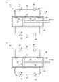
図1および図2は、本発明の実施形態に係る各種システムが適用される義肢の一例として、膝の機能を果たす膝継手が駆動可能な義足10の概略的な構成を示す。
1 and 2 show a schematic configuration of a
義足10は、大腿部に対応するプラスチック製のソケット11と、ソケット11の下端に連結される下腿部に相当する膝継手20と、膝継手20の下端に連結される足部12を備える。ソケット11と膝継手20は、その連結部分に設けられる支持点23を通り、図1の紙面に垂直な回転軸の回りに回転可能に設けられ、膝部22の屈伸動作を可能とする。また、膝継手20と足部12は弾性部材により連結され、非接地時や直立時等の接地面からの荷重が小さいときは、膝継手20と足部12の相対姿勢が一定に保たれる。また、歩行時等の接地面からの荷重が大きいときは弾性部材が弾性変形し、接地面を蹴り出す推進力を生む。
The
膝継手20は、下腿部に模した形状を有する高強度のフレーム21と、ソケット11に固定されるとともにフレーム21に対して上記の回転軸の回りに回動可能に連結される膝部22と、膝部22の回転動作を制限または補助するシリンダー30と、シリンダー30を駆動するための駆動機構40を備える。
The
シリンダー30の伸縮量と膝部22の回転角度(屈伸角度)は一対一に対応しており、シリンダー30の伸縮量を測定して膝部22の角度を検出する膝角度センサ60が、シリンダー30および膝部22の近傍に設けられる。膝角度センサ60が検出した膝角度は、制御部50で利用される。膝角度は、ソケット11の軸とフレーム21の軸がなす角度である。例えば、図1に示されるように、義足10の使用者が直立しており、ソケット11の軸とフレーム21の軸が一直線上にある場合、膝角度は0°である。また、義足10の使用者が着席し、フレーム21の軸が図1の鉛直方向のままで、ソケット11の軸が水平方向に変わった場合、膝角度は90°になる。
The expansion / contraction amount of the
フレーム21の下端には、足部12に対する膝継手20の荷重(鉛直荷重)を検出する荷重センサ70が設けられる。また、荷重センサ70に加えて、または代えて、フレーム21内の膝部22近傍には加速度センサ75が設けられる。さらに、温度センサ80が、シリンダー30に取り付けられる。これらの各センサの測定情報は、制御部50で利用される。
At the lower end of the
膝部22には、バイブレータ85が設けられる。バイブレータ85は、義足10を装着した使用者に対して振動による通知や注意喚起を行うものであり、制御部50により制御される。
A
制御部50は、膝角度センサ60、荷重センサ70、加速度センサ75、温度センサ80等の各種センサの測定情報に基づいて駆動機構40を制御し、シリンダー30を伸縮駆動する。制御部50には、義足10の各部に電力を供給するバッテリー55が接続される。なお、図2において、駆動機構40、制御部50、バッテリー55は、膝継手20の外部に示されるが、実際は膝継手20の構成部品として、フレーム21の内部またはシリンダー30と一体的に設けられる。
The
シリンダー30は、油を作動流体とし、抗力を発生することで膝部22の動作を制限または補助する油圧シリンダーである。シリンダー30は、ソケット11とフレーム21を回動可能に連結する支持点23の近傍に設けられた上部支持点31と、フレーム21の一部に連結された下部支持点32によって支持され、両支持点の間で伸縮可能である。シリンダー長が小さくなる縮小工程では膝部22が図1の反時計回り方向に回転する屈曲動作が行われ、シリンダー長が大きくなる伸長工程では膝部22が図1の時計回り方向に回転する伸展動作が行われる。ここで、シリンダー長とは、シリンダー30の上部支持点31と下部支持点32との間の長さをいう。
The
続いて、図3を参照してシリンダー30および駆動機構40について説明する。シリンダー30は、シリンダーチューブ33と、シリンダーチューブ33の一端側(図3の右端側)から挿入され、シリンダーチューブ33の長手方向(図3の左右方向)に沿って移動可能なピストンロッド34と、シリンダーチューブ33内でピストンロッド34に固定され、シリンダーチューブ33の内壁に沿って長手方向に摺動可能なピストン35を有する。シリンダーチューブ33の内部は、ピストン35によって一端側(図3の右端側)の第1キャビティ36と、他端側(図3の左端側)の第2キャビティ37に分割される。第1キャビティ36および第2キャビティ37には、作動流体である油が充填される。
Subsequently, the
駆動機構40は、油圧によりシリンダー30を伸縮駆動する油圧駆動機構である。駆動機構40は、シリンダー30にそれぞれ接続された伸展側油圧回路41と屈曲側油圧回路42を有する。伸展側油圧回路41および屈曲側油圧回路42は、それぞれ、一端側で第1キャビティ36と連通し、他端側で第2キャビティ37と連通する。伸展側油圧回路41は、油圧バルブとしての伸展側バルブ43と、伸展側逆止弁44を有する。伸展側バルブ43を開状態とすることで油が伸展側油圧回路41を流通できるが、伸展側逆止弁44の作用により、油は第1キャビティ36から第2キャビティ37に向かう方向のみに流れ、その逆方向には流れない。屈曲側油圧回路42は、油圧バルブとしての屈曲側バルブ45と、屈曲側逆止弁46を有する。屈曲側バルブ45を開状態とすることで油が屈曲側油圧回路42を流通できるが、屈曲側逆止弁46の作用により、油は第2キャビティ37から第1キャビティ36に向かう方向のみに流れ、その逆方向には流れない。伸展側バルブ43および屈曲側バルブ45は、制御部50によって、その開度が個別に制御される。各バルブの開度は、それぞれの全開(開度最高)と全閉(開度最低)の間で任意の値を取りうる。各バルブの全閉時は、油の流れが遮断され、油圧抵抗が最大となる。また、各バルブの開度が全開に向けて高くなるにつれて、各バルブ内で油の流通可能な断面積が大きくなるため、油の流量が増加し、油圧抵抗が減少する。
The
図4(a)は、膝部22の屈曲時の油の流れを示す。屈曲はシリンダー長が小さくなる縮小工程であり、ピストンロッド34が図4の左方に縮退し、ピストン35が引込側に移動する。ピストン35の移動によって第2キャビティ37から押し出される油は、伸展側逆止弁44を有する伸展側油圧回路41を流通できないため、屈曲側油圧回路42を流通して第1キャビティ36に流入する。このとき、屈曲側バルブ45の開度を低くすれば、油が屈曲側油圧回路42を流れにくくすることができるため、膝部22の屈曲動作を制限できる。
FIG. 4A shows the flow of oil when the
図4(b)は、膝部22の伸展時の油の流れを示す。伸展はシリンダー長が大きくなる伸長工程であり、ピストンロッド34が図4の右方に伸長し、ピストン35が押出側に移動する。ピストン35の移動によって第1キャビティ36から押し出される油は、屈曲側逆止弁46を有する屈曲側油圧回路42を流通できないため、伸展側油圧回路41を流通して第2キャビティ37に流入する。このとき、伸展側バルブ43の開度を低くすれば、油が伸展側油圧回路41を流れにくくすることができるため、膝部22の伸展動作を制限できる。
FIG. 4B shows the flow of oil when the
図2に戻り、義足10に設けられる各種のセンサについて説明する。
Returning to FIG. 2, various sensors provided on the
膝角度センサ60は、ピストンロッド34の伸縮位置を測定する。例えば、ピストンロッド34に取り付けた磁石の位置を、シリンダーチューブ33内に設けた磁気センサで測定する。ピストンロッド34の伸縮位置と膝部22の屈伸角度は一対一に対応しているため、膝角度センサ60は測定したピストンロッド34の伸縮位置を膝部22の角度に変換できる。なお、ピストンロッド34の伸縮位置を膝部22の角度に変換する演算は制御部50が行ってもよい。この場合、膝角度センサ60は、ピストンロッド34の伸縮位置を測定して制御部50に提供する。
The
荷重センサ70は、例えばひずみセンサにより構成され、フレーム21と足部12の間の足首部に設けられる。足首部に加わる荷重により、ひずみセンサを構成する物体にひずみが生じるため、そのひずみを検出することで荷重を測定できる。このような荷重センサを膝部22その他の関節部に設けて各関節部の荷重を測定してもよい。義肢の他の例としての義手においては、手首部、肘部、肩部等の関節部に荷重センサを設けるのが好ましい。なお、ひずみセンサが検出したひずみを荷重に変換する演算は制御部50が行ってもよい。この場合、荷重センサ70は、検出したひずみを制御部50に提供する。また、制御部50は、荷重センサ70から得られる、一歩毎の離地時および着地時の荷重や、荷重の小さい滞空時間に基づき、歩幅や歩行速度を演算により求めることができる。あるいは、歩行中の荷重の推移と、歩幅や歩行速度の相関を示す機会学習データに基づき、荷重センサ70の測定情報から歩幅や歩行速度を推定してもよい。
The
加速度センサ75で測定される加速度、それを積分して求められる速度、さらにそれを積分して求められる位置の各情報に基づき、義足10の動きを検知できる。加速度から速度および位置を求める演算は制御部50が行う。その際、制御部50は、一歩毎の離地および着地を加速度変化から検知できるため、一歩当たりの位置の変化すなわち歩幅を求めることができる。
The movement of the
温度センサ80は、シリンダー30の作動流体である油の温度を測定する。油の物性により温度変化に応じて油圧抵抗が変化するため、制御部50は温度センサ80で測定された温度に応じた所望の油圧抵抗を実現すべく、駆動機構40を制御する。具体的には、制御部50には、油圧抵抗の各値を実現するための駆動機構40への制御データセットが温度ごとに格納される。制御部50は、温度センサ80で測定された温度に対応する制御データセットを選択して制御に用いる。なお、温度センサ80は、義足10の他の場所に設けてもよい。例えば、フレーム21の表面に温度センサ80を設けることで、義足10の周囲の気温を測定できる。また、駆動機構40を制御する制御部50の制御基板付近に温度センサ80を設けてもよい。
The
制御部50は、義足10全体を制御する中央演算処理装置である。制御部50は、膝角度センサ60、荷重センサ70、加速度センサ75、温度センサ80等の各種センサの測定情報に基づいて駆動機構40を制御し、シリンダー30を伸縮駆動する。制御部50には任意の制御プログラムを実行させることができるが、以下に具体的な制御例をいくつか示す。
The
(1)義足のロック角度制御
義足10の使用者や使用状況に合わせて義足10のロック角度が設定される。ロック角度とは、通常歩行時の膝部22の最大屈曲可能角度である。例えば、高齢、病気、怪我などによって筋力や歩行能力が低下している使用者は、膝部22の屈曲角度が大きくなると身体のバランスを崩して転倒してしまう可能性があるため、ロック角度を小さく設定することで安全性を向上させる。また、階段や坂道など勾配がある場所の歩行時も転倒の恐れがあるため、ロック角度を小さくすることで、小さい歩幅での低速歩行を促す。このような制御では、制御部50が、膝角度センサ60が測定する膝部22の角度を常時モニタし、膝部22の角度がロック角度以上の場合、屈曲側バルブ45を全閉状態とすることで、屈曲側の油圧抵抗を最大として、これ以上膝部22が屈曲しないように制限する。また、膝部22の角度がロック角度未満の場合、ロック角度に近づくほど屈曲側バルブ45の開度を低くすることで、確実にロック角度を超えないように制御できる。また、階段や坂道など勾配がある場所の歩行時は、荷重センサ70で測定される荷重が大きくなる。したがって、制御部50は、荷重センサ70で測定された荷重が所定の閾値を超えた場合に、勾配がある場所の歩行と判断して、ロック角度を小さくすることができる。なお、勾配の検出は加速度センサ75で行ってもよい。
(1) Lock angle control of the prosthesis The lock angle of the
(2)温度に基づく制御
温度が高くなると、油の物性によりシリンダー30の油圧抵抗は小さくなる。このため、所望の油圧抵抗を得るためには、各油圧バルブ43、45の開度を通常時よりも低くする必要がある。このような制御では、制御部50が、温度センサ80が測定するシリンダー30の温度を常時モニタし、それに応じて各油圧バルブ43、45の開度を調整する。
(2) Temperature-based control As the temperature rises, the hydraulic resistance of the
(3)加速度に基づく制御
加速度センサ75によって、義足10を装着した使用者の動きの大きさや向きを検知できる。制御部50は、これらの情報から、歩幅や歩行速度等の歩行の基本情報や、勾配の大きさ等の歩行場所に関する情報を演算できる。制御部50は、演算された歩幅や歩行速度に応じて、駆動機構40の制御を調整できる。例えば、歩幅や歩行速度が小さい場合は、膝部22の屈曲角度は小さくてよいので上記のロック角度を小さく設定する。また、歩幅や歩行速度が小さい場合は、歩行時の身体のバランスが崩れにくいため、各油圧バルブ43、45の開度を上げることで油圧抵抗を下げて膝部22を屈伸しやすくしてもよい。逆に、歩幅や歩行速度が大きい場合は、膝部22を大きく屈曲できるようにロック角度を大きく設定するとともに、各油圧バルブ43、45の開度を下げることで油圧抵抗を上げて膝部22の急激な屈伸を防止して歩行中の身体のバランスを保つ。同様に、勾配が大きい場所を歩行する際は、ロック角度を大きく設定し、油圧抵抗を上げるのが好ましい。
(3) Control based on acceleration The
(4)セーフティロック
セーフティロックとは、膝部22が屈曲したまま静止しているときに、安全のためにそれ以上の屈曲を制限することである。この場合、制御部50は、膝角度センサ60が測定した膝部22の角度を微分して、膝部22の角速度を算出する。屈曲した膝部22の角度が所定以上で、かつ、膝部22の角速度が所定値未満の状態が一定時間継続している場合、制御部50は、膝部22が静止状態にあると判断する。そして、義足10の使用者がその静止状態を維持する意思があるとみなし、安全のためにそれ以上の屈曲を制限する。具体的には、屈曲側バルブ45を全閉状態とすることで、屈曲側の油圧抵抗を最大として、これ以上膝部22が屈曲しないようにセーフティロックをかける。セーフティロックがかかった状態では、使用者の力なしで静止状態が維持されるので、使用者は疲れることなく、その中腰の姿勢を維持できる。なお、セーフティロックは、使用者が膝部22を伸展し、伸展側油圧回路41を所定流量以上の油が流通したこと等を持って解除される。
(4) Safety lock The safety lock is to limit further flexion for safety when the
以上、義肢の一例としての義足10について説明した。続いて、このような義足10の利便性を向上させる各種のシステムについて説明する。
The
図5は、このような各種の義足システムの構成を模式的に示す機能ブロック図である。この図に示される各機能ブロックは、構成するシステムに応じて取捨選択できるものであり、全ての機能ブロックを常に設ける必要はない。 FIG. 5 is a functional block diagram schematically showing the configurations of such various artificial leg systems. Each functional block shown in this figure can be selected according to the system to be configured, and it is not always necessary to provide all the functional blocks.
義足システムは、前述した義足10と、システム制御部100と、システムメモリ200を備える。システム制御部100は、義足10の外部の情報処理装置で実現され、義足システム全体の制御と情報処理を担う。ここで、情報処理装置としては、スマートフォン、タブレット、コンピュータ等の汎用の電子機器が例示される。これらの電子機器は、義足10の使用者が使用するものでもよいし、それ以外の第三者が使用するものでよい。システム制御部100は、義足10の制御部50と、Bluetooth(登録商標)等の近距離無線通信規格、LTEや5G等の移動通信規格、Wi-Fi等の無線LAN規格等に基づいて無線通信可能である。また、システム制御部100は、インターネット等の情報通信網を介して他の任意の通信機器と通信可能である。システムメモリ200は、システム制御部100が使用する各種の情報を格納する。システムメモリ200は、システム制御部100と同一の電子機器内に設けられるものでもよいし、システム制御部100が情報通信網を介してアクセス可能な遠隔のサーバ等に設けられるものでもよい。
The artificial leg system includes the above-mentioned
システム制御部100は、駆動情報取得部101と、環境情報取得部102と、経路情報取得部103と、製品識別情報取得部104と、消費電力算出部105と、推奨経路提示部106と、推定部107と、参照情報取得部108と、生体情報取得部109と、判断部110と、制御情報調整部111と、出力部112を備える。環境情報取得部102は、路面形状情報取得部1021と、路面性状情報取得部1022を備える。出力部112は、報知部1121を備える。
The
上記の各構成のうち、後述する各種の義足システムに共通して用いられる駆動情報取得部101と環境情報取得部102について説明する。
Of the above configurations, the drive information acquisition unit 101 and the environment
駆動情報取得部101は、義足10の駆動機構40の現在の駆動状態を表す駆動情報を制御部50から無線通信によって取得する。駆動情報は義足10の駆動に関する情報であればどのようなものでもよいが、例えば以下のような情報である。
The drive information acquisition unit 101 acquires drive information representing the current drive state of the
・センサ群に含まれる膝角度センサ60、荷重センサ70、加速度センサ75、温度センサ80の測定情報
・シリンダー30または駆動機構40の内部状態を表す内部状態情報
・測定情報または内部状態情報に基づいて制御部50が演算する使用者の歩行状態を表す歩行情報
・バッテリー55の電力残量情報
-Measurement information of
内部状態情報とは、例えば以下のような情報である。
・シリンダー30または駆動機構40の各部の油圧抵抗
・ピストン35の位置、速度、加速度
・各油圧回路41、42を流通する油の流量
・各油圧バルブ43、45の開度、開閉速度、開閉加速度
・各油圧バルブ43、45の開度が、制御部50からの指令値に収束するまでの収束時間
・各油圧バルブ43、45の累計の開閉回数、開閉時間
The internal state information is, for example, the following information.
-Hydraulic resistance of each part of the
歩行情報とは、例えば以下のような情報である。
・歩幅
・歩行速度
・歩数
・膝部22の屈伸回数、屈伸時間
・一歩毎の蹴り出す力、着地時の衝撃(加速度センサ75の測定情報から演算可能)
・歩行場所の勾配
上記の各情報は、制御部50によって演算されるが、一部または全部の演算を駆動情報取得部101が代わりに行ってもよい。
The walking information is, for example, the following information.
・ Stride length ・ Walking speed ・ Number of steps ・ Number of bending and stretching of
-Slope of walking place Each of the above information is calculated by the
以上で例示列挙した各駆動情報は、使用者が装着した義足10からリアルタイムで取得される。駆動情報取得部101は、リアルタイムで取得した駆動情報の一部または全部を、履歴駆動情報としてシステムメモリ200に保存する。
Each drive information exemplified above is acquired in real time from the
環境情報取得部102は、義足10の周囲の現在の環境情報を取得する。以下に環境情報を例示列挙するが、これらの情報はシステム制御部100が実現される汎用の電子機器がインターネット等の情報通信網を介して取得する。また、システム制御部100が実現される汎用の電子機器が、義足10の使用者が携帯するスマートフォンやウェアラブルデバイス等の場合は、これらの電子機器に設けられるセンサで一部の環境情報を直接測定してもよい。
The environmental
環境情報とは例えば以下のような情報である。
・天気、温度、湿度、電磁波の強さ
・路面形状情報(路面形状情報取得部1021により取得される)
・路面性状情報(路面性状情報取得部1022により取得される)
・義足10の位置情報
The environmental information is, for example, the following information.
-Weather, temperature, humidity, strength of electromagnetic waves-Road surface shape information (acquired by the road surface shape information acquisition unit 1021)
-Road surface property information (acquired by the road surface property information acquisition unit 1022)
・ Position information of
路面形状情報は、歩行経路の路面の形状を表す情報である。ここでいう路面の形状とは、歩行経路の勾配ないし高低差を含む概念であり、勾配のない水平路面と、勾配のある傾斜路面に大別される。水平路面および傾斜路面は、それぞれ凹凸の有無でさらに細分化される。凹凸のある傾斜路面は、典型的には各凹凸を段差とする階段である。 The road surface shape information is information representing the shape of the road surface of the walking route. The shape of the road surface referred to here is a concept including the slope or height difference of the walking path, and is roughly classified into a horizontal road surface without a slope and a sloped road surface. The horizontal road surface and the inclined road surface are further subdivided depending on the presence or absence of unevenness. An uneven sloped road surface is typically a staircase with each unevenness as a step.
路面性状情報は、歩行経路の路面の性質または状態を表す情報である。路面の性質とは、路面の構成物(アスファルト、土、砂、木、金属、草など)や、その性質(硬度、弾性、摩擦係数など)を含む。路面の状態とは、例えば、路面の乾燥状態を含む。路面の乾燥状態の情報が情報通信網を介して入手できない場合は、入手可能な天気、温度、湿度等の情報に基づいて推定できる。例えば、直前まで雨が降っており、現在は曇りのまま温度が上がらず湿度も高い場合は、路面は濡れた状態であると推定できる。なお、路面の性質は路面の状態に応じて変わりうる。例えば、路面が濡れている状態では、路面の摩擦係数が小さくなる。このように、路面の性状は天気、温度、湿度等の他の環境情報に応じて変化する。 The road surface property information is information representing the nature or state of the road surface of the walking route. The properties of the road surface include the components of the road surface (asphalt, soil, sand, wood, metal, grass, etc.) and the properties thereof (hardness, elasticity, coefficient of friction, etc.). The road surface condition includes, for example, a dry condition of the road surface. If information on the dry condition of the road surface is not available via the information and communication network, it can be estimated based on available information such as weather, temperature, and humidity. For example, if it was raining until just before, and now it is cloudy, the temperature does not rise, and the humidity is high, it can be estimated that the road surface is wet. The nature of the road surface may change depending on the condition of the road surface. For example, when the road surface is wet, the coefficient of friction of the road surface becomes small. In this way, the properties of the road surface change according to other environmental information such as weather, temperature, and humidity.
義足10の位置情報は、GPS(Global Positioning System)等の衛星測位システムを利用して取得する。この場合、義足10の使用者が携帯するスマートフォンやウェアラブルデバイス等に設けられたGPSセンサを利用できる。なお、義足10の加速度センサ75で測定される加速度を積分することで義足10の位置を演算できるが、これは積分の始点からの相対的な変位であるため、地球上の絶対的な位置を取得したい場合はGPSを利用するのが好ましい。
The position information of the
続いて、図5の構成で実現できる三つの義足システムについて順番に説明する。第1のシステムは消費電力算出システムである。第2のシステムは状態推定システムである。第3のシステムは体調推定システムである。 Next, the three artificial leg systems that can be realized by the configuration of FIG. 5 will be described in order. The first system is a power consumption calculation system. The second system is a state estimation system. The third system is a physical condition estimation system.
消費電力算出システムは、義足10のバッテリー55の消費電力を算出するシステムであり、システム制御部100の構成のうち、駆動情報取得部101と、環境情報取得部102と、経路情報取得部103と、製品識別情報取得部104と、消費電力算出部105と、推奨経路提示部106と、出力部112を備える。以下の説明では、これらのシステム制御部100の構成が、義足10の使用者が携帯するスマートフォンで実現される場合を例にとる。
The power consumption calculation system is a system that calculates the power consumption of the
経路情報取得部103は、義足10を装着した使用者が歩行可能な始点から終点までの複数の経路の経路情報を取得する。義足10の使用者は、任意の地図検索サービスを利用し、スマートフォンの画面上の操作によって始点と終点を設定し、その二点を結ぶ複数の候補経路を検索する。
The route
製品識別情報取得部104は、義足10の製品識別情報を取得する。ここで、製品識別情報としては、義足10の製品の型式ごとに付与される型式番号を利用するのが好ましい。また、個々の製品を識別するために付与されるシリアル番号を利用してもよい。義足10のバッテリー55の電力消費の態様は、義足10の構成すなわち型式によって異なるため、製品識別情報を利用することで、製品ごとの消費電力の算出精度を高めることができる。
The product identification
消費電力算出部105は、経路情報取得部103が取得した各候補経路について、路面形状情報取得部1021が取得した路面形状情報および路面性状情報取得部1022が取得した路面性状情報に基づいて、製品識別情報が示す義足10を装着した使用者が経路を歩行する際のバッテリー55の消費電力を算出する。
The power
義足10のバッテリー55の消費電力のほとんどは、駆動機構40によるシリンダー30の駆動に関する。具体的には、駆動機構40の各油圧バルブ43、45の開閉駆動にほとんどの電力が消費される。ここで、義足10を装着した使用者が勾配のない水平路面を歩行する場合と、勾配のある傾斜路面を歩行する場合を比較する。水平路面歩行時は一歩毎の膝部22の屈曲角度が小さく、シリンダー30のピストンロッド34にかかる荷重も小さい。したがって、各油圧バルブ43、45は小開閉量および低負荷で駆動されるため、消費電力が小さい。逆に、傾斜路面歩行時は一歩毎の膝部22の屈曲角度が大きく、シリンダー30のピストンロッド34にかかる荷重も大きい。したがって、各油圧バルブ43、45は大開閉量および高負荷で駆動されるため、消費電力が大きい。このように、義足10のバッテリー55の消費電力は、路面の形状によって大きく変わる。
Most of the power consumption of the
そこで、消費電力算出部105は、各候補経路の消費電力を算出する際に、路面形状情報を利用する。例えば、路面形状を複数の類型に分類し、各類型について消費電力の算出式を設定する。類型は任意に設定できるが、勾配のない水平路面、勾配があり段差のない傾斜路面、勾配があり段差がある階段路面、が例示される。水平路面について、その凹凸の程度に応じて細分化した類型を設けてもよい。傾斜路面について、その傾斜角に応じて細分化した類型を設けてもよい。階段路面について、その傾斜角や段差の高低差に応じて細分化した類型を設けてもよい。このような各類型に設定される消費電力の算出式は、その類型の路面を歩行する際の単位距離当たりの消費電力を与える。なお、建物内部を通過する候補経路において、その建物内部の構造情報を入手できるときは、それに基づいて算出した消費電力を利用してもよい。
Therefore, the power
ここで、水平路面の単位距離当たりの消費電力をEa、傾斜路面の単位距離当たりの消費電力をEb、階段路面の単位距離当たりの消費電力をEcとする。第1の候補経路の路面が水平路面であり、距離がD1の場合、消費電力はEa×D1により求められる。また、第2の候補経路の路面が階段路面であり、距離がD2の場合、消費電力はEc×D2により求められる。 Here, the power consumption per unit distance of the horizontal road surface is Ea, the power consumption per unit distance of the inclined road surface is Eb, and the power consumption per unit distance of the stairs road surface is Ec. When the road surface of the first candidate route is a horizontal road surface and the distance is D1, the power consumption is obtained by Ea × D1. Further, when the road surface of the second candidate route is a staircase road surface and the distance is D2, the power consumption is obtained by Ec × D2.
このような消費電力の演算において、各候補経路を小経路に区分して、小経路毎に消費電力を求めてもよい。例えば、第3の候補経路が、距離D31の傾斜路面と、距離D32の水平路面と、距離D33の階段路面の三つの小経路に区分される場合、消費電力はEb×D31+Ea×D32+Ec×D33となる。つまり、候補経路の消費電力は、各小経路の消費電力の和である。 In such a calculation of power consumption, each candidate route may be divided into small routes and the power consumption may be obtained for each small route. For example, when the third candidate route is divided into three small routes, a sloped road surface at a distance D31, a horizontal road surface at a distance D32, and a stairway road surface at a distance D33, the power consumption is Eb × D31 + Ea × D32 + Ec × D33. Become. That is, the power consumption of the candidate route is the sum of the power consumption of each small route.
以上のように、消費電力の演算においては、路面形状情報が最も重要であるが、これに加えて、路面性状情報および製品識別情報を考慮することで、演算精度を高めることができる。路面性状情報として路面の乾燥状態を考慮する場合、例えば路面が濡れている場合は、歩行時に滑ったり泥濘に足を取られたりしないように義足10の使用者が通常よりも大きな荷重をかけて歩行するため、義足10の負荷が高くなり消費電力が大きくなる。このような影響を消費電力の演算に取り入れるため、例えば、路面の乾燥状態に応じた補正係数αを設定する。路面が完全に乾燥している場合はαを1とし、路面が濡れている場合はαを1よりも大きくする。上記の例で、路面の乾燥状態を考慮せずに求めた消費電力がEb×D31+Ea×D32+Ec×D33であった場合、路面の乾燥状態を考慮した消費電力はα×(Eb×D31+Ea×D32+Ec×D33)となる。このとき、路面形状の類型ごとに異なる補正係数αを設定してもよい。水平路面の補正係数をαa、傾斜路面の補正係数をαb、階段路面の補正係数をαcとすれば、消費電力はαb×Eb×D31+αa×Ea×D32+αc×Ec×D33となる。また、製品識別情報を消費電力の演算で考慮する場合、上記の各路面形状類型の消費電力Ea、Eb、Ecを製品の型式ごとに設定すればよい。
As described above, the road surface shape information is the most important in the calculation of power consumption, but in addition to this, the calculation accuracy can be improved by considering the road surface property information and the product identification information. When considering the dry state of the road surface as the road surface property information, for example, when the road surface is wet, the user of the
推奨経路提示部106は、消費電力算出部105が算出した消費電力に基づいて、複数の候補経路の中から推奨経路をスマートフォンの画面上に提示する。推奨の基準は任意に設定できるが、例えば、複数の候補経路の中から消費電力が最も少ない経路を推奨する。また、各候補経路の消費電力と現在のバッテリー55の電力残量を比較し、電力残量よりも少ない消費電力の候補経路のうち、歩行距離または所要時間が最短の候補経路を推奨してもよい。
The recommended
出力部112は、消費電力算出部105が算出した消費電力を出力する。例えば、スマートフォンの画面上に消費電力を表示したり、情報通信網を介して他の通信機器に消費電力を送信する。報知部1121は、消費電力算出部105が算出した消費電力がバッテリー55の電力残量を上回る場合に報知する。この報知は、推奨経路提示部106が推奨経路とともに他の候補経路を表示する際に、電力残量を上回る候補経路を強調表示することで行ってもよい。また、この報知は、候補経路の検索時だけでなく、そのうちの一つの経路を実際に歩行している間に行ってもよい。この場合、消費電力算出部105は、義足10の使用者が実際に歩行中の経路の終点までの所要電力をリアルタイムで算出し、それをバッテリー55の電力残量と比較する。そして、終点までの所要電力が、バッテリー55の電力残量を上回る場合に報知がなされる。この報知は、義足10の使用者だけでなく、遠隔の第三者に対して行ってもよい。例えば、遠隔の家族や義肢装具士に、義足10の使用者が支援の必要な状況にあることを報知できる。なお、報知部1121は、使用者に報知する際は義足10に設けられたバイブレータ85も利用できる。
The
続いて、図5の構成で実現できる第2のシステムである状態推定システムについて説明する。状態推定システムは、義足10の状態を推定するシステムであり、システム制御部100の構成のうち、駆動情報取得部101と、環境情報取得部102と、推定部107と、出力部112を備える。ここで、義足10の「状態」とは、義足10自体の異常および義足10を装着した使用者の危険を含む概念である。
Next, a state estimation system, which is a second system that can be realized by the configuration of FIG. 5, will be described. The state estimation system is a system that estimates the state of the
推定部107は、駆動情報取得部101が取得した駆動情報および環境情報取得部102が取得した環境情報に基づいて、義足10の状態を推定する。出力部112は、推定部107の推定の結果を出力する。
The
推定部107における推定の類型は次の四通りである。第1の推定の類型は、駆動情報および環境情報ともに異常が認められない場合である。このとき、推定部107は、義足10に異常なし、使用者に危険なしと推定する。第2の推定の類型は、駆動情報に異常が認められ、環境情報に異常が認められない場合である。このとき、推定部107は、義足10に異常ありと推定し、それに伴って使用者に危険ありと推定する。駆動情報に異常が認められる場合とは、例えば、義足10が正常に稼働しておらず、センサ群の測定情報、シリンダー30または駆動機構40の内部情報の値が所定の正常範囲を逸脱している場合である。このとき、出力部112の報知部1121が、義足10が正常に稼働していないことを直ちに義足10の使用者に報知し、必要に応じて遠隔の家族や義肢装具士にも報知する。
There are four types of estimation in the
第3の推定の類型は、駆動情報に異常が認められないが、環境情報に異常が認められる場合である。このとき、推定部107は、義足10に異常なしと推定し、使用者に危険ありと推定する。この類型では、駆動情報の値は正常範囲内にあるため、義足10は正常に稼働している。しかし、環境情報に異常が認められるため、その環境下で使用者が義足10を装着して歩行することに危険が伴う。
The third type of estimation is the case where no abnormality is found in the driving information, but no abnormality is found in the environmental information. At this time, the
環境情報に異常が認められる場合とは、例えば、天気、温度、湿度、電磁波の強さが所定の正常範囲を逸脱している場合である。天気が異常の場合とは、雨や風が強い場合、雪が降っている場合、日光やそれに含まれる紫外線が強い場合などである。温度や湿度が異常の場合とは、予め定められた上限値よりも高い、予め定められた下限値よりも低い場合である。電磁波の強さが異常の場合とは、予め定められた上限値よりも電磁波が強い場合である。このような異常が認められる場合、義足10の駆動または義足10を装着した使用者の歩行に悪影響が及びうるため、使用者は通常時よりも慎重に歩行する必要がある。そこで、出力部112の報知部1121は、このような環境情報の異常を報知し、使用者の注意を喚起する。図6は、このような注意喚起の一例を示す。義足10を装着した使用者が平坦な路面を歩行中に気温が上昇したため、使用者のスマートフォンの画面上で注意喚起が行われる。画面に示されるように、義足10の使用環境温度範囲は-10℃~40℃であり、現在の温度の37℃はその範囲内である。しかし、推定部107には温度の上限値として40℃よりも低い温度(例えば35℃)が設定されているため、40℃に上昇する前に予備的に注意喚起を行える。また、注意喚起文にある通り、高温時は油圧抵抗が下がるため、使用者は安全のために低速で歩行することが推奨される。
When an abnormality is found in the environmental information, for example, the weather, temperature, humidity, and the intensity of electromagnetic waves deviate from a predetermined normal range. The abnormal weather is when it is raining or windy, when it is snowing, when sunlight or ultraviolet rays contained therein are strong, and so on. The case where the temperature or humidity is abnormal is a case where the temperature or humidity is higher than the predetermined upper limit value and lower than the predetermined lower limit value. The case where the strength of the electromagnetic wave is abnormal is the case where the electromagnetic wave is stronger than the predetermined upper limit value. When such an abnormality is observed, the driving of the
環境情報に異常が認められる他の例として、上記の天気等に関する環境情報と、路面の状況に関する環境情報が、それぞれ単独では異常と認められない場合でも、これらを組み合わせると使用者に注意喚起すべき場合がある。図7は、このような注意喚起の一例を示す。義足10を装着した使用者が緩い斜面を歩行していることを環境情報の一つである路面形状情報から認識し、さらに環境情報の一つである天気等の情報から弱い降雨の可能性を認識した場合、推定部107が義足10を装着した使用者が雨で濡れた斜面を歩行することに伴う危険を推定し、報知部1121が使用者のスマートフォンの画面上で注意喚起する。
As another example in which an abnormality is found in the environmental information, even if the above-mentioned environmental information regarding the weather and the environmental information regarding the road surface condition are not recognized as abnormal by themselves, the user is alerted by combining them. There are times when it should be. FIG. 7 shows an example of such an alert. It recognizes that the user wearing the
なお、環境情報の異常の推定において、駆動情報の一つである歩行情報を参酌してもよい。例えば、推定部107は、歩行情報が示す歩幅または歩行速度を参酌し、当該歩幅または歩行速度での使用者の歩行が環境情報に照らして危険か否かを判定する。図7の例において、使用者が小さい歩幅かつ低速で歩行している場合は、斜面が多少濡れていたとしても危険は少ない。したがって、歩幅または歩行速度を参酌した結果、推定部107は危険なしと推定してもよい。逆に、使用者が大きい歩幅または高速で歩行している場合に、斜面が濡れると非常に危険であるため、推定部107は危険ありと推定し、報知部1121が使用者に報知する。なお、この例では、推定部107が、環境情報に応じた駆動情報の閾値を格納し、当該閾値と駆動情報の比較に基づいて推定を行っているに等しい。すなわち、この例の環境情報は「緩い斜面であること」(路面形状情報)および「弱い降雨の可能性があること」(天気情報)であり、それに応じた駆動情報「歩幅」「歩行速度」の閾値が設けられる。この閾値よりも実際の駆動情報「歩幅」「歩行速度」が大きい場合、推定部107が使用者の危険を推定する。
It should be noted that walking information, which is one of the driving information, may be taken into consideration in estimating the abnormality of the environmental information. For example, the
第4の推定の類型は、駆動情報および環境情報ともに異常が認められる場合である。このとき、推定部107は、義足10に異常あり、使用者に危険ありと推定する。この類型は極めてリスクが高いため、出力部112の報知部1121は、直ちに義足10の使用者に報知して歩行を中止させる。同時に、遠隔の家族や義肢装具士に報知してもよい。
The fourth type of estimation is the case where an abnormality is found in both the driving information and the environmental information. At this time, the
続いて、状態推定システムによる状態推定の特殊な例を説明する。 Next, a special example of state estimation by the state estimation system will be described.
第1の例では、推定部107が、駆動情報取得部101が取得した現在の駆動情報と、環境情報取得部102が取得した現在の位置情報が示す位置から所定範囲内で駆動情報取得部101が取得した過去の駆動情報の比較に基づいて推定を行う。ここで、現在と過去で比較される駆動情報は、例えばセンサ群に含まれる各種センサの測定情報である。これらの測定情報は、現在と過去で同様の環境で得られたものであるため、両者に乖離がある場合は、センサの異常や劣化の可能性がある。このように、効果的にセンサの異常や劣化を特定できる。
In the first example, the
第2の例では、駆動情報取得部101が、駆動情報として駆動機構40を制御する制御部50の制御基板付近の温度を取得し、環境情報取得部102が、環境情報として義足10の周囲の温度を取得し、推定部107が、制御基板付近の温度と義足10の周囲の温度の比較に基づいて、制御基板の状態を推定する。制御基板が外気温と比較して異常な高温になっている場合は、制御基板に異常がある可能性が高く、この例によれば効果的に制御基板の異常を特定できる。
In the second example, the drive information acquisition unit 101 acquires the temperature near the control board of the
第3の例では、駆動情報取得部101が、駆動情報として油圧バルブ43、45の開度がその指令値に収束するまでの収束時間を取得し、推定部107が、収束時間および環境情報に基づいて、義足10の状態を推定する。この例で駆動情報として取得される収束時間は、油圧バルブ43、45の劣化に応じて長くなる。長い収束時間は歩行速度が遅い場合には大きな問題とはならない。そこで、環境情報(路面形状情報)が坂道等の低速歩行となる路面を示す場合、推定部107は、使用者の危険を推定しない。一方、環境情報(路面形状情報)が水平路面等の高速歩行しうる路面を示す場合、推定部107は、使用者の危険を推定し、報知部1121は低速で歩行するように使用者に注意喚起する。
In the third example, the drive information acquisition unit 101 acquires the convergence time until the opening degree of the
続いて、図5の構成で実現できる第3のシステムである体調推定システムについて説明する。体調推定システムは、義足10の使用者の体調を推定するシステムであり、システム制御部100の構成のうち、駆動情報取得部101と、環境情報取得部102と、推定部107と、参照情報取得部108と、生体情報取得部109と、判断部110と、制御情報調整部111と、出力部112を備える。
Next, a physical condition estimation system, which is a third system that can be realized by the configuration of FIG. 5, will be described. The physical condition estimation system is a system for estimating the physical condition of the user of the
参照情報取得部108は、使用者が過去に同一の義足10を装着した際の、駆動情報、環境情報、使用者の体調情報を、互いに関連付けた参照情報を取得する。この参照情報は、それが記録された過去の時刻情報とともにシステムメモリ200に一元的に記録される。参照情報に含まれる使用者の体調情報は、体温、心拍、血圧、血糖値、血中酸素濃度、呼吸量、呼吸頻度、発汗量、筋電位、姿勢等の各種の生体情報や、体調の良否に関する使用者の自己申告情報を含む。参照情報は、これらの体調情報と、そのときの義足10の駆動情報と義足10の周囲の環境情報の相関関係を記録したものである。
The reference
推定部107は、使用者が義足10を装着している現在の駆動情報および環境情報と、参照情報の比較に基づき、使用者の現在の体調を推定する。
The
具体的には、まず現在の環境情報と類似の環境情報を含む参照情報を取得する。ここで、環境情報の類似の基準は任意に設定できるが、例えば、類否判断に用いる環境情報をいくつか選択し、それらの環境情報の乖離度(差分)に基づいて類否判断を行う。一例として、温度、電磁波の強さ、路面の傾斜角を選択した場合、それらの過去(参照情報記録時)と現在の差分を演算し、その総和を演算する。そして、その総和が所定値未満の場合に環境情報が類似であると判断する。なお、上記の演算において、各環境情報に重要度に基づく重みづけを行ってもよい。 Specifically, first, reference information including environmental information similar to the current environmental information is acquired. Here, similar criteria for environmental information can be arbitrarily set. For example, some environmental information used for similarity determination is selected, and similarity determination is performed based on the degree of dissociation (difference) of the environmental information. As an example, when the temperature, the strength of the electromagnetic wave, and the inclination angle of the road surface are selected, the difference between the past (at the time of recording the reference information) and the present is calculated, and the total is calculated. Then, when the total sum is less than a predetermined value, it is determined that the environmental information is similar. In the above calculation, each environmental information may be weighted based on the importance.
以上のように現在の環境情報と類似の参照情報を取得した後、その参照情報に含まれる過去の駆動情報と、現在の駆動情報の類否判断を行う。上記の環境情報と同様に、類否判断の基準は任意に設定できる。例えば、類否判断に用いる駆動情報として、各種センサの測定情報の一歩当たりの平均値、シリンダー30または駆動機構40の各部の油圧抵抗の一歩当たりの平均値、歩幅、歩行速度、一歩毎の蹴り出す力、着地時の衝撃、バッテリー55の電力残量の一部または全部を選択する。
After acquiring reference information similar to the current environment information as described above, the similarity between the past drive information included in the reference information and the current drive information is determined. Similar to the above environmental information, the criteria for similarity judgment can be set arbitrarily. For example, as the drive information used for similarity determination, the average value per step of the measurement information of various sensors, the average value per step of the hydraulic resistance of each part of the
以上の二段階の類否判断において、第1段階の環境情報の比較ステップでは現在と類似の環境情報を含む参照情報が抽出されるため、通常であれば第2段階の駆動情報の比較ステップでも駆動情報が類似する結果になる。しかし、義足10の使用者の体調に異変がある場合は、その影響が駆動情報にも現れるため、第2段階の比較ステップで駆動情報が類似しない結果になる。したがって、このような類否判断ステップを経ることで、推定部107は、義足10の使用者の体調の異変を検知できる。
In the above two-step similarity judgment, since the reference information including the environmental information similar to the present is extracted in the first step of comparing the environmental information, normally, even in the second step of comparing the driving information. The drive information has similar results. However, if there is an abnormality in the physical condition of the user of the
具体例をいくつか挙げると、類似環境下での歩行にも関わらず、通常よりも歩幅が小さい、歩行速度が遅い、一歩毎の蹴り出す力が弱い、着地時の衝撃が弱い等の場合は、義足10の使用者の体調が悪い可能性がある。また、類似環境下での歩行にも関わらず、各種センサの測定情報の一歩当たりの平均値、シリンダー30または駆動機構40の各部の油圧抵抗の一歩当たりの平均値等の義足10の各種パラメータが通常時から乖離している場合も、参照情報記録時からの体調の変化が推定される。ただし、この場合は、体調が通常より良い可能性もある。また、義足10の各種パラメータが通常時から乖離している場合は、義足10自体の異常の可能性もあるが、上記の状態推定システムを併用することで、義足10自体の異常と、義足10の使用者の体調の異常を識別できる。
To give a few specific examples, if the stride is shorter than usual, the walking speed is slow, the kicking force for each step is weak, the impact at the time of landing is weak, etc., despite walking in a similar environment. , The user of the
以上の推定部107での体調推定には、生体情報取得部109が取得する義足10装着時の使用者の現在の生体情報も利用できる。生体情報取得部109は、義足10や、義足10の使用者が使用するスマートフォンやウェアラブルデバイスに設けられる各種の生体センサから、体温、心拍、血圧、血糖値、血中酸素濃度、呼吸量、呼吸頻度、発汗量、筋電位、姿勢等の各種の生体情報を取得する。これらの現在の生体情報も参照することで、推定部107は義足10の使用者の体調を高精度に推定できる。
For the physical condition estimation by the
出力部112は、推定部107の推定結果を報知する。義足10の使用者に推定結果を報知してもよいが、使用者は自身の体調を認識していると考えられるため、使用者と異なる第三者、例えば、家族や義肢装具士に使用者の体調の異変を報知するのが重要である。ここで、第三者への報知頻度が高くなり過ぎないように、報知の基準が設定される。具体的には、判断部110は、使用者の所定時間中の移動量が所定量未満の場合に、推定部107の推定の結果を出力部112に報知させると判断する。つまり、使用者の体調が悪い場合は、移動量が低下すると考えられるため、移動量が所定量未満の場合に限って、体調不良との推定結果を第三者に報知する。
The
制御情報調整部111は、推定部107の推定の結果に応じて、義足10の制御情報を調整する。特に、推定部107が使用者の体調が悪いと推定した場合、使用者が歩行しやすくなるように制御情報を調整する。例えば、小さい歩幅での歩行を容易にするために義足10のロック角度を小さくする、小さな荷重で膝部22が屈伸できるように油圧バルブ43、45の開度を高くして油圧抵抗を下げる、使用者が中腰の姿勢で休みやすくするようにセーフティロックをかける必要静止時間を短くする等が考えられる。なお、制御情報調整部111は、予め定められた複数の調整パターンを格納し、推定部107の推定の結果に応じて、複数の調整パターンから一つを選択してもよい。
The control
なお、義足10の制御情報の調整には、義肢装具士等の第三者からの許可が必要な場合もある。このような場合、出力部112が体調不良との報知を第三者に行う際に、制御情報の調整の許可を求める。そして、制御情報調整部111は、第三者から許可を得た場合に限り、制御情報の調整を実行する。
In some cases, permission from a third party such as a prosthetist or orthotist may be required to adjust the control information of the
以上、本発明を実施形態に基づいて説明した。実施形態は例示であり、それらの各構成要素や各処理プロセスの組合せにいろいろな変形例が可能なこと、またそうした変形例も本発明の範囲にあることは当業者に理解されるところである。 The present invention has been described above based on the embodiments. It is understood by those skilled in the art that the embodiments are exemplary and that various modifications are possible in the combination of each of these components and each processing process, and that such modifications are also within the scope of the present invention.
実施形態では、義肢として義足10を例に説明したが、本発明は義手等の他の義肢にも利用できる。特に、図5の構成で実現できる三つのシステムのうち、状態推定システムと体調推定システムは、義足10を義手に代えても実現可能である。
In the embodiment, the
なお、実施形態で説明した各装置の機能構成はハードウェア資源またはソフトウェア資源により、あるいはハードウェア資源とソフトウェア資源の協働により実現できる。ハードウェア資源としてプロセッサ、ROM、RAM、その他のLSIを利用できる。ソフトウェア資源としてオペレーティングシステム、アプリケーション等のプログラムを利用できる。 The functional configuration of each device described in the embodiment can be realized by hardware resources or software resources, or by cooperation between hardware resources and software resources. Processors, ROMs, RAMs, and other LSIs can be used as hardware resources. Programs such as operating systems and applications can be used as software resources.
本明細書で開示した実施形態のうち、複数の機能が分散して設けられているものは、当該複数の機能の一部又は全部を集約して設けても良く、逆に複数の機能が集約して設けられているものを、当該複数の機能の一部又は全部が分散するように設けることができる。機能が集約されているか分散されているかにかかわらず、発明の目的を達成できるように構成されていればよい。 Among the embodiments disclosed in the present specification, those in which a plurality of functions are provided in a distributed manner may be provided by collectively providing a part or all of the plurality of functions, and conversely, a plurality of functions are aggregated. Can be provided so that a part or all of the plurality of functions is dispersed. Regardless of whether the functions are aggregated or distributed, it may be configured so as to achieve the object of the invention.
10 義足、20 膝継手、22 膝部、30 シリンダー、40 駆動機構、41 伸展側油圧回路、42 屈曲側油圧回路、43 伸展側バルブ、45 屈曲側バルブ、50 制御部、55 バッテリー、70 荷重センサ、75 加速度センサ、100 システム制御部、101 駆動情報取得部、102 環境情報取得部、103 経路情報取得部、104 製品識別情報取得部、105 消費電力算出部、106 推奨経路提示部、107 推定部、108 参照情報取得部、109 生体情報取得部、110 判断部、111 制御情報調整部、112 出力部、200 システムメモリ、1021 路面形状情報取得部、1022 路面性状情報取得部、1121 報知部。 10 prosthesis, 20 knee joint, 22 knee, 30 cylinder, 40 drive mechanism, 41 extension side hydraulic circuit, 42 flexion side hydraulic circuit, 43 extension side valve, 45 flexion side valve, 50 control unit, 55 battery, 70 load sensor , 75 Acceleration sensor, 100 system control unit, 101 drive information acquisition unit, 102 environment information acquisition unit, 103 route information acquisition unit, 104 product identification information acquisition unit, 105 power consumption calculation unit, 106 recommended route presentation unit, 107 estimation unit. , 108 Reference information acquisition unit, 109 Biometric information acquisition unit, 110 Judgment unit, 111 Control information adjustment unit, 112 Output unit, 200 System memory, 1021 Road surface shape information acquisition unit, 1022 Road surface property information acquisition unit, 1121 Notification unit.
Claims (21)
前記経路の路面の形状を表す路面形状情報を取得する路面形状情報取得部と、
前記路面形状情報に基づいて、前記義足を装着した使用者が前記経路を歩行する際の前記バッテリーの消費電力を算出する消費電力算出部と、
前記算出された消費電力を出力する出力部と
を備える義足の消費電力算出システム。 A route information acquisition unit that acquires route information indicating a route from a start point to an end point where a user wearing a prosthesis having a drive mechanism that drives a knee joint by electric power supplied from a battery can walk, and a route information acquisition unit.
A road surface shape information acquisition unit that acquires road surface shape information representing the shape of the road surface of the route, and a road surface shape information acquisition unit.
A power consumption calculation unit that calculates the power consumption of the battery when a user wearing the prosthesis walks on the route based on the road surface shape information.
A power consumption calculation system for a prosthesis including an output unit that outputs the calculated power consumption.
前記消費電力算出部は、前記路面形状情報および前記路面性状情報に基づいて、前記バッテリーの消費電力を算出する
請求項1に記載の消費電力算出システム。 A road surface property information acquisition unit for acquiring road surface property information representing the property or state of the road surface of the route is provided.
The power consumption calculation system according to claim 1, wherein the power consumption calculation unit calculates the power consumption of the battery based on the road surface shape information and the road surface property information.
請求項1または2に記載の消費電力算出システム。 The power consumption calculation system according to claim 1 or 2, further comprising a notification unit that notifies when the power consumption calculated by the power consumption calculation unit exceeds the remaining power of the battery.
前記路面形状情報取得部は、前記複数の経路の路面形状情報を取得し、
前記消費電力算出部は、前記複数の経路のそれぞれについて前記バッテリーの消費電力を算出し、
前記消費電力算出部が算出した消費電力に基づいて、前記複数の経路の中から推奨経路を提示する推奨経路提示部を備える
請求項1から3のいずれかに記載の消費電力算出システム。 The route information acquisition unit acquires route information of a plurality of routes from the start point to the end point, and obtains route information.
The road surface shape information acquisition unit acquires road surface shape information of the plurality of routes, and obtains road surface shape information.
The power consumption calculation unit calculates the power consumption of the battery for each of the plurality of paths.
The power consumption calculation system according to any one of claims 1 to 3, further comprising a recommended route presentation unit that presents a recommended route from the plurality of routes based on the power consumption calculated by the power consumption calculation unit.
前記駆動機構の現在の駆動状態を表す駆動情報を取得する駆動情報取得部と、
前記義肢の周囲の現在の環境情報を取得する環境情報取得部と、
前記駆動情報および前記環境情報に基づいて、前記義肢の状態を推定する推定部と、
前記推定の結果を出力する出力部と
を備える状態推定システム。 A state estimation system for artificial limbs that has a drive mechanism that drives a joint.
A drive information acquisition unit that acquires drive information representing the current drive state of the drive mechanism, and
The environmental information acquisition unit that acquires the current environmental information around the artificial limb,
An estimation unit that estimates the state of the artificial limb based on the driving information and the environmental information, and
A state estimation system including an output unit that outputs the estimation result.
前記駆動機構は、前記義足を装着した使用者の歩行時の加速度、歩行時に前記義足に加わる荷重の少なくともいずれかを測定するセンサを備え、
前記駆動情報取得部は、前記駆動情報として前記センサの測定情報を取得し、
前記推定部は、前記駆動情報に基づき前記義足を装着した使用者の歩幅または歩行速度を算出し、前記環境情報に照らして前記義足の状態を推定する
請求項5に記載の状態推定システム。 The prosthesis is a prosthesis having a knee joint as the joint.
The drive mechanism includes a sensor that measures at least one of the acceleration of the user wearing the prosthesis during walking and the load applied to the prosthesis during walking.
The drive information acquisition unit acquires the measurement information of the sensor as the drive information, and obtains the measurement information of the sensor.
The state estimation system according to claim 5, wherein the estimation unit calculates the stride length or walking speed of the user wearing the artificial leg based on the driving information, and estimates the state of the artificial leg in light of the environmental information.
前記環境情報取得部は、前記環境情報として前記義足の現在の位置情報を取得し、
前記推定部は、前記駆動情報取得部が取得した現在の駆動情報と、前記現在の位置情報が示す位置から所定範囲内で前記駆動情報取得部が取得した過去の駆動情報の比較に基づいて前記義足の状態を推定する
請求項5または6に記載の状態推定システム。 The prosthesis is a prosthesis having a knee joint as the joint.
The environmental information acquisition unit acquires the current position information of the artificial leg as the environmental information, and obtains the current position information of the artificial leg.
The estimation unit is based on a comparison between the current drive information acquired by the drive information acquisition unit and the past drive information acquired by the drive information acquisition unit within a predetermined range from the position indicated by the current position information. The state estimation system according to claim 5 or 6, which estimates the state of the prosthesis.
前記環境情報取得部は、前記環境情報として前記義肢の周囲の温度を取得し、
前記推定部は、前記制御基板付近の温度と前記義肢の周囲の温度の比較に基づいて、前記制御基板の状態を推定する
請求項5から7のいずれかに記載の状態推定システム。 The drive information acquisition unit acquires the temperature near the control board that controls the drive mechanism as the drive information, and obtains the temperature in the vicinity of the control board.
The environmental information acquisition unit acquires the temperature around the artificial limb as the environmental information, and obtains the temperature around the artificial limb.
The state estimation system according to any one of claims 5 to 7, wherein the estimation unit estimates the state of the control board based on the comparison between the temperature near the control board and the temperature around the artificial limb.
前記駆動情報取得部は、前記駆動情報として、前記油圧バルブの開度がその指令値に収束するまでの収束時間を取得し、
前記推定部は、前記収束時間および前記環境情報に基づいて、前記義足の状態を推定する
請求項5から8のいずれかに記載の状態推定システム。 The prosthesis is a prosthesis having a knee joint as the joint and a hydraulic drive mechanism including a hydraulic valve as the drive mechanism.
The drive information acquisition unit acquires, as the drive information, the convergence time until the opening degree of the hydraulic valve converges to the command value.
The state estimation system according to any one of claims 5 to 8, wherein the estimation unit estimates the state of the artificial leg based on the convergence time and the environmental information.
請求項9に記載の状態推定システム。 The state estimation system according to claim 9, wherein the estimation unit stores a threshold value of the driving information according to the environmental information, and estimates the state of the artificial leg based on the comparison between the threshold value and the driving information.
請求項9または10に記載の状態推定システム。 The state estimation system according to claim 9 or 10, wherein the environmental information includes at least one of weather, temperature, humidity, electromagnetic wave intensity, road surface shape, road surface properties, and road surface condition.
前記駆動機構の駆動状態を表す駆動情報を取得する駆動情報取得部と、
前記使用者が過去に前記義肢を装着した際の、前記駆動情報および前記使用者の体調情報を、互いに関連付けた参照情報を取得する参照情報取得部と、
前記使用者が前記義肢を装着している現在の前記駆動情報と前記参照情報の比較に基づき、前記使用者の現在の体調を推定する推定部と
を備える体調推定システム。 It is a physical condition estimation system for prosthetic limb users that has a drive mechanism to drive the joint.
A drive information acquisition unit that acquires drive information indicating the drive state of the drive mechanism, and
A reference information acquisition unit that acquires reference information in which the driving information and the physical condition information of the user are associated with each other when the user has worn the artificial limb in the past.
A physical condition estimation system including an estimation unit that estimates the current physical condition of the user based on the comparison between the current driving information in which the user is wearing the artificial limb and the reference information.
前記参照情報取得部は、前記使用者が過去に前記義肢を装着した際の前記環境情報を前記駆動情報および前記使用者の体調情報と互いに関連付けた参照情報を取得し、
前記推定部は、使用者が前記義肢を装着している現在の前記駆動情報および前記環境情報と、前記参照情報の比較に基づき、前記使用者の現在の体調を推定する
請求項12に記載の体調推定システム。 It is equipped with an environmental information acquisition unit that acquires environmental information around the prosthesis.
The reference information acquisition unit acquires reference information in which the environmental information when the user has worn the artificial limb in the past is associated with the driving information and the physical condition information of the user.
The 12th aspect of the present invention, wherein the estimation unit estimates the current physical condition of the user based on the comparison between the current driving information and the environmental information in which the user is wearing the artificial limb and the reference information. Physical condition estimation system.
前記推定部は、さらに現在の前記生体情報に基づき、前記使用者の現在の体調を推定する
請求項12または13に記載の体調推定システム。 It is provided with a biological information acquisition unit that acquires the biological information of the user when the artificial limb is attached.
The physical condition estimation system according to claim 12 or 13, wherein the estimation unit further estimates the current physical condition of the user based on the current biological information.
請求項12から14のいずれかに記載の体調推定システム。 The physical condition estimation system according to any one of claims 12 to 14, further comprising an output unit that outputs the estimation result.
前記使用者の所定時間中の移動量が所定量未満の場合に、前記推定の結果を前記出力部に出力させると判断する判断部を備える
請求項15に記載の体調推定システム。 The prosthesis is a prosthesis having a knee joint as the joint.
The physical condition estimation system according to claim 15, further comprising a determination unit for determining that the estimation result is output to the output unit when the movement amount of the user during a predetermined time is less than the predetermined amount.
請求項15または16に記載の体調推定システム。 The physical condition estimation system according to claim 15 or 16, wherein the output unit outputs the estimation result to a third party different from the user.
請求項12から17のいずれかに記載の体調推定システム。 The physical condition estimation system according to any one of claims 12 to 17, further comprising a control information adjusting unit that adjusts control information of the artificial limb according to the estimation result.
前記制御情報調整部は、前記第三者から許可を得た場合に、前記制御情報を調整する
請求項18に記載の体調推定システム。 It is equipped with an output unit that outputs the estimation result to a third party different from the user.
The physical condition estimation system according to claim 18, wherein the control information adjusting unit adjusts the control information when permission is obtained from the third party.
請求項18または19に記載の体調推定システム。 The physical condition estimation system according to claim 18 or 19, wherein the control information adjusting unit stores a plurality of predetermined adjustment patterns and selects one from the plurality of adjustment patterns according to the result of the estimation.
前記駆動情報は、前記義足を装着した使用者の歩行時の加速度、歩行時に前記義足に加わる荷重の少なくともいずれかを測定するセンサの測定情報、前記油圧駆動機構の内部状態を表す内部状態情報、これらの情報に基づいて推定される前記使用者の歩行状態を表す歩行情報の少なくとも一つを含む
請求項12から20のいずれかに記載の体調推定システム。 The prosthesis is a prosthesis having a knee joint as the joint and a hydraulic drive mechanism including a hydraulic valve as the drive mechanism.
The drive information includes measurement information of a sensor that measures at least one of an acceleration during walking of a user wearing the artificial leg, a load applied to the artificial leg during walking, and internal state information indicating an internal state of the hydraulic drive mechanism. The physical condition estimation system according to any one of claims 12 to 20, which includes at least one of walking information representing the walking state of the user estimated based on this information.
Priority Applications (3)
| Application Number | Priority Date | Filing Date | Title |
|---|---|---|---|
| JP2020212849A JP2022099089A (en) | 2020-12-22 | 2020-12-22 | Artificial leg power consumption calculation system, artificial leg state estimation system, and artificial leg user physical condition estimation system |
| US17/558,801 US20220192845A1 (en) | 2020-12-22 | 2021-12-22 | Power consumption calculation system for prosthetic leg, state estimation system for prosthetic limb, and physical condition estimation system for user of prosthetic limb |
| EP21217160.7A EP4026523A1 (en) | 2020-12-22 | 2021-12-22 | Power consumption calculation system for prosthetic leg, state estimation system for prosthetic limb, and physical condition estimation system for user of prosthetic limb |
Applications Claiming Priority (1)
| Application Number | Priority Date | Filing Date | Title |
|---|---|---|---|
| JP2020212849A JP2022099089A (en) | 2020-12-22 | 2020-12-22 | Artificial leg power consumption calculation system, artificial leg state estimation system, and artificial leg user physical condition estimation system |
Publications (1)
| Publication Number | Publication Date |
|---|---|
| JP2022099089A true JP2022099089A (en) | 2022-07-04 |
Family
ID=79021162
Family Applications (1)
| Application Number | Title | Priority Date | Filing Date |
|---|---|---|---|
| JP2020212849A Pending JP2022099089A (en) | 2020-12-22 | 2020-12-22 | Artificial leg power consumption calculation system, artificial leg state estimation system, and artificial leg user physical condition estimation system |
Country Status (3)
| Country | Link |
|---|---|
| US (1) | US20220192845A1 (en) |
| EP (1) | EP4026523A1 (en) |
| JP (1) | JP2022099089A (en) |
Families Citing this family (2)
| Publication number | Priority date | Publication date | Assignee | Title |
|---|---|---|---|---|
| JP2022185780A (en) * | 2021-06-03 | 2022-12-15 | ナブテスコ株式会社 | Knee joints, prosthetic legs, anti-rotation modules |
| USD1046148S1 (en) * | 2022-04-18 | 2024-10-08 | Stanley Gaskin | Amputated limb cover with a gun holster |
Family Cites Families (9)
| Publication number | Priority date | Publication date | Assignee | Title |
|---|---|---|---|---|
| US5133773A (en) * | 1988-03-25 | 1992-07-28 | Kabushiki Kaisha Kobe Seiko Sho | Teaching playback swing-phase-controlled above-knee prosthesis |
| GB9312131D0 (en) * | 1993-06-11 | 1993-07-28 | Blatchford & Sons Ltd | Prosthesis control system |
| WO2009120637A1 (en) * | 2008-03-24 | 2009-10-01 | Ossur Hf | Transfemoral prosthetic systems and methods for operating the same |
| US9554922B2 (en) * | 2008-09-04 | 2017-01-31 | Bionx Medical Technologies, Inc. | Hybrid terrain-adaptive lower-extremity systems |
| GB201121437D0 (en) * | 2011-12-13 | 2012-01-25 | Blatchford & Sons Ltd | A lower limb prothesis |
| US9044346B2 (en) * | 2012-03-29 | 2015-06-02 | össur hf | Powered prosthetic hip joint |
| JP6400530B2 (en) | 2015-06-19 | 2018-10-03 | ナブテスコ株式会社 | Prosthetic knee joint and its control method |
| US11561109B2 (en) * | 2017-07-17 | 2023-01-24 | International Business Machines Corporation | Route accessibility for users of mobility assistive technology |
| CN110711055A (en) * | 2019-11-07 | 2020-01-21 | 江苏科技大学 | A deep learning-based image sensor intelligent prosthetic leg system |
-
2020
- 2020-12-22 JP JP2020212849A patent/JP2022099089A/en active Pending
-
2021
- 2021-12-22 US US17/558,801 patent/US20220192845A1/en active Pending
- 2021-12-22 EP EP21217160.7A patent/EP4026523A1/en active Pending
Also Published As
| Publication number | Publication date |
|---|---|
| US20220192845A1 (en) | 2022-06-23 |
| EP4026523A1 (en) | 2022-07-13 |
Similar Documents
| Publication | Publication Date | Title |
|---|---|---|
| JP6923319B2 (en) | Fall detection systems, methods and computer programs | |
| ES2969892T3 (en) | System and method for user intent recognition | |
| AU2011311954B2 (en) | Human machine interfaces for lower extremity orthotics | |
| CN104799862B (en) | A kind of human body is unbalance method for early warning and system | |
| TWI564129B (en) | Method for estimating posture of robotic walking aid | |
| US20220192845A1 (en) | Power consumption calculation system for prosthetic leg, state estimation system for prosthetic limb, and physical condition estimation system for user of prosthetic limb | |
| US20170352288A1 (en) | Method and system for physical training and rehabilitation | |
| Kim et al. | Development of an IMU-based foot-ground contact detection (FGCD) algorithm | |
| EP2783630A1 (en) | Human motion analysis method and device | |
| KR102043104B1 (en) | Motion sensing method and apparatus | |
| KR102578261B1 (en) | Method for walking assist, and devices operating the same | |
| JP2023528602A (en) | Control system and method for mobile robot | |
| JP6649323B2 (en) | Gait analysis system and method | |
| WO2023035456A1 (en) | Walking aid-based fall prevention walking aid method and system, and terminal device | |
| KR20160079627A (en) | Method and apparatus for setting assistant torque | |
| KR20180047083A (en) | Smart Shoes for Gait Postural Control and Calibration | |
| WO2021174340A1 (en) | System and method for gait monitoring and improvement | |
| CN110638456B (en) | Method for calculating real-time step size and speed of running or walking individual | |
| CN114096192A (en) | Stable support system based on movement | |
| KR20170018219A (en) | Method and system for controlling walking wearable robot at stairs | |
| Chen et al. | Mobile robot assisted gait monitoring and dynamic margin of stability estimation | |
| US10299702B2 (en) | Devices and methods for determining step characteristics | |
| JP6638860B2 (en) | Information processing system, information processing apparatus, and information processing method | |
| KR102039381B1 (en) | Method and apparatus for evaluating imbalance during running and walking | |
| KR20200027650A (en) | System for analyzing walking motion |
Legal Events
| Date | Code | Title | Description |
|---|---|---|---|
| A521 | Request for written amendment filed |
Free format text: JAPANESE INTERMEDIATE CODE: A523 Effective date: 20210916 |
|
| A621 | Written request for application examination |
Free format text: JAPANESE INTERMEDIATE CODE: A621 Effective date: 20231122 |
|
| A977 | Report on retrieval |
Free format text: JAPANESE INTERMEDIATE CODE: A971007 Effective date: 20240625 |
|
| A131 | Notification of reasons for refusal |
Free format text: JAPANESE INTERMEDIATE CODE: A131 Effective date: 20240702 |
|
| A02 | Decision of refusal |
Free format text: JAPANESE INTERMEDIATE CODE: A02 Effective date: 20241126 |