JP2022093412A - Lens element - Google Patents
Lens element Download PDFInfo
- Publication number
- JP2022093412A JP2022093412A JP2022067659A JP2022067659A JP2022093412A JP 2022093412 A JP2022093412 A JP 2022093412A JP 2022067659 A JP2022067659 A JP 2022067659A JP 2022067659 A JP2022067659 A JP 2022067659A JP 2022093412 A JP2022093412 A JP 2022093412A
- Authority
- JP
- Japan
- Prior art keywords
- optical elements
- lens element
- optical
- lens
- discontinuous
- Prior art date
- Legal status (The legal status is an assumption and is not a legal conclusion. Google has not performed a legal analysis and makes no representation as to the accuracy of the status listed.)
- Granted
Links
Images


Classifications
-
- G—PHYSICS
- G02—OPTICS
- G02C—SPECTACLES; SUNGLASSES OR GOGGLES INSOFAR AS THEY HAVE THE SAME FEATURES AS SPECTACLES; CONTACT LENSES
- G02C7/00—Optical parts
- G02C7/02—Lenses; Lens systems ; Methods of designing lenses
- G02C7/06—Lenses; Lens systems ; Methods of designing lenses bifocal; multifocal ; progressive
- G02C7/061—Spectacle lenses with progressively varying focal power
-
- G—PHYSICS
- G02—OPTICS
- G02C—SPECTACLES; SUNGLASSES OR GOGGLES INSOFAR AS THEY HAVE THE SAME FEATURES AS SPECTACLES; CONTACT LENSES
- G02C7/00—Optical parts
- G02C7/02—Lenses; Lens systems ; Methods of designing lenses
- G02C7/022—Ophthalmic lenses having special refractive features achieved by special materials or material structures
-
- G—PHYSICS
- G02—OPTICS
- G02C—SPECTACLES; SUNGLASSES OR GOGGLES INSOFAR AS THEY HAVE THE SAME FEATURES AS SPECTACLES; CONTACT LENSES
- G02C7/00—Optical parts
- G02C7/02—Lenses; Lens systems ; Methods of designing lenses
- G02C7/06—Lenses; Lens systems ; Methods of designing lenses bifocal; multifocal ; progressive
- G02C7/061—Spectacle lenses with progressively varying focal power
- G02C7/063—Shape of the progressive surface
- G02C7/066—Shape, location or size of the viewing zones
-
- G—PHYSICS
- G02—OPTICS
- G02B—OPTICAL ELEMENTS, SYSTEMS OR APPARATUS
- G02B3/00—Simple or compound lenses
- G02B3/02—Simple or compound lenses with non-spherical faces
- G02B3/04—Simple or compound lenses with non-spherical faces with continuous faces that are rotationally symmetrical but deviate from a true sphere, e.g. so called "aspheric" lenses
-
- G—PHYSICS
- G02—OPTICS
- G02C—SPECTACLES; SUNGLASSES OR GOGGLES INSOFAR AS THEY HAVE THE SAME FEATURES AS SPECTACLES; CONTACT LENSES
- G02C7/00—Optical parts
- G02C7/02—Lenses; Lens systems ; Methods of designing lenses
- G02C7/06—Lenses; Lens systems ; Methods of designing lenses bifocal; multifocal ; progressive
- G02C7/061—Spectacle lenses with progressively varying focal power
- G02C7/063—Shape of the progressive surface
-
- G—PHYSICS
- G02—OPTICS
- G02C—SPECTACLES; SUNGLASSES OR GOGGLES INSOFAR AS THEY HAVE THE SAME FEATURES AS SPECTACLES; CONTACT LENSES
- G02C7/00—Optical parts
- G02C7/02—Lenses; Lens systems ; Methods of designing lenses
- G02C7/08—Auxiliary lenses; Arrangements for varying focal length
- G02C7/086—Auxiliary lenses located directly on a main spectacle lens or in the immediate vicinity of main spectacles
-
- G—PHYSICS
- G02—OPTICS
- G02C—SPECTACLES; SUNGLASSES OR GOGGLES INSOFAR AS THEY HAVE THE SAME FEATURES AS SPECTACLES; CONTACT LENSES
- G02C2202/00—Generic optical aspects applicable to one or more of the subgroups of G02C7/00
- G02C2202/20—Diffractive and Fresnel lenses or lens portions
-
- G—PHYSICS
- G02—OPTICS
- G02C—SPECTACLES; SUNGLASSES OR GOGGLES INSOFAR AS THEY HAVE THE SAME FEATURES AS SPECTACLES; CONTACT LENSES
- G02C2202/00—Generic optical aspects applicable to one or more of the subgroups of G02C7/00
- G02C2202/24—Myopia progression prevention
Landscapes
- Physics & Mathematics (AREA)
- Health & Medical Sciences (AREA)
- Ophthalmology & Optometry (AREA)
- General Physics & Mathematics (AREA)
- Optics & Photonics (AREA)
- General Health & Medical Sciences (AREA)
- Eyeglasses (AREA)
- Lenses (AREA)
- Eye Examination Apparatus (AREA)
- Optical Couplings Of Light Guides (AREA)
- Optical Head (AREA)
Abstract
【課題】近視又は遠視等の目の異常屈折の進行を抑制又は少なくとも遅くするレンズ要素を提供する。【解決手段】装用者の目の前に装用されることが意図されるレンズ要素であって、- 人の前記目の異常屈折を矯正するための処方に基づく第1の屈折力及び第1の屈折力と異なる第2の屈折力を有する屈折エリア、- 複数の少なくとも3つの光学要素であって、少なくとも1つの光学要素は、目の網膜に像を結ばないという光学機能を有して、目の異常屈折の進行を遅らせる、複数の少なくとも3つの光学要素を含むレンズ要素。【選択図】図1A lens element that suppresses or at least slows the progression of abnormal refraction of the eye such as nearsightedness or farsightedness. A lens element intended to be worn in front of a wearer's eye, comprising: a first refractive power based on a prescription for correcting abnormal refraction of said eye of a person; a refractive area having a second refractive power different from the refractive power - a plurality of at least three optical elements, wherein at least one optical element has the optical function of not forming an image on the retina of the eye; A lens element comprising a plurality of at least three optical elements for retarding the progression of abnormal refraction of the lens. [Selection drawing] Fig. 1
Description
本発明は、人の目の前に装用されて、近視又は遠視等の目の異常屈折の進行を抑制することが意図されたレンズ要素に関する。 The present invention relates to a lens element that is worn in front of the human eye and is intended to suppress the progression of abnormal refraction of the eye such as myopia or hyperopia.
目の近視は、目が遠くの物体を網膜の前で結像することを特徴とする。近視は、通常、凹レンズを使用して矯正され、遠視は、通常、凸レンズを使用して矯正される。 Myopia of the eye is characterized by the image of a distant object in front of the retina. Myopia is usually corrected using a concave lens and hyperopia is usually corrected using a convex lens.
個人によっては、特に子供において従来の単一視光学レンズを使用して矯正される場合、近くの距離にある物体を観測するとき、すなわち近見視状況において不正確に結像することが観測されてきた。遠見視について矯正された近視の子供の側でのこの結像欠点により、近くの物体の像は、網膜の背後、更に中心窩エリアにも形成される。 Some individuals have observed inaccurate imaging when observing objects at close range, i.e. in near vision situations, especially when corrected using a conventional single-optic optical lens in children. I came. Due to this imaging defect on the side of the child with myopia corrected for distant vision, images of nearby objects are formed behind the retina and even in the foveal area.
そのような結像欠陥は、そのような個人の近視の進行に影響を及ぼし得る。前記個人の大半について、近視欠陥が時間の経過に伴って増大することを観測し得る。 Such imaging defects can affect the progression of myopia in such individuals. For most of the individuals, it can be observed that myopia defects increase over time.
したがって、近視又は遠視等の目の異常屈折の進行を抑制又は少なくとも遅くするレンズ要素が必要とされているようである。 Therefore, there seems to be a need for a lens element that suppresses or at least slows the progression of abnormal refraction of the eye, such as myopia or hyperopia.
このために、本発明は、人の目の前に装用されることが意図されるレンズ要素であって、
- 人の前記目の異常屈折を矯正するための処方に基づく第1の屈折力と、第1の屈折力と異なる第2の屈折力とを有する屈折エリア、
- 複数の少なくとも3つの光学要素であって、少なくとも1つの光学要素は、目の網膜に像を結ばないという機能を有して、目の異常屈折の進行を遅らせる、複数の少なくとも3つの光学要素
を含むレンズ要素を提案する。
To this end, the present invention is a lens element intended to be worn in front of the human eye.
-A refraction area having a first refractive power based on a formulation for correcting the abnormal refraction of the human eye and a second refractive power different from the first refractive power.
-Multiple at least three optical elements, at least one of which has the function of not forming an image on the retina of the eye and slows the progression of abnormal refraction of the eye. We propose lens elements including.
有利には、屈折エリアにおいて人の目の異常屈折を矯正する第1の屈折力と異なる第2の屈折力を有することにより、近視の場合、網膜の前における光線のデフォーカスを増大させることができる。 Advantageously, in the case of myopia, increasing the defocus of light rays in front of the retina by having a second refractive power different from the first refractive power that corrects the abnormal refraction of the human eye in the refraction area. can.
換言すれば、目の網膜に像を結ばないという光学機能を有する光学要素と組み合わせて、異常屈折を矯正する屈折力と異なる第2の屈折力を屈折エリアに有することが近視又は遠視等の目の異常屈折の進行を遅らせるのに役立つことを本発明者らは観測した。 In other words, in combination with an optical element having an optical function of not forming an image on the retina of the eye, having a second refraction force different from the refraction force for correcting abnormal refraction in the refraction area is an eye such as myopia or far vision. We have observed that it helps to slow the progression of anomalous refraction.
本発明の解決策は、レンズの美観の改善及び付随するラグの補償にも役立つ。 The solution of the present invention also helps to improve the aesthetics of the lens and compensate for the accompanying lag.
単独で又は組み合わせて考慮することができる更なる実施形態によれば、
- 第1の屈折力と第2の屈折力との間の差は、0.5D以上であり、且つ/又は
- 屈折エリアは、複数の光学要素として形成されるエリア以外のエリアとして形成され、且つ/又は
- 少なくとも1つの光学要素は、非球面光学機能を有し、且つ/又は
- 光学要素の少なくとも1つ、例えば全ては、網膜以外の位置に像を結ぶという光学機能を有し、且つ/又は
- 屈折エリアにおいて、屈折力は、連続変化を有し、且つ/又は
- 屈折エリアにおいて、屈折力は、少なくとも1つの不連続性を有し、且つ/又は
- レンズ要素は、第1の屈折力に等しい屈折力を有する中央ゾーン及び45°における4つの四分円の5つの相補的なゾーンに分けられ、四分円の少なくとも1つは、第2の屈折力に等しい屈折力を有し、且つ/又は
- 中央ゾーンは、標準装用状況で真っ直ぐ前を注視している人の瞳孔に面し、及び4mm超且つ20mm未満の直径を有するフレーム基準点を含み、且つ/又は
- 少なくとも下部四分円は、第2の屈折率を有し、且つ/又は
- 屈折エリアは、累進付加ジオプタ機能を有し、且つ/又は
- 耳側四分円及び鼻側四分円の少なくとも1つは、第2の屈折力を有し、且つ/又は
- 4つの四分円は、同心屈折力累進を有し、且つ/又は
- 2mm~4mmの半径を有する円形ゾーンであって、前記半径+5mm以上の標準装用状況で真っ直ぐ前を注視しているユーザの瞳孔に面するフレーム基準の距離に配置された幾何中心を有するあらゆる円形ゾーンについて、前記円形ゾーンの内部に配置された光学要素の部分の面積の和と前記円形ゾーンの面積との比率は、20%~70%であり、且つ/又は
- 少なくとも3つの光学要素は、非連続であり、且つ/又は
- 光学要素の少なくとも1つは、球面マイクロレンズであり、且つ/又は
- 光学要素の少なくとも1つは、多焦点屈折マイクロレンズであり、且つ/又は
- 少なくとも1つの多焦点屈折マイクロレンズは、任意の回転対称の有無に関係なく非球面を有し、且つ/又は
- 光学要素の少なくとも1つは、円環屈折マイクロレンズであり、且つ/又は
- 光学要素の少なくとも1つは、円柱マイクロレンズであり、且つ/又は
- 少なくとも1つの多焦点屈折マイクロレンズは、環状面を有し、且つ/又は
- 光学要素の少なくとも1つは、複屈折材料で作られ、且つ/又は
- 光学要素の少なくとも1つは、回折レンズであり、且つ/又は
- 少なくとも1つの回折レンズは、メタ表面構造を有し、且つ/又は
- 少なくとも1つの光学要素は、人の目の網膜の前に焦面を作り出すように構成された形状を有し、且つ/又は
- 少なくとも1つの光学要素は、多焦点バイナリ構成要素であり、且つ/又は
- 少なくとも1つの光学要素は、画素化レンズであり、且つ/又は
- 少なくとも1つの光学要素は、πフレネルレンズであり、且つ/又は
- 光学要素の少なくとも一部、例えば全ては、眼科レンズの前面に配置され、且つ/又は
- 光学要素の少なくとも一部、例えば全ては、眼科レンズの背面に配置され、且つ/又は
- 光学要素の少なくとも一部、例えば全ては、眼科レンズの前面と背面との間に配置され、且つ/又は
- 光学機能の少なくとも一部、例えば全ては、高次光学収差を含み、且つ/又は
- レンズ要素は、屈折エリアを有する眼科レンズと、レンズ要素装用時、眼科レンズに取り外し可能に取り付けられるように適合された複数の少なくとも3つの光学要素を有するクリップオンとを有し、且つ/又は
- 光学要素は、レンズの少なくとも1つのセクションに沿って、光学要素の平均球面度数が前記セクションの点から前記セクションの周縁部に向かって増大するように構成され、且つ/又は
- 光学要素は、レンズの少なくとも1つのセクションに沿って、光学要素の平均円柱度数が前記セクションの点から前記セクションの周縁部に向かって増大するように構成され、且つ/又は
- 光学要素は、レンズの少なくとも1つのセクションに沿って、光学要素の平均球面度数及び/又は平均円柱度数が前記セクションの中心から前記セクションの周縁部に向かって増大するように構成され、且つ/又は
- 屈折エリアは、光学中心を含み、及び光学要素は、レンズの光学中心を通る任意のセクションに沿って、光学要素の平均球面度数及び/又は平均円柱度数が光学中心からレンズの周縁部に向かって増大するように構成され、且つ/又は
- 屈折エリアは、遠方視基準点、近方視基準及び遠方視基準点と近方視基準点とを結ぶ子午線とを含み、光学要素は、標準装用状況において、レンズの任意の水平セクションに沿って、光学要素の平均球面度数及び/又は平均円柱度数が前記水平セクションと子午線との交点からレンズの周縁部に向かって増大するように構成され、且つ/又は
- セクションに沿った平均球面度数及び/又は平均円柱度数の増加関数は、子午線に沿った前記セクションの位置に応じて異なり、且つ/又は
- セクションに沿った平均球面度数及び/又は平均円柱度数の増加関数は、非対称であり、且つ/又は
- 光学要素は、標準装用状況で少なくとも1つのセクションが水平セクションであるように構成され、且つ/又は
- 光学要素の平均球面度数及び/又は平均円柱度数は、前記セクションの第1の点から前記セクションの周縁部に向かって増大し、前記セクションの第2の点から前記セクションの周縁部に向かって低減し、第2の点は第1の点よりも前記セクションの周縁部に近く、且つ/又は
- 少なくとも1つの水平セクションに沿った平均球面度数及び/又は平均円柱度数の増加関数は、ガウス関数であり、且つ/又は
- 少なくとも1つの水平セクションに沿った平均球面度数及び/又は平均円柱度数の増加関数は、二次関数であり、且つ/又は
- 少なくとも1つ、例えば少なくとも70%、例えば全ての光学要素は、光学レンズコントローラデバイスによりアクティブ化され得るアクティブ光学要素であり、且つ/又は
- アクティブ光学要素は、値が光学レンズコントローラデバイスにより制御される可変屈折率を有する材料を含み、且つ/又は
- 少なくとも1つの光学要素は、0.8mm以上且つ3.0mm以下の直径を有する円に彫ることができる輪郭形状を有し、且つ/又は
- 光学要素は、網目構造に位置決めされ、且つ/又は
- 網目構造は、構造化網目構造であり、且つ/又は
- 構造化網目構造は、矩形網目構造、六角形網目構造、三角形網目構造又は八角形網目構造であり、且つ/又は
- レンズ要素は、光学要素の少なくとも2つの群に編成される少なくとも4つの光学要素を更に含み、且つ/又は
- 光学要素の各群は、同じ中心を有する少なくとも2つの同心リングに編成され、光学要素の各群の同心リングは、前記群の少なくとも1つの光学要素に接する最小円に対応する内径及び前記群の少なくとも1つの光学要素に接する最大円に対応する外径により定義され、且つ/又は
- 光学要素の同心リングの少なくとも一部、例えば全ては、前記光学要素が配置されるレンズ要素の表面の光学中心にセンタリングされ、且つ/又は
- 光学要素の同心リングは、9.0mm~60mmの直径を有し、且つ/又は
- 光学要素の2つの連続した同心リング間の距離は、5.0mm以上であり、2つの連続した同心リング間の距離は、第1の同心リングの内径と第2の同心リングの外径との間の差により定義され、第2の同心リングは、レンズ要素の周縁により近い。
According to further embodiments that can be considered alone or in combination.
-The difference between the first refractive power and the second refractive power is 0.5D or more, and / or-the refractive area is formed as an area other than the area formed as a plurality of optical elements. And / or-at least one optical element has an aspherical optical function and / or-at least one of the optical elements, eg, all, has an optical function of forming an image at a position other than the retina. / Or-in the refraction area, the power has a continuous variation and / or-in the refraction area, the power has at least one discontinuity and / or-the lens element is the first. Divided into a central zone with a power equal to the power and five complementary zones of four quadrants at 45 °, at least one of the quads has a power equal to the second power. And / or-the central zone faces the pupil of a person looking straight ahead in standard wearing conditions, and includes a frame reference point with a diameter greater than 4 mm and less than 20 mm, and / or-at least the lower part. The quadrant has a second optical power and / or-the refractory area has a progressive addition diopter function and / or-at least one of the ear and nasal quadrants. , And / or −4 quadrants are circular zones with concentric power progressions and / or −2 mm to 4 mm radius, said radius +5 mm or greater. For any circular zone with a geometric center located at a frame-referenced distance facing the pupil of the user looking straight ahead in standard wearing conditions, the area of the portion of the optical element located within said circular zone. The ratio of the sum to the area of the circular zone is 20% to 70%, and / or-at least three optical elements are discontinuous and / or-at least one of the optical elements is spherical. Microlenses and / or-at least one of the optical elements is a multifocal power microlens and / or-at least one multifocal power microlens is aspherical with or without any rotational symmetry. And / or-at least one of the optical elements is an annular power microlens and / or-at least one of the optical elements is a cylindrical microlens and / or-at least one poly. Focus refraction microlenses have an annular surface and / or-at least one of the optical elements is made of a biflexible material and / or-. At least one of the optics is a diffractive lens and / or-at least one diffractive lens has a meta-surface structure and / or-at least one optical element is in front of the retina of the human eye. It has a shape configured to create a focal plane and / or-at least one optical element is a multifocal binary component and / or-at least one optical element is a pixelated lens. And / or-at least one optical element is a π-Frennel lens and / or-at least a portion of the optical element, eg, all, is located in front of the ophthalmic lens and / or-at least a portion of the optical element. , For example all are located on the back of the ophthalmic lens and / or-at least some of the optical elements, eg, all, are located between the front and back of the ophthalmic lens and / or-at least one of the optical functions. Parts, such as all, contain higher order optical aberrations and / or-the lens element is an ophthalmic lens having a refraction area and at least a plurality of adapted to be detachably attached to the ophthalmic lens when the lens element is worn. It has a clip-on with three optics and / or-the optics are along at least one section of the optic with the average optic power of the optics directed from the point of the section towards the periphery of the section. And / or-the optical element is configured to increase along at least one section of the lens such that the average columnar power of the optical element increases from a point in the section towards the periphery of the section. The configured and / or-optical element is such that the average spherical power and / or average columnar power of the optical element increases from the center of the section towards the periphery of the section along at least one section of the lens. And / or-the refraction area contains the optical center, and the optical element is the optical center along any section through the optical center of the lens, with the average spherical power and / or average columnar power of the optical element. It is configured to increase from to the periphery of the lens and / or-the refraction area includes a distance vision reference point, a near vision reference and a meridian connecting the distance vision reference point and the near vision reference point. In standard wearing conditions, the optics have an average spherical power and / or an average columnar power of the optics along any horizontal section of the lens from the intersection of the horizontal section with the meridional to the periphery of the lens. The increasing function of the average spherical frequency and / or the average cylindrical frequency along the section is configured to increase towards and / or-depending on the position of the section along the meridian and / or-in the section. The increasing function of average spherical power and / or average cylindrical power along is asymmetric and / or-the optical element is configured such that at least one section is a horizontal section in standard wearing conditions and / or-. The average spherical power and / or average cylindrical power of the optical element increases from the first point of the section toward the peripheral edge of the section and decreases from the second point of the section toward the peripheral edge of the section. And the second point is closer to the periphery of the section than the first point, and / or-the increasing function of the average spherical frequency and / or the average cylindrical frequency along at least one horizontal section is the Gaussian function. And / or-the increasing function of the average spherical frequency and / or the average cylindrical frequency along at least one horizontal section is a quadratic function and / or-at least one, eg, at least 70%, eg, all. The optical element is an active optical element that can be activated by the optical lens controller device and / or-the active optical element comprises a material having a variable refractive index whose value is controlled by the optical lens controller device and / or. -At least one optical element has a contour shape that can be carved into a circle with a diameter of 0.8 mm or more and 3.0 mm or less, and / or-the optical element is positioned in a mesh structure and / or -The network structure is a structured network structure and / or-The structured network structure is a rectangular network structure, a hexagonal network structure, a triangular network structure or an octagonal network structure, and / or-the lens element is a lens element. It further comprises at least four optical elements organized into at least two groups of optical elements and / or-each group of optical elements is organized into at least two concentric rings having the same center and each group of optical elements. A concentric ring is defined by an inner diameter corresponding to the smallest circle in contact with at least one optical element in the group and an outer diameter corresponding to the largest circle in contact with at least one optical element in the group and / or-concentric of the optical elements. At least part of the ring, eg, all, is centered on the optical center of the surface of the lens element on which the optical element is located and / or-the same as the optical element. The core ring has a diameter of 9.0 mm to 60 mm and / or-the distance between two consecutive concentric rings of the optical element is 5.0 mm or more and the distance between the two consecutive concentric rings is The second concentric ring is closer to the periphery of the lens element, as defined by the difference between the inner diameter of the first concentric ring and the outer diameter of the second concentric ring.
ここで、本発明の非限定的な実施形態について添付図面を参照して説明する。 Here, a non-limiting embodiment of the present invention will be described with reference to the accompanying drawings.
図中の要素は、簡潔且つ明確にするために示されており、必ずしも一定の縮尺で描かれているわけではない。例えば、図中の要素の幾つかの寸法は、本発明の実施形態の理解改善に役立つために他の要素よりも誇張されていることがある。 The elements in the figure are shown for brevity and clarity and are not necessarily drawn to a constant scale. For example, some dimensions of the elements in the figure may be exaggerated over others to help improve understanding of embodiments of the present invention.
本発明は、人の目の前に装用されることが意図されるレンズ要素に関する。 The present invention relates to a lens element intended to be worn in front of the human eye.
説明の残りの部分において、「上」、「下」、「水平」、「垂直」、「上方」、「下方」、「前」、「後」のような用語又は相対的な位置を示す他の言葉が使用されることがある。これらの用語は、レンズ要素の装用状況において理解されるものとする。 In the rest of the description, other terms such as "top", "bottom", "horizontal", "vertical", "upper", "lower", "front", "rear" or relative positions. Words may be used. These terms shall be understood in the context of wearing the lens element.
本発明に関連して、「レンズ要素」という用語は、カットされていない光学レンズ、特定の眼鏡フレームに嵌まるような縁を有する眼鏡光学レンズ又は眼科レンズ及び眼科レンズに位置決めされるように適合された光学デバイスを指すことができる。光学デバイスは、眼科レンズの前面又は背面に位置し得る。光学デバイスは、光学パッチであり得る。光学デバイスは、眼科レンズに取り外し可能に位置決めされるように適合され得、例えば眼科レンズを有する眼鏡フレームにクリップされるように構成されたクリップであり得る。 In the context of the present invention, the term "lens element" is adapted to be positioned on an uncut optical lens, a spectacle optical lens or ophthalmic lens and ophthalmic lens with edges that fit into a particular spectacle frame. Can refer to a lensed optical device. The optical device may be located on the front or back of the ophthalmic lens. The optical device can be an optical patch. The optical device may be adapted to be removably positioned on the ophthalmic lens and may be, for example, a clip configured to be clipped to a spectacle frame having the ophthalmic lens.
本発明によるレンズ要素10は、人のために適合され、前記人の目の前に装用されることが意図される。
The
図1に表されるように、本発明によるレンズ要素10は、
- 屈折エリア12と、
- 複数の少なくとも3つの光学要素14と
を含む。
As shown in FIG. 1, the
-
-Includes a plurality of at least three
屈折エリア12は、レンズ要素が適合される人の目の処方に基づく第1の屈折力P1を有する。処方は、人の目の異常屈折を矯正するように適合される。
The
「処方」という用語は、例えば、目の前に位置するレンズにより、目の視覚欠陥を矯正するために、眼科医又は検眼医により決定される、屈折力、非点収差、プリズムによる光のブレの1組の光学特性を意味するものと理解されたい。例えば、近視眼の処方は、屈折力の値及び遠方視の軸との非点収差の値を有する。 The term "prescription" is used, for example, by a lens located in front of the eye to correct visual defects in the eye, as determined by an ophthalmologist or optometrist, refractive power, astigmatism, blurring of light by a prism. It should be understood that it means a set of optical properties of. For example, a myopic eye formulation has a value of refractive power and a value of astigmatism with the axis of far vision.
屈折エリア12は、少なくとも第1の屈折力P1と異なる第2の屈折力P2を更に有する。
The
本発明の意味では、2つの屈折力は、2つの屈折力の差が0.5D以上である場合、異なると見なされる。 In the sense of the present invention, the two refractive powers are considered to be different if the difference between the two refractive powers is 0.5D or more.
人の目の異常屈折が近視に対応する場合、第2の屈折力は、第1の屈折力よりも大きい。 When the anomalous refraction of the human eye corresponds to myopia, the second refractive power is greater than the first refractive power.
人の目の異常屈折が遠視に対応する場合、第2の屈折力は、第1の屈折力よりも小さい。 When the anomalous refraction of the human eye corresponds to hyperopia, the second refractive power is smaller than the first refractive power.
屈折エリアは、好ましくは、複数の光学要素として形成されるエリア以外のエリアとして形成される。換言すれば、屈折エリアは、複数の光学要素によって形成されるエリアに対して相補的なエリアである。 The refraction area is preferably formed as an area other than the area formed as a plurality of optical elements. In other words, the refraction area is an area complementary to the area formed by the plurality of optical elements.
屈折エリアは、連続変化する屈折力を有し得る。例えば、屈折エリアは、多焦点累進設計を有し得る。 The refraction area may have a continuously changing refractive power. For example, the refraction area may have a multifocal progressive design.
屈折エリアの光学設計は、
- 屈折力が負であるフィッティングクロス(fitting cross)、
- レンズ要素が装用者により装用中である場合、屈折エリアの耳側に延びる第1のゾーン
を含み得る。第1のゾーンでは、屈折力は、耳側に向かって移動する場合、増大し、レンズの鼻側にわたり、眼科レンズの屈折力は、フィッティングクロスと略同じである。
The optical design of the refraction area
-Fitting cross, which has a negative refractive power,
-If the lens element is being worn by the wearer, it may include a first zone extending towards the ear of the refraction area. In the first zone, the refractive power increases when moving towards the ear side, across the nasal side of the lens, and the refractive power of the ophthalmic lens is approximately the same as the fitting cloth.
そのような光学設計は、特許文献1により詳細に開示されている。
Such an optical design is disclosed in detail in
代替的に、屈折エリアにおける屈折力は、少なくとも1つの不連続部分を有し得る。 Alternatively, the refractive power in the refraction area may have at least one discontinuity.
図1に表されるように、レンズ要素は、第1の屈折力に等しい度数を有する中央ゾーン16及び45°における4つの四分円Q1、Q2、Q3、Q4の相補的なゾーンに分けられ、四分円の少なくとも1つは、屈折力が第2の屈折力に等しい少なくとも一点を有する。
As shown in FIG. 1, the lens element is divided into complementary zones of four quadrants Q1, Q2, Q3, Q4 in the
本発明の意味では、「45°における四分円」とは、図1に示されるように、TABO基準により方向45°/225°及び135°/315°に向けられた90°の等角四分円として理解されたい。 In the sense of the present invention, the "quarter circle at 45 °" is a 90 ° equiangular four oriented in the directions of 45 ° / 225 ° and 135 ° / 315 ° according to the TABO standard, as shown in FIG. Please be understood as a minute circle.
好ましくは、中央ゾーン16は、標準装用状況において真っ直ぐ前を注視している人の瞳孔に面するフレーム基準点を有し、及び4mm以上且つ22mm以下の直径を有する。
Preferably, the
装用状況とは、例えば、装用時前掲角、角膜-レンズ距離、瞳孔-角膜距離、目の回転中心(CRE)-瞳孔距離、CRE-レンズ距離及びそり角によって定義される装用者の目に相対するレンズ要素の位置として理解されたい。 The wearing situation is, for example, relative to the wearer's eye as defined by the above-mentioned angle at the time of wearing, corneal-lens distance, pupil-corneal distance, center of rotation of the eye (CRE) -pupil distance, CRE-lens distance and warpage angle. It should be understood as the position of the lens element to be used.
角膜-レンズ距離は、角膜とレンズの背面との間の第1眼位(通常、水平と解釈される)における目の視軸に沿った距離であり、例えば12mmに等しい。 The cornea-lens distance is the distance along the visual axis of the eye in the first eye position (usually interpreted as horizontal) between the cornea and the back of the lens, eg equal to 12 mm.
瞳孔-角膜距離は、瞳孔と角膜との間の目の視軸に沿った距離であり、通常、2mmに等しい。 The pupil-corneal distance is the distance between the pupil and the cornea along the visual axis of the eye and is usually equal to 2 mm.
CRE-瞳孔距離は、目の回転中心(CRE)と角膜との間の目の視軸に沿った距離であり、例えば11.5mmに等しい。 The CRE-pupil distance is the distance along the visual axis of the eye between the center of rotation (CRE) of the eye and the cornea, and is, for example, equal to 11.5 mm.
CRE-レンズ距離は、目のCREとレンズの背面との間の第1眼位(通常、水平と解釈される)における目の視軸に沿った距離であり、例えば25.5mmに等しい。 The CRE-lens distance is the distance along the visual axis of the eye in the first eye position (usually interpreted as horizontal) between the CRE of the eye and the back of the lens, and is, for example, equal to 25.5 mm.
装用時前掲角は、第1眼位におけるレンズの背面の法線と目の視軸との交点である第1眼位(通常、水平と解釈される)におけるレンズの背面と目の視軸との交点における垂直面における角度であり、例えば-8°に等しい。 The above angle when worn is the back of the lens and the visual axis of the eye in the first eye position (usually interpreted as horizontal), which is the intersection of the normal of the back of the lens in the first eye position and the visual axis of the eye. The angle in the vertical plane at the intersection of, for example equal to -8 °.
そり角は、第1眼位におけるレンズの背面の法線と目の視軸との交点である第1眼位(通常、水平と解釈される)におけるレンズの背面と目の視軸との交点における水平面における角度であり、例えば0°に等しい。 The warp angle is the intersection of the back of the lens and the visual axis of the eye in the first eye position (usually interpreted as horizontal), which is the intersection of the normal of the back of the lens in the first eye position and the visual axis of the eye. It is an angle in the horizontal plane in, for example, equal to 0 °.
標準的な装用状況の一例は、装用時前掲角-8°、角膜-レンズ距離12mm、瞳孔-角膜距離2mm、CRE-瞳孔距離11.5mm、CRE-レンズ距離25.5mm及びそり角0°により定義され得る。
An example of a standard wearing situation is when worn by the above angle -8 °, cornea-
本発明の実施形態によれば、少なくとも下部四分円Q4は、異常屈折を矯正するための処方に対応する第1の屈折力と異なる第2の屈折力を有する。 According to the embodiment of the present invention, at least the lower quadrant Q4 has a second refractive power different from the first refractive power corresponding to the formulation for correcting the anomalous refraction.
例えば、屈折エリアは、累進多焦点ジオプタ機能を有する。累進多焦点ジオプタ機能は、上部四分円Q2と下部四分円Q4との間に延び得る。 For example, the refraction area has a progressive multifocal diopter function. The progressive multifocal diopter function can extend between the upper quadrant Q2 and the lower quadrant Q4.
有利には、そのような構成では、例えば人が近見視距離を見る場合、レンズの多焦点により、付随するラグを補償することができる。 Advantageously, in such a configuration, for example, when a person looks at a near vision distance, the multifocal point of the lens can compensate for the accompanying lag.
実施形態によれば、耳側四分円Q3及び鼻側四分円Q1の少なくとも一方は、第2の屈折力を有する。例えば、耳側四分円Q3は、レンズの偏心に伴って様々な度数を有する。 According to the embodiment, at least one of the ear side quadrant Q3 and the nasal side quadrant Q1 has a second refractive power. For example, the ear-side quadrant Q3 has various dioptric powers with the eccentricity of the lens.
有利には、そのような構成は、周辺視野における異常屈折コントロールの効率を上げ、水平軸において更に効果的である。 Advantageously, such a configuration increases the efficiency of anomalous refraction control in the peripheral vision and is more effective on the horizontal axis.
実施形態によれば、4つの四分円Q1、Q2、Q3及びQ4は、同心屈折力累進を有する。 According to embodiments, the four quadrants Q1, Q2, Q3 and Q4 have concentric power progressions.
複数の少なくとも3つの光学要素14の少なくとも1つの光学要素は、レンズ要素が標準装用状況で装用されている場合、人の目の網膜に像を結ばないという光学機能を有する。
At least one of the plurality of at least three
有利には、処方の屈折力と異なる少なくとも1つの屈折力を有する屈折エリアと組み合わせられた光学要素のそのような光学機能により、レンズ要素を装用している人の目の異常屈折の進行を遅らせることができる。 Advantageously, such optical function of the optical element combined with a refraction area having at least one refractive power different from the prescribed power of refraction slows the progression of anomalous refraction of the eye of the person wearing the lens element. be able to.
光学要素は、図1に表されるように、非連続光学要素であり得る。 The optical element can be a discontinuous optical element, as shown in FIG.
本発明の意味では、2つの光学要素は、2つの光学要素をリンクする全てのパスについて、人の目の処方に基づく屈折力を少なくとも各パスの部分に沿って測定し得る場合、非連続である。 In the sense of the present invention, the two optics are discontinuous if the refractive power according to the human eye formulation can be measured at least along the portion of each pass for every pass linking the two optics. be.
2つの光学要素が球面にある場合、2つの光学要素は、2つの光学要素をリンクする全てのパスについて、少なくとも各パスの部分に沿って前記球面の曲率を測定し得るとき、非連続である。 If the two optics are on a sphere, the two optics are discontinuous when the curvature of the sphere can be measured at least along a portion of each pass for all paths linking the two optics. ..
図2に示されるように、本発明によるレンズ要素10は、物体側に向かう凸曲面として形成される物体側表面F1と、物体側表面F1の曲率と異なる曲率を有する凹面として形成される目側表面F2とを含む。
As shown in FIG. 2, the
本発明の実施形態によれば、光学要素の少なくとも一部、例えば全ては、レンズ要素の前面に配置される。 According to embodiments of the invention, at least some, for example, all of the optical elements are located in front of the lens element.
光学要素の少なくとも一部、例えば全ては、レンズ要素の背面に配置され得る。 At least some, for example, all of the optical elements can be placed on the back of the lens element.
光学要素の少なくとも一部、例えば全ては、レンズ要素の前面と背面との間に配置され得る。例えば、レンズ要素は、光学要素を形成する異なる屈折率のゾーンを含み得る。 At least some, for example, all of the optical elements may be placed between the front and back of the lens element. For example, the lens element may include zones of different refractive indexes that form the optical element.
本発明の実施形態によれば、レンズ要素の光学中心にセンタリングされたゾーンに対応するレンズの中央ゾーンは、光学要素を含まない。例えば、レンズ要素は、前記レンズ要素の光学中心にセンタリングされ、光学要素を含まない0.9mmに等しい直径を有する空ゾーンを含み得る。 According to an embodiment of the invention, the central zone of the lens corresponding to the zone centered at the optical center of the lens element does not include the optical element. For example, the lens element may include an empty zone centered at the optical center of the lens element and having a diameter equal to 0.9 mm without the optical element.
レンズ要素の光学中心は、レンズのフィッティングポイントに配置され得る。 The optical center of the lens element may be located at the fitting point of the lens.
代替的には、光学要素は、レンズ要素の全面に配置され得る。 Alternatively, the optical element may be placed over the entire surface of the lens element.
本発明の実施形態によれば、光学要素は、網目構造に位置決めされる。 According to embodiments of the present invention, the optical elements are positioned in a network structure.
光学要素が位置決めされる網目構造は、構造化網目構造であり得る。 The network structure in which the optical element is positioned can be a structured network structure.
図8に示される実施形態では、光学要素は、複数の同心リングに沿って位置決めされる。 In the embodiment shown in FIG. 8, the optical element is positioned along a plurality of concentric rings.
光学要素の同心リングは、環状リングであり得る。 The concentric rings of the optics can be annular rings.
本発明の実施形態によれば、レンズ要素は、少なくとも4つの光学要素を更に含み得る。少なくとも4つの光学要素は、光学要素の少なくとも2つの群に編成され、光学要素の各群は、同じ中心を有する少なくとも2つの同心リングに編成され、光学要素の各群の同心リングは、内径及び外径により定義される。 According to embodiments of the invention, the lens element may further include at least four optical elements. At least four optical elements are organized into at least two groups of optical elements, each group of optical elements is organized into at least two concentric rings having the same center, and the concentric rings of each group of optical elements are inner diameter and Defined by outer diameter.
光学要素の各群の同心リングの内径は、光学要素の前記群の少なくとも1つの光学要素に接する最小円に対応する。光学要素の同心リングの外径は、前記群の少なくとも1つの光学要素に接する最大円に対応する。 The inner diameter of the concentric ring of each group of optical elements corresponds to the smallest circle in contact with at least one optical element of the group of optical elements. The outer diameter of the concentric rings of the optics corresponds to the maximum circle in contact with at least one optic in the group.
例えば、レンズ要素は、光学要素のn個のリングを有し得、finner1は、レンズ要素の光学中心に最も近い同心リングの内径を指し、fouter1は、レンズ要素の光学中心に最も近い同心リングの外径を指し、finner nは、レンズ要素の周縁に最も近いリングの内径を指し、fouter nは、レンズ要素の周縁に最も近い同心リングの外径を指す。 For example, a lens element may have n rings of an optical element, finner1 refers to the inner diameter of the concentric ring closest to the optical center of the lens element, and outer1 refers to the concentric closest to the optical center of the lens element. Refers to the outer diameter of the ring, where nner n refers to the inner diameter of the ring closest to the periphery of the lens element, and f outer n refers to the outer diameter of the concentric ring closest to the periphery of the lens element.
光学要素i及びi+1の2つの連続した同心リング間の距離Diは、
Di=|finner i+1-fouter i|
として表され得、式中、fouter iは、光学要素iの第1のリングの外径を指し、finner i+1は、第1のリングに連続し、レンズ要素の周縁により近い光学要素i+1の第2のリングの内径を指す。
The distance Di between two consecutive concentric rings of the optical elements i and i + 1 is
D i = | f inner i + 1 -f outer i |
In the equation, f outer i refers to the outer diameter of the first ring of the optical element i, and finner i + 1 is continuous with the first ring and of the optical element i + 1 closer to the periphery of the lens element. Refers to the inner diameter of the second ring.
本発明の別の実施形態によれば、光学要素は、光学要素が配置されたレンズ要素の表面の光学中心にセンタリングされ、各光学要素の幾何中心をリンクする同心リングに編成される。 According to another embodiment of the invention, the optical elements are centered on the optical center of the surface of the lens element on which the optical element is located and organized into concentric rings linking the geometric centers of each optical element.
例えば、レンズ要素は、光学要素のn個のリングを有し得、f1は、レンズ要素の光学中心に最も近いリングの直径を指し、fnは、レンズ要素の周縁に最も近いリングの直径を指す。 For example, a lens element can have n rings of an optical element, where f 1 refers to the diameter of the ring closest to the optical center of the lens element and f n is the diameter of the ring closest to the periphery of the lens element. Point to.
光学要素i及びi+1の2つの連続した同心リング間の距離Diは、

光学要素の同心リングは、環状リングであり得る。 The concentric rings of the optics can be annular rings.
有利には、レンズ要素の光学中心及び光学要素の同心リングの中心は、一致する。例えば、レンズ要素の幾何中心、レンズ要素の光学中心及び光学要素の同心リングの中心は、一致する。 Advantageously, the optical center of the lens element and the center of the concentric ring of the optical element coincide. For example, the geometric center of the lens element, the optical center of the lens element, and the center of the concentric ring of the optical element coincide.
本発明の意味では、一致という用語は、一緒に実際に近い、例えば1.0mm未満の離間として理解されたい。 In the sense of the present invention, the term coincidence should be understood together as an actual close, eg, less than 1.0 mm spacing.
2つの連続した同心リング間の距離Diは、iに従って様々であり得る。例えば、2つの連続する同心リング間の距離Diは、2.0mm~5.0mmと様々であり得る。 The distance Di between two consecutive concentric rings can vary according to i . For example, the distance Di between two consecutive concentric rings can vary from 2.0 mm to 5.0 mm.
本発明の実施形態によれば、光学要素の2つの連続した同心リング間の距離Diは、2.00mm超、好ましくは3.0mm、より好ましくは5.0mmである。 According to embodiments of the present invention, the distance Di between two consecutive concentric rings of the optical element is greater than 2.00 mm, preferably 3.0 mm, more preferably 5.0 mm.
有利には、2.00mm超の光学要素の2つの連続した同心リング間の距離Diにより、光学要素のこれらのリング間でより大きい屈折エリアを管理することができ、したがってより良好な視力を提供する。 Advantageously, the distance Di between two consecutive concentric rings of the optics over 2.00 mm allows management of a larger refraction area between these rings of the optics and thus better visual acuity. offer.
1mm未満のレンズ要素の光学中心の距離に配置された幾何中心を有し、前記円形ゾーンの内部に配置された光学要素の部分の面積の和と前記円形ゾーンの面積との比率が20%~70%、好ましくは30%~60%、より好ましくは40%~50%である、9mm超の内径及び57mm未満の外径を有するレンズ要素の環状ゾーンを考える。 It has a geometric center located at a distance of the optical center of the lens element less than 1 mm, and the ratio of the sum of the areas of the optical elements arranged inside the circular zone to the area of the circular zone is 20% or more. Consider an annular zone of a lens element having an inner diameter of more than 9 mm and an outer diameter of less than 57 mm, which is 70%, preferably 30% to 60%, more preferably 40% to 50%.
換言すれば、所与の値の前記比率について、間隔が2.0mm超の同心リングへの光学要素の編成により、光学要素がレンズ要素の表面に六角形網目構造に又はランダムに配置される場合に管理される屈折エリアよりも製造が容易な屈折エリアの環状ゾーンを提供することが可能であり、それにより目の異常屈折のよりよい矯正、したがってよりよい視力を提供することを本発明者らは観測した。 In other words, for the ratio of a given value, the optical elements are arranged in a hexagonal mesh structure or randomly on the surface of the lens element by organizing the optical elements into concentric rings with spacing greater than 2.0 mm. It is possible to provide an annular zone of refraction area that is easier to manufacture than the refraction area controlled by, thereby providing better correction of anomalous refraction of the eye and thus better visual acuity. Observed.
本発明の実施形態によれば、レンズ要素の全ての光学要素の直径diは、同一である。 According to the embodiment of the present invention, the diameter di of all the optical elements of the lens element is the same.
本発明の実施形態によれば、2つの連続する同心リングi及びi+1間の距離Diは、iがレンズ要素の周縁に向かって増大する場合、増大し得る。 According to embodiments of the present invention, the distance Di between two consecutive concentric rings i and i + 1 can be increased if i increases towards the periphery of the lens element.
光学要素の同心リングは、9mm~60mmの直径を有し得る。 The concentric rings of the optics can have a diameter of 9 mm to 60 mm.
本発明の実施形態によれば、レンズ要素は、少なくとも2つ、好ましくは5つ超、より好ましくは10個超の同心リングに配置された光学要素を含む。例えば、光学要素は、レンズの光学中心にセンタリングされた11個の同心リングに配置され得る。 According to embodiments of the invention, the lens elements include at least two, preferably more than five, more preferably more than ten optical elements arranged in concentric rings. For example, the optical elements may be located in 11 concentric rings centered in the optical center of the lens.
本発明の実施形態によれば、光学要素の少なくとも1つは、網膜以外の位置に像を結ぶという光学機能を有する。 According to an embodiment of the present invention, at least one of the optical elements has an optical function of forming an image at a position other than the retina.
好ましくは、光学要素の少なくとも50%、例えば少なくとも80%、例えば全ては、網膜以外の位置に像を結ぶという光学機能を有する。 Preferably, at least 50%, eg, at least 80%, of the optical elements, eg, all, have the optical function of forming an image at a location other than the retina.
本発明の実施形態によれば、光学要素は、少なくともレンズの1つのセクションに沿って、光学要素の平均球面度数が前記セクションの点から前記セクションの周縁に向かって増大するように構成される。 According to embodiments of the invention, the optical element is configured such that the average spherical power of the optical element increases from a point in the section towards the periphery of the section, along at least one section of the lens.
光学要素は、少なくともレンズの1つのセクション、例えば少なくとも光学要素の平均球面度数が増大するセクションと同じセクションに沿って、平均円柱度数が前記セクションの点、例えば平均球面と同じ点から前記セクションの周縁部に向かって増大するように更に構成され得る。 The optics are at least one section of the lens, eg, along the same section as the section where the average spherical power of the optics increases, from a point in the section where the average cylindrical power is the same, eg, the same point as the average spherical power, to the periphery of the section. It may be further configured to increase towards the part.
有利には、レンズの少なくとも1つのセクションに沿って、光学要素の平均球面度数及び/又は平均円柱度数が前記セクションの点から前記セクションの周縁部に向かって増大するように構成された光学要素を有することにより、近視の場合には網膜の前又は遠視の場合には網膜の背後での光線のデフォーカスを増大することができる。 Advantageously, an optical element configured such that the average spherical power and / or average cylindrical power of the optical element increases from a point in the section toward the periphery of the section along at least one section of the lens. By having it, it is possible to increase the defocus of light rays in front of the retina in the case of myopia or behind the retina in the case of hyperopia.
換言すれば、レンズの少なくとも1つのセクションに沿って、光学要素の平均球面度数が前記セクションの点から前記セクションの周縁部に向かって増大するように構成された光学要素を有するが、近視又は遠視等の目の異常屈折の進行を遅らせるのに役立つことを本発明者らは観測した。 In other words, it has an optical element configured such that the average spherical power of the optical element increases from a point in the section towards the periphery of the section along at least one section of the lens, but with myopia or hyperopia. We have observed that it helps to slow the progression of anomalous refraction of the eye.
既知のように、最小曲率CURVminは、式

同様に、最大曲率CURVmaxは、式

表面が局所的に球面である場合、局所最小曲率半径Rmin及び局所最大曲率半径Rmaxは、同じであり、したがって、最小曲率CURVmin及び最大曲率CURVmaxも同一であることが認識され得る。表面が非球面である場合、局所最小曲率半径Rmin及び局所最大曲率半径Rmaxは、異なる。 When the surface is locally spherical, it can be recognized that the local minimum radius of curvature R min and the local maximum radius of curvature R max are the same, and therefore the minimum curvature CURV min and the maximum curvature CURV max are also the same. When the surface is aspherical, the local minimum radius of curvature R min and the local maximum radius of curvature R max are different.
最小曲率CURVmin及び最大曲率CURVmaxのこれらの式から、考慮する表面の種類に従ってSPHmin及びSPHmaxと記される最小及び最大の球面を推測することができる。 From these equations of minimum curvature CURV min and maximum curvature CURV max , the minimum and maximum spheres labeled SPH min and SPH max can be inferred according to the type of surface considered.
考慮する表面が物体側表面(前面とも呼ばれる)である場合、式は、以下

考慮する表面が眼球側表面(背面とも呼ばれる)である場合、式は、以下

周知のように、非球面上の任意の点における平均球面度数SPHmeanも、式

したがって、平均球面度数の式は、考慮する表面に依存し、表面が物体側表面である場合、


レンズのいかなる非球面の特徴であっても、局所平均球面度数及び局所平均円柱度数で表され得る。円柱度数が少なくとも0.25ジオプタである場合、表面は、局所的に非球面であると考えることができる。 Any aspherical feature of the lens can be represented by the local average spherical power and the local average cylindrical power. If the columnar power is at least 0.25 diopters, the surface can be considered locally aspheric.
非球面の場合、局所円柱度数軸γAXを更に定義し得る。図7aは、TABO基準において定義される非点収差軸γを示し、図7bは、非球面を特徴付けるために定義される基準における円柱度数軸γAXを示す。 For aspherical surfaces, the local columnar frequency axis γ AX can be further defined. FIG. 7a shows the astigmatism axis γ defined in the TABO reference, and FIG. 7b shows the columnar frequency axis γ AX in the reference defined to characterize the aspherical surface.
円柱度数軸γAXは、選択された回転の意味での基準軸に関連した最大曲率CURVmaxの向きの角度である。上記で定義された基準では、基準軸は、水平であり(この基準軸の角度は、0°である)、回転の意味は、装用者を見ている場合(0°≦γAX≦180°)、各目で反時計回りである。したがって、+45°という円柱度数軸γAXの軸値は、斜めの向きの軸を表し、装用者を見ている場合、右上にある四分円から左下にある四分円まで延びる。 The columnar power axis γ AX is the orientation angle of the maximum curvature CURV max associated with the reference axis in the sense of the selected rotation. In the criteria defined above, the reference axis is horizontal (the angle of this reference axis is 0 °) and the meaning of rotation is when looking at the wearer (0 ° ≤ γ AX ≤ 180 °). ), Counterclockwise with each eye. Therefore, the axis value of the cylindrical frequency axis γ AX of + 45 ° represents an axis in an oblique direction, and when looking at the wearer, it extends from the upper right quadrant to the lower left quadrant.
光学要素は、レンズの少なくとも1つのセクションに沿って、光学要素の平均球面度数及び/又は平均円柱度数が前記セクションの中心から前記セクションの周縁部に向かって増大するように構成され得る。 The optical element may be configured along at least one section of the lens so that the average spherical power and / or average cylindrical power of the optical element increases from the center of the section towards the periphery of the section.
本発明の実施形態によれば、光学要素は、標準装用状況において、少なくとも1つのセクションが水平セクションであるように構成される。 According to embodiments of the invention, the optical element is configured such that at least one section is a horizontal section in standard wearing situations.
平均球面度数及び/又は平均円柱度数は、少なくとも1つの水平セクションに沿って増加関数に従って増大し得、増加関数は、ガウス関数である。ガウス関数は、レンズの鼻側部分と耳側部分とで異なり、人の網膜の非対称性を考慮し得る。 The average spherical frequency and / or the average cylindrical frequency can be increased according to an increasing function along at least one horizontal section, and the increasing function is a Gaussian function. The Gaussian function differs between the nasal and ear parts of the lens and can take into account the asymmetry of the human retina.
代替的に、平均球面度数及び/又は平均円柱度数は、少なくとも1つの水平セクションに沿って増加関数に従って増大し得、増加関数は、二次関数である。二次関数は、レンズの鼻側部分と耳側部分とで異なり、人の網膜の非対称性を考慮し得る。 Alternatively, the average spherical frequency and / or the average cylindrical frequency can be increased according to an increasing function along at least one horizontal section, and the increasing function is a quadratic function. The quadratic function differs between the nasal and ear parts of the lens and can take into account the asymmetry of the human retina.
本発明の実施形態によれば、光学要素の平均球面度数及び/又は平均円柱度数は、前記セクションの第1の点から前記セクションの周縁部に向かって増大し、前記セクションの第2の点から前記セクションの周縁部に向かって低減し、第2の点は、第1の点よりも前記セクションの周縁部に近い。 According to embodiments of the present invention, the average spherical power and / or average cylindrical power of the optical element increases from the first point of the section towards the periphery of the section and from the second point of the section. Decreasing towards the periphery of the section, the second point is closer to the periphery of the section than the first point.
そのような実施形態は、レンズ要素の光学中心への半径方向距離に従って光学要素の平均球面度数を提供する表1に示される。 Such embodiments are shown in Table 1 which provides the average spherical power of the optical element according to the radial distance of the lens element to the optical center.
表1の例では、光学要素は、曲率329.5mmを有する球面前面に配置されたマイクロレンズであり、レンズ要素は、屈折率1.591を有する光学材料で作られ、装用者の処方された光学屈折力は、6Dである。光学要素は、標準装用状況で装用されるべきであり、装用者の網膜は、角度30°において0.8Dのデフォーカスを有すると見なされる。 In the example of Table 1, the optical element is a microlens placed in front of a spherical surface having a curvature of 329.5 mm, and the lens element is made of an optical material having a refractive index of 1.591 and is prescribed by the wearer. The optical refractive index is 6D. The optics should be worn in standard wearing situations and the wearer's retina is considered to have a defocus of 0.8D at an angle of 30 °.

表1に示されるように、レンズ要素の光学中心の近くから始まり、光学要素の平均球面度数は、前記セクションの周縁部に向かって増大し、それから前記セクションの周縁部に向かって低減する。 As shown in Table 1, starting near the optical center of the lens element, the average spherical power of the optical element increases towards the periphery of the section and then decreases towards the periphery of the section.
本発明の実施形態によれば、光学要素の平均円柱度数は、前記セクションの第1の点から前記セクションの周縁部に向かって増大し、前記セクションの第2の点から前記セクションの周縁部に向かって低減し、第2の点は、第1の点よりも前記セクションの周縁部に近い。 According to an embodiment of the invention, the average cylindrical power of the optical element increases from the first point of the section towards the periphery of the section and from the second point of the section to the periphery of the section. The second point is closer to the periphery of the section than the first point.
そのような実施形態は、局所半径方向に対応する第1の方向Y及び第1の方向に直交する第2の方向Xに射影された円柱度数ベクトルの振幅を提供する表2及び表3に示される。 Such embodiments are shown in Tables 2 and 3 which provide the amplitude of the cylindrical frequency vector projected in the first direction Y corresponding to the local radial direction and the second direction X orthogonal to the first direction. Is done.
表2の例では、光学要素は、曲率167.81mmを有する球面前面に配置されたマイクロレンズであり、レンズ要素は、屈折率1.591を有する材料で作られ、装用者の処方された光学屈折力は、-6Dである。レンズ要素は、標準装用状況で装用されるべきであり、装用者の網膜は、角度30°において0.8Dのデフォーカスを有すると見なされる。要素は、周辺デフォーカス2Dを提供するように決定される。 In the example of Table 2, the optical element is a microlens placed on the front surface of a spherical surface having a curvature of 167.81 mm, and the lens element is made of a material having a refractive index of 1.591 and the wearer's prescribed optics. The refractive power is -6D. The lens element should be worn in standard wearing situations and the wearer's retina is considered to have a defocus of 0.8D at an angle of 30 °. The element is determined to provide peripheral defocus 2D.
表3の例では、光学要素は、曲率167.81mmを有する球面前面に配置されたマイクロレンズであり、レンズ要素は、屈折率1.591を有する材料で作られ、装用者の処方された光学屈折力は、-1Dである。レンズ要素は、標準装用状況で装用されるべきであり、装用者の網膜は、角度30°において0.8Dのデフォーカスを有すると見なされる。光学要素は、周辺デフォーカス2Dを提供するように決定される。 In the example of Table 3, the optical element is a microlens placed on the front surface of a spherical surface having a curvature of 167.81 mm, and the lens element is made of a material having a refractive index of 1.591 and the wearer's prescribed optics. The refractive power is -1D. The lens element should be worn in standard wearing situations and the wearer's retina is considered to have a defocus of 0.8D at an angle of 30 °. The optics are determined to provide peripheral defocus 2D.

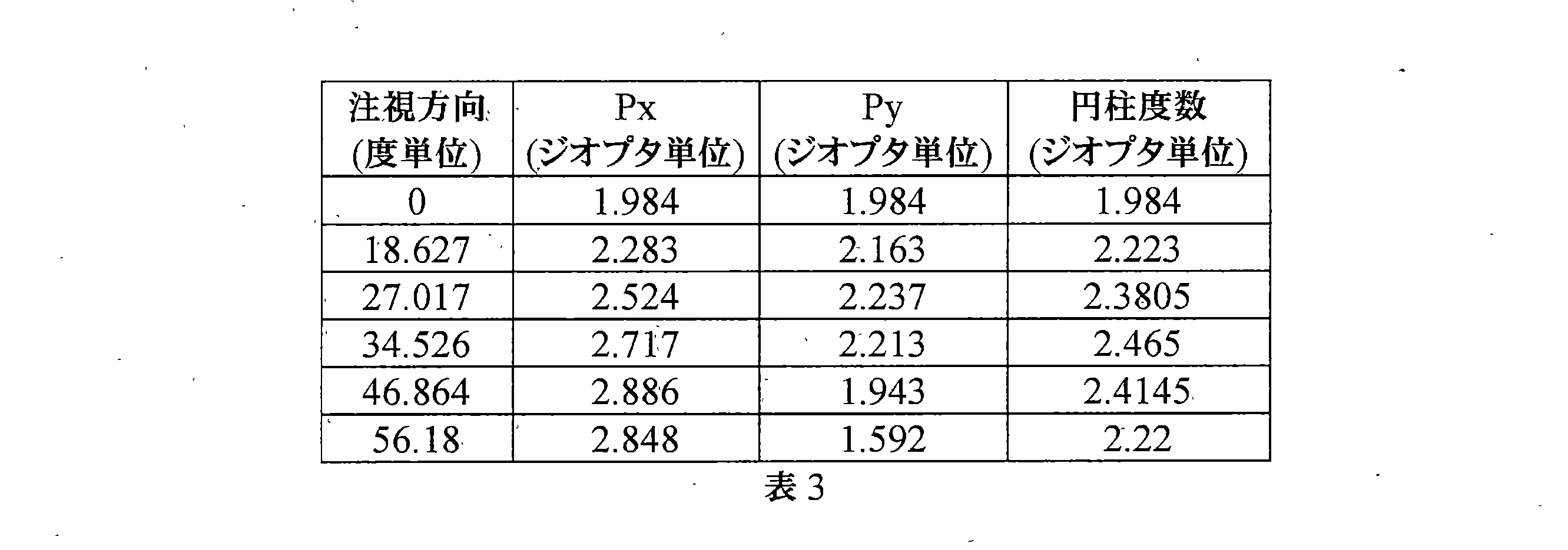
表2及び表3に示されるように、レンズ要素の光学中心の近くから始まり、光学要素の円柱度数は、前記セクションの周縁部に向かって増大し、それから前記セクションの周縁部に向かって低減する。 As shown in Tables 2 and 3, starting near the optical center of the lens element, the cylindrical power of the optical element increases towards the periphery of the section and then decreases towards the periphery of the section. ..
本発明の実施形態によれば、屈折エリアは、光学中心を含み、光学要素は、レンズの光学中心を通る任意のセクションに沿って、光学要素の平均球面度数及び/又は平均円柱度数が光学中心からレンズの周縁部に向かって増大するように構成される。 According to embodiments of the present invention, the refraction area comprises an optical center and the optical element is such that the average spherical power and / or average cylindrical power of the optical element is the optical center along any section through the optical center of the lens. It is configured to increase from the optics toward the peripheral edge of the lens.
例えば、光学要素は、屈折エリアの光学中心にセンタリングされた円に沿って規則正しく分布し得る。 For example, the optical elements can be regularly distributed along a circle centered in the optical center of the refraction area.
直径10mmであり、屈折エリアの光学中心にセンタリングされた円上の光学要素は、平均球面度数2.75Dを有するマイクロレンズであり得る。 The optical element on a circle having a diameter of 10 mm and centered at the optical center of the refraction area can be a microlens with an average spherical power of 2.75D.
直径20mmであり、屈折エリアの光学中心にセンタリングされた円上の光学要素は、平均球面度数4.75Dを有するマイクロレンズであり得る。 The optical element on a circle having a diameter of 20 mm and centered at the optical center of the refraction area can be a microlens with an average spherical power of 4.75D.
直径30mmであり、屈折エリアの光学中心にセンタリングされた円上の光学要素は、平均球面度数5.5Dを有するマイクロレンズであり得る。 The optical element on a circle having a diameter of 30 mm and centered at the optical center of the refraction area can be a microlens with an average spherical power of 5.5D.
直径40mmであり、屈折エリアの光学中心にセンタリングされた円上の光学要素は、平均球面度数5.75Dを有するマイクロレンズであり得る。 The optical element on a circle having a diameter of 40 mm and centered at the optical center of the refraction area can be a microlens with an average spherical power of 5.75D.
異なるマイクロレンズの平均円柱度数は、人の網膜の形状に基づいて調整され得る。 The average cylindrical power of different microlenses can be adjusted based on the shape of the human retina.
本発明の実施形態によれば、屈折エリアは、遠方視基準点、近方視基準及び遠方視基準点と近方視基準点とを結ぶ子午線を含む。例えば、屈折エリアは、人の処方のために適合されるか、又はレンズ要素を装用する人の目の異常屈折の進行を遅らせるように適合された累進多焦点レンズ設計を有し得る。 According to an embodiment of the present invention, the refraction area includes a far vision reference point, a near vision reference, and a meridian connecting the far vision reference point and the near vision reference point. For example, the refraction area may have a progressive multifocal lens design adapted for a person's formulation or to slow the progression of anomalous refraction in the eye of the person wearing the lens element.
好ましくは、そのような実施形態によれば、光学要素は、標準装用状況において、レンズの任意の水平セクションに沿って、光学要素の平均球面度数及び/又は平均円柱度数が前記水平セクションと子午線との交点からレンズの周縁部に向かって増大するように構成される。 Preferably, according to such an embodiment, the optics, in standard wearing conditions, have an average spherical power and / or an average cylindrical power of the optics along any horizontal section of the lens with said horizontal section and meridian. It is configured to increase from the intersection of the lenses toward the peripheral edge of the lens.
子午線は、主注視方向とレンズの表面との交点の軌跡に対応する。 The meridian corresponds to the locus of intersection between the main gaze direction and the surface of the lens.
セクションに沿った平均球面度数及び/又は平均円柱度数の増加関数は、子午線に沿った前記セクションの位置に依存して異なり得る。 The increasing function of the average spherical frequency and / or the average cylindrical frequency along the section may vary depending on the position of the section along the meridian.
特に、セクションに沿った平均球面度数及び/又は平均円柱度数の増加関数は、非対称である。例えば、平均球面度数及び/又は平均円柱度数の増加関数は、標準装用状況において、垂直セクション及び/又は水平セクションに沿って非対称である。 In particular, the increasing function of the average spherical frequency and / or the average cylindrical frequency along the section is asymmetric. For example, the increasing function of average spherical power and / or average cylindrical power is asymmetric along the vertical and / or horizontal sections in standard wearing situations.
本発明の実施形態によれば、光学要素の少なくとも1つは、非球面光学機能を有する。 According to embodiments of the present invention, at least one of the optical elements has an aspherical optical function.
光学要素14の好ましくは少なくとも50%、例えば少なくとも80%、例えば全ては、非球面光学機能を有する。
Preferred at least 50%, eg, at least 80%, of the
本発明の意味では、「非球面光学機能」は、単一焦点を有さないものとして理解されたい。 In the sense of the present invention, "aspherical optical function" should be understood as having no single focal point.
有利には、光学要素のそのような光学機能は、装用者の目の網膜の変形を低減し、レンズ要素を装用する人の目の異常屈折の進行を遅らせることができる。 Advantageously, such an optical function of the optical element can reduce the deformation of the retina of the wearer's eye and slow the progression of abnormal refraction of the eye of the person wearing the lens element.
非球面光学機能を有する少なくとも1つの要素は、透明である。 At least one element with aspherical optical function is transparent.
有利には、非連続光学要素は、レンズ要素上で可視ではなく、レンズ要素の美観に影響しない。 Advantageously, the discontinuous optical element is not visible on the lens element and does not affect the aesthetics of the lens element.
本発明の実施形態によれば、レンズ要素は、屈折エリアを有する眼科レンズと、レンズ要素が装用された場合、眼科レンズに取り外し可能に取り付けられるように適合された複数の少なくとも3つの光学要素を有するクリップオンとを含み得る。有利には、人は、遠距離環境、例えば屋外にいる場合、クリップオンを眼科レンズから分離させ、最終的に少なくとも3つの光学要素の何れもない第2のクリップオンで置換され得る。例えば、第2のクリップオンは、ソーラーティントを有し得る。人は、いかなる追加のクリップオンもない眼科レンズを使用することもできる。 According to an embodiment of the invention, the lens element comprises an ophthalmic lens having a refraction area and a plurality of at least three optical elements adapted to be detachably attached to the ophthalmic lens when the lens element is worn. May include clip-on with. Advantageously, one can separate the clip-on from the ophthalmic lens and eventually replace it with a second clip-on without any of at least three optical elements when in a long distance environment, eg outdoors. For example, the second clip-on may have a solar tint. One can also use an ophthalmic lens without any additional clip-on.
光学要素は、レンズ要素の各表面において独立してレンズ要素に追加し得る。 Optical elements can be added to the lens element independently on each surface of the lens element.
これらの光学要素は、矩形、六角形又はランダム等の定義された配列で追加することができる。 These optics can be added in a defined array such as rectangular, hexagonal or random.
光学要素は、任意の他のエリアの中心のようなレンズ要素の特定のゾーンを覆い得る。 The optics can cover a particular zone of the lens element, such as the center of any other area.
光学要素の密度又は度数量は、レンズ要素のゾーンに応じて調整され得る。通常、光学要素は、レンズ要素の周縁に位置決めされて、近視コントロールにおける光学要素の効果を増大させ、例えば網膜の周縁形状に起因した周縁デフォーカスを補償し得る。 The density or power quantity of the optical element can be adjusted according to the zone of the lens element. Typically, the optics can be positioned on the periphery of the lens element to increase the effect of the optics on myopia control and compensate for peripheral defocus due to, for example, the peripheral shape of the retina.
本発明の好ましい実施形態によれば、2mm~4mmの半径を有する円形ゾーンであって、前記半径+5mm以上のレンズ要素の光学中心の距離に配置された幾何中心を有するあらゆる円形ゾーンについて、前記円形ゾーンの内部に配置された光学要素の部分の面積の和と前記円形ゾーンの面積との比率は、20%~70%、好ましくは30%~60%、より好ましくは40%~50%である。 According to a preferred embodiment of the present invention, for any circular zone having a radius of 2 mm to 4 mm and having a geometric center located at a distance of the optical center of the lens element having a radius of +5 mm or more, the circle. The ratio of the sum of the areas of the portions of the optical elements arranged inside the zone to the area of the circular zone is 20% to 70%, preferably 30% to 60%, and more preferably 40% to 50%. ..
光学要素は、直接表面加工、成形、鋳造若しくは注入、エンボス加工、薄膜加工又はフォトリソグラフィのような異なる技術を使用して作ることができる。 Optical elements can be made using different techniques such as direct surface treatment, molding, casting or injection, embossing, thin film processing or photolithography.
本発明の実施形態によれば、光学要素の少なくとも1つ、例えば全ては、人の目の網膜の前に焦面を作り出すように構成された形状を有する。換言すれば、そのような光学要素は、光束がある場合、光束が集中するあらゆるセクション平面が人の目の網膜の前に配置されるように構成される。 According to embodiments of the invention, at least one of the optical elements, eg, all, has a shape configured to create a focal surface in front of the retina of the human eye. In other words, such optics are configured such that, in the presence of light flux, any section plane in which the light flux is concentrated is placed in front of the retina of the human eye.
本発明の実施形態によれば、非球面光学機能を有する光学要素の少なくとも1つ、例えば全ては、多焦点屈折マイクロレンズである。 According to embodiments of the present invention, at least one, for example, all of the optical elements having aspherical optical function is a multifocal refraction microlens.
本発明の意味では、「マイクロレンズ」は、0.8mm以上且つ3.0mm以下、好ましくは1.0mm以上且つ2.0mm以下の直径を有する円に彫ることができる輪郭形状を有する。 In the sense of the present invention, the "microlens" has a contour shape that can be carved into a circle having a diameter of 0.8 mm or more and 3.0 mm or less, preferably 1.0 mm or more and 2.0 mm or less.
本発明の意味では、光学要素は、「多焦点屈折マイクロレンズ」であり、二焦点(2つの焦点屈折力を有する)、三焦点(3つの焦点屈折力を有する)、連続して変化する焦点屈折力を有する多焦点累進レンズ、例えば非球面累進面レンズを含む。 In the sense of the present invention, the optical element is a "multifocal refraction microlens", bifocal (has two focal defocal forces), trifocal (has three focal defocal forces), continuously changing focal point. Includes multifocal progressive lenses with refractive power, such as aspherical progressive lenses.
本発明の実施形態によれば、光学要素の少なくとも1つ、光学要素の好ましくは50%超、より好ましくは80%超は、非球面マイクロレンズである。本発明の意味では、非球面マイクロレンズは、表面にわたり連続屈折力進化を有する。 According to embodiments of the present invention, at least one of the optical elements, preferably more than 50%, more preferably more than 80% of the optical elements, is an aspheric microlens. In the sense of the present invention, aspheric microlenses have continuous refractive power evolution over the surface.
非球面マイクロレンズは、0.1D~3Dの非球面性を有し得る。非球面マイクロレンズの非球面性は、マイクロレンズの中心において測定される光学屈折力と、マイクロレンズの周縁で測定される光学屈折力との比率に対応する。 The aspherical microlens may have an aspherical property of 0.1D to 3D. The aspherical property of an aspherical microlens corresponds to the ratio of the optical power measured at the center of the microlens to the optical power measured at the periphery of the microlens.
マイクロレンズの中心は、マイクロレンズの幾何中心にセンタリングされ、0.1mm~0.5mm、好ましくは2.0mmに等しい直径を有する球面エリアにより定義され得る。 The center of the microlens is centered on the geometric center of the microlens and can be defined by a spherical area having a diameter equal to 0.1 mm to 0.5 mm, preferably 2.0 mm.
マイクロレンズの周縁は、マイクロレンズの幾何中心にセンタリングされ、0.5mm~0.7mmの内径及び0.70mm~0.80mmの外径を有する環状ゾーンにより定義され得る。 The periphery of the microlens is centered on the geometric center of the microlens and may be defined by an annular zone with an inner diameter of 0.5 mm to 0.7 mm and an outer diameter of 0.70 mm to 0.80 mm.
本発明の実施形態によれば、非球面マイクロレンズは、絶対値で2.0D~7.0Dの光学屈折力を幾何中心において有し、絶対値で1.5D~6.0Dの光学屈折力を周縁において有する。 According to an embodiment of the present invention, the aspherical microlens has an optical power of 2.0D to 7.0D in absolute value at the geometric center and an optical power of 1.5D to 6.0D in absolute value. At the periphery.
光学要素が配置されたレンズ要素の表面をコーティングする前の非球面マイクロレンズの非球面性は、前記レンズ要素の光学中心からの半径方向距離に従って可変である。 The aspherical nature of the aspherical microlens before coating the surface of the lens element on which the optical element is located is variable according to the radial distance from the optical center of the lens element.
更に、光学要素が配置されたレンズ要素の表面をコーティングした後の非球面マイクロレンズの非球面性は、前記レンズの光学中心からの半径方向距離に従って更に可変である。 Further, the aspherical property of the aspherical microlens after coating the surface of the lens element on which the optical element is arranged is further variable according to the radial distance from the optical center of the lens.
本発明の実施形態によれば、少なくとも1つの多焦点屈折マイクロレンズは、環状面を有する。環状面は、曲率中心を通らない回転軸(最終的に無限遠に位置決めされる)の周りで円又は弧を回転させることによって作成することができる回転面である。 According to embodiments of the present invention, at least one multifocal refraction microlens has an annular surface. An annular surface is a surface of revolution that can be created by rotating a circle or arc around a axis of revolution that does not pass through the center of curvature (finally positioned at infinity).
環状面レンズは、互いに対して直角において2つの異なる半径方向プロファイルを有し、したがって2つの異なる焦点屈折力をもたらす。 An annular lens has two different radial profiles at right angles to each other and thus provides two different focal powers.
円環レンズの環状面成分及び球面成分は、単一焦点とは対照的に、非点収差光線をもたらす。 The annular and spherical components of the annulus lens result in astigmatistic rays as opposed to a single focal point.
本発明の実施形態によれば、非球面光学機能を有する光学要素の少なくとも1つ、例えば光学要素の全ては、円環屈折マイクロレンズである。例えば、0ジオプタ(δ)以上且つ+5ジオプタ(δ)以下の球面度数値及び0.25ジオプタ(δ)以上の円柱度数値を有する円環屈折マイクロレンズである。 According to an embodiment of the present invention, at least one of the optical elements having an aspherical optical function, for example, all of the optical elements are annular refraction microlenses. For example, it is an annular refraction microlens having a spherical degree value of 0 diopter (δ) or more and +5 diopter (δ) or less and a cylindricity value of 0.25 diopter (δ) or more.
特定の実施形態として、円環屈折マイクロレンズは、純粋な円筒体であり得、最小子午線屈折力がゼロである一方、最大子午線屈折力が厳密に正であり、例えば5ジオプタ未満であることを意味する。 In certain embodiments, the annular refraction microlens can be a pure cylinder with a minimum meridian power of zero while a maximum meridian power of exactly positive, eg, less than 5 diopters. means.
本発明の実施形態によれば、光学要素の少なくとも1つ、例えば全ては、複屈折材料で作られる。換言すれば、光学要素は、光の偏光方向及び伝搬方向に依存する屈折率を有する材料で作られる。複屈折性は、材料が示す屈折率間の最大差として定量化され得る。 According to embodiments of the invention, at least one of the optical elements, eg, all, is made of birefringent material. In other words, the optical element is made of a material having a refractive index that depends on the direction of polarization and the direction of propagation of light. Birefringence can be quantified as the maximum difference between the refractive indexes of the material.
本発明の実施形態によれば、光学要素の少なくとも1つ、例えば全ては、不連続面、例えばフレネル面及び/又は不連続性を有する屈折率プロファイルを有する等の不連続性を有する。 According to embodiments of the invention, at least one, eg, all, of the optical elements has a discontinuity, such as having a discontinuity, such as a Fresnel plane and / or a refractive index profile with discontinuity.
図3は、本発明に使用され得る光学要素のフレネル高さプロファイルの一例を表す。 FIG. 3 represents an example of a Fresnel height profile of an optical element that can be used in the present invention.
本発明の実施形態によれば、光学要素の少なくとも1つ、例えば全ては、回折レンズで作られる。 According to embodiments of the invention, at least one of the optical elements, eg, all, is made of a diffractive lens.
図4は、本発明に使用し得る光学要素の回折レンズ半径方向プロファイルの一例を表す。 FIG. 4 represents an example of a diffractive lens radial profile of an optical element that can be used in the present invention.
回折レンズの少なくとも1つ、例えば全ては、特許文献2に開示されるようなメタ表面構造を有し得る。
At least one, for example, all of the diffractive lenses may have a meta-surface structure as disclosed in
回折レンズは、図5に見られるように、位相関数ψ(r)が公称波長においてπ位相ジャンプを有するフレネルレンズであり得る。明確にするために、位相ジャンプが2πの倍数である単焦点フレネルレンズとは対照的に、これらの構造に「πフレネルレンズ」という名称を与え得る。位相関数が図5に表示されるπフレネルレンズは、主に、ジオプタ度数0δ及び正のジオプタ度数P、例えば3δに関連する2つの回折次数で光を回折する。 The diffractive lens can be a Fresnel lens in which the phase function ψ (r) has a π phase jump at the nominal wavelength, as seen in FIG. For clarity, these structures may be given the name "π Fresnel lens" as opposed to a single focus Fresnel lens whose phase jump is a multiple of 2π. The π Fresnel lens whose phase function is shown in FIG. 5 mainly diffracts light at a diopter power of 0δ and a positive diopter power P, eg, two diffraction orders associated with 3δ.
本発明の実施形態によれば、光学要素の少なくとも1つ、例えば全ては、多焦点バイナリ構成要素である。 According to embodiments of the invention, at least one of the optical elements, eg, all, is a multifocal binary component.
例えば、図6aに表されるようなバイナリ構造は、-P/2及びP/2で示される主に2つのジオプタ度数を示す。ジオプタ度数がP/2である図6bに示されるような屈折構造に関連する場合、図6cに表される最終構造は、ジオプタ度数0δ及びPを有する。示された事例は、P=3δに関連する。 For example, a binary structure as shown in FIG. 6a shows mainly two diopter frequencies represented by −P / 2 and P / 2. When related to a refraction structure as shown in FIG. 6b where the diopter power is P / 2, the final structure represented in FIG. 6c has diopter powers 0δ and P. The case shown is related to P = 3δ.
本発明の実施形態によれば、光学要素の少なくとも1つ、例えば全ては、画素化レンズである。多焦点画素化レンズの一例は、非特許文献2において開示されている。
According to embodiments of the present invention, at least one of the optical elements, eg, all, is a pixelated lens. An example of a multifocal pixelized lens is disclosed in
本発明の実施形態によれば、光学要素の少なくとも1つ、例えば全ては、高次光学収差を有する光学機能を有する。例えば、光学要素は、ゼルニケ多項式により定義される連続面で構成されるマイクロレンズである。 According to embodiments of the present invention, at least one of the optical elements, eg, all, has an optical function with higher order optical aberrations. For example, an optical element is a microlens composed of continuous planes defined by Zernike polynomials.
本発明について、全般的な本発明の概念を限定せずに、実施形態を用いて上述した。 The present invention has been described above using embodiments without limiting the general concept of the invention.
例示的な上記実施形態を参照して、多くの更なる変更形態及び変形形態が当業者に明らかになり、例示的な上記実施形態は、単なる例として与えられ、本発明の範囲の限定を意図せず、本発明の範囲は、添付の特許請求の範囲によってのみ決定される。 With reference to the exemplary embodiments, many further modifications and variations will be apparent to those of skill in the art, the exemplary embodiments are provided merely by way of example and are intended to limit the scope of the invention. Instead, the scope of the invention is determined solely by the appended claims.
特許請求の範囲において「含む」という用語、他の要素又はステップを除外せず、不定冠詞「1つの(a)」又は「1つの(an)」は、複数を除外しない。異なる特徴が相互に異なる従属請求項に記載されているという事実のみでは、これらの特徴の組合せが有利に使用できないことを示さない。特許請求の範囲における任意の参照符号は、本発明の範囲の限定として解釈されるべきではない。 In the claims, the term "contains", other elements or steps are not excluded, and the indefinite article "one (a)" or "one (an)" does not exclude more than one. The fact that different features are described in different dependent claims does not indicate that the combination of these features cannot be used in an advantageous manner. Any reference code in the claims should not be construed as a limitation of the scope of the invention.
10 レンズ要素
12 屈折エリア
14 光学要素
16 中央ゾーン
10
Claims (16)
- 前記目に対する処方に基づく屈折力を有する屈折エリア、及び、
- 少なくとも2つの非連続な光学要素であって、少なくとも1つの光学要素は、前記目の網膜に像を結ばないという光学機能を有して、前記目の異常屈折の進行を遅らせる、少なくとも2つの非連続な光学要素、
を含み、
2mm~4mmの半径を有する円形ゾーンであって、前記半径+5mm以上の標準装用状況で真っ直ぐ前を注視している瞳孔に面するフレーム基準の距離に配置される幾何中心を有するあらゆる円形ゾーンについて、前記円形ゾーンの内部に配置された前記少なくとも2つの非連続な光学要素の部分の面積の和と、前記円形ゾーンの面積と、の間の比率は、20%~70%である、レンズ要素。 A lens element intended to be worn in front of human eyes
-A refraction area having a refraction force based on the formulation for the eyes, and
-At least two discontinuous optical elements, at least one of which has the optical function of not forming an image on the retina of the eye and slows the progression of the abnormal refraction of the eye. Discontinuous optical element,
Including
For any circular zone with a radius of 2 mm to 4 mm and having a geometric center located at a frame reference distance facing the pupil looking straight ahead in the standard wearing situation with a radius of +5 mm or more. A lens element such that the ratio between the sum of the areas of the portions of the at least two discontinuous optical elements arranged within the circular zone and the area of the circular zone is 20% to 70%.
- 前記目に対する処方に基づく屈折力を有する屈折エリア、及び、
- 少なくとも2つの非連続な光学要素であって、少なくとも1つの光学要素は、前記目の網膜に像を結ばないという光学機能を有して、前記目の異常屈折の進行を遅らせる、少なくとも2つの非連続な光学要素、
を含み、
前記少なくとも2つの非連続な光学要素は、前記光学要素の少なくとも1つのセクションに沿って、前記少なくとも2つの非連続な光学要素の平均球面度数が、前記セクションの中心からの前記セクションの周辺部分に向かって増加するように構成される、レンズ要素。 A lens element intended to be worn in front of human eyes
-A refraction area having a refraction force based on the formulation for the eyes, and
-At least two discontinuous optical elements, at least one of which has the optical function of not forming an image on the retina of the eye and slows the progression of the abnormal refraction of the eye. Discontinuous optical element,
Including
The at least two non-contiguous optical elements have an average spherical power of the at least two discontinuous optical elements along at least one section of the optical element in the peripheral portion of the section from the center of the section. A lens element that is configured to increase towards.
- 前記目に対する処方に基づく屈折力を有する屈折エリア、及び、
- 少なくとも2つの光学要素であって、少なくとも1つの光学要素は、前記目の網膜に像を結ばないという光学機能を有して、前記目の前記異常屈折の進行を遅らせる、少なくとも2つの光学要素、
を含み、
2mm~4mmの半径を有する少なくとも1つのゾーンであって、前記半径+5mm以上の標準装用状況で真っ直ぐ前を注視している瞳孔に面するフレーム基準の距離に配置される幾何中心を有する少なくとも1つのゾーンについて、前記ゾーンの内部に配置された前記少なくとも2つの光学要素の部分の面積の和と、前記ゾーンの面積と、の間の比率は、20%~70%である、レンズ要素。 A lens element intended to be worn in front of human eyes
-A refraction area having a refraction force based on the formulation for the eyes, and
-At least two optical elements, at least one of which has the optical function of not forming an image on the retina of the eye and slows the progression of the anomalous refraction of the eye. ,
Including
At least one zone having a radius of 2 mm to 4 mm and having a geometric center located at a frame-referenced distance facing the pupil looking straight ahead in the standard wearing situation with a radius of +5 mm or more. With respect to the zone, the ratio between the sum of the areas of the portions of the at least two optical elements arranged inside the zone and the area of the zone is 20% to 70%, the lens element.
Applications Claiming Priority (18)
| Application Number | Priority Date | Filing Date | Title |
|---|---|---|---|
| EP18305217.4 | 2018-03-01 | ||
| EP18305217 | 2018-03-01 | ||
| EP18305216 | 2018-03-01 | ||
| EP18305216.6 | 2018-03-01 | ||
| EP18305384.2 | 2018-03-30 | ||
| EP18305384 | 2018-03-30 | ||
| EP18305385.9 | 2018-03-30 | ||
| EP18305385 | 2018-03-30 | ||
| EP18305435 | 2018-04-11 | ||
| EP18305435.2 | 2018-04-11 | ||
| EP18305436.0A EP3553594B1 (en) | 2018-04-11 | 2018-04-11 | Lens element |
| EP18305436.0 | 2018-04-11 | ||
| EP18305526.8A EP3561578A1 (en) | 2018-04-26 | 2018-04-26 | Lens element |
| EP18305527.6 | 2018-04-26 | ||
| EP18305527 | 2018-04-26 | ||
| EP18305526.8 | 2018-04-26 | ||
| JP2020545586A JP7532256B2 (en) | 2018-03-01 | 2019-03-01 | Lens element |
| PCT/EP2019/055216 WO2019166654A1 (en) | 2018-03-01 | 2019-03-01 | Lens element |
Related Parent Applications (1)
| Application Number | Title | Priority Date | Filing Date |
|---|---|---|---|
| JP2020545586A Division JP7532256B2 (en) | 2018-03-01 | 2019-03-01 | Lens element |
Publications (2)
| Publication Number | Publication Date |
|---|---|
| JP2022093412A true JP2022093412A (en) | 2022-06-23 |
| JP7601828B2 JP7601828B2 (en) | 2024-12-17 |
Family
ID=65576373
Family Applications (9)
| Application Number | Title | Priority Date | Filing Date |
|---|---|---|---|
| JP2020545590A Active JP7418339B2 (en) | 2018-03-01 | 2019-03-01 | lens element |
| JP2020545545A Active JP7154306B2 (en) | 2018-03-01 | 2019-03-01 | lens element |
| JP2020545548A Active JP7466450B2 (en) | 2018-03-01 | 2019-03-01 | Lens element |
| JP2020545568A Active JP7155275B2 (en) | 2018-03-01 | 2019-03-01 | lens element |
| JP2020545586A Active JP7532256B2 (en) | 2018-03-01 | 2019-03-01 | Lens element |
| JP2022067659A Active JP7601828B2 (en) | 2018-03-01 | 2022-04-15 | Lens element |
| JP2022161057A Active JP7472225B2 (en) | 2018-03-01 | 2022-10-05 | Lens element |
| JP2023000638A Pending JP2023033375A (en) | 2018-03-01 | 2023-01-05 | lens element |
| JP2024063599A Pending JP2024083545A (en) | 2018-03-01 | 2024-04-10 | Lens element |
Family Applications Before (5)
| Application Number | Title | Priority Date | Filing Date |
|---|---|---|---|
| JP2020545590A Active JP7418339B2 (en) | 2018-03-01 | 2019-03-01 | lens element |
| JP2020545545A Active JP7154306B2 (en) | 2018-03-01 | 2019-03-01 | lens element |
| JP2020545548A Active JP7466450B2 (en) | 2018-03-01 | 2019-03-01 | Lens element |
| JP2020545568A Active JP7155275B2 (en) | 2018-03-01 | 2019-03-01 | lens element |
| JP2020545586A Active JP7532256B2 (en) | 2018-03-01 | 2019-03-01 | Lens element |
Family Applications After (3)
| Application Number | Title | Priority Date | Filing Date |
|---|---|---|---|
| JP2022161057A Active JP7472225B2 (en) | 2018-03-01 | 2022-10-05 | Lens element |
| JP2023000638A Pending JP2023033375A (en) | 2018-03-01 | 2023-01-05 | lens element |
| JP2024063599A Pending JP2024083545A (en) | 2018-03-01 | 2024-04-10 | Lens element |
Country Status (15)
| Country | Link |
|---|---|
| US (21) | US12158637B2 (en) |
| EP (8) | EP3759548B1 (en) |
| JP (9) | JP7418339B2 (en) |
| KR (7) | KR102816911B1 (en) |
| CN (14) | CN111095083B (en) |
| BR (3) | BR112020017586B1 (en) |
| CA (5) | CA3155413C (en) |
| CO (5) | CO2020010242A2 (en) |
| DE (7) | DE202019005771U1 (en) |
| ES (2) | ES2983940T3 (en) |
| HU (2) | HUE062437T2 (en) |
| PL (1) | PL3759545T3 (en) |
| RU (5) | RU2765344C1 (en) |
| SG (5) | SG11202008011VA (en) |
| WO (5) | WO2019166653A1 (en) |
Cited By (2)
| Publication number | Priority date | Publication date | Assignee | Title |
|---|---|---|---|---|
| JPWO2024019071A1 (en) * | 2022-07-19 | 2024-01-25 | ||
| WO2024019070A1 (en) * | 2022-07-19 | 2024-01-25 | ホヤ レンズ タイランド リミテッド | Design method for eyeglass lens, production method for eyeglass lens, eyeglass lens, and eyeglasses |
Families Citing this family (123)
| Publication number | Priority date | Publication date | Assignee | Title |
|---|---|---|---|---|
| MX2019001339A (en) | 2016-08-01 | 2019-06-13 | Univ Washington | Ophthalmic lenses for treating myopia. |
| EP3625620B1 (en) | 2017-05-08 | 2025-09-10 | SIGHTGLASS VISION, Inc. | Methods for making contact lenses for reducing myopia |
| US10901237B2 (en) * | 2018-01-22 | 2021-01-26 | Johnson & Johnson Vision Care, Inc. | Ophthalmic lens with an optically non-coaxial zone for myopia control |
| US10884264B2 (en) | 2018-01-30 | 2021-01-05 | Sightglass Vision, Inc. | Ophthalmic lenses with light scattering for treating myopia |
| BR202019004173Y1 (en) | 2018-03-01 | 2024-02-20 | Essilor International | OPTICAL DEVICE |
| EP3759548B1 (en) * | 2018-03-01 | 2024-05-08 | Essilor International | Lens element |
| SG11202012903TA (en) | 2018-07-12 | 2021-01-28 | Sightglass Vision Inc | Methods and devices for reducing myopia in children |
| WO2020045567A1 (en) * | 2018-08-31 | 2020-03-05 | ホヤ レンズ タイランド リミテッド | Eyeglass lens, method for manufacturing eyeglass lens, and lens coating |
| EP3931626A4 (en) | 2019-03-01 | 2023-03-15 | Sightglass Vision, Inc. | OPHTHALMIC LENSES FOR REDUCING MYOPIC PROGRESSION AND METHODS FOR MAKING THEM |
| SG11202110890YA (en) | 2019-04-23 | 2021-10-28 | Sightglass Vision Inc | Ophthalmic lenses with dynamic optical properties for reducing development of myopia |
| JP7657519B2 (en) | 2019-06-25 | 2025-04-07 | ホヤ レンズ タイランド リミテッド | Eyeglass lenses and design methods thereof |
| KR20260003868A (en) * | 2019-09-25 | 2026-01-07 | 엔탈믹 홀딩 피티와이 리미티드 | Apparatus and methods of spectacle solutions for myopia |
| US12429710B2 (en) | 2019-10-07 | 2025-09-30 | Essilor International | Characterizing an optical element |
| EP3812142A1 (en) | 2019-10-23 | 2021-04-28 | Carl Zeiss Vision International GmbH | Method for producing a spectacle lens and a product comprising a spectacle lens |
| JP7402675B2 (en) * | 2019-12-23 | 2023-12-21 | ホヤ レンズ タイランド リミテッド | eyeglass lenses |
| WO2021131454A1 (en) | 2019-12-27 | 2021-07-01 | ホヤ レンズ タイランド リミテッド | Spectacle lens |
| KR102910212B1 (en) | 2020-02-12 | 2026-01-08 | 엔탈믹 홀딩 피티와이 리미티드 | Spectacle lenses with auxiliary optical elements |
| EP4120007A4 (en) * | 2020-03-09 | 2024-04-03 | Hoya Lens Thailand Ltd. | GLASSES GLASS |
| KR102811698B1 (en) * | 2020-03-17 | 2025-05-22 | 호야 렌즈 타일랜드 리미티드 | Glasses lenses |
| JP7358619B2 (en) | 2020-03-17 | 2023-10-10 | ホヤ レンズ タイランド リミテッド | eyeglass lenses |
| CN117031778A (en) * | 2020-03-31 | 2023-11-10 | 依视路国际公司 | Lens elements |
| CN115053170B (en) | 2020-04-14 | 2024-06-25 | 依视路国际公司 | Composite microlens design for reducing peripheral defocus in hyperopia |
| TWI856237B (en) * | 2020-05-14 | 2024-09-21 | 泰國商豪雅鏡片泰國有限公司 | Spectacle lens |
| AU2021275053B2 (en) | 2020-05-19 | 2024-10-03 | Sightglass Vision, Inc. | Ophthalmic lenses, methods of manufacturing the ophthalmic lenses, and methods of dispensing eye care products including the same |
| CA3174148A1 (en) * | 2020-06-08 | 2021-12-16 | Acucela Inc. | Projection of defocused images on the peripheral retina to treat refractive error |
| CN113848656B (en) * | 2020-06-28 | 2025-08-01 | 丹阳市雷登智能科技有限公司 | Spectacle lens |
| CN111694165A (en) * | 2020-07-09 | 2020-09-22 | 上海万明眼镜有限公司 | Multifunctional improved lens and preparation method thereof |
| BR112023000882A2 (en) | 2020-07-23 | 2023-02-07 | Essilor Int | OPTICAL IMPAIRMENT MONITORING EQUIPMENT COMPRISING A PAIR OF GLASSES |
| EP3943240B1 (en) | 2020-07-24 | 2025-07-09 | Essilor International | Centering apparatus and process |
| CN220553053U (en) | 2020-08-07 | 2024-03-01 | 卡尔蔡司光学国际有限公司 | Progressive addition lenses for myopia control |
| TWI887432B (en) * | 2020-08-26 | 2025-06-21 | 泰國商豪雅鏡片泰國有限公司 | Spectacle lens, design method for the same, and design system for the same |
| JP7541882B2 (en) * | 2020-09-18 | 2024-08-29 | ホヤ レンズ タイランド リミテッド | Eyeglass lenses and their design method |
| CN112162415A (en) * | 2020-09-25 | 2021-01-01 | 江苏淘镜有限公司 | Manufacturing process of anti-fatigue high-definition resin lens |
| US11126012B1 (en) | 2020-10-01 | 2021-09-21 | Michael Walach | Broadview natural addition lens |
| EP3988288A1 (en) | 2020-10-23 | 2022-04-27 | Carl Zeiss Vision International GmbH | Method of manufacturing a spectacle lens |
| EP3988289A1 (en) | 2020-10-23 | 2022-04-27 | Carl Zeiss Vision International GmbH | Method of manufacturing a spectacle lens |
| EP3988290A1 (en) | 2020-10-23 | 2022-04-27 | Carl Zeiss Vision International GmbH | Method for manufacturing a spectacle lens |
| EP4006624B1 (en) | 2020-11-26 | 2024-04-24 | Carl Zeiss Vision International GmbH | Spectacle lens design, method of manufacturing a spectacle lens and method of providing a spectacle lens for at least retarding myopia progression |
| EP4006627B1 (en) | 2020-11-26 | 2023-07-12 | Carl Zeiss Vision International GmbH | Spectacle lens design, spectacle lens kit and method of manufacturing a spectacle lens |
| EP4006626A1 (en) | 2020-11-26 | 2022-06-01 | Carl Zeiss Vision International GmbH | Spectacle lens design, spectacle lens kit and method of manufacturing a spectacle lens |
| EP4252066A1 (en) * | 2020-11-27 | 2023-10-04 | Essilor International | Lens element |
| AU2021403600A1 (en) | 2020-12-18 | 2023-06-15 | Essilor International | System and method for determining an appropriate moment for modifying or changing an initial myopia control solution |
| US20240302677A1 (en) * | 2020-12-23 | 2024-09-12 | Essilor International | An optical lens |
| WO2022189352A1 (en) | 2021-03-09 | 2022-09-15 | Essilor International | Method for automatically centering an ophthalmic lens |
| CN113050203B (en) * | 2021-03-12 | 2022-08-09 | 中国科学院上海光学精密机械研究所 | Super-surface sparse aperture lens |
| CN115236877A (en) * | 2021-04-22 | 2022-10-25 | 亮点光学股份有限公司 | Myopia Control Contact Lenses |
| KR20240006539A (en) | 2021-05-07 | 2024-01-15 | 에씰로 앙터나시오날 | Method for coating lenses with lenslets with improved control of refractive power changes |
| EP4089473A1 (en) | 2021-05-10 | 2022-11-16 | Carl Zeiss Vision International GmbH | Spectacle lens design, spectacle lens kit, method of manufacturing a spectacle lens and method of providing a spectacle lens design |
| CN113253481B (en) * | 2021-05-10 | 2022-11-15 | 苏州大学 | Spectacle lens with invisible microstructure |
| CN113296290B (en) * | 2021-05-24 | 2025-09-16 | 苏州明世光学科技有限公司 | Multi-point defocused spectacle lens patch and adhering method thereof |
| EP4094932B1 (en) | 2021-05-26 | 2024-09-04 | Essilor International | Composite mold for manufacturing a microstructured thermoset article, manufacturing method and method for obtaining the mold |
| CN115453706A (en) * | 2021-06-09 | 2022-12-09 | 浙江舜宇光学有限公司 | camera lens |
| EP4105010B1 (en) | 2021-06-18 | 2024-08-07 | Essilor International | Method for coating lenses with lenslets with an improved control on power shift |
| EP4108438A1 (en) | 2021-06-25 | 2022-12-28 | Essilor International | Method for manufacturing a lens element |
| BR112023024778A2 (en) * | 2021-06-30 | 2024-02-15 | Essilor Int | LENS ELEMENT |
| EP4119321A1 (en) | 2021-07-13 | 2023-01-18 | Essilor International | Method for fabricating microstructured inserts for injection molding |
| WO2023001780A1 (en) | 2021-07-19 | 2023-01-26 | Essilor International | Mold for manufacturing a thermoset optical article, method for manufacturing the mold and method for manufacturing the thermoset optical article |
| EP4122687A1 (en) | 2021-07-19 | 2023-01-25 | Essilor International | Composite mold insert for fabricating microstructured lenses |
| EP4122689A1 (en) | 2021-07-20 | 2023-01-25 | Essilor International | Low thermal conductivity metal insert with surface microstructures |
| JP2023042948A (en) | 2021-09-15 | 2023-03-28 | ホヤ レンズ タイランド リミテッド | Spectacle lens |
| JP7177959B1 (en) | 2021-09-15 | 2022-11-24 | ホヤ レンズ タイランド リミテッド | spectacle lenses |
| EP4163705A1 (en) | 2021-10-05 | 2023-04-12 | Essilor International | Lens element with improved visual performance |
| EP4163706A1 (en) | 2021-10-05 | 2023-04-12 | Essilor International | Lens element |
| US20250236730A1 (en) | 2021-10-15 | 2025-07-24 | Mitsui Chemicals, Inc | Photocurable composition, cured article, laminated body, method for producing cured article, and method for producing lens |
| WO2023072930A1 (en) * | 2021-10-26 | 2023-05-04 | Essilor International | Lens element |
| EP4433864A1 (en) | 2021-11-18 | 2024-09-25 | Essilor International | A method for determining an ophthalmic lens adapted to slow down the progression of a vision impairment |
| EP4187311A1 (en) | 2021-11-26 | 2023-05-31 | Essilor International | Computer-implemented method, apparatus, system and computer program for providing a user with a representation of an effect of a sightedness impairment control solution |
| MX2024007322A (en) | 2021-12-15 | 2024-06-26 | Sightglass Vision Inc | Automated process for forming features on ophthalmic lens. |
| EP4197766A1 (en) * | 2021-12-16 | 2023-06-21 | Essilor International | Method for microforming microstructured films and lenses |
| EP4197765A1 (en) | 2021-12-16 | 2023-06-21 | Essilor International | Method for encapsulating a microstructured lens by pipc |
| EP4197764A1 (en) | 2021-12-16 | 2023-06-21 | Essilor International | Method for encapsulating a microstructured lens by coating transfer |
| JP7775068B2 (en) * | 2021-12-21 | 2025-11-25 | ホヤ レンズ タイランド リミテッド | Eyeglass lens and method for designing an eyeglass lens |
| JP2023114018A (en) * | 2022-02-04 | 2023-08-17 | 東海光学株式会社 | spectacle lens |
| CN118871285A (en) | 2022-02-14 | 2024-10-29 | 依视路国际公司 | Method for manufacturing a spectacle lens |
| CN223377564U (en) | 2022-02-16 | 2025-09-23 | 卡尔蔡司光学国际有限公司 | Ophthalmic lenses for slowing myopia progression |
| JPWO2023166822A1 (en) * | 2022-03-03 | 2023-09-07 | ||
| CN119213336A (en) | 2022-03-18 | 2024-12-27 | 卡尔蔡司光学国际有限公司 | Coated lens and method of making the same |
| WO2023180403A1 (en) | 2022-03-25 | 2023-09-28 | Essilor International | Lens element |
| WO2023186763A1 (en) | 2022-03-27 | 2023-10-05 | Essilor International | Method for characterizing at least part of a lens element |
| US20250199333A1 (en) | 2022-04-21 | 2025-06-19 | Essilor International | Lens with improved visual performance |
| CN114911070B (en) | 2022-04-29 | 2023-10-03 | 麦得科科技有限公司 | Ophthalmic lenses for preventing the progression of myopia and glasses using the same |
| EP4519732A1 (en) * | 2022-05-03 | 2025-03-12 | Essilor International | Optical lens intended to be worn by a wearer |
| DE102022111995B4 (en) * | 2022-05-12 | 2024-01-18 | Rodenstock Gmbh | Spectacle lenses for reducing the progression of myopia and methods for individual refraction or manufacture |
| CN114895483B (en) * | 2022-05-19 | 2024-04-16 | 苏州大学 | Superimposed peripheral discrete cis-standard astigmatic spectacle lens and design method thereof |
| EP4283382A1 (en) | 2022-05-27 | 2023-11-29 | Carl Zeiss Vision International GmbH | Stiles-crawford-effect based mechanism and spectacle lens for retinal-region weighted prevention of myopia progression |
| CN114967178A (en) * | 2022-06-03 | 2022-08-30 | 江苏瑞尔光学有限公司 | Wave structure and micro-lens structure composite multi-focus lens |
| EP4537153A1 (en) * | 2022-06-09 | 2025-04-16 | Essilor International | Optical lens intended to be worn by a wearer |
| EP4292798A1 (en) | 2022-06-14 | 2023-12-20 | Carl Zeiss Vision International GmbH | Method of providing refractive microstructures on a surface of a spectacle lens and spectacle lens design |
| US20240012270A1 (en) * | 2022-07-07 | 2024-01-11 | Plum Needle Technology Inc. | Adjustable out-of-focus glasses |
| CN115091664A (en) * | 2022-07-15 | 2022-09-23 | 西安交通大学 | Preparation method of myopia-preventing glasses lens mold with symmetrical compound eye structure |
| JP2024027333A (en) | 2022-08-17 | 2024-03-01 | 東海光学株式会社 | Spectacle lens for suppressing progression of ametropia |
| EP4328658A1 (en) | 2022-08-26 | 2024-02-28 | Carl Zeiss Vision International GmbH | Spectacle lens design and methods to retard and control the progression of myopia |
| EP4335630A1 (en) | 2022-09-07 | 2024-03-13 | Essilor International | Method for patterning a mask, method for producing an insert or a mold, and optical article with surface microstructures |
| EP4349579A1 (en) | 2022-10-04 | 2024-04-10 | Essilor International | Method for manufacturing an optical device comprising a microstructure, manufacturing system to carry out such a method, and optical device thus obtained |
| KR20250091184A (en) | 2022-10-17 | 2025-06-20 | 에씰로 앙터나시오날 | Ophthalmic lenses designed to correct vision impairment and slow its progression |
| JP7673332B2 (en) * | 2022-10-28 | 2025-05-08 | クーパーヴィジョン インターナショナル リミテッド | Method for manufacturing an ophthalmic lens including an asymmetric gradient index optic |
| EP4365668A1 (en) | 2022-11-04 | 2024-05-08 | Carl Zeiss Vision International GmbH | Spectacle lens with non-concentric microstructures |
| CN117148598B (en) * | 2022-11-29 | 2025-11-21 | 温州医科大学附属眼视光医院 | Continuous high-order phase modulation spectacle lens and phase modulation method thereof |
| WO2024121218A1 (en) * | 2022-12-07 | 2024-06-13 | Essilor International | A pair of spectacle lenses comprising a first optical lens intended to be worn in front of a first eye of a wearer and a second optical lens intended to be worn in front of a second eye of the wearer |
| EP4382997A1 (en) | 2022-12-08 | 2024-06-12 | Essilor International | Method for designing a contact lens |
| EP4390520A1 (en) * | 2022-12-21 | 2024-06-26 | Essilor International | Spectacle lens |
| US20240210729A1 (en) * | 2022-12-22 | 2024-06-27 | Johnson & Johnson Vision Care, Inc. | Opthalmic lens for myopia control |
| EP4390516A1 (en) | 2022-12-23 | 2024-06-26 | Carl Zeiss Vision International GmbH | Spectacle lens design data and method for manufacturing a spectacle lens |
| WO2024168652A1 (en) | 2023-02-16 | 2024-08-22 | Carl Zeiss Vision International Gmbh | Digital twin of a spectacle lens and spectacle lens |
| EP4417404A1 (en) | 2023-02-17 | 2024-08-21 | Carl Zeiss Vision International GmbH | Method of manufacturing a coated spectacle lens comprising structures |
| DE102023110431B3 (en) | 2023-04-24 | 2024-10-10 | Rodenstock Gmbh | Reduction of the progression of myopia with adapted field of vision, method, series of spectacle lenses, device, computer program product and use |
| DE102023110569B3 (en) | 2023-04-25 | 2024-10-31 | Rodenstock Gmbh | Myopia management lens with dual progression control, procedure and use |
| EP4455769A1 (en) | 2023-04-27 | 2024-10-30 | Essilor International | Method and device for centering an ophthalmic lens |
| CN116360115B (en) * | 2023-05-31 | 2023-09-15 | 杭州光粒科技有限公司 | Near-to-eye display device |
| WO2025032581A1 (en) * | 2023-08-07 | 2025-02-13 | Hadasit Medical Research Services And Development Ltd. | Adaptable thin lens for correction of visual aberrations |
| WO2025037573A1 (en) | 2023-08-16 | 2025-02-20 | ホヤ レンズ タイランド リミテッド | Eyeglass lens and eyeglasses |
| WO2025037572A1 (en) * | 2023-08-16 | 2025-02-20 | ホヤ レンズ タイランド リミテッド | Spectacle lens and spectacles |
| CN117270236A (en) * | 2023-09-05 | 2023-12-22 | 江苏东宝光学有限公司 | Aspherical ring-separation multifocal lens and preparation process thereof |
| EP4530707A1 (en) | 2023-09-26 | 2025-04-02 | Essilor International | Wearing detection module to be fixed on a spectacle frame and process for determining whether a spectacle frame is worn |
| EP4549137A1 (en) | 2023-11-03 | 2025-05-07 | Essilor International | Method for manufacturing an optical article |
| EP4556844B1 (en) | 2023-11-14 | 2026-01-14 | Essilor International | Method for characterizing at least part of a lens element |
| WO2025037040A2 (en) | 2023-12-08 | 2025-02-20 | Essilor International | Myopia control lens element |
| WO2025037041A2 (en) | 2023-12-08 | 2025-02-20 | Essilor International | Myopia control lens element |
| WO2025037042A2 (en) | 2023-12-08 | 2025-02-20 | Essilor International | Myopia control lens element |
| WO2025133288A1 (en) | 2023-12-21 | 2025-06-26 | Essilor International | Method for defining an optical lens design of a pair of eyeglasses intended to be worn by a subject |
| WO2025181299A1 (en) * | 2024-02-28 | 2025-09-04 | Essilor International | Myopia control device for first time correction |
| WO2025184865A1 (en) | 2024-03-07 | 2025-09-12 | Carl Zeiss Vision International Gmbh | Spectacle lens and kit |
| DE102024114300A1 (en) | 2024-05-22 | 2025-11-27 | Rodenstock Gmbh | Spectacle lens for myopia management with grid structures |
Citations (5)
| Publication number | Priority date | Publication date | Assignee | Title |
|---|---|---|---|---|
| JP2013537317A (en) * | 2010-09-13 | 2013-09-30 | ザ ホンコン ポリテクニック ユニヴァーシティー | Method and system for delaying myopia progression |
| US20140347622A1 (en) * | 2013-05-24 | 2014-11-27 | Hiline Optical Co., Ltd. | Lens and method for correcting vision of a user |
| US20160306079A1 (en) * | 2015-04-14 | 2016-10-20 | California Institute Of Technology | Multi-wavelength optical dielectric metasurfaces |
| JP2017510851A (en) * | 2014-03-24 | 2017-04-13 | メニコン シンガポール ピーティーイー. リミテッド | Apparatus and method for axial growth control using an ophthalmic lens |
| WO2018026697A1 (en) * | 2016-08-01 | 2018-02-08 | Jay Neitz | Ophthalmic lenses for treating myopia |
Family Cites Families (138)
| Publication number | Priority date | Publication date | Assignee | Title |
|---|---|---|---|---|
| US1955047A (en) | 1931-12-03 | 1934-04-17 | Howard D Beach | Spectacle lens |
| US3902693A (en) | 1973-03-12 | 1975-09-02 | American Optical Corp | Mold for casting lenses |
| GB2129155B (en) * | 1982-10-13 | 1987-05-20 | Ng Trustees & Nominees Ltd | Bifocal contact lenses |
| US5017000A (en) | 1986-05-14 | 1991-05-21 | Cohen Allen L | Multifocals using phase shifting |
| US4981342A (en) * | 1987-09-24 | 1991-01-01 | Allergan Inc. | Multifocal birefringent lens system |
| US5798027A (en) | 1988-02-08 | 1998-08-25 | Optical Coating Laboratory, Inc. | Process for depositing optical thin films on both planar and non-planar substrates |
| US5359440A (en) | 1989-10-23 | 1994-10-25 | Sharp Kabushiki Kaisha | Image display apparatus with microlens plate having mutually fused together lenses resulting in hexagonal shaped microlenses |
| AU7130391A (en) | 1990-03-08 | 1991-09-12 | Breger, Joseph Laurence | Multifocal simultaneous vision lenses |
| US5112351A (en) | 1990-10-12 | 1992-05-12 | Ioptex Research Inc. | Multifocal intraocular lenses |
| WO1995025288A1 (en) | 1994-03-17 | 1995-09-21 | Bifocon Optics Forschungs- Und Entwicklungsgmbh | Zoned lens |
| US5517260A (en) | 1994-03-28 | 1996-05-14 | Vari-Site, Inc. | Ophthalmic lens having a progressive multifocal zone and method of manufacturing same |
| US5507806A (en) | 1994-05-13 | 1996-04-16 | Pharmacia Iovision, Inc. | Multi-faceted intraocular lens |
| US5652638A (en) | 1995-05-04 | 1997-07-29 | Johnson & Johnson Vision Products, Inc. | Concentric annular ring lens designs for astigmatism |
| US5864379A (en) * | 1996-09-27 | 1999-01-26 | Dunn; Stephen A. | Contact lens and process for fitting |
| US6045578A (en) | 1995-11-28 | 2000-04-04 | Queensland University Of Technology | Optical treatment method |
| US5753092A (en) | 1996-08-26 | 1998-05-19 | Velocidata, Inc. | Cylindrical carriage sputtering system |
| FR2753805B1 (en) | 1996-09-20 | 1998-11-13 | Essilor Int | SET OF PROGRESSIVE MULTIFOCAL OPHTHALMIC LENSES |
| US6129042A (en) | 1996-11-08 | 2000-10-10 | Coburn Optical Industries, Inc. | Process and machine for coating ophthalmic lenses |
| US6030077A (en) | 1998-03-11 | 2000-02-29 | Menicon Co., Ltd. | Multifocal ocular lens having intermediate region with continuously varying optical power |
| US6343861B1 (en) * | 1998-06-12 | 2002-02-05 | Sola International Holdings, Ltd. | Myopia lens |
| WO2000008516A1 (en) | 1998-08-06 | 2000-02-17 | Lett John B W | Multifocal aspheric lens |
| US7281795B2 (en) | 1999-01-12 | 2007-10-16 | Calhoun Vision, Inc. | Light adjustable multifocal lenses |
| US6258218B1 (en) | 1999-10-22 | 2001-07-10 | Sola International Holdings, Ltd. | Method and apparatus for vacuum coating plastic parts |
| US6554979B2 (en) | 2000-06-05 | 2003-04-29 | Applied Materials, Inc. | Method and apparatus for bias deposition in a modulating electric field |
| US6582076B1 (en) * | 2000-08-30 | 2003-06-24 | Johnson & Johnson Vision Care, Inc. | Ophthalmic lenses useful in correcting astigmatism and presbyopia |
| US6554425B1 (en) * | 2000-10-17 | 2003-04-29 | Johnson & Johnson Vision Care, Inc. | Ophthalmic lenses for high order aberration correction and processes for production of the lenses |
| WO2002077672A2 (en) | 2001-02-07 | 2002-10-03 | Corning Incorporated | High-contrast screen with random microlens array |
| US6752499B2 (en) | 2001-07-11 | 2004-06-22 | Thomas A. Aller | Myopia progression control using bifocal contact lenses |
| US6712466B2 (en) * | 2001-10-25 | 2004-03-30 | Ophthonix, Inc. | Eyeglass manufacturing method using variable index layer |
| US20030117577A1 (en) | 2001-12-20 | 2003-06-26 | Jones Larry G. | Multifocal ophthalmic lenses |
| US6654174B1 (en) | 2002-05-08 | 2003-11-25 | Pin Chien Huang | Micro lens systems and articles thereof |
| US7437980B2 (en) | 2002-05-29 | 2008-10-21 | Massachusetts Institute Of Technology | Flux-biased electromagnetic fast tool servo systems and methods |
| GB0222331D0 (en) | 2002-09-26 | 2002-10-30 | Teer Coatings Ltd | A method for depositing multilayer coatings with controlled thickness |
| US6802607B2 (en) | 2002-10-31 | 2004-10-12 | Johnson & Johnson Vision Care, Inc. | Progressive cylinder ophthalmic lenses |
| US20040141150A1 (en) | 2003-01-21 | 2004-07-22 | Roffman Jeffrey H. | Hybrid multifocal contact lenses |
| EP1629319B1 (en) * | 2003-05-21 | 2012-12-12 | Novartis AG | Contact lenses |
| US7101042B2 (en) * | 2003-08-12 | 2006-09-05 | S.I.B. Investments Llc | Multifocal contact lens |
| CA2545390C (en) * | 2003-11-19 | 2012-09-18 | Vision Crc Limited | Methods and apparatuses for altering relative curvature of field and positions of peripheral, off-axis focal positions |
| US7503655B2 (en) | 2003-11-19 | 2009-03-17 | Vision Crc Limited | Methods and apparatuses for altering relative curvature of field and positions of peripheral, off-axis focal positions |
| US8306853B2 (en) | 2004-02-17 | 2012-11-06 | Colts Laboratories | Methods for testing ophthalmic lenses |
| JP4386753B2 (en) | 2004-02-19 | 2009-12-16 | キヤノンアネルバ株式会社 | Wafer stage and plasma processing apparatus |
| WO2006025336A1 (en) | 2004-08-30 | 2006-03-09 | Ulvac, Inc. | Film forming equipment |
| GB0421389D0 (en) | 2004-09-25 | 2004-10-27 | Applied Multilayers Ltd | Material deposition apparatus and method |
| US7506983B2 (en) | 2004-09-30 | 2009-03-24 | The Hong Kong Polytechnic University | Method of optical treatment |
| GB0503401D0 (en) | 2005-02-18 | 2005-03-30 | Applied Multilayers Ltd | Apparatus and method for the application of material layer to display devices |
| EP1855873B1 (en) | 2005-03-09 | 2009-12-30 | The Walman Optical Company | Method and apparatus for coating optics |
| JP2009500662A (en) | 2005-06-29 | 2009-01-08 | リフレキサイト・コーポレーション | Collimating microlens array |
| AU2006301940B2 (en) * | 2005-10-12 | 2012-03-29 | Carl Zeiss Vision Australia Holdings Limited | Ophthalmic lens element for myopia correction |
| WO2007061389A1 (en) * | 2005-11-28 | 2007-05-31 | Nanyang Optical Co. Pte Ltd | Auxiliary lenses for prescription lenses and method for managing myopia |
| CN101300097B (en) * | 2005-12-22 | 2010-09-15 | Hoya株式会社 | Lens surface cutting processing device for spectacle lens, lens surface cutting processing method, and spectacle lens |
| WO2007082268A2 (en) | 2006-01-12 | 2007-07-19 | Institute For Eye Research | Method and apparatus for controlling peripheral image position for reducing progression of myopia |
| FR2898993B1 (en) * | 2006-03-24 | 2008-08-01 | Essilor Int | METHOD FOR DETERMINING A PROGRESSIVE OPHTHALMIC LENS |
| JP5789082B2 (en) * | 2006-06-08 | 2015-10-07 | ヴィジョン・シーアールシー・リミテッド | Means for controlling the progression of myopia |
| CN200956072Y (en) * | 2006-09-08 | 2007-10-03 | 刘伟中 | Non-sphere super-thin prism combined lens glasses |
| BRPI0716719B1 (en) * | 2006-09-15 | 2018-07-03 | Carl Zeiss Vision Australia Holdings Limited | Ophthalmic Lens Element, Series of Ophthalmic Lens Elements, and Method of Preparing or Designing an Ophthalmic Lens Element |
| US7740354B2 (en) * | 2006-10-25 | 2010-06-22 | Volk Donald A | Multi-layered gradient index progressive lens |
| FR2912820B1 (en) | 2007-02-15 | 2009-05-15 | Essilor Int | REALIZATION OF AN OPHTHALMIC ELEMENT ADAPTED FOR FOVEAL AND PERIPHERAL VISIONS |
| CN101675372B (en) | 2007-03-09 | 2012-12-26 | 奥克兰联合服务有限公司 | Contact lens and method |
| US7978411B2 (en) | 2007-05-08 | 2011-07-12 | Micron Technology, Inc. | Tetraform microlenses and method of forming the same |
| US8690319B2 (en) | 2007-05-21 | 2014-04-08 | Johnson & Johnson Vision Care, Inc. | Ophthalmic lenses for prevention of myopia progression |
| US7637612B2 (en) | 2007-05-21 | 2009-12-29 | Johnson & Johnson Vision Care, Inc. | Ophthalmic lenses for prevention of myopia progression |
| FR2916864B1 (en) | 2007-05-31 | 2010-01-08 | Essilor Int | MYOPIA CORRECTION PROGRESSIVE OPHTHALMIC GLASS AND METHOD OF MAKING SUCH A GLASS |
| SE533395C2 (en) | 2007-06-08 | 2010-09-14 | Sandvik Intellectual Property | Ways to make PVD coatings |
| US8317321B2 (en) | 2007-07-03 | 2012-11-27 | Pixeloptics, Inc. | Multifocal lens with a diffractive optical power region |
| TWI467266B (en) * | 2007-10-23 | 2015-01-01 | 視覺Crc有限公司 | Ophthalmic lens element |
| US7926941B2 (en) | 2007-12-14 | 2011-04-19 | Pixeloptics Inc. | Multiple layer multifocal composite lens |
| JP2011510798A (en) | 2008-02-05 | 2011-04-07 | レーザー エナジェティックス,インコーポレイテッド | Compound microlens implant |
| US7701636B2 (en) | 2008-03-06 | 2010-04-20 | Aptina Imaging Corporation | Gradient index microlenses and method of formation |
| CN102007444B (en) | 2008-04-18 | 2013-11-06 | 诺华股份有限公司 | device for controlling myopia |
| US7905595B2 (en) * | 2008-04-28 | 2011-03-15 | Crt Technology, Inc. | System and method to treat and prevent loss of visual acuity |
| AU2009282321A1 (en) * | 2008-08-11 | 2010-02-18 | Novartis Ag | A lens design and method for preventing or slowing the progression of myopia |
| CN201614406U (en) | 2008-08-27 | 2010-10-27 | 梯尔涂层有限公司 | Equipment for depositing materials to form coatings |
| US8922898B2 (en) * | 2008-09-04 | 2014-12-30 | Innovega Inc. | Molded lens with nanofilaments and related methods |
| FR2936879B1 (en) | 2008-10-07 | 2011-03-11 | Essilor Int | OPHTHALMIC GLASS CORRECTING FOVEAL VISION AND PERIPHERAL VISION. |
| EP2379028B1 (en) | 2008-12-22 | 2017-09-13 | Medical College Of Wisconsin, Inc. | Apparatus for limiting growth of eye length |
| US9022563B2 (en) * | 2009-02-12 | 2015-05-05 | Mitsui Chemicals, Inc. | Ophthalmic lenses with aspheric optical features |
| ES2345027B1 (en) * | 2009-03-12 | 2011-09-30 | Universidad De Murcia | OPTICAL REFRACTION CORRECTION DEVICE IN THE PERIPHERAL RETINA OF ASYMMETRICAL WAY FOR THE CONTROL OF THE PROGRESSION OF MYOPIA. |
| US9120278B2 (en) | 2009-03-31 | 2015-09-01 | Hoya Corporation | Method for producing progressive power eyeglass lens |
| JP2010252277A (en) | 2009-04-20 | 2010-11-04 | Panasonic Corp | Solid-state imaging device and electronic camera |
| WO2011049642A1 (en) * | 2009-10-22 | 2011-04-28 | Coopervision International Holding Company, Lp | Contact lens sets and methods to prevent or slow progression of myopia or hyperopia |
| JP5911812B2 (en) * | 2010-03-03 | 2016-04-27 | ブライアン・ホールデン・ビジョン・インスティチュートBrien Holden Vision Institute | Method for treating refractive error using corneal remodeling contact lens and corneal remodeling |
| US8931897B2 (en) * | 2010-03-03 | 2015-01-13 | Brien Holden Vision Institute | Contact lenses for myopic eyes and methods of treating myopia |
| CN102858521A (en) | 2010-04-02 | 2013-01-02 | 埃西勒国际通用光学公司 | Method of dip-coating a lens |
| FR2960305B1 (en) * | 2010-05-21 | 2013-03-01 | Essilor Int | IMPLEMENTING A TRANSPARENT OPTICAL COMPONENT WITH A CELLULAR STRUCTURE |
| WO2011163668A2 (en) | 2010-06-25 | 2011-12-29 | Pixeloptics, Inc. | High performance, low cost multifocal lens having dynamic progressive optical power region |
| US8113655B1 (en) * | 2010-07-22 | 2012-02-14 | Albert Tyrin | Training method for accommodative and vergence systems, and multifocal lenses therefor |
| US9423633B2 (en) * | 2010-07-26 | 2016-08-23 | Brien Holden Vision Institute | Treating ocular refractive error |
| US8950860B2 (en) * | 2010-09-09 | 2015-02-10 | The Hong Kong Polytechnic University | Method and system for retarding the progression of myopia |
| WO2012122411A1 (en) | 2011-03-08 | 2012-09-13 | Pixeloptics, Inc. | Advanced electro-active optic device |
| WO2012138426A2 (en) | 2011-04-04 | 2012-10-11 | Elenza, Inc. | An implantable ophthalmic device with multiple static apertures |
| WO2012168709A2 (en) | 2011-06-07 | 2012-12-13 | Power Vision Limited | Improvements to the application of coating materials |
| US9184199B2 (en) | 2011-08-01 | 2015-11-10 | Lytro, Inc. | Optical assembly including plenoptic microlens array |
| GB201115124D0 (en) * | 2011-09-01 | 2011-10-19 | Crosby David | Improved adjustable refractive optical device for context specific use |
| BR112014011559A2 (en) * | 2011-11-16 | 2017-05-09 | Essilor Int | method for providing an optical system of an ophthalmic eyeglass lens and method for manufacturing an ophthalmic eyeglass lens |
| TWI600428B (en) * | 2012-03-15 | 2017-10-01 | 標誌製藥公司 | Cancer treatment using TOR kinase inhibitors |
| CN102692730B (en) * | 2012-06-15 | 2013-12-04 | 戴明华 | Multi-element lens for controlling defocus and eye diopter and application thereof |
| US8817167B2 (en) | 2012-07-13 | 2014-08-26 | Google Inc. | Imaging device with a plurality of depths of field |
| JP6145990B2 (en) | 2012-10-29 | 2017-06-14 | セイコーエプソン株式会社 | Manufacturing method of microlens array substrate |
| TWI507763B (en) | 2012-11-22 | 2015-11-11 | Control the growth of the optical axis of the lens | |
| DE102012023478A1 (en) | 2012-11-28 | 2014-05-28 | Technische Universität Ilmenau | Device for manipulating image information and its use |
| CN103926710B (en) * | 2013-01-15 | 2015-11-04 | 九扬贸易有限公司 | A contact lens that uses chromatic aberration to control myopia and achieve beauty |
| US8998408B2 (en) | 2013-01-30 | 2015-04-07 | Johnson & Johnson Vision Care, Inc. | Asymmetric lens design and method for preventing and/or slowing myopia progression |
| BR112015019008A8 (en) | 2013-02-20 | 2018-08-14 | Essilor Int | PAIR OF PROGRESSIVE OPHTHALMIC LENSES |
| US9658469B2 (en) * | 2013-03-15 | 2017-05-23 | Johnson & Johnson Vision Care, Inc. | Ophthalmic devices incorporating metasurface elements |
| EP2787385A1 (en) * | 2013-04-02 | 2014-10-08 | ESSILOR INTERNATIONAL (Compagnie Générale d'Optique) | Active system of vision and associated method for improving visual comfort to a wearer |
| FR3008196B1 (en) * | 2013-07-08 | 2016-12-30 | Essilor Int | METHOD FOR MANUFACTURING AT LEAST ONE OPHTHALMIC LENS |
| US9753309B2 (en) * | 2013-11-04 | 2017-09-05 | Myopiaok Limited | Contact lens and method for prevention of myopia progression |
| CN104678572B (en) | 2013-11-29 | 2018-04-27 | 豪雅镜片泰国有限公司 | Ophthalmic len |
| WO2015110886A1 (en) * | 2014-01-21 | 2015-07-30 | Wockhardt Limited | A process for preparation of (2s, 5r)-7-oxo-n-[(3s)-pyrrolidin-3-yloxy]-6-(sulfooxy)-1,6-diazabicyclo [3.2.1]octane-2-carboxamide |
| KR102286387B1 (en) * | 2014-02-04 | 2021-08-04 | 씨알티 테크놀로지, 인크. | Multifunction contact lens |
| KR102299750B1 (en) * | 2014-04-01 | 2021-09-08 | 에씰로 앙터나시오날 | Multifocal ophthalmic spectacle lens arranged to output a supplementary image |
| US20170115509A1 (en) * | 2014-08-20 | 2017-04-27 | Johnson & Johnson Vision Care, Inc. | High plus center treatment zone lens design and method for preventing and/or slowing myopia progression |
| US9638936B2 (en) * | 2014-08-20 | 2017-05-02 | Johnson & Johnson Vision Care, Inc. | High plus treatment zone lens design for preventing and/or slowing myopia progression |
| US10061143B2 (en) * | 2014-08-29 | 2018-08-28 | Johnson & Johnson Vision Care, Inc. | Multifocal lens design for preventing and/or slowing myopia progression |
| CN107407827B (en) | 2014-12-31 | 2020-08-04 | 依视路国际公司 | Spectacle ophthalmic lenses designed to be mounted on spectacle frames |
| CN104749791A (en) * | 2015-01-15 | 2015-07-01 | 中山大学中山眼科中心 | Optical focusing regulating lens and optical focusing regulating method |
| WO2016146590A1 (en) | 2015-03-18 | 2016-09-22 | Essilor International (Compagnie Générale d'Optique) | A method for determining an ophthalmic lens having unwanted astigmatism |
| BR112017021858A2 (en) * | 2015-04-15 | 2018-07-10 | Vision Ease, Lp | ophthalmic lens with graduated microlenses. |
| US11061255B2 (en) * | 2015-06-23 | 2021-07-13 | Johnson & Johnson Vision Care, Inc. | Ophthalmic lens comprising lenslets for preventing and/or slowing myopia progression |
| US10877294B2 (en) | 2015-06-23 | 2020-12-29 | Johnson & Johnson Vision Care, Inc. | Contact lens comprising non-coaxial lenslets for preventing and/or slowing myopia progression |
| CN106405867A (en) * | 2015-07-28 | 2017-02-15 | 亨泰光学股份有限公司 | Contact lens and processing method thereof |
| US10268050B2 (en) * | 2015-11-06 | 2019-04-23 | Hoya Lens Thailand Ltd. | Spectacle lens |
| EP3395918B1 (en) | 2015-12-25 | 2020-03-25 | Nikon-Essilor Co., Ltd. | Hard-coat-layer-forming composition and optical member |
| US9977257B2 (en) * | 2016-03-22 | 2018-05-22 | Johnson & Johnson Vision Care, Inc. | Multifocal lens design and method for preventing and/or slowing myopia progression |
| EP3440484B1 (en) | 2016-04-05 | 2024-07-24 | President and Fellows of Harvard College | Meta-lenses for sub-wavelength resolution imaging |
| US20190137786A1 (en) * | 2016-06-07 | 2019-05-09 | Mackay Medical Foundation The Presbyterian Church in Taiwan Mackay Memorial | Opthalmic lenses and methods of manufacturing the same |
| RU2016124757A (en) * | 2016-06-22 | 2017-12-27 | Рашид Адыгамович Ибатулин | DEVICE FOR PREVENTION AND / OR TREATMENT OF REFRACTIONAL VISION DISORDERS |
| EP3273292A1 (en) * | 2016-07-19 | 2018-01-24 | Carl Zeiss Vision International GmbH | Spectacle glass and method for its production |
| CN120539954A (en) | 2016-10-25 | 2025-08-26 | 华柏恩视觉研究中心有限公司 | Device, system and/or method for myopia control |
| IL295913B2 (en) * | 2017-01-27 | 2024-03-01 | Magic Leap Inc | Diffraction gratings produced using a surface cell with differently oriented nano-rays |
| CN107212949B (en) * | 2017-07-12 | 2019-05-14 | 无锡蕾明视康科技有限公司 | A kind of multifocal intraocular lenses |
| TWI640307B (en) * | 2017-12-27 | 2018-11-11 | 優你康光學股份有限公司 | Dual defocus lens |
| US10901237B2 (en) * | 2018-01-22 | 2021-01-26 | Johnson & Johnson Vision Care, Inc. | Ophthalmic lens with an optically non-coaxial zone for myopia control |
| US10884264B2 (en) * | 2018-01-30 | 2021-01-05 | Sightglass Vision, Inc. | Ophthalmic lenses with light scattering for treating myopia |
| EP3759548B1 (en) * | 2018-03-01 | 2024-05-08 | Essilor International | Lens element |
| US10921612B2 (en) * | 2018-03-29 | 2021-02-16 | Reopia Optics, Llc. | Spectacles and associated methods for presbyopia treatment and myopia progression control |
| JP6928576B2 (en) | 2018-03-30 | 2021-09-01 | ホヤ レンズ タイランド リミテッドHOYA Lens Thailand Ltd | How to manufacture spectacle lenses |
| SG11202010551TA (en) * | 2018-04-26 | 2020-11-27 | Essilor Int | Lens element |
-
2019
- 2019-03-01 EP EP19708842.0A patent/EP3759548B1/en active Active
- 2019-03-01 KR KR1020207024529A patent/KR102816911B1/en active Active
- 2019-03-01 CN CN201980004571.3A patent/CN111095083B/en active Active
- 2019-03-01 CN CN201980004572.8A patent/CN111095084A/en active Pending
- 2019-03-01 JP JP2020545590A patent/JP7418339B2/en active Active
- 2019-03-01 CA CA3155413A patent/CA3155413C/en active Active
- 2019-03-01 JP JP2020545545A patent/JP7154306B2/en active Active
- 2019-03-01 RU RU2020131365A patent/RU2765344C1/en active
- 2019-03-01 CN CN202021364080.6U patent/CN213122475U/en active Active
- 2019-03-01 DE DE202019005771.4U patent/DE202019005771U1/en active Active
- 2019-03-01 EP EP19707811.6A patent/EP3759547A1/en active Pending
- 2019-03-01 KR KR1020207024531A patent/KR102822755B1/en active Active
- 2019-03-01 DE DE202019005799.4U patent/DE202019005799U1/en active Active
- 2019-03-01 PL PL19707809.0T patent/PL3759545T3/en unknown
- 2019-03-01 SG SG11202008011VA patent/SG11202008011VA/en unknown
- 2019-03-01 KR KR1020207024530A patent/KR102795477B1/en active Active
- 2019-03-01 SG SG11202008023XA patent/SG11202008023XA/en unknown
- 2019-03-01 KR KR1020207024528A patent/KR102803001B1/en active Active
- 2019-03-01 EP EP19707809.0A patent/EP3759545B1/en active Active
- 2019-03-01 US US16/976,595 patent/US12158637B2/en active Active
- 2019-03-01 HU HUE19707810A patent/HUE062437T2/en unknown
- 2019-03-01 CN CN202122895458.6U patent/CN216561274U/en active Active
- 2019-03-01 CN CN202111314339.5A patent/CN113960808B/en active Active
- 2019-03-01 KR KR1020257017853A patent/KR20250083240A/en active Pending
- 2019-03-01 CN CN202220350815.2U patent/CN217689666U/en active Active
- 2019-03-01 WO PCT/EP2019/055213 patent/WO2019166653A1/en not_active Ceased
- 2019-03-01 CA CA3092605A patent/CA3092605C/en active Active
- 2019-03-01 SG SG11202008010SA patent/SG11202008010SA/en unknown
- 2019-03-01 US US16/976,954 patent/US11852904B2/en active Active
- 2019-03-01 WO PCT/EP2019/055216 patent/WO2019166654A1/en not_active Ceased
- 2019-03-01 RU RU2020131333A patent/RU2757820C1/en active
- 2019-03-01 CN CN202111314506.6A patent/CN113960809A/en active Pending
- 2019-03-01 DE DE212019000205.6U patent/DE212019000205U1/en active Active
- 2019-03-01 EP EP21209355.3A patent/EP4020065A1/en active Pending
- 2019-03-01 DE DE212019000202.1U patent/DE212019000202U1/en active Active
- 2019-03-01 ES ES19708842T patent/ES2983940T3/en active Active
- 2019-03-01 ES ES19707809T patent/ES2973511T3/en active Active
- 2019-03-01 KR KR1020207024532A patent/KR102803002B1/en active Active
- 2019-03-01 HU HUE19707809A patent/HUE065624T2/en unknown
- 2019-03-01 US US16/976,662 patent/US11567344B2/en active Active
- 2019-03-01 DE DE202019005772.2U patent/DE202019005772U1/en active Active
- 2019-03-01 CN CN201990000358.0U patent/CN216310444U/en active Active
- 2019-03-01 JP JP2020545548A patent/JP7466450B2/en active Active
- 2019-03-01 EP EP23162108.7A patent/EP4220283A1/en active Pending
- 2019-03-01 BR BR112020017586-2A patent/BR112020017586B1/en active IP Right Grant
- 2019-03-01 CN CN202220219624.2U patent/CN217085443U/en active Active
- 2019-03-01 CN CN201980005176.7A patent/CN111226161B/en active Active
- 2019-03-01 EP EP24154646.4A patent/EP4339695A3/en active Pending
- 2019-03-01 CN CN202210386647.7A patent/CN114545660B/en active Active
- 2019-03-01 SG SG11202007813SA patent/SG11202007813SA/en unknown
- 2019-03-01 CN CN201980004568.1A patent/CN111095082B/en active Active
- 2019-03-01 WO PCT/EP2019/055217 patent/WO2019166655A1/en not_active Ceased
- 2019-03-01 CN CN202210386377.XA patent/CN114660687A/en active Pending
- 2019-03-01 CN CN202123299149.9U patent/CN216561273U/en active Active
- 2019-03-01 KR KR1020227011719A patent/KR102481762B1/en active Active
- 2019-03-01 EP EP19707812.4A patent/EP3759544A1/en active Pending
- 2019-03-01 JP JP2020545568A patent/JP7155275B2/en active Active
- 2019-03-01 RU RU2020131348A patent/RU2768515C1/en active
- 2019-03-01 BR BR112020017312-6A patent/BR112020017312B1/en active IP Right Grant
- 2019-03-01 WO PCT/EP2019/055222 patent/WO2019166659A1/en not_active Ceased
- 2019-03-01 CA CA3092428A patent/CA3092428C/en active Active
- 2019-03-01 CA CA3092609A patent/CA3092609C/en active Active
- 2019-03-01 DE DE202019005795.1U patent/DE202019005795U1/en active Active
- 2019-03-01 EP EP19707810.8A patent/EP3759546B1/en active Active
- 2019-03-01 BR BR112020017525-0A patent/BR112020017525B1/en active IP Right Grant
- 2019-03-01 CA CA3092607A patent/CA3092607C/en active Active
- 2019-03-01 DE DE212019000204.8U patent/DE212019000204U1/en active Active
- 2019-03-01 WO PCT/EP2019/055220 patent/WO2019166657A1/en not_active Ceased
- 2019-03-01 US US16/976,654 patent/US11899286B2/en active Active
- 2019-03-01 JP JP2020545586A patent/JP7532256B2/en active Active
- 2019-03-01 SG SG11202008022SA patent/SG11202008022SA/en unknown
- 2019-03-01 RU RU2020130029A patent/RU2757349C1/en active
- 2019-03-01 RU RU2020131393A patent/RU2769091C2/en active
-
2020
- 2020-08-19 CO CONC2020/0010242A patent/CO2020010242A2/en unknown
- 2020-08-25 CO CONC2020/0010439A patent/CO2020010439A2/en unknown
- 2020-08-25 CO CONC2020/0010432A patent/CO2020010432A2/en unknown
- 2020-08-28 CO CONC2020/0010799A patent/CO2020010799A2/en unknown
- 2020-09-23 CO CONC2020/0011713A patent/CO2020011713A2/en unknown
- 2020-12-22 US US17/130,979 patent/US10962804B1/en active Active
- 2020-12-23 US US17/133,349 patent/US11067832B2/en active Active
- 2020-12-23 US US17/131,855 patent/US11079612B2/en active Active
- 2020-12-28 US US17/134,606 patent/US10948744B1/en active Active
- 2020-12-28 US US17/134,600 patent/US20210116722A1/en not_active Abandoned
-
2021
- 2021-03-15 US US17/200,950 patent/US11073704B2/en active Active
- 2021-06-21 US US17/353,545 patent/US11385475B2/en active Active
- 2021-06-21 US US17/353,468 patent/US11353721B2/en active Active
- 2021-11-24 US US17/534,864 patent/US11442290B2/en active Active
- 2021-11-24 US US17/456,454 patent/US11385476B2/en active Active
-
2022
- 2022-04-15 JP JP2022067659A patent/JP7601828B2/en active Active
- 2022-10-05 JP JP2022161057A patent/JP7472225B2/en active Active
- 2022-11-11 US US17/985,609 patent/US12085784B2/en active Active
-
2023
- 2023-01-05 JP JP2023000638A patent/JP2023033375A/en active Pending
-
2024
- 2024-01-03 US US18/403,497 patent/US12468177B2/en active Active
- 2024-04-10 JP JP2024063599A patent/JP2024083545A/en active Pending
- 2024-08-05 US US18/794,193 patent/US20250035957A1/en active Pending
- 2024-08-05 US US18/794,182 patent/US20250035955A1/en active Pending
- 2024-08-05 US US18/794,200 patent/US20250035958A1/en active Pending
- 2024-08-05 US US18/794,189 patent/US20250035956A1/en active Pending
-
2025
- 2025-02-20 US US19/058,296 patent/US20250189819A1/en active Pending
Patent Citations (5)
| Publication number | Priority date | Publication date | Assignee | Title |
|---|---|---|---|---|
| JP2013537317A (en) * | 2010-09-13 | 2013-09-30 | ザ ホンコン ポリテクニック ユニヴァーシティー | Method and system for delaying myopia progression |
| US20140347622A1 (en) * | 2013-05-24 | 2014-11-27 | Hiline Optical Co., Ltd. | Lens and method for correcting vision of a user |
| JP2017510851A (en) * | 2014-03-24 | 2017-04-13 | メニコン シンガポール ピーティーイー. リミテッド | Apparatus and method for axial growth control using an ophthalmic lens |
| US20160306079A1 (en) * | 2015-04-14 | 2016-10-20 | California Institute Of Technology | Multi-wavelength optical dielectric metasurfaces |
| WO2018026697A1 (en) * | 2016-08-01 | 2018-02-08 | Jay Neitz | Ophthalmic lenses for treating myopia |
Cited By (8)
| Publication number | Priority date | Publication date | Assignee | Title |
|---|---|---|---|---|
| JPWO2024019071A1 (en) * | 2022-07-19 | 2024-01-25 | ||
| WO2024019070A1 (en) * | 2022-07-19 | 2024-01-25 | ホヤ レンズ タイランド リミテッド | Design method for eyeglass lens, production method for eyeglass lens, eyeglass lens, and eyeglasses |
| JPWO2024019070A1 (en) * | 2022-07-19 | 2024-01-25 | ||
| WO2024019071A1 (en) * | 2022-07-19 | 2024-01-25 | ホヤ レンズ タイランド リミテッド | Method for designing spectacle lens, method for manufacturing spectacle lens, spectacle lens, and spectacles |
| AU2023311663B2 (en) * | 2022-07-19 | 2026-01-08 | Hoya Lens Thailand Ltd. | Method for designing spectacle lens, method for manufacturing spectacle lens, spectacle lens, and eyeglasses |
| AU2023309968B2 (en) * | 2022-07-19 | 2026-01-08 | Hoya Lens Thailand Ltd. | Method for designing spectacle lens, method for manufacturing spectacle lens, spectacle lens, and eyeglasses |
| JP7806248B2 (en) | 2022-07-19 | 2026-01-26 | ホヤ レンズ タイランド リミテッド | Eyeglass lens design method, eyeglass lens manufacturing method, eyeglass lens and eyeglasses |
| JP7806249B2 (en) | 2022-07-19 | 2026-01-26 | ホヤ レンズ タイランド リミテッド | Eyeglass lens design method, eyeglass lens manufacturing method, eyeglass lens and eyeglasses |
Also Published As
Similar Documents
| Publication | Publication Date | Title |
|---|---|---|
| JP7601828B2 (en) | Lens element | |
| US11378818B2 (en) | Lens element | |
| TWI895204B (en) | Spectacle lens element | |
| CN110221454A (en) | Lens element |
Legal Events
| Date | Code | Title | Description |
|---|---|---|---|
| A621 | Written request for application examination |
Free format text: JAPANESE INTERMEDIATE CODE: A621 Effective date: 20220418 |
|
| A871 | Explanation of circumstances concerning accelerated examination |
Free format text: JAPANESE INTERMEDIATE CODE: A871 Effective date: 20220418 |
|
| A131 | Notification of reasons for refusal |
Free format text: JAPANESE INTERMEDIATE CODE: A131 Effective date: 20220627 |
|
| A521 | Request for written amendment filed |
Free format text: JAPANESE INTERMEDIATE CODE: A523 Effective date: 20220916 |
|
| A02 | Decision of refusal |
Free format text: JAPANESE INTERMEDIATE CODE: A02 Effective date: 20221017 |
|
| C60 | Trial request (containing other claim documents, opposition documents) |
Free format text: JAPANESE INTERMEDIATE CODE: C60 Effective date: 20230214 |
|
| A521 | Request for written amendment filed |
Free format text: JAPANESE INTERMEDIATE CODE: A523 Effective date: 20240402 |
|
| A521 | Request for written amendment filed |
Free format text: JAPANESE INTERMEDIATE CODE: A523 Effective date: 20240903 |
|
| A61 | First payment of annual fees (during grant procedure) |
Free format text: JAPANESE INTERMEDIATE CODE: A61 Effective date: 20241205 |
|
| R150 | Certificate of patent or registration of utility model |
Ref document number: 7601828 Country of ref document: JP Free format text: JAPANESE INTERMEDIATE CODE: R150 |