JP2022063784A - Electric power tool, motor control method and program - Google Patents
Electric power tool, motor control method and program Download PDFInfo
- Publication number
- JP2022063784A JP2022063784A JP2020172202A JP2020172202A JP2022063784A JP 2022063784 A JP2022063784 A JP 2022063784A JP 2020172202 A JP2020172202 A JP 2020172202A JP 2020172202 A JP2020172202 A JP 2020172202A JP 2022063784 A JP2022063784 A JP 2022063784A
- Authority
- JP
- Japan
- Prior art keywords
- motor
- rotation speed
- unstable behavior
- torque
- detected
- Prior art date
- Legal status (The legal status is an assumption and is not a legal conclusion. Google has not performed a legal analysis and makes no representation as to the accuracy of the status listed.)
- Granted
Links
Images


Classifications
-
- H—ELECTRICITY
- H02—GENERATION; CONVERSION OR DISTRIBUTION OF ELECTRIC POWER
- H02P—CONTROL OR REGULATION OF ELECTRIC MOTORS, ELECTRIC GENERATORS OR DYNAMO-ELECTRIC CONVERTERS; CONTROLLING TRANSFORMERS, REACTORS OR CHOKE COILS
- H02P6/00—Arrangements for controlling synchronous motors or other dynamo-electric motors using electronic commutation dependent on the rotor position; Electronic commutators therefor
- H02P6/08—Arrangements for controlling the speed or torque of a single motor
-
- B—PERFORMING OPERATIONS; TRANSPORTING
- B25—HAND TOOLS; PORTABLE POWER-DRIVEN TOOLS; MANIPULATORS
- B25F—COMBINATION OR MULTI-PURPOSE TOOLS NOT OTHERWISE PROVIDED FOR; DETAILS OR COMPONENTS OF PORTABLE POWER-DRIVEN TOOLS NOT PARTICULARLY RELATED TO THE OPERATIONS PERFORMED AND NOT OTHERWISE PROVIDED FOR
- B25F5/00—Details or components of portable power-driven tools not particularly related to the operations performed and not otherwise provided for
-
- H—ELECTRICITY
- H02—GENERATION; CONVERSION OR DISTRIBUTION OF ELECTRIC POWER
- H02K—DYNAMO-ELECTRIC MACHINES
- H02K11/00—Structural association of dynamo-electric machines with electric components or with devices for shielding, monitoring or protection
- H02K11/30—Structural association with control circuits or drive circuits
- H02K11/33—Drive circuits, e.g. power electronics
-
- H—ELECTRICITY
- H02—GENERATION; CONVERSION OR DISTRIBUTION OF ELECTRIC POWER
- H02K—DYNAMO-ELECTRIC MACHINES
- H02K7/00—Arrangements for handling mechanical energy structurally associated with dynamo-electric machines, e.g. structural association with mechanical driving motors or auxiliary dynamo-electric machines
- H02K7/14—Structural association with mechanical loads, e.g. with hand-held machine tools or fans
- H02K7/145—Hand-held machine tool
-
- H—ELECTRICITY
- H02—GENERATION; CONVERSION OR DISTRIBUTION OF ELECTRIC POWER
- H02P—CONTROL OR REGULATION OF ELECTRIC MOTORS, ELECTRIC GENERATORS OR DYNAMO-ELECTRIC CONVERTERS; CONTROLLING TRANSFORMERS, REACTORS OR CHOKE COILS
- H02P6/00—Arrangements for controlling synchronous motors or other dynamo-electric motors using electronic commutation dependent on the rotor position; Electronic commutators therefor
- H02P6/24—Arrangements for stopping
Landscapes
- Engineering & Computer Science (AREA)
- Power Engineering (AREA)
- Mechanical Engineering (AREA)
- Microelectronics & Electronic Packaging (AREA)
- Control Of Electric Motors In General (AREA)
- Portable Power Tools In General (AREA)
Abstract
【課題】不安定挙動を精度よく検出する。
【解決手段】電動工具1は、モータ2と、取付部と、伝達機構と、駆動制御部64と、回転数検出部62と、トルク検出部63と、を備える。取付部には、先端工具が取り付けられる。伝達機構は、モータ2の動力を取付部に伝達する。駆動制御部64は、モータ2を制御する。回転数検出部62は、モータ2と先端工具との間に配置されている第1検出対象軸の回転数を検出する。トルク検出部63は、モータ2と先端工具との間に配置されている第2検出対象軸の負荷トルクを検出する。駆動制御部64は、検出される回転数と負荷トルクとに基づいて先端工具、第1検出対象軸及び第2検出対象軸のうちの少なくとも1つの不安定挙動を検出し、不安定挙動を検出した場合に、モータ2を減速又は停止させる。
【選択図】図1
PROBLEM TO BE SOLVED: To accurately detect unstable behavior.
A power tool 1 includes a motor 2, a mounting unit, a transmission mechanism, a drive control unit 64, a rotation speed detection unit 62, and a torque detection unit 63. A tip tool is attached to the attachment portion. The transmission mechanism transmits the power of the motor 2 to the mounting portion. The drive control unit 64 controls the motor 2. The rotation speed detection unit 62 detects the rotation speed of the first detection target shaft arranged between the motor 2 and the tip tool. The torque detection unit 63 detects the load torque of the second detection target shaft arranged between the motor 2 and the tip tool. The drive control unit 64 detects unstable behavior of at least one of the tip tool, the first detection target shaft, and the second detection target shaft based on the detected rotation speed and load torque, and detects the unstable behavior. If so, the motor 2 is decelerated or stopped.
[Selection diagram] Fig. 1
Description
本開示は、一般に電動工具、モータ制御方法及びプログラムに関し、より詳細には、モータを制御することが可能な電動工具、モータ制御方法及びプログラムに関する。 The present disclosure relates generally to power tools, motor control methods and programs, and more specifically to power tools capable of controlling motors, motor control methods and programs.
特許文献1には、キックバックが発生した場合など負荷の急激な上昇が生じた場合に、モータを停止又は減速させる電動工具が記載されている。具体的には、特許文献1に記載の電動工具は、モータの慣性トルクを算出し、算出したモータの慣性トルクが慣性トルク基準値を超える場合に、モータを停止または減速させる。
近年、特許文献1に記載のような電動工具では、キックバック等が発生し得る不安定挙動を精度よく検出することが望まれている。
In recent years, in a power tool as described in
本開示は上記事由に鑑みてなされており、不安定挙動を精度よく検出することができる電動工具、モータ制御方法及びプログラムを提供することを目的とする。 The present disclosure has been made in view of the above reasons, and an object of the present invention is to provide a power tool, a motor control method, and a program capable of accurately detecting unstable behavior.
上記の課題を解決するために、本開示の一態様に係る電動工具は、モータと、取付部と、伝達機構と、駆動制御部と、回転数検出部と、トルク検出部と、を備える。前記取付部には、先端工具が取り付けられる。前記伝達機構は、前記モータの動力を前記取付部に伝達する。前記駆動制御部は、前記モータを制御する。前記回転数検出部は、前記モータと前記先端工具との間に配置されている第1検出対象軸の回転数を検出する。前記トルク検出部は、前記モータと前記先端工具との間に配置されている第2検出対象軸の前記負荷トルクを検出する。前記駆動制御部は、前記回転数検出部によって検出される前記回転数と、前記トルク検出部によって検出される前記負荷トルクとに基づいて前記先端工具、前記第1検出対象軸及び前記第2検出対象軸のうちの少なくとも1つの不安定挙動を検出し、前記不安定挙動を検出した場合に、前記モータを減速又は停止させる。 In order to solve the above problems, the power tool according to one aspect of the present disclosure includes a motor, a mounting unit, a transmission mechanism, a drive control unit, a rotation speed detection unit, and a torque detection unit. A tip tool is attached to the attachment portion. The transmission mechanism transmits the power of the motor to the mounting portion. The drive control unit controls the motor. The rotation speed detection unit detects the rotation speed of the first detection target shaft arranged between the motor and the tip tool. The torque detection unit detects the load torque of the second detection target shaft arranged between the motor and the tip tool. The drive control unit has the tip tool, the first detection target shaft, and the second detection based on the rotation speed detected by the rotation speed detection unit and the load torque detected by the torque detection unit. The unstable behavior of at least one of the target axes is detected, and when the unstable behavior is detected, the motor is decelerated or stopped.
本開示の一態様に係るモータ制御方法は、モータと、先端工具が取り付けられる取付部と、前記モータの動力を前記取付部に伝達する伝達機構とを備える電動工具における前記モータを制御するモータ制御方法である。前記モータ制御方法は、回転数検出ステップと、トルク検出ステップと、不安定挙動検出ステップと、制御ステップとを有する。前記回転数検出ステップでは、前記モータと前記先端工具との間に配置されている第1検出対象軸の前記回転数を検出する。前記トルク検出ステップでは、前記モータと前記先端工具との間に配置されている第2検出対象軸の前記負荷トルクを検出する。前記不安定挙動検出ステップでは、前記回転数検出ステップにおいて検出する前記回転数と、前記トルク検出ステップにおいて検出する前記負荷トルクとに基づいて前記先端工具、前記第1検出対象軸及び前記第2検出対象軸のうちの少なくとも1つの不安定挙動を検出する。前記制御ステップでは、前記不安定挙動検出ステップにおいて前記不安定挙動を検出した場合に、前記モータを減速又は停止させる。 A motor control method according to one aspect of the present disclosure is a motor control method for controlling a motor in an electric tool including a motor, a mounting portion to which a tip tool is mounted, and a transmission mechanism for transmitting the power of the motor to the mounting portion. The method. The motor control method includes a rotation speed detection step, a torque detection step, an unstable behavior detection step, and a control step. In the rotation speed detection step, the rotation speed of the first detection target shaft arranged between the motor and the tip tool is detected. In the torque detection step, the load torque of the second detection target shaft arranged between the motor and the tip tool is detected. In the unstable behavior detection step, the tip tool, the first detection target shaft, and the second detection are based on the rotation speed detected in the rotation speed detection step and the load torque detected in the torque detection step. Detects unstable behavior of at least one of the target axes. In the control step, when the unstable behavior is detected in the unstable behavior detection step, the motor is decelerated or stopped.
本開示の一態様に係るプログラムは、上記方法を1以上のプロセッサに実行させるためのプログラムである。 The program according to one aspect of the present disclosure is a program for causing one or more processors to execute the above method.
本開示によれば、不安定挙動をより精度よく検出することができる電動工具、モータ制御方法及びプログラムを提供することができる。 According to the present disclosure, it is possible to provide a power tool, a motor control method and a program capable of detecting unstable behavior more accurately.
以下、本開示に関する好ましい実施形態について図面を参照しつつ詳細に説明する。以下の実施形態は、本開示の様々な実施形態の一つに過ぎない。実施形態は、本開示の目的を達成できれば、設計等に応じて種々の変更が可能である。本開示において説明する各図は、模式的な図であり、各図中の各構成要素の大きさ及び厚さのそれぞれの比が、必ずしも実際の寸法比を反映しているとは限らない。なお、図面中の各方向を示す矢印は一例であり、電動工具1の使用時の方向を規定する趣旨ではない。また、図面中の各方向を示す矢印は説明のために表記しているに過ぎず、実体を伴わない。
Hereinafter, preferred embodiments of the present disclosure will be described in detail with reference to the drawings. The following embodiments are just one of the various embodiments of the present disclosure. The embodiment can be variously changed according to the design and the like as long as the object of the present disclosure can be achieved. Each figure described in the present disclosure is a schematic view, and the ratio of the size and the thickness of each component in each figure does not necessarily reflect the actual dimensional ratio. It should be noted that the arrows indicating each direction in the drawing are examples, and do not mean to specify the direction when the
(1)概要
まず、本実施形態に係る電動工具1の概要について、図1及び図2を参照して説明する。
(1) Outline First, an outline of the
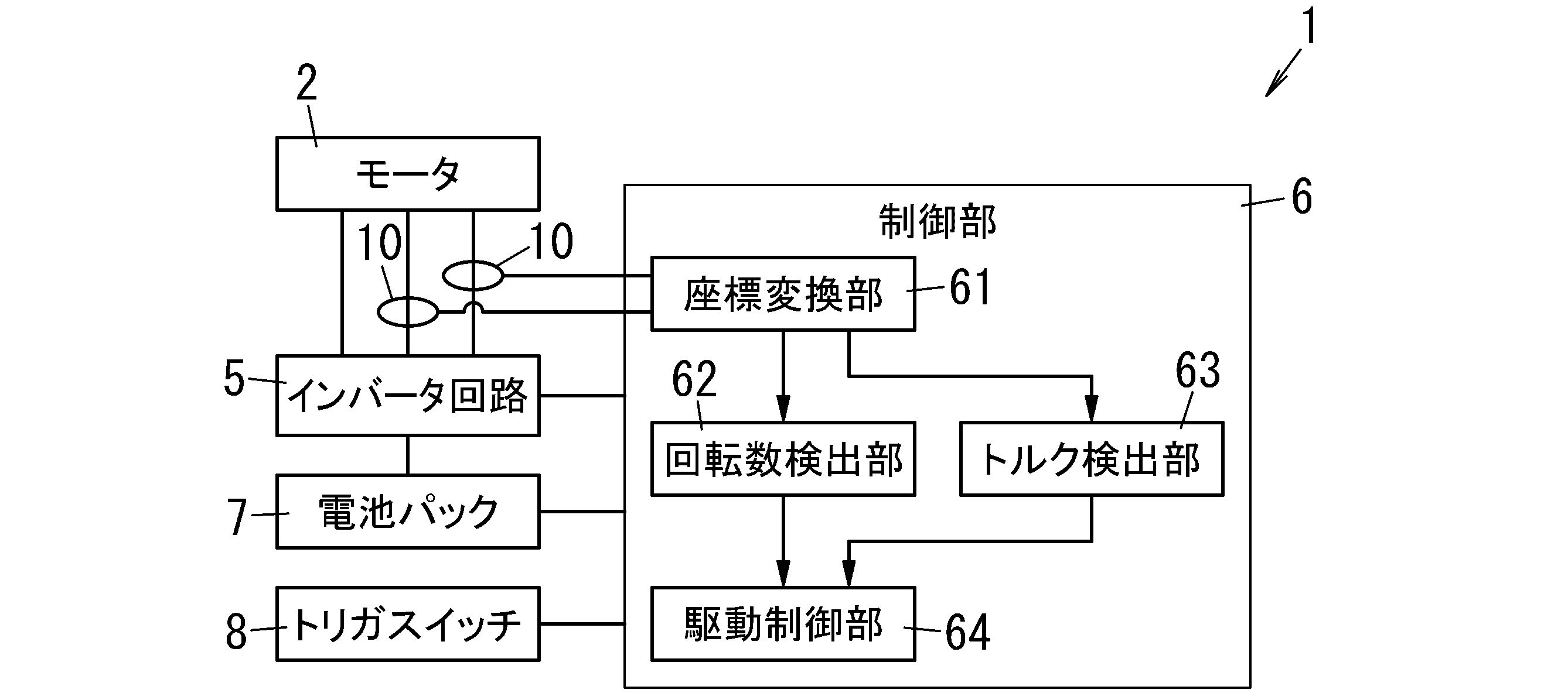
図1に示すように、電動工具1は、例えば電池パック7等の動力源からの動力(電力等)によって動作する。具体的には、電池パック7から電力が供給されたモータ2の回転軸21(図2参照)が回転し、伝達機構3(図2参照)を介して取付部4(図2参照)に回転駆動力が伝達される。この取付部4に例えばドライバビット9(図2参照)等の先端工具が取り付けられている場合、電動工具1は、作業対象となるワーク(加工対象物)に対して、締結部品(例えば、ネジ等)を取り付けることができる。すなわち、本実施形態の電動工具1は電動ドライバである。また、本実施形態の電動工具1は、先端工具にインパクトを加えることにより締結部品を締め付けるインパクトドライバではなく、ドリルドライバである。
As shown in FIG. 1, the
図1に示すように、本実施形態の電動工具1は、回転数検出部62と、トルク検出部63と、駆動制御部64とを備えている。
As shown in FIG. 1, the
本実施形態の回転数検出部62は、モータ2と先端工具との間に配置されている第1検出対象軸の回転数を検出する。ここで、「モータ2と先端工具との間に配置されている第1検出対象軸」とは、モータ2が有する回転軸21や、ドライバビット9等の先端工具の軸を含む。また、本開示でいう「回転数を検出する」とは、回転速度(角速度)及び角加速度を検出することを含む。
The rotation
本実施形態のトルク検出部63は、モータ2と先端工具との間に配置されている第2検出対象軸の負荷トルクを検出する。ここで、「モータ2と先端工具との間に配置されている第2検出対象軸」とは、モータ2が有する回転軸21や、ドライバビット9等の先端工具の軸を含む。なお、第1検出対象軸と第2検出対象軸とは、同一の軸であってもよいし、異なる軸であってもよい。本実施形態では、第1検出対象軸及び第2検出対象軸は、モータ2の回転軸21(図2参照)である。
The
駆動制御部64は、モータ2を制御する。また、本実施形態の駆動制御部64は、回転数検出部62によって検出される回転数と、トルク検出部63によって検出される負荷トルクとに基づいて、不安定挙動を検出する。本開示でいう「不安定挙動」は、モータ2の回転数と負荷トルクとのバランスが崩れた状態であるときの挙動のことをいい、負荷トルクが増大し、いわゆるキックバック等が発生し得る挙動のことをいう。ここで、「回転数と負荷トルクとのバランスが崩れた状態」とは、負荷トルクの大きさに対して回転数が低い状態を含む。更に具体的には、「不安定挙動」は、モータ2の回転数と、負荷トルクとのバランスが崩れることにより、ドライバビット9等の先端工具、出力軸31及びモータ2の回転軸21の少なくとも1つの挙動が不安定になることをいう。例えば、本実施形態の駆動制御部64は、モータ2の回転軸21の回転数r1が低下し、かつ、回転軸21の負荷トルクTq1が増大している場合等に、不安定挙動を検出する。駆動制御部64は、不安定挙動を検出した場合に、モータ2を減速又は停止させる制御(以下、「モータ停止処理」ということがある。)を行う。
The drive control unit 64 controls the
本実施形態の電動工具1では、駆動制御部64が、回転数検出部62によって検出される回転数と、トルク検出部63によって検出される負荷トルクとに基づいて不安定挙動を検出することで、不安定挙動を精度よく検出することができる。
In the
(2)電動工具の構成
以下、本実施形態に係る電動工具1の詳細な構成について、図1~図2を参照して説明する。以下の説明では、図2に示す回転軸21及び出力軸31が並んでいる方向を前後方向と規定し、出力軸31から見て取付部4側を前とし、出力軸31から見てモータ2側を後とする。また、以下の説明では、後述する胴体部12とグリップ部13とが並んでいる方向を上下方向と規定し、グリップ部13から見て胴体部12側を上とし、胴体部12から見てグリップ部13側を下とする。
(2) Configuration of Power Tool Hereinafter, a detailed configuration of the
図2に示すように、電動工具1は、ボディ11と、トリガスイッチ8とを備えている。
As shown in FIG. 2, the
ボディ11は、胴体部12と、グリップ部13と、装着部14とを有している。胴体部12の形状は、先端(前端)が開口であり、後端が有底の筒状である。胴体部12は、モータ2及び伝達機構3を収容している。グリップ部13は、胴体部12から下側に突出している。グリップ部13は、トリガスイッチ8の一部を収容している。装着部14は、電池パック7が取外し可能に装着されるように構成されている。本実施形態では、装着部14は、グリップ部13の先端部(下端部)に設けられている。言い換えれば、胴体部12と装着部14とが、グリップ部13にて連結されている。
The
本実施形態の電動工具1は、電池パック7を電源として動作する。すなわち、電池パック7は、モータ2を駆動する電流を供給する電源である。電池パック7は、電動工具1の構成要素ではない。ただし、電動工具1は、電池パック7を構成要素として備えていてもよい。電池パック7は、複数の二次電池(例えば、リチウムイオン電池)を直列接続して構成された組電池と、組電池を収容したケースとを備えている。
The
図2に示すように、トリガスイッチ8は、グリップ部13から突出している。トリガスイッチ8は、モータ2の回転を制御するための操作を受け付ける操作部である。トリガスイッチ8を引く操作により、モータ2のオンオフを切替可能である。また、トリガスイッチ8を引く操作の引込み量で、モータ2の回転速度を調整可能である。上記引込み量が大きいほど、モータ2の回転速度が速くなる。
As shown in FIG. 2, the
図1に示すように、電動工具1は、モータ2と、伝達機構3(図2参照)と、取付部4(図2参照)と、インバータ回路5と、制御部6と、複数(図1の例では2つ)の電流検出部10とを備えている。
As shown in FIG. 1, the
モータ2は、例えばブラシレスモータである。特に、本実施形態のモータ2は、同期電動機であり、より詳細には、永久磁石同期電動機(Permanent Magnet Synchronous Motor:PMSM)である。モータ2は、永久磁石を備えた回転子と、3相(U相、V相、W相)分の電機子巻線を備えた固定子とを備える。回転子は回転軸21(図2参照)を有している。
The
図2に示すように、伝達機構3は、モータ2よりも前側に配置されており、モータ2の回転軸21が機械的に接続されている。伝達機構3は、モータ2の回転駆動力(動力)を所定の減速比で減速して出力軸31に伝達する。出力軸31には、取付部4が機械的に接続されている。言い換えると、伝達機構3は、モータ2の回転駆動力を取付部4に伝達する。
As shown in FIG. 2, the
取付部4は、胴体部12の先端に配置されており、ドライバビット9等の先端工具を取り付け可能である。取付部4は、伝達機構3から伝達される回転駆動力をドライバビット9に伝達する。これにより、モータ2の回転軸21が回転すると、ドライバビット9が回転する。ドライバビット9が締結部材に当てられた状態でドライバビット9が回転することにより、締結部材を締め付ける又は緩めるといった作業が可能となる。
The mounting
なお、ドライバビット9は、取付部4に着脱可能である。本実施形態では、ドライバビット9等の先端工具は、電動工具1の構成に含まれていない。ただし、先端工具は、電動工具1の構成に含まれていてもよい。
The
図1に示すように、インバータ回路5は、電池パック7から供給される電力を、制御部6(駆動制御部64)の指令に応じた3相(U相、V相及びW相)電力に変換して、変換した3相電力をモータ2に供給する。
As shown in FIG. 1, the
2つの電流検出部10は、インバータ回路5からモータ2に供給される3相の駆動電流のうち、少なくとも2相の駆動電流を測定する。本実施形態では、2つの電流検出部10は、U相の駆動電流と、V相の駆動電流とを測定する。本実施形態の電流検出部10は、例えばシャント抵抗素子である。
The two
制御部6は、1以上のプロセッサ及びメモリを有するコンピュータシステムを含んでいる。コンピュータシステムのメモリに記録されたプログラムを、コンピュータシステムのプロセッサが実行することにより、制御部6の少なくとも一部の機能が実現される。プログラムは、メモリに記録されていてもよいし、インターネット等の電気通信回線を通して提供されてもよく、メモリカード等の非一時的記録媒体に記録されて提供されてもよい。
The
本実施形態の制御部6は、モータ電流を、トルクを発生するトルク電流i1(q軸電流)と磁束を発生させる励磁電流(d軸電流)とに分解し、それぞれの電流成分を独立に制御するベクトル制御を行う。ベクトル制御では、モータ2の回転子に設けられた永久磁石が作る磁束の回転速度と同じ速度で回転する回転座標系が考慮される。回転座標系において、永久磁石が作る磁束の方向をd軸にとり、d軸に対応する制御上の推定軸をγ軸とする。また、d軸から電気角で90度進んだ位相にq軸をとり、γ軸から電気角で90度進んだ位相に制御上の推定軸であるδ軸をとる。実軸に対応する回転座標系はd軸及びq軸を座標軸とする座標系であり、その座標軸をdq軸と呼ぶ。制御上の回転座標系はγ軸及びδ軸を座標軸とする座標系であり、その座標軸をγδ軸と呼ぶ。制御部6は、基本的に、dq軸の位相と、γδ軸の位相とが一致するようにベクトル制御を行う。より具体的には、制御部6は、dq軸の位相とγδ軸の位相との位相差が0になるようにPLL(Phase Locked Loop)制御を行う。
The
図1に示すように、本実施形態の制御部6は、座標変換部61と、回転数検出部62と、トルク検出部63と、駆動制御部64とを有している。
As shown in FIG. 1, the
座標変換部61は、2つの電流検出部10によって検出されるU相の駆動電流及びV相の駆動電流を座標変換して、γ軸電流及びδ軸電流を算出する。座標変換部61は、γ軸電流及びq軸電流の情報を回転数検出部62及びトルク検出部63に出力する。
The coordinate conversion unit 61 performs coordinate conversion of the U-phase drive current and the V-phase drive current detected by the two
回転数検出部62は、PLL制御を行うために、γ軸電流又はδ軸電流等を用いて比例積分制御等を行うことで、dq軸座標を推定する。本実施形態の回転数検出部62は、推定したdq軸座標に基づいて、モータ2の回転軸21の回転数を検出する。本実施形態の回転数検出部62は、d軸電流(励磁電流)の値に基づいて、モータ2の回転軸21の回転数r1を算出する。本実施形態の回転数検出部62は、ベクトル制御(PPL制御)に必要な励磁電流の値に基づいてモータ2の回転数r1を算出するため、電動工具1が別途エンコーダ等のセンサを有する必要がないという利点がある。なお、回転数r1の算出方法として従来から様々な方法が提案されており、回転数検出部62は、公知の何れの方法をも採用可能である。回転数検出部62は、算出した回転数r1を駆動制御部64に出力する。
The rotation
トルク検出部63は、PLL制御を行うために、γ軸電流又はδ軸電流等を用いて比例積分制御等を行うことで、dq軸座標を推定する。本実施形態のトルク検出部63は、推定したdq軸座標に基づいて、モータ2の回転軸21の負荷トルクを検出する。本実施形態のトルク検出部63は、q軸電流(トルク電流i1)の値に基づいて、モータ2の回転軸21の負荷トルクTq1を算出する。本実施形態のトルク検出部63は、ベクトル制御(PPL制御)に必要なトルク電流i1の値に基づいてモータ2の負荷トルクTq1を算出するため、電動工具1が別途トルクセンサを有する必要がないという利点がある。トルク検出部63は、算出した負荷トルクTq1を駆動制御部64に出力する。なお、トルク検出部63は、座標変換部61から入力されるトルク電流i1の値を、そのまま駆動制御部64に出力してもよい。
The
駆動制御部64は、モータ2を制御する。例えばトリガスイッチ8の引込み量等で設定されるモータ2の速度(回転速度)の目標値等に基づいて、駆動制御部64は、モータ2の速度の指令値を決定する。そして、駆動制御部64は、モータ2の速度が指令値に一致するように、U相、V相及びW相の駆動電圧の目標値(電圧指令値)を決定してインバータ回路5に出力する。
The drive control unit 64 controls the
また、本実施形態の駆動制御部64は、回転数検出部62によって検出(算出)される回転軸21の回転数r1と、トルク検出部63によって検出(算出)される回転軸21の負荷トルクTq1とに基づいて、不安定挙動を検出する。不安定挙動とは、キックバック等が発生し得る不安定な挙動をいう。ここで、駆動制御部64は、回転数検出部62によって検出される回転軸21の回転数r1と、トルク検出部63によって検出されるトルク電流i1とに基づいて、不安定挙動を検出してもよい。駆動制御部64は、不安定挙動を検出した場合、モータ2を減速又は停止させる。なお、駆動制御部64は、不安定挙動を検出しない場合、トリガスイッチ8に対するユーザの操作に基づいてモータ2を制御する。
Further, the drive control unit 64 of the present embodiment has a rotation speed r1 of the
(3)動作
次に、駆動制御部64が不安定挙動を検出する動作(モータ制御方法)について図3及び図4を参照して説明する。
(3) Operation Next, an operation (motor control method) in which the drive control unit 64 detects unstable behavior will be described with reference to FIGS. 3 and 4.
図3は、トルク電流i1(負荷トルクTq1)及び回転数r1と時間との関係を示すグラフである。図3中のグラフG1は、トルク電流i1と時間との関係を示すグラフであり、グラフG2は、トルク電流i1の増加度合いD1と時間との関係を示すグラフである。また、図3中のグラフG3は、回転数r1と時間との関係を示すグラフであり、グラフG4は、回転数r1の減少度合いD2と時間との関係を示すグラフである。 FIG. 3 is a graph showing the relationship between the torque current i1 (load torque Tq1) and the rotation speed r1 and time. The graph G1 in FIG. 3 is a graph showing the relationship between the torque current i1 and time, and the graph G2 is a graph showing the relationship between the degree of increase D1 of the torque current i1 and time. Further, the graph G3 in FIG. 3 is a graph showing the relationship between the rotation speed r1 and time, and the graph G4 is a graph showing the relationship between the decrease degree D2 of the rotation speed r1 and time.
本実施形態の駆動制御部64は、トルク電流i1の増加度合いD1と、回転数r1の減少度合いD2とに基づいて不安定挙動を検出する。増加度合いD1は、第1所定期間T1の開始時のトルク電流i1を基準としたときの第1所定期間T1の終了時のトルク電流i1の増加度合いである。言い換えると、増加度合いD1は、第1所定期間T1の終了時のトルク電流i1から第1所定期間T1の開始時のトルク電流i1を差し引いた値である。第1所定期間T1は、増加度合いD1を算出するタイミングを終点とする所定の長さの期間である。本実施形態の駆動制御部64は、増加度合いD1を算出するタイミングごとに、増加度合いD1を算出するタイミングを第1所定期間T1の終点とした増加度合いD1を算出する。図3中に記載の第1所定期間T1は、駆動制御部64が不安定挙動を検出する動作を開始した後の最初の第1所定期間T1である。つまり、図3中に記載の第1所定期間T1は、タイミングt2における第1所定期間T1である。第1所定期間T1は、例えば200msである。 The drive control unit 64 of the present embodiment detects unstable behavior based on the degree of increase D1 of the torque current i1 and the degree of decrease D2 of the rotation speed r1. The degree of increase D1 is the degree of increase of the torque current i1 at the end of the first predetermined period T1 when the torque current i1 at the start of the first predetermined period T1 is used as a reference. In other words, the degree of increase D1 is a value obtained by subtracting the torque current i1 at the start of the first predetermined period T1 from the torque current i1 at the end of the first predetermined period T1. The first predetermined period T1 is a period of a predetermined length whose end point is the timing for calculating the degree of increase D1. The drive control unit 64 of the present embodiment calculates the degree of increase D1 with the timing of calculating the degree of increase D1 as the end point of the first predetermined period T1 for each timing of calculating the degree of increase D1. The first predetermined period T1 described in FIG. 3 is the first predetermined period T1 after the drive control unit 64 starts the operation of detecting the unstable behavior. That is, the first predetermined period T1 described in FIG. 3 is the first predetermined period T1 at the timing t2. The first predetermined period T1 is, for example, 200 ms.
減少度合いD2は、第2所定期間T2の開始時の回転数r1を基準としたときの第2所定期間T2の終了時の回転数r1の減少度合いである。言い換えると、第2所定期間T2の終了時の回転数r1から第2所定期間T2の開始時の回転数r1を差し引いた値である。また、減少度合いD2は、回転速度(角速度)又は角加速度の減少度合いであってもよい。本開示では、第2所定期間T2の終了時の回転数r1から第2所定期間T2の開始時の回転数r1を差し引いた値が小さい程(マイナスの値が大きい程)、減少度合いD2が大きいとする。第2所定期間T2は、減少度合いD2を算出するタイミングを終点とする所定の長さの期間である。本実施形態の駆動制御部64は、減少度合いD2を算出するタイミング毎に、減少度合いD2を算出するタイミングを第2所定期間T2の終点とした減少度合いD2を算出する。図3中に記載の第2所定期間T2は、駆動制御部64が不安定挙動を検出する動作を開始した後の最初の第2所定期間T2である。つまり、図3中に記載の第2所定期間T2は、タイミングt2における第2所定期間T2である。第2所定期間T2は、例えば200msであり、本実施形態では第1所定期間T1と同じ長さである。 The degree of decrease D2 is the degree of decrease of the rotation speed r1 at the end of the second predetermined period T2 when the rotation speed r1 at the start of the second predetermined period T2 is used as a reference. In other words, it is a value obtained by subtracting the rotation speed r1 at the start of the second predetermined period T2 from the rotation speed r1 at the end of the second predetermined period T2. Further, the degree of decrease D2 may be the degree of decrease in the rotational speed (angular velocity) or the angular acceleration. In the present disclosure, the smaller the value obtained by subtracting the rotation speed r1 at the start of the second predetermined period T2 from the rotation speed r1 at the end of the second predetermined period T2 (the larger the negative value), the larger the degree of decrease D2. And. The second predetermined period T2 is a period of a predetermined length whose end point is the timing for calculating the degree of decrease D2. The drive control unit 64 of the present embodiment calculates the decrease degree D2 with the timing of calculating the decrease degree D2 as the end point of the second predetermined period T2 at each timing of calculating the decrease degree D2. The second predetermined period T2 described in FIG. 3 is the first second predetermined period T2 after the drive control unit 64 starts the operation of detecting the unstable behavior. That is, the second predetermined period T2 described in FIG. 3 is the second predetermined period T2 at the timing t2. The second predetermined period T2 is, for example, 200 ms, which is the same length as the first predetermined period T1 in the present embodiment.
駆動制御部64は、トルク電流i1の増加度合いD1が増加閾値Th1以上であり、かつ、回転数r1の減少度合いD2が減少閾値Th2以上である場合に、不安定挙動を検出する。トルク電流i1の増加度合いD1の増加閾値Th1は、20A~35A程度であることが好ましく、例えば25Aである。また、回転数r1の減少度合いD2の減少閾値Th2は、例えば0である。すなわち、本実施形態の駆動制御部64は、トルク電流i1の増加度合いD1が25A以上であり、かつ、回転数r1の減少度合いD2が0以上(第2所定期間T2の終了時の回転数r1から第2所定期間T2の開始時の回転数r1を差し引いた値が0以下)である場合に、不安定挙動を検出する。図3の例では、タイミングt3において、トルク電流i1の増加度合いD1が増加閾値Th1以上であり、かつ、回転数r1の減少度合いD2が減少閾値Th2以上である。したがって、駆動制御部64は、タイミングt3において不安定挙動を検出する。 The drive control unit 64 detects unstable behavior when the increase degree D1 of the torque current i1 is the increase threshold value Th1 or more and the decrease degree D2 of the rotation speed r1 is the decrease threshold value Th2 or more. The increase threshold Th1 of the degree of increase D1 of the torque current i1 is preferably about 20A to 35A, and is, for example, 25A. Further, the decrease threshold value Th2 of the decrease degree D2 of the rotation speed r1 is, for example, 0. That is, in the drive control unit 64 of the present embodiment, the degree of increase D1 of the torque current i1 is 25 A or more, and the degree of decrease D2 of the rotation speed r1 is 0 or more (the rotation speed r1 at the end of the second predetermined period T2). The unstable behavior is detected when the value obtained by subtracting the rotation speed r1 at the start of the second predetermined period T2 is 0 or less). In the example of FIG. 3, at the timing t3, the increase degree D1 of the torque current i1 is the increase threshold value Th1 or more, and the decrease degree D2 of the rotation speed r1 is the decrease threshold value Th2 or more. Therefore, the drive control unit 64 detects unstable behavior at the timing t3.
また、本実施形態の駆動制御部64は、不安定挙動を検出したタイミングt3から所定時間経過したタイミングで、モータ停止処理を行う。言い換えると、駆動制御部64は、不安定挙動を検出したタイミングt3から所定時間遅らせてからモータ停止処理を行う。所定時間中は不安定挙動を継続させることで、ユーザに不安定挙動が発生していることを認知させることができる。ここで、駆動制御部64が、不安定挙動を検出してからモータ停止処理を行うまでの所定時間は、10ms~90ms程度であることが好ましく、例えば10msである。 Further, the drive control unit 64 of the present embodiment performs the motor stop processing at the timing when a predetermined time elapses from the timing t3 when the unstable behavior is detected. In other words, the drive control unit 64 performs the motor stop process after delaying by a predetermined time from the timing t3 when the unstable behavior is detected. By continuing the unstable behavior for a predetermined time, the user can be made aware that the unstable behavior is occurring. Here, the predetermined time from the detection of the unstable behavior by the drive control unit 64 to the motor stop processing is preferably about 10 ms to 90 ms, for example, 10 ms.
また、駆動制御部64は、トリガスイッチ8が操作されたタイミングt0からモータ2が始動するタイミングt1までの期間において、不安定挙動を検出する処理を行わない。タイミングt0からタイミングt1までの期間は、モータ2に突入電流が流れることがあるため、駆動制御部64は、モータ2が始動するタイミングt1から不安定挙動を検出する処理を行う。これにより、突入電流が原因となる不安定挙動の誤検出を低減させることができる。
Further, the drive control unit 64 does not perform a process of detecting unstable behavior during the period from the timing t0 when the
また、駆動制御部64は、モータ2が始動するタイミングt1(不安定挙動の検出を開始するタイミング)から第1所定期間T1が経過するまでの間においては、トルク電流i1の絶対値が閾値Th3以上である場合に、不安定挙動を検出する。そして、モータ2が始動するタイミングt1から第1所定期間T1が経過した後においては、上述したように、駆動制御部64は、トルク電流i1の増加度合いD1と回転数r1の減少度合いD2とに基づいて不安定挙動を検出する。不安定挙動の検出を開始するタイミングt1から第1所定期間T1が経過するまでの間は、トルク電流i1の増加度合いD1を検出することができないためである。すなわち、タイミングt1から第1所定期間T1が経過するまでの間は、トルク電流i1の絶対値に基づいて不安定挙動を検出することで、トルク電流i1の増加度合いD1を検出することができない期間においても不安定挙動を検出することができる。
Further, in the drive control unit 64, the absolute value of the torque current i1 is the threshold value Th3 from the timing t1 when the
ここで、例えばトルク電流i1の絶対値の閾値Th3は、40A~70A程度であることが好ましく、例えば50Aである。閾値Th3を増加閾値Th1より大きい値としている理由は、モータ2の始動時にはモータ2の回転子(回転軸21)を回しだすのに大きなトルク電流i1が必要となるからである。閾値Th3を増加閾値Th1より大きい値とすることで、モータ2の始動時のトルク電流i1が原因となる不安定挙動の誤検出を低減することができる。
Here, for example, the threshold value Th3 of the absolute value of the torque current i1 is preferably about 40A to 70A, and is, for example, 50A. The reason why the threshold value Th3 is set to a value larger than the increase threshold value Th1 is that a large torque current i1 is required to start rotating the rotor (rotating shaft 21) of the
次に、駆動制御部64が不安定挙動を検出する動作について図4を参照して説明する。駆動制御部64は、トリガスイッチ8に対するユーザの操作を検知すると、不安定挙動を検出するための処理を開始する。また、駆動制御部64は、不安定挙動を検出するための処理を行っている最中にトリガスイッチ8に対するユーザの操作が検知されなくなった場合に、不安定挙動を検出するための処理を終了する。
Next, the operation of the drive control unit 64 to detect the unstable behavior will be described with reference to FIG. When the drive control unit 64 detects the user's operation on the
駆動制御部64は、不安定挙動を検出するための処理を開始すると、モータ2の回転数r1を確認する(S1)。モータ2の回転数r1が0であり、モータ2が始動していない場合(S2でNo)、処理はステップS1に戻る。一方、モータ2の回転数r1が0でなく、モータ2が始動している場合(S2でYes)、駆動制御部64は、モータ2の始動から第1所定期間T1が経過したか否かを確認する(S3)。モータ2の始動から第1所定期間T1が経過している場合(S3でYes)、駆動制御部64は、トルク電流i1(負荷トルクTq1)の増加度合いD1と、回転数r1の減少度合いD2とを算出する(S4,S5)。増加度合いD1が増加閾値Th1以上であり、かつ、減少度合いD2が減少閾値Th2以上である場合(S6でYes)、駆動制御部64は、不安定挙動を検出する。不安定挙動を検出した駆動制御部64は、不安定挙動を検出してから所定時間が経過するまで待機し(S7のNo)、所定時間が経過すると(S7でYes)、駆動制御部64は、モータ停止処理を行う(S8)。駆動制御部64は、モータ停止処理を行うと、不安定挙動を検出するための処理を終了する。
When the drive control unit 64 starts the process for detecting the unstable behavior, the drive control unit 64 confirms the rotation speed r1 of the motor 2 (S1). When the rotation speed r1 of the
一方、ステップS6の処理において、増加度合いD1が増加閾値Th1より小さい場合(S6でNo)、又は、減少度合いD2が減少閾値Th2より小さい場合(S6でNo)、処理はステップS4に戻る。また、ステップS6の処理において、増加度合いD1が増加閾値Th1より小さく、かつ、減少度合いD2が減少閾値Th2より小さい場合(S6でNo)も、処理はステップS4に戻る。 On the other hand, in the process of step S6, when the increase degree D1 is smaller than the increase threshold Th1 (No in S6) or the decrease degree D2 is smaller than the decrease threshold Th2 (No in S6), the process returns to step S4. Further, in the process of step S6, when the increase degree D1 is smaller than the increase threshold value Th1 and the decrease degree D2 is smaller than the decrease threshold value Th2 (No in S6), the process returns to step S4.
ステップS3の処理において、モータ2の始動から第1所定期間T1が経過していない場合(S3でNo)、駆動制御部64は、トルク電流i1(負荷トルクTq1)を確認する(S9)。トルク電流i1が閾値Th3より小さい場合(S10でNo)、処理はステップS3に戻る。一方、トルク電流i1が閾値Th3以上である場合(S10でYes)、駆動制御部64は、不安定挙動を検出する。不安定挙動を検出した駆動制御部64は、不安定挙動を検出してから所定時間が経過するまで待機し(S7のNo)、所定時間が経過すると(S7でYes)、駆動制御部64は、モータ停止処理を行う(S8)。駆動制御部64は、モータ停止処理を行うと、不安定挙動を検出するための処理を終了する。 In the process of step S3, when the first predetermined period T1 has not elapsed from the start of the motor 2 (No in S3), the drive control unit 64 confirms the torque current i1 (load torque Tq1) (S9). When the torque current i1 is smaller than the threshold value Th3 (No in S10), the process returns to step S3. On the other hand, when the torque current i1 is equal to or higher than the threshold value Th3 (Yes in S10), the drive control unit 64 detects unstable behavior. The drive control unit 64 that has detected the unstable behavior waits until a predetermined time elapses after detecting the unstable behavior (No in S7), and when the predetermined time elapses (Yes in S7), the drive control unit 64 moves. , Motor stop processing is performed (S8). When the motor stop process is performed, the drive control unit 64 ends the process for detecting unstable behavior.
(4)変形例
以下、上記実施形態の変形例を列挙する。以下の説明する変形例は、上記実施形態と適宜組み合わせて適用可能である。
(4) Modification example The following is a list of modification examples of the above embodiment. The modifications described below can be applied in combination with the above embodiments as appropriate.
上記実施形態に係る電動工具1と同等の機能は、モータ制御方法、(コンピュータ)プログラム、又はプログラムを記録した非一時的記録媒体等で具現化されてもよい。一態様に係るモータ制御方法は、モータ2と、先端工具が取り付けられる取付部4と、モータ2の動力を取付部4に伝達する伝達機構3とを備える電動工具1におけるモータ2を制御するモータ制御方法である。モータ制御方法は、回転数検出ステップと、トルク検出ステップと、不安定挙動検出ステップと、制御ステップとを有する。回転数検出ステップでは、モータ2と先端工具との間に配置されている第1検出対象軸(回転軸21)の回転数r1を検出する。トルク検出ステップでは、モータ2と先端工具との間に配置されている第2検出対象軸(回転軸21)の負荷トルクTq1を検出する。不安定挙動検出ステップでは、回転数検出ステップにおいて検出する回転数r1と、トルク検出ステップにおいて検出する負荷トルクTq1とに基づいて先端工具、第1検出対象軸及び第2検出対象軸のうちの少なくとも1つの不安定挙動を検出する。制御ステップでは、不安定挙動ステップにおいて不安定挙動を検出した場合に、モータ2を減速又は停止させる。一態様に係るプログラムは、上記のモータ制御方法を、1以上のプロセッサに実行させるためのプログラムである。
The function equivalent to that of the
電動工具1は、制御部6等にコンピュータシステムを含んでいる。コンピュータシステムは、ハードウェアとしてのプロセッサ及びメモリを主構成とする。コンピュータシステムのメモリに記録されたプログラムをプロセッサが実行することによって、本開示における制御部6としての機能が実現される。プログラムは、コンピュータシステムのメモリに予め記録されてもよく、電気通信回線を通じて提供されてもよく、コンピュータシステムで読み取り可能なメモリカード、光学ディスク、ハードディスクドライブ等の非一時的記録媒体に記録されて提供されてもよい。コンピュータシステムのプロセッサは、半導体集積回路(IC)又は大規模集積回路(LSI)を含む1ないし複数の電子回路で構成される。ここでいうIC又はLSI等の集積回路は、集積の度合いによって呼び方が異なる。IC又はLSI等の集積回路は、システムLSI、VLSI(Very Large Scale Integration)、又はULSI(Ultra Large Scale Integration)と呼ばれる集積回路を含む。さらに、LSIの製造後にプログラムされる、FPGA(Field-Programmable Gate Array)、又はLSI内部の接合関係の再構成若しくはLSI内部の回路区画の再構成が可能な論理デバイスも、プロセッサとして採用することができる。複数の電子回路は、1つのチップに集約されていてもよいし、複数のチップに分散して設けられていてもよい。複数のチップは、1つの装置に集約されていてもよいし、複数の装置に分散して設けられていてもよい。ここでいうコンピュータシステムは、1以上のプロセッサ及び1以上のメモリを有するマイクロコントローラを含む。したがって、マイクロコントローラについても、半導体集積回路又は大規模集積回路を含む1ないし複数の電子回路で構成される。
The
電動工具1は、不安定挙動を検出した場合に、不安定挙動を検出したことをユーザに通知するための表示部や、スピーカ等を備えていてもよい。表示部には、液晶ディスプレイやLED等の発光部が含まれる。また、電動工具1は、不安定挙動を検出したことを、振動や、風圧でユーザに通知してもよい。
When the
電流検出部10は、ホール素子電流センサ等であってもよい。
The
回転数検出部62は、ホール素子電流センサ、光電式エンコーダ又は磁気式エンコーダを用いて、モータ2の回転軸21の回転数r1を検出してもよい。また、回転数検出部62は、モータ2の回転軸21の回転数r1ではなく、出力軸31、取付部4又はドライバビット9等の先端工具の回転数を検出してもよい。
The rotation
トルク検出部63は、モータ2の回転軸21の負荷トルクTq1を、トルクセンサを用いて検出してもよい。ここで、トルクセンサは、例えば、ねじり歪みの検出が可能な磁歪式歪センサである。磁歪式歪センサは、回転軸21にトルクが加わることにより発生する歪みに応じた透磁率の変化を検出し、歪みに比例した電圧信号を出力するセンサである。また、トルク検出部63は、モータ2の回転軸21の負荷トルクTq1ではなく、出力軸31又はドライバビット9等の先端工具の負荷トルクを検出してもよい。
The
第1所定期間T1の長さと第2所定期間T2の長さとが異なっていてもよい。なお、第1所定期間T1及び第2所定期間T2の長さは、50ms~500ms程度であることが好ましい。 The length of the first predetermined period T1 and the length of the second predetermined period T2 may be different. The length of the first predetermined period T1 and the second predetermined period T2 is preferably about 50 ms to 500 ms.
(まとめ)
以上説明したように、第1の態様に係る電動工具(1)は、モータ(2)と、取付部(4)と、伝達機構(3)と、駆動制御部(64)と、回転数検出部(62)と、トルク検出部(63)と、を備える。取付部(4)には、先端工具(ドライバビット9)が取り付けられる。伝達機構(3)は、モータ(2)の動力を取付部(4)に伝達する。駆動制御部(64)は、モータ(2)を制御する。回転数検出部(62)は、モータ(2)と先端工具(ドライバビット9)との間に配置されている第1検出対象軸(回転軸21)の回転数(r1)を検出する。トルク検出部(63)は、モータ(2)と先端工具(ドライバビット9)との間に配置されている第2検出対象軸(回転軸21)の負荷トルク(Tq1)を検出する。駆動制御部(64)は、回転数検出部(62)によって検出される回転数(r1)と、トルク検出部(63)によって検出される負荷トルク(Tq1)とに基づいて、先端工具(ドライバビット9)、第1検出対象軸(回転軸21)及び第2検出対象軸(回転軸21)のうちの少なくとも1つの不安定挙動を検出し、不安定挙動を検出した場合に、モータ(2)を減速又は停止させる。
(summary)
As described above, the power tool (1) according to the first aspect includes the motor (2), the mounting portion (4), the transmission mechanism (3), the drive control unit (64), and the rotation speed detection. A unit (62) and a torque detection unit (63) are provided. A tip tool (driver bit 9) is attached to the attachment portion (4). The transmission mechanism (3) transmits the power of the motor (2) to the mounting portion (4). The drive control unit (64) controls the motor (2). The rotation speed detection unit (62) detects the rotation speed (r1) of the first detection target shaft (rotational shaft 21) arranged between the motor (2) and the tip tool (driver bit 9). The torque detection unit (63) detects the load torque (Tq1) of the second detection target shaft (rotary shaft 21) arranged between the motor (2) and the tip tool (driver bit 9). The drive control unit (64) is a tip tool (driver) based on the rotation speed (r1) detected by the rotation speed detection unit (62) and the load torque (Tq1) detected by the torque detection unit (63). Bit 9), the unstable behavior of at least one of the first detection target shaft (rotational shaft 21) and the second detection target shaft (rotational shaft 21) is detected, and when the unstable behavior is detected, the motor (2) ) Is decelerated or stopped.
この態様によれば、回転数検出部(62)によって検出される回転数(r1)及びトルク検出部(63)によって検出される負荷トルク(Tq1)に基づくことで不安定挙動を精度よく検出することができる。 According to this aspect, unstable behavior is accurately detected based on the rotation speed (r1) detected by the rotation speed detection unit (62) and the load torque (Tq1) detected by the torque detection unit (63). be able to.
第2の態様に係る電動工具(1)では、第1の態様において、駆動制御部(64)は、負荷トルク(Tq1)の増加度合い(D1)と、回転数(r1)の減少度合い(D2)とに基づいて不安定挙動を検出する。 In the power tool (1) according to the second aspect, in the first aspect, the drive control unit (64) has an increase degree (D1) of the load torque (Tq1) and a decrease degree (D2) of the rotation speed (r1). ) And the unstable behavior is detected.
この態様によれば、負荷トルク(Tq1)の増加度合い(D1)及び回転数(r1)の減少度合い(D2)に基づくことで、単純に負荷トルク(Tq1)が大きいだけでは不安定挙動を検出しないことが可能となる。 According to this aspect, unstable behavior is detected only when the load torque (Tq1) is simply large, based on the degree of increase (D1) of the load torque (Tq1) and the degree of decrease (D2) of the rotation speed (r1). It is possible not to.
第3の態様に係る電動工具(1)では、第2の態様において、駆動制御部(64)は、負荷トルク(Tq1)の増加度合い(D1)が増加閾値(Th1)以上であり、かつ、回転数(r1)の減少度合い(D2)が減少閾値(Th2)以上である場合に不安定挙動を検出する。増加度合い(D1)は、第1所定期間(T1)の開始時の負荷トルク(Tq1)を基準としたときの第1所定期間(T1)の終了時の負荷トルク(Tq1)の増加度合いである。減少度合い(D2)は、第2所定期間(T2)の開始時の回転数(r1)を基準としたときの第2所定期間(T2)の終了時の回転数(r1)の減少度合いである。 In the power tool (1) according to the third aspect, in the second aspect, the drive control unit (64) has an increase degree (D1) of the load torque (Tq1) equal to or more than an increase threshold value (Th1). Unstable behavior is detected when the degree of decrease (D2) of the rotation speed (r1) is equal to or greater than the decrease threshold value (Th2). The degree of increase (D1) is the degree of increase in the load torque (Tq1) at the end of the first predetermined period (T1) when the load torque (Tq1) at the start of the first predetermined period (T1) is used as a reference. .. The degree of decrease (D2) is the degree of decrease in the rotation speed (r1) at the end of the second predetermined period (T2) based on the rotation speed (r1) at the start of the second predetermined period (T2). ..
この態様によれば、簡単な演算で不安定挙動を検出することができる。 According to this aspect, unstable behavior can be detected by a simple calculation.
第4の態様に係る電動工具(1)では、第3の態様において、第1所定期間(T1)と第2所定期間(T2)とは、同じ長さである。 In the power tool (1) according to the fourth aspect, in the third aspect, the first predetermined period (T1) and the second predetermined period (T2) have the same length.
この態様によれば、第1所定期間(T1)と第2所定期間(T2)とが同じ長さであるため、同じ長さの期間における負荷トルク(Tq1)の増加度合い(D1)及び回転数(r1)の減少度合い(D2)を確認することができる。また、第1所定期間(T1)の開始タイミングと第2所定期間(T2)の開始タイミングとをそろえた場合、負荷トルク(Tq1)と回転数(r1)の測定タイミングを揃えることができる。 According to this aspect, since the first predetermined period (T1) and the second predetermined period (T2) have the same length, the degree of increase (D1) and the rotation speed of the load torque (Tq1) in the same length period. The degree of decrease (D2) in (r1) can be confirmed. Further, when the start timing of the first predetermined period (T1) and the start timing of the second predetermined period (T2) are aligned, the measurement timings of the load torque (Tq1) and the rotation speed (r1) can be aligned.
第5の態様に係る電動工具(1)では、第3又は第4の態様において、駆動制御部(64)は、モータ(2)の始動時から第1所定期間(T1)が経過するまでの間において、負荷トルク(Tq1)が閾値(Th3)以上である場合に、不安定挙動を検出する。駆動制御部(64)は、モータ(2)の始動時から第1所定期間(T1)が経過した後において、負荷トルク(Tq1)の増加度合いと、回転数(r1)の減少度合いとに基づいて、不安定挙動を検出する。 In the power tool (1) according to the fifth aspect, in the third or fourth aspect, the drive control unit (64) has the drive control unit (64) from the start of the motor (2) until the first predetermined period (T1) elapses. In the meantime, when the load torque (Tq1) is equal to or higher than the threshold value (Th3), unstable behavior is detected. The drive control unit (64) is based on the degree of increase in the load torque (Tq1) and the degree of decrease in the rotation speed (r1) after the first predetermined period (T1) has elapsed from the start of the motor (2). And detect unstable behavior.
この態様によれば、負荷トルク(Tq1)の増加度合いを検出することができないモータ(2)の始動時であっても、不安定挙動を検出することができる。 According to this aspect, unstable behavior can be detected even at the start of the motor (2), which cannot detect the degree of increase in the load torque (Tq1).
第6の態様に係る電動工具(1)では、第1から第5のいずれかの態様において、駆動制御部(64)は、不安定挙動を検出した場合に、不安定挙動を検出したタイミングから所定時間が経過したタイミングで、モータ(2)を減速又は停止させる。 In the power tool (1) according to the sixth aspect, in any one of the first to fifth aspects, when the drive control unit (64) detects the unstable behavior, from the timing when the unstable behavior is detected. The motor (2) is decelerated or stopped at the timing when the predetermined time has elapsed.
この態様によれば、所定時間は不安定挙動が続くため、ユーザに不安定挙動が起こっていることを知らせることができる。 According to this aspect, since the unstable behavior continues for a predetermined time, it is possible to inform the user that the unstable behavior is occurring.
第7の態様に係る電動工具(1)は、第1から第6のいずれかの態様において、電流検出部(10)を更に備える。電流検出部(10)は、モータ(2)に流れる駆動電流を検出する。モータ(2)はブラシレスモータである。回転数検出部(62)は、駆動電流の値に基づいて算出される励磁電流の値に基づいて回転数(r1)の算出を行う。トルク検出部(63)は、駆動電流の値に基づいて算出されるトルク電流(i1)の値に基づいて負荷トルク(Tq1)の算出を行う。 The power tool (1) according to the seventh aspect further includes a current detecting unit (10) in any one of the first to sixth aspects. The current detection unit (10) detects the drive current flowing through the motor (2). The motor (2) is a brushless motor. The rotation speed detection unit (62) calculates the rotation speed (r1) based on the value of the exciting current calculated based on the value of the drive current. The torque detection unit (63) calculates the load torque (Tq1) based on the value of the torque current (i1) calculated based on the value of the drive current.
この態様によれば、駆動電流に基づいて算出された励磁電流及びトルク電流(i1)を用いて、回転数(r1)及び負荷トルク(Tq1)を算出するため、回転数(r1)及び負荷トルク(Tq1)の検出タイミングが一致する。同タイミングで測定された回転数(r1)及び負荷トルク(Tq1)に基づいて不安定挙動を検出するため、より正確に不安定挙動を検出することができる。 According to this aspect, the rotation speed (r1) and the load torque are calculated in order to calculate the rotation speed (r1) and the load torque (Tq1) by using the excitation current and the torque current (i1) calculated based on the drive current. The detection timings of (Tq1) match. Since the unstable behavior is detected based on the rotation speed (r1) and the load torque (Tq1) measured at the same timing, the unstable behavior can be detected more accurately.
第8の態様に係る電動工具(1)では、第1から第7のいずれかの態様において、駆動制御部(64)は、モータ(2)が始動するまでは、不安定挙動を検出しない。 In the power tool (1) according to the eighth aspect, in any one of the first to seventh aspects, the drive control unit (64) does not detect unstable behavior until the motor (2) is started.
この態様によれば、モータ(2)を始動させるために大きな負荷トルク(Tq1)が必要となる期間において、不安定挙動の誤検出を低減することができる。 According to this aspect, it is possible to reduce erroneous detection of unstable behavior during a period in which a large load torque (Tq1) is required to start the motor (2).
第1の態様以外の構成については、電動工具(1)に必須の構成ではなく、適宜省略可能である。 Configurations other than the first aspect are not essential configurations for the power tool (1) and can be omitted as appropriate.
第9の態様に係るモータ制御方法は、モータ(2)と、先端工具(ドライバビット9)が取り付けられる取付部(4)と、モータ(2)の動力を取付部(4)に伝達する伝達機構(3)とを備える電動工具(1)におけるモータ(2)を制御するモータ制御方法である。モータ制御方法は、回転数検出ステップと、トルク検出ステップと、不安定挙動検出ステップと、制御ステップとを有する。回転数検出ステップでは、モータ(2)と先端工具(ドライバビット9)との間に配置されている第1検出対象軸(回転軸21)の回転数(r1)を検出する。トルク検出ステップでは、モータ(2)と先端工具(ドライバビット9)との間に配置されている第2検出対象軸(回転軸21)の負荷トルク(Tq1)を検出する。不安定挙動検出ステップでは、回転数検出ステップにおいて検出する回転数(r1)と、トルク検出ステップにおいて検出する負荷トルク(Tq1)とに基づいて先端工具(ドライバビット9)、第1検出対象軸(回転軸21)及び第2検出対象軸(回転軸21)のうちの少なくとも1つの不安定挙動を検出する。制御ステップでは、不安定挙動検出ステップにおいて不安定挙動を検出した場合に、モータ(2)を減速又は停止させる。 The motor control method according to the ninth aspect is the transmission of the motor (2), the mounting portion (4) to which the tip tool (driver bit 9) is mounted, and the power of the motor (2) to be transmitted to the mounting portion (4). This is a motor control method for controlling a motor (2) in a power tool (1) including a mechanism (3). The motor control method includes a rotation speed detection step, a torque detection step, an unstable behavior detection step, and a control step. In the rotation speed detection step, the rotation speed (r1) of the first detection target shaft (rotational shaft 21) arranged between the motor (2) and the tip tool (driver bit 9) is detected. In the torque detection step, the load torque (Tq1) of the second detection target shaft (rotary shaft 21) arranged between the motor (2) and the tip tool (driver bit 9) is detected. In the unstable behavior detection step, the tip tool (driver bit 9) and the first detection target axis (driver bit 9) are based on the rotation speed (r1) detected in the rotation speed detection step and the load torque (Tq1) detected in the torque detection step. The unstable behavior of at least one of the rotating shaft 21) and the second detection target shaft (rotating shaft 21) is detected. In the control step, when the unstable behavior is detected in the unstable behavior detection step, the motor (2) is decelerated or stopped.
この態様によれば、回転数検出ステップにおいて検出する回転数(r1)及びトルク検出ステップにおいて検出する負荷トルク(Tq1)に基づくことで、不安定挙動を精度よく検出することができる。 According to this aspect, unstable behavior can be accurately detected based on the rotation speed (r1) detected in the rotation speed detection step and the load torque (Tq1) detected in the torque detection step.
第10の態様に係るプログラムは、第9の態様に係るモータ制御方法を、1以上のプロセッサに実行させるためのプログラムである。 The program according to the tenth aspect is a program for causing one or more processors to execute the motor control method according to the ninth aspect.
この態様によれば、回転数検出ステップにおいて検出する回転数(r1)及びトルク検出ステップにおいて検出する負荷トルク(Tq1)に基づくことで、不安定挙動を精度よく検出することができる。 According to this aspect, unstable behavior can be accurately detected based on the rotation speed (r1) detected in the rotation speed detection step and the load torque (Tq1) detected in the torque detection step.
1 電動工具
2 モータ
21 回転軸(第1検出対象軸、第2検出対象軸)
3 伝達機構
4 取付部
62 回転数検出部
63 トルク検出部
64 駆動制御部
9 ドライバビット(先端工具)
10 電流検出部
D1 増加度合い
D2 減少度合い
i1 トルク電流
r1 回転数
T1 第1所定期間
T2 第2所定期間
Th1 増加閾値
Th2 減少閾値
Th3 閾値
Tq1 負荷トルク
1
3
10 Current detector D1 Increase degree D2 Decrease degree i1 Torque current r1 Rotation speed T1 First predetermined period T2 Second predetermined period Th1 Increase threshold Th2 Decrease threshold Th3 Threshold Tq1 Load torque
Claims (10)
先端工具が取り付けられる取付部と、
前記モータの動力を前記取付部に伝達する伝達機構と、
前記モータを制御する駆動制御部と、
前記モータと前記先端工具との間に配置されている第1検出対象軸の回転数を検出する回転数検出部と、
前記モータと前記先端工具との間に配置されている第2検出対象軸の負荷トルクを検出するトルク検出部と、
を備え、
前記駆動制御部は、前記回転数検出部によって検出される前記回転数と、前記トルク検出部によって検出される前記負荷トルクとに基づいて、前記先端工具、前記第1検出対象軸及び前記第2検出対象軸のうちの少なくとも1つの不安定挙動を検出し、前記不安定挙動を検出した場合に、前記モータを減速又は停止させる、
電動工具。 With the motor
The mounting part where the tip tool is mounted and
A transmission mechanism that transmits the power of the motor to the mounting portion,
The drive control unit that controls the motor and
A rotation speed detection unit that detects the rotation speed of the first detection target shaft arranged between the motor and the tip tool, and
A torque detection unit that detects the load torque of the second detection target shaft arranged between the motor and the tip tool, and
Equipped with
The drive control unit has the tip tool, the first detection target shaft, and the second detection target shaft based on the rotation speed detected by the rotation speed detection unit and the load torque detected by the torque detection unit. An unstable behavior of at least one of the detection target axes is detected, and when the unstable behavior is detected, the motor is decelerated or stopped.
Electric tool.
請求項1に記載の電動工具。 The drive control unit detects the unstable behavior based on the degree of increase in the load torque and the degree of decrease in the rotation speed.
The power tool according to claim 1.
請求項2に記載の電動工具。 In the drive control unit, the degree of increase of the load torque at the end of the first predetermined period when the load torque at the start of the first predetermined period is used as a reference is equal to or greater than the increase threshold value, and the second predetermined period is reached. The unstable behavior is detected when the degree of decrease in the rotation speed at the end of the second predetermined period based on the rotation speed at the start of the period is equal to or greater than the decrease threshold value.
The power tool according to claim 2.
請求項3に記載の電動工具。 The first predetermined period and the second predetermined period have the same length.
The power tool according to claim 3.
前記モータの始動時から前記第1所定期間が経過するまでの間において、前記負荷トルクが閾値以上である場合に、前記不安定挙動を検出し、
前記モータの始動時から前記第1所定期間が経過した後において、前記負荷トルクの増加度合いと、前記回転数の減少度合いとに基づいて、前記不安定挙動を検出する、
請求項3又は4に記載の電動工具。 The drive control unit
When the load torque is equal to or greater than the threshold value between the start of the motor and the elapse of the first predetermined period, the unstable behavior is detected.
After the first predetermined period has elapsed from the start of the motor, the unstable behavior is detected based on the degree of increase in the load torque and the degree of decrease in the rotation speed.
The power tool according to claim 3 or 4.
請求項1から5のいずれか1項に記載の電動工具。 When the drive control unit detects the unstable behavior, the drive control unit decelerates or stops the motor at a timing when a predetermined time has elapsed from the timing when the unstable behavior is detected.
The power tool according to any one of claims 1 to 5.
前記モータはブラシレスモータであり、
前記回転数検出部は、前記駆動電流の値に基づいて算出される励磁電流の値に基づいて前記回転数の算出を行い、
前記トルク検出部は、前記駆動電流の値に基づいて算出されるトルク電流の値に基づいて前記負荷トルクの算出を行う、
請求項1から6のいずれか1項に記載の電動工具。 Further, a current detection unit for detecting the drive current flowing through the motor is provided.
The motor is a brushless motor and
The rotation speed detection unit calculates the rotation speed based on the value of the exciting current calculated based on the value of the drive current.
The torque detection unit calculates the load torque based on the torque current value calculated based on the drive current value.
The power tool according to any one of claims 1 to 6.
請求項1から7のいずれか1項に記載の電動工具。 The drive control unit does not detect the unstable behavior until the motor is started.
The power tool according to any one of claims 1 to 7.
前記モータと前記先端工具との間に配置されている第1検出対象軸の回転数を検出する回転数検出ステップと、
前記モータと前記先端工具との間に配置されている第2検出対象軸の負荷トルクを検出するトルク検出ステップと、
、
前記回転数検出ステップにおいて検出する前記回転数と、前記トルク検出ステップにおいて検出する前記負荷トルクとに基づいて、前記先端工具、前記第1検出対象軸及び前記第2検出対象軸のうちの少なくとも1つの不安定挙動を検出する不安定挙動検出ステップと、
前記不安定挙動検出ステップにおいて前記不安定挙動を検出した場合に、前記モータを減速又は停止させる制御ステップと、
を有する、
モータ制御方法。 A motor control method for controlling a motor in a power tool including a motor, a mounting portion to which a tip tool is mounted, and a transmission mechanism for transmitting the power of the motor to the mounting portion.
A rotation speed detection step for detecting the rotation speed of the first detection target shaft arranged between the motor and the tip tool, and
A torque detection step for detecting the load torque of the second detection target shaft arranged between the motor and the tip tool, and
,
At least one of the tip tool, the first detection target shaft, and the second detection target shaft based on the rotation speed detected in the rotation speed detection step and the load torque detected in the torque detection step. An unstable behavior detection step that detects two unstable behaviors, and an unstable behavior detection step,
A control step for decelerating or stopping the motor when the unstable behavior is detected in the unstable behavior detection step, and a control step for decelerating or stopping the motor.
Have,
Motor control method.
Priority Applications (4)
| Application Number | Priority Date | Filing Date | Title |
|---|---|---|---|
| JP2020172202A JP7465190B2 (en) | 2020-10-12 | 2020-10-12 | Electric tool, motor control method and program |
| CN202111175030.2A CN114346970B (en) | 2020-10-12 | 2021-10-09 | Electric tool, motor control method, and non-transitory storage medium |
| EP21201956.6A EP3984706B1 (en) | 2020-10-12 | 2021-10-11 | Electric tool, motor control method, and program |
| US17/498,424 US12063007B2 (en) | 2020-10-12 | 2021-10-11 | Electric tool, motor control method, and non-transitory storage medium |
Applications Claiming Priority (1)
| Application Number | Priority Date | Filing Date | Title |
|---|---|---|---|
| JP2020172202A JP7465190B2 (en) | 2020-10-12 | 2020-10-12 | Electric tool, motor control method and program |
Publications (2)
| Publication Number | Publication Date |
|---|---|
| JP2022063784A true JP2022063784A (en) | 2022-04-22 |
| JP7465190B2 JP7465190B2 (en) | 2024-04-10 |
Family
ID=78087194
Family Applications (1)
| Application Number | Title | Priority Date | Filing Date |
|---|---|---|---|
| JP2020172202A Active JP7465190B2 (en) | 2020-10-12 | 2020-10-12 | Electric tool, motor control method and program |
Country Status (4)
| Country | Link |
|---|---|
| US (1) | US12063007B2 (en) |
| EP (1) | EP3984706B1 (en) |
| JP (1) | JP7465190B2 (en) |
| CN (1) | CN114346970B (en) |
Cited By (1)
| Publication number | Priority date | Publication date | Assignee | Title |
|---|---|---|---|---|
| JP2025523465A (en) * | 2022-06-28 | 2025-07-23 | ヒルティ アクチエンゲゼルシャフト | Machine tool and method for operating the same |
Families Citing this family (1)
| Publication number | Priority date | Publication date | Assignee | Title |
|---|---|---|---|---|
| US12122033B2 (en) * | 2020-01-06 | 2024-10-22 | Robbox Inc. | Apparatus and method of an interactive power tool |
Citations (6)
| Publication number | Priority date | Publication date | Assignee | Title |
|---|---|---|---|---|
| JP2002137178A (en) * | 2000-08-24 | 2002-05-14 | Hilti Ag | Electric tool provided with safety clutch |
| JP2004261952A (en) * | 2002-09-11 | 2004-09-24 | Black & Decker Inc | Safety cut-off system for power tool with rotating tool bit |
| JP2009190118A (en) * | 2008-02-14 | 2009-08-27 | Hitachi Koki Co Ltd | Electric rotary tool |
| JP2015080896A (en) * | 2013-10-22 | 2015-04-27 | 日立工機株式会社 | Electric tool |
| JP2015116626A (en) * | 2013-12-17 | 2015-06-25 | 日立工機株式会社 | Cordless power tool |
| JP2019525845A (en) * | 2016-06-27 | 2019-09-12 | ▲蘇▼州宝▲時▼得▲電▼▲動▼工具有限公司 | Electric tool control method, apparatus, and electric tool |
Family Cites Families (15)
| Publication number | Priority date | Publication date | Assignee | Title |
|---|---|---|---|---|
| JP5331136B2 (en) * | 2011-02-07 | 2013-10-30 | パナソニック株式会社 | Electric tool |
| DE102012200334A1 (en) * | 2012-01-11 | 2013-07-11 | Robert Bosch Gmbh | Hand tool with a planetary gear |
| JP5896143B2 (en) * | 2012-03-29 | 2016-03-30 | 日立工機株式会社 | Electric tool |
| JP5935983B2 (en) * | 2012-03-29 | 2016-06-15 | 日立工機株式会社 | Electric tool |
| WO2014162862A1 (en) * | 2013-03-30 | 2014-10-09 | 日立工機株式会社 | Power tool |
| KR101754441B1 (en) * | 2013-07-02 | 2017-07-05 | 엘에스산전 주식회사 | Apparatus for determining start of electric motor |
| JP6193673B2 (en) * | 2013-08-07 | 2017-09-06 | 株式会社マキタ | Electric machinery / equipment |
| JP6148609B2 (en) * | 2013-11-21 | 2017-06-14 | 株式会社マキタ | Electric tool |
| JP6304533B2 (en) * | 2014-03-04 | 2018-04-04 | パナソニックIpマネジメント株式会社 | Impact rotary tool |
| EP3370924B1 (en) * | 2015-11-02 | 2021-05-05 | Black & Decker Inc. | Reducing noise and lowering harmonics in power tools using conduction band control schemes |
| DE102015226087A1 (en) * | 2015-12-18 | 2017-06-22 | Robert Bosch Gmbh | Hand tool with adjustable direction of rotation |
| JP6709129B2 (en) * | 2016-08-05 | 2020-06-10 | 株式会社マキタ | Electric tool |
| JP6981744B2 (en) * | 2016-10-07 | 2021-12-17 | 株式会社マキタ | Hammer drill |
| EP3639976A4 (en) * | 2017-06-16 | 2020-07-15 | Panasonic Intellectual Property Management Co., Ltd. | Impact electrical tool |
| US11396110B2 (en) * | 2018-02-28 | 2022-07-26 | Milwaukee Electric Tool Corporation | Simulated bog-down system and method for power tools |
-
2020
- 2020-10-12 JP JP2020172202A patent/JP7465190B2/en active Active
-
2021
- 2021-10-09 CN CN202111175030.2A patent/CN114346970B/en active Active
- 2021-10-11 US US17/498,424 patent/US12063007B2/en active Active
- 2021-10-11 EP EP21201956.6A patent/EP3984706B1/en active Active
Patent Citations (6)
| Publication number | Priority date | Publication date | Assignee | Title |
|---|---|---|---|---|
| JP2002137178A (en) * | 2000-08-24 | 2002-05-14 | Hilti Ag | Electric tool provided with safety clutch |
| JP2004261952A (en) * | 2002-09-11 | 2004-09-24 | Black & Decker Inc | Safety cut-off system for power tool with rotating tool bit |
| JP2009190118A (en) * | 2008-02-14 | 2009-08-27 | Hitachi Koki Co Ltd | Electric rotary tool |
| JP2015080896A (en) * | 2013-10-22 | 2015-04-27 | 日立工機株式会社 | Electric tool |
| JP2015116626A (en) * | 2013-12-17 | 2015-06-25 | 日立工機株式会社 | Cordless power tool |
| JP2019525845A (en) * | 2016-06-27 | 2019-09-12 | ▲蘇▼州宝▲時▼得▲電▼▲動▼工具有限公司 | Electric tool control method, apparatus, and electric tool |
Cited By (1)
| Publication number | Priority date | Publication date | Assignee | Title |
|---|---|---|---|---|
| JP2025523465A (en) * | 2022-06-28 | 2025-07-23 | ヒルティ アクチエンゲゼルシャフト | Machine tool and method for operating the same |
Also Published As
| Publication number | Publication date |
|---|---|
| CN114346970A (en) | 2022-04-15 |
| JP7465190B2 (en) | 2024-04-10 |
| US12063007B2 (en) | 2024-08-13 |
| CN114346970B (en) | 2024-02-06 |
| US20220115969A1 (en) | 2022-04-14 |
| EP3984706A1 (en) | 2022-04-20 |
| EP3984706B1 (en) | 2023-10-04 |
Similar Documents
| Publication | Publication Date | Title |
|---|---|---|
| JP7417899B2 (en) | Power tool systems, control methods, and programs | |
| JP7465190B2 (en) | Electric tool, motor control method and program | |
| US11855520B2 (en) | Electric tool, control method, and program | |
| EP4063074B1 (en) | Impact tool, impact tool control method and program | |
| EP4059663B1 (en) | Impact tool, and method and program for controlling impact tool | |
| JP7555045B2 (en) | Power tool, control method, and program | |
| JP7153879B2 (en) | Electric tool | |
| WO2020255584A1 (en) | Electric tool | |
| JP7296586B2 (en) | Electric tool, control method and program | |
| JP7378064B2 (en) | Power tool system, how to use the power tool system and program | |
| WO2021100844A1 (en) | Electric tool, control method, and program | |
| JP7296587B2 (en) | Electric tool, control method and program | |
| WO2021095470A1 (en) | Electric tool, control method, and program |
Legal Events
| Date | Code | Title | Description |
|---|---|---|---|
| A621 | Written request for application examination |
Free format text: JAPANESE INTERMEDIATE CODE: A621 Effective date: 20230619 |
|
| A977 | Report on retrieval |
Free format text: JAPANESE INTERMEDIATE CODE: A971007 Effective date: 20240117 |
|
| A131 | Notification of reasons for refusal |
Free format text: JAPANESE INTERMEDIATE CODE: A131 Effective date: 20240130 |
|
| TRDD | Decision of grant or rejection written | ||
| A01 | Written decision to grant a patent or to grant a registration (utility model) |
Free format text: JAPANESE INTERMEDIATE CODE: A01 Effective date: 20240305 |
|
| A61 | First payment of annual fees (during grant procedure) |
Free format text: JAPANESE INTERMEDIATE CODE: A61 Effective date: 20240329 |
|
| R150 | Certificate of patent or registration of utility model |
Ref document number: 7465190 Country of ref document: JP Free format text: JAPANESE INTERMEDIATE CODE: R150 |