JP2022044932A - Work vehicle - Google Patents
Work vehicle Download PDFInfo
- Publication number
- JP2022044932A JP2022044932A JP2020150330A JP2020150330A JP2022044932A JP 2022044932 A JP2022044932 A JP 2022044932A JP 2020150330 A JP2020150330 A JP 2020150330A JP 2020150330 A JP2020150330 A JP 2020150330A JP 2022044932 A JP2022044932 A JP 2022044932A
- Authority
- JP
- Japan
- Prior art keywords
- work
- route
- traveling
- headland
- start point
- Prior art date
- Legal status (The legal status is an assumption and is not a legal conclusion. Google has not performed a legal analysis and makes no representation as to the accuracy of the status listed.)
- Granted
Links
Images


Landscapes
- Guiding Agricultural Machines (AREA)
Abstract
【課題】円滑に自動運転走行経路の作業開始点まで確実に移動できる作業車両を提供する。【解決手段】圃場50の内側に設定された、往復走行を繰り返す往復走行経路R1a-1と、往復走行経路R1a-1の外周形状に沿って走行する枕地走行経路R1b、R2a、R2bとを走行する走行車体を備えた作業車両であって、自動作業走行の開始指示を受信すると、枕地走行経路R1b、R2a、R2bに沿って、往復走行経路R1a-1における作業開始点Sまで、走行車体を自動で作業を伴わない移動走行をさせる制御部を備え、前記制御部は、前記枕地走行経路R1b、R2a、R2bにおける、自動で作業を伴わない移動走行中の旋回動作においては、旋回後の後進動作を行わない、ことを特徴とする作業車両。【選択図】図4An object of the present invention is to provide a work vehicle that can smoothly and reliably move to a work start point on an autonomous driving route. [Solution] A reciprocating travel route R1a-1 that is set inside a farm field 50 and repeatedly travels back and forth, and headland travel routes R1b, R2a, and R2b that travel along the outer peripheral shape of the reciprocating travel route R1a-1. When a work vehicle equipped with a traveling vehicle body receives an instruction to start automatic work travel, it travels along headland travel routes R1b, R2a, and R2b to a work start point S on the round trip route R1a-1. The control unit includes a control unit that automatically causes the vehicle body to move and run without any work, and the control unit is configured to control the turning operation in the turning operation during the movement and run that does not involve any work on the headland running routes R1b, R2a, and R2b. A work vehicle characterized by not performing a backward movement. [Selection diagram] Figure 4
Description
本発明は、耕運機などの作業車両に関する。 The present invention relates to a work vehicle such as a cultivator.
走行領域を設定し、走行領域における車両の走行経路を生成する経路生成部を備え、生成した経路に沿って自律走行する作業車両であって、走行領域には作業機により作業が行われる作業経路を含む第1の領域と、第1の領域の周囲に設定される第2の領域を含み、第2の領域において作業の開始が指示された場合、車体の向いている方位角と現在位置から作業開始点に対する方位角との角度差が所定の範囲内であれば、現在位置から作業経路の開始位置まで走行させた後、作業を開始させる作業車両が公知である(特許文献1参照)。 A work vehicle that sets a travel area and is provided with a route generation unit that generates a vehicle travel route in the travel region, and autonomously travels along the generated route. The travel region is a work route in which work is performed by a work machine. Includes a first region containing, and a second region set around the first region, and when the start of work is instructed in the second region, from the azimuth and current position facing the vehicle body. As long as the angle difference from the azimuth with respect to the work start point is within a predetermined range, a work vehicle that starts the work after traveling from the current position to the start position of the work path is known (see Patent Document 1).
しかし、従来の技術では、作業の開始位置に移動する際に、不要な急旋回や後進を行うことがあり、不必要に圃場を荒らしてしまうことがあった。 However, in the conventional technique, when moving to the work start position, an unnecessary sharp turn or reverse movement may be performed, which may unnecessarily damage the field.
本発明では、作業開始点まで圃場を荒らすようなことなく円滑に自動走行できる作業車両を提供することを目的とする。 An object of the present invention is to provide a work vehicle capable of smoothly and automatically traveling to a work start point without damaging the field.
第1の本発明は、
圃場の内側に設定された、往復走行を繰り返す往復走行経路と、前記往復走行経路の外周形状に沿って走行する枕地走行経路とを走行する走行車体を備えた作業車両であって、
自動作業走行の開始指示を受信すると、前記枕地走行経路に沿って、前記往復走行経路における作業開始点まで、前記走行車体を自動で作業を伴わない移動走行をさせる制御部を備え、
前記制御部は、前記枕地走行経路における、自動で作業を伴わない移動走行中の旋回動作においては、旋回後の後進動作を行わない、ことを特徴とする作業車両である。
The first invention is
It is a work vehicle equipped with a traveling vehicle body that travels on a round-trip traveling route that repeats round-trip traveling set inside the field and a headland traveling route that travels along the outer peripheral shape of the round-trip traveling route.
Upon receiving an instruction to start automatic work running, the vehicle is provided with a control unit that automatically moves the traveling vehicle body along the headland traveling route to the work starting point on the reciprocating traveling route without any work.
The control unit is a work vehicle characterized in that, in a turning operation during a moving traveling without automatic work on the headland traveling path, a reverse operation after turning is not performed.
第2の本発明は、
左右それぞれの後輪に片方ずつ制動する片ブレーキが可能な制動装置を備え、
前記往復走行経路の前記作業開始点が存在する経路部分に対して、直角に設定されている前記枕地走行経路の経路部分から、前記作業開始点に旋回移動する場合は、前記片ブレーキを伴わない旋回を行う、第1の本発明の作業車両である
第3の本発明は、
左右それぞれの後輪に片方ずつ制動する片ブレーキが可能な制動装置を備え、
前記往復走行経路の前記作業開始点が存在する経路部分に対して、平行な角度に設定されている前記枕地走行経路の経路部分から、前記作業開始点に旋回移動する場合は、前記片ブレーキを伴う旋回を行う、第1の本発明の作業車両である。
The second invention is
Equipped with a braking device that can brake one side at a time on each of the left and right rear wheels.
When turning from the route portion of the headland traveling route set at a right angle to the route portion where the work start point of the reciprocating travel route exists to the work start point, the one-sided brake is accompanied. The third invention, which is the work vehicle of the first invention, which makes no turn,
Equipped with a braking device that can brake one side at a time on each of the left and right rear wheels.
In the case of turning from the path portion of the headland traveling path set at an angle parallel to the path portion where the work start point of the reciprocating travel path exists to the work start point, the one-side brake It is the first work vehicle of the present invention that makes a turn accompanied by.
第4の本発明は、
前記枕地走行経路は1周を1工程として、複数工程設定され、
左右それぞれの後輪に片方ずつ制動する片ブレーキが可能な制動装置を備え、
前記往復走行経路の前記作業開始点が存在する経路部分に対して平行な角度に設定されている、前記枕地走行経路の経路部分のうち、最内周の枕地走行経路の部分以外の経路から、前記作業開始点に旋回移動する場合は、前記最内周の枕地走行経路部分から前記作業開始点に旋回移動する場合に比べて、前記片ブレーキの制動力が弱い、第1の本発明の作業車両である。
The fourth invention is
The headland traveling route is set as a plurality of processes with one lap as one process.
Equipped with a braking device that can brake one side at a time on each of the left and right rear wheels.
Of the route portions of the headland travel route set at an angle parallel to the route portion where the work start point of the round-trip travel route exists, a route other than the innermost headland travel route portion. Therefore, in the case of turning to the work start point, the braking force of the one-sided brake is weaker than in the case of turning from the innermost headland traveling path portion to the work start point. It is a work vehicle of the invention.
第1の本発明によれば、作業走行時は作業をムラなく行うために旋回後後進して作業領域を埋める必要があるが、非作業の移動走行時は不要であるため、これを省略することで圃場を不必要に荒らすことなく移動ができる。 According to the first aspect of the present invention, it is necessary to move backward after turning to fill the work area in order to perform the work evenly during the work running, but this is omitted because it is unnecessary during the non-working mobile running. This makes it possible to move the field without unnecessarily ruining it.
第2の本発明によれば、枕地走行経路から作業開始点に移動する場合に不要な制動を抑制することで不必要に圃場を荒らすことなく移動できる。 According to the second aspect of the present invention, when moving from the headland traveling path to the work start point, unnecessary braking can be suppressed so that the field can be moved without being unnecessarily damaged.
第3の本発明によれば、急旋回を要する経路を走行する場合は片ブレーキを実行することにより適切に作業開始点に移動ができる。 According to the third aspect of the present invention, when traveling on a route requiring a sharp turn, it is possible to appropriately move to the work start point by executing one-sided braking.
第4の本発明によれば、最内周の枕地走行経路以外から作業開始点に移動する場合は、最内周の枕地走行経路から開始点に移動する場合よりも緩やかに旋回できるため、強い制動力は必要としない。そのため、制動力を弱めることで不必要に圃場を荒らすことなく適切に作業開始点に移動ができる。 According to the fourth aspect of the present invention, when moving to the work start point from a route other than the innermost headland travel route, the turn can be made more gently than when moving from the innermost headland travel route to the start point. , Does not require strong braking force. Therefore, by weakening the braking force, it is possible to appropriately move to the work start point without unnecessarily damaging the field.
以下、図面を参照しながら、本発明における実施の形態について詳細に説明する。図1は本発明の実施の形態にかかる作業車両の一例としてのトラクタの側面図である。 Hereinafter, embodiments of the present invention will be described in detail with reference to the drawings. FIG. 1 is a side view of a tractor as an example of a work vehicle according to an embodiment of the present invention.
まず、図1を参照してトラクタ1の全体構成について説明する。
First, the overall configuration of the
作業車両であるトラクタ1は、自走しながら圃場などで作業を行う農業用トラクタである。また、トラクタ1は、操縦者(作業者ともいう)が搭乗して圃場内を走行しながら所定の作業を実行する他、後述する制御部40(図2参照)を中心とする制御系による各部の制御により、圃場内を自動走行しながら所定の作業を実行する。
The
また、以下において、前後方向とは、トラクタ1の直進時における進行方向であり、進行方向の前方側を「前」、後方側を「後」と規定する。トラクタ1の進行方向とは、直進時において、後述する操縦席8からステアリングホイール9に向かう方向である(図1参照)。
Further, in the following, the front-rear direction is the traveling direction when the
左右方向とは、前後方向に対して水平に直交する方向である。以下では、「前」側へ向けて左右を規定する。すなわち、トラクタ1の操縦者(「作業者」ともいう)が操縦席8に着席して前方を向いた状態で、左手側が「左」、右手側が「右」である。
The left-right direction is a direction that is horizontally orthogonal to the front-back direction. In the following, left and right are specified toward the "front" side. That is, with the operator of the tractor 1 (also referred to as “worker”) seated in the driver's
上下方向とは、鉛直方向である。前後方向、左右方向および上下方向は互いに直交する。なお、各方向は説明の便宜上定義したものであり、これらの方向によって本発明が限定されるものではない。また、以下では、トラクタ1を指して「機体」という場合がある。
The vertical direction is the vertical direction. The front-back direction, the left-right direction, and the up-down direction are orthogonal to each other. It should be noted that each direction is defined for convenience of explanation, and the present invention is not limited to these directions. Further, in the following, the
図1に示すように、トラクタ1は、走行車体2と、作業機Wとを備える。走行車体2は、車体フレーム3と、前輪4と、後輪5と、ボンネット6と、エンジンEと、操縦部7と、ミッションケース10とを備える。車体フレーム3は、走行車体2のメインフレームである。
As shown in FIG. 1, the
前輪4は、左右一対であり、主に操舵用の車輪(操舵輪)となる。後輪5は、左右一対であり、主に駆動用の車輪(駆動輪)となる。トラクタ1は、後輪5が駆動する二輪駆動(2WD)と、前輪4および後輪5が共に駆動する四輪駆動(4WD)とを切り替え可能に構成されてもよい。この場合、駆動輪は、前輪4および後輪5の両方である。なお、走行車体2は、車輪(前輪4および後輪5)に代えてクローラ装置を備えてもよい。この場合、走行クローラが駆動輪である。
The
ボンネット6は、走行車体2の前部において開閉自在に設けられる。ボンネット6は、後部を回動中心として上下方向に回動(開閉)可能である。ボンネット6は、閉じた状態で、車体フレーム3上に搭載されたエンジンEを覆う。エンジンEは、トラクタ1の駆動源であり、ディーゼル機関やガソリン機関などの熱機関である。
The bonnet 6 is provided so as to be openable and closable at the front portion of the
操縦部7は、走行車体2の上部に設けられ、操縦席8やステアリングホイール9などを備える。操縦部7は、走行車体2の上部に設けられたキャビン7aに覆われることで形成されてもよい。操縦席8は、操縦者の座席である。ステアリングホイール9は、前輪4を操舵する場合に操縦者により操作される。なお、操縦部7は、ステアリングホイール9の前方に、各種情報を表示する表示部(メータパネル)を備える。
The control unit 7 is provided on the upper portion of the
また、操縦部7は、前後進レバー、アクセルレバー、主変速レバー、副変速レバーなどの各種操作レバーや、アクセルペダル、ブレーキペダル、クラッチペダルなどの各種操作ペダルを備える。 Further, the control unit 7 includes various operation levers such as a forward / backward advance lever, an accelerator lever, a main shift lever, and an auxiliary shift lever, and various operation pedals such as an accelerator pedal, a brake pedal, and a clutch pedal.
ミッションケース10は、トランスミッション(変速機構)を収容している。トランスミッション10は、エンジンEから伝達される動力(回転動力)を適宜減速して、駆動輪である後輪5や、PTO(Power Take-off)軸へ伝達する。
The
走行車体2の後部には、圃場内で作業を行う作業機Wが連結され、作業機Wを駆動する動力を伝達するPTO軸がミッションケース10から後方へ突出している。PTO軸は、トランスミッションによって適宜減速された回転動力を、走行車体2の少なくとも後部に装着された作業機Wへ伝達する。
A working machine W that performs work in the field is connected to the rear portion of the traveling
また、走行車体2の後部には、作業機Wを昇降させる昇降装置12が設けられる。昇降装置12は、作業機Wを上昇させることで、作業機Wを非作業位置に移動させる。また、昇降装置12は、作業機Wを下降させることで、作業機Wを対地作業位置に移動させる。
Further, an elevating
作業機Wは、圃場内で作業を行う機械である。図1に示す例では、作業機Wは、圃場において耕耘作業を行うロータリ耕耘機W1である。ロータリ耕耘機W1は、PTO軸から伝達された動力によって耕耘爪が回転することで、圃場面(土壌)を耕耘する。 The working machine W is a machine that performs work in the field. In the example shown in FIG. 1, the working machine W is a rotary tilling machine W1 that performs tilling work in a field. The rotary tiller W1 cultivates the field scene (soil) by rotating the tilling claws by the power transmitted from the PTO axis.
また、トラクタ1は、図2に示すような制御部40を備える。制御部40は、エンジンEを制御するとともに(40aはエンジンECU)、走行車体2の走行速度を制御する(40bは走行系ECU)。また、制御部40は、作業機Wを制御する。40cは種々のデータを記録する記録部である。
Further, the
また、トラクタ1は、測位装置30を備える。測位装置30は、走行車体2の上部に設けられ、走行車体2の位置を測定する。測位装置30は、たとえば、GNSS(Global Navigation Satellite System)であり、上空を周回している航法衛星Saからの電波を受信して測位および計時を行うことができる。
Further, the
また、トラクタ1は、障害物センサ20を備える。障害物センサ20は、前方センサ21と、後方センサ22とを備える。前方センサ21は、たとえば、ボンネット6の前方に設けられたセンサ取付ステー13に取り付けられるなど、走行車体2の前部に配置され、走行車体2の前方に存在する物体(障害物)を検知する。後方センサ22は、たとえば、キャビン7aの上部に取り付けられるなど、走行車体2の後部上側に配置され、走行車体2の後方に存在する物体(障害物)を検知する。
Further, the
また、前方センサ21および後方センサ22は共に、中距離センサであり、好ましくは赤外線センサである。赤外線センサは、赤外線ビームを放射し、障害物からの反射光を検知する。
Further, both the
前方センサ21および後方センサ22は、たとえば、赤外線ビームを放射した後、障害物からの反射光を検知するまでの時間を測定することで、障害物までの距離を検知することができる。赤外線センサである前方センサ21および後方センサ22は、障害物を2次元的に検知し、たとえば、数メートルから数10メートル程度の検知範囲である。なお、障害物センサ20として、赤外線センサ以外の他の中距離センサを用いることも可能である。例えば超音波センサなどである。100は遠隔操作装置(リモコン)であって、トラクタ1は、作業者による遠隔操作装置100の操作によって、遠隔操作が可能である。
The
次に、圃場を上記トラクタ1で耕耘する仕方の概要を説明する。
Next, an outline of how to cultivate the field with the
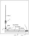
図3は、トラクタ1の一般的な走行経路などを示す図である。ここに、50は圃場、50aは圃場50のほぼ中央の往復走行を行う主要範囲領域、50bは、主要範囲領域50aの外側の枕地領域を示す。51は畔であり、52は出入り口である。枕地領域50bにおける枕地走行経路は1周を1工程として、複数工程(3本)設定されている。
FIG. 3 is a diagram showing a general traveling route of the
トラクタ1は、一点鎖線に示すように、その主要範囲領域50aを往復自動作業走行した後、その外周形状の直ぐ周りの枕地領域50bを1周だけ自動作業走行して、一時停止位置50cで停止する。R1aはその往復走行経路、R1a-1は、その往復走行における1本目の走行ラインを示す。また、R1bはその枕地領域50bの中の最も内側の1周の走行経路であって、上記のように自動作業走行経路である。
As shown by the alternate long and short dash line, the
そのような経路は制御部40の記録部40cに予め記録されており、測位装置30で受信する衛星信号とその予め記録された経路データとを照合しながら、走行系ECU40bが操舵装置9や変速装置10を操作して、トラクタ1を自律作業走行させていく。
Such a route is recorded in advance in the
そして、枕地領域50bの残る領域については、実線で示すように、その一時停止位置50cにおいて作業者53がトラクタ1に乗り込み、手動で作業走行を行う。なお、その乗り込み位置は一時停止位置50c以外も可能である。
Then, as shown by the solid line, the
ここに、R2aは枕地領域50bの中の最も外側の1周の走行経路、つまり、畔51に隣接する走行経路である。またR2bは枕地領域50bの真ん中の1周の走行経路である。つまり、図3においては、枕地領域50bの走行経路は、3本(R1b、R2a、R2b)の周走行経路が設定されている。なお、枕地領域50bの外側2本の走行経路R2a、R2bは手動による作業走行であっても、予めそれらの走行経路R2a、R2bのデータは、制御部40の記録部40cに記憶されている。例えば、作業者53の手動運転において、それらの走行経路R2a、R2bから大きく反れた場合に警告するなどに用いられる。
Here, R2a is the outermost traveling route in the headland region 50b, that is, the traveling route adjacent to the shore 51. Further, R2b is a traveling route for one round in the middle of the headland area 50b. That is, in FIG. 3, the traveling route of the headland region 50b is set to three (R1b, R2a, R2b) circumferential traveling routes. Even if the two travel paths R2a and R2b outside the headland area 50b are manually driven, the data of those travel paths R2a and R2b are stored in advance in the
このようなトラクタ1の走行において、Sは上記主要範囲領域50aにおける、つまり、往復走行経路R1aにおける自動作業走行の作業開始点である。
In such traveling of the
今、自動作業走行の開始指示を受信した場合、畔51における出入り口52に位置しているトラクタ1を、往復走行する主要範囲領域50aにおいて自動作業走行をさせるために、制御部40が、その作業開始点Sまでトラクタ1を自動で移動させる方法をいくつかのケースに分けて説明する。
Now, when the instruction to start the automatic work running is received, the
なお、この移動は、作業しない状態での自動走行である。また、圃場50の形状は、図4乃至図7に示すように、ほぼ矩形の場合を例にとり、位置を示す「上下、左右」はそれらの図面上の定義である。
It should be noted that this movement is an automatic running in a state where no work is performed. Further, as shown in FIGS. 4 to 7, the shape of the
(1)図4に示すように、作業開始点Sが、出入り口52の対角側の場合、制御部40によって以下のようにトラクタ1は非作業の自動走行を行う。
(1) As shown in FIG. 4, when the work start point S is on the diagonal side of the
すなわち、出入り口52に位置するトラクタ1は、枕地領域50bにおける3つの走行経路R1b、R2a、R2bの内、最外周経路R2a以外の最も内側の経路R1bあるいは真ん中のR2bを経路として選び自動走行していく。最外周経路R2aを走行させると、圃場領域逸脱起こりがちとなり、頻繁に停止してしまう傾向があるからである。以下の各ケースでも同様の理由で、最外周経路R2aは使用しない。
That is, the
例えば、最内周の経路R1bを走行する場合は、右辺の経路R1b-1を走行し、さらに旋回RD1して上辺R1b-2へ移り、さらに旋回RDS1して、往復走行経路R1aの1本目の走行ラインR1a-1に移る。その旋回RD1は、ほぼ直角に旋回するのでその旋回径は比較的大きく、緩やかな制御でよい。いわゆる方ブレーキを使うことはしない。 For example, when traveling on the innermost route R1b, the route R1b-1 on the right side is traveled, the turn RD1 is further moved to the upper side R1b-2, the turn RDS1 is performed, and the first round trip route R1a is traveled. Move to the running line R1a-1. Since the swivel RD1 swivels at a substantially right angle, its swivel diameter is relatively large, and gentle control may be sufficient. I don't use the so-called one brake.
あるいは、真ん中の経路R2bを経路とした場合は、右辺の経路R2b-1を走行し、さらに旋回RD2して上辺R2b-2へ移り、さらに旋回RDS2して、往復走行経路R1aの1本目の走行ラインR1a-1に移る。その旋回RD2も、ほぼ直角に旋回するのでその旋回径は比較的大きく、緩やかな制御でよい。いわゆる方ブレーキを使うことはしない。 Alternatively, when the route R2b in the middle is used as the route, the route R2b-1 on the right side is traveled, the turn RD2 is further moved to the upper side R2b-2, the turn RDS2 is performed, and the first travel of the reciprocating travel route R1a is performed. Move to line R1a-1. Since the swivel RD2 also swivels at a substantially right angle, its swivel diameter is relatively large, and gentle control may be sufficient. I don't use the so-called one brake.
このような旋回RD1、RD2においては、通常の作業を行う枕地でのロボット走行(旋回方法)とは違い、後進動作を行わない。これによって、枕地の表面を荒らさずにすみ、また余分な動作が入らないので、作業開始点Sまで迅速に移動できる。もちろん、制御ソフトの共通化を図るため、あえて後進動作を行うことにしてもよい。なお、作業開始点Sに侵入した後の後進動作は可能とする。 In such turning RD1 and RD2, unlike the robot running (turning method) on the headland where normal work is performed, the reverse movement is not performed. As a result, the surface of the headland is not roughened, and no extra movement is performed, so that the work can be quickly moved to the work start point S. Of course, in order to standardize the control software, the reverse operation may be intentionally performed. It is possible to move backward after entering the work start point S.
(2) 図5に示すように、作業開始点Sが、出入り口52と同じ側の上方に位置する場合には、制御部40によって以下のようにトラクタ1は非作業の自動走行を行う。
(2) As shown in FIG. 5, when the work start point S is located above the same side as the
すなわち、出入り口52に位置するトラクタ1は、枕地領域50bにおける3つの走行経路R1b、R2a、R2bの内、最外周経路のR2a以外の最も内側の経路R1bあるいは真ん中のR2bを経路として選び自動走行していく。
That is, the
例えば、最内周の経路R1bを走行する場合は、右辺の経路R1b-1を走行していく。さらに旋回RDS3して、往復走行経路R1aの1本目の走行ラインR1a-1に移る。その旋回RDS3は、上述した直角旋回ではなく、ほぼ平行なラインに乗せるため、例えば一点旋回を行うなど、上述した直角旋回よりも急旋回させる必要がある。すなわち、左右それぞれの後輪5.5に片方ずつ制動する片ブレーキが可能な制動装置を備え、片ブレーキを利用して一点旋回を行う。 For example, when traveling on the innermost route R1b, the vehicle travels on the right side route R1b-1. Further, the turning RDS3 is performed to move to the first traveling line R1a-1 of the reciprocating traveling route R1a. Since the turning RDS3 is placed on a substantially parallel line instead of the above-mentioned right-angle turning, it is necessary to make a sharper turning than the above-mentioned right-angle turning, for example, by performing a one-point turning. That is, each of the left and right rear wheels 5.5 is provided with a braking device capable of one-sided braking, and one-point turning is performed using the one-sided brake.
あるいは、真ん中の経路R2bを経路とした場合は、右辺の経路R2b-1を走行し、さらに旋回RDS4して、往復走行経路R1aの1本目の走行ラインR1a-1に移る。その旋回RDS4は、上述した直角旋回ではなく、ほぼ平行なラインに乗せるため、例えば一点旋回(ブレーキを利用するなど)を行うなど、直角旋回よりも急旋回させる必要がある。 Alternatively, when the route R2b in the middle is used as the route, the vehicle travels on the route R2b-1 on the right side, further turns RDS4, and moves to the first travel line R1a-1 of the reciprocating travel route R1a. Since the turning RDS4 is placed on a substantially parallel line instead of the above-mentioned right-angle turning, it is necessary to make a sharper turning than a right-angle turning, for example, by performing a one-point turning (using a brake or the like).
さらに、同じ一点旋回とはいっても、真ん中の経路R2bの場合の旋回RDS4と、上述した最内周の経路R1bの場合旋回RDS3とを比較すると、走行ラインR1a-1までの距離が異なるため、最内周の経路R1bの場合の旋回RDS3の方がより急な旋回が必要となる。 Further, even if the same one-point turn is made, when the turn RDS4 in the case of the middle path R2b and the turn RDS3 in the case of the innermost path R1b described above are compared, the distance to the traveling line R1a-1 is different. The turning RDS3 in the case of the innermost path R1b requires a steeper turning.
すなわち、往復走行経路の作業開始点Sが存在する経路部分に対して平行な角度に設定されている、枕地走行経路の経路部分のうち、最内周の枕地走行経路R1bの部分以外の経路R2bから、作業開始点Sに旋回移動する場合は、最内周の枕地走行経路R1bの部分から作業開始点Sに旋回移動する場合に比べて、片ブレーキ制動力を弱くする。 That is, among the route portions of the headland travel route, which are set at an angle parallel to the route portion where the work start point S of the round-trip travel route exists, the portion other than the innermost headland travel route R1b. When turning from the route R2b to the work start point S, the one-side brake braking force is weaker than when turning from the innermost headland traveling path R1b to the work start point S.
(3) 図6に示すように、作業開始点Sが、出入り口52の左側下方に位置し、トラクタ1が作業開始点S側へ向いていない場合には、制御部40によって以下のようにトラクタ1は非作業の自動走行を行う。
(3) As shown in FIG. 6, when the work start point S is located on the lower left side of the
すなわち、出入り口52に位置するトラクタ1は、枕地領域50bにおける3つの走行経路R1b、R2a、R2bの内、最外周経路のR2a以外の最も内側の経路R1bあるいは真ん中のR2bを経路として選び自動走行していく。
That is, the
例えば、最内周の経路R1bを走行する場合は、右辺の経路R1b-1を走行し、さらに旋回RD1して上辺R1b-2へ移り、さらに旋回RD3して、左辺の経路R1b-3に移る。さらに、旋回RDS5して、往復走行経路R1aの1本目の走行ラインR1a-1に移る。 For example, when traveling on the innermost route R1b, the vehicle travels on the right side route R1b-1, further turns RD1 to move to the upper side R1b-2, then turns RD3 to move to the left side route R1b-3. .. Further, the turning RDS5 is performed to move to the first traveling line R1a-1 of the reciprocating traveling path R1a.
その旋回RDS5は直角旋回ではなく、ほぼ平行なラインに乗せるため、例えば一点旋回(ブレーキを利用するなど)を行うなど、直角旋回よりも急旋回させる必要がある。 Since the turning RDS5 is not a right-angled turn but is placed on a substantially parallel line, it is necessary to make a sharper turn than a right-angled turn, for example, by performing a one-point turn (using a brake or the like).
あるいは、真ん中の経路R2bを経路とした場合は、右辺の経路R2b-1を走行し、さらに旋回RD2して上辺R2b-2へ移り、さらに旋回RD4して、左辺の経路R1b-3に移る。この経路は、上述した最内周の経路R1bを走行する場合と同じである。さらに、旋回RDS5して、往復走行経路R1aの1本目の走行ラインR1a-1に移る。なお、旋回RD4した後、左辺の真ん中の経路R2b-3を利用してもかまわない。 Alternatively, when the route R2b in the middle is used as the route, the vehicle travels on the route R2b-1 on the right side, further turns RD2 to move to the upper side R2b-2, and further turns RD4 to move to the route R1b-3 on the left side. This route is the same as the case of traveling on the innermost route R1b described above. Further, the turning RDS5 is performed to move to the first traveling line R1a-1 of the reciprocating traveling path R1a. After turning RD4, the path R2b-3 in the middle of the left side may be used.
これら旋回RD3と、旋回RD4はほぼ直角に旋回するので比較的穏やかに旋回させればよい。いわゆる方ブレーキを使うことはしない。 Since these turning RD3 and turning RD4 turn at a substantially right angle, they may be turned relatively gently. I don't use the so-called one brake.
また、このような旋回RD3、RD4においては、通常の作業を行う枕地でのロボット走行(旋回方法)とは違い、前後進動作を行わない。これによって、枕地の表面を荒らさずにすみ、また余分な動作が入らないので、開始点Sまで迅速に移動できる。もちろん、制御ソフトの共通化を図るため、あえて後進動作を行うことにしてもよい。なお、作業開始点Sに侵入した後の後進動作は可能とする。 Further, in such turning RD3 and RD4, unlike the robot running (turning method) on the headland where normal work is performed, the forward / backward movement is not performed. As a result, the surface of the headland is not roughened, and no extra movement is performed, so that the surface can be quickly moved to the starting point S. Of course, in order to standardize the control software, the reverse operation may be intentionally performed. It is possible to move backward after entering the work start point S.
(4) 図7に示すように、作業開始点Sが、出入り口52の左側下方に位置する場合であって、トラクタ1の向きが図6とは異なり、作業開始点S側へ向いていた場合、制御部40によって以下のようにトラクタ1は非作業の自動走行を行う。
(4) As shown in FIG. 7, when the work start point S is located on the lower left side of the
すなわち、トラクタ1の走行は原則としては反時計回りであるが、時計回りをした場合、作業開始点Sが最も近い位置にある場合であって、トラクタ1が作業開始点Sの方に向いている場合である。
That is, the traveling of the
その際も、出入り口52に位置するトラクタ1は、枕地領域50bにおける3つの走行経路R1b、R2a、R2bの内、最外周経路のR2a以外の最も内側の経路R1bあるいは真ん中のR2bを経路として選び、左側へ自動走行していく。
At that time, the
例えば、最内周の経路R1bを走行する場合は、下辺の経路R1b-4を走行し、旋回RDS6して、往復走行経路R1aの1本目の走行ラインR1a-1に移る。その旋回RDS6は、ほぼ直角に旋回するのでその旋回径は比較的大きく、緩やかな制御でよい。 For example, when traveling on the innermost route R1b, the vehicle travels on the lower route R1b-4, makes a turning RDS6, and moves to the first traveling line R1a-1 of the reciprocating traveling route R1a. Since the swivel RDS 6 swivels at a substantially right angle, its swivel diameter is relatively large, and gentle control may be sufficient.
あるいは、真ん中の経路R2bを経路とした場合は、下辺の経路R2b-4を走行し、旋回RDS7して、往復走行経路R1aの1本目の走行ラインR1a-1に移る。その旋回RDS7も、ほぼ直角に旋回するのでその旋回径は比較的大きく、緩やかな制御でよい。 Alternatively, when the middle route R2b is used as the route, the vehicle travels on the lower route R2b-4, makes a turning RDS7, and moves to the first traveling line R1a-1 of the reciprocating traveling route R1a. Since the swivel RDS7 also swivels at a substantially right angle, its swivel diameter is relatively large, and gentle control may be sufficient.
次に、以上の4つのケースのいずれの場合も、作業開始点Sへ侵入した後は、所定距離前進した後、逆に作業開始点Sまで自動操舵しながら後進して一時停止する。その際ブザーを鳴らすことも可能である。これによって残耕なく作業が可能となる。一時停止したトラクタ1に対しては遠隔操作装置100で往復走行経路R1aにおける作業走行を開始させる。
Next, in any of the above four cases, after entering the work start point S, the vehicle advances by a predetermined distance, and then, conversely, automatically steers to the work start point S while moving backward and temporarily stopping. At that time, it is also possible to sound the buzzer. This makes it possible to work without residual cultivation. For the temporarily stopped
さらに変形例として、作業開始点Sまで後進した後さらに圃場50の畔51の手前1mまで後進し、そこで逆に前進してラインに合わせて作業開始点Sで一時停止する。これによって、前進しながら作業開始点Sへ入るので侵入角度が安定し、作業開始の際の直進性が高まる。
Further, as a modification, after moving backward to the work start point S, the player further moves backward to 1 m in front of the shore 51 of the
さらには、上述のようにして作業開始点Sへ到達した後、一時停止することなく、そのまま本来の作業走行を開始することも望ましい。一時停止する場合は、さらにリモコン操作などして開始させなくてはならない手間が掛ってしまい、効率が悪いからである。 Further, it is also desirable to start the original work running as it is without pausing after reaching the work start point S as described above. This is because when pausing is performed, it takes time and effort to start it by further operating the remote controller, which is inefficient.
次に、上述した作業開始点Sまでの枕地自動走行を開始する際の条件について説明する。 Next, the conditions for starting the automatic headland running to the work start point S described above will be described.
1.上記枕地領域50bにおける3つの走行経路R1b、R2a、R2bの内、最外周経路のR2a以外の最も内側の経路R1bを選ぶ場合はその経路R1bから1m以内にトラクタ1が位置している場合のみ、自動走行を許可する。
1. 1. When selecting the innermost route R1b other than the outermost route R2a among the three travel routes R1b, R2a, and R2b in the headland region 50b, only when the
距離が遠い場合は想定外の事故が起こる可能性があり、また経路に乗せる制御仕様も簡単になるからである。1mは設計事項であり設定変更が可能である。 This is because if the distance is long, an unexpected accident may occur, and the control specifications to be put on the route are simplified. 1m is a design matter and the setting can be changed.
また、真ん中のR2bを経路として選ぶ場合も、トラクタ1が経路R2bから1m以内に位置していることが必要ある。
Also, when selecting the center R2b as the route, it is necessary that the
2.最も内側の経路R1bと真ん中の経路R2bが経路として適切な場合、現在のトラクタ1の位置(自己位置)から近い経路が自動で選択される。例えばそれら2本の経路がどちらも1m以内にある場合はより近いほうの経路が自動選択されて、経路に乗せられる。あるいは、別のやりかたとしては最も内側の経路R1bを常に選択することも可能である。
2. 2. When the innermost route R1b and the middle route R2b are appropriate as routes, the route closest to the current position (self-position) of the
3.作業開始点Sまでの自動走行を開始する際のトラクタ1の方位状態は、その近くの畔51の線に対して平行もしくは所定角度以内であることも条件である。安全性の確保のためである。
3. 3. It is also a condition that the directional state of the
4.作業開始点Sまでの自動走行を開始する際のトラクタ1の位置が圃場50を領域逸脱していないことは勿論、その位置から3m前進した場合に圃場逸脱しないことが条件である。すなわち、作業車両の位置を測位する測位装置30を利用して、制御部40は、圃場の領域の情報および作業車両の作業幅の情報を有しており、作業車両が現在の位置から所定距離前進すると仮定した場合、測位装置30が測位した作業車両の位置を利用して、作業車両の一部が圃場の領域から逸脱するかどうか判断し、逸脱しない場合に限り、往復走行経路における作業開始点Sまで、走行車体を自動で移動させる。
4. It is a condition that the position of the
5.作業開始点Sが現在のトラクタ1の位置に近い場合、例えば出入り口52に近いところに作業開始点Sがある場合は、自動走行は禁止する。手動で移動する方が無駄がないので、自動走行は禁止する。
5. If the work start point S is close to the current position of the
トラクタ1の車速については、制御部40は、作業開始点Sまでの枕地領域での車速と、作業時での車速は、走行負荷が異なるので、別々に設定可能である。枕地領域での車速の方を早くすることで時間短縮が図られる。
Regarding the vehicle speed of the
作業時において、往復走行経路と、枕地領域走行の車速は別々に設定可能とする。そのようにすることで、往復走行経路から枕地領域走行にトラクタ1が入ったときにタブレットで変速操作をする必要がなくなる。
During work, the round-trip travel route and the vehicle speed for traveling in the headland area can be set separately. By doing so, it is not necessary to perform a shift operation with the tablet when the
また、作業時において、往復走行経路と、枕地領域走行における、旋回時の前輪駆動設定と、オートブレーキ設定を、別々に設定可能とする。そのようにすることで、枕地領域走行にトラクタ1が入ったときにタブレットで一々変更操作をする必要がなくなる。また、変更をし忘れた結果、整地性が悪くなり、あるいは領域逸脱などの危険も回避できる。
Further, during work, the reciprocating travel path, the front wheel drive setting at the time of turning in the headland area travel, and the auto brake setting can be set separately. By doing so, it is not necessary to change the tablet one by one when the
また往復走行経路において、一本飛ばしで作業する場合、隣接耕の切り返し工程と、その他の工程とで前輪駆動設定と、ブレーキ設定を別々に行う。切り返し工程は、ブレーキ強、フルターン入りとし、その他の工程はブレーキ無し、オート4WDをデフォルトとする。これによって、一々タブレットで変更する必要がなくなる。また、領域逸脱の危険性も回避できる。 Further, in the case of working by skipping one line in the reciprocating travel path, the front wheel drive setting and the brake setting are separately performed in the cutting back step of the adjacent tillage and the other steps. The turning process is set to strong brake and full turn, and the other processes are set to no brake and auto 4WD is the default. This eliminates the need to make changes on the tablet one by one. In addition, the risk of deviation from the area can be avoided.
上記作業開始点Sまで枕地自動走行をさせる際のそのスタート位置まで、出入り口52からトラクタ1を手動で移動させる場合、最も内側の経路R1bまたは真ん中の経路R2bの経路の1m以内に移動させるだけでよい。すなわち、それら経路上に手動でトラクタ1を厳密に乗せる必要はない。
When manually moving the
なお、その際、その1mの範囲をディスプレイに表示し、実際に手動でその範囲内にトラクタ1を移動したとき、それを示すランプを緑色に点灯するなどすることが望ましい。
At that time, it is desirable to display the range of 1 m on the display, and when the
本発明は、作業開始点まで圃場を荒らすようなことなく円滑に自動走行できる作業車両を提供できるため、トラクタに有用である。 INDUSTRIAL APPLICABILITY The present invention is useful for a tractor because it can provide a work vehicle capable of smoothly and automatically traveling to a work start point without damaging the field.
1 トラクタ
2 走行車体
3 車体フレーム
4、5 車輪
7 操縦部
8 操縦席
30 測位装置
40 制御部
40c 記録部
50 圃場
50a 主要範囲領域(往復走行領域)
50b 枕地領域
50c 一時停止位置
51 畔
52 出入口
53 作業者
100 遠隔操作装置
R1a 往復走行経路
R1b、R2a、R2b 枕地走行経路
1
Claims (4)
自動作業走行の開始指示を受信すると、前記枕地走行経路に沿って、前記往復走行経路における作業開始点まで、前記走行車体を自動で作業を伴わない移動走行をさせる制御部を備え、
前記制御部は、前記枕地走行経路における、自動で作業を伴わない移動走行中の旋回動作においては、旋回後の後進動作を行わない、ことを特徴とする作業車両。 It is a work vehicle equipped with a traveling vehicle body that travels on a round-trip traveling route that repeats round-trip traveling set inside the field and a headland traveling route that travels along the outer peripheral shape of the round-trip traveling route.
Upon receiving an instruction to start automatic work running, the vehicle is provided with a control unit that automatically moves the traveling vehicle body along the headland traveling route to the work starting point on the reciprocating traveling route without any work.
The control unit is a work vehicle, characterized in that, in a turning operation during a moving traveling without automatic work on the headland traveling path, the control unit does not perform a reverse operation after turning.
前記往復走行経路の前記作業開始点が存在する経路部分に対して、直角に設定されている前記枕地走行経路の経路部分から、前記作業開始点に旋回移動する場合は、前記片ブレーキを伴わない旋回を行う、請求項1記載の作業車両。 Equipped with a braking device that can brake one side at a time on each of the left and right rear wheels.
When turning from the route portion of the headland traveling route set at a right angle to the route portion where the work start point of the reciprocating travel route exists to the work start point, the one-sided brake is accompanied. The work vehicle according to claim 1, which makes no turn.
前記往復走行経路の前記作業開始点が存在する経路部分に対して、平行な角度に設定されている前記枕地走行経路の経路部分から、前記作業開始点に旋回移動する場合は、前記片ブレーキを伴う旋回を行う、請求項1記載の作業車両。 Equipped with a braking device that can brake one side at a time on each of the left and right rear wheels.
In the case of turning from the path portion of the headland traveling path set at an angle parallel to the path portion where the work start point of the reciprocating travel path exists to the work start point, the one-side brake The work vehicle according to claim 1, wherein the work vehicle makes a turn accompanied by.
左右それぞれの後輪に片方ずつ制動する片ブレーキが可能な制動装置を備え、
前記往復走行経路の前記作業開始点が存在する経路部分に対して平行な角度に設定されている、前記枕地走行経路の経路部分のうち、最内周の枕地走行経路の部分以外の経路から、前記作業開始点に旋回移動する場合は、前記最内周の枕地走行経路部分から前記作業開始点に旋回移動する場合に比べて、前記片ブレーキの制動力が弱い、請求項1記載の作業車両。
The headland traveling route is set as a plurality of processes with one lap as one process.
Equipped with a braking device that can brake one side at a time on each of the left and right rear wheels.
Of the route portions of the headland travel route set at an angle parallel to the route portion where the work start point of the round-trip travel route exists, a route other than the innermost headland travel route portion. According to claim 1, the braking force of the one-sided brake is weaker in the case of turning to the work start point than in the case of turning from the innermost headland traveling path portion to the work start point. Work vehicle.
Priority Applications (2)
| Application Number | Priority Date | Filing Date | Title |
|---|---|---|---|
| JP2020150330A JP7421697B2 (en) | 2020-09-08 | 2020-09-08 | work vehicle |
| JP2023218130A JP7626191B2 (en) | 2020-09-08 | 2023-12-25 | Work vehicles |
Applications Claiming Priority (1)
| Application Number | Priority Date | Filing Date | Title |
|---|---|---|---|
| JP2020150330A JP7421697B2 (en) | 2020-09-08 | 2020-09-08 | work vehicle |
Related Child Applications (1)
| Application Number | Title | Priority Date | Filing Date |
|---|---|---|---|
| JP2023218130A Division JP7626191B2 (en) | 2020-09-08 | 2023-12-25 | Work vehicles |
Publications (2)
| Publication Number | Publication Date |
|---|---|
| JP2022044932A true JP2022044932A (en) | 2022-03-18 |
| JP7421697B2 JP7421697B2 (en) | 2024-01-25 |
Family
ID=80681910
Family Applications (2)
| Application Number | Title | Priority Date | Filing Date |
|---|---|---|---|
| JP2020150330A Active JP7421697B2 (en) | 2020-09-08 | 2020-09-08 | work vehicle |
| JP2023218130A Active JP7626191B2 (en) | 2020-09-08 | 2023-12-25 | Work vehicles |
Family Applications After (1)
| Application Number | Title | Priority Date | Filing Date |
|---|---|---|---|
| JP2023218130A Active JP7626191B2 (en) | 2020-09-08 | 2023-12-25 | Work vehicles |
Country Status (1)
| Country | Link |
|---|---|
| JP (2) | JP7421697B2 (en) |
Citations (6)
| Publication number | Priority date | Publication date | Assignee | Title |
|---|---|---|---|---|
| JPH06219291A (en) * | 1993-01-25 | 1994-08-09 | Kubota Corp | Drive operating structure for farming work vehicle |
| JPH10287264A (en) * | 1997-04-18 | 1998-10-27 | Iseki & Co Ltd | Work vehicle steering control device |
| JP2001151142A (en) * | 2000-09-11 | 2001-06-05 | Kubota Corp | Work vehicle |
| JP2017127290A (en) * | 2016-01-22 | 2017-07-27 | ヤンマー株式会社 | Agricultural working vehicle |
| JP2018144684A (en) * | 2017-03-07 | 2018-09-20 | 井関農機株式会社 | Work vehicle |
| JP2020110108A (en) * | 2019-01-15 | 2020-07-27 | 株式会社クボタ | Management system for agricultural material supplementation |
Family Cites Families (4)
| Publication number | Priority date | Publication date | Assignee | Title |
|---|---|---|---|---|
| JP3900193B2 (en) * | 2005-12-28 | 2007-04-04 | 井関農機株式会社 | Agricultural work vehicle |
| JP4605667B2 (en) * | 2008-03-31 | 2011-01-05 | 株式会社クボタ | Work vehicle control device |
| DE102015107247A1 (en) * | 2015-05-08 | 2016-11-10 | Claas Industrietechnik Gmbh | Agricultural working machine |
| JP6886626B2 (en) * | 2019-04-15 | 2021-06-16 | ヤンマーパワーテクノロジー株式会社 | Travel area registration system for work vehicles |
-
2020
- 2020-09-08 JP JP2020150330A patent/JP7421697B2/en active Active
-
2023
- 2023-12-25 JP JP2023218130A patent/JP7626191B2/en active Active
Patent Citations (6)
| Publication number | Priority date | Publication date | Assignee | Title |
|---|---|---|---|---|
| JPH06219291A (en) * | 1993-01-25 | 1994-08-09 | Kubota Corp | Drive operating structure for farming work vehicle |
| JPH10287264A (en) * | 1997-04-18 | 1998-10-27 | Iseki & Co Ltd | Work vehicle steering control device |
| JP2001151142A (en) * | 2000-09-11 | 2001-06-05 | Kubota Corp | Work vehicle |
| JP2017127290A (en) * | 2016-01-22 | 2017-07-27 | ヤンマー株式会社 | Agricultural working vehicle |
| JP2018144684A (en) * | 2017-03-07 | 2018-09-20 | 井関農機株式会社 | Work vehicle |
| JP2020110108A (en) * | 2019-01-15 | 2020-07-27 | 株式会社クボタ | Management system for agricultural material supplementation |
Also Published As
| Publication number | Publication date |
|---|---|
| JP7626191B2 (en) | 2025-02-04 |
| JP2024023859A (en) | 2024-02-21 |
| JP7421697B2 (en) | 2024-01-25 |
Similar Documents
| Publication | Publication Date | Title |
|---|---|---|
| US12457913B2 (en) | Automatic traveling system, automatic traveling method, and automatic traveling program | |
| CN111373894B (en) | Work vehicle | |
| JP7163900B2 (en) | work vehicle | |
| KR20220099533A (en) | Automated driving systems for work vehicles | |
| JP6837902B2 (en) | Work vehicle | |
| JP2018116609A (en) | Work vehicle | |
| JP2024053067A (en) | Autonomous driving system and method | |
| JP7059221B2 (en) | Control system for work vehicles | |
| EP3932164B1 (en) | Working vehicle | |
| JP7276073B2 (en) | work vehicle | |
| JP7167865B2 (en) | work vehicle | |
| JP6781056B2 (en) | Work vehicle | |
| JP7196787B2 (en) | work vehicle | |
| JP7405044B2 (en) | work vehicle | |
| JP7421697B2 (en) | work vehicle | |
| JP7475295B2 (en) | Work vehicle | |
| JP7014149B2 (en) | Work vehicle | |
| JP7006581B2 (en) | Work vehicle | |
| KR20210152387A (en) | Work vehicle system | |
| JP7317169B2 (en) | Control system for work vehicles | |
| JP2022166931A (en) | work vehicle | |
| JP7509850B2 (en) | Work vehicle | |
| JP7094337B2 (en) | Work vehicle | |
| JP2021026348A (en) | Work vehicle | |
| JP7094338B2 (en) | Work vehicle |
Legal Events
| Date | Code | Title | Description |
|---|---|---|---|
| RD02 | Notification of acceptance of power of attorney |
Free format text: JAPANESE INTERMEDIATE CODE: A7422 Effective date: 20201112 |
|
| A621 | Written request for application examination |
Free format text: JAPANESE INTERMEDIATE CODE: A621 Effective date: 20221231 |
|
| A977 | Report on retrieval |
Free format text: JAPANESE INTERMEDIATE CODE: A971007 Effective date: 20230829 |
|
| A131 | Notification of reasons for refusal |
Free format text: JAPANESE INTERMEDIATE CODE: A131 Effective date: 20230912 |
|
| A521 | Request for written amendment filed |
Free format text: JAPANESE INTERMEDIATE CODE: A523 Effective date: 20231109 |
|
| RD02 | Notification of acceptance of power of attorney |
Free format text: JAPANESE INTERMEDIATE CODE: A7422 Effective date: 20231109 |
|
| TRDD | Decision of grant or rejection written | ||
| A01 | Written decision to grant a patent or to grant a registration (utility model) |
Free format text: JAPANESE INTERMEDIATE CODE: A01 Effective date: 20231128 |
|
| A61 | First payment of annual fees (during grant procedure) |
Free format text: JAPANESE INTERMEDIATE CODE: A61 Effective date: 20231211 |
|
| R150 | Certificate of patent or registration of utility model |
Ref document number: 7421697 Country of ref document: JP Free format text: JAPANESE INTERMEDIATE CODE: R150 |