JP2022033092A - Fluid characteristic change element and fluid system - Google Patents
Fluid characteristic change element and fluid system Download PDFInfo
- Publication number
- JP2022033092A JP2022033092A JP2020137196A JP2020137196A JP2022033092A JP 2022033092 A JP2022033092 A JP 2022033092A JP 2020137196 A JP2020137196 A JP 2020137196A JP 2020137196 A JP2020137196 A JP 2020137196A JP 2022033092 A JP2022033092 A JP 2022033092A
- Authority
- JP
- Japan
- Prior art keywords
- fluid
- internal structure
- changing element
- characteristic
- characteristic changing
- Prior art date
- Legal status (The legal status is an assumption and is not a legal conclusion. Google has not performed a legal analysis and makes no representation as to the accuracy of the status listed.)
- Pending
Links
Images


Abstract
Description
本発明は、供給される流体の特性を変化させる流体特性変化素子及びこのような流体特性変化素子を用いた流体システムに関する。 The present invention relates to a fluid characteristic changing element that changes the characteristics of the supplied fluid and a fluid system using such a fluid characteristic changing element.
従来から、流体特性変化素子が種々研究開発されている。ここで、流体特性変化素子は、供給流体に対してマイクロバブル(1から100マイクロメータのサイズのバブル)やウルトラファインバブル(1マイクロメータ以下のサイズのバブル、従来はナノバブルと称されていた)などのファインバブル(微細気泡)を発生する、複数の流体を混合する、供給流体を撹拌・拡散或いはせん断する、更にはこれらの機能の実現によって、流体の分子間の連結構造に変化をもたらすことや化学変化をもたらすと考えらえていることの少なくとも一つの機能を実現して、供給流体の特性を変化させる素子である。本願特許出願人によっても、流体特性変化素子として特許第6245397号、第6245401号に開示の発明が提案されている。更には、他の特許出願人によって、WO2014/204399号や特表2016-536139号に開示の発明が提案されている。 Conventionally, various fluid property changing elements have been researched and developed. Here, the fluid characteristic changing element is a microbubble (a bubble having a size of 1 to 100 micrometer) or an ultrafine bubble (a bubble having a size of 1 micrometer or less, conventionally called a nanobubble) with respect to the supplied fluid. By generating fine bubbles (fine bubbles), mixing multiple fluids, stirring / diffusing or shearing the supplied fluid, and realizing these functions, the connection structure between the fluid molecules can be changed. It is an element that changes the characteristics of the feed fluid by realizing at least one function that is thought to bring about chemical changes. The patent applicant of the present application has also proposed the invention disclosed in Patents No. 6245397 and No. 6245401 as a fluid property changing element. Furthermore, other patent applicants have proposed the inventions disclosed in WO2014 / 204399 and Japanese Patent Publication No. 2016-536139.
これらの特許文献1~4に開示された発明によれば、供給される流体、例えば水について、流体特性変化素子により、ファインバブルを発生することが可能となっている。本願出願人は、この種の流体特性変化素子の改良により、発生する微細気泡を変化させる、具体的には、ファインバブルの単位体積当たりの発生数量を増加させ、濃度を高めることを、実現しようとしてきた。
According to the inventions disclosed in
本発明は、このような事情に鑑みて開発されたものである。本発明の目的は、供給される流体の特性を変化させる流体特性変化素子の改良を提供するものである。一つの具体例としては、発生する微細気泡が変化した流体特性変化素子を提供するものである。加えて、そのような流体特性変化素子を用いた流体システムを提供するものである。 The present invention has been developed in view of such circumstances. An object of the present invention is to provide an improvement of a fluid characteristic changing element that changes the characteristics of a supplied fluid. As one specific example, the present invention provides a fluid characteristic changing element in which generated fine bubbles are changed. In addition, it provides a fluid system using such a fluid characteristic changing element.
本発明は、上記課題を解決するために次のような構成にしてある。即ち、本発明の一実施形態は、収納体と内部構造体とで構成される流路を通過させることにより流体の特性を変化させるようにした流体特性変化素子である。内部構造体の表面の少なくとも一部に植毛加工がなされている。
本発明の一実施形態による流体システムは、このような流体特性変化素子と、供給される流体が流体特性変化素子を通して特性変更後の流体が供給され、かかる流体を利用する利用装置とから成る。
The present invention has the following configuration in order to solve the above problems. That is, one embodiment of the present invention is a fluid characteristic changing element that changes the characteristics of a fluid by passing through a flow path composed of a housing and an internal structure. At least a part of the surface of the internal structure is flocked.
The fluid system according to the embodiment of the present invention comprises such a fluid characteristic changing element and a utilization device in which the supplied fluid is supplied with the fluid after the characteristic change through the fluid characteristic changing element and the fluid is utilized.
本発明によれば、流体特性変化素子の内部構造体の表面の少なくとも一部に植毛加工がなされ、供給される液体の通過する流路に変化が起き、その結果、出力流体の特性に変化が生じる。例えば、発生する微細気泡が変化する。具体的には、マイクロバブルの発生量が増加する、また、発生するウルトラファインバブルの濃度(単位体積当たりのウルトラファインバブルの個数)、粒子径(粒子径の分布)について変化をもたらす。特に、ファインバブルの濃度を変化させることにより、ファインバブルの効果(冷却、洗浄、殺菌、滅菌、腐敗防止、脱臭、静電気防止、薬効、治療、発育促進、エネルギー等の保存や維持効果洗浄能力、その他)を変化することが可能となる。
また、このように改良された流体特性変化素子を用いることで効果的な、あるいは効率的な流体システムが構成される。つまり、流体の利用機器や、流体を用いて目的物を洗浄する洗浄機器や目的物を冷却する冷却機器などを効果的あるいは効率的に動作可能なものとする。
According to the present invention, at least a part of the surface of the internal structure of the fluid characteristic changing element is flocked, and the flow path through which the supplied liquid passes changes, resulting in a change in the characteristics of the output fluid. Occurs. For example, the generated fine bubbles change. Specifically, the amount of microbubbles generated increases, and the concentration of generated ultrafine bubbles (the number of ultrafine bubbles per unit volume) and the particle size (distribution of particle size) change. In particular, by changing the concentration of fine bubbles, the effects of fine bubbles (cooling, cleaning, sterilization, sterility, anti-corruption, deodorization, static electricity prevention, medicinal effects, treatment, growth promotion, energy preservation and maintenance effect cleaning ability, etc. Others) can be changed.
Further, by using the fluid characteristic changing element improved in this way, an effective or efficient fluid system is constructed. That is, the equipment that uses the fluid, the cleaning equipment that cleans the target object using the fluid, the cooling equipment that cools the target object, and the like can be effectively or efficiently operated.
以下の詳細な記述が以下の図面と合わせて考慮されると、本願のより深い理解が得られる。これらの図面は例示に過ぎず、本発明の範囲を限定するものではない。
以下、本発明の実施形態について、図面を参照しながら詳細に説明する。 Hereinafter, embodiments of the present invention will be described in detail with reference to the drawings.
図1は本発明に係る流体特性変化素子Sの一実施形態に含まれる内部構造体20を示す。これは、特許文献1に示したものと同様の形態をとっている。この内部構造体20は、例えば、ステンレススチールやアルミニュームのような金属から成る円柱部材(軸体)を切削や研削等により加工する方法又はプラスチックなどの樹脂を成型する方法等によって形成される。あるいは3次元プリンターによるプリント技術によって形成してもよい。内部構造体20は、上流側から下流側にむけて、円錐形の流体拡散部22と、渦巻発生部24と、流体特性付与部分に相当するバブル発生部26と、誘導部分に相当するドーム形の誘導部28を備える。
FIG. 1 shows an
流体拡散部22は上記円柱部材の一端部を円錐の形態に加工(例えば、スピニング)することで形成される。なお、この流体拡散部22の形状は円錐形に限らず、例えばドーム形であってもよい。流体拡散部22は後述する内部構造体20が収納される図5、図6の収納体30の流入口38を経て流入側部材31に流入される流体を管の中心部から外側へ、即ち、半径方向へ拡散させる。渦巻発生部24は、上記円柱部材の一部を加工して形成されたものであり、断面が円形である軸部分と、3個の螺旋状に形成された翼とからなる。図5を参照すれば、本実施形態において、渦巻発生部24の長さa2は流体拡散部22の長さa1よりは長くて、バブル発生部26の長さa4よりは短いことが理解される。また、流体拡散部22の断面積が最大である部分の半径は渦巻発生部24の半径(渦巻発生部24の軸部分の中心から翼の先端までの距離)より小さい。渦巻発生部24の翼の各々は、その先端が軸部分の円周方向に互いに120°ずつずらし、軸部分の一端から他端まで外周面に所定の間隔をあけて反時計まわりに螺旋状に形成されている。本実施形態では翼の個数を3個にしたが、このような実施形態に限定されない。また、渦巻発生部24の翼の形態は、流体拡散部22を過ぎながら拡散されて渦巻発生部24に進入した流体が、各翼の間を通過する間に渦巻流を起こすことができる形態であれば特に制限されない。本実施形態では、渦巻発生部24は、内部構造体20を後述する図5、図6に示す収納体30に収納した時に、収納体30の流出側部材34の内周面に近接する程度の外径を有する。バブル発生部26は、円柱部材の下流側、即ち、流体拡散部22及び渦巻発生部24を形成した後の下流側部分を加工して形成する。本実施形態では、渦巻発生部24とバブル発生部26との間には、長さa3の連結部25が存在する。この場合、渦巻発生部24の直径はバブル発生部26の直径と同一であるので、連結部25は同一の直径をもつが、渦巻発生部24の軸部の直径が小さく、バブル発生部の軸部の直径が大きい場合は、段差ができるが、必要に応じてテーパーをつければよい。
The
図1に示されたように、バブル発生部26の円形の断面を有する軸部分の外周面に多数の突起部(凸部)が網状に形成されている。突起部を外周面から見ると、平面的に見た場合は、図2に示す通り、ほぼ菱形形状となっている。それぞれの突起部は、軸部分の外周面から外側へ向かって突出するように、例えば、円柱部材を切削加工、研削加工、旋削加工、エンドミル加工を単独または組み合わせて遂行することによって形成されることができる。より具体的に説明するならば、それぞれの突起部の形成方法は、例えば、図2に示す通り、円柱部材の長さ方向に対して90度の方向に一定の間隔を持つ複数のライン51と、上記長さ方向に対して所定の角度(例えば、60度)を持つ一定の間隔のライン52を交差させ、ライン51とライン51との間を一回ずつ飛ばして切削すると共に、傾いたライン52とライン52との間を一回ずつ飛ばして切削する。このようにして、軸部分の外周面から突出する外周面がほぼ菱形の複数の突起部が上下(円周方向)、左右(軸部分の長さ方向)に一つずつ飛ばして規則的に形成される。また、本実施形態では、バブル発生部26は、後述する通り、図5、図6に示す内部構造体20を収納体30に収納した時、収納体30の流出側部材34の内周面に近接する程度の外径を有する。更に、内部構造体20の下流側の末端の部分をドーム形に加工して誘導部28を形成する。この誘導部28の形状は、円錐形であってもよい。流体は、誘導部28によって中心に向かって誘導される。
As shown in FIG. 1, a large number of protrusions (convex portions) are formed in a net shape on the outer peripheral surface of the shaft portion having a circular cross section of the
次に、このように形成された内部構造体20に対して、その表面の一部または全部に植毛加工を施すプロセスにつき説明する。この植毛加工は、具体的には、これに限ることではないが、静電植毛加工或いはフロック加工によるもので、図3に示す通り、プラス(+)とマイナス(-)の電極板E+、E-に直流高電圧Vから電気を流し、電界を作るようにする(図3の下から上に向かう矢印は、電界の向きを示す)。そして、この電界中に、予め接着剤を表面に塗布した内部構造体20を配置し、金属製又は樹脂製などの微小なパイルPiを帯電させ、飛翔させることによって接着剤が塗布された箇所にパイルが植え付けられることになる。図3の破線は、パイルPiが帯電することで分極回転をして(図示せず)、プラス極がマイナス電極板E-方向に引き付けられ飛翔する状態を示す。
Next, a process of flocking a part or all of the surface of the
このように、接着剤が塗布された部分にパイルPiが植え付けられ、その後乾燥してから不要となったパイルを除去することで、内部構造体20の必要部分に植毛されて、植毛加工は完成となる。なお、植毛を不要とする部分には、パイルPiが植え付けられないように、防護シートなどを被覆して植毛工程を経ることもある。なお、植毛加工を施すプロセスとしては、上記の静電植毛加工或いはフロック加工方法のほか、コンプレッサによる吹付け、散布、または機械的振動の利用などの方法もある。
In this way, the pile Pi is planted in the portion to which the adhesive is applied, and then the pile that is no longer needed after drying is removed, so that the hair is planted in the necessary portion of the
本発明の効果の検証比較のために、図4のように、植毛加工がなされる部分を、(A)内部構造体20の表面全体とする、(B)流体特性付与部分に相当するバブル発生部26の表面のみとする、(C)誘導部分に相当するドーム形の誘導部28(最下流端部)の表面みとする、(D)何も表面に植毛加工を施していないものとする、の4タイプをサンプルとして準備することとする。
For verification and comparison of the effects of the present invention, as shown in FIG. 4, the portion where the flocking process is performed is the entire surface of (A) the
さて、このようにして準備される内部構造体20は、図5、図6の収納体30に収納固定され、流体供給管10(即ち、流体特性変化素子S)が構成される。ここで、図5は、流体供給管10の側面分解図であり、図6は流体供給管10の側面透視図である。収納体30は、流入側部材31と、流出側部材34から構成される。流入側部材31と流出側部材34とは、円筒形の中が空いている管の形態を有する。流入側部材31は、一端部に所定の直径の流入口38を有し、他の端部側には流出側部材34との接続のために内周面をねじ加工することによって形成された雌ねじ32を含む。流入口38側にはナット11が一体として形成される。流入側部材31は両端部の内径、即ち、流入口38の内径と雌ねじ32との内径とが違い、流入口38の内径が雌ねじ32の内径より小さい。流入口38と雌ねじ32との間にはテーパー部33が形成されている。流出側部材34は、一端部に所定の直径の流出口39を有し、他の端部側には流入側部材31との接続のために外周面をねじ加工することによって形成された雄ねじ35を備える。流出側部材34の雄ねじ35の外周面の直径は流入側部材31の雌ねじ32の内径と同一である。流出口39側にはナット12が一体として形成される。ナット12と雄ねじ35との間には筒形部36及びテーパー部37が形成される。流出側部材34は両端部の内径、即ち、流出口39の内径と雄ねじ35との内径が違い、流出口39の内径が雄ねじ35の内径より小さい。流入側部材31の内周面の雌ねじ32と流出側部材34の外周面の雄ねじ35とのねじ結合によって流入側部材31と流出側部材34が連結されることで、収納体30が形成される。
By the way, the
収納体30の上記構成は一実施形態に過ぎない。例えば、流入側部材31と流出側部材34との連結は上記したねじ結合に限定されず、当業者に知られた機械部品の結合方法はどれでも適用可能である。また、流入側部材31と流出側部材34との形態(外形形状も含む)は、図5、図6の形態に限定されず、設計者が任意に選択したり、流体供給管10の用途によって変更したりすることができる。流入側部材31及び流出側部材34は、例えば、ステンレススチールやアルミニュームのような金属、又はプラスチックなどの樹脂から成る。
The above configuration of the
図1、図5及び図6を一緒に参照すれば、流体供給管10は、内部構造体20を流出側部材34に収納した後に、流出側部材34の外周面の雄ねじ35と流入側部材31の内周面の雌ねじ32とを結合させることによって構成されることが理解される。
Referring to FIGS. 1, 5 and 6 together, the
次に、流体が流体供給管10(流体特性変化素子S)を通過する間の流動について図面を参照して説明する。流体は、流体供給管10に供給されると、流体は、流体供給管10の流入側部材31のテーパー部33の空間を過ぎて流体拡散部22にぶつかり、流体供給管10の中心から外側に向かって、即ち、半径方向へ拡散される。流体拡散部22は流入された流体が効果的に渦巻発生部24に進入するように流体を誘導する作用を行う。拡散された流体は渦巻発生部24の反時計方向に螺旋状に形成された3個の翼の間を通過して行く。流体は渦巻発生部24の各翼によって強烈な渦巻流になって、連結部25を過ぎてバブル発生部26に送られる。
Next, the flow while the fluid passes through the fluid supply pipe 10 (fluid characteristic changing element S) will be described with reference to the drawings. When the fluid is supplied to the
そして、流体は、収納体30の円筒形状の内壁面と内部構造体20のバブル発生部26との間に形成される複雑な流路を通過することになる。具体的には、流体は、バブル発生部26の軸部分の外周面に規則的に形成された複数の突起部の間を通る。これらの複数の突起部は複数の狭い流路を形成する。図2にて説明したように、ライン52で規定される流路は、軸部分に、例えば12本形成(軸部分の円周について30度間隔となる)されている螺旋流路となり、ライン51で規定される流路は、例えば軸部分に、14本形成されている円環の閉流路となる。そして、この2系統の流路は軸体上で交差する交差流路となる。この場合、上流の渦巻発生部24からたとえば、反時計周りの渦巻流として流体が供給されるため、ライン52で規定される螺旋流路に流れる流体の勢い(速度)が、ライン51で規定される円環の閉流路に流れる流体の勢い(速度)が大となる。そして、狭い交差流路を上流から下流に流れる中で、流体は衝突を繰り返す。そして、このような流路を経由することで、流体の撹拌・拡散或いはせん断を誘発する。
Then, the fluid passes through a complicated flow path formed between the cylindrical inner wall surface of the
また、内部構造体20は、流体が、断面積が大きい上流(渦巻発生部24)から断面積が小さい下流(バブル発生部26の複数の突起部の間に形成された交差流路)へ流れる構造を有する。この構造は以下に説明するように流体の圧力を変化させる。流体に外部エネルギーが加えられない状態での圧力、速度、及び位置エネルギーの関係は次のようなベルヌーイ方程式(Bernoulli’s equation)として表される。

ここで、pは流線内の一点での圧力、つまり、静圧又は静圧力、ρは流体の密度、vはその点での流動の速度、gは重力加速度、hは基準面に対するその点の高さ、kは定数である。上記方程式として表現されるベルヌーイ定理は、エネルギー保存法則を流体に適用したものであり、第1項は、圧力のエネルギー(静圧)、第2項は運動エネルギー(動圧)、第3項は位置エネルギーに相当し、流れる流体に対して流線上ですべての形態のエネルギーの合計はいつも一定であるということを説明する。ベルヌーイ定理によると、断面積が大きい上流では、流体の速度が遅くて静圧は高い。これに対して、断面積が小さい下流では、流体の速度が速くなり静圧は低くなる。 Here, p is the pressure at one point in the streamline, that is, static pressure or static pressure, ρ is the density of the fluid, v is the velocity of flow at that point, g is the gravitational acceleration, and h is that point with respect to the reference plane. The height and k are constants. The Bernoulli theorem expressed as the above equation applies the energy conservation law to a fluid, the first term is pressure energy (static pressure), the second term is kinetic energy (dynamic pressure), and the third term is. Explain that the sum of all forms of energy, which corresponds to potential energy and is streamlined with respect to the flowing fluid, is always constant. According to Bernoulli's theorem, the fluid velocity is slow and the static pressure is high in the upstream where the cross-sectional area is large. On the other hand, in the downstream where the cross-sectional area is small, the velocity of the fluid becomes high and the static pressure becomes low.
流体が液体である場合、低くなった静圧が液体の飽和蒸気圧に到達すると液体の気化が始まる。このようにほぼ同一の温度において静圧Pがきわめて短い時間内に飽和蒸気圧Pvより低くなって(水の場合、3000-4000Pa)液体が急激に気化する現象をキャビテーション(cavitation)と称する。流体供給管10の内部構造はこのようなキャビテーション現象を誘発する。キャビテーション現象によって液体のうちに存在する100ミクロン以下の微小な気泡核を核として液体が沸騰したり溶存気体の遊離によって小さい気泡が多数生じたりする。すなわち、流体がバブル発生部26を通じながら多数のマイクロバブルやウルトラファインバブルを含むファインバブル(微細気泡)が発生する。
When the fluid is a liquid, the vaporization of the liquid begins when the lowered static pressure reaches the saturated vapor pressure of the liquid. Such a phenomenon in which the static pressure P becomes lower than the saturated vapor pressure Pv (3000-4000 Pa in the case of water) within a very short time at almost the same temperature and the liquid is rapidly vaporized is called cavitation. The internal structure of the
また、流体が、水の場合、1つの水分子が他の4個の水分子と水素結合を形成するが、この水素結合ネットワークを破壊することは容易ではない。そのために、水は水素結合を形成しない他の液体に比べて沸点や融点が非常に高く、高い粘度を示す。水の沸点が高い性質は優秀な冷却効果をもたらすので、冷却水として頻繁に用いられるが、水分子の大きさが大きくて浸透性や潤滑性は良くないという問題がある。流体供給管10を用いれば、上記したキャビテーション現象によって水の気化が起き、その結果、水の水素結合ネットワークが破壊されると考えられる。また、気化によって発生するファインバブルは流体(水)の浸透性及び潤滑性を向上させる。浸透性の向上は結果的に冷却効率を増加させる。
Also, when the fluid is water, one water molecule forms a hydrogen bond with the other four water molecules, but it is not easy to break this hydrogen bond network. Therefore, water has a much higher boiling point and melting point than other liquids that do not form hydrogen bonds, and exhibits a high viscosity. Since the high boiling point of water brings about an excellent cooling effect, it is often used as cooling water, but there is a problem that the size of water molecules is large and the permeability and lubricity are not good. If the
バブル発生部26を通過した流体は、下流側に設けられたドーム形の誘導部28によって流体供給管10の中心に向かって誘導される。その後、流体はテーパー部37を過ぎて流出口39を通じて流出される。流体供給管10などの流体特性素子Sを経由した流体は、ファインバブルを含むため、冷却効果や洗浄効果を上げる効果がある。
The fluid that has passed through the
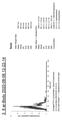
さて、ここで、先に準備した4つのサンプル(図4(A)~(D))を内部構造体20として用いた流体供給管10での微小気泡発生の比較実験を行う。なお、この4つのサンプルのサイズは同じであり、内部構造体20の全長は、88.8mm、軸の外周面(突起部表面)直径は30.8mm、軸の底面(突起部底面)直径は19.4mmとする。また、表面に植毛したパイルPiは直径50ミクロン、長さは300ミクロンのステンレススチール製である。そして、流体は、工業用純水として、同じ水温、流圧で、流体供給管10に一回だけ通すこととする(ワンタイムであり、流体を巡回させない)。このようにして各サンプルから出力する流体を採取し、各流体中に発生したウルトラファインバブルをNTA(Nano Tracking Analysis)技術により計測する。この技術は、NanoSightと呼ばれ、Malvem Panalyticalから提供されている。この技術により、流体中のナノ粒子をブラウン運動の速度を計測して、粒子径と個数を得ることが出来る。
Now, here, a comparative experiment of microbubble generation in the
図7A~図7Dは、図4(A)~(D)の内部構造体を夫々用いた場合のウルトラファインバル発生状態を測定して得られた結果を示す。各々の図の左側のグラフは、1回採取した流体中に含まれる粒子(基本的に、ウルトラファインバブルと考えられる)を、5回測定してその平均化処理をしたものであり、グラフの横軸が粒径のSize:サイズ(単位:ナノメートル)、縦軸がConcentration:濃度(1ミリリットル当たりの粒子数)である。右側の計測結果(Results)のうち、Meanが平均粒子径、Modeが最頻度粒子径、D**値は、粒度頻度を累計していった際、全体の**%になる粒子径をそれぞれ示す。 7A to 7D show the results obtained by measuring the ultrafine val generation state when the internal structures of FIGS. 4A to 4D are used respectively. The graph on the left side of each figure shows the particles (basically considered to be ultrafine bubbles) contained in the fluid collected once, measured 5 times and averaged. The horizontal axis is the size of the particle size (unit: nanometer), and the vertical axis is the concentration: concentration (number of particles per milliliter). Among the measurement results (Results) on the right side, Mean is the average particle diameter, Mode is the most frequent particle diameter, and the D ** value is the particle diameter that becomes **% of the total when the particle size frequency is accumulated. show.
実験の結果を、濃度(Concentration)の高い順に並べると、次のようになる。
1位:図7C 1.34×10の8乗個 (1.34億個)
2位:図7B 9.99×10の7乗個 (0.99億個)
3位:図7A 9.34×10の7乗個 (0.93億個)
4位:図7D 4.03×10の7乗個 (0.40億個)
その結果、図4(D)に示した何らの植毛加工を施していないタイプに比べて、植毛加工を施したサンプルは、明らかにウルトラファインバブルの個数が増えており、その比率は2.33倍から3.35倍となっている。これは、表面に対して施した植毛加工の結果、流路が複雑になり、渦や乱流が生じやすくなり、更に、流体とパイルP1との衝突や流体のせん断が繰り返されることでウルトラファインバブルの粒子数つまり濃度が高くなったものと考えられる。なお、平均粒子径(Mean)、最頻度粒子径(Mode)は、いずれも、何ら植毛加工を施さなかったサンプルの図7Dが、図7A~図7Cの植毛加工を施したサンプルと比べて小さいという結果である。
詳細に述べると、平均粒子径(Mean)の大きい順に並べると、次のようになる。
1位:図7A 124.5nm
2位:図7C 118.2nm
3位:図7B 108.7nm
4位:図7D 107.5nm
また、最頻粒子径(Mode)の大きい順に並べると、次のようになる。
1位:図7C 108.9nm
2位:図7B 98.4nm
3位:図7A 79.9nm
4位:図7D 53.8nm
このような結果から、植毛加工は、粒子径の大きなウルトラファインバブルの発生に関与している、或いはウルトラファインバブルの粒子サイズの大きさを分散する方向に働いているものと考えられる。
The results of the experiments are arranged in descending order of concentration as follows.
1st place: Fig. 7C 1.34 × 10 8 pieces (134 million pieces)
2nd place: Fig. 7B 9.99 x 10 7th power (0.99 million)
3rd place: Fig. 7A 9.34 × 10 7 pieces (903 million pieces)
4th place: Fig. 7D 4.03 × 10 7 pieces (040 million pieces)
As a result, compared to the type shown in FIG. 4 (D) without any flocking treatment, the number of ultrafine bubbles in the flocked sample clearly increased, and the ratio was 2.33. It is from double to 3.35 times. This is because, as a result of the flocking process applied to the surface, the flow path becomes complicated, vortices and turbulence are likely to occur, and further, the collision between the fluid and the pile P1 and the shearing of the fluid are repeated, resulting in ultrafine particles. It is considered that the number of particles of the bubble, that is, the concentration has increased. In addition, the average particle diameter (Mean) and the most frequent particle diameter (Mode) are both smaller in FIG. 7D of the sample not subjected to the flocking process than in the sample subjected to the flocking process of FIGS. 7A to 7C. The result is that.
More specifically, the particles are arranged in descending order of average particle size (Mean) as follows.
1st place: Fig. 7A 124.5nm
2nd place: Fig. 7C 118.2nm
3rd place: Fig. 7B 108.7 nm
4th place: Fig. 7D 107.5 nm
Further, when arranged in descending order of the most frequent particle diameter (Mode), the results are as follows.
1st place: Fig. 7C 108.9nm
2nd place: Fig. 7B 98.4 nm
3rd place: Fig. 7A 79.9 nm
4th place: Fig. 7D 53.8 nm
From these results, it is considered that the flocking process is involved in the generation of ultrafine bubbles having a large particle size, or works in the direction of dispersing the size of the particle size of the ultrafine bubbles.
上記実験結果によれば、内部構造体20の少なくとも一部に植毛処理をすることで、ウルトラファインバブルの濃度は明らかに高まる。加えて、ウルトラファインバブルよりもサイズが大きいマイクロバブル(白濁した微細気泡)の発生も目視で確認できるため、このような内部構造体20を含む流体供給管10を、各種流体システムに適用することは有用であり、以下にこのような植毛加工を表面に施した流体特性変化素子S(内部構造体20を含む流体供給管10)を用いた流体システムにつき説明する。
According to the above experimental results, the concentration of ultrafine bubbles is clearly increased by flocking at least a part of the
図8Aは、流体システムの第1実施形態である。本システムでは、流体は流体供給システム300の中のタンク1に蓄えられ、タンク1からは、ポンプ2にて流体は汲み上げられ、流体特性変化素子Sを経由して対象機器400に流体が与えられる。流体特性変化素子S(すでに説明してきた流体供給管10或いは後述するその他の構造を持ち、内部構造体の全体或いは少なくともその一部の表面に植毛加工が施されているもの)にて流体の特性が変化されたのちに、対象機器400で使用され消費される(流体は循環しない)。従って、タンク1には、流体供給が常になされることになるが、タンク1は必ずしも必要なく、例えば、水道管に直結され流体(水道水)が常に供給されるようにしたものでもよい。このような水道水を直接利用する流体システムとしては、家庭内の洗面・風呂・洗濯・洗浄等の流体システムなどがある。同様に、工場やオフイス、店舗でも水道水を直接利用する流体システムに適用できる。あるいは、ファインバブルを含む水を利用する農業、水産分野あるいはその他の分野の水処理のための流体システムに適用できる。また、食材、例えば米や農作物、鮮魚などの洗浄にも用いられる。更には、地下水や井戸水、汚染水の浄化など水処理システムに適用できる。加えて、特定の流体を使用する流体システムであれば、タンク1に適宜、当該流体を補給しながら利用することになる。そのような対象機器は、種々の製造・生産機械であり、種々の物品(食品、薬品、エマルジョン燃料など)の製造や生産に流体特性変化素子Sからの流体を利用することができる。
図8Bは、上述した図8Aの流体システムを改良した流体システムであって、図8Aのシステム構成に対して、流体特性変化素子Sから出力する流体の一部を、タンク1へのフィードバックするフィードバックループFRを設けている。このリードバックループFRによって、タンクに蓄えられる流体に含まれるファインバブルの濃度が時間経過とともに繰り返し高められることになり、流体特性変化素子による流体の特性変化がより効果的なものとなる。
FIG. 8A is a first embodiment of a fluid system. In this system, the fluid is stored in the
FIG. 8B is a fluid system that is an improvement of the above-mentioned fluid system of FIG. 8A, and is a feedback that feeds back a part of the fluid output from the fluid characteristic changing element S to the
図9は、流体システムの第2実施形態である。第1実施形態と同じ個所には同じ符号を付して説明を省略する。本システムでは、対象機器500の発する熱を熱交換器501で熱交換する流体システムに流体特性変化素子Sを適用したものである。流体特性変化素子Sからの流体(ウルトラファインバブルを含み、温度変化の効果が期待される)を熱交換器501内のパイプに通す。この熱交換器501内で、対象機器500からの循環してくる流体が別のパイプを通る中で熱交換を行い、対象機器500に戻る流体は、冷却(冷房時)或いは加熱(暖房時)されて戻る。熱交換器501を経た流体は、チラー(Chiller)502にて、本来の温度に戻して、タンク1に循環供給される。
FIG. 9 is a second embodiment of the fluid system. The same parts as those in the first embodiment are designated by the same reference numerals, and the description thereof will be omitted. In this system, the fluid characteristic changing element S is applied to a fluid system in which the heat generated by the
したがって、対象機器500、熱交換器501には、各種暖房・冷房機器が含まれる。また、エアコン、冷蔵庫、自動車のラジエーター、各種ボイラーにも適用できる。あるいは工業用の製造プロセスでの空調などにも利用できる。この場合、対象機器500から熱交換器501へ流入する流体は、液体のほか気体でもよい。
Therefore, the
図10は、流体システムの第3実施形態である。第1実施形態、第2実施形態と同じ個所には同じ符号を付して説明を省略する。本システムでは、対象機器600に流体特性変化素子Sからの流体を供給し、使用後の流体を、濾過器601により不要物や不純物を濾過した後、タンク1に循環供給する。流体特性変化素子Sからの流体は、ファインバブルを含むため、冷却効果や洗浄効果がある。従って、対象機器600としては、工作機械であって、ワークや砥石やドリルなどの刃物に、ノズルから流体を吐出し照射する。あるいは、対象機器600を工場の生産ライン(特に精密機器)の洗浄システムとすることができる。同様に、対象機器600を、ビンや容器、機材の洗浄装置とすることもできる。さらには、タンク1にオゾンを加えて蓄え、或いはタンクからの水にオゾンを混合した後(混合装置は図示せず)、流体特性変化素子Sにてオゾンバブル水に特性変化して、対象機器600において目的とするプロダクトにオゾンバブル水を照射する。このようにすれば、脱臭・脱色・殺菌効果が得られる。
FIG. 10 is a third embodiment of the fluid system. The same parts as those of the first embodiment and the second embodiment are designated by the same reference numerals, and the description thereof will be omitted. In this system, the fluid from the fluid characteristic changing element S is supplied to the
このように、各種の流体システム(上記第1~第3の実施形態の流体システムに限られない)において、内部構造体の全体或いは少なくともその一部の表面に植毛加工が施されている流体特性変化素子Sにて流体の特性が変化された(とくに、流体に含まれるファインバブルの濃度が高められた)のちに、対象機器に流体が提供され利用される。 As described above, in various fluid systems (not limited to the fluid systems of the first to third embodiments described above), the fluid characteristics in which the surface of the entire internal structure or at least a part thereof is flocked. After the characteristics of the fluid are changed by the changing element S (in particular, the concentration of fine bubbles contained in the fluid is increased), the fluid is provided to the target device and used.
更に、流体特性変化素子Sは、上述の図1、図2、図4乃至図6の構成例に限られるものではない。内部構造体20の形状は、上述した図1に示すものに限らず、例えば、軸体上に流体特性付与部分を有するものであればよい。必要に応じて設けられる拡散部分の形状は、錐体形状であればよく、円錐形のほか角錐形も含まれ、流体を特定方向に、例えば流体の流入方向に対して一定の角度をもった方向に誘導するものであればよい。
Further, the fluid characteristic changing element S is not limited to the configuration example of FIGS. 1, 2, 4 to 6 described above. The shape of the
図11に内部構造体の他の構成例として、内部構造体140を示す。その先頭には、四角錐141が形成され、残部の部分には四角柱142が形成され、四角柱142の4つの側面に複数の突起部140pが形成される。複数の突起部140pは網状に配置され、その底面は、四角柱142の外表面(側面)と同じ面であり、上面は、円柱状の内部軸体の外表面であり、総体として円弧上の高さとなって丸みを帯びる。つまり、後述する図13、図14の収納体30の内部壁面の円弧にあわせて、総体として、中心が高く、外に向かって低くなる。内部構造体140は、例えば、ステンレススチールやアルミニュームのような金属からなる円柱部材を金属加工する方法又はプラスチックのような樹脂を成型する方法等によって形成される。あるいは、金属または樹脂を、3次元プリンターを用いて形成することも可能である。金属の円柱軸体を加工して作る場合は、切削、旋削、研削の加工を単独または組み合わせて行う。例えばエンドミルによる切削加工によることができる。その製造工程としては、円柱状の内部軸体を準備する工程と、円柱状の内部軸体の一端部を角錐(本例の場合は四角錐141であるが、三角錐、或いは五角錐、六角推…、とすることも可能)に形成する工程と、底面を角柱(本例の場合は底面が正方形の四角柱142であるが、三角柱、或いは五角柱、六角柱…、とすることも可能)の側面とし上面を円柱の外径位置とする交差流路140rを形成することにより、底面を角柱の側面とし、上面を円柱の側面とする複数の突起部140pを形成する工程とを有する。もともとの円柱部材の半径は、収納体30の内壁の半径と同じまたは僅かに小さく、円柱部材が収納体に入り、隙間が出ないサイズであることが望ましい。
FIG. 11 shows an
この内部構造体140が図14のように、収納体30に挿入固定された場合、四角錐141は、流入する流体を、収納体30の円の中心から半径方向に拡散させて、四角錐142の4つの側面に誘導することになる。そして、各側面に到達した流体は、複数の突起部140pの間に形成された交差する流路140rを流れることになるが、収納体30の円筒形の内壁面とこの複数の突起部140pの高さがほぼ同じ(隙間が無い)なので、流体は、複数の突起部140pの間の交差流路140rを流れる(つまり、複数の突起部140pの上面を流れる流体はほぼ無い)ことになる。
When the
図12Aは、内部構造体140のひとつの側面を平面上にあらわして、四角錐141と突起部140pの配列とを示した図であり、上流側の四角錐141はその頂角を例えば、60度とする。勿論、この角度は適宜変更可能である。そして、下流側の四角柱142の4つの側面には、頂角41.11°の菱形(底面の形状)の突起部140pが網状に形成される。なお、この頂角も適宜変更可能である。したがって、図12Bにある通り、複数の突起部140pの間に形成される交差流路140rの交差角度も41.11°となる。具体的に言うと、一側面に形成される複数の底面が菱形の突起部140pは、上流から下流にかけて、3個、4個、3個、・・・、4個と14列形成され、ひとつの側面に49個あり、4つの側面の合計は196個となる。もちろん、この数も適宜に変更できる。複数の突起部140pの形状は、底面が菱形状の突起でなくても良く(例えば、三角形、多角形、その他)、その配列も図12A、図12Bから適宜(角度、間隔など)変更できる。また、複数の突起部140pの配列も、突起部の方向が内部軸体140の長さ方向から左右方向に、交互に、僅かに傾いているようにしてもよい。あるいは、複数の突起部140pの底面の菱形の中心を軸に、内部軸体140の長さ方向から僅かに傾いているようにしてもよい。
FIG. 12A is a diagram showing one side surface of the
そして、このように構成された内部構造体140についても、植毛加工、これに限ることはないが、例えば、図3に示した静電植毛加工を施し、その全体あるいは、その一部、例えば四角錐141の部分の表面のみ、或いは側面に複数の突起部140pが形成された四角柱142の部分の表面のみ、あるいは、出力端部に追加で設けた角錐形状(四角錘)の誘導部分(図示せず)の表面のみに静電植毛加工を行う。この場合、内部構造体の材質に応じて、金属製のパイル或いは樹脂製のパイルを植毛加工する。
The
図13はこの実施形態に係る流体供給管100(流体特性変化素子S)の側面分解図であり、図14は流体供給管100の側面透視図である。流体供給管100は収納体30と上述の内部構造体140とを含む。図14において、流体は流入口38から流出口39側へ流れる。収納体30の構造は、先に説明した実施形態(図5、図6)の収納体30と同様であるので、同じ符号を付してその説明を省略する。
FIG. 13 is a side view of the fluid supply pipe 100 (fluid characteristic changing element S) according to this embodiment, and FIG. 14 is a side perspective view of the
流入口38を通じて流入された流体は、流入側部材31のテーパー部33の空間を過ぎて内部軸体140の四角錐141にぶつかり、流体供給管100の中心から外側に向かって(即ち、半径方向であって、四角錐の底面方向へ)拡散される。拡散された流体は、四角柱142の各側面に到達し、上流側から下流にかけて3つ、4つ、3つ・・・と形成された、底面は菱形であり上面は円柱の一部で丸みを帯びた形状の複数の突起部140pの間の狭い交差流路140r(交差角41.11°)の間を進む。このとき、交差する流路での流体の流れの強さは、図12Aの上流から下流に向かって、左斜め上流から右斜め下流の方向に流れる強さと、右斜め上流から左斜め下流の方向に流れる速度は、ほぼ同じになる。なお、この2つの流れの方向の角度が上述の交差角(41.11°)になる。流体は、複数の突起部140pに衝突してせん断され、また、複数の交差流路140rで衝突、混合、分散を繰り返す。図12Aにおいて、四角柱142の側面の左端部(図12Aの上側端部)に来た流体は、折り返して、つまり上流から下流に向かって、右斜め上流から左斜め下流の方向に流れてきた流れは、左斜め上流から右斜め下流の方向に流れることになり、右端部(図12Aの下側端部)に来た流体は、折り返して、つまり上流から下流に向かって、左斜め上流から右斜め下流の方向に流れてきた流れは、右斜め上流から左斜め下流の方向に流れることになる。流体が複数の突起部140pによって形成された複数の狭い流路140rを通過することで、多数の微小な渦を発生させる。また、複数の突起部140pの多段の網状の配置によって、交差する流路140rで流体は交互に流れ左右にスイッチングするフリップフロップ現象も生じる。このような現象によって、流体の混合及び拡散を誘発する。突起部140pの上記構造は、異なる性質を有する二つ以上の流体を混合する場合にも有用である。
The fluid flowing in through the
内部構造体140は、流体が、断面積が大きい上流側(四角錐141)から断面積が小さい下流側(複数の突起部140pの間に形成された交差流路140r)へ流れるようにする構造を有する。この構造によって、先に説明した実施形態の流体供給管10と同様に、流体供給管100の内部構造はキャビテーション現象を誘発する。気化によって発生するファインバブルは流体が水の場合は、表面張力を低下させるため浸透性及び潤滑性を向上させる。浸透性の向上は結果的に冷却効率を増加させる。或いは、流体に予め空気その他の気体を注入し、多数の突起部140pとの流体の衝突によって溶存気体の遊離を起こさせ、多数のファインバブルを発生させることもできる。この場合も、発生するファインバブルは水の表面張力を低下させるため浸透性及び潤滑性を向上させる。浸透性の向上は結果的に冷却効率を増加させる。キャビテーション現象によって水の気化が起き、その結果、水の水素結合ネットワークが破壊されて粘度が低くなると考えられる。内部軸体140の四角柱142の各側面の複数の狭い交差流路140rを通過した流体は内部構造体140の下流端部に向かって流れる。下流端部では、フリップフロップ現象によって、流体は、左右方向に流れをスイッチングしながら、流出側部材34の下流のテーパー部37のある空間へ流れ出る。しかる後、流出口39を通じて流出される。また、本実施形態においても、内部構造体140の全体または少なくともその一部の表面が植毛加工されていることにより、ファインバブルの発生に変化が生じる。例えば、ファインバブルの濃度が大きくなることで、流体の与える効果が増大する。
The
図15は、更に他の流体特性変化素子Sの例を示す。これまでの実施形態では、内部構造体や収納体は、金属製或いは樹脂製であっても弾性変形しないものを前提として説明してきた。本例では、これら内部構造体1240、収納体1230を、弾性材料を用いて形成した流体供給管1200を説明する。
FIG. 15 shows an example of yet another fluid characteristic changing element S. In the embodiments so far, the internal structure and the storage body have been described on the premise that they are not elastically deformed even if they are made of metal or resin. In this example, a
本実施形態の内部構造体や収納体の弾性材料として、エラストマー材料、例えば、これに限定されるものではないが、ポリ塩化ビニル、ポリ塩化ビニリデン、フッ素系樹脂、シリコーン樹脂、更にはセラミック等を用いることができる。これらの弾性材料で内部構造体を製造するには、射出成型(インジェクションモールディング)による方法や、3次元プリンターによる方法も採用できる。これらの手法で製造された内部構造体1240は弾性力をもつため、ホースなど可撓性のある物品にこの流体供給管1200を接続する(この場合、収納体も弾性材料で形成する)ことや、かかる物品に一体的に流体供給管1200を内装設置することができる。そして、内部構造体1240は、例えば、図3に示した静電植毛加工を施し、その全体あるいは、その一部の表面、例えば四角錐1241の部分のみ、或いは側面に複数の突起部1240pが形成された四角柱1242の部分のみ、あるいは、出力端部に設けた誘導部分(図示せず)のみに静電植毛加工を行う。この場合、内部構造体の材質に応じた樹脂製のパイルを植毛する。
As the elastic material of the internal structure or the storage body of the present embodiment, an elastomer material, for example, but not limited to, polyvinyl chloride, polyvinylidene chloride, a fluororesin, a silicone resin, a ceramic, or the like can be used. Can be used. In order to manufacture the internal structure from these elastic materials, a method by injection molding or a method by a three-dimensional printer can also be adopted. Since the
図15の流体供給管1200は、流体が流入する流入口38と、流体が流出する流出口39とを有し、断面円形の内部壁面を有する中空の収納体1230と、収納体1230に収納固定される複数の側面(図15のものは4面であるが、3面であっても、それ以上の複数の面を有してもよい)を備えた角柱状の軸体(図15では四角柱1242)である内部構造体1240とを有する。収納体1230及び内部構造体1240は、弾性を有する弾性材料で形成され、全体的に弾性変形する。例えば、収納体1230はホース形状であってもよい。内部構造体1240の流入口側には、角錐(図15では、四角錐1241)が設けられる。この角錐の形状も、軸体の有する角柱の側面の数に合わせて適宜変更できる。四角柱1242の側面には、これまで説明した他の実施形態同様に、複数の突起部1240pが網状に配列され、内部構造体1240の四角柱1242の側面と収納体1230の内部壁面との間であって、複数の突起部1240pの間に形成される空間が流体の流路となる。流体は、収納体1230の流入口38から供給され、四角錐1241にて四角柱1242の各側面に分散される。そして、複数の突起部1240pの間の流路1240rを通過することにより流動特性が与えられる。しかる後、流体は流出口39から流出する。このように、本実施形態にあっては、収納体1230及び内部構造体1240がともに弾性力をもち、流体供給管1200を、全体として屈曲する必要がある場合に使用することができる。また、内部部構造体1240のみを弾性力をもたせて屈曲した形状で、弾性力を備えていない収納体1230に収納することもできる。
The
そして、本実施形態においても、内部構造体1240の全体または少なくともその一部が植毛加工されていることにより、ファインバブルの発生に変化が生じる。例えば、ファインバブルの濃度が高くなることで、流体の与える効果が増大する。
Further, also in the present embodiment, the generation of fine bubbles is changed by flocking the entire or at least a part of the
図16は、更に他の流体特性変化素子Sとして、複数の内部構造体が連結されて流体供給管1300が構成される。収納体1330の中には、複数の内部構造体1340-1、1340-2が配置される。図16では、2つであるが、それに限らず3つ以上の内部構造体を連ねることもできる。収納体1330の上流部に設けられた内部構造体1340-1には、先頭に角錐(四角錐1341)が設けられる。この角錐の形状も、軸体の有する角柱の側面の数に合わせて適宜変更できる。四角柱1342の側面には、これまで説明した他の例同様に、複数の突起部1340pが網状に配列され、内部構造体1340-1の四角柱1342の側面と収納体1310の内部壁面との間であって、複数の突起部1340pの間に形成される空間が流体の流路1340rとなる。突起部1340pが列毎に左右の異なる方向に僅かに傾いているようにすることも、軸体の長さ方向に対して、すべて平行にあるようにしてもよい。そして、この内部構造体1340-1と下流の内部構造体1340-2とは、角柱形状(図16では四角柱)の連結部1350を経由して接続される。なお、この連結部材1350の形状は、円柱形状であってもよい。
In FIG. 16, as another fluid characteristic changing element S, a plurality of internal structures are connected to form a
そして、下流の内部構造体1340-2は、上流の内部構造体1340-1の四角柱1342の部分の構成と同じであり、その機能も同様であるが、内部構造体1340-1の四角柱1342と、内部構造体1340-2とは相対的に回転して両者が接続されているようにしてもよく、例えば、相互に90度の回転がなされて接続されている。このような回転して接続することで、上流の内部構造体1340-1の4つの側面1342での個別の流動特性が付与された流体が、下流の内部構造体の1340-2の別の複数の側面に混合して供給されて、より複雑な流体の流れとなり、流動特性の付与により大きな影響を与える。図16で示した収納体1330と複数の内部構造体1340-1、1340-2は、弾性の特性を有することで、全体的に弾性変形、或いは屈曲変形が可能であり、可撓性のホースに接続したり、或いは、ホースの内部に設けたりすることもできる。なお、最下流の内部構造体(図16では、内部構造体1340-2)の下流側に角錐(図16の場合には四角錐)を一体的に設けて流体を中心に誘導するようにしてもよい(下流端部に角錐を設けることで流体の誘導を行うことが出来ることは他の構成例も同じである)。なお、内部構造体1340-1、1340-2のみを弾性材料で構成し屈曲した形状で、弾性力を備えていない収納体1330に収納することもできる。
The downstream internal structure 1340-2 has the same configuration as the portion of the
そして、上流の内部構造体1340-1、連結部1350、下流の内部構造体1340-2の全部またはその一部の表面に、例えば、図3に示した静電植毛加工を行う。この場合も、内部構造体1340-1、1340-2の材質に応じた樹脂製のパイルを植毛加工する。本実施形態においても、内部構造体1340-1、連結部1350、1340-2の全体または少なくともその一部が植毛加工されていることにより、ファインバブルの発生に変化が生じる。例えば、ファインバブルの濃度が高くなることで、流体の与える効果が増大する。
Then, for example, the electrostatic flocking process shown in FIG. 3 is performed on the surfaces of all or a part of the upstream internal structure 1340-1, the connecting
更に他の流体特性変化素子Sの例として、内部構造体の流体特性付与部分は、軸部材の外周面に多数の突起部が配列され、流体が繰り返し衝突を起こし、流体を撹拌・拡散或いはせん断する流路(或いは交差流路)が設けられておればよく、その形状も、突起部の形状も、平面上で見たときにほぼ菱形となるものに限られるものではない。例えば、特許文献3のようにエーロフォイル形(翼形)であってもよい。また、内部構造体は、特許文献4ように、シャフトにより、ノッチ(切り欠き)が形成さられた円盤状要素を複数(多数)つないだものでもよい。内部構造体は、このように種々変形、変更できる。そして、内部構造体の全体または少なくともその一部の表面が金属または樹脂などのパイルが植毛加工されることにより、ファインバブルの発生に変化が生じる。例えば、ファインバブルの濃度が大きくなることで、流体の与える効果が増大する。
As an example of another fluid characteristic changing element S, in the fluid characteristic imparting portion of the internal structure, a large number of protrusions are arranged on the outer peripheral surface of the shaft member, the fluid repeatedly collides, and the fluid is agitated / diffused or sheared. It suffices if a flow path (or a cross flow path) is provided, and the shape and the shape of the protrusion are not limited to those having a substantially rhombic shape when viewed on a plane. For example, it may be an aerofoil type (airfoil type) as in
本発明の更なる改良例としては、その全体または少なくともその一部の表面が金属または樹脂などのパイルが植毛加工され内部構造体を収納する収納体自体の内壁面に、植毛加工するものである。図17は、図4、図5に示した(図13、14の場合も同様)収納体30の流出側部材34の下流部テーパー部37に植毛加工を施す(図中30Piは、例えば金属のパイルPiが植毛処理された植毛加工面を示す)。つまり収納体30の内壁の一部(最下流)に植毛加工を施す(植毛加工は図3の方法には限らない)。このようにすると、内部構造体20(あるいは140)を経て出力する流体について、発生したファインバブルの持続、或いはファインバブルの追加発生などの効果をもたらすことになる。
なお、植毛加工する収納体の内壁面は、図17の位置に限ることなく、図18のように、収納体30の内壁のほぼ全面にわたるようにしてもよい(図中30Piが植毛加工面である)。
加えて、図15或いは、図16の構成例の場合は、ホース形状の収納体1230、1330の内壁面の一部あるは全部に樹脂製のパイルPiを植毛加工するようにすればよい。
As a further improved example of the present invention, the entire surface thereof or at least a part thereof is flocked with a pile such as metal or resin, and the inner wall surface of the storage body itself for accommodating the internal structure is flocked. .. In FIG. 17, the downstream tapered
The inner wall surface of the storage body to be flocked is not limited to the position shown in FIG. 17, and may cover almost the entire inner wall of the
In addition, in the case of the configuration example of FIG. 15 or 16, the resin pile Pi may be flocked on a part or all of the inner wall surface of the hose-shaped
以上、本発明を、複数の実施形態を利用して説明したが、本発明はこのような実施形態に限定されるものではない。本発明が属する技術分野における通常の知識を有する者は、上記説明及び関連図面から本発明の多くの変形及び他の実施形態を導出することができる。本明細書では、複数の特定用語が使われているが、これらは一般的な意味として単に説明の目的のために使われただけであり、発明を制限する目的で使われたものではない。添付の特許請求の範囲及びその均等物により定義される一般的な発明の概念及び思想を抜け出さない範囲で多様な変形が可能である。 Although the present invention has been described above by using a plurality of embodiments, the present invention is not limited to such embodiments. A person having ordinary knowledge in the technical field to which the present invention belongs can derive many modifications and other embodiments of the present invention from the above description and related drawings. Although a plurality of specific terms are used in the present specification, they are used in a general sense only for the purpose of explanation and not for the purpose of limiting the invention. Various modifications are possible within the scope of the attached claims and the general concept and idea of the invention defined by their equivalents.
10、100、1200、1300 流体供給管
20、140、1240、1340-1、1340-2 内部構造体
300 流体供給システム
400、500、600 対象機器
501 熱交換器
30Pi 植毛加工面
S 流体特性変化素子
E+、E- 電極板
V 直流高電圧
Pi パイル
10, 100, 1200, 1300
S Fluid characteristic changing element E +, E- Electrode plate V DC high voltage Pi pile
Claims (21)
内部構造体の表面の少なくとも一部に植毛加工がなされた、
ことを特徴とする流体特性変化素子。 In a fluid characteristic changing element that changes the fluid characteristics by passing through a flow path composed of a housing and an internal structure.
At least part of the surface of the internal structure has been flocked,
A fluid characteristic changing element characterized by this.
共通の軸部材上に、拡散部分と、流動特性付与部分と、を有し、
拡散部分は、錐体形又はドーム形であって、流体を特定方向に拡散し、
流動特性付与部分は、軸部材上の外周面に多数の突起部が設けられ、拡散部分から供給される流体に対して流体の特性を変化させてなり、
拡散部分及び流体特性付与部分の一方又は双方の表面に植毛加工がなされていることを特徴とする請求項1に記載の流体特性変化素子。 The internal structure is
It has a diffusion portion and a flow characteristic imparting portion on a common shaft member.
The diffusing part is pyramidal or dome-shaped, diffusing the fluid in a particular direction and
The flow characteristic imparting portion is provided with a large number of protrusions on the outer peripheral surface on the shaft member, and changes the fluid characteristics with respect to the fluid supplied from the diffusion portion.
The fluid characteristic changing element according to claim 1, wherein the surface of one or both of the diffusion portion and the fluid characteristic imparting portion is flocked.
共通の軸部材上に、拡散部分と、渦巻発生部分と、流動特性付与部分と、を有し、
拡散部分は、錐体形又はドーム形であって、流体を特定方向に拡散し、
渦巻発生部分は、拡散部分によって拡散された流体に渦巻流を発生させるようにし、
流動特性付与部分は、軸部材上の外周面に多数の突起部が設けられ、渦巻発生部分から供給される渦巻流の流体に対して流体の特性を変化させてなり、
拡散部分、渦巻発生部分及び流体特性付与部分の全体、或いは少なくとも一部分の表面に植毛加工がなされていることを特徴とする請求項1に記載の流体特性変化素子。 The internal structure is
A diffusion portion, a swirl generation portion, and a flow characteristic imparting portion are provided on a common shaft member.
The diffusing part is pyramidal or dome-shaped, diffusing the fluid in a particular direction and
The swirl generation part causes the fluid diffused by the diffusion part to generate a swirl flow.
The flow characteristic imparting portion is provided with a large number of protrusions on the outer peripheral surface on the shaft member, and changes the fluid characteristics with respect to the swirl flow fluid supplied from the swirl generation portion.
The fluid characteristic changing element according to claim 1, wherein the surface of the diffused portion, the swirl generating portion, and the fluid characteristic imparting portion is entirely or at least a part thereof is flocked.
共通の軸部材上に、拡散部分と、渦巻発生部分と、流動特性付与部分と、誘導部分とを有し、
拡散部分は、錐体形又はドーム形であって、流体を特定方向に拡散し、
渦巻発生部分は、拡散部分によって拡散された流体に渦巻流を発生させるようにし、
流動特性付与部分は、軸部材上の外周面に多数の突起部が設けられ、渦巻発生部分から供給される渦巻流の流体に対して流体の特性を変化させてなり、
誘導部分は、錐体系又はドーム形であって、流体特性付与部分からの流体を一定方向に誘導してなり、
拡散部分、渦巻発生部分、流体特性付与部分及び誘導部分の全体、或いは少なくとも一部分の表面に植毛加工がなされていることを特徴とする請求項1に記載の流体特性変化素子。 The internal structure is
A diffusion portion, a swirl generation portion, a flow characteristic imparting portion, and an induction portion are provided on a common shaft member.
The diffusing part is pyramidal or dome-shaped, diffusing the fluid in a particular direction and
The swirl generation part causes the fluid diffused by the diffusion part to generate a swirl flow.
The flow characteristic imparting portion is provided with a large number of protrusions on the outer peripheral surface on the shaft member, and changes the fluid characteristics with respect to the swirl flow fluid supplied from the swirl generation portion.
The guiding portion is a cone system or a dome shape, and is formed by guiding the fluid from the fluid property imparting portion in a certain direction.
The fluid characteristic changing element according to claim 1, wherein the surface of the diffusion portion, the swirl generation portion, the fluid characteristic imparting portion and the induction portion is entirely or at least a part of the surface is flocked.
共通の軸部材上に、拡散部分と、流動特性付与部分と、を有し、
拡散部分は、角錐状であって、流体を特定方向に拡散し、
流動特性付与部分は、複数の側面を有する角柱状であって、軸部材上の外周面に多数の突起部が設けられ、各側面に設けられる複数の突起部の上面の高さは、収納体の内部壁面の円弧にあわせて、総体として、中心が高く、外に向かって低くなっており、拡散部分から供給される流体が複数の突起部の間の流路を通過することにより流体の特性を変化させてなり、
拡散部分及び流体特性付与部分の一方又は双方の表面に植毛加工がなされていることを特徴とする請求項9に記載の流体特性変化素子。 The internal structure is
It has a diffusion portion and a flow characteristic imparting portion on a common shaft member.
The diffusion part is pyramidal and diffuses the fluid in a specific direction.
The fluid characteristic imparting portion is a prismatic column having a plurality of side surfaces, and a large number of protrusions are provided on the outer peripheral surface of the shaft member, and the height of the upper surface of the plurality of protrusions provided on each side surface is the storage body. As a whole, the center is high and the center is low toward the outside according to the arc of the inner wall surface of the inside, and the characteristics of the fluid by passing the fluid supplied from the diffusion part through the flow path between the plurality of protrusions. Be changed,
The fluid characteristic changing element according to claim 9, wherein the surface of one or both of the diffusion portion and the fluid characteristic imparting portion is flocked.
向に対して僅かに傾いていることを特徴とする請求項12に記載の流体特性変化素子。 The change in fluid characteristics according to claim 12, wherein the shape of the bottom surface of the protrusion is a rhombus, and the two vertices of the acute angles of the rhombus are slightly inclined with respect to the length direction of the axis of the internal structure. element.
供給される流体が流体特性変化素子を通して特性変更後の流体が供給され、かかる流体を利用する利用装置とから成る、
流体システム。 The fluid characteristic changing element according to any one of claims 1 to 15.
The supplied fluid is supplied with the fluid after the characteristic change through the fluid characteristic changing element, and consists of a utilization device that utilizes the fluid.
Fluid system.
The fluid characteristic changing element according to any one of claims 1 to 15, wherein at least a part of the inner wall surface of the accommodating body for accommodating the internal structure is flocked. ..
Priority Applications (1)
| Application Number | Priority Date | Filing Date | Title |
|---|---|---|---|
| JP2020137196A JP2022033092A (en) | 2020-08-15 | 2020-08-15 | Fluid characteristic change element and fluid system |
Applications Claiming Priority (1)
| Application Number | Priority Date | Filing Date | Title |
|---|---|---|---|
| JP2020137196A JP2022033092A (en) | 2020-08-15 | 2020-08-15 | Fluid characteristic change element and fluid system |
Publications (1)
| Publication Number | Publication Date |
|---|---|
| JP2022033092A true JP2022033092A (en) | 2022-02-28 |
Family
ID=80352019
Family Applications (1)
| Application Number | Title | Priority Date | Filing Date |
|---|---|---|---|
| JP2020137196A Pending JP2022033092A (en) | 2020-08-15 | 2020-08-15 | Fluid characteristic change element and fluid system |
Country Status (1)
| Country | Link |
|---|---|
| JP (1) | JP2022033092A (en) |
Cited By (1)
| Publication number | Priority date | Publication date | Assignee | Title |
|---|---|---|---|---|
| JP7338926B1 (en) * | 2023-03-24 | 2023-09-05 | 株式会社アルベール・インターナショナル | microbubble generator |
Citations (2)
| Publication number | Priority date | Publication date | Assignee | Title |
|---|---|---|---|---|
| JPH02144134A (en) * | 1988-11-22 | 1990-06-01 | Serupoole Kogyo Kk | Aerating material |
| JP6245401B1 (en) * | 2017-01-09 | 2017-12-20 | 株式会社塩 | Fluid supply pipe |
-
2020
- 2020-08-15 JP JP2020137196A patent/JP2022033092A/en active Pending
Patent Citations (2)
| Publication number | Priority date | Publication date | Assignee | Title |
|---|---|---|---|---|
| JPH02144134A (en) * | 1988-11-22 | 1990-06-01 | Serupoole Kogyo Kk | Aerating material |
| JP6245401B1 (en) * | 2017-01-09 | 2017-12-20 | 株式会社塩 | Fluid supply pipe |
Cited By (2)
| Publication number | Priority date | Publication date | Assignee | Title |
|---|---|---|---|---|
| JP7338926B1 (en) * | 2023-03-24 | 2023-09-05 | 株式会社アルベール・インターナショナル | microbubble generator |
| JP7378752B1 (en) * | 2023-03-24 | 2023-11-14 | 株式会社アルベール・インターナショナル | Micro bubble generator |
Similar Documents
| Publication | Publication Date | Title |
|---|---|---|
| EP4112159A1 (en) | Internal structure, fluid characteristic changing apparatus, and utilization apparatus thereof | |
| US10596528B2 (en) | Nanobubble-producing apparatus | |
| JP6077627B1 (en) | Ultra fine bubble generation tool | |
| CN201997321U (en) | Hydraulic cavitation reactor | |
| WO2014184585A2 (en) | Creating and using controlled fine bubbles | |
| JP2009274045A5 (en) | ||
| KR101869487B1 (en) | Nano bubble generator for bathtub or sink with cleaning and sterilizing function | |
| JPWO2019116642A1 (en) | Ultra fine bubble generator | |
| US20220212152A1 (en) | Flow Path Member for Generating Nano-Bubbles, and Integrated Flow Path Unit and Nano-Bubble Generator Using Same | |
| JP2022033092A (en) | Fluid characteristic change element and fluid system | |
| JP2021058998A (en) | Fluid supply device and inner structure | |
| JP2023166461A5 (en) | ||
| KR101864116B1 (en) | Nano-bubble generator | |
| JP2022184559A (en) | Internal structure, fluid characteristic change device and utilization device for the same | |
| JP2022017638A (en) | Gas-liquid mixture system, and production method of gas-liquid mixture fluid | |
| EP1592496A2 (en) | Self-mixing tank | |
| WO2018134887A1 (en) | Ultrafine bubble generation tool | |
| JP7558572B2 (en) | Internal structure, fluid property changing device and device using same | |
| US20120236678A1 (en) | Compact flow-through nanocavitation mixer apparatus with chamber-in-chamber design for advanced heat exchange | |
| JP3373444B2 (en) | Liquid quality alteration bubble box and liquid alteration method | |
| JP7115753B2 (en) | FLUID SYSTEM, INSPECTION DEVICE, INSPECTION METHOD, FLUID SYSTEM CONTROL METHOD AND CONTROL PROGRAM | |
| KR20180026238A (en) | Nano-bubble generator | |
| JP7355422B1 (en) | Fluid mixing output device and fluid utilization device using the same | |
| KR102348801B1 (en) | a ultrasonic wave ozone generater and ozone bubble producing device | |
| KR102112915B1 (en) | Nano-bubble water system |
Legal Events
| Date | Code | Title | Description |
|---|---|---|---|
| A621 | Written request for application examination |
Free format text: JAPANESE INTERMEDIATE CODE: A621 Effective date: 20200815 |
|
| A131 | Notification of reasons for refusal |
Free format text: JAPANESE INTERMEDIATE CODE: A131 Effective date: 20210716 |
|
| A02 | Decision of refusal |
Free format text: JAPANESE INTERMEDIATE CODE: A02 Effective date: 20220125 |