JP2022014001A - Temperature control system using woody biomass fuel - Google Patents
Temperature control system using woody biomass fuel Download PDFInfo
- Publication number
- JP2022014001A JP2022014001A JP2020116107A JP2020116107A JP2022014001A JP 2022014001 A JP2022014001 A JP 2022014001A JP 2020116107 A JP2020116107 A JP 2020116107A JP 2020116107 A JP2020116107 A JP 2020116107A JP 2022014001 A JP2022014001 A JP 2022014001A
- Authority
- JP
- Japan
- Prior art keywords
- temperature
- combustion
- damper
- unit
- mode
- Prior art date
- Legal status (The legal status is an assumption and is not a legal conclusion. Google has not performed a legal analysis and makes no representation as to the accuracy of the status listed.)
- Pending
Links
- 239000000446 fuel Substances 0.000 title claims abstract description 31
- 239000002028 Biomass Substances 0.000 title claims abstract description 30
- 238000002485 combustion reaction Methods 0.000 claims abstract description 120
- 238000013459 approach Methods 0.000 claims description 6
- 239000002803 fossil fuel Substances 0.000 claims description 6
- 239000007789 gas Substances 0.000 description 14
- 238000010438 heat treatment Methods 0.000 description 12
- 230000010354 integration Effects 0.000 description 4
- 239000003350 kerosene Substances 0.000 description 3
- 238000000034 method Methods 0.000 description 3
- 239000002023 wood Substances 0.000 description 3
- 238000010276 construction Methods 0.000 description 2
- 230000007423 decrease Effects 0.000 description 2
- VNWKTOKETHGBQD-UHFFFAOYSA-N methane Chemical compound C VNWKTOKETHGBQD-UHFFFAOYSA-N 0.000 description 2
- 238000010792 warming Methods 0.000 description 2
- 239000002699 waste material Substances 0.000 description 2
- 238000007796 conventional method Methods 0.000 description 1
- 230000003247 decreasing effect Effects 0.000 description 1
- 238000005259 measurement Methods 0.000 description 1
- 239000003345 natural gas Substances 0.000 description 1
- 239000008188 pellet Substances 0.000 description 1
- 239000002994 raw material Substances 0.000 description 1
- 230000004043 responsiveness Effects 0.000 description 1
- 125000000391 vinyl group Chemical group [H]C([*])=C([H])[H] 0.000 description 1
- 229920002554 vinyl polymer Polymers 0.000 description 1
Images


Landscapes
- Control Of Combustion (AREA)
- Solid-Fuel Combustion (AREA)
- Incineration Of Waste (AREA)
- Regulation And Control Of Combustion (AREA)
Abstract
Description
本発明は、設定温度に速やかに到達でき、且つ設定温度を精度よく維持することができる木質バイオマス燃料を使用する温度制御システムに関する。 The present invention relates to a temperature control system using a woody biomass fuel that can quickly reach a set temperature and maintain the set temperature accurately.
ビニールハウスや建物等の空間内を温める手段として灯油等の化石燃料を使用するストーブが一般的であるが、燃料代が嵩むことから木質バイオマス燃料を使用するストーブも使用されている。
木質バイオマス燃料を利用するストーブは石油ストーブと比較して経済的ではあるが、着火性や即暖性に劣るという問題や、人手を介さずに所望の温度を一定時間維持するのが難しいという問題がある。
A stove that uses fossil fuels such as kerosene is generally used as a means for warming the inside of a space such as a greenhouse or a building, but a stove that uses woody biomass fuel is also used because the fuel cost is high.
Stoves that use woody biomass fuel are more economical than kerosene heaters, but they are inferior in ignitability and immediate warming, and it is difficult to maintain the desired temperature for a certain period of time without human intervention. There is.
木質バイオマス燃料を使用する一般的な温度調整機能付きストーブでは設定温度と空間内の温度との差を検出してフィードバック制御により燃焼室への空気の流入量を調節している。他には例えば特許文献1には、煙道内の排熱温度を測定する排熱温度測定手段と、排熱温度域を設定する排熱温度域設定手段と、排熱温度が排熱温度域内になるようにフラッパの開度を調整する電子制御手段等を備えた薪ストーブが開示されている。 In a general stove with a temperature control function that uses woody biomass fuel, the difference between the set temperature and the temperature in the space is detected and the inflow of air into the combustion chamber is adjusted by feedback control. In addition, for example, Patent Document 1 describes an exhaust heat temperature measuring means for measuring the exhaust heat temperature in the flue, an exhaust heat temperature range setting means for setting the exhaust heat temperature range, and an exhaust heat temperature within the exhaust heat temperature range. A wood stove provided with an electronic control means or the like for adjusting the opening degree of the flapper is disclosed.
しかし、上記従来技術では以下のような問題が生じる。
木質バイオマス燃料を用いる場合、空気の流入量を調節してから燃料が最適な燃焼状態になり、空間内の温度が設定温度に至るまでに長時間を要したり、設定温度に対してオーバーシュート、アンダーシュート又はハンチングが出たりしやすいという問題がある。
However, the above-mentioned prior art causes the following problems.
When using woody biomass fuel, the fuel will be in the optimum combustion state after adjusting the inflow of air, and it will take a long time for the temperature in the space to reach the set temperature, or it will overshoot against the set temperature. , There is a problem that undershoot or hunting is likely to occur.
本発明は、上記のような問題を考慮して、設定温度に速やかに到達でき、且つ設定温度を精度よく維持することができる木質バイオマス燃料を使用する温度制御システムを提供することを課題とする。 In consideration of the above problems, it is an object of the present invention to provide a temperature control system using woody biomass fuel that can quickly reach the set temperature and maintain the set temperature accurately. ..
本発明の温度制御システムは、木質バイオマス燃料の燃焼熱を利用して空間内の温度を設定温度に近づけるように制御する温度制御システムにおいて、前記空間の内気温度を測定する内気温度センサと、前記空間の外気温度を測定する外気温度センサと、前記空間内の空気を開閉自在なダンパーを介して取り込み、取り込んだ空気を利用して前記木質バイオマス燃料を燃焼させると共に排気ガスを外部に排出する第1燃焼部と、前記排気ガスが外部に排出される際の実排気温度を測定する実排気温度センサと、前記空間内の空気を取り込み、取り込んだ空気を前記排気ガスの熱を利用して加温し、加温した空気を前記空間内に送り込む熱交換部と、前記ダンパーを開閉させるダンパー駆動部と、前記第1燃焼部、前記送風部及び前記ダンパー駆動部を制御する制御部とを備えており、燃焼モード中の前記制御部は、前記内気温度と前記外気温度の差に基づいて前記実排気温度の目標値である燃焼モード時目標排気温度を設定し、次に前記燃焼モード時目標排気温度と前記実排気温度の差に基づいて前記ダンパーの第1開度係数を設定すると共に前記設定温度と前記内気温度の差に基づいて前記ダンパーの第2開度係数を設定し、次に前記第1開度係数と前記第2開度係数を掛けた値を前記ダンパーの確定開度係数に設定し、当該確定開度係数に基づいて前記ダンパー駆動部の駆動を制御することを特徴とする。 The temperature control system of the present invention is a temperature control system that controls the temperature in the space to approach a set temperature by using the combustion heat of the woody biomass fuel, and the inside air temperature sensor for measuring the inside air temperature in the space and the above-mentioned The outside air temperature sensor that measures the outside air temperature of the space and the air inside the space are taken in through a damper that can be opened and closed, and the taken-in air is used to burn the woody biomass fuel and discharge the exhaust gas to the outside. 1 Combustion unit, an actual exhaust temperature sensor that measures the actual exhaust temperature when the exhaust gas is discharged to the outside, and the air in the space is taken in and the taken-in air is added by using the heat of the exhaust gas. It is provided with a heat exchange unit that sends warmed air into the space, a damper drive unit that opens and closes the damper, and a control unit that controls the first combustion unit, the blower unit, and the damper drive unit. The control unit in the combustion mode sets the target exhaust temperature in the combustion mode, which is the target value of the actual exhaust temperature, based on the difference between the inside air temperature and the outside air temperature, and then sets the target in the combustion mode. The first opening coefficient of the damper is set based on the difference between the exhaust temperature and the actual exhaust temperature, and the second opening coefficient of the damper is set based on the difference between the set temperature and the inside air temperature. The feature is that the value obtained by multiplying the first opening coefficient and the second opening coefficient is set as the fixed opening coefficient of the damper, and the drive of the damper drive unit is controlled based on the fixed opening coefficient. do.
また、更に、化石燃料の燃焼熱を利用して前記空間内の空気を加温する第2燃焼部を備えており、前記制御部は、前記第1燃焼部を稼働させてから一定時間が経過するまでの点火モードでは前記第2燃焼部を稼働させ、前記内気温度と前記外気温度の差に基づいて前記点火モードでの前記実排気温度の目標値である点火モード時目標排気温度を設定し、前記実排気温度が前記点火モード時目標排気温度に到達し、且つ前記第1燃焼部が稼働してからの前記実排気温度の時間変化を示す実排気温度-時間曲線における時間積分値が事前に定めておいた目標積分値に到達した時点で前記第2燃焼部の稼働を停止して前記点火モードを終了させ、前記燃焼モードに移行することを特徴とする。
また、前記制御部は、前記燃焼モード中に前記内気温度が前記設定温度よりも低い状態が一定時間連続した場合には前記燃焼モードを終了させ、次に焚き終わりモードに移行し、前記ダンパーの開度を100%に設定すると共に前記第2燃焼部を稼働させることを特徴とする。
また、前記木質バイオマス燃料が薪であることを特徴とする。
Further, a second combustion unit that heats the air in the space by using the combustion heat of the fossil fuel is provided, and the control unit has elapsed a certain time since the first combustion unit was operated. In the ignition mode until the above, the second combustion unit is operated, and the target exhaust temperature in the ignition mode, which is the target value of the actual exhaust temperature in the ignition mode, is set based on the difference between the inside air temperature and the outside air temperature. , The time integration value in the actual exhaust temperature-time curve indicating the time change of the actual exhaust temperature after the actual exhaust temperature reaches the target exhaust temperature in the ignition mode and the first combustion unit is operated is in advance. When the target integrated value specified in the above is reached, the operation of the second combustion unit is stopped, the ignition mode is terminated, and the combustion mode is entered.
Further, the control unit terminates the combustion mode when the inside air temperature is continuously lower than the set temperature for a certain period of time during the combustion mode, and then shifts to the combustion end mode, and the damper of the damper. It is characterized in that the opening degree is set to 100% and the second combustion unit is operated.
Further, the woody biomass fuel is characterized by being firewood.
本発明は燃焼モード中に内気温度と外気温度の差に基づいて燃焼モード時目標排気温度を設定する。これは内気温度と外気温度の差が大きい場合には小さい場合と比較して温度制御システムにかかる負荷が大きい、つまり空間内の温度を上昇させるためにエネルギーを多く消費する必要があるという知見に基づくものである。上述のとおり木質バイオマス燃料を使用する一般的な温度調整機能付きストーブは設定温度と内気温度との差を検出してフィードバック制御を行っており、外気温度を考慮していない。したがって、内気温度と外気温度の差が小さい場合(例えば外気が温かい場合)、本来であれば内気温度を上昇させるのに大きなエネルギーが必要ないところ、従来の方式では必要以上に木質バイオマス燃料を燃焼させてしまい、結果として設定温度に対してオーバーシュートが生じてしまう等の問題が生じていた。本発明では外気温度も考慮して温度制御を行うので設定温度に速やかに到達でき、且つ設定温度を精度よく維持することができる。
また、ダンパーの開度を設定するにあたり、燃焼モード時目標排気温度と実排気温度の差に基づく第1開度係数と、設定温度と内気温度の差に基づく第2開度係数を設定し、第1開度係数と第2開度係数を掛けた値を確定開度係数にするので、外気温度の変化や木質バイオマス燃料の燃焼度合いの変化に追従した応答性及び精度が高い温度管理が可能となる。
The present invention sets the target exhaust temperature in the combustion mode based on the difference between the inside air temperature and the outside air temperature in the combustion mode. This is based on the finding that when the difference between the inside air temperature and the outside air temperature is large, the load on the temperature control system is large compared to when it is small, that is, it is necessary to consume a large amount of energy in order to raise the temperature in the space. It is based on. As described above, a general stove with a temperature control function that uses woody biomass fuel detects the difference between the set temperature and the inside air temperature and performs feedback control, and does not consider the outside air temperature. Therefore, when the difference between the inside air temperature and the outside air temperature is small (for example, when the outside air temperature is warm), a large amount of energy is not normally required to raise the inside air temperature, but the conventional method burns woody biomass fuel more than necessary. As a result, there is a problem that overshoot occurs with respect to the set temperature. In the present invention, since the temperature is controlled in consideration of the outside air temperature, the set temperature can be reached quickly and the set temperature can be maintained accurately.
In addition, when setting the opening of the damper, the first opening coefficient based on the difference between the target exhaust temperature and the actual exhaust temperature in the combustion mode and the second opening coefficient based on the difference between the set temperature and the inside air temperature are set. Since the value obtained by multiplying the first opening coefficient and the second opening coefficient is used as the definite opening coefficient, it is possible to control the temperature with high responsiveness and accuracy according to changes in the outside air temperature and changes in the combustion degree of woody biomass fuel. It becomes.
また、点火モード中は木質バイオマス燃料を用いる第1燃焼部と、化石燃料を用いる第2燃焼部を併用する。制御部は実排気温度が点火モード時目標排気温度に到達し、且つ第1燃焼部が稼働してからの実排気温度の時間変化を示す実排気温度-時間曲線における時間積分値が事前に定めておいた目標積分値に到達した時点で第2燃焼部の稼働を停止する。実排気温度が点火モード時目標排気温度に到達した時点ですぐに第2燃焼部の稼働を停止させないのは空間内の熱容量を考慮しているためである。実排気温度が点火モード時目標排気温度に到達した後、上記目標積分値に到達するまで待ってから第2燃焼部を停止させることで空間全体を充分に温まった状態にすることができるので、燃焼モードに移行しても内気温度が設定温度から大きく低下する事態を防止できる。
また、焚き終わりモードでは制御部はダンパーの開度を100%に設定することで第1燃焼部内の木質バイオマス燃料を完全に燃焼させることができ、また、第2燃焼部を稼働させることで空間内の温度を設定温度に維持することができる。
木質バイオマス燃料として薪を使用することにすればどの地域でも比較的容易且つ安価に入手できるという利点がある。
In the ignition mode, the first combustion unit using woody biomass fuel and the second combustion unit using fossil fuel are used together. In the control unit, the time integration value in the actual exhaust temperature-time curve, which indicates the time change of the actual exhaust temperature after the actual exhaust temperature reaches the target exhaust temperature in the ignition mode and the first combustion unit operates, is determined in advance. When the target integrated value is reached, the operation of the second combustion unit is stopped. The reason why the operation of the second combustion unit is not stopped immediately when the actual exhaust temperature reaches the target exhaust temperature in the ignition mode is because the heat capacity in the space is taken into consideration. After the actual exhaust temperature reaches the target exhaust temperature in the ignition mode, the entire space can be sufficiently warmed by stopping the second combustion unit after waiting until the target integrated value is reached. Even if the combustion mode is entered, it is possible to prevent the inside air temperature from dropping significantly from the set temperature.
In addition, in the end-of-heating mode, the control unit can completely burn the woody biomass fuel in the first combustion unit by setting the damper opening to 100%, and the space can be operated by operating the second combustion unit. The temperature inside can be maintained at the set temperature.
If firewood is used as a woody biomass fuel, it has the advantage that it can be obtained relatively easily and inexpensively in any region.
[第1の実施の形態]
本発明の温度制御システムの第1の実施の形態について説明する。
図1に温度制御システムの点火モード、燃焼モード、焚き終わりモードの各モード中の時間経過に対する内気温度及び実排気温度の変化を示すグラフを示す。第1の実施の形態の温度制御システムの構成は空間の設定温度と内気温度(室温)との差が小さい状態での温度制御に適しており、この状態を「燃焼モード」と呼ぶ。燃焼モードに入る前、すなわち空間内の加温を開始し始めてから一定時間が経過するまでの状態を「点火モード」と呼び、点火モードでの温度制御システムの構成については第2の実施の形態で説明する。また、燃焼モードから一定時間が経過して内気温度が設定温度よりも低い状態が一定時間が経過した後の状態を「焚き終わりモード」と呼び、焚き終わりモードでの温度制御システムの構成については第3の実施の形態で説明する。
[First Embodiment]
The first embodiment of the temperature control system of this invention will be described.
FIG. 1 shows a graph showing changes in the internal air temperature and the actual exhaust temperature with respect to the passage of time in each mode of the ignition mode, the combustion mode, and the end-heating mode of the temperature control system. The configuration of the temperature control system of the first embodiment is suitable for temperature control in a state where the difference between the set temperature of the space and the inside air temperature (room temperature) is small, and this state is called "combustion mode". The state before entering the combustion mode, that is, from the start of heating in the space until a certain time elapses, is called "ignition mode", and the configuration of the temperature control system in the ignition mode is the second embodiment. I will explain in. In addition, the state after a certain period of time has passed from the combustion mode and the inside air temperature is lower than the set temperature is called the "burning end mode", and the configuration of the temperature control system in the burning end mode is described. The third embodiment will be described.
温度制御システム1はビニールハウス、工場、住宅等、暖房を要する空間の内部に設置すればよい。図2に示すように温度制御システム1は木質バイオマス燃料10の燃焼熱を利用して空間A内の温度を設定温度に近づけるように制御するものであり、内気温度センサ20、外気温度センサ21、第1燃焼部30、実排気温度センサ22、熱交換部40、ダンパー駆動部50及び制御部60を備えている。
木質バイオマス燃料10としては大別すると薪、ペレット及びチップがあり、これらの原料としては、間伐材や未利用のまま林地に残置されている林地残材、製材工場等から発生する樹皮、背板、おが屑等の廃棄木材、建設現場や住宅の解体時に発生する建築廃材等が挙げられる。
The temperature control system 1 may be installed inside a space that requires heating, such as a vinyl house, a factory, or a house. As shown in FIG. 2, the temperature control system 1 uses the combustion heat of the woody biomass fuel 10 to control the temperature in the space A so as to approach the set temperature. It includes a first combustion unit 30, an actual exhaust temperature sensor 22, a heat exchange unit 40, a damper drive unit 50, and a control unit 60.
Woody biomass fuel 10 is roughly divided into firewood, pellets and chips, and these raw materials include thinned wood, forest residue left unused in the forest, bark generated from sawmills, and backboards. , Waste wood such as sawdust, construction waste generated when dismantling construction sites and houses, etc.
内気温度センサ20は空間Aの内部に取り付けられて空間Aの内気温度を測定するものであり、周知の温度センサを使用すればよい。内気温度センサ20が測定した内気温度は制御部60に送信される。
外気温度センサ21は空間Aの外部に取り付けられて空間Aの外気温度を測定するものであり、周知の温度センサを使用すればよい。外気温度センサ21が測定した外気温度は制御部60に送信される。
第1燃焼部30は空間A内の空気を開閉自在なダンパー31を介して取り込み、取り込んだ空気を利用して木質バイオマス燃料10を燃焼させると共に排気ガス32を外部に排出するものである。第1燃焼部30の駆動は制御部60によって制御される。具体的には第1燃焼部30はダンパー31、燃焼室33及び排気筒34を備えている。ダンパーを開閉させることで規定量の空間A内の空気を燃焼室33に取り込んで木質バイオマス燃料10を燃焼させる。燃焼により生じる排気ガス32は熱交換部40の筐体41内に配置された熱交換路42を通って排気筒34から外部に排出される。
The inside air temperature sensor 20 is attached inside the space A to measure the inside air temperature of the space A, and a well-known temperature sensor may be used. The inside air temperature measured by the inside air temperature sensor 20 is transmitted to the control unit 60.
The outside air temperature sensor 21 is attached to the outside of the space A and measures the outside air temperature of the space A, and a well-known temperature sensor may be used. The outside air temperature measured by the outside air temperature sensor 21 is transmitted to the control unit 60.
The first combustion unit 30 takes in the air in the space A through the damper 31 that can be opened and closed, burns the woody biomass fuel 10 by using the taken-in air, and discharges the exhaust gas 32 to the outside. The drive of the first combustion unit 30 is controlled by the control unit 60. Specifically, the first combustion unit 30 includes a damper 31, a combustion chamber 33, and an exhaust stack 34. By opening and closing the damper, a specified amount of air in the space A is taken into the combustion chamber 33 and the woody biomass fuel 10 is burned. The exhaust gas 32 generated by combustion is discharged to the outside from the exhaust stack 34 through the heat exchange path 42 arranged in the housing 41 of the heat exchange unit 40.
実排気温度センサ22は排気ガス32が外部に排出される際の実排気温度を測定するものであり、周知の温度センサを使用すればよい。実排気温度センサ22は排気筒34の内部に取り付けられており、実排気温度センサ22が測定した実排気温度は制御部60に送信される。
熱交換部40は空間A内の空気を取り込み、取り込んだ空気を木質バイオマス燃料10の燃焼熱を利用して加温し、加温した空気を空間A内に送り込むものである。熱交換部40の筐体41内にファン43と熱交換路42を備えている。ファン43の駆動は制御部60によって制御される。ファン43を駆動させて空気取り入れ口44から空間A内の空気を筐体41内に取り込むと、当該空気は熱交換路42の周囲を通過する際に排気ガスの熱により加温され、空気吹き出し口45から再び空間A内に送り込まれる。空気吹き出し口45での空気の温度を温風センサ46で測定することにしてもよい。
ダンパー駆動部50はダンパー31を開閉させるものであり、その駆動は制御部60によって制御される。
The actual exhaust temperature sensor 22 measures the actual exhaust temperature when the exhaust gas 32 is discharged to the outside, and a well-known temperature sensor may be used. The actual exhaust temperature sensor 22 is mounted inside the exhaust pipe 34, and the actual exhaust temperature measured by the actual exhaust temperature sensor 22 is transmitted to the control unit 60.
The heat exchange unit 40 takes in the air in the space A, heats the taken-in air by using the combustion heat of the woody biomass fuel 10, and sends the heated air into the space A. A fan 43 and a heat exchange path 42 are provided in the housing 41 of the heat exchange unit 40. The drive of the fan 43 is controlled by the control unit 60. When the fan 43 is driven to take in the air in the space A from the air intake port 44 into the housing 41, the air is heated by the heat of the exhaust gas when passing around the heat exchange path 42, and the air is blown out. It is sent into space A again from mouth 45. The temperature of the air at the air outlet 45 may be measured by the warm air sensor 46.
The damper drive unit 50 opens and closes the damper 31, and its drive is controlled by the control unit 60.
燃焼モード中の制御部60は内気温度センサ20、外気温度センサ21及び実排気温度センサ22から送信される内気温度、外気温度及び実排気温度を受信し、燃焼モード時目標排気温度を設定してダンパー31の駆動を制御することで空間A内の温度を設定温度に近づけるように制御する。具体的には、制御部60は内気温度と外気温度の差Δtに基づいて実排気温度の目標値である燃焼モード時目標排気温度を設定する。表1はΔtと燃焼モード時目標排気温度との対応表であり、Δtと燃焼モード時目標排気温度との対応関係が10通り設定されている。例えば内気温度が20℃、外気温度が5℃の場合、Δtは15℃になり燃焼モード時目標排気温度は290℃になる。

次に制御部60は燃焼モード時目標排気温度と実排気温度との差ΔExtに基づいてダンパーの第1開度係数Op1を設定する。表2はΔExtとOp1との対応表であり、ΔExtとOp1との対応関係が10通り設定されている。例えば燃焼モード時目標排気温度が290℃、実排気温度が270℃の場合、ΔExtは20℃になり第1開度係数Op1は80%になる。

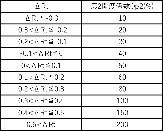
また、制御部60は設定温度と内気温度の差ΔRtに基づいてダンパーの第2開度係数Op2を設定する。表3はΔRtとOp2との対応表であり、ΔRtとOp2との対応関係が10通り設定されている。例えば設定温度が20.2℃、内気温度が20℃の場合、ΔRtは0.2℃になり第2開度係数Op2は60%になる。
次に制御部60は第1開度係数Op1と第2開度係数Op2を掛けた値をダンパーの確定開度係数Opに設定する。例えばOp1が80%、Op2が60%の場合、Op=(80/100)×(60/100)=48/100(=48%)になる。
制御部60はダンパー31の開度が48%になるようにダンパー駆動部50の駆動を制御して、空間A内の空気を第1燃焼部30に取り込ませる。なお、第1開度係数Op1と第2開度係数Op2を掛けた値が100%を超えた場合は確定開度係数Op=100%にする。
Next, the control unit 60 sets the value obtained by multiplying the first opening coefficient Op1 and the second opening coefficient Op2 as the fixed opening coefficient Op of the damper. For example, when Op1 is 80% and Op2 is 60%, Op = (80/100) × (60/100) = 48/100 (= 48%).
The control unit 60 controls the drive of the damper drive unit 50 so that the opening degree of the damper 31 becomes 48%, and causes the air in the space A to be taken into the first combustion unit 30. If the value obtained by multiplying the first opening coefficient Op1 and the second opening coefficient Op2 exceeds 100%, the fixed opening coefficient Op = 100%.
[第2の実施の形態]
本発明の温度制御システムの第2の実施の形態について説明するが、上記第1の実施の形態と同一の構成になる箇所については同一の符号を付してその説明を省略する。上記第1の実施の形態は燃焼モードにおける温度制御システム1の構成及び温度制御方法について説明したが、本実施の形態では燃焼モードの前段階にあたる点火モードでの温度制御システムの構成及び温度制御方法について説明する。
[Second embodiment]
The second embodiment of the temperature control system of the present invention will be described, but the same reference numerals will be given to the parts having the same configuration as the first embodiment, and the description thereof will be omitted. The first embodiment described the configuration and temperature control method of the temperature control system 1 in the combustion mode, but in the present embodiment, the configuration and temperature control method of the temperature control system in the ignition mode, which is the stage before the combustion mode. Will be explained.
図3に示すように本実施の形態では温度制御システム2が第2燃焼部70を備える点に特徴を有する。
第2燃焼部70は化石燃料の燃焼熱を利用して空間A内の空気を加温するものである。化石燃料としては灯油や天然ガスが挙げられる。第2燃焼部70として市販の石油ストーブ、石油ファンヒーター、ガスストーブ、ガスヒーター等を使用してもよいが、第2燃焼部70の駆動制御を制御部60で行えるようにする必要がある。
制御部60は、第1燃焼部30を稼働させてから一定時間が経過するまでの点火モードでは第2燃焼部70を稼働させる。つまり、点火モード中は第1燃焼部30と第2燃焼部70の両方を稼働させることになる。
制御部60は内気温度と外気温度の差Δtに基づいて点火モードでの実排気温度の目標値である点火モード時目標排気温度を設定する。表4はΔtと点火モード時目標排気温度との対応表であり、Δtと点火モード時目標排気温度との対応関係が10通り設定されている。例えば内気温度が10℃、外気温度が5℃の場合、Δtは5℃になり点火モード時目標排気温度は299℃になる。

The second combustion unit 70 heats the air in the space A by using the combustion heat of the fossil fuel. Examples of fossil fuels include kerosene and natural gas. A commercially available oil stove, oil fan heater, gas stove, gas heater, or the like may be used as the second combustion unit 70, but it is necessary to enable the control unit 60 to control the drive of the second combustion unit 70.
The control unit 60 operates the second combustion unit 70 in the ignition mode from the operation of the first combustion unit 30 until a certain period of time elapses. That is, in the ignition mode, both the first combustion unit 30 and the second combustion unit 70 are operated.
The control unit 60 sets the target exhaust temperature in the ignition mode, which is the target value of the actual exhaust temperature in the ignition mode, based on the difference Δt between the inside air temperature and the outside air temperature. Table 4 is a correspondence table between Δt and the target exhaust temperature in the ignition mode, and 10 correspondence relationships between Δt and the target exhaust temperature in the ignition mode are set. For example, when the inside air temperature is 10 ° C and the outside air temperature is 5 ° C, Δt is 5 ° C and the target exhaust temperature in ignition mode is 299 ° C.
制御部60は第1燃焼部30を稼働させてからの実排気温度の時間変化をチェックし続ける。そして、図1のグラフに示すように実排気温度が点火モード時目標排気温度に到達し(時間T1)、且つ第1燃焼部30が稼働してからの実排気温度の時間変化を示す実排気温度-時間曲線Lにおける時間積分値(曲線Lの網掛け部分Aの面積)が事前に定めておいた目標積分値Sに到達した時点(時間T2)で第2燃焼部70の稼働を停止して点火モードを終了させ、燃焼モードに移行する。
表5はΔtと目標積分値Sとの対応表であり、ΔtとSとの対応関係が10通り設定されている。例えば内気温度が10℃、外気温度が5℃の場合、Δtは5℃になり目標積分値Sは17,292[℃・時間]になる。なお、実排気温度センサ22による実排気温度の測定は毎秒行う必要はなく、例えば10秒毎に行うことにしてもよい。

Table 5 is a correspondence table between Δt and the target integral value S, and 10 correspondence relationships between Δt and S are set. For example, when the inside air temperature is 10 ° C and the outside air temperature is 5 ° C, Δt is 5 ° C and the target integral value S is 17,292 [° C / hour]. It should be noted that the measurement of the actual exhaust temperature by the actual exhaust temperature sensor 22 does not have to be performed every second, and may be performed, for example, every 10 seconds.
実排気温度が点火モード時目標排気温度に到達した時点(時間T1)で点火モードを終了させないのは空間A内の熱容量を考慮しているためである。時間T1ですぐに第2燃焼部70の稼働を停止し点火モードを終了させて燃焼モードに移行してしまうと内気温度が設定温度よりも大きく低下してしまうおそれがある。本実施の形態のように時間T1を経過した後、曲線Lの網掛け部分Aの面積が目標積分値Sに到達するまで待つことで空間A全体を充分に温まった状態にすることができ、燃焼モードに移行しても内気温度が設定温度から大きく低下する事態を防止できる。
なお、第1燃焼部30の稼働直後(時間T0)はダンパーの開度係数を100%にしておき、実排気温度が点火モード時目標排気温度に近づくにつれてダンパーの開度係数を小さくしてダンパーを閉じていくようにしてもよい。
The reason why the ignition mode is not terminated when the actual exhaust temperature reaches the target exhaust temperature in the ignition mode (time T1) is because the heat capacity in the space A is taken into consideration. If the operation of the second combustion unit 70 is immediately stopped at time T1 and the ignition mode is terminated to shift to the combustion mode, the inside air temperature may drop significantly below the set temperature. After the lapse of time T1 as in the present embodiment, the entire space A can be sufficiently warmed by waiting until the area of the shaded portion A of the curve L reaches the target integral value S. Even if the combustion mode is entered, it is possible to prevent the inside air temperature from dropping significantly from the set temperature.
Immediately after the operation of the first combustion unit 30 (time T0), the opening coefficient of the damper is set to 100%, and the opening coefficient of the damper is reduced as the actual exhaust temperature approaches the target exhaust temperature in the ignition mode. You may try to close.
[第3の実施の形態]
本発明の温度制御システムの第3の実施の形態について説明するが、上記各実施の形態と同一の構成になる箇所については同一の符号を付してその説明を省略する。本実施の形態では燃焼モードの後段階にあたる焚き終わりモードでの温度制御システムの構成及び温度制御方法について説明する。
図1のグラフに示すように制御部60は、燃焼モード中に内気温度が設定温度よりも低い状態が一定時間(例えば10分)連続した場合には燃焼モードを終了させ、次に焚き終わりモードに移行する。燃焼モード中に内気温度が設定温度よりも低い状態が一定時間連続するということは第1燃焼部30内の木質バイオマス燃料10が減ってしまい、充分な燃焼熱を放出できなくなった状態であるため、焚き終わりモードではダンパーの開度を100%に設定して木質バイオマスを完全燃焼させる。また、内気温度が設定温度よりも低下した状態が長く続くことを防ぐために制御部60は第2燃焼部70を再び稼働させる。焚き終わりモードでは実排気温度が徐々に低下していくが、第2燃焼部70を稼働させるので内気温度を設定温度に近い状態に維持できる。
[Third embodiment]
A third embodiment of the temperature control system of the present invention will be described, but the same reference numerals will be given to the parts having the same configuration as each of the above embodiments, and the description thereof will be omitted. In this embodiment, the configuration of the temperature control system and the temperature control method in the end-heating mode, which is the latter stage of the combustion mode, will be described.
As shown in the graph of FIG. 1, the control unit 60 terminates the combustion mode when the inside air temperature is continuously lower than the set temperature for a certain period of time (for example, 10 minutes) during the combustion mode, and then the combustion end mode. Move to. The fact that the inside air temperature is lower than the set temperature continuously for a certain period of time during the combustion mode means that the woody biomass fuel 10 in the first combustion unit 30 has decreased and sufficient combustion heat cannot be released. In the end-heating mode, the damper opening is set to 100% to completely burn the woody biomass. Further, the control unit 60 restarts the second combustion unit 70 in order to prevent the inside air temperature from falling below the set temperature for a long time. In the end-heating mode, the actual exhaust temperature gradually decreases, but since the second combustion unit 70 is operated, the inside air temperature can be maintained close to the set temperature.
次に、温度制御システムの制御の流れについてフローチャートを用いて説明する。
図4に示すように点火モードでは作業者が制御部60を操作して第1燃焼部30と第2燃焼部70を稼働させる(ステップS101)。この時点でのダンパーの開度係数は100%にしておく。なお、点火モードを開始する前に予め第2燃焼部70を稼働させておいてもよい。内気温度センサ20及び外気温度センサ21により内気温度及び外気温度が測定され(ステップS102)、制御部60は内気温度と外気温度の差に基づいて点火モード時目標排気温度を設定する(ステップS103)。制御部60は実排気温度が点火モード時目標排気温度に到達した否かを判定し(ステップS104)、到達していない場合(ステップS104でNo)、実排気温度の上昇に伴ってダンパーの開度係数を小さくしていく(ステップS105)。また、制御部60は温風センサ46で測定した空気吹き出し口45での空気の温度に基づいてファン43の駆動を制御して温風の風量を適宜調節する(ステップS106)。一方、実排気温度が点火モード時目標排気温度に到達した場合(ステップS104でYes)、制御部60は時間積分値が目標積分値Sに到達したか否かを判定し(ステップS107)、到達した場合(ステップS107でYes)、制御部60は第2燃焼部70の稼働を停止して(ステップS108)、点火モードを終了し(ステップS109)、燃焼モードに移行する(ステップS201)。
Next, the control flow of the temperature control system will be described using a flowchart.
As shown in FIG. 4, in the ignition mode, the operator operates the control unit 60 to operate the first combustion unit 30 and the second combustion unit 70 (step S101). The opening coefficient of the damper at this point is set to 100%. The second combustion unit 70 may be operated in advance before starting the ignition mode. The inside air temperature and the outside air temperature are measured by the inside air temperature sensor 20 and the outside air temperature sensor 21 (step S102), and the control unit 60 sets the target exhaust temperature in the ignition mode based on the difference between the inside air temperature and the outside air temperature (step S103). .. The control unit 60 determines whether or not the actual exhaust temperature has reached the target exhaust temperature in the ignition mode (step S104), and if not (No in step S104), the damper is opened as the actual exhaust temperature rises. Decrease the degree coefficient (step S105). Further, the control unit 60 controls the drive of the fan 43 based on the temperature of the air at the air outlet 45 measured by the warm air sensor 46, and appropriately adjusts the air volume of the hot air (step S106). On the other hand, when the actual exhaust temperature reaches the target exhaust temperature in the ignition mode (Yes in step S104), the control unit 60 determines whether or not the time integrated value has reached the target integrated value S (step S107), and reaches the target. If so (Yes in step S107), the control unit 60 stops the operation of the second combustion unit 70 (step S108), ends the ignition mode (step S109), and shifts to the combustion mode (step S201).
燃焼モードでは制御部60は燃焼モード時目標排気温度を設定し(ステップS202)、ダンパーの第1開度係数Op1及び第2開度係数Op2を設定し(ステップS203)、確定開度係数Opを設定する(ステップS204)。制御部60は確定開度係数Opに基づいてダンパー駆動部50の駆動を制御し(ステップS205)、空間A内の温度が設定温度に近づくように制御する。制御部60は内気温度が設定温度よりも低い状態が一定時間連続した場合(ステップS206でYes)、燃焼モードを終了し(ステップS207)、焚き終わりモードに移行する(ステップS301)。 In the combustion mode, the control unit 60 sets the target exhaust temperature in the combustion mode (step S202), sets the first opening coefficient Op1 and the second opening coefficient Op2 of the damper (step S203), and sets the fixed opening coefficient Op. Set (step S204). The control unit 60 controls the drive of the damper drive unit 50 based on the fixed opening coefficient Op (step S205), and controls the temperature in the space A to approach the set temperature. When the state where the inside air temperature is lower than the set temperature continues for a certain period of time (Yes in step S206), the control unit 60 ends the combustion mode (step S207) and shifts to the burning end mode (step S301).
焚き終わりモードでは制御部60はダンパーの開度を100%に設定し(ステップS302)、第2燃焼部70を再び稼働させる(ステップS303)。焚き終わりモードの終了タイミングは特に限定されず、例えば作業者が制御部60を操作して第2燃焼部70の稼働を停止させた時点で終了にしたり、或いは実排気温度が極端に低下したタイミングで制御部60が第2燃焼部70の稼働を停止させたりして焚き終わりモードを終了することにすればよい。なお、焚き終わりモード中に実排気温度が燃焼モード時目標排気温度まで戻ったときには再び燃焼モードに移行するようにしてもよい。 In the end-heating mode, the control unit 60 sets the damper opening to 100% (step S302) and restarts the second combustion unit 70 (step S303). The end timing of the heating end mode is not particularly limited. For example, the end timing is when the operator operates the control unit 60 to stop the operation of the second combustion unit 70, or the timing when the actual exhaust temperature drops extremely. Then, the control unit 60 may stop the operation of the second combustion unit 70 to end the heating end mode. When the actual exhaust temperature returns to the target exhaust temperature in the combustion mode during the end-heating mode, the combustion mode may be resumed.
本発明は、設定温度に速やかに到達でき、且つ設定温度を精度よく維持することができる木質バイオマス燃料を使用する温度制御システムであり、産業上の利用可能性を有する。 The present invention is a temperature control system using woody biomass fuel that can quickly reach the set temperature and maintain the set temperature accurately, and has industrial applicability.
A 空間
1 温度制御システム
2 温度制御システム
10 木質バイオマス燃料
20 内気温度センサ
21 外気温度センサ
22 実排気温度センサ
30 第1燃焼部
31 ダンパー
32 排気ガス
33 燃焼室
34 排気筒
40 熱交換部
41 筐体
42 熱交換路
43 ファン
44 空気取り入れ口
45 空気吹き出し口
46 温風センサ
50 ダンパー駆動部
60 制御部
70 第2燃焼部
A space
1 Temperature control system
2 Temperature control system
10 Woody biomass fuel
20 Inside air temperature sensor
21 Outside air temperature sensor
22 Actual exhaust temperature sensor
30 1st combustion part
31 damper
32 Exhaust gas
33 Combustion chamber
34 Exhaust pipe
40 Heat exchanger
41 chassis
42 heat exchange path
43 fans
44 Air intake
45 Air outlet
46 Warm air sensor
50 Damper drive unit
60 Control unit
70 2nd combustion part
Claims (4)
前記内気温度を測定する内気温度センサと、
前記空間の外気温度を測定する外気温度センサと、
前記空間内の空気を開閉自在なダンパーを介して取り込み、取り込んだ空気を利用して前記木質バイオマス燃料を燃焼させると共に排気ガスを外部に排出する第1燃焼部と、
前記排気ガスが外部に排出される際の実排気温度を測定する実排気温度センサと、
前記空間内の空気を取り込み、取り込んだ空気を前記排気ガスの熱を利用して加温し、加温した空気を前記空間内に送り込む熱交換部と、
前記ダンパーを開閉させるダンパー駆動部と、
前記第1燃焼部、前記熱交換部及び前記ダンパー駆動部の駆動を制御する制御部とを備えており、
燃焼モード中の前記制御部は、前記内気温度と前記外気温度の差に基づいて前記実排気温度の目標値である燃焼モード時目標排気温度を設定し、次に前記燃焼モード時目標排気温度と前記実排気温度の差に基づいて前記ダンパーの第1開度係数を設定すると共に前記設定温度と前記内気温度の差に基づいて前記ダンパーの第2開度係数を設定し、次に前記第1開度係数と前記第2開度係数を掛けた値を前記ダンパーの確定開度係数に設定し、当該確定開度係数に基づいて前記ダンパー駆動部の駆動を制御することを特徴とする温度制御システム。
In a temperature control system that uses the combustion heat of woody biomass fuel to control the internal air temperature of the space so that it approaches the set temperature.
The inside air temperature sensor that measures the inside air temperature and
An outside air temperature sensor that measures the outside air temperature in the space,
The first combustion unit, which takes in the air in the space through a damper that can be opened and closed, burns the woody biomass fuel using the taken in air, and discharges the exhaust gas to the outside.
An actual exhaust temperature sensor that measures the actual exhaust temperature when the exhaust gas is discharged to the outside,
A heat exchange unit that takes in the air in the space, heats the taken-in air by using the heat of the exhaust gas, and sends the heated air into the space.
A damper drive unit that opens and closes the damper,
It includes a first combustion unit, a heat exchange unit, and a control unit that controls the drive of the damper drive unit.
The control unit in the combustion mode sets the target exhaust temperature in the combustion mode, which is the target value of the actual exhaust temperature, based on the difference between the inside air temperature and the outside air temperature, and then sets the target exhaust temperature in the combustion mode. The first opening coefficient of the damper is set based on the difference in the actual exhaust temperature, and the second opening coefficient of the damper is set based on the difference between the set temperature and the inside air temperature, and then the first opening coefficient is set. Temperature control characterized in that a value obtained by multiplying the opening coefficient by the second opening coefficient is set as the fixed opening coefficient of the damper, and the drive of the damper drive unit is controlled based on the fixed opening coefficient. system.
前記制御部は、前記第1燃焼部を稼働させてから一定時間が経過するまでの点火モードでは前記第2燃焼部を稼働させ、前記内気温度と前記外気温度の差に基づいて前記点火モードでの前記実排気温度の目標値である点火モード時目標排気温度を設定し、前記実排気温度が前記点火モード時目標排気温度に到達し、且つ前記第1燃焼部が稼働してからの前記実排気温度の時間変化を示す実排気温度-時間曲線における時間積分値が事前に定めておいた目標積分値に到達した時点で前記第2燃焼部の稼働を停止して前記点火モードを終了させ、前記燃焼モードに移行することを特徴とする請求項1に記載の温度制御システム。
Furthermore, it is equipped with a second combustion unit that heats the air in the space using the combustion heat of fossil fuel.
The control unit operates the second combustion unit in the ignition mode from the operation of the first combustion unit until a certain time elapses, and in the ignition mode based on the difference between the inside air temperature and the outside air temperature. The target exhaust temperature in the ignition mode, which is the target value of the actual exhaust temperature, is set, the actual exhaust temperature reaches the target exhaust temperature in the ignition mode, and the actual first combustion unit is operated. When the time integrated value in the actual exhaust temperature-time curve indicating the time change of the exhaust temperature reaches the predetermined target integrated value, the operation of the second combustion unit is stopped and the ignition mode is terminated. The temperature control system according to claim 1, wherein the temperature control system shifts to the combustion mode.
The control unit terminates the combustion mode when the inside air temperature is continuously lower than the set temperature for a certain period of time during the combustion mode, then shifts to the combustion end mode, and opens the damper. The temperature control system according to claim 1 or 2, wherein the temperature is set to 100% and the second combustion unit is operated.
Priority Applications (1)
| Application Number | Priority Date | Filing Date | Title |
|---|---|---|---|
| JP2020116107A JP2022014001A (en) | 2020-07-06 | 2020-07-06 | Temperature control system using woody biomass fuel |
Applications Claiming Priority (1)
| Application Number | Priority Date | Filing Date | Title |
|---|---|---|---|
| JP2020116107A JP2022014001A (en) | 2020-07-06 | 2020-07-06 | Temperature control system using woody biomass fuel |
Publications (1)
| Publication Number | Publication Date |
|---|---|
| JP2022014001A true JP2022014001A (en) | 2022-01-19 |
Family
ID=80185107
Family Applications (1)
| Application Number | Title | Priority Date | Filing Date |
|---|---|---|---|
| JP2020116107A Pending JP2022014001A (en) | 2020-07-06 | 2020-07-06 | Temperature control system using woody biomass fuel |
Country Status (1)
| Country | Link |
|---|---|
| JP (1) | JP2022014001A (en) |
-
2020
- 2020-07-06 JP JP2020116107A patent/JP2022014001A/en active Pending
Similar Documents
| Publication | Publication Date | Title |
|---|---|---|
| EP2635945B1 (en) | Controller for biofuel-fired boiler | |
| EP3044513B1 (en) | Fuel feed and air feed controller for biofuel-fired furnace | |
| US20110073101A1 (en) | Control system for heating systems | |
| CN112484313A (en) | Control method, processor, device and storage medium for gas water heater | |
| US5971284A (en) | Apparatus for regulating heater cycles to improve forced-air heating system efficiency | |
| US20210190365A1 (en) | Method, System and Temperature Control of a Heating, Ventilation and Air Conditioning Unit | |
| JP2022014001A (en) | Temperature control system using woody biomass fuel | |
| US6904874B1 (en) | Forward calculation energy augmentation method | |
| NO20221396A1 (en) | A chimney control assembly for minimizing particle emission in a fuel burning heating device and a method for minimizing particle emission in a fuel burning heating device | |
| US11499752B2 (en) | Systems and methods for preventing short cycling in high-efficiency water heaters | |
| JP5557708B2 (en) | Hot air heater for facility horticulture and its cooling control method | |
| RU35561U1 (en) | Flue gas device | |
| AU742129B2 (en) | Apparatus for regulating heater cycles to improve forced-air heating system efficiency | |
| EP2902709B1 (en) | Multiphase method for controlling an air flow into the hearth of a fireplace for solid fuels, especially wood | |
| CN120890115A (en) | Heating load regulation methods and gas boilers using these methods | |
| AU2021332942A9 (en) | Electronic closed-loop control device for fireplaces comprising a lower combustion system | |
| KR20260010135A (en) | Apparatus and method for controlling combustion heat based on temperature and time | |
| JP3756998B2 (en) | Hot water heater and combustion control method during re-watering | |
| CN121067379A (en) | Heating load control methods and gas boilers using these methods | |
| CZ34162U1 (en) | Equipment with adjustable flue gas temperature with fireplace and flue gas exchanger | |
| CZ2008410A3 (en) | Method of controlling heat output of gas-burning air heaters or gas infrared radiators and apparatus for making the same | |
| JP2004125245A (en) | Heating combustor for automatically controlling combustion quantity | |
| JP2016073241A (en) | Control method of hot air heater for protected horticulture | |
| BE1022691A1 (en) | Smoke exhaust | |
| JP2014214899A (en) | Renewable fuel firing warm air heater and control method thereof |