JP2021515625A - Personal tourniquet for intermittent vascular occlusion - Google Patents
Personal tourniquet for intermittent vascular occlusion Download PDFInfo
- Publication number
- JP2021515625A JP2021515625A JP2020546173A JP2020546173A JP2021515625A JP 2021515625 A JP2021515625 A JP 2021515625A JP 2020546173 A JP2020546173 A JP 2020546173A JP 2020546173 A JP2020546173 A JP 2020546173A JP 2021515625 A JP2021515625 A JP 2021515625A
- Authority
- JP
- Japan
- Prior art keywords
- pressure
- cuff
- ptp
- level
- air bag
- Prior art date
- Legal status (The legal status is an assumption and is not a legal conclusion. Google has not performed a legal analysis and makes no representation as to the accuracy of the status listed.)
- Pending
Links
Images


Classifications
-
- A—HUMAN NECESSITIES
- A61—MEDICAL OR VETERINARY SCIENCE; HYGIENE
- A61B—DIAGNOSIS; SURGERY; IDENTIFICATION
- A61B5/00—Measuring for diagnostic purposes; Identification of persons
- A61B5/02—Detecting, measuring or recording for evaluating the cardiovascular system, e.g. pulse, heart rate, blood pressure or blood flow
- A61B5/026—Measuring blood flow
- A61B5/0261—Measuring blood flow using optical means, e.g. infrared light
-
- A—HUMAN NECESSITIES
- A61—MEDICAL OR VETERINARY SCIENCE; HYGIENE
- A61B—DIAGNOSIS; SURGERY; IDENTIFICATION
- A61B17/00—Surgical instruments, devices or methods
- A61B17/12—Surgical instruments, devices or methods for ligaturing or otherwise compressing tubular parts of the body, e.g. blood vessels or umbilical cord
- A61B17/132—Tourniquets
- A61B17/135—Tourniquets inflatable
- A61B17/1355—Automated control means therefor
-
- A—HUMAN NECESSITIES
- A61—MEDICAL OR VETERINARY SCIENCE; HYGIENE
- A61H—PHYSICAL THERAPY APPARATUS, e.g. DEVICES FOR LOCATING OR STIMULATING REFLEX POINTS IN THE BODY; ARTIFICIAL RESPIRATION; MASSAGE; BATHING DEVICES FOR SPECIAL THERAPEUTIC OR HYGIENIC PURPOSES OR SPECIFIC PARTS OF THE BODY
- A61H1/00—Apparatus for passive exercising; Vibrating apparatus; Chiropractic devices, e.g. body impacting devices, external devices for briefly extending or aligning unbroken bones
-
- A—HUMAN NECESSITIES
- A61—MEDICAL OR VETERINARY SCIENCE; HYGIENE
- A61B—DIAGNOSIS; SURGERY; IDENTIFICATION
- A61B17/00—Surgical instruments, devices or methods
- A61B2017/00017—Electrical control of surgical instruments
- A61B2017/00022—Sensing or detecting at the treatment site
-
- A—HUMAN NECESSITIES
- A61—MEDICAL OR VETERINARY SCIENCE; HYGIENE
- A61B—DIAGNOSIS; SURGERY; IDENTIFICATION
- A61B17/00—Surgical instruments, devices or methods
- A61B2017/00017—Electrical control of surgical instruments
- A61B2017/00115—Electrical control of surgical instruments with audible or visual output
- A61B2017/00119—Electrical control of surgical instruments with audible or visual output alarm; indicating an abnormal situation
-
- A—HUMAN NECESSITIES
- A61—MEDICAL OR VETERINARY SCIENCE; HYGIENE
- A61B—DIAGNOSIS; SURGERY; IDENTIFICATION
- A61B17/00—Surgical instruments, devices or methods
- A61B2017/00017—Electrical control of surgical instruments
- A61B2017/00132—Setting operation time of a device
-
- A—HUMAN NECESSITIES
- A61—MEDICAL OR VETERINARY SCIENCE; HYGIENE
- A61B—DIAGNOSIS; SURGERY; IDENTIFICATION
- A61B17/00—Surgical instruments, devices or methods
- A61B2017/00017—Electrical control of surgical instruments
- A61B2017/00199—Electrical control of surgical instruments with a console, e.g. a control panel with a display
-
- A—HUMAN NECESSITIES
- A61—MEDICAL OR VETERINARY SCIENCE; HYGIENE
- A61B—DIAGNOSIS; SURGERY; IDENTIFICATION
- A61B17/00—Surgical instruments, devices or methods
- A61B2017/00017—Electrical control of surgical instruments
- A61B2017/00221—Electrical control of surgical instruments with wireless transmission of data, e.g. by infrared radiation or radiowaves
-
- A—HUMAN NECESSITIES
- A61—MEDICAL OR VETERINARY SCIENCE; HYGIENE
- A61B—DIAGNOSIS; SURGERY; IDENTIFICATION
- A61B90/00—Instruments, implements or accessories specially adapted for surgery or diagnosis and not covered by any of the groups A61B1/00 - A61B50/00, e.g. for luxation treatment or for protecting wound edges
- A61B90/06—Measuring instruments not otherwise provided for
- A61B2090/064—Measuring instruments not otherwise provided for for measuring force, pressure or mechanical tension
-
- A—HUMAN NECESSITIES
- A61—MEDICAL OR VETERINARY SCIENCE; HYGIENE
- A61B—DIAGNOSIS; SURGERY; IDENTIFICATION
- A61B90/00—Instruments, implements or accessories specially adapted for surgery or diagnosis and not covered by any of the groups A61B1/00 - A61B50/00, e.g. for luxation treatment or for protecting wound edges
- A61B90/08—Accessories or related features not otherwise provided for
- A61B2090/0807—Indication means
-
- A—HUMAN NECESSITIES
- A61—MEDICAL OR VETERINARY SCIENCE; HYGIENE
- A61B—DIAGNOSIS; SURGERY; IDENTIFICATION
- A61B90/00—Instruments, implements or accessories specially adapted for surgery or diagnosis and not covered by any of the groups A61B1/00 - A61B50/00, e.g. for luxation treatment or for protecting wound edges
- A61B90/90—Identification means for patients or instruments, e.g. tags
- A61B90/98—Identification means for patients or instruments, e.g. tags using electromagnetic means, e.g. transponders
Landscapes
- Health & Medical Sciences (AREA)
- Life Sciences & Earth Sciences (AREA)
- Surgery (AREA)
- Animal Behavior & Ethology (AREA)
- General Health & Medical Sciences (AREA)
- Veterinary Medicine (AREA)
- Public Health (AREA)
- Hematology (AREA)
- Engineering & Computer Science (AREA)
- Biomedical Technology (AREA)
- Heart & Thoracic Surgery (AREA)
- Medical Informatics (AREA)
- Molecular Biology (AREA)
- Biophysics (AREA)
- Nuclear Medicine, Radiotherapy & Molecular Imaging (AREA)
- Vascular Medicine (AREA)
- Reproductive Health (AREA)
- Cardiology (AREA)
- Physiology (AREA)
- Physics & Mathematics (AREA)
- Pathology (AREA)
- Epidemiology (AREA)
- Pain & Pain Management (AREA)
- Physical Education & Sports Medicine (AREA)
- Rehabilitation Therapy (AREA)
- Surgical Instruments (AREA)
- Measuring Pulse, Heart Rate, Blood Pressure Or Blood Flow (AREA)
Abstract
個人向け止血帯圧力(PTP)に基づく間欠的血管閉塞のための装置は、膨張可能空気袋を有する二重目的止血帯カフと、当該カフを通過する血液侵入が止められる最小圧力を識別するべく遠位閉塞圧力(DOP)を示す圧力脈動を検知して特徴付けるように当該膨張可能空気袋と空気圧により連通する脈動センサを有するセンサモジュールと、DOPの関数であるPTPの推定を生成するべく当該脈動センサに応答するPTP推定器と、第1の期間中に当該空気袋内の圧力をPPT近くに維持して第2の期間中に当該空気袋内の圧力を第2の圧力レベル近くに維持するべく当該膨張可能空気袋と空気圧により連通するエフェクタモジュールと、当該センサモジュール及びエフェクタモジュールと協働して当該膨張可能空気袋を選択的に作動させるコントローラとを含む。A device for intermittent vascular occlusion based on personalized hemostatic band pressure (PTP) is intended to distinguish between a dual purpose hemostatic band cuff with an inflatable air bag and the minimum pressure at which blood invasion through the cuff is stopped. A sensor module with a pulsation sensor that communicates with the inflatable air bag by air pressure to detect and characterize a pressure pulsation indicating distal occlusion pressure (DOP), and the pulsation to generate an estimate of PTP, which is a function of DOP. A PTP estimator that responds to the sensor and keeps the pressure in the air bag close to the PPT during the first period and keeps the pressure in the air bag close to the second pressure level during the second period. It includes an effector module that communicates with the inflatable air bag by air pressure, and a controller that selectively operates the inflatable air bag in cooperation with the sensor module and the effector module.
Description
関連出願の相互参照
本願は、2018年3月5日に出願された米国特許出願第15/912,390号の一部継続出願であり、これは、2015年4月27日に出願された米国特許出願第14/837,999号の一部継続出願(現在の米国特許第9,931,126号)であり、これは、2015年4月25日に出願された米国特許出願第14/696,401号の一部継続出願(現在の米国特許第9,814,467号)であり、これは、2014年7月10日に出願された米国特許出願第14/328,607号の一部継続出願(現在の米国特許第9,039,730号)の一部継続出願であり、これらはすべて参照によりここに組み入れられる。
Mutual Reference to Related Applications This application is a partial continuation of US Patent Application No. 15 / 912,390 filed March 5, 2018, which was filed April 27, 2015 in the United States. This is a partial continuation application of Patent Application No. 14 / 837,999 (currently U.S. Patent No. 9,931,126), which is U.S. Patent Application No. 14/696 filed on April 25, 2015. , 401, a partial continuation application (currently U.S. Pat. No. 9,814,467), which is part of U.S. Patent Application No. 14 / 328,607 filed on July 10, 2014. It is a partial continuation application of a continuation application (currently US Pat. No. 9,039,730), all of which are incorporated herein by reference.
本発明は、一患者の一領域への動脈血の侵入を止めて外科的又は医学的処置の実行を容易にするべく一般的に使用される空気式止血帯システムに関する。詳しくは、本発明は個人用の止血帯圧力を一定時間確立及び維持する空気式止血帯の方法及び装置に関する。 The present invention relates to a pneumatic tourniquet system commonly used to stop the invasion of arterial blood into an area of a patient and facilitate the performance of surgical or medical procedures. More specifically, the present invention relates to methods and devices for pneumatic tourniquets that establish and maintain personal tourniquet pressure for a period of time.
外科的止血帯システムは、患者の肢の一部又は一領域への動脈血の侵入を止め、ひいては外科的処置の実行を容易にして結果を改善するきれいな乾燥した外科的領域をもたらすべく一般に使用される。先行技術の典型的な外科的止血帯システムは、患者の肢を所望箇所において取り囲むための止血帯カフ、止血帯器具、及び当該カフを当該器具に接続する可撓性チューブを含む。先行技術のいくつかの外科用止血帯システムにおいて、止血帯カフは、一つ又は2つのカフポートに取り付けられた可撓性チューブを介して止血帯器具に、空気圧により接続される膨張可能な空気袋を含む。止血帯器具は、カフの膨張可能空気袋内の圧力を基準圧力近くに維持するための圧力レギュレータを含む。この基準圧力は、外科的処置の実行のための適度に長い時間の間に所望箇所で患者の肢に適用されるときにカフを通過する動脈血の侵入を止めるのに必要な最小圧力を上回る。かかる空気式外科用止血帯システムの多くのタイプが、McEwenによる記載の特許文献1〜3、McEwen及びJamesonによる記載の特許文献4及び5のように、先行技術に記載されている。(
Surgical tourniquet systems are commonly used to stop the invasion of arterial blood into a portion or area of a patient's limb, thus providing a clean, dry surgical area that facilitates the performance of surgical procedures and improves results. To. A typical surgical tourniquet system of the prior art includes a tourniquet cuff to surround the patient's limb where desired, a tourniquet device, and a flexible tube connecting the cuff to the device. In some prior art surgical tourniquet systems, the tourniquet cuff is an inflatable air bag that is pneumatically connected to the tourniquet device via a flexible tube attached to one or two cuff ports. including. The tourniquet device includes a pressure regulator to keep the pressure in the inflatable air bag of the cuff close to the reference pressure. This reference pressure exceeds the minimum pressure required to stop the invasion of arterial blood through the cuff when applied to the patient's limb at the desired location over a reasonably long time for performing a surgical procedure. Many types of such pneumatic surgical tourniquet systems are described in the prior art, such as Patent Documents 1 to 3 described by McEwen and
先行技術の止血帯カフは、数分から数時間に及ぶ手術時間の間、適用されたカフを通過する動脈血の侵入を止める高圧を適用するエフェクタとして機能するように設計される。先行技術の止血帯カフは、他の目的のために設計及び使用される空気圧カフとは実質的に異なる。例えば、血圧の間欠的測定に使用される空気圧カフは典型的に、一肢を包囲しないカフの膨張可能空気袋部分の下の選択された動脈に、はるかに短い時間ではるかに低い圧力を適用するように設計される。かかるカフは、最も安全かつ最も効果的な止血帯カフの重要な設計パラメータとは根本的に異なる設計基準を満たす必要がある。先行技術の止血帯カフは、検知目的を果たすように設計されておらず、先行技術の血圧カフは、エフェクタ目的を果たすように設計されていない。 Prior art tourniquet cuffs are designed to act as effectors that apply high pressure to stop the invasion of arterial blood through the applied cuff during surgical hours ranging from minutes to hours. Prior art tourniquet cuffs are substantially different from pneumatic cuffs designed and used for other purposes. For example, pneumatic cuffs used for intermittent measurement of blood pressure typically apply much lower pressure to selected arteries under the inflatable pouch portion of the cuff that does not surround one limb in a much shorter time. Designed to do. Such cuffs must meet design criteria that are radically different from the key design parameters of the safest and most effective tourniquet cuffs. Prior art tourniquet cuffs are not designed to serve detection objectives, and prior art blood pressure cuffs are not designed to serve effector objectives.
下にある動脈を閉じるべく加圧された止血帯カフによって一肢に適用される内向きの圧縮力は、近位端から遠位端までのカフの幅にわたって等しいわけではない。その結果、止血帯カフの遠位端を通過する動脈血流を止めるのに必要な最小圧力まで膨張させた場合、当該肢内の動脈血は、動脈が閉鎖される箇所までの一定距離に対しては依然としてカフの近位端の下に侵入する。選択された止血帯カフが膨張する空気圧に加え、いくつかの変数が、カフの下で動脈血が通過する距離に影響する。これらの変数は、患者の肢の特徴(例えば肢の形状、周囲、及びカフ箇所の軟組織の特徴)、選択された止血帯カフの特徴(例えばカフ設計、カフ形状及びカフ幅、カフを肢に適用する技法(適用の快適性又は緩みの程度、及び下にある肢保護スリーブの不在、存在及びタイプ)、血圧及び肢温を含む患者の生理学的特徴、手術中に用いられる麻酔技法(例えば全身麻酔又は局所麻酔、用いられる麻酔薬の種類及び用量、並びに麻酔管理への注意の程度)、止血帯が肢において膨張したままでいる時間の長さ、手術中の肢位置の変化、並びに手術中の肢に対するカフの箇所のシフト、を含む。 The inward compressive force applied to a limb by a tourniquet cuff pressurized to close the underlying artery is not equal across the width of the cuff from the proximal end to the distal end. As a result, when inflated to the minimum pressure required to stop arterial blood flow through the distal end of the tourniquet cuff, the arterial blood in the limb is relative to a certain distance to where the artery is closed. Still penetrates under the proximal end of the cuff. In addition to the air pressure at which the selected tourniquet cuff expands, several variables affect the distance that arterial blood travels under the cuff. These variables are the characteristics of the patient's limb (eg, limb shape, circumference, and soft tissue features at the cuff location), the characteristics of the selected tourniquet cuff (eg, cuff design, cuff shape and cuff width, cuff to limb). Techniques applied (comfort or degree of looseness of application, and absence, presence and type of underlying limb protection sleeve), patient physiological characteristics including blood pressure and limb temperature, anesthesia techniques used during surgery (eg systemic) Anesthesia or local anesthesia, the type and dose of anesthetic used, and the degree of attention to anesthesia management), the length of time the tourniquet remains inflated in the limb, changes in limb position during surgery, and during surgery Includes a shift of the cuff to the limb.
医学文献に発表された多くの研究は、最も安全な止血帯の圧力は、特定患者に適用される特定カフを通過する動脈血の侵入を、その患者の手術の間に止める最低圧力であることを示している。かかる研究は、高い止血帯圧ほど、患者に対する止血帯関連損傷の高いリスクに関連付けられることを示している。したがって、手術において止血帯が使用されるとき、手術スタッフは一般に、安全性上可能と判断される最も低い止血帯圧力を使用しようとする。 Many studies published in the medical literature have found that the safest tourniquet pressure is the lowest pressure to stop the invasion of arterial blood through a particular cuff applied to a particular patient during surgery for that patient. Shown. Such studies show that higher tourniquet pressure is associated with a higher risk of tourniquet-related injury to patients. Therefore, when tourniquets are used in surgery, surgical staff generally seek to use the lowest tourniquet pressure that is considered safe.
医学文献において十分に確立されていることだが、定圧止血帯の圧力を設定するための最適なガイドラインは、「肢閉塞圧力」(Limb Occlusion Pressure(LOP))に基づいている。LOPは、特定患者の肢の特定箇所に適用される特定止血帯カフにおいて当該カフより遠位の当該肢への動脈血の流れを止めるのに特定時刻において必要な最小圧力として定義することができる。LOPは、患者の肢の特徴、選択された止血帯カフの特徴、肢へのカフの適用技法、血圧及び肢温を含む患者の生理学的特徴、並びに他の臨床的因子(例えばLOP測定中の肢の仰角範囲及び測定中の肢の動きの範囲)を含む変数によって影響を受ける。LOPに基づいて止血帯圧を設定するべく現在確立されているガイドラインは、外科的処置の期間にわたって通常起こると予想される生理学的特徴の変動及び他の変化を考慮しようとして、圧力の追加の安全マージンを、測定されたLOPに加えることである。 As is well established in the medical literature, the best guidelines for setting the pressure in a constant pressure tourniquet are based on "limb occlusion pressure" (LOP). LOP can be defined as the minimum pressure required at a particular time to stop the flow of arterial blood to a particular limb distal to the cuff in a particular tourniquet cuff applied to a particular location on a particular patient's limb. LOP refers to the characteristics of the patient's limbs, the characteristics of the selected tourniquet cuff, the technique of applying the cuff to the limbs, the patient's physiological characteristics including blood pressure and limb temperature, and other clinical factors (eg, during LOP measurement). It is affected by variables including the range of limb elevation and the range of limb movement during measurement). Currently established guidelines for setting tourniquet pressure based on LOP are the additional safety of pressure in an attempt to account for changes in physiological characteristics and other changes that are normally expected to occur over the duration of the surgical procedure. Margin is to be added to the measured LOP.
先行技術のいくつかの外科用止血帯システムは、LOPを自動的に測定する手段を含む。自動LOP測定手段を有する先行技術の止血帯装置は、特許文献1及び4に記載されている。かかる先行技術のシステムは、遠位肢における血流を検知するべくフォトプレチスモグラフィ原理を用いる血流トランスデューサを含んでいる。ただし、他の原理に基づいて血流を測定する他のトランスデューサも先行技術において示唆されている。フォトプレチスモグラフ原理を用いる血流トランスデューサは、光を使用してトランスデューサ領域に存在する血液体積を示し、この血液体積は、残留血液量と動脈拍動に起因する変動血液体積との組み合わせからなる。公表された外科文献における推奨に基づく追加の所定の圧力マージンが、外科的処置の間に動脈血流を安全に止める最低止血帯圧力を外科スタッフが選択するのを補助するガイドラインとして「推奨止血帯圧」(Recommended Tourniquet Pressure(RTP))を与えるべく、自動的に測定されたLOPに加えられる。かかる先行技術のシステムにより、外科スタッフは、その患者の止血帯圧力としてLOPに基づくRTPを選択することができ、又は外科手術が行われている施設における医師の裁量若しくはプロトコルに基づいて他の圧力を選択することもできる。
Some prior art surgical tourniquet systems include means for automatically measuring LOP. Prior art tourniquet devices with automatic LOP measuring means are described in
LOPを自動的に測定する先行技術の装置の性能が改善されているにもかかわらず、3つの重要な制限が存在する。第1の制限は、別個の、複雑かつ高コストな遠位流量センサが要求されることである。自動的なLOP測定に必要な遠位センサの正しい適用及び使用は、外科スタッフの技能、訓練及び経験に依存する。このセンサは、手術を受ける肢の遠位方向に配置する必要があり、場合によってこれは不可能になり得る。他例において、センサの遠位位置は、非無菌センサを無菌手術野内又はその近傍に配置することを必要とするので、肢の術前準備を妨害し、ひいては術前ワークフローを混乱させ、望ましくないことに周術期全体の時間及びコストを増加させる。 Despite the improved performance of prior art devices that automatically measure LOP, there are three important limitations. The first limitation is the need for a separate, complex and costly distal flow sensor. The correct application and use of the distal sensor required for automatic LOP measurement depends on the skill, training and experience of the surgical staff. This sensor must be placed distal to the limb undergoing surgery, which can be impossible in some cases. In another example, the distal position of the sensor requires the non-sterile sensor to be placed in or near the sterile surgical field, thus interfering with the preoperative preparation of the limb and thus disrupting the preoperative workflow, which is undesirable. In particular, it increases the time and cost of the entire perioperative period.
第2の制限は、先行技術の装置が、手術中の生じ得るいずれのLOPも測定又は推定しないことである。第3の制限は、推奨止血帯圧(RTP)がその個別の患者に対する個人向け止血帯圧(Personalized Tourniquet Pressure(PTP))ではなく、その代わり、手術前のある時点で測定したLOPに集団ベースの予め決められた圧力インクリメントをプラスした合計に等しい集団推定であることである。このインクリメントは、手術中に通常予測されるLOPの増加の程度よりも大きいインクリメントとなるように設定されるが、当該インクリメントの量は、多種多様な手術処置の間の手術患者の集団からの集約データに基づいており、特定の麻酔プロトコルの下で特定の手術処置を受ける個別の患者に対する個人向けではない。したがって、先行技術のRTPはPTPとはいえず、最適値よりも高く又は低くなり得る。 The second limitation is that the prior art device does not measure or estimate any possible LOP during surgery. The third limitation is that the recommended tourniquet pressure (RTP) is not the personalized tourniquet pressure (PTP) for that individual patient, but instead is population-based on the LOP measured at some point before surgery. It is a group estimate equal to the sum of the predetermined pressure increments of. This increment is set to be greater than the degree of increase in LOP normally expected during surgery, but the amount of the increment is aggregated from the population of surgical patients during a wide variety of surgical procedures. It is based on data and is not personalized for individual patients undergoing specific surgical procedures under specific anesthesia protocols. Therefore, the prior art RTP is not PTP and can be higher or lower than the optimum value.
特許文献6においてHovanesらは、止血帯カフを通過して手術野に入る血流を検出する装置を記載する。かかる先行技術の装置は非実用的である。というのは、血液は検出される前に止血帯カフを通過しなければならないところ、手術スタッフは、血液が手術野に入った場合に、手術処置を中断することと、血液の除去操作を行うこととの2つのことのうち一つを行うか、又は手術の視認性及び質に影響を与える可能性のある手術野で血液を進めるかする必要があるからである。さらに、Hovanesらは、血流関連信号の測定による止血帯カフを通過する血流の開始の正確な検知に依存している。かかる装置は、動脈血が実際に止血帯カフを通過して手術野に向かって流れているときにのみ使用することができる。 In Patent Document 6, Hovanes et al. Describe a device for detecting blood flow passing through a tourniquet cuff and entering a surgical field. Such prior art devices are impractical. This is because blood must pass through the tourniquet cuff before it can be detected, and surgical staff will interrupt the surgical procedure and perform blood removal operations when blood enters the surgical field. This is because it is necessary to do one of two things, or to advance the blood in the surgical field, which can affect the visibility and quality of the surgery. In addition, Hovanes et al. Rely on accurate detection of the initiation of blood flow through the tourniquet cuff by measuring blood flow-related signals. Such a device can only be used when arterial blood is actually flowing through the tourniquet cuff and towards the surgical field.
一定の先行技術システムは、超音波ドップラー技法を、包囲する止血帯カフの下の肢の一部分における動脈血の侵入を検知するように適合させる。このようなシステムの例は、McEwen及びJamesonによって特許文献7及び8に記載され、又はMcEwenらによって特許文献9に記載されている。超音波ドップラーの装置及び方法を適合させることによる止血帯カフ下の肢内の動脈血侵入の検出は、比較的大きなレベルのノイズの存在下で、特には当該カフ下の動脈血の量が減少するときに、小さな脈動信号の正確な測定を必要とする。さらに、かかる方法による血液侵入の検出は、手術中の止血帯圧の動的かつ正確な制御を容易にするべく、迅速かつ正確でなければならない。先行技術の超音波止血帯システムは、以下のような、他の重要な制限を有する。必要とされる追加の超音波検知アレイは、関連超音波信号処理回路及びソフトウェアとともにコストがかかる。また、止血帯カフに超音波検知アレイを適合させて組み込むことは、複雑かつ高コストであり、競合する止血帯システムが滅菌された、低コストの使い捨て製品であるカフを用いるという事実に鑑みて、法外となり得る。さらに、超音波止血帯システムの安全な動作は、現在のところ、複雑かつユーザ依存なので、追加のユーザ訓練及び技能を必要とする。 Certain prior art systems adapt ultrasonic Doppler techniques to detect the invasion of arterial blood in a portion of the limb under the surrounding tourniquet cuff. Examples of such systems are described in Patent Documents 7 and 8 by McEwen and Jameson, or in Patent Document 9 by McEwen et al. Detection of arterial blood invasion in the limb under a tourniquet cuff by adapting ultrasonic Doppler equipment and methods is performed in the presence of relatively large levels of noise, especially when the amount of arterial blood under the cuff is reduced. In addition, it requires accurate measurement of small pulsation signals. In addition, detection of blood invasion by such methods must be rapid and accurate to facilitate dynamic and accurate control of tourniquet pressure during surgery. Prior art ultrasonic tourniquet systems have other important limitations, including: The additional ultrasonic detection array required is costly along with the associated ultrasonic signal processing circuitry and software. Also, adapting and incorporating an ultrasound detection array into a tourniquet cuff is complex and costly, given the fact that competing tourniquet systems use sterilized, low-cost disposable products. , Can be exorbitant. In addition, the safe operation of ultrasonic tourniquet systems is currently complex and user-dependent and requires additional user training and skill.
止血帯システムはまた、様々な非外科的医療処置のために適用される止血帯カフを通過する動脈血流を止めるのに有用であることも見出されている。止血帯システムはまた、患者の腕又は脚以外の領域に適用されるカフを通過する動脈血流を止めるためにも使用され得る。例えば、頭皮への動脈血流を閉塞することは、化学療法関連の脱毛症を減少させるのに有益となり、手足への動脈血流を閉塞することは、爪の喪失及び化学療法に起因する「手足症候群」を減少させるのに有益となり得る。すなわち、カフを通過する動脈血流を防止するべく当該カフ内で必要とされる最小圧力を特徴付ける場合、LOPの代わりに、さらに一般的な用語である遠位閉塞圧力((Distal Occlusion Pressure(DOP))が使用される。 Tourniquet systems have also been found to be useful in stopping arterial blood flow through tourniquet cuffs applied for various non-surgical medical procedures. Tourniquet systems can also be used to stop arterial blood flow through a cuff applied to areas other than the patient's arms or legs. For example, obstructing arterial blood flow to the scalp helps reduce chemotherapy-related alopecia, and obstructing arterial blood flow to the limbs is due to nail loss and chemotherapy. It can be beneficial in reducing "hand-foot syndrome". That is, when characterizing the minimum pressure required within the cuff to prevent arterial blood flow through the cuff, instead of LOP, the more general term distal occlusion pressure ((Distal Occlusion Pressure (DOP)) )) Is used.
一部の臨床医は、典型的には肢である患者の一領域に適用される止血帯カフの高圧及びゼロ圧間の繰り返しのサイクル、すなわち肢における脈管構造の繰り返しの閉塞及び再灌流が、血管拡張及び組織酸素利用のような生理学的パラメータを改善し得ることを見出した。かかる間欠的血管閉塞(Intermittent Vascular Occlusion(IVO))サイクルは、一定の臨床及びリハビリテーションの状況において筋肉の機能及び回復を加速及び向上させることが示されている。しかしながら、不必要に高い止血帯圧は、止血帯カフの下かつ遠位の神経筋及び血管に損傷を引き起こし得るため、危険であることが知られている。また、一定タイプの患者にとって、及び一定タイプの狭いカフによっては、非常に高い圧力であっても血管閉塞を達成することができない。さらに、長期間の血管閉塞は、筋肉、神経、血管、及び他の軟組織に重篤な損傷を引き起こし得ることが知られている。よって、各患者、カフのタイプ、及びカフ適用の位置に対して最も安全な閉塞圧力を正確かつ確実に確立することができ、その個人向け閉塞圧力と非閉塞圧力との間を可能な限り安全な態様で反復的かつ自動的に循環させることができ、並びに、個別ベースで筋肉機能及び回復を最適に加速及び向上させるべくユーザが臨床的に用いることができる個人向け止血帯システムが必要とされている。 Some clinicians have repeated cycles between high pressure and zero pressure of tourniquet cuffs, which are typically applied to one area of the patient, that is, repeated occlusion and reperfusion of vasodilation in the limb. It has been found that physiological parameters such as vasodilation and tissue oxygen utilization can be improved. Such intermittent vascular occlusion (IVO) cycles have been shown to accelerate and improve muscle function and recovery in certain clinical and rehabilitation situations. However, unnecessarily high tourniquet pressure is known to be dangerous as it can cause damage to the neuromuscular and blood vessels beneath and distal to the tourniquet cuff. Also, for certain types of patients, and with certain types of narrow cuffs, vascular occlusion cannot be achieved even at very high pressures. In addition, long-term vascular occlusion is known to cause serious damage to muscles, nerves, blood vessels, and other soft tissues. Thus, the safest occlusion pressure can be accurately and reliably established for each patient, cuff type, and cuff application location, and as safe as possible between the personal occlusion pressure and the non-occlusion pressure. There is a need for a personalized tourniquet system that can be repetitively and automatically circulated in various modes and that can be used clinically by the user to optimally accelerate and improve muscle function and recovery on an individual basis. ing.
各患者用の個人向けであって、各外科的又は医学的処置に対し及び各適用止血帯カフに対し最適化された止血帯圧力を確立及び維持することができる止血帯システムが必要とされている。好ましくは、かかるシステムは、医療スタッフの側の訓練、知識又は技能を実質的に増大させる必要なく実施される。外科的又は医学的処置の前に患者の肢又は遠位閉塞圧を推定する別個の複雑かつ高コストな遠位血流センサ又は他の装置に対する先行技術の要件を克服する個人向け止血帯システムも必要性とされている。かかるシステムはまた、適用される止血帯カフの下の動脈血の侵入距離を検知、表示、監視及び制御する別個の高コストかつ複雑な装置に対する先行技術の要件も克服するであろう。これに関連して、二重目的の止血帯カフを有する個人向け止血帯システムが必要とされている。ここで、当該止血帯カフの同じ膨張可能空気袋を、患者センサとして若しくは止血帯エフェクタとして別個に動作させることができ、又はセンサとエフェクタとの組み合わせとして同時に動作させることができる。 There is a need for a tourniquet system that is personalized for each patient and is capable of establishing and maintaining optimized tourniquet pressure for each surgical or medical procedure and for each applicable tourniquet cuff. There is. Preferably, such a system is implemented without the need to substantially increase training, knowledge or skills on the part of medical staff. There are also personal tourniquet systems that overcome prior art requirements for separate complex and costly distal blood flow sensors or other devices that estimate the patient's limb or distal occlusion pressure prior to surgical or medical procedure. It is said to be necessary. Such a system will also overcome the prior art requirements for a separate, costly and complex device that detects, displays, monitors and controls the invasion distance of arterial blood under the applied tourniquet cuff. In this regard, there is a need for a personalized tourniquet system with a dual purpose tourniquet cuff. Here, the same inflatable air bag of the tourniquet cuff can be operated separately as a patient sensor or as a tourniquet effector, or can be operated simultaneously as a combination of the sensor and the effector.
例示の実施形態は、本発明を、開示された正確な形態に包括又は限定することを意図しない。その実施形態は、本発明の原理、その適用及び実用を説明し、ひいては当業者が本発明を利用できるようにするために選択及び説明される。 The illustrated embodiments are not intended to cover or limit the invention to the exact forms disclosed. The embodiments describe the principles of the invention, its application and practical use, and are selected and described in order to make the invention available to those skilled in the art.
図1は、一肢又は他の患者肢端の手術のための臨床使用における好ましい実施形態の止血帯システムを描く。止血帯カフ2が、患者肢4の手術部位6の近位箇所を包囲し、器具8に空気圧により接続されるように示される。カフ2は、二重目的の止血カフである。これは、膨張したときに当該カフを通過する血液侵入の停止を有効にするとともに、当該カフを通過する血液侵入が止められたときに当該カフが包囲する肢の部分における血液侵入の変化を検知する。
FIG. 1 depicts a tourniquet system of a preferred embodiment in clinical use for surgery on one limb or other patient's limb. A
カフ2は、二重目的カフとして適切な所定の共通パラメータを有するタイプの止血帯カフであり、これは、患者の一領域の所定の箇所を取り囲むのに十分な長さを有する単一の膨張可能空気袋と、血圧測定目的で認可されるもののような他タイプのカフとは実質的に異なるカフ幅対円周比と、カフポート10を空気圧により当該空気袋のすべての部分に接続する連続空気通路と、カフ2が、外科的又は医学的処置の間にカフ2を通過する動脈血の侵入を防止するレベルまで膨張したときに、カフ2の下の組織に安全な低圧勾配を生じさせる構造、材料、締結具及び設計とを含む。
器具8とカフ2との間の空気通路は、カフポート10、オス型ロックコネクタ12、メス型ロックコネクタ14、及び可撓性チューブ16によって与えられる。カフポート10は、カフ2への空気圧接続が無菌手術野の外側でなされることを許容するのに十分な長さを有する。カフポート10は、メス型ロックコネクタ14との解放可能な空気圧接続を形成するべくつがいとなるオス型ロックコネクタ12に嵌合される。
The air passage between the appliance 8 and the
器具8が、血液侵入の検知とカフを通過する血液侵入の停止有効化との二重の目的のために、カフ2が許容されるか否かを自動的に決定できるようにするべく、オス型ロックコネクタ12は、カフ2の物理的特徴を識別する印を含む。好ましい実施形態において、印は、器具8にとって、及び好ましい実施形態のユーザにとって、カフ2の明確な物理的特徴を識別する明確な色である。
A male to allow device 8 to automatically determine whether
メス型ロックコネクタ14は、コネクタ12の色に応答するセンサを含み、オス型コネクタ12が当該コネクタ14と嵌合して空気圧通路を形成するときに、検出した色情報を器具8に通信する。わかることだが、カフ2を自動的に識別する代替的な方法、例えば、RFIDデバイスをカフ2若しくはコネクタ12に組み入れること、又はコネクタ12及び14の形状を、二重目的のカフのみが器具8に接続可能となるように構成すること、も使用してよい。
The
図1に示される好ましい実施形態は、遠位血液トランスデューサ18を含む。遠位血液トランスデューサ18は、カフ2よりも遠位にある肢4のポートに適用されてケーブル20によって器具8に接続されるべく適合されるように示される。血液トランスデューサ18は、特許文献10に記載されるトランスデューサと機能及び構造が類似する。好ましい実施形態において、外科的処置又は医学的処置の開始前の一時点における遠位閉塞圧力(DOP)を、カフを通過する血液の侵入が許容されて当該処置の実行を妨げない場合に、自動的に決定するべく血液トランスデューサ18が使用される。DOPは、カフ2が包囲する患者の領域を動脈血が通過して、すなわち患者の肢端に向かう方向に、侵入するのを阻止するべく、カフ2の膨張可能空気袋内で必要とされる最小レベルの圧力である。DOPは、以下にさらに記載される好ましい実施形態によって、個人向け止血帯圧力(PTP)を確立するべく使用される。PTPは、外科的又は医学的処置が行われている期間中にカフ2の膨張可能空気袋内に維持すべきDOPよりも大きな圧力の患者固有の安全レベルである。
A preferred embodiment shown in FIG. 1 includes a
器具8は、ユーザに情報を表示して当該ユーザが好ましい実施形態の動作を制御することを許容するべく、グラフィカルタッチ画面ユーザインタフェイス22を利用する。
The appliance 8 utilizes a graphical touch
好ましい実施形態のユーザは、器具8が行う予定の所望のアクションを、器具8が行う予定の一アクションを表すグラフィカルアイコンの周囲内のタッチ画面22をタッチすることによって開始又は確認することができる。例えば、ユーザは、手術前の期間中に個人向け止血帯圧力(PTP)を推定するべくカフ2を患者センサとして操作することを選択することと、手術中にカフ2内の推定PTP付近の圧力レベルを維持するべくエフェクタとしてカフ2を操作することを選択することと、カフ2内に維持される圧力レベルを調整することと、カフ2の加圧を開始することと、カフ2をゼロ付近の圧力レベルまで減圧することと、処置時間アラームの制限時間を設定することと、可聴アラームを一時的に消音することと、計器8のその他の動作パラメータを設定することとを行い得る。ユーザは、危険状態が検出されたときに、いくつかのアクションを開始することを選択的に禁止され得る。所望のアクションを開始する前に確認ステップを完了するようにユーザに要求する動作もあり得る。
The user of the preferred embodiment can start or confirm the desired action scheduled to be performed by the device 8 by touching the
タッチ画面ユーザインタフェイス22はまた、器具8の動作に関する情報もユーザに表示する。タッチ画面ユーザインタフェイス22は、以下の情報のいずれかを選択的に表示し得る。すなわち、器具8が測定するカフ2内の圧力レベル(エフェクタ圧力)、カフ2が膨張したときにカフ2に維持される予定の圧力(基準圧力レベル)、カフ2が膨張していた時間の長さ、圧力警告インジケータ、アラーム基準「限度」又は値、検出されたアラーム事象を記述するアラームメッセージ、カフを通過する血流が止まっている間にカフを通過する血液侵入を示すアイコン、並びに、器具8の動作に関する情報及び命令である。器具8のユーザに提示された情報を明瞭かつ迅速に理解することを容易にするべく、英数字テキスト、グラフィックアイコン、及び色をすべて使用して情報を伝達することができる。
The touch
図1において、個人向け止血帯圧力の確立が完了した後の処置期間中のタッチ画面ユーザインタフェイス22が示される。カフ2が包囲する患者の領域への血液侵入の図的記述が、ディスプレイbyタッチ画面22によって表示される。図1に示される血液侵入の図的記述は、肢セグメントアイコン24、動脈アイコン26、カフアイコン28、カフ2が包囲する肢領域への動脈血の侵入距離を示す侵入距離インジケータ30、及び安全マージンインジケータ32からなる。
FIG. 1 shows the touch
動脈血の侵入距離は各心周期にわたって変化するが、本発明の記載を簡単にするべく、「侵入距離」という用語が、心周期中の最大侵入距離を称するべく使用される。 Although the invasion distance of arterial blood varies over each cardiac cycle, the term "invasion distance" is used to refer to the maximum invasion distance during the cardiac cycle for the sake of brevity of the present invention.
以下にさらに記載されるように、カフ2が包囲する肢領域への当該カフを通過する血液侵入の図的記述は、インジケータ30の遠位端及び動脈アイコン26の形状が、好ましい実施形態によって決定される現在の侵入距離を表すように、処置期間中に継続的に更新される。
As further described below, the graphical description of blood entry through the cuff into the limb region surrounded by the
器具8の好ましい実施形態のブロック図が図2に示される。図2を参照すると、コントローラ34は、関連メモリ、アナログ及びデジタルの周辺インタフェイス回路、並びに他のサポートコンポーネントを備えた、当技術分野で公知の典型的なマイクロコントローラである。コントローラ34は、以下に記載される器具8の動作を制御するソフトウェアプログラムを実行する。明確性を目的として、及び本発明の原理の良好な理解を可能にするべく、アクチュエータ及びトランスデューサと協働してコントローラ34が実行するいくつかの機能が、別個の機能ブロックとして図2に記載及び図示される。これらの機能ブロックは、エフェクタモジュール36、センサモジュール38、カフ識別モジュール40、遠位血液トランスデューサインタフェイス42、及び外部インタフェイスモジュール44を含む。
A block diagram of a preferred embodiment of the instrument 8 is shown in FIG. Referring to FIG. 2,
電源46が、外部AC電源に接続され、器具8の電子コンポーネントすべての正常動作のための調整済みDC電力を与える。電源46はまた、外部AC電源が不在の期間に器具8の連続動作を可能とするための電池も含む。 A power source 46 is connected to an external AC power source to provide tuned DC power for the normal operation of all electronic components of the appliance 8. The power source 46 also includes a battery for enabling continuous operation of the appliance 8 during the absence of an external AC power source.
好ましい実施形態のユーザにアラーム状態を警告するべく、スピーカ48が使用される。スピーカ48は、コントローラ34に接続される。異なるアラーム信号及び状態を特定するべく周波数が異なる電気信号が、コントローラ34によって生成され、スピーカ48によって可聴音に変換される。
The
器具8は、外部インタフェイスモジュール44を介して外部手術室情報システム又は他の外部デバイスと通信し得る。外部インタフェイスモジュール44は、USB、イーサネット(登録商標)、ブルートゥース(登録商標)又はWiFiのような物理通信インタフェイス、及び接続された外部デバイスに固有の適切な通信プロトコルを与える。外部装置に報告され得るデータは、カフ2を通過する血液侵入を止めるのに必要な最小圧力の測定、カフ圧力レベル設定、及びアラーム限界設定のような、外科的又は医学的処置の開始前に生じるデータ及び事象と、アラーム条件、血液侵入距離、カフ圧力レベル、圧力レベル設定及びアラーム限界設定の調整のような、処置中に生じるデータ及び事象とを含む。
Instrument 8 may communicate with an external operating room information system or other external device via an external interface module 44. The external interface module 44 provides a physical communication interface such as USB, Ethernet®, Bluetooth® or WiFi, and a suitable communication protocol specific to the connected external device. The data that can be reported to the external device is prior to the initiation of surgical or medical procedures, such as measuring the minimum pressure required to stop blood entry through
カフ識別モジュール40は、メス型コネクタ14の一部を形成する色センサと無線通信する。カフコネクタ12がコネクタ14と嵌合すると、コネクタ14内の色センサがコネクタ12の色を決定する。センサからの色情報が、カフ識別モジュール40へと通信される。
The
カフ識別モジュール40は、カフコネクタの色を当該接続されたカフの所定の物理的特徴に関連付けるデータ表を維持する。接続されたカフの特徴がコントローラ34へと通信され、以下にさらに記載されるようにコントローラ34によって使用される。カフ識別モジュールが維持するデータ表の一例が以下の表1に示される。
器具8に接続されたカフのタイプが二重目的カフでない場合、コントローラ34は、警告メッセージをタッチ画面22に表示することによって器具8のユーザに対して警告し、タッチ画面22を、カフをセンサ及びエフェクタとして動作させる選択を禁止するように構成する。タッチ画面22はまた、禁止された選択にオーバーライドすることをユーザに許容してカフがエフェクタとして動作することを許容するように構成されてよい。
If the type of cuff connected to the device 8 is not a dual purpose cuff, the
タッチ画面ユーザインタフェイス22は、特許文献11に記載されるタッチ画面ユーザインタフェイスと同様であり、危険を防止し、不注意なアクション及び意図しないアクションを抑制する機能を含む。タッチ画面ユーザインタフェイス22は、アクションを開始して表示のためのデータを受信するべく、コントローラ34と通信する。タッチ画面ユーザインタフェイス22はまた、図1に示される図的記述に表示するべくセンサモジュール38からの侵入距離データも受信する。
The touch
血液トランスデューサインタフェイスモジュール42は、ケーブル20を介して血液トランスデューサ18と通信し、コントローラ34とも通信する。血液トランスデューサ18は、フォトプレチスモグラフィの原理を採用し、カフ2を通過して侵入する動脈血に応答する。血液トランスデューサインタフェイスモジュール42は、トランスデューサ18からの信号を処理し、血液がカフ2を通過して侵入している場合のコントローラ34への表示を生成する。外科的又は医学的処置の開始に先立って、カフ2を通過する血液の侵入を止めるべくカフ2の膨張可能空気袋内において必要な最小圧力レベル(DOP)を決定するために、コントローラ34は、血液トランスデューサインタフェイスモジュール42がもはや、血液がカフ2を通過していることを示さなくなるまで、カフ2の膨張可能空気袋内の圧力を少しずつ増加させるように動作する。カフ2を通過する血液侵入がもはや検出されなくなったときのカフ2の膨張可能空気袋における圧力レベルは、カフ2を通過する血液侵入を止めるのに必要な最小圧力レベルである。
The blood transducer interface module 42 communicates with the
エフェクタモジュール36は、コントローラ34と通信し、カフ2の膨張可能空気袋と空気圧により連通する。エフェクタモジュール36は、図3に詳細に示される。図3を参照すると、エフェクタモジュール36は、圧力調整器50、アラーム状態検出器52、及びエフェクタタイマー54を含む。圧力調整器50は、カフ2の膨張可能空気袋内の空気の圧力を、コントローラ34から通信される基準圧力レベルの近くに調整するためのコンポーネントの集合体である。圧力調整器50は、特許文献12に記載されている止血帯圧力調整器と設計及び動作が類似し、カフ2の膨張可能空気袋内の圧力レベルを基準圧力レベル近くに維持するためのバルブと圧力源との組み合わせを含む。
The
カフ2を通過する血液の侵入を止めるべくカフ2を膨張させる処置の間、アラーム状態検出器52は、圧力調整器50の動作を監視し、検出されたアラーム状態を示す信号をコントローラ34に通信する。アラーム状態検出器52によって検出されるアラーム状態は、圧力調整器50とカフ2の膨張可能空気袋との間の空気圧通路の閉塞(閉塞アラーム)と、カフ2の膨張可能空気袋からの漏洩、又は圧力調整器50とカフ2の膨張可能空気袋との間の空気圧通路からの漏洩(漏洩アラーム)と空気袋の圧力レベルが所望の基準圧力レベルを大幅に下回ること(低圧力アラーム)と、空気袋の圧力レベルが所望の基準圧レベルを大幅に上回ること(高圧力アラーム)と、圧力調整器50の誤動作(誤作動アラーム)とを含む。わかることだが、圧力調整器50の動作に関連する他のアラーム状態も、アラーム状態検出器52によって検出されてよい。
During the procedure of inflating the
エフェクタタイマー54は、カフ2の膨張可能空気袋が膨張していた分単位の時間の長さ(処置時間)の表示を生成するべく動作する。処置時間はコントローラ34に通信され、血液がカフ2を通過して侵入するのを防止するエフェクタとしてカフ2が動作しているときにタッチ画面22上に表示される。
The
図2を参照すると、センサモジュール38が、カフ2の膨張可能空気袋と空気圧により連通し、コントローラ34及びタッチ画面ユーザインタフェイス22と通信する。センサモジュール38は、カフ2の膨張可能空気袋に生じる空気圧の脈動を検知及び分析して個人向け止血帯圧力(PTP)を確立し、カフ2を通過する血液の侵入が止まっている間に、カフ2が包囲する領域へ動脈血が侵入する距離の進行中推定値を生成する。
Referring to FIG. 2, the
検知された空気圧の脈動は、主として、カフ2が包囲する患者の領域における容積変化から生じ、当該容積変化は、カフ2を通過する血液の侵入を止めるレベルまでカフ2の膨張可能空気袋が膨張している間に、カフ2が包囲する領域への、ただしカフ2を通過することのない、各心周期中の動脈血の侵入によってもたらされる。簡単のために上述したように、本発明の記載において、「侵入距離」という用語は、心周期の間の侵入の最大距離を称するべく使用される。
The detected air pressure pulsation results primarily from a volume change in the patient's area surrounded by the
センサモジュール38は、図4に詳細に示される。図4を参照すると、脈動センサ56は、カフ2の膨張可能空気袋と空気圧により連通している。脈動センサ56は、空気の脈動を検出及び特徴付けるように最適化される。この脈動は、生理学的起源であり、各心周期中に生じるカフ2が包囲する患者の領域への血液侵入に対応する。異なる侵入距離を示すセンサ56によって生成される脈動特徴のレベルは、最大脈動振幅、脈動領域(心周期にわたる積分)、及び脈動周波数スペクトルを含む。わかることだが、センサ56によって他の脈動特徴を生成することもできる。
The
好ましい実施形態が使用される周術期環境に特有のノイズ源は、カフ2が包囲する患者の領域への血液侵入に対応する空気脈動から独立した、カフ2の空気袋内の圧力変動を生成し得る。こうしたノイズ源のいくつかは、血液侵入に関連付けられた生理学的脈動を模倣する圧力変動を生成するので、脈動センサ56が生成する脈動特徴のレベルの精度に影響し得る。生理学的圧力脈動が脈動センサ56によって検知されている間に存在するノイズのレベルを特徴化及び定量化することと、生理学的圧力脈動とノイズ源が引き起こす圧力変動とを良好に識別して脈動の正確な特徴化を確実にするのを助けることとを目的として、好ましい実施形態は、ノイズセンサ58を含む。ノイズセンサ58は、カフ2の空気袋と空気圧により連通する。
A noise source specific to the perioperative environment in which the preferred embodiment is used produces pressure fluctuations in the air bag of the
様々なノイズ源が引き起こす生理学的な空気圧脈動及び圧力変動の例が、図5a、図5b、図5c及び図5dに示される。図5aは、ノイズ源が存在しない場合の生理学的空気圧脈動のグラフ表現である。図5bは、生理学的空気圧脈動、及び肢4の動きによって生成される脈動のグラフ表現である。図5cは、生理学的空気圧脈動、及び患者の震えによって生成される脈動のグラフ表現である。図5dは、生理学的空気圧脈動、及び圧力調整器50の正常動作によって生成される脈動のグラフ表現である。
Examples of physiological pneumatic pulsations and pressure fluctuations caused by various noise sources are shown in FIGS. 5a, 5b, 5c and 5d. FIG. 5a is a graphical representation of the physiological pneumatic pulsation in the absence of a noise source. FIG. 5b is a graphical representation of the physiological pneumatic pulsations and the pulsations generated by the movements of the
生理学的脈動の検知を良好に最適化してノイズのレベルを良好に決定するべく、カフ識別モジュール40からのカフ2の物理的特徴に関する情報が、生理学的脈動センサ56及びノイズセンサ58により使用され得る。
Information about the physical characteristics of the
検知された各生理学的脈動の特徴のレベルは、脈動メモリ60及び個人向け止血帯圧力推定器62へと、脈動センサ56によって通信される。検知された脈動に関連付けられるノイズのレベルはまた、メモリ60及び推定器62へと、ノイズセンサ58によって通信される。検知された脈動に関連付けられるノイズのレベルが所定のしきい値を超える場合、脈動の特徴のレベルは、メモリ60及び推定器62によって拒絶され得る。拒絶された脈動の数が、所定の警告期間内に所定の警告限度を超えた場合、コントローラ34は、アラームメッセージをタッチ画面22に表示することによってユーザに知らせるように機能する。
The level of each detected physiological pulsation feature is communicated by the pulsation sensor 56 to the
検知された脈動に対し、メモリ60は、脈動の特徴のレベル、脈動が検知された時刻付近のノイズレベル、及び脈動が検知された時刻付近のカフ2の空気袋内の圧力レベルを記録する。脈動メモリ60は、好ましい実施形態の動作モードに応じて一以上の検知された脈動に対する、脈動特徴レベル及び関連するノイズレベル、並びに関連するカフ2の空気袋の圧力レベルを記録し得る。
For the detected pulsation, the
好ましい実施形態において、個人向け止血帯圧力推定器62が、個人向け止血帯圧力(PTP)を推定するべく、処置期間中の侵入距離の進行中推定を生成するべく、及び侵入距離推定に対する安全マージンを確立するべく使用される。
In a preferred embodiment, the personal
外科的又は医学的処置に先立つ期間中、好ましい実施形態のユーザは、タッチ画面ユーザインタフェイス22を介してPTPの推定を開始することができる。カフ識別モジュール40が、器具8に空気圧接続された許容可能な二重目的カフを検出しない場合、タッチ画面22は、PTP推定の開始を禁止する。
During the period prior to the surgical or medical procedure, the user of the preferred embodiment can initiate PTP estimation via the touch
処置期間中に維持される予定の個人向け止血帯圧力(PTP)を確立するべく、コントローラ34、センサモジュール38及び推定器62は、記載の好ましい実施形態において、以下のシーケンスで動作する。
To establish a personal tourniquet pressure (PTP) that will be maintained during the treatment period, the
a)遠位閉塞圧力(DOP)が最初に、血液トランスデューサ18を使用して上述のように推定され、その後、コントローラ34が、エフェクタモジュール36に、カフ2の空気袋をDOPレベルまで膨張させるように指示する。
a) Distal occlusion pressure (DOP) is first estimated using the
b)カフ2の空気袋内の圧力レベルがDOPに近い間に、DOPに関連付けられる生理学的脈動特徴のレベルが脈動メモリ60に記録される。このDOPに関連付けられる脈動特徴のレベルは、カフ2を完全に通過する血液侵入が止められている間に、カフ2が包囲する患者の領域内への血液侵入最大距離を表す。
b) While the pressure level in the air bag of the
c)DOPよりも大きい個人向け止血帯圧力(PTP)レベルであって、最大距離未満の侵入距離をもたらすPTPレベルを決定するべく、推定器62は、DOPに関連付けられる脈動特徴レベルをメモリ60から取得し、カフ2の空気袋がPTPに近い圧力レベルにあるときに検出される脈動特徴レベルに対応する脈動特徴レベルを、所定のパーセンテージを使用して計算する。
c) To determine the PTP level that is a personal tourniquet pressure (PTP) level greater than the DOP and results in an invasion distance less than the maximum distance, the
d)次に、コントローラ34がエフェクタモジュール36に、カフ2の空気袋内の圧力レベルを少しずつ増加させるように指示する一方、推定器62は、検出された脈動特徴レベルを、PTPに対応する、以前に計算された脈動特性レベルと比較する。検出された脈動特徴レベルが、計算された脈動特徴レベルに近い場合、カフ2の空気袋内の圧力レベルはPTPに近くなり、コントローラ34は、カフ2の空気袋内の圧力レベルをインクリメントすることを停止する。カフ2の空気袋内の圧力レベルは、推定PTPとしてコントローラ34により記録される。
d) Next, the
わかることだが、コントローラ34はまた、カフ2の空気袋内の圧力レベルを、DOPよりも実質的に高いレベルまで増加させた後に、検出された脈動特徴レベルがPTPに対応する予め計算された脈動特徴レベルに近づくまで少しずつ減少させることによって、PTPを決定してもよい。
As can be seen, the
PTPの推定が完了すると、コントローラ34が記録した推定PTPが、タッチ画面ユーザインタフェイス22に表示され、その後、ユーザは、処置期間中にカフ2の空気袋内に維持すべき圧力レベルとしてPTPを選択することができる。
When the PTP estimation is complete, the estimated PTP recorded by the
PTPに対応する脈動特徴を計算するべく推定器62が使用する所定のパーセンテージは、測定されたDOPの関数となり得る。推定器62が使用する所定の脈動パーセンテージは、カフ識別モジュール40が報告するカフ2の特徴にも依存し得る。例えば、測定されたDOPが140mmHg未満の場合、50%のパーセンテージを使用することができ、DOPが140mmHg以上の場合、55%のパーセンテージを使用することができ、又はカフの長さが34インチを超える場合、60%のパーセンテージを使用することができる。
The predetermined percentage used by the
PTPの決定において推定器62が使用する脈動特徴は、最大脈動振幅、脈動形状、脈動面積(積分)、及び脈動周波数スペクトルの一つ又は組み合わせを含み得る。
The pulsation features used by the
DOPの推定値が利用可能でないときにPTPを推定するべく、センサモジュール38は、カフ2の空気袋内の空気圧の生理学的脈動を、以下のように分析するように構成され得る。
To estimate PTP when an estimate of DOP is not available, the
a)コントローラ34は、エフェクタモジュール36に、カフ2が包囲する患者の領域を通過する血液侵入を止めて最小の侵入距離を生成するべく選択された所定のデフォルト圧力レベルまで、カフ2の空気袋を膨張させるように指示する。カフ2内の圧力レベルの変化又は患者の血圧の変化が、検知された脈動の最大振幅レベルに著しい変化を生じさせない場合に、侵入距離は最小となる。
a) The
b)カフ2の空気袋内圧力のデフォルトレベルに関連付けられる検出された生理学的脈動の最大振幅が脈動メモリ60に記録される。
b) The maximum amplitude of the detected physiological pulsation associated with the default level of pressure in the air bag of the
c)その後、推定器62は、デフォルトレベル未満の圧力レベルに関連付けられる基準脈動の最大振幅を、デフォルトレベルに関連付けられる脈動の最大振幅のパーセンテージとして計算する。
c) The
d)コントローラ34はその後、基準脈動の計算された最大振幅近くとなる最大振幅レベルを有する生理学的脈動が検出されるまでずっと、カフ2の空気袋内の圧力レベルを所定のインクリメントだけ低下させるようにエフェクタモジュール36に指示する。
d) The
e)推定器62は、PTPに関連付けられる脈動の最大振幅を、基準脈動の最大振幅のパーセンテージとして計算する。
e) The
f)コントローラ34はその後、PTPに関連付けられる脈動の最大振幅近くの最大振幅を有するカフ2の空気袋内の生理学的脈動が検出されるまでずっと、カフ2の空気袋内の圧力レベルを所定のインクリメントだけ低下させるようにエフェクタモジュール36に指示する。カフ2の空気袋内の圧力レベルは、推定PTPとしてコントローラ34により記録される。
f) The
推定器62はまた、侵入安全マージンの距離も計算する。安全マージンは、推定される侵入距離が維持される上限及び下限を有する。
The
安全マージンの上限及び下限に関連付けられる脈動特徴のレベルは、PTPに関連付けられる脈動特性のレベルの所定のパーセンテージであり、推定器62によって計算される。
The level of pulsating characteristic associated with the upper and lower limits of the safety margin is a predetermined percentage of the level of pulsating characteristic associated with PTP and is calculated by the
侵入距離が安全マージンの上限を超える場合、カフ2の適用圧力が少なすぎることにより、血液がカフ2を通過して侵入する可能性がある。侵入距離が当該下限を超える場合、カフ2の適用圧力が必要以上になることにより、カフ2が包囲する組織への損傷リスクが増加する。
If the invasion distance exceeds the upper limit of the safety margin, the applied pressure of the
どのようにしてコントローラ34、センサモジュール38及び推定器62が協働して脈動特徴のレベルを使用し、個人向け止血帯圧力を確立するのかを理解するべく、以下の例が、圧力レベル、脈動特性レベル及び比のサンプル値とともに与えられる。この単純化された例において、最大脈動振幅が、個人向け止血帯圧力(PTP)確立するときに推定器62が使用する唯一の脈動特徴となる。最大脈動振幅のレベルが高くなるほど、大きな侵入距離に関連付けられる。外科的又は医学的処置の開始に先立って、カフ2及び血液トランスデューサ18が患者に適用され、遠位閉塞圧力(DOP)の測定が行われ、DOPが150mmHgと推定される。カフ2はその後、150mmHgまで膨張され、脈動センサ56が検知する生理学的脈動が、4mmHgの最大振幅を有することが見出される。150mmHgのDOPに対し、推定器62は、所定のパーセンテージ60%を選択し、2.4mmHg(4×0.6)となる個人向け止血帯圧力において生じる脈動の最大振幅を計算する。カフ2における圧力レベルは、最大振幅が2.4mmHg近くになる生理学的脈動が検出されるまでずっと増加される。最大振幅が2.4mmHg近くになる脈動が検出されるときのカフ2における圧力レベルは195mmHgである。195mmHgは、処置期間中にカフ2において維持されるべき個人向け止血帯圧力である。推定器62はまた、PTPでの脈動の最大振幅に基づいて、侵入安全マージンの上限距離及び下限距離も計算する。この例において、推定器62は、上限に対し120%のパーセンテージ、及び下限に対し70%のパーセンテージを使用する。最大脈動振幅はそれぞれ、2.88mmHg(2.4×1.2)及び1.68mmHg(2.4×0.7)である。
To understand how the
器具8がカフ2の空気袋内圧力レベルを個人向け止血帯圧力を維持している処置期間中に、圧力推定器62は、カフ2を通過する血液侵入が止められたときに動脈血がカフ2を通過する侵入距離の推定を生成するように動作する。推定器62がこの推定値を生成するのは、最後に検出された生理学的脈動の脈動特徴のレベルを、脈動メモリ60に記録された基準脈動の特徴のレベルと比較することによってである。基準脈動の特徴レベルが典型的に、カフ2における圧力レベルがDOPに近いときに生じる脈動に対応するにもかかわらず、カフ2における他の圧力レベルで生じる脈動の特徴レベルを使用してもよいことがわかる。
During the procedure in which the device 8 maintains the pressure level in the air bag of the
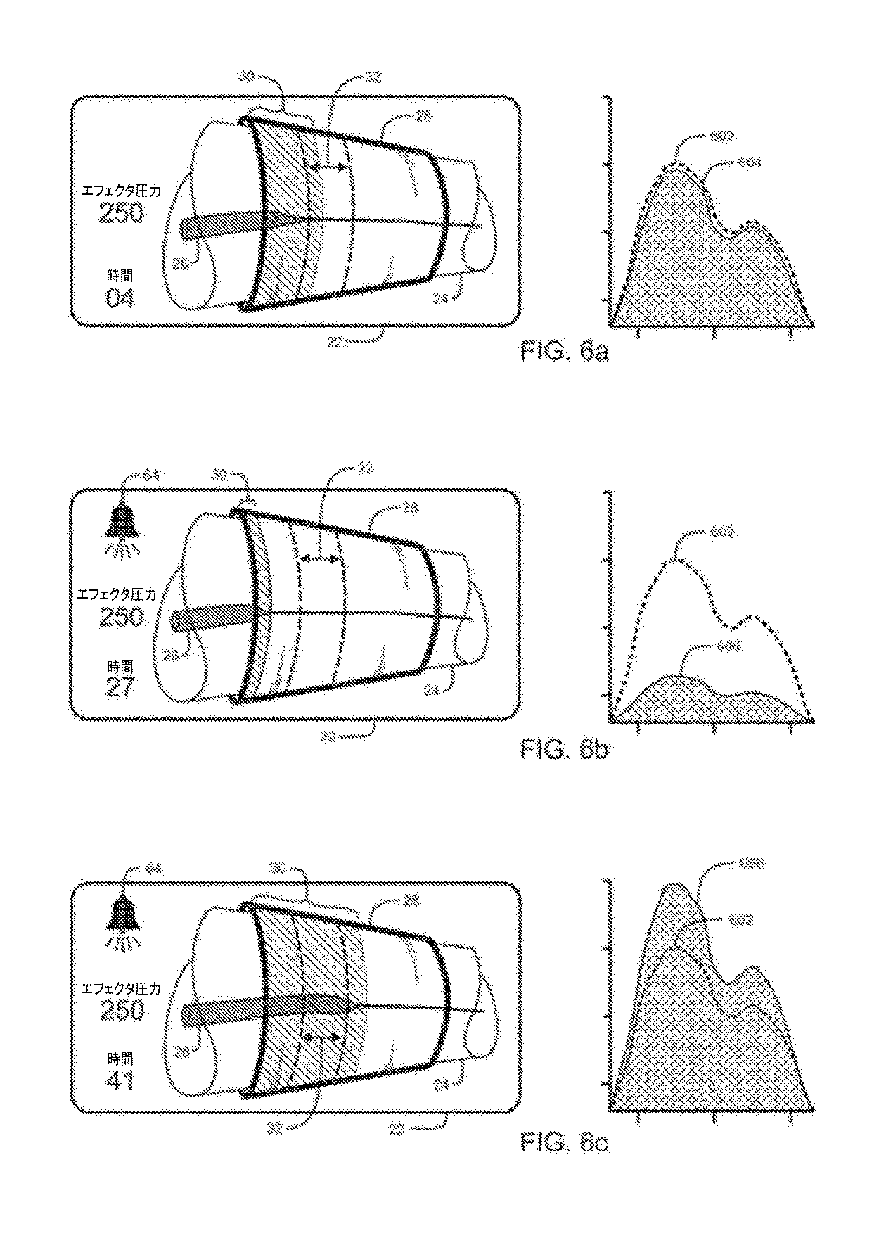
推定侵入距離は、ユーザへの表示のためにタッチ画面22に通信される。上述したように、好ましい実施形態は、推定侵入距離の図的記述を表示して、この情報をユーザに良好に伝える。図6a、図6b及び図6cは、カフ2の空気袋内の圧力レベルが一定の間、処置期間中の様々な時刻における侵入距離の図的記述、並びに関連する生理学的脈動及び基準脈動の対応するグラフを表示するタッチ画面22を示す。図6a、図6b及び図6cに示されるように、カフ2の空気袋は一定のままである。
The estimated intrusion distance is communicated to the
図6aにおいて、侵入インジケータ30距離の遠位端は、及び動脈アイコン24の形状は、侵入距離が公称距離にあることを示す。侵入インジケータ30の距離の近位端は、安全マージン限界内にあり、当該限界は超えられていない。対応するグラフは、基準生理学的脈動602、及び侵入距離の図的記述に関連付けられた生理学的脈動604を示す。
In FIG. 6a, the distal end of the
図6bは、患者の血圧低下によって引き起こされた侵入距離の低下の例示である。侵入インジケータ30の遠位端が、安全マージン下限の外側にあり、アラームインジケータアイコン64が、安全マージン限界を超えたことをユーザに警告するために表示される。対応するグラフは、基準脈動602、及び侵入距離の図的記述に関連付けられる生理学的脈動606を示す。なお、関連する生理学的脈動606の振幅は、基準脈動602の振幅未満であり、侵入距離の低下を示す。
FIG. 6b is an example of a decrease in invasion distance caused by a decrease in a patient's blood pressure. The distal end of the
図6cは、患者の血圧上昇により引き起こされる侵入距離の増加の例示である。侵入インジケータ30の遠位端が、安全マージン上限の外側にあり、アラームインジケータアイコン64が、安全マージン限界を超えたことをユーザに警告するために表示される。対応するグラフは、基準脈動602、及び侵入距離の図的記述に関連付けられる生理学的脈動608を示す。なお、関連する生理学的脈動608の振幅は、基準脈動602の振幅を超過しており、侵入距離の増加を示す。
FIG. 6c is an example of an increase in invasion distance caused by an increase in a patient's blood pressure. The distal end of the
図7a、図7b、図8a及び図8bは、侵入距離の図的記述、並びに関連する生理学的脈動及び基準脈動の対応するグラフを表示するタッチ画面22を示す。これらの図は、変化するカフ圧力の侵入距離への影響を例示する。
7a, 7b, 8a and 8b show a
図7bは、患者の血圧低下によって引き起こされた侵入距離の低下の例示である。侵入30の遠位端が、安全マージン下限の外側にあり、アラームアイコン64が、安全マージン限界を超えたことをユーザに警告するために表示される。カフ2の空気袋内の圧力レベル(エフェクタ圧力)は250mmHgである。対応するグラフは、基準脈動702、及び侵入距離の図的記述に関連付けられる生理学的脈動704を示す。なお、関連する生理学的脈動704の振幅は、基準脈動702の振幅未満であり、侵入距離の低下を示す。
FIG. 7b is an example of a decrease in invasion distance caused by a decrease in a patient's blood pressure. The distal end of the
図7bは、カフ2の空気袋内の圧力レベルの低下により引き起こされる侵入距離の増加の例示である。侵入インジケータ30の遠位端が安全マージン限界内にあり、アラームアイコン64は表示されていない。カフ2の空気袋内の圧力レベル(エフェクタ圧力)はユーザによって200mmHgまで減少している。対応するグラフは、基準脈動702、及び侵入距離の図的記述に関連付けられる生理学的脈動706を示す。なお、関連する生理学的脈動706の振幅は、基準脈動702の振幅に近付いており、侵入距離が公称距離まで回復したことを示す。
FIG. 7b is an example of an increase in penetration distance caused by a decrease in the pressure level in the air bag of the
図8cは、患者の血圧上昇により引き起こされる侵入距離の増加の例示である。侵入インジケータ30の遠位端が、安全マージン上限の外側にあり、アラームアイコン64が、安全マージン限界を超えたことをユーザに警告するために表示される。カフ2の空気袋内の圧力レベル(エフェクタ圧力)は250mmHgである。対応するグラフは、基準脈動802、及び侵入距離の図的記述に関連付けられる生理学的脈動804を示す。なお、関連する生理学的脈動804の振幅は、基準脈動802の振幅を超過しており、侵入距離の増加を示す。
FIG. 8c is an example of an increase in invasion distance caused by an increase in a patient's blood pressure. The distal end of the
図8bは、カフ2の空気袋内の圧力レベルの増加により引き起こされる侵入距離の低下の例示である。侵入インジケータ30の遠位端が安全マージン限界内にあり、アラームアイコン64は表示されていない。カフ2の空気袋内の圧力レベル(エフェクタ圧力)はユーザによって275mmHgまで増加している。対応するグラフは、基準脈動802、及び侵入距離の図的記述に関連付けられる生理学的脈動806を示す。なお、関連する生理学的脈動806の振幅は、基準脈動802の振幅に近付いており、侵入距離が公称距離まで回復したことを示す。
FIG. 8b is an example of a decrease in penetration distance caused by an increase in the pressure level in the air bag of the
カフ2の膨張可能空気袋内の圧力の安全なレベルを自動的に維持するべく、コントローラ34は、カフ2の空気袋内の圧力レベルを調整して、PTPに関連付けられる基準レベルに近い侵入距離を維持するように構成し得る。
To automatically maintain a safe level of pressure in the inflatable air bag of the
図9及び図10は、第2の好ましい実施形態の止血帯システムを描く。図9は、臨床使用における第2の好ましい実施形態を示し、図10は、この実施形態のブロック図である。この第2の好ましい実施形態は、上述の好ましい実施形態と同様であるが、トランスデューサ18及びその関連インタフェイスがこの実施形態の一部を形成しない点が異なる。以下に記載される第2の好ましい実施形態において、センサモジュール38は、カフ2をセンサとして使用し、カフ2の膨張可能空気袋内の様々な圧力レベルで検出される生理学的脈動の特徴レベルを分析することによって、遠位閉塞圧力(DOP)を直接推定する追加機能を実行する。
9 and 10 depict a tourniquet system of a second preferred embodiment. FIG. 9 shows a second preferred embodiment in clinical use, and FIG. 10 is a block diagram of this embodiment. This second preferred embodiment is similar to the preferred embodiment described above, except that the
DOP及びPTPの推定は、外科的又は内科的処置の開始前の期間中に行われる。ユーザがタッチ画面インタフェイス22を介してDOP及びPTPの推定を起動すると、コントローラ34及びセンサモジュール38は以下のように動作する。
DOP and PTP estimates are made during the period prior to the initiation of surgical or medical procedures. When the user activates the estimation of DOP and PTP via the
a)コントローラ34は、エフェクタモジュール36に、カフ2が包囲する患者の領域を通過する血液侵入を止めて最小の侵入距離を生成するべく選択された所定のデフォルト圧力レベルまで、カフ2の空気袋を膨張させるように指示する。好ましい実施形態において、所定のデフォルト圧力レベルは300mmHgである。わかることだが、他のデフォルト圧力レベルを予め定めてよく、デフォルト圧力レベルは、カフ識別モジュール40により報告される器具8に接続されたカフの特徴に依存し得る。デフォルト圧力レベルはまた、タッチ画面ユーザインタフェイス22を介して器具8のユーザにより選択され得る。
a) The
b)カフ2の空気袋内圧力のデフォルトレベルに関連付けられる検出された生理学的脈動の特徴のレベルが脈動メモリ60に記録される。検出された脈動に関連付けられるノイズのレベルもまた、脈動メモリ60に記録される。
b) The level of detected physiological pulsation features associated with the default level of pressure in the air bag of the
c)コントローラ34はその後、所定の最小圧力レベルが検出されるまでずっと、カフ2の空気袋内の圧力レベルを所定のインクリメントだけ減少させるようにエフェクタモジュール36に指示する。カフ2の空気袋内の圧力レベルの各低下に引き続き、検出された生理学的脈動の特徴のレベル、関連するノイズのレベル、及び関連する圧力レベルがメモリ60に記録される。一定の最小圧力レベルに達したとき、コントローラ34は、エフェクタモジュール36に空気袋を収縮させるように指示する。
c) The
d)推定器62はその後、脈動特徴のレベル及び関連する空気袋圧レベルをメモリ60から取得する。推定器62は、カフ2の空気袋内の圧力レベルが低下していた間に記録された脈動特徴の最大レベルを決定するべく、記録された特徴のレベルを比較及び分析する。一般に、カフ2の空気袋内の圧力レベルが低下するにつれて、カフ2が方位する領域への血液の侵入深さが増加し、生理的脈動の特徴のレベルも増加する。生理学的脈動の特徴のレベルは、カフ2の空気袋内の圧力レベルがDOP未満の圧力であり、かつ、カフ2が包囲する患者の領域を動脈血が通過して侵入しているときに、その最大レベルにある。DOPに関連付けられる脈動の特徴のレベルは、血液がカフを通過して侵入しているときに検出される脈動特徴の最大レベルと、所定の関係を有することが見出されている。
d) The
e)推定器62は、カフ2の空気袋内の圧力レベルが、デフォルト圧力レベルから所定の最小圧力レベルへと低下している間に記録された脈動特徴の最大レベルを決定した後、最大レベルの所定のパーセンテージを使用して、カフ2の空気袋内の圧力レベルがDOPに近いときに検出される脈動特徴のレベルに一致する脈動特徴のレベルを計算する。
e) The
f)推定器62は、記録された脈動特徴のレベル及び関連する圧力レベルを分析し、DOPに関連付けられる脈動特徴の以前に計算されたレベルと一致する特徴を有する脈動を生成するべくカフ2の空気袋内に必要とされる圧力レベルを計算することによって、患者のDOPを推定する。推定器62はまた、DOP推定に関連付けられるノイズレベルを決定するべく、脈動特徴に関連付けられる記録されたノイズレベルも分析する。推定器62は、ノイズがDOP推定の精度に与える影響を補償するべく、推定されたDOP、及びそのDOP推定に関連付けられるノイズレベルを使用して、推定PTPを決定する。推定器62が計算する推定PTPは、推定されたDOP、及びそのDOP推定に関連付けられるノイズレベルの関数である。DOP推定に関連付けられるノイズレベルが所定の低ノイズしきい値未満であれば、PTPは、推定されたDOPに所定の圧力インクリメントを加えることによって推定される。DOP推定に関連付けられるノイズレベルが低ノイズしきい値以上、かつ、所定の最大ノイズしきい値未満であれば、PTPは、ノイズレベルが低ノイズしきい値未満である場合に加えられる所定のインクリメントよりも大きな所定の圧力インクリメントを、推定されたDOPに加えることによって推定される。
f) The
DOP推定に関連付けられるノイズレベルが所定の最大ノイズしきい値レベル以上であれば、推定されたDOPからPTPを確実に推定することができないので、PTPは所定のデフォルトレベルに設定され、警告メッセージがタッチ画面22上に表示され、ユーザに警告するべく警告音声トーンが生成される。
If the noise level associated with the DOP estimation is greater than or equal to the predetermined maximum noise threshold level, then the PTP cannot be reliably estimated from the estimated DOP, so the PTP is set to the predetermined default level and a warning message is issued. It is displayed on the
例えば、DOPが140mmHgであると推定され、当該推定に関連付けられるノイズレベルが低ノイズしきい値を下回れば、PTPは190mmHg(140mmHg+50mmHg)となるように推定される。ノイズレベルが低ノイズしきい値を上回りかつ最大しきい値を下回る場合、PTPは、215mmHg(140mmHg+75mmHg)となるように推定される。ノイズレベルが最大ノイズしきい値よりも大きければ、推定PTPは300mmHgのデフォルト圧力となる。 For example, if the DOP is estimated to be 140 mmHg and the noise level associated with the estimate is below the low noise threshold, the PTP is estimated to be 190 mmHg (140 mmHg + 50 mmHg). If the noise level is above the low noise threshold and below the maximum threshold, the PTP is estimated to be 215 mmHg (140 mmHg + 75 mmHg). If the noise level is greater than the maximum noise threshold, the estimated PTP will be the default pressure of 300 mmHg.
わかることだが、推定されたDOP及び関連するノイズレベルの他の関数を、上述の関数以外のPTPを推定するべく使用してよい。 As you can see, other functions of the estimated DOP and related noise levels may be used to estimate PTPs other than those mentioned above.
明らかなことだが、デフォルト圧力と最小圧力との間でカフ2の空気袋内の圧力レベルを変化させることに関連付けられる脈動特徴のレベルを記録するべく、上述されたもの(圧力レベルがデフォルトレベルから最小レベルへと所定量だけ減少する場合)以外のシーケンスを使用してもよい。例えば、コントローラ34は、エフェクタモジュール36に、カフ2の空気袋を所定の最小レベルまで膨張させ、デフォルト圧力レベルに到達するまでずっと所定のインクリメントで圧力レベルを増加させるように指示することができる。コントローラ34はまた、検出された生理的脈動特徴のレベルの大きさ、及び関連するカフ2の空気袋内の圧力レベルに応答して、所定のインクリメント量、圧力のデフォルトレベル、及び圧力の最小レベルを変化させることもできる。
Obviously, what was mentioned above to record the level of pulsating features associated with varying the pressure level in the bag of
外科的又は医学的処置の開始前の期間中に、第2の好ましい実施形態のユーザは、適切な二重目的止血帯カフ2を選択し、これによって、当該カフを通過する動脈血流が止められるべき患者の領域、例えば、手術部位6の近位にある肢4が包囲される。ユーザは、肢のまわりにカフを固定し、当該カフを器具8と空気圧により連通するように接続する。カフ識別モジュール40は、当該カフが許容可能な二重目的止血帯カフか否かを決定するべく、当該カフを識別しようと試みる。カフが好ましい実施形態で使用するための許容可能な二重目的カフでない場合、又は識別できない場合、タッチ画面ユーザインタフェイス22を介してユーザに警告が与えられ、PTPの推定を開始してカフを膨張させるべく用いられる制御が無効にされることにより、許容できないカフの使用が防止される。
During the period prior to the initiation of the surgical or medical procedure, the user of the second preferred embodiment selects the appropriate dual
空気圧により接続されたカフが許容可能であれば、ユーザは、タッチ画面ユーザインタフェイス22上に示された対応グラフィックアイコンにタッチすることによって、個人向け止血帯圧力(PTP)の推定を開始することができる。
If the pneumatically connected cuff is acceptable, the user may initiate an estimation of personal tourniquet pressure (PTP) by touching the corresponding graphic icon shown on the touch
PTPを推定するべく、器具8は、カフ2の空気袋を様々なレベルまで膨張させる一方、上述した圧力レベルに関連付けられる空気圧生理学的脈動の特徴レベルを記録する。推定の間、推定の進捗を表すアイコンがタッチ画面22上に示される。PTPの推定中に、患者を剃ることによって又は患者の震えから生じるノイズのような、動脈血侵入とは無関係なノイズが存在し、そのノイズが所定のしきい値を超える場合、推定は中断されて警告メッセージがタッチ画面22に表示される。
To estimate PTP, instrument 8 inflates the air bag of
器具8がPTPの推定を完了すると、PTP及びDOPがタッチ画面22上に表示され、ユーザは、推定されたPTPを、処置期間の間カフ2の空気袋内に維持すべき圧力レベルとして選択することができる。推定されたPTPが患者の生理学的状態に関連したままであることを確実にするべく、コントローラ34は、PTPの推定が完了した後の所定期間の処置の間だけ、当該推定されたPTPを、カフ2の空気袋内に維持されるべき圧力レベルとしてユーザが選択することを許容する。その所定期間内にPTPが選択されなければ、PTPの他の推定を開始しなければならず、又はユーザが、処置中にカフ2の空気袋内に維持されるべきデフォルト圧力レベルを選択しなければならない。
When the instrument 8 completes the PTP estimation, the PTP and DOP are displayed on the
ユーザは、処置時間中にカフ2の空気袋内に維持されるべき圧力レベルを選択した後、タッチス画面22上のアイコンにタッチすることによって、止血帯エフェクタを起動する(カフ2を膨らませる)ことができる。ユーザがカフ2の空気袋内に維持されるべき圧力レベルとして事前に推定されたPTPを選択すると、器具8は、上述したように、侵入距離を表すアイコンを表示する。センサモジュール38は、カフ2の空気袋内に生じる空気の生理学的脈動を継続的に監視し、当該カフを通過する血液の侵入が防止されている間に、カフ2が包囲する患者の領域の中へと動脈血が侵入する距離の推定値を、タッチ画面22を介して表示する。侵入距離が所定の安全マージンを超える場合、アラームメッセージがタッチ画面22上に示され、潜在的に安全でない状態をユーザに警告するための音声トーンが生成される。ユーザは、タッチ画面22を介して、カフ2の空気袋内に維持される圧力レベルを調節して、侵入距離を安全マージン内にまで回復させることを選択してよい。ユーザはタッチ画面22を介して、侵入距離を安全マージン内に維持するべくカフ2の空気袋内の圧力レベルを自動的に調整するように器具8を構成することができる。
The user activates the tourniquet effector (inflates the cuff 2) by touching the icon on the
図11は、患者の腕又は脚以外の領域又は部分、具体的には頭皮、への動脈血流を止めるための臨床使用における好ましい実施形態を描く。図11において、二重目的止血帯カフ2が、カフ2を通過する頭皮の領域への動脈血の流れを防止するべく患者頭部66に適用されるように示される。遠位血流センサ18が、カフ2より遠位の頭皮への適用を目的として適合されるように示され、個人向け止血帯圧力(PTP)を決定するべく上述したような外科的又は医学的処置の開始に先立って使用され得る。さらに上述したように、カフ2は、個人向け止血帯圧力を決定するためのセンサとして使用してもよい。例えば、遠位センサ18又はカフ2を、化学療法関連脱毛症を低減するべく使用される実施形態において、化学療法剤の投与に先立ってPTPを決定するために使用してよい。
FIG. 11 depicts a preferred embodiment in clinical use for stopping arterial blood flow to a region or portion other than the patient's arm or leg, specifically the scalp. In FIG. 11, a dual
図11において、タッチ画面インタフェイス22は、PTPが確立された後の処置時間中に示される。カフ2が包囲する頭皮領域への血液侵入の図的記述が、表示される。血液侵入の図的記述は、頭部アイコン68、動脈アイコン70、カフアイコン72、侵入距離インジケータ74、及び安全マージンインジケータ76からなる。さらに上述したように、カフ2が包囲する頭部領域への当該カフを通過する血液侵入の図的記述は、インジケータ74の遠位端及び動脈アイコン70の形状が、好ましい実施形態によって決定される現在の侵入距離を表すように、処置期間中に継続的に更新される。
In FIG. 11, the
上述した第1又は第2の実施形態は、患者の領域又は部分の脈管構造を間欠的に閉塞するように適合することができる。間欠的血管閉塞(IVO)は、一定の臨床的設定及びリハビリテーション設定において、筋肉の機能及び回復を加速及び増強することが示されている。IVOは、患者の領域、典型的には肢、に適用される止血帯カフの、高い圧力とゼロ圧力との間の反復サイクルである。図12及び図13は、間欠的血管閉塞に適合された実施形態を示す。間欠的血管閉塞に適合された好ましい実施形態の例は以下の通りである。 The first or second embodiment described above can be adapted to intermittently occlude the vascular structure of the patient's area or portion. Intermittent vascular occlusion (IVO) has been shown to accelerate and enhance muscle function and recovery in certain clinical and rehabilitation settings. IVO is a repetitive cycle between high pressure and zero pressure of a tourniquet cuff applied to the patient's area, typically the limb. 12 and 13 show embodiments adapted for intermittent vascular occlusion. Examples of preferred embodiments adapted for intermittent vascular occlusion are:
a)カフ2が患者の肢4に適用され、患者のDOP及びPTPそれぞれが、好ましい実施形態に記載されるように測定及び推定される。代替的に、実際的な理由から、ユーザは、タッチ画面ユーザインタフェイス22と対話して、DOPの推定にオーバーライドして手動でPTP圧力レベルを選択してもよい。かかる状況が生じ得るのは、例えば、(1)ユーザが器具8の一部ではないセンサを使用してPTPを決定する場合、(2)血液トランスデューサ18が患者の遠位指の欠損又は循環不良ゆえにDOPを測定できない場合、(3)生理学的脈動センサ56が患者からの低い脈動信号及び高いノイズゆえに脈動特徴を測定できない場合、又は(4)時間がDOPの測定及びPTPの推定を許容しない場合である。この例では、DOPは150mmHgと測定され、PTPは165mmHg(DOPの110%)に設定される。
a) The
b)ユーザは、器具8のタッチ画面ユーザインタフェイス22を操作して、間欠的血管閉塞セッションを開始し、一以上の血管閉塞サイクル108を生成する。送達される血管閉塞サイクルの数は、ユーザによって選択されるか、又は以下にさらに記載されるように生理学的センサ106によって決定され得る。コントローラ34は、エフェクタモジュール36と通信してカフ2をPTP(165mmHg)付近の第1の圧力レベルまで膨張させ、第1の期間110(5分)の間、肢4の領域の脈管構造を閉塞する。第1の期間110の終了時、エフェクタモジュール36は、第2の期間112(3分)の間にカフ2における圧力を、肢4における動脈及び静脈が閉塞されないようにするべく0mmHgに近い第2の圧力レベルまで低減する。第1の期間110及び第2の期間112の持続時間は、予めプログラムされてよく、タッチ画面ユーザインタフェイス22を介してユーザによって選択されてよく、又は測定された生理学的パラメータによって決定されてよい。PTPは、動脈閉塞及び静脈閉塞の双方を適用するべくDOP以上になるように選択されてよく、又は動脈制限及び静脈閉塞を適用するべくDOP未満になるように選択されてよい。第2の圧力レベルは、静脈閉塞圧力未満の非閉塞圧力であってよい。PTP、第1の期間110の持続時間、第2の期間112の持続時間、又は閉塞サイクルの数が最大安全限界を超える場合、計器8及びタッチ画面ユーザインタフェイス22はアラームを発生させる。閉塞サイクルが完了すると、エフェクタモジュール36は自動的に、カフ2を0mmHg近くの圧力まで収縮させる。
b) The user operates the touch
c)間欠的血管閉塞セッションの前に、最中に、又は終了時に、ユーザは器具8のタッチ画面ユーザインタフェイス22を操作して、所望の臨床効果を達成するときのIVOの有効性を示す生理学的パラメータの値を入力することができる。生理学的パラメータは、患者の心拍数、酸素化レベル、及びクレアチンキナーゼレベルを含むが、これらに限られない。生理学的パラメータは、IVOセッションの有効性を評価してIVOプロトコルへのフィードバックを与えるべく使用することができる。例えば、有効性データに基づいて、第1の期間110の持続時間を2分だけ(7分まで)増加させ、及び/又は将来のサイクル若しくはセッションのためにPTPを195mmHg(DOPの130%)まで増加させてよい。プロトコルに対する他の変化は、第2の期間112の持続時間、IVOサイクルの数、及び第2の圧力レベルのような有効性フィードバックからもたらされ得る。IVOに関連する一以上の生理学的パラメータを測定する生理学的センサ106は、フィードバックをコントローラ34に与えてIVOプロトコルパラメータの自動適応を許容するべく器具8に組み入れてよい。
c) Before, during, or at the end of an intermittent vascular occlusion session, the user manipulates the touch
器具8はさらに、図12に示されように、追加の肢104にIVOを与えるべく追加のカフ102における圧力を制御するように適合してよい。わかることだが、器具8は、両腕及び両脚のような患者の複数の領域にIVOを与えるべく複数のカフに接続されるように適合され得る各カフは、PTP付近の第1のレベルの圧力と、同期モード又は交互モードにおける第2の非閉塞レベルの圧力との間を循環し得る。同期モードでは、各カフは同時に各IVOサイクルに入る。交互モードでは、各カフは異なる時間にIVOサイクルに入ることができる。明らかなことだが、各カフは、異なるPTP、第1の期間110の長さ、及び第2の期間112の長さを使用するように予めプログラムされていてよく、又はユーザに選択されてよい。より一般的には、代表的なサイクル圧力波形114、及び/又は任意の他の適切な波形のようなサイクル圧力波形をメモリに記憶してコントローラ34によってアクセスしてよい。サイクル圧力波形114は、サイクル期間中の各時刻における所望レベルの圧力を規定し、コントローラは、記憶されたサイクル圧力波形114を使用することにより、少なくとも一つの適用された止血帯カフ内の圧力を当該サイクル期間中の所望レベルの圧力に対応するレベル近くに維持することができる。
Instrument 8 may further be adapted to control the pressure in the
開示された発明の原理を適用することができる多くの可能な実施形態に鑑み、例示の実施形態が、本発明の好ましい例にすぎず、本発明の範囲を限定するものとみなすべきではないことを認識するべきである。むしろ、本発明の範囲は、以下の特許請求の範囲によって規定される。したがって、我々は、当該請求項の範囲及び要旨に含まれるすべてを我々の発明として主張する。
In view of the many possible embodiments to which the disclosed principles of the invention can be applied, the exemplary embodiments are merely preferred examples of the invention and should not be considered as limiting the scope of the invention. Should be recognized. Rather, the scope of the present invention is defined by the following claims. Therefore, we claim everything contained in the claims and gist as our invention.
Claims (23)
患者の一部分を包囲するべく適合された膨張可能空気袋を有する二重目的止血帯カフと、
遠位閉塞圧力(DOP)を示す圧力脈動を検知して特徴付けることにより、前記カフを通過する血液侵入を止める最小圧力を識別するべく、前記二重目的止血帯カフの膨張可能空気袋と空気圧により連通する脈動センサを有するセンサモジュールと、
前記DOPの関数であるPTPの推定を生成するべく前記脈動センサに応答するPTP推定器と、
第1期間中に前記空気袋における圧力を前記PTP近くに維持し第2期間中に前記空気袋における圧力を第2レベルの圧力近くにするべく、前記二重目的カフの膨張可能空気袋と空気圧により連通するエフェクタモジュールと、
前記膨張可能空気袋を、前記センサモジュール及び前記エフェクタモジュールと協働して選択的に動作させるコントローラと含む、装置。 A device for intermittent vascular occlusion based on personal tourniquet pressure (PTP).
A dual purpose tourniquet cuff with an inflatable air bag adapted to enclose a portion of the patient,
By detecting and characterizing a pressure pulsation indicating distal occlusion pressure (DOP), the inflatable air bag and air pressure of the dual purpose tourniquet cuff to identify the minimum pressure to stop blood invasion through the cuff. A sensor module with a communicating pulsation sensor and
A PTP estimator that responds to the pulsation sensor to generate an estimate of PTP that is a function of the DOP.
The inflatable air bag and air pressure of the dual purpose cuff to maintain the pressure in the air bag close to the PTP during the first period and to bring the pressure in the air bag close to the second level pressure during the second period. Effector module that communicates with
A device comprising the inflatable air bag with a controller that selectively operates in cooperation with the sensor module and the effector module.
前記エフェクタモジュールはさらに、前記第1サイクル期間の持続時間を、前記パラメータに応答するように適合させるべく前記生理学的センサに応答する、請求項7の装置。 Includes physiological sensors that detect and characterize parameters indicating the effectiveness of the intermittent vascular occlusion cycle for the patient's physiology.
The device of claim 7, wherein the effector module further responds to the physiological sensor to adapt the duration of the first cycle period to respond to the parameter.
前記エフェクタモジュールはさらに、前記複数のサイクルの数を、前記パラメータに応答するように適合させるべく前記生理学的センサに応答する、請求項7の装置。 Includes physiological sensors that detect and characterize parameters indicating the effectiveness of the intermittent vascular occlusion cycle for the patient's physiology.
The device of claim 7, wherein the effector module further responds to the physiological sensor to adapt the number of cycles to respond to the parameter.
前記エフェクタモジュールはさらに、前記PTPを、前記パラメータに応答するように適合させるべく前記生理学的センサに応答する、請求項7の装置。 Includes physiological sensors that detect and characterize parameters of the effectiveness of the intermittent vascular occlusion cycle for the patient's physiology.
The apparatus of claim 7, wherein the effector module further responds to the physiological sensor to adapt the PTP to respond to the parameter.
空気圧袋を有して患者の所望箇所に適用されるように構成された止血帯カフを与えることと、
前記止血帯カフを通過する血液侵入が止められる前記袋の最小圧力を示す前記箇所の遠位閉塞圧力(DOP)を確立することと、
前記DOPの関数であるPTPを確立することと、
ゼロ近くの非閉塞レベルの圧力を確立することと、
前記カフにおける圧力を第1期間中前記PTP近くに維持することと、
前記第1期間の終了時に、前記カフにおける圧力を前記非閉塞レベルまで低下させ、前記カフにおける圧力を第2期間中前記非閉塞レベル近くに維持することと
を含む、方法。 A method of providing intermittent vascular occlusion based on personal tourniquet pressure (PTP).
To give a tourniquet cuff that has a pneumatic bag and is configured to be applied where the patient wants,
To establish a distal occlusion pressure (DOP) at the location that indicates the minimum pressure of the bag to stop blood invasion through the tourniquet cuff.
Establishing PTP, which is a function of the DOP,
Establishing a non-obstructive level pressure near zero and
Maintaining the pressure in the cuff near the PTP during the first period and
A method comprising reducing the pressure in the cuff to the non-occluded level at the end of the first period and keeping the pressure in the cuff close to the non-occluded level during the second period.
遠位閉塞圧力(DOP)を、少なくとも一つの適用された止血帯カフを通過する血液侵入が止められる最小圧力に等しい推定DOPを決定することによって推定するセンサモジュールと、
前記DOPの関数であるPTPを確立するコントローラであって、前記センサモジュールによる前記DOPの推定にユーザが、前記PTPを前記ユーザが選択した圧力レベルに設定することによってオーバーライドすることを可能にするべく構成されたユーザインタフェイスを含むコントローラと、
前記適用された止血帯カフにおける圧力を、前記PTPと、複数のサイクル期間のそれぞれの間のサイクル圧力波形に応じた非閉塞レベルとの間に維持するべく動作可能なエフェクタモジュールと
を含む、装置。 A device that provides intermittent vascular occlusion based on personal tourniquet pressure (PTP).
A sensor module that estimates the distal occlusion pressure (DOP) by determining an estimated DOP equal to the minimum pressure at which blood invasion through at least one applied tourniquet cuff is stopped.
A controller that establishes a PTP that is a function of the DOP to allow the user to override the DOP estimation by the sensor module by setting the PTP to a pressure level selected by the user. A controller that includes a configured user interface, and
An apparatus comprising an effector module capable of operating to maintain pressure in the applied tourniquet cuff between the PTP and a non-obstructive level corresponding to a cycle pressure waveform during each of a plurality of cycle periods. ..
前記エフェクタモジュールはさらに、前記エフェクタモジュールの動作に適合する前記生理学的センサに応答する、請求項22の装置。 Includes physiological sensors that detect and characterize parameters indicating the effectiveness of the intermittent vascular occlusion for the patient's physiology.
22. The apparatus of claim 22, wherein the effector module further responds to said physiological sensor adapted to the operation of the effector module.
Applications Claiming Priority (3)
| Application Number | Priority Date | Filing Date | Title |
|---|---|---|---|
| US15/912,390 US10646231B2 (en) | 2014-07-10 | 2018-03-05 | Personalized tourniquet for intermittent vascular occlusion |
| US15/912,390 | 2018-03-05 | ||
| PCT/IB2019/000197 WO2019171168A1 (en) | 2018-03-05 | 2019-03-04 | Personalized tourniquet for intermittent vascular occlusion |
Publications (2)
| Publication Number | Publication Date |
|---|---|
| JP2021515625A true JP2021515625A (en) | 2021-06-24 |
| JPWO2019171168A5 JPWO2019171168A5 (en) | 2022-02-08 |
Family
ID=67846941
Family Applications (1)
| Application Number | Title | Priority Date | Filing Date |
|---|---|---|---|
| JP2020546173A Pending JP2021515625A (en) | 2018-03-05 | 2019-03-04 | Personal tourniquet for intermittent vascular occlusion |
Country Status (5)
| Country | Link |
|---|---|
| EP (1) | EP3755243B1 (en) |
| JP (1) | JP2021515625A (en) |
| CN (1) | CN112040888B (en) |
| AU (1) | AU2019229779B2 (en) |
| WO (1) | WO2019171168A1 (en) |
Families Citing this family (2)
| Publication number | Priority date | Publication date | Assignee | Title |
|---|---|---|---|---|
| US20240033163A1 (en) * | 2020-12-18 | 2024-02-01 | Arjo IP Holding Aktiebolag | Fluid pressure control system, connector and coupling assembly |
| CN118285871B (en) * | 2024-06-06 | 2024-08-06 | 嘉隆鼎业(天津)科技有限公司 | Tourniquet tightening modulation method and device based on blood pressure measurement and vibration point sensing |
Citations (5)
| Publication number | Priority date | Publication date | Assignee | Title |
|---|---|---|---|---|
| US20100324429A1 (en) * | 2009-06-23 | 2010-12-23 | Boris Leschinsky | Methods and devices for remote ischemic preconditioning and near-continuous blood pressure monitoring |
| WO2012132268A1 (en) * | 2011-03-31 | 2012-10-04 | テルモ株式会社 | Limb compression device and control method |
| JP2013523349A (en) * | 2010-04-08 | 2013-06-17 | ザ・ホスピタル・フォー・シック・チルドレン | Using remote ischemic conditioning for traumatic injury |
| JP2016516474A (en) * | 2013-03-15 | 2016-06-09 | ライフカフ テクノロジーズ インコーポレイテッド | Multi-mode inflatable limb occlusion device |
| JP2017519596A (en) * | 2014-07-10 | 2017-07-20 | ウエスタン クリニカル エンジニアリング リミテッド | Individual tourniquet system |
Family Cites Families (20)
| Publication number | Priority date | Publication date | Assignee | Title |
|---|---|---|---|---|
| US4469099A (en) | 1980-10-02 | 1984-09-04 | Western Clinical Engineering Ltd. | Pneumatic torniquet |
| EP0089369A1 (en) * | 1981-09-28 | 1983-09-28 | CLARK, Nancy G. | Pressure-responsive tourniquet |
| US4479494A (en) | 1982-01-05 | 1984-10-30 | Western Clinical Engineering Ltd. | Adaptive pneumatic tourniquet |
| US5254087A (en) | 1990-01-29 | 1993-10-19 | Ivra Systems, Inc. | Tourniquet apparatus for intravenous regional anesthesia |
| US5556415A (en) | 1990-01-29 | 1996-09-17 | Mcewen; James A. | Physiologic tourniquet for intravenous regional anesthesia |
| US5855589A (en) | 1995-08-25 | 1999-01-05 | Mcewen; James A. | Physiologic tourniquet for intravenous regional anesthesia |
| US6051016A (en) | 1999-03-29 | 2000-04-18 | Instrumed, Inc. | System and method of controlling pressure in a surgical tourniquet |
| US7485131B2 (en) * | 1999-03-29 | 2009-02-03 | Stryker Corporation | System and method for controlling pressure in a surgical tourniquet |
| US7981070B2 (en) * | 2006-05-04 | 2011-07-19 | Abatis Medical Technologies, Ltd. | Internal tourniquet for automatically controlling hemostasis within a joint capsule |
| WO2009012594A1 (en) | 2007-07-24 | 2009-01-29 | Abatis Medical Technologies Limited | Ultrasonic tourniquet system |
| US8425426B2 (en) | 2007-11-09 | 2013-04-23 | Western Clinical Engineering, Ltd | Tourniquet apparatus for measuring limb occlusion pressure |
| US8083763B2 (en) | 2009-02-10 | 2011-12-27 | Western Clinical Engineering Ltd. | Apparatus and method for estimating leakage in a surgical tourniquet system |
| WO2011088543A1 (en) | 2010-01-22 | 2011-07-28 | Abatis Medical Technologies Limited | Tourniquet apparatus for controlling blood penetration |
| US8911469B2 (en) * | 2010-03-25 | 2014-12-16 | Neocardium, Limited | Methods and apparatus for optimal remote ischemic preconditioning (ORIP) for preventing ischemia-reperfusion injuries to organs |
| WO2012005630A2 (en) * | 2010-07-06 | 2012-01-12 | Aleksey Monesovich Sudarev | Method and devices proposed for the impact on the cardiovascular system |
| WO2012009787A1 (en) | 2010-07-23 | 2012-01-26 | Western Clinical Engineering Ltd. | Tourniquet hazard suppressor |
| US8177704B1 (en) * | 2011-12-22 | 2012-05-15 | Miracor Medical Systems Gmbh | System and method for treating heart tissue |
| WO2015085302A1 (en) * | 2013-12-06 | 2015-06-11 | Memorial Sloan Kettering Cancer Center | Pressure sensitive arrangement and method for use thereof |
| US9931126B2 (en) * | 2014-07-10 | 2018-04-03 | Western Clinical Engineering Ltd. | Personalized tourniquet methods and apparatus |
| JP6777647B2 (en) * | 2015-03-18 | 2020-10-28 | ライフカフ テクノロジーズ インコーポレイテッド | Remote ischemia conditioning methods and devices via partial limb obstruction |
-
2019
- 2019-03-04 JP JP2020546173A patent/JP2021515625A/en active Pending
- 2019-03-04 WO PCT/IB2019/000197 patent/WO2019171168A1/en not_active Ceased
- 2019-03-04 CN CN201980028849.0A patent/CN112040888B/en active Active
- 2019-03-04 EP EP19763819.0A patent/EP3755243B1/en active Active
- 2019-03-04 AU AU2019229779A patent/AU2019229779B2/en active Active
Patent Citations (6)
| Publication number | Priority date | Publication date | Assignee | Title |
|---|---|---|---|---|
| US20100324429A1 (en) * | 2009-06-23 | 2010-12-23 | Boris Leschinsky | Methods and devices for remote ischemic preconditioning and near-continuous blood pressure monitoring |
| JP2013523349A (en) * | 2010-04-08 | 2013-06-17 | ザ・ホスピタル・フォー・シック・チルドレン | Using remote ischemic conditioning for traumatic injury |
| WO2012132268A1 (en) * | 2011-03-31 | 2012-10-04 | テルモ株式会社 | Limb compression device and control method |
| JP2012210359A (en) * | 2011-03-31 | 2012-11-01 | Terumo Corp | Limb compression device |
| JP2016516474A (en) * | 2013-03-15 | 2016-06-09 | ライフカフ テクノロジーズ インコーポレイテッド | Multi-mode inflatable limb occlusion device |
| JP2017519596A (en) * | 2014-07-10 | 2017-07-20 | ウエスタン クリニカル エンジニアリング リミテッド | Individual tourniquet system |
Also Published As
| Publication number | Publication date |
|---|---|
| AU2019229779A1 (en) | 2020-09-24 |
| CN112040888B (en) | 2024-03-08 |
| CN112040888A (en) | 2020-12-04 |
| EP3755243A1 (en) | 2020-12-30 |
| EP3755243A4 (en) | 2021-11-24 |
| WO2019171168A1 (en) | 2019-09-12 |
| AU2019229779B2 (en) | 2024-03-28 |
| EP3755243B1 (en) | 2024-05-29 |
Similar Documents
| Publication | Publication Date | Title |
|---|---|---|
| CN106659508B (en) | Personalized tourniquet system | |
| CA2704848C (en) | Improved tourniquet apparatus for measuring limb occlusion pressure | |
| US9931126B2 (en) | Personalized tourniquet methods and apparatus | |
| AU2008241310B2 (en) | Adaptive surgical tourniquet apparatus and method | |
| EP1876973B1 (en) | Surgical tourniquet apparatus for measuring limb occlusion pressure | |
| US10646231B2 (en) | Personalized tourniquet for intermittent vascular occlusion | |
| US9039730B1 (en) | Personalized tourniquet system having dual-purpose cuff | |
| JP2021515625A (en) | Personal tourniquet for intermittent vascular occlusion | |
| JP7224381B2 (en) | tourniquet device |
Legal Events
| Date | Code | Title | Description |
|---|---|---|---|
| A521 | Request for written amendment filed |
Free format text: JAPANESE INTERMEDIATE CODE: A523 Effective date: 20220131 |
|
| A621 | Written request for application examination |
Free format text: JAPANESE INTERMEDIATE CODE: A621 Effective date: 20220131 |
|
| A131 | Notification of reasons for refusal |
Free format text: JAPANESE INTERMEDIATE CODE: A131 Effective date: 20230322 |
|
| A521 | Request for written amendment filed |
Free format text: JAPANESE INTERMEDIATE CODE: A523 Effective date: 20230613 |
|
| A131 | Notification of reasons for refusal |
Free format text: JAPANESE INTERMEDIATE CODE: A131 Effective date: 20230704 |
|
| A02 | Decision of refusal |
Free format text: JAPANESE INTERMEDIATE CODE: A02 Effective date: 20240206 |