JP2021511907A - Delivery system aids and related systems and methods - Google Patents
Delivery system aids and related systems and methods Download PDFInfo
- Publication number
- JP2021511907A JP2021511907A JP2020542012A JP2020542012A JP2021511907A JP 2021511907 A JP2021511907 A JP 2021511907A JP 2020542012 A JP2020542012 A JP 2020542012A JP 2020542012 A JP2020542012 A JP 2020542012A JP 2021511907 A JP2021511907 A JP 2021511907A
- Authority
- JP
- Japan
- Prior art keywords
- guide wire
- lumen
- intraluminal
- tube
- opening
- Prior art date
- Legal status (The legal status is an assumption and is not a legal conclusion. Google has not performed a legal analysis and makes no representation as to the accuracy of the status listed.)
- Granted
Links
Images


Classifications
-
- A—HUMAN NECESSITIES
- A61—MEDICAL OR VETERINARY SCIENCE; HYGIENE
- A61F—FILTERS IMPLANTABLE INTO BLOOD VESSELS; PROSTHESES; DEVICES PROVIDING PATENCY TO, OR PREVENTING COLLAPSING OF, TUBULAR STRUCTURES OF THE BODY, e.g. STENTS; ORTHOPAEDIC, NURSING OR CONTRACEPTIVE DEVICES; FOMENTATION; TREATMENT OR PROTECTION OF EYES OR EARS; BANDAGES, DRESSINGS OR ABSORBENT PADS; FIRST-AID KITS
- A61F2/00—Filters implantable into blood vessels; Prostheses, i.e. artificial substitutes or replacements for parts of the body; Appliances for connecting them with the body; Devices providing patency to, or preventing collapsing of, tubular structures of the body, e.g. stents
- A61F2/95—Instruments specially adapted for placement or removal of stents or stent-grafts
- A61F2/962—Instruments specially adapted for placement or removal of stents or stent-grafts having an outer sleeve
-
- A—HUMAN NECESSITIES
- A61—MEDICAL OR VETERINARY SCIENCE; HYGIENE
- A61F—FILTERS IMPLANTABLE INTO BLOOD VESSELS; PROSTHESES; DEVICES PROVIDING PATENCY TO, OR PREVENTING COLLAPSING OF, TUBULAR STRUCTURES OF THE BODY, e.g. STENTS; ORTHOPAEDIC, NURSING OR CONTRACEPTIVE DEVICES; FOMENTATION; TREATMENT OR PROTECTION OF EYES OR EARS; BANDAGES, DRESSINGS OR ABSORBENT PADS; FIRST-AID KITS
- A61F2/00—Filters implantable into blood vessels; Prostheses, i.e. artificial substitutes or replacements for parts of the body; Appliances for connecting them with the body; Devices providing patency to, or preventing collapsing of, tubular structures of the body, e.g. stents
- A61F2/95—Instruments specially adapted for placement or removal of stents or stent-grafts
- A61F2/954—Instruments specially adapted for placement or removal of stents or stent-grafts for placing stents or stent-grafts in a bifurcation
-
- A—HUMAN NECESSITIES
- A61—MEDICAL OR VETERINARY SCIENCE; HYGIENE
- A61F—FILTERS IMPLANTABLE INTO BLOOD VESSELS; PROSTHESES; DEVICES PROVIDING PATENCY TO, OR PREVENTING COLLAPSING OF, TUBULAR STRUCTURES OF THE BODY, e.g. STENTS; ORTHOPAEDIC, NURSING OR CONTRACEPTIVE DEVICES; FOMENTATION; TREATMENT OR PROTECTION OF EYES OR EARS; BANDAGES, DRESSINGS OR ABSORBENT PADS; FIRST-AID KITS
- A61F2/00—Filters implantable into blood vessels; Prostheses, i.e. artificial substitutes or replacements for parts of the body; Appliances for connecting them with the body; Devices providing patency to, or preventing collapsing of, tubular structures of the body, e.g. stents
- A61F2/01—Filters implantable into blood vessels
- A61F2/011—Instruments for their placement or removal
-
- A—HUMAN NECESSITIES
- A61—MEDICAL OR VETERINARY SCIENCE; HYGIENE
- A61F—FILTERS IMPLANTABLE INTO BLOOD VESSELS; PROSTHESES; DEVICES PROVIDING PATENCY TO, OR PREVENTING COLLAPSING OF, TUBULAR STRUCTURES OF THE BODY, e.g. STENTS; ORTHOPAEDIC, NURSING OR CONTRACEPTIVE DEVICES; FOMENTATION; TREATMENT OR PROTECTION OF EYES OR EARS; BANDAGES, DRESSINGS OR ABSORBENT PADS; FIRST-AID KITS
- A61F2/00—Filters implantable into blood vessels; Prostheses, i.e. artificial substitutes or replacements for parts of the body; Appliances for connecting them with the body; Devices providing patency to, or preventing collapsing of, tubular structures of the body, e.g. stents
- A61F2/02—Prostheses implantable into the body
- A61F2/04—Hollow or tubular parts of organs, e.g. bladders, tracheae, bronchi or bile ducts
- A61F2/06—Blood vessels
- A61F2/07—Stent-grafts
-
- A—HUMAN NECESSITIES
- A61—MEDICAL OR VETERINARY SCIENCE; HYGIENE
- A61F—FILTERS IMPLANTABLE INTO BLOOD VESSELS; PROSTHESES; DEVICES PROVIDING PATENCY TO, OR PREVENTING COLLAPSING OF, TUBULAR STRUCTURES OF THE BODY, e.g. STENTS; ORTHOPAEDIC, NURSING OR CONTRACEPTIVE DEVICES; FOMENTATION; TREATMENT OR PROTECTION OF EYES OR EARS; BANDAGES, DRESSINGS OR ABSORBENT PADS; FIRST-AID KITS
- A61F2/00—Filters implantable into blood vessels; Prostheses, i.e. artificial substitutes or replacements for parts of the body; Appliances for connecting them with the body; Devices providing patency to, or preventing collapsing of, tubular structures of the body, e.g. stents
- A61F2/02—Prostheses implantable into the body
- A61F2/24—Heart valves ; Vascular valves, e.g. venous valves; Heart implants, e.g. passive devices for improving the function of the native valve or the heart muscle; Transmyocardial revascularisation [TMR] devices; Valves implantable in the body
- A61F2/2427—Devices for manipulating or deploying heart valves during implantation
- A61F2/2436—Deployment by retracting a sheath
-
- A—HUMAN NECESSITIES
- A61—MEDICAL OR VETERINARY SCIENCE; HYGIENE
- A61F—FILTERS IMPLANTABLE INTO BLOOD VESSELS; PROSTHESES; DEVICES PROVIDING PATENCY TO, OR PREVENTING COLLAPSING OF, TUBULAR STRUCTURES OF THE BODY, e.g. STENTS; ORTHOPAEDIC, NURSING OR CONTRACEPTIVE DEVICES; FOMENTATION; TREATMENT OR PROTECTION OF EYES OR EARS; BANDAGES, DRESSINGS OR ABSORBENT PADS; FIRST-AID KITS
- A61F2/00—Filters implantable into blood vessels; Prostheses, i.e. artificial substitutes or replacements for parts of the body; Appliances for connecting them with the body; Devices providing patency to, or preventing collapsing of, tubular structures of the body, e.g. stents
- A61F2/82—Devices providing patency to, or preventing collapsing of, tubular structures of the body, e.g. stents
- A61F2/856—Single tubular stent with a side portal passage
-
- A—HUMAN NECESSITIES
- A61—MEDICAL OR VETERINARY SCIENCE; HYGIENE
- A61F—FILTERS IMPLANTABLE INTO BLOOD VESSELS; PROSTHESES; DEVICES PROVIDING PATENCY TO, OR PREVENTING COLLAPSING OF, TUBULAR STRUCTURES OF THE BODY, e.g. STENTS; ORTHOPAEDIC, NURSING OR CONTRACEPTIVE DEVICES; FOMENTATION; TREATMENT OR PROTECTION OF EYES OR EARS; BANDAGES, DRESSINGS OR ABSORBENT PADS; FIRST-AID KITS
- A61F2/00—Filters implantable into blood vessels; Prostheses, i.e. artificial substitutes or replacements for parts of the body; Appliances for connecting them with the body; Devices providing patency to, or preventing collapsing of, tubular structures of the body, e.g. stents
- A61F2/95—Instruments specially adapted for placement or removal of stents or stent-grafts
- A61F2/962—Instruments specially adapted for placement or removal of stents or stent-grafts having an outer sleeve
- A61F2/966—Instruments specially adapted for placement or removal of stents or stent-grafts having an outer sleeve with relative longitudinal movement between outer sleeve and prosthesis, e.g. using a push rod
-
- A—HUMAN NECESSITIES
- A61—MEDICAL OR VETERINARY SCIENCE; HYGIENE
- A61F—FILTERS IMPLANTABLE INTO BLOOD VESSELS; PROSTHESES; DEVICES PROVIDING PATENCY TO, OR PREVENTING COLLAPSING OF, TUBULAR STRUCTURES OF THE BODY, e.g. STENTS; ORTHOPAEDIC, NURSING OR CONTRACEPTIVE DEVICES; FOMENTATION; TREATMENT OR PROTECTION OF EYES OR EARS; BANDAGES, DRESSINGS OR ABSORBENT PADS; FIRST-AID KITS
- A61F2/00—Filters implantable into blood vessels; Prostheses, i.e. artificial substitutes or replacements for parts of the body; Appliances for connecting them with the body; Devices providing patency to, or preventing collapsing of, tubular structures of the body, e.g. stents
- A61F2/95—Instruments specially adapted for placement or removal of stents or stent-grafts
- A61F2/962—Instruments specially adapted for placement or removal of stents or stent-grafts having an outer sleeve
- A61F2/97—Instruments specially adapted for placement or removal of stents or stent-grafts having an outer sleeve the outer sleeve being splittable
-
- A—HUMAN NECESSITIES
- A61—MEDICAL OR VETERINARY SCIENCE; HYGIENE
- A61M—DEVICES FOR INTRODUCING MEDIA INTO, OR ONTO, THE BODY; DEVICES FOR TRANSDUCING BODY MEDIA OR FOR TAKING MEDIA FROM THE BODY; DEVICES FOR PRODUCING OR ENDING SLEEP OR STUPOR
- A61M25/00—Catheters; Hollow probes
- A61M25/0067—Catheters; Hollow probes characterised by the distal end, e.g. tips
- A61M25/0082—Catheter tip comprising a tool
-
- A—HUMAN NECESSITIES
- A61—MEDICAL OR VETERINARY SCIENCE; HYGIENE
- A61M—DEVICES FOR INTRODUCING MEDIA INTO, OR ONTO, THE BODY; DEVICES FOR TRANSDUCING BODY MEDIA OR FOR TAKING MEDIA FROM THE BODY; DEVICES FOR PRODUCING OR ENDING SLEEP OR STUPOR
- A61M25/00—Catheters; Hollow probes
- A61M25/01—Introducing, guiding, advancing, emplacing or holding catheters
- A61M25/09—Guide wires
-
- A—HUMAN NECESSITIES
- A61—MEDICAL OR VETERINARY SCIENCE; HYGIENE
- A61F—FILTERS IMPLANTABLE INTO BLOOD VESSELS; PROSTHESES; DEVICES PROVIDING PATENCY TO, OR PREVENTING COLLAPSING OF, TUBULAR STRUCTURES OF THE BODY, e.g. STENTS; ORTHOPAEDIC, NURSING OR CONTRACEPTIVE DEVICES; FOMENTATION; TREATMENT OR PROTECTION OF EYES OR EARS; BANDAGES, DRESSINGS OR ABSORBENT PADS; FIRST-AID KITS
- A61F2/00—Filters implantable into blood vessels; Prostheses, i.e. artificial substitutes or replacements for parts of the body; Appliances for connecting them with the body; Devices providing patency to, or preventing collapsing of, tubular structures of the body, e.g. stents
- A61F2/02—Prostheses implantable into the body
- A61F2/04—Hollow or tubular parts of organs, e.g. bladders, tracheae, bronchi or bile ducts
- A61F2/06—Blood vessels
- A61F2002/061—Blood vessels provided with means for allowing access to secondary lumens
-
- A—HUMAN NECESSITIES
- A61—MEDICAL OR VETERINARY SCIENCE; HYGIENE
- A61F—FILTERS IMPLANTABLE INTO BLOOD VESSELS; PROSTHESES; DEVICES PROVIDING PATENCY TO, OR PREVENTING COLLAPSING OF, TUBULAR STRUCTURES OF THE BODY, e.g. STENTS; ORTHOPAEDIC, NURSING OR CONTRACEPTIVE DEVICES; FOMENTATION; TREATMENT OR PROTECTION OF EYES OR EARS; BANDAGES, DRESSINGS OR ABSORBENT PADS; FIRST-AID KITS
- A61F2/00—Filters implantable into blood vessels; Prostheses, i.e. artificial substitutes or replacements for parts of the body; Appliances for connecting them with the body; Devices providing patency to, or preventing collapsing of, tubular structures of the body, e.g. stents
- A61F2/95—Instruments specially adapted for placement or removal of stents or stent-grafts
- A61F2/962—Instruments specially adapted for placement or removal of stents or stent-grafts having an outer sleeve
- A61F2/966—Instruments specially adapted for placement or removal of stents or stent-grafts having an outer sleeve with relative longitudinal movement between outer sleeve and prosthesis, e.g. using a push rod
- A61F2002/9665—Instruments specially adapted for placement or removal of stents or stent-grafts having an outer sleeve with relative longitudinal movement between outer sleeve and prosthesis, e.g. using a push rod with additional retaining means
-
- A—HUMAN NECESSITIES
- A61—MEDICAL OR VETERINARY SCIENCE; HYGIENE
- A61F—FILTERS IMPLANTABLE INTO BLOOD VESSELS; PROSTHESES; DEVICES PROVIDING PATENCY TO, OR PREVENTING COLLAPSING OF, TUBULAR STRUCTURES OF THE BODY, e.g. STENTS; ORTHOPAEDIC, NURSING OR CONTRACEPTIVE DEVICES; FOMENTATION; TREATMENT OR PROTECTION OF EYES OR EARS; BANDAGES, DRESSINGS OR ABSORBENT PADS; FIRST-AID KITS
- A61F2210/00—Particular material properties of prostheses classified in groups A61F2/00 - A61F2/26 or A61F2/82 or A61F9/00 or A61F11/00 or subgroups thereof
- A61F2210/0004—Particular material properties of prostheses classified in groups A61F2/00 - A61F2/26 or A61F2/82 or A61F9/00 or A61F11/00 or subgroups thereof bioabsorbable
-
- A—HUMAN NECESSITIES
- A61—MEDICAL OR VETERINARY SCIENCE; HYGIENE
- A61F—FILTERS IMPLANTABLE INTO BLOOD VESSELS; PROSTHESES; DEVICES PROVIDING PATENCY TO, OR PREVENTING COLLAPSING OF, TUBULAR STRUCTURES OF THE BODY, e.g. STENTS; ORTHOPAEDIC, NURSING OR CONTRACEPTIVE DEVICES; FOMENTATION; TREATMENT OR PROTECTION OF EYES OR EARS; BANDAGES, DRESSINGS OR ABSORBENT PADS; FIRST-AID KITS
- A61F2210/00—Particular material properties of prostheses classified in groups A61F2/00 - A61F2/26 or A61F2/82 or A61F9/00 or A61F11/00 or subgroups thereof
- A61F2210/0014—Particular material properties of prostheses classified in groups A61F2/00 - A61F2/26 or A61F2/82 or A61F9/00 or A61F11/00 or subgroups thereof using shape memory or superelastic materials, e.g. nitinol
-
- A—HUMAN NECESSITIES
- A61—MEDICAL OR VETERINARY SCIENCE; HYGIENE
- A61F—FILTERS IMPLANTABLE INTO BLOOD VESSELS; PROSTHESES; DEVICES PROVIDING PATENCY TO, OR PREVENTING COLLAPSING OF, TUBULAR STRUCTURES OF THE BODY, e.g. STENTS; ORTHOPAEDIC, NURSING OR CONTRACEPTIVE DEVICES; FOMENTATION; TREATMENT OR PROTECTION OF EYES OR EARS; BANDAGES, DRESSINGS OR ABSORBENT PADS; FIRST-AID KITS
- A61F2250/00—Special features of prostheses classified in groups A61F2/00 - A61F2/26 or A61F2/82 or A61F9/00 or A61F11/00 or subgroups thereof
- A61F2250/0014—Special features of prostheses classified in groups A61F2/00 - A61F2/26 or A61F2/82 or A61F9/00 or A61F11/00 or subgroups thereof having different values of a given property or geometrical feature, e.g. mechanical property or material property, at different locations within the same prosthesis
- A61F2250/0039—Special features of prostheses classified in groups A61F2/00 - A61F2/26 or A61F2/82 or A61F9/00 or A61F11/00 or subgroups thereof having different values of a given property or geometrical feature, e.g. mechanical property or material property, at different locations within the same prosthesis differing in diameter
-
- A—HUMAN NECESSITIES
- A61—MEDICAL OR VETERINARY SCIENCE; HYGIENE
- A61F—FILTERS IMPLANTABLE INTO BLOOD VESSELS; PROSTHESES; DEVICES PROVIDING PATENCY TO, OR PREVENTING COLLAPSING OF, TUBULAR STRUCTURES OF THE BODY, e.g. STENTS; ORTHOPAEDIC, NURSING OR CONTRACEPTIVE DEVICES; FOMENTATION; TREATMENT OR PROTECTION OF EYES OR EARS; BANDAGES, DRESSINGS OR ABSORBENT PADS; FIRST-AID KITS
- A61F2250/00—Special features of prostheses classified in groups A61F2/00 - A61F2/26 or A61F2/82 or A61F9/00 or A61F11/00 or subgroups thereof
- A61F2250/0014—Special features of prostheses classified in groups A61F2/00 - A61F2/26 or A61F2/82 or A61F9/00 or A61F11/00 or subgroups thereof having different values of a given property or geometrical feature, e.g. mechanical property or material property, at different locations within the same prosthesis
- A61F2250/0048—Special features of prostheses classified in groups A61F2/00 - A61F2/26 or A61F2/82 or A61F9/00 or A61F11/00 or subgroups thereof having different values of a given property or geometrical feature, e.g. mechanical property or material property, at different locations within the same prosthesis differing in mechanical expandability, e.g. in mechanical, self- or balloon expandability
-
- A—HUMAN NECESSITIES
- A61—MEDICAL OR VETERINARY SCIENCE; HYGIENE
- A61M—DEVICES FOR INTRODUCING MEDIA INTO, OR ONTO, THE BODY; DEVICES FOR TRANSDUCING BODY MEDIA OR FOR TAKING MEDIA FROM THE BODY; DEVICES FOR PRODUCING OR ENDING SLEEP OR STUPOR
- A61M25/00—Catheters; Hollow probes
- A61M25/0067—Catheters; Hollow probes characterised by the distal end, e.g. tips
- A61M25/0082—Catheter tip comprising a tool
- A61M2025/0096—Catheter tip comprising a tool being laterally outward extensions or tools, e.g. hooks or fibres
-
- A—HUMAN NECESSITIES
- A61—MEDICAL OR VETERINARY SCIENCE; HYGIENE
- A61M—DEVICES FOR INTRODUCING MEDIA INTO, OR ONTO, THE BODY; DEVICES FOR TRANSDUCING BODY MEDIA OR FOR TAKING MEDIA FROM THE BODY; DEVICES FOR PRODUCING OR ENDING SLEEP OR STUPOR
- A61M2210/00—Anatomical parts of the body
- A61M2210/12—Blood circulatory system
Landscapes
- Health & Medical Sciences (AREA)
- Engineering & Computer Science (AREA)
- Biomedical Technology (AREA)
- Cardiology (AREA)
- Life Sciences & Earth Sciences (AREA)
- Veterinary Medicine (AREA)
- General Health & Medical Sciences (AREA)
- Heart & Thoracic Surgery (AREA)
- Public Health (AREA)
- Animal Behavior & Ethology (AREA)
- Oral & Maxillofacial Surgery (AREA)
- Transplantation (AREA)
- Vascular Medicine (AREA)
- Pulmonology (AREA)
- Biophysics (AREA)
- Anesthesiology (AREA)
- Hematology (AREA)
- Gastroenterology & Hepatology (AREA)
- Media Introduction/Drainage Providing Device (AREA)
Abstract
イントロデューサシース、前記イントロデューサシースを通過するように構成されたデリバリーカテーテル、デリバリープロファイルで前記デリバリーカテーテルに沿って解放可能に維持された管腔内デバイス、及び、前記管腔内デバイスによって取り外し可能に受け入れられたガイドワイヤチューブであって、患者の体内への前記ガイドワイヤチューブの挿入を防止するように構成された拡大特徴部を含むガイドワイヤチューブを含む、管腔内デリバリーシステム。Detachable by the introducer sheath, the delivery catheter configured to pass through the introducer sheath, the intraluminal device maintained openly along the delivery catheter in the delivery profile, and the intraluminal device. An intraluminal delivery system that includes an accepted guidewire tube that includes an enlarged feature that is configured to prevent insertion of the guidewire tube into the patient's body.
Description
分野
本開示は、一般に、管腔内デリバリーシステムに関する。より具体的には、本開示は、管腔内デリバリーシステム補助具に関し、さらにより具体的には、管腔内デリバリーシステムの取り外し可能なガイドワイヤチューブに関する。
Field This disclosure generally relates to intraluminal delivery systems. More specifically, the present disclosure relates to an intraluminal delivery system aid, and even more specifically to a removable guidewire tube of an intraluminal delivery system.
背景
ステントは、拡張可能な管腔内人工器官デバイスの例であり、体腔内の狭窄病変を維持、開放又は拡張するために、又は、動脈瘤又は切開を修復するために使用することができる。脈管疾患は、大動脈分岐、総腸骨動脈又は他のそのような領域などの導管の枝分かれ又は分岐部で発生する可能性がある。しかしながら、分岐部でのこれらの人工器官デバイスの配置及び展開は、しばしば問題となる可能性がある。
Background Stents are an example of an expandable intraluminal prosthesis device that can be used to maintain, open or dilate a stenotic lesion in a body cavity, or to repair an aneurysm or incision. Vascular disease can occur at the branching or bifurcation of conduits such as the aortic bifurcation, common iliac artery or other such area. However, the placement and deployment of these prosthesis devices at the bifurcation can often be problematic.
1つの技術は、最初に、動脈瘤を横切って、1つ以上の側壁開口部を有する本体人工器官デバイスを展開することである。1つ以上の側壁開口部は1つ以上の側枝口と位置合わせされうる。次に、1つ以上の追加の人工器官デバイスを、本体人工器官デバイスの側壁開口部を通って側枝血管に展開することができる。本体人工器官デバイスの正確な配置の制限(例えば、側壁の開口部の側枝血管への位置合わせを含む)を含む、このような技術を実践しているときに、処置上合併症に遭遇する可能性がある。 One technique is to first deploy a body prosthesis device with one or more side wall openings across the aneurysm. One or more side wall openings may be aligned with one or more side branch openings. One or more additional prosthesis devices can then be deployed into the lateral branch vessels through the side wall openings of the body prosthesis device. Treatmental complications may be encountered when practicing such techniques, including limiting the precise placement of the body prosthesis device (including, for example, aligning the side wall opening to the lateral branch vessel). There is sex.
本体人工器官デバイスの展開に次いで、本体人工器官デバイスを通し、側壁開口部を通し、次いで側枝血管内に入る側枝ガイドワイヤの配置は問題となることがある。例えば、最初に側壁の開口部が適切に位置合わせされていないならば困難が発生する可能性があり、そして側壁開口部へのアクセス及び通過は困難な可能性があることが判る。さらに、側枝ガイドワイヤを維持するための複数のカテーテル又はその他の特徴を含むデリバリーシステムは、過度に複雑になる可能性があり、本体人工器官デバイスにおいて側壁開口部を通して側枝人工器官デバイスをデリバリーする前に本体デリバリーカテーテルの取り外しを妨害又は複雑化することがある。 Following the deployment of the body prosthesis device, the placement of the side branch guide wires through the body prosthesis device, through the side wall openings, and then into the side branch vessels can be problematic. For example, it turns out that difficulties can occur if the side wall openings are not properly aligned in the first place, and access and passage to the side wall openings can be difficult. In addition, a delivery system that includes multiple catheters or other features to maintain the side branch guide wire can be overly complex and before delivering the side branch prosthesis device through the side wall opening in the body prosthesis device. May interfere with or complicate the removal of the body delivery catheter.
本体デバイスの展開前に側壁開口部ガイドワイヤを配置する代替手順は、例えば、ガイドワイヤ及び/又は側壁開口部を側枝口と位置合わせするのを助けることができる。事前に装填された側枝開口部ガイドワイヤ(すなわち、本体人工器官デバイスを所望の治療部位に配置する前に側枝開口部に装填されたガイドワイヤ)を含む幾つかの方法及びシステムが提案され、それはガイドワイヤチューブを利用して、ガイドワイヤを事前に装填し又はさもなければガイドワイヤを側枝開口部に導くのを支援する。ハマーらに付与された「側枝管腔内プロテーゼ及びそのデリバリー方法」という発明の名称の米国特許第8,267,988号明細書は、そのような目的で使用される既知のガイドワイヤチューブ及び事前装填側枝ガイドワイヤの幾つかの例を提供する。 An alternative procedure of arranging the side wall opening guide wire prior to deployment of the body device can help, for example, align the guide wire and / or the side wall opening with the side branch mouth. Several methods and systems have been proposed that include pre-loaded side branch opening guide wires (ie, guide wires loaded into the side branch openings prior to placing the body prosthesis device at the desired treatment site). A guidewire tube is utilized to assist in preloading the guidewire or otherwise guiding the guidewire to the side branch opening. U.S. Pat. No. 8,267,988, entitled "Intralateral Prosthesis and Method of Delivery," Granted to Hammer et al., Is a known guidewire tube and pre-existing guide wire tube used for such purposes. Some examples of loading side branch guide wires are provided.
例えば、ハマーらは、本体人工器官デバイス及び本体人工器官デバイスの側部開口部を通過する又はカニューレ挿入する、1つ以上の側枝ガイドワイヤ管腔又はガイドワイヤチューブを有する本体人工器官デバイスを記載している。1つ以上のガイドワイヤは、ガイドワイヤを側枝ガイドワイヤ管腔に通すことにより、本体人工器官デバイス内に、そして側部開口部を通して配置されうる。幾つかの例において、側枝ガイドワイヤ管腔は、本体デバイスを体内の所望の治療部位へと前進させる前に除去される。デリバリーの1つの方法において、本体デバイスが前進すると、側部開口部は(例えば、側枝ガイドワイヤにより)自己誘導され、側枝血管口に自己整合する。そのような例において、次いで、本体デバイスを展開して、側枝ガイドワイヤを所定の位置に残すことができる。次に、1つ以上の側枝デバイスを、側枝ガイドワイヤに沿って、本体デバイスを通り、側壁開口部を通り、自然の側枝血管に進めることができる。 For example, Hammer et al. Describe a body prosthesis device and a body prosthesis device having one or more side branch guidewire cavities or guidewire tubes that pass through or cannulate a side opening of the body prosthesis device. ing. One or more guidewires may be placed within the body prosthesis device and through the side openings by passing the guidewires through the side branch guidewire lumen. In some examples, the side branch guidewire lumen is removed before advancing the body device to the desired treatment site in the body. In one method of delivery, as the body device advances, the side opening is self-guided (eg, by a side branch guide wire) and self-aligns with the side branch vascular ostium. In such an example, the body device can then be deployed to leave the side branch guide wires in place. One or more side branch devices can then be advanced along the side branch guide wires, through the body device, through the side wall openings, and into the natural side branch vessels.
概要
様々な例は、イントロデューサシース、デリバリーカテーテル、第一のガイドワイヤ、管腔内デバイス(例えば、ステント、ステントグラフト、血管フィルタ、経カテーテル弁又は他の内部人工器官)、第二のガイドワイヤ及びガイドワイヤチューブを含む管腔内デリバリーシステムに関する。ガイドワイヤチューブは、拡大特徴部を含み、そして管腔内デバイスの一部によって取り外し可能に受け取られるように構成されている。
Overview Various examples include introducer sheaths, delivery catheters, first guide wires, intraluminal devices (eg, stents, stent grafts, vascular filters, transcatheter valves or other internal prostheses), second guide wires and Intraluminal delivery system including guide wire tube. The guidewire tube includes an enlarged feature and is configured to be removable by a portion of the intraluminal device.
1つの例(「例1」)によれば、管腔内デリバリーシステムは、近位端、遠位端、前記近位端と前記遠位端との間に延在している管腔、及び、前記管腔へのアクセスを提供する近位端における近位開口部を有するイントロデューサシースを含む。管腔内デリバリーシステムはまた、近位開口部を通過してイントロデューサシースの管腔に入るように構成されたデリバリーカテーテルを含む。管腔内デリバリーシステムはまた、デリバリープロファイルでデリバリーカテーテルに沿って解放可能に維持された管腔内デバイスを含む。デリバリープロファイルは、管腔内デバイスがデリバリープロファイルに維持されている間に、管腔内デバイスが近位開口部を通ってイントロデューサシースの管腔に通されることができるように構成されている。管腔内デバイスは、内腔、前記内腔へのアクセスを提供する第一の開口部及び前記内腔へのアクセスを提供する第二の開口部を有する。管腔内デリバリーシステムはまた、管腔内デバイスがデリバリープロファイルにあるときにガイドワイヤチューブが管腔内デバイスから取り外し可能であるように、管腔内デバイスによって取り外し可能に受け入れられているガイドワイヤチューブを含む。ガイドワイヤチューブは、第一の開口部を通過し、管腔に入り、管腔内デバイスの第二の開口部から出る。ガイドワイヤチューブは、第一の端部、第二の端部及びガイドワイヤを受け入れるように構成された管腔を有する。ガイドワイヤチューブはまた、近位開口部を通ってイントロデューサシースの管腔内へガイドワイヤチューブを挿入するのを選択的に防止するように構成された拡大特徴部を含む。 According to one example (“Example 1”), the intraluminal delivery system is a proximal end, a distal end, a lumen extending between the proximal end and the distal end, and Includes an introducer sheath with a proximal opening at the proximal end that provides access to the lumen. The intraluminal delivery system also includes a delivery catheter configured to pass through the proximal opening and into the lumen of the introducer sheath. The intraluminal delivery system also includes an intraluminal device maintained openly along the delivery catheter in the delivery profile. The delivery profile is configured to allow the intraluminal device to be passed through the lumen of the introducer sheath through the proximal opening while the intraluminal device is maintained in the delivery profile. .. The intraluminal device has a lumen, a first opening that provides access to the lumen, and a second opening that provides access to the lumen. The intraluminal delivery system also has a guidewire tube that is detachably accepted by the intraluminal device so that the guidewire tube is removable from the intraluminal device when the intraluminal device is in the delivery profile. including. The guidewire tube passes through the first opening, enters the lumen, and exits the second opening of the intraluminal device. The guidewire tube has a first end, a second end and a cavity configured to receive the guidewire. The guidewire tube also includes an enlarged feature configured to selectively prevent the guidewire tube from being inserted into the lumen of the introducer sheath through the proximal opening.
例1に加えて、別の例(「例2」)によれば、前記イントロデューサシースの管腔への近位開口部は止血弁によって画定されている。 In addition to Example 1, according to another example (“Example 2”), the proximal opening of the introducer sheath to the lumen is defined by a hemostatic valve.
例1及び2のいずれかに加えて、別の例(「例3」)によれば、前記管腔内デリバリーシステムはまた、ガイドワイヤチューブの管腔内に受け入れられるガイドワイヤを含む。 In addition to any of Examples 1 and 2, according to another example (“Example 3”), the intraluminal delivery system also includes a guide wire that is received within the lumen of the guide wire tube.
例1〜3のいずれかに加えて、別の例(「例4」)によれば、前記管腔内デリバリーシステムはまた、管腔内デバイスをデリバリー構成に解放可能に維持する拘束体を含む。 In addition to any of Examples 1-3, according to another example (“Example 4”), the intraluminal delivery system also includes a restraint that keeps the intraluminal device openly in the delivery configuration. ..
例1〜4のいずれかに加えて、別の例(「例5」)によれば、前記拡大特徴部は、ガイドワイヤチューブの残りの部分と比較して拡大された外側プロファイルを画定するガイドワイヤチューブの部分を含む。 In addition to any of Examples 1-4, according to another example (“Example 5”), the magnified feature is a guide defining an enlarged outer profile as compared to the rest of the guide wire tube. Includes part of the wire tube.
例1〜5のいずれかに加えて、別の例(「例6」)によれば、前記拡大特徴部は、ビーズ、リング、バーブ、ノブ及びキャッチの少なくとも1つを含む。 In addition to any of Examples 1-5, according to another example (“Example 6”), the enlarged feature comprises at least one of a bead, a ring, a barb, a knob and a catch.
例1〜6のいずれかに加えて、別の例(「例7」)によれば、前記拡大特徴部は実質的に涙滴形状である。 According to another example (“Example 7”) in addition to any of Examples 1-6, the enlarged feature is substantially in the shape of a teardrop.
例1〜7のいずれかに加えて、別の例(「例8」)によれば、前記拡大特徴部はガイドワイヤチューブの近位端に配置されている。 In addition to any of Examples 1-7, according to another example (“Example 8”), the enlarged feature is located at the proximal end of the guidewire tube.
例1〜8のいずれかに加えて、別の例(「例9」)によれば、前記拡大特徴部はガイドワイヤチューブの遠位部分に配置されている。 In addition to any of Examples 1-8, according to another example (“Example 9”), the enlarged feature is located at the distal portion of the guidewire tube.
例1〜9のいずれかに加えて、別の例(「例10」)によれば、前記拡大特徴部はガイドワイヤチューブの隣接部分の最大直径寸法よりも少なくとも10%、20%、30%、40%、50%、60%、100%、200%、300%又はそれ以上大きい最大直径寸法を画定する。 In addition to any of Examples 1-9, according to another example (“Example 10”), the enlarged feature is at least 10%, 20%, 30% of the maximum diameter dimension of the adjacent portion of the guidewire tube. , 40%, 50%, 60%, 100%, 200%, 300% or more to define maximum diameter dimensions.
別の例(「例11」)によれば、管腔内デリバリーシステムは、近位端、遠位端、及び前記近位端と前記遠位端との間に延在している管腔を有するイントロデューサシースを含む。管腔内デリバリーシステムはまた、デリバリーカテーテルを含む。管腔内デリバリーシステムはまた、近位端、遠位端、前記近位端から前記遠位端まで延在して管腔を形成する壁、及び、前記壁における少なくとも1つの開口部を有する拘束体を含む。管腔内デリバリーシステムはまた、第一の端部、第二の端部及び管腔を有するガイドワイヤチューブを含む。ガイドワイヤチューブは、少なくとも1つの開口部から拘束体の管腔を通って延在している。ガイドワイヤチューブは、イントロデューサシースへのガイドワイヤチューブの挿入を防止するように構成された、増大したプロファイルセクションを有する。 According to another example (“Example 11”), the intraluminal delivery system extends the proximal end, the distal end, and the lumen extending between the proximal end and the distal end. Includes introducer sheath with. Intraluminal delivery systems also include delivery catheters. The intraluminal delivery system is also constrained with a proximal end, a distal end, a wall extending from the proximal end to the distal end to form a lumen, and at least one opening in the wall. Including the body. The intraluminal delivery system also includes a guide wire tube having a first end, a second end and a lumen. The guidewire tube extends from at least one opening through the cavity of the restraint. The guide wire tube has an increased profile section configured to prevent insertion of the guide wire tube into the introducer sheath.
別の例(「例12」)によれば、例1〜10のいずれか1項記載の管腔内デリバリーシステムを使用する方法は、患者の体内の所望の治療部位にガイドワイヤをデリバリーすることを含む。この方法はまた、ガイドワイヤがガイドワイヤチューブの管腔を通って延在するように、ガイドワイヤをガイドワイヤチューブを通して挿入することを含む。この方法はまた、管腔内デリバリーシステムからガイドワイヤチューブを除去することを含む。この方法はまた、管腔内デリバリーシステムを患者の体内に挿入すること、及び、管腔内デバイスを患者の体内の所望の治療部位にデリバリーすることを含む。 According to another example (“Example 12”), the method of using the intraluminal delivery system according to any one of Examples 1 to 10 is to deliver a guide wire to a desired treatment site in the patient's body. including. The method also involves inserting the guide wire through the guide wire tube so that the guide wire extends through the lumen of the guide wire tube. The method also involves removing the guidewire tube from the intraluminal delivery system. The method also includes inserting the intraluminal delivery system into the patient's body and delivering the intraluminal device to the desired treatment site within the patient's body.
図面の簡単な説明
添付の図面は、本開示のさらなる理解を提供するために含まれ、本明細書に組み込まれ、本明細書の一部を構成し、実施形態を例示し、記載とともに本開示の原理を説明するのに役立つ。
Brief Description of Drawings The accompanying drawings are included to provide a further understanding of the present disclosure, are incorporated herein by reference, constitute a portion of the specification, exemplify embodiments, and the present disclosure with description. Helps explain the principle of.
詳細な説明
図1Aは、幾つかの実施形態による、管腔内デリバリーシステム10の概略図を示す。示されるように、管腔内デリバリーシステム10は、イントロデューサシース20、デリバリーカテーテル40、第一のガイドワイヤ50、管腔内デバイス60、第二のガイドワイヤ70及びガイドワイヤチューブ80を含む。様々な例において、管腔内デバイス60は、管腔内デバイス60がイントロデューサシース20を通過することを含む管腔内デリバリーのためのデリバリー構成におけるデリバリーカテーテル40上に維持される。参考として、デリバリー構成は、直径方向に圧縮された又は単に圧縮されたプロファイルを指すことが意図され、一方、展開構成は、直径方向に拡大された又は単に拡大されたプロファイルを指すことが意図される。さらに詳細に記載されるように、ガイドワイヤチューブ80は拡大特徴部100を含み、管腔内デバイス60の一部によって取り外し可能に受け入れるように構成されている(例えば、管腔内デバイス60を患者の体内の所望の位置にデリバリーする前に)。参考のために、拡大特徴部100は、場合により、ストップ、除去補助具、アイデンティファイア又はそれらの組み合わせとして構成される。
Detailed Description FIG. 1A shows a schematic view of the intraluminal delivery system 10 according to some embodiments. As shown, the intraluminal delivery system 10 includes an
様々な例において、管腔内デリバリーシステム10は、患者の体内の所望の治療位置において、ステント、グラフト、ステントグラフト、血管フィルタ、経カテーテル弁又は他の内部人工器官を含むことができる、管腔内デバイス60の展開を容易にする。幾つかの例において、所望の治療位置は、大動脈弓枝(頭、腕及び手の動脈)、大動脈の下側枝(腹腔)、腎臓、腸間膜、腸骨、大腿骨及び/又は下肢(脚と足)などの血管分岐の領域であることができる。
In various examples, the intraluminal delivery system 10 can include a stent, graft, stent graft, vascular filter, transcatheter valve or other internal prosthesis at a desired therapeutic location within the patient's body. Facilitates the deployment of
図1Aに示されるように、イントロデューサシース20は、近位端22、遠位端24、及び近位端22と遠位端24との間に延在する管腔26を有する。イントロデューサシース20は、所望の治療位置に応じて内側直径及び長さを有することができる。例えば、内側直径(例えば、近位開口部28における)は、約3mm〜約10mmであることができ、長さは、約10mm〜約30cm、約30cm〜約70cm、又は、代わりに、70cmを超えることができる。
As shown in FIG. 1A, the
幾つかの実施形態において、イントロデューサシース20は、実質的にまっすぐであり、先細りしており、段付きであり、又はそれらの任意の組み合わせであることができる。例えば、イントロデューサシース20は、管腔26の長さに沿って(例えば、近位端22から遠位端24まで)実質的に一定である内側直径(例えば、近位開口部28で画定される)を有することができる。別の例において、内側直径は、管腔26の長さに沿って変化しうる。例えば、内側直径は、近位端22でより小さく、遠位端24でより大きな直径に増加することができ、又はその逆もありうる。
In some embodiments, the
幾つかの実施形態において、近位端22における近位開口部28は、管腔26へのアクセスを提供する。幾つかの実施形態において、デリバリーカテーテル40を近位開口部28を通してイントロデューサシース20に挿入し、イントロデューサシース20の遠位開口部30を通って出ることができるように、遠位端24に遠位開口部30が存在することができる。
In some embodiments, the
図1Aに一般的に示されているように、イントロデューサシース20は、イントロデューサシース20の1つ以上の特徴部によって画定される近位部分28aを有し、次に、前記特徴部はイントロデューサシース20の近位開口部28を画定する。幾つかの例において、近位部分28aは(例えば、シース材料の)チューブ状突起部であることができ、近位開口部28又はルアーフィッティングなどのイントロデューサシース20の他の特徴部を画定する止血弁であることができる。近位部分28aは、破線によって図1Aに全体的に示され、イントロデューサシースの設計に関連する様々な特徴部を含むことができるが、近位部分28aの止血弁を含むイントロデューサシース20の1つの具体的な例はW.L. Gore & Associates Inc.から入手可能な“DrySeal Flex Introducer Sheath”の商品名で販売されるものである。例えば、図1Bは、近位開口部28、ならびに、バルブ部分200から延在しているシース部分202を含む、イントロデューサシース20の近位部分28aを画定するバルブ部分200を有するイントロデューサシース20の例を提供する。図1Aのより概略的な描写及び関連記載から、別の特徴(例えば、ルアーフィッティング)によって形成された近位部分28aを有しそして近位開口部28を画定するイントロデューサシースも考えられることは明らかなはずである。
As is generally shown in FIG. 1A, the
図2に見られるように、デリバリーカテーテル40は、近位端42、遠位端44及び内腔46を有する。上述のように、デリバリーカテーテル40は、イントロデューサシース20の近位開口部28を通過して管腔26に入るように構成されている。したがって、デリバリーカテーテル40は、イントロデューサシース20の管腔26を通過することができるようなサイズとすべきである。例えば、デリバリーカテーテル40は、イントロデューサシース20を通過するように構成されるデリバリーカテーテル40の部分において、約1mm〜20mm、2mm〜15mm又は2mm〜6mmの範囲の直径を有することができる。幾つかの例が提供されているが、任意の様々な直径とする。
As seen in FIG. 2, the delivery catheter 40 has a
幾つかの実施形態において、デリバリーカテーテル40は、近位端42と、前記近位端42と遠位端44との間の長手方向に位置する点との間に延在している近位部分47を有する。デリバリーカテーテル40はまた、遠位端44と、近位端42と遠位端44との間の長手方向に位置する点との間に延在している遠位部分48を有することができる。近位部分47及び遠位部分48の両方は、デリバリーカテーテル40について上に挙げたものと同様の直径を有することができる。
In some embodiments, the delivery catheter 40 extends between the
デリバリーカテーテル40は、一般に、管腔内デバイスを所望の治療部位にデリバリーするのにふさわしい長さを有する。したがって、デリバリーカテーテル40は、任意の様々な人工器官デバイスをデリバリーするのに適した長さを有することができる。近位部分47及び遠位部分48の両方を含むデリバリーカテーテル40の長さは、所望の治療位置に応じて、約20cm〜100cm超まで変化することができる。 The delivery catheter 40 generally has a length suitable for delivering the intraluminal device to the desired treatment site. Therefore, the delivery catheter 40 can have a length suitable for delivering any variety of artificial organ devices. The length of the delivery catheter 40, including both the proximal portion 47 and the distal portion 48, can vary from about 20 cm to over 100 cm, depending on the desired treatment location.
上述のイントロデューサシース20と同様に、幾つかの実施形態において、デリバリーカテーテル40は、実質的にまっすぐであり、先細りしており、段付きであり、又はそれらの任意の組み合わせであることができる。例えば、デリバリーカテーテル40は、内腔46の長さに沿って(例えば、近位端42から遠位端44まで)実質的に一定である直径を有することができる。別の例において、内側直径は、内腔46の長さに沿って変化することができる。例えば、直径は、近位端42でより小さく、遠位端44でより大きな直径に増加することができ、その逆であることもできる。
Similar to the
デリバリーカテーテル40は、ナイロン、ポリアクリルアミド、ポリカーボネート、ポリエチレン、ポリホルムアルデヒド、ポリメチルアクリレート、ポリプロピレン、ポリテトラフルオロエチレン、ポリトリフルオロクロロエチレン、ポリ塩化ビニル、ポリウレタン、エラストマー有機ケイ素ポリマー、Pebax(登録商標)ポリエーテルブロックアミド、及び、ステンレス鋼及びニチノールのような金属などの従来の医療グレードの材料を含むことができる。 The delivery catheter 40 is made of nylon, polyacrylamide, polycarbonate, polyethylene, polyformaldehyde, polymethylacrylate, polypropylene, polytetrafluoroethylene, polytrifluorochloroethylene, polyvinyl chloride, polyurethane, elastomer organic silicon polymer, Pebax (registered trademark). Conventional medical grade materials such as polyether blockamides and metals such as stainless steel and nitinol can be included.
幾つかの実施形態において、本明細書でインプラント可能デバイス又は単にデバイスとも呼ばれる、管腔内デバイス60は、デリバリーカテーテル40に、特に遠位部分48によって取り付けられる。1つの実施形態において、デバイス60は、デバイス60がイントロデューサシース20の管腔26を通過し、所望の治療位置に移動できるようなデリバリー直径に維持される。
In some embodiments, the
デバイス60は、近位端62、遠位端64及び内腔66を有する。デバイス60はまた、複数の開口部67を含むことができ(3つが図2に示されているが、あらゆる数を考えられる)、内腔66へのアクセスを提供する。幾つかの例において、デバイス60は、内腔66へのアクセスを提供する第一の開口部68a(例えば、端部開口部又は側部開口部)及び内腔66へのアクセスを提供する第二の開口部68b(例えば、端部開口部又は側部開口部)、及び、内腔66へのアクセスを提供する第三の開口部68c(例えば、端部開口部又は側部開口部)を含む。第一の開口部68a、第二の開口部68b及び/又は第三の開口部68cのいずれも、それを通るガイドワイヤチューブ80に適合するようなサイズにされうる。
The
示されるように、第一の開口部68aは、近位端62に位置する端部開口部である(図2)。しかしながら、第一の開口部68aは、デバイス60の近位端62と遠位端64との間の任意の点に位置することができ、デバイス60の近位端62の近位、デバイス60の遠位端64の近位、又は、デバイス60の近位端62と遠位端64との中間を挙げることができる。1つの例において、第二の開口部は、デバイス60の遠位端64の近位の点に位置する(図2)。しかしながら、第二の開口部68bは、場合により、デバイス60の近位端62と遠位端64との間の任意の点に位置し、デバイス60の近位端62の近位、デバイス60の近位端62と遠位端64との中間、又は、デバイス60の末端が挙げられる。幾つかの実施形態において、デバイス60は、3つより多いか又は少ない開口部を有することができる。例えば、デバイス60は、第一の開口部68a、第二の開口部68b、及び、任意の数の後続の開口部を有することができる。任意の特定の実施形態における開口部の数は、所望の治療位置、内腔に望まれるアクセス開口部の数(例えば、所望の数の分岐デバイスを受け入れる)、又は、他の追加又は代わりの考慮事項を含む、様々な要因に依存しうる。
As shown, the first opening 68a is an end opening located at the proximal end 62 (FIG. 2). However, the first opening 68a can be located at any point between the proximal end 62 and the distal end 64 of the
幾つかの実施形態において、デバイス60は、ステント、グラフト、それらの組み合わせ、又は、完全に別のタイプの人工器官デバイスである。一般的に理解されているように、ステントは単独で又はグラフト材料と組み合わせて使用できる。ステントは、グラフトの外面又は内面に構成することができ、又は、グラフトの内壁構造に組み込むことができる。グラフトは様々な構成を有することができ、例えば、チューブ、又は、チューブ状の形状に形成されたシートもしくはフィルム、織られたもしくは編まれた繊維もしくはリボン又はそれらの組み合わせから製造することができる。グラフト材料は、ナイロン、ポリエステル、ポリエチレン、ポリプロピレン、ポリテトラフルオロエチレン、ポリウレタン及びエラストマー有機ケイ素ポリマーなどの従来の医療グレードの材料を含むことができる。
In some embodiments, the
幾つかの実施形態において、ステント、グラフト又は他の人工器官デバイスは、自己拡張型又はバルーン拡張型のいずれかであることができる。典型的に、自己拡張型デバイスは、ニチノールなどの少なくとも1つの形状記憶材料を含むであろう。適切なステント材料としては、ニチノールに加えて、例えば、金属、ポリマー又は天然材料を挙げることができ、そしてナイロン、ポリアクリルアミド、ポリカーボネート、ポリエチレン、ポリホルムアルデヒド、ポリメチルメタクリレート、ポリプロピレン、ポリテトラフルオロエチレン、ポリトリフルオロクロロエチレン、ポリ塩化ビニル、ポリウレタン、エラストマー有機ケイ素ポリマー、ステンレス鋼、コバルトクロム合金及びニチノールなどの金属、及び、ウシの動脈/静脈、心膜及びコラーゲンなどの生物学的に誘導された材料などの従来の医療グレードの材料を含むことができる。ステントはまた、ポリ(アミノ酸)、ポリ(酸無水物)、ポリ(カプロラクトン)、ポリ(乳酸/グリコール酸)ポリマー、ポリ(ヒドロキシブチレート)及びポリ(オルトエステル)などの生体吸収性材料を含むこともできる。 In some embodiments, the stent, graft or other prosthesis device can be either self-expanding or balloon-expanding. Typically, the self-expanding device will include at least one shape memory material such as nitinol. Suitable stent materials include, for example, metals, polymers or natural materials in addition to nitinol, and nylon, polyacrylamide, polycarbonate, polyethylene, polyformaldehyde, polymethylmethacrylate, polypropylene, polytetrafluoroethylene, Metals such as polytrifluorochloroethylene, polyvinyl chloride, polyurethane, elastomeric organic silicon polymers, stainless steel, cobalt-chromium alloys and nitinol, and biologically derived such as bovine arteries / veins, pericardium and collagen. Conventional medical grade materials such as materials can be included. Stents also include bioabsorbable materials such as poly (amino acids), poly (acid anhydrides), poly (caprolactone), poly (lactic acid / glycolic acid) polymers, poly (hydroxybutyrate) and poly (orthoesters). You can also do it.
幾つかの実施形態において、ガイドワイヤチューブ80(図3)は、第一の端部82、第二の端部84及び管腔86、近位部分87及び遠位部分88を有する。第一の端部82及び第二の端部84は、管腔86へのアクセスを提供し、それを通してガイドワイヤを受け入れるために開放されていることができる。幾つかの実施形態において、第一の端部82又は第二の端部84のうちの一方のみが開いて、他方の反対側の端部は閉じて、ガイドワイヤによる管腔86へのアクセスを可能にするが、ガイドワイヤが管腔86を通して完全に通過することはできない。
In some embodiments, the guidewire tube 80 (FIG. 3) has a
上記で参照したように、ガイドワイヤチューブ80は、一般に、それを通るガイドワイヤに適合するようにサイズ決めされ、形作られ、さもなければ構成される。幾つかの実施形態において、ガイドワイヤチューブ80は、約0.1mm〜約2mm、0.2mm〜約1.5mmもしくは0.3mm〜約1mmの範囲又は前述の範囲のいずれかを含む任意の範囲の内側直径を有することができる。ガイドワイヤチューブは、約0.05mm〜約1mm、0.06mm〜約0.5mmもしくは0.08mm〜約0.3mmの範囲又は前述の範囲のいずれかを含む任意の範囲の壁厚を有することができる。幾つかの実施形態において、壁厚は、ガイドワイヤチューブ80の長さに沿って実質的に均一であることができる。例えば、壁厚は、第一の端部82から第二の端部84まで実質的に同じであることができる。他の実施形態において、壁厚さは第一の端部82と第二の端部84との間で変化するように、ガイドワイヤチューブ80の長さに沿って不均一であることができる。
As referred to above, the
ガイドワイヤチューブ80の長さは、所望の治療位置に応じて変化することができる。例えば、ガイドワイヤチューブ80の長さは、特定の人工器官デバイスに合わせて調整されうる。幾つかの実施形態において、ガイドワイヤチューブ80は、カテーテル全体の長さよりも有意に短くてもよく、デバイス60よりもわずかに長くてもよい。例えば、ガイドワイヤチューブ80は、約1cm〜約30cm、2cm〜約20cmもしくは4cm〜約15cmの範囲又は前述の範囲のいずれかを含む任意の範囲の長さを有することができる。
The length of the
ガイドワイヤチューブ80は、デリバリーカテーテル40について上述したものと同様の適切な医療グレードの材料を含むことができる。そのような材料の例としては、ナイロン、ポリアクリルアミド、ポリカーボネート、ポリエチレン、ポリホルムアルデヒド、ポリメチルメタクリレート、ポリプロピレン、ポリテトラフルオロエチレン、ポリトリフルオロクロロエチレン、ポリ塩化ビニル、ポリウレタン、ポリエーテルエーテルケトン(PEEK)、エラストマー有機ケイ素ポリマー、及び、ステンレス鋼及びニチノールのような金属などの従来の医療グレードの材料が挙げられる。幾つかの実施形態において、材料は、ガイドワイヤがガイドワイヤチューブ80を通って前進するときに施術者がガイドワイヤを視覚化できるように、十分に半透明であることができる。
The
幾つかの実施形態において、ガイドワイヤチューブ80と同様の1つ以上の追加のガイドワイヤチューブを使用することができる。追加のガイドワイヤチューブ(図示せず)は、例えば、複数の側壁開口部を有する内部人工器官を使用して患者の体内の分岐領域(又は複数の分岐口を有する領域)を治療するときに役立つことができる。
In some embodiments, one or more additional guidewire tubes similar to the
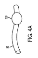
幾つかの実施形態において、ガイドワイヤチューブ80は拡大特徴部100(図3)を含む。除去補助具、アイデンティファイア又はそれらの任意の組み合わせとも呼ばれる拡大特徴部100はデバイス60及び/又はデリバリーカテーテル40のインデューサーシース20への挿入前にガイドワイヤチューブ80を除去するための施術者への視覚的注意喚起手段として機能することができる。拡大特徴部100はまた、ガイドワイヤチューブ80を引っ張り、摺動させ又はさもなければ除去するときに施術者が把持するための拡大プロファイルを提供することによって、ガイドワイヤチューブ80の除去を補助することができる。なおも別の実施形態において、拡大特徴部100は、ガイドワイヤチューブ80がデバイス60及び/又はデリバリーカテーテル40から一方向に取り外されるのを防ぎ、反対方向に取り外せるようにすることができる。幾つかの例において、拡大特徴部100は、ガイドワイヤチューブ80の直径方向に拡大した部分である。例えば、拡大特徴部は、場合により、ガイドワイヤチューブ80の隣接部分の直径よりも少なくとも10%、20%、30%、40%、50%、60%、100%、200%、300%、又は前述の反囲のいずれかを含む任意の範囲だけ大きい最大直径寸法を画定する。幾つかの例が提供されてきたが、任意の望ましい寸法の任意の拡大プロファイル部分が考えられる。
In some embodiments, the
幾つかの実施形態において、拡大特徴部100は、ガイドワイヤチューブ80の第一の端部82に位置する(図3)。しかしながら、拡大特徴部100は、場合により、ガイドワイヤチューブ80の第二の端部84に、近位部分87に沿って、遠位部分88に沿って、又は第一の端部82と第二の端部84との間のガイドワイヤチューブ80に沿った任意の他の点に沿って配置されうる。
In some embodiments, the magnifying
図4a〜dは、ガイドワイヤチューブ80及び拡大特徴部100の例示的な代替構成を示す。示されるように、拡大特徴部100は、ビーズ、リング、クリンプ、バルジ、バーブ、ノブ、フット、キャッチ、又は、拡大された外側プロファイルを提供する任意の他の特徴部のいずれかであることができ、それにより、ガイドワイヤチューブ80の除去前にイントロデューサシース20へのデバイス60及び/又はデリバリーカテーテル40の挿入を防ぐことができる。例えば、1つの実施形態において、拡大特徴部100は、ガイドワイヤチューブ80の直径よりも大きい直径を有する。他の実施形態において、拡大特徴部100は、ガイドワイヤチューブ80とは異なる形状、色又は輪郭を有することができる。例えば、拡大特徴部100は、実質的に円形、涙滴型、L型、フック型、又はガイドワイヤチューブ80のイントロデューサシース20への挿入を防止するその他の任意の形状であることができる。
4a-d show exemplary alternative configurations of the
幾つかの例において、複数のガイドワイヤチューブは(例えば、単一のデリバリーシステム、外科用キット又は他の構成の一部として)提供され、ここで、複数のガイドワイヤチューブのそれぞれは、拡大特徴部100などの拡大特徴部を含む。そのような例において、異なる拡大特徴部構成(例えば、異なるサイズ、形状、色又は他の差別化要因)を使用して、複数のガイドワイヤ、ガイドワイヤチューブ又は様々な他の特徴部を区別することができる。
In some examples, multiple guidewire tubes are provided (eg, as part of a single delivery system, surgical kit or other configuration), where each of the multiple guidewire tubes is an expanded feature. Includes an enlarged feature section such as
幾つかの実施形態において、拡大特徴部100は、ガイドワイヤチューブ80と同じ材料を含む。しかしながら、拡大特徴部100は、ガイドワイヤチューブ80とは異なる材料を含むこともできる。例えば、拡大特徴部100は紫外線(UV)硬化性接着剤及びシーラント、熱硬化性プラスチック、熱可塑性樹脂、順応性ポリマー、バンプ押出などの押出、金属フェルール及び様々なオーバーモールド部品を含むことができる。
In some embodiments, the magnifying
拡大特徴部100の表面は、所望の使用及び/又は施術者の選好を含む様々な要因に応じて変化しうる。幾つかの実施形態において、拡大特徴部100は実質的に滑らかである。しかしながら、他の例において、表面は、へこみ、線、くぼみ、クロスハッチ又は他のそのようなテクスチャ又はテクスチャの組み合わせを含むことができる。
The surface of the
図2を参照すると、デバイス60は、デリバリーカテーテル40の遠位部分48でデリバリーカテーテル40に結合される。幾つかの例において、ガイドワイヤチューブ80は、デバイス60の第一の開口部68aを通して取り外し可能に受け入れられる。しかしながら、ガイドワイヤチューブ80はまた、第二の開口部68b、第三の開口部68c又はデバイス60の他の任意の追加の開口部によって受け入れることができる。幾つかの実施形態において、ガイドワイヤチューブ80は1つの開口部を通して入り、別の開口部を通して出ていくことができる。
Referring to FIG. 2, the
所望の手順の完了に必要な任意の追加のガイドワイヤチューブは、例えば、第一の開口部68aから第二の開口部68b、第三の開口部68c又はデバイス60内の他の追加の開口部まで延在することができる。
Any additional guidewire tubing required to complete the desired procedure may be, for example, from the first opening 68a to the second opening 68b, the third opening 68c or any other additional opening within the
別の任意選択的構成において(図5)、ガイドワイヤチューブ80は、デリバリーカテーテル40の1つ以上の部分によって取り外し可能に受け入れられることができる。例えば、ガイドワイヤチューブ80は、デリバリーカテーテル40の近位端42又は遠位端44を通って入ることができる。幾つかの実施形態において、ガイドワイヤチューブ80は、近位端42又は遠位端44を通って入り、デリバリーカテーテル40の第一の開口部49を通って出ていくことができる。しかしながら、ガイドワイヤチューブ80は、デリバリーカテーテル40における任意の組み合わせの開口部を通して出入りすることができることが考えられる。上述と同様に、所望の処置の完了に必要な任意の数の追加のガイドワイヤチューブは考えられる。
In another optional configuration (FIG. 5), the
図5において、拡大特徴部100は、ガイドワイヤチューブ80の第一の端部82に示されている。しかしながら、上述のように、拡大特徴部100は、第一の端部82、第二の端部84、又は第一の端部82と第二の端部84との間の他の任意の点に位置することができる。
In FIG. 5, the
幾つかの実施形態において、拡大特徴部100は、ガイドワイヤチューブ80に接着剤で取り付けられる。拡大特徴部100は、除去力(すなわち、引張、摺動など)に耐えるのに十分に取り付けられなければならない。例えば、拡大特徴部100は、デバイス60からのガイドワイヤチューブ80の取り外しの間に変形せず、元の位置から移動せず又はガイドワイヤチューブ80から分離しないように、ガイドワイヤチューブ80に適切に接着/取り付け/接続されるべきである。したがって、様々な実施形態において、拡大特徴部100は、少なくとも約1lbf、少なくとも約4lbf、少なくとも約7lbf又は少なくとも約10lbfの取り付け力を有することができる。他の実施形態において、取り付け力は、約1〜12lbf、約6〜12lbf及び/又は約8〜12lbf又は前述の範囲のいずれかを含む任意の範囲である。
In some embodiments, the magnifying
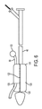
図6において、デバイス60は、デリバリーカテーテル40の遠位部分48において圧縮状態で(例えば、デリバリープロファイルで)示されている。1つの実施形態において、デバイス60は、拘束体120によって圧縮状態に維持される。
In FIG. 6, the
拘束体120は、近位端124、遠位端126及び管腔129を含む。幾つかの実施形態において、拘束体120は、本明細書においてデリバリー直径とも呼ばれる適切なデリバリープロファイルにデバイス60を圧縮することができるスリーブ、シース又はカバーである。例えば、デバイス60は、約3mm〜13mm又は最大約110mmの範囲又は前述の範囲のいずれかを含む任意の範囲、又は、所望される他の値のデリバリー直径に圧縮されることができる。
The
拘束体120は、デバイス60の全体又は一部の上に配置されうる。幾つかの実施形態において、拘束体120は、拘束体120に沿って概して長手方向のシームを形成することができる、展開コード122によって一緒にヒモ締めされる。
The
幾つかの実施形態において、拘束体120は、長手方向のシームに垂直に向けられた第一の開口部129を含む。第一の開口部129は、ガイドワイヤチューブ80がデリバリーカテーテル40及び拘束体120を出るための出口点を提供することができる。しかしながら、他の実施形態において、拘束体120は第一の開口部129を含まなくてもよい。例えば、ガイドワイヤチューブ80は長手方向のシームのステッチラインを通して出てくることができる。シース材料の拘束、シースの製造方法及び本体圧縮技術に関する詳細は、例えば、レオポルドらへの米国特許第6,352,561号明細書及びソーントンらへの米国特許第6,551,350号明細書に見出すことができる。
In some embodiments, the
図7〜11は、管腔内デリバリーシステム10を使用する方法を示す。図7に示されるように、第一のガイドワイヤ50は、イントロデューサシース20(図示せず)を通過し、本体管腔150内に配置され、第二のガイドワイヤ70は、分岐管腔152内に配置される。次いで、第一のガイドワイヤ50をデリバリーカテーテル40の遠位端44を通して近位方向に、そして内腔46中に通す。第二のガイドワイヤ70は、取り外し可能なガイドワイヤチューブ80に通される。典型的なガイドワイヤの直径は、例えば、0.089cm(0.035インチ)及び0.36cm(0.014インチ)を含む。しかしながら、特定の処置、所望の治療位置及び/又は施術者の選好に応じて、他のサイズのガイドワイヤを使用できることを理解されたい。
FIGS. 7-11 show a method of using the intraluminal delivery system 10. As shown in FIG. 7, the
図8は、デリバリーカテーテル40及びガイドワイヤチューブ80にそれぞれ通された第一のガイドワイヤ50及び第二のガイドワイヤ70を示す。図8において、ガイドワイヤチューブ80の第一の端部82及び第二の端部84の両方は、第二のガイドワイヤ70が両端から延在するように開いている。しかしながら、他の実施形態において、ガイドワイヤチューブ80の第一の端部82は、第二のガイドワイヤ70が第一の端部82から外に延在しないように第二のガイドワイヤ70の停止点を提供するように閉じられてもよい。
FIG. 8 shows a
第二のガイドワイヤ70がガイドワイヤチューブ80内に配置されると、ガイドワイヤチューブ80は、図9において矢印によって示される方向に近位方向にデバイス60から除去されることができる。別の構成において、ガイドワイヤチューブ80は、矢印の反対方向に遠位方向に除去されることができる。上述のように、拡大特徴部100は、施術者が把持するための拡大された部分又は握りを提供することにより、ガイドワイヤチューブ80の除去を補助することができる。拡大特徴部100はまた、患者の体内へのデリバリーカテーテル40及びデバイス60の挿入の前に、ガイドワイヤチューブ80を除去することの施術者への視覚的注意喚起手段を提供することができる。さらに、拡大特徴部100は、一方向のみ(すなわち、図9の矢印によって示される方向の近位方向又は図9の矢印の反対方向の遠位方向のいずれか)での除去を容易にすることができる。
When the
ガイドワイヤチューブ80が除去されると、デバイス60が遠位部分48に維持されたデリバリーカテーテル40は、第二の開口部68bが分岐管腔152と位置合わせされるまで、第一のガイドワイヤ50に沿って所望の治療位置まで前進される。図10は主管腔150内でのデバイス60の展開を示す。示されるように、第二の開口部68bは、分枝管腔152と位置合わせされ、第二のガイドワイヤ70は、第二の開口部68b及び分枝管腔152を通して延在されたままである。
When the
主管腔150内にデバイス60を展開した後に、分岐デバイス160(図11)を、第二のガイドワイヤ70に沿って分枝管腔152まで前進させることができる。幾つかの実施形態において、分岐デバイス160はステント、グラフト、又はデバイス60と同様の他の人工器官デバイスとすることができる。分岐デバイス160は、デリバリープロファイルで圧縮されることができ、上述されるように、デバイス60と同様の拘束体を含むことができる。さらに、分岐デバイス160は、分岐展開コード162(図10)を含むことができ、分岐デバイス160が分枝管腔152内の所望の位置になると、解放することができる。幾つかの実施形態において、分岐デバイス160は自己拡張型又はバルーン拡張型であることができる。幾つかの例(例えば、自己拡張型分岐デバイスの例)において、図11に示されるように、分岐展開コード162を引張ると、分岐デバイス160が拡張して分枝管腔152に適合する。
After deploying the
上述のように、管腔内デリバリーシステム10は、所望の用途のための任意の数の開口部、ガイドワイヤチューブ、ガイドワイヤ及び/又は分岐デバイスを含むことができる。これは、例えば、所望の治療位置、必要とされる分岐デバイスの数及び/又は治療される動脈瘤のサイズ又は数に依存しうる。後続の分岐デバイスの展開は、上記と同様に実現されうる。 As mentioned above, the intraluminal delivery system 10 can include any number of openings, guidewire tubes, guidewires and / or branching devices for the desired application. This may depend, for example, on the desired treatment location, the number of bifurcation devices required and / or the size or number of aneurysms being treated. Subsequent deployment of branching devices can be achieved in the same manner as described above.
当業者は、本開示の様々な態様が、意図された機能を発揮するように構成された任意の数の方法及び装置によって実現されうることを容易に理解するであろう。本明細書で参照される添付の図面は必ずしも縮尺どおりに描かれているわけではなく、本開示の様々な態様を示すために誇張されている場合があり、その点で、図面は限定として解釈されるべきではないことにも留意されたい。 Those skilled in the art will readily appreciate that various aspects of the present disclosure may be realized by any number of methods and devices configured to perform their intended function. The accompanying drawings referenced herein are not necessarily drawn to scale and may be exaggerated to show various aspects of the disclosure, in which regard the drawings shall be construed as limited. Also note that it should not be done.
この出願の発明は、一般的にも特定の実施形態に関しても上述されてきた。本開示の範囲から逸脱することなく、実施形態において様々な修正及び変更を行うことができることが当業者には明らかであろう。したがって、実施形態は、添付の特許請求の範囲及びそれらの均等の範囲内に入るかぎり、本発明の修正及び変形を網羅することが意図されている。 The inventions of this application have been described above both in general and with respect to specific embodiments. It will be apparent to those skilled in the art that various modifications and changes can be made in the embodiments without departing from the scope of the present disclosure. Accordingly, embodiments are intended to cover modifications and variations of the invention as long as they fall within the appended claims and their equality.
Claims (12)
前記近位開口部を通過して前記イントロデューサシースの管腔に入るように構成されたデリバリーカテーテルと、
デリバリープロファイルで前記デリバリーカテーテルに沿って解放可能に維持された管腔内デバイスであって、前記管腔内デバイスが前記デリバリープロファイルに維持されている間に、前記管腔内デバイスが近位開口部を通ってイントロデューサシースの管腔に通されることができるように構成されており、前記管腔内デバイスは内腔、前記内腔へのアクセスを提供する第一の開口部及び前記内腔へのアクセスを提供する第二の開口部を有する、管腔内デバイスと、
前記管腔内デバイスがデリバリープロファイルにあるときにガイドワイヤチューブが前記管腔内デバイスから取り外し可能であるように、前記管腔内デバイスによって取り外し可能に受け入れられているガイドワイヤチューブであって、前記ガイドワイヤチューブは、前記管腔内デバイスの第一の開口部を通過し、前記管腔内デバイスの内腔に入り、そして前記管腔内デバイスの第二の開口部から出て、前記ガイドワイヤチューブは、第一の端部、第二の端部及び前記ガイドワイヤを受け入れるように構成された管腔を有し、前記ガイドワイヤチューブは前記イントロデューサシースの近位開口部を通って前記イントロデューサシースの管腔内へガイドワイヤチューブを挿入するのを選択的に防止するように構成された拡大特徴部を含む、ガイドワイヤチューブと、
を含む、管腔内デリバリーシステム。 Proximal, distal, and cavities that extend between the proximal and distal ends, and proximal openings at the proximal ends that provide access to the cavities. With an introducer sheath,
A delivery catheter configured to pass through the proximal opening and into the lumen of the introducer sheath.
An intraluminal device maintained openly along the delivery catheter in the delivery profile, the intraluminal device having a proximal opening while the intraluminal device is maintained in the delivery profile. It is configured to be passed through the lumen of the introducer sheath through the lumen, said intraluminal device is a lumen, a first opening that provides access to said lumen, and said lumen. With an intraluminal device, which has a second opening that provides access to,
A guidewire tube that is detachably accepted by the intraluminal device so that the guidewire tube is removable from the intraluminal device when the intraluminal device is in the delivery profile. The guidewire tube passes through the first opening of the intraluminal device, enters the lumen of the intraluminal device, and exits the second opening of the intraluminal device, the guidewire. The tube has a first end, a second end and a lumen configured to receive the guide wire, the guide wire tube passing through the proximal opening of the introducer sheath to the intro. A guide wire tube and a guide wire tube that includes an enlarged feature configured to selectively prevent the guide wire tube from being inserted into the duct of the Ducer sheath.
Intraluminal delivery system, including.
デリバリーカテーテルと、
前記デリバリーカテーテルの少なくとも一部に結合されている管腔内デバイス、
近位端、遠位端、前記近位端から前記遠位端まで延在して管腔を形成する壁、及び、前記壁における少なくとも1つの開口部を有する拘束体、及び、
第一の端部、第二の端部及び管腔を有するガイドワイヤチューブであって、前記ガイドワイヤチューブは前記少なくとも1つの開口部から拘束体の管腔を通って延在しており、前記ガイドワイヤチューブは、前記イントロデューサシースへの前記ガイドワイヤチューブの挿入を防止するように構成された、増大したプロファイルセクションを有する、ガイドワイヤチューブと、
を含む、管腔内デリバリーシステム。 An introducer sheath having a proximal end, a distal end, and a lumen extending between the proximal end and the distal end.
Delivery catheter and
An intraluminal device, which is attached to at least a portion of the delivery catheter.
A wall extending from the proximal end to the distal end to form a lumen, and a restraint with at least one opening in the wall, and a proximal end, a distal end,
A guidewire tube having a first end, a second end and a lumen, wherein the guidewire tube extends from at least one opening through the lumen of the restraint. The guide wire tube comprises a guide wire tube having an increased profile section configured to prevent insertion of the guide wire tube into the introducer sheath.
Intraluminal delivery system, including.
前記ガイドワイヤがガイドワイヤチューブの管腔を通って延在するように、前記ガイドワイヤを、請求項1〜11のいずれか1項記載の管腔内デリバリーシステムの前記ガイドワイヤチューブを通して挿入することと、
前記管腔内デリバリーシステムから前記ガイドワイヤチューブを除去すること、
前記管腔内デリバリーシステムを前記患者の体内に挿入することと、
前記管腔内デバイスを前記患者の体内の所望の治療部位にデリバリーすることと、
を含む、管腔内デリバリーシステムを使用する方法。 Delivering the guide wire to the desired treatment site in the patient's body,
Inserting the guide wire through the guide wire tube of the intraluminal delivery system according to any one of claims 1 to 11 so that the guide wire extends through the lumen of the guide wire tube. When,
Removing the guide wire tube from the intraluminal delivery system,
Inserting the intraluminal delivery system into the patient's body
Delivering the intraluminal device to the desired treatment site within the patient's body,
Methods of using an intraluminal delivery system, including.
Priority Applications (1)
| Application Number | Priority Date | Filing Date | Title |
|---|---|---|---|
| JP2022201950A JP7454638B2 (en) | 2018-02-02 | 2022-12-19 | Delivery system aids and related systems and methods |
Applications Claiming Priority (3)
| Application Number | Priority Date | Filing Date | Title |
|---|---|---|---|
| US201862625654P | 2018-02-02 | 2018-02-02 | |
| US62/625,654 | 2018-02-02 | ||
| PCT/US2018/017037 WO2019152058A1 (en) | 2018-02-02 | 2018-02-06 | Delivery system aid and associated systems and methods |
Related Child Applications (1)
| Application Number | Title | Priority Date | Filing Date |
|---|---|---|---|
| JP2022201950A Division JP7454638B2 (en) | 2018-02-02 | 2022-12-19 | Delivery system aids and related systems and methods |
Publications (2)
| Publication Number | Publication Date |
|---|---|
| JP2021511907A true JP2021511907A (en) | 2021-05-13 |
| JP7200257B2 JP7200257B2 (en) | 2023-01-06 |
Family
ID=61258629
Family Applications (2)
| Application Number | Title | Priority Date | Filing Date |
|---|---|---|---|
| JP2020542012A Active JP7200257B2 (en) | 2018-02-02 | 2018-02-06 | Delivery system aids and related systems and methods |
| JP2022201950A Active JP7454638B2 (en) | 2018-02-02 | 2022-12-19 | Delivery system aids and related systems and methods |
Family Applications After (1)
| Application Number | Title | Priority Date | Filing Date |
|---|---|---|---|
| JP2022201950A Active JP7454638B2 (en) | 2018-02-02 | 2022-12-19 | Delivery system aids and related systems and methods |
Country Status (9)
| Country | Link |
|---|---|
| US (2) | US20200352762A1 (en) |
| EP (1) | EP3746002B1 (en) |
| JP (2) | JP7200257B2 (en) |
| CN (2) | CN118000989A (en) |
| AU (1) | AU2018405499B2 (en) |
| BR (1) | BR112020014912A2 (en) |
| CA (1) | CA3087976C (en) |
| ES (1) | ES2986371T3 (en) |
| WO (1) | WO2019152058A1 (en) |
Families Citing this family (2)
| Publication number | Priority date | Publication date | Assignee | Title |
|---|---|---|---|---|
| EP3746002B1 (en) | 2018-02-02 | 2024-06-19 | W. L. Gore & Associates, Inc. | Delivery system aid and associated systems |
| CN111281486A (en) * | 2020-03-18 | 2020-06-16 | 上海市东方医院(同济大学附属东方医院) | Stone-taking basket with thread guide holes |
Citations (3)
| Publication number | Priority date | Publication date | Assignee | Title |
|---|---|---|---|---|
| JP2010524629A (en) * | 2007-04-24 | 2010-07-22 | ゴア エンタープライズ ホールディングス,インコーポレイティド | Side branching intraluminal prosthesis and method of delivery |
| JP2012525227A (en) * | 2009-04-28 | 2012-10-22 | エンドロジックス、インク | Apparatus and method for deploying a graft or graft system |
| JP2014500752A (en) * | 2010-11-15 | 2014-01-16 | ダブリュ.エル.ゴア アンド アソシエイツ,インコーポレイティド | Stent graft with opposing side branch inlets |
Family Cites Families (45)
| Publication number | Priority date | Publication date | Assignee | Title |
|---|---|---|---|---|
| US5653743A (en) | 1994-09-09 | 1997-08-05 | Martin; Eric C. | Hypogastric artery bifurcation graft and method of implantation |
| US6042605A (en) | 1995-12-14 | 2000-03-28 | Gore Enterprose Holdings, Inc. | Kink resistant stent-graft |
| US6599316B2 (en) | 1996-11-04 | 2003-07-29 | Advanced Stent Technologies, Inc. | Extendible stent apparatus |
| US6352561B1 (en) | 1996-12-23 | 2002-03-05 | W. L. Gore & Associates | Implant deployment apparatus |
| US6551350B1 (en) | 1996-12-23 | 2003-04-22 | Gore Enterprise Holdings, Inc. | Kink resistant bifurcated prosthesis |
| DE19936207A1 (en) * | 1999-08-02 | 2001-02-15 | Angiomed Ag | Catheter and introducer with separator |
| US6645242B1 (en) | 2000-12-11 | 2003-11-11 | Stephen F. Quinn | Bifurcated side-access intravascular stent graft |
| CA2457860C (en) * | 2001-08-23 | 2010-03-16 | Darrel C. Gumm | Rotating stent delivery system for side branch access and protection and method of using same |
| US7309350B2 (en) | 2001-12-03 | 2007-12-18 | Xtent, Inc. | Apparatus and methods for deployment of vascular prostheses |
| JP4208075B2 (en) | 2002-03-25 | 2009-01-14 | クック インコーポレイティド | Bifurcated / branched vascular prosthesis |
| WO2004028399A2 (en) * | 2002-06-28 | 2004-04-08 | Cook Incorporated | Thoracic deployment device |
| US20040133130A1 (en) | 2003-01-06 | 2004-07-08 | Ferry Steven J. | Magnetically navigable medical guidewire |
| CA2512610C (en) | 2003-01-14 | 2008-12-23 | The Cleveland Clinic Foundation | Branched vessel endoluminal device |
| US8262671B2 (en) | 2003-03-14 | 2012-09-11 | Oscor Inc. | Vascular introducer having hemostatic valve with integral seal |
| US7537606B2 (en) | 2003-04-03 | 2009-05-26 | Cook Incorporated | Branch stent graft deployment and method |
| US20040199073A1 (en) | 2003-04-03 | 2004-10-07 | Agency For Science, Technology And Research | Method and apparatus for measuring motion of a body in a number of dimensions |
| US20060041303A1 (en) | 2004-08-18 | 2006-02-23 | Israel Henry M | Guidewire with stopper |
| US20070083215A1 (en) * | 2005-10-07 | 2007-04-12 | Hamer Rochelle M | Conduit for interventional procedures |
| US20070162109A1 (en) | 2006-01-11 | 2007-07-12 | Luis Davila | Intraluminal stent graft |
| JP2009534104A (en) | 2006-04-19 | 2009-09-24 | ウィリアム・エイ・クック・オーストラリア・プロプライエタリー・リミテッド | Double-branched stent graft |
| JP2010512231A (en) | 2006-12-12 | 2010-04-22 | スペンス、ポール・エー | Implant, system and method for physically diverting substances in blood to avoid head |
| US9301863B2 (en) * | 2009-03-10 | 2016-04-05 | Medtronic Vascular, Inc. | Prosthesis delivery apparatus and methods |
| US8474300B2 (en) | 2009-07-20 | 2013-07-02 | Becton, Dickinson And Company | Methods to provide a feature on a needle |
| US8474120B2 (en) | 2009-10-09 | 2013-07-02 | W. L. Gore & Associates, Inc. | Bifurcated highly conformable medical device branch access |
| US8292951B2 (en) | 2010-04-29 | 2012-10-23 | Medtronic Vascular, Inc. | Tethered pop up branch structure stent graft and method |
| EP3053545B1 (en) * | 2011-04-28 | 2019-09-18 | Cook Medical Technologies LLC | Apparatus for facilitating deployment of an endoluminal prosthesis |
| US8551158B2 (en) | 2011-05-13 | 2013-10-08 | Cook Medical Technologies Llc | Steerable iliac branch device |
| US9314328B2 (en) | 2011-08-16 | 2016-04-19 | W. L. Gore & Associates, Inc. | Branched stent graft device and deployment |
| US9144486B2 (en) | 2011-10-14 | 2015-09-29 | Trivascular, Inc. | Fenestrated inflatable graft |
| US10154894B2 (en) | 2011-10-18 | 2018-12-18 | David J. Minion | Endografts for parallel endoluminal grafts |
| US8945200B1 (en) | 2011-11-16 | 2015-02-03 | W. L. Gore & Associates, Inc. | Iliac bifurcated endoprosthesis medical apparatus and method of deploying same |
| EP2787925B1 (en) | 2011-12-06 | 2018-04-18 | Aortic Innovations LLC | Device for endovascular aortic repair |
| AU2013273849B2 (en) | 2012-12-26 | 2015-02-12 | Cleveland Clinic Foundation | Endoluminal prosthesis having modular branches and methods of deployment |
| US9655754B2 (en) | 2013-01-10 | 2017-05-23 | Trivascular, Inc. | Systems and methods for guidewire crossover for bifurcated prostheses |
| US9220614B2 (en) | 2013-03-11 | 2015-12-29 | Cook Medical Technologies Llc | Endovascular grafts for treating the iliac arteries and methods of delivery and deployment thereof |
| CN110169802B (en) | 2013-03-15 | 2022-07-08 | 柯惠有限合伙公司 | Delivery and detachment mechanism for vascular implants |
| US9868242B2 (en) | 2014-04-25 | 2018-01-16 | Medtronic Ablation Frontiers Llc | Methods of manufacturing a multi-lumen device |
| US10299948B2 (en) | 2014-11-26 | 2019-05-28 | W. L. Gore & Associates, Inc. | Balloon expandable endoprosthesis |
| PL3310305T3 (en) | 2015-06-18 | 2022-09-26 | Ascyrus Medical, Llc | Branched aortic graft |
| US20170135806A1 (en) | 2015-11-16 | 2017-05-18 | Mark P. Ombrellaro | Device for repairing aneurysm within multi-branch vessel |
| US10751485B2 (en) * | 2016-08-29 | 2020-08-25 | Cephea Valve Technologies, Inc. | Methods, systems, and devices for sealing and flushing a delivery system |
| US20180071076A1 (en) | 2016-09-13 | 2018-03-15 | Lifetech Scientific (Shenzhen) Co., Ltd. | Aneurysm Treatment Method |
| EP3547959B1 (en) | 2016-12-05 | 2024-10-23 | Medtronic Vascular Inc. | Modular aortic arch prosthetic assembly |
| EP3746002B1 (en) | 2018-02-02 | 2024-06-19 | W. L. Gore & Associates, Inc. | Delivery system aid and associated systems |
| US20220133463A1 (en) | 2019-02-26 | 2022-05-05 | W. L. Gore & Associates, Inc. | Modular branched endoprosthetic systems, devices, and methods |
-
2018
- 2018-02-06 EP EP18706923.2A patent/EP3746002B1/en active Active
- 2018-02-06 AU AU2018405499A patent/AU2018405499B2/en active Active
- 2018-02-06 CA CA3087976A patent/CA3087976C/en active Active
- 2018-02-06 JP JP2020542012A patent/JP7200257B2/en active Active
- 2018-02-06 US US16/965,696 patent/US20200352762A1/en active Pending
- 2018-02-06 ES ES18706923T patent/ES2986371T3/en active Active
- 2018-02-06 BR BR112020014912-8A patent/BR112020014912A2/en active Search and Examination
- 2018-02-06 WO PCT/US2018/017037 patent/WO2019152058A1/en not_active Ceased
- 2018-02-28 CN CN202410271941.2A patent/CN118000989A/en active Pending
- 2018-02-28 CN CN201810168590.7A patent/CN108158703B/en active Active
-
2022
- 2022-12-19 JP JP2022201950A patent/JP7454638B2/en active Active
-
2023
- 2023-08-24 US US18/237,446 patent/US12403023B2/en active Active
Patent Citations (3)
| Publication number | Priority date | Publication date | Assignee | Title |
|---|---|---|---|---|
| JP2010524629A (en) * | 2007-04-24 | 2010-07-22 | ゴア エンタープライズ ホールディングス,インコーポレイティド | Side branching intraluminal prosthesis and method of delivery |
| JP2012525227A (en) * | 2009-04-28 | 2012-10-22 | エンドロジックス、インク | Apparatus and method for deploying a graft or graft system |
| JP2014500752A (en) * | 2010-11-15 | 2014-01-16 | ダブリュ.エル.ゴア アンド アソシエイツ,インコーポレイティド | Stent graft with opposing side branch inlets |
Also Published As
| Publication number | Publication date |
|---|---|
| JP7200257B2 (en) | 2023-01-06 |
| CN108158703A (en) | 2018-06-15 |
| CA3087976A1 (en) | 2019-08-08 |
| US12403023B2 (en) | 2025-09-02 |
| ES2986371T3 (en) | 2024-11-11 |
| AU2018405499A1 (en) | 2020-07-16 |
| JP7454638B2 (en) | 2024-03-22 |
| US20230390091A1 (en) | 2023-12-07 |
| BR112020014912A2 (en) | 2020-12-08 |
| EP3746002A1 (en) | 2020-12-09 |
| CA3087976C (en) | 2023-09-12 |
| JP2023021431A (en) | 2023-02-10 |
| EP3746002B1 (en) | 2024-06-19 |
| WO2019152058A1 (en) | 2019-08-08 |
| CN108158703B (en) | 2024-03-22 |
| AU2018405499B2 (en) | 2021-08-05 |
| CN118000989A (en) | 2024-05-10 |
| US20200352762A1 (en) | 2020-11-12 |
Similar Documents
| Publication | Publication Date | Title |
|---|---|---|
| JP7074787B2 (en) | Push-pull medical device delivery system | |
| JP5123376B2 (en) | Catheter with guide wire channel | |
| JP6659753B2 (en) | Fenestration with cannula inserted in advance | |
| US7611529B2 (en) | Thoracic introducer | |
| JP5722764B2 (en) | Branched graft deployment system and deployment method | |
| AU692072B2 (en) | Endoprosthesis stent/graft deployment system | |
| ES2366004T3 (en) | ENDOLUMINAL PROSTHETICS WITH SIDE RAMIFICATION. | |
| JP2019510579A (en) | Delivery system with introducer sheath and distal sheath and method of use | |
| US8465536B2 (en) | Prosthesis deployment system | |
| US12403023B2 (en) | Delivery system aid and associated systems and methods |
Legal Events
| Date | Code | Title | Description |
|---|---|---|---|
| A621 | Written request for application examination |
Free format text: JAPANESE INTERMEDIATE CODE: A621 Effective date: 20200825 |
|
| A977 | Report on retrieval |
Free format text: JAPANESE INTERMEDIATE CODE: A971007 Effective date: 20210812 |
|
| A131 | Notification of reasons for refusal |
Free format text: JAPANESE INTERMEDIATE CODE: A131 Effective date: 20210831 |
|
| A521 | Request for written amendment filed |
Free format text: JAPANESE INTERMEDIATE CODE: A523 Effective date: 20211130 |
|
| A131 | Notification of reasons for refusal |
Free format text: JAPANESE INTERMEDIATE CODE: A131 Effective date: 20220412 |
|
| A521 | Request for written amendment filed |
Free format text: JAPANESE INTERMEDIATE CODE: A523 Effective date: 20220707 |
|
| TRDD | Decision of grant or rejection written | ||
| A01 | Written decision to grant a patent or to grant a registration (utility model) |
Free format text: JAPANESE INTERMEDIATE CODE: A01 Effective date: 20221108 |
|
| A601 | Written request for extension of time |
Free format text: JAPANESE INTERMEDIATE CODE: A601 Effective date: 20221208 |
|
| A61 | First payment of annual fees (during grant procedure) |
Free format text: JAPANESE INTERMEDIATE CODE: A61 Effective date: 20221221 |
|
| R150 | Certificate of patent or registration of utility model |
Ref document number: 7200257 Country of ref document: JP Free format text: JAPANESE INTERMEDIATE CODE: R150 |