JP2021510581A - Drug delivery device with removable cap and locking member to prevent accidental actuation - Google Patents
Drug delivery device with removable cap and locking member to prevent accidental actuation Download PDFInfo
- Publication number
- JP2021510581A JP2021510581A JP2020539035A JP2020539035A JP2021510581A JP 2021510581 A JP2021510581 A JP 2021510581A JP 2020539035 A JP2020539035 A JP 2020539035A JP 2020539035 A JP2020539035 A JP 2020539035A JP 2021510581 A JP2021510581 A JP 2021510581A
- Authority
- JP
- Japan
- Prior art keywords
- drug delivery
- delivery device
- locking member
- radial
- casing
- Prior art date
- Legal status (The legal status is an assumption and is not a legal conclusion. Google has not performed a legal analysis and makes no representation as to the accuracy of the status listed.)
- Granted
Links
- 238000012377 drug delivery Methods 0.000 title claims abstract description 56
- 239000003380 propellant Substances 0.000 claims description 19
- 150000005828 hydrofluoroalkanes Chemical class 0.000 claims description 10
- 238000010586 diagram Methods 0.000 abstract 1
- 239000003814 drug Substances 0.000 description 5
- 229940079593 drug Drugs 0.000 description 5
- 238000000034 method Methods 0.000 description 4
- 230000005489 elastic deformation Effects 0.000 description 3
- YFMFNYKEUDLDTL-UHFFFAOYSA-N 1,1,1,2,3,3,3-heptafluoropropane Chemical compound FC(F)(F)C(F)C(F)(F)F YFMFNYKEUDLDTL-UHFFFAOYSA-N 0.000 description 1
- FXRLMCRCYDHQFW-UHFFFAOYSA-N 2,3,3,3-tetrafluoropropene Chemical compound FC(=C)C(F)(F)F FXRLMCRCYDHQFW-UHFFFAOYSA-N 0.000 description 1
- -1 HFA 341a Chemical class 0.000 description 1
- 208000012266 Needlestick injury Diseases 0.000 description 1
- 230000004323 axial length Effects 0.000 description 1
- 230000000903 blocking effect Effects 0.000 description 1
- 238000002347 injection Methods 0.000 description 1
- 239000007924 injection Substances 0.000 description 1
- 230000002265 prevention Effects 0.000 description 1
Images


Classifications
-
- A—HUMAN NECESSITIES
- A61—MEDICAL OR VETERINARY SCIENCE; HYGIENE
- A61M—DEVICES FOR INTRODUCING MEDIA INTO, OR ONTO, THE BODY; DEVICES FOR TRANSDUCING BODY MEDIA OR FOR TAKING MEDIA FROM THE BODY; DEVICES FOR PRODUCING OR ENDING SLEEP OR STUPOR
- A61M5/00—Devices for bringing media into the body in a subcutaneous, intra-vascular or intramuscular way; Accessories therefor, e.g. filling or cleaning devices, arm-rests
- A61M5/178—Syringes
- A61M5/20—Automatic syringes, e.g. with automatically actuated piston rod, with automatic needle injection, filling automatically
- A61M5/2033—Spring-loaded one-shot injectors with or without automatic needle insertion
-
- A—HUMAN NECESSITIES
- A61—MEDICAL OR VETERINARY SCIENCE; HYGIENE
- A61M—DEVICES FOR INTRODUCING MEDIA INTO, OR ONTO, THE BODY; DEVICES FOR TRANSDUCING BODY MEDIA OR FOR TAKING MEDIA FROM THE BODY; DEVICES FOR PRODUCING OR ENDING SLEEP OR STUPOR
- A61M5/00—Devices for bringing media into the body in a subcutaneous, intra-vascular or intramuscular way; Accessories therefor, e.g. filling or cleaning devices, arm-rests
- A61M5/178—Syringes
- A61M5/20—Automatic syringes, e.g. with automatically actuated piston rod, with automatic needle injection, filling automatically
- A61M5/2046—Media being expelled from injector by gas generation, e.g. explosive charge
-
- A—HUMAN NECESSITIES
- A61—MEDICAL OR VETERINARY SCIENCE; HYGIENE
- A61M—DEVICES FOR INTRODUCING MEDIA INTO, OR ONTO, THE BODY; DEVICES FOR TRANSDUCING BODY MEDIA OR FOR TAKING MEDIA FROM THE BODY; DEVICES FOR PRODUCING OR ENDING SLEEP OR STUPOR
- A61M5/00—Devices for bringing media into the body in a subcutaneous, intra-vascular or intramuscular way; Accessories therefor, e.g. filling or cleaning devices, arm-rests
- A61M5/178—Syringes
- A61M5/24—Ampoule syringes, i.e. syringes with needle for use in combination with replaceable ampoules or carpules, e.g. automatic
-
- A—HUMAN NECESSITIES
- A61—MEDICAL OR VETERINARY SCIENCE; HYGIENE
- A61M—DEVICES FOR INTRODUCING MEDIA INTO, OR ONTO, THE BODY; DEVICES FOR TRANSDUCING BODY MEDIA OR FOR TAKING MEDIA FROM THE BODY; DEVICES FOR PRODUCING OR ENDING SLEEP OR STUPOR
- A61M5/00—Devices for bringing media into the body in a subcutaneous, intra-vascular or intramuscular way; Accessories therefor, e.g. filling or cleaning devices, arm-rests
- A61M5/178—Syringes
- A61M5/31—Details
- A61M5/315—Pistons; Piston-rods; Guiding, blocking or restricting the movement of the rod or piston; Appliances on the rod for facilitating dosing ; Dosing mechanisms
- A61M5/31565—Administration mechanisms, i.e. constructional features, modes of administering a dose
- A61M5/31566—Means improving security or handling thereof
- A61M5/31571—Means preventing accidental administration
-
- A—HUMAN NECESSITIES
- A61—MEDICAL OR VETERINARY SCIENCE; HYGIENE
- A61M—DEVICES FOR INTRODUCING MEDIA INTO, OR ONTO, THE BODY; DEVICES FOR TRANSDUCING BODY MEDIA OR FOR TAKING MEDIA FROM THE BODY; DEVICES FOR PRODUCING OR ENDING SLEEP OR STUPOR
- A61M5/00—Devices for bringing media into the body in a subcutaneous, intra-vascular or intramuscular way; Accessories therefor, e.g. filling or cleaning devices, arm-rests
- A61M5/178—Syringes
- A61M5/31—Details
- A61M5/32—Needles; Details of needles pertaining to their connection with syringe or hub; Accessories for bringing the needle into, or holding the needle on, the body; Devices for protection of needles
- A61M5/3202—Devices for protection of the needle before use, e.g. caps
-
- A—HUMAN NECESSITIES
- A61—MEDICAL OR VETERINARY SCIENCE; HYGIENE
- A61M—DEVICES FOR INTRODUCING MEDIA INTO, OR ONTO, THE BODY; DEVICES FOR TRANSDUCING BODY MEDIA OR FOR TAKING MEDIA FROM THE BODY; DEVICES FOR PRODUCING OR ENDING SLEEP OR STUPOR
- A61M5/00—Devices for bringing media into the body in a subcutaneous, intra-vascular or intramuscular way; Accessories therefor, e.g. filling or cleaning devices, arm-rests
- A61M5/178—Syringes
- A61M5/20—Automatic syringes, e.g. with automatically actuated piston rod, with automatic needle injection, filling automatically
- A61M2005/2073—Automatic syringes, e.g. with automatically actuated piston rod, with automatic needle injection, filling automatically preventing premature release, e.g. by making use of a safety lock
Landscapes
- Health & Medical Sciences (AREA)
- Vascular Medicine (AREA)
- Engineering & Computer Science (AREA)
- Anesthesiology (AREA)
- Biomedical Technology (AREA)
- Heart & Thoracic Surgery (AREA)
- Hematology (AREA)
- Life Sciences & Earth Sciences (AREA)
- Animal Behavior & Ethology (AREA)
- General Health & Medical Sciences (AREA)
- Public Health (AREA)
- Veterinary Medicine (AREA)
- Infusion, Injection, And Reservoir Apparatuses (AREA)
Abstract
シリンジを受け入れるためのハウジングを含む薬剤送達装置であって、このハウジングは、互いに分離可能に取り付けできる第1および第2のケーシング部を有する、薬剤送達装置が提供される。この装置はさらに、ハウジング内に受け入れられ、穴を画定する内面および反対側の外面を有する管状壁を含むスリーブを備える。係止部材は、第2のケーシング部に対して第1の軸方向位置と第2の軸方向位置との間で軸方向に移動可能になるように、第2のケーシング部内で受け入れ可能である。第1の軸方向位置において、係止部材は前記外面と係合可能であり、第1のケーシング部に対するスリーブの軸方向移動を阻害する。第2の軸方向位置においては、係止部材の前記外面との係合を解除することができる。この装置は、自動注射器としての用途を有している。【選択図】図2A drug delivery device comprising a housing for receiving a syringe, wherein the housing has first and second casing portions that can be detachably attached to each other. The device further comprises a sleeve that includes a tubular wall that is received within the housing and has an inner surface defining a hole and an outer surface on the opposite side. The locking member is acceptable within the second casing portion so that it is axially movable between the first axial position and the second axial position with respect to the second casing portion. .. At the first axial position, the locking member is engageable with the outer surface and impedes the axial movement of the sleeve with respect to the first casing portion. At the second axial position, the locking member can be disengaged from the outer surface. This device has a use as an automatic syringe. [Selection diagram] Fig. 2
Description
本発明は、薬剤送達装置、特に自動的に作動可能なシリンジに関する。 The present invention relates to drug delivery devices, in particular self-actuating syringes.
自動注射装置(autoinjector)と呼ばれることもある、自動的に作動可能なシリンジがよく知られている。これらの装置は、一回分の薬剤を患者に送達するための動力源、例えば、圧縮されたバネまたは推進剤容器を備えている。さらなる構成要素として、貯蔵中および送達の種々の段階においてこの装置のニードルを選択的に覆うためのニードルシールドを備えていてもよい。当業者には理解できるように、圧縮されたバネを開放したり推進剤の容器を開けたりするために、多くの場合、ユーザーが注射部位に装置を押し付けた時に、この装置の内部構成要素を後部に変位させることによって装置を作動させる役割をこのニードルシールドが果たし得る。しかしながら、装置が硬い面上に落下した場合、慣性によって内部構成要素は後方へ変位する可能性があり、その結果、装置は意図せず作動することになる。装置の有効性を維持するために、意図しない作動の防止が望まれることは明らかである。 Self-actuating syringes, sometimes referred to as autoinjectors, are well known. These devices include a power source for delivering a single dose of the drug to the patient, such as a compressed spring or propellant container. As a further component, a needle shield may be provided to selectively cover the needles of the device during storage and at various stages of delivery. As will be appreciated by those skilled in the art, the internal components of this device are often used when the user presses the device against the injection site to release the compressed spring or open the propellant container. The needle shield can serve to actuate the device by displacing it to the rear. However, if the device falls on a hard surface, inertia can cause the internal components to displace backwards, resulting in unintentional operation of the device. It is clear that prevention of unintended operation is desired in order to maintain the effectiveness of the device.
本発明の実施形態の目的は、1つまたは複数の周知の構成に関連する問題を少なくとも軽減することである。 An object of an embodiment of the present invention is to at least alleviate problems associated with one or more well-known configurations.
本発明の一態様によれば、互いに分離可能に取り付けできる第1及び第2のケーシング部を有していて、シリンジを受け入れるハウジングと、該ハウジング内に受け入れられ、穴を画定する内面および反対側の外面を有する管状壁を備えるスリーブと、第2のケーシング部に対して第1の軸方向位置と第2の軸方向位置との間で軸方向に移動可能になるように、第2のケーシング部内に受け入れられる係止部材とを備える薬剤送達装置であって、第1の軸方向位置において、係止部材は前記外面と係合可能であって、第1のケーシング部に対するスリーブの軸方向移動を阻害しており、第2の軸方向位置において係止部材の前記外面との係合を解除することができる、薬剤送達装置が提供される。このように、係止部材によって、スリーブに対するハウジングの相対的な位置を選択的に維持することができる。もちろん、係止部材の前記外面との係合を解除することができ、スリーブの軸方向移動を可能にすることができる。前記外面と係合することで、係止部材が装置の穴を遮らず、あるいは装置の穴に進入しないようにできる。 According to one aspect of the invention, a housing that has first and second casings that can be detachably attached to each other and receives a syringe, and an inner surface and opposite side that is received within the housing and defines a hole. A sleeve having a tubular wall with an outer surface of the second casing and a second casing so that it can be moved axially between a first axial position and a second axial position with respect to the second casing portion. A drug delivery device comprising a locking member that is accepted within the portion, the locking member being engageable with the outer surface at a first axial position and axial movement of the sleeve with respect to the first casing portion. Provided is a drug delivery device capable of disengaging the locking member from its outer surface at a second axial position. Thus, the locking member can selectively maintain the relative position of the housing with respect to the sleeve. Of course, the engagement of the locking member with the outer surface can be released, and the sleeve can be moved in the axial direction. By engaging with the outer surface, the locking member can prevent the locking member from blocking the hole in the device or entering the hole in the device.
いくつかの実施形態においては、スリーブの軸方向移動によって、つまりその直接の結果として、薬剤送達装置は作動できる。このように、係止部材によって、装置の意図しない作動の可能性を低減し得る。この軸方向移動は後方への移動であってもよい。第1および第2のケーシング部を互いに分離することによって、係止部材を第1の軸方向位置から第2の軸方向位置に移動することができる。 In some embodiments, the drug delivery device can be actuated by axial movement of the sleeve, i.e., as a direct result thereof. Thus, the locking member can reduce the possibility of unintended operation of the device. This axial movement may be a backward movement. By separating the first and second casing portions from each other, the locking member can be moved from the first axial position to the second axial position.
任意選択的に、係止部材が、前記外面と係合可能に延びる1つまたは複数の半径方向内向きの突起を有する本体部分を備えることができて、前記外面と係合することができる。本体部分は環状であってよい。本体部分は周方向に連続的、または不連続的であってもよい。いくつかの実施形態では、本体部分には、スリーブを部分的または全体的に受け入れ可能である開口を画定することができる。このように、係止部材または少なくともその一部分は、スリーブと第2のケーシング部との間に同心円状に受け入れられることができる。 Optionally, the locking member can include a body portion having one or more radial inward projections that extend engageably with the outer surface and can engage the outer surface. The body portion may be annular. The body portion may be continuous or discontinuous in the circumferential direction. In some embodiments, the body portion can be defined with an opening that is partially or totally acceptable to the sleeve. In this way, the locking member or at least a portion thereof can be concentrically received between the sleeve and the second casing portion.
前記外面には、該外面に沿って、つまりスリーブの周囲に延びる半径方向内向きの溝があって、その溝には1つまたは複数の半径方向内向きの突起が係合可能であり得るので、係止部材は前記外面と係合可能である。この半径方向内向きの溝は周方向に連続的、または不連続的であってよい。この溝によって、係止部材に対するスリーブの任意の回転方位において、1つまたは複数の半径方向内向きの突起が前記外面に係合できるようにしてもよい。 Since the outer surface has a radial inward groove extending along the outer surface, i.e. around the sleeve, the groove may be engaged with one or more radial inward protrusions. , The locking member is engageable with the outer surface. The radial inward groove may be continuous or discontinuous in the circumferential direction. The groove may allow one or more radial inward projections to engage the outer surface in any direction of rotation of the sleeve with respect to the locking member.
いくつかの実施形態では、本体部分は、軸方向に延びる1つまたは複数の第1のアームを有することができ、1つまたは複数の半径方向内向きの突起のそれぞれ1つが、そのアームの自由端に近接した位置にあって、そのアームに一体に形成されるか、もしくは連結されうる。軸方向に延びる複数の第1のアームは、本体部分の周りに等間隔で配置されていてもよい。 In some embodiments, the body portion may have one or more first arms extending axially, each with one or more radial inward projections free of the arm. It is located close to the end and can be integrally formed or connected to the arm. The plurality of first arms extending in the axial direction may be arranged at equal intervals around the main body portion.
1つまたは複数の半径方向内向きの突起の半径方向外方への移動によって、係止部材の前記外面との係合を解除することができる。1つまたは複数の半径方向内向きの突起の半径方向外方への移動は、係止リングの変形、例えば弾性変形によるものであってよい。より具体的には、1つまたは複数の半径方向内向きの突起の半径方向外方への移動は、軸方向に延びる1つまたは複数の第1のアームの変形、例えば弾性変形によるものであってよい。 The engagement of the locking member with the outer surface can be disengaged by the radial outward movement of one or more radial inward projections. The radial inward movement of one or more radial inward projections may be due to deformation of the locking ring, such as elastic deformation. More specifically, the radial inward movement of one or more radial inward projections is due to deformation of one or more first arms extending axially, such as elastic deformation. You can.
いくつかの実施形態では、第1の軸方向位置における、1つまたは複数の半径方向内向きの突起の半径方向外方への移動は、係止部材が第2のケーシング部に当接することで阻害することができる。より具体的には、1つまたは複数の半径方向内向きの突起の半径方向外方への移動は、係止部材が第2のケーシング部の半径方向内向きに延びる第1の部位に当接することで阻害することができる。半径方向内向きに延びる第1の部位は、第2のケーシング部の第1の部分の上に延在する1つまたは複数の第1のバンプ、隆起(リッジ)、および/またはリブを含みうる。 In some embodiments, the radial inward movement of one or more radial inward projections in the first axial position is such that the locking member abuts on the second casing. Can be inhibited. More specifically, the radial outward movement of one or more radial inward projections abuts the locking member in contact with a first portion of the second casing that extends radially inward. It can be inhibited by. The first portion extending radially inward may include one or more first bumps, ridges, and / or ribs extending over the first portion of the second casing portion. ..
第1の軸方向位置において、半径方向内向きに延びる第1の部位は、1つまたは複数の半径方向内向きの突起と半径方向に整列していてよく、第2の軸方向位置においては、半径方向内向きに延びる第1の部位は、1つまたは複数の半径方向内向きの突起と半径方向に整列していなくてよい。このように、第2の軸方向位置では、係止部材の撓みを許容する空間が提供されうる。第1および第2のケーシング部を互いに分離することにより、係止部材の前記外面との係合を解除することができる。 In the first axial position, the first portion extending radially inward may be radially aligned with one or more radial inward projections, and in the second axial position, The first portion extending radially inward does not have to be radially aligned with one or more radial inward projections. As described above, the second axial position may provide a space that allows the locking member to bend. By separating the first and second casing portions from each other, the engagement of the locking member with the outer surface can be released.
任意選択的に、本体部分から第2のケーシング部と係合可能に延びて、係止部材を第2のケーシング部内に保持する1つまたは複数の半径方向外向きの突起を、本体部分は有することができる。この本体部分は、軸方向に延びる1つまたは複数の第2のアームを有することができ、1つまたは複数の半径方向外向きの突起のそれぞれがそのアームの自由端に近接した位置にあって、そのアームに一体に形成されるか、もしくは連結されうる。1つまたは複数の半径方向外向きの突起が第2のケーシング部の半径方向内向きに延びる第2の部位に当接することによって、1つまたは複数の半径方向外向きの突起は、第2のケーシング部と係合可能となりうる。半径方向内向きに延びる第2の部位は、第2のケーシング部の第2の部分の上に延在する1つまたは複数の第2のバンプ、隆起(リッジ)、および/またはリブを含むことができる。 The body portion optionally has one or more radial outward projections extending from the body portion to engage with the second casing portion and holding the locking member within the second casing portion. be able to. This body portion may have one or more second arms extending axially, each of which has one or more radial outward projections close to the free end of the arm. , Can be integrally formed or connected to the arm. The one or more radial outward protrusions are made of a second by abutting the second portion of the second casing portion that extends radially inward. It can be engaged with the casing part. The second portion extending radially inward includes one or more second bumps, ridges, and / or ribs extending over the second portion of the second casing portion. Can be done.
いくつかの実施形態では、薬剤送達装置の端部において第1のケーシング部に分離可能に取り付けることができるキャップを、第2のケーシング部が備えることができる。代替的又は付加的に、スリーブは、薬剤送達装置のニードルを選択的に覆うためのニードルガードを有することができる。第2のケーシング部は、穴内部に受け入れ可能なニードルシースリムーバー(needle sheath remover)を備えていてもよいし、またはニードルシースリムーバーに連結されていてもよい。第1および第2のケーシング部は、第1および第2のケーシング部が互いに押込嵌め、スナップ嵌め、およびねじ嵌めのうちの1つを形成するので、互いに分離可能に取り付けできる。 In some embodiments, the second casing can be provided with a cap that can be separably attached to the first casing at the end of the drug delivery device. Alternatively or additionally, the sleeve can have a needle guard to selectively cover the needle of the drug delivery device. The second casing portion may be provided with an acceptable needle sheath remover inside the hole, or may be connected to a needle sheath remover. The first and second casings can be detachably attached to each other because the first and second casings form one of a push fit, a snap fit, and a screw fit to each other.
いくつかの実施形態では、薬剤送達装置は、動力源として推進剤をさらに含むことができる。推進剤は液化ガス推進剤であってもよい。動力源は、ハイドロフルオロアルカン(HFA)を含む推進剤を含むものであってよい。代替的又は付加的に、動力源はハイドロフルオロオレフィン(HFO)を含む推進剤を含むものであってよい。いくつかの実施形態では、薬剤送達装置は、圧縮されたバネを動力源として含むことができる。 In some embodiments, the drug delivery device may further include a propellant as a power source. The propellant may be a liquefied gas propellant. The power source may include a propellant containing a hydrofluoroalkane (HFA). Alternatively or additionally, the power source may include a propellant containing a hydrofluoroolefin (HFO). In some embodiments, the drug delivery device can include a compressed spring as a power source.
本発明のさらなる態様によれば、薬剤送達装置であって、互いに分離可能に取り付けできる第1及び第2のケーシング部を有していて、シリンジを受け入れるハウジングと、穴を画定する内面および反対側の外面を有する管状壁を備えていて、ハウジング内に受け入れられるアクチュエータ部材であって、第1のケーシング部に対する該アクチュエータ部材の作動させるための移動によって薬剤送達装置を作動させることができる、アクチュエータ部材と、第2のケーシング部に対して第1の軸方向位置と第2の軸方向位置との間で軸方向に移動可能になるように、第2のケーシング部内に受け入れられている係止部材とを備え、第1の軸方向位置において係止部材は前記外面と係合可能であって、作動させるための移動を阻害しており、第2の軸方向位置において係止部材の前記外面との係合を解除することができる、薬剤送達装置が提供される。 According to a further aspect of the invention, a drug delivery device having first and second casings that can be detachably attached to each other, with a housing that receives the syringe and an inner surface and opposite side that demarcate the hole. An actuator member that comprises a tubular wall having an outer surface of the device and is accepted within the housing, wherein the drug delivery device can be actuated by movement of the actuator member relative to the first casing portion to actuate. And, a locking member accepted in the second casing portion so as to be axially movable between the first axial position and the second axial position with respect to the second casing portion. The locking member is engageable with the outer surface at the first axial position, hindering the movement for operation, and with the outer surface of the locking member at the second axial position. A drug delivery device is provided that can disengage the device.
当業者であれば理解できるように、本発明の第1の態様に関して前述した特徴は、本発明のさらなる態様の特徴と組み合わせてもよい。 As will be appreciated by those skilled in the art, the features described above with respect to the first aspect of the invention may be combined with the features of a further aspect of the invention.
ここで、添付の図面を参照しながら、本発明の実施形態が記述されるが、それらの実施形態は一例にすぎない。 Here, embodiments of the present invention are described with reference to the accompanying drawings, but those embodiments are merely examples.
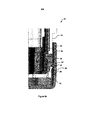
図1は、本発明のある実施形態による薬剤送達装置10を示している。装置10は、自動注射器としての特定の用途を有する。この装置10は、第1のケーシング部14および第2のケーシング部16を有するハウジング12を備えている。第1および第2のケーシング部14、16は、例えば、押込嵌め係合によって、互いに分離可能に取り付けできる。図示の実施形態に示されるように、第2のケーシング部16は、装置10の基端18において第1のケーシング部14に分離可能に取り付けできるエンドキャップであってよい。ハウジング12は、ニードル22を有するシリンジ20を受け入れるように構成されている。一回分の薬剤を患者に送達するために、シリンジ20はハウジング12内で移動可能である。この装置10はさらに、ハウジング12内に受け入れ可能なスリーブ24(図2に最もよく示されている)を備えており、第1のケーシング部14に対してこのスリーブ24が軸方向に移動可能となっている。スリーブ24は、内面28および外面30を有する管状壁26を有する。内面28は、穴32を境界付け、つまり画定しており、そこにニードル20が受け入れ可能になっている。穴32は開放端34を備えていてよく、該開放端を選択的に通って、使用時にニードル20が一回分の薬剤を送達できる。このように、スリーブ24は、ニードルガードを有してもよいし、またはニードルガードとして機能してもよい。したがって、スリーブ24は、針刺し事故の危険性を低減させ、および/または、望ましくない装置10の再使用を阻止することができる。スリーブ24は添付の図面では円筒形であるように示されているが、他の形状、例えば楕円体または直方体も考えられる。さらに、スリーブ24は周方向に連続的であってもよいし、周方向に不連続であってもよい。
FIG. 1 shows a
いくつかの実施形態において、装置10を作動させるため、つまり、動力源48を開放して一回分の薬剤の送達を行うために、第1のケーシング部14に対してスリーブ24は軸方向に移動可能である。いくつかの実施形態において、動力源48は、圧縮されたバネ(図示せず)を備えることができる。いくつかの実施形態において、動力源48は、推進剤の容器50を備えることができる。推進剤は、気化して蒸気圧を提供する液化ガス推進剤を含んでもよい。使用前は、推進剤が装置10の遠位端52で容器50に含まれていてよい。スリーブ24の軸方向移動は、容器50を圧縮して推進剤を放出し、それによって一回分の薬剤の送達を駆動することができる。当業者であれば理解できるように、推進剤は、任意の適切な推進剤か、それを含むものである。しかしながら、いくつかの実施形態では、推進剤は、ハイドロフルオロアルカン(HFA)、例えば、HFA 341a、HFA 227、HFA 422D、HFA 507またはHFA 410Aであってよく、またはそれを含むものでよい。いくつかの実施形態では、推進剤は、ハイドロフルオロオレフィン(HFO)、例えば、HFO 1234yfまたはHFO 1234zeであってよく、またはそれを含むものでよい。
In some embodiments, the
装置10は、係止部材36(図3に最もよく示されている)をさらに備える。図示の実施形態に示されるように、係止部材36は環状の本体部分38を備えうる。ただし、非環状の構成も想定される。環状の本体部分38は、少なくともその軸方向長さにわたっては、周方向に連続しうる。このように、環状の本体部分38は、そこを通って軸方向に延びる開口40を画定できる。環状の本体部分38は、そこから延びる1つまたは複数の半径方向内向きの突起42を備えていてよい。いくつかの実施形態では、半径方向内向きの突起42は、直径方向に対向する一対の半径方向内向きの突起42を含みうる。したがって、半径方向内向きの突起42は、環状の本体部分38の周りに等間隔に配置できるが、そのような等間隔の配置は、3つ以上の半径方向内向きの突起42によってなされてもよい。環状の本体部分38は、軸方向に延びる1つまたは複数の第1のアーム44を有することができ、そのアーム44の上に半径方向内向きの突起42のそれぞれ1つが一体に形成されていてもよいし、または連結されていてもよい。半径方向内向きの突起42のそれぞれは、軸方向に延びる第1のアーム44のそれぞれの自由端に近接した位置にあってよい。代替的又は付加的に、環状の本体部分38は、そこから延在する1つまたは複数の半径方向外向きの突起54を備えることができる。環状の本体部分38は、軸方向に延びる1つまたは複数の第2のアーム56を有することができ、そのアーム56の上に半径方向外向きの突起54のそれぞれ1つが一体に形成されていてもよいし、または連結されていてもよい。半径方向外向きの突起54のそれぞれは、軸方向に延びる第2のアーム56のそれぞれの自由端に近接した位置にあってよい。半径方向外向きの突起54は、環状の本体部分38の周りに等間隔に配置できるが、そのような等間隔の配置は、3つ以上の半径方向外向きの突起54によってなされてもよい。
The
係止部材36は、第2のケーシング部16内に受け入れられるようになっており、第2のケーシング部16に対して第1の軸方向位置と第2の軸方向位置との間で移動可能となっており、すなわち、係止部材は第2のケーシング部16内で軸方向にスライド可能となっている。第1の軸方向位置は図4Aと図4Bに最もよく示されているが、これらの図は互いに90度ずれており、装置10の異なる特徴を示している。第2の軸方向位置は図5A、5B、6A、および図6Bに最もよく示されているが、これらの図は同じく互いに90度ずれている。重要なことは、第1の軸方向位置では、係止部材36は、スリーブ24の外面30と係合可能で、第1のケーシング部14に対するスリーブ24の軸方向移動を阻止することである。この軸方向移動は後方への移動であってよい。図示の実施形態では、半径方向内向きの突起42が外面30の溝46内に受け入れられうることにより、係止部材36と外面30との係合が達成される。溝46は当接面を提供し、この当接面に係止部材36が当接して、スリーブ24の軸方向経路を遮ることができる。部分的または全体的に、スリーブ24の周りに外面30に沿って、溝46が半径方向内向きに延びうる。しかしながら、いくつかの実施形態では、係止部材36の外面30との係合は、別の方法で達成することができ、例えば、外面30は、係止部材36の溝内に受け入れ可能な半径方向外向きの隆起(リッジ)を備えることもできる。
The locking
半径方向内向きの突起42の半径方向外方への移動により、係止部材36の外面30との係合を解除することができる。いくつかの実施形態では、この半径方向外方への移動により、半径方向内向きの突起42が溝46から離脱できる。半径方向外方への移動は、係止リング36の変形、例えば係止リング36の弾性変形によるものであってよい。より具体的には、半径方向外方への移動は軸方向に延びる第1のアーム44の変形によるものであってもよい。該アームの上には半径方向内向きの突起42を一体に形成するか、もしくは連結することができる。
By moving the
装置10を使用する前は、係止部材36は、第1の軸方向位置にあってよい。第1の軸方向位置では、第1および第2のケーシング部14、16が互いに取り付けられたままで、係止部材36は実質的に変形されておらず、すなわち、係止部材36はフリー状態にあってよい。このように、図4Aおよび図4Bに示すように、第1の軸方向位置では、係止部材36は、第2のケーシング部16とスリーブ24の外面30との間で同心円状に受け入れられるようにすることができる。第1の軸方向位置では、係止部材36は外面30から外れることができない。これは、係止部材36が第2のケーシング部16に当接することによって、半径方向内向きの突起42の外方への移動が阻害されうるためである(つまり、第1の軸方向位置では、係止部材36の半径方向外方向に、半径方向外方への移動を許容するためのスペースがない)。このために、第2のケーシング部16は、半径方向内向きに延びる第1の部位58を備えていてよく、係止部材36は該部位に当接して、半径方向内向きの突起42の外方への移動を阻害することができる。図示の実施形態に示されるように、半径方向内向きに延びる第1の部位58は、1つまたは複数のリブを含むことができる。代替的又は付加的に、半径方向内向きに延びる第1の部位58は環状隆起(annular ridge)および/または1つまたは複数のバンプを含むことができる。
Prior to using the
装置10が遠位端52から落下した場合、もしくは遠位端52に衝撃を受けた場合、スリーブ24および/またはスリーブ24が連結されうる装置10の他の構成要素の慣性によって、スリーブ24が軸方向後方に移動するよう促される可能性がある。第1のケーシング部14に対するスリーブ24の後方への軸方向移動は、装置10を作動させることがある。いくつかの実施形態では、スリーブ24の後方への軸方向移動は、代わりに、装置10の作動準備をしうるものであるか、または装置10の種々の構成要素にずれを生じさせうるものである。しかしながら、半径方向内向きの突起42がスリーブ24の軸方向経路を遮ったり、またはふさいだりすることができるため、スリーブ24が係止部材36に軸方向に当接することで、第1のケーシング部14に対するスリーブ24の軸方向移動は阻止できる。その結果、荷重はスリーブ24から係止部材36に伝達され、その後、係止部材36から第1のケーシング部14に伝達されうる。言い換えると、スリーブ24は係止部材36によって軸方向に支持され、係止部材36は第1のケーシング部14によって支持されうる。例えば床に落下したり、あるいはぶつかったりした際の装置10の衝撃を吸収できる程度に、第1のケーシング部14は十分に硬くすることができる。
If the
装置10を使用する準備をするために、ユーザーは、例えば第2のケーシング部16を第1のケーシング部14から軸方向に引っ張ることにより、第2のケーシング部16を第1のケーシング部14から分離できる。そうすることで、係止部材36はスリーブ24と係合したままであることができるため、第2のケーシング部16に対して係止部材36は軸方向に移動できる。その結果、係止部材36は第2の軸方向位置に移動できる。第2の軸方向位置において、係止部材36は、第1の軸方向位置にあるときと同様に、実質的に変形されていなくてよい。第2の軸方向位置では、図5Aおよび図5Bに示すように、係止部材36は、第2のケーシング部16と外面30との間で同心円状に受け入れられうる。このように、第2の軸方向位置では、第1および第2のケーシング部14、16は、少なくとも部分的に互いに取り付けられたままであることができる。第2の軸方向位置では、係止部材36は外面30から係合解除可能である。これは、第2の軸方向位置では、係止部材36が第2のケーシング部16に当接することにより、半径方向内向きの突起42の外方への移動が阻害される可能性はもはやないためである(つまり、第2の軸方向位置では、係止部材36の半径方向外方向に、半径方向内向きの突起42の半径方向外方への移動を許容するためのスペースが存在しうる)。このように、第2の軸方向位置では、半径方向内向きに延びる第1の部位58が半径方向内向きの突起42と半径方向に整列する軸方向位置から、半径方向内向きに延びる部位58が半径方向内向きの突起42と半径方向に整列していない軸方向位置に、半径方向内向きに延びる第1の部位58が移動している。
To prepare to use the
半径方向外向きの突起54が第2のケーシング部16と係合して第2のケーシング部16内に係止部材36を保持できるため、第2のケーシング部16に対する係止部材36の継続的な軸方向移動を阻止することができる。より具体的には、第2の軸方向位置において、半径方向外向きの突起54は第2のケーシング部16の半径方向内向きに延びる第2の部位60に当接して、第2のケーシング部16内に係止部材36を保持することができる。図示の実施形態に示されるように、半径方向内向きに延びる第2の部位60は、1つまたは複数の隆起(リッジ)であることができる。代替的又は付加的に、半径方向内向きに延びる第2の部位60は、1つまたは複数のリブおよび/または1つまたは複数のバンプを備えることができる。互いに90度ずれている図6Aおよび図6Bに示されるように、軸方向移動を続けると、半径方向内向きの突起を半径方向外側に移動させうることになる。これは、第2の軸方向位置では、半径方向内向きの突起42が外面30に当接することで、半径方向内向きの突起42を半径方向外側にそらすことができるためである。図示の実施形態に示されるように、半径方向内向きの突起42は、溝46に当接することで、軸方向に延びる第1のアーム44が変形して、半径方向外側にそらされることができる。このように、第1および第2のケーシング部14、16を互いに分離することによって、係止部材36の係合を外面30から解除することができる。半径方向内向きの突起42をそらしやすくするため、半径方向内向きの突起42と外面30のいずれかまたは両方が、面取りされた(角をそいだ)表面を含んでいてよい。
Since the radial
図7は、互いに分離された第1および第2のケーシング部14、16と、第2のケーシング部16に保持された係止部材36とを示す。図7は、使用の準備ができている装置10を示す。
FIG. 7 shows the first and
いくつかの実施形態では、装置10の使用前に、取り外し可能なニードルシース(needle sheath)62でニードル22を覆うことができる。このように、第2のケーシング部16は、ニードルシース62と係合可能なニードルシースリムーバー64を備えることができ、これによって、第1および第2のケーシング部14、16を互いに分離することでニードルシース62がニードル22から取り外しできるようになる。ニードル22は穴32内に受け入れられうるため、ニードルシースリムーバー64も穴32内に受け入れられうる。ニードルシースリムーバー64は、開放端34を通って穴32内に受け入れられてよい。
In some embodiments, the
本明細書中において使用される場合、「軸方向」および「軸方向に」という用語は、装置10の基端18と遠位端52との間に延びる軸を指す。「半径の」及び「半径方向の」という用語は、軸に対して少なくとも実質的に垂直であり、軸から遠ざかるように延びる方向を指す。前方への移動は、軸に平行であり、基端18へ向かう動きを指し、後方への移動は、軸に平行であり、遠位端52へ向かう動きを指す。本明細書において使用される場合、「基端」という用語は、ニードル22が配置され、および/または取り付け可能である装置10の端部を指す。本明細書において使用される場合、「遠位端」という用語は装置10の端部を指し、この端部から最も離れたところでニードル22が配置され、および/または取り付けできるようになっている。本明細書に用いられる「含む」および「備える」は、同義語として用いられ、これらの用語およびそれらの変形は、非限定的に解釈されるべきである。
As used herein, the terms "axially" and "axially" refer to an axis extending between the
この明細書(任意の添付したクレーム及び図面を含む)の中で開示した全ての特徴、及び/又はそのように開示した任意の方法又はプロセスの全てのステップは、少なくとも幾つかのそのような特徴及び/又はステップが互いに排他的になる組合せを除いて、任意の組合せで組み合わせることができる。 All features disclosed herein (including any attached claims and drawings) and / or all steps of any method or process so disclosed are at least some such features. And / or any combination can be combined, except for combinations in which the steps are mutually exclusive.
(任意の添付の請求項及び図面を含む)本明細書に開示される各特徴は、特に明記されない限り、同一の目的、等価の目的、又は同様の目的を果たす代替的な特徴によって置き換えられてもよい。従って、特に明記されない限り、開示される各特徴は、一般的な一連の等価又は同様の特徴の単なる一例にすぎないことになる。 Each feature disclosed herein (including any accompanying claims and drawings) is replaced by alternative features that serve the same purpose, equivalent purpose, or similar purpose, unless otherwise specified. May be good. Thus, unless otherwise stated, each disclosed feature is merely an example of a general set of equivalent or similar features.
本発明は、任意の前述した実施形態の詳細に限定されない。本発明は本明細書(添付の特許請求の範囲及び図面を含む)において開示される特徴のうちの任意の新規の特徴、もしくはそれらの任意の新規の組み合わせ、又はそのように開示される任意の方法もしくはプロセスのステップのうちの任意の新規のステップ、もしくはそれらの任意の新規の組み合わせに及ぶ。請求項は、前述の実施形態のみを含むと解釈されるべきではなく、請求項の範囲内に包含される任意の実施形態も含むと解釈されるべきである。 The present invention is not limited to the details of any of the aforementioned embodiments. The present invention is any novel feature of the features disclosed herein (including the appended claims and drawings), or any novel combination thereof, or any such disclosure. It extends to any new step of the method or process step, or any new combination thereof. The claims should not be construed as including only the embodiments described above, but should be construed as including any embodiments included within the scope of the claims.
Claims (30)
The drug delivery device according to any one of claims 1 to 26, which comprises a compressed spring as a power source.
Applications Claiming Priority (3)
| Application Number | Priority Date | Filing Date | Title |
|---|---|---|---|
| GB1800902.7A GB2570319B (en) | 2018-01-19 | 2018-01-19 | A medicament delivery device |
| GB1800902.7 | 2018-01-19 | ||
| PCT/GB2019/050120 WO2019141985A1 (en) | 2018-01-19 | 2019-01-17 | A medicament delivery device with a removable cap and locking member for preventing accidental activiation |
Publications (2)
| Publication Number | Publication Date |
|---|---|
| JP2021510581A true JP2021510581A (en) | 2021-04-30 |
| JP7299224B2 JP7299224B2 (en) | 2023-06-27 |
Family
ID=61283711
Family Applications (1)
| Application Number | Title | Priority Date | Filing Date |
|---|---|---|---|
| JP2020539035A Active JP7299224B2 (en) | 2018-01-19 | 2019-01-17 | Drug delivery device with removable cap and locking member to prevent accidental actuation |
Country Status (10)
| Country | Link |
|---|---|
| US (1) | US11759567B2 (en) |
| EP (2) | EP4134112A1 (en) |
| JP (1) | JP7299224B2 (en) |
| CN (1) | CN111615410B (en) |
| AU (2) | AU2019208318A1 (en) |
| CA (1) | CA3088340A1 (en) |
| DK (1) | DK3740265T3 (en) |
| ES (1) | ES2932725T3 (en) |
| GB (1) | GB2570319B (en) |
| WO (1) | WO2019141985A1 (en) |
Cited By (1)
| Publication number | Priority date | Publication date | Assignee | Title |
|---|---|---|---|---|
| JP7636639B2 (en) | 2021-11-05 | 2025-02-26 | エスエイチエル・メディカル・アーゲー | Subassembly for drug delivery device - Patent application |
Families Citing this family (3)
| Publication number | Priority date | Publication date | Assignee | Title |
|---|---|---|---|---|
| CN112188907A (en) | 2018-05-24 | 2021-01-05 | 诺华股份有限公司 | Automatic drug delivery device |
| EP4126130A1 (en) * | 2020-03-26 | 2023-02-08 | SHL Medical AG | Locking mechanism for a medicament delivery device |
| GB2633605A (en) | 2023-09-15 | 2025-03-19 | Owen Mumford Ltd | Autoinjector with anti-activation feature |
Citations (6)
| Publication number | Priority date | Publication date | Assignee | Title |
|---|---|---|---|---|
| US20150174325A1 (en) * | 2012-07-09 | 2015-06-25 | Oval Medical Technologies Limited | Injector device with mechanism for preventing accidental activation |
| WO2017046556A1 (en) * | 2015-09-14 | 2017-03-23 | Consort Medical Plc | Injection device |
| JP2017508548A (en) * | 2014-03-28 | 2017-03-30 | サノフィ−アベンティス・ドイチュラント・ゲゼルシャフト・ミット・ベシュレンクテル・ハフツング | Sheath removal mechanism |
| WO2017089281A1 (en) * | 2015-11-27 | 2017-06-01 | Sanofi-Aventis Deutschland Gmbh | Medicament delivery device |
| WO2017144200A1 (en) * | 2016-02-24 | 2017-08-31 | Carebay Europe Ltd. | Safety mechanism for a medicament delivery device and a medicament delivery device comprising the same |
| WO2018011417A1 (en) * | 2016-07-15 | 2018-01-18 | Novo Nordisk A/S | Medical injector having safety feature preventing accidental expelling |
Family Cites Families (15)
| Publication number | Priority date | Publication date | Assignee | Title |
|---|---|---|---|---|
| DE3734306A1 (en) | 1987-10-10 | 1989-04-27 | Pfeiffer Erich Gmbh & Co Kg | DISCHARGE DEVICE FOR FLOWABLE MEDIA |
| US7648483B2 (en) | 2004-11-22 | 2010-01-19 | Intelliject, Inc. | Devices, systems and methods for medicament delivery |
| ES2742504T3 (en) | 2007-09-25 | 2020-02-14 | Becton Dickinson France | Autoinjector with shield elimination element comprising anti-tamper means |
| US8814834B2 (en) | 2008-03-10 | 2014-08-26 | Antares Pharma, Inc. | Injector safety device |
| US9233213B2 (en) | 2009-10-16 | 2016-01-12 | Janssen Biotech, Inc. | Palm activated drug delivery device |
| US9539624B2 (en) | 2012-04-03 | 2017-01-10 | The Boeing Company | Hole cleaning apparatus and method |
| EP2823841A1 (en) | 2013-07-09 | 2015-01-14 | Sanofi-Aventis Deutschland GmbH | Autoinjector |
| GB2519971B (en) * | 2013-11-01 | 2017-06-14 | Consort Medical Plc | Medicament delivery device sub-assembly |
| DK2745866T3 (en) | 2014-01-30 | 2017-01-23 | Tecpharma Licensing Ag | Release safety device for an auto-injector |
| EP2923714A1 (en) | 2014-03-28 | 2015-09-30 | Sanofi-Aventis Deutschland GmbH | Autoinjector triggered by skin contact |
| WO2015150578A1 (en) * | 2014-04-04 | 2015-10-08 | Novo Nordisk A/S | Autoinjector having needle shield triggering |
| GB2537638A (en) | 2015-04-21 | 2016-10-26 | Consort Medical Plc | Medicament delivery device |
| TW201707740A (en) | 2015-06-03 | 2017-03-01 | 賽諾菲阿凡提斯德意志有限公司 | Drug delivery device |
| TW201711716A (en) | 2015-06-03 | 2017-04-01 | 賽諾菲阿凡提斯德意志有限公司 | Shield lock |
| EP3311863A1 (en) * | 2016-10-24 | 2018-04-25 | Carebay Europe Ltd. | Medicament delivery device having a cap assembly |
-
2018
- 2018-01-19 GB GB1800902.7A patent/GB2570319B/en active Active
-
2019
- 2019-01-17 EP EP22200251.1A patent/EP4134112A1/en active Pending
- 2019-01-17 DK DK19701712.2T patent/DK3740265T3/en active
- 2019-01-17 WO PCT/GB2019/050120 patent/WO2019141985A1/en unknown
- 2019-01-17 CN CN201980008954.8A patent/CN111615410B/en active Active
- 2019-01-17 CA CA3088340A patent/CA3088340A1/en active Pending
- 2019-01-17 JP JP2020539035A patent/JP7299224B2/en active Active
- 2019-01-17 EP EP19701712.2A patent/EP3740265B1/en active Active
- 2019-01-17 AU AU2019208318A patent/AU2019208318A1/en not_active Abandoned
- 2019-01-17 ES ES19701712T patent/ES2932725T3/en active Active
- 2019-01-17 US US16/961,025 patent/US11759567B2/en active Active
-
2024
- 2024-10-21 AU AU2024227494A patent/AU2024227494A1/en active Pending
Patent Citations (6)
| Publication number | Priority date | Publication date | Assignee | Title |
|---|---|---|---|---|
| US20150174325A1 (en) * | 2012-07-09 | 2015-06-25 | Oval Medical Technologies Limited | Injector device with mechanism for preventing accidental activation |
| JP2017508548A (en) * | 2014-03-28 | 2017-03-30 | サノフィ−アベンティス・ドイチュラント・ゲゼルシャフト・ミット・ベシュレンクテル・ハフツング | Sheath removal mechanism |
| WO2017046556A1 (en) * | 2015-09-14 | 2017-03-23 | Consort Medical Plc | Injection device |
| WO2017089281A1 (en) * | 2015-11-27 | 2017-06-01 | Sanofi-Aventis Deutschland Gmbh | Medicament delivery device |
| WO2017144200A1 (en) * | 2016-02-24 | 2017-08-31 | Carebay Europe Ltd. | Safety mechanism for a medicament delivery device and a medicament delivery device comprising the same |
| WO2018011417A1 (en) * | 2016-07-15 | 2018-01-18 | Novo Nordisk A/S | Medical injector having safety feature preventing accidental expelling |
Cited By (1)
| Publication number | Priority date | Publication date | Assignee | Title |
|---|---|---|---|---|
| JP7636639B2 (en) | 2021-11-05 | 2025-02-26 | エスエイチエル・メディカル・アーゲー | Subassembly for drug delivery device - Patent application |
Also Published As
| Publication number | Publication date |
|---|---|
| JP7299224B2 (en) | 2023-06-27 |
| US20210060251A1 (en) | 2021-03-04 |
| EP3740265A1 (en) | 2020-11-25 |
| WO2019141985A1 (en) | 2019-07-25 |
| CA3088340A1 (en) | 2019-07-25 |
| DK3740265T3 (en) | 2022-11-28 |
| GB2570319B (en) | 2021-01-06 |
| ES2932725T3 (en) | 2023-01-24 |
| EP4134112A1 (en) | 2023-02-15 |
| AU2024227494A1 (en) | 2024-11-07 |
| US11759567B2 (en) | 2023-09-19 |
| CN111615410B (en) | 2022-10-04 |
| EP3740265B1 (en) | 2022-11-16 |
| BR112020014393A2 (en) | 2020-12-01 |
| BR112020014393A8 (en) | 2023-01-10 |
| GB2570319A (en) | 2019-07-24 |
| CN111615410A (en) | 2020-09-01 |
| GB201800902D0 (en) | 2018-03-07 |
| AU2019208318A1 (en) | 2020-07-23 |
Similar Documents
| Publication | Publication Date | Title |
|---|---|---|
| JP6902618B2 (en) | Safety assembly of medical delivery equipment | |
| US10265476B2 (en) | Two body syringe carrier assembly with dampener | |
| JP2021510581A (en) | Drug delivery device with removable cap and locking member to prevent accidental actuation | |
| JP5969396B2 (en) | Injection device comprising a protrusion disposed in the passage to narrow the effective hole of the passage | |
| US20240075209A1 (en) | Auto-Insert Injector | |
| CN108025148B (en) | Injection device | |
| US20050101919A1 (en) | Device for an injector | |
| EP3755405B1 (en) | An injection system comprising a syringe and a protective assembly | |
| US20120123350A1 (en) | Injection Device | |
| US11596742B2 (en) | Medicament delivery device | |
| JP2017529941A (en) | Injection device | |
| JP2019535411A (en) | Drug delivery device suitable for long-term storage | |
| US20240001033A1 (en) | Autoinjector for Automatic Injection of a Medical Product Into an Injection Site | |
| EP3380156B1 (en) | Medicament delivery device | |
| BR112020014393B1 (en) | MEDICATION DELIVERY DEVICE WITH A REMOVABLE LID AND LOCKING MEMBER TO PREVENT ACCIDENTAL ACTIVATION |
Legal Events
| Date | Code | Title | Description |
|---|---|---|---|
| A621 | Written request for application examination |
Free format text: JAPANESE INTERMEDIATE CODE: A621 Effective date: 20220112 |
|
| A711 | Notification of change in applicant |
Free format text: JAPANESE INTERMEDIATE CODE: A711 Effective date: 20220926 |
|
| A977 | Report on retrieval |
Free format text: JAPANESE INTERMEDIATE CODE: A971007 Effective date: 20221118 |
|
| A131 | Notification of reasons for refusal |
Free format text: JAPANESE INTERMEDIATE CODE: A131 Effective date: 20221121 |
|
| A521 | Request for written amendment filed |
Free format text: JAPANESE INTERMEDIATE CODE: A523 Effective date: 20230216 |
|
| TRDD | Decision of grant or rejection written | ||
| A01 | Written decision to grant a patent or to grant a registration (utility model) |
Free format text: JAPANESE INTERMEDIATE CODE: A01 Effective date: 20230522 |
|
| A61 | First payment of annual fees (during grant procedure) |
Free format text: JAPANESE INTERMEDIATE CODE: A61 Effective date: 20230615 |
|
| R150 | Certificate of patent or registration of utility model |
Ref document number: 7299224 Country of ref document: JP Free format text: JAPANESE INTERMEDIATE CODE: R150 |