JP2021185647A - Wireless communication device and wireless communication method - Google Patents
Wireless communication device and wireless communication method Download PDFInfo
- Publication number
- JP2021185647A JP2021185647A JP2020090221A JP2020090221A JP2021185647A JP 2021185647 A JP2021185647 A JP 2021185647A JP 2020090221 A JP2020090221 A JP 2020090221A JP 2020090221 A JP2020090221 A JP 2020090221A JP 2021185647 A JP2021185647 A JP 2021185647A
- Authority
- JP
- Japan
- Prior art keywords
- packet
- node
- wireless communication
- retransmission request
- communication device
- Prior art date
- Legal status (The legal status is an assumption and is not a legal conclusion. Google has not performed a legal analysis and makes no representation as to the accuracy of the status listed.)
- Granted
Links
Images


Landscapes
- Mobile Radio Communication Systems (AREA)
Abstract
Description
本発明は、無線マルチホップネットワークにおいて使用される無線通信装置および無線通信方法に係わる。 The present invention relates to a wireless communication device and a wireless communication method used in a wireless multi-hop network.
複数のノードを備える無線ネットワークにおいて、マルチホップ方式で全ノードに情報を配布する際には、例えば、以下の手順のよりパケットが送信される。
(1)送信元ノードは、パケットをブロードキャストする。
(2)パケットを受信した各ノードは、中継ノードとして、そのパケットをブロードキャストする(マルチホップ転送)。
(3)ただし、各ノードは、過去に受信したパケットと同じパケットを新たに受信したときは、その新たに受信パケットを中継しない(重複送信の回避)。
In a wireless network including a plurality of nodes, when distributing information to all the nodes by the multi-hop method, for example, a packet is transmitted by the following procedure.
(1) The source node broadcasts the packet.
(2) Each node that receives the packet broadcasts the packet as a relay node (multi-hop transfer).
(3) However, when each node newly receives the same packet as the packet received in the past, the newly received packet is not relayed (avoidance of duplicate transmission).
上述の手順によれば、無線ネットワーク内のすべてのノードに効率よく情報が配布される。また、各ノードは、パケットを受信すると、送信元ノードにACK信号を送信する。このとき、各ノードは、通信効率を向上させるために、所定数のパケットの受信に対して1つのACK信号を送信することがある。なお、所定数のパケットの受信に対して1つのACK信号を送信する方式は、例えば、特許文献1に記載されている。そして、送信元ノードは、すべてのノードからACK信号を受信すると、次のパケットを送信する。
According to the above procedure, information is efficiently distributed to all the nodes in the wireless network. Further, when each node receives the packet, it sends an ACK signal to the source node. At this time, each node may transmit one ACK signal for receiving a predetermined number of packets in order to improve communication efficiency. A method of transmitting one ACK signal for receiving a predetermined number of packets is described in, for example,
上述の無線マルチホップネットワークにおいては、複数のノードが同時にブロードキャストを行うことがあるので、ノード数が多いときは、パケット衝突に起因するパケット損失が発生することがある。加えて、少ない消費電力で長距離伝送が可能な無線通信規格の1つとして、LPWA(Low Power Wide Area)通信が普及しつつある。そして、現在、データ送信の開始前にキャリアセンスを行わないLPWA通信が検討されている。このため、上述の無線マルチホップネットワークおよびLPWA通信の周波数帯が互いに重複するときは、無線マルチホップネットワークの通信がLPWAにより妨害されるおそれがある。 In the above-mentioned wireless multi-hop network, since a plurality of nodes may broadcast at the same time, packet loss due to packet collision may occur when the number of nodes is large. In addition, LPWA (Low Power Wide Area) communication is becoming widespread as one of the wireless communication standards capable of long-distance transmission with low power consumption. At present, LPWA communication that does not perform carrier sense before the start of data transmission is being studied. Therefore, when the frequency bands of the above-mentioned wireless multi-hop network and LPWA communication overlap each other, the communication of the wireless multi-hop network may be disturbed by the LPWA.
パケット損失が発生すると、送信元ノードは、いくつかのノードからACK信号を受信できなくなる。そうすると、送信元ノードは、パケット再送を行う。このとき、送信元ノードは、ACK信号を送信してこない各ノードに対して、例えば、先に送信したパケットをユニキャストで再送する。この場合、先のパケットを受信できなかったノードが多いケースでは、パケット再送のためのユニキャスト通信の回数が多くなり、通信効率が悪くなる。 When packet loss occurs, the source node will not be able to receive ACK signals from some nodes. Then, the source node retransmits the packet. At this time, the source node retransmits the previously transmitted packet, for example, by unicast to each node that does not transmit the ACK signal. In this case, in the case where there are many nodes that could not receive the previous packet, the number of times of unicast communication for packet retransmission increases, and the communication efficiency deteriorates.
本発明の1つの側面に係わる目的は、無線マルチホップネットワークの通信効率を改善することである。 An object relating to one aspect of the present invention is to improve the communication efficiency of a wireless multi-hop network.
本発明の1つの態様の無線通信装置は、無線マルチホップネットワークにおいて使用される。この無線通信装置は、受信パケットのエラーを検出するエラー検出部と、前記受信パケットのヘッダ部を解析して前記受信パケットの送信元を特定するヘッダ解析部と、前記エラー検出部によりエラーが検出され、且つ、前記ヘッダ解析部が前記受信パケットの送信元を特定したときに、前記受信パケットの再送を要求する再送要求を生成する再送要求生成部と、前記再送要求を前記受信パケットの送信元に送信する送信部と、を備える。 The wireless communication device of one aspect of the present invention is used in a wireless multi-hop network. In this wireless communication device, an error is detected by an error detection unit that detects an error in a received packet, a header analysis unit that analyzes the header unit of the received packet to identify the source of the received packet, and the error detection unit. And when the header analysis unit identifies the source of the received packet, the retransmission request generation unit that generates a retransmission request requesting the retransmission of the received packet and the retransmission request generation unit that makes the retransmission request the transmission source of the received packet. It is provided with a transmission unit for transmitting to.
上述の態様によれば、無線マルチホップネットワークの通信効率が改善する。 According to the above aspect, the communication efficiency of the wireless multi-hop network is improved.
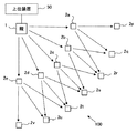
図1は、本発明の実施形態に係わる無線通信システムの一例を示す。無線通信システム100は、複数のノードを含み、マルチホップ方式でパケットを伝送する。この実施例では、無線通信システム100は、例えば、OLSRプロトコルに従ってパケットを伝送する。
FIG. 1 shows an example of a wireless communication system according to an embodiment of the present invention. The
無線通信システム100は、親ノード1および複数のノード2(2a〜2e、2p〜2v)を備える。ここで、無線通信システム100は、特に限定されるものではないが、例えば、センサネットワークである。この場合、各ノードにセンサが設けられる。そして、各ノードにおいて検出されるセンサデータは、親ノード1に送信される。このとき、親ノード1に隣接していないノードにおいて検出されるセンサデータは、1または複数のノードを経由して親ノード1に転送される。すなわち、マルチホップ転送が行われる。
The
親ノード1には、上位装置50が接続される。すなわち、親ノード1は、ゲートウェイとして動作する。上位装置50は、例えば、各ノード2から収集するデータを解析するサーバコンピュータである。また、上位装置50は、無線通信システム100に対して必要な通信制御指示を与えることができる。
The
親ノード1および各ノード2には、それぞれ無線通信装置が実装される。無線通信装置は、無線信号を送信できる。また、無線通信装置は、隣接ノードから送信される無線信号を受信できる。
A wireless communication device is mounted on the
親ノード1は、全ノード2a〜2e、2p〜2vにデータを配布することがある。この場合、データは、ブロードキャストパケットに格納されて送信される。例えば、無線通信装置が実行すべきプログラムを各ノード2に配布するときには、そのプログラムがブロードキャストパケットに格納されて送信される。この場合、親ノード1は、無線通信システム100においてブロードキャストされるデータの送信元である。よって、以下の記載では、親ノード1を「送信元ノード」と呼ぶことがある。
The
ノード2は、隣接ノードから受信するパケットを他のノードに転送できる。すなわち、ノード2は、中継ノードとして動作することがある。例えば、親ノード1からブロードキャストパケットが送信されたときは、ノード2は、必要に応じて、親ノード1または隣接ノードから受信するブロードキャストパケットを転送する。
上記構成の無線通信システム100において、各ノード2は、定期的に、Helloパケットをブロードキャストする。Helloパケットは、自分の存在を隣接ノードに通知するための制御パケットである。よって、各ノード2は、受信したHelloパケットの送信元を特定することにより、自分に隣接するノードを認識できる。そして、各ノード2は、自分に隣接するノードを表す隣接ノード情報を作成し、自ノード内のメモリに保存する。また、各ノード2により作成される隣接ノード情報は、ノード間で交換される。
In the
各ノード2により作成される隣接ノード情報は、親ノード1に送信される。すなわち、親ノード1は、各ノード2の隣接ノード情報を収集する。したがって、親ノード1は、無線通信システム100のトポロジを認識できる。
The adjacent node information created by each
図2は、ブロードキャストの一例を示す。図2に示す例では、親ノード1がノード2a〜2e、2p〜2vにデータを配布する。すなわち、親ノード1は、ブロードキャストパケットを送信する。ただし、親ノード1から送信されるブロードキャストパケットは、ノード2a〜2eに到達するが、ノード2p〜2vには到達しない。なお、ブロードキャストパケットには、例えば、宛先アドレスとしてブロードキャストアドレスが設定される。
FIG. 2 shows an example of broadcasting. In the example shown in FIG. 2, the
各ノード2a〜2eは、親ノード1から受信したパケットをブロードキャストする。このとき、ノード2aから送信されるパケットは、ノード2p〜2rに到達する。同様に、ノード2bから送信されるパケットはノード2q〜2sに到達し、ノード2cから送信されるパケットはノード2r〜2tに到達し、ノード2dから送信されるパケットはノード2s〜2uに到達し、ノード2eから送信されるパケットはノード2t〜2vに到達する。これにより、ゲートウェイノード1から送信されるデータが全ノード2a〜2e、2p〜2vにより受信される。
Each
なお、ノード2aから送信されるパケットは、ノード2p〜2r以外のノードにも到達し得る。たとえば、ノード2aから送信されるパケットは、親ノード1に到達する。ただし、このパケットに含まれるデータは、親ノード1が送信したデータと同じである。よって、この場合、親ノード1は、ノード2aから受信したパケットを転送しない。また、ノード2aから送信されるパケットは、ノード2bにも到達するものとする。ただし、このパケットに含まれるデータは、ノード2bが先に親ノード1から受信したデータと同じである。よって、この場合、ノード2bは、ノード2aから受信したパケットの再転送を行わない。
The packet transmitted from the
このように、図2に示す例では、ブロードキャストパケットを受信した各ノード2がそのパケットをブロードキャスト(再転送を除く)する。具体的には、ノード2a〜2eがそれぞれブロードキャスト転送を行う。このため、パケット衝突が起こりやすく、また、通信効率が低下することがある。
As described above, in the example shown in FIG. 2, each
これらの問題は、例えば、MPR(multipoint relay)ノードを選択することにより緩和される。MPRノードは、ノード2a〜2e、2p〜2vの中から選択され、ブロードキャスト転送を実行する。即ち、MPRノードは、ブロードキャスト通信において中継ノードとして動作する。これに対して、MPRノードとして選択されていないノード2は、ブロードキャストパケットを受信してもブロードキャスト転送を実行しない。この結果、過剰なパケット転送が抑制されるので、パケットの衝突が抑制され、また、通信効率が改善する。
These problems are alleviated, for example, by selecting an MPR (multipoint relay) node. The MPR node is selected from the
図3は、MPRノードを利用したブロードキャストの一例を示す。図3に示す例では、ノード2a、2c、2eがMPRノードとして選択されている。
FIG. 3 shows an example of broadcasting using the MPR node. In the example shown in FIG. 3,
親ノード1は、図2に示すケースと同様に、ブロードキャストパケットを送信する。そして、親ノード1から送信されるブロードキャストパケットは、ノード2a〜2eに到達する。
The
ノード2a、2c、2eは、MPRノードとして選択されているので、それぞれ親ノード1から受信したブロードキャストパケットを転送する。このとき、ノード2aから送信されるパケットはノード2p〜2rに到達し、ノード2cから送信されるパケットはノード2r〜2tに到達し、ノード2eから送信されるパケットはノード2t〜2vに到達する。したがって、親ノード1から送信されるデータが全ノード2a〜2e、2p〜2vにより受信される。
Since the
他方、MPRノードとして選択されていないノード(図3に示す例では、ノード2b、2d)は、ブロードキャスト転送を行わない。したがって、図2に示すケースと比較すると、パケット衝突が発生する確率が低下し、通信効率が改善し得る。
On the other hand, the node not selected as the MPR node (
図4は、無線通信システムの構成例およびマルチホップ経路の一例を示す。この実施例では、無線通信システムは、図4(a)に示すように、親ノードPおよび複数のノードA〜Hを備える。親ノードPおよび複数のノードA〜Hには、それぞれ、無線通信装置が実装されている。 FIG. 4 shows a configuration example of a wireless communication system and an example of a multi-hop route. In this embodiment, the wireless communication system includes a parent node P and a plurality of nodes A to H, as shown in FIG. 4 (a). A wireless communication device is mounted on the parent node P and the plurality of nodes A to H, respectively.
各ノードA〜Hは、上述したように、Helloパケットを利用して隣接ノードを検出する。例えば、各ノードA〜Hは、他のノードから送信される無線信号の受信レベルに基づいて隣接ノードを検出する。この場合、あるノードから送信される無線信号の受信レベルが所定の閾値より高いときに、そのノードを隣接ノードと判定する。或いは、他のパラメータに基づいて隣接ノードを検出してもよい。例えば、通信成功率または受信信号の信号対雑音比などに基づいて隣接ノードを検出してもよい。 As described above, each node A to H detects an adjacent node by using the Hello packet. For example, each node A to H detects an adjacent node based on the reception level of a radio signal transmitted from another node. In this case, when the reception level of the radio signal transmitted from a certain node is higher than a predetermined threshold value, that node is determined to be an adjacent node. Alternatively, the adjacent node may be detected based on other parameters. For example, the adjacent node may be detected based on the communication success rate or the signal-to-noise ratio of the received signal.
各ノードA〜Hは、検出した隣接ノードを表す隣接ノード情報を自ノード内のメモリに保存すると共に、その隣接ノード情報を親ノードPに送信する。即ち、親ノードPは、各ノードA〜Hの隣接ノード情報を受信する。よって、親ノードPは、無線通信システムのネットワークトポロジを認識することができる。この実施例では、図4(b)に示すネットワークトポロジが得られるものとする。なお、図4(b)において、ノード間を接続する実線はリンクを表す。また、1本のリンクにより接続される1組のノードは、互いに隣接ノードである。 Each node A to H stores the adjacent node information representing the detected adjacent node in the memory in the own node, and transmits the adjacent node information to the parent node P. That is, the parent node P receives the adjacent node information of each node A to H. Therefore, the parent node P can recognize the network topology of the wireless communication system. In this embodiment, it is assumed that the network topology shown in FIG. 4 (b) is obtained. In FIG. 4B, the solid line connecting the nodes represents a link. Further, a set of nodes connected by one link are adjacent nodes to each other.
親ノードPは、ネットワークトポロジに基づいて、ブロードキャストのためのマルチホップ経路を決定する。マルチホップ経路の決定は、中継ノード(図3に示す例では、MPRノード)を指定することで実現される。この実施例では、図4(c)に示すように、ノードA、B、Cが中継ノードとして選択されている。 The parent node P determines a multi-hop route for broadcasting based on the network topology. The determination of the multi-hop route is realized by designating a relay node (MPR node in the example shown in FIG. 3). In this embodiment, as shown in FIG. 4C, nodes A, B, and C are selected as relay nodes.
親ノードPから各ノードA〜Hへのブロードキャストは、以下のよう行われる。まず、図5(a)に示すように、親ノードPは、ブロードキャストパケットを送信する。このパケットは、親ノードPの隣接ノード(即ち、ノードA、E)に到達する。そうすると、中継ノードとして選択されているノードAは、図5(b)に示すように、受信パケットをブロードキャストする。このパケットは、ノードAの隣接ノード(即ち、ノードB、F、E、および親ノードP)に到達する。但し、ノードEは、先に親ノードPから同じパケットを受信しているので、そのパケットを廃棄する。また、親ノードは、そのパケットの送信元なので、そのパケットを廃棄する。なお、図5(b)〜図5(d)に示す破線矢印は、受信先ノードで廃棄されることになるパケットに伝送を表している。 Broadcasting from the parent node P to each of the nodes A to H is performed as follows. First, as shown in FIG. 5A, the parent node P transmits a broadcast packet. This packet reaches an adjacent node (that is, nodes A and E) of the parent node P. Then, the node A selected as the relay node broadcasts the received packet as shown in FIG. 5 (b). This packet reaches the adjacent node of node A (ie, node B, F, E, and parent node P). However, since the node E has received the same packet from the parent node P first, the packet is discarded. Also, since the parent node is the source of the packet, the packet is discarded. The broken line arrows shown in FIGS. 5 (b) to 5 (d) indicate transmission to the packet to be discarded at the receiving node.
中継ノードとして選択されているノードBは、図5(c)に示すように、受信パケットをブロードキャストする。このパケットは、ノードBの隣接ノード(即ち、ノードC、G、F、E、A)に到達する。ただし、ノードF、E、Aは、先に同じパケットを受信しているので、そのパケットを廃棄する。さらに、中継ノードとして選択されているノードCは、図5(d)に示すように、受信パケットをブロードキャストする。このパケットは、ノードCの隣接ノード(即ち、ノードD、H、G、F、B)に到達する。ただし、ノードG、F、Bは、先に同じパケットを受信しているので、そのパケットを廃棄する。このように、親ノードPから送信されるブロードキャストパケットは、マルチホップ通信により全ノードA〜Hにブロードキャストされる。 The node B selected as the relay node broadcasts the received packet as shown in FIG. 5 (c). This packet arrives at a node adjacent to node B (ie, nodes C, G, F, E, A). However, since the nodes F, E, and A have received the same packet first, the packet is discarded. Further, the node C selected as the relay node broadcasts the received packet as shown in FIG. 5 (d). This packet arrives at a node adjacent to node C (ie, nodes D, H, G, F, B). However, since the nodes G, F, and B have received the same packet first, the packet is discarded. In this way, the broadcast packet transmitted from the parent node P is broadcast to all the nodes A to H by multi-hop communication.
図6は、ブロードキャストシーケンスの一例を示す。この例では、図4(b)に示す無線ネットワークにおいて、図4(c)に示すマルチホップ経路が設定されているものとする。また、連続する10個のパケットに対して1個のACK信号が返送される。 FIG. 6 shows an example of a broadcast sequence. In this example, it is assumed that the multi-hop route shown in FIG. 4 (c) is set in the wireless network shown in FIG. 4 (b). Further, one ACK signal is returned for 10 consecutive packets.
親ノードPは、パケットP1〜P10を順番にブロードキャストする。各パケットP1〜P10は、図4(c)に示す経路を介してノードA〜Hに転送される。各ノードA〜Hは、パケットP1〜P10を受信すると、親ノードPにACK信号を送信する。ACK信号は、例えば、図4(c)に示す経路を逆方向に転送される。そして、親ノードPは、すべてのノードからACK信号を受信すると、次のパケットを送信する。図6では、ノードB〜D、F〜Hから送信されるACK信号は省略されている。 The parent node P broadcasts packets P1 to P10 in order. Each packet P1 to P10 is transferred to the nodes A to H via the route shown in FIG. 4 (c). Upon receiving the packets P1 to P10, the nodes A to H transmit an ACK signal to the parent node P. The ACK signal is, for example, transferred in the reverse direction along the path shown in FIG. 4 (c). Then, when the parent node P receives the ACK signal from all the nodes, it transmits the next packet. In FIG. 6, the ACK signals transmitted from the nodes B to D and F to H are omitted.
なお、本発明は、上述のシーケンスに限定されるものではない。例えば、各ノードは、1つのパケットを受信する毎に親ノードPにACK信号を送信してもよい。 The present invention is not limited to the above-mentioned sequence. For example, each node may send an ACK signal to the parent node P each time it receives one packet.
図7は、ブロードキャスト転送において受信エラーが発生したときのシーケンスの一例を示す。この例では、ノードAにおいて、親ノードPから送信されるパケットPnの受信エラーが発生している。受信エラーは、例えば、受信信号を復号することで得られるビット列がエラーを含む状態を表す。この場合、受信エラーは、例えば、パケットの末尾に付与されている誤り検出コード/誤り訂正コードを用いて検出される。なお、図7においては、説明を簡単にするために、各ノードは、1つのパケットを受信する毎に親ノードPにACK信号を送信するものとする。 FIG. 7 shows an example of a sequence when a reception error occurs in broadcast transfer. In this example, in the node A, a reception error of the packet Pn transmitted from the parent node P has occurred. The reception error represents, for example, a state in which the bit string obtained by decoding the received signal contains an error. In this case, the reception error is detected by using, for example, the error detection code / error correction code attached to the end of the packet. In FIG. 7, for the sake of simplicity, each node shall transmit an ACK signal to the parent node P each time one packet is received.
ノードAにおいてパケットPnの受信エラーが発生したときは、ノードAからノードB〜D、F〜Hへの転送は行われない。すなわち、ノードAにおいてパケットPnの受信エラーが発生したときは、ノードB〜D、F〜HはパケットPnを受信しない。この場合、親ノードPは、ノードEからACK信号を受信するが、ノードA〜D、F〜HからACK信号を受信することはない。そして、親ノードPは、パケットPnを送信した時刻から所定のタイムアウト期間が経過するまでの間に全てのノードからACK信号を受信できなかったときには、再送処理を実行する。具体的には、親ノードPは、ユニキャスト通信で、ノードA〜D、F〜Hに対してパケットPnを再送する。すなわち、パケットPnを受信できなかったノードの数と同じ回数のユニキャスト通信が実行される。この結果、通信効率が悪くなる。なお、親ノードPに近いノードで受信エラーが発生したときほど、通信効率が悪くなりやすい。また、中継ノードで受信エラーが発生したときに、通信効率が悪くなりやすい。 When a packet Pn reception error occurs in the node A, the transfer from the node A to the nodes B to D and F to H is not performed. That is, when a packet Pn reception error occurs in the node A, the nodes B to D and F to H do not receive the packet Pn. In this case, the parent node P receives the ACK signal from the node E, but does not receive the ACK signal from the nodes A to D and F to H. Then, when the parent node P cannot receive the ACK signal from all the nodes between the time when the packet Pn is transmitted and the time when the predetermined timeout period elapses, the parent node P executes the retransmission process. Specifically, the parent node P retransmits the packet Pn to the nodes A to D and F to H by unicast communication. That is, unicast communication is executed as many times as the number of nodes that could not receive the packet Pn. As a result, communication efficiency deteriorates. It should be noted that the communication efficiency tends to deteriorate as the reception error occurs in the node closer to the parent node P. Further, when a reception error occurs in the relay node, the communication efficiency tends to deteriorate.
図8は、本発明の実施形態に係わるブロードキャスト転送において受信エラーが発生したときのシーケンスの一例を示す。この例では、図7に示すケースと同様に、ノードAにおいてパケットPnの受信エラーが発生している。また、各ノードは、1つのパケットを受信する毎に親ノードPにACK信号を送信するものとする。 FIG. 8 shows an example of a sequence when a reception error occurs in the broadcast transfer according to the embodiment of the present invention. In this example, as in the case shown in FIG. 7, a packet Pn reception error has occurred at the node A. Further, each node shall transmit an ACK signal to the parent node P each time one packet is received.
ノードAは、パケットPnの受信エラーを検出したときは、そのパケットPnの送信元を特定できるか否かを判定する。受信パケットの送信元は、例えば、そのパケットのヘッダ部内の所定の領域に設定されている。なお、受信パケットのデータ部においてエラーが検出されたときであっても、ヘッダ部が正しく再生されることがある。 When the node A detects the reception error of the packet Pn, the node A determines whether or not the source of the packet Pn can be specified. The source of the received packet is set to, for example, a predetermined area in the header portion of the packet. Even when an error is detected in the data part of the received packet, the header part may be reproduced correctly.
パケットPnの送信元を特定できたときは、ノードAは、パケットPnの再送を要求する再送要求を生成する。そして、ノードAは、パケットPnの送信元に対して再送要求を送信する。この例では、パケットPnの送信元は親ノードPである。したがって、ノードAは、親ノードPに再送要求を送信する。そうすると、親ノードPは、ノードAから受信する再送要求に応じて、パケットPnの再送を実行する。このとき、親ノードPは、パケットPnをブロードキャストする。この結果、再送されたパケットPnは、ノードA〜Hに転送される。なお、ノードEは、先にパケットPnを受信しているので、新たに受信するパケットPnを廃棄してもよい。 When the source of the packet Pn can be specified, the node A generates a retransmission request requesting the retransmission of the packet Pn. Then, the node A transmits a retransmission request to the source of the packet Pn. In this example, the source of the packet Pn is the parent node P. Therefore, the node A sends a retransmission request to the parent node P. Then, the parent node P retransmits the packet Pn in response to the retransmission request received from the node A. At this time, the parent node P broadcasts the packet Pn. As a result, the retransmitted packet Pn is transferred to the nodes A to H. Since the node E has received the packet Pn first, the newly received packet Pn may be discarded.
このように、本発明の実施形態に係わるブロードキャスト転送においては、あるノードにおいて受信エラーが発生した場合であっても、受信パケットの送信元が特定されるときには、再送要求が生成される。そして、送信元ノード(図8では、親ノードP)は、再送要求に応じて、ブロードキャストパケットを再送する。したがって、本発明の実施形態に係わるシーケンスによれば、受信エラーを回復させるために必要な通信量が削減される。例えば、図7に示すケースでは、受信エラーが発生した後に、7回のユニキャスト通信が行われる。これに対して本発明の実施形態では、図8に示すように、受信エラーが発生した後に1回のブロードキャスト通信が行われるだけである。 As described above, in the broadcast transfer according to the embodiment of the present invention, even if a reception error occurs at a certain node, a retransmission request is generated when the source of the received packet is specified. Then, the source node (parent node P in FIG. 8) retransmits the broadcast packet in response to the retransmission request. Therefore, according to the sequence according to the embodiment of the present invention, the amount of communication required to recover the reception error is reduced. For example, in the case shown in FIG. 7, unicast communication is performed seven times after the reception error occurs. On the other hand, in the embodiment of the present invention, as shown in FIG. 8, only one broadcast communication is performed after the reception error occurs.
なお、送信元ノードは、パケットを送信した時刻からタイムアウト期間内にACK信号を受信できるか否かをモニタするが、図8に示す例では、送信元ノードは、再送要求を受信したときに、タイムアウト期間をカウントするタイマをリセットしてもよい。この場合は、送信元ノードは、再送要求に起因する再送信を行った時刻からタイムアウト期間内にACK信号を受信できるか否かをモニタする。 The source node monitors whether or not the ACK signal can be received within the timeout period from the time when the packet is transmitted. However, in the example shown in FIG. 8, when the source node receives the retransmission request, the source node monitors. You may reset the timer that counts the timeout period. In this case, the source node monitors whether or not the ACK signal can be received within the timeout period from the time when the retransmission is performed due to the retransmission request.
また、受信エラーに起因する再送要求の生成は、各ノードが実行できる。例えば、ノードBにおいて受信エラーが検出され、受信パケットの送信元としてノードAが特定された場合、ノードBは、再送要求を生成してノードAに送信する。そうすると、ノードAは、先に送信したパケットをブロードキャストする。なお、各ノードは、受信パケットを自ノード内のメモリに保存しているものとする。 In addition, each node can generate a retransmission request due to a reception error. For example, when a reception error is detected in node B and node A is specified as the source of the received packet, node B generates a retransmission request and transmits it to node A. Then, the node A broadcasts the previously transmitted packet. It is assumed that each node stores the received packet in the memory in its own node.
図9は、各ノードに実装される無線通信装置の一例を示す。各ノードに実装される無線通信装置10は、図9に示すように、無線送信部11、無線受信部12、通信IF13、メモリ14、および制御部15を備える。なお、無線通信装置10は、図9に示していない他の回路または機能を備えてもよい。
FIG. 9 shows an example of a wireless communication device mounted on each node. As shown in FIG. 9, the
無線送信部11は、制御部15から与えられる指示に従って無線信号を送信する。したがって、制御部15が送信パケットまたは転送パケットを出力したときは、無線送信部11は、そのパケットを送信する。無線受信部12は、他のノードから送信される無線信号を受信する。したがって、他のノードからパケットが送信されたときは、無線受信部12は、そのパケットを受信する。通信IF13は、自ノード内に実装されているデバイスとの間のインタフェースを提供する。この例では、各ノードにセンサが実装されている。よって、通信IF13は、センサから出力されるセンサデータを受信することができる。
The
メモリ14には、自ノード情報および隣接ノード情報が保存される。また、メモリ14は、無線受信部12が受信したパケットを一時的に保存するパケットバッファを含む。なお、メモリ14には、特に図示しないが、無線通信装置10の動作を記述したプログラムが格納される。
The local node information and the adjacent node information are stored in the
自ノード情報は、図10(a)に示すように、自ノードアドレス、上流ノードアドレスおよび中継ノードフラグを含む。自ノードアドレスは、無線通信装置10が実装されているノードを識別する。上流ノードアドレスは、親ノードPから各ノードA〜Hへのブロードキャストのためのマルチホップ経路において、親ノード側の隣接ノードを識別する。例えば、図4(c)に示す例では、ノードD、Hにとっての上流ノードはノードCであり、ノードC、Gにとっての上流ノードはノードBであり、ノードB、Fにとっての上流ノードはノードAであり、ノードA、Eにとっての上流ノードは親ノードPである。中継ノードフラグは、ブロードキャストパケットを中継するか否かを表す。図4(c)に示す例では、ノードA〜Cがそれぞれ中継ノードとして選択されている。なお、自ノードアドレスは、予め各ノードに割り当てられている。また、上流ノードアドレスおよび中継ノードフラグは、例えば、親ノードPから各ノードに通知される。
As shown in FIG. 10A, the local node information includes the local node address, the upstream node address, and the relay node flag. The local node address identifies the node on which the
隣接ノード情報は、図10(b)に示すように、受信監視手順において検出された1または複数のノードのアドレスおよび受信品質を表す情報を含む。受信監視手順は、たとえば、Helloパケットを監視する。受信品質としては、例えば、受信レベル、通信成功率、または受信信号の信号対雑音比が検出される。そして、隣接ノード情報として、例えば、所定の閾値より良好な受信品質を提供するノードが登録される。或いは、隣接ノード情報として、受信品質が良好な方から順番に所定数のノードが登録される。 As shown in FIG. 10B, the adjacent node information includes information indicating the address and reception quality of one or more nodes detected in the reception monitoring procedure. The reception monitoring procedure monitors, for example, Hello packets. As the reception quality, for example, the reception level, the communication success rate, or the signal-to-noise ratio of the received signal is detected. Then, as the adjacent node information, for example, a node that provides better reception quality than a predetermined threshold value is registered. Alternatively, as the adjacent node information, a predetermined number of nodes are registered in order from the one with the best reception quality.
制御部15は、無線通信装置10のパケット通信を制御する。例えば、通信IF13がセンサデータを取得したときは、制御部15は、そのセンサデータを含むパケットを作成し、無線送信部11を利用して送信する。また、無線受信部12が他のノードからパケットを受信したときは、制御部15は、そのパケットを解析して処理する。さらに、制御部15は、エラー検出部21、ヘッダ解析部22、再送要求生成部23、および再送制御部24を備える。なお、制御部15は、この実施例では、プロセッサにより実現される。
The
エラー検出部21は、無線受信部12が受信したパケットの受信エラーを検出する。ここで、無線通信システム100において送信されるパケットは、例えば、図11(a)に示すように、ヘッダ部、データ部、チェックコードから構成される。ここで、チェックコードは、誤り検出符号または誤り訂正符号であり、例えば、データ部のビット列に基づいて作成される。そして、エラー検出部21は、チェックコードを利用して、受信エラーが発生しているか否かを検出する。なお、チェックコードが誤り訂正符号であるときは、エラー検出部21は、訂正できないエラーが発生したときに受信エラーが発生したと判定してもよい。
The
ヘッダ解析部22は、無線受信部12が受信したパケットのヘッダ部を解析する。ヘッダ部は、パケットの送信元アドレス(SA)および宛先アドレス(DA)を含む。なお、ブロードキャストパケットの宛先アドレスは、予め決められたブロードキャストアドレスである。そして、受信パケットのヘッダ部を再生できたときには、ヘッダ解析部22は、受信パケットのヘッダ部からそのパケットの送信元アドレスおよび宛先アドレスを取得する。
The
なお、図11(a)に示す例では、データ部に対してチェックコードが付与されているが、本発明はこのフォーマットに限定されるものではない。例えば、図11(b)に示すように、ヘッダ部に対してチェックコードHが付与され、データ部に対してチェックコードDが付与されるフォーマットであってもよい。このフォーマットによれば、ヘッダ部で受信エラーが発生しているか否か、及び、データ部で受信エラーが発生しているか否かを個々に判定できる。 In the example shown in FIG. 11A, a check code is assigned to the data unit, but the present invention is not limited to this format. For example, as shown in FIG. 11B, a format may be used in which a check code H is assigned to the header portion and a check code D is assigned to the data portion. According to this format, it is possible to individually determine whether or not a reception error has occurred in the header section and whether or not a reception error has occurred in the data section.
また、一般に、データ部と比較してヘッダ部のサイズは小さい(例えば、ヘッダ部:20バイト、データ部:200バイト)。よって、データ部と比較して、ヘッダ部において受信エラーが発生する確率は低い。すなわち、データ部において受信エラーが発生し、且つ、ヘッダ部において受信エラーが発生していない状況は、十分に起こり得る。 Further, in general, the size of the header part is smaller than that of the data part (for example, the header part: 20 bytes, the data part: 200 bytes). Therefore, the probability that a reception error will occur in the header section is lower than that in the data section. That is, it is quite possible that a reception error has occurred in the data section and no reception error has occurred in the header section.
再送要求生成部23は、エラー検出部21により受信エラーが検出され、且つ、ヘッダ解析部22が受信パケットの送信元を特定できたときに、受信パケットの再送を要求する再送要求を生成する。このとき、再送要求生成部23は、受信エラーが検出され、且つ、受信パケットがブロードキャストパケットであり、且つ、受信パケットの送信元を特定できたときに、受信パケットの再送を要求する再送要求を生成してもよい。
The retransmission
再送要求は、ユニキャストパケットに格納される。このパケットの送信先アドレスは、ヘッダ解析部22により特定された送信元を表す。そして、無線送信部11は、このパケットを送信する。この結果、再送要求を含むパケットは、無線受信部12が受信したパケットの送信元に到達する。
The retransmission request is stored in the unicast packet. The destination address of this packet represents the source specified by the
再送制御部24は、パケット再送に係わる処理を実行する。すなわち、再送制御部24は、再送要求を含むパケットを受信したときに、先に送信したパケットを再送する。先に送信したパケットは、メモリ14内のパケットバッファに保存されている。なお、再送制御部24は、ACK信号の監視を行ってもよい。この場合、再送制御部24は、すべてのノードからACK信号を受信すると、パケット再送が不要であると判定する。
The
図12は、送信元ノードに実装される無線通信装置の処理の一例を示すフローチャートである。この例では、無線通信装置10は、S1において、ブロードキャストパケットを送信する。また、再送制御部24は、ブロードキャストパケットの送信時にタイマを起動する。なお、S1で送信したブロードキャストパケットは、メモリ14内のパケットバッファに保存されている。
FIG. 12 is a flowchart showing an example of processing of the wireless communication device mounted on the source node. In this example, the
S2〜S4において、再送制御部24は、再送要求およびACK信号の受信をモニタする。そして、再送要求を受信したときは、再送制御部24は、S5において、先に送信したブロードキャストパケットを再送する。この場合、タイマが再設定され、再送制御部24の処理はS2に戻る。なお、タイマがタイムアウトする前にすべてのノードからACK信号を受信したときは、再送制御部24の処理は終了する。
In S2 to S4, the
すべてのノードからACK信号を受信する前にタイマがタイムアウトしたときは、再送制御部24は、S6において、ユニキャスト通信による再送処理を実行する。すなわち、再送制御部24は、ACK信号を送信してこない各ノードに、ユニキャスト通信で、先に送信したパケットを送信する。このとき、パケットの宛先アドレスは、それぞれ、ACK信号を送信してこないノードを表す。
If the timer times out before receiving the ACK signal from all the nodes, the
図13は、パケットを受信する無線通信装置の処理の一例を示すフローチャートである。この例では、無線通信装置10は、他の無線通信装置から送信される無線信号を受信する。なお、無線通信装置10は、パケットの先頭を検知できるものとする。
FIG. 13 is a flowchart showing an example of processing of a wireless communication device that receives a packet. In this example, the
S11において、制御部15は、受信信号を復号する。ただし、受信信号からビット列を再生する処理は、無線受信部12が行ってもよい。そして、S12において、エラー検出部21は、受信エラーの有無を判定する。受信エラーは、上述したように、例えば、受信パケットのチェックコードを利用して検出される。
In S11, the
受信エラーが発生していないとき(あるいは、受信エラーを訂正可能なとき)は、S13において、制御部15は、受信パケットをメモリ14内に設けられているパケットバッファに保存する。S14において、制御部15は、自ノードが中継ノードか否かを判定する。自ノードが中継ノードか否かを表すフラグは、図10(a)に示すように、自ノード情報としてメモリ14に保存されている。そして、自ノードが中継ノードであるときは、S15において、制御部15は、受信パケットを転送する。
When the reception error has not occurred (or when the reception error can be corrected), in S13, the
受信エラーが検出されたときは、S16において、ヘッダ解析部22は、受信パケットのヘッダ部を解析する。そして、ヘッダ部が有効であれば、ヘッダ解析部22は、S17において、受信パケットがブロードキャストパケットであるか否かを判定する。なお、受信パケットがブロードキャストパケットであるか否かは、例えば、宛先アドレスにより判定可能である。
When a reception error is detected, in S16, the
受信パケットがブロードキャストパケットであるときは、S18において、ヘッダ解析部22は、受信パケットの送信元アドレスを特定する。S19において、再送要求生成部23は、受信パケットの再送を要求する再送要求を生成する。再送要求は、ユニキャストパケットに格納される。また、このユニキャストパケットの宛先アドレスとして、S18で特定された送信元を識別する値が設定される。そして、S20において、無線送信部11は、再送要求を含むユニキャストパケットを送信する。
When the received packet is a broadcast packet, in S18, the
このように、無線通信装10は、受信エラーを検出し、且つ、受信パケットの送信元を特定でき、且つ、受信パケットがブロードキャストパケットであったときに、その受信パケットの送信元に再送要求を送信する。この再送要求は、図12に示すフローチャートでは、S2おいて受信される。
In this way, the
なお、図13に示す例では、受信パケットがブロードキャストパケットであったときに再送要求が生成されるが、本発明はこの方式に限定されるものではない。すなわち、無線通信装置10は、受信パケットがブロードキャストパケットでないときに再送要求を生成してもよい。
In the example shown in FIG. 13, a retransmission request is generated when the received packet is a broadcast packet, but the present invention is not limited to this method. That is, the
また、無線通信装置10は、自ノードが中継ノードであるときに限って再送要求を生成してもよい。例えば、図7〜図8に示す例では、中継ノードとして動作するノードAにおいて受信エラーが検出されている。この場合、図7に示すように、再送を行わないケースでは、この中継ノードの下流側のノード(即ち、ノードB〜D、F〜H)がパケットを受信できないことになり、多数のユニキャスト通信が必要となる。すなわち、中継ノードで受信エラーが検出されたときに再送が行われれば、図7に示すユニキャスト通信が回避または抑制される。
Further, the
更に、S18において受信パケットの送信元を特定する処理は、必ずしも、受信パケットのヘッダ部から送信元アドレスを取得しなくてもよい。例えば、図4(c)に示すように、ブロードキャスト通信のためのマルチホップ経路が予め指定されているときは、図10(a)に示すように、無線通信装置10は、そのマルチホップ経路上での上流ノードのアドレスを自ノード情報として保持している。よって、この場合、無線通信装置10は、受信パケットを処理する必要があると判定したとき(例えば、受信パケットがブロードキャストパケットであり、そのパケットを転送する必要があるとき)に、自ノード情報を参照することで、受信パケットの送信元を特定できる。
Further, the process of specifying the source of the received packet in S18 does not necessarily have to acquire the source address from the header portion of the received packet. For example, as shown in FIG. 4 (c), when a multi-hop route for broadcast communication is specified in advance, as shown in FIG. 10 (a), the
10 無線通信装置
11 無線送信部
12 無線受信部
13 通信IF
14 メモリ
15 制御部
21 エラー検出部
22 ヘッダ解析部
23 再送要求生成部
24 再送制御部
100 無線通信システム
10
14
Claims (6)
受信パケットのエラーを検出するエラー検出部と、
前記受信パケットのヘッダ部を解析して前記受信パケットの送信元を特定するヘッダ解析部と、
前記エラー検出部によりエラーが検出され、且つ、前記ヘッダ解析部が前記受信パケットの送信元を特定したときに、前記受信パケットの再送を要求する再送要求を生成する再送要求生成部と、
前記再送要求を前記受信パケットの送信元に送信する送信部と、
を備える無線通信装置。 A wireless communication device used in a wireless multi-hop network.
An error detector that detects errors in received packets, and an error detector
A header analysis unit that analyzes the header unit of the received packet to identify the source of the received packet, and
When an error is detected by the error detection unit and the header analysis unit identifies the source of the received packet, a retransmission request generation unit that generates a retransmission request for retransmitting the received packet, and a retransmission request generation unit.
A transmission unit that transmits the retransmission request to the source of the received packet, and
A wireless communication device equipped with.
ことを特徴とする請求項1に記載の無線通信装置。 When the header part of the received packet is valid and an error is detected in the data part of the received packet, the header analysis unit acquires the source address set in the header part of the received packet. The wireless communication device according to claim 1, wherein the transmission unit transmits the retransmission request to the transmission source address.
前記第1のチェックコードを利用するエラー検出において前記ヘッダ部のエラーが検出されず、且つ、前記第2のチェックコードを利用するエラー検出において前記データ部のエラーが検出されたときに、前記送信部は、前記再送要求を前記送信元アドレスに送信する
ことを特徴とする請求項2に記載の無線通信装置。 The packet transferred in the wireless multi-hop network includes a first check code for detecting an error in the header section and a second check code for detecting an error in the data section.
When the error in the header section is not detected in the error detection using the first check code and the error in the data section is detected in the error detection using the second check code, the transmission is performed. The wireless communication device according to claim 2, wherein the unit transmits the retransmission request to the source address.
前記受信パケットがブロードキャストパケットであるときに、前記送信部は、前記再送要求を前記受信パケットの送信元に送信する
ことを特徴とする請求項1〜3のいずれか1つに記載の無線通信装置。 The header analysis unit determines whether or not the received packet is a broadcast packet, and determines whether or not the received packet is a broadcast packet.
The wireless communication device according to any one of claims 1 to 3, wherein when the received packet is a broadcast packet, the transmitting unit transmits the retransmission request to the source of the received packet. ..
前記無線通信装置のメモリには、前記経路上の1ホップ上流側のノードを識別する上流ノードアドレスが記録されており、
前記受信パケットがブロードキャストパケットであるときに、前記送信部は、前記再送要求を、前記メモリに記録されている上流ノードアドレスに送信する
ことを特徴とする請求項1に記載の無線通信装置。 In the wireless multi-hop network, the route of the broadcast packet is predetermined.
In the memory of the wireless communication device, an upstream node address that identifies a node on the upstream side of one hop on the route is recorded.
The wireless communication device according to claim 1, wherein when the received packet is a broadcast packet, the transmission unit transmits the retransmission request to the upstream node address recorded in the memory.
前記複数のノードの中の第1のノードに実装される第1の無線通信装置は、ブロードキャストパケットを送信し、
前記複数のノードの中の第2のノードに実装される第2の無線通信装置は、
前記ブロードキャストパケットを受信し、
前記ブロードキャストパケットのエラーを検出し、且つ、前記ブロードキャストパケットの送信元を特定したときに、前記ブロードキャストパケットの再送を要求する再送要求を生成し、
前記再送要求を前記ブロードキャストパケットの送信元に送信し、
前記第1の無線通信装置は、前記再送要求に応じて、前記ブロードキャストパケットを再送する
ことを特徴とする無線通信方法。 A wireless communication method used in a wireless multi-hop network with multiple nodes.
The first wireless communication device mounted on the first node among the plurality of nodes transmits a broadcast packet.
The second wireless communication device mounted on the second node among the plurality of nodes is
Upon receiving the broadcast packet,
When an error in the broadcast packet is detected and the source of the broadcast packet is specified, a retransmission request for retransmitting the broadcast packet is generated.
The retransmission request is transmitted to the source of the broadcast packet, and the retransmission request is transmitted.
The first wireless communication device is a wireless communication method characterized in that the broadcast packet is retransmitted in response to the retransmission request.
Priority Applications (1)
| Application Number | Priority Date | Filing Date | Title |
|---|---|---|---|
| JP2020090221A JP7484415B2 (en) | 2020-05-25 | 2020-05-25 | Wireless communication device and wireless communication method |
Applications Claiming Priority (1)
| Application Number | Priority Date | Filing Date | Title |
|---|---|---|---|
| JP2020090221A JP7484415B2 (en) | 2020-05-25 | 2020-05-25 | Wireless communication device and wireless communication method |
Publications (2)
| Publication Number | Publication Date |
|---|---|
| JP2021185647A true JP2021185647A (en) | 2021-12-09 |
| JP7484415B2 JP7484415B2 (en) | 2024-05-16 |
Family
ID=78815798
Family Applications (1)
| Application Number | Title | Priority Date | Filing Date |
|---|---|---|---|
| JP2020090221A Active JP7484415B2 (en) | 2020-05-25 | 2020-05-25 | Wireless communication device and wireless communication method |
Country Status (1)
| Country | Link |
|---|---|
| JP (1) | JP7484415B2 (en) |
Cited By (1)
| Publication number | Priority date | Publication date | Assignee | Title |
|---|---|---|---|---|
| WO2024261837A1 (en) * | 2023-06-19 | 2024-12-26 | 三菱電機株式会社 | Wireless communication device, communication method, control circuit, and storage medium |
Citations (2)
| Publication number | Priority date | Publication date | Assignee | Title |
|---|---|---|---|---|
| JP2004343567A (en) * | 2003-05-16 | 2004-12-02 | Sony Corp | Wireless communication device, wireless communication method, and program |
| JP2010081470A (en) * | 2008-09-29 | 2010-04-08 | Advanced Telecommunication Research Institute International | Wireless apparatus, and wireless network with the same |
-
2020
- 2020-05-25 JP JP2020090221A patent/JP7484415B2/en active Active
Patent Citations (2)
| Publication number | Priority date | Publication date | Assignee | Title |
|---|---|---|---|---|
| JP2004343567A (en) * | 2003-05-16 | 2004-12-02 | Sony Corp | Wireless communication device, wireless communication method, and program |
| JP2010081470A (en) * | 2008-09-29 | 2010-04-08 | Advanced Telecommunication Research Institute International | Wireless apparatus, and wireless network with the same |
Non-Patent Citations (1)
| Title |
|---|
| 宇都宮 依子: "無線アドホックネットワークにおいてNACK及び指向性アンテナによるブロードキャストデータ再送信を用い", 電子情報通信学会論文誌 (J87−B) 第2号, vol. 第J87-B巻, JPN6024001067, 1 February 2004 (2004-02-01), JP, pages 144 - 158, ISSN: 0005237749 * |
Cited By (2)
| Publication number | Priority date | Publication date | Assignee | Title |
|---|---|---|---|---|
| WO2024261837A1 (en) * | 2023-06-19 | 2024-12-26 | 三菱電機株式会社 | Wireless communication device, communication method, control circuit, and storage medium |
| JPWO2024261837A1 (en) * | 2023-06-19 | 2024-12-26 |
Also Published As
| Publication number | Publication date |
|---|---|
| JP7484415B2 (en) | 2024-05-16 |
Similar Documents
| Publication | Publication Date | Title |
|---|---|---|
| Tang et al. | Random access MAC for efficient broadcast support in ad hoc networks | |
| Rozner et al. | ER: Efficient retransmission scheme for wireless LANs | |
| US8189536B2 (en) | Delivery of data packets via aggregated spatial distribution overlay on a mesh network | |
| KR100943174B1 (en) | Message Forwarding Method in Relay Probability Based Wireless Networks | |
| KR100943175B1 (en) | Wireless Sensor Network and its Control Method Using Dynamic-based Message Delivery Method | |
| US7890112B2 (en) | Radio device having fewer route disconnections and switchings by using control packets to maintain radio links | |
| US20030227934A1 (en) | System and method for multicast media access using broadcast transmissions with multiple acknowledgements in an Ad-Hoc communications network | |
| US9819466B2 (en) | Method and apparatus for retransmitting packet for low-power wireless sensor communications | |
| US10972959B2 (en) | Model based path selection in a Bluetooth low energy, BLE, mesh network | |
| US9407552B2 (en) | Device and system for preventing congestion in ad-hoc network | |
| WO2007095542A2 (en) | Dynamic multicasting scheme for mesh networks | |
| CN103891352A (en) | Ad hoc network system and communication device | |
| JP7484415B2 (en) | Wireless communication device and wireless communication method | |
| Mahmood et al. | Event reliability in wireless sensor networks | |
| US20090175255A1 (en) | Wireless terminal and base station devices for multi-hop communication | |
| JP2021125857A (en) | Wireless communication device and wireless communication method | |
| JP7326230B2 (en) | Communication system, node, communication method and program | |
| EP4102753A1 (en) | Method and device for updating the number of retransmissions in a wireless mesh network | |
| US20110128854A1 (en) | Medium access control forwarding protocol | |
| Zhu et al. | A batched network coding scheme for wireless networks | |
| JPWO2007029337A1 (en) | Ad hoc network equipment that reduces data loss | |
| US8139554B1 (en) | Providing bounded latency communication in wireless mesh networks | |
| CN114268925B (en) | Wireless gateway protocol optimization method, electronic device and storage medium | |
| WO2009146736A1 (en) | Method for transmitting data between network elements defining an anycast group within a mesh network | |
| Hu et al. | The importance of being opportunistic: Practical network coding for wireless environments |
Legal Events
| Date | Code | Title | Description |
|---|---|---|---|
| A621 | Written request for application examination |
Free format text: JAPANESE INTERMEDIATE CODE: A621 Effective date: 20230414 |
|
| RD03 | Notification of appointment of power of attorney |
Free format text: JAPANESE INTERMEDIATE CODE: A7423 Effective date: 20231019 |
|
| A977 | Report on retrieval |
Free format text: JAPANESE INTERMEDIATE CODE: A971007 Effective date: 20240111 |
|
| A131 | Notification of reasons for refusal |
Free format text: JAPANESE INTERMEDIATE CODE: A131 Effective date: 20240116 |
|
| A521 | Request for written amendment filed |
Free format text: JAPANESE INTERMEDIATE CODE: A523 Effective date: 20240307 |
|
| TRDD | Decision of grant or rejection written | ||
| A01 | Written decision to grant a patent or to grant a registration (utility model) |
Free format text: JAPANESE INTERMEDIATE CODE: A01 Effective date: 20240402 |
|
| A61 | First payment of annual fees (during grant procedure) |
Free format text: JAPANESE INTERMEDIATE CODE: A61 Effective date: 20240415 |
|
| R150 | Certificate of patent or registration of utility model |
Ref document number: 7484415 Country of ref document: JP Free format text: JAPANESE INTERMEDIATE CODE: R150 |