JP2021149944A - Apparatus and method for throttling ray tracing pipeline - Google Patents
Apparatus and method for throttling ray tracing pipeline Download PDFInfo
- Publication number
- JP2021149944A JP2021149944A JP2020212140A JP2020212140A JP2021149944A JP 2021149944 A JP2021149944 A JP 2021149944A JP 2020212140 A JP2020212140 A JP 2020212140A JP 2020212140 A JP2020212140 A JP 2020212140A JP 2021149944 A JP2021149944 A JP 2021149944A
- Authority
- JP
- Japan
- Prior art keywords
- ray
- memory
- stack
- graphics
- data
- Prior art date
- Legal status (The legal status is an assumption and is not a legal conclusion. Google has not performed a legal analysis and makes no representation as to the accuracy of the status listed.)
- Granted
Links
Images


Classifications
-
- G—PHYSICS
- G06—COMPUTING OR CALCULATING; COUNTING
- G06T—IMAGE DATA PROCESSING OR GENERATION, IN GENERAL
- G06T15/00—3D [Three Dimensional] image rendering
- G06T15/06—Ray-tracing
-
- G—PHYSICS
- G06—COMPUTING OR CALCULATING; COUNTING
- G06T—IMAGE DATA PROCESSING OR GENERATION, IN GENERAL
- G06T1/00—General purpose image data processing
- G06T1/20—Processor architectures; Processor configuration, e.g. pipelining
-
- G—PHYSICS
- G06—COMPUTING OR CALCULATING; COUNTING
- G06T—IMAGE DATA PROCESSING OR GENERATION, IN GENERAL
- G06T1/00—General purpose image data processing
- G06T1/60—Memory management
-
- G—PHYSICS
- G06—COMPUTING OR CALCULATING; COUNTING
- G06T—IMAGE DATA PROCESSING OR GENERATION, IN GENERAL
- G06T15/00—3D [Three Dimensional] image rendering
- G06T15/005—General purpose rendering architectures
Landscapes
- Engineering & Computer Science (AREA)
- Physics & Mathematics (AREA)
- General Physics & Mathematics (AREA)
- Theoretical Computer Science (AREA)
- Computer Graphics (AREA)
- Image Generation (AREA)
Abstract
Description
本発明は、概してグラフィックスプロセッサの分野に関する。より詳細には、本発明は、レイトレーシング(ray tracing)をスロットリング(throttle)するための装置及び方法に関する。 The present invention generally relates to the field of graphics processors. More specifically, the present invention relates to devices and methods for throttling ray tracing.
レイトレーシング(ray tracing)は、光伝搬が物理ベースのレンダリングを通じてシミュレーションされる技術である。映画のレンダリングに広く使用されおり、ほんの数年前までは、リアルタイム性能にとって非常にリソース集約的であると考えられていた。レイトレーシングにおける重要な演算の1つは、バウンディングボリューム階層(bounding volume hierarchy, BVH)内のノードをトラバースして交差することにより光線-シーン交差を計算する「レイトラバーサル(ray traversal)」として知られる光線-シーン交差についての可視クエリ(visibility query)を処理することである。 Ray tracing is a technique in which light propagation is simulated through physics-based rendering. Widely used in movie rendering, only a few years ago it was considered very resource intensive for real-time performance. One of the important operations in ray tracing is known as "ray traversal", which calculates ray-scene intersections by traversing and intersecting nodes in the bounding volume hierarchy (BVH). Ray-traffic processing of visibility queries for scene intersections.
本発明のより良い理解は、以下の図面と共に以下の詳細な説明から得られることができる。
以下の説明において、説明の目的で、以下に説明する本発明の実施形態の完全な理解を提供するために、複数の特定の詳細が示される。しかし、本発明の実施形態はこれらの特定の詳細のうちいくつかなしに実施されてもよいことが当業者に明らかになる。他の例では、本発明の実施形態の基礎の原理を不明瞭にすることを回避するために、周知の構造及びデバイスがブロック図形式で示される。 In the following description, for purposes of explanation, a number of specific details are provided to provide a complete understanding of the embodiments of the invention described below. However, it will be apparent to those skilled in the art that embodiments of the present invention may be practiced without some of these particular details. In another example, well-known structures and devices are shown in block diagram format to avoid obscuring the underlying principles of the embodiments of the present invention.
[例示的なグラフィックスプロセッサのアーキテクチャ及びデータタイプ]
(システム概要)
図1は、実施形態による処理システム100のブロック図である。システム100は、単一のプロセッサデスクトップシステム、マルチプロセッサワークステーションシステム、又は多数のプロセッサ102若しくはプロセッサコア107を有するサーバシステムで使用されてもよい。一実施形態では、システム100は、ローカル又は広域ネットワークへの有線又は無線接続を有するモノのインターネット(Internet-of-things, IoT)デバイス内のような、モバイル、ハンドヘルド又は埋め込み式デバイスで使用するために、システムオンチップ(system-on-a-chip, SoC)集積回路内に組み込まれた処理プラットフォームである。
[Exemplary graphics processor architecture and data type]
(System overview)
FIG. 1 is a block diagram of the
一実施形態では、システム100は、サーバベースのゲームプラットフォーム、ゲーム及びメディアコンソールを含むゲームコンソール、モバイルゲームコンソール、ハンドヘルドゲームコンソール又はオンラインゲームコンソールを含むことができ、これらと結合でき、或いはこれらの中に統合できる。いくつかの実施形態では、システム100は、携帯電話、スマートフォン、タブレット計算デバイス、又は小さい内部記憶容量を有するラップトップのようなモバイルインターネット接続デバイスの一部である。処理システム100はまた、スマートウォッチウェアラブルデバイスのようなウェアラブルデバイス;実世界の視覚、オーディオ、触覚体験を補うための視覚、オーディオ、触覚出力を提供するか、或いはテキスト、オーディオ、グラフィックス、ビデオ、ホログラフィック画像若しくはビデオ又は触覚フィードバックを提供するための拡張現実(augmented reality, AR)又は仮想現実(virtual reality, VR)機能で強化されたスマートアイウェア又は衣類;他の拡張現実(AR)デバイス;又は他の仮想現実(VR)デバイスを含むことができ、これらと結合でき、或いはこれらの中に統合できる。いくつかの実施形態では、処理システム100は、テレビ又はセットトップボックスデバイスを含むか、或いはその一部である。一実施形態では、システム100は、バス、トラクタートレーラー、自動車、モーター又は電力サイクル、飛行機又は滑空機(又はこれらのいずれかの組み合わせ)のような自動運転車両を含むことができ、これらと結合でき、或いはこれらの中に統合できる。自動運転車両は、車両の周囲で感知された環境を処理するために、システム100を使用してもよい。
In one embodiment,
いくつかの実施形態では、1つ以上のプロセッサ102は、実行されたとき、システム又はユーザソフトウェアのための演算を実行する命令を処理するための1つ以上のプロセッサコア107をそれぞれ含む。いくつかの実施形態では、1つ以上のプロセッサコア107のうち少なくとも1つは、特定の命令セット109を処理するように構成される。いくつかの実施形態では、命令セット109は、複雑命令セット計算(Complex Instruction Set Computing, CISC)、縮小命令セット計算(Reduced Instruction Set Computing, RISC)、又は超長命令語(Very Long Instruction Word, VLIW)を介した計算を実現してもよい。1つ以上のプロセッサコア107は異なる命令セット109を処理してもよく、異なる命令セット109は、他の命令セットのエミュレーションを実現するための命令を含んでもよい。プロセッサコア107はまた、デジタルシグナルプロセッサ(Digital Signal Processor, DSP)のような他の処理デバイスを含んでもよい。
In some embodiments, the one or more processors 102, when executed, each include one or more processor cores 107 for processing instructions that perform operations for the system or user software. In some embodiments, at least one of one or more processor cores 107 is configured to process a
いくつかの実施形態では、プロセッサ102は、キャッシュメモリ104を含む。アーキテクチャに依存して、プロセッサ102は、単一の内部キャッシュ又は複数のレベルの内部キャッシュを有することができる。いくつかの実施形態では、キャッシュメモリは、プロセッサ102の様々なコンポーネントの間で共有される。いくつかの実施形態では、プロセッサ102はまた、外部キャッシュ(例えば、レベル3(Level-3, L3)キャッシュ又はラストレベルキャッシュ(Last Level Cache, LLC))(図示せず)を使用し、これは、既知のキャッシュコヒーレンシ(cache coherency)技術を使用してプロセッサコア107の間で共有されてもよい。レジスタファイル106は、プロセッサ102に更に含まれることができ、異なるタイプのデータ(例えば、整数レジスタ、浮動小数点レジスタ、状態レジスタ及び命令ポインタレジスタ)を記憶するための異なるタイプのレジスタを含んでもよい。いくつかのレジスタは汎用レジスタでもよく、他のレジスタはプロセッサ102の設計に特有でもよい。 In some embodiments, processor 102 includes cache memory 104. Depending on the architecture, processor 102 can have a single internal cache or multiple levels of internal cache. In some embodiments, the cache memory is shared among the various components of processor 102. In some embodiments, processor 102 also uses an external cache (eg, Level-3, L3 cache or Last Level Cache, LLC) (not shown), which is , May be shared between processor cores 107 using known cache coherency techniques. The register file 106 can be further included in the processor 102 and may include different types of registers for storing different types of data (eg, integer registers, floating point registers, state registers and instruction pointer registers). Some registers may be general purpose registers and others may be specific to the design of processor 102.
いくつかの実施形態では、1つ以上のプロセッサ102は、プロセッサ102とシステム100内の他のコンポーネントとの間でアドレス、データ又は制御信号のような通信信号を送信するために、1つ以上のインタフェースバス110に結合される。一実施形態では、インタフェースバス110は、或るバージョンのダイレクトメディアインターフェース(Direct Media Interface, DMI)バスのようなプロセッサバスとすることができる。しかし、プロセッサバスは、DMIバスに限定されず、1つ以上のペリフェラルコンポーネントインターコネクトバス(例えば、PCI、PCI express)、メモリバス又は他のタイプのインタフェースバスを含んでもよい。一実施形態では、プロセッサ102は、統合メモリコントローラ116と、プラットフォームコントローラハブ130とを含む。メモリコントローラ116は、メモリデバイスとシステム100の他のコンポーネントとの間の通信を実現し、プラットフォームコントローラハブ(platform controller hub, PCH)130は、ローカルI/Oバスを介してI/Oデバイスへの接続を提供する。
In some embodiments, one or more processors 102 transmit one or more communication signals, such as addresses, data, or control signals, between the processor 102 and other components within the
メモリデバイス120は、ダイナミックランダムアクセスメモリ(dynamic random access memory, DRAM)デバイス、スタティックランダムアクセスメモリ(static random access memory, SRAM)デバイス、フラッシュメモリデバイス、相変化メモリデバイス、又はプロセスメモリとして機能するのに適した性能を有する他のメモリデバイスとすることができる。一実施形態では、メモリデバイス120は、1つ以上のプロセッサ102がアプリケーション又はプロセスを実行するときに使用するために、データ122及び命令121を記憶するための、システム100のためのシステムメモリとして動作することができる。メモリコントローラ116はまた、任意選択の外部グラフィックスプロセッサ118と結合し、外部グラフィックスプロセッサ118は、グラフィックス及びメディア演算を実行するためにプロセッサ102内の1つ以上のグラフィックスプロセッサ108と通信してもよい。いくつかの実施形態では、グラフィックス、メディア、又は計算演算は、グラフィックス、メディア、又は計算演算の特殊なセットを実行するように構成できるコプロセッサであるアクセラレータ112により支援されてもよい。例えば、一実施形態では、アクセラレータ112は、機械学習又は計算演算を最適化するために使用される行列乗算アクセラレータである。一実施形態では、アクセラレータ112は、グラフィックスプロセッサ108と協調してレイトレーシング演算を実行するために使用できるレイトレーシングアクセラレータである。一実施形態では、外部アクセラレータ119がアクセラレータ112の代わりに或いはアクセラレータ112と協調して使用されてもよい。
The memory device 120 functions as a dynamic random access memory (RAM) device, a static random access memory (RAMS) device, a flash memory device, a phase change memory device, or a process memory. It can be another memory device with suitable performance. In one embodiment, memory device 120 acts as system memory for
いくつかの実施形態では、ディスプレイデバイス111は、プロセッサ102に接続できる。ディスプレイデバイス111は、モバイル電子デバイス又はラップトップデバイスのもののような1つ以上の内部ディスプレイデバイス、又はディスプレイインタフェース(例えば、DisplayPort等)を介して取り付けられた外部ディスプレイデバイスのうち1つ以上とすることができる。一実施形態では、ディスプレイデバイス111は、仮想現実(virtual reality, VR)アプリケーション又は拡張現実(augmented reality, AR)アプリケーションで使用するための立体ディスプレイデバイスのようなヘッドマウントディスプレイ(head mounted display, HMD)とすることができる。 In some embodiments, the display device 111 can be connected to the processor 102. The display device 111 shall be one or more of one or more internal display devices, such as those of mobile electronic devices or laptop devices, or one or more of external display devices attached via a display interface (eg, DisplayPort, etc.). Can be done. In one embodiment, the display device 111 is a head mounted display (HMD), such as a stereoscopic display device for use in a virtual reality (VR) application or an augmented reality (AR) application. Can be.
いくつかの実施形態では、プラットフォームコントローラハブ130は、周辺機器が高速I/Oバスを介してメモリデバイス120及びプロセッサ102に接続することを可能にする。I/O周辺機器は、オーディオコントローラ146、ネットワークコントローラ134、ファームウェアインタフェース128、無線トランシーバ126、タッチセンサ125、データ記憶デバイス124(例えば、不揮発性メモリ、揮発性メモリ、ハードディスクドライブ、フラッシュメモリ、NAND、3D NAND、3D XPoint等)を含むが、これらに限定されない。データ記憶デバイス124は、記憶インタフェース(例えば、SATA)又はペリフェラルコンポーネントインターコネクトバス(例えば、PCI、PCI express)のような周辺機器バスを介して接続できる。タッチセンサ125は、タッチスクリーンセンサ、圧力センサ又は指紋センサを含むことができる。無線トランシーバ126は、Wi-Fiトランシーバ、Bluetoothトランシーバ、又は3G、4G、5G若しくはロングタームエボリューション(Long-Term Evolution, LTE)トランシーバのようなモバイルネットワークトランシーバとすることができる。ファームウェアインタフェース128は、システムファームウェアとの通信を可能にし、例えば、ユニファイド・エクステンシブル・ファームウェア・インタフェース(unified extensible firmware interface, UEFI)とすることができる。ネットワークコントローラ134は、有線ネットワークへのネットワーク接続を可能にできる。いくつかの実施形態では、高性能ネットワークコントローラ(図示せず)がインタフェースバス110に結合する。一実施形態では、オーディオコントローラ146は、マルチチャネル高精細度オーディオコントローラである。一実施形態では、システム100は、レガシー(例えば、パーソナルシステム2(Personal System 2, PS/2))デバイスをシステムに結合するための任意選択のレガシーI/Oコントローラ140を含む。プラットフォームコントローラハブ130はまた、1つ以上のユニバーサル・シリアル・バス(Universal Serial Bus, USB)コントローラ142に接続でき、キーボード及びマウス143の組み合わせ、カメラ144又は他のUSB入力デバイスのような入力デバイスを接続できる。
In some embodiments,
図示のシステム100は例示的なものであり、限定するものではないことが認識される。この理由は、異なるように構成された他のタイプのデータ処理システムも使用されてもよいからである。例えば、メモリコントローラ116及びプラットフォームコントローラハブ130のインスタンスは、外部グラフィックスプロセッサ118のような個別の外部グラフィックスプロセッサに統合されてもよい。一実施形態では、プラットフォームコントローラハブ130及び/又はメモリコントローラ116は、1つ以上のプロセッサ102の外部にあってもよい。例えば、システム100は、外部メモリコントローラ116及びプラットフォームコントローラハブ130を含むことができ、これらは、プロセッサ102と通信するシステムチップセット内のメモリコントローラハブ及び周辺機器コントローラハブとして構成されてもよい。
It is recognized that the illustrated
例えば、更なる熱性能のために設計されたCPU、メモリ及び他のコンポーネントのようなコンポーネントが配置される回路基板(「sled」)が使用できる。いくつかの例では、プロセッサのような処理コンポーネントは、sledの上面に配置され、DIMMのようなニアメモリは、sledの下面に配置される。この設計により提供される増大した空気流の結果として、コンポーネントは、典型的なシステムにおけるものよりも高い周波数及び電力レベルで動作してもよく、それにより、性能を増加させる。さらに、sledは、ラック内の電力及びデータ通信ケーブルとブラインド的に嵌合するように構成され、それにより、迅速に取り外し、アップグレードし、再設置し、及び/又は交換する能力を強化する。同様に、プロセッサ、アクセラレータ、メモリ及びデータ記憶ドライブのような、sled上に配置された個々のコンポーネントは、互いの間隔が増加するため、容易にアップグレードされるように構成される。例示的な実施形態では、コンポーネントは、これらの真正性を証明するためのハードウェア認証機能を更に含む。 For example, a circuit board (“sled”) in which components such as CPU, memory and other components designed for additional thermal performance are placed can be used. In some examples, processing components such as processors are located on the top surface of the sled and near memory such as DIMMs are located on the bottom surface of the sled. As a result of the increased airflow provided by this design, the components may operate at higher frequencies and power levels than in a typical system, thereby increasing performance. In addition, sleds are configured to blindly fit power and data communications cables in the rack, thereby enhancing the ability to quickly remove, upgrade, re-install, and / or replace. Similarly, individual components located on sled, such as processors, accelerators, memory and data storage drives, are configured to be easily upgraded due to the increased spacing between them. In an exemplary embodiment, the component further includes a hardware authentication function to prove their authenticity.
データセンターは、イーサネット及びオムニパス(Omni-Path)を含む複数の他のネットワークアーキテクチャをサポートする単一のネットワークアーキテクチャ(「ファブリック(fabric)」)を利用できる。sledは、典型的なツイストペアケーブル(例えば、カテゴリ5、カテゴリ5e、カテゴリ6等)よりも高い帯域幅及び低い待ち時間を提供する光ファイバを介してスイッチに結合できる。高い帯域幅、低い待ち時間の相互接続及びネットワークアーキテクチャのため、データセンターは、使用時に、物理的に分解されたメモリ、アクセラレータ(例えば、GPU、グラフィックスアクセラレータ、FPGA、ASIC、ニューラルネットワーク及び/又は人工知能アクセラレータ等)及びデータ記憶ドライブのようなリソースをプールし、必要に応じてこれらを計算リソース(例えば、プロセッサ)に提供してもよく、計算リソースが、あたかもローカルであるかのように、プールされたリソースにアクセスすることを可能にする。 Data centers can utilize a single network architecture (“fabric”) that supports multiple other network architectures, including Ethernet and Omni-Path. The sled can be coupled to the switch via an optical fiber that offers higher bandwidth and lower latency than typical twisted pair cables (eg Category 5, Category 5e, Category 6, etc.). Due to high bandwidth, low latency interconnects and network architectures, data centers, when in use, physically decomposed memory, accelerators (eg GPUs, graphics accelerators, FPGAs, ASICs, neural networks and / or Resources such as artificial intelligence accelerators) and data storage drives may be pooled and provided to compute resources (eg, processors) as needed, as if the compute resources were local. Allows access to pooled resources.
電力供給又は電源は、電圧及び/又は電流をシステム100又はここに記載のいずれかのコンポーネント若しくはシステムに提供できる。一例では、電力供給は、コンセントに差し込むためのAC-DC(交流-直流)アダプタを含む。このようなAC電力は、再生可能エネルギー(例えば、ソーラーパワー)電源とすることができる。一例では、電源は、外部AC-DCコンバータのようなDC電源を含む。一例では、電源又は電力供給は、充電フィールドの近傍を介して充電するための無線充電ハードウェアを含む。一例では、電源は、内部バッテリ、交流電源、動きベースの電源、ソーラーパワー電源又は燃料電池電源を含むことができる。
The power supply or power supply can provide voltage and / or current to
図2A〜図2Dは、ここに記載の実施形態により提供される計算システム及びグラフィックスプロセッサを示す。ここでのいずれかの他の図面のエレメントと同じ参照符号(又は名称)を有する図2A〜図2Dのエレメントは、ここで他の箇所に記載されたものと同様の方式で動作又は機能できるが、このようなものに限定されない。 2A-2D show computing systems and graphics processors provided by the embodiments described herein. Although the elements of FIGS. 2A-2D having the same reference code (or name) as any other drawing element herein can operate or function in a manner similar to that described elsewhere herein. , Not limited to such things.
図2Aは、1つ以上のプロセッサコア202A〜202Nと、統合メモリコントローラ214と、統合グラフィックスプロセッサ208とを有するプロセッサ200の実施形態のブロック図である。プロセッサ200は、破線のボックスにより表される更なるコア202Nを含む更なるコアを含むことができる。プロセッサコア202A〜202Nのそれぞれは、1つ以上の内部キャッシュユニット204A〜204Nを含む。いくつかの実施形態では、各プロセッサコアはまた、1つ以上の共有キャッシュユニット206へのアクセスを有する。内部キャッシュユニット204A〜204N及び共有キャッシュユニット206は、プロセッサ200内のキャッシュメモリ階層を表す。キャッシュメモリ階層は、各プロセッサコア内の少なくとも1つのレベルの命令及びデータキャッシュと、レベル2(L2)、レベル3(L3)、レベル4(L4)又は他のレベルのキャッシュのような1つ以上のレベルの共有の中間レベルのキャッシュとを含んでもよく、外部メモリの前のキャッシュの最高レベルがLLCとして分類される。いくつかの実施形態では、キャッシュコヒーレンシロジックは、様々なキャッシュユニット206及び204A〜204Nの間のコヒーレンシを維持する。
FIG. 2A is a block diagram of an embodiment of a processor 200 having one or more processor cores 202A-202N, an
いくつかの実施形態では、プロセッサ200は、1つ以上のバスコントローラユニット216及びシステムエージェントコア210のセットを含んでもよい。1つ以上のバスコントローラユニット216は、1つ以上のPCI又はPCIエクスプレスバスのような周辺機器バスのセットを管理する。システムエージェントコア210は、様々なプロセッサコンポーネントの管理機能を提供する。いくつかの実施形態では、システムエージェントコア210は、様々な外部メモリデバイス(図示せず)へのアクセスを管理するために、1つ以上の統合メモリコントローラ214を含む。
In some embodiments, the processor 200 may include a set of one or more
いくつかの実施形態では、プロセッサコア202A〜202Nのうち1つ以上は、同時マルチスレッディングのサポートを含む。このような実施形態では、システムエージェントコア210は、マルチスレッド処理中にコア202A〜202Nを調整して動作させるためのコンポーネントを含む。システムエージェントコア210は電力制御ユニット(power control unit, PCU)を更に含んでもよく、電力制御ユニット(PCU)は、プロセッサコア202A〜202N及びグラフィックスプロセッサ208の電力状態を調整するためのロジック及びコンポーネントを含む。
In some embodiments, one or more of the processor cores 202A-202N include support for simultaneous multithreading. In such an embodiment, the system agent core 210 includes components for coordinating and operating cores 202A-202N during multithreaded processing. The system agent core 210 may further include a power control unit (PCU), which is a logic and component for adjusting the power states of the processor cores 202A-202N and the
いくつかの実施形態では、プロセッサ200は、グラフィックス処理演算を実行するためのグラフィックスプロセッサ208を更に含む。いくつかの実施形態では、グラフィックスプロセッサ208は、1つ以上の統合メモリコントローラ214を含む、共有キャッシュユニット206及びシステムエージェントコア210のセットと結合する。いくつかの実施形態では、システムエージェントコア210はまた、1つ以上の結合されたディスプレイに対してグラフィックスプロセッサ出力を駆動するためのディスプレイコントローラ211を含む。いくつかの実施形態では、ディスプレイコントローラ211はまた、少なくとも1つの相互接続を介してグラフィックスプロセッサに結合された別個のモジュールでもよく、或いは、グラフィックスプロセッサ208内に統合されてもよい。
In some embodiments, the processor 200 further includes a
いくつかの実施形態では、リングベースの相互接続ユニット212が、プロセッサ200の内部コンポーネントを結合するために使用される。しかし、ポイントツーポイント相互接続、切り替え式相互接続、又は当該技術分野で周知の技術を含む他の技術のような代替の相互接続ユニットが使用されてもよい。いくつかの実施形態では、グラフィックスプロセッサ208は、I/Oリンク213を介してリング相互接続212と結合する。
In some embodiments, a ring-based interconnect unit 212 is used to combine the internal components of processor 200. However, alternative interconnect units such as point-to-point interconnects, switchable interconnects, or other technologies, including those well known in the art, may be used. In some embodiments, the
例示的なI/Oリンク213は、様々なプロセッサコンポーネントとeDRAMモジュールのような高性能埋め込み式メモリモジュール218との間の通信を実現するオンパッケージI/O相互接続を含む、複数の種類のI/O相互接続のうち少なくとも1つを表す。いくつかの実施形態では、プロセッサコア202A〜202N及びグラフィックスプロセッサ208のそれぞれは、共有のラストレベルキャッシュとして埋め込み式メモリモジュール218を使用できる。
The exemplary I / O link 213 includes multiple types of I / O interconnects that enable communication between various processor components and high performance embedded
いくつかの実施形態では、プロセッサコア202A〜202Nは、同じ命令セットアーキテクチャを実行する同種のコアである。他の実施形態では、プロセッサコア202A〜202Nは、命令セットアーキテクチャ(instruction set architecture, ISA)に関して異種であり、プロセッサコア202A〜202Nのうち1つ以上は、第1の命令セットを実行する一方で、他のコアのうち少なくとも1つは、第1の命令セットのサブセット又は異なる命令セットを実行する。一実施形態では、プロセッサコア202A〜202Nは、マイクロアーキテクチャに関して異種であり、比較的高い電力消費を有する1つ以上のコアは、より低い電力消費を有する1つ以上の電力コアと結合する。一実施形態では、プロセッサコア202A〜202Nは、計算能力に関して異種である。さらに、プロセッサ200は、他のコンポーネントに加えて、図示のコンポーネントを有する1つ以上のチップ上に或いはSoC集積回路として実装できる。 In some embodiments, processor cores 202A-202N are homogeneous cores that perform the same instruction set architecture. In other embodiments, the processor cores 202A-202N are heterogeneous with respect to the instruction set architecture (ISA), while one or more of the processor cores 202A-202N execute the first instruction set. , At least one of the other cores executes a subset of the first instruction set or a different instruction set. In one embodiment, the processor cores 202A-202N are heterogeneous with respect to microarchitecture, with one or more cores having relatively high power consumption coupled with one or more power cores having lower power consumption. In one embodiment, the processor cores 202A-202N are heterogeneous in terms of computing power. Further, the processor 200 can be mounted on one or more chips having the components shown in addition to the other components or as an SoC integrated circuit.
図2Bは、ここに記載のいくつかの実施形態によるグラフィックスプロセッサコア219のハードウェアロジックのブロック図である。ここでのいずれかの他の図面のエレメントと同じ参照符号(又は名称)を有する図2Bのエレメントは、ここで他の箇所に記載されたものと同様の方式で動作又は機能できるが、このようなものに限定されない。グラフィックスプロセッサコア219は、場合によってはコアスライスと呼ばれ、モジュール式グラフィックスプロセッサ内の1つ又は複数のグラフィックスコアとすることができる。グラフィックスプロセッサコア219は、1つのグラフィックスコアスライスの例であり、ここに記載のグラフィックスプロセッサは、目標電力及び性能エンベロープに基づいて複数のグラフィックスコアスライスを含んでもよい。各グラフィックスプロセッサコア219は、サブスライスとも呼ばれる複数のサブコア221A〜221Fに結合された固定機能ブロック230を含むことができ、複数のサブコア221A〜221Fは、汎用及び固定機能ロジックのモジュール式ブロックを含む。
FIG. 2B is a block diagram of the hardware logic of the
いくつかの実施形態では、固定機能ブロック230は、例えば、低性能及び/又は低電力グラフィックスプロセッサの実装において、グラフィックスプロセッサコア219内の全てのサブコアにより共有できるジオメトリ/固定機能パイプライン231を含む。様々な実施形態では、ジオメトリ/固定機能パイプライン231は、3D固定機能パイプライン(例えば、以下に説明する図3及び図4におけるような3Dパイプライン312)と、ビデオフロントエンドユニットと、スレッド生成器及びスレッドディスパッチャと、ユニファイドリターンバッファ(例えば、以下に説明する図4におけるユニファイドリターンバッファ418)を管理するユニファイドリターンバッファマネージャとを含む。
In some embodiments, the fixed
一実施形態では、固定機能ブロック230はまた、グラフィックスSoCインタフェース232と、グラフィックスマイクロコントローラ233と、メディアパイプライン234とを含む。グラフィックスSoCインタフェース232は、グラフィックスプロセッサコア219とシステムオンチップ集積回路内の他のプロセッサコアとの間のインタフェースを提供する。グラフィックスマイクロコントローラ233は、スレッドディスパッチ、スケジューリング及びプリエンプションを含むグラフィックスプロセッサコア219の様々な機能を管理するように構成可能なプログラム可能サブプロセッサである。メディアパイプライン234(例えば、図3及び図4のメディアパイプライン316)は、画像及びビデオデータを含むマルチメディアデータの復号、符号化、前処理及び/又は後処理を実現するためのロジックを含む。メディアパイプライン234は、サブコア221〜221F内のロジックを計算又はサンプリングするための要求を介してメディア演算を実行する。
In one embodiment, the fixed
一実施形態では、SoCインタフェース232は、グラフィックスプロセッサコア219が共有ラストレベルキャッシュメモリ、システムRAM及び/又は埋め込み式オンチップ又はオンパッケージDRAMのようなメモリ階層エレメントを含む、SoC内の汎用アプリケーションプロセッサコア(例えば、CPU)及び/又は他のコンポーネントと通信することを可能にする。SoCインタフェース232はまた、カメラ画像処理パイプラインのようなSoC内の固定機能デバイスとの通信を可能にでき、SoC内でグラフィックスプロセッサコア219とCPUとの間で共有され得るグローバルメモリアトミック(global memory atomics)の使用を可能にし及び/又は実装する。SoCインタフェース232はまた、グラフィックスプロセッサコア219のための電力管理制御を実装し、グラフィックコア219のクロックドメインとSoC内の他のクロックドメインとの間のインタフェースを可能にできる。一実施形態では、SoCインタフェース232は、グラフィックスプロセッサ内の1つ以上のグラフィックスコアのそれぞれにコマンド及び命令を提供するように構成されたコマンドストリーマ及びグローバルスレッドディスパッチャからのコマンドバッファの受信を可能にする。コマンド及び命令は、メディア演算が実行されるときにはメディアパイプライン234に、グラフィックス処理演算が実行されるときにはジオメトリ及び固定機能パイプライン(例えば、ジオメトリ及び固定機能パイプライン231、ジオメトリ及び固定機能パイプライン237)にディスパッチできる。
In one embodiment, the
グラフィックスマイクロコントローラ233は、グラフィックスプロセッサコア219のための様々なスケジューリング及び管理タスクを実行するように構成できる。一実施形態では、グラフィックスマイクロコントローラ233は、サブコア221A〜221F内の実行ユニット(execution unit, EU)アレイ222A〜222F、224A〜224F内の様々なグラフィックス並列エンジン上でグラフィックス及び/又は計算ワークロードスケジューリングを実行できる。このスケジューリングモデルでは、グラフィックスプロセッサコア219を含むSoCのCPUコア上で実行されるホストソフトウェアは、複数のグラフィックプロセッサのドアベルのうち1つのワークロードをサブミットでき、これは、適切なグラフィックスエンジン上でのスケジューリング演算を呼び出す。スケジューリング演算は、どのワークロードを次に実行するかを決定することと、ワークロードをコマンドストリーマにサブミットすることと、エンジン上で実行している既存のワークロードをプリエンプト(pre-empt)することと、ワークロードの進行を監視することと、ワークロードが完了したときにホストソフトウェアに通知することとを含む。一実施形態では、グラフィックスマイクロコントローラ233はまた、グラフィックスプロセッサコア219の低電力状態又はアイドル状態を実現でき、システム上のオペレーティングシステム及び/又はグラフィックスドライバソフトウェアから独立して、低電力状態遷移の間でグラフィックスプロセッサコア219内のレジスタを保存及び復元する能力をグラフィックスプロセッサコア219に提供する。
Graphics microcontroller 233 can be configured to perform various scheduling and management tasks for
グラフィックスプロセッサコア219は、図示のサブコア221A〜221Fより大きいもの又は小さいものを有してもよく、N個までのモジュール式サブコアを有してもよい。N個のサブコアの各セットについて、グラフィックスプロセッサコア219はまた、共有機能ロジック235、共有及び/又はキャッシュメモリ236、ジオメトリ/固定機能パイプライン237、並びに様々なグラフィックス及び計算処理演算をアクセラレーションするための更なる固定機能ロジック238を含むことができる。共有機能ロジック235は、グラフィックスプロセッサコア219内の各N個のサブコアにより共有できる図4の共有機能ロジック420(例えば、サンプラ、数値演算及び/又はスレッド間通信ロジック)に関連する論理ユニットを含むことができる。共有及び/又はキャッシュメモリ236は、グラフィックスプロセッサコア219内のN個のサブコア221A〜221Fのセットのためのラストレベルキャッシュとすることができ、また、複数のサブコアによりアクセス可能な共有メモリとして機能できる。ジオメトリ/固定機能パイプライン237は、固定機能ブロック230内のジオメトリ/固定機能パイプライン231の代わりに含まれることができ、同じ又は同様の論理ユニットを含むことができる。
The
一実施形態では、グラフィックスプロセッサコア219は、グラフィックスプロセッサコア219により使用される様々な固定機能アクセラレーションロジックを含むことができる更なる固定機能ロジック238を含む。一実施形態では、更なる固定機能ロジック238は、位置のみのシェーディング(position only shading)で使用するための更なるジオメトリパイプラインを含む。位置のみのシェーディングでは、2つのジオメトリパイプライン、すなわち、ジオメトリ/固定機能パイプライン238、231内の全ジオメトリパイプライン、及び更なる固定機能ロジック238内に含まれてもよい更なるジオメトリパイプラインであるカリングパイプライン(cull pipeline)が存在する。一実施形態では、カリングパイプラインは、全ジオメトリパイプラインのトリミングされたバージョンである。全パイプライン及びカリングパイプラインは、同じアプリケーションの異なるインスタンスを実行でき、各インスタンスは、別々のコンテキストを有する。位置のみのシェーディングは、廃棄されたトライアングルの長時間のカリング実行を隠蔽でき、いくつかの場合、より早くシェーディングが完了可能になる。例えば、一実施形態では、更なる固定機能ロジック238内のカリングパイプラインロジックは、主アプリケーションと並列に位置シェーダ(position shader)を実行でき、一般的に、フレームバッファへのピクセルのラスタライズ(rasterization)及びレンダリングを実行することなく、カリングパイプラインが頂点の位置属性のみをフェッチしてシェード(shade)するので、全パイプラインよりも速く臨界結果を生成する。カリングパイプラインは、トライアングルがカリングされるか否かに関係なく、全てのトライアングルの可視情報を計算するために、生成された臨界結果を使用できる。全パイプライン(この場合、再生パイプラインと呼ばれてもよい)は、最終的にラスタライズ段階に渡される可視トライアングルのみをシェードするようにカリングされたトライアングルをスキップするために、可視情報を消費できる。
In one embodiment, the
一実施形態では、更なる固定機能ロジック238はまた、機械学習訓練又は推論のための最適化を含む実装のために、固定機能行列乗算ロジックのような機械学習アクセラレーションロジックを含むことができる。
In one embodiment, the additional fixed
各グラフィックスサブコア221A〜221F内に、グラフィックスパイプライン、メディアパイプライン又はシェーダプログラムによる要求に応じて、グラフィックス、メディア及び計算演算を実行するために使用され得る実行リソースのセットを含む。グラフィックスサブコア221A〜221Fは、複数のEUアレイ222A〜222F、224A〜224Fと、スレッドディスパッチ及びスレッド間通信(thread dispatch and inter-thread communication, TD/IC)ロジック223A〜223Fと、3D(例えば、テクスチャ)サンプラ225A〜225Fと、メディアサンプラ226A〜226Fと、シェーダプロセッサ227A〜227Fと、共有ローカルメモリ(shared local memory, SLM)228A〜228Fとを含む。EUアレイ222A〜222F、224A〜224Fは、複数の実行ユニットをそれぞれ含み、これらは、グラフィックス、メディア、計算シェーダプログラムを含むグラフィックス、メディア又は計算演算のサービスにおいて浮動小数点及び整数/固定小数点論理演算を実行可能な汎用グラフィックス処理ユニットである。TD/ICロジック223A〜223Fは、サブコア内の実行ユニットについてのローカルスレッドディスパッチ及びスレッド制御動作を実行し、サブコアの実行ユニット上で実行するスレッドの間の通信を実現する。3Dサンプラ225A〜225Fは、テクスチャ又は他の3Dグラフィックス関連データをメモリに読み込むことができる。3Dサンプラは、構成されたサンプル状態と、所与のテクスチャに関連するテクスチャフォーマットとに基づいて、テクスチャデータを異なって読み取ることができる。メディアサンプラ226A〜226Fは、メディアデータに関連するタイプ及びフォーマットに基づいて、同様の読み取り操作を実行できる。一実施形態では、各グラフィックスサブコア221A〜221Fは、統一3D及びメディアサンプラを交互に含むことができる。サブコア221A〜221Fのそれぞれの中の実行ユニット上で実行するスレッドは、スレッドグループ内で実行するスレッドがオンチップメモリの共通プールを使用して実行することを可能にするために、各サブコア内の共有ローカルメモリ228A〜228Fを利用できる。
Within each graphics subcore 221A-221F is a set of execution resources that can be used to perform graphics, media and computational operations as required by the graphics pipeline, media pipeline or shader program. Graphics subcores 221A-221F include
図2Cは、マルチコアグループ240A〜240Nに配置されたグラフィックス処理リソースの専用セットを含むグラフィックス処理ユニット(graphics processing unit, GPU)239を示す。単一のマルチコアグループ240Aのみの詳細が提供されるが、他のマルチコアグループ240B〜240Nは、グラフィックス処理リソースの同じセット又は同様のセットを備えてもよいことが認識される。
FIG. 2C shows a graphics processing unit (GPU) 239 containing a dedicated set of graphics processing resources arranged in multi-core groups 240A-240N. Although details are provided for a single multi-core group 240A only, it is recognized that other
図示のように、マルチコアグループ240Aは、グラフィックスコアのセット243と、テンソルコアのセット244と、レイトレーシングコアのセット245とを含んでもよい。スケジューラ/ディスパッチャ241は、様々なコア243、244、245上で実行するためにグラフィックススレッドをスケジューリングしてディスパッチする。レジスタファイルのセット242は、グラフィックススレッドを実行するときにコア243、244、245により使用されるオペランド値を記憶する。これらは、例えば、整数値を記憶するための整数レジスタと、浮動小数点値を記憶するための浮動小数点レジスタと、パックデータエレメント(packed data element)(整数及び/又は浮動小数点データエレメント)を記憶するためのベクトルレジスタと、テンソル/行列値を記憶するためのタイルレジスタとを含んでもよい。一実施形態では、タイルレジスタは、ベクトルレジスタの組み合わされたセットとして実装される。
As shown, the multi-core group 240A may include a graphic score set 243, a tensor core set 244, and a ray tracing core set 245. The scheduler /
1つ以上の組み合わされたレベル1(L1)キャッシュ及び共有メモリユニット247は、テクスチャデータ、頂点データ、ピクセルデータ、光線データ、バウンディングボリュームデータ等のようなグラフィックスデータを、各マルチコアグループ240A内にローカルに記憶する。1つ以上のテクスチャユニット247はまた、テクスチャマッピング及びサンプリングのようなテクスチャ演算を実行するために使用できる。レベル2(L2)キャッシュ253は、マルチコアグループ240A〜240Nの全て又はサブセットにより共有され、複数の同時グラフィックススレッドのためのグラフィックスデータ及び/又は命令を記憶する。図示のように、L2キャッシュ253は、複数のマルチコアグループ240A〜240Nの間で共有されてもよい。1つ以上のメモリコントローラ248は、GPU239を、システムメモリ(例えば、DRAM)及び/又は専用グラフィックスメモリ(例えば、GDDR6メモリ)でもよいメモリ249に結合する。
One or more combined Level 1 (L1) cache and shared
入出力(input/output, I/O)回路250は、GPU239を、デジタルシグナルプロセッサ(digital signal processor, DSP)、ネットワークコントローラ又はユーザ入力デバイスのような1つ以上のI/Oデバイスに252に結合する。オンチップ相互接続は、I/Oデバイス252をGPU239及びメモリ249に結合するために使用されてもよい。I/O回路250の1つ以上のI/Oメモリ管理ユニット(I/O memory management unit, IOMMU)251は、I/Oデバイス252をシステムメモリ249に直接結合する。一実施形態では、IOMMU251は、システムメモリ249内の物理アドレスに仮想アドレスをマッピングするために、ページテーブルの複数のセットを管理する。この実施形態では、I/Oデバイス252、CPU246及びGPU239は、同じ仮想アドレス空間を共有してもよい。
Input / output (I / O)
1つの実装では、IOMMU251は仮想化をサポートする。この場合、IOMMU251は、(例えば、システムメモリ249内で)ゲスト/グラフィックス仮想アドレスをゲスト/グラフィックス物理アドレスにマッピングするための第1のセットのページテーブルと、ゲスト/グラフィックス物理アドレスをシステム/ホスト物理アドレスにマッピングするための第2のセットのページテーブルとを管理してもよい。第1及び第2のセットのページテーブルのそれぞれのベースアドレスは、制御レジスタに記憶され、コンテキスト切り替えで交換されてもよい(例えば、それにより、新たなコンテキストが関連するセットのページテーブルへのアクセスを提供される)。図2Cに図示しないが、コア243、244、245及び/又はマルチコアグループ240A〜240Nのそれぞれは、ゲスト仮想対ゲスト物理変換、ゲスト物理対ホスト物理変換及びゲスト仮想対ホスト物理変換をキャッシュするためのトランスレーションルックアサイドバッファ(translation lookaside buffer, TLB)を含んでもよい。
In one implementation, IOMMU251 supports virtualization. In this case, the IOMMU251 systemizes a first set of page tables for mapping guest / graphics virtual addresses to guest / graphics physical addresses (for example, in system memory 249) and guest / graphics physical addresses. You may manage a second set of page tables for mapping to / host physical addresses. The base addresses of the first and second sets of page tables are stored in control registers and may be exchanged in context switching (eg, thereby accessing the set of page tables associated with the new context). Will be provided). Although not shown in FIG. 2C,
一実施形態では、CPU246、GPU239及びI/Oデバイス252は、単一の半導体チップ及び/又はチップパッケージに集積される。図示のメモリ249は、同じチップ上に集積されてもよく、或いは、オフチップインタフェースを介してメモリコントローラ248に結合されてもよい。1つの実装では、メモリ249は、他の物理システムレベルのメモリと同じ仮想アドレス空間を共有するGDDR6メモリを含むが、本発明の基礎の原理は、この特定の実装に限定されない。
In one embodiment, the
一実施形態では、テンソルコア244は、行列演算を実行するように特に設計された複数の実行ユニットを含み、これらは、深層学習演算を実行するために使用される基本的な計算演算である。例えば、同時行列乗算演算は、ニューラルネットワーク訓練及び推論のために使用されてもよい。テンソルコア244は、単精度浮動小数点(例えば、32ビット)、半精度浮動小数点(例えば、16ビット)、整数ワード(16ビット)、バイト(8ビット)及び半バイト(4ビット)を含む様々なオペランド精度を使用して行列処理を実行してもよい。一実施形態では、ニューラルネットワークの実装は、高品質の最終画像を構築するために、複数のフレームからの詳細を潜在的に組み合わせて、それぞれのレンダリングされたシーンの特徴を抽出する。
In one embodiment, the
深層学習の実装では、並列行列乗算作業がテンソルコア244上で実行されるようにスケジューリングされてもよい。ニューラルネットワークの訓練は、特に、かなりの数の行列ドット積演算を必要とする。N×N×N行列乗算の内積の式を処理するために、テンソルコア244は、少なくともN個のドット積処理エレメントを含んでもよい。行列乗算が始まる前に、1つの全体の行列がタイルレジスタにロードされ、第2の行列の少なくとも1つの列が、Nサイクルのサイクル毎にロードされる。サイクル毎に、処理されるN個のドット積が存在する。
In deep learning implementations, parallel matrix multiplication operations may be scheduled to be performed on the
行列要素は、16ビットワード、8ビットバイト(例えば、INT8)及び4ビット半バイト(例えば、INT4)を含む、特定の実装に依存して異なる精度で記憶されてもよい。異なるワークロード(例えば、バイト及び半バイトへの量子化に耐えることができる推論ワークロード等)に最も効率的な精度が使用されることを確保するために、異なる精度モードがテンソルコア244に指定されてもよい。
Matrix elements may be stored with different precisions depending on the particular implementation, including 16-bit words, 8-bit bytes (eg INT8) and 4-bit half-bytes (eg INT4). Different precision modes are specified for the
一実施形態では、レイトレーシングコア245は、リアルタイムレイトレーシング及び非リアルタイムレイトレーシング実装の双方についてのレイトレーシング演算をアクセラレーションする。特に、レイトレーシングコア245は、バウンディングボリューム階層(bounding volume hierarchy, BVH)を使用してレイトラバーサルを実行し、BVHボリューム内に囲まれた光線とプリミティブとの間の交差を識別するためのレイトラバーサル/交差回路を含む。レイトレーシングコア245はまた、デプステスト及びカリングを実行する(例えば、Zバッファ又は同様の構成を使用する)ための回路を含んでもよい。一実施形態では、レイトレーシングコア245は、ここに記載の画像ノイズ除去技術と協調してトラバーサル及び交差演算を実行し、その少なくとも一部は、テンソルコア244上で実行されてもよい。例えば、一実施形態では、テンソルコア244は、レイトレーシングコア245により生成されたフレームのノイズ除去を実行するために、深層学習ニューラルネットワークを実装する。しかし、CPU246、グラフィックスコア243及び/又はレイトレーシングコア245はまた、ノイズ除去及び/又は深層学習アルゴリズムの全部又は一部を実装してもよい。
In one embodiment, the
さらに、上記のように、ノイズ除去のための分散手法が使用されてもよく、GPU239がネットワーク又は高速相互接続上で他の計算デバイスに結合された計算デバイス内にある。この実施形態では、相互接続された計算デバイスは、異なるタイプの画像フレーム及び/又は異なるグラフィックスアプリケーションについて全体のシステムがノイズ除去を実行することを学習する速度を改善するために、ニューラルネットワーク学習/訓練データを共有する。
In addition, as described above, distributed techniques for denoising may be used, with the
一実施形態では、レイトレーシングコア245は、全てのBVHトラバーサル及び光線-プリミティブ交差を処理し、グラフィックスコア243が光線毎に数千の命令で過負荷になるのを防ぐ。一実施形態では、各レイトレーシングコア245は、バウンディングボックステスト(例えば、トラバーサル演算のため)を実行するための第1のセットの特殊回路と、光線-トライアングル交差テスト(例えば、トラバースされた交差する光線)を実行するための第2のセットの特殊回路とを含む。したがって、一実施形態では、マルチコアグループ240Aは、単に光線プローブ(ray probe)を起動でき、レイトレーシングコア245は、独立してレイトラバーサル及び交差を実行し、ヒットデータ(例えば、ヒット(hit)、ノーヒット(no hit)、複数ヒット(multiple hits)等)をスレッドコンテキストに戻す。他のコア243、244は、レイトレーシングコア245がトラバーサル及び交差演算を実行する間に、他のグラフィックスを実行するか或いは作業を計算するために解放される。
In one embodiment, the
一実施形態では、各レイトレーシングコア245は、BVHテスト演算を実行するためのトラバーサルユニットと、光線-プリミティブ交差テストを実行する交差ユニットとを含む。交差ユニットは「ヒット」、「ノーヒット」、又は「マルチヒット」応答を生成し、それを適切なスレッドに提供する。トラバーサル及び交差演算の間に、他のコア(例えば、グラフィックスコア243及びテンソルコア244)の実行リソースは、他の形式のグラフィックス作業を実行するために解放される。
In one embodiment, each
以下に説明する1つの特定の実施形態では、作業がグラフィックスコア243とレイトレーシングコア245との間で分散されるハイブリッドラスタライズ/レイトレーシング(hybrid rasterization/ray tracing)手法が使用される。
In one particular embodiment described below, a hybrid rasterization / ray tracing technique is used in which the work is distributed between the graphics score 243 and the
一実施形態では、レイトレーシングコア245(及び/又は他のコア243、244)は、DispatchRaysコマンドを含むMicrosoftのDXR(DirectX Ray Tracing)のようなレイトレーシング命令セット並びに光線生成シェーダ、クローゼストヒット(closest-hit)シェーダ、エニーヒット(any-hit)シェーダ及びミス(miss)シェーダのハードウェアサポートを含み、各オブジェクトのためにシェーダ及びテクスチャの固有のセットの割り当てを可能にする。レイトレーシングコア245、グラフィックスコア243及びテンソルコア244によりサポートされ得る他のレイトレーシングプラットフォームは、Vulkan 1.1.85である。しかし、本発明の基礎の原理は、特定のレイトレーシングISAに限定されない点に留意すべきである。
In one embodiment, ray tracing cores 245 (and / or
一般的に、様々なコア245、244、243は、光線生成、クローゼストヒット、エニーヒット、光線-プリミティブ交差、プリミティブ毎及び階層バウンディングボックス構築、ミス、ビジット及び例外の命令/機能を含むレイトレーシング命令セットをサポートしてもよい。より具体的には、一実施形態は、以下の機能を実行するためのレイトレーシング命令を含む。
In general,
光線生成(Ray Generation) - 光線生成命令は、各ピクセル、サンプル又は他のユーザ定義の作業割り当てについて実行されてもよい。 Ray Generation-Ray generation instructions may be executed for each pixel, sample, or other user-defined work assignment.
クローゼストヒット(Closest-Hit) - クローゼストヒット命令は、シーン内のプリミティブとの光線の最も近い交差点を見つけるために実行されてもよい。 Closest-Hit-The closest-hit instruction may be executed to find the closest intersection of a ray with a primitive in the scene.
エニーヒット(Any-Hit) - エニーヒット命令は、潜在的に新たな最も近い交差点を識別するために、シーン内で光線とプリミティブとの間の複数の交差を識別する。 Any-Hit-The Any-Hit instruction identifies multiple intersections between a ray and a primitive in the scene to potentially identify the new closest intersection.
交差(Intersection) - 交差命令は、光線-プリミティブ交差テストを実行し、結果を出力する。 Intersection-The intersection instruction performs a ray-primitive intersection test and outputs the result.
プリミティブ毎バウンディングボックス構築(Per-primitive Bounding box Construction) - この命令は、所与のプリミティブ又はプリミティブのグループの周囲にバウンディングボックスを構築する(例えば、新たなBVH又は他のアクセラレーションデータ構造を構築するとき)。 Per-primitive Bounding box Construction-This instruction builds a bounding box around a given primitive or group of primitives (eg, builds a new BVH or other acceleration data structure). When).
ミス(Miss) - 光線がシーン内の全てのジオメトリ又はシーンの指定の領域をミスすることを示す。 Miss-Indicates that a ray misses all geometry in the scene or a specified area of the scene.
ビジット(Visit) - 光線が通過する子ボリュームを示す。 Visit-Indicates the child volume through which the ray passes.
例外(Exceptions) - 様々なタイプの例外ハンドラ(例えば、様々なエラー条件で呼び出される)を含む。 Exceptions--Contains different types of exception handlers (for example, called with different error conditions).
図2Dは、ここに記載の実施形態に従ってグラフィックスプロセッサ及び/又はコンピュータアクセラレータとして構成できる汎用グラフィックス処理ユニット(general purpose graphics processing unit, GPGPU)270のブロック図である。GPGPU270は、1つ以上のシステム及び/又はメモリバスを介して、ホストプロセッサ(例えば、1つ以上のCPU246)及びメモリ271、272と相互接続できる。一実施形態では、メモリ271は、1つ以上のCPU246と共有されてもよいシステムメモリであり、メモリ272は、GPGPU270に専用のデバイスメモリである。一実施形態では、GPGPU270及びデバイスメモリ272内のコンポーネントは、1つ以上のCPU246にアクセス可能なメモリアドレスにマッピングされてもよい。メモリ271及び272へのアクセスは、メモリコントローラ268を介して実現されてもよい。一実施形態では、メモリコントローラ268は、内部ダイレクトメモリアクセス(direct memory access, DMA)コントローラ269を含むか、或いは、そうでなければDMAコントローラにより実行される動作を実行するためのロジックを含むことができる。
FIG. 2D is a block diagram of a general purpose graphics processing unit (GPGPU) 270 that can be configured as a graphics processor and / or computer accelerator according to the embodiments described herein. The GPGPU270 can be interconnected with a host processor (eg, one or more CPU 246) and
GPGPU270は、L2キャッシュ253、L1キャッシュ254、命令キャッシュ255及び共有メモリ256を含む複数のキャッシュメモリを含み、これらのうち少なくとも一部はキャッシュメモリとして分割されてもよい。GPGPU270はまた、複数の計算ユニット260A〜260Nを含む。各計算ユニット260A〜260Nは、ベクトルレジスタ261と、スカラレジスタ262と、ベクトル論理ユニット263と、スカラ論理ユニット264とのセットを含む。計算ユニット260A-260Nはまた、ローカル共有メモリ265と、プログラムカウンタ266とを含むことができる。計算ユニット260A〜260Nは、定数キャッシュ267と結合でき、定数キャッシュ267は、GPGPU270上で実行されるカーネル又はシェーダプログラムの実行中に変化しないデータである定数データを記憶するために使用できる。一実施形態では、定数キャッシュ267はスカラデータキャッシュであり、キャッシュされたデータは、スカラレジスタ262に直接フェッチできる。
The GPGPU270 includes a plurality of cache memories including an
動作中に、1つ以上のCPU246は、アクセス可能なアドレス空間にマッピングされたGPGPU270内のレジスタ又はメモリにコマンドを書き込むことができる。コマンドプロセッサ257は、レジスタ又はメモリからコマンドを読み取り、どのようにこれらのコマンドがGPGPU270内で処理されるかを決定できる。次いで、スレッドディスパッチャ258は、スレッドを計算ユニット260A〜260Nにディスパッチして、これらのコマンドを実行するために使用できる。各計算ユニット260A〜260Nは、他の計算ユニットとは独立してスレッドを実行できる。さらに、各計算ユニット260A〜260Nは、条件付き計算のために独立して構成でき、計算の結果をメモリに条件付きで出力できる。コマンドプロセッサ257は、サブミットされたコマンドが完了したとき、1つ以上のCPU246を中断できる。
During operation, one or more CPU 246s can write commands to registers or memory in GPGPU270 that are mapped to an accessible address space. Command processor 257 can read commands from registers or memory and determine how these commands are processed within GPGPU270. Thread dispatcher 258 can then be used to dispatch threads to compute
図3A〜図3Cは、ここに記載の実施形態により提供される更なるグラフィックスプロセッサ及び計算アクセラレータアーキテクチャのブロック図を示す。ここでのいずれかの他の図面のエレメントと同じ参照符号(又は名称)を有する図3A〜図3Cのエレメントは、ここで他の箇所に記載されたものと同様の方式で動作又は機能できるが、このようなものに限定されない。 3A-3C show a block diagram of the additional graphics processor and computational accelerator architecture provided by the embodiments described herein. Although the elements of FIGS. 3A-3C having the same reference code (or name) as any of the other drawing elements herein can operate or function in a manner similar to that described elsewhere herein. , Not limited to such things.
図3Aは、グラフィックスプロセッサ300のブロック図であり、これは、個別のグラフィックス処理ユニットでもよく、或いは、複数の処理コア又は限定されないがメモリデバイス若しくはネットワークインタフェースのような他の半導体デバイスと統合されたグラフィックスプロセッサでもよい。いくつかの実施形態では、グラフィックスプロセッサは、グラフィックスプロセッサ上のレジスタへのメモリマップI/Oインタフェースを介して、プロセッサメモリ内に配置されたコマンドと通信する。いくつかの実施形態では、グラフィックスプロセッサ300は、メモリにアクセスするためのメモリインタフェース314を含む。メモリインタフェース314は、ローカルメモリ、1つ以上の内部キャッシュ、1つ以上の共有外部キャッシュ及び/又はシステムメモリへのインタフェースとすることができる。 FIG. 3A is a block diagram of the graphics processor 300, which may be a separate graphics processing unit or integrated with multiple processing cores or other semiconductor devices such as, but not limited to, memory devices or network interfaces. It may be a graphics processor. In some embodiments, the graphics processor communicates with commands located in processor memory via a memory-mapped I / O interface to registers on the graphics processor. In some embodiments, the graphics processor 300 includes a memory interface 314 for accessing memory. Memory interface 314 can be an interface to local memory, one or more internal caches, one or more shared external caches and / or system memory.
いくつかの実施形態では、グラフィックスプロセッサ300はまた、ディスプレイデバイス318に対するディスプレイ出力データを駆動するためのディスプレイコントローラ302を含む。ディスプレイコントローラ302は、ビデオ又はユーザインタフェースエレメントの複数の層の表示及び構成についての1つ以上のオーバレイ面のためのハードウェアを含む。ディスプレイデバイス318は、内部又は外部のディスプレイデバイスとすることができる。一実施形態では、ディスプレイデバイス318は、仮想現実(virtual reality, VR)ディスプレイデバイス又は拡張現実(augmented reality, AR)ディスプレイデバイスのようなヘッドマウントディスプレイデバイスである。いくつかの実施例では、グラフィックスプロセッサ300は、MPEG-2のようなMPEG(Moving Picture Experts Group)フォーマット、H.264/MPEG-4 AVCのようなAVC(Advanced Video Coding)フォーマット、H.265/HEVC、AOMedia(Alliance for Open Media) VP8、VP9、並びにSMPTE(Society of Motion Picture & Television Engineers)421M/VC-1及びJPEG及びモーションJPEG(Motion JPEG, MJPEG)フォーマットのようなJPEG(Joint Photographic Experts Group)フォーマットを含むが、これらに限定されない、1つ以上のメディア符号化フォーマットにメディアを符号化するか、これらから復号するか、或いはこれらの間でコード変換するためのビデオコーデックエンジン306を含む。
In some embodiments, the graphics processor 300 also includes a
いくつかの実施形態では、グラフィックスプロセッサ300は、例えば、ビット境界ブロック転送(bit-boundary block transfer)を含む二次元(2D)ラスタライズ演算を実行するためのブロック画像転送(block image transfer, BLIT)エンジン304を含む。しかし、一実施形態では、2Dグラフィックス演算は、グラフィックス処理エンジン(graphics processing engine GPE)310の1つ以上のコンポーネントを使用して実行される。いくつかの実施形態では、GPE310は、三次元(3D)グラフィックス演算及びメディア演算を含むグラフィックス演算を実行するための計算エンジンである。
In some embodiments, the graphics processor 300 blocks image transfer (BLIT) for performing two-dimensional (2D) rasterization operations, including, for example, bit-boundary block transfer. Includes
いくつかの実施形態では、GPE310は、3Dプリミティブ形状(例えば、矩形、三角形等)に作用する処理機能を使用して三次元画像及びシーンをレンダリングする等の3D演算を実行するための3Dパイプライン312を含む。3Dパイプライン312は、エレメント内の様々なタスクを実行し、及び/又は3D/メディアサブシステム315への実行スレッドを生成するプログラム可能及び固定機能エレメントを含む。3Dパイプライン312は、メディア演算を実行するために使用できる一方で、GPE310の実施形態はまた、ビデオ後処理及び画像強調のようなメディア演算を実行するために特に使用されるメディアパイプライン316を含む。
In some embodiments, the GPE310 is a 3D pipeline for performing 3D operations such as
いくつかの実施形態では、メディアパイプライン316は、ビデオコーデックエンジン306の代わりに或いはそのために、ビデオ復号アクセラレーション、ビデオ・デインターレーシング(de-interlacing)及びビデオ符号化アクセラレーションのような、1つ以上の特殊なメディア演算を実行するための固定機能又はプログラム可能論理ユニットを含む。いくつかの実施形態では、メディアパイプライン316は、3D/メディアサブシステム315上での実行のためのスレッドを生成するスレッド生成ユニットを更に含む。生成されたスレッドは、3D/メディアサブシステム315に含まれる1つ以上のグラフィックス実行ユニット上でメディア演算についての計算を実行する。
In some embodiments, the
いくつかの実施形態では、3D/メディアサブシステム315は、3Dパイプライン312及びメディアパイプライン316により生成されたスレッドを実行するためのロジックを含む。一実施形態では、パイプラインは、スレッド実行要求を3D/メディアサブシステム315に送信し、3D/メディアサブシステム315は、様々な要求を仲裁して利用可能なスレッド実行リソースにディスパッチするためのスレッドディスパッチロジックを含む。実行リソースは、3D及びメディアスレッドを処理するためのグラフィックス実行ユニットのアレイを含む。いくつかの実施形態では、3D/メディアサブシステム315は、スレッド命令及びデータのための1つ以上の内部キャッシュを含む。いくつかの実施形態では、サブシステムはまた、スレッドの間でデータを共有して出力データを記憶するために、レジスタ及びアドレス指定可能メモリを含む共有メモリを含む。
In some embodiments, the 3D /
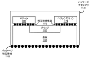
図3Bは、ここに記載の実施形態によるタイル式アーキテクチャを有するグラフィックスプロセッサ320を示す。一実施形態では、グラフィックスプロセッサ320は、グラフィックスエンジンタイル310A〜310D内に図3Aのグラフィックス処理エンジン310の複数のインスタンスを有するグラフィックス処理エンジンクラスタ322を含む。各グラフィックスエンジンタイル310A〜310Dは、タイル相互接続323A〜323Fのセットを介して相互接続できる。各グラフィックスエンジンタイル310A〜310Dはまた、メモリ相互接続325A〜325Dを介してメモリモジュール又はメモリデバイス326A〜326Dに接続できる。メモリデバイス326A〜326Dは、いずれかのグラフィックスメモリ技術を使用できる。例えば、メモリデバイス326A〜326Dは、グラフィックスダブルデータレート(graphics double data rate, GDDR)メモリでもよい。一実施形態では、メモリデバイス326A〜326Dは、それぞれのグラフィックスエンジンタイル310A〜310Dと共にダイ上にすることができる高帯域幅メモリモジュール(high-bandwidth memory, HBM)である。一実施形態では、メモリデバイス326A〜326Dは、それぞれのグラフィックスエンジンタイル310A〜310Dの上に積み重ねることができるスタック式メモリデバイスである。一実施形態では、各グラフィックスエンジンタイル310A〜310D及び関連するメモリ326A〜326Dは、図11B〜図11Dに更に詳細に記載されるように、ベースダイ又はベース基板に結合された別個のチップレット上に存在する。
FIG. 3B shows a graphics processor 320 having a tiled architecture according to the embodiments described herein. In one embodiment, the graphics processor 320 includes a graphics processing engine cluster 322 having multiple instances of the
グラフィックス処理エンジンクラスタ322は、オンチップ又はオンパッケージファブリック相互接続324と接続できる。ファブリック相互接続324は、グラフィックスエンジンタイル310A〜310Dと、ビデオコーデック306及び1つ以上のコピーエンジン304のようなコンポーネントとの間の通信を可能にできる。コピーエンジン304は、メモリデバイス326A〜326D及びグラフィックスプロセッサ320の外部にあるメモリ(例えば、システムメモリ)から、これらに、或いはこれらの間でデータを移動させるために使用できる。ファブリック相互接続324はまた、グラフィックスエンジンタイル310A〜310Dを相互接続するためにも使用できる。グラフィックスプロセッサ320は、外部ディスプレイデバイス318との接続を可能にするためのディスプレイコントローラ302を任意選択で含んでもよい。グラフィックスプロセッサはまた、グラフィックス又は計算アクセラレータとして構成されてもよい。アクセラレータ構成では、ディスプレイコントローラ302及びディスプレイデバイス318は省略されてもよい。
The graphics processing engine cluster 322 can be connected to the on-chip or on-package fabric interconnect 324. Fabric interconnect 324 can allow communication between
グラフィックスプロセッサ320は、ホストインタフェース328を介してホストシステムに接続できる。ホストインタフェース328は、グラフィックスプロセッサ320、システムメモリ及び/又は他のシステムコンポーネントの間の通信を可能にできる。ホストインタフェース328は、例えば、PCIエクスプレスバス又は他のタイプのホストシステムインタフェースとすることができる。 The graphics processor 320 can connect to the host system via the host interface 328. Host interface 328 can enable communication between the graphics processor 320, system memory and / or other system components. The host interface 328 can be, for example, a PCI Express bus or other type of host system interface.
図3Cは、ここに記載の実施形態による計算アクセラレータ330を示す。計算アクセラレータ330は、図3Bのグラフィックスプロセッサ320とのアーキテクチャの類似性を含むことができ、計算アクセラレーションのために最適化される。計算エンジンクラスタ332は、並列又はベクトルベースの汎用計算演算のために最適化された実行ロジックを含む計算エンジンタイルのセット340A〜340Dを含むことができる。いくつかの実施形態では、計算エンジンタイル340A〜340Dは、固定機能グラフィックス処理ロジックを含まないが、一実施形態では、計算エンジンタイル340A〜340Dのうち1つ以上は、メディアアクセラレーションを実行するためのロジックを含むことができる。計算エンジンタイル340A〜340Dは、メモリ相互接続325A〜325Dを介してメモリ326A〜326Dに接続できる。メモリ326A〜326D及びメモリ相互接続325A〜325Dは、グラフィックスプロセッサ320と同様の技術でもよく、或いは異なるものとすることができる。グラフィックス計算エンジンタイル340A〜340Dはまた、タイル相互接続のセット323A〜323Fを介して相互接続でき、ファブリック相互接続324と接続されてもよく、及び/又は、ファブリック相互接続324により相互接続されてもよい。一実施形態では、計算アクセラレータ330は、デバイス全体のキャッシュとして構成できる大きいL3キャッシュ336を含む。計算アクセラレータ330はまた、図3Bのグラフィックスプロセッサ320と同様に、ホストインタフェース328を介してホストプロセッサ及びメモリに接続できる。
FIG. 3C shows a computational accelerator 330 according to an embodiment described herein. Computational accelerator 330 can include architectural similarities with the graphics processor 320 of FIG. 3B and is optimized for computational acceleration.
(グラフィックス処理エンジン)
図4は、いくつかの実施形態によるグラフィックスプロセッサのグラフィックス処理エンジン410のブロック図である。一実施形態では、グラフィックス処理エンジン(graphics processing engine, GPE)410は、図3Aに示す或るバージョンのGPE310であり、また、図3Bのグラフィックスエンジンタイル310A〜310Dを表してもよい。ここでのいずれかの他の図面のエレメントと同じ参照符号(又は名称)を有する図4のエレメントは、ここで他の箇所に記載されたものと同様の方式で動作又は機能できるが、このようなものに限定されない。例えば、図3Aの3Dパイプライン312及びメディアパイプライン316が示されている。メディアパイプライン316は、GPE410のいくつかの実施形態では任意であり、GPE410内に明示的に含まれないことがある。例えば、少なくとも1つの実施形態では、別個のメディア及び/又は画像プロセッサがGPE410に結合される。
(Graphics processing engine)
FIG. 4 is a block diagram of the graphics processing engine 410 of the graphics processor according to some embodiments. In one embodiment, the graphics processing engine (GPE) 410 is a version of the
いくつかの実施形態では、GPE410は、コマンドストリームを3Dパイプライン312及び/又はメディアパイプライン316に提供するコマンドストリーマ403と結合されるか或いはこれを含む。いくつかの実施形態では、コマンドストリーマ403はメモリと結合され、メモリは、システムメモリ、又は内部キャッシュメモリ及び共有キャッシュメモリのうち1つ以上とすることができる。いくつかの実施形態では、コマンドストリーマ403は、メモリからコマンドを受信し、コマンドを3Dパイプライン312及び/又はメディアパイプライン316に送信する。コマンドは、3Dパイプライン312及びメディアパイプライン316のためのコマンドを記憶するリングバッファからフェッチされる指示である。一実施形態では、リングバッファは、複数のコマンドのバッチを記憶するバッチコマンドバッファを更に含むことができる。3Dパイプライン312のためのコマンドはまた、限定されないが3Dパイプライン312のための頂点及びジオメトリデータ及び/又はメディアパイプライン316のための画像データ及びメモリオブジェクトのような、メモリに記憶されたデータへの参照を含むことができる。3Dパイプライン312及びメディアパイプライン316は、それぞれのパイプライン内のロジックを介して動作を実行することにより、或いは1つ以上の実行スレッドをグラフィックスコアアレイ414にディスパッチすることにより、コマンド及びデータを処理する。一実施形態では、グラフィックスコアアレイ414は、グラフィックスコア(例えば、グラフィックスコア415A、グラフィックスコア415B)の1つ以上のブロックを含み、各ブロックは1つ以上のグラフィックスコアを含む。各グラフィックスコアは、グラフィックス及び計算演算を実行するための汎用且つグラフィックス特有の実行ロジックと、固定機能テクスチャ処理及び/又は機械学習及び人工知能アクセラレーションロジックとを含むグラフィックス実行リソースのセットを含む。
In some embodiments, the GPE 410 is combined with or includes a
様々な実施形態では、3Dパイプライン312は、命令を処理して実行スレッドをグラフィックスコアアレイ414にディスパッチすることにより、頂点シェーダ、ジオメトリシェーダ、ピクセルシェーダ、フラグメントシェーダ、計算シェーダ又は他のシェーダプログラムのような1つ以上のシェーダ(shader)プログラムを処理するための固定機能及びプログラム可能ロジックを含むことができる。グラフィックスコアアレイ414は、これらのシェーダプログラムを処理する際に使用する実行リソースの統一ブロックを提供する。グラフィックコアアレイ414のグラフィックスコア415A〜414B内の多目的実行ロジック(例えば、実行ユニット)は、様々な3D APIシェーダ言語のサポートを含み、複数のシェーダに関連する複数の同時実行スレッドを実行できる。
In various embodiments, the
いくつかの実施形態では、グラフィックスコアアレイ414は、ビデオ及び/又は画像処理のようなメディア機能を実行するための実行ロジックを含む。一実施形態では、実行ユニットは、グラフィックス処理演算に加えて、並列汎用計算演算を実行するようにプログラム可能な汎用ロジックを含む。汎用ロジックは、図1のプロセッサコア107又は図2Aのようなコア202A〜202N内の汎用ロジックと並列に或いは関連して処理演算を実行できる。
In some embodiments, the graphics score
グラフィックスコアアレイ414上で実行するスレッドにより生成された出力データは、ユニファイドリターンバッファ(unified return buffer, URB)418内のメモリにデータを出力できる。URB418は、複数のスレッドのデータを記憶できる。いくつかの実施形態では、URB418は、グラフィックスコアアレイ414上で実行する異なるスレッドの間でデータを送信するために使用されてもよい。いくつかの実施形態では、URB418は、グラフィックスコアアレイ上のスレッドと、共有機能ロジック420内の固定機能ロジックとの間の同期のために更に使用されてもよい。
The output data generated by the threads running on the graphics score
いくつかの実施形態では、グラフィックスコアアレイ414は、アレイが可変数のグラフィックスコアを含み、それぞれがGPE410の目標電力及び性能レベルに基づいて可変数の実行ユニットを有するようにスケーラブルである。一実施形態では、必要に応じて実行リソースが有効又は無効になってもよいように、実行リソースは動的にスケーラブルである。
In some embodiments, the graphics score
グラフィックスコアアレイ414は、グラフィックスコアアレイ内のグラフィックスコアの間で共有される複数のリソースを含む共有機能ロジック420と結合する。共有機能ロジック420内の共有機能は、特殊な補足機能をグラフィックスコアアレイ414に提供するハードウェア論理ユニットである。様々な実施形態では、共有機能ロジック420は、サンプラ421、数値演算422及びスレッド間通信(inter-thread communication, ITC)423ロジックを含むが、これらに限定されない。さらに、いくつかの実施形態は、共有機能ロジック420内に1つ以上のキャッシュ425を実装する。
The graphics score
共有機能は、所与の特殊な機能に対する需要がグラフィックスコアアレイ414内に含まれるのに不十分である場合に少なくとも実装される。その代わりに、その特殊な機能の単一のインスタンス化が、共有機能ロジック420内のスタンドアロンエンティティとして実装され、グラフィックスコアアレイ414内の実行リソースの間で共有される。グラフィックスコアアレイ414の間で共有されてグラフィックスコアアレイ414内に含まれる機能の正確なセットは、実施形態によって異なる。いくつかの実施形態では、グラフィックスコアアレイ414により広く使用される共有機能ロジック420内の特定の共有機能は、グラフィックスコアアレイ414内の共有機能ロジック416内に含まれてもよい。様々な実施形態では、グラフィックスコアアレイ414内の共有機能ロジック416は、共有機能ロジック420内の一部又は全部のロジックを含むことができる。一実施形態では、共有機能ロジック420内の全ての論理エレメントは、グラフィックスコアアレイ414の共有機能ロジック416内に複製されてもよい。一実施形態では、共有機能ロジック420は、グラフィックスコアアレイ414内の共有機能ロジック416のために除外される。
Sharing features are implemented at least when the demand for a given special feature is insufficient to be contained within the graphics score
(実行ユニット)
図5A〜図5Bは、ここに記載の実施形態に従ってグラフィックスプロセッサコアにおいて使用される処理エレメントのアレイを含むスレッド実行ロジック500を示す。ここでのいずれかの他の図面のエレメントと同じ参照符号(又は名称)を有する図5A〜図5Bのエレメントは、ここで他の箇所に記載されたものと同様の方式で動作又は機能できるが、このようなものに限定されない。図5A〜図5Bはスレッド実行ロジック600の概要を示しており、スレッド実行ロジック600は、図2Bの各サブコア221A〜221Fで示されるハードウェアロジックを表してもよい。図5Aは、汎用グラフィックスプロセッサ内の実行ユニットを表し、図5Bは、計算アクセラレータ内で使用されてもよい実行ユニットを表す。
(Execution unit)
5A-5B show
図5Aに示すように、いくつかの実施形態では、スレッド実行ロジック500は、シェーダプロセッサ502と、スレッドディスパッチャ504と、命令キャッシュ506と、複数の実行ユニット508A〜508Nを含むスケーラブル実行ユニットアレイと、サンプラ510と、共有ローカルメモリ511と、データキャッシュ512と、データポート514とを含む。一実施形態では、スケーラブル実行ユニットアレイは、ワークロードの計算要件に基づいて、1つ以上の実行ユニット(例えば、実行ユニット508A、508B、508C、508D〜508N-1及び508Nのいずれか)を有効又は無効にすることにより、動的にスケーリングできる。一実施形態では、含まれるコンポーネントは、コンポーネントのそれぞれに連結する相互接続ファブリックを介して相互接続される。いくつかの実施形態では、スレッド実行ロジック500は、命令キャッシュ506、データポート514、サンプラ510及び実行ユニット508A〜508Nのうち1つ以上を通じて、システムメモリ又はキャッシュメモリのようなメモリへの1つ以上の接続を含む。いくつかの実施形態では、各実行ユニット(例えば、508A)は、複数の同時ハードウェアスレッドを実行可能である一方で、各スレッドに対して複数のデータエレメントを並列に処理するスタンドアロンのプログラム可能汎用計算ユニットである。様々な実施形態では、実行ユニット508A〜508Nのアレイは、いずれかの数の個別の実行ユニットを含むようにスケーラブルである。
As shown in FIG. 5A, in some embodiments, the
いくつかの実施形態では、実行ユニット508A〜508Nはシェーダプログラムを実行するために主に使用される。シェーダプロセッサ502は、様々なシェーダプログラムを処理し、スレッドディスパッチャ504を介してシェーダプログラムに関連する実行スレッドをディスパッチできる。一実施形態では、スレッドディスパッチャは、グラフィックス及びメディアパイプラインからのスレッド開始要求を仲裁し、実行ユニット508A〜508N内の1つ以上の実行ユニット上で要求されたスレッドをインスタンス化するためのロジックを含む。例えば、ジオメトリパイプラインは、処理のために頂点、テセレーション(tessellation)又はジオメトリシェーダをスレッド実行ロジックにディスパッチできる。いくつかの実施形態では、スレッドディスパッチャ504はまた、実行中のシェーダプログラムからのランタイムのスレッド生成要求を処理できる。
In some embodiments,
いくつかの実施形態では、実行ユニット508A〜508Nは、グラフィックスライブラリ(例えば、Direct 3D及びOpenGL)からのシェーダプログラムが最小限の変換で実行されるように、多くの標準的な3Dグラフィックスシェーダ命令のネイティブサポートを含む命令セットをサポートする。実行ユニットは、頂点及びジオメトリ処理(例えば、頂点プログラム、ジオメトリプログラム、頂点シェーダ)、ピクセル処理(例えば、ピクセルシェーダ、フラグメントシェーダ)及び汎用処理(例えば、計算及びメディアシェーダ)をサポートする。実行ユニット508A〜508Nのそれぞれは、複数発行(multi-issue)の単一命令複数データ(single instruction multiple data, SIMD)実行が可能であり、マルチスレッド演算は、より高い待ち時間のメモリアクセスに直面したときに効率的な実行環境を可能にする。各実行ユニット内の各ハードウェアスレッドは、専用の広帯域幅レジスタファイル及び関連する独立したスレッド状態を有する。実行は、整数、単精度及び倍精度の浮動小数点演算、SIMD分岐能力、論理演算、超越演算(transcendental operation)及び他の多様な演算が可能なパイプラインへのクロック当たりの複数発行である。メモリ又は共有機能のうち1つからのデータを待機する間に、実行ユニット508A〜508N内の依存するロジックは、要求されたデータが返されるまで待機スレッドをスリープさせる。待機スレッドがスリープしている間に、ハードウェアリソースは、他のスレッドを処理するために割り当てられてもよい。例えば、頂点シェーダ演算に関連する遅延の間に、実行ユニットは、ピクセルシェーダ、フラグメントシェーダ又は他のタイプのシェーダプログラム(異なる頂点シェーダを含む)の演算を実行できる。様々な実施形態は、SIMDの使用の代替として或いはSIMDの使用に加えて、単一命令複数スレッド(Single Instruction Multiple Thread, SIMT)の使用による実行を使用するために適用できる。SIMDコア又は演算への言及はまた、SIMTに適用でき、或いは、SIMTと組み合わせてSIMDに適用できる。
In some embodiments, the
実行ユニット508A〜508N内の各実行ユニットは、データエレメントのアレイに対して動作する。データエレメントの数は「実行サイズ」又は命令のチャネル数である。実行チャネルは、データエレメントのアクセス、マスキング及び命令内のフロー制御のための実行の論理単位である。チャネルの数は、特定のグラフィックスプロセッサについての物理的な算術論理ユニット(Arithmetic Logic Unit, ALU)又は浮動小数点ユニット(Floating Point Unit, FPU)の数と独立してもよい。いくつかの実施形態では、実行ユニット508A〜508Nは、整数及び浮動小数点データタイプをサポートする。
Each execution unit in
実行ユニット命令セットはSIMD命令を含む。様々なデータエレメントは、レジスタ内のパックデータ(packed data)タイプとして記憶でき、実行ユニットは、エレメントのデータサイズに基づいて様々なエレメントを処理する。例えば、256ビット幅のベクトルに対して動作するとき、ベクトルの256ビットはレジスタに記憶され、実行ユニットは、4つの別々の54ビットのパックデータエレメント(QW(Quad-Word)サイズのデータエレメント)、8つの別々の32ビットのパックデータエレメント((DW(Double Word)サイズのデータエレメント)、16個の別々の16ビットのパックデータエレメント(W(Word)サイズのデータエレメント)又は32個の別々の8ビットのデータエレメント(B(byte)サイズのデータエレメント)としてベクトルに対して動作する。しかし、異なるベクトル幅及びレジスタサイズが可能である。 The execution unit instruction set contains SIMD instructions. The various data elements can be stored as packed data types in registers, and the execution unit processes the various elements based on the data size of the element. For example, when working on a 256-bit wide vector, 256 bits of the vector are stored in a register and the execution unit is four separate 54-bit packed data elements (QW (Quad-Word) sized data elements). , 8 separate 32-bit packed data elements ((DW (Double Word) size data elements), 16 separate 16-bit packed data elements (W (Word) size data elements) or 32 separate Acts on a vector as an 8-bit data element (B (byte) size data element), but different vector widths and register sizes are possible.
一実施形態では、1つ以上の実行ユニットは、融合EUに共通するスレッド制御ロジック(507A〜507N)を有する融合実行ユニット509A〜509Nに結合できる。複数のEUは、EUグループに融合できる。融合EUグループ内の各EUは、別々のSIMDハードウェアスレッドを実行するように構成できる。融合EUグループ内のEUの数は、実施形態に従って変化できる。さらに、様々なSIMD幅は、SIMD8、SIMD16及びSIMD32を含むが、これらに限定されないEU毎に実行できる。各融合グラフィックス実行ユニット509A〜509Nは、少なくとも2つの実行ユニットを含む。例えば、融合実行ユニット509Aは、第1のEU508Aと、第2のEU508Bと、第1のEU508A及び第2のEU508Bに共通であるスレッド制御ロジック507Aとを含む。スレッド制御ロジック507Aは、融合グラフィックス実行ユニット509A上で実行されるスレッドを制御し、融合実行ユニット509A〜509N内の各EUが共通の命令ポインタレジスタを使用して実行することを可能にする。
In one embodiment, one or more execution units can be coupled to
1つ以上の内部命令キャッシュ(例えば、506)は、実行ユニットのためのスレッド命令をキャッシュするために、スレッド実行ロジック500に含まれる。いくつかの実施形態では、1つ以上のデータキャッシュ(例えば、512)は、スレッド実行中にスレッドデータをキャッシュするために含まれる。実行ロジック500上で実行するスレッドはまた、明示的に管理されるデータを共有ローカルメモリ511に記憶できる。いくつかの実施形態では、サンプラ510は、3D演算のためのテクスチャサンプリング及びメディア演算のためのメディアサンプリングを提供するために含まれる。いくつかの実施形態では、サンプラ510は、サンプリングされたデータを実行ユニットに提供する前に、サンプリングプロセス中にテクスチャ又はメディアデータを処理するための特殊なテクスチャ又はメディアサンプリング機能を含む。
One or more internal instruction caches (eg, 506) are included in the
実行中に、グラフィックス及びメディアパイプラインは、スレッド生成及びディスパッチロジックを介してスレッド開始要求をスレッド実行ロジック500に送信する。ジオメトリックオブジェクトのグループが処理されてピクセルデータにラスタライズされると、シェーダプロセッサ502内のピクセルプロセッサロジック(例えば、ピクセルシェーダロジック、フラグメントシェーダロジック等)は、出力情報を更に計算して結果を出力面(例えば、カラーバッファ、デプスバッファ、ステンシルバッファ等)に書き込ませるために呼び出される。いくつかの実施形態では、ピクセルシェーダ又はフラグメントシェーダは、ラスタライズされたオブジェクトの間で補間されるべき様々な頂点属性の値を計算する。いくつかの実施形態では、次いで、シェーダプロセッサ502内のピクセルプロセッサロジックは、アプリケーションプログラミングインタフェース(application programming interface, API)により供給されるピクセル又はフラグメントシェーダプログラムを実行する。シェーダプログラムを実行するために、シェーダプロセッサ502は、スレッドディスパッチャ504を介してスレッドを実行ユニット(例えば、508A)にディスパッチする。いくつかの実施形態では、シェーダプロセッサ502は、メモリに記憶されたテクスチャマップ内のテクスチャデータにアクセスするために、サンプラ510内のテクスチャサンプリングロジックを使用する。テクスチャデータ及び入力ジオメトリデータに対する算術演算は、各ジオメトリックフラグメントについてピクセルカラーデータを計算するか、或いは、更なる処理から1つ以上のピクセルを廃棄する。
During execution, the graphics and media pipeline sends a thread start request to
いくつかの実施形態では、データポート514は、グラフィックスプロセッサ出力パイプライン上での更なる処理のために、スレッド実行ロジック500が処理されたデータをメモリに出力するためのメモリアクセス機構を提供する。いくつかの実施形態では、データポート514は、データポートを介してメモリアクセスのためのデータをキャッシュするために、1つ以上のキャッシュメモリ(例えば、データキャッシュ512)を含むか或いはこれに結合する。
In some embodiments, the data port 514 provides a memory access mechanism for the
一実施形態では、実行ロジック500はまた、レイトレーシングアクセラレーション機能を提供できるレイトレーサ505を含むことができる。レイトレーサ505は、光線生成のための命令/機能を含むレイトレーシング命令セットをサポートできる。レイトレーシング命令セットは、図2Cにおけるレイトレーシングコア245によりサポートされるレイトレーシング命令セットと同様のものとすることができ、或いは、異なるものとすることもできる。
In one embodiment, the
図5Bは、実施形態による実行ユニット508の例示的な内部詳細を示す。グラフィックス実行ユニット508は、命令フェッチユニット537と、汎用レジスタファイルアレイ(general register file array, GRF)524と、アーキテクチャレジスタファイルアレイ(architectural register file array, ARF)526と、スレッド仲裁器522と、送信ユニット530と、分岐ユニット532と、SIMD浮動小数点ユニットのセット534と、一実施形態では専用の整数SIMD ALUのセット535とを含むことができる。GRF524及びARF526は、グラフィックス実行ユニット508においてアクティブになり得る各同時ハードウェアスレッドに関連する汎用レジスタファイル及びアーキテクチャレジスタファイルのセットを含む。一実施形態では、スレッド毎のアーキテクチャ状態はARF526において維持される一方で、スレッド実行中に使用されるデータはGRF524に記憶される。各スレッドについての命令ポインタを含む各スレッドの実行状態は、ARF526内のスレッド固有レジスタに保持できる。
FIG. 5B shows exemplary internal details of Execution Unit 508 according to the embodiment. The graphics execution unit 508 transmits an instruction fetch
一実施形態では、グラフィックス実行ユニット508は、同時マルチスレッディング(Simultaneous Multi-Threading, SMT)と細粒度インターリーブマルチスレッディング(Interleaved Multi-Threading, IMT)との組み合わせであるアーキテクチャを有する。アーキテクチャは、同時スレッドの目標数及び実行ユニット当たりのレジスタ数に基づいて、設計時に微調整可能なモジュール式構成を有し、実行ユニットリソースは、複数の同時スレッドを実行するために使用されるロジックの間で分割される。グラフィックス実行ユニット508により実行され得る論理スレッドの数はハードウェアスレッドの数に限定されず、複数の論理スレッドが各ハードウェアスレッドに割り当てられることができる。 In one embodiment, the graphics execution unit 508 has an architecture that is a combination of Simultaneous Multi-Threading (SMT) and Interleaved Multi-Threading (IMT). The architecture has a modular configuration that can be fine-tuned at design time based on the target number of concurrent threads and the number of registers per execution unit, and the execution unit resource is the logic used to execute multiple concurrent threads. Divided between. The number of logical threads that can be executed by the graphics execution unit 508 is not limited to the number of hardware threads, and a plurality of logical threads can be assigned to each hardware thread.
一実施形態では、グラフィックス実行ユニット508は、それぞれ異なる命令でもよい複数の命令を同時発行できる。グラフィックス実行ユニットスレッド508のスレッド仲裁器522は、実行のために、送信ユニット530、分岐ユニット532又はSIMD FPU534のうち1つに命令をディスパッチできる。各実行スレッドは、GRF524内の128個の汎用レジスタにアクセスでき、各レジスタは32バイトを記憶でき、32ビットのデータエレメントのSIMDの8エレメントのベクトルとしてアクセス可能である。一実施形態では、各実行ユニットスレッドは、GRF524内の4Kバイトへのアクセスを有するが、実施形態はこれに限定されず、他の実施形態では、より大きい或いはより少ないレジスタリソースが提供されてもよい。一実施形態では、グラフィックス処理ユニット508は、計算演算を独立して実行できる7つのハードウェアスレッドに分割されるが、実行ユニット当たりのスレッドの数はまた、実施形態に従って変化できる。例えば、一実施形態では、16個までのハードウェアスレッドがサポートされる。7つのスレッドが4Kバイトにアクセスし得る実施形態では、GRF524は合計28Kバイトを記憶できる。16個のスレッドが4Kバイトにアクセスし得る場合、GRF524は合計64Kバイトを記憶できる。柔軟なアドレス指定モードは、レジスタが一緒にアドレス指定されて、より広いレジスタを効果的に構築したり或いはストライドされた矩形ブロックデータ構造を表したりすることを可能にできる。
In one embodiment, the graphics execution unit 508 can simultaneously issue a plurality of instructions, each of which may be a different instruction. The
一実施形態では、メモリ演算、サンプラ演算及び他のより長い待ち時間のシステム通信は、送信ユニット530を通過するメッセージにより実行される「送信」命令を介してディスパッチされる。一実施形態では、分岐命令は、SIMD発散(divergence)及び最終的な収束を実現するために、専用の分岐ユニット532にディスパッチされる。 In one embodiment, memory operations, sampler operations and other longer latency system communications are dispatched via a "send" instruction executed by a message passing through the transmit unit 530. In one embodiment, the branch instruction is dispatched to a dedicated branch unit 532 to achieve SIMD divergence and final convergence.
一実施形態では、グラフィックス実行ユニット508は、浮動小数点演算を実行するための1つ以上のSIMD浮動小数点ユニット(floating point unit, FPU)534を含む。一実施形態では、FPU534はまた、整数計算をサポートする。一実施形態では、FPU534は、M個までの32ビット浮動小数点(又は整数)演算をSIMD実行でき、或いは、2M個までの16ビット整数又は16ビット浮動小数点演算をSIMD実行できる。一実施形態では、FPUのうち少なくとも1つは、高スループット超越数値演算関数及び倍精度54ビット浮動小数点をサポートする拡張数値演算能力を提供する。いくつかの実施形態では、8ビット整数SIMD ALU535のセットも存在し、機械学習計算に関連する演算を実行するために特に最適化されてもよい。 In one embodiment, the graphics execution unit 508 includes one or more SIMD floating point units (FPUs) 534 for performing floating point operations. In one embodiment, the FPU534 also supports integer computation. In one embodiment, the FPU534 can SIMD up to M 32-bit floating point (or integer) operations, or SIMD up to 2M 16-bit integer or 16-bit floating point operations. In one embodiment, at least one of the FPUs provides extended math capabilities that support high throughput transcendental math functions and double precision 54-bit floating point. In some embodiments, a set of 8-bit integer SIMD ALU535 is also present and may be specifically optimized to perform operations related to machine learning calculations.
一実施形態では、グラフィックス実行ユニット508の複数のインスタンスのアレイは、グラフィックスサブコアグループ化(例えば、サブスライス)でインスタンス化できる。スケーラビリティのために、製品アーキテクトは、サブコアグループ当たりの正確な数の実行ユニットを選択できる。一実施形態では、実行ユニット508は、複数の実行チャネルの間で命令を実行できる。更なる実施形態では、グラフィックス実行ユニット508上で実行される各スレッドは、異なるチャネル上で実行される。 In one embodiment, an array of multiple instances of graphics execution unit 508 can be instantiated with graphics subcore grouping (eg, subslices). For scalability, product architects can choose the exact number of execution units per subcore group. In one embodiment, execution unit 508 can execute instructions across multiple execution channels. In a further embodiment, each thread running on the graphics execution unit 508 runs on a different channel.
図6は、一実施形態による更なる実行ユニット600を示す。実行ユニット600は、例えば、図3Cのような計算エンジンタイル340A〜340Dで使用するための計算最適化された実行ユニットでもよいが、このようなものに限定されない。また、図3Bのようなグラフィックスエンジンタイル310A〜310Dにおいて、実行ユニット600の変形が使用されてもよい。一実施形態では、実行ユニット600は、スレッド制御ユニット601と、スレッド状態ユニット602と、命令フェッチ/プリフェッチユニット603と、命令復号ユニット604とを含む。実行ユニット600は、実行ユニット内でハードウェアスレッドに割り当てられることができるレジスタを記憶するレジスタファイル606を更に含む。実行ユニット600は、送信ユニット607と、分岐ユニット608とを更に含む。一実施形態では、送信ユニット607及び分岐ユニット608は、図5Bのグラフィックス実行ユニット508の送信ユニット530及び分岐ユニット532と同様に動作できる。
FIG. 6 shows a
実行ユニット600はまた、複数の異なるタイプの機能ユニットを含む計算ユニット610を含む。一実施形態では、計算ユニット610は、算術論理ユニットのアレイを含むALUユニット611を含む。ALUユニット611は、64ビット、32ビット及び16ビットの整数及び浮動小数点演算を実行するように構成できる。整数及び浮動小数点演算は同時に実行されてもよい。計算ユニット610はまた、シストリックアレイ(systolic array)612と、数値演算ユニット613とを含むことができる。シストリックアレイ612は、シストリックにベクトル又は他のデータ並列演算を実行するために使用できるデータ処理ユニットのW幅及びD深度のネットワークを含む。一実施形態では、シストリックアレイ612は、行列ドット積演算のような行列演算を実行するように構成できる。一実施形態では、シストリックアレイ612は、16ビット浮動小数点演算と、8ビット及び4ビット整数演算とをサポートする。一実施形態では、シストリックアレイ612は、機械学習演算をアクセラレーションするように構成できる。このような実施形態では、シストリックアレイ612は、bfloat 16ビット浮動小数点フォーマットをサポートするように構成できる。一実施形態では、数値演算ユニット613は、ALUユニット611よりも効率的で低電力の方式で特定のサブセットの数値演算を実行するために含まれることができる。数値演算ユニット613は、他の実施形態(例えば、図4の共有機能論理420の数値演算ロジック422)により提供されるグラフィックス処理エンジンの共有機能ロジック内に見出され得る数値演算ロジックの変形を含むことができる。一実施形態では、数値演算ユニット613は、32ビット及び64ビットの浮動小数点演算を実行するように構成できる。
スレッド制御ユニット601は、実行ユニット内のスレッドの実行を制御するためのロジックを含む。スレッド制御ユニット601は、実行ユニット600内のスレッドの実行を開始、停止及びプリエンプトするためのスレッド仲裁ロジックを含むことができる。スレッド状態ユニット602は、実行ユニット600上で実行するために割り当てられたスレッドについてのスレッド状態を記憶するために使用できる。実行ユニット600内にスレッド状態を記憶することは、これらのスレッドがブロック又はアイドルになったときに、スレッドの迅速なプリエンプションを可能にする。命令フェッチ/プリフェッチユニット603は、より高いレベルの実行ロジックの命令キャッシュ(例えば、図5Aのような命令キャッシュ506)から命令をフェッチできる。命令フェッチ/プリフェッチユニット603はまた、現在実行中のスレッドの分析に基づいて命令キャッシュにロードされる命令についてプリフェッチ要求を発行できる。命令復号ユニット604は、計算ユニットにより実行される命令を復号するために使用できる。一実施形態では、命令復号ユニット604は、複雑な命令を構成要素のマイクロ演算に復号するための二次復号器として使用できる。
The
実行ユニット600は、実行ユニット600上で実行するハードウェアスレッドにより使用できるレジスタファイル606を更に含む。レジスタファイル606内のレジスタは、実行ユニット600の計算ユニット610内で複数の同時スレッドを実行するために使用されるロジックの間で分割できる。グラフィックス実行ユニット600により実行され得る論理スレッドの数は、ハードウェアスレッドの数に限定されず、複数の論理スレッドが各ハードウェアスレッドに割り当てられることができる。レジスタファイル606のサイズは、サポートされるハードウェアスレッドの数に基づいて、実施形態の間で変化できる。一実施形態では、レジスタをハードウェアスレッドに動的に割り当てるために、レジスタのリネームが使用されてもよい。
図7は、いくつかの実施形態によるグラフィックスプロセッサ命令フォーマット700を示すブロック図である。1つ以上の実施形態では、グラフィックスプロセッサ実行ユニットは、複数のフォーマットの命令を有する命令セットをサポートする。実線のボックスは、一般的に実行ユニット命令に含まれるコンポーネントを示し、破線は、任意選択であるか或いは命令のサブセットにのみ含まれるコンポーネントを含む。いくつかの実施形態では、記載及び図示される命令フォーマット700は、命令が処理されると命令復号から生じるマイクロ演算とは対照的に、実行ユニットに供給される命令であるという点でマクロ命令である。 FIG. 7 is a block diagram showing a graphics processor instruction format 700 according to some embodiments. In one or more embodiments, the graphics processor execution unit supports an instruction set with instructions in multiple formats. The solid box indicates the components that are generally included in the execution unit instruction, and the dashed line contains the components that are optional or contained only in a subset of the instruction. In some embodiments, the instruction format 700 described and illustrated is a macroinstruction in that the instruction is supplied to the execution unit as opposed to the microoperation that results from instruction decoding when the instruction is processed. be.
いくつかの実施形態では、グラフィックスプロセッサ実行ユニットは、128ビット命令フォーマット710の命令をネイティブにサポートする。64ビットコンパクト命令フォーマット730は、選択された命令、命令オプション及びオペランドの数に基づいて、いくつかの命令に対して利用可能である。ネイティブの128ビット命令フォーマット710は、全ての命令オプションへのアクセスを提供する一方で、いくつかのオプション及び演算は、64ビットフォーマット730で制限される。64ビットフォーマット730で利用可能なネイティブ命令は、実施形態によって変化する。いくつかの実施形態では、命令は、インデックスフィールド713内のインデックス値のセットを部分的に使用してコンパクト化される。実行ユニットハードウェアは、インデックス値に基づいてコンパクト化テーブルのセットを参照し、128ビット命令フォーマット710のネイティブ命令を再構築するためにコンパクト化テーブルの出力を使用する。他のサイズ及びフォーマットの命令も使用できる。
In some embodiments, the graphics processor execution unit natively supports instructions in 128-bit instruction format 710. The 64-bit
各フォーマットについて、命令オペコード712は、実行ユニットが実行すべき演算を定義する。実行ユニットは、各オペランドの複数のデータエレメントの間で各命令を並列に実行する。例えば、加算命令に応じて、実行ユニットは、テクスチャエレメント又はピクチャエレメントを表す各カラーチャネルの間で同時加算演算を実行する。初期設定では、実行ユニットは、オペランドの全てのデータチャネルの間で各命令を実行する。いくつかの実施形態では、命令制御フィールド714は、チャネル選択(例えば、予測)及びデータチャネル順序(例えば、スウィズル(swizzle))のような特定の実行オプションの制御を可能にする。128ビット命令フォーマット710における命令については、execサイズのフィールド716は、並列に実行されるデータチャネルの数を制限する。いくつかの実施形態では、execサイズのフィールド716は、64ビットのコンパクト命令フォーマット730での使用には利用可能ではない。
For each format,
いくつかの実行ユニット命令は、2つのソースオペランド(source operand)、すなわち、src0 720、src1 722と、1つのデスティネーション(destination)718とを含む3つまでのオペランドを有する。いくつかの実施形態では、実行ユニットは、デュアルデスティネーション命令をサポートし、デスティネーションのうち1つが暗示される。データ操作命令は、第3のソースオペランド(例えば、SRC2 724)を有することができ、命令オペコード712は、ソースオペランドの数を決定する。命令の最後のソースオペランドは、命令と共に渡される即値の(例えば、ハードコードされた)値とすることができる。
Some execution unit instructions have up to three operands, including two source operands,
いくつかの実施形態では、128ビット命令フォーマット710は、例えば、直接レジスタアドレス指定モードが使用されるか間接レジスタアドレス指定モードが使用されるかを指定するアクセス/アドレスモードフィールド726を含む。直接レジスタアドレス指定モードが使用されるとき、1つ以上のオペランドのレジスタアドレスは、命令内のビットにより直接提供される。 In some embodiments, the 128-bit instruction format 710 includes, for example, an access / address mode field 726 that specifies whether direct register addressing mode is used or indirect register addressing mode is used. When the direct register addressing mode is used, the register address of one or more operands is provided directly by the bits in the instruction.
いくつかの実施形態では、128ビット命令フォーマット710は、命令のアドレスモード及び/又はアクセスモードを指定するアクセス/アドレスモードフィールド726を含む。一実施形態では、アクセスモードは、命令のためのデータアクセスアライメントを定義するために使用される。いくつかの実施形態は、16バイトアライメントされたアクセスモード及び1バイトアライメントされたアクセスモードを含むアクセスモードをサポートし、アクセスモードのバイトアライメントは命令オペランドのアクセスアライメントを決定する。例えば、第1のモードでは、命令は、ソース及びデスティネーションオペランドのためにバイトアライメントされたアドレス指定を使用してもよく、第2のモードでは、命令は、全てのソース及びデスティネーションオペランドのために16バイトアライメントされたアドレス指定を使用してもよい。 In some embodiments, the 128-bit instruction format 710 includes an access / address mode field 726 that specifies the address mode and / or access mode of the instruction. In one embodiment, the access mode is used to define a data access alignment for the instruction. Some embodiments support an access mode that includes a 16-byte aligned access mode and a 1-byte aligned access mode, in which the byte alignment of the access mode determines the access alignment of the instruction operand. For example, in the first mode, the instruction may use byte-aligned addressing for the source and destination operands, and in the second mode, the instruction is for all source and destination operands. 16-byte aligned addressing may be used for.
一実施形態では、アクセス/アドレスモードフィールド726のアドレスモード部分は、命令が直接アドレス指定を使用するか間接アドレス指定を使用するかを決定する。直接レジスタアドレス指定モードが使用されるとき、命令内のビットは、1つ以上のオペランドのレジスタアドレスを直接提供する。間接レジスタアドレス指定モードが使用されるとき、1つ以上のオペランドのレジスタアドレスは、アドレスレジスタ値及び命令内のアドレス即値フィールドに基づいて計算されてもよい。 In one embodiment, the address mode portion of the access / address mode field 726 determines whether the instruction uses direct addressing or indirect addressing. When the direct register addressing mode is used, the bits in the instruction directly provide the register address of one or more operands. When the indirect register addressing mode is used, the register address of one or more operands may be calculated based on the address register value and the immediate address field in the instruction.
いくつかの実施形態では、命令は、オペコード復号740を簡略化するために、オペコード712のビットフィールドに基づいてグループ化される。8ビットのオペコードでは、ビット4、5及び6は、実行ユニットがオペコードのタイプを決定することを可能にする。図示の正確なオペコードのグループ化は、単なる例である。いくつかの実施形態では、移動及びロジックオペコードグループ742は、データ移動及びロジック命令(例えば、移動(mov)、比較(cmp))を含む。いくつかの実施形態では、移動及びロジックグループ742は、5つの最上位ビット(most significant bit, MSB)を共有し、移動(mov)命令は0000xxxxbの形式であり、ロジック命令は0001xxxbの形式である。フロー制御命令グループ744(例えば、呼び出し、ジャンプ(jmp))は0010xxxxb(例えば、0x20)の形式の命令を含む。多様な命令グループ746は、0011xxxxb(例えば、0x30)の形式の同期命令(例えば、待機、送信)を含む命令の混合を含む。並列数値演算命令グループ748は、0100xxxxb(例えば、0x40)の形式の、コンポーネント毎の算術命令(例えば、加算、乗算(mul))を含む。並列数値演算グループ748は、データチャネルの間で並列に算術演算を実行する。ベクトル数値演算グループ750は、0101xxxxb(例えば、0x50)の形式の算術命令(例えば、dp4)を含む。ベクトル数値演算グループは、ベクトルオペランドに対するドット積計算のような算術を実行する。一実施形態では、図示のオペコード復号740は、実行ユニットのどの部分が復号された命令を実行するために使用されるかを決定するために使用できる。例えば、いくつかの命令は、シストリックアレイにより実行されるシストリック命令として指定されてもよい。レイトレーシング命令(図示せず)のような他の命令は、実行ロジックのスライス又はパーティション内のレイトレーシングコア又はレイトレーシングロジックに経路設定できる。
In some embodiments, the instructions are grouped based on the bitfield of
(グラフィックスパイプライン)
図8は、グラフィックスプロセッサ800の他の実施形態のブロック図である。いずれかの他の図面のエレメントと同じ参照符号(又は名称)を有する図8のエレメントは、ここで他の箇所に記載されたものと同様の方式で動作又は機能できるが、これらに限定されない。
(Graphics pipeline)
FIG. 8 is a block diagram of another embodiment of the graphics processor 800. An element of FIG. 8 having the same reference code (or name) as any other drawing element may operate or function in a manner similar to that described elsewhere, but is not limited thereto.
いくつかの実施形態では、グラフィックスプロセッサ800は、ジオメトリパイプライン820と、メディアパイプライン830と、ディスプレイエンジン840と、スレッド実行ロジック850と、レンダリング出力パイプライン870とを含む。いくつかの実施形態では、グラフィックスプロセッサ800は、1つ以上の汎用処理コアを含むマルチコア処理システム内のグラフィックスプロセッサである。グラフィックスプロセッサは、1つ以上の制御レジスタ(図示せず)へのレジスタ書き込みにより、或いはリング相互接続802を介したグラフィックスプロセッサ800に発行されるコマンドを介して制御される。いくつかの実施形態では、リング相互接続802は、グラフィックスプロセッサ800を、他のグラフィックスプロセッサ又は汎用プロセッサのような他の処理コンポーネントに結合する。リング相互接続802からのコマンドは、ジオメトリパイプライン820又はメディアパイプライン830の個々のコンポーネントに命令を供給するコマンドストリーマ803により解釈される。
In some embodiments, the graphics processor 800 includes a
いくつかの実施形態では、コマンドストリーマ803は、メモリから頂点データを読み取り、コマンドストリーマ803により提供される頂点処理コマンドを実行する頂点フェッチ器805の動作を指示する。いくつかの実施形態では、頂点フェッチ器805は頂点データを頂点シェーダ807に提供し、頂点シェーダ807は、各頂点への座標空間変換及び照明演算を実行する。いくつかの実施形態では、頂点フェッチ器805及び頂点シェーダ807は、スレッドディスパッチャ831を介して実行スレッドを実行ユニット852A〜852Bにディスパッチすることにより頂点処理命令を実行する。
In some embodiments, the
いくつかの実施形態では、実行ユニット852A〜852Bは、グラフィックス及びメディア演算を実行するための命令セットを有するベクトルプロセッサのアレイである。いくつかの実施形態では、実行ユニット852A〜852Bは、各アレイに特有であるか或いはアレイの間で共有される、取り付けられたL1キャッシュ851を有する。キャッシュは、データキャッシュ、命令キャッシュ、又は異なるパーティションにおいてデータ及び命令を含むように区分された単一のキャッシュとして構成できる。 In some embodiments, execution units 852A-852B are an array of vector processors that have a set of instructions for performing graphics and media operations. In some embodiments, execution units 852A-852B have an attached L1 cache 851 that is specific to each array or shared between arrays. The cache can be configured as a data cache, an instruction cache, or a single cache partitioned to contain data and instructions in different partitions.
いくつかの実施形態では、ジオメトリパイプライン820は、3Dオブジェクトのハードウェアアクセラレーションされたテセレーションを実行するためのテセレーションコンポーネントを含む。いくつかの実施形態では、プログラム可能ハルシェーダ(programmable hull shader)811がテセレーション動作を構成する。プログラム可能ドメインシェーダ817は、テセレーション出力のバックエンド評価を提供する。テセレータ813は、ハルシェーダ811の方向で動作し、ジオメトリパイプライン820への入力として提供される粗いジオメトリックモデルに基づいて、詳細なジオメトリックオブジェクトのセットを生成するための特殊目的のロジックを含む。いくつかの実施形態では、テセレーションが使用されない場合、テセレーションコンポーネント(例えば、ハルシェーダ811、テセレータ813、及びドメインシェーダ817)はバイパスできる。
In some embodiments, the
いくつかの実施形態では、完全なジオメトリックオブジェクトは、実行ユニット852A〜852Bにディスパッチされた1つ以上のスレッドを介してジオメトリシェーダ819により処理でき、或いは、クリッパ829に直接進むことができる。いくつかの実施形態では、ジオメトリシェーダは、グラフィックスパイプラインの前の段階のように頂点又は頂点のパッチではなく、全体のジオメトリックオブジェクトに対して動作する。テセレーションが無効にされた場合、ジオメトリシェーダ819は頂点シェーダ807からの入力を受信する。いくつかの実施形態では、ジオメトリシェーダ819は、テセレーションユニットが無効にされた場合にジオメトリテセレーションを実行するように、ジオメトリシェーダプログラムによりプログラム可能である。
In some embodiments, the complete geometric object can be processed by the
ラスタライズの前に、クリッパ829は頂点データを処理する。クリッパ829は、固定機能クリッパ、又はクリッピング及びジオメトリシェーダ機能を有するプログラム可能クリッパでもよい。いくつかの実施形態では、レンダリング出力パイプライン870内のラスタライザ及びデプステストコンポーネント873は、ジオメトリックオブジェクトをピクセル毎の表現に変換するためにピクセルシェーダをディスパッチする。いくつかの実施形態では、ピクセルシェーダロジックは、スレッド実行ロジック850に含まれる。いくつかの実施形態では、アプリケーションは、ラスタライザ及びデプステストコンポーネント873をバイパスし、ストリーム出力ユニット823を介してラスタライズされていない頂点データにアクセスできる。
Prior to rasterization, Clipper 829 processes the vertex data. The clipper 829 may be a fixed function clipper or a programmable clipper having clipping and geometry shader functions. In some embodiments, the rasterizer and depth test component 873 in the
グラフィックスプロセッサ800は、相互接続バス、相互接続ファブリック、又はプロセッサの主要なコンポーネントの間でデータ及びメッセージを通過させる他の相互接続機構を有する。いくつかの実施形態では、実行ユニット852A〜852B及び関連する論理ユニット(例えば、L1キャッシュ851、サンプラ854、テクスチャキャッシュ858等)は、メモリアクセスを実行して、プロセッサのレンダリング出力パイプラインコンポーネントと通信するために、データポート856を介して相互接続する。いくつかの実施形態では、サンプラ854、キャッシュ851、858及び実行ユニット852A〜852Bは、別個のメモリアクセスパスをそれぞれ有する。一実施形態では、テクスチャキャッシュ858はまた、サンプラキャッシュとして構成できる。
The graphics processor 800 has an interconnect bus, an interconnect fabric, or other interconnect mechanism that allows data and messages to pass between key components of the processor. In some embodiments, execution units 852A-852B and related logical units (eg, L1 cache 851,
いくつかの実施形態では、レンダリング出力パイプライン870は、頂点ベースのオブジェクトを関連するピクセルベースの表現に変換するラスタライザ及びデプステストコンポーネント873を含む。いくつかの実施形態では、ラスタライザロジックは、固定機能トライアングル及び直線ラスタライズを実行するためのウインドウ/マスクユニットを含む。関連するレンダリングキャッシュ878及びデプスキャッシュ879もまた、いくつかの実施形態では利用可能である。ピクセル演算コンポーネント877は、データに対してピクセルベースの演算を実行するが、いくつかの例では、2D演算に関連するピクセル演算(例えば、ブレンドを用いたビットブロック画像転送)は、2Dエンジン841により実行されるか、或いは、表示時間においてオーバレイ表示面を使用してディスプレイコントローラ843により置き換えられる。いくつかの実施形態では、共有L3キャッシュ875は、全てのグラフィックスコンポーネントに利用可能であり、主システムメモリを使用することなくデータの共有を可能にする。
In some embodiments, the
いくつかの実施形態では、グラフィックスプロセッサメディアパイプライン830は、メディアエンジン837と、ビデオフロントエンド834とを含む。いくつかの実施形態では、ビデオフロントエンド834は、コマンドストリーマ803からパイプラインコマンドを受信する。いくつかの実施形態では、メディアパイプライン830は、別個のコマンドストリーマを含む。いくつかの実施形態では、ビデオフロントエンド834は、コマンドをメディアエンジン837に送信する前にメディアコマンドを処理する。いくつかの実施形態では、メディアエンジン837は、スレッドディスパッチャ831を介してスレッド実行ロジック850にディスパッチするスレッドを生成するためのスレッド生成機能を含む。
In some embodiments, the graphics processor media pipeline 830 includes a media engine 837 and a video front end 834. In some embodiments, the video front end 834 receives a pipeline command from the
いくつかの実施形態では、グラフィックスプロセッサ800は、ディスプレイエンジン840を含む。いくつかの実施形態では、ディスプレイエンジン840は、プロセッサ800の外部にあり、リング相互接続802又は他の相互接続バス若しくはファブリックを介してグラフィックスプロセッサと結合する。いくつかの実施形態では、ディスプレイエンジン840は、2Dエンジン841と、ディスプレイコントローラ843とを含む。いくつかの実施形態では、ディスプレイエンジン840は、3Dパイプラインから独立して動作可能な特殊目的のロジックを含む。いくつかの実施形態では、ディスプレイコントローラ843はディスプレイデバイス(図示せず)と結合し、ディスプレイデバイスは、ラップトップコンピュータにおけるもののようなシステム統合ディスプレイデバイス、又はディスプレイデバイスコネクタを介して取り付けられた外部ディスプレイデバイスでもよい。
In some embodiments, the graphics processor 800 includes a display engine 840. In some embodiments, the display engine 840 is external to the processor 800 and couples to the graphics processor via a
いくつかの実施形態では、ジオメトリパイプライン820及びメディアパイプライン830は、複数のグラフィックス及びメディアプログラミングインタフェースに基づいて動作を実行するように構成可能であり、いずれか1つのアプリケーションプログラミングインタフェース(application programming interface, API)に特有ではない。いくつかの実施形態では、グラフィックスプロセッサのためのドライバソフトウェアは、特定のグラフィックス又はメディアライブラリに特有のAPIコールを、グラフィックスプロセッサにより処理できるコマンドに変換する。いくつかの実施形態では、全てがKhronos GroupからのOpenGL(Open Graphics Library)、OpenCL(Open Computing Language)及び/又はVulkanグラフィックス及び計算APIに対するサポートが提供される。いくつかの実施形態では、Microsoft CorporationからのDirect3Dライブラリに対するサポートも提供されてもよい。いくつかの実施形態では、これらのライブラリの組み合せがサポートされてもよい。OpenCV(Open Source Computer Vision Library)に対するサポートも提供されてもよい。将来のAPIのパイプラインからグラフィックスプロセッサのパイプラインにマッピングができる場合、互換性のある3Dパイプラインを有する将来のAPIもサポートされる。
In some embodiments, the
(グラフィックスパイプラインのプログラミング)
図9Aは、いくつかの実施形態によるグラフィックスプロセッサコマンドフォーマット900を示すブロック図である。図9Bは、実施形態によるグラフィックスプロセッサコマンドシーケンス910を示すブロック図である。図9Aの実線のボックスは、一般的にグラフィックスコマンドに含まれるコンポーネントを示し、破線は、任意選択であるか或いはグラフィックスコマンドのサブセットにのみ含まれるコンポーネントを含む。図9Aの例示的なグラフィックスプロセッサコマンドフォーマット900は、クライアント902、コマンド演算コード(オペコード)904及びコマンドのデータ906を識別するためのデータフィールドを含む。サブオペコード905及びコマンドサイズ908もまた、いくつかのコマンドに含まれる。
(Graphics pipeline programming)
FIG. 9A is a block diagram showing a graphics processor command format 900 according to some embodiments. FIG. 9B is a block diagram showing a graphics
いくつかの実施形態では、クライアント902は、コマンドデータを処理するグラフィックスデバイスのクライアントユニットを指定する。いくつかの実施形態では、グラフィックスプロセッサコマンドパーサは、コマンドの更なる処理を条件付けしてコマンドデータを適切なクライアントユニットに経路設定するために、各コマンドのクライアントフィールドを検査する。いくつかの実施形態では、グラフィックスプロセッサクライアントユニットは、メモリインタフェースユニットと、レンダリングユニットと、2Dユニットと、3Dユニットと、メディアユニットとを含む。各クライアントユニットは、コマンドを処理する対応する処理パイプラインを有する。コマンドがクライアントユニットにより受信されると、クライアントユニットは、実行すべき動作を決定するために、オペコード904を読み取り、存在する場合には、サブオペコード905を読み取る。クライアントユニットは、データフィールド906内の情報を使用してコマンドを実行する。いくつかのコマンドでは、コマンドのサイズを指定するために、明示的なコマンドサイズ908が想定される。いくつかの実施形態では、コマンドパーサは、コマンドオペコードに基づいて、コマンドのうち少なくともいくつかのサイズを自動的に決定する。いくつかの実施形態では、コマンドは、ダブルワードの倍数を介してアライメントされる。他のコマンドフォーマットも使用できる。
In some embodiments, the
図9Bにおけるフロー図は、例示的なグラフィックスプロセッサコマンドシーケンス910を示す。いくつかの実施形態では、グラフィックスプロセッサの実施形態を特徴とするデータ処理システムのソフトウェア又はファームウェアは、グラフィックス演算のセットを設定して実行して終了するように示される或るバージョンのコマンドシーケンスを使用する。サンプルのコマンドシーケンスが例のみの目的で図示及び記載されるが、実施形態はこれらの特定のコマンド又はこのコマンドシーケンスに限定されない。さらに、コマンドは、グラフィックスプロセッサが少なくとも部分的に同時にコマンドのシーケンスを処理するように、コマンドシーケンス内でコマンドのバッチとして発行されてもよい。
The flow diagram in FIG. 9B shows an exemplary graphics
いくつかの実施形態では、グラフィックスプロセッサコマンドシーケンス910は、パイプラインフラッシュ(pipeline plush)コマンド912で始まり、いずれかのアクティブなグラフィックスパイプラインに、パイプラインについて現在保留中のコマンドを完了させしてもよい。いくつかの実施形態では、3Dパイプライン922及びメディアパイプライン924は、同時に動作しない。パイプラインフラッシュは、アクティブなグラフィックスパイプラインに保留中のコマンドを完了させるために実行される。パイプラインフラッシュに応じて、グラフィックスプロセッサのコマンドパーサは、アクティブな描画エンジンが保留中の演算を完了して関連する読み取りキャッシュが無効になるまで、コマンド処理を一時停止する。任意選択で、「ダーティ(dirty)」とマーキングされたレンダリングキャッシュ内のいずれかのデータがメモリにフラッシュできる。いくつかの実施形態では、パイプラインフラッシュコマンド912は、パイプライン同期のために、或いは、グラフィックスプロセッサを低電力状態にする前に使用できる。
In some embodiments, the graphics
いくつかの実施形態では、パイプライン選択コマンド913は、グラフィックスプロセッサがパイプラインの間を明示的に切り替えることをコマンドシーケンスが要求するときに使用される。いくつかの実施形態では、パイプライン選択コマンド913は、コンテキストが双方のパイプラインに対してコマンドを発行するものでない限り、パイプラインコマンドを発行する前に実行コンテキスト内で一回のみ必要とされる。いくつかの実施形態では、パイプラインフラッシュコマンド912は、パイプライン選択コマンド913を介したパイプラインの切り替えの直前に必要とされる。
In some embodiments, the
いくつかの実施形態では、パイプライン制御コマンド914は、演算のためにグラフィックスパイプラインを構成し、3Dパイプライン922及びメディアパイプライン924をプログラムするために使用される。いくつかの実施形態では、パイプライン制御コマンド914は、アクティブなパイプラインについてのパイプライン状態を構成する。一実施形態では、パイプライン制御コマンド914は、コマンドのバッチを処理する前に、パイプライン同期のために、且つアクティブなパイプライン内の1つ以上のキャッシュメモリからデータをクリアするために使用される。
In some embodiments, the
いくつかの実施形態では、リターンバッファ状態コマンド916は、データを書き込むためにそれぞれのパイプラインについてリターンバッファのセットを構成するために使用される。いくつかのパイプライン演算は、処理中に演算が中間データを書き込む1つ以上のリターンバッファの割り当て、選択又は構成を必要とする。いくつかの実施形態では、グラフィックスプロセッサはまた、出力データを記憶し、スレッド間通信を実行するために1つ以上のリターンバッファを使用する。いくつかの実施形態では、リターンバッファ状態916は、パイプライン演算のセットに使用するリターンバッファのサイズ及び数を選択することを含む。 In some embodiments, the return buffer state command 916 is used to configure a set of return buffers for each pipeline to write data. Some pipeline operations require the allocation, selection, or configuration of one or more return buffers during which the operation writes intermediate data. In some embodiments, the graphics processor also stores output data and uses one or more return buffers to perform interthread communication. In some embodiments, the return buffer state 916 comprises selecting the size and number of return buffers to use for the set of pipeline operations.
コマンドシーケンス内の残りのコマンドは、演算についてのアクティブなパイプラインに基づいて異なる。パイプラインの決定920に基づいて、コマンドシーケンスは、3Dパイプライン状態930で始まる3Dパイプライン922又はメディアパイプライン状態940で始まるメディアパイプライン924に調整される。
The remaining commands in the command sequence differ based on the active pipeline for the operation. Based on
3Dパイプライン状態930を構成するためのコマンドは、頂点バッファ状態、頂点エレメント状態、定常カラー状態、デプスバッファ状態、及び3Dプリミティブコマンドが処理される前に構成されるべき他の状態変数についての3D状態設定コマンドを含む。これらのコマンドの値は、使用中の特定の3D APIに少なくとも部分的に基づいて決定される。いくつかの実施形態では、3Dパイプライン状態930コマンドはまた、特定のパイプラインエレメントが使用されない場合に、特定のパイプラインエレメントを選択的に無効又はバイパスできる。
The commands for configuring
いくつかの実施形態では、3Dプリミティブ932コマンドは、3Dパイプラインにより処理される3Dプリミティブをサブミットするために使用される。3Dプリミティブ932コマンドを介してグラフィックスプロセッサに渡されるコマンド及び関連するパラメータは、グラフィックスパイプライン内の頂点フェッチ機能に転送される。頂点フェッチ機能は、頂点データ構造を生成するために3Dプリミティブ932コマンドデータを使用する。頂点データ構造は1つ以上のリターンバッファに記憶される。いくつかの実施形態では、3Dプリミティブ932コマンドは、頂点シェーダを介して3Dプリミティブに対して頂点演算を実行するために使用される。頂点シェーダを処理するために、3Dパイプライン922は、シェーダ実行スレッドをグラフィックスプロセッサ実行ユニットにディスパッチする。
In some embodiments, the 3D Primitive 932 command is used to submit a 3D primitive processed by the 3D pipeline. Commands and related parameters passed to the graphics processor via the 3D primitive 932 command are transferred to the vertex fetch function in the graphics pipeline. The vertex fetch feature uses 3D primitive 932 command data to generate the vertex data structure. Vertex data structures are stored in one or more return buffers. In some embodiments, the 3D Primitive 932 command is used to perform vertex operations on a 3D primitive via a vertex shader. To handle the vertex shader, the
いくつかの実施形態では、3Dパイプライン922は、実行934コマンド又はイベントを介してトリガされる。いくつかの実施形態では、レジスタ書き込みは、コマンド実行をトリガする。いくつかの実施形態では、実行は、コマンドシーケンス内の「go」又は「kick」コマンドを介してトリガされる。一実施形態では、コマンド実行は、グラフィックスパイプラインを通じてコマンドシーケンスをフラッシュするために、パイプライン同期コマンドを使用してトリガされる。3Dパイプラインは、3Dプリミティブについてジオメトリ処理を実行する。演算が完了すると、結果のジオメトリックオブジェクトがラスタライズされ、ピクセルエンジンが結果のピクセルを着色する。ピクセルシェーディング及びピクセルバックエンド演算を制御するための更なるコマンドもまた、これらの演算のために含まれてもよい。
In some embodiments, the
いくつかの実施形態では、グラフィックスプロセッサコマンドシーケンス910は、メディア演算を実行するときにメディアパイプライン924パスに従う。一般的に、メディアパイプライン924のためのプログラミングの特定の使用及び方式は、実行されるメディア又は計算演算に依存する。特定のメディア復号演算は、メディア復号中にメディアパイプラインにオフロードされてもよい。いくつかの実施形態では、メディアパイプラインはまたバイパスでき、メディア復号は、1つ以上の汎用処理コアにより提供されるリソースを使用して全体的に或いは部分的に実行できる。一実施形態では、メディアパイプラインはまた、汎用グラフィックスプロセッサユニット(general-purpose graphics processor unit, GPGPU)演算のためのエレメントを含み、グラフィックスプロセッサは、グラフィックスプリミティブのレンダリングに明示的に関連しない計算シェーダプログラムを使用してSIMDベクトル演算を実行するために使用される。
In some embodiments, the graphics
いくつかの実施形態では、メディアパイプライン924は、3Dパイプライン922と同様の方式で構成される。メディアパイプライン状態940を構成するためのコマンドのセットは、メディアオブジェクトコマンド942の前にコマンドキューにディスパッチ又は配置される。いくつかの実施形態では、メディアパイプライン状態940のためのコマンドは、メディアオブジェクトを処理するために使用されるメディアパイプラインエレメントを構成するためのデータを含む。これは、符号化又は復号フォーマットのような、メディアパイプライン内のビデオ復号及びビデオ符号化ロジックを構成するためのデータを含む。いくつかの実施形態では、メディアパイプライン状態940のためのコマンドはまた、状態設定のバッチを含む「間接」状態エレメントへの1つ以上のポインタの使用をサポートする。
In some embodiments, the
いくつかの実施形態では、メディアオブジェクトコマンド942は、メディアパイプラインによる処理のために、メディアオブジェクトへのポインタを供給する。メディアオブジェクトは、処理されるべきビデオデータを含むメモリバッファを含む。いくつかの実施形態では、全てのメディアパイプライン状態は、メディアオブジェクトコマンド942を発行する前に有効でなければならない。パイプライン状態が構成され、メディアオブジェクトコマンド942がキューイングされると、メディアパイプライン924は、実行コマンド944又は同等の実行イベント(例えば、レジスタ書き込み)を介してトリガされる。次いで、メディアパイプライン924からの出力は、3Dパイプライン922又はメディアパイプライン924により提供される演算により後処理されてもよい。いくつかの実施形態では、GPGPU演算は、メディア演算と同様の方式で構成されて実行される。
In some embodiments, the
(グラフィックスソフトウェアアーキテクチャ)
図10は、いくつかの実施形態によるデータ処理システム1000のための例示的なグラフィックスソフトウェアアーキテクチャを示す。いくつかの実施形態では、ソフトウェアアーキテクチャは、3Dグラフィックスアプリケーション1010と、オペレーティングシステム1020と、少なくとも1つのプロセッサ1030とを含む。いくつかの実施形態では、プロセッサ1030は、グラフィックスプロセッサ1032と、1つ以上の汎用プロセッサコア1034とを含む。グラフィックスアプリケーション1010及びオペレーティングシステム1020は、データ処理システムのシステムメモリ1050内でそれぞれ実行する。
(Graphics software architecture)
FIG. 10 shows an exemplary graphics software architecture for the data processing system 1000 according to some embodiments. In some embodiments, the software architecture comprises a 3D graphics application 1010, an
いくつかの実施形態では、3Dグラフィックスアプリケーション1010は、シェーダ命令1012を含む1つ以上のシェーダプログラムを含む。シェーダ言語の命令は、Direct3Dのハイレベルシェーダ言語(High-Level Shader Language, HLSL)、OpenGLシェーダ言語(OpenGL Shader Language, GLSL)等のようなハイレベルシェーダ言語でもよい。アプリケーションはまた、汎用プロセッサコア1034による実行に適した機械言語の実行可能命令1014を含む。アプリケーションはまた、頂点データにより定義されたグラフィックスオブジェクト1016を含む。
In some embodiments, the 3D graphics application 1010 includes one or more shader programs that include
いくつかの実施形態では、オペレーティングシステム1020は、Microsoft CorporationからのMicrosoft(R) Windows(R)オペレーティングシステム、独自仕様のUNIX(登録商標)のようなオペレーティングシステム、又はLinux(登録商標)カーネルの変形を使用するオープンソースのUNIX(登録商標)のようなオペレーティングシステムである。オペレーティングシステム1020は、Direct3D API、OpenGL API、又はVulkan APIのようなグラフィックスAPI1022をサポートできる。Direct3D APIが使用されているとき、オペレーティングシステム1020は、HLSLのいずれかのシェーダ命令1012をローレベルのシェーダ言語にコンパイルするために、フロントエンドシェーダコンパイラ1024を使用する。コンパイルはジャストインタイム(just-in-time, JIT)コンパイルでもよく、或いは、アプリケーションはシェーダの事前コンパイルを実行できる。いくつかの実施形態では、ハイレベルのシェーダは、3Dグラフィックスアプリケーション1010のコンパイル中にローレベルのシェーダにコンパイルされる。いくつかの実施形態では、シェーダ命令1012は、Vulkan APIにより使用される或るバージョンのSPIR(Standard Portable Intermediate Representation)のような中間形式で提供される。
In some embodiments, the
いくつかの実施形態では、ユーザモードグラフィックスドライバ1026は、シェーダ命令1012をハードウェア特有の表現に変換するためのバックエンドシェーダコンパイラ1027を含む。OpenGL APIが使用されているとき、GLSLハイレベル言語のシェーダ命令1012は、コンパイルのためにユーザモードグラフィックスドライバ1026に渡される。いくつかの実施形態では、ユーザモードグラフィックスドライバ1026は、カーネルモードグラフィックスドライバ1029と通信するために、オペレーティングシステムカーネルモード機能1028を使用する。いくつかの実施形態では、カーネルモードグラフィックスドライバ1029は、コマンド及び命令をディスパッチするためにグラフィックスプロセッサ1032と通信する。
In some embodiments, the user mode graphics driver 1026 includes a backend shader compiler 1027 for converting
(IPコアの実装)
少なくとも1つの実施形態の1つ以上の態様は、プロセッサのような集積回路内のロジックを表す及び/又は定義する機械読み取り可能媒体に記憶された表現コードにより実装されてもよい。例えば、機械読み取り可能媒体は、プロセッサ内の様々なロジックを表す命令を含んでもよい。機械により読み取られたとき、命令は、機械に、ここに記載の技術を実行するためのロジックを製造させてもよい。このような表現は、「IPコア」として知られており、集積回路の構造を記述するハードウェアモデルとして、有形の機械読み取り可能媒体に記憶され得る集積回路のためのロジックの再利用可能なユニットである。ハードウェアモデルは、様々な顧客又は製造施設に供給されてもよく、様々な顧客又は製造施設は、集積回路を製造する製造機械にハードウェアモデルをロードする。集積回路は、ここに記載の実施形態のうちいずれかに関連して記載される動作を実行するように製造されてもよい。
(Implementation of IP core)
One or more aspects of at least one embodiment may be implemented by a representation code stored on a machine-readable medium that represents and / or defines logic in an integrated circuit such as a processor. For example, a machine-readable medium may contain instructions that represent various logics within the processor. When read by the machine, the instructions may cause the machine to manufacture the logic for performing the techniques described herein. Such a representation, known as an "IP core," is a reusable unit of logic for an integrated circuit that can be stored on a tangible machine-readable medium as a hardware model that describes the structure of the integrated circuit. Is. The hardware model may be supplied to various customers or manufacturing facilities, and the various customers or manufacturing facilities load the hardware model into the manufacturing machine that manufactures the integrated circuit. The integrated circuit may be manufactured to perform the operations described in connection with any of the embodiments described herein.
図11Aは、実施形態に従って動作を実行するように集積回路を製造するために使用され得るIPコア開発システム1100を示すブロック図である。IPコア開発システム1100は、より大きい設計に組み込まれることができるか、或いは、全体の集積回路(例えば、SOC集積回路)を構築するために使用できる、モジュール式の再利用可能な設計を生成するために使用されてもよい。設計施設1130は、ハイレベルプログラミング言語(例えば、C/C++)でIPコア設計のソフトウェアシミュレーション1110を生成できる。ソフトウェアシミュレーション1110は、シミュレーションモデル1112を使用して、IPコアの挙動を設計、テスト及び検証するために使用できる。シミュレーションモデル1112は、機能シミュレーション、挙動シミュレーション及び/又はタイミングシミュレーションを含んでもよい。次いで、レジスタ転送レベル(register transfer level, RTL)設計1115が、シミュレーションモデル1112から作成又は合成できる。RTL設計1115は、ハードウェアレジスタの間のデジタル信号の流れをモデル化する集積回路の挙動の抽象化であり、モデル化されたデジタル信号を使用して実行される関連するロジックを含む。RTL設計1115に加えて、ロジックレベル又はトランジスタレベルでのローレベルの設計も、作成、設計又は合成されてもよい。したがって、初期設計及びシミュレーションの特定の詳細は、変化してもよい。
FIG. 11A is a block diagram showing an IP core development system 1100 that can be used to manufacture integrated circuits to perform operations according to embodiments. The IP core development system 1100 produces a modular, reusable design that can be incorporated into a larger design or used to build an entire integrated circuit (eg, a SOC integrated circuit). May be used for. Design Facility 1130 can generate
RTL設計1115又は同等物は、設計機能によりハードウェアモデル1120に更に合成されてもよく、ハードウェアモデル1120はハードウェア記述言語(hardware description language, HDL)又は物理設計データの他の表現でもよい。HDLは、IPコア設計を検証するために更にシミュレーション又はテストされてもよい。IPコア設計は、不揮発性メモリ1140(例えば、ハードディスク、フラッシュメモリ又はいずれかの不揮発性記憶媒体)を使用して、第三者の製造施設1165に配送するために記憶できる。代替として、IPコア設計は、有線接続1150又は無線接続1160上で(例えば、インターネットを介して)送信されてもよい。次いで、製造設施設165は、IPコア設計に少なくとも部分的に基づく集積回路を製造してもよい。製造された集積回路は、ここに記載の少なくとも1つの実施形態に従って動作を実行するように構成できる。
The RTL design 1115 or equivalent may be further synthesized into the
図11Bは、ここに記載のいくつかの実施形態による集積回路パッケージアセンブリ1170の断面側面図を示す。集積回路パッケージアセンブリ1170は、ここに記載の1つ以上のプロセッサ又はアクセラレータデバイスの実装を示す。パッケージアセンブリ1170は、基板1180に接続されたハードウェアロジック1172、1174の複数ユニットを含む。ロジック1172、1174は、構成可能ロジック又は固定機能ロジックのハードウェアに少なくとも部分的に実装されてもよく、ここに記載のプロセッサコア、グラフィックスプロセッサ又は他のアクセラレータデバイスのうちいずれかの1つ以上の部分を含むことができる。ロジック1172、1174の各ユニットは、半導体ダイ内に実装され、相互接続構造1173を介して基板1180と結合できる。相互接続構造1173は、ロジック1172、1174と基板1180との間で電気信号を経路設定するように構成されてもよく、バンプ(bump)又はピラー(pillar)のような相互接続を含むことができるが、これらに限定されない。いくつかの実施形態では、相互接続構造1173は、例えば、ロジック1172、1174の動作に関連する入出力(I/O)信号及び/又は電力若しくは接地信号のような電気信号を経路設定するように構成されてもよい。いくつかの実施形態では、基板1180は、エポキシベースの積層基板である。他の実施形態では、パッケージ基板1180は、他の適切なタイプの基板を含んでもよい。パッケージアセンブリ1170は、パッケージ相互接続1183を介して他の電気デバイスに接続できる。パッケージ相互接続1183は、マザーボード、他のチップセット又はマルチチップモジュールのような他の電気デバイスに電気信号を経路設定するために、基板1180の表面に結合されてもよい。
FIG. 11B shows a cross-sectional side view of the integrated circuit package assembly 1170 according to some of the embodiments described herein. Integrated Circuit Package Assembly 1170 illustrates the implementation of one or more processors or accelerator devices described herein. Package assembly 1170 contains multiple units of
いくつかの実施形態では、ロジック1172、1174のユニットは、ロジック1172、1174の間で電気信号を経路設定するように構成されたブリッジ1182と電気的に結合される。ブリッジ1182は、電気信号の経路を提供する高密度相互接続構造でもよい。ブリッジ1182は、ガラス又は適切な半導体材料で構成されるブリッジ基板を含んでもよい。ロジック1172、1174の間にチップ間接続を提供するために、ブリッジ基板上に電気経路設定特徴が形成できる。
In some embodiments, the units of
ロジック1172、1174及びブリッジ1182の2つのユニットが示されているが、ここに記載の実施形態は、1つ以上のダイ上に、より多くの論理ユニット又はより少ない論理ユニットを含んでもよい。ロジックが単一のダイに含まれるときにブリッジ1182は除外されてもよいので、1つ以上のダイは、0個以上のブリッジにより接続されてもよい。代替として、複数のダイ又は論理ユニットは、1つ以上のブリッジにより接続できる。さらに、複数の論理ユニット、ダイ及びブリッジは、三次元構成を含む他の可能な構成で互いに接続できる。
Although two units of
図11Cは、基板1180(例えば、ベースダイ)に接続された複数のユニットのハードウェアロジックチップレットを含むパッケージアセンブリ1190を示す。ここに記載のグラフィックス処理ユニット、並列プロセッサ及び/又は計算アクセラレータは、別々に製造された多様なシリコンチップレットから構成できる。この文脈において、チップレットは、他のチップレットと共により大きいパッケージに組み立てられることができるロジックの別個のユニットを含む、少なくとも部分的にパッケージされた集積回路である。異なるIPコアロジックを有する多様なセットのチップレットは、単一のデバイスに組み立てられることができる。さらに、チップレットは、アクティブインターポーザ(active interposer)技術を使用してベースダイ又はベースチップレットに統合できる。ここに記載の概念は、GPU内の異なる形式のIPの間の相互接続及び通信を可能にする。IPコアは、異なるプロセス技術を使用して製造でき、製造中に構成できる。これは、特に複数のフレーバーのIPを有する大きいSoC上で、複数のIPを同じ製造プロセスに収束する複雑さを回避する。複数のプロセス技術の使用を可能にすることは、販売までの時間を改善し、複数の製品のSKUを作成するためのコスト効率の良い方法を提供する。さらに、分解されたIPは、独立してパワーゲートされやすく、所与のワークロードで使用されていないコンポーネントは電源オフが可能であり、全体の電力消費を低減する。 FIG. 11C shows a package assembly 1190 containing hardware logic chiplets of multiple units connected to a substrate 1180 (eg, a base die). The graphics processing unit, parallel processor and / or computational accelerator described herein can consist of a variety of separately manufactured silicon chiplets. In this context, a chiplet is an integrated circuit that is at least partially packaged, including a separate unit of logic that can be assembled into a larger package with other chiplets. Diverse sets of chiplets with different IP core logic can be assembled into a single device. In addition, the chiplet can be integrated into the base die or base chiplet using active interposer technology. The concepts described here allow interconnection and communication between different types of IP within the GPU. IP cores can be manufactured using different process techniques and can be configured during manufacturing. This avoids the complexity of converging multiple IPs into the same manufacturing process, especially on large SoCs with multiple flavors of IP. Allowing the use of multiple process technologies improves time to sale and provides a cost-effective way to create SKUs for multiple products. In addition, the disassembled IP is prone to independent power gates, and components that are not used in a given workload can be powered off, reducing overall power consumption.
ハードウェアロジックチップレットは、特殊目的のハードウェアロジックチップレット1172、ロジック又はI/Oチップレット1174及び/又はメモリチップレット1175を含むことができる。ハードウェアロジックチップレット1172及びロジック又はI/Oチップレット1174は、構成可能ロジック又は固定機能ロジックハードウェアに少なくとも部分的に実装されてもよく、ここに記載のプロセッサコア、グラフィックスプロセッサ、並列プロセッサ又は他のアクセラレータデバイスのうちいずれかの1つ以上の部分を含むことができる。メモリチップレット1175は、DRAM(例えば、GDDR、HBM)メモリ又はキャッシュ(SRAM)メモリとすることができる。
Hardware logic chiplets can include special purpose
各チップレットは、別個の半導体ダイとして製造でき、相互接続構造1173を介して基板1180と結合できる。相互接続構造1173は、基板1180内の様々なチップレットとロジックとの間で電気信号を経路設定するように構成されてもよい。相互接続構造1173は、バンプ又はピラーのような相互接続を含むことができるが、これらに限定されない。いくつかの実施形態では、相互接続構造1173は、例えば、ロジック、I/O及びメモリチップレットの動作に関連する入出力(I/O)信号及び/又は電力若しくは接地信号のような電気信号を経路設定するように構成されてもよい。
Each chiplet can be manufactured as a separate semiconductor die and can be coupled to substrate 1180 via
いくつかの実施形態では、基板1180は、エポキシベースの積層基板である。他の実施形態では、基板1180は、他の適切なタイプの基板を含んでもよい。パッケージアセンブリ1190は、パッケージ相互接続1183を介して他の電気デバイスに接続できる。パッケージ相互接続1183は、マザーボード、他のチップセット又はマルチチップモジュールのような他の電気デバイスに電気信号を経路設定するために、基板1180の表面に結合されてもよい。
In some embodiments, substrate 1180 is an epoxy-based laminated substrate. In other embodiments, substrate 1180 may include other suitable types of substrates. Package assembly 1190 can be connected to other electrical devices via
いくつかの実施形態では、ロジック又はI/Oチップレット1174及びメモリチップレット1175は、ロジック又はI/Oチップレット1174とメモリチップレット1175との間で電気信号を経路設定するように構成されたブリッジ1187を介して電気的に結合できる。ブリッジ1187は、電気信号の経路を提供する高密度相互接続構造でもよい。ブリッジ1187は、ガラス又は適切な半導体材料で構成されるブリッジ基板を含んでもよい。ロジック又はI/Oチップレット1174とメモリチップレット1175との間にチップ間接続を提供するために、ブリッジ基板上に電気経路設定特徴が形成できる。ブリッジ1187は、シリコンブリッジ又は相互接続ブリッジとも呼ばれてもよい。例えば、いくつかの実施形態では、ブリッジ1187は、埋め込み式マルチダイ相互接続ブリッジ(Embedded Multi-die Interconnect Bridge, EMIB)である。いくつかの実施形態では、ブリッジ1187は、単に、1つのチップレットから他のチップレットへの直接接続でもよい。
In some embodiments, the logic or I /
基板1180は、I/O1191、キャッシュメモリ1192及び他のハードウェアロジック1193のためのハードウェアコンポーネントを含むことができる。基板1180内の様々なロジックチップレットとロジック1191、1193との間の通信を可能にするために、ファブリック1185が基板1180内に埋め込まれることができる。一実施形態では、I/O1191、ファブリック1185、キャッシュ、ブリッジ及び他のハードウェアロジック1193は、基板1180の上に積層されたベースダイに統合できる。
Board 1180 can include hardware components for I / O 1191,
様々な実施形態では、パッケージアセンブリ1190は、ファブリック1185又は1つ以上のブリッジ1187により相互接続された、より少ない数又はより多い数のコンポーネント及びチップレットを含むことができる。パッケージアセンブリ1190内のチップレットは、3D又は2.5D配置で配置されてもよい。一般的に、ブリッジ構造1187は、例えば、ロジック又はI/Oチップレットとメモリチップレットとの間の点間相互接続を実現するために使用されてもよい。ファブリック1185は、様々なロジック及び/又はI/Oチップレット(例えば、チップレット1172、1174、1191、1193)を他のロジック及び/又はI/Oチップレットと相互接続するために使用できる。一実施形態では、基板内のキャッシュメモリ1192は、パッケージアセンブリ1190のためのグローバルキャッシュ、分散グローバルキャッシュの一部又はファブリック1185のための専用キャッシュとして機能できる。
In various embodiments, the package assembly 1190 can include fewer or more components and chiplets interconnected by fabric 1185 or one or
図11Dは、実施形態による交換可能チップレット1195を含むパッケージアセンブリ1194を示す。交換可能チップレット1195は、1つ以上のベースチップレット1196、1198上の標準化スロットに組み立てられることができる。ベースチップレット1196、1198は、ブリッジ相互接続1197を介して結合でき、ブリッジ相互接続1197は、ここに記載の他のブリッジ相互接続と同様のものとすることができ、例えば、EMIBでもよい。メモリチップレットはまた、ブリッジ相互接続を介してロジック又はI/Oチップレットに接続できる。I/O及びロジックチップレットは、相互接続ファブリックを介して通信できる。ベースチップレットは、ロジック又はI/O又はメモリ/キャッシュのうち1つのために標準化フォーマットの1つ以上のスロットをサポートできる。
FIG. 11D shows a package assembly 1194 including a
一実施形態では、SRAM及び電力配送回路は、ベースチップレット1196、1198のうち1つ以上に製造でき、ベースチップレット1196、1198は、ベースチップレットの上に積層された交換可能チップレット1195に対して異なるプロセス技術を使用して製造できる。例えば、ベースチップレット1196、1198は、より大きいプロセス技術を使用して製造でき、交換可能チップレットは、より小さいプロセス技術を使用して製造できる。交換可能チップレット1195のうち1つ以上は、メモリ(例えば、DRAM)チップレットでもよい。パッケージアセンブリ1194について、パッケージアセンブリ1194を使用する製品を対象とした電力及び/又は性能に基づいて、異なるメモリ密度が選択できる。さらに、異なる数のタイプの機能ユニットを有するロジックチップレットは、組立時に、製品を対象とした電力及び/又は性能に基づいて選択できる。さらに、異なるタイプのIPロジックコアを含むチップレットは、交換可能チップレットのスロットに挿入でき、異なる技術のIPブロックを混在させてマッチさせることができるハイブリッドプロセッサ設計を可能にする。
In one embodiment, the SRAM and power delivery circuit can be manufactured in one or more of the
(例示的なシステムオンチップ集積回路)
図12〜図14は、ここに記載の様々な実施形態に従って1つ以上のIPコアを使用して製造され得る例示的な集積回路及び関連するグラフィックスプロセッサを示す。図示のものに加えて、更なるグラフィックスプロセッサ/コア、周辺機器インタフェースコントローラ又は汎用プロセッサコアを含む、他のロジック及び回路が含まれてもよい。
(Example system-on-chip integrated circuit)
12-14 show exemplary integrated circuits and associated graphics processors that can be manufactured using one or more IP cores according to the various embodiments described herein. In addition to those shown, other logic and circuits may be included, including additional graphics processors / cores, peripheral interface controllers or general purpose processor cores.
図12は、実施形態に従って1つ以上のIPコアを使用して製造され得る例示的なシステムオンチップ集積回路1200を示すブロック図である。例示的な集積回路1200は、1つ以上のアプリケーションプロセッサ1205(例えば、CPU)と、少なくとも1つのグラフィックスプロセッサ1210とを含み、画像プロセッサ1215及び/又はビデオプロセッサ1220を更に含んでもよく、これらのいずれかは、同じ或いは複数の異なる設計施設からのモジュール式IPコアでもよい。集積回路1200は、USBコントローラ1225、UARTコントローラ1230、SPI/SDIOコントローラ1235及びI2S/I2Cコントローラ1240を含む周辺機器又はバスロジックを含む。さらに、集積回路は、HDMI(登録商標)(high-definition multimedia interface)コントローラ1250及びMIPI(mobile industry processor interface)ディスプレイインタフェース1255のうち1つ以上に結合されたディスプレイデバイス1245を含むことができる。ストレージは、フラッシュメモリ及びフラッシュメモリコントローラを含むフラッシュメモリサブシステム1260により提供されてもよい。メモリインタフェースは、SDRAM又はSRAMメモリデバイスへのアクセスのために、メモリコントローラ1265を介して提供されてもよい。いくつかの集積回路は、埋め込み式セキュリティエンジン1270を更に含む。
FIG. 12 is a block diagram illustrating an exemplary system-on-chip integrated circuit 1200 that can be manufactured using one or more IP cores according to an embodiment. An exemplary integrated circuit 1200 includes one or more application processors 1205 (eg, CPUs) and at least one
図13〜図14は、ここに記載の実施形態に従ってSoC内で使用される例示的なグラフィックスプロセッサを示すブロック図である。図13Aは、実施形態に従って1つ以上のIPコアを使用して製造され得るシステムオンチップ集積回路の例示的なグラフィックスプロセッサ1310を示す。図13Bは、実施形態に従って1つ以上のIPコアを使用して製造され得るシステムオンチップ集積回路の更なる例示的なグラフィックスプロセッサ1340を示す。図13Aのグラフィックスプロセッサ1310は、低電力グラフィックスプロセッサコアの例である。図13Bのグラフィックスプロセッサ1340は、高性能グラフィックスプロセッサコアの例である。グラフィックスプロセッサ1310、1340のそれぞれは、図12のグラフィックスプロセッサ1210の変形とすることができる。
13-14 are block diagrams illustrating exemplary graphics processors used within the SoC according to the embodiments described herein. FIG. 13A shows an
図13に示すように、グラフィックスプロセッサ1310は、頂点プロセッサ1305と、1つ以上のフラグメントプロセッサ1315A〜1315N(例えば、1315A、1315B、1315C、1315D〜1315N-1及び1315N)とを含む。グラフィックスプロセッサ1310は、頂点プロセッサ1305が頂点シェーダプログラムについての動作を実行するように最適化される一方で、1つ以上のフラグメントプロセッサ1315A〜1315Nがフラグメント又はピクセルシェーダプログラムについてのフラグメント(例えば、ピクセル)シェーダ動作を実行するように、別々のロジックを介して異なるシェーダプログラムを実行できる。頂点プロセッサ1305は、3Dグラフィックスパイプラインの頂点処理段階を実行し、プリミティブ及び頂点データを生成する。フラグメントプロセッサ1315A〜1315Nは、ディスプレイデバイスに表示されるフレームバッファを生成するために、頂点プロセッサ1305により生成されたプリミティブ及び頂点データを使用する。一実施形態では、フラグメントプロセッサ1315A〜1315Nは、OpenGL APIにおいて提供されているようなフラグメントシェーダプログラムを実行するように最適化され、フラグメントシェーダプログラムは、Direct 3D APIにおいて提供されているようなピクセルシェーダプログラムと同様の動作を実行するために使用されてもよい。
As shown in FIG. 13, the
グラフィックスプロセッサ1310は、1つ以上のメモリ管理ユニット(memory management unit, MMU)1320A〜1320Bと、キャッシュ1325A〜1325Bと、回路相互接続1330A〜1330Bとを更に含む。1つ以上のMMU1320A〜1320Bは、頂点プロセッサ1305及び/又はフラグメントプロセッサ1315A〜1315Nを含むグラフィックスプロセッサ1310のための仮想対物理アドレスマッピングを提供し、これは、1つ以上のキャッシュ1325A〜1325Bに記憶された頂点又は画像/テクスチャデータに加えて、メモリに記憶された頂点又は画像/テクスチャデータを参照してもよい。一実施形態では、1つ以上のMMU1320A〜1320Bは、各プロセッサ1205〜1220が共有又は統一仮想メモリシステムに参加できるように、図12の1つ以上のアプリケーションプロセッサ1205、画像プロセッサ1215及び/又はビデオプロセッサ1220に関連する1つ以上のMMUを含む、システム内の他のMMUと同期してもよい。1つ以上の回路相互接続1330A〜1330Bは、実施形態に従って、グラフィックスプロセッサ1310がSoCの内部バス又は直接接続を介してSoC内の他のIPコアとインタフェース接続することを可能にする。
The
図14に示すように、グラフィックスプロセッサ1340は、図13のグラフィックスプロセッサ1310の1つ以上のMMU1320A〜1320B、キャッシュ1325A〜1325B及び回路相互接続1330A〜1330Bを含む。グラフィックスプロセッサ1340は、1つ以上のシェーダコア1355A〜1355N(例えば、1455A、1355B、1355C、1355D、1355E、1355F〜1355N-1及び1355N)を含み、これは、単一のコア又はタイプのコアが頂点シェーダ、フラグメントシェーダ及び/又は計算シェーダを実装するためのシェーダプログラムコードを含む、全てのタイプのプログラム可能シェーダコードを実行できる統一されたシェーダコアアーキテクチャを提供する。存在するシェーダコアの正確な数は、実施形態及び実装の間で異なる可能性がある。さらに、グラフィックスプロセッサ1340は、実行スレッドを1つ以上のシェーダコア1355A〜1355Nにディスパッチするためのスレッドディスパッチャとして機能するコア間タスクマネージャ1345と、タイルベースのレンダリングのタイル演算をアクセラレーションするタイルユニット1358とを含み、シーンのレンダリング演算は、例えば、シーン内の局所空間コヒーレンスを利用するため或いは内部キャッシュの使用を最適化するために、画像空間において細分化される。
As shown in FIG. 14, the graphics processor 1340 includes one or
[機械学習によるレイトレーシング]
上記のように、レイトレーシングは、物理ベースのレンダリングを通じて光伝搬がシミュレーションされるグラフィックス処理技術である。レイトレーシングにおける重要な動作のうち1つは、バウンディングボリューム階層(bounding volume hierarchy, BVH)内のノードのトラバーサル及び交差テストを必要とする可視クエリ(visibility query)を処理することである。
[Ray tracing by machine learning]
As mentioned above, ray tracing is a graphics processing technology that simulates light propagation through physics-based rendering. One of the key behaviors in ray tracing is to handle visibility queries that require traversal and cross-testing of nodes in the bounding volume hierarchy (BVH).
レイトレーシング及びパストレーシングに基づく技術は、各ピクセルを通じて光線及びパスをトレースし、影、光沢度、間接照明等のような高度な効果を計算するためにランダムサンプリングを使用することにより、画像を計算する。少ないサンプルのみを使用することは高速であるが、ノイズの多い画像を生成する一方で、多くのサンプルを使用することは高品質の画像を生成するが、非常に高いコストになる。 Ray tracing and path tracing based techniques calculate images by tracing rays and paths through each pixel and using random sampling to calculate advanced effects such as shadows, glossiness, indirect lighting, etc. do. Using only a few samples is fast, but produces a noisy image, while using many samples produces a high quality image, but at a very high cost.
機械学習は、指定のタスクの性能を革新的に改善でき、或いは革新的により正確な予測又は判断を行うことができる、いずれかの回路、プログラムコード又はこれらの組み合わせを含む。いくつかの機械学習エンジンは、タスクを実行するように或いは予測/判断を行うように明示的にプログラムされることなく、これらのタスクを実行でき、或いはこれらの予測/決定を行うことができる。教師あり学習及び半教師あり学習、教師なし学習並びに強化学習を含む(これらに限定されない)様々な機械学習技術が存在する。 Machine learning includes any circuit, program code, or a combination thereof that can innovatively improve the performance of a given task or make innovative and more accurate predictions or judgments. Some machine learning engines can perform these tasks or make these predictions / decisions without being explicitly programmed to perform the tasks or make predictions / decisions. There are a variety of machine learning techniques, including but not limited to supervised and semi-supervised learning, unsupervised learning and reinforcement learning.
過去数年の間に、リアルタイム使用のためのレイトレーシング/パストレーシングに対する画期的な解決策が「ノイズ除去(denoising)」の形で出現した。これは、ノイズの多い低サンプル数入力から高品質のフィルタリングされた/ノイズ除去された画像を生成するための画像処理技術を使用するプロセスである。最も効果的なノイズ除去技術は、機械学習エンジンが、もしより多くのサンプルで計算されていた場合に、ノイズの多い画像がどのように見えるかを学習する機械学習技術に依存する。1つの特定の実施形態では、機械学習は、畳み込みニューラルネットワーク(convolutional neural network, CNN)により実行されるが、本発明の基礎の原理は、CNNの実装に限定されない。このような実装では、訓練データは、低サンプル数入力と正解(ground-truth)とで生成される。CNNは、問題のピクセルの周囲のノイズの多いピクセル入力の近傍から収束ピクセルを予測するように訓練される。 Over the last few years, breakthrough solutions for ray tracing / path tracing for real-time use have emerged in the form of "denoising". This is a process that uses image processing techniques to produce high quality filtered / denoised images from noisy, low sample count inputs. The most effective denoising technique relies on a machine learning engine to learn what a noisy image would look like if it had been calculated with more samples. In one particular embodiment, machine learning is performed by a convolutional neural network (CNN), but the underlying principles of the invention are not limited to implementations of CNNs. In such an implementation, training data is generated with a low sample number input and a ground-truth. The CNN is trained to predict convergent pixels from the vicinity of the noisy pixel input around the pixel in question.
完全ではないが、このAIベースのノイズ除去技術は驚くほど効果的であることが証明されている。しかし、良好な訓練データが必要である点に注意する必要がある。この理由は、そうでなければネットワークが誤った結果を予測する可能性があるからである。例えば、アニメーション映画スタジオが、陸上のシーンを有する過去の映画に対してノイズ除去CNNを訓練し、次いで、水上に設定された新たな映画からフレームをノイズ除去するために、訓練されたCNNを使用することを試みた場合、ノイズ除去演算は、次善的に実行される。 Although not perfect, this AI-based denoising technique has proven to be surprisingly effective. However, it should be noted that good training data is needed. The reason for this is that otherwise the network may predict false outcomes. For example, an animated film studio trains a denoising CNN for past movies with land scenes, and then uses the trained CNN to denoise frames from new movies set on the water. If you try to do so, the denoising operation is performed suboptimally.
この問題に対処するために、レンダリングの間に学習データが動的に収集でき、CNNのような機械学習エンジンは、現在実行されているデータに基づいて継続的に訓練されてもよく、したがって、目前のタスクのための機械学習エンジンを継続的に改善する。したがって、訓練段階は、依然としてランタイム前に実行されてもよいが、ランタイム中に必要に応じて機械学習重みを調整し続ける。それにより、訓練に必要とされる参照データを計算する高コストは、学習データの生成を毎フレーム又はNフレーム毎に画像のサブ領域に制限することにより回避される。特に、フレームのノイズの多い入力が、現在のネットワークで全フレームをノイズ除去するために生成される。さらに、以下に説明するように、参照ピクセルの小さい領域が生成され、継続的な訓練に使用される。 To address this issue, training data can be dynamically collected during rendering, and machine learning engines such as CNN may be continuously trained based on the data currently running, therefore. Continuously improve the machine learning engine for the task at hand. Therefore, the training phase may still be performed before the runtime, but will continue to adjust the machine learning weights as needed during the runtime. Thereby, the high cost of calculating the reference data required for training is avoided by limiting the generation of training data to sub-regions of the image every frame or every N frames. In particular, frame noisy inputs are generated to denoise all frames in the current network. In addition, a small area of reference pixels is generated and used for continuous training, as described below.
ここでは、CNNの実装について説明するが、教師あり学習(例えば、入力及び所望の出力の双方を含むデータのセットの数値演算モデルの構築)、教師なし学習(例えば、特定のタイプの構造について入力データを評価する)及び/又は教師あり学習と教師なし学習との組み合わせを実行するシステムを含むが、これらに限定されない、いずれかの形式の機械学習エンジンが使用されてもよい。 This section describes the implementation of CNN, but supervised learning (eg, building a numerical model of a set of data containing both inputs and desired outputs), unsupervised learning (eg, input for a particular type of structure). Any form of machine learning engine may be used, including, but not limited to, systems that perform (evaluate data) and / or a combination of supervised and unsupervised learning.
既存のノイズ除去の実装は、訓練段階及びランタイム段階で動作する。訓練段階の間に、ピクセルカラー、デプス、法線、法線偏差(normal deviation)、プリミティブID及びアルベド(albedo)のような様々なピクセル毎のデータチャネルを有するN×Nピクセルの領域を受信し、最終的なピクセルカラーを生成するネットワークトポロジが定義される。「代表的な」訓練データのセットは、1フレーム分の低サンプル数入力を使用して、非常に高いサンプル数で計算された「所望の」ピクセルカラーを参照して生成される。ネットワークはこれらの入力に向かって訓練され、ネットワークの「理想的な」重みのセットを生成する。これらの実装では、参照データは、ネットワークの重みを訓練するために使用され、ネットワークの出力を所望の結果に最も近くマッチさせる。 Existing denoising implementations work during the training and runtime stages. During the training phase, it receives an area of NxN pixels with various pixel-by-pixel data channels such as pixel color, depth, normal, normal deviation, primitive ID and albedo. , The network topology that produces the final pixel color is defined. A set of "typical" training data is generated with reference to the "desired" pixel color calculated with a very high number of samples, using a low sample number input for one frame. The network is trained towards these inputs to produce the "ideal" set of weights for the network. In these implementations, the reference data is used to train the weights of the network to best match the output of the network to the desired result.
ランタイム時に、予め計算された理想的なネットワーク重みがロードされ、ネットワークが初期化される。各フレームについて、ノイズ除去入力の低サンプル数画像(すなわち、訓練に使用されるものと同じ)が生成される。各ピクセルについて、ピクセルの入力の所与の近傍は、「ノイズ除去された」ピクセルカラーを予測するためにネットワークを通じて実行され、ノイズ除去されたフレームを生成する。 At runtime, the ideal pre-computed network weights are loaded and the network is initialized. For each frame, a low sample number image of the denoising input (ie, the same one used for training) is generated. For each pixel, a given neighborhood of the pixel's input is run through the network to predict the "denoised" pixel color, producing a denoised frame.
図15は、初期訓練の実装を示す。機械学習エンジン1500(例えば、CNN)は、ピクセルカラー、デプス、法線、法線偏差、プリミティブID及びアルベドのような様々なピクセル毎のデータチャネルを有するN×Nピクセルの領域を、高サンプル数画像データ1702として受信し、最終的なピクセルカラーを生成する。代表的な訓練データは、1フレーム分の低サンプル数入力1501を使用して生成される。ネットワークは、これらの入力に向かって訓練され、「理想的な」重みのセット1505を生成し、重み1505は、機械学習エンジン1500がその後にランタイム時に低サンプル数画像をノイズ除去するために使用する。
FIG. 15 shows the implementation of initial training. The machine learning engine 1500 (eg CNN) has a high sample count of N × N pixel areas with various pixel-by-pixel data channels such as pixel color, depth, normal, normal deviation, primitive ID and albedo. Receive as image data 1702 and generate the final pixel color. Typical training data is generated using a low
上記の技術を改善するために、フレーム又はフレームのサブセット毎(例えば、N=2、3、4、10、25等の場合のNフレーム毎)に新たな訓練データを生成するためのノイズ除去段階が強化される。特に、図16に示すように、これは、ここでは「新参照領域」1602と呼ばれる、各フレーム内の1つ以上の領域が選択され、これは、高サンプル数で別個の高サンプル数バッファ1604にレンダリングされる。低サンプル数バッファ1603は、低サンプル数入力フレーム1601(新参照領域1602に対応する低サンプル領域1604を含む)を記憶する。
Noise removal step to generate new training data for each frame or subset of frames (eg, every N frames for N = 2, 3, 4, 10, 25, etc.) to improve the above technique. Is strengthened. In particular, as shown in FIG. 16, this selects one or more regions within each frame, here referred to as the "new reference region" 1602, which is a high sample count and separate high
新参照領域1602の位置は、ランダムに選択されてもよい。代替として、新参照領域1602の位置は、それぞれの新たなフレームについて予め指定された方式(例えば、フレームの間の領域の予め定義された移動を使用すること、フレームの中心の指定の領域に制限されること等)で調整されてもよい。
The position of the
どのように新参照領域が選択されるかにかかわらず、これは、機械学習エンジン1600により、ノイズ除去のために使用される訓練された重み1605を継続的に洗練及び更新するために使用される。特に、各新参照領域1602からの参照ピクセルカラーと、対応する低サンプル数領域1607からのノイズの多い参照ピクセル入力とがレンダリングされる。次いで、高サンプル数参照領域1602及び対応する低サンプル数領域1607を使用して、補足訓練が機械学習エンジン1600上で実行される。初期訓練とは対照的に、この訓練は、新参照領域1602毎にランタイム中に継続的に実行され、それにより、機械学習エンジン1600が正確に訓練されることを確保する。例えば、ピクセル毎のデータチャネル(例えば、ピクセルカラー、デプス、法線、法線偏差等)が評価されてもよく、機械学習エンジン1600は、訓練された重み1605を調整するためにピクセル毎のデータチャネルを使用する。訓練の場合(図15)と同様に、機械学習エンジン1600は、低サンプル数入力フレーム1601からノイズを除去し、ノイズ除去されたフレーム1620を生成するために、理想的な重みのセット1605に向かって訓練される。しかし、訓練された重み1605は、新たなタイプの低サンプル数入力フレーム1601の新たな画像特性に基づいて、継続的に更新される。
Regardless of how the new reference region is selected, it is used by the
機械学習エンジン1600により実行される再訓練動作は、グラフィックスプロセッサユニット(graphics processor unit, GPU)又はホストプロセッサ上のバックグラウンドプロセスで同時に実行されてもよい。ドライバコンポーネント及び/又はGPUハードウェアコンポーネントとして実装されてもよいレンダリングループは、キューに配置する新たな訓練データ(例えば、新参照領域1602の形式)を継続的に生成してもよい。GPU又はホストプロセッサ上で実行されるバックグラウンド訓練プロセスは、このキューから新たな訓練データを継続的に読み取り、機械学習エンジン1600を再訓練し、適切な間隔で新たな重み1605でこれを更新してもよい。
The retraining operations performed by the
図17は、バックグラウンド訓練プロセス1700がホストCPU1710により実装される、このような実装の例を示す。特に、バックグラウンド訓練プロセス1700は、訓練された重み1605を継続的に更新するために高サンプル数の新参照領域1602及び対応する低サンプル領域1604を使用し、それにより、機械学習エンジン1600を更新する。
FIG. 17 shows an example of such an implementation in which the background training process 1700 is implemented by the
マルチプレイヤオンラインゲームの非限定的な例について図18Aに示すように、異なるホストマシン1820〜1822は、バックグラウンド訓練プロセス1700A〜Cがサーバ1800(例えば、ゲームサーバ等)に送信する参照領域を個別に生成する。次いで、サーバ1800は、ホスト1821〜1822のそれぞれから受信した新参照領域を使用して、機械学習エンジン1810上で訓練を実行し、上記のように重み1805を更新する。サーバ1800は、これらの重み1805をホストマシン1820に送信し、ホストマシン1820は重み1605A〜Cを記憶し、それにより、それぞれの個別の機械学習エンジン(図示せず)を更新する。サーバ1800は、短期間で多数の参照領域を提供されてもよいので、ユーザにより実行されるいずれかの所与のアプリケーション(例えば、オンラインゲーム)についての重みを効率的且つ正確に更新できる。
As shown in FIG. 18A for a non-limiting example of a multiplayer online game, different host machines 1820-1822 have individual reference areas that background training processes 1700A-C send to server 1800 (eg, a game server, etc.). To generate. Server 1800 then uses the new reference regions received from hosts 1821 to 1822 to perform training on the
図18Bに示すように、異なるホストマシンは、(例えば、上記の訓練/参照領域1602に基づいて)新たな訓練された重みを生成し、新たな訓練された重みをサーバ1800(例えば、ゲームサーバ等)と共有してもよく、或いは、代替として、ピアツーピア共有プロトコルを使用してもよい。サーバ上の機械学習管理コンポーネント1810は、ホストマシンのそれぞれから受信した新たな重みを使用して、結合重みのセット1805を生成する。結合重み1805は、例えば、新たな重みから生成されてここに記載のように継続的に更新される平均値でもよい。一旦生成されると、結合重み1605A〜Cのコピーは、ホストマシン1820〜1821のそれぞれに送信されて記憶されてもよく、次いで、ホストマシン1820〜1821は、ノイズ除去演算を実行するために、ここに記載のように結合重みを使用してもよい。
As shown in FIG. 18B, the different host machines generate new trained weights (eg, based on the training /
セミクローズドループ更新機構もハードウェア製造者により使用できる。例えば、参照ネットワークは、ハードウェア製造者により配信されるドライバの一部として含まれてもよい。ドライバは、ここに記載の技術を使用して新たな訓練データを生成し、これらをハードウェア製造者に継続的に送り返すので、ハードウェア製造者は、次のドライバ更新のために機械学習の実装を改善し続けるために、この情報を使用する。 A semi-closed loop update mechanism can also be used by the hardware manufacturer. For example, the reference network may be included as part of the driver delivered by the hardware manufacturer. The driver uses the techniques described here to generate new training data and continuously send them back to the hardware manufacturer, so the hardware manufacturer implements machine learning for the next driver update. Use this information to keep improving.
例示的な実装(例えば、レンダリングファームでのバッチ映画レンダリング)では、レンダラは、新たに生成された訓練領域を(そのスタジオのレンダリングファーム内の)専用のサーバ又はデータベースに送信し、専用のサーバ又はデータベースは、時間とともに複数のレンダリングノードからのこのデータを集約する。独立したマシン上の別のプロセスは、スタジオの専用のノイズ除去ネットワークを継続的に改善し、新たなレンダリングジョブは常に最新の訓練されたネットワークを使用する。 In an exemplary implementation (eg, batch movie rendering on a rendering farm), the renderer sends the newly generated training area to a dedicated server or database (in the rendering farm of that studio) and the dedicated server or database. The database aggregates this data from multiple rendering nodes over time. Another process on a separate machine continually improves the studio's dedicated denoising network, and new rendering jobs always use the latest trained network.
機械学習方法が図19に示されている。当該方法は、ここに記載のアーキテクチャに実装されてもよいが、いずれかの特定のシステム又はグラフィックス処理アーキテクチャに限定されない。 The machine learning method is shown in FIG. The method may be implemented in the architectures described herein, but is not limited to any particular system or graphics processing architecture.
1901において、初期訓練段階の一部として、低サンプル数画像データ及び高サンプル数画像データが複数の画像フレームについて生成される。1902において、機械学習ノイズ除去エンジンが高/低サンプル数画像データを使用して訓練される。例えば、ピクセル特徴に関連する畳み込みニューラルネットワーク重みのセットは、訓練に従って更新されてもよい。しかし、いずれかの機械学習アーキテクチャが使用されてもよい。 In 1901, low sample number image data and high sample number image data are generated for a plurality of image frames as part of the initial training stage. In 1902, a machine learning denoising engine is trained using high / low sample count image data. For example, the set of convolutional neural network weights associated with pixel features may be updated with training. However, either machine learning architecture may be used.
1903において、ランタイム時に、低サンプル数画像フレームが、高サンプル数を有する少なくとも1つの参照領域と共に生成される。1904において、高サンプル数参照領域は、機械学習エンジン及び/又は別個の訓練ロジック(例えば、バックグラウンド訓練モジュール1700)により、機械学習エンジンの訓練を継続的に洗練するために使用される。例えば、高サンプル数参照領域は、ノイズ除去を最も効果的に実行する方法を機械学習エンジン1904に教示し続けるために、低サンプル数画像の対応する部分と組み合わせて使用されてもよい。例えば、CNNの実装では、これは、CNNに関連する重みを更新することを含んでもよい。
In 1903, at runtime, a low sample count image frame is generated with at least one reference region with a high sample count. In 1904, the high sample count reference region is used by the machine learning engine and / or separate training logic (eg, background training module 1700) to continuously refine the training of the machine learning engine. For example, the high sample number reference region may be used in combination with the corresponding portion of the low sample number image to continue teaching the
機械学習エンジンへのフィードバックループが構成される方式、訓練データを生成するエンティティ、どのように訓練データが訓練エンジンにフィードバックされるか、及びどのように改善されたネットワークがレンダリングエンジンに提供されるかのような、上記の複数のバリエーションが実装されてもよい。さらに、上記の例は、単一の参照領域を使用して継続的な訓練を実行するが、如何なる数の参照領域が使用されてもよい。さらに、上記のように、参照領域は、異なるサイズでもよく、異なる数の画像フレーム上で使用されてもよく、異なる技術を使用して(例えば、ランダムに、予め定められたパターンに従って等)、画像フレーム内の異なる位置に配置されてもよい。 How a feedback loop is constructed to the machine learning engine, the entity that generates the training data, how the training data is fed back to the training engine, and how an improved network is provided to the rendering engine. The above plurality of variations may be implemented. Further, the above example uses a single reference area to perform continuous training, but any number of reference areas may be used. Further, as mentioned above, the reference area may be of different sizes and may be used on different numbers of image frames, using different techniques (eg, randomly, according to a predetermined pattern, etc.). It may be placed at different positions in the image frame.
さらに、機械学習エンジン1600の一例として畳み込みニューラルネットワーク(convolutional neural network, CNN)について説明しているが、本発明の基礎の原理は、新たな訓練データを使用してその結果を継続的に洗練できるいずれかの形式の機械学習エンジンを使用して実装されてもよい。限定ではなく例として、他の機械学習の実装は、数個を挙げると、GMDH(group method of data handling)と、長短期記憶(long short-term memory)と、深層リザーバーコンピューティング(deep reservoir computing)と、深層信念ネットワーク(deep belief network)と、テンソル深層スタッキングネットワーク(tensor deep stacking network)と、深層予測符号化ネットワーク(deep predictive coding network)とを含む。
Furthermore, although a convolutional neural network (CNN) is described as an example of the
[効率的な分散ノイズ除去のための装置及び方法]
上記のように、ノイズ除去は、滑らかなノイズのない画像を用いたリアルタイムのレイトレーシングにとって重要な特徴となっている。レンダリングは、複数のデバイス上の分散システムの間で行うことができるが、これまでには、既存のノイズ除去フレームワークは全て、単一のマシン上の単一インスタンス上で動作する。レンダリングが複数のデバイスの間で行われる場合、これらは画像のノイズ除去された部分を計算するためにアクセス可能な全てのレンダリングされたピクセルを有さない可能性がある。
[Devices and methods for efficient distributed noise removal]
As mentioned above, denoising has become an important feature for real-time ray tracing with smooth, noise-free images. Rendering can be done across distributed systems on multiple devices, but so far all existing denoising frameworks run on a single instance on a single machine. If the rendering is done between multiple devices, they may not have all the rendered pixels accessible to calculate the denoised portion of the image.
人工知能(artificial intelligence, AI)及び非AIベースのノイズ除去技術の双方で機能する分散ノイズ除去アルゴリズムが提示される。画像の領域は、分散レンダリング演算からノードの間に既に分散しているか、或いは単一のフレームバッファから分割されて分散している。必要に応じて、近傍ノードから、十分なノイズ除去を計算するために必要な近傍領域のゴースト領域が収集され、最終的な結果のタイルが最終画像に合成される。 A distributed denoising algorithm that works with both artificial intelligence (AI) and non-AI-based denoising techniques is presented. The area of the image is already distributed between the nodes from the distributed rendering operation, or is divided and distributed from a single framebuffer. If necessary, the neighborhood nodes collect the ghost regions of the neighborhood needed to calculate sufficient denoising, and the final resulting tile is composited into the final image.
(分散処理)
図20は、レンダリングを実行する複数のノード2021〜2023を示す。簡潔にするために3つのノードのみが示されているが、本発明の基礎の原理は、いずれかの特定の数のノードに限定されない。実際に、単一のノードが本発明の特定の実施形態を実装するために使用されてもよい。
(Distributed processing)
FIG. 20 shows a plurality of
ノード2021〜2023は画像の一部をそれぞれレンダリングし、この例では領域2011〜2013を生じる。矩形領域2011〜2013が図20に示されているが、いずれかの形状の領域が使用されてもよく、いずれかのデバイスはいずれかの数の領域を処理できる。ノードにより十分に滑らかなノイズ除去演算を実行するために必要な領域は、ゴースト領域2011〜2013と呼ばれる。言い換えると、ゴースト領域2001〜2003は、指定のレベルの品質でノイズ除去を実行するために必要なデータの全体を表す。品質レベルを低下させることはゴースト領域のサイズを低減し、したがって、必要なデータ量を低減し、品質レベルを上昇させることは、ゴースト領域及び必要な対応するデータを増加させる。 Nodes 2021-2023 render parts of the image, respectively, resulting in regions 2011-2023 in this example. Although rectangular regions 2011-2013 are shown in FIG. 20, regions of any shape may be used and any device can handle any number of regions. The area required for a node to perform a sufficiently smooth denoising operation is called the ghost area 2011-2013. In other words, the ghost regions 2001-2003 represent the entire data required to perform denoising at a specified level of quality. Decreasing the quality level reduces the size of the ghost area, thus reducing the amount of data required and increasing the quality level increases the ghost area and the corresponding data required.
ノード2021のようなノードが、指定のレベルの品質でその領域2011をノイズ除去するために必要なゴースト領域2001の一部のローカルコピーを有する場合、ノードは、図示のようにゴースト領域2001の一部を所有するノード2022のような、1つ以上の「近傍」ノードから必要なデータを取得する。同様に、ノード2022が、指定のレベルの品質でその領域2012をノイズ除去するために必要なゴースト領域2002の一部のローカルコピーを有する場合、ノード2022は、ノード2021から必要なゴースト領域データ2032を取得する。取得は、バス、相互接続、高速メモリファブリック、ネットワーク(例えば、高速イーサネット)上で実行されてもよく、或いは、複数のコアの間でレンダリング作業を分散できるマルチコアチップ内のオンチップ相互接続でもよい(例えば、極端な解像度又は時間変化のいずれかで大きい画像をレンダリングするために使用される)。各ノード2021〜2023は、グラフィックスプロセッサ内の個別の実行ユニット又は実行ユニットの指定のセットを含んでもよい。
If a node, such as
送信されるデータの具体的な量は、使用されているノイズ除去技術に依存する。さらに、ゴースト領域からのデータは、それぞれの領域のノイズ除去を改善するために必要ないずれかのデータを含んでもよい。例えば、ゴースト領域データは、画像の色/波長、強度/アルファデータ及び/又は法線を含んでもよい。しかし、本発明の基礎の原理は、ゴースト領域データのいずれかの特定のセットに限定されない。 The specific amount of data transmitted depends on the denoising technique used. In addition, the data from the ghost regions may include any data necessary to improve denoising in each region. For example, the ghost region data may include image color / wavelength, intensity / alpha data and / or normals. However, the underlying principles of the invention are not limited to any particular set of ghost region data.
(更なる詳細)
より遅いネットワーク又は相互接続のために、既存の汎用の可逆圧縮又は非可逆圧縮を使用して、このデータの圧縮が利用できる。例は、zlib、gzip及びLZMA(Lempel-Ziv-Markov chain algorithm)を含むが、これらに限定されない。さらに、フレームの間の光線ヒット情報におけるデルタが非常にまばらである可能性があり、ノードが既に以前のフレームから収集されたデルタを有しているときに、そのデルタに寄与するサンプルのみが送信される必要があることに留意することにより、コンテンツ特有の圧縮が使用されてもよい。これらは、これらのサンプルを収集するノードiに選択的にプッシュでき、或いは、ノードiは、他のノードからサンプルを要求できる。可逆圧縮は、特定のタイプのデータ及びプログラムコードに使用され、非可逆データは、他のタイプのデータに使用される。
(Further details)
For slower networks or interconnects, compression of this data is available using existing general purpose lossless or lossy compression. Examples include, but are not limited to, zlib, gzip and LZMA (Lempel-Ziv-Markov chain algorithm). In addition, the deltas in ray hit information between frames can be very sparse, and when a node already has deltas collected from previous frames, only samples that contribute to that delta are sent. Content-specific compression may be used, noting that it needs to be done. These can be selectively pushed to node i, which collects these samples, or node i can request samples from other nodes. Lossless compression is used for certain types of data and program code, and lossy data is used for other types of data.
図21は、ノード2021〜2022の間の相互作用の更なる詳細を示す。各ノード2021〜2022は、それぞれの画像領域2011〜2012及びゴースト領域2001〜2002をレンダリングするためのレイトレーシングレンダリング回路2081〜2082を含む。ノイズ除去器2100〜2111は、各ノード2021〜2022がレンダリング及びノイズ除去を担う領域2011〜2012で、それぞれノイズ除去演算を実行する。例えば、ノイズ除去器2021〜2022は、それぞれ、ノイズ除去領域2121〜2122を生成するための回路、ソフトウェア又はこれらのいずれかの組み合わせを含んでもよい。上記のように、ノイズ除去領域を生成するとき、ノイズ除去器2021〜2022は、異なるノードにより所有されるゴースト領域内のデータに依存する必要があってもよい(例えば、ノイズ除去器2100は、ノード2022により所有されるゴースト領域2002からのデータを必要としてもよい)。
FIG. 21 shows further details of the interaction between
したがって、ノイズ除去器2100〜2111は、それぞれ領域2011〜2012及びゴースト領域2001〜2002からのデータを使用して、ノイズ除去領域2121〜2122を生成してもよく、ゴースト領域2001〜2002の少なくとも一部は、他のノードから受信されてもよい。領域データマネージャ2101〜2102は、ここに記載のように、ゴースト領域2001〜2002からのデータ転送を管理してもよい。圧縮器/伸張器ユニット2131〜2132は、それぞれノード2021〜2022の間で交換されるゴースト領域データの圧縮及び伸張を実行してもよい。
Therefore, the denoising device 2100-2111 may generate denoising regions 2121-2122 using data from regions 2011-2012 and ghost regions 2001-2002, respectively, and at least one of the ghost regions 2001-2002. The unit may be received from another node. Area data managers 2101-2102 may manage data transfers from ghost areas 2001-2002, as described herein. Compressor / decompressor units 2131 to 2132 may perform compression and decompression of ghost region data exchanged between
例えば、ノード2021の領域データマネージャ2101は、ノード2022からの要求に応じて、ゴースト領域2001からのデータを圧縮器/伸張器2131に送信し、圧縮器/伸張器2131は、ノード2022に送信する圧縮データ2106を生成するためにデータを圧縮し、それにより、相互接続、ネットワーク、バス又は他のデータ通信リンク上の帯域幅を低減する。次いで、ノード2022の圧縮器/伸張器2132は、圧縮データ2106を伸張し、ノイズ除去器2111は、領域2012からのデータのみで可能となるものより高品質のノイズ除去領域2012を生成するために、伸張されたゴーストデータを使用する。領域データマネージャ2102は、ノイズ除去領域2122を生成するときにノイズ除去器2111に利用可能にするために、ゴースト領域2001からの伸張データをキャッシュ、メモリ、レジスタファイル又は他のストレージに記憶してもよい。ゴースト領域2002からノード2021上のノイズ除去器2100にデータを提供するために、同様の動作のセットが実行されてもよく、ノイズ除去器2100は、より高品質のノイズ除去領域2121を生成するために、データを、領域2011からのデータと組み合わせて使用する。
For example, the
(データの取り込み又はレンダリング)
ノード2021〜2022のようなデバイスの間の接続が遅い場合(すなわち、閾値待ち時間及び/又は閾値帯域幅よりも低い場合)、他のデバイスからの結果を要求するよりも、ゴースト領域をローカルにレンダリングする方が速い可能性がある。これは、ネットワークトランザクション速度を追跡してゴースト領域サイズについて線形的に外挿されたレンダリング時間を追跡することにより、ランタイムで決定できる。全体のゴースト領域をレンダリング出力する方が速いような場合、複数のデバイスは、最後には画像の同じ部分をレンダリングする可能性がある。ゴースト領域のレンダリングされた部分の解像度は、ベース領域の分散及び決定されたぼやけの程度に基づいて調整されてもよい。
(Data capture or rendering)
If the connection between devices such as
(負荷分散)
静的及び/又は動的な負荷分散方式は、様々なノード2021〜2023の間で処理負荷を分散させるために使用されてもよい。動的負荷分散について、ノイズ除去フィルタにより決定される分散は、ノイズ除去においてより多くの時間を必要とするが、画像の低分散のぼやけた領域がより少ないサンプルを必要とするように、シーンの特定の領域をレンダリングするために使用されるサンプルの量を駆動する。特定のノードに割り当てられた特定の領域は、以前のフレームからのデータに基づいて動的に調整されてもよく、或いは、全てのデバイスが同じ量の作業を有するように、レンダリングしているときにデバイスの間で動的に通信されてもよい。
(load distribution)
Static and / or dynamic load balancing methods may be used to distribute the processing load among the various nodes 2021-2023. For dynamic load balancing, the variance determined by the denoising filter requires more time in denoising, but the low dispersion blur areas of the image require fewer samples, so that the scene's Drives the amount of sample used to render a particular area. A particular area allocated to a particular node may be dynamically adjusted based on data from previous frames, or when rendering so that all devices have the same amount of work. The devices may be dynamically communicated with each other.
図22は、それぞれのノード2021〜2022上で実行するモニタ2201〜2202が、ネットワークインタフェース2211〜2212上でデータを送信するために消費される時間、領域をノイズ除去するときに消費される時間(ゴースト領域データの有無を問わない)、及び各領域/ゴースト領域をレンダリングするために消費される時間を含むが、これらに限定されない、性能メトリックデータをどのように収集するかを示す。モニタ2201〜2202は、これらの性能メトリックをマネージャ又は負荷分散ノード2201に報告し、マネージャ又は負荷分散ノード2201は、各ノード2021〜2022上の現在のワークロードを識別するためにデータを分析し、様々なノイズ除去領域2121〜2122を処理するより効率的なモードを潜在的に決定する。次いで、マネージャノード2201は、検出された負荷に従って、新たな領域の新たなワークロードをノード2021〜2022に分配する。例えば、マネージャノード2201は、より多くの作業を過負荷ではないノードに送信してもよく、及び/又は、過負荷になっているノードから作業を再割り当てしてもよい。さらに、負荷分散ノード2201は、レンダリング及び/又はノイズ除去がノードのそれぞれにより実行される特定の方法を調整するために再構成コマンドを送信してもよい(そのいくつかの例が上記に記載されている)。
FIG. 22 shows the time consumed by
(ゴースト領域の決定)
ゴースト領域2001〜2002のサイズ及び形状は、ノイズ除去器2100〜2111により実装されたノイズ除去アルゴリズムに基づいて決定されてもよい。次いで、これらのそれぞれのサイズは、ノイズ除去されているサンプルの検出された分散に基づいて、動的に修正できる。AIノイズ除去自体のために使用される学習アルゴリズムは、適切な領域サイズを決定するために使用されてもよく、或いは、バイラテラルブラー(bilateral blur)のような他の場合には、所定のフィルタ幅がゴースト領域2001〜2002のサイズを決定する。学習アルゴリズムを使用する例示的な実装では、機械学習エンジンは、マネージャノード2201で実行されてもよく、及び/又は、機械学習の一部は、個々のノード2021〜2023のそれぞれで実行されてもよい(例えば、上記の図18A〜図18B及び関連する文章を参照する)。
(Determination of ghost area)
The size and shape of the ghost regions 2001-2002 may be determined based on the denoising algorithm implemented by the denoising devices 2100-2111. Each of these sizes can then be dynamically modified based on the detected variance of the denoised sample. The learning algorithm used for AI denoising itself may be used to determine the appropriate area size, or in other cases, such as bilateral blur, a predetermined filter. The width determines the size of the ghost region 2001-2002. In an exemplary implementation using a learning algorithm, the machine learning engine may be run on
(最終画像の収集)
最終画像は、ゴースト領域又は法線を必要とせずに、ノード2021〜2023のそれぞれからレンダリングされてノイズ除去された領域を収集することにより生成されてもよい。図22では、例えば、ノイズ除去領域2121〜2122は、最終的なノイズ除去画像2290を生成するために領域を結合するマネージャノード2201の領域プロセッサ2280に送信され、次いで、最終的なノイズ除去画像2290は、ディスプレイ2290に表示される。領域プロセッサ2280は、様々な2D合成技術を使用して領域を結合してもよい。別個のコンポーネントとして示されているが、領域プロセッサ2280及びノイズ除去画像2290は、ディスプレイ2290に統合されてもよい。様々なノード2021〜2022は、ノイズ除去領域2121〜2122を送信するために直接送信技術を使用してもよく、潜在的には領域データの様々な非可逆圧縮又は可逆圧縮を使用する。
(Collection of final images)
The final image may be generated by collecting rendered and denoised areas from each of the nodes 2021-2023 without the need for ghost areas or normals. In FIG. 22, for example, the
AIノイズ除去は、ゲームがクラウドに移行するにつれて、依然として高コストな演算となっている。したがって、複数のノード2021〜2022の間でのノイズ除去の分散処理は、より高いフレームレートを必要とする従来のゲーム又は仮想現実(virtual reality, VR)のためのリアルタイムフレームレートを達成するために必要となる可能性がある。映画スタジオもまた、より速いノイズ除去のために利用できる大規模なレンダリングファームでしばしばレンダリングする。
AI denoising remains a costly operation as games move to the cloud. Therefore, decentralized processing of noise reduction between
分散レンダリング及びノイズ除去を実行するための例示的な方法が図23に示されている。当該方法は、上記のシステムアーキテクチャに関して実装されてもよいが、特定のシステムアーキテクチャに限定されない。 An exemplary method for performing distributed rendering and denoising is shown in FIG. The method may be implemented with respect to the system architecture described above, but is not limited to a particular system architecture.
2301において、グラフィックス作業は、画像フレームの領域をレンダリングするためにレイトレーシング演算を実行する複数のノードにディスパッチされる。各ノードは、メモリ内に演算を実行するために必要なデータを既に有していてもよい。例えば、2つ以上のノードは、共通メモリを共有してもよく、或いは、ノードのローカルメモリは、以前のレイトレーシング演算からのデータを既に記憶してもよい。代替として或いはさらに、特定のデータが各ノードに送信されてもよい。 At 2301, graphics work is dispatched to multiple nodes that perform ray tracing operations to render areas of the image frame. Each node may already have the data needed to perform the operation in memory. For example, two or more nodes may share common memory, or the node's local memory may already store data from previous ray tracing operations. Alternatively or additionally, specific data may be sent to each node.
2302において、指定のレベルのノイズ除去(すなわち、許容可能なレベルの性能)に必要な「ゴースト領域」が決定される。ゴースト領域は、1つ以上の他のノードにより所有されるデータを含む、指定のレベルのノイズ除去を実行するために必要ないずれかのデータを含む。 At 2302, the "ghost region" required for a specified level of denoising (ie, an acceptable level of performance) is determined. The ghost area contains any data needed to perform a specified level of denoising, including data owned by one or more other nodes.
2303において、ゴースト領域(又はその一部)に関連するデータがノードの間で交換される。2304において、各ノードは、そのそれぞれの領域に対して(例えば、交換されたデータを使用して)ノイズ除去を実行し、2305において、最終的なノイズ除去された画像フレームを生成するように、結果が組み合わされる。 At 2303, data related to the ghost area (or part thereof) is exchanged between the nodes. At 2304, each node performs denoising on its respective region (eg, using the exchanged data) and at 2305 produces the final denoising image frame. The results are combined.
図22に示すようなマネージャノード又はプライマリノードは、作業をノードにディスパッチし、次いで、最終的な画像フレームを生成するように、ノードにより実行された作業を結合してもよい。ピアベースのアーキテクチャが使用でき、ノードは、最終的な画像フレームをレンダリング及びノイズ除去するためにデータを交換するピアである。 A manager node or primary node, as shown in FIG. 22, may combine the work performed by the nodes to dispatch the work to the node and then generate the final image frame. A peer-based architecture can be used, and nodes are peers that exchange data to render and denoise the final image frame.
ここに記載のノード(例えば、ノード2021〜2023)は、高速ネットワークを介して相互接続されたグラフィックス処理計算システムでもよい。代替として、ノードは、高速メモリファブリックに結合された個々の処理エレメントでもよい。ノードの全ては、共通の仮想メモリ空間及び/又は共通の物理メモリを共有してもよい。代替として、ノードは、CPUとGPUの組み合わせでもよい。例えば、上記のマネージャノード2201は、CPU及び/又はCPU上で実行されるソフトウェアでもよく、ノード2021〜2022は、GPU及び/又はGPU上で実行されるソフトウェアでもよい。様々な異なるタイプのノードが使用されてもよく、依然として本発明の基礎の原理に従う。
The nodes described here (for example,
(例示的なニューラルネットワークの実装)
多くのタイプのニューラルネットワークが存在し、単純なタイプのニューラルネットワークはフィードフォワードネットワークである。フィードフォワードネットワークは、ノードが階層に配置される非巡回グラフとして実装されてもよい。典型的には、フィードフォワードネットワークトポロジは、少なくとも1つの隠れ層により分離された入力層及び出力層を含む。隠れ層は、入力層により受け取られた入力を、出力層において出力を生成するのに有用な表現に変換する。ネットワークノードは、エッジを介して隣接する層のノードに完全に接続されるが、各層内のノードの間にエッジは存在しない。フィードフォワードネットワークの入力層のノードで受信されたデータは、層を接続するエッジのそれぞれにそれぞれ関連する係数(「重み」)に基づいて、ネットワーク内のそれぞれ連続する層のノードの状態を計算する活性化関数を介して、出力層のノードに伝搬(すなわち、「フィードフォワード」)される。実行されているアルゴリズムにより表される特定のモデルに依存して、ニューラルネットワークアルゴリズムからの出力は、様々な形式をとることができる。
(Implementation of an exemplary neural network)
There are many types of neural networks, and the simple type of neural network is a feedforward network. The feedforward network may be implemented as a non-circular graph in which the nodes are arranged in a hierarchy. Typically, the feedforward network topology includes an input layer and an output layer separated by at least one hidden layer. The hidden layer transforms the input received by the input layer into a representation useful for producing an output in the output layer. Network nodes are fully connected through edges to nodes in adjacent layers, but there are no edges between the nodes in each layer. The data received by the nodes of the input tier of the feedforward network calculates the state of the nodes of each contiguous tier in the network based on the coefficients (“weights”) associated with each of the edges connecting the tiers. It is propagated (ie, "feed forward") to the nodes of the output layer via the activation function. The output from a neural network algorithm can take various forms, depending on the particular model represented by the algorithm being executed.
機械学習アルゴリズムが特定の問題をモデル化するために使用できる前に、アルゴリズムは訓練データセットを使用して訓練される。ニューラルネットワークを訓練することは、ネットワークトポロジを選択し、ネットワークによりモデル化されている問題を表す訓練データのセットを使用し、ネットワークモデルが訓練データセットの全てのインスタンスについて最小限の誤差で実行するまで、重みを調整することを含む。例えば、ニューラルネットワークの教師あり学習訓練プロセスの間に、訓練データセット内のインスタンスを表す入力に応じてネットワークにより生成された出力は、そのインスタンスについての「正しい」ラベル付き出力と比較され、出力とラベル付き出力との間の差を表す誤差信号が計算され、誤差信号がネットワークの層を通じて逆方向に伝搬されるときにその誤差を最小化するように、接続に関連する重みが調整される。訓練データセットのインスタンスから生成された出力それぞれの誤差が最小化されたとき、ネットワークは「訓練された」とみなされる。 Algorithms are trained using training datasets before machine learning algorithms can be used to model specific problems. Training a neural network selects a network topology, uses a set of training data that represents the problem modeled by the network, and the network model runs with minimal error for all instances of the training dataset. Includes adjusting weights up to. For example, during a neural network supervised learning training process, the output generated by the network in response to an input representing an instance in a training dataset is compared to the "correct" labeled output for that instance, and the output and An error signal representing the difference from the labeled output is calculated and the weights associated with the connection are adjusted to minimize the error as the error signal propagates backwards through the layers of the network. A network is considered "trained" when the error in each output generated from an instance of the training dataset is minimized.
機械学習アルゴリズムの精度は、アルゴリズムを訓練するために使用されるデータセットの品質によりかなり影響される可能性がある。訓練プロセスは、計算集約的となる可能性があり、従来の汎用プロセッサ上でかなりの時間を必要とし得る。したがって、並列処理ハードウェアは、多くのタイプの機械学習アルゴリズムを訓練するために使用される。これは、ニューラルネットワークにおける係数を調整する際に実行される計算が当然に並列実装に向いているので、ニューラルネットワークの訓練を最適化するのに特に有用である。具体的には、多くの機械学習アルゴリズム及びソフトウェアアプリケーションは、汎用グラフィックス処理デバイス内の並列処理ハードウェアを使用するように適合されている。 The accuracy of machine learning algorithms can be significantly affected by the quality of the dataset used to train the algorithms. The training process can be computationally intensive and can take a considerable amount of time on traditional general purpose processors. Therefore, parallel processing hardware is used to train many types of machine learning algorithms. This is especially useful for optimizing training in neural networks, as the calculations performed when adjusting the coefficients in the neural network are naturally suitable for parallel implementation. Specifically, many machine learning algorithms and software applications are adapted to use parallel processing hardware within general purpose graphics processing devices.
図24は、機械学習ソフトウェアスタック2400の一般化した図である。機械学習アプリケーション2402は、訓練データセットを使用してニューラルネットワークを訓練するように、或いは、マシンインテリジェンスを実装するために訓練された深層ニューラルネットワークを使用するように構成できる。機械学習アプリケーション2402は、展開前にニューラルネットワークを訓練するために使用できるニューラルネットワーク及び/又は特殊なソフトウェアのための訓練及び推論機能を含むことができる。機械学習アプリケーション2402は、画像認識、マッピング及び位置決め、自動ナビゲーション、音声合成、医療画像又は言語翻訳を含むが、これらに限定されないいずれかのタイプのマシンインテリジェンスを実装できる。
FIG. 24 is a generalized view of the machine
機械学習アプリケーション2402のためのハードウェアアクセラレーションは、機械学習フレームワーク2404を介して可能とすることができる。機械学習フレームワーク2404は、ここに記載のプロセッサ及びコンポーネントを含む処理システム100のように、ここに記載のハードウェア上で実装されてもよい。ここでのいずれかの他の図面のエレメントと同じ名称又は同様の名称を有する図24について記載されるエレメントは、他の図面のものと同じエレメントを記述し、ここで他の箇所に記載されたものと同様の方式で動作又は機能でき、同じコンポーネントを含むことができ、他のエンティティにリンクできるが、このようなものに限定されない。機械学習フレームワーク2404は、機械学習プリミティブのライブラリを提供できる。機械学習プリミティブは、機械学習アルゴリズムにより一般的に実行される基本演算である。機械学習フレームワーク2404がなければ、機械学習アルゴリズムの開発者は、機械学習アルゴリズムに関連する主な計算ロジックを作成して最適化し、次いで、新たな並列プロセッサが開発されるにつれて計算ロジックを再最適化することが要求される。代わりに、機械学習アプリケーションは、機械学習フレームワーク2404により提供されるプリミティブを使用して必要な計算を実行するように構成できる。典型的なプリミティブは、テンソル畳み込み、活性化関数及びプーリングを含み、これらは、畳み込みニューラルネットワーク(convolutional neural network, CNN)を訓練しつつ実行される計算演算である。機械学習フレームワーク2404はまた、行列及びベクトル演算のような多くの機械学習アルゴリズムにより実行される基本線形代数サブプログラムを実装するプリミティブを提供できる。
Hardware acceleration for
機械学習フレームワーク2404は、機械学習アプリケーション2402から受信した入力データを処理し、計算フレームワーク2406への適切な入力を生成できる。計算フレームワーク2406は、機械学習フレームワーク2404がGPGPUハードウェア2410のアーキテクチャの詳細な認識を有することを要求することなく、機械学習フレームワーク2404がGPGPUハードウェア2410を介してハードウェアアクセラレーションを利用することを可能にするために、GPGPUドライバ2408に提供される基本的な命令を抽象化できる。さらに、計算フレームワーク2406は、様々なタイプ及び世代のGPGPUハードウェア2410の間で機械学習フレームワーク2404のためのハードウェアアクセラレーションを可能にできる。
(GPGPU機械学習アクセラレーション)
図25は、マルチGPU計算システム2500を示し、これは処理システム100の変形でもよい。したがって、ここでの処理システム100と組み合わせたいずれかの特徴の開示もまた、マルチGPU計算システム2500との対応する組み合わせを開示するが、このようなものに限定されない。ここでのいずれかの他の図面のエレメントと同じ名称又は同様の名称を有する図25のエレメントは、他の図面のものと同じエレメントを記述し、ここで他の箇所に記載されたものと同様の方式で動作又は機能でき、同じコンポーネントを含むことができ、他のエンティティにリンクできるが、このようなものに限定されない。マルチGPU計算システム2500は、ホストインタフェーススイッチ2504を介して複数のGPGPU2506A〜Dに結合されたプロセッサ2502を含むことができる。ホストインタフェーススイッチ2504は、例えば、プロセッサ2502がGPGPU2506A〜Dのセットと通信できるPCIエクスプレスバスにプロセッサ2502を結合するPCIエクスプレススイッチデバイスでもよい。複数のGPGPU2506A〜Dのそれぞれは、上記のGPGPUのインスタンスとすることができる。GPGPU2506A〜Dは、高速ポイントツーポイントGPU間リンク2516のセットを介して相互接続できる。高速GPU間リンクは、専用のGPUリンクを介してGPGPU2506A〜Dのそれぞれに接続できる。P2P GPUリンク2516は、プロセッサ2502が接続されるホストインタフェースバス上での通信を必要とせずに、GPGPU2506A〜Dのそれぞれの間の直接通信を可能にする。P2P GPUリンクに向けられたGPU間トラフィックによって、ホストインタフェースバスは、システムメモリアクセスのために、或いは、例えば、1つ以上のネットワークデバイスを介して、マルチGPU計算システム2500の他のインスタンスと通信するために、利用可能なままである。ホストインタフェーススイッチ2504を介してGPGPU2506A〜Dをプロセッサ2502に接続する代わりに、プロセッサ2502は、P2P GPUリンク2516の直接のサポートを含むことができ、したがって、GPGPU2506A〜Dに直接接続できる。
(GPGPU Machine Learning Acceleration)
FIG. 25 shows the multi-GPU computing system 2500, which may be a variant of the
(機械学習ニューラルネットワークの実装)
ここに記載の計算アーキテクチャは、機械学習のためのニューラルネットワークを訓練して展開するのに特に適したタイプの並列処理を実行するように構成できる。ニューラルネットワークは、グラフ関係を有する関数のネットワークとして一般化できる。当該技術分野において周知のように、機械学習において使用される様々なタイプのニューラルネットワークの実装が存在する。1つの例示的なタイプのニューラルネットワークは、上記のようなフィードフォワードネットワークである。
(Implementation of machine learning neural network)
The computational architecture described here can be configured to perform a type of parallel processing that is particularly suitable for training and deploying neural networks for machine learning. A neural network can be generalized as a network of functions having a graph relationship. As is well known in the art, there are various types of neural network implementations used in machine learning. One exemplary type of neural network is a feedforward network as described above.
第2の例示的なタイプのニューラルネットワークは、畳み込みニューラルネットワーク(Convolutional Neural Network, CNN)である。CNNは、画像データのような既知のグリッド状のトポロジを有するデータを処理するための特殊なフィードフォワードニューラルネットワークである。したがって、CNNは、コンピュータ視覚及び画像認識アプリケーションに一般的に使用されるが、音声及び言語処理のような他のタイプのパターン認識にも使用されてもよい。CNN入力層内のノードは、「フィルタ」(網膜にある受容野により励起される特徴検出器)のセットに編成され、フィルタの各セットの出力は、ネットワークの連続する層内のノードに伝搬される。CNNの計算は、フィルタの出力を生成するために畳み込み数値演算を各フィルタに適用することを含む。畳み込みは、2つの元の関数のうち一方の修正版である第3の関数を生成するように2つの関数により実行される特殊な種類の数値演算である。畳み込みネットワークの用語では、畳み込みに対する第1の関数は入力と呼ばれることがあり、第2の関数は畳み込みカーネルと呼ばれることがある。出力は、特徴マップと呼ばれてもよい。例えば、畳み込み層への入力は、入力画像の様々なカラー成分を定義するデータの多次元アレイとすることができる。畳み込みカーネルは、パラメータの多次元配列とすることができ、パラメータは、ニューラルネットワークのための訓練プロセスにより適合される。 The second exemplary type of neural network is a convolutional neural network (CNN). A CNN is a specialized feedforward neural network for processing data that has a known grid-like topology, such as image data. Therefore, CNNs are commonly used in computer visual and image recognition applications, but may also be used in other types of pattern recognition such as voice and language processing. The nodes in the CNN input layer are organized into a set of "filters" (feature detectors excited by the receptive fields in the retina), and the output of each set of filters is propagated to the nodes in a continuous layer of the network. NS. The CNN calculation involves applying a convolutional numeric operation to each filter to produce the output of the filter. Convolution is a special kind of numeric operation performed by two functions to produce a third function, which is a modified version of one of the two original functions. In convolutional network terminology, the first function for convolution is sometimes called the input, and the second function is sometimes called the convolution kernel. The output may be referred to as a feature map. For example, the input to the convolution layer can be a multidimensional array of data that defines the various color components of the input image. The convolution kernel can be a multidimensional array of parameters, which are adapted by the training process for neural networks.
再帰型ニューラルネットワーク(recurrent neural network, RNN)は、層の間のフィードバック接続を含むフィードフォワードニューラルネットワークのファミリーである。RNNは、ニューラルネットワークの異なる部分の間でパラメータデータを共有することにより、逐次データのモデル化を可能にする。RNNのアーキテクチャはサイクルを含む。RNNからの出力データの少なくとも一部が順序において後続の入力を処理するためのフィードバックとして使用されるので、サイクルは、変数の現在の値の将来の時点における自身の値への影響を表す。この特徴は、言語データが構成できる可変性のため、RNNを言語処理に特に有用にする。 Recurrent neural networks (RNNs) are a family of feedforward neural networks that include feedback connections between layers. RNNs allow sequential data modeling by sharing parameter data between different parts of a neural network. The RNN architecture involves cycles. A cycle represents the effect of a variable's current value on its own value at a future point in time, as at least part of the output data from the RNN is used as feedback to process subsequent inputs in order. This feature makes RNNs particularly useful for linguistic processing because of the variability in which linguistic data can be constructed.
以下に説明する図面は、例示的なフィードフォワード、CNN及びRNNネットワークを示し、これらのタイプのネットワークのそれぞれをそれぞれ訓練及び展開するための一般的なプロセスを説明する。これらの説明は、例示的且つ非限定的であり、図示の概念は、深層ニューラルネットワーク及び機械学習技術に一般的に適用できることが理解される。 The drawings described below show exemplary feedforward, CNN and RNN networks and describe the general process for training and deploying each of these types of networks, respectively. These descriptions are exemplary and non-limiting, and it is understood that the illustrated concepts are generally applicable to deep neural networks and machine learning techniques.
上記の例示的なニューラルネットワークは、深層学習を実行するために使用できる。深層学習は、深層ニューラルネットワークを使用した機械学習である。深層学習で使用される深層ニューラルネットワークは、単一の隠れ層のみを含む浅いニューラルネットワークとは対照的に、複数の隠れ層で構成される人工ニューラルネットワークである。より深いニューラルネットワークは、一般的に、訓練するためにより計算集約的である。しかし、ネットワークの更なる隠れ層は、浅い機械学習技術と比較して低減した出力誤差を生じる多段階パターン認識を可能にする。 The above exemplary neural network can be used to perform deep learning. Deep learning is machine learning using a deep neural network. A deep neural network used in deep learning is an artificial neural network composed of a plurality of hidden layers, in contrast to a shallow neural network containing only a single hidden layer. Deeper neural networks are generally more computationally intensive for training. However, the additional hidden layer of the network allows for multi-step pattern recognition with reduced output error compared to shallow machine learning techniques.
深層学習で使用される深層ニューラルネットワークは、典型的には、バックエンドネットワークに結合された特徴認識を実行するためのフロントエンドネットワークを含み、バックエンドネットワークは、モデルに提供される特徴表現に基づいて演算(例えば、オブジェクト分類、音声認識等)を実行できる数値演算モデルを表す。深層学習は、手作りの特徴エンジニアリングがモデルについて実行される必要なく、機械学習が実行されることを可能にする。その代わりに、深層ニューラルネットワークは、入力データ内の統計的構造又は相関に基づいて特徴を学習できる。学習された特徴は、検出された特徴を出力にマッピングできる数値演算モデルに提供できる。ネットワークにより使用される数値演算モデルは、一般的に、実行される特定のタスクに特殊化され、異なるモデルが異なるタスクを実行するために使用される。 Deep neural networks used in deep learning typically include a front-end network for performing feature recognition coupled to the back-end network, which is based on the feature representation provided in the model. Represents a numerical calculation model that can perform operations (for example, object classification, speech recognition, etc.). Deep learning allows machine learning to be performed without the need for handmade feature engineering to be performed on the model. Instead, deep neural networks can learn features based on statistical structures or correlations in the input data. The learned features can be provided to a numerical calculation model that can map the detected features to the output. Numerical arithmetic models used by networks are generally specialized for specific tasks to be performed, and different models are used to perform different tasks.
ニューラルネットワークが構築されると、学習モデルは、特定のタスクを実行するためのネットワークを訓練するためにネットワークに適用できる。学習モデルは、ネットワークの出力誤差を低減するためにどのようにモデル内の重みを調整するかを記述する。誤差の逆伝搬は、ニューラルネットワークを訓練するために使用される一般的な方法である。入力ベクトルが処理のためにネットワークに提示される。ネットワークの出力は、損失関数を使用して所望の出力と比較され、出力層のニューロンのそれぞれについて誤差値が計算される。次いで、各ニューロンが元の出力に対するその寄与をおおまかに表す関連する誤差値を有するまで、誤差値は逆方向に伝搬される。次いで、ネットワークは、ニューラルネットワークの重みを更新するために、確率的勾配降下アルゴリズムのようなアルゴリズムを使用して、これらの誤差から学習できる。 Once the neural network is built, the learning model can be applied to the network to train the network to perform a particular task. The training model describes how to adjust the weights in the model to reduce the output error of the network. Backpropagation of errors is a common method used to train neural networks. The input vector is presented to the network for processing. The output of the network is compared to the desired output using a loss function and an error value is calculated for each of the neurons in the output layer. The error values are then propagated in the opposite direction until each neuron has an associated error value that roughly represents its contribution to the original output. The network can then learn from these errors using an algorithm such as the stochastic gradient descent algorithm to update the weights of the neural network.
図26〜図27は、例示的な畳み込みニューラルネットワークを示す。図26は、CNN内の様々な層を示す。図26に示すように、画像処理をモデル化するために使用される例示的なCNNは、入力画像の赤、緑及び青(RGB)成分を記述する入力2602を受信できる。入力2602は、複数の畳み込み層(例えば、畳み込み層2604、畳み込み層2606)により処理できる。複数の畳み込み層からの出力は、任意選択で、全結合層のセット2608により処理されてもよい。フィードフォワードネットワークについて上記に説明したように、全結合層のニューロンは、前の層の全ての活性化への完全な接続を有する。全結合層2608からの出力は、ネットワークからの出力結果を生成するために使用できる。全結合層2608内の活性化は、畳み込みの代わりに行列乗算を使用して計算できる。全てのCNN実装が全結合層を利用するとは限らない。例えば、いくつかの実装では、畳み込み層2606は、CNNのための出力を生成できる。
26-27 show an exemplary convolutional neural network. FIG. 26 shows the various layers within the CNN. As shown in FIG. 26, an exemplary CNN used to model image processing can receive an
畳み込み層は疎に接続され、全結合層2608に見られる従来のニューラルネットワーク構成とは異なる。従来のニューラルネットワーク層は、全ての出力ユニットが全ての入力ユニットと相互作用するように、完全に接続される。しかし、畳み込み層は、図示のように、フィールドの畳み込みの出力が(フィールド内のノードのそれぞれの各状態値の代わりに)後続の層のノードに入力されるので、疎に接続される。畳み込み層に関連するカーネルは畳み込み演算を実行し、その出力は次の層に送信される。畳み込み層内で実行される次元低減は、CNNが大きい画像を処理するようにスケーリングすることを可能にする一態様である。
The convolutional layers are loosely connected, which is different from the conventional neural network configuration found in the fully connected
図27は、CNNの畳み込み層内の例示的な計算段階を示す。CNNの畳み込み層2712への入力は、畳み込み層2714の3つの段階で処理できる。3つの段階は、畳み込み段階2716と、検出段階2718と、プーリング段階2720とを含むことができる。次いで、畳み込み層2714は、連続する畳み込み層にデータを出力できる。ネットワークの最終的な畳み込み層は、出力特徴マップデータを生成するか、或いは、全結合層に入力を提供し、例えば、CNNへの入力のための分類値を生成できる。
FIG. 27 shows an exemplary computational step within the CNN convolution layer. The input to the
畳み込み段階2716は、線形活性化のセットを生成するために、並列にいくつかの畳み込みを実行する。畳み込み段階2716は、アフィン変換を含んでもよく、アフィン変換は、線形変換に平行移動を加えたものとして指定できるいずれかの変換である。アフィン変換は、回転、平行移動、拡大縮小(スケーリング)及びこれらの変換の組み合わせを含む。畳み込み段階は、入力の中の特定の領域に接続された関数(ニューロンなど)の出力を計算する。これはニューロンに関連するローカル領域として決定できる。ニューロンは、ニューロンの重みと、ニューロンが接続されているローカル入力内の領域との間のドット積を計算する。畳み込み段階2716からの出力は、畳み込み層2714の連続する段階により処理される線形活性化のセットを規定する。
線形活性化は、検出段階2718により処理できる。検出段階2718では、各線形活性化は、非線形活性化関数により処理される。非線形活性化関数は、畳み込み層の受容野に影響を与えることなく、全体のネットワークの非線形特性を増加させる。いくつかのタイプの非線形活性化関数が使用されてもよい。1つの特定のタイプは、正規化線形ユニット(rectified linear unit, ReLU)であり、正規化線形ユニットは、活性化がゼロで閾値設定されるように、f(x)=max(0,x)として定義される活性化関数を使用する。 Linear activation can be processed by detection step 2718. In detection stage 2718, each linear activation is processed by a non-linear activation function. The nonlinear activation function increases the nonlinear properties of the entire network without affecting the receptive fields of the convolution layer. Several types of nonlinear activation functions may be used. One particular type is the rectified linear unit (ReLU), which has f (x) = max (0, x) so that the activation is thresholded at zero. Use the activation function defined as.
プーリング段階2720は、畳み込み層2706の出力を、近傍の出力の要約統計量で置き換えるプーリング関数を使用する。プーリング関数は、入力への小さい平行移動がプーリングされた出力を変更しないように、ニューラルネットワークへの平行移動の不変性を導入するために使用できる。ローカルの平行移動に対する不変性は、入力データ内の特徴の存在が特徴の正確な位置よりも重要であるシナリオにおいて有用になり得る。プーリング段階2720の間に、最大プーリング、平均プーリング及びl2ノルム(l2-norm)プーリングを含む様々なタイプのプーリング関数が使用できる。さらに、いくつかのCNNの実装は、プーリング段階を含まない。その代わりに、このような実装は、前の畳み込み段階に対して増大したストライドを有する更なる畳み込み段階を代用する。
The
次いで、畳み込み層2714からの出力は、次の層2722により処理できる。次の層2722は、更なる畳み込み層又は全結合層2708のうち1つとすることができる。例えば、図27の第1の畳み込み層2704は第2の畳み込み層2706に出力でき、第2の畳み込み層は全結合層2808の第1の層に出力できる。
The output from the
図28は、例示的な再帰型ニューラルネットワーク2800を示す。再帰型ニューラルネットワーク(recurrent neural network, RNN)では、ネットワークの以前の状態は、ネットワークの現在の状態の出力に影響を与える。RNNは、様々な関数を使用して様々な方法で構築することができる。RNNの使用は、一般的に、事前の入力の系列に基づいて将来を予測するために数値演算的モデルを使用することを中心に展開する。例えば、RNNは、以前の単語列が与えられたとき、次の単語を予測するために統計的言語モデル化を実行するために使用されてもよい。図示のRNN2800は、入力ベクトルを受信する入力層2802と、再帰関数を実装する隠れ層2804と、以前の状態の「メモリ」を可能にするフィードバック機構2805と、結果を出力する出力層2806とを有するものとして記述できる。RNN2800は、時間ステップに基づいて動作する。所与の時間ステップにおけるRNNの状態は、フィードバック機構2805を介して、以前の時間ステップに基づいて影響される。所与の時間ステップについて、隠れ層2804の状態は、以前の状態及び現在の時間ステップにおける入力により定義される。第1の時間ステップにおける初期入力(x1)は、隠れ層2804により処理できる。第2の入力(x2)は、初期入力(x1)の処理中に決定された状態情報を使用して、隠れ層2804により処理できる。所与の状態は、s_t=f(Ux_t+Ws_(t-1))として計算でき、U及びWはパラメータ行列である。関数fは、一般的には、双曲線正接関数(Tanh)又は正規化関数f(x)=max(0,x)の変形のように非線形性である。しかし、隠れ層2804で使用される特定の数値演算関数は、RNN2800の特定の実装の詳細に依存して変化できる。
FIG. 28 shows an exemplary recurrent
上記の基本的なCNN及びRNNネットワークに加えて、これらのネットワークのバリエーションが可能になってもよい。RNNの変形の一例は、長短期記憶(long short term memory, LSTM)RNNである。LSTM RNNは、より長い系列の言語を処理するために必要になり得る長期の依存性を学習できる。CNNの変形は、CNNと同様の構造を有し、深層信念ネットワークと同様の方法で訓練される、畳み込み深層信念ネットワークである。深層信念ネットワーク(deep belief network, DBN)は、確率(ランダム)変数の複数の層で構成された生成ニューラルネットワークである。DBNは、貪欲教師なし学習(greedy unsupervised learning)を使用して層毎に訓練できる。次いで、DBNの学習した重みは、ニューラルネットワークの重みの最適な初期セットを決定することにより、予め訓練されたニューラルネットワークを提供するために使用できる。 In addition to the basic CNN and RNN networks described above, variations of these networks may be possible. An example of a variant of an RNN is a long short term memory (LSTM) RNN. LSTM RNNs can learn the long-term dependencies that may be needed to process longer series of languages. A variant of CNN is a convolutional deep belief network that has a structure similar to CNN and is trained in a manner similar to deep belief networks. A deep belief network (DBN) is a generated neural network composed of multiple layers of random variables. DBNs can be trained layer by layer using greedy unsupervised learning. The DBN trained weights can then be used to provide a pre-trained neural network by determining the optimal initial set of neural network weights.
図29は、深層ニューラルネットワークの訓練及び展開を示す。所与のネットワークがタスクのために構造化されると、ニューラルネットワークは、訓練データセット2902を使用して訓練される。様々な訓練フレームワーク2904が、訓練プロセスのハードウェアアクセラレーションを可能にするために開発されている。例えば、上記の機械学習フレームワークは、訓練フレームワークとして構成されてもよい。訓練フレームワーク2904は、訓練されていないニューラルネットワーク2906に引き込むことができ、訓練されていないニューラルネットが、ここに記載の並列処理リソースを使用して訓練され、訓練されたニューラルネット2908を生成することを可能にする。
FIG. 29 shows training and deployment of deep neural networks. Once a given network is structured for the task, the neural network is trained using the
訓練プロセスを開始するために、初期重みは、ランダムに或いは深層信念ネットワークを使用して予め訓練することにより選択されてもよい。次いで、訓練サイクルは、教師あり又は教師なしの方式のいずれかで実行される。 To initiate the training process, the initial weights may be selected randomly or by pre-training using a deep belief network. The training cycle is then performed either supervised or unsupervised.
教師あり学習は、訓練データセット2902が入力についての所望の出力とペアになった入力を含む場合、又は訓練データセットが既知の出力を有する入力を含み且つニューラルネットワークの出力が手動で採点される場合のように、訓練が仲介動作として実行される学習方法である。ネットワークは、入力を処理し、結果の出力を期待される出力又は所望の出力に対して比較する。次いで、誤差はシステムを通じて逆伝搬される。訓練フレームワーク2904は、訓練されていないニューラルネットワーク2906を制御する重みを調整するように調整できる。訓練フレームワーク2904は、どのようにして訓練されていないニューラルネットワーク2906が、既知の入力データに基づいて正しい答えを生成するのに適したモデルに向かって収束しているかを監視するツールを提供できる。訓練プロセスは、ネットワークの重みがニューラルネットワークにより生成された出力を洗練するように調整されるにつれて繰り返し発生する。訓練プロセスは、ニューラルネットワークが訓練されたニューラルネット2908に関連する統計的に所望の精度に到達するまで継続できる。次いで、訓練されたニューラルネットワーク2908は、いずれかの数の機械学習演算を実装するために展開できる。
Supervised learning is when the
教師なし学習は、ネットワークがラベルなしデータを使用して自らを訓練することを試みる学習方法である。したがって、教師なし学習のために、訓練データセット2902は、関連する出力データのない入力データを含む。訓練されていないニューラルネットワーク2906は、ラベルなし入力内のグループ化を学習でき、どのように個々の入力が全体のデータセットに関連するかを決定できる。教師なし訓練は、自己組織化マップを生成するために使用でき、自己組織化マップは、データの次元性を低減するのに有用な演算を実行できる訓練されたニューラルネットワーク2907の一種である。教師なし訓練はまた、異常検出を実行するために使用でき、これは、データの正常なパターンから逸脱する入力データセット内のデータ点の識別を可能にする。
Unsupervised learning is a learning method in which a network attempts to train itself using unlabeled data. Therefore, for unsupervised learning, the
教師あり訓練及び教師なし訓練に対するバリエーションも使用されてもよい。半教師あり学習は、訓練データセット2902において、同じ分布のラベルありデータとラベルなしデータとの混合物を含む技術である。増分学習(incremental learning)は、教師あり学習の変形であり、入力データは、モデルを更に訓練するために継続的に使用される。増分学習は、訓練されたニューラルネットワーク2908が、初期訓練中にネットワーク内に浸透した知識を忘れることなく、新たなデータ2912に適応することを可能にする。
Variations on supervised and unsupervised training may also be used. Semi-supervised learning is a technique in
教師ありであれ教師なしであれ、特に深層ニューラルネットワークのための訓練プロセスは、単一の計算ノードにとってあまりに計算集約的になる可能性がある。単一の計算ノードを使用する代わりに、計算ノードの分散ネットワークが、訓練プロセスをアクセラレーションするために使用できる。 Training processes, supervised or unsupervised, especially for deep neural networks, can be too computationally intensive for a single compute node. Instead of using a single compute node, a distributed network of compute nodes can be used to accelerate the training process.
図30Aは、分散学習を示すブロック図である。分散学習は、ニューラルネットワークの教師あり又は教師なし訓練を実行するために、上記のノードのような複数の分散計算ノードを使用する訓練モデルである。分散計算ノードは、1つ以上のホストプロセッサと、超並列の汎用グラフィックス処理ユニットのような汎用処理ノードのうち1つ以上とをそれぞれ含むことができる。図示のように、分散学習は、モデル並列化3002、データ並列化3004又はモデル及びデータ並列化の組み合わせで実行できる。 FIG. 30A is a block diagram showing distributed learning. Distributed learning is a training model that uses multiple distributed computing nodes, such as the ones described above, to perform supervised or unsupervised training in neural networks. A distributed compute node can each include one or more host processors and one or more general purpose processing nodes such as massively parallel general purpose graphics processing units. As shown, distributed learning can be performed with model parallelism 3002, data parallelism 3004, or a combination of model and data parallelism.
モデル並列化3002では、分散システム内の異なる計算ノードは、単一のネットワークの異なる部分についての訓練計算を実行できる。例えば、ニューラルネットワークの各層は、分散システムの異なる処理ノードにより訓練できる。モデルの並列化の利点は、特に大規模なモデルにスケーリングする能力を含む。ニューラルネットワークの異なる層に関連する計算を分割することは、全ての層の重みが単一の計算ノードのメモリに適合しない非常に大きいニューラルネットワークの訓練を可能にする。いくつかの例では、モデル並列化は、大きいニューラルネットワークの教師なし訓練を実行する際に特に有用になる可能性がある。 Model Parallelization 3002 allows different compute nodes in a distributed system to perform training computations on different parts of a single network. For example, each layer of a neural network can be trained by different processing nodes in a distributed system. The benefits of model parallelization include the ability to scale to larger models in particular. Partitioning the computations associated with different layers of the neural network allows training of very large neural networks where the weights of all layers do not fit into the memory of a single compute node. In some examples, model parallelization can be particularly useful when performing unsupervised training on large neural networks.
データ並列化3004では、分散ネットワークの異なるノードは、モデルの完全なインスタンスを有し、各ノードは、データの異なる部分を受信する。次いで、異なるノードからの結果が結合される。データ並列化に対する異なる手法が可能であるが、データ並列訓練手法は全て、結果を結合して各ノードの間でモデルパラメータを同期させる技術を必要とする。データを結合するための例示的な手法は、パラメータ平均化及び更新ベースのデータ並列化を含む。パラメータ平均化は、訓練データのサブセットに対して各ノードを訓練し、グローバルパラメータ(例えば、重み、バイアス)を各ノードからのパラメータの平均に設定する。パラメータ平均化は、パラメータデータを維持管理する中央パラメータサーバを使用する。更新ベースのデータ並列化は、ノードからパラメータサーバにパラメータを転送する代わりに、モデルへの更新が転送される点を除き、パラメータ平均化と同様である。さらに、更新ベースのデータ並列化は分散方式で実行でき、更新はノードの間で圧縮されて転送される。 In data parallelism 3004, different nodes in a distributed network have a complete instance of the model, and each node receives a different piece of data. Results from different nodes are then combined. Although different methods for data parallelism are possible, all data parallelism training methods require a technique to combine the results and synchronize the model parameters between each node. Illustrative techniques for combining data include parameter averaging and update-based data parallelism. Parameter averaging trains each node against a subset of the training data and sets global parameters (eg, weights, biases) to the average of the parameters from each node. Parameter averaging uses a central parameter server that maintains and manages parameter data. Update-based data parallelism is similar to parameter averaging, except that instead of transferring parameters from the node to the parameter server, updates to the model are transferred. In addition, update-based data parallelism can be performed in a distributed manner, with updates compressed and transferred between nodes.
組み合わせのモデル及びデータ並列化3006は、例えば、各計算ノードが複数のGPUを含む分散システムにおいて実装できる。各ノードはモデルの完全なインスタンスを有することができ、各ノード内の別々のGPUがモデルの異なる部分を訓練するために使用される。
The combination model and
分散訓練は、単一のマシンでの訓練に対して増加したオーバーヘッドを有する。しかし、ここに記載の並列プロセッサ及びGPGPUは、広帯域幅GPU間データ転送及びアクセラレーションされた遠隔データ同期を可能にするための技術を含む、分散訓練のオーバーヘッドを低減するための様々な技術をそれぞれ実装できる。 Distributed training has increased overhead over training on a single machine. However, the parallel processors and GPGPUs described herein offer a variety of techniques to reduce distributed training overhead, including techniques for enabling wideband GPU-to-GPU data transfer and accelerated remote data synchronization, respectively. Can be implemented.
(例示的な機械学習アプリケーション)
機械学習は、コンピュータビジョンと、自動運転及びナビゲーションと、音声認識と、言語処理とを含むが、これらに限定されない、様々な技術的問題を解決するために適用できる。従来、コンピュータビジョンは、機械学習アプリケーションのための最も活発な研究領域の1つであった。コンピュータビジョンのアプリケーションは、顔の認識のような人間の視覚能力の再現から、新たなカテゴリの視覚能力の作成までの範囲に及ぶ。例えば、コンピュータビジョンアプリケーションは、ビデオ内に見える物体において誘発される振動から音波を認識するように構成できる。並列プロセッサアクセラレーション機械学習は、コンピュータビジョンアプリケーションが以前に実現可能であったものよりもかなり大きい訓練データセットを使用して訓練されることを可能にし、推論システムが低電力並列プロセッサを使用して展開されることを可能にする。
(Exemplary machine learning application)
Machine learning can be applied to solve a variety of technical problems, including, but not limited to, computer vision, autonomous driving and navigation, speech recognition, and language processing. Traditionally, computer vision has been one of the most active areas of research for machine learning applications. Computer vision applications range from reproducing human visual abilities such as face recognition to creating new categories of visual abilities. For example, computer vision applications can be configured to recognize sound waves from vibrations induced in objects visible in video. Parallel Processor Acceleration Machine learning allows computer vision applications to be trained with significantly larger training datasets than previously feasible, and inference systems use low-power parallel processors. Allows it to be deployed.
並列プロセッサアクセラレーション機械学習は、レーン及び道路標識認識、障害物回避、ナビゲーション及び運転制御を含む自動運転アプリケーションを有する。アクセラレーション機械学習技術は、特定の訓練入力に対する適切な応答を定義するデータセットに基づいて運転モデルを訓練するために使用できる。ここに記載の並列プロセッサは、自動運転の解決策に使用されるますます複雑なニューラルネットワークの迅速な訓練を可能にし、自動運転車両への統合に適した移動プラットフォームにおける低電力推論プロセッサの展開を可能にする。 Parallel Processor Acceleration Machine Learning has autonomous driving applications that include lane and road sign recognition, obstacle avoidance, navigation and driving control. Acceleration machine learning techniques can be used to train driving models based on datasets that define the appropriate response to a particular training input. The parallel processors described here enable rapid training of increasingly complex neural networks used in autonomous driving solutions, enabling the deployment of low-power inference processors on mobile platforms suitable for integration into autonomous vehicles. to enable.
並列プロセッサアクセラレーション深層ニューラルネットワークは、自動音声認識(automatic speech recognition, ASR)への機械学習手法を可能にした。ASRは、入力音響系列が与えられたときに最も可能性の高い言語系列を計算する関数の生成を含む。深層ニューラルネットワークを使用したアクセラレーション機械学習は、ASRに以前使用されている隠れマルコフモデル(hidden Markov model, HMM)及びガウス混合モデル(Gaussian mixture model, GMM)の置き換えを可能にした。 Parallel Processor Acceleration Deep Neural Networks have enabled machine learning techniques for automatic speech recognition (ASR). ASR involves the generation of a function that computes the most likely language sequence given an input acoustic sequence. Acceleration machine learning using deep neural networks has made it possible to replace the previously used hidden Markov model (HMM) and Gaussian mixture model (GMM) in ASR.
並列プロセッサアクセラレーション機械学習もまた、自然言語処理をアクセラレーションするために使用できる。自動学習手順は、誤った入力又は珍しい入力に対してロバストなモデルを生成するために、統計的推論アルゴリズムを利用できる。例示的な自然言語プロセッサアプリケーションは、人間の言語の間の自動機械翻訳を含む。 Parallel Processor Acceleration Machine learning can also be used to accelerate natural language processing. Auto-learning procedures can utilize statistical inference algorithms to generate robust models for erroneous or unusual inputs. An exemplary natural language processor application includes automatic machine translation between human languages.
機械学習に使用される並列処理プラットフォームは、訓練プラットフォーム及び展開プラットフォームに分割できる。訓練プラットフォームは一般的に超並列であり、マルチGPU単一ノードの訓練及びマルチノードマルチGPUの訓練をアクセラレーションするための最適化を含む。訓練に適した例示的な並列プロセッサは、ここに記載の超並列汎用グラフィックス処理ユニット及び/又はマルチGPU計算システムを含む。これに対して、展開される機械学習プラットフォームは、一般的に、カメラ、自律ロボット及び自動運転車両のような製品での使用に適した低電力並列プロセッサを含む。 The parallel processing platform used for machine learning can be divided into a training platform and a deployment platform. Training platforms are generally massively parallel and include optimizations for accelerating multi-GPU single-node training and multi-node multi-GPU training. Illustrative parallel processors suitable for training include the massively parallel general purpose graphics processing units and / or multi-GPU computing systems described herein. In contrast, deployed machine learning platforms generally include low power parallel processors suitable for use in products such as cameras, autonomous robots and self-driving vehicles.
図30Bは、訓練されたモデルを使用して推論を実行するのに適した例示的な推論システムオンチップ(system on a chip, SOC)3100を示す。ここでのいずれかの他の図面のエレメントと同じ名称又は同様の名称を有する図30Bのエレメントは、他の図面のものと同じエレメントを記述し、ここで他の箇所に記載されたものと同様の方式で動作又は機能でき、同じコンポーネントを含むことができ、他のエンティティにリンクできるが、このようなものに限定されない。SOC3100は、メディアプロセッサ3102と、ビジョンプロセッサ3104と、GPGPU3106と、マルチコアプロセッサ3108とを含む処理コンポーネントを統合できる。SOC3100は、処理コンポーネントのそれぞれによりアクセス可能な共有オンチップデータプールを可能にすることができるオンチップメモリ3105を更に含むことができる。処理コンポーネントは、自動運転車両及び自律ロボットを含む様々な機械学習プラットフォームへの展開を可能にするために、低電力動作のために最適化できる。例えば、SOC3100の1つの実装は、自動運転車両のための主制御システムの一部として使用できる。SOC3100が自動運転車両での使用のために構成されるとき、SOCは、展開管轄区域の関連する機能安全参照に適合するように設計及び構成される。
FIG. 30B shows an exemplary system on a chip (SOC) 3100 suitable for performing inference using a trained model. An element of FIG. 30B having the same or similar name as any other drawing element herein describes the same element as that of the other drawing and is similar to that described elsewhere herein. Can operate or function in the manner of, can contain the same components, and can be linked to other entities, but is not limited to such. The SOC3100 can integrate processing components including a media processor 3102, a vision processor 3104, a GPGPU3106, and a
動作中に、メディアプロセッサ3102及びビジョンプロセッサ3104は、コンピュータビジョン演算をアクセラレーションするために協調して動作できる。メディアプロセッサ3102は、複数の高解像度(例えば、4K、8K)ビデオストリームの低待ち時間復号を可能にできる。復号されたビデオストリームは、オンチップメモリ3105内のバッファに書き込まれることができる。次いで、ビジョンプロセッサ3104は、復号されたビデオを解析し、訓練された画像認識モデルを使用してフレームを処理することに備えて、復号されたビデオのフレームに対して予備処理演算を実行できる。例えば、ビジョンプロセッサ3104は、高解像度ビデオデータに対して画像認識を実行するために使用されるCNNの畳み込み演算をアクセラレーションできる一方で、バックエンドモデル計算は、GPGPU3106により実行される。
During operation, the media processor 3102 and the vision processor 3104 can operate in concert to accelerate computer vision operations. The media processor 3102 can enable low latency decoding of multiple high resolution (eg, 4K, 8K) video streams. The decrypted video stream can be written to a buffer in the on-
マルチコアプロセッサ3108は、データ転送の順序付け及び同期化と、メディアプロセッサ3102及びビジョンプロセッサ3104により実行される共有メモリ操作とを支援するための制御ロジックを含むことができる。マルチコアプロセッサ3108はまた、GPGPU3106の推論計算能力を利用できるソフトウェアアプリケーションを実行するためのアプリケーションプロセッサとして機能できる。例えば、ナビゲーション及び運転ロジックの少なくとも一部は、マルチコアプロセッサ3108上で実行するソフトウェアで実装できる。このようなソフトウェアは、計算ワークロードをGPGPU3106に直接発行でき、或いは、計算ワークロードは、マルチコアプロセッサ3108に発行でき、マルチコアプロセッサ3108がこれらの演算の少なくとも一部をGPGPU3106にオフロードできる。
GPGPU3106は、超並列汎用グラフィックス処理ユニットDPLAB00内に、処理クラスタDPLAB06A〜DPLAB06Hの低電力構成のような処理クラスタを含むことができる。GPGPU3106内の処理クラスタは、訓練されたニューラルネットワーク上で推論計算を実行するために特に最適化された命令をサポートできる。例えば、GPGPU3106は、8ビット及び4ビット整数ベクトル演算のような低精度計算を実行するための命令をサポートできる。 The GPGPU3106 can include a processing cluster such as the low power configuration of the processing clusters DPLAB06A to DPLAB06H in the massively parallel general-purpose graphics processing unit DPLAB00. The processing cluster in GPGPU3106 can support instructions specifically optimized for performing inference calculations on trained neural networks. For example, GPGPU3106 can support instructions for performing low-precision calculations such as 8-bit and 4-bit integer vector operations.
[レイトレーシングアーキテクチャ]
1つの実装では、グラフィックスプロセッサは、リアルタイムレイトレーシングを実行するための回路及び/又はプログラムコードを含む。レイトラバーサル及び/又はレイ交差演算を含む、ここに記載の様々なレイトレーシング演算を実行するために、レイトレーシングコアの専用のセットがグラフィックスプロセッサに含まれてもよい。レイトレーシングコアに加えて、プログラム可能シェーディング演算を実行するためのグラフィックス処理コアの複数セット、及びテンソルデータに対して行列演算を実行するためのテンソルコアの複数セットもまた含まれてもよい。
[Ray tracing architecture]
In one implementation, the graphics processor contains circuits and / or program code for performing real-time ray tracing. A dedicated set of ray tracing cores may be included in the graphics processor to perform the various ray tracing operations described herein, including ray tracing and / or ray crossing operations. In addition to ray tracing cores, a plurality of sets of graphics processing cores for performing programmable shading operations and a plurality of sets of tensor cores for performing matrix operations on tensor data may also be included.
図31は、マルチコアグループ3100A〜3100Nに配置されたグラフィックス処理リソースの専用セットを含む1つのこのようなグラフィックス処理ユニット(graphics processing unit, GPU)3105の例示的な部分を示す。グラフィックス処理ユニット(GPU)3105は、グラフィックスプロセッサ300、GPGPU1340及び/又はここに記載のいずれかの他のグラフィックスプロセッサの変形でもよい。したがって、グラフィックスプロセッサのいずれかの特徴の開示はまた、GPU3105との対応する組み合わせを開示するが、このようなものに限定されない。さらに、ここでのいずれかの他の図面のエレメントと同じ名称又は同様の名称を有する図31のエレメントは、他の図面のものと同じエレメントを記述し、ここで他の箇所に記載されたものと同様の方式で動作又は機能でき、同じコンポーネントを含むことができ、他のエンティティにリンクできるが、このようなものに限定されない。単一のマルチコアグループ3100Aのみの詳細が提供されるが、他のマルチコアグループ3100B-Nは、グラフィックス処理リソースの同じセット又は同様のセットを備えてもよいことが認識される。
FIG. 31 shows an exemplary portion of one such graphics processing unit (GPU) 3105 that includes a dedicated set of graphics processing resources located in the multi-core groups 3100A-3100N. The graphics processing unit (GPU) 3105 may be a variant of the graphics processor 300, GPGPU1340 and / or any other graphics processor described herein. Therefore, disclosure of any feature of the graphics processor also discloses, but is not limited to, the corresponding combination with the
図示のように、マルチコアグループ2100Aは、グラフィックスコアのセット3130と、テンソルコアのセット3140と、レイトレーシングコアのセット3150とを含んでもよい。スケジューラ/ディスパッチャ241は、様々なコア3130、3140、3150上で実行するためにグラフィックススレッドをスケジューリングしてディスパッチする。レジスタファイルのセット3120は、グラフィックススレッドを実行するときにコア3130、3140、3150により使用されるオペランド値を記憶する。これらは、例えば、整数値を記憶するための整数レジスタと、浮動小数点値を記憶するための浮動小数点レジスタと、パックデータエレメント(packed data element)(整数及び/又は浮動小数点データエレメント)を記憶するためのベクトルレジスタと、テンソル/行列値を記憶するためのタイルレジスタとを含んでもよい。タイルレジスタは、ベクトルレジスタの組み合わされたセットとして実装されてもよい。
As shown, the multi-core group 2100A may include a graphic score set 3130, a tensor core set 3140, and a ray
1つ以上のレベル1(L1)キャッシュ及びテクスチャユニット3160は、テクスチャデータ、頂点データ、ピクセルデータ、光線データ、バウンディングボリュームデータ等のようなグラフィックスデータを、各マルチコアグループ3100A内にローカルに記憶する。レベル2(L2)キャッシュ3180は、マルチコアグループ3100A〜3100Nの全て又はサブセットにより共有され、複数の同時グラフィックススレッドのためのグラフィックスデータ及び/又は命令を記憶する。図示のように、L2キャッシュ3180は、複数のマルチコアグループ3100A〜3100Nの間で共有されてもよい。1つ以上のメモリコントローラ3170は、GPU3105を、システムメモリ(例えば、DRAM)及び/又は専用グラフィックスメモリ(例えば、GDDR6メモリ)でもよいメモリ3198に結合する。
One or more Level 1 (L1) caches and
入出力(input/output, IO)回路3195は、GPU3105を、デジタルシグナルプロセッサ(digital signal processor, DSP)、ネットワークコントローラ又はユーザ入力デバイスのような1つ以上のI/Oデバイスに3195に結合する。オンチップ相互接続は、I/Oデバイス3190をGPU3105及びメモリ3198に結合するために使用されてもよい。IO回路3195の1つ以上のIOメモリ管理ユニット(IO memory management unit, IOMMU)3170は、IOデバイス3190をシステムメモリ3198に直接結合する。IOMMU3170は、システムメモリ3198内の物理アドレスに仮想アドレスをマッピングするために、ページテーブルの複数のセットを管理する。さらに、IOデバイス3190、CPU3199及びGPU3105は、同じ仮想アドレス空間を共有してもよい。
The input / output (IO)
IOMMU3170はまた、仮想化をサポートする。この場合、IOMMU3170は、(例えば、システムメモリ3198内で)ゲスト/グラフィックス仮想アドレスをゲスト/グラフィックス物理アドレスにマッピングするための第1のセットのページテーブルと、ゲスト/グラフィックス物理アドレスをシステム/ホスト物理アドレスにマッピングするための第2のセットのページテーブルとを管理してもよい。第1及び第2のセットのページテーブルのそれぞれのベースアドレスは、制御レジスタに記憶され、コンテキスト切り替えで交換されてもよい(例えば、それにより、新たなコンテキストが関連するセットのページテーブルへのアクセスを提供される)。図31に図示しないが、コア3130、3140、3145及び/又はマルチコアグループ3100A〜3100Nのそれぞれは、ゲスト仮想対ゲスト物理変換、ゲスト物理対ホスト物理変換及びゲスト仮想対ホスト物理変換をキャッシュするためのトランスレーションルックアサイドバッファ(translation lookaside buffer, TLB)を含んでもよい。
IOMMU3170 also supports virtualization. In this case, the IOMMU3170 systemizes the first set of page tables for mapping guest / graphics virtual addresses to guest / graphics physical addresses (for example, in system memory 3198) and guest / graphics physical addresses. You may manage a second set of page tables for mapping to / host physical addresses. The base addresses of the first and second sets of page tables are stored in control registers and may be exchanged in context switching (eg, thereby accessing the set of page tables associated with the new context). Will be provided). Although not shown in FIG. 31,
CPU3199、GPU3105及びIOデバイス3190は、単一の半導体チップ及び/又はチップパッケージに集積できる。図示のメモリ3198は、同じチップ上に集積されてもよく、或いは、オフチップインタフェースを介してメモリコントローラ3170に結合されてもよい。1つの実装では、メモリ3198は、他の物理システムレベルのメモリと同じ仮想アドレス空間を共有するGDDR6メモリを含むが、本発明の基礎の原理は、この特定の実装に限定されない。
The CPU3199, GPU3105 and IO device 3190 can be integrated into a single semiconductor chip and / or chip package. The illustrated
テンソルコア3140は、行列演算を実行するように特に設計された複数の実行ユニットを含み、これらは、深層学習演算を実行するために使用される基本的な計算演算である。例えば、同時行列乗算演算は、ニューラルネットワーク訓練及び推論のために使用されてもよい。テンソルコア3140は、単精度浮動小数点(例えば、32ビット)、半精度浮動小数点(例えば、16ビット)、整数ワード(16ビット)、バイト(8ビット)及び半バイト(4ビット)を含む様々なオペランド精度を使用して行列処理を実行してもよい。ニューラルネットワークの実装はまた、高品質の最終画像を構築するために、複数のフレームからの詳細を潜在的に組み合わせて、それぞれのレンダリングされたシーンの特徴を抽出してもよい。
The
深層学習の実装では、並列行列乗算作業がテンソルコア3140上で実行されるようにスケジューリングされてもよい。ニューラルネットワークの訓練は、特に、かなりの数の行列ドット積演算を必要とする。N×N×N行列乗算の内積の式を処理するために、テンソルコア3140は、少なくともN個のドット積処理エレメントを含んでもよい。行列乗算が始まる前に、1つの全体の行列がタイルレジスタにロードされ、第2の行列の少なくとも1つの列が、Nサイクルのサイクル毎にロードされる。サイクル毎に、処理されるN個のドット積が存在する。
In deep learning implementations, parallel matrix multiplication operations may be scheduled to be performed on the
行列要素は、16ビットワード、8ビットバイト(例えば、INT8)及び4ビット半バイト(例えば、INT4)を含む、特定の実装に依存して異なる精度で記憶されてもよい。異なるワークロード(例えば、バイト及び半バイトへの量子化に耐えることができる推論ワークロード等)に最も効率的な精度が使用されることを確保するために、異なる精度モードがテンソルコア3140に指定されてもよい。
Matrix elements may be stored with different precisions depending on the particular implementation, including 16-bit words, 8-bit bytes (eg INT8) and 4-bit half-bytes (eg INT4). Different precision modes are specified for the
レイトレーシングコア3150は、リアルタイムレイトレーシング及び非リアルタイムレイトレーシング実装の双方についてのレイトレーシング演算をアクセラレーションするために使用されてもよい。特に、レイトレーシングコア3150は、バウンディングボリューム階層(bounding volume hierarchy, BVH)を使用してレイトラバーサルを実行し、BVHボリューム内に囲まれた光線とプリミティブとの間の交差を識別するためのレイトラバーサル/交差回路を含んでもよい。レイトレーシングコア3150はまた、デプステスト及びカリングを実行する(例えば、Zバッファ又は同様の構成を使用する)ための回路を含んでもよい。一実施形態では、レイトレーシングコア3150は、ここに記載の画像ノイズ除去技術と協調してトラバーサル及び交差演算を実行し、その少なくとも一部は、テンソルコア3140上で実行されてもよい。例えば、テンソルコア3140は、レイトレーシングコア3150により生成されたフレームのノイズ除去を実行するために、深層学習ニューラルネットワークを実装してもよい。しかし、CPU3199、グラフィックスコア3130及び/又はレイトレーシングコア3150はまた、ノイズ除去及び/又は深層学習アルゴリズムの全部又は一部を実装してもよい。
The
さらに、上記のように、ノイズ除去のための分散手法が使用されてもよく、GPU3150がネットワーク又は高速相互接続上で他の計算デバイスに結合された計算デバイス内にある。相互接続された計算デバイスは、異なるタイプの画像フレーム及び/又は異なるグラフィックスアプリケーションについて全体のシステムがノイズ除去を実行することを学習する速度を改善するために、ニューラルネットワーク学習/訓練データを更に共有してもよい。
Further, as described above, a distributed approach for denoising may be used, with the
レイトレーシングコア3150は、全てのBVHトラバーサル及び光線-プリミティブ交差を処理してもよく、グラフィックスコア3130が光線毎に数千の命令で過負荷になるのを防ぐ。各レイトレーシングコア3150は、バウンディングボックステスト(例えば、トラバーサル演算のため)を実行するための第1のセットの特殊回路と、光線-トライアングル交差テスト(例えば、トラバースされた交差する光線)を実行するための第2のセットの特殊回路とを含んでもよい。したがって、マルチコアグループ3100Aは、単に光線プローブ(ray probe)を起動でき、レイトレーシングコア3150は、独立してレイトラバーサル及び交差を実行し、ヒットデータ(例えば、ヒット(hit)、ノーヒット(no hit)、複数ヒット(multiple hits)等)をスレッドコンテキストに戻す。他のコア3130、3140は、レイトレーシングコア3150がトラバーサル及び交差演算を実行する間に、他のグラフィックスを実行するか或いは作業を計算するために解放されてもよい。
The
各レイトレーシングコア3150は、BVHテスト演算を実行するためのトラバーサルユニットと、光線-プリミティブ交差テストを実行する交差ユニットとを含んでもよい。次いで、交差ユニットは「ヒット」、「ノーヒット」、又は「マルチヒット」応答を生成してもよく、それを適切なスレッドに提供する。トラバーサル及び交差演算の間に、他のコア(例えば、グラフィックスコア3130及びテンソルコア3140)の実行リソースは、他の形式のグラフィックス作業を実行するために解放されてもよい。
Each
作業がグラフィックスコア3130とレイトレーシングコア3150との間で分散されるハイブリッドラスタライズ/レイトレーシング(hybrid rasterization/ray tracing)手法も使用されてもよい。
A hybrid rasterization / ray tracing technique may also be used in which the work is distributed between the graphics score 3130 and the
レイトレーシングコア3150(及び/又は他のコア3130、3140)は、DispatchRaysコマンドを含むMicrosoftのDXR(DirectX Ray Tracing)のようなレイトレーシング命令セット並びに光線生成シェーダ、クローゼストヒット(closest-hit)シェーダ、エニーヒット(any-hit)シェーダ及びミス(miss)シェーダのハードウェアサポートを含んでもよく、各オブジェクトのためにシェーダ及びテクスチャの固有のセットの割り当てを可能にする。レイトレーシングコア3150、グラフィックスコア3130及びテンソルコア3140によりサポートされ得る他のレイトレーシングプラットフォームは、Vulkan 1.1.85である。しかし、本発明の基礎の原理は、特定のレイトレーシングISAに限定されない点に留意すべきである。
Ray tracing cores 3150 (and / or
一般的に、様々なコア3150、3140、3130は、光線生成、クローゼストヒット、エニーヒット、光線-プリミティブ交差、プリミティブ毎及び階層バウンディングボックス構築、ミス、ビジット及び例外の命令/機能を含むレイトレーシング命令セットをサポートしてもよい。より具体的には、以下の機能を実行するためのレイトレーシング命令が含まれることができる。
In general,
光線生成(Ray Generation) - 光線生成命令は、各ピクセル、サンプル又は他のユーザ定義の作業割り当てについて実行されてもよい。 Ray Generation-Ray generation instructions may be executed for each pixel, sample, or other user-defined work assignment.
クローゼストヒット(Closest-Hit) - クローゼストヒット命令は、シーン内のプリミティブとの光線の最も近い交差点を見つけるために実行されてもよい。 Closest-Hit-The closest-hit instruction may be executed to find the closest intersection of a ray with a primitive in the scene.
エニーヒット(Any-Hit) - エニーヒット命令は、潜在的に新たな最も近い交差点を識別するために、シーン内で光線とプリミティブとの間の複数の交差を識別する。 Any-Hit-The Any-Hit instruction identifies multiple intersections between a ray and a primitive in the scene to potentially identify the new closest intersection.
交差(Intersection) - 交差命令は、光線-プリミティブ交差テストを実行し、結果を出力する。 Intersection-The intersection instruction performs a ray-primitive intersection test and outputs the result.
プリミティブ毎バウンディングボックス構築(Per-primitive Bounding box Construction) - この命令は、所与のプリミティブ又はプリミティブのグループの周囲にバウンディングボックスを構築する(例えば、新たなBVH又は他のアクセラレーションデータ構造を構築するとき)。 Per-primitive Bounding box Construction-This instruction builds a bounding box around a given primitive or group of primitives (eg, builds a new BVH or other acceleration data structure). When).
ミス(Miss) - 光線がシーン内の全てのジオメトリ又はシーンの指定の領域をミスすることを示す。 Miss-Indicates that a ray misses all geometry in the scene or a specified area of the scene.
ビジット(Visit) - 光線が通過する子ボリュームを示す。 Visit-Indicates the child volume through which the ray passes.
例外(Exceptions) - 様々なタイプの例外ハンドラ(例えば、様々なエラー条件で呼び出される)を含む。 Exceptions--Contains different types of exception handlers (for example, called with different error conditions).
[階層的ビームトレーシング]
バウンディングボリューム階層は、演算がグラフィックスプリミティブ及び他のグラフィックスオブジェクトに対して実行される効率を改善するために一般的に使用される。BVHは、ジオメトリックオブジェクトのセットに基づいて構築された階層ツリー構造である。ツリー構造の最上部は、所与のシーン内のジオメトリックオブジェクトの全てを囲むルートノードである。個々のジオメトリックオブジェクトは、ツリーのリーフノードを形成するバウンディングボリュームに囲まれる。次いで、これらのノードは、小さいセットとしてグループ化され、より大きいバウンディングボリューム内に囲まれる。次に、これらはまた、再帰的にグループ化され、他のより大きいバウンディングボリューム内に囲まれ、最終的に、ツリーの最上部においてルートノードにより表される単一のバウンディングボリュームを有するツリー構造を生じる。バウンディングボリューム階層は、レイトレーシングで使用される衝突検出(collision detection)、プリミティブカリング(primitive culling)及びレイトラバーサル/交差演算のような、ジオメトリックオブジェクトのセットに対する様々な演算を効率的にサポートするために使用される。
[Hierarchical beam tracing]
Bounding volume hierarchies are commonly used to improve the efficiency with which operations are performed on graphics primitives and other graphics objects. BVH is a hierarchical tree structure built on a set of geometric objects. The top of the tree structure is the root node that surrounds all of the geometric objects in a given scene. Each geometric object is surrounded by bounding volumes that form the leaf nodes of the tree. These nodes are then grouped into smaller sets and enclosed within a larger bounding volume. Then they are also recursively grouped, surrounded by other larger bounding volumes, and finally a tree structure with a single bounding volume represented by the root node at the top of the tree. Occurs. The bounding volume hierarchy efficiently supports various operations on a set of geometric objects, such as collision detection, primitive culling and ray tracing / intersection operations used in ray tracing. Used for.
レイトレーシングアーキテクチャでは、光線は、光線-プリミティブ交差を決定するために、BVHを通じてトラバースされる。例えば、光線がBVHのルートノードを通過しない場合、その光線は、BVHにより囲まれるプリミティブのいずれとも交差せず、このプリミティブのセットに関して、光線のための更なる処理は必要とされない。光線がBVHの第1の子ノードを通過するが、第2の子ノードを通過しない場合、光線は第2の子ノードにより囲まれたプリミティブに対してテストされる必要はない。このように、BVHは、光線-プリミティブ交差をテストするための効率的な機構を提供する。 In ray tracing architecture, rays are traversed through BVH to determine ray-primitive intersections. For example, if a ray does not pass through the root node of the BVH, the ray does not intersect any of the primitives enclosed by the BVH and no further processing is required for the ray for this set of primitives. If the ray passes through the first child node of the BVH but not the second child node, the ray does not need to be tested against the primitive enclosed by the second child node. Thus, BVH provides an efficient mechanism for testing ray-primitive intersections.
「ビーム(beam)」と呼ばれる連続する光線のグループは、個々の光線ではなく、BVHに対してテストされてもよい。図32は、4つの異なる光線により概略的に示される例示的なビーム3201を示す。4つの光線により定義されるパッチ3200と交差するいずれかの光線は、同じビーム内にあると考えられる。図32におけるビーム3201は、光線の矩形配置により規定されるが、ビームは、本発明の基礎の原理に依然として従いつつ、様々な他の方法で規定されてもよい(例えば、円、楕円等)。
A group of continuous rays, called "beams", may be tested against BVH rather than individual rays. FIG. 32 shows an
図33は、どのようにGPU3320のレイトレーシングエンジン3310が、ここに記載のビームトレーシング技術を実装するかを示す。特に、光線生成回路3304は、トラバーサル及び交差演算が実行される複数の光線を生成する。しかし、個々の光線に対してトラバーサル及び交差演算を実行するのではなく、トラバーサル及び交差演算は、ビーム階層構築回路3305により生成されたビーム3307の階層を使用して実行される。ビーム階層は、バウンディングボリューム階層(bounding volume hierarchy, BVH)と同様である。例えば、図34は、複数の異なる成分に細分されてもよい一次ビーム3400の例を提供する。特に、一次ビーム3400は、四半分(quadrant)3401〜3404に分割されてもよく、各四半分自体は、四半分3404内の部分四半分(sub-quadrant)A〜Dのような部分四半分に分割されてもよい。一次ビームは、様々な方法で細分されてもよい。例えば、一次ビームは(四半分ではなく)半分に分割されてもよく、各半分が半分に分割されてもよく、以下同様である。どのように細分が行われるかにかかわらず、階層構造は、BVHと同様に、例えば、一次ビーム3400を表すルートノード、第1レベルの子ノード(それぞれが四半分3401〜3404により表される)、部分四半分A〜D毎の第2レベルの子ノード等で生成される。
FIG. 33 shows how the
ビーム階層3307が構成されると、トラバーサル/交差回路3306は、ビーム階層3307及びBVH3308を使用してトラバーサル/交差演算を実行してもよい。特に、BVHに対してビームをテストし、BVHのどの部分とも交差しないビームの部分をカリングしてもよい。図34に示すデータを使用して、例えば、サブ領域3402及び3403に関連するサブビームがBVH又はBVHの特定の分岐と交差しない場合、これらは、BVH又は分岐に関してカリングされてもよい。残りの部分3401、3404は、デプス優先検索(depth-first search)又は他の検索アルゴリズムを実行することにより、BVHに対してテストされてもよい。
Once the
レイトレーシングのための方法が図35に示されている。当該方法は、上記のグラフィックス処理アーキテクチャのコンテキスト内で実装されてもよいが、いずれかの特定のアーキテクチャに限定されない。 A method for ray tracing is shown in FIG. The method may be implemented within the context of the graphics processing architecture described above, but is not limited to any particular architecture.
3500において、複数の光線を含む一次ビームが構築され、3501において、ビームが細分され、ビーム階層を作成するように階層的データ構造が生成される。動作3500〜3501は、複数の光線からビーム階層を構築する単一の統合された動作として実行されてもよい。3502において、ビーム階層は、(ビーム階層からの)光線及び/又はBVHからのノード/プリミティブをカリングするためにBVHと共に使用される。3503において、残りの光線及びプリミティブについて光線-プリミティブ交差が決定される。 At 3500, a primary beam containing multiple rays is constructed, and at 3501, the beam is subdivided and a hierarchical data structure is generated to create a beam hierarchy. Actions 3500-3501 may be performed as a single integrated action that builds a beam hierarchy from multiple rays. In 3502, the beam hierarchy is used with BVH to culling rays (from the beam hierarchy) and / or nodes / primitives from BVH. At 3503, ray-primitive intersections are determined for the remaining rays and primitives.
[分散レイトレーシングシステムにおける非可逆及び可逆パケット圧縮]
レイトレーシング演算は、ネットワーク上で一緒に結合された複数の計算ノードの間で分散されてもよい。例えば、図36は、複数のレイトレーシングノード3610〜3613を含むレイトレーシングクラスタ3600が並列にレイトレーシング演算を実行し、潜在的にノードのうち1つにおいて結果を結合することを示す。図示のアーキテクチャでは、レイトレーシングノード3610〜3613は、ゲートウェイを介してクライアント側レイトレーシングアプリケーション3630に通信可能に結合される。
[Lossy and lossless packet compression in distributed ray tracing systems]
Ray tracing operations may be distributed among multiple compute nodes joined together on the network. For example, FIG. 36 shows that a ray tracing cluster 3600 containing a plurality of
分散アーキテクチャの課題の1つは、レイトレーシングノード3610〜3613のそれぞれの間で送信されなければならない大量のパケット化データである。可逆圧縮技術及び非可逆圧縮技術の双方がレイトレーシングノード3610〜3613の間で送信されるデータを低減するために使用されてもよい。
One of the challenges of distributed architecture is the large amount of packetized data that must be transmitted between each of the
可逆圧縮を実装するために、特定のタイプの演算の結果で満たされたパケットを送信するのではなく、受信ノードが結果を再構築することを可能にするデータ又はコマンドが送信される。例えば、確率的にサンプリングされた領域光(area lights)及びアンビエントオクルージョン(ambient occlusion, AO)演算は、必ずしも方向を必要としない。したがって、送信ノードは単にランダムシードを送信でき、次いで、ランダムシードは受信ノードによりランダムサンプリングを実行するために使用される。例えば、シーンがノード3610〜3612の間で分散されている場合、点p1〜p3において光1をサンプリングするために、光ID及び始点(origin)のみがノード3610〜3612に送信される必要がある。次いで、各ノードは、光を独立して確率的にサンプリングしてもよい。ランダムシードは、受信ノードにより生成されてもよい。同様に、一次光線ヒットポイント(primary ray hit point)についても、アンビエントオクルージョン(AO)及びソフトシャドウサンプリングは、連続するフレームについて元の点を待機することなく、ノード3610〜3612上で計算できる。さらに、光線のセットが同じ点の光源に行くことが知られている場合、光源を識別する命令が受信ノードに送信されてもよく、受信ノードがそれを光線のセットに適用する。他の例として、単一の点を透過するN個のアンビエントオクルージョン光線が存在する場合、この点からN個のサンプルを生成するためのコマンドが送信されてもよい。
To implement lossless compression, instead of sending a packet filled with the results of a particular type of operation, data or commands are sent that allow the receiving node to reconstruct the results. For example, stochastically sampled area lights and ambient occlusion (AO) operations do not necessarily require direction. Therefore, the sending node can simply send a random seed, which is then used by the receiving node to perform random sampling. For example, if the scene is distributed between nodes 3610-3612, only the optical ID and origin need to be transmitted to nodes 3610-3612 in order to sample light 1 at points p1-p3. .. Each node may then probabilistically sample the light independently. Random seeds may be generated by the receiving node. Similarly, for primary ray hit points, ambient occlusion (AO) and soft shadow sampling can be calculated on
様々な更なる技術が非可逆圧縮のために適用されてもよい。例えば、量子化係数は、BVH、プリミティブ及び光線に関連する全ての座標値を量子化するために使用されてもよい。さらに、BVHノード及びプリミティブのようなデータに使用される32ビット浮動小数点値は8ビット整数値に変換されてもよい。例示的な実装では、光線パケットのバウンドは完全な精度で記憶されるが、個々の光線点P1〜P3は、バウンドへのインデックス付きのオフセットとして送信される。同様に、8ビット整数値をローカル座標として使用する複数のローカル座標系が生成されてもよい。これらのローカル座標系のそれぞれの始点の位置は、グローバル及びローカル座標系を効果的に接続して、完全な精度(例えば、32ビット浮動小数点)値を使用して符号化されてもよい。 Various additional techniques may be applied for lossy compression. For example, the quantization factor may be used to quantize all coordinate values associated with BVHs, primitives and rays. In addition, 32-bit floating point values used for data such as BVH nodes and primitives may be converted to 8-bit integer values. In an exemplary implementation, the bounds of a ray packet are stored with full accuracy, but the individual ray points P1 through P3 are transmitted as indexed offsets to the bounds. Similarly, multiple local coordinate systems may be generated that use 8-bit integer values as local coordinates. The position of the origin of each of these local coordinate systems may be encoded using full precision (eg, 32-bit floating point) values, effectively connecting the global and local coordinate systems.
以下は可逆圧縮の例である。レイトレーシングプログラムの内部で使用される光線データフォーマットの例は以下の通りである。
struct Ray
{
uint32 pixId;
uint32 materialID;
uint32 instanceID;
uint64 primitiveID;
uint32 geometryID;
uint32 lightID;
float origin[3];
float direction[3];
float t0;
float t;
float time;
float normal[3]; //used for geometry intersections
float u;
float v;
float wavelength;
float phase; //Interferometry
float refractedOffset; //Schlieren-esque
float amplitude;
float weight;
};
生成された各ノードの生データを送信する代わりに、このデータは値をグループ化し、可能な場合には適用可能なメタデータを使用して暗示的な光線を作成することにより圧縮できる。
The following is an example of lossless compression. Examples of ray data formats used inside ray tracing programs are as follows.
struct Ray
{
uint32 pixId;
uint32 materialID;
uint32 instanceID;
uint64 primitiveID;
uint32 geometryID;
uint32 lightID;
float origin [3];
float direction [3];
float t0;
float t;
float time;
float normal [3]; // used for geometry intersections
float u;
float v;
float wavelength;
float phase; // Interferometry
float refractedOffset; // Schlieren-esque
float amplitude;
float weight;
};
Instead of sending the raw data for each node generated, this data can be compressed by grouping the values and, where possible, creating implicit rays with applicable metadata.
(光線データのバンドリング及びグループ化)
フラグは、修飾子(modifier)を有する共通のデータ又はマスクに使用されてもよい。
struct RayPacket
{
uint32 size;
uint32 flags;
list<Ray> rays;
}
例えば、
RayPacket.rays=ray_1〜ray_256
(始点は全て共有される)
単一の始点のみが全ての光線の間で記憶されることを除いて、全ての光線データはパックされる。RAYPACKET_COMMON_ORIGINについてRayPacket.flagsが設定される。受信したときにRayPacketがアンパック(unpack)された場合、始点は単一の始点値から埋め込まれる。
(Bundling and grouping of ray data)
Flags may be used for common data or masks that have modifiers.
struct RayPacket
{
uint32 size;
uint32 flags;
list <Ray>rays;
}
for example,
RayPacket.rays = ray_1 ~ ray_256
(All starting points are shared)
All ray data is packed, except that only a single starting point is stored between all rays. RayPacket.flags is set for RAYPACKET_COMMON_ORIGIN. If the RayPacket is unpacked when it is received, the start point is embedded from a single start point value.
(始点はいくつかの光線の間でのみ共有される)
始点を共有する光線を除いて、全ての光線データはパックされる。各グループの一意の共有の始点について、演算(共有の始点)を識別し、始点を記憶し、どの光線が情報を共有するかをマスクする演算子がパックされる。このような演算は、マテリアルID、プリミティブID、始点、方向、法線等のようなノードの間でのいずれかの共有された値に対して行われることができる。
struct RayOperation
{
uint8 operationID;
void* value;
uint64 mask;
}
(暗示的な光線の送信)
しばしば、光線データは、それを生成するために使用される最小限のメタ情報によって受信端で導出できる。非常に一般的な例は、領域を確率的にサンプリングするために複数の二次光線を生成することである。送信側が二次光線を生成してそれを送信して受信側がそれに対して動作する代わりに、送信側は、光線がいずれかの従属情報と共に生成される必要があるコマンドを送信でき、光線は受信端において生成される。光線が送信側により最初に生成され、どの受信側にそれを送信するかを決定する必要がある場合、光線が生成され、正確に同じ光線が再生成されるためにランダムシードが送信できる。
(The starting point is shared only among some rays)
All ray data is packed, except for rays that share a starting point. For each group's unique shared start point, an operator is packed that identifies the operation (the start point of the share), stores the start point, and masks which rays share the information. Such operations can be performed on any shared value between nodes such as material ID, primitive ID, start point, direction, normal, and so on.
struct RayOperation
{
uint8 operationID;
void * value;
uint64 mask;
}
(Transmission of implied rays)
Often, ray data can be derived at the receiving end with the minimum meta information used to generate it. A very common example is to generate multiple secondary rays to stochastically sample a region. Instead of the sender generating a secondary ray and sending it and the receiver acting on it, the sender can send a command that the ray should be generated with some dependent information and the ray receives. Generated at the edge. If a ray is generated first by the sender and it needs to be determined to which receiver it is sent, then a ray is generated and a random seed can be sent to regenerate the exact same ray.
例えば、面光源(area light source)をサンプリングする64個のシャドウ光線でヒットポイントをサンプリングするために、全ての64個の光線は同じ計算N4からの領域と交差する。共通の始点及び法線を有するRayPacketが作成される。結果のピクセルの寄与をシェードにするように受信側に望む場合、より多くのデータが送信されてもよいが、この例では光線が他のノードデータにヒットするか否かのみを返すことを望むと仮定する。RayOperationは、生成シャドウ光線演算について作成され、サンプリングされる光IDの値と乱数シードが割り当てられる。N4が光線パケットを受信したとき、元の送信側が生成したのと同じ光線を生成するために、共有の始点データを全ての光線に埋め込み、乱数シードで確率的にサンプリングされた光線IDに基づいて方向を設定することにより、完全に埋め込まれた光線データを生成する。結果が返されるとき、全ての光線についてのバイナリ結果のみが返される必要があり、これは光線に対するマスクにより扱われることができる。 For example, to sample a hit point with 64 shadow rays that sample an area light source, all 64 rays intersect the region from the same calculation N4. A RayPacket with a common starting point and normal is created. More data may be sent if the receiver wants the resulting pixel contribution to be shaded, but in this example we only want to return whether the ray hits other node data. Suppose. RayOperation is created for the generated shadow ray operation and is assigned a sampled light ID value and a random number seed. When the N4 receives a ray packet, it embeds the shared start point data in all rays to generate the same ray that the original sender generated, based on the ray ID probabilistically sampled with a random seed. By setting the direction, it produces fully embedded ray data. When a result is returned, only the binary result for all rays needs to be returned, which can be treated by masking the rays.
この例で元の64個の光線を送信することは、104バイト×64光線=6656バイトを使用したことになる。戻ってくる光線が同様に生の形式で送信された場合、これもまた2倍の13312バイトになる。共通の光線の始点と、法線と、シード及びIDでの光線生成演算のみを送信することで可逆圧縮を使用すると、29バイトのみが、交差したマスクについて返される8バイトと共に送信される。これは、〜360:1のネットワーク上で送信される必要のあるデータ圧縮レートを生じる。これはメッセージ自体を処理するためのオーバーヘッドを含まず、メッセージは何らかの方法で識別される必要があるが、それは実装に依存する。一次光線についてピクセルIDから光線の起点及び方向を再計算するため、光線パケット内の範囲に基づいてピクセルIDを再計算するため、及び値の再計算のための多くの他の可能な実装のために、他の演算が行われてもよい。同様の演算は、パストレースにおけるシャドウ、反射、屈折、アンビエントオクルージョン、交差、ボリューム交差、シャドウイング、跳ね返り反射(bounced reflection)等を含む、送信されるいずれかの単一の光線又は光線のグループに使用できる。 Sending the original 64 rays in this example means using 104 bytes x 64 rays = 6656 bytes. If the returning rays were also transmitted in raw format, this would also double to 13312 bytes. Using lossless compression by sending only the ray generation operation with the common ray start, normal, and seed and ID, only 29 bytes are transmitted with the 8 bytes returned for the intersecting masks. This results in a data compression rate that needs to be sent over a network of ~ 360: 1. This does not include the overhead of processing the message itself, and the message needs to be identified in some way, which is implementation dependent. For recalculating the origin and direction of a ray from the pixel ID for the primary ray, for recalculating the pixel ID based on the range in the ray packet, and for many other possible implementations for recalculating the value. In addition, other operations may be performed. Similar operations can be performed on any single ray or group of rays transmitted, including shadows, reflections, refractions, ambient occlusions, intersections, volume intersections, shadowing, bounced reflections, etc. in path tracing. Can be used.
図37は、レイトレーシングパケットの圧縮及び伸張を実行する2つのレイトレーシングノード3710〜3711についての更なる詳細を示す。特に、第1のレイトレーシングエンジン3730がデータを第2のレイトレーシングエンジン3731に送信する準備ができたとき、光線圧縮回路3720は、ここに記載のように、レイトレーシングデータの非可逆圧縮及び/又は可逆圧縮を実行する(例えば、32ビット値を8ビット値に変換すること、データを再構築するための命令の代わりに生データを用いることなど)。圧縮された光線パケット3701は、ローカルネットワーク(例えば、10Gb/s、100Gb/sイーサネットネットワーク)上でネットワークインタフェース3725からネットワークインタフェース3726に送信される。次いで、必要に応じて、光線伸張回路は光線パケットを伸張する。例えば、これは、レイトレーシングデータを再構築するためのコマンドを実行してもよい(例えば、照明演算のためのランダムサンプリングを実行するためにランダムシードを使用する)。次いで、レイトレーシングエンジン3731は、レイトレーシング演算を実行するために受信データを使用する。
FIG. 37 shows further details about the two ray tracing nodes 3710-3711 that perform compression and decompression of ray tracing packets. In particular, when the first
逆方向では、光線圧縮回路3741は光線データを圧縮し、ネットワークインタフェース3726はネットワーク上で圧縮光線データを送信し(例えば、ここに記載の技術を使用する)、光線圧縮解除回路3740が必要に応じて光線データを伸張し、レイトレーシングエンジン3730はレイトレーシング演算においてデータを使用する。図37において別個のユニットとして示されているが、光線伸張回路3740〜3741は、それぞれレイトレーシングエンジン3730〜3731内に統合されてもよい。例えば、圧縮された光線データが光線データを再構築するコマンドを含む限りにおいて、これらのコマンドは、それぞれのレイトレーシングエンジン3730-3731により実行されてもよい。
In the opposite direction, the
図38に示すように、光線圧縮回路3720は、ここに記載の非可逆圧縮技術を実行する(例えば、32ビット浮動小数点座標を8ビット整数座標に変換する)ための非可逆圧縮回路3801と、可逆圧縮技術を実行する(例えば、光線再圧縮回路3821がデータを再構築することを可能にするためのコマンド及びデータを送信する)可逆圧縮回路3803とを含んでもよい。光線伸張回路3721は、非可逆伸張回路3802と、可逆伸張を実行するための可逆伸張回路3804とを含む。
As shown in FIG. 38, the ray compression circuit 3720 includes a
他の例示的な方法が図39に示されている。当該方法は、レイトレーシングアーキテクチャ又はここに記載の他のアーキテクチャ上に実装されてもよいが、いずれか特定のアーキテクチャに限定されない。 Another exemplary method is shown in FIG. The method may be implemented on a ray tracing architecture or other architectures described herein, but is not limited to any particular architecture.
3900において、第1のレイトレーシングノードから第2のレイトレーシングノードに送信される光線データが受信される。3901において、非可逆圧縮回路は、第1のレイトレーシングデータに対して非可逆圧縮を実行し、3902において、可逆圧縮回路は、第2のレイトレーシングデータに対して可逆圧縮を実行する。3903において、圧縮されたレイトレーシングデータは、第2のレイトレーシングノードに送信される。3904において、非可逆/可逆伸張回路は、レイトレーシングデータの非可逆/可逆伸張を実行し、3905において、第2のレイトレーシングノードは、伸張データを使用してレイトレーシング演算を実行する。 In the 3900, ray data transmitted from the first ray tracing node to the second ray tracing node is received. In 3901, the lossy compression circuit performs lossy compression on the first rate racing data, and in 3902, the lossy compression circuit performs lossless compression on the second loss racing data. At 3903, the compressed ray tracing data is transmitted to a second ray tracing node. In 3904, the lossy / lossy decompression circuit performs lossy / lossy decompression of the ray tracing data, and in 3905, the second ray tracing node uses the ray tracing data to perform a ray tracing operation.
[ハードウェアアクセラレーションされたハイブリッドレイトレーシングを用いたグラフィックスプロセッサ]
次に、グラフィックスコア3130上でラスタライズを実行し、レイトレーシングコア3150、グラフィックスコア3130及び/又はCPU3199コア上でレイトレーシング演算を実行するハイブリッドレンダリングパイプラインが提示される。例えば、ラスタライザ及びデプステストは、一次光線キャスティング段階の代わりにグラフィックスコア3130上で実行されてもよい。次いで、レイトレーシングコア3150は、光線反射、屈折及びシャドウのために二次光線を生成してもよい。さらに、レイトレーシングコア3150がレイトレーシング演算(例えば、高反射率レベルのようなマテリアル特性閾値に基づく)を実行するシーンの特定の領域が選択され、シーンの他の領域は、グラフィックスコア3130上のラスタライズでレンダリングされる。このハイブリッド実装は、待ち時間が重要な問題であるリアルタイムレイトレーシングアプリケーションに使用されてもよい。
[Graphics processor with hardware-accelerated hybrid ray tracing]
Next, a hybrid rendering pipeline is presented that performs rasterization on the graphics score 3130 and performs ray tracing operations on the
以下に説明するレイトラバーサルアーキテクチャは、例えば、専用のハードウェアを使用してBVHトラバーサル及び/又は交差のような重要な機能をアクセラレーションしつつ、既存の単一命令複数データ(single instruction multiple data, SIMD)及び/又は単一命令複数スレッド(single instruction multiple thread, SIMT)グラフィックスプロセッサを使用して、レイトラバーサルのプログラム可能なシェーディング及び制御を実行してもよい。非コヒーレントパス(incoherent path)のSIMD占有率は、トラバーサルの間且つシェーディングの前の特定のポイントで生成されたシェーダを再グループ化することにより改善され得る。これは、オンチップでシェーダを動的にソートする専用ハードウェアを使用して達成される。再帰(recursion)は、改善されたSIMD占有率のために、実行前に継続(continuation)を戻して再グループ化する際に実行する継続に関数を分割することにより管理される。 The late reversal architecture described below uses dedicated hardware to accelerate important features such as BVH traversal and / or intersection, while existing single instruction multiple data, SIMD) and / or single instruction multiple thread (SIMT) graphics processors may be used to perform late reversal programmable shading and control. SIMD occupancy of incoherent paths can be improved by regrouping shaders generated at specific points during traversal and prior to shading. This is achieved using dedicated hardware that dynamically sorts shaders on-chip. Recursion is managed by splitting the function into continuations that are executed when regrouping by returning continuation before execution for improved SIMD occupancy.
レイトラバーサル/交差のプログラム可能制御は、トラバーサル機能を、固定機能ハードウェアとして実装できる内部トラバーサルと、GPUプロセッサ上で実行してユーザ定義のトラバーサルシェーダを通じてプログラム可能制御を可能にする外部トラバーサルとに分解することにより達成される。ハードウェアとソフトウェアの間でトラバーサルコンテキストを転送するコストは、内部トラバーサルと外部トラバーサルとの間の遷移中に内部トラバース状態を保守的に切り捨てることにより低減される。 Late traversal / intersection programmable control breaks down into internal traversal, which allows traversal functionality to be implemented as fixed-function hardware, and external traversal, which runs on a GPU processor and allows programmable control through a user-defined traversal shader. Achieved by doing. The cost of transferring a traversal context between hardware and software is reduced by conservatively truncating the internal traversal state during the transition between internal and external traversal.
レイトレーシングのプログラム可能制御は、以下の表Aにリストされている異なるシェーダタイプを通じて表現できる。タイプ毎に複数のシェーダが存在できる。例えば、各マテリアルは異なるヒットシェーダを有することができる。 Ray tracing programmable controls can be expressed through the different shader types listed in Table A below. There can be multiple shaders for each type. For example, each material can have a different hit shader.

図40は、シェーダ実行回路4000と固定機能回路4010とを含むグラフィックス処理アーキテクチャを示す。汎用実行ハードウェアサブシステムは、複数の単一命令複数データ(single instruction multiple data, SIMD)及び/又は単一命令複数スレッド(single instructions multiple threads, SIMT)コア/実行ユニット(execution unit, EU)4001(すなわち、各コアは複数の実行ユニットを含んでもよい)と、1つ以上のサンプラ4002と、レベル1(L1)キャッシュ4003又は他の形式のローカルメモリとを含む。固定機能ハードウェアサブシステム4010は、メッセージユニット4004と、スケジューラ4007と、光線BVHトラバーサル/交差回路4005と、ソート回路4008と、ローカルL1キャッシュ4006とを含む。
FIG. 40 shows a graphics processing architecture that includes a
動作中に、一次ディスパッチャ4009は、一次光線のセットをスケジューラ4007にディスパッチし、スケジューラ4007は、作業をSIMD/SIMTコア/EU4001上で実行されるシェーダにスケジューリングする。SIMDコア/EU4001は、上記の光線トレーシングコア3150及び/又はグラフィックスコア3130でもよい。一次シェーダの実行は、実行されるべき更なる作業(例えば、1つ以上の子シェーダ及び/又は固定機能ハードウェアにより実行されるべき更なる作業)を生成する。メッセージユニット4004は、SIMDコア/EU4001により生成された作業をスケジューラ4007に分配し、必要に応じてフリースタックプール(free stack pool)、ソート回路4008又は光線-BVH交差回路4005にアクセスする。更なる作業がスケジューラ4007に送信された場合、これはSIMD/SIMTコア/EU4001での処理のためにスケジューリングされる。スケジューリングの前に、ソート回路4008は、ここに記載のように、光線をグループ又はビンにソートしてもよい(例えば、同様の特徴を有する光線をグループ化する)。光線-BVH交差回路4005は、BVHボリュームを使用して光線の交差テストを実行する。例えば、光線-BVHの交差回路4005は、光線が交差するボリュームを識別するために、光線座標を各レベルのBVHと比較してもよい。
During operation, the
シェーダは、シェーダレコードと、エントリ関数へのポインタを含むユーザ割り当て構造と、ベンダ固有のメタデータと、SIMDコア/EU4001により実行されるシェーダへのグローバル引数とを使用して参照できる。シェーダの各実行インスタンスは、親シェーダと子シェーダとの間で渡される引数を記憶するために使用されてもよいコールスタックに関連付けられる。コールスタックはまた、コールリターン時に実行される継続関数への参照を記憶してもよい。 Shaders can be referenced using shader records, a user assignment structure containing pointers to entry functions, vendor-specific metadata, and global arguments to shaders executed by the SIMD core / EU4001. Each execution instance of a shader is associated with a call stack that may be used to store the arguments passed between the parent shader and the child shader. The call stack may also remember a reference to the continuation function that is executed on call return.
図41は、一次シェーダスタック、ヒットシェーダスタック、トラバーサルシェーダスタック、継続機能スタック及び光線-BVH交差スタックを含む(これらは、記載のように、固定機能ハードウェア4010により実行されてもよい)、割り当てられたスタック4101の例示的なセットを示す。新たなシェーダの呼び出しは、フリースタックプール4102から新たなスタックを実装してもよい。コールスタック、例えば、割り当てられたスタックのセットにより構成されるスタックは、アクセスの待ち時間を低減するために、ローカルL1キャッシュ4003、4006内にキャッシュされてもよい。
FIG. 41 includes primary shader stacks, hit shader stacks, traversal shader stacks, continuation function stacks and ray-BVH crossover stacks (these may be performed by fixed function hardware 4010 as described) and assigned. An exemplary set of stacks 4101 is shown. Calling a new shader may implement a new stack from the free stack pool 4102. A call stack, eg, a stack consisting of a set of allocated stacks, may be cached in the
限られた数のコールスタックが存在してもよく、それぞれが、メモリの連続した領域に割り当てられた固定の最大サイズの「Sstack」を有する。したがって、スタックのベースアドレスは、スタックインデックス(stack index, SID)からベースアドレス=SID*Sstackとして直接計算できる。スタックIDは、作業をSIMDコア/EU4001にスケジューリングするときにスケジューラ4007により割り当てられて割り当て解除されてもよい。
There may be a limited number of call stacks, each with a fixed maximum size "Sstack" allocated to contiguous areas of memory. Therefore, the base address of the stack can be calculated directly from the stack index (SID) as base address = SID * Sstack. The stack ID may be assigned and deallocated by
一次ディスパッチャ4009は、ホスト(例えば、CPU)からのディスパッチコマンドに応じて一次シェーダをディスパッチするグラフィックスプロセッサコマンドプロセッサを含んでもよい。スケジューラ4007はこれらのディスパッチ要求を受信してもよく、SIMDレーン毎にスタックIDを割り当てることができる場合、SIMDプロセッサスレッド上でプライマリシェーダを開始する。スタックIDは、ディスパッチコマンドの開始時に初期化されたフリースタックプール4102から割り当てられてもよい。
The
実行中のシェーダは、生成メッセージをメッセージユニット4004に送信することにより、子シェーダを生成できる。このコマンドは、シェーダに関連するスタックIDを含み、また、アクティブなSIMDレーン毎に子シェーダレコードへのポインタも含む。親シェーダは、アクティブなレーンについて1回のみ、このメッセージを発行できる。全ての関連するレーンについて生成メッセージを送信した後に、親シェーダは終了してもよい。
A running shader can generate child shaders by sending a generated message to
SIMDコア/EU4001上で実行されるシェーダはまた、固定機能ハードウェアのために予約されたシェーダレコードポインタによって生成メッセージを使用して、光線-BVH交差のような固定機能タスクを生成できる。上記のように、メッセージユニット4004は、生成された光線-BVH交差作業を固定機能光線-BVH交差回路4005に送信し、呼び出し可能シェーダをソート回路4008に直接送信する。ソート回路は、同様の特性を有するSIMDバッチを導出するために、シェーダレコードポインタによりシェーダをグループ化してもよい。したがって、異なる親シェーダからのスタックIDは、ソート回路4008により同じバッチ内にグループ化できる。ソート回路4008は、グループ化されたバッチをスケジューラ4007に送信し、スケジューラ4007は、グラフィックスメモリ2511又はラストレベルキャッシュ(last level cache, LLC)4020からシェーダレコードにアクセスし、プロセッサスレッド上でシェーダを開始する。
Shaders running on the SIMD core / EU4001 can also use generated messages with shader record pointers reserved for fixed-function hardware to generate fixed-function tasks such as ray-BVH intersections. As mentioned above, the
継続は、呼び出し可能シェーダとして扱われてもよく、また、シェーダレコードを通じて参照されてもよい。子シェーダが生成されて値を親シェーダに返すとき、継続シェーダレコードへのポインタは、コールスタック4101上でプッシュされてもよい。子シェーダが返したとき、継続シェーダレコードは、コールスタック4101からポップされ、継続シェーダが生成されてもよい。任意選択で、生成された継続は、呼び出し可能シェーダと同様にソートユニットを通過し、プロセッサスレッド上で開始されてもよい。 The continuation may be treated as a callable shader or referenced through a shader record. When a child shader is generated and returns a value to the parent shader, a pointer to the continuation shader record may be pushed on the call stack 4101. When the child shader returns, the continuation shader record may be popped from the call stack 4101 and a continuation shader may be generated. Optionally, the generated continuation may pass through the sort unit as well as the callable shader and be started on the processor thread.
図42に示すように、ソート回路4008は、シェーディングのためのSIMDバッチを作成するために、シェーダレコードポインタ4201A、4201B、4201nにより生成されたタスクをグループ化する。ソートされたバッチ内のスタックID又はコンテキストIDは、異なるディスパッチ及び異なる入力SIMDレーンからグループ化できる。グループ化回路4210は、タグ4201で識別される各エントリを有する複数のエントリを含むコンテンツアドレス指定可能メモリ(content addressable memory, CAM)構造4201を使用して、ソートを実行してもよい。上記のように、タグ4201は対応するシェーダレコードポインタ4201A、4201B、4201nでもよい。CAM構造4201は、シェーダレコードポインタに対応する不完全なSIMDバッチにそれぞれ関連する限られた数のタグ(例えば、32、64、128等)を記憶してもよい。
As shown in FIG. 42, the
入来する生成コマンドについて、各SIMDレーンは、対応するスタックID(各CAMエントリにおいて16個のコンテキストID0〜15として示される)と、シェーダレコードポインタ4201A〜B,...n(タグ値として機能する)とを有する。グループ化回路4210は、一致するバッチを見つけるために、各レーンのシェーダレコードポインタをCAM構造4201内のタグ4201と比較してもよい。一致するバッチが見つかった場合、スタックID/コンテキストIDはバッチに追加されてもよい。そうでない場合、新たなシェーダレコードポインタタグを有する新たなエントリが作成されてもよく、場合によっては、不完全なバッチの古いエントリを排除する。
For incoming generation commands, each SIMD lane has a corresponding stack ID (shown as 16 context IDs 0-15 in each CAM entry) and shader record pointers 4201A-B, ... n (acting as tag values). To) and. The
実行中のシェーダは、割り当て解除メッセージをメッセージユニットに送信することにより、空のときにコールスタックを割り当て解除できる。割り当て解除メッセージはスケジューラに中継され、スケジューラは、アクティブなSIMDレーンのスタックID/コンテキストIDをフリープールに返す。 A running shader can unassign the call stack when it is empty by sending an deallocation message to the message unit. The deallocation message is relayed to the scheduler, which returns the stack ID / context ID of the active SIMD lane to the free pool.
固定機能レイトラバーサルとソフトウェアレイトラバーサルとの組み合せを使用したレイトラバーサル演算のためのハイブリッド手法が提示される。したがって、これは、固定機能トラバーサルの効率を維持しつつ、ソフトウェアトラバーサルの柔軟性を提供する。図43は、ハイブリッドトラバーサルに使用され得るアクセラレーション構造を示しており、これは、単一の最上位レベルBVH4300と、いくつかの下位レベルBVH4301及び4302とを有する2レベルのツリーである。内部トラバーサルパス4303と、外部トラバーサルパス4304と、トラバーサルノード4305と、トライアングルを有するリーフノード4306と、カスタムプリミティブを有するリーフノード4307とを示すためのグラフエレメントは、右側に示される。 A hybrid method for ray traversal operations using a combination of fixed function ray traversal and software ray traversal is presented. Therefore, this provides the flexibility of software traversal while maintaining the efficiency of fixed function traversal. FIG. 43 shows an acceleration structure that can be used for hybrid traversal, which is a two-level tree with a single top level BVH4300 and several lower levels BVH4301 and 4302. Graph elements for showing the internal traversal path 4303, the external traversal path 4304, the traversal node 4305, the leaf node 4306 with the triangle, and the leaf node 4307 with the custom primitive are shown on the right.
最上位レベルBVH4300においてトライアングルを有するリーフノード4306は、トライアングル、カスタムプリミティブの交差シェーダレコード又はトラバーサルシェーダレコードを参照できる。下位レベルBVH4301〜4302のトライアングルを有するリーフノード4306は、トライアングル及びカスタムプリミティブの交差シェーダレコードのみを参照できる。参照のタイプは、リーフノード4306内で符号化される。内部トラバーサル4303は、各BVH4300〜4302内のトラバーサルを示す。内部トラバーサル演算は、光線-BVH交差の計算を含み、BVH構造4300〜4302の間のトラバーサルは、外部トラバーサルとして知られている。内部トラバーサル演算は固定機能ハードウェアで効率的に実装できるが、外部トラバーサル演算はプログラム可能シェーダによって許容可能な性能で実行できる。したがって、内部トラバーサル演算は固定機能回路4010を使用して実行されてもよく、外部トラバーサル演算は、プログラム可能シェーダを実行するためのSIMD/SIMTコア/EU4001を含むシェーダ実行回路4000を使用して実行されてもよい。
Leaf node 4306 with a triangle at the top level BVH4300 can reference a triangle, a custom primitive cross shader record or a traversal shader record. Leaf node 4306 with lower level BVH4301-4302 triangles can only reference cross shader records for triangles and custom primitives. The type of reference is encoded in leaf node 4306. Internal traversal 4303 indicates traversal within each BVH4300-4302. The internal traversal operation involves the calculation of the ray-BVH intersection, and the traversal between the BVH structures 4300-4302 is known as the external traversal. Internal traversal operations can be implemented efficiently on fixed-function hardware, while external traversal operations can be performed with acceptable performance by programmable shaders. Therefore, internal traversal operations may be performed using fixed function circuit 4010, and external traversal operations may be performed using
SIMD/SIMTコア/EU4001は、場合によっては簡潔にするために、ここでは「コア」、「SIMDコア」、「EU」又は「SIMDプロセッサ」と単に呼ばれる点に留意すべきである。同様に、光線-BVHトラバーサル/交差回路4005は、場合によっては「トラバーサルユニット」、「トラバーサル/交差ユニット」又は「トラバーサル/交差回路」と単に呼ばれる。代替の用語が使用されるとき、それぞれの回路/ロジックを指定するために使用される特定の名称は、ここに記載のように、回路/ロジックが実行する基礎の機能を変更するものではない。
It should be noted that the SIMD / SIMT core / EU4001 is simply referred to here as "core", "SIMD core", "EU" or "SIMD processor" for the sake of brevity in some cases. Similarly, the ray-BVH traversal /
さらに、説明の目的で、図40において単一のコンポーネントとして示されているが、トラバーサル/交差ユニット4005は、別個のトラバーサルユニット及び別個の交差ユニットを含んでもよく、これらのそれぞれは、ここに記載のように回路及び/又はロジックに実装されてもよい。
Further, for purposes of illustration, although shown as a single component in FIG. 40, the traversal /
光線が内部トラバーサルの間にトラバーサルノードと交差するとき、トラバーサルシェーダが生成されてもよい。ソート回路4008は、SIMDバッチを作成するために、これらのシェーダをシェーダレコードポインタ4201A〜4201B、nによりグループ化してもよく、SIMDバッチは、グラフィックスSIMDコア/EU4001上でのSIMD実行のためにスケジューラ4007により開始される。トラバーサルシェーダはいくつかの方法でトラバーサルを変更でき、広範囲の用途を可能にする。例えば、トラバーサルシェーダは、より粗い詳細レベル(coarser level of detail, LOD)でBVHを選択でき、或いは、リジッドボディ(rigid body)変換を可能にするように光線を変換できる。次いで、トラバーサルシェーダは、選択されたBVHについて内部トラバーサルを生成してもよい。
A traversal shader may be generated when a ray intersects a traversal node during internal traversal.
内部トラバーサルは、BVHをトラバースして光線-ボックス及び光線-トライアングル交差を計算することにより、レイ-BVH交差を計算する。内部トラバーサルは、メッセージをメッセージ回路4004に送信することにより、シェーダと同じ方法で生成され、メッセージ回路4004は、対応する生成メッセージを、光線-BVH交差を計算する光線-BVH交差回路4005に中継する。
Internal traversal calculates the ray-BVH intersection by traversing the BVH and calculating the ray-box and ray-triangle intersections. Internal traversal is generated in the same way as shaders by sending a message to
内部トラバーサルのためのスタックは、固定機能回路4010内(例えば、L1キャッシュ4006内)にローカルに記憶されてもよい。光線がトラバーサルシェーダ又は交差シェーダに対応するリーフノードと交差するとき、内部トラバーサルは終了し、内部スタックは切り捨てられてもよい。切り捨てられたスタックは、光線及びBVHへのポインタとともに、呼び出し側シェーダにより指定された位置においてメモリに書き込まれてもよく、次いで、対応するトラバーサルシェーダ又は交差シェーダが生成されてもよい。光線が内部トラバーサルの間にいずれかのトライアングルと交差する場合、以下のコードに示すように、対応するヒット情報がこれらのシェーダへの入力引数として提供されてもよい。これらの生成されたシェーダは、実行のためのSIMDバッチを作成するために、ソート回路4008によりグループ化されてもよい。
struct HitInfo {
float barycentrics[2];
float tmax;
bool innerTravComplete;
uint primID;
uint geomID;
ShaderRecord* leafShaderRecord;
}
内部トラバーサルスタックを切り捨てることは、それをメモリに流出させるコストを低減する。当該手法はRestart Trail for Stackless BVH Traversal, High Performance Graphics (2010), pp. 107-111に記載されており、スタックの最上位でスタックを少数のエントリに切り捨てるために、42ビットの再開トレイル(restart trail)及び6ビットのデプス値が適用されてもよい。再開トレイルは、既にBVH内に取り込まれている分岐を示し、デプス値は、最後のスタックエントリに対応するトラバーサルのデプスを示す。これは、後に内部トラバーサルを再開するのに十分な情報である。
The stack for internal traversal may be stored locally in the fixed function circuit 4010 (eg, in the L1 cache 4006). When the ray intersects the traversal shader or the leaf node corresponding to the cross shader, the internal traversal may end and the internal stack may be truncated. The truncated stack may be written to memory at the location specified by the calling shader, along with a ray and a pointer to the BVH, and then the corresponding traversal shader or cross shader may be generated. If the ray intersects any triangle during internal traversal, the corresponding hit information may be provided as an input argument to these shaders, as shown in the code below. These generated shaders may be grouped by
struct HitInfo {
float barycentrics [2];
float tmax;
bool innerTravComplete;
uint primID;
uint geomID;
ShaderRecord * leafShaderRecord;
}
Truncation of the internal traversal stack reduces the cost of draining it into memory. The technique is described in Restart Trail for Stackless BVH Traversal, High Performance Graphics (2010), pp. 107-111, and a 42-bit restart trail (restart) to truncate the stack to a small number of entries at the top of the stack. trail) and 6-bit depth values may be applied. The resume trail indicates the branch that has already been captured in the BVH, and the depth value indicates the traversal depth corresponding to the last stack entry. This is enough information to resume internal traversal later.
内部トラバーサルは、内部スタックが空であり、テストするBVHノードが存在しないときに完了する。この場合、外部スタックが空でない場合、外部スタックの最上部をポップしてトラバーサルを再開する外部スタックハンドラが生成される。 Internal traversal completes when the internal stack is empty and there are no BVH nodes to test. In this case, if the external stack is not empty, an external stack handler is generated that pops the top of the external stack and resumes traversal.
外部トラバーサルは、主トラバーサル状態機械を実行してもよく、シェーダ実行回路4000により実行されるプログラムコードで実装されてもよい。以下の条件の下で、すなわち、(1)新たな光線がヒットシェーダ又は一次シェーダにより生成されたとき、(2)トラバーサルシェーダがトラバーサルのためにBVHを選択したとき、及び(3)外部スタックハンドラがBVHのために内部トラバーサルを再開したとき、これは内部トラバーサルクエリを生成してもよい。
The external traversal may execute the main traversal state machine or may be implemented in the program code executed by the
図44に示すように、内部トラバーサルが生成される前に、切り捨てられた内部スタック4410を記憶するために、空間が固定機能回路4010についてのコールスタック4405上に割り当てられる。コールスタック及び内部スタックの最上部へのオフセット4403〜4404は、メモリ2511にも記憶されるトラバーサル状態4400に維持される。トラバーサル状態4400はまた、ワールド空間4401及びオブジェクト空間4402内の光線と、最も近い交差プリミティブのためのヒット情報とを含む。
As shown in FIG. 44, space is allocated on the
トラバーサルシェーダ、交差シェーダ及び外部スタックハンドラは全て、光線-BVH交差回路4005により生成される。トラバーサルシェーダは、第2レベルのBVHのための新たな内部トラバーサルを開始する前に、コールスタック4405上に割り当てられる。外部スタックハンドラは、ヒット情報を更新していずれかの保留中の内部トラバーサルタスクを再開することを担うシェーダである。外部スタックハンドラはまた、トラバーサルが完了したときに、ヒット又はミスシェーダを生成することを担う。生成すべき保留中の内部トラバーサルクエリが存在しないとき、トラバーサルは完了する。トラバーサルが完了して交差が見つかったとき、ヒットシェーダが生成される。そうでない場合、ミスシェーダが生成される。
Traversal shaders, cross shaders and external stack handlers are all generated by the ray-
上記のハイブリッドトラバーサル方式は、2レベルのBVH階層を使用するが、外側トラバーサルの実装における対応する変更によって、任意の数のBVHレベルも実装されてもよい。 The hybrid traversal scheme described above uses a two-level BVH hierarchy, but any number of BVH levels may be implemented with corresponding changes in the implementation of outer traversal.
さらに、光線-BVH交差を実行するための固定機能回路4010が上記に記載されているが、他のシステムコンポーネントも、固定機能回路内に実装されてもよい。例えば、上記の外側スタックハンドラは、固定機能BVHトラバーサル/交差回路4005内に潜在的に実装され得る内部(ユーザに見えない)シェーダでもよい。この実装は、固定機能交差ハードウェア4005とプロセッサとの間の、ディスパッチされたシェーダ段階及びラウンドトリップの数を低減するために使用されてもよい。
Further, although the fixed function circuit 4010 for performing the ray-BVH intersection is described above, other system components may also be implemented within the fixed function circuit. For example, the outer stack handler described above may be an internal (user-invisible) shader that could potentially be implemented within the fixed-function BVH traversal /
ここに記載の例は、既存及び将来のGPUプロセッサ上でより大きいSIMD効率で実行できるユーザ定義の関数を使用して、プログラム可能シェーディング及びレイトラバーサル制御を可能にする。レイトラバーサルのプログラム可能制御は、手続き的インスタンス化、確率的詳細レベル選択、カスタムプリミティブ交差及びレイジーBVH更新(lazy BVH update)のようないくつかの重要な特徴を可能にする。 The examples described here enable programmable shading and late reversal control using user-defined functions that can be executed with greater SIMD efficiency on existing and future GPU processors. Programmable control of late traversal enables several important features such as procedural instantiation, stochastic detail level selection, custom primitive intersections and lazy BVH update.
ヒット及び交差シェーダの投機的実行(speculative execution)をサポートするプログラム可能な複数命令複数データ(multiple instruction multiple data, MIMD)レイトレーシングアーキテクチャも提供される。特に、当該アーキテクチャは、ハイブリッドレイトレーシングアーキテクチャにおいて、図40に関して上記に説明したプログラム可能SIMD/SIMTコア/実行ユニット4001と固定機能MIMDトラバーサル/交差ユニット4005との間のスケジューリング及び通信オーバーヘッドを低減することに焦点を当てる。いくつかのトラバーサル及びシェーディングのラウンドトリップを回避してトラバーサルハードウェアから単一のバッチでディスパッチできるヒット及び交差シェーダの複数の投機的実行方式について以下に説明する。これらの技術を実装するための専用回路が使用されてもよい。
A programmable multiple instruction multiple data (MIMD) ray tracing architecture is also provided that supports speculative execution of hit and cross shaders. In particular, the architecture reduces the scheduling and communication overhead between the programmable SIMD / SIMT core /
本発明の実施形態は、専用ハードウェアのサポートなしに実装されたときにかなりのオーバーヘッドを課す、レイトラバーサルクエリから複数のヒット又は交差シェーダの実行が望まれるユースケースにおいて特に有益である。これらは、最近傍kヒットクエリ(nearest k-hit query)(最も近いk個の交差についてヒットシェーダを開始する)及び複数のプログラム可能交差シェーダを含むが、これらに限定されない。 The embodiments of the present invention are particularly useful in use cases where it is desired to execute multiple hits or cross shaders from a late traversal query, which imposes considerable overhead when implemented without the support of dedicated hardware. These include, but are not limited to, nearest k-hit queries (starting hit shaders for the nearest k intersections) and multiple programmable intersection shaders.
ここに記載の技術は、図40に示す(及び図40〜44に関して説明する)アーキテクチャへの拡張として実装されてもよい。特に、本発明の本実施形態は、上記のユースケースの性能を改善するための拡張によってこのアーキテクチャ上に構築される。 The techniques described herein may be implemented as an extension to the architecture shown in FIG. 40 (and described with reference to FIGS. 40-44). In particular, the embodiments of the present invention are built on this architecture by extensions to improve the performance of the use cases described above.
ハイブリッドレイトレーシングのレイトラバーサルアーキテクチャの性能の制限は、実行ユニットからトラバーサルクエリを開始するオーバーヘッドと、レイトレーシングハードウェアからプログラム可能シェーダを呼び出すオーバーヘッドである。同じ光線のトラバーサル中に複数のヒット又は交差シェーダが呼び出されたとき、このオーバーヘッドは、プログラム可能コア4001とトラバーサル/交差ユニット4005との間に「実行ラウンドトリップ(execution roundtrip)」を生成する。これはまた、個々のシェーダ呼び出しからSIMD/SIMTコヒーレンスを抽出する必要があるソートユニット4008に更なる圧力を与える。
The performance limitations of the hybrid raytracing architecture's late traversal architecture are the overhead of initiating a traversal query from the execution unit and the overhead of calling a programmable shader from the raytracing hardware. When multiple hits or cross shaders are called during the traversal of the same ray, this overhead creates an "execution round trip" between the
レイトレーシングのいくつかの側面は、上の表Aにリストされている異なるシェーダタイプ(すなわち、一次、ヒット、エニーヒット、ミス、交差、トラバーサル、呼び出し可能)を通じて表現できるプログラム可能な制御を必要とする。タイプ毎に複数のシェーダが存在できる。例えば、各マテリアルは異なるヒットシェーダを有することができる。これらのシェーダタイプのうちいくつかは、現在のMicrosoft Ray Tracing APIで定義されている。 Some aspects of ray tracing require programmable control that can be represented through the different shader types listed in Table A above (ie, primary, hit, any hit, miss, cross, traversal, callable). do. There can be multiple shaders for each type. For example, each material can have a different hit shader. Some of these shader types are defined in the current Microsoft Ray Tracing API.
簡単な考察として、再帰型レイトレーシングは、一次光線について光線-シーン交差(ハードウェア及び/又はソフトウェアで実装される)を生成できる一次シェーダのセットを開始するようにGPUに命令するAPI機能により開始される。次に、これは、トラバーサルシェーダ、ヒットシェーダ又はミスシェーダのような他のシェーダを生成する。子シェーダを生成するシェーダはまた、その子シェーダから戻り値を受信できる。呼び出し可能(callable)シェーダは、他のシェーダにより直接生成できる汎用関数であり、また、値を呼び出し側シェーダに返すこともできる。 As a brief consideration, recursive ray tracing is initiated by an API feature that tells the GPU to start a set of primary shaders that can generate ray-scene intersections (implemented in hardware and / or software) for primary rays. Will be done. It then produces other shaders such as traversal shaders, hit shaders or miss shaders. A shader that produces a child shader can also receive a return value from that child shader. A callable shader is a generic function that can be generated directly by another shader and can also return a value to the calling shader.
レイトラバーサルは、バウンディングボリューム階層(bounding volume hierarchy, BVH)内のノードをトラバースして交差することにより、光線-シーン交差を計算する。最近の研究は、光線-シーン交差の計算の効率は、低減精度演算、BVH圧縮、光線毎の状態機械、専用交差パイプライン及びカスタムキャッシュのような固定機能ハードウェアにとってより適した技術を使用することにより、一桁以上も改善できることを示している。 Late traversal calculates ray-scene intersections by traversing and intersecting nodes in the bounding volume hierarchy (BVH). Recent studies have shown that the efficiency of ray-scene intersection calculations uses techniques that are more suitable for fixed function hardware such as reduced precision computation, BVH compression, ray-by-ray state machines, dedicated intersection pipelines and custom caches. This shows that it can be improved by more than an order of magnitude.
図40に示すアーキテクチャは、プログラム可能レイトレーシングを実行するためにSIMD/SIMTコア/実行ユニット4001のアレイが固定機能レイトレーシング/交差ユニット4005と相互作用するようなシステムを含む。プログラム可能シェーダは、実行ユニット/コア4001上のSIMD/SIMTスレッドにマッピングされ、SIMD/SIMTの使用率、実行及びデータコヒーレンスは、最適な性能にとって重要である。光線クエリは、以下のような様々な理由で、しばしばコヒーレンスを破壊する。
・トラバーサルの相違:BVHトラバーサルの持続時間は光線の間で大きく異なり、非同期光線処理に有利になる。
・実行の相違:同じSIMD/SIMTスレッドの異なるレーンから生成された光線は、異なるシェーダ呼び出しを生じる可能性がある。
・データアクセスの相違:例えば、異なる面にヒットする光線は異なるBVHノードをサンプリングし、プリミティブ及びシェーダは異なるテクスチャにアクセスする。様々な他のシナリオは、データアクセスの相違を引き起こす可能性がある。
The architecture shown in FIG. 40 includes a system in which an array of SIMD / SIMT cores /
-Differences in traversal: The duration of BVH traversal varies greatly between rays, which is advantageous for asynchronous ray processing.
• Differences in execution: Rays generated from different lanes of the same SIMD / SIMT thread can result in different shader calls.
• Differences in data access: For example, rays that hit different faces sample different BVH nodes, and primitives and shaders access different textures. Various other scenarios can cause differences in data access.
SIMD/SIMTコア/実行ユニット4001は、グラフィックスコア415A〜415B、シェーダコア1355A〜N、グラフィックスコア3130、グラフィックス実行ユニット608、実行ユニット852A〜852B又はここに記載のいずれかの他のコア/実行ユニットを含む、ここに記載のコア/実行ユニットの変形でもよい。SIMD/SIMTコア/実行ユニット4001は、グラフィックスコア415A〜415B、シェーダコア1355A〜1355N、グラフィックスコア3130、グラフィックス実行ユニット608、実行ユニット852A〜852B又はここに記載のいずれかの他のコア/実行ユニットの代わりに使用されてもよい。したがって、グラフィックスコア415A〜415B、シェーダコア1355A〜1355N、グラフィックスコア3130、グラフィックス実行ユニット608、実行ユニット852A〜852B又はここに記載のいずれかの他のコア/実行ユニットと組み合わせたいずれかの特徴の開示もまた、図40のSIMD/SIMTコア/実行ユニット4001との対応する組み合わせを開示するが、このようなものに限定されない。
SIMD / SIMT core /
固定機能レイトレーシング/交差ユニット4005は、各光線を個別に且つ順序外れで処理することにより、最初の2つの課題を克服し得る。しかし、これはSIMD/SIMTグループを分割する。したがって、ソートユニット4008は、再び実行ユニットにディスパッチされるシェーダ呼び出しの新たなコヒーレントなSIMD/SIMTグループを形成することを担う。
The fixed-function ray tracing /
SIMD/SIMTプロセッサ上の直接の純粋なソフトウェアベースのレイトレーシング実装と比較して、このようなアーキテクチャの利点を認識することは容易である。しかし、SIMD/SIMTコア/実行ユニット4001(ここでは、場合によってはSIMD/SIMTプロセッサ又はコア/EUと単に呼ばれる)とMIMDトラバーサル/交差ユニット4005との間のメッセージ送信に関連するオーバーヘッドが存在する。さらに、ソートユニット4008は、非コヒーレントのシェーダ呼び出しから完全なSIMD/SIMT利用率を抽出しない可能性がある。
It is easy to recognize the advantages of such an architecture compared to a direct, pure software-based ray tracing implementation on a SIMD / SIMT processor. However, there is overhead associated with sending messages between the SIMD / SIMT core / execution unit 4001 (sometimes simply referred to as the SIMD / SIMT processor or core / EU) and the MIMD traversal /
シェーダ呼び出しがトラバーサル中に特に頻繁に行われ得るユースケースが識別できる。コア/EU4001とトラバーサル/交差ユニット4005との間の通信のオーバーヘッドをかなり低減するための、ハイブリッドMIMDレイトレーシングプロセッサのための拡張について説明する。これは、k個の最も近い交差と、プログラム可能交差シェーダの実装とを見つけるときに特に有利になり得る。しかし、ここに記載の技術は、特定の処理シナリオに限定されない点に注意すべきである。
Use cases where shader calls can be made especially frequently during traversal can be identified. Describes an extension for a hybrid MIMD ray tracing processor to significantly reduce the communication overhead between the core / EU4001 and the traversal /
コア/EU4001と固定機能トラバーサル/交差ユニット4005との間のレイトレーシングコンテキスト切り替えのハイレベルのコストの要約が以下に提供される。性能オーバーヘッドのほとんどは、シェーダ呼び出しが単一レイトラバーサルの間に必要とされる毎に、これらの2つのコンテキスト切り替えにより引き起こされる。
Below is a summary of the high level costs of switching the ray tracing context between the core / EU4001 and the fixed function traversal /
光線を開始する各SIMD/SIMTレーンは、トラバースするBVHに関連するトラバーサル/交差ユニット4005への生成メッセージを生成する。データ(レイトラバーサルコンテキスト)は、生成メッセージ及び(キャッシュされた)メモリを介してトラバーサル/交差ユニット4005に中継される。トラバーサル/交差ユニット4005が新たなハードウェアスレッドを生成メッセージに割り当てる準備ができたとき、トラバーサル状態をロードし、BVHに対してトラバーサルを実行する。また、BVHの最初のトラバーサルステップの前に実行される必要がある設定コストも存在する。
Each SIMD / SIMT lane that initiates a ray generates a generated message to the traversal /
図45は、プログラム可能レイトレーシングパイプラインの動作フローを示す。トラバーサル4502及び交差4503を含む網掛けのエレメントは、固定機能回路内に実装されてもよく、残りのエレメントは、プログラム可能コア/実行ユニットで実装されてもよい。
FIG. 45 shows the operating flow of a programmable ray tracing pipeline. The shaded elements, including the traversal 4502 and the
4502において、一次光線シェーダ4501は、BVH(又は他のアクセラレーション構造)を通じて現在の光線をトラバースするトラバーサル回路に作業を送信する。リーフノードに到達したとき、4503において、トラバーサル回路は、交差回路を呼び出し、交差回路は、光線-トライアングル交差を識別すると、4504において、エニーヒットシェーダを呼び出す(これは、図示のようにトラバーサル回路に結果を戻してもよい)。 At 4502, the primary ray shader 4501 sends work to a traversal circuit that traverses the current ray through a BVH (or other acceleration structure). When reaching the leaf node, at 4503, the traversal circuit calls the cross circuit, and when the cross circuit identifies the ray-triangle cross, at 4504, it calls the any-hit shader (which is in the traversal circuit as shown). You may return the result).
代替として、トラバーサルは、リーフノードに到達する前に終了してもよく、407においてクローゼストヒットシェーダが呼び出されるか(ヒットが記録された場合)、或いは4506においてミスシェーダが呼び出される(ミスの場合)。 Alternatively, traversal may be terminated before reaching the leaf node, either the closest hit shader is called at 407 (if a hit is recorded), or the misshader is called at 4506 (in case of a miss). ).
4505に示すように、トラバーサル回路がカスタムプリミティブリーフノードに到達した場合、交差シェーダが呼び出されてもよい。カスタムプリミティブは、多角形又は多面体(例えば、四面体、ボクセル、六面体、ウェッジ、ピラミッド又は他の「非構造化」ボリューム)のようないずれかの非トライアングルのプリミティブでもよい。交差シェーダ4505は、エニーヒット処理を実装するエニーヒットシェーダ4504に対して、光線とカスタムプリミティブとの間のいずれかの交差を識別する。
As shown in 4505, the cross shader may be called when the traversal circuit reaches the custom primitive leaf node. The custom primitive may be any non-triangle primitive such as a polygon or polyhedron (eg, tetrahedron, voxel, hexahedron, wedge, pyramid or other "unstructured" volume). The
ハードウェアトラバーサル4502がプログラム可能段階に到達したとき、トラバーサル/交差ユニット4005は、シェーダを実行するために使用される実行ユニットの単一のSIMDレーンに対応する、関連するシェーダ4505〜4507へのシェーダディスパッチメッセージを生成してもよい。ディスパッチは、任意の順序の光線で発生し、呼び出されるプログラムにおいて発散するので、ソートユニット4008は、コヒーレントSIMDバッチを抽出するために、複数のディスパッチコールを累積してもよい。更新されたトラバーサル状態及び任意選択のシェーダ引数は、トラバーサル/交差ユニット4005によりメモリ2511に書き込まれてもよい。
When the hardware traversal 4502 reaches the programmable stage, the traversal /
k最近傍交差問題では、クローゼストヒットシェーダ4507が最初のk個の交差について実行される。従来の方法では、これは、最も近い交差を見つけたときにレイトラバーサルを終了し、ヒットシェーダを呼び出し、次の最も近い交差を見つけるためにヒットシェーダから新たな光線を生成することを意味する(光線の始点のオフセットによって、同じ交差は再び発生しない)。この実装は、単一の光線に対してk個の光線の生成を必要とすることを認識することは容易である。他の実装は、挿入ソート演算を使用して、全ての交差に対して呼び出されて最も近い交差のグローバルリストを維持する、エニーヒットシェーダ4504で動作する。この手法の主な問題は、エニーヒットシェーダ呼び出しの上限が存在しないことである。
In the k-nearest neighbor crossing problem, the
上記のように、交差シェーダ4505は、非トライアングル(カスタム)プリミティブに対して呼び出されてもよい。交差テストの結果及びトラバース状態(保留中のノード及びプリミティブ交差)に応じて、同じ光線のトラバーサルは交差シェーダ4505の実行後にも継続してもよい。したがって、最も近いヒットを見つけることは、実行ユニットへのいくつかのラウンドトリップを必要としてもよい。
As mentioned above, the
また、トラバーサルハードウェア及びシェーダスケジューリングモデルへの変更を通じて、交差シェーダ4505及びヒットシェーダ4504、4507についてのSIMD-MIMDコンテキスト切り替えの低減に焦点を当てることもできる。まず、レイトラバーサル回路4005は、複数の潜在的な呼び出しを累積してこれらをより大きいバッチでディスパッチすることにより、シェーダ呼び出しを遅延させる。さらに、不要と判明した特定の呼び出しは、この段階で削除されてもよい。さらに、シェーダスケジューラ4007は、同じトラバーサルコンテキストから単一のSIMDバッチに複数のシェーダ呼び出しを集約してもよく、これは単一の光線生成メッセージを生じる。1つの例示的な実装では、トラバーサルハードウェア4005は、トラバーサルスレッドを中断し、複数のシェーダ呼び出しの結果を待機する。この動作モードは、複数のシェーダのディスパッチを可能にするので、ここでは「投機的(speculative)」シェーダ実行と呼ばれ、これらのうちいくつかは、順次呼び出しを使用するときに呼び出されなくてもよい。
It is also possible to focus on reducing SIMD-MIMD context switching for
図46Aは、トラバーサル演算がサブツリー内の複数のカスタムプリミティブ4650に直面する例を示し、図46Bは、これが、どのように3つの交差ディスパッチサイクルC1〜C3で解決できるかを示す。特に、スケジューラ4007は、作業をSIMDプロセッサ4001に提出するために3サイクルを必要としてもよく、トラバーサル回路4005は、結果をソートユニット4008に提供するために3サイクルを必要とする。トラバーサル回路4005により必要とされるトラバーサル状態4601は、ローカルキャッシュ(例えば、L1キャッシュ及び/又はL2キャッシュ)のようなメモリに記憶されてもよい。
FIG. 46A shows an example where a traversal operation faces
A.遅延レイトレーシングシェーダの呼び出し
ハードウェアトラバーサル状態4601がリスト内の複数の潜在的な交差又はヒット呼び出しの蓄積を可能にするように管理される方式も、変更できる。トラバーサル中の所与の時間に、リスト内の各エントリは、シェーダ呼び出しを生成するために使用されてもよい。例えば、k最近傍交差点は、トラバーサルハードウェア4005及び/又はメモリ内のトラバーサル状態4601に累積でき、トラバーサルが完了した場合に各エレメントについてヒットシェーダが呼び出されることができる。ヒットシェーダについて、BVH内のサブツリーのために複数の潜在的な交差が蓄積されてもよい。
A. Delayed raytracing shader calls You can also change the way
k最近傍のユースケースの場合、この手法の利点は、SIMDコア/EU4001へのk-1回のラウンドトリップ及びk-1個の新たな光線生成メッセージの代わりに、全てのヒットシェーダが、トラバーサル回路4005上の単一のトラバーサル演算の間に同じトラバーサルスレッドから呼び出されることである。潜在的な実装の課題は、ヒットシェーダの実行順序を保証することが簡単ではないことである(標準の「ラウンドトリップ」手法は、最も近い交差のヒットシェーダが最初に実行されること等を保証する)。これは、ヒットシェーダの同期又は順序の緩和のいずれかにより対処されてもよい。
For k-nearest neighbor use cases, the advantage of this approach is that instead of k-1 round trips to the SIMD core / EU4001 and k-1 new ray generation messages, all hit shaders are traversal. It is called from the same traversal thread during a single traversal operation on
交差シェーダのユースケースの場合、トラバーサル回路4005は、所与のシェーダが正の交差テストを返すか否かを事前に認識しない。しかし、複数の交差シェーダを投機的に実行することは可能であり、少なくとも1つが正のヒット結果を返した場合、これは、グローバルな最も近いヒットにマージされる。特定の実装は、ディスパッチコールの数を低減するために最適な数の遅延交差テストを見つけるが、多すぎる冗長な交差シェーダを呼び出すのを回避する必要がある。
For cross shader use cases,
B.トラバーサル回路からのシェーダ呼び出しの集約
トラバーサル回路4005で生成された同じ光線から複数のシェーダをディスパッチするとき、レイトラバーサルアルゴリズムのフロー内の分岐が作成される可能性がある。これは交差シェーダにとって問題になる可能性がある。この理由は、残りのBVHトラバーサルが全てのディスパッチされた交差テストの結果に依存するからである。これは、同期演算がシェーダ呼び出しの結果を待機するために必要であることを意味し、これは、非同期ハードウェアでは課題となる可能性がある。
B. Aggregation of shader calls from the traversal circuit When dispatching multiple shaders from the same ray generated by the
シェーダ呼び出しの結果をマージする2つのポイントは、SIMDプロセッサ4001及びトラバーサル回路4005である。SIMDプロセッサ4001に関して、複数のシェーダは、標準プログラミングモデルを使用して、これらの結果を同期して集約できる。これを行うための1つの比較的簡単な方法は、グローバルアトミック(global atomics)を使用し、複数のシェーダの交差結果が記憶できるメモリ内の共有データ構造の結果を集約することである。次いで、最後のシェーダは、データ構造を解決し、トラバーサルを継続するためにトラバーサル回路4005をコールバックできる。
The two points for merging the results of shader calls are the
複数のシェーダ呼び出しの実行を、SIMDプロセッサ4001上の同じSIMDスレッドのレーンに制限する、より効率的な手法も実装されてもよい。次いで、交差テストは(グローバルアトミックに依存せずに)SIMD/SIMT低減動作を使用してローカルに低減される。この実装は、シェーダ呼び出しの小さいバッチを同じSIMDバッチに留まらせるように、ソートユニット4008内の新たな回路に依存してもよい。
A more efficient technique may also be implemented that limits the execution of multiple shader calls to the same SIMD thread lane on the
トラバーサルスレッドの実行は、トラバーサル回路4005上で更に一時停止されてもよい。従来の実行モデルを使用すると、シェーダがトラバーサル中にディスパッチされたとき、実行ユニット4001がシェーダを処理する間に他の光線生成コマンドの実行を可能にするために、シェーダスレッドは終了し、レイトラバーサル状態はメモリに保存される。トラバーサルスレッドが単に一時停止されている場合、トラバーサル状態は記憶される必要はなく、各シェーダの結果を別々に待機できる。この実装は、デッドロックを回避し、十分なハードウェア利用を提供するための回路を含んでもよい。
Execution of the traversal thread may be further suspended on the
図47〜図48は、3つのシェーダ4701を有するSIMDコア/実行ユニット4001上の単一シェーダ呼び出しを呼び出す遅延モデルの例を示す。保存されているとき、全ての交差テストは同じSIMD/SIMTグループ内で評価される。したがって、最も近い交差はまた、プログラム可能コア/実行ユニット4001上で計算できる。
47-48 show an example of a delay model that calls a single shader call on a SIMD core /
上記のように、シェーダ集約及び/又は遅延の全部又は一部は、トラバーサル/交差回路4005及び/又はコア/EUスケジューラ4007により実行されてもよい。図47は、どのようにスケジューラ4007内のシェーダ遅延/集約回路4706が特定のSIMD/SIMTスレッド/レーンに関連するシェーダのスケジューリングを、指定のトリガイベントが発生するまで遅延させるかを示す。トリガイベントを検出すると、スケジューラ4007は単一のSIMD/SIMTバッチ内の複数の集約されたシェーダをコア/EU4001にディスパッチする。
As mentioned above, all or part of the shader aggregation and / or delay may be performed by the traversal /
図48は、どのようにトラバーサル/交差回路4005内のシェーダ遅延/集約回路4805が、特定のSIMDスレッド/レーンに関連するシェーダのスケジューリングを、指定のトリガイベントが発生するまで遅延できるかを示す。トリガイベントを検出すると、トラバーサル/交差回路4005は、単一のSIMD/SIMTバッチ内で集約されたシェーダをソートユニット4008に提示する。
FIG. 48 shows how the shader delay /
しかし、シェーダ遅延及び集約技術は、ソートユニット4008のような様々な他のコンポーネント内に実装されてもよく、或いは、複数のコンポーネントの間で分散されてもよい点に留意すべきである。例えば、トラバーサル/交差回路4005は、第1のセットのシェーダ集約演算を実行してもよく、スケジューラ4007は、SIMDスレッドのシェーダがコア/EU4001上で効率的にスケジューリングされることを確保するために、第2のセットのシェーダ集約演算を実行してもよい。
However, it should be noted that shader delay and aggregation techniques may be implemented within various other components such as the
集約されたシェーダをコア/EUにディスパッチさせる「トリガイベント(triggering event)」は、特定の数の蓄積されたシェーダ又は特定のスレッドに関連する最小待ち時間のような処理イベントでもよい。代替として或いはさらに、トリガイベントは、第1のシェーダの遅延からの特定の持続時間又は特定の数のプロセッササイクルのような時間イベントでもよい。コア/EU4001及びトラバーサル/交差ユニット4005上の現在のワークロードのような他の変数もまた、いつシェーダのSIMD/SIMTバッチをディスパッチするかを決定するために、スケジューラ4007により評価されてもよい。
A "triggering event" that dispatches aggregated shaders to the core / EU may be a processing event such as a minimum latency associated with a particular number of accumulated shaders or a particular thread. Alternatively or additionally, the trigger event may be a time event such as a specific duration from the delay of the first shader or a specific number of processor cycles. Other variables such as the current workload on core / EU4001 and traversal /
本発明の異なる実施形態は、使用されている特定のシステムアーキテクチャ及びアプリケーションの要件に基づいて、上記の手法の異なる組み合わせを使用して実装されてもよい。 Different embodiments of the present invention may be implemented using different combinations of the above techniques based on the requirements of the particular system architecture and application being used.
[レイトレーシング命令]
以下に説明するレイトレーシング命令は、CPU3199及び/又はGPU3105をサポートする命令セットアーキテクチャ(instruction set architecture, ISA)に含まれる。CPUにより実行される場合、単一命令複数データ(single instruction multiple data, SIMD)命令は、記述された演算を実行するためにベクトル/パックソース及びデスティネーションレジスタを利用してもよく、CPUコアにより復号されて実行されてもよい。GPU3105により実行される場合、命令は、グラフィックスコア3130により実行されてもよい。例えば、上記の実行ユニット(execution unit, EU)4001のうちいずれかが命令を実行してもよい。代替として或いはさらに、命令は、レイトレーシングコア3150及び/又はテンソルコア3140上の実行回路により実行されてもよい。
[Ray tracing command]
The ray tracing instructions described below are included in the instruction set architecture (ISA) that supports CPU3199 and / or GPU3105. When executed by the CPU, a single instruction multiple data (SIMD) instruction may utilize vector / pack source and destination registers to perform the described operations, depending on the CPU core. It may be decrypted and executed. When executed by GPU3105, the instruction may be executed by
図49は、以下に説明するレイトレーシング命令を実行するためのアーキテクチャを示す。図示のアーキテクチャは、上記のコア3130、3140、3150(例えば、図31及び関連するテキストを参照)のうち1つ以上の中に統合されてもよく、或いは、異なるプロセッサアーキテクチャに含まれてもよい。
FIG. 49 shows an architecture for executing the ray tracing instructions described below. The illustrated architecture may be integrated into one or more of the
動作中に、命令フェッチユニット4903はメモリ3198からレイトレーシング命令4900をフェッチし、復号器4995は命令を復号する。1つの実装では、復号器4995は、実行可能な演算(例えば、マイクロ符号化コア内のウップ(uop)又はマイクロ演算)を生成するように命令を復号する。代替として、レイトレーシング命令4900の一部又は全部は、復号せずに実行されてもよく、したがって、そのような復号器4904は必要とされない。
During operation, the instruction fetch unit 4903 fetches the
いずれの実装においても、スケジューラ/ディスパッチャ4905は、機能ユニット(functional unit, FU)4910〜4912の間で命令(又は演算)をスケジューリングしてディスパッチする。図示の実装は、ベクトルレジスタ4915に記憶された複数のパックデータエレメントに対して同時に動作する単一命令複数データ(single instruction multiple data, SIMD)命令を実行するためのベクトルFU4910と、1つ以上のスカラレジスタ4916に記憶されたスカラ値に対して動作するためのスカラFU4911とを含む。任意選択のレイトレーシングFU4912は、ベクトルレジスタ4915に記憶されたパックデータ値及び/又はスカラレジスタ4916に記憶されたスカラ値に基づいて動作してもよい。専用FU4912のない実装では、ベクトルFU4910及び場合によってはスカラFU4911は、以下に説明するレイトレーシング命令を実行してもよい。
In both implementations, the scheduler / dispatcher 4905 schedules and dispatches instructions (or operations) between the functional unit (FU) 4910 and 4912. The illustrated implementation is a vector FU4910 for executing single instruction multiple data (SIMD) instructions that operate simultaneously on multiple packed data elements stored in
様々なFU4910〜4912は、ベクトルレジスタ4915、スカラレジスタ4916及び/又はローカルキャッシュサブシステム4908(例えば、L1キャッシュ)からレイトレーシング命令4900を実行するために必要なレイトレーシングデータ4902(例えば、トラバーサル/交差データ)にアクセスする。FU4910〜4912はまた、ロード及び記憶動作を介してメモリ3198へのアクセスを実行してもよく、キャッシュサブシステム4908は、データをローカルにキャッシュするために独立して動作してもよい。
Various FU4910-4912s are required to execute
レイトレーシング命令は、レイトラバーサル/交差及びBVH構築のための性能を増加させるために使用されてもよいが、これらはまた、高性能計算(high performance computing, HPC)及び汎用GPU(general purpose GPU, GPGPU)の実装のような他の分野にも適用可能になり得る。 Ray tracing instructions may be used to increase performance for ray tracing / crossing and BVH construction, but they are also high performance computing (HPC) and general purpose GPU (GPU). It could also be applicable to other areas such as the implementation of GPGPU).
以下の説明では、ダブルワードは場合によってdwと略され、符号なしバイトはubと略される。さらに、以下に示すソースレジスタ及びデスティネーションレジスタ(例えば、src0、src1、dest等)は、ベクトルレジスタ4915を示してもよく、或いは、いくつかの場合、ベクトルレジスタ4915及びスカラレジスタ4916の組み合わせを示してもよい。典型的には、命令により使用されるソース値又はデスティネーション値がパックデータエレメントを含む場合(例えば、ソース又はデスティネーションがN個のデータエレメントを記憶する場合)、ベクトルレジスタ4915が使用される。他の値は、スカラレジスタ4916又はベクトルレジスタ4915を使用してもよい。
In the following description, doublewords are sometimes abbreviated as dw and unsigned bytes are abbreviated as ub. In addition, the source and destination registers shown below (eg, src0, src1, dest, etc.) may indicate
(逆量子化)
逆量子化(Dequantize)命令の一例は、以前に量子化された値を「逆量子化」する。例として、レイトレーシング実装において、特定のBVHサブツリーは、記憶及び帯域幅要件を低減するために量子化されてもよい。逆量子化命令は、逆量子化dest src0 src1 src2の形式になってもよく、ソースレジスタsrc0はN個の符号なしバイトを記憶し、ソースレジスタsrc1は1個の符号なしバイトを記憶し、ソースレジスタsrc2は1個の浮動小数点値を記憶し、デスティネーションレジスタdestはN個の浮動小数点値を記憶する。これらのレジスタの全ては、ベクトルレジスタ4915でもよい。代替として、src0及びdestはベクトルレジスタ4915でもよく、src1及びsrc2はスカラレジスタ4916でもよい。
(Inverse quantization)
An example of the Dequantize instruction "dequantizes" a previously quantized value. As an example, in a ray tracing implementation, a particular BVH subtree may be quantized to reduce storage and bandwidth requirements. The dequantization instruction may be in the form of dequantization dest src0 src1 src2, the source register src0 stores N unsigned bytes, the source register src1 stores one unsigned byte, and the source. The register src2 stores one floating point value, and the destination register dest stores N floating point values. All of these registers may be vector registers 4915. Alternatively, src0 and dest may be
以下のコード系列は、逆量子化命令の特定の実装を定義する。
for (int i=0; i<SIMD_WIDTH) {
if (execMask[i]) {
dst[i]=src2[i]+ldexp(convert_to_float(src0[i]),src1);
}
}
この例では、ldexpは倍精度浮動小数点値を指定の2の整数べきで乗算する(すなわち、ldexp(x,exp)=x*2exp)。上記のコードにおいて、現在のSIMDデータエレメント(execMask[i])に関連する実行マスク値が1に設定されている場合、src0内の位置iにおけるSIMDデータエレメントは浮動小数点値に変換され、src1内の値の整数べき(2src1値)により乗算され、この値がsrc2内の対応するSIMDデータエレメントに加算される。
The following code sequence defines a specific implementation of the inverse quantization instruction.
for (int i = 0; i <SIMD_WIDTH) {
if (execMask [i]) {
dst [i] = src2 [i] + ldexp (convert_to_float (src0 [i]), src1);
}
}
In this example, ldexp multiplies a double-precision floating-point value by the specified integer power of 2 (ie ldexp (x, exp) = x * 2 exp ). In the above code, if the execution mask value associated with the current SIMD data element (execMask [i]) is set to 1, the SIMD data element at position i in src0 is converted to a floating point value and in src1. The value of is multiplied by the integer power (2 src1 value) and this value is added to the corresponding SIMD data element in src2.
(選択的min又はmax)
選択的min又はmax命令は、ビットマスクのビットで示されるように、レーン毎にmin又はmax演算のいずれかを実行してもよい(すなわち、値の集合の最小値又は最大値を返す)。ビットマスクは、ベクトルレジスタ4915、スカラレジスタ4916又はマスクレジスタの別個のセット(図示せず)を利用してもよい。以下のコード系列、すなわち、sel_min_max dest src0 src1 src2は、min/max命令1つの特定の実装を定義し、src0はN個のダブルワードを記憶し、src1はN個のダブルワードを記憶し、src2は1個のダブルワードを記憶し、デスティネーションレジスタはN個のダブルワードを記憶する。
(Selective min or max)
The selective min or max instruction may perform either a min or max operation per lane (ie, return the minimum or maximum value of a set of values), as indicated by the bits in the bitmask. The bitmask may utilize a separate set of
次のコード系列は、選択的min/max命令の1つの特定の実装を定義する。
for (int i=0;i<SIMD_WIDTH) {
if (execMask[i]) {
dst[i]=(1<<i)&src2 ? min(src0[i],src1[i]) : max(src0[i],src1[i]);
}
}
この例では、(1<<i)&src2の値(src2とANDされたiだけ左シフトされた1)が、src0及びsrc1のi番目のデータエレメントの最小値、又はsrc0及びsrc1のi番目のデータエレメントの最大値を選択するために使用される。現在のSIMDデータエレメントに関連する実行マスク値(execMask[i])が1に設定されている場合にのみ、i番目のデータエレメントについて演算が実行される。
The following code sequence defines one particular implementation of the selective min / max instruction.
for (int i = 0; i <SIMD_WIDTH) {
if (execMask [i]) {
dst [i] = (1 << i) & src2? Min (src0 [i], src1 [i]): max (src0 [i], src1 [i]);
}
}
In this example, the value of (1 << i) & src2 (1 shifted left by i ANDed with src2) is the minimum value of the i-th data element of src0 and src1, or the i-th of src0 and src1. Used to select the maximum value for a data element. The operation is performed on the i-th data element only if the execution mask value (execMask [i]) associated with the current SIMD data element is set to 1.
(シャッフルインデックス命令)
シャッフルインデックス命令は、入力レーンのいずれかのセットを出力レーンにコピーできる。32のSIMD幅の場合、この命令は、より低いスループットで実行できる。この命令は、shuffle_index dest src0 src1 <optional flag>という形式になり、src0はN個のダブルワードを記憶し、src1はN個の符号なしバイト(すなわちインデックス値)を記憶し、destはN個のダブルワードを記憶する。
(Shuffle index instruction)
The shuffle index instruction can copy any set of input lanes to the output lane. With a SIMD width of 32, this instruction can be executed with lower throughput. This instruction takes the form shuffle_index dest src0 src1 <optional flag>, where src0 stores N doublewords, src1 stores N unsigned bytes (ie index values), and dest is N. Memorize double words.
以下のコード系列は、シャッフルインデックス命令の1つの特定の実装を定義する。
for (int i=0; i<SIMD_WIDTH) {
uint8_t srcLane=src1.index[i];
if (execMask[i]) {
bool invalidLane=srcLane<0||srcLane>=SIMD_WIDTH||!execMask[srcLaneMod];
if (FLAG) {
invalidLane|=flag[srcLaneMod];
}
if (invalidLane) {
dst[i]=src0[i];
}
else {
dst[i]=src0[srcLane];
}
}
}
上記のコードでは、src1のインデックスは現在のレーンを識別する。実行マスク内のi番目の値が1に設定されている場合、ソースレーンが0からSIMD幅の範囲内にあることを確保するための検査が実行される。そうである場合、フラグが設定され(srcLaneMod)、デスティネーションのデータエレメントiがsrc0のデータエレメントiと等しく設定される。レーンが範囲内である(すなわち有効である)場合、src1(srcLane0)のインデックス値がsrc0(dst[i]=src0[srcLane])へのインデックスとして使用される。
The following code sequence defines one particular implementation of the shuffle index instruction.
for (int i = 0; i <SIMD_WIDTH) {
uint8_t srcLane = src1.index [i];
if (execMask [i]) {
bool invalidLane = srcLane <0 || srcLane> = SIMD_WIDTH ||! execMask [srcLaneMod];
if (FLAG) {
invalidLane | = flag [srcLaneMod];
}
if (invalidLane) {
dst [i] = src0 [i];
}
else {
dst [i] = src0 [srcLane];
}
}
}
In the above code, the index in src1 identifies the current lane. If the i-th value in the execution mask is set to 1, a check is performed to ensure that the source lane is within the 0 to SIMD width. If so, the flag is set (srcLaneMod) and the destination data element i is set equal to the data element i in src0. If the lane is in range (ie valid), the index value of src1 (srcLane0) is used as the index to src0 (dst [i] = src0 [srcLane]).
(即値シャッフルUp/Dn/XOR命令)
即値シャッフル(immediate shuffule)命令は、命令の即値に基づいて入力データエレメント/レーンをシャッフルしてもよい。即値は、即値の値に基づいて、入力レーンを1、2、4、8又は16の位置だけシフトすることを指定してもよい。任意選択で、更なるスカラ入力レジスタが充填値(fill value)として指定できる。ソースレーンインデックスが無効であるとき、充填値(提供されている場合)は、デスティネーションのデータエレメント位置に記憶される。充填値が提供されない場合、データエレメント位置は全て0に設定される。
(Immediate value shuffle Up / Dn / XOR instruction)
The immediate shuffule instruction may shuffle input data elements / lanes based on the immediate value of the instruction. The immediate value may specify that the input lane be shifted by a position of 1, 2, 4, 8 or 16 based on the immediate value. An additional scalar input register can optionally be specified as the fill value. When the source lane index is invalid, the fill value (if provided) is stored at the destination data element position. If no fill value is provided, all data element positions are set to 0.
フラグレジスタは、ソースマスクとして使用されてもよい。ソースレーンのフラグビットが1に設定されている場合、ソースレーンは無効とマーキングされ、命令が進行してもよい。 The flag register may be used as a source mask. If the flag bit of the source lane is set to 1, the source lane is marked invalid and the instruction may proceed.
以下は、即値シャッフル命令の異なる実装の例である。
shuffle_<up/dn/xor>_<1/2/4/8/16> dest src0 <optional src1> <optional flag>
shuffle_<up/dn/xor>_<1/2/4/8/16> dest src0 <optional src1> <optional flag>
この実装では、src0はN個のダブルワードを記憶し、src1は充填値(存在する場合)について1個のダブルワードを記憶し、destは結果を含むN個のダブルワードを記憶する。
The following are examples of different implementations of the immediate shuffle instruction.
shuffle_ <up / dn / xor> _ <1/2/4/8/16> dest src0 <optional src1><optionalflag>
shuffle_ <up / dn / xor> _ <1/2/4/8/16> dest src0 <optional src1><optionalflag>
In this implementation, src0 stores N doublewords, src1 stores one doubleword for the fill value (if any), and dest stores N doublewords containing the result.
以下のコード系列は、即値シャッフル命令の1つの特定の実装を定義する。
for (int i=0;i<SIMD_WIDTH) {
int8_t srcLane;
switch(SHUFFLE_TYPE) {
case UP:
srcLane=i-SHIFT;
case DN:
srcLane=i+SHIFT;
case XOR:
srcLane=i^SHIFT;
}
if (execMask[i]) {
bool invalidLane=srcLane<0||srcLane>=SIMD_WIDTH||!execMask[srcLane];
if (FLAG) {
invalidLane|=flag[srcLane];
}
if (invalidLane) {
if (SRC1)
dst[i]=src1;
else
dst[i]=0;
}
else {
dst[i]=src0[srcLane];
}
}
}
ここで、入力データエレメント/レーンは、即値の値に基づいて、1、2、4、8又は16の位置だけシフトされる。レジスタsrc1は更なるスカラソースレジスタであり、ソースレーンインデックスが無効であるときに、デスティネーションのデータエレメント位置に記憶される充填値として使用される。充填値が提供されず、ソースレーンインデックスが無効である場合、デスティネーションのデータエレメント位置は0に設定される。フラグレジスタ(FLAG)は、ソースマスクとして使用される。ソースレーンのフラグビットが1に設定されている場合、ソースレーンは無効としてマーキングされ、上記のように命令が進行する。
The following code sequence defines one particular implementation of the immediate shuffle instruction.
for (int i = 0; i <SIMD_WIDTH) {
int8_t srcLane;
switch (SHUFFLE_TYPE) {
case UP:
srcLane = i-SHIFT;
case DN:
srcLane = i + SHIFT;
case XOR:
srcLane = i ^ SHIFT;
}
if (execMask [i]) {
bool invalidLane = srcLane <0 || srcLane> = SIMD_WIDTH ||! execMask [srcLane];
if (FLAG) {
invalidLane | = flag [srcLane];
}
if (invalidLane) {
if (SRC1)
dst [i] = src1;
else else
dst [i] = 0;
}
else {
dst [i] = src0 [srcLane];
}
}
}
Here, the input data element / lane is shifted by the position of 1, 2, 4, 8 or 16 based on the immediate value. Register src1 is a further scalar source register that is used as the fill value stored in the destination data element position when the source lane index is invalid. If no fill value is provided and the source lane index is invalid, the destination data element position is set to 0. The flag register (FLAG) is used as a source mask. If the flag bit of the source lane is set to 1, the source lane is marked as invalid and the instruction proceeds as described above.
(間接シャッフルUp/Dn/XOR命令)
間接シャッフル命令は、ソースレーンからデスティネーションレーンへのマッピングを制御するソースオペランド(src1)を有する。間接シャッフル命令は、以下の形式となってもよい。shuffle_<up/dn/xor> dest src0 src1 <optional flag>
src0はN個のダブルワードを記憶し、src1は1個のダブルワードを記憶し、destはN個のダブルワードを記憶する。
(Indirect shuffle Up / Dn / XOR instruction)
The indirect shuffle instruction has a source operand (src1) that controls the mapping from the source lane to the destination lane. The indirect shuffle instruction may have the following form. shuffle_ <up / dn / xor> dest src0 src1 <optional flag>
src0 stores N doublewords, src1 stores one doubleword, and dest stores N doublewords.
以下のコード系列は、即値シャッフル命令の1つの特定の実装を定義する。
for (int i=0;i<SIMD_WIDTH) {
int8_t srcLane;
switch(SHUFFLE_TYPE) {
case UP:
srcLane=i-src1;
case DN:
srcLane=i+src1;
case XOR:
srcLane=i^src1;
}
if (execMask[i]) {
bool invalidLane=srcLane<0||srcLane>=SIMD_WIDTH||!execMask[srcLane];
if (FLAG) {
invalidLane|=flag[srcLane];
}
if (invalidLane) {
dst[i]=0;
}
else {
dst[i]=src0[srcLane];
}
}
}
したがって、間接シャッフル命令は、上記の即値シャッフル命令と同様の方式で動作するが、デスティネーションレーンへのソースレーンのマッピングは、即値ではなく、ソースレジスタsrc1により制御される。
The following code sequence defines one particular implementation of the immediate shuffle instruction.
for (int i = 0; i <SIMD_WIDTH) {
int8_t srcLane;
switch (SHUFFLE_TYPE) {
case UP:
srcLane = i-src1;
case DN:
srcLane = i + src1;
case XOR:
srcLane = i ^ src1;
}
if (execMask [i]) {
bool invalidLane = srcLane <0 || srcLane> = SIMD_WIDTH ||! execMask [srcLane];
if (FLAG) {
invalidLane | = flag [srcLane];
}
if (invalidLane) {
dst [i] = 0;
}
else {
dst [i] = src0 [srcLane];
}
}
}
Therefore, the indirect shuffle instruction operates in the same manner as the above-mentioned immediate value shuffle instruction, but the mapping of the source lane to the destination lane is controlled by the source register src1 instead of the immediate value.
(クロスレーンmin/max命令)
クロスレーン最小/最大命令は、浮動小数点及び整数データタイプについてサポートされてもよい。クロスレーン最小命令は、lane_min dest src0の形式となってもよく、クロスレーン最大命令は、lane_max dest src0の形式となってもよく、src0はN個のダブルワードを記憶し、destは1個のダブルワードを記憶する。
(Cross lane min / max instruction)
Cross-lane minimum / maximum instructions may be supported for floating point and integer data types. The cross-lane minimum instruction may be in the form lane_min dest src0, the cross-lane maximum instruction may be in the form lane_max dest src0, src0 stores N doublewords, and dest is one. Memorize double words.
例として、以下のコード系列は、クロスレーン最小の1つの特定の実装を定義する。
dst=src[0];
for (int i=1;i<SIMD_WIDTH) {
if (execMask[i]) {
dst=min(dst,src[i]);
}
}
この例では、ソースレジスタのデータエレメント位置iのダブルワード値がデスティネーションレジスタのデータエレメントと比較され、2つの値の最小値がデスティネーションレジスタにコピーされる。クロスレーン最大命令は、実質的に同じ方式で動作し、唯一の相違点は、位置iにおけるデータエレメント及びデスティネーション値の最大値が選択されることである。
As an example, the following code sequence defines one particular implementation with the smallest cross lane.
dst = src [0];
for (int i = 1; i <SIMD_WIDTH) {
if (execMask [i]) {
dst = min (dst, src [i]);
}
}
In this example, the doubleword value at the data element position i in the source register is compared to the data element in the destination register, and the minimum of the two values is copied to the destination register. The cross-lane maximum instruction operates in substantially the same manner, the only difference being that the maximum data element and destination value at position i is selected.
(クロスレーンmin/maxインデックス命令)
クロスレーン最小インデックス命令は、lane_min_index dest src0の形式となってもよく、クロスレーン最大インデックス命令は、lane_max_index dest src0の形式となってもよく、src0はN個のダブルワードを記憶し、destは1個のダブルワードを記憶する。
(Cross lane min / max index instruction)
The cross-lane minimum index instruction may be in the form lane_min_index dest src0, the cross-lane maximum index instruction may be in the form lane_max_index dest src0, src0 stores N doublewords, dest is 1 Memorize double words.
例として、以下のコード系列は、クロスレーン最小インデックス命令の1つの特定の実装を定義する。
dst_index=0;
tmp=src[0]
for (int i=1;i<SIMD_WIDTH) {
if (src[i]<tmp&&execMask[i])
{
tmp=src[i];
dst_index=i;
}
}
この例では、デスティネーションインデックスは、デスティネーションレジスタにまたがり、0からSIMD幅にインクリメントされる。実行マスクビットが設定されている場合、ソースレジスタの位置iにおけるデータエレメントは一時記憶位置(tmp)にコピーされ、デスティネーションインデックスはデータエレメント位置iに設定される。
As an example, the following code sequence defines one particular implementation of the cross-lane minimum index instruction.
dst_index = 0;
tmp = src [0]
for (int i = 1; i <SIMD_WIDTH) {
if (src [i] <tmp && execMask [i])
{
tmp = src [i];
dst_index = i;
}
}
In this example, the destination index spans the destination register and is incremented from 0 to the SIMD width. If the execution mask bit is set, the data element at position i of the source register is copied to the temporary storage position (tmp) and the destination index is set to data element position i.
(クロスレーンソーティングネットワーク命令)
クロスレーンソーティングネットワーク命令は、昇順(sortnet_min)又は降順(sortnet_max)のいずれかで、Nワイドの(安定)ソーティングネットワークを使用して、全てのN個の入力エレメントをソートしてもよい。命令のmin/maxバージョンは、それぞれsortnet_min dest src0及びsortnet_max dest src0の形式となってもよい。1つの実装では、src0及びdestはN個のダブルワードを記憶する。min/maxソートはsrc0のN個のダブルワードに対して実行され、昇順のエレメント(minの場合)又は降順のエレメント(maxの場合)がそれぞれの並べ替え順序でdestに記憶される。命令を定義するコード系列の一例は、dst=apply_N_wide_sorting_network_min/max(src0)である。
(Cross lane sorting network instruction)
The cross-lane sorting network instruction may sort all N input elements using an N-wide (stable) sorting network in either ascending order (sortnet_min) or descending order (sortnet_max). The min / max versions of the instructions may be in the form sortnet_min dest src0 and sortnet_max dest src0, respectively. In one implementation, src0 and dest store N doublewords. The min / max sort is executed for N double words in src0, and ascending elements (for min) or descending elements (for max) are stored in dest in each sort order. An example of a code sequence that defines an instruction is dst = apply_N_wide_sorting_network_min / max (src0).
(クロスレーンソーティングネットワークインデックス命令)
クロスレーンソーティングネットワークインデックス命令は、Nワイドの(安定)ソーティングネットワークを使用して全てのN個の入力エレメントをソートしてもよいが、昇順(sortnet_min)又は降順(sortnet_max)のいずれかで置換インデックスを返す。命令のmin/maxバージョンは、sortnet_min_index dest src0及びsortnet_max_index dest src0の形式となってもよく、src0及びdestはN個のダブルワードをそれぞれ記憶する。命令を定義するコード系列一例は、dst=apply_N_wide_sorting_network_min/max_index(src0)である。
(Cross-lane sorting network index instruction)
The cross-lane sorting network index instruction may sort all N input elements using an N-wide (stable) sorting network, but with a replacement index in either ascending (sortnet_min) or descending order (sortnet_max). return it. The min / max version of the instruction may be in the form sortnet_min_index dest src0 and sortnet_max_index dest src0, where src0 and dest store N doublewords, respectively. An example of a code sequence that defines an instruction is dst = apply_N_wide_sorting_network_min / max_index (src0).
上記の命令のいずれかを実行するための方法は図50に示されている。当該方法は、上記の特定のプロセッサアーキテクチャに実装されてもよいが、いずれかの特定のプロセッサ又はシステムアーキテクチャに限定されない。 A method for executing any of the above instructions is shown in FIG. The method may be implemented in the particular processor architecture described above, but is not limited to any particular processor or system architecture.
5001において、一次グラフィックススレッドの命令は、プロセッサコア上で実行される。これは、例えば、上記のコア(例えば、グラフィックスコア3130)のいずれかを含んでもよい。5002において決定された、一次グラフィックススレッド内でレイトレーシング作業に到達すると、レイトレーシング命令はレイトレーシング実行回路にオフロードされ、レイトレーシング実行回路は、図49に関して上記したような機能ユニット(functional unit, FU)の形式でもよく、或いは、図31に関して説明したような専用レイトレーシングコア3150でもよい。
In the 5001, the instructions of the primary graphics thread are executed on the processor core. It may include, for example, any of the above cores (eg, graphics score 3130). When the ray tracing operation is reached within the primary graphics thread determined in 5002, the ray tracing instruction is offloaded to the ray tracing execution circuit, which is a functional unit as described above with respect to FIG. 49. , FU) may be used, or the dedicated
5003において、レイトレーシング命令が復号され、メモリからフェッチされ、5005において、命令は、(例えば、復号器を必要とする実施形態では)実行可能演算に復号される。5004において、レイトレーシング命令がスケジューリングされ、レイトレーシング回路による実行のためにディスパッチされる。5005において、レイトレーシング命令は、レイトレーシング回路により実行される。例えば、命令は、上記のFU(例えば、ベクトルFU4910、レイトレーシングFU4912等)及び/又はグラフィックスコア3130又はレイトレーシングコア3150上にディスパッチされて実行されてもよい。
At 5003, the ray tracing instruction is decoded and fetched from memory, and at 5005, the instruction is decoded into an executable operation (eg, in embodiments that require a decoder). At 5004, raytracing instructions are scheduled and dispatched for execution by the raytracing circuit. In 5005, the ray tracing instruction is executed by the ray tracing circuit. For example, the instructions may be dispatched and executed on the above FU (eg, vector FU4910, raytracing FU4912, etc.) and / or
レイトレーシング命令の実行が完了すると、5006において、結果が記憶され(例えば、メモリ3198に記憶され)、5007において、一次グラフィックススレッドが通知される。5008において、レイトレーシング結果は、一次スレッドのコンテキスト内で処理される(例えば、メモリから読み取られ、グラフィックスレンダリング結果に統合される)。 When the execution of the ray tracing instruction is completed, the result is stored in 5006 (for example, stored in memory 3198), and the primary graphics thread is notified in 5007. In 5008, raytracing results are processed within the context of the primary thread (eg, read from memory and integrated into the graphics rendering result).
実施形態において、「エンジン」又は「モジュール」又は「ロジック」という用語は、1つ以上のソフトウェア又はファームウェアプログラム、組み合わせ論理回路及び/又は上記の機能性を提供する他の適切なコンポーネントを実行する、特定用途向け集積回路(application specific integrated circuit, ASIC)、電子回路、プロセッサ(共有、専用又はグループ)及び/又はメモリ(共有、専用又はグループ)を示してもよく、これらの一部でもよく、或いは、これらを含んでもよい。実施形態では、エンジン、モジュール又はロジックは、ファームウェア、ハードウェア、ソフトウェア、又はファームウェアとハードウェアとソフトウェアとのいずれかの組み合わせで実装されてもよい。 In embodiments, the terms "engine" or "module" or "logic" execute one or more software or firmware programs, combined logic circuits and / or other suitable components that provide the functionality described above. It may indicate an application specific integrated circuit (ASIC), an electronic circuit, a processor (shared, dedicated or group) and / or a memory (shared, dedicated or group), or part of these, or , These may be included. In embodiments, the engine, module or logic may be implemented as firmware, hardware, software, or a combination of firmware and hardware and software.
[レイトレーシングパイプラインにおいてスロットリングするための装置及び方法]
本発明の実施形態は、レイトレーシングを実行するために、固定機能アクセラレーション回路と汎用処理回路との組み合わせを含む。例えば、バウンディングボリューム階層(bounding volume hierarchy, BVH)及び交差テストのレイトラバーサルに関連する特定の演算は、固定機能アクセラレーション回路により実行されてもよく、一方で、複数の実行回路は、様々な形式のレイトレーシングシェーダ(例えば、エニーヒットシェーダ、交差シェーダ、ミスシェーダ等)を実行する。一実施形態は、光線を記憶するための複数のエントリと、BVHノードを記憶するための対応するデュアルスタックとを含むデュアル広帯域幅記憶バンクを含む。この実施形態では、トラバーサル回路は、各クロックサイクルで光線を処理するために、デュアル光線バンクとスタックとの間を交互にする。さらに、一実施形態は、内部ノードと非内部ノードとプリミティブとの間を区別し、BVHノード及びBVHノードによりバウンディングされるプリミティブの処理をインテリジェントに優先順位付けするためにこの情報を使用する優先度選択回路/ロジックを含む。
[Devices and methods for throttling in ray tracing pipelines]
Embodiments of the present invention include a combination of a fixed function acceleration circuit and a general purpose processing circuit to perform ray tracing. For example, certain operations related to bounding volume hierarchy (BVH) and ray tracing of cross-tests may be performed by fixed function acceleration circuits, while multiple execution circuits may be of various forms. Execute the ray tracing shader (for example, any hit shader, cross shader, miss shader, etc.). One embodiment includes a dual wideband storage bank that includes a plurality of entries for storing rays and a corresponding dual stack for storing BVH nodes. In this embodiment, the traversal circuit alternates between the dual ray banks and the stack to process the rays at each clock cycle. Further, one embodiment distinguishes between internal and non-internal nodes and primitives and uses this information to intelligently prioritize the processing of BVH nodes and primitives bound by BVH nodes. Includes selection circuit / logic.
1つの特定の実施形態は、トラバーサル演算中に限られた数のBVHノードを記憶するために短いスタックを使用して、トラバーサルに必要な高速メモリを低減する。この実施形態は、必要なBVHノードが利用可能であることを確保するために、短いスタックとの間でエントリを効率的にプッシュ及びポップするためのスタック管理回路/ロジックを含む。さらに、トラバーサル演算は、トラッキングデータ構造への更新を実行することによりトラッキングされる。トラバーサル回路/ロジックが一時停止されたとき、それが離れたBVH内の同じ位置でトラバーサル演算を開始するために、トラッキングデータ構造を参照できる。データ構造トラッキングにおけるトラッキングデータの維持は、トラバーサル回路/ロジックが再開できるように実行される。 One particular embodiment uses a short stack to store a limited number of BVH nodes during a traversal operation to reduce the fast memory required for traversal. This embodiment includes a stack management circuit / logic for efficiently pushing and popping entries to and from a short stack to ensure that the required BVH nodes are available. In addition, traversal operations are tracked by performing updates to the tracking data structure. When the traversal circuit / logic is paused, it can refer to the tracking data structure to start the traversal operation at the same position in the distant BVH. The maintenance of tracking data in data structure tracking is performed so that the traversal circuit / logic can be restarted.
図51は、シェーダプログラムコードを実行して関連するレイトレーシングデータ4902(例えば、BVHノードデータ及び光線データ)を処理するためのシェーダ実行回路4000と、トラバーサル及び交差演算を実行するためのレイトレーシングアクセラレーション回路5110と、RTアクセラレーション回路5110及びシェーダ実行回路4000により処理されるプログラムコード及び関連するデータを記憶するためのメモリ3198とを含む一実施形態を示す。
FIG. 51 shows a
一実施形態では、シェーダ実行回路4000は、複数のコア/実行ユニット4001を含み、コア/実行ユニット4001は、様々な形式のデータ並列演算を実行するためにシェーダプログラムコードを実行する。例えば、一実施形態では、コア/実行ユニット4001は、複数のレーンにわたって単一の命令を実行でき、命令の各インスタンスは、異なるレーンに記憶されたデータに対して動作する。SIMTの実装では、例えば、命令の各インスタンスは、異なるスレッドに関連付けられる。実行中に、L1キャッシュは、効率的なアクセスのために特定のレイトレーシングデータ(例えば、最近又は頻繁にアクセスされるデータ)を記憶する。
In one embodiment, the
一次光線のセットはスケジューラ4007にディスパッチされてもよく、スケジューラ4007は、コア/EU4001により実行されるシェーダに対する作業をスケジューリングする。コア/EU4001は、レイトレーシングコア3150、グラフィックスコア3130、CPUコア3199又はシェーダプログラムコードを実行可能な他のタイプの回路でもよい。1つ以上の一次光線シェーダ5101は一次光線を処理し、レイトレーシングアクセラレーション回路5110及び/又はコア/EU4001により実行される(例えば、1つ以上の子シェーダにより実行される)更なる作業を生成する。一次光線シェーダ5101又はコア/EU4001により実行される他のシェーダにより生成された新たな作業は、ここに記載のように光線をグループ又はビンにソートする(例えば、同様の特性を有する光線をグループ化する)ソート回路4008に分配されてもよい。次いで、スケジューラ4007は、コア/EU4001に対して新たな作業をスケジューリングする。
The set of primary rays may be dispatched to
実行され得る他のシェーダは、上記のようにヒット結果を処理するエニーヒットシェーダ4514及びクローゼストヒットシェーダ4507(例えば、所与の光線についてのいずれかのヒット又は最も近いヒットをそれぞれ識別する)を含む。ミスシェーダ4506は、光線ミス(例えば、光線がノード/プリミティブと交差しない場合)を処理する。上記のように、様々なシェーダは、1つ以上のポインタと、ベンダ固有のメタデータと、グローバル引数とを含んでもよいシェーダレコードを使用して参照できる。一実施形態では、シェーダレコードはシェーダレコード識別子(shader record identifier, SRI)により識別される。一実施形態では、シェーダの各実行インスタンスは、親シェーダと子シェーダとの間で渡される引数を記憶するコールスタック5203に関連付けられる。コールスタック5121はまた、コールが戻るときに実行される継続関数への参照を記憶してもよい。
Other shaders that can be executed include the Any Hit Shader 4514 and the Closet Hit Shader 4507 (eg, identifying any hit or closest hit for a given ray) that handles the hit results as described above. include.
レイトラバーサル回路5102は、光線によりトラバースされるノード/プリミティブを識別するために、BVHの階層の下に向かって(例えば、親ノード、子ノード及びリーフノードを通じて)、BVHのノードを通じて各光線をトラバースする。光線-BVH交差回路5103は、光線の交差テストを実行し、プリミティブ上のヒットポイントを決定し、ヒットに応じて結果を生成する。トラバーサル回路5102及び交差回路5103は、1つ以上のコールスタック5121から作業を取得してもよい。レイトレーシングアクセラレーション回路5110内では、コールスタック5121及び関連するレイトレーシングデータ4902は、トラバーサル回路5102及び交差回路5103による効率的なアクセスのために、ローカルレイトレーシングキャッシュ(local ray tracing cache, RTC)5107又は他のローカル記憶デバイス内に記憶されてもよい。以下に説明する1つの特定の実施形態は、高帯域幅光線バンク(high-bandwidth ray bank)(例えば、図52参照)を含む。
The ray traversal circuit 5102 traverses each ray down the BVH hierarchy (eg, through parent, child and leaf nodes) through the nodes of the BVH to identify the nodes / primitives that are traversed by the ray. do. Ray-
レイトレーシングアクセラレーション回路5110は、光線-BVHトラバーサル/交差回路4005と、トラバーサル回路4502及び交差回路4503と、レイトレーシングコア3150とを含む、ここに記載の様々なトラバーサル/交差回路の変形でもよい。レイトレーシングアクセラレーション回路5110は、光線-BVHトラバーサル/交差回路4005、トラバーサル回路4502及び交差回路4503並びにレイトレーシングコア3150、又はBVHスタックを処理するため及び/又はトラバーサル/交差を実行するためのいずれかの他の回路/ロジックの代わりに使用されてもよい。したがって、ここに記載の光線-BVHトラバーサル/交差回路4005、トラバーサル回路4502及び交差回路4503並びにレイトレーシングコア3150と組み合わせたいずれかの特徴の開示も、レイトレーシングアクセラレーション回路5110との対応する組み合わせを開示するが、このようなものに限定されない。
The ray tracing acceleration circuit 5110 may be a variant of the various traversal / cross circuits described herein, including a ray-BVH traversal /
図52を参照すると、レイトラバーサル回路5102の一実施形態は、第1及び第2の記憶バンク(それぞれ5201及び5202)を含み、各バンクは、メモリからロードされた対応する複数の入射光線5206を記憶するための複数のエントリを含む。対応する第1及び第2のスタック(それぞれ5203及び5204)は、メモリから読み取られて処理のためにローカルに記憶された、選択されたBVHノードデータ5290〜5291を含む。ここに記載のように、一実施形態では、スタック5203〜5204は、BVHノードデータを記憶するための限られた数のエントリ(例えば、一実施形態では6個のエントリ)を含む「短い」スタックである。光線バンク5201〜5202とは別に図示されるが、スタック5203〜5204はまた、対応する光線バンク5201〜5202内に維持されてもよい。代替として、スタック5203〜5204は、別個のローカルメモリ又はキャッシュに記憶されてもよい。
Referring to FIG. 52, one embodiment of the late reversal circuit 5102 includes first and second storage banks (5201 and 5202, respectively), where each bank receives a plurality of
トラバーサル処理回路5210の一実施形態は、次の光線又はボックス及び処理すべきノードを(例えば、ピンポン方式で)選択するときに、2つのバンク5201〜5202とスタック5203〜5204との間を交互にする。例えば、トラバーサル処理回路5210は、各クロックサイクルにおいて交互の光線バンク/スタックから新たな光線/BVHノードを選択してもよく、それにより、高効率の動作を確保する。しかし、この特定の構成は、本発明の基礎の原理に従うのに必要ではない点に留意すべきである。 One embodiment of the traversal processing circuit 5210 alternates between two banks 5201-5202 and stacks 5203-5204 when selecting the next ray or box and the node to process (eg, in a ping-pong manner). do. For example, the traversal processing circuit 5210 may select new ray / BVH nodes from alternating ray banks / stacks at each clock cycle, thereby ensuring highly efficient operation. However, it should be noted that this particular configuration is not necessary to follow the underlying principles of the invention.
一実施形態では、光線割り当て器5205は、バンク割り当てカウンタ5220のセットの現在の相対値に基づいて、第1及び第2のメモリバンク(それぞれ5201〜5202)への入射光線/ボックス6106のエントリを均衡させる。一実施形態では、バンク割り当てカウンタ5220は、第1及び第2のメモリバンク5201〜5202のそれぞれにおけるトラバースされていない光線の数のカウントを維持する。例えば、第1のバンク割り当てカウンタは、光線割り当て器5205が新たな光線を第1のバンク5201に追加するときにインクリメントされ、光線が第1のバンク5201から処理されるときにデクリメントされてもよい。同様に、第2のバンク割り当てカウンタは、光線割り当て器5205が、新たな光線を第2のバンク6101に追加するときにインクリメントされ、光線が第2のバンク5201から処理されるときにデクリメントされてもよい。
In one embodiment, the ray assigner 5205 makes entries for incident rays / boxes 6106 into the first and second memory banks (5201-5202, respectively) based on the current relative values of the set of bank allocation counters 5220. Balance. In one embodiment, the
一実施形態では、光線割り当て器5205は、現在の光線を、より小さいカウンタ値に関連するバンクに割り当てる。2つのカウンタが等しい場合、光線割り当て器5205は、いずれかのバンクを選択してもよく、或いは、カウンタが等しくなった最後の時点に選択されたもとは異なるバンクを選択してもよい。一実施形態では、各光線は、バンク5201〜5202のうち1つの1つのエントリに記憶され、各バンクは、32個までの光線を記憶するための32個のエントリを含む。しかし、本発明の基礎の原理は、これらの詳細に限定されない。 In one embodiment, the ray assigner 5205 assigns the current ray to a bank associated with a smaller counter value. If the two counters are equal, the ray assigner 5205 may select one of the banks, or it may select a different bank that was originally selected at the last time the counters were equal. In one embodiment, each ray is stored in one entry of banks 5201-5202, and each bank contains 32 entries for storing up to 32 rays. However, the underlying principles of the present invention are not limited to these details.
シェーダの実行レートがトラバーサルハードウェアの光線スループットよりも速いとき、多数の未解決の光線メッセージ及び関連する光線がキューイングでき、作業セットのサイズを増加させ、キャッシュヒット率を低減する。例えば、いくつかの状況では、コア/EU4001は、一次光線シェーダ5101を実行し、トラバーサル/交差回路5102〜5103が光線をトラバースしてノード/プリミティブと光線を交差できるよりも速く光線5206を生成してもよい。一実施形態では、コア/EU4001は、光線をL1キャッシュ4003に記憶し、トラバーサル回路5102により処理されるべき対応する光線メッセージ(場合によって、ここでは「レイトレース(RayTrace)」メッセージと呼ばれる)を送信する。光線メッセージは、光線へのアドレスポインタと、トラバーサル回路が光線を読み取って処理するために使用する他の関連するデータとを含む。光線が生成される時間と光線メッセージがトラバーサル回路5102により処理される時間との間にかなりの遅延が存在する場合、光線は、L1キャッシュ4003から追い出されてもよく、システムメモリ3198へのアクセス又はより遅いキャッシュレベルを必要とする。
When the shader execution rate is faster than the ray throughput of the traversal hardware, a large number of outstanding ray messages and associated rays can be queued, increasing the size of the working set and reducing the cache hit rate. For example, in some situations, the core / EU4001 runs the
本発明の実施形態は、この制限に対処するために、以下の技術のうち1つ以上を実装する。例えば、一実施形態では、光線メッセージキュー又はスタック内の光線メッセージの蓄積が監視される。高い閾値に到達した場合(例えば、エントリのうち80%〜90%が満たされた場合)、EU4001をスロットリングして光線発生の頻度を低減するために、フィードバックメッセージ/信号が生成される。代替として或いはさらに、光線キュー/スタックは、後入れ先出し(last in first out, LIFO)キュー/スタックとして管理されてもよく、これは、それぞれの新たな光線がスタックの最上部に追加され、RT回路5110により次に処理されることを意味する。これは、処理されるべき次の光線がL1キャッシュに見つかる可能性を増加させるが、光線の処理に関連する「公平性」を減少させる。この理由は、古い光線ほど次に処理される可能性が低くなるからである。その結果、特定の光線が処理のためにスタックの最上部に到達する前に、かなりの時間が経過する可能性がある。 Embodiments of the present invention implement one or more of the following techniques to address this limitation. For example, in one embodiment, the accumulation of ray messages in the ray message queue or stack is monitored. When a high threshold is reached (eg, 80% to 90% of the entries are met), a feedback message / signal is generated to slot the EU4001 and reduce the frequency of ray generation. Alternatively or in addition, the ray queue / stack may be managed as a last in first out (LIFO) queue / stack, where each new ray is added to the top of the stack and RT. It means that it will be processed next by the circuit 5110. This increases the likelihood that the next ray to be processed will be found in the L1 cache, but reduces the "fairness" associated with ray processing. The reason for this is that older rays are less likely to be processed next. As a result, a significant amount of time can elapse before a particular ray reaches the top of the stack for processing.
図53は、シェーダ実行回路4000により生成されてレイトレーシング回路5110により消費される光線メッセージのフローを管理する本発明の一実施形態によるメモリバック式(memory-backed)スタック管理ロジック5380を示す。一実施形態では、メモリバック式スタック管理回路5380は、光線メッセージをメモリバック式スタック5330に記憶するか、或いは、光線メッセージをメモリサブシステム5490内に流出させる。
FIG. 53 shows a memory-backed
動作中に、ディスパッチャ5305は、一次光線シェーダ5101のような作業を実行ユニット4001にディスパッチし、実行ユニット4001は、これに応じてシェーダを実行し、一次光線を生成する。光線は、EU4001のL1キャッシュ4003(又は、LLC4020又はシステムメモリ2511のようなメモリサブシステム5490のいずれかの部分)に最初に記憶される。一次光線に対応する光線メッセージは仲裁ロジック5312に送信され、仲裁ロジック5312は、仲裁ポリシー(例えば、ラウンドロビン、優先度ベース等)を実装し、光線メッセージを光線圧縮器5420に転送する。EU4001が一次光線シェーダを実行すると、特定のSIMDレーンはアイドル又は未使用になってもよく、空又は無効のスロットを生じる。光線圧縮器5320は、パイプライン内の空/無効のスロットを除去し、メッセージスロット内で可能な限り効率的に光線メッセージを圧縮及びパックし、光線メッセージFIFO5322を通じて圧縮された光線メッセージを送信する(他のバッファタイプが使用されてもよい)。一実施形態では、光線圧縮器5320は、キャッシュライン内に適合する光線データの固定サイズのチャンク(chunk)を形成する。
During operation, the
それぞれの圧縮された光線メッセージは、スタック仲裁ロジック5325を介してメモリバック式スタック5430に渡され、スタック仲裁ロジック5325は、スタック制御/フィードバック回路5331及び/又は光線メッセージFIFOフィードバック回路5321からの信号に応じて、光線メッセージをメモリバック式スタック5330のメッセージエントリにおいてキューイングするか、或いは、メッセージをメモリサブシステム5490に記憶する。上記のように、特定のアプリケーションでは、メモリバック式スタック5330は、後入れ先出し(last-in first-out, LIFO)キューとして実装されてもよい。このような実装では、仲裁ロジック5325は、RT回路5110による即時の消費のために、光線メッセージをメモリバック式スタック5330の最上部に配置する。この実施形態では、メモリバック式スタック5330が一杯になったとき、より古いレイトレースメッセージは、メモリサブシステム5390の方に記憶される。
Each compressed ray message is passed to the memory-back stack 5430 via the
メモリバック式カウント及びアドレス指定回路5335は、メモリサブシステム5390に記憶された光線メッセージをトラッキングする(例えば、メモリサブシステム5390内の光線メッセージの数を数える、及び/又は光線メッセージに関連するアドレスを維持管理する)。メモリバックエンド(memory backend)フェッチ回路5340は、制御回路5331からの要求に応じてメモリサブシステム5390から光線メッセージをフェッチするために、記憶されたカウント及びアドレスを使用し、これらをスタック5330にプッシュする。
The memory-back counting and addressing
代替として或いはさらに、ディスパッチャ5405は、それぞれの記憶エレメントに記憶されたエントリの数が指定の高い閾値に到達したとき、メモリバック式スタック5430の制御回路5331及び/又は光線メッセージFIFO5322の制御回路5321からフィードバック信号を受信してもよい。これに応じて、ディスパッチャ5405は、圧力を低減するために(例えば、以下に説明するスタックの数を制限することにより)、EU4001への新たな作業のディスパッチを応答してスロットリングしてもよい。メモリバック式スタック5430内のレイトレースメッセージの数が低い閾値に到達したとき、ディスパッチャ5405は、(例えば、可能な限り効率的に)通常のスループットでディスパッチ作業を再開する。メモリバック式スタック5430の一実施形態は、それぞれが29個の光線を記憶可能な64バイトのエントリを有する。
Alternatively, or in addition, the
一実施形態では、レイトレースメッセージは、RT回路5110によりメモリサブシステム5490から光線データを読み取って処理するために使用されるポインタ、スタックID及び補足制御データを含む。EUがSIMD回路を含む実装では、レイトレースメッセージはSIMDレーン当たり1つの光線を参照する。 In one embodiment, the raytraced message includes pointers, stack IDs and supplemental control data used to read and process ray data from memory subsystem 5490 by RT circuit 5110. In implementations where the EU includes SIMD circuits, raytraced messages refer to one ray per SIMD lane.
図54は、ローカルチップストレージ5404への書き込みの例を示し、ローカルチップストレージ5404はメモリバック式スタック5330内のエントリを含んでもよい。図示のように、書き込みは、同期圧縮メッセージ5420又は非同期圧縮メッセージ5421を含んでもよい。ここで使用されるように、同期圧縮メッセージ5420は、ローカルチップストレージ5404に書き込まれて同期的に処理される、すなわち、これらが受信されたときに処理されるものである。対照的に、非同期圧縮メッセージ5421は、順序外れで処理されてもよいものである。例えば、いくつかの光線メッセージは、他のメッセージを優先してバイパスされ、メモリサブシステム5390に流出し、次いで、5404のようなエントリ及び/又は他の処理リソースが利用可能であるときにメモリバック式スタック5330に戻されてもよい。5413において光線メッセージがメモリに非同期的に流出したとき、これは、データ及び実行リソースが利用可能であるときに、メモリ2511からローカルチップストレージ5404に非同期的に入れられてもよい。
FIG. 54 shows an example of writing to the
現在作業中のメッセージ5405は、レイトレーシング回路により現在処理されているメッセージを含む。一実施形態では、現在作業中のメッセージを実行するために必要な特定のリソース及びデータが利用不可能である場合、部分的に処理されたメッセージ5406がローカルチップストレージ5404に書き戻されてもよく、及び/又は、メモリ5413に戻されもよい。例えば、初期メッセージ復号及び評価の後に、現在作業中のメッセージ5405により参照される光線がシステムメモリ2511から要求されなければならないと決定された場合、光線要求はメモリサブシステム5390に送信されてもよく、(部分的に処理された)光線メッセージ5406は、ローカルチップストレージ5404に書き戻されてもよい。続いて、光線がシステムメモリ2511から取得され、ローカルメモリ(例えば、ローカルキャッシュ、光線バンク5201〜5202等)内に記憶されたとき、部分的に処理されたメッセージ5406は、ローカルチップストレージ5404から読み取られ、処理が完了してもよい。
或る実装は、非同期処理と同期処理との組み合わせを使用してもよい。例えば、光線メッセージがRT回路5110により消費されるレート以下のレートで生成されている場合、パイプラインは同期方式で動作してもよい。しかし、光線メッセージがRT回路5110により処理できるよりも速く生成されているとき、メモリバック式スタック5330は一杯になり、メッセージは、メモリサブシステム5390に流出し、非同期動作を生じる。 Some implementations may use a combination of asynchronous and synchronous processing. For example, if the ray message is being generated at a rate below the rate consumed by the RT circuit 5110, the pipeline may operate synchronously. However, when the ray message is being generated faster than it can be processed by the RT circuit 5110, the memory-back stack 5330 fills up and the message leaks to the memory subsystem 5390, causing asynchronous operation.
一実施形態では、メモリバック式スタック5330が高い閾値(例えば、キューイングされる光線メッセージの指定の数)に到達したとき、制御/フィードバック回路5331は、制御/フィードバック信号をディスパッチャ5305に送信してもよい。この実装では、ディスパッチ制御回路5333は、信号を解釈し、ディスパッチャ5305に対して実行ユニット4001上の負荷を低減させ(例えば、新たな一次光線シェーダがディスパッチされる頻度を低減させ)、それにより、メモリバック式スタック5330上の負荷を間接的に低減する。ディスパッチ制御回路5333の一実施形態は、メモリバック式スタック5330又はEUをRT回路5110に結合する他のバッファ/キューのサイズをサンプリングすることにより、高い閾値状態を検出する。
In one embodiment, when the memory-back stack 5330 reaches a high threshold (eg, a specified number of queued ray messages), the control / feedback circuit 5331 sends a control / feedback signal to the
1つの特定の実装では、光線メッセージは、図55の動作に従ってスロットリングされる。図示の方法は、ここに記載のアーキテクチャ上に実装されてもよいが、いずれか特定のプロセッサ又はシステムアーキテクチャに限定されない。 In one particular implementation, the ray message is throttled according to the behavior of FIG. 55. The illustrated method may be implemented on the architectures described herein, but is not limited to any particular processor or system architecture.
5501において、ライブスタック閾値は、特定の構成可能な値Nstack(例えば、2K)に初期化される。5502において決定された、Nstack個の一次シェーダスタックがスケジュールされたとき、5503において、EU(シェーダを実行する)とレイトレーシング回路との間の光線メッセージを記憶するためのFIFOバッファ/キューがサンプリングされる(例えば、現在使用されているエントリの数を決定するため)。一実施形態では、FIFOバッファ/キューは、光線メッセージFIFO5322を含むが、本発明の基礎の原理は、この特定の実装に限定されない。
At 5501, the live stack threshold is initialized to a particular configurable value N stack (eg 2K). Determined in 5502, when the N stack number of primary shader stack is scheduled, in 5503, EU (executing shader) and FIFO buffers / queues sampling for storing the light messages between the ray tracing circuit (For example, to determine the number of entries currently in use). In one embodiment, the FIFO buffer / queue comprises a
5504において、FIFOバッファ/キューの現在の状態(例えば、消費されたエントリ数)に基づいて、スタックの数が以下に従って調整される。
Nstack=Nstack-α*(FIFO.size-Size Threshold)
5504において、Nstackについて最小値及び最大値(それぞれMinStacks及びMaxStacks、又は以下に説明するデュアルサブスライス(dual sub-slice, DSS)の実装ではMinDSSStacks及びMaxDSSStacks)が設定される。次いで、プロセスは連続ループで5502に戻り、FIFOをサンプリングし、それに応じてライブスタックの数を調整する。その結果、EUの出力は、FIFO内のエントリの最大値を検出することによりスロットリングされ、レイトレーシングハードウェア時間が追いつくことが可能になる。低い閾値に到達することにより決定されることで、レイトレーシングハードウェアが追いつくと、スタックの数は、最大値に設定されてもよい。
At 5504, the number of stacks is adjusted according to the following, based on the current state of the FIFO buffer / queue (eg, the number of entries consumed).
N stack = N stack -α * (FIFO.size-Size Threshold)
In 5504, the minimum and maximum values (MinStacks and MaxStacks, respectively, or MinDSSStacks and MaxDSSStacks in the implementation of dual sub-slice (DSS) described below) are set for N stack. The process then returns to 5502 in a continuous loop, sampling the FIFO and adjusting the number of live stacks accordingly. As a result, the EU output is throttled by detecting the maximum value of the entry in the FIFO, allowing the ray tracing hardware time to catch up. The number of stacks may be set to the maximum value as the ray tracing hardware catches up, as determined by reaching a lower threshold.
上記の動作では、EUの一部を有効/無効にするために制御ビットを設定することにより、αの値は、0.25の増分で0〜1の範囲の値に構成できる。0の値はオートスロットリングを無効にする。一実施形態では、FIFOサイズ閾値は、ローカルレジスタに記憶されたFIFOのサイズの半分に設定される(例えば、レジスタに記憶される16個のスタックエントリの場合には8)。MinStacks及びMaxStacksの値はまた、制御ビットを使用して構成できる。
In the above operation, the value of α can be configured in the
上記のように、純粋な後入れ先出し(last-in-first-out, LIFO)スケジューリング方式が光線メッセージを処理するときに使用される場合、上記のようなスタックスロットリングは必要とされない。この実施形態は、EUメッセージFIFO5322の代わりに、EUメッセージLIFOスタックを使用する。しかし、複数のディスパッチコマンドがスタックにあるとき、この方式は順方向の進行を保証しない。したがって、特定のアプリケーションでは最適な構成ではない可能性がある。
As mentioned above, stack throttling as described above is not required when the pure last-in-first-out (LIFO) scheduling scheme is used when processing ray messages. This embodiment uses the EU message LIFO stack instead of the
本発明の一実施形態は、アプリケーション要件に基づいて構成可能である。アプリケーションが光線処理スケジューリングにおいて公平性を要求する場合、スタックスロットリングは、FIFO内の光線の数が特定の低い閾値に到達するまで、光線ディスパッチ頻度を減少させるように選択されてもよい。代替として、公平性が要求されない場合、LIFOメッセージ処理が使用されてもよい。 One embodiment of the invention can be configured based on application requirements. If the application requires fairness in ray processing scheduling, stack throttling may be chosen to reduce the ray dispatch frequency until the number of rays in the FIFO reaches a certain low threshold. Alternatively, if fairness is not required, LIFO message processing may be used.
動的なスタックスロットリングに加えて、本発明の一実施形態は、静的なスタックスロットリングのための技術を実装する。図56は、実行ユニット4001の実行リソースが、デュアル「サブスライス」5501〜5502の間で分散された光線を生成する一実施形態に関する更なる詳細を示す。一実施形態では、サブスライスは、EU実行リソースの指定の部分を含む。仲裁器5612は、第1のサブライス5501又は第2のサブライス5502から次の光線を選択するために、その仲裁ポリシーを適用する。スロットプロセッサは、指定のスロット内の光線圧縮器に光線をサブミットし、サブスライス5501〜5502により提供される光線データから無効な光線参照を除去し、キャッシュライン内に適合する光線データの固定サイズのチャンクを形成する。一実施形態では、各サブライス5501〜5502は、最大2Kスタックに限定されるが、本発明の基礎の原理は、この実装に限定されない。
In addition to dynamic stack throttling, one embodiment of the invention implements a technique for static stack throttling. FIG. 56 shows further details for one embodiment in which the execution resources of
本発明の一実施形態では、コンパイラ5690は、EU4001上で実行される単一命令複数スレッド(single-instruction multiple-thread, SIMT)プログラムコード又は単一命令複数データ(single-instruction multiple data, SIMD)プログラムコードのようなデータ並列プログラムコード5691を生成する。例えば、一実施形態では、各EU4001は、機能ユニット(functional unit, FU)のグループ上で同じ命令の異なるインスタンスを並列に実行し、命令の各インスタンスが入力光線データの異なる部分で動作する(ベクトルレジスタにパックされてもよい)。
In one embodiment of the invention, the compiler 5690 is a single-instruction multiple-thread (SIMT) program code or single-instruction multiple data (SIMD) running on EU4001. Generate data
一実施形態では、コンパイラ5690は、スレッドを、1つのEU、EUの一部又はEUのセットにより実行されるスレッドグループに編成する。例えば、各サブスライス5501〜5502は、EUの指定の部分、複数のEU又は個々のEUを表してもよい。スレッドグループは、EUの並列処理能力(例えば、命令を並列に実行可能な機能ユニットの数)及びEU実行リソースがサブスライスに細分される方式に基づいて、コンパイラ5690により選択されてもよい。コンパイラ5690は、光線の生成、最も近い光線のヒットの処理、光線のミスの処理等のような指定の機能を実行するためのスレッドグループのセットを含むカーネルを生成してもよい。例えば、ここに記載のシェーダは、それぞれ特定のカーネルのインスタンスでもよい。 In one embodiment, the compiler 5690 organizes threads into a thread group that runs in one EU, part of the EU, or a set of EUs. For example, each subslice 5501-5502 may represent a designated portion of the EU, multiple EUs or individual EUs. Thread groups may be selected by compiler 5690 based on EU parallel processing power (eg, the number of functional units capable of executing instructions in parallel) and the way EU execution resources are subdivided into subslices. Compiler 5690 may generate a kernel containing a set of thread groups to perform specified functions such as ray generation, handling of closest ray hits, handling of ray misses, and so on. For example, each shader described here may be an instance of a specific kernel.
1つの実装では、各EUは、その機能ユニット(functional unit, FU)のみにアクセス可能なローカルデータストアを割り当てられる。EUがデータを交換することを可能にするために、EUの全部又は一部(例えば、サブスライス)にアクセス可能なグローバルデータストアも提供されてもよい。グローバルデータストア及び/又はローカルデータストアは、専用のオンチップメモリ内に及び/又はシステムメモリ内の指定のメモリ領域を介して実装されてもよい。1つの実装では、BVHノードスタック及び光線スタックを含む、ここに記載の様々なスタックが、グローバルメモリストア及び/又はローカルメモリストアに記憶される。 In one implementation, each EU is assigned a local data store that is accessible only to its functional unit (FU). Global data stores that have access to all or part of the EU (eg, subslices) may also be provided to allow the EU to exchange data. Global data stores and / or local data stores may be implemented in dedicated on-chip memory and / or via designated memory areas in system memory. In one implementation, the various stacks described herein are stored in the global memory store and / or the local memory store, including the BVH node stack and the ray stack.
上記のように、各サブスライス5501〜5502は、最大N個のスタック(例えば、2K)を動的に割り当てられてもよい。一実施形態では、コンパイラ5690は、実行のためにカーネルをサブミットする前に、メモリマッピングされたIO(memory mapped IO, MMIO)レジスタ内の指定の値をプログラミングすることにより、スタックストレージをこの最大値よりも小さく制限できる。コンパイラ5690は、プログラムされた最大値がスレッドグループ内の全てのスレッドのスタックサイズに基づいて選択されることを確保するように(ハードウェアのハングを回避するために)、コードを評価する。例えば、SIMD16スレッド及び16個のスレッド(例えば、NUM_THREADS_IN_THREADGROUP=16)を含むスレッドグループを仮定すると、コンパイラ5690は、スタック値を少なくとも16×16=256個のスタックに設定してもよい。 As mentioned above, each subslice 5501-5502 may be dynamically allocated up to N stacks (eg 2K). In one embodiment, the compiler 5690 sets the stack storage to this maximum by programming a specified value in a memory-mapped IO (MMIO) register before submitting the kernel for execution. Can be limited to less than. Compiler 5690 evaluates the code to ensure that the programmed maximum is selected based on the stack size of all threads in the thread group (to avoid hardware hangs). For example, assuming a thread group containing 16 SIMD threads and 16 threads (eg, NUM_THREADS_IN_THREADGROUP = 16), the compiler 5690 may set the stack value to at least 16x16 = 256 stacks.
これは静的にプログラムされた値であるので、一実施形態では、全体のデュアルサブライス(dual subslice, DSS)パイプラインは、値を変更する前にアイドル状態にされ、すなわち、実行中のスレッドがなく、DSS内の全てのデータがグローバルメモリにプッシュされる。一実施形態では、コンパイラ5690は、値を変更する前にパイプ制御フラッシュ(pipe-control flush)を実行することにより、これを達成する。 Since this is a statically programmed value, in one embodiment the entire dual subslice (DSS) pipeline is idled before changing the value, i.e. the running thread. All data in DSS is pushed to global memory. In one embodiment, compiler 5690 accomplishes this by performing a pipe-control flush before changing the value.
[例]
以下は、本発明の異なる実施形態の例示的な実装である。
[example]
The following are exemplary implementations of different embodiments of the invention.
例1.複数の光線シェーダを実行して複数の一次光線及び対応する複数の光線メッセージを生成する複数の機能ユニットを含む実行回路と、EUにより生成された光線メッセージをキューイングする先入れ先出し(FIFO)バッファと、複数の一次光線のうち1つ以上を記憶するキャッシュと、複数の光線メッセージの第1のサブセットを対応する複数のエントリに記憶するメモリバック式スタックと、メモリバック式スタック内で光線メッセージにより現在占有されているエントリの数に少なくとも部分的に基づいて、複数の光線メッセージの第2のサブセットをメモリバック式スタックに記憶するか、或いは、複数の光線メッセージの第2のサブセットの1つ以上をメモリサブシステムに一時的に記憶するメモリバック式スタック管理回路と、メモリバック式スタックから次の光線メッセージを読み取り、キャッシュ又はメモリサブシステムから光線メッセージにより識別される次の一次光線を取得し、次の一次光線に対してトラバーサル演算を実行するレイトラバーサル回路とを含む装置。 Example 1. Execution circuit with multiple functional units running multiple ray shaders to generate multiple primary rays and corresponding multiple ray messages, and a first-in, first-out (FIFO) to cache ray messages generated by the EU. A buffer, a cache that stores one or more of multiple primary rays, a memory-back stack that stores the first subset of multiple ray messages in the corresponding entries, and a ray message within the memory-back stack. Stores a second subset of multiple ray messages on the memory-back stack, or one of the second subsets of multiple ray messages, at least in part based on the number of entries currently occupied by. The memory back stack management circuit that temporarily stores the above in the memory subsystem and the next ray message are read from the memory back stack, and the next primary ray identified by the ray message is acquired from the cache or the memory subsystem. A device that includes a late traversal circuit that performs traversal operations on the next primary ray.
例2.メモリバック式スタック及び/又はメモリサブシステムへの記憶の前に、複数の光線メッセージのそれぞれを一時的にキューイングする光線メッセージ先入れ先出し(FIFO)バッファを更に含む、例1に記載の装置。 Example 2. A device according to Example 1, further comprising a ray message first in, first out (FIFO) buffer that temporarily queues each of multiple ray messages prior to storage in a memory-backed stack and / or memory subsystem. ..
例3.複数の光線シェーダを実行回路にディスパッチするディスパッチャを更に含み、ディスパッチャは、メモリバック式スタック内で光線メッセージにより現在占有されているエントリの数及び/又は光線メッセージFIFOバッファ内の光線メッセージの占有率に少なくとも部分的に基づいて、複数の光線シェーダのディスパッチをスロットリングするスロットリング回路を含む、例2に記載の装置。 Example 3. Further includes a dispatcher that dispatches multiple ray shaders to the execution circuit, which is the number of entries currently occupied by ray messages in the memory-backed stack and / or the ray message in the ray message FIFO buffer. The device of Example 2, comprising a throttling circuit that throttles the dispatch of multiple ray shaders based at least in part on occupancy.
例4.スロットリング回路は、メモリバック式スタック内で光線メッセージにより現在占有されているエントリの数及び/又は光線メッセージFIFOバッファ内の光線メッセージの占有率に少なくとも部分的に基づいて、1つ以上のスタック閾値を調整する、例2に記載の装置。 Example 4. A throttling circuit has at least one or more entries based on the number of entries currently occupied by ray messages in the memory-back stack and / or the share of ray messages in the ray message FIFO buffer. The device according to Example 2, which adjusts the stack threshold of.
例5.スタック閾値は、複数の光線シェーダを実行するために機能ユニットにアクセス可能なライブスタックの最大数を示す第1の最大スタック値を含む、例4に記載の装置。 Example 5. The device of Example 4, wherein the stack threshold contains a first maximum stack value that indicates the maximum number of live stacks accessible to the functional unit to run multiple ray shaders.
例6.スタック閾値は、複数の光線シェーダを実行するために機能ユニットにアクセス可能なライブスタックの最小数を示す第1の最小スタック値を更に含む、例5に記載の装置。 Example 6. The device of Example 5, wherein the stack threshold further includes a first minimum stack value that indicates the minimum number of live stacks accessible to the functional unit to run multiple ray shaders.
例7.ディスパッチャは、最小スタック値及び/又は最大スタック値に基づいて、複数の光線シェーダを実行回路にディスパッチする、例6に記載の装置。 Example 7. The device of Example 6, wherein the dispatcher dispatches multiple ray shaders to the execution circuit based on the minimum stack value and / or the maximum stack value.
例8.実行回路は、2つ以上のサブスライスに細分され、機能ユニットの第1のサブセットを含む第1のサブスライスは、第1の最小スタック値及び/又は最大スタック値に関連付けられ、機能ユニットの第2のサブセットを含む第2のサブスライスは、第2の最小スタック値及び/又は最大スタック値に関連付けられる、例7に記載の装置。 Example 8. The execution circuit is subdivided into two or more subslices, and the first subslice containing the first subset of functional units is associated with the first minimum stack value and / or maximum stack value and functions. The device of Example 7, wherein a second subslice containing a second subset of units is associated with a second minimum stack value and / or maximum stack value.
例9.実行回路とメモリバック式スタックとの間に結合された圧縮器を更に含み、圧縮器は、単一命令複数データ(SIMD)レーンに関連する空及び/又は無効のスロットを除去する、例1に記載の装置。 Example 9. Further includes a compressor coupled between the execution circuit and the memory-back stack, which removes empty and / or invalid slots associated with a single instruction multiple data (SIMD) lane. The device described in Example 1.
例10.圧縮器は、キャッシュのキャッシュレーン内に適合する光線データの固定サイズのチャンクを生成する、例9に記載の装置。 Example 10. The device of Example 9, wherein the compressor produces a fixed-sized chunk of ray data that fits within the cache lane of the cache.
例11.メモリバック式スタック管理回路は、メモリバック式スタックにプッシュされる複数の光線メッセージの第2のサブセットの1つ以上をメモリサブシステムからフェッチするメモリバックエンドフェッチ回路を更に含む、例1に記載の装置。 Example 11. A memory-back stack management circuit further includes a memory back-end fetch circuit that fetches one or more of the second subsets of multiple ray messages pushed onto the memory-back stack from the memory subsystem. The device described in.
例12.複数の光線シェーダにより複数の一次光線及び対応する複数の光線メッセージを生成するステップと、光線メッセージを先入れ先出し(FIFO)バッファにキューイングするステップと、複数の一次光線のうち1つ以上をキャッシュに記憶するステップと、複数の光線メッセージの第1のサブセットをメモリバック式スタックの対応する複数のエントリに記憶するステップと、メモリバック式スタック内で光線メッセージにより現在占有されているエントリの数に少なくとも部分的に基づいて、複数の光線メッセージの第2のサブセットをメモリバック式スタックに記憶するか、或いは、複数の光線メッセージの第2のサブセットの1つ以上をメモリサブシステムに一時的に記憶するステップと、メモリバック式スタックから次の光線メッセージを読み取るステップと、キャッシュ又はメモリサブシステムから光線メッセージにより識別される次の一次光線を取得するステップと、次の一次光線に対してトラバーサル演算を実行するステップとを含む方法。 Example 12. Multiple ray shaders generate multiple primary rays and corresponding multiple ray messages, queuing ray messages into a first-in, first-out (FIFO) buffer, and one or more of multiple primary rays. The number of steps to cache, the first subset of multiple ray messages to the corresponding entries in the memory-back stack, and the number of entries currently occupied by the ray messages in the memory-back stack. Store a second subset of multiple ray messages on the memory-back stack, or temporarily store one or more of the second subset of multiple ray messages on the memory subsystem, at least in part. A step to memorize, a step to read the next ray message from the memory-back stack, a step to get the next primary ray identified by the ray message from the cache or memory subsystem, and a traversal operation on the next primary ray. And how to include the steps to perform.
例13.メモリバック式スタック及び/又はメモリサブシステムへの記憶の前に、複数の光線メッセージのそれぞれを光線メッセージ先入れ先出し(FIFO)バッファに一時的にキューイングするステップを更に含む、例12に記載の方法。 Example 13. See Example 12, which further includes a step of temporarily queuing each of a plurality of ray messages into a ray message first in, first out (FIFO) buffer prior to storage in a memory-backed stack and / or memory subsystem. the method of.
例14.複数の光線シェーダを実行回路にディスパッチするステップと、メモリバック式スタック内で光線メッセージにより現在占有されているエントリの数及び/又は光線メッセージFIFOバッファ内の光線メッセージの占有率に少なくとも部分的に基づいて、複数の光線シェーダのディスパッチをスロットリングするステップとを更に含む、例13に記載の方法。 Example 14. Steps to dispatch multiple ray shaders to the execution circuit and at least part of the number of entries currently occupied by ray messages in the memory-back stack and / or the share of ray messages in the ray message FIFO buffer. The method of Example 13, further comprising throttling the dispatch of multiple ray shaders based on the subject.
例15.1つ以上のスタック閾値は、メモリバック式スタック内で光線メッセージにより現在占有されているエントリの数及び/又は光線メッセージFIFOバッファ内の光線メッセージの占有率に少なくとも部分的に基づいて調整される、例13に記載の方法。 Example 15.1 or more stack thresholds are adjusted based at least in part on the number of entries currently occupied by ray messages in the memory-back stack and / or the share of ray messages in the ray message FIFO buffer. , Example 13.
例16.スタック閾値は、複数の光線シェーダを実行するために機能ユニットにアクセス可能なライブスタックの最大数を示す第1の最大スタック値を含む、例15に記載の方法。 Example 16. The method of Example 15, wherein the stack threshold contains a first maximum stack value that indicates the maximum number of live stacks that can access a functional unit to run multiple ray shaders.
例17.スタック閾値は、複数の光線シェーダを実行するために機能ユニットにアクセス可能なライブスタックの最小数を示す第1の最小スタック値を更に含む、例16に記載の方法。 Example 17. The method of Example 16, wherein the stack threshold further includes a first minimum stack value that indicates the minimum number of live stacks accessible to the functional unit to run multiple ray shaders.
例18.最小スタック値及び/又は最大スタック値に基づいて、複数の光線シェーダを実行回路にディスパッチするステップを更に含む、例17に記載の方法。 Example 18. The method of Example 17, further comprising dispatching multiple ray shaders to the execution circuit based on the minimum stack value and / or the maximum stack value.
例19.実行回路を2つ以上のサブスライスに細分するステップを更に含み、機能ユニットの第1のサブセットを含む第1のサブスライスは、第1の最小スタック値及び/又は最大スタック値に関連付けられ、機能ユニットの第2のサブセットを含む第2のサブスライスは、第2の最小スタック値及び/又は最大スタック値に関連付けられる、例18に記載の方法。 Example 19. The first subslice, which further includes the step of subdividing the execution circuit into two or more subslices and contains the first subset of functional units, is associated with the first minimum stack value and / or maximum stack value. The method of Example 18, wherein a second subslice containing a second subset of functional units is associated with a second minimum stack value and / or maximum stack value.
例20.単一命令複数データ(SIMD)レーンに関連する空及び/又は無効のスロットを除去するステップを更に含む、例12に記載の方法。 Example 20. The method of Example 12, further comprising removing empty and / or invalid slots associated with a single instruction multiple data (SIMD) lane.
例21.キャッシュのキャッシュレーン内に適合する光線データの固定サイズのチャンクを生成するステップを更に含む、例20に記載の方法。 Example 21. The method of Example 20, further comprising the step of generating a fixed size chunk of ray data that fits within the cache lane of the cache.
例22.メモリバック式スタックにプッシュされる複数の光線メッセージの第2のサブセットの1つ以上をメモリサブシステムからフェッチするステップを更に含む、例12に記載の方法。 Example 22. The method of Example 12, further comprising fetching one or more of the second subsets of multiple ray messages pushed onto the memory-backed stack from the memory subsystem.
例23.機械により実行されたとき、機械に対して、複数の光線シェーダにより複数の一次光線及び対応する複数の光線メッセージを生成する動作と、光線メッセージを先入れ先出し(FIFO)バッファにキューイングする動作と、複数の一次光線のうち1つ以上をキャッシュに記憶する動作と、複数の光線メッセージの第1のサブセットをメモリバック式スタックの対応する複数のエントリに記憶する動作と、メモリバック式スタック内で光線メッセージにより現在占有されているエントリの数に少なくとも部分的に基づいて、複数の光線メッセージの第2のサブセットをメモリバック式スタックに記憶するか、或いは、複数の光線メッセージの第2のサブセットの1つ以上をメモリサブシステムに一時的に記憶する動作と、メモリバック式スタックから次の光線メッセージを読み取る動作と、キャッシュ又はメモリサブシステムから光線メッセージにより識別される次の一次光線を取得する動作と、次の一次光線に対してトラバーサル演算を実行する動作とを実行させるプログラムコードを記憶した機械読み取り可能媒体。 Example 23. When run by a machine, multiple ray shaders generate multiple primary rays and corresponding multiple ray messages, and queue the ray messages into a first-in, first-out (FIFO) buffer. And the operation of storing one or more of multiple primary rays in the cache, the operation of storing the first subset of multiple ray messages in the corresponding entries of the memory-back stack, and the operation of storing in the memory-back stack. Store a second subset of multiple ray messages on the memory-back stack, or a second subset of multiple ray messages, based at least in part on the number of entries currently occupied by the ray message in. Temporarily store one or more of the following in the memory subsystem, read the next ray message from the memory-back stack, and get the next primary ray identified by the ray message from the cache or memory subsystem. A machine-readable medium that stores program code that causes an operation and an operation to perform a traversal operation on the next primary ray.
例24.メモリバック式スタック及び/又はメモリサブシステムへの記憶の前に、複数の光線メッセージのそれぞれを光線メッセージ先入れ先出し(FIFO)バッファに一時的にキューイングするステップを更に含む、例23に記載の方法。 Example 24. Example 23, further including a step of temporarily queuing each of a plurality of ray messages into a ray message first in, first out (FIFO) buffer prior to storage in a memory-backed stack and / or memory subsystem. the method of.
例25.複数の光線シェーダを実行回路にディスパッチするステップと、メモリバック式スタック内で光線メッセージにより現在占有されているエントリの数及び/又は光線メッセージFIFOバッファ内の光線メッセージの占有率に少なくとも部分的に基づいて、複数の光線シェーダのディスパッチをスロットリングするステップとを更に含む、例24に記載の方法。 Example 25. The step of dispatching multiple ray shaders to the execution circuit and at least part of the number of entries currently occupied by ray messages in the memory-back stack and / or the share of ray messages in the ray message FIFO buffer. 24. The method of Example 24, further comprising throttling the dispatch of multiple ray shaders based on.
例26.1つ以上のスタック閾値は、メモリバック式スタック内で光線メッセージにより現在占有されているエントリの数及び/又は光線メッセージFIFOバッファ内の光線メッセージの占有率に少なくとも部分的に基づいて調整される、例24に記載の方法。 Example 26. One or more stack thresholds are adjusted based at least in part on the number of entries currently occupied by ray messages in the memory-back stack and / or the share of ray messages in the ray message FIFO buffer. , Example 24.
例27.スタック閾値は、複数の光線シェーダを実行するために機能ユニットにアクセス可能なライブスタックの最大数を示す第1の最大スタック値を含む、例26に記載の方法。 Example 27. The method of Example 26, wherein the stack threshold includes a first maximum stack value that indicates the maximum number of live stacks accessible to the functional unit to run multiple ray shaders.
例28.スタック閾値は、複数の光線シェーダを実行するために機能ユニットにアクセス可能なライブスタックの最小数を示す第1の最小スタック値を更に含む、例27に記載の方法。 Example 28. The method of Example 27, wherein the stack threshold further includes a first minimum stack value that indicates the minimum number of live stacks accessible to the functional unit to run multiple ray shaders.
例29.最小スタック値及び/又は最大スタック値に基づいて、複数の光線シェーダを実行回路にディスパッチするステップを更に含む、例28に記載の方法。 Example 29. The method of Example 28, further comprising the step of dispatching multiple ray shaders to the execution circuit based on the minimum stack value and / or the maximum stack value.
例30.実行回路を2つ以上のサブスライスに細分するステップを更に含み、機能ユニットの第1のサブセットを含む第1のサブスライスは、第1の最小スタック値及び/又は最大スタック値に関連付けられ、機能ユニットの第2のサブセットを含む第2のサブスライスは、第2の最小スタック値及び/又は最大スタック値に関連付けられる、例29に記載の方法。 Example 30. The first subslice, which further includes the step of subdividing the execution circuit into two or more subslices and contains the first subset of functional units, is associated with the first minimum stack value and / or maximum stack value. The method of Example 29, wherein a second subslice containing a second subset of functional units is associated with a second minimum stack value and / or maximum stack value.
例31.単一命令複数データ(SIMD)レーンに関連する空及び/又は無効のスロットを除去するステップを更に含む、例23に記載の方法。 Example 31. The method of Example 23, further comprising removing empty and / or invalid slots associated with a single instruction multiple data (SIMD) lane.
例32.キャッシュのキャッシュレーン内に適合する光線データの固定サイズのチャンクを生成するステップを更に含む、例31に記載の方法。 Example 32. The method of Example 31, further comprising the step of generating a fixed size chunk of ray data that fits within the cache lane of the cache.
例33.メモリバック式スタックにプッシュされる複数の光線メッセージの第2のサブセットの1つ以上をメモリサブシステムからフェッチするステップを更に含む、例23に記載の方法。 Example 33. The method of Example 23, further comprising fetching one or more of the second subsets of multiple ray messages pushed onto the memory-backed stack from the memory subsystem.
本発明の実施形態は、上記の様々なステップを含んでもよい。ステップは、汎用又は特殊目的のプロセッサにステップを実行させるために使用され得る機械実行可能命令に具体化されてもよい。代替として、これらのステップは、ステップを実行するためのハード配線ロジックを含む特定のハードウェアコンポーネントにより、或いは、プログラムされたコンピュータコンポーネントとカスタムハードウェアコンポーネントとのいずれかの組み合わせにより実行されてもよい。 Embodiments of the present invention may include the various steps described above. The steps may be embodied in machine executable instructions that can be used to force a general purpose or special purpose processor to perform the steps. Alternatively, these steps may be performed by specific hardware components that include hardware wiring logic to perform the steps, or by a combination of programmed computer components and custom hardware components. ..
ここに記載のように、命令は、特定の動作を実行するように構成された特定用途向け集積回路(application specific integrated circuit, ASIC)のような特定の構成のハードウェアを示してもよく、或いは、非一時的なコンピュータ読み取り可能媒体に具現化されたメモリに記憶された所定の機能又はソフトウェア命令を有してもよい。したがって、図面に示す技術は、1つ以上の電子デバイス(例えば、エンドステーション、ネットワークエレメント等)上に記憶されて実行されるコード及びデータを使用して実装できる。このような電子デバイスは、非一時的なコンピュータ機械読み取り可能記憶媒体(例えば、磁気ディスク、光ディスク、ランダムアクセスメモリ、読み取り専用メモリ、フラッシュメモリデバイス、相変化メモリ)及び一時的なコンピュータ機械読み取り可能通信媒体(例えば、搬送波、赤外線信号、デジタル信号等のような電気、光学、音響又は他の形式の伝搬信号)のようなコンピュータ読み取り可能媒体を使用して、コード及びデータを記憶して通信する(内部的に及び/又はネットワーク上で他の電子デバイスと通信する)。 As described herein, an instruction may indicate a particular configuration of hardware, such as an application specific integrated circuit (ASIC), which is configured to perform a particular operation. , May have certain functions or software instructions stored in memory embodied in a non-temporary computer-readable medium. Therefore, the techniques shown in the drawings can be implemented using code and data stored and executed on one or more electronic devices (eg, end stations, network elements, etc.). Such electronic devices include non-temporary computer machine readable storage media (eg, magnetic disks, optical discs, random access memory, read-only memory, flash memory devices, phase change memory) and temporary computer machine readable communications. Computer-readable media such as media (eg, electrical, optical, acoustic or other forms of propagating signals such as carriers, infrared signals, digital signals, etc.) are used to store and communicate codes and data (eg,). Communicate internally and / or with other electronic devices on the network).
さらに、このような電子デバイスは、典型的には、1つ以上の記憶デバイス(非一時的な機械読み取り可能記憶媒体)、ユーザ入出力デバイス(例えば、キーボード、タッチスクリーン及び/又はディスプレイ)及びネットワーク接続のような1つ以上の他のコンポーネントに結合された1つ以上のプロセッサのセットを含む。プロセッサのセット及び他のコンポーネントの結合は、典型的には、1つ以上のバス及びブリッジ(バスコントローラとも呼ばれる)を通じて行われる。記憶デバイス及びネットワークトラフィックを搬送する信号は、1つ以上の機械読み取り可能記憶媒体及び機械読み取り可能通信媒体をそれぞれ表す。したがって、所与の電子デバイスの記憶デバイスは、典型的には、その電子デバイスの1つ以上のプロセッサのセット上で実行するためのコード及び/又はデータを記憶する。当然に、本発明の実施形態の1つ又は複数の部分は、ソフトウェア、ファームウェア及び/又はハードウェアの異なる組み合わせを使用して実装されてもよい。この詳細な説明を通じて、説明の目的で、本発明の完全な理解を提供するために、多数の特定の詳細が記載されている。しかし、本発明がこれらの特定の詳細のうちいくつかなしに実施され得ることは、当業者にとって明らかである。特定の場合には、本発明の対象物を不明瞭にすることを回避するために、周知の構造及び機能は詳細に記載されていない。したがって、本発明の範囲及び真意は、以下の請求項に鑑みて判断されるべきである。 In addition, such electronic devices typically include one or more storage devices (non-temporary machine-readable storage media), user input / output devices (eg, keyboards, touch screens and / or displays) and networks. Includes a set of one or more processors coupled to one or more other components such as connections. The combination of a set of processors and other components is typically done through one or more buses and bridges (also known as bus controllers). The signals carrying the storage device and network traffic represent one or more machine-readable storage media and machine-readable communication media, respectively. Thus, a storage device for a given electronic device typically stores code and / or data for execution on one or more sets of processors for that electronic device. Of course, one or more parts of the embodiments of the present invention may be implemented using different combinations of software, firmware and / or hardware. Throughout this detailed description, a number of specific details are provided to provide a complete understanding of the invention for purposes of illustration. However, it will be apparent to those skilled in the art that the present invention can be practiced without some of these particular details. In certain cases, well-known structures and functions are not described in detail in order to avoid obscuring the objects of the invention. Therefore, the scope and meaning of the present invention should be determined in view of the following claims.
Claims (26)
前記EUにより生成された前記光線メッセージをキューイングする先入れ先出し(FIFO)バッファと、
前記複数の一次光線のうち1つ以上を記憶するキャッシュと、
前記複数の光線メッセージの第1のサブセットを対応する複数のエントリに記憶するメモリバック式スタックと、
前記メモリバック式スタック内で光線メッセージにより現在占有されているエントリの数に少なくとも部分的に基づいて、前記複数の光線メッセージの第2のサブセットを前記メモリバック式スタックに記憶するか、或いは、前記複数の光線メッセージの前記第2のサブセットの1つ以上をメモリサブシステムに一時的に記憶するメモリバック式スタック管理回路と、
前記メモリバック式スタックから次の光線メッセージを読み取り、前記キャッシュ又はメモリサブシステムから前記光線メッセージにより識別される次の一次光線を取得し、前記次の一次光線に対してトラバーサル演算を実行するレイトラバーサル回路と
を含む装置。 An Execution Circuit (EU) containing multiple functional units that run multiple ray shaders to generate multiple primary rays and corresponding multiple ray messages.
A first-in first-out (FIFO) buffer that queues the ray message generated by the EU, and
A cache that stores one or more of the plurality of primary rays, and
A memory-back stack that stores the first subset of the plurality of ray messages in the corresponding entries.
A second subset of the plurality of ray messages is stored on the memory-back stack, or said, based at least in part on the number of entries currently occupied by the ray messages in the memory-back stack. A memory-backed stack management circuit that temporarily stores one or more of the second subset of multiple ray messages in a memory subsystem.
A ray traversal that reads the next ray message from the memory-back stack, gets the next primary ray identified by the ray message from the cache or memory subsystem, and performs a traversal operation on the next primary ray. A device that includes a circuit.
前記光線メッセージを先入れ先出し(FIFO)バッファにキューイングするステップと、
前記複数の一次光線のうち1つ以上をキャッシュに記憶するステップと、
前記複数の光線メッセージの第1のサブセットをメモリバック式スタックの対応する複数のエントリに記憶するステップと、
前記メモリバック式スタック内で光線メッセージにより現在占有されているエントリの数に少なくとも部分的に基づいて、前記複数の光線メッセージの第2のサブセットを前記メモリバック式スタックに記憶するか、或いは、前記複数の光線メッセージの前記第2のサブセットの1つ以上をメモリサブシステムに一時的に記憶するステップと、
前記メモリバック式スタックから次の光線メッセージを読み取るステップと、
前記キャッシュ又はメモリサブシステムから前記光線メッセージにより識別される次の一次光線を取得するステップと、
前記次の一次光線に対してトラバーサル演算を実行するステップと
を含む方法。 Steps to generate multiple primary rays and corresponding multiple ray messages with multiple ray shaders,
The step of queuing the ray message into a first-in first-out (FIFO) buffer,
A step of storing one or more of the plurality of primary rays in the cache, and
A step of storing the first subset of the plurality of ray messages in the corresponding entries of the memory-back stack.
A second subset of the plurality of ray messages is stored on the memory-back stack, or said, based at least in part on the number of entries currently occupied by the ray messages in the memory-back stack. A step of temporarily storing one or more of the second subset of multiple ray messages in a memory subsystem,
The step of reading the next ray message from the memory-back stack,
The step of retrieving the next primary ray identified by the ray message from the cache or memory subsystem.
A method comprising the step of performing a traversal operation on the next primary ray.
前記メモリバック式スタック内で光線メッセージにより現在占有されているエントリの数及び/又は前記光線メッセージFIFOバッファ内の光線メッセージの占有率に少なくとも部分的に基づいて、前記複数の光線シェーダのディスパッチをスロットリングするステップと
を更に含む、請求項13に記載の方法。 The step of dispatching the plurality of ray shaders to the execution circuit and
Slot the dispatch of the plurality of ray shaders based at least in part on the number of entries currently occupied by the ray message in the memory-back stack and / or the occupancy of the ray message in the ray message FIFO buffer. 13. The method of claim 13, further comprising a ringing step.
複数の光線シェーダにより複数の一次光線及び対応する複数の光線メッセージを生成する動作と、
前記光線メッセージを先入れ先出し(FIFO)バッファにキューイングする動作と、
前記複数の一次光線のうち1つ以上をキャッシュに記憶する動作と、
前記複数の光線メッセージの第1のサブセットをメモリバック式スタックの対応する複数のエントリに記憶する動作と、
前記メモリバック式スタック内で光線メッセージにより現在占有されているエントリの数に少なくとも部分的に基づいて、前記複数の光線メッセージの第2のサブセットを前記メモリバック式スタックに記憶するか、或いは、前記複数の光線メッセージの前記第2のサブセットの1つ以上をメモリサブシステムに一時的に記憶する動作と、
前記メモリバック式スタックから次の光線メッセージを読み取る動作と、
前記キャッシュ又はメモリサブシステムから前記光線メッセージにより識別される次の一次光線を取得する動作と、
前記次の一次光線に対してトラバーサル演算を実行する動作と
を実行させるプログラム。 When executed by a machine, against the machine
The operation of generating multiple primary rays and corresponding multiple ray messages with multiple ray shaders,
The operation of queuing the ray message into a first-in first-out (FIFO) buffer,
The operation of storing one or more of the plurality of primary rays in the cache, and
The operation of storing the first subset of the plurality of ray messages in the corresponding entries of the memory-backed stack, and
A second subset of the plurality of ray messages is stored on the memory-back stack, or said, based at least in part on the number of entries currently occupied by the ray messages in the memory-back stack. The operation of temporarily storing one or more of the second subset of multiple ray messages in a memory subsystem, and
The operation of reading the next ray message from the memory back stack,
The operation of acquiring the next primary ray identified by the ray message from the cache or memory subsystem, and
A program that executes an operation that executes a traversal operation on the next primary ray.
前記複数の光線シェーダを実行回路にディスパッチする動作と、
前記メモリバック式スタック内で光線メッセージにより現在占有されているエントリの数及び/又は前記光線メッセージFIFOバッファ内の光線メッセージの占有率に少なくとも部分的に基づいて、前記複数の光線シェーダのディスパッチをスロットリングする動作と
を更に実行させる、請求項24に記載のプログラム。 For the machine
The operation of dispatching the plurality of ray shaders to the execution circuit and
Slot the dispatch of the plurality of ray shaders based at least in part on the number of entries currently occupied by the ray message in the memory-back stack and / or the occupancy of the ray message in the ray message FIFO buffer. 24. The program of claim 24, which further performs the ringing operation.
Applications Claiming Priority (2)
| Application Number | Priority Date | Filing Date | Title |
|---|---|---|---|
| US16/820,483 US11915357B2 (en) | 2020-03-16 | 2020-03-16 | Apparatus and method for throttling a ray tracing pipeline |
| US16/820,483 | 2020-03-16 |
Publications (2)
| Publication Number | Publication Date |
|---|---|
| JP2021149944A true JP2021149944A (en) | 2021-09-27 |
| JP7661038B2 JP7661038B2 (en) | 2025-04-14 |
Family
ID=77457301
Family Applications (1)
| Application Number | Title | Priority Date | Filing Date |
|---|---|---|---|
| JP2020212140A Active JP7661038B2 (en) | 2020-03-16 | 2020-12-22 | Apparatus and method for throttling a ray tracing pipeline - Patents.com |
Country Status (6)
| Country | Link |
|---|---|
| US (2) | US11915357B2 (en) |
| JP (1) | JP7661038B2 (en) |
| KR (1) | KR20210116201A (en) |
| CN (1) | CN113409434A (en) |
| DE (1) | DE102020132377A1 (en) |
| TW (1) | TWI873249B (en) |
Families Citing this family (13)
| Publication number | Priority date | Publication date | Assignee | Title |
|---|---|---|---|---|
| US9378560B2 (en) * | 2011-06-17 | 2016-06-28 | Advanced Micro Devices, Inc. | Real time on-chip texture decompression using shader processors |
| CN111709870B (en) * | 2020-05-28 | 2023-10-03 | 钟杰东 | ZJD application processor architecture |
| US11367242B2 (en) * | 2020-07-30 | 2022-06-21 | Apple Inc. | Ray intersect circuitry with parallel ray testing |
| US11373360B2 (en) | 2020-07-30 | 2022-06-28 | Apple Inc. | Grouping techniques for ray intersection traversal |
| US12074897B1 (en) * | 2020-11-04 | 2024-08-27 | Rapid7, Inc. | Machine learned alert triage classification system |
| US11778211B2 (en) * | 2021-09-16 | 2023-10-03 | Apple Inc. | Parallel video parsing for video decoder processing |
| CN114090185B (en) * | 2021-11-26 | 2024-08-30 | 杭州杉石科技有限公司 | Method and system for performing visual display simulation |
| US12277641B2 (en) | 2022-03-31 | 2025-04-15 | Imagination Technologies Limited | Methods and hardware logic for writing ray tracing data from a shader processing unit of a graphics processing unit |
| GB2611599B (en) * | 2022-03-31 | 2024-03-20 | Imagination Tech Ltd | Methods and hardware logic for loading ray tracing data into a shader processing unit of a graphics processing unit |
| US12079510B2 (en) | 2022-09-08 | 2024-09-03 | Samsung Electronics Co., Ltd. | Systems and methods for executing data processing functions |
| KR20240101117A (en) * | 2022-12-23 | 2024-07-02 | 삼성전자주식회사 | Image processing method and apparatus using the same |
| TWI834546B (en) * | 2023-04-26 | 2024-03-01 | 吳先晃 | Pipeline defect imaging and identification system |
| US20250095273A1 (en) * | 2023-09-20 | 2025-03-20 | Apple Inc. | Page Management and Forward Progress for Ray Tracing |
Citations (7)
| Publication number | Priority date | Publication date | Assignee | Title |
|---|---|---|---|---|
| JP2011515766A (en) * | 2008-03-21 | 2011-05-19 | コースティック グラフィックス、インク. | Parallelized cross-test and shading architecture for ray-trace rendering |
| JP2014038623A (en) * | 2012-08-16 | 2014-02-27 | Samsung Electronics Co Ltd | Method and apparatus for graphic processing using parallel pipeline |
| US20160042560A1 (en) * | 2014-08-08 | 2016-02-11 | Mediatek Inc. | Graphics processing circuit having second vertex shader configured to reuse output of first vertex shader and/or process repacked vertex thread group and related graphics processing method thereof |
| US20160260193A1 (en) * | 2015-03-05 | 2016-09-08 | Imagination Technologies Limited | Systems and methods for distributed scalable ray processing |
| US20180286005A1 (en) * | 2017-04-01 | 2018-10-04 | Intel Corporation | Thread scheduling over compute blocks for power optimization |
| US20180293099A1 (en) * | 2017-04-11 | 2018-10-11 | Imagination Technologies Limited | Parallel Computing Architecture for Use with a Non-Greedy Scheduling Algorithm |
| US20200050550A1 (en) * | 2018-08-10 | 2020-02-13 | Nvidia Corporation | Method for efficient grouping of cache requests for datapath scheduling |
Family Cites Families (8)
| Publication number | Priority date | Publication date | Assignee | Title |
|---|---|---|---|---|
| US7548238B2 (en) * | 1997-07-02 | 2009-06-16 | Nvidia Corporation | Computer graphics shader systems and methods |
| US7830379B2 (en) * | 2006-09-19 | 2010-11-09 | Caustic Graphics, Inc. | Architectures for parallelized intersection testing and shading for ray-tracing rendering |
| US8826299B2 (en) * | 2007-08-13 | 2014-09-02 | International Business Machines Corporation | Spawned message state determination |
| US9035946B1 (en) * | 2014-02-13 | 2015-05-19 | Raycast Systems, Inc. | Computer hardware architecture and data structures for triangle binning to support incoherent ray traversal |
| EP3607526A4 (en) * | 2017-04-01 | 2020-11-04 | INTEL Corporation | HYBRID TECHNOLOGY DIVIDED WITH EXECUTION UNIT FOR ACCELERATED COMPUTING ON GRAPHIC PROCESSORS |
| CN109327403B (en) * | 2018-12-04 | 2022-08-16 | 锐捷网络股份有限公司 | Flow control method, flow control device, network equipment and storage medium |
| KR102169799B1 (en) * | 2019-04-11 | 2020-10-26 | 주식회사 실리콘아츠 | Portable ray tracing apparatus |
| US11250538B2 (en) * | 2020-03-09 | 2022-02-15 | Apple Inc. | Completion signaling techniques in distributed processor |
-
2020
- 2020-03-16 US US16/820,483 patent/US11915357B2/en active Active
- 2020-12-07 DE DE102020132377.8A patent/DE102020132377A1/en active Pending
- 2020-12-15 TW TW109144340A patent/TWI873249B/en active
- 2020-12-22 CN CN202011527034.8A patent/CN113409434A/en active Pending
- 2020-12-22 JP JP2020212140A patent/JP7661038B2/en active Active
- 2020-12-24 KR KR1020200183953A patent/KR20210116201A/en active Pending
-
2024
- 2024-02-26 US US18/587,761 patent/US12541908B2/en active Active
Patent Citations (7)
| Publication number | Priority date | Publication date | Assignee | Title |
|---|---|---|---|---|
| JP2011515766A (en) * | 2008-03-21 | 2011-05-19 | コースティック グラフィックス、インク. | Parallelized cross-test and shading architecture for ray-trace rendering |
| JP2014038623A (en) * | 2012-08-16 | 2014-02-27 | Samsung Electronics Co Ltd | Method and apparatus for graphic processing using parallel pipeline |
| US20160042560A1 (en) * | 2014-08-08 | 2016-02-11 | Mediatek Inc. | Graphics processing circuit having second vertex shader configured to reuse output of first vertex shader and/or process repacked vertex thread group and related graphics processing method thereof |
| US20160260193A1 (en) * | 2015-03-05 | 2016-09-08 | Imagination Technologies Limited | Systems and methods for distributed scalable ray processing |
| US20180286005A1 (en) * | 2017-04-01 | 2018-10-04 | Intel Corporation | Thread scheduling over compute blocks for power optimization |
| US20180293099A1 (en) * | 2017-04-11 | 2018-10-11 | Imagination Technologies Limited | Parallel Computing Architecture for Use with a Non-Greedy Scheduling Algorithm |
| US20200050550A1 (en) * | 2018-08-10 | 2020-02-13 | Nvidia Corporation | Method for efficient grouping of cache requests for datapath scheduling |
Also Published As
| Publication number | Publication date |
|---|---|
| JP7661038B2 (en) | 2025-04-14 |
| US12541908B2 (en) | 2026-02-03 |
| US20240282042A1 (en) | 2024-08-22 |
| TWI873249B (en) | 2025-02-21 |
| US20210295583A1 (en) | 2021-09-23 |
| US11915357B2 (en) | 2024-02-27 |
| TW202207167A (en) | 2022-02-16 |
| CN113409434A (en) | 2021-09-17 |
| DE102020132377A1 (en) | 2021-09-16 |
| KR20210116201A (en) | 2021-09-27 |
Similar Documents
| Publication | Publication Date | Title |
|---|---|---|
| JP7682625B2 (en) | Apparatus and method for displacement mesh compression | |
| US11593909B2 (en) | Apparatus and method for real time graphics processing using local and cloud-based graphics processing resources | |
| US20240257433A1 (en) | Apparatus and method for asynchronous ray tracing | |
| JP7661037B2 (en) | Apparatus and method for performing box queries in ray traversal hardware - Patents.com | |
| JP7661038B2 (en) | Apparatus and method for throttling a ray tracing pipeline - Patents.com | |
| JP7622327B2 (en) | Apparatus and method for performing non-local means filtering using motion estimation circuitry of a graphics processor - Patents.com | |
| EP3675046B1 (en) | Speculative execution of hit and intersection shaders on programmable ray tracing architectures | |
| TW202209259A (en) | Apparatus and method for efficient graphics processing including ray tracing | |
| US12307547B2 (en) | Apparatus and method for performing a stable and short latency sorting operation | |
| US11989817B2 (en) | Apparatus and method for high quality ray-traced level of detail transitions |
Legal Events
| Date | Code | Title | Description |
|---|---|---|---|
| A621 | Written request for application examination |
Free format text: JAPANESE INTERMEDIATE CODE: A621 Effective date: 20231219 |
|
| A977 | Report on retrieval |
Free format text: JAPANESE INTERMEDIATE CODE: A971007 Effective date: 20241016 |
|
| A131 | Notification of reasons for refusal |
Free format text: JAPANESE INTERMEDIATE CODE: A131 Effective date: 20241105 |
|
| A521 | Request for written amendment filed |
Free format text: JAPANESE INTERMEDIATE CODE: A523 Effective date: 20250203 |
|
| TRDD | Decision of grant or rejection written | ||
| A01 | Written decision to grant a patent or to grant a registration (utility model) |
Free format text: JAPANESE INTERMEDIATE CODE: A01 Effective date: 20250304 |
|
| A61 | First payment of annual fees (during grant procedure) |
Free format text: JAPANESE INTERMEDIATE CODE: A61 Effective date: 20250402 |
|
| R150 | Certificate of patent or registration of utility model |
Ref document number: 7661038 Country of ref document: JP Free format text: JAPANESE INTERMEDIATE CODE: R150 |