JP2021104368A - Implantable encapsulation devices - Google Patents
Implantable encapsulation devices Download PDFInfo
- Publication number
- JP2021104368A JP2021104368A JP2021062684A JP2021062684A JP2021104368A JP 2021104368 A JP2021104368 A JP 2021104368A JP 2021062684 A JP2021062684 A JP 2021062684A JP 2021062684 A JP2021062684 A JP 2021062684A JP 2021104368 A JP2021104368 A JP 2021104368A
- Authority
- JP
- Japan
- Prior art keywords
- storage
- tube
- storage tube
- cell
- manifold
- Prior art date
- Legal status (The legal status is an assumption and is not a legal conclusion. Google has not performed a legal analysis and makes no representation as to the accuracy of the status listed.)
- Granted
Links
- RKGWIZAIVKKETR-WEWOIACBSA-N C[C@H](CC1)/C1=C\N Chemical compound C[C@H](CC1)/C1=C\N RKGWIZAIVKKETR-WEWOIACBSA-N 0.000 description 1
Images


Classifications
-
- A—HUMAN NECESSITIES
- A61—MEDICAL OR VETERINARY SCIENCE; HYGIENE
- A61M—DEVICES FOR INTRODUCING MEDIA INTO, OR ONTO, THE BODY; DEVICES FOR TRANSDUCING BODY MEDIA OR FOR TAKING MEDIA FROM THE BODY; DEVICES FOR PRODUCING OR ENDING SLEEP OR STUPOR
- A61M37/00—Other apparatus for introducing media into the body; Percutany, i.e. introducing medicines into the body by diffusion through the skin
- A61M37/0069—Devices for implanting pellets, e.g. markers or solid medicaments
-
- A—HUMAN NECESSITIES
- A61—MEDICAL OR VETERINARY SCIENCE; HYGIENE
- A61F—FILTERS IMPLANTABLE INTO BLOOD VESSELS; PROSTHESES; DEVICES PROVIDING PATENCY TO, OR PREVENTING COLLAPSING OF, TUBULAR STRUCTURES OF THE BODY, e.g. STENTS; ORTHOPAEDIC, NURSING OR CONTRACEPTIVE DEVICES; FOMENTATION; TREATMENT OR PROTECTION OF EYES OR EARS; BANDAGES, DRESSINGS OR ABSORBENT PADS; FIRST-AID KITS
- A61F2/00—Filters implantable into blood vessels; Prostheses, i.e. artificial substitutes or replacements for parts of the body; Appliances for connecting them with the body; Devices providing patency to, or preventing collapsing of, tubular structures of the body, e.g. stents
- A61F2/02—Prostheses implantable into the body
- A61F2/022—Artificial gland structures using bioreactors
-
- A—HUMAN NECESSITIES
- A61—MEDICAL OR VETERINARY SCIENCE; HYGIENE
- A61K—PREPARATIONS FOR MEDICAL, DENTAL OR TOILETRY PURPOSES
- A61K9/00—Medicinal preparations characterised by special physical form
- A61K9/0012—Galenical forms characterised by the site of application
- A61K9/0019—Injectable compositions; Intramuscular, intravenous, arterial, subcutaneous administration; Compositions to be administered through the skin in an invasive manner
- A61K9/0024—Solid, semi-solid or solidifying implants, which are implanted or injected in body tissue
-
- A—HUMAN NECESSITIES
- A61—MEDICAL OR VETERINARY SCIENCE; HYGIENE
- A61K—PREPARATIONS FOR MEDICAL, DENTAL OR TOILETRY PURPOSES
- A61K9/00—Medicinal preparations characterised by special physical form
- A61K9/0087—Galenical forms not covered by A61K9/02 - A61K9/7023
- A61K9/0092—Hollow drug-filled fibres, tubes of the core-shell type, coated fibres, coated rods, microtubules or nanotubes
-
- A—HUMAN NECESSITIES
- A61—MEDICAL OR VETERINARY SCIENCE; HYGIENE
- A61L—METHODS OR APPARATUS FOR STERILISING MATERIALS OR OBJECTS IN GENERAL; DISINFECTION, STERILISATION OR DEODORISATION OF AIR; CHEMICAL ASPECTS OF BANDAGES, DRESSINGS, ABSORBENT PADS OR SURGICAL ARTICLES; MATERIALS FOR BANDAGES, DRESSINGS, ABSORBENT PADS OR SURGICAL ARTICLES
- A61L27/00—Materials for grafts or prostheses or for coating grafts or prostheses
- A61L27/02—Inorganic materials
- A61L27/04—Metals or alloys
- A61L27/047—Other specific metals or alloys not covered by A61L27/042 - A61L27/045 or A61L27/06
-
- A—HUMAN NECESSITIES
- A61—MEDICAL OR VETERINARY SCIENCE; HYGIENE
- A61L—METHODS OR APPARATUS FOR STERILISING MATERIALS OR OBJECTS IN GENERAL; DISINFECTION, STERILISATION OR DEODORISATION OF AIR; CHEMICAL ASPECTS OF BANDAGES, DRESSINGS, ABSORBENT PADS OR SURGICAL ARTICLES; MATERIALS FOR BANDAGES, DRESSINGS, ABSORBENT PADS OR SURGICAL ARTICLES
- A61L31/00—Materials for other surgical articles, e.g. stents, stent-grafts, shunts, surgical drapes, guide wires, materials for adhesion prevention, occluding devices, surgical gloves, tissue fixation devices
- A61L31/04—Macromolecular materials
- A61L31/048—Macromolecular materials obtained by reactions only involving carbon-to-carbon unsaturated bonds
-
- A—HUMAN NECESSITIES
- A61—MEDICAL OR VETERINARY SCIENCE; HYGIENE
- A61L—METHODS OR APPARATUS FOR STERILISING MATERIALS OR OBJECTS IN GENERAL; DISINFECTION, STERILISATION OR DEODORISATION OF AIR; CHEMICAL ASPECTS OF BANDAGES, DRESSINGS, ABSORBENT PADS OR SURGICAL ARTICLES; MATERIALS FOR BANDAGES, DRESSINGS, ABSORBENT PADS OR SURGICAL ARTICLES
- A61L31/00—Materials for other surgical articles, e.g. stents, stent-grafts, shunts, surgical drapes, guide wires, materials for adhesion prevention, occluding devices, surgical gloves, tissue fixation devices
- A61L31/14—Materials characterised by their function or physical properties, e.g. injectable or lubricating compositions, shape-memory materials, surface modified materials
- A61L31/146—Porous materials, e.g. foams or sponges
-
- A—HUMAN NECESSITIES
- A61—MEDICAL OR VETERINARY SCIENCE; HYGIENE
- A61L—METHODS OR APPARATUS FOR STERILISING MATERIALS OR OBJECTS IN GENERAL; DISINFECTION, STERILISATION OR DEODORISATION OF AIR; CHEMICAL ASPECTS OF BANDAGES, DRESSINGS, ABSORBENT PADS OR SURGICAL ARTICLES; MATERIALS FOR BANDAGES, DRESSINGS, ABSORBENT PADS OR SURGICAL ARTICLES
- A61L31/00—Materials for other surgical articles, e.g. stents, stent-grafts, shunts, surgical drapes, guide wires, materials for adhesion prevention, occluding devices, surgical gloves, tissue fixation devices
- A61L31/14—Materials characterised by their function or physical properties, e.g. injectable or lubricating compositions, shape-memory materials, surface modified materials
- A61L31/148—Materials at least partially resorbable by the body
-
- A—HUMAN NECESSITIES
- A61—MEDICAL OR VETERINARY SCIENCE; HYGIENE
- A61L—METHODS OR APPARATUS FOR STERILISING MATERIALS OR OBJECTS IN GENERAL; DISINFECTION, STERILISATION OR DEODORISATION OF AIR; CHEMICAL ASPECTS OF BANDAGES, DRESSINGS, ABSORBENT PADS OR SURGICAL ARTICLES; MATERIALS FOR BANDAGES, DRESSINGS, ABSORBENT PADS OR SURGICAL ARTICLES
- A61L31/00—Materials for other surgical articles, e.g. stents, stent-grafts, shunts, surgical drapes, guide wires, materials for adhesion prevention, occluding devices, surgical gloves, tissue fixation devices
- A61L31/14—Materials characterised by their function or physical properties, e.g. injectable or lubricating compositions, shape-memory materials, surface modified materials
- A61L31/16—Biologically active materials, e.g. therapeutic substances
-
- A—HUMAN NECESSITIES
- A61—MEDICAL OR VETERINARY SCIENCE; HYGIENE
- A61M—DEVICES FOR INTRODUCING MEDIA INTO, OR ONTO, THE BODY; DEVICES FOR TRANSDUCING BODY MEDIA OR FOR TAKING MEDIA FROM THE BODY; DEVICES FOR PRODUCING OR ENDING SLEEP OR STUPOR
- A61M31/00—Devices for introducing or retaining media, e.g. remedies, in cavities of the body
- A61M31/002—Devices for releasing a drug at a continuous and controlled rate for a prolonged period of time
-
- A—HUMAN NECESSITIES
- A61—MEDICAL OR VETERINARY SCIENCE; HYGIENE
- A61M—DEVICES FOR INTRODUCING MEDIA INTO, OR ONTO, THE BODY; DEVICES FOR TRANSDUCING BODY MEDIA OR FOR TAKING MEDIA FROM THE BODY; DEVICES FOR PRODUCING OR ENDING SLEEP OR STUPOR
- A61M39/00—Tubes, tube connectors, tube couplings, valves, access sites or the like, specially adapted for medical use
- A61M39/02—Access sites
- A61M39/0247—Semi-permanent or permanent transcutaneous or percutaneous access sites to the inside of the body
-
- A—HUMAN NECESSITIES
- A61—MEDICAL OR VETERINARY SCIENCE; HYGIENE
- A61F—FILTERS IMPLANTABLE INTO BLOOD VESSELS; PROSTHESES; DEVICES PROVIDING PATENCY TO, OR PREVENTING COLLAPSING OF, TUBULAR STRUCTURES OF THE BODY, e.g. STENTS; ORTHOPAEDIC, NURSING OR CONTRACEPTIVE DEVICES; FOMENTATION; TREATMENT OR PROTECTION OF EYES OR EARS; BANDAGES, DRESSINGS OR ABSORBENT PADS; FIRST-AID KITS
- A61F2/00—Filters implantable into blood vessels; Prostheses, i.e. artificial substitutes or replacements for parts of the body; Appliances for connecting them with the body; Devices providing patency to, or preventing collapsing of, tubular structures of the body, e.g. stents
- A61F2/02—Prostheses implantable into the body
- A61F2/30—Joints
- A61F2002/30001—Additional features of subject-matter classified in A61F2/28, A61F2/30 and subgroups thereof
- A61F2002/30108—Shapes
- A61F2002/30199—Three-dimensional shapes
- A61F2002/30224—Three-dimensional shapes cylindrical
- A61F2002/30235—Three-dimensional shapes cylindrical tubular, e.g. sleeves
-
- A—HUMAN NECESSITIES
- A61—MEDICAL OR VETERINARY SCIENCE; HYGIENE
- A61F—FILTERS IMPLANTABLE INTO BLOOD VESSELS; PROSTHESES; DEVICES PROVIDING PATENCY TO, OR PREVENTING COLLAPSING OF, TUBULAR STRUCTURES OF THE BODY, e.g. STENTS; ORTHOPAEDIC, NURSING OR CONTRACEPTIVE DEVICES; FOMENTATION; TREATMENT OR PROTECTION OF EYES OR EARS; BANDAGES, DRESSINGS OR ABSORBENT PADS; FIRST-AID KITS
- A61F2250/00—Special features of prostheses classified in groups A61F2/00 - A61F2/26 or A61F2/82 or A61F9/00 or A61F11/00 or subgroups thereof
- A61F2250/0058—Additional features; Implant or prostheses properties not otherwise provided for
- A61F2250/0067—Means for introducing or releasing pharmaceutical products into the body
- A61F2250/0068—Means for introducing or releasing pharmaceutical products into the body the pharmaceutical product being in a reservoir
-
- A—HUMAN NECESSITIES
- A61—MEDICAL OR VETERINARY SCIENCE; HYGIENE
- A61L—METHODS OR APPARATUS FOR STERILISING MATERIALS OR OBJECTS IN GENERAL; DISINFECTION, STERILISATION OR DEODORISATION OF AIR; CHEMICAL ASPECTS OF BANDAGES, DRESSINGS, ABSORBENT PADS OR SURGICAL ARTICLES; MATERIALS FOR BANDAGES, DRESSINGS, ABSORBENT PADS OR SURGICAL ARTICLES
- A61L2400/00—Materials characterised by their function or physical properties
- A61L2400/16—Materials with shape-memory or superelastic properties
-
- A—HUMAN NECESSITIES
- A61—MEDICAL OR VETERINARY SCIENCE; HYGIENE
- A61M—DEVICES FOR INTRODUCING MEDIA INTO, OR ONTO, THE BODY; DEVICES FOR TRANSDUCING BODY MEDIA OR FOR TAKING MEDIA FROM THE BODY; DEVICES FOR PRODUCING OR ENDING SLEEP OR STUPOR
- A61M39/00—Tubes, tube connectors, tube couplings, valves, access sites or the like, specially adapted for medical use
- A61M39/02—Access sites
- A61M39/0247—Semi-permanent or permanent transcutaneous or percutaneous access sites to the inside of the body
- A61M2039/0264—Semi-permanent or permanent transcutaneous or percutaneous access sites to the inside of the body with multiple inlets or multiple outlets
-
- A—HUMAN NECESSITIES
- A61—MEDICAL OR VETERINARY SCIENCE; HYGIENE
- A61M—DEVICES FOR INTRODUCING MEDIA INTO, OR ONTO, THE BODY; DEVICES FOR TRANSDUCING BODY MEDIA OR FOR TAKING MEDIA FROM THE BODY; DEVICES FOR PRODUCING OR ENDING SLEEP OR STUPOR
- A61M39/00—Tubes, tube connectors, tube couplings, valves, access sites or the like, specially adapted for medical use
- A61M39/02—Access sites
- A61M39/0247—Semi-permanent or permanent transcutaneous or percutaneous access sites to the inside of the body
- A61M2039/0282—Semi-permanent or permanent transcutaneous or percutaneous access sites to the inside of the body with implanted tubes connected to the port
-
- A—HUMAN NECESSITIES
- A61—MEDICAL OR VETERINARY SCIENCE; HYGIENE
- A61M—DEVICES FOR INTRODUCING MEDIA INTO, OR ONTO, THE BODY; DEVICES FOR TRANSDUCING BODY MEDIA OR FOR TAKING MEDIA FROM THE BODY; DEVICES FOR PRODUCING OR ENDING SLEEP OR STUPOR
- A61M39/00—Tubes, tube connectors, tube couplings, valves, access sites or the like, specially adapted for medical use
- A61M39/02—Access sites
- A61M39/04—Access sites having pierceable self-sealing members
Landscapes
- Health & Medical Sciences (AREA)
- Life Sciences & Earth Sciences (AREA)
- General Health & Medical Sciences (AREA)
- Animal Behavior & Ethology (AREA)
- Public Health (AREA)
- Veterinary Medicine (AREA)
- Engineering & Computer Science (AREA)
- Heart & Thoracic Surgery (AREA)
- Chemical & Material Sciences (AREA)
- Epidemiology (AREA)
- Biomedical Technology (AREA)
- Vascular Medicine (AREA)
- Medicinal Chemistry (AREA)
- Surgery (AREA)
- Transplantation (AREA)
- Bioinformatics & Cheminformatics (AREA)
- Hematology (AREA)
- Anesthesiology (AREA)
- Pharmacology & Pharmacy (AREA)
- Oral & Maxillofacial Surgery (AREA)
- Dermatology (AREA)
- Cardiology (AREA)
- Nanotechnology (AREA)
- Molecular Biology (AREA)
- Chemical Kinetics & Catalysis (AREA)
- Dispersion Chemistry (AREA)
- Neurosurgery (AREA)
- Biophysics (AREA)
- Gastroenterology & Hepatology (AREA)
- Pulmonology (AREA)
- Medical Informatics (AREA)
- Inorganic Chemistry (AREA)
- Materials For Medical Uses (AREA)
- Prostheses (AREA)
- Biotechnology (AREA)
- Organic Chemistry (AREA)
- Zoology (AREA)
- Wood Science & Technology (AREA)
- Genetics & Genomics (AREA)
- Media Introduction/Drainage Providing Device (AREA)
Abstract
Description
本発明は、移植型生物学的デバイス、より具体的には生物学的部分を収納するための移植型カプセル化デバイスに関する。 The present invention relates to a transplantable biological device, more specifically a transplantable encapsulation device for accommodating a biological portion.
末梢動脈疾患、動脈瘤、心臓疾患、アルツハイマー病及びパーキンソン病、自閉症、失明、糖尿病、及びその他の病理を治療するための方法として、生物学的療法がますます実行可能になってきている。 Biological therapies are becoming increasingly viable as a method for treating peripheral arterial disease, aneurysms, heart disease, Alzheimer's disease and Parkinson's disease, autism, blindness, diabetes, and other pathologies. ..
一般的な生物学的療法に関しては、細胞、ウイルス、ウイルスベクター、バクテリア、タンパク質、抗体、及びその他の生物学的部分を外科的及び/又は介入的方法によって患者に導入することができる。これらの方法は患者の組織床内へ生物学的部分を入れる。外科的技術は組織又は器官内への鈍的平面切開(blunt planar dissection)を含む。介入的技術は、カテーテル又はニードルを介して標的部位へ注射を施すことを含む。これらの方法は、宿主組織に外傷をもたらし、炎症、血管分布の欠如、及び免疫反応を招き、これらは全て、生物学的部分の生存能力及び効力を低下させ得る。介入的方法は、微細孔ニードル又はカテーテルを通した輸送中に被る剪断力に基づき生物学的部分の生存能力及び効力を低下させることもある。加えて、生物学的部分の注射に起因する圧力の増大も生物学的部分に外傷を引き起こし得る。結果として、移植された部分は多くの場合生着せず、注射部位から不所望に移動するおそれがある。 For general biological therapy, cells, viruses, viral vectors, bacteria, proteins, antibodies, and other biological parts can be introduced into the patient by surgical and / or interventional methods. These methods place a biological portion within the patient's tissue bed. Surgical techniques include a blunt planar dissection into a tissue or organ. Intervention techniques include injecting into the target site via a catheter or needle. These methods result in trauma to the host tissue, leading to inflammation, lack of vascular distribution, and immune response, all of which can reduce the viability and potency of the biological part. Interventional methods may also reduce the viability and potency of biological parts based on the shear forces inflicted during transport through micropore needles or catheters. In addition, increased pressure due to injection of the biological part can also cause trauma to the biological part. As a result, the transplanted site often does not engraft and can move undesirably from the injection site.
いくつかの事例では、生物学的部分は体内への導入前に宿主の免疫系から保護される。生物学的部分を保護する一つの方法は、生物学的部分を患者の組織内へ導入する前にこの部分をカプセル化することである。デバイスは宿主の免疫系の部材へのアクセスを制限する一方、栄養及び他の生体分子をデバイス内へ通すことも可能にすることによりその寿命全体(例えばローディング、移植、及び移植片除去)にわたって生物学的部分を生存可能にしておかなければならない。しかしながら、その寿命サイクルの様々な段階を通して現行のカプセル化システムの有効性には数多くの難題が残されている。1つの難題は、移植中、及び酸素源及び栄養源が制限された低酸素環境に生物学的部分が晒されている治癒段階中に生物学的部分の生存を維持することを含む。種々の療法及び用量範囲に合わせてカプセル化デバイスを設計する際のスケーラビリティも難しい。一例としては、種々のデバイス形状(geometries)を臨床前の動物モデルを通して、生物学的部分にとって異なる環境をもたらすようなクリティカルな設計寸法の変更を行うことなしに人間の治療的用量に合わせてスケーリングする必要があることが挙げられる。加えて生物学的部分が寿命の終わりに達するのに伴って、カプセル化デバイスの有用寿命を延ばすか、又は移植片の領域内の表面積を、この表面積が将来の治療のために再利用され得るように保存することが望まれる。 In some cases, the biological part is protected from the host's immune system prior to introduction into the body. One way to protect a biological part is to encapsulate it before introducing it into the patient's tissue. While the device limits access to the host's immune system components, it also allows nutrients and other biomolecules to pass through the device, thereby allowing the organism to pass its entire lifespan (eg, loading, transplantation, and graft removal). The scholarly part must be kept viable. However, many challenges remain in the effectiveness of current encapsulation systems throughout the various stages of their life cycle. One challenge involves maintaining the survival of the biological part during transplantation and during the healing phase when the biological part is exposed to a hypoxic environment with limited oxygen and nutrient sources. Scalability in designing encapsulation devices for different therapies and dose ranges is also difficult. As an example, various device geometries are scaled through preclinical animal models to human therapeutic doses without making critical design dimensional changes that result in different environments for the biological part. There is a need to do. In addition, as the biological portion reaches the end of life, the useful life of the encapsulating device can be extended or the surface area within the area of the implant can be reused for future treatment. It is desirable to store it as such.
従って、細胞及びその他の生物学的部分をカプセル化するデバイスであって、種々のタイプの生物学的部分及び/又は種々のサイズの生物学的部分を組み込むことができ、そしてデバイス寿命の種々異なる段階で異なる治療を活用するのを可能にするために、又は交換によってデバイスの有用寿命を延ばすのを可能にするために、治療デバイスを除去及び/又は交換するように容易にアクセスすることができるデバイスが依然として必要である。 Thus, devices that encapsulate cells and other biological parts can incorporate different types of biological parts and / or biological parts of different sizes, and vary in device lifespan. Easy access to remove and / or replace the therapeutic device to allow different treatments to be utilized in stages or to extend the useful life of the device by replacement. The device is still needed.
1つの態様は、移植型カプセル化デバイスであって、単一の格納チューブと、格納チューブの第1端部に配置された第1アクセスポートと、格納チューブの第2端部に配置された第2アクセスポートと、チューブを介して第2アクセスポートに流体接続されたフラッシュポートと、格納チューブの第1端部に解離可能に取り付けられて第1アクセスポートを覆うキャップとを含む、移植型カプセル化デバイスに関する。フラッシュポートは再シール可能なキャップを含んでいてもよい。格納チューブは生物学的部分(例えば細胞)又は治療デバイス(例えば細胞格納部材)を含有してよい。 One embodiment is an implantable encapsulation device, a single storage tube, a first access port located at the first end of the storage tube, and a second located at the second end of the storage tube. Implantable capsule containing two access ports, a flush port fluidly connected to the second access port via a tube, and a cap dissociably attached to the first end of the containment tube to cover the first access port. Regarding the device. The flash port may include a resealable cap. The storage tube may contain a biological portion (eg, a cell) or a therapeutic device (eg, a cell storage member).
第2の態様は、第1端部及び第2端部と、一方の端部(例えば第1端部)の単一のアクセスポートとを有する格納チューブを含む移植型カプセル化デバイスに関する。他方の端部(例えば第2端部)は単に格納チューブの端部であるか、又は第2端部に装着された永久シールであってよい。永久シールは、第2端部に解離不能に取り付けられたキャップであってよい。格納チューブは生物学的部分(例えば細胞)又は治療デバイス(例えば細胞格納部材)を含有してよい。 A second aspect relates to an implantable encapsulation device comprising a storage tube having a first end and a second end and a single access port at one end (eg, the first end). The other end (eg, the second end) may simply be the end of the containment tube or a permanent seal attached to the second end. The permanent seal may be a cap that is non-dissociable attached to the second end. The storage tube may contain a biological portion (eg, a cell) or a therapeutic device (eg, a cell storage member).
第3の態様は、複数の格納チューブを含む移植型カプセル化デバイスであって、それぞれの格納チューブが、格納チューブの第1端部に配置された第1アクセスポートと、格納チューブの第2端部に配置された第2アクセスポートとを有する、移植型カプセル化デバイスに関する。第1アクセスポート上には、格納チューブの第1端部をシールするために再シール可能なキャップが設けられていてよい。格納チューブは接続部材によって第2端部で又はその近くで相互接続されていてよい。格納チューブは互いに独立して動かすことができ、デバイスの長さに沿って互いにほぼ平行である。格納チューブは生物学的部分(例えば細胞)又は治療デバイス(例えば細胞格納部材)を含有してよい。カプセル化デバイスは、格納チューブのうちの1つ又は2つ以上と流体連通している少なくとも1つのアクセスポートを有する取り外し可能なマニホルドを更に含んでいてもよい。 A third aspect is an implantable encapsulation device that includes a plurality of storage tubes, each of which is a first access port located at the first end of the storage tube and a second end of the storage tube. The present invention relates to an implantable encapsulation device having a second access port arranged in a section. A resealable cap may be provided on the first access port to seal the first end of the containment tube. The storage tubes may be interconnected by connecting members at or near the second end. The storage tubes can be moved independently of each other and are approximately parallel to each other along the length of the device. The storage tube may contain a biological portion (eg, a cell) or a therapeutic device (eg, a cell storage member). The encapsulation device may further include a removable manifold having at least one access port in fluid communication with one or more of the storage tubes.
第4の態様は、マニホルドと複数の格納チューブとを含む移植型カプセル化デバイスであって、それぞれの格納チューブが、第1端部に配置された第1アクセスポートと、第2端部に配置された第2アクセスポートとを有する、移植型カプセル化デバイスに関する。格納チューブは、これらの第2端部でマニホルドに装着されており、第2アクセスポートを通してマニホルドに流体接続されている。マニホルドは、格納チューブの第1端部又は第2端部に配置されてよい。格納チューブの反対側の端部には再シール可能な(又は永久的な)ポートが配置されていてよい。格納チューブは、1つ又は2つ以上の接続部材によって、格納チューブの長さに沿って所定の間隔で互いに接続されていてよく、且つ/又は格納チューブの長さに沿って互いにほぼ平行であってよい。周期的な間隔は規則的(例えば間隔が接続部材間で同じである)であっても不規則(例えば接続部材間の間隔が異なる)であってもよい。いくつかの実施態様では、格納チューブは三次元形態を成して互いに積み重ねられている。さらに他の実施態様では、格納チューブは軸外相互接続部材によってほぼ平面形態を有している。格納チューブは生物学的部分(例えば細胞)又は治療デバイス(例えば細胞格納部材)を含有してよい。 A fourth aspect is an implantable encapsulation device comprising a manifold and a plurality of storage tubes, each containing a first access port located at the first end and a second access port located at the second end. The present invention relates to an implantable encapsulation device having a second access port. The storage tubing is attached to the manifold at these second ends and is fluidly connected to the manifold through the second access port. The manifold may be located at the first or second end of the storage tube. A resealable (or permanent) port may be located at the opposite end of the containment tube. The storage tubes may be connected to each other at predetermined intervals along the length of the storage tube by one or more connecting members and / or substantially parallel to each other along the length of the storage tube. You can. The periodic spacing may be regular (eg, the spacing is the same between the connecting members) or irregular (eg, the spacing between the connecting members is different). In some embodiments, the containment tubes are stacked in a three-dimensional form. In yet another embodiment, the containment tube has a substantially planar form due to the off-axis interconnect member. The storage tube may contain a biological portion (eg, a cell) or a therapeutic device (eg, a cell storage member).
第5の態様は、第1端部及び第2端部と、第1端部と第2端部との間の中央に配置されたマニホルドとを有する少なくとも1つの格納チューブを含む移植型カプセル化デバイスに関する。マニホルドは、少なくとも1つのアクセスポートを有しており、少なくとも1つの格納チューブに流体接続されている。いくつかの実施態様では、マニホルドは、少なくとも1つのアクセスポートの下方に配置された分割部材を含む。 A fifth aspect is implantable encapsulation comprising at least one storage tube having a first and second end and a centrally located manifold between the first and second ends. Regarding the device. The manifold has at least one access port and is fluid connected to at least one storage tube. In some embodiments, the manifold comprises a split member located below at least one access port.
第6の態様は、移植型カプセル化デバイスであって、積層シートと、当該それぞれの格納チャネル間に介在するシームを有する、前記積層シートの接着された層によって形成された複数の格納チャネルとを含む、移植型カプセル化デバイスに関する。複数の格納チャネルは、格納チャネルの長さに沿って前記シームを介して周期的に互いに接続されていてよい。アクセスポート、マニホルド、及び/又はフラッシュポートがこの態様に含まれてもよいことが認められる。 A sixth aspect is the implantable encapsulation device, the laminated sheet and the plurality of storage channels formed by the adhered layers of the laminated sheet having seams intervening between the respective storage channels. With respect to implantable encapsulation devices, including. The plurality of storage channels may be periodically connected to each other through the seams along the length of the storage channels. It is acknowledged that access ports, manifolds, and / or flash ports may be included in this embodiment.
第7の態様は、移植型カプセル化デバイスであって、カプセル化デバイスの第1端部又は第2端部に配置されたマニホルドと、マニホルドに個々に装着されてマニホルドと流体連通している複数の格納チューブとを含む移植型カプセル化デバイスに関する。複数の格納チューブは非平面状配列を成して相互接続されていてよい。少なくとも1つの実施態様では、格納チューブは、非平面状配列を呈するように形成されるべく、形状記憶材料を含んでいる。 A seventh aspect is an implantable encapsulation device, the manifold located at the first or second end of the encapsulation device, and a plurality of individually attached to the manifold and in fluid communication with the manifold. With respect to implantable encapsulation devices, including storage tubes. The plurality of storage tubes may be interconnected in a non-planar arrangement. In at least one embodiment, the storage tube comprises a shape memory material to be formed to exhibit a non-planar arrangement.
第8の態様は、単一の格納チューブを含む移植型カプセル化デバイスであって、格納チューブが、第1端部と、第2端部と、第1端部と第2端部との間に配置された地点と、分割部材と、格納チューブの第1端部と第2端部との間の中央に配置された地点に配置された単一のアクセスポートを有するマニホルドとを有する、移植型カプセル化デバイスに関する。分割部材は、細胞含有流体の流れが分割されるのを可能にし、これにより、細胞の一部が第1の方向に(例えば第1端部へ向かって)流れ、そして細胞の一部が第2の方向に(例えば第2端部へ向かって)流れるようになる。或いは、細胞格納部材(又は他の治療デバイス)を、アクセスポートを通して格納チューブ内部に入れてもよい。 An eighth aspect is an implantable encapsulation device that includes a single storage tube in which the storage tube is located between the first end, the second end, and the first and second ends. Implantation having a point located at, a dividing member, and a manifold having a single access port located at a centrally located point between the first and second ends of the containment tube. Regarding type encapsulation devices. The dividing member allows the flow of cell-containing fluid to be divided, thereby allowing a portion of the cell to flow in a first direction (eg, towards the first end) and a portion of the cell to be first. It will flow in two directions (for example, toward the second end). Alternatively, a cell storage member (or other therapeutic device) may be placed inside the storage tube through an access port.
第9の態様は、移植型カプセル化デバイスであって、第1遠位端及び第1アクセスポートを有する第1近位端を含む第1格納チューブと、第2遠位端及び第2アクセスポートを有する第2近位端を含む第2格納チューブと、第1近位端の第1アクセスポートと第2近位端の第2アクセスポートとに流体接続されたマニホルドとを含む移植型カプセル化デバイスに関する。マニホルドは第1及び第2格納チューブを流体接続する。 A ninth aspect is an implantable encapsulation device, the first storage tube comprising a first distal end and a first proximal end having a first access port, and a second distal end and a second access port. Implantable encapsulation including a second storage tube containing a second proximal end with a manifold and a manifold fluidly connected to a first access port at the first proximal end and a second access port at the second proximal end. Regarding the device. The manifold connects the first and second storage tubes fluidly.
第10の態様は、移植型カプセル化デバイスであって、第1端部及び第2端部を有する複数の格納チューブと、格納チューブの第1端部と第2端部との間の中央に配置された地点と、複数のアクセスポートを有するマニホルドとを含む、移植型カプセル化デバイスに関する。マニホルドは格納チューブと流体接続されている。いくつかの実施態様では、マニホルドは分割部材を含む。分割部材は、細胞含有流体の流れが分割されるのを可能にし、これにより、細胞の一部が第1の方向に(例えば第1端部へ向かって)流れ、そして細胞の一部が第2の方向に(例えば第2端部へ向かって)流れるようになる。なお、細胞格納部材を、アクセスポートを通して格納チューブ内部に入れてもよい。加えて、カプセル化デバイスは、マニホルドによって接続された複数の第1格納チューブと第2格納チューブとから形成されていてもよい。 A tenth aspect is an implantable encapsulation device, centrally located between a plurality of storage tubes having first and second ends and between the first and second ends of the storage tubes. With respect to an implantable encapsulation device, including a location and a manifold having multiple access ports. The manifold is fluid connected to the containment tube. In some embodiments, the manifold comprises a split member. The dividing member allows the flow of cell-containing fluid to be divided, thereby allowing a portion of the cell to flow in a first direction (eg, towards the first end) and a portion of the cell to be first. It will flow in two directions (for example, toward the second end). The cell storage member may be placed inside the storage tube through the access port. In addition, the encapsulation device may be formed from a plurality of first storage tubes and second storage tubes connected by a manifold.
添付の図面は開示内容のさらなる理解を可能にするために含まれ、本明細書の一部に組み込まれ、本明細書の一部を構成し、実施態様を例示し、そして記述とともに開示内容の原理を説明するのに役立つ。 The accompanying drawings are included to allow further understanding of the disclosure content and are incorporated herein by part, constitute a portion of the specification, exemplify embodiments, and include description of the disclosure content. Helps explain the principle.
当業者には明らかなように、所期機能を発揮するように形成されたいかなる数の方法及び装置によっても、本開示の種々の態様を実現することができる。なお、本明細書中に言及された添付の図面は必ずしも原寸に比例しているわけではなく、本開示の種々の態様を例示するために誇張される場合もある。そしてその点において、図面は制限的なものと解釈されるべきではない。さらに、「格納チューブ(containment tube)」及び「細胞格納チューブ(cell containment tube)」という用語は本明細書中で相互交換可能に使用される。加えて、「多孔質ポリマーメンブレン(porous polymeric membrane)」及び「ポリマーメンブレン(polymeric membrane)」という用語は本明細書中で相互交換可能に使用される。また、「治療デバイス(therapeutic device)」という用語は「細胞格納部材(cell containment member)」という用語と本明細書中で相互交換可能に使用され得ることが認められる。 As will be apparent to those skilled in the art, various aspects of the present disclosure can be achieved by any number of methods and devices formed to perform the intended function. It should be noted that the accompanying drawings referred to herein are not necessarily proportional to their actual size and may be exaggerated to illustrate various aspects of the disclosure. And in that respect, the drawings should not be construed as restrictive. In addition, the terms "containment tube" and "cell containment tube" are used interchangeably herein. In addition, the terms "porous Polypolymer membrane" and "polymeric membrane" are used interchangeably herein. It is also acknowledged that the term "therapeutic device" can be used interchangeably herein with the term "cell containment member".
本開示は、移植型カプセル化デバイスであって、生物学的部分を含有し得る少なくとも1つの格納チューブ、又は生物学的部分を含有する治療デバイスを含む移植型カプセル化デバイスに関する。治療デバイスは、細胞カプセル化デバイス、薬物送達デバイス、又は遺伝子治療デバイスを含んでよい。本明細書中に記載されたデバイスを使用したカプセル化又は移植に適した生物学的部分は、細胞、ウイルス、ウイルスベクター、遺伝子治療、バクテリア、タンパク質、多糖類、抗体、及びその他の生物活性部分を含む。便宜上、本明細書では、生物学的部分を細胞と称するが、しかしこの説明におけるいかなるものも、生物学的部分を細胞又は任意の特定のタイプの細胞に制限することはなく、以下の説明は細胞ではない生物学的部分にも適用される。 The present disclosure relates to an implantable encapsulation device that includes at least one storage tube that may contain a biological moiety, or a therapeutic device that contains a biological moiety. Therapeutic devices may include cell encapsulation devices, drug delivery devices, or gene therapy devices. Suitable biological moieties for encapsulation or transplantation using the devices described herein are cells, viruses, viral vectors, gene therapy, bacteria, proteins, polysaccharides, antibodies, and other biologically active moieties. including. For convenience, the biological part is referred to herein as a cell, but nothing in this description limits the biological part to a cell or any particular type of cell, the description below. It also applies to biological parts that are not cells.
カプセル化デバイスは1つ又は複数の格納チューブを含む。1つの格納チューブを有するカプセル化デバイスの場合、カプセル化デバイスは、単一の格納チューブと、格納チューブの近位端及び遠位端の両方に位置するアクセスポートと、遠位端のアクセスポートに流体接続されたフラッシュポートと、格納チューブの近位端に取り付けられた再シール可能な(又は永久的な)キャップとを含む。フラッシュポートは再シール可能なキャップを含んでもよい。再シール可能なキャップはアクセスポートを閉鎖し且つ/又はシールするための手段として本明細書中に記載されてはいるものの、アクセスポートを閉鎖し且つ/又はシールするために、いかなる再シール可能なデバイス(例えば永久的なキャップ又は溶接されたシール)を使用してもよい。また本明細書中に使用される「アクセスポート(access port)」という用語は、流体、生物学的部分、及び/又は治療デバイスを導入及び/又は引き出すために格納チューブ内への任意の開口を含むことを意味する。 The encapsulation device includes one or more storage tubes. For encapsulation devices with one storage tube, the encapsulation device has a single storage tube, access ports located at both the proximal and distal ends of the storage tube, and an access port at the distal end. Includes a fluidized flush port and a resealable (or permanent) cap attached to the proximal end of the containment tube. The flash port may include a resealable cap. Although resealable caps are described herein as a means of closing and / or sealing the access port, any resealable cap is possible to close and / or seal the access port. Devices (eg, permanent caps or welded seals) may be used. Also used herein, the term "access port" refers to any opening into a storage tube for introducing and / or withdrawing fluids, biological parts, and / or therapeutic devices. Means to include.
複数の格納チューブを有するカプセル化デバイスの場合、デバイスは、デバイスの長さに沿って互いにほぼ平行な、複数の相互接続された格納チューブを含んでよい。本明細書中に使用される「ほぼ平行(substantially parallel)」という用語は、格納チューブが同一方向に延びて互いに交差することがないことを意味する。別の実施態様では、格納チューブは少なくとも一度交差し、独立して運動可能である。格納チューブは近位端にアクセスポートを有している。デバイスの部材に関して本明細書中に使用される「近位端(proximal end)」及び「遠位端(distal end)」という用語は、デバイスについて説明する便宜のために使用され、本来典型的なものであることが認められる。例えば、デバイスの近位端にあるものとして記載された部材は遠位端にも等しく採用されてよい。いくつかの実施態様では、格納チューブは、複数の層から形成されており、これらの層は個々のチューブのフープ引張強さのバランスをとり、そしてこれを増強する。別の実施態様では、チューブは積層材料から形成されている。積層材料では、強度が少なくとも部分的に、積層体を形成する材料に誘導される。少なくとも1つの実施態様では、格納チューブは独立して互いに運動可能であり、ひいてはデバイスを可撓性にし、且つ/又は組織及び/又は組織の運動に対して柔軟にする。加えて、チューブの周期的な分離は、周期的なチューブ分離を介してチューブの周りの組織内方成長を可能にし、これにより血管新生、並びに栄養及び生体分子の交換のための有効デバイス表面積を改善することができる。格納チューブは、体内のデバイス設置面積に対して血管新生のために利用可能な表面積を最大化する。例えば、格納チューブは、設置面積を広くすることなしに、z方向を活用する。加えて、周囲又は遠位側のシールに基づき、使用不可能な表面はほとんどない。いくつかの実施態様では、格納チューブは、治療を必要とする個体に治療物質を提供する少なくとも1つの治療デバイスを収納するように形成されている。他の実施態様では、格納チューブは、細胞を直接に(すなわち治療デバイスなしに)収納するように形成されている。いくつかの実施態様では、細胞はマイクロカプセル化されてよい。例えば、細胞は、一例としてヒドロゲル生体材料を含む、天然起源又は合成起源の生体材料内部でマイクロカプセル化されてよい。加えて、格納チューブは流体接続されてよく、これにより、1つの格納チューブ内へ細胞を挿入すると、細胞は別の格納チューブ内へ流入することができ、或いは、格納チューブから治療デバイスを取り外すために流体流を用いることもできる。他の実施態様では、格納チューブは三次元的に積み重ねることができ、或いは、軸外相互接続部材によるほぼ平面状の配列を有することができる。 For encapsulated devices with multiple storage tubes, the device may include multiple interconnected storage tubes that are approximately parallel to each other along the length of the device. As used herein, the term "substantially parallel" means that the storage tubes extend in the same direction and do not intersect each other. In another embodiment, the containment tubes intersect at least once and can move independently. The storage tube has an access port at the proximal end. The terms "proximal end" and "distal end" as used herein with respect to the components of the device are used for convenience to describe the device and are inherently typical. It is recognized that it is a thing. For example, members described as being at the proximal end of the device may be equally employed at the distal end. In some embodiments, the containment tube is formed from multiple layers, which balance and enhance the hoop tensile strength of the individual tubes. In another embodiment, the tube is made of laminated material. In laminated materials, the strength is at least partially induced by the material forming the laminate. In at least one embodiment, the containment tubes can move independently of each other, thus making the device flexible and / or tissue and / or tissue movement. In addition, the periodic separation of the tubing allows tissue inward growth around the tubing through the periodic tubing separation, thereby providing an effective device surface area for angiogenesis and nutrient and biomolecule exchange. Can be improved. The storage tube maximizes the surface area available for angiogenesis relative to the device footprint in the body. For example, the storage tube utilizes the z direction without increasing the installation area. In addition, there are few unusable surfaces based on the peripheral or distal seals. In some embodiments, the containment tube is formed to contain at least one therapeutic device that provides a therapeutic substance to an individual in need of treatment. In another embodiment, the storage tube is formed to store the cells directly (ie, without a therapeutic device). In some embodiments, the cells may be microencapsulated. For example, cells may be microencapsulated within a biomaterial of natural or synthetic origin, including, for example, a hydrogel biomaterial. In addition, the containment tubing may be fluid connected so that when cells are inserted into one containment tube, the cells can flow into another containment tube or to remove the therapeutic device from the containment tube. A fluid flow can also be used for. In other embodiments, the containment tubes can be stacked three-dimensionally or have a nearly planar arrangement of off-axis interconnect members.
カプセル化デバイスは、格納チューブの一方又は両方の端部に取り付けられた、取り外し可能又は取り外し不能の(例えば永久的な)マニホルドを含んでいてもよい。なお、本明細書中に記載されたマニホルド、キャップ、及びシールは、具体的な状況に応じて取り外し可能であるか、又は取り外し不能であってよい。いくつかの実施態様では、マニホルドにはチューブを介してフラッシュポートが流体接続されている。このチューブの長さは、ほぼ格納チューブの長さであってよい。フラッシュポート及びマニホルドを介して格納チューブの遠位端内へ流体を導入することにより、格納チューブの近位端から1つ又は2つ以上の治療デバイスを排出するか又は取り出すのを助けることができる。別の実施態様では、カプセル化デバイスは一つ又は複数の格納チューブと、格納チューブの遠位端と近位端との間の地点(例えば中央、又は所定の距離だけ中央から外れた地点)に配置されたマニホルドとを含む。マニホルドは任意には、一つ又は複数の治療デバイス又は細胞を格納チューブの遠位端及び/又は近位端へ向かって導く分割部材を含む。一つ又は複数の格納チューブは、治療物質を提供する一つ又は複数の治療デバイスを収納するように形成されていてよい。他の実施態様では、一つ又は複数の格納チューブは、細胞を直接に収納するように形成されている。 The encapsulation device may include a removable or non-removable (eg, permanent) manifold attached to one or both ends of the containment tube. The manifolds, caps, and seals described herein may be removable or non-removable depending on the specific circumstances. In some embodiments, the manifold is fluidly connected to a flush port via a tube. The length of this tube may be approximately the length of the storage tube. Introducing fluid into the distal end of the containment tube through the flash port and manifold can help drain or remove one or more therapeutic devices from the proximal end of the containment tube. .. In another embodiment, the encapsulation device is at one or more storage tubes and at a point between the distal and proximal ends of the storage tube (eg, at the center or a point off center by a predetermined distance). Includes placed manifolds. The manifold optionally comprises a dividing member that guides one or more therapeutic devices or cells towards the distal and / or proximal end of the containment tube. The one or more storage tubes may be formed to contain one or more therapeutic devices that provide therapeutic material. In other embodiments, the one or more storage tubes are formed to directly contain the cells.
本明細書中に記載されたカプセル化デバイスは、1つ又は2つ以上の格納チューブ内へ治療デバイス又は細胞を挿入する前、又は挿入した後に患者に埋め込まれてよい。例えば、カプセル化デバイスを患者内へ挿入して血管新生させておくことにより、血管組織が格納チューブの血管新生層内へ内方成長することができる。次いで、細胞又は治療デバイスを格納チューブに生体内(in vivo)で付加することができる。或いは、カプセル化デバイスを患者の組織床内へ挿入する前に、格納チューブ内部に治療デバイス又は細胞を入れることもできる。本明細書中に記載されたカプセル化デバイスは、例えば患者が寛解しもはやデバイスを必要としない場合、或いは重篤な免疫学的反応のような他の理由からデバイスを取り出すことが必要となった場合に患者から移植片除去(explantation)又は取り外しを行うこともできる。このような場合には新しいカプセル化デバイスを移植することができる。 The encapsulation devices described herein may be implanted in a patient before or after insertion of a therapeutic device or cell into one or more storage tubes. For example, by inserting an encapsulation device into a patient to cause angiogenesis, vascular tissue can grow inward into the angiogenic layer of the containment tube. The cell or therapeutic device can then be added in vivo to the storage tube. Alternatively, the therapeutic device or cells can be placed inside the storage tube prior to inserting the encapsulation device into the patient's tissue bed. The encapsulated devices described herein require removal of the device, for example if the patient is in remission and no longer needs the device, or for other reasons such as a severe immunological response. In some cases, graft extraction or removal from the patient can also be performed. In such cases, a new encapsulation device can be ported.
I. 細胞格納部材
いくつかの実施態様では、治療を必要とする個体に治療物質を提供するために、治療デバイス、例えば細胞格納部材が移植される。「治療デバイス(therapeutic device)」という用語は、本明細書中では「細胞格納部材(cell containment member)」という用語と相互交換可能に使用することができることが認められる。細胞格納部材は、患者内の移植にとって実用的な形状を維持しながら、環境と接触している透過性メンブレンに近接した細胞の比率を最大化するように構成されている。図1A及び1Bに示されているように、このことは細胞格納部材100によって達成することができる。細胞格納部材100は、透過性メンブレン110によって取り囲まれたコア105を含んでいる。コア105の外面と透過性メンブレン110の内面との間の空間は、細胞115が含有され得る境界ゾーンを画定している。いくつかの実施態様では、細胞はマイクロカプセル化されてよい。細胞は、一例としてヒドロゲル生体材料を含む、天然起源又は合成起源の生体材料内部でマイクロカプセル化されてよい。コア105の外面と透過性メンブレン110の内面との間の最大距離は、含有される細胞115の生存及び機能に適した条件を提供するのに充分に狭い。これにより、含有される細胞115の大部分の生存能力が維持される。具体的には、細胞格納部材100内部に含有される細胞115は、細胞格納部材100外部の環境から栄養及び他の生体分子を得、そして老廃物及び治療物質を、透過性メンブレン110を通して細胞格納部材110外部へ駆出することができる。細胞の生存を保証するのに適した距離は、30ミクロン〜約1,000ミクロン、約40ミクロン〜約900ミクロン、約50ミクロン〜約800ミクロン、又は約40ミクロン〜約700ミクロンを含む。
I. Cell Retention Member In some embodiments, a therapeutic device, such as a cell storage member, is implanted to provide a therapeutic substance to an individual in need of treatment. It is acknowledged that the term "therapeutic device" can be used interchangeably herein with the term "cell containment member". The cell storage member is configured to maximize the proportion of cells in close proximity to the permeable membrane in contact with the environment while maintaining a shape that is practical for transplantation within the patient. As shown in FIGS. 1A and 1B, this can be achieved by the
細胞格納部材100の中心から細胞を押し退けるように作用するものであれば、いかなる材料もコア105の材料として使用するのに適している。例えば、好適なコア材料の一例としては、ポリテトラフルオロエチレン(PTFE)、延伸ポリテトラフルオロエチレン(ePTFE)、ポリジメチルシロキサン、ポリウレタン、ポリエステル、ポリアミド、又は多糖類から誘導されたヒドロゲル、アルギネート、加水分解ポリアクリロニトリル、及びこれらの組み合わせが挙げられる。いくつかの実施態様では、コアは可撓性のポリマー又はエラストマーである。他の実施態様では、コアは、多糖類、ポリアクリロニトリルの親水性コポリマー、ポリアクリロニトリルとアクリルアミドとのコポリマー、及び/又は他の無孔質ポリマーから製造されてよい。
Any material that acts to push cells away from the center of the
透過性メンブレンは、適切な透過特性を有する任意の生体適合性材料から製造されてよい。透過性メンブレンは、細胞栄養、生体分子、老廃物、及びデバイス内部に含有された細胞によって分泌された治療物質の通過を許す一方で、細胞カプセル化デバイスの外部にある細胞の通過を許さない透過特性を有している。好適な選択的透過性及び/又は多孔質特性を有するポリマーの一例としては、アルギネート、セルロースアセテート、ポリアルキレングリコール、例えばポリエチレングリコール及びポリプロピレングリコール、パンビニルポリマー(panvinyl polymers)、例えばポリビニルアルコール、キトサン、ポリアクリレート、例えばポリヒドロキシエチルメタクリレート、アガロース、加水分解ポリアクリロニトリル、ポリアクリロニトリルコポリマー、ポリビニルアクリレート、例えばポリエチレン−コ−アクリル酸、多孔質ポリテトラフルオロエチレン(PTFE)、改質ポリテトラフルオロエチレンポリマー、テトラフルオロエチレン(TFE)コポリマー、多孔質ポリアルキレン、例えば多孔質ポリプロピレン、及び多孔質ポリエチレン、多孔質ポリビニリデンフルオリド、多孔質ポリエステルスルホン(PES)、多孔質ポリウレタン、多孔質ポリエステル、多孔質PPX(ePPX)、多孔質超高分子量ポリエチレン(eUHMWPE)、多孔質エチレンテトラフルオロエチレン(eETFE)、多孔質ビニリデンフルオリド(eVDF)、多孔質ポリ乳酸(ePLLA)、及びこれらのコポリマー及び組み合わせ、並びに繊維又は糸の製織又は不織収集物、又は繊維マトリックスが、単独又は組み合わせの形で挙げられる。 The permeable membrane may be made from any biocompatible material with suitable permeable properties. The permeable membrane allows the passage of cell nutrients, biomolecules, waste products, and therapeutic substances secreted by the cells contained inside the device, while not allowing the passage of cells outside the cell encapsulation device. It has characteristics. Examples of polymers with suitable selective permeability and / or porous properties include alginate, cellulose acetate, polyalkylene glycols such as polyethylene glycol and polypropylene glycol, panvinyl polymers such as polyvinyl alcohol and chitosan. Polyacrylates such as polyhydroxyethyl methacrylate, agarose, hydrolyzed polyacrylonitrile, polyacrylonitrile copolymers, polyvinyl acrylates such as polyethylene-co-acrylic acid, porous polytetrafluoroethylene (PTFE), modified polytetrafluoroethylene polymers, tetra Fluoroethylene (TFE) copolymers, porous polyalkylenes such as porous polypropylene, and porous polyethylene, porous polyvinylidene fluoride, porous polyester sulfone (PES), porous polyurethane, porous polyester, porous PPX (ePPX) ), Porous ultrahigh molecular weight polyethylene (eUHMWPE), Porous ethylene tetrafluoroethylene (eETFE), Porous vinylidene fluoride (eVDF), Porous polylactic acid (ePLLA), and copolymers and combinations thereof, and fibers or threads. Woven or non-woven collections, or fiber matrices of Teflon can be mentioned alone or in combination.
本明細書中に記載された細胞格納部材及び格納チューブとともに、種々のタイプの原核細胞又は真核細胞、哺乳類細胞、非哺乳類細胞、及び幹細胞を使用することができる。いくつかの実施態様では、細胞は一例としてヒドロゲル生体材料を含む、天然起源又は合成起源の生体材料内部でマイクロカプセル化されてよい。いくつかの実施態様では、細胞は治療上有用な物質を分泌する。このような治療上有用な物質は、ホルモン、成長因子、栄養成長因子、神経伝達物質、リンホカイン、抗体、又は治療上の有用性をデバイスレシピエントに提供する他の細胞生成物を含む。このような治療細胞生成物の一例としては、インスリン、成長因子、インターロイキン、副甲状腺ホルモン、エリトロポエチン、トランスフェリン、及びファクターVIIIが挙げられる。好適な成長因子の一例としては、血管内皮成長因子、血小板由来成長因子、血小板活性化因子、形質転換成長因子、骨形成タンパク質、アクチビン、インヒビン、線維芽細胞成長因子、顆粒球コロニー刺激因子、顆粒球マクロファージコロニー刺激因子、グリア細胞株由来神経栄養因子、増殖分化因子9、上皮成長因子、及びこれらの組み合わせが挙げられる。 Various types of prokaryotic or eukaryotic cells, mammalian cells, non-mammalian cells, and stem cells can be used with the cell storage members and storage tubes described herein. In some embodiments, cells may be microencapsulated within a biomaterial of natural or synthetic origin, including, for example, a hydrogel biomaterial. In some embodiments, the cells secrete therapeutically useful substances. Such therapeutically useful substances include hormones, growth factors, vegetative growth factors, neurotransmitters, lymphokines, antibodies, or other cell products that provide therapeutic utility to device recipients. Examples of such therapeutic cell products include insulin, growth factors, interleukins, parathyroid hormone, erythropoetin, transferrin, and factor VIII. Examples of suitable growth factors include vascular endothelial growth factor, platelet-derived growth factor, platelet activator, transformed growth factor, bone-forming protein, actibine, inhibin, fibroblast growth factor, granulocyte colony stimulator, granules. Included are globulocyte colony stimulators, glial cell line-derived neurotrophic factors, proliferative differentiation factors 9, epithelial growth factors, and combinations thereof.
II 格納チューブ
図2は、模範的な移植型格納チューブ200を示している。移植型格納チューブ200は、第1アクセスポート215と、第2アクセスポート225と、格納チューブ200の外側を形成する透過性メンブレン205と、格納チューブ200を通って延びるルーメン210とを含む。いくつかの実施態様では、格納チューブ200は可撓性チューブである。可撓性チューブは、治療を必要とする個体に治療物質を提供する1つ又は2つ以上の治療デバイスを受容するように構成されている。本開示のいくつかの態様によれば、格納チューブ200の断面形状は、格納チューブ200が収容されることになっている治療デバイス(例えば細胞格納部材)の形状と少なくとも部分的に一致するか又はほぼ一致する。一例としては、格納チューブ200の断面は円形、卵形、又は楕円形である。本明細書中に開示された実施態様では、格納チューブの内径は、約100ミクロン〜約5mm、約150ミクロン〜約4.5mm、約200ミクロン〜約4mm、又は約250ミクロン〜約3.5mmであってよい。複数の格納チューブが利用されるいくつかの実施態様では、格納チューブは約0.1ミクロン〜約3mm、約5ミクロン〜約2.5mm、約10ミクロン〜約2mm、約25ミクロン〜約1.5mm、又は約50ミクロン〜約1mmの距離だけ互いに分離されていてよい。なお、本明細書中に記載された全ての範囲は本来典型的なものであり、これらの間のあらゆる値を含む。
II Storage Tube Figure 2 shows an exemplary
いくつかの実施態様では、格納チューブ200は細胞を直接に(例えば治療デバイスの存在なしに)受容するように形成された可撓性チューブである。格納チューブ200は、患者内の移植にとって実用的な形状を維持しながら、環境と接触している透過性メンブレン205に近接した細胞の数を最大化するように構成されている。ルーメン210は細胞を含有することができる領域を画定する。加えて、ルーメン210は、含有される細胞の生存及び機能に適した条件を提供する。細胞の生存を保証するのに適した距離は、約30ミクロン〜約1,000ミクロン、約40ミクロン〜約900ミクロン、約50ミクロン〜約800ミクロン、又は約40ミクロン〜約700ミクロンを含んでよい。例えば、格納チューブ200のルーメン210内部に含有された細胞は、格納チューブ200外部の環境から栄養及び他の生体分子を得、そして老廃物及び治療物質を、透過性メンブレン205を通して格納チューブ200外部へ駆出することができる。
In some embodiments, the
所定の直径範囲全体にわたって格納チューブ200を容易に形成することができ、これにより、格納チューブを使用して細胞の生存及び機能を保証しつつ様々な形状及びサイズの細胞及び/又は治療デバイスを収納し得る点において、格納チューブ200はスケーラビリティを有する。格納チューブ200内部に含有された細胞の生存及び機能に条件が適したものであることを保証するために、格納チューブ200の直径は、栄養及びその他の生体分子がチューブ200の中心に達し得るのに充分に小さく形成されており、或いは、格納チューブ200の中心部分が細胞押し退け部材を含有し、これにより押し退け部材と格納チューブ200の壁との間の最大距離は、大部分の細胞の生存能力が維持されるような大きさになっている。いくつかの実施態様では、細胞は媒質中の懸濁液又はスラリーの形態で、格納チューブ200内へ導入される。細胞は個々の細胞、細胞凝集体、又は細胞クラスターであってよい。一例としては、媒質は細胞培地又は細胞成長培地であってよく、任意には所望の影響及びその他の生体分子を含む。いくつかの実施態様では、格納チューブ内への細胞の挿入はシリンジを使用して達成することができる。
The
いくつかの実施態様では、格納チューブ200の透過性メンブレン205は、選択的な篩過特性及び/又は多孔質特性を有する多孔質ポリマー材料から形成されている。多孔質ポリマー材料は、例えば溶質、生化学物質、ウイルス、及び細胞が、主としてサイズに基づいて材料を通過するのを制御する。本明細書中に記載された格納チューブの構造に有用な、好適な選択的透過性及び/又は多孔質特性を有する多孔質ポリマー材料の一例としては、アルギネート、セルロースアセテート、ポリアルキレングリコール、例えばポリエチレングリコール及びポリプロピレングリコール、パンビニルポリマー、例えばポリビニルアルコール、キトサン、ポリアクリレート、例えばポリヒドロキシエチルメタクリレート、アガロース、加水分解ポリアクリロニトリル、ポリアクリロニトリルコポリマー、ポリビニルアクリレート、例えばポリエチレン−コ−アクリル酸、多孔質ポリテトラフルオロエチレン(PTFE)、改質ポリテトラフルオロエチレンポリマー、テトラフルオロエチレン(TFE)コポリマー、多孔質ポリアルキレン、例えば多孔質ポリプロピレン、及び多孔質ポリエチレン、多孔質ポリビニリデンフルオリド、多孔質ポリエステルスルホン(PES)、多孔質ポリウレタン、多孔質ポリエステル、及びこれらのコポリマー及び組み合わせが挙げられる。他の実施態様では、外側多孔質層として有用な材料は生体材料テキスタイルを含む。
In some embodiments, the
いくつかの実施態様では、多孔質ポリマー材料は生体吸収性材料であってよい。或いは、多孔質ポリマー材料は、生体吸収性材料で塗布されていてよく、又は生体吸収性材料が粉末の形態を成して多孔質ポリマー材料中又は多孔質ポリマー材料上に組み込まれてもよい。塗布された材料は、感染部位低減、血管新生、及び好ましい1型コラーゲンの堆積を促進することができる。本明細書中に記載された多孔質ポリマー材料は、当業者に知られているいかなる生体吸収性材料を含んでもよい。一例としては、ポリグリコリド:トリメチレンカーボネート(PGA:TMC)、ポリアルファヒドロキシ酸、例えばポリ乳酸、ポリグリコール酸、ポリ(グリコリド)、及びポリ(ラクチド−コ−カプロラクトン)、ポリ(カプロラクトン)、ポリ(カーボネート)、ポリ(ジオキサノン)、ポリ(ヒドロキシブチレート)、ポリ(ヒドロキシバレレート)、ポリ(ヒドロキシブチレート−コ−バレレート)、及びこれらのコポリマー及びブレンドが挙げられる。 In some embodiments, the porous polymer material may be a bioabsorbable material. Alternatively, the porous polymer material may be coated with a bioabsorbable material, or the bioabsorbable material may be incorporated in or on the porous polymer material in the form of a powder. The applied material can promote reduced site infection, angiogenesis, and preferred type 1 collagen deposition. The porous polymer materials described herein may include any bioabsorbable material known to those of skill in the art. Examples include polyglycolide: trimethylene carbonate (PGA: TMC), polyalphahydroxyic acid, such as polylactic acid, polyglycolic acid, poly (glycolide), and poly (lactide-co-caprolactone), poly (caprolactone), poly. Included are (carbonate), poly (dioxanone), poly (hydroxybutyrate), poly (hydroxyvalerate), poly (hydroxybutyrate-caprolate), and copolymers and blends thereof.
いくつかの実施態様では、生体吸収性材料は、種々異なるレベルの活性酸素種(ROS)を体内に発生させる能力を有していてよい。ROSは、例えば細胞の増殖、分化、移動、アポトーシス、及び血管新生の阻害又は促進を含む、体内の種々の細胞応答を促進することが判っている。ROS生成材料は、Brown他の米国特許第9,259,435号明細書に教示された内容に従って形成することができる。 In some embodiments, the bioabsorbable material may have the ability to generate varying levels of reactive oxygen species (ROS) in the body. ROS have been shown to promote a variety of cellular responses in the body, including, for example, inhibition or promotion of cell proliferation, differentiation, migration, apoptosis, and angiogenesis. The ROS-producing material can be formed according to what is taught in Brown et al., US Pat. No. 9,259,435.
透過性メンブレン205がその厚さの一部を通してのみ多孔質である実施態様の場合、多孔質メンブレン205の分画分子量、又は篩過特性は表面で始まる。結果としてある特定の溶質及び/又は細胞は、一方の側から入って材料の孔空間を通って他方の側へ通過することはない。図3は、本明細書中に記載された格納チューブにおいて有用な多孔質ポリマー材料300を示す断面図である。ここでは多孔質ポリマー材料300の選択的透過性が、細胞305がポリマー材料300の孔空間内へ移動又は成長するのを許さないのに対して、溶質310の双方向流束がポリマー材料300の厚さを横切るのを許す。血管内皮細胞は合体することによりポリマー材料上に毛管を形成することができる。格納チューブのポリマー材料300のこのような毛管形成又は新血管形成は、患者の組織と治療デバイスの内容物との間の流体及び溶質流束が増強されるのを許す。
In embodiments where the
いくつかの実施態様では、ポリマー材料の透過性は、ポリマー材料の厚さにわたって連続的に変化させることができる。図4は、本明細書中に記載された格納チューブに有用な多孔質ポリマー材料400を示す断面図である。ここではポリマー材料400の選択的透過性は、図面におけるスティップリングの密度を徐々に増大させることによって示されているように、材料の厚さにわたって連続的に変化する。いくつかの実施態様では、多孔質ポリマー材料400の透過性は、成層構造を形成するために、材料の1つの断面領域から別の断面領域へ向かって変化させられる。図5は、本明細書中に記載された格納チューブに有用なポリマー材料500を示す断面図である。ここではポリマー材料500の選択的透過性は、図面におけるスティップリングの密度を増大させることによって示されているように、材料の厚さにわたって変化する。
In some embodiments, the permeability of the polymeric material can be continuously varied over the thickness of the polymeric material. FIG. 4 is a cross-sectional view showing a
いくつかの実施態様では、多孔質ポリマー材料の透過性は、多孔質ポリマー材料付加層と一緒にその厚さにわたって変化させられる。図6は、本明細書中に記載された格納チューブに有用な多孔質ポリマー材料600を示す断面図である。ここではポリマー材料600の選択的透過性は、1つ又は2つ以上の多孔質ポリマー材料付加層605を有するポリマー材料600の厚さにわたって変化させられる。多孔質ポリマー材料付加層605は多孔質ポリマー材料初期層600と同じ組成及び透過性を有してよく、或いは、1つ又は2つ以上の付加層605は異なる組成及び/又は透過性を有してもよい。
In some embodiments, the permeability of the porous polymer material is varied over its thickness along with the porous polymer material additional layer. FIG. 6 is a cross-sectional view showing a
別の実施態様の場合、多孔質ポリマー材料の選択的透過性は、多孔質ポリマー材料のボイド空間をヒドロゲル材料で含浸することにより変化させられる。多孔質ポリマー材料のボイド空間(例えば多孔質メンブレンの孔)の全て又はほぼ全てに、又はボイド空間の一部だけにヒドロゲル材料を含浸することができる。例えば多孔質ポリマー材料の内面に隣接する且つ/又は内面に沿ったポリマー材料内部の連続した帯の形態で、多孔質ポリマー材料をヒドロゲル材料で含浸することにより、多孔質ポリマー材料の選択的透過性は多孔質ポリマー材料の外側断面領域から多孔質ポリマー材料の内側断面領域へ向かって変化させられる。図7は、本明細書中に記載された格納チューブに有用な多孔質ポリマー材料700を示す断面図である。ここではポリマー材料700の選択的透過性は、ヒドロゲル材料710を有するポリマー材料700の厚さ705にわたって変化させられる。
In another embodiment, the selective permeability of the porous polymer material is altered by impregnating the void space of the porous polymer material with a hydrogel material. The hydrogel material can be impregnated in all or almost all of the void space of the porous polymer material (eg, the pores of the porous membrane), or only part of the void space. Selective permeability of a porous polymer material, for example, by impregnating the porous polymer material with a hydrogel material in the form of a continuous band inside the polymer material adjacent to and / or along the inner surface of the porous polymer material. Is varied from the outer cross-sectional area of the porous polymer material to the inner cross-sectional area of the porous polymer material. FIG. 7 is a cross-sectional view showing a
多孔質ポリマー材料中に含浸されるヒドロゲル材料の量及び組成は、装置を構成するために使用される具体的な多孔質ポリマー材料、所与の用途のために必要とされる透過度、及びヒドロゲル材料の生体適合性に大部分が依存する。本発明において使用するのに有用なヒドロゲル材料の一例としては、加水分解ポリアクリロニトリル、アルギネート、アガロース、カラギナン、コラーゲン、ゼラチン、ポリビニルアルコール、ポリ(2−ヒドロキシエチルメタクリレート)、ポリ(N−ビニル−2−ピロリドン)、ポリエチレングリコール、ポリエチレンイミン、フィブリン−トロンビンゲル、又はジェランガム、及びこれらのコポリマーが、単独又は組み合わせの形で挙げられる。本発明のある特定の態様の場合、延伸PTFE/ヒドロゲル複合材料の総厚は約2μm〜約1000μmであってよい。 The amount and composition of the hydrogel material impregnated in the porous polymer material depends on the specific porous polymer material used to construct the device, the permeability required for a given application, and the hydrogel. It depends largely on the biocompatibility of the material. Examples of hydrogel materials useful for use in the present invention include hydrolyzed polyacrylonitrile, alginate, agarose, carrageenan, collagen, gelatin, polyvinyl alcohol, poly (2-hydroxyethyl methacrylate), poly (N-vinyl-2). -Pyrrolidone), polyethylene glycol, polyethyleneimine, fibrin-thrombin gel, or gellan gum, and copolymers thereof can be mentioned alone or in combination. For certain aspects of the invention, the total thickness of the stretched PTFE / hydrogel composite may be from about 2 μm to about 1000 μm.
さらに他の実施態様では、多孔質ポリマー材料の透過性は、多孔質ポリマー材料付加層及びさらなるヒドロゲル材料層を有するポリマー材料の厚さにわたって変化させることができる。図8は、本明細書中に記載された格納チューブに有用な多孔質ポリマー材料800を示す断面図である。ここではポリマー材料800の選択的透過性は、多孔質ポリマー材料付加層810及びさらなるヒドロゲル材料層815を有するポリマー材料800の厚さ805にわたって変化させられる。この実施態様の利点は、本明細書中に記載された故障した格納チューブ又は細胞格納部材からの細胞によって汚染されることから、移植片を施された患者が付加的に保護されることである。加えて、このような形態は、強い細胞・液性免疫分離バリアを提供することになる。
In yet another embodiment, the permeability of the porous polymeric material can vary over the thickness of the polymeric material having the porous polymeric material additional layer and the additional hydrogel material layer. FIG. 8 is a cross-sectional view showing a
いくつかの実施態様では、多孔質ポリマー材料の透過性は、患者からの細胞が、ポリマー材料を貫通するのではなくポリマー材料中へ成長するのを許すように選択される。1つ又は2つ以上の実施態様では、細胞透過性ゾーンが、多孔質ポリマー材料のボイド空間内に形成される。ボイド空間はポリマー材料の外面で始まって、細胞格納チューブの内面に隣接するポリマー材料内部の地点まで続く。ここでは、多孔質ポリマー材料の透過性は減少するので、ポリマー材料のボイド空間内へ移動した細胞はさらに移動してポリマー材料の内面を貫通することはできない。図9は、本明細書中に記載された格納チューブに有用な多孔質ポリマー材料900を示す断面図である。ここではポリマー材料900は細胞透過性ゾーン905を含む。細胞透過性ゾーン905は、ポリマー材料900の外面910で始まって、ポリマー材料900の厚さを横切って、ポリマー材料900の内面920に隣接する、そしてこれに連続するポリマー材料900内部の細胞排除ゾーン915まで続く。
In some embodiments, the permeability of the porous polymeric material is selected to allow cells from the patient to grow into the polymeric material rather than penetrating it. In one or more embodiments, cell permeable zones are formed within the void space of the porous polymer material. The void space begins at the outer surface of the polymer material and continues to a point inside the polymer material adjacent to the inner surface of the cell storage tube. Here, because the permeability of the porous polymer material is reduced, cells that have migrated into the void space of the polymer material cannot move further and penetrate the inner surface of the polymer material. FIG. 9 is a cross-sectional view showing a
細胞が移動又は成長することができない多孔質ポリマー材料の領域は、細胞排除ゾーンと呼ばれ、細胞の内方成長を遮ることができる。細胞排除ゾーンは侵入性細胞が格納チューブのルーメンに入り、格納チューブ内部に含有された治療デバイス又は細胞と接触し、これに付着し、これを汚損し、内方成長し、上方成長し、又は他の形で治療デバイス又は細胞を妨害することを防止又は最小化する。侵入する宿主細胞が貫通して格納チューブの内面まで成長する可能性を排除するために、細胞排除ゾーンの孔径は、ポロメトリーによって測定して、約5ミクロン未満、約1ミクロン未満、約0.5ミクロン未満であってよい。いくつかの実施態様では、ポリマー材料の透過性はヒドロゲル材料によって調節することができる。 Areas of the porous polymeric material from which cells cannot migrate or grow are called cell exclusion zones and can block the inward growth of cells. In the cell exclusion zone, invasive cells enter the lumen of the containment tube and come into contact with and adhere to the therapeutic device or cells contained within the containment tube, smearing it, growing inwardly, growing upwards, or Prevent or minimize interfering with therapeutic devices or cells in other ways. To eliminate the possibility of invading host cells penetrating and growing to the inner surface of the containment tube, the pore size of the cell exclusion zone is less than about 5 microns, less than about 1 micron, about 0.5 as measured by poromometry. It may be less than a micron. In some embodiments, the permeability of the polymeric material can be adjusted by the hydrogel material.
いくつかの実施態様では、透過性メンブレンは、外側多孔質ポリマー層と、外側多孔質ポリマー層に隣接して配置された内側多孔質ポリマー層とを含む複合材料又は積層体である。内側及び外側多孔質ポリマー層は、異なる有孔率を有しており、そして同じ材料又は異なる材料を含むか、又はこれらの材料から形成されていてよい。いくつかの実施態様では、内側多孔質層の有孔率は外側多孔質層の有孔率よりも低い。内側多孔質ポリマー層の部分は、格納チューブの内面を形成している。 In some embodiments, the permeable membrane is a composite material or laminate comprising an outer porous polymer layer and an inner porous polymer layer arranged adjacent to the outer porous polymer layer. The inner and outer porous polymer layers have different porosity and may contain or be formed of the same or different materials. In some embodiments, the porosity of the inner porous layer is lower than the porosity of the outer porous layer. The portion of the inner porous polymer layer forms the inner surface of the storage tube.
内側多孔質ポリマー層は細胞又は血管の内方成長を遮り、細胞保持層又はタイト層(tight layer)と呼ばれることがある。いくつかの実施態様の場合、ポロメトリーによって測定して、内側多孔質層の平均孔径は約5ミクロン未満、約1ミクロン未満、又は約0.5ミクロン未満である。いくつかの実施態様の場合、孔は細胞の内方成長に抵抗するが、しかし巨大分子を選択的に通すことができる。 The inner porous polymer layer blocks the inward growth of cells or blood vessels and is sometimes referred to as the cell retention layer or tight layer. In some embodiments, the average pore size of the inner porous layer is less than about 5 microns, less than about 1 micron, or less than about 0.5 micron, as measured by poromometry. In some embodiments, the pores resist the inward growth of cells, but can selectively pass macromolecules.
外側多孔質層の平均孔径は、患者の血管組織が外側多孔質ポリマー層の孔内へ内方成長するのを許すのに充分に大きい。この層は血管新生層又はオープン層と呼ばれることがある。いくつかの実施態様では、外側多孔質ポリマー層の孔径は、ポロメトリーによって測定して約5.0ミクロンよりも大きい。外側多孔質層を通る血管組織の内方成長は栄養及び他の生体分子が身体から、格納チューブ内にカプセル化された細胞へ移行するのを促進する。 The average pore size of the outer porous layer is large enough to allow the patient's vascular tissue to grow inward into the pores of the outer porous polymer layer. This layer is sometimes referred to as the angiogenic or open layer. In some embodiments, the pore size of the outer porous polymer layer is greater than about 5.0 microns as measured by poromometry. The inward growth of vascular tissue through the outer porous layer facilitates the transfer of nutrients and other biomolecules from the body to cells encapsulated in storage tubes.
任意には、格納チューブは外側多孔質ポリマー材料だけを含んでよく、或いは、複数の多孔質ポリマー材料から形成された積層体を含んでもよい。積層体の場合、各多孔質ポリマー材料は、患者の血管組織がポリマー材料の孔内へ内方成長するのに充分な有孔率を有している。このようなものとして、血管組織の成長は、格納チューブを形成する一つ又は複数のポリマー材料の厚さ全体を通して許される。 Optionally, the storage tube may contain only the outer porous polymer material, or may include a laminate formed from a plurality of porous polymer materials. In the case of laminates, each porous polymer material has sufficient porosity for the patient's vascular tissue to grow inwardly into the pores of the polymer material. As such, growth of vascular tissue is allowed throughout the thickness of one or more polymer materials forming the containment tube.
種々のタイプの細胞が、本明細書中に記載された格納チューブの多孔質ポリマー材料から成る血管新生(オープン)層の細胞透過性ゾーン内へ内方成長することができる。特定の多孔質ポリマー材料内へ内方成長する主要な細胞タイプは、主として移植部位、材料の組成及び透過性、並びに、例えば材料中に組み込むか、又は格納チューブを通して導入することができる任意の生物学的因子、例えばサイトカイン及び/又は細胞接着分子に依存する。いくつかの実施態様では、格納チューブ内で使用するための多孔質ポリマー材料内へ内方成長する主要な細胞タイプは、血管内皮である。患者の組織から材料の厚さ内へそして厚さを横切って(しかし細胞排除ゾーン又は細胞保持(又はタイト)層は横切らない)、装置の内面に極めて近接して材料に新血管形成が生じる結果として、毛管網の形態を成す充分に確立された血管内皮細胞群による多孔質ポリマー材料の血管新生が促される。 Various types of cells can grow inward into the cell permeable zone of the angiogenic (open) layer made of the porous polymeric material of the containment tubes described herein. The major cell types that grow inwardly into a particular porous polymer material are primarily the site of transplantation, the composition and permeability of the material, and any organism that can be incorporated into the material or introduced through a storage tube, for example. Depends on scientific factors such as cytokines and / or cell adhesion molecules. In some embodiments, the major cell type that grows inward into the porous polymer material for use within the storage tube is the vascular endothelium. As a result of new angiogenesis in the material, very close to the inner surface of the device, from the patient's tissue into and across the thickness of the material (but not the cell exclusion zone or cell retention (or tight) layer). As a result, angiogenesis of the porous polymer material is promoted by a well-established group of vascular endothelial cells in the form of a capillary network.
図10は、本明細書中に記載された格納チューブに有用な多孔質ポリマー材料1000を示す断面図である。ここではポリマー材料1000は、細胞透過性ゾーン1005を含む。細胞透過性ゾーン1005は、ポリマー材料1000の外面1010で始まって、ポリマー材料1000の厚さを横切って、ポリマー材料1000の内面1020に隣接する、そしてこれに連続するポリマー材料1000内部の細胞排除ゾーン1015まで続く。細胞透過性ゾーン1005には血管構造1025が集まっている。血管新生は、格納チューブの血管新生を促すために使用し得る生物学的因子及び/又は血管新生因子を添加することなしに発生することができる。加えて、血管新生は低酸素状態のような条件によって刺激することができる。格納チューブの新血管形成は、格納チューブの内面と患者の組織との間の治療薬又は生化学物質の物質輸送を改善し、これにより、格納チューブ内に収納された治療デバイスの内容物と患者の組織との間の治療薬又は生化学物質の輸送量及び輸送速度を増強する。
FIG. 10 is a cross-sectional view showing a
いくつかの実施態様では、カプセル化デバイスはその最終形態と類似の形態又は非類似の形態で患者内へ移植されるが、しかしカプセル化デバイスがその最終形状を成すために、移植済のカプセル化デバイスの何らかの移動が発生することがある。本明細書中に記載された格納チューブの細胞透過性ゾーンの血管新生及び他の組織の内方成長は、カプセル化デバイスを移植部位に固着させることができる。しかしながら、デバイスの形状変化は、移植直後に、そして顕著な血管新生及び他の組織成長が生じる前に発生するため、この固着は、カプセル化デバイスの一次形状への変化を阻むことはない。形状変化は、形状記憶部材、又は格納チューブの端部に接合したマニホルドによって加えられた大きな力の結果であり得る。固着は、カプセル化デバイスが時間とともに移植部位から動くのを最小化又は防止し、そしてひとたび充分な固着が行われたら、カプセル化デバイスがその形状を維持するのを助けることができる。本明細書に記載された格納チューブの形状を維持することは、容易な留置、交換、及びカプセル化デバイス内部の一つ又は複数の細胞格納チューブ内に含有された細胞の適切な機能にとってしばしば必要である。 In some embodiments, the encapsulation device is implanted into the patient in a form similar or dissimilar to its final form, but the encapsulated device has already been encapsulated to form its final form. Some movement of the device may occur. Angiogenesis and inward growth of other tissue in the cell permeable zone of the containment tube described herein can allow the encapsulation device to adhere to the implantation site. However, this fixation does not prevent the encapsulation device from changing to the primary shape, as the device shape change occurs immediately after implantation and before significant angiogenesis and other tissue growth occur. The shape change can be the result of a large force applied by a shape memory member or a manifold joined to the end of the containment tube. Adhesion minimizes or prevents the encapsulating device from moving from the implantation site over time, and once sufficient adhesion has been achieved, it can help the encapsulating device maintain its shape. Maintaining the shape of the storage tubes described herein is often necessary for easy placement, replacement, and proper functioning of cells contained within one or more cell storage tubes inside the encapsulation device. Is.
いくつかの実施態様では、格納チューブは成形部材を含む。成形部材は、組織床内で格納チューブを柔軟構造、例えば湾曲形状又は波状形状、例えばほぼトロイダル形態に誘導するように形成することができる。いくつかの実施態様では、成形部材は、移植中及びこれに続く使用中に格納チューブを所望の形状に保持してもよい。有用な成形部材の一例としては、巻き体、ストリップ、スプライン、ステント、及びこれらの組み合わせが挙げられる。成形部材は、格納チューブのコンジットの外面上、コンジットの層間、又はコンジットの内面に沿って設けられていてよい。1つの実施態様では、成形部材は、挿入に好都合な任意の形態で格納チューブを挿入する能力を提供し、そして挿入されたら、格納チューブは独立して好ましい使用時形態を成す。別の実施態様では、成形部材は使用中に好ましい形態で格納チューブを保持し、これにより治療デバイスを容易に格納チューブから取り外し、且つ格納チューブ内へ挿入することができる。 In some embodiments, the storage tube comprises a molded member. The molded member can be formed in the tissue floor to guide the storage tube into a flexible structure, such as a curved or wavy shape, such as a substantially toroidal form. In some embodiments, the molded member may hold the accommodating tube in the desired shape during transplantation and subsequent use. Examples of useful molding members include windings, strips, splines, stents, and combinations thereof. The molding member may be provided on the outer surface of the conduit of the storage tube, between the conduits, or along the inner surface of the conduit. In one embodiment, the molded member provides the ability to insert the storage tube in any form that is convenient for insertion, and once inserted, the storage tube independently forms a preferred time-of-use form. In another embodiment, the molded member holds the storage tube in a preferred manner during use, which allows the therapeutic device to be easily removed from the storage tube and inserted into the storage tube.
いくつかの実施態様では、成形部材は、形状記憶材料又は形状記憶材料から形成された構造を含む。有用な形状記憶材料の一例としては、形状記憶合金、例えばニチノール、及び形状記憶ポリマー、例えばポリエーテルエーテルケトン、ポリメチルメタクリレート、ポリエチルメタクリレート、ポリアクリレート、ポリ−アルファ−ヒドロキシ酸、ポリカプロラクトン、ポリジオキサノン、ポリエステル、ポリグリコール酸、ポリグリコール、ポリラクチド、ポリオルトエステル、ポリホスフェート、オリオキサエステル、ポリホスホエステル、ポリホスホネート、多糖類、ポリチロシンカーボネート、ポリウレタン、プレポリマー法によって形成されたイオン成分又はメソゲン成分を含むポリウレタン、及びこれらのコポリマー又はポリマーブレンドが挙げられる。他のブロックコポリマー、例えばポリエチレンテレフタレート(PET)とポリエチレンオキシド(PEO)とのブロックコポリマー、ポリスチレンとポリ(1,4−ブタジエン)とを含有するブロックコポリマー、及びポリ(2−メチル−2−オキサゾリン)とポリテトラヒドロフランとから形成されたABAトリブロックコポリマーも形状記憶効果を示す。形状記憶合金の一例としては、銅−アルミニウム−ニッケル、銅−亜鉛−アルミニウム、及び鉄−マンガン−ケイ素合金が挙げられる。格納チューブを使用時に所望の(予め決められた)形態に誘導することに加えて、形状記憶部材は移植を容易にする。このことには、移植中の格納チューブのプロファイルのいかなる変化をも容易にすることが含まれる。 In some embodiments, the molded member comprises a shape memory material or a structure formed from a shape memory material. Examples of useful shape memory materials include shape memory alloys such as nitinol, and shape memory polymers such as polyether ether ketones, polymethylmethacrylates, polyethylmethacrylates, polyacrylates, poly-alpha-hydroxyic acids, polycaprolactones, polydioxanones. , Polyester, polyglycolic acid, polyglycol, polylactide, polyorthoester, polyphosphate, orioxa ester, polyphosphoester, polyphosphonate, polysaccharide, polytyrosine carbonate, polyurethane, ionic component or mesogen formed by the prepolymer method. Polyesters containing components and copolymers or polymer blends thereof can be mentioned. Other block copolymers, such as block copolymers of polyethylene terephthalate (PET) and polyethylene oxide (PEO), block copolymers containing polystyrene and poly (1,4-butadiene), and poly (2-methyl-2-oxazoline). ABA triblock copolymers formed from and poly tetrahydrofuran also exhibit shape memory effects. Examples of shape memory alloys include copper-aluminum-nickel, copper-zinc-aluminum, and iron-manganese-silicon alloys. In addition to guiding the storage tube to the desired (predetermined) form during use, the shape memory member facilitates implantation. This includes facilitating any changes in the profile of the containment tube during implantation.
本明細書中に記載された格納チューブを構成するために使用される材料の多くは本質的に放射線不透過性である。本質的に放射線不透過性でない材料は、例えばバリウムで材料を含浸することによって放射線不透過性となるように改質することができる。材料を放射線不透過性にするための他の有用な方法は当業者に知られている。本明細書中に記載された格納チューブを構成するために使用される材料の放射線不透過性は主に、格納チューブの外科的配置を容易にするために、又は移植に続いて患者内の格納チューブの位置を確認するために用いられる。 Many of the materials used to make up the containment tubes described herein are inherently radiation opaque. Materials that are not essentially radiation opaque can be modified to be radiation opaque, for example by impregnating the material with barium. Other useful methods for making the material radiation opaque are known to those of skill in the art. The radiopaqueness of the materials used to construct the containment tubes described herein is primarily to facilitate surgical placement of the containment tubes or to contain them within the patient following transplantation. It is used to confirm the position of the tube.
いくつかの実施態様では、本明細書中に記載された格納チューブは、細胞を含有するための一貫した円筒形断面、又はほぼ円筒形に成形された治療デバイス(例えば細胞格納部材)を維持する。いくつかの管状実施態様では、チューブの開いた端部をステントによって圧潰を防止することができる。ステントは任意の形状を成すことができ、貯蔵中及び/又は移植後に、管状格納チューブの全て又は部分を開いた又は拡張した管状形態に保つのに有用な任意の生体適合性材料から形成することができる。ステントに有用な材料の一例としては、ステンレス鋼、チタン、及びヒドロゲルが挙げられる。治療デバイス(例えば細胞格納部材)が挿入されていないとき、又は細胞が存在しないときに格納チューブを拡張形態に維持するために、治療デバイスの形状及びレジリエンスを模倣する不活性コアを格納チューブ内に配置することができる。治療デバイス又は細胞を1つ又は2つ以上の格納チューブ内へ挿入する前又は挿入した後に、本明細書中に記載された細胞カプセル化デバイスを患者内へ埋め込むことができる。例えば、カプセル化デバイスを患者内へ挿入して血管新生させておくことにより、血管組織が格納チューブの血管新生層内へ内方成長することができる。次いで、細胞又は治療デバイスを格納チューブに生体内(in vivo)で付加することができる。或いは、カプセル化デバイスを患者の組織床内へ挿入する前に、格納チューブ内部に治療デバイス又は細胞を入れることもできる。 In some embodiments, the storage tubing described herein maintains a consistent cylindrical cross section for containing cells, or a therapeutic device (eg, a cell storage member) shaped into a nearly cylindrical shape. .. In some tubular embodiments, the open end of the tube can be prevented from being crushed by a stent. The stent can be of any shape and is formed from any biocompatible material that is useful for keeping all or part of the tubular storage tube in an open or dilated tubular form during storage and / or after implantation. Can be done. Examples of materials useful for stents include stainless steel, titanium, and hydrogel. An inert core that mimics the shape and resilience of the therapeutic device is placed within the containment tube to keep the containment tube in an expanded form when the therapeutic device (eg, cell containment member) is not inserted or in the absence of cells. Can be placed. The cell encapsulation device described herein can be implanted within a patient before or after insertion of a therapeutic device or cell into one or more storage tubes. For example, by inserting an encapsulation device into a patient to cause angiogenesis, vascular tissue can grow inward into the angiogenic layer of the containment tube. The cell or therapeutic device can then be added in vivo to the storage tube. Alternatively, the therapeutic device or cells can be placed inside the storage tube prior to inserting the encapsulation device into the patient's tissue bed.
III. 1つの格納チューブを備えたカプセル化デバイス
図11Aは、少なくとも1つの実施態様に基づく単一の格納チューブ1105を含有するカプセル化デバイス1100を示している。カプセル化デバイス1100は、格納チューブ1105と、近位端1115に設けられた第1アクセスポート1150と、遠位端1110に設けられた第2アクセスポート1140と、チューブ1135を介して第2アクセスポート1140に流体接続されたフラッシュポート1120と、接続部材1130とを含んでいてよい。格納チューブ1105の近位端1115には再シール可能なキャップ1125が取り付けられていてよい。フラッシュポート1120は再シール可能なキャップ1160を含んでいてもよい。再シール可能なキャップはアクセスポートを閉鎖し且つ/又はシールするための手段として本明細書中に記載されてはいるものの、いかなる再シール可能なデバイスを使用してもよい。別の実施態様では、カプセル化デバイス1100は、遠位端1110に再シール可能なキャップ1125を有し、そして近位端1115に接続部材1130を有していてもよい(図示せず)。他の実施態様では、カプセル化デバイス1100は、近位端1115及び遠位端1110の両方に再シール可能なキャップ1125を有していてもよい(図示せず)。さらに他の実施態様では、カプセル化デバイス1100は、近位端1115及び遠位端1110の両方にフラッシュポート1120を有している(図示せず)。
III. Encapsulation device with one storage tube FIG. 11A shows an
第2アクセスポート1150はアクセスポイントを提供し、このアクセスポイントを通して、格納チューブ1105のルーメン領域に対して細胞及び/又は1つ又は2つ以上の治療デバイスを出入りさせることができる。フラッシュポート1120はアクセスポイントを提供し、このアクセスポイントを通して、格納チューブ1105のルーメン領域に流体流を送達することにより、格納チューブ1105のルーメン領域を充填且つ/又はフラッシングすることができる。いくつかの実施態様では、流体流を使用して、細胞でルーメン領域を満たすことができる。他の実施態様では、流体流を使用して、格納チューブ1105のルーメン領域から、第2アクセスポート1150を通して格納チューブ1105の外部領域へ、1つ又は2つ以上の治療デバイス又は細胞を押し出すことができる。
The
上述のように、フラッシュポート1120は、チューブ1135を介して格納チューブ1105と流体連通している。いくつかの実施態様では、チューブ1135は、格納チューブ1105の長さとほぼ等しい、例えば1cm以内の長さを有する生体適合性材料から構成されているので、カプセル化デバイス1100が患者内に埋め込まれると、再シール可能なキャップ1160を備えたチューブ1135の近位端は、格納チューブ1105の近位端1115の近くに又はこれと隣接して(且つ/又はカプセル化デバイス1100の近位端の近くに)位置する。カプセル化デバイス1100が格納チューブ1105の近位端1115及び遠位端1110の両方にフラッシュポートを有する実施態様の場合、格納チューブの近位端又は遠位端のアクセスポートを使用してアクセスポイントを提供し、このアクセスポイントを通して、格納チューブのルーメン領域に対して細胞及び/又は1つ又は2つ以上の治療デバイスを出入りさせることができる(図示せず)。格納チューブ1105は、細胞保持層と血管新生層とを有する複合材料で構成されていてよい。
As described above, the
再シール可能なキャップ1125,1160及び接続部材1130は、格納チューブ1105を形成する多孔質ポリマー材料に固定されている。商業的に利用可能な取り付け具、例えばルアーロックコネクタを再シール可能なキャップ1125,1160として使用することもできる。いくつかの実施態様では、1つ又は2つ以上の再シール可能なキャップ1125,1160及び/又は接続部材1130は、中空円筒形接続部材である。中空円筒形接続部材は、格納チューブ1105の端部の内側にぴたりと嵌まる第1部分と、シーリング部材を受容して保持するために格納チューブ1105の端部を超えて延びる第2部分とを有している。いくつかの実施態様では、再シール可能なキャップ1125,1160及び/又は接続部材1130は、当業者に知られている技術を用いて、格納チューブ1105の端部上に取り付け具を射出成形することにより製作することができる。いくつかの実施態様では、再シール可能なキャップ1125は、格納チューブ1105内の穴であって、この穴を覆って閉じるように、多孔質ポリマー材料から成る1つ又は2つ以上の可撓性ピース又はフラップが配置されている。フラップはカプセル化デバイス1100の部分として形成されていてよく、或いは、カプセル化デバイス1100の構築に続いてカプセル化デバイス1100に取り付けられてもよい。
The resealable caps 1125, 1160 and connecting
再シール可能なキャップ1125,1160及び/又は接続部材1130は、シールによって繰り返し開閉することができる。本明細書中に使用されるシールの一例としては、キャップ、プラグ、クランプ、圧縮リング、又は弁が挙げられる。シールは摩擦によって、締め付けによって、又はねじ山と溝とから成るねじによって、再シール可能なキャップ1125,1160及び接続部材1130に取り付けられてよい。カプセル化デバイス1100の所期の用途に応じて、キャップ1125,1160及び接続部材1130は、気密シール、流体密シール、又は非流体密シールを形成するようにシールされる。患者内の生涯にわたる又は長期(例えば少なくとも約3週間)にわたる移植のために意図されるカプセル化デバイス1100は、気密シール又は流体密シールでシールされてよい。
The resealable caps 1125, 1160 and / or connecting
フラッシュポート1120及びチューブ1135は、格納チューブ1105のルーメン領域の充填及びフラッシングを容易にするのに適した任意の形状を有していてよい。いくつかの実施態様では、フラッシュポート1120及びチューブ1135は、細胞格納チューブ1105と同じ水平方向平面内で整列されている(図11Aに示されている)。いくつかの実施態様では、チューブ1135はエルボー又は角度(例えば30°、45°、又は90°)を有してよく、これによりチューブ1135及びフラッシュポート1120は細胞格納チューブ1105の水平方向平面を通って延びるようになっている(図示せず)。
The
いくつかの実施態様によれば、格納チューブ1105内部に治療デバイス(例えば細胞格納部材)が収納されてよい。いくつかの実施態様では、治療デバイスは、再シール可能なキャップ1125又は接続部材1130の界面でシールするように構成されている。いくつかの実施態様では、治療デバイスは把持構造(例えばタブ)を含み、これにより臨床医は把持構造を保持することによって治療デバイスを保持し、又は格納チューブ内部から操作(例えば挿入又は取り外し)することができる。加えて、治療デバイスは再シール可能なキャップ1125又は接続部材1130に対してシールによって繰り返し着脱することができるので、治療デバイスを格納チューブ1105に挿入し、これから回収することができる。いくつかの実施態様では、治療デバイスは取り外され、そして新しい治療デバイスが挿入される。治療デバイスだけが取り外し可能なのではなく、カプセル化デバイス1100も取り外すことができることが認められる。
According to some embodiments, a therapeutic device (eg, a cell storage member) may be housed within the
図11Bは、近位端1115に単一アクセスポート1150を有し、そして遠位端1110に永久キャップ1145(又はシール)を有する格納チューブ1105を示している。図11Bに示された実施態様では、再シール可能なキャップ1125は、使用していないときにアクセスポート1150を閉鎖又はシールするために使用される。いくつかの実施態様では、格納チューブ1105の遠位端1110は、格納チューブの単に閉じられた端部である(ひいては端部をシールすることを必要とされるキャップはない)。上記実施態様と同様に、治療デバイスを格納チューブ1105内部に収納することができ、アクセスポート1150を通してチューブ1105内に挿入することができる。加えて、治療デバイスはアクセスポート1150を介して格納チューブ1105からアクセス且つ/又は回収することができる。
FIG. 11B shows a
IV. 複数の格納チューブを備えたカプセル化デバイス
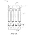
図12Aは、少なくとも1つの実施態様に基づく、複数の格納チューブを含有するカプセル化デバイスを示している。図示のように、カプセル化デバイス1200は複数の相互接続された格納チューブ1205を含む。格納チューブはデバイス1200の長さに沿って互いにほぼ平行である。それぞれの格納チューブ1205は、近位端1210に設けられた第1アクセスポート1270と、遠位端1215に設けられた第2アクセスポート1280とを有している。第2アクセスポート1280には、格納チューブ1205の遠位端をシールするために再シール可能なキャップ1250が設けられていてよい。図示されてはいないものの、格納チューブ1205の近位端をシールするために再シール可能なキャップが第1アクセスポート1270に装着されていてもよい。格納チューブ1205はこれらの近位端の接続部材1260のところで相互接続されてよい。接続部材1260は、格納チューブ1205を形成する一つ又は複数の多孔質ポリマー材料から形成されていてよく、或いは異なるポリマー材料及び/又は他の生体適合性材料から形成されていてもよい。図示されてはいないものの、図11Aに関連して上述したような形式で、一つ又は複数の格納チューブ1205にフラッシュポートを流体接続することにより、一つ又は複数の格納チューブ1205のルーメン領域を充填且つ/又はフラッシングすることができる。いくつかの実施態様では、一つ又は複数の治療デバイスは、一つ又は複数の格納チューブ1205から取り外され、そして新しい治療デバイスが挿入される。治療デバイスだけが取り外し可能なのではなく、カプセル化デバイス1200も取り外すことができることが認められる。
IV. Encapsulation device with a plurality of storage tubes FIG. 12A shows an encapsulation device containing a plurality of storage tubes based on at least one embodiment. As shown, the
図12Aに示された実施態様では、格納チューブ1205は独立して互いに運動可能であり、ひいてはデバイス1200を可撓性にし、且つ/又は組織及び/又は組織の運動に対して柔軟にする。格納チューブ1205は、少なくとも1つの治療デバイスを収納するように形成されていてよい。或いは、格納チューブ1205は細胞(又は他の生物学的部分)を直接に収納するように構成されていてもよい。いくつかの実施態様では、格納チューブ1205は、例えば接続部材1260によって、且つ/又はチューブ1240を介してマニホルド1235に接続されたフラッシュポート1255によって流体接続されていてよく(図12B参照)、これにより、格納チューブ内へ挿入された細胞は別の格納チューブ内へ流入することができ、或いは流体流を格納チューブ1205に加えることにより、格納チューブから治療デバイスを取り外すことができる。いくつかの実施態様の場合、格納チューブ内へ新しい治療デバイスが挿入される。ひとたび充填されたら、マニホルド1235を取り外し、格納チューブをシールすることができる。上述のように、シールの一例としては、キャップ、プラグ、クランプ、圧縮リング、又は弁が挙げられる。なお、図12Bに示された実施態様は、マニホルド1235を含むことにより、図12Aの実施態様よりも柔軟性が低い(剛性がより高い)。
In the embodiment shown in FIG. 12A, the
図12Cを参照すると、カプセル化デバイス1200は、遠位端1210に設けられた第1アクセスポート(図示せず)及び近位端1215に設けられた第2アクセスポート(図示せず)を有する複数の格納チューブ1205と、第2アクセスポートをシールする再シール可能なポート1225と、遠位端1210の第1アクセスポートを流体接続するマニホルド1235とを含んでよい。マニホルド1235にはチューブ1240を介して、フラッシュポート1255が流体接続されていてよい。使用していないときには、再シール可能なキャップ1245がフラッシュポート1255を覆ってシールする。
Referring to FIG. 12C, the
第2アクセスポートはアクセスポイントを提供し、このアクセスポイントを通して、格納チューブ1205のルーメン領域に対して1つ又は2つ以上の治療デバイス(例えば細胞格納部材)を出入りさせることができる。第1アクセスポートはアクセスポイントを提供し、このアクセスポイントを通して、格納チューブ1205のルーメン領域に流体流を送達することにより、複数の格納チューブ1205のルーメン領域を充填且つ/又はフラッシングすることができる。いくつかの実施態様では、流体流を使用して、格納チューブ1205のルーメン領域を細胞で満たし、又はルーメン領域から細胞を取り除くことができる。他の実施態様では、流体流を使用して、格納チューブ1205のルーメン領域から、シールされていない第1アクセスポートを通して格納チューブ1205の外部領域へ、1つ又は2つ以上の治療デバイス(例えば細胞格納部材)を押し出すことができる。複数の格納チューブ3105が、図31A及びBに示されているような、カプセル化デバイス3100の一方の端部に設けられた単一アクセスポート3110によって、又は図32A及びBに示されている、カプセル化デバイス3200の格納チューブ3205の両端部に設けられたアクセスポート3210,3220によって互いに流体接続されていてよいことが認められる。
The second access port provides an access point through which one or more therapeutic devices (eg, cell containment members) can enter and exit the lumen region of
図12Cに戻ると、マニホルド1235は生体適合性材料から構成されており、チューブ1240及びフラッシュポート1255と流体連通している少なくとも1つの接続ポート1275を含んでいる。マニホルド1235はさらに、1つ又は2つ以上の開口を有するチャンバ(図示せず)を有しているので、マニホルド1235は第2アクセスポート及び各格納チューブ1205のルーメン領域と流体連通している。チャンバが複数の開口を含む実施態様では、マニホルド1235の各開口は、それぞれの格納チューブ1205のアクセスポートと整合する。
Returning to FIG. 12C, the
いくつかの実施態様では、フラッシュポート1255及びチューブ1240は、細胞格納チューブ1205と同じ水平方向平面内で整列されていてよい(図12Aに示されている)。他の実施態様では、チューブ1240はエルボー又は角度(例えば30°、45°、又は90°)を有してよく、これによりチューブ1240は細胞格納チューブ1205の水平方向平面を通って延びるようになっている(図示せず)。複数の格納チューブ1205はマニホルド1235の端部に個々に装着(例えば永久接着されるか又は再シール可能に)されてよく、1つの群として運動可能である。
In some embodiments, the
いくつかの実施態様では、格納チューブ1240は、格納チューブ1205の長さとほぼ等しい長さを有する生体適合性材料から構成されているので、具体的にはカプセル化デバイスが患者内に埋め込まれると、再シール可能なキャップ1245を備えた格納チューブ1240の近位端は、格納チューブ1205の近位端の近くに又はこれと隣接して(且つ/又はカプセル化デバイス1200の近位端1215に又はその近くに)位置する。いくつかの実施態様では、格納チューブ1205は、本明細書中に記載された細胞保持層と血管新生層とを有する複合材料で構成することができる。
In some embodiments, the
再シール可能なポート1225は、格納チューブ1205のルーメン領域内の1つ又は2つ以上の細胞格納部材の留置、回収、及び交換を容易にするのに適した任意の形状を有することができる。いくつかの実施態様では、再シール可能なポート1225は、中空取り付け具(例えばPTFEから成る)である。中空取り付け具は、格納チューブ1205の端部の内側にぴたりと嵌まる第1部分と、シーリング部材を受容して保持するために格納チューブ1205の端部を超えて延びる第2部分とを有している。いくつかの実施態様では、再シール可能なポート1225は、当業者に知られている技術を用いて、格納チューブ1205の端部上に取り付け具を射出成形することにより製作することができる。
The
加えて、再シール可能なキャップ1225及びフラッシュポート1255は、シールによって繰り返し開閉することができる。上述のように、シールの一例としては、キャップ、プラグ、クランプ、圧縮リング、又は弁が挙げられる。シールは摩擦によって、締め付けによって、又はねじ山と溝とから成るねじによって、再シール可能なポート1225に取り付けられてよい。カプセル化デバイス1200の所期の用途に応じて、再シール可能なポート1225及び/又はフラッシュポート1255は、気密シール、流体密シール、又は非流体密シールを形成するようにシールされる。患者内の生涯にわたる又は長期(例えば少なくとも約3週間)にわたる移植のために意図されるカプセル化デバイス1200は、気密シール又は流体密シールでシールされてよい。
In addition, the
図12Dに示された別の実施態様では、カプセル化デバイス1200は、遠位端の第1アクセスポートを流体接続する第1マニホルド1235と、近位端1215の第2アクセスポートを流体接続する第2マニホルド1260とを有している。第1及び第2マニホルド1235,1260はチューブ1240及びチューブ1270によって、それぞれ第1フラッシュポート1255及び第2フラッシュポート1265に流体接続されている。使用していないときには、再シール可能なキャップ1245,1270がフラッシュポート1255を覆ってシールすることができる。近位端1215又は遠位端1210のアクセスポートを使用することによりアクセスポイントを提供する。このアクセスポイントを通して、格納チューブ1205のルーメン領域に対して1つ又は2つ以上の細胞格納部材(又は他の治療デバイス)又は細胞を出入りさせることができる。
In another embodiment shown in FIG. 12D, the
図12E〜12Gは、本明細書中に記載されたカプセル化デバイスと併せて使用し得る種々のマニホルド及びシールを示している。例えば、図12Eに示されたカプセル化デバイス1201は、頂部接続ポート1285を有するマニホルド1280と、マニホルド1280に流体接続されるように構成された格納チューブ1205と、アクセスポート1297を含有する再シール可能なコネクタ部材1290と、再シール可能なコネクタ部材1290の近位端をシールするように形成された再シール可能なキャップ1298とを含んでいる。マニホルド1280に位置する接続ポート1285、又は再シール可能なコネクタ部材1290に位置するアクセスポート1297を使用してアクセスポイントを提供することができる。このアクセスポイントを通して、格納チューブ1205のルーメン領域に対して1つ又は2つ以上の細胞格納部材(治療デバイス)又は細胞を出入りさせることができる。
12E-12G show various manifolds and seals that can be used in conjunction with the encapsulation devices described herein. For example, the
図12Fに示されたカプセル化デバイス1202は、側部接続ポート1285を有するマニホルド1280と、マニホルド1280に流体接続されるように構成された格納チューブ1205と、再シール可能なポート1204とを含んでいる。マニホルド1280に位置する接続ポート1285、又は格納チューブ1205に位置するアクセスポート1297を使用してアクセスポイントを提供することができる。このアクセスポイントを通して、格納チューブ1205のルーメン領域に対して1つ又は2つ以上の細胞格納部材(又は他の治療デバイス)又は細胞を出入りさせることができる。
The
図12Gに示されたカプセル化デバイス1203は、側部接続ポート1285及び側部接続ポート1285にチューブ1257を介して取り付けられたフラッシュポート1262を有するマニホルド1280と、マニホルド1280に流体接続されるように形成された格納チューブ1205と、格納チューブ1205の近位端1215をシールするための再シール可能なキャップ1298と、フラッシュポート1262をシールするための再シール可能なキャップ1258とを含んでいる。フラッシュポート1262、又は格納チューブ1205に位置するアクセスポート1208を使用してアクセスポイントを提供することができる。このアクセスポイントを通して、格納チューブ1205のルーメン領域に対して1つ又は2つ以上の細胞格納部材(又は他の治療デバイス)又は細胞を出入りさせることができる。いくつかの実施態様では、格納チューブと再シール可能なキャップ(図示せず)との間にコネクタ部材が配置されてよい。
The
図12Hに示されたカプセル化デバイス1204は、側部接続ポート1285を有するマニホルド1280と、マニホルド1280に流体接続されるように形成された格納チューブ1205と、(再シール可能又は永久的な)コネクタ部材1290と、再シール可能なポート1204とを含んでいる。マニホルド1280に位置する接続ポート1285、又はコネクタ部材1290に位置するアクセスポート1297を使用して、アクセスポイントを提供することができる。このアクセスポイントを通して、格納チューブ1205のルーメン領域に対して1つ又は2つ以上の細胞格納部材(又は他の治療デバイス)又は細胞を出入りさせることができる。このような実施態様では、マニホルド1280を使用して、格納チューブ1205から一つ又は複数の細胞格納部材をフラッシングするための流体流を提供することができる。
The
図13A,B及びCを参照すると、いくつかの実施態様において、単一ユニットとして一緒にグループ化されたいくつかの個別の格納チューブ1305から、カプセル化デバイス1300を構成することができる。個別の格納チューブ1305は互いに流体的又は物理的に接続されてもされなくてもよい。いくつかの実施態様では、格納チューブは接続部材を通して互いに接続されている。図13C及びDに写真で示されているように、格納チューブ1305は接続部材1375によって互いに接続されていてよく、これらの接続部材は、格納チューブ1305の長さに沿って互いに距離1320だけ周期的に間隔を置いて設けられている。この距離1320は接続部材1375間で同じであっても異なっていてもよい。このように、周期的な間隔は規則的なパターンを有していても(例えば接続部材間の距離が同じ)、不規則的なパターンを有していても(例えば接続部材間の距離が異なる)よい。図13C及びDは、接続部材1375を視覚化するためにここに含まれているのであって、さらなる調製によって、格納チューブ1305に一つ又は複数のマニホルド、一つ又は複数の再シール可能なポート、一つ又は複数のフラッシュポート、再シール可能なキャップなどを加えてもよいことが認められる。
With reference to FIGS. 13A, B and C, in some embodiments, the
接続部材1375によって格納チューブ1305が取り付けられることにより、細胞カプセル化デバイスは接続部材1375の間に可撓性を有することができると同時に、移植中に安定性が得られるようになる。加えて、接続部材1375の間で格納チューブ1305が分離していることは、宿主組織が完全に格納チューブ1305の周りに、そして格納チューブの間に一体化するのを助ける。加えて、格納チューブ1305の間の空間は、血管新生のために利用可能なチューブの表面積を最大化する。「可撓性である(flexible)」及び「可撓性(flexibility)」という用語は、細胞カプセル化デバイスの全体的な柔軟性又は曲げ剛性、及び宿主組織と接触している宿主界面/内方成長層の柔軟性を表すように意図されており、これによりそのような内方成長層は宿主組織の柔軟性、並びに宿主組織に対する細胞カプセル化デバイスの柔軟性とマッチングするので、細胞カプセル化デバイスは、デバイス及びホスト界面/内方成長層と、宿主組織との柔軟性の顕著なミスマッチに起因する過剰な炎症反応を生じさせることなしに、宿主組織と一緒に撓み、運動することができる。
The attachment of the
いくつかの実施態様では、接続部材1375は生体吸収性材料から形成されるか、又はこれを含んでよい。細胞カプセル化デバイス1300が体内に留置された後、生体吸収性材料は分解して体内へ吸収される。移植前には分解はほとんど又は全くないはずである。いくつかの実施態様では、接続部材1374の一部だけが生体吸収性材料から形成されていることにより、生体吸収性材料が吸収されると、細胞カプセル化デバイス1300は格納チューブ1305内部に細胞又は治療デバイスを収納するための何らかの構造を持ち続けるようになっている。他の実施態様では、生体吸収性材料は接続部材1375の全て又はほぼ全てを形成することにより、生体吸収性材料が吸収されたあとには接続部材1375は残らない。接続部材1375を再吸収することにより、格納チューブ1305はもはや拘束されず、独立して運動可能である。上述のように、格納チューブ1305の分離は、宿主組織が完全に格納チューブ1305の周りに、そして格納チューブの間に一体化するのを助け、血管新生のために利用可能なチューブの表面積を最大化する。加えて、意図的に又は生体吸収により接続部材1375を欠如させることは、細胞カプセル化デバイスのより容易な取り外しを可能にする。例えば、接続部材1375上及び/又は接続部材1375内への組織の成長は、棘(barb)として作用し、細胞カプセル化デバイスの移植片除去しやすさ/取り外ししやすさを妨げ又は制限することがある。
In some embodiments, the connecting
生体吸収性材料は急速に(例えば僅か数日又は数ヶ月で)完全吸収されてよく、又は完全吸収するのに著しく長い時間(例えば数年間)を要することもある。生体吸収性材料の吸収速度は材料の特質及び生物学的環境に依存し、必要に応じて当業者によって選択することができる。生体吸収性材料は固体(モールディング、押し出し、又は結晶)、(例えば格納チューブ上の)被膜、自己結合ウェブ(self-cohered web)、隆起ウェビング(raised webbing)、又はスクリーンとして形成されていてよい。ある特定の生体吸収性材料が低速の生体吸収プロファイルを提供すると有利である。このプロファイルを用いて、移植部位における接続部材内への血管新生及び他の組織内方成長を知らせることができる。例えば、生体吸収プロファイルは血管新生速度よりも遅くてよい。加えて、低速分解プロファイルは、細胞カプセル化デバイスの移植片除去/取り外しを容易にすることができる。 Bioabsorbable materials may be rapidly (eg, in just days or months) fully absorbed, or may take significantly longer times (eg, years) to be fully absorbed. The rate of absorption of the bioabsorbable material depends on the nature of the material and the biological environment and can be selected by one of ordinary skill in the art as needed. The bioabsorbable material may be formed as a solid (molding, extrusion, or crystal), a coating (eg, on a storage tube), a self-cohered web, a raised webbing, or a screen. It is advantageous for certain bioabsorbable materials to provide a slow bioabsorption profile. This profile can be used to signal angiogenesis and other tissue inward growth into the connecting member at the implantation site. For example, the bioabsorption profile may be slower than the angiogenesis rate. In addition, the slow degradation profile can facilitate graft removal / removal of cell encapsulation devices.
図13Eは、細胞カプセル化デバイス1390の近位端1314における再シール可能なポート1365を概略的に示している。細胞カプセル化デバイス1390の遠位端に再シール可能なポート(図示せず)又は再シール可能なキャップを装着させることにより、遠位端に配置された格納チューブ1305のアクセスポートをシールすることができることが認められる。図13Eは、図示しやすさのために再シール可能なキャップ1307の使用を示している。図14Fは、細胞カプセル化デバイス1395の格納チューブ1305のアクセスポートを流体接続するための取り外し可能なマニホルド1335を概略的に示している。マニホルド1335にはチューブ1337を介して、フラッシュポート1380を流体接続することができる。使用していないときには、再シール可能なキャップ1385がフラッシュポート1380を覆ってシールすることができる。細胞カプセル化デバイス1390の遠位端に再シール可能なポート(図示せず)又は再シール可能なキャップを装着することにより、遠位端に配置された格納チューブ1305のアクセスポートをシールすることができることが認められる。図13Fは、図示しやすさのために再シール可能なキャップ1307の使用を示している。接続部材1375間の距離は、0.25mm〜約10cm、約0.50mm〜約8cm、約0.75mm〜約5cm、約1mm〜約2cmであってよい。なお、これらの距離は、格納チューブ及び/又はチャネルが相互接続されている、本明細書に記載された実施態様のそれぞれに当てはめることができる。いくつかの実施態様では、個々の格納チューブ1305は、少なくともコンプライアントな配置、又は剛性的な配置(図示せず)の場合、これらの全長に沿って互いに完全に接続することができる。アクセスポート1315を使用して、格納チューブ1305のルーメン領域に対して1つ又は2つ以上の細胞格納部材(治療デバイス)及び/又は細胞を出入りさせることができる。
FIG. 13E schematically shows a
図13Bを参照すると、取り外し可能なマニホルド1335を使用して、カプセル化デバイス1300の遠位端1312でアクセスポート1315を流体接続することができる。マニホルド1335にはチューブ1340を介して、フラッシュポート1355を流体接続することができる。使用していないときには、再シール可能なキャップ1345がフラッシュポート13855を覆ってシールすることができる。アクセスポート1315はアクセスポイントを提供し、このアクセスポイントを通して、格納チューブ1305のルーメン領域に流体流を送達することにより、格納チューブ1305のルーメン領域を充填することができる。いくつかの実施態様では、流体流を使用して、格納チューブ1305のルーメン領域を細胞で充填することができる。いくつかの実施態様では、そして図13A及びBに示されているように、格納チューブ1305の周りを生体適合性材料1310で取り囲み又はオーバーモールディングすることにより、密な永久的形態を成して格納チューブを保持する。いくつかの実施態様では、格納チューブ1305は、本明細書中に記載されているような細胞保持層及び血管新生層を有する複合材料によって構成することができる。いくつかの実施態様では、織布又は不織布又はニットを細胞カプセル化デバイス1300上に被せることができる。別の実施態様では、織布又は不織布又はニットは、細胞カプセル化デバイス1300に周期的に取り付けることができる。織布又は不織布又はニットは拘束層として役立ち、組織の内方成長又は付着を助けることができる。加えて、織布又は不織布又はニットは細胞カプセル化デバイスの取り扱い性、移植、及び取り外しのための機械的支援を提供することもできる。
With reference to FIG. 13B, a
ここで図14A及びBを参照すると、いくつかのポリマー材料層を互いに接着させることにより形成される積層体から、カプセル化デバイス1400が構成されていてよい。積層体を形成するために使用されるポリマー材料層は、本明細書中に記載された格納チューブを構成するのに使用されたものと同じポリマー材料層であってよく、本明細書中に記載された細胞保持層及び血管新生層を有する複合材料層で構成されてよい。細胞カプセル化デバイス1400は格納チャネル1405を含有していて、各格納チャネル1405の間にはシーム1410が介在している。格納チャネル1405は互いに接続されていてよく、この場合それぞれの格納チャネルは図14Bに写真によって示されているように他の格納チャネルから分離され流体的に隔離されている。或いは、又はこれに加えて、格納チャネル1405は、これらが互いに流体連通するように互いに接続されていてもよい。例えば、チャネルのそれぞれを互いに流体的に隔離するように、チャネル1405をこれらの全長に沿って互いに接続することができ、或いは、隣接する格納チャネルを流体接続するように相互接続チャネルを提供するために、格納チャネル1405は、所定の間隔(又は様々な間隔)を置いて相互接続されてよい(図示せず)。いくつかの格納チャネルは互いに隔離される一方、いくつかの隣接する格納チャネルは、これらの長さに沿った1つ又は2つ以上の地点で流体接続されてよい(図示せず)。材料層が接着されているいくつかの実施態様では、シーム1410内部に組織付着及び/又は血管新生を許すように多孔性を維持することができる。
With reference to FIGS. 14A and 14B, the
他の実施態様では、シーム1410は、隣接する格納チャネル1405間に非付着領域を含むことにより、組織付着及び/又は血管新生を許すことができる。格納チャネル1405は、材料層を一方又は両方の端部で接着することにより、一方又は両方の端部でシールすることができる。いくつかの実施態様では、材料層の周囲がシリコーン1420によってオーバーモールディングされる。1実施態様では、格納チャネル1405にマニホルド1425を流体接続することにより、細胞又は細胞格納部材を留置するためにチャネルのルーメンへのアクセスを可能にすることができる。いくつかの実施態様では、積層体内へ織布又は不織布又はニットを本質的に形成することによって、細胞カプセル化デバイスの取り扱い、移植、及び取り外しのための機械的支援を増強することができる。
In another embodiment, the
図13A及びB、又は図14A及びBに示された配列において、格納チューブ1305又は格納チャネル1405は層状に形成されていてよく、これにより格納チューブ1305又は格納チャネル1405は移植型装置の長さに沿って互いに平行又はほぼ平行である。いくつかの実施態様では、格納チューブ1305又は格納チャネル1405は同じ平面内にある。格納チューブ1305又は格納チャネル1405が成形部材を含む実施態様の場合、格納チューブ1305又は格納チャネル1405は非平面状(すなわち平面状でなく、単一平面内に位置していない)であるか、又は種々の平面内に設けられている。図13A及びB、又は図14A及びBに示された二次元層形成配列の代わりに、格納チューブ1305又は格納チャネル1405は、図15及び16に示されているような三次元配列を成して積み重ねられてよく、或いは図17Aに示されているように、三次元配列、例えば製織メッシュ形態を成して互い違いに配置されてよい。三次元配列を用いて、格納チューブ1305又は格納チャネル1405を積み重ねられた又は互い違いの配向で(x,y及び/又はz方向で)提供することができる。
In the sequences shown in FIGS. 13A and B, or 14A and 14B, the
図17Bに示されたさらなる実施態様では、格納チューブ1705(又はチャネル(図示せず))は軸外相互接続部材1730を有するほぼ平面状の配列を有することにより、ラティス形態を成すことができる。本明細書中に使用される「軸外(off-axis)」とは、相互接続部材1730がゼロ度よりも大きく90°よりも小さい角度で格納チューブ1705に接続されていることを表すために意図される。図17Bに示された細胞カプセル化デバイスの場合、相互接続部材1730は、格納チューブ1705に対して約45°の角度で配向され、これによりラティス形態を形成する。格納チューブ1705は相互接続部材1730を通して互いに流体接続されている。こうして、1つの格納チューブ1705内へ入った流れは、相互接続部材1730を通って、隣接する一つ又は複数の格納チューブ1705内へ流入する。このような「ラティス(lattice)」の実施態様では、格納チューブ1705は細胞を直接に含有し、そして典型的には治療デバイスを含有しないものの、治療デバイスを含有することが禁止されているわけではない。図示されてはいないが、遠位端1712又は近位端1714に、一つ又は複数のマニホルド、一つ又は複数の再シール可能なポート、一つ又は複数の再シール可能なキャップが配置されてよい。
In a further embodiment shown in FIG. 17B, the storage tube 1705 (or channel (not shown)) can form a lattice form by having a substantially planar array with off-
図17Cに概略的に示された別の実施態様では、細胞カプセル化デバイス1750は、相互接続部材1340によって相互接続された格納チューブを含んでよい。相互接続部材1340は、格納チューブ1705に対して任意の配向、例えば軸外又は垂直の配向を有する。図17Cに示されているように、相互接続部材1740は格納チューブ1705に対して種々の角度で、そして垂直に格納チューブ1705を接続し、細胞カプセル化デバイス1750に相互接続部材1740のよりランダムな形態を与える。格納チューブ1705は、相互接続部材1740を通して互いに流体接続されている。こうして、1つの格納チューブ1705内へ入った流れは、相互接続部材1740を通って、隣接する一つ又は複数の格納チューブ1705内へ流入する。やはり、細胞カプセル化デバイス1750は一般に細胞を含有するものの、格納チューブ1705内に1つ又は2つ以上の治療デバイスを含むことが禁止されているわけではない。図示されてはいないが、遠位端1712又は近位端1714に、一つ又は複数のマニホルド、一つ又は複数の再シール可能なポート、一つ又は複数の再シール可能なキャップが配置されてよい。
In another embodiment schematically shown in FIG. 17C, the
図18A及び18Bを見ると、再シール可能なポート及び/又はマニホルドは可変の柔軟性を有することができる。いくつかの実施態様では、再シール可能なポート及び/又はマニホルドは、より剛性の構造を必要とするカプセル化デバイスの所期用途、例えば金属板の表面又は骨の上、或いは金属板の表面又は骨の内部での移植のために、柔軟性のより低い構造1805(図18Aに示されている)を有することができる。例えば、再シール可能なポート及び/又はマニホルドは、図18Aに概略的に示されているように、単一の一体型構造であってよい。他の実施態様では、再シール可能なポート及び/又はマニホルドは、より高い可撓性の構造を必要とするカプセル化デバイスの所期用途、例えば皮下領域内、又は器官表面上、又は器官内部での移植のために、柔軟性のより高い構造1810(図18Bに示されている)を有することができる。例えば、再シール可能なポート及び/又はマニホルドは、種々の開口1820の間に配置されたヒンジ様構造1815を有していてよい。いくつかの実施態様の場合、ヒンジ様構造1815は、延伸PTFEのような材料又はその他の可撓性の生体適合性材料から形成されてよい。或いは、再シール可能なポート及び/又はマニホルドの構造内に、形状記憶材料又はこれから形成された構造を含み得る本明細書中に詳述された成形部材を使用することにより、柔軟性のより高い構造をもたらすこともできる。
Looking at FIGS. 18A and 18B, the resealable port and / or manifold can have variable flexibility. In some embodiments, the resealable port and / or manifold is intended for the intended use of encapsulation devices that require a more rigid structure, such as on the surface or bone of a metal plate, or on the surface of a metal plate or For implantation inside the bone, it can have a less flexible structure 1805 (shown in FIG. 18A). For example, the resealable port and / or manifold may be a single integral structure, as schematically shown in FIG. 18A. In other embodiments, resealable ports and / or manifolds are intended for use in encapsulation devices that require a more flexible structure, such as in the subcutaneous region, or on the surface of an organ, or within an organ. Can have a more flexible structure 1810 (shown in FIG. 18B) for transplantation. For example, resealable ports and / or manifolds may have hinge-
他の実施態様では、格納チューブ内部には1つ又は2つ以上の細胞格納部材(又は他の治療デバイス)が収納されていてよい。いくつかの実施態様では、再シール可能なポート及び/又はマニホルドのインターフェイスでシールするように細胞格納部材を構成することができ、これにより、細胞格納部材はシーリング面となる(すなわち細胞格納部材は自己シール性である)。図19を参照すると、マニホルド1910が、開口1905のうちの1つに部分的に配置された細胞格納部材1900と一緒に示されている。細胞格納部材1900はシーリング部材1920を含有しているので、細胞格納部材1900は開口1905内に完全に挿入されると、マニホルドの開口1905に対してシールされる。細胞格納部材1900は把持構造1915(例えばタブ)を含んでいてもよく、これにより臨床医は把持構造1915を保持することによって細胞格納部材1900を保持又は操作(例えば挿入又は取り外し)することができる。細胞格納部材1900はシーリング部材1920を介してマニホルド1910に対してシール且つシール解除することができる。同様又は同一の細胞格納部材1900を使用して、再シール可能なポートに対してシール且つ再シールすることができることが認められる。シーリング部材1920は例えば摩擦によって、締め付けによって、又はねじ山と溝とから成るねじによって、マニホルド又は再シール可能なポートに取り付けられてよい。
In other embodiments, one or more cell storage members (or other therapeutic devices) may be housed within the storage tube. In some embodiments, the cell containment member can be configured to seal with a resealable port and / or interface of the manifold, whereby the cell containment member becomes a sealing surface (ie, the cell containment member becomes a sealing surface). It is self-sealing). With reference to FIG. 19, the
V. 中央マニホルドを備えたカプセル化デバイス
図20Aは、本開示の種々の実施態様に基づく、中央に配置されたマニホルドを備えた単一の格納チューブを含有するカプセル化デバイスを示している。本明細書中に使用される「中央に(centrally)」という用語は、マニホルドが完全にセンタリングされていないかもしれない中央地点を取り囲む距離を含むように意図されていることが認められる。他の実施態様では、マニホルドは所定の距離だけ中央から外れた、又は近位端寄り又は遠位端寄りに配置されていてよい。カプセル化デバイス2000は、格納チューブ2005と、遠位端2010と、近位端2015と、遠位端2010と近位端2015との間の(中央の、又は所定の距離だけ中央から外れた)地点2020と、分割部材2035と、単一の接続ポート2030を有するマニホルド2025とを含んでよい。分割部材2035は、細胞(又は他の生物学的部分)を含有する流体流が分割されて細胞の一部が遠位方向に流れ、そして細胞の一部が近位方向に流れるのを可能にする。マニホルド2025の接続ポート2030を通して、細胞格納部材(又は他の治療デバイス)を格納チューブ2005内部に配置することができることが認められる。
V. Encapsulation device with central manifold Figure 20A shows an encapsulation device containing a single storage tube with a centrally located manifold, based on various embodiments of the present disclosure. It is acknowledged that the term "centrally" as used herein is intended to include the distance surrounding a central point where the manifold may not be fully centered. In other embodiments, the manifold may be off-center or located closer to the proximal end or closer to the distal end by a predetermined distance. The
図20Bは、種々の実施態様に基づく、中央に配置されたマニホルドを備えた2つの格納チューブを含有するカプセル化デバイスを示している。カプセル化デバイス2000は、第1格納チューブ2040及び第2格納チューブ2045と、第1及び第2の格納チューブ2040,2045を(例えば第1及び第2格納チューブの第1アクセスポート(図示せず)で)流体接続して単一の接続ポート2030を有するマニホルド2025とを含む。マニホルドは、第1格納チューブ2040の遠位端2015と第2格納チューブ2045の遠位端2010との間の地点2020に配置されている。マニホルド2025の接続ポート2030を通して、細胞格納部材(又は他の治療デバイス)を格納チューブ2040,2045のそれぞれの内部に配置することができることが認められる。
FIG. 20B shows an encapsulation device containing two storage tubes with a centrally located manifold, based on various embodiments. The
図21は、複数の格納チューブ2105を含む細胞カプセル化デバイス2100を示している。格納チューブ2105は、遠位端2010及び近位端2015と、遠位端2110に設けられた第1アクセスポート2145と近位端2115に設けられた第2アクセスポート2135との間の地点2120とを有する。地点210は中央にあるか、又は所定の距離だけ中央から外れていてよい。加えて、マニホルド2125は複数の接続ポート2130を有している。これらの接続ポートは第1及び第2アクセスポート2135,2145に流体接続されている。いくつかの実施態様では、図33に例示されているように、マニホルド2125は第1及び第2アクセスポート2135,2145の間の中央に配置されている。他の実施態様では、図34に示されているように、マニホルドは中央から外れた、又は近位端2115寄り又は遠位端2110寄りに配置されていてよい。いくつかの実施態様では、マニホルド2125は分割部材(図示せず)を含む。分割部材は、細胞(又は他の生物学的部分)を含有する流体流が分割されて細胞の一部が遠位方向に流れ、そして細胞の一部が近位方向に流れるのを可能にする。接続ポート2130を通して、細胞格納部材(又は他の治療デバイス)を格納チューブ2105内部に配置することができることが認められる。加えて、図示されてはいないが、カプセル化デバイス2100は、図20Bを参照しながら説明したような複数の第1格納チューブと第2格納チューブとから形成されていてもよい。いくつかの実施態様では、近位端2115及び遠位端2110で格納チューブに、再シール可能なポート(図示せず)を流体接続することができる。他の実施態様では、格納チューブ2105を閉鎖し且つ/又はシールするために、再シール可能なキャップ(図示せず)を使用することができる。
FIG. 21 shows a cell encapsulation device 2100 that includes a plurality of
図22は、本発明に基づく、カプセル化デバイス2200内に挿入されている細胞格納部材であって、カプセル化デバイスは皮膚2205及び皮下組織2210の下方に、そして組織床2260内に移植されている、細胞格納部材を示している。カプセル化デバイス2200は、格納チューブ2215の遠位端2220と近位端2225との間の(中央又は所定の距離だけ中央から外れた)地点2230と、接続ポート2240を有するマニホルド2235とを含んでいてよい。図22に示された実施態様では、第1細胞カプセル化デバイス2250が格納チューブ2215内へ近位側に(格納チューブ2215の近位端2240に向かって)挿入されており、そして第2細胞カプセル化デバイス2255が格納チューブ2015内へ遠位側に(格納チューブ2015の遠位端2245に向かって)挿入されている。図20Bに示された2つの格納チューブを有するカプセル化デバイスが図22に関して示されているように移植されてよく、そして細胞格納部材がそれぞれの格納チューブ内へ挿入されてよいことが認められる。図20A〜22に示された実施態様では、マニホルドの接続ポートが皮膚に近接しているのに対して、一つ又は複数の格納チューブは組織床内部の適切な深さに位置し、その結果、細胞又は細胞格納部材(治療デバイス)を取り外すために必要な剪断力が低減されるので有利である。
FIG. 22 is a cell storage member inserted into the
図11〜19に示されたカプセル化デバイスに関して論じたように、図20A〜22に示されたカプセル化デバイスはさらに、1つ又は2つ以上の再シール可能なポートであって、アクセスポイントを提供し、このアクセスポイントを通して格納チューブのルーメン領域に対して細胞又は1つ又は2つ以上の細胞格納部材(又は他の治療デバイス)を出入りさせることができる、1つ又は2つ以上の再シール可能なポート、アクセスポイントを提供する1つ又は2つ以上のフラッシュポートであって、このアクセスポイントを通って、格納チューブのルーメン領域をフラッシングするために格納チューブのルーメン領域へ流体流を送達し得る、1つ又は2つ以上のフラッシュポート、及び/又は格納チューブ内部に収納された1つ又は2つ以上の細胞格納部材を含むことができる。細胞格納部材は、再シール可能なポート、マニホルド及び/又はアクセスポートのインターフェイスでシールするように構成することができる。 As discussed with respect to the encapsulating devices shown in FIGS. 11-19, the encapsulating devices shown in FIGS. 20A-22 are further one or more resealable ports that provide access points. One or more reseals that can provide and allow cells or one or more cell storage members (or other therapeutic devices) to enter and exit the lumen region of the storage tube through this access point. One or more flush ports that provide a possible port, access point, through which the fluid flow is delivered to the lumen region of the containment tube to flush the lumen region of the containment tube. Obtaining may include one or more flash ports and / or one or more cell storage members housed within a storage tube. The cell containment member can be configured to seal at the interface of the resealable port, manifold and / or access port.
VI.生体吸収性材料
図23〜30は、移植型カプセル化デバイスの1つ又は2つ以上の構成部分上に分配された所定量の生体吸収性材料を含む種々の実施態様を示している。生体吸収性材料は、固体(モールディング、押し出し、又は結晶)、自己結合ウェブ(self-cohered web)、隆起ウェビング(raised webbing)、又はスクリーンとして形成されていてよい。いくつかの実施態様では、一つ又は複数の生体吸収性材料層を、巨視的な孔を有する非生体吸収性材料に取り付けることにより細胞透過が複合体を形成するのを可能にする。他の実施態様では、細胞透過を低減又は防止するための微視的な孔を有する非生体吸収性材料を多孔質自己結合ウェブに解離可能に取り付けることにより、移植から数日後に患者の身体から格納チューブを無傷除去するのを可能にする。体内への吸収は好ましい1型コラーゲン堆積、新血管形成、及び感染の低下を促進することができる。他の例では、細胞カプセル化デバイス上に生体吸収性材料を粉末として組み込むことができる。好適な生体吸収性材料の一例としては、ポリグリコリド:トリメチレンカーボネート(PGA:TMC)、ポリアルファヒドロキシ酸、例えばポリ乳酸、ポリグリコール酸、ポリ(グリコリド)、及びポリ(ラクチド−コ−カプロラクトン)、ポリ(カプロラクトン)、ポリ(カーボネート)、ポリ(ジオキサノン)、ポリ(ヒドロキシブチレート)、ポリ(ヒドロキシバレレート)、ポリ(ヒドロキシブチレート−コ−バレレート)、及びこれらのコポリマー及びブレンドが挙げられる。
VI. Bioabsorbable Materials Figures 23-30 show various embodiments that include a predetermined amount of bioabsorbable material distributed over one or more components of the implantable encapsulation device. The bioabsorbable material may be formed as a solid (molding, extrusion, or crystal), self-cohered web, raised webbing, or screen. In some embodiments, one or more bioabsorbable material layers are attached to a non-bioabsorbable material with macroscopic pores to allow cell permeation to form a complex. In another embodiment, a non-bioabsorbable material with microscopic pores to reduce or prevent cell permeation is dissociably attached to the porous self-binding web from the patient's body several days after implantation. Allows the storage tube to be removed intact. Absorption into the body can promote preferred type 1 collagen deposition, neovascularization, and reduction of infection. In another example, the bioabsorbable material can be incorporated as a powder on the cell encapsulation device. Examples of suitable bioabsorbable materials include polyglycolides: trimethylene carbonate (PGA: TMC), polyalphahydroxyic acids such as polylactic acid, polyglycolic acid, poly (glycolide), and poly (lactide-co-caprolactone). , Poly (caprolactone), poly (carbonate), poly (dioxanone), poly (hydroxybutyrate), poly (hydroxyvalerate), poly (hydroxybutyrate-covalerate), and copolymers and blends thereof. ..
図23に示されたカプセル化デバイス2300は、格納チューブ2310の表面上に粉末又は突起様構造2305として散在する所定量の生体吸収性材料を含む。図24に示されたカプセル化デバイス2400は、格納チューブ2410の表面上に粉末又は突起様構造2405として散在する所定量の一つ又は複数の生体吸収性材料を含む。図25は、スクリーン又は隆起ウェビングの形態2505の、フィルム2500の表面上の所定量の一つ又は複数の生体吸収性材料を示している。フィルム2500の生体吸収性材料及び表面上で、閉じ込められた細胞が増殖して成長し始めた時に、フィルム2500が枕状に膨らむのを最小化又は防止するようにフィルム2500を支持するために、一つ又は複数の生体吸収性材料を使用することができる。いくつかの実施態様では、生体吸収性材料は、一時的な生体吸収性材料、例えばポリマー又は金属(例えばマグネシウム)であってよい。フィルム2500を使用して、単一の格納チューブ及び複数の格納チューブを含むカプセル化デバイスの種々の構成部分を形成することができる。
The
図26に示されたカプセル化デバイス2600は、突起様構造2610として散在する所定量の一つ又は複数の生体吸収性材料と、格納チューブ2620の端部にテーパ状前縁2605を有する生体吸収性材料とを含む。図27に示されたカプセル化デバイス2700は、格納チューブ2710の端部にテーパ状前縁を有する固体構造2705として、生体吸収性材を含む。図28に示されたカプセル化デバイス2800は、チャネル2810の端部にテーパ状前縁を有する固体構造として、生体吸収性材2805を含む。生体吸収性材料は、格納チャネル2810の間に自己結合ウェブ構造として散在することにより、付加的な長手方向支持体を格納チャネルに提供することもできる。カプセル化デバイス内に生体吸収性成分を組み込むことは、移植を容易にするのを助ける。例えば生体吸収性材料は温度感受性であってよい。具体的には、生体吸収性材料は低温では著しく剛性であり、高温(例えば移植時の体温)では軟化するので、生体吸収性材料は移植後に、より適合性(conformable)且つ柔軟(compliant)になる。結果として、長手方向の強度、並びに生体吸収性材料から形成されたテーパ状前縁は、臨床医が軽減された労力で且つ外傷を宿主にあまり与えることなしに、移植型装置を患者内に留置するのを可能にし、そして移植が行われたら、生体吸収性材料はより適合性且つ柔軟になる。
The
図29に示されたカプセル化デバイス2900は、テーパ状前端を備えた固体のテーパ状構造を成す生体吸収性材料2905、並びに突起様構造2910として格納チューブ2920の表面にわたって分配された所定量の生体吸収性材料の組み合わせを含む。図30に示されたカプセル化デバイス3000は、テーパ状前端を備えた固体のテーパ状構造を成す生体吸収性材料3005と、格納チューブ3020の表面上の突起様構造3010の分布との組み合わせを含む。
The
VII. 促進される栄養輸送
ある特定の材料、例えばペルフルオロカーボンエマルジョン、フルオロヒドロゲル、シリコーンオイル、シリコーンヒドロゲル、大豆油、シリコーンゴム、ポリビニルクロリド、及びこれらの組み合わせは、高い酸素透過性を有することが知られている。このような高酸素透過性材料は,移植型装置の材料構造内、例えば格納チューブ、キャップ、マニホルド、アクセスポート、把持構造、又は治療デバイスのうちの1つ又は2つ以上において利用することができる。1つの実施態様では、治療デバイス及び/又は細胞格納チューブのうちの1つ又は2つ以上が高酸素透過性材料を含む。高酸素透過性材料は、格納チューブを形成する多孔質ポリマーメンブレン又は積層体のうちの1つ又は2つ以上、各格納チャネル間に介在するシーム又はシールのうちの1つ又は2つ以上、又は突起構造を備えた格納チャネルのうちの1つ又は2つ以上の上に設けられる被膜の形態を成して利用されてよい。或いは、高酸素透過性材料は、充填剤の形態で使用することができる。充填剤は、例えば格納チューブを形成する多孔質ポリマーメンブレン又は積層体のボイド空間内に部分的に充填されるか、又は完全に充填される。いくつかの実施態様では、高酸素透過性材料は、格納チューブのルーメン内に部分的又は完全に充填される充填剤の形態で利用することができる。
VII. Promoted nutrient transport Certain materials, such as perfluorocarbon emulsions, fluorohydrogels, silicone oils, silicone hydrogels, soybean oil, silicone rubber, polyvinyl chloride, and combinations thereof, are known to have high oxygen permeability. There is. Such hyperoxygen permeable materials can be utilized within the material structure of implantable devices, such as one or more of storage tubes, caps, manifolds, access ports, grip structures, or therapeutic devices. .. In one embodiment, one or more of the therapeutic device and / or cell storage tube comprises a hyperoxygen permeable material. The hyperoxygen permeable material is one or more of the porous polymer membranes or laminates that form the storage tube, one or more of the seams or seals that intervene between each storage channel, or It may be utilized in the form of a coating provided on one or more of the storage channels having a protruding structure. Alternatively, the highly oxygen permeable material can be used in the form of a filler. The filler is partially or completely filled, for example, in the void space of the porous polymer membrane or laminate forming the storage tube. In some embodiments, the highly oxygen permeable material is available in the form of a filler that is partially or completely filled within the lumen of the containment tube.
実施例1 Example 1
Goreの米国特許第3,953,566号明細書の教示内容に従って、第1多孔質延伸ポリテトラフルオロエチレン(ePTFE)フィルムを調製した。フィルムの単位面積当たり質量は約2.43g/m2、厚さは約8.9μm、密度は約0.27g/cc、長手方向マトリックス引張強度は約663MPa、横方向マトリックス引張強度は約14.3MPa、及びIPA泡立ち点は約4.83kPAであった。 A first porous stretched polytetrafluoroethylene (ePTFE) film was prepared according to the teachings of Gore US Pat. No. 3,935,566. The mass per unit area of the film is about 2.43 g / m2, the thickness is about 8.9 μm, the density is about 0.27 g / cc, the longitudinal matrix tensile strength is about 663 MPa, and the lateral matrix tensile strength is about 14.3 MPa. , And the IPA bubbling point was about 4.83 kPA.
Bacinoの米国特許第5,476,589号明細書の教示内容に従って、第2多孔質延伸ポリテトラフルオロエチレン(ePTFE)フィルムを調製した。フィルムの単位面積当たり質量は約1.46g/m2、厚さは約0.00012インチ(ほぼ3.05μm)、密度は約0.48g/cc、長手方向マトリックス引張強度は約101,321psi(ほぼ699MPa)、横方向マトリックス引張強度は約9288psi(ほぼ64.04MPa)、及びIPA泡立ち点は約35.27psi(ほぼ243.2kPA)であった。 A second porous stretched polytetrafluoroethylene (ePTFE) film was prepared according to the teachings of Bacino US Pat. No. 5,476,589. The mass of the film per unit area is about 1.46 g / m2, the thickness is about 0.00012 inch (approximately 3.05 μm), the density is approximately 0.48 g / cc, and the longitudinal matrix tensile strength is approximately 101,321 psi (approximately 3.05 μm). 699 MPa), the lateral matrix tensile strength was about 9288 psi (approximately 64.04 MPa), and the IPA bubbling point was approximately 35.27 psi (approximately 243.2 kPA).
Brancaの米国特許第5,814,405号明細書の教示内容に従って、第3多孔質延伸ポリテトラフルオロエチレン(ePTFE)フィルムを調製した。フィルムの単位面積当たり質量は約6.23グラム/m2、厚さは約0.0017インチ(ほぼ43.2μm)、IPA泡立ち点は約0.41psi(ほぼ2.83kPA),長手方向引張強度は約27974psi(ほぼ192.87MPa)、及び横方向マトリックス引張強度は約5792psi(ほぼ39.93MPa)であった。 A third porous stretched polytetrafluoroethylene (ePTFE) film was prepared according to the teachings of Branca US Pat. No. 5,814,405. The mass of the film per unit area is about 6.23 grams / m 2 , the thickness is about 0.0017 inches (about 43.2 μm), the IPA foaming point is about 0.41 psi (about 2.83 kPA), and the longitudinal tensile strength. Was about 27974 psi (approximately 192.87 MPa), and the lateral matrix tensile strength was approximately 5792 psi (approximately 39.93 MPa).
Newman他の米国特許第6,617,151号明細書(図9、工程902〜910及び対応テキスト)に概ね従って、連続した長さの第1ePTFEを、内径0.089”(ほぼ2.26mm)のチューブにすることにより、マルチチューブ細胞含有構造を製造した。細胞格納チューブは、第1ePTFEメンブレンの1つの長手方向ラップと、第2ePTFEメンブレンの6つのオーバーラップするらせん状ラップと、第3ePTFEメンブレンの1つのオーバーラッピングするラップとを有するように形成した。細胞格納チューブを8つの区分に切断した。それぞれの区分の長さはほぼ7”(ほぼ17.8cm)であった。各チューブの一方の端部内に、0.089”(ほぼ2.26mm)のマンドレルを挿入した。 Approximately according to Newman et al., US Pat. No. 6,617,151 (FIG. 9, steps 902-910 and corresponding text), a continuous length of 1 ePTFE with an inner diameter of 0.089 "(approximately 2.26 mm). A multi-tube cell-containing structure was produced by the tube of the first ePTFE membrane, one longitudinal wrap of the first ePTFE membrane, six overlapping spiral wraps of the second ePTFE membrane, and a third ePTFE membrane. Formed to have one overlapping wrap. The cell storage tube was cut into eight compartments, each compartment having a length of approximately 7 "(approximately 17.8 cm). A 0.089 "(approximately 2.26 mm) mandrel was inserted into one end of each tube.
再シール可能な接続部材を形成するための圧縮モールドを2つの半部(上半部と下半部)の形態で製作した。それぞれの半部は平滑な角隅を有する方形キャビティ(ほぼ1/4×0.164×1.7”(ほぼ6.4mm×4.2mm×43mm))を有し、これは直径0.094”(ほぼ2.4mm)の8つの円筒形チャネルによって交差される。充分な量の熱可塑性ポリマー(ニューヨーク州オレンジバーグ在、Dyneon AmericaのTHV500)を圧縮モールド下半部内に入れ、そして熱可塑性ポリマーを溶融するのに充分な温度まで加熱することによって、接続部材の一方の半部をモールド内で形成することにより接続部材を構成した。次いで8つの円筒形マンドレルを溶融済ポリマー中に押し込んだ。次いでモールドを冷却し、半部片を取り出した。このプロセスを繰り返すことによって、接続部材の第2半部を得た。 A compression mold for forming a resealable connecting member was made in the form of two halves (upper and lower halves). Each half has a square cavity (approximately 1/4 x 0.164 x 1.7 "(approximately 6.4 mm x 4.2 mm x 43 mm)) with smooth corners, which is 0.094 in diameter. Crossed by eight cylindrical channels of "(approximately 2.4 mm)". One of the connecting members by placing a sufficient amount of thermoplastic polymer (THV500, Dyneon America, Orangeburg, NY) into the lower half of the compression mold and heating to a temperature sufficient to melt the thermoplastic polymer. The connecting member was constructed by forming a half portion of the above in the mold. Eight cylindrical mandrels were then pushed into the molten polymer. The mold was then cooled and the half pieces were removed. By repeating this process, a second half of the connecting member was obtained.
これらの接続部材半部を圧縮モールドの各半部内に入れ、マンドレルが挿入された8つのePTFEチューブをモールドを横切るように置いた。この場合ePTFEチューブの端部は方形キャビティのほぼ中間に配置された。モールドを閉じ、ホットプレス(インディアナ州ウォバシュ在、Wabash MPIによって製造されたWabashモデルC30H-15-CPX)内に入れた。プレスは400°F(ほぼ204℃)の温度に設定し、5分間にわたって予熱し、次いで0.3トン(ほぼ272kg)の圧力で2分間にわたって閉じた。モールドをホットプレスから取り出し、そして冷却した。ホットプレスによって加熱されていない第1マニホルドを有するePTFEチューブの反対側の端部でこのプロセスを繰り返した。 Half of these connecting members were placed in each half of the compression mold and eight ePTFE tubes with mandrel inserted were placed across the mold. In this case, the end of the ePTFE tube was placed approximately in the middle of the square cavity. The mold was closed and placed in a hot press (Wabash model C30H-15-CPX manufactured by Wabash MPI, Wabash, Indiana). The press was set to a temperature of 400 ° F. (approximately 204 ° C.), preheated for 5 minutes and then closed at a pressure of 0.3 tonnes (approximately 272 kg) for 2 minutes. The mold was removed from the hot press and cooled. This process was repeated at the opposite end of the ePTFE tube with a first manifold that was not heated by hot pressing.
Newman他の米国特許第6,617,151号明細書に記載されているような細胞押し退けコア及び治療細胞、又はButler他の米国特許第5,787,900号明細書に記載されているような適宜の長さの細胞ロッドでそれぞれのチューブを充填することができた。次いで端部を適宜のキャップで閉じることができる。 Cell repellent cores and therapeutic cells as described in Newman et al., U.S. Pat. No. 6,617,151, or as described in Butler et al., U.S. Pat. No. 5,787,900. Each tube could be filled with a cell rod of appropriate length. The ends can then be closed with a suitable cap.
実施例2 Example 2
厚さ1ミルEFEP熱可塑性フィルム(ほぼ0.025mm)(ニューヨーク州オレンジバーグ在、Daikin Americaから入手可能なNEOFLON(登録商標)RP-4020)をレーザーによって切断した。レーザーは、8つの平行な方形開口0.150”×5”(ほぼ3.81mm×127mm)を形成するようにプログラミングされた。開口間の間隔は0.1”(ほぼ2.5mm)(フィルムの7個所)であり、余剰の熱可塑性フィルムがそれぞれの側及び端部に存在した。 A 1 mil EFEP thermoplastic film (approximately 0.025 mm) (NEOFLON® RP-4020, available from Daikin America, Orangeburg, NY) was laser cut. The laser was programmed to form eight parallel square openings of 0.150 "x 5" (approximately 3.81 mm x 127 mm). The spacing between the openings was 0.1 "(approximately 2.5 mm) (7 locations on the film) and excess thermoplastic film was present on each side and edge.
フッ素化エチレンプロピレン(FEP)の不連続なフルオロポリマー層と一緒に接合された種々異なるメンブレンから成る層を組み合わせることにより、多層延伸PTFE(ePTFE)メンブレンを製造した。第1層(タイト層)は、Goreの米国特許第3,953,566号明細書の教示内容に基づいて処理された、より小さな孔径と、表3に挙げられた材料特性とを有するメンブレンから成る。第2層(オープン層)は、Branca他の米国特許第5,814,405号明細書の教示内容に基づいて製造されたより大きい孔径のメンブレンから成っている。ここでは不連続なFEP層がBacinoの国際公開第94/13469号パンフレットのプロセス教示内容に基づいてこのメンブレンの表面上に組み込まれているものの、この支持体がまだ空気透過性であるのを可能にしている。このオープン層の性質は表1に挙げられている。第1層(タイト層)を次いで第2層(オープン層)と接触させた。不連続FEP表面を2つのPTFE層の間に、これらの層がFEPの溶融温度を上回る温度で加熱された状態で配置し、これにより表1に特定された最終特性を有する接合多層複合メンブレンを形成した。ePTFE複合メンブレンには、親水性処理を施した。

ステンレス鋼プレート8”×8”×1/16”厚(ほぼ20.3cm×20.3cm×1.6mm厚)、シリコーンパッド6”×6” 1/4“厚(ほぼ15.2cm×15.2cm×1.6mm厚)、及び親水性処理されたePTFEメンブレンから成るスタック。ePTFEメンブレンを0.2μm側が上方に向く状態で配置した(すなわち7.5μmは、これが下方に向くように配置された)。予め切断されたEFEP熱可塑性フィルムをePTFEメンブレン上に載置した。第1ePTFEメンブレンと同一の第2ePTFEメンブレン層をEFEP熱可塑性フィルム上に置き、この場合0.2μm側が下方に向くようにした。ステンレス鋼シート6”×6”×1/16”厚(ほぼ15.2cm×15.2cm×1.6mm厚)を第2ePTFE層の上面上に置いた。 Stainless steel plate 8 "x 8" x 1/16 "thickness (approximately 20.3 cm x 20.3 cm x 1.6 mm thickness), silicone pad 6" x 6 "1/4" thickness (approximately 15.2 cm x 15. 2 cm x 1.6 mm thick), and a stack consisting of a hydrophilic treated ePTFE membrane. The ePTFE membrane was placed with the 0.2 μm side facing up (ie, 7.5 μm was placed with it facing down). A pre-cut EFEP thermoplastic film was placed on the ePTFE membrane. The same second ePTFE membrane layer as the first ePTFE membrane was placed on the EFEP thermoplastic film, with the 0.2 μm side facing downward. A stainless steel sheet 6 "x 6" x 1/16 "thickness (approximately 15.2 cm x 15.2 cm x 1.6 mm thick) was placed on the top surface of the second ePTFE layer.
スタックをホットプレス(インディアナ州ウォバシュ在、Wabash MPIによって製造されたWabashモデルC30H-15-CPX)内に入れた。ホットプレスを437°F(ほぼ225℃)の温度まで予熱し、そして0.2トン(ほぼ181kg)の設定点圧力まで5分間にわたって閉じた。次いでスタックをホットプレスから取り出し、そして鋼テーブル上でほぼ2kgのアルミニウム錘がスタックの上部に置かれた状態で、スタックが触って冷たくなるまで冷却した。 The stack was placed in a hot press (Wabash model C30H-15-CPX manufactured by Wabash MPI, Wabash, Indiana). The hot press was preheated to a temperature of 437 ° F (approximately 225 ° C) and closed for 5 minutes to a set point pressure of 0.2 tonnes (approximately 181 kg). The stack was then removed from the hot press and cooled on a steel table with an approximately 2 kg aluminum weight resting on top of the stack until the stack was cool to the touch.
冷却後、こうして形成された積層シートを取り出しトリミングすることにより、ほぼ0.1”(ほぼ0.25cm)のエッジシームを有した。端部をトリミングすることにより、開口の端部と同様にした。実施例1に記載された通りにモールディングした熱可塑性端部(ニューヨーク州オレンジバーグ在、Dyneon Americaから入手可能なTHV500)を端部に取り付けた。 After cooling, the laminated sheet thus formed was taken out and trimmed to have an edge seam of approximately 0.1 "(approximately 0.25 cm). The end was trimmed to resemble the end of the opening. A thermoplastic end (THV500 available from Dyneon America, Orangeburg, NY) molded as described in Example 1 was attached to the end.
実施例3 Example 3
Newman他の米国特許第6,617,151号明細書の“Method of Making Devices”と題する項、第11欄第18行〜第12欄第29行に概略的に記載されているように、直径0.084”(ほぼ0.21cm)の模倣細胞ロッドを形成した。細胞を有するデバイスをローディングすることなしにシールされた端部を有するマルチチューブ細胞含有構造を(実施例1に記載されたような)接続部材内へ挿入した。フィブリン/トロンビン外科用接着剤を使用してマニホルドを装着した。 Diameter, as outlined in Newman et al., US Pat. No. 6,617,151, entitled "Method of Making Devices," column 11, lines 18-12, line 29. A 0.084 "(approximately 0.21 cm) mimic cell rod was formed. A multi-tube cell-containing structure with sealed ends without loading a device with cells (as described in Example 1). The manifold was fitted using a fibrin / thrombin surgical adhesive inserted into the connecting member.
生理食塩水で充填されたシリンジを13ゲージのブラントニードルに接続した。細胞格納チューブに接続されたマニホルドに設けられた1つの開口内にブラントニードルを圧縮嵌めした。細胞格納チューブには、模倣細胞ロッドが挿入されていた。次いでシリンジのプランジャロッドを木槌で軽く叩くことにより生理食塩水中に圧力波を形成した。この圧力波は、デバイスから模倣細胞ロッドを押し出すのに役立った。 A syringe filled with saline was connected to a 13 gauge blunt needle. A blunt needle was compression-fitted into a single opening in the manifold connected to the cell storage tube. A mimic cell rod was inserted into the cell storage tube. Then, a pressure wave was formed in the physiological saline by tapping the plunger rod of the syringe with a mallet. This pressure wave helped push the mimic cell rod out of the device.
実施例4 Example 4
Goreの米国特許第3,953,566号明細書の教示内容に従って、第1多孔質延伸ポリテトラフルオロエチレン(ePTFE)フィルムを調製した。フィルムの単位面積当たり質量は約2.43g/m2、厚さは約8.9μm、密度は約0.27g/cc、長手方向マトリックス引張強度は約663MPa、横方向マトリックス引張強度は約14.3MPa、及びIPA泡立ち点は約4.83kPAであった。 A first porous stretched polytetrafluoroethylene (ePTFE) film was prepared according to the teachings of Gore US Pat. No. 3,935,566. The mass per unit area of the film is about 2.43 g / m2, the thickness is about 8.9 μm, the density is about 0.27 g / cc, the longitudinal matrix tensile strength is about 663 MPa, and the lateral matrix tensile strength is about 14.3 MPa. , And the IPA bubbling point was about 4.83 kPA.
Bacinoの米国特許第5,476,589号明細書の教示内容に従って、第2多孔質延伸ポリテトラフルオロエチレン(ePTFE)フィルムを調製した。フィルムの単位面積当たり質量は約1.46g/m2、厚さは約0.00012インチ(ほぼ3.05μm)、密度は約0.48g/cc、長手方向マトリックス引張強度は約101,321psi(ほぼ699MPa)、横方向マトリックス引張強度は約9288psi(ほぼ64.04MPa)、及びIPA泡立ち点は約35.27psi(ほぼ243.2kPA)であった。 A second porous stretched polytetrafluoroethylene (ePTFE) film was prepared according to the teachings of Bacino US Pat. No. 5,476,589. The mass of the film per unit area is about 1.46 g / m2, the thickness is about 0.00012 inch (approximately 3.05 μm), the density is approximately 0.48 g / cc, and the longitudinal matrix tensile strength is approximately 101,321 psi (approximately 3.05 μm). 699 MPa), the lateral matrix tensile strength was about 9288 psi (approximately 64.04 MPa), and the IPA bubbling point was approximately 35.27 psi (approximately 243.2 kPA).
Brancaの米国特許第5,814,405号明細書の教示内容に従って、第3多孔質延伸ポリテトラフルオロエチレン(ePTFE)フィルムを調製した。フィルムの単位面積当たり質量は約6.23グラム/m2、厚さは約0.0017インチ(ほぼ43.2μm)、IPA泡立ち点は約0.41psi(ほぼ2.83kPA)、長手方向引張強度は約27974psi(ほぼ192.87MPa)、及び横方向マトリックス引張強度は約5792psi(ほぼ39.93MPa)であった。 A third porous stretched polytetrafluoroethylene (ePTFE) film was prepared according to the teachings of Branca US Pat. No. 5,814,405. The mass of the film per unit area is about 6.23 grams / m 2 , the thickness is about 0.0017 inches (approximately 43.2 μm), the IPA foaming point is approximately 0.41 psi (approximately 2.83 kPA), and the longitudinal tensile strength. Was about 27974 psi (approximately 192.87 MPa), and the lateral matrix tensile strength was approximately 5792 psi (approximately 39.93 MPa).
Newman他の米国特許第6,617,151号明細書(図9、工程902〜910及び対応テキスト)に示された教示内容に概ね従って、
連続した長さの第1ePTFEを、内径0.089”(ほぼ2.26mm)のチューブにすることにより、シングルチューブ細胞含有構造を製造した。細胞格納チューブは、第1ePTFEメンブレンの1つの長手方向ラップと、第2ePTFEメンブレンの6つのオーバーラッピングするらせん状ラップと、第3ePTFEメンブレンの1つのオーバーラッピングするラップとを有するように形成した。細胞格納チューブを切断することにより長さほぼ6cmの区分を得た。
In general, in accordance with the teachings set forth in Newman et al., US Pat. No. 6,617,151 (FIG. 9, steps 902-910 and corresponding text).
A single tube cell-containing structure was made by converting the continuous length of the first ePTFE into a tube with an inner diameter of 0.089 "(approximately 2.26 mm). The cell storage tube is one longitudinal wrap of the first ePTFE membrane. And six overlapping spiral wraps of the second ePTFE membrane and one overlapping wrap of the third ePTFE membrane. By cutting the cell storage tube, a section of approximately 6 cm in length was obtained. rice field.
短くされたチューブの一方の端部(遠位側)内に、フッ素化エチレンプロピレン(FEP)プラグを挿入し、そしてジョー内で2.25mmワイヤホールによって改質されたハンドピース4Cを有するHOTweezersサーマルワイヤストリッパーModel M10(カリフォルニア州ウェストレイクビレッジ在、Meisei Corporation)を使用して所定の場所にシールすることによりプラグの外面を、ePTFE細胞格納チューブの内部に対して溶融した。細胞格納チューブの開いた端部内へ、リブ状突起を備えたシリコーンから製作されたほぼ5cm長のスプラインを挿入した。スプラインは、Butler他の米国特許第5,980,889号明細書の図2、符号7で記載されているものと同様であった。 HOTweezers thermal with a fluorinated ethylene propylene (FEP) plug inserted in one end (distal side) of the shortened tube and a handpiece 4C modified by a 2.25 mm wire hole in a jaw. The outer surface of the plug was melted against the inside of the ePTFE cell storage tube by sealing in place using a wire stripper Model M10 (Meisei Corporation, Westlake Village, CA). An approximately 5 cm long spline made of silicone with ribbed protrusions was inserted into the open end of the cell storage tube. The splines were similar to those described in Butler et al., US Pat. No. 5,980,889, FIG. 2, reference numeral 7.
0.89mmの内径(ID)及び1.6mmの外径(OD)及びほぼ5cmの長さの寸法を有するBionate 80A PCU (ポリカーボネートポリウレタン) (DSM Incから入手可能)チューブを採用し、そしてアダプタを一方の端部に取り付けることによって、充填集成体を構成した。アダプタはBionate 80A PCUからモールディングされ、1.6mmのID及び2.25mmのODの寸法を有した。アダプタを3mmの長さに切断した。PCUチューブ内へマンドレルを、その端部からほぼ1mm突出した状態で挿入した。次いでアダプタをBionate 80A PCUに被せることにより、Bionate 80A PCUチューブ及びアダプタの端部は整合した。アダプタとBionate 80A PCUチューブとのサブ集成体をePTFE細胞格納チューブ内へ挿入することにより、マンドレルは内部スプラインに丁度接触した。アダプタと、Bionate 80A PCUチューブと、ePTFE細胞格納チューブとを、ほぼ2.25mmの直径を有する円筒形開口を有するジョー内で2.25mmワイヤホールによって改質されたハンドピース4Cを有するHOTweezersサーマルワイヤストリッパーModel M10(カリフォルニア州ウェストレイクビレッジ在、Meisei Corporation)を使用することによって一緒にシールした。 Adopted Bionate 80A PCU (polycarbonate polyurethane) (available from DSM Inc) tubes with dimensions of 0.89 mm inner diameter (ID) and 1.6 mm outer diameter (OD) and approximately 5 cm long, and adapters By attaching to one end, a packed assembly was constructed. The adapter was molded from the Bionate 80A PCU and had dimensions of 1.6 mm ID and 2.25 mm OD. The adapter was cut to a length of 3 mm. The mandrel was inserted into the PCU tube with a protrusion of approximately 1 mm from its end. The adapter was then placed over the Bionate 80A PCU to align the Bionate 80A PCU tube and the ends of the adapter. By inserting the sub-aggregate of the adapter and the Bionate 80A PCU tube into the ePTFE cell storage tube, the mandrel was just in contact with the internal spline. HOTweezers thermal wire having an adapter, a Bionate 80A PCU tube, and an ePTFE cell storage tube with a handpiece 4C modified by a 2.25 mm wire hole in a jaw with a cylindrical opening having a diameter of approximately 2.25 mm. Sealed together by using stripper Model M10 (Meisei Corporation, Westlake Village, CA).
イソプロピルアルコール(IPA)中に浸し、そして集成体プラグの内部を空気で5psig(ほぼ0.34bar)まで加圧することにより、集成体全体の漏れ検査を行った。デバイスから逃げる泡は観察されなかった。 Leakage inspection of the entire assembly was performed by immersing it in isopropyl alcohol (IPA) and pressurizing the inside of the assembly plug with air to 5 psig (approximately 0.34 bar). No bubbles escaping from the device were observed.
実施例5 Example 5
Witzkoの米国特許第5,565,166号明細書に記載された手順に概ね従うことによって、チューブ集成体を形成した。チューブのサイズは3mm直径であり、チューブ間の間隔は1mmであった。出発メンブレンの単位面積当たり質量は42.4グラム/平方メートルであり、厚さは0.07mmであった。チューブ集成体は、8チューブ幅であり16.5cm長であるようにトリミングした。 Tube assemblies were formed by generally following the procedures described in Witzko's US Pat. No. 5,565,166. The size of the tubes was 3 mm in diameter and the spacing between the tubes was 1 mm. The starting membrane had a mass of 42.4 grams / square meter per unit area and a thickness of 0.07 mm. The tube assembly was trimmed to 8 tube width and 16.5 cm long.
再シール可能な接続部材を形成するための圧縮モールドを2つの半部(上半部と下半部)の形態で製作した。それぞれの半部は平滑な角隅を有する方形キャビティ(ほぼ1/4×0.164×1.7”(ほぼ6.4mm×4.2mm×43mm))を有し、これは直径3mの8つの円筒形チャネルによって交差される。充分な量の熱可塑性ポリマー(ニューヨーク州オレンジバーグ在、Dyneon AmericaのTHV500)を圧縮モールド下半部内に入れ、そして熱可塑性ポリマーを溶融するのに充分な温度まで加熱することによって、接続部材の一方の半部をモールド内で形成することにより接続部材を構成した。次いで8つの円筒形マンドレルを溶融済ポリマー中に押し込んだ。次いでモールドを冷却し、半部片を取り出した。このプロセスを繰り返すことによって、接続部材の第2半部を得た。 A compression mold for forming a resealable connecting member was made in the form of two halves (upper and lower halves). Each half has a square cavity (approximately 1/4 x 0.164 x 1.7 "(approximately 6.4 mm x 4.2 mm x 43 mm)) with smooth corners, which is 8 with a diameter of 3 m. Crossed by two cylindrical channels. Place a sufficient amount of thermoplastic polymer (THV500, Dyneon America, Orangeburg, NY) into the lower half of the compression mold, and to a temperature sufficient to melt the thermoplastic polymer. The connecting member was constructed by forming one half of the connecting member in the mold by heating. Then eight cylindrical mandrel was pushed into the molten polymer. Then the mold was cooled and the half piece. Was taken out. By repeating this process, a second half of the connecting member was obtained.
これらの半部片をモールドの各半部内に入れ、1.0mmマンドレルが8つの各チューブの端部内へ挿入されたePTFEチューブをモールドを横切るように置いた。この場合ePTFEチューブの端部は方形キャビティのほぼ中間に配置された。モールドの上半部を組み立て、モールドを熱可塑性ポリマーの溶融温度を上回る温度でホットプレス内に入れた。熱可塑性ポリマーを溶融するのに充分な時間にわたってモールドをホットプレス内に保持し、次いでこれを完全に閉じた。モールドをホットプレスから取り出し、そして冷却した。ホットプレスによって加熱されていない第1マニホルドを有するePTFEチューブの反対側の端部でこのプロセスを繰り返した。 These halves were placed in each half of the mold and an ePTFE tube with a 1.0 mm mandrel inserted into the ends of each of the eight tubes was placed across the mold. In this case, the end of the ePTFE tube was placed approximately in the middle of the square cavity. The upper half of the mold was assembled and the mold was placed in a hot press at a temperature above the melting temperature of the thermoplastic polymer. The mold was held in a hot press for a time sufficient to melt the thermoplastic polymer and then closed completely. The mold was removed from the hot press and cooled. This process was repeated at the opposite end of the ePTFE tube with a first manifold that was not heated by hot pressing.
この実施例のために使用される熱可塑性ポリマーは、DyneonのTHV500(ニューヨーク州オレンジバーグ在、Dyneon America)であり、プレスを400°F(ほぼ204℃)の温度に設定し、5分間にわたって予熱し、次いで0.3トン(ほぼ272.2kg)の圧力で2分間にわたって閉じた。 The thermoplastic polymer used for this example is Dyneon's THV500 (Dyneon America, Orangeburg, NY), with the press set to a temperature of 400 ° F (approximately 204 ° C) and preheated for 5 minutes. It was then closed at a pressure of 0.3 tonnes (approximately 272.2 kg) for 2 minutes.
Newmanの米国特許第6,617,151号明細書に記載されているような細胞押し退けコア及び治療細胞、又はButler他の米国特許第5,787,900号明細書に記載されているような適宜の長さの細胞ロッドでそれぞれのチューブを充填することができた。次いで端部を適宜のキャップで閉じることができた。それぞれのチューブを細胞押し退けコアなしで細胞で充填することもできた。各チューブの直径は0.5mm以下、0.25mm以下、又は0.13mm以下であってよい。 Cell repellent cores and therapeutic cells as described in Newman's US Pat. No. 6,617,151, or as appropriate as described in Butler et al., US Pat. No. 5,787,900. Each tube could be filled with a cell rod of length. The end could then be closed with a suitable cap. Each tube could also be filled with cells without a cell repellent core. The diameter of each tube may be 0.5 mm or less, 0.25 mm or less, or 0.13 mm or less.
実施例6 Example 6
Branca他の米国特許第5,814,405号明細書に教示されているようなオープンな(多孔質)マイクロ構造ePTFEメンブレンから成る3つの層を、40mm OD SSTマンドレルに巻き付けた。メンブレンは構築物内で接着剤として使用される一方の表面上に、フッ素化エチレンプロピレン(FEP)熱可塑性物質から成る不連続被膜を有した。不連続FEP被膜は多孔性を維持する一方で、ePTFE層を互いに接着する方法も提供した。不連続FEP被膜は、Campbell他の米国特許第6,159,565号明細書に教示された方法に従って適用した。ePTFE層は「シガレットロール」様式でマンドレルに巻き付けた。この場合FEPはマンドレルから離反する側に位置し、これによりePTFEメンブレンがマンドレルに付着するのを防止した。 Three layers of open (porous) microstructured ePTFE membranes as taught in Branca et al., US Pat. No. 5,814,405 were wrapped around a 40 mm OD SST mandrel. The membrane had a discontinuous coating of fluorinated ethylene propylene (FEP) thermoplastic on one surface used as an adhesive in the structure. While the discontinuous FEP coating maintained porosity, it also provided a method of adhering the ePTFE layers to each other. The discontinuous FEP coating was applied according to the method taught in Campbell et al., US Pat. No. 6,159,565. The ePTFE layer was wrapped around the mandrel in a "cigarette roll" style. In this case, the FEP was located on the side away from the mandrel, which prevented the ePTFE membrane from adhering to the mandrel.
次に、Bacinoの米国特許第5,476,589号明細書に教示されているようなタイトなマイクロ構造ePTFEメンブレンから成る2つの層をePTFE構築物に巻き付けた。このePTFEメンブレンにも前述のような不連続FEP被膜を施した。FEPはやはりマンドレルから離反する側に配置した。 Two layers of a tight microstructured ePTFE membrane as taught in Bacino's US Pat. No. 5,476,589 were then wrapped around the ePTFE construct. The ePTFE membrane was also coated with the discontinuous FEP film as described above. The FEP was also placed on the side away from the mandrel.
次いで、マンドレル及びePTFE構造を、対流空気炉(イリノイ州ラウンドレイク在、The Grieve Corporation から入手可能なGrieve, Model NT-1000)内に、FEPの溶融温度(320℃)を上回る温度で入れた。320℃で10分間の滞留後、マンドレル及びePTFE構築物を取り出し、周囲温度まで空気冷却させておいた。冷めたら構築物に長手方向のスリットを施し、そしてこれをマンドレルから取り出した。 The mandrel and ePTFE structures were then placed in a convection air oven (Grieve, Model NT-1000, available from The Grieve Corporation, Round Lake, Illinois) at temperatures above the melting temperature of FEP (320 ° C.). After staying at 320 ° C. for 10 minutes, the mandrel and the ePTFE construct were taken out and air-cooled to ambient temperature. Once cooled, the structure was slit in the longitudinal direction and removed from the mandrel.
この時点でのePTFE構築物は、平面状のePTFE多層積層体であって、一方の側ではFEPを含まない極めてオープンなマイクロ構造を有し、そして反対側では不連続FEPを含む極めてタイトなマイクロ構造ePTFEを有した。次にこの構築物を、タイトなマイクロ構造の側が互いに離反して配置されるように半分に折り曲げた。 The ePTFE construct at this point is a planar ePTFE multilayer laminate with a very open microstructure without FEP on one side and a very tight microstructure with discontinuous FEP on the other side. It had ePTFE. The structure was then folded in half so that the sides of the tight microstructure were placed apart from each other.
アルミニウムシートから製造された鋳型を使用して、McMaster Carrから入手可能なWellerはんだ鏝Model PU-120Tを使用することによって、局所的な熱を加えた。局所的な熱はFEPを再溶融し、構築物の局所的接着を生じさせた。接着されたパターンは、接着されていない材料から成る7つのチャネルと一方の端部のチャネルとを備えた、全てのチャネルが連通するのを可能にする平面状構築物をもたらした。 Local heat was applied by using a mold made from an aluminum sheet and using the Weller Solder Model PU-120T available from McMaster Carr. Local heat remelted the FEP, resulting in local adhesion of the construct. The glued pattern resulted in a planar construction that allowed all channels to communicate, with seven channels made of non-glued material and one end channel.
鋳型の平らなパターンは、4mm直径の周囲に近似する長さを有する平らなチャネルを形成するように構成した。余剰の材料を鋏でトリミングした後、外径4mmの7つのプラスチックチューブを、接着されていないチャネル内に入れた。次いで構築物を、図33に示された基本的なアルミニウムモールド内に入れた。 The flat pattern of the mold was configured to form a flat channel with a length close to the circumference of a 4 mm diameter. After trimming the excess material with scissors, seven plastic tubes with an outer diameter of 4 mm were placed in the unbonded channel. The construct was then placed in the basic aluminum mold shown in FIG.
モールドを閉位置で締め付け、そしてカリフォルニア州クパチーノ在、NuSil Corporationから利用可能な部品番号NuSil MED-1137のシリコーンを、20CCシリンジを使用してモールド内に押し込んだ。モールド及び内在する構築物を、60℃の空気対流炉(日本国東京在、Yamatomo Scientificから入手可能なYamatomo, Model DKN600)内に入れた。ほぼ12時間の滞留時間後、構築物を周囲温度まで空気冷却させておいた。冷めたら、モールドを開き、部品を取り出した。シリコーンは、ばりの僅かなトリミングを必要とした。このプロセスの結果、ほぼ54mm×85mmの積層ePTFEの構築物が得られ、構築物は、血管内方成長を促進するオープン(多孔質)マイクロ構造外層と、一方の側のシリコーンマニホルドから反対側の端部の連通チャネルへ延びる7つのチャネルとを備えた。周囲のシリコーンビードは、ハンドリング目的に充分な剛性を加えた。チャネルの内面は極めてタイトなマイクロ構造を有することにより、細胞を含有しながらも栄養及び他の生体分子の輸送を可能にした。図34に示されたこの構築物を使用して、細胞ロッドを収納するか、又は適切に寸法設定されるならば、細胞を単独で収納することができた。 The mold was tightened in a closed position, and silicone with part number NuSil MED-1137 available from NuSil Corporation in Cupertino, CA was pushed into the mold using a 20CC syringe. The mold and the internal structure were placed in an air convection furnace at 60 ° C. (Yamatomo, Model DKN600, available from Yamatomo Scientific, Tokyo, Japan). After a residence time of approximately 12 hours, the construct was air cooled to ambient temperature. When it cooled, the mold was opened and the parts were taken out. Silicone required a slight trimming of the burrs. The result of this process is an approximately 54 mm x 85 mm laminated ePTFE construct, which has an open (porous) microstructured outer layer that promotes inward growth of blood vessels and an end opposite the silicone manifold on one side. It was equipped with seven channels extending to the communication channel of. The surrounding silicone bead added sufficient rigidity for handling purposes. The extremely tight microstructure on the inner surface of the channel allowed the transport of nutrients and other biomolecules while containing cells. Using this construct shown in FIG. 34, cell rods could be housed or, if properly sized, cells could be housed alone.
実施例7 Example 7
Branca他の米国特許第5,814,405号明細書に教示されているような極めてオープンな(多孔質)マイクロ構造ePTFEメンブレンから成る3つの層を、40mm OD SSTマンドレルに巻き付けた。ePTFEメンブレンは構築物内で接着剤として使用される一方の表面上に、フッ素化エチレンプロピレン(FEP)熱可塑性物質から成る不連続被膜を有した。不連続FEP被膜は多孔性を維持する一方で、ePTFE層を互いに接着する方法も提供した。不連続FEP被膜は、Campbell他の米国特許第6,159,565号明細書に従って適用した。ePTFE層は「シガレットロール(cigarette roll)」様式でマンドレルに巻き付けた。この場合FEPはマンドレルから離反する側に位置し、これによりePTFEメンブレンがマンドレルに付着するのを防止した。 Three layers of highly open (porous) microstructured ePTFE membranes as taught in Branca et al., US Pat. No. 5,814,405 were wrapped around a 40 mm OD SST mandrel. The ePTFE membrane had a discontinuous coating made of fluorinated ethylene propylene (FEP) thermoplastic on one surface used as an adhesive in the structure. While the discontinuous FEP coating maintained porosity, it also provided a method of adhering the ePTFE layers to each other. The discontinuous FEP coating was applied in accordance with Campbell et al., US Pat. No. 6,159,565. The ePTFE layer was wrapped around the mandrel in a "cigarette roll" fashion. In this case, the FEP was located on the side away from the mandrel, which prevented the ePTFE membrane from adhering to the mandrel.
次に、Bacinoの米国特許第5,476,589号明細書に教示されているようなタイトなマイクロ構造メンブレンから成る2つの層をePTFE構築物に巻き付けた。このePTFEメンブレンにも前述のような不連続FEP被膜を施した。FEPはやはりマンドレルから離反する側に配置した。 Two layers of a tight microstructured membrane as taught in Bacino's US Pat. No. 5,476,589 were then wrapped around the ePTFE construct. The ePTFE membrane was also coated with the discontinuous FEP film as described above. The FEP was also placed on the side away from the mandrel.
次いで、マンドレル及びePTFE構造を、対流空気炉(イリノイ州ラウンドレイク在、The Grieve Corporation から入手可能なGrieve, Model NT-1000)内に、FEPの溶融温度(320℃)を上回る温度で入れた。320℃で10分間の滞留後、マンドレル及びePTFE構築物を取り出し、周囲温度まで空気冷却させておいた。冷めたら構築物に長手方向のスリットを施し、そしてこれをマンドレルから取り出した。 The mandrel and ePTFE structures were then placed in a convection air oven (Grieve, Model NT-1000, available from The Grieve Corporation, Round Lake, Illinois) at temperatures above the melting temperature of FEP (320 ° C.). After staying at 320 ° C. for 10 minutes, the mandrel and the ePTFE construct were taken out and air-cooled to ambient temperature. Once cooled, the structure was slit in the longitudinal direction and removed from the mandrel.
この時点でのePTFE構築物は、平面状のePTFE多層積層体であって、一方の側ではFEPを含まない極めてオープンなマイクロ構造を有し、そして反対側では不連続FEPを含む極めてタイトなマイクロ構造ePTFEを有した。次にこの構築物を、タイトなマイクロ構造の側が互いに離反して配置されるように半分に折り曲げた。 The ePTFE construct at this point is a planar ePTFE multilayer laminate with a very open microstructure without FEP on one side and a very tight microstructure with discontinuous FEP on the other side. It had ePTFE. The structure was then folded in half so that the sides of the tight microstructure were placed apart from each other.
次いで、層状構築物を真空プレート上に置き、セレン化亜鉛(Zinc Selenide)片(ニュージャジー州ニュートン在、Thor Labsから入手可能)によって、25ワットのCO2レーザーにおいてカバーした。真空が印加されるのに伴って、セレン化亜鉛「レーザー窓(laser window)」はePTFE積層体に圧力を加えた。セレン化亜鉛は、CO2レーザービームがそのエネルギーとのカップリングなしに通過するのを可能にした。レーザービームは出力を低減され、意図的に焦点をずらされたので、熱を生成しはするがePTFE/FEP積層体を切断することはなかった。出力及び速度の設定値を変化させ、焦点を変化させることによって、ビームを使用してePTFE/FEP積層体の焦点加熱をもたらし、これによりFEP層を溶融して再流動させ、接着を生じさせた。積層体を含有するチャンバの加熱は、レーザー出力のさらなる低減を可能にした。それというのも、レーザービームは、FEPを流動させるのに充分に局所的温度を上昇させる(ほぼ285℃)ことだけを必要としたからである。例えば、チャンバが250℃で動作しているならば、レーザーは、レーザーは接着点の局所的な温度を35℃だけ上昇させることにより接着を促進することを必要とするにすぎない。 The layered construct was then placed on a vacuum plate and covered with a zinc selenide piece (available from Thor Labs, Newton, Newton) at a 25 watt CO2 laser. As the vacuum was applied, the zinc selenide "laser window" exerted pressure on the ePTFE laminate. Zinc selenide allowed a CO2 laser beam to pass through without coupling with its energy. The laser beam was reduced in power and intentionally defocused, thus generating heat but not cutting the ePTFE / FEP laminate. By varying the output and velocity settings and changing the focus, the beam was used to result in focal heating of the ePTFE / FEP laminate, which melted and reflowed the FEP layer, resulting in adhesion. .. Heating the chamber containing the laminate allowed for a further reduction in laser power. This is because the laser beam only needed to raise the local temperature sufficiently (approximately 285 ° C.) to allow the FEP to flow. For example, if the chamber is operating at 250 ° C., the laser only needs the laser to promote adhesion by raising the local temperature of the adhesion point by 35 ° C.
接着されたパターンは、接着されていない材料から成る7つのチャネルと一方の端部のチャネルとを備えた、全てのチャネルが連通するのを可能にする、リボンチューブの例と同様の平面状構築物をもたらした。この集成体は、所望の場合には前の例のようにシリコーンでオーバーモールディングすることもできた。加えて、集成体のこの「レーザー加熱(laser heating)」法は、ハード工具が必要でなく、デバイスのパターン変更をプログラミングによって行うことができるので特に有利である。 The glued pattern is a planar construction similar to the ribbon tube example, with seven channels made of non-glued material and one end channel, allowing all channels to communicate. Brought about. The assembly could also be overmolded with silicone if desired, as in the previous example. In addition, this "laser heating" method of assembly is particularly advantageous as it does not require hard tools and the patterning of the device can be programmed.
実施例8 Example 8
Branca他の米国特許第5,814,405号明細書に教示されているようなオープンな(多孔質)マイクロ構造ePTFEメンブレンから成る3つの層を、40mm OD SSTマンドレルに巻き付けた。メンブレンは構築物内で接着剤として使用される一方の表面上に、フッ素化エチレンプロピレン(FEP)熱可塑性物質から成る不連続被膜を有する。不連続FEP被膜は多孔性を維持する一方で、ePTFE層を互いに接着する方法も提供した。不連続FEP被膜は、Campbell他の米国特許第6,159,565号明細書で教示された方法に従って適用した。ePTFE層は「シガレットロール(cigarette roll)」様式でマンドレルに巻き付けた。この場合FEPはマンドレルから離反する側に位置し、これによりePTFEメンブレンがマンドレルに付着するのを防止した。 Three layers of open (porous) microstructured ePTFE membranes as taught in Branca et al., US Pat. No. 5,814,405 were wrapped around a 40 mm OD SST mandrel. The membrane has a discontinuous coating made of fluorinated ethylene propylene (FEP) thermoplastic on one surface used as an adhesive in the structure. While the discontinuous FEP coating maintained porosity, it also provided a method of adhering the ePTFE layers to each other. The discontinuous FEP coating was applied according to the method taught in Campbell et al., US Pat. No. 6,159,565. The ePTFE layer was wrapped around the mandrel in a "cigarette roll" fashion. In this case, the FEP was located on the side away from the mandrel, which prevented the ePTFE membrane from adhering to the mandrel.
次に、Bacinoの米国特許第5,476,589号明細書に教示されているようなタイトなマイクロ構造メンブレンから成る2つの層をePTFE構築物に巻き付けた。このePTFEメンブレンにも前述のような不連続FEP被膜を施した。FEPはやはりマンドレルから離反する側に配置した。 Two layers of a tight microstructured membrane as taught in Bacino's US Pat. No. 5,476,589 were then wrapped around the ePTFE construct. The ePTFE membrane was also coated with the discontinuous FEP film as described above. The FEP was also placed on the side away from the mandrel.
次いで、マンドレル及びePTFE構造を、対流空気炉(イリノイ州ラウンドレイク在、The Grieve Corporation から入手可能なGrieve, Model NT-1000)内に、FEPの溶融温度(320℃)を上回る温度で入れた。320℃で10分間の滞留後、マンドレル及びePTFE構築物を取り出し、周囲温度まで空気冷却させておいた。冷めたら構築物に長手方向のスリットを施し、そしてこれをマンドレルから取り出した。 The mandrel and ePTFE structures were then placed in a convection air oven (Grieve, Model NT-1000, available from The Grieve Corporation, Round Lake, Illinois) at temperatures above the melting temperature of FEP (320 ° C.). After staying at 320 ° C. for 10 minutes, the mandrel and the ePTFE construct were taken out and air-cooled to ambient temperature. Once cooled, the structure was slit in the longitudinal direction and removed from the mandrel.
この時点でのePTFE構築物は、平面状のePTFE多層積層体であって、一方の側ではFEPを含まない極めてオープンなマイクロ構造を有し、そして反対側では不連続FEPを含む極めてタイトなマイクロ構造ePTFEを有した。次にこの構築物を、タイトなマイクロ構造の側が互いに離反して配置されるように半分に折り曲げた。 The ePTFE construct at this point is a planar ePTFE multilayer laminate with a very open microstructure without FEP on one side and a very tight microstructure with discontinuous FEP on the other side. It had ePTFE. The structure was then folded in half so that the sides of the tight microstructure were placed apart from each other.
アルミニウムシートから製造された、図35に示された鋳型を使用して、McMaster Carrから入手可能なWellerはんだ鏝Model PU-120Tを使用することによって、局所的な熱を加えた。局所的な熱はFEPを再溶融し、構築物の局所的接着を生じさせた。接着されたパターンは、接着されていない材料から成る7つのチャネルと一方の端部のチャネルとを備えた、全てのチャネルが連通するのを可能にする平面状構築物をもたらした。鋳型の平らなパターンは、4mm直径の周囲に近似する長さを有する平らなチャネルを形成するように構成した。余剰の材料をトリミングし、チャネルのうちの1つを部分的に分離してフラッシュポートとして指定した。 Local heat was applied by using the Weller Solder Model PU-120T available from McMaster Carr using the mold shown in FIG. 35, made from an aluminum sheet. Local heat remelted the FEP, resulting in local adhesion of the construct. The glued pattern resulted in a planar construction that allowed all channels to communicate, with seven channels made of non-glued material and one end channel. The flat pattern of the mold was configured to form a flat channel with a length close to the circumference of a 4 mm diameter. The surplus material was trimmed and one of the channels was partially separated and designated as a flash port.
次いで構築物をオーバーモールディングし、且つ/又は適切な場合に実施例6のように取り付けられたマニホルドを有することができる。この記述は、複数のチャネルと、細胞ロッドを内部から除去するのを容易にするフラッシュポートとを備えた細胞格納デバイスをもたらす。 The construct can then be overmolded and / or, where appropriate, have a manifold attached as in Example 6. This description provides a cell storage device with multiple channels and a flash port that facilitates removal of the cell rod from the inside.
実施例9 Example 9
Branca他の米国特許第5,814,405号明細書に教示されているようなオープンな(多孔質)マイクロ構造ePTFEメンブレンから成る3つの層を、40mm OD SSTマンドレルに巻き付けた。メンブレンは構築物内で接着剤として使用される一方の表面上に、フッ素化エチレンプロピレン(FEP)熱可塑性物質から成る不連続被膜を有した。不連続FEP被膜は多孔性を維持する一方で、ePTFE層を互いに接着する方法も提供した。不連続FEP被膜は、Campbell他の米国特許第6,159,565号明細書に教示された方法に従って適用した。ePTFE層は「シガレットロール」様式でマンドレルに巻き付けた。この場合FEPはマンドレルから離反する側に位置し、これによりePTFEメンブレンがマンドレルに付着するのを防止した。 Three layers of open (porous) microstructured ePTFE membranes as taught in Branca et al., US Pat. No. 5,814,405 were wrapped around a 40 mm OD SST mandrel. The membrane had a discontinuous coating of fluorinated ethylene propylene (FEP) thermoplastic on one surface used as an adhesive in the structure. While the discontinuous FEP coating maintained porosity, it also provided a method of adhering the ePTFE layers to each other. The discontinuous FEP coating was applied according to the method taught in Campbell et al., US Pat. No. 6,159,565. The ePTFE layer was wrapped around the mandrel in a "cigarette roll" style. In this case, the FEP was located on the side away from the mandrel, which prevented the ePTFE membrane from adhering to the mandrel.
次に、Bacinoの米国特許第5,476,589号明細書に教示されているようなタイトなマイクロ構造ePTFEメンブレンから成る2つの層をePTFE構築物に巻き付けた。このePTFEメンブレンにも前述のような不連続FEP被膜を施した。FEPはやはりマンドレルから離反する側に配置した。 Two layers of a tight microstructured ePTFE membrane as taught in Bacino's US Pat. No. 5,476,589 were then wrapped around the ePTFE construct. The ePTFE membrane was also coated with the discontinuous FEP film as described above. The FEP was also placed on the side away from the mandrel.
次いで、マンドレル及びePTFE構造を、対流空気炉(イリノイ州ラウンドレイク在、The Grieve Corporation から入手可能なGrieve, Model NT-1000)内に、FEPの溶融温度(320℃)を上回る温度で入れた。320℃で10分間の滞留後、マンドレル及びePTFE構築物を取り出し、周囲温度まで空気冷却させておいた。冷めたら構築物に長手方向のスリットを施し、そしてこれをマンドレルから取り出した。 The mandrel and ePTFE structures were then placed in a convection air oven (Grieve, Model NT-1000, available from The Grieve Corporation, Round Lake, Illinois) at temperatures above the melting temperature of FEP (320 ° C.). After staying at 320 ° C. for 10 minutes, the mandrel and the ePTFE construct were taken out and air-cooled to ambient temperature. Once cooled, the structure was slit in the longitudinal direction and removed from the mandrel.
この時点でのePTFE構築物は、平面状のePTFE多層積層体であって、一方の側ではFEPを含まない極めてオープンなマイクロ構造を有し、そして反対側では不連続FEPを含む極めてタイトなマイクロ構造ePTFEを有した。次にこの構築物を、タイトなマイクロ構造の側が互いに離反して配置されるように半分に折り曲げた。 The ePTFE construct at this point is a planar ePTFE multilayer laminate with a very open microstructure without FEP on one side and a very tight microstructure with discontinuous FEP on the other side. It had ePTFE. The structure was then folded in half so that the sides of the tight microstructure were placed apart from each other.
アルミニウムシートから製造された、図35に示された鋳型を使用して、McMaster Carrから入手可能なWellerはんだ鏝Model PU-120Tを使用することによって、局所的な熱を加えた。局所的な熱はFEPを再溶融し、構築物の局所的接着を生じさせた。接着されたパターンは、接着されていない材料から成る7つのチャネルと一方の端部のチャネルとを備えた、全てのチャネルが連通するのを可能にする平面状構築物をもたらした。鋳型の平らなパターンは、4mm直径の周囲に近似する長さを有する平らなチャネルを形成するように構成した。余剰の材料を鋏でトリミングした後、外径4mmの7つのプラスチックチューブを、接着されていないチャネル内に入れた。次いで構築物を、図33に示された基本的なアルミニウムモールド内に入れた。 Local heat was applied by using the Weller Solder Model PU-120T available from McMaster Carr using the mold shown in FIG. 35, made from an aluminum sheet. Local heat remelted the FEP, resulting in local adhesion of the construct. The glued pattern resulted in a planar construction that allowed all channels to communicate, with seven channels made of non-glued material and one end channel. The flat pattern of the mold was configured to form a flat channel with a length close to the circumference of a 4 mm diameter. After trimming the excess material with scissors, seven plastic tubes with an outer diameter of 4 mm were placed in the unbonded channel. The construct was then placed in the basic aluminum mold shown in FIG.
モールドを閉位置で締め付け、そしてほぼ200℃まで予熱した。予熱後、Hayesの米国特許第6,165,217号明細書に教示されたポリグリコール酸とトリメチレンカーボネート(PGA:TMC)との溶融ブレンドをモールド内へ注入した。モールドチャネルが充填されたら、モールドを室温水中でクエンチングすることにより、急速な冷却を促進した。冷めたら、モールドを分離し、部品を取り出した。結果として得られたデバイスは、モールディングされた周囲の補剛ビードが生体吸収性材料から成ることを除けば、実施例6のものに類似している。ビードは剛性を提供するために成形することができ、また、患者内への挿入を容易にするためにテーパさせるか又は先を尖らせることもできる。 The mold was tightened in the closed position and preheated to approximately 200 ° C. After preheating, a melt blend of polyglycolic acid and trimethylene carbonate (PGA: TMC) as taught in Hayes US Pat. No. 6,165,217 was injected into the mold. Once the mold channels were filled, the mold was quenched in room temperature water to facilitate rapid cooling. When it cooled, the mold was separated and the parts were taken out. The resulting device is similar to that of Example 6, except that the molded surrounding stiffening beads are made of bioabsorbable material. The bead can be molded to provide rigidity and can also be tapered or pointed to facilitate insertion into the patient.
PGA:TMCが記載されてはいるものの、他の生体吸収性ポリマーを利用することもできる。所望の要件(例えば剛性)及び/又は分解プロファイルによって選択に影響を与えることができる。生体吸収性ポリマーの多くが溶融加工可能であるので、製造プロセスは、押し出し、射出成形、及び付加製造技術(例えば3Dプリンティング)を含んでよい。 Although PGA: TMC is described, other bioabsorbable polymers can also be used. The choice can be influenced by the desired requirements (eg stiffness) and / or decomposition profile. Since many bioabsorbable polymers are melt processable, the manufacturing process may include extrusion, injection molding, and additional manufacturing techniques (eg, 3D printing).
このデバイスの生体分解性部分は金属(例えばマグネシウム)を含んでよい。この事例では、金属は別個の構成部分として機械加工するか又は形成し、そして最終組み立て時に、接着剤(例えば前述のFEP)を使用することにより接着することができる。 The biodegradable portion of this device may contain a metal (eg magnesium). In this case, the metal can be machined or formed as a separate component and bonded by using an adhesive (eg, FEP as described above) during final assembly.
実施例10 Example 10
Branca他の米国特許第5,814,405号明細書に教示されているようなオープンな(多孔質)マイクロ構造ePTFEメンブレンから成る3つの層を、40mm OD SSTマンドレルに巻き付けた。メンブレンは構築物内で接着剤として使用される一方の表面上に、フッ素化エチレンプロピレン(FEP)熱可塑性物質から成る不連続被膜を有した。不連続FEP被膜は多孔性を維持する一方で、ePTFE層を互いに接着する方法も提供した。不連続FEP被膜は、Campbell他の米国特許第6,159,565号明細書に教示された方法に従って適用した。ePTFE層は「シガレットロール」様式でマンドレルに巻き付けた。この場合FEPはマンドレルから離反する側に位置し、これによりePTFEメンブレンがマンドレルに付着するのを防止した。 Three layers of open (porous) microstructured ePTFE membranes as taught in Branca et al., US Pat. No. 5,814,405 were wrapped around a 40 mm OD SST mandrel. The membrane had a discontinuous coating of fluorinated ethylene propylene (FEP) thermoplastic on one surface used as an adhesive in the structure. While the discontinuous FEP coating maintained porosity, it also provided a method of adhering the ePTFE layers to each other. The discontinuous FEP coating was applied according to the method taught in Campbell et al., US Pat. No. 6,159,565. The ePTFE layer was wrapped around the mandrel in a "cigarette roll" style. In this case, the FEP was located on the side away from the mandrel, which prevented the ePTFE membrane from adhering to the mandrel.
次に、Bacinoの米国特許第5,476,589号明細書に教示されているようなタイトなマイクロ構造ePTFEメンブレンから成る2つの層をePTFE構築物に巻き付けた。このePTFEメンブレンにも前述のような不連続FEP被膜を施した。FEPはやはりマンドレルから離反する側に配置した。 Two layers of a tight microstructured ePTFE membrane as taught in Bacino's US Pat. No. 5,476,589 were then wrapped around the ePTFE construct. The ePTFE membrane was also coated with the discontinuous FEP film as described above. The FEP was also placed on the side away from the mandrel.
次いで、マンドレル及びePTFE構造を、対流空気炉(イリノイ州ラウンドレイク在、The Grieve Corporation から入手可能なGrieve, Model NT-1000)内に、FEPの溶融温度(320℃)を上回る温度で入れた。320℃で10分間の滞留後、マンドレル及びePTFE構築物を取り出し、周囲温度まで空気冷却させておいた。冷めたら構築物に長手方向のスリットを施し、そしてこれをマンドレルから取り出した。 The mandrel and ePTFE structures were then placed in a convection air furnace (Grieve, Model NT-1000, available from The Grieve Corporation, Round Lake, Illinois) at temperatures above the melting temperature of FEP (320 ° C.). After staying at 320 ° C. for 10 minutes, the mandrel and the ePTFE construct were taken out and air-cooled to ambient temperature. Once cooled, the structure was slit in the longitudinal direction and removed from the mandrel.
この時点でのePTFE構築物は、平面状のePTFE多層積層体であって、一方の側ではFEPを含まない極めてオープンなマイクロ構造を有し、そして反対側では不連続FEPを含む極めてタイトなマイクロ構造ePTFEを有した。次にこの構築物を、タイトなマイクロ構造の側が互いに離反して配置されるように半分に折り曲げた。 The ePTFE construct at this point is a planar ePTFE multilayer laminate with a very open microstructure without FEP on one side and a very tight microstructure with discontinuous FEP on the other side. It had ePTFE. The structure was then folded in half so that the sides of the tight microstructure were placed apart from each other.
アルミニウムシートから製造された、図35に示された鋳型を使用して、McMaster Carrから入手可能なWellerはんだ鏝Model PU-120Tを使用することによって、局所的な熱を加えた。局所的な熱はFEPを再溶融し、構築物の局所的接着を生じさせた。接着されたパターンは、接着されていない材料から成る7つのチャネルと一方の端部のチャネルとを備えた、全てのチャネルが連通するのを可能にする平面状構築物をもたらした。鋳型の平らなパターンは、4mm直径の周囲に近似する長さを有する平らなチャネルを形成するように構成した。余剰の材料を鋏でトリミングした後、外径4mmの7つのシリコーンビードを、接着されていないチャネル内に挿入した。 Local heat was applied by using the Weller Solder Model PU-120T available from McMaster Carr using the mold shown in FIG. 35, made from an aluminum sheet. Local heat remelted the FEP, resulting in local adhesion of the construct. The glued pattern resulted in a planar construction that allowed all channels to communicate, with seven channels made of non-glued material and one end channel. The flat pattern of the mold was configured to form a flat channel with a length close to the circumference of a 4 mm diameter. After trimming the excess material with scissors, seven silicone beads with an outer diameter of 4 mm were inserted into the unbonded channel.
この手順を繰り返して2つのePTFE構築物を得た。それぞれのePTFE構築物は、各チャネルを充填するシリコーンビードを有した。次に各ePTFE構築物をアルミニウムモールド内に入れた。モールドは、構築物の大部分が平面状であり、そしてチャネルの開いた端部が平面配向からほぼ90度上方に曲げられている形態で、構築物を配向した。モールド内に配置された他方の構築物は第1の構築物に対して鏡像であった。各デバイスは「背中合わせ(back-to-back)」で形成され、チャネルの全ての開いた端部は近接して、平面配向から上方に曲げられて保持された。 This procedure was repeated to obtain two ePTFE constructs. Each ePTFE construct had a silicone bead that filled each channel. Each ePTFE construct was then placed in an aluminum mold. The mold oriented the structure in such a way that the majority of the structure was planar and the open ends of the channels were bent approximately 90 degrees upward from the plane orientation. The other structure placed in the mold was a mirror image of the first structure. Each device was formed "back-to-back" and all open ends of the channel were held in close proximity, bent upwards from planar orientation.
モールドを閉位置で締め付け、そしてカリフォルニア州クパチーノ在、NuSil Corporationから利用可能な部品番号NuSil MED-1137のシリコーンを、20CCシリンジを使用してモールド内に押し込んだ。モールド及び内在する構築物を、60℃の空気対流炉(日本国東京在、Yamatomo Scientificから入手可能なYamatomo, Model DKN600)内に入れた。ほぼ12時間の滞留時間後、構築物を周囲温度まで空気冷却させておいた。冷めたら、モールドを開き、部品を取り出した。シリコーンビーディング(qty=14)をチャネルから取り出した。 The mold was tightened in a closed position, and silicone with part number NuSil MED-1137 available from NuSil Corporation in Cupertino, CA was pushed into the mold using a 20CC syringe. The mold and the internal structure were placed in an air convection furnace at 60 ° C. (Yamatomo, Model DKN600, available from Yamatomo Scientific, Tokyo, Japan). After a residence time of approximately 12 hours, the construct was air cooled to ambient temperature. When it cooled, the mold was opened and the parts were taken out. Silicone beading (qty = 14) was removed from the channel.
このプロセスの結果、ほぼ54mm×120mmの積層ePTFEの構築物が得られ、構築物は、血管内方成長を促進するオープン(多孔質)マイクロ構造外層を備え、14個のチャネルが中央のシリコーンマニホルドから2つの連通チャネルへ(各端部に1つ)延びている。周囲に配置されたシリコーンビードは、ハンドリング目的に充分な剛性を加えた。チャネルの内面はタイトなマイクロ構造を有することにより、細胞を含有しながらも栄養及び他の生体分子の輸送を可能にした。この構築物を使用して細胞ロッドを収納するか、又は適切に寸法設定されるならば、細胞を単独で収納することができた。 The result of this process is an approximately 54 mm x 120 mm laminated ePTFE construct, which comprises an open (porous) microstructured outer layer that promotes inward blood vessel growth, with 14 channels 2 from the central silicone manifold. It extends to one communication channel (one at each end). The silicone beads placed around it added sufficient rigidity for handling purposes. The tight microstructure on the inner surface of the channel allowed the transport of nutrients and other biomolecules while containing cells. The structure could be used to house cell rods or, if properly sized, cells could be housed alone.
中央マニホルド形態は、ポートが患者の皮膚表面に対してほぼ垂直にアクセスされるのを可能にし、これにより細胞ロッドの交換中に引き起こされる外傷を軽減する。また、デバイスの中央から細胞ロッドを挿入することにより細胞ロッドを取り外すために必要となる剪断力はほぼ半分に低減される。 The central manifold morphology allows the port to be accessed approximately perpendicular to the patient's skin surface, thereby reducing the trauma caused during cell rod replacement. Also, by inserting the cell rod from the center of the device, the shearing force required to remove the cell rod is reduced by almost half.
本発明は下記のものによって記述することもできる。 The present invention can also be described by:
1. 移植型カプセル化デバイスであって、 1. 1. A portable encapsulation device
接続部材によって相互接続された複数の格納チューブであって、それぞれの前記格納チューブは、前記格納チューブの第1端部に設けられた第1アクセスポートと、前記格納チューブの第2端部に設けられた第2アクセスポートとを有している、複数の格納チューブを含み、 A plurality of storage tubes interconnected by connecting members, each of which is provided at a first access port provided at the first end of the storage tube and at a second end of the storage tube. Includes multiple storage tubes, with a second access port
前記格納チューブが前記デバイスの長さに沿って互いにほぼ平行である、
移植型カプセル化デバイス。
The storage tubes are approximately parallel to each other along the length of the device.
Implantable encapsulation device.
2. 請求項1に記載のデバイスであって、 2. The device according to claim 1.
− 前記接続部材が、前記格納チューブの長さに沿って互いに所定の距離だけ周期的に間隔を置いて設けられているか、又は -The connecting members are periodically spaced from each other by a predetermined distance along the length of the storage tube, or are provided.
− 前記格納チューブの前記第2端部をシールするために、前記第2アクセスポートに装着された再シール可能なキャップを更に含むか、又は -In addition, a resealable cap attached to the second access port is included or is included to seal the second end of the storage tube.
− 前記格納チューブが、内側細胞保持層と外側血管新生層とを含む透過性メンブレンを含むか、又は -The storage tube contains a permeable membrane containing an inner cell retention layer and an outer angiogenic layer, or
− 前記格納チューブ上に生体吸収性材料が設けられているか、又は -A bioabsorbable material is provided on the storage tube, or
− 前記格納チューブがz方向に互いに積み重ねられているか、又は -The storage tubes are stacked on top of each other in the z direction, or
− 前記複数の格納チューブのそれぞれが一貫した円筒形断面を維持しているか、又は -Each of the multiple storage tubes maintains a consistent cylindrical cross section, or
− 前記格納チューブが形状記憶材料を含む、デバイス。 -A device in which the storage tube contains a shape memory material.
3. 前記格納チューブの前記第1端部に流体接続された、取り外し可能なマニホルドを更に含む、請求項1に記載のデバイス。 3. 3. The device of claim 1, further comprising a removable manifold fluidized to the first end of the containment tube.
4. 前記取り外し可能なマニホルドに流体接続されたフラッシュポートとチューブとを更に含む、請求項3に記載のデバイス。 4. The device of claim 3, further comprising a flush port and a tube fluidly connected to the removable manifold.
5. 前記格納チューブが、生物学的部分又は治療デバイスを中に受容し格納するためのルーメンを含む、請求項1に記載のデバイス。 5. The device of claim 1, wherein the storage tube comprises a lumen for receiving and storing a biological portion or therapeutic device therein.
6. 前記治療デバイスが薬物送達デバイス、遺伝子治療デバイス、細胞カプセル化デバイス、及びこれらの組み合わせを含む、請求項5に記載のデバイス。 6. The device of claim 5, wherein the therapeutic device comprises a drug delivery device, a gene therapy device, a cell encapsulation device, and a combination thereof.
7. 前記1つ又は2つ以上の治療デバイスが、前記格納チューブの前記第1端部に流体接続されたマニホルドに対して取り外し可能にシールされている、請求項6に記載のデバイス。 7. 6. The device of claim 6, wherein the one or more therapeutic devices are removably sealed to a manifold fluidly connected to the first end of the containment tube.
8. 前記1つ又は2つ以上の治療デバイスのそれぞれが把持構造を含む、請求項7に記載のデバイス。 8. The device of claim 7, wherein each of the one or more therapeutic devices comprises a gripping structure.
9. 前記生物学的部分が複数の細胞である、請求項6に記載のデバイス。 9. The device of claim 6, wherein the biological portion is a plurality of cells.
10. 固体形態及び自己結合ウェブのうちの少なくとも一方を成す生体吸収性材料を更に含む、請求項1に記載のデバイス。 10. The device of claim 1, further comprising a bioabsorbable material forming at least one of a solid form and a self-bonding web.
11. 前記生体吸収性材料が、テーパ状前縁を備えた固体形態として、前記第1端部又は前記第2端部に形成されている、請求項10に記載のデバイス。 11. 10. The device of claim 10, wherein the bioabsorbable material is formed at the first end or the second end as a solid form with a tapered anterior edge.
12. 細胞カプセル化デバイスであって、 12. A cell encapsulation device
複数の格納チューブであって、前記複数の格納チューブはそれぞれ、前記格納チューブの第1端部に設けられた第1アクセスポートと、前記格納チューブの第2端部に設けられた第2アクセスポートとを有している、複数の格納チューブと、 A plurality of storage tubes, each of which is a first access port provided at the first end of the storage tube and a second access port provided at the second end of the storage tube, respectively. With multiple storage tubes,
前記格納チューブの前記第1端部、前記第2端部、又は前記第1及び第2端部にシール可能に接続された少なくとも1つのポートと、 With at least one port sealably connected to the first end, the second end, or the first and second ends of the storage tube.
1つ又は2つ以上の開口を有し、前記格納チューブに流体接続されたマニホルドと、 With a manifold having one or more openings and fluidly connected to the containment tube,
前記マニホルドにチューブによって流体接続されたフラッシュポートと
を含む、細胞カプセル化デバイス。
A cell encapsulation device comprising a flush port fluidly connected to the manifold by a tube.
13. 請求項12に記載のデバイスであって、 13. The device according to claim 12.
− 前記フラッシュポートに装着されたシール可能なキャップを更に含むか、又は -Additional sealable cap attached to the flash port or
− 前記マニホルドが、前記格納チューブの前記第1端部又は前記第2端部に流体接続されているか、又は -The manifold is fluidly connected to the first or second end of the containment tube, or
− 前記マニホルドが、前記端部と前記第2端部との間に位置する地点に配置されており、そして -The manifold is located at a point located between the end and the second end, and
− 前記ポートが前記格納チューブの前記第1及び第2端部にシール可能に接続されているか、又は -The port is sealably connected to the first and second ends of the containment tube, or
− 前記マニホルドが、前記第1端部と前記第2端部との間の中央に配置されているか、又は -The manifold is located in the center between the first end and the second end, or
− 前記マニホルドが、前記開口間に配置されたヒンジ付き構造を含むか、又は -The manifold contains or contains a hinged structure located between the openings.
− それぞれの前記格納チューブが、前記マニホルドの前記1つ又は2つ以上の開口のうちの1つに装着されているか、又は -Each storage tube is mounted in one of the one or more openings in the manifold, or
− 前記フラッシュポート及び前記チューブが、前記格納チューブと同じ平面内に位置しているか、又は -The flash port and the tube are located in the same plane as the storage tube, or
− 前記格納チューブが、細胞保持層と血管新生層とを含む透過性メンブレンを含むか、又は -The storage tube contains a permeable membrane containing a cell retention layer and an angiogenic layer, or
− 前記複数の格納チューブのそれぞれが一貫した円筒形断面を維持しているか、又は -Each of the multiple storage tubes maintains a consistent cylindrical cross section, or
− 前記格納チューブが形状記憶材料を含む、デバイス。 -A device in which the storage tube contains a shape memory material.
14. 前記格納チューブが、生物学的部分又は治療デバイスを中に受容し格納するためのルーメンを含む、請求項12に記載のデバイス。 14. 12. The device of claim 12, wherein the storage tube comprises a lumen for receiving and storing a biological portion or therapeutic device therein.
15. 前記治療デバイスが薬物送達デバイス、遺伝子治療デバイス、細胞カプセル化デバイス、及びこれらの組み合わせを含む、請求項14に記載のデバイス。 15. The device of claim 14, wherein the therapeutic device comprises a drug delivery device, a gene therapy device, a cell encapsulation device, and a combination thereof.
16. 前記生物学的部分が複数の細胞である、請求項14に記載のデバイス。 16. 14. The device of claim 14, wherein the biological portion is a plurality of cells.
17. 前記治療デバイスが、前記格納チューブの前記第1端部に流体接続されたマニホルドに対して取り外し可能にシールされている、請求項15に記載のデバイス。 17. 15. The device of claim 15, wherein the therapeutic device is removably sealed to a manifold fluidly connected to the first end of the containment tube.
18. 前記治療デバイスが把持構造を含む、請求項17に記載のデバイス。 18. 17. The device of claim 17, wherein the therapeutic device comprises a gripping structure.
19. 前記生物学的部分が複数の細胞である、請求項15に記載のデバイス。 19. 15. The device of claim 15, wherein the biological portion is a plurality of cells.
20. 前記格納チューブ上に生体吸収性材料が設けられている、請求項12に記載のデバイス。 20. 12. The device of claim 12, wherein a bioabsorbable material is provided on the storage tube.
21. 請求項20に記載のデバイスであって、 21. The device according to claim 20.
− 前記生体吸収性材料が、固体形態及び自己結合ウェブのうちの少なくとも一方を成しているか、又は -The bioabsorbable material forms at least one of a solid form and a self-bonding web, or
− 前記生体吸収性材料が、テーパ状前縁を備えた固体形態として、前記装置の第1端部又は第2端部に形成されている、デバイス。 -A device in which the bioabsorbable material is formed at the first or second end of the device in solid form with a tapered leading edge.
22. 移植型カプセル化デバイスであって、 22. A portable encapsulation device
積層シートと、 Laminated sheet and
当該それぞれの格納チャネル間に介在するシームを有する、前記積層シートの接着された層によって形成された複数の格納チャネルと
を含み、
Includes a plurality of storage channels formed by the adhered layers of the laminated sheet, with seams intervening between the respective storage channels.
前記複数の格納チャネルが、前記複数の格納チャネルの長さに沿って前記シームを介して周期的に互いに接続されている、移植型カプセル化デバイス。 An implantable encapsulation device in which the plurality of storage channels are periodically connected to each other via the seams along the lengths of the plurality of storage channels.
23. 請求項22に記載のデバイスであって、 23. The device according to claim 22.
− 前記複数の格納チャネルがz方向に互いに積み重ねられているか、又は -The plurality of storage channels are stacked on each other in the z direction, or
− 前記複数の格納チャネル内部に収納された1つ又は2つ以上の治療デバイスを更に含むか、又は -In addition to one or more therapeutic devices housed within the plurality of storage channels, or
− 前記治療デバイスが、薬物送達デバイス、遺伝子治療デバイス、細胞カプセル化デバイス、及びこれらの組み合わせを含むか、又は -The therapeutic device comprises or comprises a drug delivery device, a gene therapy device, a cell encapsulation device, and a combination thereof.
− マニホルド、アクセスポート、及びフラッシュポートから選択された少なくとも1つの部材を更に含む、デバイス。 -A device further comprising at least one member selected from a manifold, an access port, and a flash port.
24. カプセル化デバイスであって、 24. It ’s an encapsulation device,
互いにほぼ平行な複数の格納チューブであって、前記複数の格納チューブはそれぞれ、前記格納チューブの第1端部に設けられた第1アクセスポートと、前記格納チューブの第2端部に設けられた第2アクセスポートとを有している、複数の格納チューブと、 A plurality of storage tubes substantially parallel to each other, the plurality of storage tubes being provided at a first access port provided at the first end of the storage tube and at the second end of the storage tube, respectively. With a plurality of storage tubes having a second access port,
隣接する格納チューブを流体接続する複数の相互接続部材と
を含む、カプセル化デバイス。
An encapsulation device that includes multiple interconnect members that fluidly connect adjacent containment tubes.
25. 前記相互接続部材が、前記格納チューブに対して所定の角度を成して配置されている、請求項24に記載のデバイス。 25. 24. The device of claim 24, wherein the interconnect members are arranged at a predetermined angle with respect to the storage tube.
26. 前記相互接続部材が、前記格納チューブに対してゼロ度の角度を成して配置されている、請求項25に記載のデバイス。 26. 25. The device of claim 25, wherein the interconnect members are arranged at an angle of zero degrees with respect to the storage tube.
27. 前記格納チューブのルーメン及び相互接続部材の内部に収納された生物学的部分を更に含む、請求項24に記載のデバイス。 27. 24. The device of claim 24, further comprising a biological portion housed within the lumen of the containment tube and the interconnect member.
本出願の発明を全体的に、そして具体的な実施態様に関して上述してきた。当業者には明らかなように、本開示の範囲を逸脱することなしに、種々の改変及び変更を加えることができる。このように、実施態様は本発明の改変形及び変更形にも範囲が及ぶものとする。ただし、これらが添付の請求項及びこれらと同等のものの範囲に含まれることを条件とする。本発明の実施形態の例を以下の項目[1]〜「56」に列記する。
[1]
移植型カプセル化デバイスであって、
接続部材によって相互接続された複数の格納チューブであって、それぞれの前記格納チューブは、前記格納チューブの第1端部に設けられた第1アクセスポートと、前記格納チューブの第2端部に設けられた第2アクセスポートとを有している、複数の格納チューブを含み
前記格納チューブが前記デバイスの長さに沿って互いにほぼ平行であり、
前記格納チューブは、血管組織の内方成長を許す外側ポリマー層と、前記外側ポリマー層に隣接して配置され、細胞又は血管の内方成長を遮る内側ポリマー層とを含む多孔質複合材料を含む、移植型カプセル化デバイス。
[2]
前記接続部材が、前記格納チューブの長さに沿って互いに所定の距離だけ周期的に間隔を置いて設けられている、項目1に記載のデバイス。
[3]
前記格納チューブの前記第1端部に流体接続された、取り外し可能なマニホルドを更に含む、項目1に記載のデバイス。
[4]
前記取り外し可能なマニホルドに流体接続されたフラッシュポートとチューブとを更に含む、項目3に記載のデバイス。
[5]
前記複数の格納チューブが前記接続部材によって流体的に相互接続されている、項目1に記載のデバイス。
[6]
前記接続部材は、ゼロ度よりも大きく90°よりも小さい角度で格納チューブに接続されている、項目1に記載のデバイス。
[7]
織布、不織布、又はニットを更に含む、項目1に記載のデバイス。
[8]
前記第2アクセスポートに装着され、前記格納チューブの前記第2端部をシールする、再シール可能なキャップを含む、項目1に記載のデバイス。
[9]
前記格納チューブが、生物学的部分又は治療デバイスを中に受容し格納するためのルーメンを含む、項目1に記載のデバイス。
[10]
前記治療デバイスが薬物送達デバイス、遺伝子治療デバイス、細胞カプセル化デバイス、及びこれらの組み合わせを含む、項目9に記載のデバイス。
[11]
前記1つ又は2つ以上の治療デバイスが、前記格納チューブの前記第1端部に流体接続されたマニホルドに対して取り外し可能にシールされている、項目10に記載のデバイス。
[12]
前記1つ又は2つ以上の治療デバイスのそれぞれが把持構造を含む、項目11に記載のデバイス。
[13]
前記生物学的部分が複数の細胞である、項目10に記載のデバイス。
[14]
前記格納チューブ上に生体吸収性材料が設けられている、項目1に記載のデバイス。
[15]
前記格納チューブがz方向に互いに積み重ねられている、項目1に記載のデバイス。
[16]
前記複数の格納チューブのそれぞれが一貫した円筒形断面を維持している、項目1に記載のデバイス。
[17]
固体形態及び自己結合ウェブのうちの少なくとも一方を成す生体吸収性材料を含む、項目1に記載のデバイス。
[18]
前記生体吸収性材料が、テーパ状前縁を備えた固体形態として、前記第1端部又は前記第2端部に形成されている、項目17に記載のデバイス。
[19]
前記格納チューブが形状記憶材料を含む、項目1に記載のデバイス。
[20]
細胞カプセル化デバイスであって、
複数の格納チューブであって、前記複数の格納チューブはそれぞれ、前記格納チューブの第1端部に設けられた第1アクセスポートと、前記格納チューブの第2端部に設けられた第2アクセスポートとを有している、複数の格納チューブと、
前記格納チューブの前記第1端部、前記第2端部、又は前記第1及び第2端部にシール可能に接続された少なくとも1つのポートと、
1つ又は2つ以上の開口を有し、前記格納チューブに流体接続されたマニホルドと、
前記マニホルドにチューブによって流体接続されたフラッシュポートと
を含み、
前記格納チューブは、血管組織の内方成長を許す外側ポリマー層と、前記外側ポリマー層に隣接して配置され、細胞又は血管の内方成長を遮る内側ポリマー層とを含む多孔質複合材料を含む、細胞カプセル化デバイス。
[21]
前記マニホルドが取り外し可能である、項目20に記載のデバイス。
[22]
前記フラッシュポートに装着されたシール可能なキャップを更に含む、項目20に記載のデバイス。
[23]
前記マニホルドが、前記格納チューブの前記第1端部又は前記第2端部に流体接続されている、項目20に記載のデバイス。
[24]
前記マニホルドが、前記端部と前記第2端部との間に位置する地点に配置されており、そして
前記ポートが前記格納チューブの前記第1及び第2端部にシール可能に接続されている、
項目20に記載のデバイス。
[25]
前記マニホルドが前記第1端部と前記第2端部との間の中央に配置されている、項目20に記載のデバイス。
[26]
前記マニホルドが前記開口間に配置されたヒンジ付き構造を含む、項目20に記載のデバイス。
[27]
それぞれの前記格納チューブが、前記マニホルドの前記1つ又は2つ以上の開口のうちの1つに装着されている、項目20に記載のデバイス。
[28]
前記フラッシュポート及び前記チューブが、前記格納チューブと同じ平面内に位置している、項目20に記載のデバイス。
[29]
前記格納チューブが、生物学的部分又は治療デバイスを中に受容し格納するためのルーメンを含む、項目20に記載のデバイス。
[30]
前記治療デバイスが薬物送達デバイス、遺伝子治療デバイス、細胞カプセル化デバイス、及びこれらの組み合わせを含む、項目29に記載のデバイス。
[31]
前記生物学的部分が複数の細胞である、項目29に記載のデバイス。
[32]
前記治療デバイスが、前記格納チューブの前記第1端部に流体接続されたマニホルドに対して取り外し可能にシールされている、項目31に記載のデバイス。
[33]
前記治療デバイスが把持構造を含む、項目32に記載のデバイス。
[34]
前記生物学的部分が複数の細胞である、項目30に記載のデバイス。
[35]
前記複数の格納チューブのそれぞれが一貫した円筒形断面を維持している、項目20に記載のデバイス。
[36]
前記格納チューブ上に生体吸収性材料が設けられている、項目20に記載のデバイス。
[37]
前記生体吸収性材料が、固体形態及び自己結合ウェブのうちの少なくとも一方を成している、項目36に記載のデバイス。
[38]
前記生体吸収性材料が、テーパ状前縁を備えた固体形態として、前記装置の第1端部又は第2端部に形成されている、項目36に記載のデバイス。
[39]
前記格納チューブが形状記憶材料を含む、項目20に記載のデバイス。
[40]
移植型カプセル化デバイスであって、
積層シートと、
前記積層シートの接着された層によって形成された複数の格納チャネルであって、それぞれの前記格納チャネル間に介在するシームを有する、複数の格納チャネルと
を含み、
前記複数の格納チャネルが、前記複数の格納チャネルの長さに沿って前記シームを介して周期的に互いに接続されており、
前記格納チャネルは、血管組織の内方成長を許す外側ポリマー層と、前記外側ポリマー層に隣接して配置され、細胞又は血管の内方成長を遮る内側ポリマー層とを含む多孔質複合材料を含む、移植型カプセル化デバイス。
[41]
前記複数の格納チャネルがz方向に互いに積み重ねられている、項目40に記載のデバイス。
[42]
前記複数の格納チャネル内部に収納された1つ又は2つ以上の治療デバイスを更に含む、項目40に記載のデバイス。
[43]
前記治療デバイスが、薬物送達デバイス、遺伝子治療デバイス、細胞カプセル化デバイス、及びこれらの組み合わせを含む、項目40に記載のデバイス。
[44]
マニホルド、アクセスポート、及びフラッシュポートから選択された少なくとも1つの部材を更に含む、項目40に記載のデバイス。
[45]
カプセル化デバイスであって、
互いにほぼ平行な複数の格納チューブであって、前記複数の格納チューブはそれぞれ、前記格納チューブの第1端部に設けられた第1アクセスポートと、前記格納チューブの第2端部に設けられた第2アクセスポートとを有している、複数の格納チューブと、
隣接する格納チューブを流体接続する複数の相互接続部材と
を含み、
前記格納チューブは、血管組織の内方成長を許す外側ポリマー層と、前記外側ポリマー層に隣接して配置され、細胞又は血管の内方成長を遮る内側ポリマー層とを含む多孔質複合材料を含む、カプセル化デバイス。
[46]
前記相互接続部材が、前記格納チューブに対して所定の角度を成して配置されている、項目45に記載のデバイス。
[47]
前記相互接続部材が、前記格納チューブに対してゼロ度の角度を成して配置されている、項目46に記載のデバイス。
[48]
前記格納チューブのルーメン及び相互接続部材の内部に収納された生物学的部分を更に含む、項目45に記載のデバイス。
[49]
前記生物学的部分が複数の細胞である、項目48に記載のデバイス。
[50]
前記格納チューブ及び前記相互接続部材の少なくとも一方が形状記憶材料を含む、項目45に記載のデバイス。
[51]
前記相互接続部材が、細胞保持層と血管新生層とを含む透過性メンブレンを含む、項目45に記載のデバイス。
[52]
前記格納チューブ及び前記相互接続部材の上に生体吸収性材料が設けられている、項目45に記載のデバイス。
[53]
前記生体吸収性材料が、固体形態及び自己結合ウェブのうちの少なくとも一方を成している、項目52に記載のデバイス。
[54]
前記生体吸収性材料が、テーパ状前縁を備えた固体形態として、前記第1端部又は前記第2端部に形成されている、項目53に記載のデバイス。
[55]
前記複数の格納チューブ及び相互接続部材のそれぞれが、一貫した円筒形断面を維持している、項目45に記載のデバイス。
[56]
マニホルド、アクセスポート、再シール可能なキャップ、及びフラッシュポートから選択された少なくとも1つの部材を更に含む、項目45に記載のデバイス。
The inventions of this application have been described above in general and with respect to specific embodiments. As will be apparent to those skilled in the art, various modifications and changes can be made without departing from the scope of the present disclosure. As described above, the embodiments also extend to the modified and modified forms of the present invention. Provided, however, that these are included in the appended claims and equivalents. Examples of embodiments of the present invention are listed in the following items [1] to "56".
[1]
A portable encapsulation device
A plurality of storage tubes interconnected by connecting members, each of which is provided at a first access port provided at the first end of the storage tube and at a second end of the storage tube. The storage tubes include a plurality of storage tubes having a second access port provided, the storage tubes being approximately parallel to each other along the length of the device.
The storage tube comprises a porous composite material comprising an outer polymer layer that allows inward growth of vascular tissue and an inner polymer layer that is located adjacent to the outer polymer layer and blocks the inward growth of cells or blood vessels. , Implantable encapsulation device.
[2]
The device according to item 1, wherein the connecting members are periodically spaced apart from each other by a predetermined distance along the length of the storage tube.
[3]
The device of item 1, further comprising a removable manifold fluidized to the first end of the containment tube.
[4]
The device of item 3, further comprising a flush port and a tube fluidly connected to the removable manifold.
[5]
The device of item 1, wherein the plurality of storage tubes are fluidly interconnected by the connecting member.
[6]
The device of item 1, wherein the connecting member is connected to the storage tube at an angle greater than zero degrees and less than 90 degrees.
[7]
The device of item 1, further comprising a woven fabric, a non-woven fabric, or a knit.
[8]
The device of item 1, comprising a resealable cap that is attached to the second access port and seals the second end of the containment tube.
[9]
The device of item 1, wherein the storage tube comprises a lumen for receiving and storing a biological portion or therapeutic device therein.
[10]
9. The device of item 9, wherein the therapeutic device comprises a drug delivery device, a gene therapy device, a cell encapsulation device, and a combination thereof.
[11]
10. The device of item 10, wherein the one or more therapeutic devices are removably sealed to a manifold fluidly connected to the first end of the containment tube.
[12]
11. The device of item 11, wherein each of the one or more therapeutic devices comprises a gripping structure.
[13]
10. The device of item 10, wherein the biological portion is a plurality of cells.
[14]
The device according to item 1, wherein a bioabsorbable material is provided on the storage tube.
[15]
The device of item 1, wherein the storage tubes are stacked one on top of the other in the z direction.
[16]
The device of item 1, wherein each of the plurality of storage tubes maintains a consistent cylindrical cross section.
[17]
The device of item 1, comprising a bioabsorbable material forming at least one of a solid form and a self-bonding web.
[18]
17. The device of item 17, wherein the bioabsorbable material is formed at the first end or the second end as a solid form with a tapered anterior edge.
[19]
The device of item 1, wherein the storage tube comprises a shape memory material.
[20]
A cell encapsulation device
A plurality of storage tubes, each of which is a first access port provided at the first end of the storage tube and a second access port provided at the second end of the storage tube, respectively. With multiple storage tubes,
With at least one port sealably connected to the first end, the second end, or the first and second ends of the storage tube.
With a manifold having one or more openings and fluidly connected to the containment tube,
The manifold includes a flush port fluidly connected by a tube.
The storage tube comprises a porous composite material comprising an outer polymer layer that allows inward growth of vascular tissue and an inner polymer layer that is located adjacent to the outer polymer layer and blocks the inward growth of cells or blood vessels. , Cell encapsulation device.
[21]
The device of item 20, wherein the manifold is removable.
[22]
20. The device of item 20, further comprising a sealable cap attached to the flash port.
[23]
20. The device of item 20, wherein the manifold is fluidly connected to the first or second end of the containment tube.
[24]
The manifold is located at a point located between the end and the second end, and the port is hermetically connected to the first and second ends of the containment tube. ,
The device according to item 20.
[25]
20. The device of item 20, wherein the manifold is centrally located between the first end and the second end.
[26]
20. The device of item 20, wherein the manifold comprises a hinged structure in which the manifold is located between the openings.
[27]
20. The device of item 20, wherein each storage tube is mounted in one of the one or more openings of the manifold.
[28]
20. The device of item 20, wherein the flash port and the tube are located in the same plane as the storage tube.
[29]
20. The device of item 20, wherein the storage tube comprises a lumen for receiving and storing a biological portion or therapeutic device therein.
[30]
29. The device of item 29, wherein the therapeutic device comprises a drug delivery device, a gene therapy device, a cell encapsulation device, and a combination thereof.
[31]
29. The device of item 29, wherein the biological portion is a plurality of cells.
[32]
31. The device of item 31, wherein the therapeutic device is removably sealed to a manifold fluidly connected to the first end of the containment tube.
[33]
32. The device of item 32, wherein the therapeutic device comprises a gripping structure.
[34]
30. The device of item 30, wherein the biological portion is a plurality of cells.
[35]
20. The device of item 20, wherein each of the plurality of storage tubes maintains a consistent cylindrical cross section.
[36]
The device of item 20, wherein a bioabsorbable material is provided on the storage tube.
[37]
36. The device of item 36, wherein the bioabsorbable material forms at least one of a solid form and a self-bonding web.
[38]
36. The device of item 36, wherein the bioabsorbable material is formed at the first or second end of the device as a solid form with a tapered anterior edge.
[39]
20. The device of item 20, wherein the storage tube comprises a shape memory material.
[40]
A portable encapsulation device
Laminated sheet and
A plurality of storage channels formed by an adhered layer of the laminated sheet, including a plurality of storage channels having seams intervening between the storage channels.
The plurality of storage channels are periodically connected to each other via the seams along the lengths of the plurality of storage channels.
The storage channel comprises a porous composite material comprising an outer polymer layer that allows inward growth of vascular tissue and an inner polymer layer that is located adjacent to the outer polymer layer and blocks the inward growth of cells or blood vessels. , Implantable encapsulation device.
[41]
40. The device of item 40, wherein the plurality of storage channels are stacked on top of each other in the z direction.
[42]
40. The device of item 40, further comprising one or more therapeutic devices housed within the plurality of storage channels.
[43]
40. The device of item 40, wherein the therapeutic device comprises a drug delivery device, a gene therapy device, a cell encapsulation device, and a combination thereof.
[44]
40. The device of item 40, further comprising at least one member selected from a manifold, an access port, and a flash port.
[45]
It ’s an encapsulation device,
A plurality of storage tubes substantially parallel to each other, the plurality of storage tubes being provided at a first access port provided at the first end of the storage tube and at the second end of the storage tube, respectively. With a plurality of storage tubes having a second access port,
Includes multiple interconnect members that fluidly connect adjacent containment tubes
The storage tube comprises a porous composite material comprising an outer polymer layer that allows inward growth of vascular tissue and an inner polymer layer that is located adjacent to the outer polymer layer and blocks the inward growth of cells or blood vessels. , Encapsulation device.
[46]
The device of item 45, wherein the interconnect members are arranged at a predetermined angle with respect to the storage tube.
[47]
46. The device of item 46, wherein the interconnect members are arranged at a zero degree angle with respect to the storage tube.
[48]
45. The device of item 45, further comprising a biological portion housed within the lumen of the containment tube and the interconnect member.
[49]
48. The device of item 48, wherein the biological portion is a plurality of cells.
[50]
45. The device of item 45, wherein at least one of the storage tube and the interconnect member comprises a shape memory material.
[51]
45. The device of item 45, wherein the interconnect member comprises a permeable membrane comprising a cell retention layer and an angiogenic layer.
[52]
45. The device of item 45, wherein a bioabsorbable material is provided on the storage tube and the interconnect member.
[53]
52. The device of item 52, wherein the bioabsorbable material forms at least one of a solid form and a self-bonding web.
[54]
53. The device of item 53, wherein the bioabsorbable material is formed at the first end or the second end as a solid form with a tapered anterior edge.
[55]
45. The device of item 45, wherein each of the plurality of storage tubes and interconnect members maintains a consistent cylindrical cross section.
[56]
45. The device of item 45, further comprising at least one member selected from a manifold, an access port, a resealable cap, and a flash port.
Claims (18)
接続部材によって相互接続された複数の格納チューブであって、それぞれの前記格納チューブは、前記格納チューブの第1端部に設けられた第1アクセスポートと、前記格納チューブの第2端部に設けられた第2アクセスポートとを有している、複数の格納チューブを含み
前記格納チューブが前記デバイスの長さに沿って互いにほぼ平行であり、
前記格納チューブは、血管組織の内方成長を許す外側ポリマー層と、前記外側ポリマー層に隣接して配置され、細胞又は血管の内方成長を遮る内側ポリマー層とを含む多孔質複合材料を含み、
前記複数の格納チューブが前記接続部材によって流体的に相互接続されている、移植型カプセル化デバイス。 A portable encapsulation device
A plurality of storage tubes interconnected by connecting members, each of which is provided at a first access port provided at the first end of the storage tube and at a second end of the storage tube. The storage tubes include a plurality of storage tubes having a second access port provided, the storage tubes being approximately parallel to each other along the length of the device.
The storage tube comprises a porous composite material comprising an outer polymer layer that allows inward growth of vascular tissue and an inner polymer layer that is located adjacent to the outer polymer layer and blocks the inward growth of cells or blood vessels. ,
An implantable encapsulation device in which the plurality of storage tubes are fluidly interconnected by the connecting member.
Priority Applications (1)
| Application Number | Priority Date | Filing Date | Title |
|---|---|---|---|
| JP2022161705A JP7477575B2 (en) | 2016-11-08 | 2022-10-06 | Implantable Encapsulation Device |
Applications Claiming Priority (5)
| Application Number | Priority Date | Filing Date | Title |
|---|---|---|---|
| US201662419204P | 2016-11-08 | 2016-11-08 | |
| US62/419,204 | 2016-11-08 | ||
| US15/806,054 | 2017-11-07 | ||
| US15/806,054 US11052230B2 (en) | 2016-11-08 | 2017-11-07 | Implantable encapsulation devices |
| JP2019523686A JP6867485B2 (en) | 2016-11-08 | 2017-11-08 | Implantable encapsulation device |
Related Parent Applications (1)
| Application Number | Title | Priority Date | Filing Date |
|---|---|---|---|
| JP2019523686A Division JP6867485B2 (en) | 2016-11-08 | 2017-11-08 | Implantable encapsulation device |
Related Child Applications (1)
| Application Number | Title | Priority Date | Filing Date |
|---|---|---|---|
| JP2022161705A Division JP7477575B2 (en) | 2016-11-08 | 2022-10-06 | Implantable Encapsulation Device |
Publications (2)
| Publication Number | Publication Date |
|---|---|
| JP2021104368A true JP2021104368A (en) | 2021-07-26 |
| JP7267338B2 JP7267338B2 (en) | 2023-05-01 |
Family
ID=62065944
Family Applications (3)
| Application Number | Title | Priority Date | Filing Date |
|---|---|---|---|
| JP2019523686A Active JP6867485B2 (en) | 2016-11-08 | 2017-11-08 | Implantable encapsulation device |
| JP2021062684A Active JP7267338B2 (en) | 2016-11-08 | 2021-04-01 | implantable encapsulation device |
| JP2022161705A Active JP7477575B2 (en) | 2016-11-08 | 2022-10-06 | Implantable Encapsulation Device |
Family Applications Before (1)
| Application Number | Title | Priority Date | Filing Date |
|---|---|---|---|
| JP2019523686A Active JP6867485B2 (en) | 2016-11-08 | 2017-11-08 | Implantable encapsulation device |
Family Applications After (1)
| Application Number | Title | Priority Date | Filing Date |
|---|---|---|---|
| JP2022161705A Active JP7477575B2 (en) | 2016-11-08 | 2022-10-06 | Implantable Encapsulation Device |
Country Status (9)
| Country | Link |
|---|---|
| US (3) | US11052230B2 (en) |
| EP (3) | EP3581149A1 (en) |
| JP (3) | JP6867485B2 (en) |
| KR (4) | KR102707178B1 (en) |
| CN (2) | CN115120384A (en) |
| AU (3) | AU2017359159B2 (en) |
| CA (2) | CA3176477A1 (en) |
| SG (1) | SG10202104163VA (en) |
| WO (1) | WO2018089397A2 (en) |
Families Citing this family (19)
| Publication number | Priority date | Publication date | Assignee | Title |
|---|---|---|---|---|
| AU2017396753B2 (en) | 2016-11-03 | 2021-04-29 | Arizona Board Of Regents On Behalf Of The University Of Arizona | Stacked tissue encapsulation device systems with or without oxygen delivery |
| KR20230037059A (en) | 2016-11-03 | 2023-03-15 | 아리조나 보드 오브 리전츠 온 비해프 오브 더 유니버시티 오브 아리조나 | Encapsulation device systems with oxygen sensors with or without exogenous oxygen delivery |
| CN110267526B (en) | 2016-11-03 | 2022-06-24 | 代表亚利桑那大学的亚利桑那董事会 | Method and system for real-time assessment of cells in a packaged device before and after transplantation |
| US11523940B2 (en) | 2017-03-17 | 2022-12-13 | W. L. Gore & Associates, Inc. | Delivery aids for glaucoma shunts |
| CA3110653A1 (en) | 2018-08-29 | 2020-03-05 | W. L. Gore & Associates, Inc. | Drug therapy delivery systems and methods |
| WO2020068852A1 (en) * | 2018-09-24 | 2020-04-02 | Procyon Technologies Llc | Methods and systems for implantable medical devices and vascularization membranes |
| SG11202102537TA (en) | 2018-09-26 | 2021-04-29 | Gore & Ass | Cell encapsulation devices with controlled cell bed thickness |
| WO2020204777A1 (en) * | 2019-03-29 | 2020-10-08 | Akira Science Ab | Scaffolds for use in tissue engineering and method for preparing scaffolds |
| CA3139292C (en) | 2019-05-31 | 2025-06-10 | Viacyte, Inc. | Cell encapsulation devices with controlled oxygen diffusion distances |
| KR20220081371A (en) * | 2019-10-10 | 2022-06-15 | 더블유.엘. 고어 앤드 어소시에이트스, 인코포레이티드 | cell encapsulation device |
| CA3152477A1 (en) * | 2019-10-15 | 2021-04-22 | Edward H. Cully | Atraumatic removable cell encapsulation devices |
| WO2022094380A1 (en) * | 2020-10-30 | 2022-05-05 | Arizona Board Of Regents On Behalf Of The University Of Arizona | Methods and systems for encapsulation devices for housing cells and agents |
| CN114949369B (en) * | 2021-02-19 | 2023-09-05 | 清华大学 | Packaging device for artificial tissue organ and preparation method and application thereof |
| EP4329667A1 (en) * | 2021-04-27 | 2024-03-06 | Sanofi | Implantable device and therapeutic system with passive oxygenation |
| JP2024515774A (en) * | 2021-04-27 | 2024-04-10 | サノフイ | IMPLANTABLE DEVICE AND THERAPEUTIC SYSTEM USING ACTIVE OXYGENATION - Patent application |
| KR20240013804A (en) | 2021-05-27 | 2024-01-30 | 더블유. 엘. 고어 앤드 어소시에이트스, 인코포레이티드 | Drug therapy delivery systems and methods |
| US12527691B2 (en) | 2021-11-05 | 2026-01-20 | W. L. Gore & Associates, Inc. | Fluid drainage devices, systems, and methods |
| WO2023215753A1 (en) * | 2022-05-02 | 2023-11-09 | Arizona Board Of Regents On Behalf Of The University Of Arizona | Methods and systems for therapeutic molecule delivery to subcutaneous or intraperitoneal sites |
| KR20250075649A (en) * | 2022-09-30 | 2025-05-28 | 더블유. 엘. 고어 앤드 어소시에이트스, 인코포레이티드 | Transplantable membrane structure and encapsulation device comprising the same |
Citations (4)
| Publication number | Priority date | Publication date | Assignee | Title |
|---|---|---|---|---|
| WO1991000119A1 (en) * | 1989-06-30 | 1991-01-10 | Baxter International Inc. | Implantable device |
| JPH10503964A (en) * | 1995-06-07 | 1998-04-14 | ゴア ハイブリッド テクノロジーズ,インコーポレイティド | Implantable containment device for a therapeutic device and method for loading and reloading the device therein |
| JP2013503014A (en) * | 2009-08-28 | 2013-01-31 | セルノバ コーポレイション | Methods and devices for cell transplantation |
| JP2016531149A (en) * | 2013-09-11 | 2016-10-06 | ニューロテック ユーエスエー, インコーポレイテッド | Encapsulated cell therapy cartridge |
Family Cites Families (36)
| Publication number | Priority date | Publication date | Assignee | Title |
|---|---|---|---|---|
| CA962021A (en) | 1970-05-21 | 1975-02-04 | Robert W. Gore | Porous products and process therefor |
| GB8403138D0 (en) * | 1984-02-07 | 1984-03-14 | Graham N B | Sustained release of active ingredient |
| US5786216A (en) * | 1987-11-17 | 1998-07-28 | Cytotherapeutics, Inc. | Inner-supported, biocompatible cell capsules |
| US5100392A (en) * | 1989-12-08 | 1992-03-31 | Biosynthesis, Inc. | Implantable device for administration of drugs or other liquid solutions |
| US5549674A (en) | 1992-03-02 | 1996-08-27 | The Regents Of The University Of Michigan | Methods and compositions of a bioartificial kidney suitable for use in vivo or ex vivo |
| AU4114993A (en) * | 1992-04-24 | 1993-11-29 | Polymer Technology Group, Inc., The | Biocompatible, therapeutic, implantable device |
| WO1994013469A1 (en) | 1992-12-10 | 1994-06-23 | W.L. Gore & Associates, Inc. | Composite article |
| DE69433970T2 (en) | 1993-08-10 | 2005-08-11 | W.L. Gore & Associates, Inc., Newark | cell encapsulation |
| US6159565A (en) | 1993-08-18 | 2000-12-12 | W. L. Gore & Associates, Inc. | Thin-wall intraluminal graft |
| GB2282328B (en) | 1993-09-29 | 1997-10-08 | Johnson & Johnson Medical | Absorbable structures for ligament and tendon repair |
| DE4412756C2 (en) | 1994-04-13 | 1996-06-20 | Gore W L & Ass Gmbh | Hose assembly and method of making the same |
| US5476589A (en) | 1995-03-10 | 1995-12-19 | W. L. Gore & Associates, Inc. | Porpous PTFE film and a manufacturing method therefor |
| US5626561A (en) | 1995-06-07 | 1997-05-06 | Gore Hybrid Technologies, Inc. | Implantable containment apparatus for a therapeutical device and method for loading and reloading the device therein |
| US5814405A (en) | 1995-08-04 | 1998-09-29 | W. L. Gore & Associates, Inc. | Strong, air permeable membranes of polytetrafluoroethylene |
| US5993406A (en) | 1997-05-14 | 1999-11-30 | Cedars-Sinai Medical Center | Artificial gut |
| US6165217A (en) | 1997-10-02 | 2000-12-26 | Gore Enterprise Holdings, Inc. | Self-cohering, continuous filament non-woven webs |
| US6113581A (en) * | 1998-09-08 | 2000-09-05 | Levy; Orlev Nissenbaum | Infusion needle with a bio-degradable/absorbable needle tip |
| US6617151B1 (en) | 2000-02-29 | 2003-09-09 | Gore Enterprise Holdings, Inc. | Method of closing a cell containment device with a wet seal |
| US7063707B2 (en) * | 2002-03-06 | 2006-06-20 | Scimed Life Systems, Inc. | Medical retrieval device |
| CN1703175A (en) | 2002-10-11 | 2005-11-30 | 诺沃塞尔公司 | Implantation of encapsulated biological materials for treating diseases |
| JP2007532153A (en) | 2004-03-31 | 2007-11-15 | クック インコーポレイテッド | Graft material based on ECM |
| NZ553080A (en) | 2004-07-29 | 2010-10-29 | Univ Miami | A device for receiving implanted biological material |
| US7655584B2 (en) | 2005-07-29 | 2010-02-02 | Gore Enterprise Holdings, Inc. | Highly porous self-cohered web materials |
| WO2007047420A2 (en) * | 2005-10-13 | 2007-04-26 | Synthes (U.S.A.) | Drug-impregnated encasement |
| US7815923B2 (en) * | 2005-12-29 | 2010-10-19 | Cook Biotech Incorporated | Implantable graft material |
| WO2008079997A2 (en) * | 2006-12-22 | 2008-07-03 | Medtronic, Inc. | Implantable device, angiogenesis mechanism and methods |
| CN101641057A (en) * | 2007-02-02 | 2010-02-03 | 迈阿密大学 | Therapeutic hybrid implantable devices |
| RU2009132949A (en) * | 2007-02-02 | 2011-03-10 | Юниверсити Оф Майами (Us) | THERAPEUTIC HYBRID IMPLANTED DEVICES |
| US20080279833A1 (en) | 2007-05-10 | 2008-11-13 | Matheny Robert G | Laminate sheet articles for tissue regeneration |
| CN101634760B (en) * | 2008-07-25 | 2011-03-30 | 鸿富锦精密工业(深圳)有限公司 | Display device |
| EP2356227B1 (en) * | 2008-11-14 | 2018-03-28 | Viacyte, Inc. | Encapsulation of pancreatic cells derived from human pluripotent stem cells |
| US9949811B2 (en) * | 2011-02-23 | 2018-04-24 | Boston Scientific Scimed, Inc. | Pelvic implant and therapeutic agent system and method |
| US9259435B2 (en) | 2012-08-31 | 2016-02-16 | W. L. Gore & Associates, Inc. | Reactive oxidative species generating materials and methods of use |
| WO2014099631A1 (en) * | 2012-12-21 | 2014-06-26 | Fresenius Medical Care Holdings, Inc. | Manifold for wearable artificial kidney |
| CN116212115A (en) | 2013-03-07 | 2023-06-06 | 韦尔赛特公司 | Three-dimensional large-capacity cell encapsulation device components |
| DK3131497T3 (en) * | 2014-04-16 | 2023-11-06 | Viacyte Inc | INSTRUMENTS FOR USE WITH IMPLANTABLE ENCAPSULATION DEVICES |
-
2017
- 2017-11-07 US US15/806,054 patent/US11052230B2/en active Active
- 2017-11-08 EP EP19182238.6A patent/EP3581149A1/en active Pending
- 2017-11-08 EP EP17811749.5A patent/EP3399945B1/en active Active
- 2017-11-08 CA CA3176477A patent/CA3176477A1/en active Pending
- 2017-11-08 WO PCT/US2017/060494 patent/WO2018089397A2/en not_active Ceased
- 2017-11-08 AU AU2017359159A patent/AU2017359159B2/en not_active Ceased
- 2017-11-08 CN CN202210791073.1A patent/CN115120384A/en active Pending
- 2017-11-08 KR KR1020227038514A patent/KR102707178B1/en active Active
- 2017-11-08 KR KR1020197016281A patent/KR102464471B1/en active Active
- 2017-11-08 EP EP19182243.6A patent/EP3578133A1/en active Pending
- 2017-11-08 KR KR1020227036465A patent/KR102578531B1/en active Active
- 2017-11-08 CN CN201780082508.2A patent/CN110167485B/en active Active
- 2017-11-08 SG SG10202104163VA patent/SG10202104163VA/en unknown
- 2017-11-08 JP JP2019523686A patent/JP6867485B2/en active Active
- 2017-11-08 KR KR1020217043175A patent/KR102458305B1/en active Active
- 2017-11-08 CA CA3042433A patent/CA3042433C/en active Active
-
2019
- 2019-10-29 AU AU2019257394A patent/AU2019257394B2/en not_active Ceased
-
2021
- 2021-04-01 JP JP2021062684A patent/JP7267338B2/en active Active
- 2021-04-28 AU AU2021202628A patent/AU2021202628B2/en not_active Ceased
- 2021-05-19 US US17/324,180 patent/US12246153B2/en active Active
-
2022
- 2022-01-10 US US17/572,478 patent/US11938294B2/en active Active
- 2022-10-06 JP JP2022161705A patent/JP7477575B2/en active Active
Patent Citations (4)
| Publication number | Priority date | Publication date | Assignee | Title |
|---|---|---|---|---|
| WO1991000119A1 (en) * | 1989-06-30 | 1991-01-10 | Baxter International Inc. | Implantable device |
| JPH10503964A (en) * | 1995-06-07 | 1998-04-14 | ゴア ハイブリッド テクノロジーズ,インコーポレイティド | Implantable containment device for a therapeutic device and method for loading and reloading the device therein |
| JP2013503014A (en) * | 2009-08-28 | 2013-01-31 | セルノバ コーポレイション | Methods and devices for cell transplantation |
| JP2016531149A (en) * | 2013-09-11 | 2016-10-06 | ニューロテック ユーエスエー, インコーポレイテッド | Encapsulated cell therapy cartridge |
Also Published As
Similar Documents
| Publication | Publication Date | Title |
|---|---|---|
| JP6867485B2 (en) | Implantable encapsulation device | |
| JP2022103203A (en) | Cell encapsulation device with structural spacers | |
| US11707611B2 (en) | Implantable apparatus for retention of biological moieties | |
| HK40017608A (en) | Implantable encapsulation devices | |
| HK40018149A (en) | Implantable encapsulation devices | |
| JP2022501137A (en) | Cell encapsulation device with controlled cell bed thickness | |
| HK1262005B (en) | Implantable encapsulation devices | |
| HK1262005A1 (en) | Implantable encapsulation devices |
Legal Events
| Date | Code | Title | Description |
|---|---|---|---|
| A521 | Request for written amendment filed |
Free format text: JAPANESE INTERMEDIATE CODE: A523 Effective date: 20210401 |
|
| A621 | Written request for application examination |
Free format text: JAPANESE INTERMEDIATE CODE: A621 Effective date: 20210401 |
|
| A131 | Notification of reasons for refusal |
Free format text: JAPANESE INTERMEDIATE CODE: A131 Effective date: 20220531 |
|
| A601 | Written request for extension of time |
Free format text: JAPANESE INTERMEDIATE CODE: A601 Effective date: 20220830 |
|
| A521 | Request for written amendment filed |
Free format text: JAPANESE INTERMEDIATE CODE: A523 Effective date: 20221006 |
|
| A131 | Notification of reasons for refusal |
Free format text: JAPANESE INTERMEDIATE CODE: A131 Effective date: 20230131 |
|
| A521 | Request for written amendment filed |
Free format text: JAPANESE INTERMEDIATE CODE: A523 Effective date: 20230224 |
|
| TRDD | Decision of grant or rejection written | ||
| A01 | Written decision to grant a patent or to grant a registration (utility model) |
Free format text: JAPANESE INTERMEDIATE CODE: A01 Effective date: 20230404 |
|
| A61 | First payment of annual fees (during grant procedure) |
Free format text: JAPANESE INTERMEDIATE CODE: A61 Effective date: 20230419 |
|
| R150 | Certificate of patent or registration of utility model |
Ref document number: 7267338 Country of ref document: JP Free format text: JAPANESE INTERMEDIATE CODE: R150 |