JP2021086515A - Vehicle control device - Google Patents
Vehicle control device Download PDFInfo
- Publication number
- JP2021086515A JP2021086515A JP2019216849A JP2019216849A JP2021086515A JP 2021086515 A JP2021086515 A JP 2021086515A JP 2019216849 A JP2019216849 A JP 2019216849A JP 2019216849 A JP2019216849 A JP 2019216849A JP 2021086515 A JP2021086515 A JP 2021086515A
- Authority
- JP
- Japan
- Prior art keywords
- vehicle
- control
- deceleration
- collision
- abnormality
- Prior art date
- Legal status (The legal status is an assumption and is not a legal conclusion. Google has not performed a legal analysis and makes no representation as to the accuracy of the status listed.)
- Pending
Links
- 230000005856 abnormality Effects 0.000 claims abstract description 75
- 238000001514 detection method Methods 0.000 description 16
- 238000000034 method Methods 0.000 description 16
- 230000000116 mitigating effect Effects 0.000 description 8
- 230000008569 process Effects 0.000 description 8
- 230000004044 response Effects 0.000 description 7
- 238000004590 computer program Methods 0.000 description 5
- 238000010586 diagram Methods 0.000 description 5
- 230000007257 malfunction Effects 0.000 description 5
- 230000002159 abnormal effect Effects 0.000 description 4
- VKZRWSNIWNFCIQ-WDSKDSINSA-N (2s)-2-[2-[[(1s)-1,2-dicarboxyethyl]amino]ethylamino]butanedioic acid Chemical compound OC(=O)C[C@@H](C(O)=O)NCCN[C@H](C(O)=O)CC(O)=O VKZRWSNIWNFCIQ-WDSKDSINSA-N 0.000 description 2
- FXNSVEQMUYPYJS-UHFFFAOYSA-N 4-(2-aminoethyl)benzenesulfonamide Chemical compound NCCC1=CC=C(S(N)(=O)=O)C=C1 FXNSVEQMUYPYJS-UHFFFAOYSA-N 0.000 description 2
- 238000012986 modification Methods 0.000 description 2
- 230000004048 modification Effects 0.000 description 2
- 230000002250 progressing effect Effects 0.000 description 2
- 206010042772 syncope Diseases 0.000 description 2
- 230000009471 action Effects 0.000 description 1
- 230000036772 blood pressure Effects 0.000 description 1
- 230000008859 change Effects 0.000 description 1
- 238000004891 communication Methods 0.000 description 1
- 230000000881 depressing effect Effects 0.000 description 1
- 230000000694 effects Effects 0.000 description 1
- 230000035485 pulse pressure Effects 0.000 description 1
- 239000007787 solid Substances 0.000 description 1
Images


Landscapes
- Control Of Driving Devices And Active Controlling Of Vehicle (AREA)
- Emergency Alarm Devices (AREA)
- Traffic Control Systems (AREA)
Abstract
Description
本発明は、車両を自動で減速させる車両制御装置に関する。 The present invention relates to a vehicle control device that automatically decelerates a vehicle.
従来、車両が前方の他車両や障害物に衝突しそうな場合に車両を自動で減速させる衝突被害軽減ブレーキ(AEBS;Advanced Emergency Braking System)が知られている。また、近年では、ドライバの失神といった異常が検知された場合に車両を自動で減速させてから停止させるドライバ異常時対応システム(EDSS;Emergency Driving Stop System)の開発も進んでいる(例えば特許文献1参照)。 Conventionally, a collision damage mitigation brake (AEBS; Advanced Emergency Braking System) that automatically decelerates a vehicle when the vehicle is likely to collide with another vehicle or an obstacle in front is known. Further, in recent years, the development of a driver abnormality response system (EDSS; Emergency Driving Stop System) that automatically decelerates and then stops the vehicle when an abnormality such as fainting of the driver is detected is also in progress (for example, Patent Document 1). reference).
上記のドライバ異常時対応システムの作動中は、ドライバが運転操作不能である可能性が高いため、車両の衝突を回避する観点から、衝突被害軽減ブレーキをより適切に作動させることが重要となる。しかしながら、一般に衝突被害軽減ブレーキは、ドライバに異常が無いことを前提としたものであると共に、誤作動により車両の無用な減速を招いた際のリスクがあることから、作動する状況が限定されている。よって、車両の無用な減速を抑制しつつ、衝突をより確実に回避する技術が求められている。 Since there is a high possibility that the driver cannot operate the driver while the above-mentioned driver abnormality response system is operating, it is important to operate the collision damage mitigation brake more appropriately from the viewpoint of avoiding a vehicle collision. However, in general, collision damage mitigation brakes are based on the premise that there is no abnormality in the driver, and there is a risk of causing unnecessary deceleration of the vehicle due to malfunction, so the operating conditions are limited. There is. Therefore, there is a demand for a technique for more reliably avoiding a collision while suppressing unnecessary deceleration of the vehicle.
本件は、上記のような課題に鑑み創案されたものであり、車両の無用な減速を抑制しつつ、衝突の可能性をより確実に低減することを目的の一つとする。 This case was devised in view of the above-mentioned problems, and one of the purposes is to more reliably reduce the possibility of collision while suppressing unnecessary deceleration of the vehicle.
本件は上記の課題の少なくとも一部を解決するためになされたものであり、以下の態様又は適用例として実現することができる。
本適用例に係る車両制御装置は、車両のドライバの異常が検知された場合に、前記車両を自動で減速させてから停止させる停止制御を実施する第一制御部と、前記車両に衝突の可能性が有ると判定された場合に、前記車両を自動で減速させる減速制御を実施する第二制御部と、前記異常が検知されている場合に、前記減速制御の作動モードを、前記異常が検知されていない場合の通常モードから特別モードに設定する設定部と、を備え、前記第二制御部は、前記通常モードでは、前記衝突の警報を出力してから所定時間以上経過後に前記減速制御を実施し、前記特別モードでは、前記所定時間が経過すると前記衝突を回避できないと予想される場合に、前記所定時間の経過前に前記減速制御を実施することを特徴としている。
This case was made to solve at least a part of the above problems, and can be realized as the following aspects or application examples.
The vehicle control device according to this application example can collide with the first control unit that automatically decelerates the vehicle and then stops the vehicle when an abnormality of the driver of the vehicle is detected. The abnormality detects the second control unit that automatically decelerates the vehicle when it is determined to have a property, and the operation mode of the deceleration control when the abnormality is detected. The second control unit includes a setting unit for setting the normal mode to the special mode when the mode is not set, and in the normal mode, the second control unit performs the deceleration control after a lapse of a predetermined time or more after outputting the collision alarm. The special mode is characterized in that the deceleration control is executed before the elapse of the predetermined time when it is expected that the collision cannot be avoided after the elapse of the predetermined time.
これにより、通常モードでは、減速制御の実施前に所定時間以上の警報が出力される。このため、ドライバに異常が無く、ドライバの運転操作で衝突を回避できる可能性が高い場合には、警報によりドライバが反応し操作することで、減速制御の誤作動(無用な減速制御の実施)が低減される。一方、特別モードでは、所定時間の経過後に減速制御を実施したのでは衝突を回避できないと予想される場合に、所定時間の経過前に(通常モードよりも早く)減速制御が実施される。このため、たとえドライバが運転操作不能な状態であっても、衝突が回避されやすくなる。 As a result, in the normal mode, an alarm for a predetermined time or longer is output before the deceleration control is performed. Therefore, if there is no abnormality in the driver and there is a high possibility that the collision can be avoided by the driver's driving operation, the driver reacts with an alarm and operates, resulting in a malfunction of the deceleration control (implementation of unnecessary deceleration control). Is reduced. On the other hand, in the special mode, when it is expected that the collision cannot be avoided by performing the deceleration control after the elapse of the predetermined time, the deceleration control is performed before the elapse of the predetermined time (earlier than in the normal mode). Therefore, even if the driver cannot operate the vehicle, the collision can be easily avoided.
本件によれば、車両の無用な減速を抑制しつつ、衝突の可能性をより確実に低減できる。 According to this case, the possibility of collision can be reduced more reliably while suppressing unnecessary deceleration of the vehicle.
図面を参照して、実施形態としての車両制御装置について説明する。以下に示す実施形態はあくまでも例示に過ぎず、以下の実施形態で明示しない種々の変形や技術の適用を排除する意図はない。本実施形態の各構成は、それらの趣旨を逸脱しない範囲で種々変形して実施することができる。また、必要に応じて取捨選択することができ、あるいは適宜組み合わせることができる。 A vehicle control device as an embodiment will be described with reference to the drawings. The embodiments shown below are merely examples, and there is no intention of excluding the application of various modifications and techniques not specified in the following embodiments. Each configuration of the present embodiment can be variously modified and implemented without departing from the gist thereof. In addition, it can be selected as needed, or can be combined as appropriate.
[1.装置構成]
本実施形態に係る車両制御装置1(以下、「制御装置1」ともいう)は、図1に示す車両10に適用されている。車両10は、いわゆる衝突被害軽減ブレーキ(AEBS)とドライバ異常時対応システム(EDSS)との双方を備えている。ここで、衝突被害軽減ブレーキとは、車両10に衝突の可能性(以下、「衝突可能性」と略称する)が有る場合に車両10を自動で減速させる機能である。また、ドライバ異常時対応システムとは、車両10のドライバに失神等の異常が発生した場合に車両10を自動で減速(制動)させてから停止させる機能である。制御装置1は、これらの衝突被害軽減ブレーキとドライバ異常時対応システムとの双方の機能を担う。
[1. Device configuration]
The vehicle control device 1 (hereinafter, also referred to as “control device 1”) according to the present embodiment is applied to the
以下、衝突被害軽減ブレーキにおいて車両10を自動で減速させる制御を「減速制御」ともいう。また、ドライバ異常時対応システムにおいて車両10を自動で減速させてから停止させる制御を「停止制御」ともいう。なお、図1には車両10としてバスを例示するが、車両10の種類は特に限定されない。
Hereinafter, the control for automatically decelerating the
車両10には、ドライバが車両10を加速するために踏み込み操作するアクセルペダル2と、アクセルペダル2の踏み込み量(アクセル開度)APを検出するアクセル開度センサ3とが設けられる。アクセル開度センサ3で検出されたアクセル開度APは、制御装置1に伝達される。
また、車両10には、車両10の周囲の物体に関する様々な情報を取得する取得装置4と、車両10のドライバの生体情報(心拍数、脈拍数、血圧、脈圧、心電図パターン等)を取得する生体センサ5とが設けられる。これらの取得装置4及び生体センサ5も、取得した情報を制御装置1に伝達する。
The
Further, the
取得装置4は、例えばカメラやレーダやこれらの組み合わせ等で構成される。ここでは取得装置4として、車両10の前方を検知範囲とする前方センサ4Fと、車両10の側方(左右)を検知範囲とする側方センサ4Sと、車両10の後方を検知範囲とする後方センサ4Rとを例示する。これらの前方センサ4F、側方センサ4S、及び後方センサ4Rは、各々の検知範囲内の情報を取得する。
The
取得装置4で取得された情報は、車両10の周囲の物体を検知したり、車両10からこの物体までの距離D及び車両10とこの物体との相対速度Vを推定したりするために用いられる。
生体センサ5で取得された生体情報は、ドライバの異常を検知するために用いられる。ここでは、ドライバが着座する運転席11に内蔵された生体センサ5を例示する。
The information acquired by the
The biological information acquired by the
さらに、車両10には、車両10を減速させるブレーキ装置6と、車両10の乗員(ドライバを含む)に向けて警報を出力する警報装置7とが設けられる。ブレーキ装置6は、具体的には、ドラムブレーキやディスクブレーキ等であって、車両10の車輪12に設けられる。警報装置7は、例えば、スピーカや表示装置や警報灯やこれらの組み合わせで構成され、運転席11の近傍に設けられる。ブレーキ装置6及び警報装置7はいずれも、制御装置1で制御される。
Further, the
制御装置1は、車両10に搭載される各種装置を統合制御する電子制御装置であって、例えばマイクロプロセッサやROM、RAM等を集積したLSIデバイスや組み込み電子デバイスとして構成され、車両10に設けられた車載ネットワーク網の通信ラインに接続される。本実施形態の制御装置1は、停止制御及び減速制御を実施する。
The control device 1 is an electronic control device that integrally controls various devices mounted on the
[2.制御構成]
一般に、衝突被害軽減ブレーキは、ドライバに異常が無いことを前提としたものであると共に誤作動時のリスクがあることから、作動する状況が限定されている。ただし、ドライバに異常が生じている場合とそうでない場合とでは、減速制御に対する要求が異なる。
[2. Control configuration]
In general, the collision damage mitigation brake is based on the premise that the driver has no abnormality and there is a risk of malfunction, so that the operating situation is limited. However, the requirements for deceleration control differ depending on whether the driver has an abnormality or not.
具体的には、ドライバに異常が発生していない場合には、仮に車両10が何らかの物体に衝突しそうになったとしても、ドライバが適切な運転操作を行えば衝突を回避できる可能性が高い。このため、ドライバに異常が無い場合には、減速制御を早期に実施するよりも、減速制御の誤作動を抑え(無用な減速制御の実施を回避し)、減速制御に起因した車両10の無用な減速を回避することが求められる。このためには、減速制御を実施する前に、衝突可能性が有ることを知らせる警報(以下、「衝突警報」ともいう)を出すことで、ドライバに適切な運転操作を促すことが有効である。
Specifically, if no abnormality has occurred in the driver, even if the
これに対し、ドライバに異常が発生している場合には、ドライバが適切な運転操作を行える可能性が低いことから、上記の衝突警報は意味をなさない可能性が高い。このため、ドライバに異常が有る場合には、衝突警報で無用な減速制御の実施回避を図るよりも、車両10の衝突をより確実に回避することが求められる。このためには、手遅れになる前に減速制御を実施することが有効である。
On the other hand, when an abnormality has occurred in the driver, it is unlikely that the driver can perform an appropriate driving operation, so the above collision warning is likely to be meaningless. Therefore, when there is an abnormality in the driver, it is required to avoid the collision of the
したがって、車両10の無用な減速を抑制しつつ衝突をより確実に回避するうえでは、減速制御を実施すべきか否かの判定において、ドライバの異常の有無も参照することが有効となる。そこで、本実施形態では、減速制御の作動モードとして、ドライバに異常が有る場合に設定される特別モードが設けられている。そして、減速制御を実施するか否かの判定において、この作動モードが参照される。なお、上記の特別モードと文言上区別するために、通常の減速制御の作動モードを便宜的に「通常モード」という。
Therefore, in order to more reliably avoid a collision while suppressing unnecessary deceleration of the
制御装置1は、停止制御では、生体センサ5で取得された生体情報に基づいてブレーキ装置6及び警報装置7を制御する。また、制御装置1は、減速制御では、アクセル開度センサ3、取得装置4、及び生体センサ5で取得された各種情報に基づいて、ブレーキ装置6及び警報装置7を制御する。このように、制御装置1では、停止制御だけでなく減速制御においても、生体センサ5で取得された生体情報(ドライバの異常の有無)が参照される。なお、ブレーキ装置6は、停止制御と減速制御との双方で制御されるが、減速制御が停止制御よりも優先される。
In the stop control, the control device 1 controls the
図2に示すように、制御装置1は、停止制御及び減速制御を実施するための要素として、異常検知部1A、設定部1B、判定部1C、第一制御部1D、及び第二制御部1Eを備えている。本実施形態では、これらの要素がいずれもコンピュータプログラム8の機能として設けられており、制御装置1がコンピュータプログラム8を実行することで停止制御及び減速制御を実施する例を示す。
なお、コンピュータプログラム8は、制御装置1で実行可能となるように設けられていればよく、例えば、制御装置1内のHDD(Hard Disk Drive)やSSD(Solid State Drive)等の記憶装置に格納されていてもよいし、制御装置1で読み取り可能な媒体や制御装置1が接続可能なネットワーク上のオンラインストレージに記録されていてもよい。
As shown in FIG. 2, the control device 1 has an
The computer program 8 may be provided so that it can be executed by the control device 1. For example, the computer program 8 is stored in a storage device such as an HDD (Hard Disk Drive) or SSD (Solid State Drive) in the control device 1. It may be recorded on a medium that can be read by the control device 1 or in an online storage on a network to which the control device 1 can be connected.
異常検知部1Aは、生体センサ5で取得された生体情報に基づいてドライバの異常を検知する。ドライバの異常を検知する手法は特に限定されず、公知の種々の手法を適用可能である。例えば、異常検知部1Aは、生体センサ5で取得された心拍数が所定値以下である場合にドライバの異常を検知してもよい。なお、異常検知部1Aは、生体センサ5以外の装置、例えば、ドライバを撮影するカメラによるドライバの顔情報や姿勢情報、ドライバの異変に気づいた乗員が操作する作動スイッチ、また、ドライバ自身が異常時に操作する作動スイッチで取得される情報に基づいて、ドライバの異常を検知してもよい。
The
設定部1Bは、異常検知部1Aの検知結果に基づき、減速制御の作動モードを設定する。具体的には、設定部1Bは、異常検知部1Aでドライバの異常が検知されていない場合に上記の作動モードを通常モードとし(すなわち、通常の減速制御のままとし)、異常検知部1Aでドライバの異常が検知されている場合に上記の作動モードを通常モードから特別モードに設定する。設定部1Bは、設定した作動モードの情報を第二制御部1Eに随時伝達する。
The setting unit 1B sets the operation mode of the deceleration control based on the detection result of the
判定部1Cは、取得装置4で取得された情報に基づいて衝突可能性の有無を判定し、その判定結果を第二制御部1Eに随時伝達する。詳細には、判定部1Cは、まず車両10の周囲に存在する物体の中から衝突の対象となりうる候補(以下、「対象候補」ともいう)を特定し、それから、特定した対象候補に対する衝突可能性の有無を判定する。
The determination unit 1C determines the presence or absence of a collision possibility based on the information acquired by the
判定部1Cは、例えば、車両10から所定範囲内の物体を対象候補として特定(判定)し、車両10からこの対象候補までの距離が所定距離未満となった場合に衝突可能性が有ると判定する。なお、対象候補の特定手法と、衝突可能性の有無の判定手法とは、ここで例示するものに限定されず、公知の種々の手法を適用可能である。
For example, the determination unit 1C identifies (determines) an object within a predetermined range from the
第一制御部1Dは、異常検知部1Aでドライバの異常が検知された場合に、停止制御を実施する。本実施形態の第一制御部1Dは、ドライバの異常が検知された場合に、まず警報装置7を制御することで、ドライバの異常を報知する警報(以下、「異常警報」ともいう)を出力し、それから所定の異常警報時間Teの経過後にブレーキ装置6を制御して車両10を減速させ(停止制御を開始し)、最終的に車両10を停止させる。なお、停止制御において第一制御部1Dは、安全性の観点から、車両10の減速度が所定値を超えないようにブレーキ装置6を制御する。
The
第二制御部1Eは、判定部1Cで衝突可能性が有ると判定された場合に、減速制御を実施する。ただし、第二制御部1Eは、減速制御を実施(開始)するタイミングを、設定部1Bで設定されている作動モードと、衝突を回避可能か否かの予想結果とに応じて変更する。
The
本実施形態の第二制御部1Eは、衝突可能性が有ると判定された場合に、まず警報装置7を制御することで衝突警報を出力する。第二制御部1Eは、通常モードでは、衝突警報を出力してから所定時間Ta以上経過した後に減速制御を実施する。
これに対し、第二制御部1Eは、特別モードでは、通常モードと同様のタイミングで減速制御を実施した場合に衝突回避可能かを予想する。そして、第二制御部1Eは、衝突回避可能と予想した場合に通常モードと同様のタイミングで減速制御を実施し、衝突回避不可能と予想した場合に減速制御の実施タイミングを通常モードよりも早める。
When it is determined that there is a possibility of collision, the
On the other hand, the
なお、特別モードでは、ドライバの異常が検知されていることから、たとえ減速制御の実施前に衝突警報が出力されなくても、第一制御部1Dによる異常警報は出力されている。したがって、第二制御部1Eは、特別モードにおいて衝突回避不可能と予想される場合に、第一制御部1Dによる異常警報を衝突警報として流用すると共に減速制御を早期に実施することで、衝突回避の可能性を高める。なお、上記のとおり、第二制御部1Eによる減速制御は、第一制御部1Dによる停止制御よりも優先して実施される。
In the special mode, since the driver's abnormality is detected, the abnormality alarm is output by the
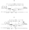
まず、通常モードの減速制御について説明する。図3に示すように、通常モードにおいて第二制御部1Eは、衝突警報を所定時間Ta以上出力した後に、ブレーキ装置6を制御して車両10を減速させる(減速制御を開始する)。ここで、所定時間Taは、異常警報時間Teよりも短く設定される(Ta<Te)。
First, the deceleration control in the normal mode will be described. As shown in FIG. 3, in the normal mode, the
本実施形態の第二制御部1Eは、通常モードの減速制御において、ブレーキ装置6の強度を二段階で制御する。具体的には、第二制御部1Eは、ブレーキ装置6を所定の弱減速時間Tbだけ弱く作動させた後に強く作動させる。以下、ブレーキ装置6による弱減速時間Tb中の弱めの制動を「弱ブレーキ」ともいい、弱減速時間Tb後の強めの制動を「強ブレーキ」ともいう。弱ブレーキは、これから車両10が強ブレーキによって急減速することを乗員に知らせる機能をもつ。
The
上記のように第二制御部1Eは、通常モードでは、衝突回避可否の予想結果に関わらず、所定時間Ta以上の衝突警報を出力してから減速制御を実施する。したがって、図3(b)に示すように、第二制御部1Eは、例えば突然の割り込みで衝突を回避できないと予想される場合であっても、通常モードにおいては、衝突警報を所定時間Ta以上出力した後に弱ブレーキを弱減速時間Tb作動させ、その後に強ブレーキを作動させる。
As described above, in the normal mode, the
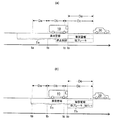
次に、図4及び図5に示す特別モードの減速制御について説明する。第二制御部1Eは、特別モードでは、衝突可能性の有る対象候補20までの距離Do(以下、「候補距離Do」ともいう)と、この対象候補20と車両10との相対速度Voと、車両10の制動回避距離Dcとを推定する。候補距離Do及び相対速度Voは、例えば取得装置4で取得された情報に基づいて推定される。また、制動回避距離Dcは、車両10が強ブレーキを開始してから停止する、あるいは対象候補20との相対速度Voが0になるまでに移動すると推測される距離に、マージン(余裕代)を加えた距離であって、車両10の走行速度や特性(ブレーキ装置6の性能や車両10の重量など)や対象候補20との相対速度Voに応じて定まり、一般に相対速度Voが高いほど長くなる。
Next, the deceleration control of the special mode shown in FIGS. 4 and 5 will be described. In the special mode, the
第二制動部1Eは、推定した候補距離Do,相対速度及び制動回避距離Dcに基づいて、通常モードと同様に衝突警報を所定時間Ta以上出力してから減速制御を実施した場合に衝突を回避できる臨界時点taを算出する。臨界時点taは、減速制御を実施すれば衝突を回避できると予想される時点tb(以下、「弱減速時点tb」ともいう)から所定時間Ta以上を遡った時点として算出される。なお、本実施形態では通常モードの減速制御が弱ブレーキと強ブレーキとの二段階で実施されることから、弱減速時点tbは弱ブレーキの開始時点に対応する。
Based on the estimated candidate distance Do, relative speed, and braking avoidance distance Dc, the
弱減速時点tbは、強ブレーキを開始すれば対象候補との衝突を回避できる時点tc(以下、「強減速時点tc」ともいう)から弱減速時間Tbを遡った時点として算出される。また、強減速時点tcは、候補距離Doが制動回避距離Dc以下(Do≦Dc)になると推測される時点に対応する。車両10が弱減速時間Tb中に移動すると推測される距離Dbを「弱減速距離Db」とすると、弱減速時点tbは、候補距離Doが制動回避距離Dcと弱減速距離Dbとの合算値以下(Do≦Dc+Db)になると推測される時点に対応する。また、車両10が所定時間Ta中に移動すると推測される距離Daを「警報距離Da」とすると、臨界時点taは、候補距離Doが制動回避距離Dcと弱減速距離Dbと警報距離Daとの合算値以下(Do≦Dc+Db+Da)になると推測される時点に対応する。
The weak deceleration time point tb is calculated as a time point when the weak deceleration time Tb is traced back from the time point tc (hereinafter, also referred to as "strong deceleration time point tc") in which a collision with the target candidate can be avoided by starting the strong braking. Further, the strong deceleration time point tc corresponds to the time point at which the candidate distance Do is estimated to be equal to or less than the braking avoidance distance Dc (Do ≦ Dc). Assuming that the distance Db estimated that the
図3(a)に示すように、第二制御部1Eは、算出した臨界時点taが現時点toよりも後である(現時点toが臨界時点taを過ぎていない)場合は、衝突を回避できると予想する。第二制御部1Eは、この場合には、通常モードと同様に衝突警報を出力してから所定時間Ta以上経過した後に減速制御を実施する。具体的には、第二制御部1Eは、衝突警報を出力した後、弱減速時点tbで弱ブレーキを作動させ、その後の強減速時点tcで強ブレーキを作動させる。
As shown in FIG. 3A, the
一方、図4及び図5に示すように、第二制御部1Eは、算出した臨界時点taが現時点to以前である(現時点toが臨界時点taである又は臨界時点taを過ぎている)場合は、衝突を回避できないと予想する。第二制御部1Eは、この場合には、下記に示すように衝突警報を出力してから所定時間Taの経過前に減速制御を実施する。
On the other hand, as shown in FIGS. 4 and 5, when the calculated critical time point ta is before the current time to (the current time to is the critical time point ta or has passed the critical time point ta), the
まず、図4(a)に示すように、算出された臨界時点taが現時点to以前であって、かつ、算出された弱減速時点tbが現時点toよりも後である場合について説明する。この場合に第二制御部1Eは、所定時間Taの経過に関わらず、弱減速時点tbで弱ブレーキを作動させる。したがって、この場合には、衝突警報が出力されてから所定時間Taの経過前に減速制御が実施される。以降は通常モードと同様であり、第二制御部1Eは、強減速時点tcで弱ブレーキを強ブレーキに移行させる。
First, as shown in FIG. 4A, a case where the calculated critical time point ta is before the current time to and the calculated weak deceleration time point tb is later than the current time to to be described will be described. In this case, the
次に、図4(b)に示すように、算出された弱減速時点tbが現時点to以前であって、かつ、算出された強減速時点tcが現時点toよりも後である場合について説明する。この場合に第二制御部1Eは、所定時間Taの経過に関わらず、即座に弱ブレーキを作動させ、その後の強減速時点tcで弱ブレーキを強ブレーキに移行させる。したがって、この場合には、衝突警報が出力されるのとほぼ同時に減速制御の弱ブレーキが作動し、それから弱減速時間Tbの経過前に強ブレーキが作動する。
Next, as shown in FIG. 4B, a case where the calculated weak deceleration time point tb is before the current time to and the calculated strong deceleration time point tc is later than the current time to to be described will be described. In this case, the
続いて、図5に示すように、算出された強減速時点tcが現時点to以前である場合について説明する。この場合に第二制御部1Eは、第一制御部1Dによる停止制御が既に実施中であるか否かを参照する。
図5(a)に示すように、第二制御部1Eは、算出した強減速時点tcが現時点to以前である場合に既に停止制御が実施中(異常警報が出力されてから異常警報時間Te以上経過後)であれば、所定時間Ta及び弱減速時間Tbの経過に関わらず、即座に強ブレーキを作動させる。したがって、この場合には、衝突警報が出力されるのとほぼ同時に減速制御の強ブレーキが作動する。このように、特別モードにおいて第二制御部1Eは、算出した強減速時点tcが現時点to以前であって既に停止制御が実施中である場合には、停止制御による制動を弱ブレーキとして流用すると共に強ブレーキの開始タイミングを早めることで、衝突回避の可能性を高める。
Subsequently, as shown in FIG. 5, a case where the calculated strong deceleration time point tc is before the current time too will be described. In this case, the
As shown in FIG. 5A, the
一方、図5(b)に示すように、第二制御部1Eは、算出した強減速時点tcが現時点to以前である場合に停止制御が未実施であれば、所定時間Taの経過に関わらず弱ブレーキを作動させる。以降は通常モードと同様であり、第二制御部1Eは、弱減速時間Tbの経過後に弱ブレーキを強ブレーキに移行させる。
このように、第二制御部1Eは、特別モードでは、衝突回避可否の予想結果に応じて減速制御よりも前の衝突警報を短縮または省略したり、減速制御の弱ブレーキを短縮または省略したりする。
On the other hand, as shown in FIG. 5B, if the calculated strong deceleration time point tc is before the current time to and the stop control is not executed, the
In this way, in the special mode, the
[3.フローチャート]
図6〜9は、制御装置1で実施される制御の手順を例示したフローチャートである。具体的には、図6のフローが設定部1Bで実施される処理を示し、図7のフローが判定部1Cで実施される処理を示している。また、図8のフローが第一制御部1Dで実施される処理を示し、図9のフローが第二制御部1Eで実施される処理を示している。
[3. flowchart]
6 to 9 are flowcharts illustrating the control procedure performed by the control device 1. Specifically, the flow of FIG. 6 shows the process executed by the setting unit 1B, and the flow of FIG. 7 shows the process executed by the determination unit 1C. Further, the flow of FIG. 8 shows the process executed by the
これらのフローは、車両10のイグニションがオンにされた場合に開始され、車両10のイグニションがオフにされた場合、及び、停止制御によって車両10が自動で停止した場合に終了する。なお、このフローの実施中、取得装置4や生体センサ5で取得された情報は制御装置1に随時伝達されているものとする。また、制御装置1内の要素1A,1B,1C,1D間では、作動モードや衝突可能性の有無の情報が随時送受されているものとする。
These flows start when the ignition of the
図6に示すように、設定部1Bでは、異常検知部1Aでドライバの異常が検知されたか否かが判定される(ステップS1)。そして、ドライバの異常が検知されている場合は、減速制御の作動モードが特別モードに設定され(ステップS2)、ドライバの異常が検知されていない場合は、上記の作動モードが通常モードに設定されて(ステップS3)、フローをリターンする。
As shown in FIG. 6, the setting unit 1B determines whether or not the driver abnormality is detected by the
図7に示すように、判定部1Cでは、取得装置4で何らかの物体が検知されたか否かが判定される(ステップA1)。ここで物体が検知されていなければ、衝突可能性が無いと判定されて(ステップA4)、フローをリターンする。一方、何らかの物体が検知されていれば、この物体を対象候補として特定するか否かが判断される(ステップA2)。ここで物体が対象候補として特定された場合は、この対象候補に対する衝突可能性の有無が判定され(ステップA3)、フローをリターンする。一方、ステップA2で対象候補が特定されない場合には衝突可能性が無いと判定され(ステップA4)、フローをリターンする。 As shown in FIG. 7, the determination unit 1C determines whether or not any object has been detected by the acquisition device 4 (step A1). If no object is detected here, it is determined that there is no possibility of collision (step A4), and the flow is returned. On the other hand, if any object is detected, it is determined whether or not to specify this object as a target candidate (step A2). If the object is identified as the target candidate here, the presence or absence of a collision possibility with respect to the target candidate is determined (step A3), and the flow is returned. On the other hand, if the target candidate is not specified in step A2, it is determined that there is no possibility of collision (step A4), and the flow is returned.
図8に示すように第一制御部1Dでは、異常検知部1Aでドライバの異常が検知されたか否かが判定される(ステップC1)。ドライバの異常が検知されていない場合は、フローをリターンする。一方、ドライバの異常が検知された場合は、警報装置7が制御されることで異常警報が出力される(ステップC2)。
As shown in FIG. 8, the
その後、異常警報時間Teが経過する(ステップC3からYESルートに進む)までステップC1の判定が繰り返され、ドライバの異常が検知されている限りステップC2の警報が継続される。そして、異常警報時間Teの経過後に停止制御が開始される(ステップC4)。なお、異常警報時間Teの経過前にドライバの異常が検知されなくなった場合は、停止制御が中止される。
ステップC4では、停止制御によるブレーキ装置6の作動で車両10が減速させられる。その後、車両10が停止したら(ステップC5からYESルートに進んだら)、ブレーキ装置6の作動が解除され(ステップC6)、停止制御が終了する。
After that, the determination in step C1 is repeated until the abnormality alarm time Te elapses (progresses from step C3 to the YES route), and the alarm in step C2 is continued as long as an abnormality in the driver is detected. Then, the stop control is started after the abnormality alarm time Te elapses (step C4). If the driver's abnormality is no longer detected before the abnormality alarm time Te elapses, the stop control is stopped.
In step C4, the
図9に示すように、第二制御部1Eでは、衝突可能性が有ると判定されているか否かが確認され(ステップB1)、衝突可能性が無いと判定されている場合は、フローをリターンする。
一方、衝突可能性が有ると判定されている場合は、警報装置7が制御されることで衝突警報が出力されると共に、上記の各時点ta,tb,tcが算出される(ステップB2)。次いで、減速制御の作動モードが特別モードであるか否かが判定され(ステップB3)、特別モードであれば、ステップB2で算出された臨界時点taが現時点to以前(臨界時点taに到達済)であるか否かが判定される(ステップB4)。
As shown in FIG. 9, the
On the other hand, when it is determined that there is a possibility of collision, the
算出された臨界時点taが現時点toよりも後(臨界時点taに未到達)である(ステップB4からNOルートに進んだ)場合は、通常モードと同様のタイミングで減速制御を実施しても衝突回避可能と予想されるため、通常モードと同様に減速制御が実施される。具体的には、ステップB2で衝突警報を出力してから所定時間Taの経過後(ステップB9からYESルートに進んだ後)に、弱ブレーキが作動させられ(ステップB11)、それから弱減速時間Tbの経過後(ステップB12からYESルートに進んだ後)に、強ブレーキが作動させられて(ステップB8)、このフローをリターンする。 If the calculated critical point ta is later than the current to (the critical point ta has not been reached) (progressed from step B4 to the NO route), a collision occurs even if deceleration control is performed at the same timing as in the normal mode. Since it is expected that it can be avoided, deceleration control is performed in the same manner as in the normal mode. Specifically, after a predetermined time Ta elapses after the collision warning is output in step B2 (after proceeding to the YES route from step B9), the weak brake is activated (step B11), and then the weak deceleration time Tb. After the elapse of (step B12 to the YES route), the strong brake is activated (step B8), and this flow is returned.
一方、ステップB4で臨界時点taが現時点to以前である(ステップB4からYESルートに進んだ)場合は、通常モードと同様のタイミングで減速制御を実施しても衝突回避不可能と予想されるため、減速制御が通常モードよりも早期に実施される。この場合には、まず算出された弱減速時点tbが現時点to以前(弱減速時点tbに到達済)であるか否かが判定される(ステップB5)。 On the other hand, if the critical point ta in step B4 is before the current to (progressed from step B4 to the YES route), it is expected that collision avoidance will not be possible even if deceleration control is performed at the same timing as in the normal mode. , Deceleration control is implemented earlier than in normal mode. In this case, it is first determined whether or not the calculated weak deceleration time point tb is before the current time to (the weak deceleration time point tb has already been reached) (step B5).
算出された弱減速時点tbが現時点toよりも後(弱減速時点tbに未到達)である(ステップB5からNOルートに進んだ)場合は、その後の弱減速時点tbで(ステップB10からYESルートに進んだ後に)、弱ブレーキが作動させられる(ステップB11)。その後は通常モードと同様であり、ステップB12及びステップB8を順に経て、このフローをリターンする。 If the calculated weak deceleration time point tb is later than the current time to (the weak deceleration time point tb has not been reached) (progressed from step B5 to the NO route), the weak deceleration time point tb thereafter (step B10 to YES route). (After proceeding to), the weak brake is activated (step B11). After that, it is the same as the normal mode, and this flow is returned through step B12 and step B8 in order.
また、ステップB5で弱減速時点tbが現時点to以前である(ステップB5からYESルートに進んだ)場合は、算出された強減速時点tcが現時点to以前(強減速時点tcに到達済)であるか否かが判定される(ステップB6)。ここで強減速時点tcが現時点toよりも後(強減速時点tcに未到達)である(ステップB6からNOルートに進んだ)場合は、すぐに弱ブレーキが作動させられ(ステップB13)、その後の強減速時点tcで(ステップB14からYESルートに進んだ後に)、強ブレーキが作動させられて(ステップB8)、このフローをリターンする。 If the weak deceleration time point tb is before the current time to in step B5 (progressing to the YES route from step B5), the calculated strong deceleration time point tc is before the current time too (the strong deceleration time point tc has already been reached). Whether or not it is determined (step B6). Here, if the strong deceleration time point tc is later than the current time to (the strong deceleration time point tc has not been reached) (progressed from step B6 to the NO route), the weak brake is immediately activated (step B13), and then. At the strong deceleration point ct (after proceeding from step B14 to the YES route), the strong brake is activated (step B8), and this flow is returned.
一方、ステップB6で強減速時点tcが現時点to以前である(ステップB6からYESルートに進んだ)場合は、第一制御部1Dによる停止制御が実施中であるか否かが参照され(ステップB7)、停止制御が既に実施中であれば、すぐに強ブレーキが作動させられて(ステップB8)、このフローをリターンする。また、ステップB7で停止制御が未実施であれば、すぐに弱ブレーキが作動させられ(ステップB11)、それから弱減速時間Tbの経過後(ステップB12からYESルートに進んだ後)に、強ブレーキが作動させられて(ステップB8)、このフローをリターンする。
On the other hand, if the strong deceleration time point tc is before the current too in step B6 (progressing from step B6 to the YES route), it is referred to whether or not the stop control by the
[4.作用及び効果]
ドライバの異常が検知されていない場合の通常モードでは、衝突警報が出力されてから所定時間Ta以上経過後に減速制御が実施される。このため、ドライバに異常が無く、ドライバの運転操作で衝突を回避できる可能性が高い場合には、減速制御の実施前に、衝突可能性が有ることをドライバに報知できる。これにより、ドライバに適切な運転操作を促すことができるため、減速制御の誤作動(無用な減速制御の実施)を低減できる。よって、減速制御に起因した車両10の無用な減速を抑制できる。
[4. Action and effect]
In the normal mode when no driver abnormality is detected, deceleration control is performed after a predetermined time Ta or more has elapsed after the collision alarm is output. Therefore, if there is no abnormality in the driver and there is a high possibility that the collision can be avoided by the driving operation of the driver, it is possible to notify the driver that there is a possibility of collision before the deceleration control is performed. As a result, it is possible to encourage the driver to perform an appropriate driving operation, and thus it is possible to reduce malfunction of deceleration control (implementation of unnecessary deceleration control). Therefore, it is possible to suppress unnecessary deceleration of the
一方、ドライバの異常が検知されている場合に設定される特別モードでは、通常モードと同様のタイミングで減速制御を実施しても衝突を回避できないと予想される場合に、通常モードよりも早いタイミングで(衝突警報が出力されてから所定時間Taの経過前に)減速制御が実施される。このため、ドライバの異常が検知されている場合には、たとえドライバが運転操作不能な状態であったとしても、減速制御で車両10の衝突可能性をより確実に低減できる。
On the other hand, in the special mode set when an abnormality of the driver is detected, when it is expected that the collision cannot be avoided even if the deceleration control is performed at the same timing as the normal mode, the timing is earlier than the normal mode. The deceleration control is performed at (before the lapse of a predetermined time Ta after the collision warning is output). Therefore, when an abnormality of the driver is detected, the possibility of collision of the
なお、特別モードにおいて、通常モードと同様のタイミングで減速制御を実施しても衝突を回避できると予想される場合には、通常モードと同様のタイミングで減速制御が実施される。このため、ドライバの異常が検知されていても、衝突が差し迫っていない場合には、減速制御の実施前に衝突警報が所定時間Ta以上出力されることで、衝突可能性が有ることを乗員に報知できる。よって、車両10の衝突回避を図りながら、急な減速制御を抑制できる。
If it is expected that the collision can be avoided even if the deceleration control is performed at the same timing as the normal mode in the special mode, the deceleration control is performed at the same timing as the normal mode. Therefore, even if an abnormality in the driver is detected, if a collision is not imminent, a collision warning is output for a predetermined time Ta or more before the deceleration control is executed, so that the occupant is informed that there is a possibility of a collision. Can be notified. Therefore, sudden deceleration control can be suppressed while avoiding a collision of the
[5.変形例]
上記の制御装置1の構成及び制御内容は一例である。衝突可能性の有無の判定は、判定部1C以外の要素が実施してもよく、この場合には判定部1Cを省略可能である。また、衝突を回避可能か否かの予想は、第二制御部1E以外の要素が実施してもよい。なお、第二制御部1Eは、減速制御においてブレーキ装置6の強度を多段階で変更しなくてもよい。
[5. Modification example]
The configuration and control contents of the control device 1 described above are examples. The determination of the presence or absence of a collision possibility may be performed by an element other than the determination unit 1C, and in this case, the determination unit 1C can be omitted. Further, an element other than the
減速制御は、所定の条件が成立した場合に中止又は終了するように構成されてもよい。例えば、車両10の室内にドライバが操作可能な解除スイッチを設け、この解除スイッチが操作された場合に減速制御を中止又は終了するようにしてもよい。停止制御も同様に、車両10の室内に設けられた解除スイッチへの操作に応じて解除可能に構成されてもよい。
異常警報及び衝突警報の具体的な内容は特に限定されない。異常警報及び衝突警報の内容は、互いに異なっていてもよい。なお、異常警報は、車両10の乗員に加えて、車両10の外部に出力されてもよい。
The deceleration control may be configured to be stopped or terminated when a predetermined condition is satisfied. For example, a release switch that can be operated by the driver may be provided in the interior of the
The specific contents of the abnormality warning and the collision warning are not particularly limited. The contents of the abnormality alarm and the collision alarm may be different from each other. The abnormality alarm may be output to the outside of the
1 制御装置(車両制御装置)
1A 異常検知部
1B 設定部
1C 判定部
1D 第一制御部
1E 第二制御部
2 アクセルペダル
3 アクセル開度センサ
4 取得装置
4F 前方センサ
4S 側方センサ
4R 後方センサ
5 生体センサ
6 ブレーキ装置
7 警報装置
8 コンピュータプログラム
10 車両
11 運転席
12 車輪
20 対象候補
D 物体までの距離
Da 警報距離
Db 弱減速距離
Dc 制動回避距離
Do 対象候補までの距離
Ta 所定時間
ta 臨界時点
Tb 弱減速時間
tb 弱減速時点
tc 強減速時点
Te 異常警報時間
V 物体との相対速度
Vo 対象候補との相対速度
1 Control device (vehicle control device)
1A Abnormality detection unit 1B Setting unit
Claims (1)
前記車両に衝突の可能性が有ると判定された場合に、前記車両を自動で減速させる減速制御を実施する第二制御部と、
前記異常が検知されている場合に、前記減速制御の作動モードを、前記異常が検知されていない場合の通常モードから特別モードに設定する設定部と、を備え、
前記第二制御部は、前記通常モードでは、前記衝突の警報を出力してから所定時間以上経過後に前記減速制御を実施し、前記特別モードでは、前記所定時間が経過すると前記衝突を回避できないと予想される場合に、前記所定時間の経過前に前記減速制御を実施することを特徴とする、車両制御装置。 A first control unit that performs stop control that automatically decelerates and then stops the vehicle when an abnormality in the driver of the vehicle is detected.
A second control unit that performs deceleration control that automatically decelerates the vehicle when it is determined that the vehicle may collide.
A setting unit for setting the operation mode of the deceleration control from the normal mode when the abnormality is not detected to the special mode when the abnormality is detected is provided.
In the normal mode, the second control unit executes the deceleration control after a lapse of a predetermined time or more after outputting the collision alarm, and in the special mode, the collision cannot be avoided after the predetermined time elapses. A vehicle control device, characterized in that the deceleration control is performed before the elapse of the predetermined time, when expected.
Priority Applications (1)
| Application Number | Priority Date | Filing Date | Title |
|---|---|---|---|
| JP2019216849A JP2021086515A (en) | 2019-11-29 | 2019-11-29 | Vehicle control device |
Applications Claiming Priority (1)
| Application Number | Priority Date | Filing Date | Title |
|---|---|---|---|
| JP2019216849A JP2021086515A (en) | 2019-11-29 | 2019-11-29 | Vehicle control device |
Publications (1)
| Publication Number | Publication Date |
|---|---|
| JP2021086515A true JP2021086515A (en) | 2021-06-03 |
Family
ID=76087916
Family Applications (1)
| Application Number | Title | Priority Date | Filing Date |
|---|---|---|---|
| JP2019216849A Pending JP2021086515A (en) | 2019-11-29 | 2019-11-29 | Vehicle control device |
Country Status (1)
| Country | Link |
|---|---|
| JP (1) | JP2021086515A (en) |
Cited By (1)
| Publication number | Priority date | Publication date | Assignee | Title |
|---|---|---|---|---|
| JP2023064312A (en) * | 2021-10-26 | 2023-05-11 | マツダ株式会社 | vehicle control system |
-
2019
- 2019-11-29 JP JP2019216849A patent/JP2021086515A/en active Pending
Cited By (1)
| Publication number | Priority date | Publication date | Assignee | Title |
|---|---|---|---|---|
| JP2023064312A (en) * | 2021-10-26 | 2023-05-11 | マツダ株式会社 | vehicle control system |
Similar Documents
| Publication | Publication Date | Title |
|---|---|---|
| EP3789254B1 (en) | Method, device and system for automatic braking of vehicle | |
| JP6532167B2 (en) | Electric drive mining vehicle and brake operation guide method therefor | |
| US9308914B1 (en) | Advanced driver assistance system for vehicle | |
| CN106965673B (en) | Parking Controls | |
| US20160214595A1 (en) | Driver Assistance System with Increased Reliability and Availability | |
| JP2010030396A (en) | Safety controller for vehicle | |
| JP2013513526A (en) | Emergency braking support system to assist the driver of the vehicle when making a call | |
| JPH1111272A (en) | Vehicle rollover prevention device | |
| CN111267802A (en) | Vehicle control method, vehicle control system and automobile | |
| US12139121B2 (en) | Vehicle control device, vehicle control method, and computer-readable recording medium having stored thereon vehicle control program | |
| JP2009051241A (en) | Automatic brake control device of vehicle | |
| JP2021086515A (en) | Vehicle control device | |
| JP2005343248A (en) | Parking assist brake controlling device | |
| JP5649641B2 (en) | Driving assistance device | |
| US20220410923A1 (en) | Method for coordinating vehicles of a group of vehicles during emergency braking, and control unit | |
| CN103476648A (en) | Method for increasing the safety of a vehicle during operation, a device for carrying out the method and a vehicle with the device | |
| EP2555955B1 (en) | Safety system and method | |
| JP5786699B2 (en) | Automatic brake control device | |
| JP5512849B1 (en) | Driving assistance device | |
| JP2005225453A (en) | Brake supporting device | |
| JP4148028B2 (en) | Vehicle travel control device | |
| CN114954383A (en) | Control method and system for preventing accelerator from being stepped on by mistake | |
| JP5761001B2 (en) | A vehicle that judges the release of automatic braking based on the pedal operation before and after the vehicle stops | |
| JP7786415B2 (en) | vehicle | |
| KR102826344B1 (en) | Electrified vehicle and method of responding to sensor failure for the same |
Legal Events
| Date | Code | Title | Description |
|---|---|---|---|
| RD02 | Notification of acceptance of power of attorney |
Free format text: JAPANESE INTERMEDIATE CODE: A7422 Effective date: 20211213 |
|
| RD02 | Notification of acceptance of power of attorney |
Free format text: JAPANESE INTERMEDIATE CODE: A7422 Effective date: 20211214 |
|
| A711 | Notification of change in applicant |
Free format text: JAPANESE INTERMEDIATE CODE: A711 Effective date: 20220530 |