JP2020531199A - Guide attachment for electric tools - Google Patents
Guide attachment for electric tools Download PDFInfo
- Publication number
- JP2020531199A JP2020531199A JP2020512397A JP2020512397A JP2020531199A JP 2020531199 A JP2020531199 A JP 2020531199A JP 2020512397 A JP2020512397 A JP 2020512397A JP 2020512397 A JP2020512397 A JP 2020512397A JP 2020531199 A JP2020531199 A JP 2020531199A
- Authority
- JP
- Japan
- Prior art keywords
- shaft
- magnetic field
- arms
- tool
- field generator
- Prior art date
- Legal status (The legal status is an assumption and is not a legal conclusion. Google has not performed a legal analysis and makes no representation as to the accuracy of the status listed.)
- Granted
Links
- 230000008685 targeting Effects 0.000 claims abstract description 109
- 230000008878 coupling Effects 0.000 claims abstract description 62
- 238000010168 coupling process Methods 0.000 claims abstract description 62
- 238000005859 coupling reaction Methods 0.000 claims abstract description 62
- 238000013519 translation Methods 0.000 claims description 35
- 210000000078 claw Anatomy 0.000 claims description 33
- 230000007246 mechanism Effects 0.000 claims description 27
- 238000004804 winding Methods 0.000 claims 1
- 239000007943 implant Substances 0.000 description 11
- 238000003780 insertion Methods 0.000 description 8
- 230000037431 insertion Effects 0.000 description 8
- 238000000034 method Methods 0.000 description 8
- 210000000988 bone and bone Anatomy 0.000 description 6
- 239000002783 friction material Substances 0.000 description 6
- 230000015572 biosynthetic process Effects 0.000 description 3
- 238000005755 formation reaction Methods 0.000 description 3
- 230000004048 modification Effects 0.000 description 3
- 238000012986 modification Methods 0.000 description 3
- 230000008569 process Effects 0.000 description 3
- 238000006073 displacement reaction Methods 0.000 description 2
- 238000002513 implantation Methods 0.000 description 2
- 238000005461 lubrication Methods 0.000 description 2
- 230000000007 visual effect Effects 0.000 description 2
- 230000001154 acute effect Effects 0.000 description 1
- 210000003484 anatomy Anatomy 0.000 description 1
- 238000005452 bending Methods 0.000 description 1
- 230000008901 benefit Effects 0.000 description 1
- 230000002457 bidirectional effect Effects 0.000 description 1
- 238000004140 cleaning Methods 0.000 description 1
- 238000005520 cutting process Methods 0.000 description 1
- 230000003247 decreasing effect Effects 0.000 description 1
- 230000001066 destructive effect Effects 0.000 description 1
- 238000009429 electrical wiring Methods 0.000 description 1
- 230000035876 healing Effects 0.000 description 1
- 238000012423 maintenance Methods 0.000 description 1
- 238000004519 manufacturing process Methods 0.000 description 1
- 239000000203 mixture Substances 0.000 description 1
- 238000003825 pressing Methods 0.000 description 1
- 230000003252 repetitive effect Effects 0.000 description 1
- 238000000926 separation method Methods 0.000 description 1
- 230000006641 stabilisation Effects 0.000 description 1
- 238000011105 stabilization Methods 0.000 description 1
- 238000006467 substitution reaction Methods 0.000 description 1
- 238000001356 surgical procedure Methods 0.000 description 1
- 210000000689 upper leg Anatomy 0.000 description 1
Images


Classifications
-
- A—HUMAN NECESSITIES
- A61—MEDICAL OR VETERINARY SCIENCE; HYGIENE
- A61B—DIAGNOSIS; SURGERY; IDENTIFICATION
- A61B17/00—Surgical instruments, devices or methods
- A61B17/16—Instruments for performing osteoclasis; Drills or chisels for bones; Trepans
- A61B17/164—Instruments for performing osteoclasis; Drills or chisels for bones; Trepans intramedullary
-
- A—HUMAN NECESSITIES
- A61—MEDICAL OR VETERINARY SCIENCE; HYGIENE
- A61B—DIAGNOSIS; SURGERY; IDENTIFICATION
- A61B17/00—Surgical instruments, devices or methods
- A61B17/16—Instruments for performing osteoclasis; Drills or chisels for bones; Trepans
- A61B17/17—Guides or aligning means for drills, mills, pins or wires
- A61B17/1707—Guides or aligning means for drills, mills, pins or wires using electromagnetic effects, e.g. with magnet and external sensors
Landscapes
- Health & Medical Sciences (AREA)
- Surgery (AREA)
- Life Sciences & Earth Sciences (AREA)
- Oral & Maxillofacial Surgery (AREA)
- Biomedical Technology (AREA)
- Orthopedic Medicine & Surgery (AREA)
- Nuclear Medicine, Radiotherapy & Molecular Imaging (AREA)
- Dentistry (AREA)
- Veterinary Medicine (AREA)
- Engineering & Computer Science (AREA)
- Public Health (AREA)
- Heart & Thoracic Surgery (AREA)
- Medical Informatics (AREA)
- Molecular Biology (AREA)
- Animal Behavior & Ethology (AREA)
- General Health & Medical Sciences (AREA)
- Physics & Mathematics (AREA)
- Electromagnetism (AREA)
- Surgical Instruments (AREA)
Abstract
外科用器具の遠位ターゲティング装置は、軸に沿って細長いシャフトを受け入れるように構成されたカップリング要素を有する磁場発生器と、軸に対して近位方向に磁場発生器から離隔するように磁場発生器に接続可能なブリッジと、を含む。ブリッジは、シャフトを操作するように構成されたツールに接続可能なアタッチメント装置を含む。ブリッジはまた、ブリッジをツールに実質的に強固に連結するような形でツールの本体を留めるように構成された一対のアームを含む。アームの少なくとも一方は、アームが様々な形状及びサイズの1つ以上を有するツール本体を実質的に強固に留めることを可能にするように調節可能な距離でアタッチメント部材に対して配置可能である。The distal targeting device for surgical instruments has a magnetic field generator with a coupling element configured to receive an elongated shaft along the axis and a magnetic field so as to be proximal to the axis and away from the magnetic field generator. Includes a bridge that can be connected to the generator. The bridge includes an attachment device that can be connected to a tool configured to operate the shaft. The bridge also includes a pair of arms configured to fasten the body of the tool in such a way that the bridge is substantially tightly connected to the tool. At least one of the arms can be placed with respect to the attachment member at an adjustable distance so that the arm allows the tool body having one or more of various shapes and sizes to be substantially secured.
Description
本開示は、外科用インプラントと共に使用するための遠位ターゲティング装置に関し、より詳細には、様々なサイズ及び/又は形状の電動ツールに遠位ターゲティング装置を取り付けるための調節可能なアタッチメント装置を有する遠位ターゲティング装置に関する。 The present disclosure relates to a distal targeting device for use with a surgical implant, more particularly with an adjustable attachment device for attaching the distal targeting device to electric tools of various sizes and / or shapes. Regarding the position targeting device.
外科用インプラントは、埋め込みの間又は埋め込みの後に外部操作を必要とする機構を含む場合がある。例えば、インプラントは、固定要素、ロック要素、位置調節要素、又は患者の解剖学的構造の治癒及び/又は安定化を促進するような形でインプラントが動作することを可能とする他の種類の要素又は機構を含むことができる。そのようなインプラントの一例として、例えば、骨の骨折部を安定させるために、大腿骨のような長い骨の髄腔内に埋め込まれる髄内釘が挙げられる。ねじなどのロック部材を少なくとも骨の皮質に貫通して穿孔されたアクセス穴に通し、釘に横方向に予め穿孔されたねじ穴などの固定穴と整列させて配置することによって、骨に対して髄内釘を固定することが一般的に行われてきた。かかる手技は、髄内釘に予め穿孔された孔が一般的には外科医に見えず、こうした孔の位置を局在化させて骨内にアクセス穴を穿孔し、かつ/又はロック部材を挿入するための外科用ドリル及び配置器具と整列させることが困難であることから、技術的な困難があった。 Surgical implants may include mechanisms that require external manipulation during or after implantation. For example, an implant may be a fixation element, a locking element, a positioning element, or another type of element that allows the implant to operate in a manner that facilitates healing and / or stabilization of the patient's anatomy. Alternatively, a mechanism can be included. An example of such an implant is an intramedullary nail that is implanted in the intramedullary cavity of a long bone, such as the femur, to stabilize the fractured part of the bone. By passing a locking member such as a screw through at least an access hole perforated through the cortex of the bone and aligning it with a fixing hole such as a screw hole pre-perforated laterally into the nail, the bone It has been common practice to fix intramedullary nails. In such a procedure, pre-drilled holes in the intramedullary nail are generally invisible to the surgeon, and the location of these holes is localized to drill an access hole in the bone and / or insert a locking member. There have been technical difficulties due to the difficulty of aligning with surgical drills and placement instruments for.
遠位ターゲティングシステムは、外科手技の間にインプラントの異なる要素の位置を検出するために多くの場合に使用されている。上記の髄内釘の例に関して、遠位ターゲティングシステムを外科用ドリルと共に使用することで、髄内釘内の1つ以上の固定孔の位置を特定し、外科用ドリルのドリルビットの遠位端に対する固定孔の相対位置を示すフィードバックを医師に提供することができる。このような遠位ターゲティングシステムは、ドリルビットを受け入れる中央ガイド孔を有する磁場発生器(単に「磁場発生器」(field generator)とも呼ばれる)を含むことができる。磁場発生器は、1つ以上の磁場を発生させるための回路を含む。髄内釘は、磁場発生器によって生成された磁場の方向及び強度を検出するように構成された1つ以上の磁場トランスポンダをそれぞれが有する1つ以上のセンサを含むことができる。かかる1つ以上のセンサはそれぞれ、制御回路を有する制御ユニットに磁場データを送信することができる。かかる1つ以上のセンサは、1つ以上のセンサと1つ以上の固定孔との相対位置が制御ユニットに知られるように髄内釘に対して位置させることができる。ガイド孔の中心軸の向き及び位置もまた、制御ユニットに知られる。ガイド孔の中心軸は、ガイド孔内に受け入れられたドリルビットの中心軸と一致する。 Distal targeting systems are often used to detect the location of different elements of an implant during a surgical procedure. For the intramedullary nail example above, a distal targeting system can be used with a surgical drill to locate one or more fixation holes within the intramedullary nail and the distal end of the drill bit of the surgical drill. Feedback can be provided to the physician indicating the relative position of the fixation hole with respect to. Such a distal targeting system can include a magnetic field generator (also simply referred to as a "field generator") having a central guide hole that receives the drill bit. The magnetic field generator includes a circuit for generating one or more magnetic fields. The intramedullary nail can include one or more sensors, each having one or more magnetic field transponders configured to detect the direction and intensity of the magnetic field generated by the magnetic field generator. Each such one or more sensors can transmit magnetic field data to a control unit having a control circuit. Such one or more sensors can be positioned relative to the intramedullary nail so that the relative positions of the one or more sensors and the one or more fixation holes are known to the control unit. The orientation and position of the central axis of the guide hole is also known to the control unit. The central axis of the guide hole coincides with the central axis of the drill bit received in the guide hole.
制御ユニットは、1つ以上のセンサからのデータを解釈して、髄内釘内の1つ以上の固定孔に対するガイド孔の中心軸の向き及び変位を確認する。制御ユニットは、髄内釘内の固定孔に対する中心軸の向き及び/又は変位を示す、例えばビュースクリーンを介した視覚フィードバック又はスピーカを介した音声フィードバックといったフィードバックを医師に送信する。他のタイプの外科用インプラントと共に使用するための遠位ターゲティングシステムは、同様の構造及び技術を用いることができる。 The control unit interprets data from one or more sensors to determine the orientation and displacement of the central axis of the guide hole with respect to one or more fixation holes in the intramedullary nail. The control unit sends feedback to the physician indicating the orientation and / or displacement of the central axis with respect to the fixation hole in the intramedullary nail, such as visual feedback via the view screen or audio feedback via the speaker. Distal targeting systems for use with other types of surgical implants can use similar structures and techniques.
本開示の一実施形態では、外科用器具の遠位ターゲティング装置は、軸に沿って細長いシャフトを受け入れるように構成されたカップリング要素を有する磁場発生器と、軸に対して近位方向に磁場発生器から離隔するように磁場発生器に接続可能なブリッジと、を含む。ブリッジは、シャフトを操作するように構成されたツールに接続可能なアタッチメント装置を含む。ブリッジはまた、ブリッジをツールに実質的に強固に連結するような形でツールの本体を留めるように構成された一対のアームを含む。アームの少なくとも一方は、異なる形状及びサイズの1つ以上を有するツール本体をアームが実質的に強固に留めることを可能にするように調節可能な距離でアタッチメント部材に対して配置可能である。 In one embodiment of the disclosure, the distal targeting device of a surgical instrument is a magnetic field generator with a coupling element configured to receive an elongated shaft along the axis and a magnetic field proximal to the axis. Includes a bridge that can be connected to the magnetic field generator so as to be separated from the generator. The bridge includes an attachment device that can be connected to a tool configured to operate the shaft. The bridge also includes a pair of arms configured to fasten the body of the tool in such a way that the bridge is substantially tightly connected to the tool. At least one of the arms can be placed with respect to the attachment member at an adjustable distance to allow the arm to substantially secure the tool body having one or more of different shapes and sizes.
本開示の別の実施形態では、標的と外科用器具のシャフトとを整列させるように構成された磁場発生器は、磁場発生回路を収容するハウジングと、長手方向に沿って互いに離隔した開口部近位端と開口部遠位端とを有する開口部を少なくとも部分的に画定するカップリング要素と、を含む。開口部は、長手方向に対して実質的に垂直な横断方向に開放していることで、シャフトの遠位端又は近位端を開口部に通すことなくシャフトを受け入れる。 In another embodiment of the present disclosure, the magnetic field generator configured to align the target with the shaft of the surgical instrument is close to the housing containing the magnetic field generation circuit and the openings separated from each other along the longitudinal direction. Includes a coupling element that at least partially defines the opening having a position end and a distal end of the opening. The opening is open in a transverse direction substantially perpendicular to the longitudinal direction to accept the shaft without passing the distal or proximal end of the shaft through the opening.
本開示の更なる実施形態では、遠位ターゲティングシステムは、ツール本体及び受け入れ要素を有する電動ツールを含む。システムは、長手方向に沿って延びる軸に沿って細長いシャフトを含む。シャフトの近位部分は、電動ツールの受け入れ要素に受け入れ可能である。システムは、シャフトを受け入れるように構成されたカップリング要素を有する磁場発生器を含む。システムはまた、軸に対して近位方向に磁場発生器から離隔するように磁場発生器に接続可能なブリッジを含む。ブリッジは、駆動ツールに接続可能なアタッチメント装置と、ブリッジをツールに実質的に強固に連結するような形でツール本体を留めるように構成された一対のアームを含む。アームの少なくとも一方は、アームが、1)ツール本体を実質的に強固に留め、2)ツール本体を解放し、3)ツール本体とは異なるサイズ及び形状の1つ以上を有する第2のツール本体を実質的に強固に留めることを可能とするように調節可能な距離でアタッチメント装置に対して配置可能である。 In a further embodiment of the present disclosure, the distal targeting system comprises a tool body and an electric tool having a receiving element. The system includes an elongated shaft along an axis that extends along the longitudinal direction. The proximal portion of the shaft is acceptable to the receiving element of the power tool. The system includes a magnetic field generator with a coupling element configured to accept the shaft. The system also includes a bridge that can be connected to the magnetic field generator so as to be proximal to the axis away from the magnetic field generator. The bridge includes an attachment device that can be connected to the drive tool and a pair of arms configured to hold the tool body in a manner that substantially tightly connects the bridge to the tool. At least one of the arms is a second tool body in which the arm 1) holds the tool body substantially tightly, 2) releases the tool body, and 3) has one or more of a size and shape different from the tool body. Can be placed with respect to the attachment device at an adjustable distance to allow for a substantially tight fit.
上記の概要及び本出願の遠位ターゲティング装置の例示的な実施形態の以下の詳細な説明を添付の図面と併せて読むことで、それらのより深い理解が得られるであろう。本願の拡張可能な椎間インプラントを説明する目的で、図面にて例示的実施形態を示す。しかし、本出願が図示される正確な配置及び手段に限定されないことを、理解しなければならない。図面は、以下のとおりである。
外科用器具によるインプラントの遠位ターゲティングを行う手技では、インプラントと外科用器具との間の可能な限り正確な関係を提供することが有利である。本開示は、電動ドリルなどの外科用器具に装着することによって、ドリルビットの遠位端などの外科用器具の遠位部分を、患者体内に配設された外科用インプラントの部分と整列させようとする医師を案内することができる遠位ターゲティング装置に関する。具体的には、本明細書に開示される遠位ターゲティング装置はそれぞれ、異なるサイズ及び/又は形状の外科用器具にターゲティング装置を頑丈かつ強固な様式で容易に装着することを可能とするように調節可能な装着要素を有する。これにより、遠位ターゲティング装置と多くの外科用器具のうちのいずれか1つとを、一人の医師が1つの遠位ターゲティングシステムとして使用することが可能となる。非限定的な例として、骨の皮質にアクセス穴を穿孔するように設計された大部分の電動ドリルは、モータカウリングなどにおけるそれぞれのツールの幅が約2.50cm〜約5.12cmの範囲内となるように、商業的に製造される。本明細書に開示される遠位ターゲティング装置の装着要素は、前述の範囲の幅を有する電力と連結されるようにサイズ調節が可能である。したがって、本明細書に開示される遠位ターゲティング装置用の装着要素は、「汎用装着要素」として特徴付けることができる。本明細書に開示される遠位ターゲティング装置は、同じターゲティング装置を髄内釘移植の分野などの外科分野における市販の電動ドリルの大半に使用することができることから多大な商業的利点を提供するものである。 In the procedure of distal targeting of implants with surgical instruments, it is advantageous to provide the most accurate possible relationship between the implant and the surgical instrument. The present disclosure will align the distal portion of a surgical instrument, such as the distal end of a drill bit, with a portion of a surgical implant placed within the patient's body by attaching it to a surgical instrument such as an electric drill. With respect to a distal targeting device that can guide the surgeon. Specifically, each of the distal targeting devices disclosed herein allows the targeting device to be easily mounted in a sturdy and robust manner on surgical instruments of different sizes and / or shapes. It has an adjustable mounting element. This allows a physician to use the distal targeting device and any one of many surgical instruments as one distal targeting system. As a non-limiting example, most electric drills designed to drill access holes in the cortex of bone have a width of each tool in the range of about 2.50 cm to about 5.12 cm, such as in motor cowling. It is manufactured commercially so that The mounting elements of the distal targeting device disclosed herein can be sized to be coupled with power having a width in the aforementioned range. Therefore, the mounting elements for distal targeting devices disclosed herein can be characterized as "general purpose mounting elements". The distal targeting devices disclosed herein offer a great commercial advantage as the same targeting device can be used for most of the commercially available electric drills in the surgical field, such as the field of intramedullary nail implantation. Is.
本開示はまた、遠位ターゲティング装置の磁場発生器にも関する。具体的には、本明細書に開示される磁場発生器は、ドリルビットのほぼ全体を開口部を通して遠位端から先に又は近位端から先に軸方向に挿入することを必要とする代わりに、ドリルビットの一部を磁場発生器内に横方向に挿入することを可能とする横入口開口部を含む。加えて、本明細書に開示される磁場発生器は、ドリルビットが磁場発生器の開口部を通して延在した状態で磁場発生器が装着要素により支持されるような形で遠位ターゲティング装置の装着要素と接続可能である。これにより、磁場発生器は、動作中にドリルビットに曲げモーメントを実質的に及ぼさない。したがって、医師が電動ドリルを操作している間に、磁場発生器を手動で安定させるうえで助手を必要としない。 The present disclosure also relates to a magnetic field generator of a distal targeting device. Specifically, the magnetic field generators disclosed herein are alternatives that require approximately the entire drill bit to be inserted axially through the opening, distal to first or proximal to first. Includes a lateral inlet opening that allows a portion of the drill bit to be inserted laterally into the magnetic field generator. In addition, the magnetic field generators disclosed herein are equipped with a distal targeting device such that the magnetic field generator is supported by a mounting element with the drill bit extending through the opening of the magnetic field generator. Can be connected to the element. As a result, the magnetic field generator substantially does not exert a bending moment on the drill bit during operation. Therefore, no assistant is required to manually stabilize the magnetic field generator while the doctor is operating the electric drill.
ここで図1を参照すると、患者の体内に挿入するためにシャフト6を受け入れて操作するように構成されたツール4に装着された遠位ターゲティング装置2を含む遠位ターゲティングシステムの実施形態が示されている。図に示されるように、ツール4は、手で操作する電動ドリルなどの、シャフト6を回転させるための電動ツールであってよい。シャフト6は、ドリルビット、ドライバビットなどのビットであってよく、又は患者体内に標的を定めて挿入するための他の任意の種類のシャフトであってもよい。電動ツール4は、シャフト6の近位部分10を受け入れるためのチャック8などの受け入れ要素を含むことができる。シャフト6は、近位部分10から遠位方向に離隔した遠位端12を画定している。遠位ターゲティング装置2は、上記に述べたように磁場を発生させるための磁場発生器14を含むことができる。磁場発生器14は、シャフト6の一部を受け入れるように構成されたカップリング要素16を含む。シャフト6は、長手方向Xに沿って延びるシャフト軸18を画定している。
Referring now to FIG. 1, an embodiment of a distal targeting system including a distal targeting device 2 mounted on a tool 4 configured to accept and operate a
遠位ターゲティング装置2は、磁場発生器14から遠位方向と反対の近位方向に延びる装着要素20を含む。近位方向及び遠位方向はそれぞれ、双方向である長手方向Xの一方向成分である点を理解されたい。装着要素20は、磁場発生器14を電動ツール4の本体21に装着するように構成されている。そのため、装着要素20は、本明細書では「ブリッジ」とも称される。図に示される実施形態では、ブリッジ20は、モータカウリングなど、ツール本体21の上部22に装着される。しかしながら、他の実施形態では、ブリッジ20は、例えばハンドル26の基部24など、ツール本体21の別の部分に装着することもできる。ブリッジ20は、磁場発生器14を異なるサイズ及び/又は異なる形状の電動ツール4に装着できるように調節可能である。
The distal targeting device 2 includes a mounting
ブリッジ20はまた、長手方向Xに対して実質的に垂直である横方向Yに対して外側に延びる一対の遠位方向に延在する枝状部分28も画定することができる。長手方向X及び横方向Yはそれぞれ、「水平」方向と呼ぶことができる。加えて、長手方向X及び横方向Yの両方と同一の広がりを持つ任意の平面を水平面と呼ぶことができる。長手方向X及び横方向Yはそれぞれ垂直方向Zに対して垂直である。本明細書で使用するとき、用語「長手方向に」は、「長手方向Xに沿って」を意味する。用語「横方向に」は、「横方向Yに沿って」を意味し、用語「垂直に」は、「垂直方向Zに沿って」を意味する。本明細書で使用するとき、「垂直−長手方向平面」は、垂直方向Z及び長手方向Xに沿って延びる平面を意味し、垂直−横方向平面は、垂直方向Z及び横方向Yに沿って延びる平面を意味する。
The
枝状部分28の遠位端30は、以下でより詳細に説明するように、磁場発生器14に連結することができる。枝状部分28は、それらの間に横方向空間32を画定することができ、それにより、シャフト6は、電動ツール4から横方向空間32を通って磁場発生器14のカップリング要素16内へと延びることができる。ブリッジ20は、ツール本体21と一対のクランプアーム36とに接続可能なアタッチメント装置34を含むことができる。アタッチメント装置34は、アーム36を操作してツール4にブリッジ20を実質的に強固に連結するような形でツール本体21を留めるように構成することができる。このようにして、アタッチメント装置34とクランプアーム36とは、協働してクランプを画定することができる。
The
図2及び3に示されるように、アーム36は、アーム36間でツール本体21をクランプするか、ないしは他の形で留めるようにツール本体21の両側に接触するように構成することができる。アーム36の一方又は両方は、異なるサイズ及び/又は形状のツール4をクランプするようにアタッチメント装置34に対して位置的に調節可能とすることができる。例えば、各アーム36は、中央の垂直−長手方向平面P(すなわち、シャフト軸18と同一の広がりを有し、垂直方向Zに沿って延びる平面)からアーム36の内側接触面38まで横方向Yに沿って測定されるそれぞれのアーム距離D1、D2を画定することができる。垂直方向Zは長手方向X及び横方向Yに対して実質的に垂直である。アーム36の内側接触面38は、垂直−横平面内で湾曲した凹状断面形状を画定することができる。上記の断面形状は、特にツール本体21が垂直−横平面内で丸みを帯びた凸状の輪郭を有する場合にアーム36のツール本体21への留めグリップを向上させることができる。アーム36の内面38はまた、ツール本体21に対するアーム36の留めグリップを増加させるための高摩擦材料の層を含むことができる。
As shown in FIGS. 2 and 3, the
引き続き図2及び3を参照すると、アーム36の両方がアタッチメント装置34によって操作されることで、それぞれのアーム距離D1、D2を調節して電動ツール4に対して必要に応じてクランプすることができる。図に示される実施形態では、アーム距離D1,D2は、約1.00cmの最小値(図2)と約3.50cmの最大値(図3)との間でそれぞれ調節することができる。上記に述べたように、このアーム距離D1,D2の範囲は、異なる形状及び/又はサイズを有する電動ツール4を含む、髄内釘と共に使用される電動ツール4の大半にブリッジ20を装着するうえで充分である。他の実施形態では、アーム36の一方は固定的なものであってよく、他方は電動ツール4をクランプするように調節可能である。アーム36及びアタッチメント装置34は、アーム距離D1,D2を調節するためのラック・アンド・ピニオン機構を共に画定することができる。具体的には、アーム36はそれぞれ、横方向Yに沿って延伸してアタッチメント装置34のアクチュエータ42と係合するように構成された調節部分40を画定することができる。各アーム36の調節部分40は、直線的に整列されたラック歯46を有するラック44を画定することができる。アクチュエータ42は、ラック歯46と噛み合うように構成された放射状のピニオン歯52を有するピニオン50を保持した作動シャフト48(図5に示す)を含むことができる。アクチュエータ42は、ピニオン50に連結されたノブ54を含むことができる。ノブ54は、作動シャフト48の中心軸56(図5)を中心としたピニオン50の手動による回転を可能とし、これによりクランプアーム36を並進させてアーム距離D1,D2を調節することができる。
Continuing with reference to FIGS. 2 and 3, both of the
次に図4を参照すると、アタッチメント装置34は、アーム36がツール本体21に対してクランプされた後にアーム36が横方向外側に動くことを防止するように構成された、ラチェットなどのアーム拡張防止器を含むことができる。かかるラチェットは、作動シャフト48の周囲に周方向に間隔をおいて設けられたラチェット歯58を含むことができる。ラチェット歯58は、ピニオン50とノブ54との間に垂直に配置することができる。ラチェットは、ラチェット歯58と係合するように構成された爪60と、爪60に連結された爪ばね62とを含むことができる。爪60は、アーム距離D1,D2が減少するようにピニオン50が第1の回転方向R1に回転することを可能とする一方で、第1の回転方向R1の反対の第2の回転方向R2に沿ったピニオン50の回転を妨げるようにラチェット58と係合するように構成することができる。図に示される実施形態では1個のみの爪60があるが、ラチェット歯58と係合するように追加の爪60を用いることもできる点を理解されたい。アクチュエータ42は、ピニオン50の下方に延びるステム64を含むことができる。アクチュエータ42はまた、ステム64の下端にフランジ66を含むことができる。
Next, referring to FIG. 4, the
次に図5及び6を参照すると、ブリッジ20の本体68は、アタッチメント装置34の構成要素を支持するように構成されたフレーム70を画定することができる。フレーム70の下面71は、電動ツール4の上面に適合するように輪郭付けすることができる。多くの電動ツール4のツール本体21は垂直−横平面内で少なくとも部分的に凸状かつ丸みを帯びた断面形状を有することから、フレーム70の下面71は、ツール本体21に対するフレーム70の適合性を向上させるように垂直−横平面内で湾曲した凹状とすることもできる。フレーム70は、クランプアーム36、アクチュエータ42、爪60、及び爪ばね62を受け入れるように構成することができる。フレーム70は、爪60を受け入れるための爪ハウジング凹部72と、爪ばね62をフレーム70に取り付けるための凹部内のばねマウント74とを含むことができる。フレーム70はまた、ブリッジ20の外面をそれぞれ画定する爪カバー76及びフレームカバー78を取り付け可能に受け入れるように構成してもよい。フレーム70は、クランプアーム36のそれぞれの調節部分40の下面に接触するように構成された主支持面80を含むことができる。この点に関して、主支持面80は、クランプアーム36の支承面を画定することができる。主支持面80は、図に示されるように実質的に平面状であってもよいが、他の構成も本開示の範囲内に含まれる。フレーム70は、アーム36のそれぞれのガイドトラックを画定することができる。各ガイドトラックは横方向に延びてよく、横方向Yに沿ったアーム36の運動を案内することができる。図に示される実施形態では、ガイドトラックは、主支持面80からブリッジ本体68内に凹んだガイド溝82をそれぞれ備える。ガイド溝82はそれぞれ、アーム36の調節部分40の下面の対応するガイド突起84を受け入れるように構成することができる。ガイド溝82とガイド突起84とは、垂直−長手方向平面内で対応するダブテール断面形状を有することができ、この断面形状は、アーム距離D1,D2の調節時にアーム36がフレーム70に対して垂直方向Z及び/又は長手方向Xに沿って動くことを防止するように構成されている。フレーム70はまた、ブリッジ本体68の側面に一対の当接肩部86を画定してもよい。当接肩部86は、ラック歯46の反対側のアーム36の調節部分40から外側に延びる当接突起88と接触するように構成することができる。これにより、必要に応じてクランプアーム36の横方向の並進を制限することができる。ブリッジ20は、異なるサイズ及び/又は形状の電動ツールにブリッジ20を更に適合させるための、異なるサイズ及び/又は異なる内面38の構成の交換式クランプアーム36を含むキットとして提供することができる点を理解されたい。
Next, referring to FIGS. 5 and 6, the
フレーム70は、アクチュエータ42のステム64を受け入れるための垂直孔90を画定することができる。垂直孔90は、上部孔部分92と、上部孔部分92よりも広い直径を有する下部孔部分94とを有することができ、それらの間に肩部96を画定することができる。図6に示されるように、上部及び下部孔部分92、94は、アクチュエータ42の底部フランジ66が下部孔部分94内で垂直に並進することはできるが、肩部96との干渉によって上部孔部分92へと上方に並進することは防止されるように構成することができる。図6では、アクチュエータ42は、フランジ66が垂直孔90の底部に位置し、ピニオン50がラック歯46と噛み合い、爪60がラチェット歯58と係合した状態にある、フレーム70に対する第1の垂直位置に示されている。アクチュエータ42を係合解除するには、医師は、アクチュエータ42が第2の垂直位置に配置されるよう、フランジ66が肩部96に当接するまでノブ54を上方に引っ張ることによって、アクチュエータ42をフレーム70に対する第2の垂直位置に動かせばよい点を理解されたい。第2の垂直位置において、ピニオン50はラック歯46から垂直方向に離隔することができ、ラチェット歯58は爪60から垂直方向に離隔することができる。第2の位置から、ピニオン50及びラチェット歯58をそれぞれラック歯46及び爪60と係合させるには、医師はノブ54を押せばよい。
The
フレーム70とアクチュエータ42とは、集合的にアクチュエータ42を第1の垂直位置又は第2の垂直位置のいずれかに保持するように作動することができる位置ロック機構を備えることができる点を理解されたい。例えば、位置ロック機構は、医師がノブ54上で上方に引っ張ってアクチュエータ42を第2の垂直位置に動かし、次いでノブ54を第1又は第2の回転方向R1,R2の一方に4分の1回転だけ回転させることによってアクチュエータ42を第2の垂直位置にロックすることができるように構成することができる。アクチュエータ42を第2の垂直位置からロック解除するには、医師はノブ54を他方の回転方向R2,R1に4分の1回転だけ回転させ、次いで、ノブ54を押してアクチュエータ42を第1の垂直位置にまで動かせばよい。他の位置ロック機能も本開示の範囲内である。更なる実施形態では、アタッチメント装置34は、例えば、第1の垂直位置にアクチュエータ42を付勢するような形で下部孔部分94内に配設することができ、肩部96及び底部フランジ66に当接することができる付勢要素を含むことができる。
It is understood that the
図5に示すように、フレーム70は、フレーム70の側面の一方の側凹部98と、側凹部98から内側に延び、垂直孔90に開口する横方向スロット100とを画定してもよい。横方向スロット100は、上部孔部分92と横方向に同一の広がりを有する上部スロット部分102と、下部孔部分94と横方向に同一の広がりを有する下部スロット部分104とを含むことができる。下部スロット部分104は上部スロット部分102よりも幅広であってよく、フランジ66を受け入れるように構成することができる。これにより、アクチュエータ42を、フランジ66が下部スロット部分104を通り、ステム64が上方スロット部分102を通るようにして、横方向スロット100に通して垂直孔90内に横方向に挿入することができる。
As shown in FIG. 5, the
アタッチメント装置34は、垂直孔90によってアクチュエータ42を保持するように構成されたロッククリップ106などのインサートを含むことができる。ロッククリップ106は、横方向スロット100内に延びるように構成された突起107を画定することができる。突起は、横方向スロット100に完全に挿入された際に、上部孔部分92及び下部孔部分94のそれぞれの一部を画定してもよい。ロッククリップ106はまた、ガイド溝82の1つ以上の一部を画定してもよい。ロッククリップ106はまた、第1の装着形成部108を画定してもよく、フレーム70の反対側の側面が第2の装着形成部109を画定してもよい。第1及び第2の装着形成部108、109は、フレームカバー78をフレーム70に固定するためのフレームカバー78の下面の対応する装着機構を受け入れるように構成することができる。
The
次に図7〜11を参照し、ブリッジ20のアタッチメント装置34の組み立てを例示的な組み立て順序に従って説明する。図7に示されるように、クランプアーム36を、アーム36の調節部分40の下面が主支持面80と接触し、アーム36のガイド突起84がフレーム70のガイド溝82内に延びるようにしてフレーム70内に横方向に挿入することができる。次に図8を参照すると、アクチュエータ42を垂直孔90内に挿入することができる。上記で述べたように、アクチュエータ42は、横方向スロット100に通して垂直孔90内に横方向に挿入することができる。アクチュエータ42を横方向に挿入する間、アクチュエータ42は第2の垂直位置に位置してよく、それによりピニオン50及びラチェット歯58の、ラック歯46及び爪60との干渉がそれぞれ回避される。次に図9を参照すると、爪60及び爪ばね62を爪ハウジング凹部72内に取り付けることができる。図10を参照すると、爪カバー76をフレーム70に取り付けることができる。ロッククリップ106もまた、突起107が横方向スロット100内に延びて垂直孔90の上部及び下部孔部分92、94を完成するように側部凹部98内に横方向に挿入することができる。これにより、ロッククリップ100は、アクチュエータ42をブリッジ本体68に対してロックすることができる。次に図11を参照すると、フレームカバー78をフレーム70に取り付けることができる。アタッチメント装置34を組み立てる他の順序も本開示の範囲内である点を理解されたい。
Next, with reference to FIGS. 7 to 11, the assembly of the
引き続き図11を参照すると、ブリッジ20は、遠位ターゲティング装置2の電気配線、コード、又はケーブルを保持するための1つ以上のワイヤブラケット110を含むことができる。枝状部分28の遠位端30は、磁場発生器14と連結するための1つ以上のカプラ112を含むことができる。図に示されるように、カプラ112はそれぞれ、関連する分岐部28から遠位方向に延びるカプラ基部114を含むことができる。カプラ112はまた、カプラ基部114から横方向に延びる尖端116をそれぞれ画定することができる。各尖端116は、カプラ基部114から直交方向に延びる近位面118と、近位面118からカプラ基部114の遠位面122まで延びるテーパ面120とを画定することができる。カプラ112は、以下に記載されるように、磁場発生器14のリンケージを係合するように構成され得る。
Continuing with reference to FIG. 11, the
次に図12を参照すると、磁場発生器14は、磁場発生回路を収納する前側ハウジング130を含むことができる。前側ハウジング130は、シャフト6の一部を受け入れるように構成されたカップリング要素16の少なくとも一部分を含むことができる。カップリング要素16は、開口近位端134と、開口近位端134から遠位方向に離隔した開口遠位端136とを有する開口部132を少なくとも部分的に画定することができる。開口部132は、横方向Tにおいて磁場発生器14の外部に開放している。横断方向Tは、長手方向Xとほぼ直交する任意の方向であってよい。本明細書で使用するとき、用語「横断方向に」とは、横断方向Tに沿っていることを意味する。開口部132は、シャフト6を磁場発生器14のカップリング要素16内に横方向に挿入することを可能にする。これにより、シャフト6の遠位端又は近位端12、10を開口部16に通すことなく、シャフト6を磁場発生器14内に挿入することができる。これは、従来技術の遠位ターゲティング装置において、シャフトのほぼ全長を遠位端から先に又は近位端から先に軸方向に開口部を通じて挿入することを必要としうる、シャフト6を磁場発生器14内に挿入するプロセスを大幅に簡素化することができる。開口部132は、磁場発生器14の中央領域ではなく、前側ハウジング130の上部138に位置させることもできる。しかしながら、開口部132は、他の実施形態では、磁場発生器14の中央領域まで延びてもよい。前側ハウジング130の上部138はまた、以下により詳細に記載されるように、ブリッジ20の枝状部分28の遠位端30のカプラ112を受け入れるための1対のレセプタクル140を画定してもよい。
Next, referring to FIG. 12, the
磁場発生器14は、前側ハウジング130の後面144に連結されるように構成された後側ハウジングカバー142を含むことにより、後部ハウジング区画146をそれらの間に画定することができる。磁場発生器14は、後部ハウジング区画146内にリンケージ148及びリテーナ150を含むことができる。リンケージ148は、ブリッジ20のカプラ112とラッチするように構成することができる。リテーナ150は、シャフト6と係合してシャフト6を開口部132内に保持するように構成することができる。磁場発生器は、リンケージ148及びリテーナ150をそれぞれ付勢位置へと付勢するように構成されたコイルばね152などの付勢要素を含むことができる。後部ハウジングカバー142は、前側ハウジング130に着脱可能に取り付けられるように構成することができる。これにより、磁場発生器14は、非限定的な例として、洗浄、メンテナンス、及び/又は改造などを行うために、必要に応じて分解するか、又は少なくとも部分的に分解することができる。
The
リンケージ148は、長手方向Xに沿って互いに離隔した前面156と後面158とを有するほぼ板状の本体154を有することができる。リンケージ本体154は、後面158から近位方向に延びる外側ガイドレール160などの突起を画定することができる。リンケージ148はまた、後面158から近位方向に延びる第1のプッシュタブ162などの押し要素を含むことができる。プッシュタブ162は、医師がリンケージ148をリンケージ付勢位置からリンケージ押位置まで横方向に動かすことができるように構成することができる。リンケージ本体154は、後面158の凹部164と、凹部164からリンケージ本体154を貫通して遠位方向に延びる開口166とを画定することができる。リンケージ148は、リンケージ本体154の上面170から延びる一対のラッチ168を含むことができる。ラッチ168のそれぞれは、テーパ状近位面172と遠位面174とを画定することができる。ラッチ168は、以下により詳しく説明されるように、ブリッジ20のカプラ112とラッチするように構成することができる。
The
リテーナ150は、長手方向Xに沿って互いに離隔した前面178と後面180とを有するほぼ板状の本体176を有することができる。リテーナ150は、リンケージ148の後面158の凹部164内に少なくとも部分的に位置するように構成することができる。リテーナ本体176は、後面180から近位方向に延びる横方向ガイドレール182などの突起を画定することができる。リンケージ150はまた、後面180から近位方向に延びる第2のプッシュタブ184などの押し器を含むことができる。第2のプッシュタブ184は、医師がリテーナ150をリテーナ付勢位置からリテーナ押位置まで横方向に動かすことができるように構成することができる。リテーナ150は、リテーナ本体176の上面188から延びるシャフトマウント186を含むことができる。シャフトマウント186は、リンケージ本体154の上面170の上に乗るように遠位方向に延びることができる。シャフトマウント186は、シャフト6が開口部132内に完全に挿入され、リテーナ150がリテーナ付勢位置にある場合に、シャフト6の軸受部分を安定させるように構成された軸受面190を画定することができる。
The
引き続き図12を参照すると、後部ハウジングカバー142は、第1及び第2のプッシュタブ162、184を通すことができる開口192を画定することができる。後部ハウジングカバー142の前面194は、横方向Yに沿った細長いガイドスロット196を画定することができる。ガイドスロット196は、リンケージ148及びリテーナ150の横方向ガイドレール160、182をそれぞれ受け入れて、リンケージ148及びリテーナ150のそれぞれの付勢位置と押位置との間の横方向の運動を案内するように構成されている。後部ハウジングカバー142はまた、磁場発生回路を1つ以上の電気配線、コード、又はケーブルに連結するための電気ソケット198などのソケットを有してもよい。
Continuing with reference to FIG. 12, the
次に図13を参照すると、後部ハウジングカバー142に連結されたリンケージ148及びリテーナ150を示すために前側ハウジング130が透視図で示された、磁場発生器14の前面斜視図が示されている。リンケージ148及びリテーナ150はそれぞれ図13において、それぞれの付勢位置に示されている。第1の取り付けポスト200及び第2の取り付けポスト202が、後部ハウジングカバー142の前面194から遠位方向に延びることができる。第3の取り付けポスト204が、リンケージ148の前面156から遠位方向に延びることができる。第4の取り付けポスト206が、リテーナ150の前面194から、リンケージ148の開口部166を通って遠位方向に延びることができる。第1及び第3の取り付けポスト200、204は、ほぼ横方向に整列してよく、一方のコイルばね152の両端を取り付けることができる。同様に、第2及び第4の取り付けポスト202、206は、ほぼ横方向に整列してよく、他方のコイルばね152の両端を取り付けることができる。各コイルばね152は、リンケージ148及びリテーナ150をそれぞれの付勢位置に向かって引っ張るように構成された引張りバネとすることができる。
Next, with reference to FIG. 13, a front perspective view of the
ここで図14を参照すると、開口部132は、磁場発生器14のカップリング要素16によって画定されるスロット208とすることができる。スロット208は、シャフト6の挿入軸209とも称される挿入経路を規定することができる。挿入軸209は、直線状及び/又は曲線上の部分を有することができる。挿入軸209は横断方向Tに沿ってほぼ全体に延びてもよい。別の言い方をすれば、挿入軸209は、挿入軸209上の任意の2点間に延びる任意の線が長手方向Xに対してほぼ横断方向に延びるようなものとすることができる。スロット208の内側端部210は、電動ツール4の動作時にシャフト6の軸受部分を安定させるように構成された軸受面212を画定することができる。軸受面212は、「シャフト座面」又は単純に磁場発生器14の「座面」として特徴付けることができる。したがって、挿入軸209の内側端部は、シャフト6がスロット208内に完全に着座された場合にシャフト軸18と一致することができる。図に示されるように、座面は、垂直方向Zなどの少なくとも横断方向Tに対して、磁場発生器14の幾何学的中心からオフセットすることができる。これにより、座面は、磁場発生器14の頂部の近くに位置することができ、その中にシャフト6を挿入しやすくする。しかしながら、他の実施形態では、座面は、実質的に磁場発生器14の幾何学的中心に(又は少なくとも磁場発生回路の幾何学的中心に)位置することができる。図14に示されるように、スロット208は、1つ以上の直線部分214と1つ以上の曲線部分216とを含むことができる。
With reference to FIG. 14, the
軸受面212は、スロット208の内側端部210に位置する軸受218によって画定することができる。いくつかの実施形態では、軸受218は、低摩擦材料の層を含むことができる。軸受面212は、表面仕上げ粗さが小さくなるように仕上げることで軸受面212とシャフト6との間の摩擦を低減することができる。他の実施形態では、軸受218は、軸受面212に沿って分散された複数のローラベアリング又はボールベアリングなどの能動的軸受要素を含むことができる。更に他の実施形態では、軸受面212は、例えば前側ハウジング130などによって、磁場発生器ハウジング自体によって画定することができる。更なる実施形態では、磁場発生器14は、動作中のシャフト6との摩擦を低減するために軸受面を潤滑するための潤滑システムを用いることができる。シャフト及び/又は磁場発生器14のカップリング要素16のための他の軸受機構も本開示の範囲内である点を理解されたい。
The bearing
次に図15を参照すると、図に示される実施形態では、シャフト6をスロット208内に挿入するため、医師は、図に示されるように、第2のプッシュタブ184を使用してリテーナ150を押されたリテーナ位置に押すことができる。シャフト6がスロット208に挿入され、リテーナ150が押されたリテーナ位置に押された状態では、シャフト6はリテーナ150によって拘束されていない。医師が第2のプッシュタブ184を解放すると、リテーナ150は、図16及び17に示されるようなリテーナ付勢位置に付勢される。リテーナ付勢位置では、シャフトマウント186はシャフト6と近接し、任意選択によりシャフト6に当接することができる。このリテーナ付勢位置では、リテーナ150は、シャフトを完全に着座した位置に保持する。スロット208の軸受面212と同様に、リテーナ150の軸受面190は、低摩擦材料の層、表面仕上げ、能動的軸受要素、潤滑、上記の任意の組み合わせ、又はシャフト6との摩擦を低減するための任意の他の種類の軸受機構のうちの1つ以上のものを用いることができる。シャフト6及びカップリング要素16は、シャフト6と、シャフトが完全に着座された際に、シャフト6と1つ以上の軸受面190,212との間にわずかな間隙が存在するように協働するよう構成することができる。他の実施形態では、シャフト6とカップリング要素16とは、破線6aに示されるようにシャフト6がシャフト軸18を中心として実質的に拘束されない形で回転する一方で、軸受面190、212の一方又は両方と軸受けの形で当接するように協働するよう構成することができる。図に示される実施形態では、リテーナ150が付勢されたリテーナ位置にある状態で軸受面190、212が磁場発生器14に対するシャフト6の横方向位置を実質的に固定することができ、これにより、遠位ターゲティングシステムの遠位ターゲティングの精度が向上する。カップリング要素16は、ある範囲内の直径のシャフトを収容するように構成することができる点を理解されたい。また、カップリング要素は、更なるシャフト6の直径を収容するために必要に応じてより大きく又は小さくすることができる点も理解されたい。
Next, referring to FIG. 15, in the embodiment shown in the figure, the
次に図18を参照すると、カップリング要素16の開口部132は、シャフトの対応する軸方向保持要素と係合するように構成された1つ以上の軸方向保持要素を含むことができる。開口部132の軸方向保持要素及びシャフト6は、少なくともシャフト6がスロット208内に完全に着座される際に、磁場発生器14に対するシャフト6の軸方向の運動を防止するように協働するよう構成することができる。図に示されるように、開口部132の軸方向保持要素は、カップリング要素16の1つ以上の当接面を含むことができる。例えば、カップリング要素16は、近位当接面220と、近位当接面220から遠位方向に離隔した遠位当接面222とを画定することができる。近位当接面220は、開口部132の近位端に配置することができる。遠位当接面220は、リンケージ148及びリテーナ150のそれぞれの遠位側であるが、開口部132の遠位端136の近位側に位置することができる。近位及び遠位当接面200、222の一方又は両方は、長手方向Xに対して直交することができる。
Next, referring to FIG. 18, the
ここで図19を参照すると、シャフト6は、開口部132内に延び、かつシャフト6が磁場発生器14に対して軸方向に並進することを防止するようにしてカップリング要素16と連結されるように構成された軸受部分224を画定することができる。図に示されるように、シャフトの軸受部分224は近位フランジ226及び遠位フランジ228を含むことができる。フランジ226、228の内面は、近位当接面220と遠位当接面222との間の長手方向距離にほぼ等しく、ただしそれよりも小さくはない距離で互いから長手方向に離隔させることができる。これにより、シャフト6の軸受部分224がスロット208内に完全に着座される場合、当接面220、220とフランジ226、288とは、磁場発生器に対するシャフト6の軸方向の並進を協働して防止することができる。これにより、シャフト6の軸方向位置は、磁場発生器14に対して実質的に固定することができ、これにより、遠位ターゲティングシステムの遠位ターゲティングの精度が更に向上する。開口部132の横縁部230は、近位及び遠位当接面220、222のそれぞれと連続していることにより、フランジ226、228を当接面220、222と当接する状態に効果的に案内するガイドを形成することができる。フランジ226、228の一方又は両方の内面、及びフランジ226と228の間のシャフト6の外面232は、表面仕上げ粗さが小さくなるような仕上げを行うことでシャフト6とカップリング要素16との間の摩擦を低減することができる。他の実施形態では、シャフト6の軸受部分224は、シャフト6とカップリング要素16との間の摩擦を低減するために、低摩擦材料の1つ以上の外側層を含むことができる。更に他の実施形態では、シャフト6の軸受部分224は、シャフト6とカップリング要素16との間の摩擦を低減するために、非限定的な例として、ジャーナルベアリング、ローラベアリング、ボールベアリング、スラストベアリング(フランジ226、228用)などの1つ以上の能動的軸受要素を含むことができる。
Referring here to FIG. 19, the
次に図20を参照すると、軸方向保持要素の別の実施形態が示されている。この実施形態では、シャフト6はボールフランジ234を画定することができ、カップリング要素16は、ボールフランジ234が着座される少なくとも部分的に球状の溝236を画定することができる。上記のように、カップリング要素16は、横入口開口部132aを画定する。他の実施形態では、シャフト6の軸受部分224は、カップリング要素16内の1個の円筒状凹部内に着座されるように構成された1個の円筒形フランジを画定することができる。しかしながら、シャフト6の他の軸方向保持機構も本開示の範囲内にある点を理解されたい。
Next, with reference to FIG. 20, another embodiment of the axial holding element is shown. In this embodiment, the
ここで図21及び22を参照すると、長手方向Xに対して部分的に斜めの開口部132bを有するカップリング要素16を有する磁場発生器14の例が示されている。部分的に斜めの開口部132bは、斜め方向上部スロット部分208aと長手方向下部スロット部分208bとを含むことができる(図22)。この実施形態では、長手方向下方スロット部分208bは、軸受面212を画定することができる。かかる実施形態では、シャフト6の少なくとも一部分が、長手方向Xに対して斜めの角度で開口部132に進入することができる。斜め方向上部スロット部分208aは、シャフト6が開口部132b内で下方に動くにしたがってシャフト6を長手方向下部スロット部分208b内に通すように構成することができる。シャフト6が開口部132内に挿入されるのにしたがってシャフト6の各点がほぼ横断方向Tに動くことができることから、部分的に斜めの開口部132bは横入口開口部として特徴付けることができる。他の種類の横入口開口部の構成も本開示の範囲内にある点を理解されたい。
Here, with reference to FIGS. 21 and 22, an example of a
図23〜26を参照し、磁場発生器14を着脱可能にブリッジ20に連結する例示的な態様について次に説明する。本明細書で使用するとき、用語「着脱可能に連結する」及びその派生語は、非破壊的な方法で繰り返し連結及び分離することを意味する。図23に示されるように、枝状部分28の遠位端30のカプラ112が前側ハウジング130の頂部138のレセプタクル140(図12)と整列するように、ブリッジ20を磁場発生器14に向かって遠位方向に前進させることができる(又は、磁場発生器14をブリッジ20に向かって近位方向に前進させることができる)。図24に示されるように、カプラ112がリンケージ148の関連するラッチ168と係合するように、ブリッジ20をレセプタクル140内に更に前進させることができる。ブリッジ20がレセプタクル140内で引き続き遠位に前進するのにしたがって、カプラ112の遠位テーパ面120がラッチ168の近位テーパ面172と係合し、ラッチ168を横方向に並進させる。図25に示されるように、尖端116がラッチ168を越えて遠位方向に前進すると、リンケージ148及びそのラッチ168がリンケージ付勢位置に戻るように付勢され、それによってラッチ168の遠位面174が尖端116の近位面118の後ろにラッチし、近位方向に機械的干渉を生じる。これにより、尖端116がラッチ168を越えて遠位方向に前進すると、ラッチ168とカプラ112とがブリッジ20を磁場発生器14に強固に連結する。図26に示されるように、カプラ112をラッチ168から解除するには、医師は第1のプッシュタブ162を押してリンケージ148をリンケージ押位置に動かすことで、ブリッジ20を磁場発生器14から近位方向に分離することができる。
An exemplary embodiment in which the
次に図27を参照すると、遠位ターゲティング装置1002の別の実施形態が示されている。遠位ターゲティング装置1002は、上述の遠位ターゲティング装置2と同様のものであってよい。遠位ターゲティング装置1002は、電動ツール1004に接続可能なアタッチメント装置1034を有するブリッジ1020を含むことができる。ブリッジ1020は、ブリッジ1020を電動ツール1004に実質的に強固に連結するような形でツール1004の本体1021を留めるように構成された一対のクランプアーム1036を有している。クランプアーム1036は、異なる形状及び/又はサイズの1つ以上を有するツール本体1021をアーム1036が実質的に強固に留めることを可能とするように調節可能な距離でアタッチメント装置1034に対して配置可能である。ブリッジ1020は、シャフト1006の両側で横方向外側に延びると共にカップリング要素1016に連結する一対の枝状部分1028を含むことができる。カップリング要素1016は、磁場発生器を保持するように構成することができるが、磁場発生器は図27には示されていない。
Next, with reference to FIG. 27, another embodiment of the
本実施形態では、クランプアーム1036は、クランプアーム1036をツール本体1021に対して付勢するように構成されたばねヒンジクランプとして構成することができる。クランプアーム1036のうちの1つ以上を、実質的に長手方向Xに沿って配向されたヒンジ軸1037を画定するばねヒンジ1035においてアタッチメント装置1034に連結することができる。図に示されるように、ブリッジ1020は2対のばねヒンジアーム1036を含むことができるが、他の実施形態では、ブリッジ1020は1対の対向するばねヒンジアーム1036を有することができる。図28及び29に示されるように、ばねヒンジ1035において、クランプアーム1036はそれぞれ、アタッチメント装置1034によって画定される第2のばねマウント1041に対向した第1のばねマウント1039を画定することができる。第2のばねマウント1041は、アタッチメント装置1034によって画定されるヒンジ凹部1043内に位置することができる。クランプアーム1036をツール本体1021に対して完全にクランプされた位置に向かって付勢するような形で引張りばね1045などの付勢要素を第1及び第2のばねマウント1039、1041に取り付けることができる。これにより、図29に示されるように、クランプアーム1036は、異なるサイズ及び/又は形状のツール本体1021を強固に留めることができる。したがって、引張りバネ1045は、クランプアーム1036をクランプするための「アクチュエータ」として特徴付けることができる。ばねヒンジ1035はまた、トグル点を画定することができ、それにより、アーム1036がトグル点を越えて外側に回転される任意選択にアーム1036は図29に示されるような完全開放位置Oへと付勢される。上記で記載したように、アーム1036の内面1038は、ツール本体1021に対するアーム1036の留めるグリップを増加させるための高摩擦材料の層を含むことができる。アタッチメント装置1034の下側1071は、例えば、垂直−横平面内で湾曲した凹状に輪郭付けすることによって、電動ツール1004の上面に適合するような外形とすることができる。
In this embodiment, the
次に図30を参照すると、遠位ターゲティング装置2002の別の実施形態が示されている。遠位ターゲティング装置2002は、上述の遠位ターゲティング装置2、1002と同様のものであってよい。遠位ターゲティング装置2002は、電動ツール2004に接続可能なアタッチメント装置2034を有するブリッジ2020を含むことができる。ブリッジ2020は、ブリッジ2020を電動ツール2004に実質的に強固に連結するような形でツール2004の本体2021を留めるように構成された一対のクランプアーム2036を有している。クランプアーム2036は、異なる形状及び/又はサイズの1つ以上を有するツール本体2021をアーム2036が実質的に強固に留めることを可能とするように調節可能な距離でアタッチメント装置2034に対して配置可能である。ブリッジ2020は、アタッチメント装置2034を支持するフレーム2070を含むことができる。ブリッジ2020は、シャフト2006の両側で横方向外側に延びると共にカップリング要素2016に連結する一対の枝状部分2028を含むことができる。カップリング要素2016は、磁場発生器を保持するように構成することができるが、磁場発生器は図30には示されていない。
Next, with reference to FIG. 30, another embodiment of the
次に図31を参照すると、各クランプアーム2036は、ヒンジ2035などのそれぞれの枢動ジョイントにおいてフレーム2070と連結することができる。ヒンジ2035はそれぞれ、クランプアーム2036がそれを中心として回転するヒンジ軸2037を画定することができる。各ヒンジ軸2037は、ほぼ長手方向Xに沿って配向することができる。各クランプアーム2036は、ヒンジ2035からツール本体2021まで延びる第1の部分2039を画定することができる。アーム2036の第1の部分2039は、ツール本体2021と接触するように構成された内側ツール接触面2038を画定することができる。上記で記載したように、アーム2036の内側ツール接触面2038は、ツール本体2021に対するアーム2036の留めるグリップを増加させるための高摩擦材料の層を含むことができる。クランプアーム2036はまた、ヒンジ2035からアタッチメント装置2034の並進部材2050のようなアクチュエータにまで延びる第2の部分2041も画定することができる。クランプアーム2036の第2の部分2041は、並進部材2050と係合するように構成された内側作動接触面2043を画定することができる。アタッチメント装置2034は、並進部材2050及びクランプアーム2036の少なくとも一部分を覆うために上部折り畳みカバーなどのカバー(図示せず)を任意選択により含むことができる点を理解されたい。
Next, referring to FIG. 31, each
再び図30を参照すると、並進部材2050は、クランプアーム2036の内側ツール接触面2038をツール本体2021に対して付勢するような形で並進軸2056に沿って並進するように構成することができる。図に示されるように、並進軸2056は、長手方向Xに沿って配向することができるが、他の向きも可能である。並進部材2050は、並進部材2050の操作を容易にするノブ2055を含むことができる。並進部材2050は、アーム2036の内側作動接触面2043と係合するように構成された1つ以上の外側接触面2051を画定することができる。図に示されるように、並進部材2050の外側接触面2051の1つ以上は、並進部材2050に楔形の構成を与えるような形で長手方向Xに対して斜めとすることができる。図に示されるように、外側接触面2051は近位方向に沿って内側にテーパすることができる。アーム2036の1つ以上の内側作動接触面2043もまた、長手方向Xに対して斜めとすることができる。内側作動接触面2043の少なくとも一部を近位方向に沿って幅が増加するように円錐形の形状とすることができる。並進部材2050の外側接触面2051とアーム2036の内側作動接触面2043とは、医師が並進部材2050を第1の並進方向X1に並進させることによって内側作動接触面2043を横方向外側に付勢する(したがって、内側ツール接触面2038を横方向内側にヒンジを介して付勢する)ことができるように協働するように構成することができる。図に示される実施形態では、第1の並進方向X1は近位方向である。
With reference to FIG. 30 again, the
アタッチメント装置2034は、アーム2036がツール本体2021に対してクランプされた後にアーム2036が横方向外側に動くことを防止するように構成されたラチェットを含むことができる。ラチェットは、並進部材2050の外側の1つ以上のラチェットラックに沿って直線的に配設されたラチェット歯2058を含むことができる。ラチェットは、並進部材2050が第1の並進方向X1に沿って並進することを可能とする一方で、第1の並進方向X1と反対の第2の並進方向X2に沿った並進は防止するような形でラチェット歯2058と係合するように構成された1つ以上の爪2060を含むことができる。1つ又は爪2060はそれぞれ、爪軸2063に沿って回転することができる。1つ又は爪2060はそれぞれ、爪2060をラチェット歯2058から手動で係合解除することを可能とするタブを含むことができる。
The
図30、32、及び33に示されるように、本実施形態のカップリング要素2016は、磁場発生器を着脱可能に取り付けるように構成された取り付けブラケット2017を画定することができる。カップリング要素2016は、上記に述べたものと同様の横入口開口部2132を画定することができる。次に図33を参照すると、カップリング要素2016は、シャフト2006が開口部2132内にも完全に着座された際にシャフト2006を着座できる溝2187を有するシャフトマウント2186を含むことができる。シャフトマウント2186は、溝2187内に軸受面2190を含むことができる。本実施形態では、シャフトマウント2186は、カップリング要素2016の柔軟なリンケージとすることができる。シャフトマウント2186は、開口部2132がシャフト2006を溝2187内に案内することができるような形で手動で押されて例えば下方にシャフトマウント2186を屈曲させることができるボタン2189を含むことができる。ボタン2189が解放されると、シャフトマウント2186は、シャフト2006が溝2187内に完全に着座されて軸受面2189と係合する位置にまで例えば上方に屈曲する。
As shown in FIGS. 30, 32, and 33, the
本明細書に開示されるカップリング要素16、1016、2016は、シャフトを磁場発生器に横方向から入れて連結するために用いることができるカップリング要素の非限定的な例を表している点を理解されたい。
Coupling
次に図34及び35を参照すると、カップリング要素2016は、カップリング要素2016の近位側の1対のレセプタクル2140内に延びる1つ以上の横方向ピン2168のようなリンケージを含むことができる。各枝状部分の遠位端は、ブリッジ2020をカップリング要素2016に実質的に強固に連結するような形で横方向ピン2186を受け入れるように構成されたカプラ凹部2112を画定することができる。
Then referring to FIGS. 34 and 35, the
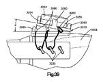
ここで図36〜39を参照すると、遠位ターゲティング装置3002の別の実施形態が示されている。図36に示されるように、遠位ターゲティング装置3002は、磁場発生器3014に連結された枝状部分3028を有するブリッジ3020を含むことができる。磁場発生器3014は、遠位ターゲティング装置3002に連結された電動ツール3004のシャフトを受け入れるための横入口開口部3132を有している。シャフト座面は、実質的に磁場発生器3014の幾何学的中心に位置することができる。本実施形態では、枝状部分3028は、ブリッジ3020のアタッチメント装置3034によって電動ツール3004の両側をブラケットのように囲んでいる。アタッチメント装置3034はテザー3040を含むことができる。枝状部分3028は、枝状部分3028の近位部分などにおいて枝状部分3028から横方向外側に延びるクリート3030などのカプラを含むことができる。テザー3040は、クリート3030に連結されることで枝状部分3028をアタッチメント装置3024に連結するように構成されている。図36は、クリート3030に緩く結ばれたテザー3040を示し、図37は、締めつけられた形態のテザーを示している。
Here, with reference to FIGS. 36-39, another embodiment of the
アタッチメント装置3034は、例えば、モータカウリングの頂部など、電動ツールの一部に取り付けられるように構成されたマウント3070を有している。マウント3070は、テザー3040を固定するように構成することができる。テザー3040は、張力付与機構3050から延びることができる。張力付与機構3050は、着脱可能にマウント3070に取り付け可能とすることができる。張力付与機構3050は、回転可能に基部3054に連結されたダイヤル3052を含むことができる。マウント3070は、張力付与機構3050の基部3054を支持するためのマウント面3055を画定することができる。マウント3070はまた、例えば、スナップ嵌め方式で着脱可能に基部3054に連結されるように構成されたタブ3060などの第1のカップリング要素を含むことができる。
The
図36に示されるように、ダイヤル3052は回転軸3053を画定することができる。ダイヤル3052は、テザー3040がその周囲に巻き付けられる内部スプールに連結することができる。張力付与機構3050は、軸3053を中心として第1の回転方向に基部3054に対してスプール(ダイヤル3052を介して)を回転させるとテザー3040が更にスプールの周囲に巻き取られるように構成することができ、これにより、テザー3040に張力が付与され、テザー3040が張力付与機構3050から延びる全体の長さが小さくなる。張力付与機構3050はラチェットを含むことができ、これにより、ラチェットが係合されるとスプール及び/又はダイヤル3052が第1の回転方向と反対の第2の回転方向に回転することが防止される。ラチェットは、例えば、ダイヤル3052を続けて押すことによって係合及び係合解除することができる。
As shown in FIG. 36, the
図39に示されるように、マウント3070は、例えば、マウント面3055から凹んだ固定スロット3080のような第2のカップリング要素を画定することができる。固定スロット3080の最遠位の1つは、前部タブ3065によって少なくとも部分的に画定することができる。固定スロット3080は、テザー3040の一部を受け入れるように構成することができる。例えば、テザーは、張力付与機構3050から引き抜かれるか、又は少なくとも緩められて、固定スロット3080の1つ以上、任意選択によりすべてに通して、枝状部分3028をマウント3070に固定するような形でクリート3030の1つ以上、任意選択によりすべての周囲に巻きつけることができる。張力付与機構3050は、スナップ嵌めによって、タブ3060を介してマウント3070のマウント面3055に連結することができる。マウント面3055は、医師のアクセスを向上させるためにシャフト軸18(図1を参照)に対して鋭角αで遠位方向に傾斜することができる。次いで、テザー3040が枝状部分3028を電動ツール3004に対して強固に引き締めるまでダイヤル3052を第1の回転方向に回転させることができる。図38に示されるように、本実施形態の枝状部分3028は、例えば異なるサイズ及び/又は形状の電動ツール3004に適合するように必要なだけ横方向に調節可能となっている。本実施形態では、枝状部分3028自体は、アタッチメント装置3024のクランプアームとして特徴付けることができる。
As shown in FIG. 39, the
次に図40〜42を参照し、上記に記載の遠位ターゲティング装置と共に使用するためのディスプレイアセンブリ300の例示的な実施形態について次に説明する。図40に示されるように、ディスプレイアセンブリ300は、図に示されるような関節運動アーム304などのアームに連結されたディスプレイ302を含むことができる。関節運動アーム304は、互いに連結された複数の関節運動可能なアームセグメント306で形成することができる。アーム304はまた、遠位ターゲティング装置に接続するための固定セグメント308も含むことができる。図41に示されるように、ディスプレイ302は、シャフト6の遠位端と、非限定的な例として、髄内釘のロックねじなどの、遠位ターゲティング装置によってターゲティングされる品目との相対位置の視覚的標示310を提供するビュースクリーン301を含むことができる。図42に示されるように、ディスプレイアセンブリ300は、遠位ターゲティング装置2のブリッジ20に連結することができる。他の実施形態では、ディスプレイアセンブリ300、又は少なくともディスプレイ302を遠位ターゲティング手技の間に手術台、ベンチ、又は医師の視界内の別の位置に連結することができる。
An exemplary embodiment of the
本開示を詳細に説明したが、添付の特許請求の範囲により定義される本発明の趣旨及び範囲から逸脱することなく、本明細書において種々の変更、代用、及び改変を行い得る点を、理解するべきである。更に、本開示の範囲は、明細書に記載される特定の実施形態に限定されるものではない。当業者が、そのプロセスから容易に理解するように、本明細書において説明される対応する実施形態と実質的に同じ機能を実施する、又は実質的に同じ結果を達成する、現在存在する又は後に開発される、機械、製造法、組成物、手段、方法、又は工程は、本開示に従って利用され得る。 Although this disclosure has been described in detail, it is understood that various modifications, substitutions, and modifications may be made herein without departing from the spirit and scope of the invention as defined by the appended claims. Should be done. Moreover, the scope of the present disclosure is not limited to the particular embodiments described herein. As one of ordinary skill in the art will readily understand from the process, it will either perform substantially the same function as the corresponding embodiment described herein, or achieve substantially the same result, currently present or later. Machines, manufacturing methods, compositions, means, methods, or processes developed may be utilized in accordance with the present disclosure.
〔実施の態様〕
(1) 外科用器具の遠位ターゲティング装置であって、
軸に沿って細長いシャフトを受け入れるように構成されたカップリング要素を有する磁場発生器と、
前記軸に対して近位方向に前記磁場発生器から離隔するように前記磁場発生器に接続可能なブリッジであって、前記シャフトを操作するように構成されたツールに接続可能なアタッチメント装置を有し、前記ブリッジを前記ツールに実質的に強固に連結するような形で前記ツールの本体を留めるように構成された一対のアームを有する、ブリッジと、を備え、前記アームの少なくとも一方は、異なる形状及びサイズの1つ以上を有するツール本体を前記アームが実質的に強固に留めることを可能とするように調節可能な距離で前記アタッチメント部材に対して配置可能である、遠位ターゲティング装置。
(2) 前記一対のアームの少なくとも一方が歯を有するラックを画定し、前記アタッチメント装置が、前記ラックの前記歯と係合するように構成されたピニオンを備えることにより、前記ピニオンの回転が前記距離を増加又は減少させる、実施態様1に記載の遠位ターゲティング装置。
(3) 前記ピニオンは、医師が前記ピニオンを操作することを可能にするように構成されたノブに連結されている、実施態様2に記載の遠位ターゲティング装置。
(4) 前記ノブがラチェット歯を画定し、前記アタッチメント装置が、前記ラチェット歯に係合するように構成された少なくとも1つの爪を備え、前記少なくとも1つの爪が、1)前記距離を減少させるように第1の回転方向に沿った前記ピニオンの回転を可能とし、かつ、2)前記第1の回転方向とは反対の第2の回転方向に沿った前記ピニオンの回転を妨げるように構成されている、実施態様3に記載の遠位ターゲティング装置。
(5) 前記アタッチメント装置が、張力付与機構と係合されたテザーを備え、前記テザーは、前記アームの前記少なくとも一方に取り付けられるように構成され、前記張力付与機構は、前記テザーに張力を加えて前記距離を減少させるように構成されている、実施態様1に記載の遠位ターゲティング装置。
[Implementation]
(1) A distal targeting device for surgical instruments.
A magnetic field generator with a coupling element configured to accept an elongated shaft along the axis,
It has an attachment device that is a bridge that can be connected to the magnetic field generator so as to be separated from the magnetic field generator in the proximal direction with respect to the axis and that can be connected to a tool configured to operate the shaft. A bridge comprising a pair of arms configured to fasten the body of the tool in such a manner that the bridge is substantially tightly coupled to the tool, wherein at least one of the arms is different. A distal targeting device in which a tool body having one or more of shapes and sizes can be placed with respect to the attachment member at an adjustable distance so that the arm is substantially able to fasten.
(2) The rotation of the pinion is such that at least one of the pair of arms defines a rack having teeth and the attachment device comprises a pinion configured to engage the teeth of the rack. The distal targeting device according to embodiment 1, wherein the distance is increased or decreased.
(3) The distal targeting device according to embodiment 2, wherein the pinion is connected to a knob configured to allow a physician to operate the pinion.
(4) The knob defines a ratchet tooth, the attachment device comprises at least one claw configured to engage the ratchet tooth, and the at least one claw 1) reduces the distance. As described above, the pinion can be rotated along the first rotation direction, and 2) the pinion is prevented from rotating along the second rotation direction opposite to the first rotation direction. The distal targeting apparatus according to embodiment 3.
(5) The attachment device includes a tether engaged with a tension applying mechanism, the tether is configured to be attached to at least one of the arms, and the tension applying mechanism applies tension to the tether. The distal targeting device according to embodiment 1, which is configured to reduce the distance.
(6) 前記一対のアームのそれぞれが1つ以上のクリートを画定し、前記テザーが、前記アームのそれぞれの前記1つ以上のクリートの周囲に結ばれることによって前記アームのそれぞれに前記テザーを取り付けるように構成されており、かつ、前記張力付与機構が、前記テザーに張力を加えて前記距離を減少させるように構成されている、実施態様5に記載の遠位ターゲティング装置。
(7) 前記張力付与機構がダイヤルを備え、前記テザーが、前記ダイヤルに接続されたスプールの周囲に巻かれることにより前記ダイヤルの回転が前記テザーに前記張力を加える、実施態様6に記載の遠位ターゲティング装置。
(8) 前記アタッチメント装置が、並進軸に沿って並進可能な並進可能部材を備え、前記並進可能部材が部材接触面を有し、前記アームの前記少なくとも一方が、前記部材接触面と係合するアーム接触面を画定し、前記部材接触面及び前記アーム接触面の少なくとも一方が前記並進軸に対して斜めの角度で配向され、前記並進軸に沿った第1の並進方向への並進可能部材の並進が、前記アームの前記少なくとも一方を動かして前記距離を減少させる、実施態様1に記載の遠位ターゲティング装置。
(9) 前記並進可能部材がラチェット歯を画定し、前記アタッチメント装置が、前記ラチェット歯と係合する少なくとも1つの爪を含み、前記少なくとも1つの爪が、1)前記並進可能部材の前記第1の並進方向への並進を可能とし、かつ、2)前記並進可能部材の前記第1の並進方向とは反対の第2の並進方向への並進を阻止するように構成されている、実施態様8に記載の遠位ターゲティング装置。
(10) 前記アームの前記少なくとも一方が、前記ツールの前記本体に当接するように構成された第1のアーム部分と、前記アーム接触面を画定する第2のアーム部分とを備え、前記アームの前記少なくとも一方が、前記第1のアーム部分と前記第2のアーム部分との間に位置する枢動ジョイントを中心として枢動可能であることにより、前記距離を減少させることによって前記第1のアーム部分が前記ツールの前記本体に対して枢動する、実施態様8に記載の遠位ターゲティング装置。
(6) Each of the pair of arms defines one or more cleats, and the tether is attached to each of the arms by being tied around the one or more cleats of each of the arms. The distal targeting apparatus according to embodiment 5, wherein the tension applying mechanism is configured to apply tension to the tether to reduce the distance.
(7) The distance according to
(8) The attachment device includes a translatable member that can be translated along a translation axis, the translatable member has a member contact surface, and at least one of the arms engages with the member contact surface. An arm contact surface is defined, and at least one of the member contact surface and the arm contact surface is oriented at an oblique angle with respect to the translation axis, and the translatable member in the first translation direction along the translation axis. The distal targeting device according to embodiment 1, wherein the translation moves at least one of the arms to reduce the distance.
(9) The translatable member defines a ratchet tooth, the attachment device comprises at least one claw that engages the ratchet tooth, and the at least one claw is 1) said first of the translatable member. 8), which is configured to enable translation in the translational direction of, and 2) prevent translation of the translatable member in a second translational direction opposite to the first translational direction. Distal targeting device according to.
(10) The arm includes a first arm portion configured so that at least one of the arms abuts on the main body of the tool, and a second arm portion defining the arm contact surface. The first arm by reducing the distance by allowing at least one of the pivots to be pivoted around a pivot joint located between the first arm portion and the second arm portion. 8. The distal targeting device according to
(11) 前記アームの前記少なくとも一方が、前記ツールの前記本体に対して前記アームの前記少なくとも一方を付勢するように構成されたばねヒンジによって前記アタッチメント装置に接続されている、実施態様1に記載の遠位ターゲティング装置。
(12) 前記一対のアームのそれぞれが、前記ツールの前記本体の両側に対して前記一対のアームを付勢するように構成されたそれぞれのばねヒンジによって前記アタッチメント装置に接続されている、実施態様11に記載の遠位ターゲティング装置。
(13) 前記ブリッジが、前記ブリッジを前記ツールに実質的に強固に連結するような形で前記一対のアームと協力して前記ツールの前記本体を留めるように構成された第2の対のアームを更に備え、前記一対のアーム及び前記第2の対のアームの各アームは、異なる形状及びサイズの1つ以上を有するツール本体を前記アームが実質的に強固に留めることを可能とするように調節可能な距離で前記アタッチメント部材に対して配置可能であり、前記第2の対のアームのそれぞれが、前記第2の対のアームを前記ツールの前記本体の両側に対して付勢するように構成されたそれぞれのばねヒンジによって前記アタッチメント装置に接続されている、実施態様12に記載の遠位ターゲティング装置。
(14) 標的と外科用器具のシャフトとを整列させるように構成された磁場発生器であって、
磁場発生回路を収容するハウジングと、
少なくとも部分的に開口部を画定するカップリング要素であって、前記開口部が、長手方向に沿って互いに離隔した開口部近位端と開口部遠位端とを有し、前記開口部が、前記長手方向に対して実質的に垂直な横方向に開放していることで前記シャフトの遠位端又は近位端を前記開口部に通すことなく前記シャフトを受け入れる、カップリング要素と、
を備えた、磁場発生器。
(15) 前記開口部が、第2のスロット部分と連通する第1のスロット部分を有するスロットであり、前記第1のスロット部分は前記横方向に開放しており、前記第2のスロット部分は前記開口部の内側端部を画定し、前記第2のスロット部分が前記第1のスロット部分から離隔している、実施態様14に記載の磁場発生器。
(11) The first embodiment, wherein at least one of the arms is connected to the attachment device by a spring hinge configured to urge the at least one of the arms against the body of the tool. Distal targeting device.
(12) An embodiment in which each of the pair of arms is connected to the attachment device by a spring hinge configured to urge the pair of arms against both sides of the body of the tool. 11. The distal targeting device according to 11.
(13) A second pair of arms configured such that the bridge cooperates with the pair of arms to fasten the body of the tool in such a manner that the bridge is substantially firmly connected to the tool. Each arm of the pair of arms and the second pair of arms allows the arms to substantially secure a tool body having one or more of different shapes and sizes. It can be placed with respect to the attachment member at an adjustable distance so that each of the second pair of arms urges the second pair of arms against both sides of the body of the tool. 12. The distal targeting device according to
(14) A magnetic field generator configured to align the target with the shaft of the surgical instrument.
A housing that houses the magnetic field generation circuit and
A coupling element that at least partially defines an opening, wherein the opening has a proximal end of the opening and a distal end of the opening that are spaced apart from each other along the longitudinal direction. A coupling element that accepts the shaft without passing the distal or proximal end of the shaft through the opening by opening laterally substantially perpendicular to the longitudinal direction.
A magnetic field generator equipped with.
(15) The opening is a slot having a first slot portion communicating with the second slot portion, the first slot portion is open in the lateral direction, and the second slot portion is The magnetic field generator according to
(16) 前記ハウジング内に可動に配設されたシャフトマウントを更に備え、前記シャフトマウントが第1の位置と第2の位置との間で動くように構成されており、1)前記第1の位置においては前記シャフトマウントは前記開口部内に前記シャフトを保持し、2)前記第2の位置においては前記シャフトは前記シャフトマウントによって拘束されない、実施態様14に記載の磁場発生器。
(17) 前記開口部及び前記シャフトマウントの少なくとも一方が、前記シャフトを回転可能に支持するための軸受面を備える、実施態様16に記載の磁場発生器。
(18) 前記カップリング要素が、前記開口部と連通したシャフト座面を画定する、実施態様14に記載の磁場発生器。
(19) 前記シャフト座面が、実質的に前記磁場発生回路の幾何学的中心に位置するか、又は前記磁場発生回路の前記幾何学的中心から垂直方向にオフセットしている、実施態様18に記載の磁場発生器。
(20) 遠位ターゲティングシステムであって、
ツール本体及び受け入れ要素を有する電動ツールと、
長手方向に沿って延びる軸に沿って細長いシャフトであって、前記シャフトの近位部分が前記受け入れ要素内に受け入れ可能である、シャフトと、
前記シャフトを受け入れるように構成されたカップリング要素を有する磁場発生器と、
前記軸に対して近位方向に前記磁場発生器から離隔するように前記磁場発生器に接続可能なブリッジであって、駆動ツールに接続可能なアタッチメント装置を有し、前記ブリッジを前記ツールに実質的に強固に連結するような形で前記ツール本体を留めるように構成された一対のアームを含む、ブリッジと、を備え、前記アームの少なくとも一方は、前記アームが、1)前記ツール本体を実質的に強固に留め、2)前記ツール本体を解放し、3)前記ツール本体とは異なるサイズ及び形状の1つ以上を有する第2のツール本体を実質的に強固に留めることを可能とするように調節可能な距離で前記アタッチメント装置に対して配置可能である、遠位ターゲティングシステム。
(16) A shaft mount movably arranged in the housing is further provided, and the shaft mount is configured to move between a first position and a second position. 1) The first position. The magnetic field generator according to
(17) The magnetic field generator according to
(18) The magnetic field generator according to
(19) In
(20) A distal targeting system
An electric tool with a tool body and receiving elements,
A shaft that is elongated along an axis extending along the longitudinal direction, the proximal portion of the shaft being receptible within the receiving element, and the shaft.
A magnetic field generator with a coupling element configured to accept the shaft,
A bridge that can be connected to the magnetic field generator in a direction proximal to the axis so as to be separated from the magnetic field generator and has an attachment device that can be connected to a drive tool, and the bridge is substantially attached to the tool. It comprises a bridge comprising a pair of arms configured to fasten the tool body in such a way that it is tightly coupled, and at least one of the arms has the arm 1) substantially the tool body. 2) Release the tool body, and 3) make it possible to substantially firmly hold the second tool body having one or more of a size and shape different from the tool body. A distal targeting system that can be placed with respect to the attachment device at an adjustable distance.
(21) 前記アタッチメント装置が、前記少なくとも一方のアームを再配置することで前記距離を調節するように構成されたアクチュエータを備える、実施態様20に記載の遠位ターゲティングシステム。
(22) 前記磁場発生器がリンケージを更に備え、前記ブリッジが、前記ブリッジの遠位端に位置する1つ以上のカプラを更に備え、前記リンケージが、前記ブリッジの前記1つ以上のカプラに着脱可能に接続可能である、実施態様20に記載の遠位ターゲティングシステム。
(21) The distal targeting system according to
(22) The magnetic field generator further comprises a linkage, the bridge further comprises one or more couplers located at the distal end of the bridge, and the linkage is attached to and detached from the one or more couplers of the bridge. 20. The distal targeting system according to
Claims (22)
軸に沿って細長いシャフトを受け入れるように構成されたカップリング要素を有する磁場発生器と、
前記軸に対して近位方向に前記磁場発生器から離隔するように前記磁場発生器に接続可能なブリッジであって、前記シャフトを操作するように構成されたツールに接続可能なアタッチメント装置を有し、前記ブリッジを前記ツールに実質的に強固に連結するような形で前記ツールの本体を留めるように構成された一対のアームを有する、ブリッジと、を備え、前記アームの少なくとも一方は、異なる形状及びサイズの1つ以上を有するツール本体を前記アームが実質的に強固に留めることを可能とするように調節可能な距離で前記アタッチメント部材に対して配置可能である、遠位ターゲティング装置。 A distal targeting device for surgical instruments
A magnetic field generator with a coupling element configured to accept an elongated shaft along the axis,
It has an attachment device that is a bridge that can be connected to the magnetic field generator so as to be separated from the magnetic field generator in the proximal direction with respect to the axis and that can be connected to a tool configured to operate the shaft. A bridge comprising a pair of arms configured to fasten the body of the tool in such a manner that the bridge is substantially tightly coupled to the tool, wherein at least one of the arms is different. A distal targeting device in which a tool body having one or more of shapes and sizes can be placed with respect to the attachment member at an adjustable distance so that the arm is substantially able to fasten.
磁場発生回路を収容するハウジングと、
少なくとも部分的に開口部を画定するカップリング要素であって、前記開口部が、長手方向に沿って互いに離隔した開口部近位端と開口部遠位端とを有し、前記開口部が、前記長手方向に対して実質的に垂直な横方向に開放していることで前記シャフトの遠位端又は近位端を前記開口部に通すことなく前記シャフトを受け入れる、カップリング要素と、
を備えた、磁場発生器。 A magnetic field generator configured to align the target with the shaft of the surgical instrument.
A housing that houses the magnetic field generation circuit and
A coupling element that at least partially defines an opening, wherein the opening has a proximal end of the opening and a distal end of the opening that are spaced apart from each other along the longitudinal direction. A coupling element that accepts the shaft without passing the distal or proximal end of the shaft through the opening by opening laterally substantially perpendicular to the longitudinal direction.
A magnetic field generator equipped with.
ツール本体及び受け入れ要素を有する電動ツールと、
長手方向に沿って延びる軸に沿って細長いシャフトであって、前記シャフトの近位部分が前記受け入れ要素内に受け入れ可能である、シャフトと、
前記シャフトを受け入れるように構成されたカップリング要素を有する磁場発生器と、
前記軸に対して近位方向に前記磁場発生器から離隔するように前記磁場発生器に接続可能なブリッジであって、駆動ツールに接続可能なアタッチメント装置を有し、前記ブリッジを前記ツールに実質的に強固に連結するような形で前記ツール本体を留めるように構成された一対のアームを含む、ブリッジと、を備え、前記アームの少なくとも一方は、前記アームが、1)前記ツール本体を実質的に強固に留め、2)前記ツール本体を解放し、3)前記ツール本体とは異なるサイズ及び形状の1つ以上を有する第2のツール本体を実質的に強固に留めることを可能とするように調節可能な距離で前記アタッチメント装置に対して配置可能である、遠位ターゲティングシステム。 Distal targeting system
An electric tool with a tool body and receiving elements,
A shaft that is elongated along an axis extending along the longitudinal direction, the proximal portion of the shaft being receptible within the receiving element, and the shaft.
A magnetic field generator with a coupling element configured to accept the shaft,
A bridge that can be connected to the magnetic field generator in a direction proximal to the axis so as to be separated from the magnetic field generator and has an attachment device that can be connected to a drive tool, and the bridge is substantially attached to the tool. It comprises a bridge comprising a pair of arms configured to fasten the tool body in such a way that it is tightly coupled, and at least one of the arms has the arm 1) substantially the tool body. 2) Release the tool body, and 3) make it possible to substantially firmly hold the second tool body having one or more of a size and shape different from the tool body. A distal targeting system that can be placed with respect to the attachment device at an adjustable distance.
Applications Claiming Priority (3)
| Application Number | Priority Date | Filing Date | Title |
|---|---|---|---|
| US15/691,906 | 2017-08-31 | ||
| US15/691,906 US10588644B2 (en) | 2017-08-31 | 2017-08-31 | Guide attachment for power tools |
| PCT/IB2018/056332 WO2019043509A1 (en) | 2017-08-31 | 2018-08-21 | Guide attachment for power tools |
Publications (2)
| Publication Number | Publication Date |
|---|---|
| JP2020531199A true JP2020531199A (en) | 2020-11-05 |
| JP7225216B2 JP7225216B2 (en) | 2023-02-20 |
Family
ID=63586777
Family Applications (1)
| Application Number | Title | Priority Date | Filing Date |
|---|---|---|---|
| JP2020512397A Active JP7225216B2 (en) | 2017-08-31 | 2018-08-21 | Guide attachment for power tools |
Country Status (8)
| Country | Link |
|---|---|
| US (1) | US10588644B2 (en) |
| EP (2) | EP3675750B1 (en) |
| JP (1) | JP7225216B2 (en) |
| CN (1) | CN111031941B (en) |
| AU (1) | AU2018322961B2 (en) |
| BR (1) | BR112020003895A2 (en) |
| CA (1) | CA3073893A1 (en) |
| WO (1) | WO2019043509A1 (en) |
Families Citing this family (4)
| Publication number | Priority date | Publication date | Assignee | Title |
|---|---|---|---|---|
| US10588644B2 (en) * | 2017-08-31 | 2020-03-17 | DePuy Synthes Products, Inc. | Guide attachment for power tools |
| EP3785808A1 (en) | 2019-08-29 | 2021-03-03 | Sulzer Mixpac AG | Cartridge holder for a dispenser |
| WO2021154794A1 (en) | 2020-01-28 | 2021-08-05 | Mason Bettenga | Systems and methods for aligning surgical devices |
| EP3903713B1 (en) * | 2020-04-29 | 2024-08-21 | Stryker European Operations Limited | Field generator assembly for surgical navigation |
Citations (7)
| Publication number | Priority date | Publication date | Assignee | Title |
|---|---|---|---|---|
| US4722336A (en) * | 1985-01-25 | 1988-02-02 | Michael Kim | Placement guide |
| US6033409A (en) * | 1996-10-31 | 2000-03-07 | Scuola Superiore Di Studi Universitari | Surgical drill with bit penetration control and breakthrough detection |
| JP2001500750A (en) * | 1996-05-06 | 2001-01-23 | オーソマトリックス インコーポレーテッド | Magnetic positioning configuration of orthopedic fixation screws |
| JP2004130094A (en) * | 2002-07-18 | 2004-04-30 | Biosense Inc | Distal targeting of locking screw in intramedullary nail |
| JP2013544138A (en) * | 2010-11-01 | 2013-12-12 | スミス アンド ネフュー インコーポレーテッド | Targeting orthopedic device labels |
| JP2014512876A (en) * | 2011-02-18 | 2014-05-29 | デピュイ・シンセス・プロダクツ・エルエルシー | Tool with integrated navigation and guidance system and associated apparatus and method |
| CN105232112A (en) * | 2015-10-15 | 2016-01-13 | 陈为坚 | Surgical electric drill |
Family Cites Families (33)
| Publication number | Priority date | Publication date | Assignee | Title |
|---|---|---|---|---|
| CA2073266A1 (en) * | 1991-07-09 | 1993-01-10 | Mehmet Rona | Distal targeting system |
| US5433720A (en) * | 1992-09-22 | 1995-07-18 | Orthofix S.R.L. | Centering means for holes of intramedullary nails |
| EP0673231B1 (en) | 1992-11-20 | 2002-02-13 | BURKE, Dennis, W. | Improved femoral implant collar |
| US6929647B2 (en) * | 2001-02-21 | 2005-08-16 | Howmedica Osteonics Corp. | Instrumentation and method for implant insertion |
| US7831292B2 (en) * | 2002-03-06 | 2010-11-09 | Mako Surgical Corp. | Guidance system and method for surgical procedures with improved feedback |
| US7720522B2 (en) * | 2003-02-25 | 2010-05-18 | Medtronic, Inc. | Fiducial marker devices, tools, and methods |
| WO2004024039A2 (en) * | 2002-09-13 | 2004-03-25 | Replication Medical, Inc. | Implant manipulation and storage tools |
| DE10303964A1 (en) * | 2003-01-31 | 2004-08-19 | Wolfgang Prof. Dr. Oettinger | Medical drilling device and medical drilling method |
| US20050267354A1 (en) * | 2003-02-04 | 2005-12-01 | Joel Marquart | System and method for providing computer assistance with spinal fixation procedures |
| US7029478B2 (en) * | 2003-09-30 | 2006-04-18 | Depuy Products, Inc. | Method and apparatus for distal targeting of locking screws in intramedullary nails |
| US7873400B2 (en) | 2003-12-10 | 2011-01-18 | Stryker Leibinger Gmbh & Co. Kg. | Adapter for surgical navigation trackers |
| US9463012B2 (en) * | 2004-10-26 | 2016-10-11 | P Tech, Llc | Apparatus for guiding and positioning an implant |
| US7840256B2 (en) * | 2005-06-27 | 2010-11-23 | Biomet Manufacturing Corporation | Image guided tracking array and method |
| US8374673B2 (en) * | 2007-01-25 | 2013-02-12 | Warsaw Orthopedic, Inc. | Integrated surgical navigational and neuromonitoring system having automated surgical assistance and control |
| US7987001B2 (en) * | 2007-01-25 | 2011-07-26 | Warsaw Orthopedic, Inc. | Surgical navigational and neuromonitoring instrument |
| EP2124799B1 (en) | 2007-02-01 | 2012-10-31 | Interactive Neuroscience Center, Llc | Surgical navigation |
| AT506937B1 (en) * | 2008-11-27 | 2010-01-15 | I T S Gmbh | DEVICE FOR CONSTRUCTING A LONG BONE |
| US8808297B2 (en) * | 2009-02-24 | 2014-08-19 | Microport Orthopedics Holdings Inc. | Orthopedic surgical guide |
| US8366719B2 (en) * | 2009-03-18 | 2013-02-05 | Integrated Spinal Concepts, Inc. | Image-guided minimal-step placement of screw into bone |
| RU2012116894A (en) * | 2009-10-06 | 2013-11-20 | Смит Энд Нефью, Инк. | GUIDANCE ON ORTHOPEDIC DEVICES |
| US8757875B2 (en) | 2011-01-26 | 2014-06-24 | Peter Mayer | Sensor positioning and stabilizing device |
| US9113918B2 (en) * | 2013-03-15 | 2015-08-25 | Depuy (Ireland) | Femoral surgical instrument and method of using same |
| EP2967352B1 (en) * | 2013-03-15 | 2020-06-24 | Microtech Medical Technologies Ltd. | Implantable device with bridge and methods of manufacturing thereof |
| US9451999B2 (en) | 2013-10-10 | 2016-09-27 | Warsaw Orthopedic, Inc. | Surgical instrument adaptor |
| WO2015121311A1 (en) * | 2014-02-11 | 2015-08-20 | KB Medical SA | Sterile handle for controlling a robotic surgical system from a sterile field |
| TWI678184B (en) * | 2014-04-25 | 2019-12-01 | 德派信迪思產品公司 | Aiming device system |
| US20170164958A1 (en) | 2014-07-29 | 2017-06-15 | David B. Rich | Surgical viewing system |
| CN107095713B (en) * | 2016-02-22 | 2020-06-09 | 北京纳通科技集团有限公司 | Fixing system for spine |
| EP3351202B1 (en) * | 2017-01-18 | 2021-09-08 | KB Medical SA | Universal instrument guide for robotic surgical systems |
| JP7583513B2 (en) * | 2017-01-18 | 2024-11-14 | ケービー メディカル エスアー | Universal instrument guide for robotic surgical systems, surgical instrument system |
| EP3360502A3 (en) * | 2017-01-18 | 2018-10-31 | KB Medical SA | Robotic navigation of robotic surgical systems |
| US20180289432A1 (en) * | 2017-04-05 | 2018-10-11 | Kb Medical, Sa | Robotic surgical systems for preparing holes in bone tissue and methods of their use |
| US10588644B2 (en) * | 2017-08-31 | 2020-03-17 | DePuy Synthes Products, Inc. | Guide attachment for power tools |
-
2017
- 2017-08-31 US US15/691,906 patent/US10588644B2/en active Active
-
2018
- 2018-08-21 CA CA3073893A patent/CA3073893A1/en active Pending
- 2018-08-21 CN CN201880056465.5A patent/CN111031941B/en active Active
- 2018-08-21 AU AU2018322961A patent/AU2018322961B2/en active Active
- 2018-08-21 WO PCT/IB2018/056332 patent/WO2019043509A1/en unknown
- 2018-08-21 JP JP2020512397A patent/JP7225216B2/en active Active
- 2018-08-21 EP EP18769801.4A patent/EP3675750B1/en active Active
- 2018-08-21 BR BR112020003895-4A patent/BR112020003895A2/en not_active Application Discontinuation
- 2018-08-21 EP EP20187845.1A patent/EP3750489A1/en not_active Withdrawn
Patent Citations (7)
| Publication number | Priority date | Publication date | Assignee | Title |
|---|---|---|---|---|
| US4722336A (en) * | 1985-01-25 | 1988-02-02 | Michael Kim | Placement guide |
| JP2001500750A (en) * | 1996-05-06 | 2001-01-23 | オーソマトリックス インコーポレーテッド | Magnetic positioning configuration of orthopedic fixation screws |
| US6033409A (en) * | 1996-10-31 | 2000-03-07 | Scuola Superiore Di Studi Universitari | Surgical drill with bit penetration control and breakthrough detection |
| JP2004130094A (en) * | 2002-07-18 | 2004-04-30 | Biosense Inc | Distal targeting of locking screw in intramedullary nail |
| JP2013544138A (en) * | 2010-11-01 | 2013-12-12 | スミス アンド ネフュー インコーポレーテッド | Targeting orthopedic device labels |
| JP2014512876A (en) * | 2011-02-18 | 2014-05-29 | デピュイ・シンセス・プロダクツ・エルエルシー | Tool with integrated navigation and guidance system and associated apparatus and method |
| CN105232112A (en) * | 2015-10-15 | 2016-01-13 | 陈为坚 | Surgical electric drill |
Also Published As
| Publication number | Publication date |
|---|---|
| CN111031941B (en) | 2023-07-07 |
| AU2018322961B2 (en) | 2023-11-30 |
| EP3750489A1 (en) | 2020-12-16 |
| CA3073893A1 (en) | 2019-03-07 |
| US20190059915A1 (en) | 2019-02-28 |
| EP3675750B1 (en) | 2024-05-22 |
| JP7225216B2 (en) | 2023-02-20 |
| US10588644B2 (en) | 2020-03-17 |
| AU2018322961A1 (en) | 2020-03-05 |
| BR112020003895A2 (en) | 2020-09-01 |
| EP3675750A1 (en) | 2020-07-08 |
| CN111031941A (en) | 2020-04-17 |
| WO2019043509A1 (en) | 2019-03-07 |
Similar Documents
| Publication | Publication Date | Title |
|---|---|---|
| JP2020531199A (en) | Guide attachment for electric tools | |
| US20210244443A1 (en) | Bone displacement system and method | |
| US11529175B2 (en) | Moveable bone plate implantation system and method of use | |
| US12042401B2 (en) | Spinal cage devices, systems, and methods of assembly and use | |
| US8740902B2 (en) | Joint fusion apparatus for the ankle-type joint and arthrodetic pin for use in said apparatus | |
| JP5215872B2 (en) | Apparatus and method for shaping a rod in a percutaneous pedicle screw extension | |
| JP5800253B2 (en) | Alignment tool | |
| US7641660B2 (en) | Method, apparatus, and system for image guided bone cutting | |
| JP5188956B2 (en) | Surgical adapter | |
| US8491599B2 (en) | Apparatus and method for aiming a surgical tool | |
| JP6127127B2 (en) | System and method for creating body tissue | |
| US20090062858A1 (en) | Methods and instruments for approximating misaligned | |
| US20070016198A1 (en) | Systems, methods and devices for placement of bone anchors and connectors | |
| US20070073306A1 (en) | Cutting block for surgical navigation | |
| JP2008531088A (en) | Instrument for aligning fixing screws | |
| EP1585436A2 (en) | Spinal rod approximator | |
| TW201144621A (en) | Bedrail clamp | |
| KR20150073124A (en) | Rod insertion device | |
| WO2010122034A1 (en) | Foot positioning system and method | |
| CN110215271A (en) | Ultrasonic pinning aims at auxiliary device in a kind of orthopaedics marrow | |
| US20160235421A1 (en) | Positioning Bracket for Multiple Bone Tunnel Drill Guides | |
| CN111803154A (en) | Guider and tendon repair device | |
| CN113693674B (en) | Fixing support | |
| CN212661856U (en) | Guider and tendon repair device | |
| US7850696B2 (en) | Device for facilitating reduction and repair of fractures of the small bones |
Legal Events
| Date | Code | Title | Description |
|---|---|---|---|
| A621 | Written request for application examination |
Free format text: JAPANESE INTERMEDIATE CODE: A621 Effective date: 20210709 |
|
| A977 | Report on retrieval |
Free format text: JAPANESE INTERMEDIATE CODE: A971007 Effective date: 20220624 |
|
| A131 | Notification of reasons for refusal |
Free format text: JAPANESE INTERMEDIATE CODE: A131 Effective date: 20220719 |
|
| A521 | Request for written amendment filed |
Free format text: JAPANESE INTERMEDIATE CODE: A523 Effective date: 20220913 |
|
| TRDD | Decision of grant or rejection written | ||
| A01 | Written decision to grant a patent or to grant a registration (utility model) |
Free format text: JAPANESE INTERMEDIATE CODE: A01 Effective date: 20230110 |
|
| A61 | First payment of annual fees (during grant procedure) |
Free format text: JAPANESE INTERMEDIATE CODE: A61 Effective date: 20230208 |
|
| R150 | Certificate of patent or registration of utility model |
Ref document number: 7225216 Country of ref document: JP Free format text: JAPANESE INTERMEDIATE CODE: R150 |