JP2020525160A - Suture grasper - Google Patents
Suture grasper Download PDFInfo
- Publication number
- JP2020525160A JP2020525160A JP2019571712A JP2019571712A JP2020525160A JP 2020525160 A JP2020525160 A JP 2020525160A JP 2019571712 A JP2019571712 A JP 2019571712A JP 2019571712 A JP2019571712 A JP 2019571712A JP 2020525160 A JP2020525160 A JP 2020525160A
- Authority
- JP
- Japan
- Prior art keywords
- suture
- needle
- capture
- notch
- threader
- Prior art date
- Legal status (The legal status is an assumption and is not a legal conclusion. Google has not performed a legal analysis and makes no representation as to the accuracy of the status listed.)
- Granted
Links
Images


Classifications
-
- A—HUMAN NECESSITIES
- A61—MEDICAL OR VETERINARY SCIENCE; HYGIENE
- A61B—DIAGNOSIS; SURGERY; IDENTIFICATION
- A61B17/00—Surgical instruments, devices or methods
- A61B17/04—Surgical instruments, devices or methods for suturing wounds; Holders or packages for needles or suture materials
- A61B17/0469—Suturing instruments for use in minimally invasive surgery, e.g. endoscopic surgery
-
- A—HUMAN NECESSITIES
- A61—MEDICAL OR VETERINARY SCIENCE; HYGIENE
- A61B—DIAGNOSIS; SURGERY; IDENTIFICATION
- A61B17/00—Surgical instruments, devices or methods
- A61B17/04—Surgical instruments, devices or methods for suturing wounds; Holders or packages for needles or suture materials
- A61B17/0482—Needle or suture guides
-
- A—HUMAN NECESSITIES
- A61—MEDICAL OR VETERINARY SCIENCE; HYGIENE
- A61B—DIAGNOSIS; SURGERY; IDENTIFICATION
- A61B17/00—Surgical instruments, devices or methods
- A61B17/04—Surgical instruments, devices or methods for suturing wounds; Holders or packages for needles or suture materials
- A61B17/0485—Devices or means, e.g. loops, for capturing the suture thread and threading it through an opening of a suturing instrument or needle eyelet
-
- A—HUMAN NECESSITIES
- A61—MEDICAL OR VETERINARY SCIENCE; HYGIENE
- A61B—DIAGNOSIS; SURGERY; IDENTIFICATION
- A61B17/00—Surgical instruments, devices or methods
- A61B17/04—Surgical instruments, devices or methods for suturing wounds; Holders or packages for needles or suture materials
- A61B17/06—Needles ; Sutures; Needle-suture combinations; Holders or packages for needles or suture materials
- A61B17/06066—Needles, e.g. needle tip configurations
- A61B17/06109—Big needles, either gripped by hand or connectable to a handle
-
- A—HUMAN NECESSITIES
- A61—MEDICAL OR VETERINARY SCIENCE; HYGIENE
- A61B—DIAGNOSIS; SURGERY; IDENTIFICATION
- A61B17/00—Surgical instruments, devices or methods
- A61B17/34—Trocars; Puncturing needles
- A61B17/3417—Details of tips or shafts, e.g. grooves, expandable, bendable; Multiple coaxial sliding cannulas, e.g. for dilating
- A61B17/3421—Cannulas
-
- A—HUMAN NECESSITIES
- A61—MEDICAL OR VETERINARY SCIENCE; HYGIENE
- A61B—DIAGNOSIS; SURGERY; IDENTIFICATION
- A61B17/00—Surgical instruments, devices or methods
- A61B17/0057—Implements for plugging an opening in the wall of a hollow or tubular organ, e.g. for sealing a vessel puncture or closing a cardiac septal defect
-
- A—HUMAN NECESSITIES
- A61—MEDICAL OR VETERINARY SCIENCE; HYGIENE
- A61B—DIAGNOSIS; SURGERY; IDENTIFICATION
- A61B17/00—Surgical instruments, devices or methods
- A61B17/04—Surgical instruments, devices or methods for suturing wounds; Holders or packages for needles or suture materials
- A61B17/0483—Hand-held instruments for holding sutures
-
- A—HUMAN NECESSITIES
- A61—MEDICAL OR VETERINARY SCIENCE; HYGIENE
- A61B—DIAGNOSIS; SURGERY; IDENTIFICATION
- A61B17/00—Surgical instruments, devices or methods
- A61B17/00234—Surgical instruments, devices or methods for minimally invasive surgery
- A61B2017/00349—Needle-like instruments having hook or barb-like gripping means, e.g. for grasping suture or tissue
-
- A—HUMAN NECESSITIES
- A61—MEDICAL OR VETERINARY SCIENCE; HYGIENE
- A61B—DIAGNOSIS; SURGERY; IDENTIFICATION
- A61B17/00—Surgical instruments, devices or methods
- A61B17/0057—Implements for plugging an opening in the wall of a hollow or tubular organ, e.g. for sealing a vessel puncture or closing a cardiac septal defect
- A61B2017/00637—Implements for plugging an opening in the wall of a hollow or tubular organ, e.g. for sealing a vessel puncture or closing a cardiac septal defect for sealing trocar wounds through abdominal wall
-
- A—HUMAN NECESSITIES
- A61—MEDICAL OR VETERINARY SCIENCE; HYGIENE
- A61B—DIAGNOSIS; SURGERY; IDENTIFICATION
- A61B17/00—Surgical instruments, devices or methods
- A61B17/0057—Implements for plugging an opening in the wall of a hollow or tubular organ, e.g. for sealing a vessel puncture or closing a cardiac septal defect
- A61B2017/00646—Type of implements
- A61B2017/00663—Type of implements the implement being a suture
-
- A—HUMAN NECESSITIES
- A61—MEDICAL OR VETERINARY SCIENCE; HYGIENE
- A61B—DIAGNOSIS; SURGERY; IDENTIFICATION
- A61B17/00—Surgical instruments, devices or methods
- A61B17/04—Surgical instruments, devices or methods for suturing wounds; Holders or packages for needles or suture materials
- A61B17/06—Needles ; Sutures; Needle-suture combinations; Holders or packages for needles or suture materials
- A61B17/06004—Means for attaching suture to needle
- A61B2017/06009—Means for attaching suture to needle having additional means for releasably clamping the suture to the needle, e.g. actuating rod slideable within the needle
-
- A—HUMAN NECESSITIES
- A61—MEDICAL OR VETERINARY SCIENCE; HYGIENE
- A61B—DIAGNOSIS; SURGERY; IDENTIFICATION
- A61B17/00—Surgical instruments, devices or methods
- A61B17/04—Surgical instruments, devices or methods for suturing wounds; Holders or packages for needles or suture materials
- A61B17/06—Needles ; Sutures; Needle-suture combinations; Holders or packages for needles or suture materials
- A61B17/06004—Means for attaching suture to needle
- A61B2017/06042—Means for attaching suture to needle located close to needle tip
-
- A—HUMAN NECESSITIES
- A61—MEDICAL OR VETERINARY SCIENCE; HYGIENE
- A61M—DEVICES FOR INTRODUCING MEDIA INTO, OR ONTO, THE BODY; DEVICES FOR TRANSDUCING BODY MEDIA OR FOR TAKING MEDIA FROM THE BODY; DEVICES FOR PRODUCING OR ENDING SLEEP OR STUPOR
- A61M5/00—Devices for bringing media into the body in a subcutaneous, intra-vascular or intramuscular way; Accessories therefor, e.g. filling or cleaning devices, arm-rests
- A61M5/178—Syringes
- A61M5/31—Details
- A61M5/32—Needles; Details of needles pertaining to their connection with syringe or hub; Accessories for bringing the needle into, or holding the needle on, the body; Devices for protection of needles
- A61M5/329—Needles; Details of needles pertaining to their connection with syringe or hub; Accessories for bringing the needle into, or holding the needle on, the body; Devices for protection of needles characterised by features of the needle shaft
- A61M5/3291—Shafts with additional lateral openings
Landscapes
- Health & Medical Sciences (AREA)
- Life Sciences & Earth Sciences (AREA)
- Surgery (AREA)
- Heart & Thoracic Surgery (AREA)
- Engineering & Computer Science (AREA)
- Biomedical Technology (AREA)
- Nuclear Medicine, Radiotherapy & Molecular Imaging (AREA)
- Medical Informatics (AREA)
- Molecular Biology (AREA)
- Animal Behavior & Ethology (AREA)
- General Health & Medical Sciences (AREA)
- Public Health (AREA)
- Veterinary Medicine (AREA)
- Pathology (AREA)
- Surgical Instruments (AREA)
Abstract
縫合糸通し器は、長手方向に延在し、捕捉位置と解放位置との間で操作されるように構成された針と、第1の縫合糸ノッチと、第2の縫合糸ノッチと、を含む。第1及び第2の縫合糸ノッチは、針を通って第1の捕捉アンダーカット及び第2の捕捉アンダーカットと共に延在する。第1及び第2の縫合糸ノッチはそれぞれ、針が捕捉方向に向かって操作される際に、縫合糸を内部に受容し、縫合糸を半径方向内方に解放可能に捕捉するように構成されている。The suture threader extends longitudinally and is configured to operate between a capture position and a release position, with a first suture notch and a second suture notch. Including. The first and second suture notches extend through the needle with a first capture undercut and a second capture undercut. Each of the first and second suture notches is configured to receive the suture internally and catch the suture inwardly and releasably as the needle is manipulated in the capture direction. ing.
Description
外科手術では、臨床医が患者の体内の体腔又はその他の望ましい手術部位にアクセスすることが必要となり得る。そのような外科手術を実施するために、患者の組織を通して体腔内に達する切開を行う場合がある。従来の外科手術では、メスなどのナイフを切開組織に当てる場合があるが、腹腔鏡及び内視鏡外科手術などの侵襲性の低い外科手術では、トロカールアセンブリを介して体腔にアクセスする場合がある。トロカールアセンブリは、一般に、トロカールカニューレ内に受け取られるトロカール閉塞具を含む。使用中、臨床医は、所望の手術部位の体腔にアクセスするために、トロカール閉塞具及びカニューレを組織内に導入する。アクセスすると、臨床医は、トロカールカニューレからトロカール閉塞具を引き抜き、トロカールカニューレを使用して外科用器具を体腔内に導入して治療を行うことができるようにする。 Surgery may require the clinician to access a body cavity within the patient's body or other desired surgical site. To perform such surgery, an incision may be made through the patient's tissue into the body cavity. In conventional surgery, a knife, such as a scalpel, may be applied to the incised tissue, while less invasive surgery, such as laparoscopic and endoscopic surgery, may access the body cavity through a trocar assembly. .. Trocar assemblies generally include a trocar obturator received within a trocar cannula. During use, the clinician introduces a trocar obturator and cannula into the tissue to access the body cavity at the desired surgical site. Upon access, the clinician withdraws the trocar obturator from the trocar cannula and uses the trocar cannula to introduce surgical instruments into the body cavity for treatment.
単に例示的なトロカールアセンブリ、その構成要素及びその他の種類の創傷閉鎖デバイスは、2011年7月19日に交付された「Vibratory Trocar」と題する米国特許第7,981,092号、2012年7月24日に交付された「Access Device with Insert」と題する米国特許第8,226,553号、2012年8月28日に交付された「Surgical Access Devices and Methods Providing Seal Movement in Predefined Paths」と題する米国特許第8,251,900号、2013年11月12日に交付された「Absorbing Fluids in a Surgical Access Device」と題する米国特許8,579,807号、2013年10月29日に交付された「Surgical Access Device with Sorbents」と題する米国特許第8,568,362号、2014年1月28日に交付された「Surgical Access Device」と題する米国特許第8,636,686号、2014年4月8日に交付された「Gas Jet Fluid Removal in a Trocar」と題する米国特許第8,690,831号、2008年8月21日公開の「Surgical Hook」と題する米国特許出願公開2008/0200950号、2015年2月5日公開の「Devices,Systems,and Methods for Providing Surgical Access and Facilitating Closure of Surgical Access Openings」と題する米国特許出願公開2015/0038793号、2015年2月5日公開の「Devices,Systems,and Methods for Providing Surgical Access and Facilitating Closure of Surgical Access Openings」と題する米国特許出願公開2015/0038994号及び、2015年4月2日公開の「Wound Closure Device including Mesh Barrier」と題する米国特許出願公開2015/0094741号に記載されている。上に引用した米国特許及び米国特許出願公開の各々の開示内容は、参照により本明細書に組み込まれている。 An exemplary trocar assembly, its components, and other types of wound closure devices are disclosed in US Patent No. 7,981,092, July 2012, entitled "Vibratory Trocar," issued July 19, 2011. U.S. Pat. No. 8,226,553 entitled "Access Device with Insert" issued on the 24th, and "Surgical Access Devices and Methods Serving in Moved in the United States" issued on August 28, 2012. Patent No. 8,251,900, US Pat. No. 8,579,807 entitled "Absorving Fluids in a Surgical Access Device" issued November 12, 2013, issued October 29, 2013. U.S. Patent No. 8,568,362 entitled "Surgical Access Device With Sorbents"; U.S. Patent No. 8,636,686 entitled "Surgical Access Device" issued Jan. 28, 2014; Apr. 8, 2014. U.S. Patent No. 8,690,831 entitled "Gas Jet Fluid Removal in a Trocar" issued Aug. 21, 2008, entitled "Surgical Hook", published in US Patent Application No. 2008/0209950, 2015. U.S. Patent Application Publication No. 5/2015, 15/Dec. 2015, published on Feb. 5, 2015, Sd. U.S. Patent Application Publication Nos. 2015/0038994 entitled "And Methods for Providing Surgical Access and Facilitating Closure of Surgical Access Openings" and "Wound Clos," published April 2, 2015. U.S. Patent Application Publication 2015/0094741 entitled "ure Device including Mesh Barrier". The disclosures of each of the above cited US patents and US patent application publications are hereby incorporated by reference.
そのようなトロカールと共に使用するための外科器具が、(例えばエンドカッター、把持具、カッター、ステープラ、クリップアプライヤ、アクセスデバイス、薬物/遺伝子治療送達デバイス及び、超音波振動、RF、レーザなどを使用するエネルギー送達デバイスなどの)様々な形でトロカールカニューレを通して組織に係合して診断又は治療効果を得ることができる遠位エンドエフェクタを有してもよい。腹腔鏡及び内視鏡外科用器具が、エンドエフェクタとハンドル部分との間に、臨床医によって操作されるシャフトを含んでもよい。このようなシャフトは、所望の深さへの挿入及びシャフトの長手方向軸を中心とした回転を可能にし、それにより患者の腔内でエンドエフェクタの位置付けを行うことを容易にする。エンドエフェクタの位置付けは、エンドエフェクタをシャフトの長手方向軸に対して選択的に関節動作させるか又は別様に偏向させることを可能にする、1つ以上の関節ジョイント又は機構を含めることによって更に容易にすることができる。 Surgical instruments for use with such trocars (eg, use end cutters, graspers, cutters, staplers, clip appliers, access devices, drug/gene therapy delivery devices and ultrasonic vibrations, RF, lasers, etc. May have a distal end effector that can engage tissue through the trocar cannula in various ways (such as an energy delivery device to provide a diagnostic or therapeutic effect). Laparoscopic and endoscopic surgical instruments may include a shaft manipulated by a clinician between the end effector and the handle portion. Such a shaft allows insertion to a desired depth and rotation about the longitudinal axis of the shaft, thereby facilitating positioning of the end effector within the patient's cavity. Positioning of the end effector is further facilitated by the inclusion of one or more articulating joints or mechanisms that allow the end effector to selectively articulate or otherwise deflect relative to the longitudinal axis of the shaft. Can be
トロカールアセンブリ、エンドエフェクタ及びその他の様々な種類の関連構成要素を含む外科用器具が作製され使用されてきたが、本発明者ら以前には、添付の特許請求の範囲に記載されている発明を誰も作製又は使用したことがないものと考えられる。 Although surgical instruments have been made and used that include trocar assemblies, end effectors, and various other types of associated components, prior to the inventors, the invention set forth in the appended claims is now described. It is believed that no one has created or used it.
本明細書に組み込まれていると共にその一部をなす添付の図面は、本発明の実施形態を示すものであり、上記の本発明の一般的説明、及び以下の実施形態の詳細な説明と共に、本発明の原理を説明する役割を果たすものである。
図面は、いかなる方式でも限定することを意図しておらず、本発明の様々な実施形態は、図面に必ずしも描写されていないものを含め、他の様々な方式で実施し得ることが企図される。本明細書に組み込まれ、その一部をなす添付図面は、本発明のいくつかの態様を図示したものであり、本説明文と共に本発明の原理を説明する役割を果たすものである。しかしながら、本発明が、示される正確な配置に限定されない点は理解される。 The drawings are not intended to be limiting in any manner, and it is contemplated that various embodiments of the invention may be implemented in various other ways, including those not necessarily depicted in the drawings. .. The accompanying drawings, which are incorporated in and constitute a part of this specification, illustrate several aspects of the present invention and together with the description serve to explain the principles of the invention. However, it is understood that the invention is not limited to the precise arrangement shown.
本発明の特定の実施例の以下の説明文は、本発明の範囲を限定する目的で用いられるべきではない。本発明の他の実施例、特徴、態様、実施形態、及び利点は、本発明を実施するために想到される最良の形態の1つを実例として示す以下の説明文より、当業者には明らかとなろう。理解されるように、本発明は、いずれも本発明から逸脱することなく、他の異なるかつ明白な態様が可能である。したがって、図面及び説明は、限定的な性質のものではなく、例示的な性質のものと見なされるべきである。 The following description of specific embodiments of the invention should not be used to limit the scope of the invention. Other embodiments, features, aspects, embodiments, and advantages of the invention will be apparent to those skilled in the art from the following description, which illustrates, by way of illustration, one of the best mode contemplated for carrying out the invention. Will be As will be appreciated, the invention is capable of other different and obvious aspects, all without departing from the invention. Therefore, the drawings and description should be regarded as illustrative in nature and not restrictive.
I.例示的な手術用アクセス装置
図1及び図2は、トロカールカニューレ(12)とトロカール閉塞具(14)とを含む、第1の例示的なトロカールアセンブリ(10)の形態の例示的な外科用アクセス装置を示す。トロカール閉塞具(14)は、トロカールカニューレ(12)のトロカールハウジング(16)を通じてトロカールカニューレ(12)内に取り外し可能に受容される。図1に示すように、トロカール閉塞具(14)がトロカールカニューレ(12)内に配置されている状態で、臨床医は、患者の体腔(18)(図3Aを参照)にアクセスするために望ましい手術部位で、患者の組織(17)(図3Aを参照)を通じてトロカールアセンブリ(12)を挿入する。単なる例として、患者の腹部内に、患者の2本の肋骨の間に、又は他の部位に、トロカールアセンブリ(10)を挿入してもよい。トロカール閉塞具(14)の先端(20)は、トロカールカニューレ(12)の遠位端部を体腔(18)(図3Bを参照)に導入するために、トロカールカニューレ(12)から遠位方向に突出して組織(17)(図3A参照)を穿孔する。臨床医は、患者の体腔(18)(図3Cを参照)がトロカールカニューレ(12)を介して手術環境と連通するように、トロカール閉塞具(14)をトロカールカニューレ(12)から近位方向に引き抜く。次いで、臨床医は、体腔(18)(図3Aを参照)を膨張させるためにガスなどの流体をトロカールカニューレ(12)を介して、及び/又は組織(17)と係合するために外科器具のエンドエフェクタをトロカールカニューレ(12)を介して導入して、診断又は治療効果を達成することができる。
I. Exemplary Surgical Access Device FIGS. 1 and 2 illustrate an exemplary surgical access in the form of a first exemplary trocar assembly (10) that includes a trocar cannula (12) and a trocar obturator (14). Shows the device. The trocar obturator (14) is removably received within the trocar cannula (12) through the trocar housing (16) of the trocar cannula (12). With the trocar obturator (14) positioned within the trocar cannula (12), as shown in FIG. 1, the clinician may desire to access the patient's body cavity (18) (see FIG. 3A). At the surgical site, insert the trocar assembly (12) through the patient's tissue (17) (see Figure 3A). By way of example only, the trocar assembly (10) may be inserted within the patient's abdomen, between the patient's two ribs, or at another site. The tip (20) of the trocar obturator (14) is distal from the trocar cannula (12) to introduce the distal end of the trocar cannula (12) into the body cavity (18) (see FIG. 3B). The tissue (17) (see FIG. 3A) is perforated by protruding. The clinician positions the trocar obturator (14) proximally from the trocar cannula (12) so that the patient's body cavity (18) (see FIG. 3C) is in communication with the surgical environment through the trocar cannula (12). Pull out. The clinician then operates a surgical instrument to engage a fluid, such as a gas, through the trocar cannula (12) to inflate the body cavity (18) (see FIG. 3A) and/or to engage the tissue (17). The end effector can be introduced via the trocar cannula (12) to achieve a diagnostic or therapeutic effect.
本明細書では、「近位」及び「遠位」といった用語は、トロカールハウジング(16)を握っている臨床医を基準として使用されていることを理解されたい。したがって、先端(20)は、より近位のトロカールハウジング(16)よりも遠位にある。便宜上、また説明を明確にするため、本明細書では「垂直」及び「水平」といった空間的用語が、図面に対して使用されている点も更に理解されるであろう。しかしながら、外科用器具は、多くの向き及び位置で使用されるものであり、これらの用語は、限定的かつ絶対的なものであることを意図するものではない。更に、一部の場合では、構成要素は、用語「アセンブリ」を含んで、及び含まずに、互換的に引用される(例えば、トロカール及びトロカールアセンブリ)。異なる構成要素を参照する用語に特別な意図はない。同様に、用語「器具」及び「装置」などの用語は互換的に使用することができる。 It should be understood that the terms "proximal" and "distal" are used herein with respect to the clinician holding the trocar housing (16). Thus, the tip (20) is more distal than the more proximal trocar housing (16). It will be further understood that, for convenience and clarity of explanation, spatial terms such as "vertical" and "horizontal" are used herein with respect to the drawings. However, surgical instruments are used in many orientations and positions, and these terms are not intended to be limiting and absolute. Further, in some cases, components are referred to interchangeably with and without the term "assembly" (eg, trocar and trocar assembly). Terms that refer to different components have no special intent. Similarly, terms such as “instrument” and “apparatus” may be used interchangeably.
A.カニューレ及び閉塞具を備える例示的なトロカールアセンブリ
図1及び図2のトロカールアセンブリ(10)は、トロカールハウジング(16)から遠位方向に延びるカニューレ(12)を含む。本例では、トロカールハウジング(16)は、遠位ハウジングチャンバ(図示せず)の上に近位の取り外し可能なキャップ(22)が設けられた概ね円筒形の形状を有する。キャップ(22)は、ハウジングチャンバ(図示せず)から選択的に着脱可能である。トロカールハウジング(16)は、トロカールアセンブリ(10)を貫く、したがってトロカールカニューレ(12)に沿った中心長手方向軸(26)の周りに周方向に延びるハウジング側壁(24)を含む。トロカールハウジング(16)は、ハウジング近位端開口部(28)からハウジング遠位端開口部(図示せず)まで延びる中央管腔(27)を更に含む。図示するように、キャップ(22)は、遠位嵌合部材(図示せず)を介してハウジング側壁(24)と選択的に嵌合し、更に、閉塞具(14)の一部分から遠位方向に延びる一対のタブ(32)にそれぞれ取り外し可能に接続するように構成された複数のスロット(図示せず)などの近位嵌合部材を含む。しかしながら、別の構造及び装置も使用中にキャップ(22)に取り外し可能に接続できることは理解されるであろう。
A. Exemplary Trocar Assembly with Cannula and Obturator The trocar assembly (10) of FIGS. 1 and 2 includes a cannula (12) extending distally from a trocar housing (16). In this example, the trocar housing (16) has a generally cylindrical shape with a proximal removable cap (22) over the distal housing chamber (not shown). The cap (22) is selectively removable from the housing chamber (not shown). The trocar housing (16) includes a housing sidewall (24) extending through the trocar assembly (10) and thus circumferentially about a central longitudinal axis (26) along the trocar cannula (12). The trocar housing (16) further includes a central lumen (27) extending from the housing proximal end opening (28) to the housing distal end opening (not shown). As shown, the cap (22) selectively mates with the housing side wall (24) via a distal mating member (not shown) and further extends distally from a portion of the obturator (14). A proximal mating member, such as a plurality of slots (not shown), each configured to removably connect to a pair of tabs (32) extending to the. However, it will be appreciated that other structures and devices may be removably connected to the cap (22) during use.
カニューレ(12)は、トロカールハウジング(16)から遠位方向に延び、また一般に、中心長手方向軸(26)の周りに周方向に延びるカニューレ側壁(33)によって画定される。カニューレ側壁(33)が遠位方向に傾斜端部(34)まで延びており、以下により詳細に記載するように、カニューレ側壁(33)及び傾斜端部(34)が組織(17)(図3Aを参照)を通して挿入されて、体腔(18)(図3Aを参照)にアクセスするように構成されている。この目的のために、カニューレ(12)は通常、組織(17)の外部に留まるように構成されたトロカールハウジング(16)よりも小さい直径を有する(図3Cを参照)。更に、カニューレ(12)は、カニューレ近位端開口部(図示せず)及びカニューレ遠位端開口部(36)を備える、傾斜端部(34)を通って延びる内部管腔(35)を画定する。本例では、トロカールハウジング(16)のハウジング遠位端開口部(図示せず)は、トロカールハウジング(16)の中央管腔(27)及びカニューレ(12)の内部管腔(35)が作業チャネル(38)を画定するように、カニューレ近位端開口部(図示せず)に流体接続している。したがって、作業チャネル(38)は、ハウジング近位端開口部(28)からカニューレ遠位端開口部(36)まで延び、体腔(18)にアクセスするための1つ以上の外科器具をその中を通して受け取るように構成されている。 The cannula (12) extends distally from the trocar housing (16) and is generally defined by a cannula sidewall (33) that extends circumferentially about a central longitudinal axis (26). The cannula sidewall (33) extends distally to the beveled end (34) such that the cannula sidewall (33) and the beveled end (34) are tissue (17) (FIG. 3A), as described in more detail below. Configured to access the body cavity (18) (see FIG. 3A). To this end, the cannula (12) typically has a smaller diameter than the trocar housing (16) configured to remain exterior to the tissue (17) (see Figure 3C). Additionally, the cannula (12) defines an internal lumen (35) extending through the beveled end (34) that includes a cannula proximal end opening (not shown) and a cannula distal end opening (36). To do. In this example, the housing distal end opening (not shown) of the trocar housing (16) has a central lumen (27) of the trocar housing (16) and an inner lumen (35) of the cannula (12) as a working channel. A fluid connection is made to the cannula proximal end opening (not shown) to define (38). Thus, the working channel (38) extends from the housing proximal end opening (28) to the cannula distal end opening (36) and has one or more surgical instruments therethrough for accessing the body cavity (18). Is configured to receive.
更に、注入ポート(40)が、カニューレ(12)の一部分を通って体腔(18)に入る二酸化炭素などの注入流体の流れを制御するために、トロカールハウジング(16)に動作可能に接続されている。より具体的には、注入ポート(40)は、管(図示せず)に入り、トロカールハウジング(16)を通ってトロカールカニューレ(12)に至る注入流体の通過を可能にし、かつ/又は防止するために協働することの可能なストップコック弁(42)及びコック弁レバー(44)を含む。トロカールハウジング(16)及びカニューレ(12)はそれぞれ、作業チャネル(38)の中央管腔(27)及び内部管腔(35)内に位置決めされた近位及び遠位シールアセンブリ(図示せず)を有する。この例では、近位シールアセンブリは器具シール(図示せず)であり、遠位シールアセンブリ(図示せず)はダックビルシール(図示せず)などのゼロ閉鎖シールである。器具シール(図示せず)は、キャップ(22)で保持され、作業チャネル(38)を通って延びる外科器具を液密にシールするように構成されている。対照的に、ダックビルシール(図示せず)は、その中に器具が位置決めされていないときに作業チャネル(38)にシールを形成し、それにより使用中の注入流体の漏れを防ぐように構成されている。当然のことながら、注入流体のそのような漏れを防止するために、別のシールアセンブリを作業チャネル(38)内に位置決めしてもよいことが理解されよう。 In addition, an infusion port (40) is operably connected to the trocar housing (16) to control the flow of infusion fluid, such as carbon dioxide, through the portion of the cannula (12) and into the body cavity (18). There is. More specifically, the infusion port (40) allows and/or prevents passage of infusion fluid into a tube (not shown) and through the trocar housing (16) to the trocar cannula (12). Includes a stopcock valve (42) and a cock valve lever (44) that can cooperate for this purpose. The trocar housing (16) and cannula (12) respectively have proximal and distal seal assemblies (not shown) positioned within the central lumen (27) and internal lumen (35) of the working channel (38). Have. In this example, the proximal seal assembly is an instrument seal (not shown) and the distal seal assembly (not shown) is a zero closure seal such as a duck bill seal (not shown). An instrument seal (not shown) is retained by the cap (22) and is configured to fluid-tightly seal the surgical instrument extending through the working channel (38). In contrast, a duckbill seal (not shown) is configured to form a seal in the working channel (38) when the device is not positioned therein, thereby preventing leakage of infusion fluid during use. ing. Of course, it will be appreciated that another seal assembly may be positioned within the working channel (38) to prevent such leakage of infusion fluid.
上記で簡単に説明したように、閉塞具(14)は、トロカールアセンブリ(10)を患者内に挿入するためにカニューレ(12)と組み合わせて使用される。本実施例の閉塞具(14)は、一般的には、以下により詳細に説明するように、組織(17)(図3Aを参照)を穿孔するように構成されている先端(20)まで遠位方向に延びる円筒形のシャフト(48)を備えるハンドルヘッド(46)を含む。ハンドルヘッド(46)は、使用中に臨床医によって把持されるように構成されており、遠位方向に延伸して、選択的な固定のためにトロカールハウジング(16)に取り外し可能に接続する、選択的に移動可能なタブ(32)を含む。シャフト(48)は、先端(20)が傾斜端部(34)から遠位方向に延びるように、作業チャネル(38)を通して受け取らされている。当然のことながら、閉塞具(14)は、作業チャネル(38)を空けて使用できるようにするために、カニューレ(12)及びトロカールハウジング(16)から選択的に取り外されてもよい。トロカールアセンブリ(10)のこの例は閉塞具(14)を有するが、いくつかの例においては、カニューレ(12)が閉塞具(14)なしで挿入されるか、又は閉塞具(14)を使用せずに挿入を補助するように構成されてもよいことが理解されよう。 As briefly described above, obturator (14) is used in combination with cannula (12) to insert trocar assembly (10) into a patient. The obturator (14) of this example is generally distal to a tip (20) that is configured to pierce tissue (17) (see FIG. 3A), as described in more detail below. It includes a handle head (46) with a cylindrical shaft (48) extending laterally. The handle head (46) is configured to be grasped by a clinician during use and extends distally to removably connect to the trocar housing (16) for selective fixation. Includes a selectively moveable tab (32). Shaft (48) is received through working channel (38) such that tip (20) extends distally from beveled end (34). Of course, the obturator (14) may be selectively removed from the cannula (12) and trocar housing (16) in order to free the working channel (38) for use. This example of the trocar assembly (10) has an obturator (14), but in some cases the cannula (12) is inserted without the obturator (14) or uses the obturator (14). It will be appreciated that it may be configured to aid insertion without.
B.患者の体腔にアクセスする例示的な方法
図3A〜図3Dは、上述のトロカールアセンブリ(10)による組織(17)を通した体腔(18)へのアクセスを示している。本例の組織(17)は、より具体的には、相対的に外側の表層及び相対的に内側の深層を有する。表層には一般に、皮膚(52)の外層と脂肪(54)の内層とが含まれる。一方、より深い層には筋膜の層(56)が含まれ、筋膜は、表層よりも張力が高く、繊維状で柔軟である。図3Aに示すように、閉塞具(14)がカニューレ(12)内に受け取られ、トロカールハウジング(16)に接続された状態で、臨床医はトロカールアセンブリ(10)を操作して、トロカールアセンブリ(10)を前後に回転させながら閉塞具(14)の先端(20)を皮膚(52)に当て、体腔(18)内に向かって付勢する。矢印(49)及び矢印(50)はそれぞれ、この内向きの動きと回転可能な動きを示している。トロカールアセンブリ(10)の内向きの付勢を続けると、図3Bに示すように、カニューレ(12)の先端(20)及び傾斜端部(34)が脂肪(54)及び筋膜(56)の層を通って体腔(18)へと更に導かれる。次に、臨床医は、別の手術器具(図示せず)での診断又は治療効果を達成するために、図3Cに示すように、閉塞具(14)をトロカールハウジング(16)から切り離して閉塞具(14)をカニューレ(12)から引き抜き、作業チャネル(38)を介して組織(17)の外部から体腔(18)内にアクセスできるようにする。診断又は治療効果が達成されると、臨床医はカニューレ(12)及びトロカールハウジング(16)を図3Dに示すように組織(17)から取り出すために外側に引き抜く。
B. Exemplary Method of Accessing a Body Cavity of a Patient FIGS. 3A-3D illustrate access to a body cavity (18) through tissue (17) by the trocar assembly (10) described above. The tissue (17) of this example more specifically has a relatively outer surface layer and a relatively inner deep layer. The surface layer generally comprises an outer layer of skin (52) and an inner layer of fat (54). The deeper layers, on the other hand, include the fascia layer (56), which has a higher tension than the surface layer and is fibrous and flexible. With the obturator (14) received in the cannula (12) and connected to the trocar housing (16), the clinician operates the trocar assembly (10) to engage the trocar assembly (10) as shown in FIG. 3A. The tip (20) of the obturator (14) is applied to the skin (52) while rotating 10) back and forth and urged into the body cavity (18). The arrows (49) and (50) respectively indicate this inward movement and rotatable movement. Continuing with the inward biasing of the trocar assembly (10), the tip (20) and the beveled end (34) of the cannula (12) are replaced with fat (54) and fascia (56) as shown in FIG. 3B. It is further guided through the layers to the body cavity (18). The clinician then separates the obturator (14) from the trocar housing (16) to occlude the occluder (14), as shown in FIG. 3C, to achieve a diagnostic or therapeutic effect with another surgical instrument (not shown). The tool (14) is withdrawn from the cannula (12) to allow access to the body cavity (18) from outside the tissue (17) via the working channel (38). Once the diagnostic or therapeutic effect is achieved, the clinician withdraws the cannula (12) and trocar housing (16) outward for removal from the tissue (17) as shown in Figure 3D.
図4Aに示すように、組織(17)からカニューレ(12)を取り出すと、通常は組織開口部(58)が生じ、組織開口部は、組織ポート又は組織創傷とも称されるが、組織(17)の治癒を促進するために臨床医によって閉じられる。一部の組織開口部は、組織(17)が接触するのに伴って十分に閉じるが、組織開口部(58)などのその他の開口部は、縫合糸(60)で縫合されて閉じられる。図4A〜図4Dに示す一例では、縫合糸(60)は、臨床医が針(62)を操作しながら縫合糸(62)を組織(17)内を通って案内するための針(62)に取り外し可能に連結されている。より具体的には、図4Bに示すように、臨床医は、針(62)が組織(17)を切り開くのに伴い、針(62)を組織開口部(58)の片側の筋膜(56)を通して下方に、次に組織開口部(58)の反対側の筋膜(56)を通して上方に導く。特に、臨床医は、組織開口部(58)にかなり近接するように組織開口部(58)から望ましい距離で離れた位置であるのと同時に、縫合糸(60)を筋膜の中に固定するのに十分な筋膜(56)を提供できる程度に、筋膜(56)に針(62)を通す。図4Cに示すように、組織開口部(58)のそれぞれの側からの縫合糸(60)が寄せ合わされ、引っ張られて組織(17)を同様に引き合わせ、組織開口部(58)を少なくとも部分的に閉じる。次いで臨床医は、図4Dに示すように、縫合糸(60)を結紮して組織(17)を互いに固定し、形成された縫合(64)で組織開口部(58)を十分に閉じる。追加の縫合(64)を組織(17)に沿って配置して、組織開口部(58)を更に閉じ、組織(17)の治癒を促進してもよい。 As shown in FIG. 4A, removal of the cannula (12) from the tissue (17) typically results in a tissue opening (58), which is also referred to as a tissue port or tissue wound, which may be referred to as tissue (17). ) Closed by the clinician to promote healing. Some tissue openings are fully closed as the tissue (17) contacts, while other openings, such as the tissue opening (58), are sutured and closed with sutures (60). In one example shown in FIGS. 4A-4D, the suture (60) is a needle (62) for the clinician to guide the suture (62) through the tissue (17) while manipulating the needle (62). Detachably connected to. More specifically, as shown in FIG. 4B, the clinician may direct the needle (62) to the fascia (56) on one side of the tissue opening (58) as the needle (62) cuts through the tissue (17). ) And then up through the fascia (56) opposite the tissue opening (58). In particular, the clinician secures the suture (60) in the fascia while at a desired distance from the tissue opening (58) such that it is fairly close to the tissue opening (58). The needle (62) is threaded through the fascia (56) to provide sufficient fascia (56) for As shown in FIG. 4C, sutures (60) from each side of the tissue opening (58) are brought together and pulled to likewise pull the tissue (17) together to at least partially cover the tissue opening (58). Close. The clinician then ligates sutures (60) to secure the tissues (17) to each other and fully close the tissue opening (58) with the formed suture (64), as shown in FIG. 4D. Additional sutures (64) may be placed along the tissue (17) to further close the tissue opening (58) and promote healing of the tissue (17).
図4A〜図4Dに示す上述の縫合技術は、トロカールアセンブリ(10)(図1参照)の使用後に縫合糸(60)で組織開口部(58)を閉じるための1つの例示的な手順であるが、他の例示的な手順及び装置を、そのような組織開口部を閉じるために代わりに用いてもよい。例えば、参照によりその全体が本明細書に組み込まれる、2016年4月1日出願の「Surgical Access Devices with Integrated Wound Closure Features」と題する米国特許出願第15/088,723号は、別のトロカールアセンブリ及び縫合技術を説明している。この目的のために、臨床医が必要に応じて別のトロカールアセンブリ及び縫合技術を任意の組み合わせで使用してもよい。 The suturing technique described above and shown in FIGS. 4A-4D is one exemplary procedure for closing the tissue opening (58) with the suture (60) after use of the trocar assembly (10) (see FIG. 1). However, other exemplary procedures and devices may be used instead to close such tissue openings. For example, US patent application Ser. No. 15/088,723, entitled “Surgical Access Devices with Integrated Wound Closure Features,” filed Apr. 1, 2016, which is incorporated herein by reference in its entirety, is another trocar assembly. And suture techniques are described. For this purpose, the clinician may use alternative trocar assemblies and suturing techniques in any combination as desired.
II.例示的な縫合糸通し器
縫合糸(60)を把持して、組織開口部(58)を閉じるための縫合糸(60)を操作することは、場合によっては困難であり、特に、組織開口部(58)内へのアクセスが限られている場合や、縫合糸(60)のサイズが相対的に小さい場合には困難であり得る。したがって、図5に示すように縫合糸通し器(100)などの縫合糸通し器を使用することが有益であり得、この縫合糸通し器は、トロカールアセンブリ(10)の取り外し後に、組織開口部(58)の閉鎖を容易にするために、縫合糸(60)を捕捉及び解放するように構成されている。例えば、縫合糸(60)が組織開口部(58)の一方の側の筋膜(56)を通って挿入された後、以下でより詳細に論じるように、縫合糸通し器(100)は、縫合糸(60)を捕捉して、縫合糸(60)を組織開口部(58)の他方の側の筋膜(56)に向けて上向きに方向を変更し、選択的に再配置する。
II. Exemplary Suture Threader Grasping the suture (60) and manipulating the suture (60) to close the tissue opening (58) is sometimes difficult, and in particular, the tissue opening. This can be difficult if access to (58) is limited or if the size of suture (60) is relatively small. Therefore, it may be beneficial to use a suture threader, such as the suture threader (100) as shown in FIG. 5, which may be used after removal of the trocar assembly (10). It is configured to capture and release suture (60) to facilitate closure of (58). For example, after the suture (60) has been inserted through the fascia (56) on one side of the tissue opening (58), the suture threader (100), as discussed in more detail below, The suture (60) is captured and redirected upwardly towards the fascia (56) on the other side of the tissue opening (58) and selectively repositioned.
以下、縫合糸(60)を患者内に捕捉し、しっかりと保持するように構成されている、図5〜15C中の様々な針ヘッド(132、232、332、432)を有する縫合糸通し器(100)の様々な実施例について説明する。各針ヘッド(132、232、332、432)は、縫合糸(60)の捕捉及び解放を可能にするように構成されている。更に、縫合糸通し器(100)は、使用中に針ヘッド(132、232、332、432)を覆う及び露出させるための様々な作動機構を含む。以下に記載される縫合糸通し器(100)及び針ヘッド(132、232、332、432)は、上述の様々なトロカールアセンブリ(10)のいずれかと共に、及び本明細書に記載される様々な参考文献に記載されている様々な手順のいずれかで使用することができる。以下の実施例は、上述のトロカールアセンブリ(10)の状況下で提供されるが、以下の教示は、任意の他の外科用アクセス装置及び器具に容易に組み込むことができる。後述する縫合糸通し器(100)が用いられ得る他の好適な方式は、本明細書の教示に鑑みれば当業者には明らかとなろう。 A suture threader having various needle heads (132, 232, 332, 432) in FIGS. 5-15C configured to capture and hold suture (60) within a patient hereinafter. Various examples of (100) will be described. Each needle head (132, 232, 332, 432) is configured to allow capture and release of suture (60). Further, the suture threader (100) includes various actuation mechanisms for covering and exposing the needle heads (132, 232, 332, 432) during use. The suture threader (100) and needle head (132, 232, 332, 432) described below may be used with any of the various trocar assemblies (10) described above, as well as variously described herein. It can be used in any of the various procedures described in the references. Although the following examples are provided in the context of the trocar assembly (10) described above, the following teachings can be readily incorporated into any other surgical access device and instrument. Other suitable ways in which the suture threader (100) described below may be used will be apparent to those of skill in the art in view of the teachings herein.
A.付勢部材を有する例示的な縫合糸通し器
図5及び6に示すように、例示的な縫合糸通し器(100)は、外側シース(110)及び内側針(130)を含む。内側針(130)は、内側針(130)の長手方向長さが外側シース(110)の穴(112)内に延在するように、外側シース(110)内にほぼ包囲される。内側針(130)は、第1の針ヘッド(132)、長手方向シャフト(140)、及びドライバ(142)を含む。長手方向シャフト(140)は、長手方向シャフト(140)の遠位端上に位置付けられた針ヘッド(132)を、長手方向シャフト(140)の反対側の近位端上に位置付けられたドライバ(142)から分離する長手方向長さを有する。内側針(130)の針ヘッド(132)は、近位ノッチ(133)及び遠位ノッチ(136)を含む。外側シース(110)は、穴(112)、ハウジング(114)、遠位開口部(116)(図7Aを参照)及び近位開口部(118)(図7Aを参照)を備える半径方向壁(115)(図8を参照)を備える。穴(112)は、ハウジング(114)及び近位開口部(118)(図7Aを参照)から遠位開口部(116)(図7Aを参照)を分離する長手方向長さを有する。開口部(116、118)(図7Aを参照)は、穴(112)と連通し、穴(112)の長手方向長さと軸方向に整列している。内側針(130)は、針ヘッド(132)を近位開口部(118)内に導き、内針(130)を穴(112)に通して摺動可能に前進させることによって、外側シース(110)内に挿入される。図6に更に示すように、内側針(130)は、外側シース(110)の付勢部材(120)と係合し、ハウジング(114)内に収容されるように構成されたラッチ(144)を更に備える。
A. Exemplary Suture Threader Having a Biasing Member As shown in FIGS. 5 and 6, the exemplary suture threader (100) includes an outer sheath (110) and an inner needle (130). The inner needle (130) is generally enclosed within the outer sheath (110) such that the longitudinal length of the inner needle (130) extends into the hole (112) of the outer sheath (110). The inner needle (130) includes a first needle head (132), a longitudinal shaft (140), and a driver (142). The longitudinal shaft (140) has a needle head (132) positioned on the distal end of the longitudinal shaft (140) and a driver (132) positioned on the opposite proximal end of the longitudinal shaft (140). 142) has a longitudinal length that separates it. The needle head (132) of the inner needle (130) includes a proximal notch (133) and a distal notch (136). The outer sheath (110) has a radial wall (with a hole (112), a housing (114), a distal opening (116) (see FIG. 7A) and a proximal opening (118) (see FIG. 7A). 115) (see FIG. 8). The hole (112) has a longitudinal length that separates the distal opening (116) (see FIG. 7A) from the housing (114) and the proximal opening (118) (see FIG. 7A). The openings (116, 118) (see FIG. 7A) communicate with the hole (112) and are axially aligned with the longitudinal length of the hole (112). The inner needle (130) guides the needle head (132) into the proximal opening (118) and slidably advances the inner needle (130) through the hole (112), thereby outer sheath (110). ) Is inserted in. As further shown in FIG. 6, the inner needle (130) engages the biasing member (120) of the outer sheath (110) and is configured to be housed within the housing (114) a latch (144). Is further provided.
単なる例示の実施例として、内側針(130)は、硬化ステンレス鋼で形成され、内側針(130)上に成形された特徴、特にドライバ(142)及びラッチ(144)は、ポリカーボネートなどのプラスチックで形成される。ノッチ(133、136)は、本実施例では内側針(130)内に機械加工されるが、代替的に、射出成形などによって内側針(130)と共に成形されてもよい。別の実施例では、内側針(130)は、プラスチック材料の形態であってもよく、アルミニウムと同様の曲げ強度で、ステンレス鋼と同様の追加表面硬度を有するようにコーティングされた金属であってもよい。内側針(130)は、内側針(130)が外側シース(110)内に摺動可能に受容されるように、外側シース(110)の直径よりも小さい直径を有する。例えば、内側針(130)は、約2ミリメートル〜約3ミリメートルの範囲の直径を有し、外側シース(110)は、米国薬局方(U.S.P.)指定2サイズの縫合糸(60)を受容するように構成された十分な隙間を有する対応の大径を有する。更に、外側シース(110)は、シームレスステンレス鋼管で形成される。当業者には明らかであるように、外側シース(110)及び内側針(130)は、患者の体腔に挿入されたときに耐久性を維持する他の様々な好適な材料で形成されてもよい。 By way of example only, the inner needle (130) is formed of hardened stainless steel and features molded onto the inner needle (130), particularly the driver (142) and latch (144), are made of plastic such as polycarbonate. It is formed. Notches (133, 136) are machined into inner needle (130) in this example, but may alternatively be molded with inner needle (130) such as by injection molding. In another embodiment, the inner needle (130) may be in the form of a plastic material and is a metal coated with a flexural strength similar to aluminum and an additional surface hardness similar to stainless steel. Good. The inner needle (130) has a diameter that is smaller than the diameter of the outer sheath (110) such that the inner needle (130) is slidably received within the outer sheath (110). For example, the inner needle (130) has a diameter in the range of about 2 millimeters to about 3 millimeters, and the outer sheath (110) has a US Pharmacopeia (USP) designated two size suture (60). ) With a corresponding large diameter with sufficient clearance configured to receive. Further, the outer sheath (110) is formed of seamless stainless steel tubing. As will be apparent to one of ordinary skill in the art, outer sheath (110) and inner needle (130) may be formed of various other suitable materials that remain durable when inserted into a body cavity of a patient. ..
図7A〜7Bは、臨床医がドライバ(142)に遠位方向の力を加えるときに後退位置から拡張位置へと移行する縫合糸通し器(100)を示す。具体的には、図7Aは、内側針(130)が外側シース(110)の穴(112)内に摺動可能に挿入されている初期後退位置における縫合糸通し器(100)を示す。圧縮状態で捕捉されている付勢部材(120)の自然な伸展状態により、縫合糸通し器(100)は、臨床医によって拡張位置に向けて操作されない限り、後退位置に留まる。後退位置にある間、内側針(130)の針ヘッド(132)は、遠位開口部(116)において穴(112)内にほぼ収容される。更に、近位ノッチ(133)及び遠位ノッチ(136)は、後退位置において外側シース(110)によって穴(112)内で完全に覆われ、ドライバ(142)は近位開口部(118)から完全に延在している。縫合糸通し器(100)が後退位置にある状態では、ノッチ(133、136)は外側シース(110)内で覆われたままであるため、ノッチ(133、136)が組織開口部(58)又は患者の身体の他の部分に接触する可能性が低減される。ハウジング(114)内の付勢部材(120)も同様に完全に延在した状態であり、内側針(130)のラッチ(144)としっかりと係合する。ラッチ(144)は、内側針(130)を外側シース(110)に移動可能に固定することで、内側針(130)が遠位開口部(116)から外側シース(110)を外れて遠位に摺動しない限定的な並進運動を行うように構成されている。 7A-7B show the suture threader (100) transitioning from a retracted position to an expanded position when the clinician applies a distal force to the driver (142). Specifically, FIG. 7A shows the suture threader (100) in an initial retracted position with the inner needle (130) slidably inserted within the hole (112) of the outer sheath (110). The natural extension of the biasing member (120) captured in the compressed state causes the suture threader (100) to remain in the retracted position unless manipulated by the clinician toward the expanded position. While in the retracted position, the needle head (132) of the inner needle (130) is generally contained within the hole (112) at the distal opening (116). Further, the proximal notch (133) and the distal notch (136) are completely covered within the hole (112) by the outer sheath (110) in the retracted position, and the driver (142) extends from the proximal opening (118). It is completely extended. When the suture threader (100) is in the retracted position, the notches (133, 136) remain covered within the outer sheath (110), so that the notches (133, 136) will not open in the tissue opening (58) or. The likelihood of contacting other parts of the patient's body is reduced. The biasing member (120) within the housing (114) is likewise fully extended and in firm engagement with the latch (144) of the inner needle (130). The latch (144) movably secures the inner needle (130) to the outer sheath (110) such that the inner needle (130) disengages the outer sheath (110) from the distal opening (116). It is configured to perform a limited translational movement that does not slide.
本実施例では、臨床医は、ハウジング(114)で縫合糸通し器(100)を把持して、縫合糸(60)に隣接する針ヘッド(132)(図4Aを参照)を患者の体腔内に選択的に位置決めする。図7Bに示すように、臨床医が、付勢部材(120)によって生じる弾性的な付勢を克服する所定の力をドライバ(142)に加えると、内側針(130)は、穴(112)内で遠位方向に摺動可能に並進する。付勢部材(120)が圧縮状態に圧縮される一方、縫合糸通し器(100)は拡張位置にあり、ドライバ(142)はハウジング(114)に向かって遠位に保持される。単なる例示の実施例として、付勢部材(120)は、約2.3lbs/インチ〜約2.8lbs/インチの範囲のばね定数を有するが、外側シース(110)内での内側針(130)の比較的滑らかな並進を提供するように構成された他のばね速度も同様に使用されてもよい。縫合糸通し器(100)が拡張位置にある状態で、内側針(130)の針ヘッド(132)は、遠位開口部(116)を通って遠位方向に延在し、ノッチ(133、136)が外側シース(110)の穴(112)を越えて延在する。この場合、内側針(130)及びノッチ(133、136)は、組織開口部(58)内で物理的に操作されて、縫合糸(60)を捕捉した後に解放するように構成される(図4Aを参照)。 In this example, the clinician grasps the suture threader (100) in the housing (114) and inserts the needle head (132) (see FIG. 4A) adjacent the suture (60) into the patient's body cavity. To position selectively. As shown in FIG. 7B, when the clinician exerts a predetermined force on the driver (142) that overcomes the elastic bias created by the biasing member (120), the inner needle (130) causes the needle (130) to puncture (112). Slidably translates distally therein. The biasing member (120) is compressed into a compressed state while the suture threader (100) is in the expanded position and the driver (142) is held distally toward the housing (114). By way of example only, the biasing member (120) has a spring constant in the range of about 2.3 lbs/inch to about 2.8 lbs/inch, but the inner needle (130) within the outer sheath (110). Other spring velocities configured to provide a relatively smooth translation of may be used as well. With the suture threader (100) in the expanded position, the needle head (132) of the inner needle (130) extends distally through the distal opening (116) and the notch (133, 136) extends beyond the hole (112) in the outer sheath (110). In this case, the inner needle (130) and notches (133, 136) are physically manipulated within the tissue opening (58) to be configured to capture and then release the suture (60) (Fig. 4A).
図8は、縫合糸通し器(100)が拡張位置にあるときに、外側シース(110)の穴(112)を越えて露出した内側針(130)の針ヘッド(132)を示す。ノッチ(133、136)に加えて、針ヘッド(132)は、内側針(130)が組織開口部(58)内に挿入されたときに、滑らかで小さな衝撃力を内側針(130)に加えるように幾何学的に構成されたドーム形ポインタ(131)を更に備える(図4Aを参照)。先が鋭利でないドーム形ポインタ(131)は、患者に縫合糸通し器(100)を挿入する際に、不注意による組織への損傷を抑制するように構成されている。 FIG. 8 shows the needle head (132) of the inner needle (130) exposed beyond the hole (112) in the outer sheath (110) when the suture threader (100) is in the expanded position. In addition to the notches (133, 136), the needle head (132) exerts a smooth, small impact force on the inner needle (130) when the inner needle (130) is inserted into the tissue opening (58). It further comprises a dome-shaped pointer (131) geometrically configured (see FIG. 4A). The blunt domed pointer (131) is configured to prevent inadvertent tissue damage during insertion of the suture threader (100) into a patient.
近位ノッチ(133)は、内側針(130)を通って延在し、近位側捕捉アンダーカット(134)及び近位解放カム表面(135)を備える。近位捕捉アンダーカット(134)は、フック付き表面(139)を有し、内側針(130)が縫合糸(60)を捕捉するように選択的に操作されたときに、内側針(130)に向かって半径方向内方に縫合糸(60)(図4Aを参照)を受容及び保持するように構成されている(図4Aを参照)。近位解放カム表面(135)は、近位捕捉アンダーカット(134)と内側針(130)の外側径方向表面(141)との間に位置付けられる。近位解放カム表面(135)は、内側針(130)の外側径方向表面(141)と面一になるまで、近位側捕捉アンダーカット(134)のフック付き表面(139)から近位方向かつ半径方向外方に延在する。近位解放カム表面(135)は、内側針(130)が縫合糸(60)(図4Aを参照)を解放するように選択的に操作されたときに、縫合糸(60)(図4Aを参照)を近位捕捉アンダーカット(134)から半径方向外方に付勢することによって、近位ノッチ(133)から縫合糸(60)(図4Aを参照)を除去するように構成されている。 The proximal notch (133) extends through the inner needle (130) and comprises a proximal capture undercut (134) and a proximal release cam surface (135). The proximal capture undercut (134) has a hooked surface (139) that allows the inner needle (130) to be selectively manipulated to capture the suture (60). Configured to receive and retain suture (60) (see FIG. 4A) radially inwardly (see FIG. 4A). The proximal release cam surface (135) is positioned between the proximal capture undercut (134) and the outer radial surface (141) of the inner needle (130). The proximal release cam surface (135) extends proximally from the hooked surface (139) of the proximal capture undercut (134) until flush with the outer radial surface (141) of the inner needle (130). And extends radially outward. The proximal release cam surface (135) allows the inner needle (130) to be selectively manipulated to release the suture (60) (see FIG. 4A) (see FIG. 4A). Configured to remove the suture (60) (see FIG. 4A) from the proximal notch (133) by biasing the reference notch (133) radially outward from the proximal capture undercut (134). ..
同様に、遠位ノッチ(136)は、内側針(130)を通って延在し、遠位側捕捉アンダーカット(137)及び遠位解放カム表面(138)を含む。遠位捕捉アンダーカット(137)は、フック付き表面(139’)を有し、内側針(130)が縫合糸(60)を捕捉するために捕捉方向に選択的に操作されたときに、内側針(130)に向かって半径方向内方に縫合糸(60)(図4Aを参照)を受容及び保持するように構成されている(図4Aを参照)。遠位解放カム表面(138)は、内側針(130)の遠位捕捉アンダーカット(137)と外側径方向表面(141)との間に位置付けられる。遠位解放カム表面(138)は、内側針(130)の外側径方向表面(141)と面一になるまで、遠位捕捉アンダーカット(137)のフック付き表面(139’)から遠位方向かつ半径方向外方に延在する。遠位解放カム表面(138)は、内側針(130)が縫合糸(60)(図4Aを参照)を解放するように選択的に操作されたときに、縫合糸(60)(図4Aを参照)を遠位捕捉アンダーカット(137)から半径方向外方に付勢することによって、遠位ノッチ(136)から縫合糸(60)(図4Aを参照)を除去するように構成されている。 Similarly, the distal notch (136) extends through the inner needle (130) and includes a distal capture undercut (137) and a distal release cam surface (138). The distal capture undercut (137) has a hooked surface (139′) that allows the inner needle (130) to be medial when selectively manipulated in the capture direction to capture the suture (60). It is configured to receive and retain suture (60) (see FIG. 4A) radially inward toward needle (130) (see FIG. 4A). The distal release cam surface (138) is positioned between the distal capture undercut (137) of the inner needle (130) and the outer radial surface (141). The distal release cam surface (138) extends distally from the hooked surface (139′) of the distal capture undercut (137) until flush with the outer radial surface (141) of the inner needle (130). And extends radially outward. Distal release cam surface (138) allows suture (60) (see FIG. 4A) to be manipulated when inner needle (130) is selectively manipulated to release suture (60) (see FIG. 4A). Configured to remove the suture (60) (see FIG. 4A) from the distal notch (136) by urging the reference notch (136) radially outward from the distal capture undercut (137). ..
図8に最も良く示すように、ノッチ(133、136)は、近位ノッチ(133)が遠位ノッチ(136)とは角度的に反対で内側針(130)上に位置付けられるように、長手方向軸(129)を中心に様々な角度位置で内側針(130)に沿って位置付けられる。内側針(130)に沿ってノッチ(133、136)が互いに対して相対的に位置決めされているが、捕捉アンダーカット(134、137)は、対応する解放カム表面(135、138)に対してそれぞれ、内側針(130)上の遠位方向に向けられている。図示されていないが、近位ノッチ(133)及び/又は遠位ノッチ(136)は、図8に示す位置とは反対の位置で内側針(130)に沿って向けられてもよいことを理解されたい。この場合、捕捉アンダーカット(134、137)はそれぞれ、解放カム表面(135、138)に対して内側針(130)上で近位に配向される。 As best shown in FIG. 8, notches (133, 136) are longitudinal so that proximal notch (133) is positioned angularly opposite distal notch (136) on inner needle (130). Positioned along the inner needle (130) at various angular positions about the directional axis (129). The notches (133, 136) are positioned relative to each other along the inner needle (130), but the capture undercuts (134, 137) are relative to the corresponding release cam surfaces (135, 138). Each is directed distally on the inner needle (130). Although not shown, it is understood that the proximal notch (133) and/or the distal notch (136) may be oriented along the inner needle (130) in a position opposite that shown in FIG. I want to be done. In this case, the capture undercuts (134, 137) are each oriented proximally on the inner needle (130) with respect to the release cam surfaces (135, 138).
図9は、内側針(230)の第2の針ヘッド(232)を示す。針ヘッド(232)は、第1の側部ノッチ(233、236)、第2の側部ノッチ(243、246)、及びドーム形ポインタ(231)を備える。ドーム形ポインタ(131)(図7Aを参照)と同様に、ドーム形ポインタ(231)は、内側針(230)が組織開口部(58)(図4Aを参照)内に挿入されたときに、内側針(230)に滑らかで小さな衝撃力を加えるように構成されて、縫合糸通し器(100)の患者への挿入時に組織が損傷する可能性を低減する。第1の側部ノッチ(233、236)は、内側針(230)を通って延在し、内側針(230)の長手方向軸(229)を中心にして第2の側部ノッチ(243、246)とは角度的に反対に位置付けられる。内側針(130)(図7Aを参照)のノッチ(133、136)(図7Aを参照)と同様に、第1の側部ノッチ(233、236)及び第2の側部ノッチ(243、246)はそれぞれ、捕捉アンダーカット(134、137)(図7Aを参照)と解放カム表面(135、138)(図7Aを参照)に関して上述したのと同様に機能するように構成された捕捉アンダーカット(234、237、244、247)と解放カム表面(235、238、245、248)を含む。 FIG. 9 shows the second needle head (232) of the inner needle (230). The needle head (232) comprises a first side notch (233, 236), a second side notch (243, 246), and a domed pointer (231). Similar to the dome-shaped pointer (131) (see FIG. 7A), the dome-shaped pointer (231) includes a needle (230) when inserted into the tissue opening (58) (see FIG. 4A). The inner needle (230) is configured to apply a smooth, small impact force to reduce the likelihood of tissue damage during insertion of the suture threader (100) into a patient. The first side notch (233, 236) extends through the inner needle (230) and is centered about the longitudinal axis (229) of the inner needle (230) and the second side notch (243, 243). 246) is positioned angularly opposite. Similar to the notches (133, 136) (see FIG. 7A) of the inner needle (130) (see FIG. 7A), the first side notch (233, 236) and the second side notch (243, 246). ) Are capture undercuts (134, 137) (see FIG. 7A) and capture undercuts configured to function similar to those described above with respect to release cam surfaces (135, 138) (see FIG. 7A), respectively. (234, 237, 244, 247) and release cam surfaces (235, 238, 245, 248).
図10及び11は、内側針(330)の第3の針ヘッド(332)を示す。本実施例では、針ヘッド(332)は、内側針(330)に沿った複数のノッチ(333)と、ドーム形ポインタ(331)とを含む。複数のノッチ(333)は、参照番号(334)によって示されるような螺旋状の配置で、内側針(330)の長手方向軸(329)を中心にして針ヘッド(332)に沿って角度をつけて位置付けられる。6つのノッチ(333)が示されているが、より多い又はより少ないノッチ(333)が針ヘッド(332)に沿って位置付けられてもよいことが、当業者には明らかであろう。 10 and 11 show the third needle head (332) of the inner needle (330). In this example, the needle head (332) includes a plurality of notches (333) along the inner needle (330) and a dome-shaped pointer (331). The plurality of notches (333) are angled along the needle head (332) about the longitudinal axis (329) of the inner needle (330) in a helical arrangement as indicated by reference numeral (334). It is attached and positioned. Although six notches (333) are shown, it will be apparent to those skilled in the art that more or less notches (333) may be located along the needle head (332).
B.回転部材を有する例示的な縫合糸通し器
図12は、外側シース(410)と、第4の針ヘッド(432)を有する内側針(430)と、を備える別の例示的な縫合糸通し器(400)を示す。内側針(430)は、内側針(430)の長手方向長さが外側シース(410)の穴(412)内に延在するように、外側シース(410)内にほぼ包囲される。内側針(430)は、針ヘッド(432)、長手方向シャフト(440)、及びドライバ(442)を含む。長手方向シャフト(440)は、長手方向シャフト(440)の遠位端上に位置付けられた針ヘッド(432)を、長手方向シャフト(440)の反対側の近位端上に位置付けられたドライバ(442)から分離する長手方向長さを有する。ドライバ(442)は、ノブ(446)、雄ねじ部分(443)、及び係合機構(445)を含む。長手方向シャフト(440)は、ドライバ(442)の対応する係合機構(445)と嵌合することによって、内側針(430)をドライバ(442)に移動可能に取り付けるように構成された係合継手(441)を更に含む。
B. Exemplary Suture Threader with Rotating Member FIG. 12 shows another exemplary suture threader with an outer sheath (410) and an inner needle (430) with a fourth needle head (432). Indicates (400). The inner needle (430) is generally enclosed within the outer sheath (410) such that the longitudinal length of the inner needle (430) extends into the hole (412) of the outer sheath (410). The inner needle (430) includes a needle head (432), a longitudinal shaft (440), and a driver (442). The longitudinal shaft (440) has a needle head (432) positioned on the distal end of the longitudinal shaft (440) and a driver () positioned on the opposite proximal end of the longitudinal shaft (440). 442) and has a longitudinal length that is separate from 442). The driver (442) includes a knob (446), an external threaded portion (443), and an engagement mechanism (445). The longitudinal shaft (440) is configured to movably attach the inner needle (430) to the driver (442) by mating with a corresponding engagement mechanism (445) of the driver (442). Further included is a fitting (441).
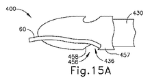
内側針(430)の針ヘッド(432)は、内側針(430)に沿って対向し角度をつけて位置付けられた、上側ノッチ(433)と下側ノッチ(436)とを有する。上側ノッチ(433)は、上側湾曲面(434)と、上側フック付き表面(435)と、を備える。上面(434、435)は、上面(434、435)が内側針(430)に沿って対向するように、長手方向に対向して位置付けられる。上側湾曲面(434)は、上側フック付き表面(435)に対して遠位方向に位置付けられる。以下でより詳細に説明するように、上側湾曲面(434)は、上側解放カム表面(455)(図13Aを参照)に向けて縫合糸(60)(図14Aを参照)を導くように構成されて、上側湾曲面(434)が縫合糸(60)(図14Aを参照)を上側ノッチ(433)から外れるように押す一方、上側フック付き表面(435)が、上側捕捉アンダーカット(454)(図13Aを参照)に対して縫合糸(60)(図14Aを参照)を捕捉及び保持するように構成されている。同様に、下側ノッチ(436)は、下側フック付き表面(437)と下側湾曲面(438)とを含む。下面(437、438)は、下面(437、438)が内側針(430)に沿って互いに対して向かうように、長手方向に互いに対して反対になるように位置付けられる。下側フック付き表面(437)は、下側湾曲面(438)よりも遠位方向に位置付けられる。以下で更に説明するように、下側湾曲面(438)は、下側解放カム表面(458)(図13Aを参照)に向けて縫合糸(60)(図15Aを参照)を導くように構成されて、下側湾曲面(438)が縫合糸(60)(図15Aを参照)を下側ノッチ(436)から外れるように押す一方、下側フック付き表面(437)は、下側捕捉アンダーカット(457)(図13Aを参照)に対して縫合糸(60)(図15Aを参照)を捕捉及び保持するように構成されている。図示されていないが、針ヘッド(432)は、内側針(430)に沿って図示されるよりも多い又は少ないノッチ(433、436)を備えてもよいことを理解されたい。 The needle head (432) of the inner needle (430) has an upper notch (433) and a lower notch (436) positioned opposite and angled along the inner needle (430). The upper notch (433) comprises an upper curved surface (434) and an upper hooked surface (435). The upper surfaces (434, 435) are longitudinally opposed so that the upper surfaces (434, 435) oppose along the inner needle (430). The upper curved surface (434) is positioned distally with respect to the upper hooked surface (435). As described in more detail below, the upper curved surface (434) is configured to guide the suture (60) (see FIG. 14A) towards the upper release cam surface (455) (see FIG. 13A). The upper curved surface (434) pushes the suture (60) (see FIG. 14A) out of the upper notch (433) while the upper hooked surface (435) is pushed over the upper capture undercut (454). It is configured to capture and retain suture (60) (see FIG. 14A) relative to (see FIG. 13A). Similarly, the lower notch (436) includes a lower hooked surface (437) and a lower curved surface (438). The lower surfaces (437, 438) are positioned longitudinally opposite one another such that the lower surfaces (437, 438) are toward each other along the inner needle (430). The lower hooked surface (437) is positioned more distally than the lower curved surface (438). As described further below, the lower curved surface (438) is configured to guide the suture (60) (see FIG. 15A) toward the lower release cam surface (458) (see FIG. 13A). The lower curved surface (438) pushes the suture (60) (see FIG. 15A) out of the lower notch (436), while the lower hooked surface (437) lowers the lower capture under. It is configured to capture and retain suture (60) (see FIG. 15A) against cut (457) (see FIG. 13A). Although not shown, it should be appreciated that the needle head (432) may include more or less notches (433, 436) along the inner needle (430) than shown.
外側シース(410)は、穴(412)、ハウジング(414)、半径方向壁(415)、及び遠位端部(416)を含む。遠位端部(416)は、組織(17)を穿孔するように構成された切断縁部で角度をつけられている。穴(412)は、近位端に位置付けられるハウジング(414)から遠位端部(416)を分離する長手方向長さを有する。内側針(430)は、ドライバ(442)の回転によって、外側シース(410)の穴(412)内で摺動可能に並進するように構成されている。換言すれば、係合機構(445)により、内側針(430)及びドライバ(442)は、ドライバ(442)が回転及び並進しても、内側針(430)が回転せずに内側針(430)が並進するように、並進は連結されているが、回転は切り離されている。この目的のため、ハウジング(414)は、雌ねじ部(420)及びスロット(422)を含み、内側針(430)を穴(412)内で摺動可能に並進させる。 The outer sheath (410) includes a hole (412), a housing (414), a radial wall (415), and a distal end (416). The distal end (416) is angled with a cutting edge configured to pierce the tissue (17). Bore (412) has a longitudinal length that separates distal end (416) from housing (414) located at the proximal end. Inner needle (430) is configured to slidably translate within hole (412) of outer sheath (410) by rotation of driver (442). In other words, the engagement mechanism (445) causes the inner needle (430) and driver (442) to rotate and translate while the inner needle (430) does not rotate, but the inner needle (430) does not rotate. The translations are linked, but the rotations are decoupled, such that To this end, the housing (414) includes internal threads (420) and slots (422) to slidably translate the inner needle (430) within the hole (412).
雌ねじ部(420)は、ドライバ(442)の雄ねじ部(443)と係合するように構成されており、近位端から見たとき、ドライバ(442)を時計回りに回転させると、内側針(430)は遠位方向に並進する。逆に、近位端から見たとき、ドライバ(442)を反時計回りに回転させると、内側針(430)は近位方向に並進する。図12に更に示すように、スロット(422)はハウジング(414)内へ内方に延在し、内側針(430)の長手方向軸(429)に平行な長手方向長さを有する。内側針(430)は、ハウジング(414)内に収容された内側針(430)の一部分に沿ってシャフト(440)から横方向に突出するラッチ(444)を更に備える。ラッチ(444)は、スロット(422)と係合するように構成されて、内側針(430)の回転を抑制するとともに、内側針(430)の長手方向並進をスロット(422)の長手方向長さに制限するように構成されている。 The internally threaded portion (420) is configured to engage the externally threaded portion (443) of the driver (442) and, when viewed from the proximal end, when the driver (442) is rotated clockwise, the inner needle. (430) translates distally. Conversely, when viewed from the proximal end, rotation of the driver (442) counterclockwise causes the inner needle (430) to translate in the proximal direction. As further shown in FIG. 12, the slot (422) extends inwardly into the housing (414) and has a longitudinal length parallel to the longitudinal axis (429) of the inner needle (430). Inner needle (430) further comprises a latch (444) projecting laterally from shaft (440) along a portion of inner needle (430) housed within housing (414). The latch (444) is configured to engage the slot (422) to inhibit rotation of the inner needle (430) and to cause longitudinal translation of the inner needle (430) into a longitudinal length of the slot (422). Is configured to be limited to
図13A〜13Cに最も良く示すように、外側シース(410)は、端部(416)の近位に上側アパーチャ(453)と下側アパーチャ(456)を更に含む。アパーチャ(453、456)は、外側シース(410)の外側径方向表面(451)と穴(412)との間の連通を提供するように構成されており、内側針(430)が穴(412)内に摺動可能に挿入されると、アパーチャ(453、456)が針ヘッド(432)を露出させる。具体的には、上側アパーチャ(453)は、針ヘッド(432)上の上側ノッチ(433)に対応するように外側シース(410)に沿って位置付けられ、下側アパーチャ(456)は、下側ノッチ(436)に対応するように外側シース(410)に沿って位置付けられる。アパーチャ(453、456)は、外側シース(410)を通って延在し、捕捉アンダーカット(454、457)と解放カム表面(455、458)とを含む。捕捉アンダーカット(454、457)は、フック付き表面(459)を有し、縫合糸通し器(400)が縫合糸(60)を捕捉する捕捉方向に選択的に操作される際に、外側シース(410)に向かって半径方向内方に縫合糸(60)(図14Aを参照)を受容及び保持するように構成されている。 As best shown in FIGS. 13A-13C, outer sheath (410) further includes an upper aperture (453) and a lower aperture (456) proximal to end (416). The apertures (453, 456) are configured to provide communication between the outer radial surface (451) of the outer sheath (410) and the hole (412), with the inner needle (430) being the hole (412). ), the apertures (453, 456) expose the needle head (432). Specifically, the upper aperture (453) is positioned along the outer sheath (410) to correspond to the upper notch (433) on the needle head (432) and the lower aperture (456) is positioned at the lower side. Positioned along outer sheath (410) to correspond to notch (436). Apertures (453, 456) extend through outer sheath (410) and include capture undercuts (454, 457) and release cam surfaces (455, 458). The capture undercuts (454, 457) have hooked surfaces (459) that allow the outer sheath to be selectively manipulated in the capture direction to capture the suture (60) by the suture threader (400). It is configured to receive and retain suture (60) (see FIG. 14A) radially inward toward (410).
解放カム表面(455、458)は、外側シース(410)の捕捉アンダーカット(454、457)と外側径方向表面(451)との間にそれぞれ位置付けられる。解放カム表面(455、458)は、外側シース(410)の外側径方向表面(451)と面一になるまで、捕捉アンダーカット(454、457)のフック付き表面(459)から遠位方向かつ半径方向外方に延在する。解放カム表面(455、458)は、縫合糸通し器(400)が縫合糸(60)を解放する解放方向に選択的に操作される際に、縫合糸(60)を捕捉アンダーカット(454、457)から半径方向外方に付勢することによって、縫合糸(60)をノッチ(433、436)から除去するように構成されている。 The release cam surfaces (455, 458) are positioned between the capture undercuts (454, 457) of the outer sheath (410) and the outer radial surface (451), respectively. The release cam surfaces (455, 458) extend distally from the hooked surface (459) of the capture undercuts (454, 457) until flush with the outer radial surface (451) of the outer sheath (410). Extends radially outward. The release cam surfaces (455, 458) capture the suture (60) undercut (454, 454) as the suture threader (400) is selectively manipulated in the release direction to release the suture (60). It is configured to remove the suture (60) from the notches (433, 436) by biasing it radially outward from 457).
上側アパーチャ(453)は、外側シース(410)の長手方向軸(429)を中心にして下側アパーチャ(456)とは角度的に反対に外側シース(410)に沿って位置付けられる。上側捕捉アンダーカット(454)は、外側シース(410)上で上側解放カム表面(455)に対して遠位方向に向けられており、これにより、上側捕捉アンダーカット(454)は遠位端部(416)の近位に位置付けられ、上側解放カム表面(455)は遠位端部(416)の遠位に位置付けられる。対照的に、下側捕捉アンダーカット(457)は、外側シース(410)上で下側解放カム表面(458)に対して近位方向に向けられており、これにより、下側捕捉アンダーカット(457)は遠位端部(416)の遠位に位置付けられ、下側解放カム表面(458)は遠位端部(416)の近位に位置付けられる。 The upper aperture (453) is positioned along the outer sheath (410) angularly opposite the lower aperture (456) about the longitudinal axis (429) of the outer sheath (410). The upper capture undercut (454) is oriented distally on the outer sheath (410) with respect to the upper release cam surface (455) such that the upper capture undercut (454) is at the distal end. Located proximal to (416), upper release cam surface (455) is located distal to distal end (416). In contrast, the lower capture undercut (457) is oriented proximally on the outer sheath (410) to the lower release cam surface (458), which results in a lower capture undercut (457). 457) is positioned distal of the distal end (416) and the lower release cam surface (458) is positioned proximal of the distal end (416).
本実施例では、臨床医がドライバ(442)を回転させると、縫合糸通し器(400)は一連の位置に移行する。具体的には、ドライバ(442)が回転すると、ラッチ(444)がスロット(422)の限界範囲に達するまで、内側針(430)は、雌ねじ部分(420)と雄ねじ部分(443)のねじ係合を通じて穴(412)内で摺動可能に前進する。図13Aに示すように、ドライバ(442)は、ノッチ(433、436)がアパーチャ(453、456)とほぼ整列するまで回転される。図13Bは、遠位方向に並進した位置にある内側針(430)を示し、ノッチ(433、436)は、アパーチャ(453、456)と実質的に整列していない代わりに、遠位端部(416)の近位位置で穴(412)によってほぼ覆われている。最後に、図13Cに示すように、ドライバ(442)は、内側針(430)が近位方向に並進した位置に達するまで逆方向に回転され、ノッチ(433、436)はアパーチャ(453、456)と実質的に整列していない代わりに、遠位端部(416)の遠位位置で穴(412)によってほぼ覆われている。 In this example, as the clinician rotates driver (442), suture threader (400) transitions into a series of positions. Specifically, as the driver (442) rotates, the inner needle (430) engages the internal thread (420) and external thread (443) threads until the latch (444) reaches the limit of the slot (422). Through the joint, it slidably advances in the hole (412). As shown in FIG. 13A, the driver (442) is rotated until the notches (433, 436) are substantially aligned with the apertures (453, 456). FIG. 13B shows the inner needle (430) in a distal translational position, with the notches (433, 436) not substantially aligned with the apertures (453, 456) but instead at the distal end. Proximal to (416) it is substantially covered by hole (412). Finally, as shown in FIG. 13C, the driver (442) is rotated in the opposite direction until the inner needle (430) reaches the proximally translated position and the notches (433, 436) are opened by the apertures (453, 456). ), but is substantially covered by hole (412) at the distal position of distal end (416).
図14A〜図14Cは、上側アパーチャ(453)及び上側ノッチ(433)内で縫合糸(60)を捕捉及び解放する縫合糸通し器(400)を示す。具体的には、図14Aは、アパーチャ(453、456)と実質的に整列されたノッチ(433、436)(図13Aに示した位置)と、上側アパーチャ(453)の上側捕捉アンダーカット(454)に解放可能に固定された縫合糸(60)と、を示す。ドライバ(442)を回転させることによって、内側針(430)は、外側シース(410)の穴(412)内で遠位に並進し、ノッチ(433、436)を遠位方向に並進させる。この場合、図14Bに示すように、上側ノッチ(433)の上側フック付き表面(435)は、縫合糸(60)を上側捕捉アンダーカット(454)に対してしっかりと捕捉し、それにより、縫合糸(60)が縫合糸通し器(400)の把持部から滑り落ちることを防止する。次いで、臨床医は縫合糸通し器(400)を選択的に操作することができ、縫合糸(60)は留置のための好ましい位置にしっかりと拘束される。図14Bに示す方向と反対方向にドライバ(442)を回転させることによって、図14Cに示すように、上側ノッチ(433)は近位方向に並進すると同時に、上側捕捉アンダーカット(454)から縫合糸(60)を解放する。上側ノッチ(433)が近位に並進すると、上側湾曲面(434)は、縫合糸(60)が上側アパーチャ(453)から自由に解放されるまで、上側解放カム表面(455)に沿って近位方向に縫合糸(60)を導く。 14A-14C show suture threader (400) capturing and releasing suture (60) within upper aperture (453) and upper notch (433). Specifically, FIG. 14A shows notches (433, 436) (position shown in FIG. 13A) substantially aligned with apertures (453, 456) and upper capture undercut (454) of upper aperture (453). ), and a suture (60) releasably secured thereto. By rotating the driver (442), the inner needle (430) translates distally within the hole (412) of the outer sheath (410), translating the notches (433, 436) distally. In this case, as shown in FIG. 14B, the upper hooked surface (435) of the upper notch (433) captures the suture (60) firmly against the upper capture undercut (454), thereby suturing. Prevents the thread (60) from sliding off the grip of the suture threader (400). The clinician can then selectively manipulate the suture threader (400) and the suture (60) is securely restrained in a preferred position for placement. By rotating the driver (442) in the opposite direction to that shown in FIG. 14B, the upper notch (433) translates proximally while the suture from the upper capture undercut (454), as shown in FIG. 14C. Release (60). As the upper notch (433) translates proximally, the upper curved surface (434) approximates along the upper release cam surface (455) until the suture (60) is free to release from the upper aperture (453). Guide the suture (60) in the distal direction.
図15A〜15Cに示すように、縫合糸通し器(400)は同様に、下側アパーチャ(456)及び下側ノッチ(436)内に縫合糸(60)を捕捉及び解放することができる。しかしながら、下側アパーチャ(456)、特に下側捕捉アンダーカット(457)及び下側解放カム表面(458)の反対配向のため、ドライバ(442)が同方向に回転すると、縫合糸通し器(400)と縫合糸(60)との間に異なる相互作用を生成することができる。例えば、図14Bに示すような方向にドライバ(442)を回転させることによって、図15Bに示すように、下側湾曲面(438)は、下側捕捉アンダーカット(457)から縫合糸(60)を解放する役割を果たす。よって、ドライバ(442)が同じ方向に回転すると、縫合糸(60)と上側ノッチ(433)又は下側ノッチ(436)との間に反対の相互作用が生成される。この場合、下側湾曲面(438)は、縫合糸(60)が下側アパーチャ(456)から自由に解放されるまで、下側解放カム表面(458)に沿って遠位方向に縫合糸(60)を導く。更に、ドライバ(442)を図14Cに示す方向に回転させることによって、下側ノッチ(436)が近位方向に並進することにより、図15Cに示すように、上側フック付き表面(437)は、上側捕捉アンダーカット(457)に対して縫合糸(60)をしっかりと捕捉する。 As shown in FIGS. 15A-15C, suture threader (400) can also capture and release suture (60) within lower aperture (456) and lower notch (436). However, due to the opposite orientation of the lower aperture (456), particularly the lower capture undercut (457) and the lower release cam surface (458), rotation of the driver (442) in the same direction causes the suture threader (400) to rotate. ) And the suture (60) can create different interactions. For example, by rotating the driver (442) in the direction as shown in FIG. 14B, the lower curved surface (438) is moved from the lower capture undercut (457) to the suture (60) as shown in FIG. 15B. Play a role in releasing. Thus, when the driver (442) rotates in the same direction, an opposite interaction is created between the suture (60) and the upper notch (433) or lower notch (436). In this case, the lower curved surface (438) is distal to the suture (60) along the lower release cam surface (458) until the suture (60) is freely released from the lower aperture (456). 60). Further, by rotating driver (442) in the direction shown in FIG. 14C, the lower notch (436) translates proximally, thereby causing upper hooked surface (437) to move, as shown in FIG. 15C. Firmly capture the suture (60) against the upper capture undercut (457).
III.例示的な組み合わせ
以下の実施例は、本明細書の教示を組み合わせるか又は適用することができる、様々な非網羅的な方法に関する。以下の実施例は、本出願における又は本出願の後の出願におけるどの時点でも提示され得る、いずれの請求項の適用範囲をも限定することを目的とするものではない。一切の否認を意図するものではない。以下の実施例は、単なる例示の目的で与えられるものにすぎない。本明細書の様々な教示は、他の多くの方法で配置及び適用が可能であると考えられる。また、いくつかの変形形態では、以下の実施例において言及される特定の特徴を省略してよいことも考えられる。したがって、本発明者又は本発明者の利益の継承者により、後日、そうである旨が明示的に示されない限り、以下に言及される態様又は特徴のいずれも重要なものとして見なされるべきではない。以下に言及される特徴以外の更なる特徴を含む請求項が本出願において、又は本出願に関連する後の出願において示される場合、それらの更なる特徴は、特許性に関連するいかなる理由によっても追加されたものとして仮定されるべきではない。
III. Illustrative Combinations The following examples relate to various non-exhaustive ways in which the teachings herein can be combined or applied. The following examples are not intended to limit the scope of any claims that may be presented at any point in this application or any subsequent application of this application. No denial is intended. The following examples are provided for illustrative purposes only. It is contemplated that the various teachings herein may be arranged and applied in many other ways. It is also contemplated that in some variations certain features referred to in the examples below may be omitted. Accordingly, none of the aspects or features referred to below should be considered significant unless, by such inventor or a successor of the inventor's interests, be explicitly indicated at a later date. .. Where claims are provided in this application, or in subsequent applications related to this application, that include additional features other than those mentioned below, those additional features may be for any reason related to patentability. It should not be assumed as added.
縫合糸通し器であって、
(a)長手方向に延在し、捕捉位置と解放位置との間で操作されるように構成された針と、(b)針を通って延在する第1の縫合糸ノッチであって、針が捕捉方向に向かって操作される際に、縫合糸を内部に受容し、縫合糸を半径方向内方へ解放可能に捕捉するように構成された第1の捕捉アンダーカットを含む、第1の縫合糸ノッチと、
(c)針を通って延在する第2の縫合糸ノッチであって、針が捕捉方向に向かって操作される際に、縫合糸を内部に受容し、縫合糸を半径方向内方へ解放可能に捕捉するように構成された第2の捕捉アンダーカットを含む、第2の縫合糸ノッチと、
を、備える、縫合糸通し器。
A suture threader,
(A) a needle extending longitudinally and configured to be manipulated between a capture position and a release position; and (b) a first suture notch extending through the needle, A first capture undercut configured to receive the suture therein and releasably capture the suture radially inward as the needle is manipulated toward the capture direction; Suture notch of
(C) A second suture notch extending through the needle that receives the suture therein and releases the suture radially inward when the needle is manipulated in the capture direction. A second suture notch including a second capture undercut configured to enable capture;
And a suture threader.
第1の縫合糸ノッチトが、針が解放方向に向かって操作される際に、縫合糸を第1の捕捉アンダーカットから半径方向外方に付勢するように構成された第1の解放カム表面を更に含む、実施例1に記載の縫合糸通し器。 A first release cam surface configured to bias the suture radially outward from the first capture undercut when the needle is manipulated toward the release direction. The suture threader of Example 1 further comprising:
針が、外側径方向表面を更に含み、第1の解放カム表面が、針の第1の捕捉アンダーカットと外側径方向表面との間に突出する、実施例2に記載の縫合糸通し器。 The suture threader of Example 2 wherein the needle further comprises an outer radial surface and the first release cam surface projects between the first capture undercut of the needle and the outer radial surface.
第1の捕捉アンダーカットが、第1の縫合糸ノッチ内にフック付き表面を画定し、第1の解放カム表面が、フック付き表面から針の外側径方向表面まで連続的に延在する、実施例3に記載の縫合糸通し器。 A first capture undercut defines a hooked surface within the first suture notch and a first release cam surface extends continuously from the hooked surface to the outer radial surface of the needle. The suture threader described in Example 3.
第1の解放カム表面が、フック付き表面から針の外側径方向表面まで遠位方向及び半径方向外方に延在する、実施例4に記載の縫合糸通し器。 The suture threader of Example 4 wherein the first release cam surface extends distally and radially outwardly from the hooked surface to the outer radial surface of the needle.
内部を通って延在する長手方向穴を有するシースを更に備え、針がシースに対して後退位置から拡張位置へと長手方向穴内で遠位方向に移動するように構成されるように、長手方向穴が、針を内部に摺動可能に受容する、実施例1〜5のうちの任意の1つ以上に記載の縫合糸通し器。 Further comprising a sheath having a longitudinal hole extending therethrough, wherein the needle is configured to move distally within the longitudinal hole from the retracted position to the expanded position relative to the sheath. The suture threader of any one or more of Examples 1-5, wherein the hole slidably receives the needle therein.
シースが、遠位シース端部まで遠位方向に延在する半径方向壁を含み、半径方向壁が、長手方向穴と連通する第1の開口を含み、第1の開口が、第1の縫合糸ノッチと長手方向に整列することによって、縫合糸を第1の開口を通じて捕捉するために第1の縫合糸ノッチを露出させるように構成されている、実施例6に記載の縫合糸通し器。 The sheath includes a radial wall extending distally to a distal sheath end, the radial wall including a first opening in communication with the longitudinal hole, the first opening including a first suture. The suture threader of Example 6 configured to expose the first suture notch for capturing the suture through the first opening by longitudinal alignment with the suture notch.
遠位シース端部が組織を穿孔するように構成されている、実施例7に記載の縫合糸通し器。 The suture threader of Example 7 wherein the distal sheath end is configured to pierce tissue.
針に動作可能に接続され、針を後退位置から拡張位置まで長手方向に選択的に並進させるように構成されたドライバを更に備える、実施例1〜8のうちの任意の1つ以上に記載の縫合糸通し器。 The method of any one or more of Examples 1-8, further comprising a driver operably connected to the needle and configured to selectively translate the needle longitudinally from a retracted position to an expanded position. Suture threader.
ドライバが、針を後退位置から拡張位置に選択的に回転させるように更に構成されている、実施例9に記載の縫合糸通し器。 The suture threader according to Example 9, wherein the driver is further configured to selectively rotate the needle from the retracted position to the expanded position.
ドライバが、針を後退位置に向けて付勢するように構成された弾性部材を更に含む、実施例9〜10のうちの任意の1つ以上に記載の縫合糸通し器。 The suture threader of any one or more of Examples 9-10, wherein the driver further comprises an elastic member configured to bias the needle toward the retracted position.
第2の縫合糸ノッチが、針が解放方向に向かって操作される際に、縫合糸を第2の捕捉アンダーカットから半径方向外方に付勢するように構成された第2の解放カム表面を含み、針が長手方向軸に沿って延在し、第1の縫合糸ノッチが、長手方向軸を中心にして第2の縫合糸ノッチとは角度的に反対に位置付けられている、請求項1〜11のうちの任意の1つ以上に記載の縫合糸通し器。 A second release cam surface configured to bias the suture radially outward from the second capture undercut when the needle is manipulated toward the release direction. Wherein the needle extends along the longitudinal axis and the first suture notch is positioned angularly opposite the second suture notch about the longitudinal axis. The suture threader according to any one or more of 1 to 11.
針を通って延在する第3の縫合糸ノッチを更に備え、第3の縫合糸ノッチが、針が捕捉方向に向かって操作される際に、縫合糸を内部に受容し、縫合糸を半径方向内方に解放可能に捕捉するように構成された第3の捕捉アンダーカットを含む、実施例12に記載の縫合糸通し器。 Further comprising a third suture notch extending through the needle, the third suture notch receiving the suture therein and radiating the suture when the needle is manipulated toward the capture direction. The suture threader of Example 12 including a third capture undercut configured to releasably capture inwardly.
第3の縫合糸ノッチは、針が解放方向に向かって操作される際に、縫合糸を第3の捕捉アンダーカットから半径方向外方に付勢するように構成された第3の解放カム表面を含み、針が長手方向軸に沿って延在し、第1、第2、及び第3の縫合糸ノッチが、長手方向に、かつ長手方向軸を中心にして螺旋状の配置で角度をつけて位置付けられている、実施例13に記載の縫合糸通し器。 The third suture notch is configured to bias the suture radially outward from the third capture undercut when the needle is manipulated toward the release direction. The needle extends along the longitudinal axis and the first, second, and third suture notches are angled longitudinally and about the longitudinal axis in a helical arrangement. Suture threader according to example 13 positioned as follows.
遠位針端部が、遠位に延在するドーム形端部を有する、実施例1〜14のうちの任意の1つ以上に記載の縫合糸通し器。 The suture threader of any one or more of Examples 1-14, wherein the distal needle end has a domed end extending distally.
縫合糸通し器であって、
(a)長手方向軸に沿って長手方向に長手方向に延在し、捕捉位置と解放位置との間で操作されるように構成された針と、(b)長手方向軸を中心に第1の位置で針を通って延在する第1の縫合糸ノッチであって、(i)針が捕捉方向に向かって操作される際に、縫合糸を内部に受容し、縫合糸を解放可能に捕捉するように構成された第1の捕捉部分と、(ii)針が解放方向に向かって操作される際に、縫合糸を第1の捕捉部分から付勢するように構成された第1の解放部分と、を含む、第1の縫合糸ノッチと、
(c)長手方向軸を中心に第2の位置で針を通って延在する第2の縫合糸ノッチであって、(i)針が捕捉方向に向かって操作される際に、縫合糸を内部に受容し、縫合糸を解放可能に捕捉するように構成された第2の捕捉部分と、針が解放方向に向かって操作される際に、縫合糸を第2の捕捉部分から付勢するように構成された第2の解放部分と、を含む、第2の縫合糸ノッチと、
を備え、第1の縫合糸ノッチの第1の位置が、第2の縫合糸ノッチの第2の位置とは異なる、縫合糸通し器。
A suture threader,
(A) a needle extending longitudinally longitudinally along the longitudinal axis and configured to be manipulated between a capture position and a release position; and (b) a first centered about the longitudinal axis. A first suture notch extending through the needle at a position of (i) to (i) receive the suture therein and allow the suture to be released when the needle is manipulated toward the capture direction. A first capture portion configured to capture, and (ii) a first suture configured to bias the suture from the first capture portion as the needle is manipulated toward the release direction. A first suture notch including a release portion;
(C) a second suture notch extending through the needle at a second position about the longitudinal axis, wherein (i) the suture is threaded when the needle is manipulated toward the capture direction. A second capture portion that is internally received and configured to releasably capture the suture and biases the suture from the second capture portion when the needle is manipulated toward the release direction. A second suture notch configured to:
A suture threader having a first position of the first suture notch different from a second position of the second suture notch.
第1の縫合糸ノッチが、長手方向軸を中心に第2の縫合糸ノッチとは角度的に反対に位置付けられている、実施例16に記載の縫合糸通し器。 17. The suture threader according to example 16, wherein the first suture notch is positioned angularly opposite the second suture notch about the longitudinal axis.
長手方向軸を中心に第3の位置で針を通って延在する第3の縫合糸ノッチを更に備え、第3の縫合糸ノッチが、(i)針が捕捉方向に向かって操作される際に、縫合糸を内部に受容し、縫合糸を解放可能に捕捉するように構成された第3の捕捉部分と、針が解放方向に向かって操作される際に、縫合糸を第3の捕捉部分から付勢するように構成された第3の解放部分と、を含み、第3の縫合糸ノッチの第3の位置が、第1の縫合糸ノッチの第1の位置及び第2の縫合糸ノッチの第2の位置とはそれぞれ異なる、実施例16〜17のうちの任意の1つ以上の実施例に記載の縫合糸通し器。 Further comprising a third suture notch extending through the needle at a third position about the longitudinal axis, the third suture notch being (i) when the needle is manipulated toward the capture direction. And a third capture portion configured to receive the suture therein and releasably capture the suture and a third capture portion of the suture when the needle is manipulated toward the release direction. A third release portion configured to bias from the portion, wherein a third position of the third suture notch includes a first position of the first suture notch and a second suture. The suture threader of any one or more of Examples 16-17, each of which is different from the second position of the notch.
第1、第2、及び第3の縫合糸ノッチが、長手方向に、かつ長手方向軸を中心にして第1、第2、及び第3の位置において螺旋状の配置で角度をつけて位置付けられている、実施例18に記載の縫合糸通し器。 First, second, and third suture notches are angularly positioned longitudinally and in first, second, and third positions in a helical arrangement about a longitudinal axis. The suture threader of Example 18, which is:
針と、針を通って延在する縫合糸ノッチと、を有する縫合糸通し器を用いて患者内に縫合糸を把持する方法であって、縫合糸ノッチが、捕捉部分及び解放部分を含み、捕捉部分が、縫合糸を内部に受容し、縫合糸を解放可能に捕捉するように構成され、解放部分が、縫合糸を捕捉部分から付勢するように構成され、方法が、
(a)針を捕捉位置から解放位置に向けて操作することと、(b)縫合糸を縫合糸ノッチの捕捉部分からカム表面で付勢することと、
(c)縫合糸を縫合糸ノッチの捕捉部分から解放することと、
を含む、方法。
A method of grasping a suture in a patient using a suture threader having a needle and a suture notch extending through the needle, the suture notch including a capture portion and a release portion, The capture portion is configured to receive the suture therein and releasably capture the suture, and the release portion is configured to bias the suture from the capture portion, the method comprising:
(A) manipulating the needle from the capture position to the release position, and (b) urging the suture from the capture portion of the suture notch with the cam surface.
(C) releasing the suture from the captured portion of the suture notch;
Including the method.
IV.その他
本明細書に記載の教示、表現要素、実施形態、実施例などのうちのいずれか1つ又は2つ以上を、本明細書に記載の他の教示、表現要素、実施形態、実施例などのうちのいずれか1つ又は2つ以上と組み合わせることができる点が理解されるべきである。したがって、上記の教示、表現、実施形態、実施例などは、互いに対して独立して考慮されるべきではない。本明細書の教示に照らして、本明細書の教示を組み合わせることができる様々な好適な方法が、当業者には容易に明らかとなろう。このような改変及び変形形態は、「特許請求の範囲」内に含まれるものとする。
IV. Others Any one or more of the teachings, expressions, embodiments, examples, etc. described in this specification may be replaced by other teachings, expressions, embodiments, examples, etc., described in this specification. It should be understood that any one or more of these can be combined. Therefore, the above teachings, expressions, embodiments, examples, etc. should not be considered independently of each other. Various suitable ways in which the teachings herein may be combined will be readily apparent to those of ordinary skill in the art in view of the teachings herein. Such modifications and variations are intended to be included within the scope of the "claims".
本明細書に参照により組み込まれると言及されるいかなる特許、公報、又は他の開示内容も、全体的に又は部分的に、組み込まれる内容が現行の定義、見解、又は本開示に記載される他の開示内容とあくまで矛盾しない範囲でのみ本明細書に組み込まれると理解されるべきである。それ自体、また必要な範囲で、本明細書に明瞭に記載される開示内容は、参考により本明細書に組み込まれるあらゆる矛盾する記載に優先するものとする。現行の定義、見解、又は本明細書に記載される他の開示内容と矛盾する任意の内容、又はそれらの部分は本明細書に参照により組み込まれるものとするが、参照内容と現行の開示内容との間に矛盾が生じない範囲においてのみ、参照されるものとする。 Any patent, publication, or other disclosure content referred to herein by reference is wholly or partially incorporated in its present definition, view, or otherwise disclosed herein. It should be understood that the disclosure is incorporated into the present specification only to the extent not inconsistent with the disclosure. As such, and to the extent necessary, the disclosure set forth herein explicitly supersedes any contradictory statements incorporated herein by reference. Any content inconsistent with the existing definitions, views, or other disclosures provided herein, or portions thereof, are hereby incorporated by reference, but the reference and current disclosures Reference shall be made only to the extent that there is no contradiction between.
上記のデバイスの変形形態は、医療専門家により行われる従来の医療処置及び手術における用途のみではなく、ロボット支援された医療処置及び手術における用途をも有することができる。ほんの一例として、本明細書の様々な教示は、ロボット外科用システム、例えばIntuitive Surgical,Inc.(Sunnyvale,California)によるDAVINCI(商標)システムなどに容易に組み込むことができる。同様に、当業者であれば、本明細書における様々な教示を、以下のうちのいずれかの様々な教示と容易に組み合わせることができることを認識するであろう:その開示が参照により本明細書に組み込まれる、1998年8月11日に交付された「Articulated Surgical Instrument For Performing Minimally Invasive Surgery With Enhanced Dexterity and Sensitivity」と題する米国特許第5,792,135号;その開示が参照により本明細書に組み込まれる、1998年10月6日に交付された「Remote Center Positioning Device with Flexible Drive」と題する米国特許第5,817,084号;その開示が参照により本明細書に組み込まれる、1999年3月2日に交付された、米国特許第5,878,193号、名称「Automated Endoscope System for Optimal Positioning」、その開示が参照により本明細書に組み込まれる、2001年5月15日に交付された、米国特許第6,231,565号、名称「Robotic Arm DLUS for Performing Surgical Tasks」、その開示が参照により本明細書に組み込まれる、2004年8月31日に交付された「Robotic Surgical Tool with Ultrasound Cauterizing and Cutting Instrument」と題する米国特許第6,783,524号;その開示が参照により本明細書に組み込まれる、2002年4月2日に交付された、米国特許第6,364,888号、名称「Alignment of Master and Slave in a Minimally Invasive Surgical Apparatus」、その開示が参照により本明細書に組み込まれる、2009年4月28日に交付された、米国特許第7,524,320号、名称「Mechanical Actuator Interface System for Robotic Surgical Tools」、その開示が参照により本明細書に組み込まれる、2010年4月6日に交付された、米国特許第7,691,098号、名称「Platform Link Wrist Mechanism」、その開示が参照により本明細書に組み込まれる、2010年10月5日に交付された「Repositioning and Reorientation of Master/Slave Relationship in Minimally Invasive Telesurgery」と題する米国特許第7,806,891号;その開示が参照により本明細書に組み込まれる、2014年9月30日に交付された「Automated End Effector Component Reloading System for Use with a Robotic System」と題する米国特許第8,844,789号;その開示内容が参照により本明細書に組み込まれる、2014年9月2日に交付された「Robotically−Controlled Surgical Instruments」と題する米国特許第8,820,605号;その開示が参照により本明細書に組み込まれる、2013年12月31日に交付された「Shiftable Drive Interface for Robotically−Controlled Surgical Tool」と題する米国特許第8,616,431号;その開示が参照により本明細書に組み込まれる、2013年11月5日に交付された「Surgical Stapling Instruments with Cam−Driven Staple Deployment Arrangements」と題する米国特許第8,573,461号;その開示が参照により本明細書に組み込まれる、2013年12月10日に交付された「Robotically−Controlled Motorized Surgical End Effector System with Rotary Actuated Closure Systems Having Variable Actuation Speeds」と題する米国特許第8,602,288号;その開示が参照により本明細書に組み込まれる、2016年4月5日に交付された「Robotically−Controlled Surgical Instrument with Selectively Articulatable End Effector」と題する米国特許第9,301,759号;その開示が参照により本明細書に組み込まれる、2014年7月22日に交付された「Robotically−Controlled Surgical End Effector System」と題する米国特許第8,783,541号;2013年7月9日に交付された「Drive Interface for Operably Coupling a Manipulatable Surgical Tool to a Robot」と題する米国特許第8,479,969号;その開示が参照により本明細書に組み込まれる、2014年8月12日に交付された「Robotically Controlled Cable−Based Surgical End Effectors」と題する米国特許公報第8,800,838号;及び/又は、その開示が参照により本明細書に組み込まれる、2013年11月5日に交付された「Robotically−Controlled Surgical End Effector System with Rotary Actuated Closure Systems」と題する米国特許第8,573,465号。
The device variations described above may have applications not only in conventional medical procedures and surgery performed by medical professionals, but also in robot-assisted medical procedures and surgery. By way of example only, various teachings herein may be directed to robotic surgical systems, such as Intuitive Surgical, Inc. (Sunnyvale, California) and the like can be easily incorporated into the DAVINCI™ system. Similarly, one skilled in the art will recognize that the various teachings herein can be readily combined with the various teachings of any of the following: the disclosures of which are hereby incorporated by reference. Incorporated herein by reference, entitled "Articulated Surgical Instrument For Performing Minimally Invertible Surgical With
本明細書で提示される教示は、以下のうちのいずれか1つ以上の様々な教示と更に組み合わせることができる。その開示が参照により本明細書に組み込まれる、同日付出願の「Needle Guide Instrument with Traverse Suture Capture Feature」と題する米国特許出願第(代理人参照番号END8137USNP)号、上記に参照により組み込まれる、米国特許出願第(代理人参照番号END8139USNP)号、上記に参照により組み込まれる、米国特許出願第(代理人参照番号END8140USNP)号、その開示が参照により本明細書に組み込まれる、同日付出願の「Suture Passing Instrument with Puncture Site Identification Feature」と題する、米国特許出願第(代理人参照番号END8141USNP)号、その開示が参照により本明細書に組み込まれる、同日付出願の「Trocar Obturator with Transverse Needle Ports」と題する、米国特許出願第(代理人参照番号END8142USNP)号、その開示が参照により本明細書に組み込まれる、同日付出願の「Surgical Port with Wound Closure Channels」と題する、米国特許出願第(代理人参照番号END8143USNP)号、その開示が参照により本明細書に組み込まれる、同日付出願の「Trocar Obturator with Detachable Rotary Tissue Fastener」と題する、米国特許出願第(代理人参照番号END8144USNP)号、その開示が参照により本明細書に組み込まれる、同日付出願の「Method of Suturing a Trocar Patch Incision」と題する、米国特許出願第(代理人参照番号END8153USNP)号及び/又は上記参照により組み込まれるその他の特許及び特許出願公開。 The teachings provided herein can be further combined with various teachings of any one or more of the following. U.S. Patent Application No. (Attorney Docket END8137USNP), entitled "Needle Guide Instrument with Traverse Suture Capture Feature", the disclosure of which is incorporated herein by reference, and incorporated herein by reference. Application No. (Attorney Docket END8139USNP), US Patent Application No. (Attorney Docket No. END8140USNP), incorporated by reference above, "Suture Passing" of the same date application, the disclosure of which is incorporated herein by reference. US Patent Application No. (Attorney Docket No. END8141USNP) entitled "Instrument with Function Site Identification Feature", co-pending application entitled "Trocar Obturator with Transverse Title", which is hereby incorporated by reference. U.S. Patent Application No. (Attorney Docket END8142USNP), U.S. Patent Application No. (Attorney Docket END8143USNP), entitled "Surgical Port with Wound Closure Channels," of the same date application, the disclosure of which is incorporated herein by reference. ), U.S. Patent Application No. (Attorney Docket END8144USNP), entitled "Trocar Obturator with Detachable Rotary Tissue Fastener," the disclosure of which is incorporated herein by reference. United States Patent Application No. (Attorney Docket END8153USNP) and/or other patents and patent application publications incorporated by reference above, entitled "Method of Suturing a Trocar Patch Incision," incorporated by reference.
上述のデバイスの変形形態は、1回の使用後に処分するように設計することができ、又はそれらは、複数回使用するように設計することができる。変形形態は、いずれか又は両方の場合においても、少なくとも1回の使用後に再利用のために再調整され得る。再調整は、デバイスの分解工程、それに続く特定の部品の洗浄又は交換工程、及びその後の再組み立て工程の、任意の組み合わせを含み得る。特に、デバイスのいくつかの変形形態は分解することができ、また、デバイスの任意の数の特定の部分若しくは部品を、任意の組み合わせで選択的に交換又は取り外してもよい。特定の部品の洗浄及び/又は交換後、デバイスのいくつかの変形形態を、再調整用の施設において、又は処置の直前に使用者によってのいずれかで、その後の使用のために再組み立てすることができる。当業者であれば、デバイスの再調整において、分解、洗浄/交換、及び再組み立てのための様々な技術を利用することができることを理解するであろう。こうした技術の使用、及び結果として得られる再調整されたデバイスは、全て本出願の範囲内にある。 The variations of the devices described above can be designed for single-use disposal, or they can be designed for multiple-use. The variations may be readjusted for reuse after at least one use in either or both cases. Reconditioning may include any combination of device disassembly steps, followed by cleaning or replacement of certain parts, and subsequent reassembly steps. In particular, some variations of the device may be disassembled, and any number of the particular pieces or parts of the device may be selectively replaced or removed in any combination. After cleaning and/or replacement of certain parts, reassembling some variations of the device for subsequent use, either at the facility for reconditioning or by the user just prior to the procedure. You can Those skilled in the art will appreciate that reconditioning of a device can utilize a variety of techniques for disassembly, cleaning/replacement, and reassembly. Use of such techniques, and the resulting reconditioned device, are all within the scope of the present application.
ほんの一例として、本明細書に記載される変形形態は、処置の前及び/又は後に滅菌されてもよい。1つの滅菌技術では、デバイスをプラスチック製又はTYVEK製のバックなど、閉鎖及び封止された容器に入れる。次いで、γ線、X線、又は高エネルギー電子線などの、容器を透過し得る放射線場に、容器及びデバイスを置いてもよい。放射線は、デバイス上及び容器内の細菌を死滅させ得る。次に、滅菌されたデバイスを、後の使用のために、滅菌容器内に保管してもよい。デバイスはまた、β線若しくはγ線、エチレンオキシド、又は水蒸気が挙げられるがこれらに限定されない、当該技術分野で既知の任意の他の技術を用いてを滅菌されてもよい。 By way of example only, the variants described herein may be sterilized before and/or after treatment. In one sterilization technique, the device is placed in a closed and sealed container, such as a plastic or TYVEK bag. The container and device may then be placed in a radiation field, such as gamma rays, X-rays, or high energy electron beams, which may penetrate the container. Radiation can kill bacteria on the device and in the container. The sterilized device may then be stored in the sterile container for later use. The device may also be sterilized using any other technique known in the art, including but not limited to beta or gamma radiation, ethylene oxide, or water vapor.
以上、本発明の様々な実施形態を示し、記載したが、当業者による適切な改変により、本発明の範囲から逸脱することなく、本明細書に記載の方法及びシステムの更なる適合化を実現することができる。そのような可能な改変のうちのいくつかについて述べたが、他の改変も当業者には明らかとなるであろう。例えば、上記の実施例、実施形態、幾何学形状、材料、寸法、比率、工程などは例示的なものであって、必須のものではない。したがって、本発明の範囲は、以下の特許請求の範囲の観点から考慮されるべきものであり、本明細書及び図面において図示され、説明された構造及び動作の細部に限定されないものとして、理解されたい。 While various embodiments of the present invention have been shown and described, it will be appreciated that appropriate adaptations of those skilled in the art may be made to further adapt the methods and systems described herein without departing from the scope of the invention. can do. Although some of such possible modifications have been mentioned, other modifications will be apparent to those skilled in the art. For example, the examples, embodiments, geometries, materials, dimensions, ratios, steps, etc., described above are exemplary and not required. Accordingly, the scope of the invention should be considered in terms of the following claims, which are to be understood as not being limited to the details of construction and operation shown and described herein and in the drawings. I want to.
〔実施の態様〕
(1) 縫合糸通し器であって、
(a)長手方向に延在し、捕捉位置と解放位置との間で操作されるように構成された針と、
(b)前記針を通って延在する第1の縫合糸ノッチであって、前記針が捕捉方向に向かって操作される際に、縫合糸を内部に受容し、前記縫合糸を半径方向内方へ解放可能に捕捉するように構成された第1の捕捉アンダーカットを含む、第1の縫合糸ノッチと、
(c)前記針を通って延在する第2の縫合糸ノッチであって、前記針が前記捕捉方向に向かって操作される際に、前記縫合糸を内部に受容し、前記縫合糸を半径方向内方へ解放可能に捕捉するように構成された第2の捕捉アンダーカットを含む、第2の縫合糸ノッチと、
を備える、縫合糸通し器。
(2) 前記第1の縫合糸ノッチは、前記針が解放方向に向かって操作される際に、前記縫合糸を前記第1の捕捉アンダーカットから半径方向外方に付勢するように構成された第1の解放カム表面を更に含む、実施態様1に記載の縫合糸通し器。
(3) 前記針が、外側径方向表面を更に含み、前記第1の解放カム表面が、前記第1の捕捉アンダーカットと前記針の前記外側径方向表面との間に突出する、実施態様2に記載の縫合糸通し器。
(4) 前記第1の捕捉アンダーカットが、前記第1の縫合糸ノッチ内にフック付き表面を画定し、前記第1の解放カム表面が、前記フック付き表面から前記針の前記外側径方向表面まで連続的に延在する、実施態様3に記載の縫合糸通し器。
(5) 前記第1の解放カム表面が、前記フック付き表面から前記針の前記外側径方向表面まで遠位方向及び半径方向外方に延在する、実施態様4に記載の縫合糸通し器。
Embodiments
(1) A suture threader,
(A) a needle extending longitudinally and configured to be manipulated between a capture position and a release position;
(B) a first suture notch extending through the needle that receives the suture therein and radially retracts the suture when the needle is manipulated in a capture direction. A first suture notch including a first capture undercut configured to releasably capture toward
(C) a second suture notch extending through the needle that receives the suture therein and radiuses the suture when the needle is manipulated toward the capture direction. A second suture notch including a second capture undercut configured to releasably capture inwardly in a direction;
And a suture threader.
(2) The first suture notch is configured to bias the suture radially outward from the first capture undercut when the needle is manipulated in a release direction. The suture threader according to embodiment 1, further comprising a first release cam surface.
(3) Embodiment 2 wherein the needle further comprises an outer radial surface and the first release cam surface projects between the first capture undercut and the outer radial surface of the needle. The suture threader according to.
(4) The first capture undercut defines a hooked surface within the first suture notch, and the first release cam surface extends from the hooked surface to the outer radial surface of the needle. The suture threader according to embodiment 3, extending continuously up to.
(5) The suture threader of embodiment 4, wherein the first release cam surface extends distally and radially outwardly from the hooked surface to the outer radial surface of the needle.
(6) 内部を通って延在する長手方向穴を有するシースを更に備え、前記針が前記シースに対して後退位置から拡張位置へと前記長手方向穴内で遠位方向に移動するように構成されるように、前記長手方向穴が、前記針を内部に摺動可能に受容する、実施態様1に記載の縫合糸通し器。
(7) 前記シースが、遠位シース端部まで遠位方向に延在する半径方向壁を含み、前記半径方向壁が、前記長手方向穴と連通する第1の開口を含み、前記第1の開口が、第1の縫合糸ノッチと長手方向に整列することによって、前記縫合糸を前記第1の開口を通じて捕捉するために前記第1の縫合糸ノッチを露出させるように構成されている、実施態様6に記載の縫合糸通し器。
(8) 前記遠位シース端部が、組織を穿孔するように構成されている、実施態様7に記載の縫合糸通し器。
(9) 前記針に動作可能に接続され、前記針を前記後退位置から前記拡張位置まで長手方向に選択的に並進させるように構成されたドライバを更に備える、実施態様1に記載の縫合糸通し器。
(10) 前記ドライバが、前記針を前記後退位置から前記拡張位置に選択的に回転させるように更に構成されている、実施態様9に記載の縫合糸通し器。
(6) further comprising a sheath having a longitudinal hole extending therethrough, the needle configured to move distally within the longitudinal hole from a retracted position to an expanded position relative to the sheath. So that the longitudinal hole slidably receives the needle therein, the suture threader of claim 1.
(7) The sheath includes a radial wall extending distally to a distal sheath end, the radial wall including a first opening communicating with the longitudinal hole, and An opening is configured to longitudinally align with a first suture notch to expose the first suture notch for trapping the suture through the first opening. A suture threader according to aspect 6.
(8) The suture threader according to embodiment 7, wherein the distal sheath end portion is configured to pierce tissue.
(9) The suture threader of embodiment 1, further comprising a driver operably connected to the needle and configured to selectively translate the needle longitudinally from the retracted position to the expanded position. vessel.
(10) The suture threader according to embodiment 9, wherein the driver is further configured to selectively rotate the needle from the retracted position to the expanded position.
(11) 前記ドライバが、前記針を前記後退位置に向けて付勢するように構成された弾性部材を更に含む、実施態様9に記載の縫合糸通し器。
(12) 前記第2の縫合糸ノッチは、前記針が前記解放方向に向かって操作される際に、前記縫合糸を前記第2の捕捉アンダーカットから半径方向外方に付勢するように構成された第2の解放カム表面を含み、前記針は長手方向軸に沿って延在し、第1の縫合糸ノッチは、前記長手方向軸を中心にして前記第2の縫合糸ノッチとは角度的に反対に位置付けられている、実施態様1に記載の縫合糸通し器。
(13) 前記針を通って延在する第3の縫合糸ノッチを更に備え、前記第3の縫合糸ノッチは、前記針が前記捕捉方向に向かって操作される際に、前記縫合糸を内部に受容し、前記縫合糸を半径方向内方に解放可能に捕捉するように構成された第3の捕捉アンダーカットを含む、実施態様12に記載の縫合糸通し器。
(14) 前記第3の縫合糸ノッチは、前記針が前記解放方向に向かって操作される際に、前記縫合糸を前記第3の捕捉アンダーカットから半径方向外方に付勢するように構成された第3の解放カム表面を含み、前記針が長手方向軸に沿って延在し、前記第1、第2、及び第3の縫合糸ノッチが、長手方向に、かつ前記長手方向軸を中心にして螺旋状の配置で角度をつけて位置付けられている、実施態様13に記載の縫合糸通し器。
(15) 前記遠位針端部は、前記遠位針端部から遠位方向に延在するドーム形端部を有する、実施態様1に記載の縫合糸通し器。
(11) The suture threader according to the ninth embodiment, wherein the driver further includes an elastic member configured to bias the needle toward the retracted position.
(12) The second suture notch is configured to bias the suture radially outward from the second capture undercut when the needle is manipulated toward the release direction. A second release cam surface, the needle extends along a longitudinal axis, and the first suture notch is angled with the second suture notch about the longitudinal axis. The suture threader according to embodiment 1, positioned in opposite positions.
(13) A third suture notch extending through the needle may further be provided, wherein the third suture notch may be configured such that when the needle is operated toward the capturing direction, the suture is internally formed. The suture threader of
(14) The third suture notch is configured to bias the suture radially outward from the third capture undercut when the needle is manipulated toward the release direction. A third release cam surface, the needle extending along a longitudinal axis, and the first, second, and third suture notches longitudinally and about the longitudinal axis. The suture threader according to embodiment 13, wherein the suture threader is angularly positioned in a central spiral arrangement.
(15) The suture threader according to Embodiment 1, wherein the distal needle end portion has a dome-shaped end portion that extends in a distal direction from the distal needle end portion.
(16) 縫合糸通し器であって、
(a)長手方向軸に沿って長手方向に延在し、捕捉位置と解放位置との間で操作されるように構成された針と、
(b)前記長手方向軸を中心にして第1の位置で前記針を通って延在する第1の縫合糸ノッチであって、
(i)前記針が前記捕捉方向に向かって操作される際に、縫合糸を内部に受容し、前記縫合糸を解放可能に捕捉するように構成された第1の捕捉部分と、
(ii)前記針が前記解放方向に向かって操作される際に、前記縫合糸を前記第1の捕捉部分から付勢するように構成された第1の解放部分と、
を含む、第1の縫合糸ノッチと、
(c)前記長手方向軸を中心にして第2の位置で前記針を通って延在する第2の縫合糸ノッチであって、
(i)前記針が前記捕捉方向に向かって操作される際に、縫合糸を内部に受容し、前記縫合糸を解放可能に捕捉するように構成された第2の捕捉部分と、
(ii)前記針が前記解放方向に向かって操作される際に、前記縫合糸を前記第2の捕捉部分から付勢するように構成された第2の解放部分と、
を含む、第2の縫合糸ノッチと、
を備え、
前記第1の縫合糸ノッチの前記第1の位置は、前記第2の縫合糸ノッチの前記第2の位置とは異なる、縫合糸通し器。
(17) 第1の縫合糸ノッチが、前記長手方向軸を中心にして前記第2の縫合糸ノッチとは角度的に反対に位置付けられている、実施態様16に記載の縫合糸通し器。
(18) 前記長手方向軸を中心にして第3の位置で前記針を通って延在する第3の縫合糸ノッチを更に備え、前記第3の縫合糸ノッチが、
(i)前記針が前記捕捉方向に向かって操作される際に、縫合糸を内部に受容し、前記縫合糸を解放可能に捕捉するように構成された第3の捕捉部分と、
(ii)前記針が前記解放方向に向かって操作される際に、前記縫合糸を前記第3の捕捉部分から付勢するように構成された第3の解放部分と、
を含み、
前記第3の縫合糸ノッチの前記第3の位置が、前記第1の縫合糸ノッチの前記第1の位置及び前記第2の縫合糸ノッチの前記第2の位置とはそれぞれ異なる、実施態様16に記載の縫合糸通し器。
(19) 第1、第2、及び第3の縫合糸ノッチが、長手方向に、かつ前記長手方向軸を中心にして前記第1、第2、及び第3の位置において螺旋状の配置で角度をつけて位置付けられている、実施態様18に記載の縫合糸通し器。
(20) 針と、前記針を通って延在する縫合糸ノッチと、を有する縫合糸通し器を用いて患者内に縫合糸を把持する方法であって、前記縫合糸ノッチが、捕捉部分及び解放部分を含み、前記捕捉部分が、前記縫合糸を内部に受容し、前記縫合糸を解放可能に捕捉するように構成され、前記解放部分が、前記縫合糸を前記捕捉部分から付勢するように構成され、前記方法が、
(a)前記針を捕捉位置から解放位置に向けて操作することと、
(b)前記縫合糸を前記縫合糸ノッチの前記捕捉部分から前記カム表面で付勢することと、
(c)前記縫合糸を前記縫合糸ノッチの前記捕捉部分から解放することと、
を含む、方法。
(16) A suture threader,
(A) a needle extending longitudinally along the longitudinal axis and configured to be manipulated between a capture position and a release position;
(B) a first suture notch extending through the needle at a first position about the longitudinal axis,
(I) a first capture portion configured to receive a suture therein and releasably capture the suture when the needle is manipulated in the capture direction.
(Ii) a first release portion configured to bias the suture from the first capture portion when the needle is manipulated in the release direction;
A first suture notch including:
(C) a second suture notch extending through the needle at a second position about the longitudinal axis,
(I) a second capture portion configured to receive a suture therein and releasably capture the suture when the needle is manipulated in the capture direction.
(Ii) a second release portion configured to bias the suture from the second capture portion when the needle is manipulated toward the release direction;
A second suture notch including:
Equipped with
The suture threader, wherein the first position of the first suture notch is different from the second position of the second suture notch.
(17) The suture threader according to
(18) further comprising a third suture notch extending through the needle at a third position about the longitudinal axis, the third suture notch comprising:
(I) a third capture portion configured to receive a suture therein and releasably capture the suture when the needle is manipulated in the capture direction.
(Ii) a third release portion configured to bias the suture from the third capture portion when the needle is manipulated in the release direction;
Including,
(19) The first, second, and third suture notches are angled longitudinally and about the longitudinal axis in a helical arrangement at the first, second, and third positions. 19. The suture threader according to
(20) A method of grasping a suture in a patient using a suture threader having a needle and a suture notch extending through the needle, the suture notch comprising a capture portion and A release portion, the capture portion configured to receive the suture therein and releasably capture the suture, the release portion biasing the suture from the capture portion; And the method comprises
(A) operating the needle from the capture position to the release position;
(B) biasing the suture from the catch portion of the suture notch at the cam surface;
(C) releasing the suture from the trapped portion of the suture notch;
Including the method.
Claims (19)
(a)長手方向に延在し、捕捉位置と解放位置との間で操作されるように構成された針と、
(b)前記針を通って延在する第1の縫合糸ノッチであって、前記針が捕捉方向に向かって操作される際に、縫合糸を内部に受容し、前記縫合糸を半径方向内方へ解放可能に捕捉するように構成された第1の捕捉アンダーカットを含む、第1の縫合糸ノッチと、
(c)前記針を通って延在する第2の縫合糸ノッチであって、前記針が前記捕捉方向に向かって操作される際に、前記縫合糸を内部に受容し、前記縫合糸を半径方向内方へ解放可能に捕捉するように構成された第2の捕捉アンダーカットを含む、第2の縫合糸ノッチと、
を備える、縫合糸通し器。 A suture threader,
(A) a needle extending longitudinally and configured to be manipulated between a capture position and a release position;
(B) a first suture notch extending through the needle that receives the suture therein and radially retracts the suture when the needle is manipulated in a capture direction. A first suture notch including a first capture undercut configured to releasably capture toward
(C) a second suture notch extending through the needle that receives the suture therein and radiuses the suture when the needle is manipulated toward the capture direction. A second suture notch including a second capture undercut configured to releasably capture inwardly in a direction;
And a suture threader.
(a)長手方向軸に沿って長手方向に延在し、捕捉位置と解放位置との間で操作されるように構成された針と、
(b)前記長手方向軸を中心にして第1の位置で前記針を通って延在する第1の縫合糸ノッチであって、
(i)前記針が前記捕捉方向に向かって操作される際に、縫合糸を内部に受容し、前記縫合糸を解放可能に捕捉するように構成された第1の捕捉部分と、
(ii)前記針が前記解放方向に向かって操作される際に、前記縫合糸を前記第1の捕捉部分から付勢するように構成された第1の解放部分と、
を含む、第1の縫合糸ノッチと、
(c)前記長手方向軸を中心にして第2の位置で前記針を通って延在する第2の縫合糸ノッチであって、
(i)前記針が前記捕捉方向に向かって操作される際に、縫合糸を内部に受容し、前記縫合糸を解放可能に捕捉するように構成された第2の捕捉部分と、
(ii)前記針が前記解放方向に向かって操作される際に、前記縫合糸を前記第2の捕捉部分から付勢するように構成された第2の解放部分と、
を含む、第2の縫合糸ノッチと、
を備え、
前記第1の縫合糸ノッチの前記第1の位置は、前記第2の縫合糸ノッチの前記第2の位置とは異なる、縫合糸通し器。 A suture threader,
(A) a needle extending longitudinally along the longitudinal axis and configured to be manipulated between a capture position and a release position;
(B) a first suture notch extending through the needle at a first position about the longitudinal axis,
(I) a first capture portion configured to receive a suture therein and releasably capture the suture when the needle is manipulated in the capture direction.
(Ii) a first release portion configured to bias the suture from the first capture portion when the needle is manipulated in the release direction;
A first suture notch including:
(C) a second suture notch extending through the needle at a second position about the longitudinal axis,
(I) a second capture portion configured to receive a suture therein and releasably capture the suture when the needle is manipulated in the capture direction.
(Ii) a second release portion configured to bias the suture from the second capture portion when the needle is manipulated toward the release direction;
A second suture notch including:
Equipped with
The suture threader, wherein the first position of the first suture notch is different from the second position of the second suture notch.
(i)前記針が前記捕捉方向に向かって操作される際に、縫合糸を内部に受容し、前記縫合糸を解放可能に捕捉するように構成された第3の捕捉部分と、
(ii)前記針が前記解放方向に向かって操作される際に、前記縫合糸を前記第3の捕捉部分から付勢するように構成された第3の解放部分と、
を含み、
前記第3の縫合糸ノッチの前記第3の位置が、前記第1の縫合糸ノッチの前記第1の位置及び前記第2の縫合糸ノッチの前記第2の位置とはそれぞれ異なる、請求項16に記載の縫合糸通し器。 Further comprising a third suture notch extending through the needle at a third position about the longitudinal axis, the third suture notch comprising:
(I) a third capture portion configured to receive a suture therein and releasably capture the suture when the needle is manipulated in the capture direction.
(Ii) a third release portion configured to bias the suture from the third capture portion when the needle is manipulated in the release direction;
Including,
17. The third position of the third suture notch is different from the first position of the first suture notch and the second position of the second suture notch, respectively. The suture threader according to.
Applications Claiming Priority (3)
| Application Number | Priority Date | Filing Date | Title |
|---|---|---|---|
| US15/637,702 | 2017-06-29 | ||
| US15/637,702 US10639029B2 (en) | 2017-06-29 | 2017-06-29 | Suture grasping instrument |
| PCT/IB2018/054521 WO2019003050A1 (en) | 2017-06-29 | 2018-06-19 | Suture grasping instrument |
Publications (2)
| Publication Number | Publication Date |
|---|---|
| JP2020525160A true JP2020525160A (en) | 2020-08-27 |
| JP7196112B2 JP7196112B2 (en) | 2022-12-26 |
Family
ID=62816355
Family Applications (1)
| Application Number | Title | Priority Date | Filing Date |
|---|---|---|---|
| JP2019571712A Active JP7196112B2 (en) | 2017-06-29 | 2018-06-19 | suture grasper |
Country Status (5)
| Country | Link |
|---|---|
| US (1) | US10639029B2 (en) |
| EP (1) | EP3420982B1 (en) |
| JP (1) | JP7196112B2 (en) |
| CN (1) | CN110831529B (en) |
| WO (1) | WO2019003050A1 (en) |
Cited By (1)
| Publication number | Priority date | Publication date | Assignee | Title |
|---|---|---|---|---|
| WO2022158406A1 (en) * | 2021-01-19 | 2022-07-28 | テルモ株式会社 | Operating device and implant indwelling tool |
Families Citing this family (2)
| Publication number | Priority date | Publication date | Assignee | Title |
|---|---|---|---|---|
| US10939937B2 (en) | 2017-06-29 | 2021-03-09 | Ethicon Llc | Trocar with oblique needle insertion port and perpendicular seal latch |
| US20220240913A1 (en) * | 2019-05-02 | 2022-08-04 | Fulbright Medical Inc. | Puncture Core Assembly and Puncture Device with Puncture Core Assembly |
Citations (3)
| Publication number | Priority date | Publication date | Assignee | Title |
|---|---|---|---|---|
| US20100241142A1 (en) * | 2009-03-23 | 2010-09-23 | Linvatec Corporation | Suture passing apparatus and method |
| US20160038141A1 (en) * | 2013-03-15 | 2016-02-11 | Alpha Scientific Corporation | Surgical suturing device with transverse engagement |
| JP2016530924A (en) * | 2013-08-02 | 2016-10-06 | コヴィディエン リミテッド パートナーシップ | Devices, systems, and methods for providing surgical access and facilitating closure of a surgical access opening |
Family Cites Families (44)
| Publication number | Priority date | Publication date | Assignee | Title |
|---|---|---|---|---|
| SE417274B (en) * | 1980-04-09 | 1981-03-09 | Mats Akerlund | PROBLEM FOR RETIRING WITHDRAWALS |
| US5657429A (en) | 1992-08-10 | 1997-08-12 | Computer Motion, Inc. | Automated endoscope system optimal positioning |
| US5281237A (en) * | 1992-09-25 | 1994-01-25 | Gimpelson Richard J | Surgical stitching device and method of use |
| JP2665052B2 (en) | 1993-05-14 | 1997-10-22 | エスアールアイ インターナショナル | Remote center positioning device |
| US5792135A (en) | 1996-05-20 | 1998-08-11 | Intuitive Surgical, Inc. | Articulated surgical instrument for performing minimally invasive surgery with enhanced dexterity and sensitivity |
| US6364888B1 (en) | 1996-09-09 | 2002-04-02 | Intuitive Surgical, Inc. | Alignment of master and slave in a minimally invasive surgical apparatus |
| US6331181B1 (en) | 1998-12-08 | 2001-12-18 | Intuitive Surgical, Inc. | Surgical robotic tools, data architecture, and use |
| US6231565B1 (en) | 1997-06-18 | 2001-05-15 | United States Surgical Corporation | Robotic arm DLUs for performing surgical tasks |
| US6459926B1 (en) | 1998-11-20 | 2002-10-01 | Intuitive Surgical, Inc. | Repositioning and reorientation of master/slave relationship in minimally invasive telesurgery |
| ATE329531T1 (en) * | 1999-07-02 | 2006-07-15 | Quickpass Inc | SURGICAL SEWING DEVICE |
| US6783524B2 (en) | 2001-04-19 | 2004-08-31 | Intuitive Surgical, Inc. | Robotic surgical tool with ultrasound cauterizing and cutting instrument |
| US6997932B2 (en) * | 2001-05-21 | 2006-02-14 | Boston Scientific Scimed, Inc. | Suture passer |
| CA2451824C (en) | 2001-06-29 | 2015-02-24 | Intuitive Surgical, Inc. | Platform link wrist mechanism |
| US8585714B2 (en) * | 2003-03-18 | 2013-11-19 | Depuy Mitek, Llc | Expandable needle suture apparatus and associated handle assembly with rotational suture manipulation system |
| US9060770B2 (en) | 2003-05-20 | 2015-06-23 | Ethicon Endo-Surgery, Inc. | Robotically-driven surgical instrument with E-beam driver |
| DE102004047974A1 (en) | 2004-10-01 | 2006-04-06 | Ethicon Gmbh | Surgical hook |
| US8800838B2 (en) | 2005-08-31 | 2014-08-12 | Ethicon Endo-Surgery, Inc. | Robotically-controlled cable-based surgical end effectors |
| US7845537B2 (en) | 2006-01-31 | 2010-12-07 | Ethicon Endo-Surgery, Inc. | Surgical instrument having recording capabilities |
| US20110290856A1 (en) | 2006-01-31 | 2011-12-01 | Ethicon Endo-Surgery, Inc. | Robotically-controlled surgical instrument with force-feedback capabilities |
| US8992422B2 (en) | 2006-03-23 | 2015-03-31 | Ethicon Endo-Surgery, Inc. | Robotically-controlled endoscopic accessory channel |
| US8251900B2 (en) | 2009-03-06 | 2012-08-28 | Ethicon Endo-Surgery, Inc. | Surgical access devices and methods providing seal movement in predefined paths |
| US8690831B2 (en) | 2008-04-25 | 2014-04-08 | Ethicon Endo-Surgery, Inc. | Gas jet fluid removal in a trocar |
| US8579807B2 (en) | 2008-04-28 | 2013-11-12 | Ethicon Endo-Surgery, Inc. | Absorbing fluids in a surgical access device |
| US8684253B2 (en) | 2007-01-10 | 2014-04-01 | Ethicon Endo-Surgery, Inc. | Surgical instrument with wireless communication between a control unit of a robotic system and remote sensor |
| US8931682B2 (en) | 2007-06-04 | 2015-01-13 | Ethicon Endo-Surgery, Inc. | Robotically-controlled shaft based rotary drive systems for surgical instruments |
| US9179912B2 (en) | 2008-02-14 | 2015-11-10 | Ethicon Endo-Surgery, Inc. | Robotically-controlled motorized surgical cutting and fastening instrument |
| US8573465B2 (en) | 2008-02-14 | 2013-11-05 | Ethicon Endo-Surgery, Inc. | Robotically-controlled surgical end effector system with rotary actuated closure systems |
| US8636686B2 (en) | 2008-04-28 | 2014-01-28 | Ethicon Endo-Surgery, Inc. | Surgical access device |
| US8568362B2 (en) | 2008-04-28 | 2013-10-29 | Ethicon Endo-Surgery, Inc. | Surgical access device with sorbents |
| US7981092B2 (en) | 2008-05-08 | 2011-07-19 | Ethicon Endo-Surgery, Inc. | Vibratory trocar |
| US8679136B2 (en) * | 2008-06-17 | 2014-03-25 | Apollo Endosurgery, Inc. | Needle capture device |
| US9386983B2 (en) | 2008-09-23 | 2016-07-12 | Ethicon Endo-Surgery, Llc | Robotically-controlled motorized surgical instrument |
| US20100249520A1 (en) | 2009-03-31 | 2010-09-30 | Shelton Iv Frederick E | Method Of Surgical Access |
| US8622275B2 (en) * | 2009-11-19 | 2014-01-07 | Ethicon Endo-Surgery, Inc. | Circular stapler introducer with rigid distal end portion |
| US8906042B2 (en) | 2010-07-29 | 2014-12-09 | Covidien Lp | Wound closure device including mesh barrier |
| US10123794B2 (en) * | 2010-09-10 | 2018-11-13 | Pivot Medical, Inc. | Method and apparatus for passing suture through tissue |
| US9033872B2 (en) * | 2011-02-16 | 2015-05-19 | Reza Mohajer-Shojaee | Laparoscopic cannula with suturing capability |
| US20130012964A1 (en) * | 2011-07-07 | 2013-01-10 | Steven Warnock | Port closure device and method |
| US9357997B2 (en) * | 2011-07-08 | 2016-06-07 | Smith & Nephew, Inc. | Suture passer and method |
| US9924938B2 (en) * | 2011-11-07 | 2018-03-27 | C.R. Bard, Inc. | Instruments for delivering transfascial sutures and methods of transfascial suturing |
| US9017347B2 (en) * | 2011-12-22 | 2015-04-28 | Edwards Lifesciences Corporation | Suture clip deployment devices |
| AU2014242092B2 (en) * | 2013-03-13 | 2016-12-01 | Medtronic Vascular Inc. | Suturing device and method for sealing an opening in a blood vessel or other biological structure |
| JP6205492B2 (en) * | 2013-07-15 | 2017-09-27 | クック・メディカル・テクノロジーズ・リミテッド・ライアビリティ・カンパニーCook Medical Technologies Llc | Suture passer and operation method thereof |
| US10299785B2 (en) | 2016-04-01 | 2019-05-28 | Ethicon Llc | Surgical access devices with integrated wound closure features |
-
2017
- 2017-06-29 US US15/637,702 patent/US10639029B2/en active Active
-
2018
- 2018-06-19 CN CN201880044206.0A patent/CN110831529B/en active Active
- 2018-06-19 JP JP2019571712A patent/JP7196112B2/en active Active
- 2018-06-19 WO PCT/IB2018/054521 patent/WO2019003050A1/en not_active Ceased
- 2018-06-28 EP EP18180376.8A patent/EP3420982B1/en active Active
Patent Citations (3)
| Publication number | Priority date | Publication date | Assignee | Title |
|---|---|---|---|---|
| US20100241142A1 (en) * | 2009-03-23 | 2010-09-23 | Linvatec Corporation | Suture passing apparatus and method |
| US20160038141A1 (en) * | 2013-03-15 | 2016-02-11 | Alpha Scientific Corporation | Surgical suturing device with transverse engagement |
| JP2016530924A (en) * | 2013-08-02 | 2016-10-06 | コヴィディエン リミテッド パートナーシップ | Devices, systems, and methods for providing surgical access and facilitating closure of a surgical access opening |
Cited By (3)
| Publication number | Priority date | Publication date | Assignee | Title |
|---|---|---|---|---|
| WO2022158406A1 (en) * | 2021-01-19 | 2022-07-28 | テルモ株式会社 | Operating device and implant indwelling tool |
| JPWO2022158406A1 (en) * | 2021-01-19 | 2022-07-28 | ||
| JP7726925B2 (en) | 2021-01-19 | 2025-08-20 | テルモ株式会社 | Operating device and implant placement device |
Also Published As
| Publication number | Publication date |
|---|---|
| EP3420982B1 (en) | 2022-11-23 |
| JP7196112B2 (en) | 2022-12-26 |
| BR112019026962A2 (en) | 2021-03-30 |
| US20190000440A1 (en) | 2019-01-03 |
| WO2019003050A1 (en) | 2019-01-03 |
| CN110831529A (en) | 2020-02-21 |
| EP3420982A1 (en) | 2019-01-02 |
| CN110831529B (en) | 2023-06-02 |
| US10639029B2 (en) | 2020-05-05 |
Similar Documents
| Publication | Publication Date | Title |
|---|---|---|
| JP7175929B2 (en) | Trocar obturator with lateral needle port | |
| CN110809444B (en) | Trocars with angled needle insertion aperture and vertical sealing latch | |
| US10675018B2 (en) | Needle guide instrument with transverse suture capture feature | |
| JP7225133B2 (en) | Trocar with oblique needle insertion port and coplanar stopcock | |
| JP7358246B2 (en) | Suture threader with puncture site identification mechanism | |
| JP7196112B2 (en) | suture grasper | |
| JP7250710B2 (en) | Trocar obturator with removable rotating tissue fastener | |
| BR112019026962B1 (en) | SUTURE HOLDER | |
| BR112019027059B1 (en) | TROCAR SET | |
| BR112019026972B1 (en) | SURGICAL INSTRUMENT FOR PASSING SUTURES WITH PUNCTURE SITE IDENTIFICATION FEATURE | |
| BR112019027119B1 (en) | SURGICAL INSTRUMENT WITH REMOVABLE ROTATING TISSUE GRIPPER |
Legal Events
| Date | Code | Title | Description |
|---|---|---|---|
| A621 | Written request for application examination |
Free format text: JAPANESE INTERMEDIATE CODE: A621 Effective date: 20210617 |
|
| A977 | Report on retrieval |
Free format text: JAPANESE INTERMEDIATE CODE: A971007 Effective date: 20220525 |
|
| A131 | Notification of reasons for refusal |
Free format text: JAPANESE INTERMEDIATE CODE: A131 Effective date: 20220531 |
|
| A521 | Request for written amendment filed |
Free format text: JAPANESE INTERMEDIATE CODE: A523 Effective date: 20220801 |
|
| TRDD | Decision of grant or rejection written | ||
| A01 | Written decision to grant a patent or to grant a registration (utility model) |
Free format text: JAPANESE INTERMEDIATE CODE: A01 Effective date: 20221115 |
|
| A61 | First payment of annual fees (during grant procedure) |
Free format text: JAPANESE INTERMEDIATE CODE: A61 Effective date: 20221214 |
|
| R150 | Certificate of patent or registration of utility model |
Ref document number: 7196112 Country of ref document: JP Free format text: JAPANESE INTERMEDIATE CODE: R150 |
|
| R250 | Receipt of annual fees |
Free format text: JAPANESE INTERMEDIATE CODE: R250 |