JP2020508590A - Apparatus and method for downmixing multi-channel audio signals - Google Patents
Apparatus and method for downmixing multi-channel audio signals Download PDFInfo
- Publication number
- JP2020508590A JP2020508590A JP2019503460A JP2019503460A JP2020508590A JP 2020508590 A JP2020508590 A JP 2020508590A JP 2019503460 A JP2019503460 A JP 2019503460A JP 2019503460 A JP2019503460 A JP 2019503460A JP 2020508590 A JP2020508590 A JP 2020508590A
- Authority
- JP
- Japan
- Prior art keywords
- channel
- component
- input
- input channel
- side component
- Prior art date
- Legal status (The legal status is an assumption and is not a legal conclusion. Google has not performed a legal analysis and makes no representation as to the accuracy of the status listed.)
- Pending
Links
- 238000000034 method Methods 0.000 title claims abstract description 72
- 230000005236 sound signal Effects 0.000 title claims abstract description 46
- 238000012545 processing Methods 0.000 claims abstract description 69
- 238000003860 storage Methods 0.000 claims description 32
- 238000004590 computer program Methods 0.000 claims description 19
- 230000006835 compression Effects 0.000 claims description 14
- 238000007906 compression Methods 0.000 claims description 14
- 230000002085 persistent effect Effects 0.000 claims description 13
- 230000000694 effects Effects 0.000 claims description 11
- 238000010586 diagram Methods 0.000 abstract description 17
- 230000008569 process Effects 0.000 description 35
- 238000004891 communication Methods 0.000 description 17
- 230000006870 function Effects 0.000 description 7
- 230000006872 improvement Effects 0.000 description 7
- 238000012546 transfer Methods 0.000 description 7
- 238000012986 modification Methods 0.000 description 6
- 230000004048 modification Effects 0.000 description 6
- 101001125402 Homo sapiens Vitamin K-dependent protein C Proteins 0.000 description 5
- 102100029477 Vitamin K-dependent protein C Human genes 0.000 description 5
- 230000001419 dependent effect Effects 0.000 description 5
- 230000003287 optical effect Effects 0.000 description 5
- 230000007246 mechanism Effects 0.000 description 4
- 239000004065 semiconductor Substances 0.000 description 3
- 230000002238 attenuated effect Effects 0.000 description 2
- 238000001914 filtration Methods 0.000 description 2
- 238000004519 manufacturing process Methods 0.000 description 2
- 230000004044 response Effects 0.000 description 2
- 230000003595 spectral effect Effects 0.000 description 2
- 238000001228 spectrum Methods 0.000 description 2
- 238000003079 width control Methods 0.000 description 2
- 238000013459 approach Methods 0.000 description 1
- 230000008901 benefit Effects 0.000 description 1
- 230000005540 biological transmission Effects 0.000 description 1
- 238000004040 coloring Methods 0.000 description 1
- 230000001143 conditioned effect Effects 0.000 description 1
- 238000007796 conventional method Methods 0.000 description 1
- 210000005069 ears Anatomy 0.000 description 1
- 230000008451 emotion Effects 0.000 description 1
- 239000004615 ingredient Substances 0.000 description 1
- 239000011159 matrix material Substances 0.000 description 1
- 238000000926 separation method Methods 0.000 description 1
- 239000007787 solid Substances 0.000 description 1
- 238000010183 spectrum analysis Methods 0.000 description 1
- 239000000758 substrate Substances 0.000 description 1
- 210000003813 thumb Anatomy 0.000 description 1
- 230000032258 transport Effects 0.000 description 1
Images


Classifications
-
- G—PHYSICS
- G10—MUSICAL INSTRUMENTS; ACOUSTICS
- G10L—SPEECH ANALYSIS TECHNIQUES OR SPEECH SYNTHESIS; SPEECH RECOGNITION; SPEECH OR VOICE PROCESSING TECHNIQUES; SPEECH OR AUDIO CODING OR DECODING
- G10L19/00—Speech or audio signals analysis-synthesis techniques for redundancy reduction, e.g. in vocoders; Coding or decoding of speech or audio signals, using source filter models or psychoacoustic analysis
- G10L19/008—Multichannel audio signal coding or decoding using interchannel correlation to reduce redundancy, e.g. joint-stereo, intensity-coding or matrixing
-
- H—ELECTRICITY
- H04—ELECTRIC COMMUNICATION TECHNIQUE
- H04S—STEREOPHONIC SYSTEMS
- H04S3/00—Systems employing more than two channels, e.g. quadraphonic
- H04S3/008—Systems employing more than two channels, e.g. quadraphonic in which the audio signals are in digital form, i.e. employing more than two discrete digital channels
-
- H—ELECTRICITY
- H04—ELECTRIC COMMUNICATION TECHNIQUE
- H04S—STEREOPHONIC SYSTEMS
- H04S2400/00—Details of stereophonic systems covered by H04S but not provided for in its groups
- H04S2400/03—Aspects of down-mixing multi-channel audio to configurations with lower numbers of playback channels, e.g. 7.1 -> 5.1
-
- H—ELECTRICITY
- H04—ELECTRIC COMMUNICATION TECHNIQUE
- H04S—STEREOPHONIC SYSTEMS
- H04S2400/00—Details of stereophonic systems covered by H04S but not provided for in its groups
- H04S2400/07—Generation or adaptation of the Low Frequency Effect [LFE] channel, e.g. distribution or signal processing
-
- H—ELECTRICITY
- H04—ELECTRIC COMMUNICATION TECHNIQUE
- H04S—STEREOPHONIC SYSTEMS
- H04S2420/00—Techniques used stereophonic systems covered by H04S but not provided for in its groups
- H04S2420/01—Enhancing the perception of the sound image or of the spatial distribution using head related transfer functions [HRTF's] or equivalents thereof, e.g. interaural time difference [ITD] or interaural level difference [ILD]
-
- H—ELECTRICITY
- H04—ELECTRIC COMMUNICATION TECHNIQUE
- H04S—STEREOPHONIC SYSTEMS
- H04S2420/00—Techniques used stereophonic systems covered by H04S but not provided for in its groups
- H04S2420/03—Application of parametric coding in stereophonic audio systems
Landscapes
- Engineering & Computer Science (AREA)
- Physics & Mathematics (AREA)
- Multimedia (AREA)
- Acoustics & Sound (AREA)
- Signal Processing (AREA)
- Mathematical Physics (AREA)
- Computational Linguistics (AREA)
- Health & Medical Sciences (AREA)
- Audiology, Speech & Language Pathology (AREA)
- Human Computer Interaction (AREA)
- Stereophonic System (AREA)
Abstract
マルチチャネル入力オーディオ信号を処理する方法が、コンピューティング装置において実行される。この方法は以下のステップ、すなわち、マルチチャネル入力オーディオ信号から、左入力チャネル及び右入力チャネルを選択することであって、この左入力チャネル及び右入力チャネルが1対の空間的に対称な信号源に対応することと、左入力チャネル及び右入力チャネルから1つ又は複数のクロスチャネルの特徴を生成することと、このクロスチャネルの特徴により、左入力チャネル及び右入力チャネルを処理して、左中間チャネル及び右中間チャネルを生成することと、左中間チャネル及び右中間チャネルのそれぞれと、マルチチャネル入力オーディオ信号の第3の入力チャネルとを結合して、2チャネル出力オーディオ信号を形成することとを含む。【選択図】 図4BA method for processing a multi-channel input audio signal is performed on a computing device. The method comprises the steps of selecting a left input channel and a right input channel from a multi-channel input audio signal, wherein the left input channel and the right input channel are a pair of spatially symmetric signal sources. And generating one or more cross-channel features from the left and right input channels, and processing the left and right input channels to produce a left intermediate Generating a channel and a right intermediate channel; and combining each of the left and right intermediate channels with a third input channel of the multi-channel input audio signal to form a two-channel output audio signal. Including. [Selection diagram] FIG. 4B
Description
技術分野
[0001] 本出願は一般に、オーディオ信号処理に関し、詳細には、マルチチャネル・オーディオ信号をダウンミックスするための、コンピュータ実施方法、実施装置、及びコンピュータが使用可能なプログラム・コードに関する。
Technical field
[0001] This application relates generally to audio signal processing, and in particular, to a computer-implemented method, implementation apparatus, and computer-usable program code for downmixing a multi-channel audio signal.
背景
[0002] サラウンド・サウンドは、リスナを囲む複数のオーディオ・チャネルを使用して、オーディオを生成、送出、及び再生するための技法である。これは通常、複数の個別のオーディオ・チャネルによって実現される。マルチチャネル又はサラウンド・サウンドの構成のうち普及している2つの構成は、5.1サラウンド・サウンド及び7.1サラウンド・サウンドである。5.1サラウンド・サウンド構成は、1対のフロント・スピーカ(L及びR)、1つのセンター・フロント・チャネル(C)、1対のサイド・スピーカ(Ls及びRs)、並びに1つの低音効果(LFE)から構成されており、順序は、従来通りのL、C、R、Ls、Rs、LFEである。7.1サラウンド・サウンド構成は、1対のフロント・スピーカ(L及びR)、1つのセンター・フロント・チャネル(C)、1対のサイド・サラウンド・スピーカ(Lss及びRss)、1対のリア・サラウンド・スピーカ(Lrs及びRrs)、並びに1つの低音効果(LFE)から構成されており、順序は、従来通りのL、C、R、Lss、Rss、Lrs、Rrs、及びLFEである。
background
[0002] Surround sound is a technique for generating, sending, and playing audio using multiple audio channels surrounding a listener. This is typically achieved by a plurality of individual audio channels. Two popular configurations of multi-channel or surround sound configurations are 5.1 surround sound and 7.1 surround sound. The 5.1 surround sound configuration consists of one pair of front speakers (L and R), one center front channel (C), one pair of side speakers (Ls and Rs), and one bass effect ( LFE), and the order is L, C, R, Ls, Rs, and LFE as in the related art. The 7.1 surround sound configuration consists of one pair of front speakers (L and R), one center front channel (C), one pair of side surround speakers (Lss and Rss), and one pair of rear speakers. Consists of surround speakers (Lrs and Rrs) and one bass effect (LFE), in the order of L, C, R, Lss, Rss, Lrs, Rrs, and LFE as is conventional.
[0003] ダウンミキシングは、マルチチャネル構成(たとえば、マルチチャネル・オーディオ・ファイル)を有するプログラムを、相対的にチャネルの少ないプログラムに変換するプロセスである。たとえば、2チャネル・ステレオ再生システムを使用してリスナに良好な聴取体験を提供しながら、2チャネル・ステレオ再生システムを使用して、5.1サラウンド・サウンド・ファイル又は7.1サラウンド・サウンド・ファイルをダウンミックス及び再生することができる。 [0003] Downmixing is a process of converting a program having a multi-channel configuration (for example, a multi-channel audio file) into a program with relatively few channels. For example, using a two-channel stereo playback system to provide a good listening experience to the listener, while using a two-channel stereo playback system to provide a 5.1 surround sound file or 7.1 surround sound file. Files can be downmixed and played.
[0004] 従来のダウンミックス・プロセスでは、マルチチャネル・オーディオ入力のそれぞれが、それぞれのプロセッサを用いて個別且つ別々に処理されて、1つ又は2つのチャネル出力を生成する。各チャネルでのプロセスは、スピーカ・ペアの間での意味のある情報を適切に考慮するものではない。したがって、これら従来のダウンミキシング・プロセスを使用して得られるオーディオ出力は、相対的に確度が低く、没入型の聴取体験を損なう場合もある。 [0004] In a conventional downmix process, each of the multi-channel audio inputs is processed individually and separately using a respective processor to produce one or two channel outputs. The process on each channel does not properly account for meaningful information between the speaker pairs. Thus, the audio output obtained using these conventional downmixing processes is relatively inaccurate and may detract from an immersive listening experience.
概要
[0005] 本出願の一目的は、入力オーディオ・チャネルをペアで処理する、オーディオ・ダウンミックス・パイプラインを開発することである。その結果得られるダウンミックス済みの出力は、元のマルチチャネル・オーディオ・ストリームの空間情報を維持しながら、確度が相対的に良好である。チャネル入力及びチャネル出力の数は、その規定の下では意味のある任意の数とすることができるが、以下の説明では、例として、5.1からステレオへのダウンミックス及び7.1からステレオへのダウンミックスを使用する。
Overview
[0005] One object of the present application is to develop an audio downmix pipeline that processes input audio channels in pairs. The resulting downmixed output has relatively good accuracy, while maintaining the spatial information of the original multi-channel audio stream. The number of channel inputs and channel outputs can be any number that is meaningful under its definition, but in the following description, as an example, a downmix from 5.1 to stereo and a 7.1 to stereo Use downmix to.
[0006] 本出願の第1の態様によれば、マルチチャネル入力オーディオ信号を処理する方法は、1つ又は複数のプロセッサ、メモリ、及び複数のプログラム・モジュールを有するコンピューティング装置において実行され、この複数のプログラム・モジュールは、メモリに格納され、1つ又は複数のプロセッサによって実行される。この方法は以下のステップ、すなわち、マルチチャネル入力オーディオ信号から、左入力チャネル及び右入力チャネルを選択することであって、この左入力チャネル及び右入力チャネルが1対の空間的に対称な信号源に対応することと、左入力チャネル及び右入力チャネルから1つ又は複数のクロスチャネルの特徴を生成することと、このクロスチャネルの特徴により、左入力チャネル及び右入力チャネルを処理して、左中間チャネル及び右中間チャネルを生成することと、左中間チャネル及び右中間チャネルのそれぞれと、マルチチャネル入力オーディオ信号の第3の入力チャネルとを結合して、2チャネル出力オーディオ信号を形成することとを含む。 [0006] According to a first aspect of the present application, a method of processing a multi-channel input audio signal is performed in a computing device having one or more processors, a memory, and a plurality of program modules. A plurality of program modules are stored in memory and executed by one or more processors. The method comprises the steps of selecting a left input channel and a right input channel from a multi-channel input audio signal, wherein the left input channel and the right input channel are a pair of spatially symmetric signal sources. And generating one or more cross-channel features from the left and right input channels, and processing the left and right input channels according to the cross-channel features to produce a left intermediate Generating a channel and a right intermediate channel; and combining each of the left and right intermediate channels with a third input channel of the multi-channel input audio signal to form a two-channel output audio signal. Including.
[0007] 本出願の別の態様によれば、コンピューティング装置は、1つ又は複数のプロセッサと、メモリと、このメモリに格納され、この1つ又は複数のプロセッサによって実行される複数のプログラム・モジュールとを含む。この複数のプログラム・モジュールは、1つ又は複数のプロセッサによって実行されると、コンピューティング装置が、マルチチャネル入力オーディオ信号を処理する前述の方法を実行できるようにする。本出願のさらに別の態様によれば、コンピュータ・プログラム製品は、1つ又は複数のプロセッサを有するコンピューティング装置と連係して、持続的でコンピュータ読取り可能な記憶媒体に記憶され、このコンピュータ・プログラム製品は複数のプログラム・モジュールを含み、このプログラム・モジュールは、1つ又は複数のプロセッサによって実行されると、コンピューティング装置が、マルチチャネル・オーディオ信号を処理する前述の方法を実行できるようにする。 [0007] According to another aspect of the present application, a computing device includes one or more processors, a memory, and a plurality of programs stored in the memory and executed by the one or more processors. Module. The plurality of program modules, when executed by one or more processors, enable the computing device to perform the foregoing method of processing a multi-channel input audio signal. According to yet another aspect of the present application, a computer program product is stored on a persistent, computer-readable storage medium in conjunction with a computing device having one or more processors, the computer program product comprising: The product includes a plurality of program modules that, when executed by one or more processors, enable the computing device to perform the aforementioned methods of processing multi-channel audio signals. .
図面の簡単な説明
[0008] 添付図面は、各実施形態のさらなる理解を実現するように含まれ、本明細書に組み込まれ、明細書の一部を構成し、説明される実施形態を例示し、この説明とともに、基本となる原理を説明するのに役立つものである。同じ参照番号は、対応する部分を指す。
BRIEF DESCRIPTION OF THE FIGURES
[0008] The accompanying drawings are included to provide a further understanding of each embodiment, are incorporated in and constitute a part of this specification, illustrate the embodiments described, and together with the description, It helps to explain the underlying principles. Like reference numbers refer to corresponding parts.
詳細な説明
[0018] 次に、実施形態を詳細に説明することにする。実施形態の例は添付図面に示す。以下の詳細な説明では、本明細書において提示される主題を理解する際の手助けとするために、数多くの非限定的で具体的な詳細を述べる。しかし、特許請求の範囲から逸脱することなく様々な選択肢を使用してもよく、これらの具体的な詳細なしに主題を実施してもよいことが当業者には明らかになろう。たとえば、本明細書において提示される主題は、スマートフォンやタブレットなど数多くのタイプの無線通信システム上で実施できることが当業者には明らかになろう。
Detailed description
Next, embodiments will be described in detail. Examples of embodiments are shown in the accompanying drawings. In the following detailed description, numerous non-limiting, specific details are set forth in order to assist in understanding the subject matter presented herein. However, it will be apparent to one skilled in the art that various alternatives may be used and the subject matter may be practiced without these specific details without departing from the scope of the claims. For example, it will be apparent to one skilled in the art that the subject matter presented herein can be implemented on many types of wireless communication systems, such as smartphones and tablets.
[0019] ここで各図を参照すると、例示的な実施形態を実施してもよいデータ処理環境の例示的なブロック図が提示されている。これらの図は例示的なものに過ぎず、様々な実施形態を実施してもよい環境について、いかなる制限を表明又は暗示するものでもないことを理解すべきである。図示した環境に対して、数多くの修正を加えてもよい。 [0019] Referring now to the figures, an exemplary block diagram of a data processing environment in which the exemplary embodiments may be implemented is presented. It is to be understood that these figures are merely exemplary, and do not represent or imply any limitations on the environment in which various embodiments may be implemented. Many modifications may be made to the depicted environment.
[0020] 図1Aは、5.1入力信号に対して実行される従来のダウンミキシング・プロセスを示すブロック図である。図1Aに示すように、各入力チャネル(すなわち、L、C、R、Ls、Rs、及びLFE)は、他のチャネルとの関係にかかわらず、別々に処理され、そのそれぞれのプロセッサ・モジュール(PROC)に送信される。プロセッサは、利得、時間遅延、低域通過フィルタ、及び/又は他の音響処理モジュールなど、1つ又は複数のサブモジュール(図示せず)を含むことができる。それぞれのチャネルでの各プロセス・モジュールの出力は、このプロセス・モジュールで実施されるプロセスのタイプに応じて、1つ又は複数のチャネルを含むことができる。最後に、これらの出力が合計されて(すなわちΣ)、この例では、2チャネル・オーディオ(すなわち、L及びRの出力チャネル)になる。 FIG. 1A is a block diagram illustrating a conventional downmixing process performed on a 5.1 input signal. As shown in FIG. 1A, each input channel (ie, L, C, R, Ls, Rs, and LFE) is processed separately, regardless of its relationship to other channels, and its respective processor module ( PROC). The processor may include one or more sub-modules (not shown), such as gain, time delay, low pass filters, and / or other sound processing modules. The output of each process module on each channel may include one or more channels, depending on the type of process performed on this process module. Finally, the outputs are summed (ie, Σ) into two-channel audio (ie, L and R output channels) in this example.
[0021] 図1Bは、5.1入力信号に対して実行される従来の左のみ/右のみ(LoRo)ダウンミキシング・プロセスを示すブロック図である。各入力チャネル(すなわち、L、C、R、Ls、Rs、及びLFE)は、利得モジュールを個別に通過することになる。利得の調整は、サラウンド・サウンド・システムによって再現された場合と同様に、物理的な場所に依存する。サラウンド・チャネルは、L/Rチャネルを超えて減衰することもあるが、左サイドと右サイドの関係は無視される。左チャネル出力は、左サイドからの全てのチャネルに加えて、減衰したC及びLFEの信号を加算することによって作成される。ステレオ再現設定では、中心線上に物理的スピーカが配置されていないので、センター・チャネルが2つに分割される。LFEもまた、2つのチャネルに分割される。右チャネル出力は、右サイドからの全てのチャネルに加えて、減衰したC及びLFEの信号を加算することによって作成される。この例では、あらゆる入力チャネルが、1つのチャネル入力を受け取り、1つ又は2つのチャネル出力を生成する、単純な利得モジュールを用いて、その個々のプロセッサによって様々に処理される。最後に、全てのPROC出力は、入力の所期の再現位置に基づいて合計されることになる。 FIG. 1B is a block diagram illustrating a conventional left only / right only (LoRo) downmixing process performed on a 5.1 input signal. Each input channel (ie, L, C, R, Ls, Rs, and LFE) will pass individually through the gain module. Adjusting the gain depends on the physical location, as if reproduced by a surround sound system. The surround channel may attenuate beyond the L / R channel, but the relationship between the left and right sides is ignored. The left channel output is created by adding all the channels from the left side plus the attenuated C and LFE signals. In the stereo reproduction setting, the center channel is divided into two since no physical speakers are arranged on the center line. The LFE is also split into two channels. The right channel output is created by summing all channels from the right side plus the attenuated C and LFE signals. In this example, every input channel is processed differently by its individual processors using a simple gain module that receives one channel input and produces one or two channel outputs. Finally, all PROC outputs will be summed based on the intended reproduction position of the input.
[0022] 図1Cは、7.1入力信号からの、サラウンド・サウンドの仮想化又は空間化の従来のダウンミキシング・プロセスを示すブロック図である。この例では、入力マルチチャネル・オーディオの各チャネル(すなわち、L、C、R、Lss、Rss、Lrs、Rrs、及びLFE)は、その個々の利得に加えて、それぞれの頭部伝達関数(HRTF)によって処理されることになり、このHRTFは、2チャネル出力を生成するためのそれぞれの物理的スピーカの所期の位置を表す。たとえば、左チャネル入力は、サラウンド・サウンド・システムのスピーカの左チャネルを表すそのHRTFによって処理されることになる。同様の処理が、他の全ての入力チャネルに適用されることになる。それぞれの入力チャネルに基づく2つのチャネル出力セットの全てが合計され、それぞれ左チャネル出力及び右チャネル出力になる。この例では、あらゆる入力チャネルはまた、個々のプロセッサ(たとえば、利得モジュール及びHRTFフィルタから構成される)によって様々に処理される。このプロセッサは、1チャネル入力を取り入れ、2チャネル出力を生成する。全ての2チャネル出力が合計され、最終の2チャネル出力になる。 FIG. 1C is a block diagram illustrating a conventional downmixing process for virtualizing or spatializing surround sound from a 7.1 input signal. In this example, each channel of the input multi-channel audio (ie, L, C, R, Lss, Rss, Lrs, Rrs, and LFE), in addition to its individual gain, has its own head related transfer function (HRTF). ), Which represents the intended position of each physical loudspeaker to produce a two-channel output. For example, the left channel input will be processed by its HRTF representing the left channel of the surround sound system speaker. Similar processing will be applied to all other input channels. All of the two sets of channel outputs based on each input channel are summed, resulting in a left channel output and a right channel output, respectively. In this example, every input channel is also processed differently by individual processors (eg, consisting of a gain module and an HRTF filter). This processor takes one channel input and produces a two channel output. All the two channel outputs are summed up to a final two channel output.
[0023] 図2には、本出願の例示的な実施形態によるオーディオ・ダウンミキシングを実行するように構成されたデータ処理システム100のブロック図が示してある。この説明に役立つ例では、データ処理システム100は、プロセッサ・ユニット104と、メモリ106と、永続記憶装置108と、通信ユニット110と、入力/出力(I/O)ユニット112と、表示装置114と、1つ又は複数のスピーカ116との間での通信を可能にする通信機構102を含む。スピーカ116は、データ処理システム100に内蔵してもよく、データ処理システム100の外部でもよいことに留意されたい。実施形態によっては、データ処理システム100は、ラップトップ・コンピュータ、デスクトップ・コンピュータ、タブレット・コンピュータ、携帯電話(スマートフォンなど)、マルチメディア・プレーヤ装置、ナビゲーション装置、教育装置(子どもの学習用玩具など)、ゲーム・システム、オーディオ/ビデオ(AV)受信機、又は制御装置(たとえば、家庭用又は産業用の制御装置)の形態をとる。
FIG. 2 shows a block diagram of a
[0024] プロセッサ・ユニット104は、メモリ106にロードできるソフトウェア・プログラム向けの命令を実行する働きをする。プロセッサ・ユニット104は、特定の実施態様に応じて、1つ又は複数のプロセッサのセットでもよく、又はマルチプロセッサ・コアでもよい。さらに、プロセッサ・ユニット104は、主プロセッサが2次プロセッサとともに単一チップ上に存在する1つ又は複数の異種プロセッサ・システムを使用して実装してもよい。説明に役立つ他の例として、プロセッサ・ユニット104は、同じタイプの複数のプロセッサを含む対称型マルチプロセッサ・システムでもよい。 [0024] Processor unit 104 serves to execute instructions for a software program that can be loaded into memory 106. Processor unit 104 may be a set of one or more processors, or may be a multi-processor core, depending on the particular implementation. Further, processor unit 104 may be implemented using one or more heterogeneous processor systems, where the main processor resides on a single chip with the secondary processor. As another illustrative example, processor unit 104 may be a symmetric multiprocessor system that includes multiple processors of the same type.
[0025] これらの例では、メモリ106は、ランダム・アクセス・メモリでもよく、又は他の任意の適切な揮発性若しくは不揮発性の記憶装置でもよい。永続記憶装置108は、具体的な実装形態に応じて、様々な形をとってもよい。たとえば、永続記憶装置108には、ハード・ドライブ、フラッシュ・メモリ、書換え可能型光ディスク、書換え可能型磁気テープ、又は以上の何らかの組合せなど、1つ又は複数の構成要素又は装置が含まれ得る。永続記憶装置108が使用する媒体は、取外し可能でもよい。たとえば、取外し可能なハード・ドライブを、永続記憶装置108用に使用してもよい。 [0025] In these examples, memory 106 may be a random access memory, or any other suitable volatile or non-volatile storage. Persistent storage 108 may take various forms, depending on the particular implementation. For example, persistent storage 108 may include one or more components or devices, such as a hard drive, flash memory, rewritable optical disk, rewritable magnetic tape, or some combination thereof. The media used by persistent storage 108 may be removable. For example, a removable hard drive may be used for persistent storage 108.
[0026] これらの例では、通信ユニット110は、他のデータ処理システム又はデータ処理装置との通信を実現する。これらの例では、通信ユニット110は、ネットワーク・インターフェース・カードである。通信ユニット110は、物理的通信リンクと無線通信リンクのいずれか、又はその両方を使用することによって通信を実現してもよい。 In these examples, the communication unit 110 implements communication with another data processing system or data processing device. In these examples, communication unit 110 is a network interface card. Communication unit 110 may implement communication by using either a physical or wireless communication link, or both.
[0027] 入力/出力ユニット112は、データ処理システム100に接続してもよい他の装置とともにデータの入力及び出力を可能にする。たとえば、入力/出力装置112は、キーボード及びマウスを介してユーザ入力用の接続部を提供してもよい。さらに、入力/出力ユニット112は、プリンタに出力を送信してもよい。表示装置114は、ユーザに情報を表示するための機構を提供する。スピーカ116は、ユーザに向けてサウンドを演奏する。
[0027] The input / output unit 112 enables data input and output with other devices that may be connected to the
[0028] オペレーティング・システム及びアプリケーション又はプログラム用の命令は、永続記憶装置108に配置される。これらの命令は、プロセッサ・ユニット104が実行するよう、メモリ106にロードしてもよい。以下に述べるような様々な実施形態のプロセスは、コンピュータ実装された命令を使用して、プロセッサ・ユニット104が実行してもよく、これらの命令は、メモリ106などのメモリ内に配置してもよい。これらの命令は、プログラム・コード(若しくはモジュール)、コンピュータ使用可能なプログラム・コード(若しくはモジュール)、又はコンピュータ読取り可能なプログラム・コード(若しくはモジュール)と呼ばれており、これらのプログラム・コードは、プロセッサ・ユニット104内のプロセッサが読み取り、実行してもよい。様々な実施形態におけるプログラム・コード(又はモジュール)は、メモリ106又は永続記憶装置108など、様々な物理的又は有形のコンピュータ読取り可能な媒体上に実施してもよい。 [0028] Instructions for the operating system and applications or programs are located in persistent storage 108. These instructions may be loaded into memory 106 for execution by processor unit 104. The processes of the various embodiments, as described below, may be performed by processor unit 104 using computer-implemented instructions, which may be located in a memory, such as memory 106. Good. These instructions are referred to as program code (or module), computer-usable program code (or module), or computer-readable program code (or module). The processor in processor unit 104 may read and execute. The program code (or module) in various embodiments may be embodied on various physical or tangible computer readable media, such as memory 106 or persistent storage 108.
[0029] プログラム・コード/モジュール120は、コンピュータ読取り可能な記憶媒体118上に機能的な形式で配置されており、この媒体は、選択的に取外し可能であり、プロセッサ・ユニット104が実行するよう、データ処理システム100にロード又は転送してもよい。プログラム・コード/モジュール120及びコンピュータ読取り可能な記憶媒体118は、これらの例ではコンピュータ・プログラム製品122を形成する。一例では、コンピュータ読取り可能な記憶媒体118は、たとえば、光ディスク又は磁気ディスクなど有形の形式にあってもよく、このディスクは、永続記憶装置108の一部分であるハード・ドライブなど、記憶装置に転送するための永続記憶装置108の一部分であるドライブ又は他の装置に、挿入又は配置される。有形の形式においては、コンピュータ読取り可能な記憶媒体118はまた、データ処理システム100に接続されるハード・ドライブ、サム・ドライブ、又はフラッシュ・メモリなど、永続記憶装置の形をとってもよい。有形の形式のコンピュータ読取り可能な記憶媒体118は、コンピュータ記録可能な記憶媒体とも呼ばれる。場合によっては、コンピュータ読取り可能な記憶媒体118は、データ処理システム100から取外し可能でなくてもよい。
[0029] The program code / modules 120 are disposed in a functional form on a computer-
[0030] あるいは、プログラム・コード/モジュール120は、コンピュータ読取り可能な記憶媒体118から、通信ユニット110への通信リンクを介して、及び/又は入力/出力ユニット112への接続を介して、データ処理システム100に転送してもよい。説明に役立つ例では、この通信リンク及び/又は接続は、物理的なもの又は無線でもよい。コンピュータ読取り可能な媒体はまた、プログラム・コード/モジュールを含む通信リンク又は無線伝送など、無形の媒体の形をとってもよい。
[0030] Alternatively, the program code / module 120 may process data from the computer
[0031] データ処理システム100用に図示した様々な構成要素は、様々な実施形態を実装してもよい方式に構造上の制限を加えるものではない。様々な例示的な実施形態は、データ処理システム100において図示した構成要素に加えた、又はその代わりの構成要素を含むデータ処理システムに実装してもよい。図1に示す他の構成要素は、図示した説明に役立つ例から変更することができる。
[0031] The various components illustrated for
[0032] 一例として、データ処理システム100内の記憶装置は、データを記憶することのできる任意のハードウェア装置である。メモリ106、永続記憶装置108、及びコンピュータ読取り可能な記憶媒体118は、有形の形式での記憶装置の例である。
As an example, the storage device in
[0033] 別の例では、バス・システムは、通信機構102を実装するのに使用してもよく、システム・バス又は入力/出力バスなど1つ又は複数のバスから構成してもよい。バス・システムは、このバス・システムに取り付けられた様々な構成要素又は装置の間でのデータの転送を可能にする、任意の適切なタイプのアーキテクチャを使用して実装してもよい。さらに、通信ユニットは、モデム又はネットワーク・アダプタなど、データを送受信するために使用される1つ又は複数の装置を含んでもよい。さらに、メモリは、たとえばメモリ106、又は、通信機構102内に存在してもよいインターフェース及びメモリの制御装置ハブで目にするようなキャッシュでもよい。
[0033] In another example, the bus system may be used to implement the
[0034] 本出願の背景技術で説明する従来の手法に関する問題を克服するため、本出願の様々な実施形態を以下に述べ、これらの実施形態は、ペアごとに入力オーディオ・チャネルをダウンミックスして、さらに良好なオーディオ情報確度を実現し、元のマルチチャネル・オーディオ・ストリームの空間情報を保持するシステム及び方法に関連する。従来の方法とは異なり、入力チャネル間の関係は2つ1組と見なされる。各ペアが、それぞれプロセッサに入る。ペアの情報が互いに比較及び解析されて、さらに密な音像及びさらに良好な空間的結果を生成する。このペアを意味のあるものにするために、プロセス内のモジュールの少なくとも1つが、ペア間で情報を相互参照する必要がある。各ペアの2チャネル出力が、単一チャネルと合計されて、左チャネル出力及び右チャネル出力を生成することになる。 [0034] To overcome the problems with the conventional approaches described in the background of the present application, various embodiments of the present application are described below, which downmix the input audio channels pair by pair. And a system and method for achieving better audio information accuracy and preserving the spatial information of the original multi-channel audio stream. Unlike conventional methods, the relationship between the input channels is considered as a pair. Each pair enters a processor. The pair information is compared and analyzed with each other to produce a denser sound image and better spatial results. In order for this pair to be meaningful, at least one of the modules in the process needs to cross-reference information between the pair. The two channel outputs of each pair will be summed with the single channel to produce a left channel output and a right channel output.
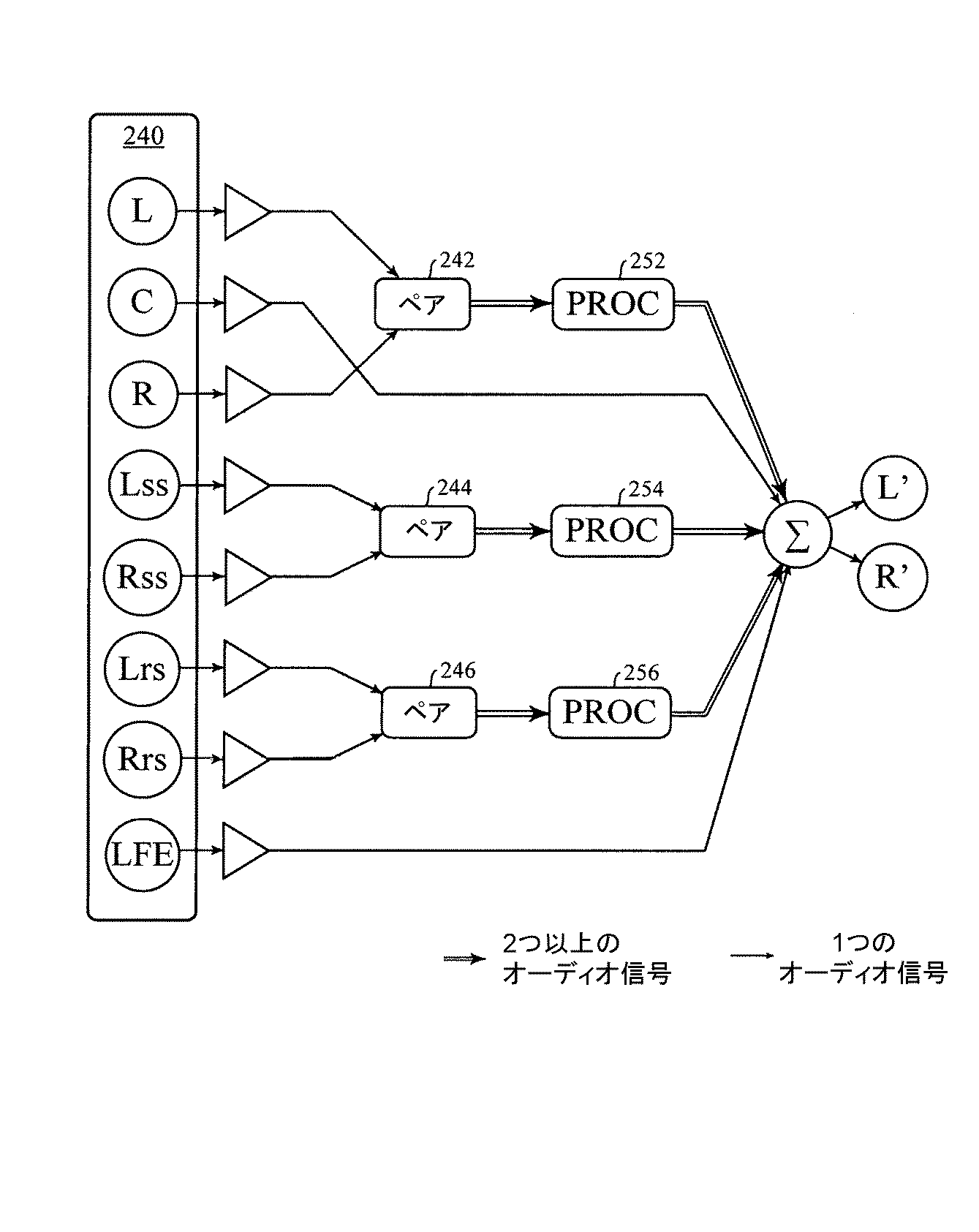
[0035] 図3A〜3Bは、いくつかの実施形態による、マルチチャネル入力信号を処理するオーディオ・ダウンミックス・パイプラインを示すブロック図である。図3Aでのマルチチャネル入力信号は、左フロント・チャネル(L)、中央フロント・チャネル(C)、右フロント・チャネル(R)、左サイド・チャネル(Ls)、右サイド・チャネル(Rs)、及び低音効果(LFE)を含む、5.1サラウンド・サウンド・ファイル210である。図3Bでのマルチチャネル入力信号は、左フロント・チャネル(L)、中央フロント・チャネル(C)、右フロント・チャネル(R)、左サイド・サラウンド・チャネル(Lss)、右サイド・サラウンド・チャネル(Rss)、左リア・サラウンド・チャネル(Lrs)、右リア・サラウンド・チャネル(Rrs)、及び低音効果(LFE)を含む、7.1サラウンド・サウンド・ファイル240である。
[0035] FIGS. 3A-3B are block diagrams illustrating an audio downmix pipeline for processing a multi-channel input signal, according to some embodiments. The multi-channel input signal in FIG. 3A includes a left front channel (L), a center front channel (C), a right front channel (R), a left side channel (Ls), a right side channel (Rs), And 5.1
[0036] 実施形態によっては、このシステムは、マルチチャネル入力信号から1つ又は複数の入力ペアを選択する。実施形態によっては、入力ペアは、対象形に配置されたスピーカで再現されるように意図された2組のオーディオ・ストリームに対応する。したがって、この入力ペアは、1対の空間的に対称な信号源を含む。実施形態によっては、入力ペアは、中心線から同じ角度を有する2つのサイド(すなわち、左サイド及び右サイド)において2つのオーディオ・チャネルを含む。たとえば、フロント・ペアは、左フロント(L)チャネル及び右フロント(R)チャネルを含み、これらは、それぞれ中心線の左及び右に対して30°の角度にある。別の例では、Dolby7.1サラウンド・サウンド設定のリア・ペアは、左リア・サラウンド(Lrs)チャネル及び右リア・サラウンド(Rrs)チャネルを、それぞれ中心線の左及び右に対して135°の角度に配置する。次いで、選択された各入力ペアが、出力オーディオ・ペアを生成するそれぞれのプロセッサ(PROC)に送信される。 [0036] In some embodiments, the system selects one or more input pairs from the multi-channel input signal. In some embodiments, the input pairs correspond to two sets of audio streams intended to be reproduced on symmetrically placed speakers. Thus, this input pair includes a pair of spatially symmetric signal sources. In some embodiments, the input pair includes two audio channels on two sides having the same angle from the centerline (ie, the left and right sides). For example, a front pair includes a left front (L) channel and a right front (R) channel, each at a 30 ° angle to the left and right of the centerline. In another example, the rear pair of the Dolby 7.1 surround sound setting has a left rear surround (Lrs) channel and a right rear surround (Rrs) channel at 135 ° to the left and right of the centerline, respectively. Place at an angle. Each selected input pair is then sent to a respective processor (PROC) that produces an output audio pair.
[0037] 図3Aに示すような実施形態によっては、5.1サラウンド・サウンド・ファイルの複数の入力チャネルのうちから、このシステムは、左フロント・チャネル(L)及び右フロント・チャネル(R)をペア222として選択し、左サイド・チャネル(Ls)及び右サイド・チャネル(Rs)をペア224として選択する。図3Bに示すような実施形態によっては、7.1サラウンド・サウンド・ファイルの複数の入力チャネルのうちから、このシステムは、左フロント・チャネル(L)及び右フロント・チャネル(R)をペア242として選択し、左サイド・サラウンド・チャネル(Lss)及び右サイド・サラウンド・チャネル(Rss)をペア244として選択し、左リア・サラウンド・チャネル(Lrs)及び右リア・サラウンド・チャネル(Rrs)をペア246として選択する。中心線上にあるチャネル(たとえば、中央のフロントCチャネル)、及び無指向性のチャネル(たとえば、LFE)は、単一のチャネルであり、他のどのようなチャネルともペアにはならない。
[0037] In some embodiments, such as that shown in Figure 3A, out of multiple input channels of a 5.1 surround sound file, the system includes a left front channel (L) and a right front channel (R). Are selected as a
[0038] 実施形態によっては、各ペアは、それぞれプロセッサに入ることになる。たとえば、図3Aでは、ペア222及び224が、それぞれPROC232及び234に送信され、図3Bでは、ペア242、244、及び246が、それぞれPROC252、254、及び256に送信される。このようなプロセスでは、ペアの情報が互いに比較及び解析されて、さらに密な音像及びさらに良好な空間的結果を生成する。このペアを意味のあるものにするには、各プロセッサPROC内の1つ又は複数のモジュールのうち少なくとも1つが、ペア内の2つのチャネル間で情報を相互参照する必要がある。各プロセッサPROCの出力信号は2つのチャネルを含み、各ペアの2チャネル出力は、単一チャネルと合計されて(Σ)、(それぞれ、図3A及び図3Bに示すように)左チャネル出力(L’)及び右チャネル出力(R’)を含む出力信号を生成する。
[0038] In some embodiments, each pair will enter a respective processor. For example, in FIG. 3A, pairs 222 and 224 are transmitted to PROCs 232 and 234, respectively, and in FIG. 3B, pairs 242, 244, and 246 are transmitted to
[0039] 実施形態によっては、ペア・プロセッサ(PROC)は、実現可能な任意の「ツーイン・ツーアウト」のオーディオ信号プロセッサとすることができる。前述の通り、プロセッサは、入力ペアからのクロスチャネルの特徴を組み込む、少なくとも1つのモジュールから構成される。実施形態によっては、ペア・プロセッサ(PROC)は、入力ペアから信号情報を取り出す1つ又は複数のモジュールを含む。入力されたペア信号情報に基づいて、次いで、ペアプロセッサ(PROC)は、ペアごとに出力ストリームを修正する。 [0039] In some embodiments, the pair processor (PROC) can be any feasible "two-in-two-out" audio signal processor. As described above, the processor is comprised of at least one module that incorporates cross-channel features from the input pair. In some embodiments, a pair processor (PROC) includes one or more modules that extract signal information from an input pair. Based on the input pair signal information, the pair processor (PROC) then modifies the output stream for each pair.
[0040] 実施形態によっては、ペア・プロセッサ(PROC)は、チャネル依存構成要素及び/又はチャネル非依存構成要素を含む、複数の互いに異なる構成要素(又はモジュール)から構成される。実施形態によっては、チャネル依存構成要素は、マルチチャネルイン・マルチチャネルアウト・プロセス、たとえば、ペア・プロセッサでのツーイン・ツーアウトアウト・プロセスを実行する。実施形態によっては、チャネル依存構成要素は、それぞれが2つ以上の入力チャネルに基づいて複数の出力チャネルを生成する。実施形態によっては、チャネル依存構成要素は、入力信号の情報を使用し、抽出されたクロスチャネル特徴に基づいてプロセスを調整する。実施形態によっては、クロスチャネル特徴は、それぞれの入力チャネルのボリュームの比較、左右の入力チャネルの周波数スペクトル特性(たとえば、振幅及び/又は位相)の関係、及び/又は、左右の入力チャネルの信号開始の時点及び振幅の差を含む。実施形態によっては、ペア・プロセッサ(PROC)は、ミッド/サイド(M/S)ミキサ、及び/又は幅制御装置(WC)など、1つ又は複数のチャネル依存構成要素を含む。たとえば、M/Sミキサは、入力された左右の信号の和と差を使用して、ミッド信号及びサイド信号を生成することができる。別の例では、M/Sミキサは、入力信号の周波数スペクトルのオーバラップ領域を比較することによって、ミッド信号及びサイド信号を生成することができる。 [0040] In some embodiments, a pair processor (PROC) is comprised of a plurality of different components (or modules), including channel-dependent components and / or channel-independent components. In some embodiments, the channel dependent component performs a multi-channel in-multi-channel out process, for example, a two-in-two-out process on a paired processor. In some embodiments, the channel-dependent component generates a plurality of output channels, each based on two or more input channels. In some embodiments, the channel-dependent component uses information from the input signal to adjust the process based on the extracted cross-channel features. In some embodiments, the cross-channel feature may be a comparison of the volume of each input channel, a relationship between frequency spectral characteristics (eg, amplitude and / or phase) of the left and right input channels, and / or a signal start of the left and right input channels. And the difference in amplitude. In some embodiments, a pair processor (PROC) includes one or more channel-dependent components, such as a mid / side (M / S) mixer, and / or a width controller (WC). For example, the M / S mixer can generate a mid signal and a side signal using the sum and difference of the input left and right signals. In another example, the M / S mixer can generate a mid signal and a side signal by comparing overlapping regions of the frequency spectrum of the input signal.
[0041] 実施形態によっては、チャネル非依存構成要素は、マルチチャネル入力ファイルのそれぞれの各チャネルを別々に処理するマルチチャネルイン・マルチチャネルアウト・プロセス(ツーイン・ツーアウトを含む)である。実施形態によっては、複数チャネルが同数のモノ信号に分割され、各モノ信号が独立して処理され、それぞれの複数チャネルの処理済みモノ信号がともに合計される場合と同様に、チャネル非依存構成要素は、マルチチャネル入力ファイルを処理する。実施形態によっては、ペア・プロセッサ(PROC)は、イコライザ(EQ)及び/又はダイナミックレンジ圧縮装置(DRC)など、1つ又は複数のチャネル非依存構成要素を含む。たとえば、イコライザ(EQ)モジュールは、各チャネルをそれぞれ取り込み、他のチャネルからのどのような情報も使用することなく、対応するチャネルを生成する。イコライザ(EQ)の結果は、各チャネルが同じ入力パラメータで別々に等化された場合と同様である。 [0041] In some embodiments, the channel-independent component is a multi-channel in-multi-channel out process (including two-in-two-out) that processes each respective channel of the multi-channel input file separately. In some embodiments, the multiple channels are divided into the same number of mono signals, each mono signal is processed independently, and the channel independent components, as in the case where the processed mono signals of each of the multiple channels are summed together. Handles multi-channel input files. In some embodiments, the pair processor (PROC) includes one or more channel-independent components, such as an equalizer (EQ) and / or a dynamic range compressor (DRC). For example, an equalizer (EQ) module captures each channel individually and creates a corresponding channel without using any information from other channels. The result of the equalizer (EQ) is the same as if each channel were separately equalized with the same input parameters.
[0042] 図4Aは、いくつかの実施形態による、入力ペア410に適用されたPROC420を含む信号ワークフローを示すブロック図である。実施形態によっては、PROC420は、入力ペア信号410を処理するように構成された(構成要素とも呼ばれる)複数のモジュールを含む。実施形態によっては、PROC420は、図3A〜図3Bに示すように、PROC232、PROC234、PROC252、PROC254、又はPROC256など、任意のペア・プロセッサとすることができる。したがって、ペア・プロセッサ420は、図3A〜図3Bに示すように、ペア222、ペア224、ペア242、ペア244、又はペア246など、任意の入力ペアに適用することができる。実施形態によっては、ペア・プロセッサ420は、図4Aに示すように、互いに結合されたミッド/サイド(M/S)ミキサ422、イコライザ(EQ)428、ダイナミックレンジ圧縮装置(DRC)430、及びクロストーク消去(XTC)モジュール432を含む。PROC420の出力信号は、幅制御装置(WC)434及び別のダイナミックレンジ圧縮装置(DRC)436でさらに処理されて、図4Aに示すように出力ペア440を得る。
FIG. 4A is a block diagram illustrating a signal workflow including a
[0043] 実施形態によっては、データ処理システム100は、まず入力の左右の信号410をM/Sミキサ422に送信する。実施形態によっては、M/Sミキサ422は、入力ペア410から3つの成分(2つのサイド成分(S)424、すなわち左サイド及び右サイド、並びに1つのミッド成分(M)426)を生成するように構成されるミキシング・ツールである。左サイド成分は、左チャネルだけに現れる音源を表し、右サイド成分は、右チャネルだけに現れる音に対応する。中央成分は、サウンドステージの音像中心にのみ現れる音源、たとえば主要な音楽的な要素及びダイアログである。
In some embodiments,
[0044] そうすることにより、M/Sミキサ422は、後に続く様々なサウンドステージの改良に有用な情報を分離し、音質における不要なひずみ(たとえば、色付け)を最小限に抑える。さらに、このステップはまた、左成分と右成分の間の相関関係を下げるのに役立つ。実施形態によっては、M/Sミキサ422は、音像を解析し、中央、左、及び右から到来する音を推定する。次いで、M/Sミキサ422は、2つの入力チャネル、すなわち左右の信号410を、1チャネルのミッド信号426及び2チャネルのサイド信号424に分割する。M/Sミキサ422のより詳細な説明は、「サウンドステージ改良のための装置及び方法」と題する、2015年10月27日出願のPCT出願第PCT/US2015/057616号に見いだすことができ、これを、参照により全体として組み込む。
[0044] In doing so, the M /
[0045] 次に、このシステムは、各サイド信号424をイコライザ(EQ)428に送信して、このサイド信号424の周波数成分を調整する。実施形態によっては、2つのサイド信号424を処理するEQ428は、この2つのサイド信号に帯域通過フィルタ処理を実行するための1つ又は複数のマルチバンド・イコライザを含む。実施形態によっては、各サイド信号に適用されるマルチバンド・イコライザは同じである。他の実施形態によっては、一方のサイド信号に適用されるマルチバンド・イコライザは、他方のサイド信号に適用されるマルチバンド・イコライザと同じではない。それにもかかわらず、これらの機能は、オーディオ信号の元の音色を保持し、これら2つの信号に存在する曖昧な空間的手がかりを回避することである。実施形態によっては、このEQ428を使用して、2つのサイド成分のスペクトル解析に基づいてターゲットの音源を選択することもできる。図4Aに示すような実施形態によっては、EQ428は、2つの出力信号450及び452を生成する。実施形態によっては、出力信号450及び452のそれぞれは、2チャネル・オーディオ信号である。実施形態によっては、EQ428は、2チャネルのサイド信号424のそれぞれに、それぞれの帯域通過フィルタを適用して、帯域通過フィルタ処理済みの信号450を得る。
Next, the system transmits each side signal 424 to an equalizer (EQ) 428 to adjust the frequency component of the
[0046] 実施形態によっては、EQ428はまた、EQ428の入力信号(すなわち、2チャネルのサイド信号424)とEQ428の出力信号(すなわち、2チャネル帯域通過フィルタ処理済みの信号450)との間の周波数帯域の差に基づいて、残留信号452を生成する。実施形態によっては、データ処理システム100は、帯域通過フィルタ処理済みの左サイド成分及び帯域通過フィルタ処理済みの右サイド成分それぞれから、左サイド成分及び右サイド成分を差し引くことによって、左サイドの残留成分及び右サイドの残留成分を生成する。実施形態によっては、それぞれの増幅器を残留信号及びクロストーク消去からの結果信号に適用して、この2つの信号の利得を調整した後に、これらの信号を互いに結合する。EQ428のより詳細な説明は、「サウンドステージ改良のための装置及び方法」と題する、2015年10月27日出願のPCT出願第PCT/US2015/057616号に見いだすことができ、これを、参照により全体として組み込む。
[0046] In some embodiments,
[0047] 実施形態によっては、帯域通過フィルタ処理済みの信号450は、ダイナミックレンジ圧縮装置(DRC)430に送信される。実施形態によっては、DRC430は、所定の周波数範囲内で2つのオーディオ信号(すなわち、2チャネル帯域通過フィルタ処理済みの信号450)を増幅するための(EQ428の帯域通過フィルタとは異なる)帯域通過フィルタを含んでいて、クロストーク・キャンセル・ブロック(XTC)432が実現するサウンドステージ改良効果を最大化する。実施形態によっては、ユーザ(たとえば、音響技師)は、特定の周波数帯域を除外するようにDRC430の帯域通過フィルタを調整することができる。そうすることにより、ユーザは、自分が選んだある特定の音響事象を強調することができる。たとえば、EQ428の第1の帯域通過フィルタを使用して左サイド成分及び右サイド成分に等化を実行した後、データ処理システム100は、DRC430の第2の帯域通過フィルタを使用して、左サイド成分及び右サイド成分から所定の周波数帯域を除去する。EQブロック428及びDRCブロック430で使用される代表的な帯域通過フィルタには、4次フィルタ又はバターワース・フィルタが含まれる。実施形態によっては、EQ428の第1の帯域通過フィルタを使用して左サイド成分及び右サイド成分への等化を実行した後、データ処理システム100は、DRC430による第1のダイナミックレンジ圧縮を左サイド成分及び右サイド成分に対して実行して、他の周波数に対して所定の周波数帯域を強調する。DRC430のより詳細な説明は、「サウンドステージ改良のための装置及び方法」と題する、2015年10月27日出願のPCT出願第PCT/US2015/057616号に見いだすことができ、これを、参照により全体として組み込む。
In some embodiments, bandpass filtered
[0048] 実施形態によっては、DRC430からの出力信号は、次いで、クロストーク・キャンセル・プロセスを実行するためのクロストーク・キャンセル(XTC)モジュール432に送信される。クロストークは、ステレオ(すなわち、2チャネル)ラウドスピーカ再生時に固有の問題である。各スピーカの反対側の耳に音が到達するとクロストークが発生し、元の信号に不要なスペクトルの音色付けがなされる。この問題に対する解決策は、クロストーク消去(XTC)アルゴリズムである。XTCアルゴリズムの1つのタイプは、頭部伝達関数(HRTF)及び/又はバイノーラル室内インパルス応答(BRIR)など、汎用型の指向性バイノーラル伝達関数を使用して、リスナの位置に対する2つの物理的ラウドスピーカの角度を表す。XTCアルゴリズム・システムの別のタイプは、頭部伝達関数(HRTF)、バイノーラル室内インパルス応答(BRIR)、又は他の任意のバイノーラル伝達関数を必要としない、再帰的クロストーク消去方法である。基本的なアルゴリズムは、以下のように公式化することができる。
left[n]=left[n]−AL*right[n−dL]
right[n]=right[n]−AR*left[n−dR]
ここで、AL及びARは信号の減衰係数であり、dL及びdRは、それぞれのスピーカから反対側の耳までのデータ・サンプル数の遅延である。実施形態によっては、図4Aに示すようなXTC432は、再帰的クロストーク消去方法又は汎用型の指向性バイノーラル伝達関数を使用する。XTC432のより詳細な説明は、「サウンドステージ改良のための装置及び方法」と題する、2014年12月12日出願の米国特許出願第14/569,490号(2016年12月27日に付与された特許第9,532,156号)、及び「サウンドステージ改良のための装置及び方法」と題する、2016年11月11日出願の米国特許出願第15/349,822号に見いだすことができ、これらを、参照により全体として組み込む。
[0048] In some embodiments, the output signal from
left [n] = left [n] -A L * right [n-d L ]
right [n] = right [n ] -A R * left [n-d R]
Here, A L and A R are the attenuation coefficients of the signals, d L and d R is a data sample number of the delay from each speaker to the ear opposite. In some embodiments,
[0049] 図4Aに示すような実施形態によっては、XTC432の出力信号が増幅器462に供給され、残留信号452のペアが増幅器464に供給され、中間成分(M)426も増幅器466に供給された後に、これらが幅制御装置(WC)434に送信されて、処理され、一緒に結合される。
In some embodiments, as shown in FIG. 4A, the output signal of
[0050] 実施形態によっては、増幅器462、464、及び466の出力信号が、WC434に送信されて、ステージの幅を調整する。実施形態によっては、WC434は、入力信号ペアの解析済み情報を使用して、出力オーディオ信号のサウンドステージ幅を制御する。ステージ幅は、0°の狭さから、トータル没入型サウンドでの360°の広さまでとすることができる。実施形態によっては、ペア(たとえば、出力ペア472又は474)のクロスチャネル情報が解析され、別の方法で調整される。実施形態によっては、以下で図5に示すように、ユーザは、所望のステージ幅を幅制御装置に割り当てることができる。割り当てられたステージ幅は、これまでに解析された情報に基づいて、WC434のペア加算行列に影響を及ぼす場合がある。例によっては、サウンドステージの幅は、以下の式を使用して調整することができる。
ここで、−5≦β≦0は、ステージ幅のパラメータである。その結果得られる信号は、β=0のときサウンドステージ幅が最大になり、β=−5のときモノ信号に近い。
[0050] In some embodiments, the output signals of
Here, −5 ≦ β ≦ 0 is a parameter of the stage width. The resulting signal has a maximum sound stage width when β = 0 and is close to a mono signal when β = −5.
[0051] 実施形態によっては、WC434の出力信号476は、第2のダイナミックレンジ圧縮装置(DRC)436に送信されて、オーディオ・マスタリング・プロセスにおいてオーディオ信号の総合的な出力レベルを増幅する。実施形態によっては、データ処理システム100は、DRC436による左サイド成分及び右サイド成分への第2のダイナミックレンジ圧縮を実行して、デジタル・オーディオ出力信号での位置特定の手がかりを保存する。
[0051] In some embodiments, the
[0052] 図4Aに示すように、パイプラインの出力は、左チャネル(L’)及び右チャネル(R’)を含むステレオ・オーディオ信号440である。実施形態によっては、PROC420を含む信号ワークフローは、図3Aに示すように、5.1サラウンド・サウンド・ファイルに適用することができる。たとえば、PROC232及び/又はPROC234は、図4Aに示すように、PROC420と同様でもよい。
[0052] As shown in FIG. 4A, the output of the pipeline is a
[0053] 図4Bは、いくつかの実施形態による、7.1サラウンド・サウンド・ファイルに適用される信号ワークフローを示すブロック図である。図3Bを参照して説明する実施形態によっては、7.1サラウンド・サウンド・ファイルの入力信号は、ペアに、すなわち、それぞれL/Rペア242、Lss/Rssペア244、及びLrs/Rrsペア246にグループ化される。次いで、L/Rペア242、Lss/Rssペア244、及びLrs/Rrsペア246は、それぞれPROC252、PROC254、及びPROC256に送信される。実施形態によっては、PROC252、PROC254、及びPROC256のそれぞれのPROCは、図4Aを参照して先に述べたPROC420と同様である。他の実施形態によっては、PROC252、PROC254、又はPROC256は、様々な構成で1つ又は複数の他のモジュール(又は構成要素)を含んでもよい。PROC252、PROC254、及びPROC256のそれぞれの出力信号は、それぞれの幅制御、たとえば、それぞれWC482、WC484、及びWC486に送信される。WC482、WC484、又はWC486は、図4Aを参照して先に述べたWC434と同様でもよい。WC482、WC484、及びWC486の出力を、中心信号C及び低音効果チャネルLFEと結合して、出力ステレオ・オーディオ信号488を生成する。
FIG. 4B is a block diagram illustrating a signal workflow applied to a 7.1 surround sound file, according to some embodiments. In some embodiments described with reference to FIG. 3B, the input signals of the 7.1 surround sound file are paired, ie, L /
[0054] 図5には、いくつかの実施形態による、7.1サラウンド・サウンド・ファイルについて図4Bを参照して述べたような、信号パイプラインの実装を管理するのに使用される、ソフトウェア・アプリケーションのユーザ・インターフェース(UI)500、又はソフトウェア・アプリケーションのプラグイン・コンポーネントが示してある。信号パイプラインは、図4Aに示すようなPROC420など、複数のペア・プロセッサを含んでもよい。この場合には、3つのペア、すなわちフロント・ペア(L、R)、サイド・ペア(Lss、Rss)、リア・ペア(Lrs、Rrs)がある。UI500の左パネル510は、それぞれの入力チャネルの利得を制御する。制御領域520は、イコライザ(EQ)の周波数成分を制御する。制御領域530は、幅制御装置の幅を制御する。図4Bを参照して先に述べた通り、各ペアは、互いに異なるパラメータを有する互いに異なるペア・プロセッサPROCを通過し、したがって、制御領域540を使用して、どのペア(たとえば、フロント・ペア、サイド・ペア、又はリア・ペア)が、PROC処理を実行するためのパラメータを入力するかを選択する。
[0054] FIG. 5 illustrates software used to manage the implementation of the signal pipeline, as described with reference to FIG. 4B for 7.1 surround sound files, according to some embodiments. An application user interface (UI) 500 or a plug-in component of a software application is shown. The signal pipeline may include multiple paired processors, such as
[0055] 前述の通り、音は、メディア及び娯楽において重要な部分である。音は、聴衆の感情に訴えかけ、聴衆を物語に引き込む。さらに没入する聴取体験を得るために、マルチチャネル・サラウンド・サウンドが導入される。マルチチャネル・オーディオ・フォーマットは、複数のオーディオ・トラックを利用して、対応するマルチチャネル・サウンド再現システム上で音を再構成する。ダウンミキシングは、制作側及び再現側の両方で発生する場合がある。制作側では、サウンド・ミキサは通常、最多のチャネル数でミキシングを開始し、それよりも少ないチャネル数にダウンミックスする。再現側では、マルチチャネル・オーディオ・トラックを、相対的に少ないチャネル数にダウンミックスして、再現システムのチャネル番号に合わせることができる。どちらの場合にも、元の独創的な意図にマッチするサウンドの使用及び配置を維持することが目標である。 [0055] As mentioned above, sound is an important part of media and entertainment. The sounds appeal to the audience's emotions and draw the audience into the story. To get a more immersive listening experience, multi-channel surround sound is introduced. The multi-channel audio format utilizes multiple audio tracks to reconstruct the sound on a corresponding multi-channel sound reproduction system. Downmixing can occur on both the production side and the reproduction side. On the production side, the sound mixer usually starts mixing with the highest number of channels and downmixes to a lower number of channels. On the reproduction side, the multi-channel audio track can be downmixed to a relatively small number of channels to match the channel number of the reproduction system. In both cases, the goal is to maintain the use and placement of sounds that match the original intent.
[0056] 図1A〜図1Cに示すように、従来のダウンミキシング方法は、個々の各トラックにプロセスを適用する。トラック間の関係は考慮に入れない。本明細書に提示される方法及びシステムは、ペアごとにオーディオ入力を受け取る。マルチチャネル・オーディオ・トラックは、第1に、再現システムの物理的な配置に応じて各ペアにグループ分けされる。第2に、ペアの2つのチャネル間の関係が解析されることになる。最後に、このペア入力は、解析結果に基づいて処理される。ペア間の関係を組み込むことによって、元のマルチチャネル・オーディオ入力の空間情報をより良好に保存することができる。その結果、本明細書で導入されるシステム及び方法でダウンミックスされるマルチチャネル・オーディオ出力は、従来の方法でダウンミックスされる同じオーディオ入力よりも元のマルチチャネル・オーディオ入力に近い、さらに正確なサウンド・スケープを生成する。 As shown in FIGS. 1A to 1C, the conventional downmixing method applies a process to each individual track. The relationship between the tracks is not taken into account. The methods and systems presented herein receive audio input on a pair-by-pair basis. Multi-channel audio tracks are first grouped into pairs according to the physical arrangement of the reproduction system. Second, the relationship between the two channels of the pair will be analyzed. Finally, the pair input is processed based on the analysis result. By incorporating the relationship between pairs, the spatial information of the original multi-channel audio input can be better preserved. As a result, the multi-channel audio output downmixed with the systems and methods introduced herein is more accurate and closer to the original multi-channel audio input than the same audio input downmixed in a conventional manner. Create a nice soundscape.
[0057] 図6A〜6Cは、いくつかの実施形態による、図2に示すデータ処理システム100を使用してマルチチャネル・オーディオ信号をダウンミックスするプロセスを示す流れ図である。データ処理システム100は、マルチチャネル入力オーディオ信号から左入力チャネル及び右入力チャネルを選択する(602)。実施形態によっては、左入力チャネル及び右入力チャネルは、空間的に対称な1対の信号源に対応する。実施形態によっては、マルチチャネル・オーディオ入力信号は、図3Aの5.1サラウンド・サウンド・ファイル210、又は図3Bの7.1サラウンド・サウンド・ファイル240である。実施形態によっては、5.1サラウンド入力信号210は、ペア222としての左フロント・チャネルL及び右フロント・チャネルR、並びにペア224としての左サイド・チャネルLs及び右サイド・チャネルRsを含む。実施形態によっては、7.1サラウンド入力信号240は、ペア242としての左フロント・チャネルL及び右フロント・チャネルR、ペア244としての左サイド・サラウンド・チャネルLss及び右サイド・サラウンド・チャネルRss、並びにペア246としての左リア・サラウンド・チャネルLrs及び右リア・サラウンド・チャネルRrsを含む。
[0057] FIGS. 6A-6C are flowcharts illustrating a process of downmixing a multi-channel audio signal using the
[0058] 次いで、データ処理システム100は、選択されたペアの左入力チャネル及び右入力チャネルから、1つ又は複数のクロスチャネル特徴を生成する(604)。実施形態によっては、1つ又は複数のクロスチャネル特徴は、ペアの左右の入力チャネルのボリュームの比較、左右の入力チャネルの周波数スペクトル特性(たとえば、振幅及び/又は位相)の関係、及び/又は、左右の入力チャネルの信号開始の時点及び振幅の差を含む。
[0058] Next,
[0059] 次いで、データ処理システム100は、選択済みのペアのクロスチャネル特徴、左入力チャネル、及び右入力チャネルに従って処理して(606)、左中間チャネル及び右中間チャネルを生成する。実施形態によっては、ペアの左入力チャネル及び右入力チャネルは、図3A〜3B及び図4A〜4Bに示すようにプロセッサ(PROC)を使用して処理される。実施形態によっては、PROCは、図4Aに示すような1つ又は複数のモジュールを含む。
[0059] The
[0060] 次に、データ処理システム100は、左中間チャネル及び右中間チャネルのそれぞれと、マルチチャネル入力オーディオ信号の第3の入力チャネルとを結合して(608)、2チャネル出力オーディオ信号を形成する。たとえば、図3Aに示すように、それぞれのPROCによって処理された左中間チャネル及び右中間チャネル(たとえば、L/Rペア又はLs/Rsペア)は、センター・チャネルC及び/又は低音効果(LFE)と結合されて、2チャネル出力オーディオ信号L’/R’を生成する。同様に、図3Bに示すように、それぞれのPROCによって処理された左中間チャネル及び右中間チャネル(たとえば、L/Rペア、Lss/Rssペア、又はLrs/Rrsペア)は、センター・チャネルC及び/又は低音効果(LFE)と結合されて、2チャネル出力オーディオ信号L’/R’を生成する。
Next, the
[0061] 音響工学では、サウンドステージは、通常、オーディオ再現において最も左に知覚される位置と最も右に知覚される位置との間の領域として定義される。すなわち、サウンドステージは、音の対象をどれくらい遠くまで知覚できるかの限界である。したがって、サウンドステージ幅は、左の境界と右の境界の間の距離として定義される。通常の場合、ステレオ再現のサウンドステージ幅は、2つのラウドスピーカの分離距離である。この用途では、サウンドステージの概念は、独立してチャネルの各対称ペアに適用されるようになっている。たとえば、実施形態によっては、データ処理システム100は、幅制御装置(たとえば、WC434)を使用して、左中間チャネル及び右中間チャネルに関連付けられたサウンドステージ幅をさらに調整した(610)後に、左中間チャネル及び右中間チャネルと第3の入力チャネルとを結合する。実施形態によっては、データ処理システム100は、2チャネル出力オーディオ信号のサウンドステージ幅を指定するユーザ入力を受信する(612)。ユーザ入力は、図5に示すように、UI500で受信することができる。
[0061] In acoustics, a sound stage is usually defined as the area between the leftmost and rightmost perceived position in audio reproduction. That is, the sound stage is the limit of how far a sound object can be perceived. Thus, the soundstage width is defined as the distance between the left and right boundaries. In the normal case, the sound stage width of a stereo reproduction is the separation distance between two loudspeakers. In this application, the concept of the soundstage is adapted to be applied independently to each symmetric pair of channels. For example, in some embodiments,
[0062] 実施形態によっては、左入力チャネル及び右入力チャネルを処理するステップ606はさらに、左入力チャネル及び右入力チャネルから、中間成分、左サイド成分、及び右サイド成分を抽出すること(614)を含む。たとえば、図4Aに示すように、入力ペア410は、M/Sミキサ422によって処理されて、中間成分426と、左サイド成分及び右サイド成分S424とを生成する。実施形態によっては、データ処理システム100は、左入力チャネル及び右入力チャネル、並びに左サイド成分及び右サイド成分を処理した(616)後に、これらと中間成分とを結合して、左中間チャネル及び右中間チャネルを生成する。
[0062] In some embodiments, processing 606 the left and right input channels further comprises extracting an intermediate component, a left side component, and a right side component from the left and right input channels (614). including. For example, as shown in FIG. 4A,
[0063] 実施形態によっては、左入力チャネル及び右入力チャネルを処理するステップ606は、帯域通過フィルタを使用して左サイド成分及び右サイド成分に(たとえば、図4AのEQブロック428による)等化を実行して(618)、左の帯域通過フィルタ処理済み成分及び右の帯域通過フィルタ処理済み成分(たとえば、EQ450の出力信号)を得ることをさらに含む。実施形態によっては、図4Aに示すような左サイド残留成分及び右サイド残留成分452のように、この等化プロセスはさらに、左サイド成分と左の帯域通過フィルタ処理済み成分との間の差に基づいて左サイド残留成分を生成し(620)、右サイド成分と右の帯域通過フィルタ処理済み成分との間の差に基づいて右サイド残留成分を生成する(620)。
[0063] In some embodiments, processing 606 the left and right input channels includes equalizing (eg, by EQ block 428 of FIG. 4A) to the left and right side components using a bandpass filter. (618) to obtain the left band-pass filtered component and the right band-pass filtered component (eg, the output signal of the EQ 450). In some embodiments, such as the left side residual component and the right side
[0064] 実施形態によっては、左サイド成分及び右サイド成分への等化を実行した後、データ処理システム100は、(たとえば、図4AのDRC430による)第1のダイナミックレンジ圧縮を、左の帯域通過フィルタ処理済み成分及び(たとえば、図4AのEQ428によって生成される)右の帯域通過フィルタ処理済み成分に対してそれぞれ実行して(622)、それに応じて左の圧縮済み成分及び右の圧縮済み成分を得る。
[0064] In some embodiments, after performing equalization to the left and right side components,
[0065] 実施形態によっては、第1のダイナミックレンジ圧縮を実行した後、データ処理システム100は、(たとえば、図4AのXTC432による)クロストーク消去を、(たとえば、図4AのDRC430によって生成される)左の圧縮済み成分及び右の圧縮済み成分にそれぞれ実行して(624)、クロストーク消去済みの左サイド成分及びクロストーク消去済みの右サイド成分を得る。
[0065] In some embodiments, after performing the first dynamic range compression,
[0066] 実施形態によっては、データ処理システム100は、クロストーク消去済みの左サイド成分及びクロストーク消去済みの右サイド成分、左サイド残留成分及び右サイド残留成分、並びに中間成分を結合して(626)、左中間チャネル及び右中間チャネルを生成する。実施形態によっては、この結合ステップはさらに、左中間チャネル及び右中間チャネルに関連付けられたサウンドステージ幅を(たとえば、図4AのWC434によって)調整した(628)後に、これらと第3の入力チャネルとを結合することを含む。たとえば、図4Bに示すように、それぞれのPROCによって生成される左右の中間チャネルは、それぞれのWCに送られて、サウンドステージ幅を調整する。次いで、調整済みの信号は、第3の入力チャネル、たとえばC又はLFEチャネルと結合されて、出力ステレオ信号488を生成する。
In some embodiments, the
[0067] 実施形態によっては、サウンドステージ幅を調整した後、データ処理システム100は、(たとえば、図4AのDRC436による)第2のダイナミックレンジ圧縮を実行して(630)、左中間チャネル及び右中間チャネルを生成する。
[0067] In some embodiments, after adjusting the sound stage width, the
[0068] 最後に、本発明は、もっぱらハードウェアの実施形態、もっぱらソフトウェアの実施形態、又はハードウェア要素及びソフトウェア要素の両方を含む実施形態の形をとることができることに留意されたい。好ましい一実施形態では、本発明は、ソフトウェアで実装されており、このソフトウェアには、それだけには限定されないが、ファームウェア、常駐ソフトウェア、マイクロコードなどが含まれている。 [0068] Finally, it is noted that the present invention may take the form of an entirely hardware embodiment, an entirely software embodiment or an embodiment containing both hardware and software elements. In a preferred embodiment, the invention is implemented in software, which includes but is not limited to firmware, resident software, microcode, and the like.
[0069] さらに、本発明は、コンピュータ若しくは任意の命令実行システムが使用するか、又はそれとともに使用するためのプログラム・コードを提供する、コンピュータ使用可能又はコンピュータ読取り可能な媒体からアクセスできるコンピュータ・プログラム製品の形をとることができる。この説明のために、コンピュータ使用可能又はコンピュータ読取り可能な媒体は、命令実行のシステム、装置、若しくはデバイスによって、又はそれらとともに使用するために、プログラムを包含、記憶、伝達、伝搬、又は移送することができる任意の有形装置とすることができる。 [0069] Further, the present invention provides a computer program accessible from a computer usable or computer readable medium that provides program code for use with or for use by a computer or any instruction execution system. It can take the form of a product. For purposes of this description, computer-usable or computer-readable media includes, stores, communicates, propagates, or transports programs for use by or with a system, apparatus, or device of instruction execution. It can be any tangible device that can do this.
[0070] この媒体は、電子、磁気、光、電磁、赤外線、若しくは半導体のシステム(若しくは機器、若しくは装置)、又は伝搬媒体とすることができる。コンピュータ読取り可能な媒体の例には、半導体メモリすなわち固体記憶装置、磁気テープ、取外し可能なコンピュータ・ディスケット、ランダム・アクセス・メモリ(RAM)、リードオンリ・メモリ(ROM)、硬質磁気ディスク、及び光ディスクが含まれる。光ディスクの現在の例には、コンパクト・ディスク・リード・オンリ・メモリ(CD−ROM)、コンパクト・ディスク読取り/書込み(CD−R/W)、及びDVDが含まれる。 [0070] This medium can be an electronic, magnetic, optical, electromagnetic, infrared, or semiconductor system (or device or device), or a propagation medium. Examples of computer readable media include semiconductor memory or solid state storage, magnetic tape, removable computer diskettes, random access memory (RAM), read only memory (ROM), hard magnetic disks, and optical disks. included. Current examples of optical disks include compact disk read only memory (CD-ROM), compact disk read / write (CD-R / W), and DVD.
[0071] プログラム・コードを記憶及び/又は実行するのに適したデータ処理システムは、システム・バスを介して記憶素子に直接又は間接に結合された、少なくとも1つのプロセッサを備えることになる。これらの記憶素子には、プログラム・コードを実際に実行する際に利用されるローカル・メモリ、大容量記憶装置、及び、少なくとも何らかのプログラム・コードを一時的に記憶して、実行中に大容量記憶装置からコードを取り出さなければならない回数を減らすキャッシュ・メモリが含まれ得る。実施形態によっては、データ処理システムは、コンピュータ又は他の電子システムの全ての構成要素をシングル・チップ基板に集積化する、半導体チップ(たとえば、システムオンチップ)の形で実装される。 [0071] A data processing system suitable for storing and / or executing program code will include at least one processor coupled directly or indirectly to a storage element via a system bus. These storage elements include a local memory used for actually executing the program code, a mass storage device, and at least temporarily store at least some program code so as to temporarily store the mass code during execution. A cache memory may be included to reduce the number of times code must be retrieved from the device. In some embodiments, the data processing system is implemented in the form of a semiconductor chip (eg, a system-on-chip) that integrates all components of a computer or other electronic system on a single chip substrate.
[0072] 入力/出力装置すなわちI/O装置(キーボード、表示装置、ポインティング装置などを含むが、それだけには限定されない)は、直接又は介在するI/O制御装置を介して、このシステムに結合することができる。 [0072] Input / output or I / O devices (including, but not limited to, keyboards, displays, pointing devices, etc.) couple to the system either directly or through intervening I / O controls. be able to.
[0073] ネットワーク・アダプタはまた、このシステムに結合して、該データ処理システムが、介在する専用ネットワーク又は公衆ネットワークを介して、他のデータ処理システム、又はリモート・プリンタ若しくは記憶装置に結合するようになっていてもよい。モデム、ケーブル・モデム、及びイーサネット・カードは、ネットワーク・アダプタの現在利用可能なタイプのうちの、ほんのいくつかに過ぎない。 [0073] A network adapter is also coupled to the system such that the data processing system couples to another data processing system or a remote printer or storage device via an intervening private or public network. It may be. Modems, cable modem and Ethernet cards are just a few of the currently available types of network adapters.
[0074] 本出願の説明は、例示し説明するためにおこなってきており、網羅的ではなく、又は開示された形での本発明に限定されるものでもない。多くの修正形態及び変形形態が、当業者には明白になろう。本発明の原理、その実際の適用例を最も良好に説明するために、また、企図された特定の使用に適した様々な修正形態とともに、様々な実施形態について本発明を当業者が理解できるようにするために実施形態が選ばれ、説明された。 The description of the present application has been presented for purposes of illustration and description, and is not exhaustive or limited to the invention in the form disclosed. Many modifications and variations will be apparent to those skilled in the art. To best explain the principles of the invention, its practical application, and various modifications suitable for the particular intended use, the invention will be understood by those skilled in the art for various embodiments. An embodiment has been chosen and described in order to
[0075] 本明細書での実施形態の説明に使用される専門用語は、特定の実施形態のみを説明することを目的としており、特許請求の範囲に記載の範囲を限定するものではない。実施形態及び添付特許請求の範囲の説明で使用されているように、単数形「a」、「an」、及び「the」は、文脈から明らかにそうでない場合を除き、複数形をも含むものである。本明細書で使用される用語「及び/又は」は、関連する列挙された項目のうち1つ又は複数の項目のありとあらゆる可能な組合せを指し、またこれらを包含することも理解されよう。用語「comprises」、及び/又は「comprising」は、本明細書において使用されるとき、明記された特徴、完全体、ステップ、動作、要素、及び/又は構成部品の存在を特定するが、1つ若しくは複数の他の特徴、完全体、ステップ、動作、要素、構成部品及び/又はそれらのグループの存在を排除しないことがさらに理解されよう。 [0075] Terminology used in the description of the embodiments herein is for the purpose of describing particular embodiments only, and is not intended to limit the scope of the claims. As used in the description of the embodiments and the appended claims, the singular forms "a," "an," and "the" include plural reference unless the context clearly dictates otherwise. . It will also be understood that the term "and / or" as used herein refers to and encompasses any and all possible combinations of one or more of the associated listed items. The terms "comprises" and / or "comprising" as used herein identify the presence of specified features, entities, steps, acts, elements and / or components, but one It will be further understood that this does not exclude the presence of or other elements, completeness, steps, acts, elements, components and / or groups thereof.
[0076] 第1、第2などの用語は、様々な要素を説明するために本明細書で使用されることがあるが、これらの要素は、これらの用語によって限定されるべきではないことも理解されよう。これらの用語はもっぱら、ある要素と別の要素を区別するために使用される。たとえば、実施形態の範囲から逸脱することなく、第1のポートを第2のポートと呼ぶこともでき、同様にして、第2のポートを第1のポートと呼ぶこともできる。第1のポート及び第2のポートは両方ともポートであるが、同じポートではない。 [0076] Terms such as "first" and "second" may be used herein to describe various elements, but these elements should not be limited by these terms. Will be understood. These terms are used exclusively to distinguish one element from another. For example, a first port may be referred to as a second port, and similarly, a second port may be referred to as a first port without departing from the scope of the embodiments. The first port and the second port are both ports, but not the same port.
[0077] 前述の説明及び関連する各図面に提示される教示の利益を享受する当業者には、本明細書に記載の実施形態の数多くの修正形態及び代替実施形態が思い浮かぶはずである。したがって、特許請求の範囲に記載の範囲は、開示された実施形態の具体例に限定されるべきではなく、修正形態及び他の実施形態が、添付の特許請求の範囲に記載の範囲内に含まれるべきものであることを理解されたい。本明細書では特定の用語が採用されているが、これらは、包括的且つ説明的な意味でのみ使用されており、限定する目的では使用されていない。 [0077] Numerous modifications and alternatives to the embodiments described herein will occur to those skilled in the art having the benefit of the foregoing description and the teachings presented in the associated figures. Therefore, the scope of the appended claims should not be limited to the specific examples of disclosed embodiments, but modifications and other embodiments are included within the scope of the appended claims. Please understand that it is something to be done. Although specific terms are employed herein, they are used in a generic and descriptive sense only and not for purposes of limitation.
[0078] 基本となる原理及びその実際的な用途を最も良好に説明するように、実施形態を選択し、また説明して、それにより、企図された特定の使用に適した様々な修正形態とともに、基本となる原理及び様々な実施形態を当業者が最も良好に利用できるようになる。
[0078] The embodiments have been selected and described in order to best explain the underlying principles and their practical applications, thereby, along with various modifications suitable for the particular use contemplated. The underlying principles and various embodiments will be best utilized by those skilled in the art.
Claims (42)
1つ又は複数のプロセッサ、メモリ、及び前記メモリ内に記憶され、前記1つ又は複数のプロセッサによって実行される複数のプログラム・モジュールを有するコンピューティング装置において、
前記マルチチャネル入力オーディオ信号から、左入力チャネル及び右入力チャネルを選択することであって、前記左入力チャネル及び前記右入力チャネルが1対の空間的に対称な信号源に対応することと、
前記左入力チャネル及び前記右入力チャネルから1つ又は複数のクロスチャネルの特徴を生成することと、
前記クロスチャネルの特徴により、前記左入力チャネル及び前記右入力チャネルを処理して、左中間チャネル及び右中間チャネルを生成することと、
前記左中間チャネル及び前記右中間チャネルのそれぞれと、前記マルチチャネル入力オーディオ信号の第3の入力チャネルとを結合して、2チャネル出力オーディオ信号を形成することと
を含む、コンピュータ実施方法。 A computer-implemented method for processing a multi-channel input audio signal, comprising:
A computing device having one or more processors, a memory, and a plurality of program modules stored in the memory and executed by the one or more processors;
Selecting a left input channel and a right input channel from the multi-channel input audio signal, wherein the left input channel and the right input channel correspond to a pair of spatially symmetric signal sources;
Generating one or more cross-channel features from the left input channel and the right input channel;
Processing the left input channel and the right input channel to generate a left intermediate channel and a right intermediate channel according to the characteristics of the cross channel;
A computer-implemented method comprising combining each of the left intermediate channel and the right intermediate channel with a third input channel of the multi-channel input audio signal to form a two-channel output audio signal.
前記左入力チャネル及び前記右入力チャネルから、中間成分、左サイド成分、及び右サイド成分を抽出することと、
前記左サイド成分及び前記右サイド成分を処理した後に、これらと前記中間成分とを結合して、前記左中間チャネル及び前記右中間チャネルを生成することと
を含む、請求項1に記載のコンピュータ実施方法。 The step of processing the left input channel and the right input channel further comprises:
Extracting an intermediate component, a left side component, and a right side component from the left input channel and the right input channel;
The computer-implemented method of claim 1, further comprising: after processing the left side component and the right side component, combining them with the intermediate component to generate the left intermediate channel and the right intermediate channel. Method.
帯域通過フィルタを使用して前記左サイド成分及び前記右サイド成分に等化を実行して、左の帯域通過フィルタ処理済み成分及び右の帯域通過フィルタ処理済み成分を得ることと、
前記左サイド成分と前記左の帯域通過フィルタ処理済み成分との間の差に基づいて左サイド残留成分を生成し、前記右サイド成分と前記右の帯域通過フィルタ処理済み成分との間の差に基づいて右サイド残留成分を生成することと
を含む、請求項4に記載のコンピュータ実施方法。 Processing the left side component and the right side component,
Performing equalization on the left side component and the right side component using a band pass filter to obtain a left band pass filtered component and a right band pass filtered component;
A left side residual component is generated based on a difference between the left side component and the left band pass filtered component, and a difference between the right side component and the right band pass filtered component is generated. Generating the right-side residual component based on the computer-implemented method.
前記左中間チャネル及び前記右中間チャネルに関連付けられたサウンドステージ幅を調整した後に、これらと前記第3の入力チャネルとを結合することを含む、請求項7に記載のコンピュータ実施方法。 Combining the left side component after crosstalk cancellation and the right side component after crosstalk cancellation, the left side residual component and the right side residual component, and the intermediate component to form the left intermediate channel and the right intermediate channel Generating, wherein the step of combining further comprises:
The computer-implemented method of claim 7, comprising adjusting a sound stage width associated with the left intermediate channel and the right intermediate channel, and then combining them with the third input channel.
1つ又は複数のプロセッサと、
メモリと、
前記メモリ内に記憶され、前記1つ又は複数のプロセッサによって実行される複数のプログラム・モジュールと
を備え、
前記複数のプログラム・モジュールは、前記1つ又は複数のプロセッサによって実行されると、
前記マルチチャネル入力オーディオ信号から、左入力チャネル及び右入力チャネルを選択することであって、前記左入力チャネル及び前記右入力チャネルが1対の空間的に対称な信号源に対応することと、
前記左入力チャネル及び前記右入力チャネルから1つ又は複数のクロスチャネルの特徴を生成することと、
前記クロスチャネルの特徴により、前記左入力チャネル及び前記右入力チャネルを処理して、左中間チャネル及び右中間チャネルを生成することと、
前記左中間チャネル及び前記右中間チャネルのそれぞれと、前記マルチチャネル入力オーディオ信号の第3の入力チャネルとを結合して、2チャネル出力オーディオ信号を形成することと
を含む複数のステップを前記コンピューティング装置が実行できるようにする、コンピューティング装置。 A computing device for processing a multi-channel input audio signal, comprising:
One or more processors;
Memory and
A plurality of program modules stored in the memory and executed by the one or more processors;
The plurality of program modules, when executed by the one or more processors,
Selecting a left input channel and a right input channel from the multi-channel input audio signal, wherein the left input channel and the right input channel correspond to a pair of spatially symmetric signal sources;
Generating one or more cross-channel features from the left input channel and the right input channel;
Processing the left input channel and the right input channel to generate a left intermediate channel and a right intermediate channel according to the characteristics of the cross channel;
Combining the left intermediate channel and the right intermediate channel each with a third input channel of the multi-channel input audio signal to form a two-channel output audio signal. A computing device that allows the device to execute.
前記左入力チャネル及び前記右入力チャネルから、中間成分、左サイド成分、及び右サイド成分を抽出することと、
前記左サイド成分及び前記右サイド成分を処理した後に、これらと前記中間成分とを結合して、前記左中間チャネル及び前記右中間チャネルを生成することと
を含む、請求項15に記載のコンピューティング装置。 The step of processing the left input channel and the right input channel further comprises:
Extracting an intermediate component, a left side component, and a right side component from the left input channel and the right input channel;
The computing of claim 15, comprising processing the left side component and the right side component and then combining them with the intermediate component to generate the left intermediate channel and the right intermediate channel. apparatus.
帯域通過フィルタを使用して前記左サイド成分及び前記右サイド成分に等化を実行して、左の帯域通過フィルタ処理済み成分及び右の帯域通過フィルタ処理済み成分を得ることと、
前記左サイド成分と前記左の帯域通過フィルタ処理済み成分との間の差に基づいて左サイド残留成分を生成し、前記右サイド成分と前記右の帯域通過フィルタ処理済み成分との間の差に基づいて右サイド残留成分を生成することと
を含む、請求項18に記載のコンピューティング装置。 Processing the left side component and the right side component,
Performing equalization on the left side component and the right side component using a band pass filter to obtain a left band pass filtered component and a right band pass filtered component;
A left side residual component is generated based on a difference between the left side component and the left band pass filtered component, and a difference between the right side component and the right band pass filtered component is generated. Generating the right-side residual component based on the computing device.
を実行するようにさらになっており、前記結合するステップがさらに、
前記左中間チャネル及び前記右中間チャネルに関連付けられたサウンドステージ幅を調整した後に、これらと前記第3の入力チャネルとを結合することを含む、請求項21に記載のコンピューティング装置。 Combining the left side component after crosstalk cancellation and the right side component after crosstalk cancellation, the left side residual component and the right side residual component, and the intermediate component to form the left intermediate channel and the right intermediate channel Further comprising performing the combining step, wherein the combining step further comprises:
22. The computing device of claim 21, comprising adjusting a sound stage width associated with the left middle channel and the right middle channel before combining them with the third input channel.
前記マルチチャネル入力オーディオ信号から、左入力チャネル及び右入力チャネルを選択することであって、前記左入力チャネル及び前記右入力チャネルが1対の空間的に対称な信号源に対応することと、
前記左入力チャネル及び前記右入力チャネルから1つ又は複数のクロスチャネルの特徴を生成することと、
前記クロスチャネルの特徴により、前記左入力チャネル及び前記右入力チャネルを処理して、左中間チャネル及び右中間チャネルを生成することと、
前記左中間チャネル及び前記右中間チャネルのそれぞれと、前記マルチチャネル入力オーディオ信号の第3の入力チャネルとを結合して、2チャネル出力オーディオ信号を形成することと
を含む複数のステップを前記コンピューティング装置が実行できるようにする複数のプログラム・モジュールを含む、コンピュータ・プログラム製品。 A computer program product stored on a persistent computer readable storage medium, with a computing device having one or more processors for processing audio signals, the computer program product being executed by the one or more processors. When,
Selecting a left input channel and a right input channel from the multi-channel input audio signal, wherein the left input channel and the right input channel correspond to a pair of spatially symmetric signal sources;
Generating one or more cross-channel features from the left input channel and the right input channel;
Processing the left input channel and the right input channel to generate a left intermediate channel and a right intermediate channel according to the characteristics of the cross channel;
Combining the left intermediate channel and the right intermediate channel each with a third input channel of the multi-channel input audio signal to form a two-channel output audio signal. A computer program product that includes a plurality of program modules that allow a device to execute.
前記左入力チャネル及び前記右入力チャネルから、中間成分、左サイド成分、及び右サイド成分を抽出することと、
前記左サイド成分及び前記右サイド成分を処理した後に、これらと前記中間成分とを結合して、前記左中間チャネル及び前記右中間チャネルを生成することと
を含む、請求項29に記載のコンピュータ・プログラム製品。 The step of processing the left input channel and the right input channel further comprises:
Extracting an intermediate component, a left side component, and a right side component from the left input channel and the right input channel;
30. The computer of claim 29, further comprising: after processing the left side component and the right side component, combining them with the intermediate component to generate the left intermediate channel and the right intermediate channel. Program products.
帯域通過フィルタを使用して前記左サイド成分及び前記右サイド成分に等化を実行して、左の帯域通過フィルタ処理済み成分及び右の帯域通過フィルタ処理済み成分を得ることと、
前記左サイド成分と前記左の帯域通過フィルタ処理済み成分との間の差に基づいて左サイド残留成分を生成し、前記右サイド成分と前記右の帯域通過フィルタ処理済み成分との間の差に基づいて右サイド残留成分を生成することと
を含む、請求項32に記載のコンピュータ・プログラム製品。 Processing the left side component and the right side component,
Performing equalization on the left side component and the right side component using a band pass filter to obtain a left band pass filtered component and a right band pass filtered component;
A left side residual component is generated based on a difference between the left side component and the left band pass filtered component, and a difference between the right side component and the right band pass filtered component is generated. Generating a right side residual based on the computer program product.
前記左サイド成分及び前記右サイド成分に等化を実行した後に、前記左の帯域通過フィルタ処理済み成分及び前記右の帯域通過フィルタ処理済み成分に、それぞれ第1のダイナミックレンジ圧縮を実行して、それに応じて左の圧縮済み成分及び右の圧縮済み成分を得るようにさらになっている、請求項33に記載のコンピュータ・プログラム製品。 The computing device comprises:
After performing equalization on the left side component and the right side component, the left band-pass filtered component and the right band-pass filtered component are each subjected to a first dynamic range compression, 34. The computer program product of claim 33, further adapted to obtain a left compressed component and a right compressed component accordingly.
前記第1のダイナミックレンジ圧縮を実行した後に、前記左の圧縮済み成分及び前記右の圧縮済み成分にそれぞれクロストーク消去を実行して、クロストーク消去済みの左サイド成分及びクロストーク消去済みの右サイド成分を得るようにさらになっている、請求項34に記載のコンピュータ・プログラム製品。 The computing device comprises:
After performing the first dynamic range compression, crosstalk cancellation is performed on the left compressed component and the right compressed component, respectively, so that the crosstalk-eliminated left side component and the crosstalk-eliminated right component are removed. 35. The computer program product of claim 34, further adapted to obtain a side component.
前記クロストーク消去済みの左サイド成分及び前記クロストーク消去済みの右サイド成分、前記左サイド残留成分及び前記右サイド残留成分、並びに前記中間成分を結合して、前記左中間チャネル及び前記右中間チャネルを生成することを実行するようにさらになっており、前記結合するステップがさらに、
前記左中間チャネル及び前記右中間チャネルに関連付けられたサウンドステージ幅を調整した後に、これらと前記第3の入力チャネルとを結合することを含む、請求項35に記載のコンピュータ・プログラム製品。 The computing device comprises:
Combining the left side component after crosstalk cancellation and the right side component after crosstalk cancellation, the left side residual component and the right side residual component, and the intermediate component to form the left intermediate channel and the right intermediate channel Further comprising performing the combining step, wherein the combining step further comprises:
36. The computer program product of claim 35, comprising adjusting a sound stage width associated with the left intermediate channel and the right intermediate channel before combining them with the third input channel.
前記サウンドステージ幅を調整した後に、第2のダイナミックレンジ圧縮を実行して、前記左中間チャネル及び前記右中間チャネルを生成するようにさらになっている、請求項36に記載のコンピュータ・プログラム製品。 The computing device comprises:
37. The computer program product of claim 36, further comprising performing a second dynamic range compression after adjusting the sound stage width to generate the left intermediate channel and the right intermediate channel.
30. The computer program product according to claim 29, wherein the third input channel is a bass effect channel.
Applications Claiming Priority (3)
| Application Number | Priority Date | Filing Date | Title |
|---|---|---|---|
| US201762460584P | 2017-02-17 | 2017-02-17 | |
| US62/460,584 | 2017-02-17 | ||
| PCT/US2018/000075 WO2018151858A1 (en) | 2017-02-17 | 2018-02-16 | Apparatus and method for downmixing multichannel audio signals |
Publications (1)
| Publication Number | Publication Date |
|---|---|
| JP2020508590A true JP2020508590A (en) | 2020-03-19 |
Family
ID=63169877
Family Applications (1)
| Application Number | Title | Priority Date | Filing Date |
|---|---|---|---|
| JP2019503460A Pending JP2020508590A (en) | 2017-02-17 | 2018-02-16 | Apparatus and method for downmixing multi-channel audio signals |
Country Status (6)
| Country | Link |
|---|---|
| EP (1) | EP3583786A4 (en) |
| JP (1) | JP2020508590A (en) |
| KR (1) | KR20190109726A (en) |
| CN (1) | CN109644315A (en) |
| TW (1) | TW201843675A (en) |
| WO (1) | WO2018151858A1 (en) |
Families Citing this family (4)
| Publication number | Priority date | Publication date | Assignee | Title |
|---|---|---|---|---|
| FR3091636B1 (en) * | 2019-01-04 | 2020-12-11 | Parrot Faurecia Automotive Sas | Multichannel audio signal processing method |
| US11432069B2 (en) * | 2019-10-10 | 2022-08-30 | Boomcloud 360, Inc. | Spectrally orthogonal audio component processing |
| US10841728B1 (en) * | 2019-10-10 | 2020-11-17 | Boomcloud 360, Inc. | Multi-channel crosstalk processing |
| CN110853658B (en) * | 2019-11-26 | 2021-12-07 | 中国电影科学技术研究所 | Method and apparatus for downmixing audio signal, computer device, and readable storage medium |
Family Cites Families (14)
| Publication number | Priority date | Publication date | Assignee | Title |
|---|---|---|---|---|
| WO2001078451A1 (en) * | 2000-04-10 | 2001-10-18 | Harman International Industries, Incorporated | Creating virtual surround using dipole and monopole pressure fields |
| CN1233200C (en) * | 2003-03-04 | 2005-12-21 | Tcl王牌电子(深圳)有限公司 | FPGA 5.1 channel virtual speech reproducing method and device |
| KR100644617B1 (en) * | 2004-06-16 | 2006-11-10 | 삼성전자주식회사 | Apparatus and method for reproducing 7.1 channel audio |
| US7853022B2 (en) * | 2004-10-28 | 2010-12-14 | Thompson Jeffrey K | Audio spatial environment engine |
| US7751572B2 (en) * | 2005-04-15 | 2010-07-06 | Dolby International Ab | Adaptive residual audio coding |
| JP5053849B2 (en) * | 2005-09-01 | 2012-10-24 | パナソニック株式会社 | Multi-channel acoustic signal processing apparatus and multi-channel acoustic signal processing method |
| US8050434B1 (en) * | 2006-12-21 | 2011-11-01 | Srs Labs, Inc. | Multi-channel audio enhancement system |
| EP2169664A3 (en) * | 2008-09-25 | 2010-04-07 | LG Electronics Inc. | A method and an apparatus for processing a signal |
| UA101542C2 (en) * | 2008-12-15 | 2013-04-10 | Долби Лабораторис Лайсензин Корпорейшн | Surround sound virtualizer and method with dynamic range compression |
| KR20140010468A (en) * | 2009-10-05 | 2014-01-24 | 하만인터내셔날인더스트리스인코포레이티드 | System for spatial extraction of audio signals |
| EP2661907B8 (en) * | 2011-01-04 | 2019-08-14 | DTS, Inc. | Immersive audio rendering system |
| TWI479905B (en) * | 2012-01-12 | 2015-04-01 | Univ Nat Central | Multi-channel down mixing device |
| CN108462936A (en) * | 2013-12-13 | 2018-08-28 | 无比的优声音科技公司 | Device and method for sound field enhancing |
| AU2015413301B2 (en) * | 2015-10-27 | 2021-04-15 | Ambidio, Inc. | Apparatus and method for sound stage enhancement |
-
2018
- 2018-02-16 JP JP2019503460A patent/JP2020508590A/en active Pending
- 2018-02-16 CN CN201880003285.0A patent/CN109644315A/en active Pending
- 2018-02-16 KR KR1020197007657A patent/KR20190109726A/en not_active Withdrawn
- 2018-02-16 EP EP18754857.3A patent/EP3583786A4/en not_active Withdrawn
- 2018-02-16 WO PCT/US2018/000075 patent/WO2018151858A1/en not_active Ceased
- 2018-02-21 TW TW107105810A patent/TW201843675A/en unknown
Also Published As
| Publication number | Publication date |
|---|---|
| EP3583786A1 (en) | 2019-12-25 |
| WO2018151858A1 (en) | 2018-08-23 |
| CN109644315A (en) | 2019-04-16 |
| KR20190109726A (en) | 2019-09-26 |
| EP3583786A4 (en) | 2020-12-23 |
| TW201843675A (en) | 2018-12-16 |
Similar Documents
| Publication | Publication Date | Title |
|---|---|---|
| JP6620235B2 (en) | Apparatus and method for sound stage expansion | |
| CN111131970B (en) | Audio signal processing device and method for filtering audio signal | |
| KR20080060640A (en) | 2 channel stereo sound reproduction method and device considering personal hearing characteristics | |
| CN101902679A (en) | Stereo audio signal processing method for simulating 5.1-channel audio signal | |
| CN113170271A (en) | Method and apparatus for processing stereo signals | |
| CN112005492B (en) | Method for dynamic sound equalization | |
| EP2484127B1 (en) | Method, computer program and apparatus for processing audio signals | |
| JP2020508590A (en) | Apparatus and method for downmixing multi-channel audio signals | |
| CN112313970B (en) | Method and system for enhancing an audio signal having a left input channel and a right input channel | |
| JP7321272B2 (en) | SOUND REPRODUCTION/SIMULATION SYSTEM AND METHOD FOR SIMULATING SOUND REPRODUCTION | |
| KR20230119192A (en) | Stereo headphone psychoacoustic sound localization system and method for reconstructing stereo psychoacoustic sound signal using the same | |
| JP7332745B2 (en) | Speech processing method and speech processing device | |
| US11924628B1 (en) | Virtual surround sound process for loudspeaker systems | |
| JP2020039168A (en) | Device and method for sound stage extension | |
| HK40004646A (en) | Apparatus and method for downmixing multichannel audio signals | |
| JP7536078B2 (en) | Acoustic Echo Cancellation Unit | |
| JP2023503140A (en) | Converting binaural signals to stereo audio signals |