JP2020503520A - Sample processing system and method - Google Patents
Sample processing system and method Download PDFInfo
- Publication number
- JP2020503520A JP2020503520A JP2019535831A JP2019535831A JP2020503520A JP 2020503520 A JP2020503520 A JP 2020503520A JP 2019535831 A JP2019535831 A JP 2019535831A JP 2019535831 A JP2019535831 A JP 2019535831A JP 2020503520 A JP2020503520 A JP 2020503520A
- Authority
- JP
- Japan
- Prior art keywords
- substrate
- platform
- fluid
- degrees
- fluid inlet
- Prior art date
- Legal status (The legal status is an assumption and is not a legal conclusion. Google has not performed a legal analysis and makes no representation as to the accuracy of the status listed.)
- Granted
Links
Images


Classifications
-
- B—PERFORMING OPERATIONS; TRANSPORTING
- B01—PHYSICAL OR CHEMICAL PROCESSES OR APPARATUS IN GENERAL
- B01L—CHEMICAL OR PHYSICAL LABORATORY APPARATUS FOR GENERAL USE
- B01L3/00—Containers or dishes for laboratory use, e.g. laboratory glassware; Droppers
- B01L3/02—Burettes; Pipettes
- B01L3/0289—Apparatus for withdrawing or distributing predetermined quantities of fluid
- B01L3/0293—Apparatus for withdrawing or distributing predetermined quantities of fluid for liquids
-
- B—PERFORMING OPERATIONS; TRANSPORTING
- B01—PHYSICAL OR CHEMICAL PROCESSES OR APPARATUS IN GENERAL
- B01L—CHEMICAL OR PHYSICAL LABORATORY APPARATUS FOR GENERAL USE
- B01L9/00—Supporting devices; Holding devices
- B01L9/52—Supports specially adapted for flat sample carriers, e.g. for plates, slides, chips
-
- G—PHYSICS
- G01—MEASURING; TESTING
- G01N—INVESTIGATING OR ANALYSING MATERIALS BY DETERMINING THEIR CHEMICAL OR PHYSICAL PROPERTIES
- G01N1/00—Sampling; Preparing specimens for investigation
- G01N1/28—Preparing specimens for investigation including physical details of (bio-)chemical methods covered elsewhere, e.g. G01N33/50, C12Q
- G01N1/30—Staining; Impregnating ; Fixation; Dehydration; Multistep processes for preparing samples of tissue, cell or nucleic acid material and the like for analysis
- G01N1/31—Apparatus therefor
- G01N1/312—Apparatus therefor for samples mounted on planar substrates
-
- B—PERFORMING OPERATIONS; TRANSPORTING
- B01—PHYSICAL OR CHEMICAL PROCESSES OR APPARATUS IN GENERAL
- B01L—CHEMICAL OR PHYSICAL LABORATORY APPARATUS FOR GENERAL USE
- B01L2200/00—Solutions for specific problems relating to chemical or physical laboratory apparatus
- B01L2200/02—Adapting objects or devices to another
- B01L2200/025—Align devices or objects to ensure defined positions relative to each other
-
- B—PERFORMING OPERATIONS; TRANSPORTING
- B01—PHYSICAL OR CHEMICAL PROCESSES OR APPARATUS IN GENERAL
- B01L—CHEMICAL OR PHYSICAL LABORATORY APPARATUS FOR GENERAL USE
- B01L2200/00—Solutions for specific problems relating to chemical or physical laboratory apparatus
- B01L2200/06—Fluid handling related problems
- B01L2200/0684—Venting, avoiding backpressure, avoid gas bubbles
-
- B—PERFORMING OPERATIONS; TRANSPORTING
- B01—PHYSICAL OR CHEMICAL PROCESSES OR APPARATUS IN GENERAL
- B01L—CHEMICAL OR PHYSICAL LABORATORY APPARATUS FOR GENERAL USE
- B01L2200/00—Solutions for specific problems relating to chemical or physical laboratory apparatus
- B01L2200/14—Process control and prevention of errors
- B01L2200/143—Quality control, feedback systems
-
- B—PERFORMING OPERATIONS; TRANSPORTING
- B01—PHYSICAL OR CHEMICAL PROCESSES OR APPARATUS IN GENERAL
- B01L—CHEMICAL OR PHYSICAL LABORATORY APPARATUS FOR GENERAL USE
- B01L2300/00—Additional constructional details
- B01L2300/08—Geometry, shape and general structure
- B01L2300/0809—Geometry, shape and general structure rectangular shaped
- B01L2300/0822—Slides
-
- B—PERFORMING OPERATIONS; TRANSPORTING
- B01—PHYSICAL OR CHEMICAL PROCESSES OR APPARATUS IN GENERAL
- B01L—CHEMICAL OR PHYSICAL LABORATORY APPARATUS FOR GENERAL USE
- B01L2300/00—Additional constructional details
- B01L2300/08—Geometry, shape and general structure
- B01L2300/089—Virtual walls for guiding liquids
-
- B—PERFORMING OPERATIONS; TRANSPORTING
- B01—PHYSICAL OR CHEMICAL PROCESSES OR APPARATUS IN GENERAL
- B01L—CHEMICAL OR PHYSICAL LABORATORY APPARATUS FOR GENERAL USE
- B01L2300/00—Additional constructional details
- B01L2300/16—Surface properties and coatings
- B01L2300/161—Control and use of surface tension forces, e.g. hydrophobic, hydrophilic
-
- B—PERFORMING OPERATIONS; TRANSPORTING
- B01—PHYSICAL OR CHEMICAL PROCESSES OR APPARATUS IN GENERAL
- B01L—CHEMICAL OR PHYSICAL LABORATORY APPARATUS FOR GENERAL USE
- B01L2400/00—Moving or stopping fluids
- B01L2400/04—Moving fluids with specific forces or mechanical means
- B01L2400/0403—Moving fluids with specific forces or mechanical means specific forces
- B01L2400/0406—Moving fluids with specific forces or mechanical means specific forces capillary forces
-
- B—PERFORMING OPERATIONS; TRANSPORTING
- B01—PHYSICAL OR CHEMICAL PROCESSES OR APPARATUS IN GENERAL
- B01L—CHEMICAL OR PHYSICAL LABORATORY APPARATUS FOR GENERAL USE
- B01L2400/00—Moving or stopping fluids
- B01L2400/04—Moving fluids with specific forces or mechanical means
- B01L2400/0475—Moving fluids with specific forces or mechanical means specific mechanical means and fluid pressure
- B01L2400/0487—Moving fluids with specific forces or mechanical means specific mechanical means and fluid pressure fluid pressure, pneumatics
-
- G—PHYSICS
- G01—MEASURING; TESTING
- G01N—INVESTIGATING OR ANALYSING MATERIALS BY DETERMINING THEIR CHEMICAL OR PHYSICAL PROPERTIES
- G01N35/00—Automatic analysis not limited to methods or materials provided for in any single one of groups G01N1/00 - G01N33/00; Handling materials therefor
- G01N35/00029—Automatic analysis not limited to methods or materials provided for in any single one of groups G01N1/00 - G01N33/00; Handling materials therefor provided with flat sample substrates, e.g. slides
- G01N2035/00099—Characterised by type of test elements
- G01N2035/00138—Slides
-
- G—PHYSICS
- G01—MEASURING; TESTING
- G01N—INVESTIGATING OR ANALYSING MATERIALS BY DETERMINING THEIR CHEMICAL OR PHYSICAL PROPERTIES
- G01N35/00—Automatic analysis not limited to methods or materials provided for in any single one of groups G01N1/00 - G01N33/00; Handling materials therefor
- G01N35/00029—Automatic analysis not limited to methods or materials provided for in any single one of groups G01N1/00 - G01N33/00; Handling materials therefor provided with flat sample substrates, e.g. slides
Landscapes
- Health & Medical Sciences (AREA)
- Chemical & Material Sciences (AREA)
- Life Sciences & Earth Sciences (AREA)
- Analytical Chemistry (AREA)
- Immunology (AREA)
- Chemical Kinetics & Catalysis (AREA)
- General Health & Medical Sciences (AREA)
- General Physics & Mathematics (AREA)
- Physics & Mathematics (AREA)
- Pathology (AREA)
- Biochemistry (AREA)
- Clinical Laboratory Science (AREA)
- Molecular Biology (AREA)
- Biomedical Technology (AREA)
- Engineering & Computer Science (AREA)
- Sampling And Sample Adjustment (AREA)
- Automatic Analysis And Handling Materials Therefor (AREA)
- Apparatus Associated With Microorganisms And Enzymes (AREA)
Abstract
本開示は、基板上で試料を調製するための方法、流体送達プラットフォーム、および装置を特徴とし、装置は、第1の位置と第2の位置との間で基板を移動させるように構成される基板ハンドラと、基板が第2の位置にあるときに、プラットフォームが基板に面するように位置決められるプラットフォームとを含み、プラットフォームは、水接触角が40度以下である親水性材料から形成される第2の表面を有する流体送達領域と、水接触角が100度以上である疎水性材料から形成され、基板が第2の位置にあるときに、基板に面する第1の表面とを含む。The present disclosure features a method, a fluid delivery platform, and a device for preparing a sample on a substrate, wherein the device is configured to move the substrate between a first position and a second position. A substrate handler, wherein the platform is positioned such that the platform faces the substrate when the substrate is in the second position, wherein the platform is formed of a hydrophilic material having a water contact angle of 40 degrees or less. A fluid delivery region having a second surface and a first surface formed of a hydrophobic material having a water contact angle of at least 100 degrees and facing the substrate when the substrate is in the second position.
Description
[関連出願の相互参照]
本出願は、2016年12月30日に出願された米国仮特許出願第62/440,847の優先権を主張し、その内容の全ては参照により本明細書に組み込まれる
[Cross-reference of related applications]
This application claims priority of US Provisional Patent Application No. 62 / 440,847, filed December 30, 2016, the entire contents of which are incorporated herein by reference.
[技術分野]
本開示は、血液および他の生物流体などの様々な流体試料、ならびに組織試料と使用するための試料処理システムに関する。
[Technical field]
The present disclosure relates to various fluid samples, such as blood and other biological fluids, as well as sample processing systems for use with tissue samples.
検査室技師は長年、最初に、試料を顕微鏡スライドなどの基板に塗布し、そして調製された基板を、たとえば顕微鏡下で視ることで、様々な生体試料を検査してきた。手動による塗布手順は、技術者個人の技術および経験の差、ならびに塗布ステップの日ごとのばらつきによる質のばらつきの影響を受ける。さらに、基板上に生体試料を手動で調製することは、典型的に複数の労働集約型ステップを伴うため、比較的遅い。 Laboratory technicians have long been examining various biological samples by first applying the sample to a substrate, such as a microscope slide, and viewing the prepared substrate, for example, under a microscope. Manual application procedures are subject to differences in technician personal skills and experience, as well as quality variations due to daily variations in the application steps. Further, manually preparing a biological sample on a substrate is relatively slow because it typically involves multiple labor intensive steps.
本開示は、後の検査、分類、および診断動作のための、基板上における試料の自動調製のシステムおよび方法を特徴とする。概して、試料は、顕微鏡スライドまたはカバースリップなどの基板に塗布される。試料は、塗布されると、基板上の試料を、そのいくつかまたはすべてが流体を試料に塗布することを伴う、様々な追加の処理ステップに曝すことによってさらに処理される。これら追加の処理ステップは、調製された試料間における、手動による調製により可能となるものよりも高い均一性および一貫性を確実にするために、自動で行われる。処理ステップの自動化は、手動による処理により可能となるものよりも高いスループットも達成し、それによって、行われる手作業の量を減少させることで、試料処理のコストが低減される。 The present disclosure features systems and methods for automatic sample preparation on a substrate for subsequent inspection, classification, and diagnostic operations. Generally, the sample is applied to a substrate such as a microscope slide or cover slip. Once applied, the sample is further processed by exposing the sample on the substrate to various additional processing steps, some or all of which involve applying a fluid to the sample. These additional processing steps are performed automatically to ensure higher uniformity and consistency between the prepared samples than is possible with manual preparation. Automation of processing steps also achieves higher throughput than is possible with manual processing, thereby reducing the amount of manual work performed and thereby reducing the cost of sample processing.
本明細書にて開示するシステムおよび方法は、概して、さらなる分析のために試料を基板に塗布するために使用される。基板に塗布され得る試料としては、たとえば、赤血球、白血球、および血小板を含有する血液試料が含まれる。さらに、骨髄、尿、膣組織、上皮組織、腫瘍、精液、および唾液などの、赤血球および/または白血球および/または血小板を含む他の生体試料も、基板に塗布され得る。基板に塗布され得る、および対象の細胞を含有し得る他の流体としては、限定されないが、脳脊髄液(CSF)、胸水を含む漿液、(たとえば腹水症のような状態による)腹水、心膜液、滑液、および持続携帯式腹膜透析(CAPD)液が含まれる。細胞を含有しないが、基板に塗布され得る流体としては、限定されないが、血漿および漿液が含まれる。 The systems and methods disclosed herein are generally used to apply a sample to a substrate for further analysis. Samples that can be applied to a substrate include, for example, blood samples containing red blood cells, white blood cells, and platelets. In addition, other biological samples, including red blood cells and / or white blood cells and / or platelets, such as bone marrow, urine, vaginal tissue, epithelial tissue, tumor, semen, and saliva may be applied to the substrate. Other fluids that can be applied to the substrate and that can contain cells of interest include, but are not limited to, cerebrospinal fluid (CSF), serum including pleural effusion, ascites (eg, due to conditions such as ascites), pericardium Fluids, synovial fluid, and continuous ambulatory peritoneal dialysis (CAPD) fluids. Fluids that do not contain cells but can be applied to a substrate include, but are not limited to, plasma and serum.
本明細書にて開示するシステムおよび方法はまた、対象の分析物を含む流体を、固定化のために基板の表面に塗布するため使用され得る。たとえば、基板表面は、特定の分析物に結合するために選択される捕獲分子またはリガンドを用いて官能化され得る。本明細書にて開示するシステムおよび方法は、生物学的分析物分子を含む流体を、官能化された基板の表面上に塗布するために使用され、基板表面上で分析物分子は捕獲され得る。そして捕獲された分析物を備える基板は、様々な診断手順および分析により処理され得る。 The systems and methods disclosed herein can also be used to apply a fluid containing an analyte of interest to a surface of a substrate for immobilization. For example, the substrate surface can be functionalized with a capture molecule or ligand that is selected to bind to a particular analyte. The systems and methods disclosed herein can be used to apply a fluid containing biological analyte molecules onto the surface of a functionalized substrate, where the analyte molecules can be captured. . The substrate with the captured analyte can then be processed by various diagnostic procedures and analyses.
基板に塗布される試料を調製するために用いられるその後の処理ステップは、試料を、試料の固定、染色、および洗浄のための1つまたは複数の流体に曝すことを含み得る。流体送達、撹拌、および流体排出などの流体搬送ステップ、ならびに乾燥などの他の調製ステップも、試料調製に含まれ得る。 Subsequent processing steps used to prepare the sample to be applied to the substrate can include exposing the sample to one or more fluids for fixing, staining, and washing the sample. Fluid delivery steps, such as fluid delivery, agitation, and fluid drainage, and other preparation steps, such as drying, can also be included in sample preparation.
概して、本明細書にて開示するシステムおよび方法は、最小の流体量を使用して迅速、効率的、かつ高度に均一な試料処理を提供する。方法は、典型的に、1つまたは複数の固定、染色、および洗浄段階を含み、固定、染色、および洗浄段階の1つまたは複数の間または後に、1つまたは複数の撹拌段階を含む。システムは、スタンドアロン装置として、または生体試料を調製および検査するためのより大きなシステム内の構成要素として実装され得る。 In general, the systems and methods disclosed herein provide for rapid, efficient, and highly uniform sample processing using minimal fluid volumes. The methods typically include one or more fixation, staining, and washing steps, and include one or more agitation steps during or after one or more of the fixing, staining, and washing steps. The system may be implemented as a stand-alone device or as a component in a larger system for preparing and testing biological samples.
概して、第1の態様では、本開示は、基板上で試料を調製するための装置であって、装置は、第1の位置と第2の位置との間で基板を移動させるように構成される基板ハンドラと、基板が第2の位置にあるときに、基板に面するように位置決めされるプラットフォームとを含み、プラットフォームは、水接触角が40度以下である親水性材料から形成される第2の表面を有する流体送達領域、および基板が第2の位置にあるときに基板に面する第1の表面であって、水接触角が100度以上である疎水性材料から形成される第1の表面を特徴とする、装置を特徴とする。 In general, in a first aspect, the present disclosure is an apparatus for preparing a sample on a substrate, the apparatus configured to move the substrate between a first position and a second position. And a platform positioned to face the substrate when the substrate is in the second position, wherein the platform is formed of a hydrophilic material having a water contact angle of 40 degrees or less. A fluid delivery region having a second surface and a first surface facing the substrate when the substrate is in the second position, the first surface being formed from a hydrophobic material having a water contact angle of 100 degrees or greater. The device is characterized by the surface of
装置の実施形態は、以下の特徴のいずれか1つまたは複数を含み得る。 Embodiments of the apparatus may include any one or more of the following features.
プラットフォームは、親水性材料で形成される第1の部材、および第1の表面を形成するために第1の部材の少なくとも一部の上に配置される疎水性材料の層を含み得る。第1の表面により画定される平面に対し垂直の方向に測定される疎水性材料の層の厚さは、100ミクロン以下(たとえば5ミクロン以下)であり得る。 The platform may include a first member formed of a hydrophilic material, and a layer of a hydrophobic material disposed on at least a portion of the first member to form a first surface. The thickness of the layer of hydrophobic material, measured in a direction perpendicular to the plane defined by the first surface, can be less than 100 microns (eg, less than 5 microns).
親水性材料は、雲母、ガラス、およびガラスセラミック複合材料からなる群から選択される少なくとも1つの材料を含み得る。親水性材料は、金属および金属酸化物からなる群から選択される少なくとも1つの材料を含み得る。親水性材料は、疎水性材料の酸化生成物を含み得る。疎水性材料は、ポリジメチルアクリルアミド、ポリジメチルシロキサン、ポリオレフィン、およびフルオロポリマーからなる群から選択される少なくとも1つの材料を含み得る。 The hydrophilic material can include at least one material selected from the group consisting of mica, glass, and glass-ceramic composite. The hydrophilic material can include at least one material selected from the group consisting of a metal and a metal oxide. The hydrophilic material may include the oxidation products of a hydrophobic material. The hydrophobic material can include at least one material selected from the group consisting of polydimethylacrylamide, polydimethylsiloxane, polyolefin, and fluoropolymer.
装置は、少なくとも1つのスペーサを含み得る。少なくとも1つのスペーサは、基板が第2の位置にあるときに、基板が少なくとも1つのスペーサに接触し、第1の表面上の任意の2つの位置についての、基板と第1の表面との間における最も近い距離の最大変動が10ミクロン以下であるように、第1の表面上に位置決めされる。 The device may include at least one spacer. The at least one spacer is configured to contact the substrate with the at least one spacer when the substrate is in the second position, and for any two positions on the first surface to be between the substrate and the first surface. Are positioned on the first surface such that the maximum variation of the closest distance at is less than 10 microns.
装置は、第2の表面上に位置決めされる流体出口ポートを含み得る。流体出口ポートの中心は、流体送達領域の中心軸から、中心軸に直交する方向に沿って変位され得る。装置は、第2の表面上で、流体送達領域の中心軸を挟んだ両側に位置決めされる第1の流体入口ポートおよび第2の流体入口ポートを含み得るが、第1の流体入口ポートおよび第2の流体入口ポートのそれぞれにおいて、流体入口ポートの中心と流体出口ポートとの間で流動軸が延び、流動軸と凹部の中心軸との間の角度が、αである。 The device may include a fluid outlet port positioned on the second surface. The center of the fluid outlet port may be displaced from a central axis of the fluid delivery area along a direction orthogonal to the central axis. The device may include a first fluid inlet port and a second fluid inlet port positioned on opposite sides of a central axis of the fluid delivery area on the second surface, wherein the first fluid inlet port and the second fluid inlet port are disposed. At each of the two fluid inlet ports, the flow axis extends between the center of the fluid inlet port and the fluid outlet port, and the angle between the flow axis and the central axis of the recess is α.
装置は、第2の表面上で、中心軸を挟んだ両側に位置決めされる第3の流体入口ポートおよび第4の流体入口ポート含み得るが、第3の流体入口ポートおよび第4の流体入口ポートのそれぞれにおいて、流体入口ポートの中心と流体出口ポートとの間で流動軸が延び、流動軸と凹部の中心軸との間の角度が、βである。αの値は、15度以下(たとえば、10度以下)であり得る。βの値は、10度以下(たとえば、6度以下)であり得る。αの値は、βの値よりも大きくなり得る。 The apparatus may include a third fluid inlet port and a fourth fluid inlet port positioned on opposite sides of the central axis on the second surface, the third fluid inlet port and the fourth fluid inlet port. The flow axis extends between the center of the fluid inlet port and the fluid outlet port, and the angle between the flow axis and the central axis of the recess is β. The value of α may be 15 degrees or less (eg, 10 degrees or less). The value of β may be 10 degrees or less (eg, 6 degrees or less). The value of α can be greater than the value of β.
上部表面に対し垂直の方向に沿って測定される流体送達領域の最大深さは、200ミクロン以下(たとえば150ミクロン以下)であり得る。疎水性材料の水接触角と親水性材料の水接触角との差は、50度以上(たとえば、70度以上)であり得る。 The maximum depth of the fluid delivery area, measured along a direction perpendicular to the top surface, can be less than 200 microns (eg, less than 150 microns). The difference between the water contact angle of the hydrophobic material and the water contact angle of the hydrophilic material can be 50 degrees or greater (eg, 70 degrees or greater).
第2の表面は、平面状であり得る。流体送達領域は、第1の表面中に凹部を形成し得る。凹部は、第1の表面と第2の表面との間に延びる側壁表面を含み得る。隣り合う側壁表面の各組は、表面のなす角度が90度よりも大きいように方向付けされ得る。隣り合う側壁表面の各組は、丸みを帯びたフィレットに沿って一体化し得る。 The second surface may be planar. The fluid delivery region may form a recess in the first surface. The recess may include a sidewall surface extending between the first surface and the second surface. Each set of adjacent sidewall surfaces may be oriented such that the angle between the surfaces is greater than 90 degrees. Each set of adjacent sidewall surfaces may be integrated along a rounded fillet.
凹部は、平行な第1の側壁表面および第2の側壁表面と、第1の側壁表面および第2の側壁表面に直交する第3の側壁表面と、第3の側壁表面と、第1の側壁表面および第2の側壁表面との間にそれぞれ延びる第4の側壁表面および第5の側壁表面と、第1の側壁表面および第2の側壁表面からそれぞれ延び、交差する第6の側壁表面および第7の側壁表面とを含み得る。凹部の底部表面は、七角形の横断形状(transverse shape)を有し、凹部の側壁表面の少なくともいくつかは、異なる長さを有し得る。第1、第2、第3、および第4の流体入口ポートは、第6の側壁表面および第7の側壁表面よりも、第3の側壁表面により近く位置決めされ得る。 The recess includes a first side wall surface and a second side wall surface parallel to each other, a third side wall surface orthogonal to the first side wall surface and the second side wall surface, a third side wall surface, and a first side wall. A fourth side wall surface and a fifth side wall surface extending between the surface and the second side wall surface, respectively, and a sixth side wall surface and the fourth side surface extending from and intersecting the first side wall surface and the second side wall surface, respectively. 7 sidewall surfaces. The bottom surface of the recess has a heptagonal transverse shape, and at least some of the sidewall surfaces of the recess may have different lengths. The first, second, third, and fourth fluid inlet ports may be positioned closer to the third sidewall surface than to the sixth and seventh sidewall surfaces.
装置の実施形態は、また、異なる実施形態に関連して開示される特徴を含め、別様に明記される場合を除いて、任意の組み合わせで本明細書において開示する他の特徴のいずれかを含み得る。 Embodiments of the apparatus also include any of the other features disclosed herein in any combination, including those disclosed in connection with different embodiments, unless otherwise specified. May be included.
別の態様では、本開示は、流体送達のプラットフォームであって、プラットフォームは、第1の表面と、第1の表面から延び、基板に接触して基板と第1の表面との間で一定の間隔を維持するように構成される少なくとも1つのスペーサとを含み、第1の表面は、第1の材料を含み、第2の表面は、第1の表面中に凹部の底部を形成し、第1の材料とは異なる第2の材料を含み、第1の材料の水接触角と第2の材料の水接触角との間の差異は、50度以上である、プラットフォームを特徴とする。 In another aspect, the present disclosure is a fluid delivery platform, wherein the platform extends from the first surface and contacts the substrate and maintains a constant between the substrate and the first surface. At least one spacer configured to maintain the spacing, the first surface including the first material, the second surface forming a bottom of the recess in the first surface, A platform comprising a second material different from the first material, wherein a difference between a water contact angle of the first material and a water contact angle of the second material is 50 degrees or more.
プラットフォームの実施形態は、以下の特徴のいずれか1つまたは複数を含み得る。 Implementations of the platform may include any one or more of the following features.
水接触角の間の差異は、70度以上であり得る。第1の材料の水接触角は、100度以上であり得る。第2の材料の水接触角は、40度以下であり得る。 The difference between the water contact angles can be 70 degrees or more. The water contact angle of the first material can be 100 degrees or more. The water contact angle of the second material may be less than or equal to 40 degrees.
第1の材料は、ポリジメチルアクリルアミド、ポリジメチルシロキサン、ポリオレフィン、およびフルオロポリマーからなる群から選択される少なくとも1つの材料を含み得る。第2の材料は、雲母、ガラス、およびガラスセラミック複合材料からなる群から選択される少なくとも1つの材料を含み得る。第2の材料は、金属および金属酸化物からなる群から選択される少なくとも1つの材料を含み得る。第2の材料は、第1の材料の酸化生成物を含み得る。 The first material can include at least one material selected from the group consisting of polydimethylacrylamide, polydimethylsiloxane, polyolefin, and fluoropolymer. The second material may include at least one material selected from the group consisting of mica, glass, and a glass-ceramic composite. The second material may include at least one material selected from the group consisting of a metal and a metal oxide. The second material may include an oxidation product of the first material.
第1の表面は、第2の材料の基板の上に配置される第1の材料の層により形成され得る。第1の表面により画定される平面に対し垂直の方向に測定される、第1の材料の層の厚さは、100ミクロン以下(たとえば、5ミクロン以下)であり得る。 The first surface may be formed by a layer of the first material disposed on a substrate of the second material. The thickness of the layer of the first material, measured in a direction perpendicular to the plane defined by the first surface, can be less than 100 microns (eg, less than 5 microns).
プラットフォームは、第1の表面の反対に、およびプラットフォームと支持基部と間に位置決めされる1つまたは複数の変形可能部材を含み得る。1つまたは複数の変形可能部材は、ばね、エラストマ材料、金属材料、ポリマー材料、ゴム材料、発泡材料、磁気サスペンション要素、電磁サスペンション要素、液圧サスペンション要素、空圧サスペンション要素のうちの少なくとも1つを含み得る。 The platform may include one or more deformable members positioned opposite the first surface and between the platform and the support base. The one or more deformable members are at least one of a spring, an elastomeric material, a metal material, a polymer material, a rubber material, a foam material, a magnetic suspension element, an electromagnetic suspension element, a hydraulic suspension element, a pneumatic suspension element. May be included.
プラットフォームの実施形態は、また、異なる実施形態に関連して開示される特徴を含め、別様に明記される場合を除いて、任意の組み合わせで本明細書において開示する他の特徴のいずれかを含み得る。 Embodiments of the platform also include any of the other features disclosed herein in any combination, including those disclosed in connection with different embodiments, unless otherwise specified. May be included.
さらなる態様では、本開示は、流体送達のプラットフォームであって、プラットフォームは、第1の表面と、第1の表面に形成され、第2の表面により形成される底部を有する凹部と、上部表面から延び、基板に接触して基板と第1の表面との間で一定の間隔を維持するように構成される少なくとも1つのスペーサと、第2の表面に沿って位置決めされる流体出口ポートであって、流体出口ポートの中心は、凹部の中心軸に沿って配置される、流体出口ポートと、第2の表面に沿って、中心軸を挟んだ両側に位置決めされる第1の流体入口ポートおよび第2の流体入口ポートと、第2の表面に沿って、中心軸を挟んだ両側に位置決めされる第3の流体入口ポートおよび第4の流体入口ポートと、を含み、第1の流体入口ポートおよび第2の流体入口ポートのそれぞれにおいて、流体入口ポートの中心と流体出口ポートとの間で流動軸が延び、流動軸と凹部の中心軸との間の角度は、αであり、第3の流体入口ポートおよび第4の流体入口ポートのそれぞれにおいて、流体入口ポートの中心と流体出口ポートとの間で流動軸が延び、流動軸と凹部の中心軸との間の角度は、βであり、αは、βよりも大きい、プラットフォームを特徴とする。 In a further aspect, the present disclosure is a fluid delivery platform, wherein the platform comprises a first surface, a recess formed in the first surface and having a bottom formed by the second surface, and a top surface. At least one spacer extending to contact the substrate and configured to maintain a constant spacing between the substrate and the first surface; and a fluid outlet port positioned along the second surface. The center of the fluid outlet port is located along the central axis of the recess, and the first fluid inlet port and the first fluid inlet port are positioned along the second surface on opposite sides of the central axis. A second fluid inlet port, and a third fluid inlet port and a fourth fluid inlet port positioned on opposite sides of the central axis along the second surface, the first fluid inlet port and Second flow At each of the inlet ports, the flow axis extends between the center of the fluid inlet port and the fluid outlet port, the angle between the flow axis and the central axis of the recess is α, and the third fluid inlet port and the third At each of the four fluid inlet ports, the flow axis extends between the center of the fluid inlet port and the fluid outlet port, and the angle between the flow axis and the central axis of the recess is β, and α is greater than β Also features a large, platform.
プラットフォームの実施形態は、以下の特徴のいずれか1つまたは複数を含み得る。 Implementations of the platform may include any one or more of the following features.
第1の流体入口ポートおよび第2の流体入口ポートのそれぞれは、それぞれの流動軸に沿って、流体出口ポートから距離a1に位置し、第3の流体入口ポートおよび第4の流体入口ポートのそれぞれは、それぞれの流動軸に沿って、流体出口ポートから距離b1に位置し、a1は、b1よりも大きくなり得る。αの値は、15度以下(たとえば、10度以下)であり得る。βの値は、10度以下(たとえば、6度以下)であり得る。 Each of the first fluid inlet port and the second fluid inlet port is located along the respective flow axis at a distance a 1 from the fluid outlet port and the third fluid inlet port and the fourth fluid inlet port. respectively along the respective flow axis, located from the fluid outlet port at a distance b 1, a 1 may be greater than b 1. The value of α may be 15 degrees or less (eg, 10 degrees or less). The value of β may be 10 degrees or less (eg, 6 degrees or less).
凹部は、平行な第1の側壁表面および第2の側壁表面と、第1の側壁表面および第2の側壁表面に直交する第3の側壁表面と、第3の側壁表面と、第1の側壁表面および第2の側壁表面との間にそれぞれ延びる第4の側壁表面および第5の側壁表面と、第1の側壁表面および第2の側壁表面からそれぞれ延び、交差する第6の側壁表面および第7の側壁表面とを含み得る。第2の表面は、七角形の横断形状を有し、凹部の側壁表面の少なくともいくつかは、異なる長さを有し得る。第1、第2、第3、および第4の流体入口ポートは、第6の側壁表面および第7の側壁表面よりも、第3の側壁表面により近く位置決めされ得る。 The recess includes a first side wall surface and a second side wall surface parallel to each other, a third side wall surface orthogonal to the first side wall surface and the second side wall surface, a third side wall surface, and a first side wall. A fourth side wall surface and a fifth side wall surface extending between the surface and the second side wall surface, respectively, and a sixth side wall surface and the fourth side surface extending from and intersecting the first side wall surface and the second side wall surface, respectively. 7 sidewall surfaces. The second surface has a heptagonal transverse shape and at least some of the sidewall surfaces of the recess may have different lengths. The first, second, third, and fourth fluid inlet ports may be positioned closer to the third sidewall surface than to the sixth and seventh sidewall surfaces.
プラットフォームは、第1の表面の反対に、およびプラットフォームと支持基部との間に位置決めされる1つまたは複数の変形可能部材を含み得る。1つまたは複数の変形可能部材は、ばね、エラストマ材料、金属材料、ポリマー材料、ゴム材料、発泡材料、磁気サスペンション要素、電磁サスペンション要素、液圧サスペンション要素、空圧サスペンション要素のうちの少なくとも1つを含み得る。 The platform may include one or more deformable members positioned opposite the first surface and between the platform and the support base. The one or more deformable members are at least one of a spring, an elastomeric material, a metal material, a polymer material, a rubber material, a foam material, a magnetic suspension element, an electromagnetic suspension element, a hydraulic suspension element, a pneumatic suspension element. May be included.
プラットフォームの実施形態は、また、異なる実施形態に関連して開示される特徴を含め、別様に明記される場合を除いて、任意の組み合わせで本明細書において開示する他の特徴のいずれかを含み得る。 Embodiments of the platform also include any of the other features disclosed herein in any combination, including those disclosed in connection with different embodiments, unless otherwise specified. May be included.
別の態様では、本開示は、流体を基板に塗布する方法を特徴とし、方法は、基板を、流体送達システムのプラットフォームに対して、基板がプラットフォームに面し、基板がプラットフォームから所定の間隙だけ分離されるように、位置決めすることであって、プラットフォームは、基板がプラットフォームに面する際に基板に面する第1の表面であって、水接触角が100度以上である疎水性材料から形成される第1の表面と、水接触角が40度以下である親水性材料から形成される第2の表面を特徴とする流体送達領域と、第2の表面上に位置決めされる複数の流体入口ポートと、第2の表面上に位置決めされる流体出口ポートとを特徴とする、位置決めすることと、流体を複数の流体入口ポートを通して送達することにより間隙を流体で充填し、それによって基板を流体と接触させることと、流体出口ポートを通して流体を排出することにより、流体を間隙から除去することとを含む。 In another aspect, the disclosure features a method of applying a fluid to a substrate, the method comprising: disposing a substrate relative to a platform of a fluid delivery system, the substrate facing the platform, and the substrate only a predetermined gap from the platform. Positioning to be separated, wherein the platform is formed from a hydrophobic material having a first surface facing the substrate when the substrate faces the platform, the water contact angle of which is greater than 100 degrees. A first surface, a fluid delivery region characterized by a second surface formed of a hydrophilic material having a water contact angle of 40 degrees or less, and a plurality of fluid inlets positioned on the second surface. Locating and delivering the fluid through a plurality of fluid inlet ports to the gap, the fluid port comprising a fluid outlet port positioned on the second surface. Filled, including it and contacting the substrate with the fluid by, by discharging the fluid through the fluid outlet port, and removing fluid from the gap.
方法の実施形態は、また、異なる実施形態に関連して開示される特徴を含め、別様に明記される場合を除いて、任意の組み合わせで本明細書において開示する他の特徴のいずれかを含み得る。 Embodiments of the method may also include any of the other features disclosed herein in any combination, including those disclosed in connection with different embodiments, unless otherwise specified. May be included.
別様に定義されない限りは、本明細書において使用される技術的および科学的用語のすべては、本開示が属する技術分野における当業者により一般的に理解されるものと同じ意味を有する。本明細書において開示するものと類似または同等の方法および材料が、本明細書における主題の実施または試験に使用され得るが、適切な方法および材料を以下において説明する。本明細書において言及されるすべての刊行物、特許出願、特許、および他の文献は、その内容の全てが参照により本明細書に組み込まれる。食い違いの場合は、本明細書が、定義を含め、管理する。さらに、材料、方法、および例は、説明のみをするものであり、限定することを意図しない。 Unless defined otherwise, all technical and scientific terms used herein have the same meaning as commonly understood by one of ordinary skill in the art to which this disclosure belongs. Although any methods and materials similar or equivalent to those disclosed herein can be used in the practice or testing of the subject matter herein, suitable methods and materials are described below. All publications, patent applications, patents, and other references mentioned herein are incorporated by reference in their entirety. In case of conflict, the present specification, including definitions, will control. In addition, the materials, methods, and examples are illustrative only and not intended to be limiting.
1つまたは複数の実施形態の詳細を、添付の図面および以下の説明にて明記する。他の特徴および利点が、説明、図面、特許請求の範囲より明白となる。 The details of one or more embodiments are set forth in the accompanying drawings and the description below. Other features and advantages will be apparent from the description, drawings, and claims.
様々な図面中において、類似の参照符号は類似の要素を示す。 Like reference symbols in the various drawings indicate like elements.
本明細書において、自動生体試料処理のための方法およびシステムを開示する。自動試料処理方法およびシステムは、最小試薬量を使用しながらも処理速度を向上させ、同時に、手作業または他のシステムにより処理された試料と比較して、染色剤、固定剤、および他の試薬の塗布に関連する変動性を大きく低減させる、高度に均一な試料調製を生成することを含む、手動および他の自動処理方法よりも有利な点を提供する。 Disclosed herein are methods and systems for automated biological sample processing. Automated sample processing methods and systems increase processing speed while using minimal reagent volumes, while at the same time, comparing stains, fixatives, and other reagents compared to samples processed manually or by other systems. Offers advantages over manual and other automated processing methods, including producing highly uniform sample preparation, which greatly reduces the variability associated with the application of the same.
従来型の自動処理方法は、典型的に、比較的高い処理スループットを有する一方で、同時に大量の処理流体を消費するか、または、より少ない量の流体を消費しながら、比較的低い処理スループットを有する。しかし、多くの適用に対し、高スループットの動作および流体の低消費の両方が望ましい。高スループットを維持することによって、試料が、後の検査のために効率的に処理され得る。流体の消費を低く維持することによって、処理試薬の必要量と共に、処理廃棄物の量が減少し、動作コストが低く維持される。流体の消費を低く抑えることは、また、生成される廃液が減少し、システムのユーザが処理し、廃棄しなければならない廃棄物の量がより少なく、システムのオンボードでの廃液の保管のために必要とされるリザーバがより小さいため、有利である。生成される廃棄物の量がより少ないことは、また、処理を必要とする潜在的に有害な材料がより少ないので、環境上においても有益である。 Conventional automated processing methods typically have relatively high processing throughput, while consuming large amounts of processing fluid at the same time, or lower processing throughput while consuming less fluid. Have. However, for many applications, both high throughput operation and low fluid consumption are desirable. By maintaining high throughput, the sample can be processed efficiently for later inspection. By keeping the fluid consumption low, the amount of processing waste, as well as the amount of processing reagent required, is reduced, and operating costs are kept low. Keeping fluid consumption low also reduces the amount of waste liquid that is generated, reduces the amount of waste that must be processed and discarded by system users, and saves waste liquid on-board the system. Advantageously, the required reservoir is smaller. The lower amount of waste generated is also environmentally beneficial as there are fewer potentially harmful materials that need to be treated.
本明細書にて開示するシステムおよび方法は、少量の処理流体(たとえば試料当たり1mL未満の流体)を使用して、高度に均一かつ反復可能である結果を生み出しながらも、試料の高速自動処理(たとえば、単一の機械により、1時間当たり100を超える試料)を可能にする。しかし、試料をより低いスループットで処理するシステムに対してすら、流体消費の減少、廃棄物の生成、保管および処理の減少、ならびに動作コストの削減を含む、前述の利点の多くが実現される。 The systems and methods disclosed herein use high volumes of small processing fluids (eg, less than 1 mL of fluid per sample) to produce highly uniform and repeatable results while still providing rapid automated processing of samples ( For example, a single machine allows for more than 100 samples per hour). However, even for systems that process samples at lower throughput, many of the aforementioned advantages are realized, including reduced fluid consumption, reduced waste generation, storage and processing, and reduced operating costs.
[はじめに−試料調製システムおよび方法]
例として、以下の説明は、本明細書にて開示するシステムおよび方法の特徴の多くを例示するために、血球を含む流体を基板の表面に適用することに焦点を当てる。しかし、方法およびシステムはこの適用のみに限定されないことが理解されるべきである。それと反対に、既に説明したように、方法およびシステムは、細胞を含有する流体、および細胞を含有しない流体を含む、幅広い範囲の流体を、制御された方法で基板の表面に塗布するために使用され得る。基板表面への細胞を含有する溶液の塗布、および堆積した試料の細胞ベースの分析を行うことの以下の説明は、決して、方法およびシステムをそのような試料の処理に限定するように解釈されるべきではない。
[Introduction-Sample Preparation System and Method]
By way of example, the following description focuses on applying a fluid containing blood cells to the surface of a substrate to illustrate many of the features of the systems and methods disclosed herein. However, it should be understood that the methods and systems are not limited to this application only. Conversely, as already described, the methods and systems are used to apply a wide range of fluids, including cell-containing fluids and cell-free fluids, to the surface of a substrate in a controlled manner. Can be done. The following description of applying a solution containing cells to a substrate surface, and performing cell-based analysis of a deposited sample, should in no way be construed to limit the method and system to processing of such a sample. Should not be.
また、例として、説明は、システムの特定の実施形態の特徴に焦点を当てる。しかし、システムおよびその各種構成要素は、様々な方法で実施され得ることが理解されるべきである。たとえば、以下において説明するように、プラットフォームの他の構成は、また、本明細書において開示する方法およびシステムと関連して使用され得る。明記される場合または明白である場合を除いて、以下の説明は、決して、本明細書で開示する様々なシステム構成および構成要素の特定の実施形態に限定されると解釈されるべきではない。 Also, by way of example, the description will focus on features of certain embodiments of the system. However, it should be understood that the system and its various components can be implemented in various ways. For example, as described below, other configurations of the platform may also be used in connection with the methods and systems disclosed herein. Except as expressly stated or otherwise clarified, the following description should not be construed as being limited to the particular embodiments of the various system configurations and components disclosed herein.
検査の前に、基板に塗布される試料は、概して、試料のある特定の特徴の視覚的外観を向上させるために一連のステップで処理される。図1は、検査のために生体試料を調製する、または顕微鏡スライド、カバースリップ、もしくは他の透明基板などの基板2上で撮像するためのシステム1の実施形態を図示する。システム1は、体液または細胞を含有する他の生体試料を含む試料の調製および分析のためのシステム全体に組み込まれ得る。システム1は、概して、試料を取得し、試料を基板に塗布し、試料を固定および染色させ、試料を乾燥させ、試料を撮像し、画像および試料から取得される他のデータを分析するシステムを含み得る、またはそのシステムの一部を形成し得る。システム1は、他の試料調製システム内で、および/または独立型装置としても使用され得る。
Prior to inspection, the sample applied to the substrate is generally processed in a series of steps to enhance the visual appearance of certain features of the sample. FIG. 1 illustrates an embodiment of a system 1 for preparing a biological sample for examination or imaging on a
システム1は、システム1の別の斜視図を提供する図4に示すように、制御システム5を含み得る、または制御システム5に接続し得る。制御システム5は、ハードドライブ、光学ドライブ、または記憶装置などのコンピュータ可読媒体に記憶されたソフトウェア命令を実行することが可能である中央処理装置をそれぞれが含む1つまたは複数のコンピュータを含み得る。さらに、制御システム5は、ソフトウェア命令を実行するための電気回路を含み得る。制御システム5は、システム1の動作を制御するためのユーザコマンドを受信するためのユーザインターフェースを含み得る。制御システム5、すなわち、(1つまたは複数の)コンピュータに記憶される、またはコンピュータに提供されるソフトウェアは、試料処理中に、流体ポンプおよび真空装置などのシステム1の構成要素の動作を制御するプログラムを含み得る。たとえば、ソフトウェアは、基板上で試料に各種固定剤、染色剤、および洗浄液を塗布するように、および試料処理中にいくつかの撹拌ステップを行うようにシステム1を指示するための命令を含み得る。 The system 1 may include or be connected to a control system 5, as shown in FIG. 4, which provides another perspective view of the system 1. Control system 5 may include one or more computers, each including a central processing unit capable of executing software instructions stored on a computer-readable medium, such as a hard drive, an optical drive, or a storage device. Further, control system 5 may include electrical circuitry for executing software instructions. Control system 5 may include a user interface for receiving user commands for controlling operation of system 1. The control system 5, i.e., software stored on or provided to the computer (s), controls the operation of components of the system 1, such as fluid pumps and vacuum equipment, during sample processing. May include programs. For example, the software may include instructions for directing the system 1 to apply various fixatives, stains, and washing solutions to the sample on the substrate, and to perform some agitation steps during sample processing. .
さらに、ソフトウェアは、デフォルト設定を含んでもよく、ユーザインターフェースは、ユーザにこれらのデフォルト設定を変更する能力を提供するカスタマイズ機能を含んでもよい。たとえば、ユーザインターフェースは、ユーザが、固定、染色、および洗浄段階の速度、頻度、または順序、ならびに(以下においてさらに説明する)撹拌パラメータをカスタマイズすることを可能にさせるためのカスタマイズ機能を含み得る。制御システム5は、ネットワークプロトコル(Appletalk(登録商標)、IPX、TCP/IP、Bluetooth(登録商標)など)を介して通信し得る。たとえば、ネットワークプロトコルは、ケーブル(ツイストペアケーブルなど)ならびに/またはWiFiおよび/もしくはBluetooth(登録商標)などの無線接続を使用してもよい。制御システム5は、ネットワークプロトコルを使用して検査室情報システムに接続されてもよい。検査室情報システムは、システム1により処理された試料に関連する情報を保存するためのサーバおよび/またはデータベースを含み得る。たとえば、データベースは、人または試料のソースに関する情報(たとえば、氏名、誕生日(DOB)、住所、試料が取られた時間、性別など)、試料処理に関する情報(処理された日付##/##/####、試料番号#など)、試料の取得された任意の画像のコピー、画像を分析することにより取得される任意の結果のコピーを提供するテーブルを含んでもよい。 Further, the software may include default settings, and the user interface may include customization features that provide a user with the ability to change these default settings. For example, the user interface may include customization features to allow a user to customize the speed, frequency, or sequence of fixation, staining, and washing steps, and agitation parameters (described further below). The control system 5 may communicate via a network protocol (Appletalk (registered trademark), IPX, TCP / IP, Bluetooth (registered trademark), or the like). For example, the network protocol may use a cable (such as a twisted pair cable) and / or a wireless connection such as WiFi and / or Bluetooth®. The control system 5 may be connected to the laboratory information system using a network protocol. The laboratory information system may include a server and / or database for storing information related to samples processed by the system 1. For example, the database may include information about the person or source of the sample (eg, name, date of birth (DOB), address, time the sample was taken, gender, etc.), information regarding sample processing (date ## / ## processed). / ####, sample number #, etc.), a copy of any obtained image of the sample, and a table that provides a copy of any results obtained by analyzing the image.
図1を参照すると、システム1は、図1に示すシステム1の試料ハンドリングモジュールを、システムまたは実験室ワークステーション内の位置に固定するための支持体110Aおよび110Bを含み得る。システム1は、また、1つまたは複数の基板アーム10Aおよび10Bを含み、それぞれは、その基部にてアクチュエータ30Aおよび30Bに接続される。基板アーム10Aおよび10Bの反対側の端部は、試料処理中に基板を受容および保持するための基板グリッパ20Aおよび20Bを含む。各基板グリッパ20Aおよび20Bは、システム1が(以下において説明する)試料処理ステップを完了する間、基板2を受容および保持する。基板は、顕微鏡スライド、カバースリップ、または、試料処理、および試料処理後の顕微鏡検査の間に、試料を保持することに適した他の透明材料であってもよく、またはそれらを含んでもよい。基板は、電磁スペクトルの少なくとも可視部分内の放射線に対し透明であってもよい、または透明でなくてもよい1つまたは複数の材料で形成され得る。そのような材料の例には、限定されないが、そのうちのいくつかは透明であってもよい、様々なガラス、石英、溶融シリカ、および様々なポリマーが含まれる。
Referring to FIG. 1, system 1 may include supports 110A and 110B for securing the sample handling module of system 1 shown in FIG. 1 to a position in the system or a laboratory workstation. The system 1 also includes one or
図1の実施形態は、生体試料3を含む基板2である、ガラス製の顕微鏡スライドを示している。吸引ポートを用いて、基板グリッパ20A、20Bは、試料処理の間、基板2を基板アーム10A、10Bに対し保持することができる。吸引管23は、吸引ポート21Aおよび21B、ならびに22Aおよび22Bを通して、基板グリッパ20Aおよび20Bへの吸引を提供する(なお、図1において、ポート21Aおよび22Aは、基板2の後ろに位置決めされ、破線で示されている)。
The embodiment of FIG. 1 shows a glass microscope slide, which is a
図1に示す実施形態は、基板アーム10Aおよび10Bのそれぞれの上で基板を保持および処理することが可能であるデュアル基板システムである。他の実施形態は、単一の基板または3つ以上の基板を、順次または同時に処理することを提供する。さらに、図1に図示する実施形態が、基板2を基板アーム10Aおよび10Bに取り付けるために吸引を用いる一方で、他の実施形態は、試料処理の間、基板2を基板アーム10Aに取り付けるために、様々な種類のクランプ、フィンガ、または磁石(基板が磁化される場合)を使用し得る。
The embodiment shown in FIG. 1 is a dual substrate system capable of holding and processing a substrate on each of the
図5に示す実施形態にて、システム1は、自動化された基板移動装置120から、または手動で個人から、試料3を担持する基板2を受容する。例として、基板移動装置120は、ステーション間で(たとえばステーション121からステーション122へ、ステーション123へ、ステーション124へ、およびステーション125へ)基板を搬送する装置であり得る。図5は、第1のラベル読み取りステーション121、塗布ステーション122、システム1を含む染色ステーション123、撮像ステーション124、および第2のラベル読み取りステーション125を有するシステムを示す。第1のラベル読み取りステーション121は、基板2から、特定の基板2およびその上の試料3を識別するために使用されるバーコードおよび/または「フットプリント(footprint)」情報などの情報を読み取るように構成される。第2のラベル読み取りステーション125は、同様に機能し、それが読み取る情報は、撮像ステーション124にて撮像される試料3が、処理された基板と同じであることを確かめるために使用される。
In the embodiment shown in FIG. 5, the system 1 receives a
代替的に、いくつかの実施形態では、システム1は、単一のラベル読み取りステーションのみを含む。たとえば、第1のラベル読み取りステーション121は、システム1内に存在しなくてもよく、システム1は、代わりに、撮像ステーション124とラベル読み取りステーション125との間に位置決めされる印刷ステーションを含み得る(印刷ステーションは図5に示されていない)。基板2がステーション124にて撮像された後、印刷ステーションが、(たとえば、ドットマトリックスプリントヘッドを使用してラベルを基板上で印刷することにより)基板にラベル付けし、次にラベル読み取りステーション125が、撮像ステーション124にて撮像された試料3がラベル付けされた基板2に対応することを確認するために、印刷ステーションにより適用されたラベルを読み取る。概して、システム1の実施形態は、単一のラベル読み取りステーション、複数のラベル読み取りステーションを含んでもよく、またはラベル読み取りステーション含んでいなくてもよい。
Alternatively, in some embodiments, system 1 includes only a single label reading station. For example, the first label reading station 121 may not be present in the system 1 and the system 1 may instead include a printing station positioned between the imaging station 124 and the label reading station 125 ( The printing station is not shown in FIG. 5). After the
基板移動装置120は、基板2を保持するためのグリッパ127と、移動装置120が、移動装置120内に基板2が取り付けられているかどうかを判定することを可能にするためのレジスタ回路またはソフトウェアとを含み得る。いくつかの実施形態では、基板移動装置120は、基板2を第1のステーション、すなわち、第1のラベル読み取りステーション121から第2のステーション、すなわち、塗布ステーション122へと移動させるための液圧シリンダを含み得る。試料処理の後、基板移動装置120は、処理された基板2を染色ステーション123から取り外し、基板2を基板/試料検査のために顕微鏡または撮像ステーション124などの別のステーションへと搬送してもよい。代替的に、個人が、試料処理後に、システム1から手動で基板2を取り外してもよい。
The
図5に示すシステム1の実施形態では、基板2上の試料3の撮像が、撮像ステーション124にて行われる。しかし、ある特定の実施形態では、試料の撮像は様々な位置で行われ得る。たとえば、試料の撮像は、試料の画像を取得するための、1つまたは複数の放射線源および1つまたは複数の検出器などの構成部品、ならびに他の様々な光学部品を含み得る染色ステーション123にて行われ得る。そのような実施形態では、システム1は、別個の撮像ステーション124を含まなくてもよく、撮像ステーションの機能のすべては、代わりにシステムの他のステーション(たとえば、染色ステーション123)にて行われる。
In the embodiment of the system 1 shown in FIG. 5, the imaging of the
図1のシステム1は、試料を2つの基板上で受容および処理するように構成されるが、以下の説明および図面では、システム1中の一組の構成要素(たとえば、基板グリッパ20A、アクチュエータ30A、基板アーム10Aなど)のみに言及する。しかし、一組の構成要素に関連して開示する、同一のステップ、特徴、および特性はまた、システム1中の他の組の構成要素(たとえば、基板グリッパ20B、アクチュエータ30B、基板アーム10Bなど)にも適用されることが理解される。したがって、本明細書における説明は、明確かつ簡便にするために、一組の構成要素にのみ焦点を当てるが、システム1のような試料検査のための機械は、二組以上の構成要素であり、各組が本明細書において説明される特徴のいくつかまたはすべてを有する構成要素を含み得ることが理解される。
The system 1 of FIG. 1 is configured to receive and process a sample on two substrates, but in the following description and drawings, a set of components in the system 1 (eg,
図7Aは、基板アームを開位置から処理位置へと移動させるための一連のステップを含むフローチャート500を示す。フローチャート500は、システム1の概略図を示す図7Bを参照して、以下においてさらに説明する。フローチャート500の第1のステップ502にて、基板移動装置120が、基板2を、基板グリッパ20Aと接触させて載置する。ステップ504にて、基板2は、基板グリッパ25A上で、「試験片上向き」または「開」位置に位置決めされる。次に、ステップ506にて、アクチュエータ30Aが、基板アーム10Aを約180°回転させて(図7B参照)、基板2を、基板2がステップ510にて処理位置にあるように、プラットフォーム60Aの真上で、「試験片下向き」または「試料処理」または「閉」位置に位置決めする(ステップ508)。上記の方法で基板アーム10Aを回転させることで、試料3が配置される基板2の表面とプラットフォーム60Aの上部表面との間に、所定の間隙距離または厚さが確立される。
FIG. 7A shows a
そして、ステップ512にて、システム1が、染色剤、洗浄流体、および固定剤を含む適切な流体を、リザーバ210A、211A、212A、および213Aから、ポート42A、43A、44A、および45Aを通って試料3に接触するようにくみ上げられるように誘導することによって、基板2上に位置決めされる試料3を染色する。余分な流体は、ポート40Aおよび41Aを通して真空引きすることにより、試料3から除去され、廃棄物収集器230および231に収集される。
Then, at
ステップ514にて、試料3の染色に続いて、アクチュエータ30Aが、基板を「試験片上向き」位置へと戻すために基板アーム10Aを約180°回転させる(ステップ506の回転を逆戻りさせる)。最後に、ステップ516にて、基板移動装置120が、処理された基板2を基板グリッパ20Aから取り外す。オペレータまたは自動基板移動装置がシステム1に/から基板を装填および取り出しし得る限り、他の開位置または「試験片上向き」位置もまた、使用され得る。たとえば、試験片上向き位置は、試料処理位置から100°以上(たとえば、120°以上、130°以上、140°以上)回転され得る。いくつかの実施形態では、オペレータまたは基板移動装置がシステム1に/から基板を装填および取り出しし得る限り、試験片上向き位置は、試料処理位置から100°より小さく(たとえば、90°より小さく、80°より小さく、70°より小さく)回転され得る。
At
アクチュエータ30Aおよび/または30Bは、基板アーム10Aおよび/または10Bを移動させるために、電動モータ、空気圧、磁気システム、または他のハードウェア(たとえば、ウォームギア)を含んでもよい。さらに、システム1は、アクチュエータ30A/30Bおよび基板アーム10A/10Bの回転により、基板がプラットフォーム60A/60Bの上部表面に対し再現性よく位置決めされ、基板とプラットフォーム表面との間に一定の厚さの間隙が確立されることを確実にするために、フィードバック測定値を制御システム5に提供するように構成される、1つまたは複数のセンサを含み得る。そのようなセンサは、たとえば、位置センサ、ならびに基板アーム10A/10Bおよび/またはアクチュエータ30A/30Bの、初期位置(たとえば、「試験片上向き」または「開」位置)からの相対変位を測定する移動距離センサを含み得る。
図1に図示するように基板アーム10Aおよび10Bが開位置にある場合、基板グリッパ20Aおよび20Bは、それぞれ基板2を受容し得る。基板グリッパ20Aまたは20B上に装填されると、アクチュエータ30Aおよび/または30Bが、基板アーム10Aおよび/または10Bを回転させ、それによって、基板2を、開(「試験片上向き」)位置から、撹拌ステップを含む、固定剤、染色剤、および洗浄液の塗布のための処理位置(図3にて基板アーム10Bの場合に示される「試験片下向き」)へと回転させ、処理の後に取り出しのための開位置へと戻るように回転させる。
When the
図3を参照すると、アクチュエータ30Bが基板アーム10Bを、図1に図示する開位置から「閉」または処理位置へと回転させている。図3は、基板アーム10B上の基板2が裏返され、図1に示すその装填位置から、基板2上の試料3がプラットフォーム60Bの表面に対して略平行となる下向き位置へと約180°回転されていることを示す。上記の図7Aに関連して説明したように、示されている試料処理位置にてプラットフォーム60Bの近位に基板2が位置決めされている間、システム1は、以下においてより詳細に説明する、いくつかの処理段階を通して様々な固定剤、染色剤、および洗浄剤を基板2上の試料3に塗布する。基板2を処理位置から取り外すために、アクチュエータ30Bが、基板アーム10Bを、図1(両方のアーム)および図3(基板アーム10Aのみが開位置にある)に示す開位置へと戻すように回転させる。
Referring to FIG. 3, actuator 30B is rotating substrate arm 10B from the open position illustrated in FIG. 1 to a "closed" or processing position. FIG. 3 shows that the
ある特定の実施形態では、制御システム5は、(図1および図3に示す)インジケータアーム101Aおよび101Bを検出するための1つまたは複数のセンサ105Aおよび105Bを利用して基板アーム10Aおよび/または10Bの位置を検出し得る。センサ105Aおよび105Bは、基板アーム10Aおよび/または10Bが存在するか否かを検出するために、たとえば赤外光または他の様々な技術(レーザ、動作検出器、誘導性センサ、容量センサ、抵抗性(すなわち、接触)センサまたはスイッチ)を利用する近接センサ、たとえば光電センサであってもよい。たとえば、センサ105Aまたは105Bは、検出領域を有してもよく、センサは、基板アーム(たとえば、アーム10Aおよび/または10B)または基板グリッパ(たとえば、グリッパ20Aおよび/または20B)が検出領域の中にあるか否かを判定してもよい。制御システム5は、基板アーム10Aおよび/または10Bの位置を判定するためにセンサから情報を受信し得る。たとえば、基板アーム10B(図3には示されない)が処理位置へと回転されると、インジケータアーム101Bの近位端部上の近接センサ105Bは、対象のグリッパ20Bが近接センサ105Bから離れるように回転されるため、対象の基板グリッパ20Bを感知しなくなる。それに応じて、近接センサ105Bは、制御システム5に、基板アーム10Bが既に検出領域の中にないことを通知する。つまり、この位置では、インジケータアーム101Bの遠位端部上の近接センサ105Bは、センサがいずれの対象(たとえば、基板アームまたは基板グリッパ)も確実に検出しないため、制御システム5に正の検出信号を送信しない。したがって、制御システム5は、近接センサ105Bからの正の検出信号が存在しないことに基づいて、基板アーム10Bが処理位置にあることを判定する。
In certain embodiments, the control system 5 utilizes one or more sensors 105A and 105B to detect the
基板アーム10Bが(図1に示すように)開位置へと回転すると、インジケータアーム101Bの遠位端部上の近接センサ105Bは、対象の基板グリッパ20Bを感知し、制御システム5に基板アーム10Bが開位置まで回転されていることを通知する。換言すると、基板アーム10Bが、センサ105Bから離れるように回転している場合、センサは、「不在」信号を制御システム5へと送信する。基板アーム10Bが開位置へと回転されると、基板アーム10Bはセンサ105Bにより近くなり、センサは「存在」信号を制御システム5に送信し得る。代替の構成では、センサは、基板アーム10Bに取り付けられ、インジケータアーム101Bの存在を検出し得る。いくつかの実施形態では、制御システム5が、アクチュエータ30Aおよび30Bの位置を既知の開位置および試料処理位置に較正するため、および/またはアクチュエータ30Aおよび30Bより受信する制御信号および/またはフィードバックに基づき基板アーム10Aおよび10Bの移動および位置を能動的に監視するために使用され得る。
As the substrate arm 10B rotates to the open position (as shown in FIG. 1), the proximity sensor 105B on the distal end of the indicator arm 101B senses the
概して、システム1は、図1に示すような、1つまたは複数の(たとえば、2つ、3つ、4つ、5つ、またはそれ以上の)試料処理のためのプラットフォーム60Aおよび60Bを含んでもよい。図2に示すように、プラットフォーム60Aは、プラットフォームの上部表面を支持するための側面を含み得る。プラットフォーム60Aとプラットフォーム60Bとの間で流体が飛散することを防止するために、図1、3および6に示す遮蔽体100が、プラットフォーム60Aとプラットフォーム60Bとの間に位置決めされ得る。いくつかの実施形態では、遮蔽体100は、プラットフォーム60Aおよび60Bのうちの1つからの流体が、他のプラットフォームを汚染することを阻止する透明材料で形成され得る。ある特定の実施形態では、遮蔽体100は、透明または不透明の材料で形成され得る。図1、3および6では、遮蔽体100は、遮蔽体100の後ろに位置決めされる他の構成要素が同じ図面中に示されることを可能にするために、透明材料で形成されて描写されている。遮蔽体100は、不透明材料で形成されて示されてもよく、その場合、プラットフォーム60Aおよびブロック80Aなどの、いくつかの構成要素のケース部分が不明瞭となる。
In general, system 1 may also include one or more (eg, two, three, four, five, or more)
図1に示すような2つのプラットフォーム60Aおよび60Bを有するシステムの場合、基板2は、典型的に、交互に基板移動装置120へと、および基板移動装置120から提供される。いくつかの実施形態では、システム1が第1の位置にある間に、第1の基板2が、第1のプラットフォーム60Aにて処理されるように、基板移動装置120から第1の基板グリッパ20Aへと提供される。第1の基板2が第1のプラットフォーム60Aにて処理される間、インデックス機構50Aが、システム1を第2の位置へと並進移動させてもよく、それによって第2の基板グリッパ20Bが、第2のプラットフォーム60Bにて第2の基板が処理されるように、第2の基板を基板移動装置120から受容し得る。第2の基板が第2のプラットフォーム60Bにて処理される間、インデックス機構50Aが、システム1を並進移動させて第1の位置へと戻してもよく、それによって基板移動装置120が、第1の基板2を第1の基板グリッパ20から取り外し得る。基板2が第1の基板グリッパ20Aから取り外されると、次の基板が、第1の基板グリッパ20Aに提供され得る。基板を交互に基板グリッパ20A、20Bに提供するためのこの方法は、3つ以上(たとえば、3つ、4つ、5つ、またはそれ以上)のステーションまたはプラットフォームに対し実施されてもよく、さらなる評価のために調製される試料のスループットが増加する。
For a system having two
基板2上の試料3への流体の送達は、ブロック80Aおよび80Bにそれぞれ取り付けられ得るプラットフォーム60Aおよび60Bを通じて行われる。ブロック80Aは、図2に示すように上面85Aを支持する側面81A〜84Aを含む。ブロック80Aおよび80Bは、金属、セラミクス、および/またはポリマーなどの材料で形成され得る。適切な材料の例として、ポリエーテルエーテルケトン(PEEK)、ポリエーテルイミド(PEI)、ポリアリールエーテルケトン(PAEK)、およびポリエーテルケトンケトン(PEKK)などの熱可塑性ポリマー材料、ポリオキシメチレン(POM)、アセタール、ポリアセタール、ポリホルムアルデヒド、ならびに他のホモポリマーおよびコポリマーが含まれる。適切な材料の例は、Celcon(登録商標)、Ramtal(登録商標)、Duracon(登録商標)、Kepital(登録商標)、Hostaform(登録商標)、およびDelrin(登録商標)の商品名で利用可能である。
Delivery of the fluid to the
Delrin(登録商標)などの材料は、特に、試料のロマノフスキー染色を実施する実施形態にて、ブロック80Aおよび80Bを形成するために使用され得る。実施形態において使用され得る他の材料としては、金属、およびTeflon(登録商標)製ポリテトラフルオロエチレン被覆アルミニウム、鋼、またはチタンが含まれる。ブロック80A/80Bを形成するために使用される金属は、コーティングされる前に、機械的に研磨され得る、および/または1つまたは複数の無機酸化物で処理され得る。
Materials such as Delrin® may be used to form
他の疎水性材料もまた、ブロック80A/80Bの一部、またはブロック全体を形成するために使用され得る。そのような疎水性材料の例には、雲母、様々なガラス、およびMicorが含まれる。
Other hydrophobic materials may also be used to form part of
いくつかの実施形態では、プラットフォーム60Aおよび/または60Bは、図1〜3に示すように持ち上げられてもよい。代替的に、ある特定の実施形態では、プラットフォーム60Aおよび/または60Bは、それぞれブロック80Aおよび80Bの上部表面と同一平面となり得る。
In some embodiments,
図1および2に示すように、プラットフォーム60Aは、プラットフォーム60Aの表面と基板2との間に間隔を提供し、基板2がプラットフォーム60Aに接触することを防止するために、オフセット70A〜70Dを含み得る。プラットフォーム60Bは、対応する組のオフセット71A〜71Dを含み得る。オフセットは、スタンドオフ、ピン、ペグ、ロッド、ビード、壁、またはプラットフォーム60Aおよび/または60Bの表面と基板2との間に間隔を提供する他の構造体を含み得る。
As shown in FIGS. 1 and 2,
オフセット70A〜70Dおよび71A〜71Dにより、基板2がオフセットに接触するときに、プラットフォーム60Aおよび60Bの表面と基板2とが分離されたままであり、それによってプラットフォームの表面と基板との間の空間または間隙が維持されることが確実になる。オフセット71A〜71Dの使用により、流体が基板とプラットフォームの表面との間の間隙から排出される際に、および基板が「処理」位置へと回転されるときに基板2をプラットフォームの表面に対し位置決めする間に、基板2がプラットフォームの表面との接触されないことが確実になる。
The
いくつかの実施形態では、上側プラットフォーム表面に面する基板2の表面と、上側プラットフォーム表面とは略平行である。本明細書において用いられるように、「略平行」という語句は、基板2がオフセットに接触したときに、基板2の表面の平坦さにおける不完全さが低減または除去されるように、2つの表面が正確に平行である、または平行に近いことを意味する。たとえば、基板の製造に細心の注意が払われているが、ある特定の基板は、捻じれおよび/または角と角が同一平面でない、などの不完全さを有している可能性がある。本明細書にて開示するシステムおよび方法にて、オフセットの使用が、必要な場合に基板2の表面の平坦さを向上させ、処理中に基板2をプラットフォーム60Aおよび60Bに対し略平行の関係に方向付けることにより、これらの不完全さを修正することの手助けとなる。「略平行」という語句は、2つの表面が、完全な平坦ではないが、少なくとも、基板の表面とオフセットとの接触点が同一平面上であるように、オフセットがすべて同一のサイズまたは高さであるという状況を含む。
In some embodiments, the surface of the
ある特定の実施形態では、上側プラットフォーム表面に面する基板2の表面と、上側プラットフォーム表面とは、表面間の間隙が、一定の厚さであるよりもむしろ楔形であるように、互いに対して傾斜して方向付けされる。楔形の間隙は、ある特定の実施形態では、表面間の流体流動の向上をもたらし、間隙への流体の送達、および/または間隙からの流体の流出に対するより良い制御を可能にし得る。上側プラットフォーム表面と、上側プラットフォーム表面に面する基板の表面との間の角度は、15度以下(たとえば、12度以下、10度以下、8度以下、5度以下、またはさらに小さい)であり得る。
In certain embodiments, the surface of the
処理位置において、プラットフォームの上側表面と基板の表面とを再現可能な位置関係で維持することの利点は、これらの2つの表面の間で包囲される容積がこのように画定され、精密に制御され得ることである。2つの表面が再現性よく位置決めされず、それらの間の角度が変化する場合、それらの間の容積も変化する。 The advantage of maintaining, in the processing position, the upper surface of the platform and the surface of the substrate in a reproducible position is that the volume enclosed between these two surfaces is thus defined, precisely controlled. Is to get. If the two surfaces are not reproducibly positioned and the angle between them changes, the volume between them also changes.
本明細書において用いられるように、「略平行」という語句は、基板2がオフセットに接触したときに、基板2の表面の平坦さにおける不完全さが低減または除去されるように、2つの表面が正確に平行である、または平行に近いことを意味する。たとえば、基板の製造に細心の注意が払われているが、ある特定の基板は、捻じれおよび/または角と角が同一平面でない、などの不完全さを有している可能性がある。本明細書にて開示するシステムおよび方法にて、オフセットの使用が、必要な場合に基板2の表面の平坦さを向上させ、処理中に基板2をプラットフォーム60Aおよび60Bに対し略平行の関係に方向付けることにより、これらの不完全さを修正することの手助けとなる。「略平行」という語句は、2つの表面が、完全な平坦ではないが、少なくとも、基板の表面とオフセットとの接触点が同一平面上であるように、オフセットがすべて同一のサイズまたは高さであるという状況を含む。
As used herein, the phrase "substantially parallel" refers to two surfaces, such that imperfections in the surface flatness of the
図6は、試料3(試料は図示されず)を有する基板2、基板グリッパ20B、ブロック80A、80B、プラットフォーム60A、60B、オフセット70A〜70Dおよび71A〜71D、ならびに基板2とプラットフォーム60Bとの間の間隙92(なお、図6の視点によりオフセット71Bは不明瞭である)を示す。間隙92により、流体が、(図2に示す)ポート40B〜45Bを含むプラットフォーム60Bの表面と、試料3を含む基板2との間で移動することが可能になる。最適な試料固定、染色、および洗浄のために必要とされる離間距離は、ポート42B〜45B(および/またはポート42A〜45A)から分注される流体の流速、ポート径、処理中に塗布される流体の粘度、ならびに基板、離間部、およびプラットフォームから、すなわちポート40B、41B(および/またはポート40A、41A)を利用して流体を除去するために利用可能な吸引の量に応じて変化する。
FIG. 6 shows
いくつかの実施形態では、たとえば、プラットフォーム60Bの表面と基板2との間に約100〜200ミクロンの間隙92を提供するオフセットにより、500〜1,500ミクロンの範囲の直径を有するポート40B〜45Bから、毎秒70〜140マイクロリットルの範囲(たとえば、毎秒90、115、または125マイクロリットル)の流速で流体を分注することが可能である実施形態にて、血球を含有する試料の固定、染色、および洗浄が可能になる。概して、間隙92のサイズまたは高さは、ある特定の実施形態の場合、そのような実施形態が、試料処理中に流体を分注および除去する間に、離間部中の流体からの表面張力に打ち勝つことが可能である限り、約50ミクロンから1,000ミクロンまで(たとえば、約50から500ミクロンまで、約75から250ミクロンまで、約100から200ミクロンまで)変化し得る。
In some embodiments, for example,
概して、プラットフォーム60Aおよび/または60B上に位置するポートの直径は、約125ミクロンから5,000ミクロンまで変化し得る。ある特定の実施形態では、ポートの直径は、すべて同一である。しかし、いくつかの実施形態では、ポートのいくつかの直径は異なり得る。個々のポートおよび/または複数組のポートは、それらを通って送達される流体の性質に応じて異なる直径を有し得る。たとえば、染色剤ポートは、これらの異なる種類の、送達される溶液の体積、およびそれらが送達される期間の持続時間に基づいて、固定剤および/または洗浄液を送達するポートよりも大きい、または小さい直径を有してもよい。
In general, the diameter of the ports located on
システム1は、試料処理中に塗布される流体の分注および除去のための一連のポートおよび管を含む。以下の説明は、プラットフォーム60Aに関連する様々なポート、管、および他の構成要素を説明するが、同様の考察がプラットフォーム60Bおよびその関連の構成要素に適用される。図2は、図1に示すシステムの拡大図を示し、プラットフォーム60A上のポート40A〜45A、およびブロック80Aに接続される管50A〜55Aを詳細に示す。管52A〜55Aは、1つまたは複数の固定剤、染色剤、および洗浄液を含むある特定の流体を、プラットフォーム60Aに亘り、離間部内へ、および基板上へ分配する。
The system 1 includes a series of ports and tubes for dispensing and removing fluid applied during sample processing. The following description describes various ports, tubes, and other components associated with
図2を参照すると、プラットフォーム60Aの上面は、管50A〜55Aに接続される6つのポート40A〜45Aを含む。流体は、1つまたは複数のポンプにより、管およびポートを通って基板2上へと駆動される。たとえば、図4に示すように、1つまたは複数の流体リザーバ210A〜213A(第1の染色剤リザーバ211A、第2の染色剤リザーバ212A、固定剤リザーバ210A、および洗浄液リザーバ213Aなど)は、流体をプラットフォーム60Aおよび基板2上へと導き得る。図1〜3に示すポート40A〜45Aの直径は、約500ミクロン〜1,500ミクロンの範囲であるが、ある特定の実施形態では、直径はより小さく、またはより大きくなり得る。いくつかの実施形態では、真空ポート40Aおよび41Aの直径は、流体ポート42A〜45Aの直径の2倍よりも大きい。
Referring to FIG. 2, the top surface of
ポート40A〜45Aのそれぞれは、典型的には、特定の流体または真空源の専用である。代替的に、2つ以上のポートが、それぞれの流体または真空源に使用されてもよく、または様々な流体および真空源からの複数の管が、プラットフォーム60A上に位置する単一のポートに接続してもよい。たとえば、いくつかの実施形態では、プラットフォーム60A上の1つのみのポートが、廃棄物除去のために使用されてもよいが、より粘度の高い流体を使用する場合、単一のポートは、残りの流体をプラットフォームから排出するための十分な吸引を提供しない可能性がある。したがって、ある特定の実施形態では、図2にてポート40Aおよび41Aとともに示すように、余分の染色剤、固定剤、および洗浄液を除去するために、プラットフォーム上の異なる位置に2つの吸引ポート(たとえば、プラットフォームの各端部に1つの吸引ポート)を設けることが望ましい場合がある。流体からポートへの構成の可変性をさらに強調すると、ある特定の実施形態では、プラットフォーム60A上の単一のポートが特定の染色剤専用であってもよく、一方で、他の実施形態では、試料処理中に染色剤を塗布するために複数のポートが使用される。実際には、ポートの数、ポートの位置、ならびに各ポートおよび流体管に割り当てられる流体に関する様々な組み合わせが、本発明の様々な実施形態に使用されてもよい。
Each of the
ポート40A〜45Aは、概して、基板2への流体送達、および基板2からの流体除去を提供するために、要求に応じてプラットフォーム60A上に位置決めされ得る。典型的に、流体ポートのそれぞれは、試料処理が行われているときに、ポートの開口部が基板2上の試料3のすぐ隣またはすぐ下に位置決めされないように、プラットフォーム60A上に位置決めされる。たとえば、試料および染色剤のある特定の組み合わせを用いて、染色剤が試料3の一部のすぐ隣またはすぐ下に位置するポートから分注される場合、試料のその部分(ポートの近傍)の細胞に、他の部分の細胞よりも大量の染色剤が塗布される可能性がある。結果として、より大量の染色料を受容する細胞は、試料の画像ではより暗く見えてしまう可能性があり、この不均一の試料細胞の染色は、試料の手動および自動評価を複雑にし、画像に基づく診断測定値および分析結果にエラーを導き得る。したがって、試料3に染色剤を送達する流体ポートは、染色結果を向上させるために、基板2、たとえばスライドの試料を含む領域からある特定の距離だけ離間し得る。
さらに、互いに反対に位置する対のポート、たとえば複数の対のポートの使用が、染色の均一性を向上させ得る。たとえば、いくつかの実施形態では、染色剤を試料3に送達するために2つのポートが使用される。2つのポートは、プラットフォーム60A上で試料3の縁部からある特定の距離だけ離間した(たとえば、オフセットした)位置に設置され、プラットフォーム60Aの短辺の縁部7に対し平行の方向で互いに反対に設置される。染色剤が2つの離間したポートから分注される場合、比較的均一量の染色剤が試料3の異なる領域にある細胞上に堆積され、染色の均質性の向上が試料の画像にて観察される。
In addition, the use of opposite pairs of ports, eg, multiple pairs of ports, may improve the uniformity of the staining. For example, in some embodiments, two ports are used to deliver stain to
同様に、廃棄物除去ポート40Aおよび41Aは、概して、1つまたは複数の真空源を用いて余分な流体を基板2の表面から除去するために、要求に応じて位置決めされ得る一方で、いくつかの実施形態では、流体除去のために使用されるポートは、基板2上の試料3内の細胞のすぐ下の、プラットフォーム60A上の位置から離間する。この方法で(すなわち、試料3の一部に直接対向させずに)廃棄物除去ポートを位置決めすることにより、そのようなポートが、流体を基板2から排出させるために作動される際に、試料3からの細胞が不注意に損傷を受ける、または流体廃棄物除去ポートへと引き込まれる可能性が低下する。ある特定の実施形態では、プラットフォーム60Aの長辺と短辺の長さの差により、廃棄物除去ポートは、試料領域の縁部から離間し、プラットフォーム60Aの長辺の縁部9に対し平行の方向に沿って互いに対向して配置される。
Similarly,
いくつかの実施形態では、1つまたは複数の追加の廃棄物除去ポートは、(図2に示す)プラットフォーム60Aおよび60Bを囲む窪みを形成するブロック80Aおよび80Bの上面85Aおよび85Bに位置決めされ得る。間隙92からの流体送達および除去の間、余分な流体が窪み内へと漏出し得る。この余分な流体は、上面85Aおよび85Bの、追加の廃棄物除去ポートを通して除去され得る。
In some embodiments, one or more additional waste removal ports may be positioned on the
システム1のさらなる態様、および流体を基板2上の試料3に塗布するためのステップは、その開示内容の全てが参照により本明細書に組み込まれる米国特許第8,454,908号明細書に開示されている。
Additional aspects of system 1 and the steps for applying a fluid to sample 3 on
[複合プラットフォーム]
試料3の一貫性のある、信頼性の高い処理を達成するために、特に、1つまたは複数の染色剤が試料3に塗布される(たとえば、単一の染色剤が試料に複数回塗布される、または複数の染色剤のそれぞれが、1回または複数回、試料に塗布される)場合、試料処理に使用される流体は、間隙92からの流体の漏出が最小である間に試料3に塗布されるべきである。上で説明したように、(180ミクロンと200ミクロンとの間、たとえば約190ミクロンの厚さを有する)間隙92を染色剤流体のような処理流体で充填するために、ポンプ圧と毛管力との組み合わせが使用される。毛管力は、基板とプラットフォームの上部表面との間の間隙92内に流体を維持し、基板の縁部により区切られて、間隙92からの流体の漏出を制限している。
[Composite platform]
In order to achieve a consistent and reliable processing of
様々な処理ステップ中に、間隙92内の流体は、間隙92内における流体分布の均質性を向上させるため、および/または間隙92内に流体を導入することにより生じる可能性のある温度勾配を除去するために、(たとえば、基板2とプラットフォーム60Aまたは60Bとの間の距離を周期的に変化させることにより)任意で撹拌され得る。しかし、その撹拌は必須ではなく、間隙92からの流体の漏出の可能性を導くことに留意すべきである。流体を間隙92内へと送達するさらなる態様は、たとえば、その開示内容の全てが参照により本明細書に組み込まれる米国特許出願公開第2016/0018302号明細書に開示されている。
During the various processing steps, the fluid in the
任意の撹拌を含むすべてのステップの間、基板2とプラットフォーム60Aまたは60Bの上部表面との間における、10ミクロン程度の比較的小さなミスアライメントすらも、間隙92内における不均質性の毛管力の分布により、間隙92からの流体の漏出につながり得る。不定の量の染色剤および/または他の流体が、処理中に試料3に接触する可能性があるため、そのような漏出は、試料3の不定の染色につながり得る。さらに、漏出は、また、流体の基板の縁部との接触につながる可能性があり、間隙92からの流体の排出が不完全となり、そして結局、システムの汚染という結果になり得る。
During all steps, including any agitation, even a relatively small misalignment, on the order of 10 microns, between the
さらに、基板2に面するプラットフォーム60Aまたは60Bの上部表面が疎水性材料で形成される場合、表面に亘る流体搬送(たとえば、染色液の流動)は常に円滑であるとは限らない。流体流動が円滑でない場合、染色液は試料に均一に送達されない可能性があるため、試料3の染色にばらつきが生じ得る。
Furthermore, if the upper surface of the
以下の説明は、プラットフォーム60Aの様々な特徴に言及する。しかし、その説明は、プラットフォーム60B、およびその対応する特徴に等しく適用されることが理解されるべきである。プラットフォーム60Aおよび60Bの両方を含むシステムは、1つまたは両方のプラットフォーム上に実装される、以下で説明する特徴のいくつかまたはすべてを含み得る。
The following description refers to various features of
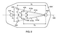
間隙92内における流体保持および分布の向上を達成するために、図8にプラットフォーム60Aの実施形態の概略図を示す。プラットフォーム60Aは、基板が「処理」位置にあるときに基板2に面する第1の表面602、および第2の表面606を有する流体送達領域604を含む。間隙92内における流体保持の向上を達成するために、プラットフォーム60Aは、複合構造体として形成される。第1の表面602は、疎水性を有する第1の材料で形成され、一方で、第2の表面606は、親水性を有する第2の材料で形成される。このようにして、ポート42A〜45Aのうちの1つまたは複数を通して流体送達領域604内に送達される流体が、容易に第2の表面606を亘って流動する。しかし、疎水性の第1の表面602は、流体送達領域604から流体が流出することを防止し、それによって間隙92から流体が漏出することを防止する。
To achieve improved fluid retention and distribution within
概して、第1の表面602を形成する第1の材料は、第1の材料が十分に疎水性であることを確実にするために、100度以上(たとえば、110度以上、120度以上、130度以上、140度以上、150度以上)の水接触角を有する。適切な第1の材料としては、限定されないが、ポリジメチルアクリルアミド、ポリジメチルシロキサン、およびフルオロポリマーが含まれる。
Generally, the first material forming the
第2の表面606を形成する第2の材料は、典型的に、第2の材料が十分に親水性であることを確実にするために、40度以下(たとえば、30度以下、25度以下、20度以下、15度以下)の水接触角を有する。適切な第2の材料としては、限定されないが、雲母、ガラス、Macor(登録商標)などのガラスセラミック複合材料、ガラスコーティング材、金属、酸化物、および窒化物が含まれる。
The second material forming the
ある特定の実施形態では、流体送達領域604は、第1の表面602内の凹部として実装される。代替的に、いくつかの実施形態では、流体送達領域604は、第1の表面602に対して隆起した領域として実装される。つまり、基板が処理位置にあるときに、第2の表面606は、第1の表面602よりも基板2に近い。流体送達領域604は、たとえば、第2の材料のうちの1つまたは複数のコーティングまたはフィルムが第1の材料に適用されるときに、そのように実装され得る。
In certain embodiments,
いくつかの実施形態では、第1の表面602および第2の表面606は、処理位置にて、基板から実質的に同じ距離にある。たとえば、第2の表面606は、第2の表面を作成するために第1の表面602の一部を酸化、または別様に処理することによって形成され得る。化学的方法(たとえば化学酸化剤を使用する)および物理的方法(たとえば、第1の表面602を紫外放射線および/またはプラズマに曝露する)が、第1の表面602を処理して第2の表面を形成するために使用され得る。
In some embodiments, the
いくつかの実施形態では、間隙92内での流体保持を確実にするために、第1の材料の水接触角と第2の材料の水接触角との間の差が、50度以上(たとえば、60度以上、70度以上、80度以上、90度以上、100度以上)である。概して、第1および第2の材料の水接触角の間の差が大きいほど、染色液などの流体がプラットフォーム60Aの第1の表面602の上方にある間隙92の部分に流入することが妨げられる程度は大きい。
In some embodiments, to ensure fluid retention within
プラットフォーム60Aの複合構造体は様々な方法で実装され得る。いくつかの実施形態では、たとえば、プラットフォーム60Aは、流体送達領域604がブロック内に形成されるように、第2の材料のブロックで製造される。第1の材料の層が、第1の表面602を形成するために第2の材料のブロック上に配置される。
The composite structure of
第1の材料の層の厚さは、本明細書において開示する複合プラットフォームの重要な特徴であることが見出された。概して、第1の材料の層の厚さが大きすぎる場合、間隙92内の毛管力が乱され、間隙92から漏れる流体の増加につながる。特に、間隙92の厚さが急激に変化する撹拌サイクルの間、第1の材料の層の厚さが大きすぎる場合、間隙の縁部における毛管力が増加し、間隙の中間領域(すなわち、流体送達領域604の中間部の上方にある間隙の部分)から流体を引き離し、その結果、染色剤が試料3に不均一に塗布されることが見出された。そのような影響を回避するために、第1の材料の層の厚さは大きすぎてはならない。それに応じて、第1の材料の層の厚さは、第1の表面602に対し垂直な方向で測定して、概して100ミクロン以下(たとえば、80ミクロン以下、60ミクロン以下、40ミクロン以下、20ミクロン以下、10ミクロン以下、5ミクロン以下、1ミクロン以下、800nm以下、600nm以下、400nm以下、200nm以下、100nm以下)である。
The thickness of the first material layer has been found to be an important feature of the composite platform disclosed herein. Generally, if the thickness of the first material layer is too large, the capillary forces in the
図8に示すように、いくつかの実施形態では、プラットフォーム60Aは、概して、本明細書の別の部分で説明するように機能する廃棄物除去ポート40Aおよび41A、ならびに流体入口ポート42A〜45Aを含む。しかし、廃棄物除去ポート40Aの位置に対する流体入口ポート42A〜45Aの位置は、染色液のような流体を間隙92内へ均質に送達すること、およびポート40Aを通して流体を効率的に除去することを確実とするために重要となり得ることが見出された。特に、ポート42A〜45Aをポート40Aに対し、傾斜して、オフセットした位置に位置決めすることにより、流体送達領域604および間隙92内での流体流動の向上が達成され得る。
As shown in FIG. 8, in some embodiments, the
図9は、流体送達領域604の概略的な上面図を示す。いくつかの実施形態では、図9に示すように、ポート40Aは、流体送達領域604の中心軸608に沿って、流体送達領域604の第2の表面606上に位置決めされる。ポート43Aおよび45Aは、中心軸608を挟んだ両側に、軸608に対し垂直の方向に測定して軸608からa1の距離、および軸608に対し平行の方向に沿って測定してポート40Aから距離a2の距離で位置決めされる。流動軸610aおよび610dは、それぞれポート43Aおよび45Aからポート40Aへと延びる。流動軸610aおよび610dのそれぞれと中心軸608との間の角度はαである。
FIG. 9 shows a schematic top view of the
同様に、ポート42Aおよび44Aは、中心軸608を挟んだ両側に、軸608に対し垂直の方向に測定して軸608からb1の距離、および軸608に対し平行の方向に沿って測定してポート40Aから距離b2の距離で位置決めされる。流動軸610cおよび610bは、それぞれポート42Aおよび44Aからポート40Aへと延びる。流動軸610cおよび610bのそれぞれと中心軸608との間の角度はβである。
Similarly,
ある特定の実施形態では、αはβよりも大きい。代替的に、いくつかの実施形態では、βはαよりも大きくなり得る。概して、たとえば、αは、15度以下(たとえば、12度以下、10度以下、8度以下、6度以下、8.3度)であり得る。さらに、βは、10度以下、8度以下、6度以下、4度以下、5.3度)であり得る。代替的に、いくつかの実施形態では、βはαよりも大きくなり得る。 In certain embodiments, α is greater than β. Alternatively, in some embodiments, β may be greater than α. In general, for example, α may be 15 degrees or less (eg, 12 degrees or less, 10 degrees or less, 8 degrees or less, 6 degrees or less, 8.3 degrees). Further, β can be 10 degrees or less, 8 degrees or less, 6 degrees or less, 4 degrees or less, 5.3 degrees). Alternatively, in some embodiments, β may be greater than α.
いくつかの実施形態では、a1はb1よりも大きくなり得る。代替的に、ある特定の実施形態では、b1はa1よりも大きくなり得る。概して、たとえば、a1は、10mm以下(たとえば、8mm以下、6mm以下、5mm以下、4mm以下、3mm以下、2mm以下、1mm以下)であり得る。さらに、b1は、10mm以下(たとえば、8mm以下、6mm以下、5mm以下、4mm以下、3mm以下、2mm以下、1mm以下)であり得る。 In some embodiments, a 1 can be greater than b 1 . Alternatively, in certain embodiments, b 1 may be greater than a 1 . In general, for example, a 1 can be 10 mm or less (eg, 8 mm or less, 6 mm or less, 5 mm or less, 4 mm or less, 3 mm or less, 2 mm or less, 1 mm or less). Further, b 1 may be 10 mm or less (eg, 8 mm or less, 6 mm or less, 5 mm or less, 4 mm or less, 3 mm or less, 2 mm or less, 1 mm or less).
ある特定の実施形態では、a2はb2よりも大きい。代替的に、いくつかの実施形態では、b2はa2よりも大きくなり得る。概して、たとえば、a2は、10mm以下(たとえば、8mm以下、6mm以下、5mm以下、4mm以下、3mm以下、2mm以下、1mm以下)であり得る。さらに、b2は、10mm以下(たとえば、8mm以下、6mm以下、5mm以下、4mm以下、3mm以下、2mm以下、1mm以下)であり得る。 In certain embodiments, a 2 is greater than b 2. Alternatively, in some embodiments, b 2 can be larger than a 2. In general, for example, a 2 can be 10 mm or less (eg, 8 mm or less, 6 mm or less, 5 mm or less, 4 mm or less, 3 mm or less, 2 mm or less, 1 mm or less). Further, b 2 may be 10 mm or less (eg, 8 mm or less, 6 mm or less, 5 mm or less, 4 mm or less, 3 mm or less, 2 mm or less, 1 mm or less).
概して、ある特定の実施形態では、ポート43Aおよび45Aは、ポート40Aに対し対称的に位置決めされない。たとえば、ポート43Aおよび45Aは、中心軸608から異なる距離に、ポート40Aから異なる距離に、および/または流動軸に沿って中心軸608に対し異なる角度で位置決めされ得る。同様に、いくつかの実施形態では、ポート42Aおよび44Aは、ポート40Aに対し対称的に位置決めされない。たとえば、ポート42Aおよび44Aは、中心軸608から異なる距離に、ポート40Aから異なる距離に、および/または流動軸に沿って中心軸608に対し異なる角度で位置決めされ得る。
Generally, in certain embodiments,
図9にて、ポート40Aおよび41Aはそれぞれ、中心軸608に沿って位置決めされる。しかし、概して、ポート40Aおよび41Aのいずれかまたは両方は、中心軸608から、軸608に対し垂直の方向に変位され得る。たとえば、ポート40Aおよび41Aの1つまたは両方を、それらが軸608から変位されるように設置することにより、ポートを通しての流体の除去を補助し得る狭窄部(constriction)が、ポート間に位置する流体内に設置され得る。特に、非軸方向位置にポートを設置することは、ポート間の中間地点に非対称性狭窄部の形成につながり得る。いくつかの実施形態では、ポート40Aおよび41Aのいずれかまたは両方は、軸608に対し垂直の方向に、2mm以上(たとえば、3mm以上、4mm以上、5mm以上、6mm以上、8mm以上、10mm以上)中心軸608から変位し得る。
In FIG. 9,
凹部として実装される場合、流体送達領域604の最大深さ、つまり第1の表面602により画定される平面と流体送達領域604の第2の表面606との間の最大距離は、概して、間隙92の厚さおよび間隙内に分注される流体の体積に基づき、要求に応じて選択され得る。いくつかの実施形態では、たとえば、流体送達領域604の最大深さは、200ミクロン以下(たとえば、180ミクロン以下、160ミクロン以下、150ミクロン以下、140ミクロン以下、130ミクロン以下、120ミクロン以下、100ミクロン以下)である。
When implemented as a recess, the maximum depth of the
いくつかの実施形態では、流体送達領域604の第2の表面606は平面状であり、第1の表面602に対し名目上、平行である。しかし、ある特定の実施形態では、第2の表面606は平面状ではなく、湾曲した(すなわち、凸状または凹状の)形状を有し得る。
In some embodiments, the
図10は、流体送達領域604の別の上面図を示す概略図である。第2の表面606に加えて、流体送達領域604は、プラットフォーム60Aの第1の表面602と第2の表面606との間に延びる側壁表面650、652、654、656、658、660、および662により境界付けされる。流体送達領域604内で再現可能かつ一貫性のある流体流動を確実にするためには、「デッドボリューム」の除去が重要であることが見出された。デッドボリュームは、流体送達領域604内の領域、典型的には、浅い角度で交差する壁と壁の間の角部により形成される領域に対応し、領域内への流体流動が減じ得る、および/または領域から流体を排出することが困難となり得る。デッドボリュームは、間隙92の流体による不完全な充填、および/または間隙92内部からの流体の不完全な排出を引き起こし得るため、試料の非均質的な処理(たとえば非均質的な染色)、および前の流体が間隙から完全に除去されていない場合、新しい流体による間隙の過剰充填により間隙92からの流体の潜在的な漏出につながる。
FIG. 10 is a schematic diagram illustrating another top view of the
流体送達領域604内のデッドボリュームを除去し、一貫性のある流体流動を確実にするために、側壁表面650、652、654、656、658、660、および662が、互いに対して特定の配置で位置決めされ得る。たとえば、図10に示すように、いくつかの実施形態では、側壁表面は、隣り合う壁表面の各組が70度よりも大きい(たとえば、80度よりも大きい、90度よりも大きい、100度よりも大きい、110度よりも大きい、120度よりも大きい)角度をなすように位置決めされる。流体送達領域604内のデッドボリュームをさらに減少させるために、いくつかの実施形態では、隣り合う側壁表面の各組は、丸みを帯びたフィレット(rounded fillet)に沿って一体化する(blend)。たとえば、図10に示すように、表面650および652は、直線に沿って交差しないが、かわりに、フィレット角部(filleted corner)651に沿って互いに一体化する。概して、丸みを帯びた角部により、流体メニスカスの「ピン止め」効果が低減する。側壁表面が鋭い直線または角部にて交わる場合、角部内の流体が、半径が比較的より小さい(すなわち、角部の幾何学的形状に適合する)メニスカスを形成する。流体安定の要因である毛管力は、メニスカス径が小さいとより大きくなるため、流体は、鋭い角部により閉じ込められやすくなる。対照的に、側壁表面が、丸みを帯びたフィレットに沿って一体化する場合、フィレットの近傍の流体により取り入れられるメニスカスは、比較的大きな半径を有し、流体内の毛管力が減少し、流体の除去が容易になる。
To eliminate dead volumes in the
第2の表面606の横断形状は、概して、流体入口および出口ポートを収容し、凹部内で、再現可能な、一貫性のある流体流動を促進するために、要求に応じて選択され得る。いくつかの実施形態では、たとえば、第2の表面606は、図10に示すように、七角形の横断形状を有する。概して、すべての側壁表面の長さは同一である、または、代替的に、図10のように、側壁表面のいくつかの長さは、異なってもよい。
The cross-sectional shape of the
流体送達領域604は、側壁表面の相対的な向きおよびサイズの一例を示す。側壁表面654および660は平行であり、一方で、壁表面650は両方の表面に対し直交である。側壁表面652および662は、壁表面650と、壁表面654および660との間をそれぞれ延びる。側壁表面656および658は、それぞれ表面654および660から延び、丸みを帯びた角部657にて交差する。
図10では、ポート42A〜45Aからの流体送達、およびポート40Aおよび41Aを通しての流体排出を促進するために、側壁表面の特定の長さおよび向きが選択される。そのために、ポート42A〜45Aは、側壁表面656および658のいずれかよりも側壁表面650の近くに位置決めされ、一方で、ポート40Aは、表面656および658の交差により形成される角部657の近位に位置決めされる。第1の疎水性材料の層を第2の親水性材料のブロック上に適用して、第1の表面602を形成するために、様々な製造方法が使用され得る。いくつかの実施形態では、たとえば、疎水性材料の層は、たとえば、その開示内容の全てが参照により本明細書に組み込まれる、Chenら、「Fabrication of Switches on Polymer−Based by Hot Embossing」、DTIP of MEMS and MOEMS、Stresa、Italy(2006)において記載されるように、ホットエンボス手順を用いて適用され得る。この手順では、親水性材料のブロックおよび疎水性材料の層がプレート上に取り付けられ、高温で押圧され、その後に結合構造物は冷却される。
In FIG. 10, a particular length and orientation of the sidewall surface is selected to facilitate fluid delivery from
ある特定の実施形態では、疎水性材料の層は、親水性材料のブロック上に化学的に被覆され得る。つまり、疎水性材料は、噴霧または湿式化学式結合を行うことにより、親水性材料上に堆積され得る。いくつかの実施形態では、従来の微細加工に用いられる結合方法が、疎水性材料の層を親水性ブロックに適用するように適合され得る。たとえば、ポリジメチルシロキサン(PDMS)が、様々な表面処理方法を用いて、PDMS層とブロックとの間に強力な永久結合を形成するために、ガラスセラミック複合材料に結合され得る。そのような方法の例が、その開示内容の全てが参照により本明細書に組み込まれる以下の、Nugen、S.R.ら、「PMMA Biosensor for Nucleic Acids with Integrated Mixer and Electrochemical Detection」、Biosensors and Bioelectronics 24(8):2428〜2433(2009)、およびShiu、P.P.ら、「Rapid Fabrication of Tooling for Microfluidics Devices Via Laser Micromachining and Hot Embossing」、Journal of Micromechanics and Microengineering 18(2):025012(2008)の文献に開示される。 In certain embodiments, a layer of hydrophobic material may be chemically coated on a block of hydrophilic material. That is, the hydrophobic material can be deposited on the hydrophilic material by spraying or performing wet chemical bonding. In some embodiments, bonding methods used in conventional microfabrication can be adapted to apply a layer of hydrophobic material to a hydrophilic block. For example, polydimethylsiloxane (PDMS) can be bonded to a glass-ceramic composite using various surface treatment methods to form a strong permanent bond between the PDMS layer and the block. Examples of such methods are described in Nugen, S., et al., Below, the entire disclosure of which is incorporated herein by reference. R. Et al., "PMMA Biosensor for Nucleic Acids with Integrated Mixer and Electrochemical Detection", Biosensors and Bioelectronics, 24 (8), 24 (8), 24 (8), 24 (8), 24 (8) and 24 (8), 24 (8). P. Et al., "Rapid Fabrication of Tooling for Microfluidics Devices Via Laser Micromachining and Hot Embossing", Journal of Microechanics and Journal of Microechanics, Vol.
いくつかの実施形態では、疎水性材料の層が、蒸着、スパッタリング、エアブラッシング、塗装、印刷、紫外放射線への曝露、およびプラズマ曝露などの1つまたは複数の物理的方法を用いて親水性材料上に形成され得る。 In some embodiments, the layer of hydrophobic material is coated with the hydrophilic material using one or more physical methods such as evaporation, sputtering, air brushing, painting, printing, exposure to ultraviolet radiation, and plasma exposure. Can be formed on top.
この項にて説明したプラットフォーム60Aを使用することにより、多数の利点が実現され得る。特に、染色液のような処理流体は、向上した均質性で間隙92内へと送達され、その結果、処理ステップの試料3への塗布がより均一となり、試料内の非システマティックな処理アーチファクトがより少なくなる。廃棄物除去ポートを通しての処理流体の排出の向上もまた、達成され得る。
A number of advantages may be realized by using the
さらに、間隙92からの流体の漏出を減少させる、または防止することにより、消費される試薬量の減少が達成され得る。たとえば、図1に示すプラットフォーム60Aの代わりに図8に示すプラットフォーム60Aを使用することで、試料ごとに約220マイクロリットルから、試料ごとに約170マイクロリットルへ、流体消費の減少が達成されている。
Further, by reducing or preventing leakage of fluid from
[他の試料処理システム]
本明細書において開示するシステムに加えて、上で説明した複合プラットフォームが、組織試料および/または生物学的流体の自動検査用に設計されるシステムを含む、他の試料処理システムとともに使用され得る。上記の複合プラットフォームと互換性のあるシステムの例が、たとえば、その開示内容の全てが参照により本明細書に組み込まれる米国特許出願公開第2013/0203100号明細書に開示されている。
[Other sample processing systems]
In addition to the systems disclosed herein, the composite platforms described above can be used with other sample processing systems, including systems designed for automated testing of tissue samples and / or biological fluids. Examples of systems compatible with the above composite platform are disclosed, for example, in US Patent Application Publication No. 2013/0203100, the disclosure of which is incorporated herein by reference in its entirety.
[システムのアライメントおよび較正]
試料の再現可能な、高品質の処理を達成するために、基板2と、プラットフォーム60Aおよび60Bとの間での高度のアライメントを維持することが重要となり得る。上で説明したように、比較的小さなミスアライメントですら、間隙92からの流体の漏出、および不均一な試料処理(たとえば、非均質的な試料染色)につながり得る。図1を参照すると、基板アーム10Aおよび10Bが、基板2をプラットフォーム60Aおよび60Bに対する位置へと回転させる。それに応じて、基板アーム10Aおよび10Bのミスアライメントは、間隙92へと分注される流体の量と、アーム10A/10Bのミスアライメントにより期待値と異なる、プラットフォーム60A/60Bと基板2との間の間隙92の容積との間の体積の不一致につながる。これが起こると、基板2とプラットフォーム60A/60Bの表面との非平行の相対配向により、流体が間隙に入る際に、間隙92内での流体メニスカスの流動が非対称になり、局所的に間隙92の厚さが大きくなりすぎ、基板2の縁部において、間隙92内での流体閉じ込めの促進に役立っているメニスカスの安定性が弱まる。これらの効果は、染色および他の処理のアーチファクトにつながり得る。
[System alignment and calibration]
To achieve reproducible, high quality processing of the sample, it may be important to maintain a high degree of alignment between the
図11は、図1の基板アーム10Aおよび/または10Bの代用として使用され得るアーム1100の概略的な等角図を示す。アーム1100は、取付孔1102を通って延びる固定具により支持体110Aまたは110Bに接続される。基板グリッパ1106は、固定具1108によりアーム1100に接続され、基板2を解放可能に取り上げる、および基板2を解放するように構成される。3つの調節ねじ1104が、基板グリッパ1106の傾き調節を可能にし、グリッパ1106の運動学的取り付け(kinematic mount)が効果的に形成される。3つのねじ1104を調節することにより、アーム1100に対する基板グリッパ1106のいずれの傾斜角に対する補償も修正され得るし、基板2は、プラットフォーム60Aおよび60Bの平面(すなわち、第1の表面602により画定される平面)に対し名目上、平行である平面上に位置決めされ得る。真空ポート1110は、基板グリッパ1106から延び、動作中、グリッパ1106中の1つまたは複数の開口部(図示されず)を通して適用される吸引によりグリッパ1106に基板2が取り付けられるように、真空源に接続され得る。
FIG. 11 shows a schematic isometric view of an
いくつかの実施形態では、固定具1108は、図19に示すように、アーム1100内に形成される凹部または溝の内部に位置決めされ得る。実際には、固定具1108は、この実施により、アーム1100内に部分的または完全に円錐状に広げられる。図19に示すように固定具1108を着座させることにより、アーム1100および基板グリッパ1106により形成される組立体は、相対移動、およびプラットフォーム60A/60Bに対する移動に対し、よりさらに耐性が強くなり、基板2とプラットフォーム60A/60Bとの相対的なアライメントが複数の処理サイクル中に維持されることが確実となり得ることが実験的に見出された。これにより、システムの長期使用に亘り再現可能である染色が確実になる。
In some embodiments, the
基板グリッパ20A/Bまたは1106と、プラットフォーム60A/Bとの間の適切なアライメントを確実にするために、センサパッドが使用され得る。図12は、3つのセンサ1202、1204、および1206を含むセンサパッド1200の画像を示す。各センサは、それぞれの電気通信線を通じて、コンピュータまたは他の演算装置との接続のために構成されるインターフェース1208に接続される。インターフェース1208を通じて、演算装置は、システム1の較正のために、センサ1202、1204、および1206により生成される電気信号を受信し得る。
Sensor pads may be used to ensure proper alignment between the
典型的には、センサパッド1200は、ポリマー材料(たとえば、ポリエステル)製の2枚のシートの間に挟まれるピエゾ抵抗素子のインクの、比較的薄い可撓性の層で形成され得る。センサパッド1200の厚さは、較正されたシステムにより使用される試薬量に影響を及ぼすため重要となり得る。センサパッド1200の厚さが増加すると、消費される試薬量が増加する。それに応じて、200ミクロン〜270ミクロンのセンサ厚さが、適切な試料処理を確実にするために十分な量の試薬の使用のバランスを効果的にとり、同時に、システムによる過剰な試薬の消費を回避することが判定された。
Typically,
アライメントの目的のために、システム1に一体化されるセンサもまた、電気信号を測定し、コンピュータまたは他の演算装置へと送信するために使用され得る。たとえば、センサは、較正のために電気信号を測定および伝送するために、プラットフォーム60A/60Bに一体化され得る。たとえば、アライメントセンサもまた、基板グリッパ20Aおよび/または20Bに一体化され得る。複数のアライメントチェックを提供するために、複数のセンサが、システム1に一体化され得るし、システムは、試料処理の前に、センサに対する複数のアライメント手順を行い得る。さらなる代替例として、いくつかの実施形態では、較正または測定スライドが、アライメントを確実にするために使用され得る。
For alignment purposes, sensors integrated into the system 1 may also be used to measure and send electrical signals to a computer or other computing device. For example, sensors may be integrated into
図13は、基板グリッパをプラットフォーム60A/Bに位置合わせするための一連のステップを含むフローチャート1300である。システム1を初期化し、染色剤の残留物を除去するためにプラットフォームの表面を洗浄した後に、ステップ1302にて、システムの真空源を作動することにより、基板(たとえば、顕微鏡スライド)が最初に基板グリッパ上に取り付けられる。このステップは、図14に示す画像で図示される。次に、グリッパが「ホーム」位置にあることを確実とした後に、ステップ1304にて、図15に示すように、グリッパが、(たとえば、アーム10A/Bまたはアーム1100を回転させることにより)「下向き」位置へと回転される。次にステップ1306にて、220マイクロリットルの固定剤が間隙92へと分注され、間隙内での固定剤の分布が、固定剤が均質に分布されているかどうかを判定するために検査される。グリッパは、次に、「上向き」位置へと戻るように回転され、基板が取り外され、余分な固定剤を除去するためにプラットフォームが洗浄される。
FIG. 13 is a flowchart 1300 that includes a series of steps for aligning the substrate gripper with the
次に、ステップ1308にて、新しいスライドが「ホーム」位置にある基板グリッパ上に取り付けられ、プラットフォーム60A/B上で廃棄真空が作動され、センサパッド1200が、プラットフォーム上に位置決めされ、プラットフォームのオフセットに位置合わせされる。センサパッド1200が、次に、演算装置に接続される。
Next, at
ステップ1310にて、センサパッド1200上の3つのセンサのうちの最初の1つが調整される。加えられる圧力に応じた(たとえば、1Vよりも低い)センサの電圧応答低下を確認するために第1のセンサに優しく圧力を加えた後に、図16に示すように20gの質量がセンサ上に載置され、電圧応答が測定される。50gの質量で、および20gと50gの質量の組み合わせでこの手順が繰り返される。そして、20g、50g、および70gで加えられる質量の場合で測定された電圧応答に基づいて、ステップ1312にて、加えられる質量の関数として電圧測定値への最適な線を判定することにより、第1のセンサの較正曲線が判定される。
At
次に、ステップ1314および1316にて、第2および第3のセンサが、第1のセンサと同じ方法で較正される。ステップ1316に続いて、3つのすべてのセンサ1202、1204、および1206の電圧応答が較正される。そして、ステップ1318にて、「ホーム」位置にある基板グリッパ上にスライドを取り付けた後、センサパッド1200がプラットフォーム上で位置合わせされたままで、グリッパが「下向き」位置へと回転され、廃棄真空が作動停止される。ステップ1320にて、センサパッド1200がスライドとプラットフォームとの間で固定された状態で、グリッパの向きが、許容可能なばらつきの範囲内で、3つのすべてのセンサ電圧応答が等しくなるまで調節される。
Next, at
最後に、ステップ1322にて、センサパッド1200がプラットフォームから取り外され、(スライドが取り付けられたままの)グリッパが「下向き」位置に設置され、アライメントの視覚的検証のために赤と青の染料が間隙92内へと分配される。検証の後、手順はステップ1324にて終了する。
Finally, at
[流体分注プラットフォーム]
上で説明したように、基板2とプラットフォーム60A/60Bとの間の間隙92を制御することは、試料を処理する再現性に影響を及ぼすため、本明細書にて開示するシステムおよび方法の重要な態様である。名目上、試料処理の間、間隙92は、基板2の表面およびプラットフォーム60A/60Bにより境界付けされる領域の体積に一致する、精密に計測された体積の流体で充填される。間隙92の容積が間隙へと分注される流体の量よりも大きい場合に生じ得るエアポケットが、間隙92内に存在しないことが重要である。エアポケットが存在する場合、染色剤のような流体が間隙92中を不均一に流動し、試料に不均一に塗布され得る。その後に染色された試料が分析されると、試料の画像中のアーチファクトが不均一の染色から生じ得るし、これらのアーチファクトは、試料に行われる定量測定を不正確にし得る。
[Fluid dispensing platform]
As discussed above, controlling the
間隙92へと分注される流体の体積が、間隙92の容積を超えないことが重要である。流体の体積が間隙の容積を超える場合、基板2の縁部における流体メニスカスが破裂し、間隙92からの流体の漏出につながり得る。このようにして流体損失が生じ、そのような条件下で染色された試料は、また、不均一の染色から生じる定量的画像アーチファクトを引き起こし得る。
It is important that the volume of fluid dispensed into the
間隙92の形状は、また、流体の充填および排出性能に影響を及ぼし得る。そして、間隙92の厚さが、間隙92内の流体流動の方向に沿って変化する場合、流体中の毛管力が変化し、流動抵抗は非線形に変化する。間隙92内で流動抵抗が著しく変化する場合、染色剤および他の流体は試料と均質に相互作用せず、不均一な染色性能につながり得る。
The shape of the
それに応じて、間隙92の厚さに対する精密な制御は、本明細書において開示する方法およびシステムの性能に対する制御に関連する。典型的には、本明細書において開示する試料処理システムでは、間隙92の厚さが約10ミクロン〜約800ミクロンであるため、間隙の厚さにおける小さな差異が、性能における著しい変動として現れ得る。
Accordingly, precise control over the thickness of the
図1の上記の説明は、プラットフォーム(たとえば、プラットフォーム60B/50B)が、試料処理の間、基板2がプラットフォームの表面に接触しないことを確実にするために一連のオフセットを含むシステムの実施形態に焦点を当てた。しかし、流体送達プラットフォームは、他の方法でも実装され得る。
The above description of FIG. 1 describes an embodiment of the system where the platform (eg, platform 60B / 50B) includes a series of offsets to ensure that
図17は、別の染色プラットフォーム1760Aの概略図である。4つのスペーサ1770A〜Dがプラットフォーム1760Aから上方向に延びている。変形可能部材1710が、支持ブロック1790と染色プラットフォーム1760Aとの間を延びる。案内要素1785が、プラットフォーム1760Aの動きの範囲を制限する。
FIG. 17 is a schematic diagram of another
動作中、基板2が処理位置へと回転すると、基板がスペーサ1770A〜Dに接触する。したがって、スペーサ1770A〜Dのそれぞれがプラットフォーム1760Aの表面を越えて延びる量を調節することによって、間隙92の幾何学的形状および容積が正確に制御され得る。プラットフォーム1760Aと基板2との間の平行関係を確立することに加えて、スペーサ1770A〜Dは、より複雑であるが、それでも再現可能である、くさび形のような形状で間隙92を画定するように調節され得る。
In operation, as the
図18に示すように、基板2がスペーサ1770A〜Dと接触するように下降されると、変形可能部材1710は、プラットフォーム1760Aがプラットフォーム1760Aの平面に対し垂直の方向に移動することを可能にする。変形可能部材1710は、プラットフォーム1760Aを基板の方向に押し出す傾向のある力を印加するため、スペーサ1770A〜Dのそれぞれが基板2に接触する。結果として、再現可能である厚さの間隙92が、プラットフォーム1760Aと基板2との間に形成され、間隙の厚さは、スペーサ1770A〜Dの幾何学的形状により画定される。
As shown in FIG. 18, when
このようにして、プラットフォーム1760Aに対するアーム10A/10Bの動きを伴う複雑な較正が排除され、間隙92の容積および形状は、基板2の厚さに合わせて調節することなく、スペーサ1770A〜Dの調節を通じてのみ画定され得る。部材1710の変形可能であるという性質により、基板の厚さが変化する、および/またはアーム10A/10Bが、毎回、基板2を正確に同じ処理位置に位置決めしない場合であっても、基板2およびスペーサ1770A〜Dがともに押圧されることが確実になる。そのような変動が生じた場合であっても、再現可能である容積および形状の間隙92が確立される。
In this way, complex calibrations involving movement of the
ある特定の他の実装に対し、基板アームの動きを伴う複雑な較正ステップ、およびそのような較正に関連する、複雑な位置決めハードウェアが排除されるため、プラットフォーム1760Aは複雑さおよびコストが低い。同時に、プラットフォーム1760Aは、間隙92の幾何学的形状に対する堅牢かつ再現可能である制御を可能にし、それによって、流体が複数の試料に一貫して塗布されることが確実になる。さらに、一貫した幾何学的形状の間隙92を確立することにより、間隙92に送達される様々な処理流体の体積が一定に維持され、システムにおける日々の変動性および流体の消費が低減され得る。
For certain other implementations, the
変形可能部材1710は、概して、様々な方法で実装され得る。いくつかの実施形態では、たとえば、変形可能部材1710は、ばねまたは他のコイル状部材であり得る。概して、変形可能部材1710は、プラットフォーム1760Aの平面に対し直交する方向に沿って圧縮され得る要素であって、プラットフォーム1760Aへと同じ方向に沿って力を印加する要素である。変形可能部材1710もまた、たとえば平ばね、円盤ばね、ならびに軟質ポリマー、ゴム、およびポリマーの発泡体などの弾性材料により形成される部材の形態で実施され得る。さらに、いくつかの実施形態では、変形可能部材1710は、液圧、空気、磁気、および/または電磁サスペンションとして実装され得る。たとえば、油圧流体、ガス、または場(たとえば磁場)が、プラットフォーム1760Aを支持ブロック1790の上方でサスペンド(suspend)するため、および基板2がスペーサ1770A〜Dに接触するときに、プラットフォーム1760Aに反対の力を印加するために使用され得る。
なお、スペーサ1770A〜Dとの接触を確実にするために、プラットフォーム1760Aに力を印加することに加えて、変形可能部材1710は、アライメントが極めて再現性よく達成され得るように、基板2に対するプラットフォーム1760Aの微小な回転も可能にする。そのようにして、システムのある特定の構成要素の、互いに対する高精度のアライメントに対する要件が排除され得る。つまり、変形可能部材1710が、回転および並進の両方のアライメントの柔軟性を可能にするため、システムの他の構成要素に対するアライメントの公差が緩和され得る。
It should be noted that, in addition to applying a force to the
いくつかの実施形態では、図17および図18に関連して上で説明したように、変形可能部材1710を用いて、プラットフォーム1760Aが支持ブロックに対してサスペンドされる。代替的に、または付加的に、ある特定の実施形態では、プラットフォーム1760Aは、剛性を有するまたは固定された結合により支持ブロック1790へ取り付けられ得るし、基板2は、1つまたは複数の可撓性部材/変形可能部材により、プラットフォーム1760Aの上方にサスペンドされる。この方法で基板2を取り付けるための変形可能部材は、様々な方法でシステムに一体化され得る。たとえば、1つまたは複数の可撓性部材から形成されるシール部が、基板2と基板グリッパ(たとえば、基板グリッパ20A/20Bおよび1106)との間に位置決めされ得る。別の例として、1つまたは複数の可撓性部材は、アーム10A/10Bと基板グリッパ20A/20B/1106との間に位置決めされ得る。さらなる例として、1つまたは複数の可撓性部材は、システム内にアクチュエータ30A/30Bを取り付けるために使用され得るし、アーム10A/10Bは、変形可能である材料から形成され得る。
In some embodiments, the
図20〜27は、追加のシステムの実施形態を示す概略図であり、変形可能部材は、システム内の様々な位置に設置されている。図20〜27のそれぞれにおいて、アクチュエータ30A(たとえばモータ)が、取付け部2002により、支持ブロック1790に接続される。アクチュエータ30Aは、基板グリッパ1106に接続されるアーム1100をプラットフォーム1760Aの上方の開位置と処理位置との間で回転させる。上で説明したように、スペーサ1770A〜D(明確にするために、図20〜27では、そのうちの1つのみがラベル付けされている)が、基板2とプラットフォーム1760Aとの間の間隙を画定する。
20-27 are schematic diagrams illustrating additional system embodiments, wherein the deformable members are located at various locations within the system. 20 to 27, an
図20および図25〜27では、複数のばねとして実装される変形可能部材1710が、上述したように、プラットフォーム1760Aを支持ブロック1790の上方にサスペンドする。図21では、変形可能部材1710は、支持ブロック1790とプラットフォーム1760Aとの間に位置決めされる弾性層として実装され、それによって、プラットフォーム1760が、支持ブロック1790に対し回転および並進することが可能になる。変形可能部材1710は、弾性材料(たとえば発泡体、ゴム)から形成されるため、図21において部材1710は、図20のばねと同じ方法でプラットフォーム1760Aおよびスペーサ1770A〜Dを基板2に対して押圧する。
20 and 25-27, a
図22では、変形可能部材1710は、アーム10Aと基板グリッパ20Aとの間に位置決めされる。プラットフォーム1760Aは、支持ブロック1790に強固に取り付けられ、変形可能部材1710は、基板2をスペーサ1770A〜Dに対して押圧する。図23では、変形可能部材1710は、取付け部2002と支持ブロック1790との間に位置決めされ、基板2をスペーサ1770A〜Dに対して押圧するために類似の方法で機能する。図24では、変形可能部材1710は、基板2と基板グリッパ20Aとの間の可撓性のシール部として実装され、図22および図23に示す変形可能部材と類似の方法で機能する。
In FIG. 22, the
上で説明したように、(1つまたは複数の)変形可能部材は、すべてのスペーサ1770A〜Dが基板表面に接触するように、基板がプラットフォームに対して押圧されることを確実にする。可撓性の変形可能要素を使用することにより、アームの移動およびモータの停止位置は、基板およびプラットフォームの両方が互いに対して強固に取り付けられ、位置決めされる際に必要とされ得るほどの高い精度で制御される必要はない。結果として、たとえば、精密なモータ位置制御要件が緩和され、それによって、様々な種類のモータが使用されることが可能になる。ステッパモータに加えて、AC/DCブラシモータまたはブラシレスモータが使用され得る。さらに、空気圧式アクチュエータなど、様々なアクチュエータも使用され得る。プラットフォームに対し正確に位置決めされた基板でアクチュエータの動きが停止されることを確実にするために使用され得る機構の例は、アーム10A/10Bのアクチュエータに基づく回転を制限するために機械式ストッパとして機能する機構と、アクチュエータの回転が、既定の(たとえばプログラムされた)数のステップ(たとえばステッパモータの場合)に制限される、またはエンコーダまたは距離センサに基づく測定により制限される機構と、基板が適切なアライメント位置に達した際に、アクチュエータの動きを停止させるフィードバック信号を提供するためにスイッチまたはセンサが使用される機構(そのようなセンサの例には、光学センサ、磁気センサ、誘導性センサ、容量センサ、電磁センサ、距離センサ、および電気接触に基づくスイッチが含まれる)と、アクチュエータにより印加されるクランプ力を(たとえば、モータ電流の測定に基づいて)測定し、印加された力が、基板とプラットフォームとの間に十分な接触をもたらすように決定される閾値を超える場合に、アクチュエータの動きを停止させる1つまたは複数のセンサを含む機構と、たとえば、プラットフォーム1760Aと支持ブロック1790との間における相対運動、アーム10A/10Bに対する基板グリッパ20A/20B/1106の相対運動、アーム10A/10Bの変形、およびアクチュエータ30A/30Bをシステムに取り付けるために使用される1つまたは複数の変形可能要素の変形を含む、システムの様々な要素の変形に基づいてフィードバック信号を提供するための、1つまたは複数のスイッチおよび/またはセンサを含む機構とを含む。相対運動および/または変形を示す適切な信号は、たとえば、電気接触スイッチ、光学センサ、磁気センサ、電磁センサ、誘導性センサ、容量センサ、歪みゲージ、力センサ、およびトルクセンサによって生成されてもよく、そのいずれか1つまたは複数が、システムに一体化され得る。
As explained above, the deformable member (s) ensure that the substrate is pressed against the platform such that all
図25〜27は、システムの構成要素の相対移動/変位を検出するための1つまたは複数のセンサを含み、アクチュエータの動きを停止させるために使用されるフィードバック信号を生成するシステムの概略図である。図25では、たとえば、センサ2004は、支持ブロック1790に対するプラットフォーム1760Aの位置を検出する。センサ2004は、機械式スイッチ、電気接触スイッチ、ならびに(限定されないが)光学センサ、磁気センサ、容量センサ、誘導性センサ、および電磁センサを含む様々なセンサのいずれかであり得る。
FIGS. 25-27 are schematic diagrams of a system that includes one or more sensors for detecting relative movement / displacement of components of the system and generates a feedback signal used to stop movement of the actuator. is there. In FIG. 25, for example,
センサは、プラットフォーム1760A以外のシステムの構成要素の相対位置/変位/変形を検出するためにも使用され得る。図26では、センサ2004は、アーム10Aの相対位置を検出するために位置決めされる。図27では、センサ2004は、基板グリッパ20Aの相対位置を検出するために位置決めされる。図26および図27のセンサ2004は、概して、図25と同じセンサ、および他のセンサのいずれかを含み得る。
Sensors may also be used to detect the relative position / displacement / deformation of components of the system other than
図17のプラットフォーム1760Aは、4つのスペーサ1770A〜Dを含む。しかし、より一般的には、プラットフォーム1760Aは、任意の数のスペーサを含み得る。たとえば、いくつかの実施形態では、プラットフォーム1760Aは、2つのスペーサまたは3つのスペーサを有する。ある特定の実施形態では、プラットフォーム1760Aは、5つ以上のスペーサ(たとえば、6つ以上のスペーサ、8つ以上のスペーサ、10以上のスペーサ、またはさらにそれ以上のスペーサ)を含む。
The
スペーサ1770A〜Dは、図17においては「ピン」として実装されるが、より一般的には、基板2のための安定した接触点を提供する任意の形状を有し得る。たとえば、いくつかの実施形態では、スペーサは、プラットフォーム1760Aの側部の少なくとも一部に沿って延びるリッジ部(ridge)として実装され得る。ある特定の実施形態では、スペーサは、L字状の角部部材として実装され得る。いくつかの実施形態では、スペーサは、円形、楕円形、正方形、長方形、三角形、六角形、八角形、または多角形断面形状を有し得る。
The
いくつかの実施形態では、スペーサは、たとえばミーリングまたは射出成形により、プラットフォーム1760Aの一部としてモノリシックに製造され得る。代替的に、ある特定の実施形態では、スペーサは、プラットフォーム1760Aとは別個の要素として製造され、糊付けまたはプレス加工などの処理によりプラットフォーム1760Aに取り付けられ得る。
In some embodiments, the spacer may be manufactured monolithically as part of
いくつかの実施形態では、スペーサは、間隙の厚さおよび形状が要求に応じて調節され得るように、調節可能であるように、プラットフォーム1760Aに取り付けられ得る。たとえば、スペーサ1770A〜Dは、プラットフォーム1760Aの表面の上方に突出する各スペーサの長さを制御する機構を使用して、たとえば、シム、長さの異なるピンセット、および/または厚さ/形状の異なるプラットフォームを使用して、プラットフォーム1760Aに取り付けられ得る。
In some embodiments, the spacer can be mounted on the
[試料処理段階]
試料3の性質に応じて、様々な多数の処理段階が、検査のために試料を調製するために処理シーケンスの全体の一部として行われ得る。そのような段階の例を以下において説明する。しかし、幅広い種類の様々な処理段階および段階の組み合わせが、本明細書において例として具体的に説明されていない段階を含め、本明細書において開示するシステムを使用して行われ得ることが理解されるべきである。
[Sample processing stage]
Depending on the nature of the
(i)固定剤段階
流体管52A〜55Aおよび52B〜55Bは、試料処理の間、固定剤をプラットフォーム60Aおよび60B、間隙92、基板2、ならびに試料3に送達するために位置決めされ得る。使用され得る固定剤は、生体試料を腐敗から保護するための化学物質を含み、そのような固定剤は、試料中に生じる生物学的反応を遅らせ、試料の機械的強度および安定性を上昇させ得る。限定されないが、メタノール、エタノール、イソプロパノール、アセトン、ホルムアルデヒド、グルタルアルデヒド、EDTA、界面活性剤、金属塩、金属イオン、尿素、およびアミノ化合物を含む様々な固定剤が使用され得る。
(I) Fixative Stage Fluid tubes 52A-55A and 52B-55B may be positioned to deliver fixative to
図4を参照すると、1つまたは複数の流体管52〜55Aは、プラットフォーム60A内部のポート、およびそれぞれの固定剤リザーバ210Aに接続され得る。流体管は、また、ポンプ200Aへの接続部、および/または固定剤をリザーバから、管およびプラットフォーム上に位置するポートを通って、基板および試料へと導くことが出来るバルブも含んでもよい。例として、ポンプ200Aは、固定剤を、リザーバ210Aから管54Aを通り、ブロック80Aを通り、ポート44Aから出て、プラットフォーム60Aに達し、プラットフォーム60Aと基板2との間の間隙92に入り、試料3を含有する基板2へと導き得る。特定量の固定剤を基板2に塗布した後、真空または他の吸引源220Aおよび/または221Aが、残りの固定剤を、プラットフォーム60A、間隙92、および基板2から、ポート40Aおよび/または41Aのうちの1つまたは複数を介し、廃棄物管50Aおよび51Aを通して、廃棄物容器230Aおよび/または231A内へと排出し得る。
Referring to FIG. 4, one or more fluid tubes 52-55A may be connected to ports inside
いくつかの実施形態では、ポンプ200Aは、メタノールなどの固定剤を、4秒間に亘り、毎秒70マイクロリットルの流速で、管54Aおよびポート44Aを通って、プラットフォーム60A上へ、および間隙92内へと導く。そして、真空または他の吸引源220Aおよび/または221Aは、ポート40Aおよび/または41A、ならびに廃棄物管50Aおよび/または51A(以下においてさらに説明する)を使用して、間隙92内および/またはプラットフォーム60Aおよび基板2上に存在する残りの固定剤を除去する。次に、ポンプ200Aは、第2の流体排出処理に続いて、再度、固定剤を、4秒間に亘り、毎秒70マイクロリットルの流速で、管54Aおよびポート44Aを通って、プラットフォーム60A上へと導き得る。固定および排出のこの過程は、固定を必要とする生体試料の種類に応じて、同じまたは異なる固定剤を使用して、再度反復され得る。
In some embodiments, pump 200A pumps a fixative, such as methanol, at a flow rate of 70 microliters per second for 4 seconds, through tube 54A and
さらに、システム1は、各固定段階において、頻度および流速を変化させることが可能である。間隙92内に位置する流体中のいずれの表面張力にも打ち勝ち、試料3をさらなる処理および評価のために固定させるために十分である他の流速も使用され得る。固定段階の頻度および/または流速を調節することにより、システム1は、いくつかの異なる固定剤を使用して、様々な試料のための最適な固定を達成し得る。いくつかの実施形態では、間隙92内への流体の流速は、充填サイクルの間、一定ではない。たとえば、流体は、最初は低速で、間隙92へと分注され得る、そして、間隙92内への流体流動の速度は、徐々に上昇され得る。ある特定の実施形態では、単一の充填サイクルの間、流体は、時間と共に下降する速度で間隙92内へと分注され得る。いくつかの実施形態では、充填は、最初は低速で行われ、間隙92の初期部分が充填された後は、上昇した速度で行われ、そして間隙92の充填が完了に近づくと低速で行われ得る。充填サイクルの最初と最後に間隙92をゆっくりと充填することによって、間隙92内の乱れた流体メニスカスによる流体の漏出の危険性が低下し得る。
Further, the system 1 can change the frequency and the flow rate at each fixing stage. Other flow rates that are sufficient to overcome any surface tension in the fluid located within the
なお、充填の頻度および流速の前述の説明が、固定段階の文脈において行われるが、同じ技術が、染色液および洗浄液を含め、他の溶液での間隙92の充填にも適用され得る。
It should be noted that while the foregoing description of the frequency and flow rate of filling is performed in the context of the fixation stage, the same techniques may be applied to filling
異なる種類の試料、流体、および処理方法のための機械命令は、制御ユニット5に組み込まれ、または予めプログラムされ、必要に応じてシステムオペレータによって選択され得る。 The machine instructions for the different types of samples, fluids and processing methods can be incorporated into the control unit 5 or pre-programmed and selected by the system operator as needed.
概して、幅広い種類の固定剤は、固定剤段階中に、試料に塗布され得る。たとえば、85%メタノールが、固定剤として使用され得る。いくつかの染色剤には、エチルアルコールまたはホルムアルデヒド系の固定剤が使用され得る。 In general, a wide variety of fixatives can be applied to the sample during the fixative stage. For example, 85% methanol can be used as a fixative. For some stains, a fixative based on ethyl alcohol or formaldehyde may be used.
(ii)染色段階
システム1は、また、1つまたは複数の染色段階にて、1つまたは複数の染料または染色剤を基板に固定された試料に塗布するように構成される管およびポートを含む。試料の染色により、顕微鏡または他の撮像装置下で視認または撮像される際に、試料のコントラストが増加する。ロマノフスキー染色剤、ならびに/またはヘマトキシリンおよびエオシン、フルオレセイン、抗体を使用するチアジン染色剤、核酸プローブ、および/もしくは金属塩および金属イオンを含む他の染料または染色剤が、使用され得る。
(Ii) Staining Stage System 1 also includes tubes and ports configured to apply one or more dyes or stains to the sample fixed to the substrate in one or more staining stages. . Staining of the sample increases the contrast of the sample when viewed or imaged under a microscope or other imaging device. Romanovsky stains and / or other dyes or stains including hematoxylin and eosin, fluorescein, thiazine stains using antibodies, nucleic acid probes, and / or metal salts and ions can be used.
ある特定の実施形態では、ポンプ201Aは、染料または染色剤をリザーバ211Aから染色剤管52A内へと導く。それから、染色剤は、ブロック80Aに取り付けられるポート42A内へと導かれる。次に、染色剤は、プラットフォーム60A中のポート42Aから、基板2とプラットフォーム60Aとの間の間隙92へと流動し、基板2上の試料3を染色する。
In certain embodiments, pump 201A directs dye or stain from
いくつかの実施形態では、染色剤を試料3に塗布するために、複数の管およびポートが使用され得る。たとえば、第2のポンプ(たとえば、ポンプ202A)は、染色剤(たとえば、リザーバ211Aから分注されるものと同じ染色剤または異なる染色剤)を、リザーバ212Aから管53Aおよびポート43Aを通って、そしてプラットフォーム60A上へと導き得る。ある特定の実施形態では、2つ以上の流体管は、共用の染色剤リザーバ、または、染色剤を、ポートを通り、そしてプラットフォーム上へと導くために使用されるポンプおよび/もしくはバルブに接続してもよい。図2を再度参照すると、管52Aは、フルオレセイン染料のような赤色染色剤を、プラットフォーム、基板2、および試料3に送達してもよい。管53Aは、チアジン染料のような青色染色剤を送達してもよい。図1〜6では、プラットフォーム60A上のポートの数、位置、およびサイズが、基板に固定される試料への染色剤の塗布を最適化するために選択される。他の染色剤が選択される場合、異なる数、位置、およびサイズのポートが、染色剤の粘度に応じて典型的である場合がある。
In some embodiments, multiple tubes and ports may be used to apply the stain to
ポート40A〜45A(および40B〜45B)のそれぞれは、流体を受容するための入力チャネル、および流体を出力するための出力チャネルの両方を含み得る。いくつかの実施形態では、洗浄ポート45A、固定剤ポート44A、および染色剤ポート42A〜43Aの出力チャネルは、プラットフォーム60Aの上部表面上にあり、真空ポート40Aおよび41Aの入力チャネルは、プラットフォーム60Aの上部表面の両端部にあってもよい。洗浄ポート45A、固定剤ポート44A、および染色剤ポート42A〜43Aの入力チャネルは、ブロック80Aの同じ側面上に位置してもよく、真空ポート40Aおよび41Aの出力チャネルは、ブロック80Aの反対の側面上に位置決めされ得る。
Each of
例として、および図2を参照して、制御システム5は、ポンプ(たとえば、ポンプ201A)に、染色剤(たとえば、フルオレセイン染料を含有する染色剤)を染色剤リザーバから流体管52A内へと導くように命令する。染色剤は、流体管からポート42Aに入る。そして、染色剤は、試料3が、5秒間に亘って、染色されるように、毎秒140マイクロリットルの流速でポート42Aを離れ、プラットフォーム60Aと試料3を含有する基板2との間の間隙92内へと堆積される。染色に続いて、真空または他の吸引源(たとえば、ポンプ220および/または221)が、ポート40A〜41Aおよび廃棄物管50A〜51Aを使用して、間隙92内に、プラットフォーム60A上に、および基板2上に存在する、残った染色剤を排出してもよい。
By way of example, and with reference to FIG. 2, control system 5 directs a pump (eg, pump 201A) to direct a stain (eg, a stain containing a fluorescein dye) from a stain reservoir into fluid conduit 52A. Command. Stain enters
システム1は、第1の染色段階に続いて、遅延(たとえば、5秒の遅延のような3秒〜10秒の遅延)後に、これらの染色および排出段階を反復するようにプログラムされ得る。第2のポンプ202Aは、制御システム5に、チアジン染料を、毎秒140マイクロリットルの流速で、染色剤リザーバから、流体管53Aを通ってポート43Aを出て、プラットフォーム60A上へとように導くように命令されてもよく、プラットフォーム60Aにて、チアジン染料は、たとえば、3秒間、試料に接触する。真空または他の吸引源(たとえば、ポンプ220Aおよび/または221)は、ポート40A〜41Aおよび廃棄物管50A〜51Aを使用して、間隙92内に、および/またはプラットフォーム60A上に、および/または基板2上に存在する残りのチアジン染料を排出してもよい。固定段階と同様に、システム1は、各染色段階における頻度、遅延時間、および流速を変化させることが可能である。流速が、間隙92内に位置する流体中に存在する表面張力に打ち勝ち、試料を、意図される評価に望ましく染色するほどに十分に高いだけでなく、空気を巻き込むことなく、および基板2の縁部に沿って形成され、流体を間隙92内に維持する手助けとなるメニスカスを破裂させることなく、間隙92の完全な充填が行われるように十分に低い限り、流速は、たとえば、毎秒70〜140マイクロリットルの範囲であってもよく、またはこの範囲の外側の限界よりも小さくても大きくてもよい(たとえば、毎秒10〜500マイクロリットル)。
The system 1 can be programmed to repeat these staining and draining steps after a delay (eg, a 3-10 second delay, such as a 5 second delay) following the first staining step. The
試料に塗布され得る例示的な染色剤には、限定されないが、ライト−ギムザ染色剤、ギムザ染色剤、およびロマノフスキー染色剤が含まれる。免疫細胞化学的試薬のような他の薬剤、または特定の細胞成分の他のマーカもまた、試料に塗布され得る。 Exemplary stains that can be applied to the sample include, but are not limited to, Wright-Giemsa stain, Giemsa stain, and Romanovsky stain. Other agents, such as immunocytochemical reagents, or other markers of particular cellular components, can also be applied to the sample.
(iii)廃棄物流体除去
既に参照したように、真空または他の吸引源220および/または221(たとえば真空キャニスタまたはポンプ)が、残りの流体を、基板2、間隙92、およびプラットフォーム60Aから、固定段階および染色段階中に、または固定段階と染色段階との間に、排出し得る。図1を参照すると、1つまたは複数の廃棄物管は、ブロック80Aの側部82Aおよび84Aに接続され得る。廃棄物または真空管50Aおよび51Aは、流体および微粒子状物質を、プラットフォーム60A、間隙92、および基板2から、廃棄物容器またはシステム1と分離した他の位置へと引き込むために使用される。図2を参照して、廃棄物管51Aおよび51Bは、廃棄物管の遠位端部にて、分離した真空源220および221、ならびに廃棄物容器230および231に接続されてもよい。代替的に、2つ以上の廃棄物管は、図4に示すように、単一の真空源、および同じ廃棄物容器に接続され得る。廃棄物管50Aおよび50Bは、図3に示すように、それぞれバルブ90Aおよび90Bを通して延びてもよい。
(Iii) Waste fluid removal As previously referenced, a vacuum or
吸引力を印加するための真空または他の源(たとえば、真空ポンプ220および/または221)は、流体をプラットフォーム60Aおよび/または60B、間隙92、ならびに基板2から廃棄物容器230および231内へと引き込むために、廃棄物管50A、50B、51A、および51Bのうちの1つまたは複数に接続されてもよい。廃棄物管内に印加される真空力は、基板2とプラットフォームとの間の間隙92が100〜200ミクロンである場合、流体を除去するために十分な吸引力を提供するために、平方インチあたり(「psi」)マイナス1〜マイナス10ポンドと同等であってもよい。概して、本明細書において使用されるように、「負」圧は、システム1、またはシステム1の周りの環境内の周囲圧力よりも小さい圧力に言及する。たとえば、いくつかの実施形態では、システム1の周りの環境は、約一気圧の周囲気圧を有する。「負」圧は、この周囲気圧よりも小さい圧力に言及する(たとえば、流体に印加されるマイナス1psiの圧力は、流体に加わる周囲気圧よりも1psi小さい圧力である)。そのような真空が、間隙92内に存在する流体中のどのような表面張力にも打ち勝ち、間隙92内に、ならびに基板2および試料3上の残りの流体のすべてを除去するほどに十分である限り、マイナス0.1psi〜マイナス14psiの範囲内(たとえば、マイナス6psi)、またはそれよりも大きい他の真空が使用され得る。さらに、流体を間隙92から排出するために真空を印加する直前に、アクチュエータ30Aは、基板2の最も近い縁部を、試料処理位置から15〜35ミクロンの距離だけ上昇させ得る。間隙92内に留まる流体の小さな液滴は、この過程中に結合して、間隙92からの排出がより容易である、流体のより大きな液滴を形成する傾向にあるため、この時間変化する離間部の、基板2とプラットフォーム60Aとの間の増加した離間は、真空段階中の、間隙92内の残りの流体の排出を向上させ得る。
Vacuum or other source for applying suction (eg,
いくつかの実施形態では、制御システム5は、試料処理の間、流体除去のために適用される頻度および真空を変化させるように構成される。固定段階に続き、たとえば、制御システム5は、バルブ90Aおよび/または90Cを開放し、マイナス5psiの真空を、5秒間、廃棄物管(たとえば、廃棄物管50Aおよび51A)内で適用し得る。この期間中に、固定剤が、間隙92、基板2、およびプラットフォーム60Aから、ポート40Aおよび41Aを通って除去される。流体は、廃棄物管内を進行し、1つまたは複数の廃棄物容器(たとえば、容器230および/または231)内で堆積される。排出期間が終了すると、制御システム5は、バルブ90A、90Cのうちの1つまたは複数に、廃棄物管50Aおよび/または51Aを閉鎖するように命令し、それによって、真空220、221によるさらなる排出を防止し得る。制御システム5は、固定段階後の度に、この流体除去ステップを反復するようにシステム1に指示してもよい。
In some embodiments, the control system 5 is configured to change the frequency and vacuum applied for fluid removal during sample processing. Following the fixation phase, for example, the control system 5 may open the valves 90A and / or 90C and apply a vacuum of minus 5 psi in the waste tubes (eg,
ピンチバルブ90A、90B、90C、および90Dが、図1に示すように、廃棄物管50A、50B、51A、および51Bを閉鎖する。バルブ90A〜90Dは、バルブ内またはバルブ外に含まれるアクチュエータにより機械的、電気的、液圧的に、または空圧的に作動されてもよい。バルブ90A〜90Dは、廃棄物管50A、50B、51A、および51Bを通る流体流動を妨げるように動作する。たとえば、満杯の廃棄物容器230をシステム1から交換する、または空にする際、バルブ(90A〜90D)を閉鎖して、廃棄物管内に存在する残りの流体の漏出を防止することが望ましい。異なるバルブの種類、またはクランプもしくはストッパなどの他の機構が、廃棄物管50A、50B、51A、および51Bを閉鎖するために、システム1の実施形態と共に使用されてもよい。
Pinch
(iv)洗浄段階
1つまたは複数の洗浄段階において、洗浄液は、試料処理の間、システム1を用いて塗布され得る。たとえば、固定段階と固定段階との間、染色段階と染色段階との間、および/または固定段階と染色段階との間に、基板2上の試料3、間隙92、ならびにプラットフォーム60Aおよび/または60Bから、残ったおよび/または余分な流体を除去することが望ましい場合がある。本システムおよび方法に対応している洗浄液としては、蒸留水、緩衝液、有機溶剤、および緩衝作用のある、または緩衝作用のない水性溶剤と有機溶剤との混合物が含まれる。
(Iv) Washing step In one or more washing steps, a washing liquid may be applied using the system 1 during sample processing. For example, the
試料を洗浄するために、ポンプ(たとえば、ポンプ203A)は、(たとえば蒸留水を含有する)洗浄液を、リザーバ(たとえば、リザーバ213A)から洗浄管(たとえば、洗浄管55A)内へと導く。洗浄液は、ブロック80Aに接続されるポート45Aに入る。洗浄液は、ポート45Aの出力チャネルを通って、プラットフォーム60A上へと流動し、そして基板2とプラットフォーム60Aとの間の間隙92に入る。そして、真空源220、221は、洗浄液を間隙92および基板2から除去するために、廃棄物管50Aおよび51Aのうちの1つまたは複数に吸引力を適用し、洗浄液は、廃棄物容器230および/または231へと搬送される。
To wash the sample, a pump (eg, pump 203A) directs a wash solution (eg, containing distilled water) from a reservoir (eg,
いくつかの実施形態では、制御システム5は、ポンプ203Aに、たとえば毎秒70マイクロリットルの流速で洗浄液を塗布するように指示してもよい。間隙92内に導入されると、洗浄段階は、たとえば5秒間、基板2上の試料3に接触する。固定段階と同様に、制御システム5は、各洗浄段階の持続時間および流速、ならびに洗浄段階の数を変化させ得る。さらに、制御システム5は、試料処理の間、1つまたは複数の洗浄段階の配置を調節してもよい。制御システム5は、たとえば、すべての固定段階の完了後に洗浄段階が一度行われ、すべての染色段階の完了後に第2の洗浄段階が一度行われるように指示してもよい。代替的に、洗浄段階は、2つ以上の固定段階の間、または2つ以上の染色段階の間に存在してもよい。
In some embodiments, control system 5 may instruct pump 203A to apply the cleaning liquid at a flow rate of, for example, 70 microliters per second. Once introduced into the
(v)撹拌段階
ある特定の実施形態における試料処理は、任意に、固定、染色、および/または洗浄段階中に、固定剤、染色剤、および/または洗浄液を間隙92、試料3を含む基板2、ならびにプラットフォーム60Aおよび/または60Bの全体に亘り分散させるための1つまたは複数の撹拌段階を含んでもよい。図3に示すアクチュエータ30Aおよび/または30Bは、基板2の位置をプラットフォーム60Aおよび/または60Bに対し変更させるための移動の微調整を提供し得る。撹拌は、試料3を処理するために使用される流体のいずれにも要求されない。しかし、いくつかの実施形態では、撹拌は、間隙が充填される際に、間隙92内の流体を混合/均質化するために、および特定の処理段階に続いて、流体の、間隙92からの排出に使用され得る。
(V) Stirring step The sample processing in certain embodiments optionally includes fixing, staining, and / or washing solutions during the fixation, staining, and / or washing steps with
制御システム5は、アクチュエータ30Aおよび/または30Bに撹拌段階を開始するように命令するためのソフトウェアおよび/またはハードウェアを含み得る。アクチュエータ30Aおよび/または30Bは、制御システム5からの撹拌開始命令の際に、基板アーム10Aおよび/または10Bを上下に移動させるように構成され得る。撹拌段階は、所定の数の撹拌サイクルを反復してもよい。本明細書において使用される「撹拌サイクル」という用語は、開始位置から上方向への運動、その後に上方向と反対の下方向への移動に言及する。いくつかの実施形態では、1つまたは複数の撹拌サイクルは、各サイクルの終了時に、または少なくともいくつかのサイクルの終了時に基板2を開始位置へと戻す。ある特定の実施形態では、基板2は、撹拌サイクルのいくつかまたはすべての終了時に開始位置に戻らないが、各サイクルは、依然として、上方向運動とそれに続く下方向運動を含む。アクチュエータ30Aおよび/または30Bは、典型的には、1つまたは複数の撹拌サイクルにて、制御システム5からアクチュエータに停止命令が送信されるまで基板2を移動させ続ける。撹拌段階は、基板2とプラットフォーム60Aおよび/または60Bの表面との間の離間サイズ(離間距離)を一時的に増加させ、そして基板2を試料処理位置に戻してもよい。さらに、撹拌段階は、基板2を、プラットフォーム60Aおよび/または60Bの表面に対して角度のある位置と、試料処理位置との間で変位させる一連の動作を含んでもよい。プラットフォーム60Aおよび/または60Bと基板2との間の間隙92へと分注される流体における表面張力は、撹拌段階中に基板2が試料処理位置から移動する際に、基板2上の流体の再分配を引き起こし、試料3に亘る流体均質性を有利に向上させ得る。
Control system 5 may include software and / or hardware to instruct
なお、本明細書において開示する撹拌のための技術のすべてにおいて、基板2とプラットフォーム60A/60Bとの間の相対変位は、流体が間隙92内に留まることを確実にするように制御される。流体が間隙内に留まることを確実にするために、メニスカスが流体閉じ込めの大きな要因であるため、基板2の縁部にて形成される流体メニスカスを破壊することなく撹拌が行われる。
It should be noted that in all of the techniques for agitation disclosed herein, the relative displacement between the
撹拌段階中に基板2をプラットフォーム60A、60Bに対し移動させるために、他の方法も使用され得る。たとえば、いくつかの実施形態では、オフセット70A〜Dおよび/または71A〜Dのうちの1つまたは複数の位置(たとえば、オフセットがプラットフォーム60Aおよび/または60Bの表面の上に延びる量)が、試料3を撹拌するために迅速に調節され得る。ある特定の実施形態では、プラットフォーム60Aおよび/または60Bの位置は、試料3の撹拌を引き起こすために調節され得る。たとえば、プラットフォーム60Aおよび/または60Bは、試料3の撹拌を引き起こすために、(たとえば、上で説明した、基板2の移動の方向に対応して)交互に上下に動かされ得る。
Other methods can be used to move the
いくつかの実施形態では、試料3の撹拌は、基板アーム10A、10Bが、以下において説明するように屈曲する材料で作製される場合、アクチュエータ30Aおよび/または30Bが基板2をオフセット70A〜Dおよび/または71A〜Dの方向に駆動する程度を変化させることによってもたらされ得る。歪みゲージは、時間の関数として基板アーム10A、10Bにおける歪みの変動を検出することによって、基板2に適用される撹拌の頻度を測定および調節するために使用され得る。試料3がこの方法で撹拌されると、基板2は、典型的には、オフセット70A〜70D(またはオフセット71A〜71D)のうちの1つまたは2つにのみ接触する。
In some embodiments, agitation of
撹拌段階は、アクチュエータ30Aおよび/または30Bにより適用される1つまたは複数の撹拌サイクルを含み得る。さらに、撹拌段階は、固定剤段階、染色剤段階、および/または洗浄段階のそれぞれの間に1回または複数回、および固定段階、染色段階、および/または洗浄段階のそれぞれの間に異なる頻度で行われ得る。たとえば、図3を参照すると、アクチュエータ30Aおよび/または30Bは、基板2の最も近い縁部を試料処理位置から垂直に35ミクロンの距離だけ上昇させ、その後に基板2を試料処理位置に戻すことを3回、各固定段階、染色段階、および洗浄段階後に1回ずつ行ってもよい。アクチュエータ30Aおよび/または30Bは、各撹拌サイクルを2秒(たとえば、試料処理位置から基板2の最も近い縁部を垂直に35ミクロンの距離だけ上昇させるために1秒、そして基板を試料処理位置へと戻すために1秒)で完了してもよい。システム1は、各撹拌サイクルおよび/または段階において、撹拌の頻度および距離を変化させるための命令を実行することが可能である。たとえば、撹拌段階は、アクチュエータ30Aおよび/または30Bが、毎秒10〜20回、基板2の最も近い縁部を試料処理位置から垂直に5ミクロンの距離だけ上昇させ、そして基板を試料処理位置へ戻すことを含んでもよい。
The agitation phase may include one or more agitation cycles applied by
撹拌の距離と頻度との代替的な組み合わせも使用され得る。たとえば、いくつかの実施形態では、撹拌距離は、5ミクロン以上(たとえば、15ミクロン以上、25ミクロン以上、50ミクロン以上、100ミクロン以上、150ミクロン以上、200ミクロン以上、250ミクロン以上、300ミクロン以上、500ミクロン以上、700ミクロン以上、1mm以上)である。たとえば、ある特定の実施形態では、撹拌距離は、35ミクロン〜350ミクロンである。 Alternative combinations of distance and frequency of agitation may also be used. For example, in some embodiments, the stirring distance is 5 microns or more (eg, 15 microns or more, 25 microns or more, 50 microns or more, 100 microns or more, 150 microns or more, 200 microns or more, 250 microns or more, 300 microns or more , 500 microns or more, 700 microns or more, 1 mm or more). For example, in certain embodiments, the agitation distance is between 35 microns and 350 microns.
いくつかの実施形態では、撹拌サイクル頻度は、毎秒1サイクル以上(たとえば、毎秒2サイクル以上、毎秒3サイクル以上、毎秒4サイクル以上、毎秒5サイクル以上、毎秒7サイクル以上、毎秒10サイクル以上)である。 In some embodiments, the agitation cycle frequency is at least 1 cycle per second (eg, at least 2 cycles per second, at least 3 cycles per second, at least 4 cycles per second, at least 5 cycles per second, at least 7 cycles per second, at least 10 cycles per second). is there.
追加の撹拌技術も使用されてもよい。たとえば、いくつかの実施形態では、基板グリッパ20Aおよび/または20Bは、図1および図3に示すアクチュエータ30Aおよび/または30Bの回転軸に対し垂直の軸の周りで基板2を回転させるアクチュエータを含んでもよい。
Additional stirring techniques may also be used. For example, in some embodiments,
代替的に、プラットフォーム60Aおよび/または60Bには、固定、染色、および洗浄段階中に、1つまたは複数のオフセット70A〜Dおよび/または71A〜Dを上昇または下降させるためにオフセット調節装置が設けられてもよい。オフセット調節装置を実装するために、プラットフォーム60Aおよび/または60Bは、プラットフォーム内の内部プレートに取り付けられるオフセットを含み得る。内部アクチュエータを使用して、プレートの高さが変化されてもよく、それによって、オフセットの高さが変化される。代替的に、基板2に対するオフセット70A〜Dおよび/または71A〜Dの位置は、アクチュエータに、プラットフォーム60Aおよび/もしくは60B、またはブロック80Aおよび/もしくは80Bを移動させるように命令することによって変更され、それによって撹拌段階中に離間距離が変更され得る。制御システム5は、試料調製処理中に、従来の染色および調製技術と比較して著しく少ない流体の量を使用し、試料をより効率的に処理するために、流体サイクルの頻度、流速、オフセットの高さ、離間距離、ならびに撹拌のパラメータおよび頻度を調節し得る。
Alternatively,
いくつかの実施形態では、基板アーム10Aおよび/または10Bは、試料処理位置にある基板2が、プラットフォームから延びる2つのオフセットのみに載置される場合、アクチュエータまたは他の推進力要素が、基板2、たとえばスライドを、スライドがオフセット70A〜Dおよび/または71A〜Dの4つのすべてに載置されるまでプラットフォームの表面の方向にさらに回転させるように、屈曲する材料で作製されてもよい。基板の位置をこの2つの位置の間で変化させることで、試料処理の間、十分な撹拌が達成され得る。基板アーム10Aおよび/または10Bは、基板アーム10Aおよび/または10Bにおける歪みを監視するための歪みゲージを含んでもよく、制御システム5に、プラットフォームのオフセット70A〜Dおよび/または71A〜Dに対する基板2の位置を知らせるために使用されてもよい。さらに、制御システム5は、基板2の厚さの不完全さに対応する情報を含んでもよく、制御システム5は、基板2を試料処理位置に設置する際に、または撹拌段階中に、基板2の厚さの不完全さに対応する情報を考慮してもよい。
In some embodiments, the
(vi)乾燥段階
ある特定の実施形態では、制御システム5は、システム1に取り付けられる乾燥機4を使用して試料3を乾燥し得る。たとえば、乾燥機4は、空気の流れを、試料3を横切るように導き得る。概して、システム1は、空気の温度、流速、適用される気流の持続時間、および試料3を乾燥させるための試料処理の間の(1つまたは複数の)段階を変化させるために制御され得る。たとえば、染色段階を完了した後に、乾燥機4は、華氏約120度の空気の流れを、毎分10リットルの速度で7秒間、試料3を横切るように導き得る。他の空気温度(たとえば華氏300度までの周囲温度)、空気流速(たとえば毎分1リットル〜毎分10リットル)、および空気流動期間(たとえば数秒〜数分)も使用され得る。
(Vi) Drying Step In certain embodiments, the control system 5 may dry the
[他の実施形態]
多数の実施形態を説明した。それにもかかわらず、本開示の精神および範囲から逸脱することなく様々な変形例が実施され得ることが理解されるであろう。それに応じて、他の実施形態は、以下の特許請求項の範囲の範囲内である。
[Other embodiments]
A number of embodiments have been described. Nevertheless, it will be understood that various modifications may be made without departing from the spirit and scope of the disclosure. Accordingly, other embodiments are within the scope of the following claims.
Claims (53)
前記装置は、
第1の位置と第2の位置との間で基板を移動させるように構成される基板ハンドラと、
前記基板が前記第2の位置にあるときに、前記基板に面するように位置決めされるプラットフォームと
を備え、
前記プラットフォームは、
水接触角が40度以下である親水性材料から形成される第2の表面を有する流体送達領域と、
前記基板が前記第2の位置にあるときに前記基板に面する第1の表面であって、水接触角が100度以上である疎水性材料から形成される第1の表面と
を備える、
装置。 An apparatus for preparing a sample on a substrate,
The device comprises:
A substrate handler configured to move the substrate between a first position and a second position;
A platform positioned to face the substrate when the substrate is in the second position;
The platform is
A fluid delivery area having a second surface formed from a hydrophilic material having a water contact angle of 40 degrees or less;
A first surface facing the substrate when the substrate is in the second position, the first surface being formed of a hydrophobic material having a water contact angle of 100 degrees or more.
apparatus.
前記流体入口ポートの中心と前記流体出口ポートとの間で流動軸が延び、
前記流動軸と凹部の前記中心軸との間の角度が、αである、
請求項10記載の装置。 A first fluid inlet port and a second fluid inlet port positioned on both sides of the central axis of the fluid delivery area on the second surface, wherein the first fluid inlet port and the At each of the two fluid inlet ports,
A flow axis extending between the center of the fluid inlet port and the fluid outlet port;
The angle between the flow axis and the central axis of the recess is α.
The device according to claim 10.
前記流体入口ポートの中心と前記流体出口ポートとの間で流動軸が延び、
前記流動軸と凹部の前記中心軸との間の角度が、βである、
請求項12記載の装置。 A third fluid inlet port and a fourth fluid inlet port positioned on both sides of the central axis on the second surface, the third fluid inlet port and the fourth fluid inlet At each of the ports,
A flow axis extending between the center of the fluid inlet port and the fluid outlet port;
The angle between the flow axis and the central axis of the recess is β.
An apparatus according to claim 12.
平行な第1の側壁表面および第2の側壁表面と、
前記第1の側壁表面および前記第2の側壁表面に直交する第3の側壁表面と、
前記第3の側壁表面と、前記第1の側壁表面および前記第2の側壁表面との間にそれぞれ延びる第4の側壁表面および第5の側壁表面と、
前記第1の側壁表面および前記第2の側壁表面からそれぞれ延び、交差する第6の側壁表面および第7の側壁表面と、
を備える、請求項24記載の装置。 The recess is
Parallel first and second sidewall surfaces;
A third side wall surface orthogonal to the first side wall surface and the second side wall surface;
A third sidewall surface, a fourth sidewall surface and a fifth sidewall surface extending between the first sidewall surface and the second sidewall surface, respectively;
A sixth side wall surface and a seventh side wall surface extending from and intersecting with the first side wall surface and the second side wall surface, respectively;
25. The device of claim 24, comprising:
前記プラットフォームは、
第1の表面と、
前記第1の表面から延び、基板に接触して前記基板と前記第1の表面との間で一定の間隔を維持するように構成される少なくとも1つのスペーサと
を備え、
前記第1の表面は、第1の材料を含み、
第2の表面は、前記第1の表面中に凹部の底部を形成し、前記第1の材料とは異なる第2の材料を含み、
前記第1の材料の水接触角と、前記第2の材料の水接触角との間の差異は、50度以上である、
プラットフォーム。 A fluid delivery platform,
The platform is
A first surface;
At least one spacer extending from the first surface and configured to contact a substrate and maintain a constant spacing between the substrate and the first surface;
The first surface includes a first material;
A second surface forming a bottom of a recess in the first surface, including a second material different from the first material;
The difference between the water contact angle of the first material and the water contact angle of the second material is 50 degrees or more;
platform.
前記プラットフォームは、
第1の表面と、
前記第1の表面に形成され、第2の表面により形成される底部を有する凹部と、
上部表面から延び、基板に接触して前記基板と前記第1の表面との間で一定の間隔を維持するように構成される少なくとも1つのスペーサと、
前記第2の表面に沿って位置決めされる流体出口ポートであって、前記流体出口ポートの中心は、前記凹部の中心軸に沿って配置される、流体出口ポートと、
前記第2の表面に沿って、前記中心軸を挟んだ両側に位置決めされる第1の流体入口ポートおよび第2の流体入口ポートと、
前記第2の表面に沿って、前記中心軸を挟んだ両側に位置決めされる第3の流体入口ポートおよび第4の流体入口ポートと、
を備え、
前記第1の流体入口ポートおよび前記第2の流体入口ポートのそれぞれにおいて、
前記流体入口ポートの中心と前記流体出口ポートとの間で流動軸が延び、前記流動軸と前記凹部の前記中心軸との間の角度は、αであり、
前記第3の流体入口ポートおよび前記第4の流体入口ポートのそれぞれにおいて、
前記流体入口ポートの中心と前記流体出口ポートとの間で流動軸が延び、前記流動軸と前記凹部の前記中心軸との間の角度は、βであり、
αは、βよりも大きい、
プラットフォーム。 A fluid delivery platform,
The platform is
A first surface;
A recess formed in the first surface and having a bottom formed by the second surface;
At least one spacer extending from the top surface and configured to contact the substrate and maintain a constant spacing between the substrate and the first surface;
A fluid outlet port positioned along the second surface, wherein a center of the fluid outlet port is disposed along a central axis of the recess;
A first fluid inlet port and a second fluid inlet port positioned along both sides of the central axis along the second surface;
A third fluid inlet port and a fourth fluid inlet port positioned along both sides of the central axis along the second surface;
With
At each of the first fluid inlet port and the second fluid inlet port,
A flow axis extends between the center of the fluid inlet port and the fluid outlet port, and the angle between the flow axis and the central axis of the recess is α,
At each of the third fluid inlet port and the fourth fluid inlet port,
A flow axis extends between the center of the fluid inlet port and the fluid outlet port, and an angle between the flow axis and the central axis of the recess is β;
α is greater than β,
platform.
平行な第1の側壁表面および第2の側壁表面と、
前記第1の側壁表面および前記第2の側壁表面に直交する第3の側壁表面と、
前記第3の側壁表面と、前記第1の側壁表面および前記第2の側壁表面との間にそれぞれ延びる第4の側壁表面および第5の側壁表面と、
前記第1の側壁表面および前記第2の側壁表面からそれぞれ延び、交差する第6の側壁表面および第7の側壁表面と、
を備える、
請求項42記載のプラットフォーム。 The recess is
Parallel first and second sidewall surfaces;
A third side wall surface orthogonal to the first side wall surface and the second side wall surface;
A third sidewall surface, a fourth sidewall surface and a fifth sidewall surface extending between the first sidewall surface and the second sidewall surface, respectively;
A sixth side wall surface and a seventh side wall surface extending from and intersecting with the first side wall surface and the second side wall surface, respectively;
Comprising,
43. The platform of claim 42.
前記基板を、流体送達システムのプラットフォームに対して、前記基板が前記プラットフォームに面し、前記基板が前記プラットフォームから所定の間隙だけ分離されるように、位置決めすることであって、
前記プラットフォームは、
前記基板が前記プラットフォームに面する際に前記基板に面する第1の表面であって、水接触角が100度以上である疎水性材料から形成される第1の表面と、
水接触角が40度以下である親水性材料から形成される第2の表面を備える流体送達領域と、
前記第2の表面上に位置決めされる複数の流体入口ポートと、
前記第2の表面上に位置決めされる流体出口ポートと
を備える、
前記基板を位置決めすることと、
前記流体を前記複数の流体入口ポートを通して送達することにより前記間隙を前記流体で充填し、それによって前記基板を前記流体と接触させることと、
前記流体出口ポートを通して前記流体を排出することにより、前記流体を前記間隙から除去することと
を含む、
方法。 A method of applying a fluid to a substrate, comprising:
Positioning the substrate relative to a platform of a fluid delivery system such that the substrate faces the platform and the substrate is separated from the platform by a predetermined gap;
The platform is
A first surface facing the substrate when the substrate faces the platform, the first surface being formed of a hydrophobic material having a water contact angle of 100 degrees or more;
A fluid delivery area comprising a second surface formed from a hydrophilic material having a water contact angle of 40 degrees or less;
A plurality of fluid inlet ports positioned on the second surface;
A fluid outlet port positioned on the second surface.
Positioning the substrate;
Filling the gap with the fluid by delivering the fluid through the plurality of fluid inlet ports, thereby contacting the substrate with the fluid;
Discharging the fluid through the fluid outlet port to remove the fluid from the gap.
Method.
Applications Claiming Priority (3)
| Application Number | Priority Date | Filing Date | Title |
|---|---|---|---|
| US201662440847P | 2016-12-30 | 2016-12-30 | |
| US62/440,847 | 2016-12-30 | ||
| PCT/US2017/068883 WO2018126098A2 (en) | 2016-12-30 | 2017-12-29 | Sample processing systems and methods |
Publications (2)
| Publication Number | Publication Date |
|---|---|
| JP2020503520A true JP2020503520A (en) | 2020-01-30 |
| JP6886023B2 JP6886023B2 (en) | 2021-06-16 |
Family
ID=61028195
Family Applications (1)
| Application Number | Title | Priority Date | Filing Date |
|---|---|---|---|
| JP2019535831A Active JP6886023B2 (en) | 2016-12-30 | 2017-12-29 | Sample processing system and method |
Country Status (5)
| Country | Link |
|---|---|
| US (2) | US11278883B2 (en) |
| EP (2) | EP3565667A2 (en) |
| JP (1) | JP6886023B2 (en) |
| CN (1) | CN110573256B (en) |
| WO (1) | WO2018126098A2 (en) |
Families Citing this family (5)
| Publication number | Priority date | Publication date | Assignee | Title |
|---|---|---|---|---|
| US11278883B2 (en) | 2016-12-30 | 2022-03-22 | Roche Diagnostics Hematology, Inc. | Sample processing systems and methods |
| CN114007988B (en) | 2019-05-03 | 2024-05-31 | 简·探针公司 | Systems and methods for managing liquid waste |
| TWI750600B (en) * | 2020-02-27 | 2021-12-21 | 國立臺灣大學 | Fluid measurement device and fabrication method thereof |
| EP3916394B1 (en) * | 2020-05-29 | 2025-07-02 | Roche Diagnostics GmbH | Module for an automated laboratory system |
| WO2025024557A1 (en) * | 2023-07-25 | 2025-01-30 | Ruby Robotics Inc | Staining methods for automated systems |
Citations (4)
| Publication number | Priority date | Publication date | Assignee | Title |
|---|---|---|---|---|
| JP2005270845A (en) * | 2004-03-25 | 2005-10-06 | Mitsubishi Rayon Co Ltd | Method for treating hydrophilic fluororesin porous membrane |
| US20120108461A1 (en) * | 2010-11-01 | 2012-05-03 | Nanolnk, Inc. | High-throughput slide processing apparatus |
| JP2015510111A (en) * | 2012-01-09 | 2015-04-02 | マイクロニクス, インコーポレイテッド | Microfluidic reactor system |
| JP2016020918A (en) * | 2010-11-10 | 2016-02-04 | コンスティテューション・メディカル・インコーポレイテッドConstitution Medical, Inc. | Automated system and method for preparing a biological sample for testing |
Family Cites Families (22)
| Publication number | Priority date | Publication date | Assignee | Title |
|---|---|---|---|---|
| US4975250A (en) | 1989-08-21 | 1990-12-04 | Fisher Scientific Co. | Aligned slideholder and assembly |
| US7332328B2 (en) * | 2001-09-07 | 2008-02-19 | Corning Incorporated | Microcolumn-platform based array for high-throughput analysis |
| CN1585898A (en) * | 2001-11-20 | 2005-02-23 | 日本电气株式会社 | Separation apparatus, method of separation, and process for producing separation apparatus |
| US7007710B2 (en) * | 2003-04-21 | 2006-03-07 | Predicant Biosciences, Inc. | Microfluidic devices and methods |
| CN101291736B (en) * | 2005-06-03 | 2011-11-23 | 斯平克斯公司 | Dosimeter for programmable micro-manipulation of fluids |
| US20070280856A1 (en) * | 2006-06-02 | 2007-12-06 | Applera Corporation | Devices and Methods for Controlling Bubble Formation in Microfluidic Devices |
| WO2008063135A1 (en) * | 2006-11-24 | 2008-05-29 | Agency For Science, Technology And Research | Apparatus for processing a sample in a liquid droplet and method of using the same |
| EP2409313A1 (en) | 2009-03-17 | 2012-01-25 | Roth & Rau AG | Substrate processing system and substrate processing method |
| US9498791B2 (en) | 2009-11-13 | 2016-11-22 | Ventana Medical Systems, Inc. | Opposables and automated specimen processing systems with opposables |
| EP3236260B1 (en) * | 2011-04-13 | 2020-09-30 | Akonni Biosystems, Inc. | Method for making a microarray assembly |
| EP2819775A1 (en) * | 2012-03-01 | 2015-01-07 | Victorious Medical Systems ApS | Method and system for distributing and agitating an amount of liquid over a microscope slide |
| US20150132742A1 (en) * | 2012-06-01 | 2015-05-14 | President And Fellows Of Harvard College | Microfluidic Devices Formed From Hydrophobic Paper |
| JP6274105B2 (en) * | 2012-08-13 | 2018-02-07 | ソニー株式会社 | Slide tray and slide transfer device |
| CN103055975A (en) * | 2012-12-31 | 2013-04-24 | 苏州汶颢芯片科技有限公司 | Micro-fluid self-driven micro-fluidic chip with temperature response and preparation method thereof |
| EP2972244A4 (en) * | 2013-03-14 | 2016-11-02 | Diagnostics For All Inc | MOLECULAR DIAGNOSTIC DEVICES WITH MAGNETIC COMPONENTS |
| JP6444371B2 (en) | 2013-04-05 | 2018-12-26 | ロッシュ ダイアグノスティクス ヘマトロジー インコーポレイテッド | Automated system and method for preparing biological samples for testing |
| EP3014330B1 (en) * | 2013-06-26 | 2024-01-03 | Alentic Microscience Inc. | Sample processing improvements for microscopy |
| EP3052609B1 (en) * | 2013-10-04 | 2021-06-09 | BioGenex Laboratories, Inc. | Assembly for forming microchamber for inverted substrate |
| CN203568342U (en) | 2013-10-10 | 2014-04-30 | 广州安必平自动化检测设备有限公司 | Detachable dyeing board |
| EP3174503A1 (en) | 2014-08-03 | 2017-06-07 | Mvalve Technologies Ltd. | Sealing elements for intracardiac devices |
| CN105344394B (en) * | 2015-09-24 | 2017-05-10 | 基蛋生物科技股份有限公司 | High-precision micro liquid equivalent flow distributor |
| US11278883B2 (en) | 2016-12-30 | 2022-03-22 | Roche Diagnostics Hematology, Inc. | Sample processing systems and methods |
-
2017
- 2017-12-29 US US16/474,942 patent/US11278883B2/en active Active
- 2017-12-29 EP EP17835773.7A patent/EP3565667A2/en active Pending
- 2017-12-29 WO PCT/US2017/068883 patent/WO2018126098A2/en not_active Ceased
- 2017-12-29 JP JP2019535831A patent/JP6886023B2/en active Active
- 2017-12-29 EP EP21207711.9A patent/EP3995212B1/en active Active
- 2017-12-29 CN CN201780087503.9A patent/CN110573256B/en active Active
-
2022
- 2022-03-21 US US17/699,872 patent/US12208382B2/en active Active
Patent Citations (4)
| Publication number | Priority date | Publication date | Assignee | Title |
|---|---|---|---|---|
| JP2005270845A (en) * | 2004-03-25 | 2005-10-06 | Mitsubishi Rayon Co Ltd | Method for treating hydrophilic fluororesin porous membrane |
| US20120108461A1 (en) * | 2010-11-01 | 2012-05-03 | Nanolnk, Inc. | High-throughput slide processing apparatus |
| JP2016020918A (en) * | 2010-11-10 | 2016-02-04 | コンスティテューション・メディカル・インコーポレイテッドConstitution Medical, Inc. | Automated system and method for preparing a biological sample for testing |
| JP2015510111A (en) * | 2012-01-09 | 2015-04-02 | マイクロニクス, インコーポレイテッド | Microfluidic reactor system |
Also Published As
| Publication number | Publication date |
|---|---|
| CN110573256A (en) | 2019-12-13 |
| US20220203350A1 (en) | 2022-06-30 |
| JP6886023B2 (en) | 2021-06-16 |
| WO2018126098A2 (en) | 2018-07-05 |
| WO2018126098A3 (en) | 2018-08-02 |
| EP3995212B1 (en) | 2025-03-12 |
| US11278883B2 (en) | 2022-03-22 |
| EP3565667A2 (en) | 2019-11-13 |
| US20190344260A1 (en) | 2019-11-14 |
| CN110573256B (en) | 2022-09-02 |
| EP3995212A1 (en) | 2022-05-11 |
| US12208382B2 (en) | 2025-01-28 |
Similar Documents
| Publication | Publication Date | Title |
|---|---|---|
| US12208382B2 (en) | Sample processing systems and methods | |
| US10775282B2 (en) | Automated systems and methods for preparing biological specimens for examination | |
| EP3693722B1 (en) | Automated systems and methods for preparing biological specimens for examination | |
| HK1189270B (en) | Automated systems and methods for preparing biological specimens for examination | |
| HK1189270A (en) | Automated systems and methods for preparing biological specimens for examination | |
| HK1244878B (en) | Automated systems and methods for preparing biological specimens for examination |
Legal Events
| Date | Code | Title | Description |
|---|---|---|---|
| A621 | Written request for application examination |
Free format text: JAPANESE INTERMEDIATE CODE: A621 Effective date: 20200107 |
|
| A131 | Notification of reasons for refusal |
Free format text: JAPANESE INTERMEDIATE CODE: A131 Effective date: 20201117 |
|
| A977 | Report on retrieval |
Free format text: JAPANESE INTERMEDIATE CODE: A971007 Effective date: 20201118 |
|
| A521 | Request for written amendment filed |
Free format text: JAPANESE INTERMEDIATE CODE: A523 Effective date: 20210215 |
|
| TRDD | Decision of grant or rejection written | ||
| A01 | Written decision to grant a patent or to grant a registration (utility model) |
Free format text: JAPANESE INTERMEDIATE CODE: A01 Effective date: 20210511 |
|
| A61 | First payment of annual fees (during grant procedure) |
Free format text: JAPANESE INTERMEDIATE CODE: A61 Effective date: 20210513 |
|
| R150 | Certificate of patent or registration of utility model |
Ref document number: 6886023 Country of ref document: JP Free format text: JAPANESE INTERMEDIATE CODE: R150 |
|
| R250 | Receipt of annual fees |
Free format text: JAPANESE INTERMEDIATE CODE: R250 |
|
| R250 | Receipt of annual fees |
Free format text: JAPANESE INTERMEDIATE CODE: R250 |