JP2020144813A - Support system and support program - Google Patents
Support system and support program Download PDFInfo
- Publication number
- JP2020144813A JP2020144813A JP2019043109A JP2019043109A JP2020144813A JP 2020144813 A JP2020144813 A JP 2020144813A JP 2019043109 A JP2019043109 A JP 2019043109A JP 2019043109 A JP2019043109 A JP 2019043109A JP 2020144813 A JP2020144813 A JP 2020144813A
- Authority
- JP
- Japan
- Prior art keywords
- target member
- mounting position
- information
- target
- support system
- Prior art date
- Legal status (The legal status is an assumption and is not a legal conclusion. Google has not performed a legal analysis and makes no representation as to the accuracy of the status listed.)
- Granted
Links
Images


Classifications
-
- Y—GENERAL TAGGING OF NEW TECHNOLOGICAL DEVELOPMENTS; GENERAL TAGGING OF CROSS-SECTIONAL TECHNOLOGIES SPANNING OVER SEVERAL SECTIONS OF THE IPC; TECHNICAL SUBJECTS COVERED BY FORMER USPC CROSS-REFERENCE ART COLLECTIONS [XRACs] AND DIGESTS
- Y02—TECHNOLOGIES OR APPLICATIONS FOR MITIGATION OR ADAPTATION AGAINST CLIMATE CHANGE
- Y02P—CLIMATE CHANGE MITIGATION TECHNOLOGIES IN THE PRODUCTION OR PROCESSING OF GOODS
- Y02P90/00—Enabling technologies with a potential contribution to greenhouse gas [GHG] emissions mitigation
- Y02P90/30—Computing systems specially adapted for manufacturing
Landscapes
- Management, Administration, Business Operations System, And Electronic Commerce (AREA)
Abstract
Description
本発明は、支援システム、及び支援プログラムに関する。 The present invention relates to a support system and a support program.
従来、様々な建築物が建設されていた(例えば、特許文献1)。特許文献1の建築物を含めて一般的な建築物を建築する場合、作業員が手作業又は重機を用いて、建築物を構成するための部材を、予め定められた位置に取付けることにより行われていた。
Conventionally, various buildings have been constructed (for example, Patent Document 1). When constructing a general building including the building of
しかしながら、建築物を構成するための部材は複数種類存在し、各部材が相互に外観が似ていることがあり、この場合、作業員が各部材を取り違えることを防止するために、各部材の確認作業に時間を要してしまい、建設作業の作業効率が低下してしまうことがあった。 However, there are a plurality of types of members for forming a building, and each member may have a similar appearance to each other. In this case, in order to prevent a worker from mistaken for each member, each member may be used. It took time for the confirmation work, and the work efficiency of the construction work was sometimes lowered.
本発明は上記事実に鑑みなされたもので、対象構造物に関する作業の作業効率を向上させることを可能にする支援システム、及び支援プログラムを提供する事を目的とする。 The present invention has been made in view of the above facts, and an object of the present invention is to provide a support system and a support program that make it possible to improve the work efficiency of work related to the target structure.
上述した課題を解決し、目的を達成するために、請求項1に記載の支援システムは、三次元実空間の対象構造物に関する作業についてのユーザへの支援を行う支援システムであって、前記対象構造物を構成する対象部材の取付位置を特定するための取付位置特定用情報を取得する取得手段と、前記取得手段が取得した前記取付位置特定用情報に基づいて、前記対象部材の取付位置を特定する特定手段と、前記特定手段の特定結果に基づいて、前記ユーザに保持される端末装置の表示部を介して、前記三次元実空間に対して前記対象部材の取付位置を示す取付位置画像を重畳して表示する表示手段と、を備え、前記取得手段は、少なくとも、前記対象部材に付されているコード情報を、前記取付位置特定用情報として取得する。
The support system according to
請求項2に記載の支援システムは、請求項1に記載の支援システムにおいて、前記取得手段は、前記対象部材の外観情報を、前記取付位置特定用情報として取得する。
The support system according to claim 2 is the support system according to
請求項3に記載の支援システムは、請求項1又は2に記載の支援システムにおいて、前記表示手段は、前記取付位置画像として、前記対象部材の外観を仮想的に示す画像を、前記三次元実空間における前記対象部材の取付位置に重畳して表示する。
The support system according to claim 3 is the support system according to
請求項4に記載の支援システムは、請求項1から3の何れか一項に記載の支援システムにおいて、前記表示手段は、前記端末装置の前記表示部を介し前記三次元実空間に対して前記対象部材が取り付けられる場合の動線を示す動線画像を重畳して表示する。
The support system according to claim 4 is the support system according to any one of
請求項5に記載の支援システムは、請求項1から4の何れか一項に記載の支援システムにおいて、前記表示手段は、前記端末装置の前記表示部を介し前記三次元実空間に対して前記対象部材の取付順序を示す順序画像を重畳して表示する。
The support system according to claim 5 is the support system according to any one of
請求項6に記載の支援システムは、請求項1から5の何れか一項に記載の支援システムにおいて、前記表示手段は、前記対象部材の取付位置が前記ユーザの視野外である場合、前記対象部材の取付位置の方向を示す情報を表示する。
The support system according to claim 6 is the support system according to any one of
請求項7に記載の支援プログラムは、三次元実空間の対象構造物に関する作業についてのユーザへの支援を行う支援プログラムであって、コンピュータを、前記対象構造物を構成する対象部材の取付位置を特定するための取付位置特定用情報を取得する取得手段と、前記取得手段が取得した前記取付位置特定用情報に基づいて、前記対象部材の取付位置を特定する特定手段と、前記特定手段の特定結果に基づいて、前記ユーザに保持される端末装置の表示部を介して、前記三次元実空間に対して前記対象部材の取付位置を示す取付位置画像を重畳して表示する表示手段と、として機能させ、前記取得手段は、少なくとも、前記対象部材に付されているコード情報を、前記取付位置特定用情報として取得する。 The support program according to claim 7 is a support program that supports a user in work related to a target structure in a three-dimensional real space, and a computer is used to determine a mounting position of a target member constituting the target structure. An acquisition means for acquiring mounting position specifying information for identification, a specific means for specifying a mounting position of the target member based on the mounting position specifying information acquired by the acquisition means, and a specification of the specific means. Based on the result, as a display means for superimposing and displaying a mounting position image indicating the mounting position of the target member on the three-dimensional real space via the display unit of the terminal device held by the user. To function, the acquisition means acquires at least the code information attached to the target member as the mounting position specifying information.
請求項1に記載の支援システム、及び請求項7に記載の支援プログラムによれば、三次元実空間に対して対象部材の取付位置を示す取付位置画像を重畳して表示することにより、例えば、対象部材の取付位置を容易且つ確実に把握させることができるので、対象構造物に関する作業の作業効率を向上させることが可能となる。特に、対象部材に付されているコード情報を取付位置特定用情報として取得することにより、例えば、取付位置特定用情報を確実に取得することができるので、取付位置特定用情報の誤取得を防止することができ、対象構造物に関する作業の作業効率を確実に向上させることが可能となる。
According to the support system according to
請求項2に記載の支援システムによれば、対象部材の外観情報を取付位置特定用情報として取得することにより、例えば、対象部材に対して二次元コード等を付す必要がないので、作業の手間を低減することができ、作業効率を向上させることが可能となる。特に、例えば、対象部材の外観を撮像する等の比較的簡単な手法にて、当該対象部材の取付位置を特定することが可能となる。 According to the support system according to claim 2, by acquiring the appearance information of the target member as the mounting position identification information, for example, it is not necessary to attach a two-dimensional code or the like to the target member, so that the work is troublesome. Can be reduced, and work efficiency can be improved. In particular, it is possible to specify the mounting position of the target member by a relatively simple method such as imaging the appearance of the target member.
請求項3に記載の支援システムによれば、対象部材の外観を仮想的に示す画像を、三次元実空間における対象部材の取付位置に重畳して表示することにより、例えば、対象部材の取付位置を直観的に把握させることができるので、対象構造物に関する作業の作業効率を向上させることが可能となる。 According to the support system according to claim 3, for example, the mounting position of the target member is displayed by superimposing an image showing the appearance of the target member on the mounting position of the target member in the three-dimensional real space. Since it is possible to intuitively grasp the above, it is possible to improve the work efficiency of the work related to the target structure.
請求項4に記載の支援システムによれば、対象部材が取り付けられる場合の動線を示す動線画像を重畳して表示することにより、例えば、作業現場の安全性を確保することが可能となる。 According to the support system according to claim 4, for example, the safety of the work site can be ensured by superimposing and displaying the flow line image showing the flow line when the target member is attached. ..
請求項5に記載の支援システムによれば、対象部材の取付順序を示す順序画像を重畳して表示することにより、例えば、作業順序の誤認等を防止することができるので、作業の手戻り等を防止することが可能となる。 According to the support system according to claim 5, by superimposing and displaying an order image showing the mounting order of the target members, for example, misidentification of the work order can be prevented, so that the work can be reworked. Can be prevented.
請求項6に記載の支援システムによれば、対象部材の取付位置がユーザの視野外である場合、対象部材の取付位置の方向を示す情報を表示することにより、例えば、取付位置を迅速に把握させることが可能となるので、対象構造物に関する作業の作業効率を向上させることが可能となる。 According to the support system according to claim 6, when the mounting position of the target member is out of the user's field of view, for example, the mounting position can be quickly grasped by displaying information indicating the direction of the mounting position of the target member. It is possible to improve the work efficiency of the work related to the target structure.
以下に添付図面を参照して、この発明に係る支援システム、及び支援プログラムの実施の形態を詳細に説明する。まず、〔I〕実施の形態の基本的概念を説明した後、〔II〕実施の形態の具体的内容について説明し、最後に、〔III〕実施の形態に対する変形例について説明する。ただし、実施の形態によって本発明が限定されるものではない。 The support system according to the present invention and the embodiment of the support program will be described in detail with reference to the accompanying drawings. First, the basic concept of the embodiment of [I] will be described, then the specific contents of the embodiment of [II] will be described, and finally, a modification of the embodiment of [III] will be described. However, the present invention is not limited to the embodiments.
〔I〕実施の形態の基本的概念
まず、実施の形態の基本的概念について説明する。実施の形態は、概略的に、支援システム、及び支援プログラムに関する。
[I] Basic concept of the embodiment First, the basic concept of the embodiment will be described. Embodiments generally relate to support systems and support programs.
本発明に係る支援システムは、三次元実空間の対象構造物に関する作業についてのユーザへの支援を行うシステムであり、例えば、ユーザへの支援を行う専用システム、あるいは、汎用的に用いられるコンピュータ(一例としては、サーバ装置、パーソナルコンピュータ、スマートフォン、タブレット端末、ゴーグル型又は他の型のウエアラブル端末装置等)に対して支援プログラムをインストールしてユーザへの支援を行う機能を実装することにより実現されるシステム等を含む概念である。また、支援システムは、例えば、取得手段、特定手段、及び表示手段を備える。 The support system according to the present invention is a system that supports a user in work related to a target structure in a three-dimensional real space. For example, a dedicated system that supports the user or a computer that is used for general purposes ( As an example, it is realized by installing a support program on a server device, personal computer, smartphone, tablet terminal, goggles type or other type wearable terminal device, etc. and implementing a function to support the user. It is a concept that includes a system, etc. In addition, the support system includes, for example, acquisition means, specific means, and display means.
ここで、「三次元実空間」とは、三次元の実際の空間であり、具体的には、屋外又は屋内の空間等を含む概念であり、例えば、建設又は工事現場の屋外又は屋内空間、オフィス内の空間、自室内の空間、玄関、外庭、公園、及び道路等の任意の空間等を含む概念である。 Here, the "three-dimensional real space" is a three-dimensional actual space, and specifically, is a concept including an outdoor or indoor space, for example, an outdoor or indoor space at a construction or construction site. It is a concept that includes the space in the office, the space in the room, the entrance, the outer garden, the park, and any space such as a road.
「対象構造物」とは、作業を行う対象となる構造であり、具体的には、少なくとも建築物又は工作物等を含む概念である。「建築物」とは、土地に定着した建物であり、例えば、屋根及び壁を備える物等を含む概念である。「工作物」とは、土地に定着した建物以外の物であって、例えば、バス停等の建物、標識、橋梁、及び柵等を含む概念である。 The "target structure" is a structure to be worked on, and specifically, is a concept including at least a building or a work. A "building" is a building that has settled on land, and is a concept that includes, for example, a building having a roof and walls. The "workpiece" is a thing other than a building settled on the land, and is a concept including, for example, a building such as a bus stop, a sign, a bridge, a fence, and the like.
「取得手段」とは、対象構造物を構成する対象部材の取付位置を特定するための取付位置特定用情報を取得する手段であり、具体的には、少なくとも、対象部材に付されているコード情報を、取付位置特定用情報として取得する手段等を含む概念であり、例えば、対象部材の外観情報を、取付位置特定用情報として取得する手段等を含む概念である。 The "acquisition means" is a means for acquiring information for specifying a mounting position for specifying a mounting position of a target member constituting the target structure, and specifically, at least, a code attached to the target member. It is a concept including means for acquiring information as mounting position specifying information, and for example, a concept including means for acquiring appearance information of a target member as mounting position specifying information.
「対象部材」とは、対象構造物を構成する部材であり、例えば、建物の建設用の部材等を含む概念である。「対象部材の取付位置」とは、対象部材を取り付けるべき位置等を含む概念であり、例えば、対象部材を取り付けるべき位置及び向き等を含む概念であり、また、予め定められている位置及び向き等を含む概念である。 The "target member" is a member constituting the target structure, and is a concept including, for example, a member for building construction. The "mounting position of the target member" is a concept including a position and the like to which the target member should be mounted, for example, a concept including a position and a direction in which the target member should be mounted, and a predetermined position and orientation. It is a concept including.
「取付位置特定用情報」とは、対象部材の取付位置を特定するために用いられる情報であり、具体的には、対象部材を取り付けるべき位置及び向き自体を特定する情報、あるいは、対象部材を取り付けるべき位置及び向き自体を特定する情報に対応付けられている情報等を含む概念であり、例えば、対象部材に付されているコード情報、及び対象部材の外観情報等を含む概念である。 The "mounting position specifying information" is information used to specify the mounting position of the target member, and specifically, information for specifying the position and orientation of the target member to be mounted, or the target member. It is a concept including information associated with information specifying the position and orientation itself to be attached, for example, code information attached to the target member, appearance information of the target member, and the like.
なお、ここでの「座標及び回転角度等に対応付けられている情報」とは、例えば、対象部材を一意に識別する部材識別情報(以下、識別情報を「ID」とも称する)と当該対象部材の座標及び回転角度が相互に関連付けられている情報が記録されていることを前提として、当該情報にアクセスして座標及び回転角度を特定するための情報である「部材ID」等を含む概念である。また、「座標及び回転角度等に対応付けられている情報」とは、例えば、対象部材の外観(色又は形状等)と当該対象部材の座標及び回転角度が相互に関連付けられている情報が記録されていることを前提として、当該情報にアクセスして座標及び回転角度を特定するための情報である「対象部材の外観(色又は形状等)」等を含む概念でもある。 The "information associated with the coordinates, rotation angle, etc." here means, for example, member identification information that uniquely identifies the target member (hereinafter, the identification information is also referred to as "ID") and the target member. Assuming that information in which the coordinates and rotation angles of the above are associated with each other is recorded, the concept includes "member ID" which is information for accessing the information and specifying the coordinates and the rotation angle. is there. Further, "information associated with coordinates and rotation angle, etc." is, for example, recorded information in which the appearance (color or shape, etc.) of the target member and the coordinates and rotation angle of the target member are mutually related. It is also a concept including "appearance (color or shape, etc.) of the target member" which is information for accessing the information and specifying the coordinates and the rotation angle on the premise that the information has been obtained.
「対象部材に付されているコード情報」とは、例えば、対象部材に物理的に付されている(つまり、実際に貼付又は取り付けられている)任意の媒体(例えば、バーコード又はQRコード(登録商標)等の二次元コードが記載されているシール、あるいは、RFID又はNFC等の任意の技術で自己が格納する情報について近距離無線通信を行う電子タグ等)から読み取り可能な情報等を含む概念である。また、「対象部材の外観情報」とは、例えば、対象部材の外観の情報であり、例えば、対象部材の色又は形状等を特定する情報等を含む概念である。 The "code information attached to the target member" is, for example, any medium physically attached (that is, actually attached or attached) to the target member (for example, a bar code or a QR code (for example). Includes information that can be read from a sticker on which a two-dimensional code such as (registered trademark) is written, or an electronic tag that performs short-range wireless communication for information stored by itself using any technology such as RFID or NFC. It is a concept. Further, the "appearance information of the target member" is, for example, information on the appearance of the target member, and is a concept including, for example, information for specifying the color or shape of the target member.
「特定手段」とは、取得手段が取得した取付位置特定用情報に基づいて、対象部材の取付位置を特定する手段である。 The "specific means" is a means for specifying the mounting position of the target member based on the mounting position specifying information acquired by the acquiring means.
「表示手段」とは、特定手段の特定結果に基づいて、ユーザに保持される端末装置の表示部を介して、三次元実空間に対して対象部材の取付位置を示す取付位置画像を重畳して表示する手段であり、例えば、取付位置画像として、対象部材の外観を仮想的に示す画像を、三次元実空間における対象部材の取付位置に重畳して表示する手段等を含む概念であり、また、端末装置の表示部を介し三次元実空間に対して対象部材が取り付けられる場合の動線を示す動線画像を重畳して表示する手段等を含む概念であり、また、端末装置の表示部を介し三次元実空間に対して対象部材の取付順序を示す順序画像を重畳して表示する手段等を含む概念であり、また、対象部材の取付位置がユーザの視野外である場合、対象部材の取付位置の方向を示す情報を表示する手段等を含む概念である。 The "display means" superimposes a mounting position image showing the mounting position of the target member on the three-dimensional real space via the display unit of the terminal device held by the user based on the specific result of the specific means. It is a concept including means for displaying, for example, as a mounting position image, a means for superimposing an image showing the appearance of the target member on the mounting position of the target member in a three-dimensional real space. Further, the concept includes means for superimposing and displaying a movement line image showing a movement line when the target member is attached to the three-dimensional real space via the display unit of the terminal device, and also for displaying the terminal device. It is a concept including means for superimposing and displaying an order image showing the mounting order of the target members on the three-dimensional real space through the unit, and when the mounting position of the target members is out of the user's field of view, the target. The concept includes means for displaying information indicating the direction of the mounting position of the member.
「取付位置画像」とは、対象部材の取付位置を示す画像の情報であり、例えば、対象部材の外観を仮想的に示す画像、あるは、外観には無関係な画像(一例としては、矢印画像、あるいは、文字や数字等のテキストが記載された画像)等を含む概念である。「対象部材の外観を仮想的に示す画像」とは、例えば、対象部材と少なくとも同一のサイズ及び同一の形状となる三次元オブジェクトに対応する画像等を含む概念である。 The "mounting position image" is information of an image showing the mounting position of the target member, for example, an image that virtually shows the appearance of the target member, or an image that is irrelevant to the appearance (for example, an arrow image). , Or an image in which texts such as letters and numbers are described) and the like. The “image virtually showing the appearance of the target member” is a concept including, for example, an image corresponding to a three-dimensional object having at least the same size and shape as the target member.
「端末装置」とは、ユーザに保持される装置であり、例えば、前述のコンピュータのうちの一部の機器(一例としては、スマートフォン、タブレット端末、ゴーグル型又は他の型のウエアラブル端末装置等)を含む概念である。 A "terminal device" is a device held by a user, and is, for example, a part of the above-mentioned computers (for example, a smartphone, a tablet terminal, a goggles type or another type of wearable terminal device, etc.). It is a concept including.
そして、以下に示す実施の形態では、「支援システム」及び「端末装置」がゴーグル型のウエアラブル端末装置である場合を例示して説明する。 Then, in the embodiment shown below, the case where the "support system" and the "terminal device" are goggle-type wearable terminal devices will be described as an example.
〔II〕実施の形態の具体的内容
次に、実施の形態の具体的内容について説明する。
[II] Specific contents of the embodiment Next, the specific contents of the embodiment will be described.
(構成−対象構造物)
まず、本実施の形態に係る端末装置を適用して作業の支援を行う対象構造物について説明する。図1は、建設中の対象構造物を示す図である。対象構造物21は、例えば、建設現場で建設されている建設中の建築物である。この対象構造物21は、例えば、当該対象構造物21の周辺に仮置きされている対象部材22を取付て固定することにより建設されるものであり、また、図示されているユーザによって建設作業が行われているものである。
(Structure-Target structure)
First, a target structure for supporting work by applying the terminal device according to the present embodiment will be described. FIG. 1 is a diagram showing a target structure under construction. The
(構成−対象構造物−対象部材) (Structure-Target structure-Target member)
対象部材22は、対象構造物21を構成するものである。この対象部材22の具体的な種類や構成は任意であるが、例えば、相互にほぼ同様な構成のパネル状の部材であり、また、図1に示すように、対象構造物21の周辺に複数個が積み重ねられて仮置きされているものである。なお、以下の説明では、図1の積み重ねられている複数の対象部材22のうちの最も上側の1個を特定する場合、対象部材221と称し、また、上側から2番目の1個を特定する場合、対象部材222と称して説明し、一方、特定する必要がない場合、対象部材22と総称して説明する。また、各対象部材22には、二次元コード23が貼付されている。
The
「二次元コード」23とは、前述のコード情報(つまり、取付位置特定用情報)が記載されているものであり、例えば、対象部材22各々を一意に識別する前述の部材IDに対応する情報が記載されているものである。ここでは、例えば、対象部材221、222の二次元コード23には、部材IDとして「ID221」、「ID222」に対応する情報が記載されているものとして、以下説明する。
The "two-dimensional code" 23 is one in which the above-mentioned code information (that is, information for specifying the mounting position) is described, and for example, information corresponding to the above-mentioned member ID that uniquely identifies each of the
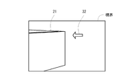
図2は、対象部材が取り付けられた状態の対象構造物を示す図である。なお、図2では、図1の対象構造物21に対して、1個の対象部材221が取り付けられた状態が図示されている。ここでは、例えば、この図1の対象部材221を図2に示すように、所定の取付位置に取り付ける作業を支援する場合を例示して説明する。
FIG. 2 is a diagram showing a target structure in a state where the target member is attached. Note that FIG. 2 shows a state in which one
(構成−端末装置)
図3は、端末装置を例示するブロック図である。端末装置1は、支援システムであり、例えば、図1に示すユーザに装着されるゴーグル型のウエアラブル端末装置であり、一例としては、通信部11、センサ部12、レンズ部13、記録部14、及び制御部15を備える。
(Configuration-Terminal device)
FIG. 3 is a block diagram illustrating a terminal device. The
(構成−端末装置−通信部)
通信部11は、ネットワーク(図示省略)を介して外部装置(例えば、不図示のサーバ装置等)との間で通信するための通信手段である。この通信部11の具体的な種類や構成は任意であるが、例えば、公知の無線通信手段を用いることができる。
(Configuration-Terminal device-Communication unit)
The
(構成−端末装置−センサ部)
センサ部12は、情報を検出又は取得する検出手段である。このセンサ部12の具体的な種類や構成は任意であるが、例えば、方向又は傾き等を検出する慣性センサ、周辺環境を三次元として認識するための情報を検出するデプスセンサ、色を認識するためのRGBカメラ、周辺環境を二次元として認識する環境認識カメラ、静止画又は動画を撮影(又は撮像)するカメラ、及び音声情報を取得するマイク等を含む任意の技術を用いることができる。そして、このようにセンサ部12を構成することにより、端末装置1にて方向又は傾き等を検出したり、あるいは、三次元空間認識を行ったり、あるいは、端末装置1自体の相対位置を検出したり、あるいは、ユーザが空間にてジェスチャーを行って情報を入力したり、音声にて情報を入力したり、あるいは、静止画又は動画を撮影したりすることが可能となる。
(Configuration-Terminal device-Sensor unit)
The
(構成−端末装置−レンズ部)
レンズ部13は、端末装置1を装着したユーザが当該レンズ部13を介して三次元実空間を視認する視認手段(表示部)である。このレンズ部13の具体的な種類や構成は任意であるが、例えば、ユーザが三次元実空間を視認できるように透明となっており、また、少なくとも表示対象を表示できるように画像表示機能も備えているものを用いることができる。そして、このようなレンズ部13に表示対象を表示することにより、当該レンズ部13を介して実環境を視認したユーザは、三次元実空間上に表示対象が表示されているように視認することが可能となる。
(Configuration-Terminal device-Lens section)
The
(構成−端末装置−記録部)
記録部14は、端末装置1の動作に必要なプログラム及び各種のデータを記録する記録手段であり、例えば、外部記録装置としてのフラッシュメモリ(図示省略)を用いて構成されている。ただし、フラッシュメモリに代えてあるいはフラッシュメモリと共に、ハードディスク、磁気ディスクの如き磁気的記録媒体、又はDVDやブルーレイディスクの如き光学的記録媒体を含む、その他の任意の記録媒体を用いることができる。この記録部14には、対象部材特定情報が記録されている。
(Configuration-Terminal device-Recording unit)
The
(構成−端末装置−記録部−対象部材特定情報)
図4は、対象部材特定情報を例示した図である。なお、図4で具体的に図示されている各情報は、説明の便宜上の記載である。「対象部材特定情報」とは、対象部材を特定する情報である。対象部材特定情報は、例えば、図4に示すように、項目「部材ID」、項目「仮想対象部材情報」、及び項目「位置情報」と、これらの各項目に対応する情報とを関連付けている情報である。項目「部材ID」に対応する情報は、前述の部材IDである(図4では、図1の対象部材221の二次元コード23に記載されている「ID221」、及び対象部材222の二次元コード23に記載されている「ID222」等)。項目「仮想対象部材情報」に対応する情報は、対象部材22の仮想対象部材オブジェクトを特定する仮想対象部材情報であり、例えば、前述の対象部材22の外観を仮想的に示す画像に対応する情報である。なお、「対象部材22の仮想対象部材オブジェクト」とは、例えば、対象部材22と少なくとも同一のサイズ、及び同一形状の仮想的に表示される三次元オブジェクト等を含む概念である。この仮想対象部材情報としては、例えば、対象部材221の仮想対象部材オブジェクトを特定する「3Dm001」、及び対象部材222の仮想対象部材オブジェクトを特定する「3Dm002」等が可能されている。項目「位置情報」に対応する情報は、対象部材22の取付位置を特定する位置情報である。この位置情報としては、任意の情報を用いることができるが、例えば、実空間上の任意の物を基準にした位置(X軸、Y軸、Z軸からなる直交座標系における座標)及び向き(X軸、Y軸、Z軸を基準にした回転角度)を特定する情報を用いることとし、一例としては、図2の対象部材221の位置及び向きを特定する「Dp001」等が記録されている。なお、ここでの位置及び向きの基準は任意であるが、三次元実空間上の任意の位置に基準物(不図示)を設け、当該基準物を基準としてもよいし、あるいは、対象構造物21が下側から上側に順次計画通りに建設されていくことを考慮して、対象構造物21の既に建設されている一部の特徴的な部分(例えば、四隅等)を基準としてもよい。
(Configuration-Terminal device-Recording unit-Target member identification information)
FIG. 4 is a diagram illustrating target member identification information. It should be noted that each information specifically illustrated in FIG. 4 is described for convenience of explanation. "Target member specific information" is information for identifying a target member. For example, as shown in FIG. 4, the target member specific information associates the item “member ID”, the item “virtual target member information”, and the item “position information” with the information corresponding to each of these items. Information. The information corresponding to the item "member ID" is the above-mentioned member ID (in FIG. 4, "ID221" described in the two-
そして、このような対象部材特定情報の具体的な格納手法は任意であるが、例えば、対象構造物21の設計時に作成したBIM(Building Information Modeling)情報に基づいて、ユーザ又は管理者が生成し任意の手法(例えば、通信を行う手法、あるいは、メモリスティック等の記録媒体を用いる手法等)で端末装置1に対して入力することにより格納されることとしてもよい。
The specific storage method of such target member specific information is arbitrary, but for example, it is generated by a user or an administrator based on BIM (Building Information Modeling) information created at the time of designing the
(構成−端末装置−制御部)
図1の制御部15は、端末装置1を制御する制御手段であり、具体的には、CPU、当該CPU上で解釈実行される各種のプログラム(OSなどの基本制御プログラムや、OS上で起動され特定機能を実現するアプリケーションプログラムを含む)、及びプログラムや各種のデータを格納するためのRAMの如き内部メモリを備えて構成されるコンピュータである。特に、実施の形態に係るプログラムは、任意の記録媒体又はネットワークを介して端末装置1にインストールされることで、制御部15の各部を実質的に構成する。
(Configuration-Terminal device-Control unit)
The
また、制御部15は、機能概念的には、例えば、取得部151、特定部152、及び表示部153を備える。取得部151は、対象構造物21を構成する対象部材22の取付位置を特定するための取付位置特定用情報を取得する取得手段である。特定部152は、取得部151が取得した取付位置特定用情報に基づいて、対象部材22の取付位置を特定する特定手段である。表示部153は、特定部152の特定結果に基づいて、ユーザに保持される端末装置1のレンズ部13を介して、三次元実空間に対して対象部材22の取付位置を示す取付位置画像を重畳して表示する表示手段である。なお、この制御部15の各部により行われる処理については、後述する。
Further, in terms of function concept, the
(処理)
次に、このように構成される端末装置1によって実行される支援処理について説明する。図5は、支援処理のフローチャートである(以下の各処理の説明ではステップを「S」と略記する)。支援処理は、概略的には、端末装置1によって行われる処理であり、具体的には、対象構造物21に関するユーザによる作業を支援する処理である。この支援処理を実行するタイミングは任意であるが、例えば、端末装置1の電源をオンした場合に、起動されて実行を開始することとして、実行を開始したところから説明する。
(processing)
Next, the support processing executed by the
図5のSA1において取得部151は、取付位置特定用情報を取得する。具体的には任意であるが、例えば、図1の端末装置1を装着しているユーザが、積み重ねられている対象部材22の周辺に移動し、当該対象部材22のコード情報23側に当該端末装置1を向けた場合(つまり、図1のレンズ部13を介して対象部材22を視認した場合)に、センサ部12のカメラがコード情報23を撮像することとし、当該カメラがコード情報23を撮像した場合に、撮像したコード情報23に記載されている部材IDを、取付位置特定用情報として取得する。ここでは、例えば、センサ部12のカメラが対象部材221のコード情報23を撮像した場合に、撮像したコード情報23に記載されている部材IDとして「ID221」を、取付位置特定用情報として取得する。
In SA1 of FIG. 5, the acquisition unit 151 acquires the mounting position specifying information. Specifically, although it is optional, for example, a user wearing the
図5のSA2において特定部152は、対象部材22の取付位置を特定する。具体的には任意であるが、例えば、SA1で取得した取付位置特定用情報である部材IDを取得し、図4の対象部材特定情報を参照して、当該取得した部材IDに対応する位置情報を取得し、取得した位置情報が特定する対象部材22の取付位置を特定する。ここでは、例えば、SA1で取得した取付位置特定用情報である部材IDとしての「ID221」を取得し、図4の対象部材特定情報を参照して、当該取得した部材IDである「ID221」に対応する位置情報である「Dp001」を取得し、取得した位置情報である「Dp001」が特定する対象部材22の取り付けられる位置及び向きとして、図2の対象部材221の位置及び向きを特定する。
In SA2 of FIG. 5, the
図5のSA3において表示部153は、端末装置1のレンズ部13を介して、三次元実空間に対して対象部材22の取付位置を示す取付位置画像を重畳して表示する。具体的には任意であるが、例えば、SA1で取得した取付位置特定用情報である部材IDを取得し、図4の対象部材特定情報を参照して、当該取得した部材IDに対応する仮想対象部材情報を取得し、取得した仮想対象部材情報が特定する対象部材22の仮想対象部材オブジェクトを、SA2で特定した対象部材22の取付位置に仮想的に重畳して固定表示する。
In SA3 of FIG. 5, the
なお、仮想対象部材オブジェクトを対象部材22の取付位置に仮想的に重畳して表示する具体的な手法は任意であり、例えば、前述の位置及び向きの基準の点、及び三次元実空間上の特徴点の点群データ等に基づく三次元空間認識を行って、ユーザがレンズ部13を介して視認した場合に、仮想対象部材オブジェクトが三次元実空間の対象部材22の取付位置に設けられているように視認できるよう重畳して表示してもよい。なお、ここでの具体的な表示手法は三次元空間認識に関する公知の手法を用いることができるので、詳細の説明を省略する。
The specific method of displaying the virtual target member object by virtually superimposing it on the mounting position of the
図6は、レンズ部を介して視認されるユーザの視界を例示した図である。なお、図6では、仮想対象部材オブジェクト31については、説明の便宜上、一点鎖線にて図示されている(図8も同様である)。ここでは、例えば、SA1で取得した取付位置特定用情報である部材IDとしての「ID221」を取得し、図4の対象部材特定情報を参照して、当該取得した部材IDである「ID221」に対応する仮想対象部材情報である「3Dm001」を取得し、取得した仮想対象部材情報が特定する対象部材22の仮想対象部材オブジェクト31(対象部材221と同一のサイズ、及び同一形状のオブジェクト)(対象部材221の外観を仮想的に示す画像)を、SA2で特定した対象部材22の取付位置に仮想的に重畳して固定表示する。このように処理することにより、ユーザは、レンズ部13を介して視認した場合、図6に示すように視認することができ、図1の対象部材221の取付位置を容易に把握することができ、作業精度及び作業効率を向上させることが可能となる。なお、この場合、端末装置1が三次元空間認識に基づく公知の処理を行うことにより、端末装置1の位置が変更された場合(つまり、ユーザが移動した場合)であっても、図6の仮想対象部材オブジェクト31は、対象構造物21に対して固定されて表示されることになるので、作業精度及び作業効率を確実に向上させることが可能となる。これにて、支援処理を終了する。
FIG. 6 is a diagram illustrating a user's field of view that is visually recognized through the lens unit. In FIG. 6, the virtual
(本実施の形態の効果)
本実施の形態によれば、三次元実空間に対して対象部材22の取付位置を示す取付位置画像(対象部材22の仮想対象部材オブジェクト31)を重畳して表示することにより、例えば、対象部材22の取付位置を容易且つ確実に把握させることができるので、対象構造物21に関する作業の作業効率を向上させることが可能となる。
(Effect of this embodiment)
According to the present embodiment, for example, the target member is displayed by superimposing a mounting position image (virtual
また、対象部材22に付されている二次元コード23のコード情報を取付位置特定用情報として取得することにより、例えば、取付位置特定用情報を確実に取得することができるので、取付位置特定用情報の誤取得を防止することができ、対象構造物21に関する作業の作業効率を確実に向上させることが可能となる。
Further, by acquiring the code information of the two-
また、対象部材22の外観を仮想的に示す画像(対象部材22の仮想対象部材オブジェクト31)を、三次元実空間における対象部材22の取付位置に重畳して表示することにより、例えば、対象部材22の取付位置を直観的に把握させることができるので、対象構造物21に関する作業の作業効率を向上させることが可能となる。
Further, for example, by superimposing an image (virtual
〔III〕実施の形態に対する変形例
以上、本発明に係る実施の形態について説明したが、本発明の具体的な構成及び手段は、特許請求の範囲に記載した各発明の技術的思想の範囲内において、任意に改変及び改良することができる。以下、このような変形例について説明する。
[III] Modifications to the Embodiment The embodiments according to the present invention have been described above, but the specific configuration and means of the present invention are within the scope of the technical idea of each invention described in the claims. Can be arbitrarily modified and improved. Hereinafter, such a modification will be described.
(解決しようとする課題や発明の効果について)
まず、発明が解決しようとする課題や発明の効果は、上述の内容に限定されるものではなく、発明の実施環境や構成の細部に応じて異なる可能性があり、上述した課題の一部のみを解決したり、上述した効果の一部のみを奏したりすることがある。
(About the problem to be solved and the effect of the invention)
First, the problem to be solved by the invention and the effect of the invention are not limited to the above-mentioned contents, and may differ depending on the implementation environment and the details of the configuration of the invention, and only a part of the above-mentioned problems. May be solved or only some of the above effects may be achieved.
(分散や統合について)
また、上述した各電気的構成要素は機能概念的なものであり、必ずしも物理的に図示の如く構成されていることを要しない。すなわち、各部の分散や統合の具体的形態は図示のものに限られず、その全部または一部を、各種の負荷や使用状況などに応じて、任意の単位で機能的または物理的に分散又は統合して構成できる。例えば、端末装置1の機能の一部を不図示のサーバ装置に設けて、当該サーバ装置との間で通信を行うことにより、前述の各処理を行うように構成してもよい。
(About distribution and integration)
Further, each of the above-mentioned electrical components is a functional concept, and does not necessarily have to be physically configured as shown in the figure. That is, the specific form of distribution or integration of each part is not limited to the one shown in the figure, and all or part of the parts may be functionally or physically dispersed or integrated in arbitrary units according to various loads and usage conditions. Can be configured. For example, a part of the function of the
(形状、数値、構造、時系列について)
実施の形態や図面において例示した構成要素に関して、形状、数値、又は複数の構成要素の構造若しくは時系列の相互関係については、本発明の技術的思想の範囲内において、任意に改変及び改良することができる。
(About shape, numerical value, structure, time series)
With respect to the components illustrated in the embodiments and drawings, the shapes, numerical values, or the interrelationships of the structures or time series of the plurality of components shall be arbitrarily modified and improved within the scope of the technical idea of the present invention. Can be done.
(対象部材特定情報について(その1))
また、上記実施の形態では、図1の二次元コード23に、部材IDに対応する情報が記載されている場合について説明したが、これに限らない。例えば、図1の二次元コード23に、部材IDの代わりに又は部材IDと共に、図4の位置情報に対応する情報を記載してもよい。この場合、二次元コード23のコード情報を読み取ることにより、対象部材22の取付位置を直接的に特定することが可能となる。また、例えば、図1の二次元コード23に、部材IDの代わりに又は部材IDと共に、対象部材22の仮想対象部材オブジェクトを特定する情報(例えば、対象部材22の寸法、形状等のデータ)を記録してもよい。この場合、二次元コード23のコード情報を読み取ることにより、表示する仮想対象部材オブジェクトを特定することが可能となる。
(About target member specific information (1))
Further, in the above embodiment, the case where the information corresponding to the member ID is described in the two-
また、上記実施の形態では、図4の対象部材特定情報において、複数種類の仮想対象部材情報が記録されている場合について説明したが、これに限らない。例えば、対象部材22の仮想対象部材オブジェクトとして、1種類のみが想定される場合、図4の対象部材特定情報を参照せずに、当該1種類のみの仮想対象部材オブジェクトを用いて処理するように構成してもよい(つまり、図4の仮想対象部材情報を1種類のみとしてもよい)。
Further, in the above-described embodiment, the case where a plurality of types of virtual target member information is recorded in the target member specific information of FIG. 4 has been described, but the present invention is not limited to this. For example, when only one type of virtual target member object of the
また、上記実施の形態では、図4の対象部材特定情報に部材IDが記録されている場合について説明したが、これに限らない。例えば、対象構造物21を構成するための対象部材の外観が相互に異なることが想定される場合、部材IDの代わりに、対象部材22の外観を特定する外観情報を記録してもよい。この場合、端末装置1で対象部材22の外観を撮影し、図4の対象部材特定情報において、撮影した外観に対応する位置情報を特定することにより、図1の対象部材22に二次元コード23を付すことなく、当該対象部材22の位置を特定することが可能となる。このように構成することにより、対象部材22の外観情報を取付位置特定用情報として取得することにより、例えば、対象部材22に対して二次元コード23等を付す必要がないので、作業の手間を低減することができ、作業効率を向上させることが可能となる。
Further, in the above-described embodiment, the case where the member ID is recorded in the target member identification information of FIG. 4 has been described, but the present invention is not limited to this. For example, when it is assumed that the appearances of the target members for forming the
(対象部材特定情報について(その2))
また、「(対象部材特定情報について(その1))」で説明した技術と、実施の形態で説明した技術とを相互に組み合わせてもよい。具体的には、図4の対象部材特定情報に図示されている各情報に加えて、対象部材22の外観を特定する外観情報を記録してもよい。そして、図1の対象部材22に付されている二次元コード23、又は対象部材22の外観を撮像して、実施の形態又は「(対象部材特定情報について(その1))」で説明した処理を行うことにより、対象部材22の取付位置を特定するように構成してもよい。このように構成した場合、対象部材22の外観情報を取付位置特定用情報として取得することにより、例えば、対象部材22の外観を撮像する等の比較的簡単な手法にて、当該対象部材22の取付位置を特定することが可能となる。
(Regarding target member specific information (Part 2))
Further, the technique described in "(Target member specific information (No. 1))" and the technique described in the embodiment may be combined with each other. Specifically, in addition to the information shown in the target member identification information of FIG. 4, appearance information that specifies the appearance of the
(表示部による表示について)
また、表示部153が、実施の形態で説明した画像以外の任意の情報を、レンズ部13を介して表示するように構成してもよい。図7及び図8は、レンズ部を介して視認されるユーザの視界を例示した図である。例えば、表示部153が、図7の方向オブジェクト32を重畳して表示するように構成してもよい。「方向オブジェクト」32は、例えば、対象部材22の取付位置がユーザの視野外である場合に、対象部材22の取付位置の方向を示す情報である。表示部153の処理は任意であるが、例えば、図3のセンサ部12の検出結果に基づいて、端末装置1が向けられている方向(つまり、ユーザが向いている方向)を特定し、特定結果に基づいて図5のSA3で重畳表示し仮想対象部材オブジェクト31が、ユーザの視界に表示されなくなったものと判定した場合、当該仮想対象部材オブジェクト31を表示させるためにユーザが向くべき方向を示す方向オブジェクト32を生成し、生成した方向オブジェクト32を表示するように構成してもよい。また、当該方向オブジェクト32と共に、あるいは、代わりに、「取付位置は左方向です」等のメッセージ情報を表示するように構成してもよい。このように構成することにより、対象部材22の取付位置がユーザの視野外である場合、対象部材22の取付位置の方向を示す情報を表示することにより、例えば、取付位置を迅速に把握させることが可能となるので、対象構造物21に関する作業の作業効率を向上させることが可能となる。
(About display by display)
Further, the
また、例えば、表示部153は、図8の仮想動線オブジェクト33を重畳して表示するように構成してもよい。「仮想動線オブジェクト」33は、例えば、対象部材22が取り付けられる場合の動線を示す画像であり、一例としては、対象部材22の仮置き場から取付位置までの動線上の矢印等に対応する画像である。表示部153の処理は任意であるが、例えば、動線を特定する情報(例えば、三次元実空間上の動線上の複数の座標等)が記録部14に記録されていることとし、この記録されている情報を任意のタイミング(例えば、図5のSA3を実行するタイミング等)に取得し、取得した当該情報に基づいて仮想動線オブジェクト33を生成して表示するように構成してもよい。このように構成することにより、対象部材22が取り付けられる場合の動線を示す動線画像(仮想動線オブジェクト33)を重畳して表示することにより、例えば、作業現場の安全性を確保することが可能となる。
Further, for example, the
また、例えば、表示部153が、対象部材22の取付順序を示す順序画像を重畳して表示するように構成してもよい。具体的には任意であるが、例えば、図4の対象部材特定情報において、取付順序を特定する取付順情報(例えば、「ID221」に対する「1」(取付順序が1番目であることを特定する情報)、及び「ID222」に対する「2」(取付順序が2番目であることを特定する情報))が記録されていることする。この場合、任意のタイミング(例えば、ユーザの所定のジェスチャー操作を受け付けたタイミング等)に、この記録されている情報を参照して、記録されている取付順序情報に対応する順序で、各対象部材22に対応する仮想対象部材オブジェクトを、対象構造物21に順序重畳する動画(アニメーション)を重畳して表示するように構成してもよい。なお、この場合、取得部151が対象部材特定情報を取得し、特定部152が取得した当該取得部151に基づいて各対象部材22の取付位置を特定し、表示部153が前述の取得した対象部材特定情報の取付順情報に基づいて取付順序を特定する処理を行い、これらの処理結果に基づいて前述の動画を表示するように構成してもよい。あるいは、動画ではなく、取付順序自体を示す画像(例えば、「1番目」、「2番目」等の画像)を表示するように構成してもよい。このように構成することにより、対象部材22の取付順序を示す順序画像(動画、又は、例えば、「1番目」、「2番目」等の画像)を重畳して表示することにより、例えば、作業順序の誤認等を防止することができるので、作業の手戻り等を防止することが可能となる。
Further, for example, the
(様々な構成について)
また、例えば、図1の二次元コード23の代わりに電子タグ(例えば、部材IDが格納されており、RFID又はNFC等の任意の技術で近距離無線通信を行う電子タグ)を用いてもよい。この場合、端末装置1との間で通信可能な他の端末装置(例えば、スマートフォンやタブレット端末)を介して、端末装置1の取得部151が、電子タグに格納されている部材IDを取得した上で、実施の形態で説明した処理と同様な処理を行うように構成してもよい。また、例えば、図1の対象構造物21自体又は当該対象構造物21の周辺に、前述の基準物として任意の座標を表す二次元コードを物理的付して、当該二次元コードに基づいて位置合わせを行うように構成してもよい。また、例えば、二次元コードや電子タグに記録する情報を生成する機能を、前述のBIMのアプリケーションに組み込むことで、一元管理を実現してもよい。また、例えば、図6のように表示されている仮想対象部材オブジェクト31について、端末装置1に対してユーザが音声入力又はジェスチャー入力を行うことにより、表示位置を微調整できるように構成してもよい。あるいは、事故防止の観点から、端末装置1が、図8の仮想動線オブジェクト33の周囲に作業員(端末装置1を装着しているユーザ以外の作業員)が近づいたか否かを、センサ部12の検出結果に基づいて判定し、近付いたものと判定した場合、ユーザに対してレンズ部13を介して警報を表示するように構成してもよいし、あるいは、不図示のスピーカを介して警報を周囲に音声出力するように構成してもよい。
(About various configurations)
Further, for example, instead of the two-
(組み合わせについて)
また、上記実施の形態の技術及び変形例の技術を任意に組み合わせてもよい。特に、例えば、取得部151による取付位置特定用情報の取得については、実施の形態の技術と、変形例の技術を組み合わせて、両者を採用してもよい。
(About combination)
Further, the technique of the above embodiment and the technique of the modified example may be arbitrarily combined. In particular, for example, for the acquisition of the mounting position specifying information by the acquisition unit 151, both of the techniques of the embodiment and the techniques of the modified example may be combined and adopted.
(付記)
付記1の支援システムは、三次元実空間の対象構造物に関する作業についてのユーザへの支援を行う支援システムであって、前記対象構造物を構成する対象部材の取付位置を特定するための取付位置特定用情報を取得する取得手段と、前記取得手段が取得した前記取付位置特定用情報に基づいて、前記対象部材の取付位置を特定する特定手段と、前記特定手段の特定結果に基づいて、前記ユーザに保持される端末装置の表示部を介して、前記三次元実空間に対して前記対象部材の取付位置を示す取付位置画像を重畳して表示する表示手段と、を備え、前記取得手段は、少なくとも、前記対象部材に付されているコード情報を、前記取付位置特定用情報として取得する。
(Additional note)
The support system of
付記2の支援システムは、付記1に記載の支援システムにおいて、前記取得手段は、前記対象部材の外観情報を、前記取付位置特定用情報として取得する。
The support system of Appendix 2 is the support system described in
付記3の支援システムは、付記1又は2に記載の支援システムにおいて、前記表示手段は、前記取付位置画像として、前記対象部材の外観を仮想的に示す画像を、前記三次元実空間における前記対象部材の取付位置に重畳して表示する。
The support system of Appendix 3 is the support system according to
付記4の支援システムは、付記1から3の何れか一項に記載の支援システムにおいて、前記表示手段は、前記端末装置の前記表示部を介し前記三次元実空間に対して前記対象部材が取り付けられる場合の動線を示す動線画像を重畳して表示する。
The support system of the supplementary note 4 is the support system according to any one of the
付記5の支援システムは、付記1から4の何れか一項に記載の支援システムにおいて、前記表示手段は、前記端末装置の前記表示部を介し前記三次元実空間に対して前記対象部材の取付順序を示す順序画像を重畳して表示する。
The support system of Supplementary Note 5 is the support system according to any one of
付記6の支援システムは、付記1から5の何れか一項に記載の支援システムにおいて、前記表示手段は、前記対象部材の取付位置が前記ユーザの視野外である場合、前記対象部材の取付位置の方向を示す情報を表示する。
The support system of the appendix 6 is the support system according to any one of the
付記7の支援プログラムは、三次元実空間の対象構造物に関する作業についてのユーザへの支援を行う支援プログラムであって、コンピュータを、前記対象構造物を構成する対象部材の取付位置を特定するための取付位置特定用情報を取得する取得手段と、前記取得手段が取得した前記取付位置特定用情報に基づいて、前記対象部材の取付位置を特定する特定手段と、前記特定手段の特定結果に基づいて、前記ユーザに保持される端末装置の表示部を介して、前記三次元実空間に対して前記対象部材の取付位置を示す取付位置画像を重畳して表示する表示手段として機能させ、前記取得手段は、少なくとも、前記対象部材に付されているコード情報を、前記取付位置特定用情報として取得する。 The support program of Appendix 7 is a support program for providing support to the user for work related to the target structure in the three-dimensional real space, in order to specify the mounting position of the target member constituting the target structure by the computer. Based on the acquisition means for acquiring the mounting position specifying information of the target member, the specific means for specifying the mounting position of the target member based on the mounting position specifying information acquired by the acquisition means, and the specific result of the specific means. The acquisition is made to function as a display means for superimposing and displaying a mounting position image indicating the mounting position of the target member on the three-dimensional real space via the display unit of the terminal device held by the user. The means acquires at least the code information attached to the target member as the mounting position specifying information.
(付記の効果)
付記1に記載の支援システム、及び付記7に記載の支援プログラムによれば、三次元実空間に対して対象部材の取付位置を示す取付位置画像を重畳して表示することにより、例えば、対象部材の取付位置を容易且つ確実に把握させることができるので、対象構造物に関する作業の作業効率を向上させることが可能となる。特に、対象部材に付されているコード情報を取付位置特定用情報として取得することにより、例えば、取付位置特定用情報を確実に取得することができるので、取付位置特定用情報の誤取得を防止することができ、対象構造物に関する作業の作業効率を確実に向上させることが可能となる。
(Effect of appendix)
According to the support system described in
付記2に記載の支援システムによれば、対象部材の外観情報を取付位置特定用情報として取得することにより、例えば、対象部材に対して二次元コード等を付す必要がないので、作業の手間を低減することができ、作業効率を向上させることが可能となる。特に、例えば、対象部材の外観を撮像する等の比較的簡単な手法にて、当該対象部材の取付位置を特定することが可能となる。 According to the support system described in Appendix 2, by acquiring the appearance information of the target member as the mounting position identification information, for example, it is not necessary to attach a two-dimensional code or the like to the target member, so that the work is troublesome. It can be reduced and the work efficiency can be improved. In particular, it is possible to specify the mounting position of the target member by a relatively simple method such as imaging the appearance of the target member.
付記3に記載の支援システムによれば、対象部材の外観を仮想的に示す画像を、三次元実空間における対象部材の取付位置に重畳して表示することにより、例えば、対象部材の取付位置を直観的に把握させることができるので、対象構造物に関する作業の作業効率を向上させることが可能となる。 According to the support system described in Appendix 3, for example, the mounting position of the target member is displayed by superimposing an image showing the appearance of the target member on the mounting position of the target member in the three-dimensional real space. Since it can be intuitively grasped, it is possible to improve the work efficiency of the work related to the target structure.
付記4に記載の支援システムによれば、対象部材が取り付けられる場合の動線を示す動線画像を重畳して表示することにより、例えば、作業現場の安全性を確保することが可能となる。 According to the support system described in Appendix 4, for example, the safety of the work site can be ensured by superimposing and displaying the flow line image showing the flow line when the target member is attached.
付記5に記載の支援システムによれば、対象部材の取付順序を示す順序画像を重畳して表示することにより、例えば、作業順序の誤認等を防止することができるので、作業の手戻り等を防止することが可能となる。 According to the support system described in Appendix 5, by superimposing and displaying an order image showing the mounting order of the target members, for example, misidentification of the work order can be prevented, so that the work can be reworked. It becomes possible to prevent.
付記6に記載の支援システムによれば、対象部材の取付位置がユーザの視野外である場合、対象部材の取付位置の方向を示す情報を表示することにより、例えば、取付位置を迅速に把握させることが可能となるので、対象構造物に関する作業の作業効率を向上させることが可能となる。 According to the support system described in Appendix 6, when the mounting position of the target member is out of the user's field of view, for example, the mounting position can be quickly grasped by displaying information indicating the direction of the mounting position of the target member. Therefore, it is possible to improve the work efficiency of the work related to the target structure.
1 端末装置
11 通信部
12 センサ部
13 レンズ部
14 記録部
15 制御部
21 対象構造物
22 対象部材
23 二次元コード
31 仮想対象部材オブジェクト
32 方向オブジェクト
33 仮想動線オブジェクト
151 取得部
152 特定部
153 表示部
221 対象部材
222 対象部材
1
Claims (7)
前記対象構造物を構成する対象部材の取付位置を特定するための取付位置特定用情報を取得する取得手段と、
前記取得手段が取得した前記取付位置特定用情報に基づいて、前記対象部材の取付位置を特定する特定手段と、
前記特定手段の特定結果に基づいて、前記ユーザに保持される端末装置の表示部を介して、前記三次元実空間に対して前記対象部材の取付位置を示す取付位置画像を重畳して表示する表示手段と、を備え、
前記取得手段は、少なくとも、前記対象部材に付されているコード情報を、前記取付位置特定用情報として取得する、
支援システム。 It is a support system that supports users in work related to target structures in three-dimensional real space.
An acquisition means for acquiring mounting position specifying information for specifying a mounting position of a target member constituting the target structure, and
Based on the mounting position specifying information acquired by the acquiring means, the specifying means for specifying the mounting position of the target member and
Based on the specific result of the specific means, the mounting position image showing the mounting position of the target member is superimposed and displayed on the three-dimensional real space via the display unit of the terminal device held by the user. With display means,
The acquisition means acquires at least the code information attached to the target member as the mounting position specifying information.
Support system.
請求項1に記載の支援システム。 The acquisition means acquires the appearance information of the target member as the mounting position specifying information.
The support system according to claim 1.
請求項1又は2に記載の支援システム。 As the mounting position image, the display means superimposes and displays an image showing the appearance of the target member on the mounting position of the target member in the three-dimensional real space.
The support system according to claim 1 or 2.
請求項1から3の何れか一項に記載の支援システム。 The display means superimposes and displays a flow line image showing a flow line when the target member is attached to the three-dimensional real space via the display unit of the terminal device.
The support system according to any one of claims 1 to 3.
請求項1から4の何れか一項に記載の支援システム。 The display means superimposes and displays an order image showing the mounting order of the target member on the three-dimensional real space via the display unit of the terminal device.
The support system according to any one of claims 1 to 4.
請求項1から5の何れか一項に記載の支援システム。 When the mounting position of the target member is outside the field of view of the user, the display means displays information indicating the direction of the mounting position of the target member.
The support system according to any one of claims 1 to 5.
コンピュータを、
前記対象構造物を構成する対象部材の取付位置を特定するための取付位置特定用情報を取得する取得手段と、
前記取得手段が取得した前記取付位置特定用情報に基づいて、前記対象部材の取付位置を特定する特定手段と、
前記特定手段の特定結果に基づいて、前記ユーザに保持される端末装置の表示部を介して、前記三次元実空間に対して前記対象部材の取付位置を示す取付位置画像を重畳して表示する表示手段と、として機能させ、
前記取得手段は、少なくとも、前記対象部材に付されているコード情報を、前記取付位置特定用情報として取得する、
支援プログラム。 A support program that assists users in work related to target structures in three-dimensional real space.
Computer,
An acquisition means for acquiring mounting position specifying information for specifying a mounting position of a target member constituting the target structure, and
Based on the mounting position specifying information acquired by the acquiring means, the specifying means for specifying the mounting position of the target member and
Based on the specific result of the specific means, the mounting position image showing the mounting position of the target member is superimposed and displayed on the three-dimensional real space via the display unit of the terminal device held by the user. To function as a display means,
The acquisition means acquires at least the code information attached to the target member as the mounting position specifying information.
Support program.
Priority Applications (1)
| Application Number | Priority Date | Filing Date | Title |
|---|---|---|---|
| JP2019043109A JP7296220B2 (en) | 2019-03-08 | 2019-03-08 | Support system and support program |
Applications Claiming Priority (1)
| Application Number | Priority Date | Filing Date | Title |
|---|---|---|---|
| JP2019043109A JP7296220B2 (en) | 2019-03-08 | 2019-03-08 | Support system and support program |
Publications (2)
| Publication Number | Publication Date |
|---|---|
| JP2020144813A true JP2020144813A (en) | 2020-09-10 |
| JP7296220B2 JP7296220B2 (en) | 2023-06-22 |
Family
ID=72354348
Family Applications (1)
| Application Number | Title | Priority Date | Filing Date |
|---|---|---|---|
| JP2019043109A Active JP7296220B2 (en) | 2019-03-08 | 2019-03-08 | Support system and support program |
Country Status (1)
| Country | Link |
|---|---|
| JP (1) | JP7296220B2 (en) |
Cited By (2)
| Publication number | Priority date | Publication date | Assignee | Title |
|---|---|---|---|---|
| JP2022155553A (en) * | 2021-03-30 | 2022-10-13 | 株式会社エム・ソフト | Business management support device, business management support system, business management support method, and business management support program |
| JP2022156097A (en) * | 2021-03-31 | 2022-10-14 | 本田技研工業株式会社 | Information provision method, program and information provision device |
Citations (10)
| Publication number | Priority date | Publication date | Assignee | Title |
|---|---|---|---|---|
| JP2000155855A (en) * | 1998-06-30 | 2000-06-06 | Tobishima Corp | Construction support information system using virtual reality. |
| JP2008225913A (en) * | 2007-03-13 | 2008-09-25 | Fujitsu Ltd | Work support system, work support device, and work support method |
| JP2011253422A (en) * | 2010-06-03 | 2011-12-15 | Honda Motor Co Ltd | Work procedure display method and work procedure display system |
| WO2013051080A1 (en) * | 2011-10-03 | 2013-04-11 | 株式会社日立製作所 | Site management method and site management device |
| JP2015188284A (en) * | 2014-03-27 | 2015-10-29 | 日本電気株式会社 | Terminal, server, work support system and work support method |
| JP2015232783A (en) * | 2014-06-09 | 2015-12-24 | 株式会社バンダイナムコエンターテインメント | Program and image creating device |
| JP2017010353A (en) * | 2015-06-24 | 2017-01-12 | 日本電信電話株式会社 | Work support device, work support method, and work support program |
| JP2017068689A (en) * | 2015-09-30 | 2017-04-06 | 富士通株式会社 | Visual field guide method, visual field guide program and visual field guide device |
| JP2017191351A (en) * | 2016-04-11 | 2017-10-19 | 株式会社日立製作所 | Work support system and method |
| JP2018124843A (en) * | 2017-02-02 | 2018-08-09 | 前田建設工業株式会社 | On-site construction management system |
-
2019
- 2019-03-08 JP JP2019043109A patent/JP7296220B2/en active Active
Patent Citations (10)
| Publication number | Priority date | Publication date | Assignee | Title |
|---|---|---|---|---|
| JP2000155855A (en) * | 1998-06-30 | 2000-06-06 | Tobishima Corp | Construction support information system using virtual reality. |
| JP2008225913A (en) * | 2007-03-13 | 2008-09-25 | Fujitsu Ltd | Work support system, work support device, and work support method |
| JP2011253422A (en) * | 2010-06-03 | 2011-12-15 | Honda Motor Co Ltd | Work procedure display method and work procedure display system |
| WO2013051080A1 (en) * | 2011-10-03 | 2013-04-11 | 株式会社日立製作所 | Site management method and site management device |
| JP2015188284A (en) * | 2014-03-27 | 2015-10-29 | 日本電気株式会社 | Terminal, server, work support system and work support method |
| JP2015232783A (en) * | 2014-06-09 | 2015-12-24 | 株式会社バンダイナムコエンターテインメント | Program and image creating device |
| JP2017010353A (en) * | 2015-06-24 | 2017-01-12 | 日本電信電話株式会社 | Work support device, work support method, and work support program |
| JP2017068689A (en) * | 2015-09-30 | 2017-04-06 | 富士通株式会社 | Visual field guide method, visual field guide program and visual field guide device |
| JP2017191351A (en) * | 2016-04-11 | 2017-10-19 | 株式会社日立製作所 | Work support system and method |
| JP2018124843A (en) * | 2017-02-02 | 2018-08-09 | 前田建設工業株式会社 | On-site construction management system |
Non-Patent Citations (1)
| Title |
|---|
| SHUNICHI KASAHARA AND JUN REKIMOTO: "JackIn: Integrating First-Person View with Out-of-Body Vision Generation for Human-Human Augmentatio", [ONLINE], JPN7022005875, 8 March 2014 (2014-03-08), pages 1 - 55, ISSN: 0004947129 * |
Cited By (3)
| Publication number | Priority date | Publication date | Assignee | Title |
|---|---|---|---|---|
| JP2022155553A (en) * | 2021-03-30 | 2022-10-13 | 株式会社エム・ソフト | Business management support device, business management support system, business management support method, and business management support program |
| JP2022156097A (en) * | 2021-03-31 | 2022-10-14 | 本田技研工業株式会社 | Information provision method, program and information provision device |
| JP7608240B2 (en) | 2021-03-31 | 2025-01-06 | 本田技研工業株式会社 | Information providing method, program, and information providing device |
Also Published As
| Publication number | Publication date |
|---|---|
| JP7296220B2 (en) | 2023-06-22 |
Similar Documents
| Publication | Publication Date | Title |
|---|---|---|
| KR102289745B1 (en) | System and method for real-time monitoring field work | |
| US9544552B2 (en) | Pickup system and pickup method | |
| US10438409B2 (en) | Augmented reality asset locator | |
| US11263818B2 (en) | Augmented reality system using visual object recognition and stored geometry to create and render virtual objects | |
| US10043314B2 (en) | Display control method and information processing apparatus | |
| JP6970858B2 (en) | Maintenance support system, maintenance support method, program and processed image generation method | |
| JP6244954B2 (en) | Terminal apparatus, information processing apparatus, display control method, and display control program | |
| US20150206352A1 (en) | System and method for controlling a display | |
| JP2020098568A (en) | Information management device, information management system, information management method, and information management program | |
| CN105183408A (en) | Controlling display of superimposed information in an augmented reality system | |
| CN103377487A (en) | Information processing apparatus, display control method, and program | |
| KR101575159B1 (en) | Method of operating application for providing parking information to mobile terminal | |
| JP2022155553A (en) | Business management support device, business management support system, business management support method, and business management support program | |
| US20190377330A1 (en) | Augmented Reality Systems, Methods And Devices | |
| KR20210081971A (en) | System and method for construction supervision using tower crane | |
| JP2007072537A (en) | 360 ° image capturing device | |
| JP6217437B2 (en) | Terminal apparatus, information processing apparatus, display control method, and display control program | |
| WO2020196276A1 (en) | Maintenance assistance system, maintenance assistance method, program, method for generating processed image, and processed image | |
| JP6543924B2 (en) | INFORMATION PROCESSING METHOD, INFORMATION PROCESSING PROGRAM, AND INFORMATION PROCESSING APPARATUS | |
| JP6686547B2 (en) | Image processing system, program, image processing method | |
| JP7296220B2 (en) | Support system and support program | |
| JP6670580B2 (en) | Architectural systems | |
| JP2018185240A (en) | Positioning device | |
| JP2020156083A (en) | Generation system and generation program | |
| KR102260193B1 (en) | Remote augmented reality communication method and system that provides security for 3d-space |
Legal Events
| Date | Code | Title | Description |
|---|---|---|---|
| A621 | Written request for application examination |
Free format text: JAPANESE INTERMEDIATE CODE: A621 Effective date: 20211223 |
|
| A977 | Report on retrieval |
Free format text: JAPANESE INTERMEDIATE CODE: A971007 Effective date: 20221118 |
|
| A131 | Notification of reasons for refusal |
Free format text: JAPANESE INTERMEDIATE CODE: A131 Effective date: 20221220 |
|
| A521 | Request for written amendment filed |
Free format text: JAPANESE INTERMEDIATE CODE: A523 Effective date: 20230120 |
|
| TRDD | Decision of grant or rejection written | ||
| A01 | Written decision to grant a patent or to grant a registration (utility model) |
Free format text: JAPANESE INTERMEDIATE CODE: A01 Effective date: 20230516 |
|
| A61 | First payment of annual fees (during grant procedure) |
Free format text: JAPANESE INTERMEDIATE CODE: A61 Effective date: 20230612 |
|
| R150 | Certificate of patent or registration of utility model |
Ref document number: 7296220 Country of ref document: JP Free format text: JAPANESE INTERMEDIATE CODE: R150 |