JP2020048367A - Vehicle charging connector holding device - Google Patents
Vehicle charging connector holding device Download PDFInfo
- Publication number
- JP2020048367A JP2020048367A JP2018176592A JP2018176592A JP2020048367A JP 2020048367 A JP2020048367 A JP 2020048367A JP 2018176592 A JP2018176592 A JP 2018176592A JP 2018176592 A JP2018176592 A JP 2018176592A JP 2020048367 A JP2020048367 A JP 2020048367A
- Authority
- JP
- Japan
- Prior art keywords
- charging connector
- case
- connector
- holding
- holding device
- Prior art date
- Legal status (The legal status is an assumption and is not a legal conclusion. Google has not performed a legal analysis and makes no representation as to the accuracy of the status listed.)
- Granted
Links
Images


Classifications
-
- Y—GENERAL TAGGING OF NEW TECHNOLOGICAL DEVELOPMENTS; GENERAL TAGGING OF CROSS-SECTIONAL TECHNOLOGIES SPANNING OVER SEVERAL SECTIONS OF THE IPC; TECHNICAL SUBJECTS COVERED BY FORMER USPC CROSS-REFERENCE ART COLLECTIONS [XRACs] AND DIGESTS
- Y02—TECHNOLOGIES OR APPLICATIONS FOR MITIGATION OR ADAPTATION AGAINST CLIMATE CHANGE
- Y02T—CLIMATE CHANGE MITIGATION TECHNOLOGIES RELATED TO TRANSPORTATION
- Y02T10/00—Road transport of goods or passengers
- Y02T10/60—Other road transportation technologies with climate change mitigation effect
- Y02T10/70—Energy storage systems for electromobility, e.g. batteries
-
- Y—GENERAL TAGGING OF NEW TECHNOLOGICAL DEVELOPMENTS; GENERAL TAGGING OF CROSS-SECTIONAL TECHNOLOGIES SPANNING OVER SEVERAL SECTIONS OF THE IPC; TECHNICAL SUBJECTS COVERED BY FORMER USPC CROSS-REFERENCE ART COLLECTIONS [XRACs] AND DIGESTS
- Y02—TECHNOLOGIES OR APPLICATIONS FOR MITIGATION OR ADAPTATION AGAINST CLIMATE CHANGE
- Y02T—CLIMATE CHANGE MITIGATION TECHNOLOGIES RELATED TO TRANSPORTATION
- Y02T10/00—Road transport of goods or passengers
- Y02T10/60—Other road transportation technologies with climate change mitigation effect
- Y02T10/7072—Electromobility specific charging systems or methods for batteries, ultracapacitors, supercapacitors or double-layer capacitors
-
- Y—GENERAL TAGGING OF NEW TECHNOLOGICAL DEVELOPMENTS; GENERAL TAGGING OF CROSS-SECTIONAL TECHNOLOGIES SPANNING OVER SEVERAL SECTIONS OF THE IPC; TECHNICAL SUBJECTS COVERED BY FORMER USPC CROSS-REFERENCE ART COLLECTIONS [XRACs] AND DIGESTS
- Y02—TECHNOLOGIES OR APPLICATIONS FOR MITIGATION OR ADAPTATION AGAINST CLIMATE CHANGE
- Y02T—CLIMATE CHANGE MITIGATION TECHNOLOGIES RELATED TO TRANSPORTATION
- Y02T90/00—Enabling technologies or technologies with a potential or indirect contribution to GHG emissions mitigation
- Y02T90/10—Technologies relating to charging of electric vehicles
- Y02T90/14—Plug-in electric vehicles
Landscapes
- Charge And Discharge Circuits For Batteries Or The Like (AREA)
- Electric Propulsion And Braking For Vehicles (AREA)
Abstract
【課題】充電コネクタの前方向若しくは左右方向への突出量を減らせるようにすること。【解決手段】車両に接続されることで電力を供給する充電コネクタを収納するコネクタ収納部2を備えた車両用充電コネクタ保持装置1であって、コネクタ収納部を、少なくとも上下方向及び左右方向に回転可能とした構成とする。【選択図】図1PROBLEM TO BE SOLVED: To reduce the amount of protrusion of a charging connector in the front direction or the left-right direction. A vehicle charging connector holding device (1) having a connector housing (2) for housing a charging connector that supplies electric power when connected to a vehicle, wherein the connector housing is at least vertically and horizontally. It is designed to be rotatable. [Selection diagram] Figure 1
Description
本発明は、車両用充電コネクタ保持装置に関するものである。 The present invention relates to a vehicle charging connector holding device.
車両用充電コネクタを保持する保持装置が知られている。特許文献1に記載されている保持装置は、回転軸が水平方向に延びており、上下方向(垂直方向)に移動するよう回転するものである。また、特許文献2に記載されている保持装置は、回転軸が垂直方向に延びており、左右方向(水平方向)に移動するよう回転するものである。
2. Description of the Related Art A holding device for holding a vehicle charging connector is known. The holding device described in
ところで、充電コネクタが上下方向のみ若しくは左右方向のみにしか回転しない場合には、充電コネクタの前方向若しくは左右方向への突出量を僅かに減らすことができるが、十分ではない。 By the way, when the charging connector rotates only in the up-down direction or only in the left-right direction, the amount of protrusion of the charging connector in the front direction or the left-right direction can be slightly reduced, but is not sufficient.
本件の発明者は、この点について鋭意検討することにより、解決を試みた。本発明の課題は、充電コネクタの前方向若しくは左右方向への突出量を減らせるようにすることである。 The inventor of the present invention sought to solve this problem by studying this point earnestly. SUMMARY OF THE INVENTION It is an object of the present invention to reduce the amount of protrusion of a charging connector in a front direction or a left and right direction.
上記課題を解決するため、車両に接続されることで電力を供給する充電コネクタを収納するコネクタ収納部を備えた車両用充電コネクタ保持装置であって、コネクタ収納部を、少なくとも上下方向及び左右方向に回転可能とした車両用充電コネクタ保持装置とする。 To solve the above-mentioned problems, a vehicle charging connector holding device including a connector storage portion that stores a charging connector that supplies electric power by being connected to a vehicle, wherein the connector storage portion is provided at least in a vertical direction and a horizontal direction. And a vehicle charging connector holding device that is rotatable.
また、コネクタ収納部は、コネクタを保持する保持部と、保持部を支持するケース部を備え、保持部は、上下方向に回転可能であり、ケース部は、左右方向に回転可能である構成とすることが好ましい。 Further, the connector housing portion includes a holding portion that holds the connector, and a case portion that supports the holding portion, the holding portion is rotatable in a vertical direction, and the case portion is rotatable in a left and right direction. Is preferred.
また、コネクタ収納部は、上面側に支持部を有し、支持部で吊り下げ支持される構成とすることが好ましい。 Further, it is preferable that the connector accommodating portion has a support portion on the upper surface side and is supported and suspended by the support portion.
また、コネクタ収納部の左右方向の回転の規制と前記規制の解除の双方が可能な回転規制機構を備えた構成とすることが好ましい。 In addition, it is preferable that a configuration is provided that includes a rotation restricting mechanism capable of both restricting rotation of the connector storage section in the left-right direction and releasing the restriction.
本発明では、充電コネクタの前方向若しくは左右方向への突出量を減らせるようにすることが可能となる。 According to the present invention, it is possible to reduce the amount of protrusion of the charging connector in the front direction or the left and right direction.
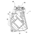
以下に発明を実施するための形態を示す。図1乃至図4に示されていることから理解されるように、本実施形態の車両用充電コネクタ保持装置1は、車両に接続されることで電力を供給する充電コネクタ91を収納するコネクタ収納部2を備えている。また、この車両用充電コネクタ保持装置1は、コネクタ収納部2を、少なくとも上下方向及び左右方向に回転可能としている。このため、充電コネクタ91の前方向若しくは左右方向への突出量を減らすことが可能となる。
Hereinafter, embodiments for carrying out the invention will be described. As can be understood from FIGS. 1 to 4, the vehicle charging
図1から図5に示されることから理解されるように、実施形態における車両用充電コネクタ保持装置1のコネクタ収納部2は、コネクタを保持する保持部10と、保持部10を支持するケース部20を備えている。また、保持部10は、上下方向に回転可能であり、ケース部20は、左右方向に回転可能である。このため、収納部の移動範囲に面状の広がりがある。ここで、保持部10は、開口部に充電コネクタ91を接続すると、充電コネクタ91の自重によって下方向へ回転し、開口部から充電コネクタ91を抜去すると、保持部10の自重によって上方向へ回転する構造となっている。
As can be understood from FIGS. 1 to 5, the
実施形態の車両用充電コネクタ保持装置1は、充電コネクタ91を保持する機能を発揮させることができるものであり、施工面などに取り付けられる取付部40を備えている。ここでいう、施工面には、家屋の外壁、家屋の庇98やカーポート等の支柱99などや、キャビネットの内部などが含まれる。なお、車両用充電コネクタ保持装置1が取り付けられるキャビネットとしては、充電機能を備えた車両用充電器であっても良いし、充電機能を備えない、防水や防犯目的のものであってもよい。
The vehicle charging
図6に示されることから理解されるように、実施形態の取付部40は、施工面に取り付けられる取付部材41と、ケース部20や保持部10を支持する支持部材42と、それらをカバーするカバー部材43で構成され、それぞれがネジなどで固定されている。実施形態の取付部材41は平面視略コ字状であって、背面に取付穴44を備え、ネジなどで施工面などに取付けられる。取付部材41の側面部には、略長方形状の取付穴45を備え、その長方形状の取付穴に紐やバンドなどを通すことで、支柱99などにも固定することができる(図7参照)。
As can be understood from FIG. 6, the
図6に示す例の支持部材42は前方へ延びる片46を有し、その片46には、ケース部20を回動可能に支持するために用いられる支持部81として機能するボルトが挿通される支持孔47を有する。このように、コネクタ収納部2の上面側に支持部81を有し、支持部81で吊り下げ支持されるようにすることが好ましい。
The
実施形態のカバー部材43は、組み合わされた取付部材41と支持部材42を覆うために、側面視略L字状となっており、背面側には、取付部材41に通した紐やバンドを回避するための切欠き48が設けられている。また、図6に示す例のカバー部材43の前面側には、ケース部20の左右方向への回転を規制するためにケース部20と当接する凸部49が形成されている。
The
実施形態のケース部20は、左側の外形を形成する左側ケース201と右側の外形を形成する右側ケース202を備え、左側ケース201と右側ケース202は上側2点、下側1点の計3点でネジ固定されている。
The
また、図8から図10に示すことから理解されるように、左側ケース201と右側ケース202は、その上部側に回転部材82を挟持する。この回転部材82は、円盤部83と軸部84で構成され、円盤部83の上面や、軸部84の周囲には、回転部材82を回転しやすくするための樹脂などが付されている。なお、支持部81となるボルトを軸部84に対して下側から挿入し、ボルトを取付部40の支持部材42の支持孔47に固定することで、回転部材82を支持し、更には、回転部材82を挟持するケース部20を支持する。
As can be understood from FIGS. 8 to 10, the
左側ケース201と右側ケース202の内側には、保持部10の軸部11を受ける軸受け21が設けられる。また、左側ケース201と右側ケース202の内側には、保持部10の回転を規制する複数の規制部が設けられている。図10に示すことから理解されるように、ケース部20の下部に設けられる第1規制部22は、充電コネクタ91が保持されていない状態で、保持部10の開口部12側が上方向に向けて回転することを規制する。また、図11に示すことから理解されるように、ケース部20の上部に設けられる第2規制部23は、充電コネクタ91が保持された状態で、保持部10の開口部12側が下方向に向けて回転することを規制する。
A bearing 21 for receiving the
ところで、保持部10の上下方向への回転をスムーズに行うために、ケース部20の軸受け21とそれに挿入される保持部10の軸部11との間には隙間が設けられている。しかし、その隙間が存在することにより、保持部10へ充電コネクタ91を挿入する際に、保持部10が固定されない状態となり、充電コネクタ91を挿入しづらいという問題が生じ得る。そこで、実施形態では、充電コネクタ91を挿入するときに、保持部10の背面が当接し保持部10の回転を抑制することができる凸部24をケース部20の内側に設けた。この凸部24を設けることで、保持部10へ充電コネクタ91を挿入しやすくすることができる。なお、この凸部24は、ケース内側の左側ケース201と右側ケース202の合わせ面付近に設けている。
A gap is provided between the bearing 21 of the
また、左側ケース201及び右側ケース202の外側には、凸部25が設けられている。図12に示すように、このケースの外側に設けた凸部25が、左右方向への回転時に取付部40の内側の凸部49と当接することで、左右方向へのそれ以上の回転を規制する。なお、取付部40の内側の凸部49を乗り越えることで、逆方向への回転を規制するものであっても良い。
Further, a
図13に示すことから理解されるように、実施形態の保持部10は、前面側に充電コネクタ91を挿入するための開口部12を備え、左右両側には、ケース部20の軸受け21に挿入される軸部11を有する。また、開口部12の上方には、充電コネクタ91の上方に設けられた爪部と嵌合し、充電コネクタ91の脱落を防止するための嵌合部13を有する。ここで、軸部11は、保持部10の開口部側の上方位置に設けられている。そうすることで、充電コネクタ91が保持されていない状態で自重により開口部側を上方向に回転させることができる。
As can be understood from FIG. 13, the holding
図13から図15に示すことから理解されるように、開口部12の後部には、スリット14が設けられ、背面側から異物を排出することができる。また、スリット14の上部には、挿入された充電コネクタ91の端子部などに、水が浸入することを防ぐために、前方へ突出するリブ15が設けられる。
As can be understood from FIGS. 13 to 15, a
図14に示すことから理解されるように、保持部10は背面側に突出部16を有している。実施形態の突出部16は上下反転した略T字状である。この突出部16の下方の左右に延びる辺の上側の面は、ケース部20の第2規制部23と当接することで、充電コネクタ91が保持された状態での保持部10の下方向への回転を規制するものである。また、突出部16の下方の左右に延びる辺の下側の面は、ケース部20の第1規制部22と当接することで、充電コネクタ91が保持されていない状態での保持部10の上方向への回転を規制するものである。
As can be understood from FIG. 14, the holding
上記の例では、車両用充電コネクタ保持装置1は、取付部40とケース部20と保持部10を備えたものとしているが、少なくとも充電コネクタ91を保持する保持部10を備えたものであればよく、ケース部20がなく、取付部40に保持部10が支持された構成のものであってもよい。また、取付部40がなく、ケース部20と保持部10のみで構成されたものを、家屋の庇98や、カーポートの屋根、天井に直接支持されるように取付ける構造としてもよい(図16参照)。
In the above example, the vehicle charging
ところで、コネクタ収納部2の左右方向の回転の規制と前記規制の解除の双方が可能な回転規制機構を備えたものとしても良い。このようにすれば、左右方向への回転の規制をしたい場合と、その規制を解除したい場合に対応できる。例えば、コネクタ収納部2の左右方向の回転の規制をするには、コネクタ収納部2を保持し、回転を防止若しくは規制するようにすれば良い。図17から図25に示す例では、支持部材42に規制孔88を設けた構造としている。この規制孔88に、ケース部20側に設けた規制ピン89を嵌めることで、ケース部20の回動を規制するものである。
By the way, it may be provided with a rotation regulating mechanism capable of both regulating the rotation of the
実施形態では、ケース部20には上下移動可能な規制ピン89が備えられている。実施形態では、保持部10に充電コネクタ91を挿し込むことで、保持部10の後側が上方に移動した際に、保持部10が規制ピン89を押し上げることができるように構成されている。この規制ピン89が規制孔88に嵌る状態となれば、ケース部20の回動が規制される。つまりは、コネクタ収納部2の左右方向の回転が規制される。なお、規制ピン89が上方に持ち上げられても規制孔88に嵌らない場合もあるが、その状態でケース部20を回転させれば、規制ピン89が規制孔88に嵌る状態とすることができる。
In the embodiment, the
また、実施形態においては、保持部10の軸部11の後かつ下方に保持部10の重心が位置するようにしている。このため、充電コネクタ91を保持部10から外せば、保持部10の後側が下方に移動する。その結果、規制ピン89を押し上げる力が解除されるため、規制ピン89が規制孔88から抜け、自動的にケース部20の左右方向への回動の規制が解除される。このように、充電コネクタ91が保持部10から取り外されることにより、コネクタ収納部2の左右方向の回転の規制を解除するようにすれば、利便性を高めることができる。
In the embodiment, the center of gravity of the holding
実施形態では、規制孔88は支持孔47を中心に90度ずつずれるように三つ設けているため、ケース部20は90度ずつずれた箇所で回転を規制することができる(図23から図25参照)。なお、規制孔88の個数はさらに増やしても良いし減らしても良い。
In the embodiment, since three regulating
以上、実施形態を例に挙げて本発明について説明してきたが、本発明は上記実施形態に限定されることはなく、各種の態様とすることが可能である。例えば、車両用充電コネクタ保持装置は、ケース部が左右方向、保持部が上下方向に回転するものを例に挙げているが、ケース部が上下方向、保持部が左右方向に回転するものであってもよい。 As described above, the present invention has been described by taking the embodiment as an example. However, the present invention is not limited to the above embodiment, and can be various modes. For example, in the vehicle charging connector holding device, an example is described in which the case portion rotates in the left-right direction and the holding portion rotates in the up-down direction, but the case portion rotates in the up-down direction and the holding portion rotates in the left-right direction. You may.
また、ケース部と保持部の一方が(例えば、保持部のみが)、左右方向及び上下方向に回転するものであってもよい。このようにするためには、例えば、ケース部の回転部材を球体状として、左側ケースと右側ケースが挟持する構造とすればよい。これにより、取付部に対して、ケース部がさまざまな方向に回転できるようになる。 Further, one of the case portion and the holding portion (for example, only the holding portion) may rotate in the left-right direction and the up-down direction. In order to achieve this, for example, the rotating member of the case portion may be formed in a spherical shape so that the left case and the right case are sandwiched. Thereby, the case portion can be rotated in various directions with respect to the mounting portion.
コネクタ収納部は、左右方向に回転した後に、ケース部の回転部材に規制部材を当接若しくは嵌合することで、回転部材が回転し辛い若しくは逆方向へ回転できないようにしても良い。また、ケース部の回転部材付近に開口を設け、ケース部を左右いずれかの方向へ回転させた後、開口から規制部材を挿入することで、回転部材と当接等するものであってもよい。 After rotating the connector housing portion in the left-right direction, the restricting member may be brought into contact with or fitted to the rotating member of the case portion so that the rotating member is difficult to rotate or cannot be rotated in the opposite direction. Further, an opening may be provided in the vicinity of the rotating member of the case portion, and after rotating the case portion in any of the left and right directions, the regulating member may be inserted through the opening to abut on the rotating member. .
また、規制部材を保持部に設けることもできる。保持部に充電コネクタを保持させると、保持部の開口部が下方向に回転するが、背面側は上方向に回転する。そこで、背面側の上方に規制部材を設け、保持部に充電コネクタが保持された状態で、回転部材の下面に規制部材が当接等するようにすることで、回転部材を回転し辛くすることも可能である。 Further, a regulating member can be provided on the holding portion. When the charging connector is held by the holding portion, the opening of the holding portion rotates downward, but the back side rotates upward. Therefore, by providing a regulating member on the upper side on the back side and making the regulating member abut on the lower surface of the rotating member in a state where the charging connector is held in the holding portion, it is difficult to rotate the rotating member. Is also possible.
1 車両用充電コネクタ保持装置
2 コネクタ収納部
10 保持部
20 ケース部
81 支持部
91 充電コネクタ
REFERENCE SIGNS
Claims (4)
コネクタ収納部を、少なくとも上下方向及び左右方向に回転可能とした車両用充電コネクタ保持装置。 A charging connector holding device for a vehicle, comprising a connector storage portion that stores a charging connector that supplies power by being connected to a vehicle,
A charging connector holding device for a vehicle, wherein a connector housing is rotatable at least in a vertical direction and a horizontal direction.
保持部は、上下方向に回転可能であり、ケース部は、左右方向に回転可能である請求項1に記載の車両用充電コネクタ保持装置。 The connector storage section includes a holding section that holds the connector, and a case section that supports the holding section,
The vehicle charging connector holding device according to claim 1, wherein the holding portion is rotatable in a vertical direction, and the case portion is rotatable in a left and right direction.
Priority Applications (1)
| Application Number | Priority Date | Filing Date | Title |
|---|---|---|---|
| JP2018176592A JP7266943B2 (en) | 2018-09-20 | 2018-09-20 | Vehicle charging connector holding device |
Applications Claiming Priority (1)
| Application Number | Priority Date | Filing Date | Title |
|---|---|---|---|
| JP2018176592A JP7266943B2 (en) | 2018-09-20 | 2018-09-20 | Vehicle charging connector holding device |
Publications (2)
| Publication Number | Publication Date |
|---|---|
| JP2020048367A true JP2020048367A (en) | 2020-03-26 |
| JP7266943B2 JP7266943B2 (en) | 2023-05-01 |
Family
ID=69900006
Family Applications (1)
| Application Number | Title | Priority Date | Filing Date |
|---|---|---|---|
| JP2018176592A Active JP7266943B2 (en) | 2018-09-20 | 2018-09-20 | Vehicle charging connector holding device |
Country Status (1)
| Country | Link |
|---|---|
| JP (1) | JP7266943B2 (en) |
Citations (8)
| Publication number | Priority date | Publication date | Assignee | Title |
|---|---|---|---|---|
| JP2010259277A (en) * | 2009-04-28 | 2010-11-11 | Nitto Electric Works Ltd | Electric vehicle charging station |
| JP2010263665A (en) * | 2009-04-30 | 2010-11-18 | Nitto Electric Works Ltd | Electric vehicle charging station |
| US20110169447A1 (en) * | 2010-01-11 | 2011-07-14 | Leviton Manufacturing Co., Inc. | Electric vehicle supply equipment |
| JP2012069293A (en) * | 2010-09-21 | 2012-04-05 | Panasonic Electric Works Co Ltd | Charging plug holding device |
| JP2012223074A (en) * | 2011-04-14 | 2012-11-12 | Nitto Kogyo Co Ltd | Charging connector holding structure of charging device for vehicle |
| JP2013046476A (en) * | 2011-08-23 | 2013-03-04 | Panasonic Corp | Charging connector holding device for electric vehicle and charger for electric vehicle using the same |
| JP2013055787A (en) * | 2011-09-02 | 2013-03-21 | Panasonic Corp | Charger for electric vehicle |
| JP2013085345A (en) * | 2011-10-07 | 2013-05-09 | Nissan Motor Co Ltd | Connector holder and charging stand |
-
2018
- 2018-09-20 JP JP2018176592A patent/JP7266943B2/en active Active
Patent Citations (8)
| Publication number | Priority date | Publication date | Assignee | Title |
|---|---|---|---|---|
| JP2010259277A (en) * | 2009-04-28 | 2010-11-11 | Nitto Electric Works Ltd | Electric vehicle charging station |
| JP2010263665A (en) * | 2009-04-30 | 2010-11-18 | Nitto Electric Works Ltd | Electric vehicle charging station |
| US20110169447A1 (en) * | 2010-01-11 | 2011-07-14 | Leviton Manufacturing Co., Inc. | Electric vehicle supply equipment |
| JP2012069293A (en) * | 2010-09-21 | 2012-04-05 | Panasonic Electric Works Co Ltd | Charging plug holding device |
| JP2012223074A (en) * | 2011-04-14 | 2012-11-12 | Nitto Kogyo Co Ltd | Charging connector holding structure of charging device for vehicle |
| JP2013046476A (en) * | 2011-08-23 | 2013-03-04 | Panasonic Corp | Charging connector holding device for electric vehicle and charger for electric vehicle using the same |
| JP2013055787A (en) * | 2011-09-02 | 2013-03-21 | Panasonic Corp | Charger for electric vehicle |
| JP2013085345A (en) * | 2011-10-07 | 2013-05-09 | Nissan Motor Co Ltd | Connector holder and charging stand |
Also Published As
| Publication number | Publication date |
|---|---|
| JP7266943B2 (en) | 2023-05-01 |
Similar Documents
| Publication | Publication Date | Title |
|---|---|---|
| CN1916754B (en) | Security camera | |
| US10673170B2 (en) | Lid arrangement | |
| JP5641399B2 (en) | Fire extinguisher case | |
| JP2020048367A (en) | Vehicle charging connector holding device | |
| JP7175562B2 (en) | Vehicle charging connector holding device | |
| CN109073144B (en) | Driving device, cloud platform, shooting device and unmanned vehicles | |
| CN222592170U (en) | Storage box and beauty instrument assembly | |
| JP7368711B2 (en) | Charging holder for electronic devices | |
| JP4859997B2 (en) | Thin display device stand and thin display device | |
| JP4237857B2 (en) | Wiring device in table | |
| CN105979130A (en) | Holder structure and camera module | |
| JP2003051875A (en) | Charger for wireless telephone | |
| CN214047855U (en) | Storage box of electronic equipment and camera with storage box | |
| JP5970697B2 (en) | Vehicle tray | |
| CN222282825U (en) | Wireless storage bracket, wireless charging assembly and electronic equipment protective shell | |
| JP4832388B2 (en) | Thin display device | |
| CN221366600U (en) | Charging gun holder and charging pile | |
| JP2014090540A (en) | Charger for vehicle | |
| JP7574104B2 (en) | Equipment storage box | |
| JP2008181043A (en) | Electronic device having a lid | |
| KR200411025Y1 (en) | Mobile phone charger | |
| CN222026008U (en) | Electric fan | |
| CN222848944U (en) | Electronic equipment accessory | |
| CN220107297U (en) | Plug box body | |
| CN211976309U (en) | Fixing device and electronic system |
Legal Events
| Date | Code | Title | Description |
|---|---|---|---|
| A621 | Written request for application examination |
Free format text: JAPANESE INTERMEDIATE CODE: A621 Effective date: 20210721 |
|
| A131 | Notification of reasons for refusal |
Free format text: JAPANESE INTERMEDIATE CODE: A131 Effective date: 20220705 |
|
| A521 | Request for written amendment filed |
Free format text: JAPANESE INTERMEDIATE CODE: A523 Effective date: 20220818 |
|
| A131 | Notification of reasons for refusal |
Free format text: JAPANESE INTERMEDIATE CODE: A131 Effective date: 20221108 |
|
| A521 | Request for written amendment filed |
Free format text: JAPANESE INTERMEDIATE CODE: A523 Effective date: 20221214 |
|
| TRDD | Decision of grant or rejection written | ||
| A01 | Written decision to grant a patent or to grant a registration (utility model) |
Free format text: JAPANESE INTERMEDIATE CODE: A01 Effective date: 20230418 |
|
| A61 | First payment of annual fees (during grant procedure) |
Free format text: JAPANESE INTERMEDIATE CODE: A61 Effective date: 20230418 |
|
| R150 | Certificate of patent or registration of utility model |
Ref document number: 7266943 Country of ref document: JP Free format text: JAPANESE INTERMEDIATE CODE: R150 |