JP2020018293A - Storage system - Google Patents
Storage system Download PDFInfo
- Publication number
- JP2020018293A JP2020018293A JP2019132633A JP2019132633A JP2020018293A JP 2020018293 A JP2020018293 A JP 2020018293A JP 2019132633 A JP2019132633 A JP 2019132633A JP 2019132633 A JP2019132633 A JP 2019132633A JP 2020018293 A JP2020018293 A JP 2020018293A
- Authority
- JP
- Japan
- Prior art keywords
- air
- concentration
- storage
- sensor
- carbon dioxide
- Prior art date
- Legal status (The legal status is an assumption and is not a legal conclusion. Google has not performed a legal analysis and makes no representation as to the accuracy of the status listed.)
- Granted
Links
- CURLTUGMZLYLDI-UHFFFAOYSA-N Carbon dioxide Chemical compound O=C=O CURLTUGMZLYLDI-UHFFFAOYSA-N 0.000 claims abstract description 284
- QVGXLLKOCUKJST-UHFFFAOYSA-N atomic oxygen Chemical compound [O] QVGXLLKOCUKJST-UHFFFAOYSA-N 0.000 claims abstract description 168
- 239000001301 oxygen Substances 0.000 claims abstract description 168
- 229910052760 oxygen Inorganic materials 0.000 claims abstract description 168
- 229910002092 carbon dioxide Inorganic materials 0.000 claims abstract description 142
- 239000001569 carbon dioxide Substances 0.000 claims abstract description 142
- 238000001514 detection method Methods 0.000 claims abstract description 40
- XLYOFNOQVPJJNP-UHFFFAOYSA-N water Substances O XLYOFNOQVPJJNP-UHFFFAOYSA-N 0.000 claims description 47
- 238000009423 ventilation Methods 0.000 claims description 25
- 238000007599 discharging Methods 0.000 claims description 16
- 230000007246 mechanism Effects 0.000 claims description 15
- 230000004913 activation Effects 0.000 claims description 11
- 238000007664 blowing Methods 0.000 claims description 8
- 238000004378 air conditioning Methods 0.000 claims description 6
- 238000001816 cooling Methods 0.000 claims description 5
- 238000010586 diagram Methods 0.000 abstract description 15
- 239000007789 gas Substances 0.000 description 66
- 238000012986 modification Methods 0.000 description 50
- 230000004048 modification Effects 0.000 description 48
- 230000005494 condensation Effects 0.000 description 32
- 238000009833 condensation Methods 0.000 description 32
- 238000012423 maintenance Methods 0.000 description 24
- 239000003507 refrigerant Substances 0.000 description 18
- 230000000694 effects Effects 0.000 description 10
- 239000003463 adsorbent Substances 0.000 description 6
- 239000012528 membrane Substances 0.000 description 6
- IJGRMHOSHXDMSA-UHFFFAOYSA-N Atomic nitrogen Chemical compound N#N IJGRMHOSHXDMSA-UHFFFAOYSA-N 0.000 description 4
- 230000005856 abnormality Effects 0.000 description 4
- 230000006870 function Effects 0.000 description 4
- 238000000926 separation method Methods 0.000 description 4
- 235000013311 vegetables Nutrition 0.000 description 4
- 230000002159 abnormal effect Effects 0.000 description 2
- 238000004320 controlled atmosphere Methods 0.000 description 2
- 230000001771 impaired effect Effects 0.000 description 2
- 238000005259 measurement Methods 0.000 description 2
- 229910052757 nitrogen Inorganic materials 0.000 description 2
- 230000035699 permeability Effects 0.000 description 2
- 230000029058 respiratory gaseous exchange Effects 0.000 description 2
- 239000002699 waste material Substances 0.000 description 2
Images


Classifications
-
- F—MECHANICAL ENGINEERING; LIGHTING; HEATING; WEAPONS; BLASTING
- F25—REFRIGERATION OR COOLING; COMBINED HEATING AND REFRIGERATION SYSTEMS; HEAT PUMP SYSTEMS; MANUFACTURE OR STORAGE OF ICE; LIQUEFACTION SOLIDIFICATION OF GASES
- F25D—REFRIGERATORS; COLD ROOMS; ICE-BOXES; COOLING OR FREEZING APPARATUS NOT OTHERWISE PROVIDED FOR
- F25D17/00—Arrangements for circulating cooling fluids; Arrangements for circulating gas, e.g. air, within refrigerated spaces
- F25D17/04—Arrangements for circulating cooling fluids; Arrangements for circulating gas, e.g. air, within refrigerated spaces for circulating air, e.g. by convection
- F25D17/042—Air treating means within refrigerated spaces
-
- A—HUMAN NECESSITIES
- A23—FOODS OR FOODSTUFFS; TREATMENT THEREOF, NOT COVERED BY OTHER CLASSES
- A23B—PRESERVATION OF FOODS, FOODSTUFFS OR NON-ALCOHOLIC BEVERAGES; CHEMICAL RIPENING OF FRUIT OR VEGETABLES
- A23B2/00—Preservation of foods or foodstuffs, in general
- A23B2/70—Preservation of foods or foodstuffs, in general by treatment with chemicals
- A23B2/704—Preservation of foods or foodstuffs, in general by treatment with chemicals in the form of gases, e.g. fumigation; Compositions or apparatus therefor
- A23B2/708—Preservation of foods or foodstuffs, in general by treatment with chemicals in the form of gases, e.g. fumigation; Compositions or apparatus therefor in a controlled atmosphere, e.g. partial vacuum, comprising only CO2, N2, O2 or H2O
-
- A—HUMAN NECESSITIES
- A23—FOODS OR FOODSTUFFS; TREATMENT THEREOF, NOT COVERED BY OTHER CLASSES
- A23B—PRESERVATION OF FOODS, FOODSTUFFS OR NON-ALCOHOLIC BEVERAGES; CHEMICAL RIPENING OF FRUIT OR VEGETABLES
- A23B7/00—Preservation of fruit or vegetables; Chemical ripening of fruit or vegetables
- A23B7/04—Freezing; Subsequent thawing; Cooling
-
- A—HUMAN NECESSITIES
- A23—FOODS OR FOODSTUFFS; TREATMENT THEREOF, NOT COVERED BY OTHER CLASSES
- A23B—PRESERVATION OF FOODS, FOODSTUFFS OR NON-ALCOHOLIC BEVERAGES; CHEMICAL RIPENING OF FRUIT OR VEGETABLES
- A23B7/00—Preservation of fruit or vegetables; Chemical ripening of fruit or vegetables
- A23B7/14—Preserving or ripening with chemicals not covered by group A23B7/08 or A23B7/10
- A23B7/144—Preserving or ripening with chemicals not covered by group A23B7/08 or A23B7/10 in the form of gases, e.g. fumigation; Compositions or apparatus therefor
- A23B7/148—Preserving or ripening with chemicals not covered by group A23B7/08 or A23B7/10 in the form of gases, e.g. fumigation; Compositions or apparatus therefor in a controlled atmosphere, e.g. partial vacuum, comprising only CO2, N2, O2 or H2O
-
- F—MECHANICAL ENGINEERING; LIGHTING; HEATING; WEAPONS; BLASTING
- F25—REFRIGERATION OR COOLING; COMBINED HEATING AND REFRIGERATION SYSTEMS; HEAT PUMP SYSTEMS; MANUFACTURE OR STORAGE OF ICE; LIQUEFACTION SOLIDIFICATION OF GASES
- F25D—REFRIGERATORS; COLD ROOMS; ICE-BOXES; COOLING OR FREEZING APPARATUS NOT OTHERWISE PROVIDED FOR
- F25D17/00—Arrangements for circulating cooling fluids; Arrangements for circulating gas, e.g. air, within refrigerated spaces
- F25D17/04—Arrangements for circulating cooling fluids; Arrangements for circulating gas, e.g. air, within refrigerated spaces for circulating air, e.g. by convection
- F25D17/06—Arrangements for circulating cooling fluids; Arrangements for circulating gas, e.g. air, within refrigerated spaces for circulating air, e.g. by convection by forced circulation
-
- F—MECHANICAL ENGINEERING; LIGHTING; HEATING; WEAPONS; BLASTING
- F25—REFRIGERATION OR COOLING; COMBINED HEATING AND REFRIGERATION SYSTEMS; HEAT PUMP SYSTEMS; MANUFACTURE OR STORAGE OF ICE; LIQUEFACTION SOLIDIFICATION OF GASES
- F25D—REFRIGERATORS; COLD ROOMS; ICE-BOXES; COOLING OR FREEZING APPARATUS NOT OTHERWISE PROVIDED FOR
- F25D21/00—Defrosting; Preventing frosting; Removing condensed or defrost water
- F25D21/14—Collecting or removing condensed and defrost water; Drip trays
-
- F—MECHANICAL ENGINEERING; LIGHTING; HEATING; WEAPONS; BLASTING
- F25—REFRIGERATION OR COOLING; COMBINED HEATING AND REFRIGERATION SYSTEMS; HEAT PUMP SYSTEMS; MANUFACTURE OR STORAGE OF ICE; LIQUEFACTION SOLIDIFICATION OF GASES
- F25D—REFRIGERATORS; COLD ROOMS; ICE-BOXES; COOLING OR FREEZING APPARATUS NOT OTHERWISE PROVIDED FOR
- F25D23/00—General constructional features
- F25D23/02—Doors; Covers
- F25D23/028—Details
-
- F—MECHANICAL ENGINEERING; LIGHTING; HEATING; WEAPONS; BLASTING
- F25—REFRIGERATION OR COOLING; COMBINED HEATING AND REFRIGERATION SYSTEMS; HEAT PUMP SYSTEMS; MANUFACTURE OR STORAGE OF ICE; LIQUEFACTION SOLIDIFICATION OF GASES
- F25D—REFRIGERATORS; COLD ROOMS; ICE-BOXES; COOLING OR FREEZING APPARATUS NOT OTHERWISE PROVIDED FOR
- F25D29/00—Arrangement or mounting of control or safety devices
- F25D29/005—Mounting of control devices
-
- F—MECHANICAL ENGINEERING; LIGHTING; HEATING; WEAPONS; BLASTING
- F25—REFRIGERATION OR COOLING; COMBINED HEATING AND REFRIGERATION SYSTEMS; HEAT PUMP SYSTEMS; MANUFACTURE OR STORAGE OF ICE; LIQUEFACTION SOLIDIFICATION OF GASES
- F25D—REFRIGERATORS; COLD ROOMS; ICE-BOXES; COOLING OR FREEZING APPARATUS NOT OTHERWISE PROVIDED FOR
- F25D2321/00—Details or arrangements for defrosting; Preventing frosting; Removing condensed or defrost water, not provided for in other groups of this subclass
- F25D2321/14—Collecting condense or defrost water; Removing condense or defrost water
- F25D2321/146—Collecting condense or defrost water; Removing condense or defrost water characterised by the pipes or pipe connections
-
- F—MECHANICAL ENGINEERING; LIGHTING; HEATING; WEAPONS; BLASTING
- F25—REFRIGERATION OR COOLING; COMBINED HEATING AND REFRIGERATION SYSTEMS; HEAT PUMP SYSTEMS; MANUFACTURE OR STORAGE OF ICE; LIQUEFACTION SOLIDIFICATION OF GASES
- F25D—REFRIGERATORS; COLD ROOMS; ICE-BOXES; COOLING OR FREEZING APPARATUS NOT OTHERWISE PROVIDED FOR
- F25D29/00—Arrangement or mounting of control or safety devices
- F25D29/006—Safety devices
Landscapes
- Engineering & Computer Science (AREA)
- Chemical & Material Sciences (AREA)
- Life Sciences & Earth Sciences (AREA)
- Physics & Mathematics (AREA)
- Thermal Sciences (AREA)
- General Engineering & Computer Science (AREA)
- Mechanical Engineering (AREA)
- Combustion & Propulsion (AREA)
- Wood Science & Technology (AREA)
- Polymers & Plastics (AREA)
- Zoology (AREA)
- Food Science & Technology (AREA)
- Chemical Kinetics & Catalysis (AREA)
- General Chemical & Material Sciences (AREA)
- Cold Air Circulating Systems And Constructional Details In Refrigerators (AREA)
- Storage Of Fruits Or Vegetables (AREA)
- Storage Of Harvested Produce (AREA)
- Ventilation (AREA)
- Air Conditioning Control Device (AREA)
Abstract
【課題】貯蔵庫の庫内空間の空気の組成をCA装置で調整する構成で、酸素センサや二酸化炭素センサが故障した場合に、庫内空気中の酸素や二酸化炭素の濃度を調べずに貯蔵庫の扉を開けてしまったり作業者が庫内空間へ入ってしまったりするような不具合を解消する構成を提供する。【解決手段】酸素センサ33aや二酸化炭素センサ33bなどの濃度センサ33を貯蔵庫10の庫外に配置し、庫内空間の濃度センサ33との間に濃度検出用の空気通路48を設ける。【選択図】図1PROBLEM TO BE SOLVED: To adjust the composition of the air in the internal space of a storage by a CA device, and when the oxygen sensor or the carbon dioxide sensor fails, the concentration of oxygen or carbon dioxide in the internal air of the storage is not checked and (EN) Provided is a configuration that solves a problem such as opening a door or a worker entering an internal space. SOLUTION: A concentration sensor 33 such as an oxygen sensor 33a or a carbon dioxide sensor 33b is arranged outside the storage 10, and an air passage 48 for concentration detection is provided between the concentration sensor 33 and the concentration sensor 33 in the storage space. [Selection diagram] Figure 1
Description
本開示は、貯蔵システムに関するものである。 The present disclosure relates to storage systems.
従来の貯蔵システムとして、貯蔵庫の庫内空間の酸素濃度や二酸化炭素濃度を調整するCA装置が貯蔵庫に設けられたものがある(例えば、特許文献1参照)。CA装置は、一般に、酸素センサや二酸化炭素センサの検出値を用いて庫内空間の空気の組成を調節する制御を行う。酸素センサや二酸化炭素センサは、貯蔵庫の庫内空間に設置される。 2. Description of the Related Art As a conventional storage system, there is a storage system in which a CA device that adjusts an oxygen concentration and a carbon dioxide concentration in an internal space of the storage is provided in the storage (for example, see Patent Document 1). The CA device generally performs control for adjusting the composition of air in the internal space using the detection values of the oxygen sensor and the carbon dioxide sensor. The oxygen sensor and the carbon dioxide sensor are installed in the storage space of the storage.
例えば貯蔵庫の庫内空間を低酸素濃度に維持する制御をしている場合、作業者が庫内へ入る際には、低酸素濃度に維持する運転を終了し、庫内空間の酸素濃度が大気相当の酸素濃度になったことを予め確認する必要がある。 For example, when control is performed to maintain the interior space of the storage at a low oxygen concentration, when the worker enters the interior, the operation of maintaining the low oxygen concentration is terminated, and the oxygen concentration of the interior space is reduced to the atmospheric level. It is necessary to confirm in advance that the oxygen concentration has reached a considerable level.
しかしながら、酸素センサが庫内空間に設置されていると、酸素センサの故障により表示にエラーが生じると、庫内空間の酸素濃度を調べることができなくなる。この場合、酸素濃度を調べずに貯蔵庫の扉を開けたり、酸素濃度を調べずに作業者が庫内空間へ入ってセンサのメンテナンスなどを行ったりするような不具合が生じるおそれがある。 However, if the oxygen sensor is installed in the storage space and an error occurs in the display due to the failure of the oxygen sensor, the oxygen concentration in the storage space cannot be checked. In this case, there is a possibility that a problem may occur such that the door of the storage is opened without checking the oxygen concentration, or the operator enters the space inside the storage and performs maintenance of the sensor without checking the oxygen concentration.
本開示の目的は、貯蔵庫の庫内空間の空気の組成をCA装置で調整する構成において、酸素センサや二酸化炭素センサが故障した場合の不具合を解消することである。 An object of the present disclosure is to solve a problem in a case where an oxygen sensor or a carbon dioxide sensor fails in a configuration in which the composition of air in the internal space of a storage is adjusted by a CA device.
本開示の第1の態様は、貯蔵庫(10)と、貯蔵庫(10)の庫内空気の組成を調節する庫内空気調節装置(20)とを備え、庫内空気調節装置(20)が、庫内空気の成分の濃度を検出する濃度センサ(33)を備えた貯蔵システムを前提とする。 A first aspect of the present disclosure includes a storage (10), and an air conditioning device (20) for adjusting the composition of air in the storage (10), wherein the air conditioning device (20) includes: It is assumed that the storage system includes a concentration sensor (33) for detecting the concentration of the component of the air in the refrigerator.
第1の態様の貯蔵システムは、
上記濃度センサ(33)が上記貯蔵庫(10)の庫外に配置され、上記貯蔵庫(10)の庫内空間(S)と上記濃度センサ(33)とに連通する空気通路(48,54)を備えていることを特徴とする。
The storage system according to the first aspect includes:
The concentration sensor (33) is disposed outside the storage (10), and an air passage (48, 54) communicating with the internal space (S) of the storage (10) and the concentration sensor (33). It is characterized by having.
本開示の第2の態様は、第1の態様において、上記濃度センサ(33)が、上記庫内空気の酸素濃度を検出する酸素センサ(33a)及び上記庫内空気の二酸化炭素濃度を検出する二酸化炭素センサ(33b)の一方または両方を含むことを特徴とする。 According to a second aspect of the present disclosure, in the first aspect, the concentration sensor (33) detects an oxygen sensor (33a) that detects an oxygen concentration of the in-compartment air and a carbon dioxide concentration of the in-compartment air. It is characterized by including one or both of the carbon dioxide sensors (33b).
第1,第2の態様では、貯蔵庫(10)の庫内空気が、貯蔵庫(10)の庫外に設置された濃度センサ(33)に供給される。庫内空気の酸素濃度や二酸化炭素濃度が貯蔵庫(10)の庫外で検出されるので、濃度センサ(33)が故障して表示にエラーが生じた場合は、濃度のセンサのメンテナンスを庫外で行える。メンテナンス後は庫内空間(S)の酸素濃度や二酸化炭素濃度を確認できる。よって、作業者が不用意に貯蔵庫(10)の扉を開けたり庫内空間(S)へ入ったりするような不具合を抑制できる。 In the first and second aspects, the air in the storage (10) is supplied to the concentration sensor (33) installed outside the storage (10). Since the oxygen concentration and carbon dioxide concentration of the air inside the storage are detected outside the storage (10), if the concentration sensor (33) fails and an error occurs in the display, maintenance of the concentration sensor is performed outside the storage. Can be done with After maintenance, you can check the oxygen concentration and carbon dioxide concentration in the storage space (S). Therefore, it is possible to suppress a problem that the worker inadvertently opens the door of the storage (10) or enters the storage space (S).
本開示の第3の態様は、第1または第2の態様において、上記空気通路(48)が、上記庫内空気を上記濃度センサ(33)に導入する導入通路(47)と、上記濃度センサ(33)から上記庫内空間(S)へ空気を戻す戻し通路(46)と、を有することを特徴とする。 According to a third aspect of the present disclosure, in the first or second aspect, the air passage (48) includes an introduction passage (47) that introduces the in-compartment air into the concentration sensor (33); (33) a return passage (46) for returning air to the internal space (S).
第3の態様では、庫内空気が低酸素濃度や高二酸化炭素濃度であるような場合でも、濃度センサ(33)に供給された庫内空気は戻し通路(46)を通って庫内へ戻り、作業者が吸い込むのを抑制できる。 In the third aspect, even when the inside air has a low oxygen concentration or a high carbon dioxide concentration, the inside air supplied to the concentration sensor (33) returns to the inside of the warehouse through the return passage (46). In addition, it is possible to suppress the worker from inhaling.
本開示の第4の態様は、第3の態様において、上記戻し通路(46)に、ドレン水を外部へ排出する水抜き管(74)が接続されていることを特徴とする。 According to a fourth aspect of the present disclosure, in the third aspect, a drain pipe (74) for discharging drain water to the outside is connected to the return passage (46).
第4の態様では、戻し通路(46)内でドレン水が生成された場合に、ドレン水を戻し通路(46)から排出でき、戻し通路(46)における「詰まり」を抑制できる。 In the fourth aspect, when drain water is generated in the return passage (46), the drain water can be discharged from the return passage (46), and "clogging" in the return passage (46) can be suppressed.
本開示の第5の態様は、第3または第4の態様において、上記庫内空間(S)に庫内ファン(15)が設けられ、上記導入通路(47)の庫内側開口(47a)は上記庫内ファン(15)の空気吹き出し側部分に配置され、上記戻し通路(46)の庫内側開口(46a)は上記庫内ファン(15)の空気吸い込み側部分に配置されていることを特徴とする。 According to a fifth aspect of the present disclosure, in the third or fourth aspect, an internal fan (15) is provided in the internal space (S), and the internal opening (47a) of the introduction passageway (47) is The internal fan (15) is disposed at an air outlet side of the internal fan (15), and the return passage (46) has an internal opening (46a) disposed at an air suction side of the internal fan (15). And
第5の態様では、庫内空気は、庫内ファン(15)の空気吹き出し側部分から導入通路(47)を通って濃度センサ(33)に供給され、濃度センサ(33)から戻し通路(46)を通って庫内ファン(15)の空気吸い込み側部分に戻るので、空気が導入通路(47)及び戻し通路(46)を円滑に流れる。 In the fifth mode, the inside air is supplied to the concentration sensor (33) from the air outlet side of the inside fan (15) through the introduction passage (47), and is returned from the concentration sensor (33) to the return passage (46). ), Returns to the air suction side portion of the internal fan (15), so that air flows smoothly through the introduction passage (47) and the return passage (46).
本開示の第6の態様は、第5の態様において、上記庫内空気調節装置(20)が、上記庫内空気の組成を調節する制御を行う制御部(31)を備え、上記制御部(31)は、上記庫内ファン(15)の起動から予め設定した時間が経過した後の上記濃度センサ(33)の検出値を用い、その検出値と目標値とから庫内空気の組成を調節する制御を行うことを特徴とする。 According to a sixth aspect of the present disclosure, in the fifth aspect, the in-compartment air conditioner (20) includes a control unit (31) configured to perform control for adjusting a composition of the in-compartment air, and 31) Using the detected value of the concentration sensor (33) after a preset time has elapsed from the activation of the in-compartment fan (15), adjusting the composition of the in-compartment air from the detected value and the target value. Is performed.
第6の態様では、庫内ファン(15)の起動から予め設定した時間が経過した後の濃度センサ(33)の検出値を用いて庫内空気の組成が調節されるので、その制御を、庫内空間(S)の酸素や二酸化炭素の濃度分布が均一になったと判断される状態の検出値に基づいて行うことができ、庫内空気調節装置(20)の動作が安定する。 In the sixth aspect, the composition of the air in the refrigerator is adjusted using the detection value of the concentration sensor (33) after a preset time has elapsed from the activation of the fan in the refrigerator (15). This can be performed based on the detected value of the state where it is determined that the concentration distribution of oxygen and carbon dioxide in the interior space (S) has become uniform, and the operation of the interior air conditioner (20) is stabilized.
本開示の第7の態様は、第1または第2の態様において、上記空気通路(54)は、上記庫内空気を上記濃度センサ(33)に導入する導入通路(55)を有し、貯蔵システムが、さらに、上記濃度センサ(33)から庫外空間(O)へ空気を排出する排出通路(56)を備えていることを特徴とする。 According to a seventh aspect of the present disclosure, in the first or second aspect, the air passage (54) has an introduction passage (55) for introducing the in-compartment air to the concentration sensor (33). The system further comprises a discharge passage (56) for discharging air from the concentration sensor (33) to the outside space (O).
第7の態様では、庫内空気が導入通路(47)を通って濃度センサ(33)に供給され、酸素濃度や二酸化炭素濃度が検出される。空気は、その後、排出通路(46)を通って庫外へ排出される。例えば、庫内空間(S)の圧力を庫外空間(O)より高くすると、庫内空気は庫外空間(O)へ押し出される。 In the seventh aspect, the inside air is supplied to the concentration sensor (33) through the introduction passage (47), and the oxygen concentration and the carbon dioxide concentration are detected. The air is then discharged out of the refrigerator through the discharge passage (46). For example, if the pressure in the internal space (S) is higher than the external space (O), the internal air is pushed out to the external space (O).
本開示の第8の態様は、第7の態様において、上記貯蔵庫(10)の庫外に配置された庫外ファン(57)を備え、上記排出通路(56)の空気流出側開口(56a)が上記庫外ファン(57)の空気吸い込み側部分に配置されていることを特徴とする。 According to an eighth aspect of the present disclosure, in the seventh aspect, an external fan (57) arranged outside the storage (10) is provided, and the air outlet side opening (56a) of the discharge passage (56) is provided. Are arranged on the air suction side portion of the outside fan (57).
第8の態様では、庫外ファン(57)を回転させることによって、庫内空気が庫内空間(S)から庫外空間(O)へ流れ、その間に酸素濃度や二酸化炭素濃度が検出される。 In the eighth aspect, by rotating the outside fan (57), the inside air flows from the inside space (S) to the outside space (O), during which the oxygen concentration and the carbon dioxide concentration are detected. .
本開示の第9の態様は、第7の態様において、上記濃度センサ(33)の近傍に該濃度センサ(33)へ送風するセンサ用ファン(58)が配置され、上記導入通路(55)の空気流出側開口(55a)が上記センサ用ファン(58)の空気吸い込み側部分に配置されていることを特徴とする。 According to a ninth aspect of the present disclosure, in the seventh aspect, a sensor fan (58) for blowing air to the density sensor (33) is arranged near the density sensor (33), and The air outlet side opening (55a) is arranged on the air suction side portion of the sensor fan (58).
第9の態様では、センサ用ファン(58)を回転させることによって、庫内空気が庫内空間(S)から濃度センサ(33)の近傍を通って庫外空間(O)へ流れ、その間に酸素濃度や二酸化炭素濃度が検出される。 In the ninth embodiment, by rotating the sensor fan (58), the air in the refrigerator flows from the internal space (S) to the external space (O) through the vicinity of the concentration sensor (33). Oxygen concentration and carbon dioxide concentration are detected.
本開示の第10の態様は、第7の態様において、電装品ボックス(30)と、該電装品ボックス(30)内の換気に用いられる換気弁(24)とを備え、上記濃度センサ(33)が上記電装品ボックス(30)の内部に配置され、上記導入通路(55)が上記換気弁(24)を通過する通路であることを特徴とする。 According to a tenth aspect of the present disclosure, in the seventh aspect, there is provided the electrical component box (30), and a ventilation valve (24) used for ventilation in the electrical component box (30), and the concentration sensor (33) is provided. ) Is disposed inside the electrical component box (30), and the introduction passage (55) is a passage that passes through the ventilation valve (24).
第10の態様では、庫内空間(S)と庫外空間(O)の差圧により、庫内空気が庫内空間(S)から濃度センサ(33)の近傍を通って庫外空間(O)へ流れ、その間に酸素濃度や二酸化炭素濃度が検出される。 In the tenth aspect, due to the pressure difference between the internal space (S) and the external space (O), the internal air passes from the internal space (S) through the vicinity of the concentration sensor (33) and the external space (O). ), During which oxygen and carbon dioxide concentrations are detected.
本開示の第11の態様は、第1から第9の態様の何れか1つにおいて、電装品ボックス(30)を備え、上記濃度センサ(33)が上記電装品ボックス(30)の内部に配置されていることを特徴とする。 According to an eleventh aspect of the present disclosure, in any one of the first to ninth aspects, an electric component box (30) is provided, and the concentration sensor (33) is disposed inside the electric component box (30). It is characterized by having been done.
第11の態様では、電装品ボックス(30)の内部には種々の電子部品等が配置されていて比較的温度が高い。濃度センサ(33)を貯蔵庫(10)の庫内に設置する場合、貯蔵庫(10)の内部が低温であると濃度センサ(33)で結露が生じるなどの問題が発生するおそれがあるが、電装品ボックス(30)内に濃度センサ(33)を設置すれば、結露の問題を抑制できる。 In the eleventh aspect, various electronic components and the like are arranged inside the electrical component box (30), and the temperature is relatively high. When the concentration sensor (33) is installed in the storage (10), if the temperature inside the storage (10) is low, there may be a problem such as dew condensation occurring in the concentration sensor (33). If the concentration sensor (33) is installed in the product box (30), the problem of condensation can be suppressed.
本開示の第12の態様は、第1から第11の態様の何れか1つにおいて、貯蔵庫(10)の庫内空間(S)を冷却する冷凍機(60)を備えていることを特徴とする。 According to a twelfth aspect of the present disclosure, in any one of the first to eleventh aspects, the refrigerator includes a refrigerator (60) that cools the internal space (S) of the storage (10). I do.
第12の態様では、貯蔵庫(10)の庫内空気が冷凍機(60)で冷却される構成において、庫内空気の酸素濃度や二酸化炭素濃度を庫外で検出でき、結露等の影響も抑制できる。 In the twelfth aspect, in the configuration in which the air in the storage (10) is cooled by the refrigerator (60), the oxygen concentration and the carbon dioxide concentration of the air in the storage can be detected outside the storage, and the influence of condensation and the like is suppressed. it can.
本開示の第13の態様は、第1から第12の態様の何れか1つにおいて、上記貯蔵庫(10)が有する扉に装着された錠(50)と、上記濃度センサ(33)の検出値が上記庫内空気の成分の濃度について予め定められた施錠濃度になると上記扉を施錠し、該検出値が上記庫内空気の成分の濃度について予め定められた解錠濃度になると上記扉を解錠する錠開閉機構(51)とを備えていることを特徴とする。 According to a thirteenth aspect of the present disclosure, in any one of the first to twelfth aspects, a lock (50) mounted on a door of the storage (10) and a detection value of the concentration sensor (33) are provided. Locks the door when the concentration of the component of the in-compartment air reaches a predetermined locking concentration, and unlocks the door when the detected value reaches the predetermined unlocking concentration for the concentration of the component of the in-compartment air. A lock opening / closing mechanism (51) for locking.
第13の態様では、庫内空気の酸素濃度が低すぎたり二酸化炭素濃度が高すぎたりする場合に扉が施錠され、酸素濃度や二酸化炭素濃度が適正値になると扉を解錠できる。 In the thirteenth aspect, the door is locked when the oxygen concentration of the air in the refrigerator is too low or the carbon dioxide concentration is too high, and the door can be unlocked when the oxygen concentration or the carbon dioxide concentration becomes an appropriate value.
《実施形態1》
実施形態1について説明する。
<<
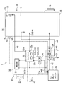
この実施形態1は、プレハブパネル組み立てタイプの貯蔵庫(10)の庫内空間(S)の酸素濃度や二酸化炭素濃度を調節することが可能な貯蔵システム(1)に関する。この貯蔵システム(1)は、図1に示すように、貯蔵庫(10)とCA装置(庫内空気調節装置/Controlled Atmosphere System)(20)とを備えている。CA装置(20)は、ポンプユニット(21)と、電装品ボックス(制御ボックス)(30)とを有する。貯蔵庫(10)の庫内には、例えば、空気中の酸素(O2)を取り込んで二酸化炭素(CO2)を放出する呼吸を行う野菜などの植物が収納される。CA装置(20)は、貯蔵庫(10)の庫内空間(S)を低酸素濃度になるように庫内空気の組成を調節することで、植物の呼吸を抑えて鮮度を維持する。 The first embodiment relates to a storage system (1) capable of adjusting the concentration of oxygen and the concentration of carbon dioxide in a space (S) of a storage (10) of a prefabricated panel assembly type. As shown in FIG. 1, the storage system (1) includes a storage (10) and a CA (Controlled Atmosphere System) (20). The CA device (20) has a pump unit (21) and an electrical component box (control box) (30). In the storage of the storage (10), for example, plants such as vegetables that take in oxygen (O 2 ) in the air and breathe to release carbon dioxide (CO 2 ) are stored. The CA device (20) suppresses plant respiration and maintains freshness by adjusting the composition of air in the storage so that the storage space (S) in the storage (10) has a low oxygen concentration.
貯蔵庫(10)は、上述したようにプレハブパネル組み立てタイプであり、前板(11)、背板(12)、右側板(図示せず)、左側板(図示せず)、底板(13)、天板(14)により組み立てられる。貯蔵庫(10)は、工場等で組み立て済みの貯蔵庫(10)であってもよいし、プレハブパネルを現地で組み立てる方式の貯蔵庫(10)であってもよい。貯蔵庫(10)には、例えば前板(11)に、庫内空間(S)に野菜などを出し入れするための片開きや両開きの扉(図示せず)が設けられる。 The storage (10) is of a prefabricated panel assembly type as described above, and includes a front plate (11), a back plate (12), a right plate (not shown), a left plate (not shown), a bottom plate (13), Assembled by the top plate (14). The storage (10) may be a storage (10) assembled at a factory or the like, or may be a storage (10) in which prefabricated panels are assembled on site. The storage (10) is provided, for example, with a one-sided or double-sided door (not shown) on the front plate (11) for putting vegetables and the like in and out of the space (S).
CA装置(20)は、構成の詳細は省略するが、貯蔵庫(10)の庫内空気の酸素濃度や二酸化炭素濃度を調整する装置である。CA装置(20)のポンプユニット(21)は、図示していないが、エアポンプが接続された空気回路を備えている。空気回路は、複数の空気流路が接続された回路であり、空気中の窒素成分を吸着するための吸着剤や、空気流路における空気の流れ方向を切り換える切り換え弁などの回路構成部材を有する回路である。空気回路は、上記吸着剤の代わりに、空気から酸素や二酸化炭素を分離する分離膜を設けた構成にしてもよい。 Although the details of the configuration are omitted, the CA device (20) is a device for adjusting the oxygen concentration and the carbon dioxide concentration of the air in the storage (10). Although not shown, the pump unit (21) of the CA device (20) includes an air circuit to which an air pump is connected. The air circuit is a circuit to which a plurality of air flow paths are connected, and has circuit components such as an adsorbent for adsorbing nitrogen components in the air and a switching valve for switching a flow direction of air in the air flow path. Circuit. The air circuit may be provided with a separation membrane for separating oxygen and carbon dioxide from air instead of the adsorbent.
ポンプユニット(21)の動作は、上記電装品ボックス(30)の制御部(31)により制御される。制御部(31)は、ポンプユニット(21)を制御して、貯蔵庫(10)の庫内空気の酸素濃度及び二酸化炭素濃度を所望の濃度にする濃度調節運転を実行する。具体的には、制御部(31)は、センサユニット(32)に設けられている濃度センサ(33)の測定結果に基づいて、貯蔵庫(10)の庫内空気の組成(酸素濃度及び二酸化炭素濃度)が所望の組成(例えば、酸素濃度5%、二酸化炭素濃度5%)になるように、CA装置(20)の動作を制御し、生成した気体を貯蔵庫(10)の庫内空間(S)へ供給する。 The operation of the pump unit (21) is controlled by the control unit (31) of the electrical component box (30). The control unit (31) controls the pump unit (21) to execute a concentration adjusting operation for adjusting the oxygen concentration and the carbon dioxide concentration of the air in the storage (10) to desired concentrations. Specifically, the control unit (31) controls the composition of the air in the storage (10) (oxygen concentration and carbon dioxide) based on the measurement result of the concentration sensor (33) provided in the sensor unit (32). The operation of the CA device (20) is controlled so that the concentration (concentration) becomes a desired composition (for example, an oxygen concentration of 5% and a carbon dioxide concentration of 5%), and the generated gas is stored in the storage space (S) of the storage (10). ).
上記制御部(31)は、具体的には、後述する庫内ファン(15)の起動から予め設定した時間が経過して、庫内空気の酸素濃度や二酸化炭素濃度の分布が均一になった後の上記濃度センサ(33)の検出値を用いて、その検出値と目標値とから、庫内空気の組成を調節する制御を行う。 Specifically, the control unit (31) makes the distribution of the oxygen concentration and the carbon dioxide concentration of the air in the refrigerator uniform after a preset time has elapsed since the activation of the later-described refrigerator fan (15). Using the detected value of the concentration sensor (33) described later, control for adjusting the composition of the air in the refrigerator is performed based on the detected value and the target value.
制御部(31)は、CA装置(20)の各要素を制御するマイクロコンピュータと、実施可能な制御プログラムが記憶されたメモリやハードディスク等とを含んでいる。なお、制御部(31)の詳細な構造やアルゴリズムは、CA装置(20)の機能を実行するどのようなハードウェアとソフトウェアとの組み合わせであってもよい。 The control unit (31) includes a microcomputer that controls each element of the CA device (20), a memory or a hard disk in which an executable control program is stored, and the like. The detailed structure and algorithm of the control unit (31) may be any combination of hardware and software that executes the function of the CA device (20).
この貯蔵システム(1)は、庫内空気の成分の濃度を検出する濃度センサ(33)として、庫内空気の酸素濃度を検出する酸素センサ(33a)と、庫内空気の二酸化炭素濃度を検出する二酸化炭素センサ(33b)とを備えている。酸素センサ(33a)と二酸化炭素センサ(33b)は、一つのセンサユニット(32)に収納され、貯蔵庫(10)の庫外に配置される上記電装品ボックス(30)の内部に設置されている。酸素センサ(33a)は、例えばガルバニ電池式センサによって構成される。二酸化炭素センサ(33b)は、例えば非分散型赤外線方式のセンサによって構成される。 This storage system (1) has an oxygen sensor (33a) that detects the oxygen concentration of the air in the refrigerator and a carbon dioxide concentration in the air in the refrigerator as a concentration sensor (33) that detects the concentration of the component of the air in the refrigerator. A carbon dioxide sensor (33b). The oxygen sensor (33a) and the carbon dioxide sensor (33b) are housed in one sensor unit (32) and are installed inside the electrical component box (30) arranged outside the storage (10). . The oxygen sensor (33a) is constituted by, for example, a galvanic cell type sensor. The carbon dioxide sensor (33b) is configured by, for example, a non-dispersive infrared sensor.
電装品ボックス(30)の外面には、例えば、通気性と防水性を有するメンブレンフィルタが収容されたフィルタボックス(22)が設けられている。フィルタボックス(22)は、ポンプユニット(21)に設けられているエアポンプの吸入ポートに、外気供給管(41)を介して接続されている。なお、本実施形態においては、「管」は硬質の部材(パイプ)でなく、柔軟性を有するチューブを表す。 On the outer surface of the electrical component box (30), for example, a filter box (22) containing a membrane filter having air permeability and waterproofness is provided. The filter box (22) is connected to a suction port of an air pump provided in the pump unit (21) via an outside air supply pipe (41). In the present embodiment, the “tube” is not a hard member (pipe) but a flexible tube.
ポンプユニット(21)の第1ガス流出ポート(21a)には、第1ガス供給管(42)を介してエアコントロールバルブ(23)が接続されている。エアコントロールバルブ(23)は、例えば三方弁により構成されている。エアコントロールバルブ(23)には、大気に開放されたガス放出管(43)と、貯蔵庫(10)の庫内空間(S)に連通する給気管(44)とが接続されている。エアコントロールバルブ(23)では、第1ガス供給管(42)から流入した低酸素濃度ガス等の組成調節後の気体が、ガス放出管(43)及び給気管(44)の一方へ、または、ガス放出管(43)及び給気管(44)の両方へ流量の割合が調整されて流出する。 An air control valve (23) is connected to a first gas outlet port (21a) of the pump unit (21) via a first gas supply pipe (42). The air control valve (23) is constituted by, for example, a three-way valve. The air control valve (23) is connected to a gas discharge pipe (43) opened to the atmosphere and an air supply pipe (44) communicating with the internal space (S) of the storage (10). In the air control valve (23), the gas whose composition has been adjusted, such as the low oxygen concentration gas, which has flowed in from the first gas supply pipe (42) is supplied to one of the gas discharge pipe (43) and the air supply pipe (44), or The flow rate is adjusted to flow out to both the gas discharge pipe (43) and the air supply pipe (44).
ポンプユニット(21)の第2ガス流出ポート(21b)には、第2ガス供給管(45)の一端が接続されている。第2ガス供給管(45)の他端は、逆止弁(34)を介して、電装品ボックス(30)内のセンサユニット(32)の流入ポート(32a)に接続されている。逆止弁(34)は、ポンプユニット(21)からセンサユニット(32)へ向かう気体の流れを許容し、逆方向への流れを禁止する。センサユニット(32)は、供給された気体の酸素濃度及び二酸化炭素濃度を測定する。 One end of a second gas supply pipe (45) is connected to the second gas outflow port (21b) of the pump unit (21). The other end of the second gas supply pipe (45) is connected via a check valve (34) to the inflow port (32a) of the sensor unit (32) in the electrical component box (30). The check valve (34) allows the flow of gas from the pump unit (21) to the sensor unit (32) and prohibits the flow in the reverse direction. The sensor unit (32) measures the oxygen concentration and the carbon dioxide concentration of the supplied gas.
センサユニット(32)の流出ポート(32b)には、戻し管(46)(戻し通路)の入口端が接続されている。戻し管(46)は、第2ガス供給管(45)の一部分を構成する。戻し管(46)の出口端(庫内側開口)(46a)は、貯蔵庫(10)の庫内空間(S)に配置されている。センサユニット(32)から流出した気体は、戻し管(46)を流れて貯蔵庫(10)の庫内空間(S)へ供給される。貯蔵庫(10)の庫内空間(S)には、戻し管(46)の出口端の近傍に庫内ファン(15)が設けられている。具体的には、戻し管(46)の出口端が庫内ファン(15)の空気吸い込み側部分(庫内ファン(15)の一次側の空間)に配置されている。 The inlet end of the return pipe (46) (return passage) is connected to the outflow port (32b) of the sensor unit (32). The return pipe (46) forms a part of the second gas supply pipe (45). The outlet end (opening inside the warehouse) (46a) of the return pipe (46) is arranged in the internal space (S) of the storage (10). The gas flowing out of the sensor unit (32) flows through the return pipe (46) and is supplied to the storage space (S) of the storage (10). An internal fan (15) is provided near the outlet end of the return pipe (46) in the internal space (S) of the storage (10). Specifically, the outlet end of the return pipe (46) is arranged in the air suction side portion of the internal fan (15) (the space on the primary side of the internal fan (15)).
第1ガス供給管(45)には、センサユニット(32)と逆止弁(34)の間に、庫内空間(S)からセンサユニット(32)へ庫内空気を導入する導入管(47)(導入通路)の一端(出口端)が接続されている。導入管(47)の他端である入口端(庫内側開口)(47a)は、庫内ファン(15)の空気吹き出し側部分(庫内ファン(15)の二次側の空間)に配置されている。センサユニット(32)へ庫内空気を導入する上記導入管(47)と、センサユニット(32)から庫内空間(S)へ庫内空気を戻す戻し管(46)により、貯蔵庫(10)の庫内空間(S)と上記センサユニット(32)の濃度センサ(33)(酸素センサ(33a)及び二酸化炭素センサ(33b))とに連通する濃度検出用の空気通路(48)が構成されている。 The first gas supply pipe (45) has an inlet pipe (47) between the sensor unit (32) and the check valve (34) for introducing air from the internal space (S) to the sensor unit (32). ) (Introduction passage) is connected to one end (outlet end). The inlet end (opening inside the warehouse) (47a), which is the other end of the introduction pipe (47), is arranged in the air blow-out side portion of the internal fan (15) (the space on the secondary side of the internal fan (15)). ing. The introduction pipe (47) for introducing the internal air to the sensor unit (32) and the return pipe (46) for returning the internal air from the sensor unit (32) to the internal space (S) form the storage chamber (10). An air passage (48) for concentration detection is formed which communicates with the interior space (S) and the concentration sensors (33) (oxygen sensor (33a) and carbon dioxide sensor (33b)) of the sensor unit (32). I have.
電装品ボックス(30)の外面には、換気弁(24)が取り付けられている。換気弁(24)は、一端が貯蔵庫(10)内で開口した換気管(49)の途中に接続され、換気管(49)の他端は大気に開放されている。 A ventilation valve (24) is mounted on the outer surface of the electrical component box (30). One end of the ventilation valve (24) is connected to the middle of a ventilation pipe (49) opened in the storage (10), and the other end of the ventilation pipe (49) is open to the atmosphere.
上記貯蔵庫(10)の扉には、庫内空間(S)の酸素濃度が低いときなどに扉が開かないようにするための錠(50)と、扉の施錠と解錠を行う錠開閉機構(50)とが設けられている。錠開閉機構(50)は、電装品ボックス(30)の制御部(31)に接続され、制御部(31)によって扉の施錠と解錠が行われる。具体的には、上記濃度センサ(33)の検出値が上記庫内空気の成分ごとに予め定められた施錠濃度(例えば、酸素濃度が17%以下、二酸化炭素濃度が3%以上)になると、上記扉が施錠される。一方、上記濃度センサ(33)の検出値が上記庫内空気の成分ごとに予め定められた解錠濃度(例えば、酸素濃度が19%以上、二酸化炭素濃度が1%以下)になると、上記扉が解錠される。 The door of the storage (10) has a lock (50) for preventing the door from opening when the oxygen concentration in the internal space (S) is low, and a lock opening / closing mechanism for locking and unlocking the door. (50) are provided. The lock opening / closing mechanism (50) is connected to the control unit (31) of the electrical component box (30), and the control unit (31) locks and unlocks the door. Specifically, when the detection value of the concentration sensor (33) becomes a predetermined lock concentration (for example, the oxygen concentration is 17% or less and the carbon dioxide concentration is 3% or more) for each component of the inside air, The door is locked. On the other hand, when the detection value of the concentration sensor (33) becomes a predetermined unlocking concentration (for example, the oxygen concentration is 19% or more and the carbon dioxide concentration is 1% or less) for each component of the inside air, the door Is unlocked.
上記貯蔵庫(10)には、貯蔵庫(10)の庫内空間(S)の圧力の異常な上昇を検出するための水柱計(16)が設けられている。 The storage (10) is provided with a water column gauge (16) for detecting an abnormal increase in pressure of the internal space (S) of the storage (10).
−運転動作−
この実施形態1では、CA装置を起動すると、外気がフィルタボックス(22)を通過してポンプユニット(21)に取り込まれる。ポンプユニット(21)では、吸着剤や分離膜により、酸素濃度や二酸化炭素濃度が調節された供給用のガスが生成され、このガスが貯蔵庫(10)の庫内空間(S)へ、第1ガス供給管(42)及び給気管(44)から供給される。起動時等は、ポンプユニット(21)から第2ガス供給管(45)を通じて庫内へガスを供給することも可能である。
-Driving operation-
In the first embodiment, when the CA device is started, outside air passes through the filter box (22) and is taken into the pump unit (21). In the pump unit (21), a gas for supply whose oxygen concentration and carbon dioxide concentration are adjusted is generated by the adsorbent and the separation membrane, and the gas is supplied to the first space (S) of the storage (10). It is supplied from a gas supply pipe (42) and an air supply pipe (44). At the time of starting or the like, it is also possible to supply gas from the pump unit (21) into the storage through the second gas supply pipe (45).
庫内空気の酸素濃度や二酸化炭素濃度は、センサユニット(32)の濃度センサ(33)で検出される。その際、ポンプユニット(21)から第2ガス供給管(45)へのガスの流れを止めるよう、第2ガス流出ポート(21b)が閉鎖される。庫内空気は、導入管(47)からセンサユニット(32)の濃度センサ(33)に供給され、貯蔵庫(10)の庫外で庫内空気の酸素濃度や二酸化炭素濃度が検出される。濃度センサ(33)を通過した庫内空気は、戻し通路(46)を通って貯蔵庫(10)の庫内空間(S)へ戻る。このようにして庫内空気の酸素濃度や二酸化炭素濃度を検出しながらポンプユニット(21)を運転し、庫内空気が所期の組成になるように、制御部(31)によるポンプユニット(21)の制御を継続する。 The oxygen concentration and carbon dioxide concentration of the air in the refrigerator are detected by the concentration sensor (33) of the sensor unit (32). At that time, the second gas outflow port (21b) is closed so as to stop the flow of gas from the pump unit (21) to the second gas supply pipe (45). The inside air is supplied from the introduction pipe (47) to the concentration sensor (33) of the sensor unit (32), and the oxygen concentration and the carbon dioxide concentration of the inside air are detected outside the storage (10). The air in the refrigerator that has passed through the concentration sensor (33) returns to the storage space (S) of the storage (10) through the return passage (46). In this way, the pump unit (21) is operated while detecting the oxygen concentration and the carbon dioxide concentration of the inside air, and the pump unit (21) is controlled by the control unit (31) so that the inside air has a desired composition. ) Is continued.
濃度センサ(33)に異常がなければ上記の動作が行われるが、濃度センサ(33)に異常が発生すると、濃度表示にエラーが生じたり濃度が表示されなくなったりして、庫内空間(S)の酸素濃度や二酸化炭素濃度を作業者等が認識できなくなる場合がある。このような場合、濃度センサ(33)が庫内空間(S)に設けられていると、庫内空間(S)の酸素濃度や二酸化炭素濃度を調べることができなくなる。その結果、作業者が酸素濃度や二酸化炭素濃度を調べずに貯蔵庫の扉を開けたり、庫内空間(S)へ入ってセンサのメンテナンスなどを行ったりするようなおそれがある。しかしながら、本実施形態では、濃度センサ(33)が貯蔵庫(10)の庫外にある電装品ボックス(30)の内部に設置されているので、濃度センサ(33)のメンテナンスを貯蔵庫(10)の庫外で行える。よって、メンテナンス後に濃度センサ(33)が正常に動作し、庫内空間(S)の酸素濃度や二酸化炭素濃度を確認してから、作業者は貯蔵庫(10)の扉を開けばよい。 If there is no abnormality in the density sensor (33), the above operation is performed. However, if an abnormality occurs in the density sensor (33), an error occurs in the density display or the density is not displayed, and the space in the storage (S In some cases, the worker or the like may not be able to recognize the oxygen concentration and the carbon dioxide concentration of the above. In such a case, if the concentration sensor (33) is provided in the storage space (S), the oxygen concentration and the carbon dioxide concentration in the storage space (S) cannot be checked. As a result, there is a risk that the worker may open the door of the storage, check the oxygen concentration or the carbon dioxide concentration, enter the storage space (S), and perform sensor maintenance. However, in this embodiment, since the concentration sensor (33) is installed inside the electrical component box (30) outside the storage (10), maintenance of the concentration sensor (33) is performed in the storage (10). Can be done outside the refrigerator. Therefore, the operator only needs to open the door of the storage (10) after the concentration sensor (33) operates normally after maintenance and confirms the oxygen concentration and the carbon dioxide concentration in the storage space (S).
−実施形態1の効果−
本実施形態では、貯蔵庫(10)と、貯蔵庫(10)の庫内空気の組成を調節する庫内空気調節装置(20)とを備え、庫内空気調節装置(20)が、庫内空気の成分の濃度を検出する濃度センサ(33)を備えた貯蔵システムにおいて、濃度センサ(33)である酸素センサ(33a)及び二酸化炭素センサ(33b)が貯蔵庫(10)の庫外に配置され、貯蔵庫(10)の庫内空間(S)と濃度センサ(33)とに連通する濃度検出用の空気通路(48)が設けられている。
-Effects of Embodiment 1-
In the present embodiment, a storage (10) and an in-compartment air conditioner (20) for adjusting the composition of the in-compartment air of the storage (10) are provided. In a storage system provided with a concentration sensor (33) for detecting the concentration of a component, an oxygen sensor (33a) and a carbon dioxide sensor (33b), which are concentration sensors (33), are arranged outside the storage (10). An air passage (48) for concentration detection is provided which communicates with the internal space (S) of (10) and the concentration sensor (33).
上記構成においては、貯蔵庫(10)の庫内空気が、貯蔵庫(10)の庫外に設置された濃度センサ(33)に供給され、庫内空気の酸素濃度や二酸化炭素濃度が貯蔵庫(10)の庫外で検出されるので、濃度センサ(33)が故障して表示にエラーが生じた場合は、濃度のセンサのメンテナンスを庫外で行える。メンテナンス後は庫内空間(S)の酸素濃度や二酸化炭素濃度を確認できる。したがって、本実施形態によれば、作業者が不用意に貯蔵庫(10)の扉を開けたり庫内空間(S)へ入ったりするような不具合を抑制できる。 In the above configuration, the air in the storage (10) is supplied to the concentration sensor (33) installed outside the storage (10), and the oxygen concentration and the carbon dioxide concentration of the air in the storage are stored in the storage (10). Therefore, when the concentration sensor (33) fails and an error occurs in the display, maintenance of the concentration sensor can be performed outside the container. After maintenance, you can check the oxygen concentration and carbon dioxide concentration in the storage space (S). Therefore, according to the present embodiment, it is possible to suppress a problem that the worker inadvertently opens the door of the storage (10) or enters the storage space (S).
本実施形態では、濃度検出用の空気通路(48)が、庫内空気を濃度センサ(33)に導入する導入通路(47)と、濃度センサ(33)から上記庫内空間(S)へ空気を戻す戻し通路(46)とを有するので、庫内空気が低酸素濃度や高二酸化炭素濃度(例えば、酸素濃度が17%以下、二酸化炭素濃度が3%以上)であるような場合でも、濃度センサ(33)に供給された庫内空気は戻し通路(46)を通って庫内へ戻り、作業者が吸い込むのを抑制できる。 In the present embodiment, the air passage (48) for concentration detection includes an introduction passage (47) for introducing the inside air to the concentration sensor (33), and air from the concentration sensor (33) to the inside space (S). And a return passage (46) for returning the air concentration, even when the inside air has a low oxygen concentration or a high carbon dioxide concentration (for example, an oxygen concentration of 17% or less and a carbon dioxide concentration of 3% or more), The in-compartment air supplied to the sensor (33) returns to the inside of the compartment through the return passage (46), thereby suppressing the inhalation of the worker.
本実施形態では、庫内空間(S)に庫内ファン(15)が設けられ、導入通路(47)の庫内側開口(47a)が庫内ファン(15)の空気吹き出し側部分に配置され、戻し通路(46)の庫内側開口(46a)が庫内ファン(15)の空気吸い込み側部分に配置されているので、庫内空気は、庫内ファン(15)の空気吹き出し側部分から導入通路(47)を通って濃度センサ(33)に供給され、濃度センサ(33)から戻し通路(46)を通って庫内ファン(15)の空気吸い込み側部分に戻る。よって、空気が導入通路(47)及び戻し通路(46)を円滑に流れるから、濃度センサ(33)を貯蔵庫(10)の庫外に設けても検出精度が低下するのを抑制できる。 In the present embodiment, an in-compartment fan (15) is provided in the in-compartment space (S), and an in-compartment opening (47a) of the introduction passageway (47) is arranged at an air blowing side portion of the in-compartment fan (15), Since the inside opening (46a) of the return passage (46) is arranged at the air suction side of the inside fan (15), the inside air is introduced from the air outlet side of the inside fan (15) to the introduction passage. It is supplied to the density sensor (33) through (47) and returns from the density sensor (33) to the air suction side portion of the internal fan (15) through the return passage (46). Therefore, since the air flows smoothly through the introduction passage (47) and the return passage (46), even if the concentration sensor (33) is provided outside the storage (10), it is possible to suppress a decrease in detection accuracy.
本実施形態では、庫内空気調節装置(20)の有する制御部(31)が、庫内ファン(15)の起動から予め設定した時間が経過した後の濃度センサ(33)の検出値を用い、その検出値と目標値とから庫内空気の組成を調節する制御を行う。したがって、本実施形態によれば、庫内空気の組成を調節する制御を、庫内空間(S)の酸素や二酸化炭素の濃度分布が均一になったと判断される状態の検出値に基づいて行うことができる。よって、庫内空気調節装置(20)の動作が安定する。 In the present embodiment, the control unit (31) of the in-compartment air conditioner (20) uses the detection value of the concentration sensor (33) after a preset time has elapsed since the activation of the in-compartment fan (15). , Control for adjusting the composition of the air in the refrigerator based on the detected value and the target value. Therefore, according to the present embodiment, the control for adjusting the composition of the air in the refrigerator is performed based on the detected value of the state in which it is determined that the concentration distribution of oxygen and carbon dioxide in the refrigerator space (S) has become uniform. be able to. Therefore, the operation of the in-compartment air conditioner (20) is stabilized.
本実施形態では、濃度センサ(33)が電装品ボックス(30)の内部に配置されている。ここで、電装品ボックス(30)の内部は、種々の電子部品等が配置されているので、比較的温度が高い。仮に濃度センサ(33)を貯蔵庫(10)の庫内に設置すると、貯蔵庫(10)の内部が低温であると濃度センサ(33)で結露が生じるなどの問題が発生するおそれがあるが、本実施形態では、電装品ボックス(30)内に濃度センサ(33)を設置しているので、結露の問題を抑制できる。 In the present embodiment, the concentration sensor (33) is arranged inside the electrical component box (30). Here, the interior of the electrical component box (30) has a relatively high temperature because various electronic components and the like are arranged therein. If the concentration sensor (33) is installed inside the storage (10), if the temperature inside the storage (10) is low, there is a possibility that the concentration sensor (33) may cause condensation or other problems. In the embodiment, since the density sensor (33) is provided in the electrical component box (30), the problem of dew condensation can be suppressed.
本実施形態では、貯蔵庫(10)が有する扉に錠(50)を装着し、濃度センサ(33)の検出値が庫内空気の成分ごとに予め定められた施錠濃度(例えば、酸素濃度が17%以下、二酸化炭素濃度が3%以上)になると上記扉が施錠され、濃度センサ(33)の検出値が庫内空気の成分ごとに予め定められた解錠濃度(例えば、酸素濃度が19%以上、二酸化炭素濃度が1%以下)になると扉が解錠される錠開閉機構(51)とを設けている。したがって、本実施形態によれば、庫内空間(S)の酸素濃度が低いときや二酸化炭素濃度が高いときに扉が開かないので、作業者が不用意に貯蔵庫(10)の扉を開けたり庫内空間(S)へ入ったりするような不具合を抑制でき、適正濃度の時にだけ扉を開くことが可能になる。 In the present embodiment, a lock (50) is attached to a door of the storage (10), and the detection value of the concentration sensor (33) is determined for each component of the air in the storage by a predetermined lock concentration (for example, when the oxygen concentration is 17%). % Or less, and the carbon dioxide concentration becomes 3% or more), the door is locked, and the detection value of the concentration sensor (33) is determined to be the unlocking concentration (for example, the oxygen concentration of 19% As described above, the lock opening / closing mechanism (51) that unlocks the door when the carbon dioxide concentration becomes 1% or less) is provided. Therefore, according to the present embodiment, the door does not open when the oxygen concentration in the storage space (S) is low or the carbon dioxide concentration is high, so that the worker may inadvertently open the door of the storage (10). Problems such as entering the interior space (S) can be suppressed, and the door can be opened only when the concentration is appropriate.
《実施形態2》
図2及び図3に示す実施形態2について説明する。
<< Embodiment 2 >>
Embodiment 2 shown in FIGS. 2 and 3 will be described.
実施形態2は、実施形態1の貯蔵システム(1)に、さらに、貯蔵庫(10)の庫内空間(S)を冷却する冷凍機(冷却ユニット)(60)を設けた例である。
Embodiment 2 is an example in which the storage system (1) of
冷凍機(60)は、図3に示す冷媒回路(61)を備えている。冷媒回路(61)は、圧縮機(62)と、凝縮器(放熱器)(63)と、膨張弁(64)と、蒸発器(65)とを、冷媒配管によって順に接続することによって構成された閉回路である。 The refrigerator (60) includes a refrigerant circuit (61) shown in FIG. The refrigerant circuit (61) is configured by sequentially connecting a compressor (62), a condenser (radiator) (63), an expansion valve (64), and an evaporator (65) by refrigerant piping. Closed circuit.
凝縮器(63)の近傍には、第1ファンモータ(66a)によって回転駆動され、貯蔵庫(10)の庫外の空気(外気)を凝縮器(63)へ送る凝縮器用ファン(66)が設けられている。凝縮器(63)では、圧縮機(62)で加圧されて凝縮器(63)の内部を流れる冷媒と庫外ファン(66)によって凝縮器(63)に送られた外気との間で熱交換が行われる。 In the vicinity of the condenser (63), there is provided a condenser fan (66) which is driven to rotate by the first fan motor (66a) and sends air (outside air) outside the storage (10) to the condenser (63). Have been. In the condenser (63), heat is generated between the refrigerant pressurized by the compressor (62) and flowing inside the condenser (63) and the outside air sent to the condenser (63) by the external fan (66). An exchange takes place.
蒸発器(65)の近傍には、第2ファンモータ(67a)によって回転駆動され、庫内空気を蒸発器(65)へ吹き出す蒸発器用ファン(67)が設けられている。蒸発器(65)では、膨張弁(64)によって減圧されて蒸発器(65)の内部を流れる冷媒と、蒸発器用ファン(67)によって蒸発器(65)に送られた庫内空気との間で熱交換が行われ、庫内空気が冷却される。 In the vicinity of the evaporator (65), there is provided an evaporator fan (67) that is rotated and driven by the second fan motor (67a) and blows out the internal air to the evaporator (65). In the evaporator (65), the refrigerant is depressurized by the expansion valve (64) and flows through the inside of the evaporator (65), and the inside air sent to the evaporator (65) by the evaporator fan (67). Heat is exchanged in the chamber, and the air in the refrigerator is cooled.
蒸発器(65)及び蒸発器用ファン(67)は、冷凍機(60)のケーシング内に設置して、貯蔵庫(10)の庫内空気をケーシング内に取り込んで冷却してから庫内空間(S)へ戻すようにしてもよい。また、蒸発器(65)及び蒸発器用ファン(67)は、貯蔵庫(10)の庫内空間(S)に設置して、庫内空気を蒸発器(65)に通して循環させながら、庫内空間(S)を冷却するようにしてもよい。 The evaporator (65) and the evaporator fan (67) are installed in the casing of the refrigerator (60), and the air inside the storage (10) is taken into the casing and cooled, and then the internal space (S ) May be returned. In addition, the evaporator (65) and the evaporator fan (67) are installed in the storage space (S) of the storage (10), and while circulating the air in the storage through the evaporator (65), The space (S) may be cooled.
この実施形態2では、給気管(44)は、庫内空間(S)の内部の開口端(44a)が、結露水容器(71)の上方に配置されている。結露水容器(71)の底面には、結露水排出管(72)の一端が接続されている。結露水排出管(72)の他端は、貯蔵庫(10)の庫外に配置されたU字状排水管(73)に接続されている。結露水排出管(72)には、戻し管(46)が庫内空間(S)内をのびる部分が、ドレン水(結露水)を排出するために水抜き管(74)で接続されている。以上のようにして結露水排出部(70)が構成され、庫内空間(S)が低温であるために、庫内空間(S)へ供給される気体から生成される結露水や、高温の電装品ボックス(30)から戻し管(46)を通って戻る気体から生成される結露水が、庫外へ排出される。 In the second embodiment, the open end (44a) of the air supply pipe (44) inside the internal space (S) is disposed above the dew condensation water container (71). One end of a dew condensation water discharge pipe (72) is connected to a bottom surface of the dew condensation water container (71). The other end of the condensed water discharge pipe (72) is connected to a U-shaped drain pipe (73) arranged outside the storage (10). The part where the return pipe (46) extends in the internal space (S) is connected to the condensed water discharge pipe (72) by a drain pipe (74) for discharging drain water (condensed water). . The condensed water discharge section (70) is configured as described above, and since the internal space (S) has a low temperature, the condensed water generated from the gas supplied to the internal space (S) and the high-temperature Condensed water generated from the gas returned from the electrical component box (30) through the return pipe (46) is discharged out of the refrigerator.
その他の構成は実施形態1と同様である。 Other configurations are the same as those of the first embodiment.
本実施形態では、冷凍機(60)を運転することにより、冷媒が冷媒回路(61)を循環する。その際に、冷媒は凝縮器(63)で庫外空気へ放熱し、蒸発器(65)で庫内空気から吸熱するので、庫内空間(S)が冷却される。 In the present embodiment, the refrigerant circulates through the refrigerant circuit (61) by operating the refrigerator (60). At this time, the refrigerant radiates heat to the outside air in the condenser (63) and absorbs heat from the air in the refrigerator in the evaporator (65), so that the internal space (S) is cooled.
CA装置(20)は、実施形態1と同様の動作を行う。具体的には、CA装置(20)により、庫内空気の酸素濃度や二酸化炭素濃度が、所望の濃度(例えば、酸素濃度5%、二酸化炭素濃度5%)を基準とする所定の範囲に保持される。 The CA device (20) performs the same operation as in the first embodiment. Specifically, the oxygen concentration and the carbon dioxide concentration of the air in the refrigerator are kept in predetermined ranges based on desired concentrations (for example, an oxygen concentration of 5% and a carbon dioxide concentration of 5%) by the CA device (20). Is done.
濃度センサ(33)に異常が発生すると、濃度表示にエラーが生じたり濃度が表示されなくなったりして、庫内空間(S)の酸素濃度や二酸化炭素濃度を作業者等が認識できなくなる場合がある。しかしながら、本実施形態では、濃度センサ(33)が貯蔵庫(10)の庫外にある電装品ボックス(30)の内部に設置されているので、濃度センサ(33)のメンテナンスを貯蔵庫(10)の庫外で行える。濃度センサ(33)が正常に動作すると、庫内空間(S)の酸素濃度や二酸化炭素濃度を確認できるので、作業者はその後に扉を開けばよい。 If an error occurs in the concentration sensor (33), an error may occur in the concentration display or the concentration may not be displayed, and the worker may not be able to recognize the oxygen concentration and the carbon dioxide concentration in the internal space (S). is there. However, in this embodiment, since the concentration sensor (33) is installed inside the electrical component box (30) outside the storage (10), maintenance of the concentration sensor (33) is performed in the storage (10). Can be done outside the refrigerator. When the concentration sensor (33) operates normally, the concentration of oxygen and the concentration of carbon dioxide in the internal space (S) can be confirmed, and the operator can then open the door.
−実施形態2の効果−
この実施形態2では、実施形態1の効果に加えて、以下の効果が得られる。
-Effects of Embodiment 2-
In the second embodiment, the following effects are obtained in addition to the effects of the first embodiment.
実施形態2では、貯蔵庫(10)内の給気管(44)の開口端部(44a)の下方に結露水容器(71)を設け、溜まった結露水を結露水排出管(72)で庫外へ排出することができるので、庫内空間(S)の湿度が上昇しすぎるのを抑制できる。また、戻し管(46)に、ドレン水(結露水)を外部へ排出する水抜き管(74)の一端を接続し、水抜き管(74)の他端を結露水排出管(72)に接続しているので、戻し管(46)における「詰まり」も抑制できる。 In the second embodiment, a dew condensation water container (71) is provided below the open end (44a) of the air supply pipe (44) in the storage (10), and the accumulated dew condensation water is discharged from the storage by the dew condensation water discharge pipe (72). Can be suppressed, so that the humidity of the internal space (S) can be prevented from excessively increasing. Also, one end of a drain pipe (74) for discharging drain water (condensed water) to the outside is connected to the return pipe (46), and the other end of the drain pipe (74) is connected to the dew water discharge pipe (72). Since the connection is made, "clogging" in the return pipe (46) can also be suppressed.
特に、この実施形態2は、貯蔵庫(10)に冷凍機(60)を設けて庫内空間(S)を冷却するシステムであり、CA装置(20)から給気管(44)を通って供給される空気や、濃度検出用の空気通路(48)により庫内空間(S)とセンサユニット(32)との間を循環する空気が冷却されて結露が生じやすいのに対して、結露水を無理なく排出できる。また、この実施形態2においても、庫内空気の酸素濃度や二酸化炭素濃度を庫外で検出できるから、濃度センサ(33)における結露の影響を抑制できる。 In particular, the second embodiment is a system in which a refrigerator (60) is provided in the storage (10) to cool the internal space (S), and is supplied from the CA device (20) through the air supply pipe (44). Air and the air circulating between the sensor unit (32) and the internal space (S) are cooled by the air passage (48) for concentration detection, and dew condensation is likely to occur. Can be discharged without waste. Also in the second embodiment, since the oxygen concentration and the carbon dioxide concentration of the air in the refrigerator can be detected outside the refrigerator, the influence of dew condensation on the concentration sensor (33) can be suppressed.
《実施形態3》
図4に示す実施形態3について説明する。
<< Embodiment 3 >>
Embodiment 3 shown in FIG. 4 will be described.
実施形態3は、貯蔵庫(10)の庫内空間(S)からセンサユニット(32)を通る空気の流路を実施形態1とは異なる構成にした例である。
Embodiment 3 is an example in which the flow path of the air passing from the internal space (S) of the storage (10) to the sensor unit (32) is different from that of
実施形態3の空気通路(54)は、庫内空気を上記濃度センサ(33)に導入する導入通路(55)で構成されている。この実施形態3の貯蔵システム(1)は、さらに、濃度センサ(33)から上記庫外空間(O)へ空気を排出する排出通路(56)を有する。ここで、上記「庫外空間」は、貯蔵庫(10)とCA装置(20)の両方に対して庫外となる空間をいう。導入通路(55)は、一端が貯蔵庫(10)の庫内空間(S)に開口し、他端が第2ガス供給管(45)に、センサユニット(32)と逆止弁(34)の間で接続されている。この実施形態3では、実施形態1の導入管(47)は設けられていない。 The air passage (54) of the third embodiment is formed by an introduction passage (55) for introducing air in the refrigerator to the concentration sensor (33). The storage system (1) according to the third embodiment further includes a discharge passage (56) for discharging air from the concentration sensor (33) to the external space (O). Here, the above-mentioned “outside-compartment space” refers to a space outside the outside of both the storage (10) and the CA device (20). One end of the introduction passage (55) opens into the internal space (S) of the storage (10), and the other end connects to the second gas supply pipe (45), and the sensor unit (32) and the check valve (34). Connected between In the third embodiment, the introduction pipe (47) of the first embodiment is not provided.
排出通路(56)は、一端がセンサユニットに接続され、他端が庫外空間(O)に開放されている。排出通路(56)の他端は空気流出側開口であり、この空気流出側開口は、貯蔵庫(10)の庫外に配置された庫外ファン(57)の空気吸い込み側部分に配置されている。 One end of the discharge passage (56) is connected to the sensor unit, and the other end is open to the external space (O). The other end of the discharge passage (56) is an air outflow side opening, and this air outflow side opening is arranged in an air suction side portion of an outside fan (57) arranged outside the storage (10). .
この実施形態3のその他の部分は、実施形態1と同様に構成されている。 Other parts of the third embodiment are configured in the same manner as the first embodiment.
この実施形態3のCA装置(20)は、実施形態1とほぼ同様の動作を行う。具体的には、CA装置(20)のポンプユニット(21)で酸素濃度や二酸化炭素濃度が調節された供給用のガスが生成され、このガスが第2ガス供給管(45)を通って貯蔵庫(10)の庫内空間(S)へ供給される。このことにより、庫内空気の酸素濃度や二酸化炭素濃度が、所望の濃度(例えば、酸素濃度5%、二酸化炭素濃度5%)を基準とする所定の範囲に保持される。 The CA device (20) according to the third embodiment performs substantially the same operation as the first embodiment. Specifically, a supply gas whose oxygen concentration and carbon dioxide concentration are adjusted is generated by the pump unit (21) of the CA device (20), and this gas passes through the second gas supply pipe (45) and is stored in the storage chamber. It is supplied to the storage space (S) of (10). As a result, the oxygen concentration and the carbon dioxide concentration of the air in the refrigerator are maintained in a predetermined range based on a desired concentration (for example, an oxygen concentration of 5% and a carbon dioxide concentration of 5%).
庫内空気の酸素濃度や二酸化炭素濃度は、庫外ファン(57)が回転して、庫内空気が導入通路(55)、センサユニット(32)、及び排出通路(56)を通って流れる際に、センサユニット(32)の内部の濃度センサ(33)で検出される。 The oxygen concentration and carbon dioxide concentration of the air in the refrigerator are measured when the fan outside the refrigerator (57) rotates and the air in the refrigerator flows through the introduction passage (55), the sensor unit (32), and the discharge passage (56). Then, it is detected by the density sensor (33) inside the sensor unit (32).
濃度センサ(33)に異常が発生すると、濃度表示にエラーが生じたり濃度が表示されなくなったりして、庫内空間(S)の酸素濃度や二酸化炭素濃度を作業者等が認識できなくなる場合がある。しかしながら、この実施形態3においても、濃度センサ(33)が貯蔵庫(10)の庫外空間(O)にある電装品ボックス(30)の内部に設置されているので、濃度センサ(33)のメンテナンスを貯蔵庫(10)の庫外で行える。メンテナンスにより濃度センサ(33)が正常に動作すると、庫内空間(S)の酸素濃度や二酸化炭素濃度を確認できるので、作業者はその後に扉を開けばよい。 If an error occurs in the concentration sensor (33), an error may occur in the concentration display or the concentration may not be displayed, and the worker may not be able to recognize the oxygen concentration and the carbon dioxide concentration in the internal space (S). is there. However, also in the third embodiment, since the density sensor (33) is installed inside the electrical component box (30) in the space (O) outside the storage (10), maintenance of the density sensor (33) is performed. Can be performed outside the storage (10). When the concentration sensor (33) operates normally due to the maintenance, the oxygen concentration and the carbon dioxide concentration in the internal space (S) can be checked, and the operator can then open the door.
この実施形態3においては、貯蔵システム(1)が、庫内空気を庫外の濃度センサ(33)に導入する導入通路(55)と、濃度センサ(33)から庫外空間(O)へ空気を排出する排出通路(56)とを有する。よって、濃度センサ(33)のメンテナンスを庫外で行えるとともに、濃度センサ(33)を貯蔵庫(10)の庫外に設けても検出精度が低下するのを抑制できるなど、実施形態1と同様の効果を奏する。 In the third embodiment, the storage system (1) includes an introduction passage (55) that introduces air inside the refrigerator to the concentration sensor (33) outside the refrigerator, and air from the concentration sensor (33) to the space outside the refrigerator (O). And a discharge passage (56) for discharging air. Accordingly, the maintenance of the concentration sensor (33) can be performed outside the storage, and the detection accuracy can be prevented from lowering even if the concentration sensor (33) is provided outside the storage (10). It works.
−実施形態3の変形例−
〈変形例1〉
図5に示す実施形態3の変形例1は、導入通路(55)と排出通路(56)を、図4の実施形態3と異なる構成にした例である。
-Modification of Embodiment 3-
<
Modification Example 1 of Embodiment 3 shown in FIG. 5 is an example in which the introduction passage (55) and the discharge passage (56) are configured differently from Embodiment 3 in FIG.
この変形例1では、センサユニット(32)のケーシングの内部にセンサ用ファン(58)が設けられる。導入通路(55)は、一端が貯蔵庫(10)の庫内空間(S)に開口し、他端(空気流出側開口)がセンサユニット(32)内に設けられているセンサ用ファン(58)の近傍の空気吸い込み側部分に配置されている。排出用通路(56)は、一端がセンサユニット(32)のケーシングに接続され、他端が庫外空間(O)、言い換えると貯蔵庫(10)とCA装置(20)の両方に対して庫外となる空間に開放されている。 In the first modification, a sensor fan (58) is provided inside the casing of the sensor unit (32). One end of the introduction passage (55) opens into the internal space (S) of the storage (10), and the other end (air outlet side opening) has a sensor fan (58) provided in the sensor unit (32). Is arranged in the air suction side portion near the air inlet. One end of the discharge passage (56) is connected to the casing of the sensor unit (32), and the other end is external to the external space (O), in other words, to both the storage (10) and the CA device (20). It is open to the space that becomes.
その他の構成は図4の実施形態3と同様である。 Other configurations are the same as those of the third embodiment shown in FIG.
この変形例1において、センサ用ファン(58)を回転させると、庫内空気がセンサユニット(32)の内部に吸い込まれ、酸素濃度と二酸化炭素濃度が検出される。その後、空気は排出通路(58)を通って庫外空間(O)へ排出される。 In the first modification, when the sensor fan (58) is rotated, air in the refrigerator is sucked into the sensor unit (32), and the oxygen concentration and the carbon dioxide concentration are detected. Then, the air is discharged to the outside space (O) through the discharge passage (58).
この変形例1のように構成しても、図4の実施形態3と同様の効果を奏する。 The same effects as those of the third embodiment shown in FIG.
〈変形例2〉
図6に示す実施形態3の変形例2は、導入通路(55)と排出通路(56)を含む空気の流路を、図5の変形例1と異なる構成にした例である。
<Modification 2>
Modification 2 of Embodiment 3 shown in FIG. 6 is an example in which the flow path of the air including the introduction passage (55) and the discharge passage (56) has a configuration different from that of
この変形例2では、貯蔵庫(10)の庫内空間(S)は、ポンプユニット(21)から空気を送り込むことで陽圧になるように制御され、庫外空間(O)よりも圧力が高い。そのため、庫内空間(S)と、庫外空間(O)及びそれに連通するセンサユニット(32)内の空間との間には圧力差が存在する。一方、図5のセンサ用ファン(58)は設けられていない。導入通路(55)の空気流出側開口は、濃度センサ(33)の近傍に配置されている。 In this modified example 2, the internal space (S) of the storage (10) is controlled to be at a positive pressure by sending air from the pump unit (21), and the pressure is higher than the external space (O). . Therefore, there is a pressure difference between the internal space (S) and the external space (O) and the space in the sensor unit (32) communicating therewith. On the other hand, the sensor fan (58) of FIG. 5 is not provided. The air outlet side opening of the introduction passage (55) is arranged near the concentration sensor (33).
排出通路(56)を含むその他の構成は、図5の変形例1と同様である。 Other configurations including the discharge passage (56) are the same as those of the first modification of FIG.
この変形例2では、庫内空間(S)の圧力が庫外空間(O)よりも高いため、庫内空気は、導入通路(55)を通ってセンサユニット(32)へ押し出され、その後に庫外空間(O)へ排出される。その際に、庫内空気は、センサユニット(32)において、酸素濃度と二酸化炭素濃度が検出される。 In the second modification, since the pressure in the internal space (S) is higher than the external space (O), the internal air is pushed out to the sensor unit (32) through the introduction passage (55), and thereafter, It is discharged to the outside space (O). At this time, the sensor unit (32) detects the oxygen concentration and the carbon dioxide concentration of the air in the refrigerator.
この変形例2のように構成すると、センサ用ファン(58)を用いずに庫内空間(S)と庫外空間(O)の圧力差を利用することにより、図4の実施形態3及び図5の変形例1と同様の効果を奏する。 When configured as in Modification Example 2, the pressure difference between the internal space (S) and the external space (O) is utilized without using the sensor fan (58), and thus the third embodiment and FIG. The same effect as that of the first modification of the fifth embodiment is obtained.
〈変形例3〉
図7に示す実施形態3の変形例3は、導入通路(55)と排出通路(56)を、図4の実施形態3と異なる構成にした例である。
<Modification 3>
A third modification of the third embodiment shown in FIG. 7 is an example in which the introduction passage (55) and the discharge passage (56) are configured differently from the third embodiment in FIG.
この変形例3では、導入通路(55)の一端は、貯蔵庫(10)の庫内空間(S)に開放されている。導入通路(55)の他端は、電装品ボックス(30)の内部に配置され且つ濃度センサ(33)を有するセンサユニット(32)に接続されている。導入通路(55)は、電装品ボックス(30)内の換気に用いるように電装品ボックス(30)に装着された換気弁(24)を通過する通路であり、換気弁(24)を開くと空気が流通する。排出通路(56)は、一端がセンサユニット(32)のケーシングに接続され、他端が庫外空間(O)に開放されている。この変形例3においても、貯蔵庫(10)の庫内空間(S)は陽圧になるように制御される。そのため、庫内空間(S)の圧力は庫外空間(O)及びそれに連通するセンサユニット(32)内の空間の圧力よりも高い。 In the third modification, one end of the introduction passage (55) is open to the storage space (S) of the storage (10). The other end of the introduction passage (55) is arranged inside the electrical component box (30) and is connected to a sensor unit (32) having a concentration sensor (33). The introduction passage (55) is a passage that passes through the ventilation valve (24) attached to the electrical component box (30) so as to use for ventilation in the electrical component box (30). Air circulates. One end of the discharge passage (56) is connected to the casing of the sensor unit (32), and the other end is open to the outside-compartment space (O). Also in the third modification, the internal space (S) of the storage (10) is controlled to have a positive pressure. Therefore, the pressure in the internal space (S) is higher than the pressure in the external space (O) and the space in the sensor unit (32) communicating therewith.
この変形例3では、庫内空間(S)の圧力が、濃度センサ(33)が配置されているセンサユニット(32)内の空間よりも高い。そのため、庫内空気は、換気弁(24)を開くと、導入通路(55)を通ってセンサユニット(32)の内部の空間へ押し出される。そして、庫内空気の酸素濃度と二酸化炭素濃度がセンサユニット(32)で検出される。センサユニット(32)の中の空気は、その後、庫外へ排出される。 In the third modification, the pressure in the internal space (S) is higher than the pressure in the sensor unit (32) in which the concentration sensor (33) is arranged. Therefore, when the ventilation valve (24) is opened, the air in the refrigerator is pushed out to the space inside the sensor unit (32) through the introduction passage (55). Then, the oxygen concentration and the carbon dioxide concentration of the air in the refrigerator are detected by the sensor unit (32). The air in the sensor unit (32) is then discharged out of the refrigerator.
この変形例3においても、庫内空間(S)と庫外空間(O)の圧力差を利用して図6の変形例2と同様の効果を奏する。 Also in Modification 3, the same effect as Modification 2 in FIG. 6 can be obtained by utilizing the pressure difference between the internal space (S) and the external space (O).
〈変形例4〉
実施形態3及びその変形例1〜3の空気通路(54)は、実施形態1の空気通路(48)の構成を変更したものであるが、実施形態2の空気通路(48)を実施形態3及びその変形例1〜3の空気通路(54)に置き換えてもよい。
<Modification 4>
The air passages (54) of the third embodiment and the modified examples 1 to 3 are modifications of the air passages (48) of the first embodiment. And the air passages (54) of the first to third modifications.
《その他の実施形態》
上記実施形態については、以下のような構成としてもよい。
<< Other embodiments >>
The above embodiment may have the following configuration.
上記実施形態では、プレハブパネルで構成される定置型の貯蔵庫(10)に適用した貯蔵システムを説明したが、貯蔵庫の形式は上記実施形態に限定されるものではなく、この貯蔵システムは、例えば、陸上輸送や海上輸送に用いられるコンテナ(移動型の貯蔵庫)に適用してもよい。 In the above embodiment, the storage system applied to the stationary storage (10) constituted by the prefabricated panels has been described. However, the type of the storage is not limited to the above embodiment. The invention may be applied to a container (mobile storage) used for land transportation or sea transportation.
上記実施形態では、濃度センサ(33)として、庫内空気の酸素濃度を検出する酸素センサ(33a)及び上記庫内空気の二酸化炭素濃度を検出する二酸化炭素センサ(33b)の両方を用いているが、何れか一方を用いてもよい。また、貯蔵庫(10)で貯蔵する対象物等に応じ、酸素センサ(33a)や二酸化炭素センサ(33b)以外の濃度センサ(33)を用いてもよい。 In the above embodiment, as the concentration sensor (33), both the oxygen sensor (33a) for detecting the oxygen concentration of the inside air and the carbon dioxide sensor (33b) for detecting the carbon dioxide concentration of the inside air are used. However, either one may be used. Further, a concentration sensor (33) other than the oxygen sensor (33a) and the carbon dioxide sensor (33b) may be used according to an object to be stored in the storage (10).
上記濃度センサ(33)は、必ずしも電装品ボックス(30)の内部に設けなくてもよく、貯蔵庫(10)の庫外に設置すればよい。また、実施形態2では、濃度センサ(33)を電装品ボックス(30)に設置する場合に、電装品ボックス(30)が冷凍機(60)の電装品を収容したものであってもよい。 The concentration sensor (33) does not necessarily need to be provided inside the electrical component box (30), and may be provided outside the storage (10). In the second embodiment, when the concentration sensor (33) is installed in the electrical component box (30), the electrical component box (30) may contain the electrical components of the refrigerator (60).
上記実施形態では、センサユニット(32)からの戻し通路(46)を貯蔵庫(10)の庫内空間(S)に連通させることで濃度検出後の気体を庫内空間(S)に戻すようにしているが、庫内空間(S)に戻した気体を、庫内空間(S)が陽圧になるように制御することで庫外へ放出するようにしてもよい。 In the above embodiment, the return passage (46) from the sensor unit (32) is communicated with the internal space (S) of the storage (10) to return the gas after the concentration detection to the internal space (S). However, the gas returned to the internal space (S) may be released to the outside by controlling the internal space (S) to have a positive pressure.
上記実施形態1において、導入管(47)の庫内側開口(47a)が庫内ファン(15)の空気吹き出し側部分に配置され、戻し管(46)の庫内側開口(46a)が庫内ファン(15)の空気吸い込み側部分に配置されるようにしているが、それらの配置は変更してもよい。 In the first embodiment, the inside opening (47a) of the introduction pipe (47) is arranged on the air blowing side portion of the inside fan (15), and the inside opening (46a) of the return pipe (46) is connected to the inside fan. Although they are arranged on the air suction side of (15), their arrangement may be changed.
例えば実施形態2において、結露水を外部へ排出する水抜き管(74)は、結露水排出管(72)に接続せずに、結露水が庫外へ直接排出されるように構成してもよい。 For example, in the second embodiment, the drainage pipe (74) for discharging the dew condensation water to the outside may be configured such that the dew condensation water is directly discharged to the outside of the refrigerator without being connected to the dew condensation water discharge pipe (72). Good.
上記制御部(31)は、庫内ファン(15)の起動から予め設定した時間が経過して濃度分布が安定した後の濃度センサ(33)の検出値を用い、その検出値と目標値とから庫内空気の組成を調節する制御を行うようにしているが、制御は適宜変更してもよい。 The control unit (31) uses the detection value of the concentration sensor (33) after the preset time has elapsed from the activation of the internal fan (15) and the concentration distribution has stabilized, and determines the detected value and the target value. Although the control for adjusting the composition of the air in the refrigerator is performed, the control may be appropriately changed.
上記実施形態において、濃度センサ(33)を電装品ボックス(30)の内部に配置しているが、配置を変更してもよい。 In the above embodiment, the concentration sensor (33) is arranged inside the electrical component box (30), but the arrangement may be changed.
上記実施形態において、濃度センサ(33)の検出値が庫内空気の成分に対して予め定められた施錠濃度になると扉を施錠し、検出値が庫内空気の成分に対して予め定められた解錠濃度になると扉を解錠する錠開閉機構(50)を設けているが、庫内の酸素濃度が扉を施錠する濃度になっていることや、扉を解錠できる濃度になっていることを、濃度表示装置や警告装置を用いて作業者に知らせるようにし、錠開閉機構(50)を設けないようにすることも可能である。 In the above embodiment, the door is locked when the detection value of the concentration sensor (33) reaches a predetermined locking concentration for the component of the internal air, and the detection value is predetermined for the component of the internal air. A lock opening / closing mechanism (50) is provided to unlock the door when the unlocking concentration is reached, but the oxygen concentration in the refrigerator is such that the door is locked or the door is unlocked. This can be notified to the operator using a concentration display device or a warning device, and the lock opening / closing mechanism (50) can be omitted.
以上、実施形態および変形例を説明したが、特許請求の範囲の趣旨および範囲から逸脱することなく、形態や詳細の多様な変更が可能である。また、以上の実施形態および変形例は、本開示の対象の機能を損なわない限り、適宜組み合わせたり、置換したりしてもよい。 Although the embodiments and the modified examples have been described above, various changes in form and details can be made without departing from the spirit and scope of the claims. In addition, the above embodiments and modified examples may be appropriately combined or replaced as long as the function of the present disclosure is not impaired.
以上説明したように、本開示は、貯蔵システムについて有用である。 As described above, the present disclosure is useful for a storage system.
1 貯蔵システム
10 貯蔵庫
15 庫内ファン
20 庫内空気調節装置
30 電装品ボックス
31 制御部
33 濃度センサ
33a 酸素センサ
33b 二酸化炭素センサ
34 換気弁
46 戻し管(戻し通路)
46a 出口端(庫内側開口)
47 導入管(導入通路)
47a 入口端(庫内側開口)
48 空気通路
50 錠
51 錠開閉機構
54 空気通路
55 導入通路
55a 空気流出側開口
56 排出通路
56a 空気流出側開口
57 庫外ファン
58 センサ用ファン
60 冷凍機
74 水抜き管
O 庫外空間
S 庫内空間
1 Storage system
10 Storage
15 Inside fan
20 Internal air conditioner
30 Electrical component box
31 Control unit
33 Concentration sensor
33a oxygen sensor
33b carbon dioxide sensor
34 Ventilation valve
46 Return pipe (return passage)
46a Exit end (opening inside the warehouse)
47 Introductory pipe (introductory passage)
47a Entrance end (opening inside the warehouse)
48 air passage
50 tablets
51 Lock opening and closing mechanism
54 Air passage
55 Introductory passage
55a Air outlet side opening
56 Discharge passage
56a Air outlet side opening
57 Outside fan
58 Sensor fan
60 refrigerator
74 Drain pipe
O External space
S Interior space
本開示は、貯蔵システムに関するものである。 The present disclosure relates to storage systems.
従来の貯蔵システムとして、貯蔵庫の庫内空間の酸素濃度や二酸化炭素濃度を調整するCA装置が貯蔵庫に設けられたものがある(例えば、特許文献1参照)。CA装置は、一般に、酸素センサや二酸化炭素センサの検出値を用いて庫内空間の空気の組成を調節する制御を行う。酸素センサや二酸化炭素センサは、貯蔵庫の庫内空間に設置される。 2. Description of the Related Art As a conventional storage system, there is a storage system in which a CA device that adjusts an oxygen concentration and a carbon dioxide concentration in an internal space of the storage is provided in the storage (for example, see Patent Document 1). The CA device generally performs control for adjusting the composition of air in the internal space using the detection values of the oxygen sensor and the carbon dioxide sensor. The oxygen sensor and the carbon dioxide sensor are installed in the storage space of the storage.
例えば貯蔵庫の庫内空間を低酸素濃度に維持する制御をしている場合、作業者が庫内へ入る際には、低酸素濃度に維持する運転を終了し、庫内空間の酸素濃度が大気相当の酸素濃度になったことを予め確認する必要がある。 For example, when control is performed to maintain the interior space of the storage at a low oxygen concentration, when the worker enters the interior, the operation of maintaining the low oxygen concentration is terminated, and the oxygen concentration of the interior space is reduced to the atmospheric level. It is necessary to confirm in advance that the oxygen concentration has reached a considerable level.
しかしながら、酸素センサが庫内空間に設置されていると、酸素センサの故障により表示にエラーが生じると、庫内空間の酸素濃度を調べることができなくなる。この場合、酸素濃度を調べずに貯蔵庫の扉を開けたり、酸素濃度を調べずに作業者が庫内空間へ入ってセンサのメンテナンスなどを行ったりするような不具合が生じるおそれがある。 However, if the oxygen sensor is installed in the storage space and an error occurs in the display due to the failure of the oxygen sensor, the oxygen concentration in the storage space cannot be checked. In this case, there is a possibility that a problem may occur such that the door of the storage is opened without checking the oxygen concentration, or an operator enters the space inside the storage and performs maintenance of the sensor without checking the oxygen concentration.
本開示の目的は、貯蔵庫の庫内空間の空気の組成をCA装置で調整する構成において、酸素センサや二酸化炭素センサが故障した場合の不具合を解消することである。 An object of the present disclosure is to solve a problem in a case where an oxygen sensor or a carbon dioxide sensor fails in a configuration in which the composition of air in the internal space of a storage is adjusted by a CA device.
本開示の第1の態様は、貯蔵庫(10)と、貯蔵庫(10)の庫内空気の組成を調節する庫内空気調節装置(20)とを備え、庫内空気調節装置(20)が、庫内空気の成分の濃度を検出する濃度センサ(33)を備えた貯蔵システムを前提とする。 A first aspect of the present disclosure includes a storage (10), and an air conditioning device (20) for adjusting the composition of air in the storage (10), wherein the air conditioning device (20) includes: It is assumed that the storage system includes a concentration sensor (33) for detecting the concentration of the component of the air in the refrigerator.
第1の態様の貯蔵システムは、
上記濃度センサ(33)が上記貯蔵庫(10)の庫外に配置され、上記貯蔵庫(10)の庫内空間(S)と上記濃度センサ(33)とに連通する空気通路(48,54)を備えていることを特徴とする。
また、第1の態様の貯蔵システムは、上記空気通路(48)が、上記庫内空気を上記濃度センサ(33)に導入する導入通路(47)と、上記濃度センサ(33)から上記庫内空間(S)へ空気を戻す戻し通路(46)と、を有する。
The storage system according to the first aspect includes:
The concentration sensor (33) is disposed outside the storage (10), and an air passage (48, 54) communicating with the internal space (S) of the storage (10) and the concentration sensor (33). It is characterized by having.
Further, in the storage system according to the first aspect, the air passage (48) may be configured such that the air passage (48) introduces the inside air into the concentration sensor (33) and the concentration sensor (33). A return passage (46) for returning air to the space (S).
この態様では、庫内空気が低酸素濃度や高二酸化炭素濃度であるような場合でも、濃度センサ(33)に供給された庫内空気は戻し通路(46)を通って庫内へ戻り、作業者が吸い込むのを抑制できる。In this embodiment, even when the inside air has a low oxygen concentration or a high carbon dioxide concentration, the inside air supplied to the concentration sensor (33) returns through the return passage (46) to the inside of the inside, and It can suppress that the person inhales.
本開示の第2の態様は、第1の態様において、さらに、上記濃度センサ(33)に、空気中の酸素濃度及び二酸化炭素濃度を調整する空気回路を有するポンプユニット(21)が第2ガス供給管(45)で接続されていることを特徴とする。 According to a second aspect of the present disclosure, in the first aspect, the concentration sensor (33) further includes a pump unit (21) having an air circuit for adjusting an oxygen concentration and a carbon dioxide concentration in air. It is characterized by being connected by a supply pipe (45) .
本開示の第3の態様は、第1または第2の態様において、上記濃度センサ(33)が、上記庫内空気の酸素濃度を検出する酸素センサ(33a)及び上記庫内空気の二酸化炭素濃度を検出する二酸化炭素センサ(33b)の一方または両方を含むことを特徴とする。 According to a third aspect of the present disclosure, in the first or second aspect, the concentration sensor (33) detects an oxygen concentration of the in-compartment air and an oxygen sensor (33a) and the carbon dioxide concentration of the in-compartment air. Characterized in that it includes one or both of a carbon dioxide sensor (33b) for detecting
第1〜第3の態様では、貯蔵庫(10)の庫内空気が、貯蔵庫(10)の庫外に設置された濃度センサ(33)に供給される。庫内空気の酸素濃度や二酸化炭素濃度が貯蔵庫(10)の庫外で検出されるので、濃度センサ(33)が故障して表示にエラーが生じた場合は、濃度のセンサのメンテナンスを庫外で行える。メンテナンス後は庫内空間(S)の酸素濃度や二酸化炭素濃度を確認できる。よって、作業者が不用意に貯蔵庫(10)の扉を開けたり庫内空間(S)へ入ったりするような不具合を抑制できる。 In the first to third aspects, the air in the storage (10) is supplied to the concentration sensor (33) installed outside the storage (10). Since the oxygen concentration and carbon dioxide concentration of the air inside the storage are detected outside the storage (10), if the concentration sensor (33) fails and an error occurs in the display, maintenance of the concentration sensor is performed outside the storage. Can be done with After maintenance, you can check the oxygen concentration and carbon dioxide concentration in the storage space (S). Therefore, it is possible to suppress a problem that the worker inadvertently opens the door of the storage (10) or enters the storage space (S).
本開示の第4の態様は、第1から第3の態様の何れか1つにおいて、上記戻し通路(46)に、ドレン水を外部へ排出する水抜き管(74)が接続されていることを特徴とする。 According to a fourth aspect of the present disclosure, in any one of the first to third aspects , a drain pipe (74) for discharging drain water to the outside is connected to the return passage (46). It is characterized by.
第4の態様では、戻し通路(46)内でドレン水が生成された場合に、ドレン水を戻し通路(46)から排出でき、戻し通路(46)における「詰まり」を抑制できる。 In the fourth aspect, when drain water is generated in the return passage (46), the drain water can be discharged from the return passage (46), and "clogging" in the return passage (46) can be suppressed.
本開示の第5の態様は、第1から第4の態様の何れか1つにおいて、上記庫内空間(S)に庫内ファン(15)が設けられ、上記導入通路(47)の庫内側開口(47a)は上記庫内ファン(15)の空気吹き出し側部分に配置され、上記戻し通路(46)の庫内側開口(46a)は上記庫内ファン(15)の空気吸い込み側部分に配置されていることを特徴とする。 According to a fifth aspect of the present disclosure, in any one of the first to fourth aspects, an in-compartment fan (15) is provided in the in-compartment space (S), and an inside of the introduction passage (47) is provided. The opening (47a) is arranged at the air outlet side of the internal fan (15), and the internal opening (46a) of the return passage (46) is arranged at the air suction side of the internal fan (15). It is characterized by having.
第5の態様では、庫内空気は、庫内ファン(15)の空気吹き出し側部分から導入通路(47)を通って濃度センサ(33)に供給され、濃度センサ(33)から戻し通路(46)を通って庫内ファン(15)の空気吸い込み側部分に戻るので、空気が導入通路(47)及び戻し通路(46)を円滑に流れる。 In the fifth mode, the inside air is supplied to the concentration sensor (33) from the air outlet side of the inside fan (15) through the introduction passage (47), and is returned from the concentration sensor (33) to the return passage (46). ), Returns to the air suction side portion of the internal fan (15), so that air flows smoothly through the introduction passage (47) and the return passage (46).
本開示の第6の態様は、第5の態様において、上記庫内空気調節装置(20)が、上記庫内空気の組成を調節する制御を行う制御部(31)を備え、上記制御部(31)は、上記庫内ファン(15)の起動から予め設定した時間が経過した後の上記濃度センサ(33)の検出値を用い、その検出値と目標値とから庫内空気の組成を調節する制御を行うことを特徴とする。 According to a sixth aspect of the present disclosure, in the fifth aspect, the in-compartment air conditioner (20) includes a control unit (31) configured to perform control for adjusting a composition of the in-compartment air, and 31) Using the detected value of the concentration sensor (33) after a preset time has elapsed from the activation of the in-compartment fan (15), adjusting the composition of the in-compartment air from the detected value and the target value. Is performed.
第6の態様では、庫内ファン(15)の起動から予め設定した時間が経過した後の濃度センサ(33)の検出値を用いて庫内空気の組成が調節されるので、その制御を、庫内空間(S)の酸素や二酸化炭素の濃度分布が均一になったと判断される状態の検出値に基づいて行うことができ、庫内空気調節装置(20)の動作が安定する。 In the sixth aspect, the composition of the air in the refrigerator is adjusted using the detection value of the concentration sensor (33) after a preset time has elapsed from the activation of the fan in the refrigerator (15). This can be performed based on the detected value of the state where it is determined that the concentration distribution of oxygen and carbon dioxide in the interior space (S) has become uniform, and the operation of the interior air conditioner (20) is stabilized.
本開示の第7の態様は、第1から第3の態様の何れか1つにおいて、上記空気通路(54)は、上記庫内空気を上記濃度センサ(33)に導入する導入通路(55)を有し、貯蔵システムが、さらに、上記濃度センサ(33)から庫外空間(O)へ空気を排出する排出通路(56)を備えていることを特徴とする。 A seventh aspect of the present disclosure is the air conditioner according to any one of the first to third aspects, wherein the air passage (54) is configured to introduce the inside air into the concentration sensor (33). And the storage system further includes a discharge passage (56) for discharging air from the concentration sensor (33) to the external space (O).
第7の態様では、庫内空気が導入通路(47)を通って濃度センサ(33)に供給され、酸素濃度や二酸化炭素濃度が検出される。空気は、その後、排出通路(46)を通って庫外へ排出される。例えば、庫内空間(S)の圧力を庫外空間(O)より高くすると、庫内空気は庫外空間(O)へ押し出される。 In the seventh aspect, the inside air is supplied to the concentration sensor (33) through the introduction passage (47), and the oxygen concentration and the carbon dioxide concentration are detected. The air is then discharged out of the refrigerator through the discharge passage (46). For example, if the pressure in the internal space (S) is higher than the external space (O), the internal air is pushed out to the external space (O).
本開示の第8の態様は、第7の態様において、上記貯蔵庫(10)の庫外に配置された庫外ファン(57)を備え、上記排出通路(56)の空気流出側開口(56a)が上記庫外ファン(57)の空気吸い込み側部分に配置されていることを特徴とする。 According to an eighth aspect of the present disclosure, in the seventh aspect, an external fan (57) arranged outside the storage (10) is provided, and the air outlet side opening (56a) of the discharge passage (56) is provided. Are arranged on the air suction side portion of the outside fan (57).
第8の態様では、庫外ファン(57)を回転させることによって、庫内空気が庫内空間(S)から庫外空間(O)へ流れ、その間に酸素濃度や二酸化炭素濃度が検出される。 In the eighth aspect, by rotating the outside fan (57), the inside air flows from the inside space (S) to the outside space (O), during which the oxygen concentration and the carbon dioxide concentration are detected. .
本開示の第9の態様は、第7の態様において、上記濃度センサ(33)の近傍に該濃度センサ(33)へ送風するセンサ用ファン(58)が配置され、上記導入通路(55)の空気流出側開口(55a)が上記センサ用ファン(58)の空気吸い込み側部分に配置されていることを特徴とする。 According to a ninth aspect of the present disclosure, in the seventh aspect, a sensor fan (58) for blowing air to the density sensor (33) is arranged near the density sensor (33), and The air outlet side opening (55a) is arranged on the air suction side portion of the sensor fan (58).
第9の態様では、センサ用ファン(58)を回転させることによって、庫内空気が庫内空間(S)から濃度センサ(33)の近傍を通って庫外空間(O)へ流れ、その間に酸素濃度や二酸化炭素濃度が検出される。 In the ninth embodiment, by rotating the sensor fan (58), the air in the refrigerator flows from the internal space (S) to the external space (O) through the vicinity of the concentration sensor (33). Oxygen concentration and carbon dioxide concentration are detected.
本開示の第10の態様は、第7の態様において、電装品ボックス(30)と、該電装品ボックス(30)内の換気に用いられる換気弁(24)とを備え、上記濃度センサ(33)が上記電装品ボックス(30)の内部に配置され、上記導入通路(55)が上記換気弁(24)を通過する通路であることを特徴とする。 According to a tenth aspect of the present disclosure, in the seventh aspect, there is provided the electrical component box (30), and a ventilation valve (24) used for ventilation in the electrical component box (30), and the concentration sensor (33) is provided. ) Is disposed inside the electrical component box (30), and the introduction passage (55) is a passage that passes through the ventilation valve (24).
第10の態様では、庫内空間(S)と庫外空間(O)の差圧により、庫内空気が庫内空間(S)から濃度センサ(33)の近傍を通って庫外空間(O)へ流れ、その間に酸素濃度や二酸化炭素濃度が検出される。 In the tenth aspect, due to the pressure difference between the internal space (S) and the external space (O), the internal air passes from the internal space (S) through the vicinity of the concentration sensor (33) and the external space (O). ), During which oxygen and carbon dioxide concentrations are detected.
本開示の第11の態様は、第1から第9の態様の何れか1つにおいて、電装品ボックス(30)を備え、上記濃度センサ(33)が上記電装品ボックス(30)の内部に配置されていることを特徴とする。 According to an eleventh aspect of the present disclosure, in any one of the first to ninth aspects, an electric component box (30) is provided, and the concentration sensor (33) is disposed inside the electric component box (30). It is characterized by having been done.
第11の態様では、電装品ボックス(30)の内部には種々の電子部品等が配置されていて比較的温度が高い。濃度センサ(33)を貯蔵庫(10)の庫内に設置する場合、貯蔵庫(10)の内部が低温であると濃度センサ(33)で結露が生じるなどの問題が発生するおそれがあるが、電装品ボックス(30)内に濃度センサ(33)を設置すれば、結露の問題を抑制できる。 In the eleventh aspect, various electronic components and the like are arranged inside the electrical component box (30), and the temperature is relatively high. When the concentration sensor (33) is installed in the storage (10), if the temperature inside the storage (10) is low, there may be a problem such as dew condensation occurring in the concentration sensor (33). If the concentration sensor (33) is installed in the product box (30), the problem of condensation can be suppressed.
本開示の第12の態様は、第1から第11の態様の何れか1つにおいて、貯蔵庫(10)の庫内空間(S)を冷却する冷凍機(60)を備えていることを特徴とする。 According to a twelfth aspect of the present disclosure, in any one of the first to eleventh aspects, the refrigerator includes a refrigerator (60) that cools the internal space (S) of the storage (10). I do.
第12の態様では、貯蔵庫(10)の庫内空気が冷凍機(60)で冷却される構成において、庫内空気の酸素濃度や二酸化炭素濃度を庫外で検出でき、結露等の影響も抑制できる。 In the twelfth aspect, in the configuration in which the air in the storage (10) is cooled by the refrigerator (60), the oxygen concentration and the carbon dioxide concentration of the air in the storage can be detected outside the storage, and the influence of condensation and the like is suppressed. it can.
本開示の第13の態様は、第1から第12の態様の何れか1つにおいて、上記貯蔵庫(10)が有する扉に装着された錠(50)と、上記濃度センサ(33)の検出値が上記庫内空気の成分の濃度について予め定められた施錠濃度になると上記扉を施錠し、該検出値が上記庫内空気の成分の濃度について予め定められた解錠濃度になると上記扉を解錠する錠開閉機構(51)とを備えていることを特徴とする。 According to a thirteenth aspect of the present disclosure, in any one of the first to twelfth aspects, a lock (50) mounted on a door of the storage (10) and a detection value of the concentration sensor (33) are provided. Locks the door when the concentration of the components in the refrigerator reaches a predetermined locking concentration, and unlocks the door when the detected value reaches the predetermined unlocking concentration for the concentration of the components in the refrigerator. A lock opening / closing mechanism (51) for locking.
第13の態様では、庫内空気の酸素濃度が低すぎたり二酸化炭素濃度が高すぎたりする場合に扉が施錠され、酸素濃度や二酸化炭素濃度が適正値になると扉を解錠できる。 In the thirteenth aspect, the door is locked when the oxygen concentration of the air in the refrigerator is too low or the carbon dioxide concentration is too high, and the door can be unlocked when the oxygen concentration or the carbon dioxide concentration becomes an appropriate value.
《実施形態1》
実施形態1について説明する。
<<
この実施形態1は、プレハブパネル組み立てタイプの貯蔵庫(10)の庫内空間(S)の酸素濃度や二酸化炭素濃度を調節することが可能な貯蔵システム(1)に関する。この貯蔵システム(1)は、図1に示すように、貯蔵庫(10)とCA装置(庫内空気調節装置/Controlled Atmosphere System)(20)とを備えている。CA装置(20)は、ポンプユニット(21)と、電装品ボックス(制御ボックス)(30)とを有する。貯蔵庫(10)の庫内には、例えば、空気中の酸素(O2)を取り込んで二酸化炭素(CO2)を放出する呼吸を行う野菜などの植物が収納される。CA装置(20)は、貯蔵庫(10)の庫内空間(S)を低酸素濃度になるように庫内空気の組成を調節することで、植物の呼吸を抑えて鮮度を維持する。 The first embodiment relates to a storage system (1) capable of adjusting the concentration of oxygen and the concentration of carbon dioxide in a space (S) of a storage (10) of a prefabricated panel assembly type. As shown in FIG. 1, the storage system (1) includes a storage (10) and a CA (Controlled Atmosphere System) (20). The CA device (20) has a pump unit (21) and an electrical component box (control box) (30). In the storage of the storage (10), for example, plants such as vegetables that take in oxygen (O 2 ) in the air and breathe to release carbon dioxide (CO 2 ) are stored. The CA device (20) suppresses plant respiration and maintains freshness by adjusting the composition of air in the storage so that the storage space (S) in the storage (10) has a low oxygen concentration.
貯蔵庫(10)は、上述したようにプレハブパネル組み立てタイプであり、前板(11)、背板(12)、右側板(図示せず)、左側板(図示せず)、底板(13)、天板(14)により組み立てられる。貯蔵庫(10)は、工場等で組み立て済みの貯蔵庫(10)であってもよいし、プレハブパネルを現地で組み立てる方式の貯蔵庫(10)であってもよい。貯蔵庫(10)には、例えば前板(11)に、庫内空間(S)に野菜などを出し入れするための片開きや両開きの扉(図示せず)が設けられる。 The storage (10) is of a prefabricated panel assembly type as described above, and includes a front plate (11), a back plate (12), a right plate (not shown), a left plate (not shown), a bottom plate (13), Assembled by the top plate (14). The storage (10) may be a storage (10) assembled at a factory or the like, or may be a storage (10) in which prefabricated panels are assembled on site. The storage (10) is provided, for example, with a one-sided or double-sided door (not shown) on the front plate (11) for putting vegetables and the like in and out of the space (S).
CA装置(20)は、構成の詳細は省略するが、貯蔵庫(10)の庫内空気の酸素濃度や二酸化炭素濃度を調整する装置である。CA装置(20)のポンプユニット(21)は、図示していないが、エアポンプが接続された空気回路を備えている。空気回路は、複数の空気流路が接続された回路であり、空気中の窒素成分を吸着するための吸着剤や、空気流路における空気の流れ方向を切り換える切り換え弁などの回路構成部材を有する回路である。空気回路は、上記吸着剤の代わりに、空気から酸素や二酸化炭素を分離する分離膜を設けた構成にしてもよい。 Although the details of the configuration are omitted, the CA device (20) is a device for adjusting the oxygen concentration and the carbon dioxide concentration of the air in the storage (10). Although not shown, the pump unit (21) of the CA device (20) includes an air circuit to which an air pump is connected. The air circuit is a circuit to which a plurality of air flow paths are connected, and has circuit components such as an adsorbent for adsorbing nitrogen components in the air and a switching valve for switching a flow direction of air in the air flow path. Circuit. The air circuit may be provided with a separation membrane for separating oxygen and carbon dioxide from air instead of the adsorbent.
ポンプユニット(21)の動作は、上記電装品ボックス(30)の制御部(31)により制御される。制御部(31)は、ポンプユニット(21)を制御して、貯蔵庫(10)の庫内空気の酸素濃度及び二酸化炭素濃度を所望の濃度にする濃度調節運転を実行する。具体的には、制御部(31)は、センサユニット(32)に設けられている濃度センサ(33)の測定結果に基づいて、貯蔵庫(10)の庫内空気の組成(酸素濃度及び二酸化炭素濃度)が所望の組成(例えば、酸素濃度5%、二酸化炭素濃度5%)になるように、CA装置(20)の動作を制御し、生成した気体を貯蔵庫(10)の庫内空間(S)へ供給する。 The operation of the pump unit (21) is controlled by the control unit (31) of the electrical component box (30). The control unit (31) controls the pump unit (21) to execute a concentration adjusting operation for adjusting the oxygen concentration and the carbon dioxide concentration of the air in the storage (10) to desired concentrations. Specifically, the control unit (31) controls the composition of the air in the storage (10) (oxygen concentration and carbon dioxide) based on the measurement result of the concentration sensor (33) provided in the sensor unit (32). The operation of the CA device (20) is controlled so that the concentration (concentration) becomes a desired composition (for example, an oxygen concentration of 5% and a carbon dioxide concentration of 5%), and the generated gas is stored in the storage space (S) of the storage (10). ).
上記制御部(31)は、具体的には、後述する庫内ファン(15)の起動から予め設定した時間が経過して、庫内空気の酸素濃度や二酸化炭素濃度の分布が均一になった後の上記濃度センサ(33)の検出値を用いて、その検出値と目標値とから、庫内空気の組成を調節する制御を行う。 Specifically, the control unit (31) makes the distribution of the oxygen concentration and the carbon dioxide concentration of the air in the refrigerator uniform after a preset time has elapsed since the activation of the later-described refrigerator fan (15). Using the detected value of the concentration sensor (33) described later, control for adjusting the composition of the air in the refrigerator is performed based on the detected value and the target value.
制御部(31)は、CA装置(20)の各要素を制御するマイクロコンピュータと、実施可能な制御プログラムが記憶されたメモリやハードディスク等とを含んでいる。なお、制御部(31)の詳細な構造やアルゴリズムは、CA装置(20)の機能を実行するどのようなハードウェアとソフトウェアとの組み合わせであってもよい。 The control unit (31) includes a microcomputer that controls each element of the CA device (20), a memory or a hard disk in which an executable control program is stored, and the like. The detailed structure and algorithm of the control unit (31) may be any combination of hardware and software that executes the function of the CA device (20).
この貯蔵システム(1)は、庫内空気の成分の濃度を検出する濃度センサ(33)として、庫内空気の酸素濃度を検出する酸素センサ(33a)と、庫内空気の二酸化炭素濃度を検出する二酸化炭素センサ(33b)とを備えている。酸素センサ(33a)と二酸化炭素センサ(33b)は、一つのセンサユニット(32)に収納され、貯蔵庫(10)の庫外に配置される上記電装品ボックス(30)の内部に設置されている。酸素センサ(33a)は、例えばガルバニ電池式センサによって構成される。二酸化炭素センサ(33b)は、例えば非分散型赤外線方式のセンサによって構成される。 This storage system (1) has an oxygen sensor (33a) that detects the oxygen concentration of the air in the refrigerator and a carbon dioxide concentration in the air in the refrigerator as a concentration sensor (33) that detects the concentration of the component of the air in the refrigerator. A carbon dioxide sensor (33b). The oxygen sensor (33a) and the carbon dioxide sensor (33b) are housed in one sensor unit (32) and are installed inside the electrical component box (30) arranged outside the storage (10). . The oxygen sensor (33a) is constituted by, for example, a galvanic cell type sensor. The carbon dioxide sensor (33b) is configured by, for example, a non-dispersive infrared sensor.
電装品ボックス(30)の外面には、例えば、通気性と防水性を有するメンブレンフィルタが収容されたフィルタボックス(22)が設けられている。フィルタボックス(22)は、ポンプユニット(21)に設けられているエアポンプの吸入ポートに、外気供給管(41)を介して接続されている。なお、本実施形態においては、「管」は硬質の部材(パイプ)でなく、柔軟性を有するチューブを表す。 On the outer surface of the electrical component box (30), for example, a filter box (22) containing a membrane filter having air permeability and waterproofness is provided. The filter box (22) is connected to a suction port of an air pump provided in the pump unit (21) via an outside air supply pipe (41). In the present embodiment, the “tube” is not a hard member (pipe) but a flexible tube.
ポンプユニット(21)の第1ガス流出ポート(21a)には、第1ガス供給管(42)を介してエアコントロールバルブ(23)が接続されている。エアコントロールバルブ(23)は、例えば三方弁により構成されている。エアコントロールバルブ(23)には、大気に開放されたガス放出管(43)と、貯蔵庫(10)の庫内空間(S)に連通する給気管(44)とが接続されている。エアコントロールバルブ(23)では、第1ガス供給管(42)から流入した低酸素濃度ガス等の組成調節後の気体が、ガス放出管(43)及び給気管(44)の一方へ、または、ガス放出管(43)及び給気管(44)の両方へ流量の割合が調整されて流出する。 An air control valve (23) is connected to a first gas outlet port (21a) of the pump unit (21) via a first gas supply pipe (42). The air control valve (23) is constituted by, for example, a three-way valve. The air control valve (23) is connected to a gas discharge pipe (43) opened to the atmosphere and an air supply pipe (44) communicating with the internal space (S) of the storage (10). In the air control valve (23), the gas whose composition has been adjusted, such as the low oxygen concentration gas, which has flowed in from the first gas supply pipe (42) is supplied to one of the gas discharge pipe (43) and the air supply pipe (44), or The flow rate is adjusted to flow out to both the gas discharge pipe (43) and the air supply pipe (44).
ポンプユニット(21)の第2ガス流出ポート(21b)には、第2ガス供給管(45)の一端が接続されている。第2ガス供給管(45)の他端は、逆止弁(34)を介して、電装品ボックス(30)内のセンサユニット(32)の流入ポート(32a)に接続されている。逆止弁(34)は、ポンプユニット(21)からセンサユニット(32)へ向かう気体の流れを許容し、逆方向への流れを禁止する。センサユニット(32)は、供給された気体の酸素濃度及び二酸化炭素濃度を測定する。 One end of a second gas supply pipe (45) is connected to the second gas outflow port (21b) of the pump unit (21). The other end of the second gas supply pipe (45) is connected via a check valve (34) to the inflow port (32a) of the sensor unit (32) in the electrical component box (30). The check valve (34) allows the flow of gas from the pump unit (21) to the sensor unit (32) and prohibits the flow in the reverse direction. The sensor unit (32) measures the oxygen concentration and the carbon dioxide concentration of the supplied gas.
センサユニット(32)の流出ポート(32b)には、戻し管(46)(戻し通路)の入口端が接続されている。戻し管(46)は、第2ガス供給管(45)の一部分を構成する。戻し管(46)の出口端(庫内側開口)(46a)は、貯蔵庫(10)の庫内空間(S)に配置されている。センサユニット(32)から流出した気体は、戻し管(46)を流れて貯蔵庫(10)の庫内空間(S)へ供給される。貯蔵庫(10)の庫内空間(S)には、戻し管(46)の出口端の近傍に庫内ファン(15)が設けられている。具体的には、戻し管(46)の出口端が庫内ファン(15)の空気吸い込み側部分(庫内ファン(15)の一次側の空間)に配置されている。 The inlet end of the return pipe (46) (return passage) is connected to the outflow port (32b) of the sensor unit (32). The return pipe (46) forms a part of the second gas supply pipe (45). The outlet end (opening inside the warehouse) (46a) of the return pipe (46) is arranged in the internal space (S) of the storage (10). The gas flowing out of the sensor unit (32) flows through the return pipe (46) and is supplied to the storage space (S) of the storage (10). An internal fan (15) is provided near the outlet end of the return pipe (46) in the internal space (S) of the storage (10). Specifically, the outlet end of the return pipe (46) is arranged in the air suction side portion of the internal fan (15) (the space on the primary side of the internal fan (15)).
第1ガス供給管(45)には、センサユニット(32)と逆止弁(34)の間に、庫内空間(S)からセンサユニット(32)へ庫内空気を導入する導入管(47)(導入通路)の一端(出口端)が接続されている。導入管(47)の他端である入口端(庫内側開口)(47a)は、庫内ファン(15)の空気吹き出し側部分(庫内ファン(15)の二次側の空間)に配置されている。センサユニット(32)へ庫内空気を導入する上記導入管(47)と、センサユニット(32)から庫内空間(S)へ庫内空気を戻す戻し管(46)により、貯蔵庫(10)の庫内空間(S)と上記センサユニット(32)の濃度センサ(33)(酸素センサ(33a)及び二酸化炭素センサ(33b))とに連通する濃度検出用の空気通路(48)が構成されている。 The first gas supply pipe (45) has an inlet pipe (47) between the sensor unit (32) and the check valve (34) for introducing air from the internal space (S) to the sensor unit (32). ) (Introduction passage) is connected to one end (outlet end). The inlet end (opening inside the warehouse) (47a), which is the other end of the introduction pipe (47), is arranged in the air blow-out side portion of the internal fan (15) (the space on the secondary side of the internal fan (15)). ing. The introduction pipe (47) for introducing the internal air to the sensor unit (32) and the return pipe (46) for returning the internal air from the sensor unit (32) to the internal space (S) form the storage chamber (10). An air passage (48) for concentration detection is formed which communicates with the interior space (S) and the concentration sensors (33) (oxygen sensor (33a) and carbon dioxide sensor (33b)) of the sensor unit (32). I have.
電装品ボックス(30)の外面には、換気弁(24)が取り付けられている。換気弁(24)は、一端が貯蔵庫(10)内で開口した換気管(49)の途中に接続され、換気管(49)の他端は大気に開放されている。 A ventilation valve (24) is mounted on the outer surface of the electrical component box (30). One end of the ventilation valve (24) is connected to the middle of a ventilation pipe (49) opened in the storage (10), and the other end of the ventilation pipe (49) is open to the atmosphere.
上記貯蔵庫(10)の扉には、庫内空間(S)の酸素濃度が低いときなどに扉が開かないようにするための錠(50)と、扉の施錠と解錠を行う錠開閉機構(50)とが設けられている。錠開閉機構(50)は、電装品ボックス(30)の制御部(31)に接続され、制御部(31)によって扉の施錠と解錠が行われる。具体的には、上記濃度センサ(33)の検出値が上記庫内空気の成分ごとに予め定められた施錠濃度(例えば、酸素濃度が17%以下、二酸化炭素濃度が3%以上)になると、上記扉が施錠される。一方、上記濃度センサ(33)の検出値が上記庫内空気の成分ごとに予め定められた解錠濃度(例えば、酸素濃度が19%以上、二酸化炭素濃度が1%以下)になると、上記扉が解錠される。 The door of the storage (10) has a lock (50) for preventing the door from opening when the oxygen concentration in the internal space (S) is low, and a lock opening / closing mechanism for locking and unlocking the door. (50) are provided. The lock opening / closing mechanism (50) is connected to the control unit (31) of the electrical component box (30), and the control unit (31) locks and unlocks the door. Specifically, when the detection value of the concentration sensor (33) becomes a predetermined lock concentration (for example, the oxygen concentration is 17% or less and the carbon dioxide concentration is 3% or more) for each component of the inside air, The door is locked. On the other hand, when the detection value of the concentration sensor (33) becomes a predetermined unlocking concentration (for example, the oxygen concentration is 19% or more and the carbon dioxide concentration is 1% or less) for each component of the inside air, the door Is unlocked.
上記貯蔵庫(10)には、貯蔵庫(10)の庫内空間(S)の圧力の異常な上昇を検出するための水柱計(16)が設けられている。 The storage (10) is provided with a water column gauge (16) for detecting an abnormal increase in pressure of the internal space (S) of the storage (10).
−運転動作−
この実施形態1では、CA装置を起動すると、外気がフィルタボックス(22)を通過してポンプユニット(21)に取り込まれる。ポンプユニット(21)では、吸着剤や分離膜により、酸素濃度や二酸化炭素濃度が調節された供給用のガスが生成され、このガスが貯蔵庫(10)の庫内空間(S)へ、第1ガス供給管(42)及び給気管(44)から供給される。起動時等は、ポンプユニット(21)から第2ガス供給管(45)を通じて庫内へガスを供給することも可能である。
-Driving operation-
In the first embodiment, when the CA device is started, outside air passes through the filter box (22) and is taken into the pump unit (21). In the pump unit (21), a gas for supply whose oxygen concentration and carbon dioxide concentration are adjusted is generated by the adsorbent and the separation membrane, and the gas is supplied to the first space (S) of the storage (10). It is supplied from a gas supply pipe (42) and an air supply pipe (44). At the time of starting or the like, it is also possible to supply gas from the pump unit (21) into the storage through the second gas supply pipe (45).
庫内空気の酸素濃度や二酸化炭素濃度は、センサユニット(32)の濃度センサ(33)で検出される。その際、ポンプユニット(21)から第2ガス供給管(45)へのガスの流れを止めるよう、第2ガス流出ポート(21b)が閉鎖される。庫内空気は、導入管(47)からセンサユニット(32)の濃度センサ(33)に供給され、貯蔵庫(10)の庫外で庫内空気の酸素濃度や二酸化炭素濃度が検出される。濃度センサ(33)を通過した庫内空気は、戻し通路(46)を通って貯蔵庫(10)の庫内空間(S)へ戻る。このようにして庫内空気の酸素濃度や二酸化炭素濃度を検出しながらポンプユニット(21)を運転し、庫内空気が所期の組成になるように、制御部(31)によるポンプユニット(21)の制御を継続する。 The oxygen concentration and carbon dioxide concentration of the air in the refrigerator are detected by the concentration sensor (33) of the sensor unit (32). At that time, the second gas outflow port (21b) is closed so as to stop the flow of gas from the pump unit (21) to the second gas supply pipe (45). The inside air is supplied from the introduction pipe (47) to the concentration sensor (33) of the sensor unit (32), and the oxygen concentration and the carbon dioxide concentration of the inside air are detected outside the storage (10). The air in the refrigerator that has passed through the concentration sensor (33) returns to the storage space (S) of the storage (10) through the return passage (46). In this way, the pump unit (21) is operated while detecting the oxygen concentration and the carbon dioxide concentration of the inside air, and the pump unit (21) is controlled by the control unit (31) so that the inside air has a desired composition. ) Is continued.
濃度センサ(33)に異常がなければ上記の動作が行われるが、濃度センサ(33)に異常が発生すると、濃度表示にエラーが生じたり濃度が表示されなくなったりして、庫内空間(S)の酸素濃度や二酸化炭素濃度を作業者等が認識できなくなる場合がある。このような場合、濃度センサ(33)が庫内空間(S)に設けられていると、庫内空間(S)の酸素濃度や二酸化炭素濃度を調べることができなくなる。その結果、作業者が酸素濃度や二酸化炭素濃度を調べずに貯蔵庫の扉を開けたり、庫内空間(S)へ入ってセンサのメンテナンスなどを行ったりするようなおそれがある。しかしながら、本実施形態では、濃度センサ(33)が貯蔵庫(10)の庫外にある電装品ボックス(30)の内部に設置されているので、濃度センサ(33)のメンテナンスを貯蔵庫(10)の庫外で行える。よって、メンテナンス後に濃度センサ(33)が正常に動作し、庫内空間(S)の酸素濃度や二酸化炭素濃度を確認してから、作業者は貯蔵庫(10)の扉を開けばよい。 If there is no abnormality in the density sensor (33), the above operation is performed. However, if an abnormality occurs in the density sensor (33), an error occurs in the density display or the density is not displayed, and the space in the storage (S In some cases, the worker or the like may not be able to recognize the oxygen concentration and the carbon dioxide concentration of the above. In such a case, if the concentration sensor (33) is provided in the storage space (S), the oxygen concentration and the carbon dioxide concentration in the storage space (S) cannot be checked. As a result, there is a risk that the worker may open the door of the storage, check the oxygen concentration or the carbon dioxide concentration, enter the storage space (S), and perform sensor maintenance. However, in this embodiment, since the concentration sensor (33) is installed inside the electrical component box (30) outside the storage (10), maintenance of the concentration sensor (33) is performed in the storage (10). Can be done outside the refrigerator. Therefore, the operator only needs to open the door of the storage (10) after the concentration sensor (33) operates normally after maintenance and confirms the oxygen concentration and the carbon dioxide concentration in the storage space (S).
−実施形態1の効果−
本実施形態では、貯蔵庫(10)と、貯蔵庫(10)の庫内空気の組成を調節する庫内空気調節装置(20)とを備え、庫内空気調節装置(20)が、庫内空気の成分の濃度を検出する濃度センサ(33)を備えた貯蔵システムにおいて、濃度センサ(33)である酸素センサ(33a)及び二酸化炭素センサ(33b)が貯蔵庫(10)の庫外に配置され、貯蔵庫(10)の庫内空間(S)と濃度センサ(33)とに連通する濃度検出用の空気通路(48)が設けられている。
-Effects of Embodiment 1-
In the present embodiment, a storage (10) and an in-compartment air conditioner (20) for adjusting the composition of the in-compartment air of the storage (10) are provided. In a storage system provided with a concentration sensor (33) for detecting the concentration of a component, an oxygen sensor (33a) and a carbon dioxide sensor (33b), which are concentration sensors (33), are arranged outside the storage (10). An air passage (48) for concentration detection is provided which communicates with the internal space (S) of (10) and the concentration sensor (33).
上記構成においては、貯蔵庫(10)の庫内空気が、貯蔵庫(10)の庫外に設置された濃度センサ(33)に供給され、庫内空気の酸素濃度や二酸化炭素濃度が貯蔵庫(10)の庫外で検出されるので、濃度センサ(33)が故障して表示にエラーが生じた場合は、濃度のセンサのメンテナンスを庫外で行える。メンテナンス後は庫内空間(S)の酸素濃度や二酸化炭素濃度を確認できる。したがって、本実施形態によれば、作業者が不用意に貯蔵庫(10)の扉を開けたり庫内空間(S)へ入ったりするような不具合を抑制できる。 In the above configuration, the air in the storage (10) is supplied to the concentration sensor (33) installed outside the storage (10), and the oxygen concentration and the carbon dioxide concentration of the air in the storage are stored in the storage (10). Therefore, when the concentration sensor (33) fails and an error occurs in the display, maintenance of the concentration sensor can be performed outside the container. After maintenance, you can check the oxygen concentration and carbon dioxide concentration in the storage space (S). Therefore, according to the present embodiment, it is possible to suppress a problem that the worker inadvertently opens the door of the storage (10) or enters the storage space (S).
本実施形態では、濃度検出用の空気通路(48)が、庫内空気を濃度センサ(33)に導入する導入通路(47)と、濃度センサ(33)から上記庫内空間(S)へ空気を戻す戻し通路(46)とを有するので、庫内空気が低酸素濃度や高二酸化炭素濃度(例えば、酸素濃度が17%以下、二酸化炭素濃度が3%以上)であるような場合でも、濃度センサ(33)に供給された庫内空気は戻し通路(46)を通って庫内へ戻り、作業者が吸い込むのを抑制できる。 In the present embodiment, the air passage (48) for concentration detection includes an introduction passage (47) for introducing the inside air to the concentration sensor (33), and air from the concentration sensor (33) to the inside space (S). And a return passage (46) for returning the air concentration, even when the inside air has a low oxygen concentration or a high carbon dioxide concentration (for example, an oxygen concentration of 17% or less and a carbon dioxide concentration of 3% or more), The in-compartment air supplied to the sensor (33) returns to the inside of the compartment through the return passage (46), thereby suppressing the inhalation of the worker.
本実施形態では、庫内空間(S)に庫内ファン(15)が設けられ、導入通路(47)の庫内側開口(47a)が庫内ファン(15)の空気吹き出し側部分に配置され、戻し通路(46)の庫内側開口(46a)が庫内ファン(15)の空気吸い込み側部分に配置されているので、庫内空気は、庫内ファン(15)の空気吹き出し側部分から導入通路(47)を通って濃度センサ(33)に供給され、濃度センサ(33)から戻し通路(46)を通って庫内ファン(15)の空気吸い込み側部分に戻る。よって、空気が導入通路(47)及び戻し通路(46)を円滑に流れるから、濃度センサ(33)を貯蔵庫(10)の庫外に設けても検出精度が低下するのを抑制できる。 In the present embodiment, an in-compartment fan (15) is provided in the in-compartment space (S), and an in-compartment opening (47a) of the introduction passageway (47) is arranged at an air blowing side portion of the in-compartment fan (15), Since the inside opening (46a) of the return passage (46) is arranged at the air suction side of the inside fan (15), the inside air is introduced from the air outlet side of the inside fan (15) to the introduction passage. It is supplied to the density sensor (33) through (47) and returns from the density sensor (33) to the air suction side portion of the internal fan (15) through the return passage (46). Therefore, since the air flows smoothly through the introduction passage (47) and the return passage (46), even if the concentration sensor (33) is provided outside the storage (10), it is possible to suppress a decrease in detection accuracy.
本実施形態では、庫内空気調節装置(20)の有する制御部(31)が、庫内ファン(15)の起動から予め設定した時間が経過した後の濃度センサ(33)の検出値を用い、その検出値と目標値とから庫内空気の組成を調節する制御を行う。したがって、本実施形態によれば、庫内空気の組成を調節する制御を、庫内空間(S)の酸素や二酸化炭素の濃度分布が均一になったと判断される状態の検出値に基づいて行うことができる。よって、庫内空気調節装置(20)の動作が安定する。 In the present embodiment, the control unit (31) of the in-compartment air conditioner (20) uses the detection value of the concentration sensor (33) after a preset time has elapsed since the activation of the in-compartment fan (15). , Control for adjusting the composition of the air in the refrigerator based on the detected value and the target value. Therefore, according to the present embodiment, the control for adjusting the composition of the air in the refrigerator is performed based on the detected value of the state in which it is determined that the concentration distribution of oxygen and carbon dioxide in the refrigerator space (S) has become uniform. be able to. Therefore, the operation of the in-compartment air conditioner (20) is stabilized.
本実施形態では、濃度センサ(33)が電装品ボックス(30)の内部に配置されている。ここで、電装品ボックス(30)の内部は、種々の電子部品等が配置されているので、比較的温度が高い。仮に濃度センサ(33)を貯蔵庫(10)の庫内に設置すると、貯蔵庫(10)の内部が低温であると濃度センサ(33)で結露が生じるなどの問題が発生するおそれがあるが、本実施形態では、電装品ボックス(30)内に濃度センサ(33)を設置しているので、結露の問題を抑制できる。 In the present embodiment, the concentration sensor (33) is arranged inside the electrical component box (30). Here, the interior of the electrical component box (30) has a relatively high temperature because various electronic components and the like are arranged therein. If the concentration sensor (33) is installed inside the storage (10), if the temperature inside the storage (10) is low, there is a possibility that the concentration sensor (33) may cause condensation or other problems. In the embodiment, since the density sensor (33) is provided in the electrical component box (30), the problem of dew condensation can be suppressed.
本実施形態では、貯蔵庫(10)が有する扉に錠(50)を装着し、濃度センサ(33)の検出値が庫内空気の成分ごとに予め定められた施錠濃度(例えば、酸素濃度が17%以下、二酸化炭素濃度が3%以上)になると上記扉が施錠され、濃度センサ(33)の検出値が庫内空気の成分ごとに予め定められた解錠濃度(例えば、酸素濃度が19%以上、二酸化炭素濃度が1%以下)になると扉が解錠される錠開閉機構(51)とを設けている。したがって、本実施形態によれば、庫内空間(S)の酸素濃度が低いときや二酸化炭素濃度が高いときに扉が開かないので、作業者が不用意に貯蔵庫(10)の扉を開けたり庫内空間(S)へ入ったりするような不具合を抑制でき、適正濃度の時にだけ扉を開くことが可能になる。 In the present embodiment, a lock (50) is attached to a door of the storage (10), and the detection value of the concentration sensor (33) is determined for each component of the air in the storage by a predetermined lock concentration (for example, when the oxygen concentration is 17%). % Or less, and the carbon dioxide concentration becomes 3% or more), the door is locked, and the detection value of the concentration sensor (33) is determined to be the unlocking concentration (for example, the oxygen concentration of 19% As described above, the lock opening / closing mechanism (51) that unlocks the door when the carbon dioxide concentration becomes 1% or less) is provided. Therefore, according to the present embodiment, the door does not open when the oxygen concentration in the storage space (S) is low or the carbon dioxide concentration is high, so that the worker may inadvertently open the door of the storage (10). Problems such as entering the interior space (S) can be suppressed, and the door can be opened only when the concentration is appropriate.
《実施形態2》
図2及び図3に示す実施形態2について説明する。
<< Embodiment 2 >>
Embodiment 2 shown in FIGS. 2 and 3 will be described.
実施形態2は、実施形態1の貯蔵システム(1)に、さらに、貯蔵庫(10)の庫内空間(S)を冷却する冷凍機(冷却ユニット)(60)を設けた例である。
Embodiment 2 is an example in which the storage system (1) of
冷凍機(60)は、図3に示す冷媒回路(61)を備えている。冷媒回路(61)は、圧縮機(62)と、凝縮器(放熱器)(63)と、膨張弁(64)と、蒸発器(65)とを、冷媒配管によって順に接続することによって構成された閉回路である。 The refrigerator (60) includes a refrigerant circuit (61) shown in FIG. The refrigerant circuit (61) is configured by sequentially connecting a compressor (62), a condenser (radiator) (63), an expansion valve (64), and an evaporator (65) by refrigerant piping. Closed circuit.
凝縮器(63)の近傍には、第1ファンモータ(66a)によって回転駆動され、貯蔵庫(10)の庫外の空気(外気)を凝縮器(63)へ送る凝縮器用ファン(66)が設けられている。凝縮器(63)では、圧縮機(62)で加圧されて凝縮器(63)の内部を流れる冷媒と庫外ファン(66)によって凝縮器(63)に送られた外気との間で熱交換が行われる。 In the vicinity of the condenser (63), there is provided a condenser fan (66) which is driven to rotate by the first fan motor (66a) and sends air (outside air) outside the storage (10) to the condenser (63). Have been. In the condenser (63), heat is generated between the refrigerant pressurized by the compressor (62) and flowing inside the condenser (63) and the outside air sent to the condenser (63) by the external fan (66). An exchange takes place.
蒸発器(65)の近傍には、第2ファンモータ(67a)によって回転駆動され、庫内空気を蒸発器(65)へ吹き出す蒸発器用ファン(67)が設けられている。蒸発器(65)では、膨張弁(64)によって減圧されて蒸発器(65)の内部を流れる冷媒と、蒸発器用ファン(67)によって蒸発器(65)に送られた庫内空気との間で熱交換が行われ、庫内空気が冷却される。 In the vicinity of the evaporator (65), there is provided an evaporator fan (67) that is rotated and driven by the second fan motor (67a) and blows out the internal air to the evaporator (65). In the evaporator (65), the refrigerant is depressurized by the expansion valve (64) and flows through the inside of the evaporator (65), and the inside air sent to the evaporator (65) by the evaporator fan (67). Heat is exchanged in the chamber, and the air in the refrigerator is cooled.
蒸発器(65)及び蒸発器用ファン(67)は、冷凍機(60)のケーシング内に設置して、貯蔵庫(10)の庫内空気をケーシング内に取り込んで冷却してから庫内空間(S)へ戻すようにしてもよい。また、蒸発器(65)及び蒸発器用ファン(67)は、貯蔵庫(10)の庫内空間(S)に設置して、庫内空気を蒸発器(65)に通して循環させながら、庫内空間(S)を冷却するようにしてもよい。 The evaporator (65) and the evaporator fan (67) are installed in the casing of the refrigerator (60), and the air inside the storage (10) is taken into the casing and cooled, and then the internal space (S ) May be returned. In addition, the evaporator (65) and the evaporator fan (67) are installed in the storage space (S) of the storage (10), and while circulating the air in the storage through the evaporator (65), The space (S) may be cooled.
この実施形態2では、給気管(44)は、庫内空間(S)の内部の開口端(44a)が、結露水容器(71)の上方に配置されている。結露水容器(71)の底面には、結露水排出管(72)の一端が接続されている。結露水排出管(72)の他端は、貯蔵庫(10)の庫外に配置されたU字状排水管(73)に接続されている。結露水排出管(72)には、戻し管(46)が庫内空間(S)内をのびる部分が、ドレン水(結露水)を排出するために水抜き管(74)で接続されている。以上のようにして結露水排出部(70)が構成され、庫内空間(S)が低温であるために、庫内空間(S)へ供給される気体から生成される結露水や、高温の電装品ボックス(30)から戻し管(46)を通って戻る気体から生成される結露水が、庫外へ排出される。 In the second embodiment, the open end (44a) of the air supply pipe (44) inside the internal space (S) is disposed above the dew condensation water container (71). One end of a dew condensation water discharge pipe (72) is connected to a bottom surface of the dew condensation water container (71). The other end of the condensed water discharge pipe (72) is connected to a U-shaped drain pipe (73) arranged outside the storage (10). The part where the return pipe (46) extends in the internal space (S) is connected to the condensed water discharge pipe (72) by a drain pipe (74) for discharging drain water (condensed water). . The condensed water discharge section (70) is configured as described above, and since the internal space (S) has a low temperature, the condensed water generated from the gas supplied to the internal space (S) and the high-temperature Condensed water generated from the gas returned from the electrical component box (30) through the return pipe (46) is discharged out of the refrigerator.
その他の構成は実施形態1と同様である。 Other configurations are the same as those of the first embodiment.
本実施形態では、冷凍機(60)を運転することにより、冷媒が冷媒回路(61)を循環する。その際に、冷媒は凝縮器(63)で庫外空気へ放熱し、蒸発器(65)で庫内空気から吸熱するので、庫内空間(S)が冷却される。 In the present embodiment, the refrigerant circulates through the refrigerant circuit (61) by operating the refrigerator (60). At this time, the refrigerant radiates heat to the outside air in the condenser (63) and absorbs heat from the air in the refrigerator in the evaporator (65), so that the internal space (S) is cooled.
CA装置(20)は、実施形態1と同様の動作を行う。具体的には、CA装置(20)により、庫内空気の酸素濃度や二酸化炭素濃度が、所望の濃度(例えば、酸素濃度5%、二酸化炭素濃度5%)を基準とする所定の範囲に保持される。 The CA device (20) performs the same operation as in the first embodiment. Specifically, the oxygen concentration and the carbon dioxide concentration of the air in the refrigerator are kept in predetermined ranges based on desired concentrations (for example, an oxygen concentration of 5% and a carbon dioxide concentration of 5%) by the CA device (20). Is done.
濃度センサ(33)に異常が発生すると、濃度表示にエラーが生じたり濃度が表示されなくなったりして、庫内空間(S)の酸素濃度や二酸化炭素濃度を作業者等が認識できなくなる場合がある。しかしながら、本実施形態では、濃度センサ(33)が貯蔵庫(10)の庫外にある電装品ボックス(30)の内部に設置されているので、濃度センサ(33)のメンテナンスを貯蔵庫(10)の庫外で行える。濃度センサ(33)が正常に動作すると、庫内空間(S)の酸素濃度や二酸化炭素濃度を確認できるので、作業者はその後に扉を開けばよい。 If an error occurs in the concentration sensor (33), an error may occur in the concentration display or the concentration may not be displayed, and the worker may not be able to recognize the oxygen concentration and the carbon dioxide concentration in the internal space (S). is there. However, in this embodiment, since the concentration sensor (33) is installed inside the electrical component box (30) outside the storage (10), maintenance of the concentration sensor (33) is performed in the storage (10). Can be done outside the refrigerator. When the concentration sensor (33) operates normally, the concentration of oxygen and the concentration of carbon dioxide in the internal space (S) can be confirmed, and the operator can then open the door.
−実施形態2の効果−
この実施形態2では、実施形態1の効果に加えて、以下の効果が得られる。
-Effects of Embodiment 2-
In the second embodiment, the following effects are obtained in addition to the effects of the first embodiment.
実施形態2では、貯蔵庫(10)内の給気管(44)の開口端部(44a)の下方に結露水容器(71)を設け、溜まった結露水を結露水排出管(72)で庫外へ排出することができるので、庫内空間(S)の湿度が上昇しすぎるのを抑制できる。また、戻し管(46)に、ドレン水(結露水)を外部へ排出する水抜き管(74)の一端を接続し、水抜き管(74)の他端を結露水排出管(72)に接続しているので、戻し管(46)における「詰まり」も抑制できる。 In the second embodiment, a dew condensation water container (71) is provided below the open end (44a) of the air supply pipe (44) in the storage (10), and the accumulated dew condensation water is discharged from the storage by the dew condensation water discharge pipe (72). Can be suppressed, so that the humidity of the internal space (S) can be prevented from excessively increasing. Also, one end of a drain pipe (74) for discharging drain water (condensed water) to the outside is connected to the return pipe (46), and the other end of the drain pipe (74) is connected to the dew water discharge pipe (72). Since the connection is made, "clogging" in the return pipe (46) can also be suppressed.
特に、この実施形態2は、貯蔵庫(10)に冷凍機(60)を設けて庫内空間(S)を冷却するシステムであり、CA装置(20)から給気管(44)を通って供給される空気や、濃度検出用の空気通路(48)により庫内空間(S)とセンサユニット(32)との間を循環する空気が冷却されて結露が生じやすいのに対して、結露水を無理なく排出できる。また、この実施形態2においても、庫内空気の酸素濃度や二酸化炭素濃度を庫外で検出できるから、濃度センサ(33)における結露の影響を抑制できる。 In particular, the second embodiment is a system in which a refrigerator (60) is provided in the storage (10) to cool the internal space (S), and is supplied from the CA device (20) through the air supply pipe (44). Air and the air circulating between the sensor unit (32) and the internal space (S) are cooled by the air passage (48) for concentration detection, and dew condensation is likely to occur. Can be discharged without waste. Also in the second embodiment, since the oxygen concentration and the carbon dioxide concentration of the air in the refrigerator can be detected outside the refrigerator, the influence of dew condensation on the concentration sensor (33) can be suppressed.
《実施形態3》
図4に示す実施形態3について説明する。
<< Embodiment 3 >>
Embodiment 3 shown in FIG. 4 will be described.
実施形態3は、貯蔵庫(10)の庫内空間(S)からセンサユニット(32)を通る空気の流路を実施形態1とは異なる構成にした例である。
Embodiment 3 is an example in which the flow path of the air passing from the internal space (S) of the storage (10) to the sensor unit (32) is different from that of
実施形態3の空気通路(54)は、庫内空気を上記濃度センサ(33)に導入する導入通路(55)で構成されている。この実施形態3の貯蔵システム(1)は、さらに、濃度センサ(33)から上記庫外空間(O)へ空気を排出する排出通路(56)を有する。ここで、上記「庫外空間」は、貯蔵庫(10)とCA装置(20)の両方に対して庫外となる空間をいう。導入通路(55)は、一端が貯蔵庫(10)の庫内空間(S)に開口し、他端が第2ガス供給管(45)に、センサユニット(32)と逆止弁(34)の間で接続されている。この実施形態3では、実施形態1の導入管(47)は設けられていない。 The air passage (54) of the third embodiment is formed by an introduction passage (55) for introducing air in the refrigerator to the concentration sensor (33). The storage system (1) according to the third embodiment further includes a discharge passage (56) for discharging air from the concentration sensor (33) to the external space (O). Here, the above-mentioned “outside-compartment space” refers to a space outside the outside of both the storage (10) and the CA device (20). One end of the introduction passage (55) opens into the internal space (S) of the storage (10), and the other end connects to the second gas supply pipe (45), and the sensor unit (32) and the check valve (34). Connected between In the third embodiment, the introduction pipe (47) of the first embodiment is not provided.
排出通路(56)は、一端がセンサユニットに接続され、他端が庫外空間(O)に開放されている。排出通路(56)の他端は空気流出側開口であり、この空気流出側開口は、貯蔵庫(10)の庫外に配置された庫外ファン(57)の空気吸い込み側部分に配置されている。 One end of the discharge passage (56) is connected to the sensor unit, and the other end is open to the external space (O). The other end of the discharge passage (56) is an air outflow side opening, and this air outflow side opening is arranged in an air suction side portion of an outside fan (57) arranged outside the storage (10). .
この実施形態3のその他の部分は、実施形態1と同様に構成されている。 Other parts of the third embodiment are configured in the same manner as the first embodiment.
この実施形態3のCA装置(20)は、実施形態1とほぼ同様の動作を行う。具体的には、CA装置(20)のポンプユニット(21)で酸素濃度や二酸化炭素濃度が調節された供給用のガスが生成され、このガスが第2ガス供給管(45)を通って貯蔵庫(10)の庫内空間(S)へ供給される。このことにより、庫内空気の酸素濃度や二酸化炭素濃度が、所望の濃度(例えば、酸素濃度5%、二酸化炭素濃度5%)を基準とする所定の範囲に保持される。 The CA device (20) according to the third embodiment performs substantially the same operation as the first embodiment. Specifically, a supply gas whose oxygen concentration and carbon dioxide concentration are adjusted is generated by the pump unit (21) of the CA device (20), and this gas passes through the second gas supply pipe (45) and is stored in the storage chamber. It is supplied to the storage space (S) of (10). As a result, the oxygen concentration and the carbon dioxide concentration of the air in the refrigerator are maintained in a predetermined range based on a desired concentration (for example, an oxygen concentration of 5% and a carbon dioxide concentration of 5%).
庫内空気の酸素濃度や二酸化炭素濃度は、庫外ファン(57)が回転して、庫内空気が導入通路(55)、センサユニット(32)、及び排出通路(56)を通って流れる際に、センサユニット(32)の内部の濃度センサ(33)で検出される。 The oxygen concentration and carbon dioxide concentration of the air in the refrigerator are measured when the fan outside the refrigerator (57) rotates and the air in the refrigerator flows through the introduction passage (55), the sensor unit (32), and the discharge passage (56). Then, it is detected by the density sensor (33) inside the sensor unit (32).
濃度センサ(33)に異常が発生すると、濃度表示にエラーが生じたり濃度が表示されなくなったりして、庫内空間(S)の酸素濃度や二酸化炭素濃度を作業者等が認識できなくなる場合がある。しかしながら、この実施形態3においても、濃度センサ(33)が貯蔵庫(10)の庫外空間(O)にある電装品ボックス(30)の内部に設置されているので、濃度センサ(33)のメンテナンスを貯蔵庫(10)の庫外で行える。メンテナンスにより濃度センサ(33)が正常に動作すると、庫内空間(S)の酸素濃度や二酸化炭素濃度を確認できるので、作業者はその後に扉を開けばよい。 If an error occurs in the concentration sensor (33), an error may occur in the concentration display or the concentration may not be displayed, and the worker may not be able to recognize the oxygen concentration and the carbon dioxide concentration in the internal space (S). is there. However, also in the third embodiment, since the density sensor (33) is installed inside the electrical component box (30) in the space (O) outside the storage (10), maintenance of the density sensor (33) is performed. Can be performed outside the storage (10). When the concentration sensor (33) operates normally due to the maintenance, the oxygen concentration and the carbon dioxide concentration in the internal space (S) can be checked, and the operator can then open the door.
この実施形態3においては、貯蔵システム(1)が、庫内空気を庫外の濃度センサ(33)に導入する導入通路(55)と、濃度センサ(33)から庫外空間(O)へ空気を排出する排出通路(56)とを有する。よって、濃度センサ(33)のメンテナンスを庫外で行えるとともに、濃度センサ(33)を貯蔵庫(10)の庫外に設けても検出精度が低下するのを抑制できるなど、実施形態1と同様の効果を奏する。 In the third embodiment, the storage system (1) includes an introduction passage (55) that introduces air inside the refrigerator to the concentration sensor (33) outside the refrigerator, and air from the concentration sensor (33) to the space outside the refrigerator (O). And a discharge passage (56) for discharging air. Accordingly, the maintenance of the concentration sensor (33) can be performed outside the storage, and the detection accuracy can be prevented from lowering even if the concentration sensor (33) is provided outside the storage (10). It works.
−実施形態3の変形例−
〈変形例1〉
図5に示す実施形態3の変形例1は、導入通路(55)と排出通路(56)を、図4の実施形態3と異なる構成にした例である。
-Modification of Embodiment 3-
<
Modification Example 1 of Embodiment 3 shown in FIG. 5 is an example in which the introduction passage (55) and the discharge passage (56) are configured differently from Embodiment 3 in FIG.
この変形例1では、センサユニット(32)のケーシングの内部にセンサ用ファン(58)が設けられる。導入通路(55)は、一端が貯蔵庫(10)の庫内空間(S)に開口し、他端(空気流出側開口)がセンサユニット(32)内に設けられているセンサ用ファン(58)の近傍の空気吸い込み側部分に配置されている。排出用通路(56)は、一端がセンサユニット(32)のケーシングに接続され、他端が庫外空間(O)、言い換えると貯蔵庫(10)とCA装置(20)の両方に対して庫外となる空間に開放されている。 In the first modification, a sensor fan (58) is provided inside the casing of the sensor unit (32). One end of the introduction passage (55) opens into the internal space (S) of the storage (10), and the other end (air outlet side opening) has a sensor fan (58) provided in the sensor unit (32). Is arranged in the air suction side portion near the air inlet. One end of the discharge passage (56) is connected to the casing of the sensor unit (32), and the other end is external to the external space (O), in other words, to both the storage (10) and the CA device (20). It is open to the space that becomes.
その他の構成は図4の実施形態3と同様である。 Other configurations are the same as those of the third embodiment shown in FIG.
この変形例1において、センサ用ファン(58)を回転させると、庫内空気がセンサユニット(32)の内部に吸い込まれ、酸素濃度と二酸化炭素濃度が検出される。その後、空気は排出通路(58)を通って庫外空間(O)へ排出される。 In the first modification, when the sensor fan (58) is rotated, air in the refrigerator is sucked into the sensor unit (32), and the oxygen concentration and the carbon dioxide concentration are detected. Then, the air is discharged to the outside space (O) through the discharge passage (58).
この変形例1のように構成しても、図4の実施形態3と同様の効果を奏する。 The same effects as those of the third embodiment shown in FIG.
〈変形例2〉
図6に示す実施形態3の変形例2は、導入通路(55)と排出通路(56)を含む空気の流路を、図5の変形例1と異なる構成にした例である。
<Modification 2>
Modification 2 of Embodiment 3 shown in FIG. 6 is an example in which the flow path of the air including the introduction passage (55) and the discharge passage (56) has a configuration different from that of
この変形例2では、貯蔵庫(10)の庫内空間(S)は、ポンプユニット(21)から空気を送り込むことで陽圧になるように制御され、庫外空間(O)よりも圧力が高い。そのため、庫内空間(S)と、庫外空間(O)及びそれに連通するセンサユニット(32)内の空間との間には圧力差が存在する。一方、図5のセンサ用ファン(58)は設けられていない。導入通路(55)の空気流出側開口は、濃度センサ(33)の近傍に配置されている。 In this modified example 2, the internal space (S) of the storage (10) is controlled to be at a positive pressure by sending air from the pump unit (21), and the pressure is higher than the external space (O). . Therefore, there is a pressure difference between the internal space (S) and the external space (O) and the space in the sensor unit (32) communicating therewith. On the other hand, the sensor fan (58) of FIG. 5 is not provided. The air outlet side opening of the introduction passage (55) is arranged near the concentration sensor (33).
排出通路(56)を含むその他の構成は、図5の変形例1と同様である。 Other configurations including the discharge passage (56) are the same as those of the first modification of FIG.
この変形例2では、庫内空間(S)の圧力が庫外空間(O)よりも高いため、庫内空気は、導入通路(55)を通ってセンサユニット(32)へ押し出され、その後に庫外空間(O)へ排出される。その際に、庫内空気は、センサユニット(32)において、酸素濃度と二酸化炭素濃度が検出される。 In the second modification, since the pressure in the internal space (S) is higher than the external space (O), the internal air is pushed out to the sensor unit (32) through the introduction passage (55), and thereafter, It is discharged to the outside space (O). At this time, the sensor unit (32) detects the oxygen concentration and the carbon dioxide concentration of the air in the refrigerator.
この変形例2のように構成すると、センサ用ファン(58)を用いずに庫内空間(S)と庫外空間(O)の圧力差を利用することにより、図4の実施形態3及び図5の変形例1と同様の効果を奏する。 When configured as in Modification Example 2, the pressure difference between the internal space (S) and the external space (O) is utilized without using the sensor fan (58), and thus the third embodiment and FIG. The same effect as that of the first modification of the fifth embodiment is obtained.
〈変形例3〉
図7に示す実施形態3の変形例3は、導入通路(55)と排出通路(56)を、図4の実施形態3と異なる構成にした例である。
<Modification 3>
A third modification of the third embodiment shown in FIG. 7 is an example in which the introduction passage (55) and the discharge passage (56) are configured differently from the third embodiment in FIG.
この変形例3では、導入通路(55)の一端は、貯蔵庫(10)の庫内空間(S)に開放されている。導入通路(55)の他端は、電装品ボックス(30)の内部に配置され且つ濃度センサ(33)を有するセンサユニット(32)に接続されている。導入通路(55)は、電装品ボックス(30)内の換気に用いるように電装品ボックス(30)に装着された換気弁(24)を通過する通路であり、換気弁(24)を開くと空気が流通する。排出通路(56)は、一端がセンサユニット(32)のケーシングに接続され、他端が庫外空間(O)に開放されている。この変形例3においても、貯蔵庫(10)の庫内空間(S)は陽圧になるように制御される。そのため、庫内空間(S)の圧力は庫外空間(O)及びそれに連通するセンサユニット(32)内の空間の圧力よりも高い。 In the third modification, one end of the introduction passage (55) is open to the storage space (S) of the storage (10). The other end of the introduction passage (55) is arranged inside the electrical component box (30) and is connected to a sensor unit (32) having a concentration sensor (33). The introduction passage (55) is a passage that passes through the ventilation valve (24) attached to the electrical component box (30) so as to use for ventilation in the electrical component box (30). Air circulates. One end of the discharge passage (56) is connected to the casing of the sensor unit (32), and the other end is open to the outside-compartment space (O). Also in the third modification, the internal space (S) of the storage (10) is controlled to have a positive pressure. Therefore, the pressure in the internal space (S) is higher than the pressure in the external space (O) and the space in the sensor unit (32) communicating therewith.
この変形例3では、庫内空間(S)の圧力が、濃度センサ(33)が配置されているセンサユニット(32)内の空間よりも高い。そのため、庫内空気は、換気弁(24)を開くと、導入通路(55)を通ってセンサユニット(32)の内部の空間へ押し出される。そして、庫内空気の酸素濃度と二酸化炭素濃度がセンサユニット(32)で検出される。センサユニット(32)の中の空気は、その後、庫外へ排出される。 In the third modification, the pressure in the internal space (S) is higher than the pressure in the sensor unit (32) in which the concentration sensor (33) is arranged. Therefore, when the ventilation valve (24) is opened, the air in the refrigerator is pushed out to the space inside the sensor unit (32) through the introduction passage (55). Then, the oxygen concentration and the carbon dioxide concentration of the air in the refrigerator are detected by the sensor unit (32). The air in the sensor unit (32) is then discharged out of the refrigerator.
この変形例3においても、庫内空間(S)と庫外空間(O)の圧力差を利用して図6の変形例2と同様の効果を奏する。 Also in Modification 3, the same effect as Modification 2 in FIG. 6 can be obtained by utilizing the pressure difference between the internal space (S) and the external space (O).
〈変形例4〉
実施形態3及びその変形例1〜3の空気通路(54)は、実施形態1の空気通路(48)の構成を変更したものであるが、実施形態2の空気通路(48)を実施形態3及びその変形例1〜3の空気通路(54)に置き換えてもよい。
<Modification 4>
The air passages (54) of the third embodiment and the modified examples 1 to 3 are modifications of the air passages (48) of the first embodiment. And the air passages (54) of the first to third modifications.
《その他の実施形態》
上記実施形態については、以下のような構成としてもよい。
<< Other embodiments >>
The above embodiment may have the following configuration.
上記実施形態では、プレハブパネルで構成される定置型の貯蔵庫(10)に適用した貯蔵システムを説明したが、貯蔵庫の形式は上記実施形態に限定されるものではなく、この貯蔵システムは、例えば、陸上輸送や海上輸送に用いられるコンテナ(移動型の貯蔵庫)に適用してもよい。 In the above embodiment, the storage system applied to the stationary storage (10) constituted by the prefabricated panels has been described. However, the type of the storage is not limited to the above embodiment. The invention may be applied to a container (mobile storage) used for land transportation or sea transportation.
上記実施形態では、濃度センサ(33)として、庫内空気の酸素濃度を検出する酸素センサ(33a)及び上記庫内空気の二酸化炭素濃度を検出する二酸化炭素センサ(33b)の両方を用いているが、何れか一方を用いてもよい。また、貯蔵庫(10)で貯蔵する対象物等に応じ、酸素センサ(33a)や二酸化炭素センサ(33b)以外の濃度センサ(33)を用いてもよい。 In the above embodiment, as the concentration sensor (33), both the oxygen sensor (33a) for detecting the oxygen concentration of the inside air and the carbon dioxide sensor (33b) for detecting the carbon dioxide concentration of the inside air are used. However, either one may be used. Further, a concentration sensor (33) other than the oxygen sensor (33a) and the carbon dioxide sensor (33b) may be used according to an object to be stored in the storage (10).
上記濃度センサ(33)は、必ずしも電装品ボックス(30)の内部に設けなくてもよく、貯蔵庫(10)の庫外に設置すればよい。また、実施形態2では、濃度センサ(33)を電装品ボックス(30)に設置する場合に、電装品ボックス(30)が冷凍機(60)の電装品を収容したものであってもよい。 The concentration sensor (33) does not necessarily need to be provided inside the electrical component box (30), and may be provided outside the storage (10). In the second embodiment, when the concentration sensor (33) is installed in the electrical component box (30), the electrical component box (30) may contain the electrical components of the refrigerator (60).
上記実施形態では、センサユニット(32)からの戻し通路(46)を貯蔵庫(10)の庫内空間(S)に連通させることで濃度検出後の気体を庫内空間(S)に戻すようにしているが、庫内空間(S)に戻した気体を、庫内空間(S)が陽圧になるように制御することで庫外へ放出するようにしてもよい。 In the above embodiment, the return passage (46) from the sensor unit (32) is communicated with the internal space (S) of the storage (10) to return the gas after the concentration detection to the internal space (S). However, the gas returned to the internal space (S) may be released to the outside by controlling the internal space (S) to have a positive pressure.
上記実施形態1において、導入管(47)の庫内側開口(47a)が庫内ファン(15)の空気吹き出し側部分に配置され、戻し管(46)の庫内側開口(46a)が庫内ファン(15)の空気吸い込み側部分に配置されるようにしているが、それらの配置は変更してもよい。 In the first embodiment, the inside opening (47a) of the introduction pipe (47) is arranged on the air blowing side portion of the inside fan (15), and the inside opening (46a) of the return pipe (46) is connected to the inside fan. Although they are arranged on the air suction side of (15), their arrangement may be changed.
例えば実施形態2において、結露水を外部へ排出する水抜き管(74)は、結露水排出管(72)に接続せずに、結露水が庫外へ直接排出されるように構成してもよい。 For example, in the second embodiment, the drainage pipe (74) for discharging the dew condensation water to the outside may be configured such that the dew condensation water is directly discharged to the outside of the refrigerator without being connected to the dew condensation water discharge pipe (72). Good.
上記制御部(31)は、庫内ファン(15)の起動から予め設定した時間が経過して濃度分布が安定した後の濃度センサ(33)の検出値を用い、その検出値と目標値とから庫内空気の組成を調節する制御を行うようにしているが、制御は適宜変更してもよい。 The control unit (31) uses the detection value of the concentration sensor (33) after the preset time has elapsed from the activation of the internal fan (15) and the concentration distribution has stabilized, and determines the detected value and the target value. Although the control for adjusting the composition of the air in the refrigerator is performed, the control may be appropriately changed.
上記実施形態において、濃度センサ(33)を電装品ボックス(30)の内部に配置しているが、配置を変更してもよい。 In the above embodiment, the concentration sensor (33) is arranged inside the electrical component box (30), but the arrangement may be changed.
上記実施形態において、濃度センサ(33)の検出値が庫内空気の成分に対して予め定められた施錠濃度になると扉を施錠し、検出値が庫内空気の成分に対して予め定められた解錠濃度になると扉を解錠する錠開閉機構(50)を設けているが、庫内の酸素濃度が扉を施錠する濃度になっていることや、扉を解錠できる濃度になっていることを、濃度表示装置や警告装置を用いて作業者に知らせるようにし、錠開閉機構(50)を設けないようにすることも可能である。 In the above embodiment, the door is locked when the detection value of the concentration sensor (33) reaches a predetermined locking concentration for the component of the internal air, and the detection value is predetermined for the component of the internal air. A lock opening / closing mechanism (50) is provided to unlock the door when the unlocking concentration is reached, but the oxygen concentration in the refrigerator is such that the door is locked or the door is unlocked. This can be notified to the operator using a concentration display device or a warning device, and the lock opening / closing mechanism (50) can be omitted.
以上、実施形態および変形例を説明したが、特許請求の範囲の趣旨および範囲から逸脱することなく、形態や詳細の多様な変更が可能である。また、以上の実施形態および変形例は、本開示の対象の機能を損なわない限り、適宜組み合わせたり、置換したりしてもよい。 Although the embodiments and the modified examples have been described above, various changes in form and details can be made without departing from the spirit and scope of the claims. In addition, the above embodiments and modified examples may be appropriately combined or replaced as long as the function of the present disclosure is not impaired.
以上説明したように、本開示は、貯蔵システムについて有用である。 As described above, the present disclosure is useful for a storage system.
1 貯蔵システム
10 貯蔵庫
15 庫内ファン
20 庫内空気調節装置
30 電装品ボックス
31 制御部
33 濃度センサ
33a 酸素センサ
33b 二酸化炭素センサ
34 換気弁
46 戻し管(戻し通路)
46a 出口端(庫内側開口)
47 導入管(導入通路)
47a 入口端(庫内側開口)
48 空気通路
50 錠
51 錠開閉機構
54 空気通路
55 導入通路
55a 空気流出側開口
56 排出通路
56a 空気流出側開口
57 庫外ファン
58 センサ用ファン
60 冷凍機
74 水抜き管
O 庫外空間
S 庫内空間
1 Storage system
10 Storage
15 Inside fan
20 Internal air conditioner
30 Electrical component box
31 Control unit
33 Concentration sensor
33a oxygen sensor
33b carbon dioxide sensor
34 Ventilation valve
46 Return pipe (return passage)
46a Exit end (opening inside the warehouse)
47 Introductory pipe (introductory passage)
47a Entrance end (opening inside the warehouse)
48 air passage
50 tablets
51 Lock opening and closing mechanism
54 Air passage
55 Introductory passage
55a Air outlet side opening
56 Discharge passage
56a Air outlet side opening
57 Outside fan
58 Sensor fan
60 refrigerator
74 Drain pipe
O External space
S Interior space
Claims (13)
庫内空気調節装置(20)が、庫内空気の成分の濃度を検出する濃度センサ(33)を備えた貯蔵システムであって、
上記濃度センサ(33)が上記貯蔵庫(10)の庫外に配置され、上記貯蔵庫(10)の庫内空間(S)と上記濃度センサ(33)とに連通する空気通路(48,54)を備えていることを特徴とする貯蔵システム。 A storage (10), and an air conditioning device (20) for adjusting the composition of air in the storage (10);
A storage system provided with a concentration sensor (33) for detecting a concentration of a component of air in the refrigerator, wherein the air conditioning device (20) in the refrigerator,
The concentration sensor (33) is disposed outside the storage (10), and an air passage (48, 54) communicating with the internal space (S) of the storage (10) and the concentration sensor (33). A storage system comprising:
上記濃度センサ(33)は、上記庫内空気の酸素濃度を検出する酸素センサ(33a)及び上記庫内空気の二酸化炭素濃度を検出する二酸化炭素センサ(33b)の一方または両方を含むことを特徴とする貯蔵システム。 In claim 1,
The concentration sensor (33) includes one or both of an oxygen sensor (33a) for detecting an oxygen concentration of the inside air and a carbon dioxide sensor (33b) for detecting a carbon dioxide concentration of the inside air. And storage system.
上記空気通路(48)は、上記庫内空気を上記濃度センサ(33)に導入する導入通路(47)と、上記濃度センサ(33)から上記庫内空間(S)へ空気を戻す戻し通路(46)と、を有することを特徴とする貯蔵システム。 In claim 1 or 2,
The air passage (48) includes an introduction passage (47) that introduces the inside air into the concentration sensor (33), and a return passage that returns air from the concentration sensor (33) to the inside space (S) ( 46), and a storage system comprising:
上記戻し通路(46)に、ドレン水を外部へ排出する水抜き管(74)が接続されていることを特徴とする貯蔵システム。 In claim 3,
A storage system, characterized in that a drain pipe (74) for discharging drain water to the outside is connected to the return passage (46).
上記庫内空間(S)に庫内ファン(15)が設けられ、
上記導入通路(47)の庫内側開口(47a)は上記庫内ファン(15)の空気吹き出し側部分に配置され、
上記戻し通路(46)の庫内側開口(46a)は上記庫内ファン(15)の空気吸い込み側部分に配置されていることを特徴とする貯蔵システム。 In claim 3 or 4,
An internal fan (15) is provided in the internal space (S),
The inside opening (47a) of the introduction passage (47) is arranged at the air blowing side of the inside fan (15),
The storage system according to claim 1, wherein the inside opening (46 a) of the return passage (46) is arranged at an air suction side portion of the inside fan (15).
上記庫内空気調節装置(20)は、上記庫内空気の組成を調節する制御を行う制御部(31)を備え、
上記制御部(31)は、上記庫内ファン(15)の起動から予め設定した時間が経過した後の上記濃度センサ(33)の検出値を用い、その検出値と目標値とから庫内空気の組成を調節する制御を行うことを特徴とする貯蔵システム。 In claim 5,
The in-compartment air conditioner (20) includes a control unit (31) that controls the composition of the in-compartment air,
The control unit (31) uses the detection value of the concentration sensor (33) after a preset time has elapsed since the activation of the internal fan (15), and calculates the internal air based on the detected value and the target value. A storage system, which controls the composition of the composition.
上記空気通路(54)は、上記庫内空気を上記濃度センサ(33)に導入する導入通路(55)を有し、
さらに、上記濃度センサ(33)から庫外空間(O)へ空気を排出する排出通路(56)を備えていることを特徴とする貯蔵システム。 In claim 1 or 2,
The air passage (54) has an introduction passage (55) for introducing the inside air into the concentration sensor (33),
The storage system further includes a discharge passage (56) for discharging air from the concentration sensor (33) to the outside space (O).
上記貯蔵庫(10)の庫外に配置された庫外ファン(57)を備え、
上記排出通路(56)の空気流出側開口(56a)は上記庫外ファン(57)の空気吸い込み側部分に配置されていることを特徴とする貯蔵システム。 In claim 7,
An external fan (57) arranged outside the storage of the storage (10);
An air outlet side opening (56a) of said discharge passage (56) is arrange | positioned at the air suction side part of said external fan (57), The storage system characterized by the above-mentioned.
上記濃度センサ(33)の近傍に該濃度センサ(33)へ送風するセンサ用ファン(58)が配置され、
上記導入通路(55)の空気流出側開口(55a)は上記センサ用ファン(58)の空気吸い込み側部分に配置されていることを特徴とする貯蔵システム。 In claim 7,
A sensor fan (58) for blowing air to the density sensor (33) is disposed near the density sensor (33).
The storage system according to claim 1, wherein the air outlet side opening (55a) of the introduction passage (55) is arranged at an air suction side portion of the sensor fan (58).
電装品ボックス(30)と、該電装品ボックス(30)内の換気に用いられる換気弁(24)とを備え、
上記濃度センサ(33)が上記電装品ボックス(30)の内部に配置され、
上記導入通路(55)が上記換気弁(24)を通過する通路であることを特徴とする貯蔵システム。 In claim 7,
An electrical component box (30), and a ventilation valve (24) used for ventilation in the electrical component box (30);
The concentration sensor (33) is disposed inside the electrical component box (30),
A storage system, wherein the introduction passage (55) is a passage that passes through the ventilation valve (24).
電装品ボックス(30)を備え、
上記濃度センサ(33)が上記電装品ボックス(30)の内部に配置されていることを特徴とする貯蔵システム。 In any one of claims 1 to 9,
Equipped with electrical component box (30),
A storage system, wherein the concentration sensor (33) is disposed inside the electrical component box (30).
貯蔵庫(10)の庫内空間(S)を冷却する冷凍機(60)を備えていることを特徴とする貯蔵システム。 In any one of claims 1 to 11,
A storage system comprising a refrigerator (60) for cooling an internal space (S) of a storage (10).
上記貯蔵庫(10)が有する扉に装着された錠(50)と、
上記濃度センサ(33)の検出値が上記庫内空気の成分の濃度について予め定められた施錠濃度になると上記扉を施錠し、該検出値が上記庫内空気の成分の濃度について予め定められた解錠濃度になると上記扉を解錠する錠開閉機構(51)とを備えていることを特徴とする貯蔵システム。 In any one of claims 1 to 12,
A lock (50) attached to a door of the storage (10);
When the detection value of the concentration sensor (33) reaches a predetermined locking concentration for the concentration of the component in the compartment air, the door is locked, and the detection value is preset for the concentration of the component of the compartment air. A storage system comprising: a lock opening / closing mechanism (51) for unlocking the door when the unlock concentration is reached.
Applications Claiming Priority (2)
| Application Number | Priority Date | Filing Date | Title |
|---|---|---|---|
| JP2018136484 | 2018-07-20 | ||
| JP2018136484 | 2018-07-20 |
Publications (2)
| Publication Number | Publication Date |
|---|---|
| JP2020018293A true JP2020018293A (en) | 2020-02-06 |
| JP6733787B2 JP6733787B2 (en) | 2020-08-05 |
Family
ID=69164662
Family Applications (1)
| Application Number | Title | Priority Date | Filing Date |
|---|---|---|---|
| JP2019132633A Active JP6733787B2 (en) | 2018-07-20 | 2019-07-18 | Storage system |
Country Status (7)
| Country | Link |
|---|---|
| US (1) | US20210127693A1 (en) |
| EP (1) | EP3811770B1 (en) |
| JP (1) | JP6733787B2 (en) |
| CN (1) | CN112449570B (en) |
| DK (1) | DK3811770T3 (en) |
| SG (1) | SG11202100526VA (en) |
| WO (1) | WO2020017595A1 (en) |
Cited By (1)
| Publication number | Priority date | Publication date | Assignee | Title |
|---|---|---|---|---|
| KR20210156151A (en) * | 2020-06-17 | 2021-12-24 | 대한민국(농촌진흥청장) | Pallet unit gas control storage system and gas control method |
Families Citing this family (5)
| Publication number | Priority date | Publication date | Assignee | Title |
|---|---|---|---|---|
| US11989902B2 (en) | 2020-12-10 | 2024-05-21 | Magna Electronics Inc. | Vehicular trailering assist system with trailer beam length estimation |
| US12136270B2 (en) | 2021-01-05 | 2024-11-05 | Magna Electronics Inc. | Vehicular trailer angle detection system for fifth-wheel trailers |
| US12071132B2 (en) | 2021-01-07 | 2024-08-27 | Magna Electronics Inc. | Vehicular trailer hitching assist system |
| EP4244485A1 (en) * | 2021-01-14 | 2023-09-20 | Huawei Technologies Co., Ltd. | Shape memory alloy actuator architecture for driving adjustable aperture |
| US12115918B2 (en) | 2022-01-31 | 2024-10-15 | Magna Mirrors Of America, Inc. | Vehicular trailering assist system with auxiliary side trailer cameras |
Citations (7)
| Publication number | Priority date | Publication date | Assignee | Title |
|---|---|---|---|---|
| JPS62198333A (en) * | 1986-02-26 | 1987-09-02 | 松下冷機株式会社 | Apparatus for storing perishables |
| JPH02122189A (en) * | 1988-10-31 | 1990-05-09 | Matsushita Refrig Co Ltd | Fresh foodstuff storage device |
| JPH0692408A (en) * | 1992-09-16 | 1994-04-05 | Tokico Ltd | Gas concentration controller |
| JPH08168A (en) * | 1994-06-15 | 1996-01-09 | Carrier Corp | Control method for internal environment-control system of refrigerating container |
| JP2010246475A (en) * | 2009-04-16 | 2010-11-04 | Sharp Corp | Food-preserving chamber |
| WO2017038055A1 (en) * | 2015-08-28 | 2017-03-09 | ダイキン工業株式会社 | Freezer device for containers |
| JP2018054333A (en) * | 2016-09-26 | 2018-04-05 | 株式会社島津製作所 | Total-organic-carbon measuring apparatus |
Family Cites Families (17)
| Publication number | Priority date | Publication date | Assignee | Title |
|---|---|---|---|---|
| JPS55165142A (en) | 1979-06-07 | 1980-12-23 | Daikin Ind Ltd | Ca storing apparatus |
| NZ225620A (en) * | 1988-07-29 | 1991-12-23 | Transfresh Corp | Transporting comestibles in computer controlled atmosphere of reduced oxygen level |
| NZ226929A (en) * | 1988-11-11 | 1992-02-25 | Transphere Systems Ltd | Storing produce in container with controlled atmosphere: carbon dioxide supplied from store of dry ice |
| US5872721A (en) * | 1990-04-11 | 1999-02-16 | Transfresh Corporation | Monitor-control systems and methods for monitoring and controlling atmospheres in containers for respiring perishables |
| US5332547A (en) * | 1991-04-16 | 1994-07-26 | Prolong Systems, Inc. | Controlled atmosphere storage container |
| US5649995A (en) * | 1995-03-09 | 1997-07-22 | Nitec, Inc. | Nitrogen generation control systems and methods for controlling oxygen content in containers for perishable goods |
| US9017156B2 (en) * | 2009-10-30 | 2015-04-28 | Mestek, Inc. | Air control module |
| DK2558803T3 (en) * | 2010-04-13 | 2018-01-22 | Carrier Corp | MANAGED ATMOSPHERE SYSTEMS AND PROCEDURES |
| KR101876367B1 (en) * | 2013-09-05 | 2018-07-10 | 삼성전자주식회사 | Refrigerator |
| WO2015032905A1 (en) * | 2013-09-05 | 2015-03-12 | Holger König | Method for preventing leakage from a container and a container having leakage safeguard |
| JP2015072103A (en) * | 2013-10-03 | 2015-04-16 | ダイキン工業株式会社 | Refrigeration device for container |
| US10345014B2 (en) * | 2013-10-03 | 2019-07-09 | Daikin Industries, Ltd. | Refrigeration unit for container |
| WO2015151400A1 (en) * | 2014-03-31 | 2015-10-08 | ダイキン工業株式会社 | Refrigeration device for container |
| JP6296090B2 (en) * | 2016-04-15 | 2018-03-20 | ダイキン工業株式会社 | Internal air conditioner and container refrigeration apparatus having the same |
| CN110945302B (en) * | 2017-07-21 | 2021-03-30 | 大金工业株式会社 | Gas supply device, air conditioner in container, and container refrigeration device |
| WO2019065872A1 (en) * | 2017-09-29 | 2019-04-04 | ダイキン工業株式会社 | Internal air conditioning device |
| EP3574764B1 (en) * | 2018-05-31 | 2022-12-14 | Thermo King Corporation | A refrigerated transport container |
-
2019
- 2019-07-18 WO PCT/JP2019/028287 patent/WO2020017595A1/en unknown
- 2019-07-18 EP EP19837825.9A patent/EP3811770B1/en active Active
- 2019-07-18 SG SG11202100526VA patent/SG11202100526VA/en unknown
- 2019-07-18 CN CN201980048333.2A patent/CN112449570B/en active Active
- 2019-07-18 DK DK19837825.9T patent/DK3811770T3/en active
- 2019-07-18 JP JP2019132633A patent/JP6733787B2/en active Active
-
2021
- 2021-01-15 US US17/150,120 patent/US20210127693A1/en not_active Abandoned
Patent Citations (7)
| Publication number | Priority date | Publication date | Assignee | Title |
|---|---|---|---|---|
| JPS62198333A (en) * | 1986-02-26 | 1987-09-02 | 松下冷機株式会社 | Apparatus for storing perishables |
| JPH02122189A (en) * | 1988-10-31 | 1990-05-09 | Matsushita Refrig Co Ltd | Fresh foodstuff storage device |
| JPH0692408A (en) * | 1992-09-16 | 1994-04-05 | Tokico Ltd | Gas concentration controller |
| JPH08168A (en) * | 1994-06-15 | 1996-01-09 | Carrier Corp | Control method for internal environment-control system of refrigerating container |
| JP2010246475A (en) * | 2009-04-16 | 2010-11-04 | Sharp Corp | Food-preserving chamber |
| WO2017038055A1 (en) * | 2015-08-28 | 2017-03-09 | ダイキン工業株式会社 | Freezer device for containers |
| JP2018054333A (en) * | 2016-09-26 | 2018-04-05 | 株式会社島津製作所 | Total-organic-carbon measuring apparatus |
Cited By (2)
| Publication number | Priority date | Publication date | Assignee | Title |
|---|---|---|---|---|
| KR20210156151A (en) * | 2020-06-17 | 2021-12-24 | 대한민국(농촌진흥청장) | Pallet unit gas control storage system and gas control method |
| KR102525958B1 (en) * | 2020-06-17 | 2023-04-27 | 대한민국 | Pallet unit gas control storage system and gas control method |
Also Published As
| Publication number | Publication date |
|---|---|
| CN112449570A (en) | 2021-03-05 |
| SG11202100526VA (en) | 2021-02-25 |
| EP3811770A1 (en) | 2021-04-28 |
| JP6733787B2 (en) | 2020-08-05 |
| EP3811770A4 (en) | 2022-04-06 |
| DK3811770T3 (en) | 2024-08-19 |
| CN112449570B (en) | 2022-12-06 |
| WO2020017595A1 (en) | 2020-01-23 |
| EP3811770B1 (en) | 2024-06-19 |
| US20210127693A1 (en) | 2021-05-06 |
Similar Documents
| Publication | Publication Date | Title |
|---|---|---|
| JP6733787B2 (en) | Storage system | |
| US10168092B2 (en) | Refrigeration device for container | |
| US11015855B2 (en) | Refrigeration apparatus for containers | |
| JP6137249B2 (en) | Internal air conditioner and container refrigeration apparatus having the same | |
| JP5971296B2 (en) | Container refrigeration equipment | |
| CN107923694B (en) | Refrigeration unit for container | |
| EP3872428B1 (en) | Inside air control system | |
| JP6056923B1 (en) | Container refrigeration equipment | |
| JP6579285B2 (en) | Internal air conditioner | |
| JP2017190935A (en) | Internal air conditioner and container refrigeration apparatus having the same | |
| WO2016136125A1 (en) | Refrigeration device for container | |
| JP6551592B2 (en) | Gas supply device, internal air conditioning device, and container refrigeration device | |
| US12187532B2 (en) | Air composition adjustment device, refrigeration apparatus, and transportation container | |
| JP2017125670A (en) | Gas supply device | |
| JP5943106B1 (en) | Gas supply apparatus and container refrigeration apparatus including the same | |
| JP2016070608A (en) | Inside air conditioner and refrigeration device for container including the same | |
| JP7148798B2 (en) | Chamber air conditioner | |
| JP6572782B2 (en) | Gas supply apparatus and container refrigeration apparatus including the same | |
| JP2017219287A (en) | Gas supply apparatus and container refrigeration apparatus including the same | |
| JP7057518B2 (en) | Refrigerating equipment for containers | |
| JP2022040585A (en) | Air composition regulators, refrigeration equipment, and shipping containers | |
| JP7161116B2 (en) | Air composition conditioners, refrigeration equipment, and containers | |
| JP2019052825A (en) | Gas supply device, device for adjusting internal air of storage and container refrigerator | |
| JP6743480B2 (en) | Gas supply device and container refrigeration device including the same |
Legal Events
| Date | Code | Title | Description |
|---|---|---|---|
| A621 | Written request for application examination |
Free format text: JAPANESE INTERMEDIATE CODE: A621 Effective date: 20190718 |
|
| A131 | Notification of reasons for refusal |
Free format text: JAPANESE INTERMEDIATE CODE: A131 Effective date: 20191008 |
|
| A521 | Request for written amendment filed |
Free format text: JAPANESE INTERMEDIATE CODE: A523 Effective date: 20191206 |
|
| TRDD | Decision of grant or rejection written | ||
| A01 | Written decision to grant a patent or to grant a registration (utility model) |
Free format text: JAPANESE INTERMEDIATE CODE: A01 Effective date: 20200609 |
|
| A61 | First payment of annual fees (during grant procedure) |
Free format text: JAPANESE INTERMEDIATE CODE: A61 Effective date: 20200622 |
|
| R151 | Written notification of patent or utility model registration |
Ref document number: 6733787 Country of ref document: JP Free format text: JAPANESE INTERMEDIATE CODE: R151 |