JP2020007297A - Perfusion apparatus and perfusion method - Google Patents
Perfusion apparatus and perfusion method Download PDFInfo
- Publication number
- JP2020007297A JP2020007297A JP2019108831A JP2019108831A JP2020007297A JP 2020007297 A JP2020007297 A JP 2020007297A JP 2019108831 A JP2019108831 A JP 2019108831A JP 2019108831 A JP2019108831 A JP 2019108831A JP 2020007297 A JP2020007297 A JP 2020007297A
- Authority
- JP
- Japan
- Prior art keywords
- oxygen
- perfusion
- gas
- perfusate
- organ
- Prior art date
- Legal status (The legal status is an assumption and is not a legal conclusion. Google has not performed a legal analysis and makes no representation as to the accuracy of the status listed.)
- Pending
Links
Images


Landscapes
- Agricultural Chemicals And Associated Chemicals (AREA)
Abstract
【課題】灌流装置において灌流液に適切な濃度の酸素を付加することができる技術を提供する。【解決手段】この灌流装置1は、灌流液を貯留するリザーバー70から臓器9へと灌流液を流入させる流入配管31と、臓器9から灌流液を排出させる排出配管51と、流入配管31内の灌流液をリザーバー70から臓器9へと送液するポンプ32と、流入配管31に介挿され、酸素透過膜332を有するガス交換器33と、ガス交換器33に酸素を供給する酸素供給部40とを有する。ガス交換器33において酸素が供給された灌流液の溶存酸素量は400mmHg以下である。このようにすれば、灌流対象の臓器において酸素過多によるROSが発生することを抑制できる。したがって、灌流対象の臓器の組織が損傷することを抑制できる。すなわち、灌流液に適切な濃度の酸素を付加することができる。【選択図】図1Kind Code: A1 To provide a technique capable of adding an appropriate concentration of oxygen to a perfusate in a perfusion apparatus. A perfusion apparatus (1) includes an inflow pipe (31) for inflowing a perfusate from a reservoir (70) storing the perfusate into an organ (9), a discharge pipe (51) for discharging the perfusate from the organ (9), and a A pump 32 that sends the perfusate from the reservoir 70 to the organ 9, a gas exchanger 33 that is inserted in the inflow pipe 31 and has an oxygen permeable membrane 332, and an oxygen supply unit 40 that supplies oxygen to the gas exchanger 33. and The dissolved oxygen content of the perfusate supplied with oxygen in the gas exchanger 33 is 400 mmHg or less. In this way, it is possible to suppress the generation of ROS due to excess oxygen in the organ to be perfused. Therefore, it is possible to suppress damage to the tissue of the organ to be perfused. That is, it is possible to add an appropriate concentration of oxygen to the perfusate. [Selection drawing] Fig. 1
Description
本発明は、臓器を灌流保存するための灌流装置および灌流方法に関する。 The present invention relates to a perfusion apparatus and a perfusion method for preserving an organ by perfusion.
臓器移植などの各種の手術において、摘出された臓器を移植可能な状態で保存するため、種々の保存方法や灌流方法が開発されている。摘出した臓器を保存するための方法として、例えば、細胞の代謝を抑制するために臓器内血液を低温の臓器保存液に置き換えてから、低温の保存液に浸漬する単純冷却法が知られている。また、保存している臓器内の老廃物の除去を目的として、臓器内血管網に灌流液を灌流させる灌流保存法が知られている。 In various operations such as organ transplantation, various preservation methods and perfusion methods have been developed in order to preserve an extracted organ in a transplantable state. As a method for preserving an isolated organ, for example, a simple cooling method in which blood in the organ is replaced with a low-temperature organ preservation solution to suppress cell metabolism, and then immersed in a low-temperature preservation solution is known. . In addition, a perfusion preservation method is known in which a perfusate is perfused through an intravascular network of organs for the purpose of removing waste products from stored organs.
従来の臓器を灌流保存するための灌流装置は、例えば、特許文献1に記載されている。特許文献1の灌流装置では、灌流液に酸素を付加することにより、灌流対象とする臓器に効率良く酸素を供給できる。
A conventional perfusion apparatus for preserving an organ by perfusion is described in
しかしながら、灌流液への酸素の付加量が多すぎると、酸素過多によるROS(reactive oxygen species)が発生する可能性がある。その場合、臓器にダメージが生じる虞がある。また、灌流液に赤血球を添加する場合には、灌流液を臓器に供給する前であっても、酸素過多により赤血球にROSが発生する虞がある。 However, if the amount of oxygen added to the perfusate is too large, ROS (reactive oxygen species) may be generated due to excessive oxygen. In that case, there is a possibility that the organ may be damaged. In addition, when red blood cells are added to the perfusion solution, ROS may be generated in the red blood cells due to excessive oxygen even before the perfusion solution is supplied to the organ.
本発明は、このような事情に鑑みなされたものであり、灌流液に適切な濃度の酸素を付加する技術を提供することを目的とする。 The present invention has been made in view of such circumstances, and has as its object to provide a technique for adding an appropriate concentration of oxygen to a perfusate.
上記課題を解決するため、本願の第1発明は、臓器に灌流液を灌流する灌流装置であって、前記灌流液を貯留するリザーバーから前記臓器へと前記灌流液を流入させる流入配管と、前記臓器から前記灌流液を排出させる排出配管と、前記流入配管内の前記灌流液を前記リザーバーから前記臓器へと送液するポンプと、前記流入配管に介挿され、酸素透過膜を有するガス交換器と、前記ガス交換器に酸素を含む酸素ガスを供給する酸素供給部と、を有し、前記ガス交換器において前記酸素ガスが供給された前記灌流液の溶存酸素量は400mmHg以下である。 In order to solve the above-mentioned problems, a first invention of the present application is a perfusion apparatus for perfusing an organ with a perfusion solution, wherein an inflow pipe for flowing the perfusion solution from a reservoir storing the perfusion solution to the organ is provided. A discharge pipe for discharging the perfusate from an organ, a pump for feeding the perfusate in the inflow pipe from the reservoir to the organ, and a gas exchanger interposed in the inflow pipe and having an oxygen permeable membrane And an oxygen supply unit for supplying an oxygen gas containing oxygen to the gas exchanger, wherein the amount of dissolved oxygen in the perfusate supplied with the oxygen gas in the gas exchanger is 400 mmHg or less.
本願の第2発明は、第1発明の灌流装置であって、前記酸素供給部は、圧縮された前記酸素ガスを供給するコンプレッサと、前記コンプレッサから供給された前記酸素ガスの圧力を200kPa以下に低下させる第1レギュレータと、前記第1レギュレータから供給された前記酸素ガスの圧力を1kPa単位に制御可能な第2レギュレータと、を有する。 A second invention according to the present application is the perfusion apparatus according to the first invention, wherein the oxygen supply unit includes a compressor that supplies the compressed oxygen gas, and a pressure of the oxygen gas supplied from the compressor set to 200 kPa or less. A first regulator that reduces the pressure; and a second regulator that can control the pressure of the oxygen gas supplied from the first regulator in units of 1 kPa.
本願の第3発明は、第1発明または第2発明の灌流装置であって、前記ガス交換器は、前記酸素供給部から前記酸素ガスが供給される気体層と、前記灌流液が通過する液体層と、前記気体層と前記液体層との間に介在する前記酸素透過膜と、前記気体層における圧力値を計測する圧力計測部と、を有し、前記酸素供給部は、前記圧力計測部の計測結果に基づいて前記酸素供給部における出力圧力の設定値を変更する。 A third invention of the present application is the perfusion apparatus according to the first invention or the second invention, wherein the gas exchanger includes a gas layer to which the oxygen gas is supplied from the oxygen supply unit, and a liquid through which the perfusion liquid passes. Layer, the oxygen permeable membrane interposed between the gas layer and the liquid layer, and a pressure measurement unit that measures a pressure value in the gas layer, the oxygen supply unit, the pressure measurement unit The set value of the output pressure in the oxygen supply unit is changed based on the measurement result of the above.
本願の第4発明は、第1発明ないし第3発明のいずれかの灌流装置であって、前記灌流液は、赤血球を含む。 A fourth invention of the present application is the perfusion apparatus according to any one of the first to third inventions, wherein the perfusion solution contains red blood cells.
本願の第5発明は、第1発明ないし第4発明のいずれかの灌流装置であって、前記臓器が肝臓であって、前記ガス交換器において前記酸素ガスが供給された前記灌流液の溶存酸素量は、200mmHg以上、かつ、400mmHg以下である。 The fifth invention of the present application is the perfusion apparatus according to any one of the first invention to the fourth invention, wherein the organ is a liver, and the dissolved oxygen of the perfusate to which the oxygen gas is supplied in the gas exchanger. The amount is 200 mmHg or more and 400 mmHg or less.
本願の第6発明は、第1発明ないし第4発明のいずれかの灌流装置であって、前記臓器が腎臓であって、前記ガス交換器において前記酸素ガスが供給された前記灌流液の溶存酸素量は、150mmHg以上、かつ、300mmHg以下である。 A sixth invention according to the present application is the perfusion apparatus according to any one of the first invention to the fourth invention, wherein the organ is a kidney, and the dissolved oxygen of the perfusion solution supplied with the oxygen gas in the gas exchanger. The amount is 150 mmHg or more and 300 mmHg or less.
本願の第7発明は、酸素透過膜を有するガス交換器において灌流液に酸素を付加し、臓器に前記灌流液を灌流する灌流方法であって、a)前記ガス交換器において、気体層における酸素ガスの圧力と、液体層を通過する前記灌流液の溶存酸素量との関係を取得する工程と、b)前記工程a)の取得結果に基づいて、目標溶存酸素量に対応する前記気体層における圧力値である目標圧力値を算出する工程と、c)前記目標圧力値に基づいて前記ガス交換器に前記酸素ガスを供給し、前記灌流液に酸素を付加する工程と、d)前記工程c)において酸素が付加された前記灌流液を臓器に供給する工程と、を有する。 The seventh invention of the present application is a perfusion method in which oxygen is added to a perfusate in a gas exchanger having an oxygen permeable membrane, and the perfusate is perfused into an organ. A step of acquiring a relationship between a gas pressure and a dissolved oxygen amount of the perfusate passing through the liquid layer; and b) obtaining a relationship between a target dissolved oxygen amount and the gas layer corresponding to a target dissolved oxygen amount based on the acquisition result of the step a). Calculating a target pressure value that is a pressure value, c) supplying the oxygen gas to the gas exchanger based on the target pressure value, and adding oxygen to the perfusate, and d) performing the step c. B) supplying the perfusate to which oxygen has been added to the organ.
本願の第8発明は、第7発明の灌流方法であって、前記工程c)は、c1)前記気体層における前記圧力値を計測する工程と、c2)前記工程c1)の計測結果に基づいて前記ガス交換器に供給する前記酸素ガスの出力圧力の設定値を算出する工程と、c3)前記工程c2)の算出結果に基づいて前記気体層に前記酸素ガスを供給する工程と、を含む。 An eighth invention of the present application is the perfusion method according to the seventh invention, wherein the step c) is based on c1) a step of measuring the pressure value in the gas layer, and c2) a measurement result of the step c1). A step of calculating a set value of an output pressure of the oxygen gas to be supplied to the gas exchanger; and c3) supplying the oxygen gas to the gas layer based on a calculation result of the step c2).
本願の第9発明は、第7発明または第8発明の灌流方法であって、前記灌流液は、赤血球を含む。 A ninth invention of the present application is the perfusion method of the seventh invention or the eighth invention, wherein the perfusion solution contains red blood cells.
本願の第10発明は、第7発明ないし第9発明のいずれかの灌流方法であって、前記工程c)において酸素が付加された前記灌流液の溶存酸素量は400mmHg以下である。 A tenth invention of the present application is the perfusion method according to any of the seventh to ninth inventions, wherein the amount of dissolved oxygen in the perfusate to which oxygen has been added in step c) is 400 mmHg or less.
本願の第11発明は、第10発明の灌流方法であって、前記臓器が肝臓であって、前記工程c)において酸素が付加された前記灌流液の溶存酸素量は、200mmHg以上、かつ、400mmHg以下である。 An eleventh invention of the present application is the perfusion method according to the tenth invention, wherein the organ is a liver, and the amount of dissolved oxygen in the perfusate to which oxygen is added in the step c) is 200 mmHg or more and 400 mmHg. It is as follows.
本願の第12発明は第10発明の灌流方法であって、前記臓器が腎臓であって、前記工程c)において酸素が付加された前記灌流液の溶存酸素量は、150mmHg以上、かつ、300mmHg以下である。 The twelfth invention of the present application is the perfusion method according to the tenth invention, wherein the organ is a kidney, and the amount of dissolved oxygen in the perfusate to which oxygen is added in the step c) is 150 mmHg or more and 300 mmHg or less. It is.
本願の第1発明から第12発明によれば、灌流対象の臓器の内部において酸素過多によるROSが発生することを抑制できる。したがって、灌流対象の臓器の組織が損傷することを抑制できる。すなわち、灌流液に適切な濃度で酸素を付加することができる。 According to the first to twelfth aspects of the present invention, it is possible to suppress the occurrence of ROS due to excessive oxygen inside the organ to be perfused. Therefore, damage to the tissue of the organ to be perfused can be suppressed. That is, oxygen can be added to the perfusate at an appropriate concentration.
特に、本願の第4発明または第9発明によれば、灌流液中の赤血球が溶血することを抑制できる。すなわち、灌流液に適切な濃度で酸素を付加することができる。 In particular, according to the fourth or ninth invention of the present application, it is possible to suppress erythrocytes in the perfusate from being hemolyzed. That is, oxygen can be added to the perfusate at an appropriate concentration.
以下、本発明の実施形態について、図面を参照しつつ説明する。本願において「ドナー」および「レシピエント」は、ヒトであってもよいし、非ヒト動物であってもよい。すなわち、本願において、「腎臓」および「肝臓」を含む「臓器」は、ヒトの臓器であってもよいし、非ヒト動物の臓器であってもよい。また、非ヒト動物は、マウスおよびラットを含む齧歯類、ブタ、ヤギおよびヒツジを含む有蹄類、チンパンジーを含む非ヒト霊長類、その他の非ヒトほ乳動物であってもよいし、ほ乳動物以外の動物であってもよい。 Hereinafter, embodiments of the present invention will be described with reference to the drawings. In the present application, “donor” and “recipient” may be a human or a non-human animal. That is, in the present application, the “organ” including “kidney” and “liver” may be a human organ or a non-human animal organ. Further, the non-human animal may be a rodent including a mouse and a rat, an ungulate including a pig, a goat and a sheep, a non-human primate including a chimpanzee, and other non-human mammals. Other animals may be used.
<1.第1実施形態>
<1−1.灌流装置の構成>
本発明の第1実施形態に係る灌流装置1について、図1を参照しつつ説明する。図1は、灌流装置1の構成を示した概略図である。この灌流装置1は、ドナーから摘出した腎臓や肝臓等の臓器を、レシピエントへ移植するまでの間、当該臓器を体外で一時的に保存するための装置である。
<1. First Embodiment>
<1-1. Configuration of perfusion device>
A
図1に示すように、灌流装置1は、筐体20と、灌流液流入部30と、酸素供給部40と、灌流液排出部50と、制御部60とを有する。灌流装置1は、摘出された臓器に対して灌流処理を行うための装置である。本実施形態では、灌流対象となる臓器は、腎臓9である。なお、灌流対象となる臓器は、肝臓や、その他の臓器であってもよい。
As shown in FIG. 1, the
筐体20は、流入配管31の一部を除く灌流液流入部30と、酸素供給部40とを収容する。本実施形態において、後述するリザーバー70は筐体20の外側に配置されるが、リザーバー70が筐体20の内部に配置されてもよい。
The
灌流液流入部30は、リザーバー70から腎臓9へと灌流液を供給する。リザーバー70は、灌流液を貯留する容器である。リザーバー70の周囲には、温度調節機構などが備えられていてもよい。本実施形態の灌流液には、例えば、ETK液に赤血球を付加したものが用いられる。なお、灌流液には、その他の種類の灌流液が用いられてもよいし、赤血球が付加されていなくてもよい。
The
灌流液流入部30は、流入配管31、ポンプ32、ガス交換器33および温度調整ユニット34を含む。ポンプ32、ガス交換器33および温度調整ユニット34は、流入配管31に介挿される。灌流液流入部30は、流入配管31の一部を除いて、筐体20の内部に配置される。
The
流入配管31は、リザーバー70から灌流対象の臓器へと灌流液を流入させるための配管である。流入配管31の一端は、リザーバー70に接続される。流入配管31の他端は、灌流処理時には、灌流対象となる臓器に接続される。本実施形態では、流入配管31の他端は、腎臓9の腎動脈に接続される。これにより、リザーバー70から腎臓9の腎動脈へと灌流液が供給される。
The
ポンプ32は、流入配管31内にリザーバー70から腎臓9へと向かう灌流液の流れを発生させる。すなわち、ポンプ32は、流入配管31内の灌流液を、リザーバー70から腎臓9へと送液する。本実施形態のポンプ32は、ブラシレスモータを搭載したポンプである。これにより、灌流液の送液量を1ml/分単位で安定して制御することが可能である。
The
ガス交換器33は、流入配管31内を流れる灌流液に酸素を付加するための機構である。図2は、本実施形態のガス交換器33の切断斜視図である。ガス交換器33は、外筒部331と、内筒部332とを有する。外筒部331は、水に対しても酸素に対しても透過性を有さない素材で形成される。内筒部332は、水に対して透過性を有しておらず、かつ、酸素透過性を有する酸素透過膜により形成される。内筒部332は、例えば、フッ素ポリマーにより形成される。
The
このガス交換器33では、内筒部332の内側が、灌流液が通過する液体層である。また、内筒部332の外側かつ外筒部331の内側が、酸素供給部40から酸素ガスが供給される気体層である。すなわち、内筒部332は、気体層と液体層との間に介在する酸素透過膜である。なお、液体層と気体層の配置は、逆であってもよい。
In the
内筒部332は、図2中に拡大して示した様に、内側の表面が凹凸を有する。これにより、液体層を流れる灌流液と酸素透過膜である内筒部332との接触面積が大きくなる。したがって、気体層に供給された酸素ガスに含まれる酸素が内筒部332を介して灌流液へと供給されやすくなる。
As shown in FIG. 2 in an enlarged manner, the inner
ガス交換器33には、外筒部331と内筒部332との間の空間の圧力値を計測する圧力センサ35が備えられる。すなわち、圧力センサ35は、ガス交換器33の気体層における圧力値を計測する圧力計測部である。
The
酸素供給部40は、酸素を含む酸素ガスをガス交換器33に供給する。具体的には、酸素供給部40は、コンプレッサ80から供給される高圧の酸素ガスの圧力を調整して、ガス交換器33の気体層に酸素ガスを供給する。酸素供給部40は、第1レギュレータ41と、第2レギュレータ42とを有する。
The
コンプレッサ80は、高圧の酸素ガスを供給する酸素ガス供給源の一例である。コンプレッサ80から供給される酸素ガスには、例えば、90%±5%の酸素が含まれる。酸素ガス供給源には、本実施形態のコンプレッサ80に代えて、手術室に設けられたユーティリティや、圧縮された酸素ガスが収容されたガスボンベ等を用いてもよい。
The
第1レギュレータ41は、圧縮された酸素ガスを供給するコンプレッサ80から供給された酸素ガスの圧力を200kPa以下に低下させる。第1レギュレータ41には、例えば、CKD株式会社製の電空レギュレータR−1000−8−W−B3Wが用いられる。
The
第2レギュレータ42は、第1レギュレータ41から出力された酸素ガスの圧力を1kPa単位に制御可能である。第2レギュレータ42には、例えば、CKD株式会社製の電空レギュレータEVL−1050−108−C13が用いられる。この電空レギュレータは、入力可能な圧力が140kPa以下であり、出力可能な圧力が0kPa以上50kPa以下である。このため、この電空レギュレータを第2レギュレータとして用いる場合、第1レギュレータ41の出力圧力を100kPaとする。
The
このように2種類のレギュレータを用いて2段階で圧力調整を行うことにより、ガス交換器33に対してより精度の高い出力を行うことができる。これにより、灌流液の溶存酸素量を精度良く調整することができる。
By performing pressure adjustment in two stages using two types of regulators in this manner, a more accurate output to the
灌流液排出部50は、腎臓9から灌流液を排出させる。灌流液排出部50は、排出配管51を有する。排出配管51の一端は、灌流処理時には、灌流対象となる臓器に接続される。本実施形態では、排出配管51の一端は、腎臓9の腎静脈に接続される。排出配管の他端は、腎臓9から排出された灌流液を貯留する廃液タンク(図示せず)に接続される。これにより、腎臓9の腎動脈から排出される灌流液が、廃液タンクに廃棄される。
The
本実施形態の灌流装置1は、腎臓9から排出された灌流液が廃棄される構成であるが、本発明はこれに限られない。腎臓9から排出された灌流液は、リザーバー70へと還流されてもよいし、他の目的に使用されてもよい。
The
なお、リザーバー70、灌流液流入部30または灌流液排出部50は、pHや、特定の成分を検出するための計測ユニットを備えていてもよい。また、灌流液流入部30および灌流液排出部50は、灌流液の流量を計測するための流量計を備えていてもよい。また、流入配管31および排出配管51には、連通を制御するための電磁弁が介挿されてもよい。また、排出配管51には、灌流液の排出を促すためのポンプが備えられていてもよい。
In addition, the
制御部60は、灌流装置1内の各部を動作制御するための部位である。図1中に概念的に示したように、本実施形態の制御部60は、CPU等の演算処理部61、RAM等のメモリ62、および、ハードディスクドライブ等の記憶部63を有するコンピュータにより構成されている。制御部60は、ポンプ32、温度調整ユニット34、圧力センサ35、第1レギュレータ41、および第2レギュレータと、それぞれ電気的に接続される。
The
灌流処理時には、制御部60は、ポンプ32の送液量を制御するとともに、圧力センサ35の計測結果に基づいて酸素供給部40を制御する。これにより、酸素供給部40は、圧力センサ35の計測結果に基づいて、ガス交換器33への酸素ガスの供給量を調整する。この灌流装置1では、ガス交換器33において酸素が供給された灌流液の溶存酸素量が400mmHg以下となるように、酸素供給部40が制御される。
At the time of the perfusion process, the
この灌流装置1は、臓器の摘出手術および移植手術を行いながら灌流処理を行うために用いてもよい。灌流装置1が図1に示す構成要素のみで構成されている場合、灌流装置1の筐体20の大きさを、60cm四方以内の大きさとすることができる。このように灌流装置1の体格を小さくすることにより、臓器の摘出手術および移植手術を行う際に、灌流装置1を術野の近傍に配置することができる。したがって、摘出手術および移植手術を行いながら灌流処理を行いやすくなる。
The
<1−2.腎臓の灌流処理時の制御について>
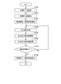
次に、本実施形態の灌流装置1を用いた腎臓9の灌流処理について、図3および図4を参照しつつ説明する。図3は、灌流装置1を用いた腎臓9の灌流処理の流れを示したフローチャートである。図4は、ガス交換器33の気体層における酸素ガスの圧力と、灌流液中の溶存酸素量との関係を示す初期データの一例を示した図である。
<1-2. Control of kidney perfusion process>
Next, a perfusion process of the kidney 9 using the
腎臓9の灌流処理を行うにあたり、まず、ガス交換器33において、気体層における酸素ガスの圧力と、灌流液中の溶存酸素量との関係を示す初期データを取得する(ステップS101)。図4の例では、酸素ガスの圧力が10kPa以下の領域では、酸素ガスの圧力が大きくなるにつれて灌流液中の溶存酸素量が上昇する。そして、酸素ガスの圧力が10kPa以上の領域では、灌流液中の溶存酸素量の上昇量が小さくなり、500mmHg前後に収束する。なお、ステップS101において、気体層における酸素ガスの圧力は、圧力センサ35により計測する。また、灌流液中の溶存酸素量は、例えば、流入配管41の他端(下流側端部)から排出される灌流液を、溶存酸素計を用いて計測する。また、溶存酸素を計測するセンサを流入配管41内に介挿することにより、灌流液中の溶存酸素量を計測してもよい。
In performing the perfusion process of the kidney 9, first, the
次に、ステップS101の取得結果である初期データに基づいて、目標溶存酸素量に対応する圧力値である目標圧力値を算出する(ステップS102)。ここで、灌流液中の溶存酸素量が400mmHg以下であれば、流入配管31や臓器の内部において、溶存酸素が気泡となる可能性が非常に低くなる。このため、灌流液流の溶存酸素量を400mmHg以下とすることが好ましい。
Next, a target pressure value, which is a pressure value corresponding to the target dissolved oxygen amount, is calculated based on the initial data obtained as a result of step S101 (step S102). Here, if the amount of dissolved oxygen in the perfusate is 400 mmHg or less, the possibility that dissolved oxygen becomes bubbles in the
本実施形態では、目標溶存酸素量を240mmHgとして目標圧力値を算出する。図4の例では、目標溶存酸素量240mmHgに対応する酸素ガスの圧力は5kPaであるため、目標圧力値を5kPaとして算出する。ここで、「目標圧力値を5kPaとする」とは、圧力センサ35で計測された圧力値が5kPaとなるように制御を行うことを意味する。
In the present embodiment, the target pressure value is calculated by setting the target dissolved oxygen amount to 240 mmHg. In the example of FIG. 4, since the pressure of the oxygen gas corresponding to the target dissolved oxygen amount of 240 mmHg is 5 kPa, the target pressure value is calculated as 5 kPa. Here, “the target pressure value is set to 5 kPa” means that control is performed so that the pressure value measured by the
ステップS101〜S102における目標圧力値設定工程は、ステップS103〜S108における灌流処理程の前に行われる。なお、目標圧力値設定工程は、灌流処理が行われる度に行われてもよいし、1度の目標圧力値設定工程により設定された目標圧力値を用いて、複数回の灌流処理が行われてもよい。 The target pressure value setting process in steps S101 to S102 is performed before the perfusion process in steps S103 to S108. The target pressure value setting step may be performed each time the perfusion processing is performed, or a plurality of times of the perfusion processing may be performed using the target pressure value set in one target pressure value setting step. You may.
また、ステップS101〜S102における目標圧力値設定工程は、制御部60が自動で行ってもよいし、ユーザが制御部60に指令を入力してステップS101を行った後に、ユーザがステップS102の目標圧力値を算出して制御部60に入力してもよい。
The target pressure value setting process in steps S101 to S102 may be automatically performed by the
続いて、灌流処理を開始する。すなわち、制御部60は、ポンプ32を駆動させて流入配管における灌流液の送液を開始するとともに、酸素供給部40を駆動させてガス交換器33への酸素ガスの供給を開始する(ステップS103)。ステップS103において、制御部60は、第2レギュレータ42からの酸素ガスの出力圧力を目標圧力値である5kPaとして、第1レギュレータ41および第2レギュレータ42を動作させる。これにより、ガス交換器33に酸素を含む酸素ガスが供給され、ガス交換器33を通過する灌流液に酸素が付加される。
Subsequently, the perfusion process is started. That is, the
灌流処理が開始されると、制御部60は、圧力センサ35によってガス交換器33の気体層における酸素ガスの圧力値を計測する(ステップS104)。上述したステップS103において、第2レギュレータ42の出力圧力を5kPaに設定したが、ステップS104の計測結果は、必ずしも正確に5kPaになっているとは限らない。制御部60は、ステップS104の計測結果に基づいて、酸素供給部40からガス交換器33に供給する酸素ガスの出力圧力の設定値をフィードバック制御により算出する(ステップS105)。その後、ステップS105における算出結果に基づいて第2レギュレータ42の出力圧力の設定値を変更した上で、酸素供給部40からガス交換器33の気体層への酸素ガスの供給を継続する(ステップS106)。すなわち、ステップS106では、酸素供給部40は、圧力センサ35の計測結果に基づいて、酸素供給部40から供給される酸素ガスの供給量を変更する。
When the perfusion process is started, the
ステップS104〜S106において酸素ガスの供給量を更新したら、制御部60は灌流処理を終了するか否かを判断する(ステップS107)。ステップS107では、例えば、外部から制御部60へと灌流処理の終了指令信号が入力されたか否かが判断される。ステップS107において、灌流処理を終了しないと判断すると、制御部60はステップS104に戻り、灌流処理を継続する。
When the supply amount of the oxygen gas is updated in steps S104 to S106, the
一方、ステップS107において、灌流処理を終了すると判断すると、制御部60は、灌流処理を終了する。すなわち、制御部60は、ポンプ32による送液を停止するとともに、酸素供給部40による酸素ガスの供給を終了する(ステップS108)。
On the other hand, when determining in step S107 that the perfusion process is to be ended, the
このように、本実施形態の灌流装置1では、灌流液中の溶存酸素量を400mmHg以下とする。これにより、灌流対象である腎臓9の内部において酸素過多によるROSが発生することを抑制できる。したがって、灌流対象の臓器の組織が損傷することを抑制できる。すなわち、灌流液に適切に酸素を付加することができる。
As described above, in the
また、これにより、流入配管31や腎臓9の内部において溶存酸素が気泡となることを抑制できる。したがって、腎臓9の組織が損傷することを抑制できる。さらに、灌流液が赤血球を含む場合に、灌流液中の赤血球が溶血することを抑制できる。
Thereby, it is possible to suppress dissolved oxygen from becoming bubbles inside the
特に、本実施形態のように、灌流対象の臓器が腎臓である場合、灌流液中の溶存酸素量を150mmHg以上300mmHg以下とすることが好ましい。このようにすれば、灌流対象である腎臓9の内部において酸素過多によるROSが発生するのをより抑制しつつ、腎臓9に適切に酸素を供給できる。 In particular, when the organ to be perfused is a kidney as in the present embodiment, it is preferable that the amount of dissolved oxygen in the perfusate be 150 mmHg or more and 300 mmHg or less. This makes it possible to appropriately supply oxygen to the kidney 9 while further suppressing the occurrence of ROS due to excessive oxygen inside the kidney 9 to be perfused.
なお、同じガス交換器33を用いて同一の溶存酸素量を得るためには、流入配管31内の灌流液の流量が大きくなるにつれて、酸素ガスの圧力値を大きくする必要がある。同様に、流入配管31内の灌流液の流量が小さくなるにつれて、酸素ガスの圧力値を小さくする必要がある。例えば、ガス交換器33として株式会社潤工社製の脱気モジュールD041を用いて、腎臓9に対して6〜8ml/分の灌流液を供給する場合、ガス交換器33に供給すべき酸素ガスの目標圧力値は2.5〜5kPaとなる。また、肝臓に対して200〜1000ml/分の灌流液を供給する場合、ガス交換器33に供給すべき酸素ガスの目標圧力値は5kPa〜8kPaとなる。
In order to obtain the same dissolved oxygen amount using the
図4に示すような、ガス交換器33の気体層における酸素ガスの圧力と、灌流液中の溶存酸素量との関係は、流入配管31内の灌流液の流量が一定であれば、ほとんど変動しない。このため、本実施形態のように、流入配管31内の溶存酸素量を計測しなくても、ガス交換器33の気体層における酸素ガスの圧力値を計測することにより、流入配管31内の溶存酸素量を精度良く推測することができる。なお、流入配管31内の溶存酸素量を計測するセンサを別途設けてもよい。その場合、当該センサの計測結果を、ガス交換器33のフィードバック制御に用いてもよい。
As shown in FIG. 4, the relationship between the pressure of oxygen gas in the gas layer of the
<2.第2実施形態>
次に、本発明の第2実施形態に係る灌流装置1Aについて、図5を参照しつつ説明する。図5は、灌流装置1Aの構成を示した概略図である。灌流装置1Aは、灌流液排出部50Aの構成が第1実施形態に係る灌流装置1と異なる。灌流装置1Aのその他の構成については、第1実施形態に係る灌流装置1と同様であるため、説明を省略する。なお、図5中、第1実施形態に係る灌流装置1と同様の構成については、図1と同じ符号が付されている。
<2. Second Embodiment>
Next, a perfusion apparatus 1A according to a second embodiment of the present invention will be described with reference to FIG. FIG. 5 is a schematic diagram showing the configuration of the perfusion apparatus 1A. The perfusion apparatus 1A is different from the
この灌流装置1Aでは、灌流液流入部30の流入配管31の一端は、リザーバー70に接続される。また、流入配管31の他端は、灌流処理時には、灌流対象となる臓器に接続される。本実施形態では、流入配管31の他端は、肝臓9Aの門脈または肝動脈と接続される。これにより、リザーバー70から肝臓9Aの門脈または肝動脈へと灌流液が供給される。なお、灌流装置1Aが2つの灌流液流入部30を有していてもよい。その場合、2つの流入配管31をそれぞれ肝臓9Aの門脈および肝動脈のそれぞれに接続できる。
In this perfusion apparatus 1A, one end of the
この灌流装置1Aでは、灌流液排出部50Aが排出配管51Aと、排出用ポンプ52Aとを有する。排出配管51Aの一端は、灌流処理時には、灌流対象となる臓器に接続される。本実施形態では、排出配管51Aの一端は、肝臓9Aの肝上部下大静脈(SH−IVC)または肝下部下大静脈(IH−IVC)に接続される。肝臓9Aの排出配管51Aの他端は、リザーバー70に接続される。これにより、肝臓9Aの肝上部下大静脈(SH−IVC)または肝下部下大静脈(IH−IVC)から排出された灌流液が、リザーバー70へと還流される。
In this perfusion apparatus 1A, the
この灌流装置1Aのように、灌流対象となる臓器から排出された灌流液をリザーバー70へと還流させて再利用してもよい。
As in the perfusion apparatus 1A, the perfusate discharged from the organ to be perfused may be returned to the
また、本実施形態の灌流装置1Aにおいても、第1実施形態に係る灌流装置1と同様に、灌流液中の溶存酸素量を400mmHg以下とする。これにより、灌流対象である肝臓9Aの内部において酸素過多によるROSが発生することを抑制できる。したがって、灌流対象の臓器の組織が損傷することを抑制できる。また、これにより、流入配管31や肝臓9Aの内部において溶存酸素が気泡となることを抑制できる。したがって、肝臓9Aの組織が損傷することを抑制できる。さらに、灌流液が赤血球を含む場合に、灌流液中の赤血球が溶血することを抑制できる。
Also in the perfusion apparatus 1A of the present embodiment, similarly to the
ここで、図6は、肝臓9Aの灌流時における流入配管31から肝臓9Aへ流入する灌流液(インフロー)における酸素溶存量と、肝臓9Aから排出配管51Aへと排出される灌流液(アウトフロー)における酸素溶存量とを示した図である。肝臓9Aは、腎臓9に比べて酸素の消費量が大きい。このため、図6に示すように、インフローにおける酸素溶存量が一時的に400mmHgを超えた場合であっても、アウトフローにおける酸素溶存量は50mmHg以下となる。すなわち、肝臓9Aでは、腎臓9に比べて、ROSが発生しない範囲で、なるべく灌流液中の溶存酸素量を大きくすることが好ましい。
Here, FIG. 6 shows the amount of oxygen dissolved in the perfusate (inflow) flowing into the
したがって、本実施形態のように、灌流対象の臓器が肝臓である場合、灌流液中の溶存酸素量を200mmHg以上400mmHg以下とすることが好ましい。このようにすれば、灌流対象である肝臓9Aの内部において酸素過多によるROSが発生するのをより抑制しつつ、肝臓9Aに適切に酸素を供給できる。
Therefore, when the organ to be perfused is the liver as in the present embodiment, the amount of dissolved oxygen in the perfusate is preferably 200 mmHg or more and 400 mmHg or less. This makes it possible to appropriately supply oxygen to the
<3.変形例>
以上、本発明の実施形態について説明したが、本発明は、上記の実施形態に限定されるものではない。
<3. Modification>
The embodiments of the present invention have been described above, but the present invention is not limited to the above embodiments.
上記の実施形態に係る灌流装置は、流入配管および排出配管をそれぞれ1つずつ有する。しかしながら、本発明はこれに限られない。本発明の灌流装置において、流入配管および排出配管の数はそれぞれ、1つでもよいし、複数であってもよい。 The perfusion apparatus according to the above embodiment has one inflow pipe and one outflow pipe. However, the present invention is not limited to this. In the perfusion apparatus of the present invention, the number of the inflow pipes and the number of the discharge pipes may be one or more.
また、上記の実施形態では、リザーバーと接続される配管が直接臓器の血管と接続された。すなわち、リザーバーと接続される配管の端部がカニューレの役割を果たした。しかしながら、本発明はこれに限られない。流入配管および排出配管の先端に別部材のカニューレが接続され、当該カニューレが血管と接続されてもよい。 Further, in the above embodiment, the pipe connected to the reservoir was directly connected to the blood vessel of the organ. That is, the end of the pipe connected to the reservoir served as a cannula. However, the present invention is not limited to this. A separate member cannula may be connected to the tip of the inflow pipe and the discharge pipe, and the cannula may be connected to a blood vessel.
また、上記の実施形態や変形例に登場した各要素を、矛盾が生じない範囲で、適宜に組み合わせてもよい。 In addition, the elements appearing in the above-described embodiments and the modified examples may be appropriately combined as long as no contradiction occurs.
1,1A 灌流装置
9 腎臓
9A 肝臓
20 筐体
30 灌流液流入部
31 流入配管
32 ポンプ
33 ガス交換器
35 圧力センサ
40 酸素供給部
41 第1レギュレータ
42 第2レギュレータ
50,50A 灌流液排出部
51,51A 排出配管
52A 排出用ポンプ
60 制御部
70 リザーバー
80 コンプレッサ
332 内筒部
1, 1A Perfusion device 9
Claims (12)
前記灌流液を貯留するリザーバーから前記臓器へと前記灌流液を流入させる流入配管と、
前記臓器から前記灌流液を排出させる排出配管と、
前記流入配管内の前記灌流液を前記リザーバーから前記臓器へと送液するポンプと、
前記流入配管に介挿され、酸素透過膜を有するガス交換器と、
前記ガス交換器に酸素を含む酸素ガスを供給する酸素供給部と、
を有し、
前記ガス交換器において前記酸素ガスが供給された前記灌流液の溶存酸素量は400mmHg以下である、灌流装置。 A perfusion apparatus for perfusing a perfusate into an organ,
An inflow pipe for allowing the perfusate to flow from the reservoir storing the perfusion solution to the organ;
A discharge pipe for discharging the perfusate from the organ,
A pump that feeds the perfusate in the inflow pipe from the reservoir to the organ,
A gas exchanger interposed in the inflow pipe and having an oxygen permeable membrane,
An oxygen supply unit that supplies oxygen gas containing oxygen to the gas exchanger,
Has,
A perfusion apparatus, wherein the amount of dissolved oxygen in the perfusion solution supplied with the oxygen gas in the gas exchanger is 400 mmHg or less.
前記酸素供給部は、
圧縮された前記酸素ガスを供給するコンプレッサと、
前記コンプレッサから供給された前記酸素ガスの圧力を200kPa以下に低下させる第1レギュレータと、
前記第1レギュレータから供給された前記酸素ガスの圧力を1kPa単位に制御可能な第2レギュレータと、
を有する、灌流装置。 The perfusion device according to claim 1, wherein
The oxygen supply unit,
A compressor for supplying the compressed oxygen gas,
A first regulator that reduces the pressure of the oxygen gas supplied from the compressor to 200 kPa or less;
A second regulator capable of controlling the pressure of the oxygen gas supplied from the first regulator in units of 1 kPa;
A perfusion device comprising:
前記ガス交換器は、
前記酸素供給部から前記酸素ガスが供給される気体層と、
前記灌流液が通過する液体層と、
前記気体層と前記液体層との間に介在する前記酸素透過膜と、
前記気体層における圧力値を計測する圧力計測部と、
を有し、
前記酸素供給部は、前記圧力計測部の計測結果に基づいて前記酸素供給部における出力圧力の設定値を変更する、灌流装置。 The perfusion device according to claim 1 or 2, wherein
The gas exchanger comprises:
A gas layer to which the oxygen gas is supplied from the oxygen supply unit,
A liquid layer through which the perfusate passes;
The oxygen permeable membrane interposed between the gas layer and the liquid layer,
A pressure measurement unit that measures a pressure value in the gas layer,
Has,
The perfusion apparatus, wherein the oxygen supply unit changes a set value of an output pressure in the oxygen supply unit based on a measurement result of the pressure measurement unit.
前記灌流液は、赤血球を含む、灌流装置。 The perfusion apparatus according to any one of claims 1 to 3, wherein
The perfusion device, wherein the perfusion solution contains red blood cells.
前記臓器が肝臓であって、
前記ガス交換器において前記酸素ガスが供給された前記灌流液の溶存酸素量は、200mmHg以上、かつ、400mmHg以下である、灌流装置。 The perfusion apparatus according to any one of claims 1 to 4, wherein
The organ is a liver,
The perfusion apparatus, wherein the amount of dissolved oxygen in the perfusion solution supplied with the oxygen gas in the gas exchanger is 200 mmHg or more and 400 mmHg or less.
前記臓器が腎臓であって、
前記ガス交換器において前記酸素ガスが供給された前記灌流液の溶存酸素量は、150mmHg以上、かつ、300mmHg以下である、灌流装置。 The perfusion apparatus according to any one of claims 1 to 4, wherein
The organ is a kidney,
The perfusion apparatus, wherein the amount of dissolved oxygen in the perfusion solution supplied with the oxygen gas in the gas exchanger is 150 mmHg or more and 300 mmHg or less.
a)前記ガス交換器において、気体層における酸素ガスの圧力と、液体層を通過する前記灌流液の溶存酸素量との関係を取得する工程と、
b)前記工程a)の取得結果に基づいて、目標溶存酸素量に対応する前記気体層における圧力値である目標圧力値を算出する工程と、
c)前記目標圧力値に基づいて前記ガス交換器に前記酸素ガスを供給し、前記灌流液に酸素を付加する工程と、
d)前記工程c)において酸素が付加された前記灌流液を臓器に供給する工程と、
を有する、灌流方法。 A perfusion method in which oxygen is added to a perfusion solution in a gas exchanger having an oxygen permeable membrane, and the organ is perfused with the perfusion solution,
a) obtaining a relationship between the pressure of oxygen gas in a gas layer and the amount of dissolved oxygen in the perfusate passing through a liquid layer in the gas exchanger;
b) calculating a target pressure value that is a pressure value in the gas layer corresponding to a target dissolved oxygen amount based on the acquisition result of the step a);
c) supplying the oxygen gas to the gas exchanger based on the target pressure value and adding oxygen to the perfusate;
d) supplying the perfusate to which oxygen has been added in the step c) to an organ;
A perfusion method.
前記工程c)は、
c1)前記気体層における前記圧力値を計測する工程と、
c2)前記工程c1)の計測結果に基づいて前記ガス交換器に供給する前記酸素ガスの出力圧力の設定値を算出する工程と、
c3)前記工程c2)の算出結果に基づいて前記気体層に前記酸素ガスを供給する工程と、
を含む、灌流方法。 The perfusion method according to claim 7, wherein
The step c) includes:
c1) measuring the pressure value in the gas layer;
c2) calculating a set value of the output pressure of the oxygen gas supplied to the gas exchanger based on the measurement result of the step c1);
c3) supplying the oxygen gas to the gas layer based on the calculation result of the step c2);
A perfusion method.
前記灌流液は、赤血球を含む、灌流方法。 The perfusion method according to claim 7 or 8, wherein
The perfusion method, wherein the perfusion solution contains red blood cells.
前記工程c)において酸素が付加された前記灌流液の溶存酸素量は400mmHg以下である、灌流方法。 The perfusion method according to any one of claims 7 to 9, wherein
A perfusion method, wherein the amount of dissolved oxygen in the perfusion solution to which oxygen has been added in the step c) is 400 mmHg or less.
前記臓器が肝臓であって、
前記工程c)において酸素が付加された前記灌流液の溶存酸素量は、200mmHg以上、かつ、400mmHg以下である、灌流方法。 The perfusion method according to claim 10, wherein
The organ is a liver,
A perfusion method, wherein the amount of dissolved oxygen in the perfusate to which oxygen has been added in the step c) is 200 mmHg or more and 400 mmHg or less.
前記臓器が腎臓であって、
前記工程c)において酸素が付加された前記灌流液の溶存酸素量は、150mmHg以上、かつ、300mmHg以下である、灌流方法。 The perfusion method according to claim 10, wherein
The organ is a kidney,
A perfusion method, wherein the amount of dissolved oxygen in the perfusate to which oxygen is added in the step c) is 150 mmHg or more and 300 mmHg or less.
Priority Applications (1)
| Application Number | Priority Date | Filing Date | Title |
|---|---|---|---|
| PCT/JP2019/024870 WO2020004295A1 (en) | 2018-06-27 | 2019-06-24 | Perfusion device and perfusion method |
Applications Claiming Priority (2)
| Application Number | Priority Date | Filing Date | Title |
|---|---|---|---|
| JP2018121454 | 2018-06-27 | ||
| JP2018121454 | 2018-06-27 |
Publications (1)
| Publication Number | Publication Date |
|---|---|
| JP2020007297A true JP2020007297A (en) | 2020-01-16 |
Family
ID=69150746
Family Applications (1)
| Application Number | Title | Priority Date | Filing Date |
|---|---|---|---|
| JP2019108831A Pending JP2020007297A (en) | 2018-06-27 | 2019-06-11 | Perfusion apparatus and perfusion method |
Country Status (1)
| Country | Link |
|---|---|
| JP (1) | JP2020007297A (en) |
Cited By (1)
| Publication number | Priority date | Publication date | Assignee | Title |
|---|---|---|---|---|
| CN115777688A (en) * | 2022-11-03 | 2023-03-14 | 河南中医药大学第一附属医院 | Isolated myocardial tissue perfusion experiment system |
Citations (5)
| Publication number | Priority date | Publication date | Assignee | Title |
|---|---|---|---|---|
| JP2001516768A (en) * | 1997-09-23 | 2001-10-02 | ハッサネイン,ワリード,エイチ. | Compositions, methods and devices for maintaining organs |
| JP2004529938A (en) * | 2001-05-04 | 2004-09-30 | ブレオニクス,インコーポレーティッド | Organ chamber for blood-free metabolic support system |
| JP2011136286A (en) * | 2009-12-28 | 2011-07-14 | Sumitomo Heavy Ind Ltd | Washing apparatus and ozone water generator |
| JP2013204680A (en) * | 2012-03-28 | 2013-10-07 | Toppan Forms Co Ltd | Actuator drive control device |
| JP2017518301A (en) * | 2014-06-02 | 2017-07-06 | トランスメディクス, インク.Transmedics, Inc. | Ex-vivo organ management system |
-
2019
- 2019-06-11 JP JP2019108831A patent/JP2020007297A/en active Pending
Patent Citations (5)
| Publication number | Priority date | Publication date | Assignee | Title |
|---|---|---|---|---|
| JP2001516768A (en) * | 1997-09-23 | 2001-10-02 | ハッサネイン,ワリード,エイチ. | Compositions, methods and devices for maintaining organs |
| JP2004529938A (en) * | 2001-05-04 | 2004-09-30 | ブレオニクス,インコーポレーティッド | Organ chamber for blood-free metabolic support system |
| JP2011136286A (en) * | 2009-12-28 | 2011-07-14 | Sumitomo Heavy Ind Ltd | Washing apparatus and ozone water generator |
| JP2013204680A (en) * | 2012-03-28 | 2013-10-07 | Toppan Forms Co Ltd | Actuator drive control device |
| JP2017518301A (en) * | 2014-06-02 | 2017-07-06 | トランスメディクス, インク.Transmedics, Inc. | Ex-vivo organ management system |
Non-Patent Citations (1)
| Title |
|---|
| GELLERT, K. ET AL., EXP. PATH., vol. 28, JPN6019035914, 1985, pages 245 - 250, ISSN: 0005021447 * |
Cited By (1)
| Publication number | Priority date | Publication date | Assignee | Title |
|---|---|---|---|---|
| CN115777688A (en) * | 2022-11-03 | 2023-03-14 | 河南中医药大学第一附属医院 | Isolated myocardial tissue perfusion experiment system |
Similar Documents
| Publication | Publication Date | Title |
|---|---|---|
| US20250261633A1 (en) | Organ perfusion device | |
| US11963526B2 (en) | Apparatus and method for organ perfusion | |
| Urbanellis et al. | Normothermic ex vivo kidney perfusion improves early DCD graft function compared with hypothermic machine perfusion and static cold storage | |
| US20200128813A1 (en) | Organ perfusion systems | |
| CN206603121U (en) | A kind of isolated organ In vitro perfusion save set | |
| EP3884776A1 (en) | Organ preservation device and organ preservation method | |
| JP7240832B2 (en) | Organ storage containers and perfusion devices | |
| CN104186459A (en) | Sub-normal-temperature or low-temperature isolated kidney storage device | |
| WO2019044354A1 (en) | Organ storage container and perfusion device | |
| WO2020004088A1 (en) | Perfusion device and perfusion method | |
| CN206115320U (en) | Continuous perfusion system of isolated organ | |
| JP2020007297A (en) | Perfusion apparatus and perfusion method | |
| JP2021017433A (en) | Organ storage container | |
| Bral et al. | Determination of minimal hemoglobin level necessary for normothermic porcine ex situ liver perfusion | |
| WO2020004295A1 (en) | Perfusion device and perfusion method | |
| JP7278898B2 (en) | Perfusion device | |
| WO2023112555A1 (en) | Organ preservation device and organ preservation method | |
| CN205357948U (en) | Separation liver perfusion system | |
| WO2024001176A1 (en) | Hypothermic liver perfusion preservation device and method | |
| JP2020046240A (en) | Ischemia time estimation method and ischemia time estimation device | |
| CN113142192B (en) | An isolated liver perfusion activity maintenance device and a method of using the same | |
| US20230043364A1 (en) | System and method for ventilating an organ | |
| WO2024111377A1 (en) | Liquid storage container | |
| JP2020143028A (en) | Perfusion device | |
| CN118020760A (en) | Organ preservation system with high pressure and low Wen Mobing |
Legal Events
| Date | Code | Title | Description |
|---|---|---|---|
| A621 | Written request for application examination |
Free format text: JAPANESE INTERMEDIATE CODE: A621 Effective date: 20211223 |
|
| A131 | Notification of reasons for refusal |
Free format text: JAPANESE INTERMEDIATE CODE: A131 Effective date: 20220913 |
|
| A02 | Decision of refusal |
Free format text: JAPANESE INTERMEDIATE CODE: A02 Effective date: 20230328 |