JP2019514653A - Adaptive compression treatment system and method - Google Patents
Adaptive compression treatment system and method Download PDFInfo
- Publication number
- JP2019514653A JP2019514653A JP2019508163A JP2019508163A JP2019514653A JP 2019514653 A JP2019514653 A JP 2019514653A JP 2019508163 A JP2019508163 A JP 2019508163A JP 2019508163 A JP2019508163 A JP 2019508163A JP 2019514653 A JP2019514653 A JP 2019514653A
- Authority
- JP
- Japan
- Prior art keywords
- compression
- data
- treatment
- sensors
- body part
- Prior art date
- Legal status (The legal status is an assumption and is not a legal conclusion. Google has not performed a legal analysis and makes no representation as to the accuracy of the status listed.)
- Pending
Links
Images


Classifications
-
- A—HUMAN NECESSITIES
- A61—MEDICAL OR VETERINARY SCIENCE; HYGIENE
- A61H—PHYSICAL THERAPY APPARATUS, e.g. DEVICES FOR LOCATING OR STIMULATING REFLEX POINTS IN THE BODY; ARTIFICIAL RESPIRATION; MASSAGE; BATHING DEVICES FOR SPECIAL THERAPEUTIC OR HYGIENIC PURPOSES OR SPECIFIC PARTS OF THE BODY
- A61H1/00—Apparatus for passive exercising; Vibrating apparatus; Chiropractic devices, e.g. body impacting devices, external devices for briefly extending or aligning unbroken bones
- A61H1/006—Apparatus for applying pressure or blows for compressive stressing of a part of the skeletal structure, e.g. for preventing or alleviating osteoporosis
-
- A—HUMAN NECESSITIES
- A41—WEARING APPAREL
- A41D—OUTERWEAR; PROTECTIVE GARMENTS; ACCESSORIES
- A41D1/00—Garments
- A41D1/002—Garments adapted to accommodate electronic equipment
- A41D1/005—Garments adapted to accommodate electronic equipment with embedded cable or connector
-
- A—HUMAN NECESSITIES
- A61—MEDICAL OR VETERINARY SCIENCE; HYGIENE
- A61B—DIAGNOSIS; SURGERY; IDENTIFICATION
- A61B5/00—Measuring for diagnostic purposes; Identification of persons
- A61B5/02—Detecting, measuring or recording for evaluating the cardiovascular system, e.g. pulse, heart rate, blood pressure or blood flow
- A61B5/02007—Evaluating blood vessel condition, e.g. elasticity, compliance
-
- A—HUMAN NECESSITIES
- A61—MEDICAL OR VETERINARY SCIENCE; HYGIENE
- A61B—DIAGNOSIS; SURGERY; IDENTIFICATION
- A61B5/00—Measuring for diagnostic purposes; Identification of persons
- A61B5/02—Detecting, measuring or recording for evaluating the cardiovascular system, e.g. pulse, heart rate, blood pressure or blood flow
- A61B5/02042—Determining blood loss or bleeding, e.g. during a surgical procedure
-
- A—HUMAN NECESSITIES
- A61—MEDICAL OR VETERINARY SCIENCE; HYGIENE
- A61B—DIAGNOSIS; SURGERY; IDENTIFICATION
- A61B5/00—Measuring for diagnostic purposes; Identification of persons
- A61B5/02—Detecting, measuring or recording for evaluating the cardiovascular system, e.g. pulse, heart rate, blood pressure or blood flow
- A61B5/021—Measuring pressure in heart or blood vessels
- A61B5/022—Measuring pressure in heart or blood vessels by applying pressure to close blood vessels, e.g. against the skin; Ophthalmodynamometers
-
- A—HUMAN NECESSITIES
- A61—MEDICAL OR VETERINARY SCIENCE; HYGIENE
- A61B—DIAGNOSIS; SURGERY; IDENTIFICATION
- A61B5/00—Measuring for diagnostic purposes; Identification of persons
- A61B5/02—Detecting, measuring or recording for evaluating the cardiovascular system, e.g. pulse, heart rate, blood pressure or blood flow
- A61B5/026—Measuring blood flow
- A61B5/0295—Measuring blood flow using plethysmography, i.e. measuring the variations in the volume of a body part as modified by the circulation of blood therethrough, e.g. impedance plethysmography
-
- A—HUMAN NECESSITIES
- A61—MEDICAL OR VETERINARY SCIENCE; HYGIENE
- A61B—DIAGNOSIS; SURGERY; IDENTIFICATION
- A61B5/00—Measuring for diagnostic purposes; Identification of persons
- A61B5/48—Other medical applications
- A61B5/4842—Monitoring progression or stage of a disease
-
- A—HUMAN NECESSITIES
- A61—MEDICAL OR VETERINARY SCIENCE; HYGIENE
- A61B—DIAGNOSIS; SURGERY; IDENTIFICATION
- A61B5/00—Measuring for diagnostic purposes; Identification of persons
- A61B5/48—Other medical applications
- A61B5/4848—Monitoring or testing the effects of treatment, e.g. of medication
-
- A—HUMAN NECESSITIES
- A61—MEDICAL OR VETERINARY SCIENCE; HYGIENE
- A61F—FILTERS IMPLANTABLE INTO BLOOD VESSELS; PROSTHESES; DEVICES PROVIDING PATENCY TO, OR PREVENTING COLLAPSING OF, TUBULAR STRUCTURES OF THE BODY, e.g. STENTS; ORTHOPAEDIC, NURSING OR CONTRACEPTIVE DEVICES; FOMENTATION; TREATMENT OR PROTECTION OF EYES OR EARS; BANDAGES, DRESSINGS OR ABSORBENT PADS; FIRST-AID KITS
- A61F5/00—Orthopaedic methods or devices for non-surgical treatment of bones or joints; Nursing devices ; Anti-rape devices
- A61F5/01—Orthopaedic devices, e.g. long-term immobilising or pressure directing devices for treating broken or deformed bones such as splints, casts or braces
- A61F5/0102—Orthopaedic devices, e.g. long-term immobilising or pressure directing devices for treating broken or deformed bones such as splints, casts or braces specially adapted for correcting deformities of the limbs or for supporting them; Ortheses, e.g. with articulations
- A61F5/0123—Orthopaedic devices, e.g. long-term immobilising or pressure directing devices for treating broken or deformed bones such as splints, casts or braces specially adapted for correcting deformities of the limbs or for supporting them; Ortheses, e.g. with articulations for the knees
-
- A—HUMAN NECESSITIES
- A61—MEDICAL OR VETERINARY SCIENCE; HYGIENE
- A61F—FILTERS IMPLANTABLE INTO BLOOD VESSELS; PROSTHESES; DEVICES PROVIDING PATENCY TO, OR PREVENTING COLLAPSING OF, TUBULAR STRUCTURES OF THE BODY, e.g. STENTS; ORTHOPAEDIC, NURSING OR CONTRACEPTIVE DEVICES; FOMENTATION; TREATMENT OR PROTECTION OF EYES OR EARS; BANDAGES, DRESSINGS OR ABSORBENT PADS; FIRST-AID KITS
- A61F5/00—Orthopaedic methods or devices for non-surgical treatment of bones or joints; Nursing devices ; Anti-rape devices
- A61F5/01—Orthopaedic devices, e.g. long-term immobilising or pressure directing devices for treating broken or deformed bones such as splints, casts or braces
- A61F5/0102—Orthopaedic devices, e.g. long-term immobilising or pressure directing devices for treating broken or deformed bones such as splints, casts or braces specially adapted for correcting deformities of the limbs or for supporting them; Ortheses, e.g. with articulations
- A61F5/013—Orthopaedic devices, e.g. long-term immobilising or pressure directing devices for treating broken or deformed bones such as splints, casts or braces specially adapted for correcting deformities of the limbs or for supporting them; Ortheses, e.g. with articulations for the arms, hands or fingers
-
- A—HUMAN NECESSITIES
- A61—MEDICAL OR VETERINARY SCIENCE; HYGIENE
- A61F—FILTERS IMPLANTABLE INTO BLOOD VESSELS; PROSTHESES; DEVICES PROVIDING PATENCY TO, OR PREVENTING COLLAPSING OF, TUBULAR STRUCTURES OF THE BODY, e.g. STENTS; ORTHOPAEDIC, NURSING OR CONTRACEPTIVE DEVICES; FOMENTATION; TREATMENT OR PROTECTION OF EYES OR EARS; BANDAGES, DRESSINGS OR ABSORBENT PADS; FIRST-AID KITS
- A61F5/00—Orthopaedic methods or devices for non-surgical treatment of bones or joints; Nursing devices ; Anti-rape devices
- A61F5/01—Orthopaedic devices, e.g. long-term immobilising or pressure directing devices for treating broken or deformed bones such as splints, casts or braces
- A61F5/02—Orthopaedic corsets
-
- A—HUMAN NECESSITIES
- A61—MEDICAL OR VETERINARY SCIENCE; HYGIENE
- A61H—PHYSICAL THERAPY APPARATUS, e.g. DEVICES FOR LOCATING OR STIMULATING REFLEX POINTS IN THE BODY; ARTIFICIAL RESPIRATION; MASSAGE; BATHING DEVICES FOR SPECIAL THERAPEUTIC OR HYGIENIC PURPOSES OR SPECIFIC PARTS OF THE BODY
- A61H31/00—Artificial respiration by a force applied to the chest; Heart stimulation, e.g. heart massage
- A61H31/004—Heart stimulation
- A61H31/005—Heart stimulation with feedback for the user
-
- A—HUMAN NECESSITIES
- A61—MEDICAL OR VETERINARY SCIENCE; HYGIENE
- A61H—PHYSICAL THERAPY APPARATUS, e.g. DEVICES FOR LOCATING OR STIMULATING REFLEX POINTS IN THE BODY; ARTIFICIAL RESPIRATION; MASSAGE; BATHING DEVICES FOR SPECIAL THERAPEUTIC OR HYGIENIC PURPOSES OR SPECIFIC PARTS OF THE BODY
- A61H31/00—Artificial respiration by a force applied to the chest; Heart stimulation, e.g. heart massage
- A61H31/004—Heart stimulation
- A61H31/006—Power driven
-
- A—HUMAN NECESSITIES
- A61—MEDICAL OR VETERINARY SCIENCE; HYGIENE
- A61H—PHYSICAL THERAPY APPARATUS, e.g. DEVICES FOR LOCATING OR STIMULATING REFLEX POINTS IN THE BODY; ARTIFICIAL RESPIRATION; MASSAGE; BATHING DEVICES FOR SPECIAL THERAPEUTIC OR HYGIENIC PURPOSES OR SPECIFIC PARTS OF THE BODY
- A61H31/00—Artificial respiration by a force applied to the chest; Heart stimulation, e.g. heart massage
- A61H31/008—Supine patient supports or bases, e.g. improving air-way access to the lungs
-
- A—HUMAN NECESSITIES
- A61—MEDICAL OR VETERINARY SCIENCE; HYGIENE
- A61H—PHYSICAL THERAPY APPARATUS, e.g. DEVICES FOR LOCATING OR STIMULATING REFLEX POINTS IN THE BODY; ARTIFICIAL RESPIRATION; MASSAGE; BATHING DEVICES FOR SPECIAL THERAPEUTIC OR HYGIENIC PURPOSES OR SPECIFIC PARTS OF THE BODY
- A61H7/00—Devices for suction-kneading massage; Devices for massaging the skin by rubbing or brushing not otherwise provided for
- A61H7/001—Devices for suction-kneading massage; Devices for massaging the skin by rubbing or brushing not otherwise provided for without substantial movement between the skin and the device
-
- G—PHYSICS
- G16—INFORMATION AND COMMUNICATION TECHNOLOGY [ICT] SPECIALLY ADAPTED FOR SPECIFIC APPLICATION FIELDS
- G16H—HEALTHCARE INFORMATICS, i.e. INFORMATION AND COMMUNICATION TECHNOLOGY [ICT] SPECIALLY ADAPTED FOR THE HANDLING OR PROCESSING OF MEDICAL OR HEALTHCARE DATA
- G16H20/00—ICT specially adapted for therapies or health-improving plans, e.g. for handling prescriptions, for steering therapy or for monitoring patient compliance
- G16H20/30—ICT specially adapted for therapies or health-improving plans, e.g. for handling prescriptions, for steering therapy or for monitoring patient compliance relating to physical therapies or activities, e.g. physiotherapy, acupressure or exercising
-
- A—HUMAN NECESSITIES
- A43—FOOTWEAR
- A43B—CHARACTERISTIC FEATURES OF FOOTWEAR; PARTS OF FOOTWEAR
- A43B3/00—Footwear characterised by the shape or the use
- A43B3/34—Footwear characterised by the shape or the use with electrical or electronic arrangements
- A43B3/38—Footwear characterised by the shape or the use with electrical or electronic arrangements with power sources
-
- A—HUMAN NECESSITIES
- A43—FOOTWEAR
- A43B—CHARACTERISTIC FEATURES OF FOOTWEAR; PARTS OF FOOTWEAR
- A43B7/00—Footwear with health or hygienic arrangements
-
- A—HUMAN NECESSITIES
- A43—FOOTWEAR
- A43B—CHARACTERISTIC FEATURES OF FOOTWEAR; PARTS OF FOOTWEAR
- A43B7/00—Footwear with health or hygienic arrangements
- A43B7/14—Footwear with health or hygienic arrangements with foot-supporting parts
- A43B7/1405—Footwear with health or hygienic arrangements with foot-supporting parts with pads or holes on one or more locations, or having an anatomical or curved form
- A43B7/1455—Footwear with health or hygienic arrangements with foot-supporting parts with pads or holes on one or more locations, or having an anatomical or curved form with special properties
- A43B7/146—Footwear with health or hygienic arrangements with foot-supporting parts with pads or holes on one or more locations, or having an anatomical or curved form with special properties provided with acupressure points or means for foot massage
-
- A—HUMAN NECESSITIES
- A43—FOOTWEAR
- A43C—FASTENINGS OR ATTACHMENTS OF FOOTWEAR; LACES IN GENERAL
- A43C1/00—Shoe lacing fastenings
- A43C1/06—Shoe lacing fastenings tightened by draw-strings
-
- A—HUMAN NECESSITIES
- A43—FOOTWEAR
- A43C—FASTENINGS OR ATTACHMENTS OF FOOTWEAR; LACES IN GENERAL
- A43C11/00—Other fastenings specially adapted for shoes
- A43C11/16—Fastenings secured by wire, bolts, or the like
-
- A—HUMAN NECESSITIES
- A43—FOOTWEAR
- A43C—FASTENINGS OR ATTACHMENTS OF FOOTWEAR; LACES IN GENERAL
- A43C11/00—Other fastenings specially adapted for shoes
- A43C11/16—Fastenings secured by wire, bolts, or the like
- A43C11/165—Fastenings secured by wire, bolts, or the like characterised by a spool, reel or pulley for winding up cables, laces or straps by rotation
-
- A—HUMAN NECESSITIES
- A61—MEDICAL OR VETERINARY SCIENCE; HYGIENE
- A61B—DIAGNOSIS; SURGERY; IDENTIFICATION
- A61B5/00—Measuring for diagnostic purposes; Identification of persons
- A61B5/0002—Remote monitoring of patients using telemetry, e.g. transmission of vital signals via a communication network
- A61B5/0015—Remote monitoring of patients using telemetry, e.g. transmission of vital signals via a communication network characterised by features of the telemetry system
- A61B5/002—Monitoring the patient using a local or closed circuit, e.g. in a room or building
-
- A—HUMAN NECESSITIES
- A61—MEDICAL OR VETERINARY SCIENCE; HYGIENE
- A61B—DIAGNOSIS; SURGERY; IDENTIFICATION
- A61B5/00—Measuring for diagnostic purposes; Identification of persons
- A61B5/0002—Remote monitoring of patients using telemetry, e.g. transmission of vital signals via a communication network
- A61B5/0015—Remote monitoring of patients using telemetry, e.g. transmission of vital signals via a communication network characterised by features of the telemetry system
- A61B5/0022—Monitoring a patient using a global network, e.g. telephone networks, internet
-
- A—HUMAN NECESSITIES
- A61—MEDICAL OR VETERINARY SCIENCE; HYGIENE
- A61B—DIAGNOSIS; SURGERY; IDENTIFICATION
- A61B5/00—Measuring for diagnostic purposes; Identification of persons
- A61B5/02—Detecting, measuring or recording for evaluating the cardiovascular system, e.g. pulse, heart rate, blood pressure or blood flow
- A61B5/0205—Simultaneously evaluating both cardiovascular conditions and different types of body conditions, e.g. heart and respiratory condition
-
- A—HUMAN NECESSITIES
- A61—MEDICAL OR VETERINARY SCIENCE; HYGIENE
- A61B—DIAGNOSIS; SURGERY; IDENTIFICATION
- A61B5/00—Measuring for diagnostic purposes; Identification of persons
- A61B5/02—Detecting, measuring or recording for evaluating the cardiovascular system, e.g. pulse, heart rate, blood pressure or blood flow
- A61B5/021—Measuring pressure in heart or blood vessels
- A61B5/02141—Details of apparatus construction, e.g. pump units or housings therefor, cuff pressurising systems, arrangements of fluid conduits or circuits
-
- A—HUMAN NECESSITIES
- A61—MEDICAL OR VETERINARY SCIENCE; HYGIENE
- A61B—DIAGNOSIS; SURGERY; IDENTIFICATION
- A61B5/00—Measuring for diagnostic purposes; Identification of persons
- A61B5/02—Detecting, measuring or recording for evaluating the cardiovascular system, e.g. pulse, heart rate, blood pressure or blood flow
- A61B5/024—Measuring pulse rate or heart rate
-
- A—HUMAN NECESSITIES
- A61—MEDICAL OR VETERINARY SCIENCE; HYGIENE
- A61B—DIAGNOSIS; SURGERY; IDENTIFICATION
- A61B5/00—Measuring for diagnostic purposes; Identification of persons
- A61B5/41—Detecting, measuring or recording for evaluating the immune or lymphatic systems
- A61B5/414—Evaluating particular organs or parts of the immune or lymphatic systems
- A61B5/418—Evaluating particular organs or parts of the immune or lymphatic systems lymph vessels, ducts or nodes
-
- A—HUMAN NECESSITIES
- A61—MEDICAL OR VETERINARY SCIENCE; HYGIENE
- A61B—DIAGNOSIS; SURGERY; IDENTIFICATION
- A61B5/00—Measuring for diagnostic purposes; Identification of persons
- A61B5/42—Detecting, measuring or recording for evaluating the gastrointestinal, the endocrine or the exocrine systems
- A61B5/4222—Evaluating particular parts, e.g. particular organs
- A61B5/4238—Evaluating particular parts, e.g. particular organs stomach
-
- A—HUMAN NECESSITIES
- A61—MEDICAL OR VETERINARY SCIENCE; HYGIENE
- A61B—DIAGNOSIS; SURGERY; IDENTIFICATION
- A61B5/00—Measuring for diagnostic purposes; Identification of persons
- A61B5/42—Detecting, measuring or recording for evaluating the gastrointestinal, the endocrine or the exocrine systems
- A61B5/4222—Evaluating particular parts, e.g. particular organs
- A61B5/4255—Intestines, colon or appendix
-
- A—HUMAN NECESSITIES
- A61—MEDICAL OR VETERINARY SCIENCE; HYGIENE
- A61B—DIAGNOSIS; SURGERY; IDENTIFICATION
- A61B5/00—Measuring for diagnostic purposes; Identification of persons
- A61B5/48—Other medical applications
- A61B5/4836—Diagnosis combined with treatment in closed-loop systems or methods
-
- A—HUMAN NECESSITIES
- A61—MEDICAL OR VETERINARY SCIENCE; HYGIENE
- A61B—DIAGNOSIS; SURGERY; IDENTIFICATION
- A61B5/00—Measuring for diagnostic purposes; Identification of persons
- A61B5/68—Arrangements of detecting, measuring or recording means, e.g. sensors, in relation to patient
- A61B5/6801—Arrangements of detecting, measuring or recording means, e.g. sensors, in relation to patient specially adapted to be attached to or worn on the body surface
- A61B5/6802—Sensor mounted on worn items
- A61B5/6812—Orthopaedic devices
-
- A—HUMAN NECESSITIES
- A61—MEDICAL OR VETERINARY SCIENCE; HYGIENE
- A61B—DIAGNOSIS; SURGERY; IDENTIFICATION
- A61B5/00—Measuring for diagnostic purposes; Identification of persons
- A61B5/68—Arrangements of detecting, measuring or recording means, e.g. sensors, in relation to patient
- A61B5/6801—Arrangements of detecting, measuring or recording means, e.g. sensors, in relation to patient specially adapted to be attached to or worn on the body surface
- A61B5/6813—Specially adapted to be attached to a specific body part
- A61B5/6824—Arm or wrist
-
- A—HUMAN NECESSITIES
- A61—MEDICAL OR VETERINARY SCIENCE; HYGIENE
- A61B—DIAGNOSIS; SURGERY; IDENTIFICATION
- A61B5/00—Measuring for diagnostic purposes; Identification of persons
- A61B5/68—Arrangements of detecting, measuring or recording means, e.g. sensors, in relation to patient
- A61B5/6801—Arrangements of detecting, measuring or recording means, e.g. sensors, in relation to patient specially adapted to be attached to or worn on the body surface
- A61B5/6813—Specially adapted to be attached to a specific body part
- A61B5/6828—Leg
-
- A—HUMAN NECESSITIES
- A61—MEDICAL OR VETERINARY SCIENCE; HYGIENE
- A61B—DIAGNOSIS; SURGERY; IDENTIFICATION
- A61B5/00—Measuring for diagnostic purposes; Identification of persons
- A61B5/68—Arrangements of detecting, measuring or recording means, e.g. sensors, in relation to patient
- A61B5/6801—Arrangements of detecting, measuring or recording means, e.g. sensors, in relation to patient specially adapted to be attached to or worn on the body surface
- A61B5/6813—Specially adapted to be attached to a specific body part
- A61B5/6829—Foot or ankle
-
- A—HUMAN NECESSITIES
- A61—MEDICAL OR VETERINARY SCIENCE; HYGIENE
- A61H—PHYSICAL THERAPY APPARATUS, e.g. DEVICES FOR LOCATING OR STIMULATING REFLEX POINTS IN THE BODY; ARTIFICIAL RESPIRATION; MASSAGE; BATHING DEVICES FOR SPECIAL THERAPEUTIC OR HYGIENIC PURPOSES OR SPECIFIC PARTS OF THE BODY
- A61H11/00—Belts, strips or combs for massage purposes
- A61H2011/005—Belts, strips or combs for massage purposes with belt or strap expanding and contracting around an encircled body part
-
- A—HUMAN NECESSITIES
- A61—MEDICAL OR VETERINARY SCIENCE; HYGIENE
- A61H—PHYSICAL THERAPY APPARATUS, e.g. DEVICES FOR LOCATING OR STIMULATING REFLEX POINTS IN THE BODY; ARTIFICIAL RESPIRATION; MASSAGE; BATHING DEVICES FOR SPECIAL THERAPEUTIC OR HYGIENIC PURPOSES OR SPECIFIC PARTS OF THE BODY
- A61H2201/00—Characteristics of apparatus not provided for in the preceding codes
- A61H2201/01—Constructive details
- A61H2201/0103—Constructive details inflatable
-
- A—HUMAN NECESSITIES
- A61—MEDICAL OR VETERINARY SCIENCE; HYGIENE
- A61H—PHYSICAL THERAPY APPARATUS, e.g. DEVICES FOR LOCATING OR STIMULATING REFLEX POINTS IN THE BODY; ARTIFICIAL RESPIRATION; MASSAGE; BATHING DEVICES FOR SPECIAL THERAPEUTIC OR HYGIENIC PURPOSES OR SPECIFIC PARTS OF THE BODY
- A61H2201/00—Characteristics of apparatus not provided for in the preceding codes
- A61H2201/01—Constructive details
- A61H2201/0173—Means for preventing injuries
- A61H2201/0176—By stopping operation
-
- A—HUMAN NECESSITIES
- A61—MEDICAL OR VETERINARY SCIENCE; HYGIENE
- A61H—PHYSICAL THERAPY APPARATUS, e.g. DEVICES FOR LOCATING OR STIMULATING REFLEX POINTS IN THE BODY; ARTIFICIAL RESPIRATION; MASSAGE; BATHING DEVICES FOR SPECIAL THERAPEUTIC OR HYGIENIC PURPOSES OR SPECIFIC PARTS OF THE BODY
- A61H2201/00—Characteristics of apparatus not provided for in the preceding codes
- A61H2201/01—Constructive details
- A61H2201/0192—Specific means for adjusting dimensions
-
- A—HUMAN NECESSITIES
- A61—MEDICAL OR VETERINARY SCIENCE; HYGIENE
- A61H—PHYSICAL THERAPY APPARATUS, e.g. DEVICES FOR LOCATING OR STIMULATING REFLEX POINTS IN THE BODY; ARTIFICIAL RESPIRATION; MASSAGE; BATHING DEVICES FOR SPECIAL THERAPEUTIC OR HYGIENIC PURPOSES OR SPECIFIC PARTS OF THE BODY
- A61H2201/00—Characteristics of apparatus not provided for in the preceding codes
- A61H2201/12—Driving means
- A61H2201/1207—Driving means with electric or magnetic drive
- A61H2201/1215—Rotary drive
-
- A—HUMAN NECESSITIES
- A61—MEDICAL OR VETERINARY SCIENCE; HYGIENE
- A61H—PHYSICAL THERAPY APPARATUS, e.g. DEVICES FOR LOCATING OR STIMULATING REFLEX POINTS IN THE BODY; ARTIFICIAL RESPIRATION; MASSAGE; BATHING DEVICES FOR SPECIAL THERAPEUTIC OR HYGIENIC PURPOSES OR SPECIFIC PARTS OF THE BODY
- A61H2201/00—Characteristics of apparatus not provided for in the preceding codes
- A61H2201/16—Physical interface with patient
- A61H2201/1602—Physical interface with patient kind of interface, e.g. head rest, knee support or lumbar support
- A61H2201/165—Wearable interfaces
-
- A—HUMAN NECESSITIES
- A61—MEDICAL OR VETERINARY SCIENCE; HYGIENE
- A61H—PHYSICAL THERAPY APPARATUS, e.g. DEVICES FOR LOCATING OR STIMULATING REFLEX POINTS IN THE BODY; ARTIFICIAL RESPIRATION; MASSAGE; BATHING DEVICES FOR SPECIAL THERAPEUTIC OR HYGIENIC PURPOSES OR SPECIFIC PARTS OF THE BODY
- A61H2201/00—Characteristics of apparatus not provided for in the preceding codes
- A61H2201/50—Control means thereof
- A61H2201/5007—Control means thereof computer controlled
- A61H2201/501—Control means thereof computer controlled connected to external computer devices or networks
-
- A—HUMAN NECESSITIES
- A61—MEDICAL OR VETERINARY SCIENCE; HYGIENE
- A61H—PHYSICAL THERAPY APPARATUS, e.g. DEVICES FOR LOCATING OR STIMULATING REFLEX POINTS IN THE BODY; ARTIFICIAL RESPIRATION; MASSAGE; BATHING DEVICES FOR SPECIAL THERAPEUTIC OR HYGIENIC PURPOSES OR SPECIFIC PARTS OF THE BODY
- A61H2201/00—Characteristics of apparatus not provided for in the preceding codes
- A61H2201/50—Control means thereof
- A61H2201/5023—Interfaces to the user
- A61H2201/5038—Interfaces to the user freely programmable by the user
-
- A—HUMAN NECESSITIES
- A61—MEDICAL OR VETERINARY SCIENCE; HYGIENE
- A61H—PHYSICAL THERAPY APPARATUS, e.g. DEVICES FOR LOCATING OR STIMULATING REFLEX POINTS IN THE BODY; ARTIFICIAL RESPIRATION; MASSAGE; BATHING DEVICES FOR SPECIAL THERAPEUTIC OR HYGIENIC PURPOSES OR SPECIFIC PARTS OF THE BODY
- A61H2201/00—Characteristics of apparatus not provided for in the preceding codes
- A61H2201/50—Control means thereof
- A61H2201/5023—Interfaces to the user
- A61H2201/5043—Displays
- A61H2201/5046—Touch screens
-
- A—HUMAN NECESSITIES
- A61—MEDICAL OR VETERINARY SCIENCE; HYGIENE
- A61H—PHYSICAL THERAPY APPARATUS, e.g. DEVICES FOR LOCATING OR STIMULATING REFLEX POINTS IN THE BODY; ARTIFICIAL RESPIRATION; MASSAGE; BATHING DEVICES FOR SPECIAL THERAPEUTIC OR HYGIENIC PURPOSES OR SPECIFIC PARTS OF THE BODY
- A61H2201/00—Characteristics of apparatus not provided for in the preceding codes
- A61H2201/50—Control means thereof
- A61H2201/5058—Sensors or detectors
- A61H2201/5061—Force sensors
-
- A—HUMAN NECESSITIES
- A61—MEDICAL OR VETERINARY SCIENCE; HYGIENE
- A61H—PHYSICAL THERAPY APPARATUS, e.g. DEVICES FOR LOCATING OR STIMULATING REFLEX POINTS IN THE BODY; ARTIFICIAL RESPIRATION; MASSAGE; BATHING DEVICES FOR SPECIAL THERAPEUTIC OR HYGIENIC PURPOSES OR SPECIFIC PARTS OF THE BODY
- A61H2201/00—Characteristics of apparatus not provided for in the preceding codes
- A61H2201/50—Control means thereof
- A61H2201/5058—Sensors or detectors
- A61H2201/5064—Position sensors
-
- A—HUMAN NECESSITIES
- A61—MEDICAL OR VETERINARY SCIENCE; HYGIENE
- A61H—PHYSICAL THERAPY APPARATUS, e.g. DEVICES FOR LOCATING OR STIMULATING REFLEX POINTS IN THE BODY; ARTIFICIAL RESPIRATION; MASSAGE; BATHING DEVICES FOR SPECIAL THERAPEUTIC OR HYGIENIC PURPOSES OR SPECIFIC PARTS OF THE BODY
- A61H2201/00—Characteristics of apparatus not provided for in the preceding codes
- A61H2201/50—Control means thereof
- A61H2201/5058—Sensors or detectors
- A61H2201/5069—Angle sensors
-
- A—HUMAN NECESSITIES
- A61—MEDICAL OR VETERINARY SCIENCE; HYGIENE
- A61H—PHYSICAL THERAPY APPARATUS, e.g. DEVICES FOR LOCATING OR STIMULATING REFLEX POINTS IN THE BODY; ARTIFICIAL RESPIRATION; MASSAGE; BATHING DEVICES FOR SPECIAL THERAPEUTIC OR HYGIENIC PURPOSES OR SPECIFIC PARTS OF THE BODY
- A61H2201/00—Characteristics of apparatus not provided for in the preceding codes
- A61H2201/50—Control means thereof
- A61H2201/5058—Sensors or detectors
- A61H2201/5071—Pressure sensors
-
- A—HUMAN NECESSITIES
- A61—MEDICAL OR VETERINARY SCIENCE; HYGIENE
- A61H—PHYSICAL THERAPY APPARATUS, e.g. DEVICES FOR LOCATING OR STIMULATING REFLEX POINTS IN THE BODY; ARTIFICIAL RESPIRATION; MASSAGE; BATHING DEVICES FOR SPECIAL THERAPEUTIC OR HYGIENIC PURPOSES OR SPECIFIC PARTS OF THE BODY
- A61H2201/00—Characteristics of apparatus not provided for in the preceding codes
- A61H2201/50—Control means thereof
- A61H2201/5058—Sensors or detectors
- A61H2201/5084—Acceleration sensors
-
- A—HUMAN NECESSITIES
- A61—MEDICAL OR VETERINARY SCIENCE; HYGIENE
- A61H—PHYSICAL THERAPY APPARATUS, e.g. DEVICES FOR LOCATING OR STIMULATING REFLEX POINTS IN THE BODY; ARTIFICIAL RESPIRATION; MASSAGE; BATHING DEVICES FOR SPECIAL THERAPEUTIC OR HYGIENIC PURPOSES OR SPECIFIC PARTS OF THE BODY
- A61H2201/00—Characteristics of apparatus not provided for in the preceding codes
- A61H2201/50—Control means thereof
- A61H2201/5058—Sensors or detectors
- A61H2201/5089—Gas sensors, e.g. for oxygen or CO2
-
- A—HUMAN NECESSITIES
- A61—MEDICAL OR VETERINARY SCIENCE; HYGIENE
- A61H—PHYSICAL THERAPY APPARATUS, e.g. DEVICES FOR LOCATING OR STIMULATING REFLEX POINTS IN THE BODY; ARTIFICIAL RESPIRATION; MASSAGE; BATHING DEVICES FOR SPECIAL THERAPEUTIC OR HYGIENIC PURPOSES OR SPECIFIC PARTS OF THE BODY
- A61H2205/00—Devices for specific parts of the body
- A61H2205/06—Arms
- A61H2205/065—Hands
- A61H2205/067—Fingers
-
- A—HUMAN NECESSITIES
- A61—MEDICAL OR VETERINARY SCIENCE; HYGIENE
- A61H—PHYSICAL THERAPY APPARATUS, e.g. DEVICES FOR LOCATING OR STIMULATING REFLEX POINTS IN THE BODY; ARTIFICIAL RESPIRATION; MASSAGE; BATHING DEVICES FOR SPECIAL THERAPEUTIC OR HYGIENIC PURPOSES OR SPECIFIC PARTS OF THE BODY
- A61H2205/00—Devices for specific parts of the body
- A61H2205/08—Trunk
- A61H2205/084—Chest
-
- A—HUMAN NECESSITIES
- A61—MEDICAL OR VETERINARY SCIENCE; HYGIENE
- A61H—PHYSICAL THERAPY APPARATUS, e.g. DEVICES FOR LOCATING OR STIMULATING REFLEX POINTS IN THE BODY; ARTIFICIAL RESPIRATION; MASSAGE; BATHING DEVICES FOR SPECIAL THERAPEUTIC OR HYGIENIC PURPOSES OR SPECIFIC PARTS OF THE BODY
- A61H2205/00—Devices for specific parts of the body
- A61H2205/10—Leg
-
- A—HUMAN NECESSITIES
- A61—MEDICAL OR VETERINARY SCIENCE; HYGIENE
- A61H—PHYSICAL THERAPY APPARATUS, e.g. DEVICES FOR LOCATING OR STIMULATING REFLEX POINTS IN THE BODY; ARTIFICIAL RESPIRATION; MASSAGE; BATHING DEVICES FOR SPECIAL THERAPEUTIC OR HYGIENIC PURPOSES OR SPECIFIC PARTS OF THE BODY
- A61H2209/00—Devices for avoiding blood stagnation, e.g. Deep Vein Thrombosis [DVT] devices
-
- A—HUMAN NECESSITIES
- A61—MEDICAL OR VETERINARY SCIENCE; HYGIENE
- A61H—PHYSICAL THERAPY APPARATUS, e.g. DEVICES FOR LOCATING OR STIMULATING REFLEX POINTS IN THE BODY; ARTIFICIAL RESPIRATION; MASSAGE; BATHING DEVICES FOR SPECIAL THERAPEUTIC OR HYGIENIC PURPOSES OR SPECIFIC PARTS OF THE BODY
- A61H2230/00—Measuring physical parameters of the user
- A61H2230/04—Heartbeat characteristics, e.g. E.G.C., blood pressure modulation
- A61H2230/045—Heartbeat characteristics, e.g. E.G.C., blood pressure modulation used as a control parameter for the apparatus
-
- A—HUMAN NECESSITIES
- A61—MEDICAL OR VETERINARY SCIENCE; HYGIENE
- A61H—PHYSICAL THERAPY APPARATUS, e.g. DEVICES FOR LOCATING OR STIMULATING REFLEX POINTS IN THE BODY; ARTIFICIAL RESPIRATION; MASSAGE; BATHING DEVICES FOR SPECIAL THERAPEUTIC OR HYGIENIC PURPOSES OR SPECIFIC PARTS OF THE BODY
- A61H2230/00—Measuring physical parameters of the user
- A61H2230/04—Heartbeat characteristics, e.g. E.G.C., blood pressure modulation
- A61H2230/06—Heartbeat rate
- A61H2230/065—Heartbeat rate used as a control parameter for the apparatus
-
- A—HUMAN NECESSITIES
- A61—MEDICAL OR VETERINARY SCIENCE; HYGIENE
- A61H—PHYSICAL THERAPY APPARATUS, e.g. DEVICES FOR LOCATING OR STIMULATING REFLEX POINTS IN THE BODY; ARTIFICIAL RESPIRATION; MASSAGE; BATHING DEVICES FOR SPECIAL THERAPEUTIC OR HYGIENIC PURPOSES OR SPECIFIC PARTS OF THE BODY
- A61H2230/00—Measuring physical parameters of the user
- A61H2230/20—Blood composition characteristics
- A61H2230/207—Blood composition characteristics partial O2-value
- A61H2230/208—Blood composition characteristics partial O2-value used as a control parameter for the apparatus
-
- A—HUMAN NECESSITIES
- A61—MEDICAL OR VETERINARY SCIENCE; HYGIENE
- A61H—PHYSICAL THERAPY APPARATUS, e.g. DEVICES FOR LOCATING OR STIMULATING REFLEX POINTS IN THE BODY; ARTIFICIAL RESPIRATION; MASSAGE; BATHING DEVICES FOR SPECIAL THERAPEUTIC OR HYGIENIC PURPOSES OR SPECIFIC PARTS OF THE BODY
- A61H2230/00—Measuring physical parameters of the user
- A61H2230/25—Blood flowrate, e.g. by Doppler effect
- A61H2230/255—Blood flowrate, e.g. by Doppler effect used as a control parameter for the apparatus
-
- A—HUMAN NECESSITIES
- A61—MEDICAL OR VETERINARY SCIENCE; HYGIENE
- A61H—PHYSICAL THERAPY APPARATUS, e.g. DEVICES FOR LOCATING OR STIMULATING REFLEX POINTS IN THE BODY; ARTIFICIAL RESPIRATION; MASSAGE; BATHING DEVICES FOR SPECIAL THERAPEUTIC OR HYGIENIC PURPOSES OR SPECIFIC PARTS OF THE BODY
- A61H2230/00—Measuring physical parameters of the user
- A61H2230/30—Blood pressure
- A61H2230/305—Blood pressure used as a control parameter for the apparatus
-
- A—HUMAN NECESSITIES
- A61—MEDICAL OR VETERINARY SCIENCE; HYGIENE
- A61H—PHYSICAL THERAPY APPARATUS, e.g. DEVICES FOR LOCATING OR STIMULATING REFLEX POINTS IN THE BODY; ARTIFICIAL RESPIRATION; MASSAGE; BATHING DEVICES FOR SPECIAL THERAPEUTIC OR HYGIENIC PURPOSES OR SPECIFIC PARTS OF THE BODY
- A61H2230/00—Measuring physical parameters of the user
- A61H2230/50—Temperature
- A61H2230/505—Temperature used as a control parameter for the apparatus
-
- A—HUMAN NECESSITIES
- A61—MEDICAL OR VETERINARY SCIENCE; HYGIENE
- A61H—PHYSICAL THERAPY APPARATUS, e.g. DEVICES FOR LOCATING OR STIMULATING REFLEX POINTS IN THE BODY; ARTIFICIAL RESPIRATION; MASSAGE; BATHING DEVICES FOR SPECIAL THERAPEUTIC OR HYGIENIC PURPOSES OR SPECIFIC PARTS OF THE BODY
- A61H2230/00—Measuring physical parameters of the user
- A61H2230/60—Muscle strain, i.e. measured on the user, e.g. Electromyography [EMG]
-
- A—HUMAN NECESSITIES
- A61—MEDICAL OR VETERINARY SCIENCE; HYGIENE
- A61H—PHYSICAL THERAPY APPARATUS, e.g. DEVICES FOR LOCATING OR STIMULATING REFLEX POINTS IN THE BODY; ARTIFICIAL RESPIRATION; MASSAGE; BATHING DEVICES FOR SPECIAL THERAPEUTIC OR HYGIENIC PURPOSES OR SPECIFIC PARTS OF THE BODY
- A61H2230/00—Measuring physical parameters of the user
- A61H2230/62—Posture
- A61H2230/625—Posture used as a control parameter for the apparatus
-
- A—HUMAN NECESSITIES
- A61—MEDICAL OR VETERINARY SCIENCE; HYGIENE
- A61H—PHYSICAL THERAPY APPARATUS, e.g. DEVICES FOR LOCATING OR STIMULATING REFLEX POINTS IN THE BODY; ARTIFICIAL RESPIRATION; MASSAGE; BATHING DEVICES FOR SPECIAL THERAPEUTIC OR HYGIENIC PURPOSES OR SPECIFIC PARTS OF THE BODY
- A61H2230/00—Measuring physical parameters of the user
- A61H2230/65—Impedance, e.g. skin conductivity; capacitance, e.g. galvanic skin response [GSR]
- A61H2230/655—Impedance, e.g. skin conductivity; capacitance, e.g. galvanic skin response [GSR] used as a control parameter for the apparatus
-
- A—HUMAN NECESSITIES
- A61—MEDICAL OR VETERINARY SCIENCE; HYGIENE
- A61H—PHYSICAL THERAPY APPARATUS, e.g. DEVICES FOR LOCATING OR STIMULATING REFLEX POINTS IN THE BODY; ARTIFICIAL RESPIRATION; MASSAGE; BATHING DEVICES FOR SPECIAL THERAPEUTIC OR HYGIENIC PURPOSES OR SPECIFIC PARTS OF THE BODY
- A61H2230/00—Measuring physical parameters of the user
- A61H2230/85—Contour of the body
Landscapes
- Health & Medical Sciences (AREA)
- Life Sciences & Earth Sciences (AREA)
- Heart & Thoracic Surgery (AREA)
- Public Health (AREA)
- General Health & Medical Sciences (AREA)
- Animal Behavior & Ethology (AREA)
- Veterinary Medicine (AREA)
- Cardiology (AREA)
- Engineering & Computer Science (AREA)
- Biomedical Technology (AREA)
- Surgery (AREA)
- Medical Informatics (AREA)
- Biophysics (AREA)
- Molecular Biology (AREA)
- Physics & Mathematics (AREA)
- Pathology (AREA)
- Vascular Medicine (AREA)
- Epidemiology (AREA)
- Physical Education & Sports Medicine (AREA)
- Pain & Pain Management (AREA)
- Rehabilitation Therapy (AREA)
- Physiology (AREA)
- Emergency Medicine (AREA)
- Pulmonology (AREA)
- Orthopedic Medicine & Surgery (AREA)
- Nursing (AREA)
- Dermatology (AREA)
- Nuclear Medicine, Radiotherapy & Molecular Imaging (AREA)
- Hematology (AREA)
- Ophthalmology & Optometry (AREA)
- Rheumatology (AREA)
- Textile Engineering (AREA)
- Primary Health Care (AREA)
- Percussion Or Vibration Massage (AREA)
- Massaging Devices (AREA)
Abstract
能動的及び/又は受動的圧迫治療を身体部位に提供する為のシステムと装置と方法は、圧迫ストッキングの上に着用される圧迫装置を含みうる。圧迫装置は、圧迫ストラップのような圧迫要素を締め付けて緩めるように、正確かつ急速な均衡方式でモータにより駆動されるプーリ式駆動列を有しうる。センサが圧迫装置及び/又は圧迫ストッキングに使用されて、圧迫処置パラメータを修正するフィードバックを提供できる。
【選択図】 図3ASystems, devices and methods for providing active and / or passive compression therapy to a body site may include a compression device worn over compression stocking. The compression device may have a pulley-type drive train driven by a motor in a precise and rapid balancing manner so as to tighten and loosen a compression element such as a compression strap. Sensors may be used on the compression device and / or compression stockings to provide feedback to correct compression treatment parameters.
[Selected figure] Figure 3A.
Description
(関連出願の相互参照)
本出願は、2016年4月27日に出願されて「適応型圧迫治療システム」の名称を持つ米国仮特許出願第62/328,574号の優先権を主張し、同出願は参照によりその全体が本明細書に援用される。
(Cross-reference to related applications)
This application claims priority to U.S. Provisional Patent Application No. 62 / 328,574, filed April 27, 2016, entitled "Adaptive Compression Therapy System", which is incorporated by reference in its entirety. Is incorporated herein by reference.
(参照による援用)
本明細書で言及されるすべての刊行物及び特許出願は、個々の刊行物又は特許出願が参照により援用されることが明確かつ個別に指摘されている場合と同程度に、参照により本明細書に援用される。
(Used by reference)
All publications and patent applications mentioned herein are hereby incorporated by reference to the same extent as if individual publications or patent applications were expressly and individually indicated to be incorporated by reference. Incorporated by reference.
本発明の実施形態は、概して、圧迫治療を身体部位に提供するシステム及び方法に、具体的には能動的及び/又は適応型の圧迫治療を身体部位に提供するシステム及び方法に関する。 Embodiments of the present invention generally relate to systems and methods for providing compression treatment to a body part, and more particularly to systems and methods for providing active and / or adaptive compression treatment to a body part.
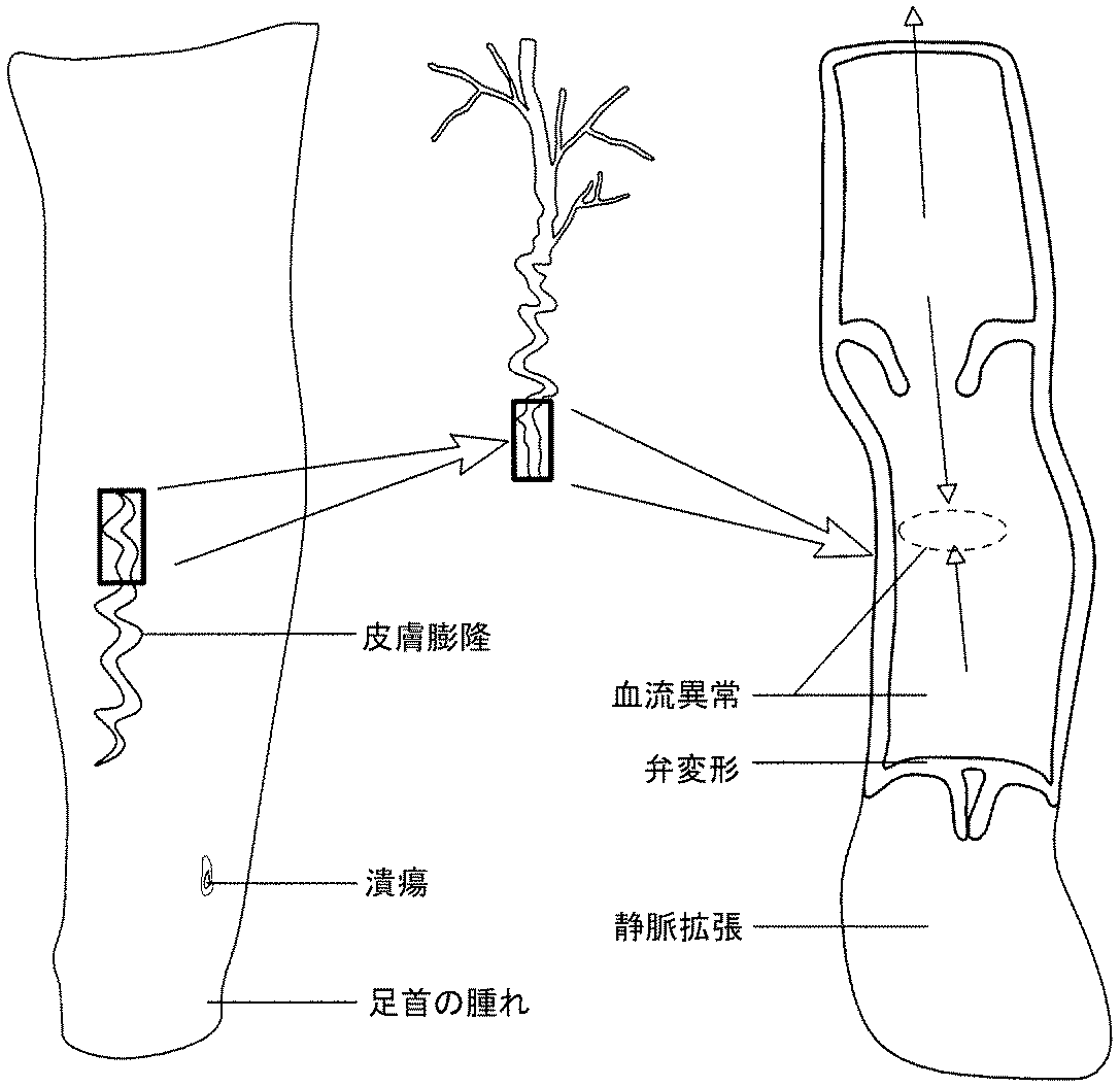
圧迫治療(CT)は、ラップ、ストッキング、膨張カフ及び包帯を使用する身体の一部分の選択的外部圧迫である。CTは、弾性か非弾性の包帯又は多層の包帯を使用する受動的圧迫(外部エネルギーが印加されない)か能動的圧迫のいずれかであり、能動的圧迫では、図1A〜Eに示されているように、身体部位に印加される圧迫力を外部エネルギー源が増強する。CTは、図2に示されている血管不全(動脈と静脈の両方)、リンパ浮腫、血栓後症候群、DVT予防、術後の疼痛/腫れ、脚の腫れ、静脈瘤、血液循環の向上、間欠性跛行症、手術不能な末梢動脈疾患、術後の腫れ、鬱血性心不全、スポーツ/運動からの回復、マッサージを含む多くの症状を処置するのに使用される。 Compression therapy (CT) is the selective external compression of a part of the body using wraps, stockings, inflation cuffs and bandages. CT is either passive compression (no external energy is applied) or active compression using elastic or inelastic bandages or multi-layered bandages, which are shown in FIGS. 1A-E. As such, the external energy source enhances the compression applied to the body site. CT shows the vascular failure (both arteries and veins), lymphedema, post-thrombotic syndrome, DVT prevention, post-operative pain / swelling, leg swelling, varicose veins, improvement of blood circulation, intermittent shown in Figure 2 It is used to treat a number of symptoms, including itching, inoperable peripheral artery disease, post-operative swelling, congestive heart failure, recovery from sports / exercise, massage.
現在利用可能な市販の圧迫包帯の幾つかの例は、3M、BSNメディカル(BSN Medical)、コンバテック(Convatec)、デルマサイエンス(Derma Sciences)、ハートマングループ(Hartman group)、ケンドル/コヴィディエン(Kendall/Covidien)、ローマンアンドローシャ(Lohman and Rauscher)、メドラインインダストリーズ(Medline Industries)、スミスアンドネフュー(Smith and Nephew)による製品を含む。圧迫包帯の圧迫力は、介護者による包帯の装着や巻き付けにより達成される。圧迫の一貫性は、包帯を装着する介護者の技術に依存する。包帯により印加される圧迫力の量についてのフィードバックはない。患者は、ストッキングがその伸展性を失うか汚れるまで包帯を着用する。包帯は一般的に、腕か脚に装着される。 Some examples of currently available commercial compression bandages are 3M, BSN Medical, BSN Medical, Convatec, Derma Sciences, Hartman group, Kendall / Covidien. Products from Lohman and Rauscher, Medline Industries, Smith and Nephew). The compression force of the compression bandage is achieved by wearing and winding the bandage by the caregiver. Consistency of compression depends on the skill of the caregiver wearing the bandage. There is no feedback on the amount of compression applied by the dressing. The patient wears a bandage until the stocking loses or becomes soiled. Bandages are generally worn on the arms or legs.
圧迫ストッキング(CS)は、一般的には長靴下や脚の靴下類のように脚下部を覆う弾性ストッキングである。ストッキングは、特定の圧迫レベルを提供するように販売され、たいていは足首の圧迫が高く、膝に向かって圧迫レベルが低下し、起立時の足首への高い静水圧を相殺する。 Compression stocking (CS) is an elastic stocking that generally covers the lower leg, like long socks and leg socks. Stockings are marketed to provide specific compression levels, usually with high ankle compression, lower compression levels towards the knees, to offset high hydrostatic pressure on the ankle when standing.
CSは、ある範囲の圧力を脚下部に付与するように設計されうる。例えば、弱い圧迫を与えるCSは20mmHg未満の圧力を付与する。中間的な圧迫は20から40mmHgの間で、強い圧迫は40と60mmHgの間であり、非常に強い圧迫は60mmHgを上回る。 The CS may be designed to apply a range of pressure to the lower leg. For example, a CS that gives weak compression will give a pressure less than 20 mm Hg. Intermediate compressions are between 20 and 40 mm Hg, strong compressions are between 40 and 60 mm Hg and very high compressions are above 60 mm Hg.
メーカーは、60mmHgまでの多様な圧迫レベルを用意している。CSメーカーのうち幾つかは、バウアーファインド(Bauerfeind)、BSN、ケンドル/コヴィディエン(Kendell/Covidien)、シグバリス(Sigvaris)を含む。 The manufacturer offers various compression levels up to 60 mmHg. Some of the CS makers include Bauerfeind, BSN, Kendell / Covidien, Sigvaris.
たいていは空気圧迫装置と呼ばれる能動的圧迫(AC)は、患者の脚又は足を包囲する空気室内蔵スリーブを使用する。ACの三つの主要カテゴリは、脚の静脈洞を圧迫するフットポンプ、スリーブ全体を同時に膨張及び収縮させる間欠性空気圧迫(IPC)、そしてスリーブの室を連続的に膨張させて血液(又はミルク)血液を足の方へ移動させて動脈流を強化するか、腰の方へ移動させて静脈のリンパ液を改善するか、運動後の乳酸の除去を強化する連続圧迫ポンプ(SC)である。 Active compression (AC), often referred to as an air compression device, uses an air chamber internal sleeve that surrounds the patient's leg or foot. The three main categories of AC are foot pumps that compress the sinus of the leg, intermittent pneumatic compression (IPC) that simultaneously inflates and deflates the entire sleeve, and blood (or milk) by continuously inflating the chamber of the sleeve. It is a continuous compression pump (SC) that moves blood towards the foot to enhance arterial flow, moves it to the waist to improve venous lymph, or enhances the removal of lactate after exercise.
AC装置は、図2に示されているようなプラグ接続式と充電式の両方のモバイルユニットとして製作される。ローラを使用してカフを延ばすヴェノウェイブ(Venowave)を例外として、空気圧迫装置は一般的に同じ方式で作動する。空気ポンプは、コンソールを介して制御されるブラダ又は一連の気密ブラダを充満させる。 AC devices are fabricated as both pluggable and rechargeable mobile units as shown in FIG. With the exception of Venowave, which uses a roller to extend the cuff, the air compression device generally operates in the same manner. The air pump fills a bladder or series of air tight bladders controlled via the console.
これらの形の圧迫治療すべてが、使用対象となる症状の処置又は防止に有益であるという強力な証拠が存在する。これらの技術すべてに見られる重大な欠点は、確認できない/一定しない圧力印加、かさばって通気性のないカフによる低い快適性、そしてストッキング又はラップの着脱の困難さである。これらの設計上の欠点は、70%もの高さであると推定されるこの技術のノンコンプライアンスを結果的に招く。圧迫治療に対する低いコンプライアンスの根本的な原因は多因子である。標準的な密着ストッキングは、すでに疾病により可動性が制限されている者にとっては着脱が難しい。患者がストッキングの着脱を助ける為にKYゼリーを脚部に塗布すると共に、ジョブストストッキングドナー(Jobst Stocking Donner)(型番110913)のような外的着脱補助具を使用するとの推奨に頼る医師もいる。加えて、これらのストッキングは多くのサイズで用意されるが、きつすぎて疼痛を与えるか緩すぎてストッキングがずり落ちてしまうエリアを含めて、ストッキングはたいてい、フィットしていないことによる問題を有している。酸化亜鉛と他の化合物を含むコットンラップの連続層で脚下部が巻かれる非弾性圧迫ラップ(例えばウナブーツ(Unna boot))は、剛性で快適ではないので患者が我慢できず、潰瘍からの滲出物の蓄積により悪臭を発生させ、毎週交換されなければならない。非弾性圧迫ラップはしばしば交換されなければならず、一般的に患者は静脈クリニックへ通って高い看護資源を利用する必要があるので、圧迫ラップは負担を増加させる。 There is strong evidence that all of these forms of compression therapy are beneficial for the treatment or prevention of the condition being used. The serious drawbacks found in all of these techniques are unverified / constant pressure application, low comfort due to bulky non-ventilated cuffs, and the difficulty of putting on or off the stocking or wrap. These design flaws result in the non-compliance of this technology, which is estimated to be as high as 70%. The root cause of low compliance with compression therapy is multifactorial. Standard tight stockings are difficult to attach and remove for persons who have already had limited mobility due to disease. Some doctors rely on the recommendation that patients apply KY jelly to their legs to aid in putting on and taking off their stockings and that they use external attachment / detachment aids such as Jobst Stocking Donner (Model No. 110913). . In addition, these stockings are available in many sizes, but stocking usually has problems due to it not fitting, including areas that are too tight and cause too much pain or slackness. doing. Inelastic compression wraps (for example Unna boot), in which the lower leg is wound with a continuous layer of cotton wrap containing zinc oxide and other compounds (eg Una boot), are stiff and not comfortable and can not be tolerated by patients and exudates from ulcers Build up of offensive odor and must be replaced weekly. Inelastic compression wraps often need to be replaced, and compression wraps increase the burden as patients generally need to go to a vein clinic to utilize high nursing resources.
米国内で罹患している何百万もの罹患患者と、不快である為に患者が使用を嫌がる装置による理解度の低い処置計画で患者を処置しようとする際に費やされる何十億ドルの為、より良い技術の必要性があるのは明らかである。その為、これらの問題に対処する革新的なマルチモード圧迫治療システムが必要である。 The millions of affected patients in the United States and the billions of dollars spent on trying to treat patients with poorly understood treatment plans with devices that they dislike using because they are uncomfortable It is clear that there is a need for better technology. Therefore, there is a need for an innovative multi-mode compression therapy system that addresses these issues.
本発明は、概して、圧迫治療を身体部位に提供するシステム及び方法に、詳しくは、能動的及び/又は適応型の圧迫治療を身体部位に提供するシステム及び方法に関する。 The present invention relates generally to systems and methods for providing compression treatment to a body part, and more particularly to systems and methods for providing active and / or adaptive compression treatment to a body part.
幾つかの実施形態では、圧迫治療を患者の身体部位に提供する為の装置が用意される。装置は、身体部位の上又は身体部位自体に載置されるように構成される駆動ユニットを含みうる。駆動ユニットは、一つ以上のモータと、一つ以上のモータの動作を制御するように構成される制御装置と、一つ以上のモータ及び制御装置との電気的連通状態にある電源と、複数のプーリと、一つ以上のモータにより引っ張られるように構成される一つ以上の駆動要素とを含み、一つ以上の駆動要素は複数のプーリに通され、さらに、身体部位の一部分に少なくとも部分的に巻かれるように構成される一つ以上の圧迫機構を含み、一つ以上の圧迫機構はプーリに装着され、プーリにより引っ張られるように構成される。 In some embodiments, an apparatus is provided for providing compression treatment to a body area of a patient. The device may include a drive unit configured to be mounted on the body part or on the body part itself. The drive unit includes one or more motors, a controller configured to control the operation of the one or more motors, a power supply in electrical communication with the one or more motors and the controller, and And one or more drive elements configured to be pulled by one or more motors, the one or more drive elements being threaded through the plurality of pulleys, and further including at least a portion of the body portion. And one or more compression mechanisms configured to be wound, wherein the one or more compression mechanisms are attached to the pulley and configured to be pulled by the pulley.
幾つかの実施形態において、複数のプーリは複数の可動プーリと複数の固定プーリとを包含し、圧迫機構は可動プーリに装着される。 In some embodiments, the plurality of pulleys includes a plurality of movable pulleys and a plurality of fixed pulleys, and the compression mechanism is attached to the movable pulleys.
幾つかの実施形態において、装置はさらに、可動プーリの移動を制限し、可動プーリを整合させるように構成される一つ以上の物理的ストップを含む。 In some embodiments, the apparatus further includes one or more physical stops configured to limit movement of the moveable pulley and to align the moveable pulley.
幾つかの実施形態において、駆動要素はコードとベルトとチェーンとから選択される。 In some embodiments, the drive element is selected from a cord, a belt and a chain.
幾つかの実施形態において、駆動ユニットは、連接されて第1プレート部分と第2プレート部分とを包含するベースプレートを包含する。 In some embodiments, the drive unit includes a base plate articulated to include a first plate portion and a second plate portion.
幾つかの実施形態において、一つ以上のモータは、第1プレート部分に配置される第1モータと、第2プレート部分に配置される第2モータとを包含し、複数のプーリは、第1プレート部分に装着される第1固定プーリセットと、第2プレート部分に装着される第2固定プーリセットとを包含する。 In some embodiments, the one or more motors include a first motor disposed in the first plate portion and a second motor disposed in the second plate portion, and the plurality of pulleys are A first fixed pulley set mounted to the plate portion and a second fixed pulley set mounted to the second plate portion.
幾つかの実施形態において、駆動ユニットはベースプレートを包含し、固定プーリは、ベースプレート内の一つ以上の通路内に配置される。 In some embodiments, the drive unit includes a base plate, and the fixed pulleys are disposed in one or more passages in the base plate.
幾つかの実施形態において、可動プーリは、ベースプレートの一つ以上の通路内に配置される。 In some embodiments, the movable pulleys are disposed in one or more passages of the base plate.
幾つかの実施形態において、可動プーリと固定プーリとの間に延在する一つ以上の駆動コードが一つ以上の通路内での可動プーリの移動方向と整合されるように、可動プーリと固定プーリとが一つ以上の通路内に配設される。 In some embodiments, the movable pulley and fixed are configured such that the one or more drive cords extending between the movable and fixed pulleys are aligned with the direction of movement of the movable pulley in the one or more passageways. A pulley and one or more passageways are disposed.
幾つかの実施形態において、装置はさらに、制御装置との通信状態にある一つ以上のセンサを含み、一つ以上のセンサは、患者に提供される圧迫治療に関連するデータ、及び/又は、患者の状態に関連するデータを測定するように構成される。 In some embodiments, the device further includes one or more sensors in communication with the controller, the one or more sensors including data related to compression treatment provided to the patient, and / or It is configured to measure data related to the condition of the patient.
幾つかの実施形態において、一つ以上のセンサは、装置により身体部位に印加される圧力の大きさを測定するように構成されるセンサを含む。 In some embodiments, the one or more sensors include a sensor configured to measure the amount of pressure applied by the device to a body site.
幾つかの実施形態において、一つ以上のセンサは、身体部位の周囲寸法又は体積を測定するように構成されるセンサを包含する。 In some embodiments, the one or more sensors include a sensor configured to measure the circumferential dimension or volume of a body part.
幾つかの実施形態において、装置はさらに、制御装置との通信状態にある無線通信モジュールを含む。 In some embodiments, the apparatus further includes a wireless communication module in communication with the controller.
幾つかの実施形態において、一つ以上の圧迫機構は衣服又は靴に一体化される。 In some embodiments, one or more compression mechanisms are integrated into the garment or shoe.
幾つかの実施形態において、駆動ユニットは衣服又は靴に一体化される。 In some embodiments, the drive unit is integrated into the garment or shoe.
幾つかの実施形態では、患者の身体部位を圧迫する為の方法が提供される。この方法は、着用圧迫装置の一つ以上の圧迫要素を身体部位の周りに締結することを含む。着用圧迫装置は、圧迫プレートと、圧迫プレートに配置されて、身体部位の周りに締結された一つ以上の圧迫要素を締め付けるか緩めるように構成される一つ以上のモータと、生理学的データ及び/又は装置性能データを測定するように構成される一つ以上のセンサと、パラメータセットに従って一つ以上のモータを制御する為の制御装置とを含みうる。この方法はさらに、圧迫治療を開始する前に一つ以上のセンサが予決定又は設定のパラメータを測定するまで一つ以上の圧迫要素の引張りを調節すること、一つ以上のモータを使用して身体部位を圧迫して一つ以上の圧迫要素を締め付けることを包含する第1圧迫サイクルを開始すること、そして、一つ以上のモータを使用して一つ以上の圧迫要素を緩めることにより身体部位を脱圧迫することと、第2圧迫サイクルを開始する前に少なくとも予決定又は設定量の時間だけ待機することと、一つ以上のセンサを使用して生理学的データ及び/又は装置性能データを測定することと、測定された生理学的データ及び/又は装置性能データに基づいて処置パラメータを調整することを含む。 In some embodiments, a method is provided for compressing a body region of a patient. The method includes fastening one or more compression elements of the wearing compression device around the body site. The wear compression device comprises a compression plate, one or more motors arranged on the compression plate and configured to tighten or loosen one or more compression elements fastened around the body part, physiological data and And / or may include one or more sensors configured to measure device performance data, and a controller for controlling one or more motors according to the parameter set. The method further comprises using one or more motors to adjust the tension of one or more compression elements until one or more sensors measure a predetermined or set parameter before starting compression treatment. Starting a first compression cycle that includes compressing the body site and tightening one or more compression elements, and the body site by loosening the one or more compression elements using one or more motors Measuring the physiological data and / or device performance data using one or more sensors, defusing the pressure, waiting at least a predetermined or set amount of time before starting the second compression cycle, and And adjusting the treatment parameters based on the measured physiological data and / or device performance data.
幾つかの実施形態において、予決定又は設定パラメータは、圧迫装置と身体部位との間の境界圧力である。 In some embodiments, the predetermined or setting parameter is the boundary pressure between the compression device and the body part.
幾つかの実施形態において、測定される生理学的データは、身体部位の周囲寸法又は身体部位の体積の測定値を包含する。 In some embodiments, the physiological data to be measured includes measurements of the perimeter of the body part or the volume of the body part.
幾つかの実施形態において、方法はさらに、一つ以上の圧迫要素の圧力を予決定レベルに調節することと、少なくとも約1分から24時間である長時間にわたって一つ以上の圧迫要素の引張りを予決定レベルに維持することとにより受動的圧迫治療を投与することを含む。 In some embodiments, the method further comprises adjusting the pressure of the one or more compression elements to a predetermined level, and pretensioning the one or more compression elements for an extended period of time of at least about 1 minute to 24 hours. Administering passive compression therapy by maintaining it at a defined level.
幾つかの実施形態において、方法はさらに、測定された生理学的データ及び/又は装置性能データを遠隔装置に無線で送信することを含む。 In some embodiments, the method further includes wirelessly transmitting the measured physiological data and / or device performance data to the remote device.
幾つかの実施形態において、方法はさらに、着用圧迫装置と第2着用圧迫装置との間に連通を確立することと、着用圧迫装置と第2着用圧迫装置との間で圧迫治療の投与を連携させることとを含む。 In some embodiments, the method further establishes establishing communication between the wear compression device and the second wear compression device, and coordinates administration of the compression treatment between the wear compression device and the second wear compression device. And including.
幾つかの実施形態において、一つ以上の圧迫要素は、連続的に締められる少なくとも二つの圧迫要素を包含する。 In some embodiments, the one or more compression elements include at least two compression elements that are tightened in series.
幾つかの実施形態では、身体部位を圧迫する為の装置が提供される。装置は、第1端部分と第2端部分とを有する圧迫伝達機構であって、身体部位の少なくとも一部分の周りに巻かれるように構成される圧迫伝達機構と、圧迫伝達機構を締め付ける及び/又は緩めるように構成される締め付け機構と、圧迫伝達機構の第1端部分の開始位置を設けるように構成される第1機械的ストップと、圧迫伝達機構の第2端部分の開始位置を設けるように構成される第2機械的ストップと、システムにより身体部位に印加される歪み、力、又は圧力を測定するように構成されるセンサと、圧迫伝達機構の第1端部分と第2端部分の両方を同時に移動させることにより圧迫伝達機構を締め付ける及び/又は緩めるように構成されるモータと、設定又は予決定の歪み、力、又は圧力をセンサが測定する時にインジケータを提供すると共に、歪みゲージが設定又は予決定の歪み、力、又は圧力を測定した後でモータを作動させることにより圧迫処置を開始するように構成される制御装置とを含む。 In some embodiments, an apparatus for compressing a body site is provided. The device is a compression transmission mechanism having a first end portion and a second end portion, the compression transmission mechanism configured to be wound around at least a portion of a body part, and / or clamp the compression transmission mechanism. A clamping mechanism configured to loosen, a first mechanical stop configured to provide a starting position for a first end portion of the compression transmission mechanism, and a starting position for a second end portion of the compression transmission mechanism A second mechanical stop configured, a sensor configured to measure strain, force or pressure applied by the system to the body site, both the first end portion and the second end portion of the compression transfer mechanism Simultaneously provides a motor configured to tighten and / or loosen the compression transfer mechanism by simultaneously moving the sensor, and an indicator when the sensor measures strain or force or pressure set or predetermined Including Rutotomoni, the strain of the strain gauge is set or pre-determined force, or a configured controller to initiate a compression treatment by operating the motor after measuring the pressure.
幾つかの実施形態において、圧迫伝達機構は、一つ以上の圧迫ストラップを包含する。 In some embodiments, the compression delivery mechanism includes one or more compression straps.
幾つかの実施形態において、圧迫伝達機構はさらに、一つ以上の圧迫ストラップにより発生される圧力を分配する為の一つ以上のパッドを包含する。 In some embodiments, the compression delivery mechanism further includes one or more pads for distributing the pressure generated by the one or more compression straps.
幾つかの実施形態において、圧迫伝達機構は、リール式引張り機構により締められるように構成される一つ以上の紐材を包含する。 In some embodiments, the compression transfer mechanism includes one or more straps configured to be tightened by a reeled tensioning mechanism.
幾つかの実施形態では、圧迫治療を投与する為のシステムが提供される。システムは、圧迫プレートと、圧迫プレートに配置されて、第1身体部位の周りに締結されるように構成される一つ以上の圧迫要素を締め付けるか緩めるように構成される一つ以上のモータと、生理学的データ及び/又は装置性能データを測定するように構成される一つ以上のセンサと、通信モジュールと、パラメータセットに従って一つ以上のモータを制御する為の制御装置とを包含する第1圧迫装置と、圧迫プレートと、圧迫プレートに配置されて、第2身体部位の周りに締結されるように構成される一つ以上の圧迫要素を締め付けるか緩めるように構成される一つ以上のモータと、生理学的データ及び/又は装置性能データを測定するように構成される一つ以上のセンサと、通信モジュールと、通信モジュールと、パラメータセットに従って一つ以上のモータを制御する為の制御装置とを含む第2圧迫装置とを含み、第1圧迫装置と第2圧迫装置とは、互いに連通して圧迫治療の投与を連携させるように構成される。 In some embodiments, a system is provided for administering compression therapy. The system includes a compression plate and one or more motors disposed on the compression plate and configured to tighten or loosen one or more compression elements configured to be fastened about the first body part. , One or more sensors configured to measure physiological data and / or device performance data, a communication module, and a control device for controlling one or more motors according to the parameter set A compression device, a compression plate, and one or more motors disposed on the compression plate and configured to tighten or loosen one or more compression elements configured to be fastened about the second body part And one or more sensors configured to measure physiological data and / or device performance data, a communication module, a communication module, and a parameter set. And a second compression device including a control device for controlling one or more motors, wherein the first compression device and the second compression device communicate with each other to coordinate administration of the compression treatment. Configured
幾つかの実施形態において、第1圧迫装置は、一つ以上のモータにより駆動されて、一つ以上の圧迫要素を締め付けるか緩めるように構成されるプーリ式駆動列を含む。 In some embodiments, the first compression device includes a pulley drive train configured to be driven by one or more motors to clamp or loosen one or more compression elements.
幾つかの実施形態において、プーリ式駆動列は複数の可動プーリを包含する。 In some embodiments, the pulley drive train includes a plurality of movable pulleys.
幾つかの実施形態において、プーリ式駆動列はさらに、可動プーリの移動を制限して可動プーリを整合させるように構成される一つ以上の物理的ストップを含む。 In some embodiments, the pulley drive train further includes one or more physical stops configured to limit movement of the moveable pulley to align the moveable pulley.
幾つかの実施形態では、圧迫治療を対象者に提供する為のシステムが提供される。このシステムは、対象者の身体部位に圧迫を提供するように構成される着用圧迫装置を含み、着用圧迫装置は、圧迫プレートと、圧迫プレートに配置される一つ以上のモータと、身体部位の周りに巻かれて一つ以上のモータにより締め付けられるか緩められるように構成される一つ以上の圧迫機構と、生理学的データ及び/又は装置性能データを測定するように構成される一つ以上のセンサと、パラメータセットに従って一つ以上のモータを制御する為の制御装置と、制御装置及び一つ以上のセンサとの通信状態にある無線通信モジュールと、着用圧迫装置の無線通信モジュールと無線で通信して、測定された生理学的データ及び/又は装置性能データを受信し、一つ以上のモータを制御する為のパラメータセットを調整するように構成される遠隔装置とを包含する。 In some embodiments, a system is provided for providing compression therapy to a subject. The system includes a wear compression device configured to provide compression to a body part of a subject, the wear compression device comprising a compression plate, one or more motors disposed on the compression plate, and a body part One or more compression mechanisms configured to be wound around and configured to be tightened or loosened by one or more motors, and one or more configured to measure physiological data and / or device performance data Wireless communication with the wireless communication module of the wearing compression device, the wireless communication module in communication with the sensor, the control device for controlling the one or more motors according to the parameter set, the control device and the one or more sensors Configured to receive measured physiological data and / or device performance data, and adjust a set of parameters for controlling one or more motors. Including a remote device.
幾つかの実施形態において、システムはさらに、遠隔装置との通信状態にあるサーバ又はクラウドコンピューティングネットワークを含み、サーバ又はクラウドコンピューティングネットワークは、母集団健康データと個人健康データとを含むデータベースを包含し、母集団健康データは、圧迫処置を使用したか使用している対象者の母集団からのデータを包含し、個人健康データは、対象者の医療データと対象者の生理学的データと装置性能データとを包含し、遠隔装置、サーバ、又はクラウドコンピューティングネットワークは、母集団健康データと個人健康データとに基づいて一つ以上のモータを制御する為のパラメータセットを調整するように構成される。 In some embodiments, the system further includes a server or cloud computing network in communication with the remote device, the server or cloud computing network including a database including population health data and personal health data. Population health data includes data from the population of subjects who used or are using compression treatment, and personal health data includes the subject's medical data and the subject's physiological data and device performance Containing data, the remote device, server or cloud computing network is configured to adjust a set of parameters for controlling one or more motors based on population health data and personal health data .
幾つかの実施形態において、遠隔装置は、スマートフォン、スマートウォッチ、タブレットコンピュータ、ラップトップコンピュータ、サーバ、コンピューティングデバイス、及びデスクトップコンピュータから成るグループから選択される。 In some embodiments, the remote device is selected from the group consisting of a smart phone, a smart watch, a tablet computer, a laptop computer, a server, a computing device, and a desktop computer.
幾つかの実施形態において、遠隔装置は、着用圧迫装置を無線で操作するようにプログラミングされる。 In some embodiments, the remote device is programmed to operate the wearing compression device wirelessly.
幾つかの実施形態において、遠隔装置は、着用圧迫装置を無線で操作して、能動的圧迫モードと受動的圧迫モードとの間で交替するようにプログラミングされる。 In some embodiments, the remote device is programmed to operate the wearing compression device wirelessly to alternate between the active compression mode and the passive compression mode.
幾つかの実施形態において、遠隔装置は、一つ以上の処置プロトコルに従って着用圧迫装置を無線で操作するようにプログラミングされる。 In some embodiments, the remote device is programmed to operate the wear compression device wirelessly according to one or more treatment protocols.
幾つかの実施形態において、処置プロトコルは予決定される。 In some embodiments, the treatment protocol is predetermined.
幾つかの実施形態において、処置プロトコルは、対象者及び/又は医療提供者によりカスタマイズされる。 In some embodiments, the treatment protocol is customized by the subject and / or the healthcare provider.
幾つかの実施形態において、制御装置及び/又は遠隔装置は、測定された生理学的データ及び/又は装置性能データに基づいて処置プロトコルのうち一つ以上を修正するようにプログラミングされる。 In some embodiments, the controller and / or the remote device are programmed to modify one or more of the treatment protocols based on the measured physiological data and / or device performance data.
幾つかの実施形態において、制御装置及び/又は遠隔装置は、測定された生理学的データ及び/又は装置性能データに基づいて処置プロトコルの一つを選択するようにプログラミングされる。 In some embodiments, the controller and / or the remote device are programmed to select one of the treatment protocols based on the measured physiological data and / or device performance data.
幾つかの実施形態において、遠隔装置は、測定された生理学的データ及び/又は装置性能データを表示するようにプログラミングされる。 In some embodiments, the remote device is programmed to display measured physiological data and / or device performance data.
幾つかの実施形態において、遠隔装置は、対象者コンプライアンスを監視して対象者コンプライアンスデータを表示するようにプログラミングされる。 In some embodiments, the remote device is programmed to monitor subject compliance and display subject compliance data.
幾つかの実施形態において、一つ以上のセンサは、歪みゲージ、圧力センサ、力センサ、心拍数センサ、GPS装置、血圧センサ、マイクロフォン、ホール効果センサ、汗生化学センサ、光センサ、インピーダンスセンサ、血餅検出センサ、血流センサ、超音波センサ、温度センサ、気体センサ、血液化学センサ、身体活動センサ、酸素センサ、EKGセンサ、ジャイロスコープ、及び加速度計から成るグループから選択される。 In some embodiments, one or more sensors include strain gauges, pressure sensors, force sensors, heart rate sensors, GPS devices, blood pressure sensors, microphones, Hall effect sensors, sweat biochemistry sensors, light sensors, impedance sensors, It is selected from the group consisting of clot detection sensors, blood flow sensors, ultrasound sensors, temperature sensors, gas sensors, blood chemistry sensors, physical activity sensors, oxygen sensors, EKG sensors, gyroscopes, and accelerometers.
幾つかの実施形態において、測定される生理学的データはプレチスモグラフィデータを含む。 In some embodiments, the physiological data measured comprises plethysmography data.
幾つかの実施形態において、制御装置及び/又は遠隔装置は、プレチスモグラフィデータに一部基づいて疾病状態及び/又は処置効果を判断するようにプログラミングされる。 In some embodiments, the controller and / or the remote device are programmed to determine the disease state and / or the treatment effect based in part on the plethysmography data.
幾つかの実施形態において、制御装置及び/又は遠隔装置は、プレチスモグラフィデータに基づいて処置プロトコルのうち一つ以上を修正するようにプログラミングされる。 In some embodiments, the controller and / or the remote device are programmed to modify one or more of the treatment protocols based on the plethysmography data.
幾つかの実施形態において、遠隔装置は、処置関連データについて対象者に指示するようにプログラミングされる。 In some embodiments, the remote device is programmed to direct the subject for treatment related data.
幾つかの実施形態において、遠隔装置は、圧迫処置及び/又は圧迫処置に対するコンプライアンスに関するリマインダを対象者に送るようにプログラミングされる。 In some embodiments, the remote device is programmed to send a reminder to the subject regarding the compression procedure and / or compliance with the compression procedure.
幾つかの実施形態において、遠隔装置は、圧迫処置及び/又は対象者に関する更新を医療提供者、家族、及び/又は他の管理者に送るようにプログラミングされる。 In some embodiments, the remote device is programmed to send compression treatments and / or updates regarding the subject to a health care provider, family member, and / or other administrator.
幾つかの実施形態において、遠隔装置は、測定される生理学的データ及び/又は装置性能データをサーバ又はクラウドコンピューティングネットワークにアップロードするように構成される。 In some embodiments, the remote device is configured to upload measured physiological data and / or device performance data to a server or cloud computing network.
幾つかの実施形態では、圧迫処置を対象者に提供する為のシステムが用意される。このシステムは、処置パラメータセットに従って対象者の身体部位に圧迫を与えるように構成される着用圧迫装置であって、身体部位に印加される圧迫のレベルを測定すると共に生理学的データ及び/又は装置性能データを測定するように構成される複数のセンサと、身体部位に印加される圧迫のレベルを記録するメモリと、着用圧迫装置により与えられる圧迫を制御する為の制御装置と、制御装置との通信状態にある無線通信モジュールとを包含する着用圧迫装置と、着用圧迫装置の無線通信モジュールと無線で通信して、測定された生理学的データ及び/又は装置性能データを受信し、着用圧迫装置を制御する為の処置パラメータセットを調整するように構成される遠隔装置と、遠隔装置との通信状態にあるサーバ又はクラウドコンピューティングネットワークであって、母集団健康データと個人健康データとを含むデータベースを含むサーバ又はクラウドコンピューティングネットワークとを含み、母集団健康データが、圧迫処置を使用したか使用している対象者の母集団からのデータを包含し、個人健康データが対象者の医療データと対象者の生理学的データと装置性能データとを含み、遠隔装置、サーバ又はクラウドコンピューティングネットワークが、母集団健康データと個人健康データとに基づいて圧迫装置を制御する為のパラメータセットを調整するように構成される。 In some embodiments, a system is provided for providing compression treatment to a subject. The system is a wear compression device configured to apply compression to a subject's body part according to a set of treatment parameters, wherein the level of compression applied to the body part is measured and physiological data and / or device performance Communication between a plurality of sensors configured to measure data, a memory for recording the level of compression applied to the body part, a control device for controlling the compression provided by the wearing compression device, and a control device And wirelessly communicate with the wireless communication module of the wearing compression device to receive measured physiological data and / or device performance data to control the wearing compression device. A remote device configured to adjust a set of treatment parameters for communication with a server or cloud computer in communication with the remote device; Networking, which includes a server or a cloud computing network including a database containing population health data and personal health data, the population health data comprising the mother of the subject using or using compression treatment. Includes data from the population, personal health data includes the subject's medical data, subject's physiological data and device performance data, and the remote device, server or cloud computing network includes population health data and personal health It is configured to adjust a set of parameters for controlling the compression device based on the data.
幾つかの実施形態において、複数のセンサは、対象者の身体部位周囲寸法、身体部位体積、姿勢、身体活動レベル、静脈充満時間、静脈逆流、静脈指数、潰瘍状態、心拍数、酸素レベル、温度、血圧、汗生化学、インピーダンス、温度、酸素レベル、電気活動、そして血流ダイナミクスから成るグループから選択される生理学的データを測定するように構成される。 In some embodiments, the plurality of sensors may be a subject's body part circumference dimension, body part volume, posture, physical activity level, venous filling time, venous regurgitation, venous index, ulcer status, heart rate, oxygen level, temperature Configured to measure physiological data selected from the group consisting of: blood pressure, sweat biochemistry, impedance, temperature, oxygen levels, electrical activity, and blood flow dynamics.
幾つかの実施形態において、圧迫装置を制御する為の処置パラメータセットは、圧迫レベルと圧迫期間と圧迫頻度と圧迫速度とを含む。 In some embodiments, the treatment parameter set for controlling the compression device includes compression level, compression period, compression frequency and compression rate.
幾つかの実施形態において、圧迫装置はさらに、一つ以上のモータにより駆動されるプーリ式駆動列を含む。 In some embodiments, the compression device further includes a pulley drive train driven by one or more motors.
幾つかの実施形態において、圧迫装置を制御する為のパラメータセットは、人工知能又は機械学習アルゴリズムに基づいて修正される。 In some embodiments, the parameter set for controlling the compression device is modified based on artificial intelligence or machine learning algorithms.
幾つかの実施形態において、遠隔装置、サーバ、又はクラウドコンピューティングネットワークは、圧迫処置に対する対象者のコンプライアンスを監視するようにプログラミングされる。 In some embodiments, the remote device, server, or cloud computing network is programmed to monitor the subject's compliance with the compression treatment.
幾つかの実施形態において、遠隔装置、サーバ、又はクラウドコンピューティングネットワークは、圧迫処置を開始するリマインダを対象者に送るようにプログラミングされる。 In some embodiments, the remote device, server, or cloud computing network is programmed to send a reminder to the subject to initiate a compression procedure.
幾つかの実施形態において、遠隔装置、サーバ、又はクラウドコンピューティングネットワークは、対象者と他の管理者により確認される対象者の圧迫処置に関する状態更新を作成するように構成される。 In some embodiments, the remote device, the server, or the cloud computing network is configured to create a status update regarding the subject's and the subject's compression treatment identified by the subject and other administrators.
幾つかの実施形態では、圧迫治療を対象者に投与する為の装置が提供される。この装置は、対象者の身体部位を圧迫するように構成される着用圧迫機構と、対象者の生理学的データ及び/又は着用圧迫機構の性能データを測定するように構成される一つ以上のセンサと、圧迫パラメータセットに基づいて着用圧迫機構を制御し、測定された生理学的データ及び/又は性能データに基づいて、機械学習及び/又は人工知能アルゴリズムを使用して圧迫パラメータセットを調整するように構成される制御装置とを含みうる。 In some embodiments, an apparatus is provided for administering compression therapy to a subject. The device comprises a wear compression mechanism configured to compress a body part of a subject, and one or more sensors configured to measure physiological data of the subject and / or performance data of the wear compression mechanism. And control the wearing compression mechanism based on the compression parameter set, and adjust the compression parameter set using machine learning and / or artificial intelligence algorithm based on the measured physiological data and / or performance data. And a controller configured.
幾つかの実施形態では、圧迫治療を対象者に投与する為の装置が提供される。装置は、対象者の身体部位を圧迫するように構成される着用圧迫機構と、着用圧迫機構と身体部位との間の境界圧力を測定するように構成されるセンサと、圧迫パラメータセットに基づいて着用圧迫機構を制御し、測定された境界圧力に基づいて身体部位の圧迫を開始する、及び/又は、圧迫パラメータセットを調整するように構成される制御装置とを含みうる。 In some embodiments, an apparatus is provided for administering compression therapy to a subject. The device is based on a wear compression mechanism configured to compress the subject's body part, a sensor configured to measure the boundary pressure between the wear compression mechanism and the body part, and a compression parameter set A controller configured to control the wear compression mechanism, initiate compression of the body site based on the measured boundary pressure, and / or adjust the set of compression parameters.
本発明の新規の特徴は、以下の請求項に詳しく提示される。本発明の特徴及び利点のより深い理解は、発明の原理が利用される例示的実施形態を提示する以下の詳細な説明を参照することにより得られ、例示的実施形態の添付図は次の通りである。
本明細書に記載されるのは、圧迫治療を、快適で一貫性があり、使用容易で実績のある治療との適合性を高めるようにカスタマイズさせるシステムと装置と方法である。加えて、効果的で低輪郭の機械的駆動システムを最新の検知・データ管理・遠隔インタフェースとの組み合わせで使用すると、成果を高める機能をシステムに付加することが可能である。システムの基本は、身体の一部位の周りの多数の圧迫バンドの間での機械的な引張りと治療の連携である。さらに、センサ、機械的フィードバック、そして個々の患者の解剖学的構造、生理学、耐性、治療需要に合わせた実時間監視と調節と適応化とを可能にするユーザ入力により、システムが実行可能となる。最後に、独自のデータスチームは、機械的、生理学的イメージングを含めてこの装置を形成し、個人と母集団の両方にとって治療を最適化する為、患者フィードバックデータは解析と人工知能により個人と母集団の両方に基づいて活用されうる。 Described herein are systems, devices, and methods that allow compression treatment to be customized to enhance comfort, consistency, ease of use, and compatibility with proven treatments. In addition, using an effective, low profile mechanical drive system in combination with modern sensing, data management, and remote interfaces, it is possible to add performance enhancing features to the system. The basis of the system is the coordination of mechanical tension and treatment between multiple compression bands around one part of the body. In addition, sensors, mechanical feedback, and user input that enables real-time monitoring, adjustment, and adaptation to individual patient anatomy, physiology, tolerance, and treatment needs make the system viable. . Finally, unique data steam forms this device, including mechanical and physiological imaging, and patient feedback data is analyzed and artificial intelligence to optimize the treatment for both individuals and the population. It can be exploited based on both groups.
本明細書に記載されるのは、遠隔監視性能との適合性を促進する可動かつ軽量で通気性の簡易境界面での標準的な圧迫と能動的治療の両方を可能にするシステムと装置と方法である。大量の処置成果データベースの蓄積を通した良好な成果を促進する為に、歪みゲージプレチスモグラフィ、傾斜検知、コンプライアンス、及び遠隔監視という付加的な特徴が含まれる。様々な実施形態は、特定患者の必要性と疾病状態の進行を学習してこれに適応するカスタマイズ処置を具現する為に実時間データと専用アルゴリズムとを使用できる「スマート」ストッキングを含む。 Described herein are systems and devices that allow for both standard compression and active treatment with a movable, lightweight, breathable simple interface that promotes compatibility with remote monitoring capabilities. It is a method. Additional features of strain gauge plethysmography, tilt sensing, compliance, and telemonitoring are included to facilitate good results through the accumulation of a large treatment outcome database. Various embodiments include "smart" stockings that can use real-time data and specialized algorithms to implement customized procedures that learn and adapt to the needs of a particular patient and the progression of the disease state.
幾つかの実施形態では、図3A〜3Cに示されているように、圧迫システム300の基本的コンポーネントは、一つ以上のギヤードモータ304と、電源(例えばバッテリ)306と、プロセッサとメモリとを備える電子制御基板308と、無線性能と、駆動コード310と圧迫プレート316に固定される可動プーリ312と固定プーリ314の両方とを含むプーリ式の力伝達駆動列と、圧迫伝達コンポーネント318と、ふくらはぎアンダーストッキング320と、パディング322と、装着機構と、足首圧迫アンダーストッキングと、遠隔制御システムと、例えば圧力センサや加速度計のような様々なセンサ324及び診断コンポーネントを含む圧迫装置302を含む。モータ304は、駆動コード310が装着された駆動プーリ326を回転させる。
In some embodiments, as shown in FIGS. 3A-3C, the basic components of
プーリレスである代替的な駆動列は、例えば米国特許出願公開第2008/0066574号に記載されているような、圧迫ストラップ又は機構に一端部で装着される駆動コードのツイストペアを使用することを含む。アクチュエータツイストペアの他端部は、駆動コードツイストペアをねじってツイストペアを短くし、力と圧迫とを発生させることのできるモータに装着され、モータがツイストペアのねじれをほどいてツイストペアを長くすると、力と圧迫とを軽減できる。また別のプーリレス駆動列は、駆動コードを圧迫ストラップ又は機構に直接的に装着してプーリを省略することを含みうる。 An alternative drive train that is pulleyless includes using a twisted pair of drive cords attached at one end to a compression strap or mechanism, as described, for example, in US Patent Application Publication No. 2008/0066574. The other end of the actuator twist pair is attached to a motor that can twist the drive cord twist pair to shorten the twist pair and generate force and compression, and when the motor untwists the twist pair and lengthens the twist pair, the force and compression Can be reduced. Yet another pulleyless drive train can include attaching the drive cord directly to the compression strap or mechanism and omitting the pulleys.
例えば、システムは、以下の表1に挙げられた部品及び特徴を含みうる。
要約すると、モータは駆動プーリで駆動シャフトを回す。駆動プーリは、プーリ式駆動列に通された駆動コードを巻き取り、駆動列は、圧迫プレートに固定される圧迫プレートプーリと、モータから圧迫ストラップシステムへ力を伝達する可動圧迫ストラッププーリの両方を含む。駆動プーリが駆動コードを巻き取る際に圧迫ストラップに引張りが印加され、モータと、駆動シャフト及び装着された駆動プーリの回転とを逆転させることにより引張りが解放され、こうして駆動コードを巻き出すことができる。加えて、圧迫された脚又は他の身体部位は当然、巻き出し及び取り出しを促進する反力を提供する。 In summary, the motor turns the drive shaft with the drive pulley. The drive pulley winds up the drive cord passed through the pulley drive train, and the drive train comprises both a compression plate pulley fixed to the compression plate and a movable compression strap pulley transmitting power from the motor to the compression strap system Including. Tension is applied to the compression strap as the drive pulley winds up the drive cord and the tension is released by reversing the motor and the rotation of the drive shaft and the attached drive pulley, thus unwinding the drive cord it can. In addition, the squeezed legs or other body parts naturally provide a counteracting force that facilitates unrolling and unrolling.
さて、システムをより詳しく説明する。図4に示されているように、圧迫ストッキング又はスリーブとも呼ばれるアンダーストッキング400が、腕、脚、手、つま先、指、胸など所望の四肢又は身体部位に載置される。アンダーストッキング400は、ストッキングの布又は材料に織り込まれる非弾性の糸、ワイヤ、及び/又はコード、織り合わされた歪みゲージや他のゲージ又はセンサ(例えば温度、O2、超音波検査)、一体的な補助療法の投与(例えば光、LED、薬物、音波、気体、電気筋肉刺激、加熱、冷却)など一体的な能動的及び/又は受動的圧迫/引張り機構402を有する、及び/又は、抗菌性材料(銀又は超微細メリノウール等)で構成されうる。ストッキングは、可動プーリ406と固定プーリ408とを含む本明細書に記載のプーリ式駆動列404と、駆動プーリ412に装着される駆動コード410とを含みうる。駆動プーリは、駆動プーリ412の境界との結合の為の相補的な境界面を有するモータ416を備える駆動ユニット414に結合されうる境界を有する。駆動ユニットは、電子機器、ユーザインタフェース、バッテリ、ストッキングと組み合わされて完成品の圧迫装置を形成する他のコンポーネントを含みうる。処置ゾーン(例えば創傷エリア)を確認可能にする、及び/又は、圧迫治療と共に光線治療が施されるように、アンダーストッキングは透明又は一部透明の材料で製作されうる。圧迫ストッキングは、創傷の処置が行われる前及び/又は間の創傷露出等の為に取り外されるかジッパーで開けられるか若しくは開かれてストッキングの下側へのアクセスを可能にする、及び/又は、患者の皮膚と接触する為のアクセスをセンサに与えることのできる一つ以上のフラップなど、規定又は予決定の開口、ゾーン、エリア、若しくはセクションを有しうる。圧迫ストッキングは、ファン、細孔、芯材のような材料設計を含めるなど通気性を向上させる一つ以上の能動的/受動的コンポーネントを有しうる。ストッキングは、システムにより能動的に動力供給される、及び/又は、監視されうる創傷治癒の為の負圧治療コンポーネントを含みうる。例えば、モータは、創傷の上に載置される密閉創傷ドレッシングに負圧を発生させるポンプを駆動できる。ストッキング構造設計は、さらに本明細書に記載されるように、スマートストッキングに含まれて基準圧力及びコンプライアンスを維持/監視する付加的な任意の能動的ユニットを追加せずに、能動的及び/又は受動的圧迫を提供しうる。能動的と受動的のいずれかの圧迫を提供しうるストッキングは、一体的センサからデータを収集し、それに応じて形状又は構成を変化させうる。圧迫ストッキングは以下のうち一つ以上を取り入れた材料から製作されうる。不織布、ニット、織布、押出成形品、付加製造によるコンポーネント、電子機器、金属、高分子、天然材料。これらの材料(織布、ニット、付加製造品)は、圧迫治療及び他の治療の提供が可能な着用コンポーネントに一体化されうる。ストッキングの履きやすさを高める為、ジッパー、フック、及び/又はループや、他の補助的装着機構及び方法が、身体部位にストッキングを載置するのに使用されうる。例えば、ストッキングは開放状態で身体の上に載置されてから、装着機構が閉止又は付着されて閉止状態を達成する。加えて、履きやすい多数の弾性アンダーストッキングが一つ以上のエリアに重ねられて、組み合わせによる高度な圧迫が重複領域で達成されうる。さらに、ストッキングとシステムの他のコンポーネントのような二つ以上の圧迫治療コンポーネントの載置は、相乗的と単独のいずれかで処置を提供できる。幾つかの実施形態において、アンダーストッキングは15,10,又は5mmHg未満など最小の圧迫を提供し、後述するように主として圧迫装置と患者の整合及び位置決めを補助するように機能できる。
Now, the system will be described in more detail. As shown in FIG. 4, an
圧迫プレート/能動的圧迫アセンブリを、圧迫ストッキング及び/又はストッキングに一体化された圧迫ストッキングアタッチメントのインデックスマーカ又はパターンと整合させることにより、圧迫プレート/能動的圧迫アセンブリはストッキング又はその周りに適切に位置合わせ、整合、配置されうる。例えば図10B及び10Cに示されているように、位置合わせは、面ファスナ、プラグ、スナップ、磁石、ストラップ、及び/又はスロットなどの締結機構を使用してシステムの能動的コンポーネントを受動的圧迫ストッキングに装着するのに、視覚的、機械的、磁気的、又は電子的な機構及び/又は方法を利用できる。幾つかの実施形態において、システムは、身体部位へのストッキングの適切な載置とストッキングへの能動的制御ユニットの適切な載置に関して、能動的な指示及び/又はフィードバックを提供する。ストッキングのサイズ調整は、圧迫される脚下部又は身体部位の長さ及び外周の測定により判断されうる。 By aligning the compression plate / active compression assembly with the compression stocking and / or the index markers or pattern of the compression stocking attachment integrated into the compression stocking, the compression plate / active compression assembly is properly positioned on or around the stocking It can be aligned, aligned and arranged. For example, as shown in FIGS. 10B and 10C, the alignment passively compressions the active components of the system using fastening mechanisms such as hook and loop fasteners, plugs, snaps, magnets, straps, and / or slots. A visual, mechanical, magnetic or electronic mechanism and / or method may be used to mount the device. In some embodiments, the system provides active instructions and / or feedback on the proper placement of the stocking on the body part and the proper placement of the active control unit on the stocking. Stocking sizing can be determined by measuring the length and circumference of the lower leg or body part being compressed.
図5Aに示されているように、システムの能動的コンポーネントは、能動的圧迫治療を開始する前に、位置合わせ又はゼロ合わせを行って確実で一貫した基準の構成を確立できる。圧迫ストロークサイクルの開始時に、圧迫プレートの両側の外側エッジに沿ったハードストップ502,504に接する「ゼロ」位置に、可動プーリ又は圧迫ストラッププーリとも呼ばれる駆動ベアリング500を置くか位置決めすることにより、これが達成されうる。圧迫プレートの両側にストップを設けると、可動プーリ500が中心から外れてその結果として圧迫サイクル中に不要なトルクが身体部位に印加されるのを防止する。ストップ502,504により、可動プーリ500は圧迫サイクルの始めに適切な位置に確実に配置されて、図5Bに示されているように、システムは、均衡の取れた確実で一貫した量の能動的圧迫を身体部位に提供することができる。基準条件へのシステムのゼロ合わせは、機械的な手段、特徴、又は機構により規定及び/又は制御され、こうして予決定されうるリミットを圧迫プレート沿いの可動プーリの移動に与えることにもなる。例えば、システムは、圧迫プレートでの可動プーリ/圧迫ストラッププーリの移動を制限する機械的ハードストップを有し、可動プーリを整合させるように機能する。圧迫プレートのエッジにストップが載置される場合には、ストップがさらなる動きを防止する前に可動プーリが圧迫プレートのエッジまで移動できる。可動プーリをゼロ合わせするこの簡単な方法/機構は、システムを身体部位に取り付けるのに使用される方法に関係なくプーリ移動位置を「ゼロ」位置に設定することにより、装着方法を能動的圧迫方法から切り離す。幾つかの実施形態では、システムをゼロ点に設定するのにシステムの充電又は動力供給は何も必要ない。可動プーリがゼロ位置にあるようにユーザによりシステムが機械的に調節されうる。幾つかの実施形態では、装置を身に着けて装置を身体部位に締結する動作は、自動的に可動プーリをストップに引き寄せ、結果的に可動プーリはゼロ位置に配置される。
As shown in FIG. 5A, active components of the system can be aligned or zeroed to establish a reliable and consistent reference configuration prior to initiating active compression therapy. At the beginning of the compression stroke cycle, this is achieved by placing or positioning the drive bearing 500, also called movable pulley or compression strap pulley, in a “zero” position adjacent to the
例えば図3A,6G,6Hに示されているシステムの圧迫ストラップは、常連の患者固有の圧迫ストラップ位置合わせ箇所まで事前に引っ張られる。ストラップは、適切な事前引張りゾーンを指示する為、ストラップ上のマーキングなどの視覚的及び/又は機械的な指示を引張りシステムに含みうる。代替的に、圧力センサ、力センサ、又は歪みゲージが引張りを測定するのに使用され、可聴音又はLED光などのインジケータが、正しい引張りレベルに達したことをユーザに指示できる。幾つかの実施形態では、図6Iに示されているように、独立圧迫ストラップ618が様々な位置で互いに交差して、圧迫を強化したエリアが設けられている。圧迫ストラップに印加される引張りは、プーリ、ギヤ、及び/又は多数のプーリにより提供されるメカニカルアドバンテージを通して発生され、こうしてモータにより発生される力は圧迫ストラップに印加された時に増幅される。圧迫ストラップは、ストラップに印加される所与の力又は引張りの為にストラップの一部分でのエリア縮小又は拡大により、脚に印加される圧力が上昇及び/又は低下したエリアを有しうる。ストラップのエリアが増大すると、ストラップにより印加される力が広いエリアに分散され、こうして印加される圧力を軽減する。代替的又は付加的に、圧迫ストラップに印加される力を増加又は減少することにより、圧迫ストラップは身体部位へ印加される圧力を増減することができる。例えば面ファスナやラチェット機構のような多様な機構を使用して圧迫ストラップが締め付けられて固着されうる。 For example, the compression straps of the system shown in FIGS. 3A, 6G, 6H are pre-pulled to the regular patient-specific compression strap alignment points. The strap may include visual and / or mechanical instructions, such as markings on the strap, in the tensioning system to indicate the appropriate pretensioning zone. Alternatively, a pressure sensor, force sensor or strain gauge can be used to measure the tension and an indicator such as an audible sound or LED light can indicate to the user that the correct tension level has been reached. In some embodiments, as shown in FIG. 61, independent compression straps 618 cross each other at various locations to provide areas of enhanced compression. The tension applied to the compression strap is generated through the mechanical advantage provided by the pulleys, gears, and / or multiple pulleys, and thus the force generated by the motor is amplified when applied to the compression strap. The compression strap may have an area where the pressure applied to the leg is increased and / or decreased due to the area contraction or enlargement at a portion of the strap for a given force or tension applied to the strap. As the area of the straps increases, the force applied by the straps is distributed over a larger area, thus reducing the pressure applied. Alternatively or additionally, the compression strap can increase or decrease the pressure applied to the body site by increasing or decreasing the force applied to the compression strap. The compression strap can be tightened and secured using various mechanisms, such as, for example, hook and loop fasteners and a ratcheting mechanism.
図6A〜6Jに示されているように、身体部位に、そして任意で圧迫ストッキング320の上に圧迫装置600を固着するのに、多様な閉止システムが使用されうる。例えば、圧迫ストラップ618が、例えば患者の脚下部の正面、側面、又は背面のような患者の身体部位の一部分と適合するパッド602及び/又はバッキングコンポーネント604のような別の力伝達コンポーネントと交換されるかこれと共に使用されうる。バッキングコンポーネント604は、装置を身体部位に装着する為の閉止システムを含む、及び/又は閉止システムと一体化されうる。例えば、図6Cに示されているように、閉止システムは、米国特許第6,202,953号、第7,954,204号、第8,468,657号に記載されているような締め付け機構606と紐材システム608とを含みうる。幾つかの実施形態では、図6Bに示されているように、単にバッキングコンポーネント604を圧迫ストラップ618の下に配置し、ストラップガイド620を使用して圧迫ストラップ618をバッキングコンポーネント604に固着することにより、代わりに面ファスナを使用してバッキングコンポーネントが圧迫ストラップ618に使用されうる。例えばクリップ又はバックル又は磁気締結部のような締結具610が、締め付け機構と係合する前に身体部位の周りで閉止システムを開閉するのに使用されうる。圧力センサ、温度センサ、及び加速度計などのセンサが、バッキングコンポーネントに埋め込まれてもよい。
As shown in FIGS. 6A-6J, a variety of closure systems may be used to secure the
パッド602とバッキングコンポーネント604とは、脚下部の前部分に密着する成形EVAフォーム又はプラスチックでありうる。パッド及びバッキングコンポーネントの使用により、個別の圧迫ストラップのみを使用するよりも圧迫力が均一に身体部位に伝達され、これは患者快適性を向上させる。紐材が患者の皮膚へ力を直接伝達しないことを保証する為、バッキングコンポーネントは、閉止システムの紐材に隣接又は近接する脚部の部分を被覆するサイズ及び形状を有しうる。圧迫ストラップが使用される場合に、バッキングコンポーネント604は、図6Bに示されているように、バッキングコンポーネントを装置の残部に装着してこれと整合させる為のループのような圧迫ストラップガイド620を含みうる。
The
他の実施形態は、紐材システム608の紐材を締め付けるのに締め付け機構606を使用する、図6Cに示されている代替的な閉止システムを利用しうる。締め付け機構606は、紐材が巻かれてほどかれるラチェット機構を備える回転リールでありうる。締め付け機構606はバッキングコンポーネント604に載置され、紐材は可動プーリに装着される。ホール効果センサのようなセンサがリールに含まれて、身体部位の外周を判断する為にリールの周りに巻かれる紐材の量を測定し、こうして処置の成功及び効果と相関する身体部位の体積が判断されうる。紐材は、閉止システムを形成する複数の紐材ガイドに通される。留め金、ラッチ、バックル、クリップ、又は他の締結機構のような締結部610は、閉止システムを開閉させて装置の着脱を容易にするように設けられうる。図のように、閉止を促進する為に磁気留め金が使用されうる。図6Cには単一の締め付け機構のみが示されているが、他の実施形態では、2,3,又は4個の締め付け機構のような複数の締め付け機構、又は各圧迫ゾーンに一つの締め付け機構を有しうる。
Other embodiments may utilize the alternative closure system shown in FIG. 6C, which uses a
圧迫プレートとモータとプーリシステムと制御装置とバッテリと駆動コードとを含む圧迫コンポーネントも、バッキングコンポーネント602について上述したようなフォームや他の快適材料で製作されうるパッド602に配置されうる。圧迫コンポーネントが取り外し可能にパッドに装着されて、パッドが汚れるか脚の周囲寸法が変化した時など、必要な時にパッドの交換を可能にする。
A compression component including a compression plate, motor, pulley system, controller, battery and drive cord may also be disposed on the
他の閉止システムは異なる引張り機構を使用しうる。例えば、図6A及び6Dは、代替的なリール式引張り機構606’,606”を図示している。ホイールの周りに巻かれて固定の為に使用されるストラップ、紐材、コード、又はリボンに周知の一定量の力を印加するバネによってリールが駆動されうる。約5,10,15,20,25,30mmHgのような予決定された量の基準圧迫を提供するように、バネが選択されうる。各圧迫ゾーンについて、図6Aに示されているように二つのストラップ618’を備える単一のリール606’が使用されるか、図6Eに示されているように各々が単一のストラップ618’を備える二つのリール606”が使用されうる。
Other closure systems may use different tensioning mechanisms. For example, Figures 6A and 6D illustrate alternative reeled
図6Dは、ラチェットストラップ618”に基づくまた別の引張り機構606”’を図示している。ストラップは歯を有し、回転ノブ又は他のラチェット機構が歯に沿って移動してストラップを締め付ける。
FIG. 6D illustrates yet another
図6Fは、紐材608’を使用する閉止システムの別の実施形態を図示している。紐材の両端部を引くことにより、ユーザによって紐材が手で締め付けられる。シンチング機構609は、紐材を締め付けるか解放して紐材を緩めた後に紐材を所定箇所に保持できる。
FIG. 6F illustrates another embodiment of a closure system that uses strap 608 '. By pulling both ends of the string material, the string material is manually tightened by the user. The
図6Bは、面ファスナを備える圧迫ストラップ618の使用を図示している。図6Gは、すべての圧迫ストラップ618を締め付けるか緩めるのに使用されるプーリ式駆動列670を駆動するのに単一のモータ660が使用されうることを図示している。圧迫ストラップ618の孔又はグロメットは、可動プーリとして作用しうる。図6Hは、平行構成で配設される圧迫ストラップ618を示し、一方で図6Iは、重複エリアに圧迫強化エリアを備える重複交差構成で配設された圧迫ストラップ618を図示している。
FIG. 6B illustrates the use of a
図6Jは、ストラップ618、駆動コード310又は紐材がプーリ612,614又はアイレットに沿ってストッキング650又はスリーブに一体化されて、圧迫レベルが調節可能なストッキングが設けられる実施形態を図示している。ストラップ又は駆動コードの両端部を引くと、圧迫ストッキングを締め付ける。
FIG. 6J illustrates an embodiment where
本明細書の記載では概して圧迫ストラップの使用が記されているが、本明細書に記載される閉止システムのいずれかが代わりに使用されてもよい。 Although the description herein generally describes the use of compression straps, any of the closure systems described herein may be used instead.
幾つかの実施形態において、着用センサ(例えば圧力、力、及び/又は歪みセンサ)と、圧迫ストラップ及び/又は圧迫プレートにより印加される圧力又は引張りを規定の基準状態又は値に合わせるフィードバックシステムとを介して、能動的フィードバックが提供される。例えば、駆動コードの線上のセンサが所望の歪みを読み取るか、患者の皮膚又は圧迫ストッキングに接したセンサが所望の圧力を測定するか、歪みと相関するモータへの負荷と相関しうる予決定又は設定の電流をモータが引き出したことをセンサが測定するまで、モータが駆動されて駆動プーリを回転させる。 In some embodiments, a wear sensor (eg, a pressure, force, and / or strain sensor) and a feedback system that adjusts the pressure or tension applied by the compression strap and / or compression plate to a prescribed reference condition or value Active feedback is provided through. For example, a sensor on the line of the drive cord reads the desired strain, or a sensor in contact with the patient's skin or compression stockings measures the desired pressure, or a pre-determination that can be correlated with the load on the motor correlating to the strain The motor is driven to rotate the drive pulley until the sensor measures that the motor has drawn the set current.
センサは、ストッキング、バッキングコンポーネント(例えばフォームカフ)、圧迫ストラップ、駆動コード、締結機構用の紐材、締結機構の引張りリール、モータ、及び/又は、力/圧力伝達コンポーネントに一体化されうる。 The sensor may be integrated into a stocking, a backing component (e.g. a foam cuff), a compression strap, a drive cord, a strap for a fastening mechanism, a tensioning reel of a fastening mechanism, a motor and / or a force / pressure transmission component.
システムは、能動的圧迫係合に先立ってユーザ/患者フィードバックを提供して、能動的圧迫治療を開始する前に基準条件が達成されることを保証することが可能である。例えば、システムは、言語的に(例えば記録された介護者の平易な話し言葉)、聴覚的に(ビープ音その他)、視覚的に(搭載ディスプレイ、スマートフォン、又は遠隔制御部)、装置を基準条件にリセットすることにユーザ/患者に関与させる合図を提供しうる。基準圧迫レベルに達した時には、ユーザフィードバック(例えば聴覚、視覚、又は触覚)がユーザに提供されうる。加えて、ユーザフィードバック(例えば聴覚、視覚、触覚)は、基準圧迫レベルにまだ達していないことをユーザ/患者に通知する為に提供されうる。 The system can provide user / patient feedback prior to active compression engagement to ensure that baseline conditions are achieved prior to initiating active compression therapy. For example, the system verbally (e.g., recorded carer's plain speech), aurally (beep or otherwise), visually (onboard display, smart phone or remote control), reference device A cue may be provided to engage the user / patient in resetting. User feedback (eg, auditory, visual or tactile) may be provided to the user when the baseline compression level is reached. In addition, user feedback (eg, auditory, visual, tactile) may be provided to notify the user / patient that the baseline compression level has not yet been reached.
幾つかの実施形態において、駆動プーリ回転は、規定のパラメータについて、固有の時間間隔、回転数、及び/又は出力(例えば入力駆動機能)で係合し、これらは処置の開始時又は処置中に予決定又は選択されうる。加えて又は代替的に、正確な一定量の圧迫をユーザ/患者に与える為、入力駆動機能はセンサ測定値により調整されうる(例えば歪みゲージ、加速度計)。例えば、圧力が20mmHg未満の軽い圧迫、20と40mmHgの間の中間的圧迫、40と60mmHgの間の強い圧迫、又は60mmHgを上回る非常に強い圧迫のように、予決定、設定、又は所望のレベルの圧迫をシステムが提供できるように、一体的な歪みゲージ、圧力センサ、及び/又は力センサが設けられて、機械的圧迫システムで圧迫レベルの実時間フィードバックを提供しうる。圧力センサ、力センサ、又は歪みゲージは、皮膚そのものに、又はストッキングそのものに、またベースプレート、圧迫ストラップ、圧迫機構、パッド、及び/又はバッキングの下に配置されて境界圧力を測定し、これは膨張圧力のみを報告する膨張圧迫装置と対照的に、身体部位に印加される実際の圧力である。 In some embodiments, drive pulley rotation is engaged at specific time intervals, rotational speeds, and / or outputs (eg, input drive functions) for defined parameters, which may be at the beginning of or during treatment It can be predetermined or selected. Additionally or alternatively, the input drive function may be adjusted by sensor measurements (eg, strain gauges, accelerometers) to provide the user / patient with a precise and constant amount of compression. For example, predetermining, setting, or desired levels, such as a light compression with a pressure less than 20 mmHg, an intermediate compression between 20 and 40 mmHg, a strong compression between 40 and 60 mmHg, or a very strong compression above 60 mmHg. Integral strain gauges, pressure sensors, and / or force sensors may be provided to provide real-time feedback of compression levels with a mechanical compression system so that the system can provide compression of A pressure sensor, force sensor or strain gauge is placed on the skin itself or on the stocking itself and also below the base plate, compression straps, compression mechanism, pad and / or backing to measure the boundary pressure, which inflates In contrast to the inflatable compression device which only reports pressure, it is the actual pressure applied to the body site.
着用処置システムの一体的歪みゲージプレチスモグラフィは、実時間フィードバックで治療システムを調節するのに使用されうる。センサは、図3Cに示されているような圧迫プレートの裏面など皮膚対向面に載置されて、身体部位に印加される圧力及び/又は力を直接的に測定できる。代替的又は付加的に、これらのセンサはバッキングコンポーネントの皮膚対向側に載置される、及び/又はストッキングに一体化されうる。代替的又は付加的に、身体部位に印加される圧迫の量を間接的に表す駆動コードの引張りを測定するようにセンサが配置及び載置されうる。身体部位への圧迫は、モータを使用して駆動コードに引張りを生じることにより発生される。駆動コードに発生される引張りは、プーリシステムの使用により伝達及び増幅されて圧迫ストラップを駆動する。プーリシステムは、圧迫プレートに装着される固定プーリと、圧迫ストラップ(又は装置を身体部位に締結するのに使用される紐材、コード等)に装着される可動プーリとの混合を含みうる。プーリシステムは、(例えば圧迫ストラップに装着されるプーリの数を増減することにより、又は異なるギヤ比を使用することにより)機械的な利点又はゾーンごとに可変のメカニカルアドバンテージを生じて、連続圧迫を強化する。圧迫システムは、最初にモータ及び駆動プーリに近い下方ゾーン又は遠位ゾーンから弛みを取り除くことにより、まずは下方ゾーンを、それから弛みが取り除かれるにつれて上方向に圧迫ゾーンを連続的に圧迫する。受動的(摩擦)又は能動的(多数のサーボ/モータ/ゾーン)手段、及び/又は、クラッチ機構を備える多数の(直径の異なる)駆動プーリによっても、連続圧迫が強化されうる。施される圧迫処置の調整は、ユーザ入力とは無関係に、様々なシステムセンサ及び/又は測定値(例えば、歪みゲージ、圧力センサ、力センサ、心拍数センサ、血圧センサ、インピーダンスセンサ、血餅形成検出、血流測定、超音波センサ、創傷サイズ測定、温度センサ、気体センサ、血液生化学、姿勢センサ、加速度計等)からの能動的な実時間フィードバックに基づく。センサフィードバックに基づく圧迫の調整は、処置を学習、調節、最適化するスマート/人工知能システムを生み出す。例えば、着用圧迫処置システムの一体的加速度計は、姿勢及び/又は活動に基づく処置の調整のように処置付随条件に従って処置を調整するのに使用されうる。幾つかの実施形態では、システムへのユーザ入力が行われてもよい。圧迫処置の修正は、無線又は有線接続或いはユーザ/患者によるシステムへの入力を通してシステムにより検索されうる外部データ(例えば、患者体重、体温、歩行、認知、心臓状態、薬物反応、治療履歴のデータベース、ユーザ入力の解析)からの能動的な実時間フィードバックにも基づきうる。例えば、1から30回の鼓動ごとのように、予決定又は設定数の鼓動ごとに圧迫を与えるなど、装置により与えられる圧迫は患者の心拍数と同期化されうる。静脈血管に血液を充満させるのに必要な時間に基づいて鼓動の数が選択されうる。心拍数との同期化は、四肢への心臓ポンプ血液を補うことにより末梢動脈疾患を処置するのに特に有益である。達成される実時間及び/又は履歴圧迫は、圧迫の大きさ、期間、及び頻度を含めて、歪みゲージ、圧力センサ、力センサその他を使用して一つ以上の圧迫ゾーンについて、及び/又は、圧迫レベルに関連する及び/又はその代用物として機能しうるモータから引き出される校正電流について、記録されうる。センサにより測定される他のパラメータのいずれかは、実時間で、及び/又は履歴方式でも記録されうる。ユーザ/患者、及び/又は、介護者/医師は、例えば、スマートフォン、タブレット、又は他のコンピューティングデバイスのアプリケーションを使用して、着用処置システムでの処置を遠隔で開始、制御、監視、及び/又は調整しうる。 The integral strain gauge plethysmography of the wear treatment system can be used to adjust the treatment system with real time feedback. The sensor can be placed on the skin-facing surface, such as the back of the compression plate as shown in FIG. 3C, to directly measure the pressure and / or force applied to the body site. Alternatively or additionally, these sensors may be mounted on the skin-facing side of the backing component and / or integrated into the stocking. Alternatively or additionally, the sensor may be arranged and mounted to measure the tension of the drive cord which indirectly represents the amount of compression applied to the body part. Compression on the body part is generated by applying tension to the drive cord using a motor. The tension generated in the drive cord is transmitted and amplified by the use of a pulley system to drive the compression strap. The pulley system may include a mixture of fixed pulleys attached to the compression plate and movable pulleys attached to the compression straps (or straps, cords, etc. used to fasten the device to the body part). The pulley system provides mechanical advantage or variable mechanical advantage per zone (eg, by increasing or decreasing the number of pulleys attached to the compression straps, or by using different gear ratios) to provide continuous compression Strengthen. The compression system sequentially squeezes the compression zone sequentially, first as the lower zone and then as the slack is removed, by first removing the slack from the lower zone or the distal zone close to the motor and drive pulley. Continuous compression may also be enhanced by passive (friction) or active (multiple servos / motors / zones) means and / or multiple (different diameter) drive pulleys with a clutch mechanism. The adjustment of the applied compression procedure is based on various system sensors and / or measurements (eg, strain gauges, pressure sensors, force sensors, heart rate sensors, blood pressure sensors, impedance sensors, clot formation, regardless of user input) Based on active real-time feedback from detection, blood flow measurement, ultrasound sensor, wound size measurement, temperature sensor, gas sensor, blood biochemistry, posture sensor, accelerometer etc). Adjustment of compression based on sensor feedback creates a smart / artificial intelligence system that learns, adjusts and optimizes the procedure. For example, the integrated accelerometer of the wear compression treatment system may be used to adjust treatment according to treatment-related conditions, such as adjustment of treatment based on posture and / or activity. In some embodiments, user input to the system may be performed. Corrections to compression treatment can be external data (eg patient weight, body temperature, gait, cognition, cardiac status, drug response, treatment history database) that can be retrieved by the system through wireless or wired connections or input by the user / patient system. It can also be based on active real-time feedback from analysis of user input. The compression provided by the device may be synchronized with the patient's heart rate, such as, for example, compression every predetermined or set number of beatings, such as every 1 to 30 beatings. The number of beats can be selected based on the time required to fill the venous blood vessels. Synchronization with heart rate is particularly beneficial for treating peripheral arterial disease by supplementing the heart pump blood to the extremities. The real-time and / or historical compression achieved may include, for example, the size, duration, and frequency of compression, for one or more compression zones using strain gauges, pressure sensors, force sensors, etc., and / or The calibration current drawn from the motor may be recorded that may be related to compression levels and / or may serve as a substitute for it. Any of the other parameters measured by the sensor may be recorded in real time and / or in a historical manner. The user / patient and / or caregiver / physician remotely initiate, control, monitor, and / or treat the treatment on the wear treatment system, for example using a smartphone, tablet or other computing device application. Or can be adjusted.
駆動コードは、モータの駆動シャフトに固定された駆動プーリに巻き取られ、巻き出される。モータが駆動シャフトと駆動プーリとを回転させると、駆動コードの巻き取りと巻き出しにより、圧迫プレートに装着される固定プーリと圧迫ストラップに装着される可動プーリとを含むプーリシステムを通して個々又は多数の圧迫ストラップに伝えられる駆動コードの引張りを発生させるか解放する。プーリシステムは、使用されるプーリ構成に応じて、1:1より大きいか小さいメカニカルアドバンテージを提供する。例えば、二つの可動プーリを圧迫ストラップに装着すると、概して、圧迫ストラップに力を発生させる駆動コードが発生した力の方向と概ね平行な配向を持つ限り、メカニカルアドバンテージを1:1より高くまで増加させるが、圧迫ストラップに装着された可動プーリの移動量は減少させる。 The drive cord is taken up and unwound by a drive pulley fixed to the drive shaft of the motor. As the motor rotates the drive shaft and the drive pulley, winding or unrolling the drive cord individually or numerously through the pulley system including the fixed pulley mounted on the compression plate and the movable pulley mounted on the compression strap. Generate or release tension on the drive cord transmitted to the compression strap. The pulley system provides mechanical advantage greater or less than 1: 1, depending on the pulley configuration used. For example, attaching two movable pulleys to the compression strap generally increases the mechanical advantage to greater than 1: 1 as long as the drive cord generating the force on the compression strap has an orientation generally parallel to the direction of the generated force However, the amount of movement of the movable pulley attached to the compression strap is reduced.
加えて、1:1より高いか低いギヤ比を駆動モータの出力から得るのにギヤ装置が使用され、こうしてメカニカルアドバンテージを発生させ、所与のモータで達成されうる圧迫力を増大させる。 In addition, gearing is used to obtain gear ratios higher or lower than 1: 1 from the output of the drive motor, thus creating a mechanical advantage and increasing the compression force that can be achieved with a given motor.
駆動プーリの周りでの駆動コードの絡まりを減少させる為、駆動プーリの周りでの駆動コードの回転及び巻き取りは、駆動プーリの約360度以下(つまり約1回転以下)に制限されうる。それ故、駆動プーリのサイズ及び外周が駆動コードの移動又は巻き取りの量を決定し、これはプーリシステム構成と共に、圧迫ストラップにより印加される圧迫の量を決定する。プーリのサイズは、所望量の圧迫を発生させる所望量の駆動コード移動を提供する最小の外周を有するように選ばれる。その結果、絡まりの生じない最小の駆動プーリが得られ、こうして縮小されスリムで小型の形状因子を持つシステムとなる。 The rotation and winding of the drive cord around the drive pulley may be limited to about 360 degrees or less (i.e., about 1 revolution or less) of the drive pulley to reduce tangling of the drive cord around the drive pulley. Therefore, the size and circumference of the drive pulley determine the amount of movement or winding of the drive cord, which, together with the pulley system configuration, determines the amount of compression applied by the compression strap. The size of the pulleys is chosen to have the smallest circumference that provides the desired amount of drive cord travel to generate the desired amount of compression. The result is a minimum drive pulley with no entanglement, thus resulting in a system that is reduced and has a slim, compact form factor.
カム、多様なプーリサイズ、多様な数のプーリの使用は、特定ゾーンのメカニカルアドバンテージの多様性、或いはゾーンの遠隔調節を可能にする(例えば、脚下部ゾーンに多くの圧迫を与える為の高いメカニカルアドバンテージ、長い移動距離、低弾性の駆動コードの使用)。例えば、カムの使用により、圧迫サイクルの間にメカニカルアドバンテージが変化して、自然な筋肉収縮に一層近づく及び/又は圧迫ダイナミクスを変えることができる。圧迫ストラップに印加される力を均等化及び/又は均衡化する為、一つ以上の可動プーリが圧迫ストラップの各端部に装着されうる。可動プーリが圧迫ストラップの一端部のみに装着されるのに対して圧迫ストラップの他端部が例えば所定箇所に固定される場合には、発生する力は脚にトルクを与えてねじる傾向があり、これは所望の圧迫力を生じることに加えてユーザにとって不快である。両端部に装着されたプーリで力を均衡化することにより、やはり圧迫力を付与しながらトルク及びねじり力が無くなるか少なくなる。同様に、例えば図6Fに示されているようなプーリ式装着システムは、装置を身体部位に締結する時に印加される力を均衡化し、それ故、類似のアドバンテージを提供する。それ故、各圧迫ストラップの両端部がプーリシステムにより両端部から均等に引かれて、印加される力を均衡化することにより圧迫ストラップの引張りを均衡化することは、システム及び方法にとって有利である。駆動コードを巻き取ると引張り及び力を駆動コードに生じ、これはプーリ式引張りシステムを使用して圧迫ストラップに伝達される。駆動コードと、圧迫ストラップのような他の圧迫システム要素とは、例えば、これらの要素をアンダーストッキングの織地/編地に一体化することにより、アンダーストッキングに部分的又は完全に一体化されうる。プーリが圧迫プレートに埋め込まれるか、アンダーストッキングの織地に直接織り込まれるように、固定プーリのようなプーリシステム部分が圧迫プレートに部分的又は完全に装着される、及び/又は、圧迫プレートに射出成形されうる。圧迫プレートは、アンダーストッキングに直接織り込まれうるかアンダーストッキングに直接的に射出成形され、或いはアンダーストッキングの上部に締結されうる。圧迫ストラップ配向、圧迫ストラップの重複エリア、身体部位での圧迫ストラップのパターン(例えば、平行、十字形、幅広ストラップから幅狭ストラップ)、及び/又は、圧迫ストラップの構造(例えば、サイズ、幅、厚さ、弾性)は、独自及び/又は所望の圧縮波及び特性を達成するように修正されうる(例えば、ストラップが多くのエリアを有するか、より効率的に最大圧迫ゾーンを圧迫し、ゾーンでの圧迫を蓄積させるか圧迫を軽減するのに重複又は斜めストラップ構成がそれぞれ使用される。)。圧迫力を身体部位により均等に分配する為、フォームとプラスチックと他の材料で製作されうるパッド又はシェルと共に圧迫ストラップが使用されうる。幾つかの実施形態では、パッド又はシェルがストッキングに一体化されうる。パッド又はシェルは身体部位にフィットするサイズであり、身体部位のサイズ及び/又は形状の測定値に基づいたカスタムサイズである。高い圧迫が所望であるエリアでは、高密度の力伝達要素(例えば圧迫ストラップ)が使用されうる。圧迫ストラップは膨張ゾーンを有するか、ストラップにパッドを設けるように全体が膨張可能である、及び/又は、圧迫力を身体部位に効率的に伝達する為に完全又は部分的に非弾性の構造でありうる。圧迫ストラップは、有線又は無線で制御ユニットと通信する、織り合わせ及び/又は一体化による電子機器を有しうる。圧迫ストラップは、編地、織地、電子紡糸、シート、及び/又は、押出成形材料、或いは布地又は非布地(マイクロデニール)の複合材料で構成されうる。例えば、圧迫ストラップは、EVAフォーム或いは布地で覆われたプラスチックで製作されうる。 The use of cams, variable pulley sizes, variable numbers of pulleys allows for a variety of mechanical advantages in certain zones, or remote control of zones (eg high mechanical to give more compression in the lower leg zone) Advantage, long travel distance, use of low elasticity drive cords). For example, the use of cams can change the mechanical advantage during the compression cycle to better approach natural muscle contraction and / or change the compression dynamics. One or more movable pulleys may be attached to each end of the compression strap to equalize and / or balance the force applied to the compression strap. If the movable pulley is mounted only at one end of the compression strap while the other end of the compression strap is fixed, for example, in place, the generated force tends to twist the leg by applying torque to the leg, This is uncomfortable for the user in addition to producing the desired compression. By balancing the forces with the pulleys mounted at both ends, torque and twisting forces are eliminated or reduced while still applying compression forces. Similarly, a pulley-type attachment system, as shown, for example, in FIG. 6F, balances the forces applied when fastening the device to the body part, thus providing similar advantages. Therefore, it is advantageous for the system and method to balance the tension on the compression straps by evenly pulling the ends of each compression strap from the ends evenly by the pulley system to balance the applied force. . Retracting the drive cord creates tension and force on the drive cord which is transmitted to the compression strap using a pulley-based tension system. The drive cord and other compression system elements, such as compression straps, may be partially or completely integrated into the understocking, for example by integrating these elements into the understocking fabric / knit. Part of the pulley system, such as a fixed pulley, is partially or completely attached to the compression plate and / or injection molded onto the compression plate so that the pulley is embedded in the compression plate or woven directly into the understocking fabric It can be done. The compression plate may be woven directly into the understocking, may be injection molded directly into the understocking, or may be fastened to the top of the understocking. Compression strap orientation, overlapping area of compression straps, pattern of compression straps at the body site (eg parallel, cruciform, wide straps to narrow straps), and / or structure of compression straps (eg size, width, thickness) (Elasticity) can be modified to achieve unique and / or desired compression waves and properties (eg, the strap has more area or more efficiently compresses the largest compression zone, and Overlap or diagonal strap configurations are used to accumulate compression or reduce compression respectively). A compression strap may be used with a pad or shell which may be made of foam, plastic and other materials to distribute the compression force more evenly to the body part. In some embodiments, a pad or shell can be integrated into the stocking. The pad or shell is sized to fit the body part and is a custom size based on measurements of body part size and / or shape. In areas where high compression is desired, a high density of force transfer elements (eg, compression straps) can be used. The compression strap may have an expansion zone or may be fully inflatable to provide padding to the strap, and / or a fully or partially inelastic structure to efficiently transmit compression forces to the body site. It is possible. The compression strap may comprise interwoven and / or integrated electronics that communicate with the control unit in a wired or wireless manner. The pressure strap may be comprised of a knit, a fabric, an electrospinning, a sheet, and / or an extruded material, or a fabric or non-fabric (microdenier) composite. For example, the compression strap may be made of EVA foam or fabric covered plastic.
図3A〜3Cと7A〜7Eに示されているように、脚下部のような四肢又は身体部位に引き寄せられて、装着された駆動列機構により解放され、圧迫プレートの下のエリアを局所的に圧迫する剛性又は半剛性の圧迫プレート316,716,716’,716”を、システム及び方法は含みうる。圧迫プレートは、選択的な圧力が特定の血管、筋肉、リンパ領域に印加されるのを促進し、可能にする。圧迫プレートは、圧迫ストラップの両端部が可動の均衡プーリに装着されて同じ駆動コードに接続されることにより、均衡状態で(つまり本明細書で記載のように実質的にはトルクを生じずに)特定の身体構造エリアに引き寄せられ、こうして圧迫ストラップの両端部に均等な力が印加されることを保証する。圧迫プレートは、異なるゾーンに異なるエリアを持つ形状である一つ以上のゾーンを含んで各ゾーンで特定の圧迫パラダイムを達成するように製作されうる。圧力=力/エリアである為、力と力が印加されるエリアのいずれか又は両方は、ゾーンごと、又は条件ごとに変化しうる。例えば、圧迫プレートの一つのゾーンを別のゾーンより小さくしてこれらのゾーンに同じ力を与えると、より小さいゾーンによってより高い圧力が加えられるという結果になる。代替的又は付加的に、圧迫プレートの各ゾーンはその独自の圧迫ストラップと関連しており、独立したモータプーリシステムを設けることで、又は、例えばプーリ構成を変化させて可動プーリの移動距離及び/又は圧迫ストラップに装着されるプーリの数を調整することにより、圧迫ストラップは異なる力を受ける。加えて、伸縮又は圧壊又は伸張する圧迫プレートのエリアにより、エリアと力の両方が修正されうる(例えば、ウィングが圧迫プレート本体に部分的又は完全に格納される)。圧迫プレートは、プラスチック、金属、カーボンファイバ、セラミック、木材、又はその組み合わせで組み立てられうる。圧迫プレートは、付加製造の方法を使用してアンダーストッキングに単独で、又は直接的に「3D印刷」されうる。皮膚に接触するアンダーストッキングが処分されるか洗濯/クリーニングされるように、圧迫プレートはアンダーストッキングから取り外し可能でありうる。圧迫プレートは、電気機械システムへの流体の侵入をユニットが防止できるようにする密閉カバーを有しうる。圧迫プレートは、電子機器と、例えば駆動コードをオルタネータに装着することによりシステムの解放ストローク中に再充電される選択的取り外し可能な再充電バッテリパックとを保持する区画を有しうる。
As shown in FIGS. 3A-3C and 7A-7E, it is attracted to an extremity or body part such as the lower leg and released by the attached drive train mechanism to locally area the area under the compression plate The system and method may include compression rigid or
図3A〜3Cに示されている圧迫プレート316は、圧迫プレート316の上面に装着される固定プーリ314を有し、可動プーリ312は、圧迫プレート316の上面又はその上、或いは切欠き内に位置して、可動プーリ312の摩擦を軽減する。代替的に、図7Aに示されているように、固定プーリ714と可動プーリ712とは、圧迫プレート716に埋め込まれる凹溝701の中に配置され、装置はスリムな形状因子を有する。加えて、固定プーリ714と可動プーリ712との間の駆動コード710が可動プーリ712の移動方向と整合されることにより、装置により伝えられる圧迫力を最大にするように、固定プーリ714と可動プーリ712とが整合されうる。固定プーリと可動プーリとのこの整合は、いずれの圧迫プレートでも達成されうる。
The
図7Bは、圧迫プレート716’が患者の身体部位にさらに適合することを可能にする連接サイドウィング703’を備える圧迫プレート716’のまた別の実施形態を図示している。幾つかの実施形態において、圧迫プレートは、患者の身体部位にさらにフィットするように湾曲しているか、少なくとも皮膚対向面が湾曲している。幾つかの実施形態では、圧迫プレート全体が湾曲しているか、サイドウィングのみが湾曲している。図7Cは、湾曲している圧迫プレート716”の実施形態を図示している。図7Cに示されているように、圧迫プレート716”は湾曲しており、例えば膝や肘や肩のような関節に圧迫プレート716”を適合させる二つのヒンジ付き又は連接サイドウィング703”を任意で備える。圧迫プレート716”は図7Cのように円形でもよいが、長方形、楕円形、長円形のように他の形状が使用されてもよい。これらの装置は、関節、及び/又は、関節の上及び/又は下の身体部分に圧迫を与えるサイズ及び形状であってもよく、身体の各部分は任意で個別の圧迫ゾーンを形成する。
FIG. 7B illustrates yet another embodiment of a compression plate 716 'comprising articulated side wings 703' that allow the compression plate 716 'to further conform to the patient's body area. In some embodiments, the compression plate is curved to further fit the patient's body area, or at least the skin facing surface is curved. In some embodiments, the entire compression plate is curved or only the side wings are curved. Fig. 7C illustrates an embodiment of a
図7Dに示されているカバー740は、モータ、電子機器、バッテリ、及びプーリのようなコンポーネントの上で圧迫プレートに装着されうる。
The
図7Eは、さらに本明細書に記載されるように、互いに連通して連携圧迫治療を投与できる二つの圧迫装置700,700’を備えるモジュールシステムを図示している。圧迫装置は互いに独立して装着されるか、延出圧迫プレートのような様々なリンク機構を通して、図のように物理的に装着されうる。
FIG. 7E illustrates a modular system comprising two
歪みゲージからの能動的フィードバックは、圧迫治療システムについてのユーザ入力とは無関係に処置の効果を評価して処置を調節するのに使用されうる。圧迫システムは、1Hzより高い圧迫サイクル周波数を提供することが可能であるが、幾つかの実施形態では、圧迫と圧迫の間に血液が静脈に充満する為に、約1から60秒ごとに、又は約5,10,15,20,25,30秒ごとに圧迫及び解放を行うように、システムははるかに低いサイクル周波数も提供できる。圧迫の速度により、システム及び方法は、本来的又は健康的な流量、体積、そして流動ダイナミクス曲線を達成し、各患者及び疾病状態の必要性に合うように調整されうる。個々の圧迫ゾーンの圧迫の速度及びタイミングにより、システムは、膨張カフを使用すると達成されえない特定の静脈、動脈、又はリンパ流波形を発生させることができる。圧迫システムは、約60mmHgより高い、また幾つかの実施形態では200mHgを超える圧迫力を発生させることが可能である。幾つかの実施形態において、圧迫システムは、約0と60,70,80,90,100,110,120,130,140,150,160,170,180,190,200mmHgとの間の圧迫力を発生させることが可能である。圧迫システムは、圧迫ゾーンごとに約0.5より大きいか、圧迫ゾーンごとに約0.1,0.2,0.3,0.4,0.5,0.6,0.7,0.8,0.9,又は1.0インチより大きい外周ストローク長を提供することが可能である。外周ストローク長はシステム、つまり圧迫サイクル中に身体部位に巻かれる圧迫ストラップ及び圧迫プレートと身体部位との外周の減少である。幾つかの実施形態において、圧迫システムは、ゾーン固有の処置を投与することが可能であり、各圧迫ゾーンが規定のサイクル周波数で規定量の圧迫を単独で投与できることを意味する。 Active feedback from the strain gauges can be used to assess the effects of the treatment and to adjust the treatment independently of the user input for the compression treatment system. The compression system can provide compression cycle frequencies higher than 1 Hz, but in some embodiments approximately every 1 to 60 seconds as blood fills the vein between compressions, Alternatively, the system can also provide much lower cycle frequencies, such as compression and release approximately every 5, 10, 15, 20, 25, 30 seconds. Depending on the rate of compression, the system and method can achieve intrinsic or healthy flow, volume, and flow dynamics curves, and can be tailored to the needs of each patient and disease state. The rate and timing of compression of the individual compression zones allow the system to generate specific venous, arterial, or lymphatic flow waveforms that can not be achieved using an inflation cuff. The compression system can generate compression forces greater than about 60 mm Hg, and in some embodiments greater than 200 mHg. In some embodiments, the compression system comprises a compression force between about 0 and 60, 70, 80, 90, 100, 110, 120, 130, 140, 150, 160, 170, 180, 190, 200 mmHg. It is possible to generate. The compression system is greater than about 0.5 per compression zone or about 0.1, 0.2, 0.3, 0.4, 0.5, 0.6, 0.7, 0 per compression zone. It is possible to provide peripheral stroke lengths greater than .8, 0.9, or 1.0 inches. The perimeter stroke length is the system, i.e., the reduction of the perimeter of the compression strap and compression plate that is wound on the body site during the compression cycle and the body site. In some embodiments, the compression system is capable of administering zone-specific treatments, meaning that each compression zone can independently administer a defined amount of compression at a defined cycle frequency.
圧迫ゾーンは、様々な技術を用いて設けられうる。例えば、図3Aは、二つのモータを使用して二つの圧迫ゾーンを用意する装置を図示しており、各モータはそのゾーンの圧迫を行う。図8A〜8Cは、単一のモータにより駆動される多数のゾーンを有する代替的実施形態を図示している。本明細書で記載されるように、モータは、可動プーリ812と、固定プーリ814と、可動プーリ812に装着される圧迫ストラップ818とを有するプーリ式駆動列を駆動できる。例えば図8Aは、例えば駆動シャフト上の二つの駆動プーリを駆動する単一のモータを使用して達成される2ゾーン装置を図示しており、各駆動プーリはそれ自体の駆動コード800,801に装着されている。同様に、図8Bは、それ自体の駆動コード800,801,802,803を各々が備える4個の駆動プーリを駆動するモータを備える4ゾーン装置を図示している。駆動プーリは、回転ごとに異なるレベルの直線移動を提供するように異なるサイズであり、その結果、各ゾーンの圧迫レベルは異なっている。付加的な駆動プーリをモータの駆動シャフトに追加するだけで、いかなる数のゾーンも形成されうる。図8Cは、単一のモータと単一の駆動プーリと単一の駆動コード800とを使用して連携圧迫を提供する実施形態を図示している。この実施形態では、可動プーリ812のペアの間の距離が変化して、各ゾーンに与えられる圧迫の量を制限する。図のように、可動プーリペアの間の距離が各々異なる4個のゾーンが設けられ、結果的に4個の異なる圧迫ゾーンが得られる。
The compression zone may be provided using various techniques. For example, FIG. 3A illustrates a device that uses two motors to provide two compression zones, with each motor compressing that zone. 8A-8C illustrate alternative embodiments having multiple zones driven by a single motor. As described herein, the motor can drive a pulley drive train having a
図8D及び8Eは、多数の圧迫ゾーンを形成する為の多数のモータ804の使用を図示している。各圧迫ストラップ818又は同等物は一つか二つのモータにより駆動されうる(例えば圧迫ストラップの各端部に一つのモータが装着される)。図のように、モータ804は圧迫プレートの外側エッジに載置されうる。代替的に、図8Eは、圧迫プレートの中央に載置されたモータ804を図示している。
Figures 8D and 8E illustrate the use of
図7Eに示されているように、本明細書に記載される圧迫システムと装置と方法は、モジュール式の相互接続方式で使用されうる。個々のユニットは、多数のユニットが物理的及び電気的に互いに接続されることを可能にする機械的及び/又は電気的リンク機構、及び/又は相互接続を任意で含みうる。例えば、磁気締結具又は他の締結具、タブとインタロックは、隣接の装置を一緒に接続するのに使用されうる。相互接続ユニットすべての間での治療の同期化を可能にするように、無線又は有線の通信が含まれうる。無線通信により、装置が物理的又は電気的に一緒に接続されていない場合でも、多数の装置が一緒に機能できる。ユニットの同期化は、多数のユニットの振幅と周波数と期間と他の圧迫パラメータとを調節して所望の流体流量及び/又は圧迫パターンを達成することを含みうる。 As shown in FIG. 7E, the compression systems, devices and methods described herein may be used in a modular interconnection manner. The individual units may optionally include mechanical and / or electrical linkages, and / or interconnections that allow multiple units to be physically and electrically connected to one another. For example, magnetic fasteners or other fasteners, tabs and interlocks can be used to connect adjacent devices together. Wireless or wired communication may be included to allow for treatment synchronization between all of the interconnection units. Wireless communication allows multiple devices to work together even when the devices are not physically or electrically connected together. Unit synchronization may include adjusting the amplitude, frequency, duration, and other compression parameters of multiple units to achieve a desired fluid flow and / or compression pattern.
例えば、静脈血管構造に血液を流す為、脚下部に載置されるユニットが脚下部に圧迫を与え、そして設定された遅延の後に脚上部のユニットは脚上部に圧迫を与える。これらのモジュール特徴により、小型装置のセットが組み合わされて、組み合わされたシステムの圧迫ゾーンの各々の間の圧迫を連携させることができる大型の装置が得られる。加えて、ユニットは、例えば脚下部、脚上部、前腕、上腕、手、指、胴体など多様な身体部位にフィットする多様なサイズを有しうる。ユニットは、極めて小さい、小さい、中間、大きい、極めて大きいなど、様々な範囲の身体部位外周にフィットする、予決定又はカスタム化された多くのサイズで用意されうる。ユニットは同期化されうるが、一つ以上のユニットが単独で操作され、独自の圧迫レベル及び周波数で操作されてもよい。 For example, to flush blood into the venous vasculature, a unit placed under the leg applies compression to the lower part of the leg, and after a set delay, the unit on the upper part applies compression to the upper part of the leg. These modular features result in a large device that can combine sets of small devices to coordinate compression between each of the compression zones of the combined system. In addition, the unit may have various sizes to fit various body parts such as lower leg, upper leg, forearm, upper arm, hand, finger, torso, for example. The units may be provided in many sizes predetermined or customized to fit a wide range of body part perimeters, such as very small, small, medium, large, very large, etc. Units may be synchronized, but one or more units may be operated alone and operated at unique compression levels and frequencies.
図9Aは、モータにより発生される力を増幅するようにプーリ式駆動列900により設けられ、その為に小型で低価格のモータの使用により大きな圧迫力を発生させることのできるメカニカルアドバンテージを図示している。メカニカルアドバンテージを高めるのに、多数のプーリ及び/又はプーリごとの多数の巻線が使用されうる。
FIG. 9A illustrates the mechanical advantage provided by the pulley-
図9Bは、多層の装置を図示し、各層910,910’,910”はプーリ式駆動列を含む。層は一緒に挟み込まれるか互いの上に層状に設けられて、小さく薄いコンポーネントを使用しながら高いメカニカルアドバンテージを持つ装置が形成される。
Fig. 9B illustrates a multi-layered device, each
図10Aは、固定プーリ104を移動ゾーンの外側エッジに配置して可動プーリ1012を固定プーリに接近及び離間させることにより所与の移動ゾーンについてプーリ移動距離が増大することを図示している。図10B及び10Cは、ストッキングの整合マーキング又は特徴に加えて使用されうる様々な任意の装着機構を用いて圧迫装置1000が圧迫ストッキング1020に装着されうることを図示している。例えば、図10Bは、圧迫装置1000がスナップフィッティング1030を用いて圧迫ストッキング1020に装着されうることを図示しているのに対して、図10Cは、磁気結合機構1040の使用を図示している。
FIG. 10A illustrates that locating the fixed pulley 104 at the outer edge of the moving zone and moving the moving
コネクティッドヘルス、高精度医療、スマート医療
本明細書に記載される圧迫システム及び方法は、位置データ(例えば圧迫ストラップ/パッド位置、患者位置―起立時又は平臥時又は着席時の装置位置)、圧力/圧迫データ、温度データ、及び/又は、可動/着用圧迫治療システムのセンサからの関連パラメータ及びデータを収集することを含む。無線で、又は有線接続を通して、スマートフォン、スマートウォッチ、タブレット、ラップトップコンピュータ、デスクトップコンピュータ、他のコンピューティング装置又は他の受信装置へデータが送信されうる。図11は、処置関連データを表示し、圧迫装置の操作を制御し、サーバ及び/又はクラウドコンピューティングネットワーク及び/又はデータベースと通信するのに使用されうるユーザインタフェース1102を備える、スマートフォン1100などの遠隔装置の実施形態を図示している。幾つかの実施形態において、スマートフォン、スマートウォッチ、又は他の遠隔装置を使用して圧迫治療処置が遠隔制御されうる。
Connected Health, High Precision Medical, Smart Medical The compression systems and methods described herein may include position data (eg, compression strap / pad position, patient position—stand-up or flat-bed or sit-on device position), Collecting pressure / pressure data, temperature data, and / or related parameters and data from sensors of the mobile / wear compression therapy system. Data may be transmitted wirelessly or through a wired connection to a smart phone, smart watch, tablet, laptop computer, desktop computer, other computing device or other receiving device. FIG. 11 is a remote, such as a
図12は、本発明の幾つかの実施形態についてシステムの様々なコンポーネントの間の通信、情報及びデータの流れ、及び/又は接続を図示するフローチャートである。例えば、ユーザ1200は圧迫システム1204から圧迫治療1202を受ける。圧迫システムの制御装置1206は、例えば、圧迫を発生させるモータの動作を制御することによりその動作を制御する。制御装置1206はセンサ1208にデータをリクエストしてこれを受信し、センサデータをフィードバックとして使用して、圧迫システム1204により与えられる圧迫治療120を調整できる。センサデータ、処置データ、装置動作データ、コンプライアンスデータ、そして他のデータはローカルデータベースの搭載メモリに記録される、及び/又は、データ解析論、機械学習アルゴリズムのような様々なアルゴリズム、及び/又は人工知能アルゴリズム1212を使用するローカルデータ解析及び/又は遠隔解析の為に遠隔データベース1210へ送られる。データが局所的及び/又は遠隔的に処理されると、さらに記載するように処置及び圧迫パラメータが調整されうる。調整後のパラメータは制御装置1206と圧迫システム1204に送られて、調整後の圧迫治療をユーザに与える。局所的圧迫装置、スマートフォンにより、或いはサーバ又はクラウドコンピューティングネットワークのような遠隔装置又はシステムにより、通知及び/又は警告1214がユーザ1200及び/又は管理者1216へ送られる。管理者1216は、コンピュータ又はスマートフォンのウェブポータル又はアプリケーションのような管理者インタフェース1218を通して局所データ及び/又は遠隔データへのアクセスを行うのに対して、ユーザは、スマートフォンやコンピュータのアプリケーション、ウェブポータル、又は圧迫装置自体であるユーザインタフェース1220を通して局所データ及び/又は遠隔データにアクセスできる。
FIG. 12 is a flow chart illustrating communication, information and data flow, and / or connections between various components of the system for some embodiments of the present invention. For example,
図13A〜図13Cは、ユーザ及び管理ユーザへ送られる及び/又はユーザ及び管理ユーザに確認される例示的な圧迫データを図示している。例えば図13Aは、圧迫装置が急速圧迫を発生させたことを示す。グラフの上の線の二つの山は、所望であればゾーンを連続的に作動させることにより、2ゾーン圧迫の結果として二峰性の圧迫波が生じることを示している。 13A-13C illustrate exemplary compression data sent to and / or confirmed by the user and the administrative user. For example, FIG. 13A shows that the compression device has generated a rapid compression. The two peaks of the line above the graph show that, if desired, operating the zones continuously results in a bimodal compression wave as a result of the two-zone compression.
例えば、歪みゲージを使用して一体的な無線歪みゲージプレチスモグラフィが実施されて身体部位の外周及び体積の変化を測定することができ、こうして供給される血液の量の判断が可能となる。処置される身体部位の外周及び/又は体積を判断するのに、他の技術も使用されうる。例えばホール効果センサを使用して駆動プーリ及び/又は駆動シャフトの回転を監視することにより、例えば、駆動コード位置(つまり駆動コードがどれほど巻き取られたか)が判断されうる。モータの電流ドロー又は負荷も駆動コード位置と相関され、電流ドローと駆動コード位置の両方は、システムにより身体に与えられる圧迫圧力と相関されうる。圧迫ストラップ又は他の閉止機構位置も同様に(つまり、締め付け機構のホール効果センサ又は他のセンサを使用するか、締め付け機構を駆動するのにモータが使用される場合にはモータの電流を監視して)判断されうる。代替的又は付加的に、圧迫ストラップのような閉止システムは、身体部位の外周を表す視覚的インジケータ又はマーキングを有しうる。 For example, integrated wireless strain gauge plethysmography can be performed using strain gauges to measure changes in the circumference and volume of a body part, thus allowing the determination of the amount of blood delivered. Other techniques may also be used to determine the circumference and / or volume of the body part to be treated. For example, by monitoring the rotation of the drive pulley and / or drive shaft using a Hall effect sensor, for example, the drive cord position (ie how much the drive cord has been wound up) can be determined. The current draw or load of the motor is also correlated with the drive cord position, and both the current draw and the drive cord position may be correlated with the compression pressure applied to the body by the system. The compression strap or other closure mechanism position as well (ie use the Hall effect sensor or other sensor of the clamping mechanism or monitor the motor current if the motor is used to drive the clamping mechanism) Can be judged. Alternatively or additionally, a closure system such as a compression strap may have a visual indicator or marking that represents the circumference of the body part.
歪みゲージプレチスモグラフィ又は他の形のプレチスモグラフィは、血流速度及び心拍数など血流の血行動態を判断するのに使用されうる。「ドップラー超音波及び歪みゲージプレチスモグラフィによる心拍ごとの前腕血流」(Beat-by beat forearm blood flow with Doppler ultrasound and strain-gauge plethysmography)、M.E.チャイコフスキー(M. E. Tschakovsky)、J.K.シューメイカー(J. K. Shoemaker)、R.L.ヒューソン(R. L. Hughson)、臨床生理学ジャーナル(Journal of Applied Physiology)1995年9月、79(3)713〜719を参照すること。判断されうる他の生理学的測定値は、血管拡張剤であって歪みゲージプレチスモグラフィを使用することにより判断されうる一酸化窒素レベルを含む。「内皮機能評価の新たな方法:歪みゲージプレチスモグラフィを使用して人体の内皮機能を調べる方法:一酸化窒素依存及び非依存の血管拡張剤」(New Methods to Evaluate Endothelial Function: Method for Assessing Endothelial Function in Humans Using a Strain-Gauge Plethysmography: Nitric Oxide-Dependent and -Independent Vasodilation)、ヒガシユキヒト及びヨシズミマサオ、薬理学ジャーナル93,399〜404(2003年)を参照すること。 Strain gauge plethysmography or other forms of plethysmography may be used to determine blood flow hemodynamics, such as blood flow rate and heart rate. "Beat-by-beat forearm blood flow with Doppler ultrasound and strain gauge plethysmography" (Meat, forearm blood flow with Doppler ultrasound and strain-gauge plethysmography). E. Tchaikovsky (M. E. Tschakovsky), J. K. J. K. Shoemaker, R.S. L. See, R. L. Hughson, Journal of Applied Physiology, September 1995, 79 (3) 713-719. Other physiological measurements that can be determined include nitric oxide levels that are vasodilators and can be determined by using strain gauge plethysmography. "A new method of endothelial function evaluation: A method of examining human endothelial function using strain gauge plethysmography: Nitric oxide dependent and independent vasodilator" (New Methods to Evaluate Endothelial Function): Method for Assessing Endothelial Function in Humans Using a Strain-Gauge Plethysmography: Nitric Oxide-Dependent and -Independent Vasodilation), Yukihito Higashi and Yoshikazumi Masao, Journal of Pharmacology 93, 399-404 (2003).
プレチスモグラフィは、静脈容量を測定すると共に静脈充満指数(VFI)を計算するのにも使用されうる。脚の体積の変化は、ふくらはぎの周りに圧迫装置を使用して測定され、仰臥位置の患者に予設定の圧迫圧力を与える。そして静脈系を空にする為、評価対象の四肢が持ち上げられる。静脈系が空になると、脚の体積がシステムにより判断及び記録され、患者は起立するように求められ、その後で再び体積変化が判断及び記録される。記録された脚の体積の差は機能的静脈容積である。機能的静脈容積の90パーセントを充満するのに必要な時間が静脈充満時間である。静脈充満指数は、機能的静脈容積を静脈充満時間で割ったものであり、正常な静脈充満指数は<2mL/秒である。静脈充満指数が高くなるほど、逆流が深刻になる。残留量と機能的静脈容積との比である残留量分率は歩行時静脈圧に正比例し、これは静脈高血圧症を診断するのに使用される。脚の体積、機能的静脈容積、静脈充満時間、静脈充満指数といったパラメータの各々と、処置進行時のこれらのパラメータの経時的変化とが処置アルゴリズムにより使用されて、圧迫処置パラメータを最適化する。例えば、圧迫パラメータの調節により、静脈充填指数の上昇のように患者の症状が悪化しているとの指示が結果的に得られた場合には、処置パラメータは以前の処置条件に戻される、及び/又は、さらに調整される。 Plethysmography can also be used to measure venous volume and to calculate the venous filling index (VFI). Changes in leg volume are measured using a compression device around the calf to provide a pre-set compression pressure to the patient in the supine position. Then, the limbs to be evaluated are lifted to empty the venous system. When the venous system is empty, the leg volume is determined and recorded by the system, the patient is asked to stand up, and then the volume change is again determined and recorded. The difference in leg volume recorded is functional venous volume. The time required to fill 90 percent of the functional venous volume is the venous fill time. The venous filling index is the functional venous volume divided by the venous filling time, the normal venous filling index is <2 mL / sec. The higher the venous filling index, the more severe the regurgitation. The fraction of residual volume, which is the ratio of residual volume to functional venous volume, is directly proportional to venous pressure during gait, which is used to diagnose venous hypertension. Each of the parameters such as leg volume, functional venous volume, venous fill time, venous fill index, and the change in these parameters over time as the treatment progresses is used by the treatment algorithm to optimize the compression treatment parameters. For example, if the adjustment of compression parameters results in an indication that the patient's condition is deteriorating, such as an increase in venous filling index, then the treatment parameters are returned to the previous treatment conditions, and And / or further adjusted.
加えて、身体部位が治癒する際には腫れが軽減される傾向があり、その結果として処置された身体部位の外周及び体積の減少が見られるので、処置される身体部位の外周及び体積の測定値は、ある種の疾病の治癒進行に相関しうる。圧迫システム自体のプロセッサを使用して、及び/又は、スマートフォン、スマートウォッチ、タブレット、他のコンピューティングデバイス、サーバ、又はクラウドコンピューティングネットワークからの遠隔処理を使用して、センサからのデータが送信及び解析され、データに基づいて圧迫処置が調節されうる。 In addition, the measurement of the circumference and volume of the body part to be treated, as swelling of the body part tends to be relieved as the body part heals and as a result a reduction in the circumference and volume of the treated body part is observed Values can be correlated to the healing process of certain diseases. Data from sensors can be transmitted and transmitted using the compression system's own processor and / or using teleprocessing from a smartphone, smart watch, tablet, other computing device, server, or cloud computing network It is analyzed and compression procedures can be adjusted based on the data.
例えば、患者が平臥しているか起立している時のような身体位置を判断するのに加速度計又はジャイロが使用されうる。起立及び平臥位置の間での腫れた脚の直径及び外周にはたいてい著しい差があるので、システムは、姿勢の変化を検出すると駆動コード又は閉止機構を締め付けるか緩めることにより基準圧迫圧力を調節できる。姿勢の変化とその結果生じる身体部位の直径/外周の変化との間のラグ又は遅延に対応して、短期間の姿勢変化についての基準圧力の変更を回避する為、システムは基準圧力を調節する前に遅延を含む。 For example, an accelerometer or gyro may be used to determine body position, such as when the patient is lying down or standing up. Because there are usually significant differences in the diameter and circumference of the swollen legs between the standing and flat bed positions, the system adjusts the reference compression pressure by detecting or changing the posture by tightening or loosening the drive cord or closing mechanism. it can. The system adjusts the reference pressure to avoid changes in reference pressure for short-term postural changes, corresponding to lags or delays between changes in posture and the resulting changes in diameter / periphery of the body part Including a delay before.
システムは、患者コンプライアンスと共に圧迫/圧力の大きさ、期間、頻度などの圧迫処置パラメータを含む、電子カルテの記録と処置中にセンサから収集されたデータなど、患者から収集され記録された個人健康データを解析し、圧迫治療パラメータ及び投与量を、本明細書に記載されるシステムにより監視されうる治癒反応及び疾病状態の成果又は進行と比較相関させることができる。処置パラメータ及び投与量が調整されて治癒反応及び疾病状態成果が監視され、調整後のパラメータが成果又は治癒反応を改善する結果となったか(例えば身体部位の外周、直径、及び/又は体積を減少させたか)どうかを判断できる。 The system includes personal health data collected and recorded from the patient including electronic medical records and data collected from sensors during treatment, including patient compliance as well as compression treatment parameters such as compression / pressure magnitude, duration, frequency etc. And compression treatment parameters and dosages can be correlated relative to the outcome or progression of the healing response and disease state that can be monitored by the systems described herein. Treatment parameters and doses have been adjusted to monitor healing response and disease status outcome, and have the adjusted parameters result in improved outcome or healing response (eg, reduction in circumference, diameter, and / or volume of body part) Can determine whether or not
加えて、システムは、本明細書に記載されるシステム及び装置或いは他の圧迫装置を使用して、医学研究、病院データ、そして患者母集団から記録されるデータのような多様なソースから編集される母集団健康データにアクセスできる。母集団健康データは、患者に与えられる治療に関するデータと、処置の成果と、治癒進行と、患者コンプライアンスと、患者の年齢、民族、性別、そして他の病状のような人口統計データとを含みうる。システムは母集団健康データを解析して、類似の背景又は人口統計情報を有する患者に最良の成果をもたらした処置を発見し、これらの処置に基づいて現在の処置パラメータを調整できる。 In addition, the system is compiled from various sources such as medical research, hospital data, and data recorded from patient populations using the systems and devices described herein or other compression devices. Access to population health data. Population health data may include data on treatment given to the patient, outcome of the treatment, healing progress, patient compliance, and demographic data such as patient's age, ethnicity, gender, and other medical conditions. . The system can analyze population health data to find treatments that have had the best outcome for patients with similar background or demographic information and adjust current treatment parameters based on these treatments.
システムは、地理位置情報、収入、天候などの参照データにもアクセスできる。 The system can also access reference data such as geolocation, income, weather and so on.
患者が保持しているスマートフォン、タブレット、ラップトップコンピュータ、又はデスクトップコンピュータのような様々なコンピューティングデバイスにより、データ解析が実施されうる。幾つかの実施形態において、患者に制御されるコンピューティングデバイスは患者健康データを解析し、このようなデータを使用して処置パラメータを調整できる。個人健康データの解析に加えて母集団健康データのデータ解析を実施するのにより適しているサーバ又はクラウドコンピューティングネットワークのようなリモートコンピューティングデバイスでも、データの解析が行われる。幾つかの実施形態において、患者に制御される装置は個人健康データと母集団健康データの両方を解析しうる。 Data analysis may be performed by various computing devices, such as smartphones, tablets, laptop computers, or desktop computers held by patients. In some embodiments, a patient controlled computing device can analyze patient health data and use such data to adjust treatment parameters. Data analysis is also performed on remote computing devices such as servers or cloud computing networks that are better suited to perform data analysis of population health data in addition to analysis of personal health data. In some embodiments, a patient controlled device may analyze both personal health data and population health data.
装置上の、又は装置と無関係な一つ以上のセンサにより検知、監視、及び/又は記録され、処置アルゴリズムに使用されて処置を調整しうる重要なデータストリームは、患者に与えられる圧迫圧力、血圧、圧迫投与量(つまり圧迫レベル/大きさ、圧迫期間、頻度、休止時間、処置期間)、患者の位置(起立と平臥)、脚の周囲寸法、活動レベル、静脈充填時間、静脈容積、静脈逆流、静脈指数、潰瘍状態、心拍数、酸素レベル(例えばパルスオキシメータを使用して測定)、温度、いびきなどの聴覚的な合図、血流、虚血を含む。例えば、脚下部及び/又は足の酸素レベルは、血液を送り出す能力と相関させることができる。 An important data stream that can be detected, monitored and / or recorded on the device or by one or more sensors unrelated to the device and used in the treatment algorithm to adjust the treatment is the compression pressure given to the patient, blood pressure , Compression dose (ie compression level / size, compression period, frequency, rest time, treatment period), patient position (up and down), leg circumference, activity level, vein filling time, vein volume, vein Including reflux, venous index, ulcer condition, heart rate, oxygen level (eg measured using a pulse oximeter), temperature, auditory cues such as snoring, blood flow, ischemia. For example, lower leg and / or foot oxygen levels can be correlated with the ability to pump blood.
可動/着用圧迫システム及び方法は、センサデータからのフィードバックと個人健康データ及び/又は母集団健康データの解析やこれらとの比較に基づいて処置パラメータを判断及び/又は調節する為の人工知能、ファジー理論、機械学習及び/又は他の決定アルゴリズムを含みうる。搭載マイクロプロセッサシステムは、一体的センサデータストリームに基づいて治療を「学習」して調節するようにプログラミングされうる。可動/着用圧迫治療システムは、例えば、装置の使用法をログインしてこれを規定の処置計画と比較することにより、規定の処置アルゴリズムのコンプライアンスを監視することが可能である。グラフィカル及びテキストユーザインタフェース及び/又は音声による質問や指示を介して患者に質問をすることが可能な対話型圧迫治療システムも設けられうる。圧迫治療システムは、ユーザ入力又はユーザ入力の解析に基づいて処置を調節、適応化、及び/又は調整しうる。例えば、処置がうまく進んでいないと患者が指摘すると、システムは、圧迫の大きさ及び/又は圧迫の頻度及び/又は圧迫の期間を増加する(つまり圧迫投与量を増加する)ことにより、一層積極的な処置スケジュールを開始しうる。患者は、データを入力する、写真を提出/アップロードする、及び/又は処置に関連する他の情報を入力しうる。データは、このデータに基づく処置を改善するのに使用されうる。 The mobile / wear compression system and method are artificial intelligence for determining and / or adjusting treatment parameters based on feedback from sensor data and analysis of personal health data and / or population health data and comparisons with these, fuzzy It may include theory, machine learning and / or other decision algorithms. The on-board microprocessor system can be programmed to "learn" and adjust the therapy based on the integral sensor data stream. The mobile / wear compression therapy system may monitor compliance with a defined treatment algorithm, for example, by logging in the usage of the device and comparing it to a defined treatment plan. An interactive compression therapy system may also be provided that can query the patient via graphical and textual user interfaces and / or spoken questions and instructions. The compression therapy system may adjust, adapt, and / or adjust the treatment based on user input or analysis of user input. For example, if the patient indicates that the treatment is not successful, the system may be more aggressive by increasing the size of the compression and / or the frequency of compression and / or the duration of the compression (ie increasing the compression dose). Treatment schedule can be started. The patient may enter data, submit / upload photos, and / or enter other information related to the treatment. Data can be used to improve treatment based on this data.
圧迫治療システム、及び/又は、圧迫治療システムと関連するかその一部であるコンピューティングデバイス、サーバ、又はクラウドコンピューティングネットワークは、処置又は処置のコンプライアンスに関して、テキスト、電話、及び/又はEメールを介して、患者リマインダを送りうる。圧迫治療システム、及び/又は、圧迫治療システムと関連するかその一部であるコンピューティングデバイス、サーバ、又はクラウドコンピューティングネットワークは、テキスト、電話、及び/又はEメールを介して、介護者、家族、又は恋人に、治療についての更新を送るようにプログラミングされうる。圧迫治療システムは、規定の治療の終了時、又は約1,2,3,4,5,10,15,20,25,30,35,40,45,50,55,60,90,120,150,又は180分ごとなど処置中の一定間隔、又は例えば一日一回午後8時など規定の時刻など、規定のスケジュールで圧迫装置から処置データをアップロードしうる。幾つかの実施形態において、データは、継続的に、又は処置中にリアルタイムでアップロードされうる。システム及び方法は、リアルタイムデータ、及び/又は、圧迫治療を使用する患者の母集団から取得した記憶済み履歴データを使用して、これらの患者の一部又は全部の処置を調節できる。 The compression therapy system, and / or the computing device, server, or cloud computing network associated with or part of the compression therapy system, text, phone, and / or email regarding the treatment or compliance of the treatment Patient reminders can be sent through. The compression therapy system and / or the computing device, server or cloud computing network associated with or part of the compression therapy system may be a caregiver, family member via text, phone and / or email Or, can be programmed to send updates about the treatment to the lover. The compression therapy system may be at the end of the prescribed treatment, or about 1, 2, 3, 4, 5, 10, 15, 20, 25, 30, 35, 40, 45, 50, 55, 60, 90, 120, Treatment data may be uploaded from the compression device on a defined schedule, such as at regular intervals during treatment, such as every 150 or 180 minutes, or at a defined time, for example, once every day at 8 pm In some embodiments, data may be uploaded continuously or in real time during a procedure. The system and method can adjust treatment of some or all of these patients using real time data and / or stored historical data obtained from a population of patients using compression therapy.
システムは、介護者又は他の管理者が処置アルゴリズム及び/又はパラメータを遠隔的に変更することを可能にする圧迫治療システムを制御する遠隔制御能力を有しうる。例えば、遠隔制御は、スマートフォン、タブレット、又は他のコンピューティングデバイスを使用して圧迫装置を操作することを含みうる。これらの遠隔制御装置は、圧迫装置と直接的にペアリングされる、及び/又は、圧迫装置とペアリングされているスマートフォンなど、圧迫装置とすでにペアリングされている装置と、無線で、又は有線接続を通して通信しうる。管理者である医療提供者など患者以外の管理者は処置の投与を制御又は調整し、記録データを検討して処置コンプライアンスを検証しうる。例えば、身体部位が治癒する際に腫れが縮小して結果的に外周及び体積が減少するので、医師は、治癒の進行に相関しうる処置後の身体部位の外周及び体積の測定に使用されうるコンプライアンス、潰瘍治癒進行、そして歪みゲージプレチスモグラフィからのデータに基づいて処置指示を調整しうる。 The system may have remote control capability to control a compression therapy system that allows the caregiver or other administrator to remotely change the treatment algorithm and / or parameters. For example, remote control may include operating a compression device using a smartphone, tablet, or other computing device. These remote control devices may be wirelessly or wired with the device already paired with the compression device, such as a smartphone that is paired directly with the compression device and / or with the compression device. It can communicate through the connection. A manager other than the patient, such as a healthcare provider who is the manager, may control or adjust the administration of the treatment and review the recorded data to verify treatment compliance. For example, because the swelling diminishes as the body part heals and the circumference and volume decrease as a result, the physician can be used to measure the circumference and volume of the body part after treatment which can be correlated to the healing process Treatment instructions may be adjusted based on data from compliance, ulcer healing progression, and strain gauge plethysmography.
圧迫治療システムは、例えば言葉、テキスト、Eメールを介した陽性強化により処置コンプライアンスについて患者に「報酬を与え」うる。システムは患者コンプライアンスを一覧表にし、医師の指示による処置過程を遵守させる為、医療費、及び/又は、自己負担金及び/又は控除免責額のような保険料に適用されうるプレゼント、賞品、又は値引きや払い戻しとして返金されうるクレジットを作成する。システムは、システムの使用についての自動的リマインダ及び指示を患者に提供しうる。患者及び/又は介護者によりコンプライアンスデータがアクセスされうる。患者がコンプライアンスを守らなかった(つまり予定の処置を行わなかった)時には、患者及び/又は介護者に通知が送られうる。 The compression treatment system may "reward" the patient for treatment compliance, for example by positive reinforcement via words, text, email. The system lists patient compliance and presents, prizes, or gifts that may be applied to premiums such as medical expenses and / or out-of-pocket and / or deductibles to ensure compliance with the physician-directed treatment process. Create credits that can be refunded as discounts or refunds. The system may provide the patient with automatic reminders and instructions for use of the system. Compliance data may be accessed by the patient and / or the caregiver. A notification may be sent to the patient and / or the caregiver when the patient fails to comply (i.e. does not take scheduled treatment).
システムは、ソーシャルネットワークコンポーネントを含みうる。例えば、システムは、処置の状態及び患者の処置コンプライアンスに関してソーシャルネットワーキングサイトをアップデートできる。処置を検討してサポートを提供するように、処置を使用している患者の為のソーシャルハブが作成されうる。加えて、ソーシャルハブは、処置コンプライアンスレベルを満たしている患者に報酬を与えるコンペ又はリーダーボードを開催できる。 The system may include a social network component. For example, the system can update the social networking site regarding the status of treatment and patient treatment compliance. A social hub may be created for the patient using the treatment to review the treatment and provide support. In addition, the social hub can host a competition or leaderboard to reward patients meeting treatment compliance levels.
圧迫治療システムは、特定の設定点での「受動」モードと特定の圧迫機能での「能動」モードとの間で調整が可能である。「受動」モードにおいて、圧迫治療システムは、受動的圧迫ストッキングと同様に作用して不変量の圧迫を身体部位に与えることができるが、ただし、例えば加速度計又はジャイロを用いて検出されうる直立と就寝の為の平臥により脚に生じるような、姿勢及び時間の結果としての身体部位のサイズ変化時でも、圧迫システムにより与えられる圧力又は引張りが指定され維持される。軽い圧迫は20mmHg未満の圧力を付与し、中間的な圧迫は20から40mmHgの間であり、強い圧迫は40と60mmHgの間であり、非常に強い圧迫は60mmHgを超える。「能動モード」は本明細書に記載されており、圧迫圧力の大きさと期間と頻度のような規定の処置パラメータに従って処置期間全体にわたって身体部位の能動的で周期的な圧迫を行う。指定時間内に患者が覚醒している間、及び/又は患者による開始時に、能動的圧迫が提供され、一方で、患者が就寝している間、及び/又は患者による開始時に、能動的圧迫処置の間に受動的圧迫が提供されうる。 The compression therapy system can be adjusted between a "passive" mode at a particular set point and an "active" mode at a particular compression function. In the "passive" mode, the compression therapy system can act in the same way as passive compression stockings to apply an invariant amount of compression to the body part, but with uprightness that can be detected using, for example, an accelerometer or a gyro. The pressure or tension provided by the compression system is also specified and maintained, even as the body part size changes as a result of posture and time, such as may occur on the legs due to bed rest. A light compression applies a pressure less than 20 mm Hg, an intermediate pressure is between 20 and 40 mm Hg, a high pressure is between 40 and 60 mm Hg, and a very high pressure is above 60 mm Hg. The "active mode" is described herein and provides active cyclic compression of the body site throughout the treatment period according to defined treatment parameters such as magnitude and duration and frequency of compression pressure. Active compression is provided while the patient is awake within the designated time and / or upon initiation by the patient, while active compression treatment is provided while the patient is asleep and / or upon initiation by the patient. Passive compression may be provided during the
システム誤作動、及び/又は、コンポーネントを交換すること、そしてこれらのコンポーネントを自動的に注文して患者/介護者に送る必要性について、介護者/製造者に遠隔的に通信できる監視システムが、圧迫治療システムに一体化されうる。システムは、リアルタイム及び/又は履歴による診断情報の捕捉に基づいて処置の便利さ、快適さ、又は効果について患者の習慣を「学習」して処置を調節することが可能である。 A monitoring system that can remotely communicate with the caregiver / manufacturer about system malfunction and / or replacing components and the need to automatically order and send these components to the patient / carer, It can be integrated into a compression treatment system. The system can "learn" the patient's habits of treatment convenience, comfort, or efficacy based on real-time and / or historical capture of diagnostic information to adjust treatment.
例えば、システムは、患者の覚醒及び睡眠パターンと活動パターンとを識別して、患者が覚醒している時の能動的圧迫と患者が睡眠している時の受動的処置とを開始し、或いは患者が一般的に活動及び起立している時には処置を起動することができる。システムはまた、例えば脚の周囲寸法又は体積の減少により測定されるように圧迫治療が最も効果的なのは何時であるかを特定し、これらの時間の圧迫治療を優先させるか命令する。 For example, the system identifies the patient's wake and sleep patterns and activity patterns to initiate active compression when the patient is awake and passive treatment when the patient is sleeping, or The treatment can generally be triggered when activity and standing up. The system also identifies when compression therapy is most effective, as measured by, for example, a reduction in leg circumference or volume, and commands or prioritizes compression therapy at these times.
一実施形態の基本的動作原理は、複数のプーリを通ってモータごとに1から6個の圧迫ストラップを連続的に引っ張って解放する単一の駆動コードを、カスタム修正された二つのバッテリ式ブラシレスサーボモータが駆動することである。二つのモータは、ふくらはぎ下部から上部への自然で連続的な圧迫を得るように連続的に起動されるふくらはぎ下部及びふくらはぎ上部の領域を画定する。電子制御システム及びバッテリを含む制御ユニットは、ストッキングから着脱可能で、軽量ストッキングモードにおいて圧迫ストラップを予定の圧迫レベルにする。 The basic operating principle of one embodiment is two battery-powered brushless motors, custom modified, with a single drive cord that pulls and releases one to six compression straps sequentially for each motor through multiple pulleys sequentially. The servomotor is to drive. The two motors define areas of the lower calf and upper calf that are continuously actuated to obtain a natural and continuous compression from the lower calf to the upper. A control unit, including an electronic control system and a battery, is removable from the stocking and brings the compression strap to a predetermined compression level in the light weight stocking mode.
複数クライアントウェブアクセスと局所的記憶性能とをサポートできるラズベリーピーアイ(登録商標)ゼロ(Raspberry Pi(登録商標)zero)により、プロタイプの電子システムに動力が提供される。ラズベリーピアイコンポーネントは、ラズベリーピーアイの必要コンポーネントすべてを含むカスタムASICと交換されうる。制御装置を動かすのはバージョン3.2アルドゥイーノ(登録商標)(Arduinio(登録商標))プラットフォームであり、これはカスタムASIC及び/又はソフトウェアと交換されうる。電圧、電流、ホール効果、Wi−Fi及び/又はブルートゥース(登録商標)、力感知レジスタ(FSR)及び傾斜センサにより、効率的な電力制御、バンド位置の検知、患者姿勢の監視、そして遠隔制御及び監視が可能である。 The power is provided to professional electronic systems by Raspberry Pi® zero, which can support multiple client web access and local storage performance. The raspberry piay component can be replaced with a custom ASIC that contains all the necessary components of raspberry pi. Running the controller is a version 3.2 Arduino® (Arduinio®) platform, which can be exchanged with custom ASICs and / or software. Voltage, current, Hall effect, Wi-Fi and / or Bluetooth®, force sensing register (FSR) and tilt sensor for efficient power control, detection of band position, patient attitude monitoring, and remote control and Monitoring is possible.
一実施形態での使用説明の案は以下の通りである。 The draft of the use description in one embodiment is as follows.
1)例えば最初に(プーリシステムを通って解放及び引張りを容易にする)前方引き紐を解放することにより、マイクロファイバ通気性軟質ストッキングが脚に引き上げられる。2)脚下部のストッキングの上に圧迫装置を引き上げる。ソフトハンドルによりユーザはストッキングの整合マーキングに装置を配置しながら所定箇所を保持できる。3)可動プーリが物理的ストップに位置するまで、そして任意であるが聴覚的又は視覚的なインジケータを通して適切な事前引張りを圧迫装置が示すまで、圧迫装置の装着システムを締め付ける。4)スマートフォンで事前引張りルーチンを起動させて適切な設定点を達成する。5)能動的/受動的圧迫ルーチンが起動される。6)ボタンを解除すると事前引張りが解除される。7)装着システムが解除されストッキングが取り外される。クリーニングの為、モータ駆動モジュールが取り外され、洗濯機でストッキングが洗濯されうる。 1) The microfiber breathable soft stockings are pulled up to the legs, for example by releasing the front pull cord (to facilitate release and tension through the pulley system) first. 2) Pull up the compression device over the lower leg stockings. The soft handle allows the user to hold the predetermined location while placing the device on the alignment markings of the stocking. 3) Tighten the attachment system of the compression device until the movable pulley is at the physical stop, and optionally, through the audible or visual indicator, the compression device indicates an appropriate pretension. 4) Launch a pretensioning routine on the smartphone to achieve the appropriate set point. 5) An active / passive compression routine is triggered. 6) Release the button to release the pretension. 7) The mounting system is released and the stocking is removed. For cleaning, the motor drive module may be removed and the stocking machine may be washed in the washing machine.
引張りバンドの位置、歪み、電流ドロー及び圧力のデータを利用して、装置は歪みゲージプレチスモグラフィ性能を備えることができ、印加圧力に応じた四肢の体積変化は静脈疾患診断を容易にする。処置の進行を能動的に監視して、必要であればこれを調節するのに使用されうるので、これは非常に有益であろう。介護者は処置進行とコンプライアンスとをリアルタイムで遠隔的に監視する。理想的には、こうして医師は、客観的な処置データに基づいて遠隔的に患者の通院を変更し計画することができる。こうして医療供者の負担が軽減され、この大きな患者母集団にとっての成果向上を促す。このシステムは、DVT予防、リンパ浮腫、末梢動脈疾患を含めて、IPCが証明されるがコンプライアンスが低い他の症状について最適化されうるので、静脈潰瘍処置の他にも重大な市場潜在性を有しうる。 Using data on tension band position, strain, current draw and pressure, the device can be equipped with strain gauge plethysmography performance, and the change in limb volume in response to applied pressure facilitates venous disease diagnosis. This would be very beneficial as it can be used to actively monitor the progress of the treatment and adjust it if necessary. The caregiver remotely monitors treatment progress and compliance in real time. Ideally, the physician can thus remotely alter and plan the patient's visit based on objective treatment data. In this way the burden on the health care provider is reduced, and this results in a better patient population. This system has significant market potential beyond venous ulcer treatment, as it can be optimized for other conditions with proven IPC but poor compliance, including DVT prevention, lymphedema, peripheral artery disease, etc. It can.
現在のラジアルシステムの実施形態は、脚の静脈において約90cm/秒までの静脈血流速度を達成できる。約1から3分という気体ブラダの充填に要する長い時間の為、空気システムはこれらの静脈血流速度を達成できないが、ラジアルシステムは、2,3,4,5,6,7,8,9,10Hzまでなど、1Hz以上の周波数で完全な圧迫を与えることができる。システムのスマートフォンインタフェース及び遠隔Wi−Fi又はブルートゥース制御を使用する初期検査は有効であり、事前引張りと循環と解除のモードが達成される。ラジアルメディカルSVSシステムは、完全に機能的な遠隔制御と監視により均一で臨床的に有意義な圧力を与えることが可能であるという概念は、初期の検査で充分に立証されている。 Current radial system embodiments can achieve venous blood flow rates of up to about 90 cm / sec in veins of the leg. Although the air system can not achieve these venous blood flow rates due to the long time required to fill the gas bladder, which is about 1 to 3 minutes, the radial systems do not have 2, 3, 4, 5, 6, 7, 8, 9 , And up to 10 Hz, etc., can give complete compression at a frequency of 1 Hz or more. Initial testing using the system's smartphone interface and remote Wi-Fi or Bluetooth control is valid, and pre-pull, circulation and release modes are achieved. The concept that the Radial Medical SVS system is capable of providing uniform, clinically relevant pressure with fully functional remote control and monitoring has been well-documented in initial testing.
システムの他の用途
上述した実施形態に加えて、多様な外用医療、内用医療、産業、及び運動の用途及び使用例に対応するいくつかの異なる構成で様々な代替的圧迫装置実施形態が設けられうる。本明細書に記載される圧迫装置、形状因子、設計エンベロープ、駆動システム、動作、方法及び技術は、これらの様々に制御される動力圧迫機構及び技術を使用して、以上及び類似の構成、類似の疾病状態の使用又は処置、或いは患者分類において以下の多様な例示的使用例及び用途を満たすようにサイズ増減され、修正され、適合化されるか他に適切に構成されうることが認知されるはずである。またさらに、圧迫装置或いは協調して機能する場合に複数の装置の用途及び所望の性能に応じた能動モード、動力駆動モード、受動モード、又は様々なモードの組み合わせでの動作の為に圧迫装置が構成されうる。
Other Applications of the System In addition to the embodiments described above, various alternative compression device embodiments are provided in several different configurations corresponding to various external medical, internal medical, industrial, and athletic applications and uses. It can be done. The compression devices, form factors, design envelopes, drive systems, operations, methods and techniques described herein, using these differently controlled powered compression mechanisms and techniques, can be configured as described above and similar It will be appreciated that it may be scaled, modified, adapted or otherwise appropriately configured to meet the following various exemplary uses and applications in the use or treatment of the disease state or in patient classification: It should be. Still further, the compression device or compression device for operation in active mode, power drive mode, passive mode, or a combination of various modes depending on the application and desired performance of the devices when functioning in concert It can be configured.
静脈デュプレックス超音波検査
静脈デュプレックス超音波は、下肢の慢性静脈疾患、下肢端静脈不全、他の静脈障害のほとんどの慢性静脈疾患を含めて、多くの静脈疾患の診断、評価、及び管理に使用される。デュプレックス超音波は、(1)血管及び他の軟組織の画像を作成できるリアルタイムBモード超音波撮像と、(2)速度、方向、層流又は乱流のような血流特性を判断する為のパルス式ドップラー超音波とを含む。撮像とドップラーには、線形の5−7Mhz超音波トランスデューサが使用されうる。
Venous duplex ultrasound Venous duplex ultrasound is used to diagnose, evaluate, and manage many venous disorders, including chronic venous disease of the lower extremities, end vein failure of the lower extremities, and most other chronic venous disorders of other venous disorders. Ru. Duplex ultrasound consists of (1) real-time B-mode ultrasound imaging capable of imaging blood vessels and other soft tissues, and (2) pulses for determining blood flow characteristics such as velocity, direction, laminar flow or turbulence. And Doppler ultrasound. Linear 5-7 Mhz ultrasound transducers may be used for imaging and Doppler.
検査は一般的に、2cm以下ごとの検査対象エリアを圧迫しながら撮像とドップラー測定の両方を実施することを含む。検査を受ける一般的な静脈は、近位総大腿静脈(両側検査)、伏在大腿合流部、中間大腿静脈、大伏在静脈、膝窩静脈、伏在膝窩合流部、小伏在静脈を含みうる。検査されうる他の静脈は、下大静脈、総腸骨、外腸骨、近位大腿深、腓腹筋、ヒラメ筋、貫通静脈を含む。身体部位の圧迫は一般的に、介護専門家の手により行われる用手圧迫を使用して行われる。しかしながら、用手圧迫には、施術者ごとの変動性、一人の施術者についての圧迫ごとの変動性、施術者の疲労が見られる。この変動性は、検査の実用性及び/又は精度を低下させ、結果を標準ガイドラインと比較することをさらに困難にする。加えて、検査中に最高静脈速度を達成することが望ましい。用手圧迫の代わりに、より確実で制御された一定量の圧迫を提供する為に、カフインフレータが時に使用される。しかしながら、このようなカフインフレータは一般的に、検査対象のエリアをカバーするのに多数の圧迫がたいてい必要とされる為に特に、適度な圧迫に達するのに用手圧迫よりも長い時間がかかり、その結果として検査を完了する時間が長くなる。加えて、カフインフレータは相対的に長い充満時間により、最高静脈速度に達することができない。 Testing generally involves performing both imaging and Doppler measurements while compressing the area under test every 2 cm or less. Common veins to be examined include proximal common femoral vein (two-sided test), saphenous femoral junction, middle femoral vein, great saphenous vein, popliteal vein, saphenous popliteal junction, small saphenous vein May be included. Other veins that may be examined include the inferior vena cava, the common iliac, the external iliac, the proximal femur, the gastrocnemius muscle, the flatfish muscle, the penetrating vein. Body part compression is generally performed using manual compression performed by the care professional. However, manual compression shows variability among practitioners, variability with compression of one practitioner, and practitioner fatigue. This variability reduces the practicality and / or accuracy of the test and makes it more difficult to compare the results with standard guidelines. In addition, it is desirable to achieve maximum venous velocity during the exam. Instead of manual compression, cuff inflators are sometimes used to provide a more reliable and controlled amount of compression. However, such cuff inflators generally take longer than manual compression to reach adequate compression, especially because a large number of compressions are often required to cover the area under test. As a result, the time to complete the examination will be longer. In addition, the cuff inflator can not reach the maximum venous velocity due to the relatively long fill time.
その為、デュプレックス超音波を実施しながら急速で制御された一定の圧迫を身体部位の特定エリアに提供する為のシステム及び方法を提供することが望ましいだろう。 Therefore, it would be desirable to provide a system and method for providing rapid, controlled and constant compression to specific areas of a body site while performing duplex ultrasound.
本明細書に記載される圧迫システム及び装置は、静脈デュプレックス超音波検査の為に身体部位の急速で制御された一定の圧迫を与えるのに使用されうる。一実施形態において、圧迫装置は、一つの圧迫ストラップと、予決定又は設定の圧力で急速圧迫を与える一つのモータとを含みうる。圧迫は1,2,3,4,又は5秒未満で予決定又は設定の圧力に達する。デュプレックス超音波システムは、圧迫装置の下流に配置されうる。圧迫システムは、例えばフットペダル、遠隔制御装置、又はスマートフォン、ハンドヘルド装置、ボタン、又はスイッチを用いて手で操作され、記録を取るためにデュプレックス超音波システムを起動する。代替的に、デュプレックス超音波システムは、フットペダル、遠隔制御装置、スマートフォン、ハンドヘルド装置、ボタン、又はスイッチにより操作され、こうして任意の遅延の後に圧迫システムが起動される。記録が取られると、圧迫装置とデュプレックス超音波システムとは次の測定の為に再配置されうる。幾つかの実施形態において、圧迫システムは、デュプレックス超音波検査を実施する超音波トランスデューサを含みうる。超音波トランスデューサは、圧迫されるエリア又はその下流に締結されうる圧迫プレート又は独立ストラップに載置されうる。 The compression systems and devices described herein may be used to provide a rapid and controlled constant compression of a body site for venous duplex ultrasound examination. In one embodiment, the compression device can include one compression strap and one motor that provides rapid compression at a predetermined or set pressure. Compression reaches a pre-determined or set pressure in less than 1, 2, 3, 4, or 5 seconds. A duplex ultrasound system may be located downstream of the compression device. The compression system is manually operated using, for example, a foot pedal, remote control or smartphone, hand held device, button or switch to activate the duplex ultrasound system for recording. Alternatively, the duplex ultrasound system is operated by a foot pedal, remote control, smart phone, handheld device, button or switch, thus activating the compression system after any delay. Once the recording is taken, the compression device and the duplex ultrasound system can be repositioned for the next measurement. In some embodiments, the compression system can include an ultrasound transducer that performs a duplex ultrasound test. The ultrasound transducer may be mounted on a compression plate or independent strap which may be fastened to the area to be compressed or downstream thereof.
別の実施形態において、圧迫装置は、2cm以下だけ離間した多数の圧迫ゾーンが設けられるように修正されうる。各圧迫ゾーンは、圧迫ストラップ用の専用モータであるモータにより単独で駆動されうる2cm以下の厚さの圧迫ストラップを含みうる。撮像及びドップラー記録を行うのに独立したデュプレックス超音波システムが使用されるか、一つ以上の超音波トランスデューサが圧迫プレートやストラップなどの圧迫装置に一体化されるか、圧迫プレートの下、及び/又は圧迫ストラップの下/上に挿入されるか身体部位の下流部分に配置されうる追加コンポーネントとして設けられうる。例えば、各圧迫ゾーンについて一つの超音波トランスデューサが設けられうる。単一圧迫ゾーン実施形態について上述したようにシステムが起動されて始動すると、マルチゾーンシステムは連続方式で各ゾーン自体を操作し、装置に覆われた身体部位全体にわたってデュプレックス検査を自動的に実施する。これは、目標エリアを完全に検査するのに必要な再配置の量を削減して検査時間を短縮する。 In another embodiment, the compression device can be modified to provide multiple compression zones separated by 2 cm or less. Each compression zone may include compression straps of 2 cm or less in thickness that can be independently driven by the motor, which is a dedicated motor for the compression straps. A separate duplex ultrasound system may be used to perform imaging and Doppler recording, one or more ultrasound transducers may be integrated into a compression device such as a compression plate or strap, under a compression plate, and / or Alternatively, it may be provided as an additional component which may be inserted under / on the compression strap or disposed downstream of the body part. For example, one ultrasound transducer may be provided for each compression zone. When the system is activated and started as described above for the single compression zone embodiment, the multi-zone system operates each zone itself in a continuous manner, automatically performing a duplex test across the entire body area covered by the device . This reduces inspection time by reducing the amount of relocation required to fully inspect the target area.
例示的な付加的外用医療用途―外用の装置
胸部圧迫補助構成の圧迫装置
さらに他の代替的な構成では、本明細書に記載される圧迫装置又は一つ以上の圧迫装置の操作方法のうち一つ以上又はその組み合わせが、肋骨及び胸骨エリアに圧迫を与えるのに適当な構成となるようにサイズ増減、修正、又は適応化されうる。一態様において、このような圧迫装置は、CPRに使用されるもののような胸部圧迫装置としての実用性が見られる。他の構成において、圧迫力の順序、速度、そして投与の程度は、単独又は組み合わせで機能する圧迫装置との組み合わせでの使用の為に調節され、マッサージ治療、リンパ浮腫治療、スポーツ又はアクティビティ関連の回復治療、或いは本明細書に記載される治療を提供する。
Exemplary Additional External Medical Applications--External Compression Device Chest Compression Assisted Configuration Compression Device In yet another alternative configuration, one of the methods of operating the compression device or one or more compression devices described herein. One or more or a combination thereof may be scaled, modified, or adapted to be a suitable configuration for applying compression to the rib and sternum area. In one aspect, such compression devices find utility as chest compression devices such as those used for CPR. In other configurations, the order, speed, and degree of compression force are adjusted for use in combination with a compression device that functions alone or in combination, and is associated with massage therapy, lymphedema treatment, sports or activity related It provides a restorative treatment, or a treatment as described herein.
図14は、「使用準備」位置にあるCPR構成の圧迫装置を含む患者の胸部領域の立面図である。この例示的実施形態では、カバーが取り除かれて、他の箇所に記載される圧迫装置実施形態の駆動システムと、制御、電力、通信システムと、他のコンポーネントとが示されている。CPR構成の圧迫装置は、合成力が主として胸骨に対する圧迫装置(又は図15に記載されているような任意の力分配パッド)の下方移動であって所望の圧迫力及び圧迫速度を患者の心臓に与えるように、同時で均一な引張りを圧迫ストラップに提供するように作動する。一態様において、CPR圧迫装置の動作特性は、充分な圧迫力を付与して、100mmHg超、120mmHg超、140mmHg超、又はCPR治療に適するか推奨される他の被選択ピーク大動脈圧力までのピーク大動脈圧力を発生させるように選択される。一態様において、CPR圧迫装置の動作特性は、15mmHg超、20mmHg超、又はCPR治療に適するか推奨される他の選択冠状潅流圧力を発生させるのに充分な圧迫力を付与するように選択される。付加的又は任意で、CPR治療の投与の為に構成される圧迫装置は、図15〜18に記載の実施形態の特徴を含むように修正されうる。 FIG. 14 is an elevation view of a patient's chest area including a compression device in a CPR configuration in a “ready to use” position. In this exemplary embodiment, the cover is removed and the drive system, control, power, communication system and other components of the compression device embodiment described elsewhere are shown. The compression device in the CPR configuration is a downward movement of the compression device (or any force distribution pad as described in FIG. 15) mainly on the sternum, with the desired compression force and compression rate applied to the patient's heart. Acting to provide a uniform and uniform tension to the compression strap at the same time. In one aspect, the operating characteristics of the CPR compression device is to provide sufficient compression to exceed 100 mm Hg, 120 mm Hg, 140 mm Hg, or other selected peak aortic pressure suitable or recommended for CPR treatment. It is chosen to generate pressure. In one aspect, the operating characteristics of the CPR compression device are selected to provide sufficient compression to generate more than 15 mmHg, 20 mmHg, or other selected coronary perfusion pressures suitable or recommended for CPR treatment. . Additionally or optionally, the compression device configured for administration of CPR treatment may be modified to include the features of the embodiments described in FIGS. 15-18.
図15は、剣状突起又はその近くへの載置の為の整合部分を含む、胸骨に沿って整合するように構成される圧迫装置の例示的な形状因子を含む人間の胸郭の斜視図である。付加的又は任意で、圧迫装置は、胸郭の全体的な湾曲に合った形状で、中央に位置する圧迫装置から胸骨を越えて近くの肋骨部分までの圧迫力の分配を助ける剛性パッドと一体化されるかこれを備えうる。 FIG. 15 is a perspective view of a human thorax including an exemplary form factor of a compression device configured to be aligned along the sternum including alignment portions for placement on or near the xiphoid process is there. Additionally or optionally, the compression device is integrated with a rigid pad that assists in the distribution of compression from the centrally located compression device over the sternum to the nearby rib section, shaped to match the general curvature of the thorax Or be provided.
図16A及び16Bは、それぞれ初期及び「使用準備」構成でCPR圧迫治療を提供するように構成された圧迫装置の実施形態による所定位置でのCPR圧迫治療が必要な患者の断面図を示す。図16Aで最も良く分かるように、患者が図のようにストラップに配置されるように、圧迫ストラップは最初に一端部で圧迫装置に接続される。ストラップへの患者の整合の為にマークや他の印が設けられうる。患者がストラップの所定位置に置かれると、圧迫装置が胸骨の所定位置へ移動されてからストラップの他端部に接続される。圧迫装置はアタッチメントAを含み、圧迫ストラップは相補的なアタッチメントBを含む。アタッチメントA及びBは、開示又は記載された接続機構又は技術のいずれかと共に、磁石、簡易接続継手、ラッチ、そしてストラップアタッチメントBの端部を圧迫装置アタッチメントAの端部に手早く結合する他の適当な接続を含む。付加的又は任意で、ストラップ又はアタッチメントは、調節ループ、スライド、又はストラップに含まれるかアタッチメントBに一体化される他の巻取り装置を含めて、患者の外周に合わせて調節されるように適応化されうる。 16A and 16B show cross-sectional views of a patient in need of CPR compression therapy in place according to an embodiment of a compression device configured to provide CPR compression therapy in an initial and "ready to use" configuration, respectively. As best seen in FIG. 16A, the compression strap is first connected to the compression device at one end so that the patient is placed on the strap as shown. Marks or other indicia may be provided to align the patient to the strap. Once the patient is in place on the strap, the compression device is moved into position on the sternum and then connected to the other end of the strap. The compression device comprises an attachment A and the compression strap comprises a complementary attachment B. Attachments A and B, along with any of the disclosed or described connection mechanisms or techniques, magnets, quick connect joints, latches and other suitable for quick coupling of the end of strap attachment B to the end of compression device attachment A Connection is included. Additionally or optionally, the strap or attachment is adapted to be adjusted to the patient's circumference, including adjustment loops, slides, or other winding devices included in the strap or integrated into attachment B. Can be
図17及び18は、押しボタン制御部及びタッチスクリーン制御部をそれぞれ備える圧迫装置の立面図である。図17及び18の各々は、図16Bのような圧迫装置の上面図を示し、CPR構成の圧迫装置が「使用準備」構成で患者に装着される。「使用準備」構成で、圧迫装置と圧迫パッド(使用される場合)が、図15に図示及び記載されているように患者の胸骨及び剣状突起に対して適切に配置されている。付加的に、圧迫装置アタッチメントAはストラップアタッチメントBに適当に結合され、本明細書に記載される技術のいずれかを用いて適切に締め付けられる。 Figures 17 and 18 are elevations of a compression device comprising a push button control and a touch screen control respectively. Each of FIGS. 17 and 18 show a top view of the compression device as in FIG. 16B, where the compression device in a CPR configuration is attached to the patient in a “ready to use” configuration. In the "ready-to-use" configuration, the compression device and compression pad (if used) are properly positioned relative to the patient's sternum and xiphoid process as shown and described in FIG. Additionally, compression device attachment A is suitably coupled to strap attachment B and is suitably tightened using any of the techniques described herein.
図17は、毎分圧迫数でのCPR圧迫速度、CPR圧迫治療の開始からの経過時間、或いはCPR圧迫装置と関連するCPR圧迫装置制御装置又は何らかのセンサ若しくは機器により提供される他の情報を示す為のディスプレイを備えるCPR圧迫装置ユーザインタフェースの実施形態を示す。圧迫装置の動作を開始及び停止させると共に圧迫速度を上昇(+)又は低下(−)させる為の分かり易い押しボタンが設けられている。CPR圧迫治療の為、又は特定の構成の為に、他の特徴及び機能が必要に応じて含まれる。 FIG. 17 shows the CPR compression rate at compressions per minute, the elapsed time since the start of CPR compression therapy, or other information provided by the CPR compression device controller or any sensor or device associated with the CPR compression device FIG. 16 illustrates an embodiment of a CPR compression device user interface with a display for An intuitive push button is provided to start and stop motion of the compression device and to increase (+) or decrease (-) the compression rate. Other features and functions are included as needed for CPR compression therapy or for specific configurations.
図18は、毎分圧迫数でのCPR圧迫速度、CPR圧迫治療の開始からの経過時間、又はCPR圧迫装置制御装置若しくはCPR圧迫装置と関連する何らかのセンサや機器により提供される他の情報を示す為のグラフィカルユーザディスプレイを備えるCPR圧迫装置ユーザインタフェースの実施形態を示す。一実施形態において、装置は、初期化、設定、圧迫開始、圧迫装置動作の停止についてユーザを案内して圧迫速度を上昇(+)又は低下(−)させるアイコンと絵文字とを含むタッチスクリーンである。他の特徴及び機能は、CPR圧迫治療又は特定の構成の為、必要に応じて含まれる。 FIG. 18 shows the CPR compression rate at compressions per minute, the elapsed time since the start of CPR compression therapy, or other information provided by the CPR compression device controller or any sensor or device associated with the CPR compression device FIG. 16 illustrates an embodiment of a CPR compression device user interface with a graphical user display for In one embodiment, the device is a touch screen that includes an icon and a pictograph that guides the user to initialize, set, start compression, stop compression device operation to increase (+) or decrease (-) compression speed. . Other features and functions are included as needed for CPR compression therapy or specific configurations.
図15〜18に記載及び図示されているCPR圧迫装置は、参照によりその全体が本明細書に援用される「自動胸部圧迫装置」の名称の米国特許出願公開第2002/0026131号と、「圧力ブラダフィードバックを含むCPR補助装置」の名称の米国特許第6,616,620号に提示されているような、例えば付加的な制御システム、センサ、そして胸部ストラップ設計その他を含む従来のCPR圧迫システムの付加的性能を含むように修正及び適応化されうる。 The CPR compression device described and illustrated in FIGS. 15-18 is described in U.S. Patent Application Publication No. 2002/0026131 entitled "Automatic Chest Compression Device", which is incorporated herein by reference in its entirety. Of a conventional CPR compression system including, for example, additional control systems, sensors, and chest strap designs etc., as presented in US Pat. No. 6,616,620 entitled “CPR Auxiliary Device Including Bladder Feedback” It can be modified and adapted to include additional performance.
前腕圧迫補助構成の圧迫装置
さらに他の代替的な構成では、本明細書に記載される圧迫装置のうち一つ以上又はその組み合わせ、或いは一つ以上の圧迫装置の作動方法は、前腕エリアに圧迫を提供するのに適当な構成となるようにサイズ増減、修正、又は適応化されうる。図19は、前腕への治療の投与の為に構成された圧迫装置の斜視図を示す。図の実施形態において、手首と肘との間の領域に圧迫治療を施すのに使用される四つのストラップが設けられる。他の構成において、圧迫装置は、圧迫治療箇所の確認を改良できるように分割された一つ以上の装置でありうる。前腕又は腕、手、胴体の単数又は複数の目標治療箇所と一つ以上の圧迫装置を整合させるように、装置が適切な衣服に含まれうる。一態様において、このような圧迫装置は、テニス肘又は手根管症候群に関係する症状の緩和に使用されるもののような前腕圧迫装置としての実用性が見られる。
Compression Device in Forearm Compression Assist Configuration In yet another alternative configuration, one or more of the compression devices described herein, or a combination thereof, or the method of operation of one or more compression devices compress the forearm area The size may be scaled, modified or adapted to be of a suitable configuration to provide FIG. 19 shows a perspective view of a compression device configured for administration of treatment to the forearm. In the illustrated embodiment, four straps are provided that are used to apply compression treatment to the area between the wrist and the elbow. In other arrangements, the compression device may be one or more devices segmented to allow for improved identification of the compression treatment site. A device may be included in suitable clothing to align one or more compression devices with one or more target treatment points on the forearm or arm, hand, torso. In one aspect, such compression devices find utility as forearm compression devices, such as those used to alleviate symptoms associated with tennis elbow or carpal tunnel syndrome.
図19の圧迫装置についてのこの例示的実施形態では、他の箇所に記載される圧迫装置実施形態の駆動システムと、制御、動力、通信システムと、他のコンポーネントを示すようにカバーが取り外されている。他の構成では、圧迫力の順序と速度と投与の程度が単独又は組み合わせで機能する圧迫装置との組み合わせでの使用の為に調節されて、マッサージ治療、リンパ浮腫治療、血流制限(BFR)トレーニング、スポーツや活動関連の回復治療、又は本明細書に記載される他の治療を提供する。 In this exemplary embodiment of the compression device of FIG. 19, the cover is removed to show the drive system, control, power, communication system and other components of the compression device embodiment described elsewhere. There is. In other configurations, the order and rate of compression forces and the degree of administration may be adjusted for use in combination with a compression device that functions alone or in combination to treat massage therapy, lymphedema treatment, flow restriction (BFR) Provide training, sports or activity related restorative treatments, or other treatments as described herein.
指圧迫補助構成の圧迫装置
さらに他の代替的構成において、本明細書に記載される圧迫装置のうち一つ以上又はその組み合わせ、一つ以上の圧迫装置の操作方法は、指又は親指の一つ以上の部分に圧迫を提供するのに適当な構成を持つようにサイズ増減、修正、又は適応化されうる。図19は、指への治療の投与の為に構成された複数の圧迫装置の斜視図も示している。この図19の例示的実施形態において、圧迫装置C1,C2,C3の駆動システムと制御、動力、通信システムと、他のコンポーネントを示すようにカバーが取り外されている。一態様において、このような圧迫装置は単独で、又は他の指での他の装置と共に、手の疲労、腱炎、関節炎、又は手根管症候群に関連する症状の緩和に使用されるものなど、手のマッサージ又は圧迫装置としての実用性が見られる。
Finger Compression Assisted Configuration Compression Device In yet another alternative configuration, one or more of the compression devices described herein, or a combination thereof, one or more compression device operation methods may be one of a finger or a thumb It may be scaled, modified, or adapted to have a configuration suitable to provide compression to the above parts. FIG. 19 also shows a perspective view of a plurality of compression devices configured for administration of treatment to the finger. In the exemplary embodiment of this FIG. 19, the cover has been removed to show the drive system and control of the compression devices C1, C2, C3, power, communication system and other components. In one aspect, such compression devices, alone or in combination with other devices on the other finger, are used to alleviate symptoms associated with hand fatigue, tendinitis, arthritis, or carpal tunnel syndrome, etc. The utility as a hand massage or compression device can be seen.
図20は、各指(F1A〜F4C)、親指(T1,T2)、そして手のひら(P)に使用する為のサイズの小型形状因子を有する複数の圧迫装置の構成の立面図である。手を基本とする圧迫装置の各々は、点線による手のアウトラインへの使用の為の位置で示されている。圧迫ストラップは、指と親指でのリング型の形状因子と、手のひらを囲繞する類似のバンドとを有しうる。指及び親指の各関節が対応の圧迫装置と共に示されているが、各指の圧迫装置の数は0,1,又は2であり、親指はゼロ又は1個を有する。幾つかの構成では手のひらの装置が省略されてもよい。一態様において、選択された数の指、親指、及び手のひらの圧迫装置は、選択された患者サイズによる使用の為のサイズであって衣服に一体化される。一態様において、衣服は手袋又はミトンである。別の態様において、手袋又はミトンは、袖又はジャケットのような圧迫治療に使用される別の衣服に含まれるかこれに装着されうる。他の構成において、手圧迫装置により加えられる圧迫力の順序、速度、及び投与の程度は、マッサージ治療、リンパ浮腫治療、スポーツ又は活動関連の回復治療、或いは本明細書に記載される他の治療を提供するように単独又は組み合わせで機能する圧迫装置との組み合わせでの使用の為に調節されうる。さらに他の構成では、捻挫及び骨折の治療をサポートする鋳造又は分割構造での圧迫を使用する分割、サポート、又は固定と共に、一つ以上の圧迫装置が使用されうる。 FIG. 20 is an elevational view of a plurality of compression device configurations having small form factors sized for use on each finger (F1A-F4C), thumb (T1, T2), and palm (P). Each hand-based compression device is shown in a position for use in the dotted outline of the hand. The compression strap may have a ring-shaped form factor with fingers and a thumb and a similar band surrounding the palm. Although each finger and thumb joint is shown with a corresponding compression device, the number of compression devices for each finger is 0, 1, or 2 and the thumb has zero or one. The palm device may be omitted in some configurations. In one aspect, the selected number of finger, thumb and palm compression devices are sized for use with the selected patient size and integrated into the garment. In one aspect, the garment is a glove or mittens. In another aspect, the gloves or mittens may be included in or attached to another garment used for pressure treatment, such as a sleeve or jacket. In other configurations, the order, rate, and degree of compression applied by the hand compression device may be massage treatment, lymphedema treatment, sports or activity related recovery treatment, or any other treatment described herein. Can be adjusted for use in combination with a compression device that functions alone or in combination to provide In still other configurations, one or more compression devices may be used, along with a split, support or fixation using compression with cast or split structures to support treatment of sprains and fractures.
スマート止血帯機能を提供する構成の圧迫装置
さらに他の代替的構成において、本明細書に記載される圧迫装置のうち一つ以上又はその組み合わせ、或いは一つ以上の圧迫装置の操作方法は、所望の処置が止血帯の使用である身体の罹患部分に圧迫を提供するのに適当な構成となるようにサイズ増減、修正、又は適応化されうる。一つの例示的実施形態において、脚などの四肢が傷を負い、結果的に一つ以上の動脈又は他の血管に損傷が生じている。圧迫装置は、罹患した血管の上の四肢に配置されてから、止血帯として作用するのに充分な圧力を印加するように操作される構成を持つ。圧迫装置は、ガーゼ又は創傷ドレッシングのような吸収材料との組み合わせで四肢に直接使用されてもよい。
Compression Device in a Configuration Providing a Smart Hemostatic Band Function In yet another alternative configuration, a method of operating one or more compression devices described herein, or one or more compression devices is desired The treatment may be sized, modified, or adapted to be of an appropriate configuration to provide compression to the affected area of the body where the tourniquet is to be used. In one exemplary embodiment, the limbs, such as the legs, are injured, resulting in damage to one or more arteries or other blood vessels. The compression device is configured to be placed in the limb above the diseased blood vessel and then manipulated to apply sufficient pressure to act as a tourniquet. The compression device may be used directly on the limb in combination with an absorbent material such as a gauze or wound dressing.
図21は、止血帯の使用による処置に適した対象者の左脚の太腿の負傷を有する対象者の脚の立面図である。図22は、止血帯機能を提供するように負傷箇所に対する位置でその上に配置された圧迫装置を含む図21の対象者の正面図である。図23は、罹患した四肢に圧力を印加して出血を止める圧迫装置の操作の為のディスプレイ及びファンクションキーを示す、図22の圧迫装置の拡大図である。この例示的実施形態において、ディスプレイは、罹患した四肢への適切な圧迫レベルの印加について圧迫装置の操作をユーザに案内する単一の対話型指示を提供する。この実施形態において、イエス(Y)又はノー(N)の為のボタン反応が提供される。この例示的な例において、対象者がまだ出血している場合には、「出血は止まったか?」という表示された質問に対する回答はノーである。Nボタンを押すと、圧迫装置制御装置は四肢に印加される圧迫レベルを上昇させる。一態様において、ユーザが指示に「イエス」で反応してYボタンを押すまで、制御装置が作動して圧迫レベルを継続的に上昇させる。別の態様では、制御装置が細かい増分で圧力を上昇させ、調節の後に、「出血は止まったか?」の指示を再び提示する。 FIG. 21 is an elevational view of a subject's leg having a left leg thigh injury suitable for treatment by use of a tourniquet. FIG. 22 is a front view of the subject of FIG. 21 including the compression device disposed thereon at a location relative to the injury site to provide a tourniquet function. FIG. 23 is an enlarged view of the compression device of FIG. 22 showing a display and function keys for operation of the compression device to apply pressure to the affected limb to stop bleeding. In this exemplary embodiment, the display provides a single interactive instruction that guides the user on the operation of the compression device for the application of appropriate compression levels to the affected limbs. In this embodiment, button responses for yes (Y) or no (N) are provided. In this illustrative example, if the subject is still bleeding, then the answer to the displayed question "Are bleeding stopped?" Is no. When the N button is pressed, the compression device controller raises the level of compression applied to the extremity. In one aspect, the controller operates to continuously increase compression levels until the user responds "yes" to the instruction and presses the Y button. In another aspect, the controller raises the pressure in fine increments and again provides an indication of "Bleeding stopped?" After adjustment.
図24は、罹患した四肢と負傷箇所の位置にあってパッチと共に機能する圧迫装置とを示す側面図である。例示的実施形態のパッチは、圧迫装置の設置場所より大きく、創傷箇所と圧迫装置の係合底面との間で負傷部位の上に配置される。この構成及び他の構成では、装置又はユーザ入力、或いは圧迫装置との通信状態にあるセンサ入力により測定又は検出されるように出血が停止したとの判断の際に、罹患した四肢への流れを回復する為、装置はこの箇所での圧迫圧力を軽減又は緩和させる。 FIG. 24 is a side view showing the affected limb and a compression device located at the injury site and working with the patch. The patch of the exemplary embodiment is larger than the placement location of the compression device, and is disposed on the injury site between the wound site and the engagement bottom surface of the compression device. In this and other configurations, flow to the affected limb may be determined upon determination that bleeding has ceased as measured or detected by the device or user input or sensor input in communication with the compression device. To recover, the device relieves or relieves the pressure at this point.
圧迫治療用のスマート創傷パッチ
さらに他の構成において、圧迫装置は、特殊な設計の創傷ドレッシングセンサパッチと共に使用される。創傷ドレッシングセンサパッチの実施形態は、一層以上の材料による一つ以上のセンサを含む。図26は、一つ以上の内側層と一つ以上のセンサ層と一つ以上の外側又は上部層とを有する例示的なスマート創傷ドレッシングパッチの分解側面図である。例示的なセンサ層の上面図が図25に示されている。この図では、三つのセンサ―センサ1、センサ2、センサ3―が設けられ、各々が異なるタイプでセンサ層の異なる位置にある。圧迫治療用のスマート創傷パッチの様々な代替的実施形態では、圧迫治療又は罹患した四肢に関連する情報を、患者、圧迫装置ユーザ(介護者など)、又は圧迫装置のコンピュータ制御装置へ提供するように一つ以上のセンサが構成されている。圧迫装置の様々な層は、層に適した性質を含む。例えば、単数又は複数の外側層は、防水特性と共に、圧迫装置の動作により印加される力に耐えてこれを伝達するのに充分な強度を含みうる。他方で、単数又は複数の内側層は、高吸収材料と共に、圧迫装置が使用されている間に創傷箇所の特性を検出、監視、記録、又は測定するセンサ層の一つ以上のセンサの動作に適した経路又は導管を含みうる。パッチと圧迫装置との間の非通電又は別の連通モードが必要とされるように、センサパッチは圧迫装置と結合されるかこれにより電力供給される。磁石、ラッチ、電気/データプラグ又は接続、或いは電気/通信接続機能を備える他のハイブリッドフィッティングが使用されて、スマート創傷パッチを圧迫装置に結合し、特定の圧迫装置又はスマート創傷パッチ実施形態に必要な電力、データ、通信性能を提供する。
Smart Wound Patches for Compression Therapy In yet another configuration, the compression device is used with a specially designed wound dressing sensor patch. Embodiments of the wound dressing sensor patch include one or more sensors of one or more materials. FIG. 26 is an exploded side view of an exemplary smart wound dressing patch having one or more inner layers, one or more sensor layers, and one or more outer or upper layers. A top view of an exemplary sensor layer is shown in FIG. In this figure, three sensors-
図27は、罹患した四肢にパッチを備える所定位置の圧迫装置の立面図である。図23と同様に、ディスプレイと、罹患した四肢に圧力を印加して出血を止めるという圧迫装置の動作の為の、三つの記号に基づくファンクションキーも示されている。前に記したように、圧迫装置制御装置は、罹患した四肢への適切なレベルの圧迫を印加する際に圧迫装置の動作をユーザに案内する為、ディスプレイに適当に提示される命令―適切な対話型指示など―を提供しうる。この例示的実施形態において、その状況下で適切な反応と合うように色分けされてもよい異なる形状のボタンが含まれる。円、矩形、三角形が図示されているが、圧迫レベルを一時停止する「停止」を表す赤色の六角形や、圧迫レベルを上げる「増加」の緑色の円のように、他の形状が使用されうる。上記のように、ディスプレイは、圧迫装置のカバー上のボタンを押すかこれと相互作用を行うようにユーザに案内する指示を提供しうる。やはりこの図に示されているのは、圧迫装置形状因子がパッチのものと異なっていることである。これが発生するのは、圧迫装置が創傷箇所に結合される時に創傷ドレッシングがすでに所定箇所にある時である。このような事例で、圧迫装置は、すでに所定箇所に置かれた創傷ドレッシングの上に載置されてこれと共に作動する。装置のボタンに反応して、圧迫装置制御装置は、罹患した四肢に印加される圧迫レベルを上昇、低下、一時停止、又は一時的に縮小しうる。一態様では、ユーザが応答するまで、制御装置は圧迫レベルを継続的に上昇させうる。別の態様において、制御装置は細かい増分で圧力を上昇させるように作動し、適切なユーザ応答により休止して圧力を保持又は上昇させる。一態様において、図のボタンは、「圧迫強化」、「圧迫レベル保持」、「低下―圧迫レベル回復」と関連しうる。例示的な一実施形態において、円は「圧迫強化」と、矩形は「圧迫レベル保持」と、三角形は「低下―圧迫レベル回復」と関連している。 FIG. 27 is an elevation view of the compression device in place with a patch on the affected limb. Similar to FIG. 23, a display and function keys based on three symbols are also shown for the operation of the compression device to apply pressure to the affected limbs to stop the bleeding. As noted above, the compression device controller is a command that is suitably presented on the display to guide the user of the motion of the compression device when applying the appropriate level of compression on the affected limb-appropriate. Provide interactive instructions etc. In this exemplary embodiment, different shaped buttons may be included that may be color-coded to match the appropriate response under the circumstances. Circles, rectangles, and triangles are shown, but other shapes are used, such as a red hexagon representing “stop” to pause compression levels, or a “increase” green circle to increase compression levels. sell. As mentioned above, the display may provide instructions to guide the user to press or interact with the button on the cover of the compression device. Also shown in this figure is the compression device form factor different from that of the patch. This occurs when the wound dressing is already in place when the compression device is attached to the wound site. In such a case, the compression device is placed on the wound dressing already in place and working with it. In response to the button of the device, the compression device controller may raise, lower, pause or temporarily reduce the compression level applied to the affected limb. In one aspect, the controller may continuously increase compression levels until the user responds. In another aspect, the controller operates to raise the pressure in fine increments and pauses with the appropriate user response to hold or raise the pressure. In one aspect, the buttons in the figure may be associated with "pressure build up", "pressure level retention", "drop-compression level recovery". In an exemplary embodiment, a circle is associated with "pressure enhancement", a rectangle is associated with "pressure level retention", and a triangle is associated with "reduction-compression level recovery".
図28は、罹患した四肢にパッチを備える所定位置の圧迫装置の立面図である。図23と同様に、ディスプレイと、罹患した四肢に圧力を印加して出血を止める圧迫装置の動作の為の記号に基づくファンクションキーとを示す。前に記したように、圧迫装置制御装置は、ディスプレイに適当に提示される命令―適切な対話型指示など―を提供し、罹患した四肢への適切な圧迫レベルの印加において圧迫装置の動作をユーザに案内する。この例示的実施形態において、ディスプレイは単一の対話型指示をユーザに提供し、罹患した四肢への適切なレベルの圧迫の印加において圧迫装置の動作を案内する。この実施形態では、「+」と「−」のボタン反応は、罹患した四肢に印加される圧迫レベルのレベル上昇又は低下にそれぞれ関連する。「+」ボタンを押すと、圧迫装置制御装置は四肢に印加される圧迫レベルを上昇させる。一態様では、ユーザが「−」で応答して所望の圧迫レベルに達したことを指示するまで、制御装置は圧迫レベルを継続的に上昇させるように作動しうる。別の態様において、ボタンは色分けされるか異なる形状であり、ディスプレイ上のメッセージに基づいてユーザが押して対話するように案内される。これらの実施形態のいずれにおいても、ディスプレイを備えるGUI又はタッチスクリーンとの対話によっても装置の動作が実行可能になりうる。やはりこの図に示されているのは、圧迫装置形状因子がパッチのものと適合性を持つことである。パッチは、圧迫装置と罹患した四肢との間に配置されるサイズであり、圧迫装置の設置面積と同じか大きい。圧迫装置は、すでにパッチの所定箇所にあるスマート圧迫パッチなどのパッチの上に載置され、罹患した四肢の創傷箇所に組み合わせユニットとして使用される。 FIG. 28 is an elevation view of the compression device in place with a patch on the affected limb. FIG. 23 shows a display and a function key based on a symbol for the operation of the compression device to apply pressure to the affected limb to stop the bleeding. As noted above, the compression device controller provides commands that are suitably presented on the display-such as appropriate interactive instructions-to operate the compression device in applying the appropriate compression levels to the affected limbs. Guide the user. In this exemplary embodiment, the display provides the user with a single interactive instruction and guides the operation of the compression device upon application of an appropriate level of compression to the affected limb. In this embodiment, the "+" and "-" button responses are respectively associated with increased or decreased levels of compression applied to the affected limb. When the "+" button is pressed, the compression device controller raises the level of compression applied to the limb. In one aspect, the controller may operate to continuously increase the compression level until the user responds with a “-” to indicate that the desired compression level has been reached. In another aspect, the buttons are color-coded or differently shaped and guided by the user to press and interact based on the messages on the display. In any of these embodiments, interaction with a GUI or touch screen with a display may also enable the operation of the device. Also shown in this figure is that the compression device form factor be compatible with that of the patch. The patch is sized to be placed between the compression device and the affected limb and is the same or larger than the footprint of the compression device. The compression device is mounted on a patch, such as a smart compression patch already in place on the patch, and is used as a combined unit at the wound site of the affected limb.
他の圧迫装置スマート止血帯構成では、圧迫力の順序、速度、及び投与の程度は、圧迫装置を着用している患者の健康、罹患した四肢、又は罹患した四肢の肢端と関連して圧迫装置により収集又は測定されるか圧迫装置との通信状態にあるセンサ入力又はデータとの組み合わせでの使用の為に調節されうる。罹患した四肢が脚である場合に、肢端は足又はつま先である。罹患した四肢が腕である場合には、肢端は手か指である。患者の健康又は罹患した四肢と関連する情報の例は、血管の健康状態又は損傷、例えばEKG、EEG、EMGを含む神経系の健康状態又は損傷、潅流の程度、パルスオキシメトリ測定、血流情報、又は観察により得られるか機器により収集される他の適当な情報についての測定値又は徴候を含む。一態様において、患者又は罹患した四肢の血管健康状態又は損傷、神経系の健康状態又は損傷を測定するかその証拠を提供するのに使用されるセンサが、圧迫装置制御装置に設けられる。特定の一態様において、センサは罹患箇所での出血の量又は速度の検出の為のものである。一態様において、圧迫装置と裂傷との間に位置する吸収性パッドが、血流を抑制するのに使用される。圧迫装置又はスマートパッチの代替的構成では、圧迫装置又はスマートパッチの一方又は両方により提供される酸素、光、又は他の創傷治療補助手段の導入など、付加的な治癒条件が罹患した四肢へ導入される。他の態様では、血液の流れ、血液の流量、又は新たな血流が検出されなくなってからの時間の一つ以上に関連するパッド内又はパッドの条件の測定値と関連する一つ以上のセンサが、フィードバックループとして使用され、罹患した四肢に圧迫装置により印加される圧迫レベルの低下又は調節を助ける。圧迫装置制御装置は、ユーザに警告するか圧迫レベルを自動的に、又はセンサ示数に基づいて予決定レベルまで調節するコンピュータ可読命令を含む。付加的又は任意で、止血帯構成の圧迫装置は、罹患した四肢の血液循環及び潅流を行うように、周期的に、又は所定の時間に、又は需要に応じて圧迫レベルを低下させうる。一態様において、止血帯構成の圧迫装置は、出血が止まるまで四肢への圧迫を増加させる簡単な制御部を含む。出血の停止が観察されると、圧迫装置はその圧迫レベルを保持する。出血が再開すると、出血が停止するまで再び圧迫レベルが上昇し、停止した時に圧迫装置は新たな高い圧迫レベルを保持する。一態様において、圧迫装置は、止血帯機能がもう必要ではない時に使用される解除ボタン、コマンド、又は機能を含み、圧迫装置は、罹患した四肢に印加される圧力を解放する。別の態様において、圧迫装置は、罹患した四肢への、特に罹患した四肢の肢端への循環を許容するように止血帯圧迫レベルが若干低下した時に使用される圧力調節ボタン、コマンド、又は機能を含む。圧力調節機能は、需要に応じて、或いは罹患した四肢又は肢端の損傷のリスクを低下させるか最小にするように選択された周期で作動する。 In other compression device smart tourniquet configurations, the order, speed, and degree of compression force compression is related to the health of the patient wearing the compression device, the affected extremity, or the extremity of the affected extremity. It may be adjusted for use in combination with sensor input or data collected or measured by the device or in communication with the compression device. When the affected limb is a leg, the extremity is a foot or toe. If the affected limb is an arm, then the extremity is a hand or a finger. Examples of information associated with the patient's health or affected limbs include vascular health or injury, eg, EKG, EEG, nervous health or injury including EMG, degree of perfusion, pulse oximetry, blood flow information Or measurement values or indications for other pertinent information obtained by observation or collected by the instrument. In one aspect, the compression device controller is provided with a sensor used to measure or provide evidence of the vascular health or injury of the patient or the affected limb, the health or injury of the nervous system. In one particular aspect, the sensor is for detection of the amount or rate of bleeding at the affected site. In one aspect, an absorbent pad located between the compression device and the tear is used to inhibit blood flow. In an alternative configuration of the compression device or smart patch, additional healing conditions are introduced to the affected limb, such as the introduction of oxygen, light, or other wound healing aid provided by one or both of the compression device or smart patch. Be done. In another aspect, one or more sensors associated with measurements of in-pad or condition of the pad associated with one or more of blood flow, blood flow, or time after no new blood flow is detected. Is used as a feedback loop to help reduce or adjust the level of compression applied by the compression device to the affected limb. The compression device controller includes computer readable instructions to alert the user or adjust compression levels automatically or to a predetermined level based on sensor readings. Additionally or optionally, the tourniquet-configured compression device may reduce compression levels periodically, at predetermined times, or on demand to provide blood circulation and perfusion of the affected limb. In one aspect, the tourniquet-compressed compression device includes a simple control that increases compression on the limb until bleeding ceases. If bleeding cessation is observed, the compression device maintains its compression level. When the bleeding resumes, the compression level rises again until the bleeding stops, at which time the compression device holds a new high compression level. In one aspect, the compression device includes a release button, command or function that is used when the tourniquet function is no longer needed, and the compression device releases the pressure applied to the affected limb. In another aspect, the compression device is a pressure control button, command, or function used when the tourniquet compression level is slightly reduced to allow circulation to the affected limb, particularly to the extremity of the affected limb. including. The pressure control function operates on demand, or with a selected cycle to reduce or minimize the risk of injury to the affected limb or extremity.
図22,23,24,27,28の例示的実施形態には、所定箇所にカバーを備える例示的圧迫装置が示されている。止血帯としての利用に適応した本明細書の他の箇所に記載の圧迫装置実施形態の駆動システムと、制御、電力、通信システムと、他のコンポーネントとは、カバーの取り外しにより露出することが認識されるはずである。別の特定構成では、止血帯のみで、又はスマート創傷パッチとの組み合わせで使用される構成を持つ圧迫装置が、カテーテル挿入箇所又は他の手術箇所での術後恒常性を提供するのに使用されうる。一つの特定実施形態では、圧迫装置は血管挿入箇所の大腿骨上部での使用の為に構成され、恒常性の徴候に基づいてその箇所での圧迫力を調節する為にスマートセンサ経路が最適化される。一態様において、所望の圧迫力とその結果の血流中断のレベルが得られるように、合成力が主として、罹患した四肢に対する圧迫装置(或いは他の箇所に記載され任意の力分配パッド又はセンサパッド又は創傷ドレッシング)の下方移動であるように、このタイプの圧迫装置は同時で均一な引張りを圧迫ストラップに付与するように適応化される。 The exemplary embodiment of FIGS. 22, 23, 24, 27, 28 shows an exemplary compression device with a cover in place. Recognize that the drive system, control, power, communication system and other components of the compression device embodiment described elsewhere herein adapted for use as a tourniquet are exposed by removal of the cover It should be done. In another particular configuration, a compression device having a configuration used with the tourniquet alone or in combination with a smart wound patch is used to provide post-operative homeostasis at the catheter insertion site or other surgical site sell. In one particular embodiment, the compression device is configured for use in the upper femur of a blood vessel insertion site, and the smart sensor path is optimized to adjust the compression force at the site based on the indication of homeostasis Be done. In one aspect, the synthetic force is primarily a compression device for the affected limb (or any force-dispensing pad or sensor pad described elsewhere) such that the desired compressive force and resulting level of blood flow interruption is obtained. Alternatively, this type of compression device is adapted to simultaneously apply even tension to the compression strap, as is the downward movement of the wound dressing.
義肢の適応フィットコントロールの為の構成の圧迫装置
他の代替的な構成では、本明細書に記載される圧迫装置のうち一つ以上又はその組み合わせ、或いは一つ以上の圧迫装置の操作方法は、切断された四肢の断端に義肢装置を固着するか固着を補助するのに充分な圧迫を切断された四肢に提供するのに適当な構成となるようにサイズ増減、修正、又は適応化されうる。図29は、右脚の切断部分と関連の脚下部と、この目的の為に構成された圧迫装置の実施形態を使用して切断後の断端に結合される義足とを含む対象者の正面図である。図示されている圧迫装置は、義足を人体の断端に装着するスマート適応手段として構成される。この構成では、義肢を断端に固着する把持力を付与するようにストラップS1及びS2が作動する。保持力は、歩行、走行、起立のような活動に基づいて動的に変化しうる。ストラップS3,S4は、切断された四肢の断端と係合して、必要に応じて制御可能な圧迫力、マッサージ、又は流体循環治療を提供する。ストラップS1,S2と同じように、四肢断端に装着されるストラップS3,S4は活動レベルに基づいて修正されうる。図30は、図29のように右脚切断部分を含む対象者の正面図である。図30の圧迫装置構成は、図29に記載されたものと類似した圧迫装置Aを含む。図30の構成は、切断された断端の太腿又は他の四肢に圧迫治療又はマッサージを提供するように配置される追加の圧迫装置Bも含む。このようにして、圧迫装置Aは義肢を固着するのに全体が使用され、圧迫装置Bは患者快適性を与えるように配置され作動する。
Compression Device in Configuration for Adaptive Fit Control of Prosthetics In another alternative configuration, one or more or a combination of the compression devices described herein, or a method of operating one or more compression devices, It may be sized, scaled, modified, or adapted to be appropriately configured to anchor the prosthetic device to the stump of the severed limb or to provide sufficient pressure to the severed limb to assist in anchoring. . FIG. 29 shows the front of a subject including the right leg cutting portion and the associated lower leg, and a prosthetic foot coupled to the stump after cutting using an embodiment of a compression device configured for this purpose. FIG. The illustrated compression device is configured as a smart adaptation to attach the prosthetic foot to the stump of the human body. In this configuration, the straps S1 and S2 operate to apply a gripping force that secures the prosthesis to the stump. Retention can change dynamically based on activities such as walking, running, standing up. The straps S3, S4 engage the stumps of the severed limbs to provide a controllable compression, massage, or fluid circulation treatment as needed. Similar to the straps S1 and S2, the straps S3 and S4 attached to the limb stumps can be corrected based on the activity level. FIG. 30 is a front view of a subject including the right leg cut portion as in FIG. The compression device configuration of FIG. 30 includes a compression device A similar to that described in FIG. The configuration of FIG. 30 also includes an additional compression device B positioned to provide compression treatment or massage to the truncated stump or other limbs. In this way, the compression device A is entirely used to secure the prosthesis and the compression device B is positioned and activated to provide patient comfort.
一態様において、装置に設けられてマッサージ又は刺激治療を提供するように断端に配置される一つ以上の圧迫装置が提供される。別の代替的な態様において、一つ以上の圧迫装置は義肢装置を断端に対する所定位置に保持するように構成される。圧迫装置の様々な実施形態が制御可能かつ構成可能な性質であることの結果として、断端に圧迫治療が施され、断端に対する義肢の安定性及び配置が犠牲にされることはない。一つの特定構成において、一つの圧迫装置は、断端に隣接状態に維持される義肢の一部分に保持力を与えるように構成され、二つ以上の圧迫装置は義肢接続点に隣接する断端の部分に設けられる。別の態様では、一つ以上の圧迫装置又は単一の圧迫装置の異なる区分が二つの異なる機能を実施するように作動する。圧迫装置の一部分は断端に対する所定箇所に義肢を保持するように作動する。圧迫装置は義肢の対応のコンポーネントを受容してからこれに保持力を印加するように構成される受容部を備えうる。圧迫装置の別の部分には、ストラップ又はハーネスの位置を維持することなどにより断端に対する位置に義肢を維持するのを助ける、可変で制御可能な保持力が与えられる。加えて又は任意で、患者の断端と係合する圧迫装置の部分は、一定、可変、段階的、又はマッサージ用の圧迫装置も、圧迫装置に結合された断端部分に提供しうる。圧迫装置のこの部分の動作は、ユーザの快適性、活動レベル、ユーザの主観的判断、又は、時刻又は活動に基づくマッサージ又は適時間隔での解放など客観的な処置提案に応じたものである。他の様々な態様において、圧迫装置は、ディスプレイ、タッチスクリーンディスプレイ、制御ボタン、センサ、或いはこの使用カテゴリへの圧迫装置の適応化に適した本明細書に記載の他の補助装置を備える構成である。本明細書に記載されるように義肢との使用の為に構成された圧迫装置の動作特徴は、スマートフォン、ハンドヘルド装置、又は他の適当な通信モードを使用して遠隔的に制御又は監視されうる。 In one aspect, one or more compression devices disposed on the stump to be provided on the device to provide a massage or stimulation treatment are provided. In another alternative aspect, the one or more compression devices are configured to hold the prosthetic device in place relative to the stump. As a result of the controllable and configurable nature of the various embodiments of the compression device, compression treatment is applied to the stump so that the stability and placement of the prosthesis relative to the stump is not sacrificed. In one particular configuration, one compression device is configured to provide retention to a portion of the prosthesis maintained adjacent to the stump, and two or more compression devices are positioned on the stump adjacent to the prosthetic connection point. It is provided in the part. In another aspect, different sections of one or more compression devices or a single compression device operate to perform two different functions. A portion of the compression device operates to hold the prosthesis in place relative to the stump. The compression device may comprise a receiver configured to receive the corresponding component of the prosthesis and then apply a holding force thereto. Another portion of the compression device is provided with a variable and controllable holding force that helps maintain the prosthesis in position relative to the stump, such as by maintaining the position of the strap or harness. Additionally or optionally, the portion of the compression device that engages the stump of the patient may also provide a constant, variable, graded, or massaging compression device to the stump portion coupled to the compression device. The operation of this part of the compression device is in response to objective comfort suggestions such as user comfort, activity level, user subjective judgment, or time-based or activity-based massage or release at timed intervals. In various other aspects, the compression device comprises a display, a touch screen display, control buttons, sensors, or other ancillary devices described herein suitable for adaptation of the compression device to this category of use. is there. The operating features of the compression device configured for use with a prosthetic limb as described herein may be remotely controlled or monitored using a smartphone, handheld device, or other suitable communication mode .
手術不能な末梢動脈疾患の患者に対する操作の為に構成された圧迫装置
さらに他の代替的構成において、本明細書に記載される圧迫装置のうち一つ以上又はその組み合わせ、或いは一つ以上の圧迫装置の操作方法は、手術不能な末梢動脈疾患の患者に圧迫治療を提供するのに適当な構成であるようにサイズ増減、修正、又は適応化されうる。これらの構成では、圧迫装置の動作は共通して、これらの患者の母集団に共通する二つの臨床的な負担、すなわち肢虚血及び切断リスクと共に、心筋梗塞及び脳卒中など、全身血管機能不全と心血管合併症に関連する他の血管床の関与に対処するのに適応している。一態様において、一つ以上の圧迫装置は手術不能状態の患者による使用の為に構成され、圧迫装置は、患者の疾病状態に適した圧迫計画をサポートするいかなる構成においても、脚/ふくらはぎの圧迫、ふくらはぎ/太腿の圧迫、脚/ふくらはぎ/太腿の圧迫に適応してその為の構成を持つ。一態様において、圧迫装置の配列は、酸素化血液を下肢及び肢端から移動させるのを助ける心臓サイクルで順番に又は順番以外で使用される。またさらなる態様において、圧迫装置及び動作パラメータは、鼠径下バイパス術、局所的血管機能不全、下肢血管形成、全身機能不全のうち一つ以上を持つ患者による有利な使用に適応化されうる。圧迫装置に基づく治療は、治療を受ける患者に所望の利点を与えるように間欠的、連続的、段階的、又は順序通りでありうる。一態様において、圧迫装置の圧迫サイクルは、100mmHg、110mmHg、若しくは120mmHgより高い圧力、又は圧迫装置制御装置にプログラミングされた他の圧力レベルを発生させる。弛緩サイクル中に、圧迫装置は、0mmHgもの低さである圧迫サイクル中に提供されるものより低い何らかの圧力レベル、或いは患者の所定位置に圧迫装置を維持するのに充分な圧力のみを提供するように作動しうる。理論に縛られたくはないが、本明細書に記載され、これらの患者分類の為に構成された圧迫装置は、空気圧迫装置により提供される間欠的な圧迫により達成されるものと匹敵するかこれより優れた臨床結果及び性能を提供しうると確信している。圧迫装置のこの構成又は他の構成の一態様では、一つ以上の圧力センサ又は収縮期/拡張期圧力を測定するのに使用される他の装置が、血圧を監視して圧迫レベルを調節し、血圧測定を可能にする制御装置命令と共に圧迫装置に設けられる。さらに他の態様において、本明細書に記載される圧迫装置の実施形態は同様に、移植フローの増大が必要な時に移植された四肢における重要な臨床的意味を伝える。(a)低出力の心臓条件での移植失敗の防止、(b)抗凝固の禁忌、(c)末梢抵抗の増加を生じることが多い後期術後段階での末梢血管再調整中。その結果、本明細書に記載される圧迫装置の実施形態は、下肢血流増強の方法に代わるが等しく保守的な方法を提供すると確信されている。その結果、下肢の間欠的圧迫を与えるように構成された圧迫装置実施形態の様々な代替的構成と動作特性は、信頼性のある非侵襲的な治療オプション、跛行改善、及び鼠径下バイパス術フローの補助でありうる。これらの患者カテゴリの為に構成された圧迫装置の付加的な特徴、特性、及び動作パラメータは、以下を参照すると理解されうる。「機械的圧迫による末梢動脈疾患の処置と血管機能不全を中心とする血管形成」(The Treatment of Peripheral Arterial Disease with Mechanical Compression and Angioplasty with Focus on Vascular Dysfunction)、フスマン,マルク(Husmann, Marc)(2016年3月2日)。「機械的圧迫による末梢動脈疾患の処置と血管機能不全を中心とする血管形成」(The Treatment of Peripheral Arterial Disease with Mechanical Compression and Angioplasty with Focus…)www.reserchgate.net/publication/281726960から検索、デリスコンスタンチノスT.その他(Delis, Konstantionos T. et al.)。ふくらはぎ動脈流入時のふくらはぎ及び太腿の間欠的空気圧迫の作用(Effects of intermittent pneumatic compression of the calf and thigh on arterial calf inflow):正常、跛行、及び移植動脈症の研究。2000年7月10日の刊行物で受理。外科2001;129:188〜95;デリス コンスタンチノスT.その他(Delis Konstantionos T. et al.)。鼠径下動脈バイパス移植後の脚の間欠的空気圧迫の血行動態作用。英国外科ジャーナル2004;91:429〜434;フスマン、マルクその他(Husmann, Marc et al.)。静脈細動脈反射神経の完全性が間欠的空気圧迫による微小血管皮膚血流強化のレベルを決定する。血管外科ジャーナル2008年12月:第48巻第6号:1509〜1513;フスマン,マルクその他(Husmann, Marc et al.)。末梢アテローム性動脈硬化症患者の起立性血管皮膚自動調節への血管内血管形成術の長期的作用。血管外科ジャーナル2006年11月;第44巻第5号:993〜997;フスマン,マルクその他(Husmann, Marc et al)。下肢血管形成の成功は末梢動脈疾患の患者の上腕動脈流量依存性拡張を改善する。血管外科ジャーナル2008年11月:第48巻第5号:1211〜1216。各々が参照によりその全体が援用される。
Compression Device Configured for Operation on Patients With Inoperable Peripheral Artery Disease In yet another alternative configuration, one or more or a combination of the compression devices described herein, or one or more compressions The method of operation of the device may be scaled, modified, or adapted to be a suitable configuration for providing compression therapy to patients with inoperable peripheral artery disease. In these configurations, the operation of the compression device is in common the two clinical burdens common to the population of these patients, namely with limb ischemia and amputation risk, with systemic vascular dysfunction such as myocardial infarction and stroke. Indicated to address other vascular bed involvement associated with cardiovascular complications. In one aspect, the one or more compression devices are configured for use by the patient in the inoperable state, and the compression devices compress the leg / calf in any configuration that supports a compression plan suitable for the patient's disease state. Adapted to pressure on the calf / thigh, leg / calf / thigh, and has a configuration for that. In one aspect, the arrangement of compression devices is used sequentially or otherwise in the cardiac cycle to help move oxygenated blood from the lower extremities and extremities. In still further embodiments, compression devices and operating parameters may be adapted for advantageous use by patients with one or more of inguinal bypass surgery, regional vascular dysfunction, lower extremity angioplasty, and systemic dysfunction. The compression device based treatment may be intermittent, continuous, staged, or ordered to provide the desired benefit to the patient being treated. In one aspect, the compression cycle of the compression device generates a pressure greater than 100 mmHg, 110 mmHg, or 120 mmHg, or other pressure levels programmed into the compression controller. During the relaxation cycle, the compression device provides some pressure level lower than that provided during the compression cycle, which is as low as 0 mmHg, or only sufficient pressure to keep the compression device in place on the patient It can operate on While not wishing to be bound by theory, is the compression device described herein and configured for these patient classifications comparable to that achieved by the intermittent compression provided by the air compression device? We are confident that we can provide better clinical results and performance. In one aspect of this or other configurations of the compression device, one or more pressure sensors or other devices used to measure systolic / diastolic pressure monitor blood pressure and adjust compression levels. , Provided on the compression device with controller instructions to enable blood pressure measurement. In still other aspects, the compression device embodiments described herein also convey important clinical implications in the implanted extremity when increased graft flow is required. (A) prevention of graft failure in low power cardiac conditions, (b) contraindications for anticoagulation, (c) peripheral vascular reconditioning during the late postoperative phase which often results in increased peripheral resistance. As a result, it is believed that the compression device embodiments described herein provide an alternative but equally conservative method of enhancing leg blood flow. As a result, various alternative configurations and operating characteristics of the compression device embodiment configured to provide intermittent compression of the lower extremity include reliable non-invasive treatment options, improved claudication, and inguinal bypass surgery flow. It can be an aid to Additional features, characteristics, and operating parameters of compression devices configured for these patient categories may be understood with reference to the following. “The treatment of peripheral artery disease by mechanical compression and angiogenesis centered on vascular dysfunction” (The Treatment of Peripheral Arterial Disease with Mechanical Compression and Angioplasty with Focus on Vascular Dysfunction), Hussmann, Marc (Husmann, Marc) (2016) March 2). "The treatment of peripheral arterial disease by mechanical compression and angiogenesis centered on vascular dysfunction" (The Treatment of Peripheral Arterial Disease with Mechanical Compression and Angioplasty with Focus ...) Search from www.reserchgate.net/publication/281726960, Delis Constantinos T. Others (Delis, Konstantionos T. et al.). Effects of intermittent pneumatic compression of the calf and thigh upon inflow of the calf artery: studies of normal, claudication, and transplant arteriopathies. Accepted in the July 10, 2000 publication. Surgery 2001; 129: 188-95; Others (Delis Konstantionos T. et al.). Hemodynamic effects of intermittent pneumatic compression of the leg after inguinal arterial bypass grafting. British Surgical Journal 2004; 91: 429-434; Hussemann, Marc et al. (Husmann, Marc et al.). The integrity of the venous arteriolar reflex determines the level of microvascular skin blood flow enhancement by intermittent air compression. Journal of Vascular Surgery December 2008: 48: 6 1509-1513; Hussemann, Marc et al. (Husmann, Marc et al.). Long-term effects of endovascular angioplasty on orthostatic vascular skin autoregulation in patients with peripheral atherosclerosis. Journal of Vascular Surgery, November 2006; 44: 5: 993-997; Hussmann, Marc et al. (Husmann, Marc et al). Successful lower limb angioplasty improves brachial artery flow-dependent dilation in patients with peripheral arterial disease. Journal of Vascular Surgery November 2008: 48 No. 5: 1211-1216. Each is incorporated by reference in its entirety.
閉塞性睡眠時無呼吸の患者への操作の為に構成された圧迫装置
さらに他の代替的構成において、本明細書に記載される圧迫装置のうち一つ以上又はその組み合わせ、或いは一つ以上の圧迫装置の操作方法は、閉塞性睡眠時無呼吸の患者に圧迫治療を提供するのに適当な構成となるようにサイズ増減、修正、又は適応化されうる。一態様において、患者が睡眠している間に作動するように構成される一つ以上の圧迫装置が患者の脚に設けられる。一態様において、圧迫装置の動作は、患者呼吸サイクル、患者睡眠サイクル、単独又は何らかの組み合わせでの呼吸補助装置の患者による使用又は操作に応じるように構成される。例示的な一例では、この使用の為の圧迫装置システムは、圧迫装置制御装置により認識される、或いはCPAPや類似の呼吸補助装置のような呼吸補助装置から受信される信号に基づくいびきや他の呼吸の痕跡など、患者の呼吸の可聴信号で作動するように構成される。別の態様において、睡眠時無呼吸の患者は、圧迫治療が行われない睡眠に入る前の日中に、間欠的、一定、タイミング調整、又は他の所望の圧迫治療を提供する圧迫装置を着用する。別の態様では、10〜12時間の期間内に印加圧力が20mmHgの受動的圧迫装置を着用している患者により得られる利点と比較した能動的圧迫治療の利点を提供するように圧迫装置が作動する。一態様において、患者の起床時間の前の1から4時間に圧迫装置が作動し、睡眠中には圧迫装置が取り外される。この患者分類の為に構成される圧迫装置の、付加的な他の動作特性及び可能な利点は、S.レドルフィその他(S. Redolfi, et al)による「血管不全の対象者における圧迫ストッキングによる閉塞性睡眠時無呼吸の減衰」(Attenuation of Obstructive Sleep Apnea by Compression Stockings in Subjects with Venous Insufficiency)Am J Respir Crit Med第184巻1062〜1066ページ、2011年に記載されており、参照によりその全体が援用される。
Compression device configured for operation on a patient with obstructive sleep apnea In yet another alternative configuration, one or more, or a combination of, or one or more of the compression devices described herein. The method of operating the compression device may be scaled, modified, or adapted to be of an appropriate configuration to provide compression therapy to a patient with obstructive sleep apnea. In one aspect, one or more compression devices configured to operate while the patient is sleeping are provided on the patient's leg. In one aspect, the operation of the compression device is configured to be responsive to patient use or manipulation of the breathing assistance device, the patient sleep cycle, the breathing assistance device alone or in any combination. In one illustrative example, a compression device system for this use may be snoring or other signal based on a signal recognized by the compression device controller or received from a breathing assistance device such as CPAP or similar breathing assistance device. It is configured to operate on an audible signal of the patient's breathing, such as a trace of breathing. In another embodiment, a patient with sleep apnea wears a compression device that provides intermittent, constant, timed adjustment, or other desired compression therapy during the day before entering sleep where compression therapy is not performed. Do. In another aspect, the compression device operates to provide the benefits of active compression therapy as compared to the benefits obtained by a patient wearing a passive compression device with a 20 mm Hg applied pressure within a 10-12 hour time period Do. In one aspect, the compression device is activated 1 to 4 hours prior to the patient's wake-up time, and the compression device is removed during sleep. Additional other operating characteristics and possible advantages of the compression device configured for this patient classification are: Attenuation of Obstructive Sleep Apnea by Compression Stockings in Patients with Vascular Failure, by S. Redolfi, et al. (Attenuation of Obstructive Sleep Apnea by Compression Stockings in Subjects with Venous Insufficiency) Am J Respir Crit Med 184, 1062-1066, 2011, which is incorporated by reference in its entirety.
深部静脈血栓症(DVT)を防止する為の入院患者への操作構成の圧迫装置
さらに他の代替的構成において、本明細書に記載される圧迫装置のうち一つ以上又はその組み合わせ、或いは一つ以上の圧迫装置の操作方法は、深部静脈血栓症の入院患者に圧迫治療を提供するのに適当な構成となるようにサイズ増減、修正、又は適応化されうる。一態様では、深部静脈血栓症の症状の処置又は緩和を補助するマッサージ又は刺激治療を提供するように患者の脚に配置される一つ以上の圧迫装置が設けられる。
Compression Device for Operating Configurations to Hospitalized Patients to Prevent Deep Vein Thrombosis (DVT) In yet another alternative configuration, one or more of the compression devices described herein, or a combination thereof, or The above method of operating the compression device may be scaled, modified, or adapted to be configured appropriately to provide compression therapy to in-patients with deep vein thrombosis. In one aspect, one or more compression devices disposed on the patient's leg are provided to provide a massage or stimulation treatment to assist in the treatment or alleviation of deep vein thrombosis symptoms.
一実施形態において、患者が着用する圧迫装置は、他の患者ベースのセンサとの通信状態にあり、室内センサからの患者データ又は情報に応じて、更に又は任意に、圧迫装置に設けられてこれと協働するセンサに応じて、圧迫治療を適応化しうる。幾つかの実施形態において、圧迫装置は、病院ネットワーク又は室内センサとの有線又は無線接続を有するように修正されうる。付加的又は任意で、圧迫装置は、設定、使用、期間、圧迫投与量、又は他の圧迫治療パラメータについてのデータを電子カルテに提供するように修正されうる。さらに他の構成において、圧迫装置は、患者血管健康状態の徴候を検出するのに使用される超音波センサ、歪みゲージ、又は他のセンサのような有効センサを備えるかこれと共に作動するように構成されうる。 In one embodiment, the compression device worn by the patient is in communication with other patient-based sensors and is additionally or optionally provided to the compression device depending on patient data or information from the room sensor Depending on the sensor working in conjunction with, compression therapy may be adapted. In some embodiments, the compression device can be modified to have a wired or wireless connection with a hospital network or an indoor sensor. Additionally or optionally, the compression device can be modified to provide data on the settings, use, duration, compression dose, or other compression treatment parameters in the electronic medical record. In yet another configuration, the compression device comprises or is configured to operate with an effective sensor, such as an ultrasonic sensor, strain gauge, or other sensor used to detect an indication of patient vascular health. It can be done.
リンパ浮腫の患者に領域固有のマッサージを提供する使用の為に構成される圧迫装置
さらに他の代替的構成において、本明細書に記載の圧迫装置のうち一つ以上又はその組み合わせ、或いは一つ以上の圧迫装置の操作方法は、リンパ浮腫に関連する器官を処置又は緩和する圧迫治療を提供するのに適当な構成となるようにサイズ増減、修正、適応化されうる。
Compression device configured for use to provide area-specific massage to patients with lymphedema In yet another alternative configuration, one or more, or a combination of, or one or more of the compression devices described herein. The method of operation of the compression device can be scaled, modified, or adapted to be of suitable configuration to provide compression treatment to treat or relieve organs associated with lymphedema.
一つの構成において、一つ以上の圧迫装置は、圧迫治療について特定された患者のリンパ節又は他の腫れ箇所との整合状態に圧迫装置を配向するように患者に着用されうる。代替的実施形態は、患者の身体の罹患エリアへの圧迫装置の着脱を容易にするように衣服の上、中、又は内部への圧迫装置の装着を含めて、下着を含むか含まない一つ以上の圧迫装置の使用を含む。 In one configuration, one or more compression devices can be worn on the patient to orient the compression device in alignment with the patient's lymph nodes or other swollen areas identified for compression therapy. An alternative embodiment includes or does not include the undergarment, including the attachment of the compression device on, in, or inside the garment to facilitate attachment and detachment of the compression device to the affected area of the patient's body Including the use of compression devices above.
特定の四肢の為の圧迫装置又は圧迫装置の組み合わせは、身体の関連領域又は何らかの組み合わせでの複数の身体領域に適用される。その後、圧迫装置の各々は、所望の臨床結果、或いは身体部位又は四肢の局所的な腫れなど患者固有の必要性に応じて制御可能で反復可能な圧力を筋肉と血管構造とリンパ系に所望の順序で印加する所定の順序で起動される。一態様において、一つ以上の圧迫装置は、連続圧迫モードで起動される。制御可能な圧迫治療の連続圧迫モードは、歩行動作を模倣するように関連の筋肉又は静脈に作用する。連続圧迫モード動作の結果として、下肢の血液の貯留を防止するように血液が心臓に向かって静脈内を移動する。 A compression device or combination of compression devices for a particular limb is applied to multiple body areas in the relevant area of the body or in some combination. Subsequently, each of the compression devices is able to control the controllable and repeatable pressure to the muscle and the vasculature and lymphatic system according to the desired clinical results or patient specific needs such as localized swelling of body parts or extremities. The order of application is activated in a predetermined order. In one aspect, one or more compression devices are activated in continuous compression mode. The continuous compression mode of controllable compression therapy acts on the relevant muscle or vein to mimic the walking motion. As a result of the continuous compression mode of operation, blood travels in the vein towards the heart to prevent pooling of blood in the lower limbs.
さらに、一つ以上の制御可能な圧迫装置の構成は、脚の筋肉及び静脈に勾配圧迫を施して、四肢(脚)の遠位端部から身体の断端まで自然なリンパの流れを模倣し、歩行のような脚の動きの作用を模倣して静脈を通って心臓まで血液又は流体を移動させるのにマッサージ作用を与えるように使用されうる。一つ以上の制御可能な圧迫装置は、本明細書で記載のように単独で、又は一つ以上の他の制御可能な圧迫装置と共に作動する各圧迫装置について、圧迫の量、圧迫の印加速度、圧迫の一時停止時間、圧迫の解放時間/速度を変化させるように適応化され構成されうる。一態様において、一つ以上の圧迫装置が患者に使用され、そして制御可能な圧迫装置の各々の圧迫プロフィールを調節することにより脚又は四肢に圧力勾配を設けるように連続的に操作される。例示的な一実施形態では、足首の45〜50mmHg、ふくらはぎの35mmHg、太腿の30mmHgの圧力まで足首から膝(又は太腿中央)へ一つ以上の圧迫装置に適切な動作パラメータが提供される。他の圧迫勾配も可能である。また、圧迫サイクルのデューティサイクルは、圧迫期間と弛緩期間とを含む。一実施形態において、圧迫サイクルは10秒、15秒、20秒であり、連続圧迫サイクルの間の弛緩サイクルは60秒以上である。幾つかの実施形態において、圧迫サイクルは、患者の鼓動の全て又は一部分で連続的に作動するようにタイミング調整される。 In addition, the configuration of one or more controllable compression devices applies gradient compression to the muscles and veins of the leg to mimic natural lymphatic flow from the distal end of the limb (leg) to the stump of the body. It can be used to provide a massage action to move blood or fluid through the veins to the heart, mimicking the action of leg movements such as gait. The amount of compression, the rate of application of compression, for each compression device that operates alone or in conjunction with one or more other controllable compression devices as described herein. , Suspension time of compression, release time / rate of compression may be adapted and configured. In one aspect, one or more compression devices are used on the patient and operated continuously to provide pressure gradients in the legs or limbs by adjusting the compression profile of each of the controllable compression devices. In an exemplary embodiment, one or more compression devices are provided with appropriate operating parameters from the ankle to the knee (or mid thigh) up to pressures of 45 to 50 mmHg at the ankle, 35 mmHg at the calf, and 30 mmHg at the thigh. . Other compression gradients are also possible. Also, the duty cycle of the compression cycle includes a compression period and a relaxation period. In one embodiment, the compression cycle is 10 seconds, 15 seconds, 20 seconds and the relaxation cycle between successive compression cycles is 60 seconds or more. In some embodiments, the compression cycle is timed to operate continuously on all or part of the patient's heartbeat.
例示的な構成は、例えば、(a)両脚に設けられて連続的に作動し、脚のリンパ系の一部分に圧迫治療を提供する圧迫装置。(b)両脚に着用され、パンツの形のサポート衣服を含む構成であり、連続的に作動して、脚のリンパ系の一部分に圧迫治療を提供する圧迫装置。(c)両腕又は片腕及び胸部に着用されて連続的に作動し、腕及び胸部のリンパ系の一部分に圧迫治療を提供する圧迫装置。(d)片腕又は両腕と胸部に着用され着用されて連続的に作動し、ジャケットの形のサポート衣服を含む構成で腕及び胸部のリンパ系の一部分に圧迫治療を提供する圧迫装置。(e)片腕又は両腕に着用され、連続的に作動して、腕のリンパ系の一部分に圧迫治療を提供する圧迫装置。(f)片腕又は両腕に着用され着用されて連続的に作動し、腕のリンパ系の一部分に圧迫治療を提供し、例えば図G1に示されているジャケットスリーブの形のサポート衣服を備える構成の圧迫装置。(g)片手又は両手に着用され連続的に作動して、リンパ浮腫治療のサポートとして手の一部分に圧迫治療を提供する圧迫装置。(h)片手又は両手に着用されて連続的に作動し、リンパ浮腫治療のサポートとして手の一部分に圧迫治療を提供し、手袋又はミトンの形のサポート衣服を備える構成の圧迫装置。 An exemplary configuration is, for example: (a) a compression device provided on both legs and operating continuously to provide compression treatment to a part of the lymphatic system of the legs. (B) A compression device worn on both legs, including support garments in the form of pants, operating continuously to provide compression therapy to a portion of the lymphatic system of the leg. (C) A compression device worn on and operated on both arms or arms and the chest and providing compression therapy to the arm and part of the lymphatic system of the chest. (D) A compression device worn on and worn continuously on one or both arms and the chest and providing compression therapy to the arm and part of the lymphatic system of the chest in a configuration including a support garment in the form of a jacket. (E) A compression device worn on one or both arms and actuated continuously to provide compression therapy to a portion of the lymphatic system of the arm. (F) configured to be worn on and worn on one arm or both arms and provide continuous action to provide compression treatment to a portion of the lymphatic system of the arm, for example with a support garment in the form of a jacket sleeve shown in Figure G1 Compression device. (G) A compression device worn on one hand or both hands and actuated continuously to provide compression treatment to a part of the hand as a support for lymphedema treatment. (H) A compression device configured to be worn continuously and operated on one hand or both hands, to provide compression treatment to a part of the hand as a support for lymphedema treatment, and to provide support clothing in the form of gloves or mittens.
スポーツ又は活動関連の回復の為に構成される圧迫装置
さらに他の代替的な構成において、本明細書に記載される圧迫装置のうち一つ以上又はその組み合わせ、或いは一つ以上の圧迫装置の操作方法は、スポーツの準備、スポーツトレーニング、又は固有の活動、スポーツ、運動競技の後での回復の補助として圧迫治療を提供するのに適当な構成を持つようにサイズ増減、修正、又は適応化されうる。これら様々な実施形態において、一つ以上の圧迫装置により与えられる圧迫力は、筋群、関節、又は軟組織と整合されて、単独で、又は終了した活動の結果として他の罹患領域との組み合わせで罹患エリアにマッサージを提供する。幾つかの構成において、一つ以上の圧迫装置は、血流制限(BFR)トレーニングでの使用の為に適応化される。
Compression Device Configured for Sport or Activity-Related Recovery In yet another alternative configuration, operation of one or more compression devices described herein, or one or more compression devices described herein The method is sized, scaled, modified or adapted to have the appropriate configuration to provide compression treatment as an aid to recovery after sport preparation, sport training, or specific activities, sports, athletics sell. In these various embodiments, the compressive force provided by the one or more compression devices is aligned with the muscle group, joint, or soft tissue, either alone or in combination with other affected areas as a result of the activity completed. Provide massage to the affected area. In some configurations, one or more compression devices are adapted for use in flow restriction (BFR) training.
一態様では、この目的の為に用意される一つ以上の圧迫装置は、乳酸除去、流体除去、腫れ、筋肉疲労その他のような所望の成果に適した圧迫治療の程度及び手法に従って配向及びグループ分けされる。その結果、圧迫装置又は装置グループが罹患エリアに圧迫治療又はマッサージを提供するように整合される。圧迫装置は、特定の治療セッションの為に圧迫装置を所定の位置に維持しながら、罹患エリアに直接載置されるか、或いは着脱を容易にするのに適切な形状因子を持つ適当な衣服の上、中、内部に含まれうる。例示的な衣服形状因子は、例を挙げると、全身オーバーオール、ジャンプスーツ、パンツ、ショーツ、ジャケット、片袖又は両袖、手袋、ブーツ、靴、ストッキング、靴下、スカーフを含む。例示的な圧迫装置が、ジャケットの袖(図31参照)又はパンツの脚部(図32参照)の上、中、内部に図示されている。様々な実施形態において、個々の圧迫装置は、所望の治療効果全体に従った関連の各圧迫部材と共に他の圧迫装置に関係する特定位置にある圧迫部材の単数又は複数の駆動装置を作動させる中央圧迫制御装置に無線で、又は有線接続を介して一緒に連結されうる。 In one aspect, the one or more compression devices provided for this purpose are oriented and grouped according to the degree and procedure of compression treatment suitable for the desired outcome such as lactic acid removal, fluid removal, swelling, muscle fatigue etc. It is divided. As a result, the compression device or device group is aligned to provide compression treatment or massage to the affected area. The compression device may be placed directly on the affected area or of a suitable garment with a suitable form factor to facilitate removal while maintaining the compression device in place for a particular treatment session. It can be included inside, inside, inside. Exemplary garment form factors include, by way of example, full-length overalls, jumpsuits, pants, shorts, jackets, one or both sleeves, gloves, boots, shoes, stockings, socks, scarves. An exemplary compression device is shown on, inside, and on the sleeves of the jacket (see FIG. 31) or the legs of the pant (see FIG. 32). In various embodiments, an individual compression device may be used to center the actuation device (s) of the compression member (s) in a specific position relative to the other compression devices with each associated compression member in accordance with the overall desired therapeutic effect. The compression control devices can be connected together wirelessly or via a wired connection.
特定の四肢の為の圧迫装置又は圧迫装置の組み合わせは、完了した活動、スポーツ、運動イベントに関連して求められる治療に関して身体の関連領域又は身体の各領域に組み合わせで適用される。その後で、圧迫装置の各々が、所望の臨床結果、或いは身体部位又は四肢の疼痛、不快感、局所的な腫れのような患者固有の必要性に応じて、筋肉、血管構造、及びリンパ系を含む軟組織に制御可能かつ反復可能な圧力を印加する所定の順序で作動される。一態様において、一つ以上の圧迫装置が連続圧迫モードで作動する。制御可能な圧迫治療の連続圧迫モードは歩行の動作を模倣するように関連の筋肉及び静脈に作用する。連続圧迫モード操作の結果として、下肢の血液の貯留を防止するように血液が静脈内を心臓に向かって移動する。付加的又は任意で、一つ以上の圧迫装置の操作モードは、印加される圧迫の程度に基づいて、マッサージと関連するレベル―弱から強の範囲―で心臓から流体を運び深部組織に圧迫を提供することである。 The compression device or combination of compression devices for a particular limb is applied in combination to relevant areas of the body or areas of the body regarding the treatment sought in connection with the completed activity, sport, exercise event. Thereafter, each of the compression devices may have muscle, vasculature, and lymphatic systems, depending on the desired clinical outcome or patient specific needs such as pain in the body part or extremities, discomfort, or local swelling. The soft tissues are actuated in a predetermined sequence to apply a controllable and repeatable pressure to the soft tissue. In one aspect, one or more compression devices operate in continuous compression mode. The continuous compression mode of controllable compression therapy acts on the relevant muscles and veins to mimic the movement of the gait. As a result of the continuous compression mode operation, blood travels in the vein toward the heart to prevent blood accumulation in the lower limbs. Additionally or optionally, the mode of operation of the one or more compression devices, based on the degree of compression applied, carries fluid from the heart at a level associated with massage—a range from weak to strong—and compresses deep tissue. It is to provide.
またさらに、一つ以上の制御可能な圧迫装置の構成は、四肢に勾配圧迫を行って、特定の治療で所望される中心部に接近又は離間するか肢端に接近又は離間する自然な流体の流れを模倣するマッサージ効果を与えるのに使用されうる。一つ以上の制御可能な圧迫装置は、単独、或いは本明細書に記載される一つ以上の他の制御可能な圧迫装置と共に作動する各圧迫装置について、圧迫の量、圧迫の印加速度、圧迫の一時停止時間、圧迫の解放時間/速度を変化させるように適応化及び構成されうることが認識されるはずである。一態様において、一つ以上の圧迫装置は、患者に設けられて、制御可能な圧迫装置の各々の圧迫プロフィールを調節することにより脚又は何らかの四肢に圧力の勾配を与えるように連続的に操作される。また、圧迫サイクルのデューティサイクルは、圧迫期間と弛緩期間とを含む。一実施形態において、圧迫サイクルは10秒、15秒、20秒であり、連続圧迫サイクルの間の弛緩サイクルは60秒以上である。幾つかの実施形態において、圧迫サイクルは、患者の鼓動の全て又は一部分で連続的に作動するようにタイミング調節される。 Still further, the configuration of the one or more controllable compression devices performs a gradient compression on the extremities to allow for natural fluid that approaches or leaves the center desired for a particular treatment or approaches or leaves the extremity. It can be used to give a massage effect that mimics the flow. The amount of compression, the rate of application of compression, the compression for each compression device that operates with one or more controllable compression devices alone or with one or more other controllable compression devices described herein. It should be appreciated that it may be adapted and configured to change the pause time of, the release time / rate of compression. In one aspect, one or more compression devices are provided on the patient and operated continuously to provide a pressure gradient to the leg or any limb by adjusting the compression profile of each of the controllable compression devices. Ru. Also, the duty cycle of the compression cycle includes a compression period and a relaxation period. In one embodiment, the compression cycle is 10 seconds, 15 seconds, 20 seconds and the relaxation cycle between successive compression cycles is 60 seconds or more. In some embodiments, the compression cycle is timed to operate continuously on all or part of the patient's heartbeat.
例示的な活動、スポーツ、及び運動回復構成は、例えば、(a)両脚に着用されて、脚部の筋肉、関節、軟組織、又はリンパ系の一部分に圧迫治療を提供するように順に操作される圧迫装置、(b)パンツの形のサポート衣服を備える構成で両脚に着用され、脚の筋肉、関節、軟組織、又はリンパ系に圧迫治療を提供するように順に操作される圧迫装置、(c)片腕又は両腕及び胸部に着用されて、腕及び胸部の筋肉、関節、軟組織又はリンパ系に圧迫治療を提供するように順に操作される圧迫装置、(d)片腕又は両腕と胸部に着用され着用されて、ジャケットの形のサポート衣服を備える構成で腕及び胸部の筋肉、関節、軟組織、又はリンパ系に圧迫治療を提供するように順に操作される圧迫装置、(e)片腕又は両腕に着用されて、腕の筋肉、関節、軟組織、又はリンパ系に圧迫治療を提供するように順に操作される圧迫装置、(f)片腕又は両腕に着用され着用されて、ジャケットスリーブの形のサポート衣服を備える構成で腕の筋肉、関節、軟組織、又はリンパ系に圧迫治療を提供するように順に操作される圧迫装置、(g)片手又は両手に着用されて、手又は指の筋肉、関節、又は軟組織に圧迫治療を提供するように順に操作される圧迫装置、(h)片手又は両手に着用されて、手袋又はミトンの形のサポート衣服を備える構成で手又は指の筋肉、関節、又は軟組織に圧迫治療を提供するように順に操作される圧迫装置を含む。 Exemplary activities, sports, and exercise recovery arrangements are, for example, (a) worn on both legs and operated sequentially to provide compression therapy to a leg muscle, joint, soft tissue, or part of the lymphatic system A compression device, (b) a compression device worn on both legs in a configuration comprising support garments in the form of pants, operated sequentially to provide compression therapy to the leg muscles, joints, soft tissue, or lymphatic system, (c) (D) a compression device worn on one or both arms and the chest and operated sequentially to provide compression treatment to the muscles, joints, soft tissue or lymph system of the arms and chest, (d) worn on one or both arms and the chest A compression device (e) on one or both arms which is worn and configured to provide compression therapy to the muscles and joints, soft tissue or lymph system of the arms and chest in a configuration with a support garment in the form of a jacket Weared an arm A compression device operated in sequence to provide compression treatment to the muscles, joints, soft tissue, or lymphatic system, (f) worn and worn on one or both arms, the arm comprising a support garment in the form of a jacket sleeve Compression device operated sequentially to provide compression treatment to the muscles, joints, soft tissue, or lymphatic system, (g) worn on one or both hands, compression treatment on the muscles, joints, or soft tissue of the hand or finger (C) wear on one hand or both hands to provide compression therapy to the muscles, joints or soft tissues of the hand or finger in a configuration comprising a support garment in the form of gloves or mittens Including a compression device that is operated in sequence.
例示的かつ付加的な内用医療用途―内用/移植用の構成の装置
スマート胃バンディング装置として使用する為の圧迫装置
他の代替的構成において、本明細書に記載される圧迫装置のうち一つ以上又はその組み合わせ、或いは一つ以上の圧迫装置の操作方法は、肥満障害の処置又は緩和の為に胃の一部分又は消化管の他の部分或いはその周りでの身体への移植に適当な構成となるようにサイズ増減、修正、又は適応化されうる。
Exemplary and Additional Internal Medical Applications-Devices for Internal / Implant Configurations Compression Device for Use as a Smart Stomach Banding Device In another alternative configuration, one of the compression devices described herein. The method of operation of one or more or combinations thereof, or one or more compression devices, is suitable for implantation into the body in or around a portion of the stomach or other part of the alimentary canal to treat or alleviate obesity disorders The size may be scaled, modified, or adapted to
図33は、患者10の胴体の様子を示す図であり、胃11が確認される。動的制御の胃閉塞装置16は、食物摂取に相関して変化する少なくとも一つの生理学的パラメータを監視し、監視された生理学的パラメータに基づいて圧迫装置から動力を受ける閉塞装置12の胃収縮の程度を制御する。別の実施形態において、動的制御による胃閉塞装置16は、圧迫装置12により提供される胃収縮の程度を時間に基づいて制御する。閉塞装置12の内径は、時間又は監視された生理学的パラメータに基づいて動的に増加又は減少して、消化(GI)管での食物の通過を許容又は制限する。閉塞装置12は、胃上部11Aに小さい胃嚢を形成して、胃下部11Bへのストーマ開口のサイズを制限することにより、食物の通過を制限する(その結果、食欲を劇的に抑制しうる)。胃収縮の程度を動的に制御することにより、装置16は、水の消化と栄養不良状態の防止に必要な最少量の熱エネルギーを許容しながら、患者の体重が減るように食物の消化を制限してカロリー摂取量を減少させる。
FIG. 33 is a view showing the torso of the
動的制御による胃閉塞装置16は、胃バンドとして構成される圧迫装置のような閉塞装置12と、圧迫装置動作を制御して、所望の胃収縮度と、ゆえに胃閉塞装置12により与えられる胃からのストーマ開口のサイズを生ずる為の適切な制御回路18とを含む。胃バンドの場合には、胃バンドの内径を減少させると、バンドにより与えられる胃収縮の程度が増加する。センサ14A及び/又は14Bのような少なくとも一つのセンサは、食物摂取量に相関して変化する生理学的パラメータを監視する。埋め込み制御モジュール20は、検知される生理学的パラメータを監視して解析し、時間に基づいて又は監視された生理学的パラメータに基づいて胃バンド12の調節を動的に制御する。生理学的パラメータがそのように指示している時に、制御モジュール20は調節制御信号を生成して閉塞装置12内の制御回路18へこれを送信する。制御回路18は調節制御信号を受信し、これに従って閉塞装置12を調節する。この目的での圧迫装置の使用及び動作の付加的な詳細は、「動的制御による胃閉塞装置」(Dynamically Controlled Gastric Occlusion Device)の名称の米国特許出願公開第2006/0173238号から得られ、その全体が援用される。
Dynamically controlled gastric occlusion device 16
図34は、移植に適応しており消化管の収縮又は操作の為の構成を持つ複数の圧迫装置を含む対象者の下部食道、胃、及び十二指腸の断面図である。図34の例示的実施形態において、胃圧迫装置(P1)は幽門又は十二指腸に隣接した位置にあり、別の装置(E1)は下部食道括約筋部又はその近くで下部食道に沿った位置にある。三つの胃圧迫装置(S1,S2,S3)は、胃に沿った位置で示されている。所望の結果を得る為に、より多く又はより少ない胃圧迫装置が追加されるか順に使用されてもよい。図33において上述したように、異なる圧迫装置により印加される圧迫力の程度は、所望の成果、装置の位置、一つ以上のセンサからの入力、又は上述のような他の基準に基づいて変化するだろう。上述したように、一つ以上のセンサは、内部又は外部の制御部と共に、各圧迫装置により胃又は消化管に与えられる収縮の量を調節するのに使用されうる。この例示的実施形態の胃圧迫装置は、内部の詳細を示す為にカバーと埋め込みハウジングとが取り外された状態で示されている。特定の胃圧迫装置により用意されるストラップの数、サイズ、長さ及び配向は、図示されたものから変化してもよいことが認識されるはずである。 FIG. 34 is a cross-sectional view of the lower esophagus, stomach, and duodenum of a subject including a plurality of compression devices adapted for implantation and having a configuration for contraction or manipulation of the digestive tract. In the exemplary embodiment of FIG. 34, the gastric compression device (P1) is at a position adjacent to the pylorus or duodenum and another device (E1) is at a position along the lower esophagus at or near the lower esophageal sphincter. Three gastric compression devices (S1, S2, S3) are shown in position along the stomach. More or less gastric compression devices may be added or used sequentially to achieve the desired result. As discussed above in FIG. 33, the degree of compression force applied by the different compression devices varies based on the desired outcome, the position of the device, the input from one or more sensors, or other criteria as described above. will do. As mentioned above, one or more sensors may be used, along with internal or external controls, to adjust the amount of contraction delivered to the stomach or gastrointestinal tract by each compression device. The gastric compression device of this exemplary embodiment is shown with the cover and the implant housing removed to show internal details. It should be appreciated that the number, size, length and orientation of the straps provided by a particular gastric compression device may vary from that shown.
心臓強化又は処置の為の圧迫装置
さらに他の代替的構成において、本明細書に記載される圧迫装置のうち一つ以上又はその組み合わせ、或いは一つ以上の圧迫装置の操作方法は、身体に埋め込まれるのに適するようにサイズ増減、修正、又は適応化され、胃圧縮実施形態のように単独で使用されて内部構造と直接接触するか、又は心臓サポート構造と共に使用される圧迫装置の調節可能かつ制御可能な特性に基づいて心臓系の治療をサポート又は提供するように構成されうる。その結果、本明細書に記載される圧迫装置は、調節可能な心臓サポートを提供して心臓サポート構造の引張りを調節するように構成される。一実施形態において、心臓治療に使用される圧迫装置は、能動モードで作動して心臓機能及び心臓出力を補助する。別の実施形態において、心臓治療に使用される圧迫装置は、受動又は再訓練モードで作動して心臓構造を補助する。
Compression Device for Cardiac Enhancement or Treatment In yet another alternative configuration, one or more of the compression devices described herein, or a combination thereof, or a method of operating one or more compression devices is implanted in the body Adjustable in size and / or modified, or adapted to be suitable for use, such as a gastric compression embodiment used alone and in direct contact with the internal structure, or used with a cardiac support structure and It may be configured to support or provide treatment of the cardiac system based on the controllable characteristic. As a result, the compression devices described herein are configured to provide adjustable cardiac support to adjust the tension of the cardiac support structure. In one embodiment, the compression device used for cardiac therapy operates in an active mode to support cardiac function and output. In another embodiment, the compression device used for cardiac therapy operates in a passive or retraining mode to assist the cardiac structure.
図35は、心臓41の一部分を囲繞する端部47,45を備える心臓強化装置との動作の為に構成された心臓圧迫装置の使用を図示している。これらの例示的実施形態において、ジャケットの編地を形成する様々な要素は、ジャケットに生じる所望の変形に応じて幾つかの異なる構成で圧迫装置に結合されうる。この実施形態において、圧迫装置は、圧迫装置により発生される引張り力をジャケットの要素の大まかな方向と整合する角度に載置される。他に記載されているように、圧迫装置との通信状態での外部装置の埋め込みの後で、圧迫装置が外部から制御されうる。図35の実施形態の付加的な詳細、構造の情報、そして使用は、「心臓強化装置」(Cardiac Reinforcement Device)の名称の米国特許第6,077,218号を参照することで認識され、これは参照により全体が本明細書に援用される。
FIG. 35 illustrates the use of a cardiac compression device configured for operation with a heart enhancement device comprising ends 47, 45 surrounding a portion of the
図36及び37は、図36では完全に、又は図37では部分的に心臓の下方部分を包囲するジャケット10による動作の為に構成された心臓圧迫装置の使用を図示している。図示されているこれらの実施形態において、ジャケットの編地を形成する様々な要素は、ジャケットに見られる所望の変形に応じて幾つかの異なる構成で圧迫装置に結合されうる。他に記載したように、圧迫装置との通信状態にある外部装置の埋め込みの後で、圧迫装置が外部から制御されうる。図36及び37の実施形態についての付加的な詳細、構造の情報、そして使用は、「心臓疾患の処置及び装置」(Cardiac Disease Treatment and Device)の名称の米国特許第6,123,662号を参照することにより認識され、これは参照により全体が本明細書に援用される。付加的な詳細、構造の情報、そして付加的なサポート構造及び使用は、「心基部の外的安定方法」(Method of External Stabilization of the Base of the Heart)の名称の米国特許第8,092,367号を参照すると理解され、これは参照により全体が本明細書に援用される。
Figures 36 and 37 illustrate the use of a cardiac compression device configured for operation with the
非医療及び/又は医療用途
ポンプとしての圧迫装置
さらに他の代替的な構成において、本明細書に記載される圧迫装置のうち一つ以上又はその組み合わせ、或いは一つ以上の圧迫装置の操作方法は、変形チューブに制御可能な流体の蠕動流を起こす連続圧迫を提供するのに適当な構成を持つようにサイズ増減、修正、適応化されうる。一構成において、圧迫装置により発生される力を受けて変形されうる適当なチューブ材料に三つの圧迫装置が配置される。そして圧迫装置は、蠕動ポンプのローラにより流体の連続的圧搾を模倣するように所望の順序で操作されてチューブに多くの流体を流す。
Compression Device as a Non-Medical and / or Medical Application Pump In yet another alternative configuration, one or more compression devices described herein, or a combination thereof, or a method of operating one or more compression devices is provided. The deformation tube can be sized, modified, adapted, and adapted to have a configuration suitable to provide continuous compression causing a peristaltic flow of controllable fluid. In one configuration, three compression devices are placed on suitable tubing that can be deformed under the force generated by the compression device. The compression device is then operated in the desired sequence to mimic the continuous squeezing of the fluid by the rollers of the peristaltic pump, causing more fluid to flow through the tube.
一つ以上の圧迫装置は、蠕動ポンプシステムでの使用の為の実験又は産業用の設定でチューブ材料に嵌着するように適応化されうる。図38は、四つの圧迫ストラップS1,S2,S3,S4を有する圧迫装置を図示している。この例示的実施形態において、S1,S2,S3,S4の順序での圧迫装置の動作は、図の配向では左から右へ進む。対照的に、S4,S3,S2,S1の順序での圧迫装置の動作は、図の配向では右から左へチューブ材料内で流体を移動させる。特定の流体ポンプ計画に必要な異なる幾何学的形状又は配向を持つストラップを一つ以上の圧迫装置がより多く又はより少なく備えてもよい。圧迫装置制御装置は、長さ、壁の厚さ、デュロメータと共にポンプ供給される流体の特性と所望の流量に応じて、圧迫駆動システムを作動させるだろう。 One or more compression devices can be adapted to fit into the tubing in an experimental or industrial setting for use in a peristaltic pump system. FIG. 38 illustrates a compression device having four compression straps S1, S2, S3, S4. In this exemplary embodiment, the operation of the compression device in the order S1, S2, S3, S4 proceeds from left to right in the illustrated orientation. In contrast, movement of the compression device in the order S4, S3, S2, S1 causes fluid to move within the tubing from right to left in the orientation of the figure. One or more compression devices may be equipped with more or less straps with different geometries or orientations as required for a particular fluid pump design. The compression device controller will operate the compression drive system depending on the length, wall thickness, characteristics of the fluid pumped with the durometer and the desired flow rate.
フットウェア内部の圧迫装置
さらに他の代替的構成において、本明細書に記載される圧迫装置のうち一つ以上又はその組み合わせ、或いは一つ以上の圧迫装置の操作方法は、フットウェアに追加機能を提供するのに適当な構成となるようにサイズ増減、修正、又は適応化されうる。一態様において、フットウェア製品に一体化される一つ以上の圧迫装置は、静脈流を増大させるか、圧迫装置強化フットウェアを履いた足の血管床に圧迫を印加するか、足で有益又は所望の流体流を増加させるように操作される。この圧迫は、マッサージとして、又は例えば固着の為の非医療用であるか、本明細書に記載されるように静脈潰瘍又は静脈不全を処置する医療用でありうる。
Compression Device Inside Footwear In yet another alternative configuration, one or more of the compression devices described herein, or a combination thereof, or method of operation of one or more compression devices may provide additional functionality to the footwear. It may be scaled, adapted or adapted to be of suitable configuration to provide. In one aspect, the one or more compression devices integrated into the footwear product increase venous flow, apply compression to the vascular bed of the foot wearing compression device reinforced footwear, benefit from the foot or It is operated to increase the desired fluid flow. This compression may be as a massage, or non-medical, for example for fixation, or medical for treating venous ulcers or venous insufficiency as described herein.
図39A及び39Bはそれぞれ、靴の上部分の上、中、又は内部に配設されるストラップS1〜S4を備える靴の靴底に一体化される圧迫装置の実施形態を有する靴の底面図と斜視図である。図40は、ブーツの靴底及び上部に一体化される圧迫装置を有するブーツの斜視図である。圧迫装置Aは、ブーツの底部の上部分の上、中、又は内部に配設されるストラップS1〜S4を備えるブーツの靴底に一体化される。圧迫装置Bは、ブーツの上部分の上、中、又は内部に配設されるストラップS1〜S3を備えるブーツの上部分に一体化される。他の圧迫装置構成が可能であり、フットウェアの使用及び設計に応じて変化しうる。フットウェア構成の圧迫装置は、靴の衝撃に基づくエネルギーを収集及び保存するように構成される充電装置も含みうる。フットウェア圧迫装置は、所望のサポートの構成及びレベルに応じて各ストラップに印加される圧迫の程度又は特定の張力を適応化することを含めて、付加的なサポートを脚に与えるようにも構成されうる。これらの圧迫装置は、腫れのような足の健康状態を検出してユーザにフィードバックを提供するセンサも含みうる。フットウェア圧迫装置は、ユーザ快適性、活動レベルに応じたものであり、マッサージと共に他の使用を提供する。 39A and 39B respectively show a bottom view of a shoe having an embodiment of a compression device integrated in the sole of the shoe comprising straps S1 to S4 disposed on, in or inside the upper part of the shoe It is a perspective view. FIG. 40 is a perspective view of a boot having a compression device integrated into the sole and upper portion of the boot. The compression device A is integrated in the sole of the boot with the straps S1 to S4 arranged on, in or on the upper part of the bottom of the boot. The compression device B is integrated in the upper part of the boot with the straps S1 to S3 arranged on, in or inside the upper part of the boot. Other compression device configurations are possible and may vary depending on the use and design of the footwear. The compression device in a footwear configuration may also include a charging device configured to collect and store energy based on the shock of the shoe. The footwear compression device is also configured to provide additional support to the leg, including adapting the degree of compression or specific tension applied to each strap depending on the configuration and level of support desired. It can be done. These compression devices may also include sensors that detect foot health such as swelling and provide feedback to the user. The footwear compression device is responsive to user comfort, activity level, and provides other uses along with massage.
本明細書で、ある徴又は要素が別の特徴又は要素「に」あると言及される時に、それは他の特徴又は要素のすぐ上にあるか、介在する特徴及び/又は要素も存在する。対照的に、特徴又は要素が別の特徴又は要素の「すぐ上に」あると言及される時に、介在する特徴又は要素は存在しない。特徴又は要素が別の特徴又は要素に「接続」、「装着」又は「結合」されると言及される時に、他の特徴又は要素に直接的に接続、装着、又は結合されるか、介在する特徴又は要素が存在しうることも理解されるだろう。対照的に、特徴又は要素が別の特徴又は要素に「直接接続」、「直接装着」、又は「直接結合」されると言及される時には、介在する特徴又は要素は存在しない。一実施形態に関して記載又は図示されていても、こうして記載又は図示された特徴又は要素は他の実施形態に適用されうる。別の特徴に「隣接して」配置される構造又は特徴についての言及は、隣接する特徴の上にあるかその下にある部分を有することも当業者に認識されるだろう。 When a feature or element is referred to herein as being "on" another feature or element, it is directly above the other feature or element or there are also intervening features and / or elements. In contrast, when a feature or element is referred to as being "directly on" another feature or element, there are no intervening features or elements present. When a feature or element is referred to as being "connected", "mounted" or "coupled" to another feature or element, it is directly connected, mounted or coupled to or otherwise intervenes in the other feature or element It will also be understood that features or elements may be present. In contrast, when a feature or element is referred to as being "directly connected", "directly attached" or "directly coupled" to another feature or element, there are no intervening features or elements. Although described or illustrated with respect to one embodiment, the features or elements described or illustrated as such may be applied to other embodiments. It will also be appreciated by those skilled in the art that reference to a structure or feature that is “adjacent to” disposed to another feature has portions that are above or below the adjacent feature.
本明細書で使用される用語は、特定の実施形態を説明することのみを目的とし、発明を限定することは意図されていない。例えば、本明細書で使用される際に、単数形“a”,“an”,“the”は、文脈からそうではないことが明示されているのでなければ複数形も含むことが意図されている。本明細書で使用される時に“comprises(包含する)”及び/又は“comprising”の語は、記された特徴、ステップ、操作、要素、及び/又は構成要素の存在を明記しているが、一つ以上の他の特徴、ステップ、操作、要素、構成要素、及び/又はそのグループの存在又は追加を除外するものではない。本明細書で使用される際に、“and/or”の語は、関連して挙げられた項目のうち一つ以上による組み合わせのいずれかとすべてとを含み、“/”と短縮されうる。 The terminology used herein is for the purpose of describing particular embodiments only and is not intended to be limiting of the invention. For example, as used herein, the singular forms "a", "an" and "the" are intended to include the plural unless the context clearly indicates otherwise. There is. The terms "comprises" and / or "comprising" as used herein specify the presence of the recited features, steps, operations, elements and / or components It does not exclude the presence or addition of one or more other features, steps, operations, elements, components, and / or groups thereof. As used herein, the term "and / or" includes any and all combinations of one or more of the associated listed items and may be abbreviated as "/".
“under(下に)”,“below(より下に)”,“lower(下方)”,“over(上に)”,“upper(上方)”その他のような空間的相対語は、図に示されている一つの要素又は特徴と別の要素又は特徴の関係を説明する際に説明を容易にする為に使用されうる。空間的相対語は図に描かれた配向に加えて、使用又は操作時の装置の異なる配向を包含することが意図されていることが理解されるだろう。例えば、図の装置が逆転されると、他の要素又は特徴の“under(下に)”又は“beneath(下の方に)”と記載された要素は他の要素又は特徴の“over(上の方に)”の配向となりうる。ゆえに、例示的な語“under(下に)”は、overとunderの両方の配向を包含しうる。装置は違う配向(90度回転されるか他の配向)を持ち、本明細書に記載される空間的相対記述語は適宜解釈されうる。同様に、“upwardly(上向きに)”,“downwardly(下向きに)”,“vertical(垂直な)”,“horizontal(水平な)”その他の語は、そうではないことが明示されない限り、説明のみを目的として本明細書で使用される。 Spatial relative terms such as “under”, “below”, “lower”, “over”, “upper” etc. It may be used to facilitate the description in describing the relationship between one element or feature shown and another element or feature. It will be understood that spatial relative terms are intended to encompass different orientations of the device at the time of use or operation, in addition to the orientation depicted in the figures. For example, if the device of the figure is reversed, an element described as "under" or "beneath" of another element or feature may be "over" another element or feature. Orientation). Thus, the exemplary word "under" may encompass both over and under orientations. The device has a different orientation (90 degrees rotated or other orientation) and the spatial relative descriptors described herein can be interpreted accordingly. Similarly, "upwardly", "downwardly", "vertical", "horizontal" and other words are explanatory only unless explicitly stated otherwise Used herein for the purpose of
“first(第1の)”,“second(第2の)”の語は様々な特徴/要素(ステップを含む)を記載するのに本明細書で使用されるが、これらの特徴/要素は、そうではないことを文脈が示しているのでなければ、これらの語により制限されるべきではない。これらの語は一つの特徴/要素を別の特徴/要素と区別するのに使用されうる。ゆえに、本発明の教示から逸脱することなく、以下に記される第1特徴/要素が第2特徴/要素と称されることがあり、同様に以下に記される第2特徴/要素が第1特徴/要素と称されることがある。 The terms "first", "second" are used herein to describe various features / elements (including steps), but these features / elements are If the context does not indicate otherwise, it should not be restricted by these words. These words can be used to distinguish one feature / element from another feature / element. Thus, without departing from the teachings of the present invention, the first feature / element described below may be referred to as the second feature / element, and the second feature / element described below may Sometimes referred to as one feature / element.
本明細書と以下に続く請求項を通して、文脈からそうではないことが必要でなければ、“comprise(包含する)”の語と“comprises”,“comprising”のようなその変形は、様々なコンポーネントが方法及び物品(組成と、装置を含む設備と、方法)において協働的に採用されうることを意味している。例えば、“comprising”の語は、記された要素又はステップを含むことを含意しているが、他の要素又はステップを除外することは含意していない。 Throughout the specification and the claims that follow, unless the context requires otherwise, the word "comprise" and its variants, such as "comprises", "comprises", may be used to generate various components. Means that they can be adopted cooperatively in the method and the articles (composition and equipment including the apparatus, the method). For example, the word "comprising" is implied to include the recited element or step, but not excluding the other element or step.
例における使用とその他での明記を含めて明細書及び請求項で使用される際に、すべての数は、そのような語ではないことが明白でなければ、“about”(約)又は“approximately”(およそ)の語が前置されているかのように解釈されうる。“about”又は“approximately”の語句は、記載される値及び/又は位置が妥当な予想範囲の値及び/又は位置に含まれることを指すように大きさ及び/又は位置を説明する時に使用されうる。例えば、数値は、記載の値(又は値範囲)の+/−0.1%、記載の値(又は値範囲)の+/−1%、記載の値(又は値範囲)の+/−2%、記載の値(又は値範囲)の+/−5%、記載の値(又は値範囲)の+/−10%等である。本明細書に挙げられるいかなる数値も、そうではないことを文脈が指しているのでなければ、約又はおよそのその値を含むと理解されるべきである。例えば、「10」の値が開示されている場合には「約10」も開示されている。本明細書に記されるいかなる数範囲も、これに包摂されるすべての部分範囲を含むことが意図されている。熟練者にはよく理解されているように、ある値がその値「以下である」と開示されている時には、「その値以上」とおそらくはそれらの値の間の範囲も開示されていることも言うまでもない。例えば、値「X」が開示されている場合には、「X以下」ばかりでなく「X以上」(例えばXが数値の場合)も開示されている。本出願を通して、データが幾つかの異なるフォーマットで提示されることと、このデータが終点及び始点、そしてデータ点のいかなる組み合わせ範囲をも表すことも言うまでもない。例えば、特定のデータ点「10」と特定のデータ点「15」とが開示される場合、10より大きい、10以上、10より小さい、10以下であると理解され、10と15に等しいというのは10と15の間も開示されていると考えられる。二つの特定単位の間の各単位も開示されていることも言うまでもない。例えば、10と15が開示されている場合には、11,12,13,14も開示されている。 As used in the specification and claims, including the use in the examples and the specification of the others, all numbers are "about" or "approximately" unless it is obvious that the term is not such a word It can be interpreted as if the word (approximately) is prefixed. The phrase "about" or "approximately" is used when describing size and / or position to indicate that the stated value and / or position is included within the reasonable expected range of values and / or position. sell. For example, the numerical value is +/- 0.1% of the stated value (or value range), +/- 1% of the stated value (or value range), +/- 2 of the stated value (or value range) %, +/- 5% of the stated value (or value range), +/- 10% of the stated value (or value range), etc. It is to be understood that any numerical value recited herein, unless the context indicates otherwise, includes about or about that value. For example, when a value of "10" is disclosed, "about 10" is also disclosed. Any numerical range recited herein is intended to include all sub-ranges subsumed therein. As well understood by those skilled in the art, when a value is disclosed as being "less than or equal to" that value, a range between "above that value" and possibly also those values may also be disclosed. Needless to say. For example, when the value "X" is disclosed, not only "X or less" but also "X or more" (eg, when X is a numerical value) is disclosed. It goes without saying that, throughout the application, the data are presented in several different formats and this data represents the end point and the start point, and any combination of data points. For example, if a particular data point "10" and a particular data point "15" are disclosed, it is understood to be greater than 10, greater than 10, less than 10, less than 10, and equal to 10 and 15. Is considered to be disclosed between 10 and 15. It goes without saying that each unit between two specific units is also disclosed. For example, if 10 and 15 are disclosed, then 11, 12, 13, 14 are also disclosed.
様々な実施形態が上に記載されたが、請求項に記載される発明の範囲を逸脱することなく、様々な実施形態に幾つかの変更を加えることができる。例えば、記載された様々な方法ステップが実施される順序は代替的実施形態では変更されることが多く、他の代替的実施形態では一つ以上の方法ステップが完全に省略されてもよい。様々な装置及びシステム実施形態の任意の特徴は、幾つかの実施形態には含まれるが、他の実施形態には含まれない。それ故、上記の説明は主に例示目的であって、請求項に提示される発明の範囲を限定すると解釈されるべきではない。 Although various embodiments have been described above, several changes can be made to the various embodiments without departing from the scope of the invention as set forth in the claims. For example, the order in which the various described method steps are performed is often altered in alternative embodiments, and in other alternative embodiments one or more method steps may be omitted entirely. Optional features of the various apparatus and system embodiments are included in some embodiments, but not included in other embodiments. Therefore, the above description is mainly for illustrative purposes, and should not be construed as limiting the scope of the invention presented in the claims.
本明細書に含まれる例及び図は、主題が実践されうる特定実施形態を限定ではなく例示として示す。上述のように、他の実施形態がこれから利用又は導出されてもよく、その為、本開示の範囲を逸脱することなく構造及び論理的な代替及び変更が行われうる。発明の主題のこのような実施形態は、簡便性の為にのみ「発明」の語で個別的又は集合的に称され、実際には一つ以上が開示されている場合に何らかの単一の発明又は進歩的概念に本出願の範囲を恣意的に限定することは意図されていない。ゆえに、特定の実施形態が本明細書に図示及び説明されているが、同じ目的を達成すると考えられる構成が、示されている特定の実施形態の代わりに使用されてもよい。本開示は、様々な実施形態のいかなるそしてすべての適応又は変形を含むことが意図されている。上記の実施形態とここに明記されていない他の実施形態との組み合わせは、上記の説明を検討すると当業者には自明であろう。 The examples and figures included herein are by way of illustration, not limitation, specific embodiments in which the subject matter may be practiced. As noted above, other embodiments may be utilized or derived therefrom, and structural and logical substitutions and modifications may be made without departing from the scope of the present disclosure. Such embodiments of the inventive subject matter are referred to individually or collectively as "invention" individually or collectively for convenience only, and in fact any single invention if one or more are disclosed Or is not intended to arbitrarily limit the scope of the present application to the inventive concept. Thus, although specific embodiments are shown and described herein, configurations that are believed to achieve the same purpose may be used instead of the specific embodiments shown. This disclosure is intended to cover any and all adaptations or variations of various embodiments. Combinations of the above embodiments with other embodiments not specified herein will be apparent to those skilled in the art upon reviewing the above description.
10 患者
11 胃
11A 胃上部
11B 胃下部
12,12’ 閉塞装置
14,14’,14A,B センサ
16 胃閉塞装置
18 制御回路
20 制御モジュール
41 心臓
45,47 端部
300 圧迫システム
302 圧迫装置
304 ギヤードモータ
306 電源
308 電子制御基板
310 駆動コード
312 可動プーリ
314 固定プーリ
316 圧迫プレート
318 圧迫伝達コンポーネント
320 ふくらはぎアンダーストッキング
322 パディング
324 センサ
326 駆動プーリ
400 アンダーストッキング
402 圧迫/引張り機構
404 駆動列
406 可動プーリ
408 固定プーリ
410 駆動コード
412 駆動プーリ
414 駆動ユニット
416 モータ
500 駆動ベアリング
502,504 ハードストップ
600 圧迫装置
602 パッド
604 バッキングコンポーネント
606,606’,606”,606”’ 締め付け機構
608,608’ 紐材システム
609 シンチング機構
610 締結具
612,614 プーリ
618,618’,618” 圧迫ストラップ
620 ストラップガイド
650 ストッキング
660 モータ
670 駆動列
700,700’ 圧迫装置
701 凹溝
703’,703” サイドウィング
710 駆動コード
712 可動プーリ
714 固定プーリ
716,716’,716” 圧迫プレート
740 カバー
800,801,802,803 駆動コード
804 モータ
812 可動プーリ
814 固定プーリ
818 圧迫ストラップ
900 駆動列
910,910’,910” 層
1000 圧迫装置
1012 可動プーリ
1014 固定プーリ
1020 圧迫ストッキング
1030 スナップフィッティング
1040 磁気結合機構
1100 スマートフォン
1102 ユーザインタフェース
1200 ユーザ
1202 圧迫治療
1204 圧迫システム
1206 制御装置
1208 センサ
1210 リモートデータベース
1212 機械学習アルゴリズム及び/又は人工知能アルゴリズム
1214 通知/警告
1216 管理者
1218 管理者インタフェース
1220 ユーザインタフェース
10 Patient 11 Stomach 11A Upper Stomach 11B Lower Stomach 12, 12 'Occlusion Device 14, 14', 14A, B Sensor 16 Gastric Occlusion Device 18 Control Circuit 20 Control Module 41 Heart 45, 47 End 300 Compression System 302 Compression Device 304 Geared Motor 306 Power supply 308 Electronic control board 310 Drive code 312 Moveable pulley 314 Fixed pulley 316 Compression plate 318 Compression transmission component 320 Calf understocking 322 Padding 324 Sensor 326 Drive pulley 400 Understocking 402 Compression / tension mechanism 404 Drive train 406 Moveable pulley 408 Fixed Pulley 410 Drive Code 412 Drive Pulley 414 Drive Unit 416 Motor 500 Drive Bearing 502, 504 Hard Stop 600 Compression Position 602 Pad 604 Backing component 606, 606 ', 606 ", 606"' Tightening mechanism 608, 608 'String system 609 Cinching mechanism 610 Fastener 612, 614 Pulley 618, 618', 618 "Compression strap 620 Strap guide 650 Stocking 660 motor 670 drive train 700, 700 'compression device 701 recessed groove 703', 703 "side wing 710 drive cord 712 movable pulley 714 fixed pulley 716, 716 ', 716" compression plate 740 cover 800, 801, 802, 803 drive cord 804 Motor 812 Movable Pulley 814 Fixed Pulley 818 Compression Strap 900 Drive Train 910, 910 ', 910 "Layer 1000 Compression Device 1012 Movable Pulley 1014 Fixed Pulley RI 1020 Compression Stocking 1030 Snap Fitting 1040 Magnetic Coupling Mechanism 1100 Smartphone 1102 User Interface 1200 User 1202 Compression Therapy 1204 Compression System 1206 Controller 1208 Sensor 1210 Remote Database 1212 Machine Learning Algorithm and / or Artificial Intelligence Algorithm 1214 Notification / Warning 1216 Manager 1218 Administrator Interface 1220 User Interface
Claims (60)
身体部位より上又は身体部位自体に載置されるように構成される駆動ユニットであって、
一つ以上のモータと、
前記一つ以上のモータの動作を制御するように構成される制御装置と、
前記一つ以上のモータ及び前記制御装置との電気的連通状態にある電源と、
複数のプーリと、
前記一つ以上のモータにより引っ張られるように構成される一つ以上の駆動要素であって、前記複数のプーリに通される一つ以上の駆動要素と、を包含する駆動ユニットと、
前記身体部位の一部分に少なくとも部分的に巻かれるように構成される一つ以上の圧迫機構であって、前記プーリに装着されて前記プーリにより引っ張られるように構成される一つ以上の圧迫機構と、
を包含する装置。 An apparatus for providing compression treatment to a body part of a patient, comprising:
A drive unit configured to be mounted above the body part or on the body part itself,
With one or more motors,
A controller configured to control the operation of the one or more motors;
A power supply in electrical communication with the one or more motors and the controller;
With multiple pulleys,
One or more drive elements configured to be pulled by the one or more motors, the drive unit including one or more drive elements passed through the plurality of pulleys;
One or more compression mechanisms configured to be at least partially wound around a portion of the body part, the one or more compression mechanisms configured to be attached to the pulley and to be pulled by the pulley ,
A device that includes
着用圧迫装置の一つ以上の圧迫要素を前記身体部位の周りに締結することであって、前記着用圧迫装置が、圧迫プレートと、前記圧迫プレートに配置されて、前記身体部位の周りに締結された前記一つ以上の圧迫要素を締め付けるか緩めるように構成される一つ以上のモータと、生理学的データ及び/又は装置性能データを測定するように構成される一つ以上のセンサと、パラメータセットに従って前記一つ以上のモータを制御する為の制御装置とを包含することと、
圧迫治療を開始する前に、前記一つ以上のセンサが予決定又は設定のパラメータを測定するまで前記一つ以上の圧迫要素の引張りを調節することと、
前記一つ以上のモータを使用して前記一つ以上の圧迫要素を締め付けることにより前記身体部位を圧迫することと、前記一つ以上のモータを使用して前記一つ以上の圧迫要素を緩めることにより前記身体部位を脱圧迫することとを包含する、第1圧迫サイクルを開始することと、
第2圧迫サイクルを開始する前に少なくとも予決定又は設定の時間量を待機することと、
前記一つ以上のセンサを使用して生理学的データ及び/又は装置性能データを測定することと、
測定された前記生理学的データ及び/又は装置性能データに基づいて前記処置パラメータを調整することと、
を包含する方法。 A method for compressing a patient's body part,
Fastening one or more compression elements of a wear compression device around the body region, the wear compression device being disposed on the compression plate and the compression plate and fastened around the body region One or more motors configured to clamp or loosen the one or more compression elements, one or more sensors configured to measure physiological data and / or device performance data, and a parameter set Including a controller for controlling the one or more motors according to
Adjusting the tension of the one or more compression elements until the one or more sensors measure a predetermined or set parameter prior to initiating compression treatment;
Squeezing the body part by tightening the one or more compression elements using the one or more motors and loosening the one or more compression elements using the one or more motors Initiating a first compression cycle, including decompressing the body part by
Waiting for at least a pre-determined or set amount of time before starting the second compression cycle;
Measuring physiological data and / or device performance data using the one or more sensors;
Adjusting the treatment parameter based on the measured physiological data and / or device performance data;
A method that includes
前記着用圧迫装置と第2着用圧迫装置との間に通信を確立することと、
前記着用圧迫装置と前記第2着用圧迫装置との間で圧迫治療の投与を連携させることと、
を包含する、請求項16の方法。 further,
Establishing communication between the wear compression device and a second wear compression device;
Coordinating administration of compression therapy between the wear compression device and the second wear compression device;
17. The method of claim 16 comprising.
第1端部分と第2端部分とを有する圧迫伝達機構であって、前記身体部位の少なくとも一部分の周りに巻かれるように構成される圧迫伝達機構と、
前記圧迫伝達機構を締め付ける及び/又は緩めるように構成される締め付け機構と、
前記圧迫伝達機構の前記第1端部分の開始位置を用意するように構成される第1機械的ストップと、
前記圧迫伝達機構の前記第2端部分の開始位置を用意するように構成される第2機械的ストップと、
前記システムにより前記身体部位に印加される歪み、力、又は圧力を測定するように構成されるセンサと、
前記圧迫伝達機構の前記第1端部分と前記第2端部分の両方を同時に移動させることにより前記圧迫伝達機構を締め付ける及び/又は緩めるように構成されるモータと、
制御装置であって、
前記センサが設定又は予決定の歪み、力、又は圧力を測定する時にインジケータを用意し、
前記歪みゲージが前記設定又は予決定の歪み、力、又は圧力を測定した後で前記モータを作動させることにより圧迫処置を開始する、
ように構成される制御装置と、
を包含する装置。 A device for compressing a body part,
A compression transmission mechanism having a first end portion and a second end portion, the compression transmission mechanism configured to be wound around at least a portion of the body part;
A clamping mechanism configured to clamp and / or loosen the compression transmission mechanism;
A first mechanical stop configured to provide a starting position of the first end portion of the compression transfer mechanism;
A second mechanical stop configured to provide a starting position of the second end portion of the compression transfer mechanism;
A sensor configured to measure strain, force or pressure applied to the body part by the system;
A motor configured to tighten and / or loosen the compression transfer mechanism by simultaneously moving both the first end portion and the second end portion of the compression transfer mechanism;
A control device,
Provide an indicator when the sensor measures set or pre-determined strain, force or pressure,
Initiating a compression procedure by activating the motor after the strain gauges measure the set or predetermined strain, force or pressure,
A controller configured to:
A device that includes
圧迫プレートと、前記圧迫プレートの上に配置され、第1身体部位の周りに締結されるように構成される一つ以上の圧迫要素を締め付けるか緩めるように構成される一つ以上のモータと、生理学的データ及び/又は装置性能データを測定するように構成される一つ以上のセンサと、通信モジュールと、パラメータセットに従って前記一つ以上のモータを制御する為の制御装置とを包含する第1圧迫装置と、
圧迫プレートと、前記圧迫プレートに配置され、第2身体部位の周りに締結されるように構成される一つ以上の圧迫要素を締め付けるか緩めるように構成される一つ以上のモータと、生理学的データ及び/又は装置性能データを測定するように構成される一つ以上のセンサと、通信モジュールと、パラメータセットに従って前記一つ以上のモータを制御する為の制御装置とを包含する第2圧迫装置と、
を包含し、
前記第1圧迫装置と前記第2圧迫装置とが互いと通信して圧迫治療の投与を連携させるように構成される、
システム。 A system for administering compression therapy,
A compression plate and one or more motors arranged on the compression plate and configured to tighten or loosen one or more compression elements configured to be fastened around the first body part; First comprising one or more sensors configured to measure physiological data and / or device performance data, a communication module, and a controller for controlling said one or more motors according to a set of parameters A compression device,
A compression plate, one or more motors arranged on said compression plate and configured to tighten or loosen one or more compression elements configured to be fastened around a second body part, physiological A second compression device including one or more sensors configured to measure data and / or device performance data, a communication module, and a controller for controlling the one or more motors according to a set of parameters When,
To include
The first compression device and the second compression device are configured to be in communication with each other to coordinate administration of compression therapy;
system.
前記対象者の身体部位に圧迫を与えるように構成される着用圧迫装置であって、圧迫プレートと、前記圧迫プレートの上に配置される一つ以上のモータと、前記身体部位の周りに巻かれて前記一つ以上のモータにより締め付けられるか緩められるように構成される一つ以上の圧迫機構と、生理学的データ及び/又は装置性能データを測定するように構成される一つ以上のセンサと、パラメータセットに従って前記一つ以上のモータを制御する為の制御装置と、前記制御装置及び前記一つ以上のセンサとの通信状態にある無線通信モジュールとを包含する着用圧迫装置と、
前記着用圧迫装置の前記無線通信モジュールと無線で通信し、測定された前記生理学的データ及び/又は装置性能データを受信し、前記一つ以上のモータを制御する為前記パラメータセットを調整するように構成される遠隔装置と、
を包含するシステム。 A system for providing compression treatment to a subject, comprising:
A wearable compression device configured to apply compression to a body part of the subject, the compression plate, one or more motors disposed above the compression plate, and wound around the body part One or more compression mechanisms configured to be tightened or loosened by the one or more motors, and one or more sensors configured to measure physiological data and / or device performance data; A wear control device including a control device for controlling the one or more motors according to a parameter set, and a wireless communication module in communication with the control device and the one or more sensors.
Communicating wirelessly with the wireless communication module of the wearing compression device, receiving the measured physiological data and / or device performance data, and adjusting the set of parameters to control the one or more motors A remote device configured;
A system that includes
処置パラメータセットに従って前記対象者の身体部位に圧迫を与えるように構成される着用圧迫装置であって、前記身体部位に印加される圧迫のレベルを測定すると共に生理学的データ及び/又は装置性能データを測定するように構成される複数のセンサと、前記身体部位に印加される圧迫のレベルを記録するメモリと、前記着用圧迫装置により与えられる前記圧迫を制御する為の制御装置と、前記制御装置との通信状態にある無線通信モジュールとを包含する着用圧迫装置と、
前記着用圧迫装置の前記無線通信モジュールと無線で通信し、測定された前記生理学的データ及び/又は装置性能データを受信し、前記着用圧迫装置を制御する為前記処置パラメータセットを調整するように構成される遠隔装置と、
前記遠隔装置との通信状態にあるサーバ又はクラウドコンピューティングネットワークであって、母集団健康データと個人健康データとを含むデータベースを包含するサーバ又はクラウドコンピューティングネットワークであり、前記母集団健康データが、圧迫処置を使用したか使用している対象者の母集団からのデータを包含し、前記個人健康データが、前記対象者の医療データと前記対象者の生理学的データと前記装置性能データとを包含し、前記遠隔装置、サーバ又はクラウドコンピューティングネットワークが、前記母集団健康データと前記個人健康データとに基づいて前記圧迫装置を制御する為前記パラメータセットを調整するように構成される、サーバ又はクラウドコンピューティングネットワークと、
を包含するシステム。 A system for providing compression treatment to a subject, comprising:
A wearable compression device configured to apply compression to a body part of the subject according to a set of treatment parameters, wherein the level of compression applied to the body part is measured and physiological data and / or device performance data are used. A plurality of sensors configured to measure, a memory for recording the level of compression applied to the body part, a control device for controlling the compression provided by the wearing compression device, the control device A wearing compression device including a wireless communication module in communication state;
Configured to wirelessly communicate with the wireless communication module of the wear compression device, receive the measured physiological data and / or device performance data, and adjust the treatment parameter set to control the wear compression device The remote device being
A server or cloud computing network in communication with the remote device, the server or cloud computing network including a database including population health data and personal health data, wherein the population health data is Including data from a population of subjects using or using compression treatment, said personal health data including medical data of said subject, physiological data of said subject and said device performance data Server or cloud, the remote device, server or cloud computing network being configured to adjust the set of parameters to control the compression device based on the population health data and the personal health data Computing network,
A system that includes
前記対象者の身体部位を圧迫するように構成される着用圧迫機構と、
前記対象者の生理学的データ及び/又は前記着用圧迫機構の性能データを測定するように構成される一つ以上のセンサと、
制御装置であって、
圧迫パラメータセットに基づいて前記着用圧迫機構を制御すると共に、
測定された前記生理学的データ及び/又は性能データに基づいて、機械学習及び/又は人工知能アルゴリズムを使用して前記圧迫パラメータセットを修正する、
ように構成される制御装置と、
を包含する装置。 A device for administering compression treatment to a subject,
A wearing compression mechanism configured to compress the subject's body part;
One or more sensors configured to measure physiological data of the subject and / or performance data of the wearing compression mechanism;
A control device,
Controlling the wearing compression mechanism based on a compression parameter set;
Modifying the compression parameter set using machine learning and / or artificial intelligence algorithms based on the measured physiological data and / or performance data.
A controller configured to:
A device that includes
前記対象者の身体部位を圧迫するように構成される着用圧迫機構と、
前記着用圧迫機構と前記身体部位との間の境界圧力を測定するように構成されるセンサと、
制御装置であって、
圧迫パラメータセットに基づいて前記着用圧迫機構を制御し、
測定された前記境界圧力に基づいて前記身体部位の圧迫を開始する、及び/又は、前記圧迫パラメータセットを調整する、
ように構成される制御装置と、
を包含する装置。 A device for administering compression treatment to a subject,
A wearing compression mechanism configured to compress the subject's body part;
A sensor configured to measure a boundary pressure between the wearing compression mechanism and the body part;
A control device,
Control the wear compression mechanism based on the compression parameter set;
Initiating compression of the body site based on the measured boundary pressure and / or adjusting the compression parameter set
A controller configured to:
A device that includes
Applications Claiming Priority (3)
| Application Number | Priority Date | Filing Date | Title |
|---|---|---|---|
| US201662328574P | 2016-04-27 | 2016-04-27 | |
| US62/328,574 | 2016-04-27 | ||
| PCT/US2017/029971 WO2017189926A1 (en) | 2016-04-27 | 2017-04-27 | Adaptive compression therapy systems and methods |
Publications (2)
| Publication Number | Publication Date |
|---|---|
| JP2019514653A true JP2019514653A (en) | 2019-06-06 |
| JP2019514653A5 JP2019514653A5 (en) | 2020-06-11 |
Family
ID=60157268
Family Applications (1)
| Application Number | Title | Priority Date | Filing Date |
|---|---|---|---|
| JP2019508163A Pending JP2019514653A (en) | 2016-04-27 | 2017-04-27 | Adaptive compression treatment system and method |
Country Status (5)
| Country | Link |
|---|---|
| US (4) | US10166164B2 (en) |
| EP (1) | EP3448330A4 (en) |
| JP (1) | JP2019514653A (en) |
| CA (1) | CA3021991A1 (en) |
| WO (1) | WO2017189926A1 (en) |
Cited By (5)
| Publication number | Priority date | Publication date | Assignee | Title |
|---|---|---|---|---|
| KR102227521B1 (en) * | 2019-10-02 | 2021-03-12 | (주)위보코리아 | Functional bands capable of lifting muscles of worn area to improve work performance and at the same time improve vascular disease |
| KR20210039990A (en) * | 2019-10-02 | 2021-04-12 | (주)위보코리아 | functional band for improvement of vascular disease |
| KR20210103777A (en) * | 2020-02-14 | 2021-08-24 | 한국기계연구원 | Apparatus for pressing, things to wear including the same and method of pressing |
| WO2022103034A1 (en) * | 2020-11-13 | 2022-05-19 | 재단법인 대구경북첨단의료산업진흥재단 | Replacement compressor system of wire driving type |
| JP2023502452A (en) * | 2019-11-22 | 2023-01-24 | ニューラルタイド | pressurized garment |
Families Citing this family (130)
| Publication number | Priority date | Publication date | Assignee | Title |
|---|---|---|---|---|
| JP4874986B2 (en) * | 2004-10-29 | 2012-02-15 | ボア テクノロジイ インコーポレイテッド | Cable tightening mechanism and biasing method thereof |
| US10852069B2 (en) | 2010-05-04 | 2020-12-01 | Fractal Heatsink Technologies, LLC | System and method for maintaining efficiency of a fractal heat sink |
| US10918561B2 (en) * | 2012-09-14 | 2021-02-16 | Recovery Force, LLC | Compression device |
| US10688007B2 (en) * | 2012-09-14 | 2020-06-23 | Recovery Force, LLC | Compression device |
| US11672729B2 (en) | 2014-02-11 | 2023-06-13 | Koya Medical, Inc. | Compression garment |
| US9161878B1 (en) | 2014-02-11 | 2015-10-20 | Compression Kinetics, Inc. | Method for building a dynamic compression garment |
| SG11201706394QA (en) | 2015-02-12 | 2017-09-28 | Foundry Innovation & Res 1 Ltd | Implantable devices and related methods for heart failure monitoring |
| WO2018031714A1 (en) | 2016-08-11 | 2018-02-15 | Foundry Innovation & Research 1, Ltd. | Systems and methods for patient fluid management |
| US12465324B2 (en) | 2015-02-12 | 2025-11-11 | Foundry Innovation & Research 1, Ltd. | Patient fluid management systems and methods employing integrated fluid status sensing |
| WO2016189539A1 (en) * | 2015-05-28 | 2016-12-01 | Hellou Elias | Intra-thorax/abdomen respiratory apparatus |
| US11957635B2 (en) | 2015-06-20 | 2024-04-16 | Therabody, Inc. | Percussive therapy device with variable amplitude |
| US11039813B2 (en) | 2015-08-03 | 2021-06-22 | Foundry Innovation & Research 1, Ltd. | Devices and methods for measurement of Vena Cava dimensions, pressure and oxygen saturation |
| US11103030B2 (en) | 2015-10-07 | 2021-08-31 | Puma SE | Article of footwear having an automatic lacing system |
| US11033079B2 (en) | 2015-10-07 | 2021-06-15 | Puma SE | Article of footwear having an automatic lacing system |
| US11185130B2 (en) | 2015-10-07 | 2021-11-30 | Puma SE | Article of footwear having an automatic lacing system |
| KR102472201B1 (en) | 2015-12-02 | 2022-11-29 | 푸마 에스이 | How to lacing shoes, especially sneakers |
| TWI549652B (en) * | 2015-12-25 | 2016-09-21 | 信泰光學(深圳)有限公司 | Rotating cylinder device |
| JP2019514653A (en) | 2016-04-27 | 2019-06-06 | ラディアル メディカル, インク.Radial Medical, Inc. | Adaptive compression treatment system and method |
| US20180021210A1 (en) * | 2016-07-19 | 2018-01-25 | James Stray-Gundersen | Efficacy based feedback system for blood flow restriction training |
| US11206992B2 (en) | 2016-08-11 | 2021-12-28 | Foundry Innovation & Research 1, Ltd. | Wireless resonant circuit and variable inductance vascular monitoring implants and anchoring structures therefore |
| US11701018B2 (en) | 2016-08-11 | 2023-07-18 | Foundry Innovation & Research 1, Ltd. | Wireless resonant circuit and variable inductance vascular monitoring implants and anchoring structures therefore |
| US11564844B2 (en) * | 2016-08-19 | 2023-01-31 | T.J.Smith And Nephew, Limited | Reduced pressure therapy systems and methods for monitoring patient movement |
| US9889038B1 (en) * | 2016-10-28 | 2018-02-13 | International Business Machines Corporation | Active adaptable compression structures |
| AU2016430821A1 (en) | 2016-11-22 | 2019-06-13 | Puma SE | Method for fastening a shoe, in particular a sports shoe, and shoe, in particular sports shoe |
| RU2715263C1 (en) | 2016-11-22 | 2020-02-26 | Пума Се | Method of putting or removing a piece of clothing on its nose or its nose, or a method of closing, putting on, opening or removing a luggage worn by a person |
| AU2017367100B2 (en) | 2016-11-29 | 2022-12-01 | Foundry Innovation & Research 1, Ltd. | Wireless resonant circuit and variable inductance vascular implants for monitoring patient vasculature and fluid status and systems and methods employing same |
| EP3576616B1 (en) * | 2017-02-06 | 2023-10-11 | Gnotrix, LLC | Apparatus for sensing a patient condition, such as anatomical position, and for controlling patient applications |
| CN115721518A (en) * | 2017-02-16 | 2023-03-03 | 科亚医疗公司 | pressurized clothing |
| US20180242655A1 (en) * | 2017-02-24 | 2018-08-30 | Regents Of The University Of Minnesota | Smart fabric |
| US11779238B2 (en) | 2017-05-31 | 2023-10-10 | Foundry Innovation & Research 1, Ltd. | Implantable sensors for vascular monitoring |
| US11944495B2 (en) | 2017-05-31 | 2024-04-02 | Foundry Innovation & Research 1, Ltd. | Implantable ultrasonic vascular sensor |
| US11160465B2 (en) * | 2017-06-07 | 2021-11-02 | Boa Wrapz, Llc | Wrap and method to provide compression, and protection to body part of user |
| WO2019006092A1 (en) * | 2017-06-30 | 2019-01-03 | Kpr U.S., Llc | Monitoring vital parameters of a compression garment wearer |
| US11280031B2 (en) | 2017-07-14 | 2022-03-22 | Regents Of The University Of Minnesota | Active knit compression garments, devices and related methods |
| US20190133215A1 (en) * | 2017-07-15 | 2019-05-09 | Sean Tremaine Whalen | Pneumatic training device and garment for increasing strength |
| SE1700147A1 (en) * | 2017-07-17 | 2018-11-20 | Ortrud Medical Ab | Tourniquet |
| USD870297S1 (en) * | 2017-09-28 | 2019-12-17 | Tactile Systems Technology, Inc. | Trunk garment |
| TR201800664A2 (en) * | 2017-10-12 | 2018-02-21 | Aydin Sinan Apaydin | WEARABLE ANTIEMBALL PNEUMATIC SOCKS |
| EP3706687B1 (en) * | 2017-11-06 | 2022-06-08 | Tactile Systems Technology, Inc. | Compression garment systems |
| JP2021502496A (en) | 2017-11-06 | 2021-01-28 | タクティル システムズ テクノロジー,インコーポレイティド | Compression garment system for trunk and legs |
| RU2670667C9 (en) * | 2017-12-28 | 2018-12-12 | Юрий Иванович Колягин | Device for determining resistance to passive movements |
| US10925410B2 (en) * | 2018-01-26 | 2021-02-23 | MedicusTek, Inc. | Mattress with sensor module for patient care |
| WO2019162272A1 (en) | 2018-02-21 | 2019-08-29 | T.J.Smith And Nephew, Limited | Monitoring of body loading and body position for the treatment of pressure ulcers or other injuries |
| US11266183B2 (en) | 2018-03-09 | 2022-03-08 | Recovery Force, LLC | Systems and method for compression control in a wearable compression device |
| KR102014218B1 (en) | 2018-04-05 | 2019-08-27 | 주식회사 세라젬 | Thermo-therapeutic apparatus with measuring heart rate and method for controlling the same |
| US12150909B2 (en) | 2018-05-11 | 2024-11-26 | Arizona Board Of Regents On Behalf Of Northern Arizona University | Exoskeleton device |
| US11451965B2 (en) | 2018-06-04 | 2022-09-20 | T.J.Smith And Nephew, Limited | Device communication management in user activity monitoring systems |
| CN108903136B (en) * | 2018-06-29 | 2020-10-16 | 北京小米移动软件有限公司 | Control method, device and readable storage medium for elastic shoelace device |
| US20210275391A1 (en) * | 2018-07-20 | 2021-09-09 | Regents Of The University Of Minnesota | Closed-loop system for cardiopulmonary resuscitation (cpr) |
| KR20210057768A (en) * | 2018-09-10 | 2021-05-21 | 에이엠비 오소피딕스, 인크. | Systems and methods for adjusting growth rods |
| US20210386594A1 (en) * | 2018-10-10 | 2021-12-16 | Inova Labs, Inc. | Compression apparatus and systems for circulatory-related disorders |
| US11086297B2 (en) | 2018-12-04 | 2021-08-10 | Sigvaris Ag | Methods and systems for fabricating, evaluating and improving therapeutic compression garments |
| KR102192619B1 (en) * | 2018-12-07 | 2020-12-17 | 순천향대학교 산학협력단 | Compression Stocking Equipped With Aircell |
| GB201820668D0 (en) * | 2018-12-19 | 2019-01-30 | Smith & Nephew Inc | Systems and methods for delivering prescribed wound therapy |
| US12064387B2 (en) | 2018-12-26 | 2024-08-20 | Therabody, Inc. | Percussive therapy device with electrically connected attachment |
| US11890253B2 (en) | 2018-12-26 | 2024-02-06 | Therabody, Inc. | Percussive therapy device with interchangeable modules |
| US11432994B2 (en) * | 2018-12-26 | 2022-09-06 | Therabody, Inc. | Intelligence engine system and method |
| US10940081B2 (en) | 2019-05-07 | 2021-03-09 | Theragun, Inc. | Percussive massage device with force meter |
| USD899053S1 (en) | 2019-01-30 | 2020-10-20 | Puma SE | Shoe |
| USD906657S1 (en) | 2019-01-30 | 2021-01-05 | Puma SE | Shoe tensioning device |
| USD889805S1 (en) | 2019-01-30 | 2020-07-14 | Puma SE | Shoe |
| US11382510B2 (en) * | 2019-02-13 | 2022-07-12 | Sports Data Labs, Inc. | Biological data tracking system and method |
| US11173095B2 (en) * | 2019-04-02 | 2021-11-16 | Recovery Force, LLC | Compression device especially for preventing deep vein thrombosis |
| US20230127829A1 (en) * | 2019-04-02 | 2023-04-27 | Recovery Force, LLC | Compression Device Especially for Preventing Deep Vein Thrombosis |
| CN109998885B (en) * | 2019-04-19 | 2021-01-12 | 四川大学华西医院 | Varicosity rehabilitation training device for vascular surgery |
| GB2597203B (en) | 2019-05-01 | 2023-11-01 | Smith & Nephew | Communication and user interface control in user activity monitoring systems |
| US11813221B2 (en) | 2019-05-07 | 2023-11-14 | Therabody, Inc. | Portable percussive massage device |
| US11998504B2 (en) | 2019-05-07 | 2024-06-04 | Therabody, Inc. | Chair including percussive massage therapy |
| US20200375506A1 (en) * | 2019-05-31 | 2020-12-03 | Nike, Inc. | Adaptive support apparel systems and methods |
| USD884197S1 (en) | 2019-07-12 | 2020-05-12 | Recoup Fitness LLC | Compression sleeve |
| EP4009882A4 (en) * | 2019-08-07 | 2023-08-02 | The General Hospital Corporation | Systems and methods for tourniquet operation and control |
| US11324622B1 (en) | 2019-08-08 | 2022-05-10 | Preferred Prescription, Inc. | Back brace belt and apparatus, and method of belt length adjustment therefor |
| EP4013297A4 (en) | 2019-08-16 | 2023-12-13 | Poltorak Technologies, LLC | DEVICE AND METHOD FOR MEDICAL DIAGNOSIS |
| WO2021055158A1 (en) * | 2019-09-16 | 2021-03-25 | Ben Yaacov Ilan | Apparatus and method for applying compression |
| US20210134458A1 (en) * | 2019-10-03 | 2021-05-06 | Rom Technologies, Inc. | System and method to enable remote adjustment of a device during a telemedicine session |
| US11484089B2 (en) | 2019-10-21 | 2022-11-01 | Puma SE | Article of footwear having an automatic lacing system with integrated sound damping |
| KR20220090533A (en) * | 2019-10-22 | 2022-06-29 | 본 헬스 테크놀로지스, 인크. | Devices for the treatment or prevention of osteopenia and osteoporosis, stimulation of bone growth, preservation or improvement of bone mineral density, and inhibition of adipogenesis |
| DE102019131055A1 (en) * | 2019-11-18 | 2021-05-20 | Osram Gmbh | Compression therapy system comprising a pressure sensor and a pulse oximetric oxygen sensor |
| DE102019131056A1 (en) * | 2019-11-18 | 2021-05-20 | Osram Gmbh | Sensor unit for compression therapy comprising a pressure sensor and a pulse oximetric oxygen sensor |
| KR102345636B1 (en) * | 2019-12-03 | 2021-12-31 | 중앙대학교 산학협력단 | An active compression sleeve with variable pressure levels using a wire-fabric mechanism and a soft sensor |
| US12507899B2 (en) * | 2019-12-06 | 2025-12-30 | Savan Patel | Systems and methods for vascular disease prediction, indication, or diagnosis |
| EP4074205A4 (en) * | 2019-12-13 | 2023-11-22 | Makoto Maeda | Undergarment |
| CN113117307A (en) * | 2019-12-30 | 2021-07-16 | 财团法人工业技术研究院 | Automatic regulation and control type protective tool and automatic regulation and control method of protective tool |
| US11911307B2 (en) * | 2020-01-23 | 2024-02-27 | Bharath Heggadahalli | Knee brace |
| US20210274880A1 (en) * | 2020-03-05 | 2021-09-09 | Michael Grayson | Kompressor: Footwear with computer controlled individually configurable inflatable air bladder orthotic and non-orthotic structures. |
| US10932985B1 (en) * | 2020-03-14 | 2021-03-02 | Ryan Whelton | Systems and methods of positioning a body of a user during stimulation for therapeutic effects |
| CN111281751B (en) * | 2020-03-16 | 2022-02-01 | 吉林大学第一医院 | Auxiliary nursing device for leg rehabilitation |
| US20210290482A1 (en) * | 2020-03-18 | 2021-09-23 | The Board Of Regents Of The University Of Oklahoma | Wearable Focal Vibration Device and Methods of Use |
| FR3108251B1 (en) * | 2020-03-18 | 2024-05-03 | Laboratoires Innothera | Compression product for the treatment of OSAHS |
| RU202209U1 (en) * | 2020-04-24 | 2021-02-08 | Валерий Иосифович Голуб | BLOOD STOPPING DEVICE |
| WO2021252770A1 (en) | 2020-06-10 | 2021-12-16 | Koya Medical, Inc. | Electro-actuatable compression garments with shape memory elements |
| US11918539B2 (en) | 2020-06-10 | 2024-03-05 | Welch Allyn, Inc. | Wearable health management system |
| EP4138607B1 (en) | 2020-07-23 | 2025-09-24 | Koya Medical, Inc. | Quick connect anchoring buckle |
| US12343305B2 (en) | 2020-08-12 | 2025-07-01 | Welch Allyn, Inc. | Health management system |
| WO2022036277A1 (en) * | 2020-08-14 | 2022-02-17 | Hyper Ice, Inc. | System, mobile application and process for an advanced recovery device |
| AU2020464643B2 (en) * | 2020-08-26 | 2025-06-05 | Icarus Medical, LLC | Unloading joint brace apparatus |
| EP3981373B1 (en) * | 2020-10-07 | 2024-01-24 | Baxter Medical Systems GmbH + Co. KG | Surgical table and method for detecting cardiopulmonary resuscitation by the surgical table |
| WO2022093517A1 (en) * | 2020-10-09 | 2022-05-05 | Rovekamp Roger Neil | Wearable coordinated autotensioning system |
| AU2021368773A1 (en) | 2020-10-29 | 2023-06-08 | Arizona Board Of Regents On Behalf Of Northern Arizona University | Differential and variable stiffness orthosis design with adjustment methods, monitoring and intelligence |
| US12440362B2 (en) | 2020-10-29 | 2025-10-14 | Arizona Board Of Regents On Behalf Of Northern Arizona University | Differential and variable stiffness orthosis design with adjustment methods, monitoring and intelligence |
| US11813073B2 (en) * | 2020-12-23 | 2023-11-14 | Industrial Technology Research Institute | Wound multiple sensing method and wound multiple sensing system |
| US20230346605A1 (en) * | 2021-01-07 | 2023-11-02 | Orbital Biodesign, Llc | Devices, systems and methods for treating and preventing venous insufficiency, thrombosis, orthostatic intolerance, and impaired lymphatic drainage |
| US20220240945A1 (en) * | 2021-02-02 | 2022-08-04 | Medical University Of South Carolina | External vascular compression device for use during cardiac arrest |
| US20240207130A1 (en) * | 2021-03-24 | 2024-06-27 | Pression Llc | System and method for limb compression |
| US20220361884A1 (en) * | 2021-05-17 | 2022-11-17 | Justin D'Addario | Venous valve apparatuses and methods for controlling blood flow |
| US20220399123A1 (en) | 2021-06-14 | 2022-12-15 | Preh Holding, Llc | Connected body surface care module |
| US12193681B2 (en) | 2021-07-06 | 2025-01-14 | Terumo Medical Corporation | Monitoring system for a hemostasis band |
| RU2763675C1 (en) * | 2021-07-14 | 2021-12-30 | Владимир Викторович Михайлов | Method for reducing excessive body weight and suit for its implementation |
| US12004753B2 (en) * | 2021-10-01 | 2024-06-11 | Marturion Electronics Limited | Tourniquet assemblies and systems, and methods for controlling tourniquets |
| US12171306B2 (en) | 2021-11-16 | 2024-12-24 | Puma SE | Article of footwear having an automatic lacing system |
| CN114247086A (en) * | 2021-12-09 | 2022-03-29 | 苏州健雄职业技术学院 | A sitting O-shaped leg correction device |
| CN114052724B (en) * | 2022-01-13 | 2022-09-09 | 西安交通大学医学院第一附属医院 | Orthopedics traction abnormity detection system based on artificial intelligence |
| US20230270448A1 (en) * | 2022-02-09 | 2023-08-31 | Golden Hour Medical, Llc | Automated emergency pneumatic tourniquet |
| US11857481B2 (en) | 2022-02-28 | 2024-01-02 | Therabody, Inc. | System for electrical connection of massage attachment to percussive therapy device |
| US12521062B2 (en) | 2022-06-14 | 2026-01-13 | The Board Of Regents Of The Nevada System Of Higher Education On Behalf Of The University Of Nevada | Pressure sensing compression garment |
| US12478271B2 (en) * | 2022-07-14 | 2025-11-25 | The Florida International University Board Of Trustees | Devices and methods for pumpless blood pressure measurement |
| WO2024023791A1 (en) | 2022-07-29 | 2024-02-01 | Foundry Innovation & Research 1, Ltd. | Multistranded conductors adapted to dynamic in vivo environments |
| WO2024079612A1 (en) * | 2022-10-13 | 2024-04-18 | Reuvers Eduard Johannis Adrianus | System and wearable breathing apparatus for regulating breathing motion of user |
| WO2024091670A1 (en) * | 2022-10-28 | 2024-05-02 | University Of Pittsburgh - Of The Commonwealth System Of Higher Education | Detecting vascular diseases in subjects from acoustic measurements of veins |
| EP4618928A1 (en) * | 2022-11-14 | 2025-09-24 | Sun Scientific, Inc. | Elastic-inelastic therapeutic compression apparatus, system and methods of use |
| US12295900B1 (en) | 2022-12-21 | 2025-05-13 | Therabody, Inc. | Systems, methods, and devices for percussive massage therapy with voice activation |
| FR3145863A1 (en) * | 2023-02-22 | 2024-08-23 | Exopump | Improved compression system for a part of a living being |
| US12402686B2 (en) | 2023-06-14 | 2025-09-02 | Therabody, Inc. | Articles of footwear having therapeutic assemblies |
| WO2025032482A1 (en) | 2023-08-04 | 2025-02-13 | Centitvc - Centro De Nanotecnologia E Materiais Tecnicos Funcionais E Inteligentes | Footwear for improvement the vascular system of a user |
| US12070229B1 (en) | 2023-09-14 | 2024-08-27 | Golden Hour Medical, Inc. | Method, device, and network for stopping blood loss |
| WO2025059992A1 (en) | 2023-09-21 | 2025-03-27 | Therabody, Inc. | Systems, methods, and devices for percussive massage therapy |
| WO2025076218A1 (en) * | 2023-10-03 | 2025-04-10 | Case Western Reserve University | Exoskeletal fluid circulation device |
| US20250185986A1 (en) * | 2023-12-08 | 2025-06-12 | Wound Pros Technology, Inc. | Methods for providing more effective compression therapy |
| US20250205087A1 (en) * | 2023-12-20 | 2025-06-26 | Illinois Tool Works Inc. | Welding headgear with head strap tightness feedback and limiting |
| CN120000507B (en) * | 2025-04-18 | 2025-07-25 | 中国医学科学院北京协和医院 | Intermittent inflation pressure device and control method based on blood flow velocity |
Citations (5)
| Publication number | Priority date | Publication date | Assignee | Title |
|---|---|---|---|---|
| US5346461A (en) * | 1992-10-23 | 1994-09-13 | Bio-Cybernetics International | Electromechanical back brace apparatus |
| US20140068838A1 (en) * | 2012-08-31 | 2014-03-13 | Nike, Inc. | Motorized Tensioning System |
| US20140081187A1 (en) * | 2012-09-14 | 2014-03-20 | Recovery Force, LLC | Compression Integument |
| US20140142485A1 (en) * | 2012-11-20 | 2014-05-22 | SpyneTech Inc. | Back brace with automatic sensing and adjustment |
| JP2018528045A (en) * | 2015-08-11 | 2018-09-27 | リカバリー・フォース,エルエルシー | Compression device |
Family Cites Families (295)
| Publication number | Priority date | Publication date | Assignee | Title |
|---|---|---|---|---|
| US651962A (en) | 1898-05-04 | 1900-06-19 | Demetrius Boghean | Apparatus for treating respiratory diseases. |
| US718766A (en) | 1902-10-14 | 1903-01-20 | Thomas D Ingram | Massage-machine. |
| US2118699A (en) | 1936-02-18 | 1938-05-24 | Bally Mfg Company | Vibrator and holder therefor |
| US2486667A (en) | 1945-07-06 | 1949-11-01 | Albert R Meister | Artificial respirator |
| US2528843A (en) | 1945-12-05 | 1950-11-07 | Philip Sampson J | Apparatus for the treatment of intermittent claudication |
| US2781041A (en) | 1955-12-02 | 1957-02-12 | Bernard D Weinberg | Progressive compression apparatus for treatment of bodily extremities |
| US3094116A (en) | 1961-11-27 | 1963-06-18 | Charles H Logan | Therapeutic apparatus |
| GB1310492A (en) | 1968-12-05 | 1973-03-21 | Flowtron Aire Ltd | Apparatus for activating parts of the body |
| US3859989A (en) | 1973-01-05 | 1975-01-14 | Theodore E Spielberg | Therapeutic cuff |
| US3804084A (en) | 1973-03-05 | 1974-04-16 | I Lehman | Knee support |
| US3853121A (en) | 1973-03-07 | 1974-12-10 | B Mizrachy | Methods for reducing the risk of incurring venous thrombosis |
| US3862629A (en) | 1973-05-02 | 1975-01-28 | Nicholas R Rotta | Fluid pressure controlled means for producing peristaltic operation of series-connected inflatable chambers in therapeutic devices, pumps and the like |
| US3942518A (en) | 1974-03-18 | 1976-03-09 | Jobst Institute, Inc. | Therapeutic intermittent compression apparatus |
| US4079962A (en) | 1974-06-14 | 1978-03-21 | The Garcia Corporation | Self restoring ski binding having single tensioning means |
| US3993053A (en) | 1974-08-05 | 1976-11-23 | Murray Grossan | Pulsating massage system |
| US3935984A (en) * | 1974-09-09 | 1976-02-03 | Ambitex Company | Automatic cuff mechanism for blood pressure measuring system |
| US4004579A (en) | 1975-10-08 | 1977-01-25 | Dedo Richard G | Respiratory assist device |
| US4029087A (en) | 1975-10-28 | 1977-06-14 | The Kendall Company | Extremity compression device |
| US4054129A (en) | 1976-03-29 | 1977-10-18 | Alba-Waldensian, Inc. | System for applying pulsating pressure to the body |
| US4206765A (en) | 1977-08-18 | 1980-06-10 | Vita-Stat Neducak Services, Inc. | Cuff mechanism |
| US4207876A (en) | 1979-01-12 | 1980-06-17 | The Kendall Company | Compression device with ventilated sleeve |
| US4243039A (en) | 1979-06-13 | 1981-01-06 | Yacov Aginsky | Emergency tourniquet |
| US4253449A (en) | 1979-08-09 | 1981-03-03 | The Kendall Company | Compression device with connection system |
| US4320746A (en) | 1979-12-07 | 1982-03-23 | The Kendall Company | Compression device with improved pressure control |
| US4333181A (en) | 1980-05-16 | 1982-06-08 | John Corriero | Protective structures for joints |
| US4375217A (en) | 1980-06-04 | 1983-03-01 | The Kendall Company | Compression device with pressure determination |
| US4396010A (en) | 1980-06-30 | 1983-08-02 | The Kendall Company | Sequential compression device |
| US4770164A (en) | 1980-10-16 | 1988-09-13 | Lach Ralph D | Resuscitation method and apparatus |
| US4402312A (en) | 1981-08-21 | 1983-09-06 | The Kendall Company | Compression device |
| DE3323138A1 (en) * | 1983-06-27 | 1985-01-10 | Helmut Dr. 8031 Alling Forster | GRAVITY RELIEF DEVICE |
| US4583522A (en) | 1983-09-01 | 1986-04-22 | Grumman Aerospace Corporation | Sequentially pressurized flight suit |
| US4608740A (en) | 1984-06-04 | 1986-09-02 | Bloys David W | Rail upholsterer |
| US4577622A (en) | 1984-07-12 | 1986-03-25 | Jennings Thomas J | Anti-shock treatment method and garment |
| FR2567374B1 (en) | 1984-07-13 | 1986-12-12 | Salomon Sa | ALPINE SKI SHOE. |
| US4738249A (en) | 1985-03-01 | 1988-04-19 | The Procter & Gamble Company | Method and apparatus for augmenting blood circulation |
| US4702232A (en) | 1985-10-15 | 1987-10-27 | Electro-Biology, Inc. | Method and apparatus for inducing venous-return flow |
| FR2589690B1 (en) | 1985-11-12 | 1988-01-29 | Salomon Sa | BACK ENTRY TYPE SKI BOOT |
| US4732140A (en) | 1986-08-18 | 1988-03-22 | Stoffregen Robert T | Vibratory massager retained against body with belt having elastic strap |
| US4865020A (en) | 1987-06-29 | 1989-09-12 | Horace Bullard | Apparatus and method for movement of blood by external pressure |
| US5022387A (en) | 1987-09-08 | 1991-06-11 | The Kendall Company | Antiembolism stocking used in combination with an intermittent pneumatic compression device |
| US4858596A (en) | 1988-02-18 | 1989-08-22 | The Kendall Company | Portable sequential compression device |
| US4793328A (en) | 1988-02-19 | 1988-12-27 | The Kendall Company | Method of producing pressure for a multi-chambered sleeve |
| US4928674A (en) | 1988-11-21 | 1990-05-29 | The Johns Hopkins University | Cardiopulmonary resuscitation and assisted circulation system |
| US4966396A (en) | 1989-04-13 | 1990-10-30 | Kendall Company | Connection device |
| US5009222A (en) | 1989-07-24 | 1991-04-23 | Her Ming Long | Diving case massager |
| US5027797A (en) | 1989-10-12 | 1991-07-02 | Horace Bullard | Apparatus for the movement of blood by external pressure |
| US4982732A (en) | 1990-02-06 | 1991-01-08 | Orthopedic Technology, Inc. | Orthopedic rehabilitation knee brace |
| US5052375A (en) | 1990-02-21 | 1991-10-01 | John G. Stark | Instrumented orthopedic restraining device and method of use |
| US5277697A (en) | 1990-08-17 | 1994-01-11 | Hanger Orthopedic Group, Inc. | Patella-femoral brace |
| US5263473A (en) | 1990-11-05 | 1993-11-23 | The Kendall Company | Compression device for the limb |
| US5117812A (en) | 1990-11-05 | 1992-06-02 | The Kendall Company | Segmented compression device for the limb |
| US5108393A (en) | 1991-04-08 | 1992-04-28 | The United States Of America As Represented By The Secretary Of The Navy | Non-invasive body-clamp |
| US5226874A (en) | 1991-06-13 | 1993-07-13 | Bio-Cybernetics International | Electromechanical back brace apparatus |
| US5312431A (en) | 1991-09-30 | 1994-05-17 | Abatis Medical Technologies Limited | Occlusive cuff |
| US5221252A (en) | 1991-10-15 | 1993-06-22 | Tru-Fit Marketing Corp. | Adjustable knee support |
| US5186163A (en) | 1991-11-25 | 1993-02-16 | The Kendall Company | Compression device |
| US6468237B1 (en) | 1991-12-17 | 2002-10-22 | Kinetic Concepts, Inc. | Pneumatic pump, housing and methods for medical purposes |
| US5769801A (en) | 1993-06-11 | 1998-06-23 | Ndm Acquisition Corp. | Medical pumping apparatus |
| AU7219194A (en) | 1993-07-08 | 1995-02-06 | Aircast, Incorporated | Method and apparatus for providing therapeutic intermittent compression for reducing risk of dvt |
| US5383894A (en) * | 1993-07-30 | 1995-01-24 | The Kendall Co. | Compression device having stepper motor controlled valves |
| US5334131A (en) | 1993-08-20 | 1994-08-02 | Omandam Ismael C | Strap-on massager with vibratory unbalanced weight |
| US5407418A (en) | 1993-10-14 | 1995-04-18 | Szpur; Roman | Pulsating compressor apparatus for enhancing blood flow |
| US5496262A (en) | 1994-01-06 | 1996-03-05 | Aircast, Inc. | Therapeutic intermittent compression system with inflatable compartments of differing pressure from a single source |
| US5437610A (en) | 1994-01-10 | 1995-08-01 | Spinal Cord Society | Extremity pump apparatus |
| DE19505765C2 (en) | 1994-02-18 | 1997-09-18 | Vladimir Dr Blazek | Device for measuring the contact pressure of medical compression stockings and bandages |
| SE503018C2 (en) | 1994-03-17 | 1996-03-11 | Ffv Aerotech Ab | Device for exerting pressure on human body |
| JPH07265354A (en) | 1994-03-30 | 1995-10-17 | Morito Kk | Knee supporter |
| US5575762A (en) | 1994-04-05 | 1996-11-19 | Beiersdorf-Jobst, Inc. | Gradient sequential compression system and method for reducing the occurrence of deep vein thrombosis |
| US5588954A (en) | 1994-04-05 | 1996-12-31 | Beiersdorf-Jobst, Inc. | Connector for a gradient sequential compression system |
| US6786879B1 (en) | 1994-04-05 | 2004-09-07 | Kci Licensing, Inc. | Gradient sequential compression system for preventing deep vein thrombosis |
| US5591200A (en) | 1994-06-17 | 1997-01-07 | World, Inc. | Method and apparatus for applying pressure to a body limb for treating edema |
| CA2153375C (en) | 1994-07-26 | 2000-09-12 | Arnold Tobler | Attachment of hook and loop fastener to a compression sleeve |
| US5575761A (en) | 1994-07-27 | 1996-11-19 | Hajianpour; Mohammed-Ali | Massage device applying variable-frequency vibration in a variable pulse sequence |
| US5569297A (en) | 1994-09-08 | 1996-10-29 | Schneider (Usa) Inc. | Selective vascular compression device |
| US5472413A (en) | 1994-10-07 | 1995-12-05 | Pro Orthopedic Devices, Inc. | Universal fit knee and elbow braces with spiders |
| US5571075A (en) | 1995-04-28 | 1996-11-05 | Bullard; Horace | Method for exercise and simultaneous movement of blood by external pressure |
| US6010470A (en) | 1995-07-10 | 2000-01-04 | The United States Of America As Represented By The Secretary Of The Air Force | Automated retrograde inflation cardiopulmonary resuscitation trousers |
| IL114768A (en) | 1995-07-27 | 2000-06-01 | Rudoy Yaakov | Vibrator appliance particularly useful for dialysis and/or promoting sleep |
| US5738637A (en) | 1995-12-15 | 1998-04-14 | Deca-Medics, Inc. | Chest compression apparatus for cardiac arrest |
| IL117902A (en) | 1996-04-15 | 2000-12-06 | Mego Afek Ind Measuring Instr | Inflatable sleeve |
| GB9608231D0 (en) | 1996-04-20 | 1996-06-26 | Gilholm S P | Compression device |
| US5843007A (en) | 1996-04-29 | 1998-12-01 | Mcewen; James Allen | Apparatus and method for periodically applying a pressure waveform to a limb |
| US5873848A (en) | 1996-06-14 | 1999-02-23 | Depuy, Inc. | Orthopedic brace |
| US5725739A (en) | 1996-07-08 | 1998-03-10 | Micron Technology, Inc. | Low angle, low energy physical vapor deposition of alloys |
| US6123662A (en) | 1998-07-13 | 2000-09-26 | Acorn Cardiovascular, Inc. | Cardiac disease treatment and device |
| US5702343A (en) | 1996-10-02 | 1997-12-30 | Acorn Medical, Inc. | Cardiac reinforcement device |
| US5865776A (en) | 1997-04-09 | 1999-02-02 | Ortho-Care, Inc. | Knee brace having differential flexibility posterior and anterior panels |
| US6179796B1 (en) | 1997-04-11 | 2001-01-30 | Tactile Systems, Inc. | Lymphedema treatment system |
| FR2764796B1 (en) | 1997-06-23 | 1999-10-15 | Innothera Topic Int | DEVICE FOR ESTABLISHING A SIMULTANEOUS MAP OF PRESSURES LIKELY TO BE APPLIED BY A COMPRESSIVE ORTHESIS ON A PART OF THE BODY, PARTICULARLY ON THE LEG |
| US6135116A (en) | 1997-07-28 | 2000-10-24 | Kci Licensing, Inc. | Therapeutic method for treating ulcers |
| US5934599A (en) | 1997-08-22 | 1999-08-10 | Hammerslag; Gary R. | Footwear lacing system |
| US20060156517A1 (en) | 1997-08-22 | 2006-07-20 | Hammerslag Gary R | Reel based closure system |
| US6142962A (en) | 1997-08-27 | 2000-11-07 | Emergency Medical Systems, Inc. | Resuscitation device having a motor driven belt to constrict/compress the chest |
| IL121661A (en) | 1997-08-31 | 2002-09-12 | Medical Compression Systems D | Device and method for pressurizing limbs particularly for immobilizing or massaging body limbs |
| US6174295B1 (en) | 1998-10-16 | 2001-01-16 | Elroy T. Cantrell | Chest mounted cardio pulmonary resuscitation device and system |
| US6494852B1 (en) | 1998-03-11 | 2002-12-17 | Medical Compression Systems (Dbn) Ltd. | Portable ambulant pneumatic compression system |
| US7591796B1 (en) | 1998-03-11 | 2009-09-22 | Medical Compression Systems (Dbn) Ltd. | Automatic portable pneumatic compression system |
| WO2002058618A1 (en) | 1998-03-16 | 2002-08-01 | Brotz Gregory R | Therapeutic stimulatory massage device |
| US6123681A (en) | 1998-03-31 | 2000-09-26 | Global Vascular Concepts, Inc. | Anti-embolism stocking device |
| US6007459A (en) | 1998-04-14 | 1999-12-28 | Burgess; Barry | Method and system for providing physical therapy services |
| US6066106A (en) | 1998-05-29 | 2000-05-23 | Emergency Medical Systems, Inc. | Modular CPR assist device |
| DE19828588C2 (en) | 1998-06-26 | 2002-11-14 | Bmra Corp Bv | Transportable device for intermittent compression to support the return transport of body fluid towards the heart, and use of this device |
| US6689076B2 (en) | 1998-07-23 | 2004-02-10 | Saringer Research Inc. | Mechanism for generating wave motion |
| US7534215B2 (en) | 1998-07-23 | 2009-05-19 | Somawave Inc. | Mechanism for generating wave motion |
| US6029294A (en) | 1998-07-23 | 2000-02-29 | Saringer Research Inc. | Mechanism for generating wave motion |
| US6872187B1 (en) | 1998-09-01 | 2005-03-29 | Izex Technologies, Inc. | Orthoses for joint rehabilitation |
| US6231532B1 (en) | 1998-10-05 | 2001-05-15 | Tyco International (Us) Inc. | Method to augment blood circulation in a limb |
| DE19851003A1 (en) | 1998-11-05 | 2000-05-11 | Andreas Boehringer | Device and method for obtaining a dynamically high-quality, partially synthesized signal for accelerating the rotor of a drive |
| WO2000027334A2 (en) | 1998-11-09 | 2000-05-18 | Johns Hopkins University | Automated chest compression apparatus |
| US6447465B1 (en) | 1998-11-10 | 2002-09-10 | Revivant Corporation | CPR device with counterpulsion mechanism |
| US6520926B2 (en) | 1999-02-24 | 2003-02-18 | Lohmann Rauscher, Inc. | Compression support sleeve |
| IL132760A0 (en) | 1999-11-04 | 2001-03-19 | Advanced Dialysis Methods Ltd | Vibrator for treatment of constipation |
| US6436064B1 (en) | 1999-04-30 | 2002-08-20 | Richard J. Kloecker | Compression garment for selective application for treatment of lymphedema and related illnesses manifested at various locations of the body |
| US6290662B1 (en) | 1999-05-28 | 2001-09-18 | John K. Morris | Portable, self-contained apparatus for deep vein thrombosis (DVT) prophylaxis |
| US6231280B1 (en) | 1999-08-10 | 2001-05-15 | Northrop Grumman Corporation | Vibration-absorbing end effector of an automated drill and countersink machine |
| US6461292B1 (en) | 1999-08-12 | 2002-10-08 | Obtech Medical Ag | Anal incontinence treatment with wireless energy supply |
| US6827670B1 (en) | 1999-10-11 | 2004-12-07 | Izex Technologies, Inc. | System for medical protocol management |
| DE19950509C1 (en) | 1999-10-20 | 2001-11-22 | Beiersdorf Ag | Bandage to relieve the muscles when tearing muscle fibers and their use |
| US7127370B2 (en) | 2000-01-07 | 2006-10-24 | Nocwatch International Inc. | Attitude indicator and activity monitoring device |
| US7044924B1 (en) | 2000-06-02 | 2006-05-16 | Midtown Technology | Massage device |
| US6589194B1 (en) | 2000-06-23 | 2003-07-08 | C-Boot Ltd | Self-powered compression devices and methods for promoting circulation and therapeutic compression |
| US6551280B1 (en) | 2000-06-30 | 2003-04-22 | Embro Corporation | Therapeutic device and system |
| US20020052568A1 (en) | 2000-09-28 | 2002-05-02 | Houser Russell A. | Joint braces and traction devices incorporating superelastic supports |
| US6558338B1 (en) | 2000-11-20 | 2003-05-06 | Mego Afek Industrial Measuring Instruments | System for and method of applying pressure to human body |
| US6780163B1 (en) | 2001-02-27 | 2004-08-24 | John H. Krusenklaus | Strap system for treating shin pain |
| IL141824A (en) | 2001-03-05 | 2008-11-03 | Flowmedic Ltd | Portable device for the enhancement of the circulation and for the prevention of stasis related deep vein thrombosis (dvt) |
| US6846294B2 (en) | 2001-05-10 | 2005-01-25 | Ppt Llc | External counterpulsation cardiac assist device |
| US6939314B2 (en) | 2001-05-25 | 2005-09-06 | Revivant Corporation | CPR compression device and method |
| US6616620B2 (en) | 2001-05-25 | 2003-09-09 | Revivant Corporation | CPR assist device with pressure bladder feedback |
| JP4083683B2 (en) | 2001-09-07 | 2008-04-30 | マーディル, インコーポレイテッド | Method and apparatus for external heart fixation |
| US6537237B1 (en) | 2001-09-28 | 2003-03-25 | R & R Holdings, Llc | Orthotic device |
| EP1465574B1 (en) | 2001-12-11 | 2015-07-29 | Covidien AG | Improvements in and relating to calf compression devices |
| IL160185A0 (en) | 2004-02-02 | 2004-07-25 | Flowmedic Israel Ltd | A portable device for the enhancement of circulation of blood and lymph flow in a limb |
| US6945944B2 (en) | 2002-04-01 | 2005-09-20 | Incappe, Llc | Therapeutic limb covering using hydrostatic pressure |
| FR2841126B1 (en) | 2002-06-19 | 2004-08-27 | Innothera Lab Sa | DEVICE FOR APPLYING A CONTROLLED AND MODULAR COMPRESSION ON A MEMBER |
| DE20213196U1 (en) | 2002-08-28 | 2004-01-15 | Campus Micro Technologies Gmbh | Device for measuring and monitoring local pressure loads acting on the human body |
| US7207959B1 (en) | 2002-11-13 | 2007-04-24 | George Chandran | Thrombus prevention apparatus and methods |
| GB0230344D0 (en) | 2002-12-31 | 2003-02-05 | Filtvedt Marius | Device for applying a pulsating pressure to a local region of the body and applications thereof |
| CN101098670B (en) | 2003-02-24 | 2011-07-27 | 丹福斯有限公司 | Electrically activated electroelastic compression bandages |
| GB0307097D0 (en) | 2003-03-27 | 2003-04-30 | Bristol Myers Squibb Co | Compression device for the limb |
| US7559908B2 (en) | 2003-03-27 | 2009-07-14 | Sundaram Ravikumar | Compression apparatus for applying localized pressure to a wound or ulcer |
| US7004919B2 (en) | 2003-07-21 | 2006-02-28 | Medical Specialties, Inc. | Patella stabilizing knee brace |
| KR100439485B1 (en) | 2003-08-13 | 2004-07-09 | 주식회사 세라젬의료기 | A location controlling means and a therapeutic mat for hot compress and acupressure comprising of it |
| US7491185B2 (en) * | 2003-08-21 | 2009-02-17 | Boston Scientific Scimed, Inc. | External counterpulsation device using electroactive polymer actuators |
| WO2005120500A2 (en) | 2003-09-03 | 2005-12-22 | Flowmedic Limited | Sleeves for accommodating a circulation enhancement device |
| IL164286A0 (en) | 2004-09-26 | 2005-12-18 | Benny Rousso | A portable device for the enhancement of blood circulation |
| US7354407B2 (en) | 2003-10-14 | 2008-04-08 | Zoll Circulation, Inc. | Methods and devices for attaching a belt cartridge to a chest compression device |
| US7135007B2 (en) | 2003-11-21 | 2006-11-14 | Julius Zorn, Inc. | Compression garments and related methods |
| AU2003286394A1 (en) | 2003-11-30 | 2005-06-17 | Flowmedic (Israel) Ltd. | A method and apparatus for enhancement of circulation within cast incased body part |
| US7637879B2 (en) | 2003-12-29 | 2009-12-29 | Medical Compression Systems, (Dbn) Ltd. | Method and apparatus for assisting vascular flow through external compression synchronized with venous phasic flow |
| EP1718261A4 (en) | 2004-02-04 | 2009-05-20 | Flowmedic Ltd | A method and system for external counterpulsation |
| DE602004003463T2 (en) | 2004-02-11 | 2007-03-15 | Ciar S.P.A., Borgo Santa Maria | Device for massaging the calves |
| ATE473390T1 (en) | 2004-02-23 | 2010-07-15 | Tyco Healthcare | FLUID LINE CONNECTOR DEVICE |
| US7354410B2 (en) | 2004-02-23 | 2008-04-08 | Tyco Healthcare Group Lp | Compression treatment system |
| US8663144B2 (en) | 2004-03-22 | 2014-03-04 | Farrow Medical Innovations Holdings Llc | Modular compression device and method of assembly |
| US7942838B2 (en) | 2004-03-22 | 2011-05-17 | Farrow Medical Innovations, Inc. | Compression garment |
| GB0407371D0 (en) | 2004-03-31 | 2004-05-05 | Bristol Myers Squibb Co | Improvements relating to socks |
| US20050273025A1 (en) | 2004-05-19 | 2005-12-08 | Houser Guy M | Braces having an assembly for exerting a manually adjustable force on a limb of a user |
| US7435233B2 (en) | 2004-05-27 | 2008-10-14 | Baldy By Design, Llc | Apparatus for mechanically ventilating a patient |
| EP1765253A4 (en) | 2004-06-09 | 2009-08-19 | Flowmedic Ltd | A portable self-contained device for enhancing circulation |
| US8313450B2 (en) | 2004-07-21 | 2012-11-20 | Mego Afek Ac Ltd. | Inflatable compression sleeve |
| US7843351B2 (en) | 2004-09-01 | 2010-11-30 | Robert Bourne | Back training device |
| US20060058716A1 (en) | 2004-09-14 | 2006-03-16 | Hui John C K | Unitary external counterpulsation device |
| IL164285A0 (en) | 2004-09-26 | 2005-12-18 | Benny Rousso | A portable device for the enhancent of blood |
| IL164284A0 (en) | 2004-09-26 | 2005-12-18 | Benny Rousso | A portable device for the enhancement of blood circulation |
| US7823219B2 (en) | 2004-09-27 | 2010-11-02 | Angiosome, Inc. | Decubitus ulcer prevention and treatment |
| IL164360A0 (en) | 2004-09-29 | 2005-12-18 | Benny Rousso | A device for providing intermittent compression toa limb |
| US20060083623A1 (en) | 2004-10-08 | 2006-04-20 | Mark Higgins | Compression pump system |
| EP1814500B1 (en) | 2004-10-11 | 2008-06-11 | SMM Medical AB | Electro active compression bandage |
| GB0423410D0 (en) | 2004-10-21 | 2004-11-24 | Bristol Myers Squibb Co | Compression device for the limb |
| CA2590844C (en) | 2005-01-04 | 2013-10-01 | Steve Carkner | An automated massage therapy device for biomechanical rehabilitation massage and method for use |
| US20060173238A1 (en) | 2005-01-31 | 2006-08-03 | Starkebaum Warren L | Dynamically controlled gastric occlusion device |
| FR2882172B1 (en) | 2005-02-16 | 2007-11-02 | Innothera Soc Par Actions Simp | DEVICE FOR ASSISTING THE SELECTION OF A CONTAINING ORTHESIS BY SIMULATION OF ITS EFFECTS ON HEMODYNAMICS OF VENOUS RETURN |
| GB0506308D0 (en) | 2005-03-29 | 2005-05-04 | Taylor Michael | Bandage pressure monitor |
| US8235921B2 (en) | 2005-05-01 | 2012-08-07 | Flow Medic Limited | Computerized portable device for the enhancement of circulation |
| US7850629B2 (en) | 2005-05-02 | 2010-12-14 | Sundaram Ravikumar | Compression apparatus for applying localized pressure to an extremity |
| TWI378791B (en) | 2005-06-08 | 2012-12-11 | Convatec Technologies Inc | A cuff for providing compression to a limb, a channel for use in a compression device and use of a separating means in the manufacture of the cuff and the channel |
| GB0515040D0 (en) | 2005-07-21 | 2005-08-31 | Bristol Myers Squibb Co | Compression device for the limb |
| US9649245B2 (en) | 2005-09-23 | 2017-05-16 | New Tec Pty Ltd | Apparatus for preventing deep vein thrombosis |
| US7976486B2 (en) | 2005-10-07 | 2011-07-12 | Thomas Raley | Apparatus for facilitating circulation |
| USD610263S1 (en) | 2005-11-14 | 2010-02-16 | Medical Compression Systems (D.B.N.) Ltd. | Massaging compression sleeve |
| BRPI0621229A2 (en) | 2006-01-13 | 2011-12-06 | Smm Medical Ab | device and system for compression treatment of a body part |
| GB0601453D0 (en) * | 2006-01-24 | 2006-03-08 | Bristol Myers Squibb Co | Pressurised medical device |
| GB0601454D0 (en) | 2006-01-24 | 2006-03-08 | Bristol Myers Squibb Co | A proximity detection apparatus |
| US7981066B2 (en) | 2006-05-24 | 2011-07-19 | Michael Paul Lewis | External pulsation treatment apparatus |
| US20080004548A1 (en) | 2006-06-30 | 2008-01-03 | Alexander Roman Oshmyansky | Stockings for prevention and treatment of deep venous thrombosis incorporating ultrasound |
| GB2439750A (en) | 2006-07-06 | 2008-01-09 | Wound Solutions Ltd | Monitoring a limb wound |
| US8142380B2 (en) | 2006-07-07 | 2012-03-27 | Hasegawa Corporation | Folding cervical vertebra protective band |
| AU2006203009B1 (en) | 2006-07-14 | 2007-03-01 | Ezy-As Abc Pty Ltd | A Compression Stocking Applicator |
| US9773060B2 (en) | 2006-09-05 | 2017-09-26 | Cardiac Pacemaker, Inc. | System and method for providing automatic setup of a remote patient care environment |
| US8277401B2 (en) | 2006-09-12 | 2012-10-02 | Boa Technology, Inc. | Closure system for braces, protective wear and similar articles |
| US20080066574A1 (en) | 2006-09-19 | 2008-03-20 | Nidec Corporation | Actuator |
| US7618384B2 (en) | 2006-09-20 | 2009-11-17 | Tyco Healthcare Group Lp | Compression device, system and method of use |
| WO2009007780A2 (en) | 2006-10-26 | 2009-01-15 | Medical Compression Systems (D.B.N.) Ltd. | System and method for deep vein thrombosis prevention and diagnosis |
| GB2443208A (en) | 2006-10-27 | 2008-04-30 | Studio 1 Ventures Ltd | Textile pressure sensor |
| GB0622415D0 (en) | 2006-11-10 | 2006-12-20 | Huntleigh Technology Plc | Compression system |
| US8175713B1 (en) | 2007-01-10 | 2012-05-08 | Jozef Cywinski | Electro-stimulation device to pump blood from legs |
| GB0700436D0 (en) | 2007-01-10 | 2007-02-21 | Novamedix Distrib Ltd | Impulse therapy for enhanced blood circulation in the body |
| US20080243041A1 (en) | 2007-03-27 | 2008-10-02 | Patricia Brenner | Butt and thigh massager |
| US8016779B2 (en) | 2007-04-09 | 2011-09-13 | Tyco Healthcare Group Lp | Compression device having cooling capability |
| US8109892B2 (en) | 2007-04-09 | 2012-02-07 | Tyco Healthcare Group Lp | Methods of making compression device with improved evaporation |
| US8128584B2 (en) | 2007-04-09 | 2012-03-06 | Tyco Healthcare Group Lp | Compression device with S-shaped bladder |
| US8029450B2 (en) | 2007-04-09 | 2011-10-04 | Tyco Healthcare Group Lp | Breathable compression device |
| US8070699B2 (en) | 2007-04-09 | 2011-12-06 | Tyco Healthcare Group Lp | Method of making compression sleeve with structural support features |
| US20080262399A1 (en) | 2007-04-20 | 2008-10-23 | Clotbuster Llc | Medical device |
| US8388557B2 (en) * | 2007-06-20 | 2013-03-05 | Remo Moomiaie-Qajar | Portable compression device |
| US8182438B2 (en) * | 2007-07-27 | 2012-05-22 | Bio Cybernetics International, Inc. | Orthotic device |
| JP5229621B2 (en) | 2007-08-20 | 2013-07-03 | 国立大学法人 筑波大学 | Wearable motion assist device, motion assist system, wearable motion assist device, and motion assist method of wearable motion assist device |
| AU2008288711A1 (en) | 2007-08-22 | 2009-02-26 | Commonwealth Scientific And Industrial Research Organisation | A system, garment and method |
| US8728016B2 (en) | 2007-09-19 | 2014-05-20 | Quiecor Heart Treatment Centers Of America | Method and system for treating person suffering from a circulatory disorder |
| US8241233B2 (en) | 2007-10-25 | 2012-08-14 | Kevin Scott Litton | Manual device for massaging appendage muscles |
| US20090287109A1 (en) | 2008-05-14 | 2009-11-19 | Searete Llc, A Limited Liability Corporation Of The State Of Delaware | Circulatory monitoring systems and methods |
| US7905849B2 (en) | 2008-02-07 | 2011-03-15 | Dae Shik Park | Back brace frame with two individual power modules |
| JP5727231B2 (en) | 2008-02-22 | 2015-06-03 | コーニンクレッカ フィリップス エヌ ヴェ | System and kit for stress and relaxation management |
| US8192380B2 (en) | 2008-03-04 | 2012-06-05 | Tyco Healthcare Group Lp | Compression device with sole |
| US8578939B1 (en) | 2008-04-07 | 2013-11-12 | Dreamscape Medical Llc | External pressure therapy apparatus |
| US9439828B2 (en) | 2008-07-08 | 2016-09-13 | Avex, L.L.C. | Foot compression system |
| US8235923B2 (en) | 2008-09-30 | 2012-08-07 | Tyco Healthcare Group Lp | Compression device with removable portion |
| US8177734B2 (en) | 2008-09-30 | 2012-05-15 | Tyco Healthcare Group Lp | Portable controller unit for a compression device |
| US8535253B2 (en) | 2008-09-30 | 2013-09-17 | Covidien Lp | Tubeless compression device |
| WO2010059989A2 (en) | 2008-11-21 | 2010-05-27 | Boa Technology, Inc. | Reel based lacing system |
| US20110245743A1 (en) | 2008-12-02 | 2011-10-06 | Medical Minds LLC | Compression device and control system for applying pressure to a limb of a living being |
| FR2940904B1 (en) | 2009-01-13 | 2012-08-31 | Urgo Laboratoires | INTERFACE PRESSURE MEASURING SYSTEM |
| KR101065892B1 (en) | 2009-01-23 | 2011-09-19 | 허영백 | Rehabilitation equipment |
| WO2010098880A1 (en) | 2009-02-26 | 2010-09-02 | Ossur Hf. | Orthopedic device for treatment of the back |
| US20120010547A1 (en) * | 2009-03-31 | 2012-01-12 | Hinds Sherry A | Wrist brace |
| EP2413851A4 (en) | 2009-03-31 | 2017-12-06 | 3M Innovative Properties Company | Ankle brace |
| US8900168B2 (en) | 2009-04-01 | 2014-12-02 | Stanley M. Yamashiro | Body surface compression with pneumatic shortening element |
| US8523793B1 (en) | 2009-04-30 | 2013-09-03 | Lester N. Waldon, Sr. | Therapeutic joint cover apparatus |
| US8162869B2 (en) | 2009-07-10 | 2012-04-24 | Tyco Healthcare Group Lp | Hybrid compression garmet |
| US8597214B2 (en) | 2009-08-14 | 2013-12-03 | Jared Von Holgreen | Apparatus and method for deep vein thrombosis prophylaxis |
| US8403870B2 (en) * | 2009-09-15 | 2013-03-26 | Covidien Lp | Portable, self-contained compression device |
| US8394042B1 (en) | 2009-09-17 | 2013-03-12 | Mansoor Mirza | Portable sequential compression device |
| US8523794B2 (en) | 2009-09-17 | 2013-09-03 | Milka Llc | Method and apparatus for treating lymphedema |
| US8419666B2 (en) | 2009-09-23 | 2013-04-16 | Caremed Supply, Inc. | Compression sleeve |
| US9572720B2 (en) | 2009-09-29 | 2017-02-21 | Covidien Lp | Reduced noise pneumatic compression garment |
| US8257289B2 (en) * | 2010-02-03 | 2012-09-04 | Tyco Healthcare Group Lp | Fitting of compression garment |
| US20110196189A1 (en) | 2010-02-09 | 2011-08-11 | Myocardiocare, Inc. | Extra-cardiac differential ventricular actuation by inertial and baric partitioning |
| US8394043B2 (en) | 2010-02-12 | 2013-03-12 | Covidien Lp | Compression garment assembly |
| US8387282B2 (en) * | 2010-04-26 | 2013-03-05 | Nike, Inc. | Cable tightening system for an article of footwear |
| US8527043B2 (en) | 2010-05-28 | 2013-09-03 | Zoll Medical Corporation | Systems and methods for enhanced venous return flow during cardiac event |
| CN103228235B (en) | 2010-07-01 | 2017-09-15 | 3M创新有限公司 | Use the protector of tight beam system |
| WO2012005630A2 (en) | 2010-07-06 | 2012-01-12 | Aleksey Monesovich Sudarev | Method and devices proposed for the impact on the cardiovascular system |
| US8845562B2 (en) | 2010-07-21 | 2014-09-30 | Hill-Rom Services, Inc. | Gas supply system |
| US9033906B2 (en) | 2010-08-12 | 2015-05-19 | Sun Scientific, Inc. | Therapeutic compression apparatus |
| US20120065561A1 (en) | 2010-09-03 | 2012-03-15 | Epoch Medical Innovations, Inc. | Device, system, and method for the treatment, prevention and diagnosis of chronic venous insufficiency, deep vein thrombosis, lymphedema and other circulatory conditions |
| US8758282B2 (en) | 2010-09-29 | 2014-06-24 | Covidien Lp | Compression garment apparatus having support bladder |
| US8753300B2 (en) | 2010-09-29 | 2014-06-17 | Covidien Lp | Compression garment apparatus having baseline pressure |
| US20120083712A1 (en) * | 2010-09-30 | 2012-04-05 | Tyco Healthcare Group Lp | Monitoring Compliance Using Venous Refill Detection |
| ES2913287T3 (en) | 2010-10-05 | 2022-06-01 | Dabir Surfaces Inc | Apparatus, system and method of support |
| US8858475B2 (en) | 2010-10-12 | 2014-10-14 | Venous Health Systems, Inc. | Apparatus, systems, and methods for augmenting the flow of fluid within body vessels |
| GB2487187A (en) | 2011-01-05 | 2012-07-18 | Stephen George Edward Barker | Pressure bandage sensors |
| KR102017858B1 (en) | 2011-03-29 | 2019-09-03 | 쓰리엠 이노베이티브 프로퍼티즈 컴파니 | Orthopedic pressure device |
| US8382693B1 (en) * | 2011-04-29 | 2013-02-26 | Neurotron Medical Inc. | Segmented orthosis with a pulley mechanism for fitting adjustment |
| US9668904B2 (en) * | 2011-04-29 | 2017-06-06 | Neurotron Medical Inc. | Segmented orthosis with a pulley mechanism for fitting adjustment |
| US9119760B2 (en) | 2011-06-09 | 2015-09-01 | William Purdy | Compression device in combination with lower limb protection |
| US20130204106A1 (en) | 2011-07-24 | 2013-08-08 | John A. Bennett | Cloud-Based Monitoring of Medical Devices |
| US9114054B2 (en) | 2011-07-24 | 2015-08-25 | Oakwell Distribution, Inc. | System for monitoring the use of medical devices |
| US20130237891A1 (en) | 2011-09-07 | 2013-09-12 | Marshall Fryman | Orthotic brace tightening device |
| EP2747722B1 (en) | 2011-09-29 | 2019-01-09 | Andover Healthcare, Inc. | System and method for treating leg ulcers |
| US20130085430A1 (en) | 2011-09-30 | 2013-04-04 | Tyco Healthcare Group Lp. | Compression sleeve |
| AU2012335000B2 (en) | 2011-11-11 | 2017-10-05 | Kci Licensing, Inc. | Dressings and systems for treating a wound on a patients limb employing liquid control |
| US10195102B2 (en) | 2012-03-12 | 2019-02-05 | Tactile Systems Technology, Inc. | Compression therapy device with multiple simultaneously active chambers |
| US8942800B2 (en) | 2012-04-20 | 2015-01-27 | Cardiac Science Corporation | Corrective prompting system for appropriate chest compressions |
| US9211226B1 (en) | 2012-04-26 | 2015-12-15 | Thomas E. Menzel | Inelastic self-adjusting graduated stocking for the treatment of venous stasis disease |
| US9144530B2 (en) | 2012-05-17 | 2015-09-29 | Nike, Inc. | Compressive therapeutic device |
| US9522096B2 (en) | 2012-05-17 | 2016-12-20 | Zoll Medical Corporation | CPR team performance |
| WO2013181632A1 (en) | 2012-06-01 | 2013-12-05 | Zoll Medical Corporation | Chest compression belt with belt position monitoring system |
| US9205021B2 (en) | 2012-06-18 | 2015-12-08 | Covidien Lp | Compression system with vent cooling feature |
| US9839553B2 (en) | 2012-06-20 | 2017-12-12 | Bio Cybernetics International, Inc. | Automated orthotic device with treatment regimen and method for using the same |
| WO2014005071A1 (en) | 2012-06-28 | 2014-01-03 | Ossur Hf | Adjustable prosthetic limb system |
| US9365387B2 (en) | 2012-08-31 | 2016-06-14 | Nike, Inc. | Motorized tensioning system with sensors |
| US10617593B2 (en) | 2012-09-14 | 2020-04-14 | Recovery Force, LLC | Compression integument |
| US10441491B2 (en) | 2012-09-14 | 2019-10-15 | Recovery Force, LLC | Compression device |
| US10918561B2 (en) * | 2012-09-14 | 2021-02-16 | Recovery Force, LLC | Compression device |
| US9872812B2 (en) | 2012-09-28 | 2018-01-23 | Kpr U.S., Llc | Residual pressure control in a compression device |
| US9168197B2 (en) | 2012-09-28 | 2015-10-27 | Covidien Lp | Vascular compression system |
| GB201219242D0 (en) | 2012-10-26 | 2012-12-12 | 3M Innovative Properties Co | Monitoring system for determining the efficiency of a compression device |
| GB201219244D0 (en) | 2012-10-26 | 2012-12-12 | 3M Innovative Properties Co | Monitoring system for use in compression therapy |
| US9539173B2 (en) | 2013-02-05 | 2017-01-10 | Physio-Control, Inc. | Fixation of device to back plate |
| WO2014138297A1 (en) * | 2013-03-05 | 2014-09-12 | Boa Technology Inc. | Systems, methods, and devices for automatic closure of medical devices |
| US9480593B2 (en) | 2013-03-15 | 2016-11-01 | University Of Tennessee Research Foundation | Distraction and mobility back support |
| US9889058B2 (en) * | 2013-03-15 | 2018-02-13 | Alterg, Inc. | Orthotic device drive system and method |
| KR101895140B1 (en) | 2013-11-18 | 2018-09-04 | 보아 테크놀러지, 인크. | Methods and devices for providing automatic closure of prosthetics and orthotics |
| US9295605B2 (en) | 2013-12-02 | 2016-03-29 | Wright Therapy Products, Inc. | Methods and systems for auto-calibration of a pneumatic compression device |
| US9161878B1 (en) | 2014-02-11 | 2015-10-20 | Compression Kinetics, Inc. | Method for building a dynamic compression garment |
| US10492974B2 (en) | 2014-06-23 | 2019-12-03 | Tactile Systems Technology, Inc. | Compression garment system with tightening apparatus |
| US10226211B2 (en) | 2014-10-11 | 2019-03-12 | Zimmer Dental, Ltd. | System and method for determining user's deep vein thrombosis prevention and diagnosis system utilization compliance |
| CN107530220A (en) | 2014-12-29 | 2018-01-02 | 伊拉斯泰美德有限公司 | Methods and mechanisms for maintaining electroactive polymers in a pre-stretched state and uses thereof |
| US10092440B2 (en) | 2015-04-24 | 2018-10-09 | Pelvicbinder, Inc. | Compression belts for selective chest compression following thoracic and cardiothoracic surgery and for selective abdominal compression following abdominal surgery |
| US10973413B2 (en) | 2015-10-07 | 2021-04-13 | Fiomet Ventures, Inc. | Advanced compression garments and systems |
| US9549867B1 (en) | 2016-03-23 | 2017-01-24 | King Saud University | Sequential compression device for treatment and prophylaxis of deep vein thromboses |
| EP3432843A4 (en) | 2016-03-25 | 2019-12-11 | Medi USA, L.P. | COMPRESSION CLOTHING FOR NEUROLOGICAL AND CIRCULATORY DISORDERS |
| JP2019514653A (en) | 2016-04-27 | 2019-06-06 | ラディアル メディカル, インク.Radial Medical, Inc. | Adaptive compression treatment system and method |
| US20200268592A1 (en) | 2017-10-26 | 2020-08-27 | Radial Medical, Inc. | Adaptive compression therapy systems and methods |
-
2017
- 2017-04-27 JP JP2019508163A patent/JP2019514653A/en active Pending
- 2017-04-27 WO PCT/US2017/029971 patent/WO2017189926A1/en not_active Ceased
- 2017-04-27 US US15/499,846 patent/US10166164B2/en not_active Expired - Fee Related
- 2017-04-27 CA CA3021991A patent/CA3021991A1/en not_active Abandoned
- 2017-04-27 US US15/499,850 patent/US10076462B2/en not_active Expired - Fee Related
- 2017-04-27 EP EP17790481.0A patent/EP3448330A4/en not_active Withdrawn
-
2018
- 2018-09-17 US US16/133,508 patent/US10736805B2/en not_active Expired - Fee Related
- 2018-12-31 US US16/237,180 patent/US20190374421A1/en not_active Abandoned
Patent Citations (5)
| Publication number | Priority date | Publication date | Assignee | Title |
|---|---|---|---|---|
| US5346461A (en) * | 1992-10-23 | 1994-09-13 | Bio-Cybernetics International | Electromechanical back brace apparatus |
| US20140068838A1 (en) * | 2012-08-31 | 2014-03-13 | Nike, Inc. | Motorized Tensioning System |
| US20140081187A1 (en) * | 2012-09-14 | 2014-03-20 | Recovery Force, LLC | Compression Integument |
| US20140142485A1 (en) * | 2012-11-20 | 2014-05-22 | SpyneTech Inc. | Back brace with automatic sensing and adjustment |
| JP2018528045A (en) * | 2015-08-11 | 2018-09-27 | リカバリー・フォース,エルエルシー | Compression device |
Cited By (7)
| Publication number | Priority date | Publication date | Assignee | Title |
|---|---|---|---|---|
| KR102227521B1 (en) * | 2019-10-02 | 2021-03-12 | (주)위보코리아 | Functional bands capable of lifting muscles of worn area to improve work performance and at the same time improve vascular disease |
| KR20210039990A (en) * | 2019-10-02 | 2021-04-12 | (주)위보코리아 | functional band for improvement of vascular disease |
| KR102256925B1 (en) | 2019-10-02 | 2021-05-27 | (주)위보코리아 | functional band for improvement of vascular disease |
| JP2023502452A (en) * | 2019-11-22 | 2023-01-24 | ニューラルタイド | pressurized garment |
| KR20210103777A (en) * | 2020-02-14 | 2021-08-24 | 한국기계연구원 | Apparatus for pressing, things to wear including the same and method of pressing |
| KR102312711B1 (en) | 2020-02-14 | 2021-10-14 | 한국기계연구원 | Apparatus for pressing, things to wear including the same and method of pressing |
| WO2022103034A1 (en) * | 2020-11-13 | 2022-05-19 | 재단법인 대구경북첨단의료산업진흥재단 | Replacement compressor system of wire driving type |
Also Published As
| Publication number | Publication date |
|---|---|
| US20190254906A1 (en) | 2019-08-22 |
| US10166164B2 (en) | 2019-01-01 |
| US20170312161A1 (en) | 2017-11-02 |
| CA3021991A1 (en) | 2017-11-02 |
| US20190374421A1 (en) | 2019-12-12 |
| EP3448330A1 (en) | 2019-03-06 |
| WO2017189926A1 (en) | 2017-11-02 |
| US10736805B2 (en) | 2020-08-11 |
| US10076462B2 (en) | 2018-09-18 |
| EP3448330A4 (en) | 2019-11-06 |
| US20170312165A1 (en) | 2017-11-02 |
Similar Documents
| Publication | Publication Date | Title |
|---|---|---|
| US10736805B2 (en) | Adaptive compression therapy systems and methods | |
| US20200268592A1 (en) | Adaptive compression therapy systems and methods | |
| EP3426136B1 (en) | Apparatus for promoting wound healing | |
| US8956387B2 (en) | Systems for replicating the beneficial effects of physical exercise and improving cardiovascular health | |
| US8578939B1 (en) | External pressure therapy apparatus | |
| CN104755017B (en) | Monitoring system for determining the efficacy of a compression device | |
| US20120065561A1 (en) | Device, system, and method for the treatment, prevention and diagnosis of chronic venous insufficiency, deep vein thrombosis, lymphedema and other circulatory conditions | |
| CN111526806A (en) | Blood blocking or restriction cuff | |
| JP2014507983A (en) | Apparatus and method for changing the arterial pulsation waveform of a body | |
| CN104918537A (en) | Monitoring system for use in compression therapy | |
| JP2013539714A (en) | Apparatus, system, and method for increasing fluid flow in a body vessel | |
| US20200297569A1 (en) | Compression devices | |
| US20200297574A1 (en) | External counterpulsation system | |
| US20220387249A1 (en) | Therapeutic compression apparatus, system and methods of use | |
| CN203943886U (en) | Multifunctional recovery treatment footwear and rehabilitation system | |
| CN111374877A (en) | Foot venous thrombosis prevention and treatment device and control method thereof | |
| EP3960136A1 (en) | Apparatus for pulse cycle pressure modulation and variable pressure therapy | |
| CN113520804A (en) | A recovered and complication monitoring devices that is used for hip fracture postoperative | |
| CN120916738A (en) | Elastic-inelastic therapeutic compression devices, systems, and methods of use | |
| EP4618929A1 (en) | Multiple bladder therapeutic compression apparatus,system and methods of use | |
| KR20240092696A (en) | Wearable and portable bio-sensing libm compression circulator device | |
| JPH09253158A (en) | Gloves and socks for stretching |
Legal Events
| Date | Code | Title | Description |
|---|---|---|---|
| A521 | Request for written amendment filed |
Free format text: JAPANESE INTERMEDIATE CODE: A523 Effective date: 20200427 |
|
| A621 | Written request for application examination |
Free format text: JAPANESE INTERMEDIATE CODE: A621 Effective date: 20200427 |
|
| A977 | Report on retrieval |
Free format text: JAPANESE INTERMEDIATE CODE: A971007 Effective date: 20210312 |
|
| A131 | Notification of reasons for refusal |
Free format text: JAPANESE INTERMEDIATE CODE: A131 Effective date: 20210427 |
|
| A02 | Decision of refusal |
Free format text: JAPANESE INTERMEDIATE CODE: A02 Effective date: 20211124 |