JP2019502516A - Applicator instrument with off-axis surgical fastener delivery - Google Patents
Applicator instrument with off-axis surgical fastener delivery Download PDFInfo
- Publication number
- JP2019502516A JP2019502516A JP2018552637A JP2018552637A JP2019502516A JP 2019502516 A JP2019502516 A JP 2019502516A JP 2018552637 A JP2018552637 A JP 2018552637A JP 2018552637 A JP2018552637 A JP 2018552637A JP 2019502516 A JP2019502516 A JP 2019502516A
- Authority
- JP
- Japan
- Prior art keywords
- distal end
- axis
- section
- end cap
- firing rod
- Prior art date
- Legal status (The legal status is an assumption and is not a legal conclusion. Google has not performed a legal analysis and makes no representation as to the accuracy of the status listed.)
- Granted
Links
- JSIGUUUNVYUWQT-UHFFFAOYSA-N CNC1CCC1 Chemical compound CNC1CCC1 JSIGUUUNVYUWQT-UHFFFAOYSA-N 0.000 description 1
Images


Classifications
-
- A—HUMAN NECESSITIES
- A61—MEDICAL OR VETERINARY SCIENCE; HYGIENE
- A61F—FILTERS IMPLANTABLE INTO BLOOD VESSELS; PROSTHESES; DEVICES PROVIDING PATENCY TO, OR PREVENTING COLLAPSING OF, TUBULAR STRUCTURES OF THE BODY, e.g. STENTS; ORTHOPAEDIC, NURSING OR CONTRACEPTIVE DEVICES; FOMENTATION; TREATMENT OR PROTECTION OF EYES OR EARS; BANDAGES, DRESSINGS OR ABSORBENT PADS; FIRST-AID KITS
- A61F2/00—Filters implantable into blood vessels; Prostheses, i.e. artificial substitutes or replacements for parts of the body; Appliances for connecting them with the body; Devices providing patency to, or preventing collapsing of, tubular structures of the body, e.g. stents
- A61F2/0063—Implantable repair or support meshes, e.g. hernia meshes
-
- A—HUMAN NECESSITIES
- A61—MEDICAL OR VETERINARY SCIENCE; HYGIENE
- A61B—DIAGNOSIS; SURGERY; IDENTIFICATION
- A61B17/00—Surgical instruments, devices or methods
- A61B17/068—Surgical staplers, e.g. containing multiple staples or clamps
- A61B17/0682—Surgical staplers, e.g. containing multiple staples or clamps for applying U-shaped staples or clamps, e.g. without a forming anvil
-
- A—HUMAN NECESSITIES
- A61—MEDICAL OR VETERINARY SCIENCE; HYGIENE
- A61B—DIAGNOSIS; SURGERY; IDENTIFICATION
- A61B17/00—Surgical instruments, devices or methods
- A61B17/064—Surgical staples, i.e. penetrating the tissue
-
- A—HUMAN NECESSITIES
- A61—MEDICAL OR VETERINARY SCIENCE; HYGIENE
- A61B—DIAGNOSIS; SURGERY; IDENTIFICATION
- A61B17/00—Surgical instruments, devices or methods
- A61B2017/0042—Surgical instruments, devices or methods with special provisions for gripping
-
- A—HUMAN NECESSITIES
- A61—MEDICAL OR VETERINARY SCIENCE; HYGIENE
- A61B—DIAGNOSIS; SURGERY; IDENTIFICATION
- A61B17/00—Surgical instruments, devices or methods
- A61B2017/00681—Aspects not otherwise provided for
- A61B2017/00738—Aspects not otherwise provided for part of the tool being offset with respect to a main axis, e.g. for better view for the surgeon
-
- A—HUMAN NECESSITIES
- A61—MEDICAL OR VETERINARY SCIENCE; HYGIENE
- A61B—DIAGNOSIS; SURGERY; IDENTIFICATION
- A61B17/00—Surgical instruments, devices or methods
- A61B17/28—Surgical forceps
- A61B17/29—Forceps for use in minimally invasive surgery
- A61B2017/2901—Details of shaft
- A61B2017/2904—Details of shaft curved, but rigid
-
- A—HUMAN NECESSITIES
- A61—MEDICAL OR VETERINARY SCIENCE; HYGIENE
- A61B—DIAGNOSIS; SURGERY; IDENTIFICATION
- A61B17/00—Surgical instruments, devices or methods
- A61B17/28—Surgical forceps
- A61B17/29—Forceps for use in minimally invasive surgery
- A61B2017/2901—Details of shaft
- A61B2017/2908—Multiple segments connected by articulations
-
- A—HUMAN NECESSITIES
- A61—MEDICAL OR VETERINARY SCIENCE; HYGIENE
- A61B—DIAGNOSIS; SURGERY; IDENTIFICATION
- A61B17/00—Surgical instruments, devices or methods
- A61B17/28—Surgical forceps
- A61B17/29—Forceps for use in minimally invasive surgery
- A61B17/2909—Handles
- A61B2017/2912—Handles transmission of forces to actuating rod or piston
- A61B2017/2923—Toothed members, e.g. rack and pinion
-
- A—HUMAN NECESSITIES
- A61—MEDICAL OR VETERINARY SCIENCE; HYGIENE
- A61B—DIAGNOSIS; SURGERY; IDENTIFICATION
- A61B17/00—Surgical instruments, devices or methods
- A61B17/28—Surgical forceps
- A61B17/29—Forceps for use in minimally invasive surgery
- A61B2017/2926—Details of heads or jaws
- A61B2017/2932—Transmission of forces to jaw members
- A61B2017/2943—Toothed members, e.g. rack and pinion
-
- A—HUMAN NECESSITIES
- A61—MEDICAL OR VETERINARY SCIENCE; HYGIENE
- A61B—DIAGNOSIS; SURGERY; IDENTIFICATION
- A61B90/00—Instruments, implements or accessories specially adapted for surgery or diagnosis and not covered by any of the groups A61B1/00 - A61B50/00, e.g. for luxation treatment or for protecting wound edges
- A61B90/08—Accessories or related features not otherwise provided for
- A61B2090/0807—Indication means
-
- A—HUMAN NECESSITIES
- A61—MEDICAL OR VETERINARY SCIENCE; HYGIENE
- A61F—FILTERS IMPLANTABLE INTO BLOOD VESSELS; PROSTHESES; DEVICES PROVIDING PATENCY TO, OR PREVENTING COLLAPSING OF, TUBULAR STRUCTURES OF THE BODY, e.g. STENTS; ORTHOPAEDIC, NURSING OR CONTRACEPTIVE DEVICES; FOMENTATION; TREATMENT OR PROTECTION OF EYES OR EARS; BANDAGES, DRESSINGS OR ABSORBENT PADS; FIRST-AID KITS
- A61F2/00—Filters implantable into blood vessels; Prostheses, i.e. artificial substitutes or replacements for parts of the body; Appliances for connecting them with the body; Devices providing patency to, or preventing collapsing of, tubular structures of the body, e.g. stents
- A61F2/0063—Implantable repair or support meshes, e.g. hernia meshes
- A61F2002/0072—Delivery tools therefor
Landscapes
- Health & Medical Sciences (AREA)
- Life Sciences & Earth Sciences (AREA)
- Veterinary Medicine (AREA)
- Animal Behavior & Ethology (AREA)
- Engineering & Computer Science (AREA)
- Biomedical Technology (AREA)
- Heart & Thoracic Surgery (AREA)
- Public Health (AREA)
- General Health & Medical Sciences (AREA)
- Surgery (AREA)
- Molecular Biology (AREA)
- Medical Informatics (AREA)
- Nuclear Medicine, Radiotherapy & Molecular Imaging (AREA)
- Cardiology (AREA)
- Oral & Maxillofacial Surgery (AREA)
- Transplantation (AREA)
- Vascular Medicine (AREA)
- Surgical Instruments (AREA)
Abstract
外科用締結具を分配するためのアプリケータ器具が、ハウジングと、ハウジング内に配置された発射システムと、発射システムを作動させるためにハウジングと結合されたアクチュエータと、ハウジングから延びる細長シャフトであって、ハウジングに固定された近位端と、遠位端と、近位端と遠位端との間に延びる第1の軸線とを有する、細長シャフトと、細長シャフト内に配置された1つ又は2つ以上の外科用締結具と、細長シャフトの遠位端に固定された遠位端キャップと、を含む。遠位端キャップは、遠位端キャップから1つ又は2つ以上の外科用締結具を分配するための外科用締結具分配窓を有する。発射システムは、遠位端キャップから1つ又は2つ以上の外科用締結具を分配するために、細長シャフトを通して延びる発射ロッドを含む。発射ロッドは、細長シャフトの第1の軸線に沿って移動する近位区間と、第1の軸線に対してある角度を規定する第2の軸線に沿って移動する遠位区間とを有する。An applicator instrument for dispensing surgical fasteners includes a housing, a firing system disposed within the housing, an actuator coupled to the housing for operating the firing system, and an elongated shaft extending from the housing. An elongate shaft having a proximal end secured to the housing, a distal end, and a first axis extending between the proximal end and the distal end, and one or more disposed within the elongate shaft Including two or more surgical fasteners and a distal end cap secured to the distal end of the elongate shaft. The distal end cap has a surgical fastener dispensing window for dispensing one or more surgical fasteners from the distal end cap. The firing system includes a firing rod that extends through the elongate shaft to dispense one or more surgical fasteners from the distal end cap. The firing rod has a proximal section that moves along a first axis of the elongate shaft and a distal section that moves along a second axis that defines an angle with respect to the first axis.
Description
本出願は、一般に、外科手技に用いられる医療装置に関し、より具体的には、補綴装置を固定する外科用締結具を配備するためのアプリケータ器具、システム及び方法に関する。 This application relates generally to medical devices used in surgical procedures, and more particularly to applicator instruments, systems, and methods for deploying surgical fasteners that secure a prosthetic device.
ヘルニアは、患者の腹部筋肉壁又は股間内の弱い場所又は欠陥を貫通して腸管又は腸の小さいループが突出する状態である。この状態は一般的にヒト、特に男性に生じる。ヘルニアは、患者が生まれつきこの疾患を有する先天性欠損により起こることもあるが、又は、腹部外科手術に先立って、過剰な負荷によって、若しくは重いものを持ち上げることによって起こることもある。重いものを持ち上げることは、腹壁に多大な圧力を生じさせ、腹筋の弱い部分で破裂又は破断を生じさせ、欠損部又は開口を生じさせる場合があることが既知であり得る。いずれの場合においても、患者はその欠損部を貫通して突出する見た目の悪い腸組織の出っ張りを有する状態となり、これが痛み、持ち上げる力の低下を生じさせる場合があり、場合によっては大腸の圧迫、又は、突出組織への血流が遮断された場合は他の合併症を生じさせる可能性がある。 A hernia is a condition where a small loop of the intestine or intestine protrudes through a weak place or defect in the patient's abdominal muscle wall or crotch. This condition generally occurs in humans, especially men. Hernias may be caused by a congenital defect in which the patient is born with this disease, or may be caused by overloading or lifting a heavy object prior to abdominal surgery. It can be known that lifting a heavy object can cause a great deal of pressure on the abdominal wall, rupture or break in weak parts of the abdominal muscles, and create defects or openings. In either case, the patient will have a poor-looking intestinal tissue bulge that protrudes through the defect, which may cause pain and reduced lifting force, and in some cases, compression of the large intestine, Or, if the blood flow to the protruding tissue is blocked, other complications can occur.
上述した問題に対する一般的な解決法は外科手術であり得る。外科的手術の間、開いた切開部を通じて、又はトロカールなどのアクセスポートを通じて内視鏡的に欠損部にアクセスし、欠損部を注意深く検査する。いずれにせよ、血管及び神経の網状組織が典型的な欠損領域に存在するため、注意深い検査が必要とされ、これは、外科医が高度な技術及び注意をもってヘルニア治療を行うことを必要とする。この領域には、胃血管、外腸骨血管、及び下腹壁血管、並びに鼠径床を通じて延びる輸精管などの生殖管などの血管構造が見出され得る。 A common solution to the problems described above can be surgery. During surgery, the defect is accessed endoscopically through an open incision or through an access port such as a trocar, and the defect is carefully inspected. In any case, careful examination is required due to the presence of vascular and neural networks in the typical defect area, which requires the surgeon to perform hernia treatment with high skill and care. In this region, vascular structures such as gastric vessels, external iliac vessels, and inferior abdominal wall vessels, and genital tracts such as the vas deferens extending through the inguinal bed can be found.
一旦、外科医が患者の生体構造に精通すると、外科医は、欠損部を通して内臓を患者の腹部内に慎重に再配置する。欠損部の修復には、欠損部を縫合糸又は締結具で閉じることが含まれ得るが、一般的には、欠損部の上にメッシュパッチなどの外科的補綴物を配置し、そのメッシュパッチを、通常の縫合糸を用いて若しくは外科用締結具を用いて腹壁又は鼠径床に取り付けることを含み得る。メッシュパッチはバリアとして機能し、欠損部を通した腸の排出を防ぐ。鼠径床にメッシュパッチを縫合することは、開放式手術に非常に適している場合があるが、内視鏡手術では、はるかに困難で時間がかかる場合がある。内視鏡手術が適用される場合、外科用締結具を適用する内視鏡外科用器具が使用され得る。しかしながら、鼠径床の組織は、クーパー靭帯などの構造を貫通するために針又は締結具が使用される場合に、特殊な困難を外科医に提示し得る。 Once the surgeon is familiar with the patient's anatomy, the surgeon carefully repositions the viscera through the defect and into the patient's abdomen. Repairing a defect can include closing the defect with sutures or fasteners, but generally a surgical prosthesis, such as a mesh patch, is placed over the defect and the mesh patch is placed over the defect. Attaching to the abdominal wall or groin using normal sutures or using surgical fasteners. The mesh patch functions as a barrier and prevents intestinal drainage through the defect. Although stitching mesh patches to the inguinal floor may be very suitable for open surgery, endoscopic surgery may be much more difficult and time consuming. When endoscopic surgery is applied, an endoscopic surgical instrument that applies surgical fasteners may be used. However, inguinal tissue can present special difficulties to the surgeon when needles or fasteners are used to penetrate structures such as Cooper ligaments.
現在、メッシュパッチを鼠径床に取り付けるために、内視鏡又は開放式手術において外科医が使用するために利用できる、様々な外科用器具及び締結具が存在する。使用される最も古いタイプの内視鏡外科用器具の1つは、外科用ステープラーである。複数の又は積み重ねた、これらの形成されていないステープルは一般的に、連続的な様式でステープルカートリッジ内に収容されている場合があり、かつ、ばね機構によって器具内で順次前進させられるか又は送達され得る。積み重ね体から最遠位のステープルを分離し、ばねで留めた積み重ね体の残りを保持するために二次弁機構又は送達機構が利用され得、かつ最遠位ステープルをステープル形成機構に送達するために該機構を使用することができる。この種類の供給機構は、米国特許第5,470,010号(Rothfussら)、及び同第5,582,616号(同じくRothfussら)に見出される。 Currently, there are a variety of surgical instruments and fasteners available for use by surgeons in endoscopic or open surgery to attach mesh patches to an inguinal floor. One of the oldest types of endoscopic surgical instruments used is a surgical stapler. A plurality or stack of these unformed staples may generally be contained within the staple cartridge in a continuous fashion and are sequentially advanced or delivered within the instrument by a spring mechanism. Can be done. A secondary valve mechanism or delivery mechanism may be utilized to separate the distal-most staple from the stack and retain the rest of the spring-loaded stack, and to deliver the distal-most staple to the staple forming mechanism This mechanism can be used. This type of delivery mechanism is found in US Pat. Nos. 5,470,010 (Rothfuss et al.) And 5,582,616 (also Rothfuss et al.).
別のヘルニアメッシュ取り付け器具は、ばねの小部分に似た螺旋状ワイヤ締結具を用いる。多数の螺旋状ワイヤ締結具は、5mmシャフト内に連続的に保存されてもよく、組織内へと螺旋状に進められるか又は回転されてもよい。荷重ばねが、複数の螺旋状締結具をシャフト内の遠位方向に付勢又は供給するために用いられ得る。突出部はシャフト内に延伸して、荷重ばねによる締結具の積み重ね体の排出を防ぐ可能性があり、また回転式締結具の通過を可能にし得る。これらの種類の器具及び締結具は、米国特許第5,582,616号(Bolducら)、同第5,810,882号(Bolducら)、及び同第5,830,221号(Steinら)に見出される。 Another hernia mesh fitting uses a helical wire fastener that resembles a small portion of the spring. A number of helical wire fasteners may be stored continuously in a 5 mm shaft and may be helically advanced or rotated into the tissue. A load spring may be used to bias or supply a plurality of helical fasteners distally within the shaft. The protrusions can extend into the shaft to prevent the stack of fasteners from being discharged by the load spring, and can allow the passage of the rotary fastener. These types of instruments and fasteners are described in US Pat. Nos. 5,582,616 (Bolduc et al.), 5,810,882 (Bolduc et al.), And 5,830,221 (Stein et al.). To be found.
一方で、上記の外科用器具はヘルニア締結用途に使用されてもよく、これらは外科用器具を通じて複数の締結具を送達するためにばね機構を使用する。ばね機構は、通常、長く柔らかいコイルばねを使用して、外科用器具のシャフト内のガイド又はトラックを介して締結具の積み重ね体を押す。これらの種類の送達機構は、一般的に単純かつ確実であり得るが、1つの締結具を積み重ね体から分離し送達するために、追加的な二次弁機構又は突出部を必要とし得る。 On the other hand, the surgical instruments described above may be used in hernia fastening applications, which use a spring mechanism to deliver multiple fasteners through the surgical instrument. The spring mechanism typically uses a long, soft coil spring to push the stack of fasteners through a guide or track in the shaft of the surgical instrument. These types of delivery mechanisms may generally be simple and reliable, but may require an additional secondary valve mechanism or protrusion to separate and deliver one fastener from the stack.
ヘルニアメッシュ取り付けのために、他の外科用締結具が使用され得るが、そうした締結具は、少数の締結具を保持する、再装填可能な単発器具又は回転式マガジンのいずれかを利用する。これらの種類の外科用締結器具は、米国特許第5,203,864号及び同第5,290,297号(いずれもEdward Phillips)に見出され得る。これらの器具は外科のコミュニティでは受け入れられておらず、その理由は恐らくは、これらの単発の能力及び回転式マガジンの大きな寸法により、これらがこのような器具を開放式手術に限定する場合があるためである。 Other surgical fasteners may be used for hernia mesh attachment, but such fasteners utilize either a reloadable single-shot instrument or a rotating magazine that holds a small number of fasteners. These types of surgical fasteners can be found in US Pat. Nos. 5,203,864 and 5,290,297 (both Edward Phillips). These instruments are not accepted by the surgical community because they may limit these instruments to open surgery, probably due to their single shot capability and the large dimensions of the rotating magazine. It is.
上記の全ての外科用器具はヘルニア締結用途に使用され得るが、これらは外科用器具を通じて複数の締結具を送達するためのばね機構、又は送達機構の代わりに回転式マガジンのいずれかを使用する。外科用クリップなどの、他の種類の外科用締結具も利用可能であり得、これらはクリップを遠位に送達するために、ばねの使用を必要としない送達機構を利用し得る。往復送給機構が、米国特許第5、601,573号、同第5,833,700号、及び同第5,921,997号(Fogelbergら)に記載されている。Fogelbergらの参照文献は、連続したクリップの積み重ね体を供給するための往復式送給バーを利用する送給機構を有するクリップアプライヤについて教示している。フィーダーシューは遠位方向に移動するフィードバーと動作可能に係合しかつ共に移動し得、また近位方向に移動するフィードバーと摺動可能に係合し得る。そのため、フィーダーシューは、遠位方向に移動するフィードバーと共にクリップの積み重ね体を遠位方向に割送り又は押すことができ、近位方向に移動するフィードバーに対しては静止状態を維持する。弁機構はまた、積み重ね体から最遠位クリップを分離し、最遠位クリップが血管に適用され得る際に、積み重ね体を静的に維持することを要求され得る。Fogelbergらの参照文献は、単一の往復部材を有する往復式送達機構を教示するが、これらはヘルニアメッシュの取り付けにおけるクリップ適用器具の使用を教示せず、また移動部材による各クリップの個別の駆動又は送達を教示することもない。 All of the above surgical instruments can be used for hernia fastening applications, but they use either a spring mechanism to deliver multiple fasteners through the surgical instrument, or a rotating magazine instead of a delivery mechanism . Other types of surgical fasteners, such as surgical clips, may also be available, which may utilize a delivery mechanism that does not require the use of a spring to deliver the clip distally. Reciprocating mechanisms are described in US Pat. Nos. 5,601,573, 5,833,700, and 5,921,997 (Fogelberg et al.). The reference by Fogelberg et al. Teaches a clip applier having a feed mechanism that utilizes a reciprocating feed bar to feed a stack of continuous clips. The feeder shoe can be operatively engaged and moved together with a feed bar moving in the distal direction and slidably engaged with a feed bar moving in the proximal direction. Thus, the feeder shoe can index or push the stack of clips distally with the feed bar moving in the distal direction and remains stationary with respect to the feed bar moving in the proximal direction. The valve mechanism may also be required to separate the most distal clip from the stack and to keep the stack static when the most distal clip can be applied to the blood vessel. The reference of Fogelberg et al. Teaches a reciprocating delivery mechanism having a single reciprocating member, but these do not teach the use of clip applicators in the attachment of a hernia mesh, and the individual drive of each clip by a moving member Or it does not teach delivery.
米国特許第3,740,994号(DeCarlo Jr.)には、複数のステープル又はクリップを割送りし得、かつ一対の対向する板ばねアセンブリのうちの一方を往復運動させることによって複数のステープル又はクリップの発射の準備をさせ得る、新規な往復式供給機構が記載されている。ステープルは、ガイドレールの平面内に延在する固定された板ばねアセンブリと共に、ガイドレール内に連続して存在する。往復運動する板ばねアセンブリは、固定された板ばねアセンブリに向かって内側に対向して延びてもよい。往復式板ばねアセンブリが遠位方向に移動すると、アセンブリの独立した板ばねの各々はステープルと係合してこれを遠位方向に移動させ得る。遠位方向に移動するステープルによって、固定した板ばねアセンブリの局所の独立した板ばねが偏向され、偏向した板ばねは、ステープルが通過した後に非偏向位置に戻り得る。移動する板ばねアセンブリが近位方向に移動すると、固定した板ばねアセンブリの板ばねはステープルを静止状態に維持し、その近位への移動を防ぐ。二次ガイドレール及び弁機構は、積み重ね体から単一のステープルを分離して形成するために提供され得、単一のクリップが形成されると、ステープルの積み重ね体を静止状態に維持し得る。 U.S. Pat. No. 3,740,994 (DeCarlo Jr.) describes a plurality of staples or clips that can be indexed and reciprocated in one of a pair of opposing leaf spring assemblies. A novel reciprocating feed mechanism is described that can prepare a clip for firing. The staples are continuously present in the guide rail with a fixed leaf spring assembly extending in the plane of the guide rail. The reciprocating leaf spring assembly may extend inwardly toward the fixed leaf spring assembly. As the reciprocating leaf spring assembly moves distally, each of the independent leaf springs of the assembly can engage the staple and move it distally. The distally moving staple deflects the local independent leaf spring of the fixed leaf spring assembly, and the deflected leaf spring can return to the undeflected position after the staple has passed. As the moving leaf spring assembly moves proximally, the leaf spring of the fixed leaf spring assembly keeps the staples stationary and prevents their proximal movement. A secondary guide rail and valve mechanism can be provided to separate and form a single staple from the stack, and once the single clip is formed, the staple stack can remain stationary.
加えて、類似の供給機構は、米国特許第4,478,220号(DiGiovanniら)及び同第4,471,780号(Mengesら)に開示されている。これらの関連特許の両方には、1つの固定部材及び1つの往復部材を用いて、複数のクリップを供給するか又は遠位方向に割送る往復式供給機構が教示されている。角度を付けられた可撓性指部がヒンジ連結によって往復部材に取り付けられ、遠位方向に移動するときにクリップと動作可能に係合し、近位方向に移動するときにクリップと摺動可能に係合し得る。クリップが遠位方向に移動して跳ね上がると、固定された部材内の角度を付けられた可撓性指部が常道を外れて偏向し、クリップが通過した後にクリップの近位への移動を阻止する。二次弁機構も更に開示される。 In addition, similar delivery mechanisms are disclosed in US Pat. Nos. 4,478,220 (DiGiovanni et al.) And 4,471,780 (Menges et al.). Both of these related patents teach a reciprocating supply mechanism that uses a single locking member and a reciprocating member to supply multiple clips or index in the distal direction. An angled flexible finger is attached to the reciprocating member by a hinged connection, operably engages the clip when moving in the distal direction, and slidable with the clip when moving in the proximal direction Can be engaged. As the clip moves distally and bounces, the angled flexible fingers within the fixed member deflect away from the normal path, preventing the clip from moving proximally after the clip has passed To do. A secondary valve mechanism is also disclosed.
その開示内容が参照により本明細書に組み込まれる、本願と同一譲受人に譲渡された米国特許第7,485,124号は、複数の独立した外科用締結具を送達するための装置を教示している。一実施形態において、送達装置は、遠位端及び近位端を有する駆動機構を含む。駆動機構は、移動部材及び固定された対向部材を有し、それにより、移動部材は送達装置に対して近位方向及び遠位方向に移動可能である。移動部材は、組織を貫通するための尖った遠位端を有する。装置は、第1の部材と第2の部材との間に位置した少なくとも1つの外科用締結具を含む。少なくとも1つの外科用締結具の各々は、近位端及び遠位端を有する。装置はまた、少なくとも2つの連続位置を有するアクチュエータを有する。移動部材を遠位方向に移動させ、組織を貫通するための第1の位置、及び移動部材を近位方向に移動させ、それによって締結具の遠位端を展開するための第2の位置である。 No. 7,485,124, assigned to the same assignee as the present application, the disclosure of which is incorporated herein by reference, teaches a device for delivering a plurality of independent surgical fasteners. ing. In one embodiment, the delivery device includes a drive mechanism having a distal end and a proximal end. The drive mechanism has a moving member and a fixed opposing member so that the moving member is movable proximally and distally relative to the delivery device. The moving member has a pointed distal end for penetrating tissue. The apparatus includes at least one surgical fastener positioned between the first member and the second member. Each of the at least one surgical fastener has a proximal end and a distal end. The apparatus also has an actuator having at least two consecutive positions. In a first position for moving the moving member in a distal direction and penetrating tissue and in a second position for moving the moving member in a proximal direction and thereby deploying the distal end of the fastener is there.
腹腔鏡的に使用されるメッシュを固定するためのタックは、一般的にステンレス鋼、ニチノール、又はチタンなどの金属から作製されている。金属製タックは、十分な保持強度、様々なプロテーゼメッシュの貫通、及び製造の容易さを提供するために必要であった。最近まで市販の吸収性タックは存在せず、外科医は、身体内に恒久的に残留しない固定手段を提供するには吸収性縫合糸を使用するしかなかった。しかしながら、縫合糸を使用することは、腹腔鏡手技に対しては過度に困難となり、したがって、縫合糸は、修復が開放形式で行われる場合を除いて一般的には用いられない。異質体の蓄積が最小限である、より低い侵襲性の技術に繋がる外科的傾向により、腹腔鏡的に適用され得る、外形が最小の吸収性タックが必要とされている。 A tack for fixing a laparoscopically used mesh is generally made of a metal such as stainless steel, nitinol, or titanium. Metal tack was necessary to provide sufficient holding strength, penetration of various prosthetic meshes, and ease of manufacture. Until recently there was no commercially available absorbable tack and surgeons had to use absorbable sutures to provide a fixation means that did not remain permanently in the body. However, the use of sutures becomes excessively difficult for laparoscopic procedures, and therefore sutures are not commonly used unless the repair is performed in an open format. Due to the surgical trend leading to less invasive techniques with minimal heterogeneous accumulation, there is a need for absorbable tack with minimal profile that can be applied laparoscopically.
その開示内容が参照によって本明細書に組み込まれる、本願と同一譲受人に譲渡された米国特許第8,920,439号は、近位シャフト区間と遠位シャフト区間とを有する細長シャフトを有する外科用締結具を分配するためのアプリケータ器具を開示している。アプリケータ器具は、遠位シャフト区間と近位シャフト区間との間の角度を選択的に変更するために遠位シャフト区間に連結された関節運動制御装置を有する。関節運動制御装置は、シャフトを通って延びる少なくとも1つの可撓性リンクを有し、アクチュエータに接続された近位端と、遠位シャフト区間と連結された遠位端とを有する。アクチュエータは、少なくとも1つの可撓性リンクを近位方向及び遠位方向に移動させるために、ハウジングの近位端と遠位端との間をスライドするようにハウジングに取り付けられる。外科用締結具は、細長シャフトの遠位端から1つずつ分配されるように細長シャフト内に配設される。 No. 8,920,439, assigned to the same assignee as the present application, the disclosure of which is incorporated herein by reference, is a surgical having an elongated shaft having a proximal shaft section and a distal shaft section. An applicator device for dispensing a surgical fastener is disclosed. The applicator instrument has an articulation control device coupled to the distal shaft section to selectively change the angle between the distal shaft section and the proximal shaft section. The articulation control device has at least one flexible link extending through the shaft and has a proximal end connected to the actuator and a distal end coupled to the distal shaft section. The actuator is attached to the housing for sliding between the proximal and distal ends of the housing to move the at least one flexible link in the proximal and distal directions. Surgical fasteners are disposed within the elongate shaft such that they are dispensed one by one from the distal end of the elongate shaft.
上記の進歩にもかかわらず、腹腔鏡手術中の術中状態は依然として外科医にとって障害となっている。エルゴノミクスを改善し、同側性(同じ側)のメッシュの緊張を可能にし、体腔の内側と外側の両方に操作性をもたらす外科用締結具を分配するためのアプリケータ器具が依然として必要とされている。また、腹壁ヘルニアの手術中に腹壁へのより良好なアクセスを可能にするために、外科用締結具を器具の第1の軸線に対してある角度をなして分配するためのアプリケータ器具が依然として必要とされている。加えて、恥骨上のクーパー靱帯に効果的にメッシュを取り付ける外科用締結具を分配するアプリケータ器具が依然として必要とされている。関節運動は、上記ニーズのうちのいくつかへの潜在的な解決策であるが、それらのニーズに関節運動なしに対処し得る装置に対しても望ましいものである。このような装置は、より単純でかつより直感的なインターフェース、より単純でかつより低コストの機構を有し、関節運動器具を使用するときにトロカールサイトで経験されるトルクの量を減少させ得る。 Despite the above advances, the intraoperative status during laparoscopic surgery remains an obstacle for surgeons. There remains a need for an applicator instrument to improve surgical ergonomics, allow for ipsilateral (same side) mesh tensioning, and distribute surgical fasteners that provide maneuverability both inside and outside the body cavity Yes. Also, an applicator instrument for dispensing surgical fasteners at an angle to the instrument's first axis to allow better access to the abdominal wall during abdominal wall hernia surgery is still present. is necessary. In addition, there remains a need for an applicator instrument that dispenses surgical fasteners that effectively attach a mesh to the Cooper ligament on the pubic bone. Articulation is a potential solution to some of the above needs, but is also desirable for devices that can address those needs without articulation. Such a device has a simpler and more intuitive interface, a simpler and lower cost mechanism and can reduce the amount of torque experienced at a trocar site when using an articulating instrument. .
一実施形態では、外科用締結具を分配するためのアプリケータ器具が、ハウジングと、ハウジング内に配置された発射システムと、発射システムを作動させるためにハウジングに結合されたアクチュエータとを含む。一実施形態では、アプリケータ器具は、ハウジングから延びる細長シャフトであって、ハウジングに固定された近位端と、遠位端と、近位端と遠位端との間に延びる第1の軸とを有する、細長シャフトと、細長シャフト内に配置された1つ又は2つ以上の外科用締結具とを含む。一実施形態では、遠位端キャップが、細長シャフトの遠位端に固定され、遠位端キャップは、遠位端キャップから1つ又は2つ以上の外科用締結具を分配するための外科用締結具分配窓を有する。一実施形態では、発射システムは、遠位端キャップから1つ又は2つ以上の外科用締結具を分配するために、細長シャフトを通して延びる発射ロッドを有する。一実施形態において、発射ロッドは、細長シャフトの第1の軸線に沿って移動する近位区間と、第1の軸線に対してある角度を規定する第2の軸線に沿って移動する遠位区間とを有する。 In one embodiment, an applicator instrument for dispensing surgical fasteners includes a housing, a firing system disposed within the housing, and an actuator coupled to the housing for actuating the firing system. In one embodiment, the applicator instrument is an elongated shaft extending from the housing, the first shaft extending between the proximal end, the distal end, and the proximal and distal ends secured to the housing. And an elongate shaft and one or more surgical fasteners disposed within the elongate shaft. In one embodiment, a distal end cap is secured to the distal end of the elongate shaft, and the distal end cap is surgical for dispensing one or more surgical fasteners from the distal end cap. It has a fastener distribution window. In one embodiment, the firing system has a firing rod that extends through the elongate shaft to dispense one or more surgical fasteners from the distal end cap. In one embodiment, the firing rod has a proximal section that moves along a first axis of the elongate shaft and a distal section that moves along a second axis that defines an angle with respect to the first axis. And have.
一実施形態において、アプリケータ器具は、細長シャフトの中へ事前装填された複数の外科用締結具を含む。一実施形態では、事前装填された外科用締結具は、細長シャフトの第1の軸線に沿って延びる長さを有する。一実施形態では、発射サイクルの間、発射システムは、事前装填された外科用締結具のうちの先頭の1つを再配向させ、それによって、第1の軸線に対してある角度で遠位端キャップから分配されるために、先頭の外科用締結具の長さが第2の軸線に沿って延びる。 In one embodiment, the applicator instrument includes a plurality of surgical fasteners preloaded into the elongate shaft. In one embodiment, the preloaded surgical fastener has a length that extends along the first axis of the elongated shaft. In one embodiment, during the firing cycle, the firing system reorients the leading one of the preloaded surgical fasteners, thereby causing the distal end at an angle relative to the first axis. In order to be dispensed from the cap, the length of the leading surgical fastener extends along the second axis.
一実施形態では、発射ロッドの近位区間と遠位区間とは、互いに枢動的に連結されている。一実施形態では、発射ロッドは、発射ロッドの近位区間と発射ロッドの遠位区間とを相互連結する接合部材を含む。一実施形態では、接合部材は、発射ロッドの近位区間と枢動的に連結されている近位端と、発射ロッドの遠位区間と枢動的に連結されている遠位端とを有する。一実施形態では、接合部材は可撓性を有し、発射ロッドの近位端と遠位端の両方に堅固に連結されている。 In one embodiment, the proximal and distal sections of the firing rod are pivotally connected to each other. In one embodiment, the firing rod includes a joining member that interconnects the proximal section of the firing rod and the distal section of the firing rod. In one embodiment, the joining member has a proximal end pivotally coupled to the proximal section of the firing rod and a distal end pivotally coupled to the distal section of the firing rod. . In one embodiment, the joining member is flexible and is rigidly connected to both the proximal and distal ends of the firing rod.
一実施形態において、発射ロッドは、近位区間と、近位区間の延長部と、接合部材と、遠位区間とを含む。一実施形態では、近位区間と近位区間の延長部とが互いに接合され、発射サイクル中に長手方向軸線A1に沿って遠位及び近位に移動する。一実施形態では、接合部材は、発射ロッドの近位区間の延長部の遠位端と枢動的に連結されている近位端と、発射ロッドの遠位区間の近位端と枢動的に連結されている遠位端とを有する。一実施形態では、発射ロッドの遠位区間は、外科用締結具のそれぞれのレッグと係合するように適合されたタインを有する挿入フォークを含む。 In one embodiment, the firing rod includes a proximal section, a proximal section extension, a joining member, and a distal section. In one embodiment, the junction and the extension of the proximal section and the proximal section with each other, to move distally and proximally along the longitudinal axis A 1 during firing cycle. In one embodiment, the joining member pivots with a proximal end pivotally connected to the distal end of the extension of the proximal section of the firing rod and with the proximal end of the distal section of the firing rod. And a distal end connected to. In one embodiment, the distal section of the firing rod includes an insertion fork having a tine adapted to engage a respective leg of the surgical fastener.
一実施形態では、発射サイクルの初期の段階の間、発射ロッドの近位区間及び発射ロッドの接合部材は第1の軸線に沿って延び、発射ロッドの遠位シャフト区間は第2の軸線に沿って延びる。一実施形態では、発射サイクルの後期の段階の間、発射ロッドの近位区間は第1の軸線に沿って延び、発射ロッドの遠位区間は、第1の軸線に対してある角度を規定する第2の軸線に沿って延び、発射ロッドの接合部材は、第1の軸線及び第2の軸線に対して非平行である第3の軸線に沿って延びる。 In one embodiment, during the initial phase of the firing cycle, the proximal section of the firing rod and the joining member of the firing rod extend along a first axis and the distal shaft section of the firing rod extends along a second axis. Extend. In one embodiment, during a later phase of the firing cycle, the proximal section of the firing rod extends along the first axis and the distal section of the firing rod defines an angle with respect to the first axis. Extending along the second axis, the firing rod joining member extends along a third axis that is non-parallel to the first axis and the second axis.
一実施形態では、遠位端キャップは、細長シャフトの遠位端から外科用締結具を分配するための外科用締結具分配窓を有する。一実施形態では、遠位端キャップは、遠位端キャップから先頭の外科用締結具を分配するときに、第2の軸線に沿った発射ロッドの遠位区間及び先頭の外科用締結具の運動を案内するように、第2の軸線に沿って延びる斜行ランプ含む。 In one embodiment, the distal end cap has a surgical fastener dispensing window for dispensing surgical fasteners from the distal end of the elongate shaft. In one embodiment, the distal end cap moves the distal section of the firing rod and the leading surgical fastener along the second axis when dispensing the leading surgical fastener from the distal end cap. And a skew ramp extending along the second axis.
一実施形態では、遠位端キャップは、互いに組み付けられているトップキャップ部とボトムキャップ部とを有する。一実施形態では、トップキャップ部は斜行ランプのシーリングを画定し、ボトムキャップ部は、遠位及び近位方向に移動する際の遠位シャフト区間の配向を集合的に維持する斜行ランプのフロアを画定する。一実施形態では、遠位端キャップ上の外科用締結具分配窓は、斜行ランプの最遠位端に位置し、トップキャップ部のシーリング及びボトムキャップ部のフロアによって境界を画されている。 In one embodiment, the distal end cap has a top cap portion and a bottom cap portion that are assembled together. In one embodiment, the top cap portion defines the ramp ramp sealing and the bottom cap portion of the ramp ramp collectively maintains the orientation of the distal shaft section as it moves in the distal and proximal directions. Define the floor. In one embodiment, the surgical fastener distribution window on the distal end cap is located at the most distal end of the skew ramp and is bounded by the top cap portion ceiling and the bottom cap portion floor.
一実施形態において、遠位端キャップは、遠位端キャップの近位端と遠位端との間に延びる曲線状ランプを有する。一実施形態において、発射ロッドは、発射ロッドの遠位区間が発射ロッドの近位区間に対して撓曲可能となるように、発射ロッドの近位区間と遠位区間とを相互連結する可撓性区間を含む。一実施形態では、曲線状ランプは、第1の軸線と整列されている近位区間と、第2の軸線と整列されている遠位端とを有する。 In one embodiment, the distal end cap has a curved ramp extending between the proximal end and the distal end of the distal end cap. In one embodiment, the firing rod is flexible to interconnect the proximal and distal sections of the firing rod such that the distal section of the firing rod is flexible relative to the proximal section of the firing rod. Includes sex intervals. In one embodiment, the curved ramp has a proximal section that is aligned with the first axis and a distal end that is aligned with the second axis.
一実施形態では、発射サイクルの初期の段階の間、発射ロッドの近位及び遠位区間は第1の軸線に沿って延び、発射サイクルの後期の段階の間、発射ロッドの近位区間は第1の軸線に沿って延び、したがって発射ロッドの遠位区間は第2の軸線に沿って延び、発射ロッドの可撓性区間は曲線状であり、遠位端キャップの曲線状ランプを通して延びる。 In one embodiment, during the early stages of the firing cycle, the proximal and distal sections of the firing rod extend along the first axis, and during the later stages of the firing cycle, the proximal section of the firing rod is Extending along one axis, and thus the distal section of the firing rod extends along the second axis, the flexible section of the firing rod is curved and extends through the curved ramp of the distal end cap.
一実施形態では、挿入フォークは、1つ又は2つ以上の外科用締結具のそれぞれのレッグと係合するように適合された対向するタインを有する。一実施形態では、対向するタインは、互いに対向する開口部を備えた、C字形状の断面を有する。一実施形態では、タインは、互いに対向する開口部を有する、C字形状の断面を備えた近位端と、互いに対向する開口部を有する、L字形状の断面を有する遠位端と、を有する。一実施形態では、タインは、互いに対向する開口部を有する、L字形状の断面を備えた長さを有する。一実施形態では、L字形状の断面を有するタインは、特に外科用締結具がある高さで遠位側に前進され、次いで挿入フォークに装填されるためにタインと整列するようにシフトされるときに、タインの間に外科用締結具を装填することを容易にする。 In one embodiment, the insertion fork has opposing tines adapted to engage respective legs of one or more surgical fasteners. In one embodiment, the opposing tines have a C-shaped cross section with openings that oppose each other. In one embodiment, the tine has a proximal end with a C-shaped cross-section with openings facing each other and a distal end with an L-shaped cross-section with openings facing each other. Have. In one embodiment, the tine has a length with an L-shaped cross section with openings facing each other. In one embodiment, a tine having an L-shaped cross-section is advanced distally at a certain height, particularly a surgical fastener, and then shifted to align with the tine for loading into an insertion fork. Sometimes it facilitates loading surgical fasteners between tines.
一実施形態では、発射ロッドの遠位区間は、1つ又は2つ以上の外科用締結具と係合するように適合された対向するタインを有する挿入フォークを含む。一実施形態では、タインは、タインが更に離れている開放位置と、タインが互いに近づいている閉鎖位置との間で移動可能である。一実施形態では、挿入フォークは、対向するタインを開放位置へと通常は押しやる力を与えるスプリングを含み、アプリケータ器具は、このスプリングの力に打ち勝ち、かつタインを閉鎖位置へと押しやるために、発射サイクルの間に挿入フォークと係合するカム表面を有する。一実施形態では、スプリングは通常はタインを閉鎖し、カム表面はタインを開放する。 In one embodiment, the distal section of the firing rod includes an insertion fork having opposing tines adapted to engage one or more surgical fasteners. In one embodiment, the tine is movable between an open position where the tine is further away and a closed position where the tine is approaching each other. In one embodiment, the insertion fork includes a spring that provides a force that normally pushes the opposing tine into the open position, and the applicator instrument overcomes the force of this spring and pushes the tine into the closed position. A cam surface that engages the insertion fork during the firing cycle. In one embodiment, the spring normally closes the tine and the cam surface opens the tine.
一実施形態では、遠位端キャップは、上面と、第2の軸線に対して垂直である平面内で延びる遠位端面とを有する。一実施形態では、遠位端キャップの上面は第1の組の離間突出部を有し、遠位端面は第2の組の離間突出部を有する。 In one embodiment, the distal end cap has a top surface and a distal end surface extending in a plane that is perpendicular to the second axis. In one embodiment, the upper surface of the distal end cap has a first set of spaced apart protrusions and the distal end surface has a second set of spaced apart protrusions.
一実施形態では、遠位端キャップは、第1の色を有する第1の区間と、第2の色を有する第2の区間とを有し、第2の色は、遠位端キャップの配向及び外科用締結具分配窓の位置の視覚的指示を与える色対照の境界を画定するように、第1の色と対照的である。一実施形態では、色対照の境界は、外科用締結具の分配角度を指示する第2の軸線と整列される。一実施形態では、色対照の境界は、外科用締結具分配窓を指し示す矢印を画定する。一実施形態では、矢印は第2の軸線と整列される。 In one embodiment, the distal end cap has a first section having a first color and a second section having a second color, wherein the second color is the orientation of the distal end cap. And contrasting with the first color to define a color contrast boundary that provides a visual indication of the location of the surgical fastener dispensing window. In one embodiment, the color contrast boundary is aligned with a second axis that indicates the dispensing angle of the surgical fastener. In one embodiment, the color contrast boundary defines an arrow pointing to the surgical fastener dispensing window. In one embodiment, the arrow is aligned with the second axis.
一実施形態では、外科用締結具を分配するためのアプリケータ器具が、ハウジングと、ハウジング内に配置された発射システムと、発射システムを作動させるためにハウジングに結合されたアクチュエータとを含む。一実施形態では、アプリケータ器具は、ハウジングから延びる細長シャフトであって、ハウジングに固定された近位端と、遠位端と、近位端と遠位端との間に延びる第1の軸線とを有する、細長シャフトと、細長シャフト内に配置された外科用締結具と、細長シャフトの遠位端に固定された遠位端キャップであって、遠位端キャップから外科用締結具を分配するための外科用締結具分配窓を有する、遠位端キャップとを有する。 In one embodiment, an applicator instrument for dispensing surgical fasteners includes a housing, a firing system disposed within the housing, and an actuator coupled to the housing for actuating the firing system. In one embodiment, the applicator instrument is an elongate shaft extending from the housing, the proximal end secured to the housing, the distal end, and a first axis extending between the proximal end and the distal end. An elongate shaft, a surgical fastener disposed within the elongate shaft, and a distal end cap secured to the distal end of the elongate shaft, the surgical fastener being dispensed from the distal end cap A distal end cap having a surgical fastener dispensing window for performing the operation.
一実施形態では、発射システムは、遠位端キャップから1つずつ外科用締結具を分配するために、細長シャフトを通しって延びる発射ロッドを含む。一実施形態では、発射ロッドは、近位区間と、遠位区間と、接合部材とを有し、接合部材は、発射ロッドの近位区間と枢動的に連結された近位端と、発射ロッドの遠位区間と枢動的に連結された遠位端とを有する。一実施形態では、発射サイクルの初期の段階の間、発射ロッドの近位区間及び接合部材は第1の軸線に沿って延び、遠位シャフト区間は第2の軸線に沿って延びる。一実施形態では、発射サイクルの後期の段階の間、発射ロッドの近位区間は第1の軸線に沿って延び、発射ロッドの遠位区間は、第1の軸線に対して斜行する第2の軸線に沿って延び、接合部材は、第1の軸線及び第2の軸線に対して非平行である第3の軸線に沿って延びる。 In one embodiment, the firing system includes a firing rod that extends through the elongate shaft to dispense surgical fasteners one by one from the distal end cap. In one embodiment, the firing rod has a proximal section, a distal section, and a joining member, the joining member including a proximal end pivotally coupled to the proximal section of the firing rod, and a firing member. It has a distal section of the rod and a pivotally connected distal end. In one embodiment, during the initial phase of the firing cycle, the proximal section of the firing rod and the joining member extend along a first axis and the distal shaft section extends along a second axis. In one embodiment, during a later phase of the firing cycle, the proximal section of the firing rod extends along the first axis and the distal section of the firing rod is second inclined with respect to the first axis. The joining member extends along a third axis that is non-parallel to the first axis and the second axis.
一実施形態では、複数の外科用締結具が細長シャフトの中に事前装填される。事前装填された外科用締結具は、第1の軸線に沿って延びる長さを有する。一実施形態では、発射サイクルの初期の段階と後期の段階との間で、発射システムは、事前装填された外科用締結具のうちの先頭の1つを第1の軸縁から第2の軸線へと再配向させ、それによって、遠位端キャップから分配するために、先頭の外科用締結具の長さが第2の軸線に沿って延びる。 In one embodiment, a plurality of surgical fasteners are preloaded into the elongate shaft. The preloaded surgical fastener has a length extending along the first axis. In one embodiment, between the early and late phases of the firing cycle, the firing system causes the leading one of the preloaded surgical fasteners to move from the first axis edge to the second axis. The length of the leading surgical fastener extends along the second axis for reorientation and dispensing from the distal end cap.
一実施形態では、遠位端キャップは、互いに組み付けられているトップキャップ部とボトムキャップ部とを有する。一実施形態では、トップキャップ部は斜行ランプのシーリングを画定し、ボトムキャップ部は斜行ランプのフロアを画定し、それによって、外科用締結具分配窓は斜行ランプの最遠位端に位置し、トップキャップ部のシーリング及びボトムキャップ部のフロアによって境界を画されている。一実施形態では、キャップの外面は、斜行ランプに対して垂直になるように傾斜を付けられている。したがって、装置が事前装填されるとき、メッシュ及び組織がこの外面に適合し、ストラップを組織の中へと垂直に接近させることが可能となる。 In one embodiment, the distal end cap has a top cap portion and a bottom cap portion that are assembled together. In one embodiment, the top cap portion defines the ramp ramp ceiling and the bottom cap portion defines the ramp ramp floor so that the surgical fastener dispensing window is at the distal end of the ramp ramp. Located and bounded by the ceiling of the top cap portion and the floor of the bottom cap portion. In one embodiment, the outer surface of the cap is sloped to be perpendicular to the skew ramp. Thus, when the device is preloaded, the mesh and tissue will conform to this outer surface, allowing the strap to be approached vertically into the tissue.
一実施形態では、ヘルニア欠損部を修復する方法は、患者の腹腔の中にメッシュを挿入することと、ヘルニア欠損部の上にメッシュを配置することと、外科用締結具を分配するためのアプリケータ器具を提供することとを含む。一実施形態では、アプリケータ器具は、ハウジングと、ハウジング内に配置された発射システムと、発射システムを作動させるためにハウジングと結合されたアクチュエータと、ハウジングから延びる細長シャフトであって、ハウジングに固定された近位端と、遠位端と、近位端と遠位端との間に延びる第1の軸線とを有する、細長シャフトと、細長シャフト内に配置された1つ又は2つ以上の外科用締結具と、細長シャフトの遠位端に固定された遠位端キャップであって、遠位端キャップから1つ又は2つ以上の外科用締結具を分配するための外科用締結具分配窓を有する、遠位端キャップと、を備え、発射システムは、遠位端キャップから1つ又は2つ以上の外科用締結具を分配するために、細長シャフトを通して延びる発射ロッドを含み、発射サイクルの間、発射ロッドは、細長シャフトの第1の軸線に沿って移動する近位区間と、第1の軸線に対してある角度を規定する第2の軸線に沿って移動する遠位区間とを有する。一実施形態では、本方法は、患者の腹腔の中に細長シャフトの遠位端を挿入することと、遠位端キャップをメッシュに当接させ、メッシュを通しかつ患者の腹壁の中へと外科用締結具のうちの1つを分配するためにアクチュエータを働かせることとを含む。 In one embodiment, a method for repairing a hernia defect includes an application for inserting a mesh into a patient's abdominal cavity, placing the mesh over the hernia defect, and dispensing a surgical fastener. Providing an instrument. In one embodiment, the applicator instrument is a housing, a firing system disposed within the housing, an actuator coupled to the housing for actuating the firing system, an elongated shaft extending from the housing and secured to the housing Having an elongated proximal end, a distal end, and a first axis extending between the proximal end and the distal end, and one or more disposed within the elongated shaft Surgical fasteners and a distal end cap secured to the distal end of the elongate shaft, the surgical fastener dispensing for dispensing one or more surgical fasteners from the distal end cap A distal end cap having a window, the firing system including a firing rod extending through the elongate shaft for dispensing one or more surgical fasteners from the distal end cap. During the firing cycle, the firing rod moves proximally along a first axis of the elongate shaft and distally along a second axis that defines an angle with respect to the first axis. Section. In one embodiment, the method includes inserting the distal end of the elongate shaft into the abdominal cavity of the patient, abutting the distal end cap against the mesh, surgically passing the mesh and into the patient's abdominal wall. Actuating an actuator to dispense one of the fasteners.
一実施形態では、事前装填された外科用締結具は、細長シャフトの細長軸線(例えば軸線A1)と同じ配向を有する長さ又は第1の軸線を有する。 In one embodiment, the preloaded surgical fastener has a length or first axis that has the same orientation as the elongate axis (eg, axis A 1 ) of the elongate shaft.
一実施形態では、外科用締結具は、それぞれの第1の軸線が外科用締結具分配窓の第2の軸線(例えば軸線A2)と実質的に同じとなるように、細長シャフト内に位置決めされる。 In one embodiment, the surgical fasteners are positioned within the elongate shaft such that each first axis is substantially the same as the second axis (eg, axis A 2 ) of the surgical fastener dispensing window. Is done.
一実施形態では、第1の軸線A1に対する第2の軸線A2の角変位は約10度〜45度である。 In one embodiment, the second angular displacement of the axis A 2 with respect to the first axis A 1 is approximately 10 degrees to 45 degrees.
一実施形態では、遠位端キャップは、発射サイクルの間に外科用メッシュを操作し、外科用メッシュを所定位置に保持するために、外科用メッシュと解放可能に係合するように外科用締結具分配窓に隣接して設けられた突出部を有する。一実施形態では、突出部は、遠位端キャップの遠位端面から半径方向外向き及び/又は軸方向に延びる。 In one embodiment, the distal end cap is surgically fastened to releasably engage the surgical mesh to manipulate the surgical mesh during the firing cycle and hold the surgical mesh in place. A protrusion provided adjacent to the tool distribution window; In one embodiment, the protrusion extends radially outward and / or axially from the distal end face of the distal end cap.
一実施形態では、発射ロッドの遠位区間は外科用締結具と係合し、細長シャフトの第1の軸線に沿った第1の位置から、外科用締結具分配窓の第2の軸線に沿った第2の位置へと外科用締結具を回転させる。 In one embodiment, the distal section of the firing rod engages the surgical fastener and from a first position along the first axis of the elongate shaft, along the second axis of the surgical fastener dispensing window. Rotate the surgical fastener to the second position.
一実施形態では、接合部材は、発射ロッドの近位区間と遠位区間との間に配置される。一実施形態では、遠位端キャップは、発射サイクル中に接合部材を変位させることを可能にするために、中央開口部をその中に設けられている。一実施形態において、遠位端キャップから外科用締結具を分配するために発射ロッドが完全に延長されたとき、発射ロッドの近位区間は第1の軸線に沿って延び、発射ロッドの遠位区間は、第1の軸線に対してある角度を規定する第2の軸線に沿って延び、接合部材は、第1の軸線に対して非平行であり、第2の軸線に対しても非平行である第3の軸線に沿って延びる。 In one embodiment, the joining member is disposed between the proximal and distal sections of the firing rod. In one embodiment, the distal end cap is provided with a central opening therein to allow the joining member to be displaced during the firing cycle. In one embodiment, when the firing rod is fully extended to dispense the surgical fastener from the distal end cap, the proximal section of the firing rod extends along the first axis and the distal end of the firing rod The section extends along a second axis that defines an angle with respect to the first axis, and the joining member is non-parallel to the first axis and also non-parallel to the second axis. Extends along the third axis.
一実施形態では、ハウジングは、細長シャフトの第1の軸線に対してある角度を規定する軸線に沿って延びるハンドグリップを有する。一実施形態では、第1の軸線に対するハンドグリップの角度は約15度〜25度、より好ましくは約20度である。一実施形態では、細長シャフトの第1の軸線に対するハンドグリップの角度は調節可能であってもよい。 In one embodiment, the housing has a handgrip extending along an axis that defines an angle with respect to the first axis of the elongated shaft. In one embodiment, the angle of the handgrip relative to the first axis is about 15 degrees to 25 degrees, more preferably about 20 degrees. In one embodiment, the angle of the handgrip relative to the first axis of the elongated shaft may be adjustable.
本発明はいかなる動作理論にも限定されるものではないが、本明細書で開示したアプリケータ器具を提供することにより、補綴装置を組織に固定するための外科用締結具を送達及び分配するのに必要な力の大きさを低減することができ、それによって、よりタイトな曲線状の幾何学的形状及び/又はより鋭角な送達角度が可能となる。 While the present invention is not limited to any theory of operation, the applicator instrument disclosed herein is provided to deliver and dispense surgical fasteners for securing a prosthetic device to tissue. The amount of force required to reduce the amount of force required, thereby allowing tighter curved geometries and / or sharper delivery angles.
一実施形態では、本アプリケータ器具は、腹壁ヘルニア手術中に腹壁へのアクセスをより良好にする角度で、外科用締結具を分配することを可能にする。 In one embodiment, the applicator instrument allows the surgical fasteners to be dispensed at an angle that provides better access to the abdominal wall during abdominal wall hernia surgery.
一実施形態では、上述の改善されたアクセスが、改良されたハンドルと組み合わされて、手技のエルゴノミクスを改善し、それによって、ユーザが組織に装置を押し付ける代わりに、装置を回転させることを可能にする。 In one embodiment, the improved access described above is combined with an improved handle to improve the ergonomics of the procedure, thereby allowing the user to rotate the device instead of pressing the device against tissue. To do.
一実施形態では、外科用締結具の分配角度を変化させることにより、シャフトの遠位端の角度を変化させる(例えば関節運動)の必要性が排除され、それによって複雑性及びコストが最小化され、外科手技の時間が短縮され得る。 In one embodiment, changing the dispensing angle of the surgical fastener eliminates the need to change the angle of the distal end of the shaft (eg, articulation), thereby minimizing complexity and cost. The time for surgical procedures can be shortened.
一実施形態において、本明細書で開示するアプリケータ器具は、クーパー靭帯を恥骨に固定するために、腹腔鏡下の鼠径ヘルニア修復術の間に使用され得る。外科手技の間は、多くの場合、クーパー靭帯の真上に固定点を設けることが望ましい。しかしながら、靭帯の真下には硬質の恥骨がある。靱帯は非常に薄い(約1mm〜3mm)ため、靭帯の上に直接締結具を送達することは困難である。しかしながら、本明細書で開示するアプリケータ器具は、組織に対してある角度をなして外科用締結具を送達することを可能にし、それによって外科用締結具は、締結具又は送達装置に損傷を与えることなく、恥骨を横切り、メッシュをクーパー靭帯により効果的に固定する。 In one embodiment, the applicator instrument disclosed herein can be used during laparoscopic inguinal hernia repair to secure the Cooper ligament to the pubic bone. During surgical procedures, it is often desirable to provide a fixation point directly above the Cooper ligament. However, there is a hard pubic bone directly under the ligament. Because the ligament is very thin (about 1 mm to 3 mm), it is difficult to deliver a fastener directly over the ligament. However, the applicator instrument disclosed herein allows the surgical fastener to be delivered at an angle to the tissue, thereby causing the surgical fastener to damage the fastener or delivery device. Without giving, cross the pubic bone and fix the mesh more effectively with Cooper ligament.
本発明のこれら及びその他の好ましい実施形態は、下記でより詳しく記述される。 These and other preferred embodiments of the present invention are described in more detail below.
図1を参照するが、一実施形態では、外科用締結具を分配するためのアプリケータ器具50は、近位端54と遠位端56とを有するハウジング52を有する。ハウジング52は、ハンドル58を有する。本明細書でより詳細に説明するように、外科用締結具を分配する発射システムを起動するためのトリガ60がハウジング52に結合される。
Referring to FIG. 1, in one embodiment, an
一実施形態では、アプリケータ器具50は、ハウジング52の遠位端56に連結された近位端64と、それから離れた遠位端66とを備えた細長シャフト62を有する。一実施形態では、細長シャフト62は、実質的に直線状であり、長手方向軸線A1に沿って延びる。アプリケータ器具50は、細長シャフト62の遠位端66に固定された遠位端キャップ68を有する。遠位端キャップ68は、細長シャフト62の長手方向軸線A1に対して軸外にあるか又は斜行する外科用締結具を分配するように設計される。
In one embodiment,
図2を参照するが、一実施形態では、アプリケータ器具50は、遠位端66を有する細長シャフト62を有する。一実施形態では、細長シャフト62は、管状の形状を有し、近位端から遠位端66へと延びる細長導管を含む。一実施形態では、発射システムは、ハウジング52(図1)の内部に配置され、細長シャフト62の細長導管を通って延びる。一実施形態では、発射システムは、延長部72を備えた近位区間70と、接合部材74と、遠位区間76とを有する発射ロッドを含み、遠位区間はタイン77A、77Bを有する挿入フォーク76を有し、タインは、細長シャフト62の遠位端66から外科用締結具78を分配するように適合される。
Referring to FIG. 2, in one embodiment,
一実施形態では、発射ロッドの近位区間70と発射ロッドの近位区間の延長部72とが互いに連結され、軸線A1に沿って遠位及び近位方向に一緒に移動するように適合される。発射ロッドの近位区間70は、スペーサ82の下側のスペーサ突出部81を受容するように適合された1つ又は2つ以上の開口80Aが中に形成されている。一実施形態では、スペーサ82は、プラスチック又は金属から作製され、細長導管内における発射ロッドの近位区間70及び近位区間の延長部72の移動を制限するように適合され、そのため、発射ロッドの近位区間及び延長部は長手方向軸線A1に沿って移動する。一実施形態では、発射ロッドの近位区間の延長部72は、上記で説明したものと同様のスペーサ82を受容するように適合された1つ又は2つ以上の開口部80Bを有する。
In one embodiment, the
一実施形態では、発射ロッドの近位区間の延長部72は、遠位ピボット連結部84を備えた遠位端86を有する。接合部材74は、延長部72の遠位端84と接合部材74の近位端88とを枢動的に連結するための近位枢動連結部90を備えた近位端88を有する。一実施形態では、接合部材74は遠位枢動連結部94を備えた遠位端92を有し、発射ロッドの遠位区間76は、接合部材74の遠位端92と発射ロッドの遠位区間76の近位端96とを枢動的に連結するための近位枢動連結部98を備えた近位端96を有する。
In one embodiment, the firing rod
一実施形態において、遠位端キャップ68は、細長シャフト62の遠位端66に固定される。一実施形態では、遠位端キャップ68は、細長シャフト62の遠位端66から分配される外科用締結具78のためのシーリングを画定するトップキャップ部100と、細長シャフトの遠位端から分配される外科用締結具のためのフロアを画定するボトムキャップ部102とを含む。一実施形態では、遠位端キャップ68は成形プラスチックから作製され、トップキャップ部100とボトムキャップ部102は互いに連結される。
In one embodiment, the
図3を参照すると、一実施形態では、発射ロッドの近位区間70は、2つ又は3つ以上のスペーサ82A、82Bを固定され、近位区間70の長さに沿って互いに離間されている。スペーサは、スペーサ突出部81を用いて近位区間70に固定されている。図3には2つのスペーサ82が示されているが、他の実施形態では、1つ又は2つ以上のスペーサが発射ロッド70の近位区間70及び延長部72に固定されてもよい。
Referring to FIG. 3, in one embodiment, the firing rod
図4A〜4Dを参照すると、一実施形態では、細長シャフト62の遠位端66は、遠位端キャップ68(図1及び2)が固定されるように設計されている。一実施形態では、細長シャフト62の遠位端66は、遠位端キャップのトップキャップ部100(図2)の近位端を着座させるように適合された上部カットアウト106を有する頂側部104と、遠位端キャップのボトムキャップ部102(図2)を着座させるように適合された下部カットアウト110を有する下端108とを有する。一実施形態では、細長シャフト62の遠位端66は、上端104と下端108との間に延びる第1の側壁112と、同様に上端104と下端108との間に延びる対向する第2の側壁114とを含む。第1の側壁112は、下端に位置する第1の固定フランジ116を有し、第2の側壁114は、下端に位置する第2の固定フランジ118を有する。第1及び第2の固定フランジ116、118は、ボトムキャップ部102を細長シャフト62の遠位端66に固定するために、ボトムキャップ部の外側部上のノッチと係合するように適合される。一実施形態では、対向する第1及び第2の側壁112、114のそれぞれの下部縁部は、第1及び第2の側壁の最遠位端に向かって上向きに傾斜する傾斜表面を画定する。
4A-4D, in one embodiment, the
図2及び5を参照すると、一実施形態では、遠位端キャップ68は、互いに組み付けられかつ細長シャフト62の遠位端66に固定されるように適合されたトップキャップ部100とボトムキャップ部102とを含む。本明細書でより詳細に説明するように、トップキャップ部100はシーリングを画定し、ボトムキャップ部102は、細長シャフト62の遠位端から分配されるときの外科用締結具のためのフロアを画定する。一実施形態では、トップ及びボトムキャップ部100、102は、外科用締結具がアプリケータ器具の遠位端から分配されるときに外科用締結具の配向及び位置を確実に制御するために、発射ロッドの遠位区間76及び/又は遠位区間へと装填された外科用締結具78と係合する内部表面を有する。
With reference to FIGS. 2 and 5, in one embodiment, the
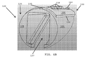
図6A〜6Cを参照すると、一実施形態では、トップキャップ部100は、細長シャフトの遠位端に固定される近位端120と、アプリケータ器具の最遠位端を規定する遠位端122とを有する。トップキャップ部100は、管状の形状を有する外壁124と、トップキャップ部100の頂側部に位置する第1の組の把持機構128(例えば突出部)のための基部126とを有する。基部126は、外壁124の外側表面に対して隆起して後方停止表面130と側方停止表面132とを画定する。図6A〜6B及び図4A〜4Bを参照すると、トップキャップ部100が細長シャフト62の遠位端66に固定されるとき、後方停止表面130及び側方停止表面132は、細長シャフト62に対してトップキャップ部100を適切に配向させるために、またトップキャップ部が細長シャフト62の遠位端66に対して移動及び/又はシフトすることを防止するために、上部カットアウト106の近位端及び外側部と係合する。
6A-6C, in one embodiment, the
図6A〜6Cを参照すると、一実施形態では、トップキャップ部100は、近位面134と、その近位面134と遠位端104との間で上向きに傾斜する傾斜底面136とを有する。傾斜底面136は、外科用締結具を分配するために発射ロッド(図2)の遠位区間76が遠位端キャップを通って遠位側に移動するときに、発射ロッドの遠位区間のスライド移動を案内するシーリングを画定する。トップキャップ部100は、近位面134から遠位端104へと延びる中央開口部137を有する。一実施形態では、中央開口部137は、外科用締結具が遠位端キャップ68(図2)から分配されるときに発射ロッドの接合部材74及び遠位区間76の近位端96が移動する(例えば、上向きに枢動又はシフトする)ための空間を設ける。
6A-6C, in one embodiment, the
図6A及び6Cを参照すると、一実施形態では、トップキャップ部100は、ボトムキャップ部102(図2)との連結を形成するために傾斜底面136から延びる一対の突出部138A、138Bを有する。傾斜底面136は、突出部138A、138Bの周りに延び、突出部の間に延びる内部領域140A、140Bを有する。一実施形態では、内部領域140A、140Bは、発射ロッドの遠位区間76の移動及び配向を制御するトップキャップ部上のシーリングを画定する。突出部138A、138Bは、ボトムキャップ部102(図5)とのスナップ嵌め連結を形成するために使用される。
With reference to FIGS. 6A and 6C, in one embodiment, the
図6A〜6Cを参照すると、一実施形態では、トップキャップ部分100は、アプリケータ器具の最遠位端と対向するメッシュを把持及び係合するためにトップキャップ部100の最遠位端に位置する第2の組の把持機構142を有する。
Referring to FIGS. 6A-6C, in one embodiment, the
図7A〜7Cを参照すると、一実施形態では、ボトムキャップ部102は、近位端144と遠位端146とを有する。ボトムキャップ部の近位端144は、ボトムキャップ部102を細長シャフト62(図4B及び4C)に固定するために細長シャフトの遠位端166にある下部カットアウト137によってボトムキャップ部を拘束する、キーイング機構148を有する。
With reference to FIGS. 7A-7C, in one embodiment, the
一実施形態では、ボトムキャップ部は、発射ロッドの遠位区間76が遠位端キャップ68を通って遠位側に移動するときに発射ロッドの遠位区間を案内するために、近位端144と遠位端146との間で上向きに傾斜する傾斜フロア150を有する。傾斜フロア150は、それぞれのスロット156A、156Bを備えた上端154A、154Bを有する対向する側壁152A、152Bによって境界を画されており、それらのスロットは、上部キャップ部100(図6A)とボトムキャップ部が互いに組み付けられ、細長シャフトの遠位端に固定されるときに、上部キャップ部の突出部138A、138Bを受容するように適合されている。
In one embodiment, the bottom cap portion has a
一実施形態では、対向する側壁152A、152Bの各々は、それらの外部側方表面に形成されたノッチ158を有する。図4C〜4D及び図7A〜7Bを参照すると、一実施形態では、細長シャフト62の遠位端66にある固定フランジ116、118は、ボトムキャップ部102を細長シャフト62に固定するために、ボトムキャップ部の対向する側壁152A、152B上にあるノッチ158の中へと挿入される。シャフトの固定フランジがボトムキャップ部102のノッチと係合することは、ボトムキャップ部をシャフトに対して適切に配向させるのに役立ち、またボトムキャップ部がシャフトに対して移動することを防止することになる。この係合はまた、ボトムキャップ部とトップキャップ部とを互いに保持することになり、また、細長シャフト62(図4D)の遠位端66にあるカットアウト106に対してトップキャップ部100(図6B)の後方停止部130を付勢することによって、トップキャップ部100を拘束することになる。
In one embodiment, each of the opposing sidewalls 152A, 152B has a
図7A〜7Cを参照すると、一実施形態では、ボトムキャップ部102の遠位端146は、第1の組の把持機構162を有する下部縁160を有し、それらの把持機構は互いに離間され、下部縁160に沿って側方に延びる。一実施形態では、ボトムキャップ部102は、第2の組の把持機構164A、164Bを有し、それらの把持機構は、第1の組の把持機構162の上方に位置している。一実施形態では、第2の組の把持機構のうちの第1の把持機構164Aは、第1の側壁152Aと整列され、第2の組の把持機構のうちの第2の把持機構164Bは第2の側壁152Bと整列される。一実施形態では、把持機構の第2の組164A、164Bは傾斜フロア150の最遠位端に隣接して配置される。把持機構は、メッシュを位置決めし、外科用締結具が器具から分配されるときにメッシュがアプリケータ器具に対して移動することを防止するために、対向する外科用メッシュに係合するように適合されている。
Referring to FIGS. 7A-7C, in one embodiment, the
図8A〜8Cを参照すると、一実施形態では、トップキャップ部100とボトムキャップ部102は互いに組み付けられて遠位端キャップ68を形成し、遠位端キャップは細長シャフト62の遠位端66に固定される。図4A〜4D及び図8A〜8Cを参照すると、一実施形態では、トップキャップ部100の隆起基部126の後方停止部130は、細長シャフト62の遠位端66において上部カットアウト106と係合し、ボトムキャップ部102のキーイング機構148は細長シャフト62の遠位端66において下部カットアウト110と係合し、細長シャフト62の遠位端66にある固定フランジ116、118は、遠位端キャップ68を細長シャフト62の遠位端66に固定するために、また遠位端キャップを細長シャフトに対して適切に配向させるために、ボトムキャップ部102のノッチ158と係合する。
With reference to FIGS. 8A-8C, in one embodiment, the
図8Aを参照すると、遠位端キャップ68が細長シャフト62の遠位端66に固定されているとき、トップキャップ部100の傾斜底面136及びボトムキャップ部102の傾斜フロア150は、細長シャフト62の長手方向軸線A1に対して約25度〜35度の鈍角を規定する軸線A2に沿って延びる。トップキャップ部の傾斜底面136は、発射ロッドの遠位区間が軸線A2に沿って移動するようにするために、挿入フォーク76の移動を確実に制御するシーリングを画定する。ボトムキャップ部の傾斜フロア150は、トップキャップ部の傾斜底面136と対向し、また、挿入フォークが軸線A2に沿って移動するようにするために、発射ロッドの遠位区間の遠位側への移動を確実に制御する。本明細書で用いられるとき、発射ロッドの遠位区間という用語は、外科用締結具と係合する対向するタインを有する挿入フォークを指すこともある。
Referring to FIG. 8A, when the
一実施形態では、発射ロッドの近位区間70の延長部72は、長手方向軸線A1に沿って遠位及び近位方向に移動するように適合される。延長部72の遠位端84は、接合部材74の近位端88に枢動的に連結される。一方、接合部材74の遠位端92は、発射ロッドの遠位区間76の近位端96に枢動的に連結される。
In one embodiment, the
図9A〜9Cを参照すると、発射サイクルの間、延長部72は、細長シャフト62の遠位端66に向かって、軸線A1に沿って遠位側に移動する。挿入フォーク76のタイン77が軸線A2に沿ってのみ移動し得るように、トップキャップ部100の傾斜底面136(図6A)及びボトムキャップ部102の傾斜フロア150は、細長シャフト62の軸線A1に対する発射ロッドの遠位区間76の配向及び遠位移動を確実に制御する。接合部材74の近位及び遠位端における枢動連結は、挿入フォーク76が図8Aに示す位置から図9Aに示す位置へと移動するときに、挿入フォークが図9Aに示す配向を維持することを可能にする。挿入フォークが遠位側に移動するとき、接合部材74は両端部で枢動し、そのため、接合部材の遠位端92及び挿入フォーク76の近位端96はトップキャップ部100(図6A〜6C)の中央開口部137を通過する。図9Aに示す延長位置において、発射ロッドの近位区間72は軸線A1に沿って延び、発射ロッドの遠位区間76は、軸線A1に対して約25度〜35度の角度を規定する軸線A2に沿って延び、発射ロッドの接合部材74は、A1とA2のいずれに対しても非平行である軸線A3に沿って延びる。
With reference to FIGS. 9A-9C, during the firing cycle,
図10A及び10Bを参照すると、発射ロッドの近位区間の延長部72が軸線A1に沿って遠位側に移動するとき、接合部材74の両端部にある枢動連結により、接合部材がボトムキャップ部102の傾斜フロア150から離れてトップキャップ部100の中央空間137(図6A及び6B)の中へと移動することが可能となる。挿入フォーク76が遠位側に移動するとき、挿入フォーク76のタイン77A、77Bの上面は、軸線A2に沿ったタイン77A、77Bの配向を維持するために、トップキャップ部100の傾斜底面136と係合する。同時に、挿入フォーク76のタイン77A、77Bの底面は、軸線A2に沿ったタイン77A、77Bの配向を維持するために、ボトムキャップ部102の傾斜フロア150と係合する。その結果、遠位端キャップ68から分配される外科用締結具78は、軸線A2に沿って延びる長さを有する。その結果、外科用締結具は、細長シャフトの長手方向軸線A1に対して約25度〜35度の角度で分配される。
Referring to FIGS. 10A and 10B, when the
一実施形態では、アプリケータ器具50(図1)は、その開示内容が参照によって本明細書に組み込まれる、本願と同一譲受人に譲渡された米国特許第8,579,920号、同第8,728,098号、同第8,728,099号、同第8,894,669号、及び同第8,920,439号に開示されているように、内部に事前装填された複数の外科用締結具を収容する多段発射デバイスである。一実施形態において、アプリケータ器具は、細長シャフトの長さ方向に沿って直列に格納された複数の外科用締結具を含む。一実施形態では、細長シャフトは、タブ付きの機構を中に組み込まれた一対のフラットスタンピングを有する。フラットスタンピングのうちの一方は、外科用締結具が細長シャフト内で近位側に移動することを防止するための静止型の後退防止スタンピングである。もう一方のフラットスタンピングは、細長シャフトの長さ方向に沿った外科用締結具の漸増的前進を促進するように、トリガが絞り込まれ、解放されるたびに、遠位及び近位方向にサイクル運動するアドバンサスタンピングである。一実施形態では、先頭の外科用締結具は、スプリングを有するステージングアセンブリによって、発射のためにステージングされる。先頭の外科用締結具がステージングアセンブリによってステージングされた後、発射ロッドが先頭の外科用締結具の中へと案内され、外科用締結具分配窓を通してその外科用締結具を送達する。一実施形態では、細長シャフトは曲線状であり、スタンピングは可撓性であり、そのため、シャフトによって画定された曲線状経路に沿って外科用締結具を案内する間、スタンピングはシャフトの曲線に適合するように湾曲し得る。一実施形態では、トリガが引かれるたびに、単一の先頭の外科用締結具が分配される。各トリガの引き込みの間、後続の外科用締結具の各々は、関節運動シャフトの遠位端に向かって遠位側に前進される。一実施形態では、アプリケータ器具は、1つの外科用締結具のみを分配する単発の装置である。 In one embodiment, applicator instrument 50 (FIG. 1) is a U.S. Pat. No. 8,579,920, assigned to the same assignee as the present application, the disclosure of which is incorporated herein by reference. 728,098, 8,728,099, 8,894,669, and 8,920,439, a plurality of pre-loaded surgeries, as disclosed in US Pat. A multi-stage launch device that houses a fastener. In one embodiment, the applicator instrument includes a plurality of surgical fasteners stored in series along the length of the elongate shaft. In one embodiment, the elongate shaft has a pair of flat stampings that incorporate a tabbed mechanism therein. One of the flat stampings is a static anti-retraction stamping to prevent the surgical fastener from moving proximally within the elongate shaft. The other flat stamping cycles in the distal and proximal directions each time the trigger is squeezed and released to facilitate incremental advancement of the surgical fastener along the length of the elongate shaft. Advanced stamping. In one embodiment, the leading surgical fastener is staged for firing by a staging assembly having a spring. After the leading surgical fastener is staged by the staging assembly, the firing rod is guided into the leading surgical fastener and delivers the surgical fastener through the surgical fastener dispensing window. In one embodiment, the elongate shaft is curved and the stamping is flexible so that the stamping conforms to the curve of the shaft while guiding the surgical fastener along a curved path defined by the shaft. Can be curved. In one embodiment, each time a trigger is pulled, a single leading surgical fastener is dispensed. During each trigger retraction, each subsequent surgical fastener is advanced distally toward the distal end of the articulation shaft. In one embodiment, the applicator instrument is a single device that dispenses only one surgical fastener.
一実施形態では、一連の外科用締結具がアプリケータ器具50(図1)の細長シャフト62の中に事前装填される。図11を参照すると、一実施形態では、単一の外科用締結具78は、近位端170と、先細端部の間にメッシュ繊維を捕捉するために互いから離間された挿入チップ174、176を有する遠位端172とを有する。一実施形態では、外科用締結具78は、その開示内容が参照によって本明細書に組み込まれる、本願と同一譲受人に譲渡された米国特許第8,579,920号、同第8,728,098号、同第8,728,099号、同第8,894,669号、及び同第8,920,439号に開示されている特徴のうちの1つ又は2つ以上を有する。
In one embodiment, a series of surgical fasteners are preloaded into the
図12Aを参照すると、一実施形態では、アプリケータ器具50は、発射システムを収容するハウジング52と、ハウジングから上向きにかつ近位側に突出するハンドル58とを含む。アプリケータ器具は、発射システム180を起動するためにハンドル58に向かって絞り込まれるトリガ60を含む。一実施形態では、発射システム180は、その開示内容が参照によって本明細書に組み込まれる、本願と同一譲受人に譲渡された米国特許第8,579,920号、同第8,728,098号、同第8,728,099号、同第8,894,669号、及び同第8,920,439号に開示されている特徴に類似した1つ又は2つ以上の特徴を有する。一実施形態では、発射システム180は、スプリングブロック182と、発射ロッド70と、スプリングブロック182の内側に配置された発射スプリング(図示せず)とを含み、発射スプリングは、トリガ60が絞り込まれたときにエネルギーを蓄積するものである。一実施形態では、発射システム180は、トリガ60が絞り込まれると時計回りの方向に回転するトリガギア184を介してトリガ60と結合される。トリガギア184は、スライディングヨーク188上の歯186と結合される。トリガギア184が時計回りの方向に回転すると、ヨーク188は、軸線A1−A1に沿って遠位方向にスライドする。トリガギア184が反時計回りの方向に回転すると、ヨーク188は、軸線A1−A1に沿って近位方向にスライドする。
Referring to FIG. 12A, in one embodiment,
図12A−1を参照すると、一実施形態では、発射システム180は、発射ロッドリリース190と、通常は発射ロッドリリース190を直立位置に保持する(図12A−1に示す)リリーススプリング192とを含む。発射ロッドリリース190は直立位置にあるとき、長手方向軸線A1に沿った発射ロッド70の遠位移動D1(すなわち、図12A−1において左に向かう)を抑制するために、発射ロッド70の側方延長部73と係合する。ヨーク188の遠位端は、発射ロッドリリース190をV1で示される方向に下方へ移動させるために、発射ロッドリリースの下端と係合するように適合された傾斜表面189を有する。
Referring to FIG. 12A-1, in one embodiment,
図12A及び12Bを参照すると、トリガ60がハンドル58に向かって絞り込まれると、トリガギア184はヨーク188及びスプリングブロック182を長手方向軸線A1に沿って遠位方向D1に押しやる。同時に、発射ロッド70が遠位側に移動するのを抑制するために、発射ロッドリリース190の上端が発射ロッド70の側方延長部73と係合する。トリガが絞り込まれると、スプリングブロック182の内側に配置された発射ロッドスプリング(図示せず)にエネルギーが蓄積される。
Referring to FIGS. 12A and 12B, when the
図12C及び12C−1を参照すると、スプリングブロック182の内側に配置された発射ロッドスプリングに付加的なエネルギーを蓄積するために、トリガ60が更に絞り込まれている。ヨーク188の傾斜表面189(図12A−1)は、図12C−1に示す位置へと発射ロッドリリース190を押しやり、その結果、発射ロッド70の側方延長部73は、軸線A1(図12B)に沿ったものであり得る遠位方向D1に自在に移動する。発射ロッドスプリングに蓄積されたエネルギーは、アプリケータ器具の遠位端から外科用締結具を分配すべく発射ロッド70を遠位方向D1に駆動するために、発射ロッド70に伝達される。
Referring to FIGS. 12C and 12C-1, the
図14を参照すると、一実施形態では、ヘルニア欠損を有する患者Pに対し、腹腔鏡下のヘルニア修復手技の準備がなされている。患者Pは診察され、ヘルニアの位置HLが触診又は他の方法を用いて確認される。患者には、導入及び吸入による従来の方式で、従来の全身麻酔が投与される。ヴェレス針が皮膚を通して腹腔の中に挿入される。1kPa〜2.0kPa(8mmHg〜15mmHg)の気腹が作り出される。1本の10mmのトロカールが、可能な限り側方へ左上腹部に挿入される。30度の腹腔鏡カメラがトロカールを通して挿入され、腹腔の内容物が評価される。2本の付加的な5mmのトロカールが、10mmのポートと同じ側で側方に置かれる。ヘルニアの内容物を低減するために腹腔鏡器具が使用される。欠損の周りの正常な筋膜の縁部が調べられ、腹壁への臓器の癒着が全て分離されて、メッシュを固定するための自由空間が作り出される。欠陥の大きさが評価される。一実施形態では、欠損部は、必要に応じて主に縫合糸で閉鎖され得る。 Referring to FIG. 14, in one embodiment, a patient P having a hernia defect is prepared for a laparoscopic hernia repair procedure. Patient P is examined and hernia location HL is confirmed using palpation or other methods. The patient is administered conventional general anesthesia in a conventional manner by induction and inhalation. A Velez needle is inserted through the skin and into the abdominal cavity. An insufflation of 1 kPa to 2.0 kPa (8 mmHg to 15 mmHg) is created. A 10 mm trocar is inserted into the upper left abdomen as laterally as possible. A 30 degree laparoscopic camera is inserted through the trocar and the contents of the abdominal cavity are evaluated. Two additional 5mm trocars are placed laterally on the same side as the 10mm port. Laparoscopic instruments are used to reduce the content of hernias. The edges of the normal fascia around the defect are examined and all the adhesions of the organs to the abdominal wall are separated to create a free space to secure the mesh. The size of the defect is evaluated. In one embodiment, the defect may be closed primarily with sutures as needed.
手技におけるこの時点では、外科医は次いで、メッシュヘルニアパッチを作製する。メッシュMは、すべての辺において欠損部の縁を越えて適切に重なり合うように寸法を定められる。メッシュは丸められ、10mmのトロカールを通して腹腔の中に挿入される。メッシュは広げられ、欠損部上に配置される。所望により、滞在縫合糸(stay suture)をメッシュを通して腹部組織内に配置してもよく、即ちメッシュの4つの羅針盤の方位(北、南、東、西)に配置してもよい。 At this point in the procedure, the surgeon then makes a mesh hernia patch. The mesh M is dimensioned so that it properly overlaps across the edge of the defect on all sides. The mesh is rolled and inserted into the abdominal cavity through a 10 mm trocar. The mesh is spread and placed on the defect. If desired, stay sutures may be placed through the mesh into the abdominal tissue, i.e. in the four compass orientations (north, south, east, west) of the mesh.
一実施形態では、本明細書で開示されるアプリケータ器具50は、5mmのトロカールの1つを通して挿入される。アプリケータ器具50の細長シャフト62上にある遠位端キャプ68は、メッシュMを操作し、固定するのに先立って所望の位置にメッシュを配置するために使用されてもよい。一実施形態では、アプリケータ器具50のトリガ60は、メッシュMを通して腹壁の中へと外科用締結具を送達するように配備される(例えば絞り込まれる)。メッシュMの周囲が、クラウン構成をなして複数の外科用締結具を使用して固定される。一実施形態では、外科用締結具の第2の内部クラウンもまた、必要に応じて適用されてよい。一実施形態では、外科医は、必要に応じて、アプリケータ器具を他のトロカールのうちの1本に移動させてもよい。
In one embodiment, the
メッシュ修復は、腹壁に十分に固定されるように検査される。アプリケータ器具は、トロカールから取り外される。カメラ、腹腔鏡器具、及びトロカールが腹腔から取り出される。トロカール切開部は、適切な縫合又は閉鎖技法を用いて閉鎖され得る。患者は回復室に移動される。 The mesh repair is inspected to be well secured to the abdominal wall. The applicator instrument is removed from the trocar. The camera, laparoscopic instrument, and trocar are removed from the abdominal cavity. The trocar incision can be closed using a suitable suture or closure technique. The patient is moved to the recovery room.
図14を参照すると、一実施形態では、腹腔鏡下の鼠径ヘルニア修復の間、多くの場合、クーパー靭帯のすぐ上に固定点を設けることが望ましい。しかしながら、靭帯の真下には硬質の恥骨がある。クーパー靭帯は非常に薄い(例えば1mm〜3mm)ため、締結具78(約6mm〜8mmの長さを有し得る)を直接クーパー靭帯の上に送達することは困難である。しかしながら、外科用締結具が組織に対してある角度をなして送達され得る場合、その外科用締結具は、恥骨を横切り、より効果的に固定されることになる。この角度付きの送達をもたらすために、本明細書で開示されるアプリケータ器具のうちの1つ又は2つ以上が使用され得る。 Referring to FIG. 14, in one embodiment, it is often desirable to provide a fixation point just above the Cooper ligament during laparoscopic inguinal hernia repair. However, there is a hard pubic bone directly under the ligament. Because the Cooper ligament is very thin (eg, 1 mm to 3 mm), it is difficult to deliver the fastener 78 (which can have a length of about 6 mm to 8 mm) directly over the Cooper ligament. However, if the surgical fastener can be delivered at an angle to the tissue, the surgical fastener will cross the pubic bone and be more effectively secured. One or more of the applicator devices disclosed herein can be used to provide this angled delivery.
図15を参照すると、一実施形態では、外科用締結具を分配するためのアプリケータ器具50’は曲線状シャフト62’を有する。一実施形態では、発射ロッド及びスタンピングは可撓性であり、そのため、細長シャフトの曲線状経路に沿って外科用締結具を案内する間、発射ロッド及びスタンピングはシャフト62’の曲線に適合するように湾曲し得る。アプリケータ器具は、本明細書で開示されるように、軸外し外科用締結具を分配するように構成される。 Referring to FIG. 15, in one embodiment, an applicator instrument 50 'for dispensing surgical fasteners has a curved shaft 62'. In one embodiment, the firing rod and stamping are flexible so that the firing rod and stamping will conform to the curve of the shaft 62 'while guiding the surgical fastener along the curved path of the elongated shaft. Can be curved. The applicator instrument is configured to dispense off-axis surgical fasteners as disclosed herein.
図16を参照すると、一実施形態では、アプリケータ器具250が、細長シャフト262と、長手方向軸線A1に沿って遠位及び近位方向に往復運動する発射ロッド270とを含む。発射ロッドの遠位端は、可撓性挿入フォーク276を含む。可撓性挿入フォーク276は、外科用締結具278のレッグと係合するタイン277A、277Bを有する。アプリケータ器具は、曲線状のランプを中に形成された遠位端キャップ268を含む。本明細書でより詳細に説明するように、曲線状のランプは、外科用締結具278が細長シャフト262の長手方向軸線A1に対してある角度をなして分配されるように、外科用締結具の配向を変化させる。可撓性挿入フォーク276は、遠位端キャップ268の曲線状のランプ区間を通過するときに湾曲するように適合されている。
Referring to FIG. 16, in one embodiment, it includes an
図17A及び17Bを参照すると、一実施形態では、可撓性挿入フォーク276のタイン277A、277Bは外科用締結具278のレッグと係合する。前進位置にあるとき、可撓性挿入フォーク276は、外科用締結具278を分配するために遠位端キャップ268の最遠位端を越えて延びる。図17Bは、直線状構成にある可撓性挿入フォーク276を示しているが、可撓性挿入フォークは、遠位端キャップ268内に位置する曲線状ランプを通過するために、湾曲するように適合されている。一実施形態では、遠位端キャップ268は、可撓性挿入フォーク276のための曲線状経路と直線状経路との間でトグルされ得る。
Referring to FIGS. 17A and 17B, in one embodiment, the
図18を参照すると、一実施形態では、遠位端キャップ268が、アプリケータ器具250の細長シャフト262の遠位端に固定される。遠位端キャップ268は、可撓性挿入フォーク276の遠位移動を案内する曲線状ランプ275を中に配設されている。一実施形態では、複数の外科用締結具278A、278Bが細長シャフト262の内部に事前装填される。2つの外科用締結具のみが示されているが、最多で20、30、又はそれより多数の外科用締結具が細長シャフト262の中に事前装填されてもよい。一実施形態では、アプリケータ器具上のトリガが絞り込まれるたびに、細長シャフト262の遠位端に1ポジションだけより近くに外科用締結具を前進させるために、アドバンサ(図示せず)が遠位側に移動する。先頭の外科用締結具278A(すなわち、最遠位側の外科用締結具)が、シャフトの遠位端において可撓性挿入フォーク276と係合される。可撓性挿入フォーク276が遠位端キャップ268を通して先頭の外科用締結具278Aを駆動するとき、可撓性挿入フォーク276は、曲線状ランプ275の曲線状経路に従うように湾曲する。先頭の外科用締結具278Aが遠位端キャップ268から分配されるとき、先頭の外科用締結具278Aは、細長シャフト262の長手方向軸線A1に対して約25度〜35度(α1で示す)の角度を規定する軸線A2に沿って分配される。
Referring to FIG. 18, in one embodiment, a
図19Aを参照すると、一実施形態では、アプリケータ器具350が、細長シャフト362と、細長シャフトの遠位端に固定された遠位端キャップ368とを含む。アプリケータ器具は、可撓性挿入フォーク376を有する発射ロッド370と、細長シャフトの遠位端に向かって外科用締結具378を前進させるアドバンサ390と、外科用締結具378が近位側に移動するのを防止する後退防止スタンピング392と、アドバンサ390と整列される第1の位置から可撓性挿入フォーク376と整列される第2の位置に先頭の外科用締結具378Aをシフトさせるステージングアセンブリ394とを含む、発射システムを有する。遠位端キャップ368は、外科用締結具が遠位端キャップ368を通過するときに外科用締結具の配向を変化させるように設計された曲線状ランプ375を中に配設されている。
Referring to FIG. 19A, in one embodiment,
図19Bを参照すると、一実施形態では、トリガが引き込まれるとき、エネルギーが発射ロッドスプリングに蓄積され、アドバンサ390が外科用締結具を遠位側に前進させ、それにより、先頭の外科用締結具278Aはステージングアセンブリ394に装填される。図19Cを参照すると、トリガが更に引き込まれると、アドバンサ390が後退し、それにより、ステージングアセンブリ394は、可撓性挿入フォーク376と整列するように先頭の外科用締結具378Aを自在にシフトさせる。
Referring to FIG. 19B, in one embodiment, when the trigger is retracted, energy is stored in the firing rod spring and the advancer 390 advances the surgical fastener distally, thereby leading the surgical fastener. 278A is loaded into the staging
図19Dを参照すると、一実施形態では、可撓性挿入フォーク376のタインを先頭の外科用締結具378Aのレッグの上に誘導するために、可撓性挿入フォークを遠位方向に移動させるようにトリガが更に引き込まれる。図19Eを参照すると、一実施形態では、発射ロッドリリース(図示せず)は発射ロッド370の近位側方延長部から係合解除される。発射ロッドスプリングに蓄積されたエネルギーが発射ロッド370及び可撓性挿入フォーク376を遠位方向に駆動する。可撓性挿入フォーク376は、遠位端キャップ368の曲線状ランプ375を通過するときに湾曲する。先頭の外科用締結具378Aが遠位端キャップ368から分配されるとき、先頭の外科用締結具378Aは、細長シャフト362の長手方向軸線A1に対して約30度の角度を規定する軸線A2に沿って延びる。図19E−1及び19E−2を参照すると、遠位端キャップ368の内部の曲線状ランプは、先頭の外科用締結具378Aが細長シャフト362の長手方向軸線A1に対して約30度の角度を規定する軸線A2に沿って延びるように、可撓性挿入フォーク376を湾曲させる。
Referring to FIG. 19D, in one embodiment, the
図20を参照すると、一実施形態では、アプリケータ器具450は、遠位端キャップ468をその遠位端に固定された細長シャフト462を有する。アプリケータ器具は、挿入フォーク476を含んだ遠位区間を有する発射ロッドを含み、挿入フォークは、外科用締結具を細長シャフトの遠位端から分配するために、外科用締結具478Aのレッグと係合するタイン477A、477Bを有する。図20には示されていないが、一実施形態では、挿入フォーク476の近位端は、本明細書に図示及び説明されるように、発射システムの発射ロッドの近位区間と連結される。
Referring to FIG. 20, in one embodiment,
一実施形態では、複数の外科用締結具がアプリケータ器具450の細長シャフト462の内部に配置される。一実施形態では、アプリケータ器具のトリガが引き込まれるたびに、一連の外科用締結具が細長シャフトの遠位端に向かって遠位側にシフトされる。一実施形態では、外科用締結具は、外科用締結具の1つ又は2つ以上と接触するスプリングによって遠位側に付勢されてもよい。一実施形態では、外科用締結具478は、第1の高さにおいて細長シャフトを通して遠位側に移動する。最遠位の位置に到達すると、先頭の外科用締結具478Aは、第2の高さへと下降されて、挿入フォーク476のタイン477A、477Bと整列する。
In one embodiment, a plurality of surgical fasteners are disposed within the
図21を参照すると、一実施形態では、挿入フォーク476のタイン478A、478Bは、それぞれのタインの長さに沿って延びるC字形状の断面を有する。このことは、先頭の外科用締結具478A(図20)の近位端がタイン477A、477Bの最遠位端から完全に離れ、タインが先頭の外科用締結具478Aのレッグを受容し得るようにすることを必要とする。
Referring to FIG. 21, in one embodiment, the
図22を参照すると、先頭の外科用締結具478A(図20)を挿入フォーク476’のタイン477A’、477B’に装填するために必要となるクリアランス空間の大きさを低減するために、一実施形態では、タインは、タインの近位端に隣接してC字形状の断面を有し、またタインの遠位端に隣接してL字形状の断面を有する。L字形状の断面は、外科用締結具の近位端とタイン477A’、477B’の遠位受容端部との間に必要とされるクリアランス空間の大きさを低減することによって、先頭の外科用締結具を上方からタインに装填することを容易にする。
Referring to FIG. 22, one implementation is performed to reduce the amount of clearance space required to load the leading
図23を参照すると、先頭の外科用締結具478A(図20)を挿入フォーク476’’のタイン477A’’、477B’’に装填するのに必要とされるクリアランス空間の大きさを更に低減するために、一実施形態では、タインは、それぞれのタインの全長に沿って延びるL字形状の断面を有する。L字形状の断面は、外科用締結具の近位端とタイン477A’’、477B’’の遠位受容端部との間に必要とされるクリアランス空間の大きさを更に低減することによって、先頭の外科用締結具を上方からタインに装填することを容易にする。図23の挿入フォーク476’’は、図22の挿入フォーク476’と比べて、より小さなクリアランス空間を必要とし、そのため、図21の挿入フォーク476よりも小さなクリアランス空間を必要とすることになる。
Referring to FIG. 23, the amount of clearance space required to load the leading
図24を参照すると、一実施形態では、挿入フォークのタインは、外科用締結具を挿入フォークに装填するための開放位置と、外科用締結具を挿入フォークのタインの間で固定するための閉鎖位置との間で移動する。一実施形態では、タインは、挿入フォークが開放位置にあるときには更に離れ、挿入フォークが閉鎖位置にあるときには互いに近づく。一実施形態では、スプリングアセンブリが通常、外科用締結具を挿入フォークに装填するためにタインを開放構成に保持し得る。一実施形態では、アプリケータ器具550は、遠位端キャップ568をその遠位端に固定された細長シャフト562を有する。アプリケータ器具は挿入フォーク576を有し、挿入フォークは、外科用締結具を細長シャフトの遠位端から分配するために、外科用締結具578Aのレッグと係合するタイン577A、577Bを有する。一実施形態では、挿入フォーク576は、挿入フォークのタイン577A、577Bに結合されたスプリングアセンブリ585を含む。スプリングアセンブリ585は通常、タイン577A、577Bを開放構成に維持し、その開放構成において、先頭の外科用締結具578Aのレッグは、先頭の外科用締結具をタインに装填するために、挿入フォークの開放したタインの間の位置へと降下し得る。一実施形態では、先頭の外科用締結具がタインの間に整列された後、タインは、外科用締結具を挿入フォークのタインの間に堅固に固定するために、閉鎖構成へと移動される。一実施形態では、発射システムは、タインを閉鎖構成へと移動させるために挿入フォークと係合するカム表面を有し得る。図24には示されていないが、一実施形態では、挿入フォーク576の近位端は、本明細書に図示及び説明されるように、細長シャフト562の遠位端から外科用締結具を分配する発射ロッドと結合される。一実施形態では、スプリングアセンブリは通常は、タインを閉鎖位置に維持してもよく、タインは、外科用締結具を挿入フォーク576に装填するために、発射サイクルの初期の段階の間に開放される。タインは次いで、発射のために閉鎖される。
Referring to FIG. 24, in one embodiment, the tine of the insertion fork includes an open position for loading the surgical fastener into the insertion fork and a closure for securing the surgical fastener between the tine of the insertion fork. Move between positions. In one embodiment, the tines are further away when the insertion fork is in the open position and closer together when the insertion fork is in the closed position. In one embodiment, a spring assembly may typically hold the tine in an open configuration for loading surgical fasteners into the insertion fork. In one embodiment, applicator instrument 550 has an
図25A及び25Bを参照すると、一実施形態では、アプリケータ器具650が、細長シャフト662と、細長シャフトの遠位端に固定された遠位端キャップ668とを含む。複数の外科用締結具678が細長シャフトの中に事前装填される。一実施形態では、外科用締結具678は、細長シャフトの長手方向軸線A1に対してある角度をなして積み重ねられる。一実施形態では、外科用締結具678は、細長シャフト662の長手方向軸線A1に対して約30度の角度を規定する軸線A2に沿って延びる長さをそれぞれ有する。一実施形態では、アプリケータ器具650は、発射ロッドを含んだ発射システムを有し、発射ロッドは、近位区間670と、延長部672と、接合部材674とを有し、接合部材は、延長部672の遠位端に枢動的に連結された近位端と、接合部材674の遠位端に枢動的に連結された近位端を有する挿入フォークを含んだ遠位端676とを有する。一実施形態では、発射サイクルの間、先頭の外科用締結具678Aは、遠位端キャップ668から分配されるように挿入フォークに装填され、それにより、先頭の外科用締結具678Aは、細長シャフト662の長手方向軸線に対してある角度をなして分配される。一実施形態では、締結具分配角度は、締結具が格納される軸線と同じ軸線A2に沿ったものである。
Referring to FIGS. 25A and 25B, in one embodiment,
一実施形態では、外科用締結具を分配するためのアプリケータ器具は、アプリケータ器具の細長シャフトの外側に延びる1つ又は2つ以上の要素を含む。図26を参照すると、一実施形態では、発射システムは、近位区間770と延長部771とを有する発射ロッドを含み、延長部は、発射サイクルの間に長手方向軸線A1に沿って遠位側及び近位側に移動するように適合されている。延長部は、枢動部材772に枢動的に連結されている。一実施形態では、枢動部材772は、第1の枢動点773を備えた上端と、第2の枢動点775を備えた下端と、第1の枢動点773と第2の枢動点775との間に配置された細長スロット779とを有する。一実施形態では、延長部771の遠位端は、細長いスロット779において枢動部材772に枢動的かつスライド可能に固定される。一実施形態では、第1の枢動点773は、細長シャフト762の内部に固定される。一実施形態では、枢動部材772の第2の枢動点775は、接合部材774の近位端778と枢動的に連結され、接合部材774の遠位端792は挿入フォーク776の近位端796に枢動的に連結される。
In one embodiment, an applicator instrument for dispensing surgical fasteners includes one or more elements that extend outside the elongate shaft of the applicator instrument. Referring to FIG. 26, in one embodiment, the firing system includes a firing rod having a
図27Aを参照すると、一実施形態では、アプリケータ器具750は、図26の要素を細長シャフト762の内部に組み付けられる。アプリケータ器具750は、細長シャフト762の遠位端に固定された遠位端キャップ768を含む。遠位端キャップ768は、斜行ランプ777を中に設けられ、斜行ランプは、外科用締結具778が遠位端キャップ768から分配されるときに、挿入フォーク776及び外科用締結具の配向を制御するものである。一実施形態では、枢動部材772の第1の枢動点773は細長シャフト762に枢動的に連結される。細長シャフト762の外壁は、枢動部材772の第2の枢動点775と整列される開口部781が中に形成されている。発射サイクルの間、開口部781は、枢動部材772及び接合部材774を細長シャフトの外壁の外に移動させるための空間を提供する。
Referring to FIG. 27A, in one embodiment,
図27Aを参照すると、一実施形態では、発射サイクルの第1の段階の間、先頭の外科用締結具778が挿入フォーク776に装填される。挿入フォーク776及び外科用締結具778の配向は、斜行ランプ777によって制御される。枢動部材772及び接合部材774は、細長外側シャフト762の外壁の周辺部の内部に配置されている。
Referring to FIG. 27A, in one embodiment, the leading
図27Bを参照すると、一実施形態では、発射サイクルの第2の段階の間、発射ロッド770は長手方向軸線A1に沿って遠位側に移動している。枢動部材772の細長スロット779と枢動的に連結された、発射ロッドの近位区間770の延長部771は、細長スロット779内でスライドするが、次にそれにより、第2の枢動点775が第1の枢動点773を中心として遠位方向に旋回する。枢動部材772の枢動的な移動により、結果として、第2の枢動点775及び接合部材774の近位端788は、開口部781を通って細長シャフト762の外部へと進むことになる。同時に、挿入フォーク776及び先頭の外科用締結具778は、遠位端キャップ768の遠位端面を越えて外科用締結具778を前進させるために、斜行ランプ777に沿って遠位側に移動する。
Referring to FIG. 27B, in one embodiment, during the second phase of the firing cycle, the firing
図27C及び27C−1を参照すると、発射サイクルの第3の段階の間、発射ロッドの近位区間770は長手方向軸線A1に沿ってその最遠位の位置に移動する。近位区間770の延長部771は、枢動部材772の細長スロット779内で更にスライドし、次にそれにより、第2の枢動点775が第1の枢動点773を中心として遠位方向に旋回する。枢動部材772の枢動的な移動により、結果として、第2の枢動点775及び接合部材774の近位端788は、細長シャフト762の外壁にある開口部781を通って遠位側に進むことになる。発射サイクルの第3の段階の間、挿入フォーク776は、外科用締結具778を遠位端キャップ768から分配するために、斜行ランプ777に沿って遠位側に移動し続ける。
Referring to FIGS. 27C and 27C-1, during the third stage of the firing cycle, the
図28を参照すると、一実施形態では、アプリケータ器具は、挿入フォーク896を遠位及び近位方向に移動させるためのラックアンドピニオン構成を有する発射システムを含む。一実施形態では、発射システムは、ラック895と、ラック895と噛み合うピニオン879を有する枢動部材872と、枢動部材872に枢動的に連結された近位端888を有する接合部材874と、接合部材874の遠位端892に枢動的に連結された近位端898を有する挿入フォーク896とを含む。一実施形態では、ピニオン879は、枢動点を中心として旋回するために、アプリケータ器具の細長シャフトと枢動的に連結される。
Referring to FIG. 28, in one embodiment, the applicator instrument includes a firing system having a rack and pinion configuration for moving the
図29を参照すると、一実施形態では、アプリケータ器具850は、上記で図27A〜27Cに示す開口部と類似した開口部881を備えた細長シャフト862を含み、それにより、枢動部材872及び接合部材874が発射サイクルの間に開口部881を通して進むことが可能となっている。一実施形態では、アプリケータ器具850は、遠位側及び近位側に移動するときの挿入フォーク876の配向角度を制御するために、斜行ランプ875を中に配設された遠位端キャップ868を含む。ラック895は、発射ロッドの遠位端に固定され、長手方向軸線A1に沿って遠位側及び近位側に移動する。ピニオン879は、枢動点873において細長シャフトに枢動的に連結されている。発射サイクルの間、ラック895は、枢動点873を中心として時計回りの方向(図29)にピニオン879を回転させるために、遠位側に移動する。結果として、枢動部材872は、ピニオン879と共に時計回りの方向に回転し、次にそれによって、接合部材874及び挿入フォーク876が遠位側に前進することになる。枢動部材872及び接合部材874は、図28に示す第1の位置から図29に示す第2の位置に移動するときに、開口部881を通って進む。
Referring to FIG. 29, in one embodiment, the
図30A〜30Cを参照すると、一実施形態では、アプリケータ器具950が、遠位端キャップ968を有する細長シャフト962を含み、遠位端キャップは細長シャフトの遠位端に固定されている。遠位端キャップ968は、遠位端面に形成された外科用締結具分配開口部969を有する。一実施形態では、遠位端キャップ968は、遠位端キャップの外壁から半径方向外向きに延びる第1の組の把持要素928を含む。一実施形態では、第1の組の把持要素928は、遠位端キャップ968の外壁の周りで、互いから均等に離間配置されている。一実施形態では、遠位端キャップは、遠位端キャップの遠位端面から軸方向に延びる第2の組の把持要素942を含む。第2の組の把持要素942は、外科用締結具分配開口部962の周りで、互いから均等に離間配置されている。
Referring to FIGS. 30A-30C, in one embodiment, an
図31A及び31Bは、腹腔にアクセスするために細長シャフトを有するアプリケータ器具がトロカールに通されるヘルニア修復手技を示す。図31Bに示すように、多くの事例では、遠位端キャップは通常、細長シャフトの遠位端の下方、後方、又は側方から観測されるため、外科医がメッシュ及び腹壁に対する細長シャフトの遠位端の配向を判断することが困難となり得る。細長シャフトの遠位端にある分配窓がメッシュに対して適切に配向されていない場合、分配される外科用締結具は、下にある腹壁にメッシュを適切に固定できないことがある。このことは、外科用締結具が細長シャフトの長手方向軸線に対してある角度をなして分配されるアプリケータ器具に対して特に当てはまる。したがって、外科用メッシュ及び下にある組織に対する遠位端キャップの配向並びに分配窓の配向を外科医が迅速かつ容易に判断することを可能にする、アプリケータ器具用の遠位端キャップが必要とされている。 FIGS. 31A and 31B illustrate a hernia repair procedure in which an applicator instrument having an elongate shaft is passed through a trocar to access the abdominal cavity. As shown in FIG. 31B, in many cases, the distal end cap is typically observed from below, posteriorly, or laterally of the distal end of the elongated shaft so that the surgeon is distal to the elongated shaft relative to the mesh and abdominal wall. It can be difficult to determine the edge orientation. If the dispensing window at the distal end of the elongate shaft is not properly oriented with respect to the mesh, the surgical fastener being dispensed may not be able to properly secure the mesh to the underlying abdominal wall. This is especially true for applicator instruments in which surgical fasteners are dispensed at an angle to the longitudinal axis of the elongate shaft. Accordingly, there is a need for a distal end cap for an applicator instrument that allows the surgeon to quickly and easily determine the orientation of the distal end cap relative to the surgical mesh and underlying tissue and the orientation of the dispensing window. ing.
図32A〜43は、外科医が外科用締結具を分配するときに器具を適切に配向させ得るように、外科医に視覚的指標を提示する端キャップを有するアプリケータ器具を示す。本発明はいかなる特定の動作理論による制限も受けないが、視覚的指標によって外科医が、分配窓の位置及び配向、並びに分配窓から分配される外科用締結具の配向及び位置を迅速に確認することが可能になると考えられる。 32A-43 illustrate an applicator instrument having an end cap that presents a visual indicator to the surgeon so that the surgeon can properly orient the instrument when dispensing surgical fasteners. Although the present invention is not limited by any particular theory of operation, the visual indicator allows the surgeon to quickly ascertain the position and orientation of the dispensing window and the orientation and position of the surgical fastener dispensed from the dispensing window. Will be possible.
図32A及び32Bを参照すると、一実施形態では、アプリケータ器具1050が、細長シャフト1062と、細長シャフトの遠位端に固定された遠位端キャップ1068とを含む。遠位端キャップ1068は、細長シャフト1062の長手方向軸線A1に対してある角度を規定する軸線A2に沿って外科用締結具を分配するように適合された外科用締結具分配窓1069を有する。遠位端キャップは、遠位端キャップ1068の上面から突出する第1の組の把持要素1028と、分配窓1069の側部、頂部、及び底部に結合された第2及び第3の把持要素1042、1043とを有する。遠位端キャップ1068は、外科医が分配窓1069の配向を判断することを可能にするために、端キャップの幅にわたって延びる凹部1055を上面に設けられている。
Referring to FIGS. 32A and 32B, in one embodiment, applicator instrument 1050 includes an
図33A及び33Bを参照すると、一実施形態では、アプリケータ器具1150が、細長シャフト1162と、細長シャフトの遠位端に固定された遠位端キャップ1168とを含む。遠位端キャップ1168は、細長シャフト1162の長手方向軸線A1に対してある角度を規定する軸線A2に沿って外科用締結具を分配するように適合された外科用締結具分配窓1169を有する。遠位端キャップは、遠位端キャップ1168の上面から突出する第1の組の把持要素1128と、分配窓1169の側部、頂部、及び底部に結合された第2及び第3の把持要素1142、1143とを有する。遠位端キャップ1168は、平坦な上面と、曲線状の底面とを有する。平坦な上面、曲線状の底面、並びに把持要素1128、1142及び1143は、外科医がメッシュ及び下にある腹壁に対して分配窓1169を配向させるのを補助するための視覚ガイドとして使用されてもよい。
With reference to FIGS. 33A and 33B, in one embodiment, an
図34A及び34Bを参照すると、一実施形態では、アプリケータ器具1250が、細長シャフト1262と、細長シャフトの遠位端に固定された遠位端キャップ1268とを含む。遠位端キャップ1268は、細長シャフト1262の長手方向軸線A1に対してある角度を規定する軸線A2に沿って外科用締結具を分配するように適合された外科用締結具分配窓1269を有する。遠位端キャップは、遠位端キャップ1268の上面から突出する第1の組の把持要素1228と、分配窓1269の側部、頂部、及び底部に結合された第2及び第3の把持要素1242、1243とを有する。遠位端キャップ1268は、端キャップの幅にわたって延びるV字形状の凹部1255を上面に設けられている。遠位端キャップは、曲線状の底面を有する。V字形状の凹部1255、曲線状の底面、並びに把持要素1228、1242及び1243は、外科医がメッシュ及び下にある腹壁に対して分配窓1269を配向させるのを補助するための視覚ガイドとして使用されてもよい。
Referring to FIGS. 34A and 34B, in one embodiment,
図35A及び35Bを参照すると、一実施形態では、アプリケータ器具1350が、細長シャフト1362と、細長シャフトの遠位端に固定された遠位端キャップ1368とを含む。遠位端キャップ1368は、細長シャフト1362の長手方向軸線A1に対してある角度を規定する軸線A2に沿って外科用締結具を分配するように適合された外科用締結具分配窓1369を有している。遠位端キャップは、遠位端キャップ1368の上面から突出する第1の組の把持要素1328と、分配窓1369の側部、頂部、及び底部に結合された第2及び第3の把持要素1342、1343とを有する。遠位端キャップ1368は、端キャップの幅にわたって延びる凹部1355を上面に設けられている。遠位端キャップは、曲線状の底面を有する。凹部1355、曲線状の底面、並びに把持要素1328、1342及び1343は、外科医がメッシュ及び下にある腹壁に対して分配窓1369を配向させるのを補助するための視覚ガイドとして使用されてもよい。
Referring to FIGS. 35A and 35B, in one embodiment, an
図36を参照すると、一実施形態では、遠位端キャップ1468が、外科用締結具分配窓の配向、及び外科用締結具が分配窓から分配される軸線に関する視覚的な手掛かりを外科医に与えるために、種々に着色された区間を含む。一実施形態では、端キャップの頂部区間1490は、淡色の材料から作製され、端キャップの底部区間1492はそれよりも暗色の材料から作製される。別の実施形態では、遠位端キャップ1468は、一体型であるが、2種類の色を印刷される。一実施形態では、頂部区間1490と底部区間1492との間のコントラストが、頂部区間と底部区間との間に延びる境界線1494を規定する。境界線1494は、分配窓と交差する軸線に沿って延び、また、外科用締結具が端キャップから分配されるときに外科用締結具の配向及び位置を指示する。遠位端キャップはまた、端キャップの頂部及び幅にわたって延びる凹部1455を有し、この凹部は外科医に更なる視覚的手掛かりを与える。一実施形態では、凹部は、遠位端キャップの物理的断面を低減することなく同じ効果を与える透明な構成要素で置き換えられる。
Referring to FIG. 36, in one embodiment, the distal end cap 1468 provides the surgeon with visual clues regarding the orientation of the surgical fastener dispensing window and the axis along which the surgical fastener is dispensed from the dispensing window. Includes variously colored sections. In one embodiment, end
図37を参照すると、一実施形態では、遠位端キャップ1568が、外科用締結具分配窓の配向、及び外科用締結具が分配窓から分配される軸線に関する視覚的な手掛かりを外科医に与えるために、種々に着色された区間を含む。一実施形態では、端キャップの頂部区間1590は、暗色の材料から作製され、端キャップの底部区間1592は淡色の材料から作製される。別の実施形態では、遠位端キャップ1568は、一体型であるが、2種類の色を印刷される。一実施形態では、頂部区間1590と底部区間1592との間のコントラストが、頂部区間と底部区間との間に延びる境界線1594を規定する。境界線1594は、分配窓と交差する軸線に沿って延び、また、外科用締結具が端キャップから分配されるときに外科用締結具の配向を指示する。遠位端キャップはまた、端キャップの頂部及び幅にわたって延びる凹部1555を有し、この凹部は外科医に更なる視覚的手掛かりを与える。一実施形態では、凹部は、遠位端キャップの物理的断面を低減することなく同じ効果を与える透明な構成要素で置き換えられる。
Referring to FIG. 37, in one embodiment, the
図38を参照すると、一実施形態では、遠位端キャップ1668が、外科用締結具分配窓の配向、及び外科用締結具が分配窓から分配される軸線に関する視覚的な手掛かりを外科医に与えるために、種々に着色された区間を含む。一実施形態では、端キャップの近位区間1690は、暗色の材料から作製され、端キャップの遠位区間1692は淡色の材料から作製される。一実施形態では、遠位区間1690と近位区間1692との間のコントラストが、近位区間と遠位区間との間に延びる、先端1696を有する矢印形状の境界線1694を規定する。矢印形状の境界線1694の先端1696は、分配窓と整列され、また、外科用締結具が端キャップから分配されるときに外科用締結具の配向を指示する。遠位端キャップはまた、端キャップの頂部及び幅にわたって延びる凹部1655を有し、この凹部は外科医に更なる視覚的手掛かりを与える。
Referring to FIG. 38, in one embodiment, the distal end cap 1668 provides the surgeon with visual clues about the orientation of the surgical fastener dispensing window and the axis along which the surgical fastener is dispensed from the dispensing window. Includes variously colored sections. In one embodiment, the end cap
図39を参照すると、一実施形態では、遠位端キャップ1768が、外科用締結具分配窓の配向、及び外科用締結具が分配窓から分配される軸線に関する視覚的な手掛かりを外科医に与えるために、種々に着色された区間を含む。一実施形態では、端キャップの近位区間1790は、淡色の材料から作製され、端キャップの遠位区間1792は暗色の材料から作製される。一実施形態では、遠位区間1790と近位区間1792との間のコントラストが、近位区間と遠位区間との間に延びる、先端1796を有する矢印形状の境界線1794を規定する。矢印形状の境界線1794の先端1796は、分配窓と整列され、また、外科用締結具が端キャップから分配されるときに外科用締結具の配向を指示する。遠位端キャップはまた、端キャップの頂部及び幅にわたって延びる凹部1755を有し、この凹部は外科医に更なる視覚的手掛かりを与える。
Referring to FIG. 39, in one embodiment, the
図40を参照すると、一実施形態では、遠位端キャップ1868が、外科用締結具分配窓の配向、及び外科用締結具が分配窓から分配される軸線に関する視覚的な手掛かりを外科医に与えるために、種々に着色された区間を含む。一実施形態では、端キャップの頂部区間1890は暗色の材料から作製され、端キャップの底部区間1892は同じ暗色の材料から作製され、淡色の材料から作製されたバンド1894が、暗色の頂部区間1890と底部区間1892との間に延びる。バンド1894は、遠位端キャップの底部から遠位端キャップの側部へと延びる。淡色のバンド1894の遠位端は、分配窓と整列されかつ分配窓と交差し、また、外科用締結具が端キャップから分配されるときに外科用締結具の配向を指示する。遠位端キャップはまた、遠位端キャップの頂部及び幅にわたって側方に延びる凹部1855を有し、この凹部は外科医に更なる視覚的手掛かりを与える。
Referring to FIG. 40, in one embodiment, the
図41を参照すると、一実施形態では、遠位端キャップ1968は淡色の材料から作製された頂部区間1990と、同様に淡色の材料から作製された底部区間1992と、淡色の頂部区間1990と底部区間1992との間に延びる、暗色の材料から作製されたバンド1994とを含む。バンド1994は、遠位端キャップの側部に沿って延びている。暗色のバンド1994の近位区間は、細長シャフトの長手方向軸線A1を示し、暗色のバンドの遠位区間は、分配窓と整列されかつ分配窓と交差する。バンドの遠位区間は、外科用締結具が遠位端キャップから分配されるときに外科用締結具の配向(すなわち、軸線A2と整列される)を指示する。遠位端キャップはまた、遠位端キャップの頂部及び幅にわたって側方に延びる凹部1955を有し、この凹部は外科医に更なる視覚的手掛かりを与える。
41, in one embodiment, the
図42を参照すると、一実施形態では、遠位端キャップ2068は、暗色の材料から作製された頂部区間2090と、淡色の材料から作製された底部区間2092とを含む。一実施形態では、頂部区間2090と底部区間2092との間のコントラストが、頂部区間と底部区間との間に延びる境界線2094を規定する。境界線2094は、遠位端キャップの底部から遠位端キャップの側部へと延びる。境界線2094は、分配窓と交差する軸線に沿って延び、また、外科用締結具が端キャップから分配されるときに外科用締結具の配向を指示する。遠位端キャップはまた、端キャップの頂部及び幅にわたって延びる凹部2055を有し、この凹部は外科医に更なる視覚的手掛かりを与える。
Referring to FIG. 42, in one embodiment, the
図43を参照すると、一実施形態では、遠位端キャップ2168は、淡色の材料から作製された頂部区間2190と、暗色の材料から作製された底部区間2192とを含む。一実施形態では、頂部区間2190と底部区間2192との間のコントラストが、頂部区間と底部区間との間に延びる境界線2194を規定する。境界線2194は、遠位端キャップの底部から遠位端キャップの側部へと延びる。境界線2194は、分配窓と交差する軸線に沿って延び、また、外科用締結具が端キャップから分配されるときに外科用締結具の配向を指示する。遠位端キャップはまた、端キャップの頂部及び幅にわたって延びる凹部2155を有し、この凹部は外科医に更なる視覚的手掛かりを与える。
Referring to FIG. 43, in one embodiment, the
上記の説明は本発明の実施形態に関するものであるが、本発明の他の及び更なる実施形態を本発明の基本的な範囲から逸脱することなく行うことが可能であり、本発明の範囲は、添付の特許請求の範囲によってのみ限定される。例えば、本発明では、本明細書に説明されるか又は本明細書に参照により組み込まれる実施形態のいずれかに示す特徴のいずれかを、本明細書に説明されるか又は本明細書に参照により組み込まれるがやはり本発明の範囲内に含まれる残りの実施形態のいずれかに示す特徴のいずれかと、組み合わせてもよいことが意図されている。 While the above description is of embodiments of the invention, other and further embodiments of the invention may be made without departing from the basic scope thereof. Limited only by the scope of the appended claims. For example, in the present invention, any feature described in any of the embodiments described herein or shown by reference herein is described or referenced herein. It is contemplated that it may be combined with any of the features shown in any of the remaining embodiments that are incorporated by reference, but still fall within the scope of the invention.
〔実施の態様〕
(1) 外科用締結具を分配するためのアプリケータ器具であって、
ハウジングと、
前記ハウジング内に配置された発射システムと、
前記発射システムを作動させるために前記ハウジングと結合されたアクチュエータと、
前記ハウジングから延びる細長シャフトであって、前記ハウジングに固定された近位端と、遠位端と、前記近位端と前記遠位端との間に延びる第1の軸線と、を有する、細長シャフトと、
前記細長シャフト内に配置された1つ又は2つ以上の外科用締結具と、
前記細長シャフトの前記遠位端に固定された遠位端キャップであって、前記遠位端キャップから前記1つ又は2つ以上の外科用締結具を分配するための外科用締結具分配窓を有する、遠位端キャップと、を備え、
前記発射システムは、前記遠位端キャップから前記1つ又は2つ以上の外科用締結具を分配するために、前記細長シャフトを通して延びる発射ロッドを含み、前記発射ロッドは、前記細長シャフトの前記第1の軸線に沿って移動する近位区間と、前記第1の軸線に対してある角度を規定する第2の軸線に沿って移動する遠位区間と、を有する、アプリケータ器具。
(2) 前記1つ又は2つ以上の外科用締結具は、前記細長シャフトの中に事前装填された複数の外科用締結具を含み、前記事前装填された外科用締結具は、前記第1の軸線に沿って延びる長さを有し、発射サイクルの間、前記器具は、前記事前装填された外科用締結具のうちの先頭の1つを再配向させ、それによって、前記遠位端キャップから分配されるために、前記先頭の外科用締結具の前記長さが前記第2の軸線に沿って延びる、実施態様1に記載のアプリケータ器具。
(3) 前記発射ロッドの前記近位区間と前記遠位区間とは、互いに枢動的に連結されている、実施態様1に記載のアプリケータ器具。
(4) 前記発射ロッドは、前記発射ロッドの前記近位区間と前記発射ロッドの前記遠位区間とを相互連結する接合部材を更に備え、前記接合部材は、前記発射ロッドの前記近位区間と枢動的に連結されている近位端と、前記発射ロッドの前記遠位区間と枢動的に連結されている遠位端と、を有する、実施態様3に記載のアプリケータ器具。
(5) 発射サイクルの初期の段階の間、前記発射ロッドの前記近位区間及び前記発射ロッドの前記接合部材は前記第1の軸線に沿って延び、前記発射ロッドの前記遠位シャフト区間は前記第2の軸線に沿って延び、前記発射サイクルの後期の段階の間、前記発射ロッドの前記近位区間は前記第1の軸線に沿って延び、前記発射ロッドの前記遠位区間は前記第2の軸線に沿って延び、前記発射ロッドの前記接合部材は、前記第1の軸線及び前記第2の軸線に対して非平行である第3の軸線に沿って延びる、実施態様4に記載のアプリケータ器具。
Embodiment
(1) An applicator instrument for dispensing surgical fasteners,
A housing;
A launch system disposed within the housing;
An actuator coupled to the housing for actuating the firing system;
An elongate shaft extending from the housing, the elongate shaft having a proximal end secured to the housing, a distal end, and a first axis extending between the proximal end and the distal end. A shaft,
One or more surgical fasteners disposed within the elongate shaft;
A distal end cap secured to the distal end of the elongate shaft, comprising a surgical fastener dispensing window for dispensing the one or more surgical fasteners from the distal end cap. A distal end cap comprising:
The firing system includes a firing rod extending through the elongate shaft to dispense the one or more surgical fasteners from the distal end cap, the firing rod being the first of the elongate shaft. An applicator instrument having a proximal section that moves along one axis and a distal section that moves along a second axis that defines an angle with respect to the first axis.
(2) The one or more surgical fasteners include a plurality of surgical fasteners preloaded in the elongate shaft, the preloaded surgical fasteners comprising the first Having a length extending along one axis, and during a firing cycle, the instrument reorients the leading one of the preloaded surgical fasteners, thereby causing the distal The applicator instrument according to
(3) The applicator instrument according to
(4) The firing rod further includes a joining member interconnecting the proximal section of the firing rod and the distal section of the firing rod, and the joining member includes the proximal section of the firing rod. 4. The applicator instrument according to
(5) During an initial stage of a firing cycle, the proximal section of the firing rod and the joining member of the firing rod extend along the first axis, and the distal shaft section of the firing rod is Extending along a second axis, and during a later stage of the firing cycle, the proximal section of the firing rod extends along the first axis and the distal section of the firing rod is the second 5. The application of
(6) 前記遠位端キャップは、前記遠位端キャップから前記1つ又は2つ以上の外科用締結具を分配するときに、前記発射ロッドの前記遠位区間の、前記第2の軸線に沿った移動を案内するように、前記第2の軸線に沿って延びる斜行ランプを有する、実施態様1に記載のアプリケータ器具。
(7) 前記遠位端キャップは、互いに組み付けられているトップキャップ部とボトムキャップ部とを有し、前記トップキャップ部は前記斜行ランプのシーリングを画定し、前記ボトムキャップ部は前記斜行ランプのフロアを画定し、前記外科用締結具分配窓は、前記斜行ランプの最遠位端に位置し、前記トップキャップ部の前記シーリング及び前記ボトムキャップ部の前記フロアによって境界を画されている、実施態様6に記載のアプリケータ器具。
(8) 前記遠位端キャップは、前記遠位端キャップの近位端と遠位端との間に延びる曲線状ランプを有し、前記発射ロッドは、前記発射ロッドの前記遠位区間が前記発射ロッドの前記近位区間に対して撓曲可能となるように、前記発射ロッドの前記近位区間と前記遠位区間とを相互連結する可撓性区間を備える、実施態様1に記載のアプリケータ器具。
(9) 前記曲線状ランプは、前記第1の軸線と整列されている近位区間と、前記第2の軸線と整列されている遠位端と、を有する、実施態様8に記載のアプリケータ器具。
(10) 発射サイクルの初期の段階の間、前記発射ロッドの前記近位区間及び前記遠位区間は前記第1の軸線に沿って延び、前記発射サイクルの後期の段階の間、前記発射ロッドの前記近位区間は前記第1の軸線に沿って延び、前記発射ロッドの前記遠位区間は前記第2の軸線に沿って延び、前記可撓性区間は曲線状であり、前記遠位端キャップの前記曲線状ランプを通して延びる、実施態様9に記載のアプリケータ器具。
(6) The distal end cap is in the second axis of the distal section of the firing rod when dispensing the one or more surgical fasteners from the distal end cap. 2. The applicator instrument according to
(7) The distal end cap has a top cap portion and a bottom cap portion assembled to each other, the top cap portion defines a ceiling of the skew ramp, and the bottom cap portion is skewed. Defining a ramp floor, wherein the surgical fastener distribution window is located at a distalmost end of the skew ramp and is bounded by the ceiling of the top cap portion and the floor of the bottom cap portion. Embodiment 7. The applicator device according to embodiment 6, wherein
(8) The distal end cap has a curved ramp extending between a proximal end and a distal end of the distal end cap, and the firing rod has the distal section of the firing rod as the 2. The application of
9. The applicator of embodiment 8, wherein the curved ramp has a proximal section that is aligned with the first axis and a distal end that is aligned with the second axis. Instruments.
(10) During the initial phase of the firing cycle, the proximal section and the distal section of the firing rod extend along the first axis, and during the later stages of the firing cycle, The proximal section extends along the first axis, the distal section of the firing rod extends along the second axis, the flexible section is curved, and the distal end cap Embodiment 10. The applicator device according to embodiment 9, which extends through the curvilinear ramp.
(11) 前記発射ロッドの前記遠位区間は、前記1つ又は2つ以上の外科用締結具のレッグと係合するように適合された対向するタインを有する挿入フォークを備え、前記対向するタインは、互いに対向する開口部を備えた、C字形状の断面を有するタイン、互いに対向する開口部を有する、C字形状の断面を備えた近位端と、互いに対向する開口部を有する、L字形状の断面を有する遠位端とを有するタイン、及び互いに対向する開口部を有する、L字形状の断面を備えた、長さを有するタインからなる群から選択されている、実施態様1に記載のアプリケータ器具。
(12) 前記発射ロッドの前記遠位区間は、前記1つ又は2つ以上の外科用締結具と係合するように適合された対向するタインを有する挿入フォークを備え、前記タインは、前記タインが更に離れている開放位置と、前記タインが互いに近づいている閉鎖位置との間で移動可能であり、前記挿入フォークは、前記対向するタインを前記開放位置へと通常は押しやる力を与えるスプリングを含み、前記アプリケータ器具は、前記スプリングの前記力に打ち勝ち、かつ前記タインを前記閉鎖位置へと押しやるために、発射サイクルの間に前記挿入フォークと係合するカム表面を含む、実施態様1に記載のアプリケータ器具。
(13) 前記遠位端キャップは、上面と、前記第2の軸線に対して垂直である平面内で延びる遠位端面とを有し、前記遠位端キャップの前記上面は第1の組の離間突出部を有し、前記遠位端面は第2の組の離間突出部を有する、実施態様1に記載のアプリケータ器具。
(14) 前記遠位端キャップは、第1の色を有する第1の区間と、第2の色を有する第2の区間とを有し、前記第2の色は、前記遠位端キャップの配向及び前記外科用締結具の送達窓の位置の視覚的指示を与える色対照の境界を画定するように、前記第1の色と対照的である、実施態様1に記載のアプリケータ器具。
(15) 前記1つ又は2つ以上の外科用締結具は、前記細長シャフトの中に事前装填された複数の外科用締結具を含み、前記事前装填された外科用締結具は、前記第2の軸線に沿って延びる長さを有し、発射サイクルの間、前記器具は、前記第2の軸線に沿って前記遠位端キャップから前記外科用締結具のうちの先頭の1つを分配する、実施態様1に記載のアプリケータ器具。
(11) The distal section of the firing rod includes an insertion fork having opposing tines adapted to engage legs of the one or more surgical fasteners, the opposing tine Is a tine with a C-shaped cross section with openings facing each other, a proximal end with a C-shaped cross section with openings facing each other, and an L with openings facing each other,
(12) The distal section of the firing rod comprises an insertion fork having opposing tines adapted to engage the one or more surgical fasteners, the tine comprising the tine Movable between an open position where the tine is further away and a closed position where the tines are approaching each other, and the insertion fork includes a spring that provides a force that normally pushes the opposing tine into the open position.
(13) The distal end cap has a top surface and a distal end surface extending in a plane perpendicular to the second axis, the top surface of the distal end cap being a first set. 2. The applicator instrument according to
(14) The distal end cap has a first section having a first color and a second section having a second color, wherein the second color is defined on the distal end cap. 2. The applicator instrument of
(15) The one or more surgical fasteners include a plurality of surgical fasteners preloaded in the elongate shaft, the preloaded surgical fasteners comprising the first Having a length extending along two axes, and during a firing cycle, the instrument dispenses a leading one of the surgical fasteners from the distal end cap along the second axis An applicator device according to
(16) 外科用締結具を分配するためのアプリケータ器具であって、
ハウジングと、
前記ハウジング内に配置された発射システムと、
前記発射システムを作動させるために前記ハウジングと結合されたアクチュエータと、
前記ハウジングから延びる細長シャフトであって、前記ハウジングに固定された近位端と、遠位端と、前記近位端と前記遠位端との間に延びる第1の軸線と、を有する、細長シャフトと、
前記細長シャフト内に配置された外科用締結具と、
前記細長シャフトの前記遠位端に固定された遠位端キャップであって、前記遠位端キャップから前記外科用締結具を分配するための外科用締結具分配窓を有する、遠位端キャップと、を備え、
前記発射システムは、前記遠位端キャップから1つずつ前記外科用締結具を分配するために、前記細長シャフトを通して延びる発射ロッドを含み、前記発射ロッドは、近位区間と、遠位区間と、接合部材とを有し、前記接合部材は、前記発射ロッドの前記近位区間と枢動的に連結された近位端と、前記発射ロッドの前記遠位区間と枢動的に連結された遠位端とを有し、発射サイクルの初期の段階の間、前記発射ロッドの前記近位区間及び前記接合部材は前記第1の軸線に沿って延び、前記遠位シャフト区間は前記第2の軸線に沿って延び、前記発射サイクルの後期の段階の間、前記発射ロッドの前記近位区間は前記第1の軸線に沿って延び、前記発射ロッドの前記遠位区間は前記第2の軸線に沿って延び、前記接合部材は、前記第1の軸線及び前記第2の軸線に対して非平行である第3の軸線に沿って延びる、アプリケータ器具。
(17) 前記遠位端キャップは、第1の色を有する第1の区間と、第2の色を有する第2の区間とを有し、前記第2の色は、前記遠位端キャップの配向及び前記外科用締結具の送達窓の位置の視覚的指示を与える色対照の境界を画定するように、前記第1の色と対照的である、実施態様16に記載のアプリケータ器具。
(18) 前記1つ又は2つ以上の外科用締結具は、前記細長シャフトの中に事前装填された複数の外科用締結具を含み、前記事前装填された外科用締結具は、前記第1の軸線に沿って延びる長さを有し、前記発射サイクルの前記初期の段階と前記後期の段階との間、前記発射システムは、前記事前装填された外科用締結具のうちの先頭の1つを再配向させ、それによって、前記遠位端キャップから分配されるために、前記先頭の外科用締結具の前記長さが前記第2の軸線に沿って延びる、実施態様16に記載のアプリケータ器具。
(19) 前記遠位端キャップは、前記遠位端キャップから前記外科用締結具のうちの前記1つを分配するときに、前記発射ロッドの前記遠位区間の、前記第2の軸線に沿った移動を案内するように、前記第2の軸線に沿って延びる斜行ランプを有する、実施態様16に記載のアプリケータ器具。
(20) 前記遠位端キャップは、互いに組み付けられているトップキャップ部とボトムキャップ部とを有し、前記トップキャップ部は前記斜行ランプのシーリングを画定し、前記ボトムキャップ部は前記斜行ランプのフロアを画定し、前記外科用締結具分配窓は、前記斜行ランプの最遠位端に位置し、前記トップキャップ部の前記シーリング及び前記ボトムキャップ部の前記フロアによって境界を画されている、実施態様19に記載のアプリケータ器具。
(16) An applicator instrument for dispensing surgical fasteners,
A housing;
A launch system disposed within the housing;
An actuator coupled to the housing for actuating the firing system;
An elongate shaft extending from the housing, the elongate shaft having a proximal end secured to the housing, a distal end, and a first axis extending between the proximal end and the distal end. A shaft,
A surgical fastener disposed within the elongate shaft;
A distal end cap secured to the distal end of the elongate shaft, the distal end cap having a surgical fastener dispensing window for dispensing the surgical fastener from the distal end cap; With
The firing system includes a firing rod extending through the elongate shaft to dispense the surgical fasteners one by one from the distal end cap, the firing rod comprising a proximal section, a distal section, A joining member, the joining member including a proximal end pivotally connected to the proximal section of the firing rod and a distal end pivotally connected to the distal section of the firing rod. The proximal section of the firing rod and the joining member extend along the first axis and the distal shaft section extends through the second axis during an initial stage of the firing cycle. And during the later stages of the firing cycle, the proximal section of the firing rod extends along the first axis and the distal section of the firing rod extends along the second axis. And the joining member extends in the first axis and Extending along a third axis which is non-parallel to the second axis, the applicator instrument.
(17) The distal end cap has a first section having a first color and a second section having a second color, and the second color is the first end of the distal end cap. Embodiment 17. The applicator instrument of embodiment 16, wherein the applicator instrument is in contrast to the first color to define a color contrast boundary that provides a visual indication of the orientation and position of the surgical fastener delivery window.
(18) The one or more surgical fasteners include a plurality of surgical fasteners preloaded in the elongate shaft, the preloaded surgical fasteners comprising the first A length extending along one axis, and during the early and late stages of the firing cycle, the firing system includes a leading end of the preloaded surgical fasteners. 17. The embodiment of embodiment 16, wherein the length of the leading surgical fastener extends along the second axis to reorient one and thereby be dispensed from the distal end cap. Applicator instrument.
(19) The distal end cap is along the second axis of the distal section of the firing rod when dispensing the one of the surgical fasteners from the distal end cap. Embodiment 17. The applicator instrument of embodiment 16, comprising a ramp ramp extending along the second axis to guide the movement.
(20) The distal end cap has a top cap portion and a bottom cap portion that are assembled to each other, the top cap portion defines a ceiling of the skew ramp, and the bottom cap portion is skewed. Defining a ramp floor, wherein the surgical fastener distribution window is located at a distalmost end of the skew ramp and is bounded by the ceiling of the top cap portion and the floor of the bottom cap portion. Embodiment 20. The applicator device according to embodiment 19, wherein
(21) ヘルニア欠損部を修復する方法であって、
患者の腹腔の中にメッシュを挿入することと、
ヘルニア欠損部の上に前記メッシュを配置することと、
外科用締結具を分配するためのアプリケータ器具を提供することであって、前記アプリケータ器具は、ハウジングと、前記ハウジング内に配置された発射システムと、前記発射システムを作動させるために前記ハウジングと結合されたアクチュエータと、前記ハウジングから延びる細長シャフトであって、前記ハウジングに固定された近位端と、遠位端と、前記近位端と前記遠位端との間に延びる第1の軸線と、を有する、細長シャフトと、前記細長シャフト内に配置された1つ又は2つ以上の外科用締結具と、前記細長シャフトの前記遠位端に固定された遠位端キャップであって、前記遠位端キャップから前記1つ又は2つ以上の外科用締結具を分配するための外科用締結具分配窓を有する、遠位端キャップと、を備え、前記発射システムは、前記遠位端キャップから前記1つ又は2つ以上の外科用締結具を分配するために、前記細長シャフトを通して延びる発射ロッドを含み、発射サイクルの間、前記発射ロッドは、前記細長シャフトの前記第1の軸線に沿って移動する近位区間と、前記第1の軸線に対してある角度を規定する第2の軸線に沿って移動する遠位区間と、を有する、ことと、
前記患者の腹腔の中に前記細長シャフトの前記遠位端を挿入することと、
前記遠位端キャップを前記メッシュに当接させ、前記メッシュを通してかつ前記患者の腹壁の中へと前記1つ又は2つ以上の外科用締結具のうちの1つを分配するために前記アクチュエータを働かせることと、を含む、方法。
(21) A method of repairing a hernia defect,
Inserting a mesh into the patient's abdominal cavity;
Placing the mesh on the hernia defect;
An applicator instrument for dispensing a surgical fastener is provided, the applicator instrument including a housing, a firing system disposed within the housing, and the housing for operating the firing system. An actuator coupled to the housing, and an elongated shaft extending from the housing, the proximal end being fixed to the housing, the distal end, and a first extending between the proximal end and the distal end An elongate shaft having an axis, one or more surgical fasteners disposed within the elongate shaft, and a distal end cap secured to the distal end of the elongate shaft, A distal end cap having a surgical fastener dispensing window for dispensing the one or more surgical fasteners from the distal end cap. A firing rod extending through the elongate shaft to dispense the one or more surgical fasteners from the distal end cap, wherein during a firing cycle, the firing rod is A proximal section that moves along a first axis and a distal section that moves along a second axis that defines an angle with respect to the first axis;
Inserting the distal end of the elongate shaft into the abdominal cavity of the patient;
The actuator is adapted to abut the distal end cap against the mesh and dispense one of the one or more surgical fasteners through the mesh and into the abdominal wall of the patient. Working, including a method.
Claims (20)
ハウジングと、
前記ハウジング内に配置された発射システムと、
前記発射システムを作動させるために前記ハウジングと結合されたアクチュエータと、
前記ハウジングから延びる細長シャフトであって、前記ハウジングに固定された近位端と、遠位端と、前記近位端と前記遠位端との間に延びる第1の軸線と、を有する、細長シャフトと、
前記細長シャフト内に配置された1つ又は2つ以上の外科用締結具と、
前記細長シャフトの前記遠位端に固定された遠位端キャップであって、前記遠位端キャップから前記1つ又は2つ以上の外科用締結具を分配するための外科用締結具分配窓を有する、遠位端キャップと、を備え、
前記発射システムは、前記遠位端キャップから前記1つ又は2つ以上の外科用締結具を分配するために、前記細長シャフトを通して延びる発射ロッドを含み、前記発射ロッドは、前記細長シャフトの前記第1の軸線に沿って移動する近位区間と、前記第1の軸線に対してある角度を規定する第2の軸線に沿って移動する遠位区間と、を有する、アプリケータ器具。 An applicator instrument for dispensing a surgical fastener,
A housing;
A launch system disposed within the housing;
An actuator coupled to the housing for actuating the firing system;
An elongate shaft extending from the housing, the elongate shaft having a proximal end secured to the housing, a distal end, and a first axis extending between the proximal end and the distal end. A shaft,
One or more surgical fasteners disposed within the elongate shaft;
A distal end cap secured to the distal end of the elongate shaft, comprising a surgical fastener dispensing window for dispensing the one or more surgical fasteners from the distal end cap. A distal end cap comprising:
The firing system includes a firing rod extending through the elongate shaft to dispense the one or more surgical fasteners from the distal end cap, the firing rod being the first of the elongate shaft. An applicator instrument having a proximal section that moves along one axis and a distal section that moves along a second axis that defines an angle with respect to the first axis.
ハウジングと、
前記ハウジング内に配置された発射システムと、
前記発射システムを作動させるために前記ハウジングと結合されたアクチュエータと、
前記ハウジングから延びる細長シャフトであって、前記ハウジングに固定された近位端と、遠位端と、前記近位端と前記遠位端との間に延びる第1の軸線と、を有する、細長シャフトと、
前記細長シャフト内に配置された外科用締結具と、
前記細長シャフトの前記遠位端に固定された遠位端キャップであって、前記遠位端キャップから前記外科用締結具を分配するための外科用締結具分配窓を有する、遠位端キャップと、を備え、
前記発射システムは、前記遠位端キャップから1つずつ前記外科用締結具を分配するために、前記細長シャフトを通して延びる発射ロッドを含み、前記発射ロッドは、近位区間と、遠位区間と、接合部材とを有し、前記接合部材は、前記発射ロッドの前記近位区間と枢動的に連結された近位端と、前記発射ロッドの前記遠位区間と枢動的に連結された遠位端とを有し、発射サイクルの初期の段階の間、前記発射ロッドの前記近位区間及び前記接合部材は前記第1の軸線に沿って延び、前記遠位シャフト区間は前記第2の軸線に沿って延び、前記発射サイクルの後期の段階の間、前記発射ロッドの前記近位区間は前記第1の軸線に沿って延び、前記発射ロッドの前記遠位区間は前記第2の軸線に沿って延び、前記接合部材は、前記第1の軸線及び前記第2の軸線に対して非平行である第3の軸線に沿って延びる、アプリケータ器具。 An applicator instrument for dispensing a surgical fastener,
A housing;
A launch system disposed within the housing;
An actuator coupled to the housing for actuating the firing system;
An elongate shaft extending from the housing, the elongate shaft having a proximal end secured to the housing, a distal end, and a first axis extending between the proximal end and the distal end. A shaft,
A surgical fastener disposed within the elongate shaft;
A distal end cap secured to the distal end of the elongate shaft, the distal end cap having a surgical fastener dispensing window for dispensing the surgical fastener from the distal end cap; With
The firing system includes a firing rod extending through the elongate shaft to dispense the surgical fasteners one by one from the distal end cap, the firing rod comprising a proximal section, a distal section, A joining member, the joining member including a proximal end pivotally connected to the proximal section of the firing rod and a distal end pivotally connected to the distal section of the firing rod. The proximal section of the firing rod and the joining member extend along the first axis and the distal shaft section extends through the second axis during an initial stage of the firing cycle. And during the later stages of the firing cycle, the proximal section of the firing rod extends along the first axis and the distal section of the firing rod extends along the second axis. And the joining member extends in the first axis and Extending along a third axis which is non-parallel to the second axis, the applicator instrument.
Applications Claiming Priority (3)
| Application Number | Priority Date | Filing Date | Title |
|---|---|---|---|
| US14/979,909 | 2015-12-28 | ||
| US14/979,909 US10299905B2 (en) | 2015-12-28 | 2015-12-28 | Applicator instruments having off-axis surgical fastener delivery |
| PCT/US2016/066922 WO2017116745A1 (en) | 2015-12-28 | 2016-12-15 | Applicator instruments having off-axis surgical fastener delivery |
Publications (2)
| Publication Number | Publication Date |
|---|---|
| JP2019502516A true JP2019502516A (en) | 2019-01-31 |
| JP6866395B2 JP6866395B2 (en) | 2021-04-28 |
Family
ID=57755474
Family Applications (1)
| Application Number | Title | Priority Date | Filing Date |
|---|---|---|---|
| JP2018552637A Expired - Fee Related JP6866395B2 (en) | 2015-12-28 | 2016-12-15 | Applicator instrument with off-axis surgical fastener delivery |
Country Status (7)
| Country | Link |
|---|---|
| US (3) | US10299905B2 (en) |
| EP (2) | EP3397176B1 (en) |
| JP (1) | JP6866395B2 (en) |
| CN (1) | CN108472034B (en) |
| CA (1) | CA3009330A1 (en) |
| MX (1) | MX2018008002A (en) |
| WO (1) | WO2017116745A1 (en) |
Families Citing this family (1)
| Publication number | Priority date | Publication date | Assignee | Title |
|---|---|---|---|---|
| US10299905B2 (en) | 2015-12-28 | 2019-05-28 | Ethicon, Inc. | Applicator instruments having off-axis surgical fastener delivery |
Citations (16)
| Publication number | Priority date | Publication date | Assignee | Title |
|---|---|---|---|---|
| US4612933A (en) * | 1984-03-30 | 1986-09-23 | Senmed, Inc. | Multiple-load cartridge assembly for a linear surgical stapling instrument |
| US5413272A (en) * | 1991-05-07 | 1995-05-09 | United States Surgical Corporation | Surgical fastening device |
| US5830221A (en) * | 1996-09-20 | 1998-11-03 | United States Surgical Corporation | Coil fastener applier |
| US5931836A (en) * | 1996-07-29 | 1999-08-03 | Olympus Optical Co., Ltd. | Electrosurgery apparatus and medical apparatus combined with the same |
| US20020077627A1 (en) * | 2000-07-25 | 2002-06-20 | Johnson Theodore C. | Method for detecting and treating tumors using localized impedance measurement |
| US20030158551A1 (en) * | 2002-02-19 | 2003-08-21 | Paton Boris E. | System and method for control of tissue welding |
| US20040193148A1 (en) * | 2002-02-11 | 2004-09-30 | Wham Robert H. | Vessel sealing system |
| JP2008510507A (en) * | 2004-08-20 | 2008-04-10 | セロン アクチエンゲゼルシャフト メディカル インスツルメンツ | Device for electrosurgical sclerosis treatment of body tissue |
| US20100327042A1 (en) * | 2008-03-14 | 2010-12-30 | Amid Parviz K | Hernia stapler with integrated mesh manipulator |
| US20110160725A1 (en) * | 2009-10-28 | 2011-06-30 | Olympus Medical Systems Corp. | High-frequency surgical apparatus and medical instrument operating method |
| US20110202055A1 (en) * | 2008-10-30 | 2011-08-18 | Peter Selig | Electrosurgical device having a temperature measurement device, method for determining a temperature and/or a temperature change at a neutral electrode |
| JP2013135916A (en) * | 2007-03-26 | 2013-07-11 | Tyco Healthcare Group Lp | Endoscopic surgical clip applier |
| US20130282084A1 (en) * | 2004-09-10 | 2013-10-24 | Vessix Vascular, Inc. | Apparatus and Method for Treatment of In-Stent Restenosis |
| US20130304091A1 (en) * | 2012-05-11 | 2013-11-14 | Ethicon, Inc. | Applicator instruments having distal end caps for facilitating the accurate placement of surgical fasteners during open repair procedures |
| US20130304092A1 (en) * | 2012-05-11 | 2013-11-14 | Ethicon, Inc. | Applicator instruments for dispensing surgical fasteners during open repair procedures |
| US8920439B2 (en) * | 2009-05-12 | 2014-12-30 | Ethicon, Inc. | Applicator instruments having curved and articulating shafts for deploying surgical fasteners and methods therefor |
Family Cites Families (25)
| Publication number | Priority date | Publication date | Assignee | Title |
|---|---|---|---|---|
| US3664408A (en) | 1969-06-04 | 1972-05-23 | Roland Offsetmaschf | Device for fastening a pattern plate to a mold table or box |
| US3740994A (en) | 1970-10-13 | 1973-06-26 | Surgical Corp | Three stage medical instrument |
| US4471780A (en) | 1982-02-05 | 1984-09-18 | Ethicon, Inc. | Multiple ligating clip applier instrument |
| US4478220A (en) | 1982-02-05 | 1984-10-23 | Ethicon, Inc. | Ligating clip cartridge |
| US5470010A (en) | 1991-04-04 | 1995-11-28 | Ethicon, Inc. | Multiple fire endoscopic stapling mechanism |
| US5203864A (en) | 1991-04-05 | 1993-04-20 | Phillips Edward H | Surgical fastener system |
| CA2143560C (en) | 1994-03-02 | 2007-01-16 | Mark Fogelberg | Sterile occlusion fasteners and instrument and method for their placement |
| US5833700A (en) | 1995-03-15 | 1998-11-10 | Ethicon Endo-Surgery, Inc. | Sterile occlusion fasteners and instrument and method for their placement |
| US5582616A (en) | 1994-08-05 | 1996-12-10 | Origin Medsystems, Inc. | Surgical helical fastener with applicator |
| US7485124B2 (en) | 2000-10-19 | 2009-02-03 | Ethicon Endo-Surgery, Inc. | Surgical instrument having a fastener delivery mechanism |
| CA2451102C (en) | 2001-07-09 | 2009-09-15 | Tyco Healthcare Group Lp | Right angle clip applier apparatus and method |
| US7758612B2 (en) | 2004-04-27 | 2010-07-20 | Tyco Healthcare Group Lp | Surgery delivery device and mesh anchor |
| US8114099B2 (en) | 2004-04-27 | 2012-02-14 | Tyco Healthcare Group Lp | Absorbable anchor for hernia mesh fixation |
| US8870049B2 (en) * | 2008-03-14 | 2014-10-28 | Transenterix, Inc. | Hernia stapler |
| US20100204717A1 (en) | 2009-02-12 | 2010-08-12 | Cardica, Inc. | Surgical Device for Multiple Clip Application |
| US8728099B2 (en) | 2009-05-12 | 2014-05-20 | Ethicon, Inc. | Surgical fasteners, applicator instruments, and methods for deploying surgical fasteners |
| US8579920B2 (en) | 2009-05-12 | 2013-11-12 | Ethicon, Inc. | Surgical fasteners, applicator instruments, and methods for deploying surgical fasteners |
| US8894669B2 (en) | 2009-05-12 | 2014-11-25 | Ethicon, Inc. | Surgical fasteners, applicator instruments, and methods for deploying surgical fasteners |
| US8728098B2 (en) | 2009-05-12 | 2014-05-20 | Ethicon, Inc. | Surgical fasteners, applicator instruments, and methods for deploying surgical fasteners |
| US8474679B2 (en) | 2009-07-13 | 2013-07-02 | C.R. Bard, Inc. | Instrument for applying a surgical fastener |
| US10575716B2 (en) | 2012-05-11 | 2020-03-03 | Ethicon Llc | Applicator instruments with imaging systems for dispensing surgical fasteners during open repair procedures |
| CN103417211B (en) * | 2013-07-17 | 2015-01-28 | 浙江大学 | functional needle handle |
| CN104908990B (en) * | 2015-06-08 | 2017-03-08 | 长兴金润大正机械有限公司 | A kind of automatic coating device of lead-acid accumulator box |
| CN104925290B (en) * | 2015-06-08 | 2017-03-08 | 长兴金润大正机械有限公司 | A kind of film head clamping device |
| US10299905B2 (en) | 2015-12-28 | 2019-05-28 | Ethicon, Inc. | Applicator instruments having off-axis surgical fastener delivery |
-
2015
- 2015-12-28 US US14/979,909 patent/US10299905B2/en active Active
-
2016
- 2016-12-15 WO PCT/US2016/066922 patent/WO2017116745A1/en not_active Ceased
- 2016-12-15 MX MX2018008002A patent/MX2018008002A/en unknown
- 2016-12-15 CN CN201680076962.2A patent/CN108472034B/en active Active
- 2016-12-15 CA CA3009330A patent/CA3009330A1/en not_active Abandoned
- 2016-12-15 EP EP16823116.5A patent/EP3397176B1/en active Active
- 2016-12-15 EP EP21151080.5A patent/EP3827756B1/en active Active
- 2016-12-15 JP JP2018552637A patent/JP6866395B2/en not_active Expired - Fee Related
-
2019
- 2019-05-24 US US16/421,805 patent/US11491000B2/en active Active
-
2022
- 2022-09-08 US US17/930,607 patent/US11950994B2/en active Active
Patent Citations (19)
| Publication number | Priority date | Publication date | Assignee | Title |
|---|---|---|---|---|
| US4612933A (en) * | 1984-03-30 | 1986-09-23 | Senmed, Inc. | Multiple-load cartridge assembly for a linear surgical stapling instrument |
| US5413272A (en) * | 1991-05-07 | 1995-05-09 | United States Surgical Corporation | Surgical fastening device |
| US5931836A (en) * | 1996-07-29 | 1999-08-03 | Olympus Optical Co., Ltd. | Electrosurgery apparatus and medical apparatus combined with the same |
| US5830221A (en) * | 1996-09-20 | 1998-11-03 | United States Surgical Corporation | Coil fastener applier |
| US20020077627A1 (en) * | 2000-07-25 | 2002-06-20 | Johnson Theodore C. | Method for detecting and treating tumors using localized impedance measurement |
| US20040193148A1 (en) * | 2002-02-11 | 2004-09-30 | Wham Robert H. | Vessel sealing system |
| US20030158551A1 (en) * | 2002-02-19 | 2003-08-21 | Paton Boris E. | System and method for control of tissue welding |
| US20090234351A1 (en) * | 2004-08-20 | 2009-09-17 | Kai Desinger | Device for the Electro-Surgical Sclerosing of body tissues |
| JP2008510507A (en) * | 2004-08-20 | 2008-04-10 | セロン アクチエンゲゼルシャフト メディカル インスツルメンツ | Device for electrosurgical sclerosis treatment of body tissue |
| US20130282084A1 (en) * | 2004-09-10 | 2013-10-24 | Vessix Vascular, Inc. | Apparatus and Method for Treatment of In-Stent Restenosis |
| JP2013135916A (en) * | 2007-03-26 | 2013-07-11 | Tyco Healthcare Group Lp | Endoscopic surgical clip applier |
| US20100327042A1 (en) * | 2008-03-14 | 2010-12-30 | Amid Parviz K | Hernia stapler with integrated mesh manipulator |
| JP2011515125A (en) * | 2008-03-14 | 2011-05-19 | セイフスティッチ メディカル インコーポレイテッド | Hernia stapler with integrated mesh manipulator |
| US20110202055A1 (en) * | 2008-10-30 | 2011-08-18 | Peter Selig | Electrosurgical device having a temperature measurement device, method for determining a temperature and/or a temperature change at a neutral electrode |
| US8920439B2 (en) * | 2009-05-12 | 2014-12-30 | Ethicon, Inc. | Applicator instruments having curved and articulating shafts for deploying surgical fasteners and methods therefor |
| US20110160725A1 (en) * | 2009-10-28 | 2011-06-30 | Olympus Medical Systems Corp. | High-frequency surgical apparatus and medical instrument operating method |
| US20130304091A1 (en) * | 2012-05-11 | 2013-11-14 | Ethicon, Inc. | Applicator instruments having distal end caps for facilitating the accurate placement of surgical fasteners during open repair procedures |
| US20130304092A1 (en) * | 2012-05-11 | 2013-11-14 | Ethicon, Inc. | Applicator instruments for dispensing surgical fasteners during open repair procedures |
| JP2015517348A (en) * | 2012-05-11 | 2015-06-22 | エシコン・インコーポレイテッドEthicon, Inc. | Applicator instrument having a distal end cap that facilitates precise placement of surgical fasteners during an open repair procedure |
Also Published As
| Publication number | Publication date |
|---|---|
| US20190274806A1 (en) | 2019-09-12 |
| MX2018008002A (en) | 2018-11-09 |
| US20230000606A1 (en) | 2023-01-05 |
| CN108472034A (en) | 2018-08-31 |
| EP3827756A1 (en) | 2021-06-02 |
| CN108472034B (en) | 2021-06-11 |
| WO2017116745A1 (en) | 2017-07-06 |
| US10299905B2 (en) | 2019-05-28 |
| EP3827756B1 (en) | 2023-07-26 |
| US11491000B2 (en) | 2022-11-08 |
| EP3397176B1 (en) | 2021-03-31 |
| CA3009330A1 (en) | 2017-07-06 |
| US20170181826A1 (en) | 2017-06-29 |
| JP6866395B2 (en) | 2021-04-28 |
| EP3397176A1 (en) | 2018-11-07 |
| US11950994B2 (en) | 2024-04-09 |
| EP3827756C0 (en) | 2023-07-26 |
Similar Documents
| Publication | Publication Date | Title |
|---|---|---|
| US10675020B2 (en) | Applicator instruments for dispensing surgical fasteners having articulating shafts and articulation control elements | |
| EP2637575B1 (en) | Applicator instruments having curved and articulating shafts for deploying surgical fasteners | |
| US10610345B2 (en) | Applicator instruments for dispensing surgical fasteners having articulating shafts | |
| US10568627B2 (en) | Surgical fasteners for mesh and tissue fixation | |
| US11950994B2 (en) | Applicator instruments having stacked surgical fasteners for off-axis surgical fastener delivery |
Legal Events
| Date | Code | Title | Description |
|---|---|---|---|
| A621 | Written request for application examination |
Free format text: JAPANESE INTERMEDIATE CODE: A621 Effective date: 20191108 |
|
| A977 | Report on retrieval |
Free format text: JAPANESE INTERMEDIATE CODE: A971007 Effective date: 20201023 |
|
| A131 | Notification of reasons for refusal |
Free format text: JAPANESE INTERMEDIATE CODE: A131 Effective date: 20201027 |
|
| A521 | Request for written amendment filed |
Free format text: JAPANESE INTERMEDIATE CODE: A523 Effective date: 20210122 |
|
| TRDD | Decision of grant or rejection written | ||
| A01 | Written decision to grant a patent or to grant a registration (utility model) |
Free format text: JAPANESE INTERMEDIATE CODE: A01 Effective date: 20210323 |
|
| A61 | First payment of annual fees (during grant procedure) |
Free format text: JAPANESE INTERMEDIATE CODE: A61 Effective date: 20210407 |
|
| R150 | Certificate of patent or registration of utility model |
Ref document number: 6866395 Country of ref document: JP Free format text: JAPANESE INTERMEDIATE CODE: R150 |
|
| R250 | Receipt of annual fees |
Free format text: JAPANESE INTERMEDIATE CODE: R250 |
|
| LAPS | Cancellation because of no payment of annual fees |