JP2019218127A - Cooking pouch - Google Patents
Cooking pouch Download PDFInfo
- Publication number
- JP2019218127A JP2019218127A JP2018118748A JP2018118748A JP2019218127A JP 2019218127 A JP2019218127 A JP 2019218127A JP 2018118748 A JP2018118748 A JP 2018118748A JP 2018118748 A JP2018118748 A JP 2018118748A JP 2019218127 A JP2019218127 A JP 2019218127A
- Authority
- JP
- Japan
- Prior art keywords
- pouch
- cooking
- film
- spout
- main body
- Prior art date
- Legal status (The legal status is an assumption and is not a legal conclusion. Google has not performed a legal analysis and makes no representation as to the accuracy of the status listed.)
- Granted
Links
Images


Landscapes
- Bag Frames (AREA)
- Packages (AREA)
Abstract
【課題】使用する調理器具の数を減らすことができ、収容部に収容されている内容物の排出操作性に優れた調理用パウチを提供する。【解決手段】前面を形成する前面フィルム21及び背面を形成する背面フィルム22を少なくとも備え、前面フィルム21と背面フィルム22との間に収容部26が形成されるパウチ本体2と、前面フィルム21及び背面フィルム22を備え、前面フィルム21と背面フィルム22との間に、収容部26に収容されている内容物F0が注出されるときに内容物F0が流通する流通路60が形成される注出口部6と、パウチ本体2に設けられ、収容部26の一端から他端に亘って延びるチャックテープ7と、を備え、注出口部6の注出方向D6は、チャックテープ7が延びる方向D7に実質的に平行である、調理用パウチ1。【選択図】図1PROBLEM TO BE SOLVED: To provide a cooking pouch which can reduce the number of cooking utensils to be used and has excellent discharge operability of the contents housed in a storage portion. SOLUTION: A pouch main body 2 having at least a front film 21 forming a front surface and a back film 22 forming a back surface, and an accommodating portion 26 formed between the front surface film 21 and the back surface film 22, a front surface film 21 and the like. A spout 60 is provided with the back film 22 and a flow passage 60 through which the content F0 flows is formed between the front film 21 and the back film 22 when the content F0 housed in the accommodating portion 26 is poured out. A chuck tape 7 provided on the pouch main body 2 and extending from one end to the other end of the accommodating portion 26 is provided, and the pouring direction D6 of the spout portion 6 is in the direction D7 in which the chuck tape 7 extends. A cooking pouch 1 that is substantially parallel. [Selection diagram] Fig. 1
Description
本発明は、収容部に収容された内容物の調理に用いられる調理用パウチに関する。 The present invention relates to a cooking pouch used for cooking contents stored in a storage unit.
調理用パウチは、その収容部に内容物を収容し、収容された内容物の調理に用いられる。調理用パウチにおいて、パウチ本体の上部開口部の近傍にチャックテープが設けられたものが知られている(例えば、特許文献1参照)。このような調理用パウチによれば、例えば、以下のように調理に用いることができる。 The cooking pouch stores contents in its storage section and is used for cooking the stored contents. 2. Description of the Related Art A cooking pouch is known in which a zipper tape is provided near an upper opening of a pouch main body (for example, see Patent Document 1). According to such a cooking pouch, for example, it can be used for cooking as follows.
収容部に小麦粉を主体とする粉体を収容し、チャックテープで封鎖すると共に、チャックテープの外側の上部にヒートシールをした状態で調理用パウチを販売する。調理者は、チャックテープの外側の部分を開封し、更にチャックテープを開封し、その後、上部開口部及びチャックテープを介して液体、卵、具などの追加材料を収容部に導入する。その後、調理者は、チャックテープを封鎖して、収容部において粉体と追加材料とを混ぜ合わせる。その後、調理者は、チャックテープを再度開封し、上部開口部及びチャックテープを介して、混ぜ合わされた材料を調理用パウチの外部に出す。このようにして、調理者は、調理用パウチを用いて、材料を混ぜ合わせる(調理の一態様)ことができる。 A powder containing mainly flour is stored in the storage section, and the pouch for cooking is sold in a state where the powder is mainly sealed with a zipper tape and the upper part outside the zipper tape is heat-sealed. The cook opens the outer portion of the zipper tape, further opens the zipper tape, and then introduces additional materials, such as liquids, eggs, and ingredients, into the container through the upper opening and the zipper tape. Thereafter, the cook closes the zipper tape and mixes the powder and the additional material in the container. Thereafter, the cook opens the zipper tape again, and discharges the mixed material to the outside of the cooking pouch through the upper opening and the zipper tape. In this way, the cook can mix the ingredients using the cooking pouch (one mode of cooking).
しかしながら、前述の調理用パウチでは、チャックテープを介して、混ぜ合わされた材料を収容部から外部へ取り出している。そのため、チャックテープを小さくすることは難しい。従って、収容部に収容されている内容物を調理用パウチの外部へ少量ずつ排出したり、細く排出したりすることは難しく、つまり、排出操作性が低い。更に、混ぜ合わされた材料を収容部から外部へ取り出す際に別途、調理器具が必要となる。これは、調理器具の洗浄数の増加に繋がる。 However, in the above-mentioned cooking pouch, the mixed ingredients are taken out of the storage section via the zipper tape. Therefore, it is difficult to reduce the size of the chuck tape. Therefore, it is difficult to discharge the content stored in the storage portion to the outside of the cooking pouch little by little or to discharge it finely, that is, the discharging operability is low. Further, when the mixed material is taken out of the storage section to the outside, a separate cooking utensil is required. This leads to an increase in the number of washings of the cooking utensil.
本発明は、使用する調理器具の数を減らすことができ、収容部に収容されている内容物の排出操作性に優れた調理用パウチを提供することを目的とする。 An object of the present invention is to provide a cooking pouch which can reduce the number of cooking utensils to be used and is excellent in the operability of discharging the contents stored in the storage section.
本発明者らは、上記課題を解決すべく、鋭意検討を行った結果、以下の手段によって上記課題を解決できることを見出し、本発明を完成するに至った。 Means for Solving the Problems The present inventors have conducted intensive studies to solve the above problems, and as a result, have found that the above problems can be solved by the following means, and have completed the present invention.
(1)本発明の調理用パウチは、前面を形成する前面フィルム及び背面を形成する背面フィルムを少なくとも備え、前記前面フィルムと前記背面フィルムとの間に収容部が形成されるパウチ本体と、前記前面フィルム及び前記背面フィルムを備え、前記前面フィルムと前記背面フィルムとの間に、前記収容部に収容されている内容物が注出されるときに内容物が流通する流通路が形成される注出口部と、前記パウチ本体に設けられ、前記収容部の一端から他端に亘って延びるチャックテープと、を備え、前記注出口部の注出方向は、前記チャックテープが延びる方向に実質的に平行である、調理用パウチである。 (1) A cooking pouch of the present invention includes at least a front film forming a front surface and a back film forming a back surface, and a pouch body in which a housing portion is formed between the front film and the back film; A spout comprising a front film and the back film, wherein a flow passage through which the contents are circulated when the contents housed in the housing part is poured out is formed between the front film and the back film. And a chuck tape provided on the pouch main body and extending from one end to the other end of the accommodating portion, and a pouring direction of the spout portion is substantially parallel to a direction in which the chuck tape extends. Which is a cooking pouch.
(2)前記パウチ本体と前記注出口部とが接続される部分は、前記パウチ本体の底部を下側にしたときに、正面視において、前記パウチ本体の上下方向の25〜75%の位置に配置されている、(1)に記載の調理用パウチ。 (2) When the bottom of the pouch main body is turned downward, the portion where the pouch main body and the spout port are connected is located at 25 to 75% of the vertical direction of the pouch main body in a front view. The cooking pouch according to (1), which is arranged.
(3)前記パウチ本体の底部を下側にしたときに、正面視において、前記収容部の上下方向の長さに対する、前記収容部と前記流通路とが接続される部分の長さの比は、15〜35%である、(1)又は(2)に記載の調理用パウチ。 (3) When the bottom of the pouch main body is on the lower side, the ratio of the length of the portion where the housing portion and the flow passage are connected to the vertical length of the housing portion in front view is: The cooking pouch according to (1) or (2), which is 15 to 35%.
(4)前記パウチ本体は、底部にマチ部を備える底部ガセットパウチ形状を有する、(1)〜(3)のいずれかに記載の調理用パウチ。 (4) The cooking pouch according to any one of (1) to (3), wherein the pouch body has a bottom gusset pouch shape having a gusset portion at a bottom.
(5)前記収容部は、少なくとも一部において透明性を有する、(1)〜(4)のいずれかに記載の調理用パウチ。 (5) The cooking pouch according to any one of (1) to (4), wherein the storage unit has transparency at least in part.
本発明によれば、使用する調理器具の数を減らすことができ、収容部に収容されている内容物の排出操作性に優れた調理用パウチを提供することができる。 ADVANTAGE OF THE INVENTION According to this invention, the number of cooking utensils to be used can be reduced, and the cooking pouch excellent in the discharge operability of the content accommodated in the accommodation part can be provided.
〔第1実施形態〕
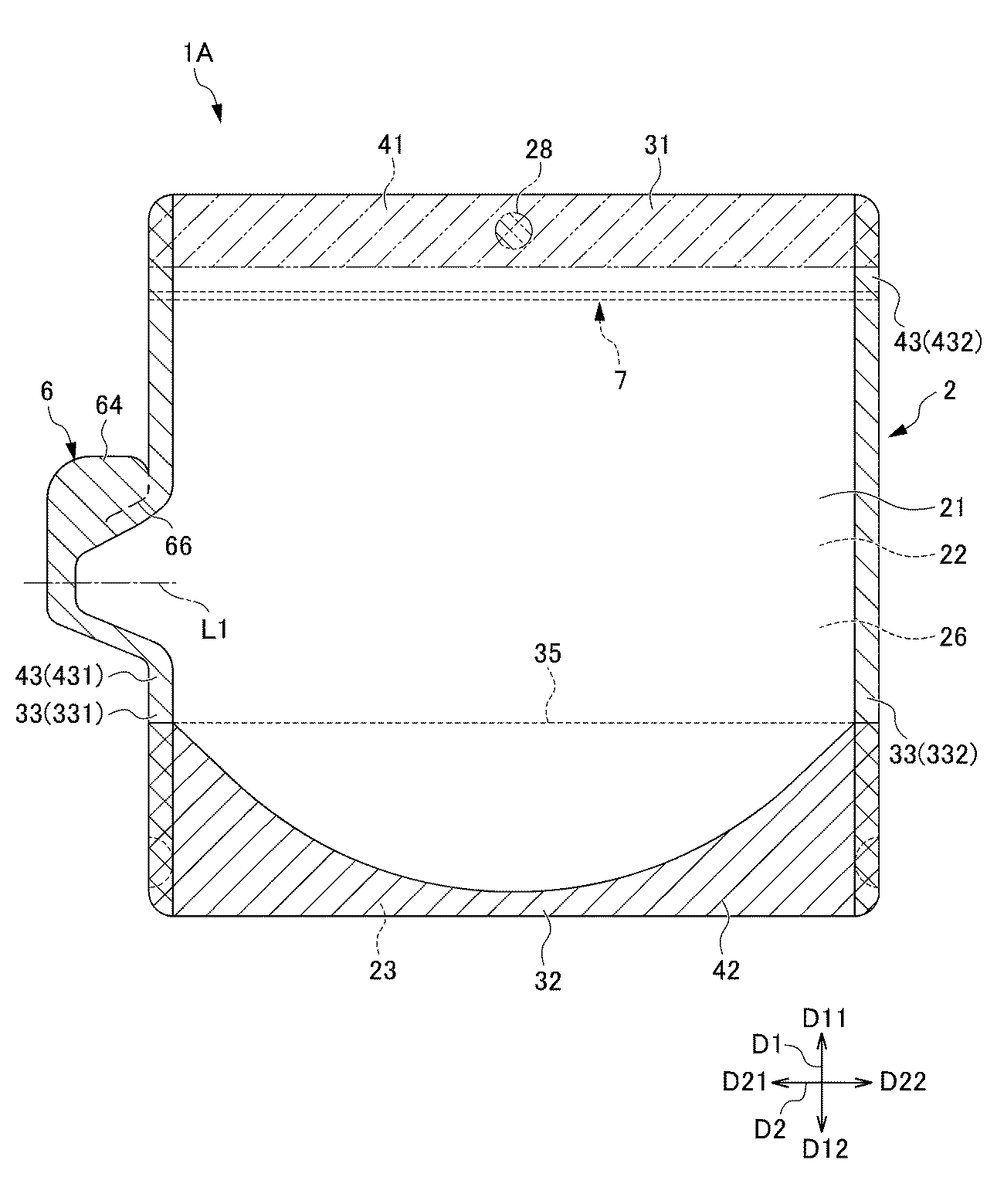
以下、図1〜図3を参照して、本発明の第1実施形態の調理用パウチ1について説明する。図1は、本発明の第1実施形態の調理用パウチ1の正面図である。図2は、第1実施形態の調理用パウチ1において、上部シール部41の形成予定領域を示す正面図である。図3は、図1に示す注出口部6の部分拡大図である。
[First Embodiment]
Hereinafter, a
図1〜図3に示すように、第1実施形態の調理用パウチ1は、パウチ本体2と、注出口部6と、チャックテープ7とを備える。調理用パウチ1は、チャックテープ7が露出した状態でチャックテープ7を開封することにより、開封したチャックテープ7を介して、パウチ本体2の収容部26に材料(内容物)を導入することができる。その後、チャックテープ7を封鎖することができる。その後、収容部26において内容物を混ぜ合わせたりして、混ぜ合わされた内容物を注出口部6から注出して排出することができる。以下に各構成について詳述する。
As shown in FIGS. 1 to 3, the
各図面において、上方向をD11で示し、下方向をD12で示し、両方向を合わせて「上下方向D1」という。左方向をD21で示し、右方向をD22で示し、両方向を合わせて「横方向D2」という。調理用パウチ1の構成を説明する場合、特に説明が無い場合には、パウチ本体の底部を下側にしたときの状態(姿勢)に基づいて、説明する。また、パウチ本体の底部を下側にしたときに、パウチ本体の底部から上部へ向かう方向、及びパウチ本体の上部から底部へ向かう方向は、それぞれ上方向D11及び下方向D12に一致する。同様に、パウチ本体の底部を下側にしたときに、パウチ本体の一方の側部から他方の側部に向かう方向は、横方向D2に一致する。
In each drawing, the upper direction is indicated by D11, the lower direction is indicated by D12, and both directions are collectively referred to as "vertical direction D1". The left direction is indicated by D21, the right direction is indicated by D22, and both directions are collectively referred to as "lateral direction D2". When the configuration of the
〔内容物〕
パウチ本体2は、内容物としての各種材料を収容する収容部26を備える。収容部26に収容される内容物は、特に制限されない。内容物としては、例えば、粉体(粒体を含む)、液体、流動性を有する食材、刻まれた食材が挙げられる。内容物は、第1の材料と第2の材料とに大別される。第1の材料は、メーカーにより、商品販売時に予め収容部26に収容されている場合と、収容部26が空の状態で調理用パウチ1を入手した調理者が、調理用パウチ1の収容部26に導入する場合と、がある。第2の材料は、調理者により、開封されたチャックテープ7を介して、第1の材料が収容されている収容部26に更に導入される材料である。
〔Contents〕
The pouch
本発明において「調理」は、広く解釈され、食に供される状態まで調理する場合(「完成調理」ともいう)のみならず、食に供される状態の手前まで調理する場合(追加調理が必要な場合。「半完成調理」ともいう)も含む。調理は、単なる混合を含む。混合は、結果的に混ぜることになれば、揉む、振る、押し潰す、その他の動作によるものを含む。 In the present invention, “cooking” is widely interpreted, and is not limited to cooking to the state of being served (also referred to as “complete cooking”), but also cooking to just before the state of being served (additional cooking is required). When necessary, also referred to as "semi-finished cooking"). Cooking involves simple mixing. Mixing includes rubbing, shaking, crushing, and other actions that result in mixing.
「混合」(混ぜる)とは、予め粉体や液状調味料などが入った容器に水や卵や肉、野菜などの別の材料を加え、容器を密閉した上で内容物を混ぜ合わせる調理のことをいう。
「揉む」とは、容器を密閉した上で容器ごと内容物を揉んだり押したりして混ぜることをいう。「振る」とは、容器を密閉した上で容器を上下左右などに振って内容物を混ぜることをいう。
"Mixing" (mixing) is a process in which water, eggs, meat, vegetables, and other ingredients are added to a container containing powder and liquid seasonings in advance, and the contents are mixed after the container is sealed. That means.
"Kneading" refers to mixing and kneading or pushing the contents together with the container after sealing the container. “Shake” refers to mixing the contents by shaking the container up, down, left, right, etc., after sealing the container.
半完成調理における第1の材料としては、例えば、いわゆる「プレミックス」(Prepared Mixの略称、pre−mix)、小麦粉(薄力粉)、強力粉、てんぷら粉が挙げられる。プレミックスは、ケーキ,パンなどを簡便に調理できる調整粉で,小麦粉等の粉類(澱粉を含む)に糖類,油脂,粉乳,卵粉、膨張剤,食塩,香料などを必要に応じて適正に配合したものである。プレミックスとしては、ホットケーキミックス、お好み焼きミックス、パンミックス、クッキーミックス、もんじゃ焼きミックスが挙げられる。また、オムレツ用の具材として、例えば、ハム、生クリーム、カット野菜、半調理された野菜、冷凍野菜が挙げられる。 As the first material in the semi-finished cooking, for example, a so-called “premix” (abbreviation of Prepared Mix, pre-mix), flour (light flour), strong flour, and tempura flour are exemplified. Premix is an adjusted powder that can be easily cooked for cakes and breads, etc. Suitable for flour and other flours (including starch), sugars, fats, milk powder, egg powder, leavening agents, salt, flavors, etc. as necessary. It is blended in. Premixes include hot cake mix, okonomiyaki mix, bread mix, cookie mix, and monjayaki mix. Examples of ingredients for omelets include ham, fresh cream, cut vegetables, semi-cooked vegetables, and frozen vegetables.
また、半完成調理又は完成調理における第1の材料としては、惣菜、プロテイン(粉)、アミノ酸(粉)、青汁(粉)等の健康食品、ダイエット食品、ドライフルーツ、シリアル、果物、ナッツ、菓子、デザート、その他加工食品、食事代替用の各種の粉体が挙げられる。また、粉末珈琲、スポーツ飲料、その他粉末の飲料の素が挙げられる。 The first ingredient in semi-finished cooking or finished cooking includes health foods such as prepared foods, protein (powder), amino acids (powder), green juice (powder), diet foods, dried fruits, cereals, fruits, nuts, Examples include confectionery, desserts, other processed foods, and various powders for meal replacement. In addition, powdered coffee, sports drinks, and other powdered drinks can be used.
第2の材料としては、例えば、牛乳、豆乳、ジュース、珈琲、紅茶、水などの液体、卵などの流動性を有する食材、チーズ、チョコレート等の、刻まれたり、溶けて流動性を有する食材、ベーキングパウダー、食塩、糖類、香辛料などの粉体、各種液状調味料、イースト菌などの酵母、氷が挙げられる。 As the second material, for example, liquid materials such as milk, soy milk, juice, coffee, tea, water, etc., liquid food materials such as eggs, cheese, chocolate, etc., chopped or melted food materials having liquidity Powders such as baking powder, salt, sugars and spices, various liquid seasonings, yeasts such as yeast, and ice.
完成調理において、第1の材料としての氷菓(シャーベット状アイスなど)、アイスクリーム類などの冷菓と、第2の材料としてのミルクやシロップ等の飲料用の液体とを混合することで、フローズン状の飲料を容易に作成することができる。 In the completed cooking, frozen confectionery such as ice confectionery (such as sherbet-like ice) and ice cream as the first material, and beverage liquid such as milk and syrup as the second material are mixed to produce a frozen confection. Beverage can be easily prepared.
本発明の調理用パウチは、ケーキやオムレツのように混合された材料に空気を多く含ませてふんわりと焼く場合に適している。また、珈琲などの飲料を泡立てて混合する場合にも適している。 The cooking pouch of the present invention is suitable for a case where a mixed material such as a cake or an omelet contains a large amount of air and is softly baked. It is also suitable for mixing beverages such as coffee by whipping.
なお、半完成調理においてプライパンやボウル等に注出されて、その後追加調理が行われる場合には、第1実施形態のようなパウチ本体2と一体的なフィルムからなる構造の注出口部(詳細は後述)が適している。
In addition, in the case of being poured into a ply pan or a bowl or the like in semi-finished cooking and then additional cooking is performed, a spout portion having a structure formed of a film integrated with the
〔パウチ本体〕
パウチ本体2の構造について更に詳述する。図1及び図2に示すように、パウチ本体2は、熱可撓性のフィルムで構成される。パウチ本体2を構成するフィルムは、前面を形成する前面フィルム21と、背面を形成する背面フィルム22と、底部32のマチ部を形成する底部フィルム23と、を備える。つまり、パウチ本体2は、底部32にマチ部を備える底部ガセットパウチ形状を有する。見方を変えると、パウチ本体2は、前面フィルム21によって形成された前面と、背面フィルム22によって形成された背面と、底部32のマチ部によって形成された底面と、を有する。調理用パウチ1は、自立性を有するスタンディングパウチとして機能する。
(Pouch body)
The structure of the pouch
第1実施形態においては、前面フィルム21及び背面フィルム22は、注出口部6の領域を除いて、略矩形のフィルムから構成される。略矩形は、幾何学上の長方形に制限されず、全体視で長方形と認められる形状を含む。例えば、側縁、底縁又は上縁のいずれか1つ以上が曲線部分を含んでいてもよい。また、フィルムの隅部は、外に凸の円弧状に丸みを帯びていてもよい。
In the first embodiment, the
マチ部は、パウチ本体2の底部32に設けられる。収容部26に内容物が収納された場合には、マチ部は十分に広がり、そのため、調理用パウチ1は自立可能となる。また、マチ部が広がるので、底部にマチ部を備えない平パウチの場合と比べて、収容部26の容積を大きくすることができる。一方、収容部26に内容物が収納されていない場合には、マチ部を形成する底部フィルム23は、上部に折り返し部35が形成されるように折り返されることができる。これにより、パウチ本体2の全体の厚さは小さくなる。
The gusset part is provided on the
また、前面フィルム21と背面フィルム22と底部フィルム23とは、パウチ本体2の形成前において、互いに別個のフィルムであってもよく、又は、一体的なフィルムであってもよい。一体的なフィルムの場合、前面フィルム21、背面フィルム22及び底部フィルム23のいずれか2つ以上が一体的であってもよい。一体的なフィルムは、折り曲げられて、前面フィルム21、背面フィルム22及び底部フィルム23のいずれか2つ以上を形成する。
The
パウチ本体2の上部31において、前面フィルム21の上部と背面フィルム22の上部とは、接合される。接合手段として、例えば、熱溶着(ヒートシール)、超音波溶着などが挙げられる(以下、同様)。この接合により、図2に示すように、パウチ本体2の上部31には、前面フィルム21の上部と背面フィルム22の上部とを接合するシール部として、上部シール部41が形成される。
In the
なお、内容物が収容されていない状態で調理用パウチが販売される場合には、上部シール部41を備えていなくてもよい。また、上部シール部41は、収容部26に内容物が収容された後に、形成されるが、図2には、収容部26に内容物が収容されていない状態において、上部シール部41の形成予定領域を2点鎖線ハッチングで示している。本発明は、内容物が収容されていない状態の調理用パウチ、及び内容物が収容されている状態の調理用パウチの両方を含む。
In addition, when the cooking pouch is sold in a state where the contents are not accommodated, the
パウチ本体2の側部33において、前面フィルム21の側部と背面フィルム22の側部とは、接合される。この接合により、パウチ本体2の左右の側部33それぞれ(左側部331、右側部332)には、前面フィルム21の側部と背面フィルム22の側部とを接合するシール部として、側部シール部43(左側部シール部431、右側部シール部432)が形成される。なお、パウチ本体2の側部33には、マチ部は設けられていない。
At the
なお、調理用パウチ1が表裏で対称的であれば、左右の区別は相対的、便宜的なものである。また、左側部331と右側部332との区別が不要で、共通する説明をする場合には、単に「側部33」と表現する。
If the
パウチ本体2の底部32において、前面フィルム21の下部周縁部と底部フィルム23の前半分の周縁部とが接合されると共に、背面フィルム22の下部周縁部と底部フィルム23の後半分の周縁部とが接合される。このようにして、パウチ本体2の底部32には、底部シール部42が形成される。なお、底部シール部42の幅は比較的広いため、シール工程時に底部シール部42に比較的気泡が生じやすい。そこで、底部シール部42の形成時には、空気孔を設けた熱板を用いるなどして、気泡を抑制することが好ましい。
At the bottom 32 of the pouch
底部フィルム23の側部に切り欠き部231が設けられている。前面フィルム21の側部と背面フィルム22の側部とは、基本的には、切り欠き部231以外の底部フィルム23が間に介在するため、接合されない。しかし、切り欠き部231の部分では、前面フィルム21の側部と背面フィルム22の側部とは直接当接する。そのため、切り欠き部231の部分において、前面フィルム21と背面フィルム22とが側部シール部43により接合される。これにより、スタンディングパウチの自立性が向上する。なお、上下方向D1において、切り欠き部231は1個だけでもよい(図1では、切り欠き部231は1個である)が、切り欠き部231は、上下方向に複数個(例えば2個)設けられていてもよい。
A
〔注出口部〕
注出口部6は、パウチ本体2に収容されている内容物を注出する部位である。第1実施形態の調理用パウチ1は、収容部26を有するパウチ本体2と、パウチ本体2に一体的に接続される注出口部6と、を備えている。注出口部6は、パウチ本体2の前面フィルム21及び背面フィルム22と一体的に(同じ材料で)構成されている。注出口部6Aの全体が、パウチ本体2と共通の前面フィルム21及び背面フィルム22によって構成される。詳述すると、フィルム21と背面フィルム22との間には、収容部26に収容されている内容物F0(図4〜図5参照)が注出されるときに内容物F0が流通する流通路60(図2参照)が形成される。
(Outlet)
The
別の見方をすると、パウチ本体2及び注出口部6は、少なくとも両者が接続される部分において互いに一体的に構成されている。具体的には、パウチ本体2及び注出口部6が接続される部分において、パウチ本体2及び注出口部6はいずれも、前面フィルム21及び背面フィルム22によって構成されている。
From another point of view, the
注出口部6の注出方向D6は、チャックテープ7が延びる方向D7に実質的に平行である。詳述すると、注出口部6は、正面視において、パウチ本体2の底部32を下側にしたときに、横方向D2を向いている。注出口部6の注出方向D6は、第1実施形態においては、真横向き(横方向D2)である。また、チャックテープ7が延びる方向D7は、同じく横方向D2である。「実質的に平行」には、厳密に平行の場合のみならず、例えば、延びる方向が±5%程度異なっていてもよい。
なお、注出口部6の注出方向D6は、横方向D2に制限されないが、操作性を考慮すると、正面視において横方向D2が好ましい。
The pouring direction D6 of the
The pouring direction D6 of the
図3に示すように、注出口部6は、流通路60と、流通路60を囲む注出口シール部67と、摘まみ部64と、開封線66と、開封予定部68と、を有する。
As shown in FIG. 3, the
流通路60は、前面フィルム21と背面フィルム22との間に形成され、パウチ本体2から左方向D21に突出した通路であり、収容部26に収容されている内容物F0が注出されるときに内容物F0が流通する通路である。流通路60は、正面視において、左方向D21に向けて徐々に先細になっている。
The
注出口シール部67は、パウチ本体2と注出口部6とが接続される第1接続部分51を除いて、流通路60を囲むシール部である。詳述すると、注出口部6においては、二等分線L1を挟んで配置される側縁部、及び二等分線L1が交差する先端部は、熱溶着されている。注出口シール部67は、注出口部6の前記側縁部及び前記先端部における熱溶着部分である。注出口部6の二等分線L1とは、正面視において、注出口部6の基部の中心点と注出口部6の先端部の中心点とを結ぶ線である。
The
摘まみ部64は、注出口部6を開封する際に指で摘ままれる部分である。開封線66は、注出口シール部67と摘まみ部64との境界線を形成する。開封予定部68は、開封されることによって内容物が注出される注出口(開口)となる予定部である。
The
開封線66を破断し、その破断方向に沿って注出口部6を破断すると、二等分線L1を跨いで反対側の注出口シール部67に向かって、開封予定部68も破断される。これにより、注出口部6の開口が形成される。図5(B)には、開封線66により開口した注出口部6が示されている。
When the
開封線66は、注出口部6を破断して注出口部6の開口を形成する作業を容易化するために、前面フィルム21及び背面フィルム22に形成される。具体的には、開封線66には、調理用パウチ1のうち、その他の部分に比べて破断され易くなるような加工が施されている。加工の例としては、ミシン目が例示される。
The
開封予定部68には、調理用パウチが開封され易くなるための易開封手段が設けられていてもよい。例えば、開封予定部68は、レーザー加工やカッターなどで形成されたハーフカット線などの易開封線を含んでいてもよい。この場合、互いにほぼ平行に延びる複数の易開封線が設けられていてもよい。前面フィルム21及び背面フィルム22を構成する積層フィルムの中に延伸フィルムを包含させ、延伸フィルムの延伸方向と開封予定部68の延びる方向とを一致させてもよい。また、開封予定部68には、特に易開封手段が設けられていなくてもよい。開封予定部68を、手で引き裂いたり、ハサミで切断してもよい。開封予定部68には、開封場所であることを使用者に示すための表示が印刷などによって設けられていてもよい。
The
〔パウチ本体に対する注出口部の相対位置〕
パウチ本体2に対する注出口部6の相対位置について、説明する。パウチ本体2と注出口部6とが接続される第1接続部分51(図3参照)は、パウチ本体2の底部32を下側にしたときに、正面視において、パウチ本体2の上下方向D1の25〜75%の位置に配置されている。図2には、パウチ本体2の上下方向について、パウチ本体2の下端が0%、パウチ本体2の上端が100%であることが示されている。
第1接続部分51の上下方向D1の長さK51(図3参照)は、例えば、30mm以上80mm以下である。
[Relative position of spout port to pouch body]
The position of the
The length K51 (see FIG. 3) of the
〔収容部26と流通路60との長さの比〕
収容部26と流通路60との長さの比について説明する。パウチ本体2の底部32を下側にしたときに、正面視において、収容部26の上下方向D1の長さK26(図1参照)に対する、収容部26と流通路60とが接続される第2接続部分52(図3参照)の長さK52の比(K52/K26)は、15〜35%である。
第2接続部分52の(上下方向D1の)長さK52は、例えば、20mm以上70mm以下である。収容部26の上下方向D1の長さK26において、上端はチャックテープ7である。
[Length ratio of
The ratio of the length of the
The length K52 (in the vertical direction D1) of the
〔チャックテープ〕
次に、チャックテープ7について詳述する。図1及び図2に示すように、チャックテープ7は、ノッチ73などの易開封手段に沿って破断されて開封された後のパウチ本体2を再び封鎖するために設けられる部材である。チャックテープ7は、少なくとも収容部26の一端から他端に亘って延びている。第1実施形態においてチャックテープ7が延びる方向は、横方向D2である。
[Chuck tape]
Next, the
チャックテープ7は、前面フィルム21又は背面フィルム22のうちの一方の内面側に設けられた雄型部材71と、雄型部材71に対向するように、前面フィルム21又は背面フィルム22のうちの他方の内面に取り付けられた雌型部材72と、を有する(図4(B)参照)。雄型部材71と雌型部材72とは、互いに嵌合可能に構成されている。雄型部材71と雌型部材72との嵌合を外すことにより、チャックテープ7を開封し、チャックテープ7を介して、材料を収容部26に導入することができる。また、雄型部材71と雌型部材72とを嵌合させることにより、チャックテープ7を開封した後のパウチ本体2の収容部26を再び封鎖することができる。「チャックテープ7を介して」とは、「嵌合が外されて分離した雄型部材71と雌型部材72との間に形成された開口を通じて」という意味である。
The
チャックテープ7は、少なくとも1回の開封及び封鎖が可能な構成を有し、実使用上、複数回の開封及び封鎖が可能なことが好ましい。チャックテープ7は、実使用上、封鎖時に水密性を確保できることが好ましい。
チャックテープ7は、公知技術の各構成を採用することができ、例えば、特開2005−231693号公報に記載のチャックテープの構成を採用することができる。
チャックテープ7は、少なくとも収容部26の一端から他端に亘って設けられている。機能的には、この範囲に設けられていれば足りるが、生産効率上、第1実施形態においては、チャックテープ7は、パウチ本体2の一端から他端に亘って設けられている(収容部26の一端から他端の間を含み、更に、パウチ本体2の側縁まで、設けられている。)。
The
The configuration of the known technique can be used for the
The
チャックテープ7は形状保持性を有していてもよい。詳細には、チャックテープ7を開封したときに、チャックテープ7の雄型部材71及び雌型部材72それぞれが、前後方向に凸に膨らんで、膨らんだ形状が保持される形状保持性を有している。形状保持性を有するチャックテープ7としては、例えば、特開2011−246188号公報記載の技術を用いることができる。チャックテープ7が形状保持性を有することにより、前記第1の材料または前記第2の材料を投入するときの作業をしやすくすることができる。
The
上部シール部41とチャックテープ7との間の前面フィルム21及び背面フィルム22には、易開封手段(後述)が設けられている。第1実施形態では、易開封手段は、パウチ本体2の左右の側部33(側部シール部43)それぞれに設けられるノッチ73から構成される。
The
チャックテープ7が開封した状態における収容部26への材料の導入方向D5は、制限されないが、操作性を考慮すると、パウチ本体の底部を下側にしたときに正面視において真下向きから真横向きの間の向きが好ましい。第1実施形態においては、導入方向D5は、正面視において、下方向D12である。
The introduction direction D5 of the material into the
注出口部6の開口の断面積は、チャックテープ7の開口の断面積よりも大幅に小さく、例えば、1/10以下、好ましくは1/20以下である。
The cross-sectional area of the opening of the
〔収容部の透明性〕
収容部26は、少なくとも一部において透明性を有していてもよい。透明性を有する部分(図示せず)は、例えば、収容部26に収容された内容物の量を確認するために用いられる。収容部26は、その全体において透明性を有していてもよい。また、パウチ本体2の一部領域のみが、透明性を有していてもよい。透明性を有する部分には、目印(図示せず)や目盛り(図示せず)が設けられていてもよい。これにより、内容物の量や混ざり具合を視認しやすい。
(Transparency of accommodation section)
The
また、例えば、収容部26の横方向D2の中央領域のみが透明性を有し、透明性を有する部分の横方向D2の外側の部分が印刷などにより不透明で、不透明な部分に各種表示が施されていてもよい。目印や目盛りを利用する場合、目印や目盛りの周辺の内容物を視認できれば、機能的には足りることが多いためである。なお、複数の調理用パウチが梱包されて販売される形態の場合、表示を省略して、全体又はほぼ全体が透明な調理用パウチであってよい。
Further, for example, only the central region in the lateral direction D2 of the
〔フィルム〕
包装材料としてのフィルムは、基材層及びシーラント層を少なくとも含む。包装材料としてのフィルムは、さらに他の層を備えていてもよい。他の層としては、印刷層や、酸素ガスや水蒸気などの透過を阻止するガスバリア層や、遮光性を付与するための遮光層や、機械的強度を付与するための支持体などが挙げられる。
基材層を構成する材料としては、ポリエチレンテレフタレート、ナイロン、ポリプロピレン等のプラスチックや、紙等を用いることができる。また、シーラント層を構成する材料としては、ポリエチレンやポリプロピレン等を用いることができる。積層フィルムは、基材層を複数備えていてもよいし、シーラント層が複数の層から構成されていてもよい。
〔the film〕
The film as a packaging material includes at least a base material layer and a sealant layer. The film as a packaging material may further include another layer. Examples of the other layers include a printing layer, a gas barrier layer for preventing permeation of oxygen gas and water vapor, a light-shielding layer for imparting light-shielding properties, and a support for imparting mechanical strength.
As a material constituting the base layer, plastics such as polyethylene terephthalate, nylon, and polypropylene, paper, and the like can be used. Further, as a material constituting the sealant layer, polyethylene, polypropylene, or the like can be used. The laminated film may include a plurality of base layers, or the sealant layer may include a plurality of layers.
印刷層は、袋に製品情報を示したり美感を付与したりするための印刷表示を含む。印刷表示としては、文字、数字、記号、図形、絵柄などを挙げることができる。
支持体としては、延伸ポリエチレンテレフタレートフィルムなどの延伸ポリエステルフィルムや延伸ナイロンフィルムなどの延伸ポリアミドフィルムや延伸ポリプロピレンフィルムなどの延伸ポリオレフィンフィルムなどが挙げられる。
ガスバリア層としては、アルミニウム箔などの金属箔や、蒸着層などが挙げられる。蒸着層は、基材層に設けてもよいし、シーラント層に設けてもよいし、支持体に設けてもよい。
蒸着層は、アルミニウムなどの金属の蒸着層からなる金属蒸着層であってもよく、酸化アルミニウムや酸化珪素などの無機酸化物の蒸着層からなる透明蒸着層であってもよい。
The printing layer includes a printed display for indicating product information or giving aesthetic appearance to the bag. Examples of the print display include letters, numbers, symbols, figures, and patterns.
Examples of the support include a stretched polyester film such as a stretched polyethylene terephthalate film, a stretched polyamide film such as a stretched nylon film, and a stretched polyolefin film such as a stretched polypropylene film.
Examples of the gas barrier layer include a metal foil such as an aluminum foil and a vapor deposition layer. The vapor deposition layer may be provided on the base material layer, the sealant layer, or the support.
The deposited layer may be a metal deposited layer made of a deposited layer of a metal such as aluminum, or may be a transparent deposited layer made of a deposited layer of an inorganic oxide such as aluminum oxide or silicon oxide.
蒸着層の上にガスバリア性塗布膜を設けてもよい。ガスバリア性塗布膜は、酸素ガスおよび水蒸気などの透過を抑制する層として機能する塗膜である。ガスバリア性塗布膜は、一般式R1nM(OR2)m(ただし、式中、R1、R2は、炭素数1〜8の有機基を表し、Mは、金属原子を表し、nは、0以上の整数を表し、mは、1以上の整数を表し、n+mは、Mの原子価を表す。)で表される少なくとも一種以上のアルコキシドと、ポリビニルアルコ−ル系樹脂および/またはエチレン・ビニルアルコ−ル共重合体とを含有し、さらに、ゾルゲル法触媒、酸、水、および、有機溶剤の存在下に、ゾルゲル法によって重縮合するガスバリア性組成物により得られる。 A gas barrier coating film may be provided on the deposition layer. The gas barrier coating film is a coating film that functions as a layer that suppresses transmission of oxygen gas, water vapor, and the like. The gas barrier coating film has a general formula R1nM (OR2) m (where R1 and R2 represent an organic group having 1 to 8 carbon atoms, M represents a metal atom, and n represents an integer of 0 or more. And m represents an integer of 1 or more, and n + m represents the valence of M.) and at least one alkoxide represented by the following formula: and a polyvinyl alcohol-based resin and / or ethylene-vinyl alcohol. It is obtained by a gas barrier composition containing a polymer and being polycondensed by a sol-gel method in the presence of a sol-gel method catalyst, an acid, water, and an organic solvent.
〔調理法に対する、パウチ本体の物性の適性〕
調理「揉む」には、コシ(剛性)が低いフィルムからなるパウチ本体2が好ましい。パウチ本体2を素手で揉むときに、シール部が硬かったり、フィルムの屈曲部が尖ったりすると、手を怪我しやすいからである。また、調理者が内容物を混ぜ合わせる感覚を直接得やすいからである。また、突き刺し強度が比較的高いパウチ本体2が好ましい。揉んでいるときに破断しにくいためである。
調理「振る」には、コシが高いフィルムからなるパウチ本体2が好ましい。内容物が収容部26の内部を移動するため、移動の度にフィルムが屈曲しにくくするためである。また、突き刺し強度が高いパウチ本体2が好ましい。振っているときに破断しにくいためである。
[Appropriate physical properties of the pouch body for cooking methods]
For cooking “kneading”, the
For cooking “shake”, the
具体的に、パウチ本体のコシ(剛性)及び突き刺し強度の好ましい範囲は以下の通りである。調理「揉む」に適しているパウチ本体のコシは、1gr以上10gr以下で、好ましくは2gr以上5gr以下である。調理「振る」に適しているパウチ本体のコシは、7gr以上20gr以下で、好ましくは9gr以上15gr以下である。なお、1gr=0.0006479891 kgである。
調理「揉む」に適しているパウチ本体の突き刺し強度は、4N以上11N未満である。調理「振る」に適しているパウチ本体の突き刺し強度は、11N以上25N以下である。
Specifically, preferred ranges of the stiffness (rigidity) and the piercing strength of the pouch main body are as follows. The stiffness of the pouch body suitable for cooking "rubbing" is 1 gr or more and 10 gr or less, preferably 2 gr or more and 5 gr or less. The stiffness of the pouch body suitable for cooking "shake" is 7gr or more and 20gr or less, preferably 9gr or more and 15gr or less. In addition, 1 gr = 0.0006478991 kg.
The piercing strength of the pouch body suitable for cooking “rubbing” is 4N or more and less than 11N. The piercing strength of the pouch body suitable for cooking “shake” is 11N or more and 25N or less.
パウチ本体2を形成する積層フィルムの具体例としては例えば以下が挙げられる。なお、「/」は、層を列記する場合に、層と層との境界を示す表記として用いている。層については、外側から内側に向かって記載する。すなわち最も左側に記載された層が最外層である。
層の略称は以下の通りである。
ALM:アルミニウム箔
ALM蒸着層:アルミニウム蒸着層
CPP:未延伸プロピレン
ONy:延伸ナイロン
LLDPE:直鎖状低密度ポリエチレン
PET:ポリエチレンテレフタレート
Specific examples of the laminated film forming the
Abbreviations of the layers are as follows.
ALM: Aluminum foil ALM deposited layer: Aluminum deposited layer CPP: Unstretched propylene ONy: Stretched nylon LLDPE: Linear low density polyethylene PET: Polyethylene terephthalate
ONy/印刷層/接着剤層/LLDPE
ONy/透明蒸着層/印刷層/接着剤層/LLDPE
PET/印刷層/接着剤層/ONy/接着剤層/LLDPE
PET/透明蒸着層/印刷層/接着剤層/ONy/接着剤層/LLDPE
ONy/印刷層/接着剤層/ALM蒸着層/PET/接着剤層/LLDPE
PET/印刷層/接着剤層/ALM/接着剤層/ONy/接着剤層/LLDPE
PET/透明蒸着層/印刷層/接着剤層/ONy/接着剤層/CPP
PET/印刷層/接着剤層/透明蒸着層/PET/接着剤層/CPP
ONy / printing layer / adhesive layer / LLDPE
ONy / Transparent deposited layer / Printed layer / Adhesive layer / LLDPE
PET / printing layer / adhesive layer / ONy / adhesive layer / LLDPE
PET / transparent vapor deposition layer / print layer / adhesive layer / ONy / adhesive layer / LLDPE
ONy / printing layer / adhesive layer / ALM deposited layer / PET / adhesive layer / LLDPE
PET / printing layer / adhesive layer / ALM / adhesive layer / ONy / adhesive layer / LLDPE
PET / Transparent deposited layer / Printed layer / Adhesive layer / ONy / Adhesive layer / CPP
PET / printing layer / adhesive layer / transparent deposited layer / PET / adhesive layer / CPP
〔使用例〕
次に、図4〜図5を参照しながら、第1実施形態の調理用パウチ1の使用例の一例について説明する。図4〜図5は、第1実施形態の使用手順を順次示す図である。
〔Example of use〕
Next, an example of a usage example of the
〔第1の材料が収容されている調理用パウチについて、チャックテープを露出させる工程〕
調理用パウチ1の収容部26には、前記第1の材料として、例えば粉体F1が収容されている。また、易開封手段73による開封はされておらず、パウチ本体2の上部は、上部シール部41及びチャックテープ7により封鎖されている。
この状態から、図4(A)に示すように、易開封手段73を利用して、上部シール部41とチャックテープ7との間の部分を横方向D2に破断して、パウチ本体2の上部を開放し、チャックテープ7を露出させる。
[Step of Exposing Chuck Tape for Cooking Pouch Containing First Material]
The
From this state, as shown in FIG. 4A, the portion between the
〔チャックテープを開封する工程〕
次に、図4(B)に示すように、チャックテープ7について、嵌合している雄型部材71と雌型部材72との嵌合を解除し、雄型部材71と雌型部材72とを分離させる。これにより、雄型部材71及び雌型部材72は、それぞれ前後方向に凸に膨らんだ形状となる。そして、雄型部材71と雌型部材72との間に、追加材料が通過可能な開口が形成される。なお、チャックテープ7が形状保持性を有するものであれば、チャックテープ7を手などで保持しなくても、開口形状は保持される。
[Step of opening zipper tape]
Next, as shown in FIG. 4 (B), with respect to the
〔チャックテープを介して、第2の材料を導入する工程〕
次に、図4(C)に示すように、チャックテープ7を介して、前記第2の材料として、例えば卵F2や液体F3を収容部26へ導入する。
次に、図4(D)に示すように、チャックテープ7を封鎖する。これにより、収容部26が封鎖される。
[Step of introducing the second material via the chuck tape]
Next, as shown in FIG. 4C, for example, eggs F2 and liquid F3 as the second material are introduced into the
Next, as shown in FIG. 4D, the
〔チャックテープによる封鎖後、第1の材料と第2の材料とを混合する工程〕
次に、収容部26が封鎖された状態において、図5(A)に示すように、調理者は手Hで収容部26を揉んで内容物(材料)F1,F2,F3を混ぜ合わせることができる。なお、混ぜ合わせる際に、揉む動作に加えて又は揉む動作に代えて、振る動作や押し潰す動作を行うこともできる。これらの動作は、前述の通り、「混合」と総称される。「混合」は「調理」の一態様である。
[Step of mixing first and second materials after sealing with zipper tape]
Next, in a state where the
〔混合された内容物を、注出口部を介して注出する工程〕
次に、図5(B)に示すように、摘まみ部64を摘まんで、開封線66を破断の起点として注出口部6を開封して、開封予定部68に沿った開口を形成する。
次に、図5(C)に示すように、チャックテープ7に実質的に平行な2つの折り畳み線に沿ってパウチ本体2を三つ折りに折り畳む。この状態で、折り畳まれたパウチ本体2を絞ることで、収容部26に収容された内容物(混ぜ合わされた材料)F0を注出口部6の開口から注出して排出することができる。注出口部6の開口の断面積は、チャックテープ7の開口の断面積よりも大幅に小さいため、適量の内容物を注出させる操作を容易に行うことができる。
(Step of pouring the mixed contents through a spout section)
Next, as shown in FIG. 5B, the
Next, as shown in FIG. 5C, the
排出された内容物F0は、フライパンなどの調理器具を用いて焼かれて調理することができる。また、内容物F0は、容器に排出された後、特に追加調理をされずに、食べたり飲んだりすることもできる。 The discharged contents F0 can be baked and cooked using a cooking utensil such as a frying pan. Further, after the content F0 is discharged into the container, the content F0 can be eaten or drunk without any additional cooking.
図4及び図5では、調理用パウチ1の収容部26に内容物(粉体F1)が予め収容されている形態を例にして説明している。しかし、収容部26に内容物が収容されていない調理用パウチ1でも、同様に使用できる。具体的には、チャックテープ7を開封し、チャックテープ7を介して、第1の材料、第2の材料・・・・・を順次導入し、その後、チャックテープ7を封鎖して、収容部26を揉んで混ぜ合わせることができる。
4 and 5 illustrate an example in which the content (powder F1) is stored in advance in the
〔第1実施形態の効果〕
第1実施形態の調理用パウチ1によれば、例えば以下の効果が奏される。第1実施形態の調理用パウチ1は、パウチ本体2と、前面フィルム21及び背面フィルム22を備え、前面フィルム21と背面フィルム22との間に、収容部26に収容されている内容物F0が注出されるときに内容物F0が流通する流通路60が形成される注出口部6と、パウチ本体2に設けられ、収容部26の一端から他端に亘って延びるチャックテープ7と、を備え、注出口部6の注出方向D6は、チャックテープ7が延びる方向D7に実質的に平行である。
[Effects of First Embodiment]
According to the
そのため、第1実施形態の調理用パウチ1によれば、調理用パウチの収容部26内で前記第1の材料と前記第2の材料とを混ぜ合わせることができるため、使用する調理器具の数を減らすことができる。このため、調理器具の洗浄数を減らすことができる。また、調理者の手を汚れにくくすることができる。また、開封されたチャックテープ7(比較的大きい面積の開口を有する場合が多い)を介して、収容部26への材料を導入することができるため、収容部26への材料の導入性は確保される。そして、開封された注出口部6(比較的小さい面積の開口を有する場合が多い)を介して、収容部26に収容されている内容物F0の排出することができるため、収容部26に収容されている内容物F0の排出操作性にも優れる。
Therefore, according to the
また、チャックテープ7が延びる方向D7に実質的に平行な折り畳み線に沿ってパウチ本体2を折り畳むことが容易である。そして、折り畳まれたパウチ本体2を絞ることで、内容物F0を注出口部6から、チャックテープ7が延びる方向D7に実質的に平行に注出することが容易である。
Further, it is easy to fold the pouch
また、内容物を注出口部6から注出する際に、内容物をチャックテープ7へ導くことを抑制しながら、注出口部6へ導くことができる。また、パウチ本体2はフィルムから形成されているため、容器本体が比較的硬質の樹脂から形成されている場合と比べて、収容部26を小さい力で揉むことができ、従って、収容部26を揉んで内容物を混ぜやすい。このため、調理用パウチの使用性に優れる。
Further, when the content is poured out from the
〔第2実施形態〕
次に、本発明の第2実施形態の調理用パウチ1Aについて、図6を参照しながら説明する。図6は、本発明の第2実施形態の調理用パウチ1Aの正面図である。第2実施形態については、主に、図2に示す第1実施形態の調理用パウチ1との相違点について説明する。そのため、第1実施形態と同一(又は同等)の構成については、詳細な説明を省略する。また、第2実施形態において特に説明しない点については、第1実施形態の説明が適宜に適用又は援用される。第2実施形態においても、第1実施形態と同様の効果が奏される。
[Second embodiment]
Next, a
第2実施形態の調理用パウチ1Aにおいては、図6に示すように、パウチ本体2の上部31の上部シール部41の形成予定領域には、吊り下げ用孔28が形成される。吊り下げ用孔28は、調理用パウチ1Aの店頭展示の際や調理時の仮置き(仮の吊り下げ)の際に、吊り下げ用フック(図示せず)が挿通されて、利用される。
In the
〔第3実施形態〕
次に、本発明の第3実施形態の調理用パウチ1Bについて、図7を参照しながら説明する。図7は、本発明の第3実施形態の調理用パウチ1Bの正面図である。第3実施形態については、主に、図3に示す第1実施形態の調理用パウチ1との相違点について説明する。そのため、第1実施形態と同一(又は同等)の構成については、詳細な説明を省略する。また、第3実施形態において特に説明しない点については、第1実施形態の説明が適宜に適用又は援用される。第3実施形態においても、第1実施形態と同様の効果が奏される。
[Third embodiment]
Next, a
第1実施形態の調理用パウチ1においては、1つの注出口部6が設けられている。これに対して、第3実施形態の調理用パウチ1Bにおいては、2つの注出口部6A,6Bが設けられている。詳述すると、第1の注出口部6Aは、左側部331に、注出方向が左方向D21になるように設けられている。第2の注出口部6Bは、右側部332に、注出方向が右方向D22になるように設けられている。
第2の注出口部6Bの開口の断面積は、第1の注出口部6Aの開口の断面積よりも大きく、例えば、1.5倍以上、好ましくは2倍以上である。
注出口部6A,6Bには、不図示の易開封手段としてのノッチが設けられている。なお、注出口部6A,6Bは、第1実施形態における注出口部6と同様の構成を有することもできる。
In the
The cross-sectional area of the opening of the
The
〔第3実施形態の効果〕
第3実施形態の調理用パウチ1Bによれば、第1実施形態の効果に加えて、例えば以下の効果が奏される。第3実施形態の調理用パウチ1Bは、開口の断面積が異なる2つの注出口部6A,6Bを備える。そのため、使用例などによって好適な断面積の開口の注出口部を使い分けることができる。例えば、収容部26に収容された内容物(混ぜ合わされた材料)F0の粘度が比較的低い場合や、注出口部から内容物F0を細く注出したい場合には、第1の注出口部6Aを使い、一方、収容部26に収容された内容物F0の粘度が比較的高い場合や、注出口部から内容物F0を太く注出したい場合には、第2の注出口部6Bを使うといった、使い分けを行うことができる。
[Effects of Third Embodiment]
According to the
〔第4実施形態〕
次に、本発明の第4実施形態の調理用パウチ1Cについて、図8を参照しながら説明する。図8は、本発明の第4実施形態の調理用パウチ1Cの正面図である。第4実施形態については、主に第1実施形態との相違点について説明する。そのため、第1実施形態と同一(又は同等)の構成については、詳細な説明を省略する。また、第4実施形態において特に説明しない点については、第1実施形態の説明が適宜に適用又は援用される。第4実施形態においても、第1実施形態と同様の効果が奏される。
[Fourth embodiment]
Next, a
第4実施形態の調理用パウチ1Cにおいては、第1実施形態と同様に、パウチ本体2の左側部331に、注出口部6が設けられている。なお、第4実施形態における注出口部6は、第1実施形態における注出口部6の構成を有していてもよく、また、第3実施形態における注出口部6Aの構成を有していてもよい。第4実施形態の調理用パウチ1Cにおいては、パウチ本体2の右側部332に、内容物導入口55が設けられている。内容物導入口55は、パウチ本体2の上部31とは別の導入経路であり、収容部26への前記第1の材料の導入口として利用される。第1の材料の導入後には、内容物導入口55には、導入口シール部45(図8においては、2点鎖線で示す)が形成される。
In the
〔第4実施形態の効果〕
第4実施形態の調理用パウチ1Cによれば、第1実施形態の効果に加えて、例えば以下の効果が奏される。
第1実施形態においては、チャックテープ7が設けられていない位置に、内容物導入口55が設けられている。そのため、パウチ本体2の収容部26に第1の材料を導入する際に、内容物導入口55を利用すれば、チャックテープ7に第1の材料を付着させる可能性をほぼ防止することができる。
[Effect of Fourth Embodiment]
According to the
In the first embodiment, the
〔参考例〕
次に、参考例の調理用パウチ1Dについて、図9を参照しながら説明する。図は、参考例の調理用パウチ1Dの正面図である。参考例については、主に第1実施形態との相違点について説明する。そのため、第1実施形態と同一(又は同等)の構成については、詳細な説明を省略する。また、参考例において特に説明しない点については、第1実施形態の説明が適宜に適用又は援用される。
(Reference example)
Next, a
〔注出口部6C〕
前記各実施形態においては、注出口部は、パウチ本体2と一体的なフィルムからなる構造の注出口部である。これに対して、参考例においては、注出口部6Cは、プラスチック成形体(スパウト)を主体として構成されている。
[
In each of the above embodiments, the spout is a spout having a structure formed of a film integral with the
注出口部6Cの筒部61は、パウチ本体2の左側部331に接続されて、取り付けられている。注出口部6Cは、パウチ本体2の底部32を下側にしたときに、横方向D2を向くようにパウチ本体2に取り付けられている。参考例では左方向D21である。
The
注出口部6Cは、プラスチック成形体(スパウト)から形成されており、例えば、射出成形法で作製することができる。注出口部6Cは、中空の円筒形状を有する筒部61と、筒部61の外周面に設けられたフランジ部62と、取付片63と、を備える。参考例においては、筒部61には、横方向D2に延びる貫通孔が形成されている。筒部61の基部側は、前面フィルム21の内面と背面フィルム22の内面とによって挟まれている。前記貫通孔を介して、パウチ本体2の収容部26に収容されている内容物は、外部に注出される。
The
フランジ部62は、前面フィルム21の内面と背面フィルム22の内面とによって挟まれていない筒部61の先端部側の外周面から延出しており、横方向D2に並んで複数個設けられている。フランジ部62の厚さ方向は横方向D2である。
The
取付片63は、前面フィルム21の内面と背面フィルム22の内面とによって挟まれる筒部61の基部側の外周面から、上下方向D1の両側に延出している板状の片部である。取付片63の厚さ方向は、パウチ本体2の前後方向である。取付片63は、注出口部6Cをパウチ本体2に取り付ける際に、前面フィルム21及び背面フィルム22に対して熱溶着される。
The
注出口部6Cは、前面フィルム21の左側部の内面と背面フィルム22の左側部の内面とに挟み込まれた状態で、注出口取付シール部としての左側部シール部431でシールされることにより取り付けられている。注出口取付シール部としての左側部シール部431は、注出口部6Cを挟んだ状態の前面フィルム21と背面フィルム22とをシールするシール部である。詳述すると、左側部シール部431は、注出口部6Cが前面フィルム21と背面フィルム22とに挟み込まれた領域においては、注出口部6Cと前面フィルム21及び背面フィルム22とを接合すると共に、注出口部6Cよりも上下方向D1の外側においては、前面フィルム21と背面フィルム22とを接合する。
The
注出口部6Cの筒部61の外周面の先端部側には、キャップ69(後述)の内周面に設けられた雌ネジ部(図示せず)と係合(螺合)する雄ネジ部(図示せず)が設けられている。
A male screw portion engaged (screw-fit) with a female screw portion (not shown) provided on the inner circumferential surface of a cap 69 (described later) is provided on the tip end side of the outer circumferential surface of the
〔キャップ〕
キャップ69は、注出口部6Cの貫通孔を封鎖するものであり、注出口部6Cに対して着脱自在である。着脱自在であると、調理された内容物を1回で使い切らずに、一旦保存するときに、注出口部6Cを再度封鎖することが容易な点で、好ましい。参考例では、着脱自在な構成は、螺合により実現されている。なお、着脱自在な構成は螺合に制限されない。また、キャップは、打栓式のものであってもよいし、注出口部6Cの筒部61から一旦外すと、再度の装着が不可能な構成であってもよい。
〔cap〕
The
参考例についてまとめると、参考例の調理用パウチ1Cは、
前面を形成する前面フィルム21及び背面を形成する背面フィルム22を少なくとも備え、前面フィルム21と背面フィルム22との間に収容部26が形成されるパウチ本体2と、
収容部26に収容されている内容物F0が注出されるときに内容物F0が流通する流通路60が形成される注出口部6Cと、
パウチ本体2に設けられ、収容部26の一端から他端に亘って延びるチャックテープ7と、を備え、
注出口部6の注出方向D6は、チャックテープ7が延びる方向D7に実質的に平行である、調理用パウチ1Cであって、
パウチ本体2と注出口部6とが接続される部分51は、パウチ本体2の底部32を下側にしたときに、正面視において、パウチ本体2の上下方向D1の25〜75%の位置に配置されている、調理用パウチである。
To summarize the reference example, the
A
A
A
The pouring direction D6 of the
When the bottom 32 of the pouch
〔参考例の効果〕
収容部26に収容された内容物F0を一回で使い切らない場合には、注出口部6Cの筒部61にキャップ69を取り付けて、注出口部6Cを再度封鎖することができる。これにより、次に内容物F0を使いまでの間の内容物F0の保存性を向上させることができる。また、次に内容物F0を使う場合には、注出口部6Cのキャップ69を再度取り外し、注出口部6Cから内容物F0を再度注出することができる。
[Effect of Reference Example]
If the contents F0 stored in the
なお、完成調理において注出口部から人の口の中へ注出されて、食に供される場合には、参考例のようなスパウト構造の注出口部6Cが適している。
また、調理としては単に「注出」する以外の用途にも適している。例えば、飾りや文様の調理、成形スリット部又は孔からの成形(麺の成形など)、定量的に出すことにも適している。
In addition, in the case of being poured into a person's mouth from the spout in the completed cooking and served for eating, the
It is also suitable for cooking other than simply “pouring”. For example, it is also suitable for cooking decorations and patterns, molding from molding slits or holes (such as molding noodles), and quantitatively.
〔変形例〕
以上、本発明の実施形態について説明した。しかし、本発明は、上述した実施形態に限定されることなく、種々の形態で実施することができる。
パウチ本体2の折り畳み数は、3つ折りに制限されず、2つ折り又は4つ折り以上であってもよい。
パウチ本体2は、底部32にマチ部を備えない平パウチであってもよい。各実施形態(及び参考例)の各構成は、適宜組み合わせることができる。
(Modification)
The embodiments of the present invention have been described above. However, the present invention can be embodied in various forms without being limited to the above embodiments.
The number of folds of the
The
パウチは、食べ物以外を収容することができる。内容物としては、例えば、薬品、農薬、肥料、洗剤、塗料、接着剤、化粧品、が挙げられる。この場合の第1の材料及び第2の材料は、それぞれ固体(粉体など)又は液体である。 Pouches can hold anything but food. The contents include, for example, drugs, pesticides, fertilizers, detergents, paints, adhesives, and cosmetics. In this case, the first material and the second material are solid (powder or the like) or liquid, respectively.
以下に、本発明の実施例により本発明を具体的に説明する。但し、本発明は実施例に限定されるものではない。
フィルムの層構成を異ならせた場合のコシ、突き刺し強度、及び調理法に対する適性について評価した。
Hereinafter, the present invention will be described specifically with reference to examples of the present invention. However, the present invention is not limited to the embodiments.
The stiffness, piercing strength, and suitability for the cooking method when the layer constitution of the film was changed were evaluated.
〔調理用パウチの寸法〕
評価対象の調理用パウチとして、図10に示す寸法を有する調理用パウチを用いた。図10は、図2に各種寸法を記載したものである。図10には、図3に示す開封予定部68も記載している。
収容部26に内容物を収容しておらず平坦にした状態において、各寸法は以下の通りである。
パウチ本体2の全高 : 205mm
底部シール部42の高さ : 45mm
パウチ本体2の上縁とチャックテープ7の中心線との上下方向D1の間隔 : 25mm
側部シール部43(左側部シール部431、右側部シール部432)の幅 : 6mm
収容部26の幅 : 148mm
注出口部6の流通路60の両側縁の開き角 : 50°
注出口部6の開口の幅:30mm
開封予定部68の下端とパウチ本体2の下縁との上下方向D1の間隔 : 89mm
[Dimensions of cooking pouch]
As a cooking pouch to be evaluated, a cooking pouch having dimensions shown in FIG. 10 was used. FIG. 10 shows various dimensions in FIG. FIG. 10 also shows the scheduled
In a state where the contents are not stored in the
Overall height of the pouch body 2: 205mm
Height of bottom seal part 42: 45 mm
Distance between the upper edge of the
Width of the side seal portion 43 (left
The width of the housing 26: 148 mm
Opening angle of both side edges of the
Width of the opening of the spout 6: 30 mm
Distance between the lower end of the scheduled
〔層構成〕
層構成が異なる実施例1〜実施例8のフィルムを備えるパウチ本体のコシ、突き刺し強度、調理法に対する適性の評価結果を下記〔表1〕に示す。各実施例の層構成は以下の通りである。〔表1〕にも層構成、その他評価結果を示している。
〔Layer structure〕
The following Table 1 shows the evaluation results of the body, the piercing strength, and the suitability for the cooking method of the pouch bodies provided with the films of Examples 1 to 8 having different layer configurations. The layer configuration of each embodiment is as follows. Table 1 also shows the layer structure and other evaluation results.
実施例1〜8の層構成は以下の通りである。括弧内は厚さを示す。なお、〔表1〕では記載を省略するが、ALM蒸着層の厚さはおよそ500Å(300Å〜800Å)であり、透明蒸着層の厚さはおよそ50Å(10Å〜200Å)である(Å:オングストローム)。
〔実施例1〕
ONy(15μm)/印刷層/接着剤層/LLDPE(60μm)
〔実施例2〕
ONy(15μm)/透明蒸着層/印刷層/接着剤層/LLDPE(60μm)
〔実施例3〕
PET(12μm)/印刷層/接着剤層/ONy(15μm)/接着剤層/LLDPE(100μm)
〔実施例4〕
PET(12μm)/透明蒸着層/印刷層/接着剤層/ONy(15μm)/接着剤層/LLDPE(60μm)
〔実施例5〕
ONy(15μm)/印刷層/接着剤層/ALM蒸着層/PET(12μm)/接着剤層/LLDPE(60μm)
〔実施例6〕
PET(12μm)/印刷層/接着剤層/ALM(7μm)/接着剤層/ONy(15μm)/接着剤層/LLDPE(60μm)
〔実施例7〕
PET(12μm)/透明蒸着層/印刷層/接着剤層/ONy(15μm)/接着剤層/CPP(60μm)
〔実施例8〕
PET(12μm)/印刷層/接着剤層/透明蒸着層/PET(12μm)/接着剤層/CPP(60μm)
The layer configurations of Examples 1 to 8 are as follows. The thickness in parentheses indicates the thickness. Although not shown in [Table 1], the thickness of the ALM vapor-deposited layer is about 500 ° (300 ° -800 °), and the thickness of the transparent vapor-deposited layer is about 50 ° (10 ° -200 °) (Å: Angstrom). ).
[Example 1]
ONy (15 μm) / printing layer / adhesive layer / LLDPE (60 μm)
[Example 2]
ONy (15 μm) / transparent vapor deposition layer / print layer / adhesive layer / LLDPE (60 μm)
[Example 3]
PET (12 μm) / printing layer / adhesive layer / ONy (15 μm) / adhesive layer / LLDPE (100 μm)
[Example 4]
PET (12 μm) / transparent vapor deposition layer / print layer / adhesive layer / ONy (15 μm) / adhesive layer / LLDPE (60 μm)
[Example 5]
ONy (15 μm) / printing layer / adhesive layer / ALM deposited layer / PET (12 μm) / adhesive layer / LLDPE (60 μm)
[Example 6]
PET (12 μm) / printing layer / adhesive layer / ALM (7 μm) / adhesive layer / ONy (15 μm) / adhesive layer / LLDPE (60 μm)
[Example 7]
PET (12 μm) / transparent vapor deposition layer / print layer / adhesive layer / ONy (15 μm) / adhesive layer / CPP (60 μm)
Example 8
PET (12 μm) / printing layer / adhesive layer / transparent vapor deposition layer / PET (12 μm) / adhesive layer / CPP (60 μm)
〔コシの測定条件〕
コシ(剛性)の測定条件は以下の通りである。
測定装置として、ループステフネステスター(登録商標)(株式会社東洋精機製作所 製)を使用した。試料片の幅は15mm、ループ長は60mmとした。試験片のMD方向(流れ方向)及びTD方向(幅方向)それぞれについて、測定した。コシの測定値の単位は「gr」である。
[Koshi measurement conditions]
The measurement conditions for stiffness (rigidity) are as follows.
As a measuring device, Loop Stefness Tester (registered trademark) (manufactured by Toyo Seiki Seisaku-sho, Ltd.) was used. The width of the sample piece was 15 mm, and the loop length was 60 mm. The measurement was performed in each of the MD direction (flow direction) and the TD direction (width direction) of the test piece. The unit of the measured value of stiffness is “gr”.
〔突き刺し強度の測定条件〕
突き刺し強度の測定条件は以下の通りである。
測定装置として、引張圧縮試験機を圧縮モードで使用した。突き刺し針の先端径はφ0.5mm、試験速度:50mm/minとした。表側(積層フィルムの外側)から、及び横側(積層フィルムの内容物側)から、それぞれ突き刺した場合の強度をそれぞれ測定した。突き刺し強度は、突き刺し針が積層フィルムを突き刺すのに要する力である。突き刺し強度の測定値の単位は「N」である。
[Measurement conditions for piercing strength]
The conditions for measuring the piercing strength are as follows.
As a measuring device, a tensile compression tester was used in a compression mode. The tip diameter of the piercing needle was φ0.5 mm, and the test speed was 50 mm / min. The strength when piercing from the front side (outside of the laminated film) and the lateral side (the content side of the laminated film) was measured. The piercing strength is the force required for the piercing needle to pierce the laminated film. The unit of the measured value of the piercing strength is “N”.
調理「揉む」の条件は以下の通りである。
第1の材料は、ホットケーキミックス:150gである。チャックテープ7を開封し、収容部26に第2の材料として牛乳(100ml)及び生卵:1個を加える。収容部26から空気を抜いて、チャックテープ7を封鎖する。パウチ本体2の外側から手で第1の材料と第2の材料とを揉んで、混合物としての生地を作る。注出口部6を開封し、開口を形成する。注出口部6の開口から生地を絞り出す。
The conditions for cooking "kneading" are as follows.
The first ingredient is a hot cake mix: 150 g. The
調理「振る」の条件は以下の通りである。
第1の材料は、飲料パウダー:25gである。チャックテープ7を開封し、収容部26に第2の材料として水(300ml)を加える。収容部26から空気を抜いて、チャックテープ7を封鎖する。パウチ本体2を両手で掴み、上下左右に30秒間振り、混合液としての飲料を作る。注出口部6を開封し、開口を形成する。注出口部6の開口から飲料を注ぎ出す。
The conditions for cooking "shake" are as follows.
The first material is beverage powder: 25 g. The
〔評価基準〕
揉む:○(良好) 適度なコシ及び突き刺し強度を有するため、揉んで混合しやすい。
揉む:△(調理可能) 揉んで混合することは可能。
振る:○(良好) 適度なコシ及び突き刺し強度を有するため、振って混合しやすい。
振る:△(調理可能) 振って混合することは可能。
空欄:評価していないことを示す。
〔Evaluation criteria〕
Kneading: ○ (good) Since it has an appropriate stiffness and piercing strength, it is easy to knead and mix.
Kneading: △ (cookable) Kneading and mixing are possible.
Shake: ((good) Since it has an appropriate stiffness and piercing strength, it is easy to shake and mix.
Shake: △ (cookable) Shake to mix.
Blank: Indicates that evaluation is not performed.
1,1A,1B,1C 調理用パウチ
2 パウチ本体
6,6A,6B 注出口部
7 チャックテープ
21 前面フィルム
22 背面フィルム
26 収容部
32 底部
51 パウチ本体と注出口部とが接続される部分
52 収容部と流通路とが接続される部分
60 流通路
D1 上下方向
D6 注出方向
D7 チャックテープが延びる方向
K26 収容部の上下方向の長さ
K52 収容部と流通路とが接続される部分の長さ
1, 1A, 1B,
Claims (5)
前記前面フィルム及び前記背面フィルムを備え、前記前面フィルムと前記背面フィルムとの間に、前記収容部に収容されている内容物が注出されるときに内容物が流通する流通路が形成される注出口部と、
前記パウチ本体に設けられ、前記収容部の一端から他端に亘って延びるチャックテープと、を備え、
前記注出口部の注出方向は、前記チャックテープが延びる方向に実質的に平行である、調理用パウチ。 A pouch body comprising at least a front film forming a front surface and a back film forming a back surface, and a pouch body in which a housing portion is formed between the front film and the back film,
Note that the front film and the back film are provided, and a flow passage through which the contents are circulated when the contents stored in the storage portion are poured is formed between the front film and the back film. Exit part,
A chuck tape provided on the pouch main body and extending from one end to the other end of the housing portion,
The pouch for cooking, wherein a pouring direction of the spout portion is substantially parallel to a direction in which the chuck tape extends.
Priority Applications (1)
| Application Number | Priority Date | Filing Date | Title |
|---|---|---|---|
| JP2018118748A JP7430979B2 (en) | 2018-06-22 | 2018-06-22 | cooking pouch |
Applications Claiming Priority (1)
| Application Number | Priority Date | Filing Date | Title |
|---|---|---|---|
| JP2018118748A JP7430979B2 (en) | 2018-06-22 | 2018-06-22 | cooking pouch |
Publications (2)
| Publication Number | Publication Date |
|---|---|
| JP2019218127A true JP2019218127A (en) | 2019-12-26 |
| JP7430979B2 JP7430979B2 (en) | 2024-02-14 |
Family
ID=69095408
Family Applications (1)
| Application Number | Title | Priority Date | Filing Date |
|---|---|---|---|
| JP2018118748A Active JP7430979B2 (en) | 2018-06-22 | 2018-06-22 | cooking pouch |
Country Status (1)
| Country | Link |
|---|---|
| JP (1) | JP7430979B2 (en) |
Cited By (3)
| Publication number | Priority date | Publication date | Assignee | Title |
|---|---|---|---|---|
| JP2022016071A (en) * | 2020-07-10 | 2022-01-21 | 大日本印刷株式会社 | Pouch and cooking method |
| JP2022040614A (en) * | 2020-08-31 | 2022-03-11 | 株式会社ニップン | Pancake mix powder in a self-supporting bag |
| JP2022124970A (en) * | 2021-02-16 | 2022-08-26 | 大日本印刷株式会社 | pouch |
Citations (7)
| Publication number | Priority date | Publication date | Assignee | Title |
|---|---|---|---|---|
| US5240112A (en) * | 1992-02-25 | 1993-08-31 | Newburger Bronson E | Evacuatable or inflatable plastic bag |
| JPH11157550A (en) * | 1997-11-27 | 1999-06-15 | Fujimori Kogyo Kk | Packaging bag |
| JP2000272634A (en) * | 1999-03-19 | 2000-10-03 | Mitsubishi Heavy Ind Ltd | Indefinitely-shaped container |
| JP2007137438A (en) * | 2005-11-15 | 2007-06-07 | Dainippon Printing Co Ltd | Boil and retort pouch |
| JP2007269330A (en) * | 2006-03-30 | 2007-10-18 | Dainippon Printing Co Ltd | Packaging bag for fluid |
| US20080233252A1 (en) * | 2005-10-27 | 2008-09-25 | Manning Paul B | Containers and Methods for the Reconstitution and Dispensation of Concentrated or Powdered Products |
| JP2015143136A (en) * | 2012-02-03 | 2015-08-06 | 凸版印刷株式会社 | Pouch, content-enclosed pouch, and manufacturing method thereof |
Family Cites Families (3)
| Publication number | Priority date | Publication date | Assignee | Title |
|---|---|---|---|---|
| JP2005289452A (en) | 2004-03-31 | 2005-10-20 | Aichi Shokai:Kk | Bag for liquid |
| JP2008127021A (en) | 2006-11-16 | 2008-06-05 | En Otsuka Pharmaceutical Co Ltd | Container for pressurized discharge |
| US20140212073A1 (en) | 2013-01-30 | 2014-07-31 | Jordan J. Takas | Refillable food pouch |
-
2018
- 2018-06-22 JP JP2018118748A patent/JP7430979B2/en active Active
Patent Citations (7)
| Publication number | Priority date | Publication date | Assignee | Title |
|---|---|---|---|---|
| US5240112A (en) * | 1992-02-25 | 1993-08-31 | Newburger Bronson E | Evacuatable or inflatable plastic bag |
| JPH11157550A (en) * | 1997-11-27 | 1999-06-15 | Fujimori Kogyo Kk | Packaging bag |
| JP2000272634A (en) * | 1999-03-19 | 2000-10-03 | Mitsubishi Heavy Ind Ltd | Indefinitely-shaped container |
| US20080233252A1 (en) * | 2005-10-27 | 2008-09-25 | Manning Paul B | Containers and Methods for the Reconstitution and Dispensation of Concentrated or Powdered Products |
| JP2007137438A (en) * | 2005-11-15 | 2007-06-07 | Dainippon Printing Co Ltd | Boil and retort pouch |
| JP2007269330A (en) * | 2006-03-30 | 2007-10-18 | Dainippon Printing Co Ltd | Packaging bag for fluid |
| JP2015143136A (en) * | 2012-02-03 | 2015-08-06 | 凸版印刷株式会社 | Pouch, content-enclosed pouch, and manufacturing method thereof |
Cited By (4)
| Publication number | Priority date | Publication date | Assignee | Title |
|---|---|---|---|---|
| JP2022016071A (en) * | 2020-07-10 | 2022-01-21 | 大日本印刷株式会社 | Pouch and cooking method |
| JP2022040614A (en) * | 2020-08-31 | 2022-03-11 | 株式会社ニップン | Pancake mix powder in a self-supporting bag |
| JP7580976B2 (en) | 2020-08-31 | 2024-11-12 | 株式会社ニップン | Self-supporting bag of hot cake mix |
| JP2022124970A (en) * | 2021-02-16 | 2022-08-26 | 大日本印刷株式会社 | pouch |
Also Published As
| Publication number | Publication date |
|---|---|
| JP7430979B2 (en) | 2024-02-14 |
Similar Documents
| Publication | Publication Date | Title |
|---|---|---|
| US6245367B1 (en) | Bowl bag | |
| US6254907B1 (en) | Bowl bag with resealable closure means | |
| US3542190A (en) | Convenience package for flat storage and shipment,that is foldable to a tetrahedronal shape for mixing and dispensing | |
| US10070708B2 (en) | Combination beverage and storage container with movable closure | |
| JP7430979B2 (en) | cooking pouch | |
| KR20120081020A (en) | Multi-function condiment container | |
| US8602246B2 (en) | Disposable dual chamber container | |
| JP2018172173A (en) | Cooking pouch | |
| US20210179319A1 (en) | Multi-compartment containers | |
| EP1831085B1 (en) | Utensil shaped container | |
| JP7326763B2 (en) | bag | |
| JPH09301419A (en) | Container and cover thereof | |
| US12065301B1 (en) | Self-combining receptacle for producing coated or admixture products | |
| JP2006168796A (en) | Food in container and container for food | |
| US20240051718A1 (en) | Multi-chamber food package system and method | |
| US11034502B2 (en) | Self-combining receptacle for producing coated or admixture products | |
| US12497227B2 (en) | Container for consumable substances with integrated utensil | |
| EP1300343A1 (en) | Food container | |
| JP2891658B2 (en) | Instant food container and instant food in a container using the same container | |
| EP0965539A1 (en) | A reusable device for the separate carrying and combined consumption of foodstuffs | |
| JP3038719U (en) | Food packaging with ingredients | |
| US20250171200A1 (en) | Multi-compartment containers | |
| US20240083628A1 (en) | Multi-compartment containers | |
| US20250171201A1 (en) | Multi-compartment containers | |
| JP7385819B2 (en) | bag |
Legal Events
| Date | Code | Title | Description |
|---|---|---|---|
| A621 | Written request for application examination |
Free format text: JAPANESE INTERMEDIATE CODE: A621 Effective date: 20210420 |
|
| A977 | Report on retrieval |
Free format text: JAPANESE INTERMEDIATE CODE: A971007 Effective date: 20220307 |
|
| A131 | Notification of reasons for refusal |
Free format text: JAPANESE INTERMEDIATE CODE: A131 Effective date: 20220315 |
|
| A521 | Request for written amendment filed |
Free format text: JAPANESE INTERMEDIATE CODE: A523 Effective date: 20220427 |
|
| A02 | Decision of refusal |
Free format text: JAPANESE INTERMEDIATE CODE: A02 Effective date: 20220712 |
|
| A521 | Request for written amendment filed |
Free format text: JAPANESE INTERMEDIATE CODE: A523 Effective date: 20220825 |
|
| C60 | Trial request (containing other claim documents, opposition documents) |
Free format text: JAPANESE INTERMEDIATE CODE: C60 Effective date: 20220825 |
|
| A911 | Transfer to examiner for re-examination before appeal (zenchi) |
Free format text: JAPANESE INTERMEDIATE CODE: A911 Effective date: 20220905 |
|
| C21 | Notice of transfer of a case for reconsideration by examiners before appeal proceedings |
Free format text: JAPANESE INTERMEDIATE CODE: C21 Effective date: 20220906 |
|
| A912 | Re-examination (zenchi) completed and case transferred to appeal board |
Free format text: JAPANESE INTERMEDIATE CODE: A912 Effective date: 20221014 |
|
| C211 | Notice of termination of reconsideration by examiners before appeal proceedings |
Free format text: JAPANESE INTERMEDIATE CODE: C211 Effective date: 20221018 |
|
| A61 | First payment of annual fees (during grant procedure) |
Free format text: JAPANESE INTERMEDIATE CODE: A61 Effective date: 20240201 |
|
| R150 | Certificate of patent or registration of utility model |
Ref document number: 7430979 Country of ref document: JP Free format text: JAPANESE INTERMEDIATE CODE: R150 |