JP2019090219A - Closed-leg prevention device in high place work tripod - Google Patents
Closed-leg prevention device in high place work tripod Download PDFInfo
- Publication number
- JP2019090219A JP2019090219A JP2017219056A JP2017219056A JP2019090219A JP 2019090219 A JP2019090219 A JP 2019090219A JP 2017219056 A JP2017219056 A JP 2017219056A JP 2017219056 A JP2017219056 A JP 2017219056A JP 2019090219 A JP2019090219 A JP 2019090219A
- Authority
- JP
- Japan
- Prior art keywords
- leg
- arm body
- posture
- closed
- tripod
- Prior art date
- Legal status (The legal status is an assumption and is not a legal conclusion. Google has not performed a legal analysis and makes no representation as to the accuracy of the status listed.)
- Granted
Links
- 230000002265 prevention Effects 0.000 title claims abstract description 31
- 229910052751 metal Inorganic materials 0.000 claims description 25
- 239000002184 metal Substances 0.000 claims description 25
- 230000000903 blocking effect Effects 0.000 claims description 4
- 238000000034 method Methods 0.000 claims description 4
- 238000010586 diagram Methods 0.000 abstract 1
- 210000002105 tongue Anatomy 0.000 description 12
- 238000003780 insertion Methods 0.000 description 6
- 230000037431 insertion Effects 0.000 description 6
- 238000005452 bending Methods 0.000 description 5
- 238000004804 winding Methods 0.000 description 3
- 230000000694 effects Effects 0.000 description 2
- 238000009434 installation Methods 0.000 description 2
- 230000000149 penetrating effect Effects 0.000 description 2
- 230000003014 reinforcing effect Effects 0.000 description 2
- 238000009420 retrofitting Methods 0.000 description 2
- 239000000758 substrate Substances 0.000 description 2
- 229910052782 aluminium Inorganic materials 0.000 description 1
- XAGFODPZIPBFFR-UHFFFAOYSA-N aluminium Chemical compound [Al] XAGFODPZIPBFFR-UHFFFAOYSA-N 0.000 description 1
- 210000000078 claw Anatomy 0.000 description 1
- 238000000354 decomposition reaction Methods 0.000 description 1
Images


Landscapes
- Ladders (AREA)
Abstract
【課題】高所作業用三脚の安全な使用が確保される閉脚防止装置を提供する。【解決手段】開脚された主脚と補助脚の間に閉脚を許すが開脚を阻止する開脚防止手段(6)を設けた高所作業用三脚において、両脚を閉脚不能に係止する閉脚防止装置(9)であり、所定踏桟の後桟フレーム(4b)を枢軸(15)として、上向きの格納姿勢と横向きの展開姿勢との間で回動自在に枢支されたアーム体(10)により構成され、展開姿勢とされたアーム体(10)の自由端部に前記補助脚(3)の閉脚を阻止する受止め手段(17)を備えており、アーム体(10)を格納姿勢から展開姿勢に向けて正転したとき、該アーム体の格納姿勢に向かう逆転は許すが、該展開姿勢から更に正転することを阻止する保持手段(16)を設けている。【選択図】図11PROBLEM TO BE SOLVED: To provide a leg closure prevention device for ensuring safe use of a tripod for aerial work. SOLUTION: In a tripod for aerial work provided with an open leg preventing means (6) which allows the closed leg between the opened main leg and the auxiliary leg but prevents the open leg, both legs are locked so as not to be closed. An arm body (9) that is rotatably supported between an upward retracted posture and a laterally deployed posture with a rear rail frame (4b) of a predetermined tread as a pivot (15). The free end of the arm body (10), which is composed of 10) and is in the deployed posture, is provided with a receiving means (17) for preventing the auxiliary leg (3) from closing, and the arm body (10) is stored. When the arm body is rotated forward from the posture to the deployed posture, the arm body is allowed to reverse toward the retracted posture, but a holding means (16) is provided to prevent the arm body from further rotating forward from the deployed posture. [Selection diagram] FIG. 11
Description
本発明は、高所作業用三脚における閉脚防止装置に関する。 The present invention relates to a closing leg preventing device for a high work tripod.
従来の高所作業用三脚を図1に示している。図示のように、三脚1は、地上で前側に設置される梯子状の主脚2と、後側に設置される棒状の補助脚3を備えている。
A conventional height work tripod is shown in FIG. As illustrated, the tripod 1 includes a ladder-like
主脚2は、それぞれ前後に縦フレーム2a、2bを並設して成る左右一対の柱脚2R、2Lの間に踏桟4を架設し、該踏桟4を上下に間隔をあけて多段状に配置することにより梯子状とされている。この際、踏桟4は、前後に並設された前桟フレーム4a及び後桟フレーム4bと、前後桟フレームを連結する連結フレーム4cにより枠体を構成している。
The
補助脚3は、脚本体3aから下向きに伸縮可能な伸縮脚3bを突出させており、図示省略しているが伸縮脚3bを所望の伸縮位置で固定させる固定手段が設けられている。
The
主脚2と補助脚3は、相互に上端部を開閉枢結手段5により横軸廻りに回動自在に枢結されており、これにより開閉自在に構成されている。この際、開閉枢結手段5は、軸部材5aと、該軸部材5aに回動自在に外挿された筒部材5bにより構成され、筒部材5bに補助脚3の上端部を固着している。
The
図示のように、三脚1は、開閉枢結手段5を介して主脚2と補助脚3を相互に開くことにより開脚姿勢とした状態で、高所作業のために使用される。開脚姿勢を所定角度の状態に保持するため、主脚2と補助脚3を連結する開脚防止手段6が設けられており、通常、開脚防止手段6は、開き止めチェーン6aにより構成されている。このように開脚姿勢とした状態で、作業者は、踏桟4に足を掛けながら主脚2を登り、所望の高さの踏桟4の上に搭乗して高所作業を行うことができる。
As shown in the figure, the tripod 1 is used for work at a high place with the
図示省略しているが、運搬及び保管の際、三脚1は、開閉枢結手段5を介して主脚2と補助脚3を相互に閉じることにより閉脚姿勢とされる。このとき、閉脚防止手段6を構成するチェーン6は、両脚2、3の間で垂れ下がり状態として格納される。
Although not shown, the tripod 1 is brought into a closed posture by mutually closing the
従来の三脚1は、開脚姿勢とした使用状態において、主脚2を構成する柱脚2R、2Lの下端に設けられた座板7、7と、補助脚3を構成する伸縮脚3bの下端に設けられた座板8を接地させることにより、3点支持状態で設置される。
The conventional tripod 1 is used in the open state, in the use state, the
主脚2と補助脚3の間に設けられた開き止めチェーン6aから成る開脚防止手段6により、所定の開脚姿勢から更に開脚することが阻止されており、これにより、高所作業の安全確保が図られている。
Further opening of the leg from the predetermined opening posture is prevented by the opening prevention means 6 formed of the
しかしながら、開き止めチェーン6aのような開脚防止手段6は、両脚2、3が開脚方向に回動することは阻止できても、閉脚方向に回動することを阻止することができない。
However, even if the
従って、例えば、搭乗中の作業者がバランスを崩して体重を移動する等、主脚2が所定の設置状態から姿勢を変更させられ、これに伴って補助脚3の座板8が地面から浮き上がると、補助脚3が自重で簡単容易に閉脚方向に向けて回動し、開脚角度を狭め、その結果、三脚1を転倒させるおそれがある。
Therefore, for example, the
この点に関して、近年、高所作業用の三脚は、ホームセンターのような量販店等で市販されており、園芸職人等の適切な使用方法を熟知した職人のみならず、一般の消費者等も使用する傾向があり、このため、転倒事故が頻発する憂慮すべき状況にある。 In this regard, in recent years, tripods for work at heights have been marketed at mass retailers, etc., such as home centers, and used by general consumers as well as artisans who are familiar with appropriate usage methods such as horticultural craftsmen It is in a worrying situation where falling accidents frequently occur.
このため、本発明は、上記に鑑み、使用中の三脚における主脚と補助脚が不慮に閉脚させられることを防止する閉脚防止装置を提供することを課題としている。 Therefore, in view of the above, it is an object of the present invention to provide a closed leg prevention device which prevents the main leg and the auxiliary leg of the tripod in use from being inadvertently closed.
そこで、本発明が上記課題を解決するための手段として構成したところは、地上で前側に設置される梯子状の主脚と後側に設置される棒状の補助脚を閉脚姿勢と開脚姿勢の間で開閉自在とするように相互に上端部を枢結すると共に、主脚と補助脚の間に閉脚を許すが開脚姿勢から更に開脚することを阻止する開脚防止手段を設けており、前記主脚は、一対の柱脚の間に架設された前桟フレームと後桟フレームにより構成された踏桟を上下に間隔をあけて配設して成る高所作業用三脚において、前記主脚と補助脚を開脚姿勢とした状態から閉脚不能に係止する閉脚防止装置であって、主脚に臨む基端部と補助脚に臨む自由端部を有するアーム体から成り、前記アーム体は、基端部を所定踏桟の後桟フレームを枢軸として、該枢軸から上向きの格納姿勢と補助脚に向かう横向きの展開姿勢との間で回動自在に枢支され、展開姿勢とされたアーム体の自由端部に前記補助脚の閉脚を阻止する受止め手段を形成し、前記アーム体を格納姿勢から展開姿勢に向けて正転したとき、該アーム体の格納姿勢に向かう逆転は許すが、該展開姿勢から更に正転することを阻止する保持手段が設けられて成る点にある。 Therefore, in the place where the present invention is configured as means for solving the above problems, a ladder-like main leg installed on the front side on the ground and a bar-like auxiliary leg installed on the rear side have closed and open legs. The upper end is pivotally connected to each other so as to be openable and closable between each other, and an open leg preventing means is provided between the main leg and the auxiliary leg to allow the closed leg but prevent further opening from the open leg position. The high work tripod according to the present invention is a tripod for high-place work, in which the main legs are provided by arranging a tread cross formed of a front cross frame and a rear cross frame erected between a pair of column legs in the vertical direction. A closed leg preventing device that locks a leg and an auxiliary leg in an open state without closing the leg, and comprises an arm body having a base end facing the main leg and a free end facing the auxiliary leg, the arm body The base end portion is pivoted about the rear rail frame of a predetermined rail, and the case is directed upward from the pivot. Receiving means pivotally supported between the posture and the sideways deployed posture toward the auxiliary leg, the free end of the arm in the deployed posture blocking the closing of the auxiliary leg; When the arm body is rotated forward from the storage position to the deployed position, holding means is provided which allows reverse rotation toward the stored position of the arm body but prevents further forward rotation from the deployed position. is there.
前記踏桟が前桟フレームと後桟フレームに架設された連結フレームを有する構成においては、前記保持手段を前記アーム体の基端部から延設された保持金具により構成し、アーム体を展開姿勢としたとき保持金具を前記連結フレームの下面に当接することにより該アーム体の正転を阻止し、アーム体を起立姿勢としたとき保持金具を前記連結フレームから離反するように構成することが好ましい。 In the configuration in which the step beam has a connection frame formed by the front beam frame and the rear beam frame, the holding means is configured by a holding metal fitting extended from the base end of the arm body, and the arm body is in the unfolded posture It is preferable that when the holding metal fitting is in contact with the lower surface of the connecting frame, normal rotation of the arm body is blocked, and the holding metal fitting is separated from the connecting frame when the arm body is in the standing posture. .
前記開脚防止手段がチェーンにより構成され、開脚姿勢とされた主脚と補助脚の開脚角度を微調整可能とする調整手段を備えて成る構成においては、前記アーム体は、展開姿勢としたとき、前記受止め手段と補助脚の間に調整用隙間を形成するように構成することが好ましい。 In the configuration in which the open leg prevention means is constituted by a chain and includes adjustment means capable of finely adjusting the open leg angle of the main leg and the auxiliary leg in the open leg posture, the arm body has a deployed posture When it does, it is preferable to comprise so that the clearance for adjustment may be formed between the said receiving means and an auxiliary leg.
前記受止め手段は、補助脚を当接自在とする斜面と、補助脚が該斜面に当接したとき、補助脚の両側を抱持する把持片を備えていることが好ましい。 It is preferable that the receiving means includes an inclined surface on which the auxiliary leg can be abutted, and a gripping piece that holds the both sides of the auxiliary leg when the auxiliary leg abuts on the inclined surface.
本発明の好ましい実施形態は、前記アーム体を展開姿勢から格納姿勢に向けて牽引自在とする操作索条を設けており、前記操作索条は、アーム体の自由端部に固定された固定部から上方に延びる牽引部と、三脚の上端部に設けられたガイド環を挿通することにより折返されて下向きに延びる操作部を構成し、前記操作部に引張力を与えることにより下向き移動させたとき前記牽引部がアーム体を引上げることにより展開姿勢から格納姿勢に向けて回動し、前記引張力を解放したとき前記牽引部と共にアーム体を自重で格納姿勢から展開姿勢に向けて回動させるように構成している。 In a preferred embodiment of the present invention, there is provided an operation cord for pulling the arm body from the deployed position to the storage position, and the operation cord is fixed to the free end of the arm body. And a guide ring provided at the upper end of the tripod, which is folded back to form an operating part extending downward, and is moved downward by applying a tensile force to the operating part The pulling portion is pivoted from the deployed position to the stored position by pulling up the arm body, and when the tensile force is released, the arm portion is pivoted from the stored position to the deployed position by its own weight. It is configured as follows.
前記ガイド環は、補助脚の上端部に一体的に設けることにより、前記牽引部によりアーム体を引上げたとき、前記ガイド環により補助脚に閉脚方向の回動力を与えるように構成することが好ましい。 Preferably, the guide ring is integrally provided at the upper end of the auxiliary leg so that when the arm body is pulled up by the pulling portion, the guide ring imparts a turning force in the closing direction to the auxiliary leg. .
請求項1に記載の本発明によれば、閉脚防止装置9を三脚1に装着することにより、主脚2と補助脚3を開脚した状態で高所作業を行うに際し、開脚防止手段6により不慮の開脚が防止されるだけでなく、閉脚防止装置9により不慮の閉脚が防止されるので、従来技術に関して説明したような閉脚による転倒事故を招来するおそれがなく、安全に高所作業を行うことができる。
According to the present invention as set forth in claim 1, the opening
特に、閉脚防止装置9は、三脚1の踏桟4(4x)を利用することにより、後桟フレーム4bを枢軸15としてアーム体10を枢結する構成であるから、取付構造が簡単であり、既存の三脚1に対する後付けも簡単容易に行うことができる利点がある。
In particular, since the closed
そして、アーム体10は、起立状態の格納姿勢と、補助脚に向かう伏臥状態の展開姿勢との間で回動自在であり、しかも、保持手段16により展開姿勢を自己保持できるので、操作が容易であるばかりでなく、展開姿勢の状態で受止め手段17により補助脚3の閉脚を確実に阻止することができる効果がある。
Then, the
請求項2に記載の本発明によれば、保持手段16は、保持金具13の舌片13aを踏桟4(4x)の連結フレーム4cの下面に当接させるように構成されているので、取付構造が簡単であり、既存の三脚1に対する後付けも簡単容易に行うことができる利点がある。
According to the second aspect of the present invention, the
請求項3に記載の本発明によれば、展開姿勢としたアーム体10の受止め手段17と補助脚3の間に調整用隙間Sを形成するように構成しているので、開脚防止手段6を構成する開き止めチェーン6aの調整手段6xを調整することにより、主脚2と補助脚3の開脚角度の微調整を可能とする。
According to the third aspect of the present invention, the adjustment gap S is formed between the
請求項4に記載の本発明によれば、補助脚3は、アーム体10の受止め手段17の斜面に沿って当接することにより好適に閉脚を阻止されるだけでなく、把持片17a、17aにより両側を抱持されるので、横揺れを受けたときでも、受止め手段17と補助脚3が相互に離脱するおそれがなく、確実な閉脚阻止状態を維持できる効果がある。
According to the fourth aspect of the present invention, the
請求項5に記載の本発明によれば、操作索条18の操作部18cを引き下げるだけで、牽引部18bによりアーム本体10を展開姿勢から格納姿勢に向けて回動させることができるので、閉脚防止装置9が三脚1の高い部位に設けられている場合でも、ユーザによる操作が簡単容易になるという利点がある。
According to the fifth aspect of the present invention, the
請求項6に記載の本発明によれば、ユーザが操作部18cを引き下げたとき、牽引部18bの張力を介して、ガイド環19が補助脚3に対して閉脚方向の回動力を与えるので、アーム体10の格納と補助脚3の閉脚を一挙に行うことができる利点がある。
According to the sixth aspect of the present invention, when the user pulls down the
以下図面に基づいて本発明の好ましい実施形態を詳述する。 Hereinafter, preferred embodiments of the present invention will be described in detail based on the drawings.
高所作業用の三脚1は、図1に基づいて説明した従来技術と同様に構成されており、従って、同一の構成部分は同一符号で示しており、上述の説明を援用することにより、説明を省略する。 The tripod 1 for work at heights is configured in the same manner as the prior art described based on FIG. 1, and therefore, the same components are indicated by the same reference numerals, and the explanation is given by using the above description. Omit.
図2ないし図5に示すように、主脚2と補助脚3の間には、該主脚と補助脚を開脚姿勢とした状態から閉脚不能に係止する閉脚防止装置9が設けられており、該閉脚防止装置9は、主脚2の踏桟4に臨む基端部と補助脚3に臨む自由端部を有するアーム体10により構成されている。
As shown in FIG. 2 to FIG. 5, a closed
図5に示すように、アーム体10は、金属製角パイプ等から成るアーム部材11と、前記基端部を構成する枢支金具12と、該枢結金具12に付設される保持金具13と、前記自由端部を構成する受止め金具14により形成されている。そこで、アーム体10は、所定踏桟4の後桟フレーム4bを枢軸15として、該枢軸15の廻りに回動自在とするように前記枢支金具12を取付けることにより、該枢軸15から上向きの格納姿勢と補助脚3に向かう横向きの展開姿勢との間で回動自在に枢支され、アーム体10を展開姿勢とした状態で、前記保持金具13により展開姿勢を自己保持する保持手段16を形成すると共に、前記受止め金具14により補助脚3の閉脚を阻止する受止め手段17を形成するように構成されている。
As shown in FIG. 5, the
この際、三脚1は、通常、最上段の開閉枢結手段5が設けられた部分から下側に1段目の踏桟4xは使用しない、つまり搭乗禁止とされ、ラベル等により搭乗禁止の表示がされている。このため、図2に示すように、アーム体10は、このような遊休状態とされている踏桟4xの後桟フレーム4bに枢結することが好ましく、これにより、踏桟4xを有効に利用することができる。しかも、開脚姿勢とした三脚1における踏桟4と補助脚3の間隔は、前記踏桟4xと補助脚3の間隔が最も短く近いので、アーム体10を短く構成することができる利点がある。
At this time, the tripod 1 normally does not use the
前記保持金具13は、アーム体11を格納姿勢から展開姿勢に向けて正転したとき、該アーム体11の格納姿勢に向かう逆転は許すが、該展開姿勢から更に正転することを阻止する保持手段16を構成しており、アーム体10の展開姿勢を自己保持する。
When the holding
図示実施形態の場合、保持手段16は、前記保持金具13から延びる舌片13aにより構成されている。舌片13aは、アーム体11を格納姿勢から正転させて展開姿勢としたとき、枢支金具12から延びて踏桟4xの連結フレーム4cの下面に当接し、これにより、アーム体11が展開姿勢から下向き垂れ下がり姿勢となることを阻止し、展開姿勢を保持させる。しかしながら、反対に、アーム体11を展開姿勢から逆転するときは、舌片13aが連結フレーム4cの下面から離反させられることにより、アーム体11の逆転を許すように構成されている。
In the case of the illustrated embodiment, the holding means 16 are constituted by
従って、保持手段16は、必ずしも図例のような舌片13aを備えた保持金具13に限られるものではなく、要するに、アーム体11を格納姿勢から展開姿勢に向けて正転したとき、該アーム体11の格納姿勢に向かう逆転は許すが、該展開姿勢から更に正転することを阻止し、展開姿勢での自己保持を可能にする構成のものであれば良い。
Therefore, the holding means 16 is not necessarily limited to the holding metal fitting 13 provided with the
図3(A)及び図11に示すように、三脚1を開脚姿勢にすると共に、アーム体10を展開姿勢としたとき、受止め金具14の受止め手段17が補助脚3に近接状態で臨まされるが、受止め手段17と補助脚3の間には調整用隙間Sが形成されるように構成することが好ましい。
As shown in FIGS. 3A and 11, when the tripod 1 is in the open leg posture and the
このような調整用隙間Sが形成されている場合でも、補助脚3が不慮に閉脚方向に向けて微回動すると、直ちに隙間Sが狭まり、補助脚3が受止め手段17に当接することにより受止められるので、好適に閉脚を阻止することができる。
Even when such an adjustment gap S is formed, when the
この際、受止め金具14の受止め手段17は、開脚姿勢とされた補助脚3の傾斜軸線に沿う斜面により形成することが好ましく、更に、受止め手段17の両側から外拡がり状に突出する把持片17a、17aを設け、補助脚3が受止め手段17に当接したとき、把持片17a、17aにより補助脚3を両側から抱持するように構成することが好ましい。
Under the present circumstances, it is preferable to form the receiving means 17 of the receiving metal fitting 14 by the inclined surface in alignment with the inclined axis line of the
ところで、一般的に三脚1における開脚防止手段6を構成する開き止めチェーン6aは、補助脚3の連結フック3cに連結される先端リンクの選択を介して長さを調整することにより、主脚2と補助脚3の開脚角度を微調整することができる調整手段6xを構成している。例えば、座板7、8が接地される地面が不陸状態の場合、開脚角度の微調整により安定接地が可能となるからである。
By the way, the
そこで、アーム体10は、受止め手段17と補助脚3の間に前記調整用隙間Sを形成することにより、開脚角度の微調整を可能としている。図3(A)に示すように、開き止めチェーン6aが最大長さとされたときの開脚角度をθ1として、この状態で調整用隙間Sが形成されるように構成しておけば、図3(B)に示すように、開き止めチェーン6aの先端リンク(調整手段6x)を飛ばして次のリンクを連結フック3cに連結すれば、補助脚3が前記調整用隙間Sを狭め、開脚角度をθ2(θ2<θ1)とするように調整することができる。
Therefore, the
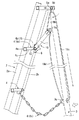
本発明の好ましい実施形態において、閉脚防止装置9は、アーム体10を展開姿勢から格納姿勢に向けて牽引自在とする操作索条18を設けている。操作索条18は、アーム体10の自由端部を構成する受止め金具14に固定された固定部18aから上方に延びる牽引部18bと、三脚の上方部位に設けられたガイド環19を挿通することにより折返されて下向きに延びる操作部18cを構成している。図例の場合、操作部18cから延びる延長部18dが連結フック3cを挿通することにより折返されて固定部18aに連繋されることにより、エンドレス状に連続して周回させられている。
In the preferred embodiment of the present invention, the closed
従って、図4に示すように、ユーザが前記操作部18cを引っ張ることにより下向き移動させると、アーム体10は、前記牽引部18bにより引上げられ、展開姿勢から格納姿勢に向けて回動する。反対に、アーム体10は、起立する格納姿勢の状態で、補助脚3を開脚すると、操作部18cが引張力を受けていない常態とされている限り、牽引部18bと共に自重で展開姿勢に向けて回動させられる。
Therefore, as shown in FIG. 4, when the user moves the
図4に示すように、前記ガイド環19は、補助脚3の上端部に一体的に設けることが好ましく、図例の場合、補助脚3の開脚及び閉脚と一体回動する筒部材5bに固着している。従って、ユーザが操作部18cを引き下げると、前記牽引部18bは、引き上げられるアーム体10とガイド環19の間で張力を生じるので、ガイド環19により補助脚3に対して閉脚方向の回動力が与えられ、アーム体10の格納と補助脚3の閉脚を一挙に行うことができる利点がある。
As shown in FIG. 4, the
図6ないし図11は、アーム体10の好ましい具体例を示している。図6に示すように、アーム部材11と受止め金具14は、予め組付けられたユニットUを構成し、これに対して、枢支金具12と、保持金具13は、踏桟4(4x)に取付けられた状態のアーム体10を構成する際に、それぞれ組付けられる部品として構成されている。
6 to 11 show a preferred embodiment of the
(ユニット)
ユニットUを構成するアーム部材11は、アルミニウム等の金属製の角筒部材から成り、自由端部に受止め金具14をリベット等の固着具20を介して固着している。受止め金具14は、1枚の金属板により折曲形成され、アーム部材11の自由端部を上下から挟持する上下板部21、22の間に上記の斜面を備えた受止め手段17を折曲形成すると共に、該受止め手段17の両側縁から折曲された把持片17a、17aを突設している。
(unit)
The
前記上下板部21、22には、左右両側縁からそれぞれ相互に対向する舌片21a、21bと舌片22a、22bが折曲形成されており、これらの舌片と上下板部21、22により囲まれた角筒状空間にアーム部材11の端部を嵌入し、上下板部21、22を前記固着具20によりアーム部材11に固着している。
The upper and
前記上下板部21、22は、アーム部材11の端面から突出する部位に挿通孔23、24を貫設しており、その側方には前記左右一方の舌片21a、22aから延設された爪片を介して凹状切欠き部を形成した巻回部21c、22cが設けられている。
The upper and
(枢支金具)
枢支金具12は、1枚の金属板により折曲形成され、踏桟4(4x)の連結フレーム4cを受入れ自在とする切欠き状の窓孔25の両側に位置して、踏桟4(4x)の後桟フレーム4bを回動自在に抱持するようにほぼ半円状に折曲された回動部26、26を設け、該回動部の上下端部から延設された上下板部27、28を備えており、該上下板部27、28によりアーム部材11の基端部を上下から挟持するように構成され、上板部27の両側縁にはアーム部材11の上側の両側部を挟持する挟持片27a、27aが下向きに折曲形成されている。尚、上下板部27、28は、アーム部材11の基端部の上下方向に貫通する固着孔11a、11aに合致するボルト挿通用の孔29、29が設けられている。
(Pivot bracket)
The
(保持金具)
保持金具13は、1枚の金属板により折曲形成され、前記枢支金具12の下板部28の下面に重合される基板部30の先端に上記保持手段16を構成する舌片13aを形成すると共に、尾端から延びる延長片31の両側にアーム部材11の下側の両側部を挟持する挟持片31a、31aを上向きに折曲形成しており、前記基板部30の両側縁から下向きに折曲された側面視がアーム形状の補強片32、32を設けている。尚、基板部30には、前記枢支金具12の孔29に合致するボルト挿通用の孔33が設けられている。
(Holding bracket)
The holding metal fitting 13 is formed by bending a single metal plate, and the
(ボルト・ナット)
図示実施形態の場合、枢支金具12及び保持金具13をアーム部材11の基端部に固着するために、ボルト34及びナット35が使用される。
(bolt and nut)
In the case of the illustrated embodiment, a
枢支金具12の上下板部27、28の間にアーム部材11の基端部を嵌入し、前記枢支金具12の下板部28の下面に保持金具13の延長片31を重ね合わせ、アーム部材11の固着孔11a、11aに枢支金具12の孔29、29と保持金具13の孔33を合致させた状態で、ボルト34を挿通させると共に、ボルト34の挿出端にナット35を締結することにより、枢支金具12及び保持金具13がアーム部材11の基端部に固着される。この際、枢支金具12の挟持片27a、27aと、保持金具13の挟持片31a、31aがアーム部材11の両側を挟持し、一体的な固着状態を確保する。
The base end of the
(閉脚防止装置の組立方法と作用)
踏桟4(4x)に取付けられたアーム体10を組立てる際、図7及び図8に示すように、最初に、枢支金具12の回動部26、26により踏桟4(4x)の後桟フレーム4bを抱持させる。この際、枢支金具12を上向き姿勢又は下向き姿勢として、上下板部27、28の間に後桟フレーム4bを導入し、枢支金具12を横向き姿勢とすれば、図8に示すように、窓孔25に連結フレーム4cが導入され、枢支金具12が後桟フレーム4bに仮止めされる。
(Assembling method and operation of closing leg prevention device)
When assembling the
引き続き、図9及び図10に示すように、仮止めされた枢支金具12の上下板部27、28の間にアーム部材11の基端部を嵌入すると共に、前記枢支金具12の下板部28の下面に保持金具13を重ね合わせ、ボルト34を挿通してナット35を締結すれば、後桟フレーム4bを枢軸15として回動自在とされたアーム体10が組立てられる。
Subsequently, as shown in FIGS. 9 and 10, the base end portion of the
操作索条18は、アーム部材11の受止め金具14に対して、アーム体10の組立前と組立後の何れのときに固着しても良く、受止め金具14に対して固定部18aにより固定される。図示実施形態の場合、図10(B)に示すように、操作索条18は、受止め金具14の挿通孔23、24に挿通した状態で、両挿通孔の間に位置する索条の部分を折曲することによりループ部を形成し、該ループ部を巻回部21c、22cに巻回状態で係止することにより、固定部18aが形成されている。
The
上記のようにして組立てられた閉脚防止装置9は、三脚1を開脚姿勢として高所作業のために使用するときは、図10に示すように、枢支金具12を後桟フレーム4bにより構成された枢軸15の廻りで回動することにより、アーム体10を展開姿勢とする。このとき、保持金具13により構成された保持手段16が連結フレーム4cの下面に当接することにより、該アーム体10を展開姿勢の状態に保持され、この状態で、受止め金具14により構成された受止め手段17が補助脚3に対して調整用隙間Sを介して臨ませられ、補助脚3が不慮に閉脚することを阻止する。
When the tripod 1 is assembled as described above and the tripod 1 is used as an open leg posture for work at high places, as shown in FIG. 10, the
不使用時において三脚1を閉脚姿勢とするときは、上述のように操作索条18を介してアーム体10の自由端部を引上げることにより、展開姿勢から格納姿勢に向けて回動させれば良い。格納姿勢とされたアーム体10は、枢軸15を構成する後桟フレーム4bから起立し、主脚2の左右縦フレーム2b、2bの間に格納されるので、補助脚3を従来の三脚と同様の位置まで閉脚させることができる。
When the tripod 1 is in the closed position when not in use, the free end of the
1 高所作業用三脚
2 主脚
2R、2L 柱脚
2a、2b 縦フレーム
3 補助脚
3a 脚本体
3b 伸縮脚
3c 連結フック
4 踏桟
4a 前桟フレーム
4b 後桟フレーム
4c 連結フレーム
5 開閉枢結手段
5a 軸部材
5b 筒部材
6 開脚防止手段
6a 開き止めチェーン
6x 調整手段
7、8 座板
9 閉脚防止装置
10 アーム体
11 アーム部材
11a 固着孔
12 枢支金具
13 保持金具
13a 舌片
14 受止め金具
15 枢軸
16 保持手段
17 受止め手段
17a 把持片
18 操作索条
18a 固定部
18b 牽引部
18c 操作部
18d 延長部
19 ガイド環
20 固着具
21 上板部
22 下板部
21a、21b、22a、22b 舌片
21c、22c 巻回部
23、24 挿通孔
25 窓孔
26 回動部
27 上板部
27a 挟持片
28 下板部
29 孔
30 基板部
31 延長片
31a 挟持片
32 補強片
33 孔
34 ボルト
35 ナット
DESCRIPTION OF SYMBOLS 1
Claims (6)
前記主脚と補助脚を開脚姿勢とした状態から閉脚不能に係止する閉脚防止装置(9)であって、主脚に臨む基端部と補助脚に臨む自由端部を有するアーム体(10)から成り、
前記アーム体(10)は、基端部を所定踏桟の後桟フレーム(4b)を枢軸(15)として、該枢軸から上向きの格納姿勢と補助脚に向かう横向きの展開姿勢との間で回動自在に枢支され、展開姿勢とされたアーム体(10)の自由端部に前記補助脚(3)の閉脚を阻止する受止め手段(17)を形成し、
前記アーム体(10)を格納姿勢から展開姿勢に向けて正転したとき、該アーム体の格納姿勢に向かう逆転は許すが、該展開姿勢から更に正転することを阻止する保持手段(16)が設けられて成ることを特徴とする高所作業用三脚における閉脚防止装置。 The upper end portions of the ladder-like main leg (2) installed on the front side on the ground and the bar-like auxiliary leg (3) installed on the rear side can be opened and closed freely between the closed leg posture and the open leg posture. An open leg preventing means (6) is provided which is pivotally connected and which allows a closed leg between the main leg and the auxiliary leg but prevents further opening from the open leg position, said main leg comprising a pair of column legs A tripod for work in the high place, which is formed by arranging a tread (4) composed of a front cross frame (4a) and a rear cross frame (4b) which are erected between the upper and lower
A closed leg preventing device (9) which locks the main leg and the auxiliary leg from the state in which the main leg and the auxiliary leg are not in the closed state so as not to be closed, and an arm body having a base end facing the main leg and a free end facing the auxiliary leg 10),
The arm body (10) rotates between a storage posture upward from the pivot and a lateral deployment posture toward the auxiliary leg with the rear end frame (4b) of the predetermined step as the pivot (15). Receiving means (17) for blocking the closing leg of said auxiliary leg (3) at the free end of the arm body (10) which is pivotably pivoted into the deployed position;
Holding means (16) for permitting reverse rotation toward the storage posture of the arm body when the arm body (10) is rotated forward from the storage posture to the deployed posture, but preventing further normal rotation from the deployed posture A closed leg preventing device for a high work tripod, characterized in that
前記保持手段(16)は、前記アーム体(10)の基端部から延設された保持金具(13)により構成され、
前記保持金具(13)は、アーム体を展開姿勢としたとき前記連結フレーム(4c)の下面に当接することにより該アーム体の正転を阻止し、アーム体を起立姿勢としたとき前記連結フレーム(4c)から離反するように構成されて成ることを特徴とする請求項1に記載の高所作業用三脚における閉脚防止装置。 In the structure having the connection frame (4c) constructed by the front rail frame and the rear rail frame, the step rail (4),
The holding means (16) is constituted by a holding metal fitting (13) extended from the base end of the arm body (10),
The holding metal fitting (13) abuts against the lower surface of the connecting frame (4c) when the arm body is in the unfolded posture, thereby blocking normal rotation of the arm body, and when the arm body is in the standing posture The closed leg preventing device according to claim 1, characterized in that it is configured to be separated from (4c).
前記アーム体(10)は、展開姿勢としたとき、前記受止め手段(17)と補助脚(3)の間に調整用隙間(S)を形成するように構成されて成ることを特徴とする請求項1又は2に記載の高所作業用三脚における閉脚防止装置。 In the configuration in which the opening prevention means (6) includes adjustment means (6x) capable of finely adjusting the opening angle of the main leg in the opening posture and the auxiliary leg,
The arm body (10) is characterized in that it is configured to form an adjustment gap (S) between the receiving means (17) and the auxiliary leg (3) when in the deployed position. The closing leg prevention apparatus in the height work tripod of Claim 1 or 2.
前記操作索条(18)は、アーム体の自由端部に固定された固定部(18a)から上方に延びる牽引部(18b)と、三脚の上端部に設けられたガイド環(19)を挿通することにより折返されて下向きに延びる操作部(18c)を構成しており、
前記操作部(18c)に引張力を与えることにより下向き移動させたとき前記牽引部(18b)がアーム体を引上げることにより展開姿勢から格納姿勢に向けて回動し、前記引張力を解放したとき前記牽引部と共にアーム体を自重で格納姿勢から展開姿勢に向けて回動させるように構成して成ることを特徴とする請求項1、2、3又は4に記載の高所作業用三脚における閉脚防止装置。 An operating cord (18) is provided which allows the arm body to be pulled from the deployed position to the stored position,
The operation cord (18) passes through the pulling portion (18b) extending upward from the fixing portion (18a) fixed to the free end of the arm body and the guide ring (19) provided on the upper end of the tripod Constitute an operating portion (18c) that is folded back and extends downward,
When the operating portion (18c) is moved downward by applying a tensile force, the pulling portion (18b) is pivoted from the deployed position to the stored position by pulling up the arm, releasing the tensile force. 5. A tripod according to any one of claims 1, 2, 3 and 4, characterized in that when said arm portion is pivoted from its storage position to its unfolded position by its own weight together with said pulling portion. Closed leg prevention device.
前記牽引部(18b)によりアーム体を引上げたとき、前記ガイド環(19)により補助脚(3)に閉脚方向の回動力を与えるように構成して成ることを特徴とする請求項5に記載の高所作業用三脚における閉脚防止装置。 The guide ring (19) is integrally provided at the upper end of the auxiliary leg (3),
A method according to claim 5, characterized in that when the arm body is pulled up by the pulling portion (18b), the guide leg (19) is configured to give the auxiliary leg (3) a turning force in the closing direction. The closing leg prevention device in the high place work tripod of.
Priority Applications (1)
| Application Number | Priority Date | Filing Date | Title |
|---|---|---|---|
| JP2017219056A JP7033890B2 (en) | 2017-11-14 | 2017-11-14 | Anti-closer device for tripods for aerial work |
Applications Claiming Priority (1)
| Application Number | Priority Date | Filing Date | Title |
|---|---|---|---|
| JP2017219056A JP7033890B2 (en) | 2017-11-14 | 2017-11-14 | Anti-closer device for tripods for aerial work |
Publications (2)
| Publication Number | Publication Date |
|---|---|
| JP2019090219A true JP2019090219A (en) | 2019-06-13 |
| JP7033890B2 JP7033890B2 (en) | 2022-03-11 |
Family
ID=66835993
Family Applications (1)
| Application Number | Title | Priority Date | Filing Date |
|---|---|---|---|
| JP2017219056A Active JP7033890B2 (en) | 2017-11-14 | 2017-11-14 | Anti-closer device for tripods for aerial work |
Country Status (1)
| Country | Link |
|---|---|
| JP (1) | JP7033890B2 (en) |
Cited By (1)
| Publication number | Priority date | Publication date | Assignee | Title |
|---|---|---|---|---|
| CN112295176A (en) * | 2020-11-02 | 2021-02-02 | 浙江金耐斯体育用品有限公司 | Running cool frame and running cool equipment |
Citations (4)
| Publication number | Priority date | Publication date | Assignee | Title |
|---|---|---|---|---|
| JPH03108797U (en) * | 1990-02-23 | 1991-11-08 | ||
| JPH09235970A (en) * | 1996-03-04 | 1997-09-09 | Alinco Inc | Tripod stepladder |
| JPH10317662A (en) * | 1997-05-21 | 1998-12-02 | Pika Corp:Kk | Tripod stepladder |
| CN104373036A (en) * | 2014-11-21 | 2015-02-25 | 罗耿池 | Special ladder for quickly picking fruits |
-
2017
- 2017-11-14 JP JP2017219056A patent/JP7033890B2/en active Active
Patent Citations (4)
| Publication number | Priority date | Publication date | Assignee | Title |
|---|---|---|---|---|
| JPH03108797U (en) * | 1990-02-23 | 1991-11-08 | ||
| JPH09235970A (en) * | 1996-03-04 | 1997-09-09 | Alinco Inc | Tripod stepladder |
| JPH10317662A (en) * | 1997-05-21 | 1998-12-02 | Pika Corp:Kk | Tripod stepladder |
| CN104373036A (en) * | 2014-11-21 | 2015-02-25 | 罗耿池 | Special ladder for quickly picking fruits |
Cited By (1)
| Publication number | Priority date | Publication date | Assignee | Title |
|---|---|---|---|---|
| CN112295176A (en) * | 2020-11-02 | 2021-02-02 | 浙江金耐斯体育用品有限公司 | Running cool frame and running cool equipment |
Also Published As
| Publication number | Publication date |
|---|---|
| JP7033890B2 (en) | 2022-03-11 |
Similar Documents
| Publication | Publication Date | Title |
|---|---|---|
| US10532919B2 (en) | Collapsible personnel basket for a crane | |
| US9593531B2 (en) | Ladder securing apparatus, ladders incorporating same and related methods | |
| US9488003B2 (en) | Portable ladder with a stand off device | |
| US9027709B2 (en) | Modular tree stand | |
| US10827744B2 (en) | Ladder stand and tree securement mechanism therefor | |
| US7584940B2 (en) | Tree stand lock apparatus and method of use | |
| US4549635A (en) | Portable folding hunting stand | |
| JP2013507544A5 (en) | ||
| US6966406B2 (en) | Step platform attachable to a ladder | |
| US9574400B2 (en) | Vehicle hitch ladder support device | |
| US4858725A (en) | Ladder brace | |
| US20080310910A1 (en) | Scaffold securement device | |
| CN111758182A (en) | Antenna structure tilting bracket | |
| US20240016142A1 (en) | Ladder stand and activity rail assembly | |
| JP2019090219A (en) | Closed-leg prevention device in high place work tripod | |
| US20070114096A1 (en) | Modular ladder and tree stand system with pivoting joint | |
| WO2005124057B1 (en) | Fittings for builders' trestles | |
| JP2001248302A (en) | Rod embracing fitting and scaffold forming method | |
| JP2001262963A (en) | Ladder | |
| JP3157095U (en) | Net bracket | |
| JP2007198000A (en) | Ladder for trailer | |
| JP2018178584A (en) | Opening and closing stop device in high place work tripod | |
| KR102228480B1 (en) | Safety ladder | |
| KR20110055063A (en) | Safety workbench | |
| US11771079B1 (en) | Quickstand hunting platform |
Legal Events
| Date | Code | Title | Description |
|---|---|---|---|
| A621 | Written request for application examination |
Free format text: JAPANESE INTERMEDIATE CODE: A621 Effective date: 20201022 |
|
| A977 | Report on retrieval |
Free format text: JAPANESE INTERMEDIATE CODE: A971007 Effective date: 20210810 |
|
| A131 | Notification of reasons for refusal |
Free format text: JAPANESE INTERMEDIATE CODE: A131 Effective date: 20210824 |
|
| A521 | Request for written amendment filed |
Free format text: JAPANESE INTERMEDIATE CODE: A523 Effective date: 20211012 |
|
| TRDD | Decision of grant or rejection written | ||
| A01 | Written decision to grant a patent or to grant a registration (utility model) |
Free format text: JAPANESE INTERMEDIATE CODE: A01 Effective date: 20220208 |
|
| A61 | First payment of annual fees (during grant procedure) |
Free format text: JAPANESE INTERMEDIATE CODE: A61 Effective date: 20220301 |
|
| R150 | Certificate of patent or registration of utility model |
Ref document number: 7033890 Country of ref document: JP Free format text: JAPANESE INTERMEDIATE CODE: R150 |
|
| R250 | Receipt of annual fees |
Free format text: JAPANESE INTERMEDIATE CODE: R250 |