JP2019069179A - Biopsy device - Google Patents
Biopsy device Download PDFInfo
- Publication number
- JP2019069179A JP2019069179A JP2018232496A JP2018232496A JP2019069179A JP 2019069179 A JP2019069179 A JP 2019069179A JP 2018232496 A JP2018232496 A JP 2018232496A JP 2018232496 A JP2018232496 A JP 2018232496A JP 2019069179 A JP2019069179 A JP 2019069179A
- Authority
- JP
- Japan
- Prior art keywords
- cutter
- biopsy device
- tissue
- tissue sample
- gear
- Prior art date
- Legal status (The legal status is an assumption and is not a legal conclusion. Google has not performed a legal analysis and makes no representation as to the accuracy of the status listed.)
- Granted
Links
Images


Classifications
-
- A—HUMAN NECESSITIES
- A61—MEDICAL OR VETERINARY SCIENCE; HYGIENE
- A61B—DIAGNOSIS; SURGERY; IDENTIFICATION
- A61B10/00—Instruments for taking body samples for diagnostic purposes; Other methods or instruments for diagnosis, e.g. for vaccination diagnosis, sex determination or ovulation-period determination; Throat striking implements
- A61B10/02—Instruments for taking cell samples or for biopsy
- A61B10/0233—Pointed or sharp biopsy instruments
- A61B10/0266—Pointed or sharp biopsy instruments means for severing sample
-
- A—HUMAN NECESSITIES
- A61—MEDICAL OR VETERINARY SCIENCE; HYGIENE
- A61B—DIAGNOSIS; SURGERY; IDENTIFICATION
- A61B10/00—Instruments for taking body samples for diagnostic purposes; Other methods or instruments for diagnosis, e.g. for vaccination diagnosis, sex determination or ovulation-period determination; Throat striking implements
- A61B10/0096—Casings for storing test samples
-
- A—HUMAN NECESSITIES
- A61—MEDICAL OR VETERINARY SCIENCE; HYGIENE
- A61B—DIAGNOSIS; SURGERY; IDENTIFICATION
- A61B10/00—Instruments for taking body samples for diagnostic purposes; Other methods or instruments for diagnosis, e.g. for vaccination diagnosis, sex determination or ovulation-period determination; Throat striking implements
- A61B10/02—Instruments for taking cell samples or for biopsy
- A61B10/0233—Pointed or sharp biopsy instruments
- A61B10/0266—Pointed or sharp biopsy instruments means for severing sample
- A61B10/0275—Pointed or sharp biopsy instruments means for severing sample with sample notch, e.g. on the side of inner stylet
-
- A—HUMAN NECESSITIES
- A61—MEDICAL OR VETERINARY SCIENCE; HYGIENE
- A61B—DIAGNOSIS; SURGERY; IDENTIFICATION
- A61B10/00—Instruments for taking body samples for diagnostic purposes; Other methods or instruments for diagnosis, e.g. for vaccination diagnosis, sex determination or ovulation-period determination; Throat striking implements
- A61B10/02—Instruments for taking cell samples or for biopsy
- A61B10/0233—Pointed or sharp biopsy instruments
- A61B10/0283—Pointed or sharp biopsy instruments with vacuum aspiration, e.g. caused by retractable plunger or by connected syringe
-
- A—HUMAN NECESSITIES
- A61—MEDICAL OR VETERINARY SCIENCE; HYGIENE
- A61B—DIAGNOSIS; SURGERY; IDENTIFICATION
- A61B10/00—Instruments for taking body samples for diagnostic purposes; Other methods or instruments for diagnosis, e.g. for vaccination diagnosis, sex determination or ovulation-period determination; Throat striking implements
- A61B10/02—Instruments for taking cell samples or for biopsy
- A61B2010/0208—Biopsy devices with actuators, e.g. with triggered spring mechanisms
-
- A—HUMAN NECESSITIES
- A61—MEDICAL OR VETERINARY SCIENCE; HYGIENE
- A61B—DIAGNOSIS; SURGERY; IDENTIFICATION
- A61B10/00—Instruments for taking body samples for diagnostic purposes; Other methods or instruments for diagnosis, e.g. for vaccination diagnosis, sex determination or ovulation-period determination; Throat striking implements
- A61B10/02—Instruments for taking cell samples or for biopsy
- A61B2010/0225—Instruments for taking cell samples or for biopsy for taking multiple samples
Landscapes
- Health & Medical Sciences (AREA)
- Life Sciences & Earth Sciences (AREA)
- Medical Informatics (AREA)
- Engineering & Computer Science (AREA)
- Biomedical Technology (AREA)
- Heart & Thoracic Surgery (AREA)
- Pathology (AREA)
- Molecular Biology (AREA)
- Surgery (AREA)
- Animal Behavior & Ethology (AREA)
- General Health & Medical Sciences (AREA)
- Public Health (AREA)
- Veterinary Medicine (AREA)
- Surgical Instruments (AREA)
- Sampling And Sample Adjustment (AREA)
Abstract
【課題】生検装置を提供すること。【解決手段】生検装置は、(a)本体と、(b)組織の中に挿入可能である針であって、前記針は、前記本体に対して遠位側に延びている、針と、(c)前記針によって受容された組織を切断するため、前記針に対して可動であるカッターであって、前記カッターは、前記カッターによって定められた長さ方向軸周りに回転可能であり、前記カッターは、前記カッターによって定められた前記長さ方向軸に沿って並進可能である、カッターと、(d)カッター駆動機構であって、(i)前記カッターに固定されたスリーブ、(ii)ギア、および(iii)ナット、を備える、カッター駆動機構と、を具備する。【選択図】図14A biopsy device is provided. The biopsy device includes: (a) a body, and (b) a needle insertable into tissue, the needle extending distally with respect to the body. (C) a cutter movable with respect to the needle to cut tissue received by the needle, the cutter being rotatable about a longitudinal axis defined by the cutter; The cutter being translatable along the longitudinal axis defined by the cutter, and (d) a cutter drive mechanism, (i) a sleeve fixed to the cutter, (ii) A cutter drive mechanism comprising: a gear; and (iii) a nut. [Selection diagram] FIG.
Description
〔優先権〕
本願は、2006年12月13日に出願された米国仮特許出願第60/869,736号および2006年12月13日に出願された米国仮特許出願第60/874,792号に基づく優先権を主張するものである。また、本願は、2007年11月20日に出願された米国非仮特許出願第11/942,764号に基づく優先権をも主張するものである。
〔priority〕
This application claims the benefit of US Provisional Patent Application No. 60 / 869,736, filed Dec. 13, 2006, and US Provisional Patent Application No. 60/874, 792, filed Dec. 13, 2006. It is. The present application also claims priority based on US Non-Provisional Patent Application No. 11 / 942,764, filed November 20, 2007.
〔背景〕
生体組織検査用のサンプルは、種々の装置を用い、種々の医療処置において、種々の方法で、採取されてきた。生体組織検査装置は、定位固定誘導の下で、超音波誘導の下で、核磁気共鳴映像法(MRI)による誘導の下で、あるいは、他の方法の下で、使用されてもよい。単なる典型例にすぎないが、生体組織検査装置は、「軟組織の生体組織検査および採取を自動的に行うための装置および方法(Method and Apparatus for Automated Biopsy and Collection of Soft Tissue)」という名称で1996年6月18日に発行された米国特許第5,526,822号明細書;「生体組織検査を自動的に行う手術装置用の制御装置(Control Apparatus for an Automated Surgical Biopsy Device)」という名称で2000年7月11日に発行された米国特許第6,086,544号明細書;「核磁気共鳴映像法(MRI)に適合した生体組織検査用の手術装置(MRI Compatible Surgical Biopsy Device)」という名称で2003年6月12日に出願公開された米国公開特許第2003/0109803号明細書;「生体組織検査手術装置用の指回し式遠隔装置(Remote Thumbwheel for a Surgical Biopsy Device)」という名称で2007年5月24日に出願公開された米国公開特許第2007/0118048号明細書;「生体組織検査システム(Biopsy System)」という名称で2006年12月13日に出願された米国仮特許出願第60/869,736号;および、「生体組織検査用サンプルの保存(Biopsy Sample Storage)」という名称で2006年12月13日に出願された米国仮特許出願第60/874,792号に開示されている。上記で挙げられた米国特許明細書、米国公開特許明細書および米国仮特許出願の各開示内容は、参照によって、この明細書に組み込まれる。生体組織検査用のサンプルを採取するために数種のシステムおよび方法が開発され、かつ、使用されてきたが、本願の発明者らよりも前に、添付された特許請求の範囲の複数の請求項に記述された発明を成した者、あるいは、使用した者は存在しないと考えられる。
〔background〕
Biopsy samples have been taken in different ways in different medical procedures using different devices. The biopsy device may be used under stereotactic guidance, under ultrasound guidance, under guidance by nuclear magnetic resonance imaging (MRI), or under other methods. Merely by way of example only, the biopsy device is referred to in 1996 as "Method and Apparatus for Automated Biopsy and Collection of Soft Tissue". No. 5,526,822 issued Jun. 18, 2012; "Control Apparatus for an Automated Surgical Biopsy Device" under the name of "Control Apparatus for an Automated Surgical Biopsy Device", July 2000 U.S. Patent No. 6,086,544 issued on November 11, June 12, 2003 under the name "MRI Compatible Surgical Biopsy Device" compatible with nuclear magnetic resonance imaging (MRI) US Published Patent Application No. 2003/0109803, filed on May 24, 2007, entitled "Remote Thumbwheel for a Surgical Biopsy Device". Published in the US US Provisional Patent Application No. 60 / 869,736, filed Dec. 13, 2006, entitled "Biopsy System", and "Biopsy Samples". No. 60 / 874,792 filed Dec. 13, 2006, entitled "Biopsy Sample Storage". The disclosures of the above mentioned US Patent Specification, US Published Patent Specification and US Provisional Patent Application are incorporated herein by reference. Although several systems and methods have been developed and used to collect samples for biopsy, several claims in the appended claims prior to the inventors of the present application It is considered that no one has made or used the invention described in the section.
この明細書が本発明を特に指摘し、かつ、本発明の権利を明確に主張する特許請求の範囲で完結しているが、本発明が、同様の参照番号が同一の要素を特定する添付の図面と併せて特定の実施例の以下の記述からより良く理解されるはずであると考えられる。 Although the specification concludes with the claims particularly pointing out and distinctly claiming the present invention, the present invention is attached with the same reference numerals specifying the same elements. It is believed that the invention will be better understood from the following description of specific embodiments in conjunction with the drawings.
〔詳細な説明〕
本発明の特定の実施例の以下の記述は、本発明の範囲を限定するために使用されないものとする。本発明の他の実施例、特徴部(features)、態様、実施の形態および利点は、本発明を実施するために検討されたベストモードの一つである例証としての以下の記述から、当業者にとって明白なはずである。明確に理解されるように、本発明は、当該本発明の範囲から全く逸脱することなく、他の異なる明白な態様を有するものである。したがって、図面および説明は、本来的に例示的なものとみなされるものであり、限定的なものとみなされてはならない。
[Detailed description]
The following description of certain embodiments of the present invention should not be used to limit the scope of the present invention. Other embodiments, features, aspects, embodiments and advantages of the present invention will be apparent to those skilled in the art from the following description by way of illustration, which is one of the best modes contemplated for carrying out the present invention. It should be clear to you. As is clearly understood, the present invention has other distinct aspects without departing from the scope of the present invention. Accordingly, the drawings and descriptions are to be regarded as illustrative in nature and not as restrictive.
図1に示されているように、生体組織検査システム(2)の一例は、生体組織検査装置(100,101)および真空制御モジュール(400)を有している。図2および図3に示されているように、生体組織検査装置(100)は、プローブ(102)およびホルスター(202)を有している。同様に、図4および図5に示されているように、生体組織検査装置(101)は、プローブ(103)およびホルスター(302)を有している。以下に詳細に記述されるように、各プローブ(102,103)は、当該プローブにそれぞれ対応するホルスター(202,302)から分離可能である。本明細書における用語「ホルスター」の使用は、ホルスター(202,302)のいずれかの部分内にプローブ(102,103)のいずれかの部分が挿入されることを要求するものと解釈されるものではない。実際には、生体組織検査装置(100,101)の一部の変形例において、プローブ(102,103)は、ホルスター(202,302)上に単に着座してもよい。他の一部の変形例において、ホルスター(202,302)の一部分は、プローブ(102,103)内に挿入されてもよい。さらに、一部の生体組織検査装置(100,101)において、プローブ(102,103)およびホルスター(202,302)は、これらの二つの構成要素が分離できないように、単一構造すなわち一体構造であってもよい。プローブ(102,103)とホルスター(202,302)との間の、さらなる他の適切な構造および機能的な関係は、この明細書における教示を考慮することで、この技術分野における当業者にとって明白なはずである。 As shown in FIG. 1, an example of a biopsy system (2) comprises a biopsy device (100, 101) and a vacuum control module (400). As shown in FIGS. 2 and 3, the biopsy device (100) comprises a probe (102) and a holster (202). Similarly, as shown in FIGS. 4 and 5, the biopsy device (101) comprises a probe (103) and a holster (302). As described in detail below, each probe (102, 103) is separable from its corresponding holster (202, 302). Any use of the term "holster" herein is to be construed as requiring that any part of the probe (102, 103) be inserted within any part of the holster (202, 302) is not. In fact, in some variations of the biopsy device (100, 101), the probe (102, 103) may simply sit on the holster (202, 302). In some other variations, a portion of the holster (202, 302) may be inserted into the probe (102, 103). In addition, in some biopsy devices (100, 101), the probe (102, 103) and the holster (202, 302) have a single or integral structure so that these two components can not be separated. It may be. Still other suitable structural and functional relationships between the probe (102, 103) and the holster (202, 302) will be apparent to those skilled in the art in view of the teachings herein. It should be.
一部の変形例において、生体組織検査装置(100,101)は、プローブ(102,103)内および/または、ホルスター(202,302)内に配され、プローブ(102,103)がホルスター(202,302)に連結されたときを検出するように構成された一つ以上のセンサ(図示せず)を含めてもよい。さらに、このようなセンサまたは他の特徴部は、特定タイプのプローブ(102,103)およびホルスター(202,302)のみが互いに連結できるように構成されてもよい。このようなセンサは、上記構成に加えて、あるいは、当該構成に代えて、適切なプローブ(102,103)およびホルスター(202,302)が互いに連結されるまで、プローブ(102,103)および/またはホルスター(202,302)の一つ以上の機能を無効にするように構成されてもよい。勿論、このようなセンサおよび特徴部は、要望どおり、変更または省略されてもよい。 In some variations, the biopsy device (100, 101) is placed in the probe (102, 103) and / or in the holster (202, 302) and the probe (102, 103) is in the holster (202). , 302) and may include one or more sensors (not shown) configured to detect when coupled. Further, such sensors or other features may be configured such that only certain types of probes (102, 103) and holsters (202, 302) can be coupled to one another. Such sensors may, in addition to or in place of the above-described configurations, probe (102, 103) and / or until the appropriate probe (102, 103) and holster (202, 302) are coupled together. Or may be configured to disable one or more features of the holster (202, 302). Of course, such sensors and features may be modified or omitted as desired.
例示のみの目的では、プローブ(102,103)は、使い捨て部品として設けられてもよく、他方、ホルスター(202,302)は、再利用可能な部品として設けられてもよい。この例示において、真空制御モジュール(400)は、カート(図示せず)上に設けられているが、この明細書に記述された他の部品と同様に、カートは単なる選択肢に過ぎない。この明細書に記述された他の部品の中で、フットスイッチ(図示せず)および/または他の装置は、生体組織検査システム(2)の少なくとも一部を少なくともある程度、制御するように使用されてもよい。導管(200)は、真空制御モジュール(vacuum control module)(400)から生体組織検査装置(100,101)へ、力(例えば、電力、空気圧など)、制御信号、生理食塩水、減圧(vacuum)、および、通気(venting)を伝達(provide communication)する。これらの各部品は、以下にさらに詳述されるはずである。 For purposes of illustration only, the probe (102, 103) may be provided as a disposable part, while the holster (202, 302) may be provided as a reusable part. In this example, the vacuum control module (400) is provided on a cart (not shown), but like the other parts described herein, the cart is merely an option. Among the other components described herein, a footswitch (not shown) and / or other devices are used to at least partially control at least a portion of the biopsy system (2) May be Conduit (200) is from a vacuum control module (400) to the biopsy device (100, 101), such as force (eg, power, air pressure, etc.), control signal, saline, vacuum. And, provide venting (venting). Each of these components should be described in further detail below.
〔I. 定位固定用のプローブ例〕 [I. Example of probe for stereotactic fixation]
図6〜図14に示されているように、プローブ(102)は、針部(10)および本体部(112)を有している。本体部(112)は、カバー部材(114)およびベース部材(116)を有している。組織サンプルホルダー(140)は、ベース部材(116)に取外し可能に固定されているが、このような構成に代えて、組織サンプルホルダー(140)は、カバー部材(114)または他の部品に固定されてもよい。以下に詳述されるように、一対のチューブ(402,404)は、プローブ(102)に連結されている。 As shown in FIGS. 6-14, the probe (102) has a needle portion (10) and a body portion (112). The main body (112) has a cover member (114) and a base member (116). The tissue sample holder (140) is removably secured to the base member (116), but alternatively, the tissue sample holder (140) is secured to the cover member (114) or other part It may be done. As detailed below, a pair of tubes (402, 404) are connected to the probe (102).
〔A. 針の例〕
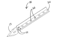
この実施例において、針部(10)は、組織穿刺用先端部(14)を有する外側カニューレ(12)と、当該組織穿刺用先端部(14)から近位側に配された組織収容用横穴(16)とを有している。組織穿刺用先端部(14)は、大きな力を要せず、かつ、組織穿刺用先端部(14)の挿入前に、組織内に開口部を予め形成する必要もなく、組織を貫通するように構成されている。組織穿刺用先端部(14)の適切な構成は、この明細書における教示を考慮することで、当業者にとって明白なはずである。例えば、図11に示されているように、この実施例における組織穿刺用先端部(14)は、針部品(18)の一部であり、この針部品(18)は、型打ち加工された金属製部品で形成されている。具体的には、針部品(18)は、組織穿刺用先端部(14)および壁部(30)を形成するように型打ち加工されており、以下にさらに詳述されるはずである。通気用開口部(34)を有する複数の開口部(32)は、壁を貫通して形成されている。流体が開口部(32,34)を経由して連通され得る種々の方法は、図61〜図65を参照しながら、以下にさらに詳述されるはずである。針部品(18)は、その後、組織穿刺用先端部(14)および壁部(30)が互いに実質的に直交するように捻られる。針部品(18)は、その後、カニューレ(12)の遠位端内に形成されたスロットを経由して組織穿刺用先端部(14)が突出するように、カニューレ(12)内に挿入される。組織阻止部(26)は、組織穿刺用先端部(14)のすぐ近位側に設けられている。代替の技術、材料および構成を有する、組織穿刺用先端部(14)が形成され得るようなさらに他の方法は、この明細書における教示を考慮することで、当業者にとって明白なはずである。
[A. Example of needle]
In this example, the needle portion (10) comprises an outer cannula (12) having a tissue piercing tip (14) and a tissue accommodation transverse hole disposed proximally from the tissue piercing tip (14). And (16). The tissue puncturing tip (14) penetrates the tissue without requiring a great deal of force and without the need for pre-forming an opening in the tissue prior to insertion of the tissue puncturing tip (14) Is configured. The appropriate configuration of the tissue penetrating tip (14) should be apparent to one of ordinary skill in the art in view of the teachings herein. For example, as shown in FIG. 11, the tissue puncturing tip (14) in this example is part of a needle component (18) which has been stamped out It is formed of metal parts. Specifically, the needle component (18) is stamped to form the tissue piercing tip (14) and the wall (30), as will be described in further detail below. A plurality of openings (32) having venting openings (34) are formed through the wall. Various ways in which fluid may be communicated via the openings (32, 34) will be described in more detail below with reference to FIGS. 61-65. The needle component (18) is then twisted so that the tissue penetrating tip (14) and the wall (30) are substantially orthogonal to one another. The needle component (18) is then inserted into the cannula (12) such that the tissue piercing tip (14) projects through the slot formed in the distal end of the cannula (12) . A tissue blocking portion (26) is provided immediately proximal to the tissue penetrating tip (14). Still other methods by which tissue penetrating tips (14) may be formed having alternative techniques, materials and configurations should be apparent to those skilled in the art in view of the teachings herein.
この実施例の外側カニューレ(12)の内部は、壁部(30)がカニューレ内腔(20)を真空内腔(40)から分離している状態で、カニューレ内腔(20)と、真空内腔(40)とを画定している。外側カニューレ(12)内には、複数の外部開口部(22)が形成されており、当該外部開口部(22)は、真空内腔(40)とは流体連通状態になっている。外部開口部(22)に類似している開口部の例は、「真空補助式の出血制御装置を備えた生体組織検査装置(Biopsy Device with Vacuum Assisted Bleeding Control)」という名称で2007年2月8日に出願公開された米国公開特許第2007/0032742号明細書に開示されており、この文献の開示内容は、参照によって、この明細書に組み込まれる。勿論、この明細書に記述された他の部品と同様に、外部開口部(22)は単なる選択肢に過ぎない。
The interior of the outer cannula (12) of this embodiment is the cannula lumen (20) and the vacuum lumen, with the wall (30) separating the cannula lumen (20) from the vacuum lumen (40). And a cavity (40). A plurality of external openings (22) are formed in the outer cannula (12), the external openings (22) being in fluid communication with the vacuum lumen (40). An example of an opening similar to the external opening (22) is the name "Biopsy Device with Vacuum Assisted Bleeding Control" with a vacuum assisted
一部の実施の形態において、壁部(30)は、針部(10)の長さに実質的に相当する長さで、延在している。他の実施の形態において、壁部(30)は、後述されるカッター(50)の遠位端が終端となる針部(10)内の領域を少し過ぎて近位方向に延在している。例えば、カニューレ内腔(20)は、カッター(50)がこのカニューレ内腔(20)内に配された状態で、カッター(50)の外側とカニューレ(12)の内側の少なくとも一部との間に隙間が存在するように、寸法設定され、かつ、構成されてもよい。このような隙間は、壁部(30)の近位端の近位に、カニューレ(12)の長さに沿って、真空内腔(40)を提供することができる。真空内腔(40)が提供され得るようなさらなる他の方法は、この明細書における教示を考慮することで、当業者にとって明白なはずである。 In some embodiments, the wall (30) extends a length substantially corresponding to the length of the needle (10). In another embodiment, the wall (30) extends in the proximal direction slightly past the area within the needle (10) which terminates at the distal end of the cutter (50) described below . For example, the cannula lumen (20) may be between the outside of the cutter (50) and at least a portion of the inside of the cannula (12) with the cutter (50) disposed within the cannula lumen (20). May be sized and configured such that there is a gap in the. Such a gap can provide a vacuum lumen (40) along the length of the cannula (12) proximal to the proximal end of the wall (30). Still other ways in which a vacuum lumen (40) may be provided should be apparent to one of ordinary skill in the art in view of the teachings herein.
この実施例において、複数の横方向開口部(32,34)は、カニューレ内腔(20)と真空内腔(40)との間を流体連通するために、壁部(30)を貫通して形成されている。以下にさらに詳述されるように、減圧、生理食塩水、および/または圧縮空気は、横方向開口部(32,34)を経由して、真空内腔(40)からカニューレ内腔(20)へ伝達されてもよい。 In this embodiment, a plurality of lateral openings (32, 34) extend through the wall (30) to provide fluid communication between the cannula lumen (20) and the vacuum lumen (40). It is formed. As detailed further below, reduced pressure, saline and / or compressed air may be passed from the vacuum lumen (40) to the cannula lumen (20) via the lateral openings (32, 34). May be transmitted to.
〔B. カッターの例〕 [B. Example of cutter]
カニューレ内腔(20)内には、中空カッター(50)が配設されている。カッター(50)の内部は、カッター内腔(52)を画定しており、これにより、流体および組織がカッター内腔(52)を経由してカッター(50)によって伝達されてもよい。以下にさらに詳述されるように、カッター(50)は、カニューレ内腔(20)内で回転し、かつ、カニューレ内腔(20)内で軸方向に並進移動するように構成されている。具体的には、カッター(50)は、外側カニューレ(12)の組織収容用横穴(16)を経由して突出する組織から生体組織検査用のサンプルを切除するように構成されている。以下にさらに詳述されるように、カッター(50)は、切除された組織サンプル(4)がカッター内腔(52)を経由して近位方向に伝達されるように、さらに構成されている。このような切除操作および近位方向への伝達操作の単なる例示的な実施例は、米国特許第5,526,822号明細書に開示されており、この文献の開示内容は、参照によって、この明細書に組み込まれるが、他の適切な任意の構造または技術は、生体組織検査システム(2)内での組織サンプル(4)の切除および/または伝達に使用されてもよい。 A hollow cutter (50) is disposed within the cannula lumen (20). The interior of the cutter (50) defines a cutter lumen (52) such that fluid and tissue may be transmitted by the cutter (50) via the cutter lumen (52). As described in further detail below, the cutter (50) is configured to rotate within the cannula lumen (20) and translate axially within the cannula lumen (20). In particular, the cutter (50) is configured to ablate a biopsy sample from the tissue projecting through the tissue accommodating lateral hole (16) of the outer cannula (12). The cutter (50) is further configured to transmit the resected tissue sample (4) in a proximal direction via the cutter lumen (52), as described in further detail below. . Only exemplary embodiments of such ablation and proximal transfer operations are disclosed in US Pat. No. 5,526,822, the disclosure content of which is incorporated herein by reference. However, any other suitable structure or technique may be used for ablation and / or communication of the tissue sample (4) within the biopsy system (2).
カッター(50)は、カッター内腔(52)を経由して組織サンプル(4)の近位方向への伝達を容易にするために、種々の処理または構成に付されてもよい。例えば、カッター内腔(52)を画定するカッター(50)の仕上げ内面は、組織とカッター(50)との間の付着力を低減させるために、ショットピーニング法(例えば、ガラスビーズ、重炭酸ナトリウムなどを用いる)に付されてもよい。このような処理または構成に加えて、あるいは、当該処理または構成に代えて、カッター内腔(52)を画定するカッター(50)の内部は、組織とカッター(50)との間の付着力を低減させるために、酸性エッチング法および/またはプラズマエッチング法に付されてもよい。このような処理または構成に加えて、あるいは、当該処理または構成に代えて、カッター内腔(52)を画定するカッター(50)の内部には、組織とカッター(50)との間の摩擦力を低減させるために、水潤滑剤(a hydrolubricous material)または他の非粘着性被覆材料が塗布されてもよい。このような処理または構成に加えて、あるいは、当該処理または構成に代えて、カッター内腔(52)を画定するカッター(50)の内部は、旋条切削表面加工に付されてもよい。カッター(50)の内部に対する他の適切な処理は、この明細書における教示を考慮することで、当業者にとって明白なはずである。このような処理または構成に代えて、カッター(50)の内部は、一部の実施の形態において、処理に全く付されてなくてもよい。 The cutter (50) may be subjected to various processes or configurations to facilitate proximal delivery of the tissue sample (4) via the cutter lumen (52). For example, the finished inner surface of the cutter (50) defining the cutter lumen (52) may be shot peened (eg, glass beads, sodium bicarbonate) to reduce adhesion between tissue and the cutter (50). Etc.). In addition to, or in place of, such treatment or configuration, the interior of the cutter (50) defining the cutter lumen (52) provides adhesion between tissue and the cutter (50). In order to reduce, it may be subjected to an acid etching method and / or a plasma etching method. In addition to, or in place of, such treatment or configuration, within the cutter (50) defining the cutter lumen (52), the friction force between the tissue and the cutter (50) Water lubricants or other non-tacky coating materials may be applied to reduce In addition to, or in place of, such treatment or configuration, the interior of the cutter (50) defining the cutter lumen (52) may be subjected to a spiral cutting surface treatment. Other suitable treatments for the interior of the cutter (50) should be apparent to one of ordinary skill in the art in view of the teachings herein. Instead of such treatment or configuration, the interior of the cutter (50) may not be subjected to any treatment at all in some embodiments.
カッター(50)の他の実施の形態において、カッター(50)の遠位部は、カッター(50)の近位部の内径および外径よりも小さな内径および外径を有している。例えば、カッター(50)の最も遠位側の部分(inch)は、ネックダウン(neck down)領域(図示せず)を提供してもよく、このネックダウン領域は、カッター(50)の残りの近位側部分の長さに沿う、より大きな直径を有する領域へ移行するものである。このようなネックダウン構成は、組織サンプル(4)がカッター内腔(52)を通って近位方向に移動する際に、組織圧縮を低減することができる。外側カニューレ(12)の遠位端は、相補的な(complimentary)ネックダウン領域を有してもよく、この領域は、カッター(50)のネックダウン領域と同一の長さ、当該ネックダウン領域より短い長さ、あるいは、当該ネックダウン領域より長い長さのいずれかを有している。カッター(50)および/または外側カニューレ(12)内のネックダウン領域の他の適切な長さは、この明細書における教示を考慮することで、当業者にとって明白なはずである。 In another embodiment of the cutter (50), the distal portion of the cutter (50) has an inner and outer diameter smaller than the inner and outer diameters of the proximal portion of the cutter (50). For example, the most distal portion (inch) of the cutter (50) may provide a neck down area (not shown), which is the remaining area of the cutter (50). Transitioning to a region of greater diameter along the length of the proximal portion. Such neck-down configuration can reduce tissue compression as the tissue sample (4) moves proximally through the cutter lumen (52). The distal end of the outer cannula (12) may have a complementary neck-down region, which is the same length as the neck-down region of the cutter (50), from the neck-down region It has either a short length or a length longer than the neck-down region. Other suitable lengths of the neck-down region within the cutter (50) and / or the outer cannula (12) should be apparent to those skilled in the art in view of the teachings herein.
カッター(50)のさらに他の実施の形態において、カッター(50)の内部内で内方に延在し、かつ、カッター(50)の長さ方向に沿って連続する複数の膨出表面が設けられている。このような膨出表面は、カッター(50)の内部に接触する組織表面を低減するように構成されてもよい。 In yet another embodiment of the cutter (50), a plurality of bulging surfaces extending inwardly inside the cutter (50) and continuous along the length of the cutter (50) are provided. It is done. Such a bulging surface may be configured to reduce the tissue surface contacting the interior of the cutter (50).
カッター(50)のさらに他の実施の形態において、内側スリーブ(図示せず)は、カッター(50)の内部の遠位端内に設けられてもよい。例えば、このような内側スリーブは、約0.15インチ(約0.381センチメートル)の長さまたは他の適切な長さを有してもよい。カッター(50)の遠位端は、上述の内側スリーブが挿入された後に、面取りされてもよく、これにより、面取りされたカッター(50)の端部および面取りされたスリーブ端部がまとまって、組織を切除するための鋭利な縁部となる。切除された組織サンプル(4)がカッター内腔(52)を通って近位方向に移動する際には、当該組織サンプル(4)が内側スリーブの近位端を通過するとすぐに、当該組織サンプル(4)は、カッター内腔(52)の大きな内径部分に衝突するはずである。このような有効径の拡大は、組織サンプル(4)の圧縮を低減し、これにより、組織サンプル(4)の輸送信頼性を改善することができる。カッター(50)のさらに他の適切な変形例は、この明細書における教示を考慮することで、当業者にとって明白なはずである。 In yet another embodiment of the cutter (50), an inner sleeve (not shown) may be provided within the interior distal end of the cutter (50). For example, such an inner sleeve may have a length of about 0.15 inches (about 0.381 centimeters) or other suitable length. The distal end of the cutter (50) may be beveled after the above-mentioned inner sleeve is inserted, so that the end of the beveled cutter (50) and the beveled sleeve end come together It becomes a sharp edge to ablate tissue. As the resected tissue sample (4) moves proximally through the cutter lumen (52), as soon as the tissue sample (4) passes the proximal end of the inner sleeve, the tissue sample (4) (4) should collide with the large inner diameter portion of the cutter lumen (52). Such an enlargement of the effective diameter can reduce the compression of the tissue sample (4) and thereby improve the transport reliability of the tissue sample (4). Still other suitable variations of the cutter (50) should be apparent to one of ordinary skill in the art in view of the teachings herein.
〔C. 針ハブの例〕 [C. Example of needle hub]
図12〜図13に示されているように、針ハブ(60)は、外側カニューレ(12)に固定されており、当該針ハブ(60)は、指回し式制御装置(thumbwheel)(62)と、この指回し式制御装置(62)から近位方向に延在するスリーブ部(64)を有している。この実施例の針ハブ(60)は、外側カニューレ(12)の近位部分の周囲に外側被覆(overmolded)されているが、針ハブ(60)は、外側カニューレ(12)上に形成されてもよく、および/または、他の任意の適切な技術(例えば、ネジ固定、粘着剤等)を用いて外側カニューレ(12)に対して固定されてもよい。さらに、この実施例の針ハブ(60)が可塑性材料で形成されているが、任意の他の適切な材料、あるいは、これらの材料の組み合わせが使用されてもよい。 As shown in FIGS. 12-13, the needle hub (60) is secured to the outer cannula (12) and the needle hub (60) is a thumbwheel (62) And a sleeve portion (64) extending proximally from the thumbwheel control (62). The needle hub (60) of this embodiment is overmolded around the proximal portion of the outer cannula (12), but the needle hub (60) is formed on the outer cannula (12) And / or may be secured to the outer cannula (12) using any other suitable technique (eg, screw fastening, adhesive, etc.). Furthermore, although the needle hub (60) of this example is formed of a plastic material, any other suitable material or combination of these materials may be used.
この実施例のスリーブ部(64)は、円環状の突出部(66)と、長さ方向スロット(68)と、スリーブ部(64)の近位端近傍に形成された横方向開口部(70)とを有している。また、一つ以上の追加の横方向開口部(70)(例えば、正反対の位置に配された複数の横方向開口部(70))は、スリーブ部(64)内に配設されてもよい。一対のO−リング(72)は、一方のO−リング(72)が横方向開口部(70)の近位側にあり、かつ、他方のO−リング(72)が横方向開口部(70)の遠位側にあるように、位置付けされている。以下にさらに詳述されるように、横方向開口部(70)は、針ハブ(60)によって画定された内部と流体連通しており、また、外側カニューレ(12)の真空内腔(40)にも流体連通している。スリーブ部(64)の他の適した構成は、この明細書における教示を考慮することで、当業者にとって明白なはずである。 The sleeve portion (64) of this embodiment comprises an annular projection (66), a longitudinal slot (68) and a transverse opening (70) formed near the proximal end of the sleeve portion (64). And. Also, one or more additional lateral openings (70) (e.g., a plurality of transverse openings (70) disposed at opposite positions) may be disposed within the sleeve portion (64) . The pair of O-rings (72) has one O-ring (72) proximal to the lateral opening (70) and the other O-ring (72) has a lateral opening (70). Positioned so as to be distal to As described in further detail below, the lateral opening (70) is in fluid communication with the interior defined by the needle hub (60) and also the vacuum lumen (40) of the outer cannula (12). Also in fluid communication. Other suitable configurations of the sleeve portion (64) should be apparent to those skilled in the art in view of the teachings herein.
指回し式制御装置(62)は、カバー部材(114)およびベース部材(116)に対して、外側カニューレ(12)をその長さ方向軸周りに回転させるように操作可能である。例えば、指回し式制御装置(62)は、外側カニューレ(12)によって画定された長さ方向軸周りの多くの所望の方位に組織収容用横穴(16)を配向させるために使用されてもよい。このような複数の方位は、例示のみの目的では、複数の組織サンプル(4)の採取中に患者から針部(10)を取り外す必要もなく、生体組織検査部位から当該複数の組織サンプル(4)を得ることが望ましい場合がある。このような回転および当該複数の組織サンプル(4)の採取の例示は、米国特許第5,526,822号明細書に開示されており、この文献の開示内容は、参照によって、この明細書に組み込まれる。複数の組織サンプル(4)が種々の位置で得られ得るような他の方法は、この明細書における教示を考慮することで、当業者にとって明白なはずである。例えば、外側カニューレ(12)の回転は、以下にさらに詳述されたいずれかの部品を用いるか、あるいは、他の適切な部品または技術を用いるなどにより、モータ駆動されてもよく、あるいは、自動化されてもよい。他の非包括的な実施例としては、生体組織検査装置(101)全体は、外側カニューレ(12)によって画定された長さ方向軸周りの種々の方位から組織サンプル(4)を得るために、組織サンプル(4)の採取中に回転してもよく、そのような回転および組織サンプル(4)の採取中に、患者から生体組織検査装置(101)を取り外す必要がなくてもよい。 The thumbwheel control (62) is operable to rotate the outer cannula (12) about its longitudinal axis relative to the cover member (114) and the base member (116). For example, the thumbwheel control (62) may be used to orient the tissue receiving cross hole (16) in many desired orientations around the longitudinal axis defined by the outer cannula (12). . Such orientations do not require removal of the needle (10) from the patient during collection of the tissue samples (4) for purposes of illustration only, and the tissue samples from the biopsy site (4 It may be desirable to obtain An example of such rotation and collection of the plurality of tissue samples (4) is disclosed in US Pat. No. 5,526,822, the disclosure content of which is hereby incorporated by reference. Other ways in which multiple tissue samples (4) may be obtained at various locations should be apparent to those skilled in the art in view of the teachings herein. For example, rotation of the outer cannula (12) may be motorized, such as by using any of the components described in more detail below, or by using other suitable components or techniques, or automation It may be done. As another non-inclusive example, the entire biopsy apparatus (101) is adapted to obtain tissue samples (4) from various orientations around the longitudinal axis defined by the outer cannula (12). It may be rotated during collection of the tissue sample (4) and it may not be necessary to remove the biopsy device (101) from the patient during such rotation and collection of the tissue sample (4).
また、外側カニューレ(12)を手動的に回転させる他の構造が使用され得ることは、正当に理解されるはずである。具体的には、図12〜図13に示されているように、露出したギア(74)は、外側カニューレ(12)に係合されてもよい。この実施例において、ギア(74)は、スリーブ部(64)の近位端上にスライドされる。ギア(74)の半径方向内方に延在する突出部(図示せず)は、スリーブ部(64)のスロット(68)に嵌合するように構成されており、これにより、ギア(74)がスリーブ部(64)に沿って長さ方向に移動可能である一方で、ギア(74)は、スリーブ部(64)と一体に回転する。スリーブ部(64)が外側カニューレ(12)に係合して一体化している状態での、ギア(74)の回転は、組織収容用横穴(16)を再配向するためのカニューレ(12)の回転をさらに引き起こすはずである。ギア(74)は、以下にさらに詳述されるように、ホルスター(202)の相補的な露出ギア(206)に係合するように、さらに構成されている。具体的には、ギア(74)は、ギア(206)がギア(74)に回転を付与し、これにより、外側カニューレ(12)を回転させることができるように、ギア(206)に噛合するように構成されている。ギア(206)を選択的に回転させるための一部の例示的な構造および技術は、以下にさらに詳述されるはずであるが、他の構造および技術は、この明細書における教示を考慮することで、当業者にとって明白なはずである。 It should also be justified that other structures for manually rotating the outer cannula (12) may be used. Specifically, as shown in FIGS. 12-13, the exposed gear (74) may be engaged to the outer cannula (12). In this embodiment, the gear (74) is slid on the proximal end of the sleeve portion (64). The radially inwardly extending projection (not shown) of the gear (74) is configured to fit in the slot (68) of the sleeve portion (64), whereby the gear (74) Is longitudinally movable along the sleeve portion (64), while the gear (74) rotates integrally with the sleeve portion (64). Rotation of the gear (74), with the sleeve portion (64) engaged and integral with the outer cannula (12), causes the cannula (12) to reorient the tissue receiving cross-hole (16). Should cause further rotation. The gear (74) is further configured to engage the complementary exposed gear (206) of the holster (202), as described in further detail below. Specifically, gear (74) meshes with gear (206) such that gear (206) imparts rotation to gear (74), thereby allowing outer cannula (12) to rotate. Is configured as. Although some exemplary structures and techniques for selectively rotating gear (206) will be described in further detail below, other structures and techniques will take into account the teachings herein. It should be clear to the person skilled in the art.
組織収容用横穴(16)の方位がグラフィカル・ユーザー・インターフェース上で表示され得ることは、この明細書における教示を考慮することで、正当に理解されるはずである。例えば、一つ以上のセンサは、組織収容用横穴(16)の方位を検出し、かつ、表示データをプロセッサに伝達するように操作可能であってよい。プロセッサは、組織収容用横穴(16)の方位を視覚的に表示する表示部(例えば、後述される表示モニタ(702)等)と通信状態にあってもよい。組織収容用横穴(16)の方位がユーザーに表示され得るような他の方法は、この明細書における教示を考慮することで、当業者にとって明白なはずである。このような構成に代えて、組織収容用横穴(16)の方位は、ユーザーに表示されなくてもよい。 It should be justified that the orientation of the tissue containment side hole (16) may be displayed on the graphical user interface, in view of the teachings herein. For example, one or more sensors may be operable to detect the orientation of the tissue accommodation side hole (16) and to communicate display data to the processor. The processor may be in communication with a display (e.g., a display monitor (702) described below) that visually displays the orientation of the tissue accommodation lateral hole (16). Other ways in which the orientation of the tissue accommodation cross-hole (16) may be displayed to the user should be apparent to those skilled in the art in view of the teachings herein. Instead of such a configuration, the orientation of the tissue accommodation side hole (16) may not be displayed to the user.
〔D. 針マニホールドの例〕 [D. Example of needle manifold]
図12に示されているように、針マニホールド(80)は、スリーブ部(64)周りに設けられている。針マニホールド(80)は、この実施例において、ベース部材(116)に固定されている。針マニホールド(80)は、チューブ(402)と流体連通しており、これにより、チューブ(402)は、以下にさらに詳述されるように、生理食塩水、減圧、大気、および/または、圧縮空気等を針マニホールド(80)に伝達することができる。さらに、針マニホールド(80)は、横方向開口部(70)を経由して、スリーブ部(64)の内部と流体連通している。O−リング(64)は、以下にさらに詳述されるように、針(10)の射出中等、スリーブ部(64)が針マニホールド(80)に対して長さ方向に並進移動するときであっても、また、スリーブ部(64)がその長さ方向軸周りに回転している間であっても、針マニホールド(80)とスリーブ部(64)との間の流体封止構造を維持するように構成されている。封止構造(図示せず)は、スリーブ部(64)の近位端で、スリーブ部(64)とカッター(50)との間のインターフェースに設けられている。したがって、針マニホールド(80)、スリーブ部(64)および外側カニューレ(12)は、チューブ(402)を経由して針マニホールド(80)に伝達される生理食塩水、減圧、大気、および/または、圧縮空気等が横方向開口部(70)を経由して真空内腔(40)に伝達されるように、構成され、かつ、配置される。勿論、他の任意の適切な構造または配置は、生理食塩水、減圧、大気、および/または、圧縮空気等をチューブ(402)から真空内腔(40)へ伝達するために、使用されてもよい。 As shown in FIG. 12, a needle manifold (80) is provided around the sleeve portion (64). The needle manifold (80) is fixed to the base member (116) in this embodiment. The needle manifold (80) is in fluid communication with the tube (402) such that the tube (402) can be saline, vacuum, atmospheric, and / or compressed, as described in further detail below. Air or the like can be transmitted to the needle manifold (80). In addition, the needle manifold (80) is in fluid communication with the interior of the sleeve portion (64) via the lateral opening (70). The o-ring (64) is when the sleeve portion (64) translates longitudinally relative to the needle manifold (80), such as during injection of the needle (10), as described in further detail below. And maintain the fluid tight structure between the needle manifold (80) and the sleeve portion (64) even while the sleeve portion (64) is rotating about its longitudinal axis Is configured as. A sealing structure (not shown) is provided at the proximal end of the sleeve portion (64) at the interface between the sleeve portion (64) and the cutter (50). Thus, the needle manifold (80), the sleeve portion (64) and the outer cannula (12) are delivered to the needle manifold (80) via the tube (402), saline, vacuum, atmosphere and / or It is constructed and arranged such that compressed air or the like is transmitted to the vacuum lumen (40) via the lateral opening (70). Of course, any other suitable structure or arrangement may also be used to transfer saline, vacuum, atmosphere, and / or compressed air, etc. from tube (402) to vacuum lumen (40). Good.
〔E. カッター回転及び並進移動機構の例〕 [E. Example of cutter rotation and translation movement mechanism]
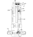
この実施例において、図14に示されているように、プローブ(102)の本体部(112)は、カッター回転及び並進移動機構(120)を含み、このカッター回転及び並進移動機構(120)は、外側カニューレ(12)内でカッター(50)を回転させ、かつ、並進移動させるように操作可能である。カッター回転及び並進移動機構(120)は、カッター(50)に一体に固定されたスリーブ(122)と、ナット部材(124)と、ギア(138)とを有している。この実施例において、スリーブ(122)は、カッター(50)の周囲に外側被覆された可塑性材料で形成されているが、他の任意の適切な材料が使用されてもよく、また、スリーブ(122)は、他の任意の適切な構造または技術(例えば、止めネジ等)を用いて、カッター(50)に固定されてもよい。ナット部材(124)は、ベース部材(116)に固定されており、雌ネジ山(126)を有している。スリーブ(122)の一部は、ナット部材(124)の雌ネジ山(126)と係合するように構成された雄ネジ山(128)を有している。ネジ山(126,128)は、スリーブ(122)がナット部材(124)に対して回転する際に、スリーブ(122)がナット部材(124)に対して、長さ方向軸方向に沿って、当該相対回転の方向によって決まる方向に並進移動するように構成されている。例示のみの目的では、ネジ山(126,128)は、1インチ(約2.5センチメートル)当たり約40〜50個のネジ山を与えるピッチを有するように構成されてもよい。このようなネジ山のピッチは、組織の切除に理想的な、カッター(50)の並進移動距離に対するカッター(50)の回転数の比を与えることになる。このような構成に代えて、他の任意のネジ山のピッチは使用されてもよい。この実施例において、スリーブ(122)がカッター(50)に一体に固定されている状態での、ナット部材(124)に対するスリーブ(122)の長さ方向への並進移動は、カッター(50)の同様の並進移動をもたらすはずである。 In this embodiment, as shown in FIG. 14, the body portion (112) of the probe (102) includes a cutter rotation and translation mechanism (120), which is a mechanism for rotation and translation mechanism (120). , Is operable to rotate and translate the cutter (50) within the outer cannula (12). The cutter rotation and translation mechanism (120) has a sleeve (122) integrally fixed to the cutter (50), a nut member (124) and a gear (138). In this embodiment, the sleeve (122) is formed of a plastic material that is coated on the periphery of the cutter (50), but any other suitable material may be used and the sleeve (122) ) May be fixed to the cutter (50) using any other suitable structure or technique (e.g. set screw etc). The nut member (124) is fixed to the base member (116) and has an internal thread (126). A portion of the sleeve (122) has an external thread (128) configured to engage with the internal thread (126) of the nut member (124). The threads (126, 128) are axially aligned with the sleeve (122) relative to the nut member (124) as the sleeve (122) rotates relative to the nut member (124). It is configured to translate in a direction determined by the direction of the relative rotation. For purposes of illustration only, the threads (126, 128) may be configured to have a pitch that provides about 40 to 50 threads per inch (about 2.5 centimeters). The pitch of such threads provides a ratio of the number of rotations of the cutter (50) to the translational distance of the cutter (50), which is ideal for tissue ablation. Instead of such a configuration, any other thread pitch may be used. In this embodiment, the translational movement of the sleeve (122) relative to the nut member (124) with the sleeve (122) integrally fixed to the cutter (50) Should produce similar translational movement.
スリーブ(122)の他の部分は、複数の外部フラット部(130)を有しており、当該外部フラット部(130)は、ギア(138)の相補的な内部フラット部(132)に係合するように構成されている。ギア(138)は、スリーブ(122)およびカッター(50)の周囲に同軸状に位置付けされている。フラット部(130,132)は、ギア(138)の回転がスリーブ(122)の回転を引き起こすように構成されている。この実施例において、スリーブ(122)がカッター(50)に一体に固定されている状態で、ギア(138)およびスリーブ(122)の回転は、カッター(50)の同様の回転をもたらすはずである。さらに、フラット部(130,132)は、スリーブ(122)がギア(138)に対して、長さ方向に沿って並進移動できるように構成されている(例えば、スリーブ(122)とギア(138)との間の嵌め合いは当該並進移動を抑制する程度に緊密ではない)。したがって、ギア(138)が回転する際に、ネジ山(126,128)およびフラット部(130,132)の相対的な構成を考えれば、ギア(138)のそのような回転が、スリーブ(122)の回転および長さ方向への並進移動を同時にもたらし、次いで、カッター(50)の回転および長さ方向への並進移動を同時にもたらすことは、正当に理解されるはずである。 Another portion of the sleeve (122) has a plurality of outer flats (130), which engage with complementary inner flats (132) of the gear (138) It is configured to The gear (138) is coaxially positioned around the sleeve (122) and the cutter (50). The flats (130, 132) are configured such that rotation of the gear (138) causes rotation of the sleeve (122). In this example, with the sleeve (122) integrally fixed to the cutter (50), rotation of the gear (138) and the sleeve (122) should result in similar rotation of the cutter (50) . Additionally, the flats (130, 132) are configured to allow the sleeve (122) to translate relative to the gear (138) along the length (e.g., the sleeve (122) and the gear (138). And the fit between the two) is not tight enough to suppress the translational movement). Thus, as the gear (138) rotates, considering the relative configuration of the threads (126, 128) and the flats (130, 132), such rotation of the gear (138) is the sleeve (122). It should be properly understood that the rotation and the translational movement in the longitudinal direction are simultaneously provided, and then the rotational movement and the translational direction in the longitudinal direction of the cutter (50) are simultaneously provided.
この実施例において、ギア(138)は、以下にさらに詳述されるように、ベース部材(116)を貫通して部分的に露出されており、ホルスター(202)の相補的な露出ギア(208)に噛合するように構成されている。具体的には、ギア(138)は、ギア(208)がギア(138)に回転を付与し、これによりカッター回転及び並進移動機構(120)を作動できるように、当該ギア(208)に噛合するように構成されている。以下にさらに詳述されるように、ギア(208)は、ホルスター(202)内に配されたモータ(272)と連絡状態にある。この実施例において、ギア(138,208)およびネジ山(126,128)は、モータ(272)の一回転がカッター(50)を約0.00012インチ(約0.000305センチメートル)、並進移動させるように構成されている。勿論、これらの部品のいずれもが、モータ(272)の回転に対するカッター(50)の並進移動の他の適切な比率をもたらす他の構成を有してもよい。 In this embodiment, the gear (138) is partially exposed through the base member (116), as described in further detail below, and the complementary exposed gear (208) of the holster (202). Are configured to mesh with each other. Specifically, gear (138) meshes with gear (208) such that gear (208) imparts rotation to gear (138), thereby allowing cutter rotational and translational movement mechanism (120) to operate. It is configured to The gear (208) is in communication with a motor (272) disposed within the holster (202), as described in further detail below. In this example, the gear (138, 208) and the thread (126, 128) translate one translation of the motor (272) about a 0.0152 inch (about 0.000305 centimeter) cutter (50) It is configured to let you Of course, any of these parts may have other configurations that provide other suitable ratios of translational movement of the cutter (50) to rotation of the motor (272).
上述されたカッター回転及び並進移動機構(120)が単なる例示であり、この例示に代えて、カッター(50)の並進移動および/または回転が他の種々の方法で提供されることがあることは、この明細書における教示を考慮することで、正当に理解されるはずである。例えば、生体組織検査用プローブ(102)は、当該プローブ(102)が露出ギア(138)を有しないように、モータ(図示せず)または他の装置を有してもよい。このような構成に代えて、露出ギア(138)以外の他の任意の構造(例えば、ラック等)は、他の部品からの動作またはエネルギの伝達を受け入れてカッター(15)を回転および/または並進移動させるために、使用されてもよい。さらに、カッター回転及び並進移動機構(120)は、一つ以上の露出ギア(138)(例えば、並進移動の動作を受け入れるための一つのギア(138)、および、回転の動作を受け入れるための他のギア(138)など)が存在するように構成されてもよい。単なる例示に過ぎない他の変形例において、カッター(50)の並進移動および/または回転は、空気圧式アクチュエータ(図示せず)、空気圧式モータ(図示せず)、あるいは、種々の他の部品によって、少なくとも部分的に実行されてもよい。さらに、カッター(50)を並進移動および/または回転させるために、空気圧式部品が他の機械式部品および/または電気機械式部品と組み合わせられてもよいことは、正当に理解されるはずである。。 The cutter rotation and translation mechanism (120) described above is merely illustrative, and alternatively, translation and / or rotation of the cutter (50) may be provided in various other ways. It should be properly understood in view of the teachings in this specification. For example, the biopsy probe (102) may have a motor (not shown) or other device such that the probe (102) does not have an exposure gear (138). Alternatively, any other structure (e.g., a rack, etc.) other than the exposure gear (138) receives movement or transmission of energy from other parts to rotate and / or rotate the cutter (15) It may be used to translate. In addition, the cutter rotation and translation mechanism (120) comprises one or more exposure gears (138) (e.g., one gear (138) for receiving the motion of translation) and the other for receiving the motion of rotation. (138) etc.) may be configured to be present. In other variations, by way of example only, the translational movement and / or rotation of the cutter (50) may be by means of a pneumatic actuator (not shown), a pneumatic motor (not shown), or various other components. , May be at least partially implemented. Further, it should be properly understood that pneumatic components may be combined with other mechanical components and / or electromechanical components to translate and / or rotate the cutter (50) . .
ベース部材(116)は、カッター(50)の近位端が内部に配設されるカッター用通路(54)をさらに含む。封止構造(56)は、カッター(50)の外表面とカッター用通路(54)の遠位端の内表面との間で減圧状態の解除または流体の漏出を防止するために、カッター(50)およびカッター用通路(54)の遠位側インターフェースに設けられている。カッター用通路(54)は、生体組織検査装置(100)の使用中に、カッター(50)が並進移動する際に、カッター(50)の遠位端がカッター用通路(54)内に残留するように、寸法設定されている。勿論、他の任意の適切な構造または構成が使用されてもよい。 The base member (116) further includes a cutter passage (54) in which the proximal end of the cutter (50) is disposed. The sealing structure (56) is a cutter (50) to prevent release of reduced pressure or leakage of fluid between the outer surface of the cutter (50) and the inner surface of the distal end of the cutter passage (54). And the distal interface of the cutter channel (54). The cutter passage (54) is such that the distal end of the cutter (50) remains in the cutter passage (54) as the cutter (50) translates during use of the biopsy device (100) So it is dimensioned. Of course, any other suitable structure or configuration may be used.
〔F. 「穿刺部品の削減(sharps reduction)」の変形例〕 [F. Modification of “sharps reduction”]
この実施例において、針部(10)およびカッター(50)は、生体組織検査装置(100)を用いた切除(session)後など、生体組織検査用プローブ(102)から取外し可能となるように構成されている。具体的には、生体組織検査用プローブ(102)の本体部(112)のベース部材(116)は、解除タブ(118)を含み、この解除タブ(118)は、アーム(119)を介してベース部材(116)に対して、弾性的に移動可能である。解除タブ(118)は、ギア(74)の軸方向への移動を規制することによって針部(10)の軸方向への移動を規制するように構成されており、当該ギア(74)は、解除タブ(118)が初期位置にあるときに、上述されたように、針ハブ(60)のスリーブ部(64)と係合される。勿論、ギア(74)とスリーブ部(64)との間の係合、ならびに、ギア(74)およびスリーブ部(64)の構成は、解除タブ(118)が初期位置にある間であっても、針部(10)の射出用など、針部(10)の軸方向への移動をある程度、許容するはずである。しかし、解除タブ(118)が、ユーザーによるなどして、十分に押し下げられた場合に、解除タブは、ギア(74)がベース部材(116)の遠位方向に移動するための隙間を提供するはずである。換言すれば、解除タブ(118)が十分に押し下げられた状態で、針ハブ(60)およびギア(74)の全体を含む針部(10)全体は、針ハブ(60)およびギア(74)の全体を含む針部(10)全体が本体部(112)から完全に分離されるように、生体組織検査用プローブ(102)の本体部(112)から遠位方向へ軸方向に引かれてもよい。 In this example, the needle (10) and the cutter (50) are configured to be removable from the biopsy probe (102), such as after a session using the biopsy device (100). It is done. Specifically, the base member (116) of the body portion (112) of the biopsy probe (102) includes a release tab (118), which is coupled to the arm (119) via the arm (119). It is elastically movable relative to the base member (116). The release tab (118) is configured to restrict axial movement of the needle portion (10) by restricting axial movement of the gear (74), and the gear (74) is configured to When the release tab (118) is in the initial position, it is engaged with the sleeve portion (64) of the needle hub (60) as described above. Of course, the engagement between the gear (74) and the sleeve portion (64), and the configuration of the gear (74) and the sleeve portion (64), even while the release tab (118) is in the initial position Axial movement of the needle (10), such as for injection of the needle (10), to some extent. However, when the release tab (118) is fully depressed, such as by the user, the release tab provides clearance for the gear (74) to move distally of the base member (116) It should be. In other words, with the release tab (118) fully depressed, the entire needle portion (10), including the entire needle hub (60) and gear (74), comprises the needle hub (60) and gear (74). Of the biopsy needle (102) distally axially away from the body (112) so that the entire needle portion (10), including the whole of the body, is completely separated from the body (112) It is also good.
針ハブ(60)およびギア(74)の全体を含む針部(10)全体が本体部(112)から完全に分離された状態で、まだ、カッター(50)が本体部(112)から延在するはずであることは、この明細書における教示を考慮することで、正当に理解されるはずである。本体部からカッター(50)を取り外すためには、ユーザーは、カッター(50)を本体部(112)から簡単に「ネジ固定を解除する(unscrew)」ことができる。具体的には、ユーザーは、本体部(112)から突出する針部(50)の一部を把持し、かつ、カッター(50)を遠位方向に引きながら、本体部(112)に対して針部(50)を回転させてもよい。このようなカッター(50)の回転および引張りは、最終的に、ネジ山(128)がネジ山(126)を越えて完全に遠位側に通過することになるネジ山(126,128)の相互作用を引き起こすことができる。ネジ山(128)がネジ山(126)を越えて完全に遠位側に通過している状態で、本体部(112)の他の部品は、軸方向においてカッター(50)を実質的に拘束することになり、これにより、カッター(50)は、更なる回転なしに、本体部(112)から完全に遠位方向に引かれることになる。換言すれば、本体部(112)に対するカッター(50)の十分な回転後に、カッター(50)は、本体部(112)から完全に分離されることになる。スリーブ(122)が針マニホールド(80)を完全に軸方向に沿って通過できるように、スリーブ(122)および針マニホールド(80)が構成され得ることは、この明細書における教示を考慮することで、正当に理解されるはずである。ギア(138)は、スリーブ(122)として、その位置に本質的に残留してもよく、カッター(50)の残りの部分は、当該スリーブ(122)に対して、軸方向に引かれる。本体部(112)からの針部(10)およびカッター(50)の取外しを行うか、許容するか、あるいは、促進する部品間の他の適切な関係は、この明細書における教示を考慮することで、当業者にとって明白なはずである。 The cutter (50) still extends from the body (112) with the entire needle portion (10) including the entire needle hub (60) and gear (74) completely separated from the body (112) What should be done should be properly understood in view of the teachings herein. To remove the cutter (50) from the body portion, the user can simply "unscrew" the cutter (50) from the body portion (112). Specifically, the user holds a portion of the needle (50) protruding from the main body (112) and pulls the cutter (50) in the distal direction against the main body (112). The needle (50) may be rotated. The rotation and tension of such a cutter (50) ultimately results in the thread (128) being completely distally passed over the thread (126) of the thread (126, 128) It can cause interaction. Other components of the body portion (112) substantially constrain the cutter (50) in the axial direction, with the thread (128) passing completely distally over the thread (126) As a result, the cutter (50) will be pulled completely distally from the body (112) without further rotation. In other words, after sufficient rotation of the cutter (50) relative to the body (112), the cutter (50) will be completely separated from the body (112). The sleeve (122) and the needle manifold (80) may be configured to allow the sleeve (122) to pass completely axially along the needle manifold (80) in view of the teachings herein. , Should be understood properly. The gear (138) may essentially remain in its position as a sleeve (122) and the remaining portion of the cutter (50) is pulled axially relative to the sleeve (122). Other suitable relationships between the parts that make, accept, or promote removal of the needle (10) and cutter (50) from the body (112) should take into account the teachings herein. And should be apparent to those skilled in the art.
解除タブ(118)および他の部品が、本体部(112)からの針部(10)およびカッター(50)の取外しを行う、および/または、許容するものとして記述されてきたが、当該取外し可能性(removability)が種々の他の構造および教示を用いて提供されうることは、この明細書における教示を考慮することで、正当に理解されるはずである。例えば、一部の実施の形態において、解除タブ(118)または他の特徴部は、ベース部材(116)が解除タブ(118)と十分な力で係合された場合に、ベース部材(116)から離脱し、これにより、針ハブ(60)およびギア(74)の全体を含む針部(10)全体の取外しを許容するように構成されている。さらに他の代替の実施の形態において、プローブ(102)は、針部(10)および針ハブ(60)が本体部(112)の残部に対して手動で角度をつけられた場合に、ベース部材(116)内に配設された保持用の特徴部の係合が解除され、これにより、針ハブ(60)およびギア(74)の全体を有する針部(10)全体が本体部(112)から軸方向に取り外されるように構成されている。本体部(112)からの針部(10)およびカッター(50)の取外しを行うか、許容するか、あるいは、促進するためのさらなる他の部品、特徴部および技術は、この明細書における教示を考慮することで、当業者にとって明白なはずである。 Although the release tab (118) and other components have been described as permitting and / or allowing removal of the needle (10) and cutter (50) from the body (112), the removable It should be appreciated that, in light of the teachings herein, removability may be provided using various other structures and teachings. For example, in some embodiments, the release tab (118) or other feature is a base member (116) when the base member (116) is engaged with the release tab (118) with sufficient force. Are configured to allow removal of the entire needle portion (10), including the entire needle hub (60) and gear (74). In yet another alternative embodiment, the probe (102) is a base member when the needle portion (10) and the needle hub (60) are manually angled relative to the remainder of the body portion (112). The retaining feature disposed within (116) is disengaged, thereby causing the entire needle portion (10) having the entire needle hub (60) and gear (74) to be the body portion (112) Are configured to be removed axially from the Still other parts, features and techniques for effecting, allowing, or facilitating removal of the needle (10) and cutter (50) from the body (112) may be taught in the present specification. It should be apparent to one of ordinary skill in the art upon consideration.
また、上述のような取外し可能性が生体組織検査装置(100)によって与えられる「穿刺部品(sharps)」の量を削減できることは、正当に理解されるはずである。具体的には、体液に露出されてきた穿刺装置の部品が、他の廃棄物の廃棄方法とは異なる方法で廃棄される必要がある(例えば、当該部品が、通常の廃棄容器とは異なる「穿刺部品廃棄容器」内に収容される)限りにおいて、本体部(112)からの針部(10)およびカッター(50)の完全な取外し可能性は、「穿刺部品(sharps)」の廃棄物の廃棄手順に従って、針部(10)およびカッター(50)が取り扱われ、本体部(112)の残部が同一の廃棄方法に付されることを必要としないことを許容することができる。換言すれば、例示のみの目的では、生体組織検査装置(100)の使用後に、針部(10)およびカッター(50)は、本体部(112)から取り外され、かつ、「穿刺部品廃棄容器」内に収容されてもよいが、本体部(112)の残部は、通常の廃棄容器内に収容されてもよい。 It should also be justified that the removability as described above can reduce the amount of "sharps" provided by the biopsy device (100). Specifically, parts of the lancing device that have been exposed to body fluids need to be disposed of differently than other waste disposal methods (e.g., the parts are different from normal waste containers) The complete removability of the needle part (10) and the cutter (50) from the body part (112) is limited to the fact that it is contained in the 'puncture parts waste container' According to the disposal procedure, it can be tolerated that the needle (10) and the cutter (50) are handled and the remainder of the body (112) does not need to be subjected to the same disposal method. In other words, for the purpose of illustration only, after use of the biopsy device (100), the needle portion (10) and the cutter (50) are removed from the main body portion (112) and the "puncture component waste container" The remainder of the body portion (112) may be contained within a conventional waste container, although it may be contained within.
〔G. 組織サンプルホルダーマニホールドの例〕 G. Example of tissue sample holder manifold
図15〜図19に示されているように、組織サンプルホルダー(140)は、プローブ(102)の本体部(112)の端部に設けられている。組織サンプルホルダー(140)は、カップ(142)と、マニホールド(144)と、複数のトレイ(160)とを有している。マニホールド(144)は、中央凹部(146)と、複数の長さ方向通路(148)と、放射状に延在する複数の壁部(152)によって画定された複数のチャンバ(150)と、複数の放射状通路(154)とを有している。各長さ方向通路(148)は、他の各長さ方向通路(148)に対して実質的に流体隔離状態(in fluid isolation)になっている。しかし、各放射状通路(154)は、マニホールド(144)の後部内に配された環状通路(図示せず)を経由して、他の各放射状通路(154)とは実質的に流体連通状態(in fluid communication)になっている。このような構成に代えて、各放射状通路(154)は、他の各放射状通路(154)に対して実質的に流体隔離状態になってもよい。この実施例において、各長さ方向通路(148)は、この細長通路(148)に対応する、各放射状通路(154)のうちの一つとは流体連通状態になっている。具体的には、各長さ方向通路(148)は、この細長通路(148)に対応する放射状通路(154)内の近位側で終端となっている。 As shown in FIGS. 15-19, a tissue sample holder (140) is provided at the end of the body (112) of the probe (102). The tissue sample holder (140) comprises a cup (142), a manifold (144) and a plurality of trays (160). A manifold (144) includes a plurality of chambers (150) defined by a central recess (146), a plurality of longitudinal passages (148), and a plurality of radially extending walls (152). And a radial passage (154). Each longitudinal passage (148) is substantially in fluid isolation with respect to each other longitudinal passage (148). However, each radial passage (154) is in substantial fluid communication with each other radial passage (154) via an annular passage (not shown) disposed within the rear of the manifold (144). in fluid communication). Alternatively, each radial passage (154) may be substantially fluidly isolated to each other radial passage (154). In this embodiment, each longitudinal passage (148) is in fluid communication with one of the respective radial passages (154) corresponding to the elongated passage (148). Specifically, each longitudinal passage (148) terminates proximally within a radial passage (154) corresponding to the elongated passage (148).
さらに、各放射状通路(154)は、それぞれの一対の開口部(156)を経由して、当該放射状通路(154)に対応する、各チャンバ(150)の一つとは流体連通状態になっている。したがって、各長さ方向通路(148)が、この細長通路(148)に対応する放射状通路(154)および一対の開口部(156)を経由して、当該細長通路(148)に対応するチャンバ(150)とは流体連通状態になっている。具体的には、中央凹部(146)を基準にして放射状の位置に配された各長さ方向通路(148)の当該放射状位置は、当該長さ方向通路(148)に関連した放射状通路(154)、一対の開口部(156)およびチャンバ(150)の放射状位置に対応している。勿論、マニホールド(144)に適した他の任意の構造または構成が使用されてもよい。 Further, each radial passage (154) is in fluid communication with one of the respective chambers (150) corresponding to the respective radial passage (154) via the respective pair of openings (156) . Thus, each longitudinal passage (148) corresponds to the elongated passage (148) via a radial passage (154) and a pair of openings (156) corresponding to the elongated passage (148). 150) is in fluid communication. Specifically, the radial position of each longitudinal passage (148) disposed at a radial position with respect to the central recess (146) is the radial passage (154) associated with the longitudinal passage (148). ), Corresponding to the radial position of the pair of openings (156) and the chamber (150). Of course, any other structure or configuration suitable for the manifold (144) may be used.
一部の変形例において、篩、メッシュまたは他の部品は、特定の開口部または隙間内へ、あるいは当該開口部または隙間を経由する組織の通過を阻止するために、マニホールド(144)上、または、マニホールド(144)内に設けられるか、あるいは、組織サンプルホルダー(140)内の他の部分に設けられている。他の変形例では、当該部品が省略される。 In some variations, the sieve, mesh or other part is placed on the manifold (144), or in a specific opening or gap, or to block the passage of tissue through the opening or gap. , Provided in the manifold (144) or at another part in the tissue sample holder (140). In another variant, the part is omitted.
〔H. 組織サンプルトレイの例〕 H. Example of tissue sample tray
この実施例のトレイ(160)は、マニホールド(144)上に配設され、かつ、以下にさらに詳述されるように、組織サンプル(4)を収容するように構成されている。各トレイ(160)は、剛体であってもよく、また、概ね、アーチ状構造を有するように予め形成されてもよい。このような構成に代えて、トレイ(160)は、可撓性材料で形成され、これにより、トレイ(160)がマニホールド(144)の曲面に一致させるように曲げられてもよい。このような構成に代えて、トレイ(160)は、一つ以上の関節部を有しており、これにより、トレイ(160)の各部が、当該関節部で曲げるか、あるいは、撓ませることができる。さらなる他の適切な構成が使用されてもよい。 The tray (160) of this embodiment is disposed on the manifold (144) and is configured to receive a tissue sample (4) as described in further detail below. Each tray (160) may be rigid and may be generally preformed to have an arched structure. Alternatively, the tray (160) may be formed of a flexible material so that the tray (160) may be bent to conform to the curved surface of the manifold (144). Instead of such a configuration, the tray (160) has one or more joints, whereby each part of the tray (160) may be bent or bent at the joints. it can. Still other suitable configurations may be used.
この実施例の各トレイ(160)は、ベース部(162)と、複数の中空壁部(164)とを有している。中空壁部(164)は、複数のチャンバ(166)を画定している。例示のみの目的では、各チャンバ(166)は、カッター(50)によって採取された一つの組織サンプル(4)を収容するように構成されてもよい。このような構成に代えて、チャンバ(166)は、各チャンバ(166)が一つ以上の組織サンプル(4)を保持できるように構成されてもよい。この実施例のマニホールド(144)およびチャンバ(166)は、組織サンプル(4)が当該チャンバ(166)内にあるときであっても、血液、生理食塩水、および/または、他の流体がチャンバ(166)を通過でき、かつ、チューブ(404)を経由して排出できるように、さらに構成されている。換言すれば、チャンバ(166)は、流体が、組織サンプル(4)の周囲を通過するのを許容するはずである。 Each tray (160) of this embodiment has a base (162) and a plurality of hollow walls (164). The hollow wall (164) defines a plurality of chambers (166). For purposes of illustration only, each chamber (166) may be configured to receive one tissue sample (4) taken by the cutter (50). Alternatively, the chambers (166) may be configured such that each chamber (166) can hold one or more tissue samples (4). The manifold (144) and the chamber (166) of this example have chambers for blood, saline and / or other fluids even when the tissue sample (4) is in the chamber (166). It is further configured to be able to pass (166) and be expelled via the tube (404). In other words, the chamber (166) should allow fluid to pass around the tissue sample (4).
図示されているように、各中空壁部(164)の下側は、マニホールド(144)の壁部(152)を収容するように構成されている。中空壁部(164)および壁部(152)は、トレイ(160)がマニホールド(144)上に配された際に、各ベース部(162)とマニホールド(144)との間に隙間が設けられるように構成されている。また、図示されているように、各中空壁部(164)は、概ね、テーパ状の構造を有しているが、任意の他の適切な構成が使用されてもよい。さらに、トレイ(160)は、各チャンバ(164)内のベース部(162)を貫通して、複数の組で形成された複数の開口部(168)を有している。したがって、トレイ(160)の各チャンバ(166)は、開口部(168)を経由して、関連したマニホールド(144)のチャンバ(150)とは流体連通状態になっている。このため、マニホールド(144)の各長さ方向通路(148)は、当該細長通路に対応する、トレイ(160)のチャンバ(166)とは流体連通状態になっている。したがって、チューブ(404)が所予の長さ方向通路(148)と流体連通状態になっている場合に、チューブ(404)が、当該長さ方向通路(148)に関連したチャンバ(166)と流体連通状態になるはずであることは、正当に理解されるはずである。 As shown, the lower side of each hollow wall (164) is configured to receive the wall (152) of the manifold (144). The hollow wall (164) and the wall (152) provide a gap between each base (162) and the manifold (144) when the tray (160) is placed on the manifold (144) Is configured as. Also, as shown, each hollow wall (164) has a generally tapered structure, but any other suitable configuration may be used. Further, the tray (160) has a plurality of sets of openings (168) formed through the base (162) in each chamber (164). Thus, each chamber (166) of the tray (160) is in fluid communication with the associated manifold (144) chamber (150) via the opening (168). Thus, each longitudinal passage (148) of the manifold (144) is in fluid communication with the chamber (166) of the tray (160) corresponding to the elongated passage. Thus, when the tube (404) is in fluid communication with the desired longitudinal passage (148), the tube (404) and the chamber (166) associated with the longitudinal passage (148) It should be properly understood that it should be in fluid communication.
この実施例において、マニホールド(144)およびトレイ(160)は、18個のチャンバ(150,166)を備える。このような構成に代えて、他の任意の数(すなわち、18個を超える数または18個未満の数)のチャンバ(150,166)が備えられてもよい。例えば、一つの変形例において、マニホールド(144)は、3個のチャンバ(150)を備えており、各トレイ(160)がチャンバ(166)を一つだけ有する、3個のトレイ(160)が使用される。さらに他の変形例において、一つのトレイ(160)が使用される。例えば、一つのトレイ(160)は、一つの大きなチャンバ(166)、あるいは、任意の適切な数のチャンバ(166)を備えてもよい。他の任意の適切な数のチャンバ(150,166)、および、当該チャンバ(150,166)が備えられ得る方法は、この明細書における教示を考慮することで、当業者にとって明白なはずである。さらに、マニホールド(144)および複数のトレイ(160)は、任意の適切な形状を有してもよい。 In this example, the manifold (144) and tray (160) comprise 18 chambers (150, 166). Alternatively, any other number (i.e. more than 18 or less than 18) of chambers (150, 166) may be provided. For example, in one variation, the manifold (144) comprises three chambers (150), each tray (160) having only one chamber (166), three trays (160) used. In yet another variation, one tray (160) is used. For example, one tray (160) may comprise one large chamber (166) or any suitable number of chambers (166). Any other suitable number of chambers (150, 166) and the manner in which such chambers (150, 166) may be provided should be apparent to those skilled in the art in view of the teachings herein. . Further, the manifold (144) and the plurality of trays (160) may have any suitable shape.
各トレイ(160)は、一つのチャンバ(166)を他のチャンバ(166)から識別するために、一種以上の標識または他の印をさらに有してもよい。例えば、番号または他の識別標識は、浮き彫り式(in relief form)、埋め込み式(in recessed form)、あるいは、他の方法等、各チャンバ(166)上、あるいは、各チャンバ(166)近傍に設けられてもよい。他の実施の形態において、放射線不透過性標識は、各チャンバ(166)上、あるいは、各チャンバ(166)近傍に設けられている。例えば、一つ以上の組織サンプル(4)を運ぶトレイ(160)全体は、評価用のX線照射下に配置されてもよく、また、各チャンバ(166)に関連した(従って、各組織サンプル(4)に関連した)放射線不透過性標識は、X線を用いて得られた画像中で可視化されてもよい。換言すれば、組織サンプル(4)は、組織サンプル(4)のX線または放射線の画像を撮影するために、トレイ(160)から必ずしも取り外される必要がない。さらに、複数のトレイ(160)は、当該トレイ(160)上に載置された組織サンプル(4)と共に、ホルマリンまたは他の液体中に直接、放り込まれてもよい。さらに、複数のトレイ(160)は、組織サンプル(4)を保護するために、および/または、組織サンプル(4)が当該トレイ(160)内に留まることを保証するために、あるいは、他の目的のために、スリーブまたは容器等の内部に、個別に、あるいは、一群で、配されてもよい。このようなスリーブまたは容器は、可撓性、剛性であってもよく、あるいは、他の特性を有してもよい。例示のみの目的では、スリーブまたは他の容器は、平坦な形状であってもよく、また、当該スリーブまたは他の容器内に挿入される可撓性のトレイ(160)を押しつぶすように構成されてもよい。組織サンプル(4)が複数のトレイ(160)に移された後など、複数のトレイ(160)と共に使用され得るような他の構造および技術は、この明細書における教示を考慮することで、当業者にとって明白なはずである。 Each tray (160) may further have one or more labels or other indicia to distinguish one chamber (166) from another (166). For example, a number or other identifying indicia may be provided on or near each chamber (166), such as in relief form, in receded form, or otherwise. It may be done. In another embodiment, radiopaque labels are provided on or near each chamber (166). For example, the entire tray (160) carrying one or more tissue samples (4) may be placed under evaluation X-ray radiation, and associated with each chamber (166) (thus, each tissue sample Radiopaque labels (related to (4)) may be visualized in the image obtained using X-rays. In other words, the tissue sample (4) does not necessarily have to be removed from the tray (160) in order to take x-ray or radiation images of the tissue sample (4). Additionally, multiple trays (160) may be dumped directly into formalin or other fluid, with the tissue sample (4) placed on the tray (160). In addition, a plurality of trays (160) may be used to protect tissue samples (4) and / or to ensure that tissue samples (4) remain in the tray (160) or other For purposes, it may be disposed individually or as a group inside a sleeve or container etc. Such sleeves or containers may be flexible, rigid or have other properties. For purposes of illustration only, the sleeve or other container may be flat shaped and configured to crush a flexible tray (160) inserted into the sleeve or other container It is also good. Other structures and techniques such as may be used with multiple trays (160), such as after tissue samples (4) have been transferred to multiple trays (160), are considered by considering the teachings herein. It should be clear to the contractor.
カップ(142)は、ベース部材(116)の差込ピン(134)に係合するように構成されており、これにより、ベース部材(116)に対するカップ(142)の十分な回転時に、カップ(142)がベース部材(116)から取り外されるか、あるいは、当該ベース部材(116)に固定されてもよい。さらに、O-リング(136)は、ベース部材(116)とカップ(142)との間の封止構造を与えるために、ベース部材(116)周りに設けられている。勿論、他の任意の適切な構造は、カップ(142)のベース部材(116)への係合、および/または、ベース部材(116)とカップ(142)との間の封止構造を与えるように使用されてもよい。また、カップ(142)は、この実施例において、透明材料で形成されており、これにより、まだ、組織サンプルホルダー(140)がベース部材(116)に連結されている間に、ユーザーが組織サンプルホルダー(140)内の組織サンプル(4)を視覚的に検査できる。例えば、ユーザーは、色、寸法、および、密度に関して(例えば、チャンバ(166)が生理食塩水等で満たされている限りにおいて)、組織サンプル(4)を検査してもよい。 The cup (142) is configured to engage the insertion pin (134) of the base member (116) such that upon sufficient rotation of the cup (142) relative to the base member (116), the cup (142) 142) may be removed from the base member (116) or fixed to the base member (116). In addition, an O-ring (136) is provided around the base member (116) to provide a sealing structure between the base member (116) and the cup (142). Of course, any other suitable structure is such that the cup (142) engages the base member (116) and / or provides a sealing structure between the base member (116) and the cup (142) May be used. Also, the cup (142) is formed of a transparent material in this example, which allows the user to select the tissue sample while the tissue sample holder (140) is still connected to the base member (116). The tissue sample (4) in the holder (140) can be inspected visually. For example, the user may examine the tissue sample (4) for color, size, and density (eg, as long as the chamber (166) is filled with saline or the like).
また、カップ(142)およびトレイ(160)の取外し可能性により、ユーザーが、比較的短時間に比較的大量の組織サンプルを採取できることは、この明細書における教示を考慮することで、正当に理解されるはずである。さらに、カップ(142)およびトレイ(160)の可撤性により、ユーザーが、不満足な組織サンプル(4)を組織サンプルホルダー(140)から(例えば、ピンセット等を用いて)除去でき、その後、更なるサンプルのために、トレイ(160)およびカップ(142)を再度、連結できる。当該可撤性、および、この実施例の組織サンプルホルダー(140)の他の特性が利用され得るような他の方法は、この明細書における教示を考慮することで、当業者にとって明白なはずである。 Also, the removability of the cup (142) and tray (160) allows the user to take a relatively large amount of tissue sample in a relatively short time, justified in light of the teachings herein. It should be done. In addition, the removability of the cup (142) and tray (160) allows the user to remove the unsatisfactory tissue sample (4) from the tissue sample holder (140) (e.g. with tweezers etc) and then further The tray (160) and the cup (142) can be reconnected for the resulting sample. Such removability and other ways in which other properties of the tissue sample holder (140) of this example may be utilized should be apparent to one of ordinary skill in the art in view of the teachings herein. is there.
〔I. マニホールドの回転および位置合わせ(Alignment)の例〕 [I. Example of Manifold Rotation and Alignment (Alignment)]
この実施例のマニホールド(144)は、以下にさらに詳述されるように、ベース部材(116)に対して回転するように構成されている。この実施例のマニホールド(144)は、各長さ方向通路(148)が、チューブ(404)と流体連通状態にあるポート部(406)と選択的に位置合わせされ(aligned)うるように、さらに構成されている。このような長さ方向通路(148)およびポート部(406)の位置合わせは、チューブ(404)と流体連通状態で位置合わせされた長さ方向通路(148)を配置し、これにより、チューブ(404)内への減圧の導入が、長さ方向通路(148)内ばかりでなく、当該長さ方向通路(148)に関連したチャンバ(166)内への減圧の導入に影響を与えるはずである。さらに、この実施例のマニホールド(144)およびトレイ(160)は、各チャンバ(166)が選択的に、カッター内腔(52)と流体連通するように配設されうるように構成されている。したがって、チューブ(404)内の減圧がカッター内腔(52)内に減圧を誘導し、その減圧状態がポート部(406)、関連の長さ方向通路(148)、関連の放射状通路(154)、関連の一対の開口部(156)、関連のチャンバ(150)、関連の一群の開口部(168)および関連のチャンバ(166)を経由して伝達され得ることは、正当に理解されるはずである。勿論、減圧がカッター内腔(52)内に誘導され得るような他の種々の方法が存在しており、かつ、他の任意の適切な構造または技術が使用されてもよい。さらに、圧縮空気、液体(例えば、生理食塩水)、あるいは、他の任意の流体は、上述の部品内に減圧が導入されること代えて、あるいは、そのことに加えて、上述の部品をいずれの方向にも経由して伝達されてもよい。 The manifold (144) of this embodiment is configured to rotate relative to the base member (116), as described in further detail below. The manifold (144) of this embodiment is further adapted to allow each longitudinal passage (148) to be selectively aligned with the port portion (406) in fluid communication with the tube (404). It is configured. Such alignment of the longitudinal passage (148) and the port portion (406) places the longitudinal passage (148) in fluid communication with the tube (404), thereby The introduction of reduced pressure into 404) should affect the introduction of reduced pressure not only in the longitudinal passage (148) but also in the chamber (166) associated with the longitudinal passage (148) . Further, the manifold (144) and tray (160) of this embodiment are configured such that each chamber (166) can be selectively placed in fluid communication with the cutter lumen (52). Thus, the reduced pressure in the tube (404) induces a reduced pressure in the cutter lumen (52), the reduced state being the port portion (406), the associated longitudinal passage (148), the associated radial passage (154) It should be properly understood that it can be transmitted via the associated pair of openings (156), the associated chamber (150), the associated group of openings (168) and the associated chamber (166) It is. Of course, there are various other ways in which reduced pressure can be induced into the cutter lumen (52), and any other suitable structure or technique may be used. Additionally, compressed air, liquid (eg, saline), or any other fluid may be used instead of or in addition to the introduction of reduced pressure into the components described above It may also be transmitted via the direction of
ギア(170)は、この実施例のマニホールド(144)に係合されている。具体的には、ギア(170)は、マニホールド(144)の中央凹部(146)内に挿入されたシャフト(172)を有している。シャフト(172)は、フラット部(174)を有しており、このフラット部(174)は、中央凹部(146)の相補的なフラット部(147)に係合するように構成されている。フラット部(174,147)の係合は、ギア(170)、シャフト(172)およびマニホールド(144)が一体に回転するように構成されている。このような構成に代えて、ギア(170)およびマニホールド(144)は、他の任意の適切な構成または関係を有してもよい。いずれにせよ、この実施例のギア(170)は、マニホールド(144)を回転させるために使用されてよく、これにより、同時に行われる複数のチャンバ(166)とカッター内腔(52)との選択的な位置合わせに加えて、複数の長さ方向通路(148)とポート部(406)との選択的な位置合わせを許容することになる。具体的には、以下にさらに詳述されるように、ギア(170)は、ホルスター(202)の相補的なギア(210)に噛合するように構成されており、これにより、ギア(210)は、ギア(170)に回転を付与するために使用され得る。このような回転は、生体組織検査装置(100)の使用中に、各チャンバ(166)内に個別の組織サンプル(4)を連続的に収集するように、チャンバ(166)をカッター内腔(52)に選択的に(例えば、連続的に)位置合わせするために、使用されてもよい。さらに、このような組織サンプル(4)の収集は、この収集中に患者に対して、針部(10)を引き抜き、かつ、再挿入する必要もなく、実行されてもよい。 The gear (170) is engaged with the manifold (144) of this embodiment. Specifically, the gear (170) has a shaft (172) inserted into the central recess (146) of the manifold (144). The shaft (172) has a flat (174), which is configured to engage a complementary flat (147) of the central recess (146). The engagement of the flats (174, 147) is configured such that the gear (170), the shaft (172) and the manifold (144) rotate together. Alternatively, the gear (170) and the manifold (144) may have any other suitable configuration or relationship. In any event, the gear (170) of this example may be used to rotate the manifold (144), thereby selecting the plurality of chambers (166) and the cutter lumen (52) to be performed simultaneously. In addition to general alignment, selective alignment of the plurality of longitudinal passageways (148) with the port portion (406) will be allowed. In particular, as described in further detail below, the gear (170) is configured to mesh with the complementary gear (210) of the holster (202), thereby causing the gear (210) to May be used to impart rotation to the gear (170). Such rotation rotates the chamber (166) into the cutter lumen (104) so as to continuously collect individual tissue samples (4) in each chamber (166) during use of the biopsy device (100). 52) may be used to selectively (eg, sequentially) align. Furthermore, the collection of such tissue samples (4) may be performed without the need to withdraw and reinsert the needle (10) into the patient during this collection.
〔J. 「停止用爪(Parking Pawl)」の例〕 [Example of J. "Stop Pawl"]
この実施例の本体部(112)は、係合部材(180)をさらに含み、この係合部材(180)は、ベース部材(116)に固定されている。図20に示されているように、係合部材(180)は、複数の歯部(184)を備えた爪部(182)を有している。爪部(182)は、歯部(184)がギア(170)に係合するように弾性的に付勢されている。具体的には、ギア(170)に対する爪部(182)の歯部(184)の係合は、ギア(170)の回転を阻止する(したがって、マニホールド(144)の回転を阻止する)。このため、爪部(182)は、当該爪部(182)が初期位置にある場合に、マニホールド(144)の回転を阻止するように構成されている。この実施例において、爪部(182)は、生体組織検査用プローブ(102)がホルスター(202)に連結されていない場合に、初期位置にある。しかし、生体組織検査用プローブ(102)がホルスター(202)に連結されている場合に、ホルスター(202)上の突起部(212)は、爪部(182)に係合するように構成されている。具体的には、ホルスター(202)上の突起部(212)は、生体組織検査用プローブ(102)がホルスター(202)に連結されている場合に、ギア(170)から爪部(182)を係合解除させるように構成されており、これにより、爪部(182)は、生体組織検査用プローブ(102)がホルスター(202)に連結されている場合に、もはや、ギア(170)またはマニホールド(144)の回転を阻止しないはずである。生体組織検査用プローブ(102)がホルスター(202)から取り外されている場合に、係合部材(180)は、その弾性力により、爪部(182)をその初期位置に戻す方向に付勢し、これにより、爪部(182)は、再度、ギア(170)およびマニホールド(144)の回転を阻止するはずである。 The body portion (112) of this embodiment further includes an engagement member (180), which is secured to the base member (116). As shown in FIG. 20, the engagement member (180) has a claw (182) with a plurality of teeth (184). The pawl (182) is resiliently biased such that the teeth (184) engage the gear (170). Specifically, engagement of the teeth (184) of the pawl (182) with the gear (170) prevents rotation of the gear (170) (and thus prevents rotation of the manifold (144)). For this reason, the claw portion (182) is configured to block the rotation of the manifold (144) when the claw portion (182) is in the initial position. In this example, the pawl (182) is in the initial position when the biopsy probe (102) is not coupled to the holster (202). However, when the biopsy probe (102) is coupled to the holster (202), the protrusions (212) on the holster (202) are configured to engage the claws (182) There is. Specifically, the projection (212) on the holster (202) can be engaged with the claw (182) from the gear (170) when the biopsy probe (102) is connected to the holster (202). Configured to disengage, whereby the pawl (182) is no longer gear (170) or manifold when the biopsy probe (102) is coupled to the holster (202) It should not prevent the rotation of (144). When the biopsy probe (102) is removed from the holster (202), the engagement member (180) urges the claw (182) to its initial position by its elastic force. Thus, the claws (182) should again prevent rotation of the gear (170) and the manifold (144).
生体組織検査用プローブ(102)が、製造施設からの輸送用に、あるいは、他の状況下で、梱包されている場合には、組織サンプルホルダー(140)は、所定のチャンバ(166)がカッター内腔(52)に位置合わせされるように構成されてもよい。生体組織検査用プローブ(102)が初回使用時のホルスター(202)に連結されている時に、爪部(182)が上述のような位置合わせを維持している状態で、生体組織検査装置(100)を制御するために使用されるソフトウエアまたは制御論理は、所定のチャンバ(166)がカッター内腔(52)に位置合わせされている点で「安全とみなす」ことができ、これにより、生体組織検査装置(100)を制御することができる。さらに、仮に、組織サンプル(4)の収集処理中に、生体組織検査用プローブ(102)がホルスター(202)から取り外されている場合には、生体組織検査装置(100)を制御するために使用されるソフトウエアまたは制御論理は、当該ソフトウエアが処理の間に、使用中、あるいは、使用後のチャンバ(166)を追跡している限りにおいて、直前に、カッター内腔(52)に位置合わせされたチャンバ(166)を「記憶する」ことができる。仮に、上記処理を継続するために、生体組織検査用プローブ(102)がホルスター(202)に再度、連結された場合には、当該ソフトウエアまたは制御論理は、当該ソフトウエアが「記憶した」チャンバ(166)に基づいて生体組織検査装置(100)の制御を継続することができる。このような構成に代えて、ユーザーは、新規の生体組織検査用プローブ(102)がホルスター(202)に連結されたことを特定でき、これにより、当該ソフトウエアまたは制御論理が、所定のチャンバ(166)がカッター内腔(52)に位置合わせされたチャンバであると再度「みなす」ことになる。 If the biopsy probe (102) is packaged for transportation from a manufacturing facility or under other circumstances, the tissue sample holder (140) may be a predetermined chamber (166) cutter. It may be configured to be aligned with the lumen (52). When the biopsy probe (102) is connected to the holster (202) in the first use, the biopsy device (100) is maintained in the state where the claw portion (182) maintains the alignment as described above. Software or control logic used to control) can be "safe" in that the given chamber (166) is aligned with the cutter lumen (52), thereby The tissue examination apparatus (100) can be controlled. Furthermore, it is used to control the biopsy device (100) if the biopsy probe (102) is removed from the holster (202) during the collection process of the tissue sample (4). Software or control logic that aligns with the cutter lumen (52) just before the software tracks the chamber (166) in use, or after use during processing The chamber (166) can be "stored". If the biopsy probe (102) is again connected to the holster (202) to continue the above process, the software or control logic may be used to "clean" the chamber in which the software is stored. Control of the biopsy apparatus (100) can be continued based on (166). Alternatively, the user can specify that the new biopsy probe (102) is connected to the holster (202), which causes the software or control logic to 166) will again be "considered" as the chamber aligned with the cutter lumen (52).
爪部(182)は、ギア(170)およびマニホールド(144)の回転を選択的に阻止する構造として記述されてきたが、他の任意の代替構造が上述の目的のために使用され得ることは、正当に理解されるはずである。例示のみの目的では、ジェネバ(Geneva)ホイール機構(図示せず)は、マニホールド(144)を回転させ、かつ、意図的な回転の合間にマニホールド(144)の回転位置を維持するための代替機構として、使用されてもよい。例えば、ギア(170)は、ジェネバ(Geneva)駆動ホイール(図示せず)に置き換えられてもよく、同時に、ギア(210)は、ジェネバ(Geneva)駆動ホイール(図示せず)に置き換えられてもよい。マニホールド(144)を回転させ、かつ/または、マニホールド(144)の回転位置を維持するための他の適切な変形例は、この明細書における教示を考慮することで、当業者にとって明白なはずである。さらに、生体組織検査装置(100)が爪部(182)または他の回転阻止特徴部を全く有しなくてもよく、これにより、生体組織検査用プローブ(102)がホルスター(202)に連結されていない場合に、マニホールド(144)が自由に回転できることは、正当に理解されるはずである。 Although the pawl (182) has been described as a structure that selectively blocks rotation of the gear (170) and the manifold (144), any other alternative structure may be used for the purpose described above , Should be understood properly. For illustration purposes only, the Geneva wheel mechanism (not shown) is an alternative mechanism for rotating the manifold (144) and maintaining the rotational position of the manifold (144) between intentional rotations. It may be used as For example, the gear (170) may be replaced by a Geneva drive wheel (not shown), while the gear (210) may be replaced by a Geneva drive wheel (not shown) Good. Other suitable variations for rotating the manifold (144) and / or maintaining the rotational position of the manifold (144) should be apparent to those skilled in the art in view of the teachings herein. is there. Furthermore, the biopsy device (100) may not have any nails (182) or other anti-rotation features so that the biopsy probe (102) is coupled to the holster (202) It should be justified that the manifold (144) is free to rotate if not.
〔K. 専用(dedicated)通路の例〕 [K. Example of dedicated passage]
図16〜図17、図19および図21に示されているように、この実施例の組織サンプルホルダー(140)は、マニホールド(144)を貫通して形成された通路(158)を有している。通路(158)は、長さ方向に沿って、マニホールド(144)を完全に貫通するように延在しており、マニホールド(144)によって定められた中心軸から外れているが、当該中心軸と平行である。チャンバ(166)と同様に、通路(158)は、カッター内腔(52)に選択的に位置合わせされるように構成されている。しかし、チャンバ(166)とは異なり、通路(158)は、長さ方向通路(148)または放射状通路(154)のいずれとも流体連通状態にならない。他の変形例において、通路(158)は、一つ以上の長さ方向通路(148)および/または放射状通路(154)と流体連通状態で設けられてもよい。 As shown in FIGS. 16-17, 19 and 21, the tissue sample holder (140) of this embodiment has a passageway (158) formed through the manifold (144). There is. The passageway (158) extends along the length completely through the manifold (144) and is offset from the central axis defined by the manifold (144), but with the central axis It is parallel. Similar to the chamber (166), the passageway (158) is configured to be selectively aligned with the cutter lumen (52). However, unlike the chamber (166), the passageway (158) is not in fluid communication with either the longitudinal passageway (148) or the radial passageway (154). In other variations, the passage (158) may be provided in fluid communication with one or more longitudinal passages (148) and / or radial passages (154).
この実施例の通路(158)は、器具および/または液体、他の材料等がマニホールド(144)およびカッター内腔(52)を通過できるように構成されている。例えば、通路(158)は、生体組織検査部位に一つ以上の標識を配置するための器具を、カッター内腔(52)および外側カニューレ(12)を経由し、組織収容用横穴(16)から出るようにして挿入するために使用されてもよい。通路(158)を経由して挿入される、単なる例示に過ぎない標識アプライヤは、米国オハイオ州シンシナティのエシコン・エンド・サージェリー・インクにより供給されるMAMMOMARKの生体組織検査部位用の標識アプライヤを包含することができる。通路(158)を経由して挿入され得るような他の適切な標識アプライヤ装置は、米国特許第7,047,063号明細書、米国特許第6,996,433号明細書、米国特許第6,993,375号明細書、または、米国公開特許第2005/0228311号明細書に記述された標識アプライヤ装置のいずれをも包含することができ、これらの各文献の開示内容は、参照によって、この明細書に組み込まれる。このようなアプライヤの変形例を含む、当該アプライヤのいずれもが、組織収容用横穴(16)を介して生体組織検査部位に一つ以上の標識を配置するために、通路(158)を経由して導入されてもよいが、針部(10)は、患者体内に挿入された状態のままである(例えば、生体組織検査用のサンプルが患者から抽出された直後など)。このような標識の配置は、組織サンプル(4)が、生体組織検査用プローブ(102)に固定された組織サンプルホルダー(140)内に残っている間であっても、達成され得る。このような構成に代えて、このような標識アプライヤは、組織サンプルホルダー(140)が生体組織検査用プローブ(102)から取り外された状態で、カッター内腔(52)内に直接、挿入されてもよい。 The passageway (158) in this example is configured to allow instruments and / or liquids, other materials, etc. to pass through the manifold (144) and the cutter lumen (52). For example, the passage (158) may be a device for placing one or more markers at the biopsy site, via the cutter lumen (52) and the outer cannula (12), from the tissue receiving cross hole (16) It may be used to insert and exit. An illustrative label applier, inserted via passage (158), includes a label applier for the biopsy site of MAMMO MARK supplied by Esicon End Surgery Inc. of Cincinnati, Ohio, USA can do. Other suitable labeled applier devices such as may be inserted via passageway (158) are described in U.S. Patent Nos. 7,047,063, 6,996,433, 6,993,375, or U.S. Patent Publication. No. 2005/0228311 can be included, and the disclosure content of each of these documents is incorporated herein by reference. Any of the appliers, including variations of such appliers, may be routed through the passage (158) to place one or more markers at the biopsy site via the tissue accommodation cross-hole (16). Although it may be introduced, the needle (10) remains inserted into the patient's body (eg, immediately after a sample for biopsy is taken from the patient, etc.). Placement of such a label can be achieved even while the tissue sample (4) remains in the tissue sample holder (140) fixed to the biopsy probe (102). Alternatively, such a labeled applier is inserted directly into the cutter lumen (52) with the tissue sample holder (140) removed from the biopsy probe (102). It is also good.
上述されたように、生体組織検査用プローブ(102)には、当初、初期設定によってカッター内腔(52)に位置合わせされている所定のチャンバ(166)が備えられてもよい。しかし、他の実施例では、生体組織検査用プローブ(102)には、当初、初期設定によってカッター内腔(52)に位置合わせされている通路(158)が備えられている。さらに、ユーザーが、生体組織検査装置(100)の使用中に、カッター内腔(52)に位置合わせされた通路(158)を有することを望む限りにおいて、マニホールド(144)が当該生体組織検査装置(100)の使用中に回転した後に、制御装置は、マニホールド(144)が回転してカッター内腔(52)に通路(158)を位置合わせるように、当該マニホールド(144)に指令するために使用されてもよい。 As mentioned above, the biopsy probe (102) may be initially provided with a predetermined chamber (166) that is aligned with the cutter lumen (52) by default. However, in other embodiments, the biopsy probe (102) is initially provided with a passageway (158) that is aligned with the cutter lumen (52) by default. Furthermore, the manifold (144) is a biomedical tissue testing device insofar as the user desires to have the passageway (158) aligned with the cutter lumen (52) during use of the biopsy device (100). After rotation during use of (100), the controller directs the manifold (144) to rotate and align the passage (158) with the cutter lumen (52). It may be used.
カップ(142)は、開口部(176)と、ハッチ部(178)とをさらに含む。開口部(176)は、カップ(142)がベース部材(116)に固定された際に、通路(158)を開口部(176)に位置合わせするためにマニホールド(144)を回転させることによるなどして、通路(158)と位置合わせされるように構成されている。ハッチ部(178)は、開口部(176)を選択的に覆うように構成されている。例えば、ハッチ部(178)は、当該ハッチ部(178)が開口部(176)を覆う場合に、当該開口部(176)を封止するように構成されてもよい。ハッチ部(178)は、開口部(176)および通路(158)への経路を確保するために、ユーザーがハッチ部(178)の「剥離」および/または「旋回」を可能にするように、さらに構成されてもよい。ハッチ部(178)が除去可能なストッパまたは他の構造を含むが、これらに限定されない種々の代替構造と置き換えられるか、あるいは、当該代替構造で補完され得ることは、この明細書における開示内容を考慮することで、正当に理解されるはずである。 Cup (142) further includes an opening (176) and a hatch (178). The opening (176) is by rotating the manifold (144) to align the passage (158) with the opening (176) when the cup (142) is secured to the base member (116), etc. Are configured to be aligned with the passageway (158). The hatch (178) is configured to selectively cover the opening (176). For example, the hatch (178) may be configured to seal the opening (176) when the hatch (178) covers the opening (176). The hatch (178) allows the user to "strip" and / or "turn" the hatch (178) to ensure a path to the opening (176) and the passageway (158). It may be further configured. It should be noted that the hatch (178) may be replaced or supplemented with various alternative structures including, but not limited to, removable stoppers or other structures. It should be properly understood by considering.
〔L. 薬物アプライヤの例〕 [Example of L. drug applier]
図21〜図22に示されているように、アプライヤ(90)は、カップ(142)内の開口部(176)およびマニホールド(144)内の通路(158)を経由して、生体組織検査用プローブ(102)と連結されてもよい。この実施例において、アプライヤ(90)は、中空のシャフト部(92)と、ルアーロック部(94)とを有している。シャフト部(92)は、アプライヤ(90)が開口部(176)および通路(158)を経由して挿入された場合に、シャフト部(92)がカッター内腔(52)に(例えば、カッター内腔(52)の内面との係合による)封止構造を創出するように寸法設定され、かつ、構成されている。これにより、シャフト部(92)およびルアーロック部(94)は、カッター内腔(52)と流体連通状態に置かれてもよい。例示のみの目的では、注射器(図示せず)または他の装置は、ルアーロック部(94)と連結されてもよい。したがって、治療薬は、生体組織検査部位に到達するように、このような注射器から、アプライヤ(90)、カッター内腔(52)、外側カニューレ(12)を経由して、組織収容用横穴(16)から出る経路で注入されてもよい。このような注入は、組織サンプル(4)が生体組織検査装置(100)を用いて収集される前または後、なされてもよく、また、当該注入は、針部(10)が患者体内に挿入されたままになっている間に、なされてもよい。アプライヤ(90)が使用され得るような他の適切な方法も、また、アプライヤ(90)が構成され得る代替の方法も、この明細書における教示を考慮することで、当業者にとって明白なはずである。例示のみの目的では、アプライヤ(90)は、上記構成に代えて、組織サンプルホルダー(140)が生体組織検査用プローブ(102)から取り外されている状態で、カッター内腔(52)内に直接、挿入されてもよい。 As shown in FIGS. 21-22, the applier (90) is for biopsy purposes via the opening (176) in the cup (142) and the passage (158) in the manifold (144). It may be linked with the probe (102). In this embodiment, the applier (90) has a hollow shaft (92) and a luer lock (94). The shaft portion (92) may be inserted into the cutter lumen (52) (eg, within the cutter) when the applier (90) is inserted through the opening (176) and the passage (158). It is sized and configured to create a sealing structure) by engagement with the inner surface of the cavity (52). The shaft portion (92) and the luer lock portion (94) may thereby be placed in fluid communication with the cutter lumen (52). For purposes of illustration only, a syringe (not shown) or other device may be coupled with the luer lock (94). Thus, the therapeutic agent can reach the biopsy site from such syringes via the applier (90), the cutter lumen (52), the outer cannula (12), the tissue receiving cross-hole (16). It may be injected in the way out of. Such an injection may be made before or after the tissue sample (4) is collected using the biopsy device (100), and the injection may be made by inserting the needle (10) into the patient's body While being done, it may be done. Other suitable methods such that the applier (90) may be used, as well as alternative methods by which the applier (90) may be configured, should be apparent to those skilled in the art in view of the teachings herein. is there. For purposes of illustration only, the applier (90) may be substituted directly into the cutter lumen (52) with the tissue sample holder (140) removed from the biopsy probe (102), instead of the above configuration. , May be inserted.
〔II. 定位固定用のホルスターの例〕 [II. Example of holster for stereotactic fixation]
図23〜図32に示されているように、ホルスター(202)は、上カバー部(204)であって、その上カバー部(204)を貫通して各ギア(206,208,210)の一部が露出されている上カバー部(204)と、側面パネル部(214,216)と、ベース部材(218)とを有している。上述されたように、突起部(212)は、上カバー部(204)上に設けられており、生体組織検査用プローブ(102)がホルスター(202)に連結された場合に、爪部(182)をギア(170)から係合解除するように構成されている。この実施例のホルスター(202)は、針回転機構(220)と、針射出機構(240)と、カッター駆動機構(270)と、組織サンプルホルダー回転機構(280)とをさらに含む。さらに、ユーザー・インターフェース(800)は、各側面パネル部(214,216)上に設けられている。これらの単なる例示に過ぎない各部品は、以下にさらに詳述されるはずである。 As shown in FIGS. 23-32, the holster (202) is an upper cover portion (204) that extends through the upper cover portion (204) of each gear (206, 208, 210). It has an upper cover portion (204) partially exposed, side panel portions (214, 216), and a base member (218). As described above, the projection (212) is provided on the upper cover (204), and when the biopsy probe (102) is connected to the holster (202), the projection (182) ) Is configured to be disengaged from the gear (170). The holster (202) of this embodiment further includes a needle rotation mechanism (220), a needle injection mechanism (240), a cutter drive mechanism (270), and a tissue sample holder rotation mechanism (280). Furthermore, a user interface (800) is provided on each side panel portion (214, 216). Each of these parts, which are merely illustrative, should be described in further detail below.
上述されたように、この実施例のホルスター(202)は、生体組織検査装置(100)を提供するために、上述された生体組織検査用プローブ(102)等の生体組織検査用プローブ(102)と連結されるように構成されている。さらに、ホルスター(202)は、定位固定またはX線照射の設定等に使用されるテーブル、固定物、または、他の装置に取り付けられるように構成されている。しかし、ホルスター(202)が種々の他の設定および組み合わせに使用され得ることは、この明細書における開示内容を考慮することで、正当に理解されるはずである。 As mentioned above, the holster (202) of this example is a biopsy probe (102) such as the biopsy probe (102) described above to provide a biopsy device (100). It is configured to be connected with. In addition, the holster (202) is configured to be attached to a table, fixture or other device used for stereotactic or x-ray setting and the like. However, it should be properly understood in view of the disclosure in this specification that the holster (202) may be used in various other settings and combinations.
〔A. 針回転機構の例〕 [A. Example of needle rotation mechanism]
この実施例において、図27に示されているように、針回転機構(220)は、一対のノブ(222)を含み、各ノブ(222)は、細長いシャフト(228)の近位端上に設けられたギア(226)に傘歯車式に係合されたギア(224)をそれぞれ有している。シャフト(228)の遠位端上に設けられた他のギア(図示せず)は、ギア(230)と係合されている。ギア(230)は、さらに他のシャフト(234)の近位端上に設けられたさらに他のギア(232)と係合されている。シャフト(234)の遠位端は、上述のギア(206)と係合された他のギア(236)を有している。したがって、一対のノブ(222)の一方または両方の回転がギア(206)の回転をもたらすことになり、このような回転がギア(224,226,230,236)およびシャフト(228,234)を経由して伝達されることは、この明細書における開示内容を考慮することで、正当に理解されるはずである。さらに、上述されたように、生体組織検査用プローブ(102)がホルスター(202)に連結された場合に、ギア(206)は、ギア(74)に噛合されるはずである。したがって、生体組織検査用プローブ(102)がホルスター(202)に連結されている場合に、一対のノブ(222)の一方または両方の回転が生体組織検査用プローブ(102)の針部(10)を回転させるはずである。勿論、種々の代替の機構、構造または構成は、針回転機構(220)の交換用または補完用として使用されてもよい。例示のみの目的では、モータ(図示せず)は、針部(10)の回転に影響を与えるために使用されてもよい。他の実施例において、針回転機構(220)は、単に、完全に省略されてもよい。 In this embodiment, as shown in FIG. 27, the needle rotation mechanism (220) includes a pair of knobs (222), each knob (222) on the proximal end of the elongate shaft (228) Gears (224) engaged with bevel gears are provided on the provided gears (226). Another gear (not shown) provided on the distal end of the shaft (228) is engaged with the gear (230). Gear (230) is engaged with yet another gear (232) provided on the proximal end of the further shaft (234). The distal end of the shaft (234) has another gear (236) engaged with the gear (206) described above. Thus, rotation of one or both of the pair of knobs (222) will result in rotation of the gear (206), such rotation causing the gears (224, 226, 230, 236) and the shaft (228, 234) to What is to be communicated via should be justified by considering the disclosure content in this specification. Furthermore, as described above, when the biopsy probe (102) is connected to the holster (202), the gear (206) should be engaged with the gear (74). Therefore, when the biopsy probe (102) is connected to the holster (202), rotation of one or both of the pair of knobs (222) is the needle portion (10) of the biopsy probe (102). Should rotate. Of course, various alternative mechanisms, structures or configurations may be used for replacing or complementing the needle rotation mechanism (220). For purposes of illustration only, a motor (not shown) may be used to affect the rotation of the needle portion (10). In other embodiments, the needle rotation mechanism (220) may simply be omitted altogether.
〔B. 針射出機構の例〕 [B. Example of needle injection mechanism]
図28〜図29に示されているように、この実施例の針射出機構(240)は、一対のトリガー(242)と、ボタン(244)と、モータ(246)と、射出用ロッド(248)と、フォーク部(250)とを有している。フォーク部(250)は、生体組織検査用プローブ(102)がホルスター(202)に連結されている場合に、針ハブ(60)のスリーブ部(64)に係合するように構成されている。例えば、フォーク部(250)は、指回し式制御装置(62)と円環状の突出部(66)との間のスリーブ部(64)に係合することができる。この実施例において、フォーク部(250)とスリーブ部(64)との間の係合は、スリーブ部(64)(したがって、針部(10))がフォーク部(250)と共に長さ方向に並進移動するようになっている。フォーク部(250)は、射出用ロッド(248)に連結されており、これにより、フォーク部(250)が射出用ロッド(248)と共に長さ方向に並進移動するはずである。 As shown in FIGS. 28-29, the needle injection mechanism (240) of this embodiment comprises a pair of triggers (242), a button (244), a motor (246), and an injection rod (248). And a fork portion (250). The fork (250) is configured to engage the sleeve (64) of the needle hub (60) when the biopsy probe (102) is connected to the holster (202). For example, the fork (250) can engage the sleeve (64) between the thumbwheel (62) and the annular projection (66). In this embodiment, the engagement between the fork (250) and the sleeve (64) is such that the sleeve (64) (and thus the needle (10)) translates longitudinally with the fork (250). It is supposed to move. The fork (250) is connected to the injection rod (248) so that the fork (250) will translate longitudinally with the injection rod (248).
ワッシャ(253)を備えたダンパ部(252)は、射出用ロッド(248)の周囲に設けられている。コイルバネ(254)も射出用ロッド(248)の周囲に設けられている。具体的には、コイルバネ(254)は、ワッシャ(253)およびベース部材(218)の一部の両方に係合されている。コイルバネ(254)は、ダンパ部(252)、ワッシャ(253)および射出用ロッド(248)を遠位方向に押圧するように付勢されている。しかし、この明細書に記述された他の部品と同様に、コイルバネ(254)が単なる例示に過ぎず、かつ、種々の代替の部品(弾性体または他の部材)が当該コイルバネ(254)に加えて、あるいは、当該コイルバネ(254)に代えて使用され得ることは、正当に理解されるはずである。 A damper portion (252) provided with a washer (253) is provided around the injection rod (248). A coil spring (254) is also provided around the firing rod (248). Specifically, the coil spring (254) is engaged with both the washer (253) and part of the base member (218). The coil spring (254) is biased to push the damper portion (252), the washer (253) and the ejection rod (248) in the distal direction. However, as with the other components described herein, the coil spring (254) is merely exemplary and various alternative components (elastic or other members) may be added to the coil spring (254). It should be properly understood that it can be used instead of the coil spring (254).
ソリ部(256)およびネジ式ギア(258)も射出用ロッド(248)に連結されている。具体的には、ソリ部(256)は、射出用ロッド(248)の近位端に連結され、かつ、射出用ロッド(248)と一体に長さ方向に並進移動するように構成されている。同様に、ネジ式ギア(258)は、射出用ロッド(248)と共に(少なくとも一部の動作範囲で)長さ方向に並進移動するが、射出用ロッド(248)周りでの回転が阻止されるように構成されている。外側ギア(260)は、ネジ式ギア(258)に係合されている。具体的には、外側ギア(260)の内部(図示せず)は、ネジ式ギア(258)のネジ山に係合されており、これにより、外側ギア(260)がネジ式ギア(258)に対して回転する場合に、当該回転は、ネジ式ギア(258)を外側ギア(260)に対して、長さ方向に並進移動させる。外側ギア(260)は、他のギア(262)と連絡状態にあり、この他のギア(262)自体は、モータ(246)に連結されたギア(264)と連絡状態にある。したがって、モータ(246)が回転するように作動された場合に、当該回転は、ネジ式ギア(258)、射出用ロッド(248)およびソリ部(256)を長さ方向に並進移動させる。換言すれば、モータ(246)の回転は、ギア(262、264)を経由して外側ギア(260)に伝達されるはずであり、これにより、当該回転運動は、外側ギア(260)およびネジ式ギア(258)の構成並びに外側ギア(260)とネジ式ギア(258)との係合に起因する長さ方向への動きに変換されるはずである。勿論、当該全部品は、単なる例示に過ぎないものであり、他の任意の適切な部品、構造または技術は、射出用ロッド(248)を長さ方向に並進移動させるために使用されてもよい。 The sled (256) and the threaded gear (258) are also connected to the injection rod (248). Specifically, the sled portion (256) is coupled to the proximal end of the firing rod (248) and is configured to translate longitudinally along the firing rod (248) . Similarly, the threaded gear (258) translates longitudinally (at least in part of the range of motion) with the injection rod (248), but rotation around the injection rod (248) is blocked Is configured as. The outer gear (260) is engaged with the threaded gear (258). Specifically, the interior (not shown) of the outer gear (260) is engaged with the threads of the threaded gear (258), which causes the outer gear (260) to be threaded (258). When rotated relative thereto, the rotation translates the threaded gear (258) longitudinally relative to the outer gear (260). The outer gear (260) is in communication with the other gear (262), which is itself in communication with the gear (264) coupled to the motor (246). Thus, when the motor (246) is actuated to rotate, the rotation causes the screw gear (258), the injection rod (248) and the sled (256) to translate longitudinally. In other words, the rotation of the motor (246) should be transmitted to the outer gear (260) via the gears (262, 264), whereby the rotational movement is achieved by the outer gear (260) and the screw. It should translate into longitudinal movement due to the configuration of the formula gear (258) as well as the engagement of the outer gear (260) with the threaded gear (258). Of course, all such parts are merely exemplary, and any other suitable parts, structures or techniques may be used to translate the injection rod (248) longitudinally. .
この実施例の複数のトリガー(242)は、それぞれ、前方および後方に部分的に回転するように構成されているが、複数のボタン(244)は、内方へ押されるように構成されている。さらに、複数のスイッチ(図示せず)は、トリガー(242)および/またはボタン(244)に連絡可能に(communicatively)連結されてもよく、これにより、当該スイッチは、トリガー(242)が前方または後方に動かされた場合、および/または、ボタン(244)が押し下げられた場合に、ユーザーによって選択的に作動される。一つ以上の弾性部材(例えば、バネ等)は、各トリガー(242)を中心方向または実質的に垂直方向に付勢するために、含まれてもよい。また、一つ以上の弾性部材(例えば、バネ等)は、各ボタン(244)を外方位置に付勢するために、含まれてもよい。また、この実施例におけるトリガー(242)およびボタン(244)は、ホルスター(202)内への流体の進入を阻止するために封止されているが、この構成は、単なる選択肢に過ぎない点で、他の態様と同様である。 The plurality of triggers (242) of this example are each configured to partially rotate forward and backward, but the plurality of buttons (244) are configured to be pushed inward. . Further, a plurality of switches (not shown) may be communicatively coupled to the trigger (242) and / or the button (244), such that the switch is forward or It is selectively actuated by the user when moved backward and / or when the button (244) is depressed. One or more resilient members (e.g., springs, etc.) may be included to bias each trigger (242) in a central or substantially vertical direction. Also, one or more resilient members (e.g., a spring or the like) may be included to bias each button (244) to an outward position. Also, although the trigger (242) and button (244) in this example are sealed to block fluid ingress into the holster (202), this configuration is merely an option , And other aspects.
この実施例において、さらに、トリガー(242)は、トリガー(242)の一方または両方が後方に動かされた場合に、当該動作がモータ(246)と連絡状態にある(in communication with)スイッチを作動するように構成されている。当該作動は、モータ(246)を回転させ、さらに、上述されたように、射出用ロッド(248)を長さ方向の近位方向に並進移動させる。したがって、以下にさらに詳述されるように、トリガー(242)の当該後方への動作は、モータ(246)に対して針射出機構(240)の作動準備(arm)すなわち「射出準備(cock)」をさせることができる。 In this embodiment, further, the trigger (242) actuates a switch in communication with the motor (246) when one or both of the trigger (242) is moved backwards. It is configured to The actuation rotates the motor (246) and further translates the firing rod (248) proximally in the longitudinal direction, as described above. Thus, as described in further detail below, the rearward movement of the trigger (242) is an arm or "cock" of the needle ejection mechanism (240) relative to the motor (246). You can
この実施例の針射出機構(240)は、ソリ部(256)に選択的に係合するように構成された捕捉部(266)をさらに含む。具体的には、射出用ロッド(248)およびソリ部(256)が(例えば、モータ(246)の回転によって)長さ方向の近位方向に並進移動する際に、ソリ部(256)は捕捉部(266)に接近する。捕捉部(266)およびソリ部(256)が係合している場合に、捕捉部(266)は、ソリ部(256)(したがって、射出用ロッド(248))を適切な位置に保持するように構成されている。捕捉部(266)は、モータ(246)が回転を停止した後であっても、また、コイルバネ(254)がソリ部(256)および射出用ロッド(248)を遠位側の位置に向けて付勢している状態であっても、ソリ部(256)の当該保持位置を維持することができる。これらの部品が近位側の位置および構成を採っている場合に、針射出機構(240)は、「射出準備」の構成とされてもよい。針射出機構(240)の単なる例示に過ぎない射出準備の構成は、図29に示されている。 The needle ejection mechanism (240) of this embodiment further includes a capture portion (266) configured to selectively engage the sled portion (256). Specifically, as the firing rod (248) and the sled (256) translate proximally in the longitudinal direction (eg, by rotation of the motor (246)), the sled (256) captures Approach section (266). When the capture portion (266) and the sled portion (256) are engaged, the capture portion (266) holds the sled portion (256) (and hence the injection rod (248)) in a proper position. Is configured. The capture portion (266) is also such that the coil spring (254) directs the sled portion (256) and the firing rod (248) to a distal position, even after the motor (246) has stopped rotating Even in the biased state, the holding position of the sled portion (256) can be maintained. The needle injection mechanism (240) may be configured as "ready for injection" when these components assume a proximal position and configuration. A configuration of injection preparation that is merely exemplary of the needle injection mechanism (240) is shown in FIG.
当該射出準備された構成にある針射出機構(240)では、フォーク部(250)および針部(10)が近位側の射出準備位置にあるはずであることは、この明細書における教示を考慮することで、正当に理解されるはずである。生体組織検査装置(100)の一つ以上の部品は、針射出機構(240)が完全に射出準備されたことを示す聴覚的および/または視覚的な表示を与えるように構成されてもよい。例えば、生体組織検査装置(100)は、明確なクリック音、ビープ音、あるいは、他の音響信号を生成することができるものであり、および/または、グラフィカル・ユーザー・インターフェースは、針射出機構(240)が射出準備されたことを示すある視覚的表示を与えることができる。 In the needle ejection mechanism (240) in the injection prepared configuration, the fork portion (250) and the needle portion (10) should be in the proximal injection preparation position, taking into account the teachings herein. It should be understood properly by doing. One or more parts of the biopsy device (100) may be configured to provide an audible and / or visual indication that the needle ejection mechanism (240) is fully primed for ejection. For example, the biopsy device (100) can generate clear clicks, beeps or other acoustic signals and / or the graphical user interface can be configured to 240) can provide some visual indication that it is ready for injection.
さらに、ホルスター(202)は、針射出機構(240)が射出準備された場合、および/または、針射出機構(240)が射出動作を行った場合の検知または検出を行えるように構成された一つ以上のセンサ(図示せず)または他の特徴部(複数の特徴部を含む)をさらに有してもよい。例えば、生体組織検査システム(2)は、針射出機構(240)が射出準備されている間で、針射出機構(240)が射出動作を行うまで、生体組織検査システム(2)の一つ以上の機能が本質的に無効になるように構成されてもよい。例示のみの目的では、生体組織検査システム(2)は、針射出機構(240)が射出準備されている間、「サンプル」サイクルの開始(後述される)、「プローブ洗浄」サイクルの開始(後述される)、あるいは、他の機能の実行を阻止してもよい。このような機能は、針射出機構(240)が射出動作を行った後、および、針部(10)が完全に射出された位置に到達した後に、再度、許容されてもよい。このような構成に代えて、針射出機構(240)の射出準備動作は、生体組織検査システム(2)の一つ以上の機能に全く影響を与えないか、あるいは、他の影響を与えるようにしてもよい。 Furthermore, the holster (202) is configured to perform detection or detection when the needle injection mechanism (240) is prepared for injection and / or when the needle injection mechanism (240) performs an injection operation. It may further have one or more sensors (not shown) or other features (including a plurality of features). For example, the biopsy system (2) may be one or more of the biopsy systems (2) until the needle ejection mechanism (240) performs ejection operation while the needle ejection mechanism (240) is being prepared for ejection. May be configured to be essentially ineffective. For illustration purposes only, the biopsy system (2) starts the "sample" cycle (described later), the "probe cleaning" cycle (described later) while the needle injection mechanism (240) is being prepared for injection. Or other functions may be blocked. Such a function may be allowed again after the needle injection mechanism (240) has performed an injection operation, and after the needle portion (10) has reached a fully ejected position. Instead of such a configuration, the injection preparation operation of the needle injection mechanism (240) does not at all or otherwise affect one or more functions of the biopsy system (2). May be
一つの変形例において、ソリ部(256)が捕捉部(266)に係合して針射出機構(240)を射出準備するように動かされた後に、モータ(246)は逆方向に回転してもよい。この変形例において、射出用ロッド(248)の近位側部分は、この射出用ロッド(248)を横方向に貫通して形成された、あるいは、当該射出用ロッド(248)内で横方向に形成された長さ方向スロットまたは凹部(図示せず)を有してもよい。ネジ式ギア(258)は、当該射出用ロッド(248)のスロットまたは他の特徴部に係合するように構成された内部ピンまたは他の特徴部(図示せず)を有してもよく、これにより、ネジ式ギア(258)の内部ピンまたは他の特徴部が、ネジ式ギア(258)の射出用ロッド(248)周りでの回転の防止、および、射出用ロッド(248)に対する一部の動作範囲でのネジ式ギア(258)の並進移動の許容を共に行えるように、さらに構成されている。例えば、針射出機構(240)が射出準備される前に、当該ネジ式ギア(258)の内部ピンまたは他の特徴部は、射出用ロッド(248)の長さ方向スロットまたは凹部の近位端に、あるいは、当該近位端近傍に位置付けされてもよく、これにより、モータ(246)がネジ式ギア(258)を近位方向に並進移動させて針射出機構(240)の射出準備をするために作動された際に、当該内部ピンまたは他の特徴部が射出用ロッド(248)に係合して、射出用ロッド(248)をネジ式ギア(258)で近位方向に押圧する。その後、ソリ部(256)が捕捉部(266)に係合するように近位方向に動かされた後に、モータ(246)は逆方向に回転してもよい。このようなモータ(246)の逆回転は、ネジ式ギア(258)を遠位方向に並進移動させることができる。射出用ロッド(248)のスロットまたは他の特徴部の構成およびネジ式ギア(258)の内部ピンまたは他の特徴部の構成は、射出用ロッドを近位の射出準備位置に置いたままで、射出用ロッド(248)に対するネジ式ギア(258)の遠位方向への並進移動を許容することができる。さらに、後述のように、針部(10)が射出されるとき、射出用ロッド(248)のスロットまたは他の特徴部の構成およびネジ式ギア(258)の内部ピンまたは他の特徴部の構成は、当該射出動作中に、射出用ロッド(248)をネジ式ギア(258)に対して、遠位方向に比較的容易に、並進移動させることができる。後述される変形例を含むが、これに限定されない、射出用ロッド(248)とネジ式ギア(258)との間の他の適切な関係が使用されてもよい。 In one variation, the motor (246) rotates in the reverse direction after the sled portion (256) is engaged to the capture portion (266) to move the needle injection mechanism (240) ready for injection. It is also good. In this variation, the proximal portion of the firing rod (248) is formed laterally through the firing rod (248) or is laterally disposed within the firing rod (248). It may have formed longitudinal slots or recesses (not shown). The threaded gear (258) may have an internal pin or other feature (not shown) configured to engage the slot or other feature of the injection rod (248), This prevents the internal pin or other feature of the threaded gear (258) from preventing rotation of the threaded gear (258) about the injection rod (248), and a portion thereof relative to the injection rod (248). It is further configured to allow for the translational movement of the threaded gear (258) together in the range of motion of For example, before the needle injection mechanism (240) is ready for injection, the internal pin or other feature of the threaded gear (258) may be the proximal end of the longitudinal slot or recess of the injection rod (248) Or may be positioned near the proximal end such that the motor (246) translates the threaded gear (258) in a proximal direction to prepare the needle ejection mechanism (240) for ejection. When actuated, the inner pin or other feature engages the firing rod (248) to push the firing rod (248) proximally with the threaded gear (258). The motor (246) may then rotate in the reverse direction after the sled portion (256) is moved proximally to engage the capture portion (266). Such reverse rotation of the motor (246) can cause the screw gear (258) to translate distally. The configuration of the slot or other feature of the firing rod (248) and the configuration of the internal pin or other feature of the threaded gear (258) are such that the firing rod remains in the proximal ready-to-fire position. Distal translational movement of the threaded gear (258) relative to the rod (248). Furthermore, as described below, the configuration of the slot or other feature of the injection rod (248) and the configuration of the internal pin or other feature of the threaded gear (258) when the needle portion (10) is fired. Can relatively easily translate the injection rod (248) in the distal direction relative to the threaded gear (258) during the injection operation. Other suitable relationships between the injection rod (248) and the threaded gear (258) may be used, including but not limited to the variations described below.
ユーザーが針部(10)を射出しようとする場合に、ユーザーは、トリガー(242)の一方または両方を前方に押し、かつ、その前方位置に保持することができると共に、トリガー(242)の一方または両方が前方位置に保持されている間、ボタン(244)の一方または両方を押すことができる。このようなトリガー(242)およびボタン(244)の動作は、捕捉部(266)にソリ部(256)を放出させることができる。捕捉部(266)にソリ部(256)を放出させることになるトリガー(複数のトリガーを含む)(242)およびボタン(複数のボタンを含む)(244)の動作を生じさせるために使用され得るような適切な構造および構成は、この明細書における教示を考慮することで、当業者にとって明白なはずである。このようにソリ部(256)が放出された状態で、コイルバネ(254)の弾性力は、ダンパ部(252)およびワッシャ(253)(したがって、射出用ロッド(248)、フォーク部(250)および針部(10))を遠位方向に押圧し、これにより、針部(10)を射出することができる。このような針部(10)の遠位方向への動作は、比較的急激になされ、かつ、針部(10)の組織穿刺用先端部(14)により組織を貫通する上で十分な力で実行されてもよい。 When the user tries to eject the needle portion (10), the user can push one or both of the triggers (242) forward and hold it in the forward position, and one of the triggers (242) Or, while both are held in the forward position, one or both of the buttons (244) can be pressed. Such actuation of the trigger (242) and button (244) can cause the capture portion (266) to release the sled portion (256). May be used to cause the action of the trigger (s) (242) and the button (s) (244) that will cause the capture (266) to release the sled (256) Such appropriate structures and configurations should be apparent to those skilled in the art in view of the teachings herein. The elastic force of the coil spring (254) is thus equal to that of the damper portion (252) and the washer (253) (therefore, the injection rod (248), the fork portion (250) and so on). The needle (10) can be pushed distally, thereby ejecting the needle (10). Such distal movement of the needle (10) is relatively rapid and with sufficient force to penetrate tissue with the tissue piercing tip (14) of the needle (10) It may be performed.
他の変形例において、モータ(246)は、針部(10)が射出される前は、ネジ式ギア(258)を遠位位置に戻すよう前進させるような逆回転をしない。例えば、ネジ式ギア(258)は、射出用ロッド(248)に一体に固定されてもよく、また、射出用ロッド(248)に対する任意の動作範囲での、長さ方向のいずれかの方向に、並進移動できないようにしてもよい。この変形例において、針部(10)が射出された際に、ギア(260,262,264)は、自由に回転するように構成されており、これにより、射出用ロッド(248)の遠位方向への動作に対する僅かな抵抗力を付与することができる。このような構成に代えて、クラッチ機構(図示せず)は、針部(10)の射出中に、ギア(260,262,264)のうち、一つ以上のギアとの係合を解除するように設けられてもよい。針射出機構(240)が構成され得るか、あるいは、作動され得るような他の方法は、この明細書における教示を考慮することで、当業者にとって明白なはずである。 In another variation, the motor (246) does not reverse rotate to advance the threaded gear (258) back to the distal position before the needle portion (10) is ejected. For example, the threaded gear (258) may be integrally fixed to the injection rod (248), and also in any direction of length, with any range of motion relative to the injection rod (248) , Translation may not be possible. In this variation, the gears (260, 262, 264) are configured to rotate freely when the needle portion (10) is ejected, whereby the distal end of the ejection rod (248) A slight resistance to movement in the direction can be applied. Instead of such a configuration, the clutch mechanism (not shown) releases the engagement with one or more of the gears (260, 262, 264) during injection of the needle portion (10). May be provided. Other ways in which the needle ejection mechanism (240) may be configured or actuated should be apparent to one of ordinary skill in the art in view of the teachings herein.
この実施例において、トリガー(242)およびボタン(244)は、トリガー(242)が前方に保持されていない限り、ボタン(244)の押下げ動作または操作が全く射出効果を与えないように構成されている。同様に、トリガー(242)の保持は、トリガー(242)が前方に保持されている間、ボタン(244)も押し下げられるまで、針部(10)の射出を引き起こさないはずである。当該トリガー(242)とボタン(244)との相互依存関係を提供するのに適した構造および構成は、当業者にとって明白なはずである。例えば、ボタン(244)はトリガー(242)と共に回転してもよく、これにより、ボタン(244)がトリガー(242)と共に前方へ回転する。この実施例において、ボタン(244)および捕捉部(266)は、ボタン(244)が前方へ回転しない限り、ボタン(244)の動作が捕捉部(266)にソリ部(256)を放出させないように構成されてもよい。トリガー(242)と共に回転するボタン(244)に加えて、あるいは、それに代えて、トリガー(242)は、トリガー(242)が前方へ回転するまで、適切な位置に捕捉部(266)を固定し、これにより、トリガー(242)の前方回転が、ボタン(244)が作動された場合に、捕捉部(266)の放出を許容するように構成されてもよい。トリガー(242)およびボタン(244)が射出の目的(あるいは、他の目的)に関する相互依存関係の部材として設けられ得るような他の方法は、この明細書における教示を考慮することで、当業者にとって明白なはずである。 In this example, the trigger (242) and the button (244) are configured such that the depression or manipulation of the button (244) has no injection effect unless the trigger (242) is held forward. ing. Similarly, retention of the trigger (242) should not cause ejection of the needle (10) until the button (244) is also depressed while the trigger (242) is held forward. Structures and configurations suitable for providing interdependencies between the trigger (242) and the button (244) should be apparent to those skilled in the art. For example, the button (244) may rotate with the trigger (242), which causes the button (244) to rotate forward with the trigger (242). In this example, the button (244) and the capture portion (266) do not cause the operation of the button (244) to release the sled portion (256) into the capture portion (266) unless the button (244) rotates forward. May be configured. In addition to or instead of the button (244) rotating with the trigger (242), the trigger (242) locks the catch (266) in place until the trigger (242) rotates forward. Thus, the forward rotation of the trigger (242) may be configured to allow release of the catch (266) when the button (244) is actuated. Other ways in which the trigger (242) and the button (244) can be provided as interdependent members for the purpose of the injection (or other purpose) are considered by those skilled in the art in view of the teachings herein. It should be clear to you.
〔C. カッター駆動機構の例〕 [C. Example of cutter drive mechanism]
図30に示されているように、この実施例のカッター駆動機構(270)は、モータ(272)を含み、このモータ(272)は、該モータ(272)から延在するシャフト(274)を備えている。ギア(208)は、シャフト(274)に取り付けられており、当該シャフト(274)と共に一体に回転するように構成されている。上述されたように、ギア(208)の一部は、上カバー部(204)を介して露出されており、これにより、生体組織検査用プローブ(102)がホルスター(202)に連結されている場合に、ギア(208)がカッター回転及び並進移動機構(120)のギア(138)に噛合する。したがって、モータ(272)が回転駆動した場合に、当該回転は、シャフト(274)およびギア(208,138)を経由して伝達されて、上述されたように、カッター(50)の回転および並進移動を同時にもたらすことができる。カッター駆動機構(270)が構成され得るか、あるいは、作動され得るような他の方法は、この明細書における教示を考慮することで、当業者にとって明白なはずである。 As shown in FIG. 30, the cutter drive mechanism (270) of this embodiment includes a motor (272) which has a shaft (274) extending from the motor (272). Have. Gear (208) is attached to shaft (274) and is configured to rotate with it (274). As mentioned above, a portion of the gear (208) is exposed through the top cover (204), thereby coupling the biopsy probe (102) to the holster (202) In some cases, the gear (208) meshes with the gear (138) of the cutter rotation and translation mechanism (120). Therefore, when the motor (272) is rotationally driven, the rotation is transmitted via the shaft (274) and the gears (208, 138) to rotate and translate the cutter (50) as described above. Movement can be brought simultaneously. Other ways in which the cutter drive mechanism (270) may be configured or actuated should be apparent to one of ordinary skill in the art in view of the teachings herein.
〔D. 組織サンプルホルダー回転機構の例〕 [D. Example of tissue sample holder rotation mechanism]
図31〜図32に示されているように、この実施例の組織サンプルホルダー回転機構(280)は、シャフト(284)を有するモータ(282)を含み、このシャフト(284)には、ギア(286)が取り付けられており、これにより、ギア(286)がシャフト(284)と一体に回転する。ギア(286)は、シャフト(290)に取り付けられたギア(288)に噛合するように構成されている。上述されたギア(210)も、シャフト(290)すなわちシャフト(290)の近位端に取り付けられている。具体的には、ギア(210)は、生体組織検査用プローブ(102)がホルスター(202)に連結された場合に、組織サンプルホルダー(140)のギア(170)に噛合するように構成されている。したがって、モータ(282)が回転駆動した場合に、当該回転は、シャフト(284,290)およびギア(286,288,210,170)を経由して伝達されて、上述されたように、マニホールド(144)の回転をもたらすことができる。 As shown in FIGS. 31-32, the tissue sample holder rotation mechanism (280) of this example includes a motor (282) having a shaft (284), which has a gear ( 286) is mounted so that the gear (286) rotates integrally with the shaft (284). Gear (286) is configured to mesh with gear (288) attached to shaft (290). The gear (210) described above is also attached to the shaft (290) or the proximal end of the shaft (290). Specifically, the gear (210) is configured to mesh with the gear (170) of the tissue sample holder (140) when the biopsy probe (102) is coupled to the holster (202) There is. Therefore, when the motor (282) is driven to rotate, the rotation is transmitted via the shaft (284, 290) and the gears (286, 288, 210, 170) and the manifold (as described above) 144) rotation can be brought about.
さらに、エンコーダホイール(292)は、シャフト(290)に連結されており、また、当該シャフト(290)と一体に回転するように構成されている。エンコーダホイール(292)は、該エンコーダホイール(292)を貫通するように形成された複数のスロット(294)を有している。複数のスロット(294)は、半径方向外方に向けて広がり、かつ、角度をもって互いに離間している。勿論、複数のスロット(294)は、他の任意の適切な構成を有してもよい。センサ(296)は、エンコーダホイール(292)近傍に位置付けされている。具体的には、センサ(296)は、エンコーダホイール(292)がシャフト(290)と共に回転する際に、スロット(294)がセンサ(296)前を連続的に通過するように、位置付けされている。したがって、センサ(296)は、スロット(294)の通過回数を計数するために使用されてもよく、当該通過回数は、マニホールド(144)の回転位置を示すデータに変換されてもよい。換言すれば、この実施例において、生体組織検査用プローブ(102)がホルスター(202)に連結された場合に、エンコーダホイール(292)およびマニホールド(144)が付随して回転するので、シャフト(290)の回転中に、センサ(296)を通過するスロット(294)の通過回数は、マニホールド(144)の回転、このため、マニホールド(144)の位置を示すものであってもよい。マニホールド(144)の位置に関する情報が、どのチャンバ(166)がカッター内腔(52)に対して位置合わせされているのかを示すものであってもよいことは、正当に理解されるはずである。このような情報に適した用途は、この明細書における教示を考慮することで、当業者にとって明白なはずである。 Further, the encoder wheel (292) is coupled to the shaft (290) and is configured to rotate integrally with the shaft (290). The encoder wheel (292) has a plurality of slots (294) formed to penetrate the encoder wheel (292). The plurality of slots (294) extend radially outwardly and are angularly spaced from one another. Of course, the plurality of slots (294) may have any other suitable configuration. A sensor (296) is located near the encoder wheel (292). Specifically, the sensor (296) is positioned such that the slot (294) passes continuously in front of the sensor (296) as the encoder wheel (292) rotates with the shaft (290) . Thus, the sensor (296) may be used to count the number of passes of the slot (294), which may be converted to data indicative of the rotational position of the manifold (144). In other words, in this example, when the biopsy probe (102) is connected to the holster (202), the encoder wheel (292) and the manifold (144) rotate concomitantly, so that the shaft (290) The number of passes of the slot (294) through the sensor (296) may be indicative of the rotation of the manifold (144), and thus the position of the manifold (144), while rotating). It should be properly understood that the information on the position of the manifold (144) may be indicative of which chamber (166) is aligned with the cutter lumen (52) . Applications suitable for such information should be apparent to those skilled in the art in view of the teachings herein.
センサ(296)に使用され得るような適切な装置は、この明細書における教示を考慮することで、当業者にとって明白なはずである。同様に、エンコーダホイール(292)およびセンサ(296)の適切な代替物が、磁石およびホール効果センサの組み合わせ、光源および光センサ等を含むが、これらに限定されないことは、当業者にとって明白なはずである。さらに、組織サンプルホルダー回転機構(280)が構成され得るか、あるいは、作動され得るような他の方法は、この明細書における教示を考慮することで、当業者にとって明白なはずである。 Appropriate devices such as may be used for the sensor (296) should be apparent to one of ordinary skill in the art in view of the teachings herein. Similarly, it should be apparent to those skilled in the art that suitable alternatives to encoder wheel (292) and sensor (296) include, but are not limited to, combinations of magnets and Hall effect sensors, light sources and light sensors etc. It is. Furthermore, other ways in which the tissue sample holder rotation mechanism (280) may be configured or actuated should be apparent to one of ordinary skill in the art in view of the teachings herein.
〔III. 超音波使用のためのプローブの例〕 III. Example of a probe for use with ultrasound
図33〜図37に示されているように、代替の生体組織検査用プローブ(103)は、針部(350)と、本体部(352)とを有している。本体部(352)は、カバー部材(354)と、ベース部材(356)とを有している。組織サンプルホルダー(368)は、ベース部材(356)に取外し可能に固定されているが、当該構成に代えて、組織サンプルホルダー(368)は、カバー部材(354)または他の部品に固定されてもよい。以下にさらに詳述されるように、一対のチューブ(402,404)は、生体組織検査用プローブ(103)に連結されている。以下にさらに詳述されるように、かつ、上述されたように、生体組織検査用プローブ(103)は、ホルスター(302)に連結されて生体組織検査装置(101)を提供するように構成されている。 As shown in FIGS. 33-37, the alternative biopsy probe (103) has a needle (350) and a body (352). The main body (352) has a cover member (354) and a base member (356). The tissue sample holder (368) is removably secured to the base member (356), but alternatively, the tissue sample holder (368) is secured to the cover member (354) or other part It is also good. A pair of tubes (402, 404) are coupled to the biopsy probe (103), as described in further detail below. As described in further detail below, and as described above, the biopsy probe (103) is configured to be coupled to the holster (302) to provide a biopsy device (101). ing.
〔A. 針の例〕 [A. Example of needle]
この実施例において、針部(350)は、組織穿刺用先端部(14)を有する外側カニューレ(12)と、当該組織穿刺用先端部(14)から近位側に配された組織収容用横穴(16)とを有している。この実施例において、当該部品は、上述された同一の名称およびアイテム番号を有する部品と本質的に同一であることから、当該部品は、ここでは、さらに詳述されない。換言すれば、上述されたように、外側カニューレ(12)、組織穿刺用先端部(14)および組織収容用横穴(16)(カニューレ内腔(20)、真空内腔(40)、壁部(30)、横方向開口部(32)等を含む)の特徴部、特性および構成要素は、針部(350)に関しても、針部(10)に関して上述されたものと同一であってもよい。勿論、それに代えて、当該特徴部、特性、および構成要素は、要望どおり、任意の適切な方法で変更されてもよい。 In this embodiment, the needle portion (350) comprises an outer cannula (12) having a tissue piercing tip (14) and a tissue accommodation transverse hole disposed proximally from the tissue piercing tip (14). And (16). In this example, the part is not further detailed here, as it is essentially identical to the part having the same name and item number as described above. In other words, as described above, the outer cannula (12), the tissue puncturing tip (14) and the tissue receiving cross hole (16) (cannula lumen (20), vacuum lumen (40), wall ( 30), the features of the lateral openings (32) etc., characteristics and components may also be identical with respect to the needle (350) as described above for the needle (10). Of course, alternatively, the features, characteristics and components may be altered in any suitable manner, as desired.
同様に、生体組織検査用プローブ(103)内のカッター(50)は、カッター(50)と針部(10)との間の上述の関係と同一である、針部(350)との関係を有してもよく、また、生体組織検査用プローブ(102)との関連で上述されたカッター(50)と同一である、あらゆる特徴部、特性および構成要素を有してもよい。したがって、このようなカッター(50)の態様は、ここで、繰り返されない。 Similarly, the cutter (50) in the biopsy probe (103) has the same relationship with the needle (350) as the above-described relationship between the cutter (50) and the needle (10). And may have any features, characteristics and components that are identical to the cutter (50) described above in connection with the biopsy probe (102). Thus, such an aspect of the cutter (50) is not repeated here.
〔B. 針ハブの例〕 [B. Example of needle hub]
図36〜図37に示されているように、針ハブ(358)は、生体組織検査用プローブ(103)の外側カニューレ(12)に固定されており、当該針ハブ(358)は、指回し式制御装置(62)と、この指回し式制御装置(62)から近位方向へ延在するスリーブ部(360)を有している。この実施例の針ハブ(358)は、外側カニューレ(12)の近位部分の周囲に外側被覆されているが、針ハブ(358)は、外側カニューレ(12)上に形成されてもよく、および/または、他の任意の適切な技術(例えば、ネジ固定)を用いて外側カニューレ(12)に対して固定されてもよい。さらに、この実施例の針ハブ(358)が可塑性材料で形成されているが、任意の他の適切な材料、または、これらの材料の組み合わせが使用されてもよい。 As shown in FIGS. 36-37, the needle hub (358) is secured to the outer cannula (12) of the biopsy probe (103) and the needle hub (358) An expression control (62) and a sleeve portion (360) extending proximally from the finger control (62). While the needle hub (358) of this embodiment is overcoated around the proximal portion of the outer cannula (12), the needle hub (358) may be formed on the outer cannula (12), And / or may be secured to the outer cannula (12) using any other suitable technique (eg, screw fastening). Furthermore, although the needle hub (358) of this example is formed of a plastic material, any other suitable material or combination of these materials may be used.
この実施例のスリーブ部(360)は、円環状の突出部(66)と、複数のフラット部(362)と、スリーブ部(360)の近位端近傍に形成された横方向開口部(70)とを有している。一対のO−リング(72)は、一方のO−リング(72)が横方向開口部(70)の近位側に、かつ、他方のO−リング(72)が横方向開口部(70)の遠位側に設けられるように、位置付けされている。以下にさらに詳述されるように、横方向開口部(70)は、針ハブ(60)によって画定された内部と流体連通しており、また、外側カニューレ(12)の真空内腔(40)とも流体連通している。この実施例において、他の横方向開口部(70)は、スリーブ部(360)を貫通して、やはりO−リング(72)間に、形成され、かつ、別の他の横方向開口部(70)とは反対側に形成されている。スリーブ部(360)に適した他の構成は、この明細書における教示を考慮することで、当業者にとって明白なはずである。 The sleeve portion (360) of this embodiment comprises an annular projection (66), a plurality of flats (362) and a transverse opening (70) formed near the proximal end of the sleeve (360). And. The pair of O-rings (72) has one O-ring (72) proximal to the lateral opening (70) and the other O-ring (72) has a lateral opening (70). Positioned so as to be located distal to the As described in further detail below, the lateral opening (70) is in fluid communication with the interior defined by the needle hub (60) and also the vacuum lumen (40) of the outer cannula (12). Both are in fluid communication. In this embodiment, the other lateral opening (70) is formed through the sleeve portion (360) and also between the O-rings (72) and another other lateral opening ( 70) is formed on the opposite side. Other configurations suitable for the sleeve portion (360) should be apparent to one of ordinary skill in the art in view of the teachings herein.
スリーブ部(360)の指回し式制御装置(62)は、上述された生体組織検査用プローブ(102)のスリーブ部(64)の指回し式制御装置(62)と本質的に同一であり、かつ、当該スリーブ部(64)の指回し式制御装置(62)と同様な方法で作動されてもよい。したがって、指回し式制御装置(62)は、ここでは、さらに詳細に説明されない。勿論、このような構成に代えて、指回し式制御装置(62)は、プローブ(102,103)のいずれかの場合において、仮に全く省略されないなら、要望どおり、任意の適切な方法で変更されてもよい。 The thumbwheel control (62) of the sleeve portion (360) is essentially identical to the thumbwheel control (62) of the sleeve portion (64) of the biopsy probe (102) described above, And, it may be operated in the same manner as the finger-turn control device (62) of the sleeve portion (64). Thus, the thumbwheel control (62) will not be described in further detail here. Of course, instead of such a configuration, the thumbwheel control (62) may be modified in any suitable manner, as desired, if not omitted at all in the case of any of the probes (102, 103). May be
この実施例において、露出ギア(364)は、スリーブ部(360)上でスライドされる。具体的には、露出ギア(364)の内部は、スリーブ部(360)のフラット部(362)に噛合するように構成されており、これにより、露出ギア(364)がスリーブ部(360)と共に一体に回転する。スリーブ部(360)が外側カニューレ(12)と一体に係合している状態で、露出ギア(364)の回転は、組織収容用横穴(16)を再配向ために、外側カニューレ(12)をさらに回転させるはずである。露出ギア(364)は、ベース部材(356)を介して露出され、かつ、ホルスター(図示せず)の相補的な露出ギア(図示せず)に係合するように、さらに構成されている。具体的には、露出ギア(364)は、相補的な露出ギアが露出ギア(364)に回転を付与し、これにより、外側カニューレ(12)を回転させることができるように、当該相補的な露出ギアに噛合するように構成されている。しかし、この実施例において、露出ギア(364)は、生体組織検査用プローブ(103)がホルスター(302)に連結された場合に、相補的なギアに係合されない。したがって、この明細書に記述された他の構成要素および特徴部と同様に、ギア(364)およびフラット部(362)が、必要なら、単に省略されてもよいことは、正当に理解されるはずである。 In this embodiment, the exposure gear (364) is slid on the sleeve portion (360). Specifically, the inside of the exposure gear (364) is configured to mesh with the flat portion (362) of the sleeve portion (360), whereby the exposure gear (364) and the sleeve portion (360) Rotate together. With the sleeve portion (360) integrally engaged with the outer cannula (12), rotation of the exposure gear (364) causes the outer cannula (12) to reorient the tissue receiving cross hole (16). Should be rotated further. The exposure gear (364) is further configured to be exposed through the base member (356) and to engage a complementary exposure gear (not shown) of a holster (not shown). Specifically, the exposure gear (364) is complementary such that the complementary exposure gear imparts rotation to the exposure gear (364), thereby allowing the outer cannula (12) to rotate. It is configured to mesh with the exposure gear. However, in this example, the exposure gear (364) is not engaged with the complementary gear when the biopsy probe (103) is connected to the holster (302). Thus, as with the other components and features described herein, it should be properly understood that the gear (364) and the flat (362) may simply be omitted if necessary. It is.
〔C. 針マニホールドの例〕 [C. Example of needle manifold]
図34〜図36に示されているように、針マニホールド(366)は、スリーブ部(360)の周囲に設けられている。針マニホールド(366)は、この実施例において、ベース部材(356)に固定されている。針マニホールド(366)は、チューブ(402)と流体連通状態にあり、これにより、チューブ(402)が、以下にさらに詳述されるように、生理食塩水、減圧および/または圧縮空気等を針マニホールド(366)に伝達することができる。さらに、針マニホールド(366)は、横方向開口部(70)を経由してスリーブ部(360)と流体連通状態になっており、当該横方向開口部(70)の一つは図37に示されている。O−リング(64)は、スリーブ部(360)が針マニホールド(366)に対して回転する場合であっても、針マニホールド(366)とスリーブ部(360)との間の流体封止構造を維持するように構成されている。封止構造(図示せず)は、スリーブ部(360)の近位端であって、スリーブ部(360)とカッター(50)との間のインターフェースにも設けられてもよい。したがって、針マニホールド(366)、スリーブ部(360)および外側カニューレ(12)は、チューブ(402)を経由して針マニホールド(366)に伝達される生理食塩水、減圧および/または圧縮空気等が、横方向開口部(70)を経由して真空内腔(40)に伝達されるように、構成され、かつ、配置されている。勿論、他の任意の適切な構造または配置は、生理食塩水、減圧および/または圧縮空気等を、チューブ(402)から真空内腔(40)へ伝達するために使用されてもよい。 As shown in FIGS. 34-36, a needle manifold (366) is provided around the sleeve portion (360). The needle manifold (366) is fixed to the base member (356) in this embodiment. The needle manifold (366) is in fluid communication with the tube (402), thereby allowing the tube (402) to needle saline, vacuum and / or compressed air, etc. as described in further detail below. It can be transmitted to the manifold (366). Furthermore, the needle manifold (366) is in fluid communication with the sleeve portion (360) via the lateral opening (70), one of which is shown in FIG. It is done. The O-ring (64) provides a fluid-tight seal between the needle manifold (366) and the sleeve portion (360), even when the sleeve portion (360) rotates relative to the needle manifold (366). It is configured to maintain. A sealing structure (not shown) may also be provided at the proximal end of the sleeve portion (360) and at the interface between the sleeve portion (360) and the cutter (50). Thus, the needle manifold (366), the sleeve portion (360) and the outer cannula (12) can be saline, decompressed and / or compressed air etc. transmitted to the needle manifold (366) via the tube (402) , Configured and arranged to be transmitted to the vacuum lumen (40) via the lateral opening (70). Of course, any other suitable structure or arrangement may be used to transfer saline, vacuum and / or compressed air or the like from the tube (402) to the vacuum lumen (40).
〔D. カッター回転及び並進移動機構の例〕 [D. Example of cutter rotation and translation movement mechanism]
この実施例において、図34〜図35に示されているように、生体組織検査用プローブ(103)の本体部(350)は、カッター回転及び並進移動機構(120)を含み、このカッター回転及び並進移動機構(120)は、外側カニューレ(12)内でカッター(50)を回転させ、かつ、並進移動させるように操作可能である。この実施例のカッター回転及び並進移動機構(120)は、プローブ(102)に関して上述されたカッター回転及び並進移動機構(120)の構成要素、特徴部および操作性と本質的に同一の構成要素、特徴部および操作性を有している。したがって、カッター回転及び並進移動機構(120)は、ここでは、さらに詳細に説明されない。勿論、このような構成に代えて、カッター回転及び並進移動機構(120)は、プローブ(102,103)のいずれかの場合において、要望どおり、任意の適切な方法で変更されてもよい。 In this embodiment, as shown in FIGS. 34-35, the body portion (350) of the biopsy probe (103) includes a cutter rotation and translation mechanism (120), the cutter rotation and The translational movement mechanism (120) is operable to rotate and translate the cutter (50) within the outer cannula (12). The cutter rotation and translation mechanism (120) of this embodiment is essentially the same components, features and maneuverability of the cutter rotation and translation mechanism (120) described above with respect to the probe (102), It has features and operability. Thus, the cutter rotation and translation mechanism (120) will not be described in further detail here. Of course, instead of such an arrangement, the cutter rotation and translation mechanism (120) may be modified in any suitable manner, as desired, in the case of any of the probes (102, 103).
〔E. 「穿刺部品の削減(sharps reduction)」の変形例〕 [E. Modification of “sharps reduction”]
さらに、生体組織検査用プローブ(103)の針部(350)およびカッター(50)は、生体組織検査用プローブ(102)からの針部(10)の取外し可能性に関して上述された方法と本質的に同一の方法で、当該生体組織検査用プローブ(103)から取り外せるように構成されてもよい。例えば、本体部(352)は、本体部(352)からの針部(350)およびカッター(50)の取外しを行うか、許容するか、あるいは、促進するために、解除タブ(118)と同様の特徴部、または、他の任意の適切な特徴部を包含してもよい。 Furthermore, the needle (350) and cutter (50) of the biopsy probe (103) are essentially the same as the method described above for the removability of the needle (10) from the biopsy probe (102) It may be configured to be removable from the biopsy probe (103) in the same manner. For example, the body portion (352) may be similar to the release tab (118) to facilitate, permit or facilitate removal of the needle portion (350) and cutter (50) from the body portion (352). Feature or any other suitable feature may be included.
〔F. 組織サンプルホルダーマニホールドの例〕 [F. Example of tissue sample holder manifold]
図38〜図40に示されているように、組織サンプルホルダー(368)は、プローブ(103)の本体部(352)の端部に設けられている。組織サンプルホルダー(368)は、カップ(142)と、マニホールド(370)と、複数のトレイ(372)とを有している。マニホールド(370)は、中央凹部(146)と、複数の開口部(374)と、長さ方向に延在する側壁部(382)とを有している。この実施例において、側壁部(382)は、マニホールド(370)の長さ部分の一部のみに延在しているが、このような構成に代えて、側壁部(382)は、要望どおり、他の任意の程度まで延在してもよい。また、マニホールド(370)は、放射状に延在する複数の壁部(380)を有している。壁部(380)、および側壁部(382)の内面は、複数の長さ方向通路(376)を画定している。各長さ方向通路(376)は、この細長通路(376)に対応する開口部(374)と流体連通している。 As shown in FIGS. 38-40, a tissue sample holder (368) is provided at the end of the body (352) of the probe (103). Tissue sample holder (368) has a cup (142), a manifold (370) and a plurality of trays (372). The manifold (370) has a central recess (146), a plurality of openings (374), and longitudinally extending side walls (382). In this example, the sidewall (382) extends only to a portion of the length of the manifold (370), but instead of such a configuration, the sidewall (382) may, as desired, It may extend to any other degree. The manifold (370) also has a plurality of radially extending walls (380). The wall (380) and the inner surface of the sidewall (382) define a plurality of longitudinal passages (376). Each longitudinal passage (376) is in fluid communication with an opening (374) corresponding to the elongated passage (376).
さらに、壁部(380)、および側壁部(382)の外面は、複数のチャンバ(378)を画定している。側壁部(382)が(例えば、マニホールド(370)の全長にわたって延在させていないことによって)隙間を提供している状態で、各チャンバ(378)は、当該各チャンバ(378)に対応する長さ方向通路(376)と流体連通している。したがって、マニホールド(370)は、各開口部(374)が該開口部(374)に対応するチャンバ(378)と流体連通しているように構成されている。勿論、マニホールド(370)に適した他の任意の構造または構成が使用されてもよい。例えば、生体組織検査用プローブ(102)に関して上述されたマニホールド(144)は、生体組織検査用プローブ(103)と共に使用されるマニホールド(370)に代えて、生体組織検査用プローブ(103)と共に使用されてもよい。同様に、マニホールド(370)は、生体組織検査用プローブ(102)と共に使用されるマニホールド(144)に代えて、生体組織検査用プローブ(102)と共に使用されてもよい。 Further, the wall (380) and the outer surface of the sidewall (382) define a plurality of chambers (378). Each chamber (378) has a length corresponding to its respective chamber (378), with the sidewalls (382) providing clearance (eg, by not extending the entire length of the manifold (370)). In fluid communication with the longitudinal passage (376). Thus, the manifold (370) is configured such that each opening (374) is in fluid communication with the chamber (378) corresponding to the opening (374). Of course, any other structure or configuration suitable for the manifold (370) may be used. For example, the manifold (144) described above with respect to the biopsy probe (102) is used with the biopsy probe (103) instead of the manifold (370) used with the biopsy probe (103) It may be done. Similarly, manifold (370) may be used with biopsy probe (102) in place of manifold (144) used with biopsy probe (102).
〔G. 組織サンプル用トレイの例〕 G. Example of a tray for tissue samples
この実施例の複数のトレイ(372)は、マニホールド(370)上に配置され、かつ、以下にさらに詳述されるように、組織サンプル(4)を収容するように構成されている。各トレイ(372)は、複数のベース部(382)と、複数の中空壁部(384)と、複数の膜部(webs)(386)とを有している。ベース部(392)、複数の中空壁部(384)および複数の膜部(386)は、チャンバ(388)を画定している。例示のみの目的では、各チャンバ(388)は、カッター(50)によって捕捉された一つの組織サンプル(4)を収容するように構成されてもよい。このような構成に代えて、チャンバ(388)は、各チャンバ(388)が一を超える組織サンプル(4)を保持できるように構成されてもよい。図示されているように、各中空壁部(384)の下側は、マニホールド(370)の壁部(380)を収容するように構成されている。また、図示されているように、各中空壁部(384)は、概ねテーパ状の構成を有しているが、他の任意の適切な構成が使用されてもよい。 The plurality of trays (372) of this embodiment are disposed on the manifold (370) and configured to receive tissue samples (4), as described in further detail below. Each tray (372) has a plurality of base portions (382), a plurality of hollow wall portions (384), and a plurality of webs (386). The base (392), the plurality of hollow walls (384) and the plurality of membranes (386) define a chamber (388). For purposes of illustration only, each chamber (388) may be configured to receive one tissue sample (4) captured by the cutter (50). Alternatively, the chambers (388) may be configured such that each chamber (388) can hold more than one tissue sample (4). As shown, the lower side of each hollow wall (384) is configured to receive the wall (380) of the manifold (370). Also, as shown, each hollow wall (384) has a generally tapered configuration, although any other suitable configuration may be used.
さらに、トレイ(372)は、複数の開口部(390)を有しており、当該開口部(390)は、各チャンバ(388)内のベース部(392)を貫通し、かつ、長さ方向に延在して形成されている。複数の開口部(390)はさらに延び、各膜部(386)の一部分を貫通して、半径方向外方に向けて延在している。したがって、側壁部(382)がマニホールド(370)の全長にわたって延在していない状態で、複数の開口部(390)は、各長さ方向通路(376)と、該細長通路(376)に対応する各チャンバ(388)との間での流体連通状態を許容する。換言すれば、各開口部(374)は、該開口部(374)に対応するチャンバ(388)と流体連通している。 Further, the tray (372) has a plurality of openings (390), which extend through the base (392) in each chamber (388) and in the longitudinal direction It is formed extending to. The plurality of openings (390) further extend and extend radially outwardly through a portion of each membrane portion (386). Thus, with the sidewall (382) not extending the entire length of the manifold (370), the plurality of openings (390) correspond to each longitudinal passage (376) and the elongated passage (376). Fluid communication with each chamber (388). In other words, each opening (374) is in fluid communication with the chamber (388) corresponding to the opening (374).
各トレイ(372)は、一つのチャンバ(388)を他のチャンバ(388)から識別するための一種以上の標識または他の印をさらに有してもよい。このような標識または印は、複数のトレイ(372)のチャンバ(166)に関して上述された標識または印と同様であってもよい。したがって、このような標識または印の説明は、ここで、繰り返されない。同様に、組織サンプルホルダー(368)のカップ(142)は、上述された組織サンプルホルダー(140)のカップ(142)と本質的に同一である。したがって、カップ(142)の説明は、ここで、繰り返されない。 Each tray (372) may further have one or more labels or other indicia to distinguish one chamber (388) from another (388). Such signs or indicia may be similar to the signs or indicia described above with respect to the chambers (166) of the plurality of trays (372). Thus, the description of such signs or indicia is not repeated here. Similarly, the cup (142) of the tissue sample holder (368) is essentially identical to the cup (142) of the tissue sample holder (140) described above. Thus, the description of the cup (142) is not repeated here.
〔H. マニホールドの回転および位置合わせの例〕 H. Example of manifold rotation and alignment
この実施例のマニホールド(370)は、以下にさらに詳述されるように、ベース部材(356)に対して回転するように構成されている。この実施例のマニホールド(370)は、各開口部(374)が、チューブ(404)と流体連通しているポート部(図示せず)と選択的に位置合わせされうるように、さらに構成されている。このような開口部(374)と当該ポート部との位置合わせは、チューブ(404)と流体連通するように開口部(374)を位置合わせし、これにより、チューブ(404)内への減圧の誘導が、開口部(374)を経由した減圧の誘導にも、開口部(374)に関連したチャンバ(388)内への減圧の誘導にも、影響を与えるはずである。さらに、この実施例のマニホールド(370)およびトレイ(372)は、各チャンバ(388)が、カッター内腔(52)と流体連通状態に選択的に置かれうるように構成されている。したがって、チューブ(406)内の減圧が、上述されたポート部、関連の開口部(374)、関連の長さ方向通路(376)および関連のチャンバ(388)を経由して減圧が伝達されるように、カッター内腔(52)内に減圧を誘導し得ることは、正当に理解されるはずである。勿論、減圧がカッター内腔(52)内に誘導される他の種々の方法が存在しており、他の任意の適切な構造または技術が使用されてもよい。さらに、圧縮空気、液体(例えば、生理食塩水)、あるいは、他の任意の流体は、減圧が上述された部品内に誘導される構成に加えて、あるいは、当該構成に代えて、当該部品を経由して伝達されてもよい。 The manifold (370) of this embodiment is configured to rotate relative to the base member (356), as described in further detail below. The manifold (370) of this embodiment is further configured such that each opening (374) can be selectively aligned with a port (not shown) in fluid communication with the tube (404). There is. Such alignment of the opening (374) with the port portion aligns the opening (374) in fluid communication with the tube (404), thereby reducing pressure in the tube (404). The induction should affect both the induction of the reduced pressure via the opening (374) and the induction of the reduced pressure into the chamber (388) associated with the opening (374). Further, the manifold (370) and tray (372) of this example are configured such that each chamber (388) can be selectively placed in fluid communication with the cutter lumen (52). Thus, the reduced pressure in the tube (406) is transmitted via the port section described above, the associated opening (374), the associated longitudinal passage (376) and the associated chamber (388) As such, it should be justified that reduced pressure can be induced into the cutter lumen (52). Of course, there are various other ways in which reduced pressure is induced into the cutter lumen (52), and any other suitable structure or technique may be used. Additionally, compressed air, liquid (eg, saline), or any other fluid may be used in addition to, or in place of, the configuration where reduced pressure is induced into the component described above. It may be transmitted via.
ギア(170)は、この実施例のマニホールド(370)に係合されている。具体的には、ギア(170)は、マニホールド(370)の中央凹部(146)内に挿入されている。ギア(170)およびマニホールド(370)の中央凹部(146)は、マニホールド(144)に関して上述されたギア(170)およびマニホールド(144)の中央凹部(146)の構成および操作性と本質的に同一の構成および操作性を有している。例えば、ギア(170)は、ホルスター(302)の相補的なギア(210)に噛合するように構成されており、これにより、ギア(210)がギア(170)に回転を付与するように使用されてもよい。このような回転は、生体組織検査装置(101)の使用中に、各チャンバ(388)内に個別の組織サンプル(4)を連続的に収集するように、チャンバ(388)をカッター内腔(52)に選択的に(例えば、連続的に)位置合わせするために、使用されてもよい。さらに、このような組織サンプル(4)の収集は、この収集中に患者に対して、針部(350)を引き抜き、かつ、再挿入する必要もなく、実行されてもよい。 The gear (170) is engaged with the manifold (370) of this embodiment. In particular, the gear (170) is inserted into the central recess (146) of the manifold (370). Gear (170) and central recess (146) of manifold (370) are essentially identical to the configuration and operability of central recess (146) of gear (170) and manifold (144) described above for manifold (144) Configuration and operability. For example, the gear (170) is configured to mesh with the complementary gear (210) of the holster (302), thereby using the gear (210) to impart rotation to the gear (170) It may be done. Such rotation rotates the chamber (388) into the cutter lumen (54) so as to continuously collect individual tissue samples (4) in each chamber (388) during use of the biopsy device (101). 52) may be used to selectively (eg, sequentially) align. Furthermore, the collection of such tissue samples (4) may be performed without having to withdraw and reinsert the needle (350) into the patient during this collection.
〔I. 「停止用爪(Parking Pawl)」の例〕 [I. Example of "Stop Pawl"]
この実施例の本体部(352)は、複数の歯部(図示せず)を有する爪部(182)をさらに含む。爪部(182)は、当該歯部がギア(170)に係合するように弾性的に付勢されている。したがって、この状況における爪部(182)は、生体組織検査用プローブ(102)の係合部材(180)の状況において上述された爪部(182)の構成および操作性と本質的に同一の構成および操作性を有している。したがって、構成、機能、操作性等に関する同一の詳細な説明は、ここで、繰り返されない。しかし、この実施例において、爪部(182)が、別体の係合部材(180)の部分として設けられるよりはむしろ、ベース部材(356)の残部と一体化されている点が留意されるべきである。勿論、本体部(352)は、爪部(182)が、ベース部材(356)に固定された別体の部品の部分として設けられているように、一部変更されてもよい。同様に、生体組織検査用プローブ(102)のベース部材(116)は、ベース部材(116)に固定された別体の係合部材(180)の部分である構成に代えて、爪部(182)が、ベース部材(116)の一体部品として形成されるように、一部変更されてもよい。さらなる他の変形例は、この明細書における教示を考慮することで、当業者にとって明白なはずである。さらに、生体組織検査装置(101)が爪部(182)を全く有しなくてもよく、これにより、生体組織検査用プローブ(103)がホルスター(302)に連結されていない場合に、マニホールド(370)が自由に回転できることは、正当に理解されるはずである。 The body portion (352) of this embodiment further includes a pawl (182) having a plurality of teeth (not shown). The pawl (182) is resiliently biased such that the teeth engage the gear (170). Thus, the pawl (182) in this situation is essentially identical in configuration and operability to the pawl (182) described above in the context of the engagement member (180) of the biopsy probe (102). And operability. Thus, the same detailed description of the configuration, functions, operability, etc. will not be repeated here. However, it is noted that in this embodiment the claws (182) are integrated with the rest of the base member (356) rather than being provided as part of a separate engagement member (180) It should. Of course, the body portion (352) may be partially modified such that the pawl portion (182) is provided as part of a separate part fixed to the base member (356). Similarly, the base member (116) of the biopsy probe (102) is a part of a separate engaging member (180) fixed to the base member (116), and is replaced by a claw (182). May be modified to be formed as an integral part of the base member (116). Still other variations should be apparent to one of ordinary skill in the art in view of the teachings herein. Furthermore, the biopsy device (101) may have no claws (182) at all, so that the biopsy probe (103) is not connected to the holster (302). It should be well understood that 370) can rotate freely.
〔J. 専用(dedicated)チャンバの例〕 [J. Example of dedicated chamber]
図38〜図40に示されているように、この実施例の組織サンプルホルダー(368)は、マニホールド(370)を貫通して形成された通路(158)を有している。マニホールド(370)の通路(158)は、上述されたマニホールド(144)の通路(158)の構成、機能、操作性等と本質的に同一の構成、機能、操作性等を有している。したがって、通路(158)の詳細な説明は、ここで、繰り返されない。しかし、マニホールド(144)の通路(158)と同様に、マニホールド(370)の通路(158)が、生体組織検査用部位への標識配置器具、アプライヤ(90)、および/または、他の装置または液体等の手段をカッター内腔(52)内へ、および/または、カッター内腔(52)を貫通して通過させるために使用され得る点が留意されるはずである。同様に、生体組織検査用プローブ(103)には、当初、初期設定によってカッター内腔(52)に位置合わせされている通路(158)が備えられてもよい。 As shown in FIGS. 38-40, the tissue sample holder (368) of this embodiment has a passageway (158) formed through the manifold (370). The passage (158) of the manifold (370) has essentially the same configuration, function, operability, etc. as the configuration, function, operability, etc. of the passage (158) of the manifold (144) described above. Thus, the detailed description of the passage (158) will not be repeated here. However, similar to the passage (158) of the manifold (144), the passage (158) of the manifold (370) is a marker placement device at the biopsy site, an applier (90), and / or other devices or It should be noted that it may be used to pass a means such as a liquid into and / or through the cutter lumen (52). Similarly, the biopsy probe (103) may be provided with a passage (158) initially aligned with the cutter lumen (52) by default.
組織サンプルホルダー(368)のカップ(142)は、開口部(176)と、ハッチ部(178)とをさらに含む。組織サンプルホルダー(368)のカップ(142)、開口部(176)およびハッチ部(178)は、組織サンプルホルダー(140)のカップ(142)、開口部(176)およびハッチ部(178)の構成、機能、操作性等と本質的に同一の構成、機能、操作性を有している。したがって、カップ(142)、開口部(176)およびハッチ部(178)の詳細な説明は、ここで、繰り返されない。 The cup (142) of the tissue sample holder (368) further includes an opening (176) and a hatch (178). The cup (142), the opening (176) and the hatch (178) of the tissue sample holder (368) constitute the cup (142), the opening (176) and the hatch (178) of the tissue sample holder (140) , Has the same configuration, function, and operability as the function, operability, and the like. Thus, the detailed description of the cup (142), the opening (176) and the hatch (178) will not be repeated here.
〔IV. 超音波使用のためのホルスターの例〕 IV. Examples of holsters for use with ultrasound
図41〜図45に示されているように、代替のホルスター(302)は、上ハウジング部材(304)であって、この上ハウジング部材(304)を貫通して各ギア(208,210)の一部が露出される、上ハウジング部材(304)と、下ハウジング部材(306)とを有している。突起部(212)は、上ハウジング部材(304)上に設けられ、かつ、生体組織検査用プローブ(103)がホルスター(302)に連結された場合に、爪部(182)をギア(170)から係合解除させるように構成されている。複数のフック部材(305)は、生体組織検査用プローブ(103)をホルスター(302)に選択的に固定するために、上ハウジング部材(304)から延在しているが、他の構造または技術が使用されてもよい。この実施例のホルスター(302)は、カッター駆動機構(310)と、組織サンプルホルダー回転機構(320)とをさらに含む。単なる例示に過ぎない各部品は、以下にさらに詳述されるはずである。この実施例のホルスター(302)は、生体組織検査装置(101)を提供するために、上述された生体組織検査用プローブ(103)等の生体組織検査用プローブ(103)に連結されるように構成されている。さらに、ホルスター(302)は、生体組織検査装置(101)がユーザーの片手によって(例えば、超音波誘導等を用いて)操作され、かつ、作動され得るように取り扱われるように構成されている。しかし、ホルスター(302)が種々の他の設定および組み合わせで使用され得ることは、この明細書における教示を考慮することで、正当に理解されるはずである。このような構成に代えて、例示のみの目的では、ホルスター(302)は、生体組織検査用プローブ(103)に代えて、生体組織検査用プローブ(102)に連結されてもよい。単なる例示に過ぎない他の実施例として、ホルスター(302)は、一部変更された針ハブ(60)(例えば、針部(10)の射出用に構成されていない、より短い針ハブ(60)等)を有する生体組織検査用プローブ(102)の変形例に連結されてもよい。 As shown in FIGS. 41-45, an alternative holster (302) is an upper housing member (304), which extends through the upper housing member (304) of each gear (208, 210). It has an upper housing member (304) and a lower housing member (306) partially exposed. The projection (212) is provided on the upper housing member (304), and when the biopsy probe (103) is connected to the holster (302), the claw (182) is engaged with the gear (170). It is configured to be disengaged from the A plurality of hook members (305) extend from the upper housing member (304) to selectively secure the biopsy probe (103) to the holster (302), but other structures or techniques May be used. The holster (302) of this example further includes a cutter drive mechanism (310) and a tissue sample holder rotation mechanism (320). Each component, which is merely exemplary, should be described in further detail below. The holster (302) of this embodiment is coupled to a biopsy probe (103) such as the biopsy probe (103) described above to provide a biopsy device (101). It is configured. In addition, the holster (302) is configured to be handled such that the biopsy device (101) can be manipulated and activated (eg, using ultrasound guidance or the like) with one hand of the user. However, it should be properly understood in view of the teachings herein that holster (302) may be used in various other settings and combinations. Instead of such a configuration, for illustrative purposes only, the holster (302) may be coupled to the biopsy probe (102) instead of the biopsy probe (103). As another example, by way of example only, the holster (302) may be a modified needle hub (60) (e.g., a shorter needle hub (60 not configured for injection of the needle portion (10)) Etc.) may be coupled to a variant of the biopsy probe (102).
〔A. カッター駆動機構の例〕 [A. Example of cutter drive mechanism]
図44に示されているように、この実施例のカッター駆動機構(310)は、モータ(312)を含み、このモータ(312)は、該モータ(312)から延在するシャフト(314)を備えている。ギア(208)は、シャフト(314)に取り付けられており、当該シャフト(314)と共に一体に回転するように構成されている。上述されたように、ギア(208)の一部は、上ハウジング部材(304)を介して露出されており、これにより、生体組織検査用プローブ(103)がホルスター(302)に連結されている場合に、ギア(208)がカッター回転及び並進移動機構(120)のギア(138)に噛合する。したがって、モータ(312)が回転駆動した場合に、当該回転は、シャフト(314)およびギア(208,138)を経由して伝達されて、上述されたように、カッター(50)の回転および並進移動を同時にもたらすことができる。カッター駆動機構(310)が構成され得るか、あるいは、作動され得るような他の方法は、この明細書における教示を考慮することで、当業者にとって明白なはずである。 As shown in FIG. 44, the cutter drive mechanism (310) of this embodiment includes a motor (312), which includes a shaft (314) extending from the motor (312). Have. The gear (208) is attached to the shaft (314) and is configured to rotate with the shaft (314). As mentioned above, a portion of the gear (208) is exposed through the upper housing member (304), thereby coupling the biopsy probe (103) to the holster (302) In some cases, the gear (208) meshes with the gear (138) of the cutter rotation and translation mechanism (120). Thus, when the motor (312) is driven to rotate, the rotation is transmitted via the shaft (314) and the gears (208, 138) to rotate and translate the cutter (50) as described above. Movement can be brought simultaneously. Other ways in which the cutter drive mechanism (310) may be configured or actuated should be apparent to one of ordinary skill in the art in view of the teachings herein.
〔B. 組織サンプルホルダー回転機構の例〕 [B. Example of tissue sample holder rotation mechanism]
図45に示されているように、この実施例の組織サンプルホルダー回転機構(320)は、シャフト(324)を有するモータ(322)を含み、このシャフト(324)には、ギア(326)が取り付けられており、これにより、ギア(326)がシャフト(324)と一体に回転する。ギア(326)は、シャフト(330)に取り付けられたギア(328)に噛合するように構成されている。上述されたギア(210)も、シャフト(330)すなわちシャフト(330)の近位端に取り付けられている。具体的には、ギア(210)は、生体組織検査用プローブ(103)がホルスター(302)に連結された場合に、組織サンプルホルダー(368)のギア(170)に噛合するように構成されている。したがって、モータ(322)が回転駆動した場合に、当該回転は、シャフト(324,330)およびギア(326,328,210,170)を経由して伝達されて、上述されたように、マニホールド(370)の回転をもたらすことができる。 As shown in FIG. 45, the tissue sample holder rotation mechanism (320) of this embodiment includes a motor (322) having a shaft (324) in which the gear (326) is Attached, this causes the gear (326) to rotate with the shaft (324). Gear (326) is configured to mesh with gear (328) attached to shaft (330). The gear (210) described above is also attached to the shaft (330) or the proximal end of the shaft (330). Specifically, the gear (210) is configured to mesh with the gear (170) of the tissue sample holder (368) when the biopsy probe (103) is coupled to the holster (302) There is. Therefore, when the motor (322) is driven to rotate, the rotation is transmitted via the shaft (324, 330) and the gears (326, 328, 210, 170) and the manifold (as described above) 370) rotation can be brought about.
さらに、エンコーダホイール(292)は、シャフト(330)に連結されており、当該シャフト(330)と一体に回転するように構成されている。エンコーダホイール(292)は、上述されたスロット(294)と同様な、当該エンコーダホイール(292)を貫通するように形成された複数のスロット(294)を有している。センサ(296)は、エンコーダホイール(292)近傍に位置付けされている。具体的には、センサ(296)は、エンコーダホイール(292)がシャフト(290)と共に回転する際に、スロット(294)がセンサ(296)前を連続的に通過するように、位置付けされている。したがって、センサ(296)は、スロット(294)の通過回数を計数するために使用されてもよく、当該通過回数は、マニホールド(366)の回転位置に変換されてもよい。換言すれば、この実施例において、生体組織検査用プローブ(103)がホルスター(302)に連結された場合に、エンコーダホイール(292)およびマニホールド(366)が付随して回転するので、シャフト(330)の回転中に、センサ(296)を通過するスロット(294)の通過回数は、マニホールド(366)の回転、このため、マニホールド(366)の位置を示すものであってもよい。このような情報が、どの特定のチャンバ(388)がカッター内腔(52)に対して位置合わせされているかを示すものであってもよいことは、正当に理解されるはずである。このような情報に適した用途は、この明細書における教示を考慮することで、当業者にとって明白なはずである。センサ(296)に使用され得るような適切な装置は、この明細書における教示を考慮することで、当業者にとって明白なはずである。さらに、組織サンプルホルダー回転機構(320)が構成され得るか、あるいは、作動され得るような他の方法は、この明細書における教示を考慮することで、当業者にとって明白なはずである。 Further, the encoder wheel (292) is coupled to the shaft (330) and is configured to rotate integrally with the shaft (330). The encoder wheel (292) has a plurality of slots (294) formed through the encoder wheel (292) similar to the slots (294) described above. A sensor (296) is located near the encoder wheel (292). Specifically, the sensor (296) is positioned such that the slot (294) passes continuously in front of the sensor (296) as the encoder wheel (292) rotates with the shaft (290) . Thus, the sensor (296) may be used to count the number of passes of the slot (294), which may be converted to the rotational position of the manifold (366). In other words, in this example, when the biopsy probe (103) is connected to the holster (302), the encoder wheel (292) and the manifold (366) rotate concomitantly, so that the shaft (330) The number of passes of the slot (294) through the sensor (296) may be indicative of the rotation of the manifold (366), and thus the position of the manifold (366), while rotating). It should be justified that such information may be indicative of which particular chamber (388) is aligned with the cutter lumen (52). Applications suitable for such information should be apparent to those skilled in the art in view of the teachings herein. Appropriate devices such as may be used for the sensor (296) should be apparent to one of ordinary skill in the art in view of the teachings herein. Furthermore, other ways in which the tissue sample holder rotation mechanism (320) may be configured or actuated should be apparent to one of ordinary skill in the art in view of the teachings herein.
〔C. 照明機構の例〕 [C. Example of lighting mechanism]
図41〜図43に示されているように、この実施例のホルスター(302)は、複数の発光ダイオード(308,316,318)をさらに含む。具体的には、一対の発光ダイオード(308)は、ホルスター(302)の遠位端上に設けられている。発光ダイオード(308)によって照射される光は、上ハウジング部材(304)の遠位端内に形成された開口部を経由して見える。発光ダイオード(308)は、針部(350)が挿入された患者の部位を照らすなどにより、生体組織検査装置(101)の「ヘッドライト」として機能するように、位置付けされ、かつ、構成されている。発光ダイオード(308)は、生体組織検査装置(101)が作動状態にある間に作動状態となるなど、連続的に作動されてもよい。このような構成に代えて、発光ダイオード(308)は、ホルスター(302)上、プローブ(103)上、真空制御モジュール(400)上のスイッチ(図示せず)、あるいは、他の方法などによって、選択的に作動状態とされてもよい。発光ダイオード(308)が作動され得るか、位置付けされ得るか、あるいは、他の手段で作動され得るか、または、構成され得るような他の方法は、この明細書における教示を考慮することで、当業者にとって明白なはずである。 As shown in FIGS. 41-43, the holster (302) of this embodiment further includes a plurality of light emitting diodes (308, 316, 318). Specifically, a pair of light emitting diodes (308) are provided on the distal end of the holster (302). The light emitted by the light emitting diode (308) is visible through an opening formed in the distal end of the upper housing member (304). The light emitting diode (308) is positioned and configured to function as a "headlight" of the biopsy device (101), such as by illuminating a portion of the patient into which the needle portion (350) is inserted. There is. The light emitting diode (308) may be activated continuously, such as being activated while the biopsy device (101) is activated. Instead of such a configuration, the light emitting diode (308) may be a switch (not shown) on the holster (302), on the probe (103), on the vacuum control module (400), or by other methods, etc. It may be selectively activated. Other methods such as the light emitting diode (308) may be actuated, positioned, actuated or otherwise configured may be taken into account in the teachings herein. It should be apparent to one skilled in the art.
発光ダイオード(316,318)は、ホルスター(302)の近位端上に設けられている。発光ダイオード(316,318)によって照射される光は、下ハウジング部材(306)の遠位端内に形成された開口部を経由して見える。図示されているように、発光ダイオード(316)は、ギア(210)と突起部(212)との間に位置付けされた発光ダイオード(318)の両側に、それぞれ、位置付けされている。発光ダイオード(316)は、組織サンプルホルダー(368)を照らすように構成されている。具体的には、マニホールド(370)および他の部品は、この実施例における発光ダイオード(316,318)により組織サンプルホルダー(368)を照らすことができるように構成されている。例えば、マニホールド(370)、ギア(170)、シャフト(172)および/または他の部品は、透明な特性および/または半透明な特性の組み合わせを提供する材料の組み合わせを含む、実質的に透明な材料または実質的に半透明な材料で形成されてもよい。カップ(142)も、ユーザーが発光ダイオード(316,318)によって照射される光の少なくとも一部を見ることができるように、実質的に透明あるいは実質的に半透明であってもよい。発光ダイオード(316,318)により組織サンプルホルダー(368)を照らすことができる上で適切な材料および部品の選択および配置は、この明細書における教示を考慮することで、当業者にとって明白なはずである。 Light emitting diodes (316, 318) are provided on the proximal end of the holster (302). Light emitted by the light emitting diodes (316, 318) is visible through an opening formed in the distal end of the lower housing member (306). As shown, the light emitting diodes (316) are respectively positioned on either side of the light emitting diode (318) positioned between the gear (210) and the projection (212). A light emitting diode (316) is configured to illuminate the tissue sample holder (368). Specifically, the manifold (370) and other components are configured to allow the tissue sample holder (368) to be illuminated by the light emitting diodes (316, 318) in this example. For example, the manifold (370), gear (170), shaft (172) and / or other components are substantially transparent, including combinations of materials that provide a combination of transparent and / or translucent properties. It may be formed of a material or a substantially translucent material. The cup (142) may also be substantially transparent or substantially translucent so that the user can view at least a portion of the light emitted by the light emitting diode (316, 318). The selection and placement of appropriate materials and components upon which the tissue sample holder (368) can be illuminated by light emitting diodes (316, 318) should be apparent to those skilled in the art in view of the teachings herein. is there.
組織サンプルホルダー(368)全体を照らすよりはむしろ、発光ダイオード(316,318)のうち、一つ以上の発光ダイオードが、組織サンプルホルダー(368)内の特定のチャンバ(388)を照らすように位置付けされ得ることも、正当に理解されるはずである。例えば、発光ダイオード(316,318)は、9時の位置、12時の位置、および/または、3時の位置に配設されたチャンバ(388)等、使用中のチャンバ(388)を照らすように構成されてもよい。さらに、発光ダイオード(308,316,318)のうち、一つ以上の発光ダイオードは、エラー状態(例えば、カッター内腔(52)が塞がれた状態、プローブ(103)がホルスター(302)に十分に連結されていない状態、チューブ(402,404,408,410)の漏れなど)を示すために、点滅するか、あるいは変色するように構成されてもよい。発光ダイオード(316,318)が作動され得るか、位置付けされ得るか、あるいは、他の手段で作動され得るか、または、構成され得るような他の方法は、この明細書における教示を考慮することで、当業者にとって明白なはずである。 Rather than illuminating the entire tissue sample holder (368), one or more of the light emitting diodes (316, 318) are positioned to illuminate a particular chamber (388) in the tissue sample holder (368) What can be done should also be justified. For example, a light emitting diode (316, 318) may illuminate a chamber (388) in use, such as a chamber (388) disposed at a 9 o'clock position, a 12 o'clock position, and / or a 3 o'clock position. May be configured. Additionally, one or more of the light emitting diodes (308, 316, 318) may be in an error state (eg, the cutter lumen (52) is blocked, the probe (103) is in the holster (302)). It may be configured to flash or change color to indicate an insufficient connection, leaks of tubes (402, 404, 408, 410, etc.). Other methods such as light emitting diodes (316, 318) may be actuated, positioned, actuated by other means, or configured should take into account the teachings herein. And should be apparent to those skilled in the art.
ホルスター(202)が発光ダイオード(308,316,318)のいずれかを有するように一部変更され得ることも、正当に理解されるはずである。同様に、プローブ(102)のマニホールド(144)および/または他の部品は、マニホールド(144)が発光ダイオード(316,318)により照らされ得るように構成されてもよく、また、カップ(142)は、観察者が生体組織検査装置(100)内の照らされたマニホールド(144)を観察できるように構成されてもよい。このような構成に代えて、発光ダイオード(308,316,318)の一部または全部は、生体組織検査装置(100,101)から単に完全に省略されてもよい。 It should also be justified that the holster (202) can be modified to include any of the light emitting diodes (308, 316, 318). Similarly, the manifold (144) and / or other components of the probe (102) may be configured such that the manifold (144) can be illuminated by the light emitting diodes (316, 318) and the cup (142) May be configured to allow the observer to observe the illuminated manifold (144) in the biopsy device (100). Alternatively, some or all of the light emitting diodes (308, 316, 318) may simply be omitted entirely from the biopsy device (100, 101).
この実施例において、発光ダイオード(308,316,318)は、照明装置として記述されてきたが、白熱電球を含むが、これに限定されない他の任意の適切な光源が使用されてもよい。このような構成に代えて、生体組織検査装置(100,101)は、光源を全く有しなくてもよい。 In this example, although the light emitting diodes (308, 316, 318) have been described as lighting devices, any other suitable light source may be used including, but not limited to, incandescent bulbs. Instead of such a configuration, the biopsy apparatus (100, 101) may have no light source at all.
〔V. 真空制御モジュールおよびキャニスターの例〕 [V. Example of vacuum control module and canister]
図46〜図47は、例示的な真空制御モジュール(400)および例示的な真空キャニスター(500)を示している。図示されているように、真空キャニスター(500)は、真空制御モジュール(400)内に挿入されるように構成されている。以下にさらに詳述されるように、真空制御モジュール(400)は、真空キャニスター(500)を経由して減圧を誘導するように操作可能であり、当該減圧は、上述されたように、生体組織検査用プローブ(102,103)に伝達されてもよい。さらに、真空キャニスター(500)は、生体組織検査用プローブ(102,103)の使用中に、生体組織検査用プローブ(102,103)から伝達された流体を収集するように操作可能である。したがって、真空キャニスター(500)は、生体組織検査用プローブ(102,103)と真空制御モジュール(400)との間に流体界面を与えるものと見なされてもよい。 46-47 illustrate an exemplary vacuum control module (400) and an exemplary vacuum canister (500). As shown, the vacuum canister (500) is configured to be inserted into the vacuum control module (400). As described in further detail below, the vacuum control module (400) is operable to induce a vacuum via the vacuum canister (500), said vacuum being a biological tissue as described above It may be transmitted to the inspection probe (102, 103). Additionally, the vacuum canister (500) is operable to collect fluid communicated from the biopsy probe (102, 103) during use of the biopsy probe (102, 103). Thus, the vacuum canister (500) may be considered to provide a fluid interface between the biopsy probe (102, 103) and the vacuum control module (400).
〔A. 真空キャニスターの例〕 [A. Example of vacuum canister]
図48〜図51に示されているように、真空キャニスター(500)は、ベース部(502)と、蓋部(506)と、ハンドル部(508)とを有している。ハンドル部(508)は、以下にさらに詳述されるように、ユーザーが真空制御モジュール(400)に真空キャニスター(500)を挿入する際、あるいは、ユーザーが真空制御モジュール(400)から真空キャニスター(500)を引き抜く際に、ユーザーによって把持されるように構成されている。ベース部(502)は、実質的に中空構造であり、生体組織検査用プローブ(102,103)から伝達された流体(例えば、生理食塩水、血液等)の収集物を収容する容器(504)を備えるように構成されている。 As shown in FIGS. 48-51, the vacuum canister (500) has a base (502), a lid (506) and a handle (508). The handle portion (508) may be used by the user to insert the vacuum canister (500) into the vacuum control module (400), as described in further detail below, or by the user from the vacuum control module (400). It is configured to be gripped by the user when pulling out 500). The base portion (502) has a substantially hollow structure and is a container (504) for containing a collection of fluid (eg, saline, blood, etc.) transmitted from the biopsy probe (102, 103). Are configured to provide.
この実施例の蓋部(506)は、その両側に形成されたトラック(530)を有している。トラック(530)は、以下にさらに詳述されるように、真空制御モジュール(400)のキャニスター区画部(458)内のレール(460)に係合するように構成されている。トラック(530)は、それぞれ、レール(460)に係合するためにトラック(530)を案内するフレア部(532)を有しており、これにより、真空制御モジュール(400)のキャニスター区画部(458)内への真空キャニスター(500)の挿入を容易にすることができる。他の実施の形態において、トラック(530)は、ベース部(502)上に設けられている。このような構成に代えて、トラック(530)は、他の任意の適切な位置に設けられた他の任意の適切な構造と置き換えられるか、あるいは、補完されてもよく、あるいは、単に完全に省略されてもよい。 The lid (506) of this embodiment has tracks (530) formed on both sides thereof. The track (530) is configured to engage a rail (460) in the canister compartment (458) of the vacuum control module (400), as described in further detail below. The tracks (530) each have a flared portion (532) that guides the track (530) to engage the rail (460), thereby allowing the canister compartment (56) of the vacuum control module (400) to 458) The insertion of the vacuum canister (500) can be facilitated. In another embodiment, the track (530) is provided on the base (502). Alternatively, track (530) may be replaced or supplemented with any other suitable structure provided at any other suitable location, or simply completely It may be omitted.
この実施例において、蓋部(506)は、その内部に形成された複数の溝(510)を有している。以下にさらに詳述されるように、溝(510)は、チューブ(402,404,408,410)を収容するように構成されている。複数の上ポート部(512)は、蓋部(506)上に形成されており、各上ポート部(512)は、該上ポート部(512)に連結されたチューブ(402,404)のうち、一方を有するように構成されている。具体的には、各上ポート部(512)は、連結されたチューブ(402,404)から、ベース部(502)によって画定された容器(504)へ伝達された流体用の通路を与えるように構成されている。蓋部(506)は、真空ポート部(514)をさらに含み、この真空ポート部(514)は、以下にさらに詳述されるように、真空制御モジュール(400)内の真空源(412)と流体連通した状態に置かれるように構成されている。真空ポート部(514)は、以下にさらに詳述されるように、相補的な真空ポート部(462)に係合された際に、封止構造を与えるように構成された一対のO-リング(534)を有している。真空源(412)が減圧を創出するために使用された場合に、当該減圧が真空ポート部(514)、容器(504)および上ポート部(512)を経由して、チューブ(402,404)に伝達され得ることは、この明細書における教示を考慮することで、正当に理解されるはずである。減圧は、チューブ(402,404)を経由して生体組織検査用プローブ(102,103)に、さらに伝達されてもよい。また、蓋部(506)は、通気用凹部(544)を含み、この通気用凹部(544)は、該通気用凹部(544)内へ通気用チューブ(410)の開口端が通気するように構成されている。このような通気は、以下にさらに詳述されるはずである。 In this embodiment, the lid (506) has a plurality of grooves (510) formed therein. The groove (510) is configured to receive the tube (402, 404, 408, 410), as described in further detail below. A plurality of upper port portions (512) are formed on the lid portion (506), and each upper port portion (512) is one of the tubes (402, 404) connected to the upper port portion (512). , Is configured to have one. Specifically, each upper port portion (512) provides a passageway for fluid communicated from the connected tube (402, 404) to the container (504) defined by the base portion (502). It is configured. The lid (506) further includes a vacuum port (514), which is coupled with a vacuum source (412) in the vacuum control module (400), as described in further detail below. It is configured to be placed in fluid communication. The vacuum port portion (514) is configured to provide a sealing structure when engaged with the complementary vacuum port portion (462), as described in further detail below. (534). When the vacuum source (412) is used to create a vacuum, the vacuum is via the vacuum port (514), the vessel (504) and the upper port (512), tubes (402, 404) It should be appreciated that, given the teachings herein, can be communicated to. The reduced pressure may be further transmitted to the biopsy probe (102, 103) via the tube (402, 404). Also, the lid (506) includes a venting recess (544) which vents the open end of the venting tube (410) into the venting recess (544). It is configured. Such venting should be described in more detail below.
また、蓋部(506)は、アクセス用ポート部(528)に取外し可能に固定されたキャップ(526)を有している。キャップ(526)は、生体組織検査システム(2)の使用中に、アクセス用ポート部(528)の封止構造を与えるように構成されている。生体組織検査システム(2)が使用された後、液体が容器(504)内に存在している状態で、キャップ(526)は、容器(504)へアクセスするために取り外されてもよい。勿論、この明細書で述べられた他の部品と同様に、キャップ(526)およびアクセス用ポート部(528)は、単なる選択肢に過ぎず、要望どおり、変更され、置き換えられ、補完され、あるいは、単に完全に省略されてもよい。 The lid (506) also includes a cap (526) removably secured to the access port (528). The cap (526) is configured to provide a sealing structure for the access port (528) during use of the biopsy system (2). With the fluid present in the container (504), the cap (526) may be removed to access the container (504) after the biopsy system (2) is used. Of course, as with the other parts mentioned in this specification, the cap (526) and the access port (528) are merely options and can be modified, replaced, complemented or otherwise as desired. It may simply be omitted altogether.
図51で最もよく分かるように、フロート部(516)は、ケージ部(518)内に設けられており、当該ケージ部(518)は、容器(504)内に向けて蓋部(506)の底部から延在している。フロート部(516)は、球形状を有するものとして図示されているが、他の任意の適切な形状が使用されてもよい。エラストマーの漏斗部材(520)は、ケージ部(518)内に部分的に配され、かつ、当該ケージ部(518)に係合している。さらに、疎水性のフィルタ(522)は、蓋部(506)の底部と漏斗部材(520)との間に設けられている。導管(524)は、蓋部(506)内に形成されており、真空ポート部(514)から、フィルタ(522)および漏斗部材(520)へ、さらに容器(504)へ流体連通することになる。フィルタ(522)は、容器(504)から導管(524)および真空ポート部(514)を経由する液体(例えば、生理食塩水、血液等)の伝達を阻止するように構成されているが、減圧は、当該部品を経由して、伝達され、あるいは、誘導されることが許容されている。 As best seen in FIG. 51, the float portion (516) is provided in the cage portion (518), which is directed towards the inside of the container (504) of the lid portion (506). It extends from the bottom. Although the float portion (516) is illustrated as having a spherical shape, any other suitable shape may be used. An elastomeric funnel member (520) is partially disposed within the cage portion (518) and is engaged with the cage portion (518). In addition, a hydrophobic filter (522) is provided between the bottom of the lid (506) and the funnel member (520). A conduit (524) is formed in the lid (506) and will be in fluid communication from the vacuum port (514) to the filter (522) and the funnel member (520) and further to the container (504) . The filter (522) is configured to block the transmission of fluid (eg, saline, blood, etc.) from the container (504) through the conduit (524) and the vacuum port (514), but with reduced pressure Are allowed to be transmitted or derived via the part.
フロート部(516)は、液体中に浮くが、減圧が容器(504)内に誘導される場合には、引き上げられないような特性(例えば、密度)を有している。換言すれば、真空源(412)が真空ポート部(514)を経由して減圧を誘導するように作動されている場合に、フロート部(516)は、必ずしも、漏斗部材(520)に抗して引き上げられないはずである。したがって、減圧は、フロート部(516)の「周囲」に、かつ、漏斗部材(520)を経由して伝達されてもよい。しかし、容器(504)が液体で満たされた際に、フロート部(516)は、漏斗部材(520)に向けて浮き上がり始めるはずである。最終的に、チューブ(402,404)および上ポート部(512)を経由して容器(504)内に引き込まれた液体は、フロート部(516)と漏斗部材(520)との間での液体の通過を阻止するために十分な方法で、フロート部(516)が漏斗部材(520)に係合するレベルまで容器(504)内の液位を到達させることができる。さらに、このようなフロート部(516)と漏斗部材(520)との係合は、真空ポート部(514)による容器(504)への減圧の伝達を阻止することができる。このような減圧の伝達阻止は、生体組織検査システム(2)内で検知されてもよく、また、当該伝達阻止は、真空キャニスター(500)が実質的に液体で満たされていることを知らせる、ある種の通知を発するきっかけを与えることができる。例えば、減圧の伝達阻止は、真空源(412)の自動停止に影響を与えることができる。また、減圧の伝達阻止は、グラフィカル・ユーザー・インターフェース上の視覚表示または音響信号を発するきっかけを与えることができる。 The float portion (516) has properties (e.g., density) such that it floats in the liquid but can not be pulled up if a reduced pressure is induced into the container (504). In other words, when the vacuum source (412) is activated to induce a vacuum via the vacuum port (514), the float (516) does not necessarily resist the funnel (520). Should not be pulled up. Thus, the reduced pressure may be transmitted "around" the float portion (516) and via the funnel member (520). However, when the container (504) is filled with liquid, the float portion (516) should begin to rise towards the funnel member (520). Finally, the liquid drawn into the container (504) via the tubes (402, 404) and the upper port (512) is the liquid between the float (516) and the funnel (520). The liquid level in the container (504) can be brought to a level where the float (516) engages the funnel member (520) in a manner sufficient to prevent passage of Further, such engagement of the float portion (516) with the funnel member (520) can prevent the transfer of the reduced pressure to the container (504) by the vacuum port portion (514). Such reduced pressure transfer blocking may be detected within the biopsy system (2) and the transfer blocking may indicate that the vacuum canister (500) is substantially full of liquid. It can provide an opportunity to emit some sort of notification. For example, the transfer blocking of the vacuum can affect the automatic shut down of the vacuum source (412). Also, the pressure blocking can provide an opportunity to emit a visual indication or an acoustic signal on the graphical user interface.
当業者は、この明細書における教示を考慮することで、フィルタ(522)、フロート部(516)、ケージ部(518)および漏斗部材(520)が全て単なる例示に過ぎないことを正当に理解するはずである。実際には、他の任意の適切な装置または構造は、上述のような部品に加えて、あるいは、当該部品に代えて、使用されてもよい。このような構成に代えて、当該部品は、単に完全に省略されてもよい。換言すれば、本発明者らは、真空キャニスター(500)に関して種々の他の構成が使用され得ると考えており、また、上述された生体組織検査システム(2)の他の全部品と同様に、真空キャニスター(500)が、この明細書で詳述された特定の構造に限定される必要がないと考えている。 Those skilled in the art will appreciate that, in view of the teachings herein, filter (522), float (516), cage (518) and funnel (520) are all merely exemplary. It should be. In fact, any other suitable apparatus or structure may be used in addition to or in place of the parts as described above. Instead of such an arrangement, the part may simply be completely omitted. In other words, we believe that various other configurations may be used for the vacuum canister (500), as well as all other parts of the biopsy system (2) described above. It is believed that the vacuum canister (500) need not be limited to the particular structure detailed herein.
〔B. チューブの連結および構成の例〕 [B. Example of tube connection and configuration]
図50は、溝(510)内に配されたチューブ(402,404,408,410)の例を示している。溝(510)は、溝(510)内にチューブ(402,404,408,410)を保持するように構成された一つ以上の特徴部を有してもよい。例えば、内方に向けられた複数のリブ部または突起部は、溝(510)の上部近傍に設けられてもよい。このような構成に代えて、溝(510)の側面は、締まり嵌めを形成してもよく、あるいは、溝(510)の側面の上部が当該溝(510)の側面の下部よりも小さな隙間を備えるように、傾斜されてもよい。このような構成に代えて、接着剤は、溝(510)内にチューブ(402,404,408,410)を固定するために使用されてもよい。他の変形例として、一つ以上のキャップ、留め金、あるいは、他の部材は、溝(510)内にチューブ(402,404,408,410)を固定するために、チューブ(402,404,408,410)の部分上に固定されてもよい。チューブ(402,404,408,410)が溝(510)内に固定され得るか、あるいは、保持され得るような他の方法は、当業者にとって明白なはずである。 FIG. 50 shows an example of a tube (402, 404, 408, 410) disposed in a groove (510). The groove (510) may have one or more features configured to hold the tube (402, 404, 408, 410) in the groove (510). For example, a plurality of inwardly directed ribs or protrusions may be provided near the top of the groove (510). Alternatively, the side surfaces of the groove (510) may form an interference fit, or alternatively, the upper portion of the side surface of the groove (510) has a smaller clearance than the lower portion of the side surface of the groove (510). It may be inclined to provide. Alternatively, an adhesive may be used to secure the tube (402, 404, 408, 410) in the groove (510). As another alternative, one or more caps, clamps or other members may be used to secure the tubes (402, 404, 408, 410) in the grooves (510). 408, 410) may be fixed. Other ways in which the tubes (402, 404, 408, 410) may be fixed or held in the groove (510) should be apparent to those skilled in the art.
複数の上ポート部(512)は、蓋部(506)上に形成されており、各上ポート部(512)は、該上ポート部(512)に連結されたチューブ(402,404)の一つを有するように構成されている。具体的には、各上ポート部(512)は、連結されたチューブ(402,404)からベース部(502)によって画定された容器(504)に伝達される流体用の通路を与えるように構成されている。一つの実施の形態において、真空キャニスター(500)は、チューブ(402,404)が製品包装前にプローブ(102,103)に連結されている状態に加えて、溝(510)内に既に位置付けされたチューブ(402,404,408,410)と共に、予め包装されている。他の実施の形態において、真空キャニスター(500)および/またはプローブ(102,103)は、チューブ(402,404,408,410)の一部または全部が予め連結されることなく、包装されてもよい。しかし、後述されるように、キャニスター区画部(458)内に真空キャニスター(500)を挿入することを別として、真空キャニスター(500)およびプローブ(102,103)が、予め連結されたチューブ(402,404,408,410)を備える一部の実施の形態において、ユーザーは、該ユーザーが行う必要がある唯一の流体接続操作としてのチューブ(408)と生理食塩水バッグ(444)との連結を行うことができる。勿論、生理食塩水が使用されていない実施の形態において、生体組織検査システム(2)に関する流体連通は、ユーザーがキャニスター区画部(458)内に真空キャニスター(500)を挿入するとすぐに、使用できる状態にされてもよい。 A plurality of upper port portions (512) are formed on the lid portion (506), and each upper port portion (512) is one of the tubes (402, 404) connected to the upper port portion (512). Are configured to have one. Specifically, each upper port portion (512) is configured to provide a passageway for fluid to be communicated from the connected tube (402, 404) to the container (504) defined by the base portion (502). It is done. In one embodiment, the vacuum canister (500) is already positioned in the groove (510) in addition to the tube (402, 404) being connected to the probe (102, 103) prior to product packaging. It is prepackaged with the tubes (402, 404, 408, 410). In another embodiment, the vacuum canister (500) and / or the probe (102, 103) may be packaged without some or all of the tubes (402, 404, 408, 410) being preconnected. Good. However, as will be described later, apart from inserting the vacuum canister (500) into the canister compartment (458), the vacuum canister (500) and the probe (102, 103) are preconnected tubes (402). , 404, 408, 410), the user may connect the tubing (408) with the saline bag (444) as the only fluid connection operation that the user needs to perform. It can be carried out. Of course, in embodiments where saline is not used, fluid communication with the biopsy system (2) can be used as soon as the user inserts the vacuum canister (500) into the canister compartment (458) It may be put in a state.
図1に示されているように、チューブ(408)は、チューブ(402)内に連絡されている。図1および図50に示されているように、チューブ(410)も、チューブ(402)内に連絡されている。具体的には、コネクタ(446)は、通気用チューブ(410)をチューブ(402)に連結すると共に、コネクタ(448)は、生理食塩水用チューブ(408)をチューブ(402)に連結する。図示されているように、コネクタ(446)は、真空キャニスター(500)近傍に設けられているが、コネクタ(448)は、プローブ(102,103)近傍に設けられている。この実施例において、コネクタ(446,448)は、単に、それぞれ、チューブ(410,402)とチューブ(408,402)との間に常に開いた導管を与える。他の実施の形態において、コネクタ(446,448)は、他の任意の適切な部品(例えば、バルブ等)を有してもよい。チューブ(402,408,410)およびコネクタ(446,448)の構成が、減圧、通気あるいは生理食塩水のいずれかのチューブ(402)経由の伝達を許容することは、この明細書における教示を考慮することで、正当に理解されるはずである。減圧、通気、あるいは生理食塩水のいずれかがチューブ(402)を経由して伝達されることを確認する例は、以下にさらに詳述されるはずである。 As shown in FIG. 1, the tube (408) is in communication with the tube (402). As shown in FIGS. 1 and 50, tube (410) is also in communication with tube (402). Specifically, connector (446) connects aeration tube (410) to tube (402), and connector (448) connects saline tube (408) to tube (402). As shown, the connector (446) is provided near the vacuum canister (500) while the connector (448) is provided near the probes (102, 103). In this example, the connectors (446, 448) simply provide a constantly open conduit between the tube (410, 402) and the tube (408, 402), respectively. In other embodiments, connectors (446, 448) may have any other suitable components (eg, valves, etc.). The configuration of the tubes (402, 408, 410) and connectors (446, 448) allows for the transmission of either vacuum, aeration or saline via the tube (402) in view of the teachings herein. It should be understood properly by doing. An example of confirming that any of vacuum, aeration, or saline is delivered via the tube (402) will be described in further detail below.
〔C. 真空制御モジュールの例〕 [C. Example of vacuum control module]
図46〜図47および図52〜図58に示されているように、この実施例の真空制御モジュール(400)は、外側ケース(414)と、真空キャニスタースロット(416)と、ハンドル部(418)と、ユーザー・インターフェース(700)とを有している。外側ケース(414)は、正面部(420)を有し、、該正面部(420)の背面には、表示モニタ(702)、容量性スイッチ(704)、およびスピーカー(706)が備えられている。正面部(420)は、表示モニタ(702)が当該正面部(420)を通して観察できるように、容量性スイッチ(704)が当該正面部(420)を介して作動され得るように、および、スピーカー(706)から発せられる音が当該正面部(420)を通して聞けるように構成されている。以下にさらに詳述されるように、表示モニタ(702)、容量性スイッチ(704)およびスピーカー(706)は、一括してユーザー・インターフェース(700)を構成するものと見なされてもよい。外側ケース(414)は、上カバー部(422)と、巻付けカバー(424)と、トリム部品(426)とをさらに含む。 As shown in FIGS. 46-47 and 52-58, the vacuum control module (400) of this embodiment includes an outer case (414), a vacuum canister slot (416), and a handle portion (418). And a user interface (700). The outer case (414) has a front portion (420), and the back of the front portion (420) is provided with a display monitor (702), a capacitive switch (704), and a speaker (706) There is. The front portion (420) is such that the capacitive switch (704) can be actuated via the front portion (420) so that the display monitor (702) can be observed through the front portion (420); The sound emitted from (706) can be heard through the front part (420). As described in further detail below, the display monitor (702), the capacitive switch (704) and the speaker (706) may be considered collectively to constitute the user interface (700). The outer case (414) further includes an upper cover portion (422), a winding cover (424), and a trim part (426).
外側ケース(414)は、該外側ケース(414)が比較的簡単に清掃できるように構成されている。例えば、表面移行部(例えば、正面部(420)、上カバー部(422)、巻付けカバー(424)およびトリム部品(426)等の間)は低減されている。さらに、容量性スイッチ(704)が正面部(420)の背面に備えられている状態で、標準的な押しボタンまたは他の機械的な入力部品に代えて、流体の進入および塵埃の捕獲領域は、除去されない場合に、低減される。 The outer case (414) is configured such that the outer case (414) can be cleaned relatively easily. For example, surface transitions (e.g., between the front portion (420), the upper cover portion (422), the wound cover (424) and the trim part (426), etc.) are reduced. Furthermore, with the capacitive switch (704) on the back of the front part (420), instead of standard push buttons or other mechanical input parts, the fluid ingress and dust capture area If not removed, it is reduced.
図53に示されているように、この実施例の真空制御モジュール(400)は、ベース部(428)をさらに含み、このベース部(428)は、該ベース部(428)から上方に延在し、かつ、ハンドル部(418)に集まるように、互いに内方に向けて延在する一対の直立部材(430)を有している。したがって、ベース部(428)、直立部材(430)およびハンドル部(418)は、ユーザーがハンドル部(418)によって真空制御モジュール(400)を運ぶ際に、真空制御モジュール(400)の重量がベース部(428)および直立部材(430)によって支えられるように構成されている。一つの実施の形態において、直立部材(430)およびハンドル部は、一括して、ネジ、ボルト、溶接、あるいは、他の部品または技術を用いるなど、ベース部材(428)にしっかり固定された一体の金属部材によって形成される。ハンドル部(418)は、当該一体の金属部材周りに形成された可塑性の外側被覆部をさらに含んでもよい。勿論、この明細書に記述された他の部品と同様に、直立部材(430)およびハンドル部(418)は、種々の代替の構造および技術を用いる種々の代替の方法で形成されてもよい。 As shown in FIG. 53, the vacuum control module (400) of this embodiment further includes a base (428), which extends upwardly from the base (428). And has a pair of upstanding members (430) extending inwardly towards one another so as to gather in the handle portion (418). Thus, the base (428), the upright (430) and the handle (418) are based on the weight of the vacuum control module (400) as the user carries the vacuum control module (400) by the handle (418) It is configured to be supported by the portion (428) and the upstanding member (430). In one embodiment, the upstanding member (430) and the handle portion are integrally fixed together to the base member (428), such as using screws, bolts, welds, or other parts or techniques. It is formed of a metal member. The handle portion (418) may further include a flexible outer covering formed around the integral metal member. Of course, as with the other components described herein, the upstanding member (430) and the handle portion (418) may be formed in various alternative ways using various alternative structures and techniques.
ハンドル部(418)では、真空制御モジュール(400)は、実質的に携帯可能な装置として設けられてもよい。例えば、真空制御モジュール(400)は、一人のユーザーが、ハンドル部(418)あるいは他の手段によって、比較的容易に、真空制御モジュール(400)を持ち上げ、かつ、運ぶことができるような寸法および重量(例えば、10キログラム未満)を有してもよい。また、真空制御モジュール(400)は、カートと共に、あるいは当該カートを用いずに、使用されてもよい。例えば、真空制御モジュール(400)の携帯性は、当該真空制御モジュール(400)の卓上または他の場所上での簡単な使用を許容することができる。このような携帯性は、核磁気共鳴装置の環境または他の環境下において望ましいことがある。 In the handle portion (418), the vacuum control module (400) may be provided as a substantially portable device. For example, the vacuum control module (400) may be sized and sized so that one user can lift and carry the vacuum control module (400) relatively easily by means of the handle portion (418) or other means. It may have a weight (eg, less than 10 kilograms). Also, the vacuum control module (400) may be used with or without the cart. For example, the portability of the vacuum control module (400) can allow easy use of the vacuum control module (400) on the tabletop or elsewhere. Such portability may be desirable in a nuclear magnetic resonance environment or other environment.
また、この実施例の真空制御モジュール(400)は、換気扇(432)と、換気口(433)とを有するが、当該部品が一部変更されるか、あるいは、省略されてもよい。また、真空制御モジュール(400)は、接地つまみ部(434)と、ユニバーサル・シリアル・バス(USB)ポート部(436)と、イーサネット(Ethernet)ポート部(438)とを有している。さらに、真空制御モジュール(400)は、当該真空制御モジュール(400)を、標準的なコードを使用して交流コンセントに連結するためのコードソケット(435)と、電源スイッチ(439)とを有している。ユニバーサル・シリアル・バス(USB)ポート部(436)および/またはイーサネット(Ethernet)ポート部(438)が、真空制御モジュール(400)を種々の他の装置に連結するために使用され得るものであり、当該他の装置が、ローカルタイプまたはリモートタイプのデスクトップコンピュータまたはラップトップコンピュータ、インターネット、ローカルエリアネットワーク、他の任意のネットワーク、記憶装置、あるいは、一つ以上の特定の画像診断法(imaging modalities)に関連した装置(例えば、核磁気共鳴映像法に関連したポッド(pod)またはカート等)を有するが、これらに限定されないことは、この明細書における教示を考慮することで、当業者にとって明白なはずである。このようなポート部(436,438)は、真空制御モジュール(400)から外部装置へのデータおよび/または命令の伝達を許容することができる。このような構成に加えて、あるいは、当該構成に代えて、ポート部(436,438)は、外部装置から真空制御モジュール(400)へのデータおよび/または命令の伝達を許容してもよい。ポート部(436,438)が使用され得るような他の方法は、この明細書における教示を考慮することで、当業者にとって明白なはずである。同様に、ポート部(436,438)が、要望どおり、置き換えられ得るか、補完され得るか、一部変更され得るか、あるいは、省略され得ることは、正当に理解されるはずである。 Also, although the vacuum control module (400) of this embodiment has a ventilation fan (432) and a ventilation opening (433), the parts may be partially changed or omitted. Also, the vacuum control module (400) has a grounding knob (434), a universal serial bus (USB) port (436), and an Ethernet port (438). Furthermore, the vacuum control module (400) has a cord socket (435) for connecting the vacuum control module (400) to an AC outlet using a standard cord, and a power switch (439) ing. A universal serial bus (USB) port portion (436) and / or an Ethernet port portion (438) may be used to couple the vacuum control module (400) to various other devices. The other device may be a local or remote type desktop computer or laptop computer, the Internet, a local area network, any other network, storage device, or one or more specific imaging modalities. Having devices (eg, pods or carts associated with nuclear magnetic resonance imaging, etc.) related to, but not limited to, as will be apparent to those skilled in the art in view of the teachings herein. It should be. Such port units (436, 438) can allow transmission of data and / or instructions from the vacuum control module (400) to an external device. In addition to or in place of such a configuration, the port portion (436, 438) may allow the transmission of data and / or instructions from an external device to the vacuum control module (400). Other ways in which port portions (436, 438) may be used should be apparent to one of ordinary skill in the art in view of the teachings herein. Similarly, it should be properly understood that port portions (436, 438) may be replaced, supplemented, modified, or omitted as desired.
また、図53に示されているように、真空ポンプ(440)は、真空制御モジュール(400)内に設けられている。マフラー組立体(442)は、真空ポンプ(440)によって生じる騒音を低減するために、当該真空ポンプ(440)に連結されている。したがって、真空ポンプ(440)およびマフラー組立体(442)は、一括して、この実施例における真空源(412)を与えるが、他の任意の適切な部品が使用されてもよい。例えば、マフラー組立体(442)は、単なる選択肢に過ぎない。真空ポンプ(440)およびマフラー組立体(442)は、ネジ、ボルト、溶接、あるいは、他の部品または技術を用いるなど、ベース部(428)にしっかりと固定されている。一つ以上のゴム足(図示せず)または同様の部品は、真空ポンプによって生じる振動を吸収し、さらに騒音を低減するために、真空ポンプ(440)とベース部(428)との間に位置付けされてもよい。真空ポンプ(440)からの騒音が低減され得るような他の方法は、この明細書における教示を考慮することで、当業者にとって明白なはずである。 Also, as shown in FIG. 53, the vacuum pump (440) is provided in the vacuum control module (400). The muffler assembly (442) is coupled to the vacuum pump (440) to reduce noise generated by the vacuum pump (440). Thus, the vacuum pump (440) and the muffler assembly (442) together provide the vacuum source (412) in this example, but any other suitable component may be used. For example, the muffler assembly (442) is merely an option. The vacuum pump (440) and the muffler assembly (442) are rigidly fixed to the base (428), such as using screws, bolts, welds or other parts or techniques. One or more rubber feet (not shown) or similar parts are positioned between the vacuum pump (440) and the base (428) to absorb the vibrations caused by the vacuum pump and to further reduce noise It may be done. Other ways in which the noise from the vacuum pump (440) may be reduced should be apparent to one of ordinary skill in the art in view of the teachings herein.
この実施例において、生理食塩水は、標準的な生理食塩水バッグ(444)によって生体組織検査システム(2)に供給され、当該生理食塩水バッグ(444)は、真空制御モジュール(400)から分離されている。例えば、生理食塩水バッグ(444)は、任意の適切な従来の固定方法を用いて、チューブ(408)に連結されてもよい。他の実施の形態において、生理食塩水は、真空制御モジュール(400)内から供給される。例えば、真空制御モジュール(400)は、生理食塩水バッグ(444)と流体連通しているチューブ(408)を配置するためのポート部(図示せず)で、標準的な生理食塩水バッグ(444)を受け入れるように操作可能である特徴部(図示せず)を有してもよい。このような構成に代えて、真空制御モジュール(400)は、生理食塩水を供給するために、ケース(414)内に設けられた他のタイプの容器を有してもよい。他の実施の形態において、生理食塩水は、生体組織検査システム(2)と一緒には、全く使用されない。また、真空制御モジュール(400)が、ポンプ、あるいは、充填されたキャニスター等、圧縮空気の供給源を有し得ることは、正当に理解されるはずである。このような圧縮空気は、任意の適切な目的のために、生体組織検査装置(100,101)に伝達されてもよく、当該目的は、内腔(20,40,52)のうち、一つ以上の内腔を経由して圧縮空気を伝達すること、生体組織検査装置(100,101)内の部品(例えば、空気圧式のモータまたはアクチュエータ等)を作動させること、あるいは、他の任意の目的を含むが、これらに限定されるものではない。真空制御モジュール(400)内に組み込まれ得るか、あるいは、当該真空制御モジュール(400)に関連付けられ得るようなさらなる他の部品は、この明細書における教示を考慮することで、当業者にとって明白なはずである。 In this example, saline is supplied to the biopsy system (2) by means of a standard saline bag (444), which is separated from the vacuum control module (400) It is done. For example, the saline bag (444) may be connected to the tube (408) using any suitable conventional fixation method. In another embodiment, saline is provided from within the vacuum control module (400). For example, the vacuum control module (400) is a port (not shown) for placing a tube (408) in fluid communication with the saline bag (444), a standard saline bag (444). ) May be operable to receive a) (not shown). Alternatively, the vacuum control module (400) may have other types of containers provided in the case (414) to supply saline. In another embodiment, saline is not used at all with the biopsy system (2). It should also be justified that the vacuum control module (400) may have a source of compressed air, such as a pump or a filled canister. Such compressed air may be delivered to the biopsy device (100, 101) for any suitable purpose, said purpose being one of the lumens (20, 40, 52) Transmitting compressed air via the above lumens, activating components (eg, pneumatic motors or actuators etc.) within the biopsy device (100, 101), or any other purpose But not limited thereto. Still other components that may be incorporated into or associated with the vacuum control module (400) will be apparent to those skilled in the art in view of the teachings herein. It should be.
〔D. 真空制御モジュール内の真空キャニスターポートの例〕 [D. Example of vacuum canister port in vacuum control module]
図53〜図58に示されているように、この実施例の真空制御モジュール(400)は、真空キャニスターポート部組立体(450)をさらに含む。真空キャニスターポート部組立体(450)は、ブラケット(452)と、内側ケース(454)と、複数のソレノイド(456)とを有している。ブラケット(452)は、ネジ、ボルト、溶接、あるいは、他の部品または技術を用いるなど、ベース部(428)にしっかりと固定されるように構成されている。複数のヒートシンク(459)は、ソレノイド(456)および内側ケース(454)と同様に、ブラケット(452)に固定されている。 As shown in FIGS. 53-58, the vacuum control module (400) of this embodiment further includes a vacuum canister port assembly (450). The vacuum canister port assembly (450) includes a bracket (452), an inner case (454), and a plurality of solenoids (456). The bracket (452) is configured to be secured to the base (428), such as using screws, bolts, welds, or other parts or techniques. A plurality of heat sinks (459) are secured to the bracket (452), as are the solenoids (456) and the inner case (454).
内側ケース(454)は、キャニスター区画部(458)を画定しており、当該キャニスター区画部(458)は、上述されたように、真空キャニスター(500)を収容するように構成されている。具体的には、レール(460)は、ブラケット(452)の内側から内方に、内側ケース(454)の側壁部を経由して、キャニスター区画部(458)内に延在している。上述されたように、レール(460)は、真空キャニスター(500)がキャニスター区画部(458)内に挿入された際に、真空キャニスター(500)上の溝(530)に係合して真空キャニスター(500)を案内するように構成されている。各レール(460)は、この実施例におけるトラック(530)との係合を促進するテーパ部(460)を有するが、テーパ部(460)は単なる選択肢に過ぎない。このような構成に代えて、レール(460)が、ブラケット(452)よりはむしろ、内側ケース(454)の側壁部のみから内方に延在し得ることは、この明細書における教示を考慮することで、正当に理解されるはずである。このような構成に代えて、レール(460)は、他の手段で構成されるか、あるいは、位置付けされてもよく、あるいは、完全に省略されてもよい。 The inner case (454) defines a canister compartment (458), which, as described above, is configured to receive the vacuum canister (500). Specifically, the rail (460) extends inwardly from the inside of the bracket (452) through the sidewall of the inner case (454) into the canister compartment (458). As described above, the rail (460) engages the groove (530) on the vacuum canister (500) to engage the vacuum canister when the vacuum canister (500) is inserted into the canister compartment (458). It is configured to guide (500). Each rail (460) has a tapered portion (460) that facilitates engagement with the track (530) in this example, but the tapered portion (460) is merely an option. Alternatively, the rail (460) may extend inwardly only from the sidewall of the inner case (454), rather than the bracket (452), taking into account the teachings herein. Should be properly understood. Alternatively, the rail (460) may be configured or positioned by other means, or may be omitted altogether.
〔E. 真空キャニスターの迅速連結の例〕 E. Example of quick connection of vacuum canisters
また、この実施例の内側ケース(454)は、真空ポート部(462)を有している。ポート連結器(464)は、内側ケース(454)の外側上であって、真空ポート部(462)の反対側の位置に設けられており、かつ、真空ポート部(462)と流体連通している。ポート連結器(464)は、チューブ、ホース、あるいは、当該ポート連結器(464)を真空ポンプ(440)に流体連結するための他の構造と連結されるように構成されている。換言すれば、真空ポンプ(440)は、ポート連結器(464)に連結されたチューブ(図示せず)を経由して真空ポート部(462)と流体連通した状態に置かれてもよく、これにより、真空ポンプ(440)が真空ポート部(462)を経由して真空引きすることができる。真空ポート部(462)は、真空キャニスター(500)がキャニスター区画部(458)内に挿入された場合に、真空キャニスター(500)の真空ポート部(514)に係合するように構成されている。具体的には、真空ポート部(462)は、雄形状の真空ポート部(514)に相補的な雌形状を備えている。真空ポート部(514)上に設けられたO-リング(534)は、真空ポート部(462)と真空ポート部(514)との間の封止的な係合を与えるように構成されている。勿論、真空ポート部(462,514)間の雌雄配置構成は、逆の構成であってもよく、あるいは、真空ポート部(462,514)間の他の関係が与えられてもよい。さらに、O-リング(534)が置き換えられるか、補完されるか、あるいは、完全に省略される他の変形例が、使用されてもよい。 Also, the inner case (454) of this embodiment has a vacuum port (462). The port coupler (464) is provided on the outside of the inner case (454) at a position opposite to the vacuum port (462) and in fluid communication with the vacuum port (462). There is. The port connector (464) is configured to be connected with a tube, hose or other structure for fluidly connecting the port connector (464) to the vacuum pump (440). In other words, the vacuum pump (440) may be placed in fluid communication with the vacuum port (462) via a tube (not shown) connected to the port coupler (464), Thus, the vacuum pump (440) can evacuate via the vacuum port (462). The vacuum port (462) is configured to engage the vacuum port (514) of the vacuum canister (500) when the vacuum canister (500) is inserted into the canister compartment (458) . Specifically, the vacuum port (462) has a female shape that is complementary to the male vacuum port (514). An O-ring (534) provided on the vacuum port (514) is configured to provide a sealing engagement between the vacuum port (462) and the vacuum port (514) . Of course, the male-female arrangement between the vacuum port portions (462, 514) may be reversed, or other relationships between the vacuum port portions (462, 514) may be provided. In addition, other variations in which the O-ring (534) is replaced, complemented or omitted altogether may be used.
〔F. バルブシステムの締付け例〕 [F. Example of tightening valve system]
ソレノイド(456)は、それぞれ、各々のロッド(470)を有している。各ロッド(470)は、当該ロッド(470)に一体に固定された、対応する係合用の先端部(472,474,476,478)を有している。各ソレノイド(456)は、当該ソレノイド(456)が作動すると、当該各ソレノイド(456)のロッド(470)を先端部(472,474,476,478)と共に上方または下方に選択的に移動させるように操作可能であり、この上方移動または下方移動は、各ソレノイド(456)に伝達された信号によって決まる。ロッド(470)は、真空キャニスター(500)がキャニスター区画部(458)内に挿入された場合に、ソレノイド(456)の選択的な作動により、先端部(472,474,476,478)がチューブ(402,404,408,410)に選択的に係合され得るように、位置付けされている。具体的には、真空キャニスター(500)が真空制御モジュール(400)のキャニスター区画部(458)内に挿入された場合に、先端部(472)は、生理食塩水用のチューブ(408)に選択的に係合するように位置付けされ、先端部(474)は、通気用のチューブ(410)に選択的に係合するように位置付けされ、先端部(476)は、軸方向の減圧処理用チューブ(404)に選択的に係合するように位置付けされ、かつ、先端部(478)は、横方向の減圧処理用チューブ(402)に選択的に係合するように位置付けされている。 The solenoids (456) each have a respective rod (470). Each rod (470) has a corresponding engaging tip (472, 474, 476, 478) integrally fixed to the rod (470). Each solenoid (456) selectively moves the rod (470) of each solenoid (456) upward or downward with the tip (472, 474, 476, 478) when the solenoid (456) is actuated. The upward or downward movement is determined by the signal transmitted to each solenoid (456). The rod (470) is tubed at its tip (472, 474, 476, 478) by selective actuation of the solenoid (456) when the vacuum canister (500) is inserted into the canister compartment (458). (402, 404, 408, 410) are positioned so as to be selectively engaged. Specifically, when the vacuum canister (500) is inserted into the canister compartment (458) of the vacuum control module (400), the tip (472) is selected as the saline tube (408) Is positioned to engage, the tip (474) is positioned to selectively engage the venting tube (410), and the tip (476) is an axial depressurization tube The tip (478) is positioned to selectively engage (404) and the tip (478) is positioned to selectively engage the lateral vacuum treatment tube (402).
凹部(536,538,540,542)は、真空キャニスター(500)の蓋部(506)内に形成されており、チューブ(402,404,408,410)に完全に係合する上で十分な隙間を先端部(472,474,476,478)に与えるように構成されている。このような係合は、蓋部(506)(例えば、係合用の表面として蓋部(506)を用いる)に対してチューブ(402,404,408,410)を締め付けることで、チューブ(402,404,408,410)を経由する流体連通を阻止する先端部(472,474,476,478)を有してもよい。 Recesses (536, 538, 540, 542) are formed in the lid (506) of the vacuum canister (500) and are sufficient to fully engage the tubes (402, 404, 408, 410) A clearance is provided to the tip (472, 474, 476, 478). Such engagement may be achieved by tightening the tube (402, 404, 408, 410) against the lid (506) (e.g., using the lid (506) as a surface for engagement), It may have a tip (472, 474, 476, 478) to block fluid communication through 404, 408, 410).
この実施例において、凹部(536)は、先端部(472)が生理食塩水用のチューブ(408)に完全に係合できるように構成され、凹部(538)は、先端部(474)が通気用のチューブ(410)に完全に係合できるように構成され、凹部(540)は、先端部(476)が軸方向の減圧処理用チューブ(410)に完全に係合できるように構成され、かつ、凹部(542)は、先端部(478)が横方向の減圧処理用チューブ(402)に完全に係合するように構成されている。チューブ(402,404,408,410)と先端部(472,474,476,478)とのこのような完全な係合は、この実施例において、完全に係合されたチューブ(402,404,408,410)を経由する流体連通を阻止するために役立つはずである。換言すれば、ソレノイド(456)、ロッド(470)および先端部(472,474,476,478)は、チューブ(402,404,408,410)に関するバルブ機能に役立つために使用されてもよく、これにより、ソレノイド(456)の選択的な作動がチューブ(402,404,408,410)を経由する流体連通を許容するか、あるいは、当該流体連通を阻止することができる。生体組織検査システム(2)の使用中に、チューブ(402,404,408,410)を経由する流体連通の許容/阻止に適した組み合わせは、以下にさらに詳述されるはずである。 In this example, the recess (536) is configured to allow the tip (472) to fully engage the saline tube (408), and the recess (538) is vented to the tip (474). The tube (410) can be fully engaged, and the recess (540) can be configured such that the tip (476) can be fully engaged with the axial decompression tube (410), And, the recess (542) is configured such that the tip (478) is fully engaged with the lateral decompression tube (402). Such complete engagement of the tube (402, 404, 408, 410) with the tip (472, 474, 476, 478) is, in this embodiment, a fully engaged tube (402, 404, It should serve to prevent fluid communication via 408, 410). In other words, the solenoid (456), the rod (470) and the tip (472, 474, 476, 478) may be used to serve the valve function for the tube (402, 404, 408, 410), This allows selective actuation of the solenoid (456) to allow or prevent fluid communication via the tubes (402, 404, 408, 410). Combinations suitable for permitting / preventing fluid communication via the tube (402, 404, 408, 410) during use of the biopsy system (2) will be described in more detail below.
一部の変形例において、各ソレノイド(456)は、一つ以上の弾性部材(例えば、バネ等)に係合されている。例えば、このような弾性部材は、ソレノイド(456)の下部に配設されてもよく、また、当該弾性部材は、当該ソレノイド(456)の積層高さ(stacked-up)を許容範囲内に制御し、かつ、当該ソレノイド(456)の力のプロファイルをチューブ(402,404,408,410)の力のプロファイルに一致させるために使用されてもよい。勿論、このような弾性部材は、他の位置に配設されてもよく、また、当該弾性部材は、上述された機能に加えて、あるいは、当該機能に代えて、他の機能を実行してもよい。同様に、他の部品は、積層高さ(stacked-up)を許容範囲内に制御し、かつ、力のプロファイルを一致させるために使用されてもよい。このような構成に代えて、当該弾性部材または他の部品は、単に完全に省略されてもよい。 In some variations, each solenoid (456) is engaged with one or more resilient members (eg, a spring, etc.). For example, such an elastic member may be disposed below the solenoid (456), and the elastic member controls the stacked-up of the solenoid (456) within an allowable range. And may be used to match the force profile of the solenoid (456) to the force profile of the tube (402, 404, 408, 410). Of course, such elastic members may be disposed at other positions, and the elastic members may perform other functions in addition to or instead of the functions described above. It is also good. Similarly, other parts may be used to control stacked-up within tolerances and to match force profiles. Instead of such a configuration, the elastic member or other parts may simply be omitted completely.
流体制御は、この実施例におけるソレノイド(456)、ロッド(470)および先端部(472,474,476,478)によって提供されるが、流体制御が他の種々の方法で提供され得ることは、正当に理解されるはずである。例えば、代替のバルブ装置またはバルブシステムは、真空制御モジュール(400)内に設けられてもよい。このような構成に代えて、バルブ機能の全部または一部は、生体組織検査装置(100,102)内で実行されてもよい。例えば、一定の減圧は、生体組織検査装置(100,102)に伝達されてもよく、また、生体組織検査装置(100,102)内のバルブ部材は、真空内腔(40)および/またはカッター内腔(52)に当該減圧を選択的に伝達するように操作可能であってもよい。他の実施の形態において、生体組織検査装置(100,101)内の一つ以上のモータは、生体組織検査装置(100,101)内に配設された真空ポンプを制御して減圧を与えるために使用されてもよい。このような真空モータは、当該ポンプの制御専用であってもよく、あるいは、先在のモータ(246,272,282,312,322)は、当該ポンプを制御するために使用されてもよい。チューブ(402,404,408,410)あるいは他の手段を経由する、生体組織検査システム(2)内への流体(例えば、生理食塩水、減圧、通気等)の伝達が選択的に制御され得るか、あるいは、提供され得るような他のさらなる方法は、この明細書における教示を考慮することで、当業者にとって明白なはずである。 Fluid control is provided by the solenoid (456), rod (470) and tip (472, 474, 476, 478) in this example, but it is possible that fluid control can be provided in various other ways. It should be understood properly. For example, alternative valve devices or valve systems may be provided in the vacuum control module (400). Alternatively, all or part of the valve function may be performed in the biopsy device (100, 102). For example, a constant reduced pressure may be communicated to the biopsy device (100, 102) and the valve member in the biopsy device (100, 102) may be a vacuum lumen (40) and / or a cutter It may be operable to selectively deliver the reduced pressure to the lumen (52). In another embodiment, one or more motors in the biopsy device (100, 101) control a vacuum pump disposed in the biopsy device (100, 101) to provide reduced pressure. May be used. Such a vacuum motor may be dedicated to control of the pump, or a pre-existing motor (246, 272, 282, 312, 322) may be used to control the pump. Transmission of fluid (eg, saline, vacuum, aeration, etc.) into the biopsy system (2) can be selectively controlled via tubes (402, 404, 408, 410) or other means Other additional methods as may be provided or should be apparent to one of ordinary skill in the art in view of the teachings herein.
〔G. 押し潰し可能なチューブの例〕 [G. Example of crushable tube]
一部の実施の形態において、図59に示されているように、チューブ(402,404,408,410)には、複数の長さ方向スリット(490)が形成されている。この実施例において、スリット(490)は、チューブ(402,404,408,410)のそれぞれの全長に沿って延在している。チューブ(402,404,408,410)が、先端部(472,474,476,478)によって選択的に係合されるだろう他の実施の形態において、スリット(490)は、チューブ(402,404,408,410)の全長の一部のみに沿って設けられている。チューブ(402,404,408,410)が低硬度のポリマーで形成され、かつ、複数のスリット(490)を備えている場合に、チューブ(402,404,408,410)は、先端部(472,474,476,478)によって押し潰されているチューブ(402,404,408,410)内での流体連通が停止される上で十分な方法で、先端部(472,474,476,478)によって押し潰されるような比較的小さな抵抗力を有している。しかし、チューブ(402,404,408,410)は、スリット(490)を有しているにもかかわらず、減圧がチューブ(402,404,408,410)内に誘導された場合に、崩壊に耐える上で十分な強度をさらに有している。また、チューブ(402,404,408,410)は、捩れに対する抵抗力を与える上で十分な厚さを有している。 In some embodiments, as shown in FIG. 59, the tubes (402, 404, 408, 410) have a plurality of longitudinal slits (490) formed therein. In this example, the slits (490) extend along the entire length of each of the tubes (402, 404, 408, 410). In another embodiment, the tube (402, 404, 408, 410) would be selectively engaged by the tip (472, 474, 476, 478), the slit (490) could be a tube (402, 402) 404, 408, 410) are provided along only a portion of the total length. When the tube (402, 404, 408, 410) is formed of a low hardness polymer and comprises a plurality of slits (490), the tube (402, 404, 408, 410) has a tip (472) , 474, 476, 478) in a manner sufficient to stop fluid communication within the tube (402, 404, 408, 410) being crushed by the tip (472, 474, 476, 478) Have a relatively small resistance force to be crushed by However, despite the fact that the tube (402, 404, 408, 410) has a slit (490), if the reduced pressure is induced into the tube (402, 404, 408, 410), it will disintegrate It further has sufficient strength to withstand. Also, the tubes (402, 404, 408, 410) have sufficient thickness to provide resistance to kinking.
スリット(490)が、種々の技術を用いて、チューブ(402,404,408,410)内に形成され得ることは、この明細書における教示を考慮することで、正当に理解されるはずである。例えば、チューブ(402,404,408,410)が熱可塑性材料の押出し成形法を用いて形成されている場合、複数の冷えたナイフは、成形材料がまだ熱い間に当該成形材料に切れ目を入れるために、押出し用ダイの出口に設けられてもよい。このような構成に代えて、チューブ(402,404,408,410)が熱硬化性材料の押出し成形法を用いて形成されている場合、複数の熱いナイフは、成形材料がまだ硬化前の状態にある間に当該成形材料に切れ目を入れるために、押出し用ガイドの出口に設けられてもよい。このような構成に代えて、スリット(490)は、硬化用オーブンまたは冷却浴の下流で切れ目を入れることによって形成されてもよい。スリット(490)が形成され得るような他の方法は、この明細書における教示を考慮することで、当業者にとって明白なはずである。スリット(490)が他の任意の適切な構成(例えば、スリット(490)の数、スリット(490)の深さ、スリット(490)の長さ、スリット(490)を有するチューブ(402,404,408,410)の選択等)を有し得ることは、正当に理解されるはずである。勿論、スリット(490)は、単に完全に省略されてもよい。 It should be appreciated that, in view of the teachings herein, the slits (490) can be formed in the tube (402, 404, 408, 410) using a variety of techniques . For example, if the tubes (402, 404, 408, 410) are formed using a thermoplastic material extrusion process, the plurality of cold knives will cut the molding material while it is still hot May be provided at the outlet of the extrusion die. Alternatively, if the tubes (402, 404, 408, 410) are formed using a thermoset extrusion process, the plurality of hot knives are in a condition where the molding material is still before curing. It may be provided at the outlet of the extrusion guide in order to score the molding material while in the above. Alternatively, the slits (490) may be formed by scoring downstream of the curing oven or cooling bath. Other ways in which the slits (490) may be formed should be apparent to one of ordinary skill in the art in view of the teachings herein. Slits (490) have tubes (402, 404, etc.) with any other suitable configuration (eg number of slits (490), depth of slits (490), length of slits (490), slits (490) It should be justified that one may have the choice of 408, 410), etc.). Of course, the slit (490) may simply be omitted completely.
さらに、チューブ(402,404,408,410)のうち、一つ以上のチューブは、当該チューブを経由して伝達され得る血液を隠すためなどの理由で、着色されるか、あるいは、半透明にされてもよい。 Additionally, one or more of the tubes (402, 404, 408, 410) may be colored or translucent, such as to hide blood that may be transmitted through the tubes. It may be done.
〔H. モータ制御の例〕 H. Example of motor control
また、この実施例の真空制御モジュール(400)は、ホルスター(202,302)内のモータ(246,272,282,312,322)を制御するように操作可能であるコントローラ(480)を有している。例えば、一つのコントローラ(480)は、同一の生体組織検査システム(2)内に存在する異なるモータ(246,272,282,312,322)に関する複数のモータ機能間で調整を図ることができる。真空制御モジュール(400)は、ケーブル(484)を経由してモータ(246,272,282,312,322)に対してモータ制御信号および電力を伝達するためのポート部(482)を有している。他の実施の形態において、モータ制御信号は、無線で供給される。この実施例のホルスター(202)が三つのモータ(246,272,282)を有し、かつ、この実施例のホルスター(302)が二つのモータ(312,322)を有しているが、同一のコントローラ(480)およびポート部(482)は、各ホルスター(202,302)を制御するために使用されてもよい。このような構成に代えて、各ホルスター(202,302)は、真空制御モジュール(400)上にそれぞれ専用のポート部を有してもよい。 Also, the vacuum control module (400) of this embodiment has a controller (480) operable to control the motors (246, 272, 282, 312, 322) in the holster (202, 302). ing. For example, one controller (480) can coordinate between multiple motor functions for different motors (246, 272, 282, 312, 322) present in the same biopsy system (2). The vacuum control module (400) has a port (482) for transmitting motor control signals and power to the motor (246, 272, 282, 312, 322) via the cable (484) There is. In another embodiment, the motor control signal is provided wirelessly. The holster (202) of this embodiment has three motors (246, 272, 282), and the holster (302) of this embodiment has two motors (312, 322) but is identical The controller (480) and port portion (482) of the may be used to control each holster (202, 302). Instead of such a configuration, each holster (202, 302) may have its own port on the vacuum control module (400).
モータ(246,272,282,312,322)は、ブラシまたはブラシレス技術の任意の適切な組み合わせ構成を有してもよい。例えば、モータ(246,272,282,312,322)のうち、一つ以上のモータは、任意の整流を使用するブラシレスモータであってもよい。一部の実施の形態において、任意の整流の使用は、核磁気共鳴装置内に見出され得るような強磁場環境に対してある程度の電磁波耐性を与えることができる。単なる例示に過ぎない、任意の整流を用いるモータの例は、「反発モータ(Repulsion Motor)」という名称で、1995年6月13日に発行された米国特許第5,424,625号明細書に開示されており、この特許文献の開示内容は、参照によって、この明細書に組み込まれる。単なる例示に過ぎない、任意の整流を用いる他のモータの例は、「ブラシレス反発モータ速度制御システム(Brushless Repulsion Motor Speed Control System)」という名称で、2006年5月30日に発行された米国特許第7,053,586号明細書に開示されており、この特許文献の開示内容は、参照によって、この明細書に組み込まれる。 The motors (246, 272, 282, 312, 322) may have any suitable combination of brush or brushless techniques. For example, one or more of the motors (246, 272, 282, 312, 322) may be brushless motors using any commutation. In some embodiments, the use of any rectification can provide some degree of electromagnetic resistance to high magnetic field environments such as may be found in nuclear magnetic resonance devices. An example of a motor using arbitrary commutation, for example only, is disclosed in US Pat. No. 5,424,625 issued Jun. 13, 1995 under the name "Repulsion Motor". The disclosure content of this patent document is incorporated herein by reference. An example of another motor using arbitrary commutation, which is merely exemplary, is the US Patent issued May 30, 2006 entitled "Brushless Repulsion Motor Speed Control System". No. 7,053,586, the disclosure content of which is incorporated herein by reference.
例示のみの目的では、モータ(246,272,282,312,322)のうち、一つ以上のモータは、一対の小反射面実装の光源/検出器OPTEKOPR5005を有してもよい。適切なセンサは、透過式センサおよび/または反射式センサを有してもよい。さらに、使用される光は、コヒーレント光(例えば、レーザ光)または非コヒーレント光(例えば、発光ダイオードによって生成される光)であってもよい。可視光または不可視光のいずれかのスペクトルが使用されてもよい。この実施例において、赤外線(IR)光ダイオードおよび赤外線(IR)光トランジスタを含む反射式の赤外線(IR)センサが使用される。複数の光学センサ(optosensors)は、プリント回路基板上の円形配列内の120°間隔で、かつ、モータのコイル相(phase coils)と角度アラインメントされた状態で、モータシャフトの周囲に配列されている。ロータ上の磁石と位置合わせされたフラッグすなわち光遮断器は、モータシャフトに固定されており、当該遮断器は、そのシャフトの周囲(permiteter)の半分で透過/非反射状態になっており、残り半分で反射/非透過状態になっている。コイル相が光学センサと適切に位置合わせされ、かつ、光学フラッグがロータ上の磁極と適切に位置合わせされた場合に、ロータの60°位置での検知が可能であり、その検知態様は、まさにホール効果センサのようである。さらに、光学センサからの論理出力レベルは、ホール効果センサからの論理出力レベルと同一になされてもよく、これにより、検知タイプとコントローラ(480)等の制御用ハードウエアとの互換性を許容することになる。任意の整流または他の手段を使用するモータを含む、モータ(246,272,282,312,322)に適した他の構造は、この明細書における教示を考慮することで、当業者にとって明白なはずである。 For purposes of illustration only, one or more of the motors (246, 272, 282, 312, 322) may have a pair of small reflective surface mounted light source / detectors OPTEKOPR 5005. Suitable sensors may include transmissive sensors and / or reflective sensors. Furthermore, the light used may be coherent light (eg laser light) or non-coherent light (eg light generated by a light emitting diode). A spectrum of either visible or invisible light may be used. In this embodiment, a reflective infrared (IR) sensor is used that includes an infrared (IR) photodiode and an infrared (IR) phototransistor. A plurality of optical sensors are arranged around the motor shaft at 120 ° intervals in a circular array on the printed circuit board and angularly aligned with the phase coils of the motor . A flag or light interrupter aligned with the magnet on the rotor is fixed to the motor shaft, which is in transmission / non-reflecting state at half the perimeter of the shaft, the rest Half is in reflection / non-transmission state. When the coil phase is properly aligned with the optical sensor, and the optical flag is properly aligned with the magnetic poles on the rotor, detection at the 60 ° position of the rotor is possible, which is exactly the manner of detection It looks like a Hall effect sensor. Furthermore, the logic output level from the optical sensor may be made the same as the logic output level from the Hall effect sensor, which allows compatibility between the sensing type and control hardware such as the controller (480). It will be. Other structures suitable for the motor (246, 272, 282, 312, 322), including motors using any commutation or other means, will be apparent to those skilled in the art in view of the teachings herein. It should be.
この実施例のコントローラ(480)は、米国マサチューセッツ州リンカーンのパフォーマンス・モーション・デバイセズ・インク(Performance Motion Devices, Inc.)から市販されたマゼラン(Magellan)4軸チップセットを有している。一つの実施の形態において、コントローラ(480)は、モータ(246,272,282,312,322)のうち、いずれか一つのモータを位置基準で制御するためのホール効果信号を使用するように構成されている。例えば、上述されたように、この実施例のモータ(282,322)は、エンコーダホイール(292)およびセンサ(296)に対して操作可能に連結されている。このような構成は、三つのチャネル(A, B, および指標パルス)の直角位相式のエンコーダを与えることができ、このエンコーダは、コントローラ(480)と組み合わせられて、約0.1°以内でのマニホールド(144,366)の反復位置付けを許容する。 The controller (480) of this example has a Magellan 4-axis chipset, commercially available from Performance Motion Devices, Inc., Lincoln, Mass., USA. In one embodiment, the controller (480) is configured to use a Hall effect signal to positionally control any one of the motors (246, 272, 282, 312, 322). It is done. For example, as described above, the motors (282, 322) of this embodiment are operably coupled to the encoder wheel (292) and the sensor (296). Such an arrangement can provide a quadrature encoder for three channels (A, B, and the index pulse), which, combined with the controller (480), is within about 0.1 ° Allow repeated positioning of the manifold (144, 366).
一部の実施の形態において、ホール効果センサは、モータ(246,272,282,312,322)のうち、少なくとも一つのモータの整流および位置の両方を制御するために使用される。コントローラ(480)は、当該ホール効果センサによって与えられた多重化方式の複数の信号およびセンサ(296)によって与えられた複数の信号を提供するように構成されており、これにより、16個の異なる信号は、ポート部(482)に連結され、かつ、ケーブル(484)を経由して有効に延びている4本または6本の特異な配線上に多重送信される。勿論、他の任意の適切な多重化方式は、いずれかの多重化方式が使用される限り、使用されてもよい。コントローラ(480)を経由して操作する上で他の適切なさらなる構成および方法は、この明細書における教示を考慮することで、当業者にとって明白なはずである。 In some embodiments, Hall effect sensors are used to control both commutation and position of at least one of the motors (246, 272, 282, 312, 322). The controller (480) is configured to provide the plurality of signals of the multiplexing scheme provided by the Hall effect sensor and the plurality of signals provided by the sensor (296), whereby 16 different The signal is multiplexed to four or six unique wires connected to the port portion (482) and effectively extending via the cable (484). Of course, any other suitable multiplexing scheme may be used as long as any multiplexing scheme is used. Other suitable additional arrangements and methods of operating via controller (480) should be apparent to those skilled in the art in view of the teachings herein.
〔VI. 動作モードの例〕 [VI. Example of operation mode]
生体組織検査システム(2)が操作され得るような種々の方法が存在することは、この明細書における教示を考慮することで、正当に理解されるはずである。例えば、流体(例えば、生理食塩水、減圧、通気等)をチューブ(402,404,408,410)または他の手段を経由して生体組織検査システム(2)内に伝達することを選択的に制御するために使用される構造または技術にもかかわらず、使用され得るような種々の時間アルゴリズムが存在する。このような時間アルゴリズムは、ユーザーによって選択された動作モードに基づいて変更してもよい。さらに、動作モード(例えば、生体組織検査システム(2)は、所与のモーメントなどで、一つ以上の動作モード状態にあってもよい)の中には、重複があってもよい。選択された動作モードに基づいて変更される流体連通の時間アルゴリズムに加えて、生体組織検査システム(2)の他の操作態様は、選択された動作モードに基づいて変更することができる。例えば、組織サンプルホルダー(140,368)の操作は、生体組織検査システム(2)のカッター(50)および他の部品の操作と同様に、選択された動作モードに基づいて変更してもよい。単なる例示に過ぎない数種の動作モードは、以下にさらに詳述されるはずであるが、他の動作モードは、この明細書における教示を考慮することで、当業者にとって明白なはずである。 It should be justified that there are various ways in which the biopsy system (2) can be operated, in view of the teachings herein. For example, selectively transmitting fluid (eg, saline, vacuum, aeration, etc.) into the biopsy system (2) via tubing (402, 404, 408, 410) or other means. Regardless of the structure or technique used to control, there are various time algorithms that can be used. Such time algorithms may change based on the operating mode selected by the user. Furthermore, there may be overlaps in the operating modes (eg, the biopsy system (2) may be in one or more operating mode states, such as at a given moment). In addition to the fluid communication time algorithm being changed based on the selected operating mode, other operating aspects of the biopsy system (2) can be changed based on the selected operating mode. For example, the operation of the tissue sample holder (140, 368) may be modified based on the selected mode of operation, as well as the operation of the cutter (50) and other components of the biopsy system (2). Although several modes of operation, which are merely exemplary, will be described in further detail below, other modes of operation should be apparent to one of ordinary skill in the art in view of the teachings herein.
〔A. 捕捉された組織サンプルの提示例〕 [A. Presentation Example of Captured Tissue Sample]
単なる例示に過ぎない一つの動作モードは、「サンプル観察」モードを有してもよい。このモードにおいて、マニホールド(144,366)は、組織サンプル(4)が収集された後に回転し、ユーザーが次の組織サンプルを収集する前に観察するために操作者に対して当該組織サンプル(4)を提示するように構成されてもよい。具体的には、図60に示されているように、組織サンプル(4)は、当該組織サンプル(4)が当初、収集された際に、12時の位置にあるチャンバ(166,388)内に引き込まれる。その後、マニホールド(144,366)は、当該組織サンプル(4)が9時の位置にくるまで回転し、これにより、ユーザーに、生体組織検査装置(100,101)の側から組織サンプル(4)を容易に観察させることができる。このような回転は、組織サンプル(4)がチャンバ(166,388)内に引き込まれた直後に、実質的に生じることがある。このような構成に代えて、生体組織検査システム(2)は、組織サンプル(4)が収集された後の特定の時間(例えば、2秒間)内に、あらゆるユーザー入力があるかどうかを確認するために「待機」してもよく、その後、当該特定時間内にユーザー入力がない場合だけ、組織サンプル(4)を3時の位置まで回転させてもよい。 One mode of operation, which is merely exemplary, may have a "sample observation" mode. In this mode, the manifold (144, 366) is rotated after the tissue sample (4) is collected and the tissue sample (4) is displayed to the operator for observation before the user collects the next tissue sample. ) May be configured. Specifically, as shown in FIG. 60, the tissue sample (4) is in the chamber (166, 388) at the 12 o'clock position when the tissue sample (4) is initially collected. Drawn into. The manifold (144, 366) is then rotated until the tissue sample (4) is at the 9 o'clock position, thereby allowing the user to view the tissue sample (4) from the side of the biopsy device (100, 101). Can be easily observed. Such rotation may occur substantially immediately after the tissue sample (4) is drawn into the chamber (166, 388). Instead of such a configuration, the biopsy system (2) checks if there is any user input within a specific time (eg 2 seconds) after the tissue sample (4) is collected The tissue sample (4) may be rotated to the 3 o'clock position only if there is no user input within the specified time period.
マニホールド(144,366)の回転位置は、他のユーザー入力が与えられるまで、組織サンプル(4)が3時の位置に維持されるように保持されてもよい。例えば、仮に、ユーザーが他の組織サンプル(4)を収集したいという要望を示す入力を与えた場合に、生体組織検査システム(2)は、次に利用可能なチャンバ(166,388)(例えば、直近に収集された組織サンプル(4)が存在するチャンバ(166,388)に直接隣接するチャンバ(166,388))をカッター内腔(52)に位置合わせするためにマニホールド(144,366)を回転することができる。次に利用可能なチャンバ(166,388)がカッター内腔(52)に位置合わせした後に、カッター(50)は、他の組織サンプル(4)を収集するように作動されてもよく、また、軸方向の減圧処理(axial vacuum)は、次に収集された組織サンプル(4)を次に利用可能なチャンバ(166,388)内に引き入れるために使用されてもよい。仮に、「プローブ洗浄」または「吸引」といったユーザー入力が与えられた場合に、マニホールド(144,366)は、組織サンプル(4)が存在するチャンバ(166,388)をカッター内腔(52)に再度、位置合わせするために回転した後に、「プローブ洗浄」または「吸引」といった制御は、後述されるように、実行されてもよい。同様に、仮に、以下にさらに詳述されることになる「スマート減圧(smart vac)」サイクルが開始された場合に、マニホールド(144,366)が、組織サンプル(4)が存在するチャンバ(166,388)をカッター内腔(52)に再度、位置合わせするために回転してもよく、これにより、当該「スマート減圧(smart vac)」サイクルが実行されてもよい。 The rotational position of the manifold (144, 366) may be held so that the tissue sample (4) is maintained at the 3 o'clock position until another user input is provided. For example, if the user provided an input indicating the desire to collect another tissue sample (4), the biopsy system (2) may then use the next available chamber (166, 388) (eg, Manifold (144, 366) to align the chamber (166, 388) directly adjacent to the chamber (166, 388) in which the most recently collected tissue sample (4) resides It can rotate. After the next available chamber (166, 388) is aligned with the cutter lumen (52), the cutter (50) may be actuated to collect other tissue samples (4), and An axial vacuum may then be used to draw the collected tissue sample (4) into the next available chamber (166, 388). If user input such as "probe wash" or "suction" is given, the manifold (144, 366) places the chamber (166, 388) in which the tissue sample (4) resides into the cutter lumen (52). After rotation to align again, controls such as "probe clean" or "suction" may be performed as described below. Similarly, if a "smart vac" cycle is initiated, which will be further detailed below, the manifold (144, 366) will be in the chamber (166) where the tissue sample (4) resides. , 388) may be rotated to align the cutter lumen (52) again, so that the “smart vac” cycle may be performed.
図60には、この実施例の回転シーケンスの例が示されている。ブロック(600)内に示されているように、組織サンプルホルダー(140,368)は、当初、第1チャンバ(166,388)が12時の位置にあるように構成されている。その後、ブロック(602)内に示されているように、組織サンプル(4)は、第1チャンバ(166,388)に伝達される。「サンプル観察」モードが作動されると、その後、マニホールド(144,366)は、ブロック(604)内に示されているように、第1チャンバ(166,388)が3時の位置となるように回転する。ブロック(606)内に示されているように、他のサンプル収集サイクルを開始するためのユーザー入力を受信すると、マニホールド(144,366)は、第2チャンバ(166,388)を12時の位置に配置するように回転し、これにより、その後、組織サンプル(4)がカッター内腔(52)を経由して第2チャンバ(166,388)内に伝達される。ブロック(608)内に示されているように、マニホールド(144,366)は、その後、第2の組織サンプル(4)をユーザーに提示するために、第2チャンバ(166,388)が3時の位置となるように回転する。ブロック(610)内に示されているように、この実施例の処理は、第3チャンバ(166,388)内に組織サンプル(4)を収集するために繰り返す。この処理は、組織サンプルホルダー(140,368)内の全チャンバ(166,388)が満たされるまで、繰り返されてもよい。 FIG. 60 shows an example of the rotation sequence of this embodiment. As shown in block (600), the tissue sample holder (140, 368) is initially configured such that the first chamber (166, 388) is in the 12 o'clock position. Thereafter, as shown in block (602), the tissue sample (4) is delivered to the first chamber (166, 388). When the “view sample” mode is activated, then the manifold (144, 366) is positioned so that the first chamber (166, 388) is in the 3 o'clock position, as shown in block (604). To rotate. As shown in block (606), the manifold (144, 366) receives the second chamber (166, 388) at the 12 o'clock position upon receiving user input to initiate another sample collection cycle. The tissue sample (4) is then transferred into the second chamber (166, 388) via the cutter lumen (52). As shown in the block (608), the manifold (144, 366) is then at 3 o'clock in the second chamber (166, 388) to present the second tissue sample (4) to the user. Rotate to the position of. As shown in block (610), the process of this example is repeated to collect the tissue sample (4) in the third chamber (166, 388). This process may be repeated until all the chambers (166, 388) in the tissue sample holder (140, 368) are filled.
ユーザー入力を待つ構成に代わる例として、ユーザーが入力したか否かにかかわらず、マニホールド(144,366)が次に利用可能なチャンバ(166,388)をカッター内腔(52)に位置合わせするように自動的に回転する状態で、組織サンプル(4)は、特定の時間(例えば、5秒間)、3時の位置に保持されてもよい。限定されない他の変形例として、生体組織検査システム(2)は、上述されたようにマニホールド(144,366)を回転させることになる当該特定の時間の終了前に、ユーザーがいずれのタイプの入力を与えない限り、当該特定の時間だけ3時の位置に組織サンプル(4)を保持してもよい。組織サンプル(4)が3時の位置に保持される継続時間を決定するためのタイミングおよび/またはユーザー入力が使用され得るような他のさらなる方法は、この明細書における教示を考慮することで、当業者にとって明白なはずである。また、このようなマニホールド(144,366)の回転制御は、エンコーダホイール(292)およびセンサ(296)からのフィードバックと組み合わせて、あるいは、他の任意の適切な部品を用いて、コントローラ(480)により少なくとも部分的に実行され得ることは、正当に理解されるはずである。 As an alternative to waiting for user input, the manifold (144, 366) aligns the next available chamber (166, 388) with the cutter lumen (52), whether or not it has been input by the user. As it rotates automatically, the tissue sample (4) may be held at the 3 o'clock position for a specific time (e.g., 5 seconds). As another non-limiting alternative, the biopsy system (2) may cause the user to input any type of input before the end of that particular time which will cause the manifold (144, 366) to rotate as described above. The tissue sample (4) may be held at the 3 o'clock position only for that particular time, unless Other additional methods such as timing and / or user input may be used to determine the duration for which the tissue sample (4) is held at the 3 o'clock position are in view of the teachings herein. It should be apparent to one skilled in the art. Also, rotation control of such manifolds (144, 366) may be combined with feedback from encoder wheels (292) and sensors (296) or using any other suitable components, controller (480) It should be justified that it can be at least partially implemented by.
また、生体組織検査システム(2)は、上述された3時の位置に代えて、ユーザーが組織サンプル(4)の提示を行うために9時の位置(あるいは、他の任意の位置)を選択できるように構成されてもよい。また、生体組織検査システム(2)は、ユーザーが「サンプル観察」モードを無効にすることを許容してもよく、これにより、組織サンプル(4)の収集の間に行われるマニホールド(144,366)の回転のみが次に利用可能なチャンバ(166,388)をカッター内腔に位置合わせすることになる。生体組織検査システム(2)の他の変形例は、「サンプル観察」モードあるいは同様のモードばかりでなく、当該モードに使用されるべき部品も完全に有しなくてもよい。 The biopsy system (2) also selects the 9 o'clock position (or any other position) for the user to present the tissue sample (4) instead of the 3 o'clock position described above It may be configured to be able to. The biopsy system (2) may also allow the user to deactivate the "sample observation" mode, which causes the manifold (144, 366) to be performed during the collection of tissue samples (4). Only the next available chamber (166, 388) is aligned with the cutter lumen. Other variations of the biopsy system (2) may not only have the "sample observation" mode or similar mode, but also completely the parts to be used in that mode.
〔B. 「サンプル収集」サイクルの例〕 [B. Example of "sample collection" cycle]
上述された「サンプル観察」モードと重複することがある他の動作モードの例は、「サンプル収集」サイクルが開始されうる間、サンプル収集モードである。「サンプル収集」サイクルにおいて、チューブ(402,404)を経由して与えられる流体連通に関連する外側カニューレ(12)内のカッター(50)の位置のシーケンス例は、図61に示されている。この「サンプル収集」サイクルは、針部(10)が患者の胸部内に挿入された後に開始される。針部(10)が挿入されている状態で、横方向および軸方向の減圧処理(lateral and axial vacuum)が適用される。具体的には、ソレノイド(456)は、先端部(476,478)が上方に動いてチューブ(402,404)を実質的に係合解除させ、これにより、減圧がチューブ(402,404)を経由して伝達されることを許容するように作動される。チューブ(402)を、針マニホールド(80,366)ばかりでなく、壁部(30)を貫通して形成された横方向開口部(32)と流体接続させたとすると、チューブ(402)を経由する減圧の伝達は、カニューレ内腔(20)に関連して横方向の減圧処理(lateral vacuum)を行うはずである。この実施例において、チューブ(404)を経由する減圧の伝達は、組織サンプルホルダー(140,368)を経由してチューブ(404)をカッター内腔(52)に流体接続させたとすると、カッター内腔(52)を経由して軸方向の減圧処理(axial vacuum)を行うはずである。 An example of another mode of operation that may overlap with the "sample observation" mode described above is the sample acquisition mode while the "sample acquisition" cycle can be initiated. An example sequence of the position of the cutter (50) within the outer cannula (12) associated with fluid communication provided via the tubes (402, 404) in the "sample collection" cycle is shown in FIG. This "sample collection" cycle is started after the needle (10) is inserted into the patient's chest. With the needle (10) inserted, lateral and axial vacuum are applied. Specifically, the solenoid (456) moves the tip (476, 478) upwards to substantially disengage the tube (402, 404) so that the reduced pressure causes the tube (402, 404) to It is actuated to allow it to be transmitted via. Assuming that the tube (402) is fluidly connected not only to the needle manifold (80, 366) but also to the lateral opening (32) formed through the wall (30), via the tube (402) The delivery of the vacuum should be a lateral vacuum associated with the cannula lumen (20). In this example, the transfer of the reduced pressure through the tube (404) is accomplished by fluidly connecting the tube (404) to the cutter lumen (52) via the tissue sample holder (140, 368). An axial vacuum should be performed via (52).
上述されたように、横方向および軸方向の減圧処理(lateral and axial vacuum)が適用されている状態では、カッター(50)は、軸方向に後退される。このような軸方向への後退は、上述されたように、モータ(272,312)およびカッター回転及び並進移動機構(120)を用いて実行される。カッター(50)の軸方向への後退は、組織収容用横穴(16)を「開ける」ために役立つことになり、これにより、上述された減圧の影響下で、当該組織収容用横穴(16)内への組織の脱垂(prolapsing)をもたらす。カッター(50)は、組織の十分な脱垂(prolapsing)を確実にするための特定の時間、後退位置に留まってもよい。 As described above, with lateral and axial vacuum applied, the cutter (50) is retracted axially. Such axial retraction is performed using the motors (272, 312) and cutter rotation and translation mechanism (120) as described above. The axial retraction of the cutter (50) will serve to "open" the tissue accommodation cross-hole (16) so that, under the influence of the above-mentioned decompression, the tissue accommodation cross-hole (16) It causes prolapsing of the tissue inwards. The cutter (50) may remain in the retracted position for a specific amount of time to ensure sufficient tissue prolapsing.
次に、カッター(50)は、遠位方向に前進することで、組織収容用横穴(16)を通過して脱垂している組織を切断する。このような前進移動は、カッター(50)の後退中に、モータ(272,312)が回転する方向とは反対の方向に、モータ(272,312)を単に回転させることによって達成されてもよい。一部の実施の形態において、カッター(50)が前進する際に、真空内腔(40)は、減圧から生理食塩水へ切り替えられる。例えば、ソレノイド(456)は、チューブ(402)を締め付け、これにより、チューブ(402)を経由する減圧の伝達をさらに阻止するために先端部(478)を下方に移動させてもよく、また、当該ソレノイド(456)は、チューブ(408)との係合を実質的に解除し、これにより、チューブ(408,402)を経由する生理食塩水の伝達を許容するために先端部(472)を上方に移動させてもよい。他の一部の実施の形態において、カッター(50)が前進する際に、真空内腔(40)は、減圧から通気へ切り替えられる。例えば、ソレノイド(456)は、チューブ(402)を締め付け、これにより、チューブ(402)を経由する減圧の伝達をさらに阻止するために先端部(478)を下方に移動させてもよく、また、当該ソレノイド(456)は、チューブ(410)の係合を実質的に解除し、これにより、チューブ(408,402)を経由する通気(例えば、大気中へ)の伝達を許容するために先端部(474)を上方に移動させてもよい。他のさらなる実施の形態において、真空内腔(40)は、生理食塩水と通気との間で交互に切り替えられる。軸方向の減圧処理(axial vacuum)は、カッター(50)が前進する際に、カッター内腔(52)を経由して伝達されるようにするために継続される。 The cutter (50) then advances distally to cut tissue drooping through the tissue receiving cross-hole (16). Such forward movement may be achieved by simply rotating the motor (272, 312) in the direction opposite to the direction of rotation of the motor (272, 312) during retraction of the cutter (50) . In some embodiments, as the cutter (50) is advanced, the vacuum lumen (40) is switched from vacuum to saline. For example, the solenoid (456) may clamp the tube (402), thereby moving the tip (478) down to further block the transmission of the reduced pressure through the tube (402), and The solenoid (456) substantially disengages the tube (408), thereby allowing the tip (472) to allow the transmission of saline through the tube (408, 402). It may be moved upward. In some other embodiments, as the cutter (50) is advanced, the vacuum lumen (40) is switched from vacuum to venting. For example, the solenoid (456) may clamp the tube (402), thereby moving the tip (478) down to further block the transmission of the reduced pressure through the tube (402), and The solenoid (456) substantially disengages the tube (410), thereby allowing the transmission of venting (eg, to the atmosphere) through the tube (408, 402). (474) may be moved upward. In another further embodiment, the vacuum lumen (40) is alternated between saline and venting. An axial vacuum is continued to be transmitted via the cutter lumen (52) as the cutter (50) is advanced.
カッター(50)が組織収容用横穴(16)を「閉じる」ように、カッター(50)の遠位端が組織収容用横穴(16)の遠位側縁部を通過する際に、組織収容用横穴(16)内に脱垂した組織は、切断され、かつ、カッター内腔(52)内に少なくとも当初、収容されるはずである。複数の横方向開口部(32)は、カッター(50)が組織収容用横穴(16)を「閉じる」位置に達した場合に、当該横方向開口部(32)のうち、少なくとも一つ以上の横方向開口部がカッター(50)によって覆われないように構成されるはずである。組織収容用横穴(16)が閉じられ、かつ、通気が組織収容用横穴(32)によってチューブ(402)を経由して与えられている状態では、カッター内腔(52)を経由してチューブ(404)により伝達される軸方向の減圧処理(axial vacuum)は、カッター内腔(52)を経由して組織サンプルホルダー(140,368)のチャンバ(166,388)内に切断された組織サンプル(4)を近位方向に引き入れるはずである。また、カッター回転及び並進移動機構(120)は、カッター(50)の最初の通過で完全に切断されなかった組織サンプルの残部を切断するために、遠位位置における僅かな動作範囲で一回以上、カッター(50)を往復させるように制御されてもよい。 A tissue containing recess as the distal end of the cutter (50) passes through the distal edge of the tissue containing cross hole (16), such that the cutter (50) "closes" the tissue containing side hole (16); The tissue that has fallen into the side holes (16) should be cut and at least initially contained within the cutter lumen (52). The plurality of lateral openings (32) are at least one or more of the lateral openings (32) when the cutter (50) reaches the tissue accommodation lateral hole (16) "close" position. It should be configured such that the lateral openings are not covered by the cutter (50). With the tissue containment side hole (16) closed and venting provided by the tissue containment side hole (32) via the tube (402), the tube (2) via the cutter lumen (52) The axial vacuum transmitted by 404) is a tissue sample (cut) into the chamber (166, 388) of the tissue sample holder (140, 368) via the cutter lumen (52). 4) should be pulled proximally. Also, the cutter rotation and translation mechanism (120) may be carried out more than once at a slight operating range at the distal position to cut the remainder of the tissue sample that was not completely cut in the first pass of the cutter (50) , And may be controlled to reciprocate the cutter (50).
組織サンプル(4)がカッター内腔(52)を経由して近位方向に伝達される前に、組織収容用横穴(16)がカッター(50)によって覆われ、真空内腔(40)がチューブ(402,410)によって通気され、かつ、軸方向の減圧処理(axial vacuum)がカッター内腔(52)を経由してチューブ(404)によって行われている状態で、カッター(50)は、短時間、組織収容用横穴(16)の一部を露出させるために、僅かに後退する。この短時間中、生理食塩水は、チューブ(402,408)によって真空内腔(40)に、大気圧で、与えられてもよい。カッター(50)の更なる後退動作は、より多くの組織収容用横穴(16)を露出させ、これにより、真空内腔(40)とカニューレ内腔(20)との間の流体連通を増大させることができる。また、カッター(50)の後退動作は、組織の空洞(組織サンプル(4)が採取されたことにより形成される)の圧力を組織サンプル(4)の遠位側の表面に曝す。この特定の実施例におけるカッター(50)の僅かな後退動作の結果として、大気圧が組織サンプル(4)の遠位側の表面に印加される可能性は高くなり、切断された組織サンプル(4)が針部(10)内に残る(別名「ドライタップ(dry tap)」)ようにしないことを保証することを助けることができる。その後、カッター(50)は、遠位方向に完全に前進することで、組織収容用横穴(16)および全横方向開口部(32)の両方を閉じる。このような横方向開口部(32)の「閉鎖」は、仮に、この時間(サンプル収集間)に痛みを緩和する薬剤が投与される場合に、当該薬剤が、横方向開口部(32)経由、および、カッター内腔(52)および組織サンプルホルダー(140,368)経由で吸引されることに代えて、外部開口部(22)を経由して胸部の空洞に到達することを保証することができる。 Before the tissue sample (4) is transmitted in the proximal direction via the cutter lumen (52), the tissue receiving cross hole (16) is covered by the cutter (50) and the vacuum lumen (40) is a tube The cutter (50) is shorted while ventilated by (402, 410) and axial vacuuming is performed by the tube (404) via the cutter lumen (52). In time, slightly retract to expose a portion of the tissue accommodation cross-hole (16). During this brief period, saline may be delivered to the vacuum lumen (40) by the tubes (402, 408) at atmospheric pressure. Further retraction of the cutter (50) exposes more tissue receiving cross holes (16), thereby increasing fluid communication between the vacuum lumen (40) and the cannula lumen (20). be able to. Also, the retracting motion of the cutter (50) exposes the pressure of the tissue cavity (formed by the tissue sample (4) being taken) to the distal surface of the tissue sample (4). As a result of the slight retraction of the cutter (50) in this particular embodiment, the atmospheric pressure is more likely to be applied to the distal surface of the tissue sample (4) and the cut tissue sample (4) Can help ensure that it does not remain in the needle portion (10) (aka "dry tap"). The cutter (50) is then advanced fully in the distal direction to close both the tissue receiving cross hole (16) and the full lateral opening (32). Such "closing" of the lateral opening (32) means that, if a drug that relieves pain is administered during this time (during sample collection), the agent passes through the lateral opening (32) And instead of being aspirated via the cutter lumen (52) and the tissue sample holder (140, 368), ensuring that the chest cavity is reached via the external opening (22) it can.
カッター(50)が完全に(例えば、全横方向開口部(32)および組織収容用横穴(16)が閉鎖されるように)前進すると共に、切断された組織サンプル(4)が、チューブ(404)により真空引きされて行われる軸方向の減圧処理(axial vacuum)によって、カッター内腔(52)を経由してチャンバ(166,388)内に近位方向に伝達されている状態で、生体組織検査装置(100,101)は、準備状態となるはずである。この準備状態において、真空内腔(40)には、大気が通気され、かつ、軸方向の減圧処理(axial vacuum)用のチューブ(404)は封止される(別名「使用不能状態(dead-headed)」となる)。換言すれば、先端部(472)は、生理食塩水用のチューブ(408)を締め付けることで当該チューブ(408)を経由する流体連通を阻止し、先端部(474)は、チューブ(410)の係合を実質的に解除することで当該チューブ(410)を経由する大気の通気を許容し、先端部(476)は、軸方向の減圧処理(axial vacuum)用のチューブ(404)を締め付けることで当該チューブ(404)を経由する流体連通を阻止し、また、先端部(478)は、横方向の減圧処理(lateral vacuum)用のチューブ(402)を締め付けることで当該チューブ(402)を経由する流体連通を阻止する。この準備状態において、生体組織検査装置(100,101)は、上述されたように、他のサンプル収集シーケンスを開始するなどによって、他の組織サンプル(4)を採取できる状態にある。 As the cutter (50) is advanced completely (e.g., so that all the transverse openings (32) and the tissue accommodation cross-hole (16) are closed), the cut tissue sample (4) can be inserted into the tube (404) Body tissue while being transmitted proximally into the chamber (166, 388) via the cutter lumen (52) by an axial vacuum carried out by The inspection device (100, 101) should be ready. In this preparation state, the vacuum lumen (40) is vented to the atmosphere and the tube (404) for axial vacuum processing is sealed (also known as "dead- headed))). In other words, the tip (472) clamps the saline tube (408) to block fluid communication through the tube (408) and the tip (474) of the tube (410) By substantially disengaging, venting the atmosphere through the tube (410) and allowing the tip (476) to clamp the tube (404) for axial vacuum. Prevent fluid communication through the tube (404), and the tip (478) passes through the tube (402) by tightening the tube (402) for lateral vacuum treatment (lateral vacuum). Prevent fluid communication. In this preparation state, the biopsy device (100, 101) is ready to take another tissue sample (4), such as by starting another sample collection sequence as described above.
「サンプル収集」サイクルが種々の代替の方法で実行され得ることは、正当に理解されるはずである。例えば、カッター(50)の動作は、組織サンプルを収集する処理中に変更してもよい。さらに、横方向の減圧処理(lateral vacuum)、軸方向の減圧処理(axial vacuum)、通気および生理食塩水の供給のタイミング、シーケンスおよび相互関係は、多くの方法で変更されてもよい。したがって、本発明者らは、このような変数の他の多くの置換を考慮しており、本発明が、形はどうあれ、上記で明白に詳述され、単なる例示に過ぎない置換例に限定されるとは考えていない。 It should be justified that the "sample collection" cycle can be performed in a variety of alternative ways. For example, the operation of the cutter (50) may be altered during the process of collecting a tissue sample. In addition, the lateral vacuum, axial vacuum, aeration and timing of the saline delivery, sequence and interrelationship may be altered in many ways. Accordingly, the present inventors have considered many other permutations of such variables, and the present invention is limited to the substitution examples described above in any manner, explicitly detailed above, and merely exemplified. I do not think that will be.
〔C. 「プローブ洗浄」サイクルの例〕 [C. Example of "probe cleaning" cycle]
生体組織検査装置(100,101)の使用中のある時点で、生体組織検査装置(100,101)が組織または他の破片で閉塞状態になっているという表示を示すことができることは、正当に理解されるはずである。このような表示は、この明細書における教示を考慮することで、当業者にとって明白なはずである。このような時間中、あるいは他の状況では、生体組織検査装置(100,101)の性能を改善するために、このような組織または破片を取り除くことができるシーケンスを開始することが望ましい場合がある。そのために、生体組織検査システム(2)は、「プローブ洗浄」サイクルの開始を許容することができる。単なる例示に過ぎない「プローブ洗浄」サイクルは、以下にさらに詳述されるはずであるが、「プローブ洗浄」サイクルの他の変形例は、この明細書における教示を考慮することで、当業者にとって明白なはずである。図62は、例示的な「プローブ洗浄」サイクルにおいて、チューブ(402,404)を経由して与えられる流体連通に関連する針部(10)内でのカッター(50)の位置のシーケンス例を示している。 At some point during use of the biopsy device (100, 101), it may be legal to be able to show an indication that the biopsy device (100, 101) is occluded with tissue or other debris. It should be understood. Such indications should be apparent to one of ordinary skill in the art in view of the teachings herein. During such time, or in other circumstances, it may be desirable to initiate a sequence that can remove such tissue or debris to improve the performance of the biopsy device (100, 101) . To that end, the biopsy system (2) can allow the start of the "probe wash" cycle. The "probe wash" cycle, which is merely exemplary, should be described in further detail below, but other variations of the "probe wash" cycle will be apparent to those of ordinary skill in the art given the teachings herein. It should be obvious. Figure 62 shows an example sequence of the position of the cutter (50) within the needle portion (10) associated with fluid communication provided via the tubes (402, 404) in an exemplary "probe cleaning" cycle. ing.
仮に、生体組織検査システム(2)が上述されたように「サンプル観察」モードにある間、この実施例の「プローブ洗浄」サイクルが開始された場合に、マニホールド(144,366)は、チャンバ(166,388)を3時の位置(または9時の位置)から12時の位置へ戻すように回転するはずである。仮に、この実施例の「プローブ洗浄」サイクルが開始された際に、生体組織検査システム(2)が「サンプル観察」モードにない場合に、その後、マニホールド(144,366)は回転しない。次に、カッター(50)は、短時間、組織収容用横穴(16)の一部を露出させるために、僅かに後退する。この露出時間中に、空気および/または生理食塩水(大気圧で)はチューブ(402)を経由して伝達される。また、この時間中に、減圧は、チューブ(404)を経由して与えられる。その後、カッター(50)は、複数の横方向開口部(32)の全部を覆うことなく、組織収容用横穴(16)を閉じるために前進する。この同一のサイクルは、「プローブ洗浄」サイクルを終了するために、追加の回数(例えば、1〜4回の追加回数)で繰り返される。「プローブ洗浄」サイクルが終了した後に、生体組織検査システム(2)は、準備状態に入る。次の「サンプル収集」サイクルが特定の時間(例えば、数秒間)内に開始されない限りにおいて、「サンプル観察」モードは、次の「サンプル収集」サイクルが開始されるまで、再度、作動されてもよい。 If the "probe clean" cycle of this example is initiated while the biopsy system (2) is in "sample observation" mode as described above, the manifold (144, 366) will It should rotate 166, 388) from the 3 o'clock position (or 9 o'clock position) back to the 12 o'clock position. If the "probe clean" cycle of this example is initiated, then the manifold (144, 366) will not rotate if the biopsy system (2) is not in the "sample observation" mode. Next, the cutter (50) retracts slightly to expose a portion of the tissue accommodation cross-hole (16) for a short time. During this exposure time, air and / or saline (at atmospheric pressure) are delivered via the tube (402). Also during this time, a vacuum is applied via the tube (404). Thereafter, the cutter (50) is advanced to close the tissue receiving cross hole (16) without covering all of the plurality of lateral openings (32). This same cycle is repeated an additional number of times (e.g. 1 to 4 additional times) to complete the "probe wash" cycle. After the "probe wash" cycle is complete, the biopsy system (2) is ready. Unless the next "sample collection" cycle is started within a specific time (for example, a few seconds), the "sample observation" mode may be activated again until the next "sample collection" cycle is started. Good.
「プローブ洗浄」サイクルが種々の代替の方法で実行され得ることは、正当に理解されるはずである。例えば、カッター(50)の動作は、生体組織検査用プローブ(102,103)を洗浄する処理中に変更してもよい。さらに、横方向の減圧処理(lateral vacuum)、軸方向の減圧処理(axial vacuum)、通気および生理食塩水の供給のタイミング、シーケンスおよび相互関係は、多くの方法で変更されてもよい。したがって、本発明者らは、このような変数の他の多くの置換を考慮しており、本発明が、形はどうあれ、上記で明白に詳述され、単なる例示に過ぎない置換例に限定されるとは考えていない。 It should be justified that the "probe wash" cycle can be performed in a variety of alternative ways. For example, the operation of the cutter (50) may be altered during the process of cleaning the biopsy probe (102, 103). In addition, the lateral vacuum, axial vacuum, aeration and timing of the saline delivery, sequence and interrelationship may be altered in many ways. Accordingly, the present inventors have considered many other permutations of such variables, and the present invention is limited to the substitution examples described above in any manner, explicitly detailed above, and merely exemplified. I do not think that will be.
〔D. 「位置付け」サイクルの例〕 [D. Example of "Positioning" cycle]
図63は、例示的な「位置付け」サイクルにおいて、チューブ(402,404)を経由して与えられる流体連通に関連する針部(10)内でのカッター(50)の位置のシーケンス例を示している。仮に、組織収容用横穴(16)が閉鎖された際(例えば、カッター(50)が遠位側の位置に前進した際)および生体組織検査装置(100,101)が準備状態にある際に、「位置付け」サイクルが開始された場合に、カッター(50)は近位方向に後退する。この時間中に、チューブ(402)には、大気が通気され続け、かつ、チューブ(404)は、先端部(476)によって締め付けられることで封止される(別名「使用不能状態(dead-headed)」となる)。 Figure 63 shows an example sequence of the position of the cutter (50) within the needle portion (10) associated with fluid communication provided via the tubes (402, 404) in an exemplary "positioning" cycle There is. Temporarily, when the tissue accommodation cross-hole (16) is closed (e.g. when the cutter (50) is advanced to the distal position) and when the biopsy device (100, 101) is in preparation, The cutter (50) retracts in a proximal direction when the "positioning" cycle is initiated. During this time, the tube (402) continues to be vented to the atmosphere and the tube (404) is sealed by being tightened by the tip (476) (aka "dead-headed" ))).
「位置付け」サイクルは、種々の状況で使用されてもよい。例えば、超音波誘導処理または他の処理中に、針部(10)は、組織収容用横穴(16)が閉鎖された状態で、組織内に挿入されてもよい。組織内での組織収容用横穴(16)の位置を確認するために、「位置付け」サイクルは、組織収容用横穴(16)の視覚化に役立てるために組織収容用横穴(16)を開けるため、開始されてもよい。一旦、組織収容用横穴(16)の位置が確認されると、「位置付け」サイクルは、組織収容用横穴(16)を閉じるために開始されてもよい。「位置付け」サイクルの他の適用は、標識がカッター内腔(52)を経由して組織内に配置され、かつ、組織収容用横穴(16)を経由して組織内に配置された際であってもよい。この状況において、「位置付け」サイクルは、開けられた組織収容用横穴(16)を経由する組織への組織標識の配置を許容するために組織収容用横穴(16)を開けるために、開始されてもよい。「位置付け」サイクルに適した他の用途は、この明細書における教示を考慮することで、当業者にとって明白なはずである。 The "positioning" cycle may be used in various situations. For example, during ultrasound guided treatment or other treatment, the needle portion (10) may be inserted into tissue with the tissue accommodation cross-hole (16) closed. In order to ascertain the position of the tissue receiving side hole (16) in the tissue, the "positioning" cycle is to open the tissue receiving side hole (16) to aid in the visualization of the tissue receiving side hole (16), It may be started. Once the position of the tissue containment cross-hole (16) is verified, a "positioning" cycle may be initiated to close the tissue containment cross-hole (16). Another application of the "positioning" cycle is when the marker is placed in the tissue via the cutter lumen (52) and in the tissue via the cross-section for tissue accommodation (16) May be In this situation, the "positioning" cycle is initiated to open the tissue storage cross hole (16) to allow placement of the tissue marker on the tissue via the open tissue storage cross hole (16). It is also good. Other applications suitable for the "positioning" cycle should be apparent to those skilled in the art in view of the teachings herein.
仮に、組織収容用横穴(16)が開けられた際(例えば、カッター(50)が近位側の位置に後退した際)および生体組織検査装置(100,101)が準備状態にある際に、「位置付け」サイクルが開始された場合に、その後、カッター(50)は、組織収容用横穴(16)を閉じるために、遠位方向に前進する。この時間中に、チューブ(402)には、大気が通気され続け、かつ、チューブ(404)は、先端部(476)によって締め付けられることで封止される(別名「使用不能状態(dead-headed)」となる)。 Temporarily, when the tissue accommodation lateral hole (16) is opened (for example, when the cutter (50) is retracted to the proximal position) and when the biopsy apparatus (100, 101) is in preparation, Once the "positioning" cycle is initiated, the cutter (50) is then advanced distally to close the tissue accommodation cross-hole (16). During this time, the tube (402) continues to be vented to the atmosphere and the tube (404) is sealed by being tightened by the tip (476) (aka "dead-headed" ))).
「位置付け」サイクルの変形例は、組織収容用横穴(16)が、「サンプル収集」サイクル中の予め選択された寸法よりもさらに開くことがないような方法で、カッター(50)と共に、組織収容用横穴(16)の寸法を変更させるために使用されてもよい。例えば、比較的短い長さの組織サンプル(4)を収集し、患者の皮膚の表面に比較的近い組織サンプル(4)を収集するために、あるいは、他の目的のために、組織収容用横穴(16)の長さを「短くする」ことが望ましい場合がある。組織サンプル(4)の収集中に、組織収容用横穴(16)の寸法を変更するためのカッター(50)の位置の使用例は、「寸法の変更可能な横穴を備えた生体組織検査装置(Biopsy Device with Variable Side Aperture)」という名称で2006年9月7日に出願公開された米国公開特許第2006/0200040号明細書に開示されており、この文献の開示内容は、参照によって、この明細書に組み込まれる。以下にさらに詳述されるように、ユーザー・インターフェース(700,800)は、組織収容用横穴(16)が「サンプル収集」サイクル中に開けられ得る程度を可変的に選択するために使用されてもよい。 A variation of the "positioning" cycle is to accommodate the tissue with the cutter (50) in such a way that the tissue receiving lateral hole (16) does not open further than the preselected dimensions in the "sample collecting" cycle. It may be used to change the dimensions of the lateral holes (16). For example, to collect tissue samples of relatively short length (4) and collect tissue samples (4) relatively close to the surface of the patient's skin, or for other purposes, for the purpose of containing tissue receiving lateral holes It may be desirable to "shorten" the length of (16). An example of the use of the position of the cutter (50) to change the dimensions of the tissue accommodation side hole (16) while collecting the tissue sample (4) Disclosed in US Patent Publication No. 2006/0200040 published on Sep. 7, 2006 under the name of "Biopsy Device with Variable Side Aperture", the disclosure of which is incorporated herein by reference. Incorporated into the book. As described in further detail below, the user interface (700, 800) is used to variably select the degree to which the tissue receiving cross hole (16) can be opened during the "sample collection" cycle. It is also good.
「位置付け」サイクルが種々の代替の方法で実行され得ることは、正当に理解されるはずである。例えば、カッター(50)の動作は、カッター(50)の位置付け処理中に変更してもよい。さらに、横方向の減圧処理(lateral vacuum)、軸方向の減圧処理(axial vacuum)、通気および生理食塩水の供給のタイミング、シーケンスおよび相互関係は、多くの方法で変更されてもよい。したがって、本発明者らは、このような変数の他の多くの置換を考慮しており、本発明が、形はどうあれ、上記で明白に詳述され、単なる例示に過ぎない置換例に限定されるとは考えていない。 It should be justified that the "positioning" cycle can be performed in various alternative ways. For example, the motion of the cutter (50) may be changed during the positioning process of the cutter (50). In addition, the lateral vacuum, axial vacuum, aeration and timing of the saline delivery, sequence and interrelationship may be altered in many ways. Accordingly, the present inventors have considered many other permutations of such variables, and the present invention is limited to the substitution examples described above in any manner, explicitly detailed above, and merely exemplified. I do not think that will be.
〔E. 「吸引」サイクルの例〕 [E. Example of "suction" cycle]
生体組織検査中に、生体組織検査部位から流体を除去することが望ましい場合がある。したがって、この実施例の生体組織検査システム(2)は、「吸引」サイクルを含み、この「吸引」サイクルは、当該流体を除去するために、あるいは、他の目的のために、使用されてもよい。図64は、例示的な「吸引」サイクルにおいて、チューブ(402,404)を経由して与えられる流体連通に関連する針部(10)内でのカッター(50)の位置のシーケンス例を示している。 During biopsy, it may be desirable to remove fluid from the biopsy site. Thus, the biopsy system (2) of this example includes a "suction" cycle, which may be used to remove the fluid or for other purposes. Good. FIG. 64 shows an example sequence of the position of the cutter (50) within the needle portion (10) associated with fluid communication provided via the tubes (402, 404) in an exemplary "suction" cycle There is.
仮に、生体組織検査システム(2)が上述されたように「サンプル観察」モードにある間に、この実施例の「吸引」サイクルが開始された場合に、マニホールド(144,366)は、チャンバ(166,388)を3時の位置(または9時の位置)から12時の位置へ戻すように回転するはずである。仮に、この実施例の「吸引」サイクルが開始された際に、生体組織検査システム(2)が「サンプル観察」モードにない場合に、その後、マニホールド(144,366)は回転しない。次に、吸引ボタン(図示せず)が作動されている場合に、あるいは、他のユーザー入力が与えられている場合に、カッター(50)は、当該作動あるいは入力が終了するまで、後退する。したがって、吸引ボタンが押し下げられる時間、あるいは、他の入力が与えられる時間が長ければ長いほど、より多くの穴(15)がカッター(50)によって露出される。さらに、吸引ボタンが作動されている場合に、あるいは、他のユーザー入力が与えられている場合に、減圧は、チューブ(402,404)の両方を経由して与えられる。したがって、このような減圧は、カッター内腔(52)を経由して軸方向に伝達され、かつ、横方向開口部(32)を経由して(カニューレ内腔(20)に対して)横方向に伝達される。組織収容用横穴(16)が少なくとも部分的に開けられている状態で、チューブ(402,404)を経由して与えられた減圧は、生体組織検査部位から流体を引き抜くために役立ててもよいことは、正当に理解されるはずである。このような流体は、この実施例における真空キュニスター(500)内に配されているはずである。 If the "suction" cycle of this example is initiated while the biopsy system (2) is in the "sample observation" mode as described above, the manifold (144, 366) will It should rotate 166, 388) from the 3 o'clock position (or 9 o'clock position) back to the 12 o'clock position. The manifold (144, 366) will not rotate after that if the biopsy system (2) is not in the "view sample" mode when the "suction" cycle of this example is initiated. The cutter (50) is then retracted until the actuation or input is complete, if the suction button (not shown) is actuated or if another user input is provided. Thus, the longer the suction button is depressed or the longer the other input is given, the more holes (15) are exposed by the cutter (50). Furthermore, if the aspiration button is actuated, or if other user input is provided, the reduced pressure is provided via both tubes (402, 404). Thus, such a reduced pressure is transmitted axially via the cutter lumen (52) and transversely (with respect to the cannula lumen (20)) via the lateral opening (32) Transmitted to With the tissue containment side hole (16) at least partially opened, the reduced pressure applied via the tube (402, 404) may also serve to withdraw fluid from the biopsy site Should be properly understood. Such fluid should be placed in the vacuum cunistar (500) in this example.
吸引ボタンの押下げが解除された場合、あるいは、同様のユーザー入力が終了するか、または、変更した場合に、チューブ(402)は、横方向の減圧処理(lateral vacuum)を与えるモードから通気状態を供給するモードに切り替えられてもよい。換言すれば、ソレノイド(456)は、先端部(478)がチューブ(402)に実質的に係合することで、チューブ(402)を経由する減圧の更なる伝達を阻止するように、かつ、先端部(474)がチューブ(410)から係合を実質的に解除することで、チューブ(410,402)を経由する通気の伝達を許容するように、作動されてもよい。さらに、チューブ(404)は、この時間、実質的にチューブ(404)に係合することでチューブ(402)を経由する減圧の更なる伝達を阻止する先端部(476)などによって封止される(別名「使用不能状態(dead-headed)」となる)。短時間(例えば、数秒間)の一時停止後に、カッター(50)は、完全に遠位方向に前進することで、組織収容用横穴(16)を閉じると共に、横方向開口部(32)を覆うことができる。その後、生体組織検査装置(100,101)は、再度、準備状態となる。 The tube (402) is vented from a mode that provides lateral vacuum if the vacuum button is released or similar user input is terminated or changed. May be switched to a mode for supplying In other words, the solenoid (456) substantially engages the tip (478) with the tube (402) to prevent further transmission of the reduced pressure through the tube (402), and The tip (474) may be actuated to substantially release engagement from the tube (410) to allow transmission of air flow through the tube (410, 402). Furthermore, the tube (404) is sealed by a tip (476) or the like that substantially prevents the further transmission of the reduced pressure through the tube (402) by engaging the tube (404) substantially during this time (Also known as "dead-headed"). After a brief (eg, few seconds) pause, the cutter (50) completely advances in the distal direction, closing the tissue containment cross-hole (16) and covering the lateral opening (32) be able to. Thereafter, the biopsy apparatus (100, 101) is ready again.
仮に、「吸引」サイクルが開始された際に、組織収容用横穴(16)が開けられた(例えば、カッター(50)が少なくとも部分的に後退した)場合に、その後、組織収容用横穴(16)は、「吸引」サイクル中に、開いたままとなるはずであると共に、減圧は、吸引ボタンが作動されている継続時間中(あるいは、他のユーザー入力が与えられている継続時間中)に、チューブ(402,404)を経由して供給される。一旦、吸引ボタンの押下げが解除されると(あるいは、同様のユーザー入力が終了するか、または、変更すると)、組織収容用横穴(16)が開けられたままとなり、生体組織検査装置(100,101)は、再度、準備状態となる。したがって、カッター(50)は、「吸引」サイクル中に、動く必要がない。 If the tissue containment side hole (16) is opened (eg, the cutter (50) is at least partially retracted) when the "suction" cycle is initiated, then the tissue containment side hole (16) ) Should remain open during the “suction” cycle and decompression is continued for the duration the suction button is actuated (or for the duration that other user input is given). , Tubes (402, 404) are supplied. Once the suction button is released (or similar user input is terminated or changed), the tissue accommodation lateral hole (16) remains opened, and the biopsy device (100 , 101) are ready again. Thus, the cutter (50) does not have to move during the "suction" cycle.
「吸引」サイクルが種々の代替の方法で実行され得ることは、正当に理解されるはずである。例えば、カッター(50)の動作は、生体組織検査用プローブ(102,103)を経由する吸引処理中に変更してもよい。さらに、横方向の減圧処理(lateral vacuum)、軸方向の減圧処理(axial vacuum)、通気および生理食塩水の供給のタイミング、シーケンスおよび相互関係は、多くの方法で変更されてもよい。したがって、本発明者らは、このような変数の他の多くの置換を考慮しており、本発明が、形はどうあれ、上記で明白に詳述され、単なる例示に過ぎない置換例に限定されるとは考えていない。 It should be justified that the "suction" cycle may be performed in a variety of alternative ways. For example, the operation of the cutter (50) may be altered during the aspiration process via the biopsy probe (102, 103). In addition, the lateral vacuum, axial vacuum, aeration and timing of the saline delivery, sequence and interrelationship may be altered in many ways. Accordingly, the present inventors have considered many other permutations of such variables, and the present invention is limited to the substitution examples described above in any manner, explicitly detailed above, and merely exemplified. I do not think that will be.
〔F. 「スマート減圧(smart vac)」サイクル〕 [F. "smart vac" cycle]
組織サンプル(4)が特定の時間に採取されずに、針部(10)が患者の胸部内に挿入されたままである場合における生体組織検査システム(2)の使用中に、生じ得る問題がある。当該特定の時間中に生体組織検査部位から流体を除去することが望ましい場合がある。したがって、この実施例の生体組織検査システム(2)は、当該特定の時間中に当該流体を定期的に除去するために、あるいは、他の目的のために、使用され得る「スマート減圧(smart vac)」サイクルを有している。図65は、例示的な「スマート減圧(smart vac)」サイクルにおいて、チューブ(402,404)を経由して与えられる流体連通に関連する針部(10)内でのカッター(50)の位置のシーケンス例を示している。 There may be problems during use of the biopsy system (2) when the needle section (10) remains inserted into the patient's chest without the tissue sample (4) being taken at a particular time . It may be desirable to remove fluid from the biopsy site during that particular time. Thus, the biopsy system (2) of this example may be used to periodically remove the fluid during that particular time, or for other purposes. ) Cycle. FIG. 65 shows the position of the cutter (50) within the needle portion (10) associated with fluid communication provided via the tubes (402, 404) in an exemplary "smart vac" cycle. An example of the sequence is shown.
この実施例の「スマート減圧(smart vac)」サイクルは、長時間(例えば、1分間、30秒間、他の時間等)中に、いかなるユーザー入力が与えられることなく、生体組織検査システム(2)が当該時間中に準備状態となった場合に、開始されてもよい。このような休止時間は、「スマート減圧(smart vac)」サイクルを自動的に開始させ、これにより、カッター(50)は、短時間(例えば、数秒間)中に、組織収容用横穴(16)の一部を露出させるために僅かに後退する。カッター(50)が僅かに後退した状態で、減圧は、生体組織検査部位から流体を除去するために、チューブ(402,404)を経由して供給される。その後、カッター(50)は、組織収容用横穴(16)を閉鎖するために自動的に前進すると共に、生体組織検査システム(2)は、準備状態に戻る。「スマート減圧(smart vac)」サイクルは、更なるユーザー入力が、最初の「スマート減圧(smart vac)」サイクルが終了した後の特定の時間内に与えられない場合には、再度、自動的に繰り返される。この処理は、永久に繰り返されてもよい。 The "smart vac" cycle of this example is a biopsy system (2) without any user input being provided during extended periods of time (eg, 1 minute, 30 seconds, other times, etc.) May be started if it becomes ready during that time. Such rest periods automatically initiate a "smart vac" cycle, which causes the cutter (50) to be inserted into the tissue receiving side hole (16) in a short time (e.g., a few seconds). Retract slightly to expose part of the. With the cutter (50) slightly retracted, reduced pressure is supplied via the tubes (402, 404) to remove fluid from the biopsy site. Thereafter, the cutter (50) advances automatically to close the tissue accommodation cross-hole (16) and the biopsy system (2) returns to the ready state. The "smart vac" cycle automatically automatically again if no further user input is given within a specific time after the first "smart vac" cycle has ended. Repeated. This process may be repeated forever.
他の実施の形態において、「スマート減圧(smart vac)」サイクル中の真空度レベルは、他の動作サイクル中の真空度レベルより低くてもよい。このような低レベルの真空度は、種々の方法で与えられてもよい。例えば、先端部(476,478)は、チューブ(402,404)を経由する流体連通を制限するが、遮断しないように、チューブ(402,404)を部分的に締め付けてもよい。このような構成に代えて、真空ポンプ(440)の動作は、真空ポンプ(440)によって誘導された真空度レベルを調節するために修正されてもよい。真空度レベルが変更され得るような他の方法は、この明細書における教示を考慮することで、当業者にとって明白なはずである。 In other embodiments, the vacuum level during the "smart vac" cycle may be lower than the vacuum level during other operating cycles. Such low levels of vacuum may be provided in a variety of ways. For example, the tips (476, 478) may partially clamp the tubes (402, 404) to restrict, but not block fluid communication through the tubes (402, 404). Alternatively, the operation of vacuum pump (440) may be modified to adjust the vacuum level induced by vacuum pump (440). Other ways in which the vacuum level may be varied should be apparent to one of ordinary skill in the art in view of the teachings herein.
「スマート減圧(smart vac)」サイクルが種々の代替の方法で実行され得ることは、正当に理解されるはずである。例えば、カッター(50)の動作は、生体組織検査部位から流体を除去する処理中に変更してもよい。さらに、横方向の減圧処理(lateral vacuum)、軸方向の減圧処理(axial vacuum)、通気および生理食塩水の供給のタイミング、シーケンスおよび相互関係は、多くの方法で変更されてもよい。したがって、本発明者らは、このような変数の他の多くの置換を考慮しており、本発明が、形はどうあれ、上記で明白に詳述され、単なる例示に過ぎない置換例に限定されるとは考えていない。 It should be justified that the "smart vac" cycle can be implemented in a variety of alternative ways. For example, the operation of the cutter (50) may be altered during the process of removing fluid from the biopsy site. In addition, the lateral vacuum, axial vacuum, aeration and timing of the saline delivery, sequence and interrelationship may be altered in many ways. Accordingly, the present inventors have considered many other permutations of such variables, and the present invention is limited to the substitution examples described above in any manner, explicitly detailed above, and merely exemplified. I do not think that will be.
〔VII. 真空制御モジュール上のユーザー・インターフェースの例〕 [VII. Example of user interface on vacuum control module]
上述されたように、表示モニタ(702)、容量性スイッチ(704)およびスピーカー(706)は、一括してユーザー・インターフェース(700)を構成するものとみなされてもよい。さらに、上述されたように、正面部(420)は、表示モニタ(702)が当該正面部(420)を通して観察できるように、容量性スイッチ(704)が当該正面部(420)を介して作動され得るように、および、スピーカー(706)から発せられる音が当該正面部(420)を通して聞けるように構成されている。容量性スイッチ(704)は、ユーザーの指が当該容量性スイッチ(704)近傍に十分に近接する際に当該容量性スイッチ(704)が作動されるように構成されている。具体的には、容量性スイッチ(704)は、電界を発生させることができ、これにより、当該スイッチ(704)に接近してくるユーザーの指が当該スイッチ(704)によって検出され得る電界内に外乱を生じさせることができる。容量性スイッチ(704)は、ユーザーが、当該容量性スイッチ(704)を作動させるために、正面部(420)に接触する必要がないように十分な感度を有してもよい。換言すれば、容量性スイッチ(704)は、当該容量性スイッチ(704)を作動させるために、正面部(420)から特定の距離の空間位置であって当該容量性スイッチ(704)上の空間位置にユーザーの指を到達させるだけで済むように構成されてもよい。勿論、他の任意の適切な「非接触(touch-free)」技術(例えば、超広帯域の電波探知機等)は、容量性スイッチ(704)に代えて、あるいは、当該容量性スイッチ(704)に加えて使用されてもよい。このような構成に代えて、他の入力装置(例えば、従来のボタン、スイッチ、スライダ、ダイヤル等)が使用されてもよい。 As mentioned above, the display monitor (702), the capacitive switch (704) and the speaker (706) may be considered together to constitute the user interface (700). Furthermore, as described above, the front section (420) is actuated by a capacitive switch (704) via the front section (420) so that the display monitor (702) can observe through the front section (420). As is possible, the sound emitted from the speaker (706) can be heard through the front part (420). The capacitive switch (704) is configured such that the capacitive switch (704) is actuated when the user's finger is in close proximity to the capacitive switch (704). Specifically, the capacitive switch (704) can generate an electric field so that the user's finger approaching the switch (704) can be detected by the switch (704). It can cause disturbances. The capacitive switch (704) may have sufficient sensitivity such that the user does not have to touch the front portion (420) to activate the capacitive switch (704). In other words, the capacitive switch (704) is a spatial position at a specific distance from the front portion (420) to operate the capacitive switch (704) and a space above the capacitive switch (704). It may be configured such that only the user's finger reaches the position. Of course, any other suitable "touch-free" technology (e.g., ultra-wide band radio detectors etc.) may replace or be capacitive switch (704) May be used in addition to Instead of such a configuration, other input devices (for example, conventional buttons, switches, sliders, dials, etc.) may be used.
この実施例の複数の容量性スイッチ(704)は、複数の発光ダイオード(図示せず)で補完されている。具体的には、発光ダイオードは、この発光ダイオードに関連した容量性スイッチ(704)がユーザーによって十分に作動された際に、視覚フィードバックを提供するために、各容量性スイッチ(704)に対して位置付けされている。例えば、各容量性スイッチ(704)に関連した発光ダイオードは、初期設定で点灯したままになっており、その発光ダイオードに関連した容量性スイッチ(704)が十分に作動された際に消灯するように切り替えてもよい。このような構成に代えて、各容量性スイッチ(704)に関連した発光ダイオードは、初期設定で消灯したままになっており、その発光ダイオードに関連した容量性スイッチ(704)が十分に作動された際に点灯するように切り替えてもよい。また、発光ダイオードは、真空制御モジュール(400)の状態に関する視覚フィードバックを提供するために使用されてもよい。例えば、状態表示用の発光ダイオードは、真空制御モジュール(400)が駆動している際に常に点灯したままになっており、真空制御モジュール(400)が「休眠モード」にある(例えば、通電状態にあるが、作動的に使用されていない)場合に、点滅(例えば、光が弱くなったり、強くなったりする)してもよい。発光ダイオードまたは他の光源または視覚表示部が容量性スイッチ(704)または他の手段のいずれかと組み合わせられて真空制御モジュールに組み込まれ得るような他の方法は、この明細書における教示を考慮することで、当業者にとって明白なはずである。 The plurality of capacitive switches (704) of this embodiment are complemented by a plurality of light emitting diodes (not shown). Specifically, a light emitting diode is provided for each capacitive switch (704) to provide visual feedback when the capacitive switch (704) associated with the light emitting diode is fully actuated by the user. It is positioned. For example, the light emitting diode associated with each capacitive switch (704) remains on at the default setting and will turn off when the capacitive switch (704) associated with the light emitting diode is fully activated. You may switch to Alternatively, the light emitting diode associated with each capacitive switch (704) remains off by default, and the capacitive switch (704) associated with the light emitting diode is fully activated. It may be switched to turn on at the time of Also, light emitting diodes may be used to provide visual feedback regarding the state of the vacuum control module (400). For example, the light emitting diode for displaying the status is always on when the vacuum control module (400) is driven, and the vacuum control module (400) is in the "sleep mode" (for example, in the energized state) (E.g., the light is weak or strong) when it is not being used in operation. Other ways in which light emitting diodes or other light sources or visual indicators may be combined with either the capacitive switch (704) or other means to be incorporated into the vacuum control module should consider the teachings herein. And should be apparent to those skilled in the art.
さらに、スピーカー(706)は、真空制御モジュール(400)の使用と関連したフィードバックを強調するために、可聴音を発生してもよい。例えば、スピーカー(706)は、容量性スイッチ(704)が作動された際に、音色を発生してもよい。さらに、特定の容量性スイッチ(704)は、特定の音色または該音色に関連した可聴パターンを有してもよい。同様に、例えば、以下にさらに詳述される選択および操作など、容量性スイッチ(704)を作動させるユーザーによってなされた特定の選択は、それぞれ、当該選択等に関連した明確な音色または可聴音パターンを有してもよい。勿論、可聴音または可聴音パターン、あるいは、スピーカー(706)に使用される他の音は、真空制御モジュール(400)および種々の代替の方法で使用される同様のモジュールに組み込まれてもよい。 Additionally, the speaker (706) may generate an audible sound to emphasize the feedback associated with the use of the vacuum control module (400). For example, the speaker (706) may generate a tone when the capacitive switch (704) is activated. In addition, certain capacitive switches (704) may have a particular tone or an audible pattern associated with the tone. Likewise, the particular selection made by the user operating the capacitive switch (704), such as, for example, the selection and manipulations described in more detail below, may each be a distinct timbre or audible sound pattern associated with the selection etc. May be included. Of course, the audible sound or audible sound pattern or other sounds used for the speaker (706) may be incorporated into the vacuum control module (400) and similar modules used in various alternative ways.
ユーザー・インターフェース(700)の他の態様は、図66〜図68に示されている。具体的には、図66〜図68は、表示モニタ(702)上に表示され得る種々の例示的な表示画面(720,740,760)を示している。単なる例示に過ぎない表示画面(720,740,760)は、それぞれ、以下にさらに詳述されるはずである。一つの実施の形態において、正面部(420)および表示モニタ(702)は、表示モニタ(702)の周囲が正面部(420)を通して観察できないように構成されている。さらに、正面部(420)は、表示モニタ(702)に関連した周囲にいかなる鮮明度をも与えない。したがって、表示モニタ(702)上に表示される文書、アイコン類および他の視覚的な表示は、真空制御モジュール(400)の正面上に「浮いて」見える。勿論、このような構成は、単なる選択肢に過ぎない。 Another aspect of the user interface (700) is illustrated in FIGS. 66-68. Specifically, FIGS. 66-68 illustrate various exemplary display screens (720, 740, 760) that may be displayed on the display monitor (702). The display screens (720, 740, 760), which are merely illustrative, respectively, should be described in further detail below. In one embodiment, the front portion (420) and the display monitor (702) are configured such that the perimeter of the display monitor (702) can not be viewed through the front portion (420). Furthermore, the front portion (420) does not provide any definition of the surroundings associated with the display monitor (702). Thus, documents, icons and other visual displays displayed on the display monitor (702) appear "floating" on the front of the vacuum control module (400). Of course, such a configuration is merely an option.
図66〜図68にも示されているように、容量性スイッチ(704)は、表示画面(720,740,760)近傍に垂直に整列されているボタン(708,710)として視覚的に表示される。ボタン(708,710)は、種々の表示画面(720,740,760)間で循環するために使用される上ボタン(708)と、使用中の表示画面(720,740,760)に関する選択を入力するために使用される複数の下ボタン(710)とを有している。具体的には、上ボタン(708)は作動されるたびに、当該作動は、表示モニタ(702)に対して、表示画面(720,740,760)のうち、使用中の一つの表示画面から使用中の次の表示画面(720,740,760)に変更させる。 As also shown in FIGS. 66-68, the capacitive switch (704) is visually displayed as a button (708, 710) vertically aligned near the display screen (720, 740, 760) Be done. The buttons (708, 710) are used to cycle between the various display screens (720, 740, 760) and the selection on the display buttons (720, 740, 760) in use. And a plurality of lower buttons (710) used for input. Specifically, each time the upper button (708) is activated, the operation is performed on the display monitor (702) from one of the display screens (720, 740, 760) that is in use. Change to the next display screen (720, 740, 760) in use.
各表示画面(720,740,760)は、当該表示画面(720,740,760)に関連した対応のタブ(722,740,762)を有している。具体的には、「状態表示」用のタブ(722)は、状態表示用の表示画面(720)に関連しており、「プローブ」用のタブ(742)は、プローブ用の表示画面(740)に関連しており、また、「システム」用のタブ(762)は、システム用の表示画面(760)に関連している。タブ(722,740,762)は、それぞれ、対応する表示画面(720,740,760)の上部に配設されており、他の表示画面(720,740,760)のタブ(722,740,762)は、所定の表示画面(720,740,760)が使用されている場合には、まだ見ることができる。例えば、図66では、状態表示用の表示画面(720)が使用されており、「プローブ用」のタブ(742)および「システム」用のタブ(762)は、まだ見ることができる。しかし、図66において、「状態表示」用のタブ(722)は、「プローブ」用のタブ(742)および「システム」用のタブ(762)より明るく点灯されている。図67では、プローブ用の表示画面(740)が使用されており、図68では、システム用の表示画面(760)が使用されている。タブ(722,740,762)が単なる例示に過ぎず、かつ、タブ(722,740,762)が種々の代替の方法でユーザー・インターフェース(700)に組み込まれ得ることは、この明細書における教示を考慮することで、当業者にとって明白なはずである。さらに、タブ(722,740,762)に加えて、あるいは、当該タブ(722,740,762)に代えて、使用され得る種々の代替の特徴部がある。 Each display screen (720, 740, 760) has a corresponding tab (722, 740, 762) associated with the display screen (720, 740, 760). Specifically, the tab for "state display" (722) relates to the display screen for state display (720), and the tab for "probe" (742) is a display screen for probe (740) And the tab for the "system" (762) is associated with the display screen for the system (760). The tabs (722, 740, 762) are disposed at the top of the corresponding display screens (720, 740, 760), respectively, and the tabs (722, 740, 760) of the other display screens (720, 740, 760). 762) can still be viewed if the given display screen (720, 740, 760) is being used. For example, in FIG. 66, a display screen (720) for status display is used, and the "probe" tab (742) and the "system" tab (762) can still be viewed. However, in FIG. 66, the “status display” tab (722) is brighter than the “probe” tab (742) and the “system” tab (762). In FIG. 67, the display screen (740) for the probe is used, and in FIG. 68, the display screen (760) for the system is used. It is taught herein that tabs (722, 740, 762) are merely exemplary and that tabs (722, 740, 762) can be incorporated into user interface (700) in a variety of alternative ways. It should be clear to the person skilled in the art by considering Furthermore, there are various alternative features that may be used in addition to or in place of the tabs (722, 740, 762).
〔A. 「状態表示」用の表示画面の例〕 [A. Example of display screen for "status display"]
図66に戻って参照すると、単なる例示に過ぎない状態表示用の表示画面(720)は、数個の視覚表示部(724,726,728,730)を有している。例えば、「サンプル観察」用の表示部(724)は、生体組織検査システム(2)が「サンプル観察」モードにあるか否かを表示するものであり、当該表示部の例は、以下にさらに詳述される。図示されているように、この実施例の「サンプル観察」用の表示部(724)は、当該「サンプル観察」モードが停止されたことを表示するために、1本の斜線を有する円として示されたアイコンを有している。チェックマークまたは他の表示は、「サンプル観察」モードが開始されたときを表示するために使用されてもよい。ユーザーは、以下にさらに詳述されるように、プローブ用の表示画面(740)が使用された際に「サンプル観察」モードを動作させるか、あるいは、停止させるかの切り替えを行うことができる。勿論、他の適切な視覚表示部は、「サンプル観察」モードの状態を表示するために、1本の斜線を有する円および/またはチェックマークに加えて、あるいは、当該円等の表示に代えて、使用されてもよい。 Referring back to FIG. 66, the display screen (720) for status display, which is merely illustrative, has several visual displays (724, 726, 728, 730). For example, the display unit (724) for "sample observation" displays whether or not the biopsy system (2) is in the "sample observation" mode, and an example of the display unit is further described below. Detailed. As shown, the display (724) for "sample observation" in this example is shown as a circle with a single diagonal line to indicate that the "sample observation" mode has been stopped. Have an icon. A check mark or other indication may be used to indicate when the "view sample" mode has been initiated. The user can switch between operating or stopping the "view sample" mode when the probe display screen (740) is used, as described in further detail below. Of course, other suitable visual indicators may be used in addition to or in place of the circle and / or check mark with a single diagonal line to indicate the status of the "sample observation" mode. , May be used.
「真空度レベル」用の表示部(726)も状態表示用の表示画面(720)上に設けられている。図示されているように、この実施例の「真空度レベル」用の表示部(726)は、生体組織検査システム(2)の真空度レベルを表示するために、上行性の一群の棒状部として示されたアイコンを有している。ユーザーは、以下にさらに詳述されるように、システム画面(760)が使用されている場合に、生体組織検査システム(2)の真空度レベルを調節することができる。真空度レベルの漸増的な上昇は、この実施例において、「真空度レベル」用の表示部(726)の、上行性の一群の棒状部における付加的な棒状部を点灯することによって表示される。換言すれば、「真空度レベル」用の表示部(726)において点灯された棒状部の数は、生体組織検査システム(2)の真空度レベルを示すはずである。勿論、他の任意の適切な視覚表示部(例えば、想定された針の口径、数など)は、生体組織検査システム(2)の真空度レベルを表示するために、上行性の棒状部に加えて、あるいは、当該棒状部に代えて、使用されてもよい。 A display unit (726) for "vacuum level" is also provided on the display screen (720) for status display. As shown, the "vacuum level" display (726) of this example is an ascending series of bars to display the vacuum level of the biopsy system (2). It has an icon shown. The user can adjust the vacuum level of the biopsy system (2) when the system screen (760) is in use, as described in further detail below. An incremental increase of the vacuum level is indicated in this example by illuminating an additional bar in the ascending group of bars of the "vacuum level" indicator (726). . In other words, the number of rod-like parts lit in the "vacuum level" indicator (726) should indicate the vacuum level of the biopsy system (2). Of course, any other suitable visual display (e.g. the assumed needle diameter, number, etc.) can be added to the ascending rod to display the vacuum level of the biopsy system (2) Alternatively, it may be used in place of the rod-like portion.
「針穴絞り(needle aperture)」用の表示部(728)も状態表示用の表示画面(720)上に設けられている。図示されているように、この実施例の「針穴絞り」用の表示部(726)は、明るく照らされたカッターを備えた針の端部として示されたアイコンを有している。この「針穴絞り」用の表示部(726)は、生体組織検査システム(2)の使用中に、カッター(50)が針部(10)内に後退することになる最大距離を示すために使用されてもよい。例えば、「位置付け」サイクルにおける状況で上述されたように、ユーザーは、カッター(50)の近位方向への移動を制限することで、組織収容用横穴(16)が胸部内で開けられることになる度合いを制限することを望むことができる。生体組織検査処置用に、組織収容用横穴(16)の開度を変更するためのカッター(50)の当該使用は、「横穴絞りを変更できる生体組織検査装置(Biopsy Device with Variable Side Aperture)」という名称で2006年9月7日に出願公開された米国公開特許第2006/0200040号明細書に記述されており、この文献の開示内容は、参照によって、この明細書に組み込まれる。ユーザーは、以下にさらに詳述されるように、プローブ用の表示画面(740)が使用されている場合に、当該組織収容用横穴(16)が有効口径となるように調節してもよい。「針穴絞り」用の表示部(726)におけるアイコンの針部分に対する「針穴絞り」用の表示部(726)におけるアイコンのカッター部分の位置は、ユーザーによって設定された組織収容用横穴(16)の有効口径を示してもよい。勿論、他の任意の適切な視覚表示部は、ユーザーによって設定された組織収容用横穴(16)の有効口径を示す針部分およびカッター部分の端部のレンダリング(rendering)に加えて、あるいは、当該レンダリングに代えて、使用されてもよい。 A display (728) for "needle aperture" is also provided on the display screen (720) for status display. As shown, the "needle hole aperture" display (726) of this embodiment has an icon shown as the end of the needle with a brightly lit cutter. This "needle hole aperture" display (726) is to indicate the maximum distance the cutter (50) will be retracted into the needle (10) during use of the biopsy system (2) It may be used. For example, as described above in the context of the "positioning" cycle, the user can limit the proximal movement of the cutter (50) to open the tissue receiving side hole (16) in the chest You may wish to limit the degree of The use of a cutter (50) to change the opening of the tissue accommodation lateral hole (16) for biopsy procedures is "Biopsy Device with Variable Side Aperture". No. 2006 / 020,040, published on Sep. 7, 2006, and the disclosure of which is incorporated herein by reference. The user may adjust the tissue accommodation side hole (16) to be an effective aperture when the display screen for probe (740) is used, as described in further detail below. The position of the cutter portion of the icon in the “needle hole aperture” display (726) with respect to the needle portion of the icon in the “needle hole aperture” display (726) is the tissue accommodation lateral hole (16 It may indicate the effective aperture of). Of course, any other suitable visual display may be in addition to or in addition to the rendering of the end of the needle portion and cutter portion indicating the effective aperture of the tissue accommodation cross hole (16) set by the user. It may be used instead of rendering.
生体組織検査システム(2)が上記で詳述されたような「スマート減圧(smart vac)」モードにあるか否かを表示するために、「スマート減圧パルス(smart vac pulse)」用の表示部(730)も状態表示用の表示画面(720)上に設けられている。図示されているように、この実施例の「スマート減圧パルス(smart vac pulse)」用の表示部(730)は、「スマート減圧パルス(smart vac pulse)」モードが開始されたことを示すために、チェックマークとして示されたアイコンを有している。1本の斜線を有する円または他の表示は、「スマート減圧パルス(smart vac pulse)」モードが停止されたときを示すために使用されてもよい。ユーザーは、以下にさらに詳述されるように、プローブ用の表示画面(740)が使用されている場合に「スマート減圧(smart vac)」モードの開始または停止を切り替えることができる。勿論、他の適切な視覚表示部が、「スマート減圧(smart vac)」モードの状態を示すために、1本の斜線を有する円および/またはチェックマークに加えて、あるいは、当該チェックマーク等に代えて、使用されてもよい。 Display for "smart vac pulse" to indicate whether the biopsy system (2) is in "smart vac" mode as detailed above (730) is also provided on the display screen (720) for status display. As shown, the display (730) for the "smart vac pulse" of this example is to indicate that the "smart vac pulse" mode has been initiated. , Has an icon shown as a check mark. A circle or other indication with a single diagonal line may be used to indicate when the "smart vac pulse" mode is stopped. The user can toggle the "smart vac" mode to start or stop when the display screen for the probe (740) is used, as described in further detail below. Of course, other suitable visual indicators may be added to or with a circle and / or a check mark with a single diagonal line to indicate the status of the "smart vac" mode. It may be used instead.
上述の記載を考慮すると、この実施例の状態表示用の表示画面(720)は、生体組織検査システム(2)内の数種の変数の状態を示すために単に使用されるに過ぎない。この特定の実施例の状態表示用の表示画面(720)は、当該変数のいずれかを変えるような、または別様に生体組織検査システム(2)の動作を変更するようなユーザー入力を受け入れるようには、構成されていない。下ボタン(710)は、状態表示用の表示画面(720)が使用されている場合には、使用されない。変数のいずれかを変えるために、ユーザーは、状態表示用の表示画面(720)からプローブ用の表示画面(740)またはシステム用の表示画面(760)へと使用画面の切り替えを行うように、状態表示用の表示画面(720)内の上ボタン(708)を作動させなければならず、この場合には、当該ユーザーは、その後、変数を変えるための入力を行うことができる。しかし、他の実施の形態において、状態表示用の表示画面(720)は、ユーザーが、当該状態表示用の表示画面(720)上に示された状態の変数の一部または全部を変更することを許容できる。状態表示用の表示画面(720)または他の画面が与えられ得るような他の方法は、この明細書における教示を考慮することで、当業者にとって明白なはずである。さらに、一部の実施の形態において、状態表示用の表示画面(720)は、(例えば、プローブ用の表示画面(740)およびシステム用の表示画面(760)のみ、および/または、他の複数の画面が使用されるように)単に完全に省略される。 In view of the above description, the display screen (720) for status display in this example is merely used to show the status of several variables in the biopsy system (2). The display screen (720) for status display in this particular example may accept user input to change any of the variables or otherwise alter the operation of the biopsy system (2). Is not configured. The lower button (710) is not used when the display screen (720) for status display is used. In order to change any of the variables, the user switches the use screen from the display screen for status display (720) to the display screen for probe (740) or the display screen for system (760), The up button (708) in the display screen (720) for status display has to be activated, in which case the user can then make an input to change the variable. However, in another embodiment, the display screen (720) for displaying the state is that the user changes some or all of the variables of the state shown on the display screen (720) for displaying the state. Is acceptable. Other ways in which a display screen (720) for status display or other screens may be provided should be apparent to one of ordinary skill in the art in view of the teachings herein. Further, in some embodiments, the display screen for status display (720) may be (e.g., only the display screen for probes (740) and the display screen for systems (760) and / or other The screen is simply completely omitted) as it is used.
〔B. 「プローブ」用の表示画面の例〕 [B. Example of display screen for "probe"]
図67に戻って参照すると、単なる例示に過ぎないプローブ用の表示画面(740)は、数個の視覚表示部(744,746,748,750)を有している。例えば、「針穴絞り」用の表示部(742)は、カッター(50)が、生体組織検査システム(2)の使用中に、針部(10)内で後退することになる最大距離を示している。例えば、上述されたように、ユーザーは、カッター(50)の近位方向への移動を制限することで、組織収容用横穴(16)が胸部内で開けられることになる度合いを制限することを望むことができる。ユーザーは、「針穴絞り」用の表示部(742)に隣接する下ボタン(710)を作動させることにより、組織収容用横穴(16)が有効口径となるように調節してもよい。ユーザーが当該下ボタン(710)を作動させるたびに、この作動に対応して、生体組織検査システム(2)は、コントローラ(480)を経由するなどにより、組織収容用横穴(16)が有効口径となるように調節するはずである。このような調節は、組織収容用横穴(16)の開度を50%、75%または100%とするように、増分してもよいが、他の増分が使用されてもよい。さらに、ユーザーが当該下ボタン(710)を作動させるたびに、「針穴絞り」用の表示部(742)内のアイコンのカッター部分が「針穴絞り」用の表示部(742)内のアイコンの針部分に対して移動する。アイコンの針部分上の複数の矢印は、ユーザーによって選択された針の最も近位側の位置を強調するように示されている。さらに、文書表示(例えば、組織収容用横穴(16)の口径が小さい「Sm」、組織収容用横穴(16)の口径が大きい「Lg」など)は、ユーザーによって選択された組織収容用横穴(16)の有効口径の大きさをさらに示すために、包含されてもよい。 Referring back to FIG. 67, the display screen for probe (740), which is merely illustrative, has several visual displays (744, 746, 748, 750). For example, the indicator (742) for the "needle hole aperture" indicates the maximum distance the cutter (50) will be retracted within the needle (10) during use of the biopsy system (2) ing. For example, as described above, the user can limit the degree to which the tissue accommodation side hole (16) will be opened in the chest by restricting the proximal movement of the cutter (50). I can hope. The user may adjust the tissue receiving side hole (16) to be an effective aperture by activating the lower button (710) adjacent to the "needle hole aperture" indicator (742). Every time the user actuates the lower button (710), in response to the actuation, the biopsy system (2) passes the controller (480), etc. Should be adjusted to Such adjustments may be incremental, such as 50%, 75% or 100%, of the opening for the tissue receiving cross-hole (16), although other increments may be used. Furthermore, each time the user actuates the lower button (710), the cutter portion of the icon in the "needle hole aperture" display (742) is the icon in the "needle hole aperture" display (742) Move with respect to the needle part of. Multiple arrows on the needle portion of the icon are shown to highlight the most proximal position of the needle selected by the user. Furthermore, the document display (for example, “Sm” with a small diameter of the tissue accommodation lateral hole (16), “Lg” with a large diameter of the tissue accommodation lateral hole (16), etc.) is a tissue accommodation lateral hole selected by the user ( It may be included to further indicate the size of the effective aperture of 16).
プローブ用の表示画面(740)上の「針穴絞り」用の表示部(742)がユーザーによって選択された組織収容用横穴(16)の有効口径の長さに関する付加的な情報を与えることを除き、プローブ用の表示画面(740)上の「針穴絞り」用の表示部(742)が状態表示用の表示画面(720)上の「針穴絞り」用の表示部(728)と同様であることは、この明細書における教示を考慮することで、正当に理解されるはずである。さらに、この実施例における状態表示用の表示画面(720)とは異なり、プローブ用の表示画面(740)は、ユーザーが、「針穴絞り」用の表示部(742)に隣接する下ボタン(710)を作動させることによって、組織収容用横穴(16)の有効口径の長さを調節することを許容する。ユーザーによって下ボタン(710)を作動させるたびに、組織収容用横穴(16)の有効口径の長さが零になるまで、当該長さを徐々に減らされる結果とすることができ、零になった後、下ボタン(710)が作動したときには、組織収容用横穴(16)が完全な長さになるように当該長さを「逆転させる(flipping back)」結果とすることができる。組織収容用横穴(16)の有効口径の長さを徐々に減らせる構成に代わる構成として、ユーザー・インターフェース(700)は、ユーザーが、当該入力装置の接触検知式(touch sensitive)の視覚表示(例えば、タッチ式スクリーン上の視覚表示)を含む、スライダ、ダイヤル、ノブなどを用いることによって、組織収容用横穴(16)の有効口径の長さを徐々に変化させることができる。ユーザーが組織収容用横穴(16)の有効口径の長さを調節し得るような他の方法は、この明細書における教示を考慮することで、当業者にとって明白なはずである。加えて、他の任意の適切な視覚表示部は、ユーザーによって設定された組織収容用横穴(16)の有効口径を示す針部分およびカッター部分の端部のレンダリングに加えて、あるいは、当該レンダリングに代えて、使用されてもよい。 The "needle hole aperture" display (742) on the probe display screen (740) provides additional information regarding the length of the effective aperture of the tissue accommodation lateral hole (16) selected by the user. Except for the above, the "needle hole aperture" display (742) on the probe display screen (740) is the same as the "needle hole aperture" display (728) on the status display screen (720). It should be properly understood in view of the teachings herein. Furthermore, unlike the display screen (720) for displaying the status in this embodiment, the display screen (740) for the probe is a lower button () adjacent to the display (742) for the "needle hole aperture". Actuating 710) allows to adjust the length of the effective aperture of the tissue accommodation lateral hole (16). Each time the user actuates the lower button (710), the length may be gradually reduced until the length of the effective diameter of the tissue accommodation lateral hole (16) becomes zero, resulting in zero After that, when the lower button (710) is actuated, the length may be "flipped back" such that the tissue receiving lateral hole (16) is a full length. As an alternative to being able to gradually reduce the length of the effective aperture of the tissue accommodation lateral hole (16), the user interface (700) provides the user with a visual display (touch sensitive) of the input device. For example, by using sliders, dials, knobs, etc., including visual display on a touch screen, the length of the effective aperture of the tissue accommodation lateral hole (16) can be gradually changed. Other ways in which the user can adjust the length of the effective aperture of the tissue accommodation cross-hole (16) should be apparent to those skilled in the art in view of the teachings herein. In addition, any other suitable visual display may be used in addition to or in the rendering of the end of the needle portion and cutter portion indicating the effective aperture of the tissue accommodation side hole (16) set by the user. It may be used instead.
また、この実施例のプローブ用の表示画面(740)は、「サンプル観察」用の表示部(746)を含み、当該「サンプル観察」用の表示部(746)は、生体組織検査システム(2)が上述されたように、「サンプル観察」モードにあるか否かを示すものである。図示されているように、この実施例の「サンプル観察」用の表示部(746)は、「サンプル観察」モードが停止されたことを示すために、1本の斜線を有する円として示されたアイコンを有している。「サンプル観察」モードを開始するために、ユーザーは、「サンプル観察」用の表示部(746)に隣接する下ボタン(710)を作動させることができる。チェックマークあるいは他のアイコンまたは表示部は、「サンプル観察」モードが開始されたことを示すために、1本の斜線を有する円と交換できる。「サンプル観察」モードを逆に停止させるために、ユーザーは、「サンプル観察」用の表示部(746)に隣接する下ボタン(710)を再度、作動させることができる。 Further, the display screen (740) for the probe of this embodiment includes a display (746) for "sample observation", and the display (746) for "sample observation" is a biological tissue inspection system (2). ) Indicates whether or not it is in the "sample observation" mode as described above. As shown, the display (746) for "sample viewing" in this example is shown as a circle with a single diagonal line to indicate that the "sample viewing" mode has been turned off. It has an icon. To initiate the "view sample" mode, the user can activate the lower button (710) adjacent the display (746) for "view sample". A checkmark or other icon or indicator can be replaced with a circle with a single diagonal line to indicate that the "view sample" mode has been initiated. To reverse the "view sample" mode, the user can again activate the lower button (710) adjacent to the "view sample" display (746).
ユーザーが「サンプル観察」用の表示部(746)に隣接する下ボタン(710)を作動させることによって、プローブ用の表示画面(740)が「サンプル観察」モードを開始でき、かつ、停止できることを許容することを除き、プローブ用の表示画面(740)上の「サンプル観察」用の表示部(746)が状態表示用の表示画面(720)上の「サンプル観察」用の表示部(724)と同様であることは、この明細書における教示を考慮することで、正当に理解されるはずである。勿論、他の任意の適切な視覚表示部は、「サンプル観察」モードの状態を示す1本の斜線を有する円および/またはチェックマークに加えて、あるいは、当該チェックマーク等に代えて使用されてもよい。 The display screen for the probe (740) can start and stop the "sample observation" mode by the user activating the down button (710) adjacent to the "sample observation" display (746). Except as permitted, the display unit for sample observation on the display screen for probe (740) (746) is the display unit for sample observation (724) on the display screen for status display (720) And the same should be properly understood in view of the teachings herein. Of course, any other suitable visual display may be used in addition to or in place of the circle and / or check mark with a single diagonal line indicating the state of the "sample observation" mode. It is also good.
また、この実施例のプローブ用の表示画面(740)は、「回転装置(revolver)の再設定」用の表示部(748)を含み、当該「回転装置の再設定」用の表示部(748)は、「回転装置の再設定」用の表示部(748)に隣接する下ボタン(710)がマニホールド(144,366)の位置を再設定するために作動され得ることを示すものである。具体的には、上述されたように、エンコーダホイール(292)およびセンサ(296)は、一部の実施の形態において、生体組織検査装置(100,101)の使用中に、マニホールド(144,366)の回転位置を追跡するために使用される。ユーザーがマニホールド(144,366)を取り替えて、それによりカッター内腔(52)と位置合わせされていると生体組織検査システム(2)が「考える(thinks)」直近に使用されたチャンバ(166,388)がもはやカッター内腔(52)とは位置合わせされていない場合に、新規のマニホールド(144,366)が生体組織検査用プローブ(102,103)と連結されたことを生体組織検査システム(2)に示すために、ユーザーは、「回転装置の再設定」用の表示部(748)に隣接する下ボタン(710)を作動させてもよい。その後、生体組織検査システム(2)は、予め定められたチャンバ(166,388)または通路(158)がカッター内腔(52)と位置合わせされると「思い込む」はずである。また、「回転装置の再設定」用の表示部(748)に隣接する下ボタン(710)は、ユーザーが、予め定められたチャンバ(166,388)をカッター内腔(52)と位置合わせするためにマニホールド(144,366)を手動で回転させた際など、他の条件下で、作動されてもよい。 In addition, the display screen (740) for the probe of this embodiment includes a display (748) for "resetting of the rotating device (revolver)", and the display (748) for "resetting of the rotating device" ) Indicates that the lower button (710) adjacent to the display (748) for "resetting of the rotating device" can be actuated to reset the position of the manifold (144, 366). Specifically, as described above, the encoder wheel (292) and the sensor (296) may, in some embodiments, be used during the use of the biopsy device (100, 101) as the manifold (144, 366). Used to track the rotational position of). The chamber (166,) where the biopsy system (2) "thinks" most recently used as the user has replaced the manifold (144, 366) and is thereby aligned with the cutter lumen (52). A biopsy system (FV) is connected to the biopsy probe (102, 103) when the new manifold (144, 366) is no longer aligned with the cutter lumen (52). In order to indicate 2), the user may activate the lower button (710) adjacent to the display (748) for "resetting of the rotating device". The biopsy system (2) should then "believe" that the predetermined chamber (166, 388) or passage (158) is aligned with the cutter lumen (52). Also, the lower button (710) adjacent to the display (748) for "resetting the rotator" allows the user to align the predetermined chamber (166, 388) with the cutter lumen (52) Other conditions may also be activated, such as when the manifold (144, 366) is manually rotated.
また、この実施例のプローブ用の表示画面(740)は、「スマート減圧パルス(smart vac pulse)」用の表示部(750)を含み、当該「スマート減圧パルス(smart vac pulse)」用の表示部(750)は、生体組織検査システム(2)が上記で詳述されたような「スマート減圧(smart vac)」モードにあるか否かを示すものである。図示されているように、この実施例の「スマート減圧パルス(smart vac pulse)」用の表示部(750)は、「スマート減圧パルス(smart vac pulse)」モードが開始されたことを示すために、チェックマークとして示されたアイコンを有している。1本の斜線を有する円または他の表示は、「スマート減圧パルス(smart vac pulse)」モードが停止されたときを示すために使用されてもよい。「スマート減圧(smart vac)」モードを停止させるために、ユーザーは、「スマート減圧パルス(smart vac pulse)」用の表示部(750)に隣接する下ボタン(710)を作動させることができる。1本の斜線を有する円または他のアイコンあるいは他の表示部は、「スマート減圧(smart vac)」モードが停止されたことを示すチェックマークに取り替えることができる。「スマート減圧(smart vac)」モードを再び開始するために、ユーザーは、「スマート減圧パルス(smart vac pulse)」用の表示部(750)に隣接する下ボタン(710)を再度、作動させることができる。 In addition, the display screen (740) for the probe of this embodiment includes a display (750) for "smart vac pulse", and the display for the "smart vac pulse" Section (750) indicates whether the biopsy system (2) is in the "smart vac" mode as detailed above. As shown, the display (750) for the "smart vac pulse" of this example is to indicate that the "smart vac pulse" mode has been initiated. , Has an icon shown as a check mark. A circle or other indication with a single diagonal line may be used to indicate when the "smart vac pulse" mode is stopped. To deactivate the "smart vac" mode, the user can activate the lower button (710) adjacent to the display (750) for "smart vac pulse". A circle or other icon or other indicator with a single diagonal line can be replaced by a check mark indicating that the "smart vac" mode has been stopped. To re-enter the "smart vac" mode, the user again activates the lower button (710) adjacent to the display (750) for "smart vac pulse" Can.
ユーザーが「スマート減圧パルス(smart vac pulse)」用の表示部(750)に隣接する下ボタン(710)を作動させることによってプローブ用の表示画面(740)が「スマート減圧(smart vac)」モードを開始でき、かつ、停止できることを許容することを除き、プローブ用の表示画面(740)上の「スマート減圧パルス(smart vac pulse)」用の表示部(750)が状態表示用の表示画面(720)上の「スマート減圧パルス(smart vac pulse)」用の表示部(730)と同様であることは、この明細書における教示を考慮することで、正当に理解されるはずである。勿論、他の任意の適切な視覚表示部は、「スマート減圧(smart vac)」モードの状態を示す1本の斜線を有する円および/またはチェックマークに加えて、あるいは、当該チェックマーク等に代えて使用されてもよい。 The display screen for the probe (740) is in "smart vac" mode by the user activating the lower button (710) adjacent to the display (750) for "smart vac pulse" (750) for the "smart vac pulse" on the display screen for the probe (740) except that it permits to start and stop the display screen for the status display ( 720) It should be justified in view of the teachings herein that it is similar to the display (730) for "smart vac pulse" above. Of course, any other suitable visual display may be added to or replaced by a circle and / or a check mark with a single diagonal line indicating the status of the "smart vac" mode It may be used.
〔C. 「システム」用の表示画面の例〕 [C. Example of display screen for "system"]
図68に戻って参照すると、単なる例示に過ぎないシステム用の表示画面(760)は、数個の視覚表示部(764,766,768,770)を有している。例えば、「真空度レベル」用の表示部(764)は、システム用の表示画面(760)上に設けられている。図示されているように、この実施例の「真空度レベル」用の表示部(764)は、生体組織検査システム(2)の真空度レベルを示すために、上行性の一群の棒状部として示されたアイコンを有している。生体組織検査システム(2)の真空度レベルを調節するために、ユーザーは、「真空度レベル」用の表示部(764)に隣接する下ボタン(710)を作動させることができる。ユーザーが当該下ボタン(710)を作動させるたびに、生体組織検査システム(2)の真空度レベルは漸増的に上昇できる。このような真空度レベルの漸増的な上昇は、「真空度レベル」用の表示部(764)の真空度レベルを示す、上行性の一群の棒状部における付加的な棒状部を点灯することによって表示される。換言すれば、「真空度レベル」用の表示部(764)において点灯された棒状部の数は、生体組織検査システム(2)の真空度レベルを示すはずである。 Referring back to FIG. 68, the display screen (760) for the system, which is merely exemplary, has several visual displays (764, 766, 768, 770). For example, the display unit (764) for "vacuum level" is provided on the display screen (760) for the system. As shown, the "vacuum level" display (764) of this example is shown as an ascending group of bars to indicate the vacuum level of the biopsy system (2). Have an icon. To adjust the vacuum level of the biopsy system (2), the user can activate the lower button (710) adjacent to the "vacuum level" display (764). Each time the user actuates the lower button (710), the vacuum level of the biopsy system (2) can be incrementally increased. Such incremental increases in vacuum level are achieved by lighting up additional bars in a group of ascending bars that indicate the vacuum level of the display (764) for the "vacuum level". Is displayed. In other words, the number of rod-like parts lit in the "vacuum level" display (764) should indicate the vacuum level of the biopsy system (2).
仮に、当該棒状部の全部が点灯された(例えば、真空度レベルが最も高いことを示す)際に、ユーザーが関連した下ボタン(710)を作動させる場合に、真空度レベルは、上行性の一群の棒状部における第1の棒状部のみが点灯されるように、最も低いレベルまで十分に下げられてもよい。したがって、ユーザーは、「真空度レベル」用の表示部(764)に隣接する下ボタン(710)を繰り返して作動させることによって、種々の漸増的な真空度レベルの循環を繰り返すことができ、真空度レベルにおける漸増的な変化は、「真空度レベル」用の表示部(764)の上行性の一群の棒状部で表示されてもよい。 If the user actuates the associated lower button (710) if all of the bars are illuminated (e.g. indicating the highest vacuum level), then the vacuum level is ascending. It may be lowered sufficiently to the lowest level so that only the first bar in a group of bars is lit. Thus, the user can repeat the cycling of various incremental vacuum levels by repeatedly activating the lower button (710) adjacent to the "vacuum level" display (764), the vacuum Incremental changes in the power level may be displayed with a group of ascending bars on the display (764) for "vacuum level".
システム用の表示画面(760)を経由して、ユーザーによって選択されたように、真空度レベルの制御が種々の方法で達成され得ることは、正当に理解されるはずである。例えば、選択された真空度レベルは、真空ポンプ(440)の操作を変更することによって達成されてもよい。このような構成に代えて、選択された真空度レベルは、減圧がチューブ(402,404)を経由して供給された際に、先端部(476,478)がチューブ(402,404)と係合解除する度合いを変更することによって達成されてもよい。例えば、ソレノイド(456)は、先端部(476,478)をチューブから僅かにだけ離脱させるように作動されてもよく、これにより、チューブ(402,404)を経由した減圧の伝達を阻止することなく、先端部(476,478)がチューブ(402,404)内に制約を与える。他の変形例において、任意の適切な位置に配された付加的なバルブ(図示せず)または他の部品は、ユーザーの選択に従って真空度レベルを変更するために使用される。 It should be justified that control of the vacuum level can be achieved in various ways, as selected by the user via the display screen (760) for the system. For example, the selected vacuum level may be achieved by altering the operation of the vacuum pump (440). Instead of such a configuration, the selected vacuum level is such that the tip (476, 478) engages the tube (402, 404) when the reduced pressure is supplied via the tube (402, 404). It may be achieved by changing the degree of cancellation. For example, the solenoid (456) may be actuated to slightly disengage the tip (476, 478) from the tube, thereby preventing transmission of reduced pressure through the tube (402, 404). Instead, the tip (476, 478) constrains within the tube (402, 404). In other variations, additional valves (not shown) or other components placed at any suitable location are used to change the vacuum level according to the user's choice.
ユーザーが「真空度レベル」用の表示部(764)に隣接する下ボタン(710)を作動させることによってシステム用の表示画面(760)が生体組織検査システム(2)の真空度レベルを変更できることを許容することを除き、システム用の表示画面(760)上の「真空度レベル」用の表示部(764)が状態表示用の表示画面(720)上の「真空度レベル」用の表示部(764)と同様であることは、この明細書における教示を考慮することで、正当に理解されるはずである。勿論、他の任意の適切な視覚表示部(例えば、想定された針の口径、数など)は、生体組織検査システム(2)の真空度レベルを表示するために、上行性の棒状部に加えて、あるいは、当該棒状部に代えて、使用されてもよい。 The display screen (760) for the system can change the vacuum level of the biopsy system (2) by the user activating the lower button (710) adjacent to the "vacuum level" display (764) The display for the “vacuum level” on the display screen for the system (760) (760) is a display for the “vacuum level” on the display screen for the status display (720) except that Similar to (764) should be justified in view of the teachings herein. Of course, any other suitable visual display (e.g. the assumed needle diameter, number, etc.) can be added to the ascending rod to display the vacuum level of the biopsy system (2) Alternatively, it may be used in place of the rod-like portion.
また、この実施例のシステム用の表示画面(760)は、「音量レベル」用の表示部(766)を有している。図示されているように、この実施例の「音量レベル」用の表示部(766)は、スピーカー(706)から発せられることになる音色の音量を示すために、スピーカー、および、サイズが大きくなる一群の棒状部として示されたアイコンを有している。音量を調節するために、ユーザーは、「音量レベル」用の表示部(766)に隣接する下ボタン(710)を作動させることができる。ユーザーが当該下ボタン(710)を作動させるたびに、音量が漸増的に上がることができる。このような音量の漸増的な上昇は、「音量レベル」用の表示部(766)の、上行性の一群の棒状部における付加的な棒状部を点灯することによって表示される。換言すれば、「音量レベル」用の表示部(766)において点灯された棒状部の数は、スピーカー(706)から発せられることになる音色または他の音響の音量レベルを示すはずである。したがって、「音量レベル」用の表示部(766)および当該「音量レベル」用の表示部(766)に関連した下ボタン(710)は、上述されたように、「真空度レベル」用の表示部(764)および当該「真空度レベル」用の表示部(764)に関連した下ボタン(710)と同様であるが、前者が音量レベルに関連しているのに対して後者が真空度レベルに関連している点を除く。勿論、他の任意の適切な視覚表示部(例えば、想定されたダイヤル、数など)は、音量レベルを表示するために、スピーカー、および、サイズが大きくなる一群の棒状部に加えて、あるいは、当該スピーカーおよび棒状部に代えて、使用されてもよい。 In addition, the display screen (760) for the system of this embodiment has a display (766) for "volume level". As shown, the display (766) for the "volume level" of this example is increased in size by the speaker and to indicate the volume of the timbre to be emitted from the speaker (706). It has an icon shown as a group of bars. To adjust the volume, the user can activate the lower button (710) adjacent to the "Volume Level" display (766). Each time the user actuates the down button (710), the volume can be incrementally increased. Such incremental increases in volume are indicated by lighting up additional bars in the ascending group of bars of the "volume level" display (766). In other words, the number of lighted bars in the "volume level" display (766) should indicate the volume level of the timbre or other sound to be emitted from the speaker (706). Therefore, the lower button (710) associated with the display (766) for the "volume level" and the display (766) for the "volume level" is a display for the "vacuum level", as described above. Section (764) and the lower button (710) associated with the "vacuum level" display (764), but the former is associated with the volume level while the latter is associated with the vacuum level Except in relation to Of course, any other suitable visual display (e.g. assumed dials, numbers etc) may be added to the speakers and to a group of bars which increase in size to display the volume level or It may replace with the said speaker and rod-shaped part, and may be used.
また、この実施例のシステム用の表示画面(760)は、「待機状態」用の表示部(768)を有している。図示されているように、この実施例の「待機状態」用の表示部(768)は、星および月として示されたアイコンを有している。生体組織検査システム(2)を待機モードに置くために、ユーザーは、「待機状態」用の表示部(768)に隣接する下ボタン(710)を作動させることができる。待機モードの一つの例において、真空ポンプ(440)が停止され、かつ、少なくとも一部のユーザー入力装置(例えば、ホルスター(202,203)上のユーザー・インターフェース(800)、フットスイッチ等)が動作停止状態とされる。待機モードの他の変形例は、この明細書における教示を考慮することで、当業者にとって明白なはずである。生体組織検査システム(2)を待機モードから離脱させるために、ユーザーは、ユーザー・インターフェース(700)における任意の容量性スイッチ(704)を単に作動させるか、ホルスター(202,203)上の任意のスイッチまたはボタンを作動させるか、あるいは、他の動作を実行してもよい。 Further, the display screen (760) for the system of this embodiment has a display (768) for the "standby state". As shown, the "standby" display (768) of this example has icons shown as a star and a moon. To place the biopsy system (2) in standby mode, the user can activate the lower button (710) adjacent to the "standby" display (768). In one example of the standby mode, the vacuum pump (440) is stopped and at least some user input devices (e.g., user interface (800) on the holster (202, 203), foot switch, etc.) operate Stopped. Other variations of the standby mode should be apparent to one of ordinary skill in the art in view of the teachings herein. In order to cause the biopsy system (2) to exit standby mode, the user can simply activate any capacitive switch (704) in the user interface (700) or any on the holster (202, 203) The switch or button may be actuated or other action may be performed.
また、この実施例のシステム用の表示画面(760)は、「動作停止」用の表示部(770)を有している。図示されているように、この実施例の「動作停止」用の表示部(770)は、電源ボタンを示すアイコンを有している。生体組織検査システム(2)の動作を停止させるために、ユーザーは、「動作停止」用の表示部(770)に隣接する下ボタン(710)を作動させることができる。勿論、ユーザーが生体組織検査システム(2)を動作停止させ得るような他の種々の方法がある。 Further, the display screen (760) for the system of this embodiment has a display (770) for "stop operation". As shown, the "stop operation" display (770) of this embodiment has an icon indicating a power button. In order to deactivate the biopsy system (2), the user can activate the lower button (710) adjacent to the "deactivation" display (770). Of course, there are various other ways in which the user can deactivate the biopsy system (2).
添付の図面には図示されていないが、表示モニタ(702)が、上記で明白に詳述されていない他の種々の表示部を表示できることは、正当に理解されるはずである。単なる一例として、ケーブル(484)がポート部(482)に連結されていない場合に、表示モニタ(702)は、ケーブル(484)を連結するようにユーザーに対して指示するメッセージを表示できる。同様に、真空キャニスター(500)がキャニスター区画部(458)内に挿入されていない場合に、あるいは、仮に、真空ポート部(462,514)間に十分な封止構造が形成されていない場合に、表示モニタ(702)は、キャニスター区画部(458)内に真空キャニスター(500)を適切に挿入するようにユーザーに対して指示するメッセージを表示できる。 Although not illustrated in the accompanying drawings, it should be properly understood that the display monitor (702) can display various other displays not explicitly detailed above. By way of example only, if the cable (484) is not connected to the port portion (482), the display monitor (702) can display a message instructing the user to connect the cable (484). Similarly, if the vacuum canister (500) is not inserted into the canister compartment (458), or if there is not a sufficient sealing structure between the vacuum port (462, 514). The display monitor (702) may display a message instructing the user to properly insert the vacuum canister (500) into the canister compartment (458).
〔VIII. ホルスター上のユーザー・インターフェースの例〕 [VIII. Example of user interface on holster]
ユーザー・インターフェース(700)が真空制御モジュール(400)によって与えられる構成に加えて、あるいは、当該構成に代えて、ユーザー・インターフェース(800)は、生体組織検査装置(100,101)上に設けられてもよい。例えば、このようなユーザー・インターフェース(800)は、生体組織検査用プローブ(102,103)上、および/または、ホルスター(202,203)上に設けられてもよい。この実施例において、単なる例示に過ぎないユーザー・インターフェース(800)は、ホルスター(202)上に設けられている。また、この実施例において、真空制御モジュール(400)のユーザー・インターフェース(700)によって与えられる制御が生体組織検査システム(2)の設定により大きく関連しているが、ホルスター(202)のユーザー・インターフェース(800)によって与えられる制御は、生体組織検査装置(100)の実際の作動により大きく関連している。しかし、このような役割が逆であっても、あるいは、組み合わされ得ることは、正当に理解されるはずである。例えば、ユーザー・インターフェース(800)は、ユーザーが生体組織検査システム(2)の少なくとも一部の設定を調節できるように構成されてもよく、および/または、ユーザー・インターフェース(700)は、ユーザーが生体組織検査システム(2)を作動させることができるように構成されてもよい。 A user interface (800) is provided on the biopsy device (100, 101) in addition to or instead of the configuration provided by the vacuum control module (400) with the user interface (700). May be For example, such a user interface (800) may be provided on the biopsy probe (102, 103) and / or on the holster (202, 203). In this example, a user interface (800), which is merely exemplary, is provided on the holster (202). Also in this example, the control provided by the user interface (700) of the vacuum control module (400) is largely related to the settings of the biopsy system (2), but the user interface of the holster (202) The control given by (800) is largely related to the actual operation of the biopsy device (100). However, it should be justified that such roles may be reversed or combined. For example, the user interface (800) may be configured to allow the user to adjust the settings of at least a portion of the biopsy system (2) and / or the user interface (700) may allow the user to It may be configured to be able to activate the biopsy system (2).
図69を参照すると、この実施例のユーザー・インターフェース(800)は、側面パネル部(214,216)の一方または両方に固定可能である膜部として設けられている。また、ユーザー・インターフェース(800)は、少なくとも部分的に、インモールド成形による装飾部(in-mold decoration)(IMD)として設けられてもよい。このようなインモールド成形による装飾部(IMD)の構成は、ホルスター(202)に封止構造を提供でき、これにより、ユーザー・インターフェース(800)の存在が、望ましくない漏出部分を形成しないようにすることができる。いずれにせよ、インモールド成形による装飾部(IMD)の構成は、後述されるボタン(802,803,804,806,808)等のユーザー入力用の可撓性領域を提供できる。他の実施の形態において、ユーザー・インターフェース(800)は、少なくとも部分的に、二重ショット成形法(a double shot molding process)によって設けられている。ユーザー・インターフェース(800)が設けられ得るような他の方法は、この明細書における教示を考慮することで、当業者にとって明白なはずである。 Referring to FIG. 69, the user interface (800) of this embodiment is provided as a membrane that can be secured to one or both of the side panels (214, 216). The user interface (800) may also be provided at least partially as an in-mold decoration (IMD). Such an in-mold decoration (IMD) configuration can provide the holster (202) with a sealing structure, such that the presence of the user interface (800) does not form an undesirable leak. can do. In any case, the in-mold decoration (IMD) configuration can provide a flexible area for user input, such as buttons (802, 803, 804, 806, 808) described below. In another embodiment, the user interface (800) is at least partially provided by a double shot molding process. Other ways in which a user interface (800) may be provided should be apparent to one of ordinary skill in the art in view of the teachings herein.
この実施例のユーザー・インターフェース(800)は、5個のボタン(802,803,804,806,808)を含み、各ボタンは、以下にさらに詳述されるはずであるが、他の任意の適切な数のボタンが使用されてもよい。一部の実施の形態において、ボタン(802,803,804,806,808)は、膜部の部分としての薄膜型スイッチとして設けられている。他の実施の形態において、ボタン(802,803,804,806,808)は、当該膜部が固着される側面パネル部(214,216)内に形成されている。他のさらなる実施の形態において、ボタン(802,803,804,806,808)は、容量性スイッチを有している。この実施例において、ボタン(802,803,804,806,808)(あるいは、ボタン(802,803,804,806,808)の少なくとも周囲)は、発光ダイオード、あるいは、膜部の背面から照らす他の光源によって点灯される。ボタン(802,803,804,806,808)が設けられ得るような他の方法は、この明細書における教示を考慮することで、当業者にとって明白なはずである。 The user interface (800) of this example includes five buttons (802, 803, 804, 806, 808), each button should be further detailed below, but any other An appropriate number of buttons may be used. In some embodiments, the buttons (802, 803, 804, 806, 808) are provided as thin film switches as part of a membrane section. In another embodiment, the buttons (802, 803, 804, 806, 808) are formed in the side panel portion (214, 216) to which the membrane portion is secured. In another further embodiment, the button (802, 803, 804, 806, 808) comprises a capacitive switch. In this embodiment, the button (802, 803, 804, 806, 808) (or at least the periphery of the button (802, 803, 804, 806, 808)) illuminates from the light emitting diode or the back of the membrane It is lit by the light source of Other ways in which the buttons (802, 803, 804, 806, 808) may be provided should be apparent to one of ordinary skill in the art in view of the teachings herein.
この実施例のボタン(802,803)は、それぞれ、カッター(50)を前進させるか、あるいは、後退させるために作動されてもよい。このような前進または後退は、上述されたように、サンプル収集サイクル中に、組織収容用横穴(16)の有効口径の大きさを選択的に減少させるために使用されてもよい。このような構成に代えて、ユーザーは、吸引中に、組織収容用横穴(16)の口径を変更させることを望むことができる。ユーザーが、ボタン(802,803)を作動させることによってカッター(50)を前進させるか、あるいは、後退させることを望む他の状況は、この明細書における教示を考慮することで、当業者にとって明白なはずである。以下にさらに詳述されるように、ユーザーがボタン(802,803)を作動させることにより達成されるカッター(50)の位置は、ユーザー・インターフェース(800)上のカッター位置表示部(810)の複数の個別点灯部(812)により表示されてもよい。 The buttons (802, 803) of this embodiment may be actuated to advance or retract the cutter (50), respectively. Such advancement or retraction may be used to selectively reduce the size of the effective aperture of the tissue receiving side hole (16) during the sample collection cycle, as described above. Alternatively, the user may wish to change the caliber of the tissue receiving side hole (16) during aspiration. Other situations in which the user desires to advance or retract the cutter (50) by activating the button (802, 803) will be apparent to those skilled in the art in view of the teachings herein. It should be. The position of the cutter (50) achieved by the user activating the button (802, 803) is determined by the position of the cutter position indicator (810) on the user interface (800) as described in further detail below. It may be displayed by a plurality of individual lighting units (812).
この実施例のボタン(804)は、サンプル収集サイクルを開始するために操作可能である。例示的なサンプル収集サイクルは、上記で詳述されていることから、ここでは、さらに詳述されない。ボタン(804)がサンプル収集サイクルを開始するために操作可能となるように形成され得る適切な方法は、この明細書における教示を考慮することで、当業者にとって明白なはずである。さらに、一部の変形例において、ボタン(804)は、上述されたボタン(802)と同一の機能を実行し、これにより、当該ボタン(802)が省略されてもよい。同様に、他の変形例において、ボタン(802)は、上述されたボタン(804)と同一の機能を実行し、これにより、当該ボタン(804)が省略されてもよい。 The button (804) in this example is operable to initiate a sample collection cycle. An exemplary sample collection cycle is not further detailed here, as it is detailed above. Suitable methods that the button (804) may be configured to be operable to initiate a sample collection cycle should be apparent to one of ordinary skill in the art in view of the teachings herein. Furthermore, in some variations, the button (804) may perform the same function as the button (802) described above, such that the button (802) may be omitted. Similarly, in other variations, the button (802) may perform the same function as the button (804) described above, such that the button (804) may be omitted.
この実施例のボタン(806)は、プローブ(102)内で横方向の減圧処理(lateral vacuum)を開始するために操作可能である。例えば、ボタン(806)の作動は、チューブ(402)を経由する減圧の伝達をもたらし、これにより、横方向開口部(32)を経由して減圧を伝達することができる。ボタン(806)が横方向の減圧処理(lateral vacuum)を開始するために操作可能となり得るような適切な方法は、この明細書における教示を考慮することで、当業者にとって明白なはずである。 The button (806) in this example is operable to initiate lateral vacuum within the probe (102). For example, actuation of the button (806) results in the transmission of the reduced pressure via the tube (402), which can transmit the reduced pressure via the lateral opening (32). An appropriate method such that the button (806) can be operable to initiate a lateral vacuum should be apparent to one of ordinary skill in the art in view of the teachings herein.
この実施例のボタン(808)は、プローブ洗浄サイクルを開始するために操作可能である。例示的なプローブ洗浄サイクルは、上記で詳述されていることから、ここでは、さらに詳述されない。ボタン(808)がプローブ洗浄サイクルを開始するために操作可能となり得るような適切な方法は、この明細書における教示を考慮することで、当業者にとって明白なはずである。 The button (808) in this example is operable to initiate a probe cleaning cycle. An exemplary probe wash cycle is not described in further detail here, as it is detailed above. Appropriate ways in which the button (808) may be operable to initiate a probe wash cycle should be apparent to one of ordinary skill in the art in view of the teachings herein.
また、ユーザー・インターフェース(800)は、カッター位置表示部(810)を含み、当該カッター位置表示部(810)は、外側カニューレ(12)の遠位端および複数の個別点灯部(812)の表示部を有している。単なる一例として、一つ以上の発光ダイオードまたは他の光源は、複数の個別点灯部(812)を照らすために使用されてもよい。個別点灯部(812)の点灯は、組織収容用横穴(16)に対するカッター(50)の位置を表示する上で役立てることができる。例えば、複数の個別点灯部(812)のうち、最後に点灯された個別点灯部(812)は、カッター(50)の遠位端を示すことができる。一部の実施の形態において、カッター(50)の位置に対応する個別点灯部(812)のみが点灯されるが、残りの個別点灯部(812)は、点灯されない。他の実施の形態において、カッター(50)の位置に対応する個別点灯部(812)が一つの色(例えば、赤色)で点灯されるが、残りの個別点灯部(812)は、他の色(例えば、黄色)で点灯される。カッター位置表示部(810)がカッター(50)の位置を示すために使用され得るような他の適切なさらなる方法は、この明細書における教示を考慮することで、当業者にとって明白なはずである。さらに、カッター(50)の位置データがカッター位置表示部(810)に効率的に伝達され得るような種々の方法がある。単なる一例として、一つ以上のセンサは、カッター(50)、カッター回転及び並進移動機構(120)および/またはカッター駆動機構(270)と連絡可能に連結されてもよい。 The user interface (800) also includes a cutter position indicator (810), which is a display of the distal end of the outer cannula (12) and a plurality of individual lights (812) Have a department. Merely by way of example, one or more light emitting diodes or other light sources may be used to illuminate the plurality of discrete lighting units (812). The lighting of the individual lights (812) can be useful to indicate the position of the cutter (50) relative to the tissue accommodation cross-hole (16). For example, of the plurality of individual lighting units (812), the last lighting individual lighting unit (812) can indicate the distal end of the cutter (50). In some embodiments, only the individual lights (812) corresponding to the position of the cutter (50) are lit, but the remaining individual lights (812) are not lit. In another embodiment, the individual lighting parts (812) corresponding to the position of the cutter (50) are lit in one color (e.g. red) while the remaining individual lighting parts (812) It lights up (for example, yellow). Other suitable additional methods such that the cutter position indicator (810) may be used to indicate the position of the cutter (50) should be apparent to those skilled in the art in view of the teachings herein. . Furthermore, there are various methods such that position data of the cutter (50) can be efficiently transmitted to the cutter position display (810). By way of example only, one or more sensors may be communicatively coupled to the cutter (50), the cutter rotation and translation mechanism (120) and / or the cutter drive mechanism (270).
また、ユーザー・インターフェース(800)は、トリガー(242)の針射出準備方向を示すアイコン(814)、並びに、トリガー(242)のロック解除方向を示すアイコン(816)を有している。トリガー(242)が射出準備し、針部(10)に対して射出動作を行うために使用され得るような方法は、上記で詳述されている。アイコン(814,816)は、当該動作を達成するためにトリガー(242)を回転させる方向を示す視覚表示部を単に備えてもよい。 The user interface (800) also has an icon (814) indicating the needle ejection preparation direction of the trigger (242), and an icon (816) indicating the unlocking direction of the trigger (242). The manner in which the trigger (242) prepares for injection and can be used to perform an injection operation on the needle (10) is described above in detail. The icon (814, 816) may simply comprise a visual indicator indicating the direction in which the trigger (242) is rotated to achieve the movement.
さらに、ユーザー・インターフェース(800)は、エラー表示灯(820)を有している。エラー表示灯(820)は、種々の状態の下で選択的に点灯されてもよい。例えば、エラー表示灯(820)は、組織がカッター内腔(52)内あるいは生体組織検査システム(2)内の他の場所で詰まっている際に点灯されてもよい。また、エラー表示灯(820)は、特定の状態に関連した特定のシーケンスまたはパターンで点滅することによる「障害コード」を備えてもよい。例えば、点滅シーケンスを繰り返す前に、エラー表示灯(820)が点滅する回数は、エラー状態に基づいて変更されてもよい。また、エラー表示灯(820)に代えて、あるいは、当該エラー表示灯(820)に加えて、ユーザー・インターフェース(800)の他の部品が一つ以上のエラー状態を連絡するために使用され得ることは、正当に理解されるはずである。例えば、カッター位置表示部(810)の個別点灯部(812)は、特定のエラー状態を示すために、特定のパターンまたはシーケンスで点滅するか、あるいは、選択的に点灯されてもよい。光または他の手段によって、エラー状態がユーザーに連絡され得るような他の方法は、この明細書における教示を考慮することで、当業者にとって明白なはずである。同様に、エラー状態が検出され得るような方法は、この明細書における教示を考慮することで、当業者にとって明白なはずである。 In addition, the user interface (800) has an error indicator (820). The error indicator light (820) may be selectively illuminated under various conditions. For example, the error indicator light (820) may be illuminated when the tissue is clogged elsewhere in the cutter lumen (52) or in the biopsy system (2). Also, the error indicator light (820) may comprise a "fault code" by flashing in a particular sequence or pattern associated with a particular condition. For example, before repeating the flashing sequence, the number of times the error indicator (820) flashes may be changed based on the error condition. Also, other components of the user interface (800) may be used to communicate one or more error conditions instead of or in addition to the error indicator (820). Things should be properly understood. For example, the individual lights (812) of the cutter position indicator (810) may flash in a particular pattern or sequence or may be selectively lit to indicate a particular error condition. Other ways in which an error condition may be communicated to the user by light or other means should be apparent to one of ordinary skill in the art in view of the teachings herein. Likewise, the manner in which an error condition may be detected should be apparent to one of ordinary skill in the art in view of the teachings herein.
ホルスター(202,302)の両側部がボタン(802,803,804,806,808)を有する場合の変形例において、生体組織検査システム(2)は、ボタン(802,803,804,806,808)が作動される第1の側部を、ホルスター(202,302)の「使用中」の側部として割り当てるように構成されてもよい。同様に、生体組織検査システム(2)は、トリガー(242)またはボタン(244)が作動される第1の側部を、ホルスター(202,302)の「使用中」の側部として割り当ててもよい。単なる一例として、上述されたような「サンプル観察」モードを提供する例において、当該「使用中」の側部を割り当てることは、直近に収集された組織サンプル(4)が3時の位置あるいは9時の位置に存在しているか否かを指示することができる。換言すれば、仮に、ユーザーが、組織サンプルホルダー(140,368)の3時の位置に対応する側部上のボタン(244,802,803,804,806,808)あるいはトリガー(242)を最初に作動させた場合に、マニホールド(144,366)は、直近に収集された組織サンプル(4)を3時の位置でユーザーに示すために回転してもよい。このような構成に代えて、生体組織検査システム(2)は、「使用中」の側部の割り当て応じて他の機能を変更するように構成されてもよく、あるいは、単に「使用中」の側部を全く割り当てなくてもよい。 In a modification in which both sides of the holster (202, 302) have buttons (802, 803, 804, 806, 808), the biopsy system (2) comprises buttons (802, 803, 804, 806, 808). May be configured to be assigned as the "in-use" side of the holster (202, 302). Similarly, the biopsy system (2) may also assign the first side on which the trigger (242) or button (244) is activated as the "in use" side of the holster (202, 302) Good. Merely by way of example, in the example providing the "sample observation" mode as described above, assigning the "in use" side means that the most recently collected tissue sample (4) is at the 3 o'clock position or 9 It can indicate whether it is present at the hour position. In other words, assume that the user initially presses the button (244, 802, 803, 804, 806, 808) or trigger (242) on the side corresponding to the 3 o'clock position of the tissue sample holder (140, 368). When activated, the manifold (144, 366) may rotate to show the user the tissue sample (4) most recently collected at the 3 o'clock position. Alternatively, the biopsy system (2) may be configured to change other functions according to the assignment of the "in use" side, or simply "in use" The sides may not be assigned at all.
種々の部品が、ボタン(802,803,804,806,808)、個別点灯部(812)およびエラー表示灯(820)の作動を実行するために使用され得ることは、正当に理解されるはずである。例えば、一つ以上のプリント回路基板(図示せず)は、ホルスター(202)内に設けられてもよい。さらに、ユーザー・インターフェース(800)は、ケーブル(484)または他の手段等により、真空制御モジュール(400)と少なくとも部分的に連絡されてもよい。ユーザー・インターフェース(800)が生体組織検査システム(2)内に組み込まれ得るような他の方法、並びに、ユーザー・インターフェース(800)の他の変形例は、この明細書における教示を考慮することで、当業者にとって明白なはずである。 It should be properly understood that various parts can be used to perform the actuation of the buttons (802, 803, 804, 806, 808), the individual lights (812) and the error indicator (820) It is. For example, one or more printed circuit boards (not shown) may be provided in the holster (202). Additionally, the user interface (800) may be at least partially in communication with the vacuum control module (400), such as by a cable (484) or other means. Other ways in which the user interface (800) may be incorporated into the biopsy system (2), as well as other variations of the user interface (800), in view of the teachings herein. It should be clear to the person skilled in the art.
本発明の実施の形態は、従来の内視鏡および開腹手術用器具内での用途、並びに、ロボット支援手術内での用途を有している。 Embodiments of the present invention have applications within conventional endoscopes and open surgical instruments, as well as within robot-assisted surgery.
この明細書で開示された装置の実施の形態は、1回の使用後に廃棄されるように設計されるか、あるいは、当該実施の形態は、複数回、使用されるように設計され得る。使い捨て用の場合および再使用可能な場合のいずれか、あるいは、両方における実施の形態は、少なくとも1回の使用後に再使用するために再生されてもよい。再生処理工程は、装置の分解ステップと、その後の特定の部品の洗浄または交換ステップと、その後の再組立ステップとの任意の組み合わせを有してもよい。具体的には、当該装置の実施の形態は、分解されてもよく、また、当該装置の多くの特定の部品または部分は、任意の組み合わせで選択的に交換または除去されてもよい。特定の部分の洗浄時および/または交換時に、当該装置の実施の形態は、後使用のために、再生設備で、あるいは、手術の直前に外科チームにより再組立されてもよい。当業者は、装置の再生が、分解、洗浄/交換、および、再組立に関する種々の技術を利用できることを正当に理解するはずである。このような技術を使用し、その結果として再生された装置は、全て、本出願の範囲内にある。 The embodiments of the device disclosed herein may be designed to be disposed of after a single use, or alternatively, the embodiments may be designed to be used multiple times. Embodiments in either the disposable case and the reusable case, or both, may be regenerated for reuse after at least one use. The regeneration process step may comprise any combination of the steps of disassembly of the device, followed by cleaning or replacement of particular parts, and subsequent reassembly. In particular, embodiments of the device may be disassembled, and many particular parts or portions of the device may be selectively replaced or removed in any combination. At the time of cleaning and / or replacement of particular parts, embodiments of the device may be reassembled by the surgical team at the regeneration facility or just prior to surgery for later use. Those skilled in the art should appreciate that regeneration of the device can utilize various techniques for disassembly, cleaning / replacement, and reassembly. All devices that use such techniques and that are regenerated as a result are within the scope of the present application.
単なる一例として、この明細書で記述された実施の形態は、手術前に処理されてもよい。第1に、新規あるいは使用済みの器具が調達されてもよく、また、必要なら、洗浄されてもよい。その後、当該器具は殺菌されてもよい。一つの殺菌方法において、当該器具は、プラスチック製またはタイベック(TYVEK)製のバッグ等、閉じられた封止容器内に配置される。その後、当該容器および器具は、γ線、X線または高エネルギ電子等、当該容器を貫通できる放射線の照射場内に配置されてもよい。放射線は、器具上および容器内の細菌を殺菌できる。その後、殺菌された器具は、殺菌済み容器内に保存されてもよい。封止された容器は、当該容器が医療施設内で開封されるまで、当該器具を無菌状態に保持できる。また、装置は、β線またはγ線、エチレンオキシド、あるいは、蒸気を含むが、これらに限定されない、この技術分野において知られた他の任意の方法を用いて殺菌されてもよい。 By way of example only, the embodiments described herein may be processed prior to surgery. First, new or used appliances may be procured and, if necessary, cleaned. Thereafter, the device may be sterilized. In one sterilization method, the device is placed in a closed and sealed container, such as a plastic or TYVEK bag. The container and instrument may then be placed in a field of radiation that can penetrate the container, such as gamma radiation, x-rays or high energy electrons. Radiation can kill bacteria on the instrument and in the container. Thereafter, the sterilized device may be stored in a sterilized container. The sealed container can keep the device sterile until the container is opened in the medical facility. The device may also be sterilized using any other method known in the art, including but not limited to beta or gamma radiation, ethylene oxide, or steam.
本発明の種々の実施の形態を図示し、かつ、記述しており、この明細書に記述された方法およびシステムの更なる改善例は、本発明の範囲から逸脱することなく、当業者による適切な変更によって達成され得る。このような数種の変更の可能性は、既に記述されており、他の変更の可能性は、当業者にとって明白なはずである。例えば、上述された実施例、実施の形態、幾何学的構造、材料、寸法、比率、処理ステップ、および、これらの同類は例示であるが、必須ではない。したがって、本発明の範囲は、特許請求の範囲の請求項の観点から検討されるべきであり、当該範囲は、明細書に記述され、かつ、図面に示された詳細な構造および動作に限定されないものと理解される。
〔実施の態様1〕
(1−1) 組織サンプルを採取するために生検装置を操作する方法であって、
前記生検装置は、第1の内腔、第2の内腔、ならびに、遠位端および近位端によって画定された横方向組織受容孔を有するカニューレを含み、
前記第1の内腔は、少なくとも1つの開口部を通して前記第2の内腔と流体連通し、
組織受容孔は、前記第1の内腔と流体連通し、
前記生検装置は、前記カニューレに対して並進移動可能なカッターであって、カッター内腔を画定しているカッターをさらに含み、
前記カッターは、前記第1の内腔内に配設されている、
方法において、
前記方法は、
(a)前記孔の前記遠位端の遠位側の位置から、前記孔の前記遠位端の近位側の第1の位置に、前記カッターを近位方向に後退させることと、
(b)前記孔を通して組織を吸引するため、近位方向に前記カッターを後退させる前記動作の少なくとも一部の間に、前記カッター内腔を通して真空引きを行うことと、
(c)前記カッターを近位方向に後退させる前記動作の少なくとも一部の間に、前記第2の内腔を通して真空引きを行うことと、
(d)前記孔を通して吸引された組織を切り離すため、切断運動を完了するために、前記孔の前記遠位端の遠位側の位置に、前記カッターを遠位方向に前進させることと、
(e)前記切断運動の完了後に少なくとも一度、前記カッターを往復移動させることであって、
前記往復移動の動作は、前記孔の前記遠位端の近位側の第2の位置に、前記カッターを近位方向に後退させること、および、前記孔の前記遠位端の遠位側の位置に、前記カッターを前進させることを含む、
往復移動させることと、
(f)前記切断運動の完了後に少なくとも一度、前記カッターを往復移動させる前記動作の少なくとも一部の間に、前記第2の内腔に大気を通気させることと、
を含む、方法。
(1−2) 実施態様(1−1)に記載の方法において、
前記孔の前記遠位端の近位側の前記第1の位置は、前記孔の前記近位端の遠位側にある、方法。
(1−3) 実施態様(1−1)に記載の方法において、
前記孔の前記遠位端の近位側の前記第2の位置は、前記孔の前記遠位端の近位側の前記第1の位置の遠位側にある、方法。
(1−4) 実施態様(1−1)に記載の方法において、
前記孔は、前記遠位端と前記近位端との間に長さ方向中点を有し、前記孔の前記遠位端の近位側の前記第2の位置は、前記長さ方向中点の遠位側にある、方法。
(1−5) 実施態様(1−4)に記載の方法において、
前記孔の前記遠位端の近位側の前記第1の位置は、前記長さ方向中点の近位側にある、方法。
(1−6) 実施態様(1−1)に記載の方法において、
前記第2の内腔は、前記カッターの外部にあり、かつ、前記カッターに平行である、方法。
(1−7) 実施態様(1−1)に記載の方法において、
前記第2の内腔を通して生理食塩水の伝達を行うことをさらに含む、方法。
(1−8) 実施態様(1−7)に記載の方法において、
前記第2の内腔を通して生理食塩水の伝達を行う前記動作は、前記カッターを遠位方向に前進させる前記動作の少なくとも一部の間に実施される、方法。
(1−9) 実施態様(1−1)に記載の方法において、
前記カッターを遠位方向に前進させる前記動作の少なくとも一部の間に前記第2の内腔に大気を通気させることをさらに含む、方法。
(1−10) 実施態様(1−6)に記載の方法において、
前記カニューレは、前記第2の内腔を前記カッターから少なくとも部分的に分離する壁をさらに含み、前記壁は、貫通するよう形成された複数の開口部を有する、方法。
(1−11) 実施態様(1−10)に記載の方法において、
前記複数の開口部は、前記孔の前記遠位端の近位側の第1の開口部、および、前記第1の開口部の近位側の第2の開口部を含み、前記孔の前記遠位端の近位側の前記第2の位置は、前記第1の開口部と前記第2の開口部との間に、長さ方向に位置付けされる、方法。
(1−12) 生検装置内部に収容された組織サンプルを洗浄するために前記生検装置を操作する方法であって、
前記生検装置は、第1の内腔、第2の内腔、ならびに、遠位端および近位端によって画定された横方向組織受容孔を有するカニューレを含み、
前記第1の内腔は、少なくとも1つの開口部を通して前記第2の内腔と流体連通し、
組織受容孔は、前記第1の内腔と流体連通し、
前記生検装置は、前記カニューレに対して並進移動可能なカッターであって、カッター内腔を画定しているカッターをさらに含み、
前記カッターは、前記第1の内腔内に配設されている、
方法において、
前記方法は、
(a)少なくとも2回、前記カッターを往復移動させることであって、
前記往復移動の動作は、
(i)最初に、前記孔の前記遠位端の遠位側の位置から、前記孔の前記遠位端の近位側の位置に、前記カッターを近位方向に後退させること、
(ii)最初に、前記孔の前記遠位端の近位側の前記位置から、前記孔の前記遠位端の遠位側の前記位置に、前記カッターを遠位方向に前進させること、
(iii)二回目に、前記孔の前記遠位端の遠位側の前記位置から、前記孔の前記遠位端の近位側の前記位置に、前記カッターを近位方向に後退させること、および
(iv)二回目に、前記孔の前記遠位端の近位側の前記位置から、前記孔の前記遠位端の遠位側の前記位置に、前記カッターを遠位方向に前進させること、を含む、
往復移動させることと、
(b)前記カッターを往復移動させる前記動作の少なくとも一部の間に、前記カッター内腔を通して真空引きを行うことと、
(c)最初に前記カッターを近位方向に後退させる前記動作の間、および、最初に前記カッターを遠位方向に前進させる前記動作の間に、前記第2の内腔を通して生理食塩水の伝達を行うことと、
(d)二回目に前記カッターを近位方向に後退させる前記動作の間、および、二回目に前記カッターを遠位方向に前進させる前記動作の間に、前記第2の内腔に大気を通気させることと、
を含む、方法。
(1−13) 実施態様(1−12)に記載の方法において、
第2の内腔は、前記カッターの外部にあり、かつ、前記カッターに平行である、方法。
(1−14) 生検装置の回転可能な組織サンプルホルダーを操作する方法であって、
前記組織サンプルホルダーは、複数の個別組織サンプル室を有し、
前記生検装置は、カッター内腔を画定するカッターを有する、
方法において、
前記方法は、
(a)前記カッターで第1の組織サンプルを捕獲することと、
(b)前記組織サンプルホルダーの第1の組織サンプル室に前記第1の組織サンプルを伝達することであって、
前記第1の組織サンプル室は、前記第1の組織サンプル室が第1の回転位置にあるときに前記第1の組織サンプルを受容するように、
伝達することと、
(c)前記第1の組織サンプルをユーザーに提示するために、前記第1の組織サンプル室を第2の回転位置に位置付けるように、前記組織サンプルホルダーを回転させることと、
(d)前記第2の組織サンプル室に第2の組織サンプルを捕捉するために、前記第1の回転位置に前記組織サンプルホルダーの第2の組織サンプル室を位置付けるように、前記組織サンプルホルダーを回転させることであって、
前記第2の組織サンプル室は、前記第1の組織サンプル室に隣接し、
前記第2の組織サンプル室が前記第1の回転位置にあるときに、前記第1の組織サンプル室は、第3の回転位置にあるように、
回転させることと、
を含む、方法。
(1−15) 実施態様(1−14)に記載の方法において、
第2の回転位置に前記第1の組織サンプル室を位置付けるように、前記組織サンプルホルダーを回転させる前記動作は、前記組織サンプルホルダーを第1の方向に回転させることを含み、
前記組織サンプルホルダーの第2の組織サンプル室を前記第1の回転位置に位置付けるように、前記サンプルホルダーを回転させる前記動作は、前記組織サンプルホルダーを、前記第1の方向とは反対の第2の方向に回転させることを含む、方法。
(1−16) 生検装置の回転可能な組織サンプルホルダーを操作する方法であって、
前記組織サンプルホルダーは、複数の個別組織サンプル室を有し、
前記生検装置は、カッター内腔を画定するカッターを有する、
方法において、
前記方法は、
(a)第1の組織サンプルを受容するために前記カッター内腔に対して第1の組織サンプル室を割り出す(indexing)ことと、
(b)割り出された前記第1の組織サンプル室に、前記カッター内腔を通して前記第1の組織サンプルを伝達することと、
(c)前記第1の組織サンプルをユーザーに提示するために、最初に前記組織サンプルホルダーを回転させることであって、
最初に前記組織サンプルホルダーを回転させる前記動作は、割り出された位置から提示位置に前記第1の組織サンプル室を回転させるように、
回転させることと、
(d)第2の組織サンプルを受容するために、前記カッター内腔に対して第2の組織サンプル室を割り出すことであって、
前記第2の組織サンプル室を割り出す前記動作は、二回目に前記組織サンプルホルダーを回転させることを含み、
二回目に前記組織サンプルホルダーを回転させる前記動作は、前記第1の組織サンプル室を、前記提示位置から離れるように回転させ、
前記第二の組織サンプル室は、前記第1の組織サンプル室に隣接するように、
割り出すことと、
を含む、方法。
(1−17) 実施態様(1−14)に記載の方法において、
前記第1の回転位置は、前記第2の回転位置と、前記第3の回転位置との間である、方法。
(1−18) 実施態様(1−14)に記載の方法において、
(a)ユーザー入力を受容することであって、
前記ユーザー入力は、プローブ洗浄サイクルまたは吸引サイクルのうちのいずれかを開始するための命令を含むように、
受容することと、
(b)前記組織サンプルホルダーの前記第2の組織サンプル室を前記第1の回転位置に位置付けるように前記組織サンプルホルダーを回転させる前記動作を実施する前に、前記第1の組織サンプル室を前記第1の回転位置に戻すことであって、
前記第1の組織サンプル室を前記第1の回転位置に戻す前記動作は、受容された前記ユーザー入力に反応して実施されるように、
戻すことと
をさらに含む、方法。
(1−19) 実施態様(1−14)に記載の方法において、
前記第1の回転位置は、ほぼ12時の位置に位置する、方法。
(1−20) 実施態様(1−19)に記載の方法において、
前記第2の回転位置は、ほぼ3時の位置またはほぼ9時の位置のうちのいずれかに位置する、方法。
(1−21) 実施態様(1−20)に記載の方法において、
前記第2の回転位置として前記3時の位置を使用するかまたは前記9時の位置を使用するかを選択する入力を受容することであって、
前記第2の回転位置は、前記受容された入力にしたがって定められる、
受容すること、
をさらに含む、方法。
(1−22) 実施態様(1−21)に記載の方法において、
前記生検装置は、左側部および右側部を有するハウジングを含み、
前記左側部および右側部はそれぞれ、前記生検装置の操作に関連する前記ユーザーからの命令を受けるよう作動可能なそれぞれのユーザーインターフェース特徴部を有し、
前記第2の回転位置として前記3時の位置を使用するかまたは前記9時の位置を使用するかを選択する、前記受容された入力は、前記ユーザーインターフェース特徴部のいずれが前記ユーザーから命令を受容するかに基づく、方法。
(1−23) 生検装置の回転可能な組織サンプルホルダーを操作する方法であって、
前記組織サンプルホルダーは、複数の個別組織サンプル室を有し、
前記生検装置は、カッター内腔を画定するカッターを有する、
方法において、
前記方法は、
(a)第1の組織サンプルを受容するために前記カッター内腔に対して第1の組織サンプル室を割り出すことと、
(b)割り出された前記第1の組織サンプル室に、前記カッター内腔を通して前記第1の組織サンプルを伝達することと、
(c)前記第1の組織サンプルをユーザーに提示するために、最初に前記組織サンプルホルダーを回転させることであって、
最初に前記組織サンプルホルダーを回転させる前記動作は、割り出された位置から提示位置に前記第1の組織サンプル室を回転させるように、
回転させることと、
(d)前記第2の組織サンプルを受容するために、前記割り出された位置に第2の組織サンプル室を位置させるように、二回目に前記組織サンプルホルダーを回転させることであって、
二回目に前記組織サンプルホルダーを回転させる前記動作は、前記第1の組織サンプル室を、前記提供位置から離れるように回転させるように、
回転させることと、
(e)前記第2の組織サンプルを前記ユーザーに提示するために、三回目に前記組織サンプルホルダーを回転させることであって、
三回目に前記組織サンプルホルダーを回転させる前記動作は、前記割り出された位置から前記提示位置に前記第2の組織サンプル室を回転させるように、
回転させることと、
(f)第3の組織サンプルを受容するために、前記割り出された位置に第3の組織サンプル室を位置させるように、四回目に前記組織サンプルホルダーを回転させることであって、
四回目に前記組織サンプルホルダーを回転させる前記動作は、前記第2の組織サンプル室を、前記提示位置から離れるように回転させるように、
回転させることと、
を含む、方法。
〔実施の態様2〕
(2−1) 生体組織検査装置の動作中に、該生体組織検査装置への流体連通を制御する方法であって、前記生体組織検査装置は、軸に沿ってカッター内腔を画定するカッターを有している、方法において、
(a)前記生体組織検査装置の複数の動作モードを与えることであって、該動作モードが、サンプル収集サイクル、プローブ洗浄サイクル、カッター位置付けサイクル、吸引サイクル、および保守用の減圧パルスサイクルを含み、前記動作モードがユーザーによって選択可能である、動作モードを与えることと、
(b)前記生体組織検査装置を経由して軸方向の流体連通を与えるように構成された第1の導管を与えることであって、前記軸方向の流体連通が前記カッター内腔の前記軸に沿うものである、第1の導管を与えることと、
(c)前記生体組織検査装置を経由して横方向の流体連通を与えるように構成された第2の導管を与えることであって、前記横方向の流体連通が前記カッター内腔の前記軸に対して横方向である、第2の導管を与えることと、
(d)前記複数の動作モードからユーザーによって選択されたモードに基づいて、前記第1の導管を経由する減圧の伝達、あるいは、前記第1の導管の封止を選択的に行なうことであって、前記伝達あるいは封止の選択的な動作が前記生体組織検査装置外部の真空制御モジュール内に配設されたバルブ締付けシステムによって実行される、伝達または封止を選択に行なうことと、
(e)前記複数の動作モードから前記ユーザーによって選択されたモードに基づいて、前記第2の導管を経由する減圧、生理食塩水、または大気の伝達、あるいは、前記第2の導管の封止を選択的に行なうことであって、前記伝達あるいは封止の選択的な動作が前記生体組織検査装置外部の真空制御モジュール内に配設されたバルブ締付けシステムによって実行される、伝達または封止を選択的に行なうことと、
(f)前記複数の動作モードから前記ユーザーによって選択されたモードに基づいて、動作サイクル中に前記カッターの軸方向の位置を変更することであって、ステップ(d)および(e)に従って実行された動作が、前記複数の動作モードから前記ユーザーによって選択されたモードに基づいて、前記動作サイクル中に前記カッターの前記軸方向の位置に応じて変わる、前記カッターの軸方向の位置を変更することと、
を含む、方法。
(2−2) 生体組織検査装置を用いて得られた組織サンプルを収集するための組織サンプルホルダーであって、前記生体組織検査装置は、軸に沿ってカッター内腔を画定するカッターを有する、組織サンプルホルダーにおいて、
(a)回転可能なマニホールドであって、該マニホールドが導管と流体連通しており、前記マニホールドが第1の軸方向から横方向へ、また前記第1の軸方向とは反対方向の第2の軸方向へ戻るよう流体の方向を変えるように構成されており、前記マニホールドが前記導管から前記カッター内腔へ減圧を伝達するように構成されており、前記マニホールドが該マニホールドの中心部分から半径方向に向けて延在する複数の壁部を有する、マニホールドと、
(b)複数の組織サンプルトレイであって、該各組織サンプルトレイが複数の個別チャンバを画定する複数の壁部を有しており、前記組織サンプルトレイの前記壁部が前記マニホールドの前記壁部に係合するように構成されており、前記各チャンバが少なくとも一つの組織サンプルを保持するように構成されており、前記組織サンプルトレイが前記マニホールドと流体連通しており、前記マニホールドが前記組織サンプルトレイを経由して前記導管から前記カッター内腔へ減圧を伝達できるように前記組織サンプルトレイが構成されており、前記複数の組織サンプルトレイが前記組織サンプルホルダーから取外し可能である、組織サンプルトレイと、
(c)前記マニホールドおよび前記複数の組織サンプルトレイを取外し可能に覆うように構成されたカバー部材であって、前記マニホールドおよび前記複数の組織サンプルトレイが前記カバー部材内で回転するように構成されている、カバー部材と、
(d)組織サンプルホルダー回転機構であって、前記組織サンプルトレイのチャンバを前記カッター内腔で割り出すために前記マニホールドを回転させるように前記組織サンプルホルダー回転機構が操作可能であり、前記生体組織検査装置の第1の部分が前記生体組織検査装置の第2の部分から分離された場合に、前記組織サンプルホルダー回転機構が前記マニホールドの回転を選択的に阻止するように構成された爪部を有している、組織サンプルホルダー回転機構と、
を含む、組織サンプルホルダー。
(2−3) 生体組織検査装置を用いて得られた組織サンプルを収集するための組織サンプルホルダーであって、前記生体組織検査装置は、軸に沿ってカッター内腔を画定するカッターを有する、組織サンプルホルダーにおいて、
(a)回転可能なマニホールドであって、該マニホールドが導管と流体連通しており、前記マニホールドが第1の軸方向から横方向へ、また前記第1の軸方向とは反対方向の第2の軸方向へ戻るよう流体の方向を変えるように構成されており、前記マニホールドが前記導管から前記カッター内腔へ減圧を伝達するように構成されており、前記マニホールドが該マニホールドの中心部分から半径方向に向けて延在する複数の壁部を有する、マニホールドと、
(b)複数の組織サンプルトレイであって、該各組織サンプルトレイが複数の個別チャンバを画定する複数の壁部を有しており、前記組織サンプルトレイの前記壁部が前記マニホールドの前記壁部に係合するように構成されており、前記各チャンバが少なくとも一つの組織サンプルを保持するように構成されており、前記組織サンプルトレイが前記マニホールドと流体連通しており、前記マニホールドが前記組織サンプルトレイを経由して前記導管から前記カッター内腔へ減圧を伝達できるように前記組織サンプルトレイが構成されており、前記複数の組織サンプルトレイが前記組織サンプルホルダーから取外し可能である、組織サンプルトレイと、
(c)前記マニホールドおよび前記複数の組織サンプルトレイを取外し可能に覆うように構成されたカバー部材であって、前記マニホールドおよび前記複数の組織サンプルトレイが前記カバー部材内で回転するように構成されており、前記カバー部材が近位側の開口部、および、該近位側の開口部を選択的に覆うためのハッチ部を有している、カバー部材と、
(d)前記マニホールドに沿って延在する通路であって、該通路が前記複数のチャンバのうち、二つのチャンバ間に位置付けされており、前記通路が前記組織サンプルトレイのうち、二つのトレイ間を延在するように前記マニホールドの一部内に設けられており、前記マニホールドが前記通路を前記カッター内腔と選択的に位置合わせするように移動可能であり、機器の一部が前記通路および前記近位側の開口部を通過して前記カッター内腔内に入れるように前記通路および前記近位側の開口部が構成されており、前記通路が前記導管と前記カッター内腔との間に流体隔離を与えるように構成されている、通路と、
を含む、組織サンプルホルダー。
(2−4) 生体組織検査装置において、
前記生体組織検査装置は、
(a)プローブ部であって、該プローブ部が軸に沿ってカッター内腔を画定するカッターを有しており、前記プローブ部が組織サンプルホルダーをさらに有しており、該組織サンプルホルダーが、
(i)回転可能なマニホールドであって、該マニホールドが導管と流体連通しており、前記マニホールドが第1の軸方向から横方向へ、また前記第1の軸方向とは反対方向の第2の軸方向へ戻るよう流体の方向を変えるように構成されており、前記マニホールドが前記導管から前記カッター内腔へ減圧を伝達するように構成されており、前記マニホールドが該マニホールドの中心部分から半径方向に向けて延在する複数の壁部を有する、マニホールド;
(ii)複数の組織サンプルトレイであって、該各組織サンプルトレイが複数の個別チャンバを画定する複数の壁部を有しており、前記組織サンプルトレイの前記壁部が前記マニホールドの前記壁部に係合するように構成されており、前記各チャンバが少なくとも一つの組織サンプルを保持するように構成されており、前記組織サンプルトレイが前記マニホールドと流体連通しており、前記マニホールドが前記組織サンプルトレイを経由して前記導管から前記カッター内腔へ減圧を伝達できるように前記組織サンプルトレイが構成されており、前記複数の組織サンプルトレイが前記組織サンプルホルダーから取外し可能である、組織サンプルトレイ;および、
(iii)前記マニホールドおよび前記複数の組織サンプルトレイを取外し可能に覆うように構成されたカバー部材であって、前記マニホールドおよび前記複数の組織サンプルトレイが前記カバー部材内で回転するように構成されている、カバー部材、
を含む、プローブ部と、
(b)ホルスター部であって、前記プローブ部が前記ホルスター部に選択的に係合可能であり、前記ホルスター部が
(i)組織サンプルホルダー回転機構であって、前記組織サンプルトレイのチャンバを前記カッター内腔で割り出すために前記マニホールドを回転させるように前記組織サンプルホルダー回転機構が操作可能である、組織サンプルホルダー回転機構;および、
(ii)組織サンプルホルダー位置検知システムであって、該組織サンプルホルダー位置検知システムがエンコーダホイールおよびセンサを有しており、前記エンコーダホイールが複数のスロットを有しており、前記エンコーダホイールが前記マニホールドに付随して回転するように構成されており、前記センサが前記エンコーダホイールの回転位置を検知し、これにより前記マニホールドの回転位置を検知するように構成されている、組織サンプルホルダー位置検知システム、
を含む、ホルスター部と、
(c)前記組織サンプルホルダー回転機構および前記組織サンプルホルダー位置検知システムと連絡状態にあるコントローラであって、前記組織サンプルホルダー位置検知システムによって検知されたときの前記マニホールドの回転位置に少なくとも部分的に基づいて、前記組織サンプルホルダー回転機構を制御するように前記コントローラが操作可能である、コントローラと、
を含む、生体組織検査装置。
(2−5) 生体組織検査装置を用いて得られた組織サンプルを収集するための組織サンプルホルダーであって、前記生体組織検査装置は、軸に沿ってカッター内腔を画定するカッターを有する、組織サンプルホルダーにおいて、
(a)回転可能なマニホールドであって、該マニホールドが導管と流体連通しており、前記マニホールドが第1の軸方向から横方向へ、また前記第1の軸方向とは反対方向の第2の軸方向へ戻るよう流体の方向を変えるように構成されており、前記マニホールドが前記導管から前記カッター内腔へ減圧を伝達するように構成されており、前記マニホールドが該マニホールドの中心部分から半径方向に向けて延在する複数の壁部を有する、マニホールドと、
(b)複数の組織サンプルトレイであって、該各組織サンプルトレイが複数の個別チャンバを画定する複数の壁部を有しており、前記組織サンプルトレイの前記壁部が前記マニホールドの前記壁部に係合するように構成されており、前記各チャンバが少なくとも一つの組織サンプルを保持するように構成されており、前記組織サンプルトレイが前記マニホールドと流体連通しており、前記マニホールドが前記組織サンプルトレイを経由して前記導管から前記カッター内腔へ減圧を伝達できるように前記組織サンプルトレイが構成されており、前記複数の組織サンプルトレイが前記組織サンプルホルダーから取外し可能である、組織サンプルトレイと、
(c)組織サンプルホルダー回転機構であって、前記組織サンプルトレイのチャンバを前記カッター内腔で割り出すために前記マニホールドを回転させるように前記組織サンプルホルダー回転機構が操作可能であり、前記生体組織検査装置の第1の部分が前記生体組織検査装置の第2の部分から分離された場合に、前記組織サンプルホルダー回転機構が前記マニホールドの回転を選択的に阻止するように構成された爪部を有している、組織サンプルホルダー回転機構と、
(d)前記組織サンプルホルダー回転機構と連絡状態にあるコントローラであって、該コントローラは、チャンバ内に収集された組織サンプルをユーザーに示すための表示位置まで前記マニホールドを回転させるように構成されており、前記組織サンプルが前記チャンバ内に収集された場合に、前記マニホールドは第1の位置にあり、前記表示位置は前記第1の位置から約90°の角度位置にあり、前記コントローラは、他の組織サンプルを採取するように前記生体組織検査装置に指示するユーザー入力に応じて前記マニホールドを第3の位置に回転させるようにさらに構成されており、前記第3の位置では空のチャンバが前記カッター内腔に位置合わせされており、前記空のチャンバは、収集された前記組織サンプルが存在する前記チャンバに隣接している、コントローラと、
を含む、組織サンプルホルダー。
(2−6) 生体組織検査装置において、
前記生体組織検査装置が、
(a)生体組織検査用プローブであって、該生体組織検査用プローブが、
(i)組織穿刺用先端部を有するカニューレであって、該カニューレが前記先端部の近位側に形成された横方向開口部を有しており、前記カニューレが第1の内腔部を第2の内腔部から分離する壁部を有しており、該壁部が、該壁部を貫通して形成された複数の開口部を有している、カニューレ、および、
(ii)前記カニューレの前記第1の内腔部内に配設されたカッターであって、前記カニューレが、前記横方向開口部を経由して突出する組織の一部を切除するために前記カニューレ内で並進移動可能であり、前記カッターが前記カニューレ内で回転可能であり、前記カッターがカッター内腔を画定している、カッター、
を含む、生体組織検査用プローブと、
(b)ホルスターであって、前記生体組織検査用プローブが前記ホルスターと選択的に連結されるように構成されており、前記ホルスターが、
(i)前記カニューレ内で前記カッターを並進移動させるように操作可能である機構、
(ii)前記カニューレ内で前記カッターを回転させるように操作可能である機構、ならびに、
(iii)薄膜スイッチを有する膜部によって与えられたユーザー・インターフェースであって、該ユーザー・インターフェースが、
(A)前記横方向開口部に対する、前記カニューレ内の前記カッターの長さ方向の位置を示す、照らされた表示部、
(B)前記カニューレ内の前記カッターの長さ方向の位置を選択的にかつ漸増的に調節するように操作可能である一つ以上のボタン、
(C)エラー状態を示すように構成されたトラブル表示点灯部、
(D)サンプル収集サイクルを開始するように操作可能であるボタンであって、前記サンプル収集サイクルが、前記カッター内腔を経由して真空引きを行うこと、および、前記カッターを回転させ、かつ、並進移動させることを含む、ボタン、
(E)プローブ洗浄サイクルを開始するように操作可能であるボタンであって、前記プローブ洗浄サイクルが、前記カッター内腔を経由して真空引きを行うこと、および、前記カニューレ内で前記カッターを往復移動させることを含む、ボタン、
(F)横方向の減圧処理サイクルを開始するように操作可能であるボタンであって、前記横方向の減圧処理サイクルが前記第2の内腔部を経由して前記壁部内の前記複数の開口部を通して真空引きを行うことを含む、ボタン、および、
(G)前記カニューレの射出準備および射出動作を行うように操作可能であるトリガー、
を含む、ユーザー・インターフェース、
を含む、ホルスターと、
を含む、生体組織検査装置。
(2−7) 生体組織検査システムにおいて、
前記生体組織検査システムが、
(a)患者から組織サンプルを採取するように構成された生体組織検査装置であって、該生体組織検査装置が、
(i)組織穿刺用先端部を有するカニューレであって、該カニューレが前記先端部の近位側に形成された横方向開口部を有しており、前記カニューレが第1の内腔部を第2の内腔部から分離する壁部を有しており、該壁部が、該壁部を貫通して形成された複数の開口部を有している、カニューレ、
(ii)前記カニューレの前記第1の内腔部内に配設されたカッターであって、前記カニューレが、前記横方向開口部を経由して突出する組織の一部を切除するために前記カニューレ内で並進移動可能であり、前記カッターが前記カニューレ内で回転可能であり、前記カッターがカッター内腔を画定している、カッター、および、
(iii)複数の個別の組織チャンバを有する回転可能な組織サンプルホルダーであって、前記各チャンバが、前記カッター内腔を経由して近位方向に伝達されたそれぞれの組織サンプルを保持するように構成されており、前記組織サンプルホルダーが、前記チャンバ内に複数の組織サンプルを連続的に収集するために回転するように操作可能である、組織サンプルホルダー、
を含む、生体組織検査装置と、
(b)真空制御モジュールであって、該真空制御モジュールが前記カッター内腔および前記第2の内腔部と選択的な連絡状態となる真空源を有しており、前記真空制御モジュールがスピーカーをさらに有しており、前記真空制御モジュールがユーザー・インターフェースを一括して与えるように構成された表示部および複数の容量性スイッチをさらに有しており、前記ユーザー・インターフェースが前記生体組織検査装置の動作を制御するボタンおよびアイコンを表示しており、該アイコンが、
(i)前記横方向開口部に対する前記カッターの位置を示す針穴絞り用のアイコン、
(ii)前記生体組織検査システムがサンプル観察モードにあるか否かを示すサンプル観察用のアイコン、
(iii)前記複数の容量性スイッチのうちの一つのスイッチによって与えられた隣接のボタンが前記回転可能な組織サンプルホルダーの位置を再設定するように操作可能であることを示す回転装置の再設定用のアイコン、
(iv)前記生体組織検査システムが保守用の減圧パルスモードにあるか否かを示す保守減圧パルス用のアイコン、
(v)前記真空源によって与えられた真空度レベルを示す真空度レベル用のアイコン、
(vi)前記スピーカーを経由して伝達された音の音量を示す音量レベル用のアイコン、
(vii)前記複数の容量性スイッチのうちの一つのスイッチによって与えられた隣接のボタンが前記生体組織検査システムを待機状態に置くように操作可能であることを示す待機状態用のアイコン、および、
(viii)前記複数の容量性スイッチのうちの一つのスイッチによって与えられた隣接のボタンが前記生体組織検査システムの動作を停止させるように操作可能であることを示す動作停止用のアイコン、
を含む、真空制御モジュールと、
を含み、
前記容量性スイッチの少なくとも一部が前記各アイコンに関連した対応のボタンを与えるように構成されており、前記各ボタンが、該ボタンに関連した前記アイコンに従って前記生体組織検査システムの状態を変更するように操作可能であり、
前記針穴絞り用のアイコン、前記サンプル観察用のアイコン、前記回転装置の再設定用のアイコン、および前記保守減圧パルス用のアイコンが、前記ユーザー・インターフェースによって与えられたプローブ用ページ上に与えられており、
前記真空度レベル用のアイコン、前記音量レベル用のアイコン、前記待機状態用のアイコン、および前記動作停止用のアイコンが、前記ユーザー・インターフェースによって与えられたシステム用ページ上に与えられており、
前記容量性スイッチの一つが前記プローブ用ページと前記システム用ページとの間を繰り返すように操作可能であるボタンを与えており、
前記スピーカーが前記各ボタンの作動と一意的に関連した音を発するように構成されている、生体組織検査システム。
(2−8) 生体組織検査システムにおいて、
前記生体組織検査システムが、
(a)患者から組織サンプルを採取するように構成された生体組織検査装置であって、該生体組織検査装置が、
(i)組織穿刺用先端部を有するカニューレであって、該カニューレが前記先端部の近位側に形成された横方向開口部を有しており、前記カニューレが第1の内腔部を第2の内腔部から分離する壁部を有しており、該壁部が、該壁部を貫通して形成された複数の開口部を有している、カニューレ、
(ii)前記カニューレの前記第1の内腔部内に配設されたカッターであって、前記カニューレが、前記横方向開口部を経由して突出する組織の一部を切除するために前記カニューレ内で並進移動可能であり、前記カッターが前記カニューレ内で回転可能であり、前記カッターがカッター内腔を画定している、カッター、および、
(iii)複数の個別の組織チャンバを有する回転可能な組織サンプルホルダーであって、前記各チャンバが、前記カッター内腔を経由して近位方向に伝達されたそれぞれの組織サンプルを保持するように構成されており、前記組織サンプルホルダーが、前記チャンバ内に複数の組織サンプルを連続的に収集するために回転するように操作可能である、組織サンプルホルダー、
を含む、生体組織検査装置と、
(b)真空制御モジュールであって、該真空制御モジュールが前記カッター内腔および前記第2の内腔部と選択的な連絡状態となる真空源を有しており、前記真空制御モジュールがスピーカーをさらに有しており、前記真空制御モジュールがグラフィカル・ユーザー・インターフェースを一括して与えるように構成された表示部および複数の容量性スイッチをさらに有しており、前記グラフィカル・ユーザー・インターフェースが複数の機能を果たすように操作可能であり、該複数の機能が、
(i)前記横方向開口部に対する前記カッターの位置を変更すること、
(ii)サンプル観察モードを選択的に作動すること、
(iii)前記回転可能な組織サンプルホルダーの位置を再設定すること、
(iv)保守用の減圧パルスモードを選択的に作動すること、
(v)前記真空源によって与えられた真空度レベルを変更すること、
(vi)前記スピーカーから発せられた音の音量レベルを変更すること、
(vii)前記生体組織検査システムを待機状態モードに選択的に置くこと、および、
(viii)前記生体組織検査システムの動作を選択的に停止させること、
を含む、真空制御モジュールと、
を含む、生体組織検査システム。
(2−9) 生体組織検査システムにおいて、
前記生体組織検査システムが、
(a)患者から組織サンプルを採取するように構成された生体組織検査装置であって、該生体組織検査装置が、
(i)組織穿刺用先端部を有するカニューレであって、該カニューレが前記先端部の近位側に形成された横方向開口部を有しており、前記カニューレが第1の内腔部を第2の内腔部から分離する壁部を有しており、該壁部が、該壁部を貫通して形成された複数の開口部を有している、カニューレ、および、
(ii)前記カニューレの前記第1の内腔部内に配設されたカッターであって、前記カニューレが、前記横方向開口部を経由して突出する組織の一部を切除するために前記カニューレ内で並進移動可能であり、前記カッターが前記カニューレ内で回転可能であり、前記カッターがカッター内腔を画定している、カッター、
を含む、生体組織検査装置と、
(b)前記カッター内腔と流体連通した第1のチューブであって、該第1のチューブがさらに真空源と流体連通している、第1のチューブと、
(c)針マニホールドを経由して前記第2の内腔部と流体連通した第2のチューブであって、該第2のチューブがさらに真空源と流体連通している、第2のチューブと、
(d)前記第2のチューブと流体連通した第3のチューブであって、該第3のチューブがさらに大気と流体連通している、第3のチューブと、
(e)前記第2のチューブと流体連通した第4のチューブであって、該第3のチューブがさらに生理食塩水の供給源と流体連通している、第4のチューブと、
(f)真空キャニスターであって、該真空キャニスターが前記第1のチューブおよび前記第2のチューブを経由して吸引した流体を収集するように構成されており、前記真空キャニスターが蓋部を有しており、該蓋部がその内部に形成された複数の溝部を有しており、前記第1のチューブ、前記第2のチューブ、前記第3のチューブ、および前記第4のチューブが、前記複数の溝部内に部分的に配設されており、前記蓋部が、前記第1のチューブ、前記第2のチューブ、前記第3のチューブ、および前記第4のチューブを経由する流体の伝達を選択的に阻止するために、前記第1のチューブ、前記第2のチューブ、前記第3のチューブ、および前記第4のチューブを締め付けるための複数の係合領域を有している、真空キャニスターと、
(g)真空制御モジュールであって、該真空制御モジュールが、
(i)前記真空源、
(ii)前記真空キャニスターを挿入した状態で収容するための区画部、
(iii)複数のソレノイドであって、該各ソレノイドが、前記第1のチューブ、前記第2のチューブ、前記第3のチューブ、および前記第4のチューブのうち、前記各ソレノイドに対応する一つのチューブに関連しており、前記各ソレノイドが、該ソレノイドに対応するロッドを作動させるように構成されている、ソレノイド、および、
(iv)複数の先端部であって、該各先端部が、前記ロッドのうち対応する1つのロッドに固定されており、該各先端部が、関連した係合領域に対して、前記第1のチューブ、前記第2のチューブ、前記第3のチューブ、および前記第4のチューブのうち、前記各先端部に対応する一つのチューブを締め付けて該対応のチューブを経由する流体の伝達を阻止するように構成されている、先端部、
を含む、真空制御モジュールと、
を含み、
前記第1のチューブ、前記第2のチューブ、前記第3のチューブ、または前記第4のチューブの一つ以上のチューブが、該チューブの一部を貫通して形成された複数の長さ方向外側スロットを有している、生体組織検査システム。
(2−10) 生体組織検査用プローブにおいて、
前記生体組織検査用プローブが、
(a)組織穿刺用先端部を有するカニューレであって、該カニューレが前記先端部の近位側に形成された横方向開口部を有しており、前記カニューレが第1の内腔部を第2の内腔部から分離する壁部を有しており、該壁部が、該壁部を貫通して形成された複数の開口部を有している、カニューレと、
(b)前記カニューレの前記第1の内腔部内に配設されたカッターであって、前記カニューレが、前記横方向開口部を経由して突出する組織の一部を切除するために前記カニューレ内で並進移動可能であり、前記カッターが前記カニューレ内で回転可能であり、前記カッターがカッター内腔を画定している、カッターと、
(c)前記カニューレに固定された針ハブであって、該針ハブが、前記カニューレによって画定された軸周りに前記カニューレを手動で回転させるために操作可能である指回し式制御装置を有しており、前記針ハブが第1のギアをさらに有しており、該第1のギアが、ノブならびに複数のギアおよびシャフトの回転に応じて前記カニューレを回転させるように操作可能である針回転機構の第2のギアと噛合するように操作可能である、針ハブと、
(d)前記カッターを回転させ、かつ、並進移動させるように操作可能であるカッター回転及び並進移動機構と、
(e)本体部であって、該本体部がタブを有しており、該タブが押し下げられるか、あるいは、取り外されるまで、前記本体部に対する前記カニューレおよび前記針ハブの軸方向の位置を保持するように前記タブが構成されており、前記タブが押し下げられた後のみ、あるいは、取り外された後のみに前記本体部から前記カニューレおよび前記針ハブが軸方向に引き出され得るように前記本体部が構成されており、前記タブが押し下げられ、あるいは、取り外され、かつ、前記カッター回転及び並進移動機構の第1の部分が前記カッター回転及び並進移動機構の第2の部分からネジ固定を解除された後のみに、前記本体部から前記カッターが軸方向に引き出され得るように前記本体部が構成されている、本体部と、
を含む、生体組織検査用プローブ。
(2−11) 患者から組織サンプルを採取するように構成された生体組織検査装置において、
前記生体組織検査装置が、
(a)プローブ部であって、該プローブ部が、
(i)組織穿刺用先端部を有するカニューレであって、該カニューレが前記先端部の近位側に形成された横方向開口部を有しており、前記カニューレが第1の内腔部を第2の内腔部から分離する壁部を有しており、該壁部が、該壁部を貫通して形成された複数の開口部を有している、カニューレ、
(ii)前記カニューレの前記第1の内腔部内に配設されたカッターであって、前記カニューレが、前記横方向開口部を経由して突出する組織の一部を切除するために前記カニューレ内で並進移動可能であり、前記カッターが前記カニューレ内で回転可能であり、前記カッターがカッター内腔を画定している、カッター、ならびに、
(iii)複数の個別の組織チャンバを有する回転可能な組織サンプルホルダーであって、前記各チャンバが、前記カッター内腔を経由して近位方向に伝達されたそれぞれの組織サンプルを保持するように構成されており、前記組織サンプルホルダーが、前記チャンバ内に複数の組織サンプルを連続的に収集するために回転するように操作可能であり、前記回転可能な組織サンプルホルダーが、シャフト、マニホールド、およびカップを有しており、前記シャフト、前記マニホールド、および前記カップが、透明または半透明である、組織サンプルホルダー、
を含む、プローブ部と、
(b)ホルスター部であって、前記プローブ部が該ホルスター部に選択的に係合可能であり、前記ホルスター部が、
(i)カッター回転及び並進移動機構であって、該カッター回転及び並進移動機構が前記カッターを回転させ、かつ、並進移動させるように操作可能である、カッター回転及び並進移動機構、
(ii)組織サンプルホルダー回転機構であって、該組織サンプルホルダー回転機構が前記組織サンプルホルダーを回転させるように操作可能である、組織サンプルホルダー回転機構、および、
(iii)複数の発光ダイオードであって、該発光ダイオードが前記回転可能な組織サンプルホルダーを照らすように構成されており、前記複数の発光ダイオードのうちの第1の発光ダイオードが前記組織サンプルホルダーの前記シャフトに位置合わせされており、前記複数の発光ダイオードのうちの第2および第3の発光ダイオードが前記組織サンプルホルダーの前記シャフトに対して横方向に位置付けされている、発光ダイオード、
を含む、ホルスター部と、
を含む、生体組織検査装置。
(2−12) 生体組織検査装置において、
前記生体組織検査装置が、
(a)生体組織検査用プローブであって、該生体組織検査用プローブが、
(i)組織穿刺用先端部を有するカニューレであって、該カニューレが前記先端部の近位側に形成された横方向開口部を有しており、前記カニューレが第1の内腔部を第2の内腔部から分離する壁部を有しており、該壁部が、該壁部を貫通して形成された複数の開口部を有している、カニューレ、
(ii)前記カニューレの前記第1の内腔部内に配設されたカッターであって、前記カニューレが、前記横方向開口部を経由して突出する組織の一部を切除するために前記カニューレ内で並進移動可能であり、前記カッターが前記カニューレ内で回転可能であり、前記カッターがカッター内腔を画定している、カッター、および、
(iii)本体部であって、前記カニューレが該本体部に対して長さ方向に移動可能である、本体部、
を含む、生体組織検査用プローブと、
(b)ホルスターであって、前記生体組織検査用プローブが前記ホルスターに選択的に連結されるように構成されており、前記ホルスターが、
(i)前記カニューレ内で前記カッターを並進移動させ、かつ、前記カニューレ内で前記カッターを回転させるように操作可能である機構、
(ii)針射出機構であって、該針射出機構が、
(A)前記カニューレと操作可能に連結されたフォーク部、
(B)前記フォークと連結された射出用ロッド、
(C)前記フォークを遠位側位置に向けて弾性的に付勢するバネ、
(D)前記射出用ロッドに連結されたネジ式ギア、
(E)前記射出用ロッドの近位端に位置付けされたソリ部、
(F)前記ソリ部が近位側位置に向けて動かされた場合に前記ソリ部に選択的に係合するように構成された捕捉部、および、
(G)前記ネジ式ギアと連絡状態にあるモータ及びギア集合体、を含み、
前記ネジ式ギアが、前記モータ及びギア集合体によって伝達される回転運動を、前記ソリ部を前記捕捉部に係合するために前記射出用ロッドを近位方向に移動させる直線運動に変換するように操作可能であり、前記モータ、前記ネジ式ギア、および前記射出用ロッドが、前記ソリ部が前記捕捉部に係合した後に前記射出用ロッドに対して前記ネジ式ギアを遠位方向に並進移動させるようにさらに構成されている、
針射出機構、
(iii)前記針射出機構の射出準備を行うために前記モータを作動させるように操作可能であるトリガーであって、前記針射出機構は、前記ソリ部が前記捕捉部に係合されると射出準備される、トリガー、ならびに、
(iv)前記ソリ部を前記捕捉部から係合解除することによって前記カニューレを射出するように操作可能であるトリガー及びボタン対であって、前記カニューレが、前記生体組織検査用プローブの前記本体部に対して前記フォーク部および前記カニューレを遠位方向に付勢する前記バネによって射出される、トリガー及びボタン対、
を含む、ホルスターと、
を含む、生体組織検査装置。
(2−13) 生体組織検査装置において、
前記生体組織検査装置が、
(a)生体組織検査用プローブであって、該生体組織検査用プローブが、
(i)組織穿刺用先端部を有するカニューレであって、該カニューレが前記先端部の近位側に形成された横方向開口部を有しており、前記カニューレが第1の内腔部を第2の内腔部から分離する壁部を有しており、該壁部が、該壁部を貫通して形成された複数の開口部を有している、カニューレ、
(ii)前記カニューレの前記第1の内腔部内に配設されたカッターであって、前記カニューレが、前記横方向開口部を経由して突出する組織の一部を切除するために前記カニューレ内で並進移動可能であり、前記カッターが前記カニューレ内で回転可能であり、前記カッターがカッター内腔を画定している、カッター、
(iii)本体部、ならびに、
(iv)カッター回転及び並進移動機構であって、該カッター回転及び並進移動機構が、
(A)前記カッターに一体固定されたスリーブであって、該スリーブが雄ネジ山を有する第1の部分および外側フラット部を有する第2の部分を有している、スリーブ、
(B)前記本体部に固定されたナットであって、該ナットが前記スリーブの前記雄ネジ山に係合するように構成された雌ネジ山を有しており、これにより、前記カッターが、前記スリーブの前記第1の部分が前記ナット内で回転する場合に長さ方向に並進移動することになり、前記雌ネジ山および前記雄ネジ山が、1インチ(2.5センチメートル)当たり約40個〜約50個のネジ山を与える相補的なファインピッチを有している、ナット、
(C)前記スリーブの前記第2の部分上でスライドさせられる第1のギアであって、該第1のギアが内側フラット部を有しており、前記第1のギアの回転が前記スリーブの回転を引き起こすように前記スリーブの前記外側フラット部に係合するように前記第1のギアの前記内側フラット部が構成されており、前記第1のギアが前記スリーブの前記第2の部分に沿って長さ方向に並進移動するように構成されている、第1のギア、
を含む、カッター回転及び並進移動機構、
を含む、生体組織検査用プローブと、
(b)ホルスターであって、前記生体組織検査用プローブが該ホルスターに選択的に連結されるように構成されており、前記ホルスターが、前記カッターを前記カニューレ内で並進移動させ、かつ、前記カッターを前記カニューレ内で回転させるように操作可能である機構を有しており、該機構が、第2のギアと連絡状態にあるモータを有しており、前記第1のギアが前記第2のギアと噛合し、これにより、前記生体組織検査用プローブ前記ホルスターに連結された場合に前記モータの作動が前記カッターの回転および並進移動を同時に行わせるように構成されている、ホルスターと、
を含む、生体組織検査装置。
〔実施の態様3〕
(3−1) 生検装置において、
(a)組織塊に挿入可能な針と、
(b)前記針により受容された組織から組織サンプルを切断するため、前記針に対して可動であるカッターと、
(c)前記針の近位側に配置された組織サンプルホルダーであって、前記組織サンプルホルダーは、前記カッターによって切られた組織サンプルを受容するように作動可能であり、前記組織サンプルホルダーは、回転可能な部材を備えている、組織サンプルホルダーと、
を具備し、
前記生検装置は、前記組織サンプルホルダーから前記サンプルを除去することなく、前記生検装置のユーザーによる観察のために組織サンプルを提示するように、前記回転可能な部材を回転させるよう作動可能である、生検装置。
(3−2) 実施態様(3−1)に記載の生検装置において、
前記組織サンプルホルダーは、周方向に離間した位置に前記組織サンプルを保持するように構成されており、
前記生検装置は、予め定められた時計位置での観察のために特定の組織サンプルを提示するように、前記回転可能な部材を回転させるよう作動可能である、生検装置。
(3−3) 実施態様(3−1)に記載の生検装置において、
前記生検装置は、サンプリングされている組織塊から前記針を除去することなく、複数の組織サンプルを獲得するように作動可能であり、
前記生検装置は、前記組織サンプルが切断された後で、次の組織サンプルを切断する前に、観察のために組織サンプルを提示するように、前記回転可能な部材を回転させるよう作動可能である、生検装置。
(3−4) 実施態様(3−3)に記載の生検装置において、
前記生検装置は、前記組織サンプルが切断された後で、観察のために組織サンプルを提示するように、第1の方向に前記回転可能な部材を回転させるよう作動可能であり、
前記生検装置は、次の組織サンプルを切断する前に、その反対方向に、前記回転可能な部材を回転させるように作動可能である、生検装置。
(3−5) 実施態様(3−1)に記載の生検装置において、
前記生検装置は、切断された組織サンプルを、第1の時計位置にある前記組織サンプルホルダーに運ぶように作動可能であり、
前記生検装置は、第2の時計位置での観察のために前記組織サンプルを提示するように、前記回転可能な部材を回転させるよう作動可能である、生検装置。
(3−6) 実施態様(3−1)に記載の生検装置において、
前記生検装置は、切断された組織サンプルを前記カッターを介して前記組織サンプルホルダーに運び、前記カッターと整列した前記組織サンプルホルダー内の位置へと入れるように作動可能であり、
前記生検装置は、観察のために前記組織サンプルを提示するように、少なくとも90度、前記回転可能な部材を回転させるよう作動可能である、生検装置。
(3−7) 実施態様(3−1)に記載の生検装置において、
前記生検装置は、12時の位置にある前記組織サンプルホルダーに、切断された組織サンプルを運ぶように作動可能であり、
前記生検装置は、前記生検装置の側部からの観察のために前記組織サンプルを提示するように、前記回転可能部材を回転させるよう作動可能である、生検装置。
(3−8) 実施態様(3−1)に記載の生検装置において、
前記生検装置は、前記生検装置の2つの側部のいずれ側からも観察のために前記組織サンプルを提示できるように作動可能である、生検装置。
(3−9) 実施態様(3−1)に記載の生検装置において、
前記生検装置は、組織をサンプリングするための動作モードと、組織を観察するための別の動作モードとを含む、生検装置。
(3−10) 実施態様(3−1)に記載の生検装置において、
前記回転可能な部材の回転位置を検知するためのセンサ、
をさらに具備する、生検装置。
(3−11) 実施態様(3−1)に記載の生検装置において、
前記組織サンプルホルダーの前記回転可能な部材を回転させるためのモータ、
をさらに具備する、生検装置。
(3−12) 実施態様(3−1)に記載の生検装置において、
前記回転可能な部材は、マニホールドを備える、生検装置。
(3−13) 生検装置を作動させる方法において、
前記生検装置は、カッター、針、前記カッターによって切断された組織サンプルを移送するための内腔、および前記カッターによって切断された前記組織サンプルを受容するための組織サンプルホルダーを有し、
前記方法は、
(a)前記生検装置の複数の動作のモードを提供することであって、前記動作のモードは、サンプルサイクル、および少なくとも1つの他の動作のモードを含み、前記動作のモードは、ユーザーによって選択可能である、提供することと、
(b)前記複数のモードからの前記ユーザーのモード選択に基づいて、前記内腔を介して、真空、生理食塩水、または大気の少なくとも1つを選択的に伝えることと、
(c)前記組織サンプルホルダーを介して真空を伝えることと、
(d)前記カッターによって切断された組織サンプルを、前記内腔を介して前記組織サンプルホルダーに移送することと、
(e)前記組織サンプルホルダー中、離間した関係で前記切断された組織サンプルを貯蔵することと、
を含む、方法。
(3−14) 実施態様(3−13)に記載の方法において、
前記生検装置は、前記サンプルモードとは別の前記生検装置の一部を洗浄するためのモードを提供し、
前記方法は、
(a)前記生検装置の一部を洗浄するために、ユーザーの選択を受け取る、および
(b)前記生検装置の一部を洗浄するため、前記ユーザーの選択に応答して、前記針部分に対して遠位側に前記カッターを前進させながら、および/または、前記針部分に対して近位側に前記カッターを引っ込めながら、前記生検装置の一部を洗浄する、
という作用をさらに含む、方法。
(3−15) 実施態様(3−13)に記載の方法において、
前記組織サンプルホルダーの一部を回転させるという作用、
をさらに含む、方法。
(3−16) 実施態様(3−15)に記載の方法において、
前記組織サンプルホルダーの一部を回転させる工程が、組織サンプルが切断されるたびに自動的に行われる、方法。
(3−17) 実施態様(3−13)に記載の方法において、
前記生検装置は、前記組織サンプルホルダー内に保持された組織サンプルを観察するためのユーザー選択可能な動作モードをさらに提供する、方法。
(3−18) 実施態様(3−17)に記載の方法において、
(a)前記組織サンプルホルダー内に保持された組織サンプルを観察するために、ユーザーの選択を受け取ることと、
(b)前記組織サンプルホルダー内に保持された組織サンプルを観察するため、前記ユーザーの選択に応答して、前記組織サンプルホルダーの一部を回転させることと、
をさらに含む、方法。
(3−19) 実施態様(3−13)に記載の方法において、
前記生検装置は、組織サンプルを取ることなく、生検処置の間、生検部位から液体を除去するためのモードをさらに提供する、
(3−20) 実施態様(3−19)に記載の方法において、
(a)前記生検部位から液体を除去するために、ユーザーの選択を受け取ることと、
(b)前記生検部位から液体を除去するため、前記ユーザーの選択に応答して吸引サイクルを開始することと、
をさらに含む、方法。
(3−21) 実施態様(3−13)に記載の方法において、
前記生検装置は、前記生検部位から液体を除去するための動作モードをさらに提供し、
前記方法は、
(a)前記ユーザーからの入力無しで、前記生検装置が予め定められた時間、ある状態になっていたことを決定することと、
(b)前記ユーザーからの入力無しで、前記生検装置が予め定められた時間、ある状態になっていたことを決定することに応答して、前記針を介して真空を伝えることと、
をさらに含む、方法。
(3−22) 実施態様(3−13)に記載の方法において、
前記生検部位から液体を除去するためのモード、
をさらに含み、
前記生検部位から液体を除去するためのモードは、前記カッターを引っ込めること、前記生検部位から流体を除去するため、前記生検装置を介して真空を適用すること、および組織サンプルを切断することなく、前記カッターを前進させることを含む、方法。
(3−23) 実施態様(3−13)に記載の方法において、
前記カッターを並進させるという作用の間、第2の導管を介して遠位側に、第1の導管を介して近位側に、生理食塩水を伝えるという作用、
をさらに含む、方法。
(3−24) 実施態様(3−13)に記載の方法において、
前記針は、第1の内腔、および第2の内腔を含み、
前記カッターは、前記第1の内腔の中を並進し、
前記第1の内腔、および前記第2の内腔は、前記針の遠位部分に流体連通している、方法。
(3−25) 実施態様(3−24)に記載の方法において、
前記生検装置の一部を洗浄するためのモードの前記ユーザーの選択に応答して、前記第2の内腔を大気に通気させること、
をさらに含む、方法。
(3−26) 実施態様(3−13)に記載の方法において、
前記生検装置は、サンプルモード、および少なくとも1つの他のモードをさらに提供し、
前記1つの他のモードは、前記生検装置の一部を介して生理食塩水を流すことを含む、方法。
(3−27) 組織塊から切断された組織サンプルを得るように作動可能な生検システムにおいて、
(a)生検装置であって、
組織塊に挿入可能な針部分、
前記針部分によって受容された組織から組織サンプルを切断するため、針に対して可動であるカッター、および
前記カッターによって切断された組織サンプルを受容するための組織サンプルホルダー、
を備える、生検装置と、
(b)前記生検装置の少なくとも3つの異なるユーザー選択可能な動作モードを提供するユーザーインターフェースと、
を具備し、
前記生検装置の前記ユーザー選択可能な動作モードの少なくとも1つは、サンプルモードを含み、
前記ユーザー選択可能な動作モードの少なくとも1つは、非サンプリングモードである、生検システム。
(3−28) 実施態様(3−27)に記載の生検システムにおいて、
前記ユーザー選択可能な動作モードの1つは、プローブ洗浄モードを含む、生検システム。
(3−29) 実施態様(3−27)に記載の生検システムにおいて、
前記ユーザー選択可能な動作モードの1つは、前記組織サンプルホルダーに貯蔵されたサンプルの観察をもたらすように作動できる観察モードを含む、生検システム。
(3−30) 実施態様(3−27)に記載の生検システムにおいて、
前記ユーザー選択可能な動作モードの1つは、組織をサンプリングすることなく、前記針に対して前記カッターを前進させるように作動可能である、生検システム。
(3−31) 実施態様(3−27)に記載の生検システムにおいて、
前記ユーザー選択可能な動作モードの1つは、前記針部分の横方向組織受容孔の有効長さを変えるように作動可能である、生検システム。
(3−32) 実施態様(3−27)に記載の生検システムにおいて、
前記針部分は、横方向組織受容孔を含み、
前記ユーザー選択可能な動作モードの1つは、前記横方向組織受容孔の長さを有効に短くするため、予め規定されたカッターの複数の位置からのユーザー選択を提供するように作動可能である、生検システム。
(3−33) 実施態様(3−27)に記載の生検システムにおいて、
前記ユーザー選択可能な動作モードの1つは、生検部位から流体を吸引するように作動可能である、生検システム。
(3−34) 実施態様(3−27)に記載の生検システムにおいて、
前記生検システムは、予め定められた時間、組織サンプルが取り出されることなく、前記針部分が組織中に挿入されたままである際に、生検部位から流体を除去するための動作サイクルを含む、生検システム。
(3−35) 実施態様(3−34)に記載の生検システムにおいて、
前記自動的に流体を除去するための前記動作サイクルは、前記針部分に対して、前記カッターを完全にではなく部分的に引っ込めるように作動可能である、生検システム。
(3−36) 実施態様(3−35)に記載の生検システムにおいて、
自動的に流体を除去するための前記動作サイクルは、前記カッターを介して真空を適用するように作動可能である、生検システム。
(3−37) 実施態様(3−34)に記載の生検システムにおいて、
前記生検部位から流体を除去するための前記動作サイクルは、さらなるユーザー入力が提供されない場合でも、予め定められた時間内、自動的に繰り返すように作動可能である、生検システム。
(3−38) 実施態様(3−34)に記載の生検システムにおいて、
前記生検部位から流体を除去するための前記動作サイクルは、前記生検部位から流体を除去するための前記動作サイクルの間に適用された真空のレベルが、前記カッターを介して前記組織サンプルホルダーに組織サンプルを移送するために適用される真空レベルよりも小さくなるように構成されている、生検システム。
(3−39) 生検装置において、
(a)針と、
(b)前記針によって受容された組織を切断するため、前記針に対して並進するように構成されたカッターと、
(c)本体部分であって、前記針が、前記本体部分に対して長さ方向に可動であり、前記針が、前記本体部分に対して回転可能である、本体部分と、
(d)前記カッターによって切断された前記組織サンプルを受容するための組織サンプルホルダーと、
(e)針射出機構であって、前記針射出機構は、前記本体部分に対して前記針を引っ込めるためのモータを備え、前記モータは、可逆モータである、針射出機構と、
を具備する、生検装置。
(3−40) 実施態様(3−39)に記載の生検装置において、
再利用可能な部分、および使い捨ての部分、
をさらに含み、
前記再利用可能な部分は、前記針射出機構を含み、
前記使い捨ての部分は、前記針、および前記カッターを含む、生検装置。
(3−41) 実施態様(3−40)に記載の生検装置において、
前記再利用可能な部分は、ユーザーインターフェースを含む、生検装置。
(3−42) 実施態様(3−40)に記載の生検装置において、
前記再利用可能な部分は、対向する側部を有し、
前記再利用可能な部分は、前記対向する側部のそれぞれにユーザーインターフェースを有する、生検装置。
(3−43) 実施態様(3−39)に記載の生検装置において、
前記生検装置は、対向する側部を有し、
ユーザーは、前記生検装置のいずれの側部から前記カッターを動かしてもよい、生検装置。
(3−44) 実施態様(3−39)に記載の生検装置において、
前記生検装置は、対向する側部を有し、
ユーザーは、前記生検装置のいずれの側部から射出のために前記針を引っ込めてもよい、生検装置。
(3−45) 実施態様(3−39)に記載の生検装置において、
前記生検装置は、対向する側部を有し、
前記ユーザーは、前記生検装置のいずれの側部から前記針を射出させてもよい、生検装置。
(3−46) 実施態様(3−39)に記載の生検装置において、
前記本体部分は、プローブ部分、およびホルスター部分を含み、
前記プローブ部分は、前記ホルスター部分に対して取り外し可能に固定されている、生検装置。
(3−47) 実施態様(3−46)に記載の生検装置において、
前記針は、前記プローブ部分から延びており、
前記針射出機構は、前記ホルスター部分に設けられている、生検装置。
(3−48) 実施態様(3−46)に記載の生検装置において、
前記ホルスターは、対向する側部を有し、
前記針の射出は、前記ホルスターの前記対向する側部のいずれ側から発動されてもよい、生検装置。
(3−49) 実施態様(3−39)に記載の生検装置において、
前記生検装置の2つの側部のそれぞれにユーザーインターフェースを有し、
前記生検装置は、前記生検装置の一方の側部の前記ユーザーインターフェースを使用可能状態にし、前記生検装置の他方の側部の前記ユーザーインターフェースを使用不可状態にするように作動可能である、生検装置。
(3−50) 実施態様(3−39)に記載の生検装置において、
前記針を引っ込めるための前記モータに加えて、前記カッターを並進させるためのモータ、および前記組織サンプルホルダーの一部を回転させるためのモータ、
をさらに具備する、生検装置。
(3−51) 実施態様(3−39)に記載の生検装置におて、
針回転機構、
をさらに具備し、
前記針は、前記針の近位端の近位側の位置から回転可能である、生検装置。
(3−52) 実施態様(3−51)に記載の生検装置において、
前記生検装置の第1の側部、および第2の側部のいずれか一方からの針の回転をもたらすように構成されている、生検装置。
(3−53) 実施態様(3−39)に記載の生検装置において、
前記針は、前記生検装置の第1の側部、および第2の側部のいずれの側から回転されてもよく、
前記針は、前記生検装置の前記第1の側部、および前記第2の側部のいずれの側から射出されてもよい、生検装置。
(3−54) 生検装置と使用するための組織サンプルホルダーにおいて、
(a)回転可能な部材であって、この回転可能な部材を介して流体の流れを受容するように構成された、回転可能な部材と、
(b)前記回転可能な部材によって運ばれ、前記回転可能な部材から取り外し可能である、少なくとも1つの組織サンプル受容用部材と、
を具備する、組織サンプルホルダー。
(3−55) 実施態様(3−54)に記載の組織サンプルホルダーにおいて、
前記回転可能な部材の少なくとも一部の周りに配置されたカバー、
をさらに具備する、組織サンプルホルダー。
(3−56) 実施態様(3−55)に記載の組織サンプルホルダーにおいて、
前記カバーは、透明である、組織サンプルホルダー。
(3−57) 実施態様(3−54)に記載の組織サンプルホルダーにおいて、
前記組織サンプルホルダーは、前記生検装置から取り外し可能である、組織サンプルホルダー。
(3−58) 実施態様(3−54)に記載の組織サンプルホルダーにおいて、
前記少なくとも1つの組織サンプル受容用部材は、前記生検装置から前記回転可能な部材を取り外すことなく、前記回転可能な部材から取り外し可能である、組織サンプルホルダー。
(3−59) 実施態様(3−54)に記載の組織サンプルホルダーにおいて、
前記回転可能な部材は、少なくとも1つの放射状通路を含む、組織サンプルホルダー。
(3−60) 実施態様(3−54)に記載の組織サンプルホルダーにおいて、
前記回転可能な部材は、少なくとも1つの長さ方向通路を含む、組織サンプルホルダー。
(3−61) 実施態様(3−54)に記載の組織サンプルホルダーにおいて、
前記回転可能な部材は、少なくとも1つの環状通路を含む、組織サンプルホルダー。
(3−62) 実施態様(3−54)に記載の組織サンプルホルダーにおいて、
前記回転可能な部材によって運ばれる少なくとも2つの別々の組織サンプル受容用部材を具備する、組織サンプルホルダー。
(3−63) 実施態様(3−54)に記載の組織サンプルホルダーにおいて、
前記少なくとも1つの組織サンプル受容用部材は、離間した関係で複数の組織サンプルを保持するように構成されている、組織サンプルホルダー。
(3−64) 実施態様(3−54)に記載の組織サンプルホルダーにおいて、
前記少なくとも1つの組織サンプル受容用部材は、曲率に従って曲げられるように構成されている、組織サンプルホルダー。
(3−65) 実施態様(3−54)に記載の組織サンプルホルダーにおいて、
前記少なくとも1つの組織サンプル受容用部材は、前記回転可能な部材中の少なくとも1つの通路に流体連通をもたらすために、この組織サンプル受容用部材を貫通する複数の開口部を含む、組織サンプルホルダー。
(3−66) 実施態様(3−54)に記載の組織サンプルホルダーにおいて、
前記少なくとも1つの組織サンプル受容用部材は、1つもしくはそれ以上の種類の標識または他の印を含む、組織サンプルホルダー。
(3−67) 実施態様(3−54)に記載の組織サンプルホルダーにおいて、
前記少なくとも1つの組織サンプル受容用部材は、前記組織サンプル受容用部材によって離間した関係で保持されている別々の組織サンプルを同定するために、複数の標識または他の印を有する、組織サンプルホルダー。
(3−68) 実施態様(3−54)に記載の組織サンプルホルダーにおいて、
前記少なくとも1つの組織サンプル受容用部材は、ホルマリンの中に置かれるように構成されている、組織サンプルホルダー。
(3−69) 実施態様(3−54)に記載の組織サンプルホルダーにおいて、
前記少なくとも1つの組織サンプル受容用部材は、放射線用マーカーを含む、組織サンプルホルダー。
(3−70) 実施態様(3−54)に記載の組織サンプルホルダーにおいて、
前記回転可能な部材は、流体の流れを向け直すように構成されている、組織サンプルホルダー。
(3−71) 実施態様(3−54)に記載の組織サンプルホルダーにおいて、
前記回転可能な部材は、前記生検装置を介して生検部位に生検マーカーを配備するための器具の挿入を可能にするように構成されている、この回転可能な部材を貫通する通路を含む、組織サンプルホルダー。
(3−72) 実施態様(3−54)に記載の組織サンプルホルダーにおいて、
前記回転可能な部材は、マニホールドを含む、組織サンプルホルダー。
(3−73) 実施態様(3−54)に記載の組織サンプルホルダーにおいて、
前記少なくとも1つの組織サンプル受容用部材は、トレイを含む、組織サンプルホルダー。
(3−74) 組織サンプルホルダーを有する生検装置と使用するための組織サンプル受容用部材において、
前記組織サンプル受容用部材は、前記生検装置の前記組織サンプルホルダーに解放可能に受容されるように構成されており、
前記組織サンプル受容用部材は、離間した関係で少なくとも2つの組織サンプルを保持するように構成されており、
前記組織サンプル受容用部材は、この組織サンプル受容用部材を貫通する複数の流体開口部を提供している、組織サンプル受容用部材。
(3−75) 実施態様(3−74)に記載の組織サンプル受容用部材において、
トレイを含む、組織サンプル受容用部材。
(3−76) 実施態様(3−74)に記載の組織サンプル受容用部材において、
離間した関係で少なくとも3つの組織サンプルを保持するように構成されている、組織サンプル受容用部材。
(3−77) 実施態様(3−74)に記載の組織サンプル受容用部材において、
前記組織サンプル受容用部材は、曲率に従って曲げられるように構成されている、組織サンプル受容用部材。
(3−78) 実施態様(3−74)に記載の組織サンプル受容用部材において、
複数の組織サンプル受容用チャンバを画定する壁部分を含む、組織サンプル受容用部材。
(3−79) 実施態様(3−74)に記載の組織サンプル受容用部材において、
テーパー状の壁部分を含む、組織サンプル受容用部材。
(3−80) 実施態様(3−74)に記載の組織サンプル受容用部材において、
離間した場所に複数の組織サンプルを保持し、複数の標識または他の印が前記離間した場所に関連するように構成されている、組織サンプル受容用部材。
(3−81) 実施態様(3−74)に記載の組織サンプル受容用部材において、
前記生検装置から前記組織サンプル受容用部材が取り外されると、前記組織サンプル受容用部材の離間した位置に複数の組織サンプルを保持するように構成されている、組織サンプル受容用部材。
(3−82) 実施態様(3−81)に記載の組織サンプル受容用部材において、
前記組織サンプル受容用部材は、離間した場所に保持された複数の組織サンプルと共にホルマリン中に浸漬されるように構成されている、組織サンプル受容用部材。
(3−83) 実施態様(3−74)に記載の組織サンプル受容用部材において、
前記組織サンプル受容用部材上の適所に前記組織サンプルを保持するため、カバーに挿入されるように構成されている、組織サンプル受容用部材。
(3−84) 生検システムにおいて、
(a)組織に挿入可能な針と、
(b)前記針によって受容された組織を切断するために、前記針に対して並進可能なカッターと、
(c)前記カッターによって切断された組織サンプルを受容して保持するように構成された組織サンプルホルダーであって、前記組織サンプルホルダーは、前記カッターと流体連通するように構成された少なくとも1つの通路を有する回転部材を含んでいる、組織サンプルホルダーと、
を具備し、
前記生検システムは、前記カッターおよび前記回転部材を介して流体の流れをもたらすように作動可能である、生検システム。
(3−85) 実施態様(3−84)に記載の生検システムにおいて、
前記回転部材は、流体の流れを向け直すように構成されている、生検システム。
(3−86) 実施態様(3−85)に記載の生検システムにおいて、
前記回転部材は、軸方向から放射方向に液体の流れを向け直すように構成されている、生検システム。
(3−87) 実施態様(3−84)に記載の生検システムにおいて、
前記生検システムは、前記回転部材を介して前記カッターに真空をもたらすように作動可能である、生検システム。
(3−88) 実施態様(3−84)に記載の生検システムにおいて、
前記生検システムは、前記カッターを介して前記回転部材を通して生理食塩水または他の液体をもたらすように作動可能である、生検システム。
(3−89) 実施態様(3−84)に記載の生検システムにおいて、
前記針は、横方向組織受容孔を含み、
前記生検システムは、前記カッターの遠位側に側方真空をもたらし、前記カッターを通して軸方向真空をもたらすように作動可能である、生検システム。
(3−90) 実施態様(3−84)に記載の生検システムにおいて、
前記生検システムは、前記カッターが遠位側に前進させられたときに、前記カッターの遠位側に生理食塩水または他の液体の流れをもたらすように作動可能である、生検システム。
(3−91) 実施態様(3−84)に記載の生検システムにおいて、
前記生検システムは、前記カッターが並進させられたときに、真空の流れから、前記カッターの遠位側の生理食塩水または他の液体の流れへと切り換えるように作動可能である、生検システム。
(3−92) 実施態様(3−84)に記載の生検システムにおいて、
真空源、および生理食塩水源、
をさらに含む、生検システム。
(3−93) 実施態様(3−84)に記載の生検システムにおいて、
前記組織サンプルホルダーの回転部材の回転位置を提供するためのセンサを含む、生検システム。
(3−94) 実施態様(3−93)に記載の生検システムにおいて、
前記センサは、前記カッターに対する前記回転部材の位置の表示を提供する、生検システム。
(3−95) 実施態様(3−84)に記載の生検システムにおいて、
前記生検システムは、
(i)前記針の横方向組織受容孔に対して前記カッターを引っ込め、
(ii)前記組織サンプルホルダーの前記回転部材を介して前記カッターを通して真空をもたらし、
(iii)前記横方向組織受容孔に組織を引き入れ、
(iv)組織サンプルを切断するために前記カッターを前進させ、
(v)大気圧を通気すること、または前記カッターの遠位側に生理食塩水を流すことのいずれか一方をもたらし、
(vi)切断された組織サンプルを、前記カッターを通して前記回転部材に伝達する、
ように作動可能である、生検システム。
(3−96) 実施態様(3−84)に記載の生検システムにおいて、
前記生検システムは、
(i)前記組織サンプルホルダーの前記回転部材を通して真空をもたらし、
(ii)組織サンプルを切断するために前記カッターを前進させ、
(iii)切断された組織サンプルを前記回転部材に伝達する、
ように作動可能である、生検システム。
(3−97) 実施態様(3−84)に記載の生検システムにおいて、
前記生検システムは、前記カッターの遠位側に生理食塩水をもたらすように作動可能である、生検システム。
(3−98) 実施態様(3−84)に記載の生検システムにおいて、
前記生検システムは、前記カッターが前記針の横方向組織受容孔を覆うように前進された状態で、前記カッターの遠位側へ真空、大気通気、または生理食塩水の少なくとも1つをもたらすように作動可能である、生検システム。
(3−99) 実施態様(3−84)に記載の生検システムにおいて、
前記生検システムは、
(i)第1の組織サンプルを切断し、
(ii)前記第1の組織サンプルを前記組織サンプルホルダーに運ぶために、前記組織サンプルホルダーを通して真空をもたらし、
(iii)前記組織サンプルホルダーの前記回転部材を回転させ、
(iv)第2の組織サンプルを切断し、
(v)前記第2の組織サンプルを前記組織サンプルホルダーに運ぶために、前記組織サンプルホルダーを通して真空をもたらす、
ように作動可能であり、
前記第1および第2の組織サンプルは、離間した関係で保持される、生検システム。
(3−100) 実施態様(3−84)に記載の生検システムにおいて、
前記回転部材は、マニホールドを含む、生検システム。
(3−101) 生検装置において、
(a)本体と、
(b)組織の中に挿入可能である針であって、前記針は、前記本体に対して遠位側に延びている、針と、
(c)前記針によって受容された組織を切断するため、前記針に対して可動であるカッターであって、前記カッターは、前記カッターによって定められた長さ方向軸周りに回転可能であり、前記カッターは、前記カッターによって定められた前記長さ方向軸に沿って並進可能である、カッターと、
(d)カッター駆動機構であって、
(i)前記カッターに固定されたスリーブであって、前記スリーブは、前記カッターによって定められた前記長さ方向軸周りに位置付けられており、前記スリーブは、雄ネジ切りを有するネジ山付き部分を含む、スリーブ、
(ii)ギアであって、前記ギアは、前記カッターによって定められた前記長さ方向軸周りに位置付けられており、前記ギアは、前記カッターを回転させるように作動可能である、ギア、および
(iii)ナットであって、前記ナットは、前記カッターによって定められた前記長さ方向軸周りに位置付けられており、前記ナットは、前記スリーブの前記雄ネジ切りに係合するように位置付けられた雌ネジ切りを含み、前記雌ネジ切りおよび雄ネジ切りは、前記カッターの回転に応答して前記カッターを並進させるように作動可能である、ナット、
を備える、カッター駆動機構と、
を具備する、生検装置。
(3−102) 実施態様(3−101)に記載の生検装置において、
前記スリーブは、前記カッターの周りに外側被覆されたプラスチックを含む、生検装置。
(3−103) 実施態様(3−101)に記載の生検装置において、
前記ギアは、前記スリーブに連結されている、生検装置。
(3−104) 実施態様(3−103)に記載の生検装置において、
前記スリーブは、外部フラット部を含み、
前記ギアは、前記外部フラット部の周りに位置付けられている、生検装置。
(3−105) 実施態様(3−104)に記載の生検装置において、
前記ネジ山付き部分は、前記外部フラット部の遠位側にある、生検装置。
(3−106) 実施態様(3−103)に記載の生検装置において、
前記スリーブは、前記ギアに対して並進するように作動可能である、生検装置。
(3−107) 実施態様(3−106)に記載の生検装置において、
前記スリーブは、前記ギアが前記スリーブを回転させている間、前記ギアに対して並進するように作動可能である、生検装置。
(3−108) 実施態様(3−101)に記載の生検装置において、
前記ナットは、前記本体に対して固定されている、生検装置。
(3−109) 実施態様(3−101)に記載の生検装置において、
前記雄ネジ切りは、1インチ(2.54cm)当たり約40〜50のネジ山のピッチを有する、生検装置。
(3−110) 実施態様(3−101)に記載の生検装置において、
前記針は、組織穿刺用先端部を有する、生検装置。
(3−111) 実施態様(3−110)に記載の生検装置において、
前記針は、前記組織穿刺用先端部の近位側に設けられた横方向組織受容孔をさらに含む、生検装置。
(3−112) 実施態様(3−101)に記載の生検装置において、
前記カッターは、前記針の周りに位置付けられている、生検装置。
(3−113) 実施態様(3−101)に記載の生検装置において、
前記カッターによって切断された組織サンプルを受容するように構成された組織サンプルホルダー、
をさらに具備する、生検装置。
(3−114) 実施態様(3−101)に記載の生検装置において、
前記本体は、プローブ部分、およびホルスター部分を含み、
前記プローブ部分は、前記ホルスター部分に取り外し可能に連結するように構成されており、
前記針は、前記プローブ部分から遠位側に延びている、生検装置。
(3−115) 実施態様(3−114に記載の生検装置において、
前記カッター、前記スリーブ、前記ギア、および前記ナットは、前記プローブ部分の内部に位置付けられている、生検装置。
(3−116) 実施態様(3−115)に記載の生検装置において、
前記ギアの一部は、前記プローブ部分に対して露出されており、
前記ギアの前記露出された部分は、前記ホルスター部分に対して露出された部分を有する相補的なギアと噛み合うように構成されている、生検装置。
(3−117) 実施態様(3−116)に記載の生検装置において、
前記ホルスター部分は、前記相補的なギアを駆動するように作動可能なモータを含み、これにより、前記プローブ部分および前記ホルスター部分が一緒に連結されると、前記カッター駆動機構を駆動させる、生検装置。
(3−118) 実施態様(3−101)に記載の生検装置において、
前記カッター駆動機構は、前記ギアを駆動するように作動可能なモータをさらに含み、これにより前記カッター駆動機構を駆動させる、生検装置。
Various further embodiments of the present invention are shown and described, and further improvements of the method and system described herein are suitable by those skilled in the art without departing from the scope of the present invention. Can be achieved by The possibility of several such modifications has already been described, and the possibility of other modifications should be apparent to the person skilled in the art. For example, the examples, embodiments, geometric structures, materials, dimensions, ratios, processing steps, and the like described above are illustrative but not required. Accordingly, the scope of the present invention should be considered in terms of the following claims, which is not limited to the detailed structure and operation described in the specification and illustrated in the drawings. It is understood as a thing.
[
(1-1) A method of operating a biopsy device to collect a tissue sample,
The biopsy device includes a cannula having a first lumen, a second lumen, and a transverse tissue receiving hole defined by a distal end and a proximal end.
The first lumen is in fluid communication with the second lumen through at least one opening,
A tissue receiving hole in fluid communication with the first lumen;
The biopsy device further includes a cutter translatable relative to the cannula, the cutter defining a cutter lumen,
The cutter is disposed in the first lumen.
In the method
The method is
(A) retracting the cutter in a proximal direction from a position distal to the distal end of the bore to a first position proximal to the distal end of the bore;
(B) drawing a vacuum through the cutter lumen during at least a portion of the act of retracting the cutter in a proximal direction to aspirate tissue through the bore;
(C) drawing a vacuum through the second lumen during at least a portion of the act of proximally retracting the cutter;
(D) advancing the cutter in a distal direction to a position distal of the distal end of the bore to complete the cutting motion to sever tissue aspirated through the bore;
(E) reciprocating the cutter at least once after completion of the cutting movement,
The reciprocating motion comprises: retracting the cutter proximally to a second position proximal of the distal end of the bore; and distal of the distal end of the bore Advancing the cutter to a position,
Reciprocating and
(F) venting the atmosphere to the second lumen during at least a portion of the moving the cutter back and forth at least once after completion of the cutting motion;
Method, including.
(1-2) In the method according to the embodiment (1-1),
The method, wherein the first position proximal to the distal end of the bore is distal to the proximal end of the bore.
(1-3) In the method according to the embodiment (1-1),
The method, wherein the second position proximal of the distal end of the bore is distal of the first position proximal of the distal end of the bore.
(1-4) In the method according to the embodiment (1-1),
The bore has a longitudinal midpoint between the distal end and the proximal end, and the second position proximal to the distal end of the bore is in the longitudinal direction The method, which is distal to the point.
(1-5) In the method according to the embodiment (1-4),
The method, wherein the first position proximal to the distal end of the bore is proximal to the longitudinal midpoint.
(1-6) In the method according to the embodiment (1-1),
The method, wherein the second lumen is external to the cutter and parallel to the cutter.
(1-7) In the method according to the embodiment (1-1),
Further comprising delivering saline through the second lumen.
(1-8) In the method according to the embodiment (1-7),
The method of delivering saline through the second lumen is performed during at least a portion of the act of advancing the cutter in a distal direction.
(1-9) In the method according to the embodiment (1-1),
The method further comprising venting the second lumen to the atmosphere during at least a portion of the moving the cutter distally.
(1-10) In the method according to the embodiment (1-6),
The method further comprises the cannula further including a wall at least partially separating the second lumen from the cutter, the wall having a plurality of openings formed therethrough.
(1-11) In the method according to the embodiment (1-10),
The plurality of openings includes a first opening proximal to the distal end of the hole and a second opening proximal to the first opening, the plurality of openings in the hole The method, wherein the second position proximal of the distal end is longitudinally positioned between the first opening and the second opening.
(1-12) A method of operating the biopsy device to wash a tissue sample housed inside the biopsy device,
The biopsy device includes a cannula having a first lumen, a second lumen, and a transverse tissue receiving hole defined by a distal end and a proximal end.
The first lumen is in fluid communication with the second lumen through at least one opening,
A tissue receiving hole in fluid communication with the first lumen;
The biopsy device further includes a cutter translatable relative to the cannula, the cutter defining a cutter lumen,
The cutter is disposed in the first lumen.
In the method
The method is
(A) reciprocating the cutter at least twice;
The operation of the reciprocating movement is
(I) initially retracting the cutter in a proximal direction from a position distal of the distal end of the bore to a position proximal of the distal end of the bore;
(Ii) first advancing the cutter in a distal direction from the position proximal of the distal end of the bore to the position distal of the distal end of the bore;
(Iii) retracting the cutter in a proximal direction from the position distal to the distal end of the bore a second time to the position proximal to the distal end of the bore, and
(Iv) advancing the cutter in a distal direction from the position proximal to the distal end of the bore a second time to the position distal to the distal end of the bore; including,
Reciprocating and
(B) drawing a vacuum through the cutter bore during at least a portion of the moving the cutter back and forth;
(C) transfer of saline through the second lumen during the act of initially retracting the cutter in the proximal direction and during the act of initially advancing the cutter in the distal direction To do
(D) venting air to the second lumen during the second time retracting the cutter in the proximal direction and during the second time advancing the cutter in the distal direction And to
Method, including.
(1-13) In the method according to the embodiment (1-12),
The method, wherein the second lumen is external to the cutter and parallel to the cutter.
(1-14) A method of operating a rotatable tissue sample holder of a biopsy device, comprising:
The tissue sample holder comprises a plurality of individual tissue sample chambers,
The biopsy device has a cutter that defines a cutter lumen.
In the method
The method is
(A) capturing a first tissue sample with the cutter;
(B) transferring the first tissue sample to a first tissue sample chamber of the tissue sample holder,
The first tissue sample chamber is adapted to receive the first tissue sample when the first tissue sample chamber is in a first rotational position.
To communicate,
(C) rotating the tissue sample holder to position the first tissue sample chamber in a second rotational position to present the first tissue sample to a user;
(D) positioning the tissue sample holder to position a second tissue sample chamber of the tissue sample holder in the first rotational position to capture a second tissue sample in the second tissue sample chamber To rotate,
The second tissue sample chamber is adjacent to the first tissue sample chamber,
The first tissue sample chamber is in a third rotational position when the second tissue sample chamber is in the first rotational position;
And rotating
Method, including.
(1-15) In the method according to the embodiment (1-14),
The act of rotating the tissue sample holder to position the first tissue sample chamber in a second rotational position includes rotating the tissue sample holder in a first direction,
The act of rotating the sample holder to position a second tissue sample chamber of the tissue sample holder in the first rotational position comprises: moving the tissue sample holder in a second opposite to the first direction Method, including rotating in the direction of.
(1-16) A method of operating a rotatable tissue sample holder of a biopsy device, comprising:
The tissue sample holder comprises a plurality of individual tissue sample chambers,
The biopsy device has a cutter that defines a cutter lumen.
In the method
The method is
(A) indexing a first tissue sample chamber relative to the cutter lumen to receive a first tissue sample;
(B) transferring the first tissue sample through the cutter lumen to the first tissue sample chamber identified;
(C) rotating the tissue sample holder first to present the first tissue sample to the user;
The act of first rotating the tissue sample holder causes the first tissue sample chamber to rotate from the indexed position to the presentation position.
And rotating
(D) indexing a second tissue sample chamber relative to the cutter lumen to receive a second tissue sample;
The act of indexing the second tissue sample chamber comprises rotating the tissue sample holder a second time,
The act of rotating the tissue sample holder a second time rotates the first tissue sample chamber away from the presentation position;
The second tissue sample chamber is adjacent to the first tissue sample chamber
To determine
Method, including.
(1-17) In the method according to the embodiment (1-14),
The method, wherein the first rotational position is between the second rotational position and the third rotational position.
(1-18) In the method according to the embodiment (1-14),
(A) accepting user input,
The user input may include instructions to initiate either a probe wash cycle or a suction cycle.
Accepting and
(B) rotating the tissue sample holder such that the tissue sample holder is rotated to position the second tissue sample chamber of the tissue sample holder to the first rotational position; Returning to the first rotational position,
The act of returning the first tissue sample chamber to the first rotational position is performed in response to the received user input;
With back
The method further including
(1-19) In the method according to the embodiment (1-14),
The method wherein the first rotational position is located at approximately a 12 o'clock position.
(1-20) In the method according to the embodiment (1-19),
The method wherein the second rotational position is located at either the approximately 3 o'clock position or the approximately 9 o'clock position.
(1-21) In the method according to embodiment (1-20),
Receiving an input selecting whether to use the 3 o'clock position or the 9 o'clock position as the second rotational position;
The second rotational position is determined according to the received input,
Accept,
The method further including
(1-22) In the method according to the embodiment (1-21),
The biopsy device includes a housing having a left side and a right side,
The left and right portions each have respective user interface features operable to receive instructions from the user associated with operation of the biopsy device;
The received input selects which of the 3 o'clock position or the 9 o'clock position is to be used as the second rotational position, the received input comprising an instruction from the user of the user interface feature. Method based on acceptance.
(1-23) A method of operating a rotatable tissue sample holder of a biopsy device, comprising:
The tissue sample holder comprises a plurality of individual tissue sample chambers,
The biopsy device has a cutter that defines a cutter lumen.
In the method
The method is
(A) indexing a first tissue sample chamber relative to the cutter lumen to receive a first tissue sample;
(B) transferring the first tissue sample through the cutter lumen to the first tissue sample chamber identified;
(C) rotating the tissue sample holder first to present the first tissue sample to the user;
The act of first rotating the tissue sample holder causes the first tissue sample chamber to rotate from the indexed position to the presentation position.
And rotating
(D) rotating the tissue sample holder a second time to position a second tissue sample chamber at the determined position to receive the second tissue sample;
The act of rotating the tissue sample holder a second time rotates the first tissue sample chamber away from the delivery position.
And rotating
(E) rotating the tissue sample holder a third time to present the second tissue sample to the user,
The operation of rotating the tissue sample holder a third time rotates the second tissue sample chamber from the indexed position to the presentation position.
And rotating
(F) rotating the tissue sample holder a fourth time to position a third tissue sample chamber at the determined position to receive a third tissue sample;
The act of rotating the tissue sample holder a fourth time rotates the second tissue sample chamber away from the presentation position.
And rotating
Method, including.
[
(2-1) A method of controlling fluid communication to a biopsy device during operation of the biopsy device, the biopsy device defining a cutter defining a cutter lumen along an axis. In the way,
(A) providing a plurality of operating modes of the biopsy device, wherein the operating modes include a sample collection cycle, a probe wash cycle, a cutter positioning cycle, a suction cycle, and a decompression pulse cycle for maintenance; Providing an operating mode, wherein the operating mode is selectable by a user;
(B) providing a first conduit configured to provide axial fluid communication via the biopsy device, wherein the axial fluid communication is with the shaft of the cutter lumen Providing a first conduit that is along;
(C) providing a second conduit configured to provide lateral fluid communication via the biopsy device, wherein the lateral fluid communication is to the shaft of the cutter lumen Providing a second conduit which is transverse to the
(D) selectively transmitting the reduced pressure through the first conduit or selectively sealing the first conduit based on a mode selected by the user from the plurality of operation modes. Selectively performing the transmission or the sealing, wherein the selective operation of the transmission or the sealing is performed by a valve clamping system disposed in a vacuum control module outside the biopsy device.
(E) transferring the reduced pressure, the saline solution, or the atmosphere via the second conduit or sealing the second conduit based on the mode selected by the user from the plurality of operation modes Selectively performing the selective action of the transmitting or sealing is performed by a valve clamping system disposed in a vacuum control module outside the biopsy device. And what to do
(F) changing the axial position of the cutter during an operating cycle based on a mode selected by the user from the plurality of operating modes, performed according to steps (d) and (e) Changing the axial position of the cutter, wherein the movement varies depending on the axial position of the cutter during the operating cycle based on a mode selected by the user from the plurality of operating modes When,
Method, including.
(2-2) A tissue sample holder for collecting a tissue sample obtained using a biopsy apparatus, wherein the biopsy apparatus has a cutter that defines a cutter lumen along an axis. In the tissue sample holder
(A) a rotatable manifold, wherein the manifold is in fluid communication with a conduit, the manifold being laterally transverse from the first axial direction, and second in a direction opposite to the first axial direction Axially configured to redirect fluid back, the manifold is configured to transfer reduced pressure from the conduit to the cutter lumen, the manifold being radially from a central portion of the manifold A manifold having a plurality of walls extending towards the
(B) a plurality of tissue sample trays, each tissue sample tray having a plurality of walls defining a plurality of individual chambers, wherein the wall of the tissue sample tray is the wall of the manifold Configured to engage at least one tissue sample, each chamber being configured to hold at least one tissue sample, the tissue sample tray being in fluid communication with the manifold, A tissue sample tray configured to transfer reduced pressure from the conduit to the cutter lumen via a tray, wherein the plurality of tissue sample trays are removable from the tissue sample holder; ,
(C) a cover member configured to removably cover the manifold and the plurality of tissue sample trays, wherein the manifold and the plurality of tissue sample trays are configured to rotate within the cover member A cover member,
(D) a tissue sample holder rotation mechanism, wherein the tissue sample holder rotation mechanism is operable to rotate the manifold to index the chamber of the tissue sample tray with the cutter lumen; The tissue sample holder rotation mechanism has a claw portion configured to selectively block rotation of the manifold when the first portion of the device is separated from the second portion of the biopsy device. And the tissue sample holder rotation mechanism,
Contains, tissue sample holders.
(2-3) A tissue sample holder for collecting a tissue sample obtained using a biopsy device, wherein the biopsy device has a cutter that defines a cutter lumen along an axis, In the tissue sample holder
(A) a rotatable manifold, wherein the manifold is in fluid communication with a conduit, the manifold being laterally transverse from the first axial direction, and second in a direction opposite to the first axial direction Axially configured to redirect fluid back, the manifold is configured to transfer reduced pressure from the conduit to the cutter lumen, the manifold being radially from a central portion of the manifold A manifold having a plurality of walls extending towards the
(B) a plurality of tissue sample trays, each tissue sample tray having a plurality of walls defining a plurality of individual chambers, wherein the wall of the tissue sample tray is the wall of the manifold Configured to engage at least one tissue sample, each chamber being configured to hold at least one tissue sample, the tissue sample tray being in fluid communication with the manifold, A tissue sample tray configured to transfer reduced pressure from the conduit to the cutter lumen via a tray, wherein the plurality of tissue sample trays are removable from the tissue sample holder; ,
(C) a cover member configured to removably cover the manifold and the plurality of tissue sample trays, wherein the manifold and the plurality of tissue sample trays are configured to rotate within the cover member A cover member, the cover member having a proximal opening and a hatch for selectively covering the proximal opening;
(D) a passage extending along the manifold, the passage being located between two of the plurality of chambers, the passage being between two of the tissue sample trays Are disposed within a portion of the manifold, the manifold is movable to selectively align the passage with the cutter lumen, and a portion of the The passage and the proximal opening are configured to pass through the proximal opening and into the cutter lumen, wherein the passage is a fluid between the conduit and the cutter lumen. An aisle, configured to provide isolation, and
Contains, tissue sample holders.
(2-4) In the biopsy apparatus,
The biopsy device is
(A) a probe portion, the probe portion comprising a cutter defining a cutter lumen along an axis, the probe portion further comprising a tissue sample holder, the tissue sample holder comprising
(I) a rotatable manifold, wherein the manifold is in fluid communication with a conduit, the manifold being transverse to a first axial direction and a second of the opposite direction to the first axial direction Axially configured to redirect fluid back, the manifold is configured to transfer reduced pressure from the conduit to the cutter lumen, the manifold being radially from a central portion of the manifold A manifold having a plurality of walls extending towards the
(Ii) a plurality of tissue sample trays, each tissue sample tray having a plurality of walls defining a plurality of individual chambers, wherein the wall of the tissue sample tray is the wall of the manifold Configured to engage at least one tissue sample, each chamber being configured to hold at least one tissue sample, the tissue sample tray being in fluid communication with the manifold, A tissue sample tray configured to transfer reduced pressure from the conduit to the cutter lumen via a tray, wherein the plurality of tissue sample trays are removable from the tissue sample holder; and,
(Iii) a cover member configured to removably cover the manifold and the plurality of tissue sample trays, wherein the manifold and the plurality of tissue sample trays are configured to rotate within the cover member Yes, cover member,
And a probe unit,
(B) a holster portion, wherein the probe portion is selectively engageable with the holster portion, and the holster portion is
(I) A tissue sample holder rotation mechanism, wherein the tissue sample holder rotation mechanism is operable to rotate the manifold to index the chamber of the tissue sample tray with the cutter lumen. Mechanism; and
(Ii) a tissue sample holder position detection system, the tissue sample holder position detection system comprising an encoder wheel and a sensor, the encoder wheel comprising a plurality of slots, the encoder wheel comprising the manifold A tissue sample holder position sensing system, configured to rotate concomitantly with the sensor, wherein the sensor is configured to sense a rotational position of the encoder wheel and thereby sense a rotational position of the manifold.
And the holster part,
(C) a controller in communication with the tissue sample holder rotation mechanism and the tissue sample holder position detection system, at least partially in rotational position of the manifold as detected by the tissue sample holder position detection system A controller, based on which the controller is operable to control the tissue sample holder rotation mechanism;
Biological tissue examination equipment including.
(2-5) A tissue sample holder for collecting a tissue sample obtained using a biopsy device, wherein the biopsy device has a cutter that defines a cutter lumen along an axis, In the tissue sample holder
(A) a rotatable manifold, wherein the manifold is in fluid communication with a conduit, the manifold being laterally transverse from the first axial direction, and second in a direction opposite to the first axial direction Axially configured to redirect fluid back, the manifold is configured to transfer reduced pressure from the conduit to the cutter lumen, the manifold being radially from a central portion of the manifold A manifold having a plurality of walls extending towards the
(B) a plurality of tissue sample trays, each tissue sample tray having a plurality of walls defining a plurality of individual chambers, wherein the wall of the tissue sample tray is the wall of the manifold Configured to engage at least one tissue sample, each chamber being configured to hold at least one tissue sample, the tissue sample tray being in fluid communication with the manifold, A tissue sample tray configured to transfer reduced pressure from the conduit to the cutter lumen via a tray, wherein the plurality of tissue sample trays are removable from the tissue sample holder; ,
(C) a tissue sample holder rotation mechanism, wherein the tissue sample holder rotation mechanism is operable to rotate the manifold to index the chamber of the tissue sample tray with the cutter lumen; The tissue sample holder rotation mechanism has a claw portion configured to selectively block rotation of the manifold when the first portion of the device is separated from the second portion of the biopsy device. And the tissue sample holder rotation mechanism,
(D) a controller in communication with the tissue sample holder rotation mechanism, wherein the controller is configured to rotate the manifold to a display position for showing to the user a tissue sample collected in the chamber When the tissue sample is collected in the chamber, the manifold is at a first position, the display position is at an angular position of about 90.degree. From the first position, and the controller Are further configured to rotate the manifold to a third position in response to a user input instructing the biopsy device to take a tissue sample of Aligned with the cutter lumen, the empty chamber is the channel in which the collected tissue sample is present. It is adjacent to, and the controller,
Contains, tissue sample holders.
(2-6) In the biopsy apparatus,
The biological tissue examination apparatus
(A) A biopsy probe, wherein the biopsy probe is
(I) a cannula having a tissue piercing tip, the cannula having a lateral opening formed proximal to the tip, the cannula having a first lumen A cannula having a wall which separates from the two lumens, the wall having a plurality of openings formed through the wall;
(Ii) a cutter disposed within the first lumen of the cannula, the cannula being adapted to ablate a portion of tissue projecting through the lateral opening; A cutter that is translatable at the same time, the cutter is rotatable within the cannula, and the cutter defines a cutter lumen;
A biopsy probe, including
(B) a holster, wherein the biopsy probe is configured to be selectively coupled to the holster, the holster comprising
(I) a mechanism operable to translate the cutter within the cannula;
(Ii) a mechanism operable to rotate the cutter within the cannula;
(Iii) a user interface provided by a membrane unit having a thin film switch, the user interface comprising:
(A) an illuminated indicator indicating the position of the cutter in the cannula in the longitudinal direction with respect to the lateral opening;
(B) one or more buttons operable to selectively and incrementally adjust the longitudinal position of the cutter within the cannula;
(C) Trouble indicator light, configured to indicate an error condition,
(D) a button operable to initiate a sample collection cycle, the sample collection cycle performing a vacuum via the cutter lumen, rotating the cutter, and Buttons, including translating
(E) a button operable to initiate a probe cleaning cycle, wherein the probe cleaning cycle performs a vacuum via the cutter lumen, and reciprocates the cutter within the cannula Button, including moving
(F) A button operable to initiate a lateral decompression cycle, the lateral decompression cycle passing through the second lumen and the plurality of openings in the wall A button, including performing vacuuming through the
(G) a trigger operable to perform injection preparation and injection operation of the cannula;
User interface, including
With holsters, including
Biological tissue examination equipment including.
(2-7) In the biopsy system,
The biopsy system is
(A) A biopsy apparatus configured to collect a tissue sample from a patient, the biopsy apparatus comprising:
(I) a cannula having a tissue piercing tip, the cannula having a lateral opening formed proximal to the tip, the cannula having a first lumen A cannula having a wall which separates from the two lumens, the wall having a plurality of openings formed through the wall,
(Ii) a cutter disposed within the first lumen of the cannula, the cannula being adapted to ablate a portion of tissue projecting through the lateral opening; A cutter that is translatable at a distance, the cutter is rotatable within the cannula, and the cutter defines a cutter lumen;
(Iii) a rotatable tissue sample holder having a plurality of individual tissue chambers, each chamber holding a respective tissue sample transmitted in a proximal direction via the cutter lumen A tissue sample holder configured, wherein the tissue sample holder is operable to rotate to sequentially collect a plurality of tissue samples in the chamber.
A biopsy device including:
(B) a vacuum control module comprising a vacuum source in selective communication with the cutter lumen and the second lumen, wherein the vacuum control module comprises a speaker The apparatus further comprises a display and a plurality of capacitive switches, wherein the vacuum control module is configured to provide a user interface in bulk, the user interface being of the biopsy device. The buttons and icons that control the operation are displayed, and the icons
(I) An icon for a needle hole throttle indicating the position of the cutter relative to the lateral opening;
(Ii) a sample observation icon indicating whether the biopsy system is in a sample observation mode;
(Iii) Resetting the rotation device to indicate that the adjacent button provided by one of the plurality of capacitive switches is operable to reposition the rotatable tissue sample holder Icon for
(Iv) An icon for maintenance decompression pulse indicating whether or not the biopsy system is in maintenance decompression pulse mode;
(V) a vacuum level icon indicating the vacuum level provided by the vacuum source;
(Vi) an icon for volume level indicating the volume of the sound transmitted via the speaker,
(Vii) a standby state icon indicating that the adjacent button provided by one of the plurality of capacitive switches is operable to place the biopsy system in a standby state;
(Viii) an operation stop icon indicating that an adjacent button provided by one of the plurality of capacitive switches is operable to stop the operation of the biopsy system;
A vacuum control module, including
Including
At least a portion of the capacitive switch is configured to provide a corresponding button associated with the respective icon, wherein each button changes the state of the biopsy system according to the icon associated with the button. It can be operated as
The icon for the needle hole aperture, the icon for the sample observation, the icon for resetting the rotation device, and the icon for the maintenance depressurization pulse are provided on the probe page provided by the user interface. Yes,
An icon for the vacuum level, an icon for the volume level, an icon for the standby state, and an icon for stopping the operation are provided on a system page provided by the user interface,
One of the capacitive switches provides a button operable to repeat between the probe page and the system page,
A biopsy system, wherein the speaker is configured to emit a sound uniquely associated with the actuation of each button.
(2-8) In the biopsy system,
The biopsy system is
(A) A biopsy apparatus configured to collect a tissue sample from a patient, the biopsy apparatus comprising:
(I) a cannula having a tissue piercing tip, the cannula having a lateral opening formed proximal to the tip, the cannula having a first lumen A cannula having a wall which separates from the two lumens, the wall having a plurality of openings formed through the wall,
(Ii) a cutter disposed within the first lumen of the cannula, the cannula being adapted to ablate a portion of tissue projecting through the lateral opening; A cutter that is translatable at a distance, the cutter is rotatable within the cannula, and the cutter defines a cutter lumen;
(Iii) a rotatable tissue sample holder having a plurality of individual tissue chambers, each chamber holding a respective tissue sample transmitted in a proximal direction via the cutter lumen A tissue sample holder configured, wherein the tissue sample holder is operable to rotate to sequentially collect a plurality of tissue samples in the chamber.
A biopsy device including:
(B) a vacuum control module comprising a vacuum source in selective communication with the cutter lumen and the second lumen, wherein the vacuum control module comprises a speaker The vacuum control module further comprises a display configured to provide a graphical user interface in bulk and a plurality of capacitive switches, the graphical user interface comprising a plurality of graphical user interfaces. The plurality of functions are operable to perform a function,
(I) changing the position of the cutter relative to the lateral opening;
(Ii) selectively operating the sample observation mode;
(Iii) repositioning the rotatable tissue sample holder,
(Iv) selectively operating the reduced pressure pulse mode for maintenance;
(V) changing the vacuum level provided by the vacuum source;
(Vi) changing the volume level of the sound emitted from the speaker,
(Vii) selectively placing the biopsy system in a standby mode;
(Viii) selectively stopping operation of the biopsy system;
A vacuum control module, including
A biopsy system, including:
(2-9) In the biopsy system,
The biopsy system is
(A) A biopsy apparatus configured to collect a tissue sample from a patient, the biopsy apparatus comprising:
(I) a cannula having a tissue piercing tip, the cannula having a lateral opening formed proximal to the tip, the cannula having a first lumen A cannula having a wall which separates from the two lumens, the wall having a plurality of openings formed through the wall;
(Ii) a cutter disposed within the first lumen of the cannula, the cannula being adapted to ablate a portion of tissue projecting through the lateral opening; A cutter that is translatable at the same time, the cutter is rotatable within the cannula, and the cutter defines a cutter lumen;
A biopsy device including:
(B) a first tube in fluid communication with the cutter bore, the first tube further in fluid communication with a vacuum source;
(C) a second tube in fluid communication with said second lumen via a needle manifold, said second tube further in fluid communication with a vacuum source;
(D) a third tube in fluid communication with the second tube, wherein the third tube is further in fluid communication with the atmosphere;
(E) a fourth tube in fluid communication with the second tube, wherein the third tube is further in fluid communication with a source of saline solution;
(F) a vacuum canister, wherein the vacuum canister is configured to collect fluid drawn through the first tube and the second tube, the vacuum canister having a lid And the lid has a plurality of grooves formed therein, and the first tube, the second tube, the third tube, and the fourth tube are the plurality of grooves. Partially disposed within the groove of the housing, and the lid selects the transmission of fluid through the first tube, the second tube, the third tube, and the fourth tube A vacuum canister having a plurality of engagement areas for clamping the first tube, the second tube, the third tube, and the fourth tube to provide mechanical blocking;
(G) a vacuum control module, wherein the vacuum control module is
(I) the vacuum source,
(Ii) a compartment for accommodating the vacuum canister in the inserted state;
(Iii) A plurality of solenoids, each of which is one of the first tube, the second tube, the third tube, and the fourth tube corresponding to the respective solenoids. A solenoid associated with the tube, each solenoid being configured to actuate a rod corresponding to the solenoid;
(Iv) a plurality of tips, each tip being secured to a corresponding one of the rods, each tip being associated with the first engagement region relative to the associated engagement region; Of the second tube, the third tube, and the fourth tube, one of the tubes corresponding to each of the tips is clamped to prevent the fluid from passing through the corresponding tube As configured, the tip,
A vacuum control module, including
Including
One or more tubes of the first tube, the second tube, the third tube, or the fourth tube are formed along a plurality of longitudinal outsides of a portion of the tubes. A biopsy system having a slot.
(2-10) In the biopsy probe,
The biopsy probe is
(A) a cannula having a tissue piercing tip, the cannula having a lateral opening formed proximal to the tip, the cannula comprising a first lumen; A cannula having a wall which separates from the two lumens, the wall having a plurality of openings formed through the wall;
(B) a cutter disposed within the first lumen of the cannula, the cannula being adapted to ablate a portion of tissue projecting through the lateral opening; A cutter that is translatable at a distance, the cutter is rotatable within the cannula, and the cutter defines a cutter lumen;
(C) a needle hub secured to the cannula, the needle hub having a thumbwheel control operable to manually rotate the cannula about an axis defined by the cannula Needle rotation, the needle hub further comprising a first gear, wherein the first gear is operable to rotate the cannula in response to rotation of the knob and the plurality of gears and shafts A needle hub operable to mesh with a second gear of the mechanism;
(D) a cutter rotation and translation mechanism operable to rotate and translate the cutter;
(E) A body portion, the body portion having a tab, which retains the axial position of the cannula and the needle hub relative to the body portion until the tab is depressed or removed And the body portion is configured such that the cannula and the needle hub can be axially pulled out of the body portion only after the tab is depressed or removed. Is configured such that the tab is depressed or removed and a first portion of the cutter rotation and translation mechanism is unscrewed from a second portion of the cutter rotation and translation mechanism A body portion, wherein the body portion is configured such that the cutter can be pulled out axially from the body portion only after
Biopsy probes, including:
(2-11) In a biopsy apparatus configured to collect a tissue sample from a patient,
The biological tissue examination apparatus
(A) a probe unit, wherein the probe unit is
(I) a cannula having a tissue piercing tip, the cannula having a lateral opening formed proximal to the tip, the cannula having a first lumen A cannula having a wall which separates from the two lumens, the wall having a plurality of openings formed through the wall,
(Ii) a cutter disposed within the first lumen of the cannula, the cannula being adapted to ablate a portion of tissue projecting through the lateral opening; A cutter that is translatable at a distance, the cutter is rotatable within the cannula, and the cutter defines a cutter lumen;
(Iii) a rotatable tissue sample holder having a plurality of individual tissue chambers, each chamber holding a respective tissue sample transmitted in a proximal direction via the cutter lumen Configured, the tissue sample holder operable to rotate to sequentially collect a plurality of tissue samples in the chamber, the rotatable tissue sample holder comprising a shaft, a manifold, and A tissue sample holder comprising a cup, wherein the shaft, the manifold and the cup are transparent or translucent;
And a probe unit,
(B) a holster portion, the probe portion being selectively engageable with the holster portion, the holster portion being
(I) a cutter rotation and translation mechanism, wherein the cutter rotation and translation mechanism is operable to rotate and translate the cutter;
(Ii) a tissue sample holder rotation mechanism, wherein the tissue sample holder rotation mechanism is operable to rotate the tissue sample holder, and
(Iii) a plurality of light emitting diodes, wherein the light emitting diodes are configured to illuminate the rotatable tissue sample holder, and a first light emitting diode of the plurality of light emitting diodes is the tissue sample holder A light emitting diode aligned with the shaft, wherein second and third light emitting diodes of the plurality of light emitting diodes are positioned transverse to the shaft of the tissue sample holder;
And the holster part,
Biological tissue examination equipment including.
(2-12) In the biopsy apparatus,
The biological tissue examination apparatus
(A) A biopsy probe, wherein the biopsy probe is
(I) a cannula having a tissue piercing tip, the cannula having a lateral opening formed proximal to the tip, the cannula having a first lumen A cannula having a wall which separates from the two lumens, the wall having a plurality of openings formed through the wall,
(Ii) a cutter disposed within the first lumen of the cannula, the cannula being adapted to ablate a portion of tissue projecting through the lateral opening; A cutter that is translatable at a distance, the cutter is rotatable within the cannula, and the cutter defines a cutter lumen;
(Iii) a body portion, wherein the cannula is movable longitudinally relative to the body portion;
A biopsy probe, including
(B) a holster, wherein the biopsy probe is configured to be selectively coupled to the holster, the holster comprising
(I) a mechanism operable to translate the cutter within the cannula and rotate the cutter within the cannula;
(Ii) a needle injection mechanism, wherein the needle injection mechanism is
(A) a fork portion operably coupled to the cannula;
(B) an injection rod connected to the fork,
(C) a spring for elastically biasing the fork toward the distal position;
(D) a screw type gear connected to the injection rod,
(E) a sled positioned at the proximal end of the injection rod,
(F) a catch configured to selectively engage the sled when the sled is moved towards the proximal position;
(G) a motor and gear assembly in communication with said screw type gear;
The screw gear converts rotational movement transmitted by the motor and gear assembly into linear movement which causes the firing rod to move proximally to engage the sled to the catch. The motor, the screw gear, and the injection rod translate the screw gear distally relative to the injection rod after the sled engages the capture portion. It is further configured to move,
Needle injection mechanism,
(Iii) a trigger operable to operate the motor to prepare for injection of the needle injection mechanism, the needle injection mechanism injecting when the sled portion is engaged with the catcher Prepared, triggers, and
(Iv) A trigger and button pair operable to eject the cannula by disengaging the sled from the capture, wherein the cannula is the body portion of the biopsy probe A trigger and button pair ejected by the spring biasing the fork and cannula distally with respect to
With holsters, including
Biological tissue examination equipment including.
(2-13) In the biopsy apparatus,
The biological tissue examination apparatus
(A) A biopsy probe, wherein the biopsy probe is
(I) a cannula having a tissue piercing tip, the cannula having a lateral opening formed proximal to the tip, the cannula having a first lumen A cannula having a wall which separates from the two lumens, the wall having a plurality of openings formed through the wall,
(Ii) a cutter disposed within the first lumen of the cannula, the cannula being adapted to ablate a portion of tissue projecting through the lateral opening; A cutter that is translatable at the same time, the cutter is rotatable within the cannula, and the cutter defines a cutter lumen;
(Iii) Main body, and
(Iv) a cutter rotation and translation mechanism, wherein the cutter rotation and translation mechanism is
(A) a sleeve integrally fixed to the cutter, the sleeve having a first portion having an external thread and a second portion having an outer flat portion;
(B) A nut fixed to the body portion, the nut comprising an internal thread configured to engage with the external thread of the sleeve, whereby the cutter is The first portion of the sleeve translates longitudinally as it rotates within the nut, and the internal thread and the external thread are about per inch (2.5 centimeters) A nut, with complementary fine pitch giving 40 to about 50 threads
(C) a first gear which is slid over the second portion of the sleeve, the first gear having an inner flat portion, the rotation of the first gear being of the sleeve The inner flat portion of the first gear is configured to engage the outer flat portion of the sleeve to cause rotation, the first gear being along the second portion of the sleeve A first gear configured to translate in a longitudinal direction,
Cutter rotation and translation mechanism, including
A biopsy probe, including
(B) a holster, wherein the biopsy probe is configured to be selectively coupled to the holster, the holster translating the cutter within the cannula, and the cutter A mechanism operable to rotate the cannula within the cannula, the mechanism comprising a motor in communication with a second gear, the first gear being the second gear. A holster configured to mesh with a gear such that actuation of the motor simultaneously causes rotation and translation of the cutter when coupled to the biopsy probe, the holster
Biological tissue examination equipment including.
[
(3-1) In the biopsy device
(A) a needle insertable into a tissue mass;
(B) a cutter movable relative to the needle to cut a tissue sample from tissue received by the needle;
(C) a tissue sample holder disposed proximal to the needle, wherein the tissue sample holder is operable to receive a tissue sample cut by the cutter, the tissue sample holder being A tissue sample holder comprising a rotatable member;
Equipped with
The biopsy device is operable to rotate the rotatable member to present a tissue sample for observation by a user of the biopsy device without removing the sample from the tissue sample holder. There is a biopsy device.
(3-2) In the biopsy device according to the embodiment (3-1),
The tissue sample holder is configured to hold the tissue sample at circumferentially spaced positions;
The biopsy device, wherein the biopsy device is operable to rotate the rotatable member to present a particular tissue sample for observation at a predetermined watch position.
(3-3) In the biopsy device according to the embodiment (3-1),
The biopsy device is operable to obtain a plurality of tissue samples without removing the needle from the tissue mass being sampled;
The biopsy device is operable to rotate the rotatable member to present the tissue sample for observation after cutting the tissue sample and before cutting the next tissue sample. There is a biopsy device.
(3-4) In the biopsy device according to the embodiment (3-3),
The biopsy device is operable to rotate the rotatable member in a first direction to present the tissue sample for observation after the tissue sample has been cut;
The biopsy device, wherein the biopsy device is operable to rotate the rotatable member in the opposite direction before cutting the next tissue sample.
(3-5) In the biopsy device according to the embodiment (3-1),
The biopsy device is operable to carry a cut tissue sample to the tissue sample holder in a first watch position;
The biopsy device, wherein the biopsy device is operable to rotate the rotatable member to present the tissue sample for observation at a second watch position.
(3-6) In the biopsy device according to the embodiment (3-1),
The biopsy device is operable to carry a cut tissue sample through the cutter to the tissue sample holder and into a position within the tissue sample holder aligned with the cutter.
The biopsy device, wherein the biopsy device is operable to rotate the rotatable member at least 90 degrees to present the tissue sample for observation.
(3-7) In the biopsy device according to the embodiment (3-1),
The biopsy device is operable to carry a cut tissue sample to the tissue sample holder at the 12 o'clock position;
The biopsy device, wherein the biopsy device is operable to rotate the rotatable member to present the tissue sample for observation from the side of the biopsy device.
(3-8) In the biopsy device according to the embodiment (3-1),
The biopsy device, wherein the biopsy device is operable to present the tissue sample for observation from either side of the two sides of the biopsy device.
(3-9) In the biopsy device according to the embodiment (3-1),
The biopsy device comprises an operating mode for sampling tissue and another operating mode for observing tissue.
(3-10) In the biopsy device according to the embodiment (3-1),
A sensor for detecting the rotational position of the rotatable member;
And a biopsy device.
(3-11) In the biopsy device according to the embodiment (3-1),
A motor for rotating the rotatable member of the tissue sample holder;
And a biopsy device.
(3-12) In the biopsy device according to the embodiment (3-1),
The biopsy device, wherein the rotatable member comprises a manifold.
(3-13) In a method of operating a biopsy device,
The biopsy device comprises a cutter, a needle, a lumen for transporting a tissue sample cut by the cutter, and a tissue sample holder for receiving the tissue sample cut by the cutter.
The method is
(A) providing a plurality of modes of operation of the biopsy device, the mode of operation including a sample cycle, and at least one other mode of operation, the mode of operation by the user Selectable, providing,
(B) selectively delivering at least one of vacuum, saline, or air through the lumen based on the user's mode selection from the plurality of modes;
(C) conveying a vacuum through the tissue sample holder;
(D) transferring the tissue sample cut by the cutter to the tissue sample holder via the lumen;
(E) storing the cut tissue sample in spaced relation in the tissue sample holder;
Method, including.
(3-14) In the method according to embodiment (3-13),
The biopsy device provides a mode for cleaning a portion of the biopsy device that is separate from the sample mode;
The method is
(A) receiving a user selection to clean a portion of the biopsy device, and
(B) advancing the cutter distally with respect to the needle portion and / or with respect to the needle portion to clean a portion of the biopsy device, in response to the user's selection, Washing a portion of the biopsy device while retracting the cutter proximally
The method further including the action of
(3-15) In the method according to embodiment (3-13),
The action of rotating a portion of the tissue sample holder,
The method further including
(3-16) In the method according to embodiment (3-15),
The method of rotating a portion of the tissue sample holder is automatically performed each time a tissue sample is cut.
(3-17) In the method according to embodiment (3-13),
The biopsy device further provides a user selectable operating mode for observing a tissue sample held in the tissue sample holder.
(3-18) In the method according to embodiment (3-17),
(A) receiving a user selection to observe a tissue sample held in said tissue sample holder;
(B) rotating a portion of the tissue sample holder in response to the user's selection to observe the tissue sample held in the tissue sample holder;
The method further including
(3-19) In the method according to embodiment (3-13),
The biopsy device further provides a mode for removing fluid from the biopsy site during a biopsy procedure without taking a tissue sample.
(3-20) In the method according to the embodiment (3-19),
(A) receiving a user selection to remove fluid from the biopsy site;
(B) initiating an aspiration cycle in response to the user's selection to remove fluid from the biopsy site;
The method further including
(3-21) In the method according to embodiment (3-13),
The biopsy device further provides an operating mode for removing fluid from the biopsy site;
The method is
(A) determining that the biopsy device has been in a certain state for a predetermined time without input from the user;
(B) conveying a vacuum through the needle in response to determining that the biopsy device has been in a certain state for a predetermined period of time without input from the user;
The method further including
(3-22) In the method according to embodiment (3-13),
A mode for removing fluid from the biopsy site,
Further include
The mode for removing fluid from the biopsy site includes retracting the cutter, applying a vacuum through the biopsy device to remove fluid from the biopsy site, and cutting a tissue sample Without advancing the cutter.
(3-23) In the method according to embodiment (3-13),
The action of delivering saline solution distally via the second conduit and proximally via the first conduit during the action of translating the cutter;
The method further including
(3-24) In the method according to embodiment (3-13),
The needle includes a first lumen and a second lumen,
The cutter translates within the first lumen,
The method, wherein the first lumen and the second lumen are in fluid communication with a distal portion of the needle.
(3-25) In the method according to embodiment (3-24),
Venting the second lumen to the atmosphere in response to the user's selection of a mode for cleaning a portion of the biopsy device;
The method further including
(3-26) In the method according to embodiment (3-13),
The biopsy device further provides a sample mode, and at least one other mode,
The one other mode includes flushing saline through a portion of the biopsy device.
(3-27) In a biopsy system operable to obtain a tissue sample cut from a tissue mass,
(A) a biopsy device,
Needles that can be inserted into the tissue mass,
A cutter movable relative to the needle to cut a tissue sample from tissue received by the needle portion;
A tissue sample holder for receiving a tissue sample cut by the cutter;
A biopsy device comprising
(B) a user interface providing at least three different user selectable modes of operation of the biopsy device;
Equipped with
At least one of the user selectable operating modes of the biopsy device includes a sample mode,
A biopsy system, wherein at least one of the user selectable operating modes is a non-sampling mode.
(3-28) In the biopsy system according to the embodiment (3-27),
A biopsy system, wherein one of the user selectable modes of operation includes a probe wash mode.
(3-29) In the biopsy system according to the embodiment (3-27),
A biopsy system, wherein one of the user selectable modes of operation comprises an observation mode operable to provide an observation of a sample stored in the tissue sample holder.
(3-30) In the biopsy system according to the embodiment (3-27),
A biopsy system, wherein one of the user selectable operating modes is operable to advance the cutter relative to the needle without sampling tissue.
(3-31) In the biopsy system according to the embodiment (3-27),
A biopsy system, wherein one of the user selectable modes of operation is operable to change the effective length of the lateral tissue receiving hole of the needle portion.
(3-32) In the biopsy system according to the embodiment (3-27),
The needle portion includes a lateral tissue receiving hole,
One of the user selectable operating modes is operable to provide user selection from a plurality of predefined cutter positions to effectively shorten the length of the lateral tissue receiving hole. , Biopsy system.
(3-33) In the biopsy system according to the embodiment (3-27),
One of the user selectable modes of operation is operable to aspirate fluid from a biopsy site.
(3-34) In the biopsy system according to the embodiment (3-27),
The biopsy system includes an operating cycle for removing fluid from the biopsy site while the needle portion remains inserted into the tissue for a predetermined period of time without a tissue sample being withdrawn. Biopsy system.
(3-35) In the biopsy system according to the embodiment (3-34),
The biopsy system wherein the operating cycle for automatically removing fluid is operable to retract the cutter partially, rather than completely, relative to the needle portion.
(3-36) In the biopsy system according to the embodiment (3-35),
The biopsy system, wherein the operating cycle for automatically removing fluid is operable to apply a vacuum through the cutter.
(3-37) In the biopsy system according to the embodiment (3-34),
The biopsy system, wherein the operating cycle for removing fluid from the biopsy site is operable to automatically repeat within a predetermined time, even if no additional user input is provided.
(3-38) In the biopsy system according to the embodiment (3-34),
The operating cycle for removing fluid from the biopsy site may include: applying a level of vacuum applied during the operating cycle for removing fluid from the biopsy site through the cutter to the tissue sample holder A biopsy system, configured to be smaller than the vacuum level applied to transport tissue samples to.
(3-39) In the biopsy device,
(A) a needle,
(B) a cutter configured to translate relative to the needle to cut tissue received by the needle;
(C) a body portion, the needle being movable longitudinally relative to the body portion, the needle being rotatable relative to the body portion;
(D) a tissue sample holder for receiving the tissue sample cut by the cutter;
(E) a needle injection mechanism, wherein the needle injection mechanism includes a motor for retracting the needle with respect to the main body portion, and the motor is a reversible motor;
Equipped with a biopsy device.
(3-40) In the biopsy device according to the embodiment (3-39),
Reusable parts, and disposable parts,
Further include
The reusable part includes the needle injection mechanism,
The biopsy device, wherein the disposable part comprises the needle and the cutter.
(3-41) In the biopsy device according to embodiment (3-40),
The biopsy device, wherein the reusable part comprises a user interface.
(3-42) In the biopsy device according to embodiment (3-40),
The reusable part has opposite sides,
The biopsy device, wherein the reusable portion has a user interface on each of the opposite sides.
(3-43) In the biopsy device according to the embodiment (3-39),
The biopsy device has opposite sides,
A biopsy device wherein a user may move the cutter from any side of the biopsy device.
(3-44) In the biopsy device according to the embodiment (3-39),
The biopsy device has opposite sides,
A biopsy device wherein a user may withdraw the needle for ejection from any side of the biopsy device.
(3-45) In the biopsy device according to the embodiment (3-39),
The biopsy device has opposite sides,
The biopsy device wherein the user may eject the needle from any side of the biopsy device.
(3-46) In the biopsy device according to the embodiment (3-39),
The body portion includes a probe portion and a holster portion
A biopsy device, wherein the probe portion is removably secured to the holster portion.
(3-47) In the biopsy device according to the embodiment (3-46),
The needle extends from the probe portion,
The biopsy device, wherein the needle injection mechanism is provided at the holster portion.
(3-48) In the biopsy device according to the embodiment (3-46),
The holster has opposite sides,
The biopsy device, wherein the ejection of the needle may be triggered from any side of the opposite side of the holster.
(3-49) In the biopsy device according to the embodiment (3-39),
Each of the two sides of the biopsy device has a user interface,
The biopsy device is operable to enable the user interface on one side of the biopsy device and disable the user interface on the other side of the biopsy device , Biopsy device.
(3-50) In the biopsy device according to the embodiment (3-39),
A motor for translating the cutter, in addition to the motor for retracting the needle, and a motor for rotating a portion of the tissue sample holder,
And a biopsy device.
(3-51) In the biopsy device according to the embodiment (3-39),
Needle rotation mechanism,
Further equipped,
The biopsy device, wherein the needle is rotatable from a position proximal to the proximal end of the needle.
(3-52) In the biopsy device according to the embodiment (3-51),
A biopsy device configured to effect rotation of a needle from either the first side or the second side of the biopsy device.
(3-53) In the biopsy device according to the embodiment (3-39),
The needle may be rotated from either side of the first side and the second side of the biopsy device.
The biopsy device, wherein the needle may be ejected from either side of the first side and the second side of the biopsy device.
(3-54) in a tissue sample holder for use with a biopsy device,
(A) a rotatable member, wherein the rotatable member is configured to receive fluid flow through the rotatable member;
(B) at least one tissue sample receiving member carried by said rotatable member and removable from said rotatable member;
Equipped with a tissue sample holder.
(3-55) In the tissue sample holder according to the embodiment (3-54),
A cover disposed about at least a portion of the rotatable member,
The tissue sample holder further comprises.
(3-56) In the tissue sample holder according to the embodiment (3-55),
The cover is transparent, tissue sample holder.
(3-57) In the tissue sample holder according to the embodiment (3-54),
A tissue sample holder, wherein the tissue sample holder is removable from the biopsy device.
(3-58) In the tissue sample holder according to the embodiment (3-54),
A tissue sample holder, wherein the at least one tissue sample receiving member is removable from the rotatable member without removing the rotatable member from the biopsy device.
(3-59) In the tissue sample holder according to the embodiment (3-54),
The tissue sample holder, wherein the rotatable member comprises at least one radial passage.
(3-60) In the tissue sample holder according to the embodiment (3-54),
The tissue sample holder, wherein the rotatable member comprises at least one longitudinal passage.
(3-61) In the tissue sample holder according to the embodiment (3-54),
The tissue sample holder, wherein the rotatable member comprises at least one annular passage.
(3-62) In the tissue sample holder according to the embodiment (3-54),
A tissue sample holder comprising at least two separate tissue sample receiving members carried by the rotatable member.
(3-63) In the tissue sample holder according to the embodiment (3-54),
A tissue sample holder, wherein the at least one tissue sample receiving member is configured to hold a plurality of tissue samples in a spaced apart relationship.
(3-64) In the tissue sample holder according to the embodiment (3-54),
A tissue sample holder, wherein the at least one tissue sample receiving member is configured to be bent according to a curvature.
(3-65) In the tissue sample holder according to the embodiment (3-54),
A tissue sample holder, wherein the at least one tissue sample receiving member includes a plurality of openings through the tissue sample receiving member to provide fluid communication to at least one passage in the rotatable member.
(3-66) In the tissue sample holder according to the embodiment (3-54),
A tissue sample holder, wherein the at least one tissue sample receiving member comprises one or more types of labels or other indicia.
(3-67) In the tissue sample holder according to the embodiment (3-54),
A tissue sample holder, wherein the at least one tissue sample receiving member has a plurality of labels or other indicia to identify separate tissue samples held in a spaced apart relationship by the tissue sample receiving member.
(3-68) In the tissue sample holder according to the embodiment (3-54),
A tissue sample holder, wherein the at least one tissue sample receiving member is configured to be placed in formalin.
(3-69) In the tissue sample holder according to the embodiment (3-54),
A tissue sample holder, wherein the at least one tissue sample receiving member comprises a marker for radiation.
(3-70) In the tissue sample holder according to the embodiment (3-54),
The tissue sample holder, wherein the rotatable member is configured to redirect fluid flow.
(3-71) In the tissue sample holder according to the embodiment (3-54),
The rotatable member is configured to allow insertion of an instrument for deploying a biopsy marker at a biopsy site through the biopsy device, a passageway through the rotatable member. Contains, tissue sample holders.
(3-72) In the tissue sample holder according to the embodiment (3-54),
The tissue sample holder, wherein the rotatable member comprises a manifold.
(3-73) In the tissue sample holder according to the embodiment (3-54),
A tissue sample holder, wherein the at least one tissue sample receiving member comprises a tray.
(3-74) A biopsy device having a tissue sample holder and a tissue sample receiving member for use in:
The tissue sample receiving member is configured to be releasably received in the tissue sample holder of the biopsy device;
The tissue sample receiving member is configured to hold at least two tissue samples in a spaced apart relationship;
A tissue sample receiving member, wherein the tissue sample receiving member provides a plurality of fluid openings through the tissue sample receiving member.
(3-75) In the tissue sample receiving member according to the embodiment (3-74),
A tissue sample receiving member, including a tray.
(3-76) In the tissue sample receiving member according to the embodiment (3-74),
A tissue sample receiving member configured to hold at least three tissue samples in a spaced apart relationship.
(3-77) In the tissue sample receiving member according to the embodiment (3-74),
A tissue sample receiving member wherein the tissue sample receiving member is configured to be bent according to a curvature.
(3-78) In the tissue sample receiving member according to the embodiment (3-74),
A tissue sample receiving member comprising a wall portion defining a plurality of tissue sample receiving chambers.
(3-79) In the tissue sample receiving member according to the embodiment (3-74),
A tissue sample receiving member comprising a tapered wall portion.
(3-80) In the tissue sample receiving member according to the embodiment (3-74),
A tissue sample receiving member holding a plurality of tissue samples at spaced locations, wherein a plurality of labels or other indicia are associated with the spaced locations.
(3-81) In the tissue sample receiving member according to the embodiment (3-74),
A tissue sample receiving member configured to hold a plurality of tissue samples at spaced apart locations of the tissue sample receiving member when the tissue sample receiving member is removed from the biopsy device.
(3-82) In the tissue sample receiving member according to the embodiment (3-81),
A tissue sample receiving member, wherein the tissue sample receiving member is configured to be immersed in formalin with a plurality of tissue samples held at spaced locations.
(3-83) In the tissue sample receiving member according to the embodiment (3-74),
A tissue sample receiving member configured to be inserted into a cover to hold the tissue sample in place on the tissue sample receiving member.
(3-84) In the biopsy system
(A) a needle that can be inserted into tissue,
(B) a cutter translatable with respect to the needle to cut tissue received by the needle;
(C) a tissue sample holder configured to receive and hold a tissue sample cut by the cutter, wherein the tissue sample holder is in fluid communication with the cutter; A tissue sample holder, comprising a rotating member having
Equipped with
The biopsy system, wherein the biopsy system is operable to provide fluid flow through the cutter and the rotating member.
(3-85) In the biopsy system according to embodiment (3-84),
The biopsy system, wherein the rotating member is configured to redirect the flow of fluid.
(3-86) In the biopsy system according to embodiment (3-85),
The biopsy system, wherein the rotating member is configured to redirect the flow of liquid radially from an axial direction.
(3-87) In the biopsy system according to embodiment (3-84),
The biopsy system, wherein the biopsy system is operable to provide a vacuum to the cutter via the rotating member.
(3-88) In the biopsy system according to embodiment (3-84),
The biopsy system, wherein the biopsy system is operable to deliver saline or other fluid through the rotating member through the cutter.
(3-89) In the biopsy system according to embodiment (3-84),
The needle includes a lateral tissue receiving hole,
The biopsy system, wherein the biopsy system is operable to provide a side vacuum distal to the cutter and to provide an axial vacuum through the cutter.
(3-90) In the biopsy system according to embodiment (3-84),
The biopsy system, wherein the biopsy system is operable to provide a flow of saline or other fluid distal to the cutter when the cutter is advanced distally.
(3-91) In the biopsy system according to embodiment (3-84),
The biopsy system is operable to switch from a flow of vacuum to a flow of saline or other fluid distal to the cutter when the cutter is translated. .
(3-92) In the biopsy system according to embodiment (3-84),
Vacuum source, and saline source,
A biopsy system, further comprising
(3-93) In the biopsy system according to embodiment (3-84),
A biopsy system, comprising a sensor for providing a rotational position of a rotational member of the tissue sample holder.
(3-94) In the biopsy system according to embodiment (3-93),
A biopsy system, wherein the sensor provides an indication of the position of the rotating member relative to the cutter.
(3-95) In the biopsy system according to embodiment (3-84),
The biopsy system
(I) retracting the cutter relative to the lateral tissue receiving hole of the needle;
(Ii) creating a vacuum through the cutter through the rotating member of the tissue sample holder;
(Iii) drawing tissue into the lateral tissue receiving hole;
(Iv) advancing the cutter to cut a tissue sample;
(V) venting atmospheric pressure or flowing saline distal to the cutter;
(Vi) transferring the cut tissue sample to the rotating member through the cutter;
As operable, a biopsy system.
(3-96) In the biopsy system according to embodiment (3-84),
The biopsy system
(I) creating a vacuum through the rotating member of the tissue sample holder;
(Ii) advancing the cutter to cut a tissue sample;
(Iii) transferring the cut tissue sample to the rotating member,
As operable, a biopsy system.
(3-97) In the biopsy system according to embodiment (3-84),
The biopsy system, wherein the biopsy system is operable to deliver saline distal to the cutter.
(3-98) In the biopsy system according to embodiment (3-84),
The biopsy system is adapted to provide at least one of vacuum, atmospheric venting, or saline distal to the cutter, with the cutter advanced to cover the lateral tissue receiving hole of the needle. A biopsy system that is operational.
(3-99) In the biopsy system according to the embodiment (3-84),
The biopsy system
(I) cutting a first tissue sample;
(Ii) applying a vacuum through the tissue sample holder to carry the first tissue sample to the tissue sample holder;
(Iii) rotating the rotating member of the tissue sample holder;
(Iv) cutting a second tissue sample;
(V) creating a vacuum through the tissue sample holder to carry the second tissue sample to the tissue sample holder;
As operable and
The biopsy system, wherein the first and second tissue samples are held in a spaced apart relationship.
(3-100) In the biopsy system according to embodiment (3-84),
The biopsy system, wherein the rotating member comprises a manifold.
(3-101) In the biopsy device
(A) Main body,
(B) a needle insertable into tissue, the needle extending distally with respect to the body;
(C) a cutter movable relative to the needle for cutting tissue received by the needle, the cutter being rotatable about a longitudinal axis defined by the cutter; A cutter is translatable along the longitudinal axis defined by the cutter;
(D) a cutter drive mechanism,
(I) a sleeve fixed to the cutter, the sleeve being positioned about the longitudinal axis defined by the cutter, the sleeve having a threaded portion with an external threading Including, sleeve,
(Ii) a gear, wherein the gear is positioned about the longitudinal axis defined by the cutter, the gear being operable to rotate the cutter;
(Iii) a nut wherein the nut is positioned about the longitudinal axis defined by the cutter and the nut is positioned to engage the external threading of the sleeve A nut including internal threading, the internal threading and external threading operable to translate the cutter in response to rotation of the cutter;
A cutter drive mechanism,
Equipped with a biopsy device.
(3-102) In the biopsy device according to embodiment (3-101),
The biopsy device, wherein the sleeve comprises a plastic coated around the cutter.
(3-103) In the biopsy device according to the embodiment (3-101),
The biopsy device wherein the gear is coupled to the sleeve.
(3-104) In the biopsy device according to the embodiment (3-103),
The sleeve includes an outer flat portion and
The biopsy device, wherein the gear is positioned around the outer flat.
(3-105) In the biopsy device according to embodiment (3-104),
The biopsy device, wherein the threaded portion is distal to the outer flat.
(3-106) In the biopsy device according to embodiment (3-103),
The biopsy device, wherein the sleeve is operable to translate relative to the gear.
(3-107) In the biopsy device according to the embodiment (3-106),
The biopsy device, wherein the sleeve is operable to translate relative to the gear while the gear rotates the sleeve.
(3-108) In the biopsy device according to embodiment (3-101),
The biopsy device wherein the nut is fixed relative to the body.
(3-109) In the biopsy device according to embodiment (3-101),
The biopsy device, wherein the external thread has a thread pitch of about 40 to 50 per inch (2.54 cm).
(3-110) In the biopsy device according to the embodiment (3-101),
The biopsy device, wherein the needle comprises a tissue piercing tip.
(3-111) In the biopsy device according to embodiment (3-110),
The biopsy device, wherein the needle further comprises a lateral tissue receiving hole provided proximal to the tissue penetrating tip.
(3-112) In the biopsy device according to embodiment (3-101),
The biopsy device wherein the cutter is positioned around the needle.
(3-113) In the biopsy device according to embodiment (3-101),
A tissue sample holder configured to receive a tissue sample cut by the cutter;
And a biopsy device.
(3-114) In the biopsy device according to the embodiment (3-101),
The body includes a probe portion and a holster portion
The probe portion is configured to be removably coupled to the holster portion,
The biopsy device, wherein the needle extends distally from the probe portion.
(3-115) The biopsy device according to the embodiment (3-114)
A biopsy device, wherein the cutter, the sleeve, the gear, and the nut are positioned inside the probe portion.
(3-116) In the biopsy device according to the embodiment (3-115),
A portion of the gear is exposed to the probe portion,
The biopsy device, wherein the exposed portion of the gear is configured to mate with a complementary gear having a portion exposed to the holster portion.
(3-117) In the biopsy device according to the embodiment (3-116),
The biopsy includes a motor operable to drive the complementary gear, whereby the holster portion drives the cutter drive mechanism when the probe portion and the holster portion are coupled together. apparatus.
(3-118) In the biopsy device according to the embodiment (3-101),
The biopsy device, wherein the cutter drive mechanism further comprises a motor operable to drive the gear, thereby driving the cutter drive mechanism.
Claims (18)
(a)本体と、
(b)組織の中に挿入可能である針であって、前記針は、前記本体に対して遠位側に延びている、針と、
(c)前記針によって受容された組織を切断するため、前記針に対して可動であるカッターであって、前記カッターは、前記カッターによって定められた長さ方向軸周りに回転可能であり、前記カッターは、前記カッターによって定められた前記長さ方向軸に沿って並進可能である、カッターと、
(d)カッター駆動機構であって、
(i)前記カッターに固定されたスリーブであって、前記スリーブは、前記カッターによって定められた前記長さ方向軸周りに位置付けられており、前記スリーブは、雄ネジ切りを有するネジ山付き部分を含む、スリーブ、
(ii)ギアであって、前記ギアは、前記カッターによって定められた前記長さ方向軸周りに位置付けられており、前記ギアは、前記カッターを回転させるように作動可能である、ギア、および
(iii)ナットであって、前記ナットは、前記カッターによって定められた前記長さ方向軸周りに位置付けられており、前記ナットは、前記スリーブの前記雄ネジ切りに係合するように位置付けられた雌ネジ切りを含み、前記雌ネジ切りおよび前記雄ネジ切りは、前記カッターの回転に応答して前記カッターを並進させるように作動可能である、ナット、
を備える、カッター駆動機構と、
を具備する、生検装置。 In the biopsy device
(A) Main body,
(B) a needle insertable into tissue, the needle extending distally with respect to the body;
(C) a cutter movable relative to the needle for cutting tissue received by the needle, the cutter being rotatable about a longitudinal axis defined by the cutter; A cutter is translatable along the longitudinal axis defined by the cutter;
(D) a cutter drive mechanism,
(I) a sleeve fixed to the cutter, the sleeve being positioned about the longitudinal axis defined by the cutter, the sleeve having a threaded portion with an external threading Including, sleeve,
(Ii) a gear, wherein the gear is positioned about the longitudinal axis defined by the cutter, the gear operable to rotate the cutter; iii) a nut, the nut being positioned about the longitudinal axis defined by the cutter, the nut being positioned to engage the external threading of the sleeve A nut including a threading, the internal threading and the external threading operable to translate the cutter in response to rotation of the cutter;
A cutter drive mechanism,
Equipped with a biopsy device.
前記スリーブは、前記カッターの周りに外側被覆されたプラスチックを含む、生検装置。 In the biopsy device according to claim 1,
The biopsy device, wherein the sleeve comprises a plastic coated around the cutter.
前記ギアは、前記スリーブに連結されている、生検装置。 In the biopsy device according to claim 1,
The biopsy device wherein the gear is coupled to the sleeve.
前記スリーブは、外部フラット部を含み、
前記ギアは、前記外部フラット部の周りに位置付けられている、生検装置。 In the biopsy device according to claim 3,
The sleeve includes an outer flat portion and
The biopsy device, wherein the gear is positioned around the outer flat.
前記ネジ山付き部分は、前記外部フラット部の遠位側にある、生検装置。 In the biopsy device according to claim 4,
The biopsy device, wherein the threaded portion is distal to the outer flat.
前記スリーブは、前記ギアに対して並進するように作動可能である、生検装置。 In the biopsy device according to claim 3,
The biopsy device, wherein the sleeve is operable to translate relative to the gear.
前記スリーブは、前記ギアが前記スリーブを回転させている間、前記ギアに対して並進するように作動可能である、生検装置。 In the biopsy device according to claim 6,
The biopsy device, wherein the sleeve is operable to translate relative to the gear while the gear rotates the sleeve.
前記ナットは、前記本体に対して固定されている、生検装置。 In the biopsy device according to claim 1,
The biopsy device wherein the nut is fixed relative to the body.
前記雄ネジ切りは、1インチ(2.54cm)当たり約40〜50のネジ山のピッチを有する、生検装置。 In the biopsy device according to claim 1,
The biopsy device, wherein the external thread has a thread pitch of about 40 to 50 per inch (2.54 cm).
前記針は、組織穿刺用先端部を有する、生検装置。 In the biopsy device according to claim 1,
The biopsy device, wherein the needle comprises a tissue piercing tip.
前記針は、前記組織穿刺用先端部の近位側に設けられた横方向組織受容孔をさらに含む、生検装置。 In the biopsy device according to claim 10,
The biopsy device, wherein the needle further comprises a lateral tissue receiving hole provided proximal to the tissue penetrating tip.
前記カッターは、前記針の周りに位置付けられている、生検装置。 In the biopsy device according to claim 1,
The biopsy device wherein the cutter is positioned around the needle.
前記カッターによって切断された組織サンプルを受容するように構成された組織サンプルホルダー、
をさらに具備する、生検装置。 In the biopsy device according to claim 1,
A tissue sample holder configured to receive a tissue sample cut by the cutter;
And a biopsy device.
前記本体は、プローブ部分、およびホルスター部分を含み、
前記プローブ部分は、前記ホルスター部分に取り外し可能に連結するように構成されており、
前記針は、前記プローブ部分から遠位側に延びている、生検装置。 In the biopsy device according to claim 1,
The body includes a probe portion and a holster portion
The probe portion is configured to be removably coupled to the holster portion,
The biopsy device, wherein the needle extends distally from the probe portion.
前記カッター、前記スリーブ、前記ギア、および前記ナットは、前記プローブ部分の内部に位置付けられている、生検装置。 In the biopsy device according to claim 14,
A biopsy device, wherein the cutter, the sleeve, the gear, and the nut are positioned inside the probe portion.
前記ギアの一部は、前記プローブ部分に対して露出されており、
前記ギアの前記露出された部分は、前記ホルスター部分に対して露出された部分を有する相補的なギアと噛み合うように構成されている、生検装置。 In the biopsy device according to claim 15,
A portion of the gear is exposed to the probe portion,
The biopsy device, wherein the exposed portion of the gear is configured to mate with a complementary gear having a portion exposed to the holster portion.
前記ホルスター部分は、前記相補的なギアを駆動するように作動可能なモータを含み、これにより、前記プローブ部分および前記ホルスター部分が一緒に連結されると、前記カッター駆動機構を駆動させる、生検装置。 In the biopsy device according to claim 16,
The biopsy includes a motor operable to drive the complementary gear, whereby the holster portion drives the cutter drive mechanism when the probe portion and the holster portion are coupled together. apparatus.
前記カッター駆動機構は、前記ギアを駆動するように作動可能なモータをさらに含み、これにより前記カッター駆動機構を駆動させる、生検装置。 In the biopsy device according to claim 1,
The biopsy device, wherein the cutter drive mechanism further comprises a motor operable to drive the gear, thereby driving the cutter drive mechanism.
Applications Claiming Priority (6)
| Application Number | Priority Date | Filing Date | Title |
|---|---|---|---|
| US87479206P | 2006-12-13 | 2006-12-13 | |
| US86973606P | 2006-12-13 | 2006-12-13 | |
| US60/869,736 | 2006-12-13 | ||
| US60/874,792 | 2006-12-13 | ||
| US11/942,764 US7938786B2 (en) | 2006-12-13 | 2007-11-20 | Vacuum timing algorithm for biopsy device |
| US11/942,764 | 2007-11-20 |
Related Parent Applications (1)
| Application Number | Title | Priority Date | Filing Date |
|---|---|---|---|
| JP2018037539A Division JP6457129B2 (en) | 2006-12-13 | 2018-03-02 | Biopsy equipment |
Publications (2)
| Publication Number | Publication Date |
|---|---|
| JP2019069179A true JP2019069179A (en) | 2019-05-09 |
| JP6545890B2 JP6545890B2 (en) | 2019-07-17 |
Family
ID=39686486
Family Applications (7)
| Application Number | Title | Priority Date | Filing Date |
|---|---|---|---|
| JP2009541517A Expired - Fee Related JP5292551B2 (en) | 2006-12-13 | 2007-12-11 | Biopsy equipment |
| JP2013090053A Expired - Fee Related JP5722380B2 (en) | 2006-12-13 | 2013-04-23 | Biopsy equipment |
| JP2015060677A Expired - Fee Related JP6001120B2 (en) | 2006-12-13 | 2015-03-24 | Biopsy equipment |
| JP2016169042A Expired - Fee Related JP6063600B1 (en) | 2006-12-13 | 2016-08-31 | Biopsy equipment |
| JP2016169023A Expired - Fee Related JP6306111B2 (en) | 2006-12-13 | 2016-08-31 | Biopsy equipment |
| JP2018037539A Expired - Fee Related JP6457129B2 (en) | 2006-12-13 | 2018-03-02 | Biopsy equipment |
| JP2018232496A Active JP6545890B2 (en) | 2006-12-13 | 2018-12-12 | Biopsy device |
Family Applications Before (6)
| Application Number | Title | Priority Date | Filing Date |
|---|---|---|---|
| JP2009541517A Expired - Fee Related JP5292551B2 (en) | 2006-12-13 | 2007-12-11 | Biopsy equipment |
| JP2013090053A Expired - Fee Related JP5722380B2 (en) | 2006-12-13 | 2013-04-23 | Biopsy equipment |
| JP2015060677A Expired - Fee Related JP6001120B2 (en) | 2006-12-13 | 2015-03-24 | Biopsy equipment |
| JP2016169042A Expired - Fee Related JP6063600B1 (en) | 2006-12-13 | 2016-08-31 | Biopsy equipment |
| JP2016169023A Expired - Fee Related JP6306111B2 (en) | 2006-12-13 | 2016-08-31 | Biopsy equipment |
| JP2018037539A Expired - Fee Related JP6457129B2 (en) | 2006-12-13 | 2018-03-02 | Biopsy equipment |
Country Status (4)
| Country | Link |
|---|---|
| US (10) | US9345457B2 (en) |
| JP (7) | JP5292551B2 (en) |
| CN (1) | CN102961168B (en) |
| PL (1) | PL2120724T3 (en) |
Families Citing this family (294)
| Publication number | Priority date | Publication date | Assignee | Title |
|---|---|---|---|---|
| EP1524940B1 (en) | 2002-03-19 | 2011-08-24 | Bard Dublin ITC Limited | Biopsy device and biopsy needle module that can be inserted into the biopsy device |
| CN1655724A (en) | 2002-03-19 | 2005-08-17 | 巴德都柏林Itc有限公司 | vacuum biopsy device |
| EP1545316B1 (en) * | 2002-08-01 | 2008-01-09 | James E. Selis | Biopsy devices |
| DE10314240B4 (en) | 2003-03-29 | 2025-05-28 | Bard Dublin Itc Ltd. | Pressure generation unit |
| US8075568B2 (en) | 2004-06-11 | 2011-12-13 | Selis James E | Biopsy devices and methods |
| EP1768571B1 (en) | 2004-07-09 | 2012-03-21 | Bard Peripheral Vascular, Inc. | Firing system for biopsy device |
| US20060074345A1 (en) | 2004-09-29 | 2006-04-06 | Hibner John A | Biopsy apparatus and method |
| US7517321B2 (en) | 2005-01-31 | 2009-04-14 | C. R. Bard, Inc. | Quick cycle biopsy system |
| US20060286004A1 (en) * | 2005-06-15 | 2006-12-21 | Jacobs Merrit N | Containers for reducing or eliminating foaming |
| US7572236B2 (en) * | 2005-08-05 | 2009-08-11 | Senorx, Inc. | Biopsy device with fluid delivery to tissue specimens |
| USRE46135E1 (en) | 2005-08-05 | 2016-09-06 | Devicor Medical Products, Inc. | Vacuum syringe assisted biopsy device |
| US7854707B2 (en) | 2005-08-05 | 2010-12-21 | Devicor Medical Products, Inc. | Tissue sample revolver drum biopsy device |
| US7867173B2 (en) | 2005-08-05 | 2011-01-11 | Devicor Medical Products, Inc. | Biopsy device with replaceable probe and incorporating vibration insertion assist and static vacuum source sample stacking retrieval |
| EP1921998B8 (en) | 2005-08-10 | 2021-07-07 | C.R.Bard, Inc. | Single-insertion, multiple sampling biopsy device with linear drive |
| ES2544879T3 (en) | 2005-08-10 | 2015-09-04 | C.R. Bard, Inc. | Multi-sample biopsy device and single insertion |
| ATE541517T1 (en) | 2005-08-10 | 2012-02-15 | Bard Inc C R | TRANSPORT SYSTEM FOR BIOPSY DEVICE WITH MULTIPLE SAMPLING BY SINGLE INSERTION |
| EP1759635A1 (en) * | 2005-09-03 | 2007-03-07 | Boehringer Mannheim Gmbh | Pricking method and hand held device therefore |
| US20170066162A9 (en) | 2006-03-28 | 2017-03-09 | Devicor Medical Products, Inc. | Method of Enhancing Ultrasound Visibility of Hyperechoic Materials |
| US11129690B2 (en) | 2006-03-28 | 2021-09-28 | Devicor Medical Products, Inc. | Method for making hydrogel markers |
| US7507210B2 (en) | 2006-05-01 | 2009-03-24 | Ethicon Endo-Surgery, Inc. | Biopsy cannula adjustable depth stop |
| US8251917B2 (en) | 2006-08-21 | 2012-08-28 | C. R. Bard, Inc. | Self-contained handheld biopsy needle |
| EP2086418B1 (en) | 2006-10-06 | 2010-12-29 | Bard Peripheral Vascular, Inc. | Tissue handling system with reduced operator exposure |
| WO2008051987A2 (en) | 2006-10-24 | 2008-05-02 | C.R. Bard Inc. | Large sample low aspect ratio biopsy needle |
| US7938786B2 (en) | 2006-12-13 | 2011-05-10 | Devicor Medical Products, Inc. | Vacuum timing algorithm for biopsy device |
| US20140039343A1 (en) * | 2006-12-13 | 2014-02-06 | Devicor Medical Products, Inc. | Biopsy system |
| US9345457B2 (en) | 2006-12-13 | 2016-05-24 | Devicor Medical Products, Inc. | Presentation of biopsy sample by biopsy device |
| US8702623B2 (en) * | 2008-12-18 | 2014-04-22 | Devicor Medical Products, Inc. | Biopsy device with discrete tissue chambers |
| US8251916B2 (en) | 2006-12-13 | 2012-08-28 | Devicor Medical Products, Inc. | Revolving tissue sample holder for biopsy device |
| US7981049B2 (en) | 2006-12-13 | 2011-07-19 | Devicor Medical Products, Inc. | Engagement interface for biopsy system vacuum module |
| US20120283563A1 (en) * | 2011-05-03 | 2012-11-08 | Moore Kyle P | Biopsy device with manifold alignment feature and tissue sensor |
| US8480595B2 (en) | 2006-12-13 | 2013-07-09 | Devicor Medical Products, Inc. | Biopsy device with motorized needle cocking |
| US20130324882A1 (en) * | 2012-05-30 | 2013-12-05 | Devicor Medical Products, Inc. | Control for biopsy device |
| US20080221605A1 (en) * | 2007-01-26 | 2008-09-11 | Laurimed Llc | Cutting device positioned via control wire to perform selective discectomy |
| US9901362B2 (en) | 2007-07-16 | 2018-02-27 | Dune Medical Devices Ltd. | Medical device and method for use in tissue characterization and treatment |
| US9999353B2 (en) | 2007-07-16 | 2018-06-19 | Dune Medical Devices Ltd. | Medical device and method for use in tissue characterization and treatment |
| US9039634B2 (en) | 2007-11-20 | 2015-05-26 | Devicor Medical Products, Inc. | Biopsy device tissue sample holder rotation control |
| US7806835B2 (en) | 2007-11-20 | 2010-10-05 | Devicor Medical Products, Inc. | Biopsy device with sharps reduction feature |
| US7575556B2 (en) * | 2007-11-20 | 2009-08-18 | Ethicon Endo-Surgery, Inc. | Deployment device interface for biopsy device |
| US7858038B2 (en) | 2007-11-20 | 2010-12-28 | Devicor Medical Products, Inc. | Biopsy device with illuminated tissue holder |
| US8454531B2 (en) | 2007-11-20 | 2013-06-04 | Devicor Medical Products, Inc. | Icon-based user interface on biopsy system control module |
| US20090131819A1 (en) * | 2007-11-20 | 2009-05-21 | Ritchie Paul G | User Interface On Biopsy Device |
| US8052616B2 (en) | 2007-11-20 | 2011-11-08 | Devicor Medical Products, Inc. | Biopsy device with fine pitch drive train |
| US8241225B2 (en) | 2007-12-20 | 2012-08-14 | C. R. Bard, Inc. | Biopsy device |
| US7854706B2 (en) | 2007-12-27 | 2010-12-21 | Devicor Medical Products, Inc. | Clutch and valving system for tetherless biopsy device |
| US20090209853A1 (en) * | 2008-02-19 | 2009-08-20 | Parihar Shailendra K | Biopsy site marker applier |
| US8532748B2 (en) * | 2008-04-23 | 2013-09-10 | Devicor Medical Products, Inc. | Devices useful in imaging |
| US20090270726A1 (en) * | 2008-04-23 | 2009-10-29 | Leimbach Jessica P | Methods For Imaging |
| US8864681B2 (en) * | 2008-04-23 | 2014-10-21 | Devicor Medical Products, Inc. | Biopsy devices |
| US11298113B2 (en) | 2008-10-01 | 2022-04-12 | Covidien Lp | Device for needle biopsy with integrated needle protection |
| US9332973B2 (en) | 2008-10-01 | 2016-05-10 | Covidien Lp | Needle biopsy device with exchangeable needle and integrated needle protection |
| US9186128B2 (en) | 2008-10-01 | 2015-11-17 | Covidien Lp | Needle biopsy device |
| US9782565B2 (en) | 2008-10-01 | 2017-10-10 | Covidien Lp | Endoscopic ultrasound-guided biliary access system |
| US8968210B2 (en) | 2008-10-01 | 2015-03-03 | Covidien LLP | Device for needle biopsy with integrated needle protection |
| US20100106052A1 (en) * | 2008-10-23 | 2010-04-29 | Margaret Uznanski | Surgical retractor |
| US8574167B2 (en) | 2008-12-16 | 2013-11-05 | Devicor Medical Products, Inc. | Needle for biopsy device |
| US20100152610A1 (en) | 2008-12-16 | 2010-06-17 | Parihar Shailendra K | Hand Actuated Tetherless Biopsy Device with Pistol Grip |
| US8162850B2 (en) | 2008-12-16 | 2012-04-24 | Devicor Medical Products, Inc. | Hand actuated tetherless biopsy device with scissors grip |
| US8366635B2 (en) * | 2008-12-18 | 2013-02-05 | Devicor Medical Products, Inc. | Biopsy probe and targeting set interface |
| US20100160819A1 (en) | 2008-12-18 | 2010-06-24 | Parihar Shailendra K | Biopsy Device with Central Thumbwheel |
| US8083687B2 (en) * | 2008-12-18 | 2011-12-27 | Devicor Medical Products, Inc. | Tissue biopsy device with rotatably linked thumbwheel and tissue sample holder |
| US20100160811A1 (en) * | 2008-12-18 | 2010-06-24 | Parihar Shailendra K | Z-Stop Feature of Targeting Set for MRI Biopsy Device |
| US7862518B2 (en) | 2008-12-18 | 2011-01-04 | Devicor Medical Products, Inc. | Biopsy device with telescoping cutter cover |
| US8167815B2 (en) * | 2008-12-18 | 2012-05-01 | Devicor Medical Products, Inc. | Biopsy device with retractable cutter |
| US8622927B2 (en) * | 2008-12-18 | 2014-01-07 | Devicor Medical Products, Inc. | Mechanical tissue sample holder indexing device |
| US9398922B2 (en) * | 2008-12-18 | 2016-07-26 | Devicor Medical Products, Inc. | Targeting set for MRI biopsy device with probe holster support |
| US8328732B2 (en) | 2008-12-18 | 2012-12-11 | Devicor Medical Products, Inc. | Control module interface for MRI biopsy device |
| US20100160822A1 (en) | 2008-12-18 | 2010-06-24 | Parihar Shailendra K | Biopsy Device with Detachable Needle |
| US8460206B2 (en) | 2008-12-18 | 2013-06-11 | Devicor Medical Products, Inc. | Multi-orientation targeting set for MRI biopsy device |
| US7846109B2 (en) | 2008-12-18 | 2010-12-07 | Devicor Medical Products, Inc. | Biopsy device with sliding cutter cover |
| JP2012520726A (en) | 2009-03-16 | 2012-09-10 | シー・アール・バード・インコーポレーテッド | Biological tissue examination apparatus having rotational cutting |
| EP3034008B1 (en) | 2009-04-15 | 2018-09-12 | C.R. Bard Inc. | Fluid management |
| DE102009021003A1 (en) * | 2009-05-12 | 2010-11-18 | Centrotherm Sitec Gmbh | Process and apparatus for providing liquid silicon |
| US8672860B2 (en) | 2009-05-18 | 2014-03-18 | Devicor Medical Products, Inc. | Tetherless biopsy device with self-reversing cutter drive mechanism |
| US8206316B2 (en) * | 2009-06-12 | 2012-06-26 | Devicor Medical Products, Inc. | Tetherless biopsy device with reusable portion |
| US8366634B2 (en) | 2009-06-16 | 2013-02-05 | Devicor Medical Products, Inc. | Biopsy targeting cube with elastomeric body |
| US8197495B2 (en) * | 2009-06-16 | 2012-06-12 | Devicor Medical Products, Inc. | Biopsy targeting cube with elastomeric edges |
| US8241302B2 (en) * | 2009-06-16 | 2012-08-14 | Devicor Medical Products, Inc. | Biopsy targeting cube with angled interface |
| US8858537B2 (en) | 2009-06-16 | 2014-10-14 | Devicor Medical Products, Inc. | Biopsy targeting cube with living hinges |
| US8167814B2 (en) * | 2009-06-16 | 2012-05-01 | Devicor Medical Products, Inc. | Biopsy targeting cube with malleable members |
| US20100324444A1 (en) | 2009-06-17 | 2010-12-23 | Mollere Rebecca J | MRI Biopsy Targeting Grid Wall Guide |
| US8206314B2 (en) | 2009-06-17 | 2012-06-26 | Devicor Medical Products, Inc. | MRI biopsy targeting grid with round openings |
| US20100324445A1 (en) * | 2009-06-17 | 2010-12-23 | Mollere Rebecca J | MRI Biopsy Cylindraceous Targeting Guide |
| EP2464294B1 (en) | 2009-08-12 | 2019-10-02 | C.R. Bard Inc. | Biopsy appaparatus having integrated thumbwheel mechanism for manual rotation of biopsy cannula |
| US8277394B2 (en) * | 2009-08-18 | 2012-10-02 | Devicor Medical Products, Inc. | Multi-button biopsy device |
| US9480463B2 (en) | 2009-08-18 | 2016-11-01 | Devicor Medical Products, Inc. | Multi-button biopsy device |
| US8485989B2 (en) | 2009-09-01 | 2013-07-16 | Bard Peripheral Vascular, Inc. | Biopsy apparatus having a tissue sample retrieval mechanism |
| USD640977S1 (en) | 2009-09-25 | 2011-07-05 | C. R. Bard, Inc. | Charging station for a battery operated biopsy device |
| US8430824B2 (en) | 2009-10-29 | 2013-04-30 | Bard Peripheral Vascular, Inc. | Biopsy driver assembly having a control circuit for conserving battery power |
| US8529465B2 (en) * | 2009-09-24 | 2013-09-10 | Devicor Medical Products, Inc. | Biopsy marker delivery devices and methods |
| US20110071391A1 (en) * | 2009-09-24 | 2011-03-24 | Speeg Trevor W V | Biopsy marker delivery device with positioning component |
| US20110082364A1 (en) | 2009-10-05 | 2011-04-07 | Hibner John A | MRI Biopsy Targeting Cube with Retention Wiper |
| US8597206B2 (en) | 2009-10-12 | 2013-12-03 | Bard Peripheral Vascular, Inc. | Biopsy probe assembly having a mechanism to prevent misalignment of components prior to installation |
| US20110092983A1 (en) * | 2009-10-16 | 2011-04-21 | Pawar Ajay D | MRI Biopsy Targeting Cube with Locking Flap |
| US8162847B2 (en) * | 2009-10-16 | 2012-04-24 | Devicor Medical Products, Inc. | MRI biopsy targeting cube with snap corners |
| US20110092850A1 (en) * | 2009-10-16 | 2011-04-21 | Kulkarni Abhijit G | MRI Biopsy Targeting Guide with Rotational Lock |
| US8162849B2 (en) * | 2009-10-16 | 2012-04-24 | Devicor Medical Products, Inc. | MRI biopsy targeting cube with gripping arms |
| US8162848B2 (en) * | 2009-10-16 | 2012-04-24 | Devicor Medical Products, Inc. | MRI biopsy targeting cube with eccentric lock |
| US20110105946A1 (en) * | 2009-10-31 | 2011-05-05 | Sorensen Peter L | Biopsy system with infrared communications |
| US8460418B2 (en) * | 2010-02-18 | 2013-06-11 | Devicor Medical Products, Inc. | Hydrophobic filter assembly for biopsy system |
| US8845546B2 (en) | 2010-02-18 | 2014-09-30 | Devicor Medical Products, Inc. | Biopsy device tissue sample holder with flow restriction device |
| US20110208090A1 (en) * | 2010-02-22 | 2011-08-25 | Parihar Shailendra K | Spring Loaded Biopsy Device |
| US8376957B2 (en) * | 2010-02-22 | 2013-02-19 | Devicor Medical Products, Inc. | Biopsy device with auxiliary vacuum source |
| US8628482B2 (en) | 2010-02-24 | 2014-01-14 | Devicor Medical Products, Inc. | Needle tip for biopsy device |
| US20110218433A1 (en) * | 2010-03-02 | 2011-09-08 | Speeg Trevor W V | Biopsy Marker Delivery Device |
| US20110237975A1 (en) | 2010-03-24 | 2011-09-29 | United States Endoscopy Group, Inc. | Multiple biopsy device |
| US8535239B2 (en) | 2010-05-11 | 2013-09-17 | Ethicon Endo-Surgery, Inc. | Tissue harvesting device with manual dicing mechanism |
| US8464925B2 (en) * | 2010-05-11 | 2013-06-18 | Ethicon Endo-Surgery, Inc. | Methods and apparatus for delivering tissue treatment compositions to stapled tissue |
| US9138210B2 (en) | 2010-05-11 | 2015-09-22 | Ethicon Endo-Surgery, Inc. | Fistula cleaning and repair device and method |
| US8646674B2 (en) | 2010-05-11 | 2014-02-11 | Ethicon Endo-Surgery, Inc. | Methods and apparatus for delivering tissue treatment compositions to stapled tissue |
| US8641641B2 (en) | 2010-05-11 | 2014-02-04 | Ethicon Endo-Surgery, Inc. | Instrument for applying therapeutic cells, with proximal portion for processing therapeutic cells |
| US8286899B2 (en) | 2010-05-11 | 2012-10-16 | Ethicon Endo-Surgery, Inc. | Tissue dicing and particle separation device |
| US8349255B2 (en) | 2010-05-11 | 2013-01-08 | Ethicon Endo-Surgery, Inc. | Tissue processing system and method |
| US8974400B2 (en) | 2010-05-11 | 2015-03-10 | Ethicon Endo-Surgery, Inc. | Instrument for applying therapeutic cells, with distal portion for processing therapeutic cells |
| US8468891B2 (en) | 2010-05-12 | 2013-06-25 | Ethicon Endo-Surgery, Inc. | Tissue processing device with ultrasonic measuring chamber |
| US8986331B2 (en) | 2010-05-12 | 2015-03-24 | Ethicon Endo-Surgery, Inc. | Instrument for debriding fistula and applying therapeutic cells |
| US8714360B2 (en) | 2010-05-12 | 2014-05-06 | Ethicon Endo-Surgery, Inc. | Tissue processing device with ultrasonic tissue particle separator |
| US20110282368A1 (en) | 2010-05-12 | 2011-11-17 | Swayze Jeffrey S | Fistula Repair Device with Extendable Barbs and Therapeutic Cell Delivery |
| US8858546B2 (en) | 2010-05-12 | 2014-10-14 | Ethicon Endo-Surgery, Inc. | Instrument for debriding fistula and applying therapeutic cells |
| US8491526B2 (en) | 2010-05-13 | 2013-07-23 | Ethicon Endo-Surgery, Inc. | Therapeutic cell applicator instrument with modular tips |
| US8568446B2 (en) | 2010-05-13 | 2013-10-29 | Ethicon Endo-Surgery, Inc. | Multi-chamber therapeutic cell applicator instrument |
| US8491497B2 (en) | 2010-05-13 | 2013-07-23 | Ethicon Endo-Surgery, Inc. | Method and apparatus for morcellating tissue |
| US8702644B2 (en) | 2010-05-13 | 2014-04-22 | Ethicon Endo-Surgery, Inc. | Instrument for debriding tissue and applying therapeutic cells |
| US8486155B2 (en) | 2010-05-13 | 2013-07-16 | Ethicon Endo-Surgery, Inc. | Fistula repair plug having multiple layers |
| US8685052B2 (en) | 2010-06-30 | 2014-04-01 | Laurimed, Llc | Devices and methods for cutting tissue |
| IN2013CN00091A (en) | 2010-06-30 | 2015-07-03 | Laurimed Llc | |
| US9446354B2 (en) | 2010-08-25 | 2016-09-20 | Repligen Corporation | Device, system and process for modification or concentration of cell-depleted fluid |
| US20120059247A1 (en) | 2010-09-03 | 2012-03-08 | Speeg Trevor W V | Echogenic needle for biopsy device |
| JP5905888B2 (en) | 2010-09-10 | 2016-04-20 | デビコー・メディカル・プロダクツ・インコーポレイテッドDevicor Medical Products, Inc. | Biopsy device tissue specimen holder with removable tray |
| US8764680B2 (en) | 2010-11-01 | 2014-07-01 | Devicor Medical Products, Inc. | Handheld biopsy device with needle firing |
| WO2012074885A1 (en) | 2010-11-24 | 2012-06-07 | Hologic, Inc. | System for improved tissue handling and in line analysis of the tissue |
| US9125640B2 (en) | 2010-12-30 | 2015-09-08 | C. R. Bard, Inc. | Biopsy device having a ratchet drive mechanism for driving a biopsy probe assembly |
| US8858465B2 (en) | 2011-04-14 | 2014-10-14 | Devicor Medical Products, Inc. | Biopsy device with motorized needle firing |
| US20120278179A1 (en) | 2011-04-28 | 2012-11-01 | Ray Campbell | Systems and methods for deducing user information from input device behavior |
| AU2015200471B2 (en) * | 2011-05-03 | 2016-07-21 | Devicor Medical Products, Inc | Biopsy device with manifold alignment feature and tissue sensor |
| US8622926B2 (en) | 2011-05-23 | 2014-01-07 | Devicor Medical Products, Inc. | Tetherless biopsy device |
| US8801742B2 (en) | 2011-06-01 | 2014-08-12 | Devicor Medical Products, Inc. | Needle assembly and blade assembly for biopsy device |
| US9414816B2 (en) | 2011-06-23 | 2016-08-16 | Devicor Medical Products, Inc. | Introducer for biopsy device |
| US8938285B2 (en) | 2011-08-08 | 2015-01-20 | Devicor Medical Products, Inc. | Access chamber and markers for biopsy device |
| US9326755B2 (en) | 2011-08-26 | 2016-05-03 | Devicor Medical Products, Inc. | Biopsy device tissue sample holder with bulk chamber and pathology chamber |
| USD695404S1 (en) | 2011-09-07 | 2013-12-10 | Devicor Medical Products, Inc. | Biopsy device |
| CN104039236B (en) | 2011-10-15 | 2016-06-15 | 转化医药7有限责任公司 | Soft tissue core biopsy device and method |
| US9486186B2 (en) | 2011-12-05 | 2016-11-08 | Devicor Medical Products, Inc. | Biopsy device with slide-in probe |
| US9955955B2 (en) | 2011-12-05 | 2018-05-01 | Devicor Medical Products, Inc. | Biopsy device with slide-in probe |
| US20140031677A1 (en) * | 2012-01-20 | 2014-01-30 | Physical Sciences, Inc. | Apparatus and Method for Aiding Needle Biopsies |
| WO2013119336A1 (en) | 2012-02-10 | 2013-08-15 | Laurimed, Llc | Vacuum powered rotary devices and methods |
| CN104039239B (en) | 2012-02-15 | 2016-09-28 | 德威科医疗产品公司 | Biopsy device valve assembly |
| EP2864467B1 (en) * | 2012-06-22 | 2019-04-03 | Leica Biosystems Nussloch GmbH | Biopsy tissue sample transport device |
| EP3536247A1 (en) * | 2012-07-12 | 2019-09-11 | Dune Medical Devices Ltd. | Medical device for use in tissue characterization and treatment |
| EP2882347B1 (en) * | 2012-08-13 | 2019-10-02 | Devicor Medical Products, Inc. | Biopsy system |
| BR112015003476A2 (en) * | 2012-08-17 | 2017-07-04 | Laurimed Llc | medical device driven by a vacuum source; and vacuum fed tissue cutting device |
| US8741232B2 (en) | 2012-09-05 | 2014-06-03 | Faxitron Bioptics, Llc | Specimen imaging device and methods for use thereof |
| US9968338B2 (en) * | 2012-11-21 | 2018-05-15 | C. R. Bard, Inc. | Core needle biopsy device |
| KR101441518B1 (en) * | 2012-12-06 | 2014-09-17 | 광주과학기술원 | Diagonosis probe |
| USD735332S1 (en) | 2013-03-06 | 2015-07-28 | C. R. Bard, Inc. | Biopsy device |
| USD737440S1 (en) | 2013-03-07 | 2015-08-25 | C. R. Bard, Inc. | Biopsy device |
| CN108125694B (en) | 2013-03-15 | 2021-09-14 | Devicor医疗产业收购公司 | Biopsy device |
| AU2014237360B2 (en) | 2013-03-15 | 2018-07-26 | Insera Therapeutics, Inc. | Vascular treatment devices and methods |
| CN105073022A (en) | 2013-03-15 | 2015-11-18 | 德维克医疗产品公司 | Biopsy site marker releaser |
| US8715314B1 (en) | 2013-03-15 | 2014-05-06 | Insera Therapeutics, Inc. | Vascular treatment measurement methods |
| DK3498176T3 (en) | 2013-03-20 | 2021-06-21 | Bard Peripheral Vascular Inc | BIOPSY DEVICE |
| US9603587B2 (en) | 2013-05-07 | 2017-03-28 | Devicor Medical Products, Inc. | Needle firing assembly for biopsy device |
| US9463001B2 (en) | 2013-05-28 | 2016-10-11 | Transmed7, Llc | Soft tissue coring biopsy devices and methods |
| USD735333S1 (en) | 2013-06-26 | 2015-07-28 | C. R. Bard, Inc. | Biopsy device |
| EP3021761B1 (en) | 2013-07-19 | 2020-03-18 | Devicor Medical Products, Inc. | Biopsy device targeting features |
| WO2017142874A2 (en) * | 2016-02-16 | 2017-08-24 | Insera Therapeutics, Inc. | Aspiration devices and anchored flow diverting devices |
| US9155527B2 (en) | 2013-08-22 | 2015-10-13 | Transmed7, Llc | Soft tissue coring biopsy devices and methods |
| CN105517496B (en) | 2013-08-28 | 2018-11-30 | 德威科医疗产品公司 | Tissue Collection Assembly for Biopsy Devices |
| US10555751B2 (en) | 2013-09-12 | 2020-02-11 | Transmed7, Llc | Soft tissue coring biopsy devices and methods |
| NZ719786A (en) | 2013-11-05 | 2019-06-28 | Bard Inc C R | Biopsy device having integrated vacuum |
| EP3622893B1 (en) | 2013-11-25 | 2024-01-24 | Devicor Medical Products, Inc. | Biopsy device with translating valve assembly |
| US8815099B1 (en) | 2014-01-21 | 2014-08-26 | Laurimed, Llc | Devices and methods for filtering and/or collecting tissue |
| WO2015134277A1 (en) | 2014-03-05 | 2015-09-11 | Faxitron Bioptics, Llc | System and method for multi-axis imaging of specimens |
| US10054262B2 (en) * | 2014-04-16 | 2018-08-21 | Cpsi Holdings Llc | Pressurized sub-cooled cryogenic system |
| US9788819B2 (en) | 2014-05-01 | 2017-10-17 | Devicor Medical Products, Inc. | Introducer for biopsy device |
| EP3142565B1 (en) | 2014-05-15 | 2022-07-06 | Devicor Medical Products, Inc. | Biopsy device |
| WO2016049147A1 (en) | 2014-09-24 | 2016-03-31 | Devicor Medical Products, Inc. | Mri biopsy system |
| CN105520756B (en) * | 2014-09-29 | 2020-03-31 | 德昌电机(深圳)有限公司 | Drive device for medical equipment |
| WO2016057785A1 (en) | 2014-10-08 | 2016-04-14 | Devicor Medical Products, Inc. | Biopsy marker |
| EP3215045A1 (en) | 2014-11-06 | 2017-09-13 | Devicor Medical Products, Inc. | Spring-ejected biopsy marker |
| WO2016086084A1 (en) | 2014-11-26 | 2016-06-02 | Devicor Medical Products, Inc. | Graphical user interface for biopsy device |
| WO2016141186A1 (en) | 2015-03-03 | 2016-09-09 | Transmed7, Llc | Devices and methods for soft tissue biopsy and tissue sample collection |
| US10485522B2 (en) | 2015-04-28 | 2019-11-26 | Transmed7, Llc | Excisional coring devices and methods for image guided hard and soft tissue biopsy |
| WO2016178656A1 (en) | 2015-05-01 | 2016-11-10 | C. R. Bard, Inc. | Biopsy device |
| US10646208B2 (en) | 2015-05-06 | 2020-05-12 | Devicor Medical Products, Inc. | Marker delivery device for use with MRI breast biopsy system |
| WO2016179145A1 (en) | 2015-05-06 | 2016-11-10 | Devicor Medical Products, Inc. | Mri guided breast biopsy targeting assembly with obturator overshoot feature |
| CN107920808B (en) | 2015-06-11 | 2021-09-14 | Devicor医疗产业收购公司 | MRI biopsy system |
| US11207059B2 (en) | 2015-07-29 | 2021-12-28 | Devicor Medical Products, Inc. | Biopsy imaging rod with an egress port, with a biopsy marker and with a biased pushrod |
| WO2017040616A1 (en) | 2015-08-31 | 2017-03-09 | Devicor Medical Products, Inc. | Multi-faceted needle tip |
| WO2017040977A1 (en) | 2015-09-04 | 2017-03-09 | Faxitron Bioptics, Llc | Multi-axis specimen imaging device with embedded orientation markers |
| EP3355826A1 (en) | 2015-09-30 | 2018-08-08 | Devicor Medical Products, Inc. | Breast support compression pillow |
| US11191498B2 (en) | 2015-10-27 | 2021-12-07 | Devicor Medical Products, Inc. | Surgical probe and apparatus with improved graphical display |
| EP3871605B1 (en) | 2015-10-27 | 2024-03-20 | Devicor Medical Products, Inc. | Surgical probe apparatus and system |
| KR102365969B1 (en) | 2015-10-30 | 2022-02-23 | 데비코어 메디컬 프로덕츠, 인코포레이티드 | Tissue sample holder with bulk tissue collection feature |
| EP3373840B1 (en) | 2015-11-11 | 2021-04-07 | Devicor Medical Products, Inc. | Marker delivery device |
| WO2017083417A1 (en) | 2015-11-12 | 2017-05-18 | Devicor Medical Products, Inc. | Marker delivery device and method of deploying a marker |
| US10335124B1 (en) | 2016-02-29 | 2019-07-02 | Devicor Medical Products, Inc. | Marker delivery device with adaptor for biopsy site marking and method of use thereof |
| US20170311933A1 (en) | 2016-04-29 | 2017-11-02 | Devicor Medical Products, Inc. | Mri guided biopsy targeting set with firing obturator |
| KR102876518B1 (en) | 2016-04-29 | 2025-10-27 | 데비코어 메디컬 프로덕츠, 인코포레이티드 | Tissue sample holder with enhanced features |
| US10610841B1 (en) | 2016-06-30 | 2020-04-07 | Devicor Medical Products, Inc. | Marker having enhanced ultrasound visibility and method of manufacturing the same |
| WO2018005958A2 (en) | 2016-07-01 | 2018-01-04 | Devicor Medical Products, Inc. | Biopsy sample container |
| WO2018005962A1 (en) | 2016-07-01 | 2018-01-04 | Devicor Medical Products, Inc. | Integrated workflow for processing tissue samples from breast biopsy procedures |
| US10357326B1 (en) | 2016-07-29 | 2019-07-23 | Devicor Medical Products, Inc. | MRI breast biopsy targeting grid and cube |
| US10729856B1 (en) | 2016-07-29 | 2020-08-04 | Devicor Medical Products, Inc. | Guide and filter for biopsy device |
| CN106388871A (en) * | 2016-08-31 | 2017-02-15 | 重庆西山科技股份有限公司 | Rotary varicotomy tool synchronous monitoring method and system |
| EP3525681A1 (en) | 2016-10-11 | 2019-08-21 | Devicor Medical Products, Inc. | Tissue strip container for formalin fixation |
| EP3525679A4 (en) | 2016-10-11 | 2020-03-04 | Devicor Medical Products, Inc. | CONTAINER TO SUPPORT A TISSUE SAMPLE TRAY |
| BR112019007374A2 (en) | 2016-10-12 | 2019-07-16 | Devicor Medical Products Inc | coarse needle biopsy device for collecting multiple samples in a single insert |
| US11160538B2 (en) | 2016-10-31 | 2021-11-02 | Devicor Medical Products, Inc. | Biopsy device with linear actuator |
| WO2018085719A1 (en) | 2016-11-04 | 2018-05-11 | Hologic, Inc. | Specimen radiography system |
| US11457901B2 (en) | 2016-11-12 | 2022-10-04 | Teesuvac Aps | Tissue collection device for collection of one or more tissue samples from a biopsy needle or biopsy device and biopsy device comprising such a tissue collection device |
| CN106691550A (en) * | 2016-11-23 | 2017-05-24 | 中国人民解放军第三军医大学第附属医院 | Breast tissue puncture biopsy needle |
| KR102672534B1 (en) | 2016-12-02 | 2024-06-07 | 데비코어 메디컬 프로덕츠, 인코포레이티드 | Multi-chamber tissue sample cup for biopsy device |
| KR102562024B1 (en) | 2016-12-02 | 2023-08-02 | 데비코어 메디컬 프로덕츠, 인코포레이티드 | Apparatus to allow biopsy sample visualization during tissue removal |
| CN106725852A (en) * | 2016-12-02 | 2017-05-31 | 上海精劢医疗科技有限公司 | The operation guiding system of lung puncture |
| US11744602B2 (en) | 2017-02-15 | 2023-09-05 | Transmed7, Llc | Advanced minimally invasive multi-functional robotic surgical devices and methods |
| US12161307B2 (en) | 2017-05-03 | 2024-12-10 | Hologic, Inc. | Devices and methods for reducing fluid in the imaging field of a tissue handling apparatus for improving biopsy system imaging quality |
| KR102332367B1 (en) | 2017-05-12 | 2021-11-30 | 데비코어 메디컬 프로덕츠, 인코포레이티드 | Biopsy device with sterile sleeve |
| CN110573108B (en) | 2017-05-12 | 2021-04-06 | Devicor医疗产业收购公司 | Biopsy device with tip protector and mounting apparatus |
| US11504101B1 (en) | 2017-05-12 | 2022-11-22 | Devicor Medical Products, Inc. | Biopsy device with remote multi-chamber tissue sample holder |
| US11844500B2 (en) | 2017-05-19 | 2023-12-19 | Merit Medical Systems, Inc. | Semi-automatic biopsy needle device and methods of use |
| EP3624699B1 (en) | 2017-05-19 | 2023-10-04 | Merit Medical Systems, Inc. | Rotating biopsy needle |
| EP3624697B1 (en) | 2017-05-19 | 2024-02-14 | Merit Medical Systems, Inc. | Biopsy needle devices and methods of use |
| US11432835B2 (en) * | 2017-06-07 | 2022-09-06 | Penumbra, Inc. | Apparatus and methods for clot aspiration |
| WO2018235972A1 (en) * | 2017-06-19 | 2018-12-27 | 백운 | A biopsy needle assembly for reducing the starting load of a motor |
| US20190069759A1 (en) * | 2017-09-06 | 2019-03-07 | Biosense Webster (Israel) Ltd. | Single Handled ENT Tool |
| EP4666952A1 (en) | 2017-09-11 | 2025-12-24 | Faxitron Bioptics, LLC | Imaging system with adaptive object magnification |
| US11090033B2 (en) | 2017-09-20 | 2021-08-17 | Devicor Medical Products, Inc. | MRI guided biopsy device with rotating depth stop device |
| KR20240042243A (en) | 2017-09-26 | 2024-04-01 | 데비코어 메디컬 프로덕츠, 인코포레이티드 | Biopsy site marker with microsphere coating |
| WO2019104114A1 (en) | 2017-11-22 | 2019-05-31 | Devicor Medical Products, Inc. | Adjustable targeting set for mri guided biopsy procedure |
| CN111432734B (en) | 2017-11-30 | 2024-05-28 | 巴德股份有限公司 | Sample container and coaxial introducer cannula for biopsy device |
| EP4285838B1 (en) | 2017-12-05 | 2025-08-13 | Devicor Medical Products, Inc. | Biopsy device with applied imaging |
| WO2019126173A1 (en) * | 2017-12-19 | 2019-06-27 | Devicor Medical Products, Inc. | Tissue collection and processing cassette |
| USD847864S1 (en) | 2018-01-22 | 2019-05-07 | Insera Therapeutics, Inc. | Pump |
| WO2019169151A1 (en) * | 2018-02-28 | 2019-09-06 | Regents Of The University Of Minnesota | Multi-compartment syringe with pump mechanism |
| CN117243643A (en) | 2018-06-08 | 2023-12-19 | Devicor医疗产业收购公司 | Apparatus allowing visualization of selective biopsy samples during tissue removal |
| CN108992095A (en) * | 2018-06-12 | 2018-12-14 | 王巍伟 | A kind of cancer pathology specimen collecting device |
| CA3103391A1 (en) | 2018-06-13 | 2019-12-19 | Stryker European Operations Limited | Bone fragment collector and processor |
| US11202622B2 (en) | 2018-06-20 | 2021-12-21 | Devicor Medical Products, Inc. | Tissue sample holder with enhanced fluid management |
| CN112512441A (en) | 2018-07-13 | 2021-03-16 | Devicor医疗产业收购公司 | Biopsy device with self-reversing knife drive |
| US10531883B1 (en) | 2018-07-20 | 2020-01-14 | Syntheon 2.0, LLC | Aspiration thrombectomy system and methods for thrombus removal with aspiration catheter |
| EP4278984A3 (en) | 2018-07-31 | 2024-01-17 | Devicor Medical Products, Inc. | Core needle biopsy device for collecting multiple samples in a single insertion |
| CN109124696B (en) * | 2018-10-16 | 2023-11-28 | 上海导向医疗系统有限公司 | Detachable sample collector assembly and biopsy rotary cutting device |
| EP3883480A2 (en) | 2018-11-20 | 2021-09-29 | Devicor Medical Products, Inc. | Needle rotation mechanism for biopsy needle |
| EP3883479B1 (en) | 2018-11-20 | 2024-06-26 | Devicor Medical Products, Inc. | Biopsy device with manual firing mechanism |
| EP3870073B1 (en) | 2018-12-14 | 2023-11-15 | Devicor Medical Products, Inc. | Biopsy device with translating shuttle valve assembly |
| EP4183347B1 (en) | 2018-12-26 | 2024-05-15 | Hologic, Inc. | Tissue imaging in presence of fluid during biopsy procedure |
| CN111374714B (en) * | 2018-12-29 | 2021-10-08 | 重庆西山科技股份有限公司 | Sample holder chamber selection method and biopsy device |
| US12029399B2 (en) | 2019-02-15 | 2024-07-09 | Devicor Medical Products, Inc. | Marker delivery device with sterile guide |
| KR102206010B1 (en) * | 2019-02-20 | 2021-01-22 | 제주대학교병원 | A biopsy syringe having a rotating needle |
| CN109820543B (en) * | 2019-03-28 | 2021-08-27 | 王振波 | Full-automatic tumour diffusion-preventing biopsy gun |
| US11234684B2 (en) | 2019-04-19 | 2022-02-01 | Transmed7, Llc | Devices and methods for portable, adjunctive vacuum source and cytology/histology collection systems for biopsy devices |
| JP7547371B2 (en) | 2019-04-24 | 2024-09-09 | デビコー・メディカル・プロダクツ・インコーポレイテッド | Biopsy device with integrated vacuum reservoir - Patents.com |
| US11413057B2 (en) * | 2019-06-27 | 2022-08-16 | Covidien Lp | Tissue resecting instruments including auxiliary vacuum features |
| CN212879457U (en) | 2019-09-27 | 2021-04-06 | 巴德阿克塞斯系统股份有限公司 | Self-advancing intraosseous access device and intraosseous access device |
| US11759235B2 (en) | 2019-09-27 | 2023-09-19 | Bard Access Systems, Inc. | Constant-torque intraosseous access devices and methods thereof |
| EP4031027B1 (en) | 2019-09-27 | 2024-10-30 | Bard Access Systems, Inc. | Various operating mechanisms for intraosseous access medical devices |
| JP7377660B2 (en) * | 2019-09-27 | 2023-11-10 | エドワーズ株式会社 | Vacuum pump and vacuum pump accessory unit |
| US12295556B2 (en) | 2019-09-27 | 2025-05-13 | Merit Medical Systems, Inc. | Rotation biopsy system and handle |
| CA3155683A1 (en) | 2019-10-17 | 2021-04-22 | Devicor Medical Products, Inc. | Sample management for core needle biopsy device |
| CN114630624B (en) | 2019-10-28 | 2025-09-30 | Devicor医疗产业收购公司 | User interface for biopsy device |
| WO2021119080A1 (en) | 2019-12-11 | 2021-06-17 | Merit Medical Systems, Inc. | Bone biopsy device and related methods |
| WO2021124117A1 (en) | 2019-12-18 | 2021-06-24 | Stryker European Operations Limited | Bone fragment collector and processor |
| WO2021178489A1 (en) | 2020-03-04 | 2021-09-10 | Devicor Medical Products, Inc. | Slide-lock for biopsy device |
| WO2021202455A1 (en) | 2020-03-31 | 2021-10-07 | Hologic, Inc. | Systems and methods for x-ray imaging tissue specimens |
| US11896264B2 (en) | 2020-04-21 | 2024-02-13 | Bard Access Systems, Inc. | Reusable push-activated intraosseous access device |
| US11628289B2 (en) | 2020-05-20 | 2023-04-18 | Bard Peripheral Vascular, Inc. | Medical system and disposable medical vacuum drainage bag for use with same |
| CN113749724B (en) | 2020-06-03 | 2026-01-13 | 巴德阿克塞斯系统股份有限公司 | Intraosseous device including sensing obturator |
| CN114098918B (en) | 2020-08-25 | 2025-12-12 | 巴德阿克塞斯系统股份有限公司 | Angled intraosseous access system |
| EP4203820B1 (en) | 2020-09-09 | 2025-01-29 | Bard Access Systems, Inc. | Aspiration apparatus for intraosseous access system |
| WO2022060566A1 (en) | 2020-09-16 | 2022-03-24 | Hologic, Inc. | Systems and methods for confirming tissue specimens removed using contrast-enhanced x-ray imaging |
| US12256946B2 (en) * | 2020-11-30 | 2025-03-25 | Timothy Tian Roberts | Surgical rongeur and methods thereof |
| CN117083022A (en) * | 2020-12-31 | 2023-11-17 | 香港中文大学 | Brain Biopsy Devices and Methods |
| CN217960227U (en) | 2021-02-08 | 2022-12-06 | 巴德阿克塞斯系统股份有限公司 | Intraosseous access system |
| CN114027888B (en) * | 2021-11-16 | 2022-11-15 | 重庆西山科技股份有限公司 | Windowing size adjusting method for sampling window of biopsy surgical device |
| US20230277164A1 (en) | 2022-03-03 | 2023-09-07 | Devicor Medical Products, Inc. | Sample management for core needle biopsy device |
| US12220139B2 (en) | 2022-03-20 | 2025-02-11 | Von Vascular, Inc. | System, devices and methods for removing obstructions in body lumens |
| EP4482396A1 (en) | 2022-04-26 | 2025-01-01 | Devicor Medical Products, Inc. | Core needle biopsy device for collecting multiple samples in a single insertion |
| WO2023229741A1 (en) | 2022-04-28 | 2023-11-30 | Devicor Medical Products, Inc. | Biopsy device with integrated dither feature |
| JP2025521873A (en) * | 2022-07-06 | 2025-07-10 | プロマクソ インコーポレイテッド | Biopsy Devices and Methods |
| CN115252007B (en) * | 2022-08-22 | 2025-07-04 | 复旦大学附属华山医院 | Biopsy sampling device |
| EP4572677A1 (en) | 2022-10-11 | 2025-06-25 | Devicor Medical Products, Inc. | Graphical user interface for biopsy device |
| WO2024091430A1 (en) | 2022-10-27 | 2024-05-02 | Devicor Medical Products, Inc. | Detection of calcification in a targeted breast biopsy tissue |
| US20240215960A1 (en) | 2022-12-28 | 2024-07-04 | Devicor Medical Products, Inc. | Integrated excessive gauss notification for mri breast biopsy system |
| WO2024145010A1 (en) | 2022-12-28 | 2024-07-04 | Devicor Medical Products, Inc. | Sample management for core needle biopsy device |
| JP2026500761A (en) | 2022-12-28 | 2026-01-08 | デビコー・メディカル・プロダクツ・インコーポレイテッド | Multi-sample core needle biopsy device with limited lancet firing |
| JP2024095618A (en) | 2022-12-28 | 2024-07-10 | デビコー・メディカル・プロダクツ・インコーポレイテッド | Biopsy system for use in magnetic resonance imaging suite |
| US12471937B2 (en) | 2023-01-25 | 2025-11-18 | Syntheon Pv, Llc | Aspiration thrombectomy systems and methods for thrombus removal with aspiration catheter |
| WO2025014629A1 (en) | 2023-07-07 | 2025-01-16 | Devicor Medical Products, Inc. | Tissue sample holder drive mechanisms for biopsy device |
| WO2025072145A1 (en) | 2023-09-28 | 2025-04-03 | Devicor Medical Products, Inc. | Articulating imaging and sample collection unit |
| WO2025072146A1 (en) | 2023-09-28 | 2025-04-03 | Devicor Medical Products, Inc. | In-line tissue analysis and transportation method |
| WO2025072142A1 (en) | 2023-09-28 | 2025-04-03 | Devicor Medical Products, Inc. | Biopsy device with in-line sample imaging outside aspiration path |
| WO2025137662A1 (en) * | 2023-12-22 | 2025-06-26 | University Of Pittsburgh - Of The Commonwealth System Of Higher Education | Devices, systems, and methods for collecting samples for analysis |
| WO2025144588A1 (en) | 2023-12-29 | 2025-07-03 | Devicor Medical Products, Inc. | Suction tissue acquisition and self-retracting stylet |
| WO2025250131A1 (en) | 2024-05-30 | 2025-12-04 | Devicor Medical Products, Inc. | Sample management for core needle biopsy device |
Citations (9)
| Publication number | Priority date | Publication date | Assignee | Title |
|---|---|---|---|---|
| JP2000312679A (en) * | 1999-03-31 | 2000-11-14 | Ethicon Endo Surgery Inc | Method for controlling tissue sampling by using biopsy device |
| JP2000316867A (en) * | 1999-03-31 | 2000-11-21 | Ethicon Endo Surgery Inc | Control device for tissue gathering using biopsy device |
| JP2006095314A (en) * | 2004-09-29 | 2006-04-13 | Ethicon Endo Surgery Inc | Biopsy device with sample storage |
| JP2006095315A (en) * | 2004-09-29 | 2006-04-13 | Ethicon Endo Surgery Inc | Cutter for biopsy device |
| JP2006095313A (en) * | 2004-09-29 | 2006-04-13 | Ethicon Endo Surgery Inc | Fluid control for biopsy device |
| JP2006095312A (en) * | 2004-09-29 | 2006-04-13 | Ethicon Endo Surgery Inc | Biopsy device and method |
| JP2006198401A (en) * | 2004-12-29 | 2006-08-03 | Ethicon Endo Surgery Inc | Core sampling biopsy device with simply coupled mri-compatible driver |
| JP2006239433A (en) * | 2005-03-04 | 2006-09-14 | Ethicon Endo Surgery Inc | Biopsy device with variable size side opening |
| JP2006239434A (en) * | 2005-03-04 | 2006-09-14 | Ethicon Endo Surgery Inc | Biopsy device incorporating adjustable probe sleeve |
Family Cites Families (277)
| Publication number | Priority date | Publication date | Assignee | Title |
|---|---|---|---|---|
| US2785991A (en) | 1952-09-16 | 1957-03-19 | C K Williams & Co | Preparation of red oxide of iron |
| US2853071A (en) | 1954-12-27 | 1958-09-23 | Jacob A Saffir | Medicament vial |
| US3732858A (en) * | 1968-09-16 | 1973-05-15 | Surgical Design Corp | Apparatus for removing blood clots, cataracts and other objects from the eye |
| US3996935A (en) | 1969-02-14 | 1976-12-14 | Surgical Design Corporation | Surgical-type method for removing material |
| US3630192A (en) | 1969-07-14 | 1971-12-28 | Khosrow Jamshidi | Instrument for internal organ biopsy |
| US3719086A (en) | 1971-01-12 | 1973-03-06 | Damon Corp | Liquids sampler with probe-bathing chamber |
| US3734099A (en) * | 1971-04-07 | 1973-05-22 | H Bender | Powered surgical cutter |
| JPS5112035B2 (en) | 1971-12-21 | 1976-04-15 | ||
| US3945375A (en) * | 1972-04-04 | 1976-03-23 | Surgical Design Corporation | Rotatable surgical instrument |
| US3889657A (en) * | 1974-02-12 | 1975-06-17 | Gomco Surgical Mfg Co | Uterine aspirating curette |
| US4083706A (en) * | 1974-10-25 | 1978-04-11 | Wiley Corless W | Sterile trap accessory for use with surgical aspirator |
| US3994297A (en) | 1974-12-09 | 1976-11-30 | Kopf J David | Ophthalmic instrument |
| US4013076A (en) * | 1975-06-17 | 1977-03-22 | Diemolding Corporation | Aspirator jar |
| US4051852A (en) | 1975-06-26 | 1977-10-04 | The Kendall Company | Aspirating device |
| US4038988A (en) * | 1975-12-31 | 1977-08-02 | Pierre Perisse | Surgical apparatus |
| US4203444A (en) * | 1977-11-07 | 1980-05-20 | Dyonics, Inc. | Surgical instrument suitable for closed surgery such as of the knee |
| US4368734A (en) * | 1978-01-27 | 1983-01-18 | Surgical Design Corp. | Surgical instrument |
| GB2018601A (en) | 1978-03-28 | 1979-10-24 | Microsurgical Administrative S | Surgical cutting apparatus |
| JPS5579813A (en) | 1978-12-08 | 1980-06-16 | Kawasaki Steel Corp | Power generating equipment for recovering energy of blast furnace top gas |
| US4320761A (en) * | 1979-02-06 | 1982-03-23 | Haddad Heskel M | Surgical device for excision of tissue |
| US4316465A (en) * | 1979-03-30 | 1982-02-23 | Dotson Robert S Jun | Ophthalmic handpiece with pneumatically operated cutter |
| US4257425A (en) * | 1979-06-04 | 1981-03-24 | Codman & Shurtleff, Inc. | Biopsy specimen collector |
| JPS5918313B2 (en) | 1979-07-19 | 1984-04-26 | ナック・エンジニヤリング株式会社 | stair lift device |
| US4393879A (en) * | 1980-04-11 | 1983-07-19 | Milex Products, Inc. | Tissue-collecting apparatus |
| CH654455A5 (en) | 1980-05-10 | 1986-02-14 | Papst Motoren Gmbh & Co Kg | BRUSHLESS DC MOTOR ARRANGEMENT, ESPECIALLY FOR MAGNETIC DISC DRIVES. |
| US4517977A (en) * | 1981-07-24 | 1985-05-21 | Unisearch Limited | Co-axial tube surgical infusion/suction cutter tip |
| US4600014A (en) * | 1984-02-10 | 1986-07-15 | Dan Beraha | Transrectal prostate biopsy device and method |
| BR8403165A (en) * | 1984-06-28 | 1984-11-27 | Jaime Roizenblatt | PNEUMATIC MODULE FOR INTRAOCULAR MICROSURGERY |
| USRE33258E (en) * | 1984-07-23 | 1990-07-10 | Surgical Dynamics Inc. | Irrigating, cutting and aspirating system for percutaneous surgery |
| US5157603A (en) | 1986-11-06 | 1992-10-20 | Storz Instrument Company | Control system for ophthalmic surgical instruments |
| US5217478A (en) * | 1987-02-18 | 1993-06-08 | Linvatec Corporation | Arthroscopic surgical instrument drive system |
| US4782833A (en) | 1987-02-19 | 1988-11-08 | Thomas A. Einhorn | Bone boring instrument |
| DE3805179A1 (en) * | 1988-02-19 | 1989-08-31 | Wolf Gmbh Richard | DEVICE WITH A ROTATING DRIVEN SURGICAL INSTRUMENT |
| US4989614A (en) * | 1988-02-23 | 1991-02-05 | Vance Products Incorporated | Fine-needle aspiration cell sampling methods |
| WO1989011831A1 (en) | 1988-06-06 | 1989-12-14 | Sumitomo Electric Industries, Ltd. | Catheter for medical treatment |
| US5374261A (en) | 1990-07-24 | 1994-12-20 | Yoon; Inbae | Multifunctional devices for use in endoscopic surgical procedures and methods-therefor |
| US4919146A (en) * | 1988-10-25 | 1990-04-24 | Medrad, Inc. | Biopsy device |
| US4982739A (en) | 1989-02-06 | 1991-01-08 | Board Of Regents For The Univeristy Of Oklahoma | Biosample aspirator |
| US5226909A (en) * | 1989-09-12 | 1993-07-13 | Devices For Vascular Intervention, Inc. | Atherectomy device having helical blade and blade guide |
| US5112299A (en) * | 1989-10-25 | 1992-05-12 | Hall Surgical Division Of Zimmer, Inc. | Arthroscopic surgical apparatus and method |
| US5249121A (en) | 1989-10-27 | 1993-09-28 | American Cyanamid Company | Remote control console for surgical control system |
| US5047008A (en) | 1989-10-27 | 1991-09-10 | Storz Instrument Company | Vitrectomy probe |
| US5295980A (en) * | 1989-10-30 | 1994-03-22 | Ersek Robert A | Multi-use cannula system |
| US5341816A (en) | 1989-11-06 | 1994-08-30 | Allen William C | Biopsy device |
| US5505210A (en) * | 1989-11-06 | 1996-04-09 | Mectra Labs, Inc. | Lavage with tissue cutting cannula |
| US5415169A (en) * | 1989-11-21 | 1995-05-16 | Fischer Imaging Corporation | Motorized mammographic biopsy apparatus |
| US5431645A (en) * | 1990-05-10 | 1995-07-11 | Symbiosis Corporation | Remotely activated endoscopic tools such as endoscopic biopsy forceps |
| US5275609A (en) * | 1990-06-22 | 1994-01-04 | Vance Products Incorporated | Surgical cutting instrument |
| JPH06114070A (en) * | 1990-06-22 | 1994-04-26 | Vance Prod Inc | Tissue abscission device for surgery |
| US5111828A (en) * | 1990-09-18 | 1992-05-12 | Peb Biopsy Corporation | Device for percutaneous excisional breast biopsy |
| US5353804A (en) | 1990-09-18 | 1994-10-11 | Peb Biopsy Corporation | Method and device for percutaneous exisional breast biopsy |
| ATE166558T1 (en) * | 1990-10-19 | 1998-06-15 | Smith & Nephew Inc | SURGICAL DEVICE |
| IL96352A (en) * | 1990-11-14 | 1994-11-11 | Du Kedem Tech Ltd | Hard tissue biopsy instrument |
| US6346107B1 (en) * | 1990-12-14 | 2002-02-12 | Robert L. Cucin | Power-assisted liposuction instrument with cauterizing cannual assembly |
| US7384417B2 (en) | 1990-12-14 | 2008-06-10 | Cucin Robert L | Air-powered tissue-aspiration instrument system employing curved bipolar-type electro-cauterizing dual cannula assembly |
| US5217479A (en) * | 1991-02-14 | 1993-06-08 | Linvatec Corporation | Surgical cutting instrument |
| US5108381A (en) * | 1991-03-11 | 1992-04-28 | Kolozsi William Z | Tissue sample collection trap |
| DE4122474A1 (en) * | 1991-07-06 | 1993-01-07 | Basf Ag | FUNGICIDAL MIXTURE |
| RU2021770C1 (en) | 1991-07-30 | 1994-10-30 | Валерий Алексеевич Огородов | Device for carrying punctional biopsy |
| AU2366092A (en) | 1991-07-31 | 1993-03-02 | Mentor O&O, Inc. | Controlling operation of handpieces during ophthalmic surgery |
| US5478003A (en) * | 1991-10-18 | 1995-12-26 | United States Surgical Corporation | Surgical apparatus |
| US5320110A (en) * | 1991-10-29 | 1994-06-14 | Wang Ko P | Pleural biopsy syringe-needles |
| US5250059A (en) | 1992-01-22 | 1993-10-05 | Devices For Vascular Intervention, Inc. | Atherectomy catheter having flexible nose cone |
| US5213110A (en) * | 1992-03-16 | 1993-05-25 | Du-Kedem Projects Ltd. | Pistol-grip vacuum soft tissue biopsy device |
| US5287857A (en) | 1992-06-22 | 1994-02-22 | David Mann | Apparatus and method for obtaining an arterial biopsy |
| US5234000A (en) | 1992-09-25 | 1993-08-10 | Hakky Said I | Automatic biopsy device housing a plurality of stylets |
| US5314406A (en) * | 1992-10-09 | 1994-05-24 | Symbiosis Corporation | Endoscopic electrosurgical suction-irrigation instrument |
| US5643304A (en) * | 1993-02-16 | 1997-07-01 | Danek Medical, Inc. | Method and apparatus for minimally invasive tissue removal |
| US5403276A (en) * | 1993-02-16 | 1995-04-04 | Danek Medical, Inc. | Apparatus for minimally invasive tissue removal |
| US5424625A (en) * | 1993-03-26 | 1995-06-13 | Haner; Lambert | Repulsion motor |
| US5432065A (en) | 1993-03-30 | 1995-07-11 | United States Biochemical Corporation | Cycle sequencing with non-thermostable DNA polymerases |
| US5466229A (en) * | 1993-08-06 | 1995-11-14 | Davstar, Inc. | Fluid collection system |
| US5601585A (en) * | 1994-02-08 | 1997-02-11 | Boston Scientific Corporation | Multi-motion side-cutting biopsy sampling device |
| US5423844A (en) * | 1993-10-22 | 1995-06-13 | Promex, Inc. | Rotary surgical cutting instrument |
| US5543695A (en) | 1993-12-15 | 1996-08-06 | Stryker Corporation | Medical instrument with programmable torque control |
| US5526822A (en) | 1994-03-24 | 1996-06-18 | Biopsys Medical, Inc. | Method and apparatus for automated biopsy and collection of soft tissue |
| US5649547A (en) | 1994-03-24 | 1997-07-22 | Biopsys Medical, Inc. | Methods and devices for automated biopsy and collection of soft tissue |
| US5532168A (en) | 1994-08-18 | 1996-07-02 | Marantz; Calvin | Tissue biopsy specimen strainer and method |
| WO1996005878A1 (en) | 1994-08-24 | 1996-02-29 | Eli Lilly Japan Kabushiki Kaisha | Injection apparatus |
| EP0781114B1 (en) * | 1994-09-16 | 2005-05-25 | Ethicon Endo-Surgery, Inc. | Devices for defining and marking tissue |
| US5596993A (en) | 1994-09-21 | 1997-01-28 | Beth Israel Hospital | Fetal data processing system and method |
| US5520635A (en) * | 1994-12-16 | 1996-05-28 | Gelbfish; Gary A. | Method and associated device for removing clot |
| US5882206A (en) | 1995-03-29 | 1999-03-16 | Gillio; Robert G. | Virtual surgery system |
| US5603900A (en) | 1995-05-19 | 1997-02-18 | Millipore Investment Holdings Limited | Vacuum filter device |
| US5779647A (en) | 1995-06-07 | 1998-07-14 | Chau; Sonny | Automated biopsy instruments |
| US5769547A (en) | 1995-08-18 | 1998-06-23 | Max Co., Ltd. | Thermal printer with pad for cleaning transfer sheet |
| US5817034A (en) * | 1995-09-08 | 1998-10-06 | United States Surgical Corporation | Apparatus and method for removing tissue |
| US6083177A (en) | 1995-09-14 | 2000-07-04 | Kobren; Myles S. | Cervical biopsy device and method |
| US5804936A (en) | 1995-10-31 | 1998-09-08 | Smith & Nephew, Inc. | Motor controlled surgical system |
| US5848978A (en) | 1995-11-14 | 1998-12-15 | Genx International, Inc. | Surgical biopsy device |
| US6042593A (en) | 1995-11-20 | 2000-03-28 | Storz Endoskop Gmbh | Shaving or cutting instrument |
| US5769086A (en) * | 1995-12-06 | 1998-06-23 | Biopsys Medical, Inc. | Control system and method for automated biopsy device |
| WO1997022379A2 (en) * | 1995-12-18 | 1997-06-26 | Kerisma Medical Products, L.L.C. | Fiberoptic-guided interstitial seed manual applicator and seed cartridge |
| AUPN741996A0 (en) | 1996-01-04 | 1996-01-25 | Interfix Limited | A driver |
| US5669923A (en) | 1996-01-24 | 1997-09-23 | Gordon; Mark G. | Anterior capsulotomy device and procedure |
| US6749576B2 (en) * | 1996-01-26 | 2004-06-15 | Allegiance Corporation | Biopsy device with adjustable sampling |
| US5685822A (en) * | 1996-08-08 | 1997-11-11 | Vision-Sciences, Inc. | Endoscope with sheath retaining device |
| US6017354A (en) | 1996-08-15 | 2000-01-25 | Stryker Corporation | Integrated system for powered surgical tools |
| US5910139A (en) * | 1996-08-29 | 1999-06-08 | Storz Instrument Co. | Numeric keypad simulated on touchscreen |
| US5913857A (en) * | 1996-08-29 | 1999-06-22 | Ethicon End0-Surgery, Inc. | Methods and devices for collection of soft tissue |
| US5976164A (en) | 1996-09-13 | 1999-11-02 | Eclipse Surgical Technologies, Inc. | Method and apparatus for myocardial revascularization and/or biopsy of the heart |
| US6142956A (en) * | 1996-11-25 | 2000-11-07 | Symbiosis Corporation | Proximal actuation handle for a biopsy forceps instrument having irrigation and aspiration capabilities |
| WO1998025556A1 (en) | 1996-12-11 | 1998-06-18 | Chiron Vision Corporation | Remote control for ophthalmic surgical control console |
| US5919146A (en) * | 1997-02-06 | 1999-07-06 | Tri-State Hospital Supply Corp. | Urine sampling and drainage device |
| US5871454A (en) * | 1997-04-22 | 1999-02-16 | Majlessi; Heshmat | Percutaneous excisional biopsy device |
| US6017316A (en) * | 1997-06-18 | 2000-01-25 | Biopsys Medical | Vacuum control system and method for automated biopsy device |
| DE19758633C2 (en) | 1997-09-11 | 2003-10-23 | Biopsytec Gmbh | Device for taking biological samples |
| US6551253B2 (en) | 1997-09-12 | 2003-04-22 | Imagyn Medical Technologies | Incisional breast biopsy device |
| US6080113A (en) * | 1998-09-11 | 2000-06-27 | Imagyn Medical Technologies California, Inc. | Incisional breast biopsy device |
| US6050955A (en) | 1997-09-19 | 2000-04-18 | United States Surgical Corporation | Biopsy apparatus and method |
| US6019733A (en) * | 1997-09-19 | 2000-02-01 | United States Surgical Corporation | Biopsy apparatus and method |
| US6142955A (en) | 1997-09-19 | 2000-11-07 | United States Surgical Corporation | Biopsy apparatus and method |
| US6120733A (en) | 1997-11-12 | 2000-09-19 | Goodman; David B. P. | Self-contained assay device |
| US6013956A (en) * | 1998-02-23 | 2000-01-11 | Cooper Automotive Products, Inc. | Touch control switches for vehicles |
| US6875182B2 (en) | 1998-03-03 | 2005-04-05 | Senorx, Inc. | Electrosurgical specimen-collection system |
| US6758848B2 (en) | 1998-03-03 | 2004-07-06 | Senorx, Inc. | Apparatus and method for accessing a body site |
| US6454727B1 (en) | 1998-03-03 | 2002-09-24 | Senorx, Inc. | Tissue acquisition system and method of use |
| US6061446A (en) * | 1998-04-01 | 2000-05-09 | Siemens Information And Communication Networks, Inc. | Mousepad telephone |
| US6347241B2 (en) * | 1999-02-02 | 2002-02-12 | Senorx, Inc. | Ultrasonic and x-ray detectable biopsy site marker and apparatus for applying it |
| US5964716A (en) | 1998-05-14 | 1999-10-12 | Ethicon Endo-Surgery, Inc. | Method of use for a multi-port biopsy instrument |
| US6077230A (en) * | 1998-05-14 | 2000-06-20 | Ethicon Endo-Surgery, Inc. | Biopsy instrument with removable extractor |
| US5944673A (en) | 1998-05-14 | 1999-08-31 | Ethicon Endo-Surgery, Inc. | Biopsy instrument with multi-port needle |
| US6007497A (en) | 1998-06-30 | 1999-12-28 | Ethicon Endo-Surgery, Inc. | Surgical biopsy device |
| US6022362A (en) * | 1998-09-03 | 2000-02-08 | Rubicor Medical, Inc. | Excisional biopsy devices and methods |
| US6602227B1 (en) | 1998-09-25 | 2003-08-05 | Sherwood Services Ag | Surgical system console |
| US6245084B1 (en) * | 1998-10-20 | 2001-06-12 | Promex, Inc. | System for controlling a motor driven surgical cutting instrument |
| US6632182B1 (en) * | 1998-10-23 | 2003-10-14 | The Trustees Of Columbia University In The City Of New York | Multiple bit, multiple specimen endoscopic biopsy forceps |
| US20010047183A1 (en) | 2000-04-05 | 2001-11-29 | Salvatore Privitera | Surgical device for the collection of soft tissue |
| CA2287087C (en) | 1998-10-23 | 2007-12-04 | Ethicon Endo-Surgery, Inc. | Surgical device for the collection of soft tissue |
| US6142946A (en) | 1998-11-20 | 2000-11-07 | Atl Ultrasound, Inc. | Ultrasonic diagnostic imaging system with cordless scanheads |
| EP1133260A4 (en) | 1998-11-25 | 2003-02-05 | United States Surgical Corp | Biopsy system |
| US7189206B2 (en) | 2003-02-24 | 2007-03-13 | Senorx, Inc. | Biopsy device with inner cutter |
| US6725083B1 (en) * | 1999-02-02 | 2004-04-20 | Senorx, Inc. | Tissue site markers for in VIVO imaging |
| US8282573B2 (en) * | 2003-02-24 | 2012-10-09 | Senorx, Inc. | Biopsy device with selectable tissue receiving aperture orientation and site illumination |
| US6402701B1 (en) | 1999-03-23 | 2002-06-11 | Fna Concepts, Llc | Biopsy needle instrument |
| JP4343316B2 (en) * | 1999-03-30 | 2009-10-14 | オリンパス株式会社 | Endoscopic treatment tool |
| US6856821B2 (en) * | 2000-05-26 | 2005-02-15 | Kci Licensing, Inc. | System for combined transcutaneous blood gas monitoring and vacuum assisted wound closure |
| US6689146B1 (en) * | 1999-04-29 | 2004-02-10 | Stryker Corporation | Powered surgical handpiece with integrated irrigator and suction application |
| FR2796997B1 (en) | 1999-07-26 | 2001-10-05 | Gitzo Holding | ASSEMBLY COMPRISING A TUBE AND A SLEEVE |
| US6162187A (en) | 1999-08-02 | 2000-12-19 | Ethicon Endo-Surgery, Inc. | Fluid collection apparatus for a surgical device |
| AU6524100A (en) * | 1999-08-06 | 2001-03-05 | Thermo Biostar Inc. | An automated point of care detection system including complete sample processingcapabilities |
| US6675037B1 (en) * | 1999-09-29 | 2004-01-06 | Regents Of The University Of Minnesota | MRI-guided interventional mammary procedures |
| US6432065B1 (en) | 1999-12-17 | 2002-08-13 | Ethicon Endo-Surgery, Inc. | Method for using a surgical biopsy system with remote control for selecting and operational mode |
| US6428487B1 (en) | 1999-12-17 | 2002-08-06 | Ethicon Endo-Surgery, Inc. | Surgical biopsy system with remote control for selecting an operational mode |
| US6808505B2 (en) * | 2000-02-01 | 2004-10-26 | Kadan Jeffrey S | Diagnostic needle arthroscopy and lavage system |
| US6428510B1 (en) * | 2000-02-01 | 2002-08-06 | Jeffrey S. Kadan | Diagnostic needle arthroscopy and lavage system |
| US6419654B1 (en) * | 2000-02-01 | 2002-07-16 | Jeffrey S. Kadan | Diagnostic needle arthroscopy and lavage system |
| US6231522B1 (en) * | 2000-02-18 | 2001-05-15 | Ethicon Endo-Surgery, Inc. | Biopsy instrument with breakable sample segments |
| FR2807827B1 (en) * | 2000-04-12 | 2002-07-05 | Technomed Medical Systems | FLUID HANDLING SYSTEM FOR THERAPY APPARATUS |
| CA2408439A1 (en) | 2000-05-03 | 2001-11-22 | Jack W. Romano | Material(s)/content(s) management method and apparatus |
| US6585664B2 (en) | 2000-08-02 | 2003-07-01 | Ethicon Endo-Surgery, Inc. | Calibration method for an automated surgical biopsy device |
| US6485436B1 (en) | 2000-08-10 | 2002-11-26 | Csaba Truckai | Pressure-assisted biopsy needle apparatus and technique |
| DE50013232D1 (en) * | 2000-08-28 | 2006-09-07 | Medela Ag | suction Pump |
| US6602203B2 (en) | 2000-10-13 | 2003-08-05 | Ethicon Endo-Surgery, Inc. | Remote thumbwheel for a surgical biopsy device |
| US6712774B2 (en) | 2000-10-13 | 2004-03-30 | James W. Voegele | Lockout for a surgical biopsy device |
| ATE386464T1 (en) | 2000-11-01 | 2008-03-15 | David Mann | KIT FOR OBTAINING AN ENDOARTERIAL BIOPSY SAMPLE |
| US6758824B1 (en) | 2000-11-06 | 2004-07-06 | Suros Surgical Systems, Inc. | Biopsy apparatus |
| US7458940B2 (en) * | 2000-11-06 | 2008-12-02 | Suros Surgical Systems, Inc. | Biopsy apparatus |
| WO2002069808A2 (en) * | 2000-11-06 | 2002-09-12 | Suros Surgical Systems, Inc. | Biopsy apparatus |
| US6592530B1 (en) | 2000-11-20 | 2003-07-15 | Ashkan Farhadi | Automated hot biopsy needle and device |
| US6409970B1 (en) * | 2000-12-18 | 2002-06-25 | Christopher R. Phifer | Biopsy collection system |
| IL140494A0 (en) * | 2000-12-22 | 2002-02-10 | Pneumatic control system for a biopsy device | |
| US20050004559A1 (en) * | 2003-06-03 | 2005-01-06 | Senorx, Inc. | Universal medical device control console |
| US6620111B2 (en) | 2001-04-20 | 2003-09-16 | Ethicon Endo-Surgery, Inc. | Surgical biopsy device having automatic rotation of the probe for taking multiple samples |
| US7510534B2 (en) | 2001-07-20 | 2009-03-31 | Ethicon Endo-Surgery, Inc. | Method for operating biopsy device |
| US6709408B2 (en) * | 2001-08-09 | 2004-03-23 | Biopsy Sciences, Llc | Dual action aspiration biopsy needle |
| GB2378734A (en) | 2001-08-14 | 2003-02-19 | Carmeli Adahan | Disposable pump with detachable motor |
| JP5073895B2 (en) * | 2001-09-25 | 2012-11-14 | オリンパス株式会社 | Endoscopic treatment tool |
| US6626849B2 (en) | 2001-11-01 | 2003-09-30 | Ethicon Endo-Surgery, Inc. | MRI compatible surgical biopsy device |
| US6722404B2 (en) * | 2001-11-15 | 2004-04-20 | Forhealth Technologies, Inc. | Syringe bandolier with control feature |
| AU2002359910A1 (en) * | 2001-12-18 | 2003-06-30 | Walter Manfred Kunitz | Fencing system |
| US20030125639A1 (en) | 2002-01-02 | 2003-07-03 | Fisher John S. | Biopsy needle having rotating core for shearing tissue |
| US6996443B2 (en) * | 2002-01-11 | 2006-02-07 | Bae Systems Information And Electronic Systems Integration Inc. | Reconfigurable digital processing system for space |
| US7335216B2 (en) | 2002-01-22 | 2008-02-26 | Cardica, Inc. | Tool for creating an opening in tissue |
| US7372510B2 (en) * | 2002-03-01 | 2008-05-13 | Planar Systems, Inc. | Reflection resistant touch screens |
| EP1524940B1 (en) | 2002-03-19 | 2011-08-24 | Bard Dublin ITC Limited | Biopsy device and biopsy needle module that can be inserted into the biopsy device |
| CN1655724A (en) | 2002-03-19 | 2005-08-17 | 巴德都柏林Itc有限公司 | vacuum biopsy device |
| US6858014B2 (en) * | 2002-04-05 | 2005-02-22 | Scimed Life Systems, Inc. | Multiple biopsy device |
| US20030199753A1 (en) | 2002-04-23 | 2003-10-23 | Ethicon Endo-Surgery | MRI compatible biopsy device with detachable probe |
| US20050075581A1 (en) * | 2002-04-23 | 2005-04-07 | Jeffrey Schwindt | Pneumatic circuit |
| US6852108B2 (en) * | 2002-05-14 | 2005-02-08 | Spiration, Inc. | Apparatus and method for resecting and removing selected body tissue from a site inside a patient |
| ES2348230T3 (en) | 2002-06-07 | 2010-12-01 | Dyax Corp. | PREVENTION AND REDUCTION OF THE ISCHEMIA. |
| US6986748B2 (en) | 2002-08-15 | 2006-01-17 | Scimed Life Systems, Inc. | Multiple biopsy apparatus and related method of use |
| KR100493729B1 (en) | 2002-09-02 | 2005-06-03 | 삼성전자주식회사 | Method for searching using keyword to display data |
| US7846141B2 (en) * | 2002-09-03 | 2010-12-07 | Bluesky Medical Group Incorporated | Reduced pressure treatment system |
| US7438692B2 (en) | 2002-10-18 | 2008-10-21 | Mark Tsonton | Localization mechanism for an MRI compatible biopsy device |
| US7351210B2 (en) | 2002-12-11 | 2008-04-01 | Ethicon-Endo-Surgery, Inc. | Biopsy device with piston advance |
| US7740597B2 (en) | 2002-12-11 | 2010-06-22 | Ethicon Endo-Surgery, Inc. | Biopsy device with sample tube |
| DE10304200A1 (en) | 2003-01-29 | 2004-08-19 | Siemens Ag | Power control method for a mobile communication terminal |
| US7229419B2 (en) | 2003-02-11 | 2007-06-12 | Promex/U.S. Biosy Llc | Single-handed biopsy system |
| US7252641B2 (en) | 2003-02-25 | 2007-08-07 | Ethicon Endo-Surgery, Inc. | Method of operating a biopsy device |
| BRPI0407847A (en) * | 2003-02-25 | 2006-02-14 | Ethicon Endo Surgery Inc | variable speed cutter feed biopsy device |
| US7156815B2 (en) * | 2003-03-19 | 2007-01-02 | Biomedical Resources, Inc. | Soft tissue biopsy instrument |
| US7641668B2 (en) | 2003-05-16 | 2010-01-05 | Scimed Life Systems, Inc. | Fluid delivery system and related methods of use |
| US6923809B2 (en) | 2003-07-30 | 2005-08-02 | Neothermia Corporation | Minimally invasive instrumentation for recovering tissue |
| US7001341B2 (en) * | 2003-08-13 | 2006-02-21 | Scimed Life Systems, Inc. | Marking biopsy sites |
| US7419472B2 (en) | 2003-09-30 | 2008-09-02 | Ethicon Endo-Surgery, Inc. | Biopsy instrument with internal specimen collection mechanism |
| US8357103B2 (en) * | 2003-10-14 | 2013-01-22 | Suros Surgical Systems, Inc. | Vacuum assisted biopsy needle set |
| US7147607B2 (en) * | 2003-10-27 | 2006-12-12 | Ko-Pen Wang | Transendoscopic double needle assembly |
| US7053586B2 (en) * | 2003-11-04 | 2006-05-30 | Dynamotors, Inc. | Brushless repulsion motor speed control system |
| US9408592B2 (en) * | 2003-12-23 | 2016-08-09 | Senorx, Inc. | Biopsy device with aperture orientation and improved tip |
| US8105849B2 (en) | 2004-02-27 | 2012-01-31 | Board Of Regents, The University Of Texas System | Integration of fluids and reagents into self-contained cartridges containing sensor elements |
| US7445739B2 (en) | 2004-03-24 | 2008-11-04 | Ethicon Endo-Surgery, Inc. | Method of forming a biopsy device |
| US9345456B2 (en) | 2004-03-24 | 2016-05-24 | Devicor Medical Products, Inc. | Biopsy device |
| US7465279B2 (en) | 2004-03-31 | 2008-12-16 | Ethicon Endo-Surgery, Inc. | Marker device and method of deploying a cavity marker using a surgical biopsy device |
| US7708751B2 (en) * | 2004-05-21 | 2010-05-04 | Ethicon Endo-Surgery, Inc. | MRI biopsy device |
| US8932233B2 (en) | 2004-05-21 | 2015-01-13 | Devicor Medical Products, Inc. | MRI biopsy device |
| EP1768571B1 (en) | 2004-07-09 | 2012-03-21 | Bard Peripheral Vascular, Inc. | Firing system for biopsy device |
| US7363118B2 (en) * | 2004-08-02 | 2008-04-22 | Volvo Trucks North America, Inc. | Methods and apparatus for reducing vehicle tire wear |
| US20060041230A1 (en) | 2004-08-17 | 2006-02-23 | Davis Jeremy M | Over-the needle peel-away sheath catheter introducer |
| US7276032B2 (en) | 2004-09-29 | 2007-10-02 | Ethicon Endo-Surgery, Inc. | Biopsy apparatus and method |
| JPWO2006038634A1 (en) | 2004-10-05 | 2008-05-15 | オリンパス株式会社 | Endoscope system, biological sample container, biological sample collection method, and biological sample processing method |
| US8062230B1 (en) * | 2004-10-14 | 2011-11-22 | Suros Surgical Systems, Inc. | Surgical site marker delivery system |
| US20060085759A1 (en) * | 2004-10-18 | 2006-04-20 | Claus Knapheide | User interface display system |
| US8795195B2 (en) * | 2004-11-29 | 2014-08-05 | Senorx, Inc. | Graphical user interface for tissue biopsy system |
| KR100757424B1 (en) | 2005-01-05 | 2007-09-11 | 엘지전자 주식회사 | Initialization device and method of vehicle media player |
| US7470237B2 (en) | 2005-01-10 | 2008-12-30 | Ethicon Endo-Surgery, Inc. | Biopsy instrument with improved needle penetration |
| JP4235189B2 (en) | 2005-03-30 | 2009-03-11 | 富士通株式会社 | Servo frame recording method, servo frame recording device, recording disk, servo frame information acquisition method, and servo frame information acquisition device |
| US20060241385A1 (en) | 2005-04-12 | 2006-10-26 | Ethicon Endo-Surgery, Inc. | Guided disposable fiducial for breast biopsy localization fixture |
| US7846107B2 (en) | 2005-05-13 | 2010-12-07 | Boston Scientific Scimed, Inc. | Endoscopic apparatus with integrated multiple biopsy device |
| US7556622B2 (en) | 2005-05-18 | 2009-07-07 | Suros Surgical Systems, Inc. | Selectively openable tissue filter |
| JP4657021B2 (en) * | 2005-06-16 | 2011-03-23 | オリンパスメディカルシステムズ株式会社 | Tissue capture device, endoscope treatment tool, and endoscope |
| US7896817B2 (en) | 2005-08-05 | 2011-03-01 | Devicor Medical Products, Inc. | Biopsy device with manually rotated sample barrel |
| US20080004545A1 (en) * | 2005-08-05 | 2008-01-03 | Garrison William A | Trigger Fired Radial Plate Specimen Retrieval Biopsy Instrument |
| US7572236B2 (en) * | 2005-08-05 | 2009-08-11 | Senorx, Inc. | Biopsy device with fluid delivery to tissue specimens |
| US7854707B2 (en) | 2005-08-05 | 2010-12-21 | Devicor Medical Products, Inc. | Tissue sample revolver drum biopsy device |
| US7867173B2 (en) * | 2005-08-05 | 2011-01-11 | Devicor Medical Products, Inc. | Biopsy device with replaceable probe and incorporating vibration insertion assist and static vacuum source sample stacking retrieval |
| US7828748B2 (en) * | 2005-08-05 | 2010-11-09 | Devicor Medical Products, Inc. | Vacuum syringe assisted biopsy device |
| US7662109B2 (en) * | 2006-02-01 | 2010-02-16 | Ethicon Endo-Surgery, Inc. | Biopsy device with replaceable probe incorporating static vacuum source dual valve sample stacking retrieval and saline flush |
| ATE541517T1 (en) * | 2005-08-10 | 2012-02-15 | Bard Inc C R | TRANSPORT SYSTEM FOR BIOPSY DEVICE WITH MULTIPLE SAMPLING BY SINGLE INSERTION |
| US20070055173A1 (en) * | 2005-08-23 | 2007-03-08 | Sanarus Medical, Inc. | Rotational core biopsy device with liquid cryogen adhesion probe |
| US7736382B2 (en) * | 2005-09-09 | 2010-06-15 | Lockheed Martin Corporation | Apparatus for optical stimulation of nerves and other animal tissue |
| US20070142852A1 (en) * | 2005-12-21 | 2007-06-21 | Manoa Medical, Inc., A Delaware Corporation | Tissue cutting device |
| US20070156125A1 (en) * | 2005-12-30 | 2007-07-05 | Russell Delonzor | Encodable cryogenic device |
| US20070191732A1 (en) | 2006-02-10 | 2007-08-16 | Voegele James W | Cryogenic probe |
| US7806834B2 (en) | 2006-03-07 | 2010-10-05 | Devicor Medical Products, Inc. | Device for minimally invasive internal tissue removal |
| CA2984315C (en) | 2006-03-31 | 2020-10-20 | Bard Peripheral Vascular, Inc. | Tissue sample collection system with visual sample inspection |
| US20070270714A1 (en) | 2006-05-19 | 2007-11-22 | E-Z-Em, Inc. | System and method for tissue specimen collection |
| ATE540544T1 (en) | 2006-08-18 | 2012-01-15 | Rohde & Schwarz | SYSTEM, MOBILE COMMUNICATION DEVICE AND METHOD FOR TESTING RECEIVER PERFORMANCE |
| EP2086418B1 (en) * | 2006-10-06 | 2010-12-29 | Bard Peripheral Vascular, Inc. | Tissue handling system with reduced operator exposure |
| WO2008051987A2 (en) | 2006-10-24 | 2008-05-02 | C.R. Bard Inc. | Large sample low aspect ratio biopsy needle |
| US8251916B2 (en) | 2006-12-13 | 2012-08-28 | Devicor Medical Products, Inc. | Revolving tissue sample holder for biopsy device |
| CN102217954B (en) | 2006-12-13 | 2013-11-06 | 伊西康内外科公司 | Biopsy device and biopsy sample storing assembly |
| CA2969611A1 (en) | 2006-12-13 | 2008-06-26 | Devicor Medical Products, Inc. | Biopsy device, system, and method |
| US20140039343A1 (en) | 2006-12-13 | 2014-02-06 | Devicor Medical Products, Inc. | Biopsy system |
| AU2013205330B2 (en) | 2006-12-13 | 2014-09-04 | Devicor Medical Products, Inc. | Biopsy sample storage |
| EP1932482B1 (en) | 2006-12-13 | 2010-04-28 | Ethicon Endo-Surgery, Inc. | Biopsy sample storage |
| US20130324882A1 (en) | 2012-05-30 | 2013-12-05 | Devicor Medical Products, Inc. | Control for biopsy device |
| US8480595B2 (en) | 2006-12-13 | 2013-07-09 | Devicor Medical Products, Inc. | Biopsy device with motorized needle cocking |
| US7938786B2 (en) | 2006-12-13 | 2011-05-10 | Devicor Medical Products, Inc. | Vacuum timing algorithm for biopsy device |
| EP1932481B1 (en) | 2006-12-13 | 2010-06-30 | Ethicon Endo-Surgery, Inc. | Biopsy system with vacuum control module |
| US9345457B2 (en) | 2006-12-13 | 2016-05-24 | Devicor Medical Products, Inc. | Presentation of biopsy sample by biopsy device |
| US7981049B2 (en) | 2006-12-13 | 2011-07-19 | Devicor Medical Products, Inc. | Engagement interface for biopsy system vacuum module |
| US8702623B2 (en) | 2008-12-18 | 2014-04-22 | Devicor Medical Products, Inc. | Biopsy device with discrete tissue chambers |
| US20080221443A1 (en) | 2007-03-07 | 2008-09-11 | Ritchie Paul G | Integrated Imaging and Biopsy System with Ancillary Device Authentication |
| US20090131821A1 (en) | 2007-11-20 | 2009-05-21 | Speeg Trevor W V | Graphical User Interface For Biopsy System Control Module |
| AU2013200958B2 (en) | 2007-11-20 | 2015-03-12 | Devicor Medical Products, Inc. | Revolving tissue sample holder for biopsy device |
| US7858038B2 (en) | 2007-11-20 | 2010-12-28 | Devicor Medical Products, Inc. | Biopsy device with illuminated tissue holder |
| US9039634B2 (en) | 2007-11-20 | 2015-05-26 | Devicor Medical Products, Inc. | Biopsy device tissue sample holder rotation control |
| US7575556B2 (en) | 2007-11-20 | 2009-08-18 | Ethicon Endo-Surgery, Inc. | Deployment device interface for biopsy device |
| US8052616B2 (en) | 2007-11-20 | 2011-11-08 | Devicor Medical Products, Inc. | Biopsy device with fine pitch drive train |
| US20090131819A1 (en) | 2007-11-20 | 2009-05-21 | Ritchie Paul G | User Interface On Biopsy Device |
| US7806835B2 (en) | 2007-11-20 | 2010-10-05 | Devicor Medical Products, Inc. | Biopsy device with sharps reduction feature |
| US8454531B2 (en) | 2007-11-20 | 2013-06-04 | Devicor Medical Products, Inc. | Icon-based user interface on biopsy system control module |
| US7854706B2 (en) | 2007-12-27 | 2010-12-21 | Devicor Medical Products, Inc. | Clutch and valving system for tetherless biopsy device |
| US20090192408A1 (en) | 2008-01-28 | 2009-07-30 | Mark Joseph L | Surgical site marker delivery system |
| US8622924B2 (en) | 2008-02-27 | 2014-01-07 | Devicor Medical Products, Inc. | Needle tip for biopsy device |
| US20100152610A1 (en) | 2008-12-16 | 2010-06-17 | Parihar Shailendra K | Hand Actuated Tetherless Biopsy Device with Pistol Grip |
| US8622927B2 (en) | 2008-12-18 | 2014-01-07 | Devicor Medical Products, Inc. | Mechanical tissue sample holder indexing device |
| US8083687B2 (en) | 2008-12-18 | 2011-12-27 | Devicor Medical Products, Inc. | Tissue biopsy device with rotatably linked thumbwheel and tissue sample holder |
| US20100160819A1 (en) | 2008-12-18 | 2010-06-24 | Parihar Shailendra K | Biopsy Device with Central Thumbwheel |
| US8206316B2 (en) | 2009-06-12 | 2012-06-26 | Devicor Medical Products, Inc. | Tetherless biopsy device with reusable portion |
| US8764680B2 (en) | 2010-11-01 | 2014-07-01 | Devicor Medical Products, Inc. | Handheld biopsy device with needle firing |
| US8858465B2 (en) | 2011-04-14 | 2014-10-14 | Devicor Medical Products, Inc. | Biopsy device with motorized needle firing |
| US8801742B2 (en) | 2011-06-01 | 2014-08-12 | Devicor Medical Products, Inc. | Needle assembly and blade assembly for biopsy device |
| US8938285B2 (en) | 2011-08-08 | 2015-01-20 | Devicor Medical Products, Inc. | Access chamber and markers for biopsy device |
| US9326755B2 (en) | 2011-08-26 | 2016-05-03 | Devicor Medical Products, Inc. | Biopsy device tissue sample holder with bulk chamber and pathology chamber |
-
2007
- 2007-11-20 US US11/942,807 patent/US9345457B2/en active Active
- 2007-12-07 US US11/952,405 patent/US8118755B2/en not_active Expired - Fee Related
- 2007-12-07 US US11/952,393 patent/US9095326B2/en active Active
- 2007-12-11 CN CN201210470709.9A patent/CN102961168B/en not_active Expired - Fee Related
- 2007-12-11 PL PL07865493T patent/PL2120724T3/en unknown
- 2007-12-11 JP JP2009541517A patent/JP5292551B2/en not_active Expired - Fee Related
-
2012
- 2012-01-11 US US13/347,941 patent/US9462999B2/en active Active
-
2013
- 2013-04-23 JP JP2013090053A patent/JP5722380B2/en not_active Expired - Fee Related
-
2015
- 2015-03-24 JP JP2015060677A patent/JP6001120B2/en not_active Expired - Fee Related
-
2016
- 2016-02-01 US US15/011,710 patent/US9486184B2/en active Active
- 2016-04-14 US US15/099,093 patent/US20160228102A1/en not_active Abandoned
- 2016-04-14 US US15/099,104 patent/US10905403B2/en active Active
- 2016-04-14 US US15/099,080 patent/US10517577B2/en active Active
- 2016-08-31 JP JP2016169042A patent/JP6063600B1/en not_active Expired - Fee Related
- 2016-08-31 JP JP2016169023A patent/JP6306111B2/en not_active Expired - Fee Related
- 2016-10-04 US US15/285,040 patent/US9974523B2/en active Active
-
2018
- 2018-03-02 JP JP2018037539A patent/JP6457129B2/en not_active Expired - Fee Related
- 2018-04-02 US US15/942,829 patent/US10966691B2/en active Active
- 2018-12-12 JP JP2018232496A patent/JP6545890B2/en active Active
Patent Citations (9)
| Publication number | Priority date | Publication date | Assignee | Title |
|---|---|---|---|---|
| JP2000312679A (en) * | 1999-03-31 | 2000-11-14 | Ethicon Endo Surgery Inc | Method for controlling tissue sampling by using biopsy device |
| JP2000316867A (en) * | 1999-03-31 | 2000-11-21 | Ethicon Endo Surgery Inc | Control device for tissue gathering using biopsy device |
| JP2006095314A (en) * | 2004-09-29 | 2006-04-13 | Ethicon Endo Surgery Inc | Biopsy device with sample storage |
| JP2006095315A (en) * | 2004-09-29 | 2006-04-13 | Ethicon Endo Surgery Inc | Cutter for biopsy device |
| JP2006095313A (en) * | 2004-09-29 | 2006-04-13 | Ethicon Endo Surgery Inc | Fluid control for biopsy device |
| JP2006095312A (en) * | 2004-09-29 | 2006-04-13 | Ethicon Endo Surgery Inc | Biopsy device and method |
| JP2006198401A (en) * | 2004-12-29 | 2006-08-03 | Ethicon Endo Surgery Inc | Core sampling biopsy device with simply coupled mri-compatible driver |
| JP2006239433A (en) * | 2005-03-04 | 2006-09-14 | Ethicon Endo Surgery Inc | Biopsy device with variable size side opening |
| JP2006239434A (en) * | 2005-03-04 | 2006-09-14 | Ethicon Endo Surgery Inc | Biopsy device incorporating adjustable probe sleeve |
Also Published As
Similar Documents
| Publication | Publication Date | Title |
|---|---|---|
| JP6545890B2 (en) | Biopsy device | |
| US9433403B2 (en) | Icon-based user interface on biopsy system control module | |
| US7858038B2 (en) | Biopsy device with illuminated tissue holder | |
| US8968212B2 (en) | Biopsy device with motorized needle cocking | |
| AU2008246291B2 (en) | User interface on biopsy device | |
| US8052616B2 (en) | Biopsy device with fine pitch drive train | |
| US7806835B2 (en) | Biopsy device with sharps reduction feature | |
| US7981049B2 (en) | Engagement interface for biopsy system vacuum module | |
| US7938786B2 (en) | Vacuum timing algorithm for biopsy device | |
| US8251916B2 (en) | Revolving tissue sample holder for biopsy device | |
| EP2120724B1 (en) | Biopsy device | |
| AU2013201864B2 (en) | Revolving tissue sample holder for biopsy device | |
| HK1178767B (en) | Biopsy device, system, and method |
Legal Events
| Date | Code | Title | Description |
|---|---|---|---|
| A621 | Written request for application examination |
Free format text: JAPANESE INTERMEDIATE CODE: A621 Effective date: 20181212 |
|
| TRDD | Decision of grant or rejection written | ||
| A01 | Written decision to grant a patent or to grant a registration (utility model) |
Free format text: JAPANESE INTERMEDIATE CODE: A01 Effective date: 20190521 |
|
| A61 | First payment of annual fees (during grant procedure) |
Free format text: JAPANESE INTERMEDIATE CODE: A61 Effective date: 20190619 |
|
| R150 | Certificate of patent or registration of utility model |
Ref document number: 6545890 Country of ref document: JP Free format text: JAPANESE INTERMEDIATE CODE: R150 |
|
| R250 | Receipt of annual fees |
Free format text: JAPANESE INTERMEDIATE CODE: R250 |
|
| R250 | Receipt of annual fees |
Free format text: JAPANESE INTERMEDIATE CODE: R250 |
|
| R250 | Receipt of annual fees |
Free format text: JAPANESE INTERMEDIATE CODE: R250 |