JP2019048369A - Stabilization of tool-carrying end of extended-reach arm of automated apparatus - Google Patents
Stabilization of tool-carrying end of extended-reach arm of automated apparatus Download PDFInfo
- Publication number
- JP2019048369A JP2019048369A JP2018111013A JP2018111013A JP2019048369A JP 2019048369 A JP2019048369 A JP 2019048369A JP 2018111013 A JP2018111013 A JP 2018111013A JP 2018111013 A JP2018111013 A JP 2018111013A JP 2019048369 A JP2019048369 A JP 2019048369A
- Authority
- JP
- Japan
- Prior art keywords
- end effector
- tool
- stabilizer
- coupled
- distal end
- Prior art date
- Legal status (The legal status is an assumption and is not a legal conclusion. Google has not performed a legal analysis and makes no representation as to the accuracy of the status listed.)
- Granted
Links
- 230000006641 stabilisation Effects 0.000 title abstract description 13
- 238000011105 stabilization Methods 0.000 title abstract description 13
- 239000012636 effector Substances 0.000 claims abstract description 165
- 239000003381 stabilizer Substances 0.000 claims abstract description 104
- 238000000034 method Methods 0.000 claims abstract description 94
- 230000033001 locomotion Effects 0.000 claims description 82
- 238000012423 maintenance Methods 0.000 claims description 42
- 230000008878 coupling Effects 0.000 claims description 16
- 238000010168 coupling process Methods 0.000 claims description 16
- 238000005859 coupling reaction Methods 0.000 claims description 16
- 230000003213 activating effect Effects 0.000 claims description 7
- 239000013536 elastomeric material Substances 0.000 claims description 7
- 230000010355 oscillation Effects 0.000 abstract 1
- 238000001931 thermography Methods 0.000 description 61
- 230000008569 process Effects 0.000 description 44
- 238000007689 inspection Methods 0.000 description 22
- 238000010586 diagram Methods 0.000 description 20
- 238000002604 ultrasonography Methods 0.000 description 19
- 239000000463 material Substances 0.000 description 18
- 230000007246 mechanism Effects 0.000 description 15
- 239000002131 composite material Substances 0.000 description 14
- 238000005259 measurement Methods 0.000 description 14
- 230000008439 repair process Effects 0.000 description 13
- 239000000523 sample Substances 0.000 description 13
- 230000004044 response Effects 0.000 description 10
- 230000000087 stabilizing effect Effects 0.000 description 9
- 230000007547 defect Effects 0.000 description 8
- 230000006870 function Effects 0.000 description 7
- 238000004519 manufacturing process Methods 0.000 description 6
- 238000013459 approach Methods 0.000 description 5
- 230000004807 localization Effects 0.000 description 5
- 230000003287 optical effect Effects 0.000 description 5
- 238000003860 storage Methods 0.000 description 5
- 238000000576 coating method Methods 0.000 description 4
- 230000001276 controlling effect Effects 0.000 description 4
- 239000011159 matrix material Substances 0.000 description 4
- 230000009466 transformation Effects 0.000 description 4
- 230000007704 transition Effects 0.000 description 4
- 230000008859 change Effects 0.000 description 3
- 239000011248 coating agent Substances 0.000 description 3
- 238000001816 cooling Methods 0.000 description 3
- 238000013507 mapping Methods 0.000 description 3
- 238000012545 processing Methods 0.000 description 3
- XEEYBQQBJWHFJM-UHFFFAOYSA-N Iron Chemical compound [Fe] XEEYBQQBJWHFJM-UHFFFAOYSA-N 0.000 description 2
- 230000008901 benefit Effects 0.000 description 2
- 238000004891 communication Methods 0.000 description 2
- 230000009193 crawling Effects 0.000 description 2
- 238000007405 data analysis Methods 0.000 description 2
- 230000032798 delamination Effects 0.000 description 2
- 238000005516 engineering process Methods 0.000 description 2
- 230000005284 excitation Effects 0.000 description 2
- 238000010438 heat treatment Methods 0.000 description 2
- 238000012986 modification Methods 0.000 description 2
- 230000004048 modification Effects 0.000 description 2
- 230000003595 spectral effect Effects 0.000 description 2
- 239000007921 spray Substances 0.000 description 2
- 230000001960 triggered effect Effects 0.000 description 2
- 238000011179 visual inspection Methods 0.000 description 2
- 229920002430 Fibre-reinforced plastic Polymers 0.000 description 1
- 229910000831 Steel Inorganic materials 0.000 description 1
- 239000000853 adhesive Substances 0.000 description 1
- 230000001070 adhesive effect Effects 0.000 description 1
- 238000003491 array Methods 0.000 description 1
- 239000000969 carrier Substances 0.000 description 1
- 239000000919 ceramic Substances 0.000 description 1
- 238000012937 correction Methods 0.000 description 1
- 230000002596 correlated effect Effects 0.000 description 1
- 238000013461 design Methods 0.000 description 1
- 230000001066 destructive effect Effects 0.000 description 1
- 238000001514 detection method Methods 0.000 description 1
- 238000009792 diffusion process Methods 0.000 description 1
- 230000000694 effects Effects 0.000 description 1
- 230000007613 environmental effect Effects 0.000 description 1
- 230000007717 exclusion Effects 0.000 description 1
- 230000005294 ferromagnetic effect Effects 0.000 description 1
- 239000011151 fibre-reinforced plastic Substances 0.000 description 1
- 238000010304 firing Methods 0.000 description 1
- 230000001976 improved effect Effects 0.000 description 1
- 238000003331 infrared imaging Methods 0.000 description 1
- 238000009434 installation Methods 0.000 description 1
- 229910052742 iron Inorganic materials 0.000 description 1
- 230000005291 magnetic effect Effects 0.000 description 1
- 238000013178 mathematical model Methods 0.000 description 1
- 238000000691 measurement method Methods 0.000 description 1
- 239000002184 metal Substances 0.000 description 1
- 229910052751 metal Inorganic materials 0.000 description 1
- 239000007769 metal material Substances 0.000 description 1
- 150000002739 metals Chemical class 0.000 description 1
- 238000009659 non-destructive testing Methods 0.000 description 1
- NJPPVKZQTLUDBO-UHFFFAOYSA-N novaluron Chemical compound C1=C(Cl)C(OC(F)(F)C(OC(F)(F)F)F)=CC=C1NC(=O)NC(=O)C1=C(F)C=CC=C1F NJPPVKZQTLUDBO-UHFFFAOYSA-N 0.000 description 1
- 238000010422 painting Methods 0.000 description 1
- 239000004033 plastic Substances 0.000 description 1
- 229920003023 plastic Polymers 0.000 description 1
- 238000011002 quantification Methods 0.000 description 1
- 230000000630 rising effect Effects 0.000 description 1
- 231100000241 scar Toxicity 0.000 description 1
- 230000003068 static effect Effects 0.000 description 1
- 239000010959 steel Substances 0.000 description 1
- 230000007847 structural defect Effects 0.000 description 1
- 230000008093 supporting effect Effects 0.000 description 1
- 230000008685 targeting Effects 0.000 description 1
- 238000012546 transfer Methods 0.000 description 1
- 238000013519 translation Methods 0.000 description 1
- 238000001771 vacuum deposition Methods 0.000 description 1
- 230000000007 visual effect Effects 0.000 description 1
- 210000000707 wrist Anatomy 0.000 description 1
- 229910052724 xenon Inorganic materials 0.000 description 1
- FHNFHKCVQCLJFQ-UHFFFAOYSA-N xenon atom Chemical compound [Xe] FHNFHKCVQCLJFQ-UHFFFAOYSA-N 0.000 description 1
Images


Classifications
-
- B—PERFORMING OPERATIONS; TRANSPORTING
- B25—HAND TOOLS; PORTABLE POWER-DRIVEN TOOLS; MANIPULATORS
- B25J—MANIPULATORS; CHAMBERS PROVIDED WITH MANIPULATION DEVICES
- B25J18/00—Arms
-
- B—PERFORMING OPERATIONS; TRANSPORTING
- B25—HAND TOOLS; PORTABLE POWER-DRIVEN TOOLS; MANIPULATORS
- B25J—MANIPULATORS; CHAMBERS PROVIDED WITH MANIPULATION DEVICES
- B25J5/00—Manipulators mounted on wheels or on carriages
- B25J5/007—Manipulators mounted on wheels or on carriages mounted on wheels
-
- B—PERFORMING OPERATIONS; TRANSPORTING
- B25—HAND TOOLS; PORTABLE POWER-DRIVEN TOOLS; MANIPULATORS
- B25J—MANIPULATORS; CHAMBERS PROVIDED WITH MANIPULATION DEVICES
- B25J9/00—Programme-controlled manipulators
- B25J9/10—Programme-controlled manipulators characterised by positioning means for manipulator elements
- B25J9/1005—Programme-controlled manipulators characterised by positioning means for manipulator elements comprising adjusting means
- B25J9/1015—Programme-controlled manipulators characterised by positioning means for manipulator elements comprising adjusting means using additional, e.g. microadjustment of the end effector
-
- B—PERFORMING OPERATIONS; TRANSPORTING
- B25—HAND TOOLS; PORTABLE POWER-DRIVEN TOOLS; MANIPULATORS
- B25J—MANIPULATORS; CHAMBERS PROVIDED WITH MANIPULATION DEVICES
- B25J15/00—Gripping heads and other end effectors
- B25J15/0019—End effectors other than grippers
-
- B—PERFORMING OPERATIONS; TRANSPORTING
- B25—HAND TOOLS; PORTABLE POWER-DRIVEN TOOLS; MANIPULATORS
- B25J—MANIPULATORS; CHAMBERS PROVIDED WITH MANIPULATION DEVICES
- B25J15/00—Gripping heads and other end effectors
- B25J15/0095—Gripping heads and other end effectors with an external support, i.e. a support which does not belong to the manipulator or the object to be gripped, e.g. for maintaining the gripping head in an accurate position, guiding it or preventing vibrations
-
- B—PERFORMING OPERATIONS; TRANSPORTING
- B25—HAND TOOLS; PORTABLE POWER-DRIVEN TOOLS; MANIPULATORS
- B25J—MANIPULATORS; CHAMBERS PROVIDED WITH MANIPULATION DEVICES
- B25J5/00—Manipulators mounted on wheels or on carriages
-
- B—PERFORMING OPERATIONS; TRANSPORTING
- B25—HAND TOOLS; PORTABLE POWER-DRIVEN TOOLS; MANIPULATORS
- B25J—MANIPULATORS; CHAMBERS PROVIDED WITH MANIPULATION DEVICES
- B25J9/00—Programme-controlled manipulators
- B25J9/10—Programme-controlled manipulators characterised by positioning means for manipulator elements
- B25J9/109—Programme-controlled manipulators characterised by positioning means for manipulator elements comprising mechanical programming means, e.g. cams
-
- B—PERFORMING OPERATIONS; TRANSPORTING
- B25—HAND TOOLS; PORTABLE POWER-DRIVEN TOOLS; MANIPULATORS
- B25J—MANIPULATORS; CHAMBERS PROVIDED WITH MANIPULATION DEVICES
- B25J9/00—Programme-controlled manipulators
- B25J9/16—Programme controls
- B25J9/1615—Programme controls characterised by special kind of manipulator, e.g. planar, scara, gantry, cantilever, space, closed chain, passive/active joints and tendon driven manipulators
- B25J9/162—Mobile manipulator, movable base with manipulator arm mounted on it
-
- B—PERFORMING OPERATIONS; TRANSPORTING
- B25—HAND TOOLS; PORTABLE POWER-DRIVEN TOOLS; MANIPULATORS
- B25J—MANIPULATORS; CHAMBERS PROVIDED WITH MANIPULATION DEVICES
- B25J9/00—Programme-controlled manipulators
- B25J9/16—Programme controls
- B25J9/1679—Programme controls characterised by the tasks executed
- B25J9/1692—Calibration of manipulator
-
- B—PERFORMING OPERATIONS; TRANSPORTING
- B25—HAND TOOLS; PORTABLE POWER-DRIVEN TOOLS; MANIPULATORS
- B25J—MANIPULATORS; CHAMBERS PROVIDED WITH MANIPULATION DEVICES
- B25J9/00—Programme-controlled manipulators
- B25J9/16—Programme controls
- B25J9/1694—Programme controls characterised by use of sensors other than normal servo-feedback from position, speed or acceleration sensors, perception control, multi-sensor controlled systems, sensor fusion
- B25J9/1697—Vision controlled systems
-
- B—PERFORMING OPERATIONS; TRANSPORTING
- B64—AIRCRAFT; AVIATION; COSMONAUTICS
- B64F—GROUND OR AIRCRAFT-CARRIER-DECK INSTALLATIONS SPECIALLY ADAPTED FOR USE IN CONNECTION WITH AIRCRAFT; DESIGNING, MANUFACTURING, ASSEMBLING, CLEANING, MAINTAINING OR REPAIRING AIRCRAFT, NOT OTHERWISE PROVIDED FOR; HANDLING, TRANSPORTING, TESTING OR INSPECTING AIRCRAFT COMPONENTS, NOT OTHERWISE PROVIDED FOR
- B64F5/00—Designing, manufacturing, assembling, cleaning, maintaining or repairing aircraft, not otherwise provided for; Handling, transporting, testing or inspecting aircraft components, not otherwise provided for
- B64F5/10—Manufacturing or assembling aircraft, e.g. jigs therefor
-
- F—MECHANICAL ENGINEERING; LIGHTING; HEATING; WEAPONS; BLASTING
- F41—WEAPONS
- F41A—FUNCTIONAL FEATURES OR DETAILS COMMON TO BOTH SMALLARMS AND ORDNANCE, e.g. CANNONS; MOUNTINGS FOR SMALLARMS OR ORDNANCE
- F41A31/00—Testing arrangements
- F41A31/02—Testing arrangements for checking gun barrels
-
- F—MECHANICAL ENGINEERING; LIGHTING; HEATING; WEAPONS; BLASTING
- F41—WEAPONS
- F41H—ARMOUR; ARMOURED TURRETS; ARMOURED OR ARMED VEHICLES; MEANS OF ATTACK OR DEFENCE, e.g. CAMOUFLAGE, IN GENERAL
- F41H11/00—Defence installations; Defence devices
- F41H11/12—Means for clearing land minefields; Systems specially adapted for detection of landmines
- F41H11/16—Self-propelled mine-clearing vehicles; Mine-clearing devices attachable to vehicles
- F41H11/32—Decoy or sacrificial vehicles; Decoy or sacrificial devices attachable to vehicles
-
- B—PERFORMING OPERATIONS; TRANSPORTING
- B64—AIRCRAFT; AVIATION; COSMONAUTICS
- B64F—GROUND OR AIRCRAFT-CARRIER-DECK INSTALLATIONS SPECIALLY ADAPTED FOR USE IN CONNECTION WITH AIRCRAFT; DESIGNING, MANUFACTURING, ASSEMBLING, CLEANING, MAINTAINING OR REPAIRING AIRCRAFT, NOT OTHERWISE PROVIDED FOR; HANDLING, TRANSPORTING, TESTING OR INSPECTING AIRCRAFT COMPONENTS, NOT OTHERWISE PROVIDED FOR
- B64F5/00—Designing, manufacturing, assembling, cleaning, maintaining or repairing aircraft, not otherwise provided for; Handling, transporting, testing or inspecting aircraft components, not otherwise provided for
- B64F5/40—Maintaining or repairing aircraft
-
- B—PERFORMING OPERATIONS; TRANSPORTING
- B64—AIRCRAFT; AVIATION; COSMONAUTICS
- B64F—GROUND OR AIRCRAFT-CARRIER-DECK INSTALLATIONS SPECIALLY ADAPTED FOR USE IN CONNECTION WITH AIRCRAFT; DESIGNING, MANUFACTURING, ASSEMBLING, CLEANING, MAINTAINING OR REPAIRING AIRCRAFT, NOT OTHERWISE PROVIDED FOR; HANDLING, TRANSPORTING, TESTING OR INSPECTING AIRCRAFT COMPONENTS, NOT OTHERWISE PROVIDED FOR
- B64F5/00—Designing, manufacturing, assembling, cleaning, maintaining or repairing aircraft, not otherwise provided for; Handling, transporting, testing or inspecting aircraft components, not otherwise provided for
- B64F5/60—Testing or inspecting aircraft components or systems
-
- G—PHYSICS
- G05—CONTROLLING; REGULATING
- G05B—CONTROL OR REGULATING SYSTEMS IN GENERAL; FUNCTIONAL ELEMENTS OF SUCH SYSTEMS; MONITORING OR TESTING ARRANGEMENTS FOR SUCH SYSTEMS OR ELEMENTS
- G05B2219/00—Program-control systems
- G05B2219/30—Nc systems
- G05B2219/39—Robotics, robotics to robotics hand
- G05B2219/39024—Calibration of manipulator
-
- G—PHYSICS
- G05—CONTROLLING; REGULATING
- G05B—CONTROL OR REGULATING SYSTEMS IN GENERAL; FUNCTIONAL ELEMENTS OF SUCH SYSTEMS; MONITORING OR TESTING ARRANGEMENTS FOR SUCH SYSTEMS OR ELEMENTS
- G05B2219/00—Program-control systems
- G05B2219/30—Nc systems
- G05B2219/40—Robotics, robotics mapping to robotics vision
- G05B2219/40298—Manipulator on vehicle, wheels, mobile
-
- G—PHYSICS
- G05—CONTROLLING; REGULATING
- G05B—CONTROL OR REGULATING SYSTEMS IN GENERAL; FUNCTIONAL ELEMENTS OF SUCH SYSTEMS; MONITORING OR TESTING ARRANGEMENTS FOR SUCH SYSTEMS OR ELEMENTS
- G05B2219/00—Program-control systems
- G05B2219/30—Nc systems
- G05B2219/45—Nc applications
- G05B2219/45066—Inspection robot
-
- G—PHYSICS
- G05—CONTROLLING; REGULATING
- G05B—CONTROL OR REGULATING SYSTEMS IN GENERAL; FUNCTIONAL ELEMENTS OF SUCH SYSTEMS; MONITORING OR TESTING ARRANGEMENTS FOR SUCH SYSTEMS OR ELEMENTS
- G05B2219/00—Program-control systems
- G05B2219/30—Nc systems
- G05B2219/45—Nc applications
- G05B2219/45071—Aircraft, airplane, ship cleaning manipulator, paint stripping
Landscapes
- Engineering & Computer Science (AREA)
- Robotics (AREA)
- Mechanical Engineering (AREA)
- General Engineering & Computer Science (AREA)
- Manufacturing & Machinery (AREA)
- Transportation (AREA)
- Aviation & Aerospace Engineering (AREA)
- Health & Medical Sciences (AREA)
- General Health & Medical Sciences (AREA)
- Orthopedic Medicine & Surgery (AREA)
- Manipulator (AREA)
Abstract
Description
本開示は、自動装置のアームの端部に取り付けられたツールを使用する大型構造物(航空機など)の製造、修理および保守のためのシステムおよび方法に関する。 The present disclosure relates to systems and methods for the manufacture, repair and maintenance of large structures (such as aircraft) using tools attached to the end of an arm of an automated device.
本明細書に開示された主題は、航空機などの大型構造物の次元マッピング、非破壊検査(NDI)および/または修理を可能にする自動化された、伸長リーチの、ツールを装備したアセンブリのアームの遠位端(およびそれに取り付けられたエンドエフェクタ)を安定させるために使用することができる装置および方法に関する。(本明細書では、「エンドエフェクタ」という用語は、アームを含む自動装置の最後のリンクを意味し、その末端にメンテナンスツールが取り付けられる。)エンドエフェクタは、プローブもしくはセンサ(例えば、NDIセンサユニット、レーザスキャナ、カメラなど)または他のツール(例えば、ドリル、サンダー、真空、「グラバー」、コーティングスプレーなど)を保持および配向することができる。本明細書に開示された安定化技術は、目標物に対するエンドエフェクタ(およびそこに取り付けられたツール)の振動を低減する一方、迅速に展開可能な地面上ロボット式可動プラットフォームを依然として可能にする。本明細書に開示される安定化デバイスは、ロボットアームモータの負荷を低減するために使用することもでき、これらのモータの電力使用効率および寿命を改善する。 The subject matter disclosed herein is an automated, stretch-reach, tool-equipped assembly arm of an automated, extended reach that enables dimensional mapping, nondestructive inspection (NDI) and / or repair of large structures such as aircraft. An apparatus and method that can be used to stabilize the distal end (and the end effector attached thereto). (As used herein, the term "end effector" refers to the last link of an automated device that includes an arm to which a maintenance tool is attached.) The end effector may be a probe or sensor (eg, an NDI sensor unit) Laser scanners, cameras, etc.) or other tools (eg, drills, sanders, vacuums, "grabbers", coating sprays, etc.) can be held and oriented. The stabilization techniques disclosed herein reduce the vibration of the end effector (and the tool attached thereto) to the target while still enabling a rapidly deployable robotic mobile platform on the ground. The stabilization devices disclosed herein can also be used to reduce the load on robotic arm motors, improving the power usage efficiency and life of these motors.
様々な実施形態によれば、安定化は、それぞれが静止部および可動部を備える3つ以上のスタビライザによって提供される。各静止部は、エンドエフェクタに対して固定されたロケーションを有する。各可動部は、それぞれの静止部に並進可能に結合され、可動部の遠位端に配置されたコンタクタを備える。スタビライザが作動されると、コンタクタは、ワークピースの表面の方に並進移動して接触し、次いで、アームの遠位端およびそれに結合されたエンドエフェクタを安定させるために、所定の位置にロックされる。ツールの動作中、スタビライザは、スタビライザの軸(相互に平行であってもよい)に実質的に平行でかつワークピース表面に向かう方向へのエンドエフェクタ(およびそれに固定的に結合されたすべての構造)の動きに抵抗する。 According to various embodiments, stabilization is provided by three or more stabilizers, each comprising a stationary part and a movable part. Each stationary part has a fixed location relative to the end effector. Each movable part comprises a contactor translatably coupled to the respective stationary part and arranged at the distal end of the movable part. When the stabilizer is actuated, the contactor translates into contact with the surface of the workpiece and then locks in place to stabilize the distal end of the arm and the end effector coupled thereto Ru. During operation of the tool, the stabilizer is substantially parallel to the axes of the stabilizer (which may be parallel to one another) and in the direction towards the workpiece surface the end effector (and all structures fixedly connected thereto) Resist movement).
いくつかの実施形態によれば、各スタビライザは、入れ子式チューブと、コンタクタ(例えば、接触パッドまたはバンパ)をワークピースの表面に押し付けるバネとを備える。他の実施形態によれば、各スタビライザは、コンタクタをワークピースの表面に押し付ける空気圧シリンダを備える。スタビライザは、表面に対するモーションに抵抗する、スタビライザに対して実質的に垂直な力を、接触ロケーションにおいて生成する。安定化のための別のアプローチは、引力、接着または把持によってワークピースの表面に付着するデバイスを提供することである。例えば、様々な実施形態によれば、安定化デバイスは、吸引力、静電引力、剥離可能な接着剤(取り外し可能なフックを壁に取り付けるために使用されるストリップのような)、またはワークピース上の突起を物理的につかむ「グリッパ」を使用することができる。 According to some embodiments, each stabilizer comprises a telescopic tube and a spring that presses a contactor (e.g., a contact pad or bumper) against the surface of the workpiece. According to another embodiment, each stabilizer comprises a pneumatic cylinder that presses the contactor against the surface of the workpiece. The stabilizer produces a force at the contact location that is substantially perpendicular to the stabilizer that resists motion against the surface. Another approach to stabilization is to provide a device that adheres to the surface of the workpiece by attraction, adhesion or gripping. For example, according to various embodiments, the stabilization device can be suction, electrostatic attraction, peelable adhesive (such as a strip used to attach a removable hook to a wall), or a workpiece A "gripper" can be used that physically grips the upper protrusion.
本明細書で開示される技術は、伸長リーチの自動装置のアームの遠位端で安定化を提供することによって、航空機および他の大型構造物の用途のためのモジュール式、迅速、低コストのロボット使用を可能にする。開示された技術は、過度の重量、複雑さおよびコストならびにモジュール性の欠如を含む、位置精度を維持しながら、ロボットアームを作業ロケーションに伸ばすためのいくつかの技術に伴う欠点のうちの1つ以上を克服する。 The technology disclosed herein provides modular, rapid, low cost for aircraft and other large structure applications by providing stabilization at the distal end of the arm of the extension reach automatic device. Enable robot use. The disclosed technology is one of the disadvantages associated with extending the robotic arm to the working location while maintaining positional accuracy, including excessive weight, complexity and cost and lack of modularity. Overcome the above.
1つのNDIアプリケーションによれば、地面を這う自動装置が、赤外線サーモグラフィスキャナや超音波トランスデューサアレイスキャナなどの交換可能なNDIデバイスを受け入れるように構成されたエンドエフェクタを有する。別のNDIアプリケーションによれば、自動装置は、超音波トランスデューサアレイスキャナが可動的に結合された赤外線サーモグラフィスキャナを受け入れるように構成されたエンドエフェクタを有する。第1のアプリケーションでは、どちらかのスキャナを、第2のアプリケーションでは、組み合わされたスキャナを、本明細書に開示された装置を使用して安定させることができる。伸長リーチアームの遠位端を安定させる能力は、航空機の製造、修理および保守のための低コストの伸長リーチロボットの使用を可能にする。 According to one NDI application, an automated ground crawling device has an end effector configured to receive a replaceable NDI device, such as an infrared thermographic scanner or an ultrasonic transducer array scanner. According to another NDI application, the automation device has an end effector configured to receive an infrared thermographic scanner in which the ultrasound transducer array scanner is movably coupled. In the first application, either scanner can be stabilized in the second application, the combined scanner can be used using the apparatus disclosed herein. The ability to stabilize the distal end of the extension reach arm enables the use of low cost extension reach robots for aircraft manufacturing, repair and maintenance.
自動装置の伸長リーチアームの遠位端に結合されたエンドエフェクタを安定させるための装置および方法の様々な実施形態が、以下にいくらか詳細に説明されるが、それらの実施形態の1つ以上が、以下の態様のうちの1つ以上によって特徴付けられ得る。 Various embodiments of devices and methods for stabilizing an end effector coupled to the distal end of an extension reach arm of an automated device are described in some detail below, one or more of those embodiments being , May be characterized by one or more of the following aspects.
以下に詳細に開示される主題の1つの態様は、遠位端を有するアームと、アームの遠位端に結合されたエンドエフェクタと、エンドエフェクタに結合された第1のツールと、各々が静止部と可動部とを備える複数のスタビライザと、を備える自動装置であり、各静止部は、エンドエフェクタに対して固定されたロケーションを有し、各可動部は、それぞれの静止部に並進可能に結合され、可動部の遠位端に配置されたコンタクタを備える。各コンタクタは、固定バンパまたは旋回可能な接触パッドを含んでもよい。いずれの場合でも、コンタクタは、好ましくはエラストマー材料で作られている。 One aspect of the subject matter disclosed in detail below is an arm having a distal end, an end effector coupled to the distal end of the arm, a first tool coupled to the end effector, and each being stationary. An automatic device comprising a plurality of stabilizers comprising a portion and a movable portion, each stationary portion having a fixed location relative to the end effector, each movable portion being translatable to a respective stationary portion A contactor is coupled and disposed at the distal end of the movable part. Each contactor may include fixed bumpers or pivotable contact pads. In any case, the contactor is preferably made of an elastomeric material.
前パラグラフに記載された自動装置の一実施形態によれば、複数のスタビライザの各スタビライザは、バネをさらに備え、複数のスタビライザの各スタビライザに対して、静止部は外側チューブを含み、可動部は、外側チューブの内部にスライド可能に配置された内側シャフトをさらに含み、コンタクタは、内側シャフトの遠位端に取り付けられ、バネは、コンタクタがエンドエフェクタからさらに遠ざかる方向に、内側シャフトを並進移動させる。 According to an embodiment of the automatic device described in the preceding paragraph, each stabilizer of the plurality of stabilizers further comprises a spring, and for each stabilizer of the plurality of stabilizers, the stationary part comprises the outer tube and the movable part is The apparatus further includes an inner shaft slidably disposed inside the outer tube, the contactor is attached to the distal end of the inner shaft, and the spring translates the inner shaft in a direction in which the contactor moves further away from the end effector .
別の実施形態によれば、複数のスタビライザの各スタビライザに対して、静止部はベースシリンダを含み、可動部は、ベースシリンダの内部でスライド可能なピストンと、ピストンに接続されたピストンロッドとをさらに含み、コンタクタはピストンロッドの遠位端に取り付けられ、静止部は、ベースシリンダに取り付けられ、ピストンロッドをロックして、動かないようにするように構成されたロッドロックをさらに含む。 According to another embodiment, for each stabilizer of the plurality of stabilizers, the stationary part comprises a base cylinder and the movable part comprises a piston slidable inside the base cylinder and a piston rod connected to the piston Further included, the contactor is attached to the distal end of the piston rod, and the stationary part further comprises a rod lock attached to the base cylinder and configured to lock the piston rod and prevent movement.
以下に詳細に開示される主題の別の態様は、メンテナンス作業を実行するための方法であって、(a)ロボット式可動プラットフォームを、アームの遠位端のツールが目標物の表面上の第1の関心領域に届くことができる第1のロケーションに移動させることと、(b)エンドエフェクタが第1の関心領域に対して適切なロケーションにあるように、ロボット式可動プラットフォームを構成することと、(c)アームに結合されている複数のスタビライザのコンタクタを、目標物の表面と接触するように伸長させることと、(d)スタビライザのコンタクタを所定の位置にロックして、エンドエフェクタを第1の関心領域に対して適切なロケーションに維持することと、(e)エンドエフェクタが第1の関心領域に対して適切なロケーションに維持されている間に、ツールを使用して第1のメンテナンス作業を実行することと、を含む方法である。本方法は、さらに、(f)メンテナンス作業の完了時に、スタビライザのコンタクタをロック解除することと、(g)スタビライザのコンタクタを格納することと、(h)ロボット式可動プラットフォームを、ツールが目標物の表面上の第2の関心領域に届くことができる第2のロケーションに移動させることと、(i)エンドエフェクタが第2の関心領域に対して適切なロケーションにあるように、ロボット式可動プラットフォームを構成することと、(j)複数のスタビライザのコンタクタを、目標物の表面と接触するように伸長させることと、(k)スタビライザのコンタクタを所定の位置にロックして、エンドエフェクタを第2の関心領域に対して適切なロケーションに維持することと、(l)エンドエフェクタが第2の関心領域に対して適切なロケーションに維持されている間に、ツールを使用して第2のメンテナンス作業を実行することと、を含んでもよい。 Another aspect of the subject matter disclosed in detail below is a method for performing a maintenance operation comprising: (a) a robotic mobile platform, a tool at the distal end of the arm on the surface of the target Moving to a first location capable of reaching one of the regions of interest; and (b) configuring the robotic mobile platform such that the end effector is at an appropriate location relative to the first region of interest. (C) extending the contactors of the plurality of stabilizers coupled to the arms into contact with the surface of the target, and (d) locking the contactors of the stabilizer in place to position the end effector (E) maintaining an appropriate location for the first region of interest, and (e) maintaining the appropriate location for the one region of interest While it is maintained, a method includes executing a first maintenance operation using a tool, a. The method further comprises: (f) unlocking the contactor of the stabilizer upon completion of the maintenance operation, (g) storing the contactor of the stabilizer, (h) a robotic movable platform, the tool being an object Moving the robot to a second location accessible to a second region of interest on the surface of the robot; (i) a robotic movable platform such that the end effector is at an appropriate location relative to the second region of interest And (j) extending the contactors of the plurality of stabilizers into contact with the surface of the target, and (k) locking the contactors of the stabilizer in place to position the end effector in a second position. Maintaining the appropriate location for the region of interest, and (l) the end effector While to being maintained at an appropriate location, and performing a second maintenance operation using a tool may include.
以下に詳細に開示される主題の別の態様は、メンテナンス作業を実行するための方法であって、(a)自動装置のアームの遠位端に結合されているエンドエフェクタに、ツールを結合することと、(b)自動装置を作動させて、目標物の表面上の関心領域に対してあるロケーションにツールを配置するアラインメント作業を実行することと、(c)ツールがそのロケーションにある間、アームの遠位端に結合された複数のスタビライザのコンタクタを、目標物の表面と接触するように伸長させることと、(d)ツールを作動させて、コンタクタが目標物の表面と接触している間にメンテナンス作業を実行することと、を含む方法である。この方法は、ツールを作動させる前に、スタビライザのコンタクタが目標物の表面と接触している間に、スタビライザのコンタクタを所定の位置にロックすることを、さらに含む。 Another aspect of the subject matter disclosed in detail below is a method for performing a maintenance operation, comprising: (a) coupling a tool to an end effector coupled to a distal end of an arm of an automation device And (b) operating the automatic device to perform an alignment operation that places the tool at a location relative to the region of interest on the surface of the target, and (c) while the tool is in that location Elongating contactors of the plurality of stabilizers coupled to the distal end of the arm into contact with the surface of the target, and (d) activating the tool to bring the contactor into contact with the surface of the target And performing maintenance work between them. The method further includes locking the stabilizer contactors in place while the stabilizer contactors are in contact with the surface of the target prior to activating the tool.
さらに別の態様は、車輪を備えるベースプラットフォームと、ベースプラットフォームに可動的に結合され、遠位端を有するアームと、アームの遠位端に結合されたエンドエフェクタと、エンドエフェクタに結合されたツールと、ツールまたはエンドエフェクタに結合された複数のスタビライザであって、各スタビライザは、ロッドと、ロッドの遠位端に配置されたコンタクタとを備え、ロッドは選択的に伸長可能または格納可能であり、コンタクタはエラストマー材料で作られている、複数のスタビライザと、を備える自動装置である。いくつかの実施形態によれば、各スタビライザは、ロッドを伸長または格納させるように動作可能な空気圧シリンダと、空気圧シリンダに取り付けられ、ロッドをロックして、動かないようにするように構成されたロッドロックとを備える。 Yet another aspect is a base platform comprising a wheel, an arm movably coupled to the base platform and having a distal end, an end effector coupled to the distal end of the arm, and a tool coupled to the end effector And a plurality of stabilizers coupled to the tool or end effector, each stabilizer comprising a rod and a contactor disposed at the distal end of the rod, wherein the rod is selectively extensible or retractable The contactor is an automatic device comprising a plurality of stabilizers made of an elastomeric material. According to some embodiments, each stabilizer is attached to a pneumatic cylinder operable to extend or retract the rod and attached to the pneumatic cylinder and configured to lock the rod and prevent movement And a rod lock.
伸長リーチの自動装置のアームの遠位端に結合されたエンドエフェクタを安定させるためのシステムと方法の他の様態が、以下に開示される。 Other aspects of systems and methods for stabilizing an end effector coupled to the distal end of an extension reach automatic device arm are disclosed below.
前のセクションで論じた特徴、機能および利点は、様々な実施形態において独立に達成することができ、またはさらに他の実施形態において組み合わせることもできる。以下、上記および他の態様を説明する目的で、図面を参照して様々な実施形態を以下に説明する。このセクションで簡単に説明した図は、どれも縮尺通りに描かれていない。 The features, functions, and advantages discussed in the previous section can be achieved independently in the various embodiments, or even be combined in other embodiments. For the purpose of describing the above and other aspects, various embodiments are hereinafter described with reference to the drawings. None of the figures briefly described in this section are drawn to scale.
以下では、図面が参照されるが、異なる図面における類似の要素には同じ参照番号が付されている。 In the following, reference is made to the drawings, wherein similar elements in different drawings are given the same reference numerals.
航空機を含む多くの大型構造物は、一般的に、様々な構成要素の検査および/または修理を含む定期的な保守を受ける。大型構造物の製造、修理、および保守において、自動化された、ツールを装備した装置(例えば、ロボット式可動プラットフォーム)を使用することが知られている。典型的には、ツールは、エンドエフェクタに結合され、エンドエフェクタは、自動装置のアームの遠位端に結合される。アームは、単一の剛性リンク、または回転可能にジョイントによって順に結合された、もしくは伸長/格納するように並進可能に結合された複数の剛性リンクから構成されてもよい。 Many large structures, including aircraft, generally receive regular maintenance, including inspection and / or repair of various components. It is known to use automated, tool-equipped devices (e.g., robotic mobile platforms) in the manufacture, repair and maintenance of large structures. Typically, the tool is coupled to an end effector, and the end effector is coupled to the distal end of the arm of the automated device. The arms may be comprised of a single rigid link, or a plurality of rigid links rotatably coupled in order by a joint or translatably coupled to extend / retract.
エンドエフェクタとアームの近位端との間の距離が、指定された閾値を超える場合、アームの遠位端における位置および向きの制御の喪失のために、自動化されたメンテナンス作業の有効性は、減少する可能性がある。より具体的には、複合航空機構造の自動化された製造、修理、検査のために開発されているロボットは、現在の多軸ペデスタル据え付けロボットを超えてリーチを伸ばさなければならない。同時に、精密な活動(スカーフ修理箇所の作成や非破壊検査中のスキャンなど)では、位置的に安定した遠位作業端が必要である。 If the distance between the end effector and the proximal end of the arm exceeds a specified threshold, the effectiveness of the automated maintenance operation is due to the loss of control of position and orientation at the distal end of the arm It may decrease. More specifically, robots being developed for automated manufacturing, repair and inspection of complex aircraft structures must extend reach beyond current multi-axis pedestal mounted robots. At the same time, precise activities (such as creating a scarf repair or scanning during nondestructive testing) require a positionally stable distal working end.
自動装置のアームを安定させるための少なくともいくつかの現在の解決法は、重量、サイズ、および費用を設計に追加し、装置の有用性、可搬性および適用性を制限する。他の既知の解決法は、真空トラックスキャンシステム(例えば、真空付着デバイスを使用してワークピースの表面に付着されたトラックに沿って移動するブリッジにスキャナが取り付けられているスキャンシステム)または表面に上がるもしくは付着するクロールロボット(例えば、複数の独立して制御される吸引デバイスを有するロボットクローラ)を使用することである。これらは、エンドエフェクタの安定性を提供するが、安全性、人間工学的な潜在的損傷およびセットアップ時間の欠点を有し得る直接取り付け/取り外し作業が必要である。 At least some current solutions for stabilizing the arms of automated devices add weight, size, and cost to the design, limiting the utility, portability and applicability of the device. Other known solutions use vacuum track scanning systems (eg, scanning systems where the scanner is attached to a bridge that travels along a track attached to the surface of the workpiece using a vacuum deposition device) or on the surface Using a crawling robot (eg, a robotic crawler with a plurality of independently controlled suction devices) rising or adhering. These provide stability of the end effector but require direct installation / removal operations that may have safety, potential ergonomic damage and set-up time drawbacks.
以下に詳細に開示される安定化デバイスは、関節式アームまたは非関節式アームの遠位端に取り付けられたエンドエフェクタを有する任意のロボット装置に取り付けられてもよい。以下に説明する実施例において、エンドエフェクタは、剛性の伸長アームに旋回可能に結合されており、アームは関節式ではない。しかし、代替の実施形態では、伸長アームは、追加の作動される並進または回転自由度を有してもよい。どのツールが、予定されたメンテナンス作業を実施するのに最適であるかに応じて、異なるタイプの多数の交換可能なメンテナンスツールのうちのいずれか1つを、エンドエフェクタに取り付け、その後、エンドエフェクタから取り外すことができる。 The stabilization device disclosed in detail below may be attached to any robotic device having an end effector attached to the articulated arm or the distal end of the non-articulated arm. In the embodiments described below, the end effector is pivotally coupled to a rigid extension arm, which is not articulated. However, in alternative embodiments, the extension arm may have additional actuated translational or rotational degrees of freedom. Depending on which tool is best suited to perform the scheduled maintenance task, any one of a number of different types of replaceable maintenance tools may be attached to the end effector and then the end effector Can be removed from
本明細書で使用される「ツール」という用語は、ロボット装置のアームの遠位端におけるエンドエフェクタに取り付けられ、自動化された製造、修理または保守手順を実行する過程で使用することができる任意のデバイスを意味する。各メンテナンスツールは、意図された機能を果たす要素を組み込んでいる。適切なメンテナンスツールのいくつかの例には、以下が含まれるが、これらに限定されない:(a)アクセスが限定された空間内での損傷の目視検査を可能にするためのビデオカメラおよび光源、(b)NDIセンサユニット(例えば、超音波トランスデューサのアレイ、渦電流プローブ、マイクロ波センサ、赤外線サーモグラフィユニットなど)、(c)寸法測定またはあるロケーションでの損傷のマッピングのためのレーザラインスキャナまたは三次元マッピングヘッド、(d)他のセンサまたはセンサアレイ、(e)修理中に材料を除去するためのミニサンダーまたはグラインダー、(f)異物の破片または修理破片を拾うための真空、(g)修理された領域を塗装またはコーティングするためのスプレーヘッド、(h)コーティングを塗布するためのアプリケータ、(i)スカーファー、(j)ドリル、(k)保守または修理のための他のツール。 As used herein, the term "tool" is attached to an end effector at the distal end of an arm of a robotic device and may be used in the course of performing an automated manufacturing, repair or maintenance procedure. Means a device. Each maintenance tool incorporates elements that perform the intended function. Some examples of suitable maintenance tools include, but are not limited to: (a) Video cameras and light sources to allow visual inspection of damage in a space where access is limited; (B) NDI sensor units (eg, arrays of ultrasound transducers, eddy current probes, microwave sensors, infrared thermographic units, etc.), (c) laser line scanners or third order for dimensional measurements or mapping of damage at certain locations Original mapping head, (d) other sensor or sensor array, (e) mini sander or grinder for removing material during repair, (f) vacuum for picking up foreign debris or repair debris, (g) repair Spray head for painting or coating coated areas, (h) coating Applicator for applying, (i) Scar fur, (j) drill, (k) other tools for maintenance or repair.
説明の目的で、複合材料(例えば、繊維強化プラスチックから作られた複合積層体)から作られた胴体部の非破壊検査のためのシステムおよび方法を以下に詳細に説明する。より具体的には、まず、エンドエフェクタに取り付けられた赤外線サーモグラフィサブアセンブリを有するロボット装置について説明する。そのロボット装置は、超音波検査アセンブリを赤外線サーモグラフィデバイスのハウジングに取り付けることによって超音波検査も行うように改造することができる。さらなる実施形態によれば、超音波検査アセンブリは、赤外線サーモグラフィデバイスを有しないロボット装置のエンドエフェクタに取り付けることができる。 For purposes of illustration, systems and methods for nondestructive inspection of carcass sections made of composite materials (eg, composite laminates made of fiber reinforced plastic) are described in detail below. More specifically, a robotic device having an infrared thermographic subassembly attached to an end effector will first be described. The robotic device can be adapted to also perform ultrasonic inspection by attaching the ultrasonic inspection assembly to the infrared thermographic device housing. According to a further embodiment, the ultrasound inspection assembly can be attached to an end effector of a robotic device that does not have an infrared thermographic device.
赤外線サーモグラフィ方法およびデバイスは、材料の非破壊検査を行って、欠陥、材料の特性の変動、または材料のコーティングまたは層の厚さの差異を検出することを可能にする。赤外線撮像は、材料の表面またはその下の熱拡散率または熱伝導率の局所的変動を検出することができる。赤外線サーモグラフィは、鋼鉄を含む鉄系材料などの金属、またはプラスチック、セラミック、複合材料などの非金属材料に使用することができる。 Infrared thermographic methods and devices allow nondestructive inspection of materials to detect defects, variations in material properties, or differences in thickness of coatings or layers of materials. Infrared imaging can detect local variations in thermal diffusivity or thermal conductivity at or below the surface of the material. Infrared thermography can be used for metals such as iron-based materials including steel, or non-metallic materials such as plastics, ceramics, and composites.
アクティブサーモグラフィは、表面下の欠陥についてサンプルを非破壊的に評価するために使用される。それは、サンプルの目視検査では検出できない、内部の結合の不連続性、層間剥離、空隙、含有物および他の構造的欠陥を明らかにするために有効である。一般に、アクティブサーモグラフィは、サンプルを加熱または冷却して、サンプル温度と周囲温度との間に差を作り、次いで、その温度が周囲温度に戻るときにサンプルから発する赤外線サーマルシグネチャーを観察することを含む。赤外線カメラは、サンプル表面からサンプルの内部への熱の拡散を阻止する表面下の欠陥によって引き起こされる冷却挙動の異常を検出することができるので、使用される。より詳細には、これらの欠陥は、欠陥の直上の表面を、周囲の欠陥のない領域とは異なる速度で冷却させる。サンプルが冷却している時に、赤外線カメラは、表面温度を示す画像の時間シーケンスを監視して記録し、それによって時間の経過にともなう表面温度の変化の記録を作成する。 Active thermography is used to nondestructively evaluate samples for subsurface defects. It is effective to reveal internal bond discontinuities, delaminations, voids, inclusions and other structural defects that can not be detected by visual inspection of the sample. In general, active thermography involves heating or cooling the sample to make a difference between the sample temperature and the ambient temperature, and then observing the infrared thermal signature emanating from the sample as the temperature returns to the ambient temperature. . Infrared cameras are used because they can detect anomalies in the cooling behavior caused by subsurface defects that block heat diffusion from the sample surface into the interior of the sample. More specifically, these defects cause the surface directly above the defect to cool at a different rate than the surrounding defect free area. As the sample cools, an infrared camera monitors and records a time sequence of the image showing the surface temperature, thereby creating a record of the surface temperature change over time.
典型的には、材料の表面は、フラッシュランプを用いて加熱され、一定時間後、加熱された材料の表面の熱画像が取得される。サーモグラフィ加熱用のシステムは、典型的には、サンプル励起のためにキセノンフラッシュチューブおよび既製の写真用電源を使用する。赤外線カメラは、材料の表面の温度を表す材料の表面からの赤外線スペクトル放射輝度を撮像する。材料の表面の温度の差は、材料の異なる熱特性を示す。材料の熱特性におけるこれらの変動は、材料欠陥の可能性または異物の含有を示す。 Typically, the surface of the material is heated using a flash lamp and after a period of time, a thermal image of the surface of the heated material is acquired. Systems for thermographic heating typically use xenon flash tubes and ready-made photographic power supplies for sample excitation. An infrared camera images infrared spectral radiance from the surface of the material that represents the temperature of the surface of the material. The difference in temperature of the surface of the material indicates different thermal properties of the material. These variations in the thermal properties of the material indicate the possibility of material defects or the inclusion of foreign matter.
赤外線シグネチャー処理に必要な構造的な厚さと積み重ね配置は、胴体部の表面上の赤外線カメラの視野の正確なロケーションを知ることによって得られる。 The structural thickness and stacking arrangement required for infrared signature processing can be obtained by knowing the exact location of the infrared camera's field of view on the surface of the fuselage.
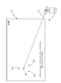
図1は、胴体部2のサーモグラフィ撮像のためのシステムのいくつかの構成要素を示すブロック図である。この赤外線サーモグラフィ検査システムは、検査されている表面に隣接して囲いを形成するように設計されたフード12内のカメラレンズ開口部5を通る方向に向けられたレンズを有するデジタル赤外線カメラ4を備える。1対のフラッシュランプ6a、6bが、フード12の内部に、フード12に対する固定された空間関係で配置されている。フラッシュランプ6a、6bは、赤外線カメラ4の動作も制御する赤外線サーモグラフィ処理制御コンピュータ(以下、「赤外線サーモグラフィコンピュータ8」という)からのトリガ信号に応答して、フラッシュ光を発する。本明細書で開示される実施形態の少なくともいくつかにおける使用に適したタイプの赤外線カメラ4の一例は、分光放射計として機能するように構成された焦点面アレイ(FPA)デバイスを含む。赤外線カメラ、1対のフラッシュランプおよびフードを備えるタイプのフラッシュランプアセンブリに含まれ得る他の構成要素に関するさらなる詳細は、例えば、米国特許第7,186,981号に見出すことができる。
FIG. 1 is a block diagram showing some components of a system for thermographic imaging of
サーモグラフィ検査の1つの方法によれば、最初に、フラッシュランプ6aおよび6bがトリガされて、胴体部2の複合材料に熱を伝達する。好ましくは、複合材料の冷却中、赤外線カメラ4は、胴体部2の加熱された部分の変化するスペクトル放射輝度の連続的なデジタル画像を取得するために、周期的にトリガされる。好ましくは、検査されている複合材料の熱的に励起された(加熱された)領域は、サンプルがその周囲と熱平衡に達するまで、励起源が除去された後に単調に冷却する。赤外線カメラ4によって取得されたデジタル赤外線画像データは、赤外線サーモグラフィコンピュータ8で受信されて処理される。赤外線サーモグラフィコンピュータ8は、赤外線画像データを処理して、材料の縁部、材料の表面下の異物、または層間剥離および許容範囲外の気孔率などの他の材料異常を検出および位置特定するようにプログラムされる。赤外線画像データは、赤外線サーモグラフィコンピュータ8と一体化されていてもよいし、別であってもよいディスプレイモニタ(図1には図示せず)上に表示されてもよい。
According to one method of thermographic inspection, first the
図1に示す実施形態によれば、赤外線サーモグラフィコンピュータ8は、赤外線カメラ4からの赤外線画像データを、赤外線サーモグラフィコンピュータ8が分析および数学的に操作できるフォーマットに変換するデジタル画像取得性能を有することができる。任意選択のデータ取得モジュール10が、赤外線サーモグラフィコンピュータ8に組み込まれてもよいし、別であってもよい(図1に示されるように)。データ取得モジュール10は、複合構造体の表面の完全な画像が単一の画像フレームに収まるには大き過ぎるときに、複合構造体の表面の完全なモザイク画像を生成するために、赤外線カメラ4が、複数の空間的に異なる画像を取得する場合に、使用することができる。赤外線サーモグラフィコンピュータ8は、赤外線カメラ4によって取得された赤外線画像データを分析するように、さらにプログラムされてもよい。詳細には、胴体部2が室温に戻るときの胴体部2の表面温度応答の時間履歴を分析して、複合材料内の欠陥の存在を検出することができる。
According to the embodiment shown in FIG. 1, the infrared thermographic computer 8 has digital image acquisition capability to convert infrared image data from the
胴体部を検査する特定の用途に関連して、非破壊検査システムは、胴体部の外部の見晴らしの利く位置から胴体部のスキンをスキャンするための手段を含むことができる。以下に開示される実施形態において、外部スキャン手段は、赤外線カメラを備えたロボットを含む。ロボットは、可動ロボットベースと、ロボットベースに結合された近位端を有するロボットアームとを備える。ロボットベースは、可動ホロノミッククローラ車両であってもよい。赤外線サーモグラフィスキャナが、ロボットアームの遠位端に結合される。赤外線サーモグラフィスキャナは、赤外線カメラと、フード内に取り付けられた2つ以上のフラッシュランプとを含む。フードは、胴体部の外面上の矩形領域を覆うようなサイズにすることができる。隣接する矩形領域から取得された赤外線画像データは、局所測位システムを用いたロボットベースのそれぞれのロケーションの測定値に基づいてスティッチングすることができる。スティッチングプロセスは、リアルタイムに実行されてもよいし、後で実行されてもよい。 In relation to a particular application for inspecting the torso, the non-destructive inspection system can include means for scanning the skin of the torso from a location outside the torso of the torso. In the embodiments disclosed below, the external scanning means comprises a robot equipped with an infrared camera. The robot comprises a movable robot base and a robot arm having a proximal end coupled to the robot base. The robot base may be a mobile holonomic crawler vehicle. An infrared thermographic scanner is coupled to the distal end of the robotic arm. An infrared thermographic scanner includes an infrared camera and two or more flash lamps mounted in a hood. The hood can be sized to cover a rectangular area on the outer surface of the torso. Infrared image data acquired from adjacent rectangular regions can be stitched based on measurements of each location of the robot base using a local positioning system. The stitching process may be performed in real time or may be performed later.
本明細書に開示されるロケーションアラインメントフィードバックのコンセプトを使用するように構成されたNDIシステムの様々な実施形態を、ここで、いくらか詳細に説明する。いくつかの実施形態によれば、NDIシステムは、飛行機のいずれの側からも胴体の上部および下部の中心線に届くことができるエンドエフェクタを備えた自動化されたプラットフォームである。このNDIシステムは、メカナムホイールホロノミックモーションベースプラットフォームと、ベースプラットフォームによって運ばれる垂直な伸長マストと、旋回エンドエフェクタと、近接センサと、エンドエフェクタに取り付けられた複数のタイプのNDIデバイスの支持体とを備える。伸長アームに旋回エンドエフェクタを備えた垂直な支持マストは、飛行機胴体部の全高の検査を可能にする。ホロノミックモーションベースプラットフォームにより、ロボットは、胴体の長さに沿ってNDIスキャナユニットを迅速かつ効率的に再配置することができる。距離センサのフィードバックを伴うモーション制御ソフトウェアにより、グリッドパターンスキャンをオーバラップさせる自動取得が可能になる。NDIスキャンを適切な飛行機座標系とアラインメントさせるために、基準位置データも取得される。このシステムは、自動または手動の制御モードのいずれにおいても、セットアップおよび使用するのが比較的容易である。渦電流、超音波、赤外線サーモグラフィ(IRT)NDIセンサを含む、エンドエフェクタに取り付けられた様々なタイプのNDIユニットを受け入れるように、このシステムは構成できる。 Various embodiments of the NDI system configured to use the location alignment feedback concept disclosed herein will now be described in some detail. According to some embodiments, the NDI system is an automated platform with end effectors that can reach the top and bottom centerlines of the torso from either side of the aircraft. The NDI system includes a Mecanum wheel holonomic motion based platform, a vertical extension mast carried by the base platform, a pivoting end effector, a proximity sensor, and a support for multiple types of NDI devices attached to the end effector. Equipped with A vertical support mast with a pivoting end effector on the extension arm allows inspection of the full height of the aircraft fuselage. The holonomic motion based platform allows the robot to quickly and efficiently reposition the NDI scanner unit along the length of the torso. Motion control software with distance sensor feedback enables automatic acquisition to overlap grid pattern scans. Reference position data is also obtained to align the NDI scan with the appropriate plane coordinate system. This system is relatively easy to set up and use in either automatic or manual control mode. The system can be configured to accept various types of NDI units attached to the end effector, including eddy current, ultrasound, infrared thermography (IRT) NDI sensors.
図2は、一実施形態による地面上型のロボット式NDI可動プラットフォーム200の側面図を表す図である。このプラットフォームは、ホロノミックモーションベースプラットフォーム204、赤外線サーモグラフィ(IRT)スキャナ214、およびロボットコントローラ(図示せず)の制御下にある(ホロノミックモーションベースプラットフォーム204によって運ばれる)自動スキャナ支持装置を備える。自動スキャナ支持装置は、IRTスキャナ214の高さを変更するために必要に応じて伸長および格納させることができる垂直な伸長可能マスト206を含む。垂直な伸長可能マスト206は、直線軸とホロノミックモーションベースプラットフォーム204に固定的に結合された1つの端部とを有する第1のマスト部206aと、直線軸を有し、第1のマスト部206aの軸に平行な線に沿ってスライドするように、第1のマスト部206aにスライド可能に結合された第2のマスト部206bと、直線軸を有し、第2のマスト部206bの軸に平行な線に沿ってスライドするように、第2のマスト部206bにスライド可能に結合された第3のマスト部206cとを備えている。1つの実施態様によれば、マストの垂直伸長部は、単一のモータとケーブルプーリーシステムによって制御される。
FIG. 2 is a diagram depicting a side view of an on-the-ground robotic NDI
図2に示す地面上型のロボット式NDI可動プラットフォーム200は、4バー連結機構の遠位端に旋回可能に結合されたエンドエフェクタ212の位置および向きを制御するための4バー連結アーム機構208を、さらに備える。4バー連結機構208のドライバリンクは、モータ駆動のリードスクリューまたは油圧シリンダ210によって第3のマスト部206cに対して回転するように駆動される。IRTスキャナ214は、エンドエフェクタ212に取り付けられ、エンドエフェクタ212と共に回転する。IRTシュラウド216は、IRTスキャナ214を取り囲み、IRTスキャナ214と湾曲したワークピース202(例えば、胴体部)との間の空間の容積を周囲環境から隔離する。
The on-the-ground robotic NDI
図3は、別の実施形態による地面上型のロボット式NDI可動プラットフォーム220の側面図を表す図である。この実施形態は、垂直な伸長可能マスト206と、第3のマスト部206cに固定的に結合された剛性の伸長アーム222と、剛性の伸長アーム222の2つの側面の遠位端に旋回可能に結合されたエンドエフェクタ224とを備える。図4は、図3に示すロボット式NDI可動プラットフォーム220のいくつかの構成要素の分解図を表す図である。この実施形態は、伸長高さ、およびエンドエフェクタのピッチに対して独立したプログラム可能な制御を有する。エンドエフェクタ224のピッチ回転は、非バック駆動可能ギヤボックス(図示せず)を備えた位置制御モータ246(図4参照)によって駆動することができる。
FIG. 3 is a diagram depicting a side view of an on-the-ground robotic NDI
図5は、複合材料で作られた湾曲したワークピース202をスキャンするプロセスにおける地面上型のロボット式NDI可動プラットフォーム230のプロトタイプの斜視図を表す図である。IRTスキャナ214が、エンドエフェクタ224に取り付けられ、エンドエフェクタ224は、ロボットコントローラ80の制御下で、ピッチ軸の周りに旋回可能である。エンドエフェクタ224は、垂直な伸長可能マスト206の最上マスト部に固定的に結合されている剛性の伸長アーム232に旋回可能に結合されている。IRTスキャナ214は、取得したデータを電気ケーブル242を介して赤外線サーモグラフィコンピュータ(図5には図示せず)に送信する。ロボット式NDI可動プラットフォーム230はまた、システムが作動されたときにオンとオフとを切り替える警告灯244を備えている。
FIG. 5 is a diagram depicting a perspective view of a prototype of a robot-on-the-ground robotic NDI
1つの提案された実施態様によれば、ホロノミックモーションベースプラットフォーム204は、一方の対角線にタイプAの対を、他方にタイプBの対を配置した4つのメカナムホイールを使用する。タイプAのメカナムホイールは、タイプBのメカナムホイールとは、前者のテーパーローラが後者のテーパーローラとは異なる角度で配向されている点で異なる。各メカナムホイールは、それぞれの独立して制御されるステッピングモータによって駆動され回転することができる。メカナムホイール車両は、各車輪の回転速度と回転方向を制御することによって、任意の方向に移動させ、回転させることができる。例えば、4つの車輪をすべて同じ速度で同じ方向に回転させると、前方または後方への動きが引き起こされる。一方の側の車輪を同じ速度で回転させるが、他方の側の車輪による回転の反対方向に回転させると、車両が回転する。タイプAの車輪を同じ速度で回転させるが、タイプBの車輪の回転の反対方向に回転させると、横方向への動きが引き起こされる。ホロノミックモーションベースプラットフォーム204は、車載制御コンピュータ(すなわちロボットコントローラ)の制御下で移動する。適切なメカナムホイールホロノミックモーションベースプラットフォームの構造および機能が、米国特許第9,410,659号に記載されており、その開示は、参照によりその全体が本明細書に組み込まれる。
According to one proposed embodiment, the holonomic motion based
一実施形態によれば、多数のセンサ(図5には図示せず)が、車両の特定の領域に障害物が存在することを示すために、ホロノミックモーションベースプラットフォーム204の周囲に取り付けられる。モーションコントローラは、そのセンサデータを使用して、その特定のセンサに関連付けられた方向に追加のモーションが発生するのをブロックするが、他の方向のモーションは、引き続き許可される。潜在的なセンサには、接触センサ、スルービームセンサ、および近接センサが含まれる。この衝突回避システムは、米国特許第7,194,358号に記載されているものと同様の方法で動作する。
According to one embodiment, a number of sensors (not shown in FIG. 5) are mounted around the holonomic motion based
前述したように、本明細書に開示されているロケーションアラインメントフィードバックプロセスは、距離センサを使用して、目標物(例えば、ワークピース202)に対するIRTスキャナ214の位置および向き(すなわち、ロケーション)を決定する。相対ロケーションをリアルタイムで計算するために、少なくとも3つの非共線距離測定デバイスを使用することができる。目標物の表面を傷つける可能性を軽減するために、距離センサとして使用するために、接触プローブの代わりにレーザ距離計が選択された。近距離の距離および角度の案内に加えて、レーザ距離計は、一般的なナビゲーション目的のために、プラットフォームモーションコントローラへの長距離の距離フィードバックの利点も提供する。
As mentioned above, the location alignment feedback process disclosed herein uses a distance sensor to determine the position and orientation (ie, location) of
一実施態様によれば、3つのレーザ距離計(図5には図示せず)が、エンドエフェクタ224に取り付けられている。図6は、図5に示されるロボット式NDI可動プラットフォームの一部分の側面図を表す図であり、この部分は、エンドエフェクタ224と、エンドエフェクタ224に取り付けられた3つのレーザ距離計とを含む。3つのレーザ距離計のうち2つのみ(すなわち、レーザ距離計236および238)が、図6に見える。第3のレーザ距離計(すなわち、レーザ距離計240)は、図7に見える。図6に示すように、第1のレーザ距離計236は、エンドエフェクタ224に取り付けられたL字形の取付板218aに取り付けられている。同様に、第2のレーザ距離計238は、エンドエフェクタ224に取り付けられたL字形の取付板218b(図6および図7に示す)に取り付けられており、第3のレーザ距離計240は、エンドエフェクタ224に取り付けられたL字形の取付板218c(図7に示す)に取り付けられている。
According to one embodiment, three laser rangefinders (not shown in FIG. 5) are attached to the
図7は、剛性の伸長アーム232に旋回可能に結合されているエンドエフェクタ224に取り付けられたIRTスキャナ214(シュラウド216が取り外されている)の斜視図を表す図である。前述のように、レーザ距離計236,238および240が、エンドエフェクタ224に取り付けられている。図8の正面図に最もよく示されているように、レーザ距離計236は、IRTスキャナ214のフード12の最も高い点の高さよりも高い高さに取り付けられ、一方、レーザ距離計238および240は、IRTスキャナ214のフード12の最も低い点の高さよりも低い高さに取り付けられ、ある距離だけ離れている。好ましくは、レーザ距離計236,238および240は、二等辺三角形の頂点に配置される。図15Aは、レーザ距離計238と240を隔てる距離(すなわち、二等辺三角形の底辺)がaであり、レーザ距離計236と、レーザ距離計238と240との間の中間点とを隔てる距離(すなわち、二等辺三角形の高さ)がbである、配置を示す。
FIG. 7 depicts a perspective view of the IRT scanner 214 (with the
図5〜図7に示すシステムは、オンボードアラインメントシステムを使用して、目標物に対するエンドエフェクタ224の相対ロケーション(位置および向き)オフセットを決定する。このプロセスは、レーザ距離計236,238および240からの距離情報を使用して、リアルタイムで相対ロケーションを計算する。次いで、システムは、そのデータをロボットコントローラに提供して、所望のフィードバックに基づくエンドエフェクタ224のモーションを生成する(ロボットの他の部分のモーション制御を含んでもよい)。
The system shown in FIGS. 5-7 uses an on-board alignment system to determine the relative location (position and orientation) offset of the
このプロセスが可能にする制御の1つの形態は、エンドエフェクタ224の向きが目標物の表面に対して常に垂直であるようにする、または常に表面から特定の距離であるようにするエンドエフェクタ224の向きなどのアラインメントのある態様において、オペレータを補助するための半自動制御である。
One form of control that this process allows is to ensure that the orientation of the
図9は、いくつかの実施形態によるアラインメントシステムのいくつかの構成要素を示すブロック図である。距離センサ14(例えば、レーザ距離計236,238,240)が、距離情報をコンピュータ16(例えば、ロボットコントローラ)に提供する。コンピュータ16は、距離センサ14から受信した距離情報に基づいてエンドエフェクタ224を目標物の表面とアラインメントさせる動作を決定するように構成されている(例えば、プログラムされている)。これらの動作は、ホロノミックモーションベースプラットフォーム204を新しいロケーションに移動させることと、垂直な伸長可能マスト206を伸長または格納させることと、エンドエフェクタ224をピッチ軸の周りに旋回させることと、のうちの1つ以上を含み得る。ロボット式NDI可動プラットフォームは、それぞれのモータコントローラ18によって制御される多数のモータ20を備える。コンピュータ16は、選択されたモータコントローラ18にコマンド信号を送り、エンドエフェクタ224を目標物の表面とアラインメントさせるようにロボットの動作を作動させる。
FIG. 9 is a block diagram illustrating some components of an alignment system according to some embodiments. Distance sensors 14 (e.g.,
このプロセスによって可能になる制御の別の形態は、オペレータがm x nグリッドパターンなどの高いレベルの目標を指定し、次に自動コントローラが高いレベルの目標とアラインメントシステムからのフィードバックに基づいてモーション計画を行なう完全自動化されたモーション制御である。例えば、図10は、大型のワークピースのIRT検査のための3×2スキャンパターン22を表す図である。まず、IRTスキャナは、スキャン領域26aのIRTデータを取得する。その後、IRTスキャナは、上方に移動し、スキャン領域26bのIRTデータを取得するロケーションで停止する。好ましくは、スキャン領域26bは、スキャン領域26aとわずかにオーバラップして、スキャンをスティッチングすることを容易にし、カバー範囲に隙間がないことを保証する。次に、IRTスキャナは、右に移動し、スキャン領域26cのIRTデータを取得するロケーションで停止する。次に、IRTスキャナは、下方に移動し、スキャン領域26dのIRTデータを取得するロケーションで停止し、続いてスキャン領域26eのIRTデータを取得するために右に移動し、次いでスキャン領域26fのIRTデータを取得するために上方に移動する。このプロセス中のIRTスキャナのスキャン経路28が、図10に矢印で示されている。
Another form of control enabled by this process is that the operator specifies a high level target, such as an m by n grid pattern, and then the automatic controller uses a high level target and a motion plan based on feedback from the alignment system. Fully automated motion control. For example, FIG. 10 is a diagram depicting a 3 × 2
アライメントプロセスは、ロボットの個々のモーションを直接プログラミングすることに対する代替手段を提供する。また、システムが予期せぬ環境の変化に適応することも可能になり、エンドエフェクタが目標表面に接触しないで目標表面に対する所望の位置および向きを達成するための衝突回避能力も提供する。 The alignment process provides an alternative to directly programming the individual motions of the robot. It also allows the system to adapt to unexpected environmental changes, and also provides collision avoidance capabilities to achieve the desired position and orientation with respect to the target surface without the end effector contacting the target surface.
ここで使用される自動化されたプロセスは、外部入力に基づいてある状態から別の状態への遷移を管理する有限状態機械制御アプリケーションに基づいている。このフレームワークにより、システムは、複数のタイプの入力とシステムの現在の状態に基づいて応答を生成することができる。自動的に生成されたモーション経路計画およびスキャナ制御信号を生成するために使用されるシステムの様々な動作は、ある作業モードと別の作業モードとの間の遷移の基準を満たすことに基づいている。一実施形態によれば、有限状態機械は、センサフィードバックを使用して、システム状態の別々のセット間の遷移をトリガする。 The automated process used herein is based on a finite state machine control application that manages transitions from one state to another based on external inputs. This framework allows the system to generate responses based on multiple types of inputs and the current state of the system. The various operations of the system used to generate automatically generated motion path planning and scanner control signals are based on meeting criteria for transitions between one work mode and another work mode . According to one embodiment, the finite state machine uses sensor feedback to trigger transitions between different sets of system states.
次に、そのプロセスが、遠位端にNDIセンサ(例えば、IRTスキャナ)を有するロボットアームを運ぶベースプラットフォーム(例えば、ホロノミックモーションベースプラットフォーム)を備え、ベースプラットフォームおよびロボットアームの動きが、デバイスコントローラ(例えば、ロボットコントローラ)によって制御される、ロボット式NDI可動プラットフォームを参照して説明される。図11は、システムの作業全体の高いレベルのプロセスを示し、図11Aおよび図11Bは、プロセスのアラインメントベースの態様に関連する詳細を示す。ロボットコントローラとNDIセンサ制御コンピュータ(例えば、図1に示す赤外線サーモグラフィコンピュータ8)との間で送られるデジタル信号が、別個のロボットシステムとNDIセンサシステムとの間の同期を可能にする。 Then, the process comprises a base platform (e.g. a holonomic motion based platform) carrying a robotic arm with an NDI sensor (e.g. an IRT scanner) at its distal end, the movement of the base platform and the robotic arm being a device controller ( For example, it will be described with reference to a robotic NDI mobile platform controlled by a robot controller). FIG. 11 shows a high level process of the overall operation of the system, and FIGS. 11A and 11B show the details associated with the alignment based aspect of the process. Digital signals sent between the robot controller and the NDI sensor control computer (e.g., the infrared thermographic computer 8 shown in FIG. 1) enable synchronization between the separate robot system and the NDI sensor system.
図11は、一実施形態によるエンドエフェクタアラインメントプロセスを使用する非破壊検査の方法100のいくつかのステップを示す。プロセスを開始するために、システムオペレータが、目標物に対するNDIセンサの第1のロケーションを特定する(ステップ102)。このステップは、視覚的方法(オペレータによる)によって、または自動的に(LPSのようなポインティングシステムを用いて)行うことができる。次に、システムオペレータは、ベースプラットフォームおよびロボットアームを操作して、NDIセンサをおおよそ第1のロケーションに移動させることができる(ステップ104)。システムオペレータは、ステップ106において、パターンにおける所望のスキャン数をデバイスコントローラに提供する。この数は、グリッドロケーションカウンタに格納されたカウントと比較され、このカウンタは、パターンにおけるスキャンが取得されるたびに、インクリメントされる。ステップ108において、デバイスコントローラは、予備的経路パラメータを計算し、自動スキャン取得を開始する。システムオペレータはさらに、近接/衝突検出を作動させる(ステップ110)。次に、システムオペレータは、外部追跡システム(例えば、LPS)を使用して、第1のロケーションの3次元座標を取得する(ステップ112)。(外部追跡システムは、目標物の座標系に対するそれ自身の3次元座標が既知であるように、予め較正されており、これにより、LPSコンピュータは、目標物の座標系に対する第1のロケーションの3次元座標を計算することができる。)その後、アラインメントプロセス中およびスキャンプロセス中にNDIセンサのモーションを制御するための有限状態機械が、イネーブルされる(ステップ114)(すなわち、図11AのAに進む)。(有限状態機械については、図11Aおよび図11Bを参照して、次のパラグラフで説明する。)NDIセンサがアラインメントされ、スキャンパターンが完了した後、システムオペレータは、外部追跡システムを使用してNDIセンサの終了ロケーションの3次元座標を取得する(ステップ116)。次いで、隣接するスキャンからのスキャンデータをスティッチングすることにより、組み合わされた画像を組み立てることができる(ステップ118)。
FIG. 11 illustrates some steps of a
図11Aおよび図11Bは(一緒に)、図11の高いレベルで示された方法で使用される有限状態機械によって実行されるいくつかのステップを特定するフローチャートを形成する。有限状態機械は、任意の与えられた時点に有限個の状態のうちの1つの状態しかとれないプロセスの数学的モデルである。 11A and 11B (together) form a flow chart identifying some steps performed by the finite state machine used in the method illustrated at the high level of FIG. A finite state machine is a mathematical model of a process that can only take one of a finite number of states at any given time.
1つの提案された実施態様によれば、ロボットコントローラは、有限状態機械(FSM)がGRID_MOVE状態にセットされているか否かを、最初にチェックする(すなわち判定する)(ステップ120)。GRID_MOVEは、ロボットが、高いレベルで定義されたグリッドロケーション間を移動している状態である。例えば、システムオペレータが、システムに、3×2パターンでデータを取得することを望む場合、ロボットは、連続したグリッドを作るために、図10に示すスキャン経路28に沿って移動する。ステップ120において、ロボットコントローラが、FSMがGRID_MOVE状態にないと判定した場合、ロボットコントローラは、ステップ128に直接進む。ステップ120において、ロボットコントローラが、FSMがGRID−MOVE状態にあると判定した場合、ロボットコントローラは、シーケンス内に追加のグリッドロケーションがあるかどうかを判定する(ステップ122)。これは、グリッドロケーションカウンタの現在のカウントを、予めセットされた取得すべきスキャン数と比較することによって達成される。ステップ122において、ロボットコントローラが、シーケンス内に追加のグリッドロケーションがない(すなわち、カウントが、予めセットされた数に等しい)と判定した場合、プロセスは、図11のステップ116に戻る。ステップ122において、ロボットコントローラが、シーケンス内に追加のグリッドロケーションがある(すなわち、カウントが、予めセットされた数より小さい)と判定した場合、ロボットは、アラインメントされていないNDIセンサの次のロケーションに移動し(ステップ124)、その後、有限状態機械の状態が、ALIGNにセットされる(ステップ126)。次のステップで、ロボットコントローラは、有限状態機械がALIGN状態にセットされているか否かを判定する(ステップ128)。
According to one proposed embodiment, the robot controller first checks (ie determines) if the finite state machine (FSM) is set to the GRID_MOVE state (step 120). GRID_MOVE is a state in which the robot is moving between grid locations defined at a high level. For example, if the system operator wants the system to acquire data in a 3 × 2 pattern, the robot moves along a
ALIGN状態は、ロボットが3つの距離センサを使用して、エンドエフェクタのピッチおよびヨーが、NDIスキャナの目的軸が目標物の表面に対して垂直になるようになっていることを保証しているときである。ステップ128において、有限状態機械がALIGN状態にないとロボットコントローラが判定した場合、ロボットコントローラは、図11Bのステップ144に直接進む。ステップ128において、有限状態機械がALIGN状態にあるとロボットコントローラが判定した場合、ロボットコントローラは、NDIセンサのロケーションを精緻化する必要があるか否かを判定する(ステップ130)。ステップ130において、ロボットコントローラが、NDIセンサのロケーションを精緻化する必要がない(すなわち、NDIスキャナの目的軸が、目標物の表面に対して垂直である)と判定した場合、ロボットコントローラは、有限状態機械の状態をSCANにセットし(ステップ132)、図11Bのステップ144に直接進む。ステップ130において、ロボットコントローラが、NDIセンサのロケーションを精緻化する必要がある(すなわち、NDIスキャナの目的軸が、目標物の表面に対して垂直でない)と判定した場合、ロボットコントローラは、以下のステップを順番に実行する:(A)距離センサから距離データを取得する(ステップ134)。(b)所望のアラインメントされたロケーションからの向きオフセットおよび並進オフセットを計算する(ステップ136)。(c)距離を所望のオフセットにアラインメントさせる(ステップ138)。(d)エンドエフェクタのヨー角をアラインメントさせて、目標物の表面に対する垂直を達成し、横方向位置を調整する(ステップ140)。(e)エンドエフェクタのピッチ角をアラインメントさせて、目標物の表面に対する垂直を達成し、高さを調整する(ステップ142)。(f)ステップ130に戻る。
The ALIGN state ensures that the robot uses three distance sensors so that the pitch and yaw of the end effector are such that the target axis of the NDI scanner is perpendicular to the surface of the target It is time. If at
前述したように、ロボットコントローラが、ステップ130において、NDIセンサのロケーションを精緻化する必要がないと判定した場合、ロボットコントローラは、有限状態機械の状態をSCANにセットし(ステップ132)、図11Bのステップ144に直接進む。ステップ144において、ロボットコントローラは、有限状態機械がALIGN状態にセットされているか否かを判定する。ステップ144において、有限状態機械がSCAN状態にないとロボットコントローラが判定した場合、ロボットコントローラは、図11Aのステップ120に戻る。ステップ144において、有限状態機械がSCAN状態であるとロボットコントローラが判定した場合、ロボットコントローラは、スキャナ制御コマンドをNDIスキャナ制御コンピュータ(例えば、図1に示された赤外線サーモグラフィコンピュータ8)に送信する(ステップ146)。次いで、ロボットコントローラは、スキャナ応答をチェックし(ステップ148)、スキャンパターンが完了したか否かを判定する(ステップ150)。ステップ150で、スキャンパターンが完了していないとロボットコントローラが判定した場合、ロボットコントローラは、ステップ148に戻る。ステップ150において、ロボットコントローラが、スキャンパターンが完了したと判定した場合、ロボットコントローラは、以下のステップを順番に実行する:(a)NDIスキャナをそのロケーションに戻す(ステップ152)。(b)有限状態機械の状態をGRID_MOVEにセットする。(c)グリッドロケーションカウンタをインクリメントする。(d)図11のステップ114に戻る。
As described above, if the robot controller determines in
自動スキャンシーケンスが完了した後に、各IRTスキャンからの個々の画像をスティッチングして、検査領域の単一の表現を作成することができる。 After the auto scan sequence is complete, the individual images from each IRT scan can be stitched to create a single representation of the examination area.
上述のシステムは、ロボットマニピュレータまたは他のデバイスの一般的なアラインメントタスクのための多くの潜在的な使用事例を有し得る。これらの使用事例の1つは、飛行機胴体のグリッドベースのスキャンなどの、航空宇宙製造および保守環境におけるグリッドベースのNDIスキャン取得に対するものである。 The system described above may have many potential use cases for the general alignment task of robotic manipulators or other devices. One of these use cases is for grid-based NDI scan acquisition in aerospace manufacturing and maintenance environments, such as a grid-based scan of an aircraft fuselage.
典型的な動作中、このシステムは、ユーザによっておおよそ第1のロケーションに駆動(遠隔操作)されることができ、その後、図10に示すように、飛行機胴体の両側に沿ってオペレータ定義の垂直および水平のパターンで配置されたグリッドスキャンを自動的に取得するように設定される。 During typical operation, the system can be driven (remotely controlled) by the user to approximately the first location, and then, as shown in FIG. It is set to automatically acquire grid scans arranged in a horizontal pattern.
モーション制御アルゴリズムの自動グリッドスキャンの特徴は、3つのレーザ距離計236,238および240からの距離データをモーション制御アルゴリズムにフィードバックし、それぞれプラットフォーム204およびエンドエフェクタ224の水平および垂直配置、ならびにヨーおよびピッチの向きを設定することを含む。このアプローチにより、システムのための個別の事前定義されたモーション経路が不要になり、使用が簡単になり、セットアップ時間が短縮される。
The automatic grid scan feature of the motion control algorithm feeds distance data from the three
システムは、オペレータが手動でデータを取得することができるように、遠隔操作モードで十分に制御することもできる。半自動モードも可能であり、このモードでは、システムオペレータが、プラットフォームのロケーションとマストの高さを制御し、システムは、エンドエフェクタのピッチの向きを自動的に調整して、その前の表面との垂直なアラインメントを維持する。 The system can also be fully controlled in the remote control mode so that the operator can obtain data manually. A semi-automatic mode is also possible, in which the system operator controls the platform location and height of the mast, and the system automatically adjusts the end effector's pitch orientation to that of the front surface. Maintain vertical alignment.
飛行機の座標系においてスキャンを正しく位置特定するために、スキャンの境界領域の3次元座標位置測定が行われる。この境界参照は、組み合わされたスキャン画像を、目標物およびそれに関連するCADモデルと同じ座標系に配置することを可能にする。これにより、取得されたスキャンと目標物のそれぞれの3次元モデルとの関連付けが可能になり、将来の参照のためのロケーションデータが提供される。このシステムでは、目標物54の座標系における3次元座標位置データを取得するために、局所測位システム(LPS)24(図12に示す)が使用される。例えば、図12は、測定される境界位置60にレーザビーム30を向けるLPS24を示す。LPS24が、目標物54の座標系に対してすでに較正されていると仮定すると、LPS24によって取得された境界位置データ点を使用して、目標物54の座標系における各境界位置の座標を決定することができる。
In order to correctly locate the scan in the plane's coordinate system, a three-dimensional coordinate location measurement of the border area of the scan is performed. This boundary reference allows the combined scan image to be placed in the same coordinate system as the target and its associated CAD model. This allows association of the acquired scan with the respective three-dimensional model of the target, and provides location data for future reference. In this system, a local positioning system (LPS) 24 (shown in FIG. 12) is used to obtain three-dimensional coordinate position data in the coordinate system of the
一実施形態によれば、IRTスキャナ214(図5および図8参照)が、特定のロケーションのスキャンデータを取得しているときに、IRTシュラウド216のコーナーをターゲットにすることによって、スキャンの境界の取得を達成することができる。これらのLPS境界測定は、最初のスキャンの前と最後のスキャンの後、またはグリッドシーケンスの任意の中間ロケーションで実行される。1つの提案された実施態様によれば、IRTシュラウド216のコーナー(またはいくつかの既知のロケーション)は、アクティブ(例えば、LED)もしくはパッシブ光学ターゲットのいずれか、または他の可視的特徴を有することができる。パッシブアプローチでは、システムオペレータは、これらの点をターゲットにするために、LPS24を使用する必要がある。アクティブLEDターゲットを使用すると、LPSカメラを使用してLEDを検出する自動アプローチが可能になる。理想的には、スキャン領域の4つのコーナーをすべて取得することが最も好ましいが、IRTシュラウド216が、光学ターゲットを遮断することがあり、それによって、ターゲットにすることが難しくなる。プロセスのこの部分に必要な光学ターゲットの最小数は、2であるが、これは、例えば、目標物の3次元CADモデルからの表面法線を使用して、X×Yスキャン領域の形状について仮定を行うことができるからである。
According to one embodiment, by targeting the corners of the
LPS24の電動パンチルト制御の態様は、LPS24が、スキャンのための所望の第1のロケーションを示すための初期ロケーション参照および案内機能を提供することも可能にする。LPS24を目標物上の既知のロケーションに対して最初に較正した後、オペレータは、LPS24に、そのレーザポインタを目標表面上の指定された3次元座標に向けるように指示することができ、そのレーザスポット38が、図13に示されている。次いで、オペレータは、ロボットを駆動して、図13に示すように、それぞれレーザ距離計236,238および240のレーザスポット32a、32bおよび32cを、LPSレーザスポット38の周りにアラインメントさせる。
The motorized pan-tilt control aspect of the
LPS24を使用して、目標物54(例えば、飛行機)の座標系における測定値を取得するために、システムオペレータは、目標物上の3つの既知の点を使用する。これらの3つの点は、スキャン登録プロセスのために測定されたIRTシュラウド216上の点とは別個の較正点である。つまり、スキャンデータを飛行機座標とアラインメントさせたい場合、LPS測定の最小総数は5であり、最初のLPS較正のために3つ、スキャンが行われた矩形領域を画定するために2つである。
To use the
図14は、一実施形態による、ロボット対ターゲットの位置特定プロセスを実行することができるシステムの斜視図である。ロボット対ターゲットの位置特定プロセスは、制御可能なパンチルトユニット42上の単一のカメラ40およびレーザ距離計(図示せず)を備えるLPS24を使用して実行される。LPSの動作および較正プロセスは、米国特許第7,859,655号に開示されており、その開示は、参照によりその全体が本明細書に組み込まれる。
FIG. 14 is a perspective view of a system capable of performing a robot-to-target location process according to one embodiment. The robot-to-target location process is performed using a
より具体的には、図14に示す局所測位システムは、自動(遠隔制御)ズーム機能を有することができるビデオカメラ40を備える。ビデオカメラ40は、パンチルト機構42に支持されている。ビデオカメラ40およびパンチルト機構42は、LPS制御コンピュータ48によって動作させることができる。LPS制御コンピュータ48は、ビデオ/制御ケーブル46を介してビデオカメラ40およびパンチルト機構42と通信する。あるいは、LPS制御コンピュータ48は、無線通信経路(図示せず)を介してビデオカメラ40およびパンチルト機構42と通信してもよい。LPS制御コンピュータ48は、レーザ距離計(図示せず)、ビデオカメラ40およびパンチルト機構42を含むLPSハードウェアの動作を制御するように構成されている。例えば、パンチルト機構42のパンおよびチルト角、従ってビデオカメラ40の向きは、コンピュータ48のキーボードまたは他のユーザインターフェースハードウェア36(例えば、ゲームパッド)を用いて制御することができる。ビデオカメラ40によって見られる光学画像視野を、LPS制御コンピュータ48のモニタ33に表示することができる。
More specifically, the local positioning system shown in FIG. 14 includes a
パンチルト機構42は、レーザ距離計(図示せず)およびビデオカメラ40を、垂直の方位角(パン)軸および水平の仰角(チルト)軸の周りの選択された角度に回転調整するように、制御される。三脚44の固定座標系(またはパンチルトユニットが取り付けられている他のプラットフォーム)に対するレーザ距離計(図示せず)およびビデオカメラ40の向きを表す方向ベクトル66(図14に破線で示す)は、カメラが目標点に向けられるときのパン角およびチルト角から決定される。図14において、方向ベクトル66は、レーザ距離計(図示せず)およびビデオカメラ40から延び、シュラウド216の1つのコーナー上の点94aと交わる。
The pan and
レーザ距離計は、方向ベクトル66に沿ってレーザビームを送るように、カメラ40のハウジングの内部に組み込まれてもよく、またはカメラ40の外側に取り付けられてもよい。レーザ距離計は、シュラウド216上の任意の可視的特徴部(例えば、コーナー94a〜94cの1つ)までの距離、または湾曲したワークピース202上の任意の較正点(例えば、点92a〜92c)までの距離を測定するように構成される。(各較正点は、湾曲したワークピース202上の可視的特徴部であってもよいし、または湾曲したワークピース202に取り付けられた光学ターゲットであってもよい。)レーザ距離計は、レーザと、衝突点から反射されたレーザビームに応答して検出されたレーザ光に基づいて距離を計算するように構成されたユニットとを有することができる。
The laser rangefinder may be incorporated inside the housing of the
図14に示す局所測位システムは、LPS制御コンピュータ48にロードされる3次元位置特定ソフトウェアをさらに含む。例えば、3次元位置特定ソフトウェアは、湾曲したワークピース202上の複数の較正点92a〜92cを使用して、湾曲したワークピース202に対するビデオカメラ40のロケーション(位置および向き)を定めるタイプであってもよい。較正点92a〜92cは、特徴位置の3次元データベース(例えば、CADモデル)または他の測定技術から決定されるような、湾曲したワークピース202の局所座標系における既知の位置の可視的特徴部であってもよい。LPS較正プロセス中に、少なくとも3つの非共線点に関するX、Y、Zデータが、CADモデルから抽出される。典型的には、目標物上で容易に位置特定することができる特徴に対応する較正点が、選択される。3次元位置特定ソフトウェアは、較正点92a〜92cのX、Y、Zデータ、ならびにパンチルト機構42からのパンおよびチルトデータを利用して、湾曲したワークピース202の局所座標系に関するビデオカメラ40の相対位置および向きを定める。較正点92a〜92cまでの測定された距離が、湾曲したワークピース202に対するカメラの位置および向きを求めるために、パンチルト機構42からのパンおよびチルト角と連携して使用されてもよい。器具対ターゲットの較正変換行列(カメラ姿勢と呼ばれることもある)を生成する方法が、米国特許第7,859,655号に開示されている。既知のデータおよび測定データを用いて、較正プロセスは、湾曲したワークピース202に対するビデオカメラ40の位置および向きを定める4×4の同次変換行列を計算する。
The local positioning system shown in FIG. 14 further includes three-dimensional positioning software loaded into the
湾曲したワークピース202に対するビデオカメラ40の位置および向きが決定され、カメラ姿勢変換行列が生成されると、カメラパンデータ(方位角軸の周りのビデオカメラ40の回転角度)およびチルトデータ(仰角軸の周りのビデオカメラ40の回転角度)が、ビデオカメラ40の計算された位置および向きと共に使用されて、湾曲したワークピース202の座標系におけるシュラウド216上の任意の目標点のX、YおよびZ座標を決定することができる。スキャンパターンの始めと終わりにシュラウド216を位置特定することによって、湾曲したワークピース202の座標系におけるスキャンパターンのロケーションを決定することができる。
Once the position and orientation of the
より具体的には、相対位置特定プロセスを使用して、スキャンパターンの始めと終わりに湾曲したワークピース202の座標系におけるシュラウド216の可視的特徴部(例えば、図14に示すコーナー94a〜94cのいずれか1つ)のロケーションを決定することができる。シュラウド216に適用される基本的なプロセスシーケンスは、以下の通りである。(1)局所測位システムが、目標物上の3つの既知の点92a〜92cを測定することによって、検査されている目標物(例えば、湾曲したワークピース202)の座標系に対して較正される。(2)ロボットが、スキャンパターンの始め(例えば、図12に見られるスキャン領域26aに対して)にあるときに、局所測位システムが、シュラウド216上の可視的特徴部(例えば、コーナー94a)のロケーションを測定する。(3)その後、ロボットが、スキャンパターンの終わり(例えば、図12に見られるスキャン領域26fに対して)にあるときに、局所測位システムが使用されて、シュラウド216上の同じ可視的特徴部または異なる可視的特徴部(例えば、コーナー94bまたは94c)のロケーションを測定する。(4)これにより、オペレータは、モザイクパターンを構成するスキャンの境界を決定することができる。
More specifically, visible features of shroud 216 (e.g.,
コンピュータ48内で動作するLPS制御ソフトウェアが、湾曲したワークピース202の座標系に対するシュラウド216上の各可視的特徴部のロケーションを計算する。LPS制御コンピュータ48(図14参照)が、将来の参照のためにロケーション座標を記録するように構成されている、図17に示すエキスパートワークステーション74に、ロケーションデータを送信する。このロケーションデータを使用して、スキャンデータを目標物のCADモデルとアラインメントさせることもできる。
LPS control software operating within
コンピュータ48上のLPS制御ソフトウェアは、X、YおよびZ値として点データを出力するが、制御アプリケーションは、湾曲したワークピース202の位置および向きを提供するために、単なるX、YおよびZデータ点ではなく、それ以上を使用する。位置および向きの問題を解くために、3つの測定点92a〜92cからのX、YおよびZデータならびにこれらの点の既知の寸法を使用して、まるまる6自由度の位置および向きの表現を計算する。これを、前述の位置特定ソフトウェアが行う。位置特定ソフトウェアが使用する位置および向きのフォーマットは、4x4変換行列であるが、データを表す他の方法もある。
The LPS control software on the
システムオペレータが、(米国特許出願公開第2015/0268033号に記載されているような)相対的なLPSスキャンを実行したい場合、オペレータは、目標物上の任意の3つの非共線点を使用することができるが、それらの点の3次元座標を事前に知る(標準的なLPS法の場合に行うような)必要はない。システムオペレータは、相対的なモードを使用して目標物座標において結果を取得することはないであろうが、一部のアプリケーションでは、それは必要とされない。相対的なLPS位置特定プロセスは、NDIセンサが以前の状況と同じ領域にアラインメントされていることを保証するために、使用することができる。また、いくつかの別々のスキャンをつなぎ合わせる場合や、LPSを移動する必要がある場合に、便利である。 If the system operator wants to perform a relative LPS scan (as described in US Patent Application Publication No. 2015/0268033), the operator uses any three non-collinear points on the target It is possible, but it is not necessary to know in advance the 3D coordinates of those points (as in the case of the standard LPS method). The system operator will not obtain results in target coordinates using relative modes, but in some applications it is not required. The relative LPS localization process can be used to ensure that the NDI sensor is aligned to the same area as the previous situation. It is also useful when you need to combine several separate scans, or when you need to move the LPS.
先に開示したように、このシステムは、レーザ、ストリングエンコーダ、超音波センサなどの距離測定デバイスを使用し、少なくとも3つの非共線距離測定デバイスが、基本的な要件である。1つの距離センサ配置(上述)は、三角形構成に配置された3つの距離測定レーザを使用する。代替の実施形態では、4つの距離測定レーザが、矩形構成に配置されている。どのセンサ配置が使用されているかに関わらず、距離データが、エンドエフェクタの向きデータとともに、ロボットコントローラ80に供給される。フィードバック制御方法を使用して、現在の角度と所望の角度との間の誤差をゼロにすることができる。
As disclosed above, this system uses distance measuring devices such as lasers, string encoders, ultrasound sensors etc, and at least three non-collinear distance measuring devices are a basic requirement. One distance sensor arrangement (described above) uses three distance measuring lasers arranged in a triangular configuration. In an alternative embodiment, four distance measuring lasers are arranged in a rectangular configuration. Regardless of which sensor arrangement is used, distance data is provided to the
次に、レーザ距離計を用いて角度を決定する方法を、図15A〜図15Cを参照して説明する。図15A〜図15Cは、共通の平面に三角形のパターンで配置され、目標物54の表面上のそれぞれのスポットに向けられた3つのレーザ距離計236,238,240の、それぞれ正面図、側面図、上面図であり、レーザ距離計およびスポットは、それぞれの距離だけ離されている。
Next, a method of determining an angle using a laser range finder will be described with reference to FIGS. 15A to 15C. 15A-15C are front and side views, respectively, of three
ターゲットまでの距離を決定するために3つのレーザを使用することに加えて、それらはまた、ヨー角およびピッチ角を決定するためにも使用される。図15Aは、目標物54の表面までの測定距離d1、d2、d3とともに、横寸法aと縦寸法bを用いて、互いに対するレーザ距離計236,238,240の位置を示している。ピッチ角およびヨー角を計算するために、式(1)および式(2)を使用することができる。
PitchAngle = atan2(d1 - (d2 + d3)/2, b) (1)
YawAngle = atan2(d2 - d3, a) (2)
ここで、PitchAngleおよびYawAngleは、目標物54の表面に対する、図15A〜図15Cに示すアラインメント装置の現在の計算された角度である。現在のロケーションでの表面法線に対して測定されるこれらの角度の目標は、ゼロに等しくなることである。目標角度を達成するプロセスを以下に説明する。
In addition to using three lasers to determine the distance to the target, they are also used to determine the yaw angle and the pitch angle. FIG. 15A shows the position of the
PitchAngle = atan 2 (d 1- (d 2 + d 3 ) / 2, b) (1)
YawAngle = atan 2 (d 2 -d 3 , a) (2)
Here, PitchAngle and YawAngle are the current calculated angles of the alignment device shown in FIGS. 15A-15C with respect to the surface of the
現在のヨー角およびピッチ角を計算すると、システムモーションコントローラは、制御されたモーション、すなわちパン、チルト、および距離のために速度制御方法を使用することができる。比例積分微分(PID)コントローラなどのフィードバックコントローラを使用して、現在の角度と所望の角度との間の誤差をゼロにすることができる。ピッチおよびヨーモーション制御を計算するために、式(3)および(4)を使用することができる。
PitchRate = Kppitch * (PitchAngle - PitchAnglegoal) (3)
YawRate = Kpyaw * (YawAngle - YawAnglegoal) (4)
ここで、PitchRateおよびYawRateは、それぞれ、アラインメント装置のピッチ軸の周りおよびベースのヨー軸の周りの角回転速度を表す。KppitchおよびKpyawは、それぞれ、ピッチ軸およびヨー軸に関連する比例フィードバックゲインである。PitchAngleとYawAngleは、それぞれ、式(1)および式(2)から計算された角度である。PitchAnglegoalとYawAnglegoalは、それに向かってコントローラがシステムを駆動しているところの所望の目標角度である(前述のとおり、この例では両方ともゼロである)。積分および微分フィードバックも使用できるが、ここには示されていない。
Having calculated the current yaw and pitch angles, the system motion controller can use speed control methods for controlled motion, ie pan, tilt and distance. A feedback controller, such as a proportional integral derivative (PID) controller, can be used to null the error between the current angle and the desired angle. Equations (3) and (4) can be used to calculate pitch and yaw motion control.
PitchRate = Kp pitch * (PitchAngle-PitchAngle goal ) (3)
YawRate = Kp yaw * (YawAngle-YawAngle goal ) (4)
Here, PitchRate and YawRate represent angular rotational speeds around the alignment device's pitch axis and around the base's yaw axis, respectively. Kp pitch and Kp yaw are proportional feedback gains associated with the pitch and yaw axes, respectively. PitchAngle and YawAngle are angles calculated from Equation (1) and Equation (2), respectively. PitchAngle goal and YawAngle goal are the desired target angles towards which the controller is driving the system (as mentioned earlier, both are zero in this example). Integral and differential feedback can also be used, but are not shown here.
ベース速度の式は、次のとおりである。
Velx = Kpx * (MinDistx - offsetx) (5)
Vely = Kpy * (MinDisty - offsety) (6)
ここで、VelxとVelyは、ベースの横方向速度である。KpxおよびKpyは、それぞれ、ベースのX方向およびY方向の比例フィードバックゲインである。MinDistxおよびMinDistyは、それぞれ、X方向およびY方向にレーザによって測定された最小値である。offsetxとoffsetyは、目標オフセット距離である。一部のアプリケーションでは、レーザは、X方向とY方向の両方で測定するようには構成されていない。そのような場合には、アラインメントプロセスに関連するXまたはY速度制御式が、使用されない。
The equation for base speed is:
Vel x = Kp x * (MinDist x -offset x ) (5)
Vel y = Kp y * (MinDist y -offset y ) (6)
Here, Vel x and Vel y are the lateral velocity of the base. Kp x and Kp y are proportional feedback gains in the X and Y directions of the base, respectively. MinDist x and MinDist y are respectively the minimum values measured by the laser in the X and Y directions. offset x and offset y are target offset distances. In some applications, the laser is not configured to measure in both the X and Y directions. In such cases, the X or Y velocity control equation associated with the alignment process is not used.
ベースフレーム62と、一方の対角線に沿った1対のタイプAメカナムホイールW1およびW3と、他方の対角線に沿った1対のタイプBメカナムホイールW2およびW4とを備えるホロノミックモーションベースプラットフォームに対して、運動学を用いて、4つの個々の車輪速度を計算することができる。車両の寸法(LおよびD)および所望の回転点(距離a1、a2、b1、b2によって記述される)が、図16に示されている。車輪W1〜W4の個々の車輪速度は、式(7)〜(10)に示される。
VW1 = Vely - Velx + YawRate * (a1 + b1) (7)
VW2 = Vely + Velx - YawRate * (a1 + b2) (8)
VW3 = Vely - Velx - YawRate * (a2 + b2) (9)
VW4 = Vely + Velx + YawRate * (a2 + b1) (10)
ここで、VWi(i=1,2,3,4)は、個々の車輪速度である。VelxとVelyは、式(5)および式(6)からの横方向速度である。YawRateは、式(4)からのヨー回転速度である。a1、a2、b1、b2は、図16に示す回転点距離である。
For a holonomic motion based platform comprising a
V W1 = Vel y -Vel x + YawRate * (a 1 + b 1 ) (7)
V W2 = Vel y + Vel x -YawRate * (a 1 + b 2 ) (8)
V W3 = Vel y -Vel x -YawRate * (a 2 + b 2 ) (9)
V W4 = Vel y + Vel x + YawRate * (a 2 + b 1 ) (10)
Here, V Wi (i = 1, 2, 3, 4) is an individual wheel speed. Vel x and Vel y are the lateral velocities from Equation (5) and Equation (6). YawRate is the yaw rotational speed from equation (4). a 1 , a 2 , b 1 and b 2 are rotation point distances shown in FIG.
エンドエフェクタの主なピボット構成は、次のとおりである。(a)1軸ピボット:1つのモータ、1つの角度センサ、(b)2軸ジンバル:2つのモータ、2つの角度センサ。 The main pivot configuration of the end effector is as follows. (A) 1-axis pivot: 1 motor, 1 angle sensor, (b) 2 axis gimbal: 2 motors, 2 angle sensors.
上述のアラインメントプロセスは、離散的および連続的なセンサ更新の両方の使用事例に対処し、このコンセプトは、スタンドアロンシステムとしてまたは既存システムの一部として詰め込むこともできる。 The alignment process described above addresses both discrete and continuous sensor update use cases, and this concept can also be packaged as a standalone system or as part of an existing system.
本明細書に開示されたコンセプトは、ホロノミックモーションベースプラットフォームに適用されるが、変形例が、他のシステムにも適用可能である。潜在的な使用事例には、ホロノミックおよび非ホロノミックプラットフォーム、関節式ロボットアーム、ガントリーアーム、ハイブリッドモーションベース/アームシステム、ヘリコプターとUAV、カメラ、ライト、ツールが含まれる。 Although the concepts disclosed herein apply to holonomic motion based platforms, variations are also applicable to other systems. Potential use cases include holonomic and non-holonomic platforms, articulated robot arms, gantry arms, hybrid motion base / arm systems, helicopters and UAVs, cameras, lights, tools.
本明細書に開示されているレーザベースのアラインメントプロセスは、ロボットをオンラインで教える必要も、オフラインで事前にプログラムする必要もなしに、システムを動作させることを可能にし、このアプローチをより使いやすくする。これは、環境における予期せぬ変化に適応しながら、エンドエフェクタを所定の場所に導く。リストまたは事前にプログラムされたモーションステップを実行する代わりに、システムは、センサからのフィードバックを使用して、アラインメント、グリッドベースのモーション、およびスキャンプロセスのさまざまなステップ間を遷移する有限状態機械として動作する。 The laser-based alignment process disclosed herein allows the system to operate without the need to teach the robot online or pre-program off-line, making this approach more usable. . This brings the end effector into place while adapting to unexpected changes in the environment. Instead of performing a list or pre-programmed motion steps, the system acts as a finite state machine that transitions between the various steps of alignment, grid-based motion, and scanning processes using feedback from sensors Do.
アラインメントセンサは、エンドエフェクタの衝突回避能力も提供する。システムのこの構成により、地面上型のホロノミックプラットフォームからクラウン(頂上部)まで胴体のすべての領域に届くことができる。この解決法は、外部測定システム(LPS)を使用してロケーション基準データを収集する任意選択のプロセスを提供する。 The alignment sensor also provides the collision avoidance capability of the end effector. This configuration of the system allows all areas of the torso to reach from the on-ground holonomic platform to the crown. This solution provides an optional process of collecting location reference data using an external measurement system (LPS).
目標物(例えば、飛行機)の座標系において定められたロケーションデータを収集する能力は、保守/修理のためのCADデータを伴うスキャンデータの正確な登録と、保管目的のためにロケーション情報を記録する方法とを可能にする。 The ability to collect location data defined in the coordinate system of a target (e.g. an airplane) records accurate registration of scan data with CAD data for maintenance / repair and records location information for storage purposes Make the way possible.
アラインメントセンサ要素に加えて、回転する手首およびモジュール式ツールマウントを備えた垂直な伸長アームを使用するシステムの構成は、最小限の地表面積で胴体の周りの必要な領域に届くことができるコンパクトで比較的低コストのプラットフォームを提供する。 In addition to the alignment sensor elements, the configuration of the system using a rotating wrist and a vertical extension arm with a modular tool mount is compact enough to reach the required area around the torso with minimal ground surface area Provide a relatively low cost platform.
本明細書に開示されたシステムは、渦電流センサ、超音波センサ、赤外線サーモグラフィ(IRT)センサを含む、エンドエフェクタに取り付けられた様々なタイプのNDIデバイスを受け入れるように構成できる。伸長アームに旋回エンドエフェクタを備えた垂直な支持マストは、飛行機胴体部の全高の検査を可能にする。ホロノミックモーションベースは、胴体の長さに沿ったセンサユニットの効率的な再配置を可能にする。モーション制御ソフトウェアは、グリッドパターンスキャンをオーバラップさせる自動取得を可能にする。基準位置データが、飛行機座標とのスキャンアラインメントのために取得される。 The systems disclosed herein can be configured to receive various types of NDI devices attached to the end effector, including eddy current sensors, ultrasound sensors, infrared thermography (IRT) sensors. A vertical support mast with a pivoting end effector on the extension arm allows inspection of the full height of the aircraft fuselage. The holonomic motion base enables efficient repositioning of the sensor unit along the length of the torso. Motion control software enables automatic acquisition to overlap grid pattern scans. Reference position data is obtained for scan alignment with plane coordinates.
動作中、このシステムは、開始領域の一般的なロケーションに移動するように、オペレータによって駆動される(遠隔操作される)ことができ、次いで、飛行機胴体の両側に沿ってオペレータ定義の垂直および水平パターンで配置されたグリッドスキャンを自動的に取得するように構成される。ここで使用されるモーション制御アルゴリズムの特徴の1つは、システムのための個別の事前定義されたモーション経路を必要とするのではなく、距離センサのフィードバックを伴うことであり、これにより、使用が簡単になり、セットアップ時間が短縮される。飛行機の座標系においてスキャンを正しく位置特定するために、スキャンの境界領域の3次元座標位置測定が行われる。局所測位システムを使用して、飛行機の座標系における3次元座標位置データを取得する。次いで、この基準位置データが使用されて、NDIスキャンを適切な飛行機座標系とアラインメントさせる。 In operation, the system can be driven by the operator (remotely controlled) to move to a common location in the start area, and then, operator defined vertical and horizontal along both sides of the aircraft fuselage It is configured to automatically acquire grid scans arranged in a pattern. One of the features of the motion control algorithm used here is that it does not require a separate predefined motion path for the system, but with the feedback of the distance sensor, which makes the use Simplifies and reduces setup time. In order to correctly locate the scan in the plane's coordinate system, a three-dimensional coordinate location measurement of the border area of the scan is performed. The local positioning system is used to acquire three-dimensional coordinate position data in the plane's coordinate system. This reference position data is then used to align the NDI scan with the appropriate plane coordinate system.
図17は、1つのコンピュータアーキテクチャによる、大規模複合構造体の赤外線サーモグラフィ検査用システムのいくつかの構成要素を示すブロック図である。ロボット64の動きは、有限状態機械と、少なくとも距離センサ(例えば、3つのレーザ距離計)からのフィードバックとに基づいて、ロボットコントローラ80によって制御される。LPS24の動きおよび発射は、LPS制御コンピュータ48によって制御され、LPS制御コンピュータ48は、LPS24からレーザ追跡データを受信する。赤外線カメラ4およびフラッシュランプ6の作動は、赤外線サーモグラフィコンピュータ8によって制御され、赤外線サーモグラフィコンピュータ8は、赤外線カメラ4から赤外線画像データを受信する。これらのコンピュータの全てが、エキスパートワークステーション74におけるマスタコンピュータと有線または無線通信することができる。エキスパートワークステーション74のマスタコンピュータは、レーザ追跡データを赤外線画像データと相互関連させるようにプログラムすることができる。マスタコンピュータは、3次元モデルデータベースサーバ96に3次元モデルデータを要求するように、さらにプログラムされてもよい。サーモグラフィ気孔率測定の場合、エキスパートワークステーション74のマスタコンピュータは、基準サーマルシグネチャーデータベースサーバ98に基準サーマルシグネチャーデータを要求するように、プログラムすることもできる。
FIG. 17 is a block diagram showing some components of a system for infrared thermographic inspection of large scale composite structures according to one computer architecture. The motion of the
LPS制御コンピュータ48は、複合構造体の3次元座標系における赤外線カメラ4のロケーションデータを取得する。バレル形の胴体部の場合、赤外線画像データを胴体部の3次元モデルに直接マッピングすることができる。赤外線画像データと3次元モデルデータとのオーバーレイにより、改善されたデータ解析および潜在的な自動データ解析も可能になる。例えば、3次元モデル上に赤外線画像データを直接オーバーレイすることによって、特徴部/欠陥表示を胴体構造に直接相互関連させることができる。さらに、モデル上への直接的なデータオーバーレイを使用して、気孔率の定量化に必要な局所領域または空間点の厚さを決定することができる。一実施形態において、このプロセスは、1つ以上のコンピュータグラフィックステクスチャマップとしての赤外線画像データストリップの適用を含み、赤外線画像データストリップが、エキスパートワークステーション74のモニタまたはコンピュータ画面上に表示される仮想環境内の3次元モデル表面上に投影される。
The
一部の用途では、IRTスキャナ214は、IRTシュラウド216を取り外した状態で使用することができる。シュラウドが必要でない場合、接触ベースのNDI用の追加の装置(例えば、超音波トランスデューサアレイまたは渦電流プローブ)をIRTスキャナ214に取り付けることができる。このような実施形態は、自動装置のアームの遠位端を安定させるための手段を設けることによって、強化することができる。様々な実施形態によれば、安定化は、それぞれが静止部および可動部を備える3つ以上のスタビライザによって提供される。各静止部は、エンドエフェクタに対して固定されたロケーションを有する。各可動部は、それぞれの静止部に並進可能に結合され、可動部の遠位端に配置されたコンタクタを備える。スタビライザが作動されると、コンタクタは、ワークピースの表面の方に並進移動して接触し、次いで、アームの遠位端およびそれに結合されたエンドエフェクタを安定させるために、所定の位置にロックされる。ツールの動作中、スタビライザは、エンドエフェクタ224(およびそれに固定的に結合されたすべての構造)の振動を低減する。
In some applications,
図18は、IRTシュラウドが使用されないさらなる実施形態による、空気圧で安定化されたIRTスキャナ214を使用して湾曲したワークピースをスキャンするプロセスにおける、地面上型のロボット式NDI可動プラットフォームの斜視図を表す図である。スキャン動作中、エンドエフェクタ224およびそこに取り付けられたIRTスキャナ214は、IRTスキャナ214によってスキャンされる領域の外側の領域で湾曲したワークピース202の表面に接触する4つの空気圧スタビライザ34a〜34dによって安定化される。しかしながら、スタビライザの数は、4つではなく3つであってもよいし、4よりも大きい数であってもよい。(3つのスタビライザしか使用されていない場合、それらは、同一直線上にあるべきではなく、近似的に同一直線上にあるべきでもなく、関心領域の範囲を定める三角形の頂点に配置されるべきである。)図18に示す実施形態において、空気圧スタビライザ34a〜34dの各々は、IRTスキャナ214のハウジングに取り付けられた静止部を備える。空気圧スタビライザ34a〜34dの構造および動作については、図20および図23を参照して後に詳述する。
FIG. 18 shows a perspective view of a robotic NDI mobile platform on the ground in the process of scanning a curved workpiece using a pneumatically stabilized
図19は、メンテナンスツールと複数のスタビライザとを備えたロボット式可動プラットフォームを使用してメンテナンス作業を実行する方法250のステップを示すフローチャートである。方法250は、以下のステップを含む。(a)ロボット式可動プラットフォームを、アームの遠位端のツールが目標物の表面上の第1の関心領域に届くことができる第1のロケーションに移動させる(ステップ252)。(b)アームの遠位端に結合されたエンドエフェクタが第1の関心領域に対して適切なロケーションにあるように、ロボット式可動プラットフォームを構成する(ステップ254)。(c)アームに結合されている複数のスタビライザのコンタクタを、目標物の表面と接触するように伸長させる(ステップ256)。(d)スタビライザのコンタクタを所定の位置にロックして、エンドエフェクタを第1の関心領域に対して適切なロケーションに維持する(ステップ258)。(e)エンドエフェクタが第1の関心領域に対して適切なロケーションに維持されている間に、ツールを使用して第1のメンテナンス作業を実行する(ステップ260)。(f)メンテナンス作業の完了時に、スタビライザのコンタクタをロック解除する(ステップ262)。(g)スタビライザのコンタクタを格納する(ステップ264)。
FIG. 19 is a flow chart illustrating the steps of a
図19には示されていないが、メンテナンス作業を実行する方法は、(h)ロボット式可動プラットフォームを、ツールが目標物の表面上の第2の関心領域に届くことができる第2のロケーションに移動させることと、(i)エンドエフェクタが第2の関心領域に対して適切なロケーションにあるように、ロボット式可動プラットフォームを構成することと、(j)複数のスタビライザのコンタクタを、目標物の表面と接触するように伸長させることと、(k)スタビライザのコンタクタを所定の位置にロックして、エンドエフェクタを第2の関心領域に対して適切なロケーションに維持することと、(l)エンドエフェクタが第2の関心領域に対して適切なロケーションに維持されている間に、ツールを使用して第2のメンテナンス作業を実行することと、をさらに含んでもよい。第2のメンテナンス作業が完了すると、コンタクタは、再びロック解除され、格納させることができ、ロボット式可動プラットフォームは、次の第2のロケーションに移動することができる。 Although not shown in FIG. 19, the method of performing the maintenance operation is (h) a robotic mobile platform at a second location where the tool can reach a second area of interest on the surface of the target Moving the robotic movable platform such that (i) the end effector is at an appropriate location relative to the second region of interest; and (j) a plurality of stabilizer contactors Extending into contact with the surface; (k) locking the contactors of the stabilizer in place to maintain the end effector in a suitable location relative to the second region of interest; (l) the end The tool is used to perform a second maintenance task while the effector is maintained at an appropriate location relative to the second region of interest. And the rows may further include a. Once the second maintenance operation is complete, the contactor can be unlocked and stored again and the robotic mobile platform can be moved to the next second location.
1つの提案された実施態様によれば、方法250の構成するステップは、以下の動作の一方または両方を含む。(a)エンドエフェクタの軸が関心領域で目標物の表面に対して垂直になるように、エンドエフェクタを回転させること。(b)エンドエフェクタが目標オフセット距離だけ目標物の表面から離されるように、エンドエフェクタを変位させること。後に詳述するように、コンピュータシステムが、レーザ距離計236,238および240からのフィードバックに応じて、自動装置上の様々なモータを制御して、湾曲したワークピース202の対向する表面に対するエンドエフェクタの目標向きと、湾曲したワークピース202の対向する表面からエンドエフェクタを隔てる目標オフセット距離とを達成するように構成される。
According to one proposed embodiment, the configuring steps of
図20は、代替の実施形態による、エンドエフェクタ224に取り付けられた安定化されたハイブリッドツールアセンブリを示す図である。図21および図22は、それぞれ、図20に示すハイブリッドツールアセンブリの正面図および側面図を示す図である。この実施形態において、(レーザ距離計236,238,240が取り付けられる)L字形の取付板218a〜218cは、エンドエフェクタ224のそれぞれのリンクである。エンドエフェクタは、それぞれのシャフトカップリング172(そのうちの1つのみが、図20に見える)を支持する1対のD字形のシャフト取付板170(そのうちの1つのみが、図20に見える)をさらに備え、それぞれのシャフトカップリング172は、伸長アーム232の端部に回転可能に結合されたシャフト(図示せず)にエンドエフェクタ224を結合する。
FIG. 20 is a diagram illustrating a stabilized hybrid tool assembly attached to end
前述したように、IRTスキャナ214をエンドエフェクタ224に取り付けることができ、故に、このスキャナは、前述のシャフトの軸の周りに旋回可能である。IRTスキャナ214のハウジングは、ウィンドウ332を形成する、スプラッシュカバーが取り付けられたウィンドウフレーム76を含み、ロボット式NDI可動プラットフォーム200がIRT検査を実行するために使用されているときに、ウィンドウ332を通して、赤外線カメラ4が、関心領域を見ることができる。
As mentioned above, the
図22に示されたハイブリッドツールアセンブリは、アレイ支持アセンブリによってIRTスキャナ214に可動的に結合された超音波トランスデューサアレイ72をさらに備える。IRTシュラウド216(図4および図5参照)は、ベースIRTシステムの拡張部品であり、遠距離の画像を取得することを可能にするが、IRTスキャナ214は、シュラウドなしで近距離の画像を取得するために、使用することができる。以下に詳細に説明するように、IRTスキャナ内部の赤外線カメラの視界を遮る可能性のあるアレイ支持アセンブリの要素は、IRTスキャナ214が使用されているときに、邪魔にならないように片側に移動させることができる。
The hybrid tool assembly shown in FIG. 22 further comprises an
図20に示すように、アレイ支持アセンブリは、ウィンドウフレーム76の前面に取り付けられた1対の互いに平行な水平直線レール312および314に乗っている移動ブリッジ300を備える。移動ブリッジは、ブロックコネクタ310および316に埋め込まれたそれぞれのスライダによって、水平直線レール312および314にスライド可能に結合される。移動ブリッジ300は、水平直線レール312および314に垂直に配置された1対の互いに平行な垂直直線レール320および322を備える。垂直直線レール320および322は、ブロックコネクタ310および316に取り付けられている。さらに、キャリッジ70が、スライダ318(キャリッジが取り外された状態で、図20の垂直直線レール320,322に沿った中間位置に示されている)によって、垂直直線レール320および322にスライド可能に結合されている。1つの提案された実施態様によれば、スライダ/直線レールアセンブリは、THK Co.Ltd.,Tokyo,Japanから市販されているタイプのケージドボールリニアモーションガイド(caged−ball linear motion guide)である。
As shown in FIG. 20, the array support assembly comprises a
図20Aおよび図20Bは、図20に示されるそれぞれの破線の矩形20Aおよび20B内のハイブリッドツールアセンブリのそれぞれの部分の拡大図を表す図である。図20Aに示すように、移動ブリッジ300は、ブロックコネクタ310に埋め込まれたスライダ328によって、水平直線レール312にスライド可能に結合される。図20Bに示すように、移動ブリッジ300は、ブロックコネクタ316に埋め込まれたスライダ330によって、水平直線レール314にスライド可能に結合される。
20A and 20B are diagrams depicting enlarged views of respective portions of the hybrid tool assembly within respective dashed
この開示のために、X方向が水平直線レール312および314に平行であり、Y方向が垂直直線レール320および322に平行であり、Z方向がX、Y方向に垂直であるX−Y−Z座標系が採用される。超音波トランスデューサアレイ72が、Z方向の並進運動のために、キャリッジ70にスライド可能に結合される。キャリッジ70は、Y方向の並進運動のために、垂直直線レール320,322にスライド可能に結合される。移動ブリッジ300は、X方向の並進運動のために、水平直線レール312,314にスライド可能に結合される。
For this disclosure, the X-direction is parallel to the horizontal
図20に示すアレイ支持アセンブリは、1対のリードスクリュー302および304をさらに備える。リードスクリュー302は、ブロックコネクタ316内に組み込まれたリードスクリューナット(図示せず)にねじ結合される(図20A参照)。リードスクリュー304は、キャリッジ70に固定的に結合されたリードスクリューナット338にねじ結合される(図20B参照)。リードスクリュー302の一端が、ベアリング308の内部に回転可能に装着され、他端が、X軸運動モータ306の出力シャフトに接続される。ベアリング308とX軸運動モータ306の両方が、ウィンドウフレーム76に取り付けられている。代替の実施形態において、水平直線レール312,314、ベアリング308およびX軸運動モータ306は、エンドエフェクタ224に直接取り付けられたフレームに取り付けられてもよい(この場合、IRTスキャナ214は取り外される)。加えて、リードスクリュー304の一端が、ベアリング326の内部に回転可能に装着され、他端が、Y軸運動モータ324の出力シャフトに接続される。ベアリング326およびY軸運動モータ324の両方が、移動ブリッジ300の構成要素である。移動ブリッジ300は、リードスクリュー302が回転する度に、水平直線レール312,314に沿ってスライドする。キャリッジ70は、リードスクリュー304が回転する度に、垂直直線レール320,322に沿ってスライドする。並進運動の方向は、リードスクリューの回転方向に依存する。このように、超音波トランスデューサアレイ72は、超音波検査手順の間、湾曲したワークピース202の表面にわたってXおよびY方向にスキャンされ得る。
The array support assembly shown in FIG. 20 further comprises a pair of
アレイ支持アセンブリは、1対のドラッグチェーンケーブルキャリア174および176をさらに備える。ドラッグチェーンケーブルキャリア174は、Y軸運動モータ324に接続する電気ケーブル(図示せず)を担持し、ケーブルキャリア176は、超音波トランスデューサアレイ72に接続する電気ケーブル(図示せず)を担持する。図20Bに最もよく示されているように、ケーブルキャリア176の一端が、キャリッジ70に旋回可能に結合され、キャリッジ70と直列になって垂直に並進運動する。ケーブルキャリア176の他端が、図20Aには示されていないデバイスに旋回可能に結合され、移動ブリッジ300と直列になって水平に並進運動する。同様に、ケーブルキャリア174の一端が、図20Aには示されていない同じデバイスに旋回可能に結合され、移動ブリッジ300と直列になって水平に並進運動する。ケーブルキャリア174の他端は、並進運動しない。
The array support assembly further comprises a pair of drag
図20Bに最もよく示されているように、アレイ支持アセンブリは、キャリッジ70に並進可能かつ回転可能に結合された受動2軸ジンバル71を、さらに備える。超音波トランスデューサアレイ72は、受動2軸ジンバル71に取り付けられており、これにより超音波トランスデューサアレイ72は、X軸およびY軸の周りの角度位置を調整することができる。アレイ支持アセンブリは、Z方向と平行に配置された第5の直線レール334と、受動2軸ジンバル71がZ方向に並進運動することを可能にするスライダ336とを、さらに備える。スライダ336は、キャリッジ70に取り付けられている。直線レール334は、受動2軸ジンバル71と共に移動する。これらの特徴は、超音波トランスデューサアレイ72が、Z軸に沿ったその位置、ならびにX軸およびY軸の周りのそのピッチ角およびヨー角を調整することによって、曲面との接触中にそのロケーションを自己修正することを、可能にする。受動2軸ジンバル71は、Z方向の追従性を提供するために、バネで留められている。ジンバルに取り付けられた超音波トランスデューサアレイ72のZ軸運動を駆動するモータはない。
As best shown in FIG. 20B, the array support assembly further comprises a passive two-
前述したように、本明細書に開示されたロボット式NDI可動プラットフォームおよび伸長リーチアームを有する他のロボット装置の動作は、エンドエフェクタ224をワークピースに対して安定させる手段を設けることによって向上させることができる。図21の正面図を参照すると、図20に示す実施形態で使用される安定化手段は、4つの空気圧スタビライザ34a〜34dを含む。各スタビライザは、空気圧スタビライザ34a〜34dが伸長されて接触したときに、静止摩擦を提供し、湾曲したワークピース202の表面を傷つけないようにするために、好ましくはエラストマー材料から作られているコンタクタ154を備える。
As noted above, the operation of the robotic NDI mobile platform disclosed herein and other robotic devices having an extended reach arm may be enhanced by providing a means for stabilizing the
図20および図22に部分的に示すように、各空気圧スタビライザ34a〜34dは、それぞれのソレノイドバルブ164および可撓性ホース(図示せず)を介して圧力調整器162に動作的に結合された空気圧シリンダ155を備える。圧力調整器162は、配管166、主空気供給源168、および図示しないアンビリカルケーブルを介して供給される圧縮空気の圧力を調整(すなわち低減)する。空気圧シリンダ155は、好ましくは、複動式であり、伸長ストロークまたは格納ストロークのいずれかを生成するためにピストンを互いに反対の方向のうちのいずれか一方の方向に移動させることができることを意味する。
As partially shown in FIGS. 20 and 22, each
具体的には、各空気圧シリンダ155は、ベースシリンダ158と、ベースシリンダ158の内部でスライド可能なピストン(図22では図示せず)と、ピストンに接続されてベースシリンダ158の外側に延びるピストンロッド157とを備えている。コンタクタ154は、ピストンロッド157の遠位端に取り付けられている。ソレノイドバルブ164の状態は、安定化モードにおいて、ソレノイドバルブ164を開くことによってピストンロッド157の伸長を作動させ、それにより、コンタクタ154が、図22に示す格納された位置から、コンタクタ154が全てワークピース表面に接触する伸長した位置に移動するように構成されたコンピュータによって制御される。
Specifically, each
空気圧スタビライザ34a〜34dは、4つ全てが特定の圧力で表面に接触するように、プロセスの開始時に協調的であり、超音波トランスデューサアレイ72が表面上を移動している間、アセンブリが跳ね返るのを防ぐために、所定の位置にロックする。したがって、各空気圧スタビライザ34a〜34dは、ベースシリンダ158に取り付けられ、ピストンロッド157をロックして、動かないようにするように構成されたロッドロック160を、さらに備える。1つの提案された実施態様によれば、ロッドロック160は、蓄積エネルギーの解放時にピストンロッドが動かないようにする(すなわち、ロッドロック160は、動力損失または圧力損失の間、負荷を保持する)。ロッドロック160は、両方向にクランプするための複動式ロック機能を有する。
図23は、ロッドロック機構160を有する空気圧シリンダ155を用いて伸長リーチアームの遠位端を安定させるシステムのいくつかの構成要素を示す図である。ロボット制御コンピュータ80は、レーザ距離計236,238および240から距離測定データを受信し、次に自動装置の様々なモータを制御して、エンドエフェクタ224をワークピース上の関心領域に対して所望のロケーションに配置するように構成されている。ロボット制御コンピュータ80はまた、所望のロケーションに達したときに、空気圧スタビライザ34a〜34dを、システムオペレータからの安定化コマンドに応答して、または自己生成安定化制御信号に応答して、一致して伸長させるように構成される。ロボット制御コンピュータ80は、コンタクタがすべてワークピース表面に接触したときに、システムオペレータからのロックコマンドに応答して、または自己生成ロック制御信号に応答して、ロッドロック160にピストンロッド157を所定の位置にロックさせるように、さらに構成される。
FIG. 23 is a diagram showing some components of a system for stabilizing the distal end of the extension reach arm using a
ロボット制御コンピュータ80は、すべての空気圧スタビライザ34a〜34dの状態を制御するが、図23は、簡略化のために1つの空気圧スタビライザの構成要素のみを示している。複動式空気圧シリンダ158は、圧縮空気をピストン156の後方の内部容積186(ピストンロッド157の伸長ストロークのための)またはピストン156の前方の内部容積188(ピストンロッド157の格納ストロークのための)のいずれかに入れることを可能にする2つのポートを有する。どちらの内部容積が、主空気供給源168からの圧縮空気で満たされるかは、シリンダバルブ178の状態に依存し、その状態は、ロボット制御コンピュータ80によって制御される。シリンダバルブ178は、ピストンロッド157の伸長および格納中、作動していなければならない。また、方向変化が必要になるまで各ストロークの終わりに作動する必要がある。空気圧システムは、ピストン運動中に作動されなければならないロックバルブ169をさらに備える。ロックバルブ169が作動されていないとき、ロッドロック160が係合される。
超音波トランスデューサアレイ72がIRTスキャナ214に可動的に結合されている図22に示す装置と対照的に、超音波トランスデューサアレイ72は、IRTスキャナ214が取り外された後でエンドエフェクタ224に直接的に結合させることができる。図24は、超音波トランスデューサアレイ72およびスタビライザ50をエンドエフェクタ224に結合するために使用される機械的カップリングを示すブロック図である。説明のために、エンドエフェクタ224は、旋回可能なカップリング36によって自動装置のアームの遠位端234に結合されていると仮定されるが、これは、エンドエフェクタは遠位端234に対して旋回可能であることを意味する。代替の実施形態において、エンドエフェクタ224は、遠位端234に固定的に結合されることができる。この例示的な実施形態において、超音波トランスデューサアレイ72は、ジンバル71に取り付けられ、このジンバル71は、キャリッジ70に取り付けられ、キャリッジ70は、変位可能なカップリング69によってエンドエフェクタ224に結合されており、つまり、キャリッジ70は、エンドエフェクタに対して(例えば、XY平面内で)変位可能である。さらに、スタビライザ50は、固定されたカップリング68によってエンドエフェクタ224に結合される。これらの実施形態によれば、スタビライザ50は、エンドエフェクタ224に固定的に結合された静止部52と、並進可能なカップリング58によって静止部52に結合されている可動部56とを備え、つまり、可動部56は、静止部52に対して並進可能である。図20に示す例示的な実施形態において、ベースシリンダ158とロッドロック160は、スタビライザの静止部52を形成するように固定的に結合され、ピストンロッド157は、スタビライザの可動部56である。
In contrast to the device shown in FIG. 22 in which the
図25は、図20Bに示す超音波トランスデューサアレイ72の相対ロケーション(例えば、局所測位システムを使用して取得された初期ロケーションに対する)を追跡するためにロータリエンコーダを使用する制御システムの構成要素を示すブロック図である。制御システムは、モーション制御アプリケーションソフトウェア352およびNDIスキャンアプリケーションソフトウェア354でプログラムされた地面上型の制御コンピュータ350を備える。制御コンピュータ350は、(水平直線レール312,314に沿って移動ブリッジ300の並進運動を駆動する)X軸運動モータ360と、(移動ブリッジ300の垂直直線レール320,322に沿ってキャリッジ70の並進運動を駆動する)Y軸運動モータ364とに接続されている。1つの提案された実施態様によれば、X軸運動モータ360およびY軸運動モータ364は、モーション制御のために外部エンコーダからのフィードバックを必要としないステッピングモータである。制御コンピュータ350は、モータを制御するためのそれぞれのソフトウェアモジュールを含むモーション制御アプリケーションソフトウェア352でプログラムされた汎用コンピュータを含むことができる。モーション制御アプリケーション352は、それぞれのロータリエンコーダ、すなわちX軸ロータリエンコーダ362およびY軸ロータリエンコーダ366からの回転フィードバックに基づいて、モータの動作を制御する。エンコーダからの回転カウントが、線形測定値に変換される。
FIG. 25 illustrates components of a control system that uses a rotary encoder to track the relative locations of the
制御コンピュータ350は、電子機器ボックス(図25には図示せず)を介してモータおよびエンコーダに接続されている。電子機器ボックスは、システム電源を含み、すべてのスキャナ制御接続部を統合し、制御コンピュータ350と、モータに接続するそれぞれの可撓性電気ケーブルとの間のインターフェースを提供する。X軸ロータリエンコーダ362およびY軸ロータリエンコーダ366からの符号化データは、超音波パルサ/レシーバ356に供給される。
The
パルサ/レシーバ356は、エンコーダパルスをNDIスキャンアプリケーション354に送る。NDIスキャンアプリケーション354は、エンコーダ値を使用して、スキャンデータを適切なロケーションに配置する。
The pulser /
制御コンピュータ350は、超音波パルサ/レシーバ356を制御する超音波データ取得および表示ソフトウェアをホストする。超音波パルサ/レシーバ356は、超音波トランスデューサアレイ72にパルスを送信し、超音波トランスデューサアレイ72からのリターン信号を受信する。NDIスキャンアプリケーションソフトウェア354が、スキャンデータおよびデータの表示のすべての詳細を制御する。
図26は、代替の実施形態による、固定されたカップリング78によってエンドエフェクタ224に結合されたスタビライザのいくつかの構成要素を示すブロック図である。この実施例では、スタビライザは、エンドエフェクタ224に固定的に結合された外側チューブ82と、外側チューブ82の内側に入れ子にされた内側シャフト86と、内側シャフト86の遠位端に取り付けられたコンタクタ88と、コンタクタ88がワークピースの表面に接触するまで内側シャフト86を伸長させるバネ力を働かせるバネ84とを備える。このタイプのバネ式スタビライザは、制御システムによる作動を必要としない。いくつかの実施形態では、ロック機構を有することが有用であり得る。
FIG. 26 is a block diagram illustrating some components of a stabilizer coupled to the
図27は、さらなる実施形態による、アーム232の遠位端に旋回可能に結合された空気圧で安定化されたエンドエフェクタ224を有する地面上型のロボット式NDI可動プラットフォームの側面図を表す図である。この例では、フレーム76が、エンドエフェクタ224に取り付けられている。超音波トランスデューサアレイ72が、図20Bを参照して前述したのと同じ方法で、キャリッジ70に可動的に結合される。キャリッジ70は、図20、図20Aおよび図21を参照して前述したのと同じ方法で、フレーム76に変位可能に結合される(乱雑さを避けるために、リードスクリュー304のみが、図27に示されている)。図27に示す実施形態と、図20に示す実施形態との間の1つの差異は、4つの空気圧スタビライザ(図27には、2つの空気圧スタビライザ180aおよび180bのみが、示されている)が各々、ピストンロッド157の遠位端に旋回可能に結合された旋回可能な接触パッド182を備えることである。各旋回可能な接触パッド182は、4つの空気圧スタビライザ(空気圧スタビライザ180aおよび180bならびに図27には示されていない2つの追加の空気圧スタビライザを含む)が、表面に接触しているとき、静止摩擦を提供し、湾曲したワークピース202の表面を傷つけないようにするために、好ましくはエラストマー材料から作られている。この実施形態は、接触摩擦を使用して、横方向の運動の抵抗を提供するが、吸引および静電パッドを代わりに使用することができる(または、表面が強磁性である場合には、磁気でさえも)。
FIG. 27 depicts a side view of a robotic NDI mobile platform on the ground type having a pneumatically stabilized
伸長リーチロボット装置のエンドエフェクタに取り付けられたツールを安定させるためのシステムおよび方法が、様々な実施形態を参照して説明されてきたが、当業者であれば、本明細書の教示の範囲から逸脱することなく、様々な変更が可能であり、その要素の代わりに等価物を使用することができることが、理解されるであろう。さらに、本明細書の教示を、その範囲から逸脱することなく、特定の状況に適合させるために、多くの修正がなされてもよい。したがって、特許請求の範囲は、本明細書に開示される特定の実施形態に限定されない、ということが意図される。 While systems and methods for stabilizing a tool attached to the end effector of a stretch reach robotic device have been described with reference to various embodiments, one of ordinary skill in the art would be within the scope of the teachings herein. It will be understood that various modifications may be made without departing from and equivalents may be substituted for the elements. In addition, many modifications may be made to adapt the teachings herein to a particular situation without departing from its scope. Thus, it is intended that the claims not be limited to the specific embodiments disclosed herein.
特許請求の範囲で使用される場合、用語「ロケーション」は、3次元座標系における位置およびその座標系に関する向きを含む。特許請求の範囲で使用される場合、用語「に結合される」は、2つの構成要素を互いに直接に結合すること、および介在する構成要素によって2つの構成要素を結合することを含むと、広く解釈されるべきである(例えば、第1のツールは、エンドエフェクタへの取り付けによって、またはエンドエフェクタに取り付けられた第2のツールもしくは他の介在する構成要素への結合によって、エンドエフェクタに結合させることができる)。特許請求の範囲で使用される場合、用語「複数」は、3つ以上を意味する。 As used in the claims, the term "location" includes a position in a three-dimensional coordinate system and an orientation with respect to that coordinate system. As used in the claims, the term "coupled to" broadly refers to directly coupling two components to one another, and coupling two components by intervening components. Should be interpreted (eg, the first tool is coupled to the end effector by attachment to the end effector or by coupling to a second tool or other intervening component attached to the end effector be able to). As used in the claims, the term "plural" means three or more.
本明細書に記載の方法は、記憶デバイスおよび/またはメモリデバイスを含むが、これに限定されない非一過性の有形のコンピュータ可読記憶媒体に具体化された実行可能な命令として符号化することができる。このような命令は、処理システムまたは計算システムによって実行されると、システムデバイスに、本明細書に記載された方法の少なくとも一部を実行させる。 The methods described herein may be encoded as executable instructions embodied in a non-transitory tangible computer readable storage medium, including but not limited to storage devices and / or memory devices. it can. Such instructions, when executed by the processing system or computing system, cause the system device to perform at least a portion of the methods described herein.
さらに、本開示は、以下の条項による実施形態を含む。 Furthermore, the present disclosure includes embodiments according to the following clauses.
条項1.
遠位端を有するアームと、
アームの遠位端に結合されたエンドエフェクタと、
エンドエフェクタに結合された第1のツールと、
静止部と可動部を備えるスタビライザであって、静止部は、エンドエフェクタに対して固定されたロケーションを有し、可動部は、静止部に並進可能に結合され、可動部の遠位端に配置されたコンタクタを備える、スタビライザと、
を備える自動装置。
An arm having a distal end,
An end effector coupled to the distal end of the arm;
A first tool coupled to the end effector;
A stabilizer comprising a stationary part and a movable part, the stationary part having a location fixed relative to the end effector, the movable part being translatably coupled to the stationary part and disposed at the distal end of the movable part A stabilizer comprising the contactors
Automatic equipment with
条項2.
スタビライザが、バネを備える、条項1に記載の自動装置。
The automatic device according to
条項3.
静止部が、外側チューブを含み、可動部が、外側チューブの内部にスライド可能に配置された内側シャフトをさらに含み、コンタクタが、内側シャフトの遠位端に取り付けられており、バネが、コンタクタがエンドエフェクタからさらに遠ざかる方向に、内側シャフトを並進移動させる、条項2に記載の自動装置。
Clause 3.
The stationary portion includes the outer tube, the movable portion further includes the inner shaft slidably disposed inside the outer tube, the contactor is attached to the distal end of the inner shaft, the spring is the contactor. The automated apparatus of
条項4.
静止部が、ベースシリンダを含み、可動部が、ベースシリンダの内部でスライド可能なピストンと、ピストンに接続されたピストンロッドとをさらに含み、コンタクタが、ピストンロッドの遠位端に取り付けられている、条項1から3のいずれかに記載の自動装置。
The stationary part includes a base cylinder, the movable part further includes a piston slidable inside the base cylinder, and a piston rod connected to the piston, and the contactor is attached to the distal end of the piston rod , Automatic device according to any of
条項5.
静止部が、ベースシリンダに取り付けられ、ピストンロッドをロックして、動かないようにするように構成されたロッドロックをさらに含む、条項4に記載の自動装置。
The automatic device according to
条項6.
第1のツールに可動的に結合された第2のツールをさらに備え、第1のツールが、エンドエフェクタに固定的に結合され、スタビライザの静止部が、第1のツールに固定的に結合されている、条項1から5のいずれかに記載の自動装置。
Clause 6.
The system further comprises a second tool movably coupled to the first tool, the first tool being fixedly coupled to the end effector, and the stationary portion of the stabilizer being fixedly coupled to the first tool The automatic device according to any one of
条項7.
第1のツールが、赤外線サーモグラフィスキャナであり、第2のツールが、超音波トランスデューサアレイである、条項6に記載の自動装置。
Clause 7.
The automatic device according to clause 6, wherein the first tool is an infrared thermographic scanner and the second tool is an ultrasound transducer array.
条項8.
第1のツールが、エンドエフェクタに可動的に結合され、スタビライザの静止部が、エンドエフェクタに固定的に結合されている、条項1から7のいずれかに記載の自動装置。
Clause 8.
The automated apparatus of any of
条項9.
第1のツールが、超音波トランスデューサアレイである、条項8に記載の自動装置。
The automated apparatus of clause 8, wherein the first tool is an ultrasound transducer array.
条項10.
エンドエフェクタに対してそれぞれの固定されたロケーションに、第1の方向と平行に配置された第1および第2のレールと、
第1の方向に垂直な第2の方向と平行に配置され、第1の方向に移動するように第1および第2のレールに並進可能に結合された第3および第4のレールと、
第2の方向に移動するように第3および第4のレールに並進可能に結合されたキャリッジと、
キャリッジに取り付けられ、第1および第2の方向に垂直に配置された第5のレールと、
第3の方向に移動するように第5のレールに並進可能に結合されたジンバルと、
をさらに備え、
超音波トランスデューサアレイが、ジンバルに取り付けられている、条項9に記載の自動装置。
First and second rails disposed parallel to the first direction at respective fixed locations relative to the end effector;
Third and fourth rails disposed parallel to a second direction perpendicular to the first direction and translatably coupled to the first and second rails for movement in the first direction;
A carriage translatably coupled to the third and fourth rails for movement in a second direction;
A fifth rail mounted on the carriage and disposed perpendicularly to the first and second directions;
A gimbal translatably coupled to the fifth rail for movement in a third direction;
And further
The automated apparatus of
条項11.
コンタクタが、旋回可能な接触パッドを含む、条項1から10のいずれかに記載の自動装置。
Clause 11.
The automatic device according to any of
条項12.
コンタクタが、エラストマー材料で作られている、条項1から11のいずれかに記載の自動装置。
The automatic device according to any of the
条項13.
条項1から12のいずれかに記載の構造を有するタイプの複数のスタビライザをさらに備える、条項1から12のいずれかに記載の自動装置。
Clause 13.
The automatic device according to any of the clauses 1-12, further comprising a plurality of stabilizers of the type having a structure according to any of the clauses 1-12.
条項14.
メンテナンス作業を実行するための方法であって、
(a)ロボット式可動プラットフォームを、アームの遠位端のツールが目標物の表面上の第1の関心領域に届くことができる第1のロケーションに移動させることと、
(b)エンドエフェクタが第1の関心領域に対して適切なロケーションにあるように、ロボット式可動プラットフォームを構成することと、
(c)アームに結合されている複数のスタビライザのコンタクタを、目標物の表面と接触するように伸長させることと、
(d)スタビライザのコンタクタを所定の位置にロックして、エンドエフェクタを第1の関心領域に対して適切なロケーションに維持することと、
(e)エンドエフェクタが第1の関心領域に対して適切なロケーションに維持されている間に、ツールを使用して第1のメンテナンス作業を実行することと、
を含む方法。
A method for performing maintenance tasks,
(A) moving the robotic mobile platform to a first location where the tool at the distal end of the arm can reach a first area of interest on the surface of the target;
(B) configuring the robotic mobile platform such that the end effector is at an appropriate location relative to the first region of interest;
(C) extending a plurality of stabilizer contactors coupled to the arm into contact with the surface of the target;
(D) locking the stabilizer contactors in place to maintain the end effector in a suitable location relative to the first region of interest;
(E) performing a first maintenance task using a tool while the end effector is maintained at an appropriate location relative to the first region of interest;
Method including.
条項15.
(f)メンテナンス作業の完了時に、スタビライザのコンタクタをロック解除することと、
(g)スタビライザのコンタクタを格納することと、
(h)ロボット式可動プラットフォームを、ツールが目標物の表面上の第2の関心領域に届くことができる第2のロケーションに移動させることと、
(i)エンドエフェクタが第2の関心領域に対して適切なロケーションにあるように、ロボット式可動プラットフォームを構成することと、
(j)複数のスタビライザのコンタクタを、目標物の表面と接触するように伸長させることと、
(k)スタビライザのコンタクタを所定の位置にロックして、エンドエフェクタを第2の関心領域に対して適切なロケーションに維持することと、
(l)エンドエフェクタが第2の関心領域に対して適切なロケーションに維持されている間に、ツールを使用して第2のメンテナンス作業を実行することと、
をさらに含む、条項14に記載の方法。
Clause 15.
(F) unlocking the contactor of the stabilizer at the completion of the maintenance work;
(G) storing the contactor of the stabilizer,
(H) moving the robotic mobile platform to a second location where the tool can reach a second region of interest on the surface of the target;
(I) configuring the robotic mobile platform such that the end effector is at an appropriate location relative to the second region of interest;
(J) stretching the contactors of the plurality of stabilizers into contact with the surface of the target;
(K) locking the stabilizer contactors in place to maintain the end effector in a suitable location relative to the second region of interest;
(L) performing a second maintenance task using a tool while the end effector is maintained at an appropriate location relative to the second region of interest;
The method of
条項16.
構成することが、エンドエフェクタの軸が関心領域において目標物の表面に垂直になるように、エンドエフェクタを回転させることを含む、条項14または15に記載の方法。
The method according to
条項17.
構成することが、エンドエフェクタが目標オフセット距離だけ目標物の表面から離されるように、エンドエフェクタを変位させることを含む、条項14から16のいずれかに記載の方法。
Clause 17.
15. The method according to any of clauses 14-16, wherein configuring comprises displacing the end effector such that the end effector is separated from the surface of the target by a target offset distance.
条項18.
メンテナンス作業を実行するための方法であって、
(a)自動装置のアームの遠位端に結合されているエンドエフェクタに、ツールを結合することと、
(b)自動装置を作動させて、目標物の表面上の関心領域に対してあるロケーションにツールを配置するアラインメント作業を実行することと、
(c)ツールがそのロケーションにある間に、アームの遠位端に結合された複数のスタビライザのコンタクタを、目標物の表面と接触するように伸長させることと、
(d)ツールを作動させて、コンタクタが目標物の表面と接触している間にメンテナンス作業を実行することと、
を含む方法。
A method for performing maintenance tasks,
(A) coupling the tool to an end effector coupled to the distal end of the arm of the automation device;
(B) activating an automatic device to perform an alignment operation that places the tool at a location relative to the region of interest on the surface of the target;
(C) extending a plurality of stabilizer contactors coupled to the distal end of the arm into contact with the surface of the target while the tool is in its location;
(D) activating the tool to perform maintenance operations while the contactor is in contact with the surface of the target;
Method including.
条項19.
メンテナンス作業が、目標物の一部の非破壊検査である、条項18に記載の方法。
Clause 19.
The method according to
条項20.
ツールを作動させる前に、スタビライザのコンタクタが目標物の表面と接触している間に、スタビライザのコンタクタを所定の位置にロックすることを、さらに含む、条項18または19に記載の方法。
A method according to
条項21.
車輪を備えるベースプラットフォームと、
ベースプラットフォームに可動的に結合され、遠位端を有するアームと、
アームの遠位端に旋回可能に結合されたエンドエフェクタと、
エンドエフェクタに結合されたツールと、
ツールまたはエンドエフェクタに結合され、ロッドと、ロッドの遠位端に配置されたコンタクタとを備えるスタビライザであって、ロッドは選択的に伸長可能または格納可能であり、コンタクタはエラストマー材料で作られている、スタビライザと、
を備える自動装置。
Clause 21.
A base platform comprising wheels,
An arm movably coupled to the base platform and having a distal end;
An end effector pivotally coupled to the distal end of the arm;
A tool coupled to the end effector,
A stabilizer coupled to a tool or end effector and comprising a rod and a contactor disposed at the distal end of the rod, wherein the rod is selectively extensible or retractable, the contactor being made of an elastomeric material And the stabilizer,
Automatic equipment with
条項22.
スタビライザが、ロッドを伸長または格納させるように動作可能な空気圧シリンダを備える、条項21に記載の自動装置。
22. The automatic device according to clause 21, wherein the stabilizer comprises a pneumatic cylinder operable to extend or retract the rod.
条項23.
スタビライザが、空気圧シリンダに取り付けられ、ロッドをロックして、動かないようにするように構成されたロッドロックをさらに備える、条項22に記載の自動装置。
Clause 23.
The automatic device according to
条項24.
エンドエフェクタに対してそれぞれの固定されたロケーションに、第1の方向と平行に配置された第1および第2のレールと、
第1の方向に垂直な第2の方向と平行に配置され、第1の方向に移動するように第1および第2のレールに並進可能に結合された第3および第4のレールと、
第2の方向に移動するように第3および第4のレールに並進可能に結合されたキャリッジと、
キャリッジに取り付けられ、第1および第2の方向に垂直に配置された第5のレールと、
第3の方向に移動するように第5のレールに並進可能に結合されたジンバルと、
をさらに備える、条項8に記載の自動装置。
First and second rails disposed parallel to the first direction at respective fixed locations relative to the end effector;
Third and fourth rails disposed parallel to a second direction perpendicular to the first direction and translatably coupled to the first and second rails for movement in the first direction;
A carriage translatably coupled to the third and fourth rails for movement in a second direction;
A fifth rail mounted on the carriage and disposed perpendicularly to the first and second directions;
A gimbal translatably coupled to the fifth rail for movement in a third direction;
The automatic device according to clause 8, further comprising:
以下に記載される方法の請求項は、請求項の言葉が、それらのステップの一部または全部が実行される特定の順序を示す条件を明示的に指定または記載している場合を除いて、そこに列挙されたステップが、アルファベット順に(請求項における任意のアルファベットの順序は、前に列挙されたステップを参照する目的のためにのみ使用される)またはそれらが列挙される順序で実行されることを必要とすると、解釈されるべきではない。また、方法の請求項は、請求項の言葉が、そのような解釈を排除する条件を明示的に述べていない限り、2つ以上のステップの任意の部分が同時にまたは交互に実行されることを除外すると解釈されるべきでもない。 In the method claims that follow, the language of the claims is expressly provided, unless the language of the claims explicitly states or states conditions that indicate a particular order in which some or all of the steps are performed. The steps listed there are performed alphabetically (the order of any alphabet in the claims is used only for the purpose of referring to the previously listed steps) or in the order in which they are listed It should not be interpreted when it is necessary. Also, in the method claims, any part of two or more steps may be performed simultaneously or alternately, unless the words of the claims explicitly state a condition that precludes such an interpretation. It should not be interpreted as an exclusion.
Claims (10)
前記アームの遠位端に結合されたエンドエフェクタ(212)と、
前記エンドエフェクタ(212)に結合された第1のツール(214)と、
静止部(52)と可動部(56)を備えるスタビライザ(50)であって、前記静止部(52)が、前記エンドエフェクタ(212)に対して固定されたロケーションを有し、前記可動部(56)が、前記静止部(52)に並進可能に結合され、かつ前記可動部(56)の遠位端に配置されたコンタクタ(88)を備える、スタビライザ(50)と
を備える自動装置。 An arm having a distal end,
An end effector (212) coupled to the distal end of the arm;
A first tool (214) coupled to the end effector (212);
A stabilizer (50) comprising a stationary part (52) and a movable part (56), the stationary part (52) having a location fixed relative to the end effector (212), the movable part (52) 56) A stabilizer (50) comprising a contactor (88) translatably coupled to the stationary part (52) and disposed at the distal end of the movable part (56).
(a)ロボット式可動プラットフォームを、アームの遠位端のツール(214)が目標物の表面上の第1の関心領域に届くことができる第1のロケーションに移動させることと、
(b)エンドエフェクタ(212)が前記第1の関心領域に対して適切なロケーションにあるように、前記ロボット式可動プラットフォームを構成することと、
(c)前記アームに結合されている複数のスタビライザのコンタクタ(88)を、前記目標物の前記表面と接触するように伸長させることと、
(d)前記スタビライザの前記コンタクタ(88)を所定の位置にロックして、前記エンドエフェクタ(212)を前記第1の関心領域に対して前記適切なロケーションに維持することと、
(e)前記エンドエフェクタ(212)が前記第1の関心領域に対して前記適切なロケーションに維持されている間に、前記ツール(214)を使用して第1のメンテナンス作業を実行することと
を含む方法。 A method for performing maintenance tasks,
(A) moving the robotic mobile platform to a first location where the tool (214) at the distal end of the arm can reach the first area of interest on the surface of the target;
(B) configuring the robotic mobile platform such that an end effector (212) is at an appropriate location relative to the first region of interest;
(C) extending a plurality of stabilizer contactors (88) coupled to the arms into contact with the surface of the target;
(D) locking the contactor (88) of the stabilizer in place to maintain the end effector (212) in the proper location relative to the first region of interest;
(E) performing a first maintenance task using the tool (214) while the end effector (212) is maintained at the appropriate location relative to the first region of interest; Method including.
(g)前記スタビライザの前記コンタクタ(88)を格納することと、
(h)前記ロボット式可動プラットフォームを、前記ツール(214)が前記目標物の前記表面上の第2の関心領域に届くことができる第2のロケーションに移動させることと、
(i)前記エンドエフェクタ(212)が前記第2の関心領域に対して適切なロケーションにあるように、前記ロボット式可動プラットフォームを構成することと、
(j)複数のスタビライザのコンタクタ(88)を、前記目標物の前記表面と接触するように伸長させることと、
(k)前記スタビライザの前記コンタクタ(88)を所定の位置にロックして、前記エンドエフェクタ(212)を前記第2の関心領域に対して前記適切なロケーションに維持することと、
(l)前記エンドエフェクタ(212)が前記第2の関心領域に対して前記適切なロケーションに維持されている間に、前記ツール(214)を使用して第2のメンテナンス作業を実行することと
をさらに含む、請求項7に記載の方法。 (F) unlocking the contactor (88) of the stabilizer at the completion of the maintenance work;
(G) storing the contactor (88) of the stabilizer;
(H) moving the robotic mobile platform to a second location where the tool (214) can reach a second region of interest on the surface of the target;
(I) configuring the robotic mobile platform such that the end effector (212) is at an appropriate location relative to the second region of interest;
(J) extending a plurality of stabilizer contactors (88) into contact with the surface of the target;
(K) locking the contactor (88) of the stabilizer in place to maintain the end effector (212) in the proper location relative to the second region of interest;
(L) performing a second maintenance task using the tool (214) while the end effector (212) is maintained at the appropriate location relative to the second region of interest; The method of claim 7, further comprising
(a)自動装置のアームの遠位端に結合されているエンドエフェクタ(212)に、ツール(214)を結合することと、
(b)前記自動装置を作動させて、目標物の表面上の関心領域に対してあるロケーションに前記ツール(214)を配置するアラインメント作業を実行することと、
(c)前記ツール(214)が前記ロケーションにある間に、前記アームの前記遠位端に結合された複数のスタビライザのコンタクタ(88)を、前記目標物の前記表面と接触するように伸長させることと、
(d)前記ツール(214)を作動させて、前記コンタクタ(88)が前記目標物の前記表面と接触している間にメンテナンス作業を実行することと
を含む方法。 A method for performing maintenance tasks,
(A) coupling the tool (214) to an end effector (212) coupled to the distal end of the arm of the automation device;
(B) activating the automatic device to perform an alignment operation to position the tool (214) at a location relative to the region of interest on the surface of the target;
(C) extending a plurality of stabilizer contactors (88) coupled to the distal end of the arm into contact with the surface of the target while the tool (214) is at the location And
(D) activating the tool (214) to perform a maintenance operation while the contactor (88) is in contact with the surface of the target.
前記ベースプラットフォーム(204)に可動的に結合され、かつ遠位端を有するアームと、
前記アームの前記遠位端に旋回可能に結合されたエンドエフェクタ(212)と、
前記エンドエフェクタ(212)に結合されたツール(214)と、
前記ツール(214)または前記エンドエフェクタ(212)に結合され、ロッド(157)と、前記ロッド(157)の遠位端に配置されたコンタクタ(88)とを備えるスタビライザ(50)であって、前記ロッド(157)が、選択的に伸長可能または格納可能であり、前記コンタクタ(88)が、エラストマー材料で作られている、スタビライザ(50)と
を備える自動装置。 A base platform (204) comprising wheels;
An arm movably coupled to the base platform (204) and having a distal end;
An end effector (212) pivotally coupled to the distal end of the arm;
A tool (214) coupled to the end effector (212);
A stabilizer (50) comprising a rod (157) coupled to the tool (214) or the end effector (212) and a contactor (88) disposed at the distal end of the rod (157), An automatic device comprising a stabilizer (50), wherein the rod (157) is selectively extensible or retractable, and the contactor (88) is made of an elastomeric material.
Applications Claiming Priority (4)
| Application Number | Priority Date | Filing Date | Title |
|---|---|---|---|
| US15/623,304 US10625427B2 (en) | 2017-06-14 | 2017-06-14 | Method for controlling location of end effector of robot using location alignment feedback |
| US15/623,304 | 2017-06-14 | ||
| US15/878,642 US10814480B2 (en) | 2017-06-14 | 2018-01-24 | Stabilization of tool-carrying end of extended-reach arm of automated apparatus |
| US15/878,642 | 2018-01-24 |
Publications (2)
| Publication Number | Publication Date |
|---|---|
| JP2019048369A true JP2019048369A (en) | 2019-03-28 |
| JP7232581B2 JP7232581B2 (en) | 2023-03-03 |
Family
ID=62116334
Family Applications (1)
| Application Number | Title | Priority Date | Filing Date |
|---|---|---|---|
| JP2018111013A Active JP7232581B2 (en) | 2017-06-14 | 2018-06-11 | Stabilization of the tool holding end of the extended reach arm of automated equipment |
Country Status (4)
| Country | Link |
|---|---|
| US (1) | US10814480B2 (en) |
| EP (1) | EP3415285A3 (en) |
| JP (1) | JP7232581B2 (en) |
| CN (1) | CN109079842B (en) |
Families Citing this family (47)
| Publication number | Priority date | Publication date | Assignee | Title |
|---|---|---|---|---|
| EP3188993A4 (en) * | 2014-10-28 | 2018-08-29 | Festo AG & Co. KG | Universal end of arm robot tool |
| US10884426B2 (en) | 2016-09-06 | 2021-01-05 | Advanced Intelligent Systems Inc. | Mobile work station for transporting a plurality of articles |
| US10625427B2 (en) * | 2017-06-14 | 2020-04-21 | The Boeing Company | Method for controlling location of end effector of robot using location alignment feedback |
| WO2019000433A1 (en) * | 2017-06-30 | 2019-01-03 | 深圳市大疆创新科技有限公司 | Two-wheeled balancing vehicle |
| CA3090827C (en) | 2018-02-15 | 2021-01-19 | Advanced Intelligent Systems Inc. | Apparatus for supporting an article during transport |
| US11238675B2 (en) | 2018-04-04 | 2022-02-01 | The Boeing Company | Mobile visual-inspection system |
| US10634632B2 (en) * | 2018-04-25 | 2020-04-28 | The Boeing Company | Methods for inspecting structures having non-planar surfaces using location alignment feedback |
| US11869243B2 (en) * | 2018-05-30 | 2024-01-09 | Araani Nv | Method and system for detecting heating |
| US10800550B2 (en) * | 2018-06-21 | 2020-10-13 | The Boeing Company | Positioning enhancements to localization process for three-dimensional visualization |
| ES2976466T3 (en) * | 2018-07-04 | 2024-08-01 | H3 Dynamics Pte Ltd | Defect detection system using a camera-equipped UAV for building facades in complex building geometry with an optimal flight path automatically free of conflicts with obstacles |
| US11745354B2 (en) | 2018-08-16 | 2023-09-05 | Mitutoyo Corporation | Supplementary metrology position coordinates determination system including an alignment sensor for use with a robot |
| US10871366B2 (en) | 2018-08-16 | 2020-12-22 | Mitutoyo Corporation | Supplementary metrology position coordinates determination system for use with a robot |
| US11002529B2 (en) | 2018-08-16 | 2021-05-11 | Mitutoyo Corporation | Robot system with supplementary metrology position determination system |
| US10751883B2 (en) * | 2018-08-16 | 2020-08-25 | Mitutoyo Corporation | Robot system with supplementary metrology position coordinates determination system |
| US10913156B2 (en) | 2018-09-24 | 2021-02-09 | Mitutoyo Corporation | Robot system with end tool metrology position coordinates determination system |
| US10745219B2 (en) | 2018-09-28 | 2020-08-18 | Advanced Intelligent Systems Inc. | Manipulator apparatus, methods, and systems with at least one cable |
| US10751888B2 (en) | 2018-10-04 | 2020-08-25 | Advanced Intelligent Systems Inc. | Manipulator apparatus for operating on articles |
| US20230052887A1 (en) * | 2018-10-07 | 2023-02-16 | Erin Hong | Robotic Platforms and Robots for Nondestructive Testing Applications, Including Their Production and Use |
| US10966374B2 (en) | 2018-10-29 | 2021-04-06 | Advanced Intelligent Systems Inc. | Method and apparatus for performing pruning operations using an autonomous vehicle |
| US10645882B1 (en) | 2018-10-29 | 2020-05-12 | Advanced Intelligent Systems Inc. | Method and apparatus for performing pruning operations using an autonomous vehicle |
| US10676279B1 (en) | 2018-11-20 | 2020-06-09 | Advanced Intelligent Systems Inc. | Systems, methods, and storage units for article transport and storage |
| JP7156962B2 (en) * | 2019-02-06 | 2022-10-19 | 株式会社日立ビルシステム | Work machine unit and articulated robot |
| GB2589418A (en) * | 2019-08-09 | 2021-06-02 | Quantum Leap Tech Limited | Fabric maintenance system and method of use |
| GB2589419A (en) * | 2019-08-09 | 2021-06-02 | Quantum Leap Tech Limited | Fabric maintenance sensor system |
| US11485018B2 (en) | 2019-09-16 | 2022-11-01 | The Boeing Company | Robotic end effector system with surface tracking and methods for use |
| US11187527B2 (en) * | 2019-10-07 | 2021-11-30 | The Boeing Company | Multi-probe non-destructive inspection system |
| US11529777B2 (en) | 2020-02-05 | 2022-12-20 | The Boeing Company | Hot bond repair of structures using unmanned aerial vehicles |
| US11891174B2 (en) * | 2020-02-05 | 2024-02-06 | The Boeing Company | Repair of structures using unmanned aerial vehicles |
| EP3875227A1 (en) * | 2020-03-06 | 2021-09-08 | Scape Technologies A/S | Method of operating a picking robot and related devices |
| US11555693B2 (en) * | 2020-05-12 | 2023-01-17 | The Boeing Company | Measurement of surface profiles using unmanned aerial vehicles |
| US11548161B2 (en) * | 2020-05-14 | 2023-01-10 | The Boeing Company | Methods of performing a plurality of operations within a region of a part utilizing an end effector of a robot and robots that perform the methods |
| US11885671B2 (en) * | 2020-06-03 | 2024-01-30 | Labsphere, Inc. | Field spectral radiometers including calibration assemblies |
| US11745872B2 (en) | 2020-06-19 | 2023-09-05 | The Boeing Company | Methods for marking surfaces using unmanned aerial vehicles |
| US11303074B2 (en) * | 2020-06-22 | 2022-04-12 | Google Llc | Enclosures to constrain the location of connectors in automation applications |
| KR20220015635A (en) * | 2020-07-31 | 2022-02-08 | 주식회사 엘지에너지솔루션 | Device for detecting foreign matter and method for detecting foreign matter |
| US11674910B2 (en) * | 2020-12-04 | 2023-06-13 | Aroboticscompany Inc. | Robotic systems and methods for surface imaging of structure's vertical surface |
| US20220178492A1 (en) * | 2020-12-09 | 2022-06-09 | Faro Technologies, Inc. | Stable mobile platform for coordinate measurement |
| US11639914B2 (en) | 2020-12-16 | 2023-05-02 | The Boeing Company | Non-destructive test systems with infrared thermography assemblies and ultrasonic test assemblies, and associated methods |
| CN112882379B (en) * | 2021-01-13 | 2022-09-30 | 哈尔滨工业大学 | Airplane longitudinal gravity center allocation control method |
| JP2022175508A (en) * | 2021-05-13 | 2022-11-25 | オムロン株式会社 | Region setting device, rack, control system, region setting method, and program |
| JP2022185565A (en) * | 2021-06-02 | 2022-12-14 | ザ・ボーイング・カンパニー | Pitch-yaw actuation system and method for actuating device head |
| US12194569B2 (en) * | 2021-08-10 | 2025-01-14 | Lockheed Martin Corporation | Transparent coating removal through laser ablation |
| US11502729B1 (en) * | 2021-08-10 | 2022-11-15 | The Boeing Company | Methods for through-structure power and data transfer between mobile robots and sensor nodes |
| US12174005B2 (en) | 2021-12-27 | 2024-12-24 | Mitutoyo Corporation | Metrology system with position and orientation tracking utilizing light beams |
| US11837986B2 (en) | 2022-02-11 | 2023-12-05 | L3Harris Technologies, Inc. | Systems and methods for controlling motors using fusions of motor encoder and resolver feedback |
| WO2024178497A1 (en) * | 2023-02-28 | 2024-09-06 | Evident Canada, Inc. | Probe alignment and surface following for non-destructive test (ndt) |
| WO2024196259A2 (en) * | 2023-03-22 | 2024-09-26 | Canrig Robotic Technologies As | Robot system for ground operations |
Citations (12)
| Publication number | Priority date | Publication date | Assignee | Title |
|---|---|---|---|---|
| JPS5475751A (en) * | 1977-11-29 | 1979-06-16 | Toshiba Corp | Conveying apparatus |
| JPS60249519A (en) * | 1984-05-26 | 1985-12-10 | Daikin Ind Ltd | Tool holder for robot |
| JPH0442394U (en) * | 1990-08-08 | 1992-04-10 | ||
| JPH07291440A (en) * | 1994-04-22 | 1995-11-07 | Toshiba Corp | Conveying device |
| JP2008037423A (en) * | 1996-03-22 | 2008-02-21 | Boeing Co:The | Chord locator tool |
| JP2010188465A (en) * | 2009-02-18 | 2010-09-02 | Kanto Auto Works Ltd | Robot hand |
| JP2013154464A (en) * | 2012-01-17 | 2013-08-15 | Boeing Co:The | Robot for clamping onto upright frame member |
| US20140305217A1 (en) * | 2013-04-12 | 2014-10-16 | The Boeing Company | Apparatus for Automated Rastering of an End Effector Over an Airfoil-Shaped Body |
| US20150329221A1 (en) * | 2014-05-16 | 2015-11-19 | The Boeing Company | Automated Scanning Systems for Non-Destructive Inspection of Curved Cylinder-Like Workpieces |
| US20150367509A1 (en) * | 2014-06-18 | 2015-12-24 | The Boeing Company | Stabilization of an End of an Extended-Reach Apparatus in a Limited-Access Space |
| WO2016174445A1 (en) * | 2015-04-30 | 2016-11-03 | Bae Systems Plc | Drilling apparatus for drilling aircraft panels |
| US20160334301A1 (en) * | 2012-10-30 | 2016-11-17 | The Boeing Company | Apparatus for Automated Maintenance of Aircraft Structural Elements |
Family Cites Families (30)
| Publication number | Priority date | Publication date | Assignee | Title |
|---|---|---|---|---|
| US7800758B1 (en) * | 1999-07-23 | 2010-09-21 | Faro Laser Trackers, Llc | Laser-based coordinate measuring device and laser-based method for measuring coordinates |
| US6231280B1 (en) | 1999-08-10 | 2001-05-15 | Northrop Grumman Corporation | Vibration-absorbing end effector of an automated drill and countersink machine |
| US6751342B2 (en) | 1999-12-02 | 2004-06-15 | Thermal Wave Imaging, Inc. | System for generating thermographic images using thermographic signal reconstruction |
| US6990215B1 (en) | 2000-07-31 | 2006-01-24 | Geodetic Services, Inc. | Photogrammetric measurement system and method |
| US6826299B2 (en) | 2000-07-31 | 2004-11-30 | Geodetic Services, Inc. | Photogrammetric image correlation and measurement system and method |
| US7110194B2 (en) | 2002-11-27 | 2006-09-19 | Hubbs Machine & Manufacturing Inc. | Spherical retro-reflector mount negative |
| US7075084B2 (en) | 2002-12-20 | 2006-07-11 | The Boeing Company | Ultrasonic thermography inspection method and apparatus |
| US7186981B2 (en) | 2003-07-29 | 2007-03-06 | Thermal Wave Imaging, Inc. | Method and apparatus for thermographic imaging using flash pulse truncation |
| US7384220B2 (en) | 2004-01-06 | 2008-06-10 | The Boeing Company | Laser-guided coordination hole drilling |
| US7194358B2 (en) * | 2004-02-25 | 2007-03-20 | The Boeing Company | Lift collision avoidance system |
| US7513964B2 (en) * | 2005-02-28 | 2009-04-07 | The Boeing Company | Real-time infrared thermography inspection and control for automated composite marterial layup |
| US7287902B2 (en) | 2005-06-07 | 2007-10-30 | The Boeing Company | Systems and methods for thermographic inspection of composite structures |
| US7783376B2 (en) * | 2006-05-10 | 2010-08-24 | The Boeing Company | Photogrammetric contrasting light for hole recognition |
| US7454265B2 (en) | 2006-05-10 | 2008-11-18 | The Boeing Company | Laser and Photogrammetry merged process |
| US7587258B2 (en) | 2006-05-10 | 2009-09-08 | The Boeing Company | Merged laser and photogrammetry measurement using precise camera placement |
| US20070269098A1 (en) * | 2006-05-19 | 2007-11-22 | Marsh Bobby J | Combination laser and photogrammetry target |
| US7643893B2 (en) | 2006-07-24 | 2010-01-05 | The Boeing Company | Closed-loop feedback control using motion capture systems |
| US8051547B2 (en) * | 2006-12-29 | 2011-11-08 | The Boeing Company | Robot-deployed assembly tool |
| US7743660B2 (en) | 2007-06-15 | 2010-06-29 | The Boeing Company | System and method for automated inspection of large-scale part |
| US7859655B2 (en) | 2007-09-28 | 2010-12-28 | The Boeing Company | Method involving a pointing instrument and a target object |
| EP2197199B1 (en) | 2008-12-12 | 2017-10-18 | Testo SE & Co. KGaA | Thermal imaging camera and method for constructing a thermographic image |
| CN101664931B (en) * | 2009-09-23 | 2011-06-22 | 清华大学 | Mechanical arm with adjustable pressure and force sensor |
| US8619265B2 (en) | 2011-03-14 | 2013-12-31 | Faro Technologies, Inc. | Automatic measurement of dimensional data with a laser tracker |
| US9149929B2 (en) | 2010-05-26 | 2015-10-06 | The Boeing Company | Methods and systems for inspection sensor placement |
| US8713998B2 (en) * | 2011-06-14 | 2014-05-06 | The Boeing Company | Autonomous non-destructive evaluation system for aircraft structures |
| US8892252B1 (en) * | 2011-08-16 | 2014-11-18 | The Boeing Company | Motion capture tracking for nondestructive inspection |
| US9410659B2 (en) * | 2014-02-10 | 2016-08-09 | The Boeing Company | Automated mobile boom system for crawling robots |
| US10310054B2 (en) * | 2014-03-21 | 2019-06-04 | The Boeing Company | Relative object localization process for local positioning system |
| CN103963071B (en) * | 2014-05-27 | 2017-01-04 | 广州大正新材料科技有限公司 | A kind of mechanical hand |
| US9962834B2 (en) * | 2015-06-17 | 2018-05-08 | The Boeing Company | Compliant end effectors, robots that include compliant end effectors, and methods of utilizing the same |
-
2018
- 2018-01-24 US US15/878,642 patent/US10814480B2/en active Active
- 2018-05-04 EP EP18170755.5A patent/EP3415285A3/en active Pending
- 2018-06-11 JP JP2018111013A patent/JP7232581B2/en active Active
- 2018-06-13 CN CN201810605365.5A patent/CN109079842B/en active Active
Patent Citations (12)
| Publication number | Priority date | Publication date | Assignee | Title |
|---|---|---|---|---|
| JPS5475751A (en) * | 1977-11-29 | 1979-06-16 | Toshiba Corp | Conveying apparatus |
| JPS60249519A (en) * | 1984-05-26 | 1985-12-10 | Daikin Ind Ltd | Tool holder for robot |
| JPH0442394U (en) * | 1990-08-08 | 1992-04-10 | ||
| JPH07291440A (en) * | 1994-04-22 | 1995-11-07 | Toshiba Corp | Conveying device |
| JP2008037423A (en) * | 1996-03-22 | 2008-02-21 | Boeing Co:The | Chord locator tool |
| JP2010188465A (en) * | 2009-02-18 | 2010-09-02 | Kanto Auto Works Ltd | Robot hand |
| JP2013154464A (en) * | 2012-01-17 | 2013-08-15 | Boeing Co:The | Robot for clamping onto upright frame member |
| US20160334301A1 (en) * | 2012-10-30 | 2016-11-17 | The Boeing Company | Apparatus for Automated Maintenance of Aircraft Structural Elements |
| US20140305217A1 (en) * | 2013-04-12 | 2014-10-16 | The Boeing Company | Apparatus for Automated Rastering of an End Effector Over an Airfoil-Shaped Body |
| US20150329221A1 (en) * | 2014-05-16 | 2015-11-19 | The Boeing Company | Automated Scanning Systems for Non-Destructive Inspection of Curved Cylinder-Like Workpieces |
| US20150367509A1 (en) * | 2014-06-18 | 2015-12-24 | The Boeing Company | Stabilization of an End of an Extended-Reach Apparatus in a Limited-Access Space |
| WO2016174445A1 (en) * | 2015-04-30 | 2016-11-03 | Bae Systems Plc | Drilling apparatus for drilling aircraft panels |
Also Published As
| Publication number | Publication date |
|---|---|
| US20180361571A1 (en) | 2018-12-20 |
| CN109079842B (en) | 2023-05-30 |
| EP3415285A2 (en) | 2018-12-19 |
| JP7232581B2 (en) | 2023-03-03 |
| US10814480B2 (en) | 2020-10-27 |
| CN109079842A (en) | 2018-12-25 |
| EP3415285A3 (en) | 2019-01-02 |
Similar Documents
| Publication | Publication Date | Title |
|---|---|---|
| JP7232581B2 (en) | Stabilization of the tool holding end of the extended reach arm of automated equipment | |
| CN109079775B (en) | Method for controlling the position of a robotic end effector using position alignment feedback | |
| US11044011B2 (en) | Automated scanning systems for non-destructive inspection of curved cylinder-like workpieces | |
| US10634632B2 (en) | Methods for inspecting structures having non-planar surfaces using location alignment feedback | |
| US11485018B2 (en) | Robotic end effector system with surface tracking and methods for use | |
| US9221506B1 (en) | Location tracking and motion control of automated marking device | |
| US6636581B2 (en) | Inspection system and method | |
| KR101909766B1 (en) | Holonomic motion vehicle for travel on non-level surfaces | |
| US9804577B1 (en) | Remotely operated mobile stand-off measurement and inspection system | |
| EP3799790B1 (en) | Method for tracking location of two-dimensional non-destructive inspection scanner on target object using scanned structural features | |
| US7499772B2 (en) | Method and system for navigating a nondestructive evaluation device | |
| US20210090269A1 (en) | System and Method for Continual Localization of Scanner Using Non-Destructive Inspection Data | |
| EP2820407B1 (en) | Automated inspection of soft-tooled hollow structure | |
| EP3567340A1 (en) | Visual inspection arrangement | |
| EP3810379B1 (en) | Localisation system and methods | |
| EP1930240B1 (en) | Method and system for navigating a nondestructive evaluation device | |
| JPS60211315A (en) | Inspecting device for clean room |
Legal Events
| Date | Code | Title | Description |
|---|---|---|---|
| A621 | Written request for application examination |
Free format text: JAPANESE INTERMEDIATE CODE: A621 Effective date: 20210604 |
|
| A977 | Report on retrieval |
Free format text: JAPANESE INTERMEDIATE CODE: A971007 Effective date: 20220729 |
|
| A131 | Notification of reasons for refusal |
Free format text: JAPANESE INTERMEDIATE CODE: A131 Effective date: 20220809 |
|
| A521 | Request for written amendment filed |
Free format text: JAPANESE INTERMEDIATE CODE: A523 Effective date: 20221108 |
|
| TRDD | Decision of grant or rejection written | ||
| A01 | Written decision to grant a patent or to grant a registration (utility model) |
Free format text: JAPANESE INTERMEDIATE CODE: A01 Effective date: 20230124 |
|
| A61 | First payment of annual fees (during grant procedure) |
Free format text: JAPANESE INTERMEDIATE CODE: A61 Effective date: 20230220 |
|
| R150 | Certificate of patent or registration of utility model |
Ref document number: 7232581 Country of ref document: JP Free format text: JAPANESE INTERMEDIATE CODE: R150 |