JP2018536789A - Battery connector device for battery jump start device - Google Patents
Battery connector device for battery jump start device Download PDFInfo
- Publication number
- JP2018536789A JP2018536789A JP2017561919A JP2017561919A JP2018536789A JP 2018536789 A JP2018536789 A JP 2018536789A JP 2017561919 A JP2017561919 A JP 2017561919A JP 2017561919 A JP2017561919 A JP 2017561919A JP 2018536789 A JP2018536789 A JP 2018536789A
- Authority
- JP
- Japan
- Prior art keywords
- battery
- positive
- circuit board
- cable
- conductor bar
- Prior art date
- Legal status (The legal status is an assumption and is not a legal conclusion. Google has not performed a legal analysis and makes no representation as to the accuracy of the status listed.)
- Granted
Links
Images


Classifications
-
- F—MECHANICAL ENGINEERING; LIGHTING; HEATING; WEAPONS; BLASTING
- F02—COMBUSTION ENGINES; HOT-GAS OR COMBUSTION-PRODUCT ENGINE PLANTS
- F02N—STARTING OF COMBUSTION ENGINES; STARTING AIDS FOR SUCH ENGINES, NOT OTHERWISE PROVIDED FOR
- F02N11/00—Starting of engines by means of electric motors
- F02N11/12—Starting of engines by means of mobile, e.g. portable, starting sets
-
- F—MECHANICAL ENGINEERING; LIGHTING; HEATING; WEAPONS; BLASTING
- F02—COMBUSTION ENGINES; HOT-GAS OR COMBUSTION-PRODUCT ENGINE PLANTS
- F02N—STARTING OF COMBUSTION ENGINES; STARTING AIDS FOR SUCH ENGINES, NOT OTHERWISE PROVIDED FOR
- F02N11/00—Starting of engines by means of electric motors
- F02N11/08—Circuits specially adapted for starting of engines
- F02N11/087—Details of the switching means in starting circuits, e.g. relays or electronic switches
-
- F—MECHANICAL ENGINEERING; LIGHTING; HEATING; WEAPONS; BLASTING
- F02—COMBUSTION ENGINES; HOT-GAS OR COMBUSTION-PRODUCT ENGINE PLANTS
- F02N—STARTING OF COMBUSTION ENGINES; STARTING AIDS FOR SUCH ENGINES, NOT OTHERWISE PROVIDED FOR
- F02N11/00—Starting of engines by means of electric motors
- F02N11/14—Starting of engines by means of electric starters with external current supply
-
- F—MECHANICAL ENGINEERING; LIGHTING; HEATING; WEAPONS; BLASTING
- F02—COMBUSTION ENGINES; HOT-GAS OR COMBUSTION-PRODUCT ENGINE PLANTS
- F02N—STARTING OF COMBUSTION ENGINES; STARTING AIDS FOR SUCH ENGINES, NOT OTHERWISE PROVIDED FOR
- F02N19/00—Starting aids for combustion engines, not otherwise provided for
-
- H—ELECTRICITY
- H01—ELECTRIC ELEMENTS
- H01M—PROCESSES OR MEANS, e.g. BATTERIES, FOR THE DIRECT CONVERSION OF CHEMICAL ENERGY INTO ELECTRICAL ENERGY
- H01M10/00—Secondary cells; Manufacture thereof
- H01M10/05—Accumulators with non-aqueous electrolyte
- H01M10/052—Li-accumulators
- H01M10/0525—Rocking-chair batteries, i.e. batteries with lithium insertion or intercalation in both electrodes; Lithium-ion batteries
-
- H—ELECTRICITY
- H01—ELECTRIC ELEMENTS
- H01M—PROCESSES OR MEANS, e.g. BATTERIES, FOR THE DIRECT CONVERSION OF CHEMICAL ENERGY INTO ELECTRICAL ENERGY
- H01M50/00—Constructional details or processes of manufacture of the non-active parts of electrochemical cells other than fuel cells, e.g. hybrid cells
- H01M50/20—Mountings; Secondary casings or frames; Racks, modules or packs; Suspension devices; Shock absorbers; Transport or carrying devices; Holders
- H01M50/249—Mountings; Secondary casings or frames; Racks, modules or packs; Suspension devices; Shock absorbers; Transport or carrying devices; Holders specially adapted for aircraft or vehicles, e.g. cars or trains
-
- H—ELECTRICITY
- H02—GENERATION; CONVERSION OR DISTRIBUTION OF ELECTRIC POWER
- H02J—CIRCUIT ARRANGEMENTS OR SYSTEMS FOR SUPPLYING OR DISTRIBUTING ELECTRIC POWER; SYSTEMS FOR STORING ELECTRIC ENERGY
- H02J1/00—Circuit arrangements for DC mains or DC distribution networks
- H02J1/10—Parallel operation of DC sources
- H02J1/122—Provisions for temporary connection of DC sources of essentially the same voltage, e.g. jumpstart cables
-
- H—ELECTRICITY
- H02—GENERATION; CONVERSION OR DISTRIBUTION OF ELECTRIC POWER
- H02J—CIRCUIT ARRANGEMENTS OR SYSTEMS FOR SUPPLYING OR DISTRIBUTING ELECTRIC POWER; SYSTEMS FOR STORING ELECTRIC ENERGY
- H02J7/00—Circuit arrangements for charging or depolarising batteries or for supplying loads from batteries
-
- H02J7/667—
-
- H02J7/70—
-
- H—ELECTRICITY
- H01—ELECTRIC ELEMENTS
- H01M—PROCESSES OR MEANS, e.g. BATTERIES, FOR THE DIRECT CONVERSION OF CHEMICAL ENERGY INTO ELECTRICAL ENERGY
- H01M10/00—Secondary cells; Manufacture thereof
- H01M10/42—Methods or arrangements for servicing or maintenance of secondary cells or secondary half-cells
- H01M10/44—Methods for charging or discharging
-
- H—ELECTRICITY
- H01—ELECTRIC ELEMENTS
- H01M—PROCESSES OR MEANS, e.g. BATTERIES, FOR THE DIRECT CONVERSION OF CHEMICAL ENERGY INTO ELECTRICAL ENERGY
- H01M50/00—Constructional details or processes of manufacture of the non-active parts of electrochemical cells other than fuel cells, e.g. hybrid cells
- H01M50/50—Current conducting connections for cells or batteries
- H01M50/543—Terminals
- H01M50/547—Terminals characterised by the disposition of the terminals on the cells
- H01M50/548—Terminals characterised by the disposition of the terminals on the cells on opposite sides of the cell
-
- Y—GENERAL TAGGING OF NEW TECHNOLOGICAL DEVELOPMENTS; GENERAL TAGGING OF CROSS-SECTIONAL TECHNOLOGIES SPANNING OVER SEVERAL SECTIONS OF THE IPC; TECHNICAL SUBJECTS COVERED BY FORMER USPC CROSS-REFERENCE ART COLLECTIONS [XRACs] AND DIGESTS
- Y02—TECHNOLOGIES OR APPLICATIONS FOR MITIGATION OR ADAPTATION AGAINST CLIMATE CHANGE
- Y02E—REDUCTION OF GREENHOUSE GAS [GHG] EMISSIONS, RELATED TO ENERGY GENERATION, TRANSMISSION OR DISTRIBUTION
- Y02E60/00—Enabling technologies; Technologies with a potential or indirect contribution to GHG emissions mitigation
- Y02E60/10—Energy storage using batteries
Landscapes
- Engineering & Computer Science (AREA)
- Chemical & Material Sciences (AREA)
- Combustion & Propulsion (AREA)
- Mechanical Engineering (AREA)
- General Engineering & Computer Science (AREA)
- Power Engineering (AREA)
- General Chemical & Material Sciences (AREA)
- Chemical Kinetics & Catalysis (AREA)
- Electrochemistry (AREA)
- Aviation & Aerospace Engineering (AREA)
- Materials Engineering (AREA)
- Manufacturing & Machinery (AREA)
- Connection Of Batteries Or Terminals (AREA)
- Charge And Discharge Circuits For Batteries Or The Like (AREA)
- Battery Mounting, Suspending (AREA)
Abstract
バッテリジャンプスタート装置で使用するための改良導電率バッテリコネクタ装置。バッテリからバッテリジャンプスタート装置によって再充電されるバッテリへの高められた導電率を提供する改良導電率バッテリコネクタ。
【選択図】図1Improved conductivity battery connector device for use in a battery jump start device. An improved conductivity battery connector that provides increased conductivity from a battery to a battery that is recharged by a battery jump start device.
[Selection] Figure 1
Description
ジャンプスタート装置のバッテリと、充電されるバッテリとの間の導電率を高めるように構成された携帯用のバッテリコネクタ装置、例えば、バッテリジャンプスタート装置(特に携帯型車両ジャンプスタート装置)用のバッテリコネクタ配置ないしアセンブリ。 Portable battery connector device configured to increase conductivity between a battery of a jump start device and a battery to be charged, for example, a battery connector for a battery jump start device (particularly a portable vehicle jump start device) Placement or assembly.
ヌック(Nook)らの米国特許第9007015号に開示されているような携帯型車両バッテリジャンプスタート装置が存在する。この装置は、リチウムイオンバッテリパックを使用する。このタイプの装置では、バッテリパックからジャンプスタートされる車両の車載バッテリへの導電率を最大化する必要がある。 There is a portable vehicle battery jump start device such as that disclosed in US Pat. No. 9,007015 to Nook et al. This device uses a lithium ion battery pack. In this type of device, it is necessary to maximize the electrical conductivity to the in-vehicle battery of the vehicle that is jump-started from the battery pack.
自動車のジャンプスタートの成功のためには、結果を決定づける主な要素が2つある。第1の要素は、前記リチウムイオンバッテリパックから供給される電力量であり、第2の要素は、最大導電率である。大型のエンジンをジャンプスタートする最良の可能性を得るためには両方の要素が必要である。他方の要素がなく一方の要素だけでは、不十分である。 There are two main factors that determine the outcome for a successful car jump start. The first element is the amount of power supplied from the lithium ion battery pack, and the second element is the maximum conductivity. Both factors are necessary to get the best chance to jump start a large engine. If there is no other element and only one element is insufficient.
ここで説明する主題は、車両のジャンプスタート用の装置に使用されるバッテリ装置(例えば、バッテリコネクタ、バッテリコネクタ配置、又はバッテリ導体アセンブリ)、及びバッテリコネクタ装置を有する車両のジャンプスタート用の装置を対象にする。 The subject matter described herein is a battery device (eg, battery connector, battery connector arrangement, or battery conductor assembly) used in a vehicle jump start device, and a vehicle jump start device having a battery connector device. Target.
ここで説明する主題は、バッテリの端子に接続された少なくとも1つのバッテリ導体を有するバッテリを備えるないしはかかるバッテリからなるバッテリコネクタ装置を対象とする。 The subject matter described herein is directed to a battery connector device comprising or consisting of a battery having at least one battery conductor connected to a terminal of the battery.
ここで説明する主題は、バッテリのバッテリタブに接続された少なくとも1つのバッテリ導体ないしケーブルを備えるないしはかかるバッテリからなるバッテリコネクタ装置を対象とする。 The subject matter described herein is directed to a battery connector device comprising or consisting of at least one battery conductor or cable connected to the battery tab of the battery.
ここで説明する主題は、バッテリに接続された正極導体及び負極導体を有するバッテリを備えるないしはかかるバッテリからなるバッテリコネクタ装置を対象とする。 The subject matter described herein is directed to a battery connector device comprising or comprising a battery having a positive and a negative conductor connected to a battery.
ここで説明する主題は、バッテリに接続された正極導体板及び/又は負極導体板を有するバッテリを備えるないしはかかるバッテリからなるバッテリコネクタ装置を対象とする。 The subject matter described here is directed to a battery connector device comprising or comprising a battery having a positive and / or negative conductor plate connected to a battery.
ここで説明する主題は、バッテリに接続された正極導体板及び/又は負極導体板と、正極導体板に接続された正極ケーブル及び/又は負極導体板に接続された負極ケーブルとを有するバッテリを備えるないしはかかるバッテリからなるバッテリコネクタ装置を対象とする。 The subject matter described herein comprises a battery having a positive and / or negative conductor plate connected to the battery, and a positive and / or negative cable connected to the positive and negative conductor plates. Or a battery connector device comprising such a battery is intended.
ここで説明する主題は、バッテリの正極端子に接続された正極バッテリ導体及び/又はバッテリの負極端子に接続された負極バッテリ導体を有するバッテリを備えるないしはかかるバッテリからなるバッテリコネクタ装置を対象とする。 The subject matter described herein is directed to a battery connector device comprising or comprising a battery having a positive battery conductor connected to the positive terminal of the battery and / or a negative battery conductor connected to the negative terminal of the battery.
ここで説明する主題は、バッテリの正極端子接点に接続された正極バッテリ導体及び/又はバッテリの負極端子接点に接続された負極バッテリ導体を有し、前記バッテリ導体は、前記バッテリのそれぞれの端子にはんだ付けされている前記バッテリを備えるないしはかかるバッテリからなるバッテリコネクタ装置を対象とする。 The subject matter described herein includes a positive battery conductor connected to a positive terminal contact of a battery and / or a negative battery conductor connected to a negative terminal contact of the battery, the battery conductor being connected to a respective terminal of the battery. A battery connector device including the battery that is soldered or including such a battery is intended.
ここで説明する主題は、バッテリの正極端子に接続された正極バッテリ導体及び/又はバッテリの負極端子接点に接続された負極バッテリ導体と、バッテリのバッテリ導体の1つに接続されたリレーとを有するバッテリを備えるないしはかかるバッテリからなるバッテリコネクタ装置。 The subject matter described herein includes a positive battery conductor connected to the positive terminal of the battery and / or a negative battery conductor connected to the negative terminal contact of the battery, and a relay connected to one of the battery conductors of the battery. A battery connector device comprising or comprising a battery.
ここで説明する主題は、バッテリの正極端子接点に接続された正極バッテリ導体及び/又はバッテリの負極端子接点に接続された負極バッテリ導体と、負極バッテリ導体に接続されたリレーとを有するバッテリを備えるないしはかかるバッテリからなるバッテリコネクタ装置を対象とする。 The subject matter described herein comprises a battery having a positive battery conductor connected to the positive terminal contact of the battery and / or a negative battery conductor connected to the negative terminal contact of the battery, and a relay connected to the negative battery conductor. Or a battery connector device comprising such a battery is intended.
ここで説明する主題は、バッテリの正極端子接点に接続された正極バッテリ導体及び/又はバッテリの負極端子接点に接続された負極バッテリ導体と、負極バッテリ導体に接続されたリレーとを有するバッテリを備えるないしはかかるバッテリからなるバッテリコネクタ装置を対象とする。 The subject matter described herein comprises a battery having a positive battery conductor connected to the positive terminal contact of the battery and / or a negative battery conductor connected to the negative terminal contact of the battery, and a relay connected to the negative battery conductor. Or a battery connector device comprising such a battery is intended.
ここで説明する主題は、バッテリの正極端子接点に接続された正極バッテリ導体及び/又はバッテリの負極端子接点に接続された負極バッテリ導体と、負極バッテリ導体に接続された複数のリレーとを有するバッテリを備えるないしはかかるバッテリからなるバッテリコネクタ装置を対象とする。 The subject matter described herein is a battery having a positive battery conductor connected to a positive terminal contact of the battery and / or a negative battery conductor connected to a negative terminal contact of the battery, and a plurality of relays connected to the negative battery conductor. Or a battery connector device comprising such a battery.
ここで説明する主題は、バッテリの正極端子接点に接続された正極バッテリ導体及び/又はバッテリの負極端子接点に接続された負極バッテリ導体と、正極バッテリ導体に接続された正極ケーブルとを有するバッテリを備えるないしはかかるバッテリからなるバッテリコネクタ装置を対象とする。 The subject matter described herein includes a battery having a positive battery conductor connected to a positive terminal contact of the battery and / or a negative battery conductor connected to a negative terminal contact of the battery, and a positive cable connected to the positive battery conductor. A battery connector device comprising or including such a battery is intended.
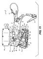
バッテリジャンプスタータ装置10を図1及び2に示す。バッテリジャンプスタート装置10は、複数の発光ダイオード(LEDs)16が配列されたディスプレイ14を有するケーシング12を備える。
A battery
バッテリジャンプスタート装置10は、正極クランプ20を有する正極ケーブル18と、負極クランプ24を有する負極ケーブル22とを更に備える。正極ケーブル18及び負極ケーブル22とは、ケーシング12中の開口12a,12bをそれぞれ通過する。
The battery
クランプ20,24は、図1に示すようにクランプ20,24のそれぞれがケーシング12の両端から外側に延びるそれぞれのサイドポスト26をクランプすることによって、展開されていない状態で格納ないしは固定される。サイドポスト26は、図2に示される。クランプ20,24は、バッテリジャンプスタータ装置10が使用されないときに固定され、その後使用するときにサイドポスト26からアンクランプされる。
As shown in FIG. 1, the
バッテリジャンプスタート装置10は、車載バッテリをジャンプスタートするように構成されている。例えば、バッテリジャンプスタート装置10は、米国特許第9007015号(参照することにより本明細書に全体を援用する)に開示されている安全保護付携帯型車両ジャンプスタート装置、又はこれに類似する装置であってもよい。
The battery
バッテリジャンプスタート装置10は、ケーシング12の内側に配置された電気部品ないしは部品を備える。例えば、バッテリジャンプスタート装置10は、図3から図9に示すバッテリコネクタ装置100を備える。
The battery
バッテリコネクタ装置100は、バッテリ112を有するバッテリアセンブリ110を備える。例えば、バッテリ112は、充電式リチウムイオンバッテリである。バッテリコネクタ装置100は、バッテリ112からバッテリジャンプスタータ装置10のケーブル18,22及びクランプ20,24への電気導電率を最大化するように構成されている。バッテリ112は、バッテリケーシング112a、例えば、矩形状のバッテリケーシング112aを備える。
The
バッテリ112は、バッテリ112の一方の端部(例えば幅端部)に正極タブを備え、バッテリ112の他方の端部(例えば幅端部)に負極タブを備える。例えば、バッテリ112は、正極タブ及び負極タブをそれぞれ有する1又は複数のバッテリセルを備える。例えば、バッテリセルの正極タブは、バッテリ112の前記一方の端部に配置され、バッテリセルの負極タブは、バッテリ112の前記他方の端部に配置される。正極端子導体板114は、バッテリ112の前記一方の端部で、バッテリ112の正極タブ(すなわち接点)に接続(例えば、はんだ付け、溶接、又は超音波接合)される。正極端子導体板114は、バッテリ112の前記一方の端部(例えば幅端部)に沿って延在している。
The
正極ケーブル18は、正極端子導体板114及び/又はバッテリ112の正極タブに接続(例えば、はんだ付けによって直接接続)されてもよい。例えば、正極端子導体バー114は、導体環116を備えていてもよい。導体環116は、正極ケーブル18の露出端部18aに巻き付いて(例えば、全体に巻き付いて)、接続(例えば、圧着及び/又ははんだ付け)されている。例えば、正極端子導体板114は、(例えば、機械加工された、切断された、又は厚肉銅板から打ち抜かれた)厚肉銅板から作られる。
The
図5及び図6に示すように、正極端子導体シート114は、(例えば、L字状の)バッテリ112の矩形状のケーシング112aの正方形状の角部のうちの1つに巻き付くように構成(例えば、屈曲)されていてもよい。L字状正極端子導体シート114は、図5に示すように、バッテリ112の端部と、バッテリ112の側部の少なくとも一部に沿って延在してもよい。
As shown in FIGS. 5 and 6, the positive
また、正極端子導体板114は、(例えば、バッテリジャンプスタータ装置10を落下試験したときに機械的な衝撃に耐えるように組み立てられる)付加的な支持及び安定性を提供するように、バッテリケーシング112aの外表面に機械的に結合及び/又は接着されてもよい。例えば、正極端子導体バー114は、バッテリケーシング112に接着剤(例えば、シリコン接着剤)、両面テープ、両面フォームテープ、スナップフィット接続及び/又は接着接続を有する絶縁プラスチック若しくはセラミックのコネクタによって機械的に接続されてもよい。バッテリケーシング112は、正極端子導体板114と機械的に接続(例えば、スナップフィット接続又は干渉接続)するように形成(例えば、成形)されていてもよい。
The positive
正極ケーブル18は、バッテリ110から正極クランプ20へと延びる1本のワイヤないしはケーブル(例えば、撚線又は編組線)であってもよい。具体的には、正極ケーブル18の一方の端部は、バッテリ18に接続された正極端子導体板114に接続されており、正極ケーブル18の他方の端部は、正極クランプ20に接続されている。
The
より具体的には、正極ケーブル18は、ケーシング12内で正極ケーブル18の向きを変更するために、可撓性ケーブル部ないしは屈曲ケーブル部118を備えていてもよい。正極ケーブル18は、ケーシング12を通過する正極ケーブル18を柔軟に収容するために、可撓性内側スリーブ部122につながる可撓性外側スリーブ部120が装着されてもよい。可撓性外側スリーブ部120は、バッテリジャンプスタータ装置10のケーシング12に対して外側に位置しており、可撓性内側スリーブ部122は、バッテリジャンプスタータ装置10のケーシング12に対して内側に位置している。
More specifically, the
可撓性外側スリーブ部120は、可撓性を維持しつつ、正極ケーブル18とバッテリジャンプスタータ装置のケーシング12との間の接続を補強するように構成されている。例えば、可撓性外側スリーブ部120は、正極ケーブル18の複数の部分を露出させる1又は複数(例えば、図5では3つ)の溝124を備える。1又は複数の溝124は、ヒンジとして機能して、可撓性外側スリーブ部120内の正極ケーブル18の屈曲を容易にする。
The flexible
可撓性スリーブ120は、内側フランジ126から(例えば、バッテリジャンプスタータ装置10のケーシング12の壁厚とほぼ等しい短い距離で)離間した外側フランジ124を備える。フランジ124,126は、正極ケーブル18をバッテリジャンプスタータ装置10のケーシング12にさらに固定する。
The
可撓性スリーブ120は、外側フランジ124と内側フランジ126とを接続するスリーブ部128(図6)を備える。例えば、可撓性外側スリーブ部120は、単一ユニットとして正極ケーブル18上及びその周囲に、成形ないしは取り付けられる(例えば、可撓性スリーブ120は、成形工程の間に金型内に挿入されている正極ケーブル18の一部に成形される)。あるいは、可撓性スリーブ120は、別個に製造(例えば成形)され、その後正極ケーブル18の一部に設置されるか組み付けられる。
The
正極ケーブル18は、外側絶縁シース18c(例えば、押出プラスチックシース)内に配置された内側導体18b(例えば、素線導体、撚線、又は編組線)を備える。
内側導体18bは、例えば、単線導体又はワイヤ束18dを有する多重撚線金属線導体を備えていてもよい。
The
The inner conductor 18b may include, for example, a multi-stranded metal wire conductor having a single wire conductor or a wire bundle 18d.
内部電線は、銅ないしはアルミニウムから作られてもよい。可撓性スリーブ120は、正極ケーブル18の外側絶縁シース18c上及びその周りに(例えば、成形されるか設置されるか組み付けられて)取り付けられてもよい。
The internal wire may be made from copper or aluminum. The
バッテリコネクタ装置100は、バッテリ112の負極タブ(すなわち接点)に、バッテリ112の他方の端部において接続(例えば、はんだ付け、溶接又は超音波溶着)された負極端子導体板130を更に備える。負極端子導体板130は、バッテリ112の他方の端部に沿って延在してもよい。
The
負極端子導体板130の他方の端部は、図5及び図6に示すように、負極端子導体板コネクタ部132を備える。
The other end of the negative
負極端子導体板130は、矩形状バッテリ112の複数の角部の1つに巻き付くように(例えばL字状に)構成されていてもよい。L字状負極端子導体板130は、図5及び図6に示すように、バッテリ112の端部に沿って及びバッテリ112の側部の少なくとも一部に沿って延在してもよい。
The negative
負極端子導体バー130は、また、(例えば、バッテリジャンプスタータ装置10を落下試験したときに機械的な衝撃に耐えるために)付加的な支持及び安定性を提供するために、バッテリケーシング112aの外表面に機械的に結合及び/又は接着されてもよい。
例えば、負極端子導体バー114は、接着剤(例えばシリコン接着剤)、両面テープ、両面フォームテープ、スナップフィット接続及び/又は接着接続を有する絶縁プラスチックないしはセラミックのコネクタによって、バッテリケーシング112aに機械的に接続されてもよい。バッテリケーシング112は、正極端子導体板114と機械的に接続(例えば、スナップフィット接続又は干渉接続)するように形成(例えば成形)されてもよい。
The negative
For example, the negative
バッテリコネクタ装置100は、スマートスイッチバッテリインターフェイス134をさらに備える。スマートスイッチバッテリインターフェイス134は、リレープリント回路基板(PCB)136を備え、回路基板136は、図5及び図6に示すように、回路基板136の一方側に配置された第2回路基板導体バー140から離間した第1回路基板導体バー138を備える。
The
一対のリレー142は、回路基板136の反対側に搭載されている。リレー142は、リレープリント回路基板136の部品穴136aに配置されているリレーアンカーピン142aを含む。リレー142は、回路基板136に設けられた部品穴136bと第1導体バーに設けられたスロット138aとを通過して延びるリレーコネクタピン142bを備える。さらに、リレー142は、回路基板136に設けられた部品穴136cと第2導体バー140に設けられた部品穴140aとに配置されたリレーコネクタピン142cをさらに備える。リレーアンカーピン136aは、適切な位置にはんだ付けされて、リレー142を回路基板136に機械的に接続している。リレーコネクタピン142b,142cは、適切な位置にはんだ付けされて、それぞれリレー142を回路基板導体板138,140に機械的及び電気的に接続している。
The pair of
回路基板136の部品穴136aは、矩形状(図5及び図7)であり、リレーアンカーピン142aを収容する。具体的には、リレーアンカーピン142aの基部は、正方形の端部を有する矩形状である。前記正方形の端部は、回路基板136の外表面と同一平面に配置された横方向の縁部を形成する基部と比較して、寸法的に幅が狭い。リレーアンカーピン142aの露出端部にはんだが塗布されたとき、はんだは、前記正方形の端部の側部と横方向の縁部とを接続し、リレーアンカーピンを回路基板136に固定及び固着する。
The
負極端子導体板コネクタ部132に設けられたスロット132aは、矩形状であり、第1回路基板導体バー138に設けられた部品穴138a(図3)は、T字状であり、図3に示すように3つの水平を向いたリレーコネクタピン142cを収容する。リレーコネクタピン142bの端部は、負極端子導体バーコネクタ部132の外表面と同一平面に示されている。はんだがリレーコネクタピン142bの露出端部に塗布されたとき、はんだは負極端子導体バーコネクタ部132のスロット132aと、第1回路基板導体バー138の部品穴138aとを満たし、コネクタピン142bの側部とスロット132a及び部品穴138aの内縁とを接続し、リレー142を回路基板136と負極端子導体バーコネクタ部132とに接続する。また、塗布されたはんだは、負極端子導体バーコネクタ部132を第1回路基板導体バー138に電気的に接続する。
The
第2回路基板導体バー140に設けられた部品穴140aは、図3に示すように、T字状であり、3つの垂直に向いたリレーコネクタピン142cを収容する。リレーコネクタ突起140aは、図7に示すように、回路基板136の外表面から外側に延びて、負極ケーブル144の露出導体端部144aと接続している。露出導体端部144aとリレーコネクタ突起140aの端部とにはんだが塗布されたとき、はんだは、T字状のスロットを満たし、リレーコネクタ突起140aと、第2回路基板導体140と、負極ケーブル144の露出導体端部144aとを接続する。
As shown in FIG. 3, the
負極端子導体バー130の負極端子導体バーコネクタ部132は、回路基板136の第1回路基板導体バー138に(例えば、はんだ付けにより)接続されている。負極ケーブル22の露出導体端部22a(すなわち、絶縁シースが取り除かれている)は、図9に示すように第2回路基板導体バー140に(例えば、はんだ付けにより)接続されている。
The negative terminal conductor
バッテリコネクタ装置100は、図10に示すように、正極ケーブル18にダイオード接続部150を提供することで改良されてもよい。例えば、ダイオード接続部は、正極ケーブル18に設置される(例えば、接合される)。ダイオード接続部150は、ダイオードプリント回路基板(PCB)152を備える。
ダイオードプリント回路基板152は、回路基板152の一方側に配置された一組のバックチャージダイオード154(例えば、ショットキーダイオード)と、回路基板152の他方側に設けられた導体バー156とを備える。
The
The diode printed
(組み立て)
バッテリジャンプスタート装置10は、図11に示すように、上側ケーシング部12aと下側ケーシング部12bとを有するケーシング12を備える。上側ケーシング部12aと下側ケーシング部12bとは、バッテリジャンプスタート装置10を組み立てるときに、互いに接続されるように構成されている。
(assembly)
As shown in FIG. 11, the battery
バッテリジャンプスタート装置10は、バッテリコネクタ装置100とコントローラアセンブリ210とをさらに備え、バッテリコネクタ装置100とコントローラアセンブリ210との両方が、ケーシング12内に配置されている。コントローラアセンブリ210は、回路基板212を備え、回路基板212は、他の回路基板214に隣接して配置されている。
The battery
バッテリアセンブリ110(図12)の正極端子は、正極電源線216を介して回路基板212に接続されている。例えば、正極電源線216は、正極導体バー114(図5)に接続されている。バッテリアセンブリ110の負極端子は、負極電源線218を介して回路基板214に接続されている。
The positive terminal of the battery assembly 110 (FIG. 12) is connected to the
リレー回路基板136は、コネクタ222を有するワイヤセット220を備える。コネクタ222は、バッテリジャンプスタート装置10の組み立てのときに、コントローラアセンブリ210の回路基板212上に配置されるリレー基板コネクタ224と接続するように構成されている。
The
バッテリアセンブリ110は、コネクタ228を有するワイヤセット226をさらに備える。コネクタ228は、コントローラアセンブリ220の回路基板212上に配置されたバッテリセル充電/監視コネクタ230と接続するように構成されている。
The
バッテリアセンブリ110は、ワイヤセット232を有するバッテリ温度センサを備え、ワイヤセット232はコネクタ234を有する。コネクタ234は、コントローラアセンブリ220の回路基板212上に配置された温度センサコネクタ236と接続するように構成されている。
The
回路基板212は、図11に示すように、充電電力抵抗器240と、出力リレー242とを備える。
さらに、下側ケーシング部12aは、回路基板214に接続されたワイヤセット246を有するメインユーザ出力コネクタ244と、回路基板214に接続されたワイヤセット250を有するメインユーザ入力コネクタ248とを備える。
As shown in FIG. 11, the
Further, the
バッテリアセンブリ110は、図11に示すように、バッテリジャンプスタート装置10と接続されている。バッテリコネクタ装置110は、組み立てられたとき、バッテリジャンプスタート装置10のケーシング12内に設置されている。
As shown in FIG. 11, the
(導電率の改良)
改良導電率バッテリコネクタ装置400は、図13から図25に示されている。改良導電率バッテリコネクタ装置400は、図5から図10に示されたバッテリコネクタ装置100と比較して大幅に増加した導電率を提供する。
(Improved conductivity)
An improved conductivity
バッテリ412からクランプへと伝導される電力量は、以下のように改良され得る。
The amount of power conducted from the
1)ワイヤゲージを大きくする
例えば、4AWG(米国ワイヤゲージ規格)の正極ケーブル18及び負極ケーブル22(図9)を、2AWG正極ケーブル318及び負極ケーブル322(図13及び図15)に変更する。
1) Increasing the wire gauge For example, the 4AWG (US wire gauge standard)
2)負極ケーブル接続部の導電率を高める
例えば、リレーへの負極ケーブル端部322a(図15)が、リレー422のコネクタピン422cに幅広くまたがって延びる。
2) Increasing the conductivity of the negative cable connecting portion For example, the
3)正極ケーブル接続部の導電率を高める
例えば、正極ケーブル318が正極バッテリタブ414に巻かれ、互いに完全にはんだ付けされるように正極バッテリタブ414を伸ばす。
3) Increasing the conductivity of the positive cable connection For example, the
4)ダイオード接続部の導電率を高める
例えば、ダイオード接続部150(図5)をダイオード接続部450(図23)に置き換える。
4) Increasing the conductivity of the diode connection portion For example, the diode connection portion 150 (FIG. 5) is replaced with a diode connection portion 450 (FIG. 23).
5)抵抗器/ダイオードプリント回路基板(PCB)を再設計する
例えば、ダイオードプリント回路基板(PCB)152をダイオードプリント回路基板(PCB)452(図23)に置き換える。
5) Redesign resistor / diode printed circuit board (PCB) For example, the diode printed circuit board (PCB) 152 is replaced with a diode printed circuit board (PCB) 452 (FIG. 23).
6)抵抗器を再接続する
例えば、再び接続されるダイオードプリント回路基板(PCB)152(図10)上に配置された抵抗器R134A及びB、135A及びBを再接続する。
6) Reconnect resistors For example, reconnect resistors R134A and B, 135A and B located on diode printed circuit board (PCB) 152 (FIG. 10) to be reconnected.
これらの導電率を増加する特徴ないし配置のそれぞれの詳細な説明を以下に述べる。 A detailed description of each of these features or arrangements that increase conductivity is provided below.
1)ワイヤゲージを大きくする
正極ケーブル18及び負極ケーブル22(図9)のゲージは、例えば、4AWG(米国ワイヤゲージ規格)ケーブルから、正極ケーブル318及び負極ケーブル322(図13及び図15)の2AWGケーブルへと増加されてもよい。4AWGケーブルと2AWGケーブルの比較仕様は、以下の通りである。
1) Increase the wire gauge The gauge of the

2AWGケーブルは、4AWGケーブルと比較して、導電率(すなわち許容電流)の大幅な増加(すなわち約36%)を提供する。 The 2AWG cable provides a significant increase (ie, about 36%) in conductivity (ie, allowable current) compared to the 4AWG cable.
2)負極ケーブル接続部の導電率を増加する
負極ケーブル322(図15)は、バッテリ412と負極ケーブル322との間の導電率(すなわち許容電流)を増加する方法で、バッテリ412(図13)に接続されてもよい。例えば、負極ケーブル端部322aは、リレー422のコネクタ突起442c(図15)に直接接続(例えば、はんだ付け)されてもよい。具体的には、負極ケーブル端部322aは、図14及び図15に示すように、スマートスイッチバッテリインターフェイス434の全てのリレー342に渡って延在して、それらに直接接続されてもよい。
2) Increasing the conductivity of the negative cable connecting portion The negative cable 322 (FIG. 15) is a method of increasing the conductivity (ie, allowable current) between the
さらに、負極ケーブル端部322aは、回路基板導体バー440の導体環441に接続されてもよい。
Further, the
負極ケーブル322は、例えば、内側電線導体322bを有する撚線であってもよい。内側電線導体322bは、外側電気絶縁シース322c内に配置された、撚られていない又は撚られたワイヤ束322dから構成される。負極ケーブル322の電気絶縁シース322cは、負極ケーブル端部322aから取り除かれて、負極ケーブル端部322aにおいて内側電導体322bを露出してもよい。
The
電導体322bの露出ワイヤ束322dは、リレー422の露出コネクタピン442cの端部に押し付けられ、ワイヤ322dの撚り糸が隣接するコネクタピン442cの間に捕捉される。露出ワイヤ束332dは、導体バー440(例えば、銅からなる)に接触されてもよい。はんだ423は、このアセンブリに塗布され、はんだが露出ワイヤ束422dとコネクタピン442cと導体バー440との間を流れ、負極ケーブル322と、バッテリ412に接続されたスマートスイッチバッテリインターフェイス434との間の電気的な接続が完成する
The exposed wire bundle 322d of the
露出ワイヤ束322dの長さは、露出ワイヤ束322dがひとつひとつのリレー422のコネクタピン422cの各組と直接接続し、負極ケーブル322とバッテリ412との間の最大電気導電率(すなわち最大許容電流)を提供するように、選択される。
The length of the exposed wire bundle 322d is such that the exposed wire bundle 322d is directly connected to each set of connector pins 422c of each
3)正極ケーブル接続の導電率を増加する
正極ケーブル318は、バッテリ412と正極ケーブル318との間の導電率(すなわち、許容電流)を増加する方法で、バッテリ412に接続されてもよい。例えば、正極ケーブル318は、正極バッテリタブ414に巻かれて、完全に互いにはんだ付けされてもよい。正極ケーブル318とバッテリ412との間の接続は、図16から図22に示される。
3) Increasing the conductivity of the positive cable connection The
正極ケーブル318は、例えば、内側電線導体318bを有する撚線であってもよい。内側電線導体318bは、外側電気絶縁シース318c内に配置された、撚られていないないしは撚られたワイヤ束318dから構成される。正極ケーブル318の電気絶縁シース318cは、正極ケーブル端部318aから取り除かれて、正極ケーブル端部318aにおいて内側電導体318bを露出してもよい。
The
バッテリ412は、正極バッテリタブ414を備える。正極バッテリタブ414は、バッテリ412の正極バッテリタブ414に接続された金属板(例えば銅板)である。
The
内側電導体318bの露出ワイヤ束318dは、スズを用いてはんだ付けされて、その後正極バッテリタブ312a内に巻かれてもよい。はんだ415(図21)は、露出ワイヤ束318dと正極バッテリタブ312aとに塗布されている。
The exposed wire bundle 318d of the
露出ワイヤ束318dの長さは、露出ワイヤ束318dが正極バッテリタブ414の全幅と直接接続し、バッテリ312と正極ケーブル318との間の最大電気導電率(すなわち最大許容電流)を提供するように、選択される。
The length of the exposed wire bundle 318d is such that the exposed wire bundle 318d connects directly with the full width of the
4)ダイオード接続部の導電率を高める
正極ケーブル318は、図23から図25に示すように、正極ケーブル318に沿った導電率を高めるように構成されたダイオード接続部450を備えてもよい。
4) Increasing Conductivity of Diode Connection The
ダイオード接続部450は、正極ケーブル部分318e及び318f(図25)との間に接続された複数のダイオード454を備える。
例えば、ダイオード接続部450は、6つのバックチャージ型ダイオード(例えば、ショットキーバリアダイオード)を備える。
The
For example, the
ダイオード454は、正極ケーブル部分318e及び318fの間にはんだ付けされている。具体的には、ダイオード導体タブ454aは、正極ケーブル部分318eにはんだ付けされ、ダイオード導体突起454bは、正極ケーブル部分318fにはんだ付けされる。より具体的には、ダイオード354のダイオード導体突起454bは、ダイオード回路基板452を通じて、ワイヤ束318dに及び、その後適切な位置ではんだ付けされて、ダイオード接続部450の組み立てを完了する。
The
ダイオード接続部450は、その後、例えば収縮包装絶縁体455(図25)を用いて、絶縁される。収縮包装絶縁体455は、ダイオード接続部450の周囲に取り付けられ、その後、熱を加えることで(例えば、熱線銃を用いて)収縮する。
The
抵抗器/ダイオードプリント回路基板(PCB)を再設計する
例えば、抵抗器/ダイオードPCBを再設計して、抵抗器/ダイオードPCBから延びるダイオードを排除する。
Redesign Resistor / Diode Printed Circuit Board (PCB) For example, the resistor / diode PCB is redesigned to eliminate diodes extending from the resistor / diode PCB.
抵抗器を再接続する
例えば、再度接続される抵抗器/ダイオードPCB上の抵抗器R134A及びB、135A及びBを再接続する。
Reconnect Resistors For example, reconnect resistors R134A and B, 135A and B on the reconnected resistor / diode PCB.
(試験1)
図5に示されるバッテリコネクタ装置100は、1250Aの負荷試験に付された。結果を図27に示す。また、以下の通りである。
(Test 1)
The
(試験2)
図13に示されるバッテリコネクタ装置400は、1250Aの負荷試験に付された。結果を図28に示す。また、以下の通りである。
(Test 2)
The
これは、試験1の結果と比較して、最大出力で約20パーセント(20%)の大幅な増加という結果になった。 This resulted in a significant increase of about 20 percent (20%) at maximum power compared to the results of Test 1.
他の改良伝導率バッテリ導体装置500は、図29から図37に示される。
改良伝導率バッテリコネクタ装置500は、図5から図10に示されるバッテリコネクタ装置100と比較して、大幅に増加した導電率を提供する。
Another improved conductivity
The improved conductivity
バッテリ導体装置500は、バッテリアセンブリ410を備え、バッテリアセンブリ410は、正極ケーブル518及び負極端子導体板530に接続されたバッテリ512を含む。正極ワイヤ519は、バッテリ530の正極タブないし正極ケーブル518と直接的又は間接的に接続され、負極ワイヤ523は、負極タブないし負極端子導体板530に直接的又は間接的に接続される。バッテリ導体装置500は、バッテリ512に接続されるか、バッテリ512の動作に関連するワイヤ束570を更に含んでいてもよい(例えば、バッテリ温度センサ、電力供給など)。
The
バッテリ512は、単一のバッテリセル512c(図30)、又は端と端を直列に接続された複数のバッテリセル512Cを備えていてもよい。図30では、3つの別々のバッテリセル512cが示されている。
The
バッテリセル512cは、各バッテリセル512cの対向する端部に配置された正極及び負極タブ512dをそれぞれ有する。バッテリセル512cは、正極及び負極タブ512dをそれぞれ直列に共に溶接(例えば、超音波溶着及び/又は熱溶着)及び/又ははんだ付けすることで、共に接続されている。
例えば、タブ512dは、互いに重なるように配置されている(例えば、縁部が対向するタブ512dに重なるか、又は縁部と縁部)
The
For example, the
タブ512dは、各バッテリセル512cの本体及び両端から外側に延在する金属板(例えば、比較的薄い金属片)である。図30に示すように、タブ512dは、各バッテリセル512cの幅の両端に沿って延在する。タブ512dは、それぞれ、中央に位置し、各バッテリセル512cの両端部のそれぞれの幅の大部分に延在する。
The
図30及び図31に示すように、セパレートタブ512eは、バッテリセル512cの右側に追加されるか接続されて、タブ512dの長さを伸ばす。セパレートタブ512eは、タブ512dと同一の幅を有するものとしてしめされているが、この幅は異なってもよい。セパレートタブ512eをタブ512dに組み付けるために、例えば、セパレートタブ512eは、タブ512d上に重なるように配置され、その後溶着(例えば超音波溶着及び/又は熱溶着)及び/又ははんだ付けされる。正極ケーブル518の露出端部は、図32及び図34に示すように、その後、セパレートタブの内側に巻き上げられる。例えば、最初は平坦なセパレートタブ512eは、正極ケーブル518の露出端部に巻き付き、その後、溶着(例えば、超音波溶着及び/又は熱溶着)及び/又ははんだ付けによって、露出端部に接続される。例えば、はんだの層は、セパレートタブ512eの一方側又は両側に塗布され、そして、セパレートタブ512eを正極ワイヤ518の露出端部の周りに巻き付けた後、アセンブリは、加熱されて、層状のはんだは溶かされ、アセンブリは全体としてはんだ付けされる、
As shown in FIGS. 30 and 31, a
図32に示すように、一度共に接続された3つのバッテリセル512cは、その後、図33に示す層状のバッテリセル構成に互いに折り畳まれる。層状のバッテリセル構成は、包装されてもよいし(例えば、3つのバッテリセルは、ともにテープでくくられるか、収縮包装される)、又は、図34に示すように、バッテリカバーないしケーシングの内部に配置される。
As shown in FIG. 32, the three
図35に示すように、負極タブ512dは、負極端子導体板530に取り付けられてもよい。例えば、負極タブ512dは、部分的に又は全体的に(図視するように)負極端子導体板530の周りに巻き付けられてもよい。負極タブ512dは、負極タブ512dの負極端子導体板530への溶着及び/又ははんだ付けを容易にするために、複数の部品穴512fを備えてもよい。例えば、部品穴512fは、図35に示すように、格子状に配置された複数の正方形状の部品穴であってもよい。負極ワイヤ523は、負極タブ512dに接続(例えば、はんだ付け)されて示されている。
As shown in FIG. 35, the
セパレートタブ512e(図30参照)は、負極タブ512dに接続されて、負極タブ512dを伸ばしてもよく、伸ばされた負極タブは、1回以上(例えば、2、3、4又はそれ以上)負極端子導体板530を包み込むか巻き付く。この方法で、負極タブ512dと負極端子導体板530との間の電気的な接続は強化される。このセパレートタブ512eは、一方側ないし両側にはんだの層を備えていてよく、セパレートタブ512eが負極端子導体板530を包み込むか巻き付いた後に、アセンブリは、加熱されて、セパレートタブ512eを負極端子導体板530上にはんだ付けする。
The
正極ケーブル518(図29)の露出端部を包むか巻き付く準備ができている接続されたセパレート正極タブ512dを有するバッテリ導体装置500の完成したアセンブリは、図36に示されている。図36に示されているワイヤ束570は、バッテリ512内に埋設された温度センサ(例えば、バッテリタブの近傍、又はバッテリセルの間に配置された温度センサ)用のワイヤ572を含む。ワイヤ572a,572bを有する温度センサ574は、図37に示されている。
A completed assembly of the
バッテリ導体装置500は、図38に示すように、一列に接続されたダイオードコネクタ550を備えてもよく、正極ケーブル518に接合されてもよい。
As shown in FIG. 38, the
バッテリ導体装置500は、ダイオード回路基板552を備え、ダイオード回路基板552は、ダイオード回路基板552上に組み付けられた複数のダイオード454を備える。ダイオード454は、正極ケーブル518の露出端部に接続(例えば、はんだ付け)されたダイオード導体タブ454aをそれぞれ備える。ダイオード454の突起は、ダイオード回路基板552の部品穴に延在し、導電性トレースと正極ケーブル518の露出端部との両方に、抵抗器576と共にはんだ付けされ、アセンブリは完成する。
The
Claims (18)
正極端子タブと、負極端子タブとを有するバッテリと、
前記バッテリの前記正極端子タブに接続された正極端子導体板と、
前記バッテリの前記負極端子タブに接続された負極端子導体バーと、
前記バッテリの前記正極端子導体板に接続された正極ケーブルと、
第2回路基板導体バーから離間した第1回路基板導体バーを有する回路基板を有し、前記ジャンプスタート装置の前記スマートスイッチに接続可能なスマートスイッチインターフェイスと、
前記第2回路基板導体バーに接続された負極ケーブルと
を備え、
前記第1回路基板導体バーは、前記バッテリの前記負極端子導体バーに電気的に接続され、
前記スマートスイッチインターフェイスは、前記バッテリの前記負極端子タブとジャンプスタートされるバッテリとの間の隔離を提供するために第1回路基板導体バーと第2回路基板導体バーとの間に接続された1又は複数のリレーを更に備える、バッテリコネクタ装置。 A battery connector device for a battery jump start device having a smart switch,
A battery having a positive terminal tab and a negative terminal tab;
A positive terminal conductor plate connected to the positive terminal tab of the battery;
A negative terminal conductor bar connected to the negative terminal tab of the battery;
A positive cable connected to the positive terminal conductor plate of the battery;
A smart switch interface having a circuit board having a first circuit board conductor bar spaced from a second circuit board conductor bar and connectable to the smart switch of the jump start device;
A negative cable connected to the second circuit board conductor bar,
The first circuit board conductor bar is electrically connected to the negative terminal conductor bar of the battery;
The smart switch interface is connected between a first circuit board conductor bar and a second circuit board conductor bar to provide isolation between the negative terminal tab of the battery and a jump-started battery. Or the battery connector apparatus further provided with a some relay.
正極端子タブと、負極端子タブとを有する再充電可能なバッテリと、
前記バッテリの前記正極端子タブに接続された正極端子導体板と、
前記バッテリの前記負極端子タブに接続された負極端子導体バーと、
前記バッテリの前記正極端子導体板に接続された正極ケーブルと、
第2回路基板導体バーから離間した第1回路基板導体バーを有する回路基板を有し、前記ジャンプスタート装置の前記スマートスイッチに接続可能なスマートスイッチインターフェイスと、
前記第2回路基板導体バーに接続された負極ケーブルと
を備え、
前記第1回路基板導体バーは、前記バッテリの前記負極端子導体バーに電気的に接続され、
前記スマートスイッチインターフェイスは、前記バッテリの前記負極端子タブとジャンプスタートされるバッテリとの間の隔離を提供するために第1回路基板導体バーと第2回路基板導体バーとの間に接続された1又は複数のリレーを更に備え、
前記負極ケーブルは、前記複数のリレーのそれぞれに電気的に接続されている、バッテリコネクタ装置。 A battery connector device for a battery jump start device having a smart switch,
A rechargeable battery having a positive terminal tab and a negative terminal tab;
A positive terminal conductor plate connected to the positive terminal tab of the battery;
A negative terminal conductor bar connected to the negative terminal tab of the battery;
A positive cable connected to the positive terminal conductor plate of the battery;
A smart switch interface having a circuit board having a first circuit board conductor bar spaced from a second circuit board conductor bar and connectable to the smart switch of the jump start device;
A negative cable connected to the second circuit board conductor bar,
The first circuit board conductor bar is electrically connected to the negative terminal conductor bar of the battery;
The smart switch interface is connected between a first circuit board conductor bar and a second circuit board conductor bar to provide isolation between the negative terminal tab of the battery and a jump-started battery. Or a plurality of relays,
The battery connector device, wherein the negative cable is electrically connected to each of the plurality of relays.
正極端子タブと、負極端子タブとを有する再充電可能なバッテリと、
前記バッテリの前記正極端子タブに接続された正極端子導体板と、
前記バッテリの前記負極端子タブに接続された負極端子導体バーと、
前記バッテリの前記正極端子導体板に接続された正極ケーブルと、
第2回路基板導体バーから離間した第1回路基板導体バーを有する回路基板を有し、前記ジャンプスタート装置の前記スマートスイッチに接続可能なスマートスイッチインターフェイスと、
前記第2回路基板導体バーに接続された負極ケーブルと、
前記正極ケーブルの第1部分と、前記正極ケーブルの第2部分との間に設けられたダイオード接続部と
を備え、
前記第1回路基板導体バーは、前記バッテリの前記負極端子導体バーに電気的に接続され、
前記スマートスイッチインターフェイスは、前記バッテリの前記負極端子タブとジャンプスタートされるバッテリとの間の隔離を提供するために第1回路基板導体バーと第2回路基板導体バーとの間に接続された1又は複数のリレーを更に備え、
前記負極ケーブルは、前記複数のリレーのそれぞれに電気的に接続されている、バッテリコネクタ装置。 A battery connector device for a battery jump start device having a smart switch,
A rechargeable battery having a positive terminal tab and a negative terminal tab;
A positive terminal conductor plate connected to the positive terminal tab of the battery;
A negative terminal conductor bar connected to the negative terminal tab of the battery;
A positive cable connected to the positive terminal conductor plate of the battery;
A smart switch interface having a circuit board having a first circuit board conductor bar spaced from a second circuit board conductor bar and connectable to the smart switch of the jump start device;
A negative cable connected to the second circuit board conductor bar;
A diode connecting portion provided between a first portion of the positive cable and a second portion of the positive cable;
The first circuit board conductor bar is electrically connected to the negative terminal conductor bar of the battery;
The smart switch interface is connected between a first circuit board conductor bar and a second circuit board conductor bar to provide isolation between the negative terminal tab of the battery and a jump-started battery. Or a plurality of relays,
The battery connector device, wherein the negative cable is electrically connected to each of the plurality of relays.
前記バッテリの前記正極端子導体板の幅は、前記バッテリの幅と等しく、
前記負極端子導体バーは、L字状であり、前記バッテリのそれぞれの角に巻き付くように構成されている、請求項1に記載の装置。 The battery is rectangular,
The width of the positive terminal conductor plate of the battery is equal to the width of the battery,
The apparatus of claim 1, wherein the negative terminal conductor bar is L-shaped and configured to wrap around each corner of the battery.
前記複数のダイオードの前記導体突起は、前記正極ケーブルの前記第2部分に接続されている、請求項13に記載の装置。
Conductor tabs of the plurality of diodes are connected to the first portion of the positive cable,
The apparatus of claim 13, wherein the conductor protrusions of the plurality of diodes are connected to the second portion of the positive cable.
Applications Claiming Priority (9)
| Application Number | Priority Date | Filing Date | Title |
|---|---|---|---|
| US201662294067P | 2016-02-11 | 2016-02-11 | |
| US62/294,067 | 2016-02-11 | ||
| US15/137,626 US11601004B2 (en) | 2016-02-11 | 2016-03-29 | Battery assembly device |
| PCT/US2016/024680 WO2017138963A1 (en) | 2016-02-11 | 2016-03-29 | Battery assembly device |
| USPCT/US2016/024680 | 2016-03-29 | ||
| US15/137,626 | 2016-04-25 | ||
| US201662424297P | 2016-11-18 | 2016-11-18 | |
| US62/424,297 | 2016-11-18 | ||
| PCT/US2017/017289 WO2017139524A1 (en) | 2016-02-11 | 2017-02-10 | Battery connector device for a battery jump starting device |
Related Child Applications (1)
| Application Number | Title | Priority Date | Filing Date |
|---|---|---|---|
| JP2020167183A Division JP7217252B2 (en) | 2016-02-11 | 2020-10-01 | Battery connector device for battery jump start device |
Publications (2)
| Publication Number | Publication Date |
|---|---|
| JP2018536789A true JP2018536789A (en) | 2018-12-13 |
| JP6971855B2 JP6971855B2 (en) | 2021-11-24 |
Family
ID=64663977
Family Applications (2)
| Application Number | Title | Priority Date | Filing Date |
|---|---|---|---|
| JP2017561919A Active JP6971855B2 (en) | 2016-02-11 | 2017-02-10 | Battery connector device for battery jump start device |
| JP2020167183A Active JP7217252B2 (en) | 2016-02-11 | 2020-10-01 | Battery connector device for battery jump start device |
Family Applications After (1)
| Application Number | Title | Priority Date | Filing Date |
|---|---|---|---|
| JP2020167183A Active JP7217252B2 (en) | 2016-02-11 | 2020-10-01 | Battery connector device for battery jump start device |
Country Status (5)
| Country | Link |
|---|---|
| EP (1) | EP4376246A3 (en) |
| JP (2) | JP6971855B2 (en) |
| AU (2) | AU2023200778B2 (en) |
| DE (1) | DE202017007295U1 (en) |
| GB (1) | GB2588555B (en) |
Cited By (12)
| Publication number | Priority date | Publication date | Assignee | Title |
|---|---|---|---|---|
| US10604024B2 (en) | 2014-07-03 | 2020-03-31 | The Noco Company | Portable vehicle battery jump start apparatus with safety protection |
| JP2020532938A (en) * | 2017-08-30 | 2020-11-12 | ザ・ノコ・カンパニーThe Noco Company | Rechargeable Battery Jump Start Device and Rechargeable Battery Assembly |
| JP2020532934A (en) * | 2017-08-30 | 2020-11-12 | ザ・ノコ・カンパニーThe Noco Company | Rechargeable Portable Battery Jump Start Device |
| JP2020534771A (en) * | 2017-09-22 | 2020-11-26 | ザ・ノコ・カンパニーThe Noco Company | Rechargeable battery jump starter with dual battery diode bridge system |
| CN114788121A (en) * | 2019-12-09 | 2022-07-22 | 尼科公司 | Jumper jump starting device with jumper jump starting current sharing system and jumper jump starting current sharing method |
| CN114946069A (en) * | 2020-12-01 | 2022-08-26 | 东莞新能安科技有限公司 | Interconnection piece and battery package, consumer |
| US11458851B2 (en) | 2014-07-03 | 2022-10-04 | The Noco Company | Jump starting apparatus |
| JP2022551513A (en) * | 2019-10-09 | 2022-12-09 | ザ・ノコ・カンパニー | Battery charging device, battery charging system and method for charging deeply discharged battery |
| US11611222B2 (en) | 2017-12-14 | 2023-03-21 | The Noco Company | Portable vehicle battery jump starter with air pump |
| USRE49976E1 (en) | 2016-06-30 | 2024-05-21 | Shenzhen Carku Technology Co., Ltd. | Battery clamp |
| US12074434B2 (en) | 2017-09-22 | 2024-08-27 | The Noco Company | Portable vehicle battery jump starter with air pump |
| USRE50619E1 (en) | 2013-01-07 | 2025-10-07 | Shenzen Carku Technology Co., Ltd. | Emergency power source |
Citations (7)
| Publication number | Priority date | Publication date | Assignee | Title |
|---|---|---|---|---|
| US4972135A (en) * | 1989-08-04 | 1990-11-20 | Bates Bobby L | Switching system for battery jumper cables |
| US20040130298A1 (en) * | 2002-02-19 | 2004-07-08 | Michael Krieger | Microprocessor controlled booster apparatus with polarity protection |
| US20100244766A1 (en) * | 2010-02-23 | 2010-09-30 | Alan Olsberg | Low battery voltage alert system |
| JP2011023249A (en) * | 2009-07-16 | 2011-02-03 | Nissan Motor Co Ltd | Secondary battery, battery pack |
| JP2012169161A (en) * | 2011-02-15 | 2012-09-06 | Panasonic Corp | Cylindrical nonaqueous electrolyte battery and method for manufacturing the same |
| JP2014232666A (en) * | 2013-05-29 | 2014-12-11 | 株式会社カネカ | Nonaqueous electrolyte secondary battery |
| US9007015B1 (en) * | 2014-07-03 | 2015-04-14 | The Noco Company | Portable vehicle battery jump start apparatus with safety protection |
Family Cites Families (18)
| Publication number | Priority date | Publication date | Assignee | Title |
|---|---|---|---|---|
| US5597331A (en) * | 1996-02-23 | 1997-01-28 | Ford Motor Company | Battery connector for an automotive electrical system |
| US5707257A (en) * | 1997-01-30 | 1998-01-13 | Yazaki Corporation | Elliptical battery post and terminal |
| US6215273B1 (en) * | 2000-03-23 | 2001-04-10 | Jack Shy | Portable electrical energy source |
| JP2003112586A (en) * | 2001-10-09 | 2003-04-15 | Denso Corp | Battery cable for starter |
| JP2008517440A (en) * | 2004-11-26 | 2008-05-22 | エルジー・ケム・リミテッド | Electrode connector including plate and battery module using the same |
| JP5082054B2 (en) * | 2006-12-08 | 2012-11-28 | 日産自動車株式会社 | Battery module, battery case, battery case winding device and method |
| JP5413650B2 (en) * | 2009-04-14 | 2014-02-12 | 株式会社オートネットワーク技術研究所 | Battery module |
| JP5345175B2 (en) * | 2010-06-21 | 2013-11-20 | 三星エスディアイ株式会社 | Battery pack connector and method of connecting the same |
| US9412994B2 (en) * | 2010-11-29 | 2016-08-09 | Martin Koebler | Lithium starter battery and solid state switch therefor |
| JP5537674B2 (en) * | 2010-12-08 | 2014-07-02 | 株式会社日立製作所 | Non-aqueous secondary battery and secondary battery system |
| JP5734076B2 (en) * | 2011-04-25 | 2015-06-10 | Jmエナジー株式会社 | Power storage device and power storage module |
| JP5897121B2 (en) * | 2011-07-25 | 2016-03-30 | エルジー・ケム・リミテッド | Battery module with improved reliability and medium-large battery pack having the same |
| US8986872B2 (en) * | 2012-02-15 | 2015-03-24 | GM Global Technology Operations LLC | Battery design |
| US9401608B2 (en) * | 2013-02-28 | 2016-07-26 | Charles Chapple | System for vehicle jump starting |
| JP5986973B2 (en) * | 2013-10-04 | 2016-09-06 | 三菱重工業株式会社 | Battery monitoring apparatus and threshold setting method |
| JP2015115979A (en) * | 2013-12-09 | 2015-06-22 | Sfj株式会社 | Vehicular auxiliary power feeder |
| JP6244965B2 (en) * | 2014-02-18 | 2017-12-13 | 株式会社デンソー | Battery unit |
| CN204558575U (en) * | 2015-01-30 | 2015-08-12 | 中国科学院广州能源研究所 | A kind of soft-package battery lug coupling assembling and battery pack |
-
2017
- 2017-02-10 JP JP2017561919A patent/JP6971855B2/en active Active
- 2017-02-10 DE DE202017007295.5U patent/DE202017007295U1/en active Active
- 2017-02-10 EP EP24153797.6A patent/EP4376246A3/en active Pending
- 2017-02-10 GB GB2100281.1A patent/GB2588555B/en active Active
-
2020
- 2020-10-01 JP JP2020167183A patent/JP7217252B2/en active Active
-
2023
- 2023-02-13 AU AU2023200778A patent/AU2023200778B2/en active Active
-
2024
- 2024-11-21 AU AU2024266758A patent/AU2024266758B2/en active Active
Patent Citations (7)
| Publication number | Priority date | Publication date | Assignee | Title |
|---|---|---|---|---|
| US4972135A (en) * | 1989-08-04 | 1990-11-20 | Bates Bobby L | Switching system for battery jumper cables |
| US20040130298A1 (en) * | 2002-02-19 | 2004-07-08 | Michael Krieger | Microprocessor controlled booster apparatus with polarity protection |
| JP2011023249A (en) * | 2009-07-16 | 2011-02-03 | Nissan Motor Co Ltd | Secondary battery, battery pack |
| US20100244766A1 (en) * | 2010-02-23 | 2010-09-30 | Alan Olsberg | Low battery voltage alert system |
| JP2012169161A (en) * | 2011-02-15 | 2012-09-06 | Panasonic Corp | Cylindrical nonaqueous electrolyte battery and method for manufacturing the same |
| JP2014232666A (en) * | 2013-05-29 | 2014-12-11 | 株式会社カネカ | Nonaqueous electrolyte secondary battery |
| US9007015B1 (en) * | 2014-07-03 | 2015-04-14 | The Noco Company | Portable vehicle battery jump start apparatus with safety protection |
Cited By (35)
| Publication number | Priority date | Publication date | Assignee | Title |
|---|---|---|---|---|
| USRE50619E1 (en) | 2013-01-07 | 2025-10-07 | Shenzen Carku Technology Co., Ltd. | Emergency power source |
| US11584243B2 (en) | 2014-07-03 | 2023-02-21 | The Noco Company | Jump starting device with USB |
| US12208696B2 (en) | 2014-07-03 | 2025-01-28 | The Noco Company | Portable vehicle battery jump start apparatus with safety protection |
| US12187143B2 (en) | 2014-07-03 | 2025-01-07 | The Noco Company | Portable vehicle battery jump start apparatus with safety protection |
| US12157381B2 (en) | 2014-07-03 | 2024-12-03 | The Noco Company | Jump starting apparatus |
| US11766945B2 (en) | 2014-07-03 | 2023-09-26 | The Noco Company | Jump starting apparatus |
| US11447023B2 (en) | 2014-07-03 | 2022-09-20 | The Noco Company | Portable vehicle battery jump start apparatus with safety protection and jumper cable device thereof |
| US10604024B2 (en) | 2014-07-03 | 2020-03-31 | The Noco Company | Portable vehicle battery jump start apparatus with safety protection |
| US11458851B2 (en) | 2014-07-03 | 2022-10-04 | The Noco Company | Jump starting apparatus |
| US11667203B2 (en) | 2014-07-03 | 2023-06-06 | The Noco Company | Portable vehicle battery jump start apparatus with safety protection |
| USRE49976E1 (en) | 2016-06-30 | 2024-05-21 | Shenzhen Carku Technology Co., Ltd. | Battery clamp |
| JP7143397B2 (en) | 2017-08-30 | 2022-09-28 | ザ・ノコ・カンパニー | Rechargeable portable battery jump start device |
| US12176742B2 (en) | 2017-08-30 | 2024-12-24 | The Noco Company | Rechargeable battery jump starting device and rechargeable battery assembly |
| US12515542B2 (en) | 2017-08-30 | 2026-01-06 | The Noco Company | Portable rechargeable battery jump starting device |
| JP2020532938A (en) * | 2017-08-30 | 2020-11-12 | ザ・ノコ・カンパニーThe Noco Company | Rechargeable Battery Jump Start Device and Rechargeable Battery Assembly |
| JP2020532934A (en) * | 2017-08-30 | 2020-11-12 | ザ・ノコ・カンパニーThe Noco Company | Rechargeable Portable Battery Jump Start Device |
| JP7224341B2 (en) | 2017-08-30 | 2023-02-17 | ザ・ノコ・カンパニー | Rechargeable battery jump start device and rechargeable battery assembly |
| US11764591B2 (en) | 2017-08-30 | 2023-09-19 | The Noco Company | Rechargeable battery jump starting device and rechargeable battery assembly |
| JP2020534771A (en) * | 2017-09-22 | 2020-11-26 | ザ・ノコ・カンパニーThe Noco Company | Rechargeable battery jump starter with dual battery diode bridge system |
| CN111052536B (en) * | 2017-09-22 | 2023-12-08 | 尼科公司 | Rechargeable battery jump starting device with dual battery diode bridge system |
| US11652355B2 (en) | 2017-09-22 | 2023-05-16 | The Noco Company | Rechargeable battery jump starting device with a dual battery diode bridge system |
| US12212170B2 (en) | 2017-09-22 | 2025-01-28 | The Noco Company | Rechargeable battery jump starting device and battery frame |
| US12015291B2 (en) | 2017-09-22 | 2024-06-18 | The Noco Company | Rechargeable battery jump starting device with a dual battery diode bridge system |
| US12074434B2 (en) | 2017-09-22 | 2024-08-27 | The Noco Company | Portable vehicle battery jump starter with air pump |
| JP7024059B2 (en) | 2017-09-22 | 2022-02-22 | ザ・ノコ・カンパニー | Rechargeable battery jump starter with dual battery diode bridge system |
| US11611222B2 (en) | 2017-12-14 | 2023-03-21 | The Noco Company | Portable vehicle battery jump starter with air pump |
| JP2022551513A (en) * | 2019-10-09 | 2022-12-09 | ザ・ノコ・カンパニー | Battery charging device, battery charging system and method for charging deeply discharged battery |
| JP2024063190A (en) * | 2019-10-09 | 2024-05-10 | ザ・ノコ・カンパニー | Battery charging device, battery charging system and method for charging a deeply discharged battery |
| JP7671384B2 (en) | 2019-10-09 | 2025-05-01 | ザ・ノコ・カンパニー | Battery charging device, battery charging system and method for charging a deeply discharged battery |
| JP7451693B2 (en) | 2019-10-09 | 2024-03-18 | ザ・ノコ・カンパニー | Battery charging device, battery charging system and method for charging a deeply discharged battery |
| CN114788121A (en) * | 2019-12-09 | 2022-07-22 | 尼科公司 | Jumper jump starting device with jumper jump starting current sharing system and jumper jump starting current sharing method |
| US12266928B2 (en) | 2019-12-09 | 2025-04-01 | The Noco Company | Jump starting device with a jump start current sharing system, and a jump start current sharing method |
| CN114788121B (en) * | 2019-12-09 | 2025-10-10 | 尼科公司 | Jumper jump starting device with jumper jump starting current sharing system and jumper jump starting current sharing method |
| JP2023504580A (en) * | 2019-12-09 | 2023-02-03 | ザ・ノコ・カンパニー | Jump-start device with current-sharing system for jump-start and current-sharing method for jump-start |
| CN114946069A (en) * | 2020-12-01 | 2022-08-26 | 东莞新能安科技有限公司 | Interconnection piece and battery package, consumer |
Also Published As
| Publication number | Publication date |
|---|---|
| JP6971855B2 (en) | 2021-11-24 |
| EP4376246A2 (en) | 2024-05-29 |
| DE202017007295U1 (en) | 2020-10-22 |
| AU2024266758B2 (en) | 2025-09-25 |
| JP2021013299A (en) | 2021-02-04 |
| GB2588555A (en) | 2021-04-28 |
| AU2023200778B2 (en) | 2024-09-05 |
| AU2023200778A1 (en) | 2023-03-09 |
| GB202100281D0 (en) | 2021-02-24 |
| GB2588555B (en) | 2021-11-17 |
| EP4376246A3 (en) | 2024-07-24 |
| AU2024266758A1 (en) | 2024-12-12 |
| JP7217252B2 (en) | 2023-02-02 |
Similar Documents
| Publication | Publication Date | Title |
|---|---|---|
| JP7217252B2 (en) | Battery connector device for battery jump start device | |
| US12135002B2 (en) | Battery device for a battery jump starting device | |
| AU2020277175B2 (en) | Battery connector device for a battery jump starting device | |
| JP7418534B2 (en) | battery assembly equipment | |
| GB2592825A (en) | Battery connector device for a battery jump starting device |
Legal Events
| Date | Code | Title | Description |
|---|---|---|---|
| A521 | Request for written amendment filed |
Free format text: JAPANESE INTERMEDIATE CODE: A523 Effective date: 20180314 |
|
| A621 | Written request for application examination |
Free format text: JAPANESE INTERMEDIATE CODE: A621 Effective date: 20180314 |
|
| A131 | Notification of reasons for refusal |
Free format text: JAPANESE INTERMEDIATE CODE: A131 Effective date: 20190219 |
|
| A521 | Request for written amendment filed |
Free format text: JAPANESE INTERMEDIATE CODE: A523 Effective date: 20190517 |
|
| A131 | Notification of reasons for refusal |
Free format text: JAPANESE INTERMEDIATE CODE: A131 Effective date: 20191029 |
|
| A521 | Request for written amendment filed |
Free format text: JAPANESE INTERMEDIATE CODE: A523 Effective date: 20200128 |
|
| A02 | Decision of refusal |
Free format text: JAPANESE INTERMEDIATE CODE: A02 Effective date: 20200602 |
|
| A521 | Request for written amendment filed |
Free format text: JAPANESE INTERMEDIATE CODE: A523 Effective date: 20201001 |
|
| C60 | Trial request (containing other claim documents, opposition documents) |
Free format text: JAPANESE INTERMEDIATE CODE: C60 Effective date: 20201001 |
|
| A911 | Transfer to examiner for re-examination before appeal (zenchi) |
Free format text: JAPANESE INTERMEDIATE CODE: A911 Effective date: 20201013 |
|
| C21 | Notice of transfer of a case for reconsideration by examiners before appeal proceedings |
Free format text: JAPANESE INTERMEDIATE CODE: C21 Effective date: 20201020 |
|
| A912 | Re-examination (zenchi) completed and case transferred to appeal board |
Free format text: JAPANESE INTERMEDIATE CODE: A912 Effective date: 20201204 |
|
| C211 | Notice of termination of reconsideration by examiners before appeal proceedings |
Free format text: JAPANESE INTERMEDIATE CODE: C211 Effective date: 20201208 |
|
| C22 | Notice of designation (change) of administrative judge |
Free format text: JAPANESE INTERMEDIATE CODE: C22 Effective date: 20210126 |
|
| C13 | Notice of reasons for refusal |
Free format text: JAPANESE INTERMEDIATE CODE: C13 Effective date: 20210413 |
|
| A601 | Written request for extension of time |
Free format text: JAPANESE INTERMEDIATE CODE: A601 Effective date: 20210712 |
|
| A521 | Request for written amendment filed |
Free format text: JAPANESE INTERMEDIATE CODE: A523 Effective date: 20210811 |
|
| C23 | Notice of termination of proceedings |
Free format text: JAPANESE INTERMEDIATE CODE: C23 Effective date: 20210907 |
|
| C03 | Trial/appeal decision taken |
Free format text: JAPANESE INTERMEDIATE CODE: C03 Effective date: 20211012 |
|
| C30A | Notification sent |
Free format text: JAPANESE INTERMEDIATE CODE: C3012 Effective date: 20211012 |
|
| A61 | First payment of annual fees (during grant procedure) |
Free format text: JAPANESE INTERMEDIATE CODE: A61 Effective date: 20211102 |
|
| R150 | Certificate of patent or registration of utility model |
Ref document number: 6971855 Country of ref document: JP Free format text: JAPANESE INTERMEDIATE CODE: R150 |
|
| R250 | Receipt of annual fees |
Free format text: JAPANESE INTERMEDIATE CODE: R250 |
|
| R250 | Receipt of annual fees |
Free format text: JAPANESE INTERMEDIATE CODE: R250 |