JP2018530398A - Intra-annular band for mitral valve repair - Google Patents
Intra-annular band for mitral valve repair Download PDFInfo
- Publication number
- JP2018530398A JP2018530398A JP2018519296A JP2018519296A JP2018530398A JP 2018530398 A JP2018530398 A JP 2018530398A JP 2018519296 A JP2018519296 A JP 2018519296A JP 2018519296 A JP2018519296 A JP 2018519296A JP 2018530398 A JP2018530398 A JP 2018530398A
- Authority
- JP
- Japan
- Prior art keywords
- valve
- band
- intra
- mitral
- annulus
- Prior art date
- Legal status (The legal status is an assumption and is not a legal conclusion. Google has not performed a legal analysis and makes no representation as to the accuracy of the status listed.)
- Pending
Links
Images


Classifications
-
- A—HUMAN NECESSITIES
- A61—MEDICAL OR VETERINARY SCIENCE; HYGIENE
- A61F—FILTERS IMPLANTABLE INTO BLOOD VESSELS; PROSTHESES; DEVICES PROVIDING PATENCY TO, OR PREVENTING COLLAPSING OF, TUBULAR STRUCTURES OF THE BODY, e.g. STENTS; ORTHOPAEDIC, NURSING OR CONTRACEPTIVE DEVICES; FOMENTATION; TREATMENT OR PROTECTION OF EYES OR EARS; BANDAGES, DRESSINGS OR ABSORBENT PADS; FIRST-AID KITS
- A61F2/00—Filters implantable into blood vessels; Prostheses, i.e. artificial substitutes or replacements for parts of the body; Appliances for connecting them with the body; Devices providing patency to, or preventing collapsing of, tubular structures of the body, e.g. stents
- A61F2/02—Prostheses implantable into the body
- A61F2/24—Heart valves ; Vascular valves, e.g. venous valves; Heart implants, e.g. passive devices for improving the function of the native valve or the heart muscle; Transmyocardial revascularisation [TMR] devices; Valves implantable in the body
- A61F2/2442—Annuloplasty rings or inserts for correcting the valve shape; Implants for improving the function of a native heart valve
- A61F2/2466—Delivery devices therefor
-
- A—HUMAN NECESSITIES
- A61—MEDICAL OR VETERINARY SCIENCE; HYGIENE
- A61F—FILTERS IMPLANTABLE INTO BLOOD VESSELS; PROSTHESES; DEVICES PROVIDING PATENCY TO, OR PREVENTING COLLAPSING OF, TUBULAR STRUCTURES OF THE BODY, e.g. STENTS; ORTHOPAEDIC, NURSING OR CONTRACEPTIVE DEVICES; FOMENTATION; TREATMENT OR PROTECTION OF EYES OR EARS; BANDAGES, DRESSINGS OR ABSORBENT PADS; FIRST-AID KITS
- A61F2/00—Filters implantable into blood vessels; Prostheses, i.e. artificial substitutes or replacements for parts of the body; Appliances for connecting them with the body; Devices providing patency to, or preventing collapsing of, tubular structures of the body, e.g. stents
- A61F2/02—Prostheses implantable into the body
- A61F2/24—Heart valves ; Vascular valves, e.g. venous valves; Heart implants, e.g. passive devices for improving the function of the native valve or the heart muscle; Transmyocardial revascularisation [TMR] devices; Valves implantable in the body
- A61F2/2442—Annuloplasty rings or inserts for correcting the valve shape; Implants for improving the function of a native heart valve
- A61F2/2454—Means for preventing inversion of the valve leaflets, e.g. chordae tendineae prostheses
- A61F2/2457—Chordae tendineae prostheses
-
- A—HUMAN NECESSITIES
- A61—MEDICAL OR VETERINARY SCIENCE; HYGIENE
- A61F—FILTERS IMPLANTABLE INTO BLOOD VESSELS; PROSTHESES; DEVICES PROVIDING PATENCY TO, OR PREVENTING COLLAPSING OF, TUBULAR STRUCTURES OF THE BODY, e.g. STENTS; ORTHOPAEDIC, NURSING OR CONTRACEPTIVE DEVICES; FOMENTATION; TREATMENT OR PROTECTION OF EYES OR EARS; BANDAGES, DRESSINGS OR ABSORBENT PADS; FIRST-AID KITS
- A61F2/00—Filters implantable into blood vessels; Prostheses, i.e. artificial substitutes or replacements for parts of the body; Appliances for connecting them with the body; Devices providing patency to, or preventing collapsing of, tubular structures of the body, e.g. stents
- A61F2/02—Prostheses implantable into the body
- A61F2/24—Heart valves ; Vascular valves, e.g. venous valves; Heart implants, e.g. passive devices for improving the function of the native valve or the heart muscle; Transmyocardial revascularisation [TMR] devices; Valves implantable in the body
- A61F2/2478—Passive devices for improving the function of the heart muscle, i.e. devices for reshaping the external surface of the heart, e.g. bags, strips or bands
- A61F2/2487—Devices within the heart chamber, e.g. splints
-
- A—HUMAN NECESSITIES
- A61—MEDICAL OR VETERINARY SCIENCE; HYGIENE
- A61F—FILTERS IMPLANTABLE INTO BLOOD VESSELS; PROSTHESES; DEVICES PROVIDING PATENCY TO, OR PREVENTING COLLAPSING OF, TUBULAR STRUCTURES OF THE BODY, e.g. STENTS; ORTHOPAEDIC, NURSING OR CONTRACEPTIVE DEVICES; FOMENTATION; TREATMENT OR PROTECTION OF EYES OR EARS; BANDAGES, DRESSINGS OR ABSORBENT PADS; FIRST-AID KITS
- A61F2210/00—Particular material properties of prostheses classified in groups A61F2/00 - A61F2/26 or A61F2/82 or A61F9/00 or A61F11/00 or subgroups thereof
- A61F2210/0014—Particular material properties of prostheses classified in groups A61F2/00 - A61F2/26 or A61F2/82 or A61F9/00 or A61F11/00 or subgroups thereof using shape memory or superelastic materials, e.g. nitinol
-
- A—HUMAN NECESSITIES
- A61—MEDICAL OR VETERINARY SCIENCE; HYGIENE
- A61F—FILTERS IMPLANTABLE INTO BLOOD VESSELS; PROSTHESES; DEVICES PROVIDING PATENCY TO, OR PREVENTING COLLAPSING OF, TUBULAR STRUCTURES OF THE BODY, e.g. STENTS; ORTHOPAEDIC, NURSING OR CONTRACEPTIVE DEVICES; FOMENTATION; TREATMENT OR PROTECTION OF EYES OR EARS; BANDAGES, DRESSINGS OR ABSORBENT PADS; FIRST-AID KITS
- A61F2220/00—Fixations or connections for prostheses classified in groups A61F2/00 - A61F2/26 or A61F2/82 or A61F9/00 or A61F11/00 or subgroups thereof
- A61F2220/0008—Fixation appliances for connecting prostheses to the body
- A61F2220/0016—Fixation appliances for connecting prostheses to the body with sharp anchoring protrusions, e.g. barbs, pins, spikes
-
- A—HUMAN NECESSITIES
- A61—MEDICAL OR VETERINARY SCIENCE; HYGIENE
- A61F—FILTERS IMPLANTABLE INTO BLOOD VESSELS; PROSTHESES; DEVICES PROVIDING PATENCY TO, OR PREVENTING COLLAPSING OF, TUBULAR STRUCTURES OF THE BODY, e.g. STENTS; ORTHOPAEDIC, NURSING OR CONTRACEPTIVE DEVICES; FOMENTATION; TREATMENT OR PROTECTION OF EYES OR EARS; BANDAGES, DRESSINGS OR ABSORBENT PADS; FIRST-AID KITS
- A61F2230/00—Geometry of prostheses classified in groups A61F2/00 - A61F2/26 or A61F2/82 or A61F9/00 or A61F11/00 or subgroups thereof
- A61F2230/0002—Two-dimensional shapes, e.g. cross-sections
- A61F2230/0028—Shapes in the form of latin or greek characters
- A61F2230/0058—X-shaped
-
- A—HUMAN NECESSITIES
- A61—MEDICAL OR VETERINARY SCIENCE; HYGIENE
- A61F—FILTERS IMPLANTABLE INTO BLOOD VESSELS; PROSTHESES; DEVICES PROVIDING PATENCY TO, OR PREVENTING COLLAPSING OF, TUBULAR STRUCTURES OF THE BODY, e.g. STENTS; ORTHOPAEDIC, NURSING OR CONTRACEPTIVE DEVICES; FOMENTATION; TREATMENT OR PROTECTION OF EYES OR EARS; BANDAGES, DRESSINGS OR ABSORBENT PADS; FIRST-AID KITS
- A61F2310/00—Prostheses classified in A61F2/28 or A61F2/30 - A61F2/44 being constructed from or coated with a particular material
- A61F2310/00005—The prosthesis being constructed from a particular material
- A61F2310/00011—Metals or alloys
- A61F2310/00023—Titanium or titanium-based alloys, e.g. Ti-Ni alloys
Landscapes
- Health & Medical Sciences (AREA)
- Cardiology (AREA)
- Oral & Maxillofacial Surgery (AREA)
- Transplantation (AREA)
- Engineering & Computer Science (AREA)
- Biomedical Technology (AREA)
- Heart & Thoracic Surgery (AREA)
- Vascular Medicine (AREA)
- Life Sciences & Earth Sciences (AREA)
- Animal Behavior & Ethology (AREA)
- General Health & Medical Sciences (AREA)
- Public Health (AREA)
- Veterinary Medicine (AREA)
- Prostheses (AREA)
Abstract
僧帽弁逸脱および僧帽弁逆流は、弁輪に弁口環内バンドを埋め込むことによって治療することができる。バンドは、第1の端部と、第1の端部に近接して位置する第1の固定部分と、第2の端部と、第2の端部に近接して位置する第2の固定部分と、中央部分とを有する。中央部分は、僧帽弁尖の閉止によって形成される接合縁を横切って横断方向に延在するように位置決めされる。バンドは、経腔アクセスを介して、または開胸術によって埋め込まれてもよい。Mitral valve prolapse and mitral regurgitation can be treated by implanting an intra-annular band in the annulus. The band includes a first end, a first fixed portion located close to the first end, a second end, and a second fixed located close to the second end. A portion and a central portion. The central portion is positioned to extend transversely across the joint edge formed by the closure of the mitral leaflet. The band may be implanted via transluminal access or by thoracotomy.
Description
[関連出願の相互参照]
本出願は、米国特許法第119条(e)項に基づいて、2015年10月14日付けの米国仮特許出願第62/241,687号の非仮特許出願としての利益を主張し、その出願全体を参照により本明細書に援用する。本出願はまた、2015年2月20日付けの米国特許出願第14/628,114号に関連し、この出願は、現在は2015年2月24日付けで米国特許第8,961,597号として発行されている2012年10月12日付けの米国特許出願第13/650,998号の継続出願であり、この出願は、現在放棄されている2009年10月14日付けの米国特許出願第12/579,330号の継続出願であり、この出願は、2008年4月16日付けの米国特許出願第12/104,011号の一部継続出願であり、2012年9月11日付けで米国特許第8,262,725号として発行されたものである。上述の出願それぞれの開示は、それらの全体を参照により本明細書に援用する。
[Cross-reference of related applications]
This application claims the benefit of a non-provisional patent application of US Provisional Patent Application No. 62 / 241,687 dated October 14, 2015, based on Section 119 (e) of the US Patent Act. Is incorporated herein by reference. This application is also related to U.S. Patent Application No. 14 / 628,114 dated February 20, 2015, which is now issued as U.S. Patent No. 8,961,597 dated February 24, 2015. This is a continuation application of U.S. Patent Application No. 13 / 650,998 dated October 12, 2009, and is a continuation application of U.S. Patent Application No. 12 / 579,330 dated October 14, 2009, now abandoned. This application is a continuation-in-part of U.S. Patent Application No. 12 / 104,011 dated April 16, 2008 and was issued as U.S. Patent No. 8,262,725 dated September 11, 2012. . The disclosures of each of the aforementioned applications are incorporated herein by reference in their entirety.
本発明の実施形態は、概して、僧帽弁または三尖弁の逸脱および僧帽弁逆流の治療に関し、より具体的には、僧帽弁逸脱および僧帽弁逆流を治療する弁口環内バンド(transvalvular intraannular band)の使用に関する。 Embodiments of the present invention generally relate to the treatment of mitral or tricuspid valve prolapse and mitral regurgitation, and more specifically, an intra-annular band for treating mitral prolapse and mitral regurgitation Regarding the use of (transvalvular intraannular band).
心臓は、二様(左側および右側)の自己調節式筋肉ポンプであり、その各部は調和して働いて身体の全ての部分へと血液を送る。心臓の右側は、身体からの酸素量の低い(「静脈」)血液を上大静脈および下大静脈から受け取り、その血を酸素添加のために肺動脈を通して肺に送る。左側は、酸素を豊富に含む(「動脈」)血を肺静脈を通して肺から受け取り、その血を大動脈に送って全身に分配させる。 The heart is a bimodal (left and right) self-regulating muscle pump, each of which works in concert to send blood to all parts of the body. The right side of the heart receives low oxygen (“vein”) blood from the body from the superior and inferior vena cava and sends it through the pulmonary artery to the lungs for oxygenation. The left side receives oxygen-rich (“arteries”) blood from the lungs through the pulmonary veins and sends it to the aorta for distribution throughout the body.
心臓は両側に2つずつ計4つの、右心房と左心房、および右心室および左心室という心腔を有する。心房は、血液を受け入れる心腔であり、心室へと血液を送り込む。膜性部および筋性部で構成される壁は、心房中隔と呼ばれ、右心房と左心房を分離する。心室は血液を放出する心腔である。膜性部および筋性部で構成される壁は、心室中隔と呼ばれ、右心室と左心室を分離する。 The heart has four chambers, two on each side, right and left atria, and right and left ventricles. The atrium is a heart chamber that receives blood and pumps blood into the ventricles. The wall composed of the membranous and muscular parts is called the atrial septum and separates the right and left atria. The ventricles are heart chambers that release blood. The wall composed of the membranous and muscular parts is called the ventricular septum and separates the right and left ventricles.
心臓の左側および右側の同期的なポンピング作用は心周期を構成する。周期は、心室拡張期と呼ばれる心室が弛緩する期間で始まる。周期は、心室収縮期と呼ばれる心室が収縮する期間で終わる。 Synchronous pumping of the left and right sides of the heart constitutes the cardiac cycle. The cycle begins with a period of relaxation of the ventricle called the ventricular diastole. The cycle ends with a period of time during which the ventricle contracts, called the ventricular systole.
心臓は4つの弁を有し、それらによって心周期中に血液が誤った方向に流れないことが担保され、即ち、血液が心室から対応する心房内へと逆流しないこと、または動脈から対応する心室内へと逆流しないことが担保される。左心房と左心室との間の弁は僧帽弁である。右心房と右心室との間の弁は三尖弁である。肺動脈弁は肺動脈の開口部にある。大動脈弁は大動脈の開口部にある。 The heart has four valves that ensure that blood does not flow in the wrong direction during the cardiac cycle, i.e. blood does not flow back from the ventricle into the corresponding atrium, or the corresponding heart from the artery. It is guaranteed that it will not flow back into the room. The valve between the left atrium and the left ventricle is the mitral valve. The valve between the right atrium and the right ventricle is a tricuspid valve. The pulmonary valve is at the opening of the pulmonary artery. The aortic valve is at the opening of the aorta.
様々な疾患過程が、これらの弁のうち1つ以上の適切な機能を害する場合がある。それには、変性過程(例えば、バーロー病、繊維弾性の欠乏(fibroelastic deficiency))、炎症過程(例えば、リウマチ性心疾患)、および感染過程(例えば、心内膜炎)が挙げられる。それに加えて、心臓発作の既往症による心室の損傷(即ち、冠動脈疾患に続発する心筋梗塞)または他の心疾患(例えば、心筋疾患)が、弁の幾何学形状を歪ませて、機能不全を引き起こす場合がある。 Various disease processes may impair the proper function of one or more of these valves. It includes degenerative processes (eg, Barlow disease, fibroelastic deficiency), inflammatory processes (eg, rheumatic heart disease), and infectious processes (eg, endocarditis). In addition, ventricular damage due to a history of a heart attack (i.e. myocardial infarction secondary to coronary artery disease) or other heart diseases (e.g. myocardial disease) distorts the valve geometry and causes dysfunction There is a case.
僧帽弁は前尖および後尖で構成される。弁尖の基部は、周囲の部分的に線維状の構造である弁輪に固定されて、弁の離開を防ぐ。索および乳頭筋の弁下組織は、弁が左心房内へと逸脱するのを防ぐ。僧帽弁疾患は、弁または弁下構造のどちらかの複雑な様々の病理学的病変として表すことができるが、弁の機能的状態に関係する場合もある。機能的には、僧帽弁疾患は、弁尖の運動の増加、即ち弁尖の逸脱が逆流につながるもの、または弁尖の運動の減少、即ち限定された弁尖の運動が血流の妨害および/または逆流につながるものという、2つの異常に分類することができる。 The mitral valve consists of an anterior leaflet and a posterior leaflet. The base of the leaflet is secured to the surrounding annulus, which is a partially fibrous structure, to prevent the valve from opening. The cord and papillary muscle subvalvular tissues prevent the valve from escaping into the left atrium. Mitral valve disease can be represented as a complex variety of pathological lesions of either the valve or the subvalvular structure, but may also be related to the functional state of the valve. Functionally, mitral valve disease is an increase in leaflet movement, i.e., valve leaflet deviation leads to reflux, or a decrease in valve leaflet movement, i.e., limited leaflet movement impedes blood flow. And / or can be classified into two abnormalities, one that leads to backflow.
弁尖逸脱は、心室収縮中に弁尖の一部分が開口の面の上に乗り上げる場合として定義される。僧帽弁逆流はまた、環状の心室組織の変化および心室の幾何学形状の変化とそれに続く弁尖の不完全な接合に続発して発生する場合がある。虚血性心不全では、これは、乳頭または側壁筋の機能不全に起因する場合があり、非虚血性心不全では、輪状拡大および腱索係留に帰する場合があり、全てが機能不全のリモデリングの結果である。 Leaflet prolapse is defined as the portion of the leaflet that rides over the surface of the opening during ventricular contraction. Mitral regurgitation may also occur secondary to annular ventricular tissue changes and ventricular geometry changes followed by incomplete joints of the leaflets. In ischemic heart failure, this may be due to nipple or sidewall muscle dysfunction, and in non-ischemic heart failure, it may be attributed to annulus enlargement and chordal anchoring, all resulting from dysfunction remodeling It is.
僧帽弁の機能不全の主な原因は逆流であり、それによって心ポンプ機能が無効となって、心室および心房拡大、肺高血圧症、ならびに心不全、また最終的には死亡など、いくつかの有害な状態が引き起こされる。 The main cause of mitral valve dysfunction is regurgitation, which disables the heart pump function and causes several harmful effects such as ventricular and atrial enlargement, pulmonary hypertension, and heart failure and ultimately death State is caused.
外科的修正の主な目的は、正常な機能を回復することであり、必ずしも解剖学的構造の修正ではない。これは、弁の置換によって、または弁の再構築によって遂行される。処置は両方とも、心肺バイパスを使用することを要し、無視できない早期罹患率および死亡率のリスク、ならびに相当の術後疼痛がある数ヶ月にわたる術後リハビリを伴う、大がかりな外科手術である。従来、機能的僧帽弁逆流の患者に対する外科的手法は、僧帽弁置換であったが、血栓塞栓性合併症、抗凝血の必要性、弁の不十分な耐久性、心室の機能および幾何学形状の損失など、特定の不利な結果を伴っていた。 The main purpose of surgical correction is to restore normal function, not necessarily anatomical correction. This is accomplished by valve replacement or by valve remodeling. Both treatments are extensive surgery requiring the use of cardiopulmonary bypass, with a risk of non-negligible early morbidity and mortality, and postoperative rehabilitation over several months with considerable postoperative pain. Traditionally, the surgical approach for patients with functional mitral regurgitation has been mitral valve replacement, but thromboembolic complications, the need for anticoagulation, insufficient valve durability, ventricular function and It had certain adverse consequences, such as loss of geometry.
したがって、僧帽弁の再構築は、僧帽弁逆流を修正するための好ましい治療であり、一般的に、後方弁の矩形切除(弁形成術)と、リングを弁輪上に縫合することによる僧帽弁輪の縮小(弁輪形成術)との組み合わせから成る。これらの処置は、外科的に困難であり、最適な手術結果のためには無血の十分に露出した術野を要する。その技術は、30年超実質的に変化していない。 Therefore, mitral valve reconstruction is the preferred treatment for correcting mitral regurgitation, generally by rectangular resection of the posterior valve (valvuloplasty) and suturing the ring over the annulus Combining with mitral annulus reduction (annuloplasty). These procedures are surgically difficult and require a bloodless, well-exposed surgical field for optimal surgical outcome. The technology has not changed substantially over 30 years.
より近年は、弁の逸脱は、逸脱している弁尖の自由縁を反対側の弁尖の対応する自由縁に固着し、それによって、必ずしも接合ではなく付着を復元することによって修復されてきた。この処置では、完全な接合を得るため、リング弁輪形成術も必要とされる。 More recently, valve deviations have been repaired by anchoring the free edge of the deviating leaflet to the corresponding free edge of the opposite leaflet, thereby restoring adhesion rather than necessarily joining. . This procedure also requires a ring annuloplasty to obtain a perfect joint.
この方法は、一般にエッジ・ツー・エッジ(edge-to-edge)または「アルフィエリ法」と呼ばれるが、これにも、二重開口弁が作られること、またそれによって有効開口面積が低減されることなど、特定の欠点がある。カテーテルを通してクリップを配置して弁縁部を縫合することによって僧帽弁逆流を修復する、エッジ・ツー・エッジ技術に関連するいくつかの低侵襲性手法が提案されてきた。しかしながら、弁輪形成処置が依然として行われ、弁輪形成処置はカテーテル技術によっていまだ解決されていないので、従来の外科手術によって実施されなければならず、このことがこの方法を非実用的なものにしている。 This method is commonly referred to as edge-to-edge or “Alfieri method”, but this also creates a double-open valve and thereby reduces the effective open area. There are certain drawbacks. Several minimally invasive techniques related to edge-to-edge techniques have been proposed that repair mitral regurgitation by placing a clip through the catheter and suturing the valve edge. However, since an annuloplasty procedure is still performed and the annuloplasty procedure has not yet been solved by catheter technology, it must be performed by conventional surgery, which makes this method impractical. ing.
様々な現在利用可能な外科技術、および将来の有望なカテーテルベースの処置が存在するにもかかわらず、僧帽弁逆流を低減させる、単純であるが有効なデバイス、およびそれに対応する外科的な低侵襲性または経血管的処置が依然として必要とされている。 A simple but effective device that reduces mitral regurgitation, and the corresponding surgical low, despite a variety of currently available surgical techniques and future promising catheter-based procedures There remains a need for invasive or transvascular procedures.
本発明のさらなる特徴および利点は、以下の好ましい実施形態の詳細な説明を添付図面および特許請求の範囲と併せて考慮することで、当業者には明白となるであろう。 Additional features and advantages of the invention will be apparent to those skilled in the art from the following detailed description of the preferred embodiment, taken in conjunction with the accompanying drawings and claims.
本発明のいくつかの実施形態は、僧帽弁逸脱および僧帽弁逆流を治療する弁口環内バンドを対象とする。「弁口」という用語は、本明細書で使用するとき、任意の手段によって弁表面「を横切る」、「の上にある」、「を通る」ことを包含し、「環内」は、天然の弁輪内、または弁輪内で機能する役割を果たす環状バンドの、軸線方向の空間的基準となる。弁軸に対する軸線方向は、弁の軸線に沿っていることを意味し、心房に対して「上の」、または心室に対して「下の」位置を説明することができる。具体的には、上述の軸線が貫通する平面を通る軸線を作り、各心周期中に作られる弁平面または一連の弁平面における接合に対応するため環内であるが、心周期中に明らかに環内または環上であってもよい本発明の他の顕著な特徴を除去しない、一実施形態を包含する。さらに、以下の説明における用語は、「渡環バンド」または「バンド」を使用することがあり、軸線に関する記述的用語それぞれの記載の有無にかかわらず、環下、環内、または環上であってもよい全ての特徴を含むことを意味する。同様に、「オフセット」は、基準フレームから一方向に変位していることを指す。 Some embodiments of the invention are directed to an intra-annular band that treats mitral valve prolapse and mitral regurgitation. The term “valve” as used herein encompasses “crossing”, “being on”, “passing through” the valve surface by any means, and “intra-ring” means natural This is a spatial reference in the axial direction of the annular band or the annular band that plays a role in the annulus. An axial direction with respect to the valve axis means along the axis of the valve and can describe a position “up” relative to the atrium or “down” relative to the ventricle. Specifically, it creates an axis that passes through the plane through which the axis passes, and is within the annulus to accommodate joints in the valve plane or series of valve planes created during each cardiac cycle, but clearly during the cardiac cycle It includes an embodiment that does not remove other salient features of the invention that may be in or on the ring. In addition, the terms used in the following description may use “cross-ring band” or “band” and may be below, within, or above the ring, regardless of whether or not each descriptive term for the axis is listed. It is meant to include all the features that may be. Similarly, “offset” refers to displacement in one direction from the reference frame.
いくつかの実施形態では、本明細書には、弁口環内インプラントを送達する方法が開示される。方法は、細長い本体を備える送達カテーテルと、可動の外側シースと、長手方向軸線を有するとともに弁尖支持部分および固定部分を備え、弁尖支持部分が固定部分から少なくとも部分的に長手方向でオフセットされた、弁口環内インプラントとを提供するステップと、送達カテーテルを心臓弁輪の近傍まで経皮的に送達するステップと、第1の径方向で縮小された構成から第2の径方向で拡大された構成へとインプラントを変換するステップと、インプラントの長手方向軸線が弁輪内で位置決めされた心臓弁の接合縁を実質的に横断して配向されるようにして弁輪内でインプラントが配向されるように、第2の径方向で拡大された構成のインプラントを心臓弁輪内で位置決めするステップとを含む。心臓弁輪は、例えば、僧帽弁輪、大動脈弁輪、三尖弁輪、または肺動脈弁輪であり得る。いくつかの実施形態では、第1の径方向で縮小された構成から第2の径方向で拡大された構成へとインプラントを変換するステップは、送達カテーテルの可動の外側シースを後退させるかまたは前に押し出してインプラントを露出させるステップを含む。送達カテーテルは、例えば、弁口インプラントに動作可能に接続されるリングまたはステントなど、自己拡張式の支持構造をさらに含むことができる。送達カテーテルを弁輪の近傍まで経皮的に送達するステップは、弁輪を環上位置、環内位置、心房内もしくは心室内中隔などの心中隔、血管切開部、または胸腔鏡下処置から弁輪へのアプローチの1つ以上を含むことができる。インプラントの固定部分は、組織アンカーをインプラントの固定部分および弁輪の組織に通すなど、弁輪の組織に固定することができる。いくつかの実施形態では、送達カテーテルを提供するステップは、インプラントに動作可能に取り付けられた制御ワイヤを提供するステップを含み、インプラントを位置決めするステップは、制御ワイヤに張力を加えてインプラントを移動させるステップを含む。制御ワイヤは、いくつかの実施形態では、適切に位置決めされた後にインプラントから取り外すことができる。 In some embodiments, disclosed herein is a method of delivering an intra-annular implant. The method includes a delivery catheter having an elongated body, a movable outer sheath, a longitudinal axis and a leaflet support portion and a fixed portion, the leaflet support portion being at least partially longitudinally offset from the fixed portion. Providing a valve intra-annular implant, delivering a delivery catheter percutaneously to the vicinity of the heart annulus, and expanding from the first radially reduced configuration to the second radial Transforming the implant into a configured configuration and orienting the implant within the annulus such that the longitudinal axis of the implant is oriented substantially transverse to the junction edge of the heart valve positioned within the annulus Positioning a second radially expanded configuration of the implant within the heart annulus. The heart annulus can be, for example, a mitral annulus, an aortic annulus, a tricuspid annulus, or a pulmonary annulus. In some embodiments, converting the implant from a first radially reduced configuration to a second radially expanded configuration includes retracting or previously moving the movable outer sheath of the delivery catheter. And extruding to expose the implant. The delivery catheter can further include a self-expanding support structure, such as, for example, a ring or stent operatively connected to the valve port implant. Delivering the delivery catheter percutaneously to the vicinity of the annulus includes the annulus from an supra-annular position, an intra-annular position, a cardiac septum such as an intraatrial or intraventricular septum, a vascular incision, or a thoracoscopic procedure One or more of the approaches to the annulus can be included. The anchoring portion of the implant can be anchored to the annulus tissue, such as passing a tissue anchor through the anchoring portion of the implant and the annulus tissue. In some embodiments, providing the delivery catheter includes providing a control wire operably attached to the implant, and positioning the implant causes the control wire to be tensioned to move the implant. Includes steps. The control wire, in some embodiments, can be removed from the implant after being properly positioned.
また、本明細書には、弁口環内送達システムも開示される。システムは、細長い本体を備える送達カテーテルと、可動の外側シースと、長手方向軸線を有するとともに弁尖支持部分および固定部分を備え、弁尖支持部分が固定部分から少なくとも部分的に長手方向でオフセットされた、弁口環内インプラントとを含み、弁口インプラントは、第1の径方向で縮小された構成から第2の径方向で拡大された構成へと変換可能であるように構成され、弁口インプラントは、第1の径方向で縮小された構成の経皮的送達カテーテル内に収納されるように構成され、弁口インプラントは、インプラントの長手方向軸線が弁輪内で位置決めされた心臓弁の接合縁を実質的に横断して配向されるようにして弁輪内でインプラントが配向されるように、第2の径方向で拡大された構成で心臓弁輪内に位置決めされるように構成される。システムはまた、インプラントを心臓弁輪内で位置決めする、インプラントに動作可能に取り付けられた制御ワイヤを含むことができる。いくつかの実施形態では、システムはまた、インプラントを弁輪の組織に取り付ける、少なくとも1つの組織アンカーを含む。いくつかの実施形態では、システムはまた、インプラントを弁輪の組織に固定する、弁口インプラントに動作可能に接続された自己拡張式の支持構造を含む。また、本明細書には、第1の端部と、第1の端部に近接して位置する第1の固定部分と、第2の端部と、第2の端部に近接して位置する第2の固定部分と、第1の端部および第2の端部に接続される中央部分とを含むことができる、弁口環内バンドが開示される。いくつかの実施形態では、中央部分は凸状の弓状形状を有し、熱可塑性材料に封入された複数の交差する支柱を含むことができ、交差する支柱は交差区域で交差し、中央部分は、僧帽弁輪を含むとともにバンドが弁輪に取り付けられたときに血流の方向を横断する環内平面から、横断方向で変位される。中央部分は、環内平面に垂直な第2の平面にほぼ沿って延在し、第2の平面は第1の端部および第2の端部を含み、第1の端部および第2の端部は、環内平面内で僧帽弁輪に取り付けられるように構成され、中央部分は、心室の方向で凸状であって、環内平面から心室に向かって変位させた地点で僧帽弁尖を支持するように構成される。第1の端部および第2の端部は、バンドを僧帽弁輪に取り付けたとき、僧帽弁尖の接合縁を横断するほぼ中隔・外側軸線上にあることができる。いくつかの実施形態では、バンドは弁輪形成リングを含まない。 Also disclosed herein is an intra-annular delivery system. The system comprises a delivery catheter comprising an elongated body, a movable outer sheath, a longitudinal axis and a leaflet support portion and a fixed portion, the leaflet support portion being at least partially longitudinally offset from the fixed portion. The valve implant is configured to be convertible from a first radially reduced configuration to a second radially expanded configuration, The implant is configured to be housed within a first radially reduced configuration percutaneous delivery catheter, and the valve mouth implant is a heart valve with the longitudinal axis of the implant positioned within the annulus. It is configured to be positioned within the heart annulus in a second radially expanded configuration such that the implant is oriented within the annulus with orientation substantially transverse to the joint edge. Made. The system can also include a control wire operably attached to the implant that positions the implant within the heart valve annulus. In some embodiments, the system also includes at least one tissue anchor that attaches the implant to the annulus tissue. In some embodiments, the system also includes a self-expanding support structure operably connected to the valve mouth implant that secures the implant to the annulus tissue. Further, in the present specification, the first end portion, the first fixed portion located near the first end portion, the second end portion, and the second end portion are located. An intra-annular band is disclosed that can include a second securing portion and a central portion connected to the first end and the second end. In some embodiments, the central portion has a convex arcuate shape and can include a plurality of intersecting struts encapsulated in a thermoplastic material, the intersecting struts intersecting at the intersection area and the central portion Is displaced transversely from an intra-annular plane that includes the mitral annulus and that intersects the direction of blood flow when the band is attached to the annulus. The central portion extends substantially along a second plane perpendicular to the inner ring plane, the second plane includes a first end and a second end, the first end and the second end The end is configured to be attached to the mitral annulus in the intra-annular plane, and the central portion is convex in the direction of the ventricle and is displaced from the intra-annular plane toward the ventricle. Configured to support the leaflets. The first end and the second end can be approximately on the septal-lateral axis that traverses the junction edge of the mitral leaflet when the band is attached to the mitral annulus. In some embodiments, the band does not include an annuloplasty ring.
図1は、収縮期における正常な僧帽弁18を有する心臓10の断面図を示している。図示されるように、心臓10は、酸素化された血液を肺静脈14から受け取る左心房12と、血液を左心房12から受け取る左心室16とを備える。僧帽弁18は、左心房12と左心室16との間に位置し、左心房12から左心室16への血流を調節するように機能する。心室拡張期の間、僧帽弁18は開いていて、血液が左心室16を満たすことを可能にする。心室収縮期の間、左心室16は収縮し、その結果として左心室16内部の圧力が増加する。僧帽弁18は、左心室16内部の圧力が左心房12内の圧力よりも増加すると閉じる。左心室16内の圧力は、左心室16内の圧力が大動脈20内の圧力を上回るまで増加し続け、それによって大動脈弁22が開き、血液が左心室から大動脈20内へと排出される。
FIG. 1 shows a cross-sectional view of a
僧帽弁18は、僧帽弁輪28と呼ばれる線維性リングに付着した基部部分を有する、前尖24および後尖26を備える。各弁尖24および26はそれぞれ自由縁36および38を有する。弁尖24および26の心室側には、比較的非弾性の腱索30が付着している。腱索30は、心室内中隔34から延在する乳頭筋32に固定されている。腱索30および乳頭筋32は、弁尖24および26が逸脱するのを防ぐように機能し、僧帽弁18の閉止中の弁尖24および26の適切な接合を可能にする。また、環内平面を表す弁輪28を通る線9も概略的に示されている。矢印8は、左心房12に向かって環上を指し、矢印7は、左心室16に向かって環内を指している。
The
図2は、拡張期における正常な僧帽弁18を有する心臓10の断面図を示している。左心室16が血液を大動脈内へと排出した後、左心室は弛緩し、その結果として左心室16内の圧力が低下する。左心室16の圧力が大動脈20の圧力よりも低下すると、大動脈弁22が閉止する。左心室16内の圧力は、左心室16内の圧力が左心房12の圧力を下回るまで低下し続け、その時点で、図2に示されるように僧帽弁18が開く。早期充満期の間、血液は左心室16を受動的に満たし、これは個人の安静時における左心室16の充満の大部分を占める。充満期の終わりに、左心房12は収縮し、追加の血液を左心室内へと排出する最終的な反動を提供する。また、上述したような環内平面9、および弁18の長手方向軸線6を表す線6も示されている。
FIG. 2 shows a cross-sectional view of the
図3は、左心房から左心室を見た、収縮期における正常な僧帽弁18の底面図を示している。図示されるように、前尖24および後尖26は適切に接合されており、それによって、僧帽弁逆流として知られる、僧帽弁18を通る逆行性の血流を防ぐシールを形成する接合縁40が形成される。図4は、拡張期における正常な僧帽弁18の底面図を示している。図5は、収縮期における正常な僧帽弁18の横断面図を提供している。図5に示されるように、弁尖24および26は通常、弁輪によって規定される平面Pを横切らず、自由縁36および38は互いに接合して接合縁40を形成する。
FIG. 3 shows a bottom view of a normal
図5はまた、接合区域41を示している。好ましくは、接合の深さ(l弁尖24および26が接触している、血流方向における区域41の長さ)は、少なくとも約2mmまたは5mmであり、また好ましくは、僧帽弁の場合は約7mm〜約10mmの範囲内である。
FIG. 5 also shows the joining area 41. Preferably, the junction depth (the length of the area 41 in the direction of blood flow where the
したがって、本発明によるデバイスの埋込みは、好ましくは、接合の深さの増加をもたらす。少なくとも約1mm、好ましくは少なくとも約2mmの増加、またいくつかの実例では、少なくとも約3mm〜5mm以上の増加が達成されてもよい。 Therefore, the implantation of the device according to the invention preferably results in an increase of the junction depth. An increase of at least about 1 mm, preferably at least about 2 mm, and in some instances, an increase of at least about 3 mm to 5 mm or more may be achieved.
接合深さの改善に加えて、本発明によるデバイスの埋込みは、好ましくは、接合平面に沿った接合の幅も増加させる。これは、例えば、下記図19Aおよび図19Bに関連して示されるように、接合領域で弁尖に接触するように広がった部分を有するインプラントを利用することによって達成されてもよい。本発明によって達成される弁尖の接合作用のさらなる修正は、早期接合を達成することである。これは、心室方向でのインプラントの湾曲または他の隆起によって達成される。これによって、本発明によるデバイスの埋込み前の接合点に対して、心周期に対する早期接合を達成することが可能になる。 In addition to improving the junction depth, the embedding of the device according to the invention preferably also increases the width of the junction along the junction plane. This may be accomplished, for example, by utilizing an implant having a portion that extends to contact the leaflets at the junction region, as shown in connection with FIGS. 19A and 19B below. A further modification of the leaflet joining action achieved by the present invention is to achieve early joining. This is achieved by bending or other bulging of the implant in the ventricular direction. This makes it possible to achieve early bonding with respect to the cardiac cycle relative to the bonding point before implantation of the device according to the invention.
図4および図6は、拡張期における正常な僧帽弁18を示している。図示されるように、前尖24および後尖26は完全に開いた構成の状態であって、左心房から左心室へと血液が流れるのを可能にしている。
4 and 6 show a normal
図7および図8は、僧帽弁18の前尖24が逸脱している、収縮期における心臓10を示している。前尖24の逸脱は様々なメカニズムによって起こり得る。例えば、図7に示されるように、前尖24に付着した腱索30の一部分の断裂42によって、僧帽弁18の閉止中に前尖24の自由縁36が反転する場合がある。図8に示されるように、前尖24の反転44は、僧帽弁尖24および26が適切に接合し、シールを形成するのを妨げる場合がある。僧帽弁18の閉止中に前尖24の自由縁36が左心房12の中に入るこの状況は、僧帽弁逆流につながる場合がある。
7 and 8 show the
同様に、図9および図10は、後尖26に付着した腱索30の断裂によって引き起こされた後尖26の逸脱を示している。この場合、僧帽弁18の閉止中、後尖26が反転し、左心房12の中に入る場合がある。後尖26の反転は、僧帽弁尖24および26が適切に接合し、シールを形成するのを妨げる場合があり、それが僧帽弁逆流につながる場合がある。
Similarly, FIGS. 9 and 10 show the deviation of the
僧帽弁逆流はまた、細長い弁尖24および26によって起こる場合がある。例えば、細長い前尖24は、図11に示されるように、僧帽弁18の閉止中に弁尖24および26が適切に接合するのを妨げる場合がある。これは、前尖24が左心房12内へと過度に張り出すこと、または接合中における自由縁36および38の位置合わせ不良につながる場合があり、それが僧帽弁逆流につながる場合がある。
Mitral regurgitation may also be caused by
僧帽弁尖24および26の接合を改善し、僧帽弁逆流を防止または低減する弁口バンド50の一実施形態が、図12および図13に示されている。図12は、弁口バンド50の上面図を提供し、図13は、弁口バンド50の側面図を提供する。この実施形態では、弁口バンド50は細長い湾曲した構造を備え、第1の端部52と、第2の端部54と、2つの端部52および54の間に位置する中央部分64と、弁輪を横切って延在することができる長さとを有する。弁尖接触面56は、図13に最も良く示されるように、長手方向軸線に沿った凸状である。他の実施形態では、弁尖接触面56は異なる形状および輪郭を有することができる。例えば、接触面56は、凹状、直線状、凸状、凹状、および/または直線状の組み合わせ、あるいは頂点で合わさる2つの凹状または直線状部分であることができる。図12に示されるように、弁口バンド50は、第1の端部52と第2の端部54との間で実質的に一定の幅を有することができる。第1の端部52は第1の固定部分58を有し、第2の端部54は第2の固定部分60を有する。
One embodiment of a
固定部分58および60は、弁口バンド50を弁輪に固定することを可能にする縫合糸用の穴62を有することができる。あるいは、他の実施形態では、固定部分58および60は、弁口バンド50を弁輪に固定する他の手段を有することができる。例えば、固定部分58および60は、DacronまたはePTFEなど、膜または他の布様材料で作ることができる。縫合糸は、個別の穴62を必要とせず、布地に直接通すことができる。布地は、様々な技術によって、弁口バンド50の他の部分に取り付けることができる。例えば、布地は、接着剤を使用して、縫合によって、結束によって、クランプ締めによって、または各部を互いに融着することによって、弁口バンド50の他の部分に取り付けることができる。弁口バンドを弁輪に固定する他の非限定的な技術は、可鍛金属素地をコーティングすることによって、シリコーンなどのポリマーを用いて弁口バンドの骨格を固定する構造を作り出し、所望のときの総合的な組織内成長のため、PET(即ち、Dacron)ベロアなどの材料を結合するものである。
The securing
弁口バンド50の中央部分は、図14〜図17に示されるように、様々な断面形状を有することができる。例えば、断面形状は、実質的に長方形、円形、楕円形、または三角形であることができる。弁口バンド50の縁部は、弁口バンド50が弁尖に対して傷を付けない表面51を提示するように、丸み付けるかまたは別の形で構成することができる。いくつかの実施形態では、断面は、弁口バンド50の性能を向上させる特定の方式で配向させることができる。例えば、図14に示されるように、三角形の断面を有する弁口バンド50は、三角形の比較的大きい表面56が弁尖に接触し、表面51に対向する三角形の高さが低い方の前縁53が左心房に面するように設計することができる。この構成により、より大きい表面積が僧帽弁尖と接触しこれらを支持する一方、左心房から左心室へと流れる血液に対する抵抗を減らす、より流線型の形状を呈することが可能になる。血流に対する抵抗を減少させることは、乱流を低減し、左心室の充満時における弁口バンド50のインピーダンスを低減させることができるので、望ましい。同様に、楕円形または長方形の断面を有する弁口バンド50は、弁尖と接触する表面積を増加させるように配向するか、あるいは血流に対する抵抗を低減させるように配向することができる。
The central portion of the
弁口バンド50の寸法は、バンド50の特定の構成および対象の患者に応じて変動する。一般に、弁口バンド50は、約20mm〜約32mmの範囲内で、第1の端部52から第2の端部54までの軸線方向長さを有するようになる。一般的な成人男性を対象とする一実施形態では、弁口バンド50の軸線方向長さは約24mm〜26mmである。中央区域64における弁口バンド50の幅は、本明細書で考察するように、所望の性能に応じて変動させてもよい。一般に、弁尖が据え付けられる後面51は、好ましくは、閉じた弁尖とインプラントとの間で繰り返される接触によって生じる侵食のリスクを最小限に抑えるのに十分な大きさである。前縁53の幅は、上述したように、乱流およびフローの閉塞を最小限に抑えるため、好ましくは最小限にされる。一般に、血流に対して垂直に測定した表面51の幅は、約5mm未満であることが現在想到されており、多くの場合、接合区域では約5mm〜約10mmの範囲内である。
The dimensions of the
図18に示されるようないくつかの実施形態では、弁口バンド50の中央部分64は、第1および第2の固定部分58および60よりも、血流に対して垂直に測定して幅を狭くすることができる。中央部分64を狭くすることによって、血流に対する抵抗を低減することができる。しかしながら、中央部分64を狭くすることによって、弁尖を支持する弁尖接触面56の表面積が低減される。
In some embodiments, such as shown in FIG. 18, the
図18に示される実施形態では、狭くなった中央部分64は、第1の肩部57および第2の肩部59によって、第1の固定部分58および第2の固定部分60から分離されている。第1の肩部57と第2の肩部59との間の中央部分64の長さは、デバイスの全長の約50%未満、または弁が閉じたときに弁尖を支持するより幅広の横断方向表面を提供しながら流路の中央の閉塞を最小限に抑えることが望ましい場合は、デバイスの全長の約30%未満であることができる。あるいは、中央区域64の長さは、インプラントの全長の50%超過、いくつかの実施形態では75%超過であってもよい。
In the embodiment shown in FIG. 18, the narrowed
図19A、図19B、図21、および図23に示されるようないくつかの実施形態では、弁口バンド50の中央部分64の接合縁支持部分66は、第1および第2の固定部分58および60まで至り、それらを潜在的に含む弁口バンド50の隣接部分よりも幅広であることができる。接合縁支持部分66の幅および表面積を増加させることによって、接合縁の弁尖に対してさらなる支持を提供することができる。この支持の増加によって、弁尖接合の幅を増加させることができる。中央部分64の他の部分は、血流に対する抵抗を低減するため、幅が狭いままであることができる。支持部分66は、固定位置にあるか、または外科医がその位置を最適化し、次に縫合などによって固定地点で固定するか、または不要と見なされた場合は除去することができるように、弁口バンドに沿って調節可能であることができる。
In some embodiments as shown in FIGS. 19A, 19B, 21, and 23, the joining
本発明の一実現例では、弁口バンドは、根本的な減少のための第1の構成要素と、微調節のための第2の構成要素とを備える。例えば、図19Aに示されるデバイスは、調節可能な(例えば、摺動可能な)支持部分66を備えてもよい。弁口バンドは、本明細書に記載してきたように、弁輪を横切って位置決めされてもよく、弁の血行力学的機能が評価されてもよい。支持部分66は、その後、接合区域を増加させることなどによって、残存する漏れを処理するか、あるいはインプラントの機能性を最適化するため、弁口バンドの長さに沿って調節されてもよい。第2の構成要素(例えば、支持部分66)は、その後、縫合糸、クリップ、接着剤、または当該分野で知られている他の技術などによって、弁口バンドに対して固定されてもよい。あるいは、第2の部分は、弁口バンドから分離しており、縫い合わせ、クリップ、または当該分野で知られている他の技術などで、弁口バンドに接続可能であってもよい。
In one implementation of the invention, the valve band comprises a first component for radical reduction and a second component for fine adjustment. For example, the device shown in FIG. 19A may include an adjustable (eg, slidable)
それに加えて、接合縁支持部分66は、前尖と後尖との間の非対称性を反映させるため、弁口バンド50の中心からオフセットすることができる。例えば、接合縁支持部分66は、第2の固定部分60よりも第1の固定部分58の近くに位置決めすることができる。特定の実施形態では、縁支持部分66は、最も近い端部からインプラントの全長の約20%〜45%の範囲内の点を中心とするようになる。
In addition, the junction
図20は、図18に示される弁口バンド50を修正したものである、弁口バンド50の別の実施形態を示している。図20に示されるように、弁口バンド50は、血流に対する抵抗が比較的低くなる、幅が狭い中央部分64を有する。しかしながら、第1および第2の固定部分58および60は、さらに横方向に延在し、僧帽弁輪に適合するように弓状であることができる。これらの横方向に延在した固定部分58および60は、弁口バンド50の付加的な固定をもたらし、埋込み後のデバイスの安定性を改善する助けとすることができる。横方向に延在する固定部分58および60は、弁輪に対する固定を容易にする様々な構造のいずれかを備えてもよい。例えば、従来の縫い合わせのための、または様々なクリップもしくは組織アンカーのいずれかを受け入れる、複数のアパーチャ61を備えてもよい。あるいは、固定部分は、様々な返しもしくはフックのいずれかを備えてもよく、または縫製を容易にするDacronスリーブなどの布カバーを備えてもよい。さらに、いくつかの実施形態では、この縫製リングはエラストマー性コアを有してもよく、その上にDacronが固定されて、インプラントを保持するのにより適合する構造を提供する。(インプラント50の長手方向軸線を横断する)円周方向で測定して、横方向に延在する固定部分は、約5mm超過の、またいくつかの実施形態では約1cm超過の円弧長さを有するようになる。所望の臨床性能に応じて、少なくとも約2cm、またいくつかの実施形態では少なくとも約3cmの円弧長さが利用されてもよい。
FIG. 20 shows another embodiment of the
図21は、延在する固定部分58および60と、より幅広のオフセットされた接合縁支持部分66とを有する、弁口バンド50の別の実施形態を示している。この実施形態は、延在する固定部分58および60と接合縁の支持補強によってもたらされる付加的な安定性という利点を有する。
FIG. 21 shows another embodiment of the
図22および図23は、環状リング68と組み合わされた弁口バンド50の別の実施形態を示している。環状リング68は、弁口バンド50の支持体としても、また所望の場合は、僧帽弁輪自体のサイズおよび形状を安定化させる助けとしても使用することができる。いくつかの実施形態では、環状リング68は、僧帽弁輪のサイズを低減し、僧帽弁尖を互いに近付けるのに使用することができる。これは、例えば、僧帽弁輪をより小さい直径の環状リング68に縫合することによって遂行することができる。それに加えて、環状リング68は、弁口バンド50に付加的な支持および安定性を提供する。弁口バンド50の固定部分58および60は、環状リング68と一体的に形成することができ、または固定部分58および60は、縫合、結合、接着剤、ステープル留め、および融着などの様々な手段によって環状リングに取り付けることができる。図22は、幅の狭い中央部分64を有する一実施形態を開示しており、図23は、幅広のオフセットされた接合縁支持部分66を有する一実施形態を開示している。
22 and 23 show another embodiment of the
図23Aは、後弁輪形成術を用いて虚血性僧帽弁逆流を治療するように適合された、本発明のさらなる実現例を示している。弁口バンド61は、本明細書に記載してきたように、弁尖接合面にわたるように提供される。本明細書に開示する他の弁口バンドと関連して記載される特徴のいずれかを、弁口バンド61に組み込んでもよい。
FIG. 23A illustrates a further implementation of the present invention adapted to treat ischemic mitral regurgitation using posterior annuloplasty. The
弓状の後弁輪形成支持体63は、弁口バンド61に接続され、天然の弁輪に沿った円弧長さを延在するように適合される。図示される実施形態では、支持体63は、第1の三角取付け区域65から第2の三角取付け区域67まで延在する、約180°の円弧を通して延在する。取付け区域は、縫合穴、布カバー、または組織への取付けを容易にする他の構造を備えてもよい。一般に、弁口バンド61は、本明細書の別の箇所に記載するものと同様の寸法を有するようになる。第1の三角取付け区域65から第2の三角取付け区域67までの横断寸法は、天然の弁輪のサイズに応じて変動することがあるが、一般に、約35mm〜約45mmの範囲内となる。
An arcuate
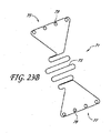
図23Bを参照すると、単一の長さまたは複数の長さの可撓性ワイヤから形成された、本発明による弁口バンドが示されている。図示される実施形態における支柱の曲げ角度および配向は、特定の配備処置に対して望ましいことがある所望の圧縮軸に適合させるため、容易に変更することができる。 Referring to FIG. 23B, a valve band according to the present invention formed from a single length or multiple lengths of flexible wire is shown. The bend angle and orientation of the struts in the illustrated embodiment can be easily changed to accommodate the desired compression axis that may be desirable for a particular deployment procedure.
一般に、弁口バンド71は、本明細書において考察してきたように、弁尖に対する支持を提供する、蛇行パターンに形成された細長い可撓性ワイヤ73を備える。図23Bには示されていないが、ワイヤ73は、本明細書の別の箇所で考察するように、早期の閉止を達成するため、心室の方向に曲がるかまたは傾斜するように形成されてもよい。ワイヤ73は、第1の接続区画75および第2の接続区画77内まで延在してもよい。接続区画75および77はそれぞれ、インプラントを弁輪に取り付けるのに縫合糸を受け入れる、複数のアイレット79を備えてもよい。インプラントは、本明細書の別の箇所に記載する様々なポリマー、ならびにチタン、チタン合金、ニチノール、ステンレス鋼、エルジロイ、MP35N、または当該分野で知られている他の金属を含む、様々な可撓性材料のいずれかから形成されてもよい。この設計には、弁尖に対して比較的大きい支持占有面積が得られると同時に、流れる血流を最大限にすることができるようにオープンスペースの面積を最適化するという利点がある。設計は、血栓形成または侵食などの有害な作用を排除するため、シリコーンもしくは他の適切な材料で処理またはコーティングしてもよい。処理は逐次的であってもよく、適切な材料の電解研磨、ハーパライゼーション(harperization)、タンブリング、酸洗い、めっき、封入または物理的蒸着のうち2つ以上を含んでもよいがそれらに限定されない。
In general, the valve band 71 comprises an elongate
図24〜図27は、異なる傾斜を有する弁口バンド50の側面図を示している。本発明の目的の1つは、本明細書の別の箇所で考察するように、単に収縮期中の弁尖を支持するだけではなく、接合平面を心室の方向で上昇させ、心周期に対して早期接合(閉止)をもたらすことである。条件の変動、および患者ごとの変動により、所与の事例に対して適切なインプラントを選択する臨床的判断を下すことができるように、本発明の弁口バンドを種々のサイズおよび/または構成で生産することが正当なものになり得る。あるいは、弁口バンドは、所望の構成のインプラントを臨床現場で手術中に構築または修正できるように、調節可能な形態またはモジュール式の形態で提供されてもよい。図24〜図27に示されるような3つのセグメントの実施形態では、中央セグメントは、流路の中央内に、または弁尖の接合縁上で中心に位置決めするために提供されてもよい。第1および第2の端部は、中央部分を組織アンカーに対して支持するため、中央部分に接続されてもよい。第1および第2の端部は、様々な長さおよび曲率で提供されて、特定の患者に対して望ましいような、比較的カスタマイズされたモジュール式インプラントを構築できるようにしてもよい。
FIGS. 24-27 show side views of the
例えば、図24は、中央部分64と、2つの緩い角度を付けたアーム部分70および72とを有する弁口バンド50を示している。第1および第2の端部52および54はそれぞれ、高さh1およびh2の分、中央部分64から変位されている。図24では、h1およびh2はほぼ等しく、約0mm〜約10mmの範囲であることができる。好ましくは、h1およびh2は少なくとも約2mmとなり、多くの場合、少なくとも約4mmまたは6mm以上となるが、一般には約10mmまたは12mm以下である。
For example, FIG. 24 shows a
図25は、中央部分64と、2つの鋭い角度を付けたアーム部分70および72とを有する弁口バンド50を示している。第1および第2の端部52および54はそれぞれ、高さh1およびh2の分、中央部分64から変位されている。図25では、h1およびh2はほぼ等しく、約8mm〜約12mmの範囲であることができる。図26は、中央部分64と、大きい角度を付けた第1のアーム70と、緩い角度を付けた第2のアーム72とを有する弁口バンド50を示している。第1および第2の端部52および54はそれぞれ、高さh1およびh2の分、中央部分64から変位されている。図26では、h1はh2よりも高い。h1は約6mm〜約10mmの範囲であり、h2は約2mm〜約6mmの範囲である。図27は、中央部分64と、緩い角度を付けた第1のアーム70と、大きい角度を付けた第2のアーム72とを有する弁口バンド50を示している。第1および第2の端部52および54はそれぞれ、高さh1およびh2の分、中央部分64から変位されている。図27は図26の鏡像であってもよい。
FIG. 25 shows a
弁口バンド50は、患者の体内での埋込みと適合性があり、僧帽弁尖を支持するために必要な構造的一体性を有する、様々な材料のいずれかで作ることができる。例えば、適切な材料としては、チタン、チタン合金、ステンレス鋼、ステンレス鋼合金、ニチノール、エルジロイ、MP35N、他の金属および合金、セラミックス、ならびにPTFE、ポリカーボネート、ポリプロピレン、UHMWPE、HDPE、PEEK、PEBAXなどのポリマーが挙げられる。
The
弁口バンド50の血栓形成性を低減するため、弁口バンド50は、平滑な表面を備えるか、またはいくつかの実施形態では、多孔質もしくは微孔性構造を介して表面を適切に微構造化することができる。現場でのニーズに合致する表面の化学的性質、エネルギー、モルフォロジー、巨視的特徴、および一般の材料特性などの他の要因も、バンドの表面を調整する際に考慮することができる。それに加えて、弁口バンド50は、血栓形成性を低減するのに、様々な物質でコーティングすることができる。例えば、弁口バンド50は、ヘパリン、PTFEなどのポリマー、またはヘパリンもしくは別の抗血栓薬と抱合させたポリマーなど、抗血栓薬でコーティングすることができる。ヘパリンコーティングは様々な方法で達成することができ、その1つは、TDMAC-ヘパリン(トリドデシルメチルアンモニウム・ヘパリナート)中で人工器官をコーティングするか、または人工器官をそれに浸すというものであってもよい。
In order to reduce the thrombus formation of the
図28〜図31に示されるように、弁口バンド50は、前尖26に付着した腱索30の断裂42によって引き起こされる前尖26の逸脱を患っている患者の僧帽弁輪28の平面内に埋め込まれる。逸脱した前尖26が示されているが、本明細書に記載する方法は、後尖逸脱、ならびに細長い弁尖24および26によって起こる逸脱など、他の種類の逸脱の治療にも適用可能であることが理解されるべきである。弁口バンド50は、縫合糸、アンカー、返し、ステープル、自己拡張式ステント、または当業者には知られているかもしくは明白である他の技術など、様々な技術によって弁輪28に取り付けることができる。
As shown in FIGS. 28-31, the
図29および図31に最も良く示されるように、弁口バンド50は、弁口バンド50が僧帽弁尖24および26の閉止によって形成される接合縁42をほぼ横断して位置決めされるように、弁輪28内で配向される。弁口バンド50はまた、弁口バンド50が前尖24の逸脱部分を直接支持し、前尖24を僧帽弁輪28の平面よりも下方で保持し、即ち心室もしくは順行流の方向で持ち上げ、それによって逸脱および僧帽弁逆流を防止もしくは低減するようにして、前尖26の逸脱部分の上に位置決めされる。
As best shown in FIGS. 29 and 31, the
図28および図29は、収縮期中の僧帽弁18に対する弁口バンド50の影響を示している。図示されるように、前尖24および後尖26は両方とも、僧帽弁18の閉止中、弁口バンドによって支持される。弓状の弁口バンド50は、両方の弁尖24および26を弁輪28の平面よりも下方で保持するように機能し、弁尖24および26が接合縁40を形成できるようにする。単一の弁口バンド50が図示されているが、いくつかの実施形態では、僧帽弁尖24および26を付加的に支持するため、2つまたは3つまたはそれ以上などの複数の弁口バンド50を弁輪28にわたって埋め込むことができる。
28 and 29 show the effect of the
図30および図31は、拡張期中の僧帽弁18に対する弁口バンド50の影響を示している。拡張期の間、僧帽弁18は開いているので、血液が左心房12から左心室16に充満することができる。図31に最も良く示されるように、弁口バンド50は、僧帽弁18開口部の小さい部分しか閉塞しないので、血流に対する過度の抵抗を生じない。
30 and 31 show the effect of the
図32〜図35は、弁口バンド50の支持を有する場合と有しない場合の、僧帽弁18の横断面図である。収縮期の間、僧帽弁18は閉じている。弁口バンド50がないと、図33に示されるように、前尖24は僧帽弁輪28によって規定される平面Pを横切って逸脱し、それが僧房弁逆流につながっている。しかしながら、弓状弁口バンド50が左心室に向かって弧を描き、中央部分64が平面Pから変位されるようにして、弁口バンド50を弁輪28に埋め込むことによって、前尖24が平面Pの上方に逸脱するのが防止されるので、逆流(図33に図示)が排除または低減される。弁尖24および26は弁口バンド50の上にあり、血液によって弁尖24および26の遠位部分にかかる圧力が接合縁40を形成する。図34および図35に示されるように、拡張期中の僧帽弁18の性能は、弁口バンド50によって実質的に影響されない。
32 to 35 are cross-sectional views of the
弁口バンド50を埋め込み位置決めする方法について、弁口バンド50の一実施形態を用いて説明してきたが、上述したような他の実施形態も使用することができる。例えば、図36は、僧帽弁輪に埋め込まれている、より幅広のオフセットされた接合縁支持部分66を有する弁口バンド50を示している。図示されるように、接合縁支持体66はオフセットされて、僧帽弁18の接合縁を支持するように位置決めされている。それに加えて、弁口バンド50は、上述した別個のまたは一体的に取り付けられた環状もしくは弁輪形成リングなど、他のデバイスおよび処置と併せて使用することができる。それに加えて、弁口バンド50は、図38に示されるように、僧帽弁尖24および26の先端が互いに縫合74される、アルフィエリ式処置と併せて使用することができる。
Although the method of implanting and positioning the
図37を参照すると、心室の方向、または順行性と見なすことができる拡張期の血流の方向で延在する、横断方向の突出部または支持体51を有する弁口バンド50の斜視図が示されている。支持体51は、少なくとも約3mm、いくつかの実施形態では少なくとも約5mm、他の実施形態では少なくとも約1.0cmであってもよい、幅Wを有する。突出部51は、僧帽弁の弁尖が突出部51の対向する側壁53および55に接して閉じるように、アルフィエリ縫合なしで利用されてもよい。そのように、突出部51は、弁尖の閉止の心出し、ならびに接合幅の制御の助けとなる。それに加えて、バンド50は、本明細書で考察してきたように早期閉止を遂行するため、心室の方向で凸状として示されている。
Referring to FIG. 37, there is a perspective view of a
本発明による弁口バンドは、開腹外科手術によって、開胸術(例えば、経心尖的)によって、あるいは径腔的に埋込み可能な実施形態を使用する経皮的処置によって埋め込むことができる。径腔的に埋込み可能な実施形態では、その拡大直径に対して比較的短い軸線方向長さを有する自己拡張式リングまたは自己拡張式ステントなど、1つ以上の弁口バンドを自己拡張式の支持構造に取り付けることができる。弁口バンドおよび圧縮された自己拡張式の支持構造は、経皮的に挿入され、径腔的に僧帽弁内へまたはそれを超えて前進させられる、伸縮自在の外側シースを有するカテーテルに装填される。伸縮自在の外側シースを後退させて、自己拡張式の支持構造が弁輪に隣接してまたはそれに接して拡張し、それによって僧帽弁輪のほぼ平面内で1つ以上の弁口バンドを位置決めするのを可能にすることができる。各弁口バンドは長手方向軸線によって特徴付けることができ、弁口バンドは、弁口バンドの長手方向軸線が僧帽弁の接合縁を実質的に横断して配向されるように、僧帽弁内で配向される。 The valve band according to the present invention can be implanted by open surgery, by thoracotomy (eg, transapical) or by a percutaneous procedure using a radially implantable embodiment. In a radially implantable embodiment, a self-expanding support for one or more valve bands, such as a self-expanding ring or self-expanding stent having a relatively short axial length relative to its expanded diameter Can be attached to the structure. The valve band and compressed self-expanding support structure is loaded into a catheter with a telescopic outer sheath that is inserted percutaneously and advanced radially into or beyond the mitral valve Is done. With the retractable outer sheath retracted, the self-expanding support structure expands adjacent to or adjacent to the annulus, thereby positioning one or more valve bands in approximately the plane of the mitral annulus Can be made possible. Each valve band can be characterized by a longitudinal axis that is positioned within the mitral valve such that the longitudinal axis of the valve band is oriented substantially transverse to the junction edge of the mitral valve. Oriented.
「経皮的」によって、心臓から離れた血管系の位置が、例えばセルジンガー技術による針アクセスを使用するなど、皮膚を通してアクセスされることを意味する。しかしながら、外科的縮小処置または低侵襲性処置を使用することも含んでもよい。遠隔の血管系に経皮的にアクセスできることは、良く知られており、特許および医学文献に記載されている。 By “percutaneous” is meant that the location of the vasculature away from the heart is accessed through the skin, for example using needle access by Seldinger technology. However, it may also involve using a surgical reduction procedure or a minimally invasive procedure. The percutaneous access to remote vasculature is well known and is described in the patent and medical literature.
血管アクセスの地点に応じて、僧帽弁へのアプローチは順行性であってもよく、肺静脈を介した、または心房中隔を横切ることによる、左心房への進入を要することがある。あるいは、僧帽弁へのアプローチは、大動脈弁を通して左心室に入る逆行性であり得る。経皮的アクセスが達成されると、介入ツールおよび支持カテーテルが経血管的に心臓まで前進させられて、本明細書の別の箇所に記載するような様々な方法で、標的の心臓弁に隣接して位置決めされてもよい。方法は、好ましくは経皮的または経血管的となるが、本明細書に記載するインプラントおよびカテーテルの多くも、当然ながら、心臓が拍動または停止していて心筋組織を通して心臓弁にアクセスする、開腹外科技術を行うのに有用となる。デバイスの多くは、胸腔鏡的にアクセスが達成され、通常は心臓が停止されるがいくつかの事例では拍動したままであり得る、低侵襲性処置にも用途が見出される。 Depending on the point of vascular access, the approach to the mitral valve may be antegrade and may require entry into the left atrium via the pulmonary vein or across the atrial septum. Alternatively, the approach to the mitral valve may be retrograde, entering the left ventricle through the aortic valve. Once percutaneous access is achieved, the interventional tool and support catheter are advanced transvascularly to the heart and adjacent to the target heart valve in a variety of ways as described elsewhere herein. And may be positioned. The method will preferably be percutaneous or transvascular, but many of the implants and catheters described herein will of course also access the heart valve through the myocardial tissue when the heart is beating or stopped. Useful for performing open surgical techniques. Many of the devices also find use in minimally invasive procedures where access is achieved thoracoscopically and the heart is usually stopped but may remain beating in some cases.
僧帽弁への一般的な順行性アプローチが図39に示されている。僧帽弁MVは、右心房RAを通って心房中隔IASを横切り、僧帽弁MVの上方で左心房LAに入る、下大静脈IVCまたは上大静脈SVCからの標準的なアプローチによってアクセスされてもよい。図示されるように、針122を有するカテーテル120を、下大静脈IVCから右心房RA内へと前進させてもよい。カテーテル120が心房中隔IASに達すると、卵円窩FOまたは卵円孔で中隔を貫通して左心房LAに入るように、針122を前進させてもよい。この時点で、ガイドワイヤを針122から外へと前進させ、カテーテル120を撤回してもよい。
A general antegrade approach to the mitral valve is shown in FIG. The mitral valve MV is accessed by a standard approach from the inferior vena cava IVC or superior vena cava SVC across the atrial septum IAS through the right atrium RA and into the left atrium LA above the mitral valve MV May be. As shown, a
図40に示されるように、心房中隔IASを通したアクセスは、通常、ガイドカテーテル125を、一般的には上述したように配置されているガイドワイヤ124の上に配置することによって維持される。ガイドカテーテル125は、以下でさらに詳細に記載するように、弁または組織の修正を行うのに使用されるツールを導入できるようにする、その後のアクセスを提供する。 As shown in FIG. 40, access through the atrial septum IAS is typically maintained by placing a guide catheter 125 over a guidewire 124 that is typically placed as described above. . Guide catheter 125 provides subsequent access that allows the introduction of tools used to perform valve or tissue modifications, as described in more detail below.
僧帽弁への一般的な逆行性アプローチが図41に示されている。ここで、僧帽弁MVは、大動脈弓AAから、大動脈弁AVを横切って、僧帽弁MVの下の左心室内へのアプローチによってアクセスされてもよい。大動脈弓AAは、従来の大腿動脈アクセス経路を通して、ならびに上腕動脈、腋窩動脈、または橈骨動脈もしくは頚動脈を介するより直接的なアプローチを通してアクセスされてもよい。図42に示されるように、かかるアクセスはガイドワイヤ128を使用して達成されてもよい。配置されると、ガイドカテーテル126はガイドワイヤ128の上を辿ってもよい。ガイドカテーテル126は、以下でさらに詳細に記載するように、弁の修正を行うのに使用されるツールを導入できるようにする、その後のアクセスを提供する。
A general retrograde approach to the mitral valve is shown in FIG. Here, the mitral valve MV may be accessed from the aortic arch AA across the aortic valve AV by an approach into the left ventricle below the mitral valve MV. The aortic arch AA may be accessed through conventional femoral artery access pathways and through a more direct approach via the brachial artery, axillary artery, or radial or carotid artery. Such access may be achieved using a
いくつかの例では、僧帽弁へのアクセス経路は、順行性および逆行性両方のアプローチ方向で確立されてもよい。これは、例えば、1つの経路を通して導入された特定のデバイスを使用して把持が行われ、別の経路を通して導入された別個のデバイスを使用して固定が達成される場合に有用なことがある。1つの可能な状況では、弁口バンドは逆行性アプローチで導入されてもよい。弁口バンドが定位置で保持された状態で、固定ツールを順行性アプローチで導入して、弁口バンドを定位置に固定してもよい。あるいは、弁口バンドおよび固定ツールのアクセス経路は反対にしてもよい。このように、様々なアクセス経路が個別に、または本発明の方法およびデバイスと組み合わせて使用されてもよい。 In some examples, the access path to the mitral valve may be established in both antegrade and retrograde approach directions. This may be useful, for example, when gripping is performed using a specific device introduced through one path and fixation is achieved using a separate device introduced through another path. . In one possible situation, the valve band may be introduced with a retrograde approach. With the valve band held in place, a locking tool may be introduced with an antegrade approach to fix the valve band in place. Alternatively, the access path of the valve band and the fixation tool may be reversed. Thus, various access paths may be used individually or in combination with the methods and devices of the present invention.
図43Aを参照すると、本発明の一態様による経皮的に送達可能なインプラントの概略図が示されている。配備システムは配備カテーテル200を含み、本明細書ではその遠位端のみが示されている。配備カテーテル200は、従来の寸法および当業者に知られている材料を利用して、僧帽弁にアクセスするように、既知の技術にしたがって構成される。一般に、配備カテーテル200は、近位端(図示なし)と遠位端204との間を延在する細長い可撓性の管状体202を備える。近位端は、カテーテル200の各機能的管腔と連通しているルアーコネクタなどのアクセスポータルを含む、近位側マニホルドを備える。
Referring to FIG. 43A, a schematic diagram of a transdermally deliverable implant according to one embodiment of the present invention is shown. The deployment system includes a
遠位端204は、中央管腔206を介して近位端と連通している、遠位側に面する開口部208を備える。
The
中央管腔206内には折り畳まれたインプラント210が位置決めされている。インプラント210は、配備カテーテル200内に位置決めするためなどの第1の径方向で縮小された構成と、治療部位で位置決めするための第2の径方向で拡大された構成(図43Cを参照)との間で変換可能である。第1の構成から第2の構成へのインプラントの変換は、バルーン拡張を介するなど、正の力の下で遂行されてもよい。あるいは、本明細書に示されるように、変換は、管状体202によってもたらされる拘束が除去されるのに応答して、インプラント210が自己拡張することによって遂行される。
A folded
一般に、インプラント210は、フレームまたはアンカー構成要素212と、弁尖支持構成要素214とを備える。弁尖支持構成要素214は、配備カテーテル内に位置決めするのに環状バンドが径方向で低減され、続いて僧帽弁に広がるように径方向で拡大されてもよいように構成または再構成された、環状バンドとして本明細書で上述したものに類似する様々な構造のいずれかを備えてもよい。インプラント210は、それに加えて、弁尖支持体214を治療部位で固定するアンカー構成要素を備える。図示される実施形態では、アンカー212は、拘束が除去された後に径方向で拡大可能である、ジグザグのワイヤまたはフィラメント構造として概略的に示されている。しかしながら、様々な構成のいずれかをアンカー212に利用してもよい。
In general, the
図43Bを参照すると、外側の管状可撓性本体202が、インプラントから部分的に後退されて、インプラントが径方向で拡大し始められることが示されている。図43Cは、アンカー212を配備部位で完全に解放する、管状体202のさらなる後退を示している。図示されるように、アンカー212は左心房内において径方向で拡大する。弁尖支持体214は、僧帽弁尖の接合縁に対してほぼ横断方向で延在し、本明細書の別の箇所に記載しているように、僧帽弁尖の接合を心室の方向に前進させるため、僧帽弁の方向で凸状であるかまたは傾斜している。
Referring to FIG. 43B, the outer tubular
図43Aで分かるように、インプラント210は少なくとも1つの制御ライン216によって制御される。制御ライン216は、配備カテーテル200の長さ全体を通して、近位側マニホルドまたはその付近にある少なくとも1つのコントロールまで延在する。これによって、インプラント210に対して可撓性本体202を近位側に後退させ、また配備システムの最終分離前のインプラント210を制御することができる。
As can be seen in FIG. 43A, the
図43Cを参照すると、少なくとも第1の制御ワイヤ216と、第2の制御ワイヤ218と、第3の制御ワイヤ220とが、アンカー212に接続されて示されている。制御ワイヤ216、218、および220によって、インプラントをその所望の最終位置へと操作することができ、最終分離前にインプラントを取り外すという判断がなされた場合、必要であれば、インプラントを配備カテーテル内へと近位側に後退させることができる。
Referring to FIG. 43C, at least a
インプラント210の最終分離前に、インプラントをその所望の埋込み位置で保定するのに、追加の固定構造が係合されてもよい。例えば、アンカー212は、僧帽弁輪または弁尖の基部または他の隣接した解剖学的構造を係合する、様々な組織アンカーまたは返しのいずれかを備えてもよい。あるいは、別個の組織アンカーを、配備カテーテル200を通して前進させ、アンカー212を隣接組織に固定するのに利用してもよい。適切なアンカーは、好ましくは、配備カテーテル200を通して移動し組織を穿孔する第1の縮小断面構成から、組織からの除去に抵抗する第2の拡大構成へと拡大可能である。図43Cに示される実施形態では、簡潔にするため、二次的な固定構造は示されていない。
Prior to final separation of the
インプラント210の位置が検証され容認可能であることが分かり、二次的な固定構造を導入するか否かの判断が行われると、制御ワイヤ216、218、および220はアンカー212から分離され、配備カテーテル200は患者から除去される。インプラント210からの制御ワイヤの分離は、電解分離、軟化性もしくは可溶性リンクの温度上昇による分離、制御ワイヤのねじ込み端部がアンカー212からねじ式で係脱されるように制御ワイヤを回転させることなどによる機械的分離、またはシステムの所望の機能性および輪郭に応じた他の分離技術など、様々な方法のいずれかで遂行されてもよい。
Once the position of the
図43Dを参照すると、拘束されていない(例えば、ベンチトップ)拡大構成のインプラント210の側面図が示されている。アンカー210は、第1の端部で複数の頂点224によって、また第2の端部で複数の頂点226によって接合されて、「Zステント」構成と呼ばれる場合があるジグザグ構造を作り出す、複数の支柱222を備える。この構成は便利であり、血管内インプラントの分野で良く理解されているが、任意の多種多様な構造が利用されてもよい。例えば、ジグザグワイヤパターン、金網パターン、または正弦ワイヤパターンが利用されてもよい。管材原料などからのレーザー切断壁パターンも利用されてもよく、多種多様の複雑な壁パターンのいずれかを備えてもよい。一般に、様々なニチノール合金のいずれかなど、ニッケルチタン合金が好ましい。しかしながら、壁パターンに応じて、ステンレス鋼、エルジロイ、特定のポリマー、または他の材料も使用されてもよい。ニチノールなどの合金をアニーリングし、形状設定するのに熱処理を要することがある。他の合金は、前の処理中に生じた応力を緩和するのに、アニーリングのみを要することがある。
Referring to FIG. 43D, a side view of an unconstrained (eg, bench top) expanded
図43Eを参照すると、インプラントの弁口バンド部分の横断方向構成を示すため、図43Dに示されるインプラントの端面図が示されている。この図では、弁口バンドは、接合点232でアンカー212に接続される複数の支柱230を備える。次いで、支柱230は、弁の接合縁に沿って測定される弁口バンドの有効占有面積を増加させる一方で、中を流れる血流の閉塞を最小限に抑えるため、分岐区画234または他の構成へと分割されてもよい。埋め込まれた弁の接合縁は、好ましくは、埋め込まれたバンドの図43Eに示される横断方向軸線236とほぼ整列されるようになる。僧帽弁の接合の軸線は、好ましくは、埋め込まれた構成の軸線236に平行であるが、軸線236の約45°以内、好ましくは約20°以内、最も好ましくは約10°以内であってもよい。
Referring to FIG. 43E, an end view of the implant shown in FIG. 43D is shown to illustrate the transverse configuration of the valve band portion of the implant. In this view, the valve band comprises a plurality of
図44Aおよび図44Bを参照すると、固定構造212の隣接組織に対する一次的または二次的な固定を提供するのに利用されてもよい、アンカー配備カテーテルが示されている。アンカー配備カテーテル250は、僧帽弁の近傍にアクセスするように構成された細長い可撓性の管状体252を備える。管状体252は、近位端254と遠位端256との間を延在する。遠位端256は、中央管腔260へのアクセスを可能にする遠位側開口部258を備える。細長い可撓性のコアワイヤ262は、近位端254から管腔260の長さの大部分にわたって遠位面264まで延在する。図44Cを参照のこと。コアワイヤ262の近位端は、中央管腔260内におけるコアワイヤ262の軸線方向での往復移動を可能にする、制御部266を備える。
Referring to FIGS. 44A and 44B, an anchor deployment catheter is shown that may be utilized to provide primary or secondary fixation to adjacent tissue of the
組織アンカー268は、送達カテーテル250の遠位端内に位置決めされてもよい。使用の際、管状体252に対して軸線方向で遠位側に前進させることなどによる、制御部266の操作によって、コアワイヤ262が軸線方向で前進して、遠位側開口部258を通してアンカー268を排出する。遠位側開口部258は、好ましくは、鋭い遠位先端270をもたらすため、傾斜または角度を付けた切断部を備える。これにより、アンカー268の全てまたは一部分を標的組織内に配備するように制御部266を操作できるように、遠位先端270を所望の部位で組織内へと遠位側軸線方向で前進させることができる。
インプラントおよびインプラント固定境界面の所望の構成に応じて、様々な組織アンカー268のいずれかが利用されてもよい。図示される実施形態では、アンカー268は二重「Tタグ」アンカーとして構成される。第1の組織係合要素272は、フィラメント276によって第2のインプラント係合要素274に接続される。使用の際、遠位先端270は僧帽弁輪の組織内に位置決めされる。制御部266は、組織表面の下方に第1の要素272を配備するように操作される。その後、管状体252は近位側に後退されて、第2の要素274がインプラントを係合し、隣接組織に接して保定することが可能になる。
Any of a variety of tissue anchors 268 may be utilized depending on the desired configuration of the implant and the implant fixation interface. In the illustrated embodiment,
アンカー送達カテーテル250は、配備カテーテル200を通して、ならびに/またはガイドワイヤもしくは支持ワイヤなどのガイドに沿って前進させられてもよい。図示される実施形態では、アンカー配備カテーテル250は、アンカー送達カテーテルがガイドワイヤに沿って辿ることを可能にするガイド管腔278を備える。ガイド管腔278は管状壁280によって規定される。管状壁280は、カテーテル本体を二重管腔押出しとして形成することなどによって、アンカー送達カテーテル250の全長に延在してもよい。あるいは、管状壁280は、約3cm以下、好ましくは約2cm以下の長さなど、カテーテルの全長と比べて短い軸線方向長さを備えてもよい。これにより、以下で説明するような、モノレールまたは急速交換の方法で、アンカー送達カテーテルがガイドワイヤに沿って進むことが可能になる。
図45Aおよび図45Bを参照すると、上述のアンカー送達カテーテルと共に使用するように構成されたインプラントが示されている。一般に、インプラントは、可撓性接続部296によって分離された、第1の弁尖支持体292と第2の弁尖支持体294とを備える。可撓性接続部296によって、インプラント290を配備カテーテル内で折り畳み、インプラント290が上述したような弁口バンドとして機能できるような形で後で拡大することができる。インプラント290は、当業者には理解されるように、ワイヤフレームの使用、またはシート原料からレーザー切断することなどによる、様々な方法のいずれかで製造されてもよい。
Referring to FIGS. 45A and 45B, an implant configured for use with the anchor delivery catheter described above is shown. In general, the implant comprises a
図示される実施形態では、第1および第2の可撓性接続部296は、埋め込まれた方向としての接合軸線に実質的に平行であるように構成された平面内にある。第1の弁尖支持体292および第2の弁尖支持体294のそれぞれの横縁部は、組織アンカーを受け入れる、少なくとも1つ、好ましくは2つまたは3つの穴298、布地パッチ、または他のアンカー取付け構造を備える。
In the illustrated embodiment, the first and second
図45Bを参照すると、図45Aのインプラントは、可撓性接続部296の周りで屈曲された部分的に折り畳まれた構成で示されている。それに加えて、制御ワイヤ300、302、および304は、インプラント290に解放可能に接続されて示されている。制御ワイヤ300、302、および304は、インプラント290を、上述したカテーテル200などの配備カテーテルから前進させ、アンカーが完全に配備されるまでインプラントを操作するのに利用されてもよい。その後、制御ワイヤ300、302、および304は、デバイスの望ましい機能性に応じて、電解分離、ポリマー性リンクの溶融、ねじ込み接続のねじを外すこと、または他の分離メカニズムなどによって取り外されてもよい。
Referring to FIG. 45B, the implant of FIG. 45A is shown in a partially folded configuration that is bent around a
図46A〜図46Eを参照すると、インプラントを僧帽弁に順行方向から配備する手順を示している。インプラント290は、図45Aおよび図45Bに示されるものと類似しているか、または本明細書の別の箇所に開示される他のインプラントの壁パターンまたは特性を有してもよい。一般に、インプラント290は、図46A〜図46Cに示される手順でカテーテル200から配備される。単純にするため、周囲の解剖学的構造は除去している。
Referring to FIGS. 46A-46E, a procedure for deploying the implant to the mitral valve from the antegrade direction is shown. The
図46Dを参照すると、アンカー送達カテーテル250は、制御ワイヤ300がガイド管腔278内で軸線方向で移動可能に位置決めされるように、制御ワイヤ300のうち1つの近位端上へと前進させられる。これにより、カテーテル分野で理解されているようなモノレールまたは急速交換構成で、アンカー送達カテーテル250を制御ワイヤ300に沿って前進させることができる。アンカー送達カテーテル250は、遠位先端270が、穴298または布地タブまたは他の取付け構造を通って前進し、僧帽弁尖または僧帽弁輪の基部の隣接組織に入るまで、制御ワイヤ300に沿って前進させられる。制御部266は、図46Dに示されるように、第1のアンカー要素272を遠位側開口部258から組織内へと前進させる遠位方向前進などによって操作される。
Referring to FIG. 46D, the
アンカー送達カテーテル250は、その後、遠位側開口部258を穴298のデバイス近位側に位置決めするように近位方向に撤回され、コアワイヤ262は、第2のアンカー要素274をアンカー送達カテーテル250の遠位側開口部258から配備するため、さらに遠位方向に前進させられる。アンカー送達カテーテル250は、その後、患者から近位方向に撤回されてもよい。その後、同じまたは異なるアンカー送達カテーテル250を、第3の制御ワイヤ304に沿って前進させて、図46Eに示されるように別の組織アンカーの配備を可能にしてもよい。
The
インプラント290は、図46Eでは、本明細書の別の箇所で考察しているように、心室の方向に傾いて弁尖を支持する中央部分を有するものとして示されている。この構成は、インプラント290の構造および材料に組み込まれている固有のバイアスによって保定されてもよい。あるいは、心室の方向に傾いた構成は、機械的インターロック、容量性放電/電解溶接を用いた現場での熱溶接、制御ワイヤ302を用いた、または単に僧帽弁輪に起因する機械的力による、クリップもしくは他の係止構造の適用などにより、積極的介入によって保定されてもよく、それによって、可撓性接続部296が心房の方向で反転するのに十分なデバイスの横方向拡大が妨げられる。あるいは、後述する本発明の経心尖的な実現例に関連して記載するように、可撓性接続部296の近傍などにあるインプラント290を心室の対向する壁に接続する、埋込み可能な制御ワイヤ(図示なし)が導入されてもよい。
The
本発明のさらなる実現例が、図47A〜図47Eに関連して図示されている。図47Aを参照すると、第1の制御ライン300および第3の制御ライン304が、第1のガイドチューブ310および第2のガイドチューブ312に置き換えられている。第1のガイドチューブ310および第2のガイドチューブ312はそれぞれ、インプラントの配備を制御すること、ならびにそこを通して組織アンカーを導入するのを可能にすることという二重の機能を有する。これによって、上述したような別個の組織アンカー配備カテーテルの使用が回避される。
A further implementation of the present invention is illustrated in connection with FIGS. 47A-47E. Referring to FIG. 47A, the
図47Bに示されるように、インプラントが僧帽弁の近傍に暫定的に位置決めされると、第1の組織アンカー314が第1のガイドチューブ310を通して配備される。第2の組織アンカー316は第2のガイドチューブ312を通して配備される。組織アンカーは、「T」タグタイプの構造、ピグテールもしくはコークスクリュー構造、または当該分野で知られている他の様々な軟組織アンカーのいずれかを含んでもよい。一般に、本目的に利用される組織アンカーは、好ましくは、第1の縮小断面構成から第2の径方向に拡大した断面構成へと変形可能であって、小さい針またはチューブを通して配備し、次に引抜きに対して比較的高い抵抗をもたらすことができるようにしている。径方向の拡大は、アンカーの一部分の角運動によって、または径方向の物理的拡張によって遂行されてもよい。
As shown in FIG. 47B, a
図47Cを参照すると、第1のガイドチューブ310および第2のガイドチューブ312は、組織アンカーの配備後に除去されている。ガイドチューブは、本明細書の別の箇所に開示される様々な分離技術のいずれかを使用して除去されてもよい。ガイドチューブの除去の前または後に、管状体202または制御ワイヤ302のどちらかに対する遠位方向の圧力によって、図47Cに示される構成から図47Dおよび図47Eに示される最終構成へとインプラントが反転する。図47Dおよび図47Eの反転した構成は、固定によって僧帽弁輪に付与される機械的バイアスによって、または本明細書の別の箇所に記載される技術を使用して保定されてもよい。制御ワイヤ300は、その後、図47Eに示されるように、インプラントから分離される。
Referring to FIG. 47C, the
あるいは、本発明の様々なインプラントのいずれかが、経心尖アプローチなど、心室を横切って導入されてもよい。当業者であれば本明細書の開示に照らして理解するように、僧帽弁への逆行性アプローチには、インプラントおよび配備システムの両方に対して特定の修正を要することになる。 Alternatively, any of the various implants of the present invention may be introduced across the ventricle, such as a transapical approach. As those skilled in the art will appreciate in light of the disclosure herein, the retrograde approach to the mitral valve will require specific modifications to both the implant and the deployment system.
例えば、経心室アプローチが図48A〜図48Dに示されている。配備カテーテル320は、心室に導入され、僧帽弁を通って逆行して、遠位側開口部208を心房内で位置決めする。インプラントは、本明細書の他の箇所に記載しているように、配備カテーテル320内で運ばれる。一般に、インプラントは、可撓性区域または枢動点によって分離された、第1の弁尖支持体292と第2の弁尖支持体294とを備える。
For example, a transventricular approach is shown in FIGS. 48A-48D. The
本発明の逆行性の実現例では、第1および第2の弁尖支持体は、制御ワイヤ300の軸線と実質的に平行である第1の構成と、図48A〜図48Dに示されるような、デバイスの近位方向で制御ワイヤ300の長手方向軸線から径方向外側に傾いた第2の位置との間で移動させてもよいように、可撓性であるか、または制御ワイヤ300の長手方向軸線に対して枢動可能である。したがって、インプラントは、組織アンカー314および316がそれぞれデバイスの近位方向を指している状態で、第1の弁尖支持体292および第2の弁尖支持体294が第1の縮小断面プロファイル構成のとき、配備カテーテル320内にあってもよい。この実施形態では、組織アンカー314は、第1の弁尖支持体292および第2のアンカー316が第2の弁尖支持体294によって同様に支えられてもよいように、恒久的に固定されるかまたは一体であってもよい。
In the retrograde implementation of the present invention, the first and second leaflet supports are in a first configuration that is substantially parallel to the axis of the
配備カテーテル320の遠位端が心房内で位置決めされていると、制御ワイヤ300を遠位方向に前進させて、遠位側開口部208を超えてアンカー314および316を前進させてもよい。これにより、インプラントが解放され、第1および第2の弁尖支持体の間の角度を増加することが可能になって、組織アンカー314および316が所望の組織アンカー標的部位に向けることができる。制御ワイヤ300の近位方向の後退は、図48Bに示されるように、組織アンカーを標的組織内に据え付けるのに利用されてもよい。
Once the distal end of
制御ワイヤ300のさらなる近位方向の牽引は、インプラントを図48Cに示される構成へと反転させるのに利用されてもよい。この時点で、制御ワイヤ300は、本明細書の別の箇所で考察されているように、インプラントから切断されてもよい。あるいは、配備カテーテル320は、制御ワイヤ300がインプラントに固定されたままで近位方向に後退されてもよく、制御ワイヤの第2の部分は、心室の心外膜面内または面上で組織アンカー322に固定されてもよい。アンカー322は、綿撒糸、ボタン、または心室内への制御ワイヤ300の後退に抵抗する心外膜面に対する占有面積を提供する他の構造など、様々な構造のいずれかを含んでもよい。制御ワイヤ300は、その後、心室に広がり、図48Dに示されるようなインプラントの構成を保定するように、制御ワイヤ300およびアンカー322を配置したまま、アンカー322に対する固定の近位側で切断されてもよい。
Further proximal traction of the
前述の全ての実施形態では、僧帽弁内のインプラントの最終構成が非常に概略化された形態で示されており、心室の方向への傾きの角度および程度は、望ましい臨床性能に応じて、本明細書に示されるものよりも大幅に大きくてもよい。弁口バンドの傾きは、健康な天然の弁に接合されているように、表面が弁尖によって作られる三次元的特徴を模倣するので、好ましい方法で「生理学的接合」を容易にする臨床上の利益を提供するのに、いくつかの実施形態では非常に有利な場合がある。 In all the previous embodiments, the final configuration of the implant within the mitral valve is shown in a highly schematic form, with the angle and degree of tilt toward the ventricle depending on the desired clinical performance, It may be significantly larger than that shown herein. The inclination of the valve band mimics the three-dimensional features created by the leaflets, as it is bonded to a healthy natural valve, thus clinically facilitating “physiological bonding” in a preferred way. In some embodiments, it may be very advantageous to provide this benefit.
図49A〜図49Hを参照すると、僧帽弁への経心尖アプローチ、および本発明による弁口バンドの配備が示されている。図49Aに示されるように、配備カテーテル320は開胸術などによって導入され、僧帽弁を通して逆行して前進させられている。弁口バンド324は、カテーテル320から遠位側に配備されており、左心房内における拡張構成で図49Aに示されている。カテーテル320内で位置決めするための縮小断面プロファイルから、図49Aに示される拡大断面プロファイルへの弁口バンド324の拡張は、膨張式バルーンの膨張または他の機械的メカニズムなどによって、機械的力の下で遂行されてもよい。しかしながら、好ましくは、弁口バンド324は自己拡張式なので、カテーテル320の遠位端から配備されると、縮小プロファイルから拡大プロファイルへと自動的に変換する。
49A-49H, a transapical approach to a mitral valve and the deployment of a valve band according to the present invention are shown. As shown in FIG. 49A, the
図示される実施形態では、弁口バンド324は、心室の方向で凸状である弓状の中央部分325を備える。図49Aおよび図49Bを参照のこと。弁口バンド324は、第1の取付け構造326および第2の取付け構造328を備える。取付け構造326および328は、フックまたは返しを含む、組織アンカーなど、本明細書に開示する様々な構造のいずれかを含んでもよい。本発明の一実現例では、第1の取付け構造326および第2の取付け構造328はそれぞれ、以下に開示するようなアンカーを受け入れる標的を備える。本目的に適した標的としては、織布または不織布、ポリマー、または後述するように、針もしくは尖ったアンカーが貫通できるようにする他の材料もしくは構造物が挙げられる。本発明の一実現例では、取付け構造はそれぞれ、メッシュを支持し、メッシュを弁口バンド324に固定するフレームを有する、Darconメッシュを含む。
In the illustrated embodiment, the
図49Bを参照すると、図49Aに示される弁口バンド324の斜視図が示されている。弁口バンド324は、本明細書に記載してきたように、弁尖の閉止に影響を及ぼす、心室の方向で凸状である中央区画325を備える。中央区画325は、第1の取付け構造326と第2の取付け構造328との間を延在する少なくとも1つの支柱329を備える、フレーム327によって形成される。図示される実施形態では、3つの支柱が互いにほぼ平行に延在して、少なくとも2つの細長い開口部を間に規定している。構造物の構造的一体性を向上させるため、1つまたは2つまたは4つまたはそれ以上の横断方向要素331が提供されてもよい。少なくとも第1の制御ワイヤ300、また任意に第2または第3または第4の制御ワイヤ300が、弁口バンド324に解放可能に取り付けられて、バンドを操作して図49Cに示されるような位置に至らせるのを可能にしている。制御ワイヤ300は、接続点301で弁口バンド324に解放可能に接続される。地点301での接続は、ねじ込み係合、電解分離可能なリンクもしくは溶接、または他の分離メカニズムによって確立されてもよい。電解分離可能な配備システムは、他の分野の中でも、神経血管塞栓症コイルおよびステントの分野で知られており、適切なシステムが、米国特許第5,976,131号(Guglielmi, et al.)、同第6,168,618号(Frantzen)、および同第6,468,266号(Bashiri, et al.)に開示されており、それらの全体を参照により本明細書に援用する。
Referring to FIG. 49B, a perspective view of the
第1の取付け構造326は、フレーム327によって支えられた支持体333を備える。図示される実施形態では、支持体333は、メッシュ337で充満または被覆された中央開口部を有する閉鎖ループを備える。あるいは、支持体333は、所望の性能に応じて、単一の線形要素、正弦またはジグザグパターンなど、様々な構造のいずれかを含んでもよい。図示される実施形態では、支持体333は、ほぼ平面構成でメッシュ337を保持するのを容易にし、アンカー、縫合糸、または他の保定構造によって穿孔できるようにメッシュを支持するため、ループの形態で便利に提供される。第2の支持体335は、同様に、取付けを容易にするメッシュ337を備える。メッシュ337は、便利には、シリコーンコアをDarconジャケットと統合したものなど、取付け構造による穿孔ならびに長期保定の間の組織内成長の両方を容易にする、Darconまたは他の材料の層もしくはパッドであってもよい。第1の支持体333および第2の支持体335は、X線透視下でアンカー配備システムをメッシュ337内へと向けることができるように、放射線不透過性材料を含むか、または放射線不透過性マーカーを備えてもよい。
The
弁口バンド324が図49Cに示される位置へと運ばれると、様々なクリップ、ステープル、返し、縫合糸、またはメッシュ337を便利に貫通させてもよい、ならびに/または第1および第2の支持体333、335の周りでループ状にされてもよい他の構造のいずれかを使用して、第1の取付け構造326および第2の取付け構造328が隣接組織に固定されてもよい。保定要素は、胸壁の低侵襲性穿刺などによって、左心房の横から、心室から、または心外膜的にアプローチされてもよい。以下に記載する方法の実現例では、保定要素を左心室から前進させる例について記載する。
Once the
図49Cを参照すると、カテーテル320および制御ワイヤ300の近位方向牽引によって、弁口バンド324が僧帽弁の左心房側にぴったり引き寄せられるので、第1の取付け構造326および第2の取付け構造328が弁輪に接して据え付けられる。
Referring to FIG. 49C, the proximal traction of the
図49Dを参照すると、第1のアンカーガイド330および第2のアンカーガイド332は、カテーテル320の縁位端から遠位方向に前進している。あるいは、アンカーガイド330および332は、様々な形でカテーテル320と関連付けられるかまたはそれによって支えられてもよい。例えば、第1および第2のアンカーガイド330および332は、カテーテルの長手方向軸線から遠位方向で径方向外側に傾けられてもよいように、カテーテル320によって枢動可能に支えられてもよい。
Referring to FIG. 49D, the
図示された実施形態では、第1および第2のアンカーガイドは、後述するようにアンカーを方向付けるワイヤまたはチューブを備える。アンカーガイドのワイヤまたはチューブは、カテーテル320から遠位方向で前進する際に図49Dに示されるのと同様の位置を取るように事前設定されてもよい、ニッケルチタン合金(例えば、ニチノール)など、様々な材料のいずれかを含んでもよい。第1および第2のアンカーガイドは、X線透視ガイダンスを可能にするため、放射線不透過性マーカーを備えてもよく、または放射線不透過性材料から構築されてもよい。図示される実施形態では、第1および第2のアンカーガイドは、組織アンカーおよび組織アンカー配備構造を軸線方向で摺動可能に受け入れる、チューブの形態である。 In the illustrated embodiment, the first and second anchor guides comprise wires or tubes that direct the anchor as described below. The anchor guide wire or tube may be pre-set to assume a position similar to that shown in FIG. Any of a variety of materials may be included. The first and second anchor guides may comprise radiopaque markers or may be constructed from radiopaque materials to allow fluoroscopic guidance. In the illustrated embodiment, the first and second anchor guides are in the form of tubes that slidably receive the tissue anchor and the tissue anchor deployment structure in the axial direction.
図49Eを参照すると、第1のアンカー334の形態の保定要素は、第1のアンカーガイド330から、僧帽弁輪の近傍の組織を通り、第1の取付け構造326を通って遠位方向に前進させられて示されている。第1の取付け構造326を通る第1のアンカー334の貫通は、制御ワイヤ300を近位方向に牽引している間に遂行されてもよい。
Referring to FIG. 49E, the retaining element in the form of the
第1のアンカー334は、第1のアンカー334が第1の取付け構造326に形成された開口部を通って近位方向に後退するのに抵抗する、少なくとも1つ、好ましくは2つまたは4つまたはそれ以上の横断方向要素336を備える。横断方向要素または表面336は、傘状構造、Tタグ、返し、または第1の取付け構造326に形成された開口部を通って第1の方向で通過できるが、第1の取付け構造326を通って戻る第2の反対方向での後退には抵抗する他の固定構成など、様々な構造のいずれかに設けられてもよい。
The
横断方向要素336は、隣接する心筋組織を通って延在するフィラメント338によって支えられる。フィラメント338は、ポリプロピレンから作られたモノフィラメントまたはマルチフィラメント構造、ポリエチレンなどの様々な他の既知の縫合材料のいずれか、またはステンレス鋼、ニチノール、および当該分野で知られている他のものなどの金属など、様々な材料のいずれかを含んでもよい。フィラメント338は、所望の臨床性能に応じて編組または織成されてもよい、モノフィラメント構造またはマルチフィラメント構造であってもよい。少なくとも第2の類似のアンカー340が、僧帽弁の反対側に導入される。
The
図49Fを参照すると、第2の横断方向要素342は、弁口バンドの組織壁を通してしっかり固定するため、フィラメント338の心室端部に固定されるか支えられて示されている。同様の構造が僧帽弁の反対側に提供される。第1および第2の固定システムのみについて上述してきたが、左右対称とするため、合計4つまたは6つまたは8つまたはそれ以上など、一般的には偶数の追加の固定システムが使用されてもよい。組織アンカーの数および構成は、本明細書の開示に照らして当業者には明白となるように、弁口バンドの構成に応じて決まる。
Referring to FIG. 49F, the second
図49Fに示されるように、アンカーは完全に配備されており、第1のアンカーガイド330および第2のアンカーガイド332はカテーテル320内へと近位方向で後退させられている。
As shown in FIG. 49F, the anchor is fully deployed, and the
図49Gを参照すると、制御ワイヤ300は、その後、弁口バンドから分離され、除去されてもよい。制御ワイヤ300の分離は、本明細書の別の箇所に記載しているような様々な方法のいずれかで遂行されてもよい。
Referring to FIG. 49G, the
あるいは、制御ワイヤ300は、図49Hに示されるように配置されたままであってもよい。制御ワイヤ300は、記載してきたように、経心室トラスを提供するため、心外膜アンカー322に固定されてもよい。
Alternatively, the
図50Aおよび図50Bを参照すると、図49A〜図49Hの経心尖送達、または本明細書に記載する他の任意の送達モードのいずれかで使用するように適合されてもよい、配備カテーテル360の遠位端の概略側面図が示されている。図示される実施形態では、配備カテーテル360は、遠位端364で開いている中央管腔362を有する細長い管状体を含む。中央管腔362内には、丸められた構成の弁口バンド366がある。弁口バンド366は、配備カテーテル360によって与えられる拘束によって、丸められた構成で維持される。しかしながら、押し要素368を遠位方向に前進させて、図50Bに示されるように、遠位端364を超えて弁口バンド366を配備すると、弁口バンド366はその自然なバイアス下で広がって、僧帽弁を横切って埋め込むための所定の構成となる。
With reference to FIGS. 50A and 50B, a
弁口バンドの1つの構成が、図51Aの平面図で広げられて示されている。しかしながら、本明細書に開示される様々な代替の弁口バンド構成のいずれかを、図50Aおよび図50Bのカテーテルと共に利用することができる。 One configuration of the valve band is shown expanded in the plan view of FIG. 51A. However, any of the various alternative valve band configurations disclosed herein can be utilized with the catheters of FIGS. 50A and 50B.
図51Aを参照すると、僧帽弁の接合縁にわたる中央部分368を有する弁口バンド366が示されている。第1の取付け区域370および第2の取付け区域372は、中央部分368の対向する端部上に設けられる。
Referring to FIG. 51A, a
中央部分は、考察してきたように僧帽弁にわたる、少なくとも第1の支柱374を備える。図示される実施形態では、第2の支柱376および第3の支柱378が設けられ、弁尖との接触占有面積の幅を増加させるが血流が通るように離間している。支柱374、376、および378のそれぞれの第1の端部は第1の取付け区域370で接続され、3つの支柱の第2の端部は第2の取付け区域372で接続される。
The central portion comprises at least a
第1および第2の取付け区域は、長期の取付けを容易にする補強要素382を備えてもよい。弁口バンド366が開腹外科処置で使用することが意図されるものであるとき、手で縫合できるようにするのに提供されてもよい、アパーチャ380が示される。あるいは、経腔または経心尖配備で使用されることが意図されるとき、アパーチャ380は、アンカー配備カテーテルを使用した取付け用に構成されてもよい。第1、第2、および第3のリブはそれぞれ、ニチノールもしくはステンレス鋼のワイヤまたはリボンなどの中央コアと、シリコーンのようなコポリマーを有するもしくは有さないポリカーボネートウレタン、シリコーンコーティング、またはPET、ePTFE、ポリエチレンなどの布地、あるいは例えば、上述の材料を含浸させたシリコーンコーティングのハイブリッドなどの外側コーティングとを備えて、僧帽弁尖の擦過のリスクを低減してもよい。図51Aの円形区域51Dの拡大図が図51Dに示されている。
The first and second attachment areas may include a reinforcing
図51Dは、図51Dに示される支柱374、376、378のうち1つ、2つ、またはそれ以上の近位および/または遠位端の耐疲労性末端部分の一実施形態を示している。末端部分51Dは、非線形部分378'と頭部部分379とを有してもよい。非線形部分は、支柱の耐疲労性を有利に増加させる、らせん、ジグザグ、または他の任意のほぼ非線形の形状を有するコイルであることができる。いくつかの実施形態では、疲労耐性をさらに改善するため、末端部分51Dの少なくとも一部分は、シリコーン、ポリカーボネート、ウレタンなどのエラストマーに埋没させている。いくつかの実施形態では、末端部分51Dは、支柱の20%未満、15%未満、10%未満、5%未満、またはそれ以下の直線長さを有してもよい。いくつかの実施形態では、末端部分51Dは、支柱の長さの少なくとも約5%、10%、15%、20%、25%、またはそれ以上の直線長さを有してもよく、あるいはさらには、第1の取付け区域370から第2の取付け区域372までの1つ、2つ、またはそれ以上の支柱374、376、378の全長を網羅することができる(例えば、線形部分を有さない支柱)。頭部部分379は非線形部分378'に動作可能に接続され、部分は一体的に形成されてもよい。頭部部分379は、球状、卵形、正方形、長方形、三角形、または様々な他の形状であることができる。頭部部分379は、次いで、第1の取付け区域370および/または第2の取付け区域372に動作可能に接続される。いくつかの実施形態では、頭部部分379は取付け区域に取り付けられておらず、それよりもむしろ、支柱374、376、378のうち1つ以上の自由端として終端する。
FIG. 51D illustrates one embodiment of one, two, or more of the proximal and / or distal end fatigue resistant end portions of the
図51Bは、図51Aの弁口バンド366の側面図であり、平面構成で示されている。しかしながら、本明細書の別の箇所で考察してきたように、弁口バンドは、一般的に、僧帽弁尖を心室の方向で前進させ、生理学的接合をもたらすように、湾曲を備えるようになる。
FIG. 51B is a side view of the
図51Cは、図50Bに示されるものと同様の、送達用に丸められた構成の渡環バンド366の斜視図を示している。バンドは、バンド366を中央またはその付近(363付近)で捕捉し、両端が図示されるように内側に引き込まれるように丸めるなど、様々な形で丸めることができる。いくつかの実施形態では、バンドは、巻物のように丸めるか、または「V」、「W」、もしくは様々な他の形状に折り畳むことができる。いくつかの実施形態では、バンド366の少なくとも一部分は、送達カテーテル内の心棒367または他の細長い本体の遠位端363上にある、1つ以上のスロット363または可動の顎様要素内に存在する。顎様要素を作動させてバンド366を解放すること、押出しチューブを遠位方向で移動させること、心棒367を別のカテーテルに対して後退させること、または他のメカニズムを用いて、バンド366を配備することができる。いくつかの実施形態では、心棒を、約90°など所望の距離だけ回転させることは、配備のためにバンド366を展開するのを容易にする助けとすることができる。
FIG. 51C shows a perspective view of a
図52A〜図52Cを参照すると、経皮的用途または開腹手術用途のどちらかに適合されていてもよい組織取付けシステムを有する、本発明による弁口バンドが示されている。弁口バンドは、記載してきたような第1の取付け区域370および第2の取付け区域372を有する中央区域368を備える。
Referring to FIGS. 52A-52C, a valve band according to the present invention is shown having a tissue attachment system that may be adapted for either percutaneous or open surgical applications. The valve band comprises a
「Tタグ」アンカーなどの組織アンカー390は、横断方向要素392と細長い可撓性縫合糸394とを含む。本明細書で使用するとき、「縫合糸」という用語は、その通常の定義に限定されず、ポリマー、金属、それら両方の組み合わせ、ならびにものフィラメントおよびマルチフィラメント構造を含む、多種多様な細長い可撓性フィラメントの任意のものも含む。マルチフィラメント構造は、所望の性能に応じて、編組、織成、または別の方法で構成されてもよい。
A
縫合糸394は、第2の取付け区域372の第1のガイド396を通って延在して示されている。単純にするため、単一の固定システムについてのみ本明細書で開示する。しかしながら、固定システムは、中央区域368の両端で利用されてもよく、2つまたは3つまたはそれ以上など、1つを超えるアンカー390が各取付け区域で利用されてもよいことが理解されるべきである。
The
縫合糸394は、第1のガイド396を通り、次に後述するロック398を通って延在するものとして示されている。縫合糸394の自由端402は、第2のガイド400を通してさらに前進させられる。システムの意図される用途に応じて、自由端402は、配備カテーテルの長さ全体を通して近位方向に延在してもよく、その場合、第2の取付け区域372を横断方向要素392に対して引き締めるために、近位方向の牽引などによって操作されてもよい。その後、自由端402は、第2の取付け区域372の近傍または別の場所で切断されてもよい。
The
図52Cを参照すると、ロック398の詳細を見ることができる。一般に、ロック398はアパーチャ404を含み、そこを通って縫合糸394が延在してもよい。係合要素406、縫合糸がアパーチャ404を通って第1の方向で前進するが、アパーチャ404を通る反対方向での縫合糸394の動きには抵抗するように、アパーチャの内部に対して露出している。図示される実施形態では、係合要素406は、縫合糸394を機械的に穿孔または係合するように構成された、尖った先端またはスパイクである。
Referring to FIG. 52C, details of the
上述の構造により、横断方向要素392を第2の取付け区域372の近くに引き寄せる形で、自由端402を第2の取付け区域372から離れるように近位方向に撤回することが可能になる。しかしながら、横断方向要素392を牽引することによって、縫合糸394が係合要素406を係合し、横断方向要素392が第2の取付け区域372から引き離されなくなる。
The structure described above allows the
図52Dを参照すると、アンカーの1つ、2つ、またはそれ以上の横断方向要素392を通してループ状にすることができる、縫合糸394が示されている。アンカーを通してループ状にされた縫合糸394は、プーリーとして機能することができ、縫合糸394の適切な牽引によってアンカーを定位置に引き締めることができる。例えば2つ、3つ、4つ、5つ、またはそれ以上のアンカーなど、複数のアンカーを図示されるように1つのループに接続することで、有利には、1つの締付け操作でアンカーの全てを一度に引き締めるのを可能にすることができる。
Referring to FIG. 52D, a
図52Aを再び参照すると、アンカー配備ツール408が示されている。配備ツール408は、近位端410および遠位端412を有する細長い可撓性ワイヤを備えてもよい。配備ツール408は、近位端410を露出させるか制御部に取り付けて、配備ツール408の軸線方向往復移動を可能にして、経皮的経腔カテーテルの長さ全体を通して延在してもよい。遠位端412は、横断方向要素392の第1の端部にあるアパーチャ414内に解放可能に位置決めされる。横断方向要素392の第2の端部は尖った先端416を備える。
Referring again to FIG. 52A, an
使用の際、配備ツール408の遠位側軸線方向の前進は、横断方向要素392を標的組織内へと所望の深さまで駆動するのに利用される。所望の深さに達すると、配備ツール408を近位方向で後退させることによって遠位端412が近位方向に後退してアパーチャ414の外に出て、横断方向要素392を標的組織内に残したまま配備ツール408を除去することが可能になる。縫合糸394の自由端402を近位方向に牽引することで、弁口バンドを横断方向要素392に対して引き締めることができる。所望のレベルの引締めが達成されると、自由端402を解放することによって、係合要素406がさらなる解放に対抗して縫合糸394をロックすることが可能になり、それによって弁口バンドが定位置で保持される。
In use, the distal axial advancement of the
ロック398は閉じたアパーチャとして示されているが、代替のロックの実施形態は、インプラントの横縁部からのアクセスを伴うことがある。これにより、縫合糸をロックに横から装填することができ、いくつかの例では、アパーチャを通して縫合糸を端部から装填することを要する閉じたアパーチャよりも望ましいことがある。様々な代替の横装填ロックの構成が図53に示されている。
Although
図54を参照すると、本発明による代替の弁口バンドの斜視図が示されている。この実施形態では、中央区画368は、僧帽弁尖を非対称的に支持する非対称の湾曲を備える。これは、弁口バンドの幅または中央部分に沿って、健康な天然弁における接合した僧帽弁の三次元形状を模倣した輪郭をもたらし、接合中に適正な解剖学的構造を促進することによって生理学的類似体を提供する。
Referring to FIG. 54, a perspective view of an alternative valve band according to the present invention is shown. In this embodiment, the
図55および図56は、本発明による代替の弁口バンドを示している。これらの実施形態では、取付け区域は、弁輪の組織を貫通するように構成された組織アンカーを備える。一般に、組織アンカーはそれぞれ、組織を貫通する尖った端部と、組織アンカーを組織から除去するのに対抗する保定構造とを備える。図55の保定要素は、当業者には理解されるように、第1もしくは第2の返しまたは肩部の形態である。図56に示される弁口バンドの保定機構は、組織貫通構造の弓状構成を含む。弁尖の閉止による中央区域の凸状側に対する圧縮は、組織アンカーに対して円周方向の力を付与して、遠位点をそれ自体の弓状経路の方向でさらに前進させる傾向がある。この構造は、僧帽弁の閉止の自然な力によって、隣接組織内における組織アンカーの保定を増大させることを可能にする傾向がある。いくつかの実施形態では、返しを、圧着するかまたは別の方法で定位置で固定することができる一次アンカーとして使用することができる。他の実施形態では、返しは、位置を確認しながらバンドを定位置で一時的に保持する、位置決め機構として作用することができる。バンドは次に、圧着、ステープル、縫合糸、または本明細書に記載するような他のアンカーなどを使用して、第2のステップで固定することができる。いくつかの実施形態では、返しは、組織を貫通する際に自己ロックすることができる。 55 and 56 show an alternative valve band according to the present invention. In these embodiments, the attachment area comprises a tissue anchor configured to penetrate the tissue of the annulus. In general, each tissue anchor includes a pointed end that penetrates the tissue and a retention structure that resists removal of the tissue anchor from the tissue. The retaining element of FIG. 55 is in the form of a first or second barb or shoulder as will be appreciated by those skilled in the art. The valve band retention mechanism shown in FIG. 56 includes an arcuate configuration of tissue penetrating structure. Compression against the convex side of the central section due to valve leaflet closure tends to apply a circumferential force to the tissue anchor to further advance the distal point in the direction of its own arcuate path. This structure tends to allow the retention of tissue anchors in adjacent tissues to be increased by the natural force of mitral valve closure. In some embodiments, the barbs can be used as primary anchors that can be crimped or otherwise fixed in place. In other embodiments, the barb can act as a positioning mechanism that temporarily holds the band in place while checking the position. The band can then be secured in a second step using crimps, staples, sutures, or other anchors as described herein. In some embodiments, the barbs can self-lock as they penetrate tissue.
いくつかの実施形態では、粘弾性応答のような、索が接合に対して継続的な非線形的方式で抵抗するのと同じ方法で、接合に対して抵抗する弁口バンドが開示されている。このバンドは、上記に記載し例示したような構成を有することができ、接合に対する非線形抵抗をもたらす材料特性または追加の機構を有することができる。かかる実施形態は、接合された僧帽弁の自然な三次元表面を模倣する湾曲を保定することができるが、適切であれば、解剖学的に適正な接合平面まで逆行方向で変位することができる。僧帽弁に対する変位の方向は、例えば、収縮期中の心房方向としてより良好に説明され、弁尖が隆起のあるインプラント構造に衝突し、衝突縁部周囲の線維症または薄化など、潜在的に有害な形でリモデリングされるのとは対照的に、衝撃に対するクッションを弁尖に提供する。図56Aは、全体を参照により本明細書に援用する、Nielsen et al, Circulation 2003;108:486-491, Influence of Anterior Mitral Leaflet Second-Order Chordae Tendineae on Left Ventricular Systolic Functionから再現したものであり、等容性収縮中のLV圧力と索張力との間の双線形関係、排出中の高いLV圧力にかかわらない索張力の低下、および等容性弛緩中のほぼ線形の減少を示している。図56Bは、Nielsen et al, J Thorac Cardiovasc Surg 2005;129:525-31, Imbalanced chordal force distribution causes acute ischemic mitral regurgitation: Mechanistic insights from chordae tendineae force measurements in pigsから再現したものであり、その全体を参照により援用する。これらの図は、時間の増加に対する索力、およびその後の収縮期中における非線形的な減衰を示している。この性能を模倣するバンドは、その接合力がほぼ正常状態に戻る際に弁表面に利益をもたらすことができる。いくつかの実施形態では、バンドは、接合弁尖表面と繰返し接触することによって起こる物理的ストレスを、和らげるかまたは生理学的に低減もしくは防止することができる。バンドは、流体などの媒体を充填していてもいなくてもよい、チャンバ状の支柱などの構造によって、これを遂行することができる。これらのチャンバは封止されており、生存期間内の血液または血液成分の浸透に対して不透過性もしくは実質的に不透過性であろう。接合の衝撃緩和の別の方法は、接合中のある程度の屈曲を可能にするデバイスであろう。この可撓性は、支柱の材料、厚さ、幅、リプルなどの下側および上側断面、またはエラストマーもしくはエラストマー性発泡体などの封入材料に基づいて設計することができる。発泡材料は、全体の可撓性が同等の外部ポリマーによって封止することができる。追加の実施形態は、コイル(図51Dで上述したものなど)、または固有の非線形変位特性を生成するコイル中のコイル、または任意にポリマーを充填することができるニチノールレーザー切断チューブなどのチューブであろう。さらに別の実施形態は、それ自体が心室交差部分に向かってループを成す支柱を含む。このループも、そのばね力によって、接合に対するこの非線形抵抗を作り出す。他の実施形態では、バンドは索まで下方に進行することができ、デバイスは、自然生理を達成するために索を短縮または増強するように適合させることができる。この方法のデバイスは、例えば、圧着したバンドの間にエラストマー性本体を有する圧着したバンドであることができる。エラストマー性本体は、接合中の適正な力曲線を模倣するのに、索の欠陥部分を複製するであろう。これにより、緩和ケアを提供するかまたはそれを解決するように、疾患の一部の等級に十分な利益がもたらされてもよい。 In some embodiments, a valve band is disclosed that resists the joint in the same way that the cord resists the joint in a continuous non-linear fashion, such as a viscoelastic response. This band can have a configuration as described and exemplified above and can have material properties or additional mechanisms that provide a non-linear resistance to the junction. Such an embodiment can retain a curvature that mimics the natural three-dimensional surface of the joined mitral valve, but if appropriate, can be displaced in a retrograde direction to an anatomically correct joining plane. it can. The direction of displacement relative to the mitral valve is better described, for example, as the atrial direction during systole, where the leaflets collide with the raised implant structure, potentially including fibrosis or thinning around the collision edge In contrast to being remodeled in a detrimental form, it provides a cushion against impacts on the leaflets. FIG. 56A is a reproduction of Nielsen et al, Circulation 2003; 108: 486-491, Influence of Anterior Mitral Leaflet Second-Order Chordae Tendineae on Left Ventricular Systolic Function, which is incorporated herein by reference in its entirety. It shows a bilinear relationship between LV pressure and cord tension during isovolumetric contraction, a decrease in cord tension regardless of high LV pressure during drainage, and a nearly linear decrease during isovolumetric relaxation. Figure 56B is reproduced from Nielsen et al, J Thorac Cardiovasc Surg 2005; 129: 525-31, Imbalanced chordal force distribution causes acute ischemic mitral regurgitation: Mechanistic insights from chordae tendineae force measurements in pigs. Incorporated by These figures show the traction force with increasing time and non-linear decay during the subsequent systole. A band that mimics this performance can benefit the valve surface when its joining force returns to near normal. In some embodiments, the band can relieve or physiologically reduce or prevent physical stress caused by repeated contact with the junction leaflet surface. The band can accomplish this by structures such as chambered struts that may or may not be filled with a medium such as a fluid. These chambers are sealed and will be impermeable or substantially impermeable to the penetration of blood or blood components during their lifetime. Another method of bonding impact mitigation would be a device that allows some degree of bending during bonding. This flexibility can be designed based on the strut material, thickness, width, lower and upper cross-sections such as ripples, or encapsulating materials such as elastomers or elastomeric foams. The foamed material can be sealed with an external polymer of comparable overall flexibility. Additional embodiments are tubes, such as coils (such as those described above in FIG. 51D), or coils in a coil that produce unique nonlinear displacement characteristics, or Nitinol laser cutting tubes that can optionally be filled with polymer. Let's go. Yet another embodiment includes a strut that loops itself toward the ventricular intersection. This loop also creates this non-linear resistance to the joint by its spring force. In other embodiments, the band can travel down to the cord and the device can be adapted to shorten or enhance the cord to achieve natural physiology. The device of this method can be, for example, a crimped band having an elastomeric body between the crimped bands. The elastomeric body will replicate the defective portion of the cord to mimic the proper force curve during joining. This may provide sufficient benefit for some grades of the disease to provide or solve palliative care.
図57A〜図57Dは、僧帽弁ブリッジなど、本明細書では弁口ブリッジとも呼ばれる場合がある、弁口バンド500の別の実施形態を示している。図57Aは、本発明のいくつかの実施形態による弁口ブリッジ500の斜視図である。弁口ブリッジ500は、ブリッジ500の第1の端部に第1の取付け構造504と、ブリッジ500の第2の端部に第2の取付け構造526とを含むことができ、それらの取付け構造504、526は両方とも、弁輪を固定する、本明細書の別の箇所で考察したような様々な構造を含むことができる。図示されるように、取付け構造504、526は、Dacronメッシュなどのベロア材料の1つ以上の層515を有することができ、メッシュを支持し、メッシュを弁口バンド500に固定するための、基礎を成すフレームを有することができる。ベロアは、いくつかの実施形態では、6111 Polyester Double Velour Fabricであることができる。メッシュ材料は、いくつかの実施形態では、有利には、組織内成長を促進することができる。取付け構造504、526はまた、縫合糸を通して弁口ブリッジ500を弁輪に付着させるのを可能にするように構成することができる、1つもしくは複数のアパーチャ508を含むことができる。
57A-57D illustrate another embodiment of a
図57Aを引き続き参照すると、弁口ブリッジ500はまた、心室の方向で全体的に凸状であることができる、弓状の中央部分502を含むことができる。図示されるように、中央部分502は、交差区域または接合部518で交差してほぼ「X」形状を形成する、複数の支柱516を含むことができる。支柱516は、金属、例えばニチノールなどの形状記憶金属など、任意の適切な材料で作ることができる。支柱516、ならびに支柱516間の空間514は、血栓形成または侵食などの有害な作用を排除するために、シリコーンもしくは別の適切な材料で処理または被覆、例えば封入することができる。
With continued reference to FIG. 57A, the
図57Bは、図57Aの弁口ブリッジ500の上面図である。図示されるように、中央部分502は、第1の取付け部分504と第2の取付け部分526との間に及び、取付け部分504、526と実質的に同じ横断方向幅を有することができるが、交差区域518に向かう中心に向かって狭くなることができる。いくつかの実施形態では、中央交差区域518の幅C(血流に対して垂直に測定)は、取付け部分504、526に直ぐ近接した中央部分502の幅の約20%〜約80%、例えば約25%〜約50%、または約20%、25%、30%、35%、40%、45%、50%、55%、60%、65%、70%、もしくは75%であり、図示されるように中心に向かって徐々に狭くなることができる。いくつかの実施形態では、中央交差区域518の幅Cは、約4mm〜約7mm、例えば約5mm〜約6mm、または約5mm、約5.2mm、約5.4mm、約5.6mm、約5.8mm、もしくは約6mmであることができる。中央部分502を狭くすることによって、血流に対する抵抗を有利に低減することができる。
FIG. 57B is a top view of the
図57Cは、図57A〜Bと関連して図示し記載した弁口ブリッジ500の側面図である。いくつかの実施形態では、中央部分502の厚さT2は、支柱516および支柱を取り囲む封入層514によって規定することができる。いくつかの実施形態では、取付け部分504、526の厚さT1は、支柱516の端部、支柱516を取り囲む封入層514、および/または上述したようなベロア材料層515によって規定することができる。取付け部分504、526は、中央部分502の厚さよりも相対的に厚い厚さを有することができる。いくつかの実施形態では、取付け部分504、526は、中央部分502の厚さよりも約25%〜約75%厚い厚さ、例えば中央部分502の厚さよりも約40%〜約60%、または約25%、30%、40%、45%、50%、55%、60%、65%、70%、もしくは75%厚い厚さを有することができる。いくつかの実施形態では、中央部分502は、約0.6mm、0.7mm、または0.8mmなど、約0.5mm〜約1.0mmの厚さT1を有することができる。いくつかの実施形態では、取付け部分504、526は、約0.9mm、1.0mm、1.05mm、1.07mm、1.1mm、または1.2mmなど、約0.8mm〜約1.3mmの厚さを有することができる。
FIG. 57C is a side view of the
図57Cを引き続き参照すると、弁口ブリッジ500は、いくつかの実施形態では、患者の解剖学的構造に応じて、約20mm〜約32mmなど、約15mm〜約40mmの合計軸線方向長さAを有することができる。いくつかの実施形態では、弁口ブリッジ500の中央部分502は、いくつかの実施形態の約12mm〜約20mmなど、約8mm〜約24mmの軸線方向長さを有することができる。
With continued reference to FIG. 57C, the
図57Dは、支柱516、シリコーン封入層514、および取付け部分514を示す、上述の図57A〜図57Cと関連して図示し記載した弁口ブリッジ500の端面図を示している。いくつかの実施形態では、取付け構造504、526の幅Wは、約10mm〜約20mm、およびいくつかの実施形態では約15mmであることができる。
FIG. 57D shows an end view of the
図57E〜図57Hは、弁口ブリッジ500の基礎を成すスケルトン層560の図を示しており、上述したような心室の方向で凸状であることができる、形状設定されたニチノールスケルトンで形成することができる。図57Eは、上述したように交差区域518で交差する支柱516を含むことができる、弁口ブリッジ500の形状記憶スケルトン560の斜視図である。スケルトン560の側端部は、上述したように縫合に利用することができるアパーチャ508を規定する、リング509を含むことができる。弁口バンド500の中央部分502に対するスケルトン層560の寄与としては、第1の曲率を有する支柱516の外側曲線状移行区域521と、それが次いで接続される、第1の曲率とは異なる第2の曲率を有する支柱516の内側曲線状移行区域522と、弓状の中央部分502の頂点を含む交差区域518とを挙げることができる。図57Fは、図57Eのスケルトン層560の上面図である。図示されるように、いくつかの実施形態では、支柱516の外側曲線状移行区域521は、図示されるように下方に傾斜するように構成された状態で、スケルトン560の(また弁口ブリッジ500の)長手方向軸線と実質的に平行に延びることができ、一方で内側曲線状移行区域522は、スケルトン560および弁口ブリッジ500の長手方向軸線に対して斜めであることができる。いくつかの実施形態では、スケルトン層560の軸線方向長さCCは約13mm〜約25mmであることができ、各支柱516の幅BBは、約1.3mm〜約2.0mmなど、約1mm〜約2mmであることができる。図57Gは、図57E〜図57Fの形状設定ニチノールスケルトンの側面図、図57Hは端面図である。
FIGS. 57E-57H show views of the
上述したように、僧帽弁および支持構造は、弁輪、2つの弁尖、腱索、および乳頭筋で構成される。前尖および後尖は、中隔・外側方向で配向され、収縮期中の弁開口部を閉止する。収縮期の間、弁輪および弁表面は、弧を描くことによって閉止中の力を最適化するサドル形状を作り出す。索および乳頭筋は共に働いて、環内平面に対する弁尖接合を制限する。 As described above, the mitral valve and the support structure are composed of an annulus, two leaflets, chordae, and papillary muscles. The anterior and posterior cusps are oriented in the septal / lateral direction and close the valve opening during systole. During systole, the annulus and valve surface create a saddle shape that optimizes the force during closure by drawing an arc. The cord and papillary muscles work together to limit leaflet junctions to the intraannular plane.
僧帽弁ブリッジの定量的運動とそれに対する負荷:僧帽弁はサドル形状を有する。サドルが深くなるにつれて、交連は低下し、前後方向の直径が収縮する。この収縮によって、弁口ブリッジに対する圧縮負荷がもたらされる。この収縮中、弁尖の後方の圧力によって弁尖が弁口ブリッジ支柱に接触する。いくつかの実施形態では、僧帽弁ブリッジは、いくつかの実施形態では、心周期当たりおおよそまたは少なくとも約0.35N、0.40N、0.45N、0.50N、もしくは約0.368Nの、僧帽弁ブリッジに加えられる合計の円周方向力または圧縮力に耐えるように構成される。いくつかの実施形態では、僧帽弁ブリッジは、心周期中、おおよそまたは少なくとも約0.4mm、0.5mm、もしくは0.6mmの中隔・外側変位を許容するように構成することができる。そのため、僧帽弁ブリッジは、損傷なく周期疲労の負荷に耐えて長期機能を可能にし、逆流を排除する早期接合のためのAP直径または中隔・外側直径を維持し、ならびに/あるいはLVリモデリングを容易にするAP直径を維持するように構成することができる。 Quantitative movement of the mitral valve bridge and the load on it: The mitral valve has a saddle shape. As the saddle gets deeper, commissure decreases and the anteroposterior diameter shrinks. This contraction provides a compressive load on the valve bridge. During this contraction, the leaflet contacts the valve bridge strut due to the pressure behind the leaflet. In some embodiments, the mitral valve bridge is in some embodiments a mitral valve bridge that is approximately or at least about 0.35N, 0.40N, 0.45N, 0.50N, or about 0.368N per cardiac cycle. Configured to withstand the total circumferential or compressive force applied. In some embodiments, the mitral valve bridge can be configured to allow a septal-lateral displacement approximately or at least about 0.4 mm, 0.5 mm, or 0.6 mm during the cardiac cycle. Therefore, the mitral valve bridge withstands cyclic fatigue loads without damage, enables long-term function, maintains AP diameter or septal / outer diameter for early joining to eliminate backflow, and / or LV remodeling Can be configured to maintain AP diameter to facilitate.
定量的な弁尖負荷:乳頭筋に作用する力は、いくつかの実施形態では、一般的には120〜200mmHgの範囲の収縮期圧力に応じて、約3.97〜6.42Nであることができる。2つの乳頭筋が存在する。両方の筋肉が機能していない場合、僧帽弁尖に作用する負荷は13Nであろう。僧帽弁ブリッジに伝達される力は、総開口面積と僧帽弁ブリッジ支柱の面積の比を使用することによって計算できる。開口およびMB支柱面積はそれぞれ、一般的に、1000mm2および100mm2である。MB支柱に対する結果として得られる負荷は約1.3Nである。これは、索および乳頭筋が負荷を吸収していない場合に僧帽弁ブリッジが受けるであろう負荷である。したがって、いくつかの実施形態では、僧帽弁ブリッジは、損傷なしに負荷に耐えて長期機能を可能にするため、約1N〜約2N、あるいはおおよそまたは少なくとも約1.2N、1.3N、1.4N、もしくは1.5Nの弁尖負荷に耐えるように構成することができる。 Quantitative leaflet loading: The force acting on the papillary muscle can be about 3.97-6.42 N, depending on the systolic pressure, generally in the range of 120-200 mmHg, in some embodiments. There are two papillary muscles. If both muscles are not functioning, the load acting on the mitral leaflet will be 13N. The force transmitted to the mitral valve bridge can be calculated by using the ratio of the total opening area to the area of the mitral valve bridge strut. The aperture and MB strut areas are typically 1000 mm 2 and 100 mm 2 , respectively. The resulting load on the MB strut is about 1.3N. This is the load that the mitral valve bridge will experience if the cord and papillary muscles are not absorbing the load. Thus, in some embodiments, the mitral valve bridge is about 1N to about 2N, or approximately or at least about 1.2N, 1.3N, 1.4N, to withstand a load without damage and allow long-term function. Or it can be configured to withstand 1.5N leaflet load.
僧帽弁ブリッジの定量的運動:6か月にわたるブタの僧帽弁ブリッジの長期的研究によれば、その研究のエコー分析で、デバイスの中隔・外側(SL)面からの知覚できる変位がなかったことが示された。しかしながら、いくつかの実施形態では、僧帽弁ブリッジは、圧縮時および緊張時において約0.5mmの変位を許容するように構成することができる。デバイスを±0.5mm変位させる平均の力は、緊張時で約0.8358Nなど、約0.80N〜約0.85N、圧縮時で約0.63808Nなど、約0.60N〜約0.70Nである。見出された力は円周方向力の二倍超である。上述したような損傷、変位、実質的な変位を生じることなく弁接合を改善するため、僧帽弁ブリッジは、埋め込まれたときに、かかる力に耐え、安定して機能し続けるように構成することができる。したがって、僧帽弁ブリッジは、いくつかの実施形態では、おおよそまたは少なくとも約0.75N、0.80N、0.85N、0.90N、0.95N、1.00N、もしくはそれ以上の張力を許容するように構成することができる。したがって、僧帽弁ブリッジは、いくつかの実施形態では、おおよそまたは少なくとも約0.55N、0.60N、0.65N、0.70N、0.75N、0.80N、もしくはそれ以上の圧縮力を許容するように構成することができる。 Quantitative movement of the mitral valve bridge: According to a 6-month long-term study of porcine mitral valve bridge, the echo analysis of the study shows a perceptible displacement from the septal / lateral (SL) surface of the device. It was shown that there was not. However, in some embodiments, the mitral valve bridge can be configured to allow a displacement of about 0.5 mm during compression and tension. The average force that displaces the device by ± 0.5 mm is about 0.60 N to about 0.70 N, such as about 0.80N to about 0.85 N, such as about 0.8358 N when tensioned, and about 0.63808 N when compressed. The force found is more than twice the circumferential force. In order to improve valve joints without causing damage, displacement or substantial displacement as described above, the mitral valve bridge is configured to withstand such forces and remain stable when implanted. be able to. Thus, the mitral valve bridge may in some embodiments be configured to allow a tension of approximately or at least about 0.75N, 0.80N, 0.85N, 0.90N, 0.95N, 1.00N, or more. Can do. Accordingly, the mitral valve bridge is configured in some embodiments to allow a compressive force of approximately or at least about 0.55N, 0.60N, 0.65N, 0.70N, 0.75N, 0.80N, or more. be able to.
多種多様な特定の組織アンカー構造のいずれかが、本発明の弁口バンドと組み合わせて利用されてもよい。それに加えて、本発明の様々な実現例と関連して、例示として様々な特徴について記載してきた。当業者には明白であるように、本発明から逸脱することなく、上述した特徴のいずれかを、本明細書に開示した実施形態の他のいずれかと組み合わせ直してもよい。いくつかの実施形態では、弁口バンドは、完全なまたは部分的な弁輪形成リングを含まず、ならびに/あるいは弁輪に動作可能に取り付けたとき、弁輪のサイズおよび/または形状に影響しないかもしくは実質的に影響しない。 Any of a wide variety of specific tissue anchor structures may be utilized in combination with the valve band of the present invention. In addition, various features have been described by way of example in connection with various implementations of the invention. As will be apparent to those skilled in the art, any of the features described above may be recombined with any of the other embodiments disclosed herein without departing from the invention. In some embodiments, the valve band does not include a complete or partial annuloplasty ring and / or does not affect the size and / or shape of the annulus when operably attached to the annulus. Or has virtually no effect.
上述の詳細な説明は、本発明の装置および方法のいくつかの例示的な実施形態について説明してきたが、上述の説明は単なる例示であり、開示した発明を限定するものではないことが理解されるべきである。開示した特定の寸法および構成は上述のものと異なる場合があり、記載した方法は、身体内のあらゆる生物学的導管内で使用できることが理解されるであろう。 Although the foregoing detailed description has described several exemplary embodiments of the apparatus and method of the present invention, it is understood that the above description is illustrative only and is not intended to limit the disclosed invention. Should be. It will be appreciated that the specific dimensions and configurations disclosed may differ from those described above and that the described method can be used in any biological conduit in the body.
他の様々な修正、適合、および代替の設計は、当然ながら、上述の教示に照らして可能である。したがって、この時点で、添付の特許請求の範囲内で、本発明は本明細書に具体的に記載したのとは別の方法で実施されてもよいことが理解されるべきである。上記に開示した実施形態における特定の特徴および態様の様々な組み合わせまたは部分的組み合わせが行われてもよく、それらは依然として本発明の1つ以上に含まれることが想到される。さらに、一実施形態と関連する、任意の特定の特徴、態様、方法、性質、特性、品質、属性、要素などに関する本明細書の開示を、本明細書で説明する他の全ての実施形態で使用することができる。したがって、開示した発明の様々なモードを形成するために、開示した実施形態の様々な特徴および態様を互いに組み合わせるか、または互いに置換することができることが理解されるべきである。したがって、本明細書に開示する本発明の範囲は、上記の特定の開示した実施形態によって限定されないものとする。さらに、本発明は様々な修正の影響を受けやすいが、それらの特定の例については図面に示しており、本明細書で詳細に記載している。しかしながら、本発明は、開示した特定の形態または方法に限定されるものではなく、それとは逆に、本発明は、開示した様々な実施形態および添付の請求項の趣旨および範囲内にある、全ての修正例、等価物、および代替例を網羅するものである。本明細書に開示するいずれの方法も、必ずしも列挙した順序で実施されなくてもよい。本明細書に開示した方法は、実践者が行う特定の行為を含むが、明示または暗示による、それらの行為に関する任意の第三者の指示も含むことができる。例えば、「弁口ブリッジを僧帽弁輪に付着させる」などの動作は、「弁口ブリッジを僧帽弁輪に付着させるように指示する」ことを含む。本明細書に開示した範囲はまた、あらゆる重なり合う部分範囲およびそれらの組み合わせを包含する。「〜以下」、「少なくとも」、「〜超過」、「〜未満」、「〜の間」などの文言は、列挙した数を含む。「約」、「おおよそ」、および「実質的に」などの用語に続く数字は、本明細書で使用するとき、列挙した数字を含み(例えば、約10%=10%)、また、依然として所望の機能を実施するかまたは所望の結果を達成する、提示された量に近い量を表す。例えば、「約」、「おおよそ」、および「実質的に」という用語は、提示された量の10%未満以内、5%未満以内、1%未満以内、0.1%未満以内、および0.01%未満以内の量を指すことがある。 Various other modifications, adaptations, and alternative designs are, of course, possible in light of the above teachings. Accordingly, it is to be understood at this point that within the scope of the appended claims, the present invention may be practiced otherwise than as specifically described herein. Various combinations or subcombinations of particular features and aspects in the embodiments disclosed above may be made and still be contemplated as being included in one or more of the present invention. Further, the disclosure herein regarding any particular features, aspects, methods, properties, characteristics, qualities, attributes, elements, etc. associated with one embodiment may be considered in all other embodiments described herein. Can be used. Thus, it is to be understood that various features and aspects of the disclosed embodiments can be combined with each other or substituted for each other to form various modes of the disclosed invention. Accordingly, the scope of the invention disclosed herein is not intended to be limited by the particular disclosed embodiments described above. Moreover, although the present invention is susceptible to various modifications, specific examples thereof are illustrated in the drawings and are described in detail herein. However, the invention is not limited to the specific forms or methods disclosed, but on the contrary, the invention is all within the spirit and scope of the various disclosed embodiments and the appended claims. These modifications, equivalents, and alternatives are intended to be covered. Any method disclosed herein may not necessarily be performed in the order listed. The methods disclosed herein include specific acts performed by the practitioner, but may also include any third party instructions regarding those acts, either express or implied. For example, actions such as “attach the valve bridge to the mitral annulus” include “instruct the valve bridge to attach to the mitral annulus”. The ranges disclosed herein also encompass any overlapping subranges and combinations thereof. Words such as “below”, “at least”, “exceeding”, “less than”, “between” include the recited numbers. Numbers following terms such as “about”, “approximately”, and “substantially”, as used herein, include the listed numbers (e.g., about 10% = 10%) and are still desirable. Represents an amount close to the amount presented that performs the function of or achieves the desired result. For example, the terms “about”, “approximately”, and “substantially” refer to less than 10%, less than 5%, less than 1%, less than 0.1%, and less than 0.01% of the amount presented. May refer to the amount.
6 長手方向軸線
7 矢印
8 矢印
9 環内平面
10 心臓
12 左心房
14 肺静脈
16 左心室
18 僧帽弁
20 大動脈
22 大動脈弁
24 前尖
26 後尖
28 弁輪
30 腱索
32 乳頭筋
34 中隔
36 自由縁
38 自由縁
40 接合縁
41 接合区域
42 断裂
44 反転
50 弁口バンド
51 支持体
52 第1の端部
53 側壁
54 第2の端部
55 側壁
56 弁尖接触面
58 第1の固定部分
60 第2の固定部分
61 弁口バンド
62 穴
63 支持体
64 中央部分
65 第1の三角取付け区域
66 接合縁支持部分
67 第2の三角取付け区域
68 環状リング
70 アーム部分
71 弁口バンド
72 アーム部分
73 可撓性ワイヤ
74 縫合
75 第1の接続区画
77 第2の接続区画
79 アイレット
120 カテーテル
122 針
124 ガイドワイヤ
125 ガイドカテーテル
126 ガイドカテーテル
128 ガイドワイヤ
200 カテーテル
202 管状体
204 遠位端
206 中央管腔
208 開口部
210 インプラント
212 アンカー構成要素
214 弁尖支持構成要素
216 第1の制御ワイヤ
218 第2の制御ワイヤ
220 第3の制御ワイヤ
222 支柱
224 頂点
226 頂点
230 支柱
232 接合点
234 分岐区画
236 横断方向軸線
250 アンカー配備カテーテル
252 管状体
254 近位端
256 遠位端
258 遠位側開口部
260 管腔
262 コアワイヤ
264 遠位面
266 制御部
268 アンカー
270 遠位先端
272 第1の要素
274 第2の要素
276 フィラメント
278 ガイド管腔
280 管状壁
290 インプラント
292 第1の弁尖支持体
294 第2の弁尖支持体
296 可撓性接続部
298 穴
300 制御ワイヤ
302 制御ワイヤ
304 制御ワイヤ
310 第1のガイドチューブ
312 第2のガイドチューブ
314 第1の組織アンカー
316 第2の組織アンカー
320 配備カテーテル
322 アンカー
324 弁口バンド
325 中央区画
326 第1の取付け構造
327 フレーム
328 第2の取付け構造
329 支柱
330 第1のアンカーガイド
331 横断方向要素
332 第2のアンカーガイド
333 第1の支持体
334 第1のアンカー
335 第2の支持体
336 横断方向要素
337 メッシュ
338 フィラメント
340 第2のアンカー
342 第2の横断方向要素
360 配備カテーテル
362 中央管腔
363 スロット
364 遠位端
366 弁口バンド、渡環バンド
367 心棒
368 中央部分、押し要素、中央区域
370 第1の取付け区域
372 第2の取付け区域
374 第1の支柱
376 第2の支柱
378 第3の支柱
378' 非線形部分
379 頭部部分
380 アパーチャ
382 補強要素
390 アンカー
392 横断方向要素
394 縫合糸
396 第1のガイド
398 ロック
400 第2のガイド
402 自由端
404 アパーチャ
406 係合要素
408 アンカー配備ツール
410 近位端
412 遠位端
414 アパーチャ
416 尖った先端
500 弁口ブリッジ
502 中央部分
504 第1の取付け構造
508 アパーチャ
509 リング
514 空間、封入層、取付け部分
515 ベロア材料層
516 支柱
518 接合部、交差区域
521 外側曲線状移行区域
522 内側曲線状移行区域
526 第2の取付け構造
560 スケルトン層
A 軸線方向長さ
AA 大動脈弓
AV 大動脈弁
BB 幅
C 幅
CC 軸線方向長さ
FO 卵円窩
IAS 心房中隔
IVC 下大静脈
LA 左心房
LV 左心室
MV 僧帽弁
P 平面
RA 右心房
SVC 上大静脈
T1 厚さ
T2 厚さ
W 幅
h1 高さ
h2 高さ
6 Longitudinal axis
7 arrows
8 arrows
9 Inner ring plane
10 heart
12 Left atrium
14 Pulmonary vein
16 Left ventricle
18 Mitral valve
20 Aorta
22 Aortic valve
24 forehead
26 posterior leaflet
28 Annulus
30 chords
32 Papillary muscles
34 Septum
36 Free edge
38 Free edge
40 Joining edge
41 Joining area
42 Rupture
44 Invert
50 Valve band
51 Support
52 First end
53 Side wall
54 Second end
55 Side wall
56 Valve leaflet contact surface
58 First fixed part
60 Second fixed part
61 Valve band
62 holes
63 Support
64 Center part
65 First triangular mounting area
66 Joint edge support part
67 Second triangular mounting area
68 Annular ring
70 Arm part
71 Valve band
72 Arm part
73 flexible wire
74 Suture
75 First connection compartment
77 Second connection compartment
79 Eyelet
120 catheter
122 needles
124 guide wire
125 guide catheter
126 Guide catheter
128 guidewire
200 catheter
202 Tubular body
204 Distal end
206 Central lumen
208 opening
210 implants
212 Anchor component
214 Valve leaflet support components
216 first control wire
218 Second control wire
220 Third control wire
222 Prop
224 vertex
226 Vertex
230 Prop
232 junction
234 branch
236 transverse axis
250 anchor deployment catheter
252 Tubular body
254 Proximal end
256 distal end
258 Distal opening
260 lumens
262 core wire
264 Distal surface
266 Controller
268 Anchor
270 Distal tip
272 1st element
274 Second element
276 filament
278 Guide lumen
280 tubular wall
290 implants
292 First leaflet support
294 Second leaflet support
296 Flexible connection
298 holes
300 control wire
302 Control wire
304 control wire
310 First guide tube
312 Second guide tube
314 First tissue anchor
316 Second tissue anchor
320 Deployment catheter
322 Anchor
324 Valve band
325 Central compartment
326 First mounting structure
327 frames
328 Second mounting structure
329 prop
330 First anchor guide
331 Transverse element
332 Second Anchor Guide
333 first support
334 First anchor
335 Second support
336 Transverse element
337 mesh
338 Filament
340 Second anchor
342 Second transverse element
360 deployment catheter
362 Central lumen
363 slots
364 Distal end
366 Valve band, Watanabe band
367 Mandrel
368 Central part, push element, central area
370 First installation area
372 Second installation area
374 1st support
376 Second column
378 Third column
378 'Nonlinear part
379 head
380 Aperture
382 Reinforcing elements
390 anchor
392 Transverse element
394 suture
396 First Guide
398 lock
400 Second Guide
402 Free end
404 aperture
406 Engagement element
408 Anchor deployment tool
410 proximal end
412 Distal end
414 aperture
416 Pointed tip
500 Valve bridge
502 center
504 First mounting structure
508 aperture
509 ring
514 Space, encapsulation layer, mounting area
515 Velor material layer
516 prop
518 Junction, intersection area
521 Outer curved transition area
522 Inner curve transition area
526 Second mounting structure
560 Skeleton layer
A Axial length
AA aortic arch
AV aortic valve
BB width
C width
CC axial length
FO oval
IAS Atrial septum
IVC inferior vena cava
LA left atrium
LV left ventricle
MV mitral valve
P plane
RA right atrium
SVC superior vena cava
T1 thickness
T2 thickness
W width
h1 height
h2 height
Claims (13)
前記中央部分が凸状の弓状形状を含み、材料に封入された複数の交差する支柱を含み、前記交差する支柱が交差区域で交差し、前記中央部分が、弁輪を含むとともにバンドが前記弁輪に取り付けられたときに血流の方向を横断する環内平面から、横断方向で変位され、前記中央部分が前記環内平面に垂直な第2の平面にほぼ沿って延在し、前記第2の平面が前記第1の端部および前記第2の端部を含み、
前記第1の端部および前記第2の端部が、前記環内平面内で僧帽弁輪に取り付けられるように構成され、前記中央部分が、流出の方向で凸状であって前記環内平面から心室に向かって変位させた地点で弁尖を支持するように構成され、
前記第1の端部および前記第2の端部が、前記バンドを前記弁輪に取り付けたとき、前記弁尖の接合縁を横断するほぼ中隔・外側軸線上にあり、
前記バンドが、前記弁輪に埋め込まれたときに少なくとも約0.80Nの張力に耐えるように構成され、
前記バンドが弁輪形成リングを含まない、弁口環内バンド。 A first end portion, a first fixed portion located in proximity to the first end portion, a second end portion, a second fixed portion located in proximity to the second end portion, and the Comprising an elongated body having a first end and a central portion connected to the second end;
The central portion includes a convex arcuate shape, includes a plurality of intersecting struts encapsulated in material, the intersecting struts intersect at a crossing area, the central portion includes an annulus and a band includes the band Displaced in a transverse direction from an intra-annular plane transverse to the direction of blood flow when attached to the annulus, the central portion extending substantially along a second plane perpendicular to the intra-annular plane, A second plane includes the first end and the second end;
The first end and the second end are configured to be attached to a mitral annulus in the intra-annular plane, and the central portion is convex in the outflow direction, Configured to support the leaflet at a point displaced from the plane toward the ventricle,
The first end and the second end are substantially on the septum-outer axis that crosses the joint edge of the leaflet when the band is attached to the annulus,
The band is configured to withstand a tension of at least about 0.80 N when embedded in the annulus;
An intra-annular band, wherein the band does not include an annuloplasty ring.
Applications Claiming Priority (3)
| Application Number | Priority Date | Filing Date | Title |
|---|---|---|---|
| US201562241687P | 2015-10-14 | 2015-10-14 | |
| US62/241,687 | 2015-10-14 | ||
| PCT/US2016/056900 WO2017066480A1 (en) | 2015-10-14 | 2016-10-13 | Transvalvular intraannular band for mitral valve repair |
Publications (1)
| Publication Number | Publication Date |
|---|---|
| JP2018530398A true JP2018530398A (en) | 2018-10-18 |
Family
ID=58517933
Family Applications (1)
| Application Number | Title | Priority Date | Filing Date |
|---|---|---|---|
| JP2018519296A Pending JP2018530398A (en) | 2015-10-14 | 2016-10-13 | Intra-annular band for mitral valve repair |
Country Status (6)
| Country | Link |
|---|---|
| US (2) | US20200253733A1 (en) |
| EP (1) | EP3361991B1 (en) |
| JP (1) | JP2018530398A (en) |
| AU (1) | AU2016339984A1 (en) |
| CA (1) | CA3001338A1 (en) |
| WO (1) | WO2017066480A1 (en) |
Families Citing this family (31)
| Publication number | Priority date | Publication date | Assignee | Title |
|---|---|---|---|---|
| US10456259B2 (en) | 2008-04-16 | 2019-10-29 | Heart Repair Technologies, Inc. | Transvalvular intraannular band for mitral valve repair |
| US20100121435A1 (en) | 2008-04-16 | 2010-05-13 | Cardiovascular Technologies, Llc | Percutaneous transvalvular intrannular band for mitral valve repair |
| US11013599B2 (en) | 2008-04-16 | 2021-05-25 | Heart Repair Technologies, Inc. | Percutaneous transvalvular intraannular band for mitral valve repair |
| US11083579B2 (en) | 2008-04-16 | 2021-08-10 | Heart Repair Technologies, Inc. | Transvalvular intraanular band and chordae cutting for ischemic and dilated cardiomyopathy |
| US20100121437A1 (en) | 2008-04-16 | 2010-05-13 | Cardiovascular Technologies, Llc | Transvalvular intraannular band and chordae cutting for ischemic and dilated cardiomyopathy |
| US9308087B2 (en) | 2011-04-28 | 2016-04-12 | Neovasc Tiara Inc. | Sequentially deployed transcatheter mitral valve prosthesis |
| US9554897B2 (en) | 2011-04-28 | 2017-01-31 | Neovasc Tiara Inc. | Methods and apparatus for engaging a valve prosthesis with tissue |
| EP3389557B1 (en) | 2015-12-15 | 2022-07-13 | Neovasc Tiara Inc. | Transseptal delivery system |
| US10433952B2 (en) | 2016-01-29 | 2019-10-08 | Neovasc Tiara Inc. | Prosthetic valve for avoiding obstruction of outflow |
| US20200146854A1 (en) * | 2016-05-16 | 2020-05-14 | Elixir Medical Corporation | Methods and devices for heart valve repair |
| CN113893064A (en) | 2016-11-21 | 2022-01-07 | 内奥瓦斯克迪亚拉公司 | Methods and systems for rapid retrieval of transcatheter heart valve delivery systems |
| US11033391B2 (en) | 2016-12-22 | 2021-06-15 | Heart Repair Technologies, Inc. | Percutaneous delivery systems for anchoring an implant in a cardiac valve annulus |
| US10653523B2 (en) | 2017-01-19 | 2020-05-19 | 4C Medical Technologies, Inc. | Systems, methods and devices for delivery systems, methods and devices for implanting prosthetic heart valves |
| US10561495B2 (en) | 2017-01-24 | 2020-02-18 | 4C Medical Technologies, Inc. | Systems, methods and devices for two-step delivery and implantation of prosthetic heart valve |
| US12029647B2 (en) | 2017-03-07 | 2024-07-09 | 4C Medical Technologies, Inc. | Systems, methods and devices for prosthetic heart valve with single valve leaflet |
| US12036113B2 (en) | 2017-06-14 | 2024-07-16 | 4C Medical Technologies, Inc. | Delivery of heart chamber prosthetic valve implant |
| CA3073834A1 (en) | 2017-08-25 | 2019-02-28 | Neovasc Tiara Inc. | Sequentially deployed transcatheter mitral valve prosthesis |
| EP3569140A1 (en) * | 2018-05-17 | 2019-11-20 | BIOTRONIK SE & Co. KG | System with an implant, in particular for pulmonary pressure measurement, with a catheter for implanting the implant |
| US11857441B2 (en) | 2018-09-04 | 2024-01-02 | 4C Medical Technologies, Inc. | Stent loading device |
| US11737872B2 (en) | 2018-11-08 | 2023-08-29 | Neovasc Tiara Inc. | Ventricular deployment of a transcatheter mitral valve prosthesis |
| US12364604B2 (en) | 2019-02-11 | 2025-07-22 | Heart Repair Technologies, Inc. | Percutaneous delivery systems for anchoring an implant in a cardiac valve annulus |
| WO2020185597A1 (en) | 2019-03-08 | 2020-09-17 | Neovasc Tiara Inc. | Retrievable prosthesis delivery system |
| CN113924065B (en) | 2019-04-10 | 2026-01-30 | 内奥瓦斯克迪亚拉公司 | Prosthetic valve with natural blood flow |
| US11452628B2 (en) | 2019-04-15 | 2022-09-27 | 4C Medical Technologies, Inc. | Loading systems for collapsible prosthetic heart valve devices and methods thereof |
| WO2020236931A1 (en) | 2019-05-20 | 2020-11-26 | Neovasc Tiara Inc. | Introducer with hemostasis mechanism |
| EP3986332A4 (en) | 2019-06-20 | 2023-07-19 | Neovasc Tiara Inc. | Low profile prosthetic mitral valve |
| US12133797B2 (en) | 2020-01-31 | 2024-11-05 | 4C Medical Technologies, Inc. | Prosthetic heart valve delivery system: paddle attachment feature |
| US11931253B2 (en) | 2020-01-31 | 2024-03-19 | 4C Medical Technologies, Inc. | Prosthetic heart valve delivery system: ball-slide attachment |
| US12053375B2 (en) | 2020-03-05 | 2024-08-06 | 4C Medical Technologies, Inc. | Prosthetic mitral valve with improved atrial and/or annular apposition and paravalvular leakage mitigation |
| US11992403B2 (en) | 2020-03-06 | 2024-05-28 | 4C Medical Technologies, Inc. | Devices, systems and methods for improving recapture of prosthetic heart valve device with stent frame having valve support with inwardly stent cells |
| WO2022183159A1 (en) * | 2021-02-26 | 2022-09-01 | Heart Repair Technologies, Inc. | Transvalvular intraannular implant for valve repair |
Citations (5)
| Publication number | Priority date | Publication date | Assignee | Title |
|---|---|---|---|---|
| JPH06511404A (en) * | 1991-07-16 | 1994-12-22 | ヴァン クレー ジャン−フランソワ | Intravenous device for partially or totally flattening a blood vessel |
| US20040127981A1 (en) * | 2000-09-20 | 2004-07-01 | Ample Medical, Inc. | Devices, systems, and methods for retaining a native heart valve leaflet |
| JP2007524460A (en) * | 2003-06-25 | 2007-08-30 | ジョージア テック リサーチ コーポレイション | Annuloplasty chain |
| JP2011517999A (en) * | 2008-04-16 | 2011-06-23 | カーディオヴァスキュラー・テクノロジーズ・エルエルシー | Band in the valve ring for valve repair |
| JP2013508027A (en) * | 2009-10-14 | 2013-03-07 | カーディオヴァスキュラー・テクノロジーズ・エルエルシー | Percutaneous intraoral band for mitral valve repair |
Family Cites Families (5)
| Publication number | Priority date | Publication date | Assignee | Title |
|---|---|---|---|---|
| US5976131A (en) | 1990-03-13 | 1999-11-02 | The Regents Of The University At California | Detachable endovascular occlusion device activated by alternating electric current |
| US5984929A (en) | 1997-08-29 | 1999-11-16 | Target Therapeutics, Inc. | Fast detaching electronically isolated implant |
| US5873907A (en) | 1998-01-27 | 1999-02-23 | Endotex Interventional Systems, Inc. | Electrolytic stent delivery system and methods of use |
| US20100121435A1 (en) * | 2008-04-16 | 2010-05-13 | Cardiovascular Technologies, Llc | Percutaneous transvalvular intrannular band for mitral valve repair |
| US20100121437A1 (en) * | 2008-04-16 | 2010-05-13 | Cardiovascular Technologies, Llc | Transvalvular intraannular band and chordae cutting for ischemic and dilated cardiomyopathy |
-
2016
- 2016-10-13 JP JP2018519296A patent/JP2018530398A/en active Pending
- 2016-10-13 CA CA3001338A patent/CA3001338A1/en not_active Abandoned
- 2016-10-13 EP EP16856213.0A patent/EP3361991B1/en active Active
- 2016-10-13 WO PCT/US2016/056900 patent/WO2017066480A1/en not_active Ceased
- 2016-10-13 AU AU2016339984A patent/AU2016339984A1/en not_active Abandoned
-
2019
- 2019-10-17 US US16/655,786 patent/US20200253733A1/en not_active Abandoned
-
2021
- 2021-11-23 US US17/533,644 patent/US20220151783A1/en active Pending
Patent Citations (5)
| Publication number | Priority date | Publication date | Assignee | Title |
|---|---|---|---|---|
| JPH06511404A (en) * | 1991-07-16 | 1994-12-22 | ヴァン クレー ジャン−フランソワ | Intravenous device for partially or totally flattening a blood vessel |
| US20040127981A1 (en) * | 2000-09-20 | 2004-07-01 | Ample Medical, Inc. | Devices, systems, and methods for retaining a native heart valve leaflet |
| JP2007524460A (en) * | 2003-06-25 | 2007-08-30 | ジョージア テック リサーチ コーポレイション | Annuloplasty chain |
| JP2011517999A (en) * | 2008-04-16 | 2011-06-23 | カーディオヴァスキュラー・テクノロジーズ・エルエルシー | Band in the valve ring for valve repair |
| JP2013508027A (en) * | 2009-10-14 | 2013-03-07 | カーディオヴァスキュラー・テクノロジーズ・エルエルシー | Percutaneous intraoral band for mitral valve repair |
Also Published As
| Publication number | Publication date |
|---|---|
| EP3361991A1 (en) | 2018-08-22 |
| EP3361991A4 (en) | 2019-05-08 |
| CA3001338A1 (en) | 2017-04-20 |
| EP3361991B1 (en) | 2023-07-05 |
| AU2016339984A1 (en) | 2018-04-26 |
| WO2017066480A1 (en) | 2017-04-20 |
| US20200253733A1 (en) | 2020-08-13 |
| US20220151783A1 (en) | 2022-05-19 |
Similar Documents
| Publication | Publication Date | Title |
|---|---|---|
| US20220151783A1 (en) | Transvalvular intraannular band for mitral valve repair | |
| US10456259B2 (en) | Transvalvular intraannular band for mitral valve repair | |
| JP5774594B2 (en) | Percutaneous intraoral band for mitral valve repair | |
| US10238488B2 (en) | Percutaneous transvalvular intraannular band for mitral valve repair | |
| US12201526B2 (en) | Percutaneous transvalvular intraannular band for mitral valve repair | |
| US10219903B2 (en) | Transvalvular intraanular band and chordae cutting for ischemic and dilated cardiomyopathy | |
| US9585753B2 (en) | Transvalvular intraannular band for valve repair | |
| US11083579B2 (en) | Transvalvular intraanular band and chordae cutting for ischemic and dilated cardiomyopathy | |
| US20210290391A1 (en) | Percutaneous delivery systems for anchoring an implant in a cardiac valve annulus |
Legal Events
| Date | Code | Title | Description |
|---|---|---|---|
| A621 | Written request for application examination |
Free format text: JAPANESE INTERMEDIATE CODE: A621 Effective date: 20191008 |
|
| A977 | Report on retrieval |
Free format text: JAPANESE INTERMEDIATE CODE: A971007 Effective date: 20201013 |
|
| A131 | Notification of reasons for refusal |
Free format text: JAPANESE INTERMEDIATE CODE: A131 Effective date: 20201124 |
|
| A02 | Decision of refusal |
Free format text: JAPANESE INTERMEDIATE CODE: A02 Effective date: 20210628 |