JP2018510722A - Needle tip shield device and catheter hub therefor - Google Patents
Needle tip shield device and catheter hub therefor Download PDFInfo
- Publication number
- JP2018510722A JP2018510722A JP2017552455A JP2017552455A JP2018510722A JP 2018510722 A JP2018510722 A JP 2018510722A JP 2017552455 A JP2017552455 A JP 2017552455A JP 2017552455 A JP2017552455 A JP 2017552455A JP 2018510722 A JP2018510722 A JP 2018510722A
- Authority
- JP
- Japan
- Prior art keywords
- needle
- catheter
- needle tip
- shield device
- tip shield
- Prior art date
- Legal status (The legal status is an assumption and is not a legal conclusion. Google has not performed a legal analysis and makes no representation as to the accuracy of the status listed.)
- Pending
Links
- 239000004417 polycarbonate Substances 0.000 claims description 7
- 229920000515 polycarbonate Polymers 0.000 claims description 7
- 229920001577 copolymer Polymers 0.000 claims description 2
- 239000007924 injection Substances 0.000 claims description 2
- 238000002347 injection Methods 0.000 claims description 2
- 229920000728 polyester Polymers 0.000 claims 1
- 229920003023 plastic Polymers 0.000 description 16
- 239000004033 plastic Substances 0.000 description 16
- 239000000463 material Substances 0.000 description 15
- 230000003993 interaction Effects 0.000 description 12
- 239000002184 metal Substances 0.000 description 11
- 229920000642 polymer Polymers 0.000 description 7
- 210000003462 vein Anatomy 0.000 description 6
- 229920000106 Liquid crystal polymer Polymers 0.000 description 5
- 239000004977 Liquid-crystal polymers (LCPs) Substances 0.000 description 5
- 230000008901 benefit Effects 0.000 description 4
- 230000000694 effects Effects 0.000 description 4
- 239000012530 fluid Substances 0.000 description 4
- 230000006870 function Effects 0.000 description 4
- 231100000206 health hazard Toxicity 0.000 description 4
- -1 polypropylene Polymers 0.000 description 4
- 238000002360 preparation method Methods 0.000 description 4
- 239000004721 Polyphenylene oxide Substances 0.000 description 3
- 229920006380 polyphenylene oxide Polymers 0.000 description 3
- 230000004044 response Effects 0.000 description 3
- 229920001169 thermoplastic Polymers 0.000 description 3
- 229930040373 Paraformaldehyde Natural products 0.000 description 2
- 239000004952 Polyamide Substances 0.000 description 2
- 239000004697 Polyetherimide Substances 0.000 description 2
- 238000005452 bending Methods 0.000 description 2
- 230000015572 biosynthetic process Effects 0.000 description 2
- 239000008280 blood Substances 0.000 description 2
- 210000004369 blood Anatomy 0.000 description 2
- 238000004891 communication Methods 0.000 description 2
- 230000036541 health Effects 0.000 description 2
- 238000001746 injection moulding Methods 0.000 description 2
- 238000003780 insertion Methods 0.000 description 2
- 230000037431 insertion Effects 0.000 description 2
- 238000004519 manufacturing process Methods 0.000 description 2
- 238000000034 method Methods 0.000 description 2
- 230000037368 penetrate the skin Effects 0.000 description 2
- 229920003229 poly(methyl methacrylate) Polymers 0.000 description 2
- 229920002492 poly(sulfone) Polymers 0.000 description 2
- 229920002647 polyamide Polymers 0.000 description 2
- 229920001707 polybutylene terephthalate Polymers 0.000 description 2
- 229920001601 polyetherimide Polymers 0.000 description 2
- 239000004926 polymethyl methacrylate Substances 0.000 description 2
- 229920006324 polyoxymethylene Polymers 0.000 description 2
- 230000001012 protector Effects 0.000 description 2
- 238000006748 scratching Methods 0.000 description 2
- 230000002393 scratching effect Effects 0.000 description 2
- 239000011115 styrene butadiene Substances 0.000 description 2
- NIXOWILDQLNWCW-UHFFFAOYSA-M Acrylate Chemical compound [O-]C(=O)C=C NIXOWILDQLNWCW-UHFFFAOYSA-M 0.000 description 1
- 206010069803 Injury associated with device Diseases 0.000 description 1
- 239000004698 Polyethylene Substances 0.000 description 1
- 239000004743 Polypropylene Substances 0.000 description 1
- 239000004793 Polystyrene Substances 0.000 description 1
- 239000002174 Styrene-butadiene Substances 0.000 description 1
- 238000005299 abrasion Methods 0.000 description 1
- 239000004676 acrylonitrile butadiene styrene Substances 0.000 description 1
- 229920001893 acrylonitrile styrene Polymers 0.000 description 1
- 239000000956 alloy Substances 0.000 description 1
- 229910045601 alloy Inorganic materials 0.000 description 1
- 230000009286 beneficial effect Effects 0.000 description 1
- 210000004204 blood vessel Anatomy 0.000 description 1
- 210000001124 body fluid Anatomy 0.000 description 1
- 238000006664 bond formation reaction Methods 0.000 description 1
- MTAZNLWOLGHBHU-UHFFFAOYSA-N butadiene-styrene rubber Chemical compound C=CC=C.C=CC1=CC=CC=C1 MTAZNLWOLGHBHU-UHFFFAOYSA-N 0.000 description 1
- 238000011161 development Methods 0.000 description 1
- 201000010099 disease Diseases 0.000 description 1
- 208000037265 diseases, disorders, signs and symptoms Diseases 0.000 description 1
- 239000003814 drug Substances 0.000 description 1
- 229940079593 drug Drugs 0.000 description 1
- 238000002637 fluid replacement therapy Methods 0.000 description 1
- 239000000383 hazardous chemical Substances 0.000 description 1
- 208000006454 hepatitis Diseases 0.000 description 1
- 231100000283 hepatitis Toxicity 0.000 description 1
- 239000012678 infectious agent Substances 0.000 description 1
- 238000001802 infusion Methods 0.000 description 1
- 239000003978 infusion fluid Substances 0.000 description 1
- 239000007788 liquid Substances 0.000 description 1
- 239000002923 metal particle Substances 0.000 description 1
- 239000002991 molded plastic Substances 0.000 description 1
- 239000002245 particle Substances 0.000 description 1
- 230000000737 periodic effect Effects 0.000 description 1
- 229920000573 polyethylene Polymers 0.000 description 1
- 229920001155 polypropylene Polymers 0.000 description 1
- SCUZVMOVTVSBLE-UHFFFAOYSA-N prop-2-enenitrile;styrene Chemical compound C=CC#N.C=CC1=CC=CC=C1 SCUZVMOVTVSBLE-UHFFFAOYSA-N 0.000 description 1
- 230000005855 radiation Effects 0.000 description 1
- 238000001959 radiotherapy Methods 0.000 description 1
- 230000006335 response to radiation Effects 0.000 description 1
- 230000002441 reversible effect Effects 0.000 description 1
- 230000001954 sterilising effect Effects 0.000 description 1
- 238000003860 storage Methods 0.000 description 1
- 239000011145 styrene acrylonitrile resin Substances 0.000 description 1
- 229920003048 styrene butadiene rubber Polymers 0.000 description 1
- 230000002459 sustained effect Effects 0.000 description 1
- 229920001897 terpolymer Polymers 0.000 description 1
- 210000005166 vasculature Anatomy 0.000 description 1
Images


Classifications
-
- A—HUMAN NECESSITIES
- A61—MEDICAL OR VETERINARY SCIENCE; HYGIENE
- A61M—DEVICES FOR INTRODUCING MEDIA INTO, OR ONTO, THE BODY; DEVICES FOR TRANSDUCING BODY MEDIA OR FOR TAKING MEDIA FROM THE BODY; DEVICES FOR PRODUCING OR ENDING SLEEP OR STUPOR
- A61M25/00—Catheters; Hollow probes
- A61M25/01—Introducing, guiding, advancing, emplacing or holding catheters
- A61M25/06—Body-piercing guide needles or the like
- A61M25/0612—Devices for protecting the needle; Devices to help insertion of the needle, e.g. wings or holders
- A61M25/0618—Devices for protecting the needle; Devices to help insertion of the needle, e.g. wings or holders having means for protecting only the distal tip of the needle, e.g. a needle guard
-
- A—HUMAN NECESSITIES
- A61—MEDICAL OR VETERINARY SCIENCE; HYGIENE
- A61M—DEVICES FOR INTRODUCING MEDIA INTO, OR ONTO, THE BODY; DEVICES FOR TRANSDUCING BODY MEDIA OR FOR TAKING MEDIA FROM THE BODY; DEVICES FOR PRODUCING OR ENDING SLEEP OR STUPOR
- A61M25/00—Catheters; Hollow probes
- A61M25/01—Introducing, guiding, advancing, emplacing or holding catheters
- A61M25/06—Body-piercing guide needles or the like
- A61M25/0612—Devices for protecting the needle; Devices to help insertion of the needle, e.g. wings or holders
-
- A—HUMAN NECESSITIES
- A61—MEDICAL OR VETERINARY SCIENCE; HYGIENE
- A61M—DEVICES FOR INTRODUCING MEDIA INTO, OR ONTO, THE BODY; DEVICES FOR TRANSDUCING BODY MEDIA OR FOR TAKING MEDIA FROM THE BODY; DEVICES FOR PRODUCING OR ENDING SLEEP OR STUPOR
- A61M25/00—Catheters; Hollow probes
- A61M25/0097—Catheters; Hollow probes characterised by the hub
-
- A—HUMAN NECESSITIES
- A61—MEDICAL OR VETERINARY SCIENCE; HYGIENE
- A61M—DEVICES FOR INTRODUCING MEDIA INTO, OR ONTO, THE BODY; DEVICES FOR TRANSDUCING BODY MEDIA OR FOR TAKING MEDIA FROM THE BODY; DEVICES FOR PRODUCING OR ENDING SLEEP OR STUPOR
- A61M25/00—Catheters; Hollow probes
- A61M25/01—Introducing, guiding, advancing, emplacing or holding catheters
- A61M25/06—Body-piercing guide needles or the like
- A61M25/0606—"Over-the-needle" catheter assemblies, e.g. I.V. catheters
-
- A—HUMAN NECESSITIES
- A61—MEDICAL OR VETERINARY SCIENCE; HYGIENE
- A61M—DEVICES FOR INTRODUCING MEDIA INTO, OR ONTO, THE BODY; DEVICES FOR TRANSDUCING BODY MEDIA OR FOR TAKING MEDIA FROM THE BODY; DEVICES FOR PRODUCING OR ENDING SLEEP OR STUPOR
- A61M25/00—Catheters; Hollow probes
- A61M25/01—Introducing, guiding, advancing, emplacing or holding catheters
- A61M25/06—Body-piercing guide needles or the like
- A61M25/065—Guide needles
-
- A—HUMAN NECESSITIES
- A61—MEDICAL OR VETERINARY SCIENCE; HYGIENE
- A61M—DEVICES FOR INTRODUCING MEDIA INTO, OR ONTO, THE BODY; DEVICES FOR TRANSDUCING BODY MEDIA OR FOR TAKING MEDIA FROM THE BODY; DEVICES FOR PRODUCING OR ENDING SLEEP OR STUPOR
- A61M5/00—Devices for bringing media into the body in a subcutaneous, intra-vascular or intramuscular way; Accessories therefor, e.g. filling or cleaning devices, arm-rests
- A61M5/178—Syringes
- A61M5/31—Details
- A61M5/32—Needles; Details of needles pertaining to their connection with syringe or hub; Accessories for bringing the needle into, or holding the needle on, the body; Devices for protection of needles
- A61M5/3205—Apparatus for removing or disposing of used needles or syringes, e.g. containers; Means for protection against accidental injuries from used needles
- A61M5/321—Means for protection against accidental injuries by used needles
- A61M5/322—Retractable needles, i.e. disconnected from and withdrawn into the syringe barrel by the piston
- A61M5/3221—Constructional features thereof, e.g. to improve manipulation or functioning
- A61M2005/3223—Means impeding or disabling repositioning of used needles at the syringe nozzle
- A61M2005/3226—Means impeding or disabling repositioning of used needles at the syringe nozzle with means obstructing or blocking the needle mounting opening
-
- A—HUMAN NECESSITIES
- A61—MEDICAL OR VETERINARY SCIENCE; HYGIENE
- A61M—DEVICES FOR INTRODUCING MEDIA INTO, OR ONTO, THE BODY; DEVICES FOR TRANSDUCING BODY MEDIA OR FOR TAKING MEDIA FROM THE BODY; DEVICES FOR PRODUCING OR ENDING SLEEP OR STUPOR
- A61M5/00—Devices for bringing media into the body in a subcutaneous, intra-vascular or intramuscular way; Accessories therefor, e.g. filling or cleaning devices, arm-rests
- A61M5/178—Syringes
- A61M5/31—Details
- A61M5/32—Needles; Details of needles pertaining to their connection with syringe or hub; Accessories for bringing the needle into, or holding the needle on, the body; Devices for protection of needles
- A61M5/3205—Apparatus for removing or disposing of used needles or syringes, e.g. containers; Means for protection against accidental injuries from used needles
- A61M5/321—Means for protection against accidental injuries by used needles
- A61M5/3243—Means for protection against accidental injuries by used needles being axially-extensible, e.g. protective sleeves coaxially slidable on the syringe barrel
- A61M5/3245—Constructional features thereof, e.g. to improve manipulation or functioning
- A61M2005/3247—Means to impede repositioning of protection sleeve from needle covering to needle uncovering position
- A61M2005/325—Means obstructing the needle passage at distal end of a needle protection sleeve
-
- A—HUMAN NECESSITIES
- A61—MEDICAL OR VETERINARY SCIENCE; HYGIENE
- A61M—DEVICES FOR INTRODUCING MEDIA INTO, OR ONTO, THE BODY; DEVICES FOR TRANSDUCING BODY MEDIA OR FOR TAKING MEDIA FROM THE BODY; DEVICES FOR PRODUCING OR ENDING SLEEP OR STUPOR
- A61M5/00—Devices for bringing media into the body in a subcutaneous, intra-vascular or intramuscular way; Accessories therefor, e.g. filling or cleaning devices, arm-rests
- A61M5/14—Infusion devices, e.g. infusing by gravity; Blood infusion; Accessories therefor
- A61M5/162—Needle sets, i.e. connections by puncture between reservoir and tube ; Connections between reservoir and tube
- A61M5/1626—Needle protectors therefor
Landscapes
- Health & Medical Sciences (AREA)
- Life Sciences & Earth Sciences (AREA)
- Engineering & Computer Science (AREA)
- Hematology (AREA)
- General Health & Medical Sciences (AREA)
- Anesthesiology (AREA)
- Biomedical Technology (AREA)
- Heart & Thoracic Surgery (AREA)
- Veterinary Medicine (AREA)
- Animal Behavior & Ethology (AREA)
- Public Health (AREA)
- Pulmonology (AREA)
- Biophysics (AREA)
- Vascular Medicine (AREA)
- Environmental & Geological Engineering (AREA)
- Media Introduction/Drainage Providing Device (AREA)
- Infusion, Injection, And Reservoir Apparatuses (AREA)
Abstract
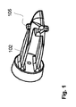
ベースプレート101の近位側からベースプレートの遠位側まで通って延びる孔102を有するベースプレート101、および前記ベースプレート101の取付点で延びる少なくとも1つの弾性アーム103を備える、針先端シールド装置100が設けられる。弾性アーム103は、弾性アーム103の遠位のフック104が前記ベースプレート101の軸方向において前記孔102を通って長手方向に延びるまっすぐな想像線と一致する静止状態を有する。弾性アーム103は、その遠位端でノブ105を備え、前記ノブ105は、弾性アーム103から横に延びる。ノブ105は、針先端シールド装置100の中心軸線に平行な軸の周りで横平面106における外側の曲率によって形づくられる。前記ノブ105は、針先端シールド装置100の中心軸線に垂直な軸の周りで正中面107における外側の曲率によって形づくられる。【選択図】図1A needle tip shield device 100 is provided, comprising a base plate 101 having a hole 102 extending from the proximal side of the base plate 101 to the distal side of the base plate, and at least one elastic arm 103 extending at an attachment point of the base plate 101. The elastic arm 103 has a stationary state where the distal hook 104 of the elastic arm 103 coincides with a straight imaginary line extending longitudinally through the hole 102 in the axial direction of the base plate 101. The elastic arm 103 includes a knob 105 at its distal end, and the knob 105 extends laterally from the elastic arm 103. The knob 105 is shaped by an outer curvature in the transverse plane 106 about an axis parallel to the central axis of the needle tip shield device 100. The knob 105 is shaped by an outer curvature at the median plane 107 about an axis perpendicular to the central axis of the needle tip shield device 100. [Selection] Figure 1
Description
本発明は、針先端シールド装置、針ハブおよびカテーテルハブを備えるカテーテル器具用の針先端シールド装置に関する。針先端シールド装置は、針上に、そして、患者の脈管系へのカテーテル管の導入のためのその利用後の針の自動安全シールド用のカテーテルハブにおいて配置される。 The present invention relates to a needle tip shield device, a needle hub, and a needle tip shield device for a catheter device including a catheter hub. The needle tip shield device is placed on the needle and in a catheter hub for automatic safety shielding of the needle after its utilization for introduction of the catheter tube into the patient's vasculature.
可撓性カテーテル管の内側に取り付けられるとがった中空針の臨床的利用は、カテーテルの導入のための医術では周知である。この種の医療機器において、カテーテル管は、カテーテル管の長さに沿って針が摺動して、はまり込むことができるような方法で、針の周りにきつく配置される。使用前に、針の先端は、皮膚を容易に貫通できるために、カテーテル管の開口を通してわずかに突出している。皮膚を穿刺して針を導入すると即座に、カテーテル管の遠位端は、患者の所望の目標体腔の内側(例えば血管(例えば静脈)の内側)に同時にもたらされる。針は、次いで、カテーテルの導入の支援におけるその任務を果たして、カテーテルを通して後方に引かれることによって引っ込められる。針の解放に応じて、カテーテルは、より長い期間の間続いて、例えば、流体または液体状態の薬物の周期的な投与または注入、血液サンプルなどの収集を含む、その意図された作業モードにセットされる。 The clinical use of pointed hollow needles attached to the inside of a flexible catheter tube is well known in medical practice for catheter introduction. In this type of medical device, the catheter tube is tightly placed around the needle in such a way that the needle can slide and snap along the length of the catheter tube. Prior to use, the needle tip protrudes slightly through the opening of the catheter tube so that it can easily penetrate the skin. As soon as the skin is punctured and the needle is introduced, the distal end of the catheter tube is simultaneously brought inside the patient's desired target body cavity (eg, inside a blood vessel (eg, a vein)). The needle is then withdrawn by pulling back through the catheter, fulfilling its duty in assisting with the introduction of the catheter. In response to the release of the needle, the catheter continues for a longer period of time and is set to its intended working mode, including, for example, periodic administration or infusion of drugs in fluid or liquid state, collection of blood samples, etc. Is done.
しかしながら、皮膚を容易に貫通する針先端の固有の能力と結合して、例えば患者の血液または他の体液から生じる感染病原体によってそれが汚染されうるという事実に起因して、保護されていない解放された針は、重篤な健康被害を構成する。それ故、それが彼等の皮膚と偶然に接触する場合、解放された針を扱っている医療従事者は、対応する疾患(例えばHIVまたは肝炎)を得る場合がある。とりわけこの種の解放された針と関連した健康被害を回避するかまたは軽減するために、「絶対確実」と呼ばれてもよいタイプの自動異型上の特別な焦点を有するさまざまな種類の針先端プロテクタの開発に充てられる多くの効果があった。 However, combined with the inherent ability of the needle tip to easily penetrate the skin, it is released unprotected due to the fact that it can be contaminated by, for example, infectious agents arising from the patient's blood or other bodily fluids. The needles constitute a serious health hazard. Therefore, if it happens to come into contact with their skin, health care workers handling the released needle may get the corresponding disease (eg, HIV or hepatitis). Various types of needle tips with special focus on a type of automatic variant that may be called "absolute certainty", especially to avoid or mitigate the health hazards associated with this type of released needle There were many effects devoted to the development of the protector.
特許文献1は、通常カテーテルハブに位置する強力なばねクリップを含む安全IVカテーテルを開示する。安全IVカテーテルの針は、針の軸移動を可能にするばねクリップの孔を通過する。針が前方位置にあるとき、すなわち安全IVカテーテルが使用準備状態にあるときに、針の存在は、ばねクリップのパーツを、これらのパーツがカテーテルハブの内側に対してロックし、これにより、カテーテルハブに対するばねクリップの動きが防止される位置に強制する。先端がこれらのパーツを通過する地点まで針が引っ込められるにつれて、ばねクリップは、それが針先端へのアクセスを阻止する位置へとスナップインする。同時に、以前カテーテルハブの内側にロックされたばねクリップの部分は、この位置からスナップアウトして、これにより、カテーテルハブに対するばねクリップの動きは生じてよい。針がさらに引っ込められるにつれて、ばねクリップを針にロックするための手段(例えば、針上のスロットまたは波形)が設けられ、これにより、ばねクリップは、針と共にカテーテルハブから放出されて、針上に配置される。 U.S. Patent No. 6,057,031 discloses a safety IV catheter that includes a strong spring clip that is typically located on a catheter hub. The safety IV catheter needle passes through a hole in a spring clip that allows axial movement of the needle. When the needle is in the forward position, i.e. when the safety IV catheter is ready for use, the presence of the needle locks the parts of the spring clip against the inside of the catheter hub so that the catheter Force the spring clip to move against the hub. As the needle is retracted to the point where the tip passes through these parts, the spring clip snaps into a position where it prevents access to the needle tip. At the same time, the portion of the spring clip previously locked inside the catheter hub snaps out of this position, which may cause movement of the spring clip relative to the catheter hub. As the needle is further retracted, means are provided for locking the spring clip to the needle (eg, a slot or corrugation on the needle) so that the spring clip is released from the catheter hub with the needle and onto the needle. Be placed.
例えば実際的、経済的および技術的理由を含むさまざまな理由のために、上記したばねクリップおよび類似の市場に出された異型は、今日、金属でできていて、そしてカテーテルハブはプラスチック材料でできている。この用途におけるこれらの材料の組合せの不利な点は、針の引っ込みに応じてばねクリップがカテーテルハブから放出されるときに、プラスチック・カテーテルハブの内側に対する金属ばねクリップの擦過によって、例えば顕微鏡的なプラスチック先端および金属粒子の解放を含む。これらの先端および粒子は、対応するカテーテルの正常な使用の際に患者の血流に容易に流れ込んでもよく、したがって、同じように重篤な健康被害を表してもよい。針先端が金属ばねクリップの遠位端を通るときに解放されるまで、金属ばねクリップがその上に保持された位置にもたらされなければならない、ばねクリップがカテーテルハブのキャビティ内にバルジまたは類似の何かを越えて通過することを必要とするときに、これは特に真である。針が引っ込められるにつれて針がばねクリップを通してばねクリップ上を摺動するにつれて発生する擦過振動である。金属上の金属摺動に起因する、そして明らかに聞こえることができて、感知されることができるこの擦過振動は、すでに不快な露出した状況にあって、非常に心配していてよい患者に、非常に不快でありそして気がかりである。 For various reasons including, for example, practical, economic and technical reasons, the above mentioned spring clips and similar marketed variants are today made of metal and the catheter hub can be made of plastic material. ing. The disadvantage of the combination of these materials in this application is that when the spring clip is released from the catheter hub in response to needle retraction, the metal spring clip rubs against the inside of the plastic catheter hub, for example, microscopically. Includes release of plastic tips and metal particles. These tips and particles may easily flow into the patient's bloodstream during normal use of the corresponding catheter and thus represent a serious health hazard as well. The metal spring clip must be brought to a position held on it until the needle tip is released when passing through the distal end of the metal spring clip, the spring clip is bulged or similar in the cavity of the catheter hub This is especially true when you need to pass beyond anything. Friction vibration that occurs as the needle slides over the spring clip through the spring clip as the needle is retracted. This chafing vibration due to metal sliding on metal and can be clearly heard and sensed is already uncomfortable in exposed situations and can be very worried for patients Very uncomfortable and anxious.
これらの理由により、カテーテルハブのルーメンを破壊しない材料のばねクリップを製造する試みは、実行された。特許文献2は、プラスチック材料のばねクリップを開示する。前記ばねクリップは、そのベースプレートを通してカテーテルハブのルーメンと相互作用する。しかしながら、あまりに多くカテーテルハブ・ルーメンと相互作用するベースプレートの危険がある。というのも、カテーテルハブに配置されるときに、ばねクリップ・ベースプレートの舌部は、緊張状態にあるからである。 For these reasons, attempts have been made to produce spring clips of material that do not break the lumen of the catheter hub. Patent document 2 discloses the spring clip of a plastic material. The spring clip interacts with the lumen of the catheter hub through its base plate. However, there is a danger of the base plate interacting with the catheter hub lumen too much. This is because the tongue of the spring clip base plate is in tension when placed on the catheter hub.
その代わりにカテーテルハブのルーメンとのばねクリップの相互作用があまりに弛緩している場合には、針先端がばねクリップの遠位端を通ってしまう前に、ばねクリップ上の針軸からの引っ張りは、ばねクリップのあまりに早い解放につながってよい。実質的に、ばねクリップは、針先端を保護することに失敗する。そして、針先端が保護されているのを医師が予想するかもしれないので、重篤な健康被害を構成する。 Instead, if the interaction of the spring clip with the lumen of the catheter hub is too relaxed, the pull from the needle axis on the spring clip is not allowed before the needle tip passes through the distal end of the spring clip. May lead to too early release of the spring clip. In effect, the spring clip fails to protect the needle tip. And because the doctor may expect that the needle tip is protected, it constitutes a serious health hazard.
したがって、例えば顕微鏡的なプラスチック先端の解放を回避すると共に、高い製品信頼性を確実にする針保護装置を有するカテーテル器具を開発することは、有益である。 Thus, it would be beneficial to develop a catheter device having a needle protector that, for example, avoids the release of a microscopic plastic tip and ensures high product reliability.
したがって、本発明は、好ましくは、ベースプレートの近位側からベースプレートの遠位側まで通って延びる孔を有するベースプレート、および前記ベースプレートの取付点で延びる少なくとも1つの弾性アームを備える、針先端シールド装置であって、前記少なくとも1つの弾性アームは、弾性アームの遠位のフックが前記ベースプレートの軸方向において前記孔を通って長手方向に延びるまっすぐな想像線と一致する静止状態を有し、前記少なくとも1つの弾性アームは、その遠位端でノブを備え、前記ノブは、弾性アームから横に延び、前記ノブは、針先端シールド装置の中心軸線に平行な軸の周りで横平面における外側の曲率によって形づくられ、前記ノブは、針先端シールド装置の中心軸線に垂直な軸の周りで正中面における外側の曲率によって形づくられる、針先端シールド装置を提供することによって、従来技術において上で確認した欠点および不利な点を単独でまたは任意の組合せで緩和するか、軽減するかまたは除去しようとして、そして少なくとも上述の課題を解決する。 Thus, the present invention is preferably a needle tip shield device comprising a base plate having a hole extending from the proximal side of the base plate to the distal side of the base plate, and at least one elastic arm extending at an attachment point of the base plate. Wherein the at least one elastic arm has a stationary state in which a distal hook of the elastic arm coincides with a straight imaginary line extending longitudinally through the hole in the axial direction of the base plate; One elastic arm comprises a knob at its distal end, said knob extending laterally from the elastic arm, said knob being externally curved in a transverse plane about an axis parallel to the central axis of the needle tip shield device Formed and said knob is outside in the median plane about an axis perpendicular to the central axis of the needle tip shield device By providing a needle tip shield device shaped by curvature, the drawbacks and disadvantages identified above in the prior art are to be alleviated, reduced or eliminated, alone or in any combination, and at least as described above. Solve the problem.
この種の針先端シールド装置を備えるカテーテル器具も設けられる。 A catheter device comprising this type of needle tip shield device is also provided.
本発明の有利な実施形態は、添付のクレームセットから明らかである。 Advantageous embodiments of the invention are evident from the appended claim set.
本発明が可能であるこれらのおよび他の態様、特徴および利点は、添付図面を参照して、本発明の実施形態の以下の説明から明らかとなり、解明される。 These and other aspects, features and advantages of the present invention will become apparent and elucidated from the following description of embodiments of the invention with reference to the accompanying drawings.
本発明を実施することが可能な当業者のために、本発明の実施形態は、添付図面を参照して以下でさらに詳細に説明される。しかしながら、本発明は、多くの異なる形で実施されてよく、そして本明細書に記載される実施形態に制限されるように解釈されてはならない。むしろ、これらの実施形態は、この開示が完全であり完了していて、当業者に対して本発明の範囲を詳細に伝えるように提供される。 For those skilled in the art capable of practicing the present invention, embodiments of the present invention are described in further detail below with reference to the accompanying drawings. The invention may, however, be embodied in many different forms and should not be construed as limited to the embodiments set forth herein; Rather, these embodiments are provided so that this disclosure will be thorough and complete, and will fully convey the scope of the invention to those skilled in the art.
さらに、添付図面に示される具体例の詳細な説明において使用する用語は、本発明の制限をすることを意図しない。より詳しくは、「近位」という用語は、本明細書に開示されるIVカテーテルシステムの正常な使用の間、アイテムまたはアイテムの部分の位置または方向が、ユーザ(すなわち臨床医)に最も近く、そしてIVカテーテルシステムを受容する患者から最も遠いことを指す。同様に、「遠位」という用語は、本明細書に開示されるIVカテーテルシステムの正常な使用の間、アイテムまたはアイテムの部分の位置または方向が、患者に最も近く、そして臨床医から最も遠いことを指す。「横に」という用語は、IVカテーテルシステムの中心軸線と垂直なベクトル成分のような、組立てられたIVカテーテルシステムの針およびカテーテルがIVカテーテルシステムの中心軸線と一致する、IVカテーテルシステムの中心軸線から離れる方向を指す。次に、「内側に」という用語は、IVカテーテルシステムの中心軸線と垂直なベクトル成分のような、組立てられたIVカテーテルシステムの針およびカテーテルがIVカテーテルシステムの中心軸線と一致する、IVカテーテルシステムの中心軸線に向かう方向を指す。「横平面」という用語は、横軸線およびカテーテルの中心軸線と垂直な軸線によって定義される近位部分と遠位部分とにカテーテルシステムを分ける平面を指す。「正中面(正中矢状面)」という用語は、カテーテルの中心軸線および横軸線によって定義されるカテーテルシステムの正中線を通る縦平面を指す。 Furthermore, the terms used in the detailed description of the specific examples shown in the accompanying drawings are not intended to limit the present invention. More specifically, the term “proximal” means that during normal use of the IV catheter system disclosed herein, the position or orientation of the item or part of the item is closest to the user (ie, the clinician) And refers to the furthest away from the patient receiving the IV catheter system. Similarly, the term “distal” means that during normal use of the IV catheter system disclosed herein, the position or orientation of the item or part of the item is closest to the patient and furthest from the clinician Refers to that. The term “laterally” refers to the central axis of the IV catheter system where the assembled IV catheter system needle and catheter coincide with the central axis of the IV catheter system, such as a vector component perpendicular to the central axis of the IV catheter system. The direction away from. Next, the term “inward” refers to an IV catheter system in which the assembled IV catheter system needle and catheter, such as a vector component perpendicular to the central axis of the IV catheter system, coincides with the central axis of the IV catheter system. The direction toward the central axis of The term “lateral plane” refers to a plane that divides the catheter system into a proximal portion and a distal portion defined by a transverse axis and an axis perpendicular to the central axis of the catheter. The term “midline plane (midline sagittal plane)” refers to a longitudinal plane through the midline of the catheter system defined by the central axis and the horizontal axis of the catheter.
本発明によれば、図1〜図4は、針先端シールド装置100(例えば、ばねクリップ・針先端シールド装置100)を示す。ばねクリップ・針先端シールド装置100は、ベースプレート101を備える。ベースプレート101は、それを通って、すなわちベースプレート101の近位側から遠位側まで延びる孔102を備える。針302がカテーテル器具1000の準備位置にしたがって配置されると共に、前記孔102を通る針302の配置が容易であるように、好ましくは、孔102は、ベースプレート101の中央に配置される。
In accordance with the present invention, FIGS. 1-4 show a needle tip shield device 100 (e.g., a spring clip and needle tip shield device 100). The spring clip / needle
第1の弾性アーム103は、前記ベースプレート101での取付点から遠位に延びている。製造理由に起因して、好ましくは、取付点は、ベースプレート101の周辺に位置する。少なくとも1つの弾性アーム103は、静止状態を有する。そこからそれは、前記ベースプレート101の軸線方向に前記孔102を通る針302のための自由な通過を与えるために緊張状態へと押圧されてよい。カテーテル器具1000がその準備位置にあるときに、弾性アーム103は、その緊張状態にある。弾性アーム103が前記静止状態にあるときに、弾性アーム103は、孔102を通って延びる針302の針先端をクランプするために適合される。このために、前記弾性アーム103が前記静止状態にあるときに、前記ベースプレート101の軸線方向に前記孔102を通って長手方向に延びるまっすぐな想像線は、前記少なくとも1つの弾性アーム103と一致する。これは、弾性アーム103の遠位端で弾性アーム103に遠位フック要素104を設けることによって容易であってよい。ばねクリップ・針先端シールド装置100は、カテーテルハブ201の内部キャビティ204内にこのように配置されてよい。そして、前記針は、前記針の軸によってその緊張状態へと押圧される弾性アーム103とともに、前記孔102を通って配置される。
The first
カテーテルハブ201の内側を破壊しないように、ばねクリップ・針先端シールド装置100は、良好な柔軟性および緊張維持特性を有するプラスチック材料(例えば、ポリカーボネート)でモノリシック的に製造される。次いで、少なくとも1つの弾性アーム103は、カテーテル器具1000がその準備位置にあるときに、それが緊張状態へと曲げられてよいように寸法取りされる。
In order not to break the inside of the
少なくとも1つの弾性アーム103は、少なくとも1つのノブ106を備える。ノブ106は、弾性アーム103から横に外向きに延びる。ノブ105は、少なくとも1つの弾性アーム103の遠位端にまたはそれの近くに位置する。このようにして、ノブ106は、弾性アーム103そしてしたがって100とカテーテルハブ200との間の協働を促進するために、そしてまたカテーテルハブ200の内部キャビティ204の形状における矛盾を補償するために、いくぶん曲げられてよい。
The at least one
少なくとも1つのノブ105を弾性アーム103の遠位部に配置することによって、ばねクリップ・針先端シールド装置100は、ノブ105とカテーテルユニット200の溝205または隆起206との相互作用によって、少なくとも1つのアーム103が緊張状態にある間、カテーテルユニット200内の位置へと可逆的にロックされる。一旦アーム103が静止状態に復帰すると、すなわち、一旦針先端305がカテーテル202から針先端シールド装置100へと引き抜かれると、針シールド101は、それ自身を針先端305周辺にクランプし、そしてこのように、針シールド100の少なくとも1つのアーム103は、静止状態に戻る。これが起こるにつれて、ノブ105は、カテーテルユニット200の溝205または隆起206との接触を解放する。このように、針先端204が安全に保護されるときに、最初にカテーテルハブ201からロック解放する。
By placing at least one
少なくとも1つのノブ105は、ばねクリップ・針先端シールド装置100の中心軸線と平行な軸線まわりの横平面106における外側の湾曲形状、外側の曲率を有する。ノブ105と機能要素(カテーテルハブ201のこの種の溝または隆起)との間の相互作用が、ノブ105、カテーテルハブ201または溝205または隆起206の変形の過度のスクラッチングなしで起こり得ることを、横平面106の外側の曲率は、確実にする。これはまた、針クリップ・シールド装置のより円滑でより一貫した機能を確実にする。ノブ105が横平面において鋭い角部を含む場合、いくつかの欠点は、動作中に明らかになる。カテーテルハブからの針シールドの解放の間の力は、ノブ105上の鋭い角部に集中する。そして、カテーテルハブ201と相互作用する。低い弾性係数(ポリマー(PC)2300MPaまたは(LCP)7000MPa)とともに、ノブ105の鋭い角部は、それが形崩れするかまたは破壊する(より多くの力を必要とする)または屈曲する(より少ない力を必要とする)までフックとして作用するかもしれない。この種の矛盾する挙動は、安全な機能をこのように危険にさらす。
At least one
さらに、少なくとも1つのノブ105は、ばねクリップ・針先端シールド装置100の中心軸線と垂直な軸線まわりの正中面107における外側の湾曲形状、外側の曲率を有する。
Further, the at least one
カテーテルハブ201の内部は、正中面において円を描く。ノブ105の正中面107において対応する湾曲形状は、より大きい領域に相互作用力を広げる。両方とも弾性係数(ポリマー(PC)2300MPaまたは(LCP)7000MPa)を有するポリマーから作られるばねクリップ・針先端シールド装置100およびカテーテルハブ201とともに、より大きい領域の相互作用は、いかなる持続する変形または擦過もなしに、材料を曲げることに結果としてなる。
The inside of the
これは、(例えば、特許文献1の)折り畳まれた金属シートから作られる針ガードのために特別に明らかになる。ここで、金属シートは、曲げ位置での鋭い角部を有する表面を平面に本質的に導くクリップへと曲げられる。金属クリップ(210000MPa)の弾性係数と比較して、カテーテルユニット200のポリマー・ボディは、実質的により低い弾性係数(ポリマー(PC)2300MPaまたは(LCP)7000MPa)を有する。このようにして、相互作用の間にカテーテルハブの表面が硬質合金クリップによって擦られる代わりに、鋭い金属角部は、変形しない。
This is especially evident for needle guards made from folded metal sheets (eg, from US Pat. Here, the metal sheet is bent into a clip that essentially leads the surface with sharp corners at the bending position to a plane. Compared to the elastic modulus of the metal clip (210000 MPa), the polymer body of the
図5〜図7は、カテーテルハブ201およびカテーテルハブ201から遠位に延びるカテーテル202を備えるカテーテルユニット200の実施例を示す。カテーテル202は、中空および管状であり、そしてその中に針101を収容するように構成される。カテーテルユニット200は、開いたまたは閉じたカテーテルシステム用のカテーテルユニットでもよい。
5-7 illustrate an embodiment of a
カテーテル202は、適切な高分子材料でできている。カテーテルハブ201も、適切な高分子材料(例えば、ポリプロピレンまたはポリエチレン)でできている。そしてそれは、良好な射出成形特性を有する安価なプラスチック材料である。カテーテル202の中空および管状構成は、カテーテルハブ201の内部キャビティ204と流体連通するルーメン203を提供する。内部キャビティ204は、カテーテルハブ201の近位端に位置する。そして内部キャビティ204への近位開口は、患者への静脈内補液を管理するチューブセットを周知の方法で受容するのに適したルアー(luer)部品(例えば、ルアー(luer)ロックまたはルアー(luer)スリップ)において終えてもよい。カテーテルユニット200は、カテーテルハブ201およびカテーテルハブ201から遠位に延びるカテーテル202をこのように備える。前記カテーテル202は、カテーテルハブ201の内部キャビティ204と流体連通するルーメン203を有する。カテーテル202は、通路の中に受容されるスリーブによって、ハブの遠位部の軸線方向通路の中に固定される。そしてそれは、カテーテルの近位端202を係合する。この通路は、その近位端で内部キャビティ204と連通する。そしてそれは、カテーテルハブ201内に形成されるフラッシュチャンバとしても作用する。患者の静脈への導入を容易にするために、カテーテルの遠位端202は、テーパ付けられてもよい。
カテーテルハブ201の内部キャビティ204は、カテーテルユニット200の内部キャビティ204の壁上に少なくとも1つの円周方向の溝205または隆起206を備えていてよい。
The
図6〜図7で分かるように、少なくとも1つの円周方向溝205は、カテーテルユニット200の中心軸線周辺で、内部キャビティ204からカテーテルハブ201の壁へと放射状に延びる。円周方向溝205の深さは、0.05〜0.1mmである。溝205は、ベースプレート101の近位側から針シールドのノブ105までの距離と同じだけ、カテーテルハブ201の近位側から遠位の距離に置かれる。
As can be seen in FIGS. 6-7, at least one
少なくとも1つの円周方向隆起206の場合、図8〜図10で分かるように、隆起206は、カテーテルハブ201の壁から内部キャビティ204へと中心軸線周辺で内側に延びる。円周方向隆起206の高さは、0.05〜0.1mmである。隆起206は、ベースプレート101の近位側から針シールドのノブ105までの距離よりも短い(例えば、0.1〜1mm短い)、カテーテルハブ201の近位側から遠位の距離に置かれる。
In the case of at least one
少なくとも1つの溝205または隆起206は、針シールド100の少なくとも1つのノブ105と相互作用する。ノブ105の横平面106の外側の曲率は、ノブ105と溝205または隆起206との間の相互作用がノブ105、カテーテルハブ201または溝205または隆起206の変形の過度のスクラッチングなしで起こることを確実にする。これはまた、針クリップ・シールド装置のスムーザおよびより一貫した機能を確実にする。
At least one
ばねクリップ・シールド装置100をカテーテルハブ201の内部キャビティ204内に受容するときに、ばねクリップ・シールド装置100は、カテーテルハブ201に中央にそして遠位に押圧される。一旦針シールド100のベースプレート102が完全に挿入されると、ばねクリップ・シールド装置100は、その挿入位置に達する。針シールド100が完全に挿入されるときに、少なくとも1つのアーム103のノブ105は、図3、図4、図5および図6に開示したように、少なくとも1つの円周方向溝205と相互作用するために適所にある。同様に、カテーテルハブ201の内部キャビティ204が少なくとも1つの円周方向隆起206を備えるときに、少なくとも1つのアーム103のノブ105は、針シールド100が完全に挿入されるときにカテーテルハブ200と相互作用するために適所にある。
When receiving the spring clip and
少なくとも1つのノブ105を弾性アーム103の遠位部に配置することによって、ばねクリップ・針先端シールド装置100は、少なくとも1つのアーム103が緊張状態にある間、カテーテルユニット200内に可逆的にロックされる。そして、ノブ105をカテーテルユニット200の溝205または隆起206と接触させる。ばねクリップ・シールド装置100を通して取り付けられる針軸303は、カテーテルハブ201内に取り付けられるときに、少なくとも弾性アーム103上に横の圧力をかけて、それをカテーテル壁の方へ外向きに押す。このように、ノブ105は、円周方向溝205内にまたは隆起206の背後にスナップインする。これは、針先端304が針シールド100の安全位置へと通過してしまうまで、針シールド100がカテーテルユニット200から意図せずに解放されない安全装置となる。一旦針先端204がカテーテル202から近位に、そして針先端シールド装置100へと引き抜かれると、針シールド101は、針先端204の周りにそれ自身をクランプする。したがって、針シールド100の少なくとも1つのアーム103は、静止状態に戻る。これが起こるにつれて、ノブ105は、カテーテルユニット200の溝205または隆起206との接触を解放する。したがって、針シールド100は、針先端204が安全に保護されるときに、最初にカテーテルハブ201からのロックを解放して、保護された針のカテーテルハブからの簡単な解放を容易にする。
By placing at least one
図6は、カテーテルハブ201の内部キャビティ204に完全に挿入されている針シールドを示す。ここで、ノブ105は、カテーテルハブ201の対応する溝にスナップインした。溝205とノブ105との間の相互作用は、針シールド100を取り付け位置に完全に維持する。
FIG. 6 shows the needle shield fully inserted into the
図7は、挿入位置における針シールドを示す。この位置の針シールドは、弾性アーム103のフック104に近位の位置に格納される針302を有し、それにより、針からの弾性アーム上への圧力が解放されて、弾性アームがリラックス位置へ移動することを可能にする。
FIG. 7 shows the needle shield in the insertion position. The needle shield in this position has a
針ユニット300は、針ハブ301および針302を含む。ここで、針302は針ハブ301から遠位に延びる。針ハブ301は、針302の近位端ゾーンを受容するための軸孔を有してよい。針302は、針軸303および針先端305を含む。前記針先端305は、針ユニット300の遠位端を形成する。針ハブ301は、従来のように、中空でもよくて、その近位端でフラッシュチャンバを含んでもよい。また、従来のように、針302は、中空管状カテーテル202内に受容される。そしてその近位端は、カテーテルハブ201の遠位端の内部に同心に固定される。針軸303の遠位端ゾーンで、針302は、バルジ304および針先端305を備える。このように針ユニット300は、針ハブ301と、針軸303、バルジ304および針ハブ301から遠位に延びる針先端305を有する針302とを含む。
針システム400は、針ハブ301と、針302と、本発明によるばねクリップ・シールド装置100とを含む。ばねクリップ・シールド装置100は、針軸303上に取り付けられて、針ハブ301と針バルジ304との間に位置する。
図16および図17は、本発明によるばねクリップ・針先端シールド装置100、カテーテルユニット200および針ユニット300を含む、本発明による安全IVカテーテル器具1000の実施例を示す。安全IVカテーテル器具は、開閉カテーテルシステムでもよい。
16 and 17 show an embodiment of a safety
カテーテル器具1000の準備位置において、カテーテルハブ201の近位端は、針ハブ301の遠位端にぴったりとそして取り外し可能に受容される。そうすると、針先端がカテーテル202の遠位端を越えて延びるように、針302は、キャビティ204、通路を通り、そしてカテーテルハブ201およびカテーテル202を越えて遠位に延びる。このように、針ハブ301は、カテーテルハブ201の近位端に接続される。そして、前記針軸は、前記カテーテル器具1000の準備位置においてカテーテル202のルーメン203内に配置される。針ハブ301は、カテーテルハブ201の近位端に接続されてよい。そして、前記針軸は、前記カテーテル器具1000の準備位置において、カテーテル202のルーメン203に配置される。
In the ready position of the
使用中、針302およびカテーテル202の遠位端は、患者の静脈に挿入される。その後、健康管理医師は、カテーテル202を手動でさらに静脈に入れて位置させ、次いで、針ユニット300の近位端を手で掴んで動かすことによって、針を引っ込める。安全性IVカテーテル器具1000の実施例において、カテーテルハブ200のルアー(luer)は、キャビティ204の近位端において、次いで、患者の静脈へと投与される流体のソースと結合される。
In use,
針302およびカテーテル202の遠位先端が患者の静脈へと挿入された後、針ユニット300は、カテーテルユニット200およびばねクリップ・針先端シールド装置100に関して近位に変位される。ばねクリップ・針先端シールド装置100は、上記にしたがって、ベースプレート102間に相互作用を通してカテーテルユニット200のカテーテルハブ201に保持される。針ユニット300がカテーテルユニット200およびばねクリップ・針先端シールド装置100に関して近位に変位されるときに、針302も、これら2つに関して近位に変位される。一旦針先端が弾性アーム103の遠位端(例えばフック要素104)を越えて近位に通過すると、弾性アーム103の遠位端は、針先端の前方にスナップインする。次いで、針軸のバルジは、ベースプレート102を打つ。というのも、バルジはベースプレート102の貫通孔よりもいくらか大きい直径を有して寸法取りされたからである。また、バルジは、ベースプレート102と弾性アーム103の遠位端との間の距離に主に対応する針先端からの距離で針軸上に配置された。そうすると、一旦針先端がばねクリップ・針先端シールド装置100の遠位端(例えばフック要素104)を越えて近位に変位されたならば、ばねクリップ・針先端シールド装置100は、針302の遠位端に固定されてよい。この位置において、ばねクリップ・針先端シールド装置100は、上記にしたがって、ベースプレート102とカテーテルハブ201の内部壁との間の摩擦力を克服することによりカテーテルユニット200から解放される。図7、図10および図12で分かるように、ノブ105とカテーテルユニット200における溝205または隆起206との間の相互作用の可逆的連動は、偶然の針刺しを禁止し、防止するために針シールド300が針304の先端に確実に配置されるまで、針シールドが解放されないことを確実にする。
After the
図11〜図13は、針シールド100が針に取り付けられる構成を示す。針軸206は、針シールド・ベースプレートの孔を通って延びる。ベースプレートは近位端にあり、2つの弾性アーム103は遠位端にある。図12および図13で分かるように、針シールド100の各弾性アーム105は、横に延びる弾性アーム103の遠位側にノブ105を有する。2つの対応する溝205は、針302の延長部に対して横に、針ハブ201の内部キャビティ204の内径に沿って走る。ノブ105は、針シールド100の近位端から異なる距離にある、そして、距離は、それぞれ、2つの溝205とカテーテルハブ200の近位端との間の距離に対応する。
11 to 13 show a configuration in which the
図12は、2つの弾性アーム103のフック104に対して近位の位置に格納される針を有する、挿入された位置のシールドを示す。それにより、針302からの弾性アーム102上の圧力は解放された。そして、弾性アーム103がリラックス位置にあることを可能にする。
FIG. 12 shows the shield in the inserted position with the needle stored in a position proximal to the
図13は、カテーテルハブ201の内部キャビティ204に完全に挿入される針シールドを示す。ここで、ノブは、カテーテルハブ201の対応する溝にスナップインされた。溝108とノブ105との間の相互作用は、挿入された位置の針シールド100を安全に維持する。
FIG. 13 shows the needle shield fully inserted into the
一実施形態によれば、針シールド100は、プラスチック材料でできていてよい。好ましくは、プラスチック材料は、その意図された目的のために、引っ張り強さ、剛性、耐疲労性、弾性、およびクリープ変形抵抗の好適な組合せを有する。好適なプラスチック材料は、高いクリープ変形抵抗を有する、すなわち、それは、適用された外圧の影響を受けて、ゆっくり動くかまたは永久に変形する低い傾向を有する。それ故、針シールド100を備える本発明のカテーテルシステム1000は、アーム103またはノブ105の広範囲なクリープ変形なしに、長時間の間、組み立てられた準備モードにおいて保管されてよい。プラスチック針シールド100の利点は、針シールド100が針302の引っ込みに応じてプラスチック・カテーテルハブ200から放出されるときに、プラスチック・カテーテルハブ200の擦過によって、金属と比較して、例えば顕微鏡的なプラスチック先端の解放の非常に減じた傾向を含む。したがって、擦過マーク(影響を受けたコネクタによるリークに結果としてなる場合がある)の形成の傾向は、非常に減少する。加えて、プラスチック・針先端シールド装置100は、その特定の応用に応じて、容易に色コード化されてもよいかまたは透明でもよい。
According to one embodiment,
針シールド100は、モノリシックまたは同種の射出成形された針シールド法100(成形されたプラスチック材料でできている)である。本発明の実施形態による針シールド100の異なるパーツの特定の構成に起因して、針シールド100は、その異なるパーツ間にインターフェースなしに同種の1つ(すなわちモノリシック、部分および/または1つの一体型ユニット)に型成形(例えば射出成形)されてもよい。モノリシック針シールド100の利点は、組立てられなければならない複数の部分でできている他の装置と比較して低い生産コストを含む。針シールド100は、この点で、熱可塑性ポリマーでできていてもよい。熱可塑性ポリマーは、結晶質、非晶質、または結晶質および非晶質交互の領域を含む、でありえた。最良の熱可塑性ポリマーのクリープ抵抗は、好ましくは少なくとも1200MPa(ISO527、ASTMD638)でもよい。針シールド100のための適切なプラスチックは、ポリオキシメチレン(POM)、ポリブチレンテレフタレート(PBTP)、ポリメチルメタクリレート(PMMA)、アクリロニトリル・ブタジエン・スチレン(ABS)、スチレンアクリロニトリル(SAN)、アクリロニトリル・スチレン・アクリレート(ASA)、ポリスチレン(PS)、スチレン・ブタジエン(SB)、液晶ポリマー(LCP)、ポリアミド(PA)、ポリスルホン(PSU)、ポリエーテルイミド(PEI)、ポリカーボネート(PC)、ポリフェニレンオキシド(PPO)、および/またはPPO/SB、およびそのco−およびその三元重合体から成っているグループから選択されてよい。これらのポリマーの優れた構造的メモリに起因して、これらのポリマーは、カテーテルハブに関して強化された格納容量(緊張状態においてさえ)および優れた協働能力を提供する利点を特に有する。
2つのボディ(例えばカテーテルハブ200に取り付けられる針シールド100)の接触する滑らかな形状は、特に接触領域が大きくてそれらが一緒に押圧される場合に、これらのボディ間の重要な引力に結果としてなってよい。このタイプの引力のための基礎をなす根拠は、2つのボディの分子の間の分子間引力を含む。そしてその2つのボディの分子ファンデルワールス相互作用および表面張力は、重要な要因である。密接に相互作用する表面間の共有結合形成は、引力に関与してもよい。この種の共有結合形成および2つの表面間の他のタイプの引力は、放射線治療(例えば、これらを殺菌する例えばカテーテル器具の放射線治療)に応じて結果としてなる場合もある。針シールド100がカテーテルハブ200から解放されようとするときに、この種の引力は、目立つようになってもよい。次いで、カテーテルハブ100から針シールド300を解放するために必要な力は、予想されるよりも著しく高くなる。この効果(「引力効果」と呼ばれてもよい)は、カテーテルハブの一部からの装置の一部(例えばばね付勢アーム等)の例えば自動解放に依存する場合、針先端シールド装置100の意図する機能を冒険することさえしてもよい。針シールド100は、針シールド100とカテーテルハブ200との間の少なくとも1つのインターフェース表面を介して組み立て状態のカテーテルハブ200と接触しているように保たれる。このように、一実施形態において、カテーテルハブの内部ルーメンと接触している針シールド100の表面は、カテーテルハブの高分子材料に比べて異なる高分子材料である。
The smooth shape of contact between two bodies (eg,
請求項において、「含む/備える」という用語は、他の要素またはステップの存在を排除しない。さらに、個々にリストされるにもかかわらず、複数の手段、要素または方法ステップは、例えば単一のユニットまたはプロセッサによって実施されてもよい。加えて、個々の特徴が異なる請求項に含まれてよいにもかかわらず、これらは、おそらく都合よく組み合わされてよい。そして、異なる請求項における包含は、特徴の組合せが可能でなくておよび/または有利でないことを意味しない。加えて、単数の参照は、複数を排除しない。用語「1」、「1つ」、「第1」、「第2」などは、複数を排除しない。請求項における参照符号は、実施例の明確化としてのみ単に設けられて、いかなる形であれ請求項の範囲を制限するものとして解釈されない。 In the claims, the term “comprising / comprising” does not exclude the presence of other elements or steps. Moreover, although individually listed, a plurality of means, elements or method steps may be implemented by eg a single unit or processor. In addition, although individual features may be included in different claims, they may possibly be combined conveniently. And inclusion in different claims does not mean that a combination of features is not possible and / or advantageous. In addition, singular references do not exclude a plurality. The terms “1”, “one”, “first”, “second”, etc. do not exclude a plurality. Reference signs in the claims are provided merely as a clarifying example and shall not be construed as limiting the scope of the claims in any way.
Claims (13)
前記少なくとも1つの弾性アーム(103)は、弾性アーム(103)の遠位のフック(104)が前記ベースプレート(101)の軸方向において前記孔(102)を通って長手方向に延びるまっすぐな想像線と一致する静止状態を有し、
前記少なくとも1つの弾性アーム(103)は、その遠位端でノブ(105)を備え、前記ノブ(105)は、弾性アーム(103)から横に延び、
前記ノブ(105)は、針先端シールド装置(100)の中心軸線に平行な軸の周りで横平面(106)における外側の曲率によって形づくられる、針先端シールド装置(100)。 A base plate (101) having a hole (102) extending from the proximal side of the base plate (101) to the distal side of the base plate, and at least one elastic arm (103) extending at an attachment point of the base plate (101). A needle tip shield device (100) comprising:
The at least one elastic arm (103) is a straight imaginary line in which the distal hook (104) of the elastic arm (103) extends longitudinally through the hole (102) in the axial direction of the base plate (101). Has a stationary state that matches
The at least one resilient arm (103) comprises a knob (105) at its distal end, the knob (105) extending laterally from the resilient arm (103);
The needle tip shield device (100), wherein the knob (105) is shaped by an outer curvature in a transverse plane (106) about an axis parallel to the central axis of the needle tip shield device (100).
前記針ユニット(300)は、カテーテルハブ(200)内に配置され、そうすると、前記針ユニット(300)の針(301)は、前記カテーテルユニット(200)のカテーテル(202)のルーメン(203)内に摺動的に配置され、そうすると、前記針(301)は、前記カテーテルユニット(200)から近位に引き込まれてよく、
前記針先端シールド装置(100)は、端部キャビティ(207)内にそして針軸(302)上に配置され、そうすると、少なくとも1つのアーム(103)は、針(301)の針軸(302)上に静止して、そして針(301)の針軸(302)によってばね負荷され、
前記針(301)は、組み立て状態において、ベースプレート(102)の貫通孔の中に摺動的に配置され、
前記カテーテルハブ(200)から針シールド(100)を解放するために、針ハブ(301)がカテーテルハブ(200)から引き込まれるときに、針バルジ(303)は、ベースプレート(102)と相互作用して、そして解放された状態で、少なくとも1つのアーム(103)は、針(301)の先端(304)をカバーする、カテーテル器具(1000)であって、
少なくとも1つのノブ(105)は、カテーテルユニット(200)の少なくとも1つの円周方向溝(205)または隆起(206)と相互作用して、組み立て状態のカテーテルユニット(200)内に前記針先端シールド装置(100)を可逆的にロックすることを特徴とする、カテーテル器具(1000)。 A catheter device (1000) comprising the needle tip shield device (100) according to any one of claims 1 to 12, a catheter unit (200) and a needle unit (300),
The needle unit (300) is disposed within a catheter hub (200), so that the needle (301) of the needle unit (300) is within the lumen (203) of the catheter (202) of the catheter unit (200). The needle (301) may be retracted proximally from the catheter unit (200);
The needle tip shield device (100) is disposed in the end cavity (207) and on the needle shaft (302), so that at least one arm (103) is disposed on the needle shaft (302) of the needle (301). Stationary on and spring loaded by the needle shaft (302) of the needle (301),
The needle (301) is slidably disposed in the through hole of the base plate (102) in the assembled state,
When the needle hub (301) is retracted from the catheter hub (200) to release the needle shield (100) from the catheter hub (200), the needle bulge (303) interacts with the base plate (102). And in the released state, at least one arm (103) is a catheter device (1000) covering the tip (304) of the needle (301),
At least one knob (105) interacts with at least one circumferential groove (205) or ridge (206) of the catheter unit (200) to place the needle tip shield within the assembled catheter unit (200). Catheter device (1000), characterized in that the device (100) is reversibly locked.
Applications Claiming Priority (3)
| Application Number | Priority Date | Filing Date | Title |
|---|---|---|---|
| SE1550419 | 2015-04-09 | ||
| SE1550419-4 | 2015-04-09 | ||
| PCT/SE2016/050295 WO2016163939A1 (en) | 2015-04-09 | 2016-04-07 | Needle tip shielding device and catheter hub therefore |
Publications (1)
| Publication Number | Publication Date |
|---|---|
| JP2018510722A true JP2018510722A (en) | 2018-04-19 |
Family
ID=57072069
Family Applications (1)
| Application Number | Title | Priority Date | Filing Date |
|---|---|---|---|
| JP2017552455A Pending JP2018510722A (en) | 2015-04-09 | 2016-04-07 | Needle tip shield device and catheter hub therefor |
Country Status (9)
| Country | Link |
|---|---|
| US (1) | US11202887B2 (en) |
| EP (1) | EP3283146B1 (en) |
| JP (1) | JP2018510722A (en) |
| KR (1) | KR20170135874A (en) |
| CN (2) | CN107530505A (en) |
| AU (1) | AU2016246366A1 (en) |
| CA (1) | CA2981463A1 (en) |
| ES (1) | ES2968791T3 (en) |
| WO (1) | WO2016163939A1 (en) |
Families Citing this family (25)
| Publication number | Priority date | Publication date | Assignee | Title |
|---|---|---|---|---|
| WO2017151052A1 (en) * | 2016-03-04 | 2017-09-08 | Vigmed Ab | Blood collection device |
| ES2955558T3 (en) | 2016-10-27 | 2023-12-04 | Bard Inc C R | Intraosseous access device |
| US10946176B2 (en) * | 2017-04-06 | 2021-03-16 | Becton, Dickinson And Company | Intravenous catheter assembly with safety clip |
| WO2019065943A1 (en) | 2017-09-29 | 2019-04-04 | テルモ株式会社 | Catheter assembly and medical valve |
| CN107929874B (en) * | 2017-12-15 | 2023-04-28 | 稳健平安医疗科技(湖南)有限公司 | Needle-punching prevention assembly of safety indwelling needle and safety indwelling needle |
| WO2020195848A1 (en) | 2019-03-28 | 2020-10-01 | テルモ株式会社 | Catheter assembly |
| WO2021004880A2 (en) * | 2019-07-08 | 2021-01-14 | B. Braun Melsungen Ag | Hybrid safety spring clip for sharp medical devices and related methods |
| EP4028104A4 (en) | 2019-09-10 | 2023-12-13 | MedSource International LLC | An intravenous catheter device |
| US11759235B2 (en) | 2019-09-27 | 2023-09-19 | Bard Access Systems, Inc. | Constant-torque intraosseous access devices and methods thereof |
| CN112568962A (en) | 2019-09-27 | 2021-03-30 | 巴德阿克塞斯系统股份有限公司 | Stepped needle for an intraosseous access device |
| EP4031027B1 (en) | 2019-09-27 | 2024-10-30 | Bard Access Systems, Inc. | Various operating mechanisms for intraosseous access medical devices |
| CN212879457U (en) | 2019-09-27 | 2021-04-06 | 巴德阿克塞斯系统股份有限公司 | Self-advancing intraosseous access device and intraosseous access device |
| CN113317840A (en) | 2020-02-28 | 2021-08-31 | 巴德阿克塞斯系统股份有限公司 | Flexible intra-osseous obturator |
| US11896264B2 (en) | 2020-04-21 | 2024-02-13 | Bard Access Systems, Inc. | Reusable push-activated intraosseous access device |
| CN113749724B (en) | 2020-06-03 | 2026-01-13 | 巴德阿克塞斯系统股份有限公司 | Intraosseous device including sensing obturator |
| CN113940727A (en) | 2020-07-17 | 2022-01-18 | 巴德阿克塞斯系统股份有限公司 | Safety mechanism |
| USD974552S1 (en) * | 2020-08-17 | 2023-01-03 | Rejuvatek Medical Inc. | Needle cartridge clip |
| CN114098918B (en) | 2020-08-25 | 2025-12-12 | 巴德阿克塞斯系统股份有限公司 | Angled intraosseous access system |
| EP4203820B1 (en) | 2020-09-09 | 2025-01-29 | Bard Access Systems, Inc. | Aspiration apparatus for intraosseous access system |
| CN114762745A (en) * | 2021-01-12 | 2022-07-19 | 苏州林华医疗器械股份有限公司 | Anti-acupuncture mechanism and safe type vein indwelling needle |
| CN217960227U (en) | 2021-02-08 | 2022-12-06 | 巴德阿克塞斯系统股份有限公司 | Intraosseous access system |
| WO2022184771A1 (en) * | 2021-03-02 | 2022-09-09 | Greiner Bio-One Gmbh | Needle tip shielding device, process for manufacturing a thermoplastic element |
| US12337123B2 (en) | 2021-05-06 | 2025-06-24 | Medsource Labs, Llc | Safety intravenous cannula |
| US12186497B2 (en) | 2022-01-14 | 2025-01-07 | Medsource International Llc | Intravenous cannula |
| CN117462784A (en) * | 2023-12-11 | 2024-01-30 | 安徽天康医疗科技股份有限公司 | A safe special needle for implantable drug delivery device |
Family Cites Families (25)
| Publication number | Priority date | Publication date | Assignee | Title |
|---|---|---|---|---|
| US4929241A (en) * | 1988-08-05 | 1990-05-29 | Kulli John C | Medical needle puncture guard |
| US5135504A (en) * | 1989-07-17 | 1992-08-04 | Mclees Donald J | Needle tip guard |
| US5599310A (en) * | 1995-06-07 | 1997-02-04 | Johnson & Johnson Medical, Inc. | I.V. catheter assembly with automatic cannula tip guard |
| US6117108A (en) | 1997-08-20 | 2000-09-12 | Braun Melsungen Ag | Spring clip safety IV catheter |
| US6616630B1 (en) * | 1997-08-20 | 2003-09-09 | B. Braun Melsungen A.G. | Spring clip safety IV catheter |
| ITMI20062127A1 (en) * | 2006-11-07 | 2008-05-08 | Artsana Spa | SAFETY TUBE NEEDLE WITH AGING PROTECTION ELEMENT AUTOMATICALLY ACTIVATED WITH THE LOCKING OF THIS LAST FROM THE CATHETER |
| EP2016963B2 (en) * | 2007-07-17 | 2014-04-23 | Poly Medicure Ltd. | Needle safety device |
| EA018449B1 (en) * | 2008-03-17 | 2013-08-30 | Поли Медикьюэ Лимитед | Needle safety device |
| EP2251056B1 (en) * | 2008-05-28 | 2012-07-11 | Poly Medicure Ltd. | Catheter introducer |
| WO2010061405A2 (en) | 2008-11-28 | 2010-06-03 | Malhotra Samarth | Safely disposable i.v. cannula device |
| SE535169C2 (en) | 2010-04-13 | 2012-05-08 | Vigmed Ab | Polymer protective device for a catheter needle tip |
| UA110794C2 (en) * | 2010-05-05 | 2016-02-25 | Полі Медікьюе Лімітед | Protective device for medical needles instruments and node iv catheter comprising said needle protective device |
| CN106943647B (en) * | 2010-08-05 | 2020-09-04 | B·布朗·梅尔松根有限公司 | Needle safety device and assembly |
| EP2517751B8 (en) * | 2011-04-27 | 2018-02-28 | Kpr U.S., Llc | Safety IV catheter assemblies |
| US9440053B2 (en) * | 2011-07-26 | 2016-09-13 | Poly Medicure Limited | Needle tip protector assembly for safety IV catheter assembly |
| EP2736577B1 (en) * | 2011-07-26 | 2022-11-30 | Poly Medicure Limited | Needle tip protector assembly for safety iv catheter assembly |
| US9427555B2 (en) * | 2011-08-09 | 2016-08-30 | Poly Medicure Limited | Needle safety device |
| JP5838681B2 (en) * | 2011-09-16 | 2016-01-06 | いすゞ自動車株式会社 | Actuator control method and actuator control apparatus |
| US8628497B2 (en) * | 2011-09-26 | 2014-01-14 | Covidien Lp | Safety catheter |
| ES3053957T3 (en) * | 2011-11-08 | 2026-01-28 | Poly Medicure Ltd | Intravenous catheter apparatus |
| SE537334C2 (en) * | 2012-04-27 | 2015-04-07 | Vigmed Ab | Protective device for needle point and mounting device |
| SE537262C2 (en) | 2012-06-15 | 2015-03-17 | Vigmed Ab | A closed IV catheter system comprising a needle guard device |
| US20150196737A1 (en) * | 2012-06-19 | 2015-07-16 | Poly Medicure Limited | Needle guard |
| WO2015092041A1 (en) * | 2013-12-20 | 2015-06-25 | B. Braun Melsungen Ag | Safety needle assemblies and related methods |
| US20160008581A1 (en) * | 2014-07-08 | 2016-01-14 | B. Braun Melsungen Ag | Needle safety devices and related methods |
-
2016
- 2016-04-07 JP JP2017552455A patent/JP2018510722A/en active Pending
- 2016-04-07 CN CN201680020685.3A patent/CN107530505A/en active Pending
- 2016-04-07 EP EP16776993.4A patent/EP3283146B1/en active Active
- 2016-04-07 US US15/565,343 patent/US11202887B2/en active Active
- 2016-04-07 CN CN202410084190.3A patent/CN118217513A/en active Pending
- 2016-04-07 ES ES16776993T patent/ES2968791T3/en active Active
- 2016-04-07 WO PCT/SE2016/050295 patent/WO2016163939A1/en not_active Ceased
- 2016-04-07 CA CA2981463A patent/CA2981463A1/en not_active Abandoned
- 2016-04-07 AU AU2016246366A patent/AU2016246366A1/en not_active Abandoned
- 2016-04-07 KR KR1020177030591A patent/KR20170135874A/en not_active Withdrawn
Also Published As
| Publication number | Publication date |
|---|---|
| EP3283146B1 (en) | 2023-10-25 |
| CN107530505A (en) | 2018-01-02 |
| EP3283146A4 (en) | 2019-02-27 |
| AU2016246366A1 (en) | 2017-11-23 |
| ES2968791T3 (en) | 2024-05-14 |
| US11202887B2 (en) | 2021-12-21 |
| CN118217513A (en) | 2024-06-21 |
| US20180304048A1 (en) | 2018-10-25 |
| BR112017021515A2 (en) | 2018-07-03 |
| KR20170135874A (en) | 2017-12-08 |
| WO2016163939A1 (en) | 2016-10-13 |
| EP3283146A1 (en) | 2018-02-21 |
| CA2981463A1 (en) | 2016-10-13 |
| BR112017021515A8 (en) | 2022-08-16 |
Similar Documents
| Publication | Publication Date | Title |
|---|---|---|
| JP2018510722A (en) | Needle tip shield device and catheter hub therefor | |
| JP7309674B2 (en) | Needle hub and IV catheter system comprising such a needle hub | |
| EP2841134B1 (en) | Needle tip shielding device and fixing arrangement | |
| EP2861292B1 (en) | Needle tip shielding device and fixing arrangement | |
| EP2464408B1 (en) | Catheter instrument | |
| EP2618874B2 (en) | Needle tip shielding device | |
| BR112012026081B1 (en) | CATHETER TYPE INSTRUMENT | |
| JP2018507012A (en) | Safe venous catheter with friction-based retention and unusable function | |
| BR112017021515B1 (en) | NEEDLE TIP PROTECTION DEVICE AND CATHETER INSTRUMENT | |
| HK1243012A1 (en) | Needle tip shielding device and catheter hub therefor | |
| BR112017014247B1 (en) | IV CATHETER SYSTEM COMPRISING A CATHETER HUB |