JP2018199101A - Sludge treatment system and sludge treatment method - Google Patents
Sludge treatment system and sludge treatment method Download PDFInfo
- Publication number
- JP2018199101A JP2018199101A JP2017104636A JP2017104636A JP2018199101A JP 2018199101 A JP2018199101 A JP 2018199101A JP 2017104636 A JP2017104636 A JP 2017104636A JP 2017104636 A JP2017104636 A JP 2017104636A JP 2018199101 A JP2018199101 A JP 2018199101A
- Authority
- JP
- Japan
- Prior art keywords
- sludge
- digested sludge
- tank
- map
- digested
- Prior art date
- Legal status (The legal status is an assumption and is not a legal conclusion. Google has not performed a legal analysis and makes no representation as to the accuracy of the status listed.)
- Granted
Links
Images


Classifications
-
- Y—GENERAL TAGGING OF NEW TECHNOLOGICAL DEVELOPMENTS; GENERAL TAGGING OF CROSS-SECTIONAL TECHNOLOGIES SPANNING OVER SEVERAL SECTIONS OF THE IPC; TECHNICAL SUBJECTS COVERED BY FORMER USPC CROSS-REFERENCE ART COLLECTIONS [XRACs] AND DIGESTS
- Y02—TECHNOLOGIES OR APPLICATIONS FOR MITIGATION OR ADAPTATION AGAINST CLIMATE CHANGE
- Y02E—REDUCTION OF GREENHOUSE GAS [GHG] EMISSIONS, RELATED TO ENERGY GENERATION, TRANSMISSION OR DISTRIBUTION
- Y02E50/00—Technologies for the production of fuel of non-fossil origin
- Y02E50/30—Fuel from waste, e.g. synthetic alcohol or diesel
Landscapes
- Treatment Of Sludge (AREA)
Abstract
Description
本発明の実施形態は、汚泥処理システムおよび汚泥処理方法に関する。 Embodiments described herein relate generally to a sludge treatment system and a sludge treatment method.
排水処理施設において、被処理液中のリンを回収・除去する方法の一例として、嫌気好気法(AO法)がある。このAO法では、まず、嫌気槽内にて、微生物が被処理液中にリン酸を放出する。その後、被処理液は微生物と共に好気槽に送られて、好気処理される。このとき、好気槽に送られた微生物は、嫌気槽にて放出したリン酸量以上のリンを、ポリリン酸として摂取する。そのため、好気槽で過剰に増殖した微生物である余剰汚泥には、リンが多量に含まれている。この余剰汚泥は、下水汚泥として汚泥処理施設に送られて処理される。 An example of a method for recovering and removing phosphorus in a liquid to be treated in a wastewater treatment facility is an anaerobic aerobic method (AO method). In this AO method, first, microorganisms release phosphoric acid into the liquid to be treated in an anaerobic tank. Thereafter, the liquid to be treated is sent to the aerobic tank together with the microorganisms for aerobic treatment. At this time, the microorganisms sent to the aerobic tank ingest phosphorus more than the amount of phosphoric acid released in the anaerobic tank as polyphosphoric acid. Therefore, a large amount of phosphorus is contained in excess sludge, which is a microorganism that proliferated excessively in the aerobic tank. This surplus sludge is sent to a sludge treatment facility as sewage sludge and processed.
汚泥処理施設では、排水処理施設から送られた下水汚泥、食品産業から送られた排水等を含む有機性廃棄物の処理が行われる。汚泥処理施設に送られた有機性廃棄物は、消化槽で嫌気性処理(消化処理)されて消化汚泥とバイオガスとを生成する。このとき、上述したリンを多量に含む微生物が、消化汚泥中にリン酸を放出する。そのため、消化汚泥を脱水して得た脱離液は、多量のリンを含む。この脱離液は、排水処理施設に返送されて排水処理される。しかし、多量のリンを含む脱離液を排水処理施設に送ると、排水処理施設のリン負荷が増大する。そのため、消化汚泥または脱離液中のリンを除去することが行われている。 In the sludge treatment facility, organic waste including sewage sludge sent from the wastewater treatment facility and wastewater sent from the food industry is processed. The organic waste sent to the sludge treatment facility is subjected to anaerobic treatment (digestion treatment) in a digestion tank to produce digested sludge and biogas. At this time, the above-described microorganism containing a large amount of phosphorus releases phosphoric acid into the digested sludge. Therefore, the detachment liquid obtained by dewatering digested sludge contains a large amount of phosphorus. This desorbed liquid is returned to the wastewater treatment facility for wastewater treatment. However, if a desorbed liquid containing a large amount of phosphorus is sent to a wastewater treatment facility, the phosphorus load on the wastewater treatment facility increases. Therefore, removal of phosphorus in digested sludge or detachment liquid is performed.
汚泥処理におけるリンの回収方法として、MAP(Magnesium Ammonium Phosphate)法が知られている。MAP法では、リンの回収効率を向上させるために、被処理液のpHをアルカリ性に調整することで、リンを含む結晶を晶析・成長させ、この結晶を回収することにより、被処理液中のリンを回収・除去する。 A MAP (Magnesium Ammonium Phosphate) method is known as a method for collecting phosphorus in sludge treatment. In the MAP method, in order to improve the recovery efficiency of phosphorus, the pH of the liquid to be treated is adjusted to be alkaline, so that crystals containing phosphorus are crystallized and grown, and the crystals are collected to recover the liquid in the liquid to be treated. Collect and remove phosphorus.
本発明が解決しようとする課題は、薬剤を使用することなく、消化汚泥中のリンを効率的に回収・除去できる汚泥処理システムおよび汚泥処理方法を提供することである。 The problem to be solved by the present invention is to provide a sludge treatment system and a sludge treatment method that can efficiently recover and remove phosphorus in digested sludge without using chemicals.
実施形態の汚泥処理システムは、消化槽と、MAP生成槽と、二酸化炭素散気装置と、マグネシウム源供給装置と、を持つ。
前記消化槽は、有機性廃棄物を消化処理して消化汚泥およびバイオガスを得る。
前記MAP生成槽は、前記消化汚泥または可溶化処理した前記消化汚泥とマグネシウム源とを撹拌混合してリン酸マグネシウムアンモニウム(MAP)および脱リン処理物を得る。
前記二酸化炭素散気装置は、前記MAP生成槽内の前記消化汚泥または可溶化処理した前記消化汚泥に二酸化炭素を散気する。
マグネシウム源供給装置は、前記MAP生成槽にマグネシウム源を供給する。
The sludge treatment system of the embodiment includes a digestion tank, a MAP generation tank, a carbon dioxide aeration device, and a magnesium source supply device.
The digester digests organic waste to obtain digested sludge and biogas.
In the MAP production tank, the digested sludge or the solubilized digested sludge and a magnesium source are stirred and mixed to obtain magnesium ammonium phosphate (MAP) and a dephosphorized product.
The carbon dioxide diffuser diffuses carbon dioxide into the digested sludge or the solubilized digested sludge in the MAP production tank.
The magnesium source supply device supplies a magnesium source to the MAP production tank.
以下、実施形態の汚泥処理システムおよび汚泥処理方法を、図面を参照して説明する。 Hereinafter, a sludge treatment system and a sludge treatment method of an embodiment will be described with reference to the drawings.
(第1の実施形態)
図1は、本実施形態の汚泥処理システムを示す図である。
本実施形態の汚泥処理システム100は、消化槽1と、MAP生成槽2と、二酸化炭素散気装置4と、マグネシウム源供給装置5と、を備える。
また、汚泥処理システム100は、図1に示すように、脱水装置3と、pH計6と、凝集剤供給装置7と、を備えていてもよい。
(First embodiment)
FIG. 1 is a diagram showing a sludge treatment system of the present embodiment.
The
Moreover, as shown in FIG. 1, the
消化槽1は、図示略の排水処理施設から有機性廃棄物流入ラインを介して送られた有機性廃棄物を嫌気性微生物によって消化処理して、二酸化炭素、メタンおよびアンモニア並びに消化汚泥に分解する、消化処理を行う槽である。消化槽1に送られる有機性廃棄物には下水汚泥が含まれており、この下水汚泥は余剰汚泥を含む。
消化槽1は、消化汚泥送泥ラインを介してMAP生成槽2と接続されている。また、消化槽1は、図示略のバイオガス送気ラインを介して、消化槽1外へバイオガスを排出できるようになっている。
The
The
MAP生成槽2は、消化槽1から送られた消化汚泥とマグネシウム源とを撹拌混合して、リン酸マグネシウムアンモニウム(MAP)を生成させ、MAPおよび脱リン処理物を得る槽である。なお、本実施形態において脱リン処理物とは、MAP生成槽2でリンが除去された後の消化汚泥のことをいう。MAP生成槽2は、図示略の撹拌手段を備えている。
The
MAP生成槽2は、脱リン処理物送泥ラインを介して脱水装置3と接続されている。また、MAP生成槽2は、MAP排出ラインを介して、MAP生成槽2外部にMAPを排出できるようになっている。
The
二酸化炭素散気装置4は、MAP生成槽2内の消化汚泥に二酸化炭素を散気する装置である。二酸化炭素散気装置4が散気する二酸化炭素としては、例えば、市販の二酸化炭素ボンベ中の二酸化炭素、大気中の二酸化炭素、消化槽1で生成したバイオガス中の二酸化炭素、消化槽1で生成したバイオガスを焼成して得られた二酸化炭素等が挙げられる。
二酸化炭素散気装置4は、二酸化炭素送気ラインを介してMAP生成槽2と接続されている。
The
The
マグネシウム源供給装置5は、MAP生成槽2内に種晶となるマグネシウム源を供給する装置である。マグネシウム源としては、例えば、塩化マグネシウム、水酸化マグネシウム等が挙げられる。
マグネシウム源供給装置5は、マグネシウム源供給ラインを介してMAP生成槽2と接続されている。
The magnesium
The magnesium
pH計6は、MAP生成槽2内の消化汚泥のpHを計測する計測器である。
The
脱水装置3は、MAP生成槽2から送られた脱リン処理物を脱水して脱水汚泥および脱離液を得る装置である。脱水装置3としては、例えば、ベルトプレス脱水機、フィルタープレス脱水機、ロータリープレス脱水機、スクリュープレス脱水機、遠心分離脱水機、多重円盤脱水機等が挙げられる。
The
脱水装置3は、脱水汚泥送泥ラインを介して図示略の乾燥装置と接続されている。また、脱水装置3は、脱離液送液ラインを介して図示略の排水処理施設と接続されている。更に、脱水装置3は、凝集剤供給ラインを介して凝集剤供給装置7と接続されている。
The
凝集剤供給装置7は、脱水装置3に凝集剤を供給する装置である。凝集剤供給装置7が供給する凝集剤としては、例えば、ポリ塩化アルミニウム、硫酸バンド、塩化第二鉄、硫酸第一鉄、ケイ酸ナトリウム溶液、ポリシリカ鉄等の無機系凝集剤や有機系高分子凝集剤等の有機系凝集剤が挙げられる。
The
次に、本実施形態の汚泥処理システム100のそれぞれの構成要素の作用を説明すると共に、当該汚泥処理システム100を用いた汚泥処理方法について説明する。
Next, the operation of each component of the
本実施形態の汚泥処理方法は、有機性廃棄物を消化処理して消化汚泥を得る消化処理工程と、前記消化汚泥に二酸化炭素を散気した後、前記消化汚泥とマグネシウム源とを撹拌混合してリン酸マグネシウムアンモニウム(MAP)および脱リン処理物を得るMAP生成工程と、から構成される。 In the sludge treatment method of the present embodiment, a digestion treatment step of digesting organic waste to obtain digested sludge, and after agitating carbon dioxide into the digested sludge, the digested sludge and a magnesium source are stirred and mixed. And MAP production step for obtaining a magnesium ammonium phosphate (MAP) and a dephosphorylated product.
また、本実施形態の汚泥処理方法は、MAP生成槽2から脱水装置3に送られた脱リン処理物に、凝集剤供給装置7から凝集剤を添加した後、脱水して脱離液および脱水汚泥を得る脱水工程を有していてもよい。
以下、各工程について説明する。
Further, in the sludge treatment method of the present embodiment, the flocculant is added from the
Hereinafter, each step will be described.
まず、消化処理工程について説明する。消化処理工程では、消化槽1により、排水処理施設から送られた有機性廃棄物を消化処理することで、二酸化炭素、メタンおよびアンモニア並びに消化汚泥を得る。また、消化処理工程では、有機性廃棄物中の余剰汚泥がリン酸の形態でリンを放出する。余剰汚泥が放出したリン酸は、消化汚泥に含まれる水分に溶解する。
First, the digestion process will be described. In the digestion treatment step, carbon dioxide, methane, ammonia and digested sludge are obtained by digesting organic waste sent from the wastewater treatment facility by the
また、消化処理工程で生じたアンモニアの一部は、一部の二酸化炭素およびメタンと共にバイオガスとなる。残部のアンモニアおよび二酸化炭素は、消化汚泥に含まれる水分に溶解し、消化汚泥に含まれる状態となる。すなわち、消化処理工程で生じた消化汚泥中の水分には、リン酸、アンモニアおよび二酸化炭素が含まれる。
消化汚泥における水分以外の成分は、嫌気性微生物が分解しきれなかった有機性廃棄物(有機物)の残渣および嫌気性微生物である。
In addition, a part of the ammonia generated in the digestion process becomes biogas together with some carbon dioxide and methane. The remaining ammonia and carbon dioxide are dissolved in the moisture contained in the digested sludge and become a state contained in the digested sludge. That is, the moisture in the digested sludge generated in the digestion process includes phosphoric acid, ammonia, and carbon dioxide.
Components other than moisture in the digested sludge are organic waste (organic matter) residues and anaerobic microorganisms that the anaerobic microorganisms could not be completely decomposed.
消化槽1で得られたバイオガスは、図示略のバイオガス送気ラインを介して消化槽1外へ排出される。一方、消化槽1で生じた消化汚泥は、消化汚泥送泥ラインを介してMAP生成槽2に送られる。
The biogas obtained in the
次に、MAP生成工程について説明する。MAP生成工程では、消化槽1からMAP生成槽2に送られた消化汚泥に二酸化炭素を散気した後、消化汚泥にマグネシウム源を供給して撹拌混合することで、脱リン処理物とMAPとを得る。
Next, the MAP generation process will be described. In the MAP generation step, carbon dioxide is diffused to the digested sludge sent from the
MAP生成工程では、MAP法によるリンの回収・除去を行う。MAP法とは、リン酸、アンモニアが多く含まれる消化汚泥に液体のマグネシウム源または種晶となる固体のマグネシウム源を添加して、リン酸マグネシウムアンモニウム6水和物(MgNH4PO4・6H2O)の結晶を晶析・成長させる方法である。リンを多く含む結晶(固形物)を回収することで、消化汚泥からリンおよびアンモニアを回収・除去することができる。 In the MAP generation step, phosphorus is collected and removed by the MAP method. In the MAP method, a magnesium magnesium phosphate hexahydrate (MgNH 4 PO 4 .6H 2) is prepared by adding a liquid magnesium source or a solid magnesium source as a seed crystal to digested sludge containing a large amount of phosphoric acid and ammonia. This is a method for crystallizing and growing O) crystals. By recovering crystals (solid matter) containing a large amount of phosphorus, phosphorus and ammonia can be recovered and removed from the digested sludge.
本発明者らは、上記MAP法において、MAPの飽和溶解度となる消化汚泥のpHが6.23であることを知見した。すなわち、消化汚泥のpHが6.23未満の領域では、MAPが晶析しないことを知見した。また、被処理液のpHが6.23以上の領域では、pHが上昇するにつれて、MAPが晶析せず、種晶を成長させる形でMAPが生成する過飽和領域と、微細なMAPが多量に晶析する領域とが存在することを知見した。消化汚泥のpHが高く、微細なMAPが多量に晶析する領域である場合には、微細に晶析したMAPが沈降せず、消化汚泥と共に後段の脱水装置に送られてしまい、消化汚泥からリンを回収・除去できない場合がある。消化処理工程を経た消化汚泥のpHは7.5〜8.5であり、このままMAP法によるリン回収を行うと、微細なMAPが多量に晶析する。したがって、消化汚泥中のリンを効率的に回収するためには、消化汚泥のpHを低下させて、消化汚泥のpHをMAPが晶析しないpHである6.23以上かつ、種晶を成長させる形でMAPが生成するpHである上記過飽和領域の範囲にすることが重要である。 In the MAP method, the present inventors have found that the pH of the digested sludge that is the saturated solubility of MAP is 6.23. That is, it was found that MAP does not crystallize in the region where the pH of digested sludge is less than 6.23. Further, in the region where the pH of the liquid to be treated is 6.23 or more, as the pH increases, MAP does not crystallize, and a large amount of fine MAP is generated in a supersaturated region where MAP is generated in the form of growing seed crystals. It was found that there is a region to crystallize. If the digested sludge has a high pH and is a region where a large amount of fine MAP is crystallized, the finely crystallized MAP does not settle and is sent to the subsequent dewatering device together with the digested sludge. Phosphorus may not be recovered / removed. The pH of the digested sludge that has undergone the digestion process is 7.5 to 8.5, and if phosphorus is recovered by the MAP method as it is, fine MAP is crystallized in a large amount. Therefore, in order to efficiently recover phosphorus in the digested sludge, the pH of the digested sludge is lowered, and the pH of the digested sludge is 6.23 or higher, which is a pH at which MAP does not crystallize, and seed crystals are grown. It is important to be in the above supersaturated region, which is the pH at which MAP is produced.
本実施形態の汚泥処理方法では、MAP生成槽2内の消化汚泥に、二酸化炭素散気装置4によって二酸化炭素を散気することによって、消化汚泥のpHを低下させる。消化汚泥に散気した二酸化炭素(CO2)は、水(H2O)と結合して炭酸(H2CO3)を形成する。この炭酸(H2CO3)が、水素イオン(H+)と炭酸イオン(HCO3 −)とに分離することによって、消化汚泥中の水素イオン濃度が高くなり、消化汚泥のpHが低下する。
In the sludge treatment method of the present embodiment, the pH of the digested sludge is reduced by aeration of carbon dioxide into the digested sludge in the
また、本発明者らは、消化汚泥に二酸化炭素を散気し続けても、消化汚泥のpHが略7までしか低下しないことを知見した。更に、このpHが上記過飽和領域の範囲内であるため、二酸化炭素を散気してpHを低下させた消化汚泥は、MAP法に好適に用いることができることを知見した。
消化汚泥に二酸化炭素を散気し続けても消化汚泥のpHが略7まで低下しないのは、消化処理により生じた二酸化炭素が消化汚泥にすでに溶存しており、この消化汚泥に二酸化炭素を散気してもある程度の量の二酸化炭素しか溶解しないためだと考えられる。
Further, the present inventors have found that the pH of the digested sludge decreases only to about 7 even if carbon dioxide is continuously diffused into the digested sludge. Furthermore, since this pH is in the range of the supersaturated region, it was found that digested sludge having a reduced pH by aeration of carbon dioxide can be suitably used for the MAP method.
Even if carbon dioxide is continuously diffused into the digested sludge, the pH of the digested sludge does not drop to about 7. The reason is that the carbon dioxide generated by the digestion process is already dissolved in the digested sludge. This is probably because only a certain amount of carbon dioxide dissolves even if it is noticed.
消化汚泥に二酸化炭素を散気する時間の下限は、消化汚泥のpHを上記過飽和領域のpHまで低下させるために、15分以上とすることが好ましく、30分以上とすることがより好ましい。消化汚泥に二酸化炭素を散気する時間の上限は、MAP生成槽2における処理時間の短縮の観点から、例えば、1時間以下とするとよい。
The lower limit of the time during which carbon dioxide is diffused into the digested sludge is preferably 15 minutes or more, and more preferably 30 minutes or more in order to lower the pH of the digested sludge to the pH of the supersaturated region. From the viewpoint of shortening the processing time in the
次に、二酸化炭素を散気してpHを低下した消化汚泥と、マグネシウム源供給装置5から供給したマグネシウム源とを撹拌混合する。マグネシウム源の供給量は、消化汚泥中のリン濃度に応じて、適宜調整するとよい。
上述したように二酸化炭素を散気した消化汚泥のpHは、MAPが晶析せず、種晶であるマグネシウム源を成長させる形でMAPが生成される過飽和領域のpHである。そのため、種晶となるマグネシウム源と消化汚泥とを撹拌混合すると、消化汚泥中のリン酸およびアンモニアは、微細なMAPとして多量に晶析することはないが、種晶であるマグネシウム源を成長させる形でMAPの結晶となる。
Next, the digested sludge whose pH has been lowered by aeration of carbon dioxide and the magnesium source supplied from the magnesium
As described above, the pH of the digested sludge diffused with carbon dioxide is the pH in the supersaturated region where MAP is generated in a form in which the MAP is not crystallized and a magnesium source as a seed crystal is grown. Therefore, when the magnesium source that becomes the seed crystal and the digested sludge are mixed with stirring, phosphoric acid and ammonia in the digested sludge do not crystallize in large quantities as fine MAP, but grow the magnesium source that is the seed crystal. In the form of MAP crystals.
成長したMAPの結晶は、MAP生成槽2の下層に沈降する。沈降したMAPは、MAP排出ラインを介してMAP生成槽2外へ排出される。一方、リンを除去された後の脱リン処理物は、脱リン処理物送泥ラインを介して脱水装置3に送られる。なお、この脱リン処理物のpHは、消化汚泥のpHと同じであり、pHが略7である。
The grown MAP crystals settle in the lower layer of the
次に、MAP生成槽2から脱水装置3に送られた脱リン汚泥に凝集剤を添加した後、脱水装置により脱水して、脱水汚泥および脱離液を得る(脱水工程)。
脱水工程では、凝集剤供給装置7から、脱水装置3内の脱リン処理物に凝集剤を添加する。脱リン汚泥に凝集剤が添加されると、脱リン汚泥中の固形物が高分子化される。
Next, after adding a flocculant to the dephosphorization sludge sent from the
In the dehydration step, the flocculant is added from the
凝集剤を添加した後、脱リン処理物を脱水装置3によって脱水する。脱リン処理物を脱水することで得られた脱水汚泥は、脱水汚泥送泥ラインを介して図示略の乾燥装置に送られる。乾燥装置に送られた脱水汚泥は、乾燥された後、廃棄される。一方、脱離液は、脱離液送液ラインを介して図示略の排水処理施設に送られて処理される。
After adding the flocculant, the dephosphorization product is dehydrated by the
なお、本実施形態の汚泥処理システム100は、MAP生成槽2において、消化汚泥に二酸化炭素を散気してからマグネシウム源を供給するように動作する。すなわち、MAP生成槽2において、二酸化炭素散気装置4が消化汚泥に二酸化炭素を散気して、消化汚泥のpHが低下されてから、マグネシウム源供給装置5がマグネシウム源を供給するように動作する。
MAP生成槽2内の消化汚泥にマグネシウム源を添加するタイミングは、タイマーによって時間を計測して、ある一定時間経過後に手動で添加してもよく、MAP生成槽2内の消化汚泥のpHを計測して、消化汚泥のpHが低下したことを確認してから手動で添加してもよく、これらのいずれかを制御装置により自動で行ってもよい。
Note that the
The timing of adding the magnesium source to the digested sludge in the
以上の構成によれば、消化汚泥に二酸化炭素を散気することによって、薬剤を使用することなく消化汚泥のpHを低下させることができ、消化汚泥のpHを過飽和領域のpHとすることができる。そのため、MAP生成槽2において、微細なMAPが晶析することなく、粗大なMAPを成長させることができる。粗大に成長したMAPは沈降しやすいため、MAP生成槽2内に容易に沈降して、回収することができる。これにより、消化汚泥中のリンを効率的に回収・除去することができる。また、脱リン処理物を脱水して得られる脱離液中のリン濃度を低減でき、この脱離液を排水処理施設に送った場合に、排水処理施設におけるリン負荷を低減できる。これにより、排水処理施設におけるリン除去に要する曝気等の運転コストを削減できる。
According to the above configuration, by aeration of carbon dioxide in the digested sludge, the pH of the digested sludge can be lowered without using a chemical, and the pH of the digested sludge can be set to the pH of the supersaturated region. . Therefore, in the
また、消化汚泥に二酸化炭素を散気することによって、薬剤を使用することなく消化汚泥のpHを低下させることができるため、脱リン処理物を脱水して得られる脱水汚泥および脱離液中に薬剤が残存することがない。そのため、脱水汚泥を乾燥して得られる乾燥汚泥を埋め立て等の方法により廃棄する場合に、環境への負荷を考慮する必要がない。更に、脱離液を排水処理施設に送って処理する場合に、排水処理施設における生物処理に悪影響を及ぼすことがない。 In addition, by aeration of carbon dioxide in the digested sludge, it is possible to lower the pH of the digested sludge without using chemicals. Therefore, in the dehydrated sludge and desorbed liquid obtained by dehydrating the dephosphorized material. The drug never remains. Therefore, when the dried sludge obtained by drying the dehydrated sludge is discarded by a method such as landfill, it is not necessary to consider the environmental load. Furthermore, when the desorbed liquid is sent to the wastewater treatment facility for processing, the biological treatment at the wastewater treatment facility is not adversely affected.
また、二酸化炭素を散気することにより消化汚泥のpHを低下しているため、薬剤によってpHを調整した場合と比べて、消化汚泥のpHを容易に過飽和領域のpHとすることができる。過飽和領域のpHは中性域であり、有機酸や無機酸等の薬剤を使用してpHを中性域に調整するのは非常に困難である。しかし、上述した実施形態では、消化汚泥に二酸化炭素を散気し続けても、pHが略7までしか低下しないため、pHを過飽和領域とすることが容易である。 Further, since the pH of the digested sludge is lowered by aeration of carbon dioxide, the pH of the digested sludge can be easily set to the pH of the supersaturated region as compared with the case where the pH is adjusted with a chemical. The pH of the supersaturated region is in the neutral region, and it is very difficult to adjust the pH to the neutral region using chemicals such as organic acids and inorganic acids. However, in the above-described embodiment, even if carbon dioxide is continuously diffused into the digested sludge, the pH is reduced only to about 7, and thus it is easy to set the pH to the supersaturated region.
また、MAP生成槽2から脱水装置3に送られる脱リン処理物はpHが低いため、凝集剤による凝集効果を向上できる。これにより、脱水装置3における脱水効率を向上できる。更に、脱リン処理物に添加する凝集剤の添加量を少なくすることができる。
Moreover, since the dephosphorization process thing sent to the
(第2の実施形態)
図2に示す本実施形態の汚泥処理システム200は、第1の実施形態の汚泥処理システム100と同様に、消化槽1と、MAP生成槽2と、二酸化炭素散気装置4と、マグネシウム源供給装置5と、を備える。
また、本実施形態の汚泥処理システム200は、消化槽1とMAP生成槽2との間に、可溶化処理槽8を備える。
また、本実施形態の汚泥処理システム200は、図2に示すように、脱水装置3と、pH計6と、凝集剤供給装置7と、を備えていてもよい。図2に示す汚泥処理システム200の構成要素のうち、第1の実施形態の汚泥処理システム100の構成要素と同一の構成要素には、図1と同一の符号を付してその説明を省略する。
(Second Embodiment)
As in the
Moreover, the
Moreover, the
可溶化処理槽8は、消化槽1から消化汚泥送泥ラインを介して送られた消化汚泥を可溶化処理する槽である。可溶化処理槽8は、消化汚泥送泥ラインを介して消化槽1と接続されており、消化汚泥を受け入れるようになっている。また、可溶化処理槽8は、可溶化処理物送泥ラインを介してMAP生成槽2と接続されている。
The
次に、本実施形態の汚泥処理システム200のそれぞれの構成要素の作用を説明すると共に、当該汚泥処理システムを用いた汚泥処理方法について説明する。
Next, the operation of each component of the
本実施形態の汚泥処理方法は、有機性廃棄物を消化処理して消化汚泥を得る消化処理工程と、消化汚泥を可溶化処理する可溶化処理工程と、可溶化処理した消化汚泥に二酸化炭素を散気した後、可溶化処理した消化汚泥とマグネシウム源とを撹拌混合して脱リン処理物およびリン酸マグネシウムアンモニウム(MAP)を得るMAP生成工程と、から構成される。 The sludge treatment method of the present embodiment includes a digestion treatment step for digesting organic waste to obtain digestion sludge, a solubilization treatment step for solubilizing digested sludge, and carbon dioxide in the digested sludge solubilized. After diffusing, the solubilized digested sludge and the magnesium source are stirred and mixed to obtain a dephosphorized product and a magnesium ammonium phosphate (MAP) production step.
また、本実施形態の汚泥処理方法は、MAP生成槽2から脱水装置3に送られた脱リン処理物に、凝集剤供給装置7から凝集剤を添加した後、脱水して脱離液および脱水汚泥を得る脱水工程を有していてもよい。
以下、それぞれの工程のうち、第1の実施形態と同じものについては、説明を省略または簡略する。
Further, in the sludge treatment method of the present embodiment, the flocculant is added from the
Hereinafter, the description of the same steps as those in the first embodiment is omitted or simplified.
まず、消化槽1により、排水処理施設から送られた有機性廃棄物を消化処理することで、二酸化炭素、メタンおよびアンモニア並びに消化汚泥を得る(消化処理工程)。消化処理工程で得られる消化汚泥中の水分には、余剰汚泥が放出したリン酸、消化処理により生じた二酸化炭素およびアンモニアが含まれる。
消化槽1で生じた消化汚泥は、消化汚泥送泥ラインを介して可溶化処理槽8に送られる。
First, carbon dioxide, methane, ammonia, and digested sludge are obtained by digesting the organic waste sent from the wastewater treatment facility by the digestion tank 1 (digestion treatment step). The moisture in the digested sludge obtained in the digestion process includes phosphoric acid released by excess sludge, carbon dioxide and ammonia generated by the digestion process.
Digested sludge generated in the
次に、消化槽1から可溶化処理槽8に送られた消化汚泥を可溶化処理する(可溶化処理工程)。なお、可溶化処理の方法としては、例えば、オゾンや薬剤を使用する化学的方法、熱処理やマイクロ波加熱を利用する物理化学的方法、超音波やビーズミルを用いて破砕処理する力学的方法、電気分解による電気化学的方法、酵素を利用した酵素反応方法等を用いることができる。
Next, the digested sludge sent to the
消化汚泥を可溶化処理すると、消化汚泥中の難分解性有機物が低分子化されて易分解性有機物となる。この易分解性有機物は水分に溶解し易い。そのため、難分解性有機物が低分子化されて生じた易分解性有機物は、消化汚泥中の水分に溶解する。すると、消化汚泥中の固形物量が減少する。また、難分解性有機物に含まれていたリンが、可溶化処理により低分子化され、リン酸として消化汚泥中の水分に溶解する。すると、消化汚泥中のリン濃度が上昇する。
可溶化処理された消化汚泥は、可溶化処理物送泥ラインを介してMAP生成槽2に送られる。
When the digested sludge is solubilized, the hardly decomposable organic matter in the digested sludge is reduced to a readily decomposable organic matter. This easily decomposable organic substance is easily dissolved in moisture. Therefore, the easily decomposable organic substance produced by reducing the molecular weight of the hardly decomposable organic substance is dissolved in the moisture in the digested sludge. Then, the amount of solid matter in the digested sludge decreases. Moreover, the phosphorus contained in the hardly decomposable organic substance is reduced in molecular weight by the solubilization treatment, and is dissolved in the moisture in the digested sludge as phosphoric acid. Then, the phosphorus concentration in the digested sludge increases.
The digested sludge subjected to the solubilization treatment is sent to the
次に、MAP生成槽2に送られた可溶化処理後の消化汚泥中のリンを回収・除去する(MAP生成工程)。その後、リンを除去した脱リン処理物を脱水装置3に送り、脱離液と脱水汚泥とに分離する(脱水工程)。脱リン処理物を脱水して得られた脱水汚泥は、脱水汚泥送泥ラインを介して図示略の乾燥装置に送られる。一方、脱離液は、脱離液送液ラインを介して図示略の排水処理施設に送られ、排水処理される。
Next, phosphorus in the digested sludge after the solubilization process sent to the
以上の構成によれば、消化汚泥に二酸化炭素を散気することによって、薬剤を使用することなく消化汚泥のpHを低下させることができ、消化汚泥のpHを過飽和領域のpHとすることができる。そのため、MAP生成槽2において、微細なMAPが晶析することなく、粗大なMAPを成長させることができる。これにより、消化汚泥中のリンを効率的に回収・除去することができる。また、脱リン処理物を脱水して得られる脱離液中のリン濃度が低減し、この脱離液を排水処理施設に送った場合に、排水処理施設におけるリン負荷が低減できる。これにより、排水処理施設におけるリン除去に要する曝気等の運転コストを削減できる。
According to the above configuration, by aeration of carbon dioxide in the digested sludge, the pH of the digested sludge can be lowered without using a chemical, and the pH of the digested sludge can be set to the pH of the supersaturated region. . Therefore, in the
また、消化汚泥に二酸化炭素を散気することによって、薬剤を使用することなく消化汚泥のpHを低下させることができるため、脱リン処理物を脱水して得られる脱水汚泥および脱離液中に薬剤が残存することがない。
また、二酸化炭素を散気することにより消化汚泥のpHを低下しているため、薬剤によってpHを調整した場合と比べて、容易に過飽和領域のpHとすることができる。
In addition, by aeration of carbon dioxide in the digested sludge, the pH of the digested sludge can be lowered without using chemicals. The drug never remains.
In addition, since the pH of the digested sludge is lowered by aeration of carbon dioxide, the pH in the supersaturated region can be easily set as compared with the case where the pH is adjusted with a chemical.
また、MAP生成槽2から脱水装置3に送られる脱リン処理物はpHが低いため、凝集剤による凝集効果を向上できる。これにより、脱水装置3における脱水効率を向上でき、脱リン処理物に添加する凝集剤の添加量を少なくすることができる。
Moreover, since the dephosphorization process thing sent to the
また、消化槽1で生じた消化汚泥を可溶化処理するため、消化汚泥中の有機物を低分子化でき、消化汚泥中の固形物量を低減できる。そのため、脱リン処理物を脱水して得られる脱水汚泥量を低減することができ、最終処分する乾燥汚泥の量を低減できる。これにより、乾燥汚泥を埋め立て、焼却等する場合の廃棄に要するコストを低減できる。さらに、消化汚泥を可溶化処理することで、可溶化処理した消化汚泥中の水分に多量のリンを溶解させることができ、MAP生成槽2におけるリンの回収効率を向上できる。
In addition, since the digested sludge generated in the
また、可溶化処理槽8で、消化汚泥を可溶化処理しているため、有機性廃棄物を可溶化処理した場合と比べて可溶化処理効率を向上できる。有機性廃棄物を可溶化処理すると、消化槽1内の嫌気性微生物が分解することができる有機物まで低分子化してしまう。すると、可溶化処理に要する薬剤やエネルギーが多くなる場合がある。しかし、上述のように本実施形態では、消化汚泥を可溶化処理している。そのため、主に嫌気性微生物が分解しきれなかった有機物を可溶化処理することになり、可溶化処理に要する薬剤やエネルギーを低減できる。
Moreover, since the digested sludge is solubilized in the
(第3の実施形態)
図3に示す本実施形態の汚泥処理システム300は、第1の実施形態の汚泥処理システム100と同様に、消化槽1と、MAP生成槽2と、二酸化炭素散気装置4と、マグネシウム源供給装置5と、を備える。
また、本実施形態の汚泥処理システム300は、可溶化処理槽8と、送泥手段10と、返送手段11と、を備えている。
また、本実施形態の汚泥処理システム300は、図3に示すように、脱水装置3と、pH計6と、凝集剤供給装置7と、を備えていてもよい。図3に示す汚泥処理システム300の構成要素のうち、第1の実施形態の汚泥処理システム100の構成要素と同一の構成要素には、図1と同一の符号を付してその説明を省略する。
(Third embodiment)
The
Further, the
Moreover, as shown in FIG. 3, the
送泥手段10は、消化槽1で生じた消化汚泥の一部を可溶化処理槽8に送る手段である。送泥手段10としては、例えば、ポンプを有する配管が挙げられる。
The mud sending means 10 is means for sending a part of the digested sludge generated in the
可溶化処理槽8は、消化槽1から送泥手段10によって送られた消化汚泥を可溶化処理する槽である。
可溶化処理槽8は、送泥手段10を介して消化槽1と接続されている。また、可溶化処理槽8は、返送手段11を介して消化槽1に接続されている。
The
The
返送手段11は、可溶化処理槽8で可溶化処理された消化汚泥を、消化槽1に送る手段である。返送手段11としては、例えば、ポンプを有する配管が挙げられる。
The return means 11 is means for sending the digested sludge solubilized in the
次に、本実施形態の汚泥処理システム300のそれぞれの構成要素の作用を説明すると共に、当該汚泥処理システムを用いた汚泥処理方法について説明する。
Next, the operation of each component of the
本実施形態の汚泥処理方法は、有機性廃棄物を消化処理して消化汚泥を得る消化処理工程と、消化汚泥の一部を可溶化処理する可溶化処理工程と、可溶化処理した消化汚泥を消化槽1に送る返送工程と、消化槽1から送られた消化汚泥に二酸化炭素を散気した後、消化汚泥とマグネシウム源とを撹拌混合して脱リン処理物およびリン酸マグネシウムアンモニウム(MAP)を得るMAP生成工程と、から構成される。
The sludge treatment method of the present embodiment comprises a digestion treatment step for digesting organic waste to obtain a digested sludge, a solubilization treatment step for solubilizing a part of the digested sludge, and a solubilized digested sludge. After returning the carbon dioxide to the digested sludge sent from the
また、本実施形態の汚泥処理方法は、MAP生成槽2から脱水装置3に送られた脱リン処理物に、凝集剤供給装置7から凝集剤を添加した後、脱水して脱離液および脱水汚泥を得る脱水工程を有していてもよい。
以下、それぞれの工程のうち、第1の実施形態と同じものについては、説明を省略または簡略する。なお、本実施形態では、消化槽1からMAP生成槽2に送られる汚泥を消化汚泥と記載する。すなわち、消化槽1により、有機性廃棄物を消化処理して生じた汚泥と、可溶化処理した消化汚泥を消化処理して生じた汚泥とを、消化汚泥と記載する。
Further, in the sludge treatment method of the present embodiment, the flocculant is added from the
Hereinafter, the description of the same steps as those in the first embodiment is omitted or simplified. In this embodiment, the sludge sent from the
まず、消化槽1により、排水処理施設から送られた有機性廃棄物を消化処理することで、二酸化炭素、メタンおよびアンモニア並びに消化汚泥を得る(消化処理工程)。消化処理工程で得られる消化汚泥中の水分には、余剰汚泥が放出したリン酸、消化処理により生じた二酸化炭素およびアンモニアが含まれる。
消化槽1で生じた消化汚泥の一部は、消化汚泥送泥ラインを介してMAP生成槽2に送られる。消化汚泥の残部は、送泥手段10によって可溶化処理槽8に送られる。
First, carbon dioxide, methane, ammonia, and digested sludge are obtained by digesting the organic waste sent from the wastewater treatment facility by the digestion tank 1 (digestion treatment step). The moisture in the digested sludge obtained in the digestion process includes phosphoric acid released by excess sludge, carbon dioxide and ammonia generated by the digestion process.
Part of the digested sludge generated in the
次に、消化槽1から送泥手段10によって送られた消化汚泥を可溶化処理する(可溶化処理工程)。可溶化処理の方法としては、例えば、オゾンや薬剤を使用する化学的方法、熱処理やマイクロ波加熱を利用する物理化学的方法、超音波やビーズミルを用いて破砕処理する力学的方法、電気分解による電気化学的方法、酵素を利用した酵素反応方法等を用いることができる。消化汚泥を可溶化処理すると、消化汚泥中の難分解性有機物が低分子化されて易分解性有機物となる。この易分解性有機物は水分に溶解し易い。そのため、難分解性有機物が低分子化されて生じた易分解性有機物は、消化汚泥中の水分に溶解する。すると、消化汚泥中の固形物量が減少する。また、難分解性有機物に含まれていたリンが、可溶化処理により低分子化され、リン酸として消化汚泥中の水分に溶解する。すると、消化汚泥中のリン濃度が上昇する。
Next, the digested sludge sent from the
次に、可溶化処理槽8で可溶化処理された消化汚泥を返送手段11によって消化槽1に送る(返送工程)。消化槽1に送られた可溶化処理後の消化汚泥は、消化槽1によって、有機性廃棄物とともに消化処理される。可溶化処理後の消化汚泥中の有機物は、消化槽1内の嫌気性微生物が分解し易い形態となっているため、嫌気性微生物による消化処理が効率的に行われる。有機性廃棄物と可溶化処理後の消化汚泥とを消化処理して生じた消化汚泥は、一部が消化汚泥送泥ラインを介してMAP生成槽2に送られ、残部が送泥手段10によって可溶化処理槽8に送られる。
Next, the digested sludge solubilized in the
次に、消化槽1からMAP生成槽2に送られた消化汚泥中のリンを回収・除去する(MAP生成工程)。消化槽1から送られる消化汚泥には、可溶化処理槽8で可溶化処理された消化汚泥も含まれており、固液物の量が少ない一方、リン濃度が高い消化汚泥となっている。
Next, phosphorus in the digested sludge sent from the
次に、MAP生成工程後のリンが除去された脱リン処理物は、脱水装置3に送られ、脱水工程に供される。脱水工程では、脱リン処理物を脱水装置3により脱水して、脱離液と脱水汚泥とに分離する。脱リン処理物を脱水して得られた脱水汚泥は、脱水汚泥送泥ラインを介して図示略の乾燥装置に送る。一方、脱離液は、脱離液送液ラインを介して図示略の排水処理施設に送り、排水処理する。
Next, the dephosphorized product from which phosphorus has been removed after the MAP generation step is sent to the
以上の構成によれば、消化汚泥に二酸化炭素を散気することによって、薬剤を使用することなく消化汚泥のpHを低下させることができ、消化汚泥のpHを過飽和領域のpHとすることができる。そのため、MAP生成槽2において、微細なMAPが晶析することなく、粗大なMAPを成長させることができる。これにより、消化汚泥中のリンを効率的に回収・除去することができる。また、脱リン処理物を脱水して得られる脱離液中のリン濃度が低減し、この脱離液を排水処理施設に送った場合に、排水処理施設におけるリン負荷を低減できる。これにより、排水処理施設におけるリン除去に要する曝気等の運転コストを削減できる。
According to the above configuration, by aeration of carbon dioxide in the digested sludge, the pH of the digested sludge can be lowered without using a chemical, and the pH of the digested sludge can be set to the pH of the supersaturated region. . Therefore, in the
また、消化汚泥に二酸化炭素を散気することによって、薬剤を使用することなく消化汚泥のpHを低下させることができるため、脱リン処理物を脱水して得られる脱水汚泥および脱離液中に薬剤が残存することがない。
また、二酸化炭素を散気することにより消化汚泥のpHを低下しているため、薬剤によってpHを調整した場合と比べて、容易に過飽和領域のpHとすることができる。
In addition, by aeration of carbon dioxide in the digested sludge, it is possible to lower the pH of the digested sludge without using chemicals. Therefore, in the dehydrated sludge and desorbed liquid obtained by dehydrating the dephosphorized material. The drug never remains.
In addition, since the pH of the digested sludge is lowered by aeration of carbon dioxide, the pH in the supersaturated region can be easily set as compared with the case where the pH is adjusted with a chemical.
また、MAP生成槽2から脱水装置3に送られる脱リン処理物はpHが低いため、凝集剤による凝集効果を向上できる。これにより、脱水装置3における脱水効率を向上でき、脱リン処理物に添加する凝集剤の添加量を少なくすることができる。
Moreover, since the dephosphorization process thing sent to the
また、可溶化処理槽8により、消化槽1で生じた消化汚泥を可溶化処理するため、消化汚泥中の有機物を低分子化できる。また、返送手段11により、消化汚泥中の有機物が、嫌気性微生物が分解し易い形態である可溶化処理した消化汚泥を消化槽1に返送することで、消化槽1における消化処理効率を向上できる。これにより、消化槽1におけるバイオガス発生量を増加できるとともに、消化汚泥中の固形物量を低減できる。消化汚泥中の固形物量を低減できるため、脱リン処理物を脱水して得られる脱水汚泥量を低減することができ、最終処分する乾燥汚泥の量が低減できる。これにより、乾燥汚泥を埋め立て、焼却等する場合の廃棄に要するコストを低減できる。さらに、消化汚泥を可溶化処理することで、可溶化処理した消化汚泥中の水分に多量のリンを溶解させることができ、MAP生成槽2におけるリンの回収効率を向上できる。
Moreover, since the digested sludge produced in the
以上に述べた少なくとも一つの実施形態によれば、消化汚泥に二酸化炭素を散気することによって、薬剤を使用することなく消化汚泥のpHを低下させることができ、消化汚泥のpHを過飽和領域のpHとすることができる。これにより、消化汚泥中のリンを効率的に回収・除去することができる。また、脱リン処理物を脱水して得られる脱離液中のリン濃度が低減し、この脱離液を排水処理施設に送った場合に、排水処理施設におけるリン負荷を低減できる。これにより、排水処理施設におけるリン除去に要する曝気等の運転コストを削減できる。 According to at least one embodiment described above, the pH of the digested sludge can be lowered without using a chemical agent by aeration of carbon dioxide in the digested sludge. The pH can be set. Thereby, phosphorus in digested sludge can be efficiently recovered and removed. Further, when the phosphorus concentration in the desorbed liquid obtained by dehydrating the dephosphorized product is reduced and the desorbed liquid is sent to the wastewater treatment facility, the phosphorus load in the wastewater treatment facility can be reduced. Thereby, the operating costs such as aeration required for phosphorus removal in the wastewater treatment facility can be reduced.
本発明のいくつかの実施形態を説明したが、これらの実施形態は、例として提示したものであり、発明の範囲を限定することは意図していない。これら実施形態は、その他の様々な形態で実施されることが可能であり、発明の要旨を逸脱しない範囲で、種々の省略、置き換え、変更を行うことができる。これら実施形態やその変形は、発明の範囲や要旨に含まれると同様に、特許請求の範囲に記載された発明とその均等の範囲に含まれるものである。 Although several embodiments of the present invention have been described, these embodiments are presented by way of example and are not intended to limit the scope of the invention. These embodiments can be implemented in various other forms, and various omissions, replacements, and changes can be made without departing from the spirit of the invention. These embodiments and their modifications are included in the scope and gist of the invention, and are also included in the invention described in the claims and the equivalents thereof.
(実施例1−1)
消化汚泥に二酸化炭素を散気して、二酸化炭素の散気時間と消化汚泥のpHとの関係を、以下の方法により調べた。
pHが異なる3種の消化汚泥に二酸化炭素を散気して、それぞれの消化汚泥のpHの経時変化を観察した。二酸化炭素を散気する前の消化汚泥のpHはそれぞれ、7.5、7.6、8.1であった。また、比較のため、水道水に二酸化炭素を散気して、水道水のpHの経時変化を観察した。二酸化炭素を散気する前の水道水のpHは、7.2であった。
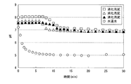
結果を図4に示す。なお、図4は、消化汚泥および水道水のpHと、二酸化炭素散気時間との関係を示す図である。
(Example 1-1)
Carbon dioxide was diffused into the digested sludge, and the relationship between the carbon dioxide aeration time and the pH of the digested sludge was examined by the following method.
Carbon dioxide was diffused into three kinds of digested sludges having different pHs, and changes in pH of each digested sludge were observed over time. The pH of the digested sludge before aeration of carbon dioxide was 7.5, 7.6, and 8.1, respectively. For comparison, carbon dioxide was diffused into tap water, and changes in the pH of tap water over time were observed. The pH of tap water before aeration of carbon dioxide was 7.2.
The results are shown in FIG. In addition, FIG. 4 is a figure which shows the relationship between digested sludge and tap water pH, and a carbon dioxide aeration time.
図4から、pHが7.5〜8.1であった消化汚泥のpHが、二酸化炭素を散気してから15分で、6.9〜7.2となり、二酸化炭素を散気してから30分で、6.8〜7.0となっている。また、二酸化炭素を散気してから15分以降では、消化汚泥のpHが略横ばいで推移している。一方、二酸化炭素を散気した水道水は、pHが7付近であったpHが、二酸化炭素を散気して8分でpHが略5まで低下した。 From FIG. 4, the pH of the digested sludge whose pH was 7.5 to 8.1 was 6.9 to 7.2 in 15 minutes after the carbon dioxide was diffused, and the carbon dioxide was diffused. 30 minutes from 6.8 to 7.0. Further, after 15 minutes from the aeration of carbon dioxide, the pH of the digested sludge has remained substantially flat. On the other hand, the tap water in which carbon dioxide was diffused had a pH of around 7 and the pH dropped to about 5 in 8 minutes after the carbon dioxide was diffused.
以上の結果から、二酸化炭素の散気時間を15分とすることで、7.5〜8.1であった消化汚泥のpHを6.9〜7.2まで低下でき、散気時間を30分とすることで、消化汚泥のpHを6.8〜7.0まで低下できることが分かる。また、二酸化炭素を散気してから15分経過した後は、水道水とは異なり、二酸化炭素を散気してもpHがほとんど低下せず、横ばいに推移することが分かる。そのため、二酸化炭素の散気が過剰になり、消化汚泥のpHが、MAPが晶析しないpH(6.23未満)まで低下しないことが分かる。よって、消化汚泥のpHを測定しつつ、二酸化炭素の散気量および散気時間を制御する必要がないことが分かる。 From the above results, by setting the carbon dioxide aeration time to 15 minutes, the pH of the digested sludge, which was 7.5 to 8.1, can be lowered to 6.9 to 7.2, and the aeration time is set to 30. It turns out that the pH of digested sludge can be reduced to 6.8-7.0 by setting it as minutes. In addition, after 15 minutes have passed since the carbon dioxide was diffused, unlike tap water, it was found that even when the carbon dioxide was diffused, the pH hardly decreased and remained flat. Therefore, it turns out that the aeration of carbon dioxide becomes excessive, and the pH of the digested sludge does not decrease to a pH at which MAP does not crystallize (less than 6.23). Therefore, it turns out that it is not necessary to control the amount of aeration of carbon dioxide and the time for aeration while measuring the pH of digested sludge.
(実施例1−2)
二酸化炭素を散気してpHを低下した消化汚泥を用いて、MAP法によるリンの回収率・除去を行った場合のリンの回収率・除去率について、以下の方法により調べた。
図5は、消化汚泥中のリン酸態リン濃度(PO4 3−−P)と撹拌時間との関係を示す図である。図5について、以下に詳細に説明する。
なお、本実施例では、実施例1−1において、二酸化炭素を30分間散気して、pHを7.0まで低下した消化汚泥を対象とした。この消化汚泥は、リン酸態リン濃度(PO4 3−−P)が200mg/Lであり、アンモニア態窒素濃度(NH4 +−N)が700mg/Lであった。
(Example 1-2)
Using the digested sludge whose pH was lowered by aeration of carbon dioxide, the recovery rate / removal rate of phosphorus when the phosphorus recovery rate / removal rate was performed by the MAP method was examined by the following method.
FIG. 5 is a diagram showing the relationship between the phosphate phosphorus concentration (PO 4 3- P) in the digested sludge and the stirring time. FIG. 5 will be described in detail below.
In this example, in Example 1-1, the digested sludge whose pH was lowered to 7.0 by aeration of carbon dioxide for 30 minutes was used. This digested sludge had a phosphate phosphorus concentration (PO 4 3-- P) of 200 mg / L and an ammonia nitrogen concentration (NH 4 + -N) of 700 mg / L.
上記消化汚泥に、Mg/P比が1.5wt/wtとなるように、塩化マグネシウム溶液を添加して、撹拌混合した。そして、一定時間ごとに消化汚泥中のリン酸態リン濃度を測定した。図5に示すように、塩化マグネシウム溶液を添加してから1時間経過した時点で、リン酸態リン濃度はほとんど変化しなかった。 A magnesium chloride solution was added to the digested sludge so that the Mg / P ratio was 1.5 wt / wt, and the mixture was stirred and mixed. And the phosphate-type phosphorus density | concentration in digested sludge was measured for every fixed time. As shown in FIG. 5, at the time when 1 hour had passed since the magnesium chloride solution was added, the phosphate phosphorus concentration hardly changed.
これより、上記消化汚泥のpHは、MAPが晶析しないpHであることが分かる。すなわち、pHが7.0である消化汚泥中のリン酸およびアンモニアは、液体のマグネシウム源を添加しても、MAPとして晶析しないことが分かる。 This shows that the pH of the digested sludge is a pH at which MAP does not crystallize. That is, it can be seen that phosphoric acid and ammonia in digested sludge having a pH of 7.0 do not crystallize as MAP even when a liquid magnesium source is added.
次に、上記消化汚泥に、種晶となる市販のMAPの結晶を添加し、撹拌混合した。図5に示すように、MAPの結晶を添加してからは、消化汚泥中のリン酸態リン濃度が徐々に減少した。MAPの結晶を添加してから5時間後には、消化汚泥中のリン酸態リン濃度が、30mg/Lとなった。すなわち、消化汚泥中のリン酸態リンのうち、全量の85%が除去されたことが分かる。言い換えると、消化汚泥中のリン酸態リンのうち、全量の85%がMAPの結晶となったことが分かる。 Next, a commercially available MAP crystal serving as a seed crystal was added to the digested sludge and mixed with stirring. As shown in FIG. 5, after adding MAP crystals, the phosphate phosphorus concentration in the digested sludge gradually decreased. Five hours after adding the MAP crystals, the phosphate phosphorus concentration in the digested sludge was 30 mg / L. That is, it can be seen that 85% of the total amount of phosphate phosphorus in the digested sludge has been removed. In other words, it can be seen that 85% of the total amount of phosphate phosphorus in the digested sludge became MAP crystals.
これより、消化汚泥中のリン酸およびアンモニアは、MAPの結晶を添加したことで、種晶であるMAPの結晶を成長させる形でMAPとなったことが分かる。すなわち、pHが7.0である消化汚泥中のリン酸およびアンモニアは、微細なMAPとして晶析せず、種晶であるマグネシウム源を成長させる形でMAPとなることが分かる。よって、二酸化炭素を散気してpHが略7まで低下した消化汚泥は、MAP法によるリン除去に好適に用いることができることが分かる。 From this, it can be seen that phosphoric acid and ammonia in the digested sludge became MAP by growing MAP crystals as seed crystals by adding MAP crystals. That is, it can be seen that phosphoric acid and ammonia in digested sludge having a pH of 7.0 do not crystallize as fine MAP, but become MAP in the form of growing a magnesium source as a seed crystal. Therefore, it can be seen that digested sludge having a pH reduced to about 7 by aeration of carbon dioxide can be suitably used for phosphorus removal by the MAP method.
次に、撹拌を止めて30分間静置して、MAPを沈降させた。その後、処理液(脱リン処理物)を排出して底部に沈降した固形物を回収した。回収した固形物を水ですすいだ後、45℃で恒量となるまで乾燥させた。乾燥させた後の乾燥物に対して、XRD分析を行った。XRD分析の結果、この乾燥物はMAP(MgNH4PO4・6H2O)と同定された。 Next, stirring was stopped and the mixture was allowed to stand for 30 minutes to precipitate MAP. Thereafter, the treatment liquid (dephosphorization product) was discharged, and the solid matter settled at the bottom was collected. The collected solid was rinsed with water and then dried at 45 ° C. until a constant weight was reached. XRD analysis was performed on the dried product after drying. As a result of XRD analysis, this dried product was identified as MAP (MgNH 4 PO 4 .6H 2 O).
上記乾燥物の重量から投入したMAP結晶の重量を引き、その差からリン量を計算した結果、乾燥物に含まれるリン量は、消化汚泥中のリン酸態リン濃度で150mg/Lに相当する量であった。すなわち、消化汚泥中のリン酸態リン量のうち、全量の75%がMAPの結晶として回収できたことが分かる。上述のように、MAPの結晶となった消化汚泥中のリン酸態リン量は、全量の85%であるため、回収できたリン酸態リンの量と10%の差がある。この差分である10%は、MAPの結晶が小さく、処理液(脱リン処理物)と共に排出されたものと推察された。 As a result of subtracting the weight of the MAP crystal charged from the weight of the dried product and calculating the amount of phosphorus from the difference, the amount of phosphorus contained in the dried product is equivalent to 150 mg / L of phosphate phosphorus in the digested sludge. It was an amount. That is, it can be seen that 75% of the total amount of phosphate phosphorus in the digested sludge was recovered as MAP crystals. As described above, the amount of phosphate phosphorus in the digested sludge that has become MAP crystals is 85% of the total amount, so there is a difference of 10% from the amount of phosphate phosphorus recovered. This difference of 10% was presumed that the MAP crystals were small and were discharged together with the treatment liquid (dephosphorization product).
以上説明したリン酸態リンの除去率・回収率に関する結果を、図6に示す。なお、図6は、実施例1−2における、消化汚泥中のリン除去率とMAP回収率との結果を示す図である。 The results regarding the removal rate / recovery rate of phosphate phosphorus described above are shown in FIG. In addition, FIG. 6 is a figure which shows the result of the phosphorus removal rate in digested sludge, and a MAP collection | recovery rate in Example 1-2.
以上の結果から、pHが6.23〜7.0である消化汚泥中のリン酸およびアンモニアは、微細なMAPとして晶析せず、種晶であるマグネシウム源(MAP)を成長させる形でMAPとなることが分かる。よって、二酸化炭素を散気してpHが略7まで低下された消化汚泥は、MAP法によるリンの回収・除去に好適に用いることができることが分かる。また、pHが7.0である消化汚泥中に種晶となるMAPを添加した場合、消化汚泥中のリン酸態リンのうち、全量の75%をMAPとして回収できることが分かる。 From the above results, phosphoric acid and ammonia in the digested sludge having a pH of 6.23-7.0 do not crystallize as fine MAP, but grow MAP as a seed crystal magnesium source (MAP). It turns out that it becomes. Therefore, it can be seen that the digested sludge having a pH reduced to about 7 by aeration of carbon dioxide can be suitably used for phosphorus recovery and removal by the MAP method. Moreover, when MAP used as a seed crystal is added to digested sludge having a pH of 7.0, 75% of the total amount of phosphate phosphorus in the digested sludge can be recovered as MAP.
100,200,300…汚泥処理システム、1…消化槽、2…MAP生成槽、3…脱水装置、4…二酸化炭素散気装置、5…マグネシウム源供給装置、7…凝集剤供給装置、8…可溶化処理槽、10…送泥手段、11…返送手段。 DESCRIPTION OF SYMBOLS 100,200,300 ... Sludge processing system, 1 ... Digestion tank, 2 ... MAP production tank, 3 ... Dehydration apparatus, 4 ... Carbon dioxide aeration apparatus, 5 ... Magnesium source supply apparatus, 7 ... Coagulant supply apparatus, 8 ... Solubilization treatment tank, 10 ... mud feeding means, 11 ... return means.
Claims (8)
前記消化汚泥または可溶化処理した前記消化汚泥、並びにマグネシウム源を混合して、MAPおよび脱リン処理物を得るMAP生成槽と、
前記MAP生成槽にマグネシウム源を供給するマグネシウム源供給装置と、
前記MAP生成槽内の前記消化汚泥または可溶化処理した前記消化汚泥に二酸化炭素を散気する二酸化炭素散気装置と、を備え、
前記MAP生成槽において、前記消化汚泥または可溶化処理した前記消化汚泥に二酸化炭素を散気してからマグネシウム源を供給するように動作する汚泥処理システム。 A digester that digests organic waste to obtain digested sludge;
A MAP production tank in which the digested sludge or the solubilized digested sludge and a magnesium source are mixed to obtain a MAP and a dephosphorized product;
A magnesium source supply device for supplying a magnesium source to the MAP generation tank;
A carbon dioxide diffuser that diffuses carbon dioxide into the digested sludge in the MAP generation tank or the digested sludge solubilized;
In the MAP generation tank, a sludge treatment system that operates to supply a magnesium source after aeration of carbon dioxide in the digested sludge or the solubilized digested sludge.
前記脱水装置内の前記脱リン処理物に凝集剤を添加する凝集剤供給装置と、
を備える請求項1に記載の汚泥処理システム。 A dehydrating apparatus for dehydrating the dephosphorized material to obtain dehydrated sludge and desorbed liquid;
A flocculant supply device for adding a flocculant to the dephosphorized product in the dehydrator;
A sludge treatment system according to claim 1.
前記消化槽から前記消化汚泥を前記可溶化処理槽に送る送泥手段と、
前記可溶化処理槽から可溶化処理した前記消化汚泥を前記消化槽に送る返送手段と、
を備える請求項1または請求項2に記載の汚泥処理システム。 A solubilization tank for solubilizing the digested sludge;
Mud feeding means for sending the digested sludge from the digestion tank to the solubilization treatment tank;
Return means for sending the digested sludge solubilized from the solubilization tank to the digester,
The sludge treatment system of Claim 1 or Claim 2 provided with these.
前記消化汚泥または可溶化処理した前記消化汚泥に二酸化炭素を散気した後、前記消化汚泥または可溶化処理した前記消化汚泥とマグネシウム源とを撹拌混合してMAPおよび脱リン処理物を得るMAP生成工程と、
備える汚泥処理方法。 A digestion process that digests organic waste to obtain digested sludge;
After the carbon dioxide is diffused into the digested sludge or the solubilized digested sludge, the digested sludge or the solubilized digested sludge and the magnesium source are stirred and mixed to obtain MAP and a dephosphorized product. Process,
Provided sludge treatment method.
可溶化処理した前記消化汚泥を前記消化処理工程に返送する返送工程と、
を備える請求項5または請求項6に記載の汚泥処理方法。 A solubilization process for solubilizing a part of the digested sludge produced in the digestion process; and
A return step of returning the digested sludge solubilized to the digestion step;
A sludge treatment method according to claim 5 or claim 6 comprising:
Priority Applications (1)
| Application Number | Priority Date | Filing Date | Title |
|---|---|---|---|
| JP2017104636A JP6873821B2 (en) | 2017-05-26 | 2017-05-26 | Sludge treatment system and sludge treatment method |
Applications Claiming Priority (1)
| Application Number | Priority Date | Filing Date | Title |
|---|---|---|---|
| JP2017104636A JP6873821B2 (en) | 2017-05-26 | 2017-05-26 | Sludge treatment system and sludge treatment method |
Publications (2)
| Publication Number | Publication Date |
|---|---|
| JP2018199101A true JP2018199101A (en) | 2018-12-20 |
| JP6873821B2 JP6873821B2 (en) | 2021-05-19 |
Family
ID=64666834
Family Applications (1)
| Application Number | Title | Priority Date | Filing Date |
|---|---|---|---|
| JP2017104636A Active JP6873821B2 (en) | 2017-05-26 | 2017-05-26 | Sludge treatment system and sludge treatment method |
Country Status (1)
| Country | Link |
|---|---|
| JP (1) | JP6873821B2 (en) |
Cited By (2)
| Publication number | Priority date | Publication date | Assignee | Title |
|---|---|---|---|---|
| KR102035782B1 (en) * | 2019-07-03 | 2019-10-23 | 김동은 | Accumulated sludge treating system and method thereof |
| JP2020127925A (en) * | 2019-02-08 | 2020-08-27 | 日立造船株式会社 | Sludge treatment method and sludge treatment device |
Citations (10)
| Publication number | Priority date | Publication date | Assignee | Title |
|---|---|---|---|---|
| JPS62266200A (en) * | 1986-05-14 | 1987-11-18 | Meidensha Electric Mfg Co Ltd | Control of methane fermentation |
| JPH0263600A (en) * | 1988-08-30 | 1990-03-02 | Ebara Infilco Co Ltd | Method of dehydrating organic sludge |
| JPH11197694A (en) * | 1998-01-07 | 1999-07-27 | Maezawa Ind Inc | Waste water treatment equipment |
| JP2005238103A (en) * | 2004-02-26 | 2005-09-08 | Jfe Engineering Kk | Treatment method for organic waste |
| JP2006026542A (en) * | 2004-07-16 | 2006-02-02 | Ebara Corp | Anaerobic digestion treatment method and apparatus for organic sludge |
| JP2006122799A (en) * | 2004-10-28 | 2006-05-18 | Ebara Corp | Organic waste treatment method and apparatus |
| JP2013215681A (en) * | 2012-04-10 | 2013-10-24 | Hitachi Power Solutions Co Ltd | Ammonium magnesium phosphate generation suppression system and methane fermentation system |
| JP2015020160A (en) * | 2013-07-23 | 2015-02-02 | 株式会社東芝 | Phosphorus recovery method from phosphorus-containing effluent |
| US20160347630A1 (en) * | 2015-06-01 | 2016-12-01 | The United States Of America, As Represented By The Secretary Of Agriculture | Systems and methods for recovering ammonium and phosphorus from liquid effluents |
| JP2017159216A (en) * | 2016-03-08 | 2017-09-14 | 株式会社東芝 | Sludge treatment system |
-
2017
- 2017-05-26 JP JP2017104636A patent/JP6873821B2/en active Active
Patent Citations (10)
| Publication number | Priority date | Publication date | Assignee | Title |
|---|---|---|---|---|
| JPS62266200A (en) * | 1986-05-14 | 1987-11-18 | Meidensha Electric Mfg Co Ltd | Control of methane fermentation |
| JPH0263600A (en) * | 1988-08-30 | 1990-03-02 | Ebara Infilco Co Ltd | Method of dehydrating organic sludge |
| JPH11197694A (en) * | 1998-01-07 | 1999-07-27 | Maezawa Ind Inc | Waste water treatment equipment |
| JP2005238103A (en) * | 2004-02-26 | 2005-09-08 | Jfe Engineering Kk | Treatment method for organic waste |
| JP2006026542A (en) * | 2004-07-16 | 2006-02-02 | Ebara Corp | Anaerobic digestion treatment method and apparatus for organic sludge |
| JP2006122799A (en) * | 2004-10-28 | 2006-05-18 | Ebara Corp | Organic waste treatment method and apparatus |
| JP2013215681A (en) * | 2012-04-10 | 2013-10-24 | Hitachi Power Solutions Co Ltd | Ammonium magnesium phosphate generation suppression system and methane fermentation system |
| JP2015020160A (en) * | 2013-07-23 | 2015-02-02 | 株式会社東芝 | Phosphorus recovery method from phosphorus-containing effluent |
| US20160347630A1 (en) * | 2015-06-01 | 2016-12-01 | The United States Of America, As Represented By The Secretary Of Agriculture | Systems and methods for recovering ammonium and phosphorus from liquid effluents |
| JP2017159216A (en) * | 2016-03-08 | 2017-09-14 | 株式会社東芝 | Sludge treatment system |
Cited By (3)
| Publication number | Priority date | Publication date | Assignee | Title |
|---|---|---|---|---|
| JP2020127925A (en) * | 2019-02-08 | 2020-08-27 | 日立造船株式会社 | Sludge treatment method and sludge treatment device |
| JP7183066B2 (en) | 2019-02-08 | 2022-12-05 | 日立造船株式会社 | Sludge treatment method and sludge treatment equipment |
| KR102035782B1 (en) * | 2019-07-03 | 2019-10-23 | 김동은 | Accumulated sludge treating system and method thereof |
Also Published As
| Publication number | Publication date |
|---|---|
| JP6873821B2 (en) | 2021-05-19 |
Similar Documents
| Publication | Publication Date | Title |
|---|---|---|
| JP4412538B2 (en) | Organic waste treatment methods | |
| JP3452439B2 (en) | Recovery and recycling of useful substances from organic waste | |
| WO2005049511A1 (en) | Method of formation/recovery of magnesium ammonium phosphate and apparatus therefor | |
| JP2000015231A (en) | Method for methane fermentation of organic waste | |
| JP5211769B2 (en) | Biological treatment method and treatment apparatus for organic waste liquid | |
| JP3570888B2 (en) | Waste treatment method | |
| JP3835927B2 (en) | Organic waste treatment methods | |
| JPH11197636A (en) | Method for treatment of organic waste | |
| JP3879136B2 (en) | Dephosphorization equipment | |
| JP6873821B2 (en) | Sludge treatment system and sludge treatment method | |
| JP2014104387A (en) | Sludge treatment device and method for producing phosphorous | |
| JP2006167522A (en) | Method for controlling anaerobic digestion of organic waste | |
| JP2000015230A (en) | Method for removing ammonia | |
| JP2000153259A (en) | Methane fermentation method of easily degradable organic waste | |
| JP2004000941A (en) | Treatment method for organic wastewater or sludge and treatment apparatus therefor | |
| JP2004008843A (en) | Method for treating organic waste water | |
| JP5963656B2 (en) | Sludge treatment apparatus and phosphorus production method | |
| JP2018001137A (en) | Treatment method and treatment device of organic sludge | |
| JP3970163B2 (en) | Organic waste treatment method and apparatus | |
| JP3181521B2 (en) | Water treatment method and water treatment device | |
| JP4223334B2 (en) | Phosphorus recovery equipment | |
| JP5530703B2 (en) | Phosphorus recovery method | |
| JP2022034249A (en) | Purification treatment method for methane fermentation digestion liquid and purification treatment system for methane fermentation digestion liquid | |
| JP2005040739A (en) | Phosphate-containing wastewater treatment method | |
| JPH11277096A (en) | Dephosphorizing method |
Legal Events
| Date | Code | Title | Description |
|---|---|---|---|
| A711 | Notification of change in applicant |
Free format text: JAPANESE INTERMEDIATE CODE: A711 Effective date: 20170913 Free format text: JAPANESE INTERMEDIATE CODE: A712 Effective date: 20170913 |
|
| A621 | Written request for application examination |
Free format text: JAPANESE INTERMEDIATE CODE: A621 Effective date: 20200408 |
|
| A977 | Report on retrieval |
Free format text: JAPANESE INTERMEDIATE CODE: A971007 Effective date: 20210222 |
|
| TRDD | Decision of grant or rejection written | ||
| A01 | Written decision to grant a patent or to grant a registration (utility model) |
Free format text: JAPANESE INTERMEDIATE CODE: A01 Effective date: 20210323 |
|
| A61 | First payment of annual fees (during grant procedure) |
Free format text: JAPANESE INTERMEDIATE CODE: A61 Effective date: 20210421 |
|
| R150 | Certificate of patent or registration of utility model |
Ref document number: 6873821 Country of ref document: JP Free format text: JAPANESE INTERMEDIATE CODE: R150 |