[go: up one dir, main page]

JP2018134375A - Jewelry - Google Patents

Jewelry Download PDF

Info

Publication number
JP2018134375A
JP2018134375A JP2017168318A JP2017168318A JP2018134375A JP 2018134375 A JP2018134375 A JP 2018134375A JP 2017168318 A JP2017168318 A JP 2017168318A JP 2017168318 A JP2017168318 A JP 2017168318A JP 2018134375 A JP2018134375 A JP 2018134375A
Authority
JP
Japan
Prior art keywords
wire member
stone
shape
wearer
accessory
Prior art date
Legal status (The legal status is an assumption and is not a legal conclusion. Google has not performed a legal analysis and makes no representation as to the accuracy of the status listed.)
Granted
Application number
JP2017168318A
Other languages
Japanese (ja)
Other versions
JP7075736B2 (en
Inventor
一夫 岡村
Kazuo Okamura
一夫 岡村
Current Assignee (The listed assignees may be inaccurate. Google has not performed a legal analysis and makes no representation or warranty as to the accuracy of the list.)
Individual
Original Assignee
Individual
Priority date (The priority date is an assumption and is not a legal conclusion. Google has not performed a legal analysis and makes no representation as to the accuracy of the date listed.)
Filing date
Publication date
Application filed by Individual filed Critical Individual
Priority to PCT/JP2017/036243 priority Critical patent/WO2018154834A1/en
Publication of JP2018134375A publication Critical patent/JP2018134375A/en
Application granted granted Critical
Publication of JP7075736B2 publication Critical patent/JP7075736B2/en
Active legal-status Critical Current
Anticipated expiration legal-status Critical

Links

Images

Landscapes

  • Adornments (AREA)

Abstract

【課題】形状記憶合金製のワイヤ部材によって石座を数珠つなぎ状としても、宝玉を常に相手に見える向きとすることが可能な装身具を提供する。
【解決手段】宝玉4が上部に嵌め込まれることにより宝玉を保持する四角枡形状の複数の石座2と、複数の石座2を連結する1本のワイヤ部材3とを備える。石座2における対面した側面部11に非円形の穴からなる連結用開口部14が形成される。ワイヤ部材3は連結用開口部14に対応した非円形断面に形成され、連結用開口部14に挿通されることにより複数の石座2を連結する。ワイヤ部材3は着用者の体温近辺の温度域でリング状となる形状が記憶された形状記憶合金によって形成される。
【選択図】図7
An object of the present invention is to provide an accessory capable of making a jewel in a direction that can always be seen by a partner even when a stone member is connected in a rosary shape by a wire member made of a shape memory alloy.
SOLUTION: A plurality of square-shaped stone staves 2 that hold the jewels by fitting the jewels 4 into the upper part, and a single wire member 3 that connects the plurality of stone staves 2 are provided. A connecting opening 14 formed of a non-circular hole is formed in the side surface 11 facing the stone seat 2. The wire member 3 is formed in a non-circular cross section corresponding to the connection opening 14 and is inserted into the connection opening 14 to connect the plurality of stone seats 2. The wire member 3 is formed of a shape memory alloy in which a ring shape is stored in a temperature range near the body temperature of the wearer.
[Selection] Figure 7

Description

本発明は、ブレスレット、ネックレス等の装身具に関し、特に、宝玉が常に相手から見える構造とすることにより良好な装飾性を有した装身具に関する。   The present invention relates to a jewelry such as a bracelet and a necklace, and more particularly, to a jewelry having a good decorative property by making a gemstone always visible to the other party.

特許文献1には、球状の宝玉を形状記憶合金からなるワイヤによって数珠つなぎ状に連続させたネックレスが記載されている。芯材となるワイヤは円形断面形状となっており、着用者の体温近辺でリング状となる形状が記憶されている。この構造のネックレスでは、着用することにより着用者の体温で自動的にリング状に復元するため、首回りへの装飾性を付与するようになっている。   Patent Document 1 describes a necklace in which spherical jewels are connected in a daisy chain shape with a wire made of a shape memory alloy. The wire used as the core has a circular cross-sectional shape, and a ring-shaped shape is stored in the vicinity of the wearer's body temperature. The necklace with this structure is automatically restored to a ring shape at the body temperature of the wearer when worn, so that decoration around the neck is imparted.

しかしながら、特許文献1のネックレスでは、宝玉を石座に取り付け、この石座をワイヤによって連続させた装身具に適用することができないものである。ワイヤが円形断面であって方向性(向き)への規制がなく、このようなワイヤによって石座を連続させた場合、石座がワイヤの回りで回って任意の方向に向くため、石座に固定した宝玉を常に相手に見える向きとすることができないためである。   However, the necklace of Patent Document 1 cannot be applied to a jewelry accessory in which a gem is attached to a stone seat and the stone seat is continued by a wire. If the wire has a circular cross section and there is no restriction on directionality (direction), and if the stone is made continuous by such a wire, the stone turns around the wire and faces in any direction. This is because the fixed jewel cannot always be seen by the opponent.

特許文献2には、宝玉を石座に取り付け、石座を数珠つなぎ状とした構造であっても、宝玉が相手に見える向きとすることが可能な装身具が記載されている。この装身具は、四角枡形状の石座に宝玉を固定すると共に石座の側面に連結用穴を形成し、この連結用穴に連結部材を抜け止め状態で差し込むことにより複数の石座を連結する構造となっている。連結部材としては金属からなる短尺な平板が使用される。石座の連結用穴は石座の側面部に形成されており、側面部の連結用穴に平板状の連結部材を差し込むことにより石座が連結される。石座の下面には、石座の回転を防止するために石座の側面部よりも外側に延びる受け板部が形成され、この受け板部に連結部材が接触する。この接触によって石座が連結部材の板厚方向へ回転することを防止している。これにより石座の向きが揃うため、宝玉を相手側に揃えることができ、宝玉を相手に見せることが可能となっている。   Patent Document 2 describes an accessory that allows a jewel to be visible to the other party even if the jewel is attached to the stone pedestal and the pedestal is connected in a rosary shape. In this accessory, a gemstone is fixed to a square-shaped stone seat and a connecting hole is formed on the side surface of the stone seat, and a plurality of stone seats are connected to each other by inserting a connecting member into the connecting hole in a retaining state. It has a structure. A short flat plate made of metal is used as the connecting member. The connecting hole of the stone seat is formed in the side surface portion of the stone seat, and the stone seat is connected by inserting a flat plate-like connecting member into the connecting hole of the side surface portion. A receiving plate portion extending outward from the side surface portion of the stone seat is formed on the lower surface of the stone seat to prevent the stone seat from rotating, and the connecting member contacts the receiving plate portion. This contact prevents the stone seat from rotating in the thickness direction of the connecting member. As a result, the direction of the stone seats is aligned, so that the jewels can be aligned with the other party and the jewels can be shown to the other party.

特開平9−103310号公報JP-A-9-103310 特許第3268493号公報Japanese Patent No. 3268493

上述した特許文献1の装身具では、ワイヤが円形断面形状のため、宝玉を石座に取り付けた構造とした場合、ワイヤに対して石座が回転して宝玉を常に相手に見える向きとすることができないができない問題がある。このため特許文献1の装身具では、石座を用いた装身具に使用することができないものとなっている。   In the jewelry of Patent Document 1 described above, since the wire has a circular cross-sectional shape, when the jewel is mounted on the stone, the stone rotates relative to the wire so that the jewel is always visible to the other party. There is a problem that cannot be done. For this reason, in the jewelry of patent document 1, it cannot be used for the jewelry using the stone seat.

特許文献2の装身具では、石座を用いるが、石座を連結する連結部材が短尺であるため、連結部材としてリング状に復元する長尺な形状記憶合金製のワイヤを用いることができないものとなっている。このため、装身具の着用の際に着用者の体温で自動的にリング状となる機能を備えることができない問題がある。又、特許文献2の装身具では、石座を連結部材によって1つずつ連結する構造のため、石座を数珠つなぎ状とする作業が面倒で熟練を要しており、装身具を製造するために多くの労力と時間が必要となっている。さらに、強度保持のため、連結部材としてステンレス等の硬い材料を用いる必要がある。これにより石座を連結部材によって連続させた装身具の全体が硬くなり、着用しにくいばかりでなく、任意の着用形態への適用が制限される問題がある。加えて、連結部材が切れたり折れやすいため、装身具の数珠つなぎが簡単に分解する問題も有している。   In the jewelry of Patent Document 2, a stone seat is used, but since the connecting member that connects the stone seat is short, a long shape memory alloy wire that is restored to a ring shape cannot be used as the connecting member. It has become. For this reason, there is a problem that it is not possible to provide a ring-shaped function automatically at the body temperature of the wearer when wearing the accessory. Moreover, in the jewelry of patent document 2, since the structure which connects a stone seat one by one with a connection member, the operation | work which connects a stone seat in the shape of a rosary is troublesome and requires skill, and many in order to manufacture a jewelry Effort and time are needed. Furthermore, in order to maintain strength, it is necessary to use a hard material such as stainless steel as the connecting member. As a result, there is a problem that not only is the entire accessory made up of the stone seats connected by the connecting member hardened and hard to wear, but also the application to any wearing form is limited. In addition, since the connecting member is easily cut or broken, there is a problem that the rosary chain of the accessory can be easily disassembled.

本発明は、以上の従来技術の問題点を考慮してなされたものであり、形状記憶合金製のワイヤを用いると共に、このワイヤによって石座を数珠つなぎ状としても、宝玉を常に相手に見える向きとすることが可能な装身具を提供することを目的とする。   The present invention has been made in consideration of the above-described problems of the prior art, and uses a wire made of a shape memory alloy, and even if the stone is connected in a rosary shape with this wire, the direction in which the jewel is always visible to the opponent is used. It is an object of the present invention to provide an accessory that can be used.

本発明の装身具は、宝玉が上部に嵌め込まれることにより宝玉を保持する四角枡形状の複数の石座と、複数の石座を連結するワイヤ部材と、を備え、前記石座における対面した側面部に非円形の穴からなる連結用開口部が形成され、前記ワイヤ部材は前記連結用開口部に対応した非円形断面に形成され、前記連結用開口部に挿通されることにより前記複数の石座を連結し、前記ワイヤ部材は着用者の体温近辺の温度域でリング状となる形状が記憶された形状記憶合金によって形成されていることを特徴とする。   The jewelry according to the present invention includes a plurality of square-stone-shaped stone staves that hold the jewels by fitting the jewels into the upper part, and wire members that connect the plurality of stone constellations. And a plurality of stone seats are formed by inserting the wire member into a non-circular cross section corresponding to the connection opening and being inserted into the connection opening. The wire member is formed of a shape memory alloy in which a ring shape is memorized in a temperature range near the body temperature of the wearer.

本発明において、前記ワイヤ部材は着用者の体温近辺の温度域で複数巻きのリング状となる形状が記憶された形状記憶合金によって形成されていることを特徴とする。
又、前記ワイヤ部材は着用者の体温近辺の温度域で単巻きのリング状となる形状が記憶された形状記憶合金によって形成されていることを特徴とする。
In this invention, the said wire member is formed with the shape memory alloy by which the shape used as the ring shape of multiple winding was memorize | stored in the temperature range of a wearer's body temperature vicinity.
In addition, the wire member is formed of a shape memory alloy in which a single ring shape is memorized in a temperature range near the body temperature of the wearer.

本発明では、前記連結用開口部は長辺部が前記石座の宝玉取り付け面と平行となる横長四角形状の穴によって形成され、前記ワイヤ部材は横長四角形断面に形成されていることを特徴とする。
又、前記連結用開口部は長辺部が前記石座の宝玉取り付け面と直交する縦長四角形状の穴によって形成され、前記ワイヤ部材は縦長四角形断面に形成されていることを特徴とする。
さらに、前記連結用開口部は長辺部が前記石座の宝玉取り付け面と平行となる横長四角形状の穴と、長辺部が前記石座の宝玉取り付け面と直交する縦長四角形状の穴とによって形成され、前記横長四角形状の穴が前記石座の対面した一の側面部に形成され、前記縦長四角形状の穴が前記石座の対面した他の側面部に形成されていることを特徴とする。
又、前記連結用開口部は正四角形状の穴によって形成され、前記ワイヤ部材は正四角形断面に形成されていることを特徴とする。
さらに、前記連結用開口部は楕円形状の穴によって形成され、前記ワイヤ部材は楕円形断面に形成されていることを特徴とする。
さらに、前記連結用開口部は長円形状の穴によって形成され、前記ワイヤ部材は長円形断面に形成されていることを特徴とする。
In the present invention, the connecting opening is formed by a horizontally long rectangular hole whose long side is parallel to the gemstone mounting surface of the stone seat, and the wire member is formed in a horizontally long rectangular cross section. To do.
The connecting opening is formed by a vertically long rectangular hole whose long side is orthogonal to the gemstone mounting surface of the stone seat, and the wire member has a vertically long rectangular cross section.
Further, the connecting opening has a horizontally long rectangular hole whose long side portion is parallel to the gemstone mounting surface of the stone seat, and a vertically long rectangular hole whose long side portion is perpendicular to the gemstone mounting surface of the stone seat. The horizontally long rectangular hole is formed in one side surface facing the stone seat, and the vertically long hole is formed in the other side surface facing the stone seat. And
Further, the connection opening is formed by a square hole, and the wire member is formed in a square cross section.
Further, the connection opening is formed by an elliptical hole, and the wire member is formed in an elliptical cross section.
Further, the connection opening is formed by an oval hole, and the wire member is formed in an oval cross section.

本発明では、前記石座は打ち抜き加工された原形板金をプレス加工することにより四角枡形状に形成され、前記石座の側面部は原形板金の側面片の突合せによって形成され、突き合わされた側面片がレーザー溶接されていることを特徴とする。
又、前記石座は4つの側面部の角部分から上方に突出し加締められることにより前記宝玉を固定する爪部を有していることを特徴とする。
In the present invention, the stone base is formed into a square bowl shape by pressing a stamped original sheet metal, and the side surface portion of the stone seat is formed by butting the side pieces of the original sheet metal, Are laser welded.
Further, the stone seat has a claw portion for fixing the jewel by protruding upward from the corner portions of the four side surface portions and crimping.

本発明において、前記ワイヤ部材は複数の石座を連結した石座連結体の両端部から外側に抜き出された余長部分を有し、当該余長部分に前記石座連結体からの石座の抜け止めを行う抜け止め部が設けられていることを特徴とする。
前記抜け止め部は前記ワイヤ部材の余長部分における前記石座連結体の一方の端部に対応して取り付けられた雄金具と、他方の端部に対応して取り付けられた雌金具とからなり、前記雄金具は、前記雌金具内に係脱自在に挿入される板ばねからなり、前記板ばねに前記雌金具との係合を解除するための押し下げ部が形成され、前記雌金具は、前記雄金具が挿入されるケースからなり、前記ケースは前記押し下げ部より高く形成されていることを特徴とする。
又、前記抜け止め部は前記ワイヤ部材の余長部分における前記石座連結体の両端部に対応して設けられた飾りボタンであることを特徴とする。
本発明における前記ワイヤ部材はマルテンサイト変態を呈するNi−Ti合金又はCu−Zn−Al合金であることを特徴とする。
In this invention, the said wire member has the extra length part extracted outside from the both ends of the stone seat coupling body which connected several stone seats, The stone seat from the said stone seat coupling body in the said extra length part It is characterized in that a retaining portion for retaining the retaining member is provided.
The retaining portion includes a male fitting attached to one end of the stone seat coupling body in the extra length portion of the wire member and a female fitting attached to the other end. The male metal fitting is composed of a leaf spring that is detachably inserted into the female metal fitting, and a push-down portion for releasing the engagement with the female metal fitting is formed on the plate spring. It comprises a case into which the male fitting is inserted, and the case is formed higher than the push-down portion.
Further, the retaining portion is a decorative button provided corresponding to both end portions of the stone seat coupling body in the extra length portion of the wire member.
In the present invention, the wire member is a Ni-Ti alloy or a Cu-Zn-Al alloy exhibiting martensitic transformation.

本発明の別の装身具は、非円形の穴からなる連結用開口部が形成された複数の駒が横並び状に連結され、長さ方向の両端部が自由端となっているバンドと、前記連結用開口部に対応した非円形断面に形成され、前記複数の駒に挿通されて複数の駒を横並び状に連結するワイヤ部材と、を備え、前記ワイヤ部材は着用者の体温近辺の温度域でリング状となる形状が記憶された形状記憶合金によって形成されていることを特徴とする。   Another accessory of the present invention includes a band in which a plurality of pieces formed with a connection opening made of a non-circular hole are connected side by side, and both ends in the length direction are free ends, and the connection A wire member that is formed in a non-circular cross-section corresponding to the opening for use, and is inserted through the plurality of pieces to connect the plurality of pieces in a side-by-side manner, and the wire member is in a temperature range near the wearer's body temperature. It is formed of a shape memory alloy that stores a ring shape.

この装身具において、前記ワイヤ部材は着用者の体温近辺の温度域で複数巻きのリング状となる形状が記憶された形状記憶合金によって形成されていることを特徴とする。
又、前記連結用開口部は幅方向が長い横長四角形状の穴によって形成され、前記ワイヤ部材は横長四角形断面に形成されていることを特徴とする。
又、前記ワイヤ部材における少なくとも一方の端部に飾り部材又は携帯型機器からなる端末部材が着脱自在に取り付けられていることを特徴とする。
又、前記駒は貴金属光沢を発する材料によって形成されていることを特徴とする。
さらに、前記複数の駒は前記ワイヤ部材の長さ方向に沿って幅寸法が漸減する形状に形成されていることを特徴とする。
In this accessory, the wire member is formed of a shape memory alloy in which a shape that forms a plurality of windings in a temperature range near the body temperature of the wearer is stored.
The connecting opening is formed by a horizontally long rectangular hole having a long width direction, and the wire member is formed in a horizontally long rectangular cross section.
In addition, a terminal member made of a decorative member or a portable device is detachably attached to at least one end of the wire member.
Further, the piece is made of a material that emits noble metal luster.
Further, the plurality of pieces are formed in a shape in which a width dimension gradually decreases along a length direction of the wire member.

本発明のさらに別の装身具は、幅方向が長い横長四角断面に形成され、着用者の体温近辺の温度域でリング状となる形状が記憶された形状記憶合金からなるワイヤ部材と、前期ワイヤ部材を被覆するカバー部材と、前記ワイヤ部材の長さ方向の少なくとも一端部に着脱自在に連結される飾り部材又は携帯型機器からなる端末部材と、を備えていることを特徴とする。   Yet another accessory of the present invention is a wire member made of a shape memory alloy formed in a laterally long rectangular cross section with a long width direction and memorized in a ring shape in the temperature range near the wearer's body temperature, and the previous wire member And a terminal member made of a decorative member or a portable device that is detachably connected to at least one end in the length direction of the wire member.

この装身具において、前記ワイヤ部材は着用者の体温近辺の温度域で複数巻きのリング状となる形状が記憶された形状記憶合金によって形成されていることを特徴とする。
又、前記ワイヤ部材における少なくとも一方の端部に飾り部材又は携帯型機器が着脱自在に取り付けられていることを特徴とする。
In this accessory, the wire member is formed of a shape memory alloy in which a shape that forms a plurality of windings in a temperature range near the body temperature of the wearer is stored.
In addition, a decoration member or a portable device is detachably attached to at least one end of the wire member.

本発明の装身具は、宝玉を保持する石座の側面部に非円形の穴からなる連結用開口部を形成し、この連結用開口部に非円形断面のワイヤ部材を挿通して数珠つなぎ状とするため、石座が回転することがなく、全ての石座の向きを一定とすることができ、宝玉を相手に見える向きとすることができる。又、複数の石座を連結するワイヤ部材として着用者の体温近辺の温度域でリング状となる形状が記憶された形状記憶合金を用いるため、装身具を着用すると自動的にリング状となる機能を備えることができる。以上により、本発明の装身具は着用の際に宝玉を見せることができるため、装飾性を向上させることができる。   In the jewelry of the present invention, a connecting opening made of a non-circular hole is formed in a side surface portion of a stone seat holding a jewel, and a wire member having a non-circular cross section is inserted into the connecting opening to form a rosary connection. Therefore, the stone seats do not rotate, the directions of all the stone seats can be made constant, and the jewels can be seen by the opponent. In addition, since a shape memory alloy in which a ring shape is stored in the temperature range near the body temperature of the wearer is used as a wire member for connecting a plurality of stone seats, a function that automatically becomes a ring shape when wearing a jewelry accessory is provided. Can be provided. As described above, since the accessory of the present invention can show a gem when worn, the decorativeness can be improved.

本発明の装身具では、ワイヤ部材を石座の連結用開口部に挿通させる作業を連続的に行うことにより、複数の石座を数珠つなぎ状とすることができる。このため石座を数珠つなぎ状とする作業が容易で熟練が不要となり、装身具の製造を省力化且つ迅速に行うことができる。さらに、ワイヤ部材として形状記憶合金を用いるため、形状記憶合金の柔軟性が装身具に付与され、装身具の着用が円滑で、しかも任意の着用形態に適用することができる。ワイヤ部材が柔軟性を有しているため、切れたり折れることがなく、装身具の分解を抑制することができる。   In the jewelry of the present invention, a plurality of stone staves can be formed in a daisy chain by continuously performing the operation of inserting the wire member through the opening for connecting the stone staves. For this reason, the work of connecting the stone seats in a rosary shape is easy and skill is not required, and the production of the accessory can be labor-saving and quick. Furthermore, since the shape memory alloy is used as the wire member, the flexibility of the shape memory alloy is imparted to the accessory, the accessory can be worn smoothly, and can be applied to any wearing form. Since the wire member has flexibility, it is not cut or broken, and decomposition of the accessory can be suppressed.

本発明の装身具をネックレスに用いた場合の斜視図である。It is a perspective view at the time of using the accessory of this invention for a necklace. 装身具をブレスレットに用いた場合の斜視図である。It is a perspective view at the time of using an accessory for a bracelet. (A)、(B)は石座を示す斜視図である。(A), (B) is a perspective view which shows a stone seat. 石座に用いる原形板金を示す平面図である。It is a top view which shows the original sheet metal used for a stone seat. (A)は記憶されたリング状となったワイヤ部材の斜視図、(B)は通常状態の斜視図である。(A) is a perspective view of the memorized ring-shaped wire member, (B) is a perspective view of a normal state. 装身具の組み立ての第1段階を示す斜視図である。It is a perspective view which shows the 1st step of the assembly of jewelry. 装身具の組み立てのその後の段階を示す斜視図である。It is a perspective view which shows the subsequent stage of the assembly of jewelry. 宝玉を省略した図7の状態を示す平面図である。It is a top view which shows the state of FIG. 7 which omitted the jewel. 装身具をブレスレットとして用いた装着状態を示す斜視図である。It is a perspective view which shows the mounting state which used the accessory as a bracelet. 装身具をネックレスとして用いた装着状態を示す斜視図である。It is a perspective view which shows the mounting state which used the accessory as a necklace. 石座の第1の別の形態を示す斜視図である。It is a perspective view which shows the 1st another form of a stone seat. 石座の第2の別の形態を示す斜視図である。It is a perspective view which shows the 2nd another form of a stone seat. 石座の第3の別の形態を示す斜視図である。It is a perspective view which shows the 3rd another form of a stone seat. ワイヤ部材に抜け止め部を取り付けた状態を示す斜視図である。It is a perspective view which shows the state which attached the retaining part to the wire member. 抜け止め部を断面で示す図14の側面図である。It is a side view of FIG. 14 which shows a retaining part in a cross section. 抜け止め部の動作を示す断面図である。It is sectional drawing which shows operation | movement of a retaining part. 抜け止め部の構造を示す断面図である。It is sectional drawing which shows the structure of a retaining part. 石座の第4の別の形態を示す斜視図である。It is a perspective view which shows the 4th another form of a stone seat. 図18の石座に用いるワイヤ部材を示し、(A)は通常状態の斜視図、(B)は単巻き状のリング状となった状態の斜視図、(C)は複数巻きのリング状となった状態の斜視図、(D)はねじった状態の斜視図である。The wire member used for the stone seat of FIG. 18 is shown, (A) is a perspective view in a normal state, (B) is a perspective view in a state of a single winding ring shape, and (C) is a multiple winding ring shape. (D) is a perspective view in a twisted state. 図19のワイヤ部材を用いた装身具の装着状態を示し、(A)はネックレスの状態、(B)はブレスレットの状態である。The attachment state of the accessory using the wire member of FIG. 19 is shown, (A) is the state of a necklace, (B) is the state of a bracelet. (A)は石座の第5の別の形態を示す斜視図、(B)は(A)の石座に用いるワイヤ部材の斜視図である。(A) is a perspective view which shows the 5th another form of a stone seat, (B) is a perspective view of the wire member used for the stone seat of (A). (A)は石座の第6の別の形態を示す斜視図、(B)は(A)の石座に用いるワイヤ部材の斜視図である。(A) is a perspective view which shows the 6th another form of a stone seat, (B) is a perspective view of the wire member used for the stone seat of (A). 別の形状を記憶したワイヤ部材の斜視図である。It is a perspective view of the wire member which memorize | stored another shape. 本発明の第2実施形態の装身具を示す全体斜視図である。It is a whole perspective view which shows the accessory of 2nd Embodiment of this invention. 図24の装身具に用いるバンドを示す部分斜視図である。It is a fragmentary perspective view which shows the band used for the jewelry of FIG. 図24の装身具のバンドの中央部分の断面図である。It is sectional drawing of the center part of the band of the accessory of FIG. 図25におけるN−N線断面図である。It is the NN sectional view taken on the line in FIG. ワイヤ部材の端部に端末部材を連結する構造を示す断面図である。It is sectional drawing which shows the structure which connects a terminal member to the edge part of a wire member. 本発明の第3実施形態の装身具を示す全体斜視図である。It is a whole perspective view which shows the accessory of 3rd Embodiment of this invention. 図29におけるQ−Q線断面図である。It is the QQ sectional view taken on the line in FIG. 第3実施形態の変形々態の装身具を示す全体斜視図である。It is a whole perspective view which shows the accessories of the deformation state of 3rd Embodiment.

本発明の装身具は、宝玉4を保持する石座2の複数に対して1本のワイヤ部材3が挿通することにより複数の石座2を数珠つなぎ状に連結した構造である。ワイヤ部材3は着用者の体温近辺の温度でリング状となる形状が記憶された形状記憶合金によって形成される。石座2の側面部11には、ワイヤ部材3が挿通する連結用開口部14が形成される。
本発明では、連結用開口部14が非円形の穴によって形成されると共に、連結用開口部に挿通するワイヤ部材3も連結用開口部14に対応した非円形断面に形成される。石座2の連結用開口部14と連結用開口部14を挿通するワイヤ部材3とが共に非円形となっていることにより、石座2がワイヤ部材3に対して回転することがなく、全ての石座2を同じ向きとすることができる。従って、石座2に保持された宝玉4を相手から見える向きとすることができる。非円形としては、長四角形(矩形)、正四角形、楕円形、長円形、三角形、五角形以上の多角形等を適宜選択することができる。
以下、本発明を実施形態により具体的に説明する。
The jewelry according to the present invention has a structure in which a plurality of stone staves 2 are connected in a daisy chain shape by inserting a single wire member 3 into a plurality of stone stadiums 2 holding jewels 4. The wire member 3 is formed of a shape memory alloy in which a ring shape is stored at a temperature close to the body temperature of the wearer. A connecting opening 14 through which the wire member 3 is inserted is formed in the side surface 11 of the stone seat 2.
In the present invention, the connection opening 14 is formed by a non-circular hole, and the wire member 3 inserted through the connection opening is also formed in a non-circular cross section corresponding to the connection opening 14. Since the connecting opening 14 of the stone seat 2 and the wire member 3 inserted through the connecting opening 14 are both non-circular, the stone seat 2 does not rotate with respect to the wire member 3, The stone seat 2 can be in the same direction. Therefore, the jewel 4 held on the stone seat 2 can be seen from the other party. As the non-circular shape, a long rectangle (rectangle), a regular rectangle, an ellipse, an oval, a triangle, a pentagon or more polygon, and the like can be selected as appropriate.
Hereinafter, the present invention will be specifically described with reference to embodiments.

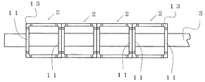
図1〜図10は本発明の一実施形態であり、図1及び図2は装身具1を示し、図3は石座2を示す。図1及び図2に示すように、この実施形態の装身具1は、宝玉4をそれぞれ保持する複数の石座2と、複数の石座2を連結する1本のワイヤ部材3とを有する。宝玉4としては、ダイヤモンド、サファイア、その他のものを使用することができる。図3に示すように、左右方向(長さ方向)をX方向、上下方向(高さ方向)をY方向、前後方向をZ方向として説明する。   FIGS. 1-10 is one Embodiment of this invention, FIG.1 and FIG.2 shows the accessory 1 and FIG. As shown in FIG. 1 and FIG. 2, the accessory 1 of this embodiment includes a plurality of stone pedestals 2 that respectively hold the gems 4 and a single wire member 3 that connects the plurality of stone pedestals 2. As the jewel 4, diamond, sapphire, and others can be used. As shown in FIG. 3, the description will be made assuming that the left-right direction (length direction) is the X direction, the up-down direction (height direction) is the Y direction, and the front-back direction is the Z direction.

図3に示すように、石座2は上面が開口された四角枡形状に形成される。石座2は全体が金色や銀色等の光沢を呈する金、白金、銀等の貴金属或いはこれらの貴金属が表面にメッキされたメッキ金属によって形成され、それ自体で装飾性を備えている。石座2は4つの側面部11が同大の正方形となっていることにより上面が開口された四角枡形状となっている。   As shown in FIG. 3, the stone seat 2 is formed in a square ridge shape having an upper surface opened. The stone seat 2 is formed of gold, platinum, silver or other precious metal having a luster such as gold or silver, or a plated metal obtained by plating these precious metals on the surface, and has a decorative property. The stone seat 2 has a square ridge shape with the upper surface opened by the four side portions 11 being the same size square.

4つの側面部11の角部には、上方に突出する4つの爪部13が形成される。爪部13は石座2の上部に設けられており、爪部13の間には図6に示すように、宝玉4が嵌め込まれる。この嵌め込み状態で爪部13を加締めることにより宝玉4が固定される。これにより宝玉4が石座2の上部に保持状態で固定される。かかる宝玉4の固定に際しては、爪部13を加締めた後、爪部13をスポット的にレーザー照射して溶融させることも可能であり、この爪部13のスポット的な溶融によって宝玉4をさらに強固に固定することができる。
図示する形態において、石座2の底面部分は閉じているが、底面部分を開口しても良い。底面部分を開口することにより石座2に保持された宝玉4を下側から見ることが可能となる。
Four claw portions 13 projecting upward are formed at the corners of the four side surface portions 11. The claw portion 13 is provided on the top of the stone seat 2, and the gem 4 is fitted between the claw portions 13 as shown in FIG. 6. The jewel 4 is fixed by crimping the claw 13 in this fitted state. Thereby, the jewel 4 is fixed to the upper part of the stone seat 2 in a holding state. In fixing the jewel 4, after the claw portion 13 is swaged, the claw portion 13 can be melted by spot-irradiating laser, and the jewel 4 can be further melted by spot melting of the claw portion 13. It can be firmly fixed.
In the illustrated form, the bottom surface portion of the stone seat 2 is closed, but the bottom surface portion may be opened. By opening the bottom surface portion, it is possible to see the jewel 4 held on the stone seat 2 from below.

石座2における対面した2つの側面部11には、連結用開口部14がそれぞれ形成される。この形態において、連結用開口部14は左右方向(X方向)で対面している2つの側面部11に対して対となるように形成され、前後方向(Z方向)で対面した2つの側面部11には形成されていない。左右方向で対となっている連結用開口部14は同一高さ位置となるように左右方向の2つの側面部11に形成されている。
図3に示すように、対となっている連結開口部14は前後方向(Z方向)に延びた同じ大きさの横長四角形状の穴14aによって構成されている。横長四角形状の穴14aは、長辺部141が宝玉取り付け面12と平行となるように形成される。宝玉取り付け面12は4つの側面部11の上端部(上端面)によって形成される面である。長四角形状の穴14aの寸法は、後述するワイヤ部材3の幅及び厚さと一致するように形成される。かかる横長四角形状の穴14aからなる連結用開口部14には、ワイヤ部材3が挿通するものであり、ワイヤ部材3の挿通によって石座2がワイヤ部材3に取り付けられる。
A connecting opening 14 is formed in each of the two side surfaces 11 facing each other in the stone seat 2. In this embodiment, the connecting opening 14 is formed so as to be paired with the two side surfaces 11 facing in the left-right direction (X direction), and the two side surfaces facing each other in the front-rear direction (Z direction). 11 is not formed. The connecting openings 14 paired in the left-right direction are formed in the two side surfaces 11 in the left-right direction so as to be at the same height position.
As shown in FIG. 3, the paired connecting openings 14 are formed by horizontally elongated rectangular holes 14a having the same size and extending in the front-rear direction (Z direction). The horizontally-long rectangular hole 14 a is formed such that the long side portion 141 is parallel to the gemstone mounting surface 12. The jewelry mounting surface 12 is a surface formed by the upper end portions (upper end surfaces) of the four side surface portions 11. The dimension of the long rectangular hole 14a is formed so as to coincide with the width and thickness of the wire member 3 described later. The wire member 3 is inserted into the connecting opening 14 formed of the horizontally long rectangular hole 14 a, and the stone seat 2 is attached to the wire member 3 by the insertion of the wire member 3.

図4は石座2を成形するための原形板金5を示す。原形板金5は上述した金属材料の薄板を打ち抜き加工することにより形成されるものであり、四角枡形状を展開した形状となっている。すなわち原形板金5は正方形の底面片15と、底面片15の2片に連設した2つの縦面片16と、それぞれの縦面片16の前後(図示例では、左右)に連設した側面片17とによって形成されている。側面片17には、連結用開口部14(横長四角形状の穴14a)を形成するための矩形のスリット部19が形成されている。この原形板金5をプレス加工することにより立体的な四角枡形状の石座2を作製する。   FIG. 4 shows an original sheet metal 5 for forming the stone base 2. The original sheet metal 5 is formed by punching a thin plate of the above-described metal material, and has a shape obtained by developing a square ridge shape. That is, the original sheet metal 5 includes a square bottom piece 15, two vertical face pieces 16 provided continuously with the two pieces of the bottom face piece 15, and side faces provided before and after each of the vertical face pieces 16 (left and right in the illustrated example). It is formed by the piece 17. The side piece 17 is formed with a rectangular slit portion 19 for forming the connecting opening 14 (horizontally long rectangular hole 14a). The original sheet metal 5 is pressed to produce a three-dimensional square-shaped stone seat 2.

原形板金5のプレス加工では、2つの縦面片16を底面片15から立ち上げ、立ち上げた縦面片16をさらに横プレスすることにより左右の側面片17を同方向に折り曲げる。折り曲げられた左右の側面片17は突き合わせられ、この側面片17の突き合わせにより石座2の側面部11が形成される。かかる側面片17のスリット部19によって連結用開口部14(横長四角形状の穴14a)が形成される。   In the pressing of the original sheet metal 5, the two vertical surface pieces 16 are raised from the bottom surface piece 15, and the raised vertical surface pieces 16 are further laterally pressed to bend the left and right side surface pieces 17 in the same direction. The bent left and right side pieces 17 are brought into contact with each other, and the side parts 11 of the stone seat 2 are formed by the contact of the side pieces 17. The slit 14 of the side piece 17 forms a connection opening 14 (horizontally long rectangular hole 14a).

突き合わせられた側面片17の間には、隙間18が形成されており(図3(A)参照)、この隙間18を掛け渡すように側面片17をレーザー溶接する。図3(B)はレーザー溶接後の状態を示し、突き合わされている左右の側面片17がレーザー溶接による溶接部20によって結合する。これにより左右の側面部11に強度が付与され、側面部11が連結用開口部14を有しても変形を防止することができる。レーザー溶接については省くことも可能である。   A gap 18 is formed between the butted side pieces 17 (see FIG. 3A), and the side pieces 17 are laser-welded so as to span the gap 18. FIG. 3 (B) shows a state after laser welding, and the left and right side pieces 17 which are abutted are joined together by a welded portion 20 by laser welding. As a result, strength is imparted to the left and right side surface portions 11, and deformation can be prevented even if the side surface portion 11 has the connection opening 14. Laser welding can be omitted.

図5はワイヤ部材3を示す。ワイヤ部材3は石座2の連結用開口部14に挿通されるものであり、ワイヤ部材3の挿通により複数の石座2が数珠つなぎ状に連結される。ワイヤ部材3は石座2の連結用開口部14(横長四角形状の穴14a)に対応した幅及び厚さを有した横長四角形断面に形成されている。ワイヤ部材3としては、例えば幅0.5mm、厚さ0.25mmの横長四角形断面に形成される。   FIG. 5 shows the wire member 3. The wire member 3 is inserted into the connection opening 14 of the stone base 2, and the plurality of stone bases 2 are connected in a daisy chain by the insertion of the wire member 3. The wire member 3 is formed in a horizontally long rectangular cross section having a width and a thickness corresponding to the connection opening 14 (horizontally long rectangular hole 14a) of the stone seat 2. The wire member 3 is formed in a horizontally long rectangular cross section having a width of 0.5 mm and a thickness of 0.25 mm, for example.

ワイヤ部材3は横長四角形断面となっている形状記憶合金によって形成される。ワイヤ部材3としては、マルテンサイト変態を呈するNi−Ti合金又はCu−Zn−Al合金からなる形状記憶合金が選択される。形状記憶合金からなるワイヤ部材3は着用者の体温近辺の温度域でリング状となる形状が記憶されるものであり、着用者の体温近辺の温度域を外れる場合には単に延びた平板状となる。図5(A)はワイヤ部材3が着用者の体温近辺の温度域にある状態、(B)はこの温度域を外れた状態を示す。着用者の体温近辺での変態開始温度としては、10〜50℃、好ましくは20〜40℃を選択することができる。
図5におけるワイヤ部材3は複数巻きのリング状(コイル状)となる形状が記憶されている。複数巻きのリング状となることにより、図9に示すように複数巻きのブレスレットへの適用が可能となる。ワイヤ部材3としては、U字形に近似した単巻きのリング状となる形状が記憶されたものであっても良い。単巻きのリング状となることにより、図10に示すような首掛け一重ネックレスへの適用が可能となる。
The wire member 3 is formed of a shape memory alloy having a horizontally long rectangular cross section. As the wire member 3, a shape memory alloy made of a Ni—Ti alloy or a Cu—Zn—Al alloy exhibiting martensitic transformation is selected. The shape of the wire member 3 made of a shape memory alloy is such that a ring shape is memorized in the temperature range near the wearer's body temperature. Become. FIG. 5A shows a state in which the wire member 3 is in a temperature range near the wearer's body temperature, and FIG. 5B shows a state in which the temperature is outside this temperature range. As a transformation start temperature in the vicinity of the body temperature of the wearer, 10 to 50 ° C, preferably 20 to 40 ° C can be selected.
The wire member 3 in FIG. 5 stores a shape of a plurality of windings in a ring shape (coil shape). By becoming a multiple-winding ring shape, application to a multiple-winding bracelet is possible as shown in FIG. As the wire member 3, a shape that is a single ring shape similar to a U-shape may be stored. Application to a necklace single necklace as shown in FIG.

図6〜図8は、この実施形態の装身具1の組み立て手順を示す。上述したように打ち抜き加工した原形板金5(図4参照)をプレス加工することにより図3に示す四角枡形状の石座2を作製する。この石座2の上部に対し宝玉4を嵌め込み、爪部13を加締めて宝玉4を石座2に保持して固定する。   FIGS. 6-8 shows the assembly procedure of the accessory 1 of this embodiment. The square-shaped stone base 2 shown in FIG. 3 is manufactured by pressing the original sheet metal 5 (see FIG. 4) punched as described above. The jewel 4 is fitted into the upper portion of the stone seat 2, and the claw portion 13 is crimped to hold the jewel 4 to the stone seat 2 and fix it.

宝玉4が固定された石座2に対し、図6に示すようにワイヤ部材3を挿通する。ワイヤ部材3は対となっている側面部11の連結用開口部14(横長四角形状の穴14a)に挿通させる。この挿通に際し、ワイヤ部材3は平板の状態として操作することが良好である。すなわち着用者の体温近辺から外れた温度域とすることによりワイヤ部材3を図5(B)に示す平板状態とし、この平板状態でワイヤ部材3を石座2の連結用開口部14に挿通させることが良好である。   As shown in FIG. 6, the wire member 3 is inserted into the stone seat 2 to which the jewel 4 is fixed. The wire member 3 is inserted through the connecting opening 14 (horizontal elongated square hole 14a) of the side surface portion 11 that forms a pair. In this insertion, the wire member 3 is preferably operated as a flat plate. That is, the wire member 3 is brought into the flat plate state shown in FIG. 5B by setting the temperature range to be near the body temperature of the wearer, and the wire member 3 is inserted into the connection opening 14 of the stone seat 2 in this flat plate state. Is good.

図7及び図8は、以上のワイヤ部材3の挿通を複数の石座2に対して連続的に行う状態を示す。ワイヤ部材3を複数の石座2に挿通することにより、複数の石座2がワイヤ部材3によって数珠つなぎ状に連結されて石座連結体6となる。このときワイヤ部材3の両端部は石座連結体6から外側に抜き出されることにより余長部分21となる(図1及び図2参照)。かかる余長部分21に対しては抜け止め部7が設けられる。図1及び図2において、抜け止め部7はワイヤ部材3の余長部分21に取り付けた飾りボタンによって形成されている。なお、抜け止め部7としては飾りボタンではなく、余長部分21の端部をレーザー等によって熱溶融させることによりワイヤ部材3の形状が拡大したボタン状としても良い。   7 and 8 show a state in which the wire member 3 is continuously inserted into the plurality of stone pedestals 2. By inserting the wire member 3 through the plurality of stone pedestals 2, the plurality of stone pedestals 2 are connected in a daisy chain by the wire members 3, thereby forming the stone seat coupling body 6. At this time, both ends of the wire member 3 become the extra length portion 21 by being pulled out from the stone seat coupling body 6 (see FIGS. 1 and 2). The extra length portion 21 is provided with a retaining portion 7. 1 and 2, the retaining portion 7 is formed by a decorative button attached to the extra length portion 21 of the wire member 3. The retaining portion 7 is not a decorative button, but may be a button shape in which the shape of the wire member 3 is expanded by thermally melting the end of the extra length portion 21 with a laser or the like.

このような装身具1は、宝玉4を保持する石座2の側面部11に横長四角形状の穴14aからなる連結用開口部14を形成し、この連結用開口部14に横長四角形断面のワイヤ部材3を挿通してワイヤ部材3を連結用開口部14に嵌め合わせることにより石座2を数珠つなぎ状とする。このため、石座2が回転することがなく、全ての石座の向きを一定とすることができる。このため、宝玉4を相手に見える向きとすることができ、良好な装飾性を有した装身具1とすることができる。又、複数の石座2を連結するワイヤ部材3として着用者の体温近辺の温度域でリング状となる形状が記憶された形状記憶合金を用いるため、着用することによって自動的にリング状となる機能を備えることができる。このリング状では、石座2が回転することがなく宝玉4を相手側に揃えることができるため、着用の際に宝玉4を相手側に見せることができ、装飾性を向上させることができる。   In such an accessory 1, a connection opening 14 formed of a horizontally long rectangular hole 14 a is formed in the side surface 11 of the stone seat 2 that holds the gem 4, and a wire member having a horizontally long rectangular cross section is formed in the connection opening 14. 3 is inserted and the wire member 3 is fitted into the connecting opening 14 to make the stone seat 2 into a daisy chain. For this reason, the stone seat 2 does not rotate, and the orientation of all the stone seats can be made constant. For this reason, it can be set as the direction which the jewel 4 can be seen by the other party, and it can be set as the accessory 1 with favorable decorativeness. Moreover, since the shape memory alloy in which the shape which becomes ring shape was memorize | stored in the temperature range of a wearer's body temperature is used as the wire member 3 which connects several stone seats 2, it will become ring shape automatically by wearing. A function can be provided. In this ring shape, the jewels 4 can be arranged on the other side without the stone seat 2 rotating, so that the jewels 4 can be shown to the other side when worn, and the decorativeness can be improved.

図2及び図9は、装身具1をブレスレットとして用いた状態を示し、着用者Mの手首に装身具1を複数回巻き付け、この巻き付け状態を短時間保持する。このことにより、ワイヤ部材3に着用者Mの体温が伝達してリング状に自動的に復元する。これにより、装身具1の全体が着用者Mの手首に巻き付いて装着される。この状態では全ての宝玉4が表側に位置して相手が見ることができるため、宝玉4による良好な装飾性を発揮することができる。   2 and 9 show a state in which the accessory 1 is used as a bracelet, and the accessory 1 is wound around the wrist of the wearer M a plurality of times, and this wound state is held for a short time. As a result, the body temperature of the wearer M is transmitted to the wire member 3 to automatically restore the ring shape. As a result, the entire accessory 1 is wound around the wrist of the wearer M and attached. In this state, since all the jewels 4 are located on the front side and can be viewed by the opponent, good decorative properties by the jewels 4 can be exhibited.

図1及び図10は、装身具1をネックレスとして用いた状態を示す。ネックレスとして用いる場合、ワイヤ部材3としては着用者の体温近辺の温度域で単巻きのリング状となる形状が記憶される。この装身具1を着用者Mの首回りに吊り下げ、この吊り下げ状態を短時間保持する。このことにより、ワイヤ部材3に着用者Mの体温が伝達して単巻きのリング状に自動的に復元し、装身具1の全体が着用者Mの首回りに吊り下げられて装着される。この装着状態では、石座2が回転することがなく、石座2に固定された宝玉4が相手側を向いた状態となるため、宝玉4を相手が見ることができる。このため、宝玉4による良好な装飾性を発揮することができる。   1 and 10 show a state in which the accessory 1 is used as a necklace. When used as a necklace, the wire member 3 stores a shape that forms a single ring in the temperature range near the wearer's body temperature. The jewelry 1 is suspended around the neck of the wearer M, and this suspended state is held for a short time. As a result, the body temperature of the wearer M is transmitted to the wire member 3 and is automatically restored to a single ring shape, and the entire accessory 1 is suspended and worn around the neck of the wearer M. In this mounted state, the stone 2 is not rotated, and the gem 4 fixed to the stone 2 is directed to the opponent, so that the opponent can see the gem 4. For this reason, the good decorative property by the jewel 6 can be exhibited.

図1、図2、図9及び図10に示すように、装身具1は着用者Mの体温によって自動的にリング状となって着用者Mの身体に巻き付いた状態を保持する。このため、装身具1をリング状に保持するため、相互に係合するフック金具等の金具が不要となり、スッキリしたデザインの簡単な構造となり、外観が向上すると共に着用及び取り外しの操作が容易となる。   As shown in FIGS. 1, 2, 9, and 10, the accessory 1 automatically becomes a ring shape depending on the body temperature of the wearer M and maintains a state of being wound around the body of the wearer M. For this reason, since the accessory 1 is held in a ring shape, there is no need for fittings such as hook fittings that are engaged with each other, a simple structure with a clean design is achieved, the appearance is improved, and wearing and removal operations are facilitated. .

以上の実施形態の装身具1においては、1本のワイヤ部材3を石座2の連結用開口部14に挿通させる作業を連続的に行うことにより、複数の石座2を数珠つなぎ状とすることができる。このため石座2を数珠つなぎ状とする作業が容易で熟練が不要となり、装身具1の製造を省力化且つ迅速に行うことができる。さらに、ワイヤ部材3として温度による形状変形力を有する柔軟性を備えた形状記憶合金を用いるため、形状記憶合金の柔軟性が装身具1に付与される。このため装身具1の着用が円滑で、しかも任意の着用形態に適用することができる。ワイヤ部材3が柔軟性を有しているため、切れたり、折れることがなく、装身具1の分解を抑制することができる。   In the jewelry 1 of the above embodiment, the plurality of stone staves 2 are formed in a daisy chain by continuously performing the operation of inserting one wire member 3 into the connection opening 14 of the stone stadium 2. Can do. For this reason, the work which makes the stone seat 2 a rosary shape is easy and skill is not required, and the production of the accessory 1 can be labor-saving and quickly performed. Furthermore, since the shape memory alloy provided with the softness | flexibility which has the shape deformation force by temperature is used as the wire member 3, the softness | flexibility of a shape memory alloy is provided to the jewelry 1. FIG. For this reason, wearing of the accessory 1 is smooth and can be applied to any wearing form. Since the wire member 3 has flexibility, it can be prevented from being broken or broken, and the disassembly of the accessory 1 can be suppressed.

次に、石座2の別の形態を図11〜図13及び図18〜図22により説明する。これらの形態において、同一の部材には同一の符号を付して対応させてある。   Next, another embodiment of the stone seat 2 will be described with reference to FIGS. 11 to 13 and FIGS. 18 to 22. In these embodiments, the same members are associated with the same reference numerals.

図11は第1の別の形態の石座2を示す。図11の石座2においては、全て(4つ)の側面部11に対して連結用開口部14を形成するものである。全ての連結用開口部14は同形同大の横長四角形状の穴14aからなり、それぞれの側面部11における同一の位置に形成される。この連結用開口部14に対しワイヤ部材3の挿通が可能となっている。ワイヤ部材3は連結用開口部14に対応した横長四角形断面に形成される。このように全ての側面部11に対して連結用開口部14を形成することにより、ワイヤ部材3の挿通時における石座2の姿勢を任意に選択することができるため、装身具1の組み立てが容易になる。   FIG. 11 shows a first alternative form of the stone seat 2. In the stone seat 2 of FIG. 11, the connection openings 14 are formed for all (four) side surface parts 11. All the connecting openings 14 are formed of horizontally-shaped rectangular holes 14a having the same shape and the same size, and are formed at the same positions in the side surfaces 11 respectively. The wire member 3 can be inserted into the connecting opening 14. The wire member 3 is formed in a horizontally long rectangular cross section corresponding to the connection opening 14. By forming the connection openings 14 for all of the side surfaces 11 in this way, the posture of the stone seat 2 when the wire member 3 is inserted can be arbitrarily selected, so that the accessory 1 can be easily assembled. become.

図12は第2の別の形態の石座2を示す。図12の石座2においては、前後方向(Z方向)で対面する一対の側面部11に対し、上下方向(Y方向)の連結用開口部14を形成するものである。連結用開口部14は縦長四角形状の穴14bからなり、この縦長四角形状の穴14bからなる連結用開口部14に対してワイヤ部材3を挿通する。縦長四角形状の穴14bは長辺部141が宝玉取り付け面12と直交するように形成される。
ワイヤ部材3は着用者の体温近辺の温度域でリング状となる形状が記憶された形状記憶合金によって形成される。ワイヤ部材3は連結用開口部14(縦長四角形状の穴14b)に対応した縦長四角形断面に形成される。このような形態においては、宝玉4を相手が横方向から見る場合に適用することができる。
FIG. 12 shows a second alternative form of the stone seat 2. In the stone seat 2 of FIG. 12, the opening part 14 for a connection of an up-down direction (Y direction) is formed with respect to a pair of side part 11 which faces in the front-back direction (Z direction). The connecting opening portion 14 is formed of a vertically long rectangular hole 14b, and the wire member 3 is inserted into the connecting opening portion 14 including the vertically long rectangular hole 14b. The vertically long rectangular hole 14 b is formed so that the long side portion 141 is orthogonal to the gemstone mounting surface 12.
The wire member 3 is formed of a shape memory alloy in which a ring shape is stored in a temperature range near the body temperature of the wearer. The wire member 3 is formed in a vertically long rectangular section corresponding to the connecting opening 14 (a vertically long rectangular hole 14b). In such a form, it can be applied when the opponent sees the jewel 4 from the lateral direction.

図13は第3の別の形態の石座2を示す。図13の石座2においては、対面する一対の側面部11に対し、横方向及び縦方向の連結用開口部14を形成するものである。すなわち、左右方向(X方向)で対面する一対の側面部11に対しては、横長四角形状の穴14aからなる連結用開口部14を形成し、前後方向(Z方向)で対面する一対の側面部11に対しては、縦長の四角形状の穴14bからなる連結用開口部14を形成するものである。横長四角形状及び縦長四角形状としては、同じ寸法の穴を横方向及び縦方向に形成することが良好である。
ワイヤ部材3は着用者の体温近辺の温度域でリング状となる形状が記憶された形状記憶合金によって形成される。この形態におけるワイヤ部材3は横長四角形断面のものを用い、石座2に対する挿通姿勢を横方向及び縦方向に変更することにより横長四角形状の穴14a及び縦長四角形状の穴14bの双方に対して共通して使用することができる。このように横方向及び縦方向の連結用開口部14を形成することにより、相手が宝玉4を見るいずれの方向に対しても対応できるメリットがある。
FIG. 13 shows a third alternative form of the stone seat 2. In the stone seat 2 of FIG. 13, the connection opening part 14 of a horizontal direction and a vertical direction is formed with respect to a pair of side part 11 which faces. That is, for the pair of side surfaces 11 facing in the left-right direction (X direction), a connection opening 14 formed of a horizontally long rectangular hole 14a is formed, and the pair of side surfaces facing in the front-rear direction (Z direction). For the portion 11, a connecting opening 14 formed of a vertically long rectangular hole 14 b is formed. As the horizontally long rectangular shape and the vertically long rectangular shape, it is preferable to form holes of the same size in the horizontal direction and the vertical direction.
The wire member 3 is formed of a shape memory alloy in which a ring shape is stored in a temperature range near the body temperature of the wearer. In this embodiment, the wire member 3 has a horizontally long rectangular cross section, and by changing the insertion posture with respect to the stone seat 2 to the horizontal direction and the vertical direction, both the horizontally long rectangular hole 14a and the vertically long rectangular hole 14b are used. Can be used in common. By forming the connecting openings 14 in the horizontal direction and the vertical direction in this way, there is an advantage that it is possible to cope with any direction in which the opponent views the jewel 4.

図18は第4の別の形態の石座2を示し、図19はこの図18の石座2に対応したワイヤ部材3を示す。
図18に示すように、石座2における左右方向(X方向)で対面する一対の側面部11に対し、正四角形状の穴14cからなる連結用開口部14が形成される。一対の側面部11の正四角形状の穴14cは同大となっており、対面した側面部11に対し、同じ高さ位置及び前後位置に形成される。対面した側面部11における正四角形状の穴14cには、ワイヤ部材3が挿通される。
18 shows a fourth alternative form of the pedestal 2, and FIG. 19 shows a wire member 3 corresponding to the pedestal 2 of FIG.
As shown in FIG. 18, a connection opening 14 formed of a regular square hole 14 c is formed in the pair of side surfaces 11 facing in the left-right direction (X direction) in the stone seat 2. The regular rectangular holes 14c of the pair of side surface portions 11 are the same size, and are formed at the same height position and front-rear position with respect to the facing side surface portions 11. The wire member 3 is inserted into the regular quadrangular hole 14c in the side surface portion 11 facing.

ワイヤ部材3は図19に示すように、石座2の正四角形状の穴14cに対応した断面に形成されるものであり、このためワイヤ部材3は正四角形断面に形成される。正四角形断面のワイヤ部材3を正四角形状の穴14cからなる石座2の連結用開口部14に挿通すると、ワイヤ部材3と連結用開口部14とが嵌め合った状態となる。このため、石座2が回転することがなく、石座2が保持した宝玉4を相手側に向かせることができ、相手が宝玉4を視認することができる(図20参照)。   As shown in FIG. 19, the wire member 3 is formed in a cross section corresponding to the square-shaped hole 14 c of the stone seat 2. For this reason, the wire member 3 is formed in a regular square cross section. When the wire member 3 having a regular quadrilateral cross section is inserted into the connection opening 14 of the stone base 2 formed of a regular square hole 14c, the wire member 3 and the connection opening 14 are fitted together. For this reason, the stone 2 is not rotated, the gem 4 held by the stone 2 can be directed to the opponent, and the opponent can visually recognize the gem 4 (see FIG. 20).

正四角形断面のワイヤ部材3は着用者の体温近辺の温度域でリング状となる形状が記憶された形状記憶合金によって形成される。図19(A)は、着用者の体温近辺の温度域を外れた状態のワイヤ部材3を示し、単に延びた平板形状となる。同図(B)及び(C)は、着用者の体温近辺の温度域にあり、形状記憶した形状に復元した状態を示す。   The wire member 3 having a square cross section is formed of a shape memory alloy in which a ring shape is stored in a temperature range near the wearer's body temperature. FIG. 19A shows the wire member 3 in a state outside the temperature range near the wearer's body temperature, and has a flat plate shape that simply extends. (B) and (C) of the figure are in a temperature range near the wearer's body temperature, and show a state in which the shape is memorized.

同図(B)で示すワイヤ部材3はU字形に近似した単巻きのリング状となる形状が記憶されている。このような形状記憶状態で装身具1を着用すると、ワイヤ部材3が記憶された形状に復元するため、図20(A)で示すように、装身具1の全体が自動的に首掛け一重ネックレスとなる。この場合、石座2はワイヤ部材3に対して回転しないため、全ての宝玉4を着用者の前側に向かせることができ、良好な装飾性を発揮する装身具1とすることができる。
同図(C)で示すワイヤ部材3は複数巻きのリング状(コイル状)となる形状が記憶されている。このような複数巻きのリング状を形状記憶した状態で装身具1を着用すると、ワイヤ部材3が記憶された形状に復元するため、図20(B)で示すように、装身具1の全体が自動的に複数巻きのブレスレットとなる。この場合、石座2はワイヤ部材3に対して回転しないため、全ての宝玉4を着用者の腕回りの外側に向かせることができる。このため、相手が全ての宝玉4を見ることができ、豪華な装飾性を発揮することができる。
同図(D)で示すワイヤ部材3は全体を長さ方向に沿ってねじった状態となっている。このワイヤ部材3を石座2の正四角形状の穴14cに挿通させると、宝玉4が異なった方向に向いた状態となり、装飾性を発揮することができる。
The wire member 3 shown in FIG. 5B stores a single-ring shape that is similar to a U-shape. When the accessory 1 is worn in such a shape memory state, the wire member 3 is restored to the stored shape, so that the entire accessory 1 automatically becomes a necked single necklace as shown in FIG. . In this case, since the stone seat 2 does not rotate with respect to the wire member 3, all the jewels 4 can be directed to the front side of the wearer, and the accessory 1 that exhibits good decorativeness can be obtained.
The wire member 3 shown in FIG. 5C stores a shape that forms a plurality of rings (coil). When the accessory 1 is worn with the shape of such a plurality of windings being memorized, the wire member 3 is restored to the memorized shape. Therefore, as shown in FIG. It becomes a bracelet with multiple windings. In this case, since the stone seat 2 does not rotate with respect to the wire member 3, all the jewels 4 can be directed to the outside around the wearer's arm. For this reason, the opponent can see all the jewels 4 and can exhibit a luxurious decoration.
The wire member 3 shown in FIG. 4D is in a state where the whole is twisted along the length direction. When the wire member 3 is inserted into the square-shaped hole 14c of the stone seat 2, the jewel 4 is in a different direction and can exhibit decorativeness.

図21(A)は第5の別の形態の石座2を示す。石座2における左右方向(X方向)で対面する一対の側面部11に対し、楕円形状の穴14dからなる連結用開口部14が形成される。楕円形状の穴14dは、その長軸が宝玉取り付け面12に沿った状態で石座2に形成される。一対の側面部11における楕円形状の穴14dは同大となっていると共に、対面した側面部11に対し、同じ高さ位置及び前後位置に形成される。対面した側面部11における楕円形状の穴14dにはワイヤ部材3が挿通される。   FIG. 21A shows a fifth alternative form of the stone seat 2. A connection opening 14 formed of an elliptical hole 14d is formed in the pair of side surfaces 11 facing in the left-right direction (X direction) in the stone seat 2. The elliptical hole 14 d is formed in the stone base 2 with its long axis along the gem mounting surface 12. The elliptical holes 14d in the pair of side portions 11 have the same size, and are formed at the same height position and front-rear position with respect to the facing side portions 11. The wire member 3 is inserted into the elliptical hole 14d in the side surface portion 11 facing.

図21(B)はこの石座2に挿通されるワイヤ部材3を示す。ワイヤ部材3は石座2の連結用開口部14(楕円形状の穴14d)に対応するように、楕円形断面に形成される。その大きさは連結用開口部14に嵌め込み可能なように設定される。このような楕円形断面のワイヤ部材3を楕円形状の穴14dからなる石座2の連結用開口部14に挿通すると、ワイヤ部材3と連結用開口部14とが嵌め合った状態となる。このため、石座2が回転することがなく、石座2が保持した宝玉4を相手側に向かせることができ、相手が宝玉4を視認することができる。   FIG. 21B shows the wire member 3 inserted through the stone seat 2. The wire member 3 is formed in an elliptical cross section so as to correspond to the connection opening 14 (the elliptical hole 14d) of the stone seat 2. Its size is set so that it can be fitted into the connecting opening 14. When the wire member 3 having such an elliptical cross section is inserted into the connection opening 14 of the stone seat 2 formed of the elliptical hole 14d, the wire member 3 and the connection opening 14 are fitted. For this reason, the stone seat 2 does not rotate, the jewel 4 held by the stone stadium 2 can be directed to the opponent, and the opponent can visually recognize the jewel 4.

ワイヤ部材3は着用者の体温近辺の温度域でリング状となる形状が記憶された形状記憶合金によって形成される。ワイヤ部材3として、複数巻きのリング状(コイル状)となる形状が記憶された場合、複数巻きのブレスレットとすることができ、単巻き状のリング状となる形状が記憶された場合、首掛け一重ネックレスとすることができる。   The wire member 3 is formed of a shape memory alloy in which a ring shape is stored in a temperature range near the body temperature of the wearer. As the wire member 3, when a shape of a multi-turn ring shape (coil shape) is stored, it can be a multi-turn bracelet, and when a shape of a single turn ring shape is stored, It can be a single necklace.

図22(A)は第6の別の形態の石座2を示す。石座2における左右方向(X方向)で対面する一対の側面部11に対し、長円形状の穴14eからなる連結用開口部14が形成される。長円形状の穴14eは楕円の長軸に沿った上下面が平行となった非円形である。一対の側面部11における長円形状の穴14eは同大となっていると共に、対面した側面部11に対し、同じ高さ位置及び前後位置に形成される。対面した側面部11における長円形状の穴14eにはワイヤ部材3が挿通される。   FIG. 22A shows a sixth alternative form of the stone seat 2. A connection opening 14 formed of an oval hole 14e is formed on the pair of side surfaces 11 facing in the left-right direction (X direction) in the stone seat 2. The oval hole 14e is a non-circular shape whose upper and lower surfaces along the major axis of the ellipse are parallel. The oval holes 14e in the pair of side portions 11 are the same size, and are formed at the same height position and front-rear position with respect to the facing side portions 11. The wire member 3 is inserted into the oval hole 14e in the side surface portion 11 facing.

図22(B)はこの石座2に挿通されるワイヤ部材3を示す。ワイヤ部材3は石座2の連結用開口部14(長円形状の穴14e)に対応するように、長円形断面に形成される。その大きさは連結用開口部14に嵌め込み可能なように設定される。このような長円形断面のワイヤ部材3を長円形状の穴14eからなる石座2の連結用開口部14に挿通すると、ワイヤ部材3と連結用開口部14とが嵌め合った状態となる。このため、石座2が回転することがなく、石座2が保持した宝玉4を相手側に向かせることができ、相手が宝玉4を視認することができる。   FIG. 22B shows the wire member 3 inserted through the stone seat 2. The wire member 3 is formed in an oval cross section so as to correspond to the connection opening 14 (the oval hole 14e) of the stone seat 2. Its size is set so that it can be fitted into the connecting opening 14. When the wire member 3 having such an oval cross section is inserted into the connection opening 14 of the stone seat 2 formed of the oval hole 14e, the wire member 3 and the connection opening 14 are fitted. For this reason, the stone seat 2 does not rotate, the jewel 4 held by the stone stadium 2 can be directed to the opponent, and the opponent can visually recognize the jewel 4.

この形態においても、ワイヤ部材3は着用者の体温近辺の温度域でリング状となる形状が記憶された形状記憶合金によって形成される。ワイヤ部材3として、複数巻きのリング状(コイル状)となる形状が記憶された場合、複数巻きのブレスレットとすることができ、単巻き状のリング状となる形状が記憶された場合、首掛け一重ネックレスとすることができる。   Also in this form, the wire member 3 is formed of a shape memory alloy in which a ring shape is stored in the temperature range near the wearer's body temperature. As the wire member 3, when a shape of a multi-turn ring shape (coil shape) is stored, it can be a multi-turn bracelet, and when a shape of a single turn ring shape is stored, It can be a single necklace.

図23は本発明に使用可能なワイヤ部材3の別の記憶形状を示す。ワイヤ部材3は形状記憶合金によって形成されるが、図示例のワイヤ部材3では、着用者の体温近辺の温度域で12角形となる形状が記憶される。12角形における屈曲部35は鈍角となっていると共に一部は開放されており、これにより単巻きのリング状となる形状が記憶される。ワイヤ部材3の断面としては、長四角形、正四角形、楕円形、長円形、五角形以上の多角形となる非円形とすることができる。
これに対し、石座2の連結用開口部14をワイヤ部材3の非円形断面に合わせた穴形状とすることにより、ワイヤ部材3及び連結用開口部14が嵌め合った状態となって石座2の回転がロックされる。このため、石座2が回転することがなく、石座2が保持した宝玉4を相手側に向かせることができ、相手が宝玉4を視認することができる
FIG. 23 shows another memory shape of the wire member 3 that can be used in the present invention. Although the wire member 3 is formed of a shape memory alloy, the wire member 3 in the illustrated example stores a shape that is a dodecagon in the temperature range near the body temperature of the wearer. The bent portion 35 in the dodecagon has an obtuse angle and a part thereof is opened, so that the shape of a single ring shape is stored. The cross section of the wire member 3 may be a long rectangle, a regular rectangle, an ellipse, an oval, or a non-circular shape that is a pentagon or more polygon.
On the other hand, by forming the connecting opening 14 of the stone seat 2 into a hole shape that matches the non-circular cross section of the wire member 3, the wire member 3 and the connecting opening 14 are fitted together. The rotation of 2 is locked. For this reason, the stone 2 is not rotated, the gem 4 held by the stone 2 can be directed to the opponent, and the opponent can visually recognize the gem 4.

図14〜図17は、ワイヤ部材3の余長部分21の抜け止め部7として、留め金具を用いた形態を示す。抜け止め部としての留め金具は雄金具25及び雌金具26からなり、石座連結体6から外側に抜き出されたワイヤ部材3の余長部分21の両端部にそれぞれ固定される。   14 to 17 show a form in which a fastener is used as the retaining portion 7 of the extra length portion 21 of the wire member 3. The fasteners as the retaining portions are made up of a male metal fitting 25 and a female metal fitting 26, and are fixed to both ends of the extra length portion 21 of the wire member 3 extracted outward from the stone seat coupling body 6, respectively.

雄金具25は図15及び図16に示すように、板ばね27によって形成される。板ばね27は雌金具26側の先端部分(図示例では、左端部分)が細くなり、この先端部分(左端部分)から基端部分(右端部分)に向かって徐々に上下方向に離れるばね片によって形成されている。板ばね27(雄金具25)には、雌金具26に係脱自在に係合する係合凸部29が形成されている。又、板ばね27の基端部分は、押し下げ部28となっており、この押し下げ部28を押し下げることにより雌金具26との係合を解除することができる。   The male fitting 25 is formed by a leaf spring 27 as shown in FIGS. The leaf spring 27 has a thin tip at the female fitting 26 side (left end portion in the example shown in the figure), and a spring piece that gradually moves up and down from the tip portion (left end portion) toward the base end portion (right end portion). Is formed. The leaf spring 27 (male fitting 25) is formed with an engaging projection 29 that is detachably engaged with the female fitting 26. Further, the base end portion of the leaf spring 27 is a push-down portion 28, and the engagement with the female fitting 26 can be released by pushing down the push-down portion 28.

図15及び図16に示すように、雌金具26は横長ブロック状のケース30によって形成される。ケース30には、雄金具25が差し込まれる差し込み穴部31が形成されると共に、雄金具25の係合凸部29が係合する係合穴部32が形成されている。従って雄金具25を雌金具26のケース30内に差し込むと、雄金具25の係合凸部29が雌金具26の係合穴部32に係合する。この係合により装身具1が無端状となるため、着用者への着用が可能となる。   As shown in FIGS. 15 and 16, the female fitting 26 is formed by a horizontally long block-shaped case 30. The case 30 is formed with an insertion hole portion 31 into which the male fitting 25 is inserted, and an engagement hole portion 32 with which the engagement convex portion 29 of the male fitting 25 is engaged. Therefore, when the male metal fitting 25 is inserted into the case 30 of the female metal fitting 26, the engagement convex portion 29 of the male metal fitting 25 engages with the engagement hole portion 32 of the female metal fitting 26. This engagement makes the accessory 1 endless, so that it can be worn by the wearer.

以上に加えて、雌金具26のケース30は、図17に示すように、雄金具26の押し下げ部28よりも高くなるように設定されている(ケース30の高さh2>押し上げ部28の高さh1)。これにより周囲から不用意に外力が作用してもケース30が外力を受けるため、外力が押し下げ部28に加わることを抑制することができ、雄金具25の不用意な係合解除を抑制できる。このような構造では、不用意な外力が作用しても雄金具25が雌金具26との締結から解除されることがないため、装身具1の着用状態を安定させることができる。   In addition to the above, the case 30 of the female fitting 26 is set to be higher than the push-down portion 28 of the male fitting 26 as shown in FIG. 17 (the height h2 of the case 30> the height of the push-up portion 28). H1). As a result, even if an external force is inadvertently applied from the surroundings, the case 30 receives the external force, so that it is possible to suppress the external force from being applied to the push-down portion 28, and to prevent inadvertent release of the male fitting 25. In such a structure, the male fitting 25 is not released from the fastening with the female fitting 26 even when an inadvertent external force is applied, so that the wearing state of the accessory 1 can be stabilized.

図24〜図27は、本発明の第2実施形態の装身具51を示す。この形態の装身具51は図24に示すように、バンド52、ワイヤ部材3及び端末部材54によって形成されている。   24-27 shows the accessory 51 of the second embodiment of the present invention. As shown in FIG. 24, the accessory 51 in this form is formed by a band 52, a wire member 3, and a terminal member 54.

バンド51は複数の駒53を横並び状に連結することにより形成される。バンド52は長さ方向の両端部が自由端となっている。すなわちバンド52は長さ方向の両端部にフック金具、雌雄嵌合金具等の連結用金具が取り付けられることがない。これによりスッキリしたデザインとなり外観が向上する。なお、図示例において、バンド52の一側の端部には、端末部材54が取り付けられるが、この端末部材54は単なる飾りであってバンド52をリング状に保持するための連結用金具とは異なっている。このように両端部を自由端としても、後述するように、着用者Mの身体に巻き付けることによりワイヤ部材3が自動的にリング状となって着用者Mの身体に巻き付いた状態を保持することができる。   The band 51 is formed by connecting a plurality of pieces 53 side by side. Both ends of the band 52 in the length direction are free ends. In other words, the band 52 is not attached with a connecting metal fitting such as a hook metal fitting or a male / female fitting metal fitting at both ends in the length direction. This gives a clean design and improves the appearance. In the illustrated example, a terminal member 54 is attached to one end portion of the band 52. The terminal member 54 is merely a decoration, and is a connection metal fitting for holding the band 52 in a ring shape. Is different. Thus, even if both ends are set as free ends, as described later, the wire member 3 automatically becomes a ring shape and is held around the wearer's M body by being wound around the wearer's M body. Can do.

駒53は表面から貴金属光沢を発する材料によって形成される。駒53の材料としては、金、白金、銀等の貴金属又はこれらの貴金属と他の金属との合金或いはこれらの貴金属が表面にメッキ被覆や蒸着された金属や樹脂を用いることができる。複数の駒53のそれぞれが貴金属光沢を発しており、この駒53が横並び状に連結されてバンド52が形成されることによりバンド52(すなわち装身具51)に高級感を付与することができる。   The piece 53 is formed of a material that emits noble metal luster from the surface. As the material of the piece 53, a noble metal such as gold, platinum, silver or the like, an alloy of these noble metals and other metals, or a metal or resin in which these noble metals are plated or deposited on the surface can be used. Each of the plurality of pieces 53 emits noble metal luster, and the pieces 53 are connected side by side to form a band 52, whereby a high-quality feeling can be imparted to the band 52 (that is, the accessory 51).

図25に示すように、それぞれの駒52には、非円形の穴からなる連結用開口部55が貫通するように形成され、この連結用開口部55にワイヤ部材3が挿通する。ワイヤ部材3の挿通によって複数の駒53が横並び状に連結されてバンド52が形成される。連結用開口部55はそれぞれの駒53の長さ方向(W方向と直交する方向)を貫通するように形成される。   As shown in FIG. 25, each piece 52 is formed so as to pass through a connection opening 55 formed of a non-circular hole, and the wire member 3 is inserted into the connection opening 55. By inserting the wire member 3, a plurality of pieces 53 are connected side by side to form a band 52. The connection opening 55 is formed so as to penetrate the length direction (direction orthogonal to the W direction) of each piece 53.

この実施形態において、非円形の連結用開口部55は駒53の幅方向(W方向)が長くなった横長四角形状に形成されて駒53の長さ方向を貫通している。ワイヤ部材3はこの横長四角形状に対応した横長四角形断面に形成されて全体で扁平形状となっており、この状態で複数の駒53に挿通する(図26参照)。このように扁平形状のワイヤ部材3が複数の駒53に挿通することにより駒53が回転したり、浮き上がりや横ずれすることがなくなる。このため全ての駒53を整列状態で横並び状とすることができ、バンド52全体に高級感が付与されると共に外観が向上し、商品価値を増大させることができる。
この実施形態において、連結用開口部55及びワイヤ部材3における非円形としては、正四角形、楕円形、長円形等であっても良い。
In this embodiment, the non-circular connection opening 55 is formed in a horizontally long rectangular shape in which the width direction (W direction) of the piece 53 is long and penetrates the length direction of the piece 53. The wire member 3 is formed in a horizontally long rectangular cross section corresponding to this horizontally long rectangular shape and has a flat shape as a whole, and is inserted into the plurality of pieces 53 in this state (see FIG. 26). In this way, when the flat wire member 3 is inserted into the plurality of pieces 53, the piece 53 is prevented from rotating, floating, or being laterally displaced. For this reason, all the pieces 53 can be arranged side by side in an aligned state, a high-quality feeling is imparted to the entire band 52, the appearance is improved, and the commercial value can be increased.
In this embodiment, the non-circular shape in the connection opening 55 and the wire member 3 may be a regular square, an oval, an oval, or the like.

複数の駒53における隣接した駒53はワイヤ部材3の挿通により連結されるが、このワイヤ部材3による連結に加えて隣接する駒52を相互に連結状態とする構造としても良い。図25及び図27はこの構造の一例を示す。隣接する一方の駒52の端面には、ボール状の凸部56及び穴状の凹部57が連結用開口部55を跨ぐように形成され、これに対応した他方の駒52の端面には、凸部56に対応した凹部57及び凹部57に対応した凸部56が連結用開口部55を跨ぐように形成されている。凸部56及び凹部57を嵌合させることにより隣接する駒53を連結することができる。このように駒53を連結状態とすることにより、バンド52の組み立て時におけるワイヤ部材3の駒53への挿通を容易且つ確実に行うことができる。   The adjacent pieces 53 in the plurality of pieces 53 are connected by the insertion of the wire member 3, but in addition to the connection by the wire member 3, the adjacent pieces 52 may be connected to each other. 25 and 27 show an example of this structure. A ball-shaped convex portion 56 and a hole-shaped concave portion 57 are formed on the end face of one adjacent piece 52 so as to straddle the connecting opening 55, and the corresponding end face of the other piece 52 has a convex shape. A concave portion 57 corresponding to the portion 56 and a convex portion 56 corresponding to the concave portion 57 are formed so as to straddle the connecting opening 55. By fitting the convex portion 56 and the concave portion 57, the adjacent pieces 53 can be connected. Thus, by setting the piece 53 in the connected state, the wire member 3 can be easily and reliably inserted into the piece 53 when the band 52 is assembled.

扁平断面(横長四角形断面)からなるワイヤ部材3は、着用者Mの体温近辺の温度域でリング状となる形状が記憶された形状記憶合金によって形成されている。ワイヤ部材3としては、マルテンサイト変態を呈するNi−Ti合金又はCu−Zn−Al合金からなる形状記憶合金が選択される。形状記憶合金からなるワイヤ部材3は着用者の体温近辺の温度域でリング状となる形状が記憶されるものであり、着用者の体温近辺の温度域を外れる場合には単に延びた平板状となる。すなわちワイヤ部材3は図5(A)に示すように、着用者Mの体温近辺で複数巻きのリング状(コイル状)となる形状が記憶されており、着用者Mの体温近辺の温度域を外れた場合には、図5(B)で示すように、単に延びた平板状となる。このようなワイヤ部材3を備えたバンド52は着用者Mの腕等に巻き付けることにより着用者の体温によって自動的にリング状となる。このため着用者の腕に美粧性を付与すると共にこの美粧性の付与状態で安定して装着される。   The wire member 3 having a flat cross section (horizontally long rectangular cross section) is formed of a shape memory alloy in which a ring shape is memorized in the temperature range near the body temperature of the wearer M. As the wire member 3, a shape memory alloy made of a Ni—Ti alloy or a Cu—Zn—Al alloy exhibiting martensitic transformation is selected. The shape of the wire member 3 made of a shape memory alloy is such that a ring shape is memorized in the temperature range near the wearer's body temperature. Become. That is, as shown in FIG. 5A, the wire member 3 stores a shape of a plurality of windings (coiled) around the body temperature of the wearer M, and the temperature range around the body temperature of the wearer M is stored. In the case of detachment, as shown in FIG. The band 52 including the wire member 3 is automatically ring-shaped according to the wearer's body temperature by being wound around the arm of the wearer M or the like. For this reason, cosmetics are imparted to the wearer's arm and the cosmetics are stably worn in the cosmetics imparted state.

この実施形態において、複数の駒53はワイヤ部材3の長さ方向に沿って幅寸法が漸減する形状に形成されている。すなわち、図24に示すように、端末部材54側の駒53は幅が大きいのに対し反対側の駒53は幅が小さくなり、この間の駒53では幅が漸減するように駒53が連結される。これによりバンド52は横幅が長さ方向に沿って漸減した外観となる。従ってバンド52に形状変化を付与することができるため、興趣性のある装身具51とすることができる。   In this embodiment, the plurality of pieces 53 are formed in a shape in which the width dimension gradually decreases along the length direction of the wire member 3. That is, as shown in FIG. 24, the piece 53 on the terminal member 54 side has a large width, whereas the piece 53 on the opposite side has a small width, and the piece 53 is connected so that the width of the piece 53 in between decreases gradually. The As a result, the band 52 has an appearance in which the lateral width gradually decreases along the length direction. Therefore, since a shape change can be given to the band 52, it can be set as the ornamental accessory 51 with interest.

端末部材54はワイヤ部材3の一側の端部に取り付けられる。端末部材54はバンド52に装飾性又は機能性を付与する部材であり、装飾性付与のためには、ブローチ等の飾り部材が選択され、機能性付与のためには万歩計(登録商標)、腕時計、ヘモグロビン測定器等の携帯型機器が選択される。図示する形態では、端末部材54として腕時計が用いられている。かかる腕時計からなる端末部材54はワイヤ部材3の端部に対して着脱自在となっている。   The terminal member 54 is attached to one end of the wire member 3. The terminal member 54 is a member that imparts decorativeness or functionality to the band 52, and a decorative member such as a brooch is selected for imparting decorativeness, and a pedometer (registered trademark) for imparting functionality. A portable device such as a wristwatch or a hemoglobin measuring device is selected. In the illustrated form, a wristwatch is used as the terminal member 54. The terminal member 54 made of such a wrist watch is detachable from the end of the wire member 3.

図28は端末部材54を着脱自在とするための構造の一例を示す。端末部材54は図24に示すように、腕時計からなる端末本体部58と、端末本体部58周囲の枠部材としてのベゼル部59とを有しており、ベゼル部59がワイヤ部材3に連結される。図28に示すように、ベゼル部3には、一対の舌片状の係合口部60が形成され、この係合口部60に係合凹部61が形成されている。
一方、ワイヤ部材3の端部には、着脱用金具62が取り付けられる。着脱用金具62は復元可能な板ばね部63を有しており、この板ばね部63に係合凸部64が形成されている。着脱用金具62をベゼル部59の係合口部60に挿入して係合凸部64を係合凹部61に係合させることにより、ワイヤ部材3の端部に端末部材54を装着することができる。一方、板ばね部63を押し下げることにより係合凹部61と係合凸部64との係合が解除されるため、ワイヤ部材3から端末部材54を取り外すことができる。これにより端末部材54を簡単に交換することができる。なお、ワイヤ部材3と端末部材54との連結は、ねじ、その他の手段によって行うこともできる。
FIG. 28 shows an example of a structure for making the terminal member 54 detachable. As shown in FIG. 24, the terminal member 54 has a terminal main body portion 58 made of a wristwatch and a bezel portion 59 as a frame member around the terminal main body portion 58, and the bezel portion 59 is connected to the wire member 3. The As shown in FIG. 28, the bezel portion 3 is formed with a pair of tongue-like engagement port portions 60, and the engagement recess portions 61 are formed in the engagement port portions 60.
On the other hand, a metal fitting 62 for attachment / detachment is attached to the end of the wire member 3. The detachable metal fitting 62 has a plate spring portion 63 that can be restored, and an engagement convex portion 64 is formed on the plate spring portion 63. The terminal member 54 can be attached to the end portion of the wire member 3 by inserting the attaching / detaching metal fitting 62 into the engaging port portion 60 of the bezel portion 59 and engaging the engaging convex portion 64 with the engaging concave portion 61. . On the other hand, since the engagement between the engagement concave portion 61 and the engagement convex portion 64 is released by pushing down the leaf spring portion 63, the terminal member 54 can be removed from the wire member 3. As a result, the terminal member 54 can be easily replaced. The connection between the wire member 3 and the terminal member 54 can also be performed by a screw or other means.

以上の装身具51では、非円形の穴からなる連結用開口部55が形成された複数の駒53が横並び状に連結されたバンド52と、複数の駒53に挿通されて複数の駒53を横並び状に連結するワイヤ部材3とを備え、ワイヤ部材3として着用者の体温近辺の温度域でリング状となる形状が記された形状記憶合金を用いるため、着用者の身体に自動的に巻き付いて装着される。このため、高級感を付与できると共に外観が向上し、商品価値を増大させることができる。又、装身具着用のために装身具51をリング状に保持するためのフック金具等の金具が不要となるため、スッキリしたデザインとなると共に身体への着用が容易となる。   In the above jewelry 51, a band 52 in which a plurality of pieces 53 each having a connection opening 55 formed of a non-circular hole are connected side by side, and a plurality of pieces 53 are inserted side by side through the plurality of pieces 53. Since the shape memory alloy in which the shape which becomes a ring shape in the temperature range near the wearer's body temperature is used as the wire member 3 is provided around the wearer's body. Installed. For this reason, a high-class feeling can be given, an external appearance can be improved, and a commercial value can be increased. In addition, since a fitting such as a hook fitting for holding the accessory 51 in a ring shape is not required for wearing the accessory, a neat design and easy wearing on the body are facilitated.

図29及び図30は、本発明の第3実施形態の装身具71を示す。この実施形態の装身具71は、ベルト部材72と、端末部材54とによって形成される。   29 and 30 show an accessory 71 according to a third embodiment of the present invention. The accessory 71 of this embodiment is formed by a belt member 72 and a terminal member 54.

ベルト部材72はワイヤ部材3を芯材とし、この芯材をカバー部材73が被覆した構造となっている。図30はベルト部材72の断面を示し、ワイヤ部材3の全周をカバー部材73が被覆した状態となっている。   The belt member 72 has a structure in which the wire member 3 is a core material and the core material is covered with a cover member 73. FIG. 30 shows a cross section of the belt member 72, and the cover member 73 covers the entire circumference of the wire member 3.

図30に示すように、ワイヤ部材3は幅方向が長い横長四角形断面となっており、これにより扁平形状となっている。従って、腕等への着用を安定して行うことができる。ワイヤ部材3は着用者Mの体温近辺の温度域でリング状となる形状が記憶された形状記憶合金によって形成されている。ワイヤ部材3としては、マルテンサイト変態を呈するNi−Ti合金又はCu−Zn−Al合金からなる形状記憶合金が選択される。
形状記憶合金からなるワイヤ部材3は着用者の体温近辺の温度域でリング状となる形状が記憶されるものであり、着用者の体温近辺の温度域を外れる場合には単に延びた平板状となる。すなわちワイヤ部材3は図5(A)に示すように、着用者Mの体温近辺で複数巻きのリング状(コイル状)となる形状が記憶されており、着用者Mの体温近辺の温度域を外れた場合には、図5(B)で示すように、単に延びた平板状となる。このようなワイヤ部材3を備えたベルト部材72は着用者Mの腕等に巻き付けることにより着用者の体温によって自動的にリング状となる。このように自動的にリング状となって着用されるため、ベルト部材72をリング状に保持するためのフック金具等の金具がベルト部材72の両端部に不要となる。これにより簡単に着用できると共にスッキリしたデザインとなり外観が向上する。
As shown in FIG. 30, the wire member 3 has a horizontally long rectangular cross section with a long width direction, and thereby has a flat shape. Therefore, it can be stably worn on the arm or the like. The wire member 3 is formed of a shape memory alloy in which a ring shape is stored in a temperature range near the body temperature of the wearer M. As the wire member 3, a shape memory alloy made of a Ni—Ti alloy or a Cu—Zn—Al alloy exhibiting martensitic transformation is selected.
The shape of the wire member 3 made of a shape memory alloy is such that a ring shape is memorized in the temperature range near the wearer's body temperature. Become. That is, as shown in FIG. 5A, the wire member 3 stores a shape of a plurality of windings (coiled) around the body temperature of the wearer M, and the temperature range around the body temperature of the wearer M is stored. In the case of detachment, as shown in FIG. The belt member 72 provided with such a wire member 3 is automatically ring-shaped according to the body temperature of the wearer by being wound around the arm of the wearer M or the like. Since it is automatically worn in a ring shape in this way, metal fittings such as hook metal fittings for holding the belt member 72 in a ring shape are not required at both ends of the belt member 72. This makes it easy to wear and a clean design that improves the appearance.

ワイヤ部材3を被覆するカバー部材73は着色された革、布、樹脂等によって形成されている。カバー部材73がワイヤ部材3を被覆することによりカバー部材73の質感や色がベルト部材72に付与される。このためベルト部材72に高級感を付与することができる。又、ワイヤ部材3が皮膚と接触しないため、ソフトな使用感とすることができる。 The cover member 73 that covers the wire member 3 is formed of colored leather, cloth, resin, or the like. By covering the wire member 3 with the cover member 73, the texture and color of the cover member 73 are imparted to the belt member 72. For this reason, a high-class feeling can be given to the belt member 72. Further, since the wire member 3 does not come into contact with the skin, a soft feeling can be obtained.

端末部材54はワイヤ部材3の一側の端部に取り付けられる。端末部材54はベルト部材72に装飾性又は機能性を付与する部材であり、装飾性付与のためには、ブローチ等の飾り部材が選択され、機能性付与のためには万歩計(登録商標)、腕時計、ヘモグロビン測定器等の携帯型機器が選択される。図示する形態では、端末部材54として万歩計(登録商標)が用いられている。この万歩計(登録商標)からなる端末部材54はワイヤ部材3の端部に対して着脱自在となっている。   The terminal member 54 is attached to one end of the wire member 3. The terminal member 54 is a member that imparts decorativeness or functionality to the belt member 72, and a decorative member such as a brooch is selected for imparting decorativeness, and a pedometer (registered trademark) for imparting functionality. ), Portable devices such as wristwatches and hemoglobin measuring devices are selected. In the illustrated form, a pedometer (registered trademark) is used as the terminal member 54. A terminal member 54 made of this pedometer (registered trademark) is detachable from the end of the wire member 3.

端末部材54をワイヤ部材3に対して着脱自在とする構造は、図28と同様な構造とすることができる。すなわち図28に示すように、端末部材54のベゼル部59に一対の舌片状の係合口部60を形成し、この係合口部60に係合凹部61を形成する。ワイヤ部材3の端部には、着脱用金具62を取り付ける。着脱用金具62は復元可能な板ばね部63を有しており、この板ばね部63に係合凸部64が形成されている。着脱用金具62をベゼル部59の係合口部60に挿入して係合凸部64を係合凹部61に係合させることにより、ワイヤ部材3の端部に端末部材54を装着することができる。一方、板ばね部63を押し下げることにより係合凹部61と係合凸部64との係合が解除されるため、ワイヤ部材3から端末部材54を取り外すことができる。これにより端末部材54を他の端末部材54と簡単に交換することができる。   The structure in which the terminal member 54 is detachable from the wire member 3 can be the same as that shown in FIG. That is, as shown in FIG. 28, a pair of tongue-shaped engagement port portions 60 are formed in the bezel portion 59 of the terminal member 54, and an engagement recess 61 is formed in the engagement port portion 60. An attachment / detachment fitting 62 is attached to the end of the wire member 3. The detachable metal fitting 62 has a plate spring portion 63 that can be restored, and an engagement convex portion 64 is formed on the plate spring portion 63. The terminal member 54 can be attached to the end portion of the wire member 3 by inserting the attaching / detaching metal fitting 62 into the engaging port portion 60 of the bezel portion 59 and engaging the engaging convex portion 64 with the engaging concave portion 61. . On the other hand, since the engagement between the engagement concave portion 61 and the engagement convex portion 64 is released by pushing down the leaf spring portion 63, the terminal member 54 can be removed from the wire member 3. As a result, the terminal member 54 can be easily replaced with another terminal member 54.

この実施形態において、ベルト部材72は端末部材54側の幅が大きいのに対し反対側の幅が小さくなり、この間では幅が漸減している。これによりベルト部材72は横幅が長さ方向に沿って漸減した外観となる。従ってベルト部材72に形状変化を付与することができるため、興趣性のある装身具71とすることができる。 In this embodiment, the belt member 72 has a large width on the terminal member 54 side, whereas the width on the opposite side is small, and the width gradually decreases during this period. As a result, the belt member 72 has an appearance in which the lateral width gradually decreases along the length direction. Therefore, since a shape change can be given to the belt member 72, it can be set as the ornamental accessory 71 with interest.

図31は図29の装身具71の変形々態を示す。図31に示す装身具75において、端末部材54として腕時計が用いられており、この端末部材54の一側には、図29と同様なベルト部材72が取り付けられる。ベルト部材72は内部のワイヤ部材3をカバー部材73が被覆することにより形成される。   FIG. 31 shows a modification of the accessory 71 of FIG. In the accessory 75 shown in FIG. 31, a wristwatch is used as the terminal member 54, and a belt member 72 similar to that in FIG. The belt member 72 is formed by covering the inner wire member 3 with a cover member 73.

ワイヤ部材3は図30と同様に、幅方向が長い横長四角形断面となっており、長さ方向の全体が扁平形状となっている。従って、腕等への着用を安定して行うことができる。ワイヤ部材3は着用者Mの体温近辺の温度域でリング状となる形状が記憶された形状記憶合金によって形成されている。ワイヤ部材3としては、マルテンサイト変態を呈するNi−Ti合金又はCu−Zn−Al合金からなる形状記憶合金が選択される。   Similarly to FIG. 30, the wire member 3 has a horizontally long rectangular cross section with a long width direction, and the entire length direction has a flat shape. Therefore, it can be stably worn on the arm or the like. The wire member 3 is formed of a shape memory alloy in which a ring shape is stored in a temperature range near the body temperature of the wearer M. As the wire member 3, a shape memory alloy made of a Ni—Ti alloy or a Cu—Zn—Al alloy exhibiting martensitic transformation is selected.

形状記憶合金からなるワイヤ部材3は着用者の体温近辺の温度域でリング状となる形状が記憶されるものであり、着用者の体温近辺の温度域を外れる場合には単に延びた平板状となる。すなわちワイヤ部材3は図5(A)に示すように、着用者Mの体温近辺で複数巻きのリング状(コイル状)となる形状が記憶されており、着用者Mの体温近辺の温度域を外れた場合には、図5(B)で示すように、単に延びた平板状となる。このようなワイヤ部材3を備えたベルト部材72は着用者Mの腕等に巻き付けることにより着用者の体温によって自動的にリング状となる。このように自動的にリング状となって着用されるため、ベルト部材72をリング状に保持するためのフック金具等の金具がベルト部材72の両端部に不要となる。
かかるベルト部材72は図28と同様な構造を用いることにより端末部材54への取り付けが行われる。すなわちベルト部材72の内部のワイヤ部材3が端末部材54に着脱自在に取り付けられるものである。
なお、ベルト部材72は端末部材54側の幅が大きいのに対し反対側の幅が小さくなり、この間では幅が漸減した形状となっている。これによりベルト部材72は横幅が長さ方向に沿って漸減した外観となる。従ってベルト部材72に形状変化を付与することができるため、興趣性のある装身具71とすることができる。
The shape of the wire member 3 made of a shape memory alloy is such that a ring shape is memorized in the temperature range near the wearer's body temperature. Become. That is, as shown in FIG. 5A, the wire member 3 stores a shape of a plurality of windings (coiled) around the body temperature of the wearer M, and the temperature range around the body temperature of the wearer M is stored. In the case of detachment, as shown in FIG. The belt member 72 provided with such a wire member 3 is automatically ring-shaped according to the body temperature of the wearer by being wound around the arm of the wearer M or the like. Since it is automatically worn in a ring shape in this way, metal fittings such as hook metal fittings for holding the belt member 72 in a ring shape are not required at both ends of the belt member 72.
The belt member 72 is attached to the terminal member 54 by using a structure similar to that shown in FIG. That is, the wire member 3 inside the belt member 72 is detachably attached to the terminal member 54.
The belt member 72 has a large width on the terminal member 54 side, whereas the width on the opposite side is small, and the width gradually decreases in the meantime. As a result, the belt member 72 has an appearance in which the lateral width gradually decreases along the length direction. Therefore, since a shape change can be given to the belt member 72, it can be set as the ornamental accessory 71 with interest.

以上に加えて、この装身具75では、端末部材54の他側にサブベルト76が取り付けられている。サブベルト76は端末部材54のベゼル部59に取り付けられており、その先端部分にベルト金具77が取り付けられている。ベルト金具77の針金具78をベルト部材72に形成したベルト穴79に差し込むことにより装身具75を腕等に装着することができる。この実施形態において、ベルト穴79はベルト部材72における端末部材54との近接箇所に形成されており、ベルト穴79から遠ざかる残余のベルト部材72は着用者の体温によってリング状となって自動的に腕等に巻き付けられる。このような残余のベルト部材72によって装飾性が付与され、興趣性ある使用を行うことができる。   In addition to the above, in the accessory 75, a sub belt 76 is attached to the other side of the terminal member 54. The sub belt 76 is attached to the bezel portion 59 of the terminal member 54, and a belt metal fitting 77 is attached to the tip portion thereof. By inserting the needle fitting 78 of the belt fitting 77 into the belt hole 79 formed in the belt member 72, the accessory 75 can be attached to the arm or the like. In this embodiment, the belt hole 79 is formed in the belt member 72 at a location close to the terminal member 54, and the remaining belt member 72 away from the belt hole 79 is automatically ring-shaped according to the body temperature of the wearer. Wound around the arm. Such a remaining belt member 72 gives decorativeness and can be used with interest.

以上の図29及び図31に示す装身具として着用者の腕への巻き付けを説明したが、これに限らず、着衣のベルトにも同様に適用することができる。   Although the wrapping around the wearer's arm has been described as the accessory shown in FIG. 29 and FIG. 31, the present invention is not limited to this and can be similarly applied to a belt of clothes.

本発明の装身具1は、宝玉4を保持する石座2の対面した側面部11に非円形の穴からなる連結用開口部14が形成され、石座2に挿通されるワイヤ部材3が連結用開口部14に合わせた非円形断面に形成されるため、ワイヤ部材3が連結用開口部14に嵌め合った状態となる。これにより石座2がワイヤ部材3に対して回転することがなくなり、全ての石座を同じ向きとすることができる。そしてワイヤ部材3を着用者の体温近辺の温度域でリング状となる形状が記憶された形状記憶合金によって形成する。このことにより装身具を着用すると、自動的にリング状となるため、着用の際に宝玉を見せることができ、装飾性を向上させることができる。
本発明の装身具1は、ワイヤ部材3を石座2の連結用開口部14に挿通させる作業を連続的に行うことにより、複数の石座2を数珠つなぎ状とすることができ、石座2を数珠つなぎ状とするための作業が容易で熟練が不要となり、装身具1の製造を省力化且つ迅速に行うことができる。ワイヤ部材3として形状記憶合金を用いるため、ワイヤ部材3が柔軟性を有しており、切れたり、折れることがなく、装身具1の分解を抑制することができる。しかも形状記憶合金の柔軟性が装身具1に付与され、装身具1の着用が円滑となり任意の着用形態にも対応することができる。
In the accessory 1 of the present invention, a connecting opening 14 formed of a non-circular hole is formed in a side surface portion 11 of a stone seat 2 that holds a jewel 4, and a wire member 3 inserted through the stone seat 2 is used for connection. Since the non-circular cross section is formed in accordance with the opening 14, the wire member 3 is fitted in the connection opening 14. Thereby, the stone base 2 does not rotate with respect to the wire member 3, and all the stone seats can be in the same direction. And the wire member 3 is formed with the shape memory alloy by which the shape which becomes a ring shape was memorize | stored in the temperature range of a wearer's body temperature vicinity. Thus, when the accessory is worn, it automatically becomes a ring shape, so that it is possible to show a jewel in the case of wearing and to improve the decorativeness.
The jewelry 1 of the present invention can continuously form a plurality of stone staves 2 by connecting the wire member 3 through the connecting opening 14 of the stone stadium 2 to form a rosary shape. Can be easily connected to each other, and skill is not required, and the production of the accessory 1 can be labor-saving and quick. Since the shape memory alloy is used as the wire member 3, the wire member 3 has flexibility and can be prevented from being broken or broken, and the disassembly of the accessory 1 can be suppressed. Moreover, the flexibility of the shape memory alloy is imparted to the accessory 1, so that the accessory 1 can be worn smoothly and can be applied to any wearing form.

1 装身具
2 石座
3 ワイヤ部材
4 宝玉
5 原形板金
6 石座連結体
7 抜け止め部
11 側面部
12 宝玉取り付け面
13 爪部
14 連結用開口部
14a 横長四角形状の穴
14b 縦長四角形状の穴
14c 正四角形状の穴
14d 楕円形状の穴
14e 長円形状の穴
17 側面片
21 余長部分
25 雄金具
26 雌金具
27 板ばね
28 押し下げ部
30 ケース
51、71、75 装身具
52 バンド
54 端末部材
72 ベルト部材
73 カバー部材
DESCRIPTION OF SYMBOLS 1 Jewelry 2 Stone seat 3 Wire member 4 Jewel 5 Original sheet metal 6 Stone seat coupling body 7 Retaining part 11 Side part 12 Jewel attachment surface 13 Claw part 14 Connection opening 14a Horizontal rectangular hole 14b Vertical rectangular hole 14c Regular square hole 14d Oval hole 14e Oval hole 17 Side piece 21 Extra length portion 25 Male fitting 26 Female fitting 27 Leaf spring 28 Push-down part 30 Case 51, 71, 75 Accessories 52 Band 54 Terminal member 72 Belt Member 73 Cover member

Claims (24)

宝玉が上部に嵌め込まれることにより宝玉を保持する四角枡形状の複数の石座と、
複数の石座を連結するワイヤ部材と、を備え、
前記石座における対面した側面部に非円形の穴からなる連結用開口部が形成され、
前記ワイヤ部材は前記連結用開口部に対応した非円形断面に形成され、前記連結用開口部に挿通されることにより前記複数の石座を連結し、
前記ワイヤ部材は着用者の体温近辺の温度域でリング状となる形状が記憶された形状記憶合金によって形成されていることを特徴とする装身具。
A plurality of square-shaped stone seats that hold the jewels by fitting them into the upper part,
A wire member for connecting a plurality of stone seats,
A connecting opening made of a non-circular hole is formed on the side surface facing the stone seat,
The wire member is formed in a non-circular cross section corresponding to the connection opening, and the plurality of stone seats are connected by being inserted through the connection opening,
The said wire member is formed with the shape memory alloy by which the shape which becomes a ring shape was memorize | stored in the temperature range of a wearer's body temperature vicinity, The jewelry characterized by the above-mentioned.
前記ワイヤ部材は着用者の体温近辺の温度域で複数巻きのリング状となる形状が記憶された形状記憶合金によって形成されていることを特徴とする請求項1記載の装身具。   2. The accessory according to claim 1, wherein the wire member is formed of a shape memory alloy in which a plurality of winding shapes are stored in a temperature range near a wearer's body temperature. 前記ワイヤ部材は着用者の体温近辺の温度域で単巻きのリング状となる形状が記憶された形状記憶合金によって形成されていることを特徴とする請求項1記載の装身具。   The accessory according to claim 1, wherein the wire member is formed of a shape memory alloy in which a shape of a single-turn ring shape is stored in a temperature range near a wearer's body temperature. 前記連結用開口部は長辺部が前記石座の宝玉取り付け面と平行となる横長四角形状の穴によって形成され、前記ワイヤ部材は横長四角形断面に形成されていることを特徴とする請求項1乃至3のいずれか1項記載の装身具。   2. The connecting opening is formed by a horizontally long rectangular hole having a long side parallel to the gemstone mounting surface of the stone seat, and the wire member has a horizontally long rectangular cross section. The accessory of any one of thru | or 3. 前記連結用開口部は長辺部が前記石座の宝玉取り付け面と直交する縦長四角形状の穴によって形成され、前記ワイヤ部材は縦長四角形断面に形成されていることを特徴とする請求項1乃至3のいずれか1記載の装身具。   2. The connecting opening is formed by a vertically long rectangular hole having a long side portion orthogonal to a gemstone mounting surface of the stone seat, and the wire member is formed in a vertically long rectangular cross section. 4. The jewelry according to any one of 3. 前記連結用開口部は長辺部が前記石座の宝玉取り付け面と平行となる横長四角形状の穴と、長辺部が前記石座の宝玉取り付け面と直交する縦長四角形状の穴とによって形成され、前記横長四角形状の穴が前記石座の対面した一の側面部に形成され、前記縦長四角形状の穴が前記石座の対面した他の側面部に形成されていることを特徴とする請求項1乃至3のいずれか1項記載の装身具。   The connection opening is formed by a horizontally long rectangular hole whose long side is parallel to the gemstone mounting surface of the stone seat and a long rectangular hole whose long side is perpendicular to the stone ball mounting surface of the stone seat. The laterally long rectangular hole is formed in one side surface facing the stone seat, and the vertical rectangular hole is formed in the other side surface facing the stone seat. The jewelry according to any one of claims 1 to 3. 前記連結用開口部は正四角形状の穴によって形成され、前記ワイヤ部材は正四角形断面に形成されていることを特徴とする請求項1乃至3のいずれか1項記載の装身具。   The accessory according to any one of claims 1 to 3, wherein the connection opening is formed by a square hole, and the wire member is formed in a square cross section. 前記連結用開口部は楕円形状の穴によって形成され、前記ワイヤ部材は楕円形断面に形成されていることを特徴とする請求項1乃至3のいずれか1項記載の装身具。   The accessory according to any one of claims 1 to 3, wherein the connection opening is formed by an elliptical hole, and the wire member is formed in an elliptical cross section. 前記連結用開口部は長円形状の穴によって形成され、前記ワイヤ部材は長円形断面に形成されていることを特徴とする請求項1乃至3のいずれか1項記載の装身具。   The accessory according to any one of claims 1 to 3, wherein the connecting opening is formed by an oval hole, and the wire member is formed in an oval cross section. 前記石座は打ち抜き加工された原形板金をプレス加工することにより四角枡形状に形成され、前記石座の側面部は原形板金の側面片の突合せによって形成され、突き合わされた側面片がレーザー溶接されていることを特徴とする請求項1乃至9のいずれか1項記載の装身具。   The stone base is formed into a square shape by pressing a stamped original sheet metal, the side surface of the stone base is formed by abutting the side pieces of the original sheet metal, and the abutted side pieces are laser welded. The accessory according to any one of claims 1 to 9, wherein the accessory is provided. 前記石座は4つの側面部の角部分から上方に突出し加締められることにより前記宝玉を固定する爪部を有していることを特徴とする請求項1乃至10のいずれか1項記載の装身具。   The jewelry according to any one of claims 1 to 10, wherein the stone seat has a claw portion for fixing the jewel by protruding upward from corner portions of four side surface portions and being crimped. . 前記ワイヤ部材は複数の石座を連結した石座連結体の両端部から外側に抜き出された余長部分を有し、当該余長部分に前記石座連結体からの石座の抜け止めを行う抜け止め部が設けられていることを特徴とする請求項1乃至11のいずれか1項記載の装身具。   The wire member has a surplus length portion extracted outward from both ends of a stone seat coupling body in which a plurality of stone seats are coupled, and the surplus length portion is used to prevent the stone seat from coming off from the stone seat coupling body. The jewelry according to any one of claims 1 to 11, further comprising a retaining portion for performing the retaining. 前記抜け止め部は前記ワイヤ部材の余長部分における前記石座連結体の一方の端部に対応して取り付けられた雄金具と、他方の端部に対応して取り付けられた雌金具とからなり、
前記雄金具は、前記雌金具内に係脱自在に挿入される板ばねからなり、前記板ばねに前記雌金具との係合を解除するための押し下げ部が形成され、
前記雌金具は、前記雄金具が挿入されるケースからなり、前記ケースは前記押し下げ部より高く形成されていることを特徴とする請求項12記載の装身具。
The retaining portion includes a male fitting attached to one end of the stone seat coupling body in the extra length portion of the wire member and a female fitting attached to the other end. ,
The male fitting is composed of a leaf spring that is detachably inserted into the female fitting, and a push-down portion for releasing the engagement with the female fitting is formed on the leaf spring,
The accessory according to claim 12, wherein the female fitting is a case into which the male fitting is inserted, and the case is formed higher than the push-down portion.
前記抜け止め部は前記ワイヤ部材の余長部分における前記石座連結体の両端部に対応して設けられた飾りボタンであることを特徴とする請求項12記載の装身具。   The accessory according to claim 12, wherein the retaining portion is a decorative button provided corresponding to both ends of the stone seat coupling body in the extra length portion of the wire member. 前記ワイヤ部材はマルテンサイト変態を呈するNi−Ti合金又はCu−Zn−Al合金であることを特徴とする請求項1乃至14のいずれか1項記載の装身具。   The jewelry according to any one of claims 1 to 14, wherein the wire member is a Ni-Ti alloy or a Cu-Zn-Al alloy exhibiting martensitic transformation. 非円形の穴からなる連結用開口部が形成された複数の駒が横並び状に連結され、長さ方向の両端部が自由端となっているバンドと、
前記連結用開口部に対応した非円形断面に形成され、前記複数の駒に挿通されて複数の駒を横並び状に連結するワイヤ部材と、を備え、
前記ワイヤ部材は着用者の体温近辺の温度域でリング状となる形状が記憶された形状記憶合金によって形成されていることを特徴とする装身具。
A band in which a plurality of pieces formed with connecting openings made of non-circular holes are connected side by side, and both ends in the length direction are free ends,
A wire member that is formed in a non-circular cross-section corresponding to the connection opening, and is inserted through the plurality of pieces to connect the plurality of pieces side by side;
The said wire member is formed with the shape memory alloy by which the shape which becomes a ring shape was memorize | stored in the temperature range of a wearer's body temperature vicinity, The jewelry characterized by the above-mentioned.
前記ワイヤ部材は着用者の体温近辺の温度域で複数巻きのリング状となる形状が記憶された形状記憶合金によって形成されていることを特徴とする請求項16記載の装身具。   17. The accessory according to claim 16, wherein the wire member is formed of a shape memory alloy in which a plurality of winding shapes are stored in a temperature range near a wearer's body temperature. 前記連結用開口部は幅方向が長い横長四角形状の穴によって形成され、前記ワイヤ部材は横長四角形断面に形成されていることを特徴とする請求項16記載の装身具。   17. The accessory according to claim 16, wherein the connecting opening is formed by a horizontally long rectangular hole having a long width direction, and the wire member is formed in a horizontally long rectangular cross section. 前記ワイヤ部材における少なくとも一方の端部に飾り部材又は携帯型機器からなる端末部材が着脱自在に取り付けられていることを特徴とする請求項16記載の装身具。   The accessory according to claim 16, wherein a terminal member made of a decorative member or a portable device is detachably attached to at least one end of the wire member. 前記駒は貴金属光沢を発する材料によって形成されていることを特徴とする請求項16記載の装身具。   17. The accessory according to claim 16, wherein the piece is made of a material that emits noble metal luster. 前記複数の駒は前記ワイヤ部材の長さ方向に沿って幅寸法が漸減する形状に形成されていることを特徴とする請求項16記載の装身具。   The accessory according to claim 16, wherein the plurality of pieces are formed in a shape in which a width dimension gradually decreases along a length direction of the wire member. 幅方向が長い横長四角形断面に形成され、着用者の体温近辺の温度域でリング状となる形状が記憶された形状記憶合金からなるワイヤ部材と、
前期ワイヤ部材を被覆するカバー部材と、
前記ワイヤ部材の長さ方向の少なくとも一端部に着脱自在に連結される飾り部材又は携帯型機器からなる端末部材と、を備えていることを特徴とする装身具。
A wire member made of a shape memory alloy, which is formed into a long rectangular cross section with a long width direction and in which a ring-shaped shape is stored in a temperature range near the body temperature of the wearer;
A cover member for covering the wire member in the previous period;
And a terminal member made of a decorative member or a portable device that is detachably connected to at least one end portion of the wire member in the length direction.
前記ワイヤ部材は着用者の体温近辺の温度域で複数巻きのリング状となる形状が記憶された形状記憶合金によって形成されていることを特徴とする請求項22記載の装身具。   23. The jewelry according to claim 22, wherein the wire member is formed of a shape memory alloy in which a shape that forms a plurality of windings in a temperature range near a wearer's body temperature is stored. 前記ワイヤ部材における少なくとも一方の端部に飾り部材又は携帯型機器が着脱自在に取り付けられていることを特徴とする請求項22記載の装身具。   The accessory according to claim 22, wherein a decoration member or a portable device is detachably attached to at least one end of the wire member.
JP2017168318A 2017-02-23 2017-09-01 Jewelery Active JP7075736B2 (en)

Priority Applications (1)

Application Number Priority Date Filing Date Title
PCT/JP2017/036243 WO2018154834A1 (en) 2017-02-23 2017-10-05 Accessory

Applications Claiming Priority (2)

Application Number Priority Date Filing Date Title
JP2017032433 2017-02-23

Publications (2)

Publication Number Publication Date
JP2018134375A true JP2018134375A (en) 2018-08-30
JP7075736B2 JP7075736B2 (en) 2022-05-26

Family

ID=63366340

Family Applications (1)

Application Number Title Priority Date Filing Date
JP2017168318A Active JP7075736B2 (en) 2017-02-23 2017-09-01 Jewelery

Country Status (1)

Country Link
JP (1) JP7075736B2 (en)

Cited By (2)

* Cited by examiner, † Cited by third party
Publication number Priority date Publication date Assignee Title
KR102016310B1 (en) * 2018-03-08 2019-08-30 송재하 Bracelet with built-in leaf spring and its manufacturing method
WO2022172932A1 (en) * 2021-02-10 2022-08-18 河野 良太 Necklace

Citations (11)

* Cited by examiner, † Cited by third party
Publication number Priority date Publication date Assignee Title
JPS5985335A (en) * 1982-11-09 1984-05-17 Citizen Watch Co Ltd Manufacture of watch band
JPS59149105A (en) * 1983-02-15 1984-08-27 上尾精密株式会社 Production of clock band
JPH01110303A (en) * 1987-10-23 1989-04-27 Furukawa Electric Co Ltd:The Accessory and production thereof
JPH02102602A (en) * 1988-10-13 1990-04-16 Seiko Epson Corp Watch band
JPH0282912U (en) * 1989-09-20 1990-06-27
JPH10127321A (en) * 1996-10-30 1998-05-19 Seberu Piko:Kk Fastening metal fitting for accessory
JP2006055505A (en) * 2004-08-23 2006-03-02 Sankyo:Kk Accessory
JP2009077886A (en) * 2007-09-26 2009-04-16 Seiko Epson Corp Band member having core material and skin material, and wristwatch and accessory provided with the same
KR101153716B1 (en) * 2012-02-14 2012-06-14 이혜선 Manufacturing method of accessory chain and apparamanufacturing method of accessory chain and apparatusthereof tusthereof
KR101639679B1 (en) * 2016-01-07 2016-07-15 김선강 A ornamental chain
KR20170011430A (en) * 2015-07-23 2017-02-02 김명길 Manufacturing method of accessory chain and apparatusthereof

Patent Citations (11)

* Cited by examiner, † Cited by third party
Publication number Priority date Publication date Assignee Title
JPS5985335A (en) * 1982-11-09 1984-05-17 Citizen Watch Co Ltd Manufacture of watch band
JPS59149105A (en) * 1983-02-15 1984-08-27 上尾精密株式会社 Production of clock band
JPH01110303A (en) * 1987-10-23 1989-04-27 Furukawa Electric Co Ltd:The Accessory and production thereof
JPH02102602A (en) * 1988-10-13 1990-04-16 Seiko Epson Corp Watch band
JPH0282912U (en) * 1989-09-20 1990-06-27
JPH10127321A (en) * 1996-10-30 1998-05-19 Seberu Piko:Kk Fastening metal fitting for accessory
JP2006055505A (en) * 2004-08-23 2006-03-02 Sankyo:Kk Accessory
JP2009077886A (en) * 2007-09-26 2009-04-16 Seiko Epson Corp Band member having core material and skin material, and wristwatch and accessory provided with the same
KR101153716B1 (en) * 2012-02-14 2012-06-14 이혜선 Manufacturing method of accessory chain and apparamanufacturing method of accessory chain and apparatusthereof tusthereof
KR20170011430A (en) * 2015-07-23 2017-02-02 김명길 Manufacturing method of accessory chain and apparatusthereof
KR101639679B1 (en) * 2016-01-07 2016-07-15 김선강 A ornamental chain

Cited By (4)

* Cited by examiner, † Cited by third party
Publication number Priority date Publication date Assignee Title
KR102016310B1 (en) * 2018-03-08 2019-08-30 송재하 Bracelet with built-in leaf spring and its manufacturing method
WO2022172932A1 (en) * 2021-02-10 2022-08-18 河野 良太 Necklace
JP2022122774A (en) * 2021-02-10 2022-08-23 河野 良太 necklace
JP7134422B2 (en) 2021-02-10 2022-09-12 河野 良太 necklace

Also Published As

Publication number Publication date
JP7075736B2 (en) 2022-05-26

Similar Documents

Publication Publication Date Title
US6804977B1 (en) Necklace and bracelet pendant-clasp
JP6401259B2 (en) Decorative body pedestal for removable decorative bodies, products and methods comprising such pedestals
KR20180049014A (en) Decorative fashion jewelery including flat lining in contact with cutting part of metal plate
JPWO2016030922A1 (en) Ring-shaped accessory
JP7075736B2 (en) Jewelery
JP2010046218A (en) Rocking ornament
KR101364522B1 (en) Piercings or earrings into easy-to-use accessory
WO2018154834A1 (en) Accessory
CN112399809B (en) Fastening member for ornament, fastener for ornament, and assembly kit for fastening member for ornament
KR200443779Y1 (en) Jewelry House
KR20120035660A (en) Structure fixing precious stones for a personalornaments
KR200418686Y1 (en) Earrings
JP3132896U (en) Trinkets for jewelry and jewelry using the same
JP3140698U (en) Decorative member locking structure and decorative article having the locking structure
KR20180002696U (en) Accessory
JP3131204U (en) Bracelet with frame and frame used therefor
KR102529788B1 (en) Jewelry to keep replaceable ornaments
US12082665B2 (en) Jewelry arrangement system
JP2016202616A (en) Clasp
TW201412260A (en) Ornamental articles
CN218942454U (en) Wearing structure convenient to assemble and disassemble and watch convenient to assemble and disassemble
US20080163467A1 (en) Snap fastener
JP3109530U (en) Headdress
JP4165764B1 (en) Twirl holder type pendant top
KR200391064Y1 (en) shaking type ornament

Legal Events

Date Code Title Description
AA64 Notification of invalidation of claim of internal priority (with term)

Free format text: JAPANESE INTERMEDIATE CODE: A241764

Effective date: 20171024

A521 Request for written amendment filed

Free format text: JAPANESE INTERMEDIATE CODE: A523

Effective date: 20171026

A621 Written request for application examination

Free format text: JAPANESE INTERMEDIATE CODE: A621

Effective date: 20200827

A131 Notification of reasons for refusal

Free format text: JAPANESE INTERMEDIATE CODE: A131

Effective date: 20211012

A521 Request for written amendment filed

Free format text: JAPANESE INTERMEDIATE CODE: A523

Effective date: 20211213

TRDD Decision of grant or rejection written
A01 Written decision to grant a patent or to grant a registration (utility model)

Free format text: JAPANESE INTERMEDIATE CODE: A01

Effective date: 20220419

A61 First payment of annual fees (during grant procedure)

Free format text: JAPANESE INTERMEDIATE CODE: A61

Effective date: 20220516

R150 Certificate of patent or registration of utility model

Ref document number: 7075736

Country of ref document: JP

Free format text: JAPANESE INTERMEDIATE CODE: R150