JP2018116418A - Card reader and control method of card reader - Google Patents
Card reader and control method of card reader Download PDFInfo
- Publication number
- JP2018116418A JP2018116418A JP2017006047A JP2017006047A JP2018116418A JP 2018116418 A JP2018116418 A JP 2018116418A JP 2017006047 A JP2017006047 A JP 2017006047A JP 2017006047 A JP2017006047 A JP 2017006047A JP 2018116418 A JP2018116418 A JP 2018116418A
- Authority
- JP
- Japan
- Prior art keywords
- card
- sensor
- card reader
- capacitance sensor
- detection
- Prior art date
- Legal status (The legal status is an assumption and is not a legal conclusion. Google has not performed a legal analysis and makes no representation as to the accuracy of the status listed.)
- Granted
Links
Images


Classifications
-
- G—PHYSICS
- G07—CHECKING-DEVICES
- G07F—COIN-FREED OR LIKE APPARATUS
- G07F19/00—Complete banking systems; Coded card-freed arrangements adapted for dispensing or receiving monies or the like and posting such transactions to existing accounts, e.g. automatic teller machines
- G07F19/20—Automatic teller machines [ATMs]
- G07F19/205—Housing aspects of ATMs
- G07F19/2055—Anti-skimming aspects at ATMs
-
- G—PHYSICS
- G06—COMPUTING OR CALCULATING; COUNTING
- G06K—GRAPHICAL DATA READING; PRESENTATION OF DATA; RECORD CARRIERS; HANDLING RECORD CARRIERS
- G06K7/00—Methods or arrangements for sensing record carriers, e.g. for reading patterns
- G06K7/08—Methods or arrangements for sensing record carriers, e.g. for reading patterns by means detecting the change of an electrostatic or magnetic field, e.g. by detecting change of capacitance between electrodes
- G06K7/081—Methods or arrangements for sensing record carriers, e.g. for reading patterns by means detecting the change of an electrostatic or magnetic field, e.g. by detecting change of capacitance between electrodes electrostatic, e.g. by detecting the charge of capacitance between electrodes
-
- G—PHYSICS
- G11—INFORMATION STORAGE
- G11B—INFORMATION STORAGE BASED ON RELATIVE MOVEMENT BETWEEN RECORD CARRIER AND TRANSDUCER
- G11B5/00—Recording by magnetisation or demagnetisation of a record carrier; Reproducing by magnetic means; Record carriers therefor
- G11B5/02—Recording, reproducing, or erasing methods; Read, write or erase circuits therefor
Landscapes
- Physics & Mathematics (AREA)
- General Physics & Mathematics (AREA)
- Engineering & Computer Science (AREA)
- Business, Economics & Management (AREA)
- Accounting & Taxation (AREA)
- Finance (AREA)
- Artificial Intelligence (AREA)
- Computer Vision & Pattern Recognition (AREA)
- Theoretical Computer Science (AREA)
- Conveying Record Carriers (AREA)
- Recording Or Reproducing By Magnetic Means (AREA)
Abstract
【課題】不正行為のためにカードリーダの内部に取り付けられる異物を静電容量センサによって検知し、且つ、カードを異物として誤検知するおそれを少なくすること。【解決手段】カードリーダ1の制御部30は、カードセンサ9の出力信号に基づいてカード通過路6におけるカード2の有無を監視する。カード2が無いと判定した場合に、静電容量センサ10の出力信号に基づいて異物の有無を判定する。カードリーダ1は温度センサ41および湿度センサ42を備える。制御部30は、記憶部34から読み出した検出閾値CTに対して温度補正および湿度補正を行い、補正後の検出閾値CT1を用いて異物の有無を判定する。【選択図】図5An object of the present invention is to detect a foreign object attached to the inside of a card reader for fraud by a capacitance sensor and reduce the possibility of erroneously detecting a card as a foreign object. A controller 30 of a card reader 1 monitors the presence or absence of a card 2 in a card passage 6 based on an output signal of a card sensor 9. When it is determined that there is no card 2, the presence / absence of a foreign object is determined based on the output signal of the capacitance sensor 10. The card reader 1 includes a temperature sensor 41 and a humidity sensor 42. The control unit 30 performs temperature correction and humidity correction on the detection threshold value CT read from the storage unit 34, and determines the presence or absence of foreign matter using the corrected detection threshold value CT1. [Selection] Figure 5
Description
本発明は、カードに対して磁気データの記録および読取りを行うカードリーダおよびその制御方法に関する。 The present invention relates to a card reader for recording and reading magnetic data on a card and a control method therefor.
磁気情報が記録されたカードを取り込み、磁気ヘッドによって磁気データの記録および読取りを行うカードリーダに対して、カードを挿入するカード挿入部に磁気ヘッドを取り付けて不正に磁気データを読み取る不正行為(いわゆる、スキミング)が問題となっている。このような不正行為への対策として、カード挿入部に異物が取り付けられたことを検知するセンサを備えるカードリーダが提案されている。 A fraudulent act of reading a magnetic data illegally by attaching a magnetic head to a card insertion portion for inserting the card into a card reader that takes in a card in which magnetic information is recorded and records and reads the magnetic data by the magnetic head Skimming) is a problem. As a countermeasure against such an illegal act, a card reader including a sensor for detecting that a foreign object is attached to the card insertion portion has been proposed.
しかしながら、スキミングの手口は年々巧妙化しており、従来取り付けられることのなかったカードリーダの内部にスキミング用の磁気ヘッドが取り付けられ、不正に磁気データが読み取られるという事態が発生している。カードリーダの内部にスキミング用の磁気ヘッドが取り付けられた場合、外部から見えないために不正が行われていることに気付きにくい。そのため、長期間に亘ってスキミングか行われて被害が大きくなるおそれが高い。そこで、カードリーダの内部にスキミング用の磁気ヘッドが取り付けられたことを検知するセンサを備えるカードリーダが提案されている。特許文献1には、この種のカードリーダが開示されている。 However, skimming techniques have become more sophisticated year by year, and a situation has arisen in which a magnetic head for skimming is attached inside a card reader that has not been conventionally attached, and magnetic data is read illegally. When a magnetic head for skimming is mounted inside the card reader, it is difficult to notice that fraud is being performed because it is not visible from the outside. Therefore, there is a high possibility that the skimming is performed over a long period of time and the damage is increased. Therefore, a card reader has been proposed that includes a sensor that detects that a magnetic head for skimming is attached inside the card reader. Patent Document 1 discloses this type of card reader.
特許文献1のカードリーダは、カードの挿入口から挿入されたカードが通過するカード通過路に取り付けられた異物を検知する静電容量センサを備える。カード通過路にスキミング用の磁気ヘッドが取り付けられると、静電容量センサによって異物として検知され、上位装置に所定のアラームを通知する等の処理が行われる。従って、スキミング用の磁気ヘッドが取り付けられたことを管理者に知らせることができ、不正行為を阻止できる。 The card reader of Patent Document 1 includes a capacitance sensor that detects foreign matter attached to a card passage through which a card inserted from a card insertion slot passes. When a skimming magnetic head is attached to the card passage, it is detected as a foreign substance by a capacitance sensor, and processing such as notification of a predetermined alarm to the host device is performed. Therefore, it is possible to notify the administrator that the magnetic head for skimming has been attached, and to prevent fraud.
しかしながら、静電容量センサによってカード通過路に取り付けられた異物を検出する場合、カードと異物の判別がつきにくい。従って、スキミング用の磁気ヘッドを異物として検知するだけでなく、カード通過路に存在するカードを異物として誤検知してしまうという問題がある。 However, when a foreign object attached to the card passage is detected by the capacitance sensor, it is difficult to distinguish the card from the foreign object. Therefore, there is a problem that not only the magnetic head for skimming is detected as a foreign object but also a card existing in the card passage is erroneously detected as a foreign object.
以上の問題に鑑みて、本発明の課題は、不正行為のためにカードリーダの内部に取り付けられた異物を静電容量センサによって検知でき、且つ、カードを異物として誤検知するおそれが少ないカードリーダおよびその制御方法を提案することにある。 In view of the above problems, an object of the present invention is to provide a card reader that can detect a foreign object attached to the inside of the card reader due to fraud by a capacitance sensor and that is less likely to be erroneously detected as a foreign object. And to propose a control method thereof.
上記課題を解決するために、本発明のカードリーダは、カード挿入口から挿入されたカードが通過するカード通過路と、前記カードの磁気ストライプに記録された磁気データの読取りおよび前記磁気ストライプへの磁気データの記録の少なくとも一方を行う磁気ヘッドと、前記カード通過路に異物が取り付けられたことを検知する静電容量センサと、前記静電容量センサの検出領域における前記カードの有無を検知するカードセンサと、前記カ
ードセンサの出力信号に基づいて前記検出領域に前記カードが無いと判定した場合に、前記静電容量センサの出力信号と所定の検出閾値とに基づいて異物の有無を判定する異物判定処理を行う制御部と、を有することを特徴とする。
In order to solve the above problems, a card reader according to the present invention includes a card passage through which a card inserted from a card insertion slot passes, reading of magnetic data recorded on the magnetic stripe of the card, and reading to the magnetic stripe. A magnetic head for recording at least one of magnetic data, a capacitance sensor for detecting that a foreign object is attached to the card passage, and a card for detecting the presence or absence of the card in a detection area of the capacitance sensor A foreign object that determines the presence or absence of a foreign substance based on an output signal of the capacitance sensor and a predetermined detection threshold when it is determined that there is no card in the detection area based on the sensor and the output signal of the card sensor And a control unit that performs a determination process.
上記課題を解決するために、本発明は、カード挿入口から挿入されたカードが通過するカード通過路と、前記カードの磁気ストライプに記録された磁気データの読取および前記磁気ストライプへの磁気データの記録の少なくとも一方を行う磁気ヘッドと、前記カード通過路に異物が取り付けられたことを検知する静電容量センサと、前記静電容量センサの検出領域における前記カードの有無を検知するカードセンサと、を有するカードリーダの制御方法であって、前記カードセンサの出力信号に基づいて前記検出領域における前記カードの有無を監視するカード検出ステップと、前記検出領域に前記カードが無いと判定した場合に、前記静電容量センサの出力信号と所定の検出閾値とに基づいて異物の有無を判定する異物判定ステップと、を行うことを特徴とする。 In order to solve the above problems, the present invention provides a card passage through which a card inserted from a card insertion slot passes, reading of magnetic data recorded on the magnetic stripe of the card, and reading of magnetic data to the magnetic stripe. A magnetic head that performs at least one of recording; a capacitance sensor that detects that a foreign object is attached to the card passage; a card sensor that detects the presence or absence of the card in a detection area of the capacitance sensor; And a card detection step of monitoring the presence or absence of the card in the detection area based on an output signal of the card sensor, and when determining that there is no card in the detection area, A foreign matter determination step for determining the presence or absence of foreign matter based on an output signal of the capacitance sensor and a predetermined detection threshold; And wherein the Ukoto.
本発明によれば、静電容量センサの検出領域におけるカードの有無をカードセンサによって検知し、カードが無いと判定した場合に、静電容量センサによって異物の有無を判定する。このようにすれば、カードが無いことが明らかな場合に異物判定を行うので、カードを異物として誤検知することを回避できる。従って、カード通過路にスキミング用の磁気ヘッドが取り付けられた場合にそのことを精度良く検出することができる。 According to the present invention, when the card sensor detects the presence or absence of a card in the detection area of the capacitance sensor, and determines that there is no card, the capacitance sensor determines the presence or absence of a foreign object. In this way, foreign object determination is performed when it is clear that there is no card, and thus erroneous detection of a card as a foreign object can be avoided. Therefore, when a skimming magnetic head is attached to the card passage, it can be detected with high accuracy.
本発明において、前記制御部は、前記検出領域に前記カードが有ると判定した場合に、前記検出領域に前記カードが無いと判定されるまで、前記カードセンサの出力信号に基づいて前記検出領域における前記カードの有無の判定を所定の周期で行うことが望ましい。このようにすれば、カードが存在して異物判定を行うことができなかったとしても、カード排出後に異物判定を行うことができる。従って、カード通過路にスキミング用の磁気ヘッドが取り付けられた場合にそのことを検出できる。 In the present invention, when the control unit determines that the card is present in the detection area, the control unit determines whether the card is present in the detection area until it is determined that there is no card in the detection area. It is desirable to determine the presence or absence of the card at a predetermined cycle. In this way, even if the card is present and the foreign object cannot be determined, the foreign object can be determined after the card is discharged. Therefore, when a skimming magnetic head is attached to the card passage, it can be detected.
本発明において、温度センサを有し、前記制御部は、前記温度センサで検出された温度および前記静電容量センサの温度特性に基づいて前記検出閾値の補正を行い、補正後の検出閾値に基づいて前記異物判定処理を行うことが望ましい。このようにすると、温度変化による静電容量センサの出力信号の変化を考慮して検出閾値を広く設定する必要がないので、検出閾値を狭く設定することができる。よって、温度変化がある場所に設置された場合においても検出精度を落とさずに、カード通過路にスキミング用の磁気ヘッドが取り付けられた場合にそのことを検出することができる。 In this invention, it has a temperature sensor, The said control part correct | amends the said detection threshold value based on the temperature detected by the said temperature sensor, and the temperature characteristic of the said capacitance sensor, and based on the detection threshold value after correction | amendment It is desirable to perform the foreign matter determination process. In this way, it is not necessary to set the detection threshold wide in consideration of changes in the output signal of the capacitance sensor due to temperature changes, so the detection threshold can be set narrow. Therefore, even when installed in a place where there is a temperature change, this can be detected when a skimming magnetic head is attached to the card passage without reducing the detection accuracy.
本発明において、湿度センサを有し、前記制御部は、前記湿度センサで検出された湿度および静電容量センサの湿度特性に基づいて前記検出閾値の補正を行い、補正後の検出閾値に基づいて前記異物判定処理を行うことが望ましい。このようにすると、湿度変化による静電容量センサの出力信号の変化を考慮して検出閾値を広く設定する必要がないので、検出閾値を狭く設定することができる。よって、湿度変化がある場所に設置された場合においても検出精度を落とさずに、カード通過路にスキミング用の磁気ヘッドが取り付けられた場合にそのことを検出することができる。 In this invention, it has a humidity sensor, The said control part correct | amends the said detection threshold value based on the humidity characteristic of the humidity detected by the said humidity sensor and an electrostatic capacitance sensor, and based on the detection threshold value after correction | amendment It is desirable to perform the foreign matter determination process. In this way, it is not necessary to set the detection threshold wide in consideration of changes in the output signal of the capacitance sensor due to changes in humidity, so the detection threshold can be set narrow. Therefore, even when the sensor is installed in a place where there is a change in humidity, it can be detected when a magnetic head for skimming is attached to the card passage without reducing the detection accuracy.
本発明において、前記制御部は、前記異物判定処理において前記静電容量センサの出力信号と静電容量基準値との差が前記検出閾値以上である状態が所定量続いた場合に異物有りの判定を確定させて所定の異常処理を行うことが望ましい。このようにすると、ノイズによって異物有りと判定された際に異常処理が行われないようにすることができる。 In the present invention, the control unit determines that there is a foreign object when a state in which the difference between the output signal of the capacitance sensor and a capacitance reference value is equal to or greater than the detection threshold continues for a predetermined amount in the foreign object determination process. It is desirable to perform predetermined abnormality processing by confirming. In this way, it is possible to prevent abnormal processing from being performed when it is determined that there is a foreign object due to noise.
本発明において、前記制御部は、前記異物有りの判定を確定させた時から所定時間以上経過後に、前記異常処理を実行することが望ましい。このようにすると、スキミング用の
磁気ヘッドが取り付けられた時に、すぐに異常処理が行われて犯罪者に異物検知機構の存在やその動作に関する情報を知られるおそれを少なくすることができる。
In the present invention, it is preferable that the control unit executes the abnormality process after a predetermined time or more has elapsed since the determination of the presence of the foreign object was confirmed. In this way, when the skimming magnetic head is attached, it is possible to reduce the possibility that the abnormal process is immediately performed and the criminal is informed about the presence of the foreign object detection mechanism and the operation thereof.
本発明によれば、静電容量センサの検出領域におけるカードの有無をカードセンサによって検知し、カードが無いと判定した場合に、静電容量センサによって異物の有無を判定する。従って、カードが無いことが明らかな場合に異物判定を行うので、カードを異物として誤検知することを回避できる。よって、カード通過路にスキミング用の磁気ヘッドが取り付けられた場合にそのことを精度良く検出することができる。 According to the present invention, when the card sensor detects the presence or absence of a card in the detection area of the capacitance sensor, and determines that there is no card, the capacitance sensor determines the presence or absence of a foreign object. Therefore, since foreign matter determination is performed when it is clear that there is no card, erroneous detection of a card as a foreign matter can be avoided. Therefore, when a skimming magnetic head is attached to the card passage, this can be detected with high accuracy.
以下、図面を参照しながら、本発明を適用したカードリーダおよびその制御方法の実施形態を説明する。 Hereinafter, embodiments of a card reader to which the present invention is applied and a control method thereof will be described with reference to the drawings.
(カードリーダ)
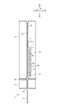
図1は、本発明の実施形態に係るカードリーダおよびカードの平面図であり、図2は図1のカードリーダおよびカードの断面図である。カードリーダ1は、カード2に記録された磁気データの読取りおよびカード2への磁気データの記録の少なくとも一方を行う装置である。カードリーダ1は、例えば、ATM(Automated Teller Machine)等の装置に搭載される。
(Card reader)
FIG. 1 is a plan view of a card reader and a card according to an embodiment of the present invention, and FIG. 2 is a cross-sectional view of the card reader and card of FIG. The card reader 1 is a device that reads at least one of magnetic data recorded on the
カード2は、例えば、厚さが0.7〜0.8mm程度の矩形状の塩化ビニール製のカードである。カード2の裏面には、磁気データが記録される磁気ストライプ2aが形成されている。磁気ストライプ2aは、略長方形のカード2の長手方向に延在する。また、カード2にはICチップが内蔵されており、カード2のおもて面には、ICチップの外部接続端子2bが形成されている。
The
カードリーダ1は、カード2が挿入されるカード挿入口3を備えるカード挿入部4と、カード挿入部4が固定される本体部5を備える。カード挿入部4は、本体部5の前端に取り付けられる。カードリーダ1の内部には、カード挿入口3から挿入されたカード2が通過するカード通過路6が形成されている。また、カードリーダ1の内部には、カード通過路6に沿ってカード2を搬送するための図示しない駆動ローラおよびパッドローラを備える搬送機構31(図4参照)が配置されている。
The card reader 1 includes a card insertion part 4 having a
本明細書において、X方向、Y方向、Z方向は互いに直交する方向である。以下、X方向を前後方向とし、Y方向を左右方向とし、Z方向を上下方向とする。また、前後方向(X方向)のうちの一方側(X1方向)を後方とし、他方側(X2方向)を前方とし、上下方向のうちの一方側(Z1方向)を上方とし、他方側(Z2方向)を下方とする。図2に示すように、カード通過路6は前後方向(X方向)に延在する。X1方向はカード2の挿入方向であり、X2方向はカード2の排出方向である。カード通過路6を通過するカード2の長手方向は前後方向(X方向)と一致し、カード2の幅方向(短手幅方向)は左右方向(Y方向)と一致し、カード2の厚さ方向は上下方向(Z方向)と一致する。
In this specification, the X direction, the Y direction, and the Z direction are directions orthogonal to each other. Hereinafter, the X direction is the front-rear direction, the Y direction is the left-right direction, and the Z direction is the up-down direction. Also, one side (X1 direction) in the front-rear direction (X direction) is the rear, the other side (X2 direction) is the front, one side (Z1 direction) in the vertical direction is the upper side, and the other side (Z2) Direction) is the downward direction. As shown in FIG. 2, the
カードリーダ1は、磁気ストライプ2aに記録された磁気データの読取りおよび磁気ストライプ2aへの磁気データの記録の少なくとも一方を行う磁気ヘッド7と、カード通過路6を閉鎖するためのシャッタ部材8と、カード通過路6においてカード2の有無を検出するためのカードセンサ9と、カード通過路6に異物が取り付けられたことを検知するための静電容量センサ10を備える。カードセンサ9は、本形態では光学センサであるが、光学式以外の検出方法によりカード2の有無を検出するセンサを用いてもよい。また、カードリーダ1は、カード2に設けられた外部接続端子2bに接触してICチップとの間でデータの通信を行うIC接点ブロック(図示省略)およびIC接点ブロックを駆動するブロック移動機構32(図4参照)を備える。
The card reader 1 includes a
シャッタ部材8は、カード挿入部4の後端に配置される。シャッタ部材8は、シャッタ駆動機構33(図4参照)により、カード通過路6を閉鎖する閉鎖位置とカード通過路6から退避した開放位置との間で移動する。なお、シャッタ部材8は、カード挿入部4と本体部5との境界部分、あるいは、本体部5の前端に配置されても良い。
The
磁気ヘッド7は、本体部5の内部に配置され、磁気ヘッド7のギャップ部がカード通過路6に下側から臨むように配置される。また、磁気ヘッド7は、左右方向(Y方向)において、カード挿入口3から挿入されたカード2の磁気ストライプ2aが通過する位置に配置される。カード通過路6をカード2が通過する際、磁気ヘッド7のギャップ部に磁気ストライプ2aが接触して磁気データの読取りあるいは磁気データの記録が行われる。
The
カードセンサ9は、本体部5の内部に複数配置されている。複数のカードセンサ9は、前後方向(X方向)に所定の間隔を空けて配置される。カードセンサ9は、カード通過路6を挟むように対向配置される発光素子と受光素子を備える透過型のセンサである。あるいは、カードセンサ9は、カード通過路6の上側あるいは下側に隣接配置される発光素子と受光素子を備える反射型のセンサであってもよい。カードセンサ9は、静電容量センサ10による異物の検出領域に存在するカード2を検出可能な位置に配置されている。
A plurality of
静電容量センサ10は、本体部5の内部に配置され、前後方向(X方向)において磁気ヘッド7とシャッタ部材8との間に配置されている。静電容量センサ10は、薄膜状の検知部11が形成された静電容量センサプレート12と、静電容量センサプレート12と平行に配置された制御基板13に実装された静電容量検出回路を備える。静電容量センサ10は、検知部11に設けられた一対の電極20A、20B(図3参照)間の静電容量の変化に基づいてカード通過路6に配置された異物を検知する。また、制御基板13上には、温度センサ41および湿度センサ42が配置される。温度センサ41は、制御基板13上に実装された回路素子等の発熱の影響が少ない基板端部に配置される。
The
図3は静電容量センサ10の検知部11を示す平面図である。検知部11は、電極20A、20Bによる検出パターンと、検出パターンを覆う保護膜を備えており、電極20A、20Bは制御基板13上の静電容量検出回路に接続される。静電容量検出回路の出力信号は制御基板13に実装されたCPUに入力され、CPUは静電容量センサ10の出力信号に基づいてデジタル信号を生成して出力する。なお、静電容量検出回路およびCPUは、カードリーダ1の制御部30(図4参照)を構成する図示しないメイン基板に実装することもできる。
FIG. 3 is a plan view showing the
図3に示すように、電極20A、20Bは、左右方向(Y方向)の一方側へ突出するとともに前後方向(X方向)において一定のピッチで配置される複数の凸部21と、凸部21の間に形成される複数の凹部22とを備える。すなわち、電極20A、20Bは櫛歯状に形成されている。一対の電極20A、20Bは、左右方向(Y方向)において所定の間隔をあけた状態で配置される。また、一対の電極20A、20Bのうちの一方の凹部22
の中に他方の凸部21が入り込むとともに、他方の凹部22の中に一方の凸部21が入り込んでいる。
As shown in FIG. 3, the electrodes 20 </ b> A and 20 </ b> B project to one side in the left-right direction (Y direction) and are arranged at a constant pitch in the front-rear direction (X direction), and the
The other
図2に示すように、静電容量センサ10は、カード通過路6よりも下側に配置される。本形態では、カード通過路6の下側の面を構成するガイド部材15に図示しない異物逃がし穴が形成され、この異物逃がし穴を覆うように配置された非導電材のカバー16に静電容量センサプレート12が固定される。あるいは、静電容量センサプレート12がガイド部材15に直接固定される構成を採用することもできる。静電容量センサ10は、検知部11の厚さ方向と上下方向(Z方向)とが一致し、かつ、検知部11の長辺方向と前後方向(X方向)とが一致するように配置される。また、検知部11は、左右方向(Y方向)において、カード挿入口3から挿入されたカード2の磁気ストライプ2aが通過する位置に配置される。
As shown in FIG. 2, the
図4はカードリーダ1の制御系を示す概略ブロック図である。カードリーダ1は、磁気ヘッド7、搬送機構31、ブロック移動機構32、シャッタ駆動機構33等を制御する制御部30を備える。制御部30は、シャッタ駆動機構33および搬送機構31を制御して、カード通過路6へのカード2の取り込み動作およびカード2の排出動作を行う。制御部30は、カード通過路6へカード2を取り込んだ後、磁気ヘッド7および搬送機構31を制御して、カード2を搬送するとともに磁気ストライプ2aへの磁気データの記録あるいは磁気ストライプ2aからの磁気データの読取りを行う。また、制御部30は、ブロック移動機構32を駆動してIC接点ブロックを外部接続端子2bに接触させ、ICチップとの間でデータの通信を行う。
FIG. 4 is a schematic block diagram showing a control system of the card reader 1. The card reader 1 includes a
制御部30には、カードセンサ9および静電容量センサ10の出力信号が入力される。制御部30は、複数のカードセンサ9の出力信号に基づいて、それぞれのカードセンサ9の位置におけるカード2の有無を検出する。制御部30は、カード2を搬送する際、複数のカードセンサ9の出力信号に基づいてカード2の搬送位置を制御する。また、制御部30は、静電容量センサ10の出力信号に基づき、カード通過路6に異物が取り付けられたことを検知する。更に、制御部30には、温度センサ41および湿度センサ42の出力信号が入力される。後述するように、制御部30は、温度センサ41および湿度センサ42によって計測された温度および湿度に基づき、静電容量センサ10による異物検出処理に用いられる検出閾値CTを補正する。
Output signals from the
(静電容量センサ)
カードリーダ1にカード2が挿入されていない待機状態における静電容量センサ10の出力信号を静電容量基準値CBとする。カードリーダ1の制御部30は、静電容量基準値CBおよび所定の検出閾値CTを記憶する記憶部34を備える。制御部30は、静電容量センサ10の出力信号と、静電容量基準値CBおよび検出閾値CTに基づいて異物検出処理を行う。具体的には、静電容量基準値CBに対する静電容量センサ10の出力信号の変化量ΔCが検出閾値CT以上である状態が所定の異常判定時間TE以上続いた場合に、異物有りと判定する。異常判定時間TEは、例えば、30秒、5分などの長さに設定される。あるいは、異常判定時間TEは、正常なカード2の処理を行うための処理時間より長い時間に設定される。このようにすると、正常なカード2の処理の際にカード2がカード通過路6に留まる間は異物として判定されないようにすることができる。
(Capacitance sensor)
An output signal of the
制御部30は、静電容量センサ10の出力信号に基づいて異物検出処理を行う際には、制御部30に記憶されている検出閾値CTを現在の温度および湿度に基づいて補正し、補正後の検出閾値CT1に基づいて異物検出処理を行う。検出閾値CTの温度補正は、温度補正テーブルTTBLに基づいて行う。温度補正テーブルTTBLは、静電容量センサ10の温度特性に基づいて予め作成され、記憶部34に記憶されている。例えば、温度変化
に従って静電容量が線形に変化するような温度特性を持つ場合、このような温度特性を示す温度補正テーブルTTBLが記憶部34に記憶される。同様に、検出閾値CTの湿度補正は、湿度補正テーブルHTBLに基づいて行われる。湿度補正テーブルHTBLは、静電容量センサ10の湿度特性に基づいて予め作成され、記憶部34に記憶されている。例えば、湿度が90%を超えると静電容量が変化するような湿度特性を持つ場合、このような湿度特性を示す湿度補正テーブルHTBLが記憶部34に記憶される。
When performing the foreign object detection process based on the output signal of the
(異物検出処理)
図5は異物検出処理のフローチャートである。カードリーダ1の制御部30は、カードセンサ9の出力信号に基づいてカード通過路6におけるカード2の有無を監視する。そして、カード通過路6にカード2が無いと判定した場合に、静電容量センサ10の出力信号と補正後の検出閾値CT1に基づいて異物の有無を判定する。本形態では、カードセンサ9の検出領域は静電容量センサ10の検出領域を包含するため、カードセンサ9は、静電容量センサ10の検出領域におけるカード2の有無を検知する。つまり、制御部30は、静電容量センサ10の検出領域にカードが無いと判定した場合に、静電容量センサ10の出力信号と補正後の検出閾値CT1とに基づいて異物の有無を判定する。
(Foreign matter detection processing)
FIG. 5 is a flowchart of the foreign object detection process. The
制御部30は、まず、ステップST1において、異物検出処理に用いる設定値を記憶部34から読み出す。具体的には、静電容量基準値CB、検出閾値CT、および異常判定時間TEを記憶部34から読み出す。
First, in step ST1, the
次に、制御部30は、カードセンサ9の出力信号に基づいてカード通過路6におけるカード2の有無を判定するカード検出ステップ(ステップST2)を行う。カード有りと判定された場合(ステップST2:Yes)、異物の有無を判定する処理(ステップST3)は行わず、予め定められた周期時間(例えば、1秒)経過後に再びカード2の有無の判定(ステップST2)を行う。そして、カード2が無いと判定されるまで、予め定められた周期でステップST2の判定を繰り返す。すなわち、カード2が無いと判定されるまで、カード通過路6におけるカード2の有無の監視を所定の監視周期で継続する。
Next, the
ステップST2においてカード無しと判定された場合(ステップST2:No)、制御部30は、異物判定ステップ(ステップST3〜ST5)を行う。ステップST3では、温度センサ41および湿度センサ42の出力信号に基づき、記憶部34から読み出した検出閾値CTを現在の温湿度で補正する。具体的には、上述したように、検出閾値CTに対して温度センサ41の出力信号および温度補正テーブルTTBLに基づいて補正値TTBL(T)を求めて温度補正を行うとともに、湿度センサ42の出力信号および湿度補正テーブルHTBLに基づき補正値HTBL(H)を求めて湿度補正を行う。これにより、検出閾値CT1が算出される。
When it is determined in step ST2 that there is no card (step ST2: No), the
続いて、ステップST4では、制御部30は、静電容量基準値CBに対する静電容量センサ10の出力信号の変化量ΔCが補正後の検出閾値CT1以上であるか否かを判定する。変化量ΔCは絶対値であり、静電容量センサ10の出力値C−静電容量基準値CB、もしくは静電容量基準値CB−出力値Cにより求められる。変化量ΔCが検出閾値CT1以上でない場合(ステップST4:No)、ステップST2へ戻り、カード2の有無の監視を続ける。一方、変化量ΔCが検出閾値CT1以上である場合(ステップST4:Yes)、ステップST5へ進み、変化量ΔCが検出閾値CT1以上である状態の継続時間である異物有り継続時間ΔTが異常判定時間TE以上であるか否かを判定する。異物有り継続時間ΔTが異常判定時間TE以上でない場合(ステップST5:No)、ステップST3へ戻る。そして、現在の温湿度で再び検出閾値CTを補正する。すなわち、制御部30は、温湿度の変化に応じて検出閾値CTを随時補正しながら、静電容量センサ10の出力値Cの判定(ステップST4)を行い、その結果に基づいて、異物有り継続時間ΔTが異常
判定時間TE以上であるか否かを判定する。一方、異物有り継続時間ΔTが異常判定時間TE以上である場合(ステップST5:Yes)、異物有りの判定を確定させる。
Subsequently, in step ST4, the
制御部30は、ステップST5で異物有りの判定を確定させた場合、カード通過路6にスキミング用装置等の異物が取り付けられたと判定して、異常処理ステップ(ステップST6)へ進む。そして、ステップST6において所定の異常処理を行う。異常処理としては、例えば、ホストコンピュータなどの上位装置へ所定のアラーム通知を送信する処理、カードリーダ1の表示部に所定の表示(エラー表示、取り扱い中止表示等)を行う処理、カードリーダ1のランプを所定の態様で点灯させる処理などが行われる。あるいは、カードリーダ1を使用停止にする処理を行うこともできる。例えば、シャッタ部材8を閉鎖位置に移動させる処理を行う。
When determining that there is a foreign object in step ST5, the
(本形態の主な効果)
以上説明したように、本形態のカードリーダ1は、静電容量センサ10の検出領域におけるカード2の有無をカードセンサ9によって検知し、カード2が無いと判定した場合に、静電容量センサ10の出力信号に基づいて異物の有無を判定する。このようにすれば、カード2が無いことが明らかな場合に異物判定を行うので、カード2を異物として誤検知することを回避できる。従って、カード通過路6にスキミング用の磁気ヘッドが取り付けられた場合にそのことを精度良く検出することができる。よって、カード通過路6にスキミング用の磁気ヘッドが取り付けられたことによる不正行為を防止できる。
(Main effects of this form)
As described above, the card reader 1 according to the present embodiment detects the presence or absence of the
本形態では、カードセンサ9によってカード2が検知された場合には、カードセンサ9によってカード2が検知されなくなるまで(すなわち、静電容量センサ10の検出領域にカード2が無いと判定されるまで)、所定の周期でカードセンサ9によるカード2の有無の判定を行う。これにより、カード通過路6にカード2が存在して異物判定を行うことができなかったとしても、カード2の排出後にはカード2が無いと判定されるため、異物判定を行うことができる。従って、カード通過路6にスキミング用の磁気ヘッドが取り付けられた場合にそのことを検出できる。よって、不正行為を防止できる。
In this embodiment, when the
本形態では、温度センサ41で検出された温度および静電容量センサ10の温度特性(温度補正テーブルTTBL)に基づいて検出閾値CTの補正を行うとともに、湿度センサ42で検出された湿度および静電容量センサ10の湿度特性(湿度補正テーブルHTBL)に基づいて検出閾値CTの補正を行う。そして、補正後の検出閾値CT1および静電容量センサ10の出力信号に基づいて異物の有無を判定する。これにより、温度変化および湿度変化による静電容量センサ10の出力信号の変化を考慮して検出閾値を広く設定する必要がないので、検出閾値を狭く設定することができる。よって、温度変化や湿度変化がある場所にカードリーダ1が設置された場合においても検出精度を落とさずに、カード通過路6にスキミング用の磁気ヘッドが取り付けられた場合にそのことを検出できる。よって、不正行為を防止できる。
In this embodiment, the detection threshold CT is corrected based on the temperature detected by the
なお、温湿度による検出閾値CTの補正を省略してもよい。また、温度センサ41のみを設けて検出閾値CTの温度補正のみを行ってもよい。あるいは、湿度センサ42のみを設けて検出閾値CTの湿度補正のみを行ってもよい。
Note that the correction of the detection threshold CT based on temperature and humidity may be omitted. Alternatively, only the
本形態では、静電容量センサ10の出力信号による異物判定処理において、静電容量センサ10の出力値Cの変化量ΔCが検出閾値CT1以上である状態が異常判定時間TE以上に亘って続いた場合に、異物有りの判定を確定させて所定の異常処理を行う。また、異物有り判定(ΔC≧CT1)の継続時間を監視する間、温湿度の変化に応じて検出閾値CTを随時補正しながら、静電容量センサ10の出力値Cの判定(ステップST4)を行う。このようにすれば、ノイズによって異物有りと判定された際に異常処理が行われないよ
うにすることができる。また、異常判定時間TEを正常なカード2の処理を行うための処理時間より長い時間に設定すれば、正常なカード2の処理が行われる間はカード2が異物として判定されないようにすることができる。更に、温湿度の変化に随時対応できるため、精度良く異物の有無を判定することができる。なお、異物有りの判定を確定させるための判定は、異常判定時間TE以外の所定量に基づいて行うこともできる。例えば、ステップST4でΔC≧CT1であると判定された回数が予め設定された異常判定回数以上続いた場合に、異物有りの判定を確定させる制御を行うこともできる。
In the present embodiment, in the foreign matter determination process based on the output signal of the
異物有りの判定を確定させて所定の異常処理を行う場合に、異常処理を実行するタイミングは、異物有りの判定を確定させた時から所定時間以上経過後とすることもできる。このようにすれば、スキミング用の磁気ヘッドが取り付けられた時に、すぐに異常処理が行われて犯罪者に異物検知機構の存在やその動作に関する情報を知られるおそれを少なくすることができる。また、異常処理を実行するまでの時間をその都度異ならせるようにしてもよい。 In the case where the determination of the presence of foreign matter is confirmed and the predetermined abnormality processing is performed, the timing of executing the abnormality processing may be after a predetermined time or more has elapsed since the determination of the presence of foreign matter is confirmed. In this way, when the skimming magnetic head is attached, it is possible to reduce the possibility that the abnormal process is immediately performed and the criminal is informed about the presence of the foreign object detection mechanism and the operation thereof. Further, the time until the abnormality process is executed may be varied each time.
1…カードリーダ、2…カード、2a…磁気ストライプ、2b…外部接続端子、3…カード挿入口、4…カード挿入部、5…本体部、6…カード通過路、7…磁気ヘッド、8…シャッタ部材、9…カードセンサ、10…静電容量センサ、11…検知部、12…静電容量センサプレート、13…制御基板、15…ガイド部材、16…カバー、20A、20B…電極、21…凸部、22…凹部、30…制御部、31…搬送機構、32…ブロック移動機構、33…シャッタ駆動機構、34…記憶部、41…温度センサ、42…湿度センサ DESCRIPTION OF SYMBOLS 1 ... Card reader, 2 ... Card, 2a ... Magnetic stripe, 2b ... External connection terminal, 3 ... Card insertion slot, 4 ... Card insertion part, 5 ... Main-body part, 6 ... Card passage, 7 ... Magnetic head, 8 ... Shutter member, 9 ... card sensor, 10 ... capacitance sensor, 11 ... detection unit, 12 ... capacitance sensor plate, 13 ... control board, 15 ... guide member, 16 ... cover, 20A, 20B ... electrode, 21 ... Convex part, 22 ... concave part, 30 ... control part, 31 ... transport mechanism, 32 ... block moving mechanism, 33 ... shutter drive mechanism, 34 ... storage part, 41 ... temperature sensor, 42 ... humidity sensor
Claims (12)
前記カードの磁気ストライプに記録された磁気データの読取りおよび前記磁気ストライプへの磁気データの記録の少なくとも一方を行う磁気ヘッドと、
前記カード通過路に異物が取り付けられたことを検知する静電容量センサと、
前記静電容量センサの検出領域における前記カードの有無を検知するカードセンサと、
前記カードセンサの出力信号に基づいて前記検出領域に前記カードが無いと判定した場合に、前記静電容量センサの出力信号と所定の検出閾値とに基づいて異物の有無を判定する異物判定処理を行う制御部と、を有することを特徴とするカードリーダ。 A card passing path through which a card inserted from the card insertion slot passes,
A magnetic head for reading at least one of magnetic data recorded on the magnetic stripe of the card and recording magnetic data on the magnetic stripe;
A capacitance sensor that detects that a foreign object is attached to the card passage;
A card sensor for detecting the presence or absence of the card in the detection area of the capacitance sensor;
Foreign matter determination processing for determining the presence or absence of foreign matter based on the output signal of the capacitance sensor and a predetermined detection threshold when it is determined that there is no card in the detection area based on the output signal of the card sensor. A card reader.
前記制御部は、前記温度センサで検出された温度および前記静電容量センサの温度特性に基づいて前記検出閾値の補正を行い、補正後の検出閾値に基づいて前記異物判定処理を行うことを特徴とする請求項1または2に記載のカードリーダ。 Have a temperature sensor,
The control unit corrects the detection threshold based on a temperature detected by the temperature sensor and a temperature characteristic of the capacitance sensor, and performs the foreign matter determination processing based on the corrected detection threshold. The card reader according to claim 1 or 2.
前記制御部は、前記制御部は、前記湿度センサで検出された湿度および静電容量センサの湿度特性に基づいて前記検出閾値の補正を行い、補正後の検出閾値に基づいて前記異物判定処理を行うことを特徴とする請求項1から3の何れか一項に記載のカードリーダ。 Have a humidity sensor,
The control unit corrects the detection threshold based on humidity detected by the humidity sensor and humidity characteristics of the capacitance sensor, and performs the foreign matter determination processing based on the corrected detection threshold. The card reader according to claim 1, wherein the card reader is performed.
前記カードの磁気ストライプに記録された磁気データの読取および前記磁気ストライプへの磁気データの記録の少なくとも一方を行う磁気ヘッドと、
前記カード通過路に異物が取り付けられたことを検知する静電容量センサと、
前記静電容量センサの検出領域における前記カードの有無を検知するカードセンサと、を有するカードリーダの制御方法であって、
前記カードセンサの出力信号に基づいて前記検出領域における前記カードの有無を監視するカード検出ステップと、
前記検出領域に前記カードが無いと判定した場合に、前記静電容量センサの出力信号と所定の検出閾値とに基づいて異物の有無を判定する異物判定ステップと、を行うことを特徴とするカードリーダの制御方法。 A card passing path through which a card inserted from the card insertion slot passes,
A magnetic head for reading at least one of magnetic data recorded on the magnetic stripe of the card and recording magnetic data on the magnetic stripe;
A capacitance sensor that detects that a foreign object is attached to the card passage;
A card reader for detecting the presence or absence of the card in a detection area of the capacitance sensor, and a card reader control method comprising:
A card detection step of monitoring the presence or absence of the card in the detection area based on an output signal of the card sensor;
A foreign object determination step of determining the presence or absence of a foreign object based on an output signal of the capacitance sensor and a predetermined detection threshold when it is determined that the card is not in the detection area. Reader control method.
前記異物有りの判定が確定した場合に、所定の異常処理を実行する異常処理ステップを行うことを特徴とする請求項7から10の何れか一項に記載のカードリーダの制御方法。 In the foreign matter determination step, when the state in which the difference between the output signal of the capacitance sensor and the capacitance reference value is equal to or greater than the detection threshold continues for a predetermined amount, the determination of the presence of foreign matter is confirmed.
11. The card reader control method according to claim 7, wherein an abnormality processing step of executing a predetermined abnormality processing is performed when the determination of the presence of a foreign object is confirmed.
Priority Applications (3)
| Application Number | Priority Date | Filing Date | Title |
|---|---|---|---|
| JP2017006047A JP6904715B2 (en) | 2017-01-17 | 2017-01-17 | Card reader and card reader control method |
| PCT/JP2018/000339 WO2018135354A1 (en) | 2017-01-17 | 2018-01-10 | Card reader and card reader control method |
| US16/478,262 US20200126368A1 (en) | 2017-01-17 | 2018-01-10 | Card reader and control method of card reader |
Applications Claiming Priority (1)
| Application Number | Priority Date | Filing Date | Title |
|---|---|---|---|
| JP2017006047A JP6904715B2 (en) | 2017-01-17 | 2017-01-17 | Card reader and card reader control method |
Publications (2)
| Publication Number | Publication Date |
|---|---|
| JP2018116418A true JP2018116418A (en) | 2018-07-26 |
| JP6904715B2 JP6904715B2 (en) | 2021-07-21 |
Family
ID=62908828
Family Applications (1)
| Application Number | Title | Priority Date | Filing Date |
|---|---|---|---|
| JP2017006047A Active JP6904715B2 (en) | 2017-01-17 | 2017-01-17 | Card reader and card reader control method |
Country Status (3)
| Country | Link |
|---|---|
| US (1) | US20200126368A1 (en) |
| JP (1) | JP6904715B2 (en) |
| WO (1) | WO2018135354A1 (en) |
Cited By (2)
| Publication number | Priority date | Publication date | Assignee | Title |
|---|---|---|---|---|
| JP2020067973A (en) * | 2018-10-26 | 2020-04-30 | 日本電産サンキョー株式会社 | Information processing device and foreign matter detection method |
| CN112085905A (en) * | 2019-06-14 | 2020-12-15 | 中电金融设备系统(深圳)有限公司 | Magnetic stripe card reader, magnetic stripe data processing device and magnetic stripe data processing method |
Families Citing this family (5)
| Publication number | Priority date | Publication date | Assignee | Title |
|---|---|---|---|---|
| JP7085932B2 (en) * | 2018-07-20 | 2022-06-17 | 日本電産サンキョー株式会社 | Card reader |
| JP7576988B2 (en) * | 2021-01-29 | 2024-11-01 | ニデックインスツルメンツ株式会社 | Card reader and foreign object detection method |
| JP7600036B2 (en) * | 2021-06-04 | 2024-12-16 | 日立チャネルソリューションズ株式会社 | CARD READER AND METHOD FOR DETECTING FOREIGN OBJECT IN CARD READER |
| US11551014B1 (en) * | 2021-06-29 | 2023-01-10 | Ncr Corporation | Device, system, and method for card skimming protection |
| US12254373B2 (en) * | 2023-03-31 | 2025-03-18 | Ncr Atleos Corporation | Card reader foreign object detection |
Citations (5)
| Publication number | Priority date | Publication date | Assignee | Title |
|---|---|---|---|---|
| JPH08272922A (en) * | 1995-03-29 | 1996-10-18 | Sankyo Seiki Mfg Co Ltd | Detecting mechanism for insertion of foreign body into travel path of card reader |
| JP2005044107A (en) * | 2003-07-28 | 2005-02-17 | Omron Corp | Magnetic card processing device |
| JP2013037555A (en) * | 2011-08-09 | 2013-02-21 | Nidec Sankyo Corp | Card reader |
| JP2014221562A (en) * | 2013-05-13 | 2014-11-27 | Necプラットフォームズ株式会社 | Seating state determination device, seat belt and seating state determination method |
| JP2016110415A (en) * | 2014-12-08 | 2016-06-20 | 日本電産サンキョー株式会社 | Card reader |
-
2017
- 2017-01-17 JP JP2017006047A patent/JP6904715B2/en active Active
-
2018
- 2018-01-10 WO PCT/JP2018/000339 patent/WO2018135354A1/en not_active Ceased
- 2018-01-10 US US16/478,262 patent/US20200126368A1/en not_active Abandoned
Patent Citations (5)
| Publication number | Priority date | Publication date | Assignee | Title |
|---|---|---|---|---|
| JPH08272922A (en) * | 1995-03-29 | 1996-10-18 | Sankyo Seiki Mfg Co Ltd | Detecting mechanism for insertion of foreign body into travel path of card reader |
| JP2005044107A (en) * | 2003-07-28 | 2005-02-17 | Omron Corp | Magnetic card processing device |
| JP2013037555A (en) * | 2011-08-09 | 2013-02-21 | Nidec Sankyo Corp | Card reader |
| JP2014221562A (en) * | 2013-05-13 | 2014-11-27 | Necプラットフォームズ株式会社 | Seating state determination device, seat belt and seating state determination method |
| JP2016110415A (en) * | 2014-12-08 | 2016-06-20 | 日本電産サンキョー株式会社 | Card reader |
Cited By (4)
| Publication number | Priority date | Publication date | Assignee | Title |
|---|---|---|---|---|
| JP2020067973A (en) * | 2018-10-26 | 2020-04-30 | 日本電産サンキョー株式会社 | Information processing device and foreign matter detection method |
| JP7202140B2 (en) | 2018-10-26 | 2023-01-11 | 日本電産サンキョー株式会社 | Information processing device and foreign matter detection method |
| CN112085905A (en) * | 2019-06-14 | 2020-12-15 | 中电金融设备系统(深圳)有限公司 | Magnetic stripe card reader, magnetic stripe data processing device and magnetic stripe data processing method |
| CN112085905B (en) * | 2019-06-14 | 2022-03-01 | 中电金融设备系统(深圳)有限公司 | Magnetic stripe card reader, magnetic stripe data processing device and magnetic stripe data processing method |
Also Published As
| Publication number | Publication date |
|---|---|
| JP6904715B2 (en) | 2021-07-21 |
| US20200126368A1 (en) | 2020-04-23 |
| WO2018135354A1 (en) | 2018-07-26 |
Similar Documents
| Publication | Publication Date | Title |
|---|---|---|
| JP6904715B2 (en) | Card reader and card reader control method | |
| US9734363B2 (en) | Card reader | |
| JP6023409B2 (en) | Card reader | |
| JP5648173B2 (en) | Card reader and processing method thereof | |
| US10706240B2 (en) | Card reader and foreign matter detection method | |
| JP5210900B2 (en) | Transaction processing equipment | |
| JP5648024B2 (en) | Card reader | |
| JP2017219971A (en) | Card reader | |
| CN110619243A (en) | Card reader and foreign matter detection method | |
| JP5759552B2 (en) | Magnetic recording medium reader | |
| WO2011065315A1 (en) | Card-shaped medium processing device and control method of card-shaped medium processing device | |
| JP6472752B2 (en) | Card reader | |
| JP5385812B2 (en) | Card reader | |
| US11710004B2 (en) | Card reader and foreign object detection method for card reader | |
| JP6081884B2 (en) | Card reader | |
| US10198602B2 (en) | Card processing device and a control method of card processing device | |
| US11182571B2 (en) | Magnetic recording medium processing device and control method | |
| US6467689B1 (en) | Skew detecting apparatus, medium processing apparatus, magnetic card processing apparatus and card processing system | |
| JP2019219826A (en) | Card reader and foreign matter detection method | |
| JP2018055557A (en) | Card reader and method for controlling card reader | |
| JP4955617B2 (en) | Magnetic card reader and magnetic card defect detection method | |
| JP2019102107A (en) | Card reader and control method for card reader | |
| JPH11250320A (en) | Fraud card detection device |
Legal Events
| Date | Code | Title | Description |
|---|---|---|---|
| A621 | Written request for application examination |
Free format text: JAPANESE INTERMEDIATE CODE: A621 Effective date: 20191202 |
|
| A131 | Notification of reasons for refusal |
Free format text: JAPANESE INTERMEDIATE CODE: A131 Effective date: 20210119 |
|
| A521 | Request for written amendment filed |
Free format text: JAPANESE INTERMEDIATE CODE: A523 Effective date: 20210322 |
|
| TRDD | Decision of grant or rejection written | ||
| A01 | Written decision to grant a patent or to grant a registration (utility model) |
Free format text: JAPANESE INTERMEDIATE CODE: A01 Effective date: 20210601 |
|
| A61 | First payment of annual fees (during grant procedure) |
Free format text: JAPANESE INTERMEDIATE CODE: A61 Effective date: 20210624 |
|
| R150 | Certificate of patent or registration of utility model |
Ref document number: 6904715 Country of ref document: JP Free format text: JAPANESE INTERMEDIATE CODE: R150 |