JP2018053782A - Exhaust gas purification device for internal combustion engine - Google Patents
Exhaust gas purification device for internal combustion engine Download PDFInfo
- Publication number
- JP2018053782A JP2018053782A JP2016189726A JP2016189726A JP2018053782A JP 2018053782 A JP2018053782 A JP 2018053782A JP 2016189726 A JP2016189726 A JP 2016189726A JP 2016189726 A JP2016189726 A JP 2016189726A JP 2018053782 A JP2018053782 A JP 2018053782A
- Authority
- JP
- Japan
- Prior art keywords
- temperature
- insulation resistance
- resistance value
- ehc
- value
- Prior art date
- Legal status (The legal status is an assumption and is not a legal conclusion. Google has not performed a legal analysis and makes no representation as to the accuracy of the status listed.)
- Pending
Links
- 238000002485 combustion reaction Methods 0.000 title claims abstract description 30
- 238000000746 purification Methods 0.000 title claims abstract description 16
- 239000013618 particulate matter Substances 0.000 claims abstract description 240
- 238000009413 insulation Methods 0.000 claims abstract description 172
- 239000003054 catalyst Substances 0.000 claims abstract description 133
- XLYOFNOQVPJJNP-UHFFFAOYSA-N water Substances O XLYOFNOQVPJJNP-UHFFFAOYSA-N 0.000 claims description 48
- 230000007423 decrease Effects 0.000 claims description 25
- 238000005259 measurement Methods 0.000 claims description 16
- 238000005485 electric heating Methods 0.000 claims description 3
- 239000000446 fuel Substances 0.000 abstract description 68
- 238000012545 processing Methods 0.000 abstract description 7
- 238000000034 method Methods 0.000 description 25
- 239000007789 gas Substances 0.000 description 20
- 230000008569 process Effects 0.000 description 20
- 238000000151 deposition Methods 0.000 description 16
- 230000008021 deposition Effects 0.000 description 14
- 238000011144 upstream manufacturing Methods 0.000 description 9
- 230000008859 change Effects 0.000 description 8
- 238000001514 detection method Methods 0.000 description 8
- 238000002347 injection Methods 0.000 description 7
- 239000007924 injection Substances 0.000 description 7
- QVGXLLKOCUKJST-UHFFFAOYSA-N atomic oxygen Chemical compound [O] QVGXLLKOCUKJST-UHFFFAOYSA-N 0.000 description 6
- 238000006243 chemical reaction Methods 0.000 description 6
- 230000006870 function Effects 0.000 description 6
- 229910052760 oxygen Inorganic materials 0.000 description 6
- 239000001301 oxygen Substances 0.000 description 6
- 238000002474 experimental method Methods 0.000 description 5
- 230000002093 peripheral effect Effects 0.000 description 5
- 239000000203 mixture Substances 0.000 description 4
- 238000009825 accumulation Methods 0.000 description 3
- 238000009833 condensation Methods 0.000 description 3
- 230000005494 condensation Effects 0.000 description 3
- 239000000498 cooling water Substances 0.000 description 3
- 230000003247 decreasing effect Effects 0.000 description 3
- 239000000463 material Substances 0.000 description 3
- 230000004048 modification Effects 0.000 description 3
- 238000012986 modification Methods 0.000 description 3
- 230000000979 retarding effect Effects 0.000 description 3
- 230000002159 abnormal effect Effects 0.000 description 2
- 230000005856 abnormality Effects 0.000 description 2
- 230000006866 deterioration Effects 0.000 description 2
- 230000009467 reduction Effects 0.000 description 2
- OKTJSMMVPCPJKN-UHFFFAOYSA-N Carbon Chemical compound [C] OKTJSMMVPCPJKN-UHFFFAOYSA-N 0.000 description 1
- UNPLRYRWJLTVAE-UHFFFAOYSA-N Cloperastine hydrochloride Chemical compound Cl.C1=CC(Cl)=CC=C1C(C=1C=CC=CC=1)OCCN1CCCCC1 UNPLRYRWJLTVAE-UHFFFAOYSA-N 0.000 description 1
- PNEYBMLMFCGWSK-UHFFFAOYSA-N aluminium oxide Inorganic materials [O-2].[O-2].[O-2].[Al+3].[Al+3] PNEYBMLMFCGWSK-UHFFFAOYSA-N 0.000 description 1
- 229910052799 carbon Inorganic materials 0.000 description 1
- 239000000969 carrier Substances 0.000 description 1
- 239000000919 ceramic Substances 0.000 description 1
- 239000000567 combustion gas Substances 0.000 description 1
- 230000006835 compression Effects 0.000 description 1
- 238000007906 compression Methods 0.000 description 1
- 238000001816 cooling Methods 0.000 description 1
- 238000010586 diagram Methods 0.000 description 1
- 239000002283 diesel fuel Substances 0.000 description 1
- 238000007599 discharging Methods 0.000 description 1
- 230000000694 effects Effects 0.000 description 1
- 239000000835 fiber Substances 0.000 description 1
- 238000010438 heat treatment Methods 0.000 description 1
- 239000012784 inorganic fiber Substances 0.000 description 1
- 239000012212 insulator Substances 0.000 description 1
- 239000002184 metal Substances 0.000 description 1
- 230000003647 oxidation Effects 0.000 description 1
- 238000007254 oxidation reaction Methods 0.000 description 1
- 230000001590 oxidative effect Effects 0.000 description 1
- 239000002245 particle Substances 0.000 description 1
- 239000011236 particulate material Substances 0.000 description 1
- 229910001220 stainless steel Inorganic materials 0.000 description 1
- 239000010935 stainless steel Substances 0.000 description 1
Images


Classifications
-
- F—MECHANICAL ENGINEERING; LIGHTING; HEATING; WEAPONS; BLASTING
- F01—MACHINES OR ENGINES IN GENERAL; ENGINE PLANTS IN GENERAL; STEAM ENGINES
- F01N—GAS-FLOW SILENCERS OR EXHAUST APPARATUS FOR MACHINES OR ENGINES IN GENERAL; GAS-FLOW SILENCERS OR EXHAUST APPARATUS FOR INTERNAL COMBUSTION ENGINES
- F01N3/00—Exhaust or silencing apparatus having means for purifying, rendering innocuous, or otherwise treating exhaust
- F01N3/08—Exhaust or silencing apparatus having means for purifying, rendering innocuous, or otherwise treating exhaust for rendering innocuous
- F01N3/10—Exhaust or silencing apparatus having means for purifying, rendering innocuous, or otherwise treating exhaust for rendering innocuous by thermal or catalytic conversion of noxious components of exhaust
- F01N3/18—Exhaust or silencing apparatus having means for purifying, rendering innocuous, or otherwise treating exhaust for rendering innocuous by thermal or catalytic conversion of noxious components of exhaust characterised by methods of operation; Control
- F01N3/20—Exhaust or silencing apparatus having means for purifying, rendering innocuous, or otherwise treating exhaust for rendering innocuous by thermal or catalytic conversion of noxious components of exhaust characterised by methods of operation; Control specially adapted for catalytic conversion ; Methods of operation or control of catalytic converters
- F01N3/2006—Periodically heating or cooling catalytic reactors, e.g. at cold starting or overheating
- F01N3/2013—Periodically heating or cooling catalytic reactors, e.g. at cold starting or overheating using electric or magnetic heating means
-
- F—MECHANICAL ENGINEERING; LIGHTING; HEATING; WEAPONS; BLASTING
- F01—MACHINES OR ENGINES IN GENERAL; ENGINE PLANTS IN GENERAL; STEAM ENGINES
- F01N—GAS-FLOW SILENCERS OR EXHAUST APPARATUS FOR MACHINES OR ENGINES IN GENERAL; GAS-FLOW SILENCERS OR EXHAUST APPARATUS FOR INTERNAL COMBUSTION ENGINES
- F01N13/00—Exhaust or silencing apparatus characterised by constructional features ; Exhaust or silencing apparatus, or parts thereof, having pertinent characteristics not provided for in, or of interest apart from, groups F01N1/00 - F01N5/00, F01N9/00, F01N11/00
- F01N13/14—Exhaust or silencing apparatus characterised by constructional features ; Exhaust or silencing apparatus, or parts thereof, having pertinent characteristics not provided for in, or of interest apart from, groups F01N1/00 - F01N5/00, F01N9/00, F01N11/00 having thermal insulation
-
- F—MECHANICAL ENGINEERING; LIGHTING; HEATING; WEAPONS; BLASTING
- F01—MACHINES OR ENGINES IN GENERAL; ENGINE PLANTS IN GENERAL; STEAM ENGINES
- F01N—GAS-FLOW SILENCERS OR EXHAUST APPARATUS FOR MACHINES OR ENGINES IN GENERAL; GAS-FLOW SILENCERS OR EXHAUST APPARATUS FOR INTERNAL COMBUSTION ENGINES
- F01N3/00—Exhaust or silencing apparatus having means for purifying, rendering innocuous, or otherwise treating exhaust
- F01N3/02—Exhaust or silencing apparatus having means for purifying, rendering innocuous, or otherwise treating exhaust for cooling, or for removing solid constituents of, exhaust
- F01N3/021—Exhaust or silencing apparatus having means for purifying, rendering innocuous, or otherwise treating exhaust for cooling, or for removing solid constituents of, exhaust by means of filters
- F01N3/023—Exhaust or silencing apparatus having means for purifying, rendering innocuous, or otherwise treating exhaust for cooling, or for removing solid constituents of, exhaust by means of filters using means for regenerating the filters, e.g. by burning trapped particles
- F01N3/027—Exhaust or silencing apparatus having means for purifying, rendering innocuous, or otherwise treating exhaust for cooling, or for removing solid constituents of, exhaust by means of filters using means for regenerating the filters, e.g. by burning trapped particles using electric or magnetic heating means
-
- F—MECHANICAL ENGINEERING; LIGHTING; HEATING; WEAPONS; BLASTING
- F01—MACHINES OR ENGINES IN GENERAL; ENGINE PLANTS IN GENERAL; STEAM ENGINES
- F01N—GAS-FLOW SILENCERS OR EXHAUST APPARATUS FOR MACHINES OR ENGINES IN GENERAL; GAS-FLOW SILENCERS OR EXHAUST APPARATUS FOR INTERNAL COMBUSTION ENGINES
- F01N3/00—Exhaust or silencing apparatus having means for purifying, rendering innocuous, or otherwise treating exhaust
- F01N3/02—Exhaust or silencing apparatus having means for purifying, rendering innocuous, or otherwise treating exhaust for cooling, or for removing solid constituents of, exhaust
- F01N3/021—Exhaust or silencing apparatus having means for purifying, rendering innocuous, or otherwise treating exhaust for cooling, or for removing solid constituents of, exhaust by means of filters
- F01N3/033—Exhaust or silencing apparatus having means for purifying, rendering innocuous, or otherwise treating exhaust for cooling, or for removing solid constituents of, exhaust by means of filters in combination with other devices
- F01N3/035—Exhaust or silencing apparatus having means for purifying, rendering innocuous, or otherwise treating exhaust for cooling, or for removing solid constituents of, exhaust by means of filters in combination with other devices with catalytic reactors, e.g. catalysed diesel particulate filters
-
- F—MECHANICAL ENGINEERING; LIGHTING; HEATING; WEAPONS; BLASTING
- F01—MACHINES OR ENGINES IN GENERAL; ENGINE PLANTS IN GENERAL; STEAM ENGINES
- F01N—GAS-FLOW SILENCERS OR EXHAUST APPARATUS FOR MACHINES OR ENGINES IN GENERAL; GAS-FLOW SILENCERS OR EXHAUST APPARATUS FOR INTERNAL COMBUSTION ENGINES
- F01N3/00—Exhaust or silencing apparatus having means for purifying, rendering innocuous, or otherwise treating exhaust
- F01N3/08—Exhaust or silencing apparatus having means for purifying, rendering innocuous, or otherwise treating exhaust for rendering innocuous
- F01N3/10—Exhaust or silencing apparatus having means for purifying, rendering innocuous, or otherwise treating exhaust for rendering innocuous by thermal or catalytic conversion of noxious components of exhaust
- F01N3/18—Exhaust or silencing apparatus having means for purifying, rendering innocuous, or otherwise treating exhaust for rendering innocuous by thermal or catalytic conversion of noxious components of exhaust characterised by methods of operation; Control
- F01N3/20—Exhaust or silencing apparatus having means for purifying, rendering innocuous, or otherwise treating exhaust for rendering innocuous by thermal or catalytic conversion of noxious components of exhaust characterised by methods of operation; Control specially adapted for catalytic conversion ; Methods of operation or control of catalytic converters
- F01N3/2006—Periodically heating or cooling catalytic reactors, e.g. at cold starting or overheating
- F01N3/2013—Periodically heating or cooling catalytic reactors, e.g. at cold starting or overheating using electric or magnetic heating means
- F01N3/2026—Periodically heating or cooling catalytic reactors, e.g. at cold starting or overheating using electric or magnetic heating means directly electrifying the catalyst substrate, i.e. heating the electrically conductive catalyst substrate by joule effect
-
- F—MECHANICAL ENGINEERING; LIGHTING; HEATING; WEAPONS; BLASTING
- F01—MACHINES OR ENGINES IN GENERAL; ENGINE PLANTS IN GENERAL; STEAM ENGINES
- F01N—GAS-FLOW SILENCERS OR EXHAUST APPARATUS FOR MACHINES OR ENGINES IN GENERAL; GAS-FLOW SILENCERS OR EXHAUST APPARATUS FOR INTERNAL COMBUSTION ENGINES
- F01N9/00—Electrical control of exhaust gas treating apparatus
- F01N9/002—Electrical control of exhaust gas treating apparatus of filter regeneration, e.g. detection of clogging
-
- F—MECHANICAL ENGINEERING; LIGHTING; HEATING; WEAPONS; BLASTING
- F01—MACHINES OR ENGINES IN GENERAL; ENGINE PLANTS IN GENERAL; STEAM ENGINES
- F01N—GAS-FLOW SILENCERS OR EXHAUST APPARATUS FOR MACHINES OR ENGINES IN GENERAL; GAS-FLOW SILENCERS OR EXHAUST APPARATUS FOR INTERNAL COMBUSTION ENGINES
- F01N2550/00—Monitoring or diagnosing the deterioration of exhaust systems
- F01N2550/04—Filtering activity of particulate filters
-
- F—MECHANICAL ENGINEERING; LIGHTING; HEATING; WEAPONS; BLASTING
- F01—MACHINES OR ENGINES IN GENERAL; ENGINE PLANTS IN GENERAL; STEAM ENGINES
- F01N—GAS-FLOW SILENCERS OR EXHAUST APPARATUS FOR MACHINES OR ENGINES IN GENERAL; GAS-FLOW SILENCERS OR EXHAUST APPARATUS FOR INTERNAL COMBUSTION ENGINES
- F01N2550/00—Monitoring or diagnosing the deterioration of exhaust systems
- F01N2550/22—Monitoring or diagnosing the deterioration of exhaust systems of electric heaters for exhaust systems or their power supply
-
- F—MECHANICAL ENGINEERING; LIGHTING; HEATING; WEAPONS; BLASTING
- F01—MACHINES OR ENGINES IN GENERAL; ENGINE PLANTS IN GENERAL; STEAM ENGINES
- F01N—GAS-FLOW SILENCERS OR EXHAUST APPARATUS FOR MACHINES OR ENGINES IN GENERAL; GAS-FLOW SILENCERS OR EXHAUST APPARATUS FOR INTERNAL COMBUSTION ENGINES
- F01N2900/00—Details of electrical control or of the monitoring of the exhaust gas treating apparatus
- F01N2900/06—Parameters used for exhaust control or diagnosing
- F01N2900/16—Parameters used for exhaust control or diagnosing said parameters being related to the exhaust apparatus, e.g. particulate filter or catalyst
- F01N2900/1631—Heat amount provided to exhaust apparatus
-
- Y—GENERAL TAGGING OF NEW TECHNOLOGICAL DEVELOPMENTS; GENERAL TAGGING OF CROSS-SECTIONAL TECHNOLOGIES SPANNING OVER SEVERAL SECTIONS OF THE IPC; TECHNICAL SUBJECTS COVERED BY FORMER USPC CROSS-REFERENCE ART COLLECTIONS [XRACs] AND DIGESTS
- Y02—TECHNOLOGIES OR APPLICATIONS FOR MITIGATION OR ADAPTATION AGAINST CLIMATE CHANGE
- Y02T—CLIMATE CHANGE MITIGATION TECHNOLOGIES RELATED TO TRANSPORTATION
- Y02T10/00—Road transport of goods or passengers
- Y02T10/10—Internal combustion engine [ICE] based vehicles
- Y02T10/12—Improving ICE efficiencies
-
- Y—GENERAL TAGGING OF NEW TECHNOLOGICAL DEVELOPMENTS; GENERAL TAGGING OF CROSS-SECTIONAL TECHNOLOGIES SPANNING OVER SEVERAL SECTIONS OF THE IPC; TECHNICAL SUBJECTS COVERED BY FORMER USPC CROSS-REFERENCE ART COLLECTIONS [XRACs] AND DIGESTS
- Y02—TECHNOLOGIES OR APPLICATIONS FOR MITIGATION OR ADAPTATION AGAINST CLIMATE CHANGE
- Y02T—CLIMATE CHANGE MITIGATION TECHNOLOGIES RELATED TO TRANSPORTATION
- Y02T10/00—Road transport of goods or passengers
- Y02T10/10—Internal combustion engine [ICE] based vehicles
- Y02T10/40—Engine management systems
Landscapes
- Engineering & Computer Science (AREA)
- Chemical & Material Sciences (AREA)
- Combustion & Propulsion (AREA)
- Mechanical Engineering (AREA)
- General Engineering & Computer Science (AREA)
- Chemical Kinetics & Catalysis (AREA)
- Health & Medical Sciences (AREA)
- Toxicology (AREA)
- Exhaust Gas After Treatment (AREA)
- Electrical Control Of Air Or Fuel Supplied To Internal-Combustion Engine (AREA)
- Combined Controls Of Internal Combustion Engines (AREA)
Abstract
【課題】PMの電気抵抗率がPMの温度に依存して変化することを考慮した上でPM除去処理を実行したり実行しなかったりすることにより、無駄に燃料を消費する可能性を低下することができる、内燃機関の排気浄化装置を提供する。【解決手段】電気加熱式触媒を備える内燃機関の排気浄化装置は、電気加熱式触媒に堆積した粒子状物質を除去すべきであるときに満たす所定の除去条件をPM温度と絶縁抵抗値(触媒担体とケースとの間の抵抗値)とが満たす場合(S408)、機関から排気通路へと排出されるエネルギによって電気加熱式触媒を昇温させることにより前記堆積した粒子状物質を除去するPM除去制御を実行する(S409)。【選択図】図7[PROBLEMS] To reduce the possibility of wasteful fuel consumption by performing or not performing PM removal processing in consideration of the fact that the electrical resistivity of PM changes depending on the temperature of PM. An exhaust emission control device for an internal combustion engine is provided. An exhaust gas purification apparatus for an internal combustion engine including an electrically heated catalyst has a predetermined removal condition that is satisfied when particulate matter deposited on the electrically heated catalyst is to be removed as a PM temperature and an insulation resistance value (catalyst). If the resistance value between the carrier and the case is satisfied (S408), the PM removal is performed to remove the accumulated particulate matter by raising the temperature of the electrically heated catalyst by the energy discharged from the engine to the exhaust passage. Control is executed (S409). [Selection] Figure 7
Description
本発明は、電気加熱式触媒を有する内燃機関の排気浄化装置に関する。 The present invention relates to an exhaust emission control device for an internal combustion engine having an electrically heated catalyst.
従来から知られている電気加熱式触媒(EHC:Electrical Heating Catalyzer)は、触媒を担持するとともに通電されたときに発熱する触媒担体と、触媒担体に設けられ且つ触媒担体に通電するための一対の電極と、その電極が設けられた触媒担体を収容するケースと、を備える。更に、触媒担体とケースとの間には絶縁部材が配設されている。電気加熱式触媒は、触媒の温度が低い場合に触媒担体に通電がなされることにより、触媒を早期に昇温させて活性化させる。 A conventionally known electric heating catalyst (EHC) includes a catalyst carrier that supports a catalyst and generates heat when energized, and a pair of catalyst carriers that are provided on the catalyst carrier and energize the catalyst carrier. An electrode and a case for accommodating a catalyst carrier provided with the electrode. Further, an insulating member is disposed between the catalyst carrier and the case. The electrically heated catalyst is activated by raising the temperature of the catalyst early by energizing the catalyst carrier when the temperature of the catalyst is low.
このような電気加熱式触媒において、触媒担体とケースとの間の抵抗値が低下した状態にて触媒担体に通電がなされると、過大な電流が触媒担体及び/又は電極からケースへと流れる可能性(即ち、漏電する可能性)がある。よって、電気加熱式触媒の触媒担体とケースとの間の抵抗値が低い場合、電気加熱式触媒に対する通電を抑制する必要がある。 In such an electrically heated catalyst, if the catalyst carrier is energized with a reduced resistance between the catalyst carrier and the case, an excessive current can flow from the catalyst carrier and / or electrode to the case. (That is, there is a possibility of electric leakage). Therefore, when the resistance value between the catalyst carrier of the electrically heated catalyst and the case is low, it is necessary to suppress energization to the electrically heated catalyst.
触媒担体とケースとの間の抵抗値は、電気加熱式触媒が正常であっても、触媒担体とケースとの間に凝縮水が存在する場合、及び/又は、排気に含まれるカーボン等の粒子状物質(以下、「PM」と称呼する。)が絶縁部材に付着・堆積した場合に低下する。凝縮水の電気抵抗率及びPMの電気抵抗率は、何れも、絶縁部材の電気抵抗率より大幅に小さいからである。更に、絶縁部材に存在する凝縮水及び/又はPMの量が多くなるほど、触媒担体とケースとの間の抵抗値は低下する。 The resistance value between the catalyst carrier and the case is such that, even if the electrically heated catalyst is normal, condensed water exists between the catalyst carrier and the case, and / or particles such as carbon contained in the exhaust gas. It decreases when a particulate material (hereinafter referred to as “PM”) adheres to and accumulates on an insulating member. This is because both the electrical resistivity of the condensed water and the electrical resistivity of PM are significantly smaller than the electrical resistivity of the insulating member. Furthermore, the greater the amount of condensed water and / or PM present in the insulating member, the lower the resistance value between the catalyst carrier and the case.
そこで、触媒担体に通電していない状態において、触媒担体とケースとの間の抵抗値が閾値よりも低い場合、触媒担体に通電することなく電気加熱式触媒を昇温させ、それにより、凝縮水及びPMを除去する技術が提案されている(例えば、特許文献1を参照。)。また、内燃機関に供給される混合気の空燃比(機関の空燃比)をリッチ空燃比とリーン空燃比との間で強制的に所定の周期で変動させることにより触媒温度を上昇させておき、その後のフューエルカットによりもたらされる酸素によってPMを燃焼させて除去する処理も提案されている(例えば、特許文献2を参照。)。更に、内燃機関の燃料噴射時期及び/又は点火時期を変更するなどして、排気温度を上昇させて触媒上のPMを燃焼させ、以てPMを除去する処理も知られている。以下、これらのPMを除去する処理を、単に「PM除去処理」と称呼する場合がある。PM除去処理は、内燃機関の熱効率を低下させるから、燃費を悪化させてしまう。 Therefore, when the resistance value between the catalyst carrier and the case is lower than the threshold value when the catalyst carrier is not energized, the temperature of the electrically heated catalyst is increased without energizing the catalyst carrier, thereby condensing water. And the technique of removing PM is proposed (for example, refer patent document 1). Further, the catalyst temperature is raised by forcibly changing the air-fuel ratio of the air-fuel mixture supplied to the internal combustion engine (the air-fuel ratio of the engine) between the rich air-fuel ratio and the lean air-fuel ratio in a predetermined cycle, A process for burning and removing PM by oxygen produced by subsequent fuel cut has also been proposed (see, for example, Patent Document 2). Furthermore, a process is also known in which the PM on the catalyst is burned by raising the exhaust gas temperature by changing the fuel injection timing and / or the ignition timing of the internal combustion engine, thereby removing the PM. Hereinafter, the process for removing these PMs may be simply referred to as “PM removal process”. Since the PM removal process decreases the thermal efficiency of the internal combustion engine, the fuel consumption is deteriorated.
しかしながら、PMの電気抵抗率はPMの温度が高いほど小さくなる。そのため、PMの温度が高い場合には、絶縁部材に堆積したPMの量がPM除去処理を行なう必要がない程度に少なくても、触媒担体とケースとの間の抵抗値が前記閾値よりも低くなることがある。そして、このような場合、前述したPM除去処理が実行されてしまうので、燃費が悪化するという問題が生じる。 However, the electrical resistivity of PM decreases as the temperature of PM increases. Therefore, when the temperature of the PM is high, the resistance value between the catalyst carrier and the case is lower than the threshold value even if the amount of PM deposited on the insulating member is so small that it is not necessary to perform the PM removal process. May be. In such a case, since the PM removal process described above is executed, there arises a problem that fuel efficiency is deteriorated.
本発明は、上述した課題に対処するために為されたものである。即ち、本発明の目的の一つは、PMの電気抵抗率がPMの温度(以下、「PM温度」とも表記する。)に依存して変化することを考慮した上でPM除去処理を実行したり実行しなかったりすることにより、無駄に燃料を消費する可能性を低下することができる、内燃機関の排気浄化装置を提供することにある。 The present invention has been made to address the above-described problems. That is, one of the objects of the present invention is to execute the PM removal process in consideration of the fact that the electrical resistivity of PM changes depending on the temperature of PM (hereinafter also referred to as “PM temperature”). It is an object of the present invention to provide an exhaust gas purification apparatus for an internal combustion engine that can reduce the possibility of wasting fuel unnecessarily.
本発明の内燃機関の排気浄化装置(以下、「本発明装置」とも呼称する。)は、
触媒を担持するとともに通電されたときに発熱する触媒担体(31)、前記触媒担体(31)に設けられ且つ前記触媒担体(31)に通電するための一対の電極(33)、前記電極(33)が設けられた前記触媒担体(31)を収容するケース(32)及び前記触媒担体(31)と前記ケース(32)との間に配置された絶縁部材(34)を備え、内燃機関(11)の排気通路に配置される電気加熱式触媒(13)と、
前記触媒担体(31)への通電要求が発生したときに前記一対の電極(33)に電位差を付与することにより前記触媒担体(31)に通電する通電制御手段(S101乃至S106)と、
を備える。
更に、本発明装置は、
前記触媒担体(31)と前記ケース(32)との間の絶縁抵抗値を測定する抵抗測定手段(25)と、
前記電気加熱式触媒に堆積した粒子状物質の温度であるPM温度を推定するPM温度推定手段(S402)と、
前記触媒担体(31)に通電されていない状態において、前記電気加熱式触媒(13)に堆積した粒子状物質を除去すべきであるときに満たす所定の除去条件を前記PM温度と前記絶縁抵抗値とが満たす場合、前記電気加熱式触媒の温度を前記内燃機関から前記排気通路へと排出されるエネルギを用いて上昇させることにより前記堆積した粒子状物質を除去するPM除去制御を実行するPM除去制御手段(S401乃至S409)と、
を備える。
An exhaust emission control device for an internal combustion engine of the present invention (hereinafter also referred to as “the present invention device”)
A catalyst carrier (31) which carries a catalyst and generates heat when energized, a pair of electrodes (33) provided on the catalyst carrier (31) and energized to the catalyst carrier (31), and the electrodes (33) ) Provided with a case (32) for housing the catalyst carrier (31) and an insulating member (34) disposed between the catalyst carrier (31) and the case (32). An electrically heated catalyst (13) disposed in the exhaust passage of
Energization control means (S101 to S106) for energizing the catalyst carrier (31) by applying a potential difference to the pair of electrodes (33) when an energization request to the catalyst carrier (31) occurs;
Is provided.
Furthermore, the device of the present invention
Resistance measuring means (25) for measuring an insulation resistance value between the catalyst carrier (31) and the case (32);
PM temperature estimating means (S402) for estimating the PM temperature which is the temperature of the particulate matter deposited on the electrically heated catalyst;
The PM temperature and the insulation resistance value satisfy predetermined removal conditions that are satisfied when the particulate matter deposited on the electrically heated catalyst (13) should be removed in a state where the catalyst carrier (31) is not energized. Is satisfied, the PM removal control is executed to remove the accumulated particulate matter by increasing the temperature of the electrically heated catalyst using the energy discharged from the internal combustion engine to the exhaust passage. Control means (S401 to S409);
Is provided.
PM温度が高いほど、PMの電気抵抗率が小さくなるため、絶縁抵抗値が低下してしまう。よって、PM温度が高い場合には、絶縁抵抗値の低下要因が、PM温度によるPMの電気抵抗率の低下なのか、PMの堆積量の増加によるものなのかが不明である。そこで、本発明装置は、PM温度と絶縁抵抗値が所定の除去条件を満たす場合のみ、PM除去制御を実行する。これにより、PM温度による電気抵抗率の変化を考慮してPMを除去するか否かを決定できるので、燃料を不要に消費することなく適切なタイミングにてPMを除去して、絶縁抵抗を回復することができる。 As the PM temperature is higher, the electrical resistivity of the PM becomes smaller, so that the insulation resistance value decreases. Therefore, when the PM temperature is high, it is unclear whether the cause of the decrease in the insulation resistance value is a decrease in the electrical resistivity of PM due to the PM temperature or an increase in the amount of PM deposited. Therefore, the device of the present invention executes PM removal control only when the PM temperature and the insulation resistance value satisfy predetermined removal conditions. As a result, it is possible to determine whether or not to remove PM in consideration of the change in electrical resistivity due to the PM temperature, so that PM is removed at an appropriate timing without unnecessarily consuming fuel and the insulation resistance is restored. can do.
本発明装置の一側面において、前記PM除去制御手段は、
前記電気加熱式触媒に水が付着していないと推定される状態において、前記所定の除去条件を前記PM温度と前記絶縁抵抗値とが満たす場合、前記PM除去制御を実行する(S404乃至S409)。
In one aspect of the device of the present invention, the PM removal control means includes:
In a state where it is estimated that water does not adhere to the electrically heated catalyst, the PM removal control is executed when the PM temperature and the insulation resistance value satisfy the predetermined removal condition (S404 to S409). .
電気加熱式触媒に凝縮水が付着しているとき、その凝縮水によっても絶縁抵抗が低下する。そのため、電気加熱式触媒に水が付着しているときに、前記所定の除去条件が満たされたとしても、必ずしもPMの堆積量が除去すべき堆積量ではない場合がある。そこで、上記側面によれば、前記電気加熱式触媒に水が付着していないと推定される状態において、前記所定の除去条件を前記PM温度と前記絶縁抵抗値とが満たす場合、前記PM除去制御を実行する。これによれば、凝縮水による絶縁抵抗の低下を考慮する必要がなく、PMによる絶縁抵抗の低下のみを考えればいいため、PM温度と絶縁抵抗とから、電気加熱式触媒に堆積したPM量が過大であるか否かを正確に判断することができる。そのため、燃料を不要に消費することなく適切なタイミングにてPMを除去して、絶縁抵抗を回復することができる。 When condensed water adheres to the electrically heated catalyst, the insulation resistance also decreases due to the condensed water. Therefore, when water adheres to the electrically heated catalyst, even if the predetermined removal condition is satisfied, the PM deposition amount is not necessarily the deposition amount to be removed. Therefore, according to the above aspect, the PM removal control is performed when the PM temperature and the insulation resistance value satisfy the predetermined removal condition in a state in which water is not attached to the electrically heated catalyst. Execute. According to this, since there is no need to consider the decrease in insulation resistance due to condensed water, it is only necessary to consider the decrease in insulation resistance due to PM. Therefore, the amount of PM deposited on the electrically heated catalyst can be calculated from the PM temperature and the insulation resistance. It is possible to accurately determine whether or not it is excessive. Therefore, PM can be removed at an appropriate timing without unnecessarily consuming fuel, and the insulation resistance can be recovered.
前記PM除去制御手段は、
前記絶縁抵抗値が測定されたときの前記推定されたPM温度である測定時PM温度に基づいて、前記絶縁抵抗値を所定の基準PM温度における絶縁抵抗値に変換した値を基準絶縁抵抗値として取得する基準絶縁抵抗値取得手段と(S402、S406及びS407)、
前記基準絶縁抵抗値が第1抵抗閾値よりも小さいか否かを判定し、前記基準絶縁抵抗値が前記第1抵抗閾値よりも小さいと判定したとき前記所定の除去条件が満たされたと判定する判定手段と(S408)、を含み、
前記所定の除去条件が満たされたと判定された場合に前記PM除去制御を実行するように構成され(S409)、
前記基準絶縁抵抗値取得手段は、
前記測定時PM温度が前記基準PM温度以上の場合には前記測定時PM温度が高くなるほど前記絶縁抵抗値が大きくなるように同絶縁抵抗値を変換した値を前記基準絶縁抵抗値として取得し、前記測定時PM温度が前記基準PM温度未満の場合には前記測定時PM温度が低くなるほど前記絶縁抵抗値が小さくなるように同絶縁抵抗値を変換した値を前記基準絶縁抵抗値として取得するように構成されてもよい(S407)。
The PM removal control means includes
Based on the measured PM temperature which is the estimated PM temperature when the insulation resistance value is measured, a value obtained by converting the insulation resistance value into an insulation resistance value at a predetermined reference PM temperature is used as a reference insulation resistance value. Reference insulation resistance value acquisition means to acquire (S402, S406 and S407);
It is determined whether or not the reference insulation resistance value is smaller than a first resistance threshold value, and it is determined that the predetermined removal condition is satisfied when it is determined that the reference insulation resistance value is smaller than the first resistance threshold value. Means (S408),
The PM removal control is configured to be executed when it is determined that the predetermined removal condition is satisfied (S409),
The reference insulation resistance value acquisition means includes
When the measurement PM temperature is equal to or higher than the reference PM temperature, a value obtained by converting the insulation resistance value so that the insulation resistance value increases as the measurement PM temperature increases is obtained as the reference insulation resistance value. When the measurement PM temperature is lower than the reference PM temperature, a value obtained by converting the insulation resistance value so that the insulation resistance value decreases as the measurement PM temperature decreases is obtained as the reference insulation resistance value. (S407).
PM温度が高いほど絶縁抵抗値は小さくなる。そこで、上記側面は、測定時PM温度が基準PM温度以上の場合には測定時PM温度が高くなるほど絶縁抵抗値が大きくなるように同絶縁抵抗値を変換した値を前記基準絶縁抵抗値として取得する。更に、上記側面は、前記測定時PM温度が前記基準PM温度未満の場合には前記測定時PM温度が低くなるほど前記絶縁抵抗値が小さくなるように同絶縁抵抗値を変換した値を前記基準絶縁抵抗値として取得する。そして、このように取得された基準絶縁抵抗値が第1抵抗閾値よりも小さいと判定されたときには、測定時PM温度に関わらず、電気加熱式触媒に堆積したPM量が所定の堆積量よりも多いと判断できるので(即ち、前記所定の除去条件が満たされたと判定されるので)、PM除去制御が実行される。よって、燃料を無駄に消費することなく、必要な場合にPMを除去することにより、絶縁抵抗を回復することができる。 The insulation resistance value decreases as the PM temperature increases. Therefore, in the above aspect, when the measured PM temperature is equal to or higher than the reference PM temperature, a value obtained by converting the insulation resistance value so that the insulation resistance value increases as the measured PM temperature increases is obtained as the reference insulation resistance value. To do. Further, in the above aspect, when the measurement PM temperature is lower than the reference PM temperature, a value obtained by converting the insulation resistance value so that the insulation resistance value becomes smaller as the measurement PM temperature becomes lower is used as the reference insulation. Obtained as a resistance value. And when it determines with the reference | standard insulation resistance value acquired in this way being smaller than a 1st resistance threshold value, regardless of PM temperature at the time of measurement, PM amount deposited on the electrically heated catalyst is larger than a predetermined accumulation amount Since it can be determined that there are many (that is, it is determined that the predetermined removal condition is satisfied), PM removal control is executed. Therefore, the insulation resistance can be recovered by removing PM when necessary without wasting fuel.
代替えとして、前記PM除去制御手段は、
前記絶縁抵抗値が測定されたときの前記推定されたPM温度である測定時PM温度に基づいて、所定の基準PM温度に対して予め定められた基準抵抗閾値を前記測定時PM温度に対応する値に変換した値を前記第2抵抗閾値として取得する閾値取得手段と(S507)、
前記絶縁抵抗値が前記第2抵抗閾値よりも小さいか否かを判定し、前記絶縁抵抗値が前記第2抵抗閾値よりも小さいと判定したとき前記所定の除去条件が満たされたと判定する判定手段と(S508)、を含み、
前記所定の除去条件が満たされたと判定された場合に前記PM除去制御を実行するように構成され(S509)、
前記閾値取得手段は、
前記測定時PM温度が小さい場合に比べて大きい場合には、前記第2抵抗閾値として前記基準絶縁抵抗値を変換した値がより小さくなるように前記第2抵抗閾値を取得してもよい(S507)。
Alternatively, the PM removal control means is
Based on the measured PM temperature, which is the estimated PM temperature when the insulation resistance value is measured, a reference resistance threshold predetermined for a predetermined reference PM temperature is associated with the measured PM temperature. Threshold acquisition means for acquiring a value converted into a value as the second resistance threshold (S507);
A determination unit that determines whether or not the insulation resistance value is smaller than the second resistance threshold value, and determines that the predetermined removal condition is satisfied when it is determined that the insulation resistance value is smaller than the second resistance threshold value. And (S508),
The PM removal control is configured to be executed when it is determined that the predetermined removal condition is satisfied (S509),
The threshold acquisition means includes
When the PM temperature at the time of measurement is higher than when it is low, the second resistance threshold value may be acquired so that a value obtained by converting the reference insulation resistance value becomes smaller as the second resistance threshold value (S507). ).
PM温度が高いほど絶縁抵抗値は小さくなる。そこで、上記側面は、測定時PM温度に応じて、PM除去制御を行うか否かを決定する際に使用される閾値(第2抵抗閾値)を測定時PM温度に応じて変更する。そして、絶縁抵抗値がその閾値(第2抵抗閾値)よりも小さいと判定されたときには、測定時PM温度に関わらず、電気加熱式触媒に堆積したPM量が所定の堆積量よりも多いと判断できるので(即ち、前記所定の除去条件が満たされたと判定されるので)、PM除去制御が実行される。よって、燃料を無駄に消費することなく、必要な場合にPMを除去することにより、絶縁抵抗を回復することができる。 The insulation resistance value decreases as the PM temperature increases. Therefore, the above-described aspect changes the threshold (second resistance threshold) used when determining whether or not to perform PM removal control according to the measurement PM temperature according to the measurement PM temperature. When it is determined that the insulation resistance value is smaller than the threshold value (second resistance threshold value), it is determined that the PM amount deposited on the electrically heated catalyst is larger than the predetermined accumulation amount regardless of the PM temperature at the time of measurement. Since it is possible (that is, it is determined that the predetermined removal condition is satisfied), PM removal control is executed. Therefore, the insulation resistance can be recovered by removing PM when necessary without wasting fuel.
なお、上記説明においては、本発明の理解を助けるために、後述する実施形態に対応する発明の構成に対し、その実施形態で用いた名称及び/又は符号を括弧書きで添えている。しかしながら、本発明の各構成要素は、前記符号によって規定される実施形態に限定されるものではない。本発明の他の目的、他の特徴及び付随する利点は、以下の図面を参照しつつ記述される本発明の実施形態についての説明から容易に理解されるであろう。 In the above description, in order to help understanding of the present invention, names and / or symbols used in the embodiment are attached to the configuration of the invention corresponding to the embodiment described later in parentheses. However, each component of the present invention is not limited to the embodiment defined by the reference numerals. Other objects, other features and attendant advantages of the present invention will be readily understood from the description of the embodiments of the present invention described with reference to the following drawings.
<第1実施形態>
(構成)
図1に示したように、本発明の第1実施形態に係る内燃機関の排気浄化装置(以下、「第1装置」とも呼称する。)10は、内燃機関(機関)11に適用される。機関11は、駆動源として図示しない車両に搭載されている。機関11は、多気筒(本例においては、直列4気筒)・4サイクル・ピストン往復動型・火花点火式・ガソリン燃料・エンジンである。なお、機関11は、4サイクル・ピストン往復動型・圧縮着火式・ディーゼル燃料・エンジンであってもよい。機関11には機関11から排出された排気を大気に放出するための排気管12が接続されている。即ち、排気管12は機関11の排気通路を構成している。
<First Embodiment>
(Constitution)
As shown in FIG. 1, an exhaust gas purification device (hereinafter also referred to as “first device”) 10 for an internal combustion engine according to a first embodiment of the present invention is applied to an internal combustion engine (engine) 11. The
第1装置は、電気加熱式触媒(以下、「EHC」とも称呼する。)13を備えている。電気加熱式触媒13は排気管12に配設されている。EHC13は、図示しない車両に搭載されたバッテリ14(図2を参照。)から電力が供給されたとき(即ち、EHC13が通電されたとき)、発熱することにより昇温する排気浄化触媒装置である。このEHC13の詳細な構成については後述する。
The first device includes an electrically heated catalyst (hereinafter also referred to as “EHC”) 13. The electrically
第1装置は、更に、ECU(電子制御ユニット)20と、以下に述べるセンサ及びスイッチ等(21−28)と、を備える。ECU20は、これらのセンサ及びスイッチ等と接続され、これらからの信号を受け取るようになっている。ECU20は、機関11の図示しない燃料噴射弁に指示信号を送出し、機関11に供給される混合気の空燃比(即ち、機関の空燃比)を変更するようになっている。なお、ECU20は、エレクトロニックコントロールユニットの略称であり、CPU、ROM、RAM、バックアップRAM及びインターフェース等を含むマイクロコンピュータを主要構成部品として有する電子制御回路である。CPUは、メモリ(ROM)に格納されたインストラクション(ルーチン、プログラム)を実行することにより後述する各種機能を実現する。
The first device further includes an ECU (electronic control unit) 20 and sensors and switches (21-28) described below. The
空燃比センサ21:これは、排気管12内を流れ且つEHC13に流入する排気の空燃比を測定し、この空燃比(触媒上流空燃比)AFSを表す信号を出力する。
上流側温度センサ22:これは、排気管12内を流れ且つEHC13に流入する排気の温度(EHC13の上流側の排気の温度)を測定し、この排気の温度Tupを表す信号を出力する。
酸素濃度センサ(O2センサ)23:これは、排気管12内を流れ且つEHC13から流出する排気の酸素濃度に応じた信号Voxを出力する。
下流側温度センサ24:これは、排気管12内を流れ且つEHC13から流出する排気の温度(EHC13の下流側の排気の温度)を測定し、この排気の温度Tdnを表す信号を出力する。
絶縁抵抗検出装置25:これは、後述するEHC13の絶縁抵抗値(抵抗値)R0を検出する。絶縁抵抗検出装置25については後に詳述する。
イグニッションスイッチ26:これは、機関11を作動させたり機関11の作動を停止させたりするために運転者によって操作されるスイッチであり、そのオン・オフ状態を表す信号をECU20に送出する。
エアフローメータ27:これは、「図示しない機関11の吸気管」を通過して機関11に吸入される空気の質量流量(吸入空気量Ga)を測定し、この吸入空気量Gaを表す信号を出力する。
水温センサ28:これは、機関11を冷却する冷却水の温度(冷却水温THW)を測定し、この冷却水温THWを表す信号を出力する。
Air-fuel ratio sensor 21: This measures the air-fuel ratio of the exhaust gas flowing through the
Upstream temperature sensor 22: This measures the temperature of the exhaust gas flowing through the
Oxygen concentration sensor (O 2 sensor) 23: This outputs a signal Vox corresponding to the oxygen concentration of the exhaust gas flowing in the
Downstream temperature sensor 24: This measures the temperature of the exhaust gas flowing through the
Insulation resistance detecting device 25: this detects the insulation resistance value (the resistance value) R 0 described later
Ignition switch 26: This is a switch operated by the driver to operate the
Air flow meter 27: This measures the mass flow rate (intake air amount Ga) of the air that passes through the “intake pipe of the engine 11 (not shown)” and is sucked into the
Water temperature sensor 28: This measures the temperature of the cooling water for cooling the engine 11 (cooling water temperature THW), and outputs a signal representing this cooling water temperature THW.
次に、EHC13の詳細な構成について図2を参照して説明する。EHC13は、触媒担体31、ケース32及びマット部材34を備えている。
Next, a detailed configuration of the
触媒担体31は、円柱状に成形されたハニカム構造体である。このハニカム構造体は多孔質のセラミック(たとえば、SiC)により形成されている。触媒担体31には、三元触媒が担持されている。但し、触媒担体31に担持される触媒は他の触媒であってもよい。即ち、EHC13は、例えば、酸化機能を有する触媒及びNOxを吸蔵及び還元する機能を有する触媒が担持されている吸蔵還元型NOX触媒装置であってもよく、選択還元型NOX触媒装置等であってもよい。
The
更に、触媒担体31の外周面(又は、外周面近傍の周部)には、一対の電極33が設けられている。一対の電極33は、触媒担体31を挟んで互いに対向する位置に配置されている。一対の電極33に電位差が付与されると(即ち、触媒担体31(EHC13)に通電がなされると)、触媒担体31は発熱する。換言すると、触媒担体31自身は電力が供給されたときに発熱する発熱体である。
Further, a pair of
ケース32は、触媒担体31を収容する金属製(たとえば、ステンレス鋼材)の筐体である。ケース32は導電性である。ケース32は、触媒担体31の外径より大きな内径を有する円筒状に成形されている。ケース32は、触媒担体31とケース32とが同軸となるように触媒担体31を収容している。なお、ケース32の上流側端部と下流側端部は、触媒担体31から離間するほど縮径するテーパ状に成形されている。
The
マット部材34は、触媒担体31の外周面とケース32の内周面との間に圧入される環状の部材である。マット部材34は、電気伝導率が低い材質(たとえば、アルミナ繊維などの無機繊維)により形成され、ケース32と触媒担体31(電極33)とを絶縁しながら触媒担体31をケース32に対して支持(保持)している。なお、マット部材34は、本発明に係る絶縁部材の一実施態様である。マット部材34は、電気伝導率が低く、耐熱性が高く、且つ、緩衝材としての機能を有するものであれば、どのような材質からなっていてもよい。
The
マット部材34及びケース32の軸方向中央部近傍であって、一対の電極33のそれぞれの中央部を通る領域には、軸方向と直交する方向に軸線を有する円柱状の一対の貫通孔が形成されている。その貫通孔のそれぞれには、円柱状の導電部材(電極端子)37が挿入される。導電部材37の一端は電極33に接続され、導電部材37の他端はケース32を貫通してケース32の外部へ突出している。これら一対の導電部材37には、電位差が付与され、これにより、一対の電極33の間に電位差が付与されるようになっている。
A pair of cylindrical through holes having an axial line in a direction perpendicular to the axial direction is formed in the vicinity of the central portion in the axial direction of the
なお、導電部材37がケース32を貫通する部分において、導電部材37とケース32との間には、支持部材36が配設されている。支持部材36は、電気伝導率が低い絶縁体により形成され、導電部材37とケース32とを絶縁している。さらに、支持部材36と導電部材37とは気密に接合されるとともに、支持部材36とケース32とも気密に接合されている。
A
このように構成されたEHC13において、一対の電極33間にバッテリ14から電圧(即ち、バッテリ電圧)が印加されると(電位差が付与されると)、触媒担体31が抵抗体となって発熱する。その結果、触媒の温度(床温)が上昇する。たとえば、内燃機関11が冷間始動された場合に、電極33へバッテリ電圧を印加することにより、触媒担体31に担持された触媒を早期に活性化させることが可能となる。また、内燃機関11が減速フューエルカット運転状態にあるときに電極33へバッテリ電圧を印加することにより、触媒担体31に担持された触媒の温度が上昇して触媒の活性度が低下することを回避することができる。
In the
ここで、EHC13の絶縁抵抗値R0の測定方法について説明する。絶縁抵抗検出装置25は、負極が接地された基準電源251、基準抵抗252、電圧計253及び絶縁抵抗回路スイッチ254を備えている。絶縁抵抗回路スイッチ254は、ECU20により導通状態が切り替えられる。更に、ケース32は接地されている。よって、基準抵抗252と絶縁部材34とは、導電部材37及び電極33を介して、基準電源251に対して直列に接続されている。そして、基準電源251は、絶縁抵抗回路スイッチ254が導通状態に設定されたとき、一定の基準電圧を基準抵抗252及び絶縁部材34が直列接続された回路部に印加する。電圧計253は、基準抵抗252と絶縁部材34との間における電圧(電位)を表す信号をECU20に送出する。なお、この絶縁抵抗値を測定するための回路は、EHC13を発熱させるために通電する通電回路とは別に設けられている。通電回路は、バッテリ14、ECU20により導通状態が切り替えられるスイッチ141を含む回路である。この通電回路において、スイッチ141が導通状態に設定されると、バッテリ14は一対の電極33の間にバッテリ14の電圧を印加する。
Here, a description will be given of a measuring method of the insulation resistance value R 0 of the
ここで、基準電源251の基準電圧をVref、基準抵抗252の抵抗値(基準抵抗値)をRref、基準抵抗252及び絶縁部材34に流れる電流をI及び電圧計253によって計測される電圧をVEHCとする。この場合、絶縁部材34の抵抗値REHCは、下記式(1)及び(2)を用いて表すことができる。
I=(Vref−VEHC)/Rref ・・・ (1)
REHC=VEHC/I
=Rref・VEHC/(Vref−VEHC) ・・・ (2)
Here, the reference voltage of the
I = (V ref −V EHC ) / R ref (1)
R EHC = V EHC / I
= R ref · V EHC / (V ref -V EHC ) (2)
ところで、EHC13において触媒担体31とケース32との間の抵抗値(絶縁抵抗値R0)が低下した場合は、EHC13の「上記通電回路を用いた通電時」にケース32へ漏電する虞がある。そのため、絶縁抵抗検出装置25により触媒担体31とケース32との間の絶縁抵抗値R0を測定し、その絶縁抵抗値R0が閾値(たとえば、1MΩ)を下回る場合はEHC13の通電を禁止する必要がある。この点は、例えば、北米法規(FMVSS305)にも定められている。なお、EHC13の「上記通電回路を用いた通電」を行う制御を、以下、通電制御と称呼する。
By the way, when the resistance value (insulation resistance value R 0 ) between the
そこで、従来から、上述の絶縁抵抗値R0が閾値よりも低下した場合、機関11の点火時期を「機関11の負荷及び回転速度」から定まる最適点火時期(基本点火時期)から所定の点火遅角量だけ遅角させることにより排気温度を上昇させ、且つ、内燃機関11に供給される混合気の空燃比を一時的にリーン空燃比(理論空燃比よりも大きい空燃比)に設定することにより、十分に高い温度においてPMを酸化させることによってPMを除去する処理が行われている。なお、この処理は「PM除去処理」又は「PM除去制御」とも称呼される。しかしながら、PM温度(PMの温度)が高いほどPMの電気抵抗率は小さくなるため、PMの温度が高い場合には、絶縁部材34に堆積したPMの量が除去すべき堆積量よりも少ない場合であっても、絶縁抵抗値R0が閾値よりも低くなる場合が生じる。その結果、PM温度が高い場合、絶縁部材34に対するPMの堆積量が除去すべき堆積量より少ない場合であっても、PM除去処理が行われてしまう。その結果、点火遅角により熱効率が低下することに起因して、燃費が悪化する虞がある。
Therefore, conventionally, when the above-described insulation resistance value R 0 falls below the threshold value, the ignition timing of the
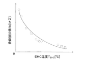
ここで、図3を参照して、PM温度とPMの電気抵抗率との関係について説明する。図3は、横軸がEHC13の温度TEHCを表し、縦軸は触媒担体31とケース32との間の絶縁抵抗値R0を表したグラフである。これは、EHC13に所定量のPMが堆積している場合に、EHC13の温度を変化させた時の絶縁抵抗値R0を実際に測定した結果を示す。なお、EHC13の温度TEHCはPMの温度と実質的に等しいと考えることができる。
Here, the relationship between the PM temperature and the electrical resistivity of the PM will be described with reference to FIG. FIG. 3 is a graph in which the horizontal axis represents the temperature T EHC of the EHC 13 and the vertical axis represents the insulation resistance value R 0 between the
図3から、EHC13の温度TEHCが大きくなるほど、絶縁抵抗値R0は小さくなることが分かる。絶縁抵抗値R0が小さくなる要因としては、EHC13の温度が高くなることにより、PM又は絶縁部材34の温度が高くなり、よって、PM又は絶縁部材34の電気抵抗率が低下することが考えられる。
FIG. 3 shows that the insulation resistance value R 0 decreases as the
一方、PM除去制御及びEHC13への通電制御を実行した場合でも、EHC13の温度TEHCは、相当に高い所定温度Taよりも低い温度領域に存在する。更に、温度TEHCが、「機関11の停止時のEHC13の温度」から「PM除去制御及びEHC13への通電制御を実行した場合に達するEHC13の温度」までの温度領域内にある場合、絶縁部材34の電気抵抗率は殆んど変化しない。即ち、所定温度Taよりも低い温度領域においては、絶縁部材34の電気抵抗率は、EHC13の温度が変化してもほぼ変化しない。従って、PM温度が上昇した際に絶縁抵抗値R0が低下する手段たる要因は、PMの電気抵抗率の低下であると考えられる。
On the other hand, even when the PM removal control and the energization control to the EHC 13 are executed, the temperature T EHC of the EHC 13 exists in a temperature region lower than the considerably high predetermined temperature Ta. Further, when the temperature T EHC is within the temperature range from “the temperature of the EHC 13 when the
そこで、ECU20は、EHC13に堆積したPMの温度と、触媒担体31とケース32との間の絶縁抵抗値R0とに基づいて、PM除去処理を実行するか否かを決定する。即ち、ECU20は、PM温度を考慮した絶縁抵抗値に基づいて、EHCに堆積したPMを除去するか否かを決定する。具体的には、第1装置は、PM温度と絶縁抵抗値R0とから、基準温度における絶縁抵抗値を算出し、基準温度における絶縁抵抗値が所定の抵抗値(PMが除去すべき量だけ堆積している場合の基準温度における絶縁抵抗値であり、「第1抵抗閾値」とも称呼される。)よりも小さい場合に、PM除去処理を行なう。これに対し、絶縁抵抗の低下の主要因が、PM温度の上昇による電気抵抗率の低下による場合には、基準温度における絶縁抵抗値が第1抵抗閾値よりも大きくなるので、第1装置はPM除去処理を行なわない。従って、燃費の悪化を回避することができる。
Therefore, the
(実際の作動)
次に、ECU20のCPU(以下、単に「CPU」と称呼する。)の実際の作動について説明する。CPUは図4に示したEHC通電開始制御ルーチンの処理を所定時間が経過する毎に繰り返し実行する。従って、所定のタイミングになると、CPUは図4のS101に進み、以下に述べる3つの条件が総て成立しているか否かを判定する。
・凝縮水除去制御実行フラグXWが「0」に設定されている。
・PM除去制御実行フラグXPMが「0」に設定されている。
・故障フラグ(EHC異常フラグ)Xijoが「0」に設定されている。
(Actual operation)
Next, the actual operation of the CPU of the ECU 20 (hereinafter simply referred to as “CPU”) will be described. The CPU repeatedly executes the processing of the EHC energization start control routine shown in FIG. 4 every time a predetermined time elapses. Therefore, when the predetermined timing comes, the CPU proceeds to S101 in FIG. 4 and determines whether or not all of the following three conditions are satisfied.
The condensed water removal control execution flag XW is set to “0”.
PM removal control execution flag X PM is set to “0”.
The failure flag (EHC abnormality flag) X ijo is set to “0”.
凝縮水除去制御実行フラグXWの値は後述する凝縮水除去制御が実行されている場合に「1」に設定され、凝縮水除去制御が実行されていない場合に「0」に設定される。凝縮水除去制御実行フラグXWの値はRAMに格納される。
PM除去制御実行フラグXPMの値は後述するPM除去制御(PM除去処理)が実行されている場合に「1」に設定され、PM除去制御が実行されていない場合に「0」に設定される。PM除去制御実行フラグXPMの値はRAMに格納される。
なお、凝縮水除去制御実行フラグXW及びPM除去制御実行フラグXPMの値は、図示しないイグニッション・キー・スイッチの操作位置がオフ位置からオン位置へと変更されたときにCPUが実行するイニシャルルーチンにおいて「0」に設定される。
EHC異常フラグXijoの値は、後述するように、EHC13が異常である(故障している)と判定された場合に「1」に設定され、バックアップRAMに格納される。
The value of the condensate removal control executing flag X W is set to "1" when the condensate removal control described later is executed, it is set to "0" when the condensate removal control is not being executed. The value of the condensate removal control executing flag X W is stored in the RAM.
The value of the PM removal control execution flag X PM is set to “1” when PM removal control (PM removal processing) described later is executed, and is set to “0” when PM removal control is not executed. The The value of the PM removal control execution flag X PM is stored in the RAM.
The values of the condensed water removal control execution flag XW and the PM removal control execution flag X PM are the initial values executed by the CPU when the operation position of an ignition key switch (not shown) is changed from the off position to the on position. It is set to “0” in the routine.
As described later, the value of the EHC abnormality flag X ijo is set to “1” when the
フラグXW、フラグXPM及びフラグXijoのうちの少なくとも1つが「0」に設定されていない場合、CPUはS101にて「No」と判定し、本ルーチンを一旦終了する。一方、フラグXW、フラグXPM及びフラグXijoの総てが「0」に設定されている場合、CPUはS101にて「Yes」と判定してS102に進む。 If at least one of the flag X W , the flag X PM, and the flag X ijo is not set to “0”, the CPU makes a “No” determination in S101 to end the present routine tentatively . On the other hand, when all of the flag X W , the flag X PM, and the flag X ijo are set to “0”, the CPU determines “Yes” in S101 and proceeds to S102.
S102では、CPUは、EHC13の温度TEHCが第1温度Tthよりも低いか否かを判定する。即ち、CPUは、S102において、ECH13への通電要求が発生しているか否かを判定する。なお、CPUは、例えば、下記の式(3)に基づいてEHC13の温度TEHCを取得(推定)している。式(3)において、αは0よりも大きく1よりも小さい所定の定数である。αは、温度TupがEHC13の温度変化に影響を及ぼす度合及びEHC13の放熱割合等を考慮して適宜決定される値である。TEHC(前回値)は、一定時間前に式(3)に基づいて計算された温度TEHCである。温度Tupは上流側温度センサ22により検出されたECH13の上流側の排気温度である。但し、温度TEHCを取得(推定)する方法は、式(3)を用いる方法に限定されず、他の周知の方法であってもよい。
TEHC=α・Tup+(1−α)・TEHC(前回値) ・・・(3)
In S102, the CPU determines whether or not the temperature T EHC of the EHC 13 is lower than the first temperature T th . That is, the CPU determines whether or not a request for energizing the
T EHC = α ・ Tup + (1−α) ・ T EHC (previous value) (3)
EHC13の温度TEHCが第1温度Tth以上の場合には、CPUはS102にて「No」と判定し、本ルーチンを一旦終了する。一方、EHC13の温度TEHCが第1温度Tthよりも低い場合には、CPUはS102にて「Yes」と判定してS103に進む。 When the temperature T EHC of the EHC 13 is equal to or higher than the first temperature T th , the CPU makes a “No” determination at S102 to end the present routine tentatively. On the other hand, if the temperature T EHC of the EHC 13 is lower than the first temperature T th , the CPU makes a “Yes” determination at S102 to proceed to S103.
S103では、CPUは、EHC13が非通電中か否かを判定する。EHC13が通電中である場合には、CPUはS103にて「No」と判定し、本ルーチンを一旦終了する。一方、EHC13が非通電中である場合には、CPUはS103にて「Yes」と判定して104に進む。
In S103, the CPU determines whether or not the
S104では、CPUは、絶縁抵抗検出装置25を用いて、現時点での抵抗値(絶縁抵抗値)R0を取得する。次に、CPUはS105に進み、絶縁抵抗値R0が所定抵抗値Rth以上か否かを判定する。絶縁抵抗値R0が所定抵抗値Rth以上の場合には、CPUはS105にて「Yes」と判定してS106に進み、スイッチ141の状態を遮断状態から導通状態へと変更することにより一対の電極33間に電位差を付与し、もって、EHC13への通電を実行して本ルーチンを一旦終了する。ここで所定抵抗値Rthは、EHC13への通電を実行した場合に、過大な電流が触媒担体及び/又は電極からケースへと流れる可能性のある絶縁抵抗値である。即ち、絶縁抵抗値R0が所定抵抗値Rthよりも大きい場合には、過大な電流が触媒担体及び/又は電極からケースへと流れる可能性は低い。一方、絶縁抵抗値R0が所定抵抗値Rthよりも小さい場合には、過大な電流が触媒担体及び/又は電極からケースへと流れる可能性が高い。
In S104, the CPU acquires the current resistance value (insulation resistance value) R0 using the insulation
ところで、絶縁抵抗値R0が所定抵抗値Rthよりも小さい場合、凝縮水が触媒担体31に存在している可能性がある。そこで、この場合、CPUはS105にて「No」と判定してS107に進み、凝縮水除去制御実行フラグXWを「1」に設定して本ルーチンを一旦終了する。この結果、後述するように、凝縮水除去制御が開始される。
By the way, when the insulation resistance value R 0 is smaller than the predetermined resistance value R th , condensed water may be present in the
また、CPUは図4に示したEHC通電開始制御のルーチンと並行して、図5に示したEHC通電終了制御ルーチンの処理を所定時間が経過する毎に繰り返し実行する。従って、所定のタイミングになると、CPUは図5のS201に進み、EHC13が通電中であるか否かを判定する。EHC13が通電中でない場合には、CPUはS201にて「No」と判定し、本ルーチンを一旦終了する。一方、EHC13が通電中である場合には、CPUはS201にて「Yes」と判定してS202に進む。
Further, the CPU repeatedly executes the processing of the EHC energization end control routine shown in FIG. 5 every time a predetermined time elapses in parallel with the EHC energization start control routine shown in FIG. Therefore, when the predetermined timing comes, the CPU proceeds to S201 in FIG. 5 and determines whether or not the
S202では、EHC13の温度TEHCが、EHC13の暖機が完了したと判断できる第2温度(EHC触媒暖機完了温度)Tdanki以上か否かを判定する。この第2温度Tdankiは、当然、第1温度Tthよりも高い。EHC13の温度TEHCが第2温度Tdankiよりも低い場合には、CPUはS202にて「No」と判定し、本ルーチンを一旦終了する。一方、EHC13の温度TEHCが第2温度Tdanki以上の場合には、CPUはS202にて「Yes」と判定してS203に進み、スイッチ141の状態を導通状態から遮断状態へと変更することによりEHC13への通電を終了して本ルーチンを一旦終了する。
In S202, the temperature T EHC of EHC13 determines whether the second temperature (EHC catalyst warm-up completion temperature) T Danki or it can be determined that warm-up of EHC13 is completed. This second temperature Tdanki is naturally higher than the first temperature Tth . If the temperature T EHC of the EHC 13 is lower than the second temperature T danki , the CPU makes a “No” determination at S202 to end the present routine tentatively . On the other hand, if the temperature T EHC of the EHC 13 is equal to or higher than the second temperature T danki , the CPU determines “Yes” in S202 and proceeds to S203 to change the state of the
更に、CPUは図4に示したEHC通電開始制御ルーチン及び図5に示したEHC通電終了制御のルーチンと並行して、図6に示した凝縮水除去制御ルーチンの処理を所定時間が経過する毎に繰り返し実行する。従って、所定のタイミングになると、CPUは図のS301に進み、現時点が、凝縮水除去制御実行フラグXWが「0」から「1」に変化した時点の直後であるか否かを判定する。現時点が、凝縮水除去制御実行フラグXWが「0」から「1」に変化した時点の直後である場合には、CPUはS301にて「Yes」と判定し、EHC13への投入エネルギEを「0」に設定してS307に進む。 Further, the CPU performs the process of the condensed water removal control routine shown in FIG. 6 in parallel with the EHC energization start control routine shown in FIG. 4 and the EHC energization end control routine shown in FIG. Repeatedly. Accordingly, at a predetermined timing, CPU advances to S301 in FIG, current is equal to or immediately after the time when the condensation water removal control executing flag X W is changed from "0" to "1". Present time, if the condensation water removal control executing flag X W has just from the "0" at the time it was changed to "1", CPU makes a "Yes" determination at S301, the input energy E to EHC13 Set to “0” and proceed to S307.
S307では、CPUは、凝縮水除去制御実行フラグXWが「1」であるか否かを判定する。凝縮水除去制御実行フラグXWが「1」に設定されている場合には、CPUはS307にて「Yes」と判定してS308に進み、凝縮水除去制御を実行して本ルーチンを一旦終了する。ここで、凝縮水除去制御は、具体的には機関11の点火時期を「機関11の負荷及び回転速度」から定まる最適点火時期(基本点火時期)から所定の点火遅角量だけ遅角させる点火遅角を行う制御である。点火遅角を実行することにより機関11から排気通路に排出される得エネルギが増大して排気温度が上昇するため、EHC13に通電させることなくEHC13の温度TEHCを上昇させてEHC13に付着している凝縮水を除去することができる。なお、EHC13に通電させることなくEHC13の温度TEHCを上昇させることが可能であれば、凝縮水除去実行制御は点火遅角でなくても構わない。即ち、例えば、機関11の図示しない排気弁の開弁時期を進角させることにより、排気通路にエネルギ(排気温度)の大きい排気を排出することによって、EHC13の温度TEHCを上昇させてもよい。
In S307, the CPU determines whether or not the condensed water removal control execution flag XW is “1”. If the condensed water removal control execution flag XW is set to “1”, the CPU makes a “Yes” determination in S307 to proceed to S308, executes the condensed water removal control, and ends this routine once. To do. Here, the condensed water removal control is specifically an ignition that retards the ignition timing of the
一方、凝縮水除去制御実行フラグXWが「0」に設定されている場合には、CPUはS307にて「No」と判定してS309に進み、点火遅角量を「0」に設定することにより凝縮水除去制御を終了して本ルーチンを一旦終了する。 On the other hand, when the condensed water removal control execution flag XW is set to “0”, the CPU makes a “No” determination at S307 to proceed to S309, and sets the ignition retard amount to “0”. As a result, the condensate removal control is terminated and this routine is terminated once.
また、現時点が、凝縮水除去制御実行フラグXWが「0」から「1」に変化した時点の直後でない場合(即ち、凝縮水除去制御実行フラグXWが「0」又は「1」のままの場合)には、CPUはS301にて「No」と判定し、S303に進む。 Further, the present time, while condensate removal control executing flag X W from "0" if it is not immediately after the time of the change to "1" (i.e., condensate removal control executing flag X W is "0" or "1" In this case, the CPU makes a “No” determination at S301 to proceed to S303.
S303では、CPUは、凝縮水除去制御実行フラグXWが「1」であるか否かを判定する。凝縮水除去制御実行フラグXWが「0」に設定されている場合には、CPUはS303にて「No」と判定してS307に直接進む。一方、凝縮水除去制御実行フラグXWが「1」に設定されている場合には、CPUはS303にて「Yes」と判定してS304に進む。 In S303, the CPU determines whether or not the condensed water removal control execution flag XW is “1”. If the condensed water removal control execution flag XW is set to “0”, the CPU makes a “No” determination at S303 to proceed directly to S307. On the other hand, if the condensed water removal control execution flag XW is set to “1”, the CPU makes a “Yes” determination at S303 to proceed to S304.
S304では、CPUは、EHC13への投入エネルギEを「Tex・γ・Ga+E(前回値)」に設定する。Texは上流側温度センサ22により検出されたEHC13の上流側の排気温度Tupと等しい。更に、γは排気の比熱を示し、Gaはエアフローメータ27により測定された吸入空気量Gaを示す。E(前回値)は、本ルーチンが前回実行された時点にて算出された投入エネルギEである。投入エネルギEは、例えば、点火遅角量及び吸入空気量Gaに基いて推定することができる。
In S304, the CPU sets the input energy E to the
次に、CPUはS305に進み、以下の何れかの条件が成立しているか否かを判定する。
・EHC13への投入エネルギEが所定エネルギEth以上である。
・EHC13の温度TEHCが第2温度(触媒暖機完了温度)Tdanki以上である。
Next, the CPU proceeds to S305, and determines whether any of the following conditions is satisfied.
· EHC13 input energy E to is a predetermined energy E th or more.
The temperature T EHC of the EHC 13 is equal to or higher than the second temperature (catalyst warm-up completion temperature) T danki .
EHC13への投入エネルギEが所定エネルギEthよりも小さく、且つ、EHC13の温度TEHCが第2温度Tdanki未満である場合、触媒担体31に存在している凝縮水は蒸発(除去)していない可能性があると考えられる。そこで、この場合、CPUはS305にて「No」と判定し、S307に進む。その結果、現時点では、凝縮水除去制御実行フラグXWが「1」であるから、S308にて凝縮水除去制御が継続される。
When the input energy E to the EHC 13 is smaller than the predetermined energy E th and the temperature T EHC of the EHC 13 is lower than the second temperature T danki , the condensed water present in the
一方、EHC13への投入エネルギEが所定エネルギEth以上である場合、又は、EHC13の温度TEHCが第2温度Tdanki以上である場合、触媒担体31に存在している凝縮水は蒸発(除去)したと考えられる。そこで、この場合、CPUはS305にて「Yes」と判定してS306に進み、凝縮水除去制御実行フラグXWを「0」に設定してS307に進む。その結果、凝縮水除去制御実行フラグXWが「0」になるから、S309にて凝縮水除去制御が終了させられる。
On the other hand, when the input energy E to the EHC 13 is equal to or higher than the predetermined energy E th , or when the temperature T EHC of the EHC 13 is equal to or higher than the second temperature T danki , the condensed water present in the
更に、CPUは図4乃至図6に示したルーチンと並行して、図7に示したPM除去制御ルーチンの処理を所定時間が経過する毎に繰り返し実行する。従って、所定のタイミングになると、CPUは図7のS401に進み、EHC13が非通電中であるか否かを判定する。EHC13が通電中である場合には、CPUはS401にて「No」と判定し、本ルーチンを一旦終了する。一方、EHC13が非通電中である場合には、CPUはS401にて「Yes」と判定し、S402に進む。
Further, in parallel with the routines shown in FIGS. 4 to 6, the CPU repeatedly executes the process of the PM removal control routine shown in FIG. 7 every time a predetermined time elapses. Therefore, when the predetermined timing comes, the CPU proceeds to S401 in FIG. 7 and determines whether or not the
S402では、CPUは、上記(3)式により別途算出されているEHC13の温度TEHCを取得する。次に、CPUはS403に進み、PM除去制御実行フラグXPMが「0」に設定されているか否かを判定する。PM除去制御実行フラグXPMが「0」に設定されている場合には、CPUはS403にて「Yes」と判定し、S404にて「凝縮水除去制御が終了した時点の直後であるか否か」を判定する。即ち、CPUは、現時点が、凝縮水除去制御実行フラグが「1」から「0」に変化した直後であるか否かを判定する。現時点が、凝縮水除去制御実行フラグが「1」から「0」に変化した直後である場合には、CPUはS404にて「Yes」と判定し、S406に進む。 In S402, the CPU obtains the temperature T EHC of the EHC 13 that is separately calculated by the above equation (3). Next, the CPU proceeds to S403 to determine whether or not the PM removal control execution flag XPM is set to “0”. When the PM removal control execution flag X PM is set to “0”, the CPU makes a “Yes” determination in S403, and in S404, “is immediately after the point when the condensed water removal control ends. Is determined. That is, the CPU determines whether or not the present time is immediately after the condensed water removal control execution flag is changed from “1” to “0”. If the current time is immediately after the condensed water removal control execution flag is changed from “1” to “0”, the CPU makes a “Yes” determination in S404 to proceed to S406.
S406では、CPUは、絶縁抵抗検出装置25を用いて、現時点での絶縁抵抗値R0を絶縁抵抗値R1として取得する。その後、CPUはS407に進み、現時点での絶縁抵抗値R1と現時点でのEHC13の温度TEHC(即ち、絶縁抵抗値R0を測定した時点の温度TEHC)とに基づいて基準絶縁抵抗値RPMを求める。この基準絶縁抵抗値RPMは、EHC13に凝縮水が存在していない状態においてEHC12に堆積したPMによってもたらされる抵抗値であって且つEHC13の温度(従って、触媒担体31に付着・堆積しているPMの温度)が基準温度T0であると仮定した場合の絶縁抵抗値(触媒担体31とケース32との間の抵抗値)である。
In S <b> 406, the CPU acquires the current insulation resistance value R 0 as the insulation resistance value R 1 using the insulation
より具体的に述べると、触媒担体31に付着・堆積しているPMの量(以下、「PM堆積量」と称呼する。)を種々の値に設定し、それぞれのPM堆積量についてPMの温度を変化させた場合の絶縁抵抗値を実験により予め測定しておく。なお、この実験を行う場合、触媒担体31には凝縮水が存在しないように凝縮水を除去しておく。そして、PM堆積量が「ある量X」である場合に、PMの温度が基準温度T0であるときの絶縁抵抗値R(T0,X)と、PMの温度が任意の温度Txであるときの絶縁抵抗値R(Tx、X)と、を求め、それらの比(=R(T0,X)/R(Tx、X))を変換係数k(Tx,R(Tx、X))として求め、ルックアップテーブルMapAの形式でROMに格納しておく。即ち、ルックアップテーブルMapAは、以下のように記述することができる。
k(Tx,R(Tx、X))=MapA(Tx,R(Tx、X)) ・・・(4)
More specifically, the amount of PM adhering to and depositing on the catalyst carrier 31 (hereinafter referred to as “PM deposition amount”) is set to various values, and the PM temperature is set for each PM deposition amount. The insulation resistance value when changing is previously measured by experiment. When this experiment is performed, the condensed water is removed so that no condensed water exists in the
k (Tx, R (Tx, X)) = MapA (Tx, R (Tx, X)) (4)
そして、CPUは、ルックアップテーブルMapAの引数Txに現時点でのEHC13の温度TEHCを代入し、ルックアップテーブルMapAの引数R(Tx、X)に現時点での絶縁抵抗値R1を代入することにより、変換係数k(TEHC,R1)を求める。更に、CPUは、式(5)のように、現時点での絶縁抵抗値R1に変換係数k(TEHC,R1)を乗じることにより、基準絶縁抵抗値RPMを求める。
RPM=k(TEHC,R1)・R1 ・・・(5)
Then, the CPU substitutes the current temperature T EHC of the EHC 13 for the argument Tx of the lookup table MapA, and substitutes the current insulation resistance value R 1 for the argument R (Tx, X) of the lookup table MapA. Thus, the conversion coefficient k (T EHC , R 1 ) is obtained. Further, the CPU obtains the reference insulation resistance value R PM by multiplying the current insulation resistance value R 1 by the conversion coefficient k (T EHC , R 1 ) as shown in Expression (5).
R PM = k (T EHC , R 1 ) · R 1 (5)
なお、RPM=k(TEHC,R1)・R1=fa(TEHC,R1)である(faは、所定の関数)ことから、PMの温度が温度TEHCであるときの絶縁抵抗値R1が分かれば、それらから基準絶縁抵抗値RPMを直接求めることができる。即ち、CPUは、以下のルックアップテーブルMapBにより基準絶縁抵抗値RPMを直接求めてもよい。
RPM=MapB(TEHC,RPM)=fa(TEHC,R1) ・・・(6)
Since R PM = k (T EHC , R 1 ) · R 1 = fa (T EHC , R 1 ) (fa is a predetermined function), insulation when the temperature of PM is the temperature T EHC If the resistance value R 1 is known, the reference insulation resistance value R PM can be directly determined from them. That, CPU is a reference insulation resistance value R PM may be determined directly by following the look-up table MapB.
R PM = MapB (T EHC , R PM ) = fa (T EHC , R 1 ) (6)
次に、CPUはS408に進み、S407にて求めた基準絶縁抵抗値RPMが第1抵抗閾値RPMthよりも小さいか否かを判定する。基準絶縁抵抗値RPMが第1抵抗閾値RPMth以上の場合には、PM堆積量は付着・体積したPMを除去すべきほど多くないと判定できる。よって、この場合、CPUはS408に「No」と判定し、本ルーチンを一旦終了する。一方、基準絶縁抵抗値RPMが第1抵抗閾値RPMthよりも小さい場合には、PM堆積量は付着・体積したPMを除去すべき量よりも多くなっていると判定できる。よって、この場合、CPUはS408にて「Yes」と判定してS409に進み、PM除去制御実行フラグXPMを「1」に設定するとともにPM除去制御を開始し、本ルーチンを一旦終了する。 Next, the CPU proceeds to S408, and determines whether or not the reference insulation resistance value R PM obtained in S407 is smaller than the first resistance threshold value R PMth . When the reference insulation resistance value R PM is equal to or greater than the first resistance threshold value R PMth , it can be determined that the PM deposition amount is not so large as to remove adhered and volumetric PM. Therefore, in this case, the CPU makes a “No” determination in S408 to end the present routine tentatively. On the other hand, when the reference insulation resistance value R PM is smaller than the first resistance threshold value R PMth, it can be determined that the PM deposition amount is larger than the amount to which the adhered and volumetric PM should be removed. Therefore, in this case, the CPU makes a “Yes” determination in S408 to proceed to S409, sets the PM removal control execution flag XPM to “1”, starts the PM removal control, and once ends this routine.
ここで、PM除去制御は、具体的には、機関11の点火時期を「機関11の負荷及び回転速度」から定まる最適点火時期(基本点火時期)から所定の点火遅角量だけ遅角させることにより排気温度を上昇させ、且つ、燃料噴射弁から噴射される燃料の量(燃料噴射量)を、吸入空気量Ga、機関回転速度NE及び目標空燃比から定まる量に設定することにより実行される。PM除去制御における目標空燃比は、理論空燃比より相当に小さい強リッチ空燃比(PM除去制御が行われていない場合の空燃比フィードバック中に通常なり得るリッチ空燃比よりも小さい空燃比)と理論空燃比より大きい強リーン空燃比(PM除去制御が行われていない場合の空燃比フィードバック中に通常なり得るリーン空燃比よりも大きい空燃比)との間で所定の周期で変更される。この空燃比制御は、一般には、アクティブ空燃比制御又は空燃比パータベーション制御とも称呼される。この結果、点火遅角により排気温度が上昇し、且つ、目標空燃比が強リーン空燃比に設定された期間においてEHC13に多量の酸素が供給される。よって、EHC13内においてPMを酸化させることができ、EHC13に堆積したPMを除去することができる。なお、アクティブ空燃比制御により、EHC13に供給される排ガスの空燃比の平均値は略理論空燃比に維持されるので、エミッションの大きな悪化は発生しない。
Here, in the PM removal control, specifically, the ignition timing of the
ところで、CPUがS404の処理を行う時点が、凝縮水除去制御実行フラグXWが「1」から「0」に変化した時点の直後でない場合(即ち、凝縮水除去制御実行フラグXWが「1」又は「0」のままの場合)には、CPUはS404にて「No」と判定し、S405に進む。S405では、CPUは、EHC13の温度TEHCが前述した第2温度(EHC触媒暖機完了温度)Tdanki以上か否かを判定する。EHC13の温度TEHCが第2温度Tdankiよりも低い場合には、CPUはS404にて「No」と判定し、本ルーチンを一旦終了する。一方、EHC13の温度TEHCが第2温度Tdanki以上である場合には触媒担体31に存在している凝縮水は蒸発(除去)し終わっていると考えられるので、CPUはS405にて「Yes」と判定し、前述したS406以降に進む。なお、このとき、CPUは、凝縮水除去制御実行フラグXWの値を「0」に設定する。
Meanwhile, when the CPU executes S404 is, if not immediately after the time when the condensation water removal control executing flag X W is changed from "1" to "0" (i.e., condensate removal control executing flag X W is "1 ”Or“ 0 ”), the CPU makes a“ No ”determination at S404 to proceed to S405. In S405, the CPU determines whether or not the
更に、CPUがS403の処理を実行する時点において、PM除去制御実行フラグXPMが「1」である場合には、CPUはS403において「No」と判定し、S410に進む。S410では、CPUは、PM除去制御の継続時間tPMが所定時間tPMth以上であるか否かを判定する。PM除去制御の継続時間tPMが所定時間tPMthよりも短い場合には、CPUはS410にて「No」と判定し、本ルーチンを一旦終了する。この結果、PM除去制御が継続して実行される。 Further, if the PM removal control execution flag XPM is “1” at the time when the CPU executes the process of S403, the CPU determines “No” in S403, and proceeds to S410. In S410, CPU is the duration t PM in the PM removal control is equal to or a predetermined time t PMTH more. When the duration t PM of PM removal control is shorter than the predetermined time t PMth , the CPU makes a “No” determination at S410 to end the present routine tentatively . As a result, PM removal control is continuously executed.
一方、PM除去制御の継続時間TPMが所定時間TPMth以上である場合には、EHC13に付着・堆積していたPMの除去が完了したと判定できる。よって、この場合、CPUはS410にて「Yes」と判定してS411に進み、PM除去制御実行フラグXPMを「0」に設定するとともに、PM除去制御を終了する。
On the other hand, when the duration T PM of PM removal control is equal to or longer than the predetermined time T PMth , it can be determined that the removal of the PM adhering to and depositing on the
その後、CPUは、S412に進み、絶縁抵抗検出装置25を用いて、現時点での絶縁抵抗値R0を絶縁抵抗値R2として取得する。そして、CPUはS413に進み、現時点での絶縁抵抗値R2が所定抵抗値Rth(所定抵抗値Rthより若干低い抵抗値であってもよい)よりも大きいか否かを判定する。現時点ではEHC13に付着・堆積していたPMの除去が完了しているので、EHC13が正常であれば、絶縁抵抗値R2は十分に大きくなっている筈である。そこで、CPUは、現時点での絶縁抵抗値R2が所定抵抗値Rthよりも大きい場合には、S413にて「Yes」と判定してS414に進み、故障フラグXijoを「0」に設定して本ルーチンを一旦終了する。即ち、CPUは、EHC13が正常であると判定する。
Thereafter, CPU proceeds to S412, by using an
一方、現時点での絶縁抵抗値R2が所定抵抗値Rth以下である場合には、EHC13は異常であると考えられる。そこで、この場合、CPUはS413にて「No」と判定してS415に進み、故障フラグXijoを「1」に設定して本ルーチンを一旦終了する。
On the other hand, if the insulation resistance value R 2 at the present time is equal to or less than the predetermined resistance value R th is,
次に、図4乃至図7のルーチンを実行した際の、排気浄化装置10の実際の作動について説明する。ここでは、EHC13は故障しておらず、且つ、EHC13に凝縮水及びPMが付着している場合を考える。
Next, the actual operation of the exhaust
まず、時刻t1にて、CPUは、EHC13の温度TEHCを測定し、EHC13の温度TEHCが第1温度Tthよりも低いか否かを判定する。図8の場合では、TEHCは第1温度Tthよりも低いため、「EHC13への通電によりEHC13の温度TEHCを上昇させる要求(通電要求)」が発生する。次に、CPUは、EHC13が非通電中であることを確認し、絶縁抵抗検出装置25を用いて、絶縁部材34の絶縁抵抗値R0を検出する。そして、CPUは絶縁抵抗R0が所定抵抗値Rth以上か否かを判定する。図8の場合は、絶縁抵抗値R0が所定抵抗値Rthよりも小さいため、EHC13に凝縮水が付着している可能性があると考えられることから、CPUは凝縮水除去制御の実行を開始するとともに、投入エネルギEの値を初期化する(即ち、投入エネルギEを「0」に設定する。)。
First, at time t 1, CPU measures the temperature T EHC of
その後、時間経過とともに投入エネルギEの値は加算されていき、時刻t2にて、CPUは、投入エネルギEが所定エネルギEthに達したときに、凝縮水除去制御を終了する。そして、時刻t3にて、絶縁抵抗検出装置25を用いて、現時点での絶縁抵抗値R1を取得する。その後、CPUは、現時点での絶縁抵抗値R1と現時点でのEHC13の温度TEHCとに基づいて基準絶縁抵抗値RPMを求め、基準絶縁抵抗値RPMが第1抵抗閾値RPMthよりも小さいか否かを判定する。図8の場合には、基準絶縁抵抗値RPMが第1抵抗閾値RPMthよりも小さいため、EHC13にPMが堆積していると考えられることから、PM除去制御の実行を開始する。
Thereafter, the value of input energy E over time is gradually being added, at time t 2, CPU, when the applied energy E reaches a predetermined energy E th, terminates the condensate removal control. At time t 3 , the current insulation resistance value R 1 is acquired using the insulation
時刻t3から所定期間t0が経過した時刻t4にて、CPUは、PM除去制御を終了する。所定期間t0の間、PM除去制御を実行したことにより、EHC13に堆積していたPMは除去されたと考えられる。次に、時刻t5にて、CPUは、絶縁抵抗検出装置25を用いて、現時点での絶縁抵抗値R2を検出し、絶縁抵抗値R2が所定抵抗値Rthよりも大きいか否かを判定する。図8の場合には、絶縁抵抗値R2は所定抵抗値Rthよりも大きいため、EHC13は正常であると判断される。そして、EHC13の温度TEHCが第1温度Tthよりも大きいため、EHCに通電させることなく、本制御を終了する。
The predetermined period t 0 is at time t 4 when elapsed from the time t 3, CPU ends the PM removal control. During the predetermined time period t 0, by executing the PM removal control, PM that has been deposited in EHC13 it is considered to have been removed. Then, at time t 5, CPU, using an
以上説明したように、第1装置においては、PM堆積量を種々の値に設定し、それぞれのPM堆積量についてPMの温度を変化させた場合の絶縁抵抗値を実験により予め測定しておく。そして、第1装置は、実際の絶縁抵抗値を検出した時点でのPM温度とその絶縁抵抗値とから、基準温度の絶縁抵抗値である基準絶縁抵抗値を算出する。基準絶縁抵抗値が第1抵抗閾値よりも小さい場合には、電気加熱式触媒に堆積・付着したPM量が除去すべき堆積・付着したPM量よりも多いと判断できる。そのため、その場合のみ第1装置はPMを除去するPM除去制御を実行する。以上により、第1装置は、燃料を無駄に消費することなく、絶縁抵抗を回復することができる。 As described above, in the first apparatus, the PM deposition amount is set to various values, and the insulation resistance value when the PM temperature is changed for each PM deposition amount is measured in advance by experiments. Then, the first device calculates a reference insulation resistance value, which is an insulation resistance value at the reference temperature, from the PM temperature at the time when the actual insulation resistance value is detected and the insulation resistance value. When the reference insulation resistance value is smaller than the first resistance threshold value, it can be determined that the amount of PM deposited / attached on the electrically heated catalyst is larger than the amount of PM deposited / attached to be removed. Therefore, only in that case, the first device executes PM removal control for removing PM. As described above, the first device can recover the insulation resistance without wasting fuel.
<第2実施形態>
次に、本発明の第2実施形態に係る内燃機関の排気浄化装置(以下、「第2装置」とも呼称する。)について説明する。第2実施形態は、そのECU20が、図7に示したルーチンに代わる図9に示したルーチンを実行する点のみにおいて第1実施形態と相違している。以下、この相違点を中心として説明する。
Second Embodiment
Next, an exhaust emission control device for an internal combustion engine according to a second embodiment of the present invention (hereinafter also referred to as “second device”) will be described. The second embodiment is different from the first embodiment only in that the
図9に示したルーチンのS501乃至S515は、S507及びS508を除き、図7に示したルーチンのS401乃至S415のそれぞれと同様の処理を行うステップである。従って、以下においては、S507及びS508の処理について説明を加える。 Steps S501 to S515 of the routine shown in FIG. 9 are steps for performing the same processing as S401 to S415 of the routine shown in FIG. 7 except for S507 and S508. Therefore, in the following, the processing of S507 and S508 will be described.
S507にて、CPUは、現時点でのEHC13の温度TEHCから、絶縁抵抗の閾値である第2抵抗閾値RthEHCを算出する。より具体的に述べると、触媒担体31に、PM除去制御を行うか否かを決定する際に使用されるPMの量(この量以上のPMが堆積している場合にはPM除去制御を実行すべきであるというPM堆積量であり、以下、「PM除去堆積量Y」と称呼する。)のPMを実際に堆積させておき、PMの温度(即ち、EHC13の温度TEHC)を変化させた場合の絶縁抵抗値を実験により予め測定しておく。なお、この実験を行う場合、触媒担体31には凝縮水が存在しないように凝縮水を除去しておく。そして、PM堆積量がPM除去堆積量Yである場合に、PMの温度が基準温度T0であるときの絶縁抵抗値R(T0)と、PMの温度が任意の温度TYであるときの絶縁抵抗値R(TY)と、を求め、それらの比(=R(TY)/R(T0))を変換係数m(TY)として求め、ルックアップテーブルMapCの形式でROMに格納しておく。即ち、ルックアップテーブルMapCは、以下のように記述することができる。
m(TY)=MapC(TY) ・・・(7)
In S507, the CPU calculates a second resistance threshold value RthEHC , which is a threshold value of the insulation resistance, from the
m (T Y ) = MapC (T Y ) (7)
そして、CPUは、ルックアップテーブルMapCの引数TYに現時点でのEHC13の温度TEHCを代入することにより、変換係数m(TEHC)を求める。更に、CPUは、式(8)に示したように、PMの温度が基準温度T0であるときの絶縁抵抗値R(T0)に変換係数m(TEHC)を乗じることにより、第2抵抗閾値RthEHCを求める。なお、現時点でのEHC13の温度TEHCが小さい場合に比べて大きい場合には、第2抵抗閾値RthEHCが小さい値になるように「PMの温度が基準温度T0であるときの絶縁抵抗値R(T0)」が変換係数m(TEHC)により変換されて第2抵抗閾値RthEHCが求められる。これは、PMの温度が大きくなるほど、PMの電気抵抗率が低下することにより、絶縁抵抗値Rが小さくなることを考慮しているためである。
RthEHC=m(TEHC)・R(T0) ・・・(8)
Then, CPU substitutes the temperature T EHC of EHC13 at present argument T Y lookup table mapc, obtaining the conversion coefficient m (T EHC). Further, as shown in the equation (8), the CPU multiplies the insulation resistance value R (T 0 ) when the temperature of the PM is the reference temperature T 0 by the conversion coefficient m (T EHC ) to obtain the second A resistance threshold value R thEHC is obtained. If the
R thEHC = m (T EHC ) · R (T 0 ) (8)
なお、RthEHC=m(TEHC)・R(T0)=ga(TEHC)である(gaは所定の関数)ことから、PMの温度TEHCが分かれば、第2抵抗閾値RthEHCを直接求めることができる。即ち、CPUは、以下のルックアップテーブルMapDにより第2抵抗閾値RthEHCを直接求めてもよい。
RthEHC=MapD(TEHC)=ga(TEHC) ・・・(9)
Since R thEHC = m (T EHC ) · R (T 0 ) = ga (T EHC ) (ga is a predetermined function), if the PM temperature T EHC is known, the second resistance threshold R thEHC is set to You can ask directly. That is, the CPU may directly obtain the second resistance threshold value R thEHC using the following lookup table MapD.
R thEHC = MapD (T EHC ) = ga (T EHC ) (9)
そして、CPUはS508に進み、S506にて取得した現時点での絶縁抵抗値R1が第2抵抗閾値RthEHCよりも小さいか否かを判定する。現時点での絶縁抵抗値R1が第2抵抗閾値RthEHC以上の場合には、CPUはS508に「No」と判定し、本ルーチンを一旦終了する。一方、現時点での絶縁抵抗R1が第2抵抗閾値RthEHCよりも小さい場合には、CPUはS508にて「Yes」と判定し、S509に進む。 Then, CPU proceeds to S508, the insulation resistance value R 1 at the present time acquired in S506 determines whether less than a second resistance threshold R thEHC. Insulation resistance R 1 at the present time is in the case of the above second resistor threshold R ThEHC is, CPU makes a "No" in S508, the routine is finished. On the other hand, the insulation resistance R 1 of currently smaller than the second threshold resistance value R ThEHC is, CPU makes a "Yes" determination at S508, the process proceeds to S509.
第2装置は、PMの温度と見做されるEHC13の温度TEHC毎に、PMがPM除去堆積量Y(所定堆積量)だけ堆積した場合の絶縁抵抗値である第2抵抗閾値RthEHCを予め求める。そして、第2装置は、絶縁抵抗検出装置25(抵抗測定手段)によって測定された絶縁抵抗値が第2抵抗閾値よりも小さい場合には、PM温度に関わらず、電気加熱式触媒の端部に堆積したPM量がPM除去堆積量Yよりも多いと判断してPM除去制御を実行する。そのため、堆積したPM量がPM除去堆積量Yよりも多い場合にのみPM除去制御が実行されるので、燃料を無駄に消費することなく、絶縁抵抗を回復することができる。
The second device calculates a second resistance threshold value R thEHC that is an insulation resistance value when PM is deposited by the PM removal deposition amount Y (predetermined deposition amount) for each
以上、説明したように、本発明の各実施形態及び各変形例によれば、PMの温度による電気抵抗率の変化を考慮してPMを除去するか否かを決定できる。よって、燃料を無駄に消費することなく、絶縁抵抗を回復することができる。なお、本発明は上記実施形態に限定されることはなく、本発明の範囲内において種々の変形例を採用することができる。 As described above, according to each embodiment and each modification of the present invention, it is possible to determine whether or not to remove PM in consideration of a change in electrical resistivity due to the temperature of PM. Therefore, the insulation resistance can be recovered without consuming fuel wastefully. In addition, this invention is not limited to the said embodiment, A various modification can be employ | adopted within the scope of the present invention.
例えば、本発明の各実施形態は、PM温度と絶縁抵抗値とから、粒子状物質(PM)を除去するか否か(PM除去制御を実行すべきか否か)を決定する構成であれば、図7及び図9に示したPM除去制御のルーチン以外のルーチンを実行しても構わない。例えば、本発明による他の態様の排気浄化装置のCPUは、図7に示したS407及びS408の処理を行わず、S402にて取得したEHC13の温度TEHCと、S406にて取得した現時点での絶縁抵抗R1とを「温度TEHCと絶縁抵抗R1とにより決まる点が、PM除去制御を実行すべき領域にあるか否かを定めた領域マップ(ルックアップテーブル)」に適用することによってPM除去制御を実行するか否かを直接的に決定してもよい。この場合、基準絶縁抵抗値RPM又は第2抵抗閾値RthEHCを算出する工程を省略することができる。よって、PM温度による電気抵抗率の変化を考慮して、燃料を無駄に消費することなく、絶縁抵抗を回復することができるとともに、PM除去制御のルーチンを簡素化できる。 For example, each embodiment of the present invention is configured to determine whether to remove particulate matter (PM) from PM temperature and insulation resistance value (whether to perform PM removal control) or not. A routine other than the PM removal control routine shown in FIGS. 7 and 9 may be executed. For example, the CPU of the exhaust emission control device according to another aspect of the present invention does not perform the processing of S407 and S408 shown in FIG. 7, and the temperature T EHC of the EHC 13 acquired in S402 and the current time acquired in S406. By applying the insulation resistance R 1 to the “region map (lookup table) that determines whether or not the point determined by the temperature T EHC and the insulation resistance R 1 is in the region where the PM removal control is to be executed”. Whether or not to execute the PM removal control may be directly determined. In this case, the step of calculating the reference insulation resistance value R PM or the second resistance threshold value R thEHC can be omitted. Therefore, considering the change in electrical resistivity due to the PM temperature, the insulation resistance can be recovered without wasting fuel, and the routine for PM removal control can be simplified.
また、PM除去制御は、例えば、機関11がディーゼル機関である場合には、燃料噴射時期を遅角させたり或いはメイン噴射の後にポスト噴射を行なったりすることによって排気管内において燃料を燃焼させ(即ち、機関11から排気通路に排出されるエネルギを増大させ)、その燃焼により発生した熱によってEHC13の温度を上昇させた上でEHC13に供給される過剰な酸素によってPMを燃焼させて除去する制御であってもよい。この場合、機関11の燃焼室に供給される燃料の一部が排気の昇温に用いられることになるため、トルク発生に寄与しない燃料の消費量が増大するが、本発明によれば、そのようなPM除去制御が不要に行われないので、燃費の悪化を回避することができる。
Further, for example, when the
或いは、機関11がガソリン燃料機関であっても、ディーゼル機関であっても、排気弁の開弁タイミングを進角することにより、より高温な燃焼ガスを排気通路に排出させ(即ち、機関11から排気通路に排出されるエネルギを増大させ)、以て、EHC13を昇温させ、かつ、その後に機関に供給される混合気の空燃比をリーン空燃比に設定することによってEHC13に十分な酸素を供給することにより、PMを燃焼させて除去させてもよい。即ち、本発明の排気浄化装置の実施形態及び変形例は、EHC13に通電することなく、関から排気通路へと排出されるエネルギによりEHC13(EHC13に堆積したPM)を昇温させることによってPMを燃焼(除去)する装置であればよい。
Alternatively, regardless of whether the
11…機関、13…電気加熱式触媒、14…バッテリ、20…ECU、22…上流側温度センサ、24…下流側温度センサ、25…絶縁抵抗検出装置、31…触媒担体、32…ケース、33…電極、34…絶縁部材。
DESCRIPTION OF
Claims (4)
前記触媒担体への通電要求が発生したときに前記一対の電極に電位差を付与することにより前記触媒担体に通電する通電制御手段と、
を備える、内燃機関の排気浄化装置であって、
前記触媒担体と前記ケースとの間の絶縁抵抗値を測定する抵抗測定手段と、
前記電気加熱式触媒に堆積した粒子状物質の温度であるPM温度を推定するPM温度推定手段と、
前記触媒担体が通電されていない状態において、前記電気加熱式触媒に堆積した粒子状物質を除去すべきであるときに満たす所定の除去条件を前記PM温度と前記絶縁抵抗値とが満たす場合、前記電気加熱式触媒の温度を前記内燃機関から前記排気通路へと排出されるエネルギを用いて上昇させることにより前記堆積した粒子状物質を除去するPM除去制御を実行するPM除去制御手段と、を備えた内燃機関の排気浄化装置。 A catalyst carrier that carries a catalyst and generates heat when energized, a pair of electrodes provided on the catalyst carrier and energized to the catalyst carrier, a case for housing the catalyst carrier provided with the electrode, and the catalyst An electrically heated catalyst provided with an insulating member disposed between the carrier and the case, and disposed in an exhaust passage of the internal combustion engine;
Energization control means for energizing the catalyst carrier by applying a potential difference to the pair of electrodes when an energization request to the catalyst carrier occurs;
An exhaust purification device for an internal combustion engine, comprising:
Resistance measuring means for measuring an insulation resistance value between the catalyst carrier and the case;
PM temperature estimating means for estimating the PM temperature, which is the temperature of the particulate matter deposited on the electrically heated catalyst,
When the PM temperature and the insulation resistance value satisfy a predetermined removal condition that is satisfied when the particulate matter deposited on the electrically heated catalyst is to be removed in a state where the catalyst carrier is not energized, PM removal control means for performing PM removal control for removing the accumulated particulate matter by increasing the temperature of the electrically heated catalyst using energy discharged from the internal combustion engine to the exhaust passage. Exhaust gas purification device for internal combustion engine.
前記PM除去制御手段は、
前記電気加熱式触媒に水が付着していないと推定される状態において、前記所定の除去条件を前記PM温度と前記絶縁抵抗値とが満たす場合、前記PM除去制御を実行するように構成された内燃機関の排気浄化装置。 The exhaust gas purification apparatus for an internal combustion engine according to claim 1,
The PM removal control means includes
The PM removal control is configured to be executed when the PM temperature and the insulation resistance value satisfy the predetermined removal condition in a state where water is not attached to the electric heating catalyst. An exhaust purification device for an internal combustion engine.
前記PM除去制御手段は、
前記絶縁抵抗値が測定されたときの前記推定されたPM温度である測定時PM温度に基づいて、前記絶縁抵抗値を所定の基準PM温度における絶縁抵抗値に変換した値を基準絶縁抵抗値として取得する基準絶縁抵抗値取得手段と、
前記基準絶縁抵抗値が第1抵抗閾値よりも小さいか否かを判定し、前記基準絶縁抵抗値が前記第1抵抗閾値よりも小さいと判定したとき前記所定の除去条件が満たされたと判定する判定手段と、を含み、
前記所定の除去条件が満たされたと判定された場合に前記PM除去制御を実行するように構成され、
前記基準絶縁抵抗値取得手段は、
前記測定時PM温度が前記基準PM温度以上の場合には前記測定時PM温度が高くなるほど前記絶縁抵抗値が大きくなるように同絶縁抵抗値を変換した値を前記基準絶縁抵抗値として取得し、前記測定時PM温度が前記基準PM温度未満の場合には前記測定時PM温度が低くなるほど前記絶縁抵抗値が小さくなるように同絶縁抵抗値を変換した値を前記基準絶縁抵抗値として取得するように構成された内燃機関の排気浄化装置。 The exhaust gas purification apparatus for an internal combustion engine according to claim 1 or 2,
The PM removal control means includes
Based on the measured PM temperature which is the estimated PM temperature when the insulation resistance value is measured, a value obtained by converting the insulation resistance value into an insulation resistance value at a predetermined reference PM temperature is used as a reference insulation resistance value. A reference insulation resistance value acquisition means to acquire;
It is determined whether or not the reference insulation resistance value is smaller than a first resistance threshold value, and it is determined that the predetermined removal condition is satisfied when it is determined that the reference insulation resistance value is smaller than the first resistance threshold value. Means,
The PM removal control is configured to be executed when it is determined that the predetermined removal condition is satisfied,
The reference insulation resistance value acquisition means includes
When the measurement PM temperature is equal to or higher than the reference PM temperature, a value obtained by converting the insulation resistance value so that the insulation resistance value increases as the measurement PM temperature increases is obtained as the reference insulation resistance value. When the measurement PM temperature is lower than the reference PM temperature, a value obtained by converting the insulation resistance value so that the insulation resistance value decreases as the measurement PM temperature decreases is obtained as the reference insulation resistance value. An exhaust gas purification apparatus for an internal combustion engine configured as described above.
前記PM除去制御手段は、
前記絶縁抵抗値が測定されたときの前記推定されたPM温度である測定時PM温度に基づいて、所定の基準PM温度に対して予め定められた基準抵抗閾値を前記測定時PM温度に対応する値に変換した値を第2抵抗閾値として取得する閾値取得手段と、
前記絶縁抵抗値が前記第2抵抗閾値よりも小さいか否かを判定し、前記絶縁抵抗値が前記第2抵抗閾値よりも小さいと判定したとき前記所定の除去条件が満たされたと判定する判定手段と、を含み、
前記所定の除去条件が満たされたと判定された場合に前記PM除去制御を実行するように構成され、
前記閾値取得手段は、
前記測定時PM温度が小さい場合に比べて大きい場合には、前記第2抵抗閾値として前記基準絶縁抵抗値を変換した値がより小さくなるように前記第2抵抗閾値を取得するように構成された内燃機関の排気浄化装置。
The exhaust gas purification apparatus for an internal combustion engine according to claim 1 or 2,
The PM removal control means includes
Based on the measured PM temperature, which is the estimated PM temperature when the insulation resistance value is measured, a reference resistance threshold predetermined for a predetermined reference PM temperature is associated with the measured PM temperature. Threshold acquisition means for acquiring a value converted into a value as a second resistance threshold;
A determination unit that determines whether or not the insulation resistance value is smaller than the second resistance threshold value, and determines that the predetermined removal condition is satisfied when it is determined that the insulation resistance value is smaller than the second resistance threshold value. And including
The PM removal control is configured to be executed when it is determined that the predetermined removal condition is satisfied,
The threshold acquisition means includes
The second resistance threshold value is acquired so that a value obtained by converting the reference insulation resistance value becomes smaller as the second resistance threshold value when the PM temperature at the time of measurement is higher than when the temperature is low. An exhaust purification device for an internal combustion engine.
Priority Applications (2)
| Application Number | Priority Date | Filing Date | Title |
|---|---|---|---|
| JP2016189726A JP2018053782A (en) | 2016-09-28 | 2016-09-28 | Exhaust gas purification device for internal combustion engine |
| US15/689,392 US20180087427A1 (en) | 2016-09-28 | 2017-08-29 | Exhaust gas purification apparatus of internal combustion engine |
Applications Claiming Priority (1)
| Application Number | Priority Date | Filing Date | Title |
|---|---|---|---|
| JP2016189726A JP2018053782A (en) | 2016-09-28 | 2016-09-28 | Exhaust gas purification device for internal combustion engine |
Publications (1)
| Publication Number | Publication Date |
|---|---|
| JP2018053782A true JP2018053782A (en) | 2018-04-05 |
Family
ID=61687702
Family Applications (1)
| Application Number | Title | Priority Date | Filing Date |
|---|---|---|---|
| JP2016189726A Pending JP2018053782A (en) | 2016-09-28 | 2016-09-28 | Exhaust gas purification device for internal combustion engine |
Country Status (2)
| Country | Link |
|---|---|
| US (1) | US20180087427A1 (en) |
| JP (1) | JP2018053782A (en) |
Cited By (1)
| Publication number | Priority date | Publication date | Assignee | Title |
|---|---|---|---|---|
| DE102021110318A1 (en) | 2020-05-19 | 2021-11-25 | Toyota Jidosha Kabushiki Kaisha | Exhaust gas purification device and method for controlling the exhaust gas purification device |
Families Citing this family (6)
| Publication number | Priority date | Publication date | Assignee | Title |
|---|---|---|---|---|
| DE102016215380A1 (en) * | 2016-08-17 | 2018-02-22 | Robert Bosch Gmbh | Method for detecting a blocked pressure line |
| JP6996456B2 (en) * | 2018-08-31 | 2022-01-17 | トヨタ自動車株式会社 | Vehicle and vehicle control method |
| JP7028140B2 (en) * | 2018-10-26 | 2022-03-02 | トヨタ自動車株式会社 | Exhaust purification device for internal combustion engine |
| JP2022165778A (en) * | 2021-04-20 | 2022-11-01 | トヨタ自動車株式会社 | Control device for internal combustion engine |
| JP7380657B2 (en) * | 2021-08-05 | 2023-11-15 | トヨタ自動車株式会社 | Internal combustion engine control device |
| FR3129978A1 (en) * | 2021-12-06 | 2023-06-09 | Faurecia Systemes D'echappement | Self-regulating heating element |
Citations (5)
| Publication number | Priority date | Publication date | Assignee | Title |
|---|---|---|---|---|
| JP2006342709A (en) * | 2005-06-08 | 2006-12-21 | Nissin Electric Co Ltd | Exhaust gas purification method and exhaust gas purifier |
| WO2011114451A1 (en) * | 2010-03-17 | 2011-09-22 | トヨタ自動車株式会社 | Vehicle control device |
| JP2012037371A (en) * | 2010-08-06 | 2012-02-23 | Denso Corp | Sensor controller |
| JP2012072665A (en) * | 2010-09-27 | 2012-04-12 | Toyota Motor Corp | Vehicle control apparatus |
| WO2014064758A1 (en) * | 2012-10-23 | 2014-05-01 | トヨタ自動車株式会社 | Vehicle and vehicle control method |
-
2016
- 2016-09-28 JP JP2016189726A patent/JP2018053782A/en active Pending
-
2017
- 2017-08-29 US US15/689,392 patent/US20180087427A1/en not_active Abandoned
Patent Citations (5)
| Publication number | Priority date | Publication date | Assignee | Title |
|---|---|---|---|---|
| JP2006342709A (en) * | 2005-06-08 | 2006-12-21 | Nissin Electric Co Ltd | Exhaust gas purification method and exhaust gas purifier |
| WO2011114451A1 (en) * | 2010-03-17 | 2011-09-22 | トヨタ自動車株式会社 | Vehicle control device |
| JP2012037371A (en) * | 2010-08-06 | 2012-02-23 | Denso Corp | Sensor controller |
| JP2012072665A (en) * | 2010-09-27 | 2012-04-12 | Toyota Motor Corp | Vehicle control apparatus |
| WO2014064758A1 (en) * | 2012-10-23 | 2014-05-01 | トヨタ自動車株式会社 | Vehicle and vehicle control method |
Cited By (2)
| Publication number | Priority date | Publication date | Assignee | Title |
|---|---|---|---|---|
| DE102021110318A1 (en) | 2020-05-19 | 2021-11-25 | Toyota Jidosha Kabushiki Kaisha | Exhaust gas purification device and method for controlling the exhaust gas purification device |
| US11441471B2 (en) | 2020-05-19 | 2022-09-13 | Toyota Jidosha Kabushiki Kaisha | Exhaust purifying apparatus and method for controlling exhaust purifying apparatus |
Also Published As
| Publication number | Publication date |
|---|---|
| US20180087427A1 (en) | 2018-03-29 |
Similar Documents
| Publication | Publication Date | Title |
|---|---|---|
| JP2018053782A (en) | Exhaust gas purification device for internal combustion engine | |
| JP5333652B2 (en) | Vehicle control device | |
| JP5733419B2 (en) | Electric heating catalyst control device and electric heating catalyst electrode deterioration degree estimation device | |
| JP5120500B2 (en) | Exhaust gas purification device for internal combustion engine | |
| JP5786958B2 (en) | Failure detection device for electrically heated catalyst | |
| US9206728B2 (en) | Control system and control method for electrical heating catalyzer | |
| US20110320171A1 (en) | Failure detection device for exhaust gas purification filter | |
| EP3067525A1 (en) | Failure diagnosis device of emission control system | |
| US11306640B2 (en) | Abnormality detection apparatus for electrically heated catalyst | |
| JP2008267230A (en) | Control device of internal combustion engine | |
| US10895187B2 (en) | Exhaust gas purification apparatus for internal combustion engine | |
| JPH05321645A (en) | Exhaust emission control device | |
| US8943800B2 (en) | Air-fuel ratio control apparatus | |
| JP4400633B2 (en) | Internal combustion engine control system | |
| JP2015075068A (en) | Vehicle control device | |
| JP2009007939A (en) | Device for estimating temperature of gas sensor element | |
| JP2013181517A (en) | Internal combustion engine control system | |
| US11441471B2 (en) | Exhaust purifying apparatus and method for controlling exhaust purifying apparatus | |
| JP5975069B2 (en) | Control device for internal combustion engine | |
| JP2008121463A (en) | Oxygen sensor failure diagnosis device |
Legal Events
| Date | Code | Title | Description |
|---|---|---|---|
| A621 | Written request for application examination |
Free format text: JAPANESE INTERMEDIATE CODE: A621 Effective date: 20180320 |
|
| A977 | Report on retrieval |
Free format text: JAPANESE INTERMEDIATE CODE: A971007 Effective date: 20190227 |
|
| A131 | Notification of reasons for refusal |
Free format text: JAPANESE INTERMEDIATE CODE: A131 Effective date: 20190305 |
|
| A02 | Decision of refusal |
Free format text: JAPANESE INTERMEDIATE CODE: A02 Effective date: 20190903 |