JP2018051861A - Printing device - Google Patents
Printing device Download PDFInfo
- Publication number
- JP2018051861A JP2018051861A JP2016189161A JP2016189161A JP2018051861A JP 2018051861 A JP2018051861 A JP 2018051861A JP 2016189161 A JP2016189161 A JP 2016189161A JP 2016189161 A JP2016189161 A JP 2016189161A JP 2018051861 A JP2018051861 A JP 2018051861A
- Authority
- JP
- Japan
- Prior art keywords
- printing
- image
- unit
- printing apparatus
- Prior art date
- Legal status (The legal status is an assumption and is not a legal conclusion. Google has not performed a legal analysis and makes no representation as to the accuracy of the status listed.)
- Granted
Links
- 238000007639 printing Methods 0.000 title claims abstract description 375
- 238000004891 communication Methods 0.000 description 18
- 238000000034 method Methods 0.000 description 18
- 230000006870 function Effects 0.000 description 12
- 238000001514 detection method Methods 0.000 description 10
- 230000003287 optical effect Effects 0.000 description 5
- 230000010365 information processing Effects 0.000 description 3
- 239000000123 paper Substances 0.000 description 3
- 239000011111 cardboard Substances 0.000 description 2
- 238000010586 diagram Methods 0.000 description 2
- 239000004744 fabric Substances 0.000 description 2
- 229920003002 synthetic resin Polymers 0.000 description 2
- 239000000057 synthetic resin Substances 0.000 description 2
- 230000005540 biological transmission Effects 0.000 description 1
- 238000005034 decoration Methods 0.000 description 1
- 239000004973 liquid crystal related substance Substances 0.000 description 1
- 239000000463 material Substances 0.000 description 1
- 230000004044 response Effects 0.000 description 1
- 238000010023 transfer printing Methods 0.000 description 1
Images


Classifications
-
- B—PERFORMING OPERATIONS; TRANSPORTING
- B41—PRINTING; LINING MACHINES; TYPEWRITERS; STAMPS
- B41J—TYPEWRITERS; SELECTIVE PRINTING MECHANISMS, i.e. MECHANISMS PRINTING OTHERWISE THAN FROM A FORME; CORRECTION OF TYPOGRAPHICAL ERRORS
- B41J2/00—Typewriters or selective printing mechanisms characterised by the printing or marking process for which they are designed
- B41J2/005—Typewriters or selective printing mechanisms characterised by the printing or marking process for which they are designed characterised by bringing liquid or particles selectively into contact with a printing material
- B41J2/01—Ink jet
-
- B—PERFORMING OPERATIONS; TRANSPORTING
- B41—PRINTING; LINING MACHINES; TYPEWRITERS; STAMPS
- B41J—TYPEWRITERS; SELECTIVE PRINTING MECHANISMS, i.e. MECHANISMS PRINTING OTHERWISE THAN FROM A FORME; CORRECTION OF TYPOGRAPHICAL ERRORS
- B41J3/00—Typewriters or selective printing or marking mechanisms characterised by the purpose for which they are constructed
- B41J3/44—Typewriters or selective printing mechanisms having dual functions or combined with, or coupled to, apparatus performing other functions
- B41J3/46—Printing mechanisms combined with apparatus providing a visual indication
-
- B—PERFORMING OPERATIONS; TRANSPORTING
- B41—PRINTING; LINING MACHINES; TYPEWRITERS; STAMPS
- B41J—TYPEWRITERS; SELECTIVE PRINTING MECHANISMS, i.e. MECHANISMS PRINTING OTHERWISE THAN FROM A FORME; CORRECTION OF TYPOGRAPHICAL ERRORS
- B41J3/00—Typewriters or selective printing or marking mechanisms characterised by the purpose for which they are constructed
- B41J3/28—Typewriters or selective printing or marking mechanisms characterised by the purpose for which they are constructed for printing downwardly on flat surfaces, e.g. of books, drawings, boxes, envelopes, e.g. flat-bed ink-jet printers
-
- B—PERFORMING OPERATIONS; TRANSPORTING
- B41—PRINTING; LINING MACHINES; TYPEWRITERS; STAMPS
- B41J—TYPEWRITERS; SELECTIVE PRINTING MECHANISMS, i.e. MECHANISMS PRINTING OTHERWISE THAN FROM A FORME; CORRECTION OF TYPOGRAPHICAL ERRORS
- B41J3/00—Typewriters or selective printing or marking mechanisms characterised by the purpose for which they are constructed
- B41J3/36—Typewriters or selective printing or marking mechanisms characterised by the purpose for which they are constructed for portability, i.e. hand-held printers or laptop printers
-
- H—ELECTRICITY
- H04—ELECTRIC COMMUNICATION TECHNIQUE
- H04N—PICTORIAL COMMUNICATION, e.g. TELEVISION
- H04N1/00—Scanning, transmission or reproduction of documents or the like, e.g. facsimile transmission; Details thereof
- H04N1/024—Details of scanning heads ; Means for illuminating the original
- H04N1/032—Details of scanning heads ; Means for illuminating the original for picture information reproduction
-
- H—ELECTRICITY
- H04—ELECTRIC COMMUNICATION TECHNIQUE
- H04N—PICTORIAL COMMUNICATION, e.g. TELEVISION
- H04N1/00—Scanning, transmission or reproduction of documents or the like, e.g. facsimile transmission; Details thereof
- H04N1/04—Scanning arrangements, i.e. arrangements for the displacement of active reading or reproducing elements relative to the original or reproducing medium, or vice versa
- H04N1/0461—Scanning arrangements, i.e. arrangements for the displacement of active reading or reproducing elements relative to the original or reproducing medium, or vice versa part of the apparatus being used in common for reading and reproducing
-
- H—ELECTRICITY
- H04—ELECTRIC COMMUNICATION TECHNIQUE
- H04N—PICTORIAL COMMUNICATION, e.g. TELEVISION
- H04N1/00—Scanning, transmission or reproduction of documents or the like, e.g. facsimile transmission; Details thereof
- H04N1/04—Scanning arrangements, i.e. arrangements for the displacement of active reading or reproducing elements relative to the original or reproducing medium, or vice versa
- H04N1/047—Detection, control or error compensation of scanning velocity or position
-
- H—ELECTRICITY
- H04—ELECTRIC COMMUNICATION TECHNIQUE
- H04N—PICTORIAL COMMUNICATION, e.g. TELEVISION
- H04N1/00—Scanning, transmission or reproduction of documents or the like, e.g. facsimile transmission; Details thereof
- H04N1/04—Scanning arrangements, i.e. arrangements for the displacement of active reading or reproducing elements relative to the original or reproducing medium, or vice versa
- H04N1/10—Scanning arrangements, i.e. arrangements for the displacement of active reading or reproducing elements relative to the original or reproducing medium, or vice versa using flat picture-bearing surfaces
- H04N1/107—Scanning arrangements, i.e. arrangements for the displacement of active reading or reproducing elements relative to the original or reproducing medium, or vice versa using flat picture-bearing surfaces with manual scanning
- H04N1/1077—Arrangements for facilitating movement over the scanned medium, e.g. disposition of rollers
-
- H—ELECTRICITY
- H04—ELECTRIC COMMUNICATION TECHNIQUE
- H04N—PICTORIAL COMMUNICATION, e.g. TELEVISION
- H04N2201/00—Indexing scheme relating to scanning, transmission or reproduction of documents or the like, and to details thereof
- H04N2201/0077—Types of the still picture apparatus
- H04N2201/0082—Image hardcopy reproducer
-
- H—ELECTRICITY
- H04—ELECTRIC COMMUNICATION TECHNIQUE
- H04N—PICTORIAL COMMUNICATION, e.g. TELEVISION
- H04N2201/00—Indexing scheme relating to scanning, transmission or reproduction of documents or the like, and to details thereof
- H04N2201/04—Scanning arrangements
- H04N2201/0402—Arrangements not specific to a particular one of the scanning methods covered by groups H04N1/04 - H04N1/207
- H04N2201/0414—Scanning an image in a series of overlapping zones
-
- H—ELECTRICITY
- H04—ELECTRIC COMMUNICATION TECHNIQUE
- H04N—PICTORIAL COMMUNICATION, e.g. TELEVISION
- H04N2201/00—Indexing scheme relating to scanning, transmission or reproduction of documents or the like, and to details thereof
- H04N2201/04—Scanning arrangements
- H04N2201/047—Detection, control or error compensation of scanning velocity or position
- H04N2201/04701—Detection of scanning velocity or position
- H04N2201/0471—Detection of scanning velocity or position using dedicated detectors
-
- H—ELECTRICITY
- H04—ELECTRIC COMMUNICATION TECHNIQUE
- H04N—PICTORIAL COMMUNICATION, e.g. TELEVISION
- H04N2201/00—Indexing scheme relating to scanning, transmission or reproduction of documents or the like, and to details thereof
- H04N2201/04—Scanning arrangements
- H04N2201/047—Detection, control or error compensation of scanning velocity or position
- H04N2201/04701—Detection of scanning velocity or position
- H04N2201/04737—Detection of scanning velocity or position by detecting the scanned medium directly, e.g. a leading edge
-
- H—ELECTRICITY
- H04—ELECTRIC COMMUNICATION TECHNIQUE
- H04N—PICTORIAL COMMUNICATION, e.g. TELEVISION
- H04N2201/00—Indexing scheme relating to scanning, transmission or reproduction of documents or the like, and to details thereof
- H04N2201/04—Scanning arrangements
- H04N2201/047—Detection, control or error compensation of scanning velocity or position
- H04N2201/04753—Control or error compensation of scanning position or velocity
- H04N2201/04789—Control or error compensation of scanning position or velocity in the main-scan direction
-
- H—ELECTRICITY
- H04—ELECTRIC COMMUNICATION TECHNIQUE
- H04N—PICTORIAL COMMUNICATION, e.g. TELEVISION
- H04N2201/00—Indexing scheme relating to scanning, transmission or reproduction of documents or the like, and to details thereof
- H04N2201/04—Scanning arrangements
- H04N2201/047—Detection, control or error compensation of scanning velocity or position
- H04N2201/04753—Control or error compensation of scanning position or velocity
- H04N2201/04791—Control or error compensation of scanning position or velocity in the sub-scan direction
Landscapes
- Accessory Devices And Overall Control Thereof (AREA)
- Printers Characterized By Their Purpose (AREA)
- Ink Jet (AREA)
Abstract
【課題】印刷装置の移動に合わせて実行される印刷において、印刷開始位置を容易な操作で直感的に設定できる印刷装置を提供する。【解決手段】印刷装置1は、印刷媒体M上における自装置の移動に合わせて印刷媒体Mに印刷対象の画像を印刷する印刷装置である。印刷装置1は、筐体100と、印刷部102と、案内手段103と、を備える。筐体100は互いに対向する上面100aと下面100bを有し、印刷部102は、筐体100の下面100bに設けられ、印刷媒体Mに印刷対象の画像を印刷する。案内手段は上面100aにおける印刷部102の真上となる位置に配置されて、印刷部102の位置を表している。【選択図】図1The present invention provides a printing apparatus capable of intuitively setting a print start position by an easy operation in printing executed in accordance with movement of the printing apparatus. A printing apparatus 1 is a printing apparatus that prints an image to be printed on a print medium M in accordance with the movement of the apparatus on the print medium M. The printing apparatus 1 includes a housing 100, a printing unit 102, and guide means 103. The housing 100 has an upper surface 100a and a lower surface 100b facing each other, and the printing unit 102 is provided on the lower surface 100b of the housing 100 and prints an image to be printed on the print medium M. The guide means is disposed at a position directly above the printing unit 102 on the upper surface 100 a and represents the position of the printing unit 102. [Selection] Figure 1
Description
本発明は、印刷装置に関する。 The present invention relates to a printing apparatus.
印刷媒体上における自装置の移動に合わせて印刷媒体に印刷対象の画像を印刷する印刷装置が知られている。 A printing apparatus that prints an image to be printed on a print medium in accordance with the movement of the apparatus on the print medium is known.
例えば、特許文献1には、ユーザが手に持って印刷媒体上で動かすと、この印刷媒体に画像を印刷するハンドヘルドプリンタが開示されている。
For example,
特許文献1に記載されたハンドヘルドプリンタを用いて印刷する場合、印刷を実行する印刷ヘッドが印刷媒体上の所望の位置に配置されるように、ユーザが当該ハンドヘルドプリンタを印刷媒体上に載置した後、印刷を開始させることによって、印刷媒体に印刷を行う。しかしながら、特許文献1に記載されているようなハンドヘルドプリンタでは、印刷ヘッドが、本体であるポータブルハウジングの印刷媒体に接触する面に設けられている。このため、このようなハンドヘルドプリンタを印刷媒体上に載置した際、印刷ヘッドはポータブルハウジングによって隠されてしまっているため、ユーザは、印刷媒体上における印刷ヘッドの配置を把握し難い構造となっていた。従って、このようなハンドヘルドプリンタを用いて印刷する場合、印刷媒体の所望の位置に印刷を行うことが困難であった。
When printing using the handheld printer described in
本発明は、上記の事情に鑑みてなされたものであり、印刷装置の移動に合わせて実行される印刷において、印刷開始位置を容易な操作で直感的に設定できる印刷装置を提供することを目的とする。 The present invention has been made in view of the above circumstances, and an object of the present invention is to provide a printing apparatus capable of intuitively setting a printing start position by an easy operation in printing executed in accordance with movement of the printing apparatus. And
上記目的を達成するため、本発明に係る印刷装置は、
上面と、前記上面に対向する下面とを有する筐体と、
前記筐体の前記下面に設けられ、印刷媒体に画像を印刷する印刷部と、
前記筐体の前記上面における前記印刷部の真上となる位置に配置されて、前記印刷部の位置を表す案内手段と、
を備えることを特徴とする。
In order to achieve the above object, a printing apparatus according to the present invention includes:
A housing having an upper surface and a lower surface facing the upper surface;
A printing unit provided on the lower surface of the housing and printing an image on a print medium;
A guiding means arranged at a position on the upper surface of the housing to be directly above the printing unit, and representing the position of the printing unit;
It is characterized by providing.
本発明によれば、印刷装置の移動に合わせて実行される印刷において、印刷開始位置を容易な操作で直感的に設定できる印刷装置を提供できる。 ADVANTAGE OF THE INVENTION According to this invention, the printing apparatus which can set a printing start position intuitively by easy operation in the printing performed according to the movement of a printing apparatus can be provided.
(第1実施形態)
以下、本発明の第1実施形態に係る印刷装置について、図面を参照しながら説明する。図中、互いに同一又は同等の構成には、互いに同一の符号を付す。
(First embodiment)
Hereinafter, a printing apparatus according to a first embodiment of the present invention will be described with reference to the drawings. In the figure, the same or equivalent components are denoted by the same reference numerals.
図1に示す印刷装置1は、ユーザが把持して印刷媒体M上を移動させることが可能であり、当該移動に合わせて印刷媒体Mに印刷対象の画像を印刷することが可能な、手動走査型の印刷装置である。手動走査型の印刷装置は、ハンディプリンタ、ハンドヘルドプリンタ又はハンドヘルドポータブルプリンタ等と呼ばれることもある。
The
印刷対象の画像は、印刷時に印刷媒体Mに印刷される画像である。印刷対象の画像は、印刷画像又は印刷パターン等と呼ばれることもある。印刷対象の画像の具体例としては、文字、図形、記号、模様、絵又はこれらの組み合わせ等が挙げられる。 The image to be printed is an image printed on the print medium M at the time of printing. The image to be printed may be called a print image or a print pattern. Specific examples of the image to be printed include characters, figures, symbols, patterns, pictures, or combinations thereof.
印刷媒体Mは、印刷時に印刷対象の画像が印刷される対象物である。印刷媒体Mは、被印刷媒体、記録媒体又は印刷対象物等と呼ばれることもある。印刷媒体Mの具体例としては、紙、布、合成樹脂、段ボール、箱又は瓶等が挙げられる。手動走査型の印刷装置である印刷装置1は、印刷媒体Mを搬送しつつ印刷する据置型の印刷装置に比べて、より多様な印刷媒体Mに印刷できる。すなわち、印刷装置1は、搬送が容易な紙等の印刷媒体Mに据置型の印刷装置と同様に印刷できるのみならず、搬送が困難な材質又は形状を有するため据置型の印刷装置では印刷が困難な布、合成樹脂、段ボール、箱又は瓶等の印刷媒体Mにも印刷できる。
The print medium M is an object on which an image to be printed is printed at the time of printing. The print medium M is sometimes called a print medium, a recording medium, a print object, or the like. Specific examples of the printing medium M include paper, cloth, synthetic resin, cardboard, box or bottle. The
ユーザが印刷時に印刷装置1を移動させる方向を、印刷方向と呼ぶ。印刷方向は、副走査方向や移動方向等とも呼ばれる。なお、理解を容易にするため、図1に示すxyz座標軸を設定する。以下、ユーザがx軸方向を印刷方向として印刷装置1を移動させる場合を例に説明する。また、以下、y軸方向を奥、z軸方向を上と呼ぶ。
A direction in which the user moves the
印刷装置1は、図1に示すように、ユーザによって把持される筐体100と、印刷媒体M上における、印刷媒体Mに対する印刷装置1の移動量を検出する移動量検出部101と、印刷を実行する印刷部102と、を備えている。
As illustrated in FIG. 1, the
筐体100は、印刷装置1の本体に相当し、ユーザが把持しやすいように直方体状に形成されている。筐体100は、上面100aと、下面100bと、を有している。なお、筐体100は、直方体状に限らず任意の形状を有することができる。例えば、筐体100は、半球状に形成されていてもよい。
The
下面100bには、図2に示すように、移動量検出部101と印刷部102とが配置されている。移動量検出部101は、下面100bに設けられた第1開口部100cを通じて筐体100の外部へ露出している。印刷部102は、下面100bに設けられた第2開口部100dを通じて筐体100の外部へ露出している。
As shown in FIG. 2, a movement
移動量検出部101は、レーザ式光学センサを備えており、印刷装置1の印刷媒体Mに対する移動量を検出する。具体的に、レーザ式光学センサは、印刷媒体Mの表面へレーザ光を照射し、印刷媒体Mの表面で反射されたレーザ光により形成される干渉縞をイメージセンサによって撮像する。レーザ式光学センサは、撮像した干渉縞を解析することによって、印刷装置1の移動量を検出する。
The movement
印刷部102は、微滴化したインクを印刷媒体Mへ吐出するインクジェット方式により、印刷対象の画像を印刷媒体Mに印刷する。具体的に、印刷部102は、何れも図示しない複数のインクノズルを備えている。インクノズルには、図示しないインクタンクから供給されたインクが充填されている。そして、印刷部102は、例えば、サーマル方式のインクジェットであり、インクノズル内のインクがヒータによって加熱されて気泡が生じ、この気泡が破裂することによってインクノズルから印刷媒体Mへインクが吐出され、印刷が実行される。なお、印刷部102はピエゾ方式を有し、ピエゾ素子を用いてインクを吐出するインクジェットであってもよい。
The
印刷部102は、印刷対象の画像を様々な印刷幅で印刷できる。印刷幅は、印刷対象の画像のy軸方向の長さである。また、印刷部102は、印刷対象の画像を様々な印刷位置に印刷できる。例えば、印刷部102は、印刷部102の奥側端部と印刷対象の画像の奥側端部とが一致する印刷位置に印刷対象の画像を印刷する「上寄せ印刷」を実行できる。また、印刷部102は、印刷部102の手前側端部と印刷対象の画像の手前側端部とが一致する印刷位置に印刷対象の画像を印刷する「下寄せ印刷」を実行できる。印刷部102のy軸方向の長さLbは、一度の移動で印刷部102が印刷対象の画像を印刷できるy軸方向の範囲に相当する。
The
上面100aは、下面100bに対向する面である。上面100aには、図3に示すように、印刷開始ボタン103が配置されている。印刷開始ボタン103は、ユーザによる印刷開始の指示操作を受け付けるスイッチをなす押しボタンであり、ユーザにより押下されたときに印刷開始が指示される。印刷開始ボタン103は、例えば上面100aより上部に突出した形状を有している。印刷開始ボタン103は、例えば、図3(a)に示すように、印刷開始ボタン103の中央部に、ユーザが指を置きやすいように円形の窪みが設けられている。なお、当該円形の窪みには、ユーザが印刷開始ボタン103の中心Caを認識できる印が表示されていてもよい。また、印刷開始ボタン103は、図3(b)に示すように、円形の窪みが設けられていない、略長方形の形状に形成されていてもよい。
The
印刷開始ボタン103は、印刷部102の真上に配置されている。言い換えると、印刷部102は、印刷開始ボタン103の真下に配置されている。すなわち、印刷開始ボタン103の中心Caと、印刷部102の中心Cbと、を通る基準線Vは、下面100bに直交する。従って、印刷開始ボタン103の中心Caのx座標及びy座標は、印刷部102の中心Cbのx座標及びy座標にそれぞれ一致する。従って、印刷開始ボタン103は、印刷部102の位置を表す案内手段に相当する。
The
また、印刷開始ボタン103の大きさは、印刷部102の大きさと同一の大きさである。具体的に、印刷開始ボタン103のy軸方向の長さLaは、印刷部102のy軸方向の長さLbと同一の長さである。印刷開始ボタン103と印刷部102とは、基準線Vに沿った方向に見ると、印刷開始ボタン103が印刷部102を含むように重なり合っている。また、上述したように、印刷部102のy軸方向の長さLbは、一度の移動で印刷部102が印刷対象の画像を印刷できるy軸方向の範囲に相当する。すなわち、印刷開始ボタン103のy軸方向の長さLaは、一度の移動で印刷部102が印刷対象の画像を印刷できるy軸方向の範囲を表している。
Further, the size of the
印刷装置1を用いて印刷を行う場合、ユーザは、まず、印刷開始ボタン103を目視しつつ、印刷装置1を移動させ、所望する位置を印刷開始位置として設定する必要がある。以下、所望する位置を印刷開始位置として設定する場合において印刷開始ボタン103が果たす機能を、図4及び図5を参照して説明する。具体的には、印刷媒体Mにおける位置Aを印刷開始位置として設定することをユーザが所望する場合を例に説明する。
When performing printing using the
印刷時、ユーザは、筐体100の下面100bが印刷媒体Mに接触するように印刷装置1を載置する。これにより、下面100bに配置された印刷部102は筐体100によって隠されるものの、筐体100の上面100aに配置された印刷開始ボタン103は、図4及び図5に示すように、依然としてユーザに目視できる。
At the time of printing, the user places the
ユーザは、印刷開始ボタン103を目視しつつ印刷装置1を移動させ、図4(a)に示すように、印刷開始ボタン103の中心Caのx座標及びy座標と、印刷媒体Mにおける位置Aのx座標Xa及びy座標Yaと、がそれぞれ互いに一致するように載置する。上述したように、印刷開始ボタン103の中心Caのx座標及びy座標は、印刷部102の中心Cbのx座標及びy座標にそれぞれ一致するため、図5(a)に示すように、印刷部102のx座標及びy座標と、位置Aのx座標Xa及びy座標Yaと、も互いに一致することとなる。これによって、位置Aが、印刷開始位置として設定される。この状態において、ユーザが印刷開始ボタン103を押下することで印刷開始を指示し、印刷装置1を印刷方向へ移動させると、図4(b)及び図5(b)に示すように、位置Aを印刷開始位置として、印刷対象の画像であるテキスト「ABCDE」が印刷される。
The user moves the
ユーザは、通常、印刷開始ボタン103に指を置いた状態で印刷装置1を把持して印刷媒体M上で移動させる。ユーザは、この状態において、あたかも印刷開始ボタン103に置いた指で位置Aを指差し確認するかのような容易な操作を行うことによって、印刷媒体Mにおける位置Aを印刷開始位置として直感的に設定できるのである。
The user usually holds the
また、上述したとおり、印刷開始ボタン103のy軸方向の長さLaは、一度の移動で印刷部102が印刷対象の画像を印刷できるy軸方向の範囲を表している。このため、ユーザは、印刷開始ボタン103を目視して、一度の移動で印刷部102が印刷対象の画像を印刷できるy軸方向の範囲を把握しつつ印刷装置1を移動させることによって、y軸方向の印刷位置を適切に設定できる。具体的に、印刷媒体Mがノートやレポート用紙等の罫線が印刷された媒体である場合、ユーザは、印刷開始ボタン103がy軸方向において罫線の間に収まるように印刷装置1を載置することで、印刷対象の画像が罫線の間に収まるように印刷位置を設定できる。
Further, as described above, the length La in the y-axis direction of the
また、上述したとおり、印刷開始ボタン103は印刷部102の真上に配置されている。このため、ユーザが印刷開始を指示するために印刷開始ボタン103を押下すると、印刷開始ボタン103の真下に配置された印刷部102が押し下げられ、印刷媒体Mへ押しつけられる。これにより、印刷部102が印刷媒体Mから浮き上がってしまって印刷品質が低下することが抑制される。
Further, as described above, the
印刷装置1は、図6に示すように、上述の各構成に加えて、制御部104と、印刷制御部105と、電源部106と、表示制御部107と、表示部108と、無線通信部109と、有線通信部110と、UI(User Interface)部111と、記憶部112と、を備える。
As illustrated in FIG. 6, the
制御部104は、CPU(Central Processing Unit)を備え、記憶部112に格納されたプログラム及びデータに従って各種処理を実行する。制御部104は、コマンド及びデータの伝送経路であるシステムバスを介して印刷装置1の各部に接続されており、印刷装置1全体を制御する。
The
印刷制御部105は、制御部104による制御に従って、印刷部102によるインクの吐出を制御する。具体的に、印刷制御部105は、ドライバIC(Integrated Circuit)を備え、印刷部102が備えるヒータを、記憶部112に記憶された後述する印刷データに従って発熱駆動することによって、印刷部102にインクを吐出させる。
The
電源部106は、電源IC、電池又はバッテリ等の電源と、この電源を制御する電源制御回路と、を備え、制御部104による制御に従って、印刷装置1の各部へ電力を供給する。
The
表示制御部107は、制御部104による制御に従って、表示部108を制御する。
The
表示部108は、LCD(Liquid Crystal Display)パネル等の表示デバイスを備え、表示制御部107による制御に従って、各種画像を表示する。
The
無線通信部109は、Bluetooth(登録商標)モジュール又はWLAN(Wireless Local Area Network)モジュール等の無線通信デバイスを備え、PC(Personal Computer)又はスマートフォン等の外部装置との間で無線通信を行って各種データを送受信する。
The
有線通信部110は、USB(Universal Serial Bus)ポート等の有線通信デバイスを備え、PC又はスマートフォン等の外部装置との間で有線通信を行って各種データを送受信する。
The
UI部111は、キーボード、マウス、ボタン、操作キー、スイッチ、タッチパッド又はタッチパネル等の入力デバイスを備え、ユーザによる入力操作を受け付ける。UI部111は、入力内容を表すデータを、制御部104へ供給する。
The
記憶部112は、何れも図示しないRAM(Random Access Memory)と、ROM(Read Only Memory)と、RAM及びROMを制御する制御回路と、を備え、各種プログラム及び各種データを記憶する。また、記憶部112は、記憶している各種プログラム及び各種データを、制御部104へ供給する。具体的に、RAMは、制御部104が各種処理を実行することによって生成したデータを、制御回路による制御に従って記憶する。また、RAMは、記憶しているデータを、制御回路による制御に従って、制御部104へ供給する。また、RAMは、制御部104のワークエリアとして機能する。すなわち、制御部104は、ROMに記憶されたプログラム又はデータをRAMへ展開し、展開されたプログラム又はデータを参照して各種処理を実行する。ROMは、制御部104が各種処理を実行するために使用する各種プログラム及び各種データを記憶する。具体的に、ROMは、制御部104によって実行される、印刷装置1全体を制御するためのプログラムを記憶する。また、ROMは、フォントや文字サイズ等の印刷における各種設定を表すデータを記憶する。また、ROMは、印刷データを記憶する。印刷データは、印刷対象の画像を表すデータである。印刷データは、PC又はスマートフォン等の外部装置において、ユーザによる印刷内容の入力をキーボード等の入力手段によって受け付けることで生成される。印刷装置1は、この印刷データを、無線通信部109又は有線通信部110によって外部装置から取得し、ROMに記憶させる。
The
以下、上述の構成を有する印刷装置1が実行する印刷処理について、図7を参照して説明する。
Hereinafter, a printing process executed by the
印刷装置1は、印刷データを、PC又はスマートフォン等の外部装置から無線通信部109又は有線通信部110を用いて予め取得し、記憶部112が備えるROMに格納している。
The
ユーザは、印刷開始ボタン103を目視しつつ印刷装置1を把持して印刷媒体M上を移動させ、印刷媒体Mにおける所望の位置Aのx座標Xa及びy座標Yaと、印刷開始ボタン103の中心のx座標及びy座標と、をそれぞれ互いに一致するように載置することで、位置Aを印刷開始位置として設定する。
The user grasps the
この状態において、ユーザが印刷開始ボタン103を押下することで印刷開始を指示すると、制御部104は、図7のフローチャートに示す印刷処理を開始する。
In this state, when the user instructs to start printing by pressing the
印刷処理を開始すると、制御部104は、記憶部112が備えるROMに記憶された印刷データを、記憶部112が備えるRAMに展開する(ステップS101)。次に、制御部104は、移動量検出部101が印刷装置1の移動量を検出したか否かを判定する(ステップS102)。移動量を検出していないと制御部104が判定すると(ステップS102;No)、処理はステップS102へ戻り、移動量の検出を待機する。ユーザが、印刷装置1を把持して印刷媒体M上を印刷方向へ移動させると、制御部104は、これに応答して、移動量を検出したと判定する(ステップS102;Yes)。制御部104は、検出した移動量と、ステップS101でRAMに展開した印刷データと、に応じて印刷部102にインクを吐出させることによって印刷を実行する(ステップS103)。制御部104は、ステップS103でインクの吐出に用いた分の印刷データをRAMから削除し(ステップS104)、印刷が完了したか否かを、印刷データがRAMに残っているか否かを判定することによって判定する(ステップS105)。印刷が完了していないと制御部104が判定すると(ステップS105;No)、処理はステップS102へ戻る。制御部104は、印刷が完了したと判定するまでステップS102〜S105の処理を繰り返すことにより、印刷データを印刷媒体Mに印刷する。印刷が完了したと判定すると(ステップS105;Yes)、制御部104は、印刷処理を終了する。
When the printing process is started, the
以上説明したように、印刷装置1による印刷において、ユーザは、印刷開始ボタン103の中心Caのx座標及びy座標と、所望の位置Aのx座標Xa及びy座標Yaと、がそれぞれ互いに一致するように印刷装置1を載置する容易な操作を行うことによって、印刷部102のx座標及びy座標と、位置Aのx座標Xa及びy座標Yaと、を一致させることができる。そのため、ユーザは、印刷媒体Mにおける位置Aを印刷開始位置として直感的に設定できる。
As described above, in printing by the
また、ユーザは、印刷開始ボタン103を目視しつつ印刷装置1を載置することによって、印刷対象の画像のy軸方向における印刷位置を適切に設定できる。
Further, the user can appropriately set the print position in the y-axis direction of the image to be printed by placing the
また、印刷部102の真上に配置された印刷開始ボタン103が押下されることによって、印刷部102が印刷媒体Mへ押しつけられ、印刷部102が印刷媒体Mから浮き上がることによる印刷品質の低下が抑制される。
In addition, when the
なお、上記第1実施形態において、印刷開始ボタン103の大きさは、印刷部102の大きさと同一の大きさであるものとして説明したが、これは一例に過ぎない。印刷開始ボタン103の大きさと印刷部102の大きさとは、ユーザがこれらの大きさが互いに同一であると認識する範囲内において、互いに異なってもよい。具体的に、上記第1実施形態において、印刷開始ボタン103のy軸方向の長さLaと、印刷部102のy軸方向の長さLbと、が互いに同一であるものとして説明したが、印刷開始ボタン103のy軸方向の長さLaと印刷部102のy軸方向の長さLbとは、ユーザがこれらの長さが互いに同一であると認識する範囲において、互いに異なっていてもよい。また、印刷開始ボタン103の大きさと印刷部102の大きさとが、ユーザがこれらの大きさが互いに同一であると認識する範囲内を超えて異なっていてもよい。この場合であっても、印刷開始ボタン103は印刷部102の真上に設けられているため、ユーザは、印刷開始ボタン103の中心Caの位置のx座標及びy座標と、印刷媒体Mにおける所望の位置Aのx座標Xa及びy座標Yaと、がそれぞれ互いに一致するように印刷装置1を載置する容易な操作を行うことで、印刷媒体Mにおける位置Aを印刷開始位置として直感的に設定できる。
In the first embodiment, the size of the
また、上記第1実施形態において、印刷開始ボタン103と印刷部102とは、基準線Vに沿った方向に見ると、印刷開始ボタン103が印刷部102を含むように重なり合っているものとして説明した。しかし、これは一例に過ぎず、印刷開始ボタン103と印刷部102とは、互いの形状及び配置の異同に応じ、基準線Vに沿った方向に見て、印刷部102が印刷開始ボタン103を含むように重なり合っていてもよいし、印刷開始ボタン103と印刷部102とが互いに相手を含むように重なり合っていてもよい。
In the first embodiment, the
(第2実施形態)
上記第1実施形態では、印刷部102の真上に印刷開始ボタン103が配置されるものとして説明したが、これは一例に過ぎない。印刷部102の真上には、任意の構成を配置できる。以下、印刷部102の真上に、発光部113を備える印刷開始ボタン114が配置された印刷装置2について、図8〜図10を参照して説明する。
(Second Embodiment)
In the first embodiment, it has been described that the
印刷装置2は、印刷装置1と概ね同一の構成を備えているものの、図8に示すように、印刷開始ボタン103の代わりに発光部113を備えた印刷開始ボタン114が、印刷部102の真上に配置されている点で印刷装置1とは異なる。以下、印刷装置2について、印刷装置1との相違点を中心に説明する。
Although the
印刷開始ボタン114は、ユーザによる印刷開始の指示操作を受け付けるためのボタンである。印刷開始ボタン114の中心Ccと、印刷部102の中心Cbと、を通る基準線Vは、下面100bに直交する。印刷開始ボタン114と印刷部102とは、基準線Vに沿った方向に見ると、印刷開始ボタン114が印刷部102を含むように重ね合わされている。印刷開始ボタン114の大きさは、印刷部102の大きさと同一の大きさである。具体的に、印刷開始ボタン114のy軸方向の長さLcは、印刷部102のy軸方向の長さLbと同一の長さである。なお、印刷開始ボタン114の中心Ccには、ユーザが印刷開始ボタン114の中心であることが認識できるように印が表示されていてもよい。なお、後述する発光部113を構成する、複数の光源113A〜113Lのいずれかが中心Ccとなるようにそれぞれの光源113A〜113Lが備えられていてもよい。具体的に、中心Ccの役割を果たす光源は他の光源よりも大きく構成されているなど、中心Ccであることが容易にユーザに認識される形状で構成されていてもよい。
The
印刷開始ボタン114は、発光部113を備えている。発光部113は、制御部104による制御に従って、印刷対象の画像の印刷時の大きさと、印刷対象の画像の印刷時の位置と、を表す態様で発光する。以下、発光部113について、図9を参照して説明する。
The
発光部113は、図9に示すように、y軸方向に沿って直線状に配列された複数の光源113A〜113Lを備えている。各光源113A〜113Lは、例えばLED(Light Emitting Diode)である。発光部113は、印刷幅Ldと、印刷対象の画像のy軸方向の印刷位置と、に応じて光源113A〜113Lの点灯を制御することで、印刷幅Ldと、印刷対象の画像のy軸方向の印刷位置と、を表す態様で発光する。
As shown in FIG. 9, the
以下、印刷部102が、ユーザがUI部111を操作することで設定した印刷幅Ldを有する印刷対象の画像を、ユーザがUI部111を操作することで設定したy軸方向の印刷位置に印刷する場合を例に説明する。
Hereinafter, the
制御部104は、UI部111から、ユーザが設定した印刷幅Ldとy軸方向の印刷位置とを表す設定データを取得する。また、光源113A〜113Lの発光部113上の位置を表す光源位置データが記憶部112のROMに格納されていて、制御部104は、記憶部112から、光源113A〜113Lの発光部113上の位置を表す光源位置データを取得する。制御部104は、設定データと光源位置データとに基づいて、光源113A〜113Lのうちの、印刷対象の画像の奥側端部Tuと手前側端部Tbとの間の距離範囲に属する、例えば光源113D〜光源113Jを特定する。発光部113は、図9に示すように、制御部104によって特定された光源113D〜113Jを点灯させる。
The
点灯された光源113D〜光源113Jは、y軸方向に直線を成す。この直線の長さは、印刷幅Ldをおおまかに表しており、この直線のy軸方向の位置は、印刷対象の画像のy軸方向の印刷位置をおおまかに表している。すなわち、発光部113は、制御部104による制御に従って、印刷幅Ldと、印刷対象の画像のy軸方向の印刷位置と、をおおまかに表す態様で発光する。
The
印刷装置2を用いた印刷において、ユーザは、印刷開始ボタン114を目視しつつ、印刷装置2を移動させる。以下、印刷装置2を用いた印刷において印刷開始ボタン114が果たす機能について、図10を参照して説明する。以下、印刷媒体Mにおける位置Aを印刷開始位置として設定することをユーザが所望する場合を例に説明する。
In printing using the
印刷装置2を用いた印刷において、光源113B〜光源113Fが点灯している場合に、ユーザは、印刷開始ボタン114を目視しつつ印刷装置2を移動させ、図10(a)に示すように、印刷開始ボタン114の光源113Fのx座標及びy座標と、印刷媒体Mにおける位置Aのx座標Xa及びy座標Yaと、がそれぞれ互いに一致するように載置する。すると、印刷部102による印刷位置のy軸方向の下側端部のx座標及びy座標と、位置Aのx座標Xa及びy座標Yaと、も互いに一致する。これによって、印刷媒体Mにおける位置Aが、印刷開始位置として設定される。この状態において、ユーザが印刷開始ボタン114を押下することで印刷開始を指示し、印刷装置2を印刷方向へ移動させると、図10(b)に示すように、印刷媒体Mにおける位置Aを印刷開始位置として、印刷対象の画像であるテキスト「ABC」が印刷される。テキスト「ABC」は、発光部113の発光の態様が表す印刷幅Ldを有するように、発光部113の発光の態様が表すy軸方向の印刷位置に印刷される。
In the printing using the
ユーザは、発光部113の発光の態様を目視して、印刷幅Ldと、印刷対象の画像のy軸方向の印刷位置と、を把握しつつ印刷装置2を移動させて載置することによって、印刷対象の画像のy軸方向の印刷位置を適切に設定できる。
The user visually observes the light emission mode of the
また、上述したとおり、印刷開始ボタン114は印刷部102の真上に配置されている。このため、ユーザが印刷開始を指示するために印刷開始ボタン114を押下すると、印刷開始ボタン114の真下に配置された印刷部102が押し下げられ、印刷媒体Mへ押しつけられる。これにより、印刷部102が印刷媒体Mから浮き上がってしまって印刷品質が低下することが抑制される。
Further, as described above, the
なお、上記第2実施形態では、発光部113が複数の光源113A〜113Lを備えるものとして説明したが、これは一例に過ぎず、より多くの数の光源により構成されていてもよい。また、発光部113は、電球等の任意の発光手段により構成されていてもよい。
In the second embodiment, the
なお、上記第2実施形態では、印刷対象の画像の主走査方向における長さLdをユーザが設定するものとして説明したが、これは一例に過ぎず、印刷装置2が、印刷対象の画像の印刷幅Ldを設定してもよい。例えば、印刷対象の画像がテキストである場合、印刷装置2は、ユーザがUI部111を操作することによって設定した文字装飾や文字フォントに応じて、印刷幅Ldを設定することができる。
In the second embodiment, the length Ld in the main scanning direction of the image to be printed is set by the user. However, this is only an example, and the
なお、上記第2実施形態において、印刷開始ボタン114の大きさは、印刷部102の大きさと同一の大きさであるものとして説明したが、これは一例に過ぎない。印刷開始ボタン114の大きさと印刷部102の大きさとは、ユーザがこれらの大きさが互いに同一であると認識する範囲内において、互いに異なってもよい。具体的に、上記第2実施形態において、印刷開始ボタン114のy軸方向の長さLcと、印刷部102のy軸方向の長さLbと、が互いに同一であるものとして説明したが、印刷開始ボタン114のy軸方向の長さLcと印刷部102のy軸方向の長さLbとは、ユーザがこれらの長さが互いに同一であると認識する範囲において、互いに異なっていてもよい。また、印刷開始ボタン114の大きさと印刷部102の大きさとが、ユーザがこれらの大きさが互いに同一であると認識する範囲内を超えて異なっていてもよい。この場合であっても、印刷開始ボタン114は印刷部102の真上に設けられているため、ユーザは、印刷開始ボタン114の発光部113の一端の位置のx座標及びy座標と、印刷媒体Mにおける所望の位置Aのx座標Xa及びy座標Yaと、がそれぞれ互いに一致するように印刷装置1を載置する容易な操作を行うことで、印刷媒体Mにおける位置Aを印刷開始位置として直感的に設定できる。また、ユーザは、発光部113の発光の態様を目視して、印刷幅Ldと、印刷対象の画像のy軸方向の印刷位置と、を把握しつつ印刷装置2を移動させて載置することによって、印刷対象の画像のy軸方向の印刷位置を適切に設定できる。
In the second embodiment, the size of the
また、上記第1実施形態において、印刷開始ボタン114と印刷部102とは、基準線Vに沿った方向に見ると、印刷開始ボタン114が印刷部102を含むように重なり合っているものとして説明した。しかし、これは一例に過ぎず、印刷開始ボタン114と印刷部102とは、互いの形状及び配置の異同に応じ、基準線Vに沿った方向に見て、印刷部102が印刷開始ボタン114を含むように重なり合っていてもよいし、印刷開始ボタン114と印刷部102とが互いに相手を含むように重なり合っていてもよい。
In the first embodiment, the
(第3実施形態)
上記第1実施形態では、印刷部102の真上に印刷開始ボタン103が配置されるものとして説明した。また、上記第2実施形態では、印刷部102の真上に発光部113を有する印刷開始ボタン114が配置されるものとして説明した。しかし、これらは例に過ぎず、印刷部102の真上には、任意の構成を配置できる。以下、印刷部102の真上に表示部115が配置された印刷装置3について、図11及び図12を参照して説明する。
(Third embodiment)
In the first embodiment, it has been described that the
印刷装置3は、印刷装置1と概ね同一の構成を備えているものの、図11に示すように、印刷開始ボタン103の代わりに表示領域を有する表示部115が印刷部102の真上に配置されている点で印刷装置1とは異なる。以下、印刷装置3について、印刷装置1との相違点を中心に説明する。
Although the
表示部115は筐体100の上面100aに配置されている。表示部115は、印刷部102の真上を含む領域に設けられている。
The
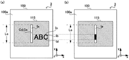
表示部115は、制御部104による制御に従って、各種画像を表示する。具体的に、表示部115は、図11(a)に示すように、第1画像Ia、第2画像Ib、第3画像Ic及び第4画像Idを表示する。
The
第1画像Iaは、印刷部102の位置を表すために表示される画像であり、具体的には印刷部102の外形を表す画像である。第1画像Iaは、印刷部102の位置をユーザに示すものであり、第1の案内画像に相当する。第1画像Iaは、印刷部102の真上に表示される。言い換えると、印刷部102は、第1画像Iaの真下に配置されている。すなわち、第1画像Iaの中心Ceと印刷部102の中心Cbとを通る基準線Vは、下面100bに直交する。従って、第1画像Iaの中心Ceのx座標及びy座標は、印刷部102の中心Cbのx座標及びy座標にそれぞれ一致する。第1画像Iaの大きさは、印刷部102の大きさと同一の大きさである。具体的に、第1画像Iaのy軸方向の長さLeは、印刷部102のy軸方向の長さLbと同一の長さである。第1画像Iaと印刷部102とは、基準線Vに沿った方向に見ると、印刷部102と第1画像Iaとが互いに相手を含むように重なり合っている。また、上述したように、印刷部102のy軸方向の長さLbは、一度の移動で印刷部102が印刷対象の画像を印刷できるy軸方向の範囲に相当する。すなわち、第1画像Iaのy軸方向の長さLeは、一度の移動で印刷部102が印刷対象の画像を印刷できるy軸方向の範囲を表している。なお、第1画像Iaの中心Ceには、ユーザが第1画像Iaの中心であることが認識できるように印が表示されていてもよい。
The first image Ia is an image that is displayed to represent the position of the
制御部104は、記憶部112に予め記憶されている、第1画像Iaの表示位置及び表示サイズを表す表示データに基づいて、第1画像Iaを表示部115に表示する。
The
第2画像Ib〜第4画像Idは、印刷対象の画像の印刷時の大きさと、印刷対象の画像の印刷時の位置と、を表す画像であり、印刷時の大きさ及び位置をユーザに示す第2の案内画像に相当する。具体的に、第2画像Ibは、印刷対象の画像を表す画像である。表示部115は、第2画像Ibを、第2画像Ibのy座標と、印刷対象の画像のy軸方向の印刷位置と、が互いに一致する位置に表示する。また、表示部115は、第2画像Ibを、第2画像Ibのy軸方向の長さと印刷幅Ldとが互いに一致するように表示する。第3画像Icは、印刷対象の画像のy軸方向の上側端部の位置を表す画像である。また、第4画像Idは、印刷対象の画像のy軸方向の下側端部の位置を表す画像である。すなわち、ユーザは、第2画像Ib〜第4画像Idを目視することによって、印刷幅Ldと、印刷対象の画像のy軸方向の印刷位置と、を把握できる。
なお、表示部115は上記のような画像を表示する態様に限るものではない。例えば、図11(b)に示すような第5画像Ieを表示するようにしてもよい。第5画像Ieは、第1画像Iaと同様の大きさを有し、第1画像Iaと同様の位置に表示されて、印刷部102の位置を示すとともに、第5画像Ieにおける印刷媒体Mにおける印刷対象の画像のy軸方向の上側端部の位置と下側端部の位置との間の領域を、それ以外の領域と濃さや色等を変えた画像とされる。これにより、ユーザは、第5画像Ieを目視することによって、印刷幅Ldと、印刷対象の画像のy軸方向の印刷位置と、を把握できる。
The second image Ib to the fourth image Id are images representing the size of the image to be printed at the time of printing and the position at the time of printing of the image to be printed, and indicate the size and position at the time of printing to the user. This corresponds to the second guidance image. Specifically, the second image Ib is an image representing an image to be printed. The
Note that the
以下、ユーザがUI部111を操作することによって、印刷対象の画像のy軸方向の印刷位置及び印刷幅Ldを設定する場合を例に説明する。制御部104は、ユーザが設定した印刷対象の画像のy軸方向の印刷位置及び印刷幅Ldを表す設定データをUI部111から取得する。制御部104は、表示部115に、第2画像Ib、第3画像Ic及び第4画像Idを、設定データが表すy軸方向の印刷位置及び印刷幅Ldに応じて表示する。
Hereinafter, a case where the user operates the
印刷装置3を用いた印刷において、ユーザは、表示部115に表示された第1画像Ia〜第4画像Idを目視しつつ印刷装置3を移動させ印刷開始位置を設定し、印刷を開始する。以下、印刷装置3を用いた印刷において表示部115に表示された第1画像Ia〜第4画像Idが果たす機能について、図12を参照して説明する。以下、印刷媒体Mにおける位置Aを印刷開始位置として設定することをユーザが所望する場合を例に説明する。
In printing using the
印刷時、ユーザは、筐体100の下面100bが印刷媒体Mに接触するように印刷装置3を載置する。これにより、下面100bに配置された印刷部102は筐体100によって隠されるものの、筐体100の上面100aに配置された表示部115に表示された第1画像Ia〜第4画像Idは、図12に示すように、依然としてユーザに目視できる。
At the time of printing, the user places the
ユーザは、表示部115に表示された第1画像Iaを目視しつつ印刷装置3を移動させ、図12(a)に示すように、第1画像Iaにおける第4画像Idで示される位置のx座標及びy座標と、印刷媒体Mにおける位置Aのx座標Xa及びy座標Yaと、がそれぞれ互いに一致するように載置する。上述したように、第1画像Iaの中心Ceのx座標及びy座標は、印刷部102の中心Cbのx座標及びy座標にそれぞれ一致するため、印刷部102のx座標及びy座標と、印刷媒体Mにおける位置Aのx座標Xa及びy座標Yaと、も互いに一致する。これによって、印刷媒体Mにおける位置Aが、印刷開始位置として設定される。この状態において、ユーザが印刷開始を指示し、印刷装置3を印刷方向へ移動させると、図12(b)に示すように、印刷媒体Mにおける位置Aを印刷開始位置として、印刷対象の画像であるテキスト「ABC」が印刷される。テキスト「ABC」は、第2画像Ib〜第4画像Idが表す印刷幅Ldを有するように、第2画像Ib〜第4画像Idが表すy軸方向の印刷位置に印刷される。
The user moves the
すなわち、ユーザは、第1画像Iaにおける第4画像Idで示される位置のx座標及びy座標と、印刷媒体Mにおける位置Aのx座標Xa及びy座標Yaと、がそれぞれ互いに一致するように印刷装置3を載置する容易な操作を行うことによって、印刷媒体Mにおける位置Aを印刷開始位置として直感的に設定できる。
That is, the user prints so that the x-coordinate and y-coordinate of the position indicated by the fourth image Id in the first image Ia and the x-coordinate Xa and y-coordinate Ya of the position A on the print medium M coincide with each other. By performing an easy operation for placing the
また、ユーザは、第2画像Ib〜第4画像Idを目視して、印刷幅Ld及び印刷対象の画像のy軸方向の印刷位置を把握しつつ印刷装置3を移動させることによって、y軸方向の印刷位置を適切に設定できる。
In addition, the user visually observes the second image Ib to the fourth image Id, and moves the
なお、上記第3実施形態において、第1画像Iaの大きさは、印刷部102の大きさと同一の大きさであるものとして説明したが、これは一例に過ぎない。第1画像Iaの大きさと印刷部102の大きさとは、ユーザがこれらの大きさが互いに同一であると認識する範囲内において、互いに異なってもよい。具体的に、上記第3実施形態において、第1画像Iaのy軸方向の長さLeと、印刷部102のy軸方向の長さLbと、が互いに同一であるものとして説明したが、第1画像Iaのy軸方向の長さLeと印刷部102のy軸方向の長さLbとは、ユーザがこれらの長さが互いに同一であると認識する範囲において、互いに異なっていてもよい。また、第1画像Iaの大きさと印刷部102の大きさとが、ユーザがこれらの大きさが互いに同一であると認識する範囲内を超えて異なっていてもよい。この場合であっても、第1画像Iaは印刷部102の真上に配置されているため、ユーザは、第1画像Iaの中心Ccの位置のx座標及びy座標と、印刷媒体Mにおける所望の位置Aのx座標Xa及びy座標Yaと、がそれぞれ互いに一致するように印刷装置3を載置する容易な操作を行うことで、印刷媒体Mにおける位置Aを印刷開始位置として直感的に設定できる。
In the third embodiment, the first image Ia has been described as having the same size as the
なお、上記第3実施形態において、表示部115は、第2画像Ibを、第2画像Ibのy軸方向の長さと印刷幅Ldとが互いに一致するように表示するものとして説明したが、これは一例に過ぎない。第2画像Ibのy軸方向の長さと印刷幅Ldとは、ユーザがこれらの大きさが互いに同一であると認識する範囲内において、互いに異なってもよい。
In the third embodiment, the
なお、上記第3実施形態において、第1画像Iaと印刷部102とは、基準線Vに沿った方向に見ると、互いに相手を含むように重なり合っているものとして説明した。しかし、これは一例に過ぎず、第1画像Iaと印刷部102とは、互いの形状及び配置の異同に応じ、基準線Vに沿った方向に見て、第1画像Iaが印刷部102を含むように重なり合っていてもよいし、印刷部102が第1画像Iaを含むように重なり合っていてもよい。
In the third embodiment, the first image Ia and the
なお、上記第3実施形態において、表示部115に重畳してタッチパネル等の入力デバイスを配置し、この入力デバイスにより、ユーザによる表示部115の押下を、ユーザによる印刷開始の指示操作として受け付けるようになっていてもよい。この形態によれば、印刷開始を指示するためにユーザが表示部115を押下すると、表示部115の真下に配置された印刷部102が押し下げられ、印刷媒体Mへ押しつけられる。これにより、印刷部102が印刷媒体Mから浮き上がってしまい印刷品質が低下することが抑制される。
In the third embodiment, an input device such as a touch panel is arranged so as to be superimposed on the
なお、上記第3実施形態において、表示部115は、印刷部102の位置を表す第1画像Iaと、印刷対象の画像のy軸方向における印刷位置及び印刷幅Ldを表す第2画像Ib〜第4画像Idと、の両方を表示するものとして説明した。しかし、これは一例に過ぎず、表示部115は、印刷部102の位置を表す画像と、印刷対象の画像のy軸方向における印刷位置及び印刷幅Ldを表す画像と、のうちの何れか一方のみを表示してもよい。
In the third embodiment, the
なお、上記第3実施形態において、表示部115は、印刷対象の画像のy軸方向における印刷位置及び印刷幅Ldを表す画像として、第2画像Ib〜第4画像Idを表示するものとして説明した。しかし、これは一例に過ぎず、表示部115は、第2画像Ibと、第3画像Ic及び第4画像Idと、のうちの何れか一方のみを、印刷対象の画像のy軸方向における印刷位置及び印刷幅Ldを表す画像として表示してもよい。
In the third embodiment, the
なお、第2画像Ib〜第4画像Idを表示する表示手段を、上記第1実施形態における印刷装置1に設けてもよい。
Note that display means for displaying the second image Ib to the fourth image Id may be provided in the
以上に本発明の実施形態について説明したが、上記実施形態は一例であり、本発明の適用範囲はこれに限られない。すなわち、本発明の実施形態は種々の応用が可能であり、あらゆる実施の形態が本発明の範囲に含まれる。 Although the embodiment of the present invention has been described above, the above embodiment is an example, and the scope of application of the present invention is not limited to this. That is, the embodiments of the present invention can be applied in various ways, and all the embodiments are included in the scope of the present invention.
上記第1実施形態では、案内手段として、印刷部102の真上に印刷開始ボタン103が配置されるものとして説明した。また、上記第2実施形態では、案内手段として、印刷部102の真上に発光部113を有する印刷開始ボタン114が配置されるものとして説明した。また、上記第3実施形態では、案内手段として表示部115が配置されるものとして説明した。しかし、これらは例に過ぎず、印刷部102の真上には、案内手段として、任意の構成を配置できる。例えば、マーク、突起又はインジケータ等の構成を、案内手段として、印刷部102の真上に配置するようにしてもよい。
In the first embodiment, it has been described that the
また、上記第1〜第3実施形態では、微滴化したインクを印刷媒体Mへ吐出するインクジェット方式で印刷対象の画像を印刷媒体Mに印刷するものとして説明したが、これは一例に過ぎず、印刷装置1〜3は、印刷対象の画像を任意の方法で印刷できる。例えば、印刷装置1〜3は、発熱駆動されるサーマルヘッドを印刷部102の代わりに備え、このサーマルヘッドを用いた熱転写印刷によって印刷対象の画像を印刷してもよい。
In the first to third embodiments described above, the image to be printed is printed on the print medium M by the inkjet method in which the atomized ink is ejected onto the print medium M. However, this is only an example. The
また、上記第1〜第3実施形態において、印刷データは、無線通信部109又は有線通信部110によって外部装置から取得されるものとして説明したが、これは一例に過ぎず、印刷装置1〜3は、任意の方法で印刷データを取得できる。例えば、印刷装置1は、ユーザによる印刷内容の入力をUI部111によって受け付けることによって印刷データを取得してもよい。
In the first to third embodiments, the print data is described as being acquired from the external device by the
また、上記第1〜第3実施形態において、移動量検出部101は、レーザ式光学センサを用いて印刷装置1〜3の移動量を検出するものとして説明したが、これは一例に過ぎず、移動量検出部101は、任意の方法によって移動量を検出できる。例えば、移動量検出部101は、LED式光学センサを備え、LED光源から印刷媒体Mの表面へ光を照射し、印刷媒体M表面の凹凸により生じた影をイメージセンサで撮像して解析することによって印刷装置1〜3の移動量を検出してもよい。
Moreover, in the said 1st-3rd embodiment, although the movement
また、上記第1〜第3実施形態において、印刷時、下面100bが印刷媒体Mに接触するものとして説明したが、これは一例に過ぎない。印刷装置1〜3が車輪や脚部等の支持手段を備え、当該支持手段によって支持されつつ印刷媒体M上を移動する場合、下面100bは当該支持手段によって、印刷媒体Mに対向するように支持され、印刷媒体Mに接触することなく印刷媒体M上を移動することもできる。
In the first to third embodiments described above, the
なお、本発明に係る機能を実現するための構成を予め備えた印刷装置として提供できることはもとより、プログラムの適用により、既存の情報処理装置等を、本発明に係る印刷装置として機能させることもできる。すなわち、本発明に係る印刷装置の各機能構成を実現させるためのプログラムを、既存の情報処理装置等を制御するCPU等が実行できるように適用することで、当該既存の情報処理装置等を本発明に係る印刷装置として機能させることができる。 In addition, not only can a configuration for realizing the functions according to the present invention be provided in advance as a printing apparatus, but also an existing information processing apparatus can be caused to function as the printing apparatus according to the present invention by applying a program. . That is, by applying a program for realizing each functional configuration of the printing apparatus according to the present invention so that a CPU or the like that controls the existing information processing apparatus can be executed, the existing information processing apparatus or the like is It can function as a printing apparatus according to the invention.
なお、このようなプログラムの適用方法は任意である。プログラムを、例えば、フレキシブルディスク、CD(Compact Disc)−ROM、DVD(Digital Versatile Disc)−ROM、メモリカード等のコンピュータ読み取り可能な記憶媒体に格納して適用できる。さらに、プログラムを搬送波に重畳し、インターネットなどの通信媒体を介して適用することもできる。例えば、通信ネットワーク上の掲示板(BBS:Bulletin Board System)にプログラムを掲示して配信してもよい。そして、このプログラムを起動し、OS(Operating System)の制御下で、他のアプリケーションプログラムと同様に実行することにより、上記の処理を実行できるように構成してもよい。 In addition, the application method of such a program is arbitrary. The program can be applied by being stored in a computer-readable storage medium such as a flexible disk, a CD (Compact Disc) -ROM, a DVD (Digital Versatile Disc) -ROM, or a memory card. Furthermore, the program can be superimposed on a carrier wave and applied via a communication medium such as the Internet. For example, the program may be posted on a bulletin board (BBS: Bulletin Board System) on a communication network and distributed. The program may be started and executed in the same manner as other application programs under the control of an OS (Operating System) so that the above-described processing can be executed.
以上、本発明の好ましい実施形態について説明したが、本発明は係る特定の実施形態に限定されるものではなく、本発明には、特許請求の範囲に記載された発明とその均等の範囲とが含まれる。以下に、本願出願の当初の特許請求の範囲に記載された発明を付記する。 The preferred embodiments of the present invention have been described above. However, the present invention is not limited to the specific embodiments, and the present invention includes the invention described in the claims and the equivalent scope thereof. included. Hereinafter, the invention described in the scope of claims of the present application will be appended.
(付記1)
上面と、前記上面に対向する下面とを有する筐体と、
前記筐体の前記下面に設けられ、印刷媒体に画像を印刷する印刷部と、
前記筐体の前記上面における前記印刷部の真上となる位置に配置されて、前記印刷部の位置を表す案内手段と、
を備えることを特徴とする印刷装置。
(Appendix 1)
A housing having an upper surface and a lower surface facing the upper surface;
A printing unit provided on the lower surface of the housing and printing an image on a print medium;
A guiding means arranged at a position on the upper surface of the housing to be directly above the printing unit, and representing the position of the printing unit;
A printing apparatus comprising:
(付記2)
前記案内手段は、前記下面における前記印刷部の位置及び前記印刷部の大きさを表すように形成された案内部を有し、
前記案内部は、前記案内部の前記上面に沿った面での中心が前記印刷部の前記下面に沿った面での中心の真上となる位置に設けられていることを特徴とする付記1に記載の印刷装置。
(Appendix 2)
The guide means has a guide part formed to represent the position of the printing part on the lower surface and the size of the printing part,
The guide portion is provided at a position where the center of the guide portion along the upper surface is directly above the center of the print portion along the lower surface. The printing apparatus as described in.
(付記3)
前記案内部は、前記上面に配置されている、押しボタン、マーク、突起及びインジケータの何れかであることを特徴とする付記2に記載の印刷装置。
(Appendix 3)
The printing apparatus according to
(付記4)
前記案内手段は、前記印刷部の長さ方向に沿って直線状に配列された複数の光源を有する発光部を備え、
前記発光部の前記複数の光源の各々は、前記画像の、前記印刷媒体における印刷時のサイズ及び印刷時の位置を表すように発光が制御されることを特徴とする付記1乃至3の何れか一つに記載の印刷装置。
(Appendix 4)
The guide means includes a light emitting unit having a plurality of light sources arranged linearly along the length direction of the printing unit,
The light emission of each of the plurality of light sources of the light emitting unit is controlled so as to represent a size and a printing position of the image on the printing medium. The printing apparatus according to one.
(付記5)
前記案内手段は、前記下面における前記印刷部の位置及び前記印刷部の大きさを表す第1の案内画像を表示する表示部を有し、
前記第1の案内画像は、前記第1の案内画像の前記上面に沿った面での中心が前記印刷部の前記下面に沿った面での中心の真上となる位置に表示されることを特徴とする付記1に記載の印刷装置。
(Appendix 5)
The guide means includes a display unit that displays a first guide image representing the position of the printing unit and the size of the printing unit on the lower surface,
The first guide image is displayed at a position where the center of the first guide image along the surface along the upper surface is directly above the center of the surface along the lower surface of the printing unit. The printing apparatus according to
(付記6)
前記表示部は、前記画像の、前記印刷媒体における印刷時の大きさ及び印刷時の位置を表す第2の案内画像をさらに表示することを特徴とする付記5に記載の印刷装置。
(Appendix 6)
6. The printing apparatus according to appendix 5, wherein the display unit further displays a second guide image representing a size and a printing position of the image on the printing medium.
1,2,3…印刷装置、100…筐体、100a…上面、100b…下面、100c…第1開口部、100d…第2開口部、101…移動量検出部、102…印刷部、103,114…印刷開始ボタン、104…制御部、105…印刷制御部、106…電源部、107…表示制御部、108,115…表示部、109…無線通信部、110…有線通信部、111…UI部、112…記憶部、113…発光部、113A〜113L…光源、A…所望の位置、Ca,Cc…印刷開始ボタンの中心、Cb…印刷部の中心、Cd…表示部の中心、Ce…第1画像の中心、Ia…第1画像、Ib…第2画像、Ic…第3画像、Id…第4画像、Ie…第5画像、La,Lc…印刷開始ボタンのy軸方向の長さ、Lb…印刷部のy軸方向の長さ、Ld…印刷対象の画像の印刷幅、Le…第1画像のy軸方向の長さ、M…印刷媒体、Tu…印刷対象の画像の奥側端部、Tb…印刷対象の画像の手前側端部、V…基準線、Xa…所望の位置のx座標、Ya…所望の位置のy座標
DESCRIPTION OF
Claims (6)
前記筐体の前記下面に設けられ、印刷媒体に画像を印刷する印刷部と、
前記筐体の前記上面における前記印刷部の真上となる位置に配置されて、前記印刷部の位置を表す案内手段と、
を備えることを特徴とする印刷装置。 A housing having an upper surface and a lower surface facing the upper surface;
A printing unit provided on the lower surface of the housing and printing an image on a print medium;
A guiding means arranged at a position on the upper surface of the housing to be directly above the printing unit, and representing the position of the printing unit;
A printing apparatus comprising:
前記案内部は、前記案内部の前記上面に沿った面での中心が前記印刷部の前記下面に沿った面での中心の真上となる位置に設けられていることを特徴とする請求項1に記載の印刷装置。 The guide means has a guide part formed to represent the position of the printing part on the lower surface and the size of the printing part,
The guide portion is provided at a position where a center of the guide portion along the upper surface is directly above a center of the print portion along the lower surface. The printing apparatus according to 1.
前記発光部の前記複数の光源の各々は、前記画像の、前記印刷媒体における印刷時のサイズ及び印刷時の位置を表すように発光が制御されることを特徴とする請求項1乃至3の何れか一項に記載の印刷装置。 The guide means includes a light emitting unit having a plurality of light sources arranged linearly along the length direction of the printing unit,
4. The light emission is controlled so that each of the plurality of light sources of the light emitting unit represents a size and a printing position of the image on the printing medium. A printing apparatus according to claim 1.
前記第1の案内画像は、前記第1の案内画像の前記上面に沿った面での中心が前記印刷部の前記下面に沿った面での中心の真上となる位置に表示されることを特徴とする請求項1に記載の印刷装置。 The guide means includes a display unit that displays a first guide image representing the position of the printing unit and the size of the printing unit on the lower surface,
The first guide image is displayed at a position where the center of the first guide image along the surface along the upper surface is directly above the center of the surface along the lower surface of the printing unit. The printing apparatus according to claim 1, wherein:
Priority Applications (3)
| Application Number | Priority Date | Filing Date | Title |
|---|---|---|---|
| JP2016189161A JP6790673B2 (en) | 2016-09-28 | 2016-09-28 | Printing equipment |
| US15/675,198 US10124607B2 (en) | 2016-09-28 | 2017-08-11 | Printing apparatus including a guiding mechanism that represents a position of a print area |
| CN201710767326.0A CN107867063B (en) | 2016-09-28 | 2017-08-30 | printing device |
Applications Claiming Priority (1)
| Application Number | Priority Date | Filing Date | Title |
|---|---|---|---|
| JP2016189161A JP6790673B2 (en) | 2016-09-28 | 2016-09-28 | Printing equipment |
Publications (3)
| Publication Number | Publication Date |
|---|---|
| JP2018051861A true JP2018051861A (en) | 2018-04-05 |
| JP2018051861A5 JP2018051861A5 (en) | 2019-10-24 |
| JP6790673B2 JP6790673B2 (en) | 2020-11-25 |
Family
ID=61687143
Family Applications (1)
| Application Number | Title | Priority Date | Filing Date |
|---|---|---|---|
| JP2016189161A Active JP6790673B2 (en) | 2016-09-28 | 2016-09-28 | Printing equipment |
Country Status (3)
| Country | Link |
|---|---|
| US (1) | US10124607B2 (en) |
| JP (1) | JP6790673B2 (en) |
| CN (1) | CN107867063B (en) |
Cited By (4)
| Publication number | Priority date | Publication date | Assignee | Title |
|---|---|---|---|---|
| JP2020040276A (en) * | 2018-09-10 | 2020-03-19 | 株式会社リコー | Portable image formation device and portable image formation device body |
| JP2020040272A (en) * | 2018-09-10 | 2020-03-19 | 株式会社リコー | Portable image formation device |
| JP2021160126A (en) * | 2020-03-31 | 2021-10-11 | 京セラ株式会社 | Printer |
| JP2021178403A (en) * | 2020-05-11 | 2021-11-18 | セイコーエプソン株式会社 | Printer and control method for printer |
Families Citing this family (5)
| Publication number | Priority date | Publication date | Assignee | Title |
|---|---|---|---|---|
| JP7180331B2 (en) * | 2018-12-03 | 2022-11-30 | カシオ計算機株式会社 | printer |
| CN110435302B (en) * | 2019-07-24 | 2024-09-13 | 苏州奥泰智能装备有限公司 | Quick-printing handheld printer |
| WO2021021195A1 (en) * | 2019-07-31 | 2021-02-04 | Hewlett-Packard Development Company, L. P. | Generate images to have intended justifications |
| JP7476664B2 (en) * | 2020-05-21 | 2024-05-01 | セイコーエプソン株式会社 | Printing device |
| JP7419988B2 (en) * | 2020-06-25 | 2024-01-23 | セイコーエプソン株式会社 | Printing device, printing device control method, and program |
Citations (6)
| Publication number | Priority date | Publication date | Assignee | Title |
|---|---|---|---|---|
| US3656169A (en) * | 1969-05-23 | 1972-04-11 | Casio Computer Co Ltd | Method and apparatus for writing characters |
| JPH01165263A (en) * | 1987-12-22 | 1989-06-29 | Alps Electric Co Ltd | Image processor |
| JPH0367671A (en) * | 1989-08-08 | 1991-03-22 | Oki Electric Ind Co Ltd | Printer |
| JPH09286139A (en) * | 1996-04-24 | 1997-11-04 | Brother Ind Ltd | Printing device |
| JPH1035028A (en) * | 1996-07-23 | 1998-02-10 | Brother Ind Ltd | Manual printing device |
| CN101172428A (en) * | 2006-11-01 | 2008-05-07 | 光宝科技股份有限公司 | Hand-held printing device |
Family Cites Families (19)
| Publication number | Priority date | Publication date | Assignee | Title |
|---|---|---|---|---|
| US5634730A (en) * | 1995-11-06 | 1997-06-03 | Bobry; Howard H. | Hand-held electronic printer |
| US5825995A (en) * | 1996-03-11 | 1998-10-20 | Intermec Technologies, Inc. | Printer with motion detection |
| JPH1158844A (en) * | 1997-08-08 | 1999-03-02 | Hewlett Packard Co <Hp> | Handy printer system |
| US6229565B1 (en) * | 1997-08-15 | 2001-05-08 | Howard H. Bobry | Hand-held electronic camera with integral printer |
| US6357939B1 (en) * | 2001-02-02 | 2002-03-19 | Hewlett-Packard Company | Method of and apparatus for handheld printing of images on a media |
| SE519352C2 (en) * | 2001-07-13 | 2003-02-18 | Print Dreams Europe Ab | Handheld and hand operated random movement typing apparatus and method of writing thereof. |
| JP2003136786A (en) * | 2001-11-01 | 2003-05-14 | Fuji Photo Film Co Ltd | Scanning printer |
| JP3977133B2 (en) * | 2002-04-24 | 2007-09-19 | シャープ株式会社 | Telescopic portable printer |
| JP3722117B2 (en) * | 2002-12-20 | 2005-11-30 | ブラザー工業株式会社 | Tape printer |
| JP3773208B2 (en) * | 2005-01-19 | 2006-05-10 | 松下電器産業株式会社 | Foldable information processing device |
| US7524051B2 (en) * | 2005-12-20 | 2009-04-28 | Lexmark International, Inc. | Hand-operated printer having a user interface |
| US7876472B2 (en) | 2006-10-12 | 2011-01-25 | Ricoh Co. Ltd. | Handheld printer and method of operation |
| EP2127354A1 (en) * | 2007-03-02 | 2009-12-02 | Marvell World Trade Ltd. | Position correction for handheld printer |
| US20090040286A1 (en) * | 2007-08-08 | 2009-02-12 | Tan Theresa Joy L | Print scheduling in handheld printers |
| CN103153630B (en) * | 2010-06-24 | 2016-08-10 | 艾利丹尼森公司 | Hand-held portable printers |
| JP5772414B2 (en) * | 2011-09-07 | 2015-09-02 | セイコーエプソン株式会社 | Document creation device, tape printer, document creation method |
| JP5954078B2 (en) * | 2012-09-25 | 2016-07-20 | ブラザー工業株式会社 | Printing device |
| JP6291950B2 (en) * | 2014-03-25 | 2018-03-14 | セイコーエプソン株式会社 | Printing medium, printing apparatus, and printing method of printing apparatus |
| CN204622845U (en) * | 2015-05-15 | 2015-09-09 | 重庆品胜科技有限公司 | A kind of Portable label printer |
-
2016
- 2016-09-28 JP JP2016189161A patent/JP6790673B2/en active Active
-
2017
- 2017-08-11 US US15/675,198 patent/US10124607B2/en active Active
- 2017-08-30 CN CN201710767326.0A patent/CN107867063B/en active Active
Patent Citations (6)
| Publication number | Priority date | Publication date | Assignee | Title |
|---|---|---|---|---|
| US3656169A (en) * | 1969-05-23 | 1972-04-11 | Casio Computer Co Ltd | Method and apparatus for writing characters |
| JPH01165263A (en) * | 1987-12-22 | 1989-06-29 | Alps Electric Co Ltd | Image processor |
| JPH0367671A (en) * | 1989-08-08 | 1991-03-22 | Oki Electric Ind Co Ltd | Printer |
| JPH09286139A (en) * | 1996-04-24 | 1997-11-04 | Brother Ind Ltd | Printing device |
| JPH1035028A (en) * | 1996-07-23 | 1998-02-10 | Brother Ind Ltd | Manual printing device |
| CN101172428A (en) * | 2006-11-01 | 2008-05-07 | 光宝科技股份有限公司 | Hand-held printing device |
Cited By (7)
| Publication number | Priority date | Publication date | Assignee | Title |
|---|---|---|---|---|
| JP2020040276A (en) * | 2018-09-10 | 2020-03-19 | 株式会社リコー | Portable image formation device and portable image formation device body |
| JP2020040272A (en) * | 2018-09-10 | 2020-03-19 | 株式会社リコー | Portable image formation device |
| JP7125671B2 (en) | 2018-09-10 | 2022-08-25 | 株式会社リコー | Portable image forming apparatus and main body of portable image forming apparatus |
| JP2021160126A (en) * | 2020-03-31 | 2021-10-11 | 京セラ株式会社 | Printer |
| JP7454984B2 (en) | 2020-03-31 | 2024-03-25 | 京セラ株式会社 | printer |
| JP2021178403A (en) * | 2020-05-11 | 2021-11-18 | セイコーエプソン株式会社 | Printer and control method for printer |
| JP7435225B2 (en) | 2020-05-11 | 2024-02-21 | セイコーエプソン株式会社 | Printing device and method of controlling the printing device |
Also Published As
| Publication number | Publication date |
|---|---|
| CN107867063A (en) | 2018-04-03 |
| US20180086106A1 (en) | 2018-03-29 |
| US10124607B2 (en) | 2018-11-13 |
| CN107867063B (en) | 2019-09-03 |
| JP6790673B2 (en) | 2020-11-25 |
Similar Documents
| Publication | Publication Date | Title |
|---|---|---|
| JP6790673B2 (en) | Printing equipment | |
| JP6996195B2 (en) | Printing equipment, printing methods and programs | |
| CN107160866B (en) | Printing device, printing control method of printing device, and storage medium | |
| US20170280000A1 (en) | Printer, method of printing, and computer-readable storage medium | |
| JP6746987B2 (en) | Printing device, printing method, and program | |
| US20200207137A1 (en) | Setting apparatus, shaping system, setting method, and computer-readable recording medium | |
| JP7006242B2 (en) | Printing equipment, printing methods and programs | |
| JP2017170804A (en) | Printing apparatus, printing method, and program | |
| JP6919751B2 (en) | Printing equipment, printing methods and programs | |
| JP7099583B2 (en) | Printing equipment, printing methods and programs | |
| JP6922296B2 (en) | Printing equipment, printing methods and programs | |
| JP2017177809A (en) | Printer, method of selecting printing image, and program of selecting printing image | |
| JP7155557B2 (en) | PRINTING DEVICE, PRINTING SUPPORT METHOD AND PROGRAM | |
| US11738566B2 (en) | Printing program and producing method for print | |
| JP7459667B2 (en) | Printing device and method for producing printed matter | |
| JP2017170761A (en) | Printing device, printing method and program | |
| JP7070769B2 (en) | Printing equipment, printing methods and programs | |
| US10861365B2 (en) | Display apparatus, shaping system, display method, and computer-readable recording medium | |
| JP2019130734A (en) | Printing system, terminal device, printer, printing method and program | |
| JP7151386B2 (en) | PRINTING DEVICE, PRINTING SUPPORT METHOD AND PROGRAM | |
| JP2020128078A (en) | Printing device | |
| JP2017170803A (en) | Printing device, printing method and program |
Legal Events
| Date | Code | Title | Description |
|---|---|---|---|
| A521 | Request for written amendment filed |
Free format text: JAPANESE INTERMEDIATE CODE: A523 Effective date: 20190910 |
|
| A621 | Written request for application examination |
Free format text: JAPANESE INTERMEDIATE CODE: A621 Effective date: 20190910 |
|
| A977 | Report on retrieval |
Free format text: JAPANESE INTERMEDIATE CODE: A971007 Effective date: 20200715 |
|
| A131 | Notification of reasons for refusal |
Free format text: JAPANESE INTERMEDIATE CODE: A131 Effective date: 20200804 |
|
| A521 | Request for written amendment filed |
Free format text: JAPANESE INTERMEDIATE CODE: A523 Effective date: 20200923 |
|
| TRDD | Decision of grant or rejection written | ||
| A01 | Written decision to grant a patent or to grant a registration (utility model) |
Free format text: JAPANESE INTERMEDIATE CODE: A01 Effective date: 20201006 |
|
| A61 | First payment of annual fees (during grant procedure) |
Free format text: JAPANESE INTERMEDIATE CODE: A61 Effective date: 20201019 |
|
| R150 | Certificate of patent or registration of utility model |
Ref document number: 6790673 Country of ref document: JP Free format text: JAPANESE INTERMEDIATE CODE: R150 |