JP2018049471A - Pseudo server control device, pseudo server control method, and pseudo server control program - Google Patents
Pseudo server control device, pseudo server control method, and pseudo server control program Download PDFInfo
- Publication number
- JP2018049471A JP2018049471A JP2016184611A JP2016184611A JP2018049471A JP 2018049471 A JP2018049471 A JP 2018049471A JP 2016184611 A JP2016184611 A JP 2016184611A JP 2016184611 A JP2016184611 A JP 2016184611A JP 2018049471 A JP2018049471 A JP 2018049471A
- Authority
- JP
- Japan
- Prior art keywords
- request
- pseudo
- server
- pseudo server
- production
- Prior art date
- Legal status (The legal status is an assumption and is not a legal conclusion. Google has not performed a legal analysis and makes no representation as to the accuracy of the status listed.)
- Granted
Links
Images


Landscapes
- Debugging And Monitoring (AREA)
- Test And Diagnosis Of Digital Computers (AREA)
- Computer And Data Communications (AREA)
Abstract
【課題】サービス可用性を維持するための状況把握や状況改善に向けた計画立案を確実且つ容易に実施することを可能とする。【解決手段】疑似サーバ制御装置は、処理のリクエストを発生する機器から受け付けたリクエストを、本番サーバを少なくとも含む本番系ネットワークと、疑似サーバを少なくとも含む疑似系ネットワークとに転送するリクエスト転送モジュールと、疑似系ネットワークに転送されたリクエストを一時的に蓄積し、疑似サーバの負荷状態に応じて、リクエストの疑似サーバへの送信タイミングを制御するリクエスト蓄積モジュールと、を備える。【選択図】 図1PROBLEM TO BE SOLVED: To surely and easily carry out planning for grasping a situation and improving a situation for maintaining service availability. A pseudo server control device includes a request transfer module that transfers a request received from a device that generates a processing request to a production network including at least a production server and a pseudo network including at least a pseudo server. It is provided with a request storage module that temporarily stores the requests transferred to the pseudo system network and controls the transmission timing of the requests to the pseudo server according to the load status of the pseudo server. [Selection diagram] Fig. 1
Description
本発明は、主に、ウェブサービスを提供するウェブサービスシステムに用いられる疑似サーバ制御装置、疑似サーバ制御方法、および疑似サーバ制御プログラムに関する。 The present invention mainly relates to a pseudo server control device, a pseudo server control method, and a pseudo server control program used in a web service system that provides web services.
ウェブサービスを提供する場合、サービス提供者にとって、特にサービス可用性(Availabilityとも呼ばれる/システムなどが使用できる状態を維持し続ける能力)の維持は重要なミッションである。可用性を維持するために、例えば、リクエストの集中アクセス等によってサーバが高負荷状態になってもダウンせずに正常に動作するシステム設計が求められる。通常、これらのシステム設計は、製品出荷前(例えば、設計段階)に十分検討されるので、多くの場合、問題は発生しない。 When providing a web service, maintenance of service availability (also called availability / ability to keep a system or the like usable) is an important mission for a service provider. In order to maintain the availability, for example, a system design that operates normally without being down even if the server is in a high load state due to centralized access of requests or the like is required. Usually, these system designs are thoroughly considered before the product is shipped (for example, at the design stage), and in many cases, problems do not occur.
しかしながら、客先にて実際の運用が開始されてから、想定外の数のリクエストがサーバに集中することが判明する場合がある。サーバの負荷が所定のレベルを超えた場合、最悪、サーバがダウンする虞がある。 However, it may be found that an unexpected number of requests are concentrated on the server after the actual operation is started at the customer. When the load on the server exceeds a predetermined level, there is a possibility that the server may go down in the worst case.
そこで、サービス提供者は、上記の如き状況にならないようにサービス可用性の観点から、実際の運用が開始された後でも予め状況把握や可用性管理に向けた計画を立ててそれを実施する必要がある。 Therefore, from the viewpoint of service availability, the service provider needs to make a plan for grasping the situation and managing availability in advance even after the actual operation is started so that the above situation does not occur. .
例えば、実際にユーザにウェブサービスを提供するための環境である本番環境にて、本来の運用サービスを実行しながら並行して実際に運用される本番サーバ自身がその状況の把握および問題解消に向けた計画の立案等を実行する方法が考えられる。 For example, in a production environment, which is an environment for actually providing web services to users, the production server itself that is actually operated in parallel while executing the original operation service aims to grasp the situation and solve the problem. A method for executing the planning of a new plan can be considered.
また、例えば、ウェブサービスが実際にユーザに提供する本番環境とは別に、本番環境と同等のリクエスト状況が再現可能な疑似環境を作り出し、この疑似環境上で本番環境の性能チューニング(可用性を維持可能なシステム規模への変更)を行う手法が考えられる。 In addition, for example, apart from the production environment that the web service actually provides to the user, a pseudo environment that can reproduce the request status equivalent to the production environment is created, and the performance tuning of the production environment can be maintained on this pseudo environment (the availability can be maintained) To change the system scale).
なお、特許文献1には、リクエストを一旦キューに格納し、システムで決定した待機時間だけ待機した後本番サーバに送信する技術が記載されている。 Patent Document 1 describes a technique in which a request is temporarily stored in a queue and transmitted to a production server after waiting for a waiting time determined by the system.
特許文献2には、パケット交換型ネットワークにおいて、ネットワーク負荷分散を行うことにより、通常だと破棄せざるを得なかったパケットを別経路で転送するなどして救済する技術についての記載がある。 Japanese Patent Application Laid-Open No. 2004-228688 describes a technique for relieving a packet exchanged network by distributing the network load and transferring the packet, which normally had to be discarded, by another route.
特許文献3には、ウェブサーバからの処理要求(リクエスト)を、本番系サーバへ送信するとともに処理待ちキューに登録する処理要求転送装置についての記載がある。この処理要求転送装置により、リクエストを試験系サーバに転送することができ、且つそのリクエストの転送間隔も制御することが可能となる。
しかしながら、近年、ウェブサービスシステム(特に、クライアントやウェブ利用回数の増加に伴う本番環境のサーバの数)の大規模化が顕著になっている。従って、本番環境上にて本来サービスと並行して状況把握や計画立案を実施する手法の場合、それら可用性対応処理の負荷自体が本番サーバ全体の負荷を高めることになり、結果として、本来サービスの処理能力が低下する虞もある。 However, in recent years, the scale of web service systems (especially the number of clients and servers in the production environment accompanying an increase in the number of web usages) has become significant. Therefore, in the case of a method that grasps the situation and plans in parallel with the original service in the production environment, the load of the availability handling process itself increases the load of the entire production server. There is also a risk that the processing capacity is reduced.
一方、疑似環境上で本番環境の性能チューニングを行う構成の場合、本番環境を再現するとの宿命上、本番環境の大規模化につれて、どうしても、疑似環境のコストの増大化および装置構成の複雑化が懸念される。 On the other hand, in the case of a configuration that performs performance tuning of the production environment on the simulated environment, the production environment is fatefully reproduced, and as the scale of the production environment increases, the cost of the simulated environment and the complexity of the device configuration inevitably increase. Concerned.
特許文献1や特許文献2の技術は、いずれも本番サーバにおけるデータ(特にリクエスト)の取りこぼしを防ぐための技術であり、サービス可用性を維持するための状況把握や状況改善に向けた計画立案のための技術ではない。
The techniques of Patent Document 1 and
また、特許文献3の処理要求転送装置は、ウェブサーバと実際に処理を行うアプリケーションサーバとの間に配置されている。従って、ウェブサーバだけで処理が完結する静的コンテンツのリクエストなどは対象とならない。すなわち、特許文献3の技術ではシステム全体を行き交うリクエストの全てを把握できないため、状況把握や状況改善に向けた計画立案を確実に実施することはできない。
Further, the processing request transfer apparatus of
本発明は、上記課題を解決するためになされたものであり、サービス可用性を維持するための状況把握や状況改善に向けた計画立案を確実且つ容易に実施することが可能な疑似サーバ制御装置、疑似サーバ制御方法、および疑似サーバ制御プログラムを提供することを目的とする。 The present invention has been made to solve the above-described problem, and is a pseudo server control device capable of reliably and easily implementing a plan for situation grasp and situation improvement for maintaining service availability, An object is to provide a pseudo server control method and a pseudo server control program.
本発明の疑似サーバ制御装置は、処理のリクエストを発生する機器から受け付けた前記リクエストを、本番サーバを少なくとも含む本番系ネットワークと、疑似サーバを少なくとも含む疑似系ネットワークとに転送するリクエスト転送モジュールと、前記疑似系ネットワークに転送された前記リクエストを一時的に蓄積し、前記疑似サーバの負荷状態に応じて、前記リクエストの前記疑似サーバへの送信タイミングを制御するリクエスト蓄積モジュールと、を備える。 The pseudo server control device of the present invention, the request transfer module for transferring the request received from a device that generates a processing request to a production network including at least a production server and a pseudo network including at least a pseudo server, A request storage module that temporarily stores the request transferred to the pseudo network and controls transmission timing of the request to the pseudo server according to a load state of the pseudo server.
本発明の疑似サーバ制御方法は、処理のリクエストを発生する機器から受け付けた前記リクエストを、本番サーバを少なくとも含む本番系ネットワークと、疑似サーバを少なくとも含む疑似系ネットワークとに転送し、前記疑似系ネットワークに転送された前記リクエストを一時的に蓄積し、前記疑似サーバの負荷状態に応じて、前記リクエストの前記疑似サーバへの送信タイミングを制御することを特徴とする。 The pseudo server control method of the present invention transfers the request received from a device that generates a processing request to a production system network including at least a production server and a pseudo system network including at least a pseudo server, and the pseudo system network. The request transferred to the server is temporarily stored, and the transmission timing of the request to the pseudo server is controlled according to the load state of the pseudo server.
本発明の疑似サーバ制御プログラムは、処理のリクエストを発生する機器から受け付けた前記リクエストを、本番サーバを少なくとも含む本番系ネットワークと、疑似サーバを少なくとも含む疑似系ネットワークとに転送するリクエスト転送処理と、前記疑似系ネットワークに転送された前記リクエストを一時的に蓄積し、前記疑似サーバの負荷状態に応じて、前記リクエストの前記疑似サーバへの送信タイミングを制御するリクエスト蓄積処理と、をコンピュータに実行させるためのプログラムである。 The pseudo server control program of the present invention is a request transfer process for transferring the request received from a device that generates a processing request to a production network including at least a production server and a pseudo network including at least a pseudo server; Temporarily storing the request transferred to the pseudo network and causing a computer to execute a request accumulation process for controlling a transmission timing of the request to the pseudo server according to a load state of the pseudo server. It is a program for.
本発明によれば、サービス可用性を維持するための状況把握や状況改善に向けた計画立案を確実且つ容易に実施することが可能となる。 According to the present invention, it is possible to surely and easily implement a plan for grasping a situation for maintaining service availability and improving the situation.
[第1の実施形態]
(構成の説明)
図1は、本発明の第1の実施形態の疑似サーバ制御装置10の構成例を示すブロック図である。疑似サーバ制御装置10は、リクエスト転送モジュール12と、リクエスト蓄積モジュール14と、を備える。リクエスト転送モジュール12は、処理のリクエストを発生する機器(例えば、エンドユーザ機器)から受け付けたリクエストを、本番サーバを少なくとも含む本番系ネットワークと、疑似サーバを少なくとも含む疑似系ネットワークとに転送する。ここで、本番サーバとは、例えば、ウェブサービスが実際にユーザに提供する本番環境に用いられる実運用サーバのことである。リクエスト蓄積モジュール14は、疑似系ネットワークに転送されたリクエストを一時的に蓄積し、疑似サーバの負荷状態に応じて、リクエストの疑似サーバへの送信タイミングを制御する。
(動作の説明)
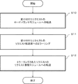
図2は、図1に示す疑似サーバ制御装置10の動作例を説明するためのフローチャートである。リクエスト転送モジュール12は、エンドユーザ機器から受け付けたリクエストを、本番サーバを少なくとも含む本番系ネットワークと、疑似サーバを少なくとも含む疑似系ネットワークとに転送する(ステップS1)。リクエスト蓄積モジュール14は、疑似系ネットワークに転送されたリクエストを一時的に蓄積し、疑似サーバの負荷状態に応じて、例えば、サーバが高負荷状態とならないように、リクエストの疑似サーバへの送信タイミングを制御する(ステップS2)。
(効果の説明)
以上説明した第1の実施形態において、エンドユーザ機器からのリクエストは、リクエスト転送モジュール12によって疑似系ネットワークに転送(ミラーリング)された後、リクエスト蓄積モジュール14に一時的に蓄積される。そして、蓄積されたリクエストは、リクエスト蓄積モジュール14によって、疑似サーバの負荷状態に応じて疑似サーバへ送信される。
[First Embodiment]
(Description of configuration)
FIG. 1 is a block diagram illustrating a configuration example of the pseudo
(Description of operation)
FIG. 2 is a flowchart for explaining an operation example of the pseudo
(Explanation of effect)
In the first embodiment described above, a request from an end user device is transferred (mirrored) to the pseudo network by the
第1の実施形態により、疑似系ネットワーク(特に、疑似サーバ)上で本番系ネットワーク(特に、本番サーバ)と同等のリクエスト状況を再現することが可能となる。従って、本番系ネットワークへの処理負荷に影響を与えることなく、しかも確実に、サービス可用性を維持するための状況把握や状況改善に向けた計画立案を実施することが可能となる。 According to the first embodiment, it is possible to reproduce a request situation equivalent to that of a production system network (particularly a production server) on a pseudo system network (particularly, a pseudo server). Therefore, it is possible to execute a plan for grasping the situation and improving the situation in order to maintain the service availability without affecting the processing load on the production network.
さらに、第1の実施形態の場合、リクエストはリクエスト蓄積モジュール14に一時的に蓄積され、且つその送信タイミングは疑似サーバが高負荷状態とならないように調整することができる。すなわち、第1の実施形態によれば、疑似系ネットワークを、ロードバランサや多数の本番サーバから成る本番系ネットワークに比して簡素且つ低コストに構築することが可能となる。
Furthermore, in the case of the first embodiment, the request is temporarily stored in the
以上を纏めると、第1の実施形態によれば、サービス可用性を維持するための状況把握や状況改善に向けた計画立案を確実且つ容易に実施することが可能となる。
[第2の実施形態]
図3は、本発明の第2の実施形態の疑似サーバ制御装置30の構成例を示すブロック図である。疑似サーバ制御装置30は、記憶部32と、制御部34と、を備える。記憶部32は、コンピュータ読み取り可能な記録媒体であり、疑似サーバ制御プログラム40を記憶する。疑似サーバ制御プログラム40は、図2に示される処理を制御部34に実行させるためのプログラムである。
Summarizing the above, according to the first embodiment, it is possible to reliably and easily carry out planning for grasping the situation and maintaining the situation for maintaining service availability.
[Second Embodiment]
FIG. 3 is a block diagram illustrating a configuration example of the pseudo
以上説明した第2の実施形態によれば、第1の実施形態と同様に、サービス可用性を維持するための状況把握や状況改善に向けた計画立案を確実且つ容易に実施することが可能となる。 According to the second embodiment described above, as in the first embodiment, it is possible to reliably and easily carry out a plan for grasping a situation for maintaining service availability and improving the situation. .
なお、制御部34の例としては、例えば、CPU(Central Processing Unit)とCPUが実行する命令を記憶するメモリを挙げることができる。また、コンピュータ読み取り可能な記録媒体は、例えば、非一時的な記憶装置である。非一時的な記憶装置の例としては、例えば、光磁気ディスク、ROM(Read Only Memory)、不揮発性半導体メモリ等の可搬媒体、コンピュータシステムに内蔵されるハードディスクを挙げることができる。また、コンピュータ読み取り可能な記録媒体は、一時的な記憶装置を含んでももよい。一時的な記憶装置の例としては、例えば、インターネット等のネットワークや電話回線等の通信回線を介してプログラムを送信する場合の通信線、あるいは、コンピュータシステム内部の揮発性メモリを挙げることができる。
[第3の実施形態]
(構成の説明)
図4は、本発明の第3の実施形態に係る疑似サーバ制御装置150を含むウェブサービスシステム100の構成例を示すブロック図である。
Examples of the
[Third Embodiment]
(Description of configuration)
FIG. 4 is a block diagram illustrating a configuration example of the
ウェブサービスシステム100は、1つ以上のエンドユーザ機器102−1〜102−n(nは自然数)と、ロードバランサパッケージ104と、1つ以上の本番サーバ106−1〜106−nと、リクエスト蓄積モジュール108と、疑似サーバ110と、を含む。
The
エンドユーザ機器102−1〜102−nは、所望のウェブサービスを受けるために、本番サーバ106−1〜106−nに対して、リクエスト(処理要求)を送信する。 The end user devices 102-1 to 102-n transmit requests (processing requests) to the production servers 106-1 to 106-n in order to receive a desired web service.
本番サーバ106−1〜106−nは、エンドユーザ機器102−1〜102−nから受信したリクエストに対応したサービスを提供する。 The production servers 106-1 to 106-n provide services corresponding to the requests received from the end user devices 102-1 to 102-n.
エンドユーザ機器102−1〜102−nから送信されたリクエストは、一旦、ロードバランサパッケージ104に入力する。ロードバランサパッケージ104は、ロードバランサモジュール120と、リクエスト転送モジュール122とを含む。
The requests transmitted from the end user devices 102-1 to 102-n are once input to the
リクエスト転送モジュール122は、エンドユーザ機器102−1〜102−nから受け付けたリクエストを、本番サーバ106−1〜106−nを少なくとも含む本番系ネットワークと、疑似サーバ110を少なくとも含む疑似系ネットワークとに転送する。具体的には、リクエスト転送モジュール122は、リクエストを、本番系ネットワークを構成する要素の1つであるロードバランサモジュール120に転送するとともに、疑似系ネットワークを構成するリクエスト蓄積モジュール108へ転送(この転送をミラーリングと呼ぶ場合がある)する。
The
ロードバランサモジュール120は、受信したリクエストを、本番サーバ106−1〜106−nの負荷が分散されるように考慮しながら送信する。
The
本実施形態の疑似サーバ制御装置150(図4において、一点鎖線で示す)は、リクエスト転送モジュール122と、リクエスト蓄積モジュール108と、を備える。疑似サーバ制御装置150は、第1の実施形態の疑似サーバ制御装置10の一例であり、また、第2の実施形態の疑似サーバ制御装置30のようなプロセッサを含むコンピュータによって構成されてもよい。
The pseudo server control device 150 (shown by a one-dot chain line in FIG. 4) of the present embodiment includes a
図5は、図4に示すリクエスト転送モジュール122とその周辺のモジュールを含むシステムの構成例を示すブロック図である。リクエスト転送モジュール122は、リクエスト受付部200(リクエスト受付手段の一例)と、リクエスト転送部202(リクエスト転送手段の一例)と、を備える。
FIG. 5 is a block diagram illustrating a configuration example of a system including the
リクエスト受付部200は、エンドユーザ機器102−1〜102−nからのリクエストを受け付け、受け付けたリクエストを、ロードバランサモジュール120(本番系ネットワークを構成する要素の一つ)へ転送する。さらに、リクエスト受付部200は、受け付けたリクエストをリクエスト転送部202(疑似系ネットワークを構成する要素の一つ)へミラーリングする。
The
リクエスト転送部202は、リクエスト受付部200によってミラーリングされたリクエストをリクエスト蓄積モジュール108へ転送する。
The
なお、リクエスト転送モジュール122は、ロードバランサモジュール120を少なくとも含むロードバランサパッケージ104内に配置されてもよい。
Note that the
図6は、図4に示すリクエスト蓄積モジュール108を含む疑似系ネットワークのシステムの構成例を示すブロック図である。リクエスト蓄積モジュール108は、リクエストデータベース300と、リクエスト蓄積制御部302(リクエスト蓄積制御手段)と、リクエスト送信制御部304(リクエスト送信制御手段)と、を備える。
FIG. 6 is a block diagram showing a configuration example of a pseudo network system including the
リクエストデータベース300は、リクエスト転送モジュール122から転送されたリクエストを一時的に保持する。そして、少なくとも、リクエスト転送モジュール122からリクエストを受信してそのリクエストが疑似サーバ110に転送されるまでの間、リクエストデータベース300には、リクエストの送信を管理するためのリクエスト管理テーブル330が作成される。
The
図7は、リクエストデータベース300に構築されるリクエスト管理テーブル330の構成例を示すデータ構成図である。リクエスト管理テーブル330は、リクエスト自体とこのリクエストの送信を管理するための少なくとも1つのフィールド情報とからなる、少なくとも1つのレコード情報を含む。
FIG. 7 is a data configuration diagram showing a configuration example of the request management table 330 constructed in the
フィールド情報とは、図7において、列方向のデータ(例えば、Index、Method、Request等)のことである。レコード情報とは、図7において、行方向のデータ(例えば、Index=1についての各フィールド情報およびリクエスト(request)の集まり)である。 The field information is data in the column direction (for example, Index, Method, Request, etc.) in FIG. In FIG. 7, the record information is data in the row direction (for example, a collection of field information and a request for Index = 1).
なお、図7において、Indexは、レコード情報を識別するために割り振られる数字であり、通常、そのレコード情報に含まれるリクエストの受信順に割り振られる(つまり、先に受信されたリクエストを含むレコード情報のIndexほど小さい値になる)。 In FIG. 7, Index is a number assigned to identify record information, and is normally assigned in the order of reception of the requests included in the record information (that is, the record information including the request received earlier). The smaller the index, the smaller the value).
Methodは、ウェブサイト(=ウェブサーバ、本実施形態の本番サーバ106−1〜106−nに相当)にデータを受け渡すときに用いる方法のことである。Methodには、例えば、GETメソッドとPOSTメソッドがある。一般的に、リクエストは、URL(Uniform Resource Locator)を含むヘッダ部とボディ部とで構成される。GETメソッドは、URLの後にフォーム入力などのユーザデータを付加するメソッドである。これに対して、POSTメソッドは、ボディ部にユーザデータを収容するメソッドである。 Method is a method used when transferring data to a website (= web server, corresponding to the production servers 106-1 to 106-n in the present embodiment). Methods include, for example, a GET method and a POST method. Generally, a request is composed of a header part including a URL (Uniform Resource Locator) and a body part. The GET method is a method for adding user data such as form input after a URL. On the other hand, the POST method is a method for storing user data in the body part.
Requestは、本実施形態等で使用しているリクエストそのものである。Hostは、ウェブサーバ(例えば、本番サーバ106−1〜106−n)の名前である。Cookieは、ウェブブラウザ(例えば、エンドユーザ機器102−1〜102−n)でウェブサイト(例えば、本番サーバ106−1〜106−n)にアクセスした際に、そのサイトから送信されるファイル(情報)である。Cookieには、例えば、ウェブサイト(ウェブサーバ)側が指定したデータを保存しておくことができる。Content-Lengthは、データの長さ、例えば、レコード情報のデータの長さ、あるいはリクエストのデータの長さを示す。 Request is the request itself used in the present embodiment. Host is the name of a web server (for example, production servers 106-1 to 106-n). A cookie is a file (information) transmitted from a web browser (for example, the end user devices 102-1 to 102-n) when the website (for example, the production server 106-1 to 106-n) is accessed. ). For example, data specified by the website (web server) can be stored in the cookie. Content-Length indicates the length of data, for example, the length of data of record information, or the length of data of request.
リクエスト蓄積制御部302は、リクエストのリクエストデータベース300への蓄積、より詳細にはリクエスト管理テーブル330への書き込みを制御する。リクエスト蓄積制御部302は、リクエストをリクエスト管理テーブル330に書き込む際、リクエストの宛先情報を疑似サーバ110の宛先情報に書き換える。
The request
リクエスト送信制御部304は、疑似サーバ110の負荷状態に応じてリクエストの疑似サーバ110への送信タイミングを制御する。本実施形態では、負荷状態に応じた制御の一例として、疑似サーバ110が高負荷状態とならないように制御する場合を例に挙げる。例えば、リクエスト送信制御部304は、所定のリクエストを送信する際、その所定のリクエストの前に送信された別のリクエストのTAT(Turn Around Time)の値が所定の閾値を下回っている場合、疑似サーバ110が高負荷状態ではないと判断し、所定のリクエストを疑似サーバ110へ送信する。
The request
すなわち、リクエスト送信制御部304は、ただ単に、リクエスト管理テーブル330のリクエストを送信するのではなく、疑似サーバ110が高負荷にならないように疑似サーバ110への単位時間当たりのリクエスト送信数を制御し、必要があればリクエストの送信を遅延させる。
That is, the request
これによりリクエストの取りこぼしが回避される。すなわち、疑似サーバ110は、本番サーバ106−1〜106−nと同数のリクエストを受信することができる。このことは、疑似サーバ110上に本番サーバ106−1〜106−nと同一の環境が再現されたことを意味する。
(動作の説明)
以下、疑似サーバ制御装置150の動作について説明する。なお、図4における疑似サーバ制御装置150と直接関係の無い装置の動作(例えば、ロードバランサモジュール120や本番サーバ106−1〜106−n等の動作)についての説明は、省略する。
This avoids missing requests. That is, the
(Description of operation)
Hereinafter, the operation of the pseudo
図8は、リクエスト転送モジュール122の動作例を説明するためのフローチャートである。リクエスト転送モジュール122のリクエスト受付部200は、エンドユーザ機器102−1〜102−nからのリクエストを受け付け、受け付けたリクエストを、ロードバランサモジュール120へ転送する(ステップS10)。さらに、リクエスト受付部200は、受け付けたリクエストをリクエスト転送部202へミラーリングする(ステップS11)。リクエスト転送モジュール122のリクエスト転送部202は、リクエスト受付部200によってミラーリングされたリクエストをリクエスト蓄積モジュール108へ転送する(ステップS12)。
FIG. 8 is a flowchart for explaining an operation example of the
図9は、リクエスト蓄積モジュール108の第1の動作例(リクエストをリクエストデータベース300に格納するまでの動作)を説明するためのフローチャートである。リクエスト蓄積モジュール108のリクエスト蓄積制御部302は、リクエスト転送モジュール122から転送されたリクエストの宛先情報を疑似サーバ110の宛先情報に書き換える(ステップS20)。宛先情報は、例えば、FQDN(Fully Qualified Domain Name)やホスト(例えば、本番サーバ106−1〜106−n)の名前である。リクエスト蓄積制御部302は、このリクエストをリクエスト管理テーブル330へ登録する(ステップS21)。
FIG. 9 is a flowchart for explaining a first operation example (operation until a request is stored in the request database 300) of the
図10は、リクエスト蓄積モジュール108の第2の動作例(リクエストをリクエストデータベース300から読み出して疑似サーバ110に転送するまでの動作)を説明するためのフローチャートである。
FIG. 10 is a flowchart for explaining a second operation example (operation until a request is read from the
リクエスト蓄積モジュール108のリクエスト送信制御部304は、リクエスト管理テーブル330に送信すべきリクエストが存在するか否か判定する(ステップS30)。送信すべきリクエストが存在しない場合(ステップS30においてNo)、リクエスト送信制御部304は、ステップS30の処理を再度実行する。
The request
リクエスト管理テーブル330に送信すべきリクエストが存在する場合、リクエスト送信制御部304は、疑似サーバ110が高負荷状態にあるか否かを判定する(ステップS31)。ここで、高負荷状態とは、例えば、負荷を示すある物理量の値が所定の閾値を上回っている状態のことを指す。例えば、リクエスト送信制御部304は、送信しようとするリクエストの前に送信された別のリクエストのTAT(時間)に基づいて疑似サーバ110の負荷状態を判定することができる。
When there is a request to be transmitted in the request management table 330, the request
疑似サーバ110が高負荷状態にある場合(ステップS31においてYes)、リクエスト送信制御部304は、当該リクエストの送信を行わず、ステップS31の処理を再度実行する。すなわち、この場合、リクエストは、疑似サーバ110が低負荷状態になるまでウェイトされて送信されることはない。
When the
疑似サーバ110が低負荷状態にある場合(ステップS31においてNo)、リクエスト送信制御部304は、リクエスト管理テーブル330からIndexが最も小さいレコード情報に含まれるリクエストを抽出する(ステップS32)。リクエスト送信制御部304は、抽出したリクエストを、疑似サーバ110へ送信する(ステップS33)。
(効果の説明)
以上説明した第3の実施形態において、エンドユーザ機器102−1〜102−nからのリクエストは、リクエスト転送モジュール122によってミラーリングされた後、リクエスト蓄積モジュール108に一時的に蓄積される。そして、蓄積されたリクエストは、リクエスト蓄積モジュール108によって、疑似サーバ110が高負荷状態とならないように疑似サーバ110へ送信される。
When the
(Explanation of effect)
In the third embodiment described above, requests from the end user devices 102-1 to 102-n are mirrored by the
第3の実施形態により、疑似系ネットワーク(特に、疑似サーバ110)上で本番系ネットワーク(特に、本番サーバ106−1〜106−n)と同等のリクエスト状況を再現することが可能となる。従って、本番系ネットワークへの処理負荷に影響を与えることなく、しかも確実に、サービス可用性を維持するための状況把握や状況改善に向けた計画立案を実施することが可能となる。 According to the third embodiment, it is possible to reproduce a request situation equivalent to that of the production network (particularly, the production servers 106-1 to 106-n) on the pseudo system network (particularly, the pseudo server 110). Therefore, it is possible to execute a plan for grasping the situation and improving the situation in order to maintain the service availability without affecting the processing load on the production network.
さらに、第3の実施形態の場合、リクエストはリクエスト蓄積モジュール108に一時的に蓄積され且つその送信タイミングは疑似サーバ110が高負荷状態とならないように調整されている。すなわち、第3の実施形態によれば、疑似系ネットワークを、ロードバランサモジュール120や多数の本番サーバ106−1〜106−nから成る本番系ネットワークに比して簡素且つ低コストに構築することが可能となる。
Furthermore, in the case of the third embodiment, the request is temporarily stored in the
以上を纏めると、第3の実施形態によれば、サービス可用性を維持するための状況把握や状況改善に向けた計画立案を確実且つ容易に実施することが可能となる。
(変形例の説明)
以上説明した第3の実施形態において、リクエスト管理テーブル330(図7参照)を複数(例えば、さらにもう一つ追加する)設けることができる。これにより、疑似サーバ110を複数作成することが可能となる。
Summarizing the above, according to the third embodiment, it is possible to reliably and easily carry out planning for grasping the situation for maintaining service availability and improving the situation.
(Description of modification)
In the third embodiment described above, a plurality of request management tables 330 (see FIG. 7) can be provided (for example, another one is added). Thereby, a plurality of
そして、この追加されたリクエスト管理テーブル330にリクエストを登録する際、例えば、特定のリクエストのみを格納するとのルールが設けられてもよい。このことにより、通常の疑似サーバ110に加え、ある特定のリクエストのみを集中させた別の疑似サーバ110を追加することができる。このことは、現在の本番環境をスケールアウト(本番サーバ106−1〜106−nの追加)させる場合の調査分析等にとって極めて有用である。
When a request is registered in the added request management table 330, for example, a rule that stores only a specific request may be provided. Thus, in addition to the normal
また、以上説明した第3の実施形態において、疑似サーバ制御装置150と疑似サーバ110との間を専用線で結び、セキュアな通信を約束することが可能である。これにより、漏洩が許されない本番環境の情報を、サービス運用者側のクローズドな社内網に構築することが可能となる。
Further, in the third embodiment described above, the pseudo
さらに、以上説明した第3の実施形態において、リクエスト蓄積制御部302は、リクエストのメソッドを解析し、GETリクエストおよびPOSTリクエストそれぞれに対してメソッドに応じた処理を追加することができる。例えば、「GETリクエストについては疑似サーバ110からのレスポンスは受け取らない」や「POSTリクエストについては応答を拾い、httpレスポンスに従った処理分岐を設ける」等の処理を追加することができる。これにより、疑似サーバ制御装置150は、疑似サーバ110の状態を任意に制御することが可能となる。
Furthermore, in the third embodiment described above, the request
また、以上説明した第3の実施形態は、例えば、第2の実施形態のように、図8〜10に示す動作がプログラムとして記述されてコンピュータ読み取り可能な記録媒体に記憶され、そのプログラムがCPU等の演算装置により実行される構成とすることもできる。なお、図8〜図10の動作を一つのコンピュータで実行できない場合、複数のコンピュータが分担してこれらの動作を実行してもよい。 Further, in the third embodiment described above, for example, as in the second embodiment, the operations shown in FIGS. 8 to 10 are described as a program and stored in a computer-readable recording medium, and the program is stored in a CPU. It can also be set as the structure performed by arithmetic units, such as. If the operations shown in FIGS. 8 to 10 cannot be executed by a single computer, a plurality of computers may share these operations.
以上、各実施形態を用いて本発明を説明したが、本発明の技術的範囲は、上記各実施形態の記載に限定されない。上記各実施形態に多様な変更又は改良を加えることが可能であることは当業者にとって自明である。従って、そのような変更又は改良を加えた形態もまた本発明の技術的範囲に含まれることは説明するまでもない。また、以上説明した各実施形態において使用される、数値や各構成の名称等は例示的なものであり適宜変更可能である。 As mentioned above, although this invention was demonstrated using each embodiment, the technical scope of this invention is not limited to description of said each embodiment. It is obvious to those skilled in the art that various modifications or improvements can be added to the above embodiments. Therefore, it is needless to say that embodiments with such changes or improvements are also included in the technical scope of the present invention. The numerical values and names of the components used in the embodiments described above are illustrative and can be changed as appropriate.
また、上述した各実施形態の一部又は全部は、以下の付記のようにも記載されうる。
(付記1)
処理のリクエストを発生する機器から受け付けた前記リクエストを、本番サーバを少なくとも含む本番系ネットワークと、疑似サーバを少なくとも含む疑似系ネットワークとに転送するリクエスト転送モジュールと、
前記疑似系ネットワークに転送された前記リクエストを一時的に蓄積し、前記疑似サーバの負荷状態に応じて、前記リクエストの前記疑似サーバへの送信タイミングを制御するリクエスト蓄積モジュールと、
を備えることを特徴とする疑似サーバ制御装置。
(付記2)
前記リクエスト蓄積モジュールは、
前記リクエスト転送モジュールから転送された前記リクエストを一時的に保持するリクエストデータベースと、
前記リクエストの前記リクエストデータベースへの蓄積を制御するリクエスト蓄積制御手段と、
前記リクエストの前記送信タイミングを制御するリクエスト送信制御手段と
を備えることを特徴とする付記1記載の疑似サーバ制御装置。
(付記3)
前記リクエスト送信制御手段は、所定の前記リクエストを送信する前に送信された別の前記リクエストのTAT(Turn Around Time)の値が所定の閾値を下回っている場合に、所定の前記リクエストを前記疑似サーバへ送信することを特徴とする付記2記載の疑似サーバ制御装置。
(付記4)
少なくとも、前記リクエスト転送モジュールから前記リクエストを受信してその前記リクエストが前記疑似サーバに転送されるまでの間、前記リクエストデータベースには、前記リクエストの送信を管理するためのテーブルであり、前記リクエスト自体とこの前記リクエストの送信を管理するための少なくとも1つのフィールド情報とからなる、少なくとも1つのリクエストレコード情報を備えるリクエスト管理テーブルが構築されることを特徴とする付記2または3記載の疑似サーバ制御装置。
(付記5)
前記リクエスト蓄積制御手段は、前記リクエストを前記リクエスト管理テーブルに蓄積する際、前記リクエストの宛先情報を前記疑似サーバの宛先情報に書き換えることを特徴とする付記4記載の疑似サーバ制御装置。
(付記6)
前記リクエスト転送モジュールは、
前記エンドユーザ機器からの前記リクエストを受け付け、受け付けた前記リクエストを、前記本番系ネットワークへ転送するとともに、前記疑似系ネットワークへミラーリングするリクエスト受付手段と、
前記リクエスト受付手段によってミラーリングされた前記リクエストを前記リクエスト蓄積モジュールへ転送するリクエスト転送手段と、
を含むことを特徴とする付記1−5のいずれか1項に記載の疑似サーバ制御装置。
(付記7)
前記リクエスト受付手段は、受け付けた前記リクエストを、前記本番サーバへの負荷分散を行うロードバランサモジュールへ転送することを特徴とする付記6記載の疑似サーバ制御装置。
(付記8)
前記リクエスト転送モジュールは、前記ロードバランサモジュールを少なくとも含むロードバランサパッケージ内に配置されることを特徴とする付記7記載の疑似サーバ制御装置。
(付記9)
処理のリクエストを発生する機器から受け付けた前記リクエストを、本番サーバを少なくとも含む本番系ネットワークと、疑似サーバを少なくとも含む疑似系ネットワークとに転送し、
前記疑似系ネットワークに転送された前記リクエストを一時的に蓄積し、前記疑似サーバの負荷状態に応じて、前記リクエストの前記疑似サーバへの送信タイミングを制御する
ことを特徴とする疑似サーバ制御方法。
(付記10)
前記疑似系ネットワークに転送された前記リクエストを、リクエストデータベースに一時的に保持し、
前記リクエストの前記リクエストデータベースへの蓄積を制御し、
前記リクエストの前記送信タイミングを制御する
ことを特徴とする付記9記載の疑似サーバ制御方法。
(付記11)
処理のリクエストを発生する機器から受け付けた前記リクエストを、本番サーバを少なくとも含む本番系ネットワークと、疑似サーバを少なくとも含む疑似系ネットワークとに転送するリクエスト転送処理と、
前記疑似系ネットワークに転送された前記リクエストを一時的に蓄積し、前記疑似サーバの負荷状態に応じて、前記リクエストの前記疑似サーバへの送信タイミングを制御するリクエスト蓄積処理と、
をコンピュータに実行させるための疑似サーバ制御プログラム。
(付記12)
前記リクエスト蓄積処理は、
前記疑似系ネットワークに転送された前記リクエストを、リクエストデータベースに一時的に保持する保持処理と、
前記リクエストの前記リクエストデータベースへの蓄積を制御するリクエスト蓄積制御処理と、
前記リクエストの前記送信タイミングを制御するリクエスト送信制御処理と
を含むことを特徴とする付記11記載の疑似サーバ制御プログラム。
Moreover, a part or all of each embodiment mentioned above can be described also as the following additional remarks.
(Appendix 1)
A request transfer module that transfers the request received from a device that generates a processing request to a production network including at least a production server and a pseudo network including at least a pseudo server;
A request storage module that temporarily stores the request transferred to the pseudo network and controls transmission timing of the request to the pseudo server according to a load state of the pseudo server;
A pseudo server control device comprising:
(Appendix 2)
The request accumulation module includes:
A request database that temporarily holds the request transferred from the request transfer module;
Request accumulation control means for controlling accumulation of the request in the request database;
The pseudo server control device according to claim 1, further comprising request transmission control means for controlling the transmission timing of the request.
(Appendix 3)
The request transmission control means, when a TAT (Turn Around Time) value of another request transmitted before transmitting the predetermined request is below a predetermined threshold, The pseudo server control device according to
(Appendix 4)
The request database is a table for managing the transmission of the request until at least the request is received from the request transfer module and the request is transferred to the pseudo server. And a request management table comprising at least one piece of request record information, and the pseudo server control device according to
(Appendix 5)
5. The pseudo server control device according to
(Appendix 6)
The request transfer module includes:
A request receiving means for receiving the request from the end user device, transferring the received request to the production network, and mirroring the pseudo network;
Request transfer means for transferring the request mirrored by the request reception means to the request storage module;
The pseudo server control device according to any one of appendix 1-5, including:
(Appendix 7)
The pseudo server control device according to appendix 6, wherein the request receiving means transfers the received request to a load balancer module that distributes a load to the production server.
(Appendix 8)
The pseudo server control device according to appendix 7, wherein the request transfer module is arranged in a load balancer package including at least the load balancer module.
(Appendix 9)
Transfer the request received from a device that generates a processing request to a production network including at least a production server and a pseudo network including at least a pseudo server,
The pseudo server control method, wherein the request transferred to the pseudo network is temporarily stored, and the transmission timing of the request to the pseudo server is controlled according to a load state of the pseudo server.
(Appendix 10)
The request transferred to the pseudo network is temporarily stored in a request database,
Control the accumulation of the request in the request database;
The pseudo server control method according to appendix 9, wherein the transmission timing of the request is controlled.
(Appendix 11)
A request transfer process for transferring the request received from a device that generates a processing request to a production network including at least a production server and a pseudo network including at least a pseudo server;
A request accumulation process for temporarily accumulating the request transferred to the pseudo network and controlling a transmission timing of the request to the pseudo server according to a load state of the pseudo server;
A pseudo server control program for causing a computer to execute.
(Appendix 12)
The request accumulation process includes:
A holding process for temporarily holding the request transferred to the pseudo network in a request database;
A request accumulation control process for controlling accumulation of the request in the request database;
The pseudo server control program according to appendix 11, further comprising: a request transmission control process for controlling the transmission timing of the request.
10 疑似サーバ制御装置
12 リクエスト転送モジュール
14 リクエスト蓄積モジュール
30 疑似サーバ制御装置
32 記憶部
34 制御部
40 疑似サーバ制御プログラム
100 ウェブサービスシステム
102−1〜102−n エンドユーザ機器
104 ロードバランサパッケージ
106−1〜106−n 本番サーバ
108 リクエスト蓄積モジュール
110 疑似サーバ
120 ロードバランサモジュール
122 リクエスト転送モジュール
150 疑似サーバ制御装置
200 リクエスト受付部
202 リクエスト転送部
300 リクエストデータベース
302 リクエスト蓄積制御部
304 リクエスト送信制御部
330 リクエスト管理テーブル
DESCRIPTION OF
Claims (10)
前記疑似系ネットワークに転送された前記リクエストを一時的に蓄積し、前記疑似サーバの負荷状態に応じて、前記リクエストの前記疑似サーバへの送信タイミングを制御するリクエスト蓄積モジュールと、
を備えることを特徴とする疑似サーバ制御装置。 A request transfer module that transfers the request received from a device that generates a processing request to a production network including at least a production server and a pseudo network including at least a pseudo server;
A request storage module that temporarily stores the request transferred to the pseudo network and controls transmission timing of the request to the pseudo server according to a load state of the pseudo server;
A pseudo server control device comprising:
前記リクエスト転送モジュールから転送された前記リクエストを一時的に保持するリクエストデータベースと、
前記リクエストの前記リクエストデータベースへの蓄積を制御するリクエスト蓄積制御手段と、
前記リクエストの前記送信タイミングを制御するリクエスト送信制御手段と
を備えることを特徴とする請求項1記載の疑似サーバ制御装置。 The request accumulation module includes:
A request database that temporarily holds the request transferred from the request transfer module;
Request accumulation control means for controlling accumulation of the request in the request database;
The pseudo server control device according to claim 1, further comprising request transmission control means for controlling the transmission timing of the request.
前記エンドユーザ機器からの前記リクエストを受け付け、受け付けた前記リクエストを、前記本番系ネットワークへ転送するとともに、前記疑似系ネットワークへミラーリングするリクエスト受付手段と、
前記リクエスト受付手段によってミラーリングされた前記リクエストを前記リクエスト蓄積モジュールへ転送するリクエスト転送手段と、
を含むことを特徴とする請求項1−5のいずれか1項に記載の疑似サーバ制御装置。 The request transfer module includes:
A request receiving means for receiving the request from the end user device, transferring the received request to the production network, and mirroring the pseudo network;
Request transfer means for transferring the request mirrored by the request reception means to the request storage module;
The pseudo server control apparatus according to claim 1, wherein the pseudo server control apparatus includes:
前記疑似系ネットワークに転送された前記リクエストを一時的に蓄積し、前記疑似サーバの負荷状態に応じて、前記リクエストの前記疑似サーバへの送信タイミングを制御する
ことを特徴とする疑似サーバ制御方法。 Transfer the request received from a device that generates a processing request to a production network including at least a production server and a pseudo network including at least a pseudo server,
The pseudo server control method, wherein the request transferred to the pseudo network is temporarily stored, and the transmission timing of the request to the pseudo server is controlled according to a load state of the pseudo server.
前記疑似系ネットワークに転送された前記リクエストを一時的に蓄積し、前記疑似サーバの負荷状態に応じて、前記リクエストの前記疑似サーバへの送信タイミングを制御するリクエスト蓄積処理と、
をコンピュータに実行させるための疑似サーバ制御プログラム。 A request transfer process for transferring the request received from a device that generates a processing request to a production network including at least a production server and a pseudo network including at least a pseudo server;
A request accumulation process for temporarily accumulating the request transferred to the pseudo network and controlling a transmission timing of the request to the pseudo server according to a load state of the pseudo server;
A pseudo server control program for causing a computer to execute.
Priority Applications (1)
| Application Number | Priority Date | Filing Date | Title |
|---|---|---|---|
| JP2016184611A JP6903888B2 (en) | 2016-09-21 | 2016-09-21 | Pseudo-server controller, pseudo-server control method, and pseudo-server control program |
Applications Claiming Priority (1)
| Application Number | Priority Date | Filing Date | Title |
|---|---|---|---|
| JP2016184611A JP6903888B2 (en) | 2016-09-21 | 2016-09-21 | Pseudo-server controller, pseudo-server control method, and pseudo-server control program |
Publications (2)
| Publication Number | Publication Date |
|---|---|
| JP2018049471A true JP2018049471A (en) | 2018-03-29 |
| JP6903888B2 JP6903888B2 (en) | 2021-07-14 |
Family
ID=61767675
Family Applications (1)
| Application Number | Title | Priority Date | Filing Date |
|---|---|---|---|
| JP2016184611A Active JP6903888B2 (en) | 2016-09-21 | 2016-09-21 | Pseudo-server controller, pseudo-server control method, and pseudo-server control program |
Country Status (1)
| Country | Link |
|---|---|
| JP (1) | JP6903888B2 (en) |
Citations (2)
| Publication number | Priority date | Publication date | Assignee | Title |
|---|---|---|---|---|
| WO2007125942A1 (en) * | 2006-04-26 | 2007-11-08 | Nippon Telegraph And Telephone Corporation | Load control device and its method |
| JP2015102951A (en) * | 2013-11-22 | 2015-06-04 | 株式会社日立製作所 | Processing request reading/transferring device and processing request transferring method |
-
2016
- 2016-09-21 JP JP2016184611A patent/JP6903888B2/en active Active
Patent Citations (2)
| Publication number | Priority date | Publication date | Assignee | Title |
|---|---|---|---|---|
| WO2007125942A1 (en) * | 2006-04-26 | 2007-11-08 | Nippon Telegraph And Telephone Corporation | Load control device and its method |
| JP2015102951A (en) * | 2013-11-22 | 2015-06-04 | 株式会社日立製作所 | Processing request reading/transferring device and processing request transferring method |
Also Published As
| Publication number | Publication date |
|---|---|
| JP6903888B2 (en) | 2021-07-14 |
Similar Documents
| Publication | Publication Date | Title |
|---|---|---|
| US9705800B2 (en) | Load distribution in data networks | |
| US10148617B2 (en) | Enhanced thread handling in security handshakingdomain name system bypass in user applications | |
| US10192179B1 (en) | Session transfer in a customer service environment | |
| US9160791B2 (en) | Managing connection failover in a load balancer | |
| US20130067024A1 (en) | Distributing multi-source push notifications to multiple targets | |
| EP2251800A2 (en) | Client server systems and methods for accessing metadata information across a network using proxies | |
| US20170289294A1 (en) | Proxy application with dynamic filter updating | |
| JP5724687B2 (en) | Information processing apparatus, server selection method, and program | |
| US20180139269A1 (en) | Dynamic load balancing among data centers | |
| CN103209223A (en) | Distributed application conversation information sharing method and system and application server | |
| WO2013023306A1 (en) | Stream processing using a client-server architecture | |
| CN109510878B (en) | Long connection session keeping method and device | |
| US20180139273A1 (en) | Entity based routing | |
| CN103391312A (en) | Resource offline downloading method and device | |
| US8854977B2 (en) | Relay node | |
| EP2939105B1 (en) | Data purge distribution and coherency | |
| CN110413846A (en) | For the data processing method of webpage mirror image, device and computer readable storage medium | |
| US10445136B1 (en) | Randomized subrequest selection using request-specific nonce | |
| JP2013182509A (en) | Virtualization system, load distribution device, load distribution method and load distribution program | |
| US9736082B2 (en) | Intelligent high-volume cloud application programming interface request caching | |
| JP6364727B2 (en) | Information processing system, distributed processing method, and program | |
| Zhou et al. | TAP: Timeliness‐aware predication‐based replica selection algorithm for key‐value stores | |
| CN111078975B (en) | Multi-node incremental data acquisition system and acquisition method | |
| JP2018049471A (en) | Pseudo server control device, pseudo server control method, and pseudo server control program | |
| JP6193078B2 (en) | Message transfer system and queue management method |
Legal Events
| Date | Code | Title | Description |
|---|---|---|---|
| A621 | Written request for application examination |
Free format text: JAPANESE INTERMEDIATE CODE: A621 Effective date: 20190820 |
|
| A977 | Report on retrieval |
Free format text: JAPANESE INTERMEDIATE CODE: A971007 Effective date: 20200728 |
|
| A131 | Notification of reasons for refusal |
Free format text: JAPANESE INTERMEDIATE CODE: A131 Effective date: 20201020 |
|
| A521 | Request for written amendment filed |
Free format text: JAPANESE INTERMEDIATE CODE: A523 Effective date: 20201217 |
|
| TRDD | Decision of grant or rejection written | ||
| A01 | Written decision to grant a patent or to grant a registration (utility model) |
Free format text: JAPANESE INTERMEDIATE CODE: A01 Effective date: 20210525 |
|
| A61 | First payment of annual fees (during grant procedure) |
Free format text: JAPANESE INTERMEDIATE CODE: A61 Effective date: 20210607 |
|
| R150 | Certificate of patent or registration of utility model |
Ref document number: 6903888 Country of ref document: JP Free format text: JAPANESE INTERMEDIATE CODE: R150 |