JP2017530807A - Universal razor cartridge handle - Google Patents
Universal razor cartridge handle Download PDFInfo
- Publication number
- JP2017530807A JP2017530807A JP2017519254A JP2017519254A JP2017530807A JP 2017530807 A JP2017530807 A JP 2017530807A JP 2017519254 A JP2017519254 A JP 2017519254A JP 2017519254 A JP2017519254 A JP 2017519254A JP 2017530807 A JP2017530807 A JP 2017530807A
- Authority
- JP
- Japan
- Prior art keywords
- razor cartridge
- handle
- cartridge
- type
- ejector
- Prior art date
- Legal status (The legal status is an assumption and is not a legal conclusion. Google has not performed a legal analysis and makes no representation as to the accuracy of the status listed.)
- Granted
Links
- 230000000712 assembly Effects 0.000 claims description 4
- 238000000429 assembly Methods 0.000 claims description 4
- 238000004891 communication Methods 0.000 claims description 2
- 230000007246 mechanism Effects 0.000 description 3
- 230000008901 benefit Effects 0.000 description 2
- 230000013011 mating Effects 0.000 description 2
- 238000003032 molecular docking Methods 0.000 description 2
- 230000007935 neutral effect Effects 0.000 description 2
- 230000000087 stabilizing effect Effects 0.000 description 2
- 239000012634 fragment Substances 0.000 description 1
- 238000000034 method Methods 0.000 description 1
- 238000012986 modification Methods 0.000 description 1
- 230000004048 modification Effects 0.000 description 1
Images


Classifications
-
- B—PERFORMING OPERATIONS; TRANSPORTING
- B26—HAND CUTTING TOOLS; CUTTING; SEVERING
- B26B—HAND-HELD CUTTING TOOLS NOT OTHERWISE PROVIDED FOR
- B26B21/00—Razors of the open or knife type; Safety razors or other shaving implements of the planing type; Hair-trimming devices involving a razor-blade; Equipment therefor
- B26B21/40—Details or accessories
- B26B21/52—Handles, e.g. tiltable, flexible
- B26B21/521—Connection details, e.g. connection to razor heads
Landscapes
- Life Sciences & Earth Sciences (AREA)
- Forests & Forestry (AREA)
- Engineering & Computer Science (AREA)
- Mechanical Engineering (AREA)
- Packaging Of Annular Or Rod-Shaped Articles, Wearing Apparel, Cassettes, Or The Like (AREA)
Abstract
互いから異なる第1及び第2タイプかみそりカートリッジに接続されるように構成されたかみそりカートリッジハンドルを提供する。ハンドルは、カートリッジ端部、第1アセンブリ、第2アセンブリ、エジェクタ、及びプランジャを含む。第1アセンブリは、第1タイプかみそりカートリッジをハンドルのカートリッジ端部に接続するように構成される。第2アセンブリは、第2タイプかみそりカートリッジをハンドルのカートリッジ端部に接続するように構成される。かみそりカートリッジエジェクタは、第1タイプかみそりカートリッジ及び第2タイプかみそりカートリッジの両方を選択的に押し出すように作動可能である。プランジャは、プランジャの遠位端が、取り付けられたかみそりカートリッジと接触する位置まで通常は付勢されている。【選択図】図1A razor cartridge handle configured to be connected to different first and second type razor cartridges from each other is provided. The handle includes a cartridge end, a first assembly, a second assembly, an ejector, and a plunger. The first assembly is configured to connect a first type razor cartridge to the cartridge end of the handle. The second assembly is configured to connect a second type razor cartridge to the cartridge end of the handle. The razor cartridge ejector is operable to selectively extrude both the first type razor cartridge and the second type razor cartridge. The plunger is normally biased to a position where the distal end of the plunger contacts the attached razor cartridge. [Selection] Figure 1
Description
〔関連出願への相互参照〕
本出願は、本明細書にその内容が引用によって全体的に組み込まれている2014年10月10日出願の米国仮特許出願第62/062221号の利益を主張するものである。
[Cross-reference to related applications]
This application claims the benefit of US Provisional Patent Application No. 62/062221, filed October 10, 2014, the contents of which are hereby incorporated by reference in their entirety.
本発明の開示は、一般的に安全かみそりハンドルに関し、特に、使い捨てかみそりカートリッジを装着するための安全かみそりハンドルに関する。 The present disclosure relates generally to a safety razor handle, and more particularly to a safety razor handle for mounting a disposable razor cartridge.
安全かみそりとしても公知の多くの最新の湿式髭剃かみそりは、ハンドルとハンドルに装着されたかみそりカートリッジとを含む。一部のかみそりは、いわゆる使い捨てかみそりであり、ハンドル及びかみそりカートリッジは、使用後に一緒に処分される。他のかみそりは、再利用することができるハンドルと、使用後に処分されて新しいカートリッジに交換することができる取り外し可能かみそりカートリッジとを含むいわゆるシステムの形態にあるとすることができる。 Many modern wet shaving razors, also known as safety razors, include a handle and a razor cartridge attached to the handle. Some razors are so-called disposable razors, and the handle and razor cartridge are disposed of together after use. The other razor may be in the form of a so-called system that includes a handle that can be reused and a removable razor cartridge that can be discarded after use and replaced with a new cartridge.
一部のシステム−タイプの安全かみそりは、一点プラグ及びソケットドッキング装置を含み、それによってかみそりカートリッジは、ハンドルのカートリッジ端部の単一延長部又は雄突出部を受け入れるようになった単一凹部又は空洞部分を備えた接続部材を有する。米国特許第5,956,851号明細書及び米国特許第7,168,173号明細書は、カートリッジをハンドルに装着する2つのそのようなドッキング装置を示している。これらの文献において容易に判断することができるように、各それぞれの延長部及び凹部は、例えば、’851特許による市販かみそりカートリッジを’173特許による市販ハンドルに容易に装着することができないように異なって成形される。これは、ユーザが互換性のない延長部を備えたハンドルを保有するだけなのに1つの特定の接続部材凹部と共にだけ提供されるであろうある一定の髭剃技術を試したい場合があるユーザとって欠点である可能性がある。 Some system-type safety razors include a single point plug and socket docking device whereby the razor cartridge is adapted to accept a single extension or male protrusion at the cartridge end of the handle. A connecting member having a hollow portion; US Pat. No. 5,956,851 and US Pat. No. 7,168,173 show two such docking devices for attaching a cartridge to a handle. As can be readily determined in these documents, each extension and recess is different so that, for example, a commercial razor cartridge according to the '851 patent cannot be easily attached to a commercial handle according to the' 173 patent. To be molded. This is for users who may only want to try certain shaving techniques that would only be provided with one specific connection member recess, while the user only has a handle with an incompatible extension. It may be a drawback.
米国特許第8,793,880号明細書は、比較的大きい接続部材内に比較的小さいハンドル延長部を受け入れることができるように、接続部材凹部に嵌合して凹部の寸法を実質的に低減するような大きさにされたアダプタを開示している。これは、製造業者が店頭で古いかみそりカートリッジと共に新しいかみそりカートリッジのサンプルを提供することを可能にすることができる。消費者が古くて異なる髭剃かみそりハンドル構成に対して新しいかみそりカートリッジを試すことを可能にするアダプタを新しい髭剃かみそりカートリッジ設計と共に提供することが望ましい。 U.S. Pat. No. 8,793,880 fits into a connection member recess to substantially reduce the size of the recess so that a relatively small handle extension can be received within a relatively large connection member. An adapter sized to do so is disclosed. This can allow the manufacturer to provide a sample of the new razor cartridge along with the old razor cartridge at the store. It would be desirable to provide an adapter with a new shaving razor cartridge design that allows the consumer to try a new razor cartridge against an old and different shaving razor handle configuration.
本発明の開示の態様により、第1タイプかみそりカートリッジに接続されるように構成され、かつ第2タイプかみそりカートリッジに接続されるように構成されたかみそりカートリッジハンドルを提供し、第1タイプかみそりカートリッジは、第2タイプかみそりカートリッジとは異なっている。ハンドルは、カートリッジ端部、第1アセンブリ、第2アセンブリ、エジェクタボタン、エジェクタ、及びプランジャを含む。第1アセンブリは、第1タイプかみそりカートリッジをハンドルのカートリッジ端部に接続するように構成される。第2アセンブリは、第2タイプかみそりカートリッジをハンドルのカートリッジ端部に接続するように構成される。第1及び第2アセンブリは、一度に単一かみそりカートリッジのみをハンドルに取り付けることができるように構成される。エジェクタボタンは、通常はハンドルに対して第1の位置に付勢されており、かつ押し出し位置まで平行移動可能である。エジェクタは、遠位端を有する第1のアームと遠位端を有する第2のアームとを有する。エジェクタは、通常は、アームが実質的にハンドル内に存在する後退位置に付勢されている。エジェクタは、エジェクタボタンを押し出し位置まで平行移動することにより、エジェクタアームが、ハンドルカートリッジから外向きに延び、かつエジェクタアームの遠位端が、取り付けられたかみそりカートリッジに接触するようにエジェクタボタンと連通している。プランジャは、遠位端を有する。プランジャは、通常はハンドルカートリッジ端部から外向きに付勢されて拡張位置に存在し、拡張位置では、プランジャの遠位端は、取り付けられたかみそりカートリッジと接触している。 In accordance with an aspect of the present disclosure, there is provided a razor cartridge handle configured to be connected to a first type razor cartridge and configured to be connected to a second type razor cartridge, wherein the first type razor cartridge is The second type razor cartridge is different. The handle includes a cartridge end, a first assembly, a second assembly, an ejector button, an ejector, and a plunger. The first assembly is configured to connect a first type razor cartridge to the cartridge end of the handle. The second assembly is configured to connect a second type razor cartridge to the cartridge end of the handle. The first and second assemblies are configured such that only a single razor cartridge can be attached to the handle at a time. The ejector button is normally urged to the first position with respect to the handle and can be moved in parallel to the pushing position. The ejector has a first arm having a distal end and a second arm having a distal end. The ejector is normally biased to a retracted position where the arm is substantially within the handle. The ejector translates the ejector button to the pushed out position so that the ejector arm extends outward from the handle cartridge and the distal end of the ejector arm communicates with the attached razor cartridge. doing. The plunger has a distal end. The plunger is normally biased outwardly from the end of the handle cartridge and is in the expanded position, where the distal end of the plunger is in contact with the attached razor cartridge.
本発明の開示の別の態様により、第1タイプかみそりカートリッジに接続されるように構成され、かつ第2タイプかみそりカートリッジに接続されるように構成されたかみそりカートリッジハンドルを提供し、第1タイプかみそりカートリッジは、第2タイプかみそりカートリッジとは異なっている。ハンドルは、カートリッジ端部、第1アセンブリ、第2アセンブリ、エジェクタ、及びプランジャを含む。第1アセンブリは、第1タイプかみそりカートリッジをハンドルのカートリッジ端部に接続するように構成される。第2アセンブリは、第2タイプかみそりカートリッジをハンドルのカートリッジ端部に接続するように構成される。第1及び第2アセンブリは、一度に単一のかみそりカートリッジだけをハンドルに装着することができるように構成される。かみそりカートリッジエジェクタは、第1タイプかみそりカートリッジ及び第2タイプかみそりカートリッジの両方を選択的に押し出すように作動可能である。プランジャは、プランジャの遠位端が、取り付けられたかみそりカートリッジと接触する位置まで通常は付勢される。 In accordance with another aspect of the present disclosure, there is provided a razor cartridge handle configured to be connected to a first type razor cartridge and configured to be connected to a second type razor cartridge, the first type razor. The cartridge is different from the second type razor cartridge. The handle includes a cartridge end, a first assembly, a second assembly, an ejector, and a plunger. The first assembly is configured to connect a first type razor cartridge to the cartridge end of the handle. The second assembly is configured to connect a second type razor cartridge to the cartridge end of the handle. The first and second assemblies are configured so that only a single razor cartridge can be attached to the handle at a time. The razor cartridge ejector is operable to selectively extrude both the first type razor cartridge and the second type razor cartridge. The plunger is normally biased to a position where the plunger's distal end contacts the attached razor cartridge.
本発明のかみそりカートリッジハンドルの上記実施形態のうちのいずれかの更に別の実施形態において、第1アセンブリは、ハンドルのカートリッジ端部から外向きに延びる本体を含み、その本体は、第1タイプかみそりカートリッジの接続部材内に受け入れられるように構成される。本体は、対向する底部パネルから離間した上部パネルと、上部及び底部パネル間を延びる端部パネルとを含み、底部パネルは、1対のタブスロットを含む。エジェクタは、遠位端を有する第1のアームと遠位端を有する第2のアームとを含む。プランジャの少なくとも一部分とエジェクタアームとは、上部及び底部パネル間に配置される。 In yet another embodiment of any of the above embodiments of the razor cartridge handle of the present invention, the first assembly includes a body extending outwardly from the cartridge end of the handle, the body comprising a first type razor. It is configured to be received within the connecting member of the cartridge. The body includes a top panel spaced from opposing bottom panels and an end panel extending between the top and bottom panels, the bottom panel including a pair of tab slots. The ejector includes a first arm having a distal end and a second arm having a distal end. At least a portion of the plunger and the ejector arm are disposed between the top and bottom panels.
本発明のかみそりカートリッジハンドルの上記実施形態のうちのいずれかの更に別の実施形態において、第2アセンブリは、本体上部パネルから離間した上部位置付けパネルと、本体底部パネルから離間した底部位置付けパネルとを含む。 In yet another embodiment of any of the above embodiments of the razor cartridge handle of the present invention, the second assembly includes an upper positioning panel spaced from the body top panel and a bottom positioning panel spaced from the body bottom panel. Including.
本発明のかみそりカートリッジハンドルの上記実施形態のうちのいずれかの更に別の実施形態において、第2アセンブリは、本体端部パネルから外向きに延びる楔形突出部を更に含む。 In yet another embodiment of any of the above embodiments of the razor cartridge handle of the present invention, the second assembly further includes a wedge-shaped protrusion that extends outwardly from the body end panel.
本発明のかみそりカートリッジハンドルの上記実施形態のうちのいずれかの更に別の実施形態において、楔形突出部の少なくとも一部分は、エジェクタアームがハンドルカートリッジ端部から外向きに拡張された時にエジェクタアームの間に配置され、プランジャは、楔形突出部から外向きに延びるように通常は付勢されている。 In yet another embodiment of any of the above embodiments of the razor cartridge handle of the present invention, at least a portion of the wedge shaped protrusion is located between the ejector arms when the ejector arms are expanded outwardly from the handle cartridge end. The plunger is normally biased to extend outwardly from the wedge shaped protrusion.
本発明のかみそりカートリッジハンドルの上記実施形態のうちのいずれかの更に別の実施形態において、プランジャの遠位端は、取り付けられた第1タイプかみそりカートリッジの刃ユニットと係合するように構成され、かつ取り付けられた第2タイプかみそりカートリッジの刃ユニットの面と係合するように構成される。 In yet another embodiment of any of the above embodiments of the razor cartridge handle of the present invention, the distal end of the plunger is configured to engage a blade unit of an attached first type razor cartridge; And is configured to engage the face of the blade unit of the attached second type razor cartridge.
本発明のかみそりカートリッジハンドルの上記実施形態のうちのいずれかの更に別の実施形態において、エジェクタは、遠位端を有する第1のアームと遠位端を有する第2のアームとを含み、エジェクタアームの遠位端は、取り付けられたかみそりカートリッジを本発明のかみそりカートリッジハンドルから取り外すことを可能にするために、取り付けられた第1タイプかみそりカートリッジの接続部材と協働するように構成され、かつ取り付けられた第2タイプかみそりカートリッジの接続部材と協働するように構成される。 In yet another embodiment of any of the above embodiments of the razor cartridge handle of the present invention, the ejector includes a first arm having a distal end and a second arm having a distal end, the ejector The distal end of the arm is configured to cooperate with a connection member of the attached first type razor cartridge to allow the attached razor cartridge to be removed from the razor cartridge handle of the present invention, and It is configured to cooperate with the connecting member of the attached second type razor cartridge.
本発明の開示の特徴及び利点は、以下に与える開示の詳細説明に照らしてかつ添付図面に示すように明らかになるであろう。 The features and advantages of the present disclosure will become apparent in light of the detailed description of the disclosure provided below and as shown in the accompanying drawings.
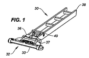
図1及び図2を参照して、かみそりカートリッジハンドル(ハンドル)30を提供する。第1タイプかみそりカートリッジ32の例は、米国特許第5,787,586号明細書及び米国特許第5,956,851号明細書に一般的に説明されており、これらの特許は、これによりその全体が引用によって組み込まれる。第2タイプかみそりカートリッジ34の例は、米国特許第7,168,173号明細書に説明されており、この特許は、これによりその全体が引用によって組み込まれる。以下により詳細に説明するように、両タイプのかみそりカートリッジ32、34は、接続部材(例えば、第1タイプかみそりカートリッジ接続部材37、第2タイプかみそりカートリッジ接続部材39)にピボット式に取り付けられた刃ユニット(例えば、第1タイプかみそりカートリッジ刃ユニット33、第2タイプかみそりカートリッジ刃ユニット35)を含む。
1 and 2, a razor cartridge handle (handle) 30 is provided. Examples of first
かみそりカートリッジハンドル30は、複数の異なるかみそりカートリッジタイプに接続するように構成され、与えられた時点でいずれかのタイプの単に1つのかみそりカートリッジが取り付けられ、各かみそりカートリッジタイプは、以下で説明するように、他のかみそりカートリッジタイプの取付機構とは異なるハンドル30への取付のための機構を有する。各タイプのかみそりカートリッジの接続部材は、その取付機構の少なくとも一部分を含む。
The razor cartridge handle 30 is configured to connect to a plurality of different razor cartridge types, and at any given time only one razor cartridge of any type is attached, each razor cartridge type as described below. In addition, it has a mechanism for attachment to the
図1〜4及び5A〜5Cを参照すると、かみそりカートリッジハンドル30は、カートリッジ端部36及び対向する端部38を含む。図1及び2、並びに図3〜5Cに示すかみそりカートリッジハンドル30は、本発明のかみそりカートリッジハンドル30の異なる実施形態である。本発明のかみそりカートリッジハンドル30は、これらの実施形態のいずれにも限定されない。以下では、本発明の開示を説明するのに使用する用語「かみそりカートリッジハンドル」は、それ以外に言及しない限り、これらの実施形態の両方を指すことになる。ハンドル30は、ハンドル30を人間工学的に保持しやすくするように湾曲させることができるが(例えば、図3〜5Cを参照)、いずれの特定の形状構成にも限定されない。
1-4 and 5A-5C, the razor cartridge handle 30 includes a
ハンドル30は、ハンドル30に対して第1の位置に通常は付勢されて通常位置(例えば、かみそりカートリッジが取り付けられた時)とカートリッジ−押し出し位置の間で平行移動可能であるエジェクタボタン40を含む。図1及び3に示すハンドル30の実施形態は、ハンドル30のカートリッジ端部36の近くに配置されたエジェクタボタン40を示している。ハンドル30は、この実施形態に限定されない。
The
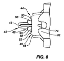
図3〜14を参照すると、ハンドル30は、拡張位置に存在するようにハンドルカートリッジ端部36から外向きに通常は付勢されている(例えば、バネにより)プランジャ42を含む。かみそりカートリッジがハンドル30に取り付けられた時に、プランジャ42は、かみそりカートリッジ刃ユニットのカム面と係合し、髭剃り中に刃ユニットが遭遇する力が取り除かれた時にハンドル30に対して刃ユニットを中立又は静止位置に付勢する。プランジャ42は、第1タイプかみそりカートリッジ32の刃ユニット33のカム面と、第2タイプかみそりカートリッジ34の刃ユニット35のカム面との両方と協働するように構成された遠位端43を含み、すなわち、本発明のプランジャ42は、両タイプのかみそりカートリッジと共に機能する。かみそりカートリッジ刃ユニットが、例えば髭剃り力の下で、中立位置から離れて回転すると、プランジャ42は、ハンドル30内に後退する。用語「協働する」は、プランジャ42の遠位端が、両タイプのかみそりカートリッジに対して刃ユニットの係合(例えば、意図する通常の付勢された位置での刃ユニットの位置決め)、プランジャ42の軸線方向移動、及び刃ユニット33、35の回転移動を容易にするように、回転移動刃ユニット33、35のカム面と係合する意味でこの段落で上記に使用されている。図10は、第2タイプかみそりカートリッジ34がハンドル30に取り付けられた本発明のハンドル30の実施形態の断面図を示し、通常の付勢された位置に配置されてその遠位端43が第2タイプかみそりカートリッジ34の刃ユニット35上のカム面45と係合したプランジャ42を示している。図11は、第1タイプかみそりカートリッジ32がハンドル30に取り付けられた本発明のハンドル30の実施形態の断面図を示し、通常の付勢された位置に配置されてその遠位端43が第1タイプかみそりカートリッジ32の刃ユニット33上のカム面47と係合したプランジャ42を示している。
3-14, the
ハンドル30は、第1のアーム46と第2のアーム48とを有するエジェクタ44を含む(例えば、図6、7、13、14を参照)。第1のアーム46は、遠位端50を含み、第2のアームも遠位端52を含む。エジェクタ44は、アーム46、48が実質的にハンドル30に存在する後退位置に通常は付勢されている(例えば、バネにより)。エジェクタ44は、エジェクタボタン40をカートリッジ−押し出し位置まで平行移動することにより、エジェクタアーム46、48が、ハンドルカートリッジ端部36から外向きに延び、エジェクタアーム46、48の遠位端50、52が、取り付けられたかみそりカートリッジと接触するように、エジェクタボタン40と連通している(例えば、図5Cを参照)。図13は、例えば、本発明のハンドル30の実施形態に取り付けられた第2タイプかみそりカートリッジ34の部分断面図である。図13に示す図では、エジェクタアーム46、48は、後退位置に示されており、各エジェクタアーム46、48の遠位端50、52が、第2タイプかみそりカートリッジ接続部材39(第2タイプかみそりカートリッジ接続部材39の更なる説明は以下に示されている)の端壁の一部を形成する片持ちラッチ54、56に位置合わせすることを見ることができる。図14は、本発明のハンドル30の実施形態に取り付けられた第1タイプかみそりカートリッジ32の部分断面図である。図14に示す図では、エジェクタアーム46、48は、後退位置に示されており、各エジェクタアーム46、48の遠位端50、52が、第1タイプかみそりカートリッジ接続部材37(第1タイプかみそりカートリッジ接続部材37の更なる説明は以下に示されている)の特徴要素に位置合わせすることを見ることができる。
The
従って、エジェクタアーム46、48の遠位端50、52は、第1タイプかみそりカートリッジ32の接続部材37の特徴要素と、同じく第2タイプかみそりカートリッジ34の接続部材39の特徴要素と協働し、それぞれのタイプのかみそりカートリッジ32、34を本発明のかみそりカートリッジハンドル30から取り外すことを可能にするように構成され、すなわち、本発明のエジェクタアーム46、48は、両タイプのかみそりカートリッジ32、34と共に機能することを上記から見ることができる。用語「協働する」は、エジェクタアーム46、48の遠位端50、52が、両タイプのかみそりカートリッジのそれぞれの接続部材37、39の特徴要素の係合を容易にするように構成され、そのタイプのかみそりカートリッジを本発明のかみそりカートリッジハンドル30から取り外すことを可能にする意味でこの段落で上記に使用されている。
Accordingly, the distal ends 50, 52 of the
図3〜9を参照すると、ハンドル30は、ハンドル30を第1タイプかみそりカートリッジ32に接続するように構成された第1アセンブリ58を含む。第1アセンブリ58は、ハンドル30のカートリッジ端部36から出て延びる本体60を含む。本体60は、第1タイプかみそりカートリッジ内に受け入れられるように構成される。図6〜9、14、及び15に見ることができるように、本体60は、第1タイプかみそりカートリッジ接続部材37の嵌合雌空洞部分に受け入れられるように構成された雄突出部であり、嵌合する雄突出部及び雌空洞は、「接続対」と呼ぶことができる。本体60は、対向する底部パネル64から離間した上部パネル62と、端部パネル66と、1対の側部パネル68とを含む。端部パネル66及び側部パネル68は、上部パネル及び底部パネル62、64の間を延びる。底部パネル64は、第1タイプかみそりカートリッジ32(例えば、以下に説明するように、図12、16を参照)に取り付けられたタブ72を受け入れるように位置決めされた1対のタブスロット70を含む。プランジャ42及びエジェクタアーム46、48は、上部パネル及び底部パネル62、64の間で、例えば、通常の付勢された位置に配置され、エジェクタアーム46、48は、実質的にハンドル30の本体60部分内に存在する。第1アセンブリ58は、上部パネル62から出て延びる傾斜タブ74(例えば、図7〜9を参照)を更に含む。傾斜タブ74は、交換第1タイプかみそりカートリッジ32を収容するのに使用されるカートリッジ取り出し器(図示せず)のタブ保持器部分と係合するように構成かつ位置決めされ、例えば、ハンドル30が、取り出し器内に配置された交換カートリッジと係合するように移動する時に、傾斜タブ74は、タブ保持具を変位させ、それによってハンドル30が交換かみそりカートリッジと接続することを可能にする。
With reference to FIGS. 3-9, the
第1アセンブリ58の完全な理解を与えるために、第1タイプかみそりカートリッジ32の一部の態様を簡単に説明することが有用である。図15及び16は、第1タイプかみそりカートリッジ32の図を示し、このカートリッジは、接続部材37にピボット式に取り付けられた刃ユニット33を含む。接続部材37は、1対の側壁78A、78Bによって部分的に形成された空洞76(すなわち、上述の接続対の雌部材)を含む。空洞76は、本発明のハンドル第1アセンブリ58の本体60(すなわち、接続対の雄突出部)を受け入れるように構成される。接続部材37は、本体底部パネル64に配置されたタブスロット70と係合するように構成された1対のタブ72を含む。
In order to provide a complete understanding of the
図6〜12を参照すると、上述のように、本発明のかみそりカートリッジハンドル30のエジェクタ44は、通常位置とカートリッジ−押し出し位置との間で平行移動可能である。第1タイプかみそりカートリッジ32を本発明のハンドル30に取り付けてエジェクタ44が通常位置にある時に、接続部材のタブ72は、本体60(例えば、図12を参照)に配置されたタブスロット70と係合し、それによってカートリッジ32が通常作動中にハンドル30から脱落するのを防止する。以下で更に説明するように、本発明のハンドル30は、本体上部パネル62から離間した上部位置付けパネル82と本体底部パネル64から離間した底部位置付けパネル84とを有する第2アセンブリ80を含む。第1タイプかみそりカートリッジ32がハンドル30に取り付けられた時に、第1タイプかみそりカートリッジ接続部材37の側壁78A、78Bのうちの一方は、上部位置付けパネル82と本体上部パネル62の間の間隙に配置され、他方の側壁78A、78Bは、底部位置付けパネル84と本体底部パネル64の間の間隙に配置される。エジェクタアーム46、48は、第1タイプかみそりカートリッジ32に配置された特徴要素と係合するように構成される。エジェクタ44が、カートリッジ−押し出し位置の中に平行移動された時に、エジェクタアーム46、48は、特徴要素と係合し、それら及び取り付けられたタブ72を偏向させ、タブ72を本体上部パネル64内のタブスロット70から係合解除させ、それによってかみそりカートリッジ32をハンドル30から取り外すことを可能にする。
Referring to FIGS. 6-12, as described above, the
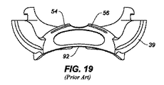
第2アセンブリ80は、ハンドル30を第2タイプかみそりカートリッジ34に接続するように構成される。第2アセンブリ80は、本体端部パネル66(例えば、図8、9、及び13を参照)から外向きに延びる楔形突出部86を含む。突出部86は、1対の側壁88と、端部パネル90とを含み、この側壁88は、端壁90から本体端部パネル66に延び、この側壁88は、本体端部パネル66の方向に互いに向けて収束する。楔形突出部86は、大きい遠位端(端壁90での)及び比較的小さい端部(本体端部パネル66での)を有すると説明することができる。上述のように、第2アセンブリ80は、本体上部パネル62から離間した上部位置付けパネル82(すなわち、間隙が上部位置付けパネル82を本体上部パネル62から分離する)と、本体底部パネル64から離間した底部位置付けパネル84(すなわち、間隙が底部位置付けパネル84を本体上部パネル64から分離する)とを更に含み、例えば、図10を参照されたい。以下に説明するように、上部位置付けパネル及び底部位置付けパネル82、84は、第2タイプかみそりカートリッジ34(例えば、図10を参照)の接続部材39に配置された空洞92内に受け入れられるように構成される。上部位置付けパネル82は、第2タイプかみそりカートリッジ34の空洞と嵌合するように弓形に成形された遠位縁94を有する。底部位置付けパネル84も、第2タイプかみそりカートリッジ34の空洞と嵌合するように弓形に成形された遠位縁96を有する。例えば、図6及び7に示す実施形態において、上部位置付けパネル及び底部位置付けパネル82、84の遠位縁94、96の曲率は、互いに異なっている。第2アセンブリ80は、底部位置付けパネル84から出て延びる突出部98を更に含み、突出部98は、第2タイプかみそりカートリッジ接続部材39の縁部と係合して第2タイプかみそりカートリッジ34とハンドル30の間の移動を防止するように位置決めされる。上部位置付けパネル82は、第1タイプかみそりカートリッジ32を収容するのに使用されるカートリッジ取り出し器(図示せず)のタブ保持器部分を受け入れるように構成されたスロット100(例えば、図8を参照)を含む。
The
第2アセンブリ80の完全な理解を与えるために、第2タイプかみそりカートリッジ34の一部の態様を簡単に説明することが有用である。図17及び18は、それぞれ第2タイプかみそりカートリッジ34の前面及び後面図である。図19及び20は、それぞれ第2タイプかみそりカートリッジ34の接続部材39の前面及び底面図である。上述のように、第2タイプかみそりカートリッジ34は、接続部材39にピボット式に取り付けられた刃ユニット35を含む。接続部材39は、側壁102と端壁とによって部分的に形成された空洞92を有する本体を含み、例えば、図10を参照されたい。1対の片持ちラッチ56A、56Bが、端壁の一部を形成する。各片持ちラッチ54、56は、端壁を通って延びる開口部の一部分を形成する自由遠位端54A、56A(図20を参照)含み、その開口部は、幅「W」を有する。
In order to provide a complete understanding of the
ここで図13を参照すると、第2タイプカートリッジは、本発明のハンドル30に接続されて略図様式で部分的に示されている。第2タイプかみそりカートリッジ34及び本発明のハンドル30が取り付けられた時に、第2タイプかみそりカートリッジ接続部材39のラッチ54、56の遠位端は、楔形突出部86の側壁88と係合する。楔形は、かみそりの通常作動中にハンドル30からの第2タイプかみそりカートリッジ34の取り外しを抑制する。
Referring now to FIG. 13, the second type cartridge is shown partially in schematic form connected to the
図10を参照すると、第2タイプカートリッジがハンドル30に取り付けられた時に、上部位置付けパネル及び底部位置付けパネル82、84は、空洞92のそれぞれの側部の近傍で第2のかみそりタイプの接続部材に配置された空洞92内に受け入れられ、ハンドル30と第2タイプかみそりカートリッジ34の間の相対移動を抑制する。底部位置付けパネル84から出て延びる突出部98は、第2タイプかみそりカートリッジ接続部材39の縁部と係合し、同じく第2タイプかみそりカートリッジ34とハンドル30の間の移動を抑制する。
Referring to FIG. 10, when the second type cartridge is attached to the
上述のように、エジェクタ44(すなわち、第1タイプかみそりカートリッジ32と係合解除するように作動可能な同じエジェクタ44)は、通常位置とカートリッジ−押し出し位置との間で平行移動可能である。エジェクタアーム46、48は、接続部材39の片持ちラッチ54、56部分と係合するように構成される。エジェクタ44がカートリッジ−押し出し位置の中に平行移動された時に、エジェクタアーム46、48は、片持ちラッチ54、56と係合し、それらを楔形突出部86との係合から出るように偏向させ、それによってハンドル30からの第2タイプかみそりカートリッジ34の取り外しを可能にする。
As described above, the ejector 44 (ie, the
図21を参照すると、ハンドル30のカートリッジ端部36を示す本発明のかみそりカートリッジハンドル30の別の実施形態の部分概略斜視図が示されている。この実施形態は、上述のように、エジェクタボタン40、プランジャ42、及びエジェクタ44を含む。この実施形態は、上述のように、ハンドル30を第1タイプかみそりカートリッジ32(図示せず)に接続するように構成された第1アセンブリ58を更に含む。この実施形態はまた、ハンドル30を第2タイプかみそりカートリッジ34(図示せず)に接続するように構成された第2アセンブリ80を含む。第2アセンブリは、上部位置付けパネル82及び底部位置付けパネル84を含む。この実施形態において、上部位置付けパネル及び底部位置付けパネル82、84の一方又は両方には、タブ110が設けられている。タブは、図示のように、あらゆる位置付けパネルから外向きに延びる。図22は、ハンドル30に取り付けられた(明瞭化のためにプランジャ42及びエジェクタ44が省略された)第2タイプかみそりカートリッジ34の接続部材39の一部分を示す図21の部分断面側面図である。図示のように、上部位置付けパネル82及び底部位置付けパネル84の両方には、タブ110が設けられている。接続部材39には、タブ110を受け入れ、それによって第2タイプかみそりカートリッジ34をハンドル30に取り付けようにスロット112が設けられている。
Referring to FIG. 21, a partial schematic perspective view of another embodiment of the razor cartridge handle 30 of the present invention showing the
図21では、ハンドル30には、横方向に対向する安定化突出部114、116が設けられている。図23は、単に例示的な目的のために(第1タイプかみそりカートリッジの接続部材37は、一点鎖線で示されている)、同時にハンドル30に取り付けられた第1及び第2タイプかみそりカートリッジ32、34の接続部材37、39の断片を示す図21の略図又は概略断面上面図である。安定化突出部114及び116は、これに代えて、第2タイプかみそりカートリッジ34の接続部材39に嵌合するか又は第1タイプかみそりカートリッジ32の接続部材37の外部であり、ユーザがいずれかのタイプのかみそりカートリッジをハンドルに取り付ける時にガイダンスを提供し、ハンドル30に対して左右に(図23の平面に示すように時計回り/反時計回り)又は横方向に揺動するいずれのタイプのかみそりカートリッジに対しても抵抗するように意図している。
In FIG. 21, the
本発明のハンドル30は、第1タイプかみそりカートリッジ32及び第2タイプかみそりカートリッジ34の両方と共に全てが作動するようになったエジェクタボタン40、エジェクタ44、及びプランジャ42を含み、例えば、プランジャ42は、両タイプのかみそりカートリッジ32、34の後部部分を付勢してハンドル30から離れて回転するように作動可能であり、エジェクタ44及びエジェクタボタン44は、ハンドル30から両タイプのかみそりカートリッジ32、34を係合解除するように起動することができることは上記から見ることができる。その結果、本発明のハンドル30は、複数の異なるタイプのかみそりカートリッジを単一ハンドルと共に使用することを可能にし(ハンドルとは無関係のアダプタのための費用又は必要性なしで)、それによっていずれのタイプのかみそりカートリッジの作動も損なうことなくハンドルの多様性を大きく増大させる。
The
当業者は、以下の特許請求の範囲によって定められるような本発明の開示の真の範囲から逸脱することなく変形及び修正を行うことができることを認識するであろう。例えば、いずれか1つの実施形態に関連して開示した特徴は、単独で又はそれぞれの他の実施形態の各特徴と組み合わせて使用することができる。 Those skilled in the art will recognize that variations and modifications can be made without departing from the true scope of the present disclosure as defined by the following claims. For example, the features disclosed in connection with any one embodiment can be used alone or in combination with each feature of each other embodiment.
30 かみそりカートリッジハンドル
32 かみそりカートリッジ
33 刃ユニット
36 カートリッジ端部
40 エジェクタボタン
30 Razor cartridge handle 32
Claims (18)
カートリッジ端部及び対向する端部と、
前記第1タイプかみそりカートリッジをハンドルの前記カートリッジ端部に接続するように構成された第1アセンブリ、及び前記第2タイプかみそりカートリッジをハンドルの該カートリッジ端部に接続するように構成された第2アセンブリであって、該第1及び第2アセンブリが、一度に単一のかみそりカートリッジだけをハンドルに取り付けることができるように構成され、この取り付けられたかみそりカートリッジが、第1タイプかみそりカートリッジ又は第2タイプかみそりカートリッジのいずれかである前記第1アセンブリ及び前記第2アセンブリと、
ハンドルに対して第1の位置に通常は付勢され、かつ押し出し位置まで平行移動可能であるエジェクタボタンと、
遠位端を有する第1のアームと遠位端を有する第2のアームとを有し、該アームが実質的にハンドル内に存在する後退位置に通常は付勢されているエジェクタであって、前記エジェクタボタンを前記押し出し位置まで平行移動することにより、該エジェクタアームが、前記ハンドルカートリッジ端部から外向きに延び、かつ該エジェクタアームの該遠位端が、前記取り付けられたかみそりカートリッジに接触するように、該エジェクタボタンと連通している前記エジェクタと、
遠位端を有し、拡張位置に存在するように前記ハンドルカートリッジ端部から外向きに通常は付勢されているプランジャであって、該拡張位置では、該プランジャの該遠位端が、前記取り付けられたかみそりカートリッジと接触している前記プランジャと、
を含むことを特徴とするハンドル。 A razor cartridge handle configured to be connected to a first type razor cartridge and configured to be connected to a second type razor cartridge, wherein the first type razor cartridge is different from the second type razor cartridge. Because
A cartridge end and an opposite end;
A first assembly configured to connect the first type razor cartridge to the cartridge end of the handle, and a second assembly configured to connect the second type razor cartridge to the cartridge end of the handle. The first and second assemblies are configured such that only a single razor cartridge can be attached to the handle at a time, the attached razor cartridge being a first type razor cartridge or a second type The first assembly and the second assembly being any of a razor cartridge;
An ejector button that is normally biased to a first position relative to the handle and is translatable to an extruded position;
An ejector having a first arm having a distal end and a second arm having a distal end, wherein the arm is normally biased to a retracted position substantially within the handle, By translating the ejector button to the push position, the ejector arm extends outwardly from the handle cartridge end and the distal end of the ejector arm contacts the attached razor cartridge. The ejector in communication with the ejector button;
A plunger having a distal end and normally biased outwardly from the handle cartridge end to be in the expanded position, wherein the distal end of the plunger is the The plunger in contact with an attached razor cartridge;
A handle characterized by including.
前記プランジャ及びエジェクタアームは、実質的に前記上部及び底部パネル間に配置される、
ことを特徴とする請求項1に記載のかみそりカートリッジハンドル。 The first assembly includes a body extending outwardly from the cartridge end of a handle, the body configured to be received within a connection member of the first type razor cartridge, the body having an opposing bottom A top panel spaced from the panel and an end panel extending between the top and bottom panels, the bottom panel including a pair of tab slots;
The plunger and ejector arm are disposed substantially between the top and bottom panels;
The razor cartridge handle according to claim 1.
前記第2アセンブリは、前記本体端部パネルから外向きに延びる楔形突出部を更に含み、この突出部は、1対の側壁と、端壁とを含み、これらの側壁は、該端壁から該本体端部パネルまで延びて互いに向けて収束する、
ことを特徴とする請求項1に記載のかみそりカートリッジハンドル。 The first assembly includes a body extending outwardly from the cartridge end of the handle, the body including a top panel spaced from an opposing bottom panel and an end panel extending between the top and bottom panels. ,
The second assembly further includes a wedge-shaped protrusion that extends outwardly from the body end panel, the protrusion including a pair of side walls and an end wall that extends from the end wall to the end wall. Extend to the body end panel and converge towards each other,
The razor cartridge handle according to claim 1.
前記第1タイプかみそりカートリッジをハンドルのカートリッジ端部に接続するように構成された第1アセンブリ、及び前記第2タイプかみそりカートリッジをハンドルの該カートリッジ端部に接続するように構成された第2アセンブリであって、該第1及び第2アセンブリが、一度に単一のかみそりカートリッジだけをハンドルに取り付けることができるように構成され、この取り付けられたかみそりカートリッジが、該第1タイプかみそりカートリッジ又は該第2タイプかみそりカートリッジのいずれかである前記第1アセンブリ及び前記第2アセンブリと、
取り付けられた第1タイプかみそりカートリッジを選択的に押し出すように作動可能、かつ取り付けられた第2タイプかみそりカートリッジを選択的に押し出すように作動可能なかみそりカートリッジエジェクタと、
遠位端を有するプランジャであって、該プランジャの該遠位端が、前記取り付けられたかみそりカートリッジと接触している位置まで通常は付勢されている前記プランジャと、
を含むことを特徴とするハンドル。 A razor cartridge handle configured to be connected to a first type razor cartridge and configured to be connected to a second type razor cartridge, wherein the first type razor cartridge is different from the second type razor cartridge. Because
A first assembly configured to connect the first type razor cartridge to a cartridge end of the handle, and a second assembly configured to connect the second type razor cartridge to the cartridge end of the handle; And wherein the first and second assemblies are configured such that only a single razor cartridge can be attached to the handle at a time, the attached razor cartridge being the first type razor cartridge or the second The first assembly and the second assembly being any of a type razor cartridge;
A razor cartridge ejector operable to selectively extrude an attached first type razor cartridge and operable to selectively extrude an attached second type razor cartridge;
A plunger having a distal end, wherein the plunger is normally biased to a position where the distal end of the plunger is in contact with the attached razor cartridge;
A handle characterized by including.
前記エジェクタは、遠位端を有する第1のアームと遠位端を有する第2のアームとを含み、
前記プランジャの少なくとも一部分と、エジェクタアームとは、前記上部及び底部パネル間に配置される、
ことを特徴とする請求項10に記載のかみそりカートリッジハンドル。 The first assembly includes a body extending outwardly from the cartridge end of a handle, the body configured to be received within a connection member of the first type razor cartridge, the body having an opposing bottom A top panel spaced from the panel and an end panel extending between the top and bottom panels, the bottom panel including a pair of tab slots;
The ejector includes a first arm having a distal end and a second arm having a distal end;
At least a portion of the plunger and an ejector arm are disposed between the top and bottom panels;
The razor cartridge handle according to claim 10.
前記第2アセンブリは、前記本体端部パネルから外向きに延びる楔形突出部を更に含む、
ことを特徴とする請求項10に記載のかみそりカートリッジハンドル。 The first assembly includes a body extending outwardly from the cartridge end of the handle, the body including a top panel spaced from an opposing bottom panel and an end panel extending between the top and bottom panels. ,
The second assembly further includes a wedge-shaped protrusion extending outwardly from the body end panel.
The razor cartridge handle according to claim 10.
Applications Claiming Priority (3)
| Application Number | Priority Date | Filing Date | Title |
|---|---|---|---|
| US201462062221P | 2014-10-10 | 2014-10-10 | |
| US62/062,221 | 2014-10-10 | ||
| PCT/US2015/054583 WO2016057732A1 (en) | 2014-10-10 | 2015-10-08 | Universal razor cartridge handle |
Publications (2)
| Publication Number | Publication Date |
|---|---|
| JP2017530807A true JP2017530807A (en) | 2017-10-19 |
| JP6502487B2 JP6502487B2 (en) | 2019-04-17 |
Family
ID=54345602
Family Applications (1)
| Application Number | Title | Priority Date | Filing Date |
|---|---|---|---|
| JP2017519254A Active JP6502487B2 (en) | 2014-10-10 | 2015-10-08 | Universal razor cartridge handle |
Country Status (6)
| Country | Link |
|---|---|
| US (2) | US9999981B2 (en) |
| EP (3) | EP3204198B1 (en) |
| JP (1) | JP6502487B2 (en) |
| AU (1) | AU2015330925B2 (en) |
| PL (2) | PL3385043T3 (en) |
| WO (1) | WO2016057732A1 (en) |
Cited By (1)
| Publication number | Priority date | Publication date | Assignee | Title |
|---|---|---|---|---|
| JP2021504042A (en) * | 2017-11-28 | 2021-02-15 | エッジウェル パーソナル ケア ブランズ リミテッド ライアビリティ カンパニーEdgewell Personal Care Brands, LLC | Razor handle |
Families Citing this family (24)
| Publication number | Priority date | Publication date | Assignee | Title |
|---|---|---|---|---|
| EP3204198B1 (en) * | 2014-10-10 | 2020-09-30 | Edgewell Personal Care Brands, LLC | Universal razor cartridge handle |
| US10131063B2 (en) * | 2015-09-29 | 2018-11-20 | The Gillette Company Llc | Adapter for attaching a razor cartridge to a razor handle |
| US20170087733A1 (en) * | 2015-09-29 | 2017-03-30 | The Gillette Company | Kit Comprising A Razor Cartridge And An Adapter |
| JP6588162B2 (en) * | 2015-11-20 | 2019-10-09 | ドルコ・カンパニー・リミテッドDorco Co., Ltd. | Handle assembly and razor including the same |
| US11052558B2 (en) * | 2016-05-31 | 2021-07-06 | The Gillette Company Llc | Adapter for a handle and a cartridge of different razor systems |
| KR102663783B1 (en) | 2017-03-10 | 2024-05-07 | 빅 비올렉스 싱글 멤버 에스.아. | Razor handle, razor comprising such handle, and method of manufacturing the same |
| EP3546159B1 (en) * | 2018-03-30 | 2022-08-03 | The Gillette Company LLC | Razor mechanisms |
| WO2019191345A1 (en) | 2018-03-30 | 2019-10-03 | The Gillette Company Llc | Razor handle with a pivoting portion |
| JP2021517043A (en) | 2018-03-30 | 2021-07-15 | ザ ジレット カンパニー リミテッド ライアビリティ カンパニーThe Gillette Company Llc | Razor handle with pivot part |
| USD874061S1 (en) | 2018-03-30 | 2020-01-28 | The Gillette Company Llc | Shaving razor cartridge |
| BR112020020123A2 (en) | 2018-03-30 | 2021-01-26 | The Gillette Company Llc | shaver or shaving handle with a pivoting portion |
| EP3546156B1 (en) | 2018-03-30 | 2021-03-10 | The Gillette Company LLC | Razor handle with a pivoting portion |
| US11607820B2 (en) | 2018-03-30 | 2023-03-21 | The Gillette Company Llc | Razor handle with movable members |
| WO2019191163A1 (en) | 2018-03-30 | 2019-10-03 | The Gillette Company Llc | Razor handle with a pivoting portion |
| BR112020020132A2 (en) | 2018-03-30 | 2021-01-05 | The Gillette Company Llc | HANDLE OF SHAVING OR DEVILING APPLIANCE WITH MOBILE LIMBS |
| CN111819046B (en) | 2018-03-30 | 2022-09-13 | 吉列有限责任公司 | Razor handle with movable member |
| AU2019242730A1 (en) | 2018-03-30 | 2020-09-24 | The Gillette Company Llc | Razor handle with movable members |
| CN111801201B (en) | 2018-03-30 | 2022-06-03 | 吉列有限责任公司 | Razor cartridge |
| EP3744490B1 (en) * | 2019-05-29 | 2022-11-09 | BIC Violex Single Member S.A. | Handle assembly and recycling process therefor |
| EP3771530B1 (en) | 2019-07-31 | 2024-08-28 | BIC Violex Single Member S.A. | Mechanical assembly of a skin care device, skin care device and process for manufacturing thereof |
| WO2021076116A1 (en) * | 2019-10-16 | 2021-04-22 | Yigal Mesika | Shaving apparatus having a razor handle for disposable razor cartridges |
| EP3888861B1 (en) | 2020-03-30 | 2024-06-26 | BIC Violex Single Member S.A. | Coupling mechanism |
| USD953640S1 (en) * | 2020-12-04 | 2022-05-31 | Athena Club Holdings, Inc. | Razor handle |
| DE102022120574A1 (en) * | 2022-08-16 | 2024-02-22 | PAPACKS SALES GmbH | razor |
Citations (3)
| Publication number | Priority date | Publication date | Assignee | Title |
|---|---|---|---|---|
| US20080034589A1 (en) * | 2006-08-11 | 2008-02-14 | Nearing Matthew E | Razor cartridge adapter |
| JP2013541405A (en) * | 2011-02-09 | 2013-11-14 | ザ ジレット カンパニー | Swivel razor |
| US8683701B1 (en) * | 2012-02-10 | 2014-04-01 | Jonathan L. Loftin | Vibrating razor handle assembly |
Family Cites Families (109)
| Publication number | Priority date | Publication date | Assignee | Title |
|---|---|---|---|---|
| US4198746A (en) * | 1977-06-09 | 1980-04-22 | The Gillette Company | All plastic swivel head razor handle |
| US4266340A (en) * | 1979-06-11 | 1981-05-12 | Warner-Lambert Company | Razor handle for mounting pivotable razor blade cartridges |
| US4339876A (en) | 1980-11-03 | 1982-07-20 | Davis Alton A | Shaving system and method |
| US4428116A (en) * | 1981-03-02 | 1984-01-31 | Warner-Lambert Company | Support for releasably retaining a blade cartridge |
| US4461078A (en) | 1982-02-01 | 1984-07-24 | Carreker Reginald V | Styling razor |
| US4446619A (en) * | 1982-06-07 | 1984-05-08 | The Gillette Company | Razor handle |
| US4501066A (en) | 1983-04-11 | 1985-02-26 | Sceberras Conrad T | Dual headed razor system |
| USD319893S (en) * | 1988-09-30 | 1991-09-10 | Wilkinson Sword Limited | Razor handle |
| USD325689S (en) * | 1989-08-07 | 1992-04-28 | The Gilette Company | Razor handle |
| US4989328A (en) | 1990-03-16 | 1991-02-05 | Daniel Sokoloff | Dual headed razor assembly |
| US5016352A (en) * | 1990-03-22 | 1991-05-21 | The Gillette Company | Single button razor |
| US5333383A (en) * | 1990-04-10 | 1994-08-02 | Warner-Lambert Company | Razor handle mechanism with convex-concave slidable cartridge support |
| USD327550S (en) * | 1990-04-10 | 1992-06-30 | Warner-Lambert Company | Razor handle |
| US5157834A (en) * | 1990-04-10 | 1992-10-27 | Warner-Lambert Company | Razor mechanism with slidable cartridge support |
| US5027511A (en) * | 1990-09-28 | 1991-07-02 | The Gillette Company | Shaving system |
| USD355049S (en) * | 1991-02-04 | 1995-01-31 | Warner-Lambert Company | Razor handle |
| USD363142S (en) * | 1991-06-26 | 1995-10-10 | The Gillette Company | Razor handle |
| EP1645376B1 (en) * | 1991-11-27 | 2008-02-20 | The Gillette Company | Razors |
| US5669139A (en) * | 1991-11-27 | 1997-09-23 | The Gillette Company | Razor with blade protection means |
| GB9208098D0 (en) * | 1992-04-13 | 1992-05-27 | Gillette Co | Razor with movable cartridge |
| USD352689S (en) | 1993-08-16 | 1994-11-22 | Niemier Timothy A | Water craft |
| US5347717A (en) * | 1993-11-05 | 1994-09-20 | Ts Ai Tse Jen | Chuck assembly for a disposable razor |
| USD378623S (en) * | 1994-06-03 | 1997-03-25 | American Safety Razor Company | Razor handle |
| USD365419S (en) * | 1994-07-07 | 1995-12-19 | Feather Safety Razor Co., Ltd. | Razor handle |
| USD389955S (en) * | 1996-02-09 | 1998-01-27 | American Safety Razor Company | Razor handle |
| US5956851A (en) | 1996-04-10 | 1999-09-28 | The Gillette Company | Shaving system including handle and replaceable cartridges |
| US5787586A (en) | 1996-04-10 | 1998-08-04 | The Gillette Company | Shaving system and method |
| USD397512S (en) * | 1996-04-10 | 1998-08-25 | The Gillette Company | Razor handle |
| US6085426A (en) * | 1996-04-10 | 2000-07-11 | The Gillette Company | Dispensing razor blade cartridges used with a handle |
| US5784790A (en) * | 1996-04-10 | 1998-07-28 | The Gillette Company | Shaving razor and method |
| USD392417S (en) * | 1996-04-10 | 1998-03-17 | The Gillette Company | Razor handle |
| USD406393S (en) * | 1996-04-10 | 1999-03-02 | The Gillette Company | Razor handle |
| US5953824A (en) * | 1997-09-23 | 1999-09-21 | Warner-Lambert Company | Razors providing pivoting and swivelling razor head support |
| US5906027A (en) | 1997-11-24 | 1999-05-25 | Barous; Paul R. | Handle with interchangeable implements |
| US6070478A (en) | 1998-02-19 | 2000-06-06 | Hewlett-Packard Company | Removable fixture adapter with RF connections |
| USD417034S (en) * | 1998-04-24 | 1999-11-23 | The Gillette Company | Razor handle button |
| USD407851S (en) * | 1998-04-24 | 1999-04-06 | The Gillette Company | Razor handle |
| USD408101S (en) * | 1998-04-24 | 1999-04-13 | The Gillette Company | Razor handle grip |
| US6581290B1 (en) | 1998-09-08 | 2003-06-24 | Rhonda Fishel | Shaving system with variable sized razor cartridges |
| US6052905A (en) | 1999-01-02 | 2000-04-25 | Branchinelli; Anthony | Dual sculptor retractable razor |
| USD429034S (en) * | 1999-04-23 | 2000-08-01 | The Gillette Company | Razor handle button |
| US6425184B1 (en) * | 1999-09-17 | 2002-07-30 | Bo Sik Min | Wet shaving razor having a blade assembly moveable in a plurality of directions |
| US6493950B1 (en) * | 2000-06-23 | 2002-12-17 | Rolling Razor, L.L.C. | Rolling razor and shaving method |
| KR100352838B1 (en) * | 2000-06-24 | 2002-09-16 | 주식회사 도루코 | Shaver |
| US6560881B2 (en) * | 2001-02-28 | 2003-05-13 | Warner-Lambert Company | Shaving razor with pivoting blade carrier and replaceable blade cartridge therefor |
| US20020116831A1 (en) * | 2001-02-28 | 2002-08-29 | Coffin David C. | Apparatus for releasably retaining a disposable razor cartridge |
| US6560876B2 (en) | 2001-06-26 | 2003-05-13 | Michael Bryan Strahley Carr | Dual headed razor |
| AU2003212586A1 (en) * | 2002-05-16 | 2003-12-02 | Warner-Lambert Company Llc | Razor cartridge mounting structure |
| USD500888S1 (en) * | 2003-01-31 | 2005-01-11 | The Gillette Company | Razor |
| ATE375850T1 (en) * | 2003-02-25 | 2007-11-15 | Eveready Battery Inc | SHAVER |
| EP1608491A1 (en) * | 2003-03-28 | 2005-12-28 | Eveready Battery Company, Inc. | Ergonomic handle for a shaving implement |
| USD495828S1 (en) * | 2003-12-23 | 2004-09-07 | The Gillette Company | Razor handle |
| US7168173B2 (en) | 2004-03-11 | 2007-01-30 | The Gillette Company | Shaving system |
| EP1789238B1 (en) * | 2004-09-07 | 2008-03-19 | BIC Violex S.A. | Razor handle and shaver including such a handle |
| US8033023B2 (en) | 2004-10-20 | 2011-10-11 | The Gillette Company | Shaving razors and cartridges |
| US7219430B2 (en) * | 2005-03-08 | 2007-05-22 | The Gillette Company | Oscillating razors |
| EP1885527B1 (en) * | 2005-04-05 | 2011-03-30 | Eveready Battery Company, Inc. | Shaving implement having a moving blade |
| JP4875074B2 (en) * | 2005-06-20 | 2012-02-15 | エバレデイ バツテリ カンパニー インコーポレーテツド | Shaving device with cap forward pivot |
| US20090119924A1 (en) * | 2005-09-06 | 2009-05-14 | Ioannis Bozikis | Vibrating wet shaver |
| US20080000089A1 (en) * | 2006-01-05 | 2008-01-03 | Eveready Battery Company, Inc. | Multi-use shaving implement |
| US7526869B2 (en) * | 2006-06-08 | 2009-05-05 | Eveready Battery Company, Inc. | Razor handle |
| US20070283567A1 (en) * | 2006-06-13 | 2007-12-13 | Magli Anthony J | Dual headed razor |
| US7461458B2 (en) * | 2006-06-14 | 2008-12-09 | Eveready Battery Company, Inc. | Wet shaving razor |
| ES2368897T3 (en) * | 2006-08-25 | 2011-11-23 | Bic Violex S.A. | SHAVING BLADE UNIT AND SHAVING MACHINE THAT HAS SUCH BLADE UNIT. |
| US8869809B2 (en) * | 2007-02-12 | 2014-10-28 | The Gillette Company | Shaving system |
| KR100903191B1 (en) * | 2007-05-31 | 2009-06-17 | 주식회사 도루코 | Shaver |
| US7770294B2 (en) * | 2007-08-30 | 2010-08-10 | The Gillette Company | Razor with blade unit biasing member |
| US7877880B2 (en) | 2007-08-31 | 2011-02-01 | The Gillette Company | Hand held personal care appliance |
| US8230600B2 (en) * | 2007-09-17 | 2012-07-31 | The Gillette Company | Cartridge detachment sensor |
| BRPI0822615A2 (en) * | 2008-04-11 | 2015-06-23 | Bic Violex Sa | Shaver cord for a retractable shaver cartridge and a shaver comprising such shaver cord |
| US20090293292A1 (en) * | 2008-05-27 | 2009-12-03 | Christopher Ramm | Resilient razor handle |
| US20100005669A1 (en) * | 2008-07-14 | 2010-01-14 | Florina Winter | Razor Handle |
| JP5465869B2 (en) * | 2008-12-05 | 2014-04-09 | 株式会社貝印刃物開発センター | Replaceable blade razor |
| GB2457974A (en) | 2008-12-08 | 2009-09-02 | Ferdinal Constantine Knight | Dual headed razor |
| US8474144B2 (en) * | 2009-08-12 | 2013-07-02 | The Gillette Company | Safety razor with rotational movement and locking button |
| US8387259B2 (en) | 2009-08-20 | 2013-03-05 | Carol Starr | Dual headed razor blade system |
| US20110088269A1 (en) * | 2009-10-21 | 2011-04-21 | Walker Jr Vincent Paul | Docking Mechanisms for Shaving Razors and Cartridges |
| USD624701S1 (en) * | 2010-01-31 | 2010-09-28 | Dorco Co., Ltd. | Razor handle |
| US8793880B2 (en) * | 2010-02-16 | 2014-08-05 | The Gillette Company | Shaving razor adapter attaching a shaving razor cartridge to a shaving razor handle |
| US8732955B2 (en) * | 2010-10-20 | 2014-05-27 | The Gillette Company | Shaving razor including a biasing member producing a progressively increasing cartridge return torque |
| USD652991S1 (en) * | 2010-11-17 | 2012-01-24 | The Gillette Company | Razor handle |
| USD651345S1 (en) * | 2011-04-28 | 2011-12-27 | Eveready Battery Company, Inc. | Safety razor handle |
| USD674551S1 (en) * | 2012-06-27 | 2013-01-15 | Eveready Battery Company, Inc. | Safety razor handle |
| USD674552S1 (en) * | 2012-06-28 | 2013-01-15 | Eveready Battery Comapny, Inc. | Safety razor handle |
| USD674553S1 (en) * | 2012-06-29 | 2013-01-15 | Eveready Battery Company, Inc. | Safety razor handle |
| USD699395S1 (en) * | 2012-08-17 | 2014-02-11 | Dorco Co., Ltd. | Razor handle |
| USD699000S1 (en) * | 2012-08-17 | 2014-02-04 | Dorco Co., Ltd. | Razor handle |
| US20140116211A1 (en) * | 2012-10-25 | 2014-05-01 | Shavelogic, Inc. | Dedicated Attachment Systems for Consumer Products |
| WO2014089758A1 (en) * | 2012-12-11 | 2014-06-19 | Ren Xiangrong | Handle for shaver, and shaver |
| WO2014094909A1 (en) * | 2012-12-21 | 2014-06-26 | Bic-Violex Sa | Shaver |
| USD695960S1 (en) * | 2013-01-25 | 2013-12-17 | The Gillette Company | Handle for a razor |
| US9643327B2 (en) * | 2013-02-20 | 2017-05-09 | The Gillette Company | Wet shaving razor |
| US20140230258A1 (en) * | 2013-02-20 | 2014-08-21 | The Gillette Company | Compact hand held device |
| USD700996S1 (en) * | 2013-03-07 | 2014-03-11 | ADKM Inc. | Razor handle |
| USD700995S1 (en) * | 2013-03-07 | 2014-03-11 | ADKM Inc. | Razor handle |
| WO2014143790A1 (en) * | 2013-03-15 | 2014-09-18 | Prime 9 Shave, Inc. | Multi-headed safety razor |
| US9579809B2 (en) * | 2013-12-20 | 2017-02-28 | The Gillette Company Llc | Removable razor cartridge having magnetic elements |
| BR112016023605B1 (en) * | 2014-04-16 | 2021-03-30 | Bic-Violex Sa | CABLE FOR SHAVING EQUIPMENT, SHAVING EQUIPMENT AND METHOD OF MANUFACTURING A CABLE |
| EP2962815A1 (en) * | 2014-07-02 | 2016-01-06 | The Gillette Company | Shaving razor pivot lock |
| EP3204198B1 (en) * | 2014-10-10 | 2020-09-30 | Edgewell Personal Care Brands, LLC | Universal razor cartridge handle |
| USD749267S1 (en) * | 2014-11-24 | 2016-02-09 | EdgewellPersonal Care Brands, LLC | Safety razor handle |
| JP1545604S (en) * | 2015-03-06 | 2016-03-14 | ||
| JP1557812S (en) * | 2015-06-25 | 2016-09-05 | ||
| USD779122S1 (en) * | 2015-11-03 | 2017-02-14 | Dollar Shave Club, Inc. | Razor handle |
| USD778500S1 (en) * | 2015-11-03 | 2017-02-07 | Dollar Shave Club, Inc. | Razor handle |
| USD778499S1 (en) * | 2015-11-03 | 2017-02-07 | Dollar Shave Club, Inc. | Razor handle |
| USD776876S1 (en) * | 2015-12-16 | 2017-01-17 | Project Razor Llc | Shaving razor handle |
| WO2019046097A1 (en) * | 2017-08-28 | 2019-03-07 | Edgewell Personal Care Brands, Llc | Razor cartridge connector |
| JP7235746B2 (en) * | 2017-11-28 | 2023-03-08 | エッジウェル パーソナル ケア ブランズ リミテッド ライアビリティ カンパニー | razor handle |
-
2015
- 2015-10-08 EP EP15784525.6A patent/EP3204198B1/en active Active
- 2015-10-08 EP EP20196348.5A patent/EP3782781B1/en active Active
- 2015-10-08 AU AU2015330925A patent/AU2015330925B2/en active Active
- 2015-10-08 JP JP2017519254A patent/JP6502487B2/en active Active
- 2015-10-08 PL PL18170656.5T patent/PL3385043T3/en unknown
- 2015-10-08 WO PCT/US2015/054583 patent/WO2016057732A1/en active Application Filing
- 2015-10-08 PL PL20196348.5T patent/PL3782781T3/en unknown
- 2015-10-08 EP EP18170656.5A patent/EP3385043B1/en active Active
- 2015-10-08 US US14/877,999 patent/US9999981B2/en active Active
-
2018
- 2018-03-14 US US15/920,762 patent/US10807259B2/en active Active
Patent Citations (3)
| Publication number | Priority date | Publication date | Assignee | Title |
|---|---|---|---|---|
| US20080034589A1 (en) * | 2006-08-11 | 2008-02-14 | Nearing Matthew E | Razor cartridge adapter |
| JP2013541405A (en) * | 2011-02-09 | 2013-11-14 | ザ ジレット カンパニー | Swivel razor |
| US8683701B1 (en) * | 2012-02-10 | 2014-04-01 | Jonathan L. Loftin | Vibrating razor handle assembly |
Cited By (2)
| Publication number | Priority date | Publication date | Assignee | Title |
|---|---|---|---|---|
| JP2021504042A (en) * | 2017-11-28 | 2021-02-15 | エッジウェル パーソナル ケア ブランズ リミテッド ライアビリティ カンパニーEdgewell Personal Care Brands, LLC | Razor handle |
| JP7235746B2 (en) | 2017-11-28 | 2023-03-08 | エッジウェル パーソナル ケア ブランズ リミテッド ライアビリティ カンパニー | razor handle |
Also Published As
| Publication number | Publication date |
|---|---|
| EP3204198B1 (en) | 2020-09-30 |
| EP3204198A1 (en) | 2017-08-16 |
| JP6502487B2 (en) | 2019-04-17 |
| PL3782781T3 (en) | 2024-08-19 |
| US20160101531A1 (en) | 2016-04-14 |
| EP3385043B1 (en) | 2022-06-08 |
| WO2016057732A1 (en) | 2016-04-14 |
| AU2015330925A1 (en) | 2017-03-23 |
| EP3782781A1 (en) | 2021-02-24 |
| EP3385043A1 (en) | 2018-10-10 |
| PL3385043T3 (en) | 2022-10-03 |
| AU2015330925B2 (en) | 2019-08-15 |
| US10807259B2 (en) | 2020-10-20 |
| US9999981B2 (en) | 2018-06-19 |
| EP3782781B1 (en) | 2024-04-10 |
| US20180200901A1 (en) | 2018-07-19 |
Similar Documents
| Publication | Publication Date | Title |
|---|---|---|
| JP6502487B2 (en) | Universal razor cartridge handle | |
| EP3448637B1 (en) | Adapter for a handle | |
| JP7164597B2 (en) | razor cartridge connector | |
| US11628583B2 (en) | Adapter for a handle and a cartridge of different razor systems | |
| SK287062B6 (en) | Shaving system including handle and replaceable cartridge | |
| JP4542965B2 (en) | Belt lock | |
| JP4377820B2 (en) | Optical connector unlocking mechanism | |
| WO2015101050A1 (en) | Manual razor | |
| JP5474422B2 (en) | Pipe fitting | |
| JP7235746B2 (en) | razor handle | |
| JP5233008B2 (en) | cutter knife | |
| JP7123708B2 (en) | optical connector | |
| JP6385742B2 (en) | Hand tools | |
| JP2012141392A (en) | Optical connector | |
| JP2009104945A (en) | Lock structure and connector | |
| RU2762358C1 (en) | Connecting structure and shaving device | |
| JP2016007467A (en) | Hand-held tool | |
| JP2006073333A (en) | Connector | |
| JP2003320182A (en) | Simple razer with cap |
Legal Events
| Date | Code | Title | Description |
|---|---|---|---|
| A621 | Written request for application examination |
Free format text: JAPANESE INTERMEDIATE CODE: A621 Effective date: 20170410 |
|
| A131 | Notification of reasons for refusal |
Free format text: JAPANESE INTERMEDIATE CODE: A131 Effective date: 20180104 |
|
| A521 | Request for written amendment filed |
Free format text: JAPANESE INTERMEDIATE CODE: A523 Effective date: 20180404 |
|
| A131 | Notification of reasons for refusal |
Free format text: JAPANESE INTERMEDIATE CODE: A131 Effective date: 20180618 |
|
| A521 | Request for written amendment filed |
Free format text: JAPANESE INTERMEDIATE CODE: A523 Effective date: 20180918 |
|
| A131 | Notification of reasons for refusal |
Free format text: JAPANESE INTERMEDIATE CODE: A131 Effective date: 20181015 |
|
| A521 | Request for written amendment filed |
Free format text: JAPANESE INTERMEDIATE CODE: A523 Effective date: 20190111 |
|
| TRDD | Decision of grant or rejection written | ||
| A01 | Written decision to grant a patent or to grant a registration (utility model) |
Free format text: JAPANESE INTERMEDIATE CODE: A01 Effective date: 20190318 |
|
| A61 | First payment of annual fees (during grant procedure) |
Free format text: JAPANESE INTERMEDIATE CODE: A61 Effective date: 20190320 |
|
| R150 | Certificate of patent or registration of utility model |
Ref document number: 6502487 Country of ref document: JP Free format text: JAPANESE INTERMEDIATE CODE: R150 |
|
| R250 | Receipt of annual fees |
Free format text: JAPANESE INTERMEDIATE CODE: R250 |
|
| R250 | Receipt of annual fees |
Free format text: JAPANESE INTERMEDIATE CODE: R250 |
|
| R250 | Receipt of annual fees |
Free format text: JAPANESE INTERMEDIATE CODE: R250 |