JP2017521192A - Intervertebral disc implant and method for restoring function of a damaged functional spinal unit using such an intervertebral disc implant - Google Patents
Intervertebral disc implant and method for restoring function of a damaged functional spinal unit using such an intervertebral disc implant Download PDFInfo
- Publication number
- JP2017521192A JP2017521192A JP2017504090A JP2017504090A JP2017521192A JP 2017521192 A JP2017521192 A JP 2017521192A JP 2017504090 A JP2017504090 A JP 2017504090A JP 2017504090 A JP2017504090 A JP 2017504090A JP 2017521192 A JP2017521192 A JP 2017521192A
- Authority
- JP
- Japan
- Prior art keywords
- intervertebral disc
- convex
- disc implant
- protrusion
- upper member
- Prior art date
- Legal status (The legal status is an assumption and is not a legal conclusion. Google has not performed a legal analysis and makes no representation as to the accuracy of the status listed.)
- Granted
Links
Images


Classifications
-
- A—HUMAN NECESSITIES
- A61—MEDICAL OR VETERINARY SCIENCE; HYGIENE
- A61F—FILTERS IMPLANTABLE INTO BLOOD VESSELS; PROSTHESES; DEVICES PROVIDING PATENCY TO, OR PREVENTING COLLAPSING OF, TUBULAR STRUCTURES OF THE BODY, e.g. STENTS; ORTHOPAEDIC, NURSING OR CONTRACEPTIVE DEVICES; FOMENTATION; TREATMENT OR PROTECTION OF EYES OR EARS; BANDAGES, DRESSINGS OR ABSORBENT PADS; FIRST-AID KITS
- A61F2/00—Filters implantable into blood vessels; Prostheses, i.e. artificial substitutes or replacements for parts of the body; Appliances for connecting them with the body; Devices providing patency to, or preventing collapsing of, tubular structures of the body, e.g. stents
- A61F2/02—Prostheses implantable into the body
- A61F2/30—Joints
- A61F2/44—Joints for the spine, e.g. vertebrae, spinal discs
- A61F2/442—Intervertebral or spinal discs, e.g. resilient
- A61F2/4425—Intervertebral or spinal discs, e.g. resilient made of articulated components
-
- A—HUMAN NECESSITIES
- A61—MEDICAL OR VETERINARY SCIENCE; HYGIENE
- A61F—FILTERS IMPLANTABLE INTO BLOOD VESSELS; PROSTHESES; DEVICES PROVIDING PATENCY TO, OR PREVENTING COLLAPSING OF, TUBULAR STRUCTURES OF THE BODY, e.g. STENTS; ORTHOPAEDIC, NURSING OR CONTRACEPTIVE DEVICES; FOMENTATION; TREATMENT OR PROTECTION OF EYES OR EARS; BANDAGES, DRESSINGS OR ABSORBENT PADS; FIRST-AID KITS
- A61F2/00—Filters implantable into blood vessels; Prostheses, i.e. artificial substitutes or replacements for parts of the body; Appliances for connecting them with the body; Devices providing patency to, or preventing collapsing of, tubular structures of the body, e.g. stents
- A61F2/02—Prostheses implantable into the body
- A61F2/30—Joints
- A61F2/44—Joints for the spine, e.g. vertebrae, spinal discs
-
- A—HUMAN NECESSITIES
- A61—MEDICAL OR VETERINARY SCIENCE; HYGIENE
- A61F—FILTERS IMPLANTABLE INTO BLOOD VESSELS; PROSTHESES; DEVICES PROVIDING PATENCY TO, OR PREVENTING COLLAPSING OF, TUBULAR STRUCTURES OF THE BODY, e.g. STENTS; ORTHOPAEDIC, NURSING OR CONTRACEPTIVE DEVICES; FOMENTATION; TREATMENT OR PROTECTION OF EYES OR EARS; BANDAGES, DRESSINGS OR ABSORBENT PADS; FIRST-AID KITS
- A61F2/00—Filters implantable into blood vessels; Prostheses, i.e. artificial substitutes or replacements for parts of the body; Appliances for connecting them with the body; Devices providing patency to, or preventing collapsing of, tubular structures of the body, e.g. stents
- A61F2/02—Prostheses implantable into the body
- A61F2/30—Joints
- A61F2002/30001—Additional features of subject-matter classified in A61F2/28, A61F2/30 and subgroups thereof
- A61F2002/30108—Shapes
- A61F2002/3011—Cross-sections or two-dimensional shapes
- A61F2002/30138—Convex polygonal shapes
- A61F2002/30158—Convex polygonal shapes trapezoidal
-
- A—HUMAN NECESSITIES
- A61—MEDICAL OR VETERINARY SCIENCE; HYGIENE
- A61F—FILTERS IMPLANTABLE INTO BLOOD VESSELS; PROSTHESES; DEVICES PROVIDING PATENCY TO, OR PREVENTING COLLAPSING OF, TUBULAR STRUCTURES OF THE BODY, e.g. STENTS; ORTHOPAEDIC, NURSING OR CONTRACEPTIVE DEVICES; FOMENTATION; TREATMENT OR PROTECTION OF EYES OR EARS; BANDAGES, DRESSINGS OR ABSORBENT PADS; FIRST-AID KITS
- A61F2/00—Filters implantable into blood vessels; Prostheses, i.e. artificial substitutes or replacements for parts of the body; Appliances for connecting them with the body; Devices providing patency to, or preventing collapsing of, tubular structures of the body, e.g. stents
- A61F2/02—Prostheses implantable into the body
- A61F2/30—Joints
- A61F2002/30001—Additional features of subject-matter classified in A61F2/28, A61F2/30 and subgroups thereof
- A61F2002/30108—Shapes
- A61F2002/30199—Three-dimensional shapes
- A61F2002/30301—Three-dimensional shapes saddle-shaped
-
- A—HUMAN NECESSITIES
- A61—MEDICAL OR VETERINARY SCIENCE; HYGIENE
- A61F—FILTERS IMPLANTABLE INTO BLOOD VESSELS; PROSTHESES; DEVICES PROVIDING PATENCY TO, OR PREVENTING COLLAPSING OF, TUBULAR STRUCTURES OF THE BODY, e.g. STENTS; ORTHOPAEDIC, NURSING OR CONTRACEPTIVE DEVICES; FOMENTATION; TREATMENT OR PROTECTION OF EYES OR EARS; BANDAGES, DRESSINGS OR ABSORBENT PADS; FIRST-AID KITS
- A61F2/00—Filters implantable into blood vessels; Prostheses, i.e. artificial substitutes or replacements for parts of the body; Appliances for connecting them with the body; Devices providing patency to, or preventing collapsing of, tubular structures of the body, e.g. stents
- A61F2/02—Prostheses implantable into the body
- A61F2/30—Joints
- A61F2002/30001—Additional features of subject-matter classified in A61F2/28, A61F2/30 and subgroups thereof
- A61F2002/30316—The prosthesis having different structural features at different locations within the same prosthesis; Connections between prosthetic parts; Special structural features of bone or joint prostheses not otherwise provided for
- A61F2002/30329—Connections or couplings between prosthetic parts, e.g. between modular parts; Connecting elements
- A61F2002/30518—Connections or couplings between prosthetic parts, e.g. between modular parts; Connecting elements with possibility of relative movement between the prosthetic parts
-
- A—HUMAN NECESSITIES
- A61—MEDICAL OR VETERINARY SCIENCE; HYGIENE
- A61F—FILTERS IMPLANTABLE INTO BLOOD VESSELS; PROSTHESES; DEVICES PROVIDING PATENCY TO, OR PREVENTING COLLAPSING OF, TUBULAR STRUCTURES OF THE BODY, e.g. STENTS; ORTHOPAEDIC, NURSING OR CONTRACEPTIVE DEVICES; FOMENTATION; TREATMENT OR PROTECTION OF EYES OR EARS; BANDAGES, DRESSINGS OR ABSORBENT PADS; FIRST-AID KITS
- A61F2/00—Filters implantable into blood vessels; Prostheses, i.e. artificial substitutes or replacements for parts of the body; Appliances for connecting them with the body; Devices providing patency to, or preventing collapsing of, tubular structures of the body, e.g. stents
- A61F2/02—Prostheses implantable into the body
- A61F2/30—Joints
- A61F2002/30001—Additional features of subject-matter classified in A61F2/28, A61F2/30 and subgroups thereof
- A61F2002/30621—Features concerning the anatomical functioning or articulation of the prosthetic joint
- A61F2002/30649—Ball-and-socket joints
-
- A—HUMAN NECESSITIES
- A61—MEDICAL OR VETERINARY SCIENCE; HYGIENE
- A61F—FILTERS IMPLANTABLE INTO BLOOD VESSELS; PROSTHESES; DEVICES PROVIDING PATENCY TO, OR PREVENTING COLLAPSING OF, TUBULAR STRUCTURES OF THE BODY, e.g. STENTS; ORTHOPAEDIC, NURSING OR CONTRACEPTIVE DEVICES; FOMENTATION; TREATMENT OR PROTECTION OF EYES OR EARS; BANDAGES, DRESSINGS OR ABSORBENT PADS; FIRST-AID KITS
- A61F2/00—Filters implantable into blood vessels; Prostheses, i.e. artificial substitutes or replacements for parts of the body; Appliances for connecting them with the body; Devices providing patency to, or preventing collapsing of, tubular structures of the body, e.g. stents
- A61F2/02—Prostheses implantable into the body
- A61F2/30—Joints
- A61F2/30767—Special external or bone-contacting surface, e.g. coating for improving bone ingrowth
- A61F2/30771—Special external or bone-contacting surface, e.g. coating for improving bone ingrowth applied in original prostheses, e.g. holes or grooves
- A61F2002/30841—Sharp anchoring protrusions for impaction into the bone, e.g. sharp pins, spikes
-
- A—HUMAN NECESSITIES
- A61—MEDICAL OR VETERINARY SCIENCE; HYGIENE
- A61F—FILTERS IMPLANTABLE INTO BLOOD VESSELS; PROSTHESES; DEVICES PROVIDING PATENCY TO, OR PREVENTING COLLAPSING OF, TUBULAR STRUCTURES OF THE BODY, e.g. STENTS; ORTHOPAEDIC, NURSING OR CONTRACEPTIVE DEVICES; FOMENTATION; TREATMENT OR PROTECTION OF EYES OR EARS; BANDAGES, DRESSINGS OR ABSORBENT PADS; FIRST-AID KITS
- A61F2/00—Filters implantable into blood vessels; Prostheses, i.e. artificial substitutes or replacements for parts of the body; Appliances for connecting them with the body; Devices providing patency to, or preventing collapsing of, tubular structures of the body, e.g. stents
- A61F2/02—Prostheses implantable into the body
- A61F2/30—Joints
- A61F2/30767—Special external or bone-contacting surface, e.g. coating for improving bone ingrowth
- A61F2/30771—Special external or bone-contacting surface, e.g. coating for improving bone ingrowth applied in original prostheses, e.g. holes or grooves
- A61F2002/30904—Special external or bone-contacting surface, e.g. coating for improving bone ingrowth applied in original prostheses, e.g. holes or grooves serrated profile, i.e. saw-toothed
-
- A—HUMAN NECESSITIES
- A61—MEDICAL OR VETERINARY SCIENCE; HYGIENE
- A61F—FILTERS IMPLANTABLE INTO BLOOD VESSELS; PROSTHESES; DEVICES PROVIDING PATENCY TO, OR PREVENTING COLLAPSING OF, TUBULAR STRUCTURES OF THE BODY, e.g. STENTS; ORTHOPAEDIC, NURSING OR CONTRACEPTIVE DEVICES; FOMENTATION; TREATMENT OR PROTECTION OF EYES OR EARS; BANDAGES, DRESSINGS OR ABSORBENT PADS; FIRST-AID KITS
- A61F2/00—Filters implantable into blood vessels; Prostheses, i.e. artificial substitutes or replacements for parts of the body; Appliances for connecting them with the body; Devices providing patency to, or preventing collapsing of, tubular structures of the body, e.g. stents
- A61F2/02—Prostheses implantable into the body
- A61F2/30—Joints
- A61F2/44—Joints for the spine, e.g. vertebrae, spinal discs
- A61F2/442—Intervertebral or spinal discs, e.g. resilient
- A61F2/4425—Intervertebral or spinal discs, e.g. resilient made of articulated components
- A61F2002/443—Intervertebral or spinal discs, e.g. resilient made of articulated components having two transversal endplates and at least one intermediate component
Landscapes
- Health & Medical Sciences (AREA)
- Engineering & Computer Science (AREA)
- Biomedical Technology (AREA)
- Orthopedic Medicine & Surgery (AREA)
- Neurology (AREA)
- Heart & Thoracic Surgery (AREA)
- Oral & Maxillofacial Surgery (AREA)
- Transplantation (AREA)
- Cardiology (AREA)
- Vascular Medicine (AREA)
- Life Sciences & Earth Sciences (AREA)
- Animal Behavior & Ethology (AREA)
- General Health & Medical Sciences (AREA)
- Public Health (AREA)
- Veterinary Medicine (AREA)
- Prostheses (AREA)
Abstract
提示されるのは、頸椎内の椎間板(3)の全置換のための椎間板インプラント(20)であって、2つの関節部材(21,25)を備え、下側部材(21)がその上部面で上部椎体(1)と係合するように適合され、その下部面が凸状突起(23)を有し、下側部材(25)が下部面で下部椎体(4)と係合するように適合され、その上部面が鞍状突起(27)を有し、鞍状突起は、長手方向の前後輪郭では凸状であり、且つ、横断側面の輪郭では上側部材(21)の凸状突起(23)と概ね同じ直径を持つ凹状であり、従って、可変の回旋の中心上での屈曲−伸展運動を許容し、加えて、上側部材(21)の凸状突起(23)の直径によって画定される距離で椎間板インプラント(20)の上に位置する第2の独立した回旋の中心を介した回旋及び側屈を許容し、従って、屈曲/伸展から独立した回旋及び側屈のための連結した運動を許容し、従って、頸椎椎間板の自然な運動学をより厳密に再現する。【選択図】図2Presented is an intervertebral disc implant (20) for total replacement of the intervertebral disc (3) in the cervical vertebra, comprising two articulating members (21, 25), with the lower member (21) on its upper surface Adapted to engage the upper vertebral body (1) with its lower surface having convex projections (23) and the lower member (25) engaging the lower vertebral body (4) on the lower surface The upper surface of which has a hook-like protrusion (27), the hook-like protrusion is convex in the longitudinal front-rear profile and the convex of the upper member (21) in the cross-sectional profile A concave shape having approximately the same diameter as the projection (23), thus allowing a flexion-extension movement on the center of the variable convolution, in addition, depending on the diameter of the convex projection (23) of the upper member (21) Via a second independent center of rotation located above the disc implant (20) at a defined distance. Allow handed and lateral bending, thus, allowing the linked movement for independent rotation and side bending from flexion / extension, therefore, to reproduce the natural kinematics of the cervical disc more closely. [Selection] Figure 2
Description
本発明は、頸椎の椎間板の全置換のための椎間板インプラント、及び、斯かる椎間板インプラントを用いて損傷した機能的脊椎単位の機能を回復させる方法に関する。 The present invention relates to an intervertebral disc implant for total replacement of a cervical disc and a method for restoring the function of a damaged functional spinal unit using such an intervertebral disc implant.
頸椎椎間板プロテーゼは、頸椎における椎間板全置換用に10年を超えて臨床的に使用されている。椎間板プロテーゼの使用による頸椎椎間板切除後の運動の維持又は回復は、特定の生物力学的な考慮に関しては固定術に比べて有利であると考えられている。頸椎運動セグメントの固定術は、隣接セグメントにおける椎間板間の圧力の著しい増大につながる。従って、固定術は、隣接セグメントの変成の加速化を引き起こし得る。また、頸椎椎間板切除後の固定術は、頸椎の可動域を減少又は少なくとも変化させ、その程度は関節形成術よりも大きい。通常、患者は、固定術後よりも関節形成術後のほうが早く日常の活動に戻ることが分かっている。 Cervical disc prostheses have been used clinically for over 10 years for total disc replacement in the cervical spine. Maintenance or recovery of movement after cervical discectomy by use of an intervertebral disc prosthesis is believed to be advantageous over fusion procedures for certain biomechanical considerations. Cervical motion segment fixation leads to a significant increase in pressure between the intervertebral discs in adjacent segments. Thus, fusion can cause acceleration of adjacent segment metamorphosis. In addition, fixation after cervical discectomy reduces or at least changes the range of motion of the cervical spine, to a greater extent than arthroplasty. Usually, patients have been found to return to daily activity sooner after arthroplasty than after fusion surgery.
概して、頸椎椎間板プロテーゼは、頸椎椎間板の自然な運動学を出来るだけ厳密に再現すべきであることが認められている。椎間板プロテーゼは、その埋植後に、それぞれの運動セグメントの自然な運動に従うことが可能でなくてならない。椎間板プロテーゼの生物力学的な設計が不適切である場合、運動セグメントは自然に動けず、プロテーゼの生物力学に従わざるを得ない。斯かる不自然な運動は、面関節に対する応力の増大及び痛みを伴う面変性を引き起こし、さらに、プロテーゼと、隣接する椎体終板との接触領域における応力の増大を引き起こし、ひいては、椎体内へのインプラントの移動、又は、インプラントの変位につながる。さらに、生物力学的に不適切である椎間板プロテーゼは、隣接する運動セグメントにおける運動学も変え、従って、隣接するセグメントの変性に関して従来の固定術に類似したリスクを担うとみなすべきである。 In general, it has been recognized that the cervical disc prosthesis should reproduce as closely as possible the natural kinematics of the cervical disc. The intervertebral disc prosthesis must be able to follow the natural motion of each motion segment after its implantation. If the biomechanical design of the intervertebral disc prosthesis is improper, the motion segment cannot move naturally and must follow the biomechanics of the prosthesis. Such unnatural movement causes increased stress on the facet joints and painful surface degeneration, and further increases the stress in the contact area between the prosthesis and the adjacent vertebral endplates, and thus in the vertebral body. Lead to movement of the implant or displacement of the implant. Furthermore, an intervertebral disc prosthesis that is biomechanically inadequate should also be considered to carry kinematics in adjacent motion segments and therefore bear a risk similar to conventional fixation with respect to adjacent segment degeneration.
従って、頸椎椎間板プロテーゼを設計する前に、自然な頸部運動セグメントの運動学を十分に理解しなくてはいけない。頸部の運動セグメントには、いくつかの独立した運動特性が見つかる。穏やかな前後並進移動と連結する屈曲−伸展運動がある。並進移動は主に頭蓋セグメントで見られ、C3/4からC6/7で次第に減少する(C2/3の運動セグメントは、文献における各研究においてほぼ除外されているが、おそらく全頸部関節形成の指標が概してC3/4からC6/7のセグメントを含むからである)。この運動パターンは、回旋の中心(COR)によって決定し、回旋の中心は、C6/7ではC7椎骨の上部終板の高さあたりに見つかり、C3/4セグメントに関するC4の上部終板のおよそ12mm下にある頭蓋運動セグメントに関しては、次第に尾側に移動する。加えて、C3及びC7の間には側屈及び回旋に対する連結した運動があり:これら頸部運動セグメントにおける側屈は全て、同側の回旋につながり、回旋は同側の側屈につながる。この運動パターンは、前述の屈曲−伸展に関するCORとは完全に独立し、各運動セグメントの上部椎骨の下部終板の上側に見つかる、回旋の中心すなわち「COR」によって定義される。この連結した側屈/回旋は、それぞれのCORを通り、およそ上部の椎骨の下部終板の前側端部を横切り、且つ、最終的に同一の椎体の上部終板の後側端部を横切る、斜めの方向に従う、長手方向の前後軸線回りで促進される。 Therefore, before designing a cervical disc prosthesis, the natural kinematic segment kinematics must be fully understood. Several independent motion characteristics are found in the cervical motion segment. There is a flexion-extension movement coupled with a gentle back-and-forth translation. Translational movements are mainly seen in the cranial segment and gradually decrease from C3 / 4 to C6 / 7 (the C2 / 3 motor segment has been largely excluded in each study in the literature, but probably of total neck arthroplasty. Because the index generally includes segments from C3 / 4 to C6 / 7). This movement pattern is determined by the center of rotation (COR), which is found around the height of the upper endplate of the C7 vertebra in C6 / 7 and approximately 12 mm of the upper endplate of C4 for the C3 / 4 segment. With respect to the underlying cranial motion segment, it gradually moves to the caudal side. In addition, there is a coupled movement between C3 and C7 for lateral flexion and rotation: all lateral bending in these cervical motion segments leads to ipsilateral rotation, and rotation leads to ipsilateral lateral bending. This movement pattern is completely independent of the aforementioned COR for flexion-extension and is defined by the center of rotation or “COR” found above the lower endplate of the upper vertebra of each movement segment. This connected lateral flexion / rotation passes through each COR, approximately across the anterior end of the lower endplate of the upper vertebra and finally across the posterior end of the upper endplate of the same vertebral body. According to the oblique direction, promoted around the longitudinal longitudinal axis.
自然な運動を許容するために、頸椎椎間板プロテーゼは、前述の生物力学的特性を厳密に再現しなくてはならず、2つの独立したCORを介した運動を必ず許容する必要がある。さらに、上部頸椎及び下部頸椎の異なる運動学を再現するために、屈曲−伸展に関するプロテーゼCORは可変でなくてはいけない。最終的に、それぞれの患者のCORに関する個人間の違いが考慮されなくてはならず、また、頸椎椎間板手術の対象は、それら運動セグメントの運動学にも影響を及ぼす、頸椎全体における変性変化を提示することが多いことを考慮しなくてはならない。 In order to allow natural movement, the cervical disc prosthesis must closely reproduce the biomechanical properties described above and must always allow movement through two independent CORs. Furthermore, in order to reproduce the different kinematics of the upper and lower cervical vertebrae, the prosthesis COR for flexion-extension must be variable. Ultimately, individual differences regarding the COR of each patient must be taken into account, and subjects of cervical disc surgery will have degenerative changes throughout the cervical spine that also affect the kinematics of those motor segments. You must take into account the fact that it is often presented.
2つの独立したCORを介する運動を達成するため、2つの終板及びインレーを持つ3ピースのプロテーゼは、2ピースの構築物よりも、生物力学的な設計に関してより柔軟性を提供する。上部プロテーゼ終板対インレーの上部面、及び、インレーの下部面対下部プロテーゼ終板という、2つの独立した滑走対を持つ3ピースのプロテーゼは、単一のプロテーゼにおける2つの独立した運動パターンを含む特性を担う。にもかかわらず、現在利用可能な3ピースのプロテーゼはほとんどいずれも、前述の生物力学的要件を満たしていない。自然な運動を厳密に再現したBryanのプロテーゼを除いて、他の3ピースのプロテーゼの多くは適切な生物力学的特性を欠如している。米国特許出願第2010/0137992(A1)号明細書に開示される3ピースのプロテーゼの種類は、いずれも、前述のインプラント上での側屈/回旋のためのCORを示しておらず、前述の通り充分な可変性を有する屈曲/伸展のためのCORも示していない。米国特許出願第2010/0137992(A1)号明細書に記載される2ピースのプロテーゼは、屈曲/伸展及び側屈/回旋に対して異なる直径を示すが、側屈のためのCORはインプラントの下にあり、従って、自然な運動を提供できない。米国特許出願第2005/0228497(A1)号明細書の図面は、複数の実施形態とともに椎間板プロテーゼを示す:図のいくつかは屈曲における非生理的な後側並進移動、及び、伸展における非生理的な前側並進移動を示しており;他の図は、屈曲/伸展を伴うほぼ生理的な並進移動を許容する鞍状関節面を開示するが、これら図面によれば、いずれの回旋もインプラントの頭尾方向の延長(distraction)を引き起こし、これは、完全に非生理的である。 To achieve movement through two independent CORs, a three-piece prosthesis with two endplates and an inlay provides more flexibility in terms of biomechanical design than a two-piece construction. A three-piece prosthesis with two independent sliding pairs, upper prosthesis endplate vs. inlay top and inlay bottom vs. lower prosthesis endplate, includes two independent movement patterns in a single prosthesis Take on the characteristics. Nevertheless, almost all currently available three-piece prostheses do not meet the aforementioned biomechanical requirements. With the exception of Bryan's prosthesis, which closely reproduces natural movement, many other three-piece prostheses lack the appropriate biomechanical properties. None of the three-piece prosthesis types disclosed in US Patent Application No. 2010/0137992 (A1) show COR for lateral bending / rotation on the aforementioned implants, Also not shown is a COR for flexion / extension with sufficient variability. The two-piece prosthesis described in US Patent Application No. 2010/0137992 (A1) exhibits different diameters for flexion / extension and lateral bending / rotation, but the COR for lateral bending is below the implant. And therefore cannot provide natural exercise. The drawings of US Patent Application No. 2005/0228497 (A1) show an intervertebral disc prosthesis with multiple embodiments: some of the figures are non-physiological posterior translation in flexion and non-physiological in extension The other figures disclose saddle-shaped articular surfaces that allow near physiological translation with flexion / extension, but according to these figures, either rotation is the head of the implant. Causes a tail-direction distraction, which is completely non-physiological.
脊椎の解剖及び用語の簡単な概要は、本明細書に記載する本発明の1又はそれ以上の態様を説明する際に有益になるだろう。図1Aは、側面図又は矢状面図から機能的脊椎単位を示し、機能的脊椎単位は、内側無定形塊の物質、即ち髄核を囲む線維状コラーゲン物質の外輪(繊維輪)で構成される椎間板3を介して、骨の下側椎体又は下部椎体4に接続される、椎体終板2を有する骨の上側椎体又は上部椎体1を有する。棘突起5、椎弓根6、椎間関節7及び横突起8を含む後側要素も示されている。図1Bは、横断面図又は頭尾軸線に沿った軸方向断面図である。椎体1、4の正面部分又は前側部分は曲がっており、後側部分は比較的平らである。さらに後側には椎間関節7及び他の後側要素並びに(図示しない)種々の靭帯がある。
A brief overview of spinal anatomy and terminology will be helpful in describing one or more aspects of the present invention described herein. FIG. 1A shows a functional spinal unit from a side or sagittal view, the functional spinal unit being composed of an inner amorphous mass of material, ie an outer ring (fibrous ring) of fibrous collagen material surrounding the nucleus pulposus. It has a bone upper vertebral body or upper
本明細書に開示される本発明の1又はそれ以上の実施形態は、頸椎椎間板全置換のための改良した2ピースの椎間板インプラント又は頸椎椎間板インプラントを提供し、該インプラントは、屈曲/伸展及び側屈/回旋のために2つの別個の独立したCORを有し、屈曲/伸展のためのCORは、幅広く可変性を有するように操作可能であり、側屈及び連結した回旋の可動域は、埋植後、屈曲/伸展角度によって殆ど制限されない。インプラント又はプロテーゼ設計は、上部プロテーゼの終板に凸状湾曲を開示し、凸状湾曲は下部プロテーゼの終板における凹凸双方の鞍状滑走面に一致し、従って、前後並進移動と、より大きな接触領域上への圧縮力の分配とを促進し、且つ、2つの関節面の点状接触を回避する。開示される1又はそれ以上のプロテーゼの端部設計は、頸部の運動セグメントの生理的可動域内において、プロテーゼの埋植角度及びその終板の瞬間的な位置から独立した、屈曲/伸展、側屈及び回旋の制限のない運動を許容し、従って、端部接触から生成される高せん断力によって引き起こされるインプラントの緩みのリスクを回避し、従って、運動が主に椎体鉤状突起関節、面関節及び後側の長手方向の靭帯によって制御及び制限される、自然な条件を再現する。こうして、部材の外側端部又は周辺は、インプラントの運動を妨害せず、又は、対向椎体間に位置付けられるときに互いに接触しない。 One or more embodiments of the present invention disclosed herein provide an improved two-piece or cervical disc implant for total cervical disc replacement, wherein the implant comprises flexion / extension and lateral It has two separate independent CORs for bending / turning, the COR for bending / extension can be manipulated to have a wide range of variability, and the range of motion of the side-bending and connected turning is embedded After planting, it is hardly limited by the flexion / extension angle. The implant or prosthesis design discloses a convex curvature in the end plate of the upper prosthesis, which conforms to both the ridges of the concave and convex surfaces in the end plate of the lower prosthesis, and therefore, forward and backward translation and greater contact. It promotes the distribution of compressive force over the area and avoids point contact of the two articular surfaces. The disclosed end design of one or more prostheses is a flexion / extension, lateral, independent of the implantation angle of the prosthesis and the instantaneous position of its endplate, within the physiological range of motion of the cervical motion segment. Allows unrestricted movement of flexion and rotation, thus avoiding the risk of loosening of the implant caused by high shear forces generated from the end contact, and therefore movement is mainly vertebral pterygoid joint, face It reproduces the natural conditions controlled and limited by the joint and the posterior longitudinal ligament. Thus, the outer ends or periphery of the members do not interfere with the movement of the implant or do not contact each other when positioned between opposing vertebral bodies.
本明細書において提供される一実施形態では、椎間板インプラントが、凸状突起の形状に形成された第1関節面と第1椎体終板に係合するよう構成された第2対向面とを含む第1部材又は上側部材と、第2関節面と第2対向椎体終板に接触するよう構成された第2対向面とを含む第2部材又は下側部材と、を含んでよく、この第2関節面がさらに、前記第1軸線に沿って凸状輪郭と、第1軸線に対して直交する第2軸線に沿って凹状輪郭と、を持つ鞍状突起を有する延長部を画定する。使用の際には、第1関節面が、第1軸線に沿って弓形経路で第2関節面の凸部分に沿って走ることによって、前記部材間に複数の回旋の中心を許容し、且つ、第1軸線に沿った移動を許容する。 In one embodiment provided herein, an intervertebral disc implant includes a first articular surface formed in the shape of a convex process and a second opposing surface configured to engage a first vertebral body endplate. A first member or upper member including a second member or lower member including a second articulating surface and a second opposing surface configured to contact the second opposing vertebral body endplate. The second articulating surface further defines an extension having a ridge-like projection having a convex contour along the first axis and a concave contour along a second axis perpendicular to the first axis. In use, the first articular surface runs along the convex portion of the second articulating surface along an arcuate path along the first axis, thereby allowing a plurality of centers of rotation between the members; and Allow movement along the first axis.
各部材は、底板及び/又は及び支持面が延びるアンカーを備えてよい。 Each member may comprise an anchor from which the bottom plate and / or the support surface extends.
第1関節面上の凸状突起は、三次元に2以上の軸線に沿って凸状に、及び/又は、2又はそれ以上の軸線回りで非対称にすることができる。 The convex protrusion on the first articulating surface can be convex along two or more axes in three dimensions and / or asymmetric about two or more axes.
いくつかの実施形態では、1又はそれ以上の運動学的条件が適用されてもよい:凸状突起と鞍状突起との間の回旋は制限されず、凸状突起と鞍状突起との間の第1軸線に沿った並進移動は曲線をなす;凸状突起と鞍状突起との間の第2軸線に沿った並進移動は制限される;凸状突起と鞍状突起との間の第2軸線に沿った並進移動は阻止される;正中側面軸線に沿った並進移動は限定される;正中側面軸線に沿った並進移動は阻止される。 In some embodiments, one or more kinematic conditions may be applied: the rotation between the convex and ridges is not limited and between the convex and ridges Translation along the first axis is curved; translational movement along the second axis between the convex and ridges is limited; the translation between the convex and ridges is limited. Translation along two axes is prevented; translation along the medial side axis is limited; translation along the median side axis is prevented.
さらに提示されるのは、斯かる椎間板インプラントを用いて損傷した機能的脊椎単位の機能を回復させる方法であり、該方法は:
−上部椎体の第1終板に沿って凸状突起の形状に形成された第1関節面を定着させ、前記第1関節面が第1椎体終板に接触するよう構成された第2対向面を有すること;
−対向する下部椎体の第2終板に沿って、前後軸線(第1軸線)を画定する凸状輪郭と正中側面軸線(第2軸線)を画定する凹状輪郭とを有する鞍状突起を有する第2関節面を定着させ、前記第2関節面が下側椎体の第2対向椎体終板に接触するよう構成された第2対向面を有すること;
−第1関節面が前後軸線に沿って弓形経路で第2関節面の凸部分に沿って走ることによって、前記部材間に複数の回旋の中心を許容し、且つ、前記前後軸線に沿った並進移動を制限するように、前記2つの関節面をかみ合わせること、を伴う。
Further presented is a method of restoring the function of a damaged functional spinal unit using such an intervertebral disc implant, the method comprising:
-A second joint configured to fix a first articular surface formed in the shape of a convex projection along the first end plate of the upper vertebral body, the first articular surface contacting the first vertebral body end plate; Having an opposing surface;
-Along the second endplate of the opposing lower vertebral body, having a saddle-like process having a convex profile defining a anteroposterior axis (first axis) and a concave profile defining a medial lateral axis (second axis) Fixing a second articular surface and having a second opposing surface configured to contact a second opposing vertebral body endplate of the lower vertebral body;
The first joint surface runs along the front-rear axis along an arcuate path along the convex portion of the second joint surface, thereby allowing a plurality of centers of rotation between the members and translation along the front-rear axis; Engaging the two articular surfaces to limit movement.
2つの対向する椎体終板を含む斯かる椎間板インプラントを用いて損傷した機能的脊椎単位の機能を回復させる、本明細書に記載される別の方法は、次の工程:
−上部椎体の第1終板に沿って、第1関節面を含む第1部材又は上側部材を埋植し、前記面が、凸状輪郭を持つ延長部を画定し、前記関節面が、前記関節面の反対側に、上部椎体の第1椎体終板と係合するように構成された、第2対向面を有すること;
−下部椎体の第2終板に沿って、第2関節面を含む第2部材又は下側部材を埋植し、前記面が、第1軸線に沿って凸状輪郭と前記第1軸線に対して直交する第2軸線に沿って凹状輪郭とを持つ鞍状突起と、前記関節面の反対側に、下部椎体の第2対向椎体終板に接触するよう構成された第2対向面と、を有する延長部を画定すること;
−第1関節面が第1軸線に沿って弓形経路で第2関節面の凸部分に沿って並進移動するよう動作可能であることによって、前記部材間に複数の回旋の中心を許容し、且つ、第1軸線に沿って移動を許容するように、前記関節面を係合すること、を伴う。
Another method described herein for restoring the function of a damaged functional spinal unit using such an intervertebral disc implant that includes two opposing vertebral endplates includes the following steps:
-Implanting a first or upper member including a first articular surface along a first endplate of the upper vertebral body, wherein the surface defines an extension with a convex contour; Having a second opposing surface configured to engage the first vertebral endplate of the upper vertebral body on the opposite side of the articular surface;
-Implanting a second member or lower member including a second articular surface along the second end plate of the lower vertebral body, the surface extending into a convex contour and the first axis along the first axis; A saddle-like projection having a concave contour along a second axis perpendicular to the second axis, and a second opposing surface configured to contact a second opposing vertebral body endplate of the lower vertebral body on the opposite side of the joint surface And defining an extension having;
The first joint surface is operable to translate along a convex portion of the second joint surface along an arcuate path along the first axis, thereby allowing a plurality of centers of rotation between the members; and Engaging the articulating surface to allow movement along the first axis.
最終的に、これら方法はさらに、患者の前後軸線と同一線上にない外科的アプローチに沿って第2関節を挿入し、次いで、前記面を第1関節面にかみ合わせ、その後、前記凸状輪郭の第2面が第2終板の前後軸線と同一線上にあるように、前記第2面を回旋させる工程を含む。 Finally, these methods further insert a second joint along a surgical approach that is not collinear with the patient's anteroposterior axis, and then engage the surface with the first joint surface, after which the convex contour A step of rotating the second surface such that the second surface is collinear with the longitudinal axis of the second end plate.
本明細書に開示されるインプラントデバイス及び方法は、頸椎椎間板全置換のための改良した2部品の椎間板プロテーゼ/頸椎椎間板プロテーゼを提供し、椎間板/頸椎椎間板は、屈曲/伸展及び側屈/回旋のための2つの別個の独立した回旋の中心、即ち「COR」を有し、屈曲/伸展のためのCORは、幅広く可変性を有するように操作可能であり、さらに、側屈及び連結した回旋のための可動域は、埋植後に屈曲/伸展角度によって殆ど制限されない。 The implant devices and methods disclosed herein provide an improved two-part disc prosthesis / cervical disc prosthesis for total cervical disc replacement, wherein the disc / cervical disc prosthesis is flexion / extension and lateral flexion / rotation With two separate and independent centers of rotation, or “COR”, for bending / extension, the COR can be manipulated to be widely variable, and further bend and link The range of motion for this is hardly limited by the flexion / extension angle after implantation.
本明細書で開示される通り、本発明の1又はそれ以上の態様における2つの部品、パートナ又は部材は、機能的脊椎単位の損傷した椎間板及び/又は後側要素を置換するように動作可能な、関節面、滑走面又は支持面の連結、関節又はペアを形成できる。 As disclosed herein, two parts, partners or members in one or more aspects of the present invention are operable to replace a damaged disc and / or posterior element of a functional spinal unit. , Articulating surfaces, sliding surfaces or support surface connections, joints or pairs can be formed.
本明細書で開示される椎間板インプラントの1又はそれ以上の実施形態は、独立した回旋の中心上で、互いに独立した背腹運動(屈曲/伸展)及び側方運動(側屈)及び回旋を提供し、回旋の中心は、大きさにおいて異なり、且つ、背腹運動(屈曲/伸展)に関しては可変半径を持つ頭側に凸状の湾曲に従うが、側方運動(側屈)に関しては画定された半径を持つ尾側に凸状の湾曲に従う、振幅を有する。 One or more embodiments of the disc implant disclosed herein provide independent dorsal abdominal movement (flexion / extension) and lateral movement (lateral bending) and rotation on independent rotation centers. However, the center of convolution differs in size and follows a head-side convex curvature with a variable radius for dorsoventral movement (flexion / extension), but is defined for lateral movement (lateral bending) It has an amplitude that follows a convex curvature on the caudal side with a radius.
背腹回旋(屈曲/伸展)とともに種々の度合いの背腹並進移動をもたらす、可変性の回旋の中心上での背腹運動(屈曲/伸展)は、頭側(上側)部材の背腹回旋(屈曲/伸展)、及び/又は、尾側(下側)部材の凸関節上での回転及び/又は滑走を許容するような方法で、頭側(上側)部材と尾側(下側)部材の鞍状突起内の凸状突起との関節によって促進されてよい。 The dorsoventral movement (flexion / extension) on the center of the variable rotation, which provides various degrees of dorsoventral translation with dorsoventral rotation (flexion / extension), Flexure / extension) and / or rotation and / or sliding of the caudal (lower) member on the convex joint in a manner that allows the cranial (upper) and caudal (lower) members to It may be promoted by a joint with a convex protrusion in the hook-shaped protrusion.
独立した側方運動(側屈)は、瞬間的な屈曲/伸展角度又は瞬間的な背腹並進移動の振幅から独立して、2つの部材の関節上に位置する画定された回旋の中心上での側方回旋(側屈)を許容するような方法で、頭側(上側)部材と尾側(下側)部材の双曲放物面の「鞍状」凹凸関節内の凸状突起との関節によって促進されてよい。 Independent lateral movement (lateral bending) is performed on a defined center of rotation located on the joint of the two members, independent of the instantaneous flexion / extension angle or the amplitude of the instantaneous dorsoventral translation. In a way that allows lateral rotation of the head (upper) and caudal paraboloids of the head (upper) member and caudal (lower) member, May be promoted by joints.
独立した横断回旋(回旋)は、頭側(上側)部材が、瞬間的な屈曲/伸展角度又は瞬間的な背腹並進移動の振幅又は瞬間的な側屈角度から独立して仮想の垂直軸線回りに常に回旋でき、且つ、頭側(上側)部材がさらに、瞬間的な屈曲/伸展角度又は瞬間的な背腹並進移動の振幅又は瞬間的な側屈角度から独立して頭側(上側)部材の終板に対して直交する仮想の軸線回りにも常に回旋できるような方法で、頭側(上側)部材と尾側(下側)部材の鞍状突起内の凸状突起との関節によって促進される。 Independent transverse rotation (rotation) means that the cranial (upper) member is rotated about a virtual vertical axis independent of the momentary flexion / extension angle or momentary dorsal translational amplitude or momentary lateral bending angle. And the cranial (upper) member is further independent of the instantaneous flexion / extension angle or the instantaneous dorsal-abdominal translational amplitude or instantaneous lateral bending angle. In such a way that it can always rotate around an imaginary axis perpendicular to the end plate, it is promoted by the joint of the convex protrusion in the hook-shaped protrusion of the cranial (upper) member and the caudal (lower) member Is done.
本発明の特定の実施形態による、異なる運動角度、曲線及び振幅は、頸椎の2部品の椎間板プロテーゼの連結した側方運動(側屈)及び回旋のための独立した能力とともに、頸椎椎間板の自然な運動学を模倣する。 Different motion angles, curves and amplitudes according to certain embodiments of the present invention, together with independent capabilities for coupled lateral movement (lateral bending) and rotation of the two-part vertebral disc prosthesis of the cervical vertebra, together with the natural ability of the cervical disc Imitate kinematics.
図に戻ると、図2は、本発明の1又はそれ以上の態様の一実施形態を、2つの対向する椎体1、4の間に埋植した配置で例示する。椎間板インプラント20は、2つの対関節滑走部材として、側面又は矢状面透視図で示されており、上部面上にある上部又は上側部材21は、脊椎係合部分すなわち底板22を有し、上部椎体1にしっかりと組み立てられるよう適合される。底板22から延びているのは、支持面を画定する、好ましくは球状に凸である湾曲を有する凸状突起23である。下部又は下側部材25は、その下部面上に、脊椎係合部分すなわち底板26を有し、下部椎体4にしっかりと組み立てられるよう適合される。底板26の対向する上部面は、第1軸線A1に沿った長手方向の前後延長部では、上側部材21の好ましくは球状に凸である突起23の直径のおよそ2倍(他の比も可能であるが)の直径を有する凸状であり、第2軸線A2に沿った横断側面延長部では、上側部材21の球状に凸である突起23とおよそ同一の直径(すなわち1〜5mm内)を有する凹状である、鞍状突起27を有する。上側部材21はまた、点線28で示す通り、下側部材25の凹状(正面図における前後軸線又は第1軸線A1に沿って)曲線とかみ合って部分的に隠されているのも示される。
Returning to the drawings, FIG. 2 illustrates one embodiment of one or more aspects of the present invention in an implanted configuration between two opposing
いずれの部材も、各椎体の上側又は下側終板のいずれかに沿って埋植でき、よって、互いに取り換え可能であり;「上部」、「下部」、「上側」、「下側」、「第1」及び「第2」といった用語に本明細書で言及する場合は、本明細書で記載されるすべての実施形態でその通りに解釈されるべきである。また、支持面は双方とも円及び球状の観点から説明されてきたが、1又はそれ以上の平面を含有する、又は、細長い、浅い若しくは角度のついた(pitched)「D」又は曲線をなす「砂時計」の凹面といった様々な半径の湾曲を1又は2つの軸線に沿って有する、他の凹凸面及び左右対称性がより小さい他の形状も企図される。椎間板インプラントの種々の実施形態の対支持面の延長部の多くは、対向する椎体終板と接触するための別々及び異なる底板を備えるが、1又は双方の底板は取り除かれてもよく、対向する突起の非支持面は、終板に直接接触して固定、又は、摩擦若しくは他の手段を介して定位置に保持されてもよい。 Either member can be implanted along either the upper or lower endplate of each vertebral body and thus interchangeable with each other; “upper”, “lower”, “upper”, “lower”, Any reference herein to terms such as “first” and “second” should be construed accordingly in all embodiments described herein. Also, both support surfaces have been described in terms of circles and spheres, but contain one or more planes, or are elongated, shallow or pitched “D” or curved “ Other concavo-convex surfaces and other shapes with less symmetry are also contemplated, with various radius curvatures along one or two axes, such as the concave surface of an “hourglass”. Many of the counter-bearing surface extensions of the various embodiments of the intervertebral disc implant include separate and different bottom plates for contacting the opposing vertebral endplates, although one or both bottom plates may be removed, facing The non-supporting surface of the projecting protrusion may be fixed in direct contact with the end plate, or held in place via friction or other means.
本明細書に記載される様々な椎間板インプラントがどのように機能するかをより理解するために、複数の埋植される実施形態における対支持面の各部材がどのように他の部材と連接するか、及び、脊椎セグメントの自然で生理的な運動がどのように維持されるかを示す一連の図を提示する。次に、並進移動を伴う及び並進移動を伴わない、屈曲、伸展、及び側屈を示す。デバイスが一見「間違った場所に配置」され、それでも比較的自然で生理的な運動がセグメント間で維持されているように見える埋植も示す。最終的に、支持面が形成され且つかみ合わされる方法に起因して、デバイスは回旋を限定又は制限しない(埋植されていない場合、面は360度で回旋し得る)が、後部要素及び靭帯がデバイスを埋植した場合に角度を制御する。正中側面並進移動は、(面の間の微細な動きを除いて)限定又は阻止までされるが、前後並進移動は、前後軸線に沿った弓形又は曲線経路又は軌道(垂直)に限定される。いくつかの実施形態では、下側部材は、鞍状突起の双方の部分のいずれかにおいてさらなる並進移動を防止する、フランジ、縁、突起又はストップ面を備える。ストップ面は、底板の末端の端部又は終板の端部に対応する領域といった、支持面に沿ったあらゆる点に配置されてよい。ぎっくり腰の傾向を阻止(前部並進移動を制限)又は椎間関節への力を低下(後部並進移動を制限)する他の箇所が選択されてもよい。 To better understand how the various intervertebral disc implants described herein function, how each member of the counter-support surface in a plurality of implanted embodiments articulates with other members And a series of diagrams showing how the natural physiological movement of the spinal segment is maintained. Next, bending, extension, and lateral bending with and without translation are shown. It also shows an implant where the device appears to be "placed in the wrong place" but still appears to maintain relatively natural and physiological movement between segments. Finally, due to the manner in which the support surface is formed and mated, the device does not limit or limit the rotation (if not implanted, the surface can be rotated 360 degrees), but the posterior element and ligament Controls the angle when the device is implanted. Medial side translation is limited or blocked (except for fine movement between faces), but back and forth translation is limited to arcuate or curvilinear paths or trajectories (vertical) along the back and forth axis. In some embodiments, the lower member comprises a flange, edge, protrusion, or stop surface that prevents further translational movement in either of the portions of the hook-shaped protrusion. The stop surface may be located at any point along the support surface, such as the end corresponding to the end of the bottom plate or the end of the end plate. Other locations may be selected that prevent a tight waist tendency (limit anterior translation) or reduce force on the facet joint (limit posterior translation).
図3A〜図3Cは、本発明の一態様に従った椎間板インプラント20を伴う脊椎セグメントを示す。矢状面又は側面から見た一連の図では、上側部21の凸状突起23は、下側部材25の鞍状突起27の前後軸線に沿って並進移動せず(又はしても非常に小さく)、これは、おそらくより小さい半径のために、頸椎のC6/7の椎骨で見られる典型的な脊椎運動であるだろう。図3A〜図3Cは、それぞれ、屈曲、何もしていない位置、及び伸展下にある脊椎セグメントを示す。
3A-3C illustrate a spinal segment with an
図4A〜図4Cは、本発明の別の態様に従った椎間板インプラント20を伴う脊椎セグメントを示す。この一連の図では、上側部21の凸状突起23は、下側部材25の鞍状突起27の前後軸線に沿って並進移動しており、これは、おそらくより大きい半径のために、頸椎のC3/4椎骨で見られる典型的な脊椎運動であるだろう。図4A〜図4Cは、それぞれ、屈曲、何もしていない位置、及び伸展下にある脊椎セグメントを示す。上の一連の図の通り、下側部材25の鞍状突起27の前後軸線に沿った回転又は滑走の直線の並進移動が存在し、2つの支持面間の接触点が変わっているため、示される全位置に関するCORは異なる。また、各位置において、支持面は、上の一連の図の通り回旋が自由である。最後に、図5A〜図5Cは、側屈を行っているセグメント内に埋植した椎間板インプラント20を正面図から示す。ここでは、側屈のためのCORが、伸展、中立、及び屈曲のCORから独立していることが分かる。
4A-4C illustrate a spinal segment with an
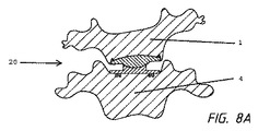
次の一連の図では、図3、図4及び図5で例示したものに類似したデバイスが、手術の結果として、又は、不利もしくは変性構造のために、理想に満たない条件下で埋植される。幸運なことに、対インプラントの支持面は、2つの椎体1、4の間に、耐荷重性及び自然な動きを許容する空間及び運動学的関係性を提供する。結果的に、一見「間違った場所に配置」されていても、椎間板インプラント20は依然として脊椎セグメントの自然で生理的な動きを模倣する。図6A〜図6Cは、おそらく上側部材21の配置が後ろすぎるために、支持面の連結が、脊柱が前彎した条件を形成するようなセグメントに埋植された椎間板インプラント20を示す。示す通り、この一連では、下側部材25の鞍状突起27に沿った並進移動は伴わない。図6Bで見られる通り、いわゆる何もしていない位置は、かすかに伸展しているように見え、図6Cでは、脊椎セグメントはかなり伸展しているが、それでもまだ機能的及び耐荷重性であるように見える。図7A〜図7Cでは、同一の椎間板インプラント20が、脊柱が前彎するに間違った場所に配置されて埋植された同一の環境において並進移動を行っているのを示している。椎間板インプラント20は、それぞれ屈曲、何もしていない、及び伸展の状態で示される。次に、図8A〜図8Cは、セグメント内に埋植された同一の椎間板インプラント20の正面図である。上部椎体1の椎体終板2は、間違った場所に配置されている(平行でなく、左に傾いている)。しかし、右屈曲、何もしていない、左屈曲の一連の図で見られる通り、セグメントの比較的生理的な動きが維持されている。
In the next series of figures, devices similar to those illustrated in FIGS. 3, 4 and 5 are implanted under sub-ideal conditions as a result of surgery or due to adverse or degenerative structures. The Fortunately, the anti-implant bearing surface provides a load-bearing and spatial and kinematic relationship that allows natural movement between the two
一実施形態では、本発明の1又はそれ以上の態様に従った椎間板インプラント20は、特に頸椎での使用のために適合され、上側部材21及び下側部材25を備える。各部材は、第1上部面及び椎体1、4の終板2に対する配置用に適合された第2下部対向面に、突起23及び突起27を持つ底板22、26を備えてよい。代わりに、底板22、26は、単に突起23、27の支持面の対向側として単に形成されてもよい。椎間板インプラント20を備える対部材21、25の各突起23、27又は支持面は、双方の部材21、25が対向する椎体1、4の間に埋植されると、対向する支持面と協働する。下側部材25の鞍状突起27は、概して、凹凸面領域を画定する鞍状構造を作成するよう形成される。斯かる一実施形態が図9及び図10に例示され、底板26及び鞍状面30を有する鞍状突起27を備える。面30の領域は、およそ12mmの直径D1(インプラントの異なるサイズによって±5mm)で、軸線A1に沿った矢状面において凸状であり、矢状面で円C1の45度(又は20度及び60度の間)の扇形を表し、円の「中心」は下部にある。面30の領域は、軸線A2に沿った前面部では、およそ6mmの直径D2(インプラントの異なるサイズによって±5mm)で凹状であり、前頭面で60度(又は40度及び80度の間)の円の扇形を表し、円の「中心」は、上部にある。面30領域は、前頭面において、45度の矢状面凸状扇形を、およそ6mm(インプラントの異なるサイズによって±5mm)の半径、及び、正中矢状部のおよそ6mm(インプラントの異なるサイズによって±5mm)上にある回旋の中心を伴って60度回旋させることで生じる。面30は、矢状面において、60度の前頭面凹状扇形を、およそ12mm(インプラントの異なるサイズによって±5mm)の半径、及び、正中前頭部のおよそ12mm(インプラントの異なるサイズによって±5mm)下にある回旋の中心を伴って、45度回旋させることもさらに提供でき、こうして、矢状面の凸面は正中矢状面で最も低く、前頭面の凹面は正中前頭面で最も高く、45度の矢状面凸状扇形を切り取る横断セマイト(semayt)面によって画定される縁によって囲まれた、鞍状面30が作成される。図11及び図12A〜図12Cは、円、円環面、及び鞍を含む、下側部材25の鞍状突起27の凹凸面を画定するための幾何学的な参照形状をいくつか示す。
In one embodiment, an
上側部材21の凸状突起23は、概して、好ましくは球状の凸状面領域を作成するよう形成される。斯かる一実施形態が図13A及び図13Bに例示され、底板22及び凸様面を有する凸状突起23を備える。面領域は、矢状面及び前頭面の双方で、およそ6mm(インプラントの異なるサイズによって±5mm)の直径D2を有する凸状であり、球の90度の扇形を表しているが、70及び110の間のほかの扇形も可能である。面は、概して、下側部材25の面領域に一致しており、その形状は、90度のボールの扇形を切り取った横断セマイト面によって画定される縁によって囲まれることを特徴とすることができる。この参照ボールC2は図13Cに示される。
The
上側部材21及び下側部材25が、対向する延長部がかみ合う、又は、そうでなければ互いに接触するインプラント配向では、いくつかの利点が見られる。対向する底板22、26の縁又は周辺の平らな設計、及び、上側部材21の凸状突起23の高さによって、端部の接触を伴わずに、屈曲/伸展、側屈及び回旋のための頸部運動セグメントの生理的可動域内において、制限のない運動を許容する。さらに、下側部材25の鞍状突起27は、上側部材21の凸状突起23と一緒に、上側部材21の下側部材25の凸面上での前後滑走を許容する。設計はさらに、上側部材21の下側部材25上での前後回旋、及び、上側部材21の下側部材25上での前後回転を促進する。また、上側部材21の下側部材25上での、回旋の中心が上にある側屈(側方回旋)も促進される。また、設計はさらに、上側部材21の下側部材25上での横断回旋を許容し、従って、屈曲/伸展の瞬間的な範囲から独立した、生理的及び斜めである矢状面回旋軸線上での、側屈(側方回旋)及び横断回旋の連結運動が可能になり、よって、側屈及び/又は回旋の瞬間的な範囲から独立した、可変の生理的な回旋の中心を持つ屈曲/伸展が可能になる。
In an implant orientation where the
椎間板インプラント20の材料に関して、本発明に従うと、部材21、25は、好ましくは、埋植技術により良く確立された材料、例えば、チタン、チタン合金、コバルトクロム合金、タンタル合金、炭素繊維複合材、PEEK、セラミックス、ポリエチレン又は上記のうちのいずれかの組み合わせである。関節面は、好ましくは、低摩擦の原則に従って、磨耗を最小にするため高光沢に磨かれる。例えば骨とプロテーゼとの接触面における骨内部成長を促進するために、2つの終板2の外側の部分を、多孔性チタン若しくは同様の材料、又は、生物活性材料で覆うこともさらに意図される。
With regard to the material of the
さらに好ましい設計では、本発明に従うと、底板22、26又は突起23、27に沿って、部材21、25のうち1つの少なくとも一部分に、衝撃吸収層としてポリエチレン又は他の適切なプラスチックを含むことも意図される。
In a further preferred design, according to the invention, at least a part of one of the
好都合な設計では、本発明に従うと、下側部材25の端部は、頸部の椎体の上側終板の自然な構造に近い台形設計を有し、台形の長辺は前方にあって少し屈曲しており、台形の短辺は後方にあってまっすぐである。この設計では、この台形終板の、各椎間板の隙間の尾側にある椎体の上側終板に対面する外側の辺は、例えば1又は2つのキール、又はスパイク又は椎間板プロテーゼを椎体の終板に固定するのに適切なあらゆるデバイスの組み合わせによって、椎体の終板内での強固な固定手段を有する。
In an advantageous design, according to the present invention, the end of the
好都合な設計では、本発明の一態様に従うと、上側部材21の端部は、頸部の椎体の上側終板の自然な構造に近い、かすかに湾曲した球状のドームのような設計を有する。この設計では、このドーム形状終板の、各椎間板の隙間の頭側の椎体の頭蓋の下側終板に対面する外側の辺は、図14に示す通り、刃状とすることができ、又は、スパイクの列から形成できる1又はそれ以上のアンカー24又はキール、図15で示すような全体又は部分的な環状縁又はフランジ、又は、スパイクの様々なパターン、又は、椎間板インプラント20を椎体1、4の終板2に固定するのに適切な接着剤といったあらゆるデバイスの組み合わせといった、椎体の終板内での強固な固定手段を有する。
In an advantageous design, according to one aspect of the invention, the end of
さらなる設計では、双方の終板は、上記の通り台形設計を有し、双方とも、椎体1、4の隣接した終板2での固定に適切なデバイス又はアンカー24を伴う。
In a further design, both endplates have a trapezoidal design as described above, both with devices or anchors 24 suitable for fixation of adjacent
さらなる設計では、上記の通り、双方の終板はかすかに湾曲した球状ドーム形状設計を有し、双方とも、隣接する椎体終板での固定に適切なデバイスを伴う。 In a further design, as described above, both endplates have a slightly curved spherical dome shape design, both with devices suitable for fixation at adjacent vertebral endplates.
好都合な設計では、各椎間板の頭側にある椎体1の下側終板2に対面する上側部材21の終板の端部の外側部分は、台形若しくはドーム形状又は他の形状であろうと、その形状に関わらず、2つの滑走部材の端部の内面が平行でインプラントが何もしていない位置である場合に終板の外面が互いにおよそ7度(又は5度及び15度の間)の脊柱前彎角度が作成されるよう、この滑走部材の端部の内面に関してわずかに角度をなす。
In an advantageous design, the outer part of the end plate end of the
さらなる設計では、各椎間板の頭側の椎体1の下側終板2から対面する上側部材21の終板の端部の外側部分は、台形若しくはドーム形状又は他の形状であろうと、その形状に関わらず、角度はなしておらず、従って、2つの滑走部材の端部の内面が平行でインプラントが何もしていない位置である場合、終板の外面は互いに平行である。
In a further design, the outer portion of the end plate end of the
特に頸椎の椎間板インプラント用に適合された特定の好ましい実施形態は、板部材又は関節部材に関して次の寸法上の考慮を含むことができ、約13mm、約15mm、約17mm、約19mm、又は約21mmを包含する13〜21mmの最大幅(前頭部における側方伸展)、約12mm、約14mm、約16mm又は約18mmを包含する12〜18mmの最大深(矢状部における背腹伸展)、及び、約5mm、約7mm、約9mm、約11mm、又は約13mmを包含する5〜13mmの最大高である。 Certain preferred embodiments, particularly adapted for cervical spinal disc implants, can include the following dimensional considerations for plate members or joint members: about 13 mm, about 15 mm, about 17 mm, about 19 mm, or about 21 mm. A maximum width of 13 to 21 mm (lateral extension in the forehead), including a maximum depth of 12 to 18 mm (dorsal abdominal extension in the sagittal region), including about 12 mm, about 14 mm, about 16 mm or about 18 mm , About 5 mm, about 7 mm, about 9 mm, about 11 mm, or about 13 mm.
送達の一方法では、選択された椎体間に部位が準備され、椎間板インプラントの少なくとも一部分が取り除かれる。椎体は、器具を用いて、又は、患者の首又は脊椎部分を凸面に沿って配置することで、骨延長(distracted)されてもよい。外科アプローチの角度が直接的に前後ではなく前側部若しくは後側部である場合、凸/凹状突起を有する下側部材を、凹状部分が埋植の軌道(又は外科アプローチ)の軸線に対して垂直に配向された状態で送達できる。凸状突起を有する上側部材とかみ合うと、上側部材の凹状面が終板の中央に沿って長手方向の前後軸線に垂直に配向され、凸部分が横断側面軸線に垂直であるように、回旋できる。こうして、いずれの部材も最初に挿入されるが、凸/凹状突起又は延長部を有する下側部材は、下側面が前後軸線に沿って適切な位置に回旋され得る前に、支持面の適切な関節を許容するために、正確な軌道に沿って挿入されなくてはならない。その後、各底板は対応する椎体終板に固定される。よって、並進移動は、後側部軸線に沿って促進されるが、横断側面軸線に沿っては制限又は限定され、しかし、上記の通り、回旋、屈曲、伸展及び側屈の特徴は維持される。 In one method of delivery, a site is prepared between selected vertebral bodies and at least a portion of the disc implant is removed. The vertebral body may be distracted using an instrument or by placing the patient's neck or spine portion along a convex surface. If the angle of the surgical approach is not directly back and forth but the anterior or posterior side, the lower member with the convex / concave projections should be perpendicular to the axis of the implant trajectory (or surgical approach). Can be delivered in an oriented state. When engaged with an upper member having a convex protrusion, it can be rotated so that the concave surface of the upper member is oriented perpendicular to the longitudinal longitudinal axis along the center of the endplate and the convex portion is perpendicular to the transverse side axis . Thus, either member is inserted first, but the lower member with convex / concave protrusions or extensions is not suitable for the support surface before the lower surface can be rotated into the proper position along the longitudinal axis. In order to allow the joint, it must be inserted along an exact trajectory. Each bottom plate is then secured to the corresponding vertebral body endplate. Thus, translational movement is facilitated along the posterior side axis, but limited or limited along the transverse side axis, but as described above, the features of rotation, bending, extension and lateral bending are maintained. .
本発明の様々な実施形態が、好まれる、及び、好ましい実施形態を参照しながら説明されてきたが、当業者は、様々な修正、追加及び削除が、次に続く特許請求の範囲が定義する本発明の範囲内に包含されることを理解するだろう。 While various embodiments of the invention have been described and described with reference to the preferred embodiments, those skilled in the art will recognize that various modifications, additions and deletions are defined by the following claims. It will be understood that it is encompassed within the scope of the present invention.
Claims (14)
対向する第1面及び第2面を有する上側部材(21)であって、第1面が1つの椎体(1)の椎体終板(2)への取付け用に適合され、第2面が前記第2面から延びる凸状突起(23)を備える、上側部材と、
対向する第1面及び第2面を有する下側部材(25)であって、第1面が、対向する椎体(4)の椎体終板(2)への取付け用に適合される、下側部材と、
を備える、椎間板インプラントにおいて、
前記下側部材(25)の前記第2面が、矢状面における第1軸線(A1)に沿った凸状輪郭と、横断面における第2軸線(A2)に沿った凹状輪郭と、を有する鞍状突起(27)を備え、
前記上側部材(21)の前記凸状突起(23)及び前記下側部材(23)の前記鞍状突起(27)が、一緒に一致して嵌まるように適合され、且つ、前記2つの対向する椎体の間に埋植されたときに、前記2つの対向する椎体(1,4)の矢状面に沿った回旋、枢動、及び並進移動を促進する、
ことを特徴とする椎間板インプラント。 A disc implant (20) for implantation between two opposing vertebral bodies (1, 4),
An upper member (21) having opposing first and second surfaces, wherein the first surface is adapted for attachment of one vertebral body (1) to the vertebral body endplate (2), the second surface An upper member comprising a convex protrusion (23) extending from the second surface;
A lower member (25) having opposing first and second surfaces, wherein the first surface is adapted for attachment of the opposing vertebral body (4) to the vertebral body endplate (2). A lower member;
In an intervertebral disc implant comprising:
The second surface of the lower member (25) has a convex contour along the first axis (A1) in the sagittal plane and a concave contour along the second axis (A2) in the transverse section. Provided with hook-shaped projections (27);
The convex protrusions (23) of the upper member (21) and the hook-shaped protrusions (27) of the lower member (23) are adapted to fit together and the two opposing Facilitates rotation, pivoting, and translational movement along the sagittal plane of the two opposing vertebral bodies (1, 4) when implanted between the vertebral bodies
An intervertebral disc implant characterized by that.
Applications Claiming Priority (3)
| Application Number | Priority Date | Filing Date | Title |
|---|---|---|---|
| US201461999184P | 2014-07-19 | 2014-07-19 | |
| US61/999,184 | 2014-07-19 | ||
| PCT/EP2015/066401 WO2016012361A1 (en) | 2014-07-19 | 2015-07-17 | Intervertebral disc implant and method for restoring function to a damaged functional spinal unit using such an intervertebral disc implant |
Publications (2)
| Publication Number | Publication Date |
|---|---|
| JP2017521192A true JP2017521192A (en) | 2017-08-03 |
| JP6629833B2 JP6629833B2 (en) | 2020-01-15 |
Family
ID=53673088
Family Applications (1)
| Application Number | Title | Priority Date | Filing Date |
|---|---|---|---|
| JP2017504090A Active JP6629833B2 (en) | 2014-07-19 | 2015-07-17 | Disc implant |
Country Status (5)
| Country | Link |
|---|---|
| US (1) | US10603184B2 (en) |
| EP (1) | EP3169280B1 (en) |
| JP (1) | JP6629833B2 (en) |
| ES (1) | ES2895551T3 (en) |
| WO (1) | WO2016012361A1 (en) |
Families Citing this family (4)
| Publication number | Priority date | Publication date | Assignee | Title |
|---|---|---|---|---|
| GB201511646D0 (en) * | 2015-07-02 | 2015-08-19 | Nottingham University Hospitals Nhs Trust | Improvements relating to bone anchors |
| US11197765B2 (en) | 2019-12-04 | 2021-12-14 | Robert S. Bray, Jr. | Artificial disc replacement device |
| US11839554B2 (en) | 2020-01-23 | 2023-12-12 | Robert S. Bray, Jr. | Method of implanting an artificial disc replacement device |
| WO2022072806A1 (en) * | 2020-10-02 | 2022-04-07 | Facet Mobility, Llc | Artificial spinal prosthesis |
Citations (11)
| Publication number | Priority date | Publication date | Assignee | Title |
|---|---|---|---|---|
| JPH11137585A (en) * | 1997-11-05 | 1999-05-25 | Chubu Bearing Kk | Artificial vertebral disk |
| US20050165487A1 (en) * | 2004-01-28 | 2005-07-28 | Muhanna Nabil L. | Artificial intervertebral disc |
| JP2005523109A (en) * | 2002-04-23 | 2005-08-04 | スパインコア インコーポレイテッド | Alternative artificial intervertebral disc with natural motor function |
| JP2005538783A (en) * | 2002-09-18 | 2005-12-22 | マシーズ メディツィナルテヒニク アクチエンゲゼルシャフト | Implant with a two-part joint |
| JP2006510452A (en) * | 2002-12-17 | 2006-03-30 | アメディカ コーポレイション | Total disc implant |
| JP2006519671A (en) * | 2003-03-06 | 2006-08-31 | スパインコア,インコーポレイテッド | Cervical disc replacement |
| JP2007522827A (en) * | 2003-09-10 | 2007-08-16 | ウォーソー・オーソペディック・インコーポレーテッド | Artificial spinal disc transplantation device and method |
| JP2008516686A (en) * | 2004-10-18 | 2008-05-22 | イービーアイ,エル.ピー. | Intervertebral implant and method related thereto |
| US20130110240A1 (en) * | 2011-10-26 | 2013-05-02 | Noah Hansell | Artificial Discs |
| US20140100658A1 (en) * | 2012-10-04 | 2014-04-10 | Kurt Schmura | Articulating intervertebral implant |
| US20140148906A1 (en) * | 2002-04-12 | 2014-05-29 | Spinecore, Inc. | Spacerless artificial disc replacements |
Family Cites Families (2)
| Publication number | Priority date | Publication date | Assignee | Title |
|---|---|---|---|---|
| WO2006042485A1 (en) | 2004-10-18 | 2006-04-27 | Buettner-Janz Karin | Intervertebral disk endoprosthesis for lumbar and cervical spine, which corresponds to the physiology of movement |
| US8721722B2 (en) * | 2004-10-18 | 2014-05-13 | Ebi, Llc | Intervertebral implant and associated method |
-
2015
- 2015-07-17 EP EP15738662.4A patent/EP3169280B1/en active Active
- 2015-07-17 JP JP2017504090A patent/JP6629833B2/en active Active
- 2015-07-17 US US15/326,976 patent/US10603184B2/en active Active
- 2015-07-17 WO PCT/EP2015/066401 patent/WO2016012361A1/en not_active Ceased
- 2015-07-17 ES ES15738662T patent/ES2895551T3/en active Active
Patent Citations (11)
| Publication number | Priority date | Publication date | Assignee | Title |
|---|---|---|---|---|
| JPH11137585A (en) * | 1997-11-05 | 1999-05-25 | Chubu Bearing Kk | Artificial vertebral disk |
| US20140148906A1 (en) * | 2002-04-12 | 2014-05-29 | Spinecore, Inc. | Spacerless artificial disc replacements |
| JP2005523109A (en) * | 2002-04-23 | 2005-08-04 | スパインコア インコーポレイテッド | Alternative artificial intervertebral disc with natural motor function |
| JP2005538783A (en) * | 2002-09-18 | 2005-12-22 | マシーズ メディツィナルテヒニク アクチエンゲゼルシャフト | Implant with a two-part joint |
| JP2006510452A (en) * | 2002-12-17 | 2006-03-30 | アメディカ コーポレイション | Total disc implant |
| JP2006519671A (en) * | 2003-03-06 | 2006-08-31 | スパインコア,インコーポレイテッド | Cervical disc replacement |
| JP2007522827A (en) * | 2003-09-10 | 2007-08-16 | ウォーソー・オーソペディック・インコーポレーテッド | Artificial spinal disc transplantation device and method |
| US20050165487A1 (en) * | 2004-01-28 | 2005-07-28 | Muhanna Nabil L. | Artificial intervertebral disc |
| JP2008516686A (en) * | 2004-10-18 | 2008-05-22 | イービーアイ,エル.ピー. | Intervertebral implant and method related thereto |
| US20130110240A1 (en) * | 2011-10-26 | 2013-05-02 | Noah Hansell | Artificial Discs |
| US20140100658A1 (en) * | 2012-10-04 | 2014-04-10 | Kurt Schmura | Articulating intervertebral implant |
Also Published As
| Publication number | Publication date |
|---|---|
| US10603184B2 (en) | 2020-03-31 |
| JP6629833B2 (en) | 2020-01-15 |
| EP3169280B1 (en) | 2021-10-13 |
| ES2895551T3 (en) | 2022-02-21 |
| WO2016012361A1 (en) | 2016-01-28 |
| US20170202676A1 (en) | 2017-07-20 |
| EP3169280A1 (en) | 2017-05-24 |
Similar Documents
| Publication | Publication Date | Title |
|---|---|---|
| CN101056598B (en) | Intervertebral disc endoprosthesis with a motion-adaptive edge for the lumbar and cervical spine | |
| US10369005B2 (en) | Cervical disc replacement | |
| JP4980225B2 (en) | Lumbar and cervical intervertebral disc prosthesis with a cylindrical articulating surface curved surface bent laterally | |
| US6228118B1 (en) | Multiple axis intervertebral prosthesis | |
| EP1587461B1 (en) | Articulating spinal disc prosthesis | |
| CN102821718B (en) | Endplates for intervertebral implants and implants | |
| US20050165487A1 (en) | Artificial intervertebral disc | |
| US9937051B2 (en) | Artificial disc devices and related methods of use | |
| JP2011504377A (en) | Total posterior joint replacement | |
| JP4980223B2 (en) | Lumbar and cervical disc prosthesis with physiological movement | |
| JP6629833B2 (en) | Disc implant | |
| EP2624789B1 (en) | Prosthesis for cervical and lumbar spine | |
| AU2004220630B2 (en) | Cervical disc replacement | |
| GB2471133A (en) | Intervertebral disc prosthesis with modular construction |
Legal Events
| Date | Code | Title | Description |
|---|---|---|---|
| A621 | Written request for application examination |
Free format text: JAPANESE INTERMEDIATE CODE: A621 Effective date: 20180606 |
|
| A131 | Notification of reasons for refusal |
Free format text: JAPANESE INTERMEDIATE CODE: A131 Effective date: 20190319 |
|
| A977 | Report on retrieval |
Free format text: JAPANESE INTERMEDIATE CODE: A971007 Effective date: 20190315 |
|
| A521 | Request for written amendment filed |
Free format text: JAPANESE INTERMEDIATE CODE: A523 Effective date: 20190610 |
|
| TRDD | Decision of grant or rejection written | ||
| A01 | Written decision to grant a patent or to grant a registration (utility model) |
Free format text: JAPANESE INTERMEDIATE CODE: A01 Effective date: 20191105 |
|
| A61 | First payment of annual fees (during grant procedure) |
Free format text: JAPANESE INTERMEDIATE CODE: A61 Effective date: 20191205 |
|
| R150 | Certificate of patent or registration of utility model |
Ref document number: 6629833 Country of ref document: JP Free format text: JAPANESE INTERMEDIATE CODE: R150 |
|
| R250 | Receipt of annual fees |
Free format text: JAPANESE INTERMEDIATE CODE: R250 |
|
| R250 | Receipt of annual fees |
Free format text: JAPANESE INTERMEDIATE CODE: R250 |
|
| R250 | Receipt of annual fees |
Free format text: JAPANESE INTERMEDIATE CODE: R250 |
|
| R250 | Receipt of annual fees |
Free format text: JAPANESE INTERMEDIATE CODE: R250 |