JP2017105365A - Hybrid vehicle driving force control device - Google Patents
Hybrid vehicle driving force control device Download PDFInfo
- Publication number
- JP2017105365A JP2017105365A JP2015241536A JP2015241536A JP2017105365A JP 2017105365 A JP2017105365 A JP 2017105365A JP 2015241536 A JP2015241536 A JP 2015241536A JP 2015241536 A JP2015241536 A JP 2015241536A JP 2017105365 A JP2017105365 A JP 2017105365A
- Authority
- JP
- Japan
- Prior art keywords
- engine
- motor
- torque
- mode
- output
- Prior art date
- Legal status (The legal status is an assumption and is not a legal conclusion. Google has not performed a legal analysis and makes no representation as to the accuracy of the status listed.)
- Pending
Links
Images


Classifications
-
- B—PERFORMING OPERATIONS; TRANSPORTING
- B60—VEHICLES IN GENERAL
- B60W—CONJOINT CONTROL OF VEHICLE SUB-UNITS OF DIFFERENT TYPE OR DIFFERENT FUNCTION; CONTROL SYSTEMS SPECIALLY ADAPTED FOR HYBRID VEHICLES; ROAD VEHICLE DRIVE CONTROL SYSTEMS FOR PURPOSES NOT RELATED TO THE CONTROL OF A PARTICULAR SUB-UNIT
- B60W20/00—Control systems specially adapted for hybrid vehicles
- B60W20/20—Control strategies involving selection of hybrid configuration, e.g. selection between series or parallel configuration
-
- B—PERFORMING OPERATIONS; TRANSPORTING
- B60—VEHICLES IN GENERAL
- B60K—ARRANGEMENT OR MOUNTING OF PROPULSION UNITS OR OF TRANSMISSIONS IN VEHICLES; ARRANGEMENT OR MOUNTING OF PLURAL DIVERSE PRIME-MOVERS IN VEHICLES; AUXILIARY DRIVES FOR VEHICLES; INSTRUMENTATION OR DASHBOARDS FOR VEHICLES; ARRANGEMENTS IN CONNECTION WITH COOLING, AIR INTAKE, GAS EXHAUST OR FUEL SUPPLY OF PROPULSION UNITS IN VEHICLES
- B60K6/00—Arrangement or mounting of plural diverse prime-movers for mutual or common propulsion, e.g. hybrid propulsion systems comprising electric motors and internal combustion engines
- B60K6/20—Arrangement or mounting of plural diverse prime-movers for mutual or common propulsion, e.g. hybrid propulsion systems comprising electric motors and internal combustion engines the prime-movers consisting of electric motors and internal combustion engines, e.g. HEVs
- B60K6/22—Arrangement or mounting of plural diverse prime-movers for mutual or common propulsion, e.g. hybrid propulsion systems comprising electric motors and internal combustion engines the prime-movers consisting of electric motors and internal combustion engines, e.g. HEVs characterised by apparatus, components or means specially adapted for HEVs
- B60K6/36—Arrangement or mounting of plural diverse prime-movers for mutual or common propulsion, e.g. hybrid propulsion systems comprising electric motors and internal combustion engines the prime-movers consisting of electric motors and internal combustion engines, e.g. HEVs characterised by apparatus, components or means specially adapted for HEVs characterised by the transmission gearings
-
- B—PERFORMING OPERATIONS; TRANSPORTING
- B60—VEHICLES IN GENERAL
- B60K—ARRANGEMENT OR MOUNTING OF PROPULSION UNITS OR OF TRANSMISSIONS IN VEHICLES; ARRANGEMENT OR MOUNTING OF PLURAL DIVERSE PRIME-MOVERS IN VEHICLES; AUXILIARY DRIVES FOR VEHICLES; INSTRUMENTATION OR DASHBOARDS FOR VEHICLES; ARRANGEMENTS IN CONNECTION WITH COOLING, AIR INTAKE, GAS EXHAUST OR FUEL SUPPLY OF PROPULSION UNITS IN VEHICLES
- B60K6/00—Arrangement or mounting of plural diverse prime-movers for mutual or common propulsion, e.g. hybrid propulsion systems comprising electric motors and internal combustion engines
- B60K6/20—Arrangement or mounting of plural diverse prime-movers for mutual or common propulsion, e.g. hybrid propulsion systems comprising electric motors and internal combustion engines the prime-movers consisting of electric motors and internal combustion engines, e.g. HEVs
- B60K6/22—Arrangement or mounting of plural diverse prime-movers for mutual or common propulsion, e.g. hybrid propulsion systems comprising electric motors and internal combustion engines the prime-movers consisting of electric motors and internal combustion engines, e.g. HEVs characterised by apparatus, components or means specially adapted for HEVs
- B60K6/38—Arrangement or mounting of plural diverse prime-movers for mutual or common propulsion, e.g. hybrid propulsion systems comprising electric motors and internal combustion engines the prime-movers consisting of electric motors and internal combustion engines, e.g. HEVs characterised by apparatus, components or means specially adapted for HEVs characterised by the driveline clutches
- B60K6/387—Actuated clutches, i.e. clutches engaged or disengaged by electric, hydraulic or mechanical actuating means
-
- B—PERFORMING OPERATIONS; TRANSPORTING
- B60—VEHICLES IN GENERAL
- B60K—ARRANGEMENT OR MOUNTING OF PROPULSION UNITS OR OF TRANSMISSIONS IN VEHICLES; ARRANGEMENT OR MOUNTING OF PLURAL DIVERSE PRIME-MOVERS IN VEHICLES; AUXILIARY DRIVES FOR VEHICLES; INSTRUMENTATION OR DASHBOARDS FOR VEHICLES; ARRANGEMENTS IN CONNECTION WITH COOLING, AIR INTAKE, GAS EXHAUST OR FUEL SUPPLY OF PROPULSION UNITS IN VEHICLES
- B60K6/00—Arrangement or mounting of plural diverse prime-movers for mutual or common propulsion, e.g. hybrid propulsion systems comprising electric motors and internal combustion engines
- B60K6/20—Arrangement or mounting of plural diverse prime-movers for mutual or common propulsion, e.g. hybrid propulsion systems comprising electric motors and internal combustion engines the prime-movers consisting of electric motors and internal combustion engines, e.g. HEVs
- B60K6/22—Arrangement or mounting of plural diverse prime-movers for mutual or common propulsion, e.g. hybrid propulsion systems comprising electric motors and internal combustion engines the prime-movers consisting of electric motors and internal combustion engines, e.g. HEVs characterised by apparatus, components or means specially adapted for HEVs
- B60K6/40—Arrangement or mounting of plural diverse prime-movers for mutual or common propulsion, e.g. hybrid propulsion systems comprising electric motors and internal combustion engines the prime-movers consisting of electric motors and internal combustion engines, e.g. HEVs characterised by apparatus, components or means specially adapted for HEVs characterised by the assembly or relative disposition of components
-
- B—PERFORMING OPERATIONS; TRANSPORTING
- B60—VEHICLES IN GENERAL
- B60K—ARRANGEMENT OR MOUNTING OF PROPULSION UNITS OR OF TRANSMISSIONS IN VEHICLES; ARRANGEMENT OR MOUNTING OF PLURAL DIVERSE PRIME-MOVERS IN VEHICLES; AUXILIARY DRIVES FOR VEHICLES; INSTRUMENTATION OR DASHBOARDS FOR VEHICLES; ARRANGEMENTS IN CONNECTION WITH COOLING, AIR INTAKE, GAS EXHAUST OR FUEL SUPPLY OF PROPULSION UNITS IN VEHICLES
- B60K6/00—Arrangement or mounting of plural diverse prime-movers for mutual or common propulsion, e.g. hybrid propulsion systems comprising electric motors and internal combustion engines
- B60K6/20—Arrangement or mounting of plural diverse prime-movers for mutual or common propulsion, e.g. hybrid propulsion systems comprising electric motors and internal combustion engines the prime-movers consisting of electric motors and internal combustion engines, e.g. HEVs
- B60K6/42—Arrangement or mounting of plural diverse prime-movers for mutual or common propulsion, e.g. hybrid propulsion systems comprising electric motors and internal combustion engines the prime-movers consisting of electric motors and internal combustion engines, e.g. HEVs characterised by the architecture of the hybrid electric vehicle
- B60K6/44—Series-parallel type
- B60K6/442—Series-parallel switching type
-
- B—PERFORMING OPERATIONS; TRANSPORTING
- B60—VEHICLES IN GENERAL
- B60K—ARRANGEMENT OR MOUNTING OF PROPULSION UNITS OR OF TRANSMISSIONS IN VEHICLES; ARRANGEMENT OR MOUNTING OF PLURAL DIVERSE PRIME-MOVERS IN VEHICLES; AUXILIARY DRIVES FOR VEHICLES; INSTRUMENTATION OR DASHBOARDS FOR VEHICLES; ARRANGEMENTS IN CONNECTION WITH COOLING, AIR INTAKE, GAS EXHAUST OR FUEL SUPPLY OF PROPULSION UNITS IN VEHICLES
- B60K6/00—Arrangement or mounting of plural diverse prime-movers for mutual or common propulsion, e.g. hybrid propulsion systems comprising electric motors and internal combustion engines
- B60K6/20—Arrangement or mounting of plural diverse prime-movers for mutual or common propulsion, e.g. hybrid propulsion systems comprising electric motors and internal combustion engines the prime-movers consisting of electric motors and internal combustion engines, e.g. HEVs
- B60K6/42—Arrangement or mounting of plural diverse prime-movers for mutual or common propulsion, e.g. hybrid propulsion systems comprising electric motors and internal combustion engines the prime-movers consisting of electric motors and internal combustion engines, e.g. HEVs characterised by the architecture of the hybrid electric vehicle
- B60K6/44—Series-parallel type
- B60K6/445—Differential gearing distribution type
-
- B—PERFORMING OPERATIONS; TRANSPORTING
- B60—VEHICLES IN GENERAL
- B60K—ARRANGEMENT OR MOUNTING OF PROPULSION UNITS OR OF TRANSMISSIONS IN VEHICLES; ARRANGEMENT OR MOUNTING OF PLURAL DIVERSE PRIME-MOVERS IN VEHICLES; AUXILIARY DRIVES FOR VEHICLES; INSTRUMENTATION OR DASHBOARDS FOR VEHICLES; ARRANGEMENTS IN CONNECTION WITH COOLING, AIR INTAKE, GAS EXHAUST OR FUEL SUPPLY OF PROPULSION UNITS IN VEHICLES
- B60K6/00—Arrangement or mounting of plural diverse prime-movers for mutual or common propulsion, e.g. hybrid propulsion systems comprising electric motors and internal combustion engines
- B60K6/20—Arrangement or mounting of plural diverse prime-movers for mutual or common propulsion, e.g. hybrid propulsion systems comprising electric motors and internal combustion engines the prime-movers consisting of electric motors and internal combustion engines, e.g. HEVs
- B60K6/50—Architecture of the driveline characterised by arrangement or kind of transmission units
- B60K6/52—Driving a plurality of drive axles, e.g. four-wheel drive
-
- B—PERFORMING OPERATIONS; TRANSPORTING
- B60—VEHICLES IN GENERAL
- B60W—CONJOINT CONTROL OF VEHICLE SUB-UNITS OF DIFFERENT TYPE OR DIFFERENT FUNCTION; CONTROL SYSTEMS SPECIALLY ADAPTED FOR HYBRID VEHICLES; ROAD VEHICLE DRIVE CONTROL SYSTEMS FOR PURPOSES NOT RELATED TO THE CONTROL OF A PARTICULAR SUB-UNIT
- B60W10/00—Conjoint control of vehicle sub-units of different type or different function
- B60W10/02—Conjoint control of vehicle sub-units of different type or different function including control of driveline clutches
-
- B—PERFORMING OPERATIONS; TRANSPORTING
- B60—VEHICLES IN GENERAL
- B60W—CONJOINT CONTROL OF VEHICLE SUB-UNITS OF DIFFERENT TYPE OR DIFFERENT FUNCTION; CONTROL SYSTEMS SPECIALLY ADAPTED FOR HYBRID VEHICLES; ROAD VEHICLE DRIVE CONTROL SYSTEMS FOR PURPOSES NOT RELATED TO THE CONTROL OF A PARTICULAR SUB-UNIT
- B60W10/00—Conjoint control of vehicle sub-units of different type or different function
- B60W10/04—Conjoint control of vehicle sub-units of different type or different function including control of propulsion units
- B60W10/06—Conjoint control of vehicle sub-units of different type or different function including control of propulsion units including control of combustion engines
-
- B—PERFORMING OPERATIONS; TRANSPORTING
- B60—VEHICLES IN GENERAL
- B60W—CONJOINT CONTROL OF VEHICLE SUB-UNITS OF DIFFERENT TYPE OR DIFFERENT FUNCTION; CONTROL SYSTEMS SPECIALLY ADAPTED FOR HYBRID VEHICLES; ROAD VEHICLE DRIVE CONTROL SYSTEMS FOR PURPOSES NOT RELATED TO THE CONTROL OF A PARTICULAR SUB-UNIT
- B60W10/00—Conjoint control of vehicle sub-units of different type or different function
- B60W10/04—Conjoint control of vehicle sub-units of different type or different function including control of propulsion units
- B60W10/08—Conjoint control of vehicle sub-units of different type or different function including control of propulsion units including control of electric propulsion units, e.g. motors or generators
-
- B—PERFORMING OPERATIONS; TRANSPORTING
- B60—VEHICLES IN GENERAL
- B60W—CONJOINT CONTROL OF VEHICLE SUB-UNITS OF DIFFERENT TYPE OR DIFFERENT FUNCTION; CONTROL SYSTEMS SPECIALLY ADAPTED FOR HYBRID VEHICLES; ROAD VEHICLE DRIVE CONTROL SYSTEMS FOR PURPOSES NOT RELATED TO THE CONTROL OF A PARTICULAR SUB-UNIT
- B60W20/00—Control systems specially adapted for hybrid vehicles
- B60W20/30—Control strategies involving selection of transmission gear ratio
-
- B—PERFORMING OPERATIONS; TRANSPORTING
- B60—VEHICLES IN GENERAL
- B60W—CONJOINT CONTROL OF VEHICLE SUB-UNITS OF DIFFERENT TYPE OR DIFFERENT FUNCTION; CONTROL SYSTEMS SPECIALLY ADAPTED FOR HYBRID VEHICLES; ROAD VEHICLE DRIVE CONTROL SYSTEMS FOR PURPOSES NOT RELATED TO THE CONTROL OF A PARTICULAR SUB-UNIT
- B60W20/00—Control systems specially adapted for hybrid vehicles
- B60W20/40—Controlling the engagement or disengagement of prime movers, e.g. for transition between prime movers
-
- F—MECHANICAL ENGINEERING; LIGHTING; HEATING; WEAPONS; BLASTING
- F02—COMBUSTION ENGINES; HOT-GAS OR COMBUSTION-PRODUCT ENGINE PLANTS
- F02B—INTERNAL-COMBUSTION PISTON ENGINES; COMBUSTION ENGINES IN GENERAL
- F02B63/00—Adaptations of engines for driving pumps, hand-held tools or electric generators; Portable combinations of engines with engine-driven devices
- F02B63/04—Adaptations of engines for driving pumps, hand-held tools or electric generators; Portable combinations of engines with engine-driven devices for electric generators
-
- F—MECHANICAL ENGINEERING; LIGHTING; HEATING; WEAPONS; BLASTING
- F16—ENGINEERING ELEMENTS AND UNITS; GENERAL MEASURES FOR PRODUCING AND MAINTAINING EFFECTIVE FUNCTIONING OF MACHINES OR INSTALLATIONS; THERMAL INSULATION IN GENERAL
- F16H—GEARING
- F16H37/00—Combinations of mechanical gearings, not provided for in groups F16H1/00 - F16H35/00
- F16H37/02—Combinations of mechanical gearings, not provided for in groups F16H1/00 - F16H35/00 comprising essentially only toothed or friction gearings
- F16H37/06—Combinations of mechanical gearings, not provided for in groups F16H1/00 - F16H35/00 comprising essentially only toothed or friction gearings with a plurality of driving or driven shafts; with arrangements for dividing torque between two or more intermediate shafts
- F16H37/08—Combinations of mechanical gearings, not provided for in groups F16H1/00 - F16H35/00 comprising essentially only toothed or friction gearings with a plurality of driving or driven shafts; with arrangements for dividing torque between two or more intermediate shafts with differential gearing
- F16H37/0806—Combinations of mechanical gearings, not provided for in groups F16H1/00 - F16H35/00 comprising essentially only toothed or friction gearings with a plurality of driving or driven shafts; with arrangements for dividing torque between two or more intermediate shafts with differential gearing with a plurality of driving or driven shafts
-
- F—MECHANICAL ENGINEERING; LIGHTING; HEATING; WEAPONS; BLASTING
- F16—ENGINEERING ELEMENTS AND UNITS; GENERAL MEASURES FOR PRODUCING AND MAINTAINING EFFECTIVE FUNCTIONING OF MACHINES OR INSTALLATIONS; THERMAL INSULATION IN GENERAL
- F16H—GEARING
- F16H37/00—Combinations of mechanical gearings, not provided for in groups F16H1/00 - F16H35/00
- F16H37/02—Combinations of mechanical gearings, not provided for in groups F16H1/00 - F16H35/00 comprising essentially only toothed or friction gearings
- F16H37/06—Combinations of mechanical gearings, not provided for in groups F16H1/00 - F16H35/00 comprising essentially only toothed or friction gearings with a plurality of driving or driven shafts; with arrangements for dividing torque between two or more intermediate shafts
- F16H37/08—Combinations of mechanical gearings, not provided for in groups F16H1/00 - F16H35/00 comprising essentially only toothed or friction gearings with a plurality of driving or driven shafts; with arrangements for dividing torque between two or more intermediate shafts with differential gearing
- F16H37/0833—Combinations of mechanical gearings, not provided for in groups F16H1/00 - F16H35/00 comprising essentially only toothed or friction gearings with a plurality of driving or driven shafts; with arrangements for dividing torque between two or more intermediate shafts with differential gearing with arrangements for dividing torque between two or more intermediate shafts, i.e. with two or more internal power paths
-
- F—MECHANICAL ENGINEERING; LIGHTING; HEATING; WEAPONS; BLASTING
- F16—ENGINEERING ELEMENTS AND UNITS; GENERAL MEASURES FOR PRODUCING AND MAINTAINING EFFECTIVE FUNCTIONING OF MACHINES OR INSTALLATIONS; THERMAL INSULATION IN GENERAL
- F16H—GEARING
- F16H48/00—Differential gearings
- F16H48/06—Differential gearings with gears having orbital motion
- F16H48/10—Differential gearings with gears having orbital motion with orbital spur gears
-
- B—PERFORMING OPERATIONS; TRANSPORTING
- B60—VEHICLES IN GENERAL
- B60W—CONJOINT CONTROL OF VEHICLE SUB-UNITS OF DIFFERENT TYPE OR DIFFERENT FUNCTION; CONTROL SYSTEMS SPECIALLY ADAPTED FOR HYBRID VEHICLES; ROAD VEHICLE DRIVE CONTROL SYSTEMS FOR PURPOSES NOT RELATED TO THE CONTROL OF A PARTICULAR SUB-UNIT
- B60W20/00—Control systems specially adapted for hybrid vehicles
-
- B—PERFORMING OPERATIONS; TRANSPORTING
- B60—VEHICLES IN GENERAL
- B60W—CONJOINT CONTROL OF VEHICLE SUB-UNITS OF DIFFERENT TYPE OR DIFFERENT FUNCTION; CONTROL SYSTEMS SPECIALLY ADAPTED FOR HYBRID VEHICLES; ROAD VEHICLE DRIVE CONTROL SYSTEMS FOR PURPOSES NOT RELATED TO THE CONTROL OF A PARTICULAR SUB-UNIT
- B60W2510/00—Input parameters relating to a particular sub-units
- B60W2510/06—Combustion engines, Gas turbines
- B60W2510/0604—Throttle position
-
- B—PERFORMING OPERATIONS; TRANSPORTING
- B60—VEHICLES IN GENERAL
- B60W—CONJOINT CONTROL OF VEHICLE SUB-UNITS OF DIFFERENT TYPE OR DIFFERENT FUNCTION; CONTROL SYSTEMS SPECIALLY ADAPTED FOR HYBRID VEHICLES; ROAD VEHICLE DRIVE CONTROL SYSTEMS FOR PURPOSES NOT RELATED TO THE CONTROL OF A PARTICULAR SUB-UNIT
- B60W2510/00—Input parameters relating to a particular sub-units
- B60W2510/24—Energy storage means
- B60W2510/242—Energy storage means for electrical energy
- B60W2510/244—Charge state
-
- B—PERFORMING OPERATIONS; TRANSPORTING
- B60—VEHICLES IN GENERAL
- B60W—CONJOINT CONTROL OF VEHICLE SUB-UNITS OF DIFFERENT TYPE OR DIFFERENT FUNCTION; CONTROL SYSTEMS SPECIALLY ADAPTED FOR HYBRID VEHICLES; ROAD VEHICLE DRIVE CONTROL SYSTEMS FOR PURPOSES NOT RELATED TO THE CONTROL OF A PARTICULAR SUB-UNIT
- B60W2520/00—Input parameters relating to overall vehicle dynamics
- B60W2520/10—Longitudinal speed
-
- B—PERFORMING OPERATIONS; TRANSPORTING
- B60—VEHICLES IN GENERAL
- B60W—CONJOINT CONTROL OF VEHICLE SUB-UNITS OF DIFFERENT TYPE OR DIFFERENT FUNCTION; CONTROL SYSTEMS SPECIALLY ADAPTED FOR HYBRID VEHICLES; ROAD VEHICLE DRIVE CONTROL SYSTEMS FOR PURPOSES NOT RELATED TO THE CONTROL OF A PARTICULAR SUB-UNIT
- B60W2710/00—Output or target parameters relating to a particular sub-units
- B60W2710/02—Clutches
- B60W2710/021—Clutch engagement state
-
- B—PERFORMING OPERATIONS; TRANSPORTING
- B60—VEHICLES IN GENERAL
- B60W—CONJOINT CONTROL OF VEHICLE SUB-UNITS OF DIFFERENT TYPE OR DIFFERENT FUNCTION; CONTROL SYSTEMS SPECIALLY ADAPTED FOR HYBRID VEHICLES; ROAD VEHICLE DRIVE CONTROL SYSTEMS FOR PURPOSES NOT RELATED TO THE CONTROL OF A PARTICULAR SUB-UNIT
- B60W2710/00—Output or target parameters relating to a particular sub-units
- B60W2710/06—Combustion engines, Gas turbines
-
- B—PERFORMING OPERATIONS; TRANSPORTING
- B60—VEHICLES IN GENERAL
- B60W—CONJOINT CONTROL OF VEHICLE SUB-UNITS OF DIFFERENT TYPE OR DIFFERENT FUNCTION; CONTROL SYSTEMS SPECIALLY ADAPTED FOR HYBRID VEHICLES; ROAD VEHICLE DRIVE CONTROL SYSTEMS FOR PURPOSES NOT RELATED TO THE CONTROL OF A PARTICULAR SUB-UNIT
- B60W2710/00—Output or target parameters relating to a particular sub-units
- B60W2710/08—Electric propulsion units
- B60W2710/083—Torque
-
- B—PERFORMING OPERATIONS; TRANSPORTING
- B60—VEHICLES IN GENERAL
- B60Y—INDEXING SCHEME RELATING TO ASPECTS CROSS-CUTTING VEHICLE TECHNOLOGY
- B60Y2200/00—Type of vehicle
- B60Y2200/90—Vehicles comprising electric prime movers
- B60Y2200/92—Hybrid vehicles
-
- B—PERFORMING OPERATIONS; TRANSPORTING
- B60—VEHICLES IN GENERAL
- B60Y—INDEXING SCHEME RELATING TO ASPECTS CROSS-CUTTING VEHICLE TECHNOLOGY
- B60Y2300/00—Purposes or special features of road vehicle drive control systems
- B60Y2300/42—Control of clutches
-
- Y—GENERAL TAGGING OF NEW TECHNOLOGICAL DEVELOPMENTS; GENERAL TAGGING OF CROSS-SECTIONAL TECHNOLOGIES SPANNING OVER SEVERAL SECTIONS OF THE IPC; TECHNICAL SUBJECTS COVERED BY FORMER USPC CROSS-REFERENCE ART COLLECTIONS [XRACs] AND DIGESTS
- Y02—TECHNOLOGIES OR APPLICATIONS FOR MITIGATION OR ADAPTATION AGAINST CLIMATE CHANGE
- Y02T—CLIMATE CHANGE MITIGATION TECHNOLOGIES RELATED TO TRANSPORTATION
- Y02T10/00—Road transport of goods or passengers
- Y02T10/60—Other road transportation technologies with climate change mitigation effect
- Y02T10/62—Hybrid vehicles
-
- Y—GENERAL TAGGING OF NEW TECHNOLOGICAL DEVELOPMENTS; GENERAL TAGGING OF CROSS-SECTIONAL TECHNOLOGIES SPANNING OVER SEVERAL SECTIONS OF THE IPC; TECHNICAL SUBJECTS COVERED BY FORMER USPC CROSS-REFERENCE ART COLLECTIONS [XRACs] AND DIGESTS
- Y10—TECHNICAL SUBJECTS COVERED BY FORMER USPC
- Y10S—TECHNICAL SUBJECTS COVERED BY FORMER USPC CROSS-REFERENCE ART COLLECTIONS [XRACs] AND DIGESTS
- Y10S903/00—Hybrid electric vehicles, HEVS
- Y10S903/902—Prime movers comprising electrical and internal combustion motors
- Y10S903/903—Prime movers comprising electrical and internal combustion motors having energy storing means, e.g. battery, capacitor
- Y10S903/904—Component specially adapted for hev
- Y10S903/915—Specific drive or transmission adapted for hev
Landscapes
- Engineering & Computer Science (AREA)
- Chemical & Material Sciences (AREA)
- Combustion & Propulsion (AREA)
- Mechanical Engineering (AREA)
- Transportation (AREA)
- General Engineering & Computer Science (AREA)
- Automation & Control Theory (AREA)
- Hybrid Electric Vehicles (AREA)
- Electric Propulsion And Braking For Vehicles (AREA)
- Control Of Driving Devices And Active Controlling Of Vehicle (AREA)
- Control Of Vehicle Engines Or Engines For Specific Uses (AREA)
Abstract
【課題】エンジンを始動させて走行する走行モードを設定する場合に、エンジン始動後にクラッチやブレーキの係合状態の切り換えによって生じるビジー感を抑制することができるHV車両の駆動力制御装置を提供する。
【解決手段】HV車両の駆動力制御装置において、前記エンジンおよび前記各係合装置CSを制御するコントローラは、前記エンジンを始動する要求の有無を判断(S1)し、前記エンジンを始動した後に設定する走行モードを、前記エンジンを始動する要求があった場合に判定し、判定された走行モードを設定するべく係合させられる前記各係合装置CSのうち少なくとも一つの係合装置を係合させ、その状態で前記エンジンを始動する。
【選択図】図1Provided is a driving force control device for an HV vehicle capable of suppressing a busy feeling caused by switching of an engagement state of a clutch and a brake after the engine is started when a traveling mode in which the engine is started is set. .
In a driving force control device for an HV vehicle, a controller for controlling the engine and each engagement device CS determines whether or not there is a request to start the engine (S1), and sets the engine after starting the engine. The travel mode to be determined is determined when there is a request to start the engine, and at least one engagement device among the engagement devices CS that are engaged to set the determined travel mode is engaged. In this state, the engine is started.
[Selection] Figure 1
Description
この発明は、エンジンとモータとを動力源として備えた駆動力制御装置に関し、特に、エンジンに加えて少なくとも二つのモータもしくはモータ・ジェネレータを備えたハイブリッド車両の駆動力制御装置に関するものである。 The present invention relates to a driving force control apparatus including an engine and a motor as a power source, and more particularly to a driving force control apparatus for a hybrid vehicle including at least two motors or a motor generator in addition to the engine.
特許文献1に開示されたハイブリッド車両の駆動装置は、エンジンを停止した状態で電動機の駆動力によって走行するEVモードと、エンジンの動力によって発電機で発電し、その発電で生じた電力によって電動機が出力する駆動力で走行するシリーズモードと、エンジンの駆動力の一部と電動機が出力する駆動力とによって走行するシリーズパラレルモードとを備えている。そして、二つのクラッチとブレーキとを係合あるいは解放することによって、上記のEVモード、シリーズモードおよびシリーズパラレルモードとを切り換えることができる。また、特許文献2には、走行モードとしてEVモード、シリーズモードおよびシリーズパラレルモードとを備えたハイブリッド車両の駆動装置が開示されている。
The hybrid vehicle drive device disclosed in
特許文献1および2に開示されている駆動装置では、エンジンを停止した状態の走行モードから、車速やアクセル開度などに応じてエンジンを始動する走行モードに遷移する場合がある。エンジン始動を伴う走行モードの切り換えは、まずエンジンを始動させ、ついでクラッチやブレーキの係合あるいは解放の状態を切り換えている。例えば、特許文献1の駆動装置では、EVモードからHVモードに遷移させる場合に、まずブレーキを係合させ、MG1を駆動することによってエンジンをクランキングする。エンジンをクランキングして始動させた後に、ブレーキを解放し、第1クラッチあるいは第2クラッチを係合することでHVモードが設定される。
In the drive devices disclosed in
また、特許文献2の駆動装置では、EVモードからシリーズパラレルモードに切り換える場合に、まず第1クラッチを解放し、かつ第2クラッチを係合して第1MGによってエンジンをクランキングする。そして、エンジンをクランキングして始動させた後に、第1クラッチを係合し、次いで第2クラッチを解放することでシリーズパラレルモードが設定される。
Further, in the drive device of
しかしながら、特許文献1および2の駆動装置では、係合装置を特定の係合状態にしてエンジンを始動した後に、エンジン始動後の走行モードに基づいてクラッチやブレーキを係合あるいは解放させることで走行モードを切り換えている。そのため、エンジンを始動した後に、設定される走行モードに伴ってクラッチやブレーキの係合状態を切り換えることによって、ショックなどの運転者が意図しない挙動が生じ、そのためビジー感や違和感が発生するおそれがあった。
However, in the drive devices disclosed in
この発明は上記の技術的課題に着目してなされたものであって、エンジンを始動させて走行する走行モードを設定する場合に、エンジン始動後にクラッチやブレーキの係合状態の切り換えによって生じるビジー感を抑制することができるハイブリッド車両の駆動力制御装置を提供することを目的とするものである。 The present invention has been made paying attention to the technical problem described above, and when setting a running mode in which the engine is started to run, the busy feeling generated by switching the engagement state of the clutch and the brake after the engine is started. It is an object of the present invention to provide a driving force control device for a hybrid vehicle that can suppress the above-described problem.
この発明は、上記の目的を達成するために、エンジンと、発電機能のある第1モータと、前記エンジンからトルクが伝達される入力要素および前記第1モータからトルクが伝達される反力要素ならびに出力要素の少なくとも三つの回転要素によって差動作用を行う動力分割機構と、前記出力要素からトルクが伝達される出力部材と、前記エンジンから前記第1モータへのトルクの伝達および遮断を選択的に行う第1係合装置と、前記第1係合装置とは異なる係合装置であってかつ前記エンジンから前記動力分割機構を介して前記出力部材に到るトルクの伝達を選択的に行う第2係合装置と、前記第1モータで発電した電力によって駆動されて走行のための駆動トルクを出力する第2モータとを備え、前記第1係合装置を係合させるとともに前記エンジンによって前記第1モータを駆動し、かつ前記第1モータが発電した電力で前記第2モータを駆動して走行するシリーズモードと、前記第2係合装置を係合させるとともに少なくとも前記エンジンが出力する駆動力の一部と前記第2モータが出力する駆動力とによって走行するシリーズパラレルモードとの少なくとも二つの走行モードを設定可能なハイブリッド車両の駆動力制御装置において、前記エンジンおよび前記第1係合装置および前記第2係合装置を制御するコントローラを備え、前記コントローラは、前記エンジンを始動する要求の有無を判断し、前記エンジンを始動した後に設定する走行モードを、前記エンジンを始動する要求があった場合に判定し、判定された走行モードを達成する前記第1係合装置および前記第2係合装置のうち少なくとも一つの係合装置を係合させ、前記少なくとも一つの係合装置を係合させた状態で前記エンジンを始動するように構成されていることを特徴とするものである。 In order to achieve the above object, the present invention provides an engine, a first motor having a power generation function, an input element to which torque is transmitted from the engine, a reaction force element to which torque is transmitted from the first motor, and A power split mechanism that performs differential action by at least three rotating elements of the output element, an output member that transmits torque from the output element, and transmission and interruption of torque from the engine to the first motor are selectively performed A first engaging device to be performed, and a second engaging device different from the first engaging device, and selectively transmitting torque from the engine to the output member via the power split mechanism An engagement device; and a second motor that is driven by the electric power generated by the first motor and outputs a driving torque for traveling, and engages the first engagement device and A series mode in which the first motor is driven by the engine and the second motor is driven by the electric power generated by the first motor, and the second engagement device is engaged, and at least the engine outputs In the driving force control apparatus for a hybrid vehicle capable of setting at least two traveling modes, that is, a series parallel mode in which traveling is performed by a part of the driving force to be output and the driving force output by the second motor, the engine and the first engagement A controller for controlling the combined device and the second engagement device, wherein the controller determines whether or not there is a request for starting the engine, and a request for starting the engine in a travel mode set after the engine is started. The first engagement device and the second to achieve the determined travel mode. Engaging the at least one engaging device of the coupling device, the is characterized in that it is configured to start the engine in a state of engaging at least one engaging device.
前記コントローラは、前記エンジンを始動した後に設定される走行モードがシリーズモードであった場合には、前記第1係合装置を係合させた状態で前記エンジンを始動するように構成されていてよい。 The controller may be configured to start the engine with the first engagement device engaged when a travel mode set after starting the engine is a series mode. .
前記コントローラは、前記エンジンを始動した後に設定される走行モードがシリーズパラレルモードであった場合には、前記第2係合装置を係合させた状態で前記エンジンを始動するように構成されていてよい。 The controller is configured to start the engine with the second engagement device engaged when a traveling mode set after starting the engine is a series parallel mode. Good.
前記エンジンの出力軸の回転を選択的に止めることができる第3係合装置を備え、前記第3係合装置を係合するとともに前記第1モータが出力する駆動力と前記第2モータが出力する駆動力とで走行する両駆動モードを設定可能に構成されていてよい。 A third engagement device capable of selectively stopping rotation of the output shaft of the engine; and engaging the third engagement device and outputting the driving force output by the first motor and the second motor. Both driving modes for traveling with the driving force to be set may be settable.
前記エンジンの出力軸と同一の軸線上に、前記エンジン側から、前記第3係合装置、前記第2係合装置、前記動力分割機構、前記第1モータ、前記第1係合装置の順に配置され、前記第2モータは、前記第2モータの回転中心軸線が前記エンジンの出力軸と平行になるように配置されていてよい。 On the same axis as the output shaft of the engine, the third engagement device, the second engagement device, the power split mechanism, the first motor, and the first engagement device are arranged in this order from the engine side. The second motor may be arranged such that the rotation center axis of the second motor is parallel to the output shaft of the engine.
前記エンジンの出力軸の回転中心軸線と前記第2モータの回転中心軸線との間に、これらの回転中心軸線と平行にカウンタ軸が配置され、前記カウンタ軸に大径ギヤと小径ギヤとが取り付けられており、前記大径ギヤに前記出力部材および前記第2モータからトルクが伝達され、かつ前記小径ギヤから駆動トルクを出力するように構成されていてよい。 Between the rotation center axis of the engine output shaft and the rotation center axis of the second motor, a counter shaft is disposed in parallel with the rotation center axis, and a large diameter gear and a small diameter gear are attached to the counter shaft. The torque may be transmitted to the large-diameter gear from the output member and the second motor, and the driving torque may be output from the small-diameter gear.
この発明によれば、コントローラは、走行モードの切り換えに伴ってエンジンを始動する場合に、エンジンを始動するために係合する係合装置を、エンジン始動後の走行モードに基づいて選択する。そのため、エンジンを始動した後に各係合装置における係合状態の切り換えが生じることを抑制または回避できる。したがって、エンジン始動後に、走行モードの遷移に伴い各係合装置の係合状態を切り換えることによって、運転者が意図しない挙動が生じ、そのためビジー感や違和感が発生することを抑制あるいは回避することができる。 According to the present invention, when the engine is started in accordance with the switching of the travel mode, the controller selects the engagement device that is engaged to start the engine based on the travel mode after the engine is started. Therefore, it is possible to suppress or avoid occurrence of switching of the engagement state in each engagement device after starting the engine. Therefore, after the engine is started, by switching the engagement state of each engagement device in accordance with the transition of the travel mode, it is possible to suppress or avoid the occurrence of a behavior unintended by the driver, and thus the occurrence of a busy feeling or a strange feeling. it can.
この発明によれば、コントローラは、エンジン始動後の走行モードとしてシリーズモードが設定される場合には、第1係合装置を係合させた状態でエンジンを始動させる。したがって、エンジン始動後に、走行モードの遷移に伴う係合装置における係合状態の切り換えによって、運転者が意図しない挙動が生じ、そのためビジー感や違和感が発生することを抑制あるいは回避することができる。 According to this invention, the controller starts the engine with the first engagement device engaged when the series mode is set as the travel mode after engine startup. Therefore, after the engine is started, a behavior unintended by the driver is caused by switching of the engagement state in the engagement device in accordance with the transition of the travel mode, so that it is possible to suppress or avoid the occurrence of a busy feeling or a strange feeling.
この発明によれば、コントローラは、エンジン始動後の走行モードとしてシリーズパラレルモードが設定される場合には、第2係合装置のみ係合させた状態でエンジンを始動させている。したがって、エンジン始動後に、走行モードの遷移に伴う係合装置における係合状態の切り換え、運転者が意図しない挙動が生じ、そのためビジー感や違和感が発生することを抑制あるいは回避することができる。 According to the present invention, when the series parallel mode is set as the travel mode after engine startup, the controller starts the engine with only the second engagement device engaged. Therefore, after the engine is started, switching of the engagement state in the engagement device accompanying the transition of the travel mode and a behavior unintended by the driver occur, so that it is possible to suppress or avoid the occurrence of a busy feeling or a strange feeling.
図2は、この発明の実施形態における駆動装置の一例を示すスケルトン図であり、フロントエンジン・フロントドライブ車に適するように構成した例である。なお、図2は各構成部材の連結関係を示し、特に説明していない限り、各構成部材の相対位置を示すものではない。ここに示す例は、複軸式でかつ二つのモータを備えたハイブリッド駆動装置である。複軸式とは、駆動力の伝達に関与する複数の回転軸が互いに平行な複数の軸線上に配置されている形式である。二つのモータは、内燃機関(以下、エンジンと記す)と共に駆動力源となっており、永久磁石式同期電動機などの発電機能のあるモータである。 FIG. 2 is a skeleton diagram showing an example of a drive device according to an embodiment of the present invention, which is an example configured to be suitable for a front engine / front drive vehicle. In addition, FIG. 2 shows the connection relationship of each structural member, and does not indicate the relative position of each structural member unless otherwise described. The example shown here is a hybrid drive device that is a multi-shaft type and includes two motors. The multi-shaft type is a form in which a plurality of rotating shafts involved in transmission of driving force are arranged on a plurality of parallel axes. The two motors are driving force sources together with the internal combustion engine (hereinafter referred to as the engine), and are motors having a power generation function such as a permanent magnet synchronous motor.
図2に示すエンジン(ENG)1は、ガソリンエンジンあるいはLPGエンジンあるいはディーゼルエンジンであって、出力軸(クランクシャフト)2と同一の回転中心軸線上に、動力分割機構3および発電機能のある第1モータ(MG1)4が、ここに挙げた順に配置されている。動力分割機構3は、入力要素と、反力要素と、出力要素との三つの回転要素によって差動作用を行う機構であって、図2に示す例では、シングルピニオン型の遊星歯車機構によって構成されている。すなわち、動力分割機構3は、反力要素に相当するサンギヤ5と、サンギヤ5に対して同心円上に配置されかつ出力要素に相当するリングギヤ6と、これらサンギヤ5およびリングギヤ6に噛み合っているプラネタリピニオンを自転可能かつ公転可能に保持し入力要素に相当するキャリヤ7を有している。
An engine (ENG) 1 shown in FIG. 2 is a gasoline engine, an LPG engine, or a diesel engine, and has a
エンジン1の出力軸2に連結された入力軸8が、この動力分割機構3の回転中心軸線に沿って配置されている。これら入力軸8とキャリヤ7とを選択的に連結する入力クラッチC0が設けられている。入力クラッチC0は、この発明の実施形態における第2係合装置に相当し、係合することでエンジン1のトルクを後述する駆動輪23に伝達することができる。また、入力軸8およびエンジン1の出力軸2の回転を選択的に止めるためのブレーキB0が設けられている。
An
動力分割機構3を挟んでエンジン1とは反対側に第1モータ4が配置されており、第1モータ4の第1ロータ9と一体の第1ロータ軸10がサンギヤ5に連結されている。第1ロータ軸10は、中空軸であって、第1ロータ軸10の内部にその回転中心軸線に沿って中間軸11が挿入されている。中間軸11と第1ロータ軸10とは相対回転できるように構成されている。また、中間軸11は前述した入力軸8に連結され、入力軸8と一体となって回転する。さらに、中間軸11と第1ロータ軸10とを選択的に連結するシリーズクラッチCSが設けられている。このシリーズクラッチCSは、この発明の実施形態における第1係合装置に相当し、図2に示すように、エンジン1から第1ロータ9に対するトルクの伝達と遮断とを行うことができる。
A
動力分割機構3におけるリングギヤ6に、この実施形態における出力部材の一例である出力ギヤ12が連結され、これらリングギヤ6と出力ギヤ12とは一体となって回転する。したがって、前述した入力クラッチC0が係合し、かつ第1モータ4が反力トルクを発生している状態では、エンジン1の出力トルクが動力分割機構3を介して出力ギヤ12に伝達される。このようなエンジン1から動力分割機構3を介して出力ギヤ12に到るトルクの伝達を、上記の入力クラッチC0によって行い、またそのトルク伝達を入力クラッチC0によって遮断するようになっている。
An
エンジン1の出力軸2やこれと一体となって回転する入力軸8および中間軸11などに対して平行にカウンタ軸13が配置されている。カウンタ軸13にはこの発明の大径ギヤに相当するドリブンギヤ14と、この発明の小径ギヤに相当する第1ドライブギヤ15とが設けられており、ドリブンギヤ14が上記の出力ギヤ12に噛み合っている。
A
さらに、カウンタ軸13と平行に、発電機能のある第2モータ(MG2)16が配置されている。第2モータ16における第2ロータ17と一体となっている第2ロータ軸18には第2ドライブギヤ19が設けられており、第2ドライブギヤ19は上記のドリブンギヤ14に噛み合っている。第2モータ16は、前述した第1モータ4と同様に、例えば永久磁石式の同期電動機であって、電力が供給されることによりトルクを出力し、出力ギヤ12から出力されたトルクに第2モータ16の出力トルクを加えるように構成されている。
Further, a second motor (MG2) 16 having a power generation function is arranged in parallel with the
前記カウンタ軸13や第2モータ16と平行に終減速機であるデファレンシャルギヤ20が設けられている。このデファレンシャルギヤ20のリングギヤ21が、カウンタ軸13上の第1ドライブギヤ15に噛み合っている。そして、第2モータ16などから出力された駆動トルクがデファレンシャルギヤ20からドライブシャフト22を介して左右の駆動輪23に伝達される。
A
すなわち、この発明の実施形態における駆動装置の一例は、エンジン1の出力軸2と同一の軸線上に、エンジン1側から、ブレーキB0、入力クラッチC0、動力分割機構3、第1モータ4、シリーズクラッチCSの順に配置され、第2モータ16は、第2モータ16の回転中心軸線がエンジン1の出力軸2と平行になるように配置されている。また、エンジン1の出力軸2の回転中心軸線と第2モータ16の回転中心軸線との間に、これらの回転中心軸線と平行にカウンタ軸13が配置されている。そして、カウンタ軸13にドリブンギヤ14と第1ドライブギヤ15とが取り付けられており、ドリブンギヤ14に出力ギヤ12および第2モータ16からトルクが伝達され、かつ第1ドライブギヤ15から駆動トルクを出力するように構成されている。第1ドライブギヤ15から出力された駆動トルクは、デファレンシャルギヤ20からドライブシャフト22を介して駆動輪23に伝達されるように構成されている。
That is, an example of the drive device according to the embodiment of the present invention includes a brake B0, an input clutch C0, a
また、第1モータ4および第2モータ16は、図示しないバッテリやキャパシタなどからなる蓄電装置やインバータを含む電源部にそれぞれ電気的に接続されている。そして、第1モータ4および第2モータ16は、図示しない電源部によって制御されて、それぞれモータとして動作し、あるいは発電機として動作し、さらには第1モータ4で発電した電力で第2モータ16をモータとして動作させるように構成されている。
Moreover, the
上述した駆動装置は、複数の走行モードを設定することができる。その走行モードは、大きく分けて電気走行(EV=Electric Vehicle)モードとハイブリッド(HV)モードとであり、HVモードにはシリーズモードとシリーズパラレルモードとがある。これらの走行モードの選択や各走行モードでの駆動力の制御、あるいはエンジン1や各クラッチCS,C0およびブレーキB0の制御などを行うためのハイブリッド用電子制御装置(HV−ECU)100が設けられている。図3はそのHV−ECU100を中心とした制御信号系統を示すブロック図である。HV−ECU100は、この発明におけるコントローラに相当し、マイクロコンピュータを主体にして構成され、入力されるデータおよび予め記憶しているデータならびにプログラムを使用して演算を行い、演算結果を制御指令信号として出力するように構成されている。その入力されるデータの例を挙げると、車速、アクセル開度(もしくは駆動要求量)、第1モータ4の回転数、第2モータ16の回転数、出力軸回転数(前記出力ギヤ12もしくはカウンタ軸13の回転数)、蓄電装置の充電残量(SOC:State Of Charge)、エンジン水温センサ(ENG水温センサ)などである。制御指令信号の例を挙げると、第1モータ4のトルク指令信号、第2モータ16のトルク指令信号、エンジン1のトルク指令信号、シリーズクラッチCSの油圧指令信号PbCS、入力クラッチC0の油圧指令信号PbC0、ブレーキB0の油圧指令信号PbB0などである。なお、各クラッチC0,CSおよびブレーキB0の油圧は、それぞれの油圧指令信号PbCS,PbC0,PbB0によって図示しないソレノイドバルブの電流を制御することにより行われる。これは、従来知られている車両用自動変速機における油圧の制御と同様である。
The drive device described above can set a plurality of travel modes. The driving modes are roughly divided into an electric driving (EV = Electric Vehicle) mode and a hybrid (HV) mode, and the HV mode includes a series mode and a series parallel mode. A hybrid electronic control unit (HV-ECU) 100 is provided for selecting these travel modes, controlling the driving force in each travel mode, or controlling the
さらに、モータ用電子制御装置(MG−ECU)101およびエンジン用電子制御装置(ENG−ECU)102が設けられている。これらの電子制御装置101,102は、上記のHV−ECU100と同様に、マイクロコンピュータを主体に構成され、入力されるデータおよび予め記憶しているデータならびにプログラムを使用して演算を行い、演算結果を制御指令信号として出力するように構成されている。MG−ECU101は、HV−ECU100から伝送される第1モータ4および第2モータ16のトルク指令信号に基づいて演算を行い、第1モータ4の電流および第2モータ16の電流を制御する信号を出力する。また、ENG−ECU102は、HV−ECU100から伝送されるエンジントルク指令信号に基づいて演算を行い、エンジン1に付設されている図示しない電子スロットルバルブの開度信号やエンジン1に対する燃料の供給を制御する噴射信号を出力するように構成されている。
Furthermore, a motor electronic control unit (MG-ECU) 101 and an engine electronic control unit (ENG-ECU) 102 are provided. These
図4は、各走行モードを設定あるいは達成するためのクラッチC0,CSおよびブレーキB0の係合および解放の状態をまとめて示す係合作動表である。なお、図4で「〇」印は係合していることを示し、空欄は解放していることを示す。EVモードは、蓄電装置の電力で走行するモードであって、第1モータ4が出力する駆動力と第2モータ16が出力する駆動力とのうち少なくとも第2モータ16が出力する駆動力で走行するように構成され、第2モータ16のみを駆動する単駆動モードと、二つのモータ4,16を駆動する両駆動モードとがある。さらに、単駆動モードでは、第1モータ4を回転させないMG1切り離しモードと、第1モータ4を連れ回すMG1引き摺りモードとが可能である。
FIG. 4 is an engagement operation table collectively showing the engagement and disengagement states of the clutches C0 and CS and the brake B0 for setting or achieving each travel mode. In FIG. 4, “◯” marks indicate engagement, and blanks indicate release. The EV mode is a mode in which the vehicle travels with the electric power of the power storage device, and travels with at least the driving force output by the
MG1切り離しモードは、入力クラッチC0およびブレーキB0を解放状態にし、シリーズクラッチCSの係合あるいは解放を適宜決定することによって設定することができる。また、第2モータ16が蓄電装置の電力で駆動される。したがって、第2モータ16による駆動トルクがカウンタ軸13を経由してデファレンシャルギヤ20に伝達される。その場合、ドリブンギヤ14が回転することにより出力ギヤ12が回転するが、キャリヤ7が自由に回転することができるために、エンジン1や第1モータ4は停止状態を維持することができる。このとき第1モータ4の回転数を0に維持するために、コギングトルクを利用する、あるいはHV−ECU100によって回転数を0に維持するように制御する、さらにd軸ロックによって回転数を0に維持するように制御するなどの方法が挙げられる。
The MG1 disengagement mode can be set by bringing the input clutch C0 and the brake B0 into the disengaged state and appropriately determining whether the series clutch CS is engaged or disengaged. Further, the
これに対して、後者のMG1引き摺りモードは、入力クラッチC0のみを係合させ、その状態で第2モータ16を蓄電装置の電力で駆動する。この場合、動力分割機構3のキャリヤ7が入力軸8に連結され、その回転が止められるから、サンギヤ5およびこれに連結されている第1ロータ軸10ならびに第1ロータ9が第2モータ16とは反対方向(負方向)に回転する。なお、減速時に第2モータ16において回生エネルギーによる発電ができないときに、入力クラッチC0を係合することによってエンジンブレーキを併用することができる。具体的には、入力クラッチC0を係合することによってエンジン1が駆動輪23と連結され、その状態で第1モータ4によってエンジン1の回転数を上げることによってエンジンブレーキを作用させることができる。
On the other hand, in the latter MG1 drag mode, only the input clutch C0 is engaged, and in this state, the
このMG1引き摺りモードの動作状態を動力分割機構3を構成している遊星歯車機構についての共線図として、前進走行時の共線図を図5の(a)に示し、後進走行時の共線図を図5(b)に示してある。なお、図5において、各クラッチC0,CSやブレーキB0について付記してある「OFF」は解放していることを示し、「ON」は係合していることを示している。また、太い矢印はトルクの方向を示している。
The operation state of the MG1 drag mode is a collinear diagram for the planetary gear mechanism constituting the
両駆動モードは、第1モータ4および第2モータ16を蓄電装置の電力でモータとして駆動し、これらのモータ4,16が出力するトルクで走行するモードである。この両駆動モードは、入力クラッチC0とブレーキB0とを係合して設定される。動力分割機構3では、キャリヤ7が固定されるから、第1モータ4がモータとして動作して負方向に回転すると、リングギヤ6およびこれと一体の出力ギヤ12が前進走行する方向(正方向)に回転する。こうして第1モータ4の出力したトルクが出力ギヤ12からカウンタ軸13を経由してデファレンシャルギヤ20に伝達される。また、第2モータ16がモータとして動作して正方向に回転すると、その出力トルクがカウンタ軸13上で、前記出力ギヤ12から伝達されたトルクに加算され、こうして合算されたトルクがデファレンシャルギヤ20に伝達される。また、EVモードにおける後進走行時は、前進走行の際の動作状態と後進走行の際の動作状態と同じであって、第2モータ16の回転(トルク)を前進時とは反対の方向にし、両駆動モードであれば第1モータ4も前進時とは反対の方向に回転させることによって後進走行が可能である。
Both drive modes are modes in which the
HVモードのうちのシリーズモードは、シリーズクラッチCSのみを係合させることにより設定される。シリーズモードにおける動作状態を図5の(c)および図5の(d)に、動力分割機構3を構成している遊星歯車機構についての共線図で示してある。エンジン1の出力トルクはシリーズクラッチCSを介して第1モータ4に伝達され、第1モータ4が発電機として機能する。その場合、動力分割機構3におけるキャリヤ7が自由に回転する状態になっているので、出力ギヤ12にはエンジン1のトルクが伝達されない。第1モータ4で発生した電力は第2モータ16に供給されて第2モータ16がモータとして動作し、その出力トルクがカウンタ軸13を経由してデファレンシャルギヤ20に伝達され、その結果、第2モータ16による駆動トルクで車両が走行する。図5の(c)は前進時の状態を示してあり、リングギヤ6が車速に応じた回転数で正方向に回転し、これに対してサンギヤ5はエンジン1と同じ回転数になるので、キャリヤ7はリングギヤ6の回転数およびサンギヤ5の回転数ならびに遊星歯車機構のギヤ比(サンギヤ5の歯数とリングギヤ6の歯数との比)に応じた回転数で空転する。なお、第2モータ16は正方向および負方向のいずれにも回転することができるから、第2モータ16の回転方向に応じて、車両は前進し、あるいは後進する。すなわち、図5(d)に示すように、エンジン1の回転数は前進走行時と比較して小さくし、第2モータ16はモータとして動作して負方向に回転させることによって、車両が後進走行することができる。
The series mode of the HV mode is set by engaging only the series clutch CS. Operation states in the series mode are shown in FIG. 5C and FIG. 5D as collinear diagrams of the planetary gear mechanism constituting the
HVモードのうちのシリーズパラレルモードは、エンジン1の出力トルクとモータ4,16の出力トルクとによって走行するモードであり、前進時には、エンジン1の回転数と出力軸回転数(例えば出力ギヤ12の回転数)との比を無段階に変化させることのできる無段状態と、動力分割機構3の全体を一体化させる固定段状態とを設定することが可能である。
The series / parallel mode of the HV mode is a mode in which the vehicle travels based on the output torque of the
無段状態は入力クラッチC0のみを係合させて設定され、エンジン1が駆動力を出力する。その動作状態を動力分割機構3を構成している遊星歯車機構の共線図として図5の(e)に示してある。エンジン1の出力トルクは入力クラッチC0を介して動力分割機構3のキャリヤ7に伝達され、キャリヤ7が正方向に回転する。その状態で、第1モータ4を発電機として動作させることによりサンギヤ5に負方向のトルク(負トルク)を加える。こうすることによりリングギヤ6およびこれと一体の出力ギヤ12に正方向のトルクが伝達される。一方、第1モータ4によって発電された電力は、第2モータ16に供給されて第2モータ16がモータとして機能し、その出力トルクが前記出力ギヤ12から伝達されるトルクにカウンタ軸13を介して加えられる。したがって、エンジン1が出力する動力の一部が、動力分割機構3を介して出力ギヤ12からデファレンシャルギヤ20に向けて出力され、かつエンジン1が出力する動力の他の部分が一旦電力に変換された後、第2モータ16から駆動トルクとしてデファレンシャルギヤ20に向けて出力される。そして、第1モータ4の回転数を変化させることによりエンジン1の回転数が変化する。したがって、エンジン1の回転数を例えば燃費が最適になる回転数に制御することができる。また、シリーズパラレルモードで後進走行する場合、入力クラッチC0のみを係合させた状態で、エンジン1を駆動し、かつ第1モータ4を発電機として機能させて正方向に回転させる。また、第2モータ16はモータとして機能させ、負方向に回転させ、その出力トルクによって後進走行する。
The continuously variable state is set by engaging only the input clutch C0, and the
固定段状態は、入力クラッチC0およびシリーズクラッチCSを係合させることによって設定される。その動作状態を動力分割機構3を構成している遊星歯車機構の共線図として図5の(f)に示してある。これら二つのクラッチC0,CSを係合させることにより動力分割機構3におけるキャリヤ7とサンギヤ5とが連結されるので、動力分割機構3はその全体が一体となって回転する。したがって、エンジン1が出力したトルクは、動力分割機構3によって増減されることなく出力ギヤ12に伝達される。その場合、第1モータ4は動力分割機構3を介してエンジン1に連結された状態になるので、蓄電装置の電力で第1モータ4をモータとして動作させることにより、第1モータ4の出力トルクを駆動トルクとして、エンジン1の出力トルクに加えることができる。また同様に、蓄電装置の電力で第2モータ16をモータとして動作させることにより、第2モータ16の出力トルクを駆動トルクとして、エンジン1の出力トルクに加えることができる。
The fixed stage state is set by engaging the input clutch C0 and the series clutch CS. The operation state is shown in FIG. 5F as a collinear diagram of the planetary gear mechanism constituting the
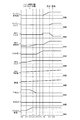
上述したEVモードおよびシリーズモードは、各モータ4,16の出力トルクで走行し、もしくは第2モータ16の出力トルクで走行するモードであるから、最大駆動トルクはモータ4,16の特性に応じて制限される。例えばシリーズモードで出力できる最大駆動トルクは、図6に示すように、第2モータ16の特性に応じたものとなり、車速がある程度増大した後は、車速の増大に従って低下する。したがって、シリーズモードとシリーズパラレルモードとの切り換え制御を行うためには、図6に示すように、車速と出力軸トルク(もしくは要求トルク)とによって各モードの領域を定めたマップを用意しておき、実際の走行状態が属しているモードを設定することとすればよい。
The EV mode and the series mode described above are modes that run with the output torque of the
図6に示すマップにおいて、シリーズパラレルモードが設定される領域は、シリーズモードが設定される領域と重複している。言い換えれば、シリーズモードを設定できる領域はシリーズパラレルモードを設定できる領域でもある。そのため、シリーズモードを設定できる領域では、燃費を重視して走行する場合にはシリーズモードを設定し、動力性能を重視する場合にはシリーズパラレルモードを設定するように構成されている。動力性能を重視する場合の一例として、例えば、運転者によってスポーツモードが選択された場合、つまりエンジン1の回転数が比較的高く維持され、減速時にはエンジンブレーキを発生するような場合などが挙げられる。
In the map shown in FIG. 6, the area where the series parallel mode is set overlaps with the area where the series mode is set. In other words, the area where the series mode can be set is also the area where the series parallel mode can be set. For this reason, in the region where the series mode can be set, the series mode is set when traveling with emphasis on fuel efficiency, and the series parallel mode is set when focusing on power performance. As an example of the case where importance is attached to the power performance, for example, when the sports mode is selected by the driver, that is, the case where the
また、アクセル開度および車速に応じてエンジン1を始動あるいは停止する制御に、図7に示すようなマップを用いてもよい。すなわち、アクセル開度および車速に基づいてエンジン1を制御する判定線を予め定めておき、アクセル開度もしくは車速がその判定線に達したときにエンジン1を始動あるいは停止するように構成する。したがって、エンジン1の始動あるいは停止を図7に基づいて行い、エンジン1の始動時には、図6に基づいてエンジン1を始動した後の走行モードを決定するように構成されている。
Further, a map as shown in FIG. 7 may be used for control for starting or stopping the
つぎに、この発明における駆動力制御装置が搭載された車両において、エンジン1が停止している走行モードが設定されている状態、すなわちEVモードが設定されている状態からエンジン1を始動する場合に実行される制御を図1のフローチャートを用いて説明する。また、以下の制御は、この発明の実施形態におけるコントローラに相当するHV−ECU100によって実行される。
Next, in a vehicle equipped with the driving force control apparatus according to the present invention, when the
上述したように、HV−ECU100は、エンジン1を停止して走行している状態、つまりEVモードで走行している状態の車両に、エンジン1を始動する必要があるか否かをステップS1で判断する。エンジン1を始動する走行モードに切り換えるか否かの判断は、アクセル開度センサによって取得されるアクセル開度の大きさ、車速度センサによって取得される車速、充電残量(SOC)などに基づいて決定される。ステップS1で否定的に判断された場合、つまりHV−ECU100が、エンジン1を始動させる必要がないと判断した場合にはリターンする。
As described above, in step S1, the HV-
ステップS1で肯定的に判断された場合、つまりHV−ECU100からエンジン1を始動する要求がある場合には、エンジン1を始動した後に設定される走行モードの判定、つまりエンジン1を始動した後に設定される走行モードがシリーズモードであるか否かがステップS2で判断される。なお、エンジン1を始動した後の走行モードは、エンジン1を始動するときの車速やアクセル開度に基づいて決定される。
If the determination in step S1 is affirmative, that is, if there is a request for starting the
ステップS2で肯定的に判断された場合、つまりエンジン1を始動した後に設定される走行モードがシリーズモードであった場合には、ステップS3の制御が実行される。すなわち、シリーズクラッチCSを係合させた状態でエンジン1を始動する。具体的には、HV−ECU100は、エンジン1を始動した後に設定される走行モードであるシリーズモードを設定するときに係合されるシリーズクラッチCSを係合し、入力クラッチC0およびブレーキB0を解放する。そして、各クラッチCS,C0およびブレーキB0の係合あるいは解放の状態を切り換えた後にエンジン1を始動する。言い換えれば、エンジン1始動後の走行モードに基づいて選択された各クラッチCS,C0のうち少なくとも一方を係合してエンジン1を始動する。HV−ECU100によるエンジン1を始動する制御は、第1モータ4からトルクを出力するように制御することでシリーズクラッチCSを介してエンジン1にトルクが伝達される。そのトルクによってエンジン1をクランキングすることでエンジン1を始動させている。
If the determination in step S2 is affirmative, that is, if the traveling mode set after starting the
ステップS2で否定的に判断された場合には、ステップS4の制御が実行される。この実施形態において、ステップS2で否定的に判断された場合に、エンジン1を始動した後に設定される走行モードはシリーズパラレルモードである。そのため、入力クラッチC0を係合させた状態でエンジン1を始動する。具体的には、HV−ECU100は、エンジン1を始動した後に設定される走行モードであるシリーズパラレルモードを設定するときに係合される入力クラッチC0を係合し、シリーズクラッチCSおよびブレーキB0を解放する。そして、各クラッチCS,C0およびブレーキB0の係合あるいは解放の状態を切り換えた後にエンジン1を始動する。HV−ECU100によるエンジン1を始動する制御は、第1モータ4からトルクを出力するように制御する。第1モータ4から出力されたトルクは、動力分割機構3および入力クラッチC0を介してエンジン1に伝達される。エンジン1は、伝達された第1モータ4からのトルクによってクランキングされた後に点火されることで始動する。
If a negative determination is made in step S2, the control in step S4 is executed. In this embodiment, when a negative determination is made in step S2, the travel mode set after the
この構成によれば、HV−ECU(コントローラ)100は、判定された走行モードを設定するためにエンジン1を始動する場合に、係合する各クラッチCS,C0を、エンジン1を始動した後に設定される走行モードに基づいて選択する。そして、選択された各クラッチCS,C0を係合した後にエンジン1を始動する。すなわち、エンジン1を始動した後に各クラッチCS,C0およびブレーキB0の係合状態の切り換えが生じることを抑制または回避できる。したがって、エンジン1を始動した後に、走行モードの遷移に伴い各クラッチCS,C0およびブレーキB0の係合状態を切り換えることによって、運転者が意図しない挙動が生じ、そのためビジー感や違和感が発生することを抑制あるいは回避することができる。また、エンジン1が停止している状態(すなわちエンジン1からのトルクが掛かっていない状態)で各クラッチCS,C0の係合あるいは解放の状態を切り換えるため、各クラッチCS,C0を係合させる場合の各クラッチCS,C0に作用させる油圧の制御や第1モータ4の回転数制御などが煩雑になることを抑制することができる。
According to this configuration, the HV-ECU (controller) 100 sets the clutches CS and C0 to be engaged after starting the
つぎに、上述した制御を実行したときの各クラッチCS,C0に作用する油圧や第1モータ4、第2モータ16およびエンジン1が出力するトルクなどの変化を、図8ないし図13に示すタイムチャートを用いて説明する。図8に示すタイムチャートは、エンジン1を始動する前に設定されている走行モードがEVモードにおけるMG1切り離しモードであって、エンジン1を始動した後に設定される走行モードがシリーズモードであるときに、上述した制御を実行した場合における各クラッチCS,C0に作用する油圧などの変化を表している。
Next, changes in the hydraulic pressure acting on each of the clutches CS and C0 and the torque output from the
図8に示すように、エンジン1を始動するように判断される前であるt0時点では、MG1切り離しモードであるため、各クラッチCS,C0およびブレーキB0は解放されていて、エンジン1および第1モータ4は停止している状態であり、第2モータ4から出力される動力で走行している状態である。
As shown in FIG. 8, at the time t0 before it is determined to start the
運転者の操作により、t1時点において、アクセルが踏み込まれてアクセル開度が大きくなると、それに伴って第2モータ16が出力するトルクが増大される。そして、アクセル開度が大きくなり所定のしきい値を超えるt2時点に達すると、エンジン1を始動する必要があると判断される。すなわち、アクセル開度が大きくなったことにより、アクセル開度と車速とによって決まる車両の走行状態(もしくはエンジン1の運転点)が、図7におけるエンジン1を停止させる領域から判定線を越えてエンジン1を始動させる領域に達したため、エンジン1を始動する必要があると判断される。また、走行モードの決定は、エンジン1を始動する判断とともに実行される。言い換えれば、HV−ECU100は、アクセル開度および車速に応じてエンジン1を始動する必要があると判断した場合に、そのエンジン1の始動の判断とともに、エンジン1を始動した後に設定する走行モードを上述した図6に示すマップなどに基づいて決定するように制御する。そのため、図8において、エンジン1を始動する判断とシリーズモードが設定される判断とが同じt2時点で発生している。HV−ECU100は、シリーズモードを設定するため、まずt2時点においてシリーズクラッチCSを係合させるように油圧指令信号PbCSを制御する。
When the accelerator is depressed by the driver's operation and the accelerator opening is increased at time t1, the torque output by the
運転者の操作によって、しきい値を超えたアクセル開度がさらに増大された状態で一定になるt3時点において、第2モータ16が出力するトルクも増大された状態で一定になるように制御される。また、シリーズクラッチCSは、係合されるt4時点において、トルク伝達が可能な状態になる。HV−ECU100は、シリーズクラッチCSが係合すると、第1モータ4の出力するトルクを第1モータ4が正回転するトルク、つまり正トルクを出力するように制御する。シリーズクラッチCSが係合していることにより、第1モータ4とエンジン1とが機械的に直結されている状態であるため、第1モータ4が正トルクを出力するとエンジン1が連れ回されて回転する。また、エンジン1と第1モータ4とが直結しているため、エンジン1における回転数と第1モータ4における回転数とが同一回転数で上昇する。
The torque output by the
第1モータ4のトルクによってエンジン1の回転数が所定の回転数に達するt5時点においてエンジン1が点火される。所定の回転数とは、エンジン1が自立運転できる回転数であって、その回転数で点火することによってエンジン1の始動をスムースにすることができる。エンジン1は点火されることでトルクを出力し始め、それに伴って第1モータ4は、HV−ECU100によって次第に出力するトルクが小さくなるように制御される。第1モータ4は、HV−ECU100によって出力するトルクが次第に減少されて停止した後、それまでとは反対の方向に回転するトルク、つまり負トルクを出力するように制御される。また、エンジン1のトルクが増大されるとともに、第1モータ4の正トルクは減少されるため、エンジン1の回転数および第1モータ4の回転数は一定の回転数で維持される。
The
エンジン1が自立運転できる状態、つまり完爆の状態になるt6時点において、エンジン1の始動が完了するとともにシリーズモードの設定が完了する。すなわち、負トルクを出力している第1モータ4は、エンジン1のトルクによって正方向に回転されることで発電している状態になり、車両は第2モータのトルクによって走行している状態となる。なお、車速および第2モータ16の回転数は、アクセル開度が大きくなり始めたt1時点からシリーズモードが設定されたt6時点より後においても大きくなるように制御されていて、次第にアクセル開度に応じた車速になるように制御されている。
At the time t6 when the
なお、上述した実施形態では、エンジン1を始動する前の走行モードとしてシリーズクラッチCSが解放された状態のMG1切り離しモードを用いて説明したが、シリーズクラッチCSが係合された状態のMG1切り離しモードでもよい。その場合には、シリーズクラッチCSがすでに係合しているため、各クラッチCS,C0およびブレーキB0において、係合あるいは解放の状態を切り換えることなくエンジン1を始動させる制御を実行することができる。
In the above-described embodiment, the MG1 disengagement mode in which the series clutch CS is released has been described as the travel mode before starting the
この構成によれば、HV−ECU(コントローラ)100は、MG1切り離しモードからシリーズモードが設定される場合に、解放されていればシリーズクラッチCSを係合させ、その後に第1モータ4のトルクによってエンジン1をクランキングする。したがって、エンジン1を始動させた後に、走行モードの遷移に伴い各クラッチCS,C0およびブレーキB0における係合あるいは解放の状態の切り換えが生じない。すなわち、運転者が意図しない挙動が生じ、そのためビジー感や違和感が発生することを抑制あるいは回避することができる。
According to this configuration, when the series mode is set from the MG1 disengagement mode, the HV-ECU (controller) 100 engages the series clutch CS if it is released, and then the torque of the
つぎに、図9を用いて、エンジン1を始動する前に設定されている走行モードがEVモードにおけるMG1引き摺りモードであって、エンジン1を始動した後に設定される走行モードがシリーズモードであるときに、上述した制御を実行した場合における各クラッチCS,C0に作用する油圧などの変化を説明する。以下の説明において、上述した説明と同じ変化の場合には、省略して説明する場合がある。
Next, referring to FIG. 9, when the travel mode set before starting the
図9に示すように、エンジン1を始動するように判断される前であるt10時点では、MG1引き摺りモードであるため、入力クラッチC0が係合されていて、シリーズクラッチCSおよびブレーキB0は解放されている状態である。また、エンジン1は停止しているためトルクを出力しておらず、第2モータ16が出力するトルクによって走行している状態である。第1モータ4は、トルクは出力していないが、入力クラッチC0が係合されていることによってキャリヤ7が反力要素となるため、第2モータ16からの動力によって回転されるリングギヤ6の回転によって負方向に回転されている。
As shown in FIG. 9, at the time t10 before it is determined to start the
そのため、t11時点において、アクセル開度が大きくなるにつれて第2モータ16の出力するトルクが増大され、車速および第2モータ16の回転数が大きくなると、それに応じて第1モータ4の回転数も負方向へ大きくなる。アクセル開度が大きくなり、予め定められたしきい値を超えるt12時点に達すると、HV−ECU100はエンジン1を始動する必要があると判断する。エンジン1を始動すると判断したときに、上述した図6に示すマップなどに基づいて、エンジン1を始動した後の走行モードとしてシリーズモードが選択される。
Therefore, at time t11, as the accelerator opening increases, the torque output from the
MG1引き摺りモードでは入力クラッチC0が係合しているため、シリーズモードへ移行するには入力クラッチC0を解放してシリーズクラッチCSを係合させる。そのため、HV−ECU100は、まず入力クラッチC0を係合するように作用していた油圧を次第に小さくするように油圧指令信号PbC0を制御する。入力クラッチC0に作用していた油圧が小さくなることにより、次第にキャリヤ7が反力要素として作用しなくなるため、第1モータ4の負方向への回転数が小さくなる。そして、入力クラッチC0が解放されるt14時点において、第1モータ4の負回転も停止する。なお、入力クラッチC0が解放される過程であるt13時点において、アクセル開度および第2モータ16の出力するトルクは、増大された状態で一定になっている。
Since the input clutch C0 is engaged in the MG1 drag mode, the input clutch C0 is released and the series clutch CS is engaged to shift to the series mode. Therefore, the HV-
HV−ECU100は、入力クラッチC0が解放されると、ついでシリーズクラッチCSを係合させるように油圧指令信号PbCSを制御する。シリーズクラッチCSは、t15時点において次第にトルクを伝達するように油圧が作用されていて、t16時点において完全にトルクを伝達することができる状態、つまり完全に係合した状態になる。シリーズクラッチCSが係合すると、HV−ECU100は、第1モータ4から正トルクを出力するように制御し、その正トルクによってエンジン1をクランキングする。そして、エンジン1のクランキングが完了したt17時点においてエンジン1を点火して始動する。点火されたエンジン1が完爆した状態になるt18時点において、エンジン1の始動が完了するとともに、シリーズモードの設定が完了する。
When the input clutch C0 is released, the HV-
この構成によれば、HV−ECU(コントローラ)100は、MG1引き摺りモードからシリーズモードが設定される場合に、入力クラッチC0を解放させるとともにシリーズクラッチCSを係合させ、その後に第1モータ4のトルクによってエンジン1をクランキングする。したがって、エンジン1を始動した後に、走行モードの遷移に伴い各クラッチCS,C0およびブレーキB0における係合あるいは解放の状態の切り換えが生じない。すなわち、運転者が意図しない挙動が生じ、そのためビジー感や違和感が発生することを抑制あるいは回避することができる。
According to this configuration, when the series mode is set from the MG1 drag mode, the HV-ECU (controller) 100 releases the input clutch C0 and engages the series clutch CS, and then the
つぎに、図10を用いて、エンジン1を始動する前に設定されている走行モードがEVモードにおける両駆動モードであって、エンジン1を始動した後に設定される走行モードがシリーズモードであるときに、上述した制御を実行した場合における各クラッチCS,C0に作用する油圧などの変化を説明する。以下の説明において、上述した説明と同じ変化の場合には、省略して説明する場合がある。
Next, referring to FIG. 10, when the travel mode set before starting
図10に示すように、エンジン1を始動するように判断される前であるt20時点では、両駆動モードであるため、入力クラッチC0およびブレーキB0が係合されていて、シリーズクラッチCSが解放されている状態である。また、エンジン1は停止した状態であって、第2モータ16が出力するトルクおよび第1モータ4が出力するトルクによって走行している状態である。上述したように、両駆動モードでは、入力クラッチC0およびブレーキB0が係合していることで第1モータの負トルクが駆動力として駆動輪23に伝達される。すなわち、この第1モータ4の負トルクと、第2モータ16が出力する正トルクとを合わせたトルクとによって走行している状態である。
As shown in FIG. 10, at the time point t20 before it is determined to start the
そのため、t21時点において、アクセル開度が大きくなるにつれて第1モータ4の出力する負トルクおよび第2モータの出力する正トルクが増大するように制御される。アクセル開度が大きくなり、予め定められたしきい値を超えるt22時点に達すると、HV−ECU100はエンジン1を始動する必要があると判断する。エンジン1を始動すると判断したときに、上述した図6に示すマップなどに基づいて、エンジン1を始動した後の走行モードとしてシリーズモードが選択される。
Therefore, at time t21, the negative torque output from the
両駆動モードでは、入力クラッチC0およびブレーキB0が係合されていて、シリーズクラッチCSが解放されている状態である。そのため、HV−ECU100は、エンジン1の始動が必要であると判断すると、入力クラッチC0およびブレーキB0を解放し、シリーズクラッチCSを係合するように制御する。まず、HV−ECU100は、入力クラッチC0およびブレーキB0を係合するように作用していた油圧を次第に小さくするように各油圧指令信号PbC0,PbB0を制御する。また、シリーズモードへ切り換えるため、HV−ECU100は、第1モータ4が出力する負トルクを次第に小さくするように制御する。第1モータ4は、負トルクが次第に小さくなるように制御されるとともに、入力クラッチC0が解放されることによって第2モータ16の出力するトルクが伝達されなくなるため、回転数が次第に小さくなる。
In both drive modes, the input clutch C0 and the brake B0 are engaged and the series clutch CS is released. Therefore, when HV-
そして、HV−ECU100は、入力クラッチC0およびブレーキB0が解放されるt24時点において、第1モータ4の出力する負トルクも停止するように制御する。なお、入力クラッチC0およびブレーキB0が解放される過程であるt23時点において、アクセル開度は大きくなった状態で一定になっているが、第2モータ16の出力するトルクは、第1モータ4が停止するt24時点まで次第に増大させられる。第1モータ4が停止することによって駆動力が低下するため、第2モータ16が出力するトルクを増大させることで駆動力および車速を維持するためである。
Then, the HV-
HV−ECU100は、入力クラッチC0およびブレーキB0が解放されると、ついでシリーズクラッチCSを係合させるように油圧指令信号PbCSを制御する。シリーズクラッチCSは、t25時点において次第にトルクを伝達するように油圧が作用されていて、t26時点において完全にトルクを伝達することができる状態、つまり完全に係合した状態になる。シリーズクラッチCSが係合した後は、上述した制御と同様の制御によってエンジン1を始動する。すなわち、HV−ECU100は、第1モータ4から出力する正トルクによってエンジン1をクランキングし、そのクランキングが完了するt27時点においてエンジン1を点火するように制御する。そして、HV−ECU100は、エンジン1が点火されて完爆するまでの間に第1モータ4の出力するトルクを負トルクにする。エンジン1が完爆するt28時点において、エンジン1が自立運転を開始することによって、エンジン1の始動およびシリーズモードの設定が完了する。
When the input clutch C0 and the brake B0 are released, the HV-
この構成によれば、HV−ECU(コントローラ)100は、両駆動モードからシリーズモードが設定される場合に、入力クラッチC0およびブレーキB0を解放させるとともにシリーズクラッチCSを係合させ、その後に第1モータ4のトルクによってエンジン1をクランキングする。したがって、エンジン1を始動した後に、走行モードの遷移に伴い各クラッチCS,C0およびブレーキB0における係合あるいは解放の状態の切り換えが生じない。すなわち、運転者が意図しない挙動が生じ、そのためビジー感や違和感が発生することを抑制あるいは回避することができる。
According to this configuration, when the series mode is set from both drive modes, the HV-ECU (controller) 100 releases the input clutch C0 and the brake B0 and engages the series clutch CS, and then the first mode is set. The
つぎに、図11を用いて、エンジン1を始動する前に設定されている走行モードがEVモードにおけるMG1切り離しモードであって、エンジン1を始動した後に設定される走行モードがシリーズパラレルモード(シリパラモード)における無段状態であるときに、上述した制御を実行した場合における各クラッチCS,C0に作用する油圧などの変化を説明する。以下の説明において、上述した説明と同じ変化の場合には、省略して説明する場合がある。
Next, referring to FIG. 11, the travel mode set before starting the
図11に示すように、エンジン1を始動するように判断される前であるt30時点では、MG1切り離しモードであるため、各クラッチCS,C0およびブレーキB0は解放されている状態である。また、エンジン1および第1モータ4は停止していて、第2モータ16が出力するトルクによって走行している状態である。運転者の操作により、t31時点においてアクセル開度が大きくなると、それに伴って第2モータ16が出力するトルクが大きくなる。アクセル開度が大きくなり、予め定められたしきい値を超えるt32時点に達すると、HV−ECU100は、エンジン1を始動する必要があると判断する。すなわち、エンジン1を始動すると判断したときに、上述した図6に示すマップなどに基づいて、エンジン1を始動した後の走行モードとしてシリーズパラレルモードにおける無段状態が選択される。
As shown in FIG. 11, at the time t30 before it is determined to start the
HV−ECU100は、エンジン1の始動が必要であると判断すると、まず第1モータ4が負トルクを出力するように制御する。負トルクを出力することで第1モータ4は負方向に回転する。第1モータ4の負トルクによってサンギヤ5が負方向に回転するため、第2モータ4のトルクによって正回転で空転しているキャリヤ7の回転が停止する。キャリヤ7の回転が停止するため、入力クラッチC0の係合をスムースにすることができる。HV−ECU100は、第1モータ4の負方向への回転が所定の回転数に達するt33時点において、入力クラッチC0を次第に係合させるように油圧指令信号PbC0を制御する。また、このときにアクセル開度および第2モータ16の出力するトルクは、増大された状態で一定になっていて、第1モータ4はトルクを出力しない状態に制御される。
When the HV-
HV−ECU100は、入力クラッチC0が係合するように作用する油圧が次第に大きくなり、完全に係合するt34時点において、第1モータ4が正トルクを出力するように制御する。この正トルクによって、動力分割機構3および入力クラッチC0を介してエンジン1がクランキングされる。また、入力クラッチC0が係合した状態で第1モータ4が正トルクを出力するため、この正トルクが制動力として作用する。そのため、第2モータ16が出力する正トルクを増大させることによって車速を維持する。第1モータ4は、正トルクを出力するように制御されるため、回転方向が負方向から正方向に変化する。
The HV-
HV−ECU100は、第1モータ4によるエンジン1のクランキングが完了するt35時点において、エンジン1を点火するように制御する。また、エンジン1の点火に伴い、第1モータ4の出力するトルクを正トルクから負トルクに制御し、第2モータ16の出力する正トルクを減少するように制御する。すなわち、エンジン1がトルクの出力を開始していて、さらに、第1モータ4が出力するトルクによる制動力が小さくなっている。そのため、駆動力に大きな変化が生じないように第2モータ16が出力するトルクを制御している。第1モータ4は、出力するトルクが正トルクから負トルクに変化しているが、入力クラッチC0が係合されているため、エンジン1の出力するトルクおよび第2モータ16が出力するトルクによって回転の向きは正方向で維持される。
The HV-
エンジン1が完爆するt36時点において、エンジン1の始動およびシリーズパラレルモードの設定が完了する。具体的には、入力クラッチC0のみ係合されている状態でエンジン1がトルクを出力し、第2モータ16が正トルクを出力し、第1モータ4が負トルクが出力している。そのため、第2モータ16の正トルクおよびエンジン1におけるトルクの一部が駆動力として作用し、エンジン1におけるトルクの他の部分と第1モータ4の負トルクとによって第1モータ4で発電している状態となる。
At time t36 when the
なお、上述した実施形態では、エンジン1を始動する前の走行モードとしてシリーズクラッチCSが解放された状態のMG1切り離しモードを用いて説明したが、シリーズクラッチCSが係合された状態のMG1切り離しモードでもよい。その場合には、シリーズクラッチCSを解放させた後に入力クラッチC0を係合させ、その後にエンジン1を始動させる制御を実行する。
In the above-described embodiment, the MG1 disengagement mode in which the series clutch CS is released has been described as the travel mode before starting the
この構成によれば、HV−ECU(コントローラ)100は、MG1切り離しモードからシリーズパラレルモードにおける無段状態が設定される場合に、係合されていればシリーズクラッチCSを解放させるとともに入力クラッチC0を係合させる。その後に、第1モータ4のトルクによって動力分割機構3および入力クラッチC0を介してエンジン1をクランキングする。したがって、エンジン1を始動した後に、走行モードの遷移に伴い各クラッチCS,C0およびブレーキB0における係合あるいは解放の状態を切り換えることによって、運転者が意図しない挙動が生じ、そのためビジー感や違和感が発生することを抑制あるいは回避することができる。
According to this configuration, the HV-ECU (controller) 100 releases the series clutch CS and engages the input clutch C0 if engaged when the continuously variable state in the series parallel mode is set from the MG1 disconnection mode. Engage. Thereafter, the
つぎに、図12を用いて、エンジン1を始動する前に設定されている走行モードがEVモードにおけるMG1引き摺りモードであって、エンジン1を始動した後に設定される走行モードがシリーズパラレルモードにおける無段状態であるときに、上述した制御を実行した場合における各クラッチCS,C0に作用する油圧などの変化を説明する。以下の説明において、上述した説明と同じ変化の場合には、省略して説明する場合がある。
Next, referring to FIG. 12, the travel mode set before starting
図12に示すように、エンジン1を始動するように判断される前であるt40時点では、MG1引き摺りモードであるため、入力クラッチC0が係合されていて、シリーズクラッチCSおよびブレーキB0は解放されている状態である。また、エンジン1および第1モータ4は停止していて、第2モータ16が出力する動力によって走行している状態である。
As shown in FIG. 12, at the time t40 before it is determined to start the
運転者の操作によってアクセル開度が大きくなるt41時点において、アクセル開度に応じて第2モータ16の出力するトルクが増大され、車速および第2モータ16の回転数も大きくなる。アクセル開度が大きくなり、しきい値を超えるt42時点に達すると、HV−ECU100はエンジン1を始動する必要があると判断する。エンジン1を始動すると判断したときに、上述した図6に示すマップなどに基づいて、エンジン1を始動した後の走行モードとしてシリーズパラレルモードにおける無段状態が選択される。
At time t41 when the accelerator opening is increased by the driver's operation, the torque output by the
MG1引き摺りモードでは、すでに入力クラッチC0のみ係合している状態であるため、各クラッチCS,C0およびブレーキB0における係合あるいは解放を切り換える必要がない。そのため、t42時点において、HV−ECU100は、エンジン1をクランキングするために第1モータ4が正トルクを出力する。また、HV−ECU100は、第1モータ4の出力する正トルクによって制動力が生じるため、第2モータ16が出力しているトルクを、第1モータ4が出力するトルクと同じ程度増大させることで車速を維持する。さらに、アクセル開度がt42時点において大きくなり続けているため、第2モータ16のトルクは、そのアクセル開度に応じて大きくなるように制御される。そして、アクセル開度が大きくなった状態で一定になると、第2モータ16が出力するトルクも増大された状態で一定になる。なお、第1モータ4は、正トルクを出力することによって、負回転から正回転に変化する。
In the MG1 drag mode, since only the input clutch C0 is already engaged, it is not necessary to switch engagement or disengagement between the clutches CS and C0 and the brake B0. Therefore, at time t <b> 42, the HV-
第1モータ4によるエンジン1のクランキングが完了するt44時点において、エンジン1が点火される。エンジン1が点火されてから完爆するまでは、上述したように、HV−ECU100によって、第1モータ4は次第に負トルクを出力するように制御され、第2モータ16は次第に出力する正トルクを減少するように制御される。エンジン1が完爆するt45時点において、エンジン1の始動およびシリーズパラレルモードにおける無段状態の設定が完了する。
At time t44 when cranking of the
この構成によれば、HV−ECU(コントローラ)100は、MG1引き摺りモードからシリーズパラレルモードにおける無段状態が設定される場合に、各クラッチCS,C0およびブレーキB0における係合状態を維持し、第1モータ4のトルクによって動力分割機構3および入力クラッチC0を介してエンジン1をクランキングする。したがって、エンジン1を始動した後に、走行モードの遷移に伴い各クラッチCS,C0およびブレーキB0における係合あるいは解放の状態を切り換えることによって、運転者が意図しない挙動が生じ、そのためビジー感や違和感が発生することを抑制あるいは回避することができる。
According to this configuration, the HV-ECU (controller) 100 maintains the engaged state in each of the clutches CS and C0 and the brake B0 when the continuously variable state from the MG1 drag mode to the series parallel mode is set. The
つぎに、図13を用いて、エンジン1を始動する前に設定されている走行モードがEVモードにおける両駆動モードであって、エンジン1を始動した後に設定される走行モードがシリーズパラレルモードにおける無段状態であるときに、上述した制御を実行した場合における各クラッチCS,C0に作用する油圧などの変化を説明する。以下の説明において、上述した説明と同じ変化の場合には、省略して説明する場合がある。
Next, referring to FIG. 13, the driving mode set before starting
図13に示すように、エンジン1を始動するように判断される前であるt50時点では、両駆動モードであるため、入力クラッチC0およびブレーキB0が係合されていて、シリーズクラッチCSが解放されている状態である。また、エンジン1は停止した状態であって、第2モータ16が出力する動力および第1モータ4が出力する動力によって走行している状態である。
As shown in FIG. 13, at the time point t50 before it is determined to start the
そのため、t51時点において、運転者の操作によりアクセル開度が大きくなると、第1モータ4の出力する負トルクおよび第2モータの出力する正トルクが次第に大きくされる。アクセル開度が大きくなり、予め定められたしきい値を超えるt52時点に達すると、HV−ECU100はエンジン1を始動する必要があると判断する。エンジン1を始動すると判断したときに、上述した図6に示すマップなどに基づいて、エンジン1を始動した後の走行モードとしてシリーズパラレルモードにおける無段状態が選択される。
Therefore, when the accelerator opening is increased by the driver's operation at time t51, the negative torque output from the
両駆動モードでは、入力クラッチC0およびブレーキB0が係合していて、シリーズクラッチCSが解放されている状態である。そのため、HV−ECU100は、エンジン1の始動が必要であると判断すると、ブレーキB0を解放する。まず、HV−ECU100は、ブレーキB0を係合するように作用していた油圧を次第に小さくするように油圧指令信号PbB0を制御する。また、シリーズパラレルモードにおける無段状態へ切り換えるため、HV−ECU100は、第1モータ4が出力する負トルクを次第に減少するように制御する。
In both drive modes, the input clutch C0 and the brake B0 are engaged and the series clutch CS is released. Therefore, when HV-
そして、HV−ECU100は、ブレーキB0が解放されるt54時点において、第1モータ4はトルクを出力しない状態に制御する。また、第2モータ16は、第1モータ4が次第に停止を開始するt52時点において、第1モータの停止によって減少するトルクを補うために、正トルクが大きくなるように制御される。入力クラッチC0が係合された状態で第2モータ16が出力する正トルクが増大されるため、第1モータ4の出力するトルクは減少されるが、第1モータ4の負方向への回転数は次第に大きくなる。なお、ブレーキB0が解放される過程であるt53時点において、アクセル開度は大きくなった状態で一定になっている。
The HV-
ブレーキB0を解放した後は、上述した制御と同様の制御によってエンジン1を始動する。具体的には、HV−ECU100は、ブレーキB0を解放し、第1モータ4の出力する正トルクによってエンジン1をクランキングするとともに、第2モータ16が出力する正トルクを大きくすることで車速を維持する。第1モータ4は、正トルクを出力するように制御されるため、負方向に回転している状態から正方向へ回転している状態に変化する。
After releasing the brake B0, the
HV−ECU100は、エンジン1のクランキングが完了するt55時点において、エンジン1を点火するように制御する。エンジン1の点火から完爆までの間に、HV−ECU100は、第1モータの出力するトルクを負トルクにし、第2モータ16の出力する正トルクを小さくするように制御する。そして、エンジン1が完爆するt56時点において、エンジン1の始動およびシリーズパラレルモードにおける無段状態の設定が完了する。
The HV-
この構成によれば、HV−ECU(コントローラ)100は、両駆動モードからシリーズパラレルモードにおける無段状態が設定される場合に、ブレーキB0を解放した後に、第1モータ4のトルクによって動力分割機構3および入力クラッチC0を介してエンジン1をクランキングする。したがって、エンジン1を始動した後に、走行モードの遷移に伴い各クラッチCS,C0およびブレーキB0における係合あるいは解放の状態を切り換えることによって、運転者が意図しない挙動が生じ、そのためビジー感や違和感が発生することを抑制あるいは回避することができる。
According to this configuration, the HV-ECU (controller) 100 allows the power split mechanism to be driven by the torque of the
なお、上述した実施形態では、エンジン1を始動した後の走行モードとしてシリーズパラレルモードにおける無段状態を用いて説明したが、シリーズパラレルモードにおける固定段状態を用いることもできる。その場合には、上述したエンジン1を始動する制御を実行した後に、シリーズクラッチCSを係合するように制御することによって設定することができる。また、上述した制御は、前進走行および後進走行のいずれの走行方向であってもよい。
In the above-described embodiment, the traveling mode after starting the
つぎに、この発明における駆動力制御装置の対象とすることができる他の車両の構成について説明する。他の車両の構成における入力クラッチC0は、エンジン1から動力分割機構3を介して出力ギヤ12にトルクを伝達する経路をトルク伝達可能な状態にし、またそのトルク伝達を遮断するように構成されていればよく、またシリーズクラッチCSはエンジン1の出力トルクを第1モータ4に伝達し、その伝達を遮断するように構成されていればよい。したがって、この発明の実施形態では、入力クラッチC0は図14に示すように、動力分割機構3のリングギヤ6と出力ギヤ12との間に設けられていて、またシリーズクラッチCSはキャリヤ7と第1ロータ軸10との間に設けられている。図14に示す他の構成は、前述した図2に示す構成と同様であるから、図14に図2と同様の符号を付してその説明を省略する。
Next, the configuration of another vehicle that can be a target of the driving force control apparatus according to the present invention will be described. The input clutch C0 in the configuration of another vehicle is configured so that a path for transmitting torque from the
図14に示す構成の駆動装置であっても、前述した図4に示すように、各クラッチC0,CSおよびブレーキB0を係合もしくは解放することにより、EVモードやHVモードを設定することができる。第2モータ16によって走行するEVモードでは、各クラッチC0,CSおよびブレーキB0を解放する。その結果、出力ギヤ12と動力分割機構3におけるリングギヤ6との連結が解除されるので、動力分割機構3を構成しているサンギヤ5およびリングギヤ6ならびにキャリヤ7は停止している。これに対して、入力クラッチC0を係合させれば、リングギヤ6が出力ギヤ12と共に回転し、またキャリヤ7がエンジン1と共に停止しているので、サンギヤ5およびこれに連結されている第1モータ4が負方向に回転する。すなわち、第1モータ4を連れ回すMG1引き摺りモードになる。この動作状態を動力分割機構3を構成している遊星歯車機構についての共線図として図15(a)に示してある。さらに、その状態でブレーキB0を係合させて入力軸8およびキャリヤ7を固定すれば、第1モータ4がトルクを出力することに対する反力トルクをキャリヤ7で受け持つことができるので、第1モータ4を負方向に回転させ、かつ第2モータ16を正方向に回転させて、これら二つのモータ4,16のトルクで走行する両駆動モードとなる。なお、MG1引き摺りモードにおける後進走行時の共線図は、上述したように、各クラッチC0,CSの位置が異なるものの、サンギヤ5およびリングギヤ6ならびキャリヤ7の回転方向などは同じであり、図15(b)に示す共線図によって表すことができる。
Even in the drive device having the configuration shown in FIG. 14, the EV mode or the HV mode can be set by engaging or releasing the clutches C0 and CS and the brake B0 as shown in FIG. . In the EV mode running by the
シリーズモードは、シリーズクラッチCSを係合させてエンジン1によって第1モータ4を駆動し、その第1モータ4で発電した電力によって第2モータ16を駆動して走行するモードである。したがって、図14に示す構成では、シリーズクラッチCSによってサンギヤ5とキャリヤ7とが連結されることにより動力分割機構3の全体が一体となって回転する。その結果、第1モータ4がエンジン1によって駆動されて発電する。しかしながら、入力クラッチC0が解放していてリングギヤ6と出力ギヤ12とが連結されていないので、エンジン1の出力トルクは出力ギヤ12に伝達されることはない。図15の(c)はその状態を共線図で示しており、サンギヤ5およびリングギヤ6ならびにキャリヤ7は同一回転数になっている。なお、シリーズモードによる後進走行時は、エンジン1および第1モータ4の動作は同様であり、第2モータ16のみ負方向に回転することによって後進する。
The series mode is a mode in which the
シリーズパラレルモードでの前進時における無段状態は、エンジン1の回転数を第1モータ4によって制御し、その結果、第1モータ4で発生した電力を第2モータ16に供給して第2モータ16が駆動トルクを出力する。その動作状態を図15の(d)に共線図で示してある。これは、前述した図5の(e)に示す共線図と各クラッチC0,CSの位置が異なるものの、サンギヤ5およびリングギヤ6ならびキャリヤ7の回転方向などは同じである。また、後進走行時には、入力クラッチC0のみを係合させた状態で、エンジン1を駆動し、かつ第1モータ4を発電機として機能させて正方向に回転させる。そして、第2モータ16はモータとして機能させ、負方向に回転させ、その出力トルクによって後進走行する。
In the stepless state during forward movement in the series parallel mode, the rotational speed of the
シリーズパラレルモードでの前進時の固定段状態は各クラッチC0,CSを係合させることにより設定され、したがって動力分割機構3の全体が一体となって回転する。したがって、エンジン1に加えて各モータ4,16をモータとして駆動させてトルクを出力させることにより、エンジン1および各モータ4,16のトルクで走行するいわゆる両駆動状態となる。その動作状態を図15の(e)に共線図で示してある。これは、前述した図5の(f)に示す共線図とクラッチC0,CSの位置が異なるものの、サンギヤ5およびリングギヤ6ならびキャリヤ7の回転方向などは同じである。
The fixed stage state at the time of forward movement in the series parallel mode is set by engaging the clutches C0 and CS. Therefore, the entire
以上、添付図面を参照しながら本発明の好適な例について説明したが、本発明は上述した構成に限定されない。すなわち、上述した構成は、発明の理解を容易とするための例示に過ぎず、特に断る場合を除き、本発明を限定するものではない。また、特許請求の範囲に記載された発明の要旨の範囲内で種々の変更が可能である。すなわち、上述したような構成の車両において、エンジン1および各クラッチCS,C0およびブレーキB0を制御するコントローラが、エンジン1を始動する要求の有無を判断し、かつエンジン1を始動した後に設定する走行モードを、エンジン1を始動する要求があった場合に判定し、さらに判定された走行モードを設定するべく係合させられる各クラッチCS,C0のうち少なくとも一つのクラッチを係合させ、少なくとも一つのクラッチを係合させた状態でエンジン1を始動するように構成されていればよい。
As mentioned above, although the suitable example of this invention was demonstrated referring an accompanying drawing, this invention is not limited to the structure mentioned above. That is, the above-described configuration is merely an example for facilitating understanding of the invention, and does not limit the present invention unless otherwise specified. In addition, various modifications can be made within the scope of the gist of the invention described in the claims. That is, in the vehicle configured as described above, the controller that controls the
1…エンジン、 2…出力軸、 3…動力分割機構、 4…第1モータ(MG1)、 5…サンギヤ、 6…リングギヤ、 7…キャリヤ、 9…第1ロータ 12…出力ギヤ、 14…ドリブンギヤ、 15…第1ドライブギヤ、 16…第2モータ(MG2)、 100…HV−ECU(コントローラ)、 CS…シリーズクラッチ、 C0…入力クラッチ。
DESCRIPTION OF
Claims (6)
前記第1係合装置を係合させるとともに前記エンジンによって前記第1モータを駆動し、かつ前記第1モータが発電した電力で前記第2モータを駆動して走行するシリーズモードと、前記第2係合装置を係合させるとともに少なくとも前記エンジンが出力する駆動力の一部と前記第2モータが出力する駆動力とによって走行するシリーズパラレルモードとの少なくとも二つの走行モードを設定可能なハイブリッド車両の駆動力制御装置において、
前記エンジンおよび前記第1係合装置および前記第2係合装置を制御するコントローラを備え、
前記コントローラは、
前記エンジンを始動する要求の有無を判断し、
前記エンジンを始動した後に設定する走行モードを、前記エンジンを始動する要求があった場合に判定し、
判定された走行モードを達成する前記第1係合装置および前記第2係合装置のうち少なくとも一つの係合装置を係合させ、
前記少なくとも一つの係合装置を係合させた状態で前記エンジンを始動する
ように構成されていることを特徴とするハイブリッド車両の駆動力制御装置。 The engine, a first motor having a power generation function, an input element to which torque is transmitted from the engine, a reaction force element to which torque is transmitted from the first motor, and an output element, and a differential action are provided by at least three rotating elements. A power split mechanism to perform, an output member to which torque is transmitted from the output element, a first engagement device for selectively transmitting and interrupting torque from the engine to the first motor, and the first engagement A second engagement device that is different from the device and selectively transmits torque from the engine to the output member via the power split mechanism, and electric power generated by the first motor A second motor that is driven by and outputs a driving torque for traveling,
A series mode in which the first engagement device is engaged, the first motor is driven by the engine, and the second motor is driven by electric power generated by the first motor; Driving a hybrid vehicle that engages a combined device and can set at least two travel modes, ie, a series parallel mode that travels by at least a part of the drive force output by the engine and the drive force output by the second motor In the force control device,
A controller for controlling the engine and the first engagement device and the second engagement device;
The controller is
Determining whether there is a request to start the engine;
The driving mode set after starting the engine is determined when there is a request to start the engine,
Engaging at least one engagement device of the first engagement device and the second engagement device that achieves the determined traveling mode;
A driving force control device for a hybrid vehicle, wherein the engine is started with the at least one engagement device engaged.
前記エンジンを始動した後に設定される走行モードがシリーズモードであった場合には、前記第1係合装置を係合させた状態で前記エンジンを始動するように構成されていることを特徴とする請求項1に記載のハイブリッド車両の駆動力制御装置。 The controller is
When the travel mode set after starting the engine is a series mode, the engine is started with the first engagement device engaged. The driving force control apparatus for a hybrid vehicle according to claim 1.
前記エンジンを始動した後に設定される走行モードがシリーズパラレルモードであった場合には、前記第2係合装置を係合させた状態で前記エンジンを始動するように構成されていることを特徴とする請求項1に記載のハイブリッド車両の駆動力制御装置。 The controller is
When the travel mode set after starting the engine is a series parallel mode, the engine is started with the second engagement device engaged. The driving force control apparatus for a hybrid vehicle according to claim 1.
前記第3係合装置を係合するとともに前記第1モータが出力する駆動力と前記第2モータが出力する駆動力とで走行する両駆動モードを設定可能に構成されている
ことを特徴とする請求項1ないし3のいずれか一項に記載のハイブリッド車両の駆動力制御装置。 A third engagement device capable of selectively stopping rotation of the output shaft of the engine;
It is configured to be able to set both driving modes in which the third engagement device is engaged and the vehicle is driven by the driving force output by the first motor and the driving force output by the second motor. The driving force control apparatus for a hybrid vehicle according to any one of claims 1 to 3.
前記第2モータは、前記第2モータの回転中心軸線が前記エンジンの出力軸と平行になるように配置されている
ことを特徴とする請求項4に記載のハイブリッド車両の駆動力制御装置。 On the same axis as the output shaft of the engine, the third engagement device, the second engagement device, the power split mechanism, the first motor, and the first engagement device are arranged in this order from the engine side. And
5. The driving force control apparatus for a hybrid vehicle according to claim 4, wherein the second motor is disposed such that a rotation center axis of the second motor is parallel to an output shaft of the engine.
前記カウンタ軸に大径ギヤと小径ギヤとが取り付けられており、
前記大径ギヤに前記出力部材および前記第2モータからトルクが伝達され、かつ
前記小径ギヤから駆動トルクを出力する
ように構成されている
ことを特徴とする請求項5に記載のハイブリッド車両の駆動力制御装置。 Between the rotation center axis of the output shaft of the engine and the rotation center axis of the second motor, a counter shaft is disposed in parallel with these rotation center axes,
A large-diameter gear and a small-diameter gear are attached to the counter shaft,
The hybrid vehicle drive according to claim 5, wherein torque is transmitted from the output member and the second motor to the large-diameter gear, and driving torque is output from the small-diameter gear. Force control device.
Priority Applications (4)
| Application Number | Priority Date | Filing Date | Title |
|---|---|---|---|
| JP2015241536A JP2017105365A (en) | 2015-12-10 | 2015-12-10 | Hybrid vehicle driving force control device |
| DE102016122459.6A DE102016122459A1 (en) | 2015-12-10 | 2016-11-22 | Driving force control system for a hybrid vehicle |
| US15/372,570 US9868437B2 (en) | 2015-12-10 | 2016-12-08 | Driving force control system for hybrid vehicle |
| CN201611125054.6A CN106864452A (en) | 2015-12-10 | 2016-12-09 | The driving-force control apparatus of motor vehicle driven by mixed power |
Applications Claiming Priority (1)
| Application Number | Priority Date | Filing Date | Title |
|---|---|---|---|
| JP2015241536A JP2017105365A (en) | 2015-12-10 | 2015-12-10 | Hybrid vehicle driving force control device |
Publications (1)
| Publication Number | Publication Date |
|---|---|
| JP2017105365A true JP2017105365A (en) | 2017-06-15 |
Family
ID=58773707
Family Applications (1)
| Application Number | Title | Priority Date | Filing Date |
|---|---|---|---|
| JP2015241536A Pending JP2017105365A (en) | 2015-12-10 | 2015-12-10 | Hybrid vehicle driving force control device |
Country Status (4)
| Country | Link |
|---|---|
| US (1) | US9868437B2 (en) |
| JP (1) | JP2017105365A (en) |
| CN (1) | CN106864452A (en) |
| DE (1) | DE102016122459A1 (en) |
Families Citing this family (6)
| Publication number | Priority date | Publication date | Assignee | Title |
|---|---|---|---|---|
| US10525970B2 (en) * | 2017-02-24 | 2020-01-07 | Ford Global Technologies, Llc | Systems and methods for controlling an engine start in a hybrid vehicle |
| CN107355304B (en) * | 2017-08-11 | 2023-08-01 | 广西玉柴机器股份有限公司 | Control method and system for generator for vehicle |
| CN112824180B (en) * | 2019-11-21 | 2022-04-05 | 广州汽车集团股份有限公司 | Torque control method and controller of a hybrid drive device |
| DE102022107926A1 (en) | 2022-04-04 | 2023-10-05 | Bayerische Motoren Werke Aktiengesellschaft | Motor vehicle drive device |
| KR20230171526A (en) * | 2022-06-13 | 2023-12-21 | 현대자동차주식회사 | Hybrid vehicle and controlling method thereof |
| JP7722305B2 (en) * | 2022-09-16 | 2025-08-13 | トヨタ自動車株式会社 | Vehicle control device |
Citations (8)
| Publication number | Priority date | Publication date | Assignee | Title |
|---|---|---|---|---|
| JP2002316542A (en) * | 2001-04-23 | 2002-10-29 | Nissan Motor Co Ltd | Drive unit for hybrid vehicles |
| JP2006168480A (en) * | 2004-12-14 | 2006-06-29 | Nissan Motor Co Ltd | Control device for hybrid vehicle |
| JP2011063136A (en) * | 2009-09-17 | 2011-03-31 | Toyota Motor Corp | Driving device for hybrid vehicle |
| JP2011156997A (en) * | 2010-02-02 | 2011-08-18 | Toyota Motor Corp | Controller for hybrid vehicle |
| JP2012071699A (en) * | 2010-09-29 | 2012-04-12 | Toyota Motor Corp | Hybrid vehicle drive control device |
| US20130035186A1 (en) * | 2011-08-04 | 2013-02-07 | Ford Global Technologies, Llc | Reconfigurable Powersplit Powertrain for an Electric Vehicle |
| JP2014065383A (en) * | 2012-09-25 | 2014-04-17 | Honda Motor Co Ltd | Vehicular running gear |
| JP2014118022A (en) * | 2012-12-14 | 2014-06-30 | Toyota Motor Corp | Power transmission system of hybrid vehicle, and hybrid system |
Family Cites Families (11)
| Publication number | Priority date | Publication date | Assignee | Title |
|---|---|---|---|---|
| JP3402236B2 (en) * | 1999-01-13 | 2003-05-06 | トヨタ自動車株式会社 | Power output device, hybrid vehicle, and control method therefor |
| US7223200B2 (en) * | 2001-10-22 | 2007-05-29 | Toyota Jidosha Kabushiki Kaisha | Hybrid-vehicle drive system and operation method with a transmission |
| JP4265570B2 (en) * | 2005-05-10 | 2009-05-20 | トヨタ自動車株式会社 | Power output device, automobile equipped with the same, drive device, and control method for power output device |
| JP4743121B2 (en) * | 2006-03-29 | 2011-08-10 | 日産自動車株式会社 | Brake distribution control device at the time of vehicle collision |
| WO2010151655A1 (en) * | 2009-06-24 | 2010-12-29 | Fisker Automotive, Inc. | Drive configurations for high hybrid series/parallel high speed motor drive systems |
| DE112010005487T5 (en) * | 2010-04-14 | 2013-03-21 | Toyota Jidosha Kabushiki Kaisha | Drive assembly |
| JP5352745B2 (en) * | 2010-11-04 | 2013-11-27 | トヨタ自動車株式会社 | Control device for hybrid vehicle |
| EP2703243B1 (en) * | 2011-04-27 | 2016-04-27 | Toyota Jidosha Kabushiki Kaisha | Control device for vehicle |
| CN104010902B (en) * | 2011-12-24 | 2016-10-12 | 丰田自动车株式会社 | The control device of vehicle |
| WO2014013556A1 (en) * | 2012-07-17 | 2014-01-23 | トヨタ自動車株式会社 | Hybrid vehicle drive apparatus |
| KR101703764B1 (en) * | 2012-12-12 | 2017-02-07 | 도요타 지도샤(주) | Hybrid vehicle control device |
-
2015
- 2015-12-10 JP JP2015241536A patent/JP2017105365A/en active Pending
-
2016
- 2016-11-22 DE DE102016122459.6A patent/DE102016122459A1/en not_active Withdrawn
- 2016-12-08 US US15/372,570 patent/US9868437B2/en not_active Expired - Fee Related
- 2016-12-09 CN CN201611125054.6A patent/CN106864452A/en active Pending
Patent Citations (8)
| Publication number | Priority date | Publication date | Assignee | Title |
|---|---|---|---|---|
| JP2002316542A (en) * | 2001-04-23 | 2002-10-29 | Nissan Motor Co Ltd | Drive unit for hybrid vehicles |
| JP2006168480A (en) * | 2004-12-14 | 2006-06-29 | Nissan Motor Co Ltd | Control device for hybrid vehicle |
| JP2011063136A (en) * | 2009-09-17 | 2011-03-31 | Toyota Motor Corp | Driving device for hybrid vehicle |
| JP2011156997A (en) * | 2010-02-02 | 2011-08-18 | Toyota Motor Corp | Controller for hybrid vehicle |
| JP2012071699A (en) * | 2010-09-29 | 2012-04-12 | Toyota Motor Corp | Hybrid vehicle drive control device |
| US20130035186A1 (en) * | 2011-08-04 | 2013-02-07 | Ford Global Technologies, Llc | Reconfigurable Powersplit Powertrain for an Electric Vehicle |
| JP2014065383A (en) * | 2012-09-25 | 2014-04-17 | Honda Motor Co Ltd | Vehicular running gear |
| JP2014118022A (en) * | 2012-12-14 | 2014-06-30 | Toyota Motor Corp | Power transmission system of hybrid vehicle, and hybrid system |
Also Published As
| Publication number | Publication date |
|---|---|
| US20170166191A1 (en) | 2017-06-15 |
| US9868437B2 (en) | 2018-01-16 |
| DE102016122459A1 (en) | 2017-06-14 |
| CN106864452A (en) | 2017-06-20 |
Similar Documents
| Publication | Publication Date | Title |
|---|---|---|
| JP6327238B2 (en) | Drive control apparatus for hybrid vehicle | |
| US7108630B2 (en) | Control system for hybrid drive unit | |
| JP6003843B2 (en) | Control device for hybrid vehicle | |
| EP3098104A1 (en) | Hybrid vehicle | |
| JP5812183B2 (en) | Drive device for hybrid vehicle | |
| JP2017105365A (en) | Hybrid vehicle driving force control device | |
| JP6414025B2 (en) | Hybrid vehicle driving force control device | |
| US9682697B2 (en) | Control system for hybrid vehicle | |
| JPWO2013186924A1 (en) | Hybrid vehicle drive device | |
| JP6885368B2 (en) | Vehicle control device | |
| WO2013140546A1 (en) | Drive control device for hybrid vehicle | |
| JP6252616B2 (en) | Engine start control device for hybrid vehicle | |
| JP7287351B2 (en) | Hybrid vehicle control device | |
| JP6070451B2 (en) | Control device for hybrid vehicle | |
| JP7172894B2 (en) | vehicle controller | |
| JP4779936B2 (en) | Hybrid drive unit | |
| JP2019151232A (en) | Control device for vehicle | |
| JP6015489B2 (en) | Hybrid vehicle drive device | |
| JP2006214500A (en) | Hybrid vehicle | |
| JP2020090116A (en) | Control device of hybrid vehicle | |
| JP2017087794A (en) | Hybrid-vehicular drive control apparatus | |
| JP2018149917A (en) | Control device for hybrid vehicle | |
| JP6424808B2 (en) | Driving force control device for hybrid vehicle | |
| JP2017087808A (en) | Hybrid vehicle driving force control device | |
| JP5359828B2 (en) | Hybrid car |
Legal Events
| Date | Code | Title | Description |
|---|---|---|---|
| A621 | Written request for application examination |
Free format text: JAPANESE INTERMEDIATE CODE: A621 Effective date: 20170419 |
|
| A977 | Report on retrieval |
Free format text: JAPANESE INTERMEDIATE CODE: A971007 Effective date: 20180125 |
|
| A131 | Notification of reasons for refusal |
Free format text: JAPANESE INTERMEDIATE CODE: A131 Effective date: 20180130 |
|
| A02 | Decision of refusal |
Free format text: JAPANESE INTERMEDIATE CODE: A02 Effective date: 20180807 |