JP2017093939A - Detection element, analyzer and insulin feeding device - Google Patents
Detection element, analyzer and insulin feeding device Download PDFInfo
- Publication number
- JP2017093939A JP2017093939A JP2015231415A JP2015231415A JP2017093939A JP 2017093939 A JP2017093939 A JP 2017093939A JP 2015231415 A JP2015231415 A JP 2015231415A JP 2015231415 A JP2015231415 A JP 2015231415A JP 2017093939 A JP2017093939 A JP 2017093939A
- Authority
- JP
- Japan
- Prior art keywords
- layer
- analyte
- sensing layer
- detection element
- enzyme
- Prior art date
- Legal status (The legal status is an assumption and is not a legal conclusion. Google has not performed a legal analysis and makes no representation as to the accuracy of the status listed.)
- Pending
Links
- 238000001514 detection method Methods 0.000 title claims abstract description 108
- NOESYZHRGYRDHS-UHFFFAOYSA-N insulin Chemical compound N1C(=O)C(NC(=O)C(CCC(N)=O)NC(=O)C(CCC(O)=O)NC(=O)C(C(C)C)NC(=O)C(NC(=O)CN)C(C)CC)CSSCC(C(NC(CO)C(=O)NC(CC(C)C)C(=O)NC(CC=2C=CC(O)=CC=2)C(=O)NC(CCC(N)=O)C(=O)NC(CC(C)C)C(=O)NC(CCC(O)=O)C(=O)NC(CC(N)=O)C(=O)NC(CC=2C=CC(O)=CC=2)C(=O)NC(CSSCC(NC(=O)C(C(C)C)NC(=O)C(CC(C)C)NC(=O)C(CC=2C=CC(O)=CC=2)NC(=O)C(CC(C)C)NC(=O)C(C)NC(=O)C(CCC(O)=O)NC(=O)C(C(C)C)NC(=O)C(CC(C)C)NC(=O)C(CC=2NC=NC=2)NC(=O)C(CO)NC(=O)CNC2=O)C(=O)NCC(=O)NC(CCC(O)=O)C(=O)NC(CCCNC(N)=N)C(=O)NCC(=O)NC(CC=3C=CC=CC=3)C(=O)NC(CC=3C=CC=CC=3)C(=O)NC(CC=3C=CC(O)=CC=3)C(=O)NC(C(C)O)C(=O)N3C(CCC3)C(=O)NC(CCCCN)C(=O)NC(C)C(O)=O)C(=O)NC(CC(N)=O)C(O)=O)=O)NC(=O)C(C(C)CC)NC(=O)C(CO)NC(=O)C(C(C)O)NC(=O)C1CSSCC2NC(=O)C(CC(C)C)NC(=O)C(NC(=O)C(CCC(N)=O)NC(=O)C(CC(N)=O)NC(=O)C(NC(=O)C(N)CC=1C=CC=CC=1)C(C)C)CC1=CN=CN1 NOESYZHRGYRDHS-UHFFFAOYSA-N 0.000 title claims abstract description 64
- 102000004877 Insulin Human genes 0.000 title claims abstract description 32
- 108090001061 Insulin Proteins 0.000 title claims abstract description 32
- 229940125396 insulin Drugs 0.000 title claims abstract description 32
- 239000012491 analyte Substances 0.000 claims abstract description 172
- 108090000790 Enzymes Proteins 0.000 claims abstract description 71
- 102000004190 Enzymes Human genes 0.000 claims abstract description 71
- 239000000758 substrate Substances 0.000 claims abstract description 17
- 229940088598 enzyme Drugs 0.000 claims description 70
- 238000005259 measurement Methods 0.000 claims description 20
- 206010033675 panniculitis Diseases 0.000 claims description 18
- 210000004304 subcutaneous tissue Anatomy 0.000 claims description 18
- 238000004458 analytical method Methods 0.000 claims description 17
- 238000012545 processing Methods 0.000 claims description 16
- 229920002451 polyvinyl alcohol Polymers 0.000 claims description 15
- 239000004366 Glucose oxidase Substances 0.000 claims description 12
- 108010015776 Glucose oxidase Proteins 0.000 claims description 12
- 229940116332 glucose oxidase Drugs 0.000 claims description 12
- 235000019420 glucose oxidase Nutrition 0.000 claims description 12
- 150000001875 compounds Chemical class 0.000 claims description 10
- IQPQWNKOIGAROB-UHFFFAOYSA-N isocyanate group Chemical group [N-]=C=O IQPQWNKOIGAROB-UHFFFAOYSA-N 0.000 claims description 9
- 230000003750 conditioning effect Effects 0.000 claims description 4
- 239000010410 layer Substances 0.000 description 280
- WQZGKKKJIJFFOK-GASJEMHNSA-N Glucose Natural products OC[C@H]1OC(O)[C@H](O)[C@@H](O)[C@@H]1O WQZGKKKJIJFFOK-GASJEMHNSA-N 0.000 description 93
- 239000008103 glucose Substances 0.000 description 93
- MHAJPDPJQMAIIY-UHFFFAOYSA-N Hydrogen peroxide Chemical compound OO MHAJPDPJQMAIIY-UHFFFAOYSA-N 0.000 description 53
- 239000000463 material Substances 0.000 description 35
- 210000003722 extracellular fluid Anatomy 0.000 description 28
- 239000010408 film Substances 0.000 description 24
- 239000008280 blood Substances 0.000 description 20
- 210000004369 blood Anatomy 0.000 description 20
- 230000035945 sensitivity Effects 0.000 description 18
- 230000000694 effects Effects 0.000 description 16
- 238000006911 enzymatic reaction Methods 0.000 description 16
- 238000000034 method Methods 0.000 description 14
- 239000012086 standard solution Substances 0.000 description 13
- BASFCYQUMIYNBI-UHFFFAOYSA-N platinum Chemical compound [Pt] BASFCYQUMIYNBI-UHFFFAOYSA-N 0.000 description 12
- 239000011230 binding agent Substances 0.000 description 9
- 239000003795 chemical substances by application Substances 0.000 description 8
- 239000000470 constituent Substances 0.000 description 8
- -1 silane compound Chemical class 0.000 description 8
- 108010088751 Albumins Proteins 0.000 description 7
- 102000009027 Albumins Human genes 0.000 description 7
- QVGXLLKOCUKJST-UHFFFAOYSA-N atomic oxygen Chemical compound [O] QVGXLLKOCUKJST-UHFFFAOYSA-N 0.000 description 7
- 230000000052 comparative effect Effects 0.000 description 7
- 239000001301 oxygen Substances 0.000 description 7
- 229910052760 oxygen Inorganic materials 0.000 description 7
- 229920005989 resin Polymers 0.000 description 7
- 239000011347 resin Substances 0.000 description 7
- OKTJSMMVPCPJKN-UHFFFAOYSA-N Carbon Chemical compound [C] OKTJSMMVPCPJKN-UHFFFAOYSA-N 0.000 description 6
- 238000004364 calculation method Methods 0.000 description 6
- 210000002615 epidermis Anatomy 0.000 description 6
- 229910052697 platinum Inorganic materials 0.000 description 6
- 230000008569 process Effects 0.000 description 6
- RGHNJXZEOKUKBD-SQOUGZDYSA-N D-gluconic acid Chemical compound OC[C@@H](O)[C@@H](O)[C@H](O)[C@@H](O)C(O)=O RGHNJXZEOKUKBD-SQOUGZDYSA-N 0.000 description 5
- 239000004372 Polyvinyl alcohol Substances 0.000 description 5
- 125000000524 functional group Chemical group 0.000 description 5
- 239000012948 isocyanate Chemical group 0.000 description 5
- 239000007788 liquid Substances 0.000 description 5
- 238000002156 mixing Methods 0.000 description 5
- 239000012466 permeate Substances 0.000 description 5
- 238000004528 spin coating Methods 0.000 description 5
- 239000010409 thin film Substances 0.000 description 5
- 229940081735 acetylcellulose Drugs 0.000 description 4
- 239000007864 aqueous solution Substances 0.000 description 4
- 229920002301 cellulose acetate Polymers 0.000 description 4
- 230000001678 irradiating effect Effects 0.000 description 4
- 235000012054 meals Nutrition 0.000 description 4
- 229920000609 methyl cellulose Polymers 0.000 description 4
- 239000001923 methylcellulose Substances 0.000 description 4
- 235000010981 methylcellulose Nutrition 0.000 description 4
- 229920001451 polypropylene glycol Polymers 0.000 description 4
- 229920000036 polyvinylpyrrolidone Polymers 0.000 description 4
- 239000001267 polyvinylpyrrolidone Substances 0.000 description 4
- 235000013855 polyvinylpyrrolidone Nutrition 0.000 description 4
- 238000000926 separation method Methods 0.000 description 4
- 229910021642 ultra pure water Inorganic materials 0.000 description 4
- 239000012498 ultrapure water Substances 0.000 description 4
- RGHNJXZEOKUKBD-UHFFFAOYSA-N D-gluconic acid Natural products OCC(O)C(O)C(O)C(O)C(O)=O RGHNJXZEOKUKBD-UHFFFAOYSA-N 0.000 description 3
- WOBHKFSMXKNTIM-UHFFFAOYSA-N Hydroxyethyl methacrylate Chemical compound CC(=C)C(=O)OCCO WOBHKFSMXKNTIM-UHFFFAOYSA-N 0.000 description 3
- KFZMGEQAYNKOFK-UHFFFAOYSA-N Isopropanol Chemical compound CC(C)O KFZMGEQAYNKOFK-UHFFFAOYSA-N 0.000 description 3
- 239000004696 Poly ether ether ketone Substances 0.000 description 3
- 239000004697 Polyetherimide Substances 0.000 description 3
- YXFVVABEGXRONW-UHFFFAOYSA-N Toluene Chemical compound CC1=CC=CC=C1 YXFVVABEGXRONW-UHFFFAOYSA-N 0.000 description 3
- 230000004888 barrier function Effects 0.000 description 3
- WQZGKKKJIJFFOK-VFUOTHLCSA-N beta-D-glucose Chemical compound OC[C@H]1O[C@@H](O)[C@H](O)[C@@H](O)[C@@H]1O WQZGKKKJIJFFOK-VFUOTHLCSA-N 0.000 description 3
- 230000015572 biosynthetic process Effects 0.000 description 3
- 229910052799 carbon Inorganic materials 0.000 description 3
- 206010012601 diabetes mellitus Diseases 0.000 description 3
- 239000011521 glass Substances 0.000 description 3
- 239000000174 gluconic acid Substances 0.000 description 3
- 235000012208 gluconic acid Nutrition 0.000 description 3
- 239000010439 graphite Substances 0.000 description 3
- 229910002804 graphite Inorganic materials 0.000 description 3
- 150000002513 isocyanates Chemical group 0.000 description 3
- 238000012544 monitoring process Methods 0.000 description 3
- 238000005192 partition Methods 0.000 description 3
- 238000009832 plasma treatment Methods 0.000 description 3
- 229920002530 polyetherether ketone Polymers 0.000 description 3
- 229920001601 polyetherimide Polymers 0.000 description 3
- 229920002338 polyhydroxyethylmethacrylate Polymers 0.000 description 3
- 230000000717 retained effect Effects 0.000 description 3
- 210000003491 skin Anatomy 0.000 description 3
- 239000000243 solution Substances 0.000 description 3
- 208000024891 symptom Diseases 0.000 description 3
- ZSZRUEAFVQITHH-UHFFFAOYSA-N 2-(2-methylprop-2-enoyloxy)ethyl 2-(trimethylazaniumyl)ethyl phosphate Chemical compound CC(=C)C(=O)OCCOP([O-])(=O)OCC[N+](C)(C)C ZSZRUEAFVQITHH-UHFFFAOYSA-N 0.000 description 2
- WADSJYLPJPTMLN-UHFFFAOYSA-N 3-(cycloundecen-1-yl)-1,2-diazacycloundec-2-ene Chemical compound C1CCCCCCCCC=C1C1=NNCCCCCCCC1 WADSJYLPJPTMLN-UHFFFAOYSA-N 0.000 description 2
- RZVAJINKPMORJF-UHFFFAOYSA-N Acetaminophen Chemical compound CC(=O)NC1=CC=C(O)C=C1 RZVAJINKPMORJF-UHFFFAOYSA-N 0.000 description 2
- CSCPPACGZOOCGX-UHFFFAOYSA-N Acetone Chemical compound CC(C)=O CSCPPACGZOOCGX-UHFFFAOYSA-N 0.000 description 2
- XKRFYHLGVUSROY-UHFFFAOYSA-N Argon Chemical compound [Ar] XKRFYHLGVUSROY-UHFFFAOYSA-N 0.000 description 2
- 108091003079 Bovine Serum Albumin Proteins 0.000 description 2
- 108091006905 Human Serum Albumin Proteins 0.000 description 2
- 102000008100 Human Serum Albumin Human genes 0.000 description 2
- 239000005058 Isophorone diisocyanate Substances 0.000 description 2
- 229910019142 PO4 Inorganic materials 0.000 description 2
- 239000004952 Polyamide Substances 0.000 description 2
- 239000002202 Polyethylene glycol Substances 0.000 description 2
- 239000004642 Polyimide Substances 0.000 description 2
- 239000004734 Polyphenylene sulfide Substances 0.000 description 2
- SMEGJBVQLJJKKX-HOTMZDKISA-N [(2R,3S,4S,5R,6R)-5-acetyloxy-3,4,6-trihydroxyoxan-2-yl]methyl acetate Chemical compound CC(=O)OC[C@@H]1[C@H]([C@@H]([C@H]([C@@H](O1)O)OC(=O)C)O)O SMEGJBVQLJJKKX-HOTMZDKISA-N 0.000 description 2
- 239000002318 adhesion promoter Substances 0.000 description 2
- 239000000956 alloy Substances 0.000 description 2
- 229910045601 alloy Inorganic materials 0.000 description 2
- 125000003277 amino group Chemical group 0.000 description 2
- 238000010241 blood sampling Methods 0.000 description 2
- 210000004204 blood vessel Anatomy 0.000 description 2
- 239000010839 body fluid Substances 0.000 description 2
- GTKRFUAGOKINCA-UHFFFAOYSA-M chlorosilver;silver Chemical compound [Ag].[Ag]Cl GTKRFUAGOKINCA-UHFFFAOYSA-M 0.000 description 2
- 238000004891 communication Methods 0.000 description 2
- 230000003247 decreasing effect Effects 0.000 description 2
- 238000003795 desorption Methods 0.000 description 2
- 238000005868 electrolysis reaction Methods 0.000 description 2
- 238000011156 evaluation Methods 0.000 description 2
- 229920002313 fluoropolymer Polymers 0.000 description 2
- PCHJSUWPFVWCPO-UHFFFAOYSA-N gold Chemical compound [Au] PCHJSUWPFVWCPO-UHFFFAOYSA-N 0.000 description 2
- 229910052737 gold Inorganic materials 0.000 description 2
- 239000010931 gold Substances 0.000 description 2
- 125000002887 hydroxy group Chemical group [H]O* 0.000 description 2
- 201000001421 hyperglycemia Diseases 0.000 description 2
- 230000002779 inactivation Effects 0.000 description 2
- 239000007924 injection Substances 0.000 description 2
- 238000002347 injection Methods 0.000 description 2
- NIMLQBUJDJZYEJ-UHFFFAOYSA-N isophorone diisocyanate Chemical compound CC1(C)CC(N=C=O)CC(C)(CN=C=O)C1 NIMLQBUJDJZYEJ-UHFFFAOYSA-N 0.000 description 2
- JVTAAEKCZFNVCJ-UHFFFAOYSA-N lactic acid Chemical compound CC(O)C(O)=O JVTAAEKCZFNVCJ-UHFFFAOYSA-N 0.000 description 2
- QYSGYZVSCZSLHT-UHFFFAOYSA-N octafluoropropane Chemical compound FC(F)(F)C(F)(F)C(F)(F)F QYSGYZVSCZSLHT-UHFFFAOYSA-N 0.000 description 2
- 210000000496 pancreas Anatomy 0.000 description 2
- 230000000149 penetrating effect Effects 0.000 description 2
- NBIIXXVUZAFLBC-UHFFFAOYSA-K phosphate Chemical compound [O-]P([O-])([O-])=O NBIIXXVUZAFLBC-UHFFFAOYSA-K 0.000 description 2
- 239000010452 phosphate Substances 0.000 description 2
- 229920002492 poly(sulfone) Polymers 0.000 description 2
- 229920002647 polyamide Polymers 0.000 description 2
- 229920001230 polyarylate Polymers 0.000 description 2
- 229920001223 polyethylene glycol Polymers 0.000 description 2
- 229920000139 polyethylene terephthalate Polymers 0.000 description 2
- 239000005020 polyethylene terephthalate Substances 0.000 description 2
- 229920001721 polyimide Polymers 0.000 description 2
- 229920000069 polyphenylene sulfide Polymers 0.000 description 2
- 229920002689 polyvinyl acetate Polymers 0.000 description 2
- 239000011118 polyvinyl acetate Substances 0.000 description 2
- 239000011241 protective layer Substances 0.000 description 2
- 239000011342 resin composition Substances 0.000 description 2
- 125000006850 spacer group Chemical group 0.000 description 2
- 238000004544 sputter deposition Methods 0.000 description 2
- 229920002554 vinyl polymer Polymers 0.000 description 2
- XDIYNQZUNSSENW-UUBOPVPUSA-N (2R,3S,4R,5R)-2,3,4,5,6-pentahydroxyhexanal Chemical compound OC[C@@H](O)[C@@H](O)[C@H](O)[C@@H](O)C=O.OC[C@@H](O)[C@@H](O)[C@H](O)[C@@H](O)C=O XDIYNQZUNSSENW-UUBOPVPUSA-N 0.000 description 1
- 229920002818 (Hydroxyethyl)methacrylate Polymers 0.000 description 1
- CIWBSHSKHKDKBQ-JLAZNSOCSA-N Ascorbic acid Natural products OC[C@H](O)[C@H]1OC(=O)C(O)=C1O CIWBSHSKHKDKBQ-JLAZNSOCSA-N 0.000 description 1
- 208000031636 Body Temperature Changes Diseases 0.000 description 1
- 102100026735 Coagulation factor VIII Human genes 0.000 description 1
- 208000007342 Diabetic Nephropathies Diseases 0.000 description 1
- 208000032131 Diabetic Neuropathies Diseases 0.000 description 1
- 206010054044 Diabetic microangiopathy Diseases 0.000 description 1
- 206010012689 Diabetic retinopathy Diseases 0.000 description 1
- JOYRKODLDBILNP-UHFFFAOYSA-N Ethyl urethane Chemical compound CCOC(N)=O JOYRKODLDBILNP-UHFFFAOYSA-N 0.000 description 1
- SXRSQZLOMIGNAQ-UHFFFAOYSA-N Glutaraldehyde Chemical compound O=CCCCC=O SXRSQZLOMIGNAQ-UHFFFAOYSA-N 0.000 description 1
- 101000911390 Homo sapiens Coagulation factor VIII Proteins 0.000 description 1
- 239000004677 Nylon Substances 0.000 description 1
- 208000016222 Pancreatic disease Diseases 0.000 description 1
- 229920012266 Poly(ether sulfone) PES Polymers 0.000 description 1
- BQCADISMDOOEFD-UHFFFAOYSA-N Silver Chemical compound [Ag] BQCADISMDOOEFD-UHFFFAOYSA-N 0.000 description 1
- FAPWRFPIFSIZLT-UHFFFAOYSA-M Sodium chloride Chemical compound [Na+].[Cl-] FAPWRFPIFSIZLT-UHFFFAOYSA-M 0.000 description 1
- XSTXAVWGXDQKEL-UHFFFAOYSA-N Trichloroethylene Chemical compound ClC=C(Cl)Cl XSTXAVWGXDQKEL-UHFFFAOYSA-N 0.000 description 1
- 206010067584 Type 1 diabetes mellitus Diseases 0.000 description 1
- 229920001807 Urea-formaldehyde Polymers 0.000 description 1
- LEHOTFFKMJEONL-UHFFFAOYSA-N Uric Acid Chemical compound N1C(=O)NC(=O)C2=C1NC(=O)N2 LEHOTFFKMJEONL-UHFFFAOYSA-N 0.000 description 1
- TVWHNULVHGKJHS-UHFFFAOYSA-N Uric acid Natural products N1C(=O)NC(=O)C2NC(=O)NC21 TVWHNULVHGKJHS-UHFFFAOYSA-N 0.000 description 1
- NIXOWILDQLNWCW-UHFFFAOYSA-N acrylic acid group Chemical group C(C=C)(=O)O NIXOWILDQLNWCW-UHFFFAOYSA-N 0.000 description 1
- 239000012790 adhesive layer Substances 0.000 description 1
- 239000003570 air Substances 0.000 description 1
- 150000001299 aldehydes Chemical group 0.000 description 1
- 150000001408 amides Chemical class 0.000 description 1
- 229910052786 argon Inorganic materials 0.000 description 1
- 235000010323 ascorbic acid Nutrition 0.000 description 1
- 229960005070 ascorbic acid Drugs 0.000 description 1
- 239000011668 ascorbic acid Substances 0.000 description 1
- JUPQTSLXMOCDHR-UHFFFAOYSA-N benzene-1,4-diol;bis(4-fluorophenyl)methanone Chemical compound OC1=CC=C(O)C=C1.C1=CC(F)=CC=C1C(=O)C1=CC=C(F)C=C1 JUPQTSLXMOCDHR-UHFFFAOYSA-N 0.000 description 1
- 230000005540 biological transmission Effects 0.000 description 1
- 230000000903 blocking effect Effects 0.000 description 1
- 210000001124 body fluid Anatomy 0.000 description 1
- 210000000476 body water Anatomy 0.000 description 1
- 125000000484 butyl group Chemical group [H]C([*])([H])C([H])([H])C([H])([H])C([H])([H])[H] 0.000 description 1
- 239000004202 carbamide Substances 0.000 description 1
- 239000003575 carbonaceous material Substances 0.000 description 1
- 238000006243 chemical reaction Methods 0.000 description 1
- 239000003431 cross linking reagent Substances 0.000 description 1
- 230000009849 deactivation Effects 0.000 description 1
- 230000002950 deficient Effects 0.000 description 1
- 238000011161 development Methods 0.000 description 1
- 201000009101 diabetic angiopathy Diseases 0.000 description 1
- 208000033679 diabetic kidney disease Diseases 0.000 description 1
- 239000004205 dimethyl polysiloxane Substances 0.000 description 1
- 201000010099 disease Diseases 0.000 description 1
- 208000037265 diseases, disorders, signs and symptoms Diseases 0.000 description 1
- KPUWHANPEXNPJT-UHFFFAOYSA-N disiloxane Chemical class [SiH3]O[SiH3] KPUWHANPEXNPJT-UHFFFAOYSA-N 0.000 description 1
- 238000001035 drying Methods 0.000 description 1
- 239000003792 electrolyte Substances 0.000 description 1
- 125000003700 epoxy group Chemical group 0.000 description 1
- 238000001704 evaporation Methods 0.000 description 1
- 230000008020 evaporation Effects 0.000 description 1
- 239000007789 gas Substances 0.000 description 1
- 230000036541 health Effects 0.000 description 1
- 238000010438 heat treatment Methods 0.000 description 1
- 230000006872 improvement Effects 0.000 description 1
- 229910010272 inorganic material Inorganic materials 0.000 description 1
- 239000011147 inorganic material Substances 0.000 description 1
- 238000003780 insertion Methods 0.000 description 1
- 230000037431 insertion Effects 0.000 description 1
- 230000003914 insulin secretion Effects 0.000 description 1
- TYQCGQRIZGCHNB-JLAZNSOCSA-N l-ascorbic acid Chemical compound OC[C@H](O)[C@H]1OC(O)=C(O)C1=O TYQCGQRIZGCHNB-JLAZNSOCSA-N 0.000 description 1
- 235000014655 lactic acid Nutrition 0.000 description 1
- 239000004310 lactic acid Substances 0.000 description 1
- 230000014759 maintenance of location Effects 0.000 description 1
- 238000004519 manufacturing process Methods 0.000 description 1
- 238000000691 measurement method Methods 0.000 description 1
- 230000006371 metabolic abnormality Effects 0.000 description 1
- 239000007769 metal material Substances 0.000 description 1
- 229910044991 metal oxide Inorganic materials 0.000 description 1
- 150000004706 metal oxides Chemical class 0.000 description 1
- 229920001778 nylon Polymers 0.000 description 1
- 210000000056 organ Anatomy 0.000 description 1
- 229960005489 paracetamol Drugs 0.000 description 1
- 239000002245 particle Substances 0.000 description 1
- 230000035515 penetration Effects 0.000 description 1
- 230000002085 persistent effect Effects 0.000 description 1
- 239000008363 phosphate buffer Substances 0.000 description 1
- 229920002120 photoresistant polymer Polymers 0.000 description 1
- 239000002504 physiological saline solution Substances 0.000 description 1
- 238000007747 plating Methods 0.000 description 1
- 229920000435 poly(dimethylsiloxane) Polymers 0.000 description 1
- 229920000728 polyester Polymers 0.000 description 1
- 229920000642 polymer Polymers 0.000 description 1
- 230000000291 postprandial effect Effects 0.000 description 1
- 239000000047 product Substances 0.000 description 1
- 238000011002 quantification Methods 0.000 description 1
- 230000009257 reactivity Effects 0.000 description 1
- 210000003296 saliva Anatomy 0.000 description 1
- 230000028327 secretion Effects 0.000 description 1
- 229910000077 silane Inorganic materials 0.000 description 1
- 229910052709 silver Inorganic materials 0.000 description 1
- 239000004332 silver Substances 0.000 description 1
- 239000011780 sodium chloride Substances 0.000 description 1
- 239000002904 solvent Substances 0.000 description 1
- 230000006641 stabilisation Effects 0.000 description 1
- 238000011105 stabilization Methods 0.000 description 1
- 238000003756 stirring Methods 0.000 description 1
- 210000004243 sweat Anatomy 0.000 description 1
- DVKJHBMWWAPEIU-UHFFFAOYSA-N toluene 2,4-diisocyanate Chemical compound CC1=CC=C(N=C=O)C=C1N=C=O DVKJHBMWWAPEIU-UHFFFAOYSA-N 0.000 description 1
- 238000011282 treatment Methods 0.000 description 1
- 238000004506 ultrasonic cleaning Methods 0.000 description 1
- 229940116269 uric acid Drugs 0.000 description 1
- XLYOFNOQVPJJNP-UHFFFAOYSA-N water Substances O XLYOFNOQVPJJNP-UHFFFAOYSA-N 0.000 description 1
- 230000004580 weight loss Effects 0.000 description 1
Images


Landscapes
- Measurement Of The Respiration, Hearing Ability, Form, And Blood Characteristics Of Living Organisms (AREA)
Abstract
Description
本発明は、検出素子、分析装置およびインスリン供給装置に関するものである。 The present invention relates to a detection element, an analyzer, and an insulin supply device.
近年の健康志向の向上に伴って、特定の個人における血液、間質液、唾液、汗のような体液中における血糖値、乳酸値、抗体量および酵素量等を経時的に測定して、健康管理を実施することが行われている。 Along with the recent improvement in health-consciousness, blood glucose, lactic acid levels, antibody levels, and enzyme levels in body fluids such as blood, interstitial fluid, saliva, and sweat in specific individuals are measured over time to improve health. Management is carried out.
例えば、糖尿病患者にとって、血糖値の経時的な測定(モニタリング)は、特に、重要である。 For example, for diabetics, measuring blood glucose levels over time (monitoring) is particularly important.
ここで、糖尿病患者はその症状によりI型とII型とに分けられるが、ともに膵臓からのインスリン分泌が正常ではなく、これにより、体内臓器がブドウ糖(グルコース)を正常に取り込むことが出来なくなり、代謝異常をきたし体重も減少する。さらには、血糖値が高い状態が長期間にわたって保たれていると、「糖尿病性網膜症」、「糖尿病性腎症」「糖尿病性細小血管障害」、「糖尿病性神経障害」等の重篤な合併症が発症してしまうことが知られている。このような重篤な合併症の発症を防止することを目的に、高血糖状態が続く患者はインスリンを注射により投与することで血糖値を正常な範囲内に維持させる治療方法がとられているのが現状である。 Here, diabetic patients are classified into type I and type II depending on their symptoms, but both do not have normal insulin secretion from the pancreas, which prevents the body organs from taking glucose (glucose) normally, Metabolic abnormalities cause weight loss. Furthermore, if a high blood glucose level is maintained for a long period of time, serious symptoms such as “diabetic retinopathy”, “diabetic nephropathy”, “diabetic microangiopathy”, “diabetic neuropathy”, etc. It is known that complications will develop. In order to prevent the onset of such serious complications, patients with persistent hyperglycemia are treated with insulin to administer insulin by injection to maintain blood glucose levels within the normal range. is the current situation.
I型糖尿病の患者は、膵臓疾患によりインスリンの分泌が全く無い為に、一日数回(最低食事前と就寝前の4回)の採血による血糖値測定を行い、インスリン投与をしなければならない。投与のタイミングとしては食後血糖値の過度な上昇を抑えるためには食前の血糖値を測定し、食事量のカロリーを計算した上でインスリンの投与量を決定し、食前に注射投与をおこなっている。また、血糖値の上昇として知られているのは「暁現象」と称される症状で、就寝8〜10時間後の明け方に血糖値が上昇する。しかしながら、この生理現象に対処するためには夜明け前に一度起きて、採血による血糖値測定を行い、高血糖であればインスリンを投与しなければならない。このように一般の健常者は血糖値のこと等何も気にせず日常生活を送れるのであるが、糖尿病患者(特にI型糖尿病患者)は1日中血糖値を気にしながらの生活を余儀なくされている。 Since patients with type I diabetes have no secretion of insulin due to pancreatic disease, they must measure blood sugar levels by blood sampling several times a day (minimum before meals and 4 times before going to bed) and administer insulin. As for the timing of administration, in order to suppress an excessive increase in postprandial blood glucose level, the blood glucose level before meal is measured, the calorie of the meal amount is calculated, the dose of insulin is determined, and injection is administered before meal . In addition, what is known as an increase in blood glucose level is a symptom called a “disease phenomenon”, and the blood glucose level increases at dawn 8 to 10 hours after going to bed. However, in order to cope with this physiological phenomenon, it is necessary to wake up once before dawn, measure blood sugar level by blood sampling, and administer insulin if hyperglycemia. In this way, a normal healthy person can live a daily life without worrying about blood sugar level, but diabetic patients (especially type I diabetic patients) are forced to live while worrying about blood sugar level throughout the day. ing.
このような患者および患者を補佐する家族の生活上の負担を軽減化するため、すなわち患者および患者の家族のQOLを向上させるために、人工すい臓、または、それに準ずる装置の開発が求められているのが現状である。そのために、まずは血糖値を経時的(連続的)かつ自動的に測定/管理されることが必要とされている。 In order to reduce the burden on the life of such a patient and a family supporting the patient, that is, in order to improve the QOL of the patient and the patient's family, development of an artificial pancreas or a device equivalent thereto is required. is the current situation. For this purpose, it is first necessary to measure / manage blood glucose levels over time (continuously) and automatically.
例えば、血糖値センサーを体内(皮下組織)に埋め込み、患者の間質液中におけるグルコース濃度を長期に亘って監視する目的のデバイス、いわゆる、酵素反応を利用した連続式グルコースモニター(CGM)装置の提案がなされている。 For example, a device for the purpose of monitoring a glucose concentration in a patient's interstitial fluid over a long period of time by implanting a blood glucose sensor in the body (subcutaneous tissue), a so-called continuous glucose monitor (CGM) device using an enzyme reaction Proposals have been made.
この酵素反応を用いたグルコース定量測定の基本原理は、酵素(例えば、グルコースオキシダーゼ)の存在下でグルコースと酸素が酵素近傍に存在するとグルコン酸と過酸化水素が生成する。その生成した過酸化水素を電気分解することで発生した電流量を測定することで過酸化水素の量を定量化することができるため、これに基づいて、グルコースの量を算出することが可能となる。このような酵素反応を用いることで、体内に埋め込まれたセンサーにより、連続的に血糖値をモニターすることが可能となる。 The basic principle of quantitative glucose measurement using this enzyme reaction is that gluconic acid and hydrogen peroxide are produced when glucose and oxygen are present in the vicinity of the enzyme in the presence of an enzyme (for example, glucose oxidase). Since the amount of hydrogen peroxide can be quantified by measuring the amount of current generated by electrolyzing the generated hydrogen peroxide, it is possible to calculate the amount of glucose based on this Become. By using such an enzyme reaction, it becomes possible to continuously monitor the blood glucose level by a sensor embedded in the body.
かかるグルコース定量測定の基本原理を用いた分析装置(分析物センサ)として、例えば、特許文献1では、グルコース定量測定が行われるセンシング層が、酵素を含有する酵素層(分析物感知層)と、酵素層に接触するグルコースの量を調節するための分析物接触層(分析物調整層)と、酵素層と分析物接触層との接触および/または接着を向上させるための接着促進剤層とを備えるものが提案されている。
As an analyzer (analyte sensor) using the basic principle of glucose quantitative measurement, for example, in
しかしながら、この分析装置では、接着促進剤層がシラン化合物を含む単分子膜で構成され、その厚さが非常に薄いため、機械的強度が十分ではなかった。このことから、血糖値センサーを皮下組織に埋め込む際や、センシング層に間質液が浸透する際等に、酵素層(分析物感知層)に外的な負荷が掛かるため物理的な損傷が生じると言う問題があった。 However, in this analyzer, the adhesion promoter layer is composed of a monomolecular film containing a silane compound, and the thickness thereof is very thin, so that the mechanical strength is not sufficient. Therefore, when the blood glucose level sensor is implanted in the subcutaneous tissue or when the interstitial fluid penetrates into the sensing layer, an external load is applied to the enzyme layer (analyte sensing layer), resulting in physical damage. There was a problem.
本発明の目的の一つは、分析物感知層に外的な負荷が掛かったとしても、分析物感知層における物理的な損傷が生じるのが的確に抑制または防止された検出素子、ならびに、この検出素子を備える分析装置およびインスリン供給装置を提供することにある。 One of the objects of the present invention is to provide a detection element in which physical damage in the analyte sensing layer is accurately suppressed or prevented even when an external load is applied to the analyte sensing layer. An object of the present invention is to provide an analyzer and an insulin supply device including a detection element.
このような目的は、下記の本発明により達成される。
本発明の検出素子は、基板と、
前記基板に形成された導電層と、
前記導電層に形成されたセンシング層と、を有する検出部を備え、
前記センシング層は、分析物を感知する分析物感知層と、前記分析物を調整する分析物調整層と、前記分析物感知層と前記分析物調整層を離間させる中間層と、を含み、
厚み方向に対して、前記導電層、前記分析物感知層、前記中間層、前記分析物調整層の順に配置されることを特徴とする。
Such an object is achieved by the present invention described below.
The detection element of the present invention comprises a substrate,
A conductive layer formed on the substrate;
A sensing unit having a sensing layer formed on the conductive layer,
The sensing layer includes an analyte sensing layer that senses an analyte, an analyte conditioning layer that regulates the analyte, and an intermediate layer that separates the analyte sensing layer and the analyte conditioning layer;
The conductive layer, the analyte sensing layer, the intermediate layer, and the analyte adjustment layer are arranged in this order with respect to the thickness direction.
これにより、分析物感知層に外的な負荷が掛かったとしても、分析物感知層において、物理的な損傷が生じるのを的確に抑制または防止することができる。 Thereby, even if an external load is applied to the analyte sensing layer, it is possible to accurately suppress or prevent physical damage from occurring in the analyte sensing layer.
本発明の検出素子では、前記分析物感知層は、酵素と他成分とで形成され、
前記中間層は、前記他成分のみで形成されることが好ましい。
In the detection element of the present invention, the analyte sensing layer is formed of an enzyme and other components,
The intermediate layer is preferably formed of only the other component.
これにより、中間層と分析物感知層との界面を均一なものとすることができる。そのため、分析物調整層から浸透してきた測定対象を、中間層と分析物感知層との界面が障壁となることなく、中間層から分析物感知層に供給することができる。 Thereby, the interface between the intermediate layer and the analyte sensing layer can be made uniform. Therefore, the measurement object that has penetrated from the analyte adjustment layer can be supplied from the intermediate layer to the analyte sensing layer without the interface between the intermediate layer and the analyte sensing layer becoming a barrier.
本発明の検出素子では、前記分析物感知層は、前記酵素とポリ(ビニルアルコール)−スチリルピリジニウム化合物とを含み、前記中間層は、ポリ(ビニルアルコール)−スチリルピリジニウム化合物を含むことが好ましい。 In the detection element of the present invention, it is preferable that the analyte sensing layer includes the enzyme and a poly (vinyl alcohol) -styrylpyridinium compound, and the intermediate layer includes a poly (vinyl alcohol) -styrylpyridinium compound.
これにより、中間層および分析物感知層がともに多孔体で構成されることになる。さらに、ポリ(ビニルアルコール)−スチリルピリジニウム化合物は、親水性に優れる材料であるため、分析物調整層から浸透してくる測定対象を、中間層を介して、円滑に分析物感知層内に取り込ませることができる。そのため、測定対象と酵素との接触機会が増大することから、酵素反応を円滑に進行させることができる。 As a result, both the intermediate layer and the analyte sensing layer are composed of the porous body. Furthermore, since the poly (vinyl alcohol) -styrylpyridinium compound is a material having excellent hydrophilicity, the measurement object penetrating from the analyte adjustment layer is smoothly taken into the analyte sensing layer through the intermediate layer. Can be made. Therefore, since the contact opportunity of a measuring object and an enzyme increases, an enzyme reaction can be advanced smoothly.
本発明の検出素子では、前記分析物感知層の平均厚さをA[μm]とし、前記中間層の平均厚さをB[μm]としたとき、1.0≦B/A≦2.5なる関係を満足することが好ましい。 In the detection element of the present invention, when the average thickness of the analyte sensing layer is A [μm] and the average thickness of the intermediate layer is B [μm], 1.0 ≦ B / A ≦ 2.5 It is preferable to satisfy the following relationship.
B/Aが前記下限値未満であると、分析物感知層と分析物調整層との離間距離が小さくなり過ぎ、分析物感知層に含まれる酵素の種類等によっては、中間層を設けることにより得られる効果、すなわち、酵素の活性度の低下ひいては酵素の失活を抑制または防止する効果を十分に得られないおそれがある。また、B/Aが前記上限値を超えると、分析物感知層と分析物調整層との離間距離が大きくなり過ぎ、分析物感知層への測定対象の浸透がなされず、測定対象の検出感度の低下を招くおそれがある。 If B / A is less than the lower limit, the separation distance between the analyte sensing layer and the analyte adjustment layer becomes too small, and depending on the type of enzyme contained in the analyte sensing layer, an intermediate layer may be provided. There is a possibility that the effect to be obtained, that is, the effect of suppressing or preventing the decrease in the activity of the enzyme and thus the inactivation of the enzyme may not be sufficiently obtained. In addition, when B / A exceeds the upper limit, the separation distance between the analyte sensing layer and the analyte adjustment layer becomes too large, the penetration of the measurement target into the analyte detection layer is not performed, and the detection sensitivity of the measurement target is not achieved. There is a risk of lowering.
本発明の検出素子では、前記中間層の平均厚さAは、0.1μm以上25μm以下であることが好ましい。 In the detection element of the present invention, the average thickness A of the intermediate layer is preferably 0.1 μm or more and 25 μm or less.
これにより、酵素の活性度の低下を的確に抑制または防止しつつ、優れた検出感度で測定対象を検出することができる。 Thereby, it is possible to detect the measurement object with excellent detection sensitivity while accurately suppressing or preventing a decrease in the activity of the enzyme.
本発明の検出素子では、前記酵素は、グルコースオキシダーゼであることが好ましい。
グルコースオキシダーゼによれば、酵素反応を、優れた活性度で進行させることができるため、O2およびH2Oの存在下で、グルコースから過酸化水素を確実に生成させることができる。
In the detection element of the present invention, the enzyme is preferably glucose oxidase.
According to glucose oxidase, since the enzyme reaction can proceed with excellent activity, hydrogen peroxide can be reliably generated from glucose in the presence of O 2 and H 2 O.
本発明の検出素子では、前記分析物調整層は、ウレタン結合またはウレア結合を含む架橋構造を備え、前記ウレタン結合の形成の際に残存したイソシアネート基を有することが好ましい。 In the detection element of the present invention, it is preferable that the analyte adjustment layer has a crosslinked structure including a urethane bond or a urea bond, and has an isocyanate group remaining when the urethane bond is formed.
かかる構成の分析物調整層を備える検出素子に、本発明の検出素子を適用して、分析物感知層と分析物調整層との間に中間層を介在させて、これら同士を離間させることにより、イソシアネート基と酵素との接触機会を減少させることができるため、酵素の活性度が低下するのを的確に抑制または防止することができる。 By applying the detection element of the present invention to a detection element having an analyte adjustment layer having such a configuration, interposing an intermediate layer between the analyte sensing layer and the analyte adjustment layer, and separating them from each other Since the contact opportunity between the isocyanate group and the enzyme can be reduced, it is possible to accurately suppress or prevent the enzyme activity from decreasing.
本発明の検出素子では、前記分析物調整層の平均厚さは、0.1μm以上10μm以下であることが好ましい。 In the detection element of the present invention, the average thickness of the analyte adjusting layer is preferably 0.1 μm or more and 10 μm or less.
これにより、分析物調整層内に測定対象を円滑に透過させることができるとともに、分析物感知層に保持されていた酵素が、間質液側に漏出するのを的確に抑制または防止することができる。 As a result, the measurement target can be smoothly permeated into the analyte adjustment layer, and the enzyme retained in the analyte sensing layer can be accurately suppressed or prevented from leaking to the interstitial fluid side. it can.
本発明の分析装置は、本発明の検出素子と、前記検出素子で得られた電流値を解析する処理回路を備えた演算装置と、前記演算装置で演算することで得られた測定値を表示する表示部とを備えることを特徴する。
このような分析装置は、信頼性に優れる。
The analysis device of the present invention displays the detection element of the present invention, an arithmetic device provided with a processing circuit for analyzing the current value obtained by the detection element, and a measurement value obtained by calculating with the arithmetic device And a display unit to be provided.
Such an analyzer is excellent in reliability.
本発明のインスリン供給装置は、本発明の検出素子と、前記検出素子で得られた電流値を解析する処理回路を備えた演算装置と、前記演算装置で演算することで得られた測定値に基づいて皮下組織にインスリンを供給する供給部とを備えることを特徴する。
このようなインスリン供給装置は、信頼性に優れる。
The insulin supply device of the present invention includes a detection element of the present invention, an arithmetic device provided with a processing circuit for analyzing a current value obtained by the detection element, and a measurement value obtained by calculating by the arithmetic device. And a supply unit for supplying insulin to the subcutaneous tissue.
Such an insulin supply device is excellent in reliability.
以下、本発明の検出素子、分析装置およびインスリン供給装置を添付図面に示す実施形態に基づいて詳細に説明する。 Hereinafter, a detection element, an analysis device, and an insulin supply device of the present invention will be described in detail based on embodiments shown in the accompanying drawings.
なお、本実施形態では、本発明の分析装置を、間質液中におけるグルコース濃度を長期に亘って連続的に監視する連続式グルコースモニター(CGM)装置に適用した場合を一例に説明する。 In the present embodiment, the case where the analyzer of the present invention is applied to a continuous glucose monitor (CGM) device that continuously monitors the glucose concentration in the interstitial fluid over a long period will be described as an example.
<分析装置>
まず、本発明の検出素子が装着された分析装置(本発明の分析装置)について説明する。
<Analyzer>
First, an analysis apparatus (analysis apparatus of the present invention) equipped with the detection element of the present invention will be described.
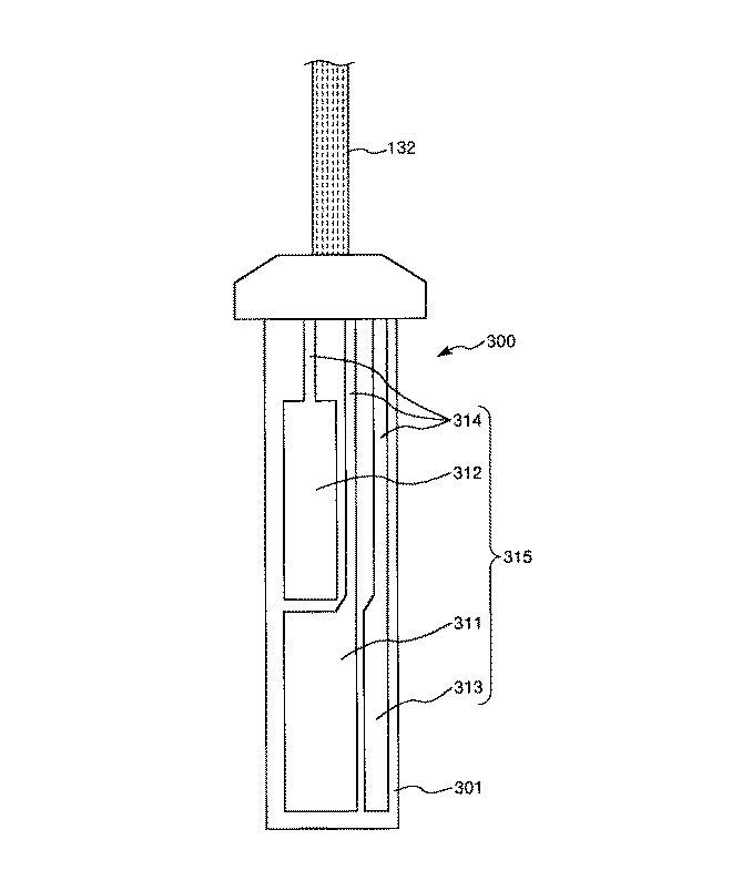
図1は、本発明の分析装置の実施形態を模式的に示す斜視図であり、分析装置が有する検出素子が備える脱着部を本体部に装着した状態を示し、図2は、本発明の分析装置の実施形態を模式的に示す斜視図であり、分析装置が有する検出素子が備える脱着部を本体部から離脱させた状態を示し、図3は、本発明の分析装置の実施形態が有する検出素子を皮膚に装着した状態を示す側面図、図4は、図3に示す検出素子が備えるカニューレを拡大して示す縦断面図、図5は、図3に示す検出素子が備える検出部を示す平面図、図6は、図3に示す検出素子が備える検出部を示す縦断面図である。なお、以下の説明では、図3、図4、図6中の上側を「上」、下側を「下」と言う。また、図5中の紙面手前側を「上」、紙面奥側を「下」と言う。 FIG. 1 is a perspective view schematically showing an embodiment of the analyzer of the present invention, showing a state in which a detachable part included in a detection element included in the analyzer is mounted on a main body, and FIG. 2 is an analysis of the present invention. FIG. 3 is a perspective view schematically showing an embodiment of the apparatus, showing a state in which a detachable part included in a detection element included in the analyzer is detached from the main body, and FIG. 3 is a detection that the embodiment of the analyzer of the present invention has FIG. 4 is an enlarged longitudinal sectional view showing a cannula provided in the detection element shown in FIG. 3, and FIG. 5 shows a detection unit provided in the detection element shown in FIG. FIG. 6 is a plan view showing a detection unit included in the detection element shown in FIG. In the following description, the upper side in FIGS. 3, 4, and 6 is referred to as “upper” and the lower side is referred to as “lower”. Further, the front side of the paper surface in FIG.
図1、図2に示す分析装置101は、検出素子100を接続して使用されるものであり、検出素子100と、検出素子100でグルコース濃度に基づく電流値を得るための回路400、得られた電流値を解析する処理回路200を備えた演算装置210および演算装置210で演算することで得られた測定値を表示するモニター151を備える表示部155と、検出素子100を表示部155に装着(接続)するコネクタ131と、検出素子100とコネクタ131とを接続する配線132とを有する。
The
検出素子100は、図1〜図4に示すとおり、皮下組織502に挿入されるカニューレ111を備える本体部110と、本体部110に対して着脱可能であり、先端側に針部121を備える着脱部120とを有している。
As shown in FIGS. 1 to 4, the
着脱部120は、基端側に位置する把持部122と、先端側に位置する針部121とを有しており、針部121を本体部110が備える貫通孔112に挿通させることで本体部110に装着され(図1参照)、さらに、把持部122を把持した状態で針部121を引き抜くことで離脱可能となっている(図2参照)。
The
針部(挿入針)121は、その先端が鋭利であり、全体形状が半円筒状をなしている。着脱部120を本体部110に装着させた際に、貫通孔112を貫通して本体部110の下面から突出することで、図4に示すとおり、カニューレ111の側面の一部を取り囲み、これにより、カニューレ111と嵌合するよう構成されている。したがって、本体部110を表皮501に装着する際に、針部121が表皮501を突き刺すこととなるが、このとき、針部121に取り囲まれたカニューレ111も針部121とともに、表皮501を突き刺し、皮下組織502に挿入される。そして、この皮下組織502へのカニューレ111を伴った針部121の挿入の後に、把持部122を把持して着脱部120を本体部110から離脱させることで、カニューレ111を皮下組織502に挿入(残存)させた状態で、針部121を皮下組織502から取り除く(引き抜く)ことができる。このように、着脱部120(針部121)は、本体部110を表皮501に装着した際に、本体部110から突出するカニューレ111を、経皮的に、皮下組織502へと配置させるための誘導部材として用いられる。
The needle portion (insertion needle) 121 has a sharp tip, and the overall shape is a semi-cylindrical shape. When the
本体部110は、その全体形状がドーム状をなしており、その下面から突出するカニューレ111を備えている。この本体部110は、下面に粘着層を備えており、この下面を表皮501に、当接させることで、装着(固定)される。この際、前述した針部121の誘導により、カニューレ111が皮下組織502に配置される。
The
カニューレ111は、全体形状が円筒状をなし、その基端から先端に連通する連通孔(貫通孔)で構成される中空部114と、この中空部114をカニューレ111の外側に開放する窓部113とを有する。
The
また、中空部114には、本体部110が備える検出部300が設けられている。この検出部300に、皮下組織502に血管503から移行することで含まれる間質液が、窓部113を介して接触する。そのため、検出部300により、間質液中におけるグルコースが検出される。そして、本体部110を表皮501に装着することで、カニューレ111を皮下組織502に長期に亘って配置させることができるため、この間質液中におけるグルコースの検出を連続的に行うことができる。すなわち、本体部110(検出素子100)は、間質液中におけるグルコース値を連続的に観察するCGMS(continuous glucose monitoring system)に用いられる。
The
ここで、検出部300によるグルコースの検出は、以下のような原理を用いて行われる。
Here, the detection of glucose by the
すなわち、酵素(例えば、グルコースオキシダーゼ)の存在下でグルコースと酸素とが酵素近傍に存在すると酵素反応により、下記式(1)のようにグルコン酸と過酸化水素とが生成する。そして、その生成した過酸化水素に電圧(例えば600mV)を印加して電気分解することで発生した電流量を、作用電極と対電極との間で、測定することで過酸化水素の量を定量化することができる。そのため、この定量化された過酸化水素の量に基づいて、グルコースの量を算出することができる。 That is, when glucose and oxygen are present in the vicinity of an enzyme in the presence of an enzyme (for example, glucose oxidase), gluconic acid and hydrogen peroxide are generated as shown in the following formula (1) by an enzyme reaction. Then, the amount of hydrogen peroxide is quantified by measuring the amount of current generated by applying a voltage (for example, 600 mV) to the generated hydrogen peroxide and electrolyzing it between the working electrode and the counter electrode. Can be Therefore, the amount of glucose can be calculated based on the quantified amount of hydrogen peroxide.
なお、過酸化水素の電気分解の際には、作用電極(アノード)側では、下記式(2)のように、過酸化水素の電気分解によりプロトン、酸素および電子が生成され、対電極(カソード)側では、下記式(3)のように、作用電極から供給された電子と、電極付近に存在する酸素および水とが反応することにより水酸化物イオンが生成される。 In the electrolysis of hydrogen peroxide, protons, oxygen and electrons are generated on the working electrode (anode) side by electrolysis of hydrogen peroxide as shown in the following formula (2), and the counter electrode (cathode) On the) side, hydroxide ions are generated by the reaction of electrons supplied from the working electrode with oxygen and water present in the vicinity of the electrode, as shown in the following formula (3).
酵素反応: グルコース+O2+H2O → グルコン酸+H2O2 ・・・ (1)
作用電極: H2O2 → O2+2H++2e− ・・・ (2)
対電極 : O2+H2O+4e− → 4OH− ・・・ (3)
Enzyme reaction: Glucose + O 2 + H 2 O → Gluconic acid + H 2 O 2 (1)
Working electrode: H 2 O 2 → O 2 + 2H + + 2e − (2)
Counter electrode: O 2 + H 2 O + 4e − → 4OH − (3)
以下、かかる原理を用いてグルコースを検出する検出部300について詳述する。
検出部300は、図5および図6に示すとおり、基板301と、導電層(電極)315と、センシング層(酵素層)320とを有している。
Hereinafter, the
As shown in FIGS. 5 and 6, the
基板(ベース基板)301は、検出部300を構成する各部(本実施形態では、導電層315およびセンシング層320)を支持するものである。
The substrate (base substrate) 301 supports each unit (in this embodiment, the
基板301の構成材料としては、大気、水および体液、血液、間質液に対して化学反応することなく安定したものであれば、特に限定されることなく各種材料を用いることができる。具体的には、ガラス、SUSのような無機材料、非晶ポリアリレート(PAR:Polyarylate)、ポリサルホン(PSF:Polysulfone)、ポリエーテルサルホン(PES:Polyethersulfone)、ポリフェニレンスルファイド(PPS:Polyphenylene sulfide)、ポリエーテルエーテルケトン(PEEK:Polyether ether ketone / 別称:芳香族ポリエーテルケトン)、ポリイミド(PI:Polyimide)、ポリエーテルイミド(PEI:Polyetherimide)、フッ素樹脂(Fluorocarbon polymer)や、ナイロン、アミドを含むポリアミド(PA)、ポリエチレンテレフタレート(PET)のようなポリエステル等の樹脂材料等が挙げられ、これらのうちの1種または2種以上を組み合わせて用いることができる。
As a constituent material of the
導電層(電極層)315は、後述するセンシング層320で生成した過酸化水素を電気分解することで発生した電子を検出し、この検出された電子を電流量として測定するものである。
The conductive layer (electrode layer) 315 detects electrons generated by electrolyzing hydrogen peroxide generated in the
この導電層315は、基板301に形成され、作用電極311、対電極312、参照電極313および配線314を有している。
The
各電極311、312、313は、それぞれ独立して、配線314、配線132およびコネクタ131を介して、回路400および処理回路200と電気的に接続されている。これにより、各電極311、312(導電層315)で測定された電流値が、配線314、132を介して表示部155が備える回路400および処理回路200に伝達され、処理回路200を備える演算装置210の解析により、間質液中におけるグルコース値が測定値として算出される。そして、この測定値(グルコース値)がモニター151に表示され、装着者にグルコース値が連続的に知らされる。
Each of the
また、各電極311、312および313の構成材料としては、酵素電極として用いることが可能であれば、特に限定されず、それぞれ、例えば、金、銀、白金またはこれらを含む合金のような金属材料、ITOのような金属酸化物系材料、カーボン(グラファイト)のような炭素系材料等が挙げられる。
Further, the constituent material of each of the
なお、各電極311、312、313の成膜は、各電極311、312、313を白金、金またはそれらの合金で構成する場合、スパッタ法、メッキ法、真空加熱蒸着法により成膜可能である。また、各電極311、312、313をカーボングラファイトで構成する場合、カーボングラファイトを適当な溶剤に溶かし込んだバインダーに混ぜ込んで塗布することで実現できる。
The
センシング層320は、導電層315に積層して形成されており、すなわち、作用電極311、対電極312および参照電極313を覆って形成されており、センシング層320の上面に接触した間質液から浸透したグルコースから酵素反応により過酸化水素を生成して、この過酸化水素を、前述した導電層315に供給するものであり、グルコースから過酸化水素を生成する酵素反応によりグルコースを感知するものである。
The
このセンシング層320は、本発明では、分析物感知層321と、中間層322と、分析物調整層323とを有しており、これらが、導電層315側からこの順で積層された積層体で構成されている。以下、これら各層について説明する。
In the present invention, the
分析物感知層(酵素層)321は、作用電極311、対電極312および参照電極313を覆って形成されており、中間層322および分析物調整層323を介して浸透したグルコースから酵素反応により過酸化水素を生成するものである。そして、生成した過酸化水素を、導電層315に供給するものである。
The analyte sensing layer (enzyme layer) 321 is formed so as to cover the working
この分析物感知層321は、酵素を含んで構成される層であり、前述の通り検出素子100は、間質液中におけるグルコース(分析物)を検出(感知)するものであるため、この酵素としては、グルコースオキシダーゼ(GOD)が好ましく用いられる。グルコースオキシダーゼによれば、前記式(1)で表わされる酵素反応を、優れた活性度で進行させることができるため、O2およびH2Oの存在下で、グルコースから過酸化水素を確実に生成させることができる。
The
また、分析物感知層321には、酵素の他に、他成分として、分析物感知層321中に酵素を保持することを目的に、樹脂材料が含まれる。
In addition to the enzyme, the
樹脂材料としては、特に限定されないが、例えば、メチルセルロース(MC)、アセチルセルロース(酢酸セルロース)、ポリビニルピロリドン(PVP)、ポリビニルアルコール(PVA)およびポリビニルアルコール−ポリ酢酸ビニル共重合体(PVA−PVAc)等が好ましく用いられ、これらのうちの1種または2種以上を組み合わせて用いることができる。これらの樹脂材料を用いることにより、分析物感知層321中に酵素を保持し、分析物感知層321外に酵素が移動することを抑制することができる。
The resin material is not particularly limited. For example, methyl cellulose (MC), acetyl cellulose (cellulose acetate), polyvinyl pyrrolidone (PVP), polyvinyl alcohol (PVA), and polyvinyl alcohol-polyvinyl acetate copolymer (PVA-PVAc). Etc. are preferably used, and one or more of these can be used in combination. By using these resin materials, the enzyme can be held in the
さらに、分析物感知層321には、結合剤もしくは硬化剤の他、アルブミン、リン酸緩衝材等が含まれていてもよい。
Further, the
結合剤もしくは硬化剤は、アルデヒド、イソシアネート等の官能基を分子内に2つ以上有している材料が挙げられる。このような結合剤もしくは硬化剤を分析物感知層321中に含まれることにより、分析物感知層321は、優れた保持率で酵素を分析物感知層321中に保持し得るものとなる。
Examples of the binder or curing agent include materials having two or more functional groups such as aldehyde and isocyanate in the molecule. By including such a binder or curing agent in the
この結合剤、硬化剤としては、具体的には、例えば、グルタルアルデヒド、トルエンジイソシアネート、イソホロンジイソシアネート等が挙げられ、これらのうちの1種または2種以上を組み合わせて用いることができる。また、UV硬化性を利用した結合剤、硬化剤としては、例えば、ポリ(ビニルアルコール)−スチリルピリジニウム化合物(PVA−SbQ)等が挙げられる。 Specific examples of the binder and curing agent include glutaraldehyde, toluene diisocyanate, isophorone diisocyanate, and the like, and one or more of these can be used in combination. Moreover, as a binder and a hardening | curing agent using UV curability, a poly (vinyl alcohol) -styryl pyridinium compound (PVA-SbQ) etc. are mentioned, for example.
なお、このような結合剤もしくは硬化剤を含む分析物感知層321は、結合剤もしくは硬化剤と、これらが備える官能基と結合できる官能基、具体的には水酸基、アミノ基、エポキシ基等を末端に有する樹脂材料と、酵素とを混合した樹脂組成物を硬化させることにより得ることができる。
The
さらに、UV硬化性を利用した結合剤、硬化剤としては、ポリ(ビニルアルコール)−スチリルピリジニウム化合物(PVA−SbQ)を用いる場合には、官能基を末端に有する樹脂材料の添加を省略して、PVA−SbQと酵素とを含有する樹脂組成物を硬化させることにより得られた硬化物で、分析物感知層321を構成することもできる。この場合、分析物感知層321は、PVA−SbQで構成される多孔体に、酵素が保持され、中間層322側から浸透してくる間質液を円滑に分析物感知層321内に取り込むことができ、間質液内に含まれるグルコースと酵素との接触機会を増大させることができ、前記式(1)で表わされる酵素反応を、円滑に進行させることができるため、O2およびH2Oの存在下で、グルコースから過酸化水素を確実に生成させることができる。また、PVA−SbQで構成される多孔体に、酵素を強固に保持することができるため、酵素が中間層322側に移行するのを的確に抑制または防止することができる。
Furthermore, when using a poly (vinyl alcohol) -styrylpyridinium compound (PVA-SbQ) as a binder or curing agent using UV curability, the addition of a resin material having a functional group at the end is omitted. The
また、アルブミンとしては、人アルブミン、牛アルブミン等が挙げられ、アルブミンが含まれることにより、酵素の保護・安定化を図ることができる。 Examples of albumin include human albumin and bovine albumin. By containing albumin, the enzyme can be protected and stabilized.
このような分析物感知層321の平均厚さは、特に限定されないが、0.1μm以上10.0μm以下程度であるのが好ましく、0.5μm以上5.0μm以下程度であるのがより好ましい。これにより、中間層322側から浸透したグルコースと分析物感知層321に保持された酵素との酵素反応により過酸化水素を円滑に生成することができるとともに、生成した過酸化水素を、円滑に導電層315に供給することができる。
The average thickness of the
分析物調整層323は、中間層322を介して、分析物感知層321の上側に積層され、この分析物調整層323により、分析物感知層321が測定対象(間質液、さらには血液)と接触することを抑制または防止しつつ、グルコース(分析物)を透過させて、中間層322を介して、分析物感知層321に円滑に浸透させる機能を発揮するものである。すなわち、分析物感知層321への透過を調整する機能を有するものである。さらに、分析物感知層321に保持されている酵素が、間質液側に漏出するのを防止するブロッキング層としての機能も発揮する。
The
また、かかる機能を備える分析物調整層323は、グルコースよりも酸素をより多く透過(浸透)させ得ることが好ましい。これにより、上記式(1)〜(3)を用いたグルコースの検出において、酸素が不足することに起因して、グルコースの測定値が見かけ上、低下してしまうのを的確に抑制または防止することができる。すなわち、グルコース測定値の検出精度の向上が図られる。
Moreover, it is preferable that the
このような分析物調整層323としては、特に限定されないが、例えば、イソシアネート化合物等の架橋剤と、末端水酸基を備えるポリマーであるポリエチレングリコール(PEG)、ポリプロピレングリコール(PPG)、アクリル酸4−ヒドロキシブチル等を単体もしくは混合させたものとを用いて、ウレタン結合を生成させて架橋構造を構築したものが特に好ましく用いられる。これにより、上述した分析物調整層323としての機能をより顕著に発揮させることができる。
Such an
また、その他、イソシアネートとアミノ基とを用いることで尿素樹脂を形成させた、アミノプロピルポリシロキサン等で構成されるものを用いることができ、さらには、ポリジメチルシロキサンのようなシロキサン樹脂で構成されるものを用いることもできる。 In addition, it is possible to use those composed of aminopropylpolysiloxane or the like in which urea resin is formed by using isocyanate and amino group, and further composed of siloxane resin such as polydimethylsiloxane. A thing can also be used.
このような分析物調整層323の平均厚さは、特に限定されないが、0.1μm以上10.0μm以下程度であるのが好ましく、0.5μm以上5.0μm以下程度であるのがより好ましい。これにより、分析物調整層323内にグルコースを円滑に透過させることができるとともに、分析物感知層321に保持されていた酵素が、間質液側に漏出するのを的確に抑制または防止することができる。
The average thickness of the
中間層(保護層)322は、酵素を含有しない層であり、分析物感知層321上に積層され、分析物感知層321と分析物調整層323との間に位置して、分析物感知層321と分析物調整層323とを離間している。
The intermediate layer (protective layer) 322 is a layer that does not contain an enzyme, is laminated on the
これにより、導電層315と、分析物感知層321と、中間層322と、分析物調整層323とが、厚さ方向に対して、この順で積層されている。
Accordingly, the
ここで、上述した分析物感知層321は、中間層322側から浸透したグルコースと分析物感知層321に保持された酵素との酵素反応により、円滑に過酸化水素を生成させる機能を発揮させるとともに、生成した過酸化水素を、円滑に導電層315に供給する機能を発揮させるために、その平均厚さ(膜厚)は、比較的薄く設定され、具体的には、好ましくは、0.1μm以上10μm以下程度に設定される。このような薄い膜厚に設定された分析物感知層321には、カニューレ111を皮下組織502に挿入する際や、センシング層320(分析物感知層321)に間質液が浸透する際等に、外的な負荷が掛かるため物理的な損傷が生じると言う問題があった。
Here, the
これに対して、本発明では、分析物感知層321と分析物調整層323との間に、中間層322が設けられており、分析物感知層321上に積層されることで、分析物感知層321を被覆して補強する保護層としての機能を発揮する。そのため、分析物感知層321に外的な負荷が掛かったとしても、分析物感知層321において、物理的な損傷が生じるのを的確に抑制または防止することができる。
On the other hand, in the present invention, an
また、分析物感知層321と分析物調整層323との間に中間層322が位置しているため、中間層322は、酵素が分析物調整層323側に移行するのを防止するバリア層としての機能を発揮することもできる。
Further, since the
この中間層322の構成材料としては、特に限定されないが、UV硬化性および生体適合性を示し、かつ、優れた親水性を示し円滑にグルコースを透過させ得るものが好ましく用いられ、具体的には、例えば、ポリ(ビニルアルコール)−スチリルピリジニウム化合物(PVA−SbQ)、ポリ(2−ヒドロキシエチルメタクリレート)(PHEMA/PAA−HEMA)、2−メタクリロイルオキシエチルホスホリルコリン(MPC)、ポリNイソプロピルアクリルアミド化ポリビニルアルコール(PNIPAAm−PVA)等が挙げられ、これらのうち1種または2種以上を組み合わせて用いることができる。
The constituent material of the
このような中間層322は、酵素を含まず、さらに、構成材料として、分析物感知層321と同一の主成分(すなわち、上述した他成分)を含有することが好ましい。これにより、中間層322と分析物感知層321との界面を均一なものとすることができる。そのため、分析物調整層323から浸透してきたグルコースを、中間層322と分析物感知層321との界面が障壁となることなく、中間層322から分析物感知層321に供給できることから、この供給されたグルコースと分析物感知層321に保持された酵素との酵素反応により、円滑に過酸化水素を生成させることができる。
Such an
なお、このような中間層322と分析物感知層321との構成材料の組み合わせとしては、具体的には、例えば、中間層322および分析物感知層321の構成材料として、ともに、ポリ(ビニルアルコール)−スチリルピリジニウム化合物(PVA−SbQ)を主成分として含有することが好ましい。すなわち、分析物感知層321は、酵素とPVA−SbQとを含み、中間層322は、酵素を含まず、PVA−SbQを含んで形成されていることが好ましく、さらに、中間層322は、酵素を含まないPVA−SbQで構成される多孔体で構成され、分析物感知層321は、PVA−SbQで構成される多孔体に、酵素が保持された構成となっていることが好ましい。
As a combination of the constituent materials of the
このように、中間層322および分析物感知層321がともに多孔体で構成され、かつ、PVA−SbQは、親水性に優れる材料であるため、分析物調整層323から浸透してくる間質液を、中間層322を介して、円滑に分析物感知層321内に取り込ませることができる。そのため、間質液内に含まれるグルコースと酵素との接触機会が増大することから、前記式(1)で表わされる酵素反応を、円滑に進行させることができ、O2およびH2Oの存在下で、グルコースから過酸化水素を確実に生成させることができる。
Thus, since the
また、PVA−SbQで構成される多孔体に、酵素を強固に保持することができるため、酵素が中間層322側に移行するのを的確に抑制または防止することができる。
In addition, since the enzyme can be firmly held in the porous body composed of PVA-SbQ, it is possible to accurately suppress or prevent the enzyme from moving to the
さらに、中間層322と分析物感知層321との界面において、分析物感知層321が中間層322と接触することに起因して、酵素が失活するのを的確に抑制または防止することができる。
Furthermore, it is possible to accurately suppress or prevent the enzyme from being deactivated due to the
なお、中間層322には、上述した構成材料の他、アルブミン等が含まれていてもよい。また、アルブミンとしては、人アルブミン、牛アルブミン等が挙げられ、アルブミンが含まれることにより、分析物感知層321の上部界面(上面)における、酵素の保護・安定化を図ることができる。
Note that the
また、中間層322は、分析物感知層321と分析物調整層323との間に位置することで、これら同士を離間するスペーサとしての機能を発揮する。
In addition, the
ここで、分析物調整層323は、特に好ましくは、ウレタン結合を含む架橋構造を構築したもので構成され、この場合、分析物調整層323には、ウレタン結合の形成の際に残存したイソシアネート基が含まれる。このようなイソシアネート基は、反応性に優れるため、分析物感知層321と分析物調整層323とが中間層322を介することなく接合する構成であると、イソシアネート基が分析物感知層321に含まれる酵素に接触することに起因して、酵素の活性度の低下ひいては酵素の失活を招き、間質液中におけるグルコースの検出(定量)感度に不具合が生じる。
Here, the
これに対して、分析物感知層321と分析物調整層323との間に中間層322を介在させて、これら同士を離間させることにより、イソシアネート基と酵素との接触機会を減少させることができるため、酵素の活性度が低下するのを的確に抑制または防止することができる。その結果、間質液中におけるグルコースの検出(定量)感度に不具合が生じることなく、グルコースの検出が実施される。
In contrast, by interposing the
このように、中間層322にスペーサとしての機能を発揮させる場合には、分析物感知層321の平均厚さをA[μm]とし、中間層322の平均厚さをB[μm]としたとき、1.0≦B/A≦2.5なる関係を満足することが好ましく、1.0≦B/A≦2.0なる関係を満足することがより好ましい。B/Aが前記下限値未満であると、分析物感知層321と分析物調整層323との離間距離が小さくなり過ぎ、分析物感知層321に含まれる酵素の種類等によっては、中間層322を設けることにより得られる効果、すなわち、酵素の活性度の低下ひいては酵素の失活を抑制または防止する効果を十分に得られないおそれがある。また、B/Aが前記上限値を超えると、分析物感知層321と分析物調整層323との離間距離が大きくなり過ぎ、分析物感知層321へのグルコースの浸透が十分になされず、グルコースの検出感度の低下を招くおそれがある。
As described above, when the
このような中間層322の平均厚さAは、具体的には、0.1μm以上25μm以下程度であるのが好ましく、0.5μm以上12μm以下程度であるのがより好ましい。これにより、酵素の活性度の低下を的確に抑制または防止しつつ、優れた検出感度でグルコースの濃度を検出することができる。
Specifically, the average thickness A of the
なお、センシング層320は、前述した、分析物感知層321、中間層322および分析物調整層323の他に、他の層を備えるものであってもよく、このような層としては、例えば、分析物感知層321の下側に積層されたノイズ除去層が挙げられる。
The
このノイズ除去層は、間質液中に含まれる可能性を有する、アセトアミノフェン、アスコルビン酸、および尿酸等の化合物が分析物感知層321を透過して導電層315に到達することに起因する、グルコース測定値の検出感度の低下を阻止する機能を有するものである。
This noise removal layer is caused by a compound such as acetaminophen, ascorbic acid, and uric acid, which may be included in the interstitial fluid, passing through the
このノイズ除去層の構成材料としては、前記機能を発揮し得るものであれば、特に限定されないが、例えば、メチルセルロース(MC)、アセチルセルロース(酢酸セルロース)、ポリビニルピロリドン(PVP)、ポリビニルアルコール(PVA)、ポリビニルアルコール−ポリ酢酸ビニル共重合体(PVA−PVAc)、メタクリル酸ヒドロキシエチル、およびポリ(2−ヒドロキシエチルメタクリレート)(HEMA)等が挙げられ、これらのうちの1種または2種以上を組み合わせて用いることができる。 The constituent material of the noise removal layer is not particularly limited as long as it can exhibit the above functions. For example, methyl cellulose (MC), acetyl cellulose (cellulose acetate), polyvinyl pyrrolidone (PVP), polyvinyl alcohol (PVA) ), Polyvinyl alcohol-polyvinyl acetate copolymer (PVA-PVAc), hydroxyethyl methacrylate, poly (2-hydroxyethyl methacrylate) (HEMA), and the like. They can be used in combination.
なお、ノイズ除去層を不溶化させるために、イソシアネートを官能基として用い得るように、イソシアネート系化合物をノイズ除去層に添加してもよいし、UV硬化性を利用し得るように、ポリ(ビニルアルコール)−スチリルピリジニウム化合物(PVA−SbQ)等をノイズ除去層に添加してもよい。 In order to insolubilize the noise removal layer, an isocyanate compound may be added to the noise removal layer so that isocyanate can be used as a functional group, or poly (vinyl alcohol) may be used so that UV curability can be utilized. ) -Styrylpyridinium compound (PVA-SbQ) or the like may be added to the noise removal layer.
さらに、ノイズ除去層にアルブミンを含有させてもよい。これにより、ノイズ除去層上に位置する分析物感知層の下部境界面(下面)を保護することができる。 Furthermore, albumin may be contained in the noise removal layer. This can protect the lower boundary surface (lower surface) of the analyte sensing layer located on the noise removal layer.
なお、本実施形態では、検出部300において、導電層315が備える作用電極311、対電極312、参照電極313および配線314の全体を、分析物感知層321で覆う場合について説明したが、かかる構成に限定されず、作用電極311および対電極312上に選択的に分析物感知層321が形成されていてもよいし、作用電極311上に選択的に分析物感知層321が形成されていてもよい。
In the present embodiment, the
また、表示部155は、図1、2に示すとおり、その内部に配設され、配線314、132を介して電気的に接続された、検出部300を駆動させるための回路400を有している。
Further, as shown in FIGS. 1 and 2, the
この回路400には、検出部300が備える作用電極311、参照電極313、および対電極312が電気的に接続されている。
The
作用電極311と参照電極313との間では、例えば、600mVの電圧の差が維持され、この差が、検出部300に対する印加電圧となり、その結果、センシング層320に含まれる過酸化水素が電気分解することで、電子が生成される。そして、この電子を、作用電極311と対電極312との間で、グルコース濃度に基づく電流値として測定し、また、この電流値を処理回路200が備える演算装置210で解析することで、グルコース値が測定値として算出され、さらに、この測定値がモニター151により表示される。
For example, a voltage difference of 600 mV is maintained between the working
<測定方法>
また、上記の分析装置101を用いた、間質液中におけるグルコース値の測定は、具体的には、例えば、以下のようにして行われる。
<Measurement method>
In addition, the measurement of the glucose value in the interstitial fluid using the above-described
図7は、本発明の分析装置を用いて、グルコース値を測定する方法を示すフローチャートである。 FIG. 7 is a flowchart showing a method for measuring a glucose level using the analyzer of the present invention.
[1]まず、カニューレ111を皮下組織502に挿入して、検出部300(センシング層320)を間質液に接触させることで、安定化させる(S1)。
[1] First, the
[2]次に、作用電極311と参照電極313との間に定電圧を所定の長さで印加する。これにより、安定化の際にセンシング層320の作用電極311近傍に生じた過酸化水素を上記式(2)のように電気分解することで、センシング層320の作用電極311近傍を初期設定させる(S2)。
[2] Next, a constant voltage is applied between the working
[3]次に、一定時間の間隔をあけた後に、作用電極311と参照電極313との間に定電圧を所定の長さで印加する。これにより、センシング層320の作用電極311近傍に生じた過酸化水素が上記式(2)のように電気分解され、その結果、生じた電子を、作用電極311と対電極312との間に流れた電流値として測定することで、間質液中におけるグルコース値が求められる(S3)。
[3] Next, after a certain time interval, a constant voltage is applied between the working
なお、この工程[3]は、1回であってもよいが、工程[3]を繰り返して行い、この間に測定されたグルコース値の平均値を求めることにより、グルコース値が平均化されるため、グルコース値をより優れた信頼度で求めることができる。 In addition, although this process [3] may be performed once, since glucose value is averaged by repeating process [3] and calculating | requiring the average value of the glucose value measured in the meantime, , The glucose level can be determined with higher reliability.
以上のような工程[1]〜工程[3]を、所定の間隔を空けて繰り返して行うことで、
間質液中におけるグルコース値(グルコース濃度)を連続的に測定することができる。
By repeatedly performing the above steps [1] to [3] at a predetermined interval,
The glucose level (glucose concentration) in the interstitial fluid can be continuously measured.
<インスリン供給装置>
また、本発明の検出素子は、上記のように分析装置に装着される他、例えば、インスリン供給装置(本発明のインスリン供給装置)に装着される。
<Insulin supply device>
In addition to being mounted on the analyzer as described above, the detection element of the present invention is mounted on, for example, an insulin supply device (insulin supply device of the present invention).
図8は、本発明の検出素子をインスリン供給装置に装着した状態を模式的に示す斜視図である。 FIG. 8 is a perspective view schematically showing a state in which the detection element of the present invention is mounted on the insulin supply apparatus.
図8に示すインスリン供給装置171は、検出素子100を接続して使用されるものであり、検出素子100と、検出素子100で得られた電流値を解析する処理回路200を備えた演算装置210および演算装置210で演算することで得られた測定値に基づいて皮下組織502にインスリンを供給(投与)する針部172を備える供給部175と、検出素子100を供給部175に装着(接続)するコネクタ131と、処理回路200とコネクタ131とを接続する配線132とを有する。このようなインスリン供給装置171では、作用電極311と対電極312との間に流れた電流値が、本体部110が備える回路400および配線132を介して、処理回路200に伝達され、処理回路200を備える演算装置210の解析により、間質液中におけるグルコース値(グルコース濃度)が測定値として算出される。そして、この測定値(グルコース値)に基づいて、すなわち測定値が設定された濃度よりも高い場合に、インスリン供給装置171が作動し、針部172を介して、装着者にインスリンが自動的に投与される。
An
以上、本発明の検出素子、分析装置およびインスリン供給装置を図示の実施形態に基づいて説明したが、本発明はこれに限定されるものではない。 As described above, the detection element, the analysis device, and the insulin supply device of the present invention have been described based on the illustrated embodiment, but the present invention is not limited to this.
例えば、本発明の検出素子、分析装置およびインスリン供給装置における各部の構成は、同様の機能を有する任意の構成のものに置換することができる。また、本発明に、他の任意の構成物が付加されていてもよい。また、本発明は、前記分析装置およびインスリン供給装置のうちの、任意の2以上の構成(特徴)を組み合わせたものであってもよい。 For example, the configuration of each unit in the detection element, analysis device, and insulin supply device of the present invention can be replaced with any configuration having the same function. In addition, any other component may be added to the present invention. Further, the present invention may be a combination of any two or more configurations (features) of the analysis device and the insulin supply device.
また、カニューレを皮下組織に挿入する他、皮内に挿入するようにしてもよい。
さらに、分析装置およびインスリン供給装置において、検出素子で測定された電流値は、配線を介することなく、処理回路に伝達するようにしてもよく、例えば、通信手段を介して無線で、電流値を処理回路に伝達するようにしてもよい。
In addition to inserting the cannula into the subcutaneous tissue, the cannula may be inserted into the skin.
Furthermore, in the analyzer and the insulin supply device, the current value measured by the detection element may be transmitted to the processing circuit without going through the wiring. For example, the current value can be transmitted wirelessly via the communication means. You may make it transmit to a processing circuit.
また、分析装置において、検出素子と表示部とは配線を介して接続されているものに限らず、これらが一体的に形成されているものであってもよいし、インスリン供給装置において、検出素子と供給部とは配線を介して接続されているものに限らず、これらが一体的に形成されているものであってもよい。 Further, in the analysis device, the detection element and the display unit are not limited to being connected via a wiring, and these may be integrally formed. In the insulin supply device, the detection element And the supply unit are not limited to those connected via wiring, and may be integrally formed.
次に、本発明の具体的実施例について説明する。
1.検出素子の製造
(実施例1)
<1> まず、平均厚さ0.5mmの透明なガラス基板を基板301として用意した。
Next, specific examples of the present invention will be described.
1. Production of detection element (Example 1)
<1> First, a transparent glass substrate having an average thickness of 0.5 mm was prepared as the
<2> 次いで、ガラス基板上に、マスクスパッタ法により平均厚さ200nmのパターニングされた白金膜を、作用電極311、対電極312および参照電極313を備える導電層(電極層)315として形成した。
<2> Next, a patterned platinum film having an average thickness of 200 nm was formed as a conductive layer (electrode layer) 315 including a working
<3> 次いで、白金膜上に、アクリル材料を用いたフォトレジストにより平均高さ8μmのバンクを形成するとともに、測定対象液(血液、間質液)と接触する開口部を開けることにより、隔壁層331を形成した。
<3> Next, a bank having an average height of 8 μm is formed on the platinum film with a photoresist using an acrylic material, and an opening that contacts the liquid to be measured (blood, interstitial fluid) is opened, thereby forming a
<4> 次いで、導電性ITO膜、白金膜および隔壁層が積層された基板をアセトン、2−プロパノールの順に浸漬し、超音波洗浄した後、酸素プラズマ処理およびアルゴンプラズマ処理を施した。これらのプラズマ処理は、それぞれ、基板を70〜90℃に加温した状態で、プラズマパワー100W、ガス流量20sccm、処理時間5secで行った。 <4> Next, the substrate on which the conductive ITO film, the platinum film, and the partition wall layer were laminated was immersed in acetone and 2-propanol in this order, subjected to ultrasonic cleaning, and then subjected to oxygen plasma treatment and argon plasma treatment. Each of these plasma treatments was performed at a plasma power of 100 W, a gas flow rate of 20 sccm, and a treatment time of 5 seconds with the substrate heated to 70 to 90 ° C.
<5> 次いで、参照電極313の白金電極上に、銀−塩化銀粒子を含んだインクをインクジェット方式により乾燥後膜厚が3μmになる量を充填し、120℃のオーブンで乾燥させることで、銀−塩化銀膜を形成した。
<5> Next, on the platinum electrode of the
<6> 次いで、GOD(グルコースオキシダーゼ 活性度 150U/mg)5mgを超純水6.1gに溶解させGOD溶液とし、さらに得られたGOD溶液を1.22g秤量し、PVA−SbQ(13.3%水溶液)1.0gと混合させることで、分析物感知層形成用材料を調製した。 <6> Next, 5 mg of GOD (glucose oxidase activity 150 U / mg) was dissolved in 6.1 g of ultrapure water to obtain a GOD solution. Further, 1.22 g of the obtained GOD solution was weighed, and PVA-SbQ (13.3). The material for forming an analyte sensing layer was prepared by mixing with 1.0 g of a% aqueous solution.
そして、この分析物感知層形成用材料を、作用電極311、対電極312および参照電極313の全面に、シリンジで滴下し1000rpm−300secの条件でスピンコート法を用いて塗布することで膜厚0.8μmの液状被膜を成膜した後、5分間自然乾燥させることで薄膜を得た。その後、波長365nmの紫外線を5分間照射して不溶化膜(硬化膜)を形成することで、分析物感知層321を成膜した。
Then, the analyte sensing layer forming material is dropped on the entire surface of the working
<7> 次いで、PVA−SbQ(13.3%水溶液)1.0gと超純水2.33gとを混合することで、中間層形成用材料を調製した。 <7> Next, an intermediate layer forming material was prepared by mixing 1.0 g of PVA-SbQ (13.3% aqueous solution) and 2.33 g of ultrapure water.
そして、この中間層形成用材料を、分析物感知層の全面にシリンジで中間層形成用材料を滴下し1000rpm−300secの条件でスピンコート法を用いて塗布することで液状被膜を成膜した後、自然乾燥させることで膜厚0.2μmの薄膜を得た。その後、波長365nmの紫外線を5分間照射して不溶化膜(硬化膜)を形成することで、中間層322を成膜した。
After this intermediate layer forming material is deposited on the entire surface of the analyte sensing layer with a syringe, the intermediate layer forming material is applied using a spin coating method under the condition of 1000 rpm-300 sec. The film was naturally dried to obtain a thin film having a thickness of 0.2 μm. Thereafter, an
<8> 次いで、PPG(ポリプロピレングリコール)トリオール型(300)0.45g、トルエン0.5g、イソホロンジイソシアネートが0.5g、ジアザビシクロウンデセン(DBU)1滴とを撹拌させながら混合することで、分析物調整層形成用材料を調製した。 <8> Next, 0.45 g of PPG (polypropylene glycol) triol type (300), 0.5 g of toluene, 0.5 g of isophorone diisocyanate, and 1 drop of diazabicycloundecene (DBU) are mixed with stirring. Then, an analyte adjusting layer forming material was prepared.
そして、この分析物調整層形成用材料を、中間層の全面に、シリンジで分析物調製層形成用材料を滴下し1000rpm−300secの条件でスピンコート法を用いて塗布した後、24時間放置してウレタンを生成させることで、膜厚6.0μmの、ウレタン結合を含む架橋構造を備え、ウレタン結合の形成の際に残存したイソシアネート基を有する構成をなす分析物調整層323を成膜した。
以上の工程により、図9の構成をなす実施例1の検出部300を製造した。
Then, this analyte adjusting layer forming material is applied onto the entire surface of the intermediate layer by dropping the analyte preparing layer forming material with a syringe under the condition of 1000 rpm-300 sec using a spin coating method, and then left for 24 hours. By forming urethane, an
Through the above steps, the
(実施例2)
前記工程<7>を、以下に示す工程<7A>に変更したこと以外は、前記実施例1と同様にして、図9の構成をなす実施例2の検出部300を製造した。
(Example 2)
A
<7A> PVA−SbQ(13.3%水溶液)1.0gと超純水1.22gとを混合することで、中間層形成用材料を調製した。 <7A> An intermediate layer forming material was prepared by mixing 1.0 g of PVA-SbQ (13.3% aqueous solution) and 1.22 g of ultrapure water.
そして、この中間層形成用材料を、分析物感知層の全面にシリンジで中間層形成用材料を滴下し3000rpm−300secの条件でスピンコート法を用いて塗布することで液状被膜を成膜した後、自然乾燥させることで膜厚0.4μmの薄膜を得た。その後、波長365nmの紫外線を5分間照射して不溶化膜(硬化膜)を形成することで、中間層322を成膜した。
After forming the liquid film by applying the intermediate layer forming material to the entire surface of the analyte sensing layer with a syringe and applying the intermediate layer forming material using a spin coating method at 3000 rpm to 300 sec. The film was naturally dried to obtain a thin film having a thickness of 0.4 μm. Thereafter, an
(実施例3)
前記工程<7>を、以下に示す工程<7B>に変更したこと以外は、前記実施例1と同様にして、図9の構成をなす実施例3の検出部300を製造した。
(Example 3)
A
<7B> PVA−SbQ(13.3%水溶液)1.0gと超純水1.22gとを混合することで、中間層形成用材料を調製した。 <7B> An intermediate layer forming material was prepared by mixing 1.0 g of PVA-SbQ (13.3% aqueous solution) and 1.22 g of ultrapure water.
そして、この中間層形成用材料を、分析物感知層の全面にシリンジで中間層形成用材料を滴下し1000rpm−300secの条件でスピンコート法を用いて塗布することで液状被膜を成膜した後、自然乾燥させることで膜厚0.8μmの薄膜を得た。その後、波長365nmの紫外線を5分間照射して不溶化膜(硬化膜)を形成することで、中間層322を成膜した。
After this intermediate layer forming material is deposited on the entire surface of the analyte sensing layer with a syringe, the intermediate layer forming material is applied using a spin coating method under the condition of 1000 rpm-300 sec. A thin film having a thickness of 0.8 μm was obtained by natural drying. Thereafter, an
(比較例1)
前記工程<7>を省略したこと以外は、前記実施例1と同様にして、比較例1の検出部300を製造した。
(Comparative Example 1)
A
2.評価
2−1.グルコース感度の測定
まず、リン酸生理食塩水にグルコース濃度が1mg/dLになるように調製したものを標準液として準備した。
そして、この標準液を35℃で一定になるように加温した。
2. Evaluation 2-1. Measurement of glucose sensitivity First, a solution prepared in phosphate physiological saline so that the glucose concentration was 1 mg / dL was prepared as a standard solution.
And this standard solution was heated so that it might become fixed at 35 degreeC.
次いで、加温された標準液に、各実施例および比較例の検出部300を浸漬することで、作用電極、対電極および参照電極に対応する位置における、分析物感知層321、中間層322および分析物調整層323に標準液を含浸させた。
Next, the
次いで、標準液が含浸された、各実施例および比較例の検出部300について、それぞれ、参照電極と作用電極との間が0.6Vになるように電圧を印加した際に、作用電極と対電極との間に流れる電流値を測定した。
Next, with respect to the
2−2.電流値の直線性の評価
まず、リン酸生理食塩水にグルコース濃度が1mg/dL、10mg/dL、30mg/dL、70mg/dLおよび100mg/dLになるように調製したものをそれぞれ標準液として準備した。
そして、これら各標準液を35℃で一定になるように加温した。
2-2. Evaluation of linearity of current value First, prepared as standard solutions were prepared in phosphate saline so that the glucose concentration was 1 mg / dL, 10 mg / dL, 30 mg / dL, 70 mg / dL and 100 mg / dL. did.
And each of these standard solutions was heated so that it might become fixed at 35 degreeC.
次いで、加温された各標準液に、各実施例および比較例の検出部300を浸漬することで、作用電極、対電極および参照電極に対応する位置における、分析物感知層321、中間層322および分析物調整層323に標準液を含浸させた。
Subsequently, the
次いで、各標準液が含浸された、各実施例および比較例の検出部300について、それぞれ、参照電極と作用電極との間が0.6Vになるように電圧を印加した際に、作用電極と対電極との間に流れる電流値を測定した。
Next, with respect to the
そして、各実施例および比較例ごとに、各標準液について測定された電流値を用いて、下記計算式(A)により、直線性(R2)を求めた。なお、計算式中、xは、各標準液中に含まれるグルコース濃度、yは、各グルコース濃度に対応する標準液で測定された電流値を表す。 And linearity (R2) was calculated | required by the following formula (A) using the electric current value measured about each standard solution for every Example and the comparative example. In the calculation formula, x represents the glucose concentration contained in each standard solution, and y represents the current value measured with the standard solution corresponding to each glucose concentration.
これらの結果を、表1に示す。 These results are shown in Table 1.
表1に示したように、分析物調整層323を、ウレタン結合を含む架橋構造を備え、ウレタン結合の形成の際に残存したイソシアネート基を有する構成とした場合には、分析物感知層の平均厚さA[μm]と、中間層の平均厚さB[μm]との比であるB/Aを、1.0以上とすることで、酵素の活性度の低下ひいては酵素の失活を抑制または防止することができ、優れたグルコース感度および直線性が得られる結果を示した。
As shown in Table 1, when the
これに対して、B/Aが1.0未満である場合には、酵素の活性度の低下ひいては酵素の失活を招き、十分なグルコース感度および直線性が得られているとは言えない結果を示した。 On the other hand, when B / A is less than 1.0, the enzyme activity is lowered and the enzyme is deactivated, and it cannot be said that sufficient glucose sensitivity and linearity are obtained. showed that.
また、B/Aが1.0である実施例3では、グルコース感度の大きさが0.412nA/mgとなっている。 In Example 3 where B / A is 1.0, the magnitude of glucose sensitivity is 0.412 nA / mg.
ここで、グルコース濃度±10mg/dLの違いをセンシングするセンサーに必要な感度は、グルコース感度が0.4nA/mgであるときには、4nA/mm2の精度が必要であり、グルコース感度が0.2nA/mgであるときには、2nA/mm2の精度が必要であり、さらに、グルコース感度が0.1nA/mgであるときには、1nA/mm2の精度が必要であることが判っている。
Here, the sensitivity required for the sensor that senses the difference in glucose concentration ± 10 mg / dL requires an accuracy of 4 nA / mm 2 when the glucose sensitivity is 0.4 nA / mg, and the glucose sensitivity is 0.2 nA. / when mg is, it is necessary to precision 2nA / mm 2, further, when the glucose sensitivity is 0.1 nA / mg has been shown to be required for
さらに、1nA/mm2以下の電流は、生体温度変化やグルコース以外の成分の影響によるノイズとしてカウントされるため、センサーを優れた精度を有するものとするには、1nA/mm2超の電流、好ましくは2nA/mm2以上の電流が必要となってくる。 Furthermore, 1 nA / mm 2 or less of the current is to be counted as noise due to the influence of components other than the living body temperature change or glucose to as having excellent accuracy of the sensor is 1 nA / mm 2 greater than the current, Preferably, a current of 2 nA / mm 2 or more is required.
そのため、グルコース感度としては、0.1nA/mg超、好ましくは0.2nA/mg以上が必要となってくる。 Therefore, the glucose sensitivity needs to exceed 0.1 nA / mg, preferably 0.2 nA / mg or more.
そこで、グルコース感度は、中間層の膜厚に対して相関性を示すと推察されることから、グルコース感度を0.1nA/mg超、好ましくは0.2nA/mg以上とするには、B/Aの膜厚の上限値は、2.5以下、好ましくは2.0以下とする必要があると考えられた。 Therefore, since it is presumed that the glucose sensitivity shows a correlation with the film thickness of the intermediate layer, in order to make the glucose sensitivity more than 0.1 nA / mg, preferably 0.2 nA / mg or more, B / The upper limit value of the film thickness of A was considered to be 2.5 or less, preferably 2.0 or less.
100…検出素子、101…分析装置、110…本体部、111…カニューレ、112…貫通孔、113…窓部、114…中空部、120…着脱部、121…針部、122…把持部、131…コネクタ、132…配線、151…モニター、155…表示部、171…インスリン供給装置、172…針部、175…供給部、200…処理回路、210…演算装置、300…検出部、301…基板、311…作用電極、312…対電極、313…参照電極、314…配線、315…導電層、320…センシング層、321…分析物感知層、322…中間層、323…分析物調整層、331…隔壁層、400…回路、501…表皮、502…皮下組織、503…血管
DESCRIPTION OF
Claims (10)
前記基板に形成された導電層と、
前記導電層に形成されたセンシング層と、を有する検出部を備え、
前記センシング層は、分析物を感知する分析物感知層と、前記分析物を調整する分析物調整層と、前記分析物感知層と前記分析物調整層を離間させる中間層と、を含み、
厚み方向に対して、前記導電層、前記分析物感知層、前記中間層、前記分析物調整層の順に配置されることを特徴とする検出素子。 A substrate,
A conductive layer formed on the substrate;
A sensing unit having a sensing layer formed on the conductive layer,
The sensing layer includes an analyte sensing layer that senses an analyte, an analyte conditioning layer that regulates the analyte, and an intermediate layer that separates the analyte sensing layer and the analyte conditioning layer;
The detection element, wherein the conductive layer, the analyte sensing layer, the intermediate layer, and the analyte adjustment layer are arranged in this order in the thickness direction.
前記中間層は、前記他成分のみで形成される請求項1に記載の検出素子。 The analyte sensing layer is formed of an enzyme and other components,
The detection element according to claim 1, wherein the intermediate layer is formed of only the other component.
Priority Applications (1)
| Application Number | Priority Date | Filing Date | Title |
|---|---|---|---|
| JP2015231415A JP2017093939A (en) | 2015-11-27 | 2015-11-27 | Detection element, analyzer and insulin feeding device |
Applications Claiming Priority (1)
| Application Number | Priority Date | Filing Date | Title |
|---|---|---|---|
| JP2015231415A JP2017093939A (en) | 2015-11-27 | 2015-11-27 | Detection element, analyzer and insulin feeding device |
Publications (1)
| Publication Number | Publication Date |
|---|---|
| JP2017093939A true JP2017093939A (en) | 2017-06-01 |
Family
ID=58803397
Family Applications (1)
| Application Number | Title | Priority Date | Filing Date |
|---|---|---|---|
| JP2015231415A Pending JP2017093939A (en) | 2015-11-27 | 2015-11-27 | Detection element, analyzer and insulin feeding device |
Country Status (1)
| Country | Link |
|---|---|
| JP (1) | JP2017093939A (en) |
Cited By (1)
| Publication number | Priority date | Publication date | Assignee | Title |
|---|---|---|---|---|
| KR101947639B1 (en) | 2017-08-08 | 2019-02-14 | 한국화학연구원 | Glucose sensor for ex-vivo diagnosis comprising graphene-based electrode |
-
2015
- 2015-11-27 JP JP2015231415A patent/JP2017093939A/en active Pending
Cited By (1)
| Publication number | Priority date | Publication date | Assignee | Title |
|---|---|---|---|---|
| KR101947639B1 (en) | 2017-08-08 | 2019-02-14 | 한국화학연구원 | Glucose sensor for ex-vivo diagnosis comprising graphene-based electrode |
Similar Documents
| Publication | Publication Date | Title |
|---|---|---|
| US12478734B2 (en) | Methods and systems for insulin delivery and glucose measurement | |
| JP5777639B2 (en) | Insertion device for combination of sensor and infusion set | |
| CN109312383B (en) | In situ chemical stack for continuous glucose sensor | |
| CN103648382B (en) | For the method for continuous analyte monitoring | |
| EP2732837B1 (en) | Combined sensor and infusion set using separated sites | |
| JP6088064B2 (en) | Method and system for optimizing sensor function by applying voltage | |
| CN110678122A (en) | Analyte sensor and method for manufacturing an analyte sensor | |
| JP2008545460A (en) | Integrated drug delivery and analyte sensor device | |
| JP2017118911A (en) | Sensor substrate, analysis element, glucose measuring device, and insulin feeding device | |
| US12495995B2 (en) | Measurement of glucose near an insulin delivery catheter by minimizing the adverse effects of insulin preservatives: alternative ligands and redox mediator metals | |
| JP2018019826A (en) | Detection element, measurement device, agent feeding device, and manufacturing method for detection element | |
| KR102031669B1 (en) | Biosensor capable of measuring biological signals and delivering drugs simultaneously and manufacturing method | |
| CN105902276A (en) | Detection method using detection element, detection element, measurement device, and insulin supply device | |
| JP2017093939A (en) | Detection element, analyzer and insulin feeding device | |
| JP2018021811A (en) | Manufacturing method of detection element | |
| JP2018017688A (en) | Measuring apparatus and measuring method | |
| JP2017051593A (en) | Analysis apparatus and analysis method | |
| JP2018042797A (en) | Sensor element and measuring device | |
| US20170074817A1 (en) | Analysis device and analysis method | |
| JP2018015378A (en) | Measuring apparatus and measuring method | |
| US20170176373A1 (en) | Measuring device, measuring method, and supply device |